US11219711B2 - System and method for hybrid control of reduced pressures delivered to a tissue site - Google Patents
System and method for hybrid control of reduced pressures delivered to a tissue siteDownload PDFInfo
- Publication number
- US11219711B2 US11219711B2US16/158,525US201816158525AUS11219711B2US 11219711 B2US11219711 B2US 11219711B2US 201816158525 AUS201816158525 AUS 201816158525AUS 11219711 B2US11219711 B2US 11219711B2
- Authority
- US
- United States
- Prior art keywords
- pressure
- wound
- controller
- pump
- bang
- Prior art date
- Legal status (The legal status is an assumption and is not a legal conclusion. Google has not performed a legal analysis and makes no representation as to the accuracy of the status listed.)
- Active, expires
Links
Images


Classifications
- A—HUMAN NECESSITIES
- A61—MEDICAL OR VETERINARY SCIENCE; HYGIENE
- A61M—DEVICES FOR INTRODUCING MEDIA INTO, OR ONTO, THE BODY; DEVICES FOR TRANSDUCING BODY MEDIA OR FOR TAKING MEDIA FROM THE BODY; DEVICES FOR PRODUCING OR ENDING SLEEP OR STUPOR
- A61M1/00—Suction or pumping devices for medical purposes; Devices for carrying-off, for treatment of, or for carrying-over, body-liquids; Drainage systems
- A61M1/71—Suction drainage systems
- A61M1/73—Suction drainage systems comprising sensors or indicators for physical values
- A—HUMAN NECESSITIES
- A61—MEDICAL OR VETERINARY SCIENCE; HYGIENE
- A61M—DEVICES FOR INTRODUCING MEDIA INTO, OR ONTO, THE BODY; DEVICES FOR TRANSDUCING BODY MEDIA OR FOR TAKING MEDIA FROM THE BODY; DEVICES FOR PRODUCING OR ENDING SLEEP OR STUPOR
- A61M1/00—Suction or pumping devices for medical purposes; Devices for carrying-off, for treatment of, or for carrying-over, body-liquids; Drainage systems
- A61M1/71—Suction drainage systems
- A61M1/74—Suction control
- A—HUMAN NECESSITIES
- A61—MEDICAL OR VETERINARY SCIENCE; HYGIENE
- A61M—DEVICES FOR INTRODUCING MEDIA INTO, OR ONTO, THE BODY; DEVICES FOR TRANSDUCING BODY MEDIA OR FOR TAKING MEDIA FROM THE BODY; DEVICES FOR PRODUCING OR ENDING SLEEP OR STUPOR
- A61M1/00—Suction or pumping devices for medical purposes; Devices for carrying-off, for treatment of, or for carrying-over, body-liquids; Drainage systems
- A61M1/90—Negative pressure wound therapy devices, i.e. devices for applying suction to a wound to promote healing, e.g. including a vacuum dressing
- A61M1/96—Suction control thereof
- A—HUMAN NECESSITIES
- A61—MEDICAL OR VETERINARY SCIENCE; HYGIENE
- A61M—DEVICES FOR INTRODUCING MEDIA INTO, OR ONTO, THE BODY; DEVICES FOR TRANSDUCING BODY MEDIA OR FOR TAKING MEDIA FROM THE BODY; DEVICES FOR PRODUCING OR ENDING SLEEP OR STUPOR
- A61M1/00—Suction or pumping devices for medical purposes; Devices for carrying-off, for treatment of, or for carrying-over, body-liquids; Drainage systems
- A61M1/90—Negative pressure wound therapy devices, i.e. devices for applying suction to a wound to promote healing, e.g. including a vacuum dressing
- A61M1/91—Suction aspects of the dressing
- A61M1/912—Connectors between dressing and drainage tube
- A—HUMAN NECESSITIES
- A61—MEDICAL OR VETERINARY SCIENCE; HYGIENE
- A61M—DEVICES FOR INTRODUCING MEDIA INTO, OR ONTO, THE BODY; DEVICES FOR TRANSDUCING BODY MEDIA OR FOR TAKING MEDIA FROM THE BODY; DEVICES FOR PRODUCING OR ENDING SLEEP OR STUPOR
- A61M1/00—Suction or pumping devices for medical purposes; Devices for carrying-off, for treatment of, or for carrying-over, body-liquids; Drainage systems
- A61M1/90—Negative pressure wound therapy devices, i.e. devices for applying suction to a wound to promote healing, e.g. including a vacuum dressing
- A61M1/96—Suction control thereof
- A61M1/966—Suction control thereof having a pressure sensor on or near the dressing
- A—HUMAN NECESSITIES
- A61—MEDICAL OR VETERINARY SCIENCE; HYGIENE
- A61M—DEVICES FOR INTRODUCING MEDIA INTO, OR ONTO, THE BODY; DEVICES FOR TRANSDUCING BODY MEDIA OR FOR TAKING MEDIA FROM THE BODY; DEVICES FOR PRODUCING OR ENDING SLEEP OR STUPOR
- A61M2205/00—General characteristics of the apparatus
- A61M2205/15—Detection of leaks
- A—HUMAN NECESSITIES
- A61—MEDICAL OR VETERINARY SCIENCE; HYGIENE
- A61M—DEVICES FOR INTRODUCING MEDIA INTO, OR ONTO, THE BODY; DEVICES FOR TRANSDUCING BODY MEDIA OR FOR TAKING MEDIA FROM THE BODY; DEVICES FOR PRODUCING OR ENDING SLEEP OR STUPOR
- A61M2205/00—General characteristics of the apparatus
- A61M2205/33—Controlling, regulating or measuring
- A61M2205/3331—Pressure; Flow
- A61M2205/3334—Measuring or controlling the flow rate
- A—HUMAN NECESSITIES
- A61—MEDICAL OR VETERINARY SCIENCE; HYGIENE
- A61M—DEVICES FOR INTRODUCING MEDIA INTO, OR ONTO, THE BODY; DEVICES FOR TRANSDUCING BODY MEDIA OR FOR TAKING MEDIA FROM THE BODY; DEVICES FOR PRODUCING OR ENDING SLEEP OR STUPOR
- A61M2205/00—General characteristics of the apparatus
- A61M2205/33—Controlling, regulating or measuring
- A61M2205/3331—Pressure; Flow
- A61M2205/3341—Pressure; Flow stabilising pressure or flow to avoid excessive variation
- A—HUMAN NECESSITIES
- A61—MEDICAL OR VETERINARY SCIENCE; HYGIENE
- A61M—DEVICES FOR INTRODUCING MEDIA INTO, OR ONTO, THE BODY; DEVICES FOR TRANSDUCING BODY MEDIA OR FOR TAKING MEDIA FROM THE BODY; DEVICES FOR PRODUCING OR ENDING SLEEP OR STUPOR
- A61M2205/00—General characteristics of the apparatus
- A61M2205/33—Controlling, regulating or measuring
- A61M2205/3331—Pressure; Flow
- A61M2205/3344—Measuring or controlling pressure at the body treatment site
- A—HUMAN NECESSITIES
- A61—MEDICAL OR VETERINARY SCIENCE; HYGIENE
- A61M—DEVICES FOR INTRODUCING MEDIA INTO, OR ONTO, THE BODY; DEVICES FOR TRANSDUCING BODY MEDIA OR FOR TAKING MEDIA FROM THE BODY; DEVICES FOR PRODUCING OR ENDING SLEEP OR STUPOR
- A61M2205/00—General characteristics of the apparatus
- A61M2205/50—General characteristics of the apparatus with microprocessors or computers
Definitions
- the inventions as set forth in the appended claimsrelate generally to a negative-pressure tissue treatment system and method and more particularly, but without limitation, to a hybrid control of therapy pressures applied by such tissue treatment system and method to a tissue site wherein the therapy pressures may be varied based on the pressure leakage of the tissue treatment system and method.
- Negative-pressure therapymay provide a number of benefits, including migration of epithelial and subcutaneous tissues, improved blood flow, and micro-deformation of tissue at a wound site. Together, these benefits can increase development of granulation tissue and reduce healing times.
- the reduced pressure provided by a reduced pressure treatment system to a tissue site such as, for example, an incision or a woundmay need to be properly controlled to increase the effectiveness of the reduced pressure treatment.
- the reduced pressure treatment systemmay include a pump for providing reduced pressure, a wound dressing disposed adjacent the wound, and a drape that covers both to provide a sealed environment for providing the reduced pressure treatment from the pump to the sealed environment. Leaks and blockages may occur in the components of the reduced pressure treatment system such as, for example, leaks between the drape and the tissue site, that may need to be detected in order to adjust the pressure provided by the pump to maintain effective treatment.
- the type of method used for controlling reduced pressure treatment systemsmay vary depending on the magnitude of the pressure leaks or blockages and/or the rate of change of the pressure leaks or blockages. Consequently, the pump pressure control best suited for a high leak rate may be different from the pump pressure control best suited for a low leak rate.
- a controller and control methodsare described herein that include both PID and bang-bang controllers and an algorithm for switching between the two controls based on the level of leakage of components in the negative pressure system. The controller and control methods may select PID control for high leakage conditions and bang-bang control for low leakage conditions to conserve battery power and reduce noise from the pump.
- the PID controlmight run constantly to maintain the pressure in a high leakage condition which would reduce battery power and expose the patient to the constant humming of the pump, while the bang-bang control might be sufficiently responsive in a low leakage condition which would conserve battery power and be less irritating because it would not need to be on all the time.
- a system for stimulating healing of tissue at a wound sitecomprises a dressing including a porous pad and a drape covering the pad at a wound site for maintaining negative pressure at a wound site, a negative-pressure source including a pump and an electric motor to generate a pump pressure (PP) for applying to the wound site, and a first pressure sensor for sensing the pump pressure (PP).
- the systemmay further comprise a system controller coupled to the first pressure sensor and electric motor that may include a PID controller that operates continuously to maintain the wound pressure (WP) at a target one pressure (TP) and a bang-bang controller that is turned on and off to maintain the wound pressure (WP) within a range of pressures proximate the target wound pressure (TP).
- the system controllermay be further configured to alternatively select the bang-bang controller when the system is in a low-leakage condition or the PID controller when the system is in a high-leakage condition.
- a system for stimulating healing of tissue at a wound sitecomprises a dressing including a porous pad configured to be positioned and at the wound site and adapted to be covered by a drape to form a seal around the wound site for receiving negative pressure.
- the systemfurther may further comprise a negative-pressure source including a pump fluidly coupled to the porous pad for applying a pump pressure (PP) to the wound site and an electric motor for driving the pump in response to the application of power, and a first pressure sensor having an input for sensing the pump pressure (PP) and an output for providing a pump pressure signal corresponding to the pump pressure (PP).
- PPpump pressure
- the systemmay further comprise a system controller electrically coupled to the electric motor and the output of the first pressure sensor, the system controller being responsive to the pump pressure signal to control a wound pressure (WP) at the tissue site and configured to determine a flow rate (FR) of fluid between the pump and the porous pad.
- the systemmay further comprise a PID controller responsive to the system controller and configured to compare the pump pressure (PP) to a first set of minimum and maximum pump pressure values and vary the power applied to the electric motor in response to the comparison to maintain the wound pressure (WP) proximate a target pressure (TP).
- the systemmay further comprise a bang-bang controller responsive to the system controller and configured to compare the pump pressure (PP) to a second set of minimum and maximum pump pressure values and turn the electric motor on and off to maintain the wound pressure (WP) within a range of pressures from the target pressure (TP).
- the system controllermay be further configured to engage the bang-bang controller if the flow rate (FR) is less than a first target flow rate (TFR1) and the PID controller if the flow rate (FR) is greater than the first target flow rate (TFR1).
- FIG. 1is a functional block diagram of an embodiment of one example of a reduced-pressure therapy system including a controller coupled to a pump motor and a pump that can provide hybrid control of pressure being provided to a tissue site in accordance with this specification;
- FIG. 1Ais a perspective view of a multi-lumen tube that may be used in the reduced pressure therapy system of FIG. 1 in accordance with an illustrative embodiment of the invention
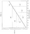
- FIG. 2is a graph illustrating stall voltage characteristics for a pump motor that may be used in the reduced pressure therapy system of FIG. 1 wherein the x-axis represents the vacuum pressure loading for the pump motor and the y-access represents the stall voltage;
- FIG. 3is a graph illustrating pressure control of a motor-drive system in accordance with an illustrative embodiment of the example embodiment wherein the x-axis represents time in minutes (min) and/or seconds (sec) and the y-axis represents pressure generated by a pump in Torr (mmHg) that varies with time in a continuous control mode and an intermittent mode that may be used in the reduced pressure therapy system of FIG. 1 ;
- mmHgpump in Torr
- FIG. 4is a graph illustrating pressure control of a motor-drive system in accordance with an illustrative embodiment of the example embodiment wherein the x-axis represents time in minutes (min) and/or seconds (sec) and the y-axis represents pressure generated by a pump in Torr (mmHg) that compares a manipulated variable, i.e., a tissue site or wound pressure (WP) at a tissue site, and a control variable, i.e., a pump pressure (PP), for use with a PID controller and/or a bang-bang controller;
- a manipulated variablei.e., a tissue site or wound pressure (WP) at a tissue site
- WPwound pressure
- PPpump pressure
- FIGS. 5 and 5A /Bare graphs illustrating pressure control for a bang-bang controller in accordance with an illustrative embodiment of the example embodiment wherein the x-axis represents time in seconds (sec) and the y-axis represents pressure generated by a pump in Torr (mmHg) that varies with time in an continuous control mode and wherein the pressure control of the bang-bang controller is subjected to a larger head pressure created by the reduced-pressure's therapy system of FIG. 1 as shown in FIG. 5 compared to the smaller head pressure shown in FIGS. 5A /B, FIG. 5B having an expanded vertical pressure scale than that shown in FIG. 5A ;
- FIG. 6is a graph illustrating pressure control for a PID controller in accordance with an illustrative embodiment of the example embodiment wherein the x-axis represents time in seconds (sec) and the y-axis represents pressure generated by a pump in Torr (mmHg) that varies with time in an continuous control mode and wherein the horizontal time scale is substantially the same as the horizontal timescale shown in FIG. 5B for comparing pressure control with that of the bang-bang controller; and
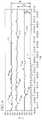
- FIG. 7is a flowchart illustrating a process or therapy loop for controlling reduced pressure at a tissue site that may be stored on the controller of FIG. 1 including a therapy algorithm for selecting the appropriate pump pressure control for controlling reduced pressure at a tissue site in accordance with an illustrative embodiment of the example embodiment.
- FIG. 1is a simplified functional block diagram of an example embodiment of a reduced-pressure therapy system 100 that can provide negative-pressure therapy in accordance with this specification. More specifically, the therapy system 100 may be used for controlling which pump pressure control is utilized to provide the appropriate amount of reduced pressure to tissue site 105 .
- Tissue site 105may be the bodily tissue of any human, animal, or other organism, including bone tissue, adipose tissue, muscle tissue, dermal tissue, vascular tissue, connective tissue, cartilage, tendons, ligaments, or any other tissue. While tissue site 105 may include a wound, diseased tissue, or defective tissue, the tissue site may further include healthy tissue that is not wounded, diseased, or defective.
- tissue site 105may be used to promote the drainage of exudate and other liquids from tissue site 105 , as well as promote the growth of additional tissue.
- tissue site 105is a wound site
- the application of reduced pressure to non-wounded or non-defective tissue, including healthy tissuemay be used to promote the growth of tissue that may be harvested and transplanted to another tissue location.
- the reduced pressure applied to the tissue site 105may be provided by a reduced pressure source 110 .
- Reduced pressure source 110may be any type of manually, mechanically, or electrically operated pump.
- Non-limiting examples of reduced pressure source 110include devices that are driven by stored energy, and which are capable of producing a reduced pressure. Examples of these stored energy, reduced pressure sources include, without limitation, pumps driven by piezoelectric energy, spring energy, solar energy, kinetic energy, energy stored in capacitors, combustion, and energy developed by Sterling or similar cycles.
- reduced pressure source 110may include a pump 112 wherein the pump 112 provides negative or reduced pressure, i.e., a pump pressure (PP), to the tissue site 105 that may be driven by a motor 114 electrically coupled to a controller 170 which is also a component of the reduced-pressure therapy system 100 , also referred to as a system controller.
- PPpump pressure
- the motor 114may be a direct-current motor powered by a DC power supply such as, for example, a battery (not shown).
- a DC power supplysuch as, for example, a battery (not shown).
- the pump 112uses low amounts of power and is capable of operating for an extended period of time on a single charge of the battery such as, for example, a diaphragm pump.
- the reduced pressure source 110comprises a DC motor 114 powered by a battery, i.e., the applied power.
- the applied powercan be varied to control the speed of the motor by varying either the current or the voltage applied to the motor, i.e., the “applied voltage” (V A ).
- the applied voltage (V A )may be varied, for example, by modulating the voltage with a square wave and varying the duty cycle of the square wave to control the speed of the DC motor 114 .
- the reduced pressure source 110also comprises a pump 112 that provides a reduced pressure or vacuum to the tissue site 105 .
- the pump 112represents the load on the DC motor 114 so that when the therapy requires that the reduced pressure at the tissue site 105 needs to be increased, the applied voltage (V A ) provided to the DC motor 114 is increased to achieve the targeted reduced pressure at the tissue site 105 .
- the DC motor 114will not run or turn the pump until the applied voltage (V A ) is sufficient to overcome the inertia or load of the pump 112 , which in this case may be a diaphragm pump.
- a graph 301 illustrating the voltages for the pump motor 114 necessary to start the pump 112is shown wherein the X-axis represents the pump pressure (PP) loading the DC pump motor and the Y-axis represents the applied voltage (V A ).
- the controller 170may need to apply at least 2.3V to the DC motor 114 before it will turn the pump 112 when loaded at a pressure of 100 mmHg as indicated by the dashed lines 302 , 303 . Applying any less than 2.3V to the DC motor 114 would yield insufficient power for the motor to turn the pump, i.e., the loaded motor would remain stopped or “stalled” so that the motor is unable to turn the pump.
- the 2.3V valueis often referred to in the industry as the “stall voltage” that would be calculated for a DC motor under a load of 100 mmHg of pressure, i.e., the “stall pressure.”
- the controller 170may need to apply a larger voltage of at least 2.45V 304 to the DC motor before it will turn the pump when loaded at a greater pressure of 125 mmHg 305 . Applying any less than the stall voltage of 2.45V to the DC motor would not be sufficient to cause the DC motor to turn the pump under a stall pressure of 125 mmHg.
- Variations in the stall voltageare proportional to the variations in the pressure load on the motor, i.e., the greater the pressure load is on the motor, the greater the stall voltage needed to overcome the pressure load.
- the specific stall voltage for a specific DC motor used to drive a diaphragm pumpcan typically be determined by one skilled in the art from the specifications available for the DC motor.
- the diaphragm pump and DC motormay be and integrated device such as, for example, a Thomas Model No. 30130002 series 4.5V diaphragm pump for which such information is readily available. (Thomas; thomas.de@gardnerdenver.com)
- the graph 301 illustrating the stall voltage for the pump motor, the Y-axisrepresents the stall voltages calculated for this Thomas motor based on the specifications presently available at the Thomas website referred to above.
- the examples provided in the paragraph aboveinclude voltages and pressures that are exemplary only.
- the graph 301simply illustrates that one skilled in the art can calculate the various stall voltages for a DC motor based on specifications typically available for that motor.
- Data from pump specificationsis typically limited to the relation of maximum flow to vacuum pressure at maximum pump voltage (e.g., 4.5V for Thomas pump identified above).
- the graph 301 in FIG. 2was generated based on the motor specifications and the stall voltages observed that were needed to drive this pump.
- the reduced pressure source 110may provide reduced pressure to the tissue site 105 via a dressing 115 .
- dressing 115may include a tissue interface such as, for example, a manifold 120 which may be placed adjacent to or in contact with the tissue site 105 .
- Manifold 120may be a biocompatible, porous material that is capable of being placed in contact with tissue site 105 and distributing reduced pressure to the tissue site 105 .
- Manifold 120may be made from foam, gauze, felted mat, or any other material suited to a particular biological application.
- Manifold 120may include a plurality of flow channels or pathways to facilitate distribution of reduced pressure or fluids to or from tissue site 105 .
- manifold 120is a porous foam and includes a plurality of interconnected cells or pores that act as flow channels.
- the porous foammay be a polyurethane, open-cell, reticulated foam such as GranuFoam manufactured by Kinetic Concepts, Inc. of San Antonio, Tex. If an open-cell foam is used, the porosity may vary, but is preferably about 400 to 600 microns.
- the flow channelsallow fluid communication throughout the portion of manifold 120 having open cells.
- the cells and flow channelsmay be uniform in shape and size, or may include patterned or random variations in shape and size. Variations in shape and size of the cells of manifold result in variations in the flow channels, and such characteristics may be used to alter the flow characteristics of fluid through manifold 120 .
- the manifold 120may further include portions that include “closed cells.” These closed-cells portions of manifold 120 contain a plurality of cells, the majority of which are not fluidly connected to adjacent cells. Closed-cell portions may be selectively disposed in manifold 120 to prevent transmission of fluids through perimeter surfaces of manifold 120 .
- Manifold 120may also be constructed from bioresorbable materials that do not have to be removed from a patient's body following use of reduced pressure treatment system 100 .
- Suitable bioresorbable materialsmay include, without limitation, a polymeric blend of polylactic acid (PLA) and polyglycolic acid (PGA).
- the polymeric blendmay also include without limitation polycarbonates, polyfumarates, and capralactones.
- Manifold 120may further serve as a scaffold for new cell-growth, or a scaffold material may be used in conjunction with manifold 120 to promote cell-growth.
- a scaffoldis a substance or structure used to enhance or promote the growth of cells or formation of tissue, such as a three-dimensional porous structure that provides a template for cell growth.
- scaffold materialsinclude calcium phosphate, collagen, PLA/PGA, coral hydroxy apatites, carbonates, or processed allograft materials.
- the scaffold materialhas a high void-friction (i.e., a high content of air).
- the dressing 115may also include sealing member 125 also referred to as a drape or cover.
- Manifold 120may be secured to tissue site 105 using sealing member 125 .
- Sealing member 125may be a cover that is used to secure manifold 120 at tissue site 105 . While sealing member 125 may be impermeable or semi-permeable, in one example sealing member 125 is capable of maintaining a reduced pressure at tissue site 105 after installation of the sealing member 125 over manifold 120 .
- Sealing member 125may be a flexible drape or film made from a silicone based compound, acrylic, hydrogel or hydrogel-foaming material, or any other biocompatible material that includes the impermeability or permeability characteristics desired for tissue site 105 .
- Sealing member 125may be formed of a hydrophobic material to prevent moisture absorption by the sealing member 125 .
- sealing member 125is configured to provide a sealed connection with the tissue surrounding manifold 120 and tissue site 105 .
- the sealed connectionmay be provided by an adhesive (not shown) positioned along a perimeter of sealing member 125 or on any portion of sealing member 125 to secure sealing member 125 to the manifold 120 or the undamaged epidermis peripheral to a tissue site, i.e., the peritissue.
- the adhesivemay be pre-positioned on sealing member 125 or may be sprayed or otherwise applied to sealing member 125 immediately prior to installing sealing member 125 .
- components of the therapy system 100may be coupled directly or indirectly.
- Componentsmay be fluidly coupled to each other to provide a path for transferring fluids (i.e., liquid and/or gas) between the components.
- componentsmay be fluidly coupled through a tube.
- a tubeis an elongated, cylindrical structure with some flexibility, but the geometry and rigidity may vary.
- componentsmay additionally or alternatively be coupled by virtue of physical proximity, being integral to a single structure, or being formed from the same piece of material. Coupling may also include mechanical, thermal, electrical, or chemical coupling (such as a chemical bond) in some contexts
- the reduced pressure generated by reduced pressure source 110may be applied to tissue site 105 through source tube 130 and delivery tube 135 .
- Source tube 130 and delivery tube 135may be any tube through which a gas, liquid, gel, or other fluid may flow.
- exudate from tissue site 105may flow through delivery tube 135 .
- source tube 130couples reduced pressure source 110 to a canister 140 and delivery tube 135 couples the canister 140 to the dressing 115 .
- reduced pressure source 135may be directly coupled to dressing 115 using delivery tube 135 .
- Source tube 130 and delivery tube 135may be made from any material.
- Source tube 130 and delivery tube 135may be either flexible or inflexible.
- source tube 130 and delivery tube 135may include one or more paths or lumens through which fluid may flow.
- delivery tube 135may include two lumens.
- one lumenmay be used for the passage of exudate from tissue site 105 to canister 140 .
- the other lumenmay be used to deliver fluids, such as air, antibacterial agents, antiviral agents, cell-growth promotion agents, irrigation fluids, or other chemically active agents, to tissue site 105 .
- the fluid source from which these fluids originateis not shown in FIG. 1 . Additional details regarding the inclusion of multi-lumen tubes in reduced pressure treatment system 100 are provided below.
- delivery tube 135is coupled to manifold 120 via connection member 145 .
- Connection member 145permits the passage of fluid from manifold 120 to delivery tube 135 , and vice versa.
- exudates collected from tissue site 105 using manifold 120may enter delivery tube 135 via connection member 145 .
- reduced pressure treatment system 100does not include connection member 145 .
- delivery tube 135may be inserted directly into sealing member 125 or manifold 120 such that an end of delivery tube 135 is adjacent to or in contact with manifold 120 .
- Canister 140may be any device or cavity capable of containing a fluid, such as gases and liquids, as well as fluids that contain solids.
- canister 140may contain exudates from tissue site 105 .
- Source tube 130 and delivery tube 135may be directly connected to canister 140 , or may be coupled to canister 140 via a connector, such as connector 150 , as indicated by arrow 151 .
- the canister 140may be a flexible or rigid canister, a bag, or pouch fluidly connected to manifold 120 by delivery tube 135 .
- Canister 140may be a separate canister or may be operably combined with reduced pressure source 110 to collect exudate and fluids.
- Reduced pressure treatment system 100may further comprise a first pressure sensor 155 electrically coupled to the controller 170 .
- Pressure sensor 155detects an actual reduced pressure at or proximate the tissue site 105 , i.e., the tissue site pressure or wound pressure (WP).
- WPwound pressure
- the reference to the word “wound” as part of the term wound pressure (WP)is exemplary only and does not limit the term or description herein as applying to the measurement of pressure at other types of tissue sites such as, for example, incisions or subcutaneous cavities.
- pressure sensor 155is a silicon piezo-resistive gauge pressure sensor.
- Pressure sensor 155may be configured to detect the wound pressure (WP) via a control tube 160 fluidly coupled to the connection member 145 or via one of the lumens of the delivery to 135 as described above through the connector 150 .
- Control tube 160is any tube through which a gas may flow.
- Control tube 160may be made from any material.
- Control tube 160may be either flexible or inflexible.
- control tube 160may include one or more paths or lumens through which fluid may flow.
- Reduced pressure treatment system 100may further comprise a second pressure sensor 156 electrically coupled to the controller 170 .
- Pressure sensor 156detects a reduced pressure at or downstream from the canister 140 indicated by arrows 157 and 158 , respectively, i.e., the pump pressure (PP).
- pressure sensor 156is a silicon piezo-resistive gauge pressure sensor.
- the pressure sensor 156may be fluidly coupled directly to the canister 144 or the source tube 130 , or indirectly via a control tube (not shown) as indicated by the arrows 157 and 158 , to detect the pump pressure (PP).
- the pressure sensor 156may also be fluidly coupled to the canister 144 through the connector 150 .
- control tube 160is shown as passing through connector 150 .
- control tube 160may be routed through canister 140 , along an outside surface of canister 140 , or may bypass canister 140 .
- the end of control tube 160 that is opposite of pressure sensor 155may be coupled to manifold 120 via the connection member 145 .
- control tube 160may be inserted directly into sealing member 125 or manifold 120 such that an end of control tube 160 is adjacent to or in contact with manifold 120 .
- delivery tube 135 and control tube 160are each lumens in a single multi-lumen tube.
- Source tube 130 and control tube 160may also each be lumens in a single multi-lumen tube.
- a single multi-lumen tubemay be used to couple both reduced pressure source 110 and pressure sensor 155 to manifold 120 .
- FIG. 1Aa perspective view of a multi-lumen tube is depicted in accordance with an illustrative embodiment of the present invention. Specifically, FIG. 1A depicts multi-lumen tube 190 , which may be implemented in a reduced pressure treatment system, such as reduced pressure treatment system 100 in FIG. 1 .
- Multi-lumen tube 190includes two lumens. Specifically, multi-lumen tube 190 includes lumens 192 and 194 . Although multi-lumen tube 190 includes two lumens 192 and 194 , multi-lumen tube may have any number of lumens, such as three, four, or ten. In one embodiment, one of lumens 192 and 194 , such as lumen 192 , is a delivery tube or source tube, such as delivery tube 135 and source tube 130 in FIG. 1 . In another embodiment, one of lumens 192 and 194 , such as lumen 194 , is a control tube, such as control tube 160 in FIG. 1 .
- the number of separate tubes included in the reduced pressure treatment systemmay be reduced.
- the reduced number of tubessimplifies the reduced pressure treatment system for use by a user, and lessens the burden of carrying the reduced pressure treatment system.
- Pressure sensors 155 and 156may be located anywhere on or within the reduced pressure treatment system 100 . Referring back to FIG. 1 , pressure sensor 155 is shown to be remote from tissue site 105 . In this example, the reduced pressure at tissue site 105 may be detected from remotely located pressure sensor 155 through the control tube 160 , which permits the flow of gas. Also in this example, pressure sensor 156 may be directly or indirectly coupled to other remotely located components of reduced pressure treatment system 100 , such as reduced pressure source 110 , the canister 140 , or any other illustrated component of reduced pressure treatment system 100 . In another example, pressure sensor 155 may not require the use of control tube 160 to detect the pressure at tissue site 105 . In one non-limiting example, pressure sensor 155 is directly coupled to manifold 120 or placed between sealing member 125 and manifold 120 .
- Reduced pressure treatment system 100may also include control tube valve 165 .
- Control tube valve 165may be coupled to control tube 160 as indicated by arrow 166 or indirectly coupled to the source tube 134 or the canister 140 as indicated by arrow 168 .
- Control tube valve 165may be any valve capable of relieving the reduced pressure in control tube 160 .
- Non-limiting examples of control tube valve 165include a pneumatic solenoid valve, a proportional valve, or a mechanical valve.
- control tube valve 165may be manually controlled by a caregiver.
- control tube valve 165may be controlled by a controller.
- control tube valve 165may be opened to relieve the reduced pressure in control tube 160 or the source tube 130 when a blockage is detected in either one.
- Such a blockagemay occur, for example, when exudate or other fluid from tissue site 105 clogs control tube 160 or the source tube 130 .
- the blockagemay be cleared from either one.
- the manifold 120may be placed within, over, on, or otherwise proximate to a tissue site.
- the sealing member 125may be placed over the manifold 120 and sealed to tissue near the tissue site 105 .
- the sealing member 125may be sealed to undamaged epidermis peripheral to a tissue site, i.e., the peritissue.
- the dressing 115can provide a sealed therapeutic environment proximate to a tissue site, substantially isolated from the external environment, and the reduced pressure source 110 can reduce the pressure in the sealed therapeutic environment.
- Reduced pressure applied across the tissue site through the manifold 120 in the sealed therapeutic environmentcan induce macrostrain and microstrain in the tissue site, as well as remove exudates and other fluids from the tissue site, which can be collected in the canister 140 and disposed of properly.
- the fluid mechanics of using a reduced-pressure source to reduce pressure in another component or location, such as within a sealed therapeutic environment,can be mathematically complex.
- the basic principles of fluid mechanics applicable to negative-pressure therapyare generally well-known to those skilled in the art, and the process of reducing pressure may be described illustratively herein as “delivering,” “distributing,” or “generating” negative pressure, for example.
- tissue sitein this context broadly refers to a wound or defect located on or within tissue, including but not limited to, bone tissue, adipose tissue, muscle tissue, neural tissue, dermal tissue, vascular tissue, connective tissue, cartilage, tendons, or ligaments.
- a woundmay include chronic, acute, traumatic, subacute, and dehisced wounds, partial-thickness burns, ulcers (such as diabetic, pressure, or venous insufficiency ulcers), flaps, and grafts, for example.
- tissue sitemay also refer to areas of any tissue that are not necessarily wounded or defective, but are instead areas in which it may be desirable to add or promote the growth of additional tissue. For example, negative pressure may be used in certain tissue areas to grow additional tissue that may be harvested and transplanted to another tissue location.
- “Negative or reduced pressure”generally refers to a pressure less than a local ambient pressure, such as the ambient pressure in a local environment external to a sealed therapeutic environment provided by the dressing 102 .
- the local ambient pressuremay also be the atmospheric pressure at which a tissue site is located.
- the pressuremay be less than a hydrostatic pressure associated with tissue at the tissue site. Unless otherwise indicated, values of pressure stated herein are gauge pressures.
- references to increases in negative pressuretypically refer to a decrease in absolute pressure, while decreases in negative pressure typically refer to an increase in absolute pressure.
- a negative-pressure sourcesuch as the reduced pressure source 110
- a negative-pressure sourcemay be housed within or used in conjunction with other components, such as processing units, alarm indicators, memory, databases, software, display devices, or user interfaces that further facilitate negative-pressure therapy.
- the reduced pressure source 110 and the controller 106may be housed within a therapy control unit.
- the pressureis generally a low vacuum, also commonly referred to as a rough vacuum, between ⁇ 5 mm Hg ( ⁇ 667 Pa) and ⁇ 500 mm Hg ( ⁇ 66.7 kPa).
- a rough vacuumbetween ⁇ 5 mm Hg ( ⁇ 667 Pa) and ⁇ 500 mm Hg ( ⁇ 66.7 kPa).
- Common therapeutic rangesare between ⁇ 75 mm Hg ( ⁇ 9.9 kPa) and ⁇ 300 mm Hg ( ⁇ 39.9 kPa).
- the applied voltage (V A ) provided to the DC motor 114is used to control the pump pressure (PP) and ultimately achieve the desired or targeted pressure at the tissue site 105 .
- the applied voltage (V A )provides an indication of the pump pressure (PP) and may be monitored by the controller 170 which in turn may determine the time rate of change of the applied voltage (V A ) that necessarily corresponds to the time rate of change of the pump pressure (PP).
- the controller 170may use this computation for determining the flow rate of air between the reduced pressure source 110 and tissue site 105 , i.e., the flow rate (FR).
- the reduced pressure treatment system 100may further comprise a sensing device (not shown) that directly measures the flow rate (FR) such as, for example, a flow-meter or a differential processor for computing the time rate of change in the difference between the wound pressure (WP) and the pump pressure (PP).
- the flow rate (FR)may be measured, for example, as cubic centimeters of air per minute (cc/min), between the reduced pressure source 110 and the tissue site 105 .
- the flow rate (FR)provides some indication of the extent to which the dressing 115 or other components of the negative pressure system 100 might be leaking to reduce the pressure at the tissue site 105 below the desired pressure targeted for therapy.
- a high flow ratemight indicate that the dressing 115 or other components of the system 100 are considered to be in a “high leakage condition”
- a lower flow ratemight indicate that the dressing 115 or other components of the system 100 are considered to be in a more efficient “low leakage condition” requiring less battery power for driving the DC motor 114 to continue running in order to offset the higher leakage.
- the controller 170may be an integrated or separate component of the reduced-pressure treatment system 100 .
- Controller 170may be any device capable of processing data, such as data from pressure sensor 155 and/or the pressure sensor 156 .
- Controller 170may also control the operation of one or more components of reduced pressure treatment system 100 , such as reduced pressure source 110 , motor 114 , control tube valve 165 , pressure sensors 155 and 156 , and indicator 172 .
- the controller 170may control and receive data from other components (not shown) of the reduced pressure source 110 including the pump 112 and the motor 114 .
- controller 170receives and processes data, such as the wound pressure (WP) from the pressure sensor 155 , the pump pressure (PP) from the pressure sensor 156 , and the flow rate (FR) from monitoring the applied voltage (V A ) to the motor 114 as described above.
- the controller 170may also control the operation of one or more components of reduced pressure treatment system 100 to manage the wound pressure (WP) at tissue site 105 .
- controller 170may including an input for receiving a desired target pressure (TP) set by a clinician or other user and may be program for processing data relating to the setting and inputting of the target pressure (TP) to be applied to the tissue site 105 .
- TPdesired target pressure
- the target pressure (TP)may be a fixed pressure value determined by a user/caregiver as the reduced pressure target desired for therapy at the tissue site 105 and then provided as input to the controller 110 .
- the usermay be a nurse or a doctor or other approved clinician who prescribes the desired reduced pressure to which the tissue site 105 should be applied.
- the desired tissue site pressurewill vary from tissue site to tissue site, but will generally be chosen based on the type of tissue making up the tissue site, the type of injury or wound (if any), the medical condition of the patient, and the preference of the attending physician.
- the reduced pressure source 110is controlled to achieve the target pressure (TP) desired for application to the tissue site 105 .
- the target pressure (TP)may be set by the user in a continuous mode as indicated by solid line 401 and dotted line 402 wherein the wound pressure (WP) is applied to the tissue site 105 until the user deactivates the reduced pressure source 110 .
- the target pressure (TP)may also be set by the user in an intermittent mode as indicated by solid lines 401 , 403 and 405 wherein the wound pressure (WP) is cycled between the target pressure (TP) and atmospheric pressure.
- the target pressure (TP)may be set by the user at 125 mmHg for a specified period of time (e.g., 5 min) followed by the therapy being turned off for a specified period of time (e.g., 2 min) as indicated by lines 403 by venting the tissue site 105 to the atmosphere, and then repeating the cycle by turning the therapy back on as indicated by line 405 which consequently forms a square wave pattern between the target pressure (TP) level and no pressure.
- TPtarget pressure
- the increase of the wound pressure (WP) at the tissue site 105 from ambient pressure to the target pressure (TP)is not instantaneous, but rather limited depending on the type of therapy equipment and the dressing.
- the reduced pressure source 110 and the dressing 115may have an initial rise time as indicated by the dashed line 407 that may vary depending on the type of dressing and therapy equipment being used.
- the initial rise time for one therapy systemmay be in the range between about 20-30 mmHg/second or, more specifically, equal to about 25 mmHg/second, and in the range between about 5-10 mmHg/second for another therapy system.
- the repeating rise time 405may be a value substantially equal to the initial rise time 407 .
- the target pressuremay also be a variable target pressure (VTP) controlled or determined by controller 170 that varies in a dynamic pressure mode.
- VTPvariable target pressure
- the variable target pressure (VTP)may vary between a maximum and minimum pressure value that may be set as an input by a user as the range of reduced pressures desired for therapy at the tissue site 105 .
- the variable target pressure (VTP)may also be processed and controlled by controller 170 that varies the target pressure (TP) according to a predetermined waveform such as, for example, a sine waveform or a saw-tooth waveform or a triangular waveform, that may be set as an input by a user as the predetermined or time-varying reduced pressures desired for therapy at the tissue site 105 .
- variable target pressuremay be a reduced pressure that provides an effective treatment by applying reduced pressure to tissue site 105 in the form of a triangular waveform varying between 50-125 mmHg with a rise time set at +25 mmHg/min and a descent time set at ⁇ 25 mmHg/min.
- the variable target pressure (VTP)may be a reduced pressure that applies reduced pressure to tissue site 105 in the form of a triangular waveform varying between 25-125 mmHg with a rise time set at a rate of +30 mmHg/min and a descent time set at ⁇ 30 mmHg/min.
- the type of system and tissue sitedetermines the type of reduced pressure therapy to be used.
- the reduced pressure source 104is operated to achieve the desired pressure at the wound site 105 by controlling pressure (PP).
- PPpump pressure
- the reduced pressure source 110to be operated at a higher pump pressure (PP) than that of the target pressure (TP) due to pressure losses between the reduced pressure source 110 and the tissue site 105 .
- the head pressure of exudates and other fluids within the conduitsmay result in a reduction of vacuum pressure at the tissue site 105 .
- the height of the canister 140 above the tissue site 105may determine the amount of head pressure imposed on the tissue site 105 by fluid in the conduits. For exudates and fluids with a density similar to water, the head pressure imposed by one foot of fluid is almost 25 mmHg. Some fluids withdrawn from the tissue site 105 may be even heavier or more viscous than water, and therefore have a more pronounced effect on pressure losses at the tissue site 105 .
- the target pressure (TP) prescribed for a particular tissue sitemay be ⁇ 125 mm Hg wherein the wound pressure (WP) varies as the reduced pressure is applied to the tissue site 105 .
- the steady sinusoidal variations of the wound pressure (WP) shown in FIG. 4are only explanatory and not representative of the actual variations of the wound pressure (WP) under normal operational conditions such as, for example, the variations shown in FIGS.
- the pump 112needs to provide a pump pressure (PP) rising to a maximum pump pressure value (PPmax) of approximately 185 mmHg and dropping to a minimum pump pressure value (PPmin) of approximately 165 mmHg (a median target pump pressure (TPP) of approximately 175 mmHg) to yield a target pressure (TP) at the tissue site 105 of approximately 125 mmHg.
- PPpump pressure
- PPmaxmaximum pump pressure value
- PPminminimum pump pressure value
- TPPmedian target pump pressure
- the controller 110may also be programmed and controlled by a user to maintain the target pressure (TP) within an acceptable range of pressures. For example, if the target pressure (TP) is set at 125 mmHg as the desired therapeutic pressure for the tissue site 105 , a user may desire that the wound pressure (WP) varies by no more than ⁇ 10 mmHg from the desired target pressure (TP) so that the wound pressure (WP) is controlled between a minimum wound pressure value (WPmin) of 115 mmHg and a maximum wound pressure value (WPmax) of 135 mmHg, i.e., a differential wound pressure range ( ⁇ WP) of about 20 mmHg.
- WPminminimum wound pressure value
- WPmaxmaximum wound pressure value
- the pump pressure (PP)must also be variable by ⁇ 10 mmHg from the target pump pressure (TPP) so that the pump pressure (PP) may be varied in a range extending from the minimum pump pressure value (PPmin) of approximately 165 mmHg to the maximum pump pressure value (PPmax) of approximately 185 mmHg, i.e., a differential pump pressure ( ⁇ TTP) of about 20 mmHg.
- PPminminimum pump pressure value
- PPmaxmaximum pump pressure value
- ⁇ TTPdifferential pump pressure
- Controlling the pump pressure (PP) to stay within this rangeindirectly maintains the wound pressure (WP) within a range extending from the minimum wound pressure value (WPmin) of approximately 115 mmHg to the maximum wound pressure value (WPmax) of approximately 135 mm.
- the pressure differential ( ⁇ P) between the pump pressure (PP) and the wound pressure (WP)is the result of a fairly high leakage rate (LR) of approximately 300 cc/min in the dressing 115 and other components in the system.
- the wound pressure (WP)is being controlled to cycle between approximately 135 mmHg and 115 mmHg as described above by providing a pump pressure (PP) that rises to a maximum pump pressure value (PPmax) of approximately 155 mmHg and drops to a minimum pump pressure value (PPmin) of approximately 120 mmHg to yield a target pressure (TP) at the tissue site 105 of approximately 125 mmHg.
- PPpump pressure
- PPminmaximum pump pressure value
- TPtarget pressure
- the pressure differential ( ⁇ P)is approximately 15 mmHg which is much less than the pressure differential of approximately 50 mmHg resulting from the head pressure in the example associated with FIG. 4 above.
- FIG. 5A and 5Billustrate yet another example wherein the pressure differential ( ⁇ P) between the pump pressure (PP) and the wound pressure (WP) is the result of a lower leakage rate (LR) of approximately 50 cc/min in the dressing 115 and other components in the system.
- the wound pressure (WP)is again being controlled to cycle between approximately 135 mmHg and 115 mmHg by providing a pump pressure (PP) that rises to a maximum pump pressure value (PPmax) of 140 mmHg and drops to a minimum pump pressure value (PPmin) of 115 mmHg to yield a target pressure (TP) at the tissue site 105 of approximately 125 mmHg.
- the pressure differential ( ⁇ P)is approximately 5 mmHg which is even less than the pressure differential in the previous example.
- the pressure variations shown in FIG. 5Bare the same as those shown in FIG. 5A except only that the pressure variations in FIG. 5B are shown with an expanded pressure scale.
- the controller 170may also comprise a bang-bang controller (not shown) which is also referred to as an on-off controller, or a hysteresis controller.
- the bang-bang controlleris a feedback controller that switches abruptly between two states, e.g., between on and off. Essentially, the bang-bang controller may apply an all-or-nothing form of control.
- a bang-bang controllermay be used to generate the pressure variations described generally above in conjunction with FIGS. 5, 5A and 5B . Continuing with that general description, the bang-bang controller may operate in one mode as follows.
- the reduced pressure pump 112is turned on with an applied voltage (V A ) greater than the stall voltage, i.e., the bang-bang on voltage (V ON ) at a start time (t on ), to increase the pump pressure (PP) to the maximum pump pressure (PPmax).
- V Aapplied voltage
- V ONbang-bang on voltage
- PPmaxmaximum pump pressure
- an increase in the pump pressure (PP)may slightly lag the application of the applied voltage (V A )
- the increasing pump pressure (PP)eventually causes the wound pressure (WP) to increase as well as shown at time t 1 .
- the bang-bang on voltage (V ON )continues to be applied until the pump pressure (PP) reaches the maximum pump pressure value (PPmax) or the wound pressure (WP) reaches the maximum wound pressure value (WPmax), whichever occurs first.
- the reduced pressure pump 112is turned off at an off time (t off ) so that no pump pressure (PP) is applied allowing the residual pressure in the reduced pressure therapy system 100 to decrease as a result of the leakage in the system.
- the reduced pressure pump 112remains off until the wound pressure (WP) is again less than or equal to the minimum wound pressure value (WPmin) or the pump pressure (PP) is less than or equal to the minimum pump pressure value (PPmin), whichever occurs first.
- the residual pressuremay also be reduced more quickly by opening a relief valve (not shown) that vents air pressure from the system.
- the bang-bang controllerswitches between these two states wherein the reduced pressure pump 112 is turned on when the wound pressure or the pump pressure drops too low in a descending mode and turns the reduced pressure pump 112 off when the wound pressure or pump pressure rises too high in an ascending mode.
- the bang-bang controllerallows the wound pressure (WP) to oscillate proximate the target pressure (TP) of 125 mmHg as contained between the two limits that a user programs into the controller 170 , e.g., the minimum wound pressure value (WPmin) of 115 mmHg and the maximum wound pressure value (WPmax) of 135 mmHg.
- the wound pressure (WP)is not pulled back within the wound pressure range ( ⁇ WP) of 20 mmHg unless the wound pressure (WP) exceeds either one of these limits.
- the bang-bang controllerkeeps the wound pressure (WP) substantially within this range because the bang-bang controller does not need to overcompensate for leakage in a low-leakage environment.
- the controller 170may also include a PID controller (not shown) that provides a control loop feedback mechanism that calculates an error value as the difference between a measured process variable and a desired setpoint or target, in this case the wound pressure (WP) and the corresponding target pressure (TP) at the wound site 105 , respectively.
- PID controllersare well-known by those skilled in the art as providing proportionality information, historical information, and time rate of change information to maintain the wound pressure (WP) close to the target pressure (TP).
- the PID summationis used to adjust the process, in this case the reduced pressure therapy process, by a control element such as the power or voltage supplied to a DC motor, i.e. the applied voltage (V A ), which is directly related to the pump pressure (PP) as described above.
- the applied voltage (V A )may be varied as described above by adjusting the pulse-width modulation to achieve the desired pump pressure (PP) necessary to compensate for the leakage of the dressing 115 and/or the pressure head referred to above.
- the response of the PID controlleris dependent on the responsiveness of the controller to an error, the degree to which the controller overshoots the setpoint, e.g., the target pressure (TP), and the degree of system oscillation, e.g., the degree of oscillation of the wound pressure (WP) within the acceptable range described above.
- TPtarget pressure
- WPwound pressure
- a preferred embodiment of the PID controlleris a digital controller
- the PID controllermay also be an analog controller or a simple RC circuit.
- the analog or digital PID controllermay be implemented in hardware components or software as part of a program logic controller well-known in the art.
- the PID controlleradjusts the pump pressure (PP) by supplying the applied voltage (V A ) necessary for adjusting the wound pressure (WP) back to the target pressure (TP), i.e., the pump pressure correction ( ⁇ PP).
- the pump pressure correction ( ⁇ PP)is the additional pressure needed to maintain the wound pressure (WP) at the desired target pressure (TP), e.g., 125 mmHg, and may be calculated every few seconds.
- the PID controlvaries the applied voltage (V A ) to the DC motor 114 to achieve a pump pressure (PP) between a minimum pump pressure value (PPmin) and a maximum pump pressure value (PPmax) which maintains the wound pressure (WP) proximate the target wound pressure (TP).
- V Aapplied voltage
- PPminminimum pump pressure value
- PPmaxmaximum pump pressure value
- the pressure differential ( ⁇ P) between the pump pressure (PP) and the wound pressure (WP)is the result of different leakage rates (LR) as illustrated by the three examples including the first pump pressure (PP1), the second pump pressure (PP2), and the third pump pressure (PP3).
- the first pump pressure (PP1)has a relatively large pressure differential ( ⁇ P1) of approximately 15-16 mmHg resulting from a fairly high leakage rate (LR) of approximately 350 cc/min.
- the first pressure (PP1)is varied by the PID controller between a maximum pump pressure value (PPmax) and a minimum pump pressure value (PPmin) to maintain the wound pressure (WP) at the target pressure (TP) of 125 mmHg.
- the PID controllervaries the first pump pressure (PP1) between 140 mmHg and 141 mmHg to maintain the wound pressure (WP) at the target pressure (TP) of 125 mmHg.
- the second pump pressure (PP2)also has a relatively large pressure differential ( ⁇ P2) of approximately 11-12 mmHg resulting from a fairly high leakage rate (LR) of approximately 250 cc/min and is varied by the PID controller between a maximum pump pressure value (PPmax) and a minimum pump pressure value (PPmin) to maintain the wound pressure (WP) at the target pressure (TP) of 125 mmHg.
- the PID controllervaries the second pump pressure (PP2) between 136 mmHg and 137 mmHg to maintain the wound pressure (WP) at the target pressure (TP) of 125 mmHg.
- the difference between these two examplesis that the higher leakage rate (LR) requires a larger pressure differential ( ⁇ P) to maintain the wound pressure (WP) at the same target pressure (TP).
- the third exampleillustrates the same difference wherein the third pump pressure (PP3) also has a much smaller pressure differential ( ⁇ P3) of approximately 4-5 mmHg resulting from a lower leakage rate (LR) of approximately 100 cc/min and is varied by the PID controller between 129 mmHg and 130 mmHg to maintain the wound pressure (WP) at the target pressure (TP) of 125 mmHg.
- the PID controllerdoes not switch the reduced pressure pump 112 on and off, but rather continuously controls the application of the pump pressure (PP) between the maximum and minimum pressure values, (PPmax) and (PPmin), to maintain the wound pressure (WP) at a relatively constant level, e.g., at a target pressure (TP) all of 125 mmHg as shown by the dashed line, rather than allowing it to vary between a maximum and minimum pressure value, (WPmax) and (WPmin) as shown with the bang-bang controller. Therefore, the extent to which the pump pressure (PP) drops towards the minimum pump pressure value (PPmin), the more that the PID controller increases the applied voltage (V A ) being provided to the DC motor 114 .
- the PID controllerdetermines the wound pressure (WP) varies from the target pressure (TP) .
- the action taken to increase or decrease the applied voltage (V A )is proportional to the degree that the wound pressure (WP) provided by the reduced pressure system diverges from the target wound pressure (TP).
- the PID controllercontinuously operates in order to keep the wound pressure (WP) as close to the target wound pressure (TP) as possible, especially for high leakage rates (LR). Consequently, the PID controller causes the reduced pressure therapy system 100 to run smoother than the bang-bang controller as shown when comparing the wound pressure (WP) variations of FIGS. 6 and 5 , respectively, because the PID controller maintains the wound pressure (WP) closer to the target wound pressure (TP) on average, while the bang-bang controller allows the wound pressure (WP) to oscillate between the two limits as described above.
- the bang-bang controllermay provide a sufficiently smooth wound pressure (WP) during treatment while conserving battery power and reducing noise by virtue of the reduced pressure pump 112 being intermittently turned off during the same treatment period.
- the DC motor 114 and pump 112are turned off for a significant percentage of time during the one minute period shown in FIG. 5B , but run continuously when the PID controller is operative as shown in FIG. 6 .
- the bang-bang controller 170includes both the PID controller and the bang-bang controller, i.e., a hybrid controller, and additional processing that switches between them depending on the degree of leakage of the reduced pressure therapy system 100 regardless of the location of the leaks or leakage.
- the controller 170may be programmed to use the bang-bang controller in conjunction with the PID controller operating as described above to enable or disable the PID controller depending on a specific switching condition relating to the amount of air leakage created by the dressing 115 or other components of the reduced pressure therapy system 100 that affect the flow rate (FR).
- a hybrid controllerwould be preferable to utilizing only a PID controller which runs continuously during the continuous control mode as described above (or the enabled portions of an intermittent control mode as described above) to more tightly maintain the wound pressure (WP) at the target wound pressure (TP), but may continually generate noise and more rapidly drain the battery driving the motor 114 .
- the hybrid controllermay engage the bang-bang controller so that the DC motor 114 is turned on and off to conserve battery power and reduce noise generated by the pump 112 during therapy treatments.
- the controller 170may further include an input for a user/caregiver to set one or more target flow rates (TFR).
- the user/caregivermay set the target flow rates (TFR) as the switching condition for determining whether the dressing 115 or other components are in a high leakage state or a low leakage state. If the flow rate (FR) is greater than the fixed target flow rate (TFR), i.e., a high leak condition, the bang-bang controller is disabled so that the PID controller takes over in order to keep the wound pressure (WP) as close to the target wound pressure (TP) as possible.
- TFRtarget flow rates
- the bang-bang controlleris enabled to contain the wound pressure (WP) within the differential wound pressure ( ⁇ WP) range while conserving battery power and reducing noise from the pump 112 .
- the fixed target flow rate (TFR)may be 65 cc/min. As indicated above, it is desirable to keep the bang-bang controller running as much as possible during treatments when the dressing 115 is in a low leakage condition.
- the controller 170may engage the bang-bang controller when the flow rate (FR) is less than or equal to the fixed target flow rate (TFR), but switch back to the PID controller when the flow rate (FR) is greater than the fixed target flow rate (TFR) as a result of additional leakage that develops in the dressing 115 because the patient moving around which ultimately creates a high leak condition.
- the bang-bang controllermay have a dual target flow rate (TFR) capability wherein the controller 170 further includes an input for a user to set two target flow rates (TFR) as switching conditions for determining whether the dressing 115 or other components are in a high leakage state or a low leakage state: an ascending target flow rate (TFR A ) when the bang-bang controller is enabled with an increasing flow rate (FR) and a descending target flow rate (TFR D ) when the PID controller is enabled with a decreasing flow rate (FR).
- TFR Aascending target flow rate
- FR Ddescending target flow rate
- both the ascending target flow rate (TFR A ) and the descending target flow rate (TFR D )are greater than the fixed target flow rate (TFR) so that the controller 170 switches more quickly from the PID controller to the bang-bang controller and more slowly from the bang-bang controller to the PID controller.
- the ascending target flow rate (TFR A ) and the descending target flow rate (TFR D )may both be set to about 80 cc/min which is higher than the fixed target flow rate (TFR) of 65 cc/min in the previous example.
- the ascending target flow rate (TFR A )may also be greater than the descending target flow rate (TFR D ) so that the controller 170 switches even more quickly from the PID controller to the bang-bang controller and even more slowly from the bang-bang controller to the PID controller.
- the controller 170favors the benefits derived from using the bang-bang controller as opposed to the deficiencies associated with the continuous operation of the PID controller.
- the ascending target flow rate (TFR A )may be 75 cc/min and the descending target flow rate (TFR D ) may be about 85 cc/min.
- the descending target flow rate (TFR D )would be set at 85 cc/min rather than 65 cc/min so that the controller 170 switches more quickly from the PID controller to enable the bang-bang controller.
- the ascending target flow rate (TFR A )would be set at 75 cc/min rather than 65 cc/min so that the controller 170 switches more slowly to disable the bang-bang controller.
- controller 170may provide an output signal to the indicator 172 to emit a visual and/or audible signal in response to the wound pressure (WP) at tissue site 105 , as measured by pressure sensor 155 , being nonresponsive to increasing the pump pressure (PP).
- the indicatormay be a light emitting diode (LED) that provides a visual signal.
- indicator 172illuminates in response to the wound pressure (WP) at tissue site 105 being nonresponsive to an increasing pump pressure.
- indicator 180is a sound emitting device, such as a speaker. In this embodiment, indicator 172 emits a sound in response to the wound pressure (WP) at tissue site 105 being nonresponsive to an increasing pump pressure.
- the controller 170may provide other output signals indicating whether the negative pressure therapy system is in a low or high leak condition.
- FIG. 7an example embodiment of a method or process for controlling the wound pressure (WP) as implemented as a supreme controller on the controller 170 as described above or, alternatively, on another example embodiment of the controller 170 is shown.
- the controller 170 and other componentsmay implement this process as described above according to a therapy loop 700 illustrated as the flowchart in FIG. 7 .
- the therapy loop 700includes a therapy algorithm 703 for selecting the appropriate controller, i.e., the PID controller or the bang-bang controller, for controlling the delivery of reduced pressure to the tissue site while conserving power and reducing noise from the pump 112 and the motor 114 at the same time.
- the appropriate controlleri.e., the PID controller or the bang-bang controller
- the controller 170first checks to see if the negative pressure therapy system 100 has been turned on at 705 so that if the negative pressure therapy system 100 is not on, the applied voltage (V A ) is set to 0 V at 707 and applied to the motor 114 as a new motor voltage (V M ) at 709 so that the motor 114 is not running. If the negative pressure therapy system 100 is turned on, the controller 170 checks to determine whether enough time has elapsed at 711 to engage the therapy algorithm 703 , i.e., the duty cycle therapy time (t DC ).
- the duty cycle of the therapy algorithm 703may be, for example, about 50 ms.
- the motor voltage (V M )remains set at the previously applied voltage (V A ) at 709 .
- the duty cycle of the therapy loop 700itself may be, for example, 10 ms without engaging the therapy algorithm 703 .
- the controller 170recalculates the therapy algorithm 703 and proceeds to check the current wound pressure (WP) and/or the pump pressure (PP) at 713 with respect to their corresponding maximum and minimum wound pressure and pump pressure values as described above, i.e., (WPmax) and (WPmin), and (PPmax) and (PPmin), respectively.
- the therapy algorithm 703begins by determining whether the bang-bang controller is active or not at 713 . If the PID controller is engaged and the bang-bang controller is not, a local pump pressure (PPL) is set at a current pump pressure (PPC) at 715 . As described above, the PID control adjusts the applied voltage (V A ) to the DC motor 114 to achieve a pump pressure (PP) between the minimum pump pressure value (PPmin) and the maximum pump pressure value (PPmax) to maintain the wound pressure (WP) proximate the target wound pressure (TP). Referring back to FIG.
- the PID controllervaries the first pump pressure (PP1) between 140 mmHg and 141 mmHg to maintain the wound pressure (WP) at the target pressure (TP) of 125 mmHg and continues to control the pump pressure (PP) during a high leakage condition.
- the controller 170determines the value of applied voltage (V A ) corresponding to the current pump pressure (PPC) at 717 and applies that voltage as the motor voltage (V M ) at 709 .
- the therapy algorithm 703determines whether the bang-bang controller is ascending or descending at 719 .
- the reduced pressure pump 112When the wound pressure (WP) drops too low in the descending mode, e.g., below the minimum wound pressure value (WPmin) as described above, the reduced pressure pump 112 is turned on with an applied voltage (V A ) greater than the stall voltage, i.e., the bang-bang on voltage (V ON ), to increase the pump pressure (PP) to the maximum pump pressure (PPmax) in the ascending mode.
- V Aapplied voltage
- V ONthe bang-bang on voltage
- the bang-bang on voltage (V ON )continues to be applied until the pump pressure (PP) reaches the maximum pump pressure value (PPmax) as shown, for example, at 501 and 503 , or the wound pressure (WP) reaches the maximum wound pressure value (WPmax) as shown, for example, at 502 and 504 , whichever occurs first.
- the therapy algorithm 703sets the local target wound pressure (TPL) at the target wound pressure (TP) plus a hysteresis value (H) at 723 .
- the hysteresis value (H)is the maximum amount of pressure that the wound pressure (WP) should increase above the target wound pressure (TP) when in the ascending mode before the controller 170 turns off the pump 112 to protect the tissue site 105 from an excessive amount of reduced pressure that could be damaging.
- the hysteresis value (H)sets the upper limit above the target wound pressure (TP) which is the maximum pressure value (WPmax). For example, if the hysteresis value (H) is 10 mmHg, the maximum wound pressure value (WPmax) is set at 135 mmHg as shown in FIG. 5B .
- the wound pressure (WP)normally trails the ascending pump pressure (PP) as shown by the wound pressure peaks at 502 and 504 , and the pump pressure peaks at 501 and 503 , the wound pressure (WP) is normally less than the maximum wound pressure value (WPmax), e.g., about 132 mmHg at 505 and 506 , when the pump pressure (PP) hits the maximum pump pressure value (PPmax), e.g., about 140 mmHg at 501 in 503 . Consequently, the controller 170 allows the bang-bang controller to continue regulating the application of reduced pressure, but does turns off the pump 112 in the descending mode of the reduced pressure cycle.
- WPmaxmaximum wound pressure value
- the reduced pressure pump 112when the wound pressure (WP) rises too high in the ascending mode, e.g., above the maximum wound pressure value (WPmax) or the maximum pump pressure value (PPmax) as described above, the reduced pressure pump 112 is turned off so that no pump pressure (PP) is applied allowing the residual pressure in the reduced pressure therapy system 100 to decrease in the descending mode as a result of the leakage in the system.
- the reduced pressure pump 112remains off until the wound pressure (WP) is again less than or equal to the minimum wound pressure value (WPmin) is shown, for example, at 508 , or the pump pressure (PP) is less than or equal to the minimum pump pressure value (PPmin) as shown, for example, that 507 , whichever occurs first.
- the therapy algorithm 703sets the local target wound pressure (TPL) at the target wound pressure (TP) minus the hysteresis value (H) at 721 .
- the hysteresis value (H)is the minimum amount of pressure that the wound pressure (WP) should decrease below the target wound pressure (TP) when in the descending mode before the controller 170 determines that the leakage rate (LR) has increased to a flow rate that is large enough to require the PID controller to maintain the wound pressure (WP) closer to the target wound pressure (TP) as described above.
- the hysteresis value (H)also sets the lower limit below the target wound pressure (TP) which is the minimum pressure value (WPmin). For example, if the hysteresis value (H) is 10 mmHg, the minimum wound pressure value (WPmin) is set at 115 mmHg as shown in FIG. 5B . Because the pump pressure (PP) normally follows the descending wound pressure (WP) as shown between the pump and wound pressure peaks at 501 and 502 , respectively, and the pump and wound pressure minimums that 507 and 508 , respectively, the bang-bang controller turns the pump 112 back on at 507 after which the wound pressure (WP) begins to increase again in the ascending mode.
- TPtarget wound pressure
- WPminthe minimum wound pressure value
- the controller 170allows the bang-bang controller to continue regulating the application of reduced pressure, and does so by turning on the pump 112 in the ascending mode of the reduced pressure cycle.
- the bang-bang controllerallows the wound pressure (WP) to effectively oscillate around the target pressure (TP) of 125 mmHg as contained between the two limits that may be programmed into the controller 170 separately using the minimum wound pressure value (WPmin) of 115 mmHg and the maximum wound pressure value (WPmax) of 135 mmHg, or using the hysteresis value (H). In either case, the bang-bang controller maintains the wound pressure (WP) within a wound pressure range ( ⁇ WP), e.g., a wound pressure range ( ⁇ WP) of 20 mmHg.
- ⁇ WPwound pressure range
- the therapy loop 700After the therapy algorithm 703 sets the motor voltage (V M ) to equal the applied voltage (V A ) at 709 to reenter the therapy loop 700 , the therapy loop 700 then reads the current flow rate (FR) measured by the controller 170 at 725 and determines whether or not the current flow rate (FR) is less than the target flow rate (TFR) at 727 . If the flow rate (FR) is less than the target flow rate (TFR) indicating a low leakage condition as described above, then the bang-bang controller stays on or is enabled as indicated at 729 .
- the bang-bang controllerstays off or is disabled as indicated at 731 .
- the therapy loop 700checks to see if the negative pressure wound therapy system 100 has been turned off at 733 and, if not, continues the therapy loop as indicated at 735 . If the negative pressure therapy system 100 has been turned off, the therapy loop ends at 737 .
- PID control algorithmsconstantly adjust a negative-pressure source to maintain pressure within a specified tolerance, which can be inefficient in low-leak applications, drawing more power than a simple hysteresis control algorithm.
- a hysteresis algorithmcan work well in low-leak applications and uses relatively little power, but can cause a negative-pressure source to turn off and on frequently in high-leak applications, which can be noisy and increase power consumption.
- Hybrid controlas described herein, can combine the benefits of PID and hysteresis control algorithms to minimize power consumption and noise.
- a hybrid control algorithmcan select a hysteresis control algorithm to minimize power consumption. If the application changes or develops a higher leak, a hybrid control algorithm can switch to a PID control algorithm to minimize noise.
Landscapes
- Health & Medical Sciences (AREA)
- Heart & Thoracic Surgery (AREA)
- Vascular Medicine (AREA)
- Engineering & Computer Science (AREA)
- Anesthesiology (AREA)
- Biomedical Technology (AREA)
- Hematology (AREA)
- Life Sciences & Earth Sciences (AREA)
- Animal Behavior & Ethology (AREA)
- General Health & Medical Sciences (AREA)
- Public Health (AREA)
- Veterinary Medicine (AREA)
- Media Introduction/Drainage Providing Device (AREA)
Abstract
Description
Claims (31)
Priority Applications (1)
| Application Number | Priority Date | Filing Date | Title |
|---|---|---|---|
| US16/158,525US11219711B2 (en) | 2015-01-16 | 2018-10-12 | System and method for hybrid control of reduced pressures delivered to a tissue site |
Applications Claiming Priority (3)
| Application Number | Priority Date | Filing Date | Title |
|---|---|---|---|
| US201562104529P | 2015-01-16 | 2015-01-16 | |
| US14/995,871US10124093B1 (en) | 2015-01-16 | 2016-01-14 | System and method for hybrid control of reduced pressures delivered to a tissue site |
| US16/158,525US11219711B2 (en) | 2015-01-16 | 2018-10-12 | System and method for hybrid control of reduced pressures delivered to a tissue site |
Related Parent Applications (1)
| Application Number | Title | Priority Date | Filing Date |
|---|---|---|---|
| US14/995,871ContinuationUS10124093B1 (en) | 2015-01-16 | 2016-01-14 | System and method for hybrid control of reduced pressures delivered to a tissue site |
Publications (2)
| Publication Number | Publication Date |
|---|---|
| US20190125942A1 US20190125942A1 (en) | 2019-05-02 |
| US11219711B2true US11219711B2 (en) | 2022-01-11 |
Family
ID=64050712
Family Applications (2)
| Application Number | Title | Priority Date | Filing Date |
|---|---|---|---|
| US14/995,871Active2037-06-16US10124093B1 (en) | 2015-01-16 | 2016-01-14 | System and method for hybrid control of reduced pressures delivered to a tissue site |
| US16/158,525Active2037-05-17US11219711B2 (en) | 2015-01-16 | 2018-10-12 | System and method for hybrid control of reduced pressures delivered to a tissue site |
Family Applications Before (1)
| Application Number | Title | Priority Date | Filing Date |
|---|---|---|---|
| US14/995,871Active2037-06-16US10124093B1 (en) | 2015-01-16 | 2016-01-14 | System and method for hybrid control of reduced pressures delivered to a tissue site |
Country Status (1)
| Country | Link |
|---|---|
| US (2) | US10124093B1 (en) |
Families Citing this family (27)
| Publication number | Priority date | Publication date | Assignee | Title |
|---|---|---|---|---|
| US12010987B2 (en) | 2004-10-07 | 2024-06-18 | Transmedics, Inc. | Systems and methods for ex-vivo organ care and for using lactate as an indication of donor organ status |
| JP5113522B2 (en) | 2004-10-07 | 2013-01-09 | トランスメディクス, インク. | System and method for organ management ex-vivo |
| US9078428B2 (en) | 2005-06-28 | 2015-07-14 | Transmedics, Inc. | Systems, methods, compositions and solutions for perfusing an organ |
| US9457179B2 (en) | 2007-03-20 | 2016-10-04 | Transmedics, Inc. | Systems for monitoring and applying electrical currents in an organ perfusion system |
| US10750738B2 (en) | 2008-01-31 | 2020-08-25 | Transmedics, Inc. | Systems and methods for ex vivo lung care |
| JP6029650B2 (en) | 2011-04-14 | 2016-11-24 | トランスメディクス,インコーポレイテッド | Organ protection solution for mechanical perfusion in ex-vivo of donor lung |
| CA3185937A1 (en) | 2014-06-02 | 2015-12-10 | Transmedics, Inc. | Ex vivo organ care system |
| EP3229588B1 (en) | 2014-12-12 | 2025-04-23 | TransMedics, Inc. | Apparatus and method for organ perfusion |
| AU2016305091B2 (en) | 2015-08-13 | 2021-06-10 | Smith & Nephew, Inc. | Systems and methods for applying reduced pressure therapy |
| DK3347084T3 (en) | 2015-09-09 | 2021-02-15 | Transmedics Inc | AORTIC NEEDLE FOR EX VIVO ORGAN CARE SYSTEM |
| WO2017205967A1 (en)* | 2016-05-30 | 2017-12-07 | Freed Darren | Apparatus and method for ex vivo lung ventilation with a varying exterior pressure |
| US11395870B2 (en) | 2017-02-15 | 2022-07-26 | Smith & Nephew Asia Pacific Pte. Limited | Negative pressure wound therapy apparatuses and methods for using the same |
| EP3595736B1 (en)* | 2017-03-15 | 2025-07-23 | Smith & Nephew, Inc | Pressure control in negative pressure wound therapy systems |
| EP3687592B1 (en) | 2017-09-29 | 2025-09-03 | T.J. Smith & Nephew, Limited | Negative pressure wound therapy apparatus with removable panels |
| GB201813282D0 (en) | 2018-08-15 | 2018-09-26 | Smith & Nephew | System for medical device activation and opertion |
| US10624794B2 (en) | 2018-02-12 | 2020-04-21 | Healyx Labs, Inc. | Negative pressure wound therapy systems, devices, and methods |
| GB201804347D0 (en) | 2018-03-19 | 2018-05-02 | Smith & Nephew Inc | Securing control of settings of negative pressure wound therapy apparatuses and methods for using the same |
| WO2019211731A1 (en) | 2018-04-30 | 2019-11-07 | Smith & Nephew Pte. Limited | Systems and methods for controlling dual mode negative pressure wound therapy apparatus |
| GB201806988D0 (en) | 2018-04-30 | 2018-06-13 | Quintanar Felix Clarence | Power source charging for negative pressure wound therapy apparatus |
| GB201808438D0 (en)* | 2018-05-23 | 2018-07-11 | Smith & Nephew | Systems and methods for determining blockages in a negative pressure wound therapy system |
| GB201914283D0 (en) | 2019-10-03 | 2019-11-20 | Smith & Nephew | Apparatuses and methods for negative pressure wound therapy |
| GB202002338D0 (en)* | 2020-02-20 | 2020-04-08 | Convatec Ltd | A method and control system for a wound therapy apparatus |
| GB202005928D0 (en)* | 2020-04-23 | 2020-06-10 | Smith & Nephew | Dual mode negative pressure source operation for provision of negative pressure wound therapy |
| JP2023536927A (en)* | 2020-08-06 | 2023-08-30 | ケーシーアイ マニュファクチャリング アンリミテッド カンパニー | Device for controlling leaks in reduced pressure treatment systems |
| CN112604042B (en)* | 2020-12-31 | 2023-03-24 | 广东普门生物医疗科技有限公司 | Reduced pressure drainage system, method of controlling the same, and computer-readable storage medium |
| CN114209938B (en)* | 2021-11-23 | 2023-11-10 | 北京谊安医疗系统股份有限公司 | Pressure control method and control system for breathing machine |
| CN115337142A (en)* | 2022-10-13 | 2022-11-15 | 广东麦特维逊医学研究发展有限公司 | Eye negative pressure control and monitoring system and method thereof |
Citations (137)
| Publication number | Priority date | Publication date | Assignee | Title |
|---|---|---|---|---|
| US1355846A (en) | 1920-02-06 | 1920-10-19 | David A Rannells | Medical appliance |
| US2547758A (en) | 1949-01-05 | 1951-04-03 | Wilmer B Keeling | Instrument for treating the male urethra |
| US2632443A (en) | 1949-04-18 | 1953-03-24 | Eleanor P Lesher | Surgical dressing |
| GB692578A (en) | 1949-09-13 | 1953-06-10 | Minnesota Mining & Mfg | Improvements in or relating to drape sheets for surgical use |
| US2682873A (en) | 1952-07-30 | 1954-07-06 | Johnson & Johnson | General purpose protective dressing |
| US2910763A (en) | 1955-08-17 | 1959-11-03 | Du Pont | Felt-like products |
| US2969057A (en) | 1957-11-04 | 1961-01-24 | Brady Co W H | Nematodic swab |
| US3066672A (en) | 1960-09-27 | 1962-12-04 | Jr William H Crosby | Method and apparatus for serial sampling of intestinal juice |
| US3367332A (en) | 1965-08-27 | 1968-02-06 | Gen Electric | Product and process for establishing a sterile area of skin |
| US3520300A (en) | 1967-03-15 | 1970-07-14 | Amp Inc | Surgical sponge and suction device |
| US3568675A (en) | 1968-08-30 | 1971-03-09 | Clyde B Harvey | Fistula and penetrating wound dressing |
| US3648692A (en) | 1970-12-07 | 1972-03-14 | Parke Davis & Co | Medical-surgical dressing for burns and the like |
| US3682180A (en) | 1970-06-08 | 1972-08-08 | Coilform Co Inc | Drain clip for surgical drain |
| US3826254A (en) | 1973-02-26 | 1974-07-30 | Verco Ind | Needle or catheter retaining appliance |
| DE2640413A1 (en) | 1976-09-08 | 1978-03-09 | Wolf Gmbh Richard | CATHETER MONITORING DEVICE |
| US4080970A (en) | 1976-11-17 | 1978-03-28 | Miller Thomas J | Post-operative combination dressing and internal drain tube with external shield and tube connector |
| US4096853A (en) | 1975-06-21 | 1978-06-27 | Hoechst Aktiengesellschaft | Device for the introduction of contrast medium into an anus praeter |
| US4139004A (en) | 1977-02-17 | 1979-02-13 | Gonzalez Jr Harry | Bandage apparatus for treating burns |
| US4165748A (en) | 1977-11-07 | 1979-08-28 | Johnson Melissa C | Catheter tube holder |
| US4184510A (en) | 1977-03-15 | 1980-01-22 | Fibra-Sonics, Inc. | Valued device for controlling vacuum in surgery |
| WO1980002182A1 (en) | 1979-04-06 | 1980-10-16 | J Moss | Portable suction device for collecting fluids from a closed wound |
| US4233969A (en) | 1976-11-11 | 1980-11-18 | Lock Peter M | Wound dressing materials |
| US4245630A (en) | 1976-10-08 | 1981-01-20 | T. J. Smith & Nephew, Ltd. | Tearable composite strip of materials |
| US4256109A (en) | 1978-07-10 | 1981-03-17 | Nichols Robert L | Shut off valve for medical suction apparatus |
| US4261363A (en) | 1979-11-09 | 1981-04-14 | C. R. Bard, Inc. | Retention clips for body fluid drains |
| US4275721A (en) | 1978-11-28 | 1981-06-30 | Landstingens Inkopscentral Lic, Ekonomisk Forening | Vein catheter bandage |
| US4284079A (en) | 1979-06-28 | 1981-08-18 | Adair Edwin Lloyd | Method for applying a male incontinence device |
| US4297995A (en) | 1980-06-03 | 1981-11-03 | Key Pharmaceuticals, Inc. | Bandage containing attachment post |
| US4333468A (en) | 1980-08-18 | 1982-06-08 | Geist Robert W | Mesentery tube holder apparatus |
| US4373519A (en) | 1981-06-26 | 1983-02-15 | Minnesota Mining And Manufacturing Company | Composite wound dressing |
| US4382441A (en) | 1978-12-06 | 1983-05-10 | Svedman Paul | Device for treating tissues, for example skin |
| US4392853A (en) | 1981-03-16 | 1983-07-12 | Rudolph Muto | Sterile assembly for protecting and fastening an indwelling device |
| US4392858A (en) | 1981-07-16 | 1983-07-12 | Sherwood Medical Company | Wound drainage device |
| US4419097A (en) | 1981-07-31 | 1983-12-06 | Rexar Industries, Inc. | Attachment for catheter tube |
| EP0100148A1 (en) | 1982-07-06 | 1984-02-08 | Dow Corning Limited | Medical-surgical dressing and a process for the production thereof |
| US4465485A (en) | 1981-03-06 | 1984-08-14 | Becton, Dickinson And Company | Suction canister with unitary shut-off valve and filter features |
| EP0117632A2 (en) | 1983-01-27 | 1984-09-05 | Johnson & Johnson Products Inc. | Adhesive film dressing |
| US4475909A (en) | 1982-05-06 | 1984-10-09 | Eisenberg Melvin I | Male urinary device and method for applying the device |
| US4480638A (en) | 1980-03-11 | 1984-11-06 | Eduard Schmid | Cushion for holding an element of grafted skin |
| US4525374A (en) | 1984-02-27 | 1985-06-25 | Manresa, Inc. | Treating hydrophobic filters to render them hydrophilic |
| US4525166A (en) | 1981-11-21 | 1985-06-25 | Intermedicat Gmbh | Rolled flexible medical suction drainage device |
| US4540412A (en) | 1983-07-14 | 1985-09-10 | The Kendall Company | Device for moist heat therapy |
| US4543100A (en) | 1983-11-01 | 1985-09-24 | Brodsky Stuart A | Catheter and drain tube retainer |
| US4548202A (en) | 1983-06-20 | 1985-10-22 | Ethicon, Inc. | Mesh tissue fasteners |
| US4551139A (en) | 1982-02-08 | 1985-11-05 | Marion Laboratories, Inc. | Method and apparatus for burn wound treatment |
| EP0161865A2 (en) | 1984-05-03 | 1985-11-21 | Smith and Nephew Associated Companies p.l.c. | Adhesive wound dressing |
| US4569348A (en) | 1980-02-22 | 1986-02-11 | Velcro Usa Inc. | Catheter tube holder strap |
| AU550575B2 (en) | 1981-08-07 | 1986-03-27 | Richard Christian Wright | Wound drainage device |
| US4605399A (en) | 1984-12-04 | 1986-08-12 | Complex, Inc. | Transdermal infusion device |
| US4608041A (en) | 1981-10-14 | 1986-08-26 | Frese Nielsen | Device for treatment of wounds in body tissue of patients by exposure to jets of gas |
| US4640688A (en) | 1985-08-23 | 1987-02-03 | Mentor Corporation | Urine collection catheter |
| US4655754A (en) | 1984-11-09 | 1987-04-07 | Stryker Corporation | Vacuum wound drainage system and lipids baffle therefor |
| US4664662A (en) | 1984-08-02 | 1987-05-12 | Smith And Nephew Associated Companies Plc | Wound dressing |
| WO1987004626A1 (en) | 1986-01-31 | 1987-08-13 | Osmond, Roger, L., W. | Suction system for wound and gastro-intestinal drainage |
| US4710165A (en) | 1985-09-16 | 1987-12-01 | Mcneil Charles B | Wearable, variable rate suction/collection device |
| US4733659A (en) | 1986-01-17 | 1988-03-29 | Seton Company | Foam bandage |
| GB2195255A (en) | 1986-09-30 | 1988-04-07 | Vacutec Uk Limited | Method and apparatus for vacuum treatment of an epidermal surface |
| US4743232A (en) | 1986-10-06 | 1988-05-10 | The Clinipad Corporation | Package assembly for plastic film bandage |
| GB2197789A (en) | 1986-11-28 | 1988-06-02 | Smiths Industries Plc | Anti-foaming disinfectants used in surgical suction apparatus |
| US4758220A (en) | 1985-09-26 | 1988-07-19 | Alcon Laboratories, Inc. | Surgical cassette proximity sensing and latching apparatus |
| US4787888A (en) | 1987-06-01 | 1988-11-29 | University Of Connecticut | Disposable piezoelectric polymer bandage for percutaneous delivery of drugs and method for such percutaneous delivery (a) |
| US4826494A (en) | 1984-11-09 | 1989-05-02 | Stryker Corporation | Vacuum wound drainage system |
| US4838883A (en) | 1986-03-07 | 1989-06-13 | Nissho Corporation | Urine-collecting device |
| US4840187A (en) | 1986-09-11 | 1989-06-20 | Bard Limited | Sheath applicator |
| US4863449A (en) | 1987-07-06 | 1989-09-05 | Hollister Incorporated | Adhesive-lined elastic condom cathether |
| US4872450A (en) | 1984-08-17 | 1989-10-10 | Austad Eric D | Wound dressing and method of forming same |
| US4878901A (en) | 1986-10-10 | 1989-11-07 | Sachse Hans Ernst | Condom catheter, a urethral catheter for the prevention of ascending infections |
| GB2220357A (en) | 1988-05-28 | 1990-01-10 | Smiths Industries Plc | Medico-surgical containers |
| US4897081A (en) | 1984-05-25 | 1990-01-30 | Thermedics Inc. | Percutaneous access device |
| US4906233A (en) | 1986-05-29 | 1990-03-06 | Terumo Kabushiki Kaisha | Method of securing a catheter body to a human skin surface |
| US4906240A (en) | 1988-02-01 | 1990-03-06 | Matrix Medica, Inc. | Adhesive-faced porous absorbent sheet and method of making same |
| US4919654A (en) | 1988-08-03 | 1990-04-24 | Kalt Medical Corporation | IV clamp with membrane |
| CA2005436A1 (en) | 1988-12-13 | 1990-06-13 | Glenda G. Kalt | Transparent tracheostomy tube dressing |
| US4941882A (en) | 1987-03-14 | 1990-07-17 | Smith And Nephew Associated Companies, P.L.C. | Adhesive dressing for retaining a cannula on the skin |
| US4953565A (en) | 1986-11-26 | 1990-09-04 | Shunro Tachibana | Endermic application kits for external medicines |
| WO1990010424A1 (en) | 1989-03-16 | 1990-09-20 | Smith & Nephew Plc | Absorbent devices and precursors therefor |
| US4969880A (en) | 1989-04-03 | 1990-11-13 | Zamierowski David S | Wound dressing and treatment method |
| US4985019A (en) | 1988-03-11 | 1991-01-15 | Michelson Gary K | X-ray marker |
| GB2235877A (en) | 1989-09-18 | 1991-03-20 | Antonio Talluri | Closed wound suction apparatus |
| US5037397A (en) | 1985-05-03 | 1991-08-06 | Medical Distributors, Inc. | Universal clamp |
| US5086170A (en) | 1989-01-16 | 1992-02-04 | Roussel Uclaf | Process for the preparation of azabicyclo compounds |
| US5092858A (en) | 1990-03-20 | 1992-03-03 | Becton, Dickinson And Company | Liquid gelling agent distributor device |
| US5100396A (en) | 1989-04-03 | 1992-03-31 | Zamierowski David S | Fluidic connection system and method |
| US5134994A (en) | 1990-02-12 | 1992-08-04 | Say Sam L | Field aspirator in a soft pack with externally mounted container |
| US5149331A (en) | 1991-05-03 | 1992-09-22 | Ariel Ferdman | Method and device for wound closure |
| US5167613A (en) | 1992-03-23 | 1992-12-01 | The Kendall Company | Composite vented wound dressing |
| US5176663A (en) | 1987-12-02 | 1993-01-05 | Pal Svedman | Dressing having pad with compressibility limiting elements |
| WO1993009727A1 (en) | 1991-11-14 | 1993-05-27 | Wake Forest University | Method and apparatus for treating tissue damage |
| US5215522A (en) | 1984-07-23 | 1993-06-01 | Ballard Medical Products | Single use medical aspirating device and method |
| US5232453A (en) | 1989-07-14 | 1993-08-03 | E. R. Squibb & Sons, Inc. | Catheter holder |
| US5261893A (en) | 1989-04-03 | 1993-11-16 | Zamierowski David S | Fastening system and method |
| US5278100A (en) | 1991-11-08 | 1994-01-11 | Micron Technology, Inc. | Chemical vapor deposition technique for depositing titanium silicide on semiconductor wafers |
| US5279550A (en) | 1991-12-19 | 1994-01-18 | Gish Biomedical, Inc. | Orthopedic autotransfusion system |
| US5298015A (en) | 1989-07-11 | 1994-03-29 | Nippon Zeon Co., Ltd. | Wound dressing having a porous structure |
| US5342376A (en) | 1993-05-03 | 1994-08-30 | Dermagraphics, Inc. | Inserting device for a barbed tissue connector |
| US5344415A (en) | 1993-06-15 | 1994-09-06 | Deroyal Industries, Inc. | Sterile system for dressing vascular access site |
| DE4306478A1 (en) | 1993-03-02 | 1994-09-08 | Wolfgang Dr Wagner | Drainage device, in particular pleural drainage device, and drainage method |
| WO1994020041A1 (en) | 1993-03-09 | 1994-09-15 | Wake Forest University | Wound treatment employing reduced pressure |
| US5358494A (en) | 1989-07-11 | 1994-10-25 | Svedman Paul | Irrigation dressing |
| US5437622A (en) | 1992-04-29 | 1995-08-01 | Laboratoire Hydrex (Sa) | Transparent adhesive dressing with reinforced starter cuts |
| US5437651A (en) | 1993-09-01 | 1995-08-01 | Research Medical, Inc. | Medical suction apparatus |
| DE29504378U1 (en) | 1995-03-15 | 1995-09-14 | MTG Medizinisch, technische Gerätebau GmbH, 66299 Friedrichsthal | Electronically controlled low-vacuum pump for chest and wound drainage |
| WO1996005873A1 (en) | 1994-08-22 | 1996-02-29 | Kinetic Concepts Inc. | Wound drainage equipment |
| US5527293A (en) | 1989-04-03 | 1996-06-18 | Kinetic Concepts, Inc. | Fastening system and method |
| US5549584A (en) | 1994-02-14 | 1996-08-27 | The Kendall Company | Apparatus for removing fluid from a wound |
| US5556375A (en) | 1994-06-16 | 1996-09-17 | Hercules Incorporated | Wound dressing having a fenestrated base layer |
| US5607388A (en) | 1994-06-16 | 1997-03-04 | Hercules Incorporated | Multi-purpose wound dressing |
| WO1997018007A1 (en) | 1995-11-14 | 1997-05-22 | Kci Medical Limited | Portable wound treatment apparatus |
| GB2329127A (en) | 1997-09-12 | 1999-03-17 | Kci Medical Ltd | Suction head and drape wound treatment assembly |
| US6071267A (en) | 1998-02-06 | 2000-06-06 | Kinetic Concepts, Inc. | Medical patient fluid management interface system and method |
| US6135116A (en) | 1997-07-28 | 2000-10-24 | Kci Licensing, Inc. | Therapeutic method for treating ulcers |
| US6241747B1 (en) | 1993-05-03 | 2001-06-05 | Quill Medical, Inc. | Barbed Bodily tissue connector |
| US6287316B1 (en) | 1999-03-26 | 2001-09-11 | Ethicon, Inc. | Knitted surgical mesh |
| US20020077661A1 (en) | 2000-12-20 | 2002-06-20 | Vahid Saadat | Multi-barbed device for retaining tissue in apposition and methods of use |
| US20020115951A1 (en) | 2001-02-22 | 2002-08-22 | Core Products International, Inc. | Ankle brace providing upper and lower ankle adjustment |
| US20020120185A1 (en) | 2000-05-26 | 2002-08-29 | Kci Licensing, Inc. | System for combined transcutaneous blood gas monitoring and vacuum assisted wound closure |
| US20020143286A1 (en) | 2001-03-05 | 2002-10-03 | Kci Licensing, Inc. | Vacuum assisted wound treatment apparatus and infection identification system and method |
| US6488643B1 (en) | 1998-10-08 | 2002-12-03 | Kci Licensing, Inc. | Wound healing foot wrap |
| US6493568B1 (en) | 1994-07-19 | 2002-12-10 | Kci Licensing, Inc. | Patient interface system |
| AU755496B2 (en) | 1997-09-12 | 2002-12-12 | Kci Licensing, Inc. | Surgical drape and suction head for wound treatment |
| US7022113B2 (en) | 2001-07-12 | 2006-04-04 | Hill-Rom Services, Inc. | Control of vacuum level rate of change |
| JP4129536B2 (en) | 2000-02-24 | 2008-08-06 | ヴェネテック インターナショナル,インコーポレイテッド | Highly compatible catheter anchoring system |
| US7625362B2 (en) | 2003-09-16 | 2009-12-01 | Boehringer Technologies, L.P. | Apparatus and method for suction-assisted wound healing |
| US7846141B2 (en) | 2002-09-03 | 2010-12-07 | Bluesky Medical Group Incorporated | Reduced pressure treatment system |
| US8216198B2 (en) | 2009-01-09 | 2012-07-10 | Tyco Healthcare Group Lp | Canister for receiving wound exudate in a negative pressure therapy system |
| US8251979B2 (en) | 2009-05-11 | 2012-08-28 | Tyco Healthcare Group Lp | Orientation independent canister for a negative pressure wound therapy device |
| US8257327B2 (en) | 2003-10-28 | 2012-09-04 | Smith & Nephew Plc | Wound cleansing apparatus with actives |
| US8323264B2 (en) | 2006-10-17 | 2012-12-04 | Bluesky Medical Group, Inc. | Auxiliary powered negative pressure wound therapy apparatuses and methods |
| US8398614B2 (en) | 2002-10-28 | 2013-03-19 | Smith & Nephew Plc | Apparatus for aspirating, irrigating and cleansing wounds |
| US8444613B2 (en) | 2009-07-14 | 2013-05-21 | Richard Vogel | Pump leak monitor for negative pressure wound therapy |
| US8449509B2 (en) | 2004-04-05 | 2013-05-28 | Bluesky Medical Group Incorporated | Flexible reduced pressure treatment appliance |
| US8529548B2 (en) | 2004-04-27 | 2013-09-10 | Smith & Nephew Plc | Wound treatment apparatus and method |
| US8551060B2 (en) | 2008-07-17 | 2013-10-08 | Smith & Nephew, Inc. | Subatmospheric pressure mechanism for wound therapy system and related methods therefor |
| US8663200B2 (en) | 2006-10-13 | 2014-03-04 | Bluesky Medical Group Inc. | Control circuit and method for negative pressure wound treatment apparatus |
| US8926592B2 (en) | 2003-10-28 | 2015-01-06 | Smith & Nephew Plc | Wound cleansing apparatus with heat |
| US9017302B2 (en) | 2008-07-21 | 2015-04-28 | Smith & Nephew, Inc. | Thin film wound dressing |
| US9308714B2 (en) | 2013-03-05 | 2016-04-12 | International Business Machines Corporation | Method for improving surface quality of spalled substrates |
- 2016
- 2016-01-14USUS14/995,871patent/US10124093B1/enactiveActive
- 2018
- 2018-10-12USUS16/158,525patent/US11219711B2/enactiveActive
Patent Citations (157)
| Publication number | Priority date | Publication date | Assignee | Title |
|---|---|---|---|---|
| US1355846A (en) | 1920-02-06 | 1920-10-19 | David A Rannells | Medical appliance |
| US2547758A (en) | 1949-01-05 | 1951-04-03 | Wilmer B Keeling | Instrument for treating the male urethra |
| US2632443A (en) | 1949-04-18 | 1953-03-24 | Eleanor P Lesher | Surgical dressing |
| GB692578A (en) | 1949-09-13 | 1953-06-10 | Minnesota Mining & Mfg | Improvements in or relating to drape sheets for surgical use |
| US2682873A (en) | 1952-07-30 | 1954-07-06 | Johnson & Johnson | General purpose protective dressing |
| US2910763A (en) | 1955-08-17 | 1959-11-03 | Du Pont | Felt-like products |
| US2969057A (en) | 1957-11-04 | 1961-01-24 | Brady Co W H | Nematodic swab |
| US3066672A (en) | 1960-09-27 | 1962-12-04 | Jr William H Crosby | Method and apparatus for serial sampling of intestinal juice |
| US3367332A (en) | 1965-08-27 | 1968-02-06 | Gen Electric | Product and process for establishing a sterile area of skin |
| US3520300A (en) | 1967-03-15 | 1970-07-14 | Amp Inc | Surgical sponge and suction device |
| US3568675A (en) | 1968-08-30 | 1971-03-09 | Clyde B Harvey | Fistula and penetrating wound dressing |
| US3682180A (en) | 1970-06-08 | 1972-08-08 | Coilform Co Inc | Drain clip for surgical drain |
| US3648692A (en) | 1970-12-07 | 1972-03-14 | Parke Davis & Co | Medical-surgical dressing for burns and the like |
| US3826254A (en) | 1973-02-26 | 1974-07-30 | Verco Ind | Needle or catheter retaining appliance |
| US4096853A (en) | 1975-06-21 | 1978-06-27 | Hoechst Aktiengesellschaft | Device for the introduction of contrast medium into an anus praeter |
| DE2640413A1 (en) | 1976-09-08 | 1978-03-09 | Wolf Gmbh Richard | CATHETER MONITORING DEVICE |
| US4245630A (en) | 1976-10-08 | 1981-01-20 | T. J. Smith & Nephew, Ltd. | Tearable composite strip of materials |
| US4233969A (en) | 1976-11-11 | 1980-11-18 | Lock Peter M | Wound dressing materials |
| US4080970A (en) | 1976-11-17 | 1978-03-28 | Miller Thomas J | Post-operative combination dressing and internal drain tube with external shield and tube connector |
| US4139004A (en) | 1977-02-17 | 1979-02-13 | Gonzalez Jr Harry | Bandage apparatus for treating burns |
| US4184510A (en) | 1977-03-15 | 1980-01-22 | Fibra-Sonics, Inc. | Valued device for controlling vacuum in surgery |
| US4165748A (en) | 1977-11-07 | 1979-08-28 | Johnson Melissa C | Catheter tube holder |
| US4256109A (en) | 1978-07-10 | 1981-03-17 | Nichols Robert L | Shut off valve for medical suction apparatus |
| US4275721A (en) | 1978-11-28 | 1981-06-30 | Landstingens Inkopscentral Lic, Ekonomisk Forening | Vein catheter bandage |
| US4382441A (en) | 1978-12-06 | 1983-05-10 | Svedman Paul | Device for treating tissues, for example skin |
| WO1980002182A1 (en) | 1979-04-06 | 1980-10-16 | J Moss | Portable suction device for collecting fluids from a closed wound |
| US4284079A (en) | 1979-06-28 | 1981-08-18 | Adair Edwin Lloyd | Method for applying a male incontinence device |
| US4261363A (en) | 1979-11-09 | 1981-04-14 | C. R. Bard, Inc. | Retention clips for body fluid drains |
| US4569348A (en) | 1980-02-22 | 1986-02-11 | Velcro Usa Inc. | Catheter tube holder strap |
| US4480638A (en) | 1980-03-11 | 1984-11-06 | Eduard Schmid | Cushion for holding an element of grafted skin |
| US4297995A (en) | 1980-06-03 | 1981-11-03 | Key Pharmaceuticals, Inc. | Bandage containing attachment post |
| US4333468A (en) | 1980-08-18 | 1982-06-08 | Geist Robert W | Mesentery tube holder apparatus |
| US4465485A (en) | 1981-03-06 | 1984-08-14 | Becton, Dickinson And Company | Suction canister with unitary shut-off valve and filter features |
| US4392853A (en) | 1981-03-16 | 1983-07-12 | Rudolph Muto | Sterile assembly for protecting and fastening an indwelling device |
| US4373519A (en) | 1981-06-26 | 1983-02-15 | Minnesota Mining And Manufacturing Company | Composite wound dressing |
| US4392858A (en) | 1981-07-16 | 1983-07-12 | Sherwood Medical Company | Wound drainage device |
| US4419097A (en) | 1981-07-31 | 1983-12-06 | Rexar Industries, Inc. | Attachment for catheter tube |
| AU550575B2 (en) | 1981-08-07 | 1986-03-27 | Richard Christian Wright | Wound drainage device |
| US4608041A (en) | 1981-10-14 | 1986-08-26 | Frese Nielsen | Device for treatment of wounds in body tissue of patients by exposure to jets of gas |
| US4525166A (en) | 1981-11-21 | 1985-06-25 | Intermedicat Gmbh | Rolled flexible medical suction drainage device |
| US4551139A (en) | 1982-02-08 | 1985-11-05 | Marion Laboratories, Inc. | Method and apparatus for burn wound treatment |
| US4475909A (en) | 1982-05-06 | 1984-10-09 | Eisenberg Melvin I | Male urinary device and method for applying the device |
| EP0100148A1 (en) | 1982-07-06 | 1984-02-08 | Dow Corning Limited | Medical-surgical dressing and a process for the production thereof |
| EP0117632A2 (en) | 1983-01-27 | 1984-09-05 | Johnson & Johnson Products Inc. | Adhesive film dressing |
| US4548202A (en) | 1983-06-20 | 1985-10-22 | Ethicon, Inc. | Mesh tissue fasteners |
| US4540412A (en) | 1983-07-14 | 1985-09-10 | The Kendall Company | Device for moist heat therapy |
| US4543100A (en) | 1983-11-01 | 1985-09-24 | Brodsky Stuart A | Catheter and drain tube retainer |
| US4525374A (en) | 1984-02-27 | 1985-06-25 | Manresa, Inc. | Treating hydrophobic filters to render them hydrophilic |
| EP0161865A2 (en) | 1984-05-03 | 1985-11-21 | Smith and Nephew Associated Companies p.l.c. | Adhesive wound dressing |
| US4897081A (en) | 1984-05-25 | 1990-01-30 | Thermedics Inc. | Percutaneous access device |
| US5215522A (en) | 1984-07-23 | 1993-06-01 | Ballard Medical Products | Single use medical aspirating device and method |
| US4664662A (en) | 1984-08-02 | 1987-05-12 | Smith And Nephew Associated Companies Plc | Wound dressing |
| US4872450A (en) | 1984-08-17 | 1989-10-10 | Austad Eric D | Wound dressing and method of forming same |
| US4655754A (en) | 1984-11-09 | 1987-04-07 | Stryker Corporation | Vacuum wound drainage system and lipids baffle therefor |
| US4826494A (en) | 1984-11-09 | 1989-05-02 | Stryker Corporation | Vacuum wound drainage system |
| US4605399A (en) | 1984-12-04 | 1986-08-12 | Complex, Inc. | Transdermal infusion device |
| US5037397A (en) | 1985-05-03 | 1991-08-06 | Medical Distributors, Inc. | Universal clamp |
| US4640688A (en) | 1985-08-23 | 1987-02-03 | Mentor Corporation | Urine collection catheter |
| US4710165A (en) | 1985-09-16 | 1987-12-01 | Mcneil Charles B | Wearable, variable rate suction/collection device |
| US4758220A (en) | 1985-09-26 | 1988-07-19 | Alcon Laboratories, Inc. | Surgical cassette proximity sensing and latching apparatus |
| US4733659A (en) | 1986-01-17 | 1988-03-29 | Seton Company | Foam bandage |
| WO1987004626A1 (en) | 1986-01-31 | 1987-08-13 | Osmond, Roger, L., W. | Suction system for wound and gastro-intestinal drainage |
| US4838883A (en) | 1986-03-07 | 1989-06-13 | Nissho Corporation | Urine-collecting device |
| US4906233A (en) | 1986-05-29 | 1990-03-06 | Terumo Kabushiki Kaisha | Method of securing a catheter body to a human skin surface |
| US4840187A (en) | 1986-09-11 | 1989-06-20 | Bard Limited | Sheath applicator |
| GB2195255A (en) | 1986-09-30 | 1988-04-07 | Vacutec Uk Limited | Method and apparatus for vacuum treatment of an epidermal surface |
| US4743232A (en) | 1986-10-06 | 1988-05-10 | The Clinipad Corporation | Package assembly for plastic film bandage |
| US4878901A (en) | 1986-10-10 | 1989-11-07 | Sachse Hans Ernst | Condom catheter, a urethral catheter for the prevention of ascending infections |
| US4953565A (en) | 1986-11-26 | 1990-09-04 | Shunro Tachibana | Endermic application kits for external medicines |
| GB2197789A (en) | 1986-11-28 | 1988-06-02 | Smiths Industries Plc | Anti-foaming disinfectants used in surgical suction apparatus |
| US4941882A (en) | 1987-03-14 | 1990-07-17 | Smith And Nephew Associated Companies, P.L.C. | Adhesive dressing for retaining a cannula on the skin |
| US4787888A (en) | 1987-06-01 | 1988-11-29 | University Of Connecticut | Disposable piezoelectric polymer bandage for percutaneous delivery of drugs and method for such percutaneous delivery (a) |
| US4863449A (en) | 1987-07-06 | 1989-09-05 | Hollister Incorporated | Adhesive-lined elastic condom cathether |
| US5176663A (en) | 1987-12-02 | 1993-01-05 | Pal Svedman | Dressing having pad with compressibility limiting elements |
| US4906240A (en) | 1988-02-01 | 1990-03-06 | Matrix Medica, Inc. | Adhesive-faced porous absorbent sheet and method of making same |
| US4985019A (en) | 1988-03-11 | 1991-01-15 | Michelson Gary K | X-ray marker |
| EP0358302A2 (en) | 1988-05-28 | 1990-03-14 | Smiths Industries Public Limited Company | Medico-surgical suction container |
| GB2220357A (en) | 1988-05-28 | 1990-01-10 | Smiths Industries Plc | Medico-surgical containers |
| US4919654A (en) | 1988-08-03 | 1990-04-24 | Kalt Medical Corporation | IV clamp with membrane |
| CA2005436A1 (en) | 1988-12-13 | 1990-06-13 | Glenda G. Kalt | Transparent tracheostomy tube dressing |
| US5086170A (en) | 1989-01-16 | 1992-02-04 | Roussel Uclaf | Process for the preparation of azabicyclo compounds |
| WO1990010424A1 (en) | 1989-03-16 | 1990-09-20 | Smith & Nephew Plc | Absorbent devices and precursors therefor |
| US4969880A (en) | 1989-04-03 | 1990-11-13 | Zamierowski David S | Wound dressing and treatment method |
| US5261893A (en) | 1989-04-03 | 1993-11-16 | Zamierowski David S | Fastening system and method |
| US5100396A (en) | 1989-04-03 | 1992-03-31 | Zamierowski David S | Fluidic connection system and method |
| US5527293A (en) | 1989-04-03 | 1996-06-18 | Kinetic Concepts, Inc. | Fastening system and method |
| US5358494A (en) | 1989-07-11 | 1994-10-25 | Svedman Paul | Irrigation dressing |
| US5298015A (en) | 1989-07-11 | 1994-03-29 | Nippon Zeon Co., Ltd. | Wound dressing having a porous structure |
| US5232453A (en) | 1989-07-14 | 1993-08-03 | E. R. Squibb & Sons, Inc. | Catheter holder |
| GB2235877A (en) | 1989-09-18 | 1991-03-20 | Antonio Talluri | Closed wound suction apparatus |
| US5134994A (en) | 1990-02-12 | 1992-08-04 | Say Sam L | Field aspirator in a soft pack with externally mounted container |
| US5092858A (en) | 1990-03-20 | 1992-03-03 | Becton, Dickinson And Company | Liquid gelling agent distributor device |
| US5149331A (en) | 1991-05-03 | 1992-09-22 | Ariel Ferdman | Method and device for wound closure |
| US5278100A (en) | 1991-11-08 | 1994-01-11 | Micron Technology, Inc. | Chemical vapor deposition technique for depositing titanium silicide on semiconductor wafers |
| WO1993009727A1 (en) | 1991-11-14 | 1993-05-27 | Wake Forest University | Method and apparatus for treating tissue damage |
| US5636643A (en) | 1991-11-14 | 1997-06-10 | Wake Forest University | Wound treatment employing reduced pressure |
| US5645081A (en) | 1991-11-14 | 1997-07-08 | Wake Forest University | Method of treating tissue damage and apparatus for same |
| US5279550A (en) | 1991-12-19 | 1994-01-18 | Gish Biomedical, Inc. | Orthopedic autotransfusion system |
| US5167613A (en) | 1992-03-23 | 1992-12-01 | The Kendall Company | Composite vented wound dressing |
| US5437622A (en) | 1992-04-29 | 1995-08-01 | Laboratoire Hydrex (Sa) | Transparent adhesive dressing with reinforced starter cuts |
| DE4306478A1 (en) | 1993-03-02 | 1994-09-08 | Wolfgang Dr Wagner | Drainage device, in particular pleural drainage device, and drainage method |
| WO1994020041A1 (en) | 1993-03-09 | 1994-09-15 | Wake Forest University | Wound treatment employing reduced pressure |
| US5342376A (en) | 1993-05-03 | 1994-08-30 | Dermagraphics, Inc. | Inserting device for a barbed tissue connector |
| US6241747B1 (en) | 1993-05-03 | 2001-06-05 | Quill Medical, Inc. | Barbed Bodily tissue connector |
| US5344415A (en) | 1993-06-15 | 1994-09-06 | Deroyal Industries, Inc. | Sterile system for dressing vascular access site |
| US5437651A (en) | 1993-09-01 | 1995-08-01 | Research Medical, Inc. | Medical suction apparatus |
| US5549584A (en) | 1994-02-14 | 1996-08-27 | The Kendall Company | Apparatus for removing fluid from a wound |
| US5556375A (en) | 1994-06-16 | 1996-09-17 | Hercules Incorporated | Wound dressing having a fenestrated base layer |
| US5607388A (en) | 1994-06-16 | 1997-03-04 | Hercules Incorporated | Multi-purpose wound dressing |
| US6493568B1 (en) | 1994-07-19 | 2002-12-10 | Kci Licensing, Inc. | Patient interface system |
| WO1996005873A1 (en) | 1994-08-22 | 1996-02-29 | Kinetic Concepts Inc. | Wound drainage equipment |
| DE29504378U1 (en) | 1995-03-15 | 1995-09-14 | MTG Medizinisch, technische Gerätebau GmbH, 66299 Friedrichsthal | Electronically controlled low-vacuum pump for chest and wound drainage |
| WO1997018007A1 (en) | 1995-11-14 | 1997-05-22 | Kci Medical Limited | Portable wound treatment apparatus |
| US6135116A (en) | 1997-07-28 | 2000-10-24 | Kci Licensing, Inc. | Therapeutic method for treating ulcers |
| AU745271B2 (en) | 1997-09-12 | 2002-03-14 | Kci Licensing, Inc. | Surgical drape and suction head for wound treatment |
| AU755496B2 (en) | 1997-09-12 | 2002-12-12 | Kci Licensing, Inc. | Surgical drape and suction head for wound treatment |
| US6814079B2 (en) | 1997-09-12 | 2004-11-09 | Kci Licensing, Inc. | Surgical drape and suction head for wound treatment |
| GB2333965A (en) | 1997-09-12 | 1999-08-11 | Kci Medical Ltd | Surgical drape |
| US6553998B2 (en) | 1997-09-12 | 2003-04-29 | Kci Licensing, Inc. | Surgical drape and suction head for wound treatment |
| US6345623B1 (en) | 1997-09-12 | 2002-02-12 | Keith Patrick Heaton | Surgical drape and suction head for wound treatment |
| WO1999013793A1 (en) | 1997-09-12 | 1999-03-25 | Kci Medical Limited | Surgical drape and suction head for wound treatment |
| EP1018967A1 (en) | 1997-09-12 | 2000-07-19 | KCI Medical Ltd. | Surgical drape and suction head for wound treatment |
| GB2329127A (en) | 1997-09-12 | 1999-03-17 | Kci Medical Ltd | Suction head and drape wound treatment assembly |
| US6071267A (en) | 1998-02-06 | 2000-06-06 | Kinetic Concepts, Inc. | Medical patient fluid management interface system and method |
| US6488643B1 (en) | 1998-10-08 | 2002-12-03 | Kci Licensing, Inc. | Wound healing foot wrap |
| US6287316B1 (en) | 1999-03-26 | 2001-09-11 | Ethicon, Inc. | Knitted surgical mesh |
| JP4129536B2 (en) | 2000-02-24 | 2008-08-06 | ヴェネテック インターナショナル,インコーポレイテッド | Highly compatible catheter anchoring system |
| US20020120185A1 (en) | 2000-05-26 | 2002-08-29 | Kci Licensing, Inc. | System for combined transcutaneous blood gas monitoring and vacuum assisted wound closure |
| US20020077661A1 (en) | 2000-12-20 | 2002-06-20 | Vahid Saadat | Multi-barbed device for retaining tissue in apposition and methods of use |
| US20020115951A1 (en) | 2001-02-22 | 2002-08-22 | Core Products International, Inc. | Ankle brace providing upper and lower ankle adjustment |
| US20020143286A1 (en) | 2001-03-05 | 2002-10-03 | Kci Licensing, Inc. | Vacuum assisted wound treatment apparatus and infection identification system and method |
| US7022113B2 (en) | 2001-07-12 | 2006-04-04 | Hill-Rom Services, Inc. | Control of vacuum level rate of change |
| US7846141B2 (en) | 2002-09-03 | 2010-12-07 | Bluesky Medical Group Incorporated | Reduced pressure treatment system |
| US8062273B2 (en) | 2002-09-03 | 2011-11-22 | Bluesky Medical Group Incorporated | Reduced pressure treatment system |
| US9211365B2 (en) | 2002-09-03 | 2015-12-15 | Bluesky Medical Group, Inc. | Reduced pressure treatment system |
| US8535296B2 (en) | 2002-10-28 | 2013-09-17 | Smith & Nephew Plc | Apparatus for aspirating, irrigating and cleansing wounds |
| US8398614B2 (en) | 2002-10-28 | 2013-03-19 | Smith & Nephew Plc | Apparatus for aspirating, irrigating and cleansing wounds |
| US8834451B2 (en) | 2002-10-28 | 2014-09-16 | Smith & Nephew Plc | In-situ wound cleansing apparatus |
| US7625362B2 (en) | 2003-09-16 | 2009-12-01 | Boehringer Technologies, L.P. | Apparatus and method for suction-assisted wound healing |
| US9289542B2 (en) | 2003-10-28 | 2016-03-22 | Smith & Nephew Plc | Wound cleansing apparatus |
| US8257327B2 (en) | 2003-10-28 | 2012-09-04 | Smith & Nephew Plc | Wound cleansing apparatus with actives |
| US8926592B2 (en) | 2003-10-28 | 2015-01-06 | Smith & Nephew Plc | Wound cleansing apparatus with heat |
| US8449509B2 (en) | 2004-04-05 | 2013-05-28 | Bluesky Medical Group Incorporated | Flexible reduced pressure treatment appliance |
| US9198801B2 (en) | 2004-04-05 | 2015-12-01 | Bluesky Medical Group, Inc. | Flexible reduced pressure treatment appliance |
| US8529548B2 (en) | 2004-04-27 | 2013-09-10 | Smith & Nephew Plc | Wound treatment apparatus and method |
| US20150080788A1 (en) | 2004-04-27 | 2015-03-19 | Smith & Nephew Plc | Wound treatment apparatus and method |
| US8663200B2 (en) | 2006-10-13 | 2014-03-04 | Bluesky Medical Group Inc. | Control circuit and method for negative pressure wound treatment apparatus |
| US8323264B2 (en) | 2006-10-17 | 2012-12-04 | Bluesky Medical Group, Inc. | Auxiliary powered negative pressure wound therapy apparatuses and methods |
| US8551060B2 (en) | 2008-07-17 | 2013-10-08 | Smith & Nephew, Inc. | Subatmospheric pressure mechanism for wound therapy system and related methods therefor |
| US20140163491A1 (en) | 2008-07-17 | 2014-06-12 | Smith & Nephew, Inc. | Subatmospheric pressure mechanism for wound therapy system and related methods therefor |
| US9017302B2 (en) | 2008-07-21 | 2015-04-28 | Smith & Nephew, Inc. | Thin film wound dressing |
| US8216198B2 (en) | 2009-01-09 | 2012-07-10 | Tyco Healthcare Group Lp | Canister for receiving wound exudate in a negative pressure therapy system |
| US8679081B2 (en) | 2009-01-09 | 2014-03-25 | Smith & Nephew, Inc. | Canister for receiving wound exudate in a negative pressure therapy system |
| US8568386B2 (en) | 2009-05-11 | 2013-10-29 | Smith & Nephew, Inc. | Orientation independent canister for a negative pressure wound therapy device |
| US8251979B2 (en) | 2009-05-11 | 2012-08-28 | Tyco Healthcare Group Lp | Orientation independent canister for a negative pressure wound therapy device |
| US8444613B2 (en) | 2009-07-14 | 2013-05-21 | Richard Vogel | Pump leak monitor for negative pressure wound therapy |
| US9308714B2 (en) | 2013-03-05 | 2016-04-12 | International Business Machines Corporation | Method for improving surface quality of spalled substrates |
Non-Patent Citations (40)
| Title |
|---|
| A.A. Safronov, Dissertation Abstract, Vacuum Therapy of Trophic Ulcers of the Lower Leg with Simultaneous Autoplasty of the Skin (Central Scientific Research Institute of Traumatology and Orthopedics, Moscow, U.S.S.R. 1967) (copy and certified translation). |
| Arnljots, Björn et al.: "irrigation Treatment in Split-Thickness Skin Grafting of intractable Leg Ulcers", Scand J. Plast Reconstr. Surg., No. 19, 1985, pp. 211-213. |
| C.E. Tennants, "The Use of Hypermia in the Postoperative Treatment of Lesions of the Extremities and Thorax,"Journal of the American Medical Association 64 (1915), pp. 1548-1549. |
| Chariker, Mark E., M.D., et al; "Effective Management of incisional and cutaneous fistulae with closed suction wound drainage"; Contemporary Surgery, vol. 34, Jun. 1989, pp. 59-63. |
| Chinn, Steven D. et al.: "Closed Wound Suction Drainage", The Journal of Foot Surgery, vol. 24, No. 1, 1985, pp. 76-81. |
| D.E. Tribble, An Improved Sump Drain-Irrigation Device of Simple Construction, Archives of Surgery 105 (1972) pp. 511-513. |
| Dattilo, Philip P., Jr., et al.; "Medical Textiles: Application of an Absorbable Barbed Bi-directional Surgical Suture"; Journal of Textile and Apparel, Technology and Management, vol. 2, Issue 2, Spring 2002, pp. 1-5. |
| Davydov, Yu, A., et al.; "Vacuum Therapy in the Treatment of Purulent Lactation Mastitis"; Vestnik Khirurgi, May 14, 1986, pp. 66-70, and 9 page English translation thereof. |
| Davydov, Yu.A., et al.; "Bacteriological and Cytological Assessment of Vacuum Therapy for Purulent Wounds" Vestnik Khirugi, Oct. 1988, pp. 48-52, and 8 page English translation thereof. |
| Davydov, Yu.A., et al; "Concepts for the Clinical-Biological Management of the Wound Process in the Treatment of Purulent Wounds by Means of Vacuum Therapy"; Vestnik Khirurgi, Jul. 7, 1980, pp. 132-136, and 8 page English translation thereof. |
| Egnell Minor, Instruction Book, First Edition, 300 7502, Feb. 1975, pp. 24. |
| Egnell Minor: Addition to the Users Manual Concerning Overflow Protection—Concerns all Egnell Pumps, Feb. 3, 1983, pp. 2. |
| F.E. Johnson, "An Improved Technique for Skin Graft Placement Using a Suction Drain," Surgery, Gynecology, and Obstetrics 159 (1984), pp. 584-585. |
| G. {hacek over (Z)}ivadinovi?, V. ?uki?, {hacek over (Z)}. Maksimovi?, ?. Radak, and P. Pe{hacek over (s)}ka, "Vacuum Therapy in the Treatment of Peripheral Blood Vessels," Timok Medical Journal 11 (1986), pp. 161-164 (copy and certified translation). |
| George V. Letsou, MD., et al.; "Stimulation of Adenylate Cyclase Activity in Cultured Endothelial Cells Subjected to Cyclic Stretch"; Journal of Cardiovascular Surgery, 31, 1990, pp. 634-639. |
| International Search Report for PCT International Application PCT/GB95/01983; dated Nov. 23, 1995. |
| James H. Blackburn II, MD et al.: Negative-Pressure Dressings as a Bolster for Skin Grafts; Annals of Plastic Surgery, vol. 40, No. 5, May 1998, pp. 453-457; Lippincott Williams & Wilkins, Inc., Pnilidelphia, PA, USA. |
| John Masters; "Reliable, Inexpensive and Simple Suction Dressings"; Letter to the Editor, British Journal of Plastic Surgery, 1998, vol. 51 (3), p. 267; Elsevier Science/The British Association of Plastic Surgeons, UK. |
| K.F. Jeter, T.E. Tintle, and M. Chariker, "Managing Draining Wounds and Fistulae: New and Established Methods," Chronic Wound Care, edited by D. Krasner (Health Management Publications, Inc., King of Prussia, PA 1990), pp. 240-246. |
| Kostyuchenok, B.M., et al.; "Vacuum Treatment in the Surgical Management of Purulent Wounds"; Vestnik Khirurgi, Sep. 1986, pp. 18-21 and 6 page English translation thereof. |
| Louis C. Argenta, MD and Michael J. Morykwas, PHD; Vacuum-Assisted Closure: A New Method for Wound Control and Treatment: Clinical Experience; Annals of Plastic Surgery; vol. 38, No. 6, Jun. 1997; pp. 563-576. |
| M. Schein, R. Saadia, J.R. Jamieson, and G.A.G. Decker, "The ‘Sandwich Technique’ in the Management of the Open Abdomen," British Journal of Surgery 73 (1986), pp. 369-370. |
| M.J. Morykwas, L.C. Argenta, E.I. Shelton-Brown, and W. McGuirt, "Vacuum-Assisted Closure: A New Method for Wound Control and Treatment: Animal Studies and Basic Foundation," Annals of Plastic Surgery 38 (1997), pp. 553-562 (Morykwas I). |
| N.A. Bagautdinov, "Variant of External Vacuum Aspiration in the Treatment of Purulent Diseases of Soft Tissues," Current Problems in Modern Clinical Surgery: Interdepartmental Collection, edited by V. Ye Volkov et al. (Chuvashia State University, Cheboksary, U.S.S.R. 1986); pp. 94-96 (copy and certified translation). |
| Orringer, Jay, et al.; "Management of Wounds in Patients with Complex Enterocutaneous Fistulas"; Surgery, Gynecology & Obstetrics, Jul. 1987, vol. 165, pp. 79-80. |
| PCT International Examination and Search Report, PCT International Application PCT/GE96/02802; dated Jan. 15, 1998 & dated Apr. 29, 1997. |
| PCT international Search Report for PCT International Application PCT/GB98/02713; dated Jan. 8, 1999. |
| PCT Written Opinion, PCT International Application PCT/GB96/02802; dated Sep. 3, 1997. |
| PCT Written Opinion; PCT International Application PCT/GB98/02713; dated Jun. 8, 1999. |
| S.E. Greer, et al. "The Use of Subatmospheric Pressure Dressing Therapy to Close Lymphocutaneous Fistulas of the Groin" British Journal of Plastic Surgery (2000), 53, pp. 484-487. |
| Selections from W. Meyer and V. Schmieden, Bier's Hyperemic Treatment in Surgery, Medicine, and the Specialties: A Manual of Its Practical Application, (W.B. Saunders Co., Philadelphia, PA 1909), pp. 17-25, 44-64, 90-96, 167-170, and 210-211. |
| Susan Mendez-Eatmen, RN; "When wounds Won't Heal" RN Jan. 1998, vol. 61 (1); Medical Economics Company, Inc., Montvale, NJ, USA; pp. 20-24. |
| Svedman, P. et al.: "A Dressing System Providing Fluid Supply and Suction Drainage Used for Continuous of Intermittent Irrigation", Annals of Plastic Surgery, vol. 17, No. 2, Aug. 1986, pp. 125-133. |
| Svedman, P.: "A Dressing Allowing Continuous Treatment of a Biosurface", IRCS Medical Science: Biomedical Technology, Clinical Medicine, Surgery and Transplantation, vol. 7, 1979, p. 221. |
| Svedman, P.: "Irrigation Treatment of Leg Ulcers", The Lancet, Sep. 3, 1983, pp. 532-534. |
| V.A. Kuznetsov & N.A. Bagautdinov, "Vacuum and Vacuum-Sorption Treatment of Open Septic Wounds," in II All-Union Conference on Wounds and Wound Infections: Presentation Abstracts, edited by B.M. Kostyuchenok et al. (Moscow, U.S.S.R. Oct. 28-29, 1986) pp. 91-92 ("Bagautdinov II"). |
| V.A. Solovev et al., Guidelines, The Method of Treatment of Immature External Fistulas in the Upper Gastrointestinal Tract, editor-in-chief Prov. V.I. Parahonyak (S.M. Kirov Gorky State Medical institute, Gorky, U.S.S.R. 1987) ("Solovev Guidelines"). |
| V.A. Solovev, Dissertation Abstract, Treatment and Prevention or Suture Fanures after Gastric Resection (S.M. Kirov Gorky State Medical Institute, Gorky, U.S.S.R, 1988) ("Solovev Abstract"). |
| V.A.C.® Therapy Clinical Guidelines: A Reference Source for Clinicians; Jul. 2007. |
| Yusupov. Yu.N., et al.; "Active Wound Drainage", Vestnki Khirurgi, vol. 138, Issue 4, 1987, and 7 page English translation thereof. |
Also Published As
| Publication number | Publication date |
|---|---|
| US10124093B1 (en) | 2018-11-13 |
| US20190125942A1 (en) | 2019-05-02 |
Similar Documents
| Publication | Publication Date | Title |
|---|---|---|
| US11219711B2 (en) | System and method for hybrid control of reduced pressures delivered to a tissue site | |
| US11957829B2 (en) | System and method for improving battery life of portable negative-pressure therapy through hysteresis control | |
| US20210260270A1 (en) | System and method for managing reduced pressure delivered to a tissue site | |
| US11547789B2 (en) | Oxygen therapy with fluid removal | |
| US10016538B2 (en) | System and method for managing reduced pressure at a tissue site | |
| US11241338B2 (en) | Apparatus and methods for regulating negative pressure in a negative pressure wound therapy system | |
| US11167074B2 (en) | Systems and methods for treating a tissue site using one manifold and multiple therapy units | |
| US20230310218A1 (en) | Apparatus for controlling leakage of a reduce pressure therapy system | |
| US20200237978A1 (en) | Systems and methods for instillation purging |
Legal Events
| Date | Code | Title | Description |
|---|---|---|---|
| FEPP | Fee payment procedure | Free format text:ENTITY STATUS SET TO UNDISCOUNTED (ORIGINAL EVENT CODE: BIG.); ENTITY STATUS OF PATENT OWNER: LARGE ENTITY | |
| AS | Assignment | Owner name:KCI LICENSING, INC., TEXAS Free format text:ASSIGNMENT OF ASSIGNORS INTEREST;ASSIGNORS:FRANCIS, LOREN;EDGAR, REUBEN WALTER, JR.;SIGNING DATES FROM 20150129 TO 20150130;REEL/FRAME:047163/0139 | |
| STPP | Information on status: patent application and granting procedure in general | Free format text:APPLICATION DISPATCHED FROM PREEXAM, NOT YET DOCKETED | |
| STPP | Information on status: patent application and granting procedure in general | Free format text:DOCKETED NEW CASE - READY FOR EXAMINATION | |
| STPP | Information on status: patent application and granting procedure in general | Free format text:NON FINAL ACTION MAILED | |
| STPP | Information on status: patent application and granting procedure in general | Free format text:RESPONSE TO NON-FINAL OFFICE ACTION ENTERED AND FORWARDED TO EXAMINER | |
| STPP | Information on status: patent application and granting procedure in general | Free format text:FINAL REJECTION MAILED | |
| STPP | Information on status: patent application and granting procedure in general | Free format text:RESPONSE AFTER FINAL ACTION FORWARDED TO EXAMINER | |
| STPP | Information on status: patent application and granting procedure in general | Free format text:NOTICE OF ALLOWANCE MAILED -- APPLICATION RECEIVED IN OFFICE OF PUBLICATIONS | |
| STPP | Information on status: patent application and granting procedure in general | Free format text:PUBLICATIONS -- ISSUE FEE PAYMENT VERIFIED | |
| STCF | Information on status: patent grant | Free format text:PATENTED CASE | |
| AS | Assignment | Owner name:3M INNOVATIVE PROPERTIES COMPANY, MINNESOTA Free format text:ASSIGNMENT OF ASSIGNORS INTEREST;ASSIGNOR:KCI LICENSING, INC.;REEL/FRAME:064730/0636 Effective date:20230824 | |
| AS | Assignment | Owner name:SOLVENTUM INTELLECTUAL PROPERTIES COMPANY, MINNESOTA Free format text:ASSIGNMENT OF ASSIGNORS INTEREST;ASSIGNOR:3M INNOVATIVE PROPERTIES COMPANY;REEL/FRAME:066436/0063 Effective date:20240201 | |
| CC | Certificate of correction | ||
| MAFP | Maintenance fee payment | Free format text:PAYMENT OF MAINTENANCE FEE, 4TH YEAR, LARGE ENTITY (ORIGINAL EVENT CODE: M1551); ENTITY STATUS OF PATENT OWNER: LARGE ENTITY Year of fee payment:4 |