US11219502B2 - Transformative shape-memory polymer tissue cavity marker devices, systems and deployment methods - Google Patents
Transformative shape-memory polymer tissue cavity marker devices, systems and deployment methodsDownload PDFInfo
- Publication number
- US11219502B2 US11219502B2US16/033,694US201816033694AUS11219502B2US 11219502 B2US11219502 B2US 11219502B2US 201816033694 AUS201816033694 AUS 201816033694AUS 11219502 B2US11219502 B2US 11219502B2
- Authority
- US
- United States
- Prior art keywords
- tissue cavity
- marker
- cavity marker
- tissue
- transformative
- Prior art date
- Legal status (The legal status is an assumption and is not a legal conclusion. Google has not performed a legal analysis and makes no representation as to the accuracy of the status listed.)
- Active, expires
Links
Images


Classifications
- A—HUMAN NECESSITIES
- A61—MEDICAL OR VETERINARY SCIENCE; HYGIENE
- A61B—DIAGNOSIS; SURGERY; IDENTIFICATION
- A61B90/00—Instruments, implements or accessories specially adapted for surgery or diagnosis and not covered by any of the groups A61B1/00 - A61B50/00, e.g. for luxation treatment or for protecting wound edges
- A61B90/39—Markers, e.g. radio-opaque or breast lesions markers
- A—HUMAN NECESSITIES
- A61—MEDICAL OR VETERINARY SCIENCE; HYGIENE
- A61B—DIAGNOSIS; SURGERY; IDENTIFICATION
- A61B17/00—Surgical instruments, devices or methods
- A61B2017/00004—(bio)absorbable, (bio)resorbable or resorptive
- A—HUMAN NECESSITIES
- A61—MEDICAL OR VETERINARY SCIENCE; HYGIENE
- A61B—DIAGNOSIS; SURGERY; IDENTIFICATION
- A61B17/00—Surgical instruments, devices or methods
- A61B2017/00831—Material properties
- A61B2017/00867—Material properties shape memory effect
- A—HUMAN NECESSITIES
- A61—MEDICAL OR VETERINARY SCIENCE; HYGIENE
- A61B—DIAGNOSIS; SURGERY; IDENTIFICATION
- A61B17/00—Surgical instruments, devices or methods
- A61B2017/00831—Material properties
- A61B2017/00867—Material properties shape memory effect
- A61B2017/00871—Material properties shape memory effect polymeric
- A—HUMAN NECESSITIES
- A61—MEDICAL OR VETERINARY SCIENCE; HYGIENE
- A61B—DIAGNOSIS; SURGERY; IDENTIFICATION
- A61B90/00—Instruments, implements or accessories specially adapted for surgery or diagnosis and not covered by any of the groups A61B1/00 - A61B50/00, e.g. for luxation treatment or for protecting wound edges
- A61B90/39—Markers, e.g. radio-opaque or breast lesions markers
- A61B2090/3904—Markers, e.g. radio-opaque or breast lesions markers specially adapted for marking specified tissue
- A61B2090/3908—Soft tissue, e.g. breast tissue
- A—HUMAN NECESSITIES
- A61—MEDICAL OR VETERINARY SCIENCE; HYGIENE
- A61B—DIAGNOSIS; SURGERY; IDENTIFICATION
- A61B90/00—Instruments, implements or accessories specially adapted for surgery or diagnosis and not covered by any of the groups A61B1/00 - A61B50/00, e.g. for luxation treatment or for protecting wound edges
- A61B90/39—Markers, e.g. radio-opaque or breast lesions markers
- A61B2090/3904—Markers, e.g. radio-opaque or breast lesions markers specially adapted for marking specified tissue
- A61B2090/3912—Body cavities
- A—HUMAN NECESSITIES
- A61—MEDICAL OR VETERINARY SCIENCE; HYGIENE
- A61B—DIAGNOSIS; SURGERY; IDENTIFICATION
- A61B90/00—Instruments, implements or accessories specially adapted for surgery or diagnosis and not covered by any of the groups A61B1/00 - A61B50/00, e.g. for luxation treatment or for protecting wound edges
- A61B90/39—Markers, e.g. radio-opaque or breast lesions markers
- A61B2090/3962—Markers, e.g. radio-opaque or breast lesions markers palpable
- A—HUMAN NECESSITIES
- A61—MEDICAL OR VETERINARY SCIENCE; HYGIENE
- A61B—DIAGNOSIS; SURGERY; IDENTIFICATION
- A61B90/00—Instruments, implements or accessories specially adapted for surgery or diagnosis and not covered by any of the groups A61B1/00 - A61B50/00, e.g. for luxation treatment or for protecting wound edges
- A61B90/39—Markers, e.g. radio-opaque or breast lesions markers
- A61B2090/3966—Radiopaque markers visible in an X-ray image
- A—HUMAN NECESSITIES
- A61—MEDICAL OR VETERINARY SCIENCE; HYGIENE
- A61B—DIAGNOSIS; SURGERY; IDENTIFICATION
- A61B90/00—Instruments, implements or accessories specially adapted for surgery or diagnosis and not covered by any of the groups A61B1/00 - A61B50/00, e.g. for luxation treatment or for protecting wound edges
- A61B90/39—Markers, e.g. radio-opaque or breast lesions markers
- A61B2090/3987—Applicators for implanting markers
Definitions
- This disclosurerelates generally to tissue markers and more particularly to transformative shape-memory polymer tissue cavity markers and corresponding systems and deployment methods.
- Minimally invasive procedurescan be more comfortable and provide quicker healing for patients than open surgical procedures, while at the same time being less complex to perform.
- localized radiation therapycan be provided to treat tissue remaining proximate the procedure area (e.g., at the “margin” of the cavity created when the tissue was removed) and reduce the chance of local recurrence in cases in which the removed tissue is found to be abnormal or cancerous and some abnormal or cancerous cells may have been left behind.
- radiopaque markerscan be placed at the tissue removal site.
- radiopaque markerscan be placed at the site immediately after the tissue is removed, conventional markers typically are small in size and therefore can migrate within the cavity created when the tissue was removed or later as new tissue grows and fills the cavity. Conventional radiopaque markers also cannot fully define or mark the walls of the cavity.
- markersare mounted on or coupled to a support structure device that more completely fills the cavity volume.
- These support structure devicesare large, however, and cannot be delivered via the same incision used in the minimally invasive procedure to remove the tissue. Moreover, these devices can be uncomfortable for patients both as they are delivered (and removed, if they must be later) and when they are in place.
- Embodiments of transformative shape-memory polymer tissue cavity markers and corresponding systems and deployment methodsare disclosed.
- tissue cavity marker for delivery to a tissue cavity via a minimally invasive surgical incisioncomprises a transformative body having a first three-dimensional shape in a permanent state and a second three-dimensional shape different from the first three-dimensional shape in a temporary state, the transformative body comprising a shape-memory polymer material and being automatically transformable between the temporary state for delivery to a tissue cavity and the permanent state for residence within the tissue cavity by application of a stimulus; and at least one radiopaque marker coupled to the transformative body.
- FIG. 1Adepicts a shape-memory polymer tissue cavity marker in a permanent state according to an embodiment.
- FIG. 1Bdepicts the shape-memory polymer tissue cavity marker of FIG. 1A in a temporary state.
- FIG. 2Adepicts a shape-memory polymer tissue cavity marker in a permanent state according to an embodiment.
- FIG. 2Bdepicts the shape-memory polymer tissue cavity marker of FIG. 2A in a temporary state.
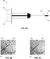
- FIG. 3Adepicts a delivery device loaded with a shape-memory polymer tissue cavity marker according to an embodiment.
- FIG. 3Bdepicts a distal portion of a delivery device delivering a shape-memory polymer tissue cavity marker to a tissue cavity according to an embodiment.
- FIG. 3Cdepicts a distal portion of a delivery device delivering a heated fluid to the shape-memory polymer tissue cavity marker and tissue cavity of FIG. 3B .
- FIG. 3Ddepicts a delivery device loaded with a shape-memory polymer tissue cavity marker according to another embodiment.
- FIG. 3Edepicts a delivery device loaded with a shape-memory polymer tissue cavity marker according to yet another embodiment.
- FIG. 4is a flowchart of a method of forming a shape-memory polymer tissue cavity marker according to an embodiment.
- a shape-memory polymer tissue cavity markercomprises a shape-memory polymer material structure and at least one radiopaque marker element coupled with the shape-memory polymer material structure.
- the shape memory polymer materialenables the tissue cavity marker to transform between a temporary state, in which a profile or dimension of the tissue cavity marker is reduced such that the tissue cavity marker can be deployed through a minimally invasive surgical procedure incision, and a permanent state, in which a profile or dimension of the tissue cavity marker is increased such that the tissue cavity marker fills or defines a volume of a tissue cavity.
- a deployment devicecomprises a catheter, syringe or other tool having a proximal (operator) end and a distal (patient) end.
- the proximal endcomprises a control mechanism by which the deployment device can be operated during use.
- the distal endcomprises an aperture into which a shape-memory polymer tissue cavity marker in the temporary state can be loaded.
- the distal endcan be inserted through a minimally invasive surgical incision to deliver the tissue cavity marker to a target site.
- the control mechanismcan be used to deploy and release the tissue cavity marker from the deployment device.
- the tissue cavity markercan be transitioned to the permanent state, such as by using the deployment device; using a separate device, tool or material; by body temperature within the tissue cavity; or without further active intervention.
- Tissue cavity marker 100comprises a transformative body 110 and at least one radiopaque marker 120 coupled with transformative body 110 .
- transformative body 110is generally of a size, three-dimensional shape, and sufficient rigidity to be deployed and maintain (for some amount of time) a structural configuration within a tissue cavity created by a biopsy, lumpectomy or other resection of tissue.
- transformative body 110 or tissue cavity marker 100overall can have a compressed diameter in its delivery or temporary state (permanent and temporary states are discussed in more detail below) of about 10 millimeters (mm) or less, such as about 8 mm or less, about 7 mm or less, about 6 mm or less, or about 5 mm or less, in various embodiments.
- transformative body 110 or tissue cavity marker 100In its deployed or permanent state, transformative body 110 or tissue cavity marker 100 overall can have a diameter of about 10 mm or more, such as about 15 mm or more, about 20 mm or more, about 25 mm or more, or about 30 mm or more, in various embodiments.
- a range of diameters of transformative body 110 or tissue cavity marker 100 overall in the deployed or permanent stateis about 10 mm to about 30 mm in one example.
- Transformative body 110 of tissue cavity marker 100can comprise a variety of different three-dimensional shapes in a permanent state (permanent and temporary states are discussed below) in various embodiments, such as the generally spherical cage-like configuration shown in FIG. 1A .
- transformative body 110comprises a plurality of spaced-apart branches 112 coupled together by first and second end portions 114 and 116 .
- a number or relative arrangement of branches 112can vary, such that transformative body 110 comprises more or fewer branches 112 spaced closer together or farther apart from one another, or differently sized from one another.
- first and second end portions 114 and 116can have other shapes or configurations or be omitted in other embodiments.
- transformative body 110can comprise a helix (see, e.g., tissue cavity marker 200 of FIGS. 2A and 2B ), spiral, spheroid, ellipsoid, ovoid, cylinder, cuboid, cone, triangular prism, pyramid, or some other three-dimensional shape, including a combination of two or more of these shapes.
- tissue cavity size, configuration, patient anatomy or typee.g., human adult, human pediatric, veterinary
- deployment device or situation, or other characteristicmay benefit from a custom shape, which can be created in some embodiments.
- tissue cavity marker 100is sized and shaped for residence in a tissue cavity and can be sized and shaped so as to just fit within a particular cavity or to be slightly compressed when installed in and restrained by the tissue surrounding the cavity. In at least this sense, tissue cavity marker 100 can physically interact with at least a portion of a margin of the cavity in which it is deployed.
- Transformative body 110comprises a shape-memory material in embodiments, such as a shape-memory polymer.
- Shape-memory polymersare polymeric “smart” materials that have the ability to transition between a first three-dimensional shape in a permanent state and a second three-dimensional shape different from the first three-dimensional shape in a temporary state when induced to do so by an external stimulus or trigger.
- a first three-dimensional shape in a permanent state of tissue cavity marker 100is depicted in FIG. 1A
- a second three-dimensional shape different from the first three-dimensional shape in a temporary state of tissue cavity marker 100is depicted in FIG. 1B .
- the permanent state of tissue cavity marker 100is the state or configuration of tissue cavity marker 100 when it is deployed and resident in a tissue cavity
- the temporary state of tissue cavity marker 100is a state that enables at least one dimension (e.g., a diameter, radius, width or volume) but sometimes two or all three dimensions of tissue cavity marker 100 to be temporarily reduced in order to enable or ease delivery and deployment of tissue cavity marker 100 in a tissue cavity via a minimally invasive surgical incision.
- at least two dimensions of tissue cavity marker 100 in its permanent stateare greater than a length of a minimally invasive surgical incision, but in its temporary state these dimensions are reduced such that tissue cavity marker 100 can be delivered via the minimally invasive surgical incision.
- Minimally invasive surgical incisionscan be about 3 centimeters (cm) long or less, such as about 2 cm long or less, or about 1 cm long or less, or less than about 7 mm long, for example about 6 mm long in one example.
- a range of minimally invasive surgical incision lengthsis between 5 mm and 1 cm in one example.
- Some shape-memory polymers referred to as triple-shape-memory polymersalso have a third state (for example, a first temporary state, a second temporary state, and a permanent state) and can have applicability in some embodiments of tissue cavity marker 100 .
- the permanent and temporary statesare used as discussed above herein, they also can be reversed, such that tissue cavity marker 100 is in a temporary state when resident in a tissue cavity and a permanent state when being delivered to the tissue cavity.
- the permanent statecan be influenced by or depend upon the shape and configuration of transformative body 110 .
- the spherical cage-like configuration of FIG. 1Aenables radial expansion and compression of transformative body 110 as branches 112 move toward or away from a central axis A that extends lengthwise through tissue cavity marker 100 from end portion 114 to end portion 116 .
- branches 112radially expand or compress
- end portions 114 and 116move toward or away from one another along axis A.
- both the diameter and length of transformative body 110change between the permanent and temporary states of tissue cavity marker 100 .
- Other shapeswill exhibit other changes in transition between expanded and compressed/contracted states.
- Tissue cavity marker 200 of FIGS. 2A and 2Bfor example, transitions between a permanent helical state depicted in FIG. 2A and a temporary extended state depicted in FIG. 2B .
- the permanent state of tissue cavity marker 100is a “memory” state, in that the shape-memory polymer material of transformative body 110 is programmed to assume a particular permanent state shape.
- This programmingcan be done as part of the manufacturing process and involve, e.g., thermodynamic strain and stress locking processing, or other processes according to the particular external stimulus to which the shape-memory polymer is responsive.
- a similar programmingcan be performed for the temporary state, as well as for a third state in embodiments in which one is used, such that the various states of tissue cavity marker 100 are predefined according to material properties of transformative body 110 .
- the external stimulus or trigger that causes a shape-memory polymer material to transition between permanent and temporary statescan be a temperature change (e.g., heating or cooling the material), photo-illumination (e.g., exposing the material to different wavelengths of light), electro-activation, or some other stimulus.
- the same external stimulus or triggercan cause the material to transition both from the permanent state to the temporary state, and from the temporary state to the permanent state.
- Example shape-memory polymers that can be suitable for use in embodiments of tissue cavity marker 100include those that are biodegradable or bioabsorbable (also referred to as resorbable), and those that are homopolymers, copolymers or terpolymers.
- PLApoly-lactic acid
- PLApoly-L-lactide
- PLGApoly-L-glycolic acid
- PCLpolycaprolactone
- PLA-, PLGA- and PCL-based materialsPLA-, PLGA- and PCL-based materials.
- combinations of one or more of these or other suitable shape-memory polymerscan be used, with particular combinations selected to achieve particular shape-memory effects or responses.
- Other suitable biodegradable polymers and other shape-memory polymer materialswill be recognized by those of ordinary skill in the art.
- non-bioabsorbable shape-memory polymers or other materialscan be used, in addition to or instead of the aforementioned bioabsorbable materials.
- the terms polymers and shape-memory polymersgenerally are used herein and can include any of these materials or formulations.
- Tissue cavity marker devices formed from shape-memory polymer materialscan be distinguished from other materials or devices, such as mechanical springs that can be compressed or stretched from a resting position but require constant applied force to remain stretched or compressed (depending upon their resting spring state).
- Some medical devices, such as stentsrely on spring-like properties when they are mechanically compressed in order to be loaded into and delivered by a catheter, and they return to their resting position when the compression is removed or released.
- Other deviceshave a compressed resting position that requires controlled mechanical force once delivered (e.g., via a balloon catheter or saline injection) in order to be expanded. None of these devices, however, can automatically and repeatedly transition between permanent and temporary states, and remain in either the permanent or temporary state, without an external mechanical force continuously acting on the device to maintain it in at least one of the states.
- Tissue cavity marker 100can additionally or instead comprise a shape-memory alloy material, such as Nitinol.
- Shape-memory alloysare not bioabsorbable but may have application in some procedures or situations in which bioabsorbability of some or all of transformative body 110 is not desired or required.
- at least one marker 120 coupled to transformative body 110comprises a shape-memory alloy, while transformative body 110 comprises a shape-memory polymer.
- markers 120comprise a radiopaque material without shape-memory transition properties.
- Radiopaque materialsare those that are opaque to and therefore visible on X-ray or other radiation images. Examples of radiopaque materials include metals (e.g., titanium, nonferromagnetic stainless steel) as well as some plastics and polymers known to those of ordinary skill in the art.
- Including radiopaque markers 120 on transformative body 110 of tissue cavity marker 100makes it possible to locate markers 120 (and thereby the cavity in which tissue cavity marker 100 is resident) on radiation images after tissue cavity marker 100 is deployed in the cavity, including after transformative body 110 is resorbed. This can be helpful for follow-up treatments (e.g., targeted radiation therapy) and ongoing monitoring of the cavity and tissue margins of the cavity.
- the number, size and relative arrangement of markers 120can vary from those depicted in FIGS. 1A and 1B .
- end portions 114 and 116also can comprise one or more markers 120 in embodiments. In other embodiments, some markers 120 may be smaller, larger, or differently shaped than other markers 120 .
- the permanent and temporary states of tissue cavity marker 100can be considered when arranging a plurality of markers 120 thereon.
- two markers 120can be staggered such that when tissue cavity marker 100 is in the temporary state of FIG. 1B adjacent markers 120 do not align in ways that interfere with one another and a profile of tissue cavity marker 100 can still be sufficiently reduced to be loaded into a deployment device and delivered by a minimally invasive surgical incision.
- markers 120can comprise clips that are coupled to transformative body 110 . This coupling can be accomplished in a variety of ways, such as by folding, wrapping, crimping or otherwise forming a length of material around a portion (e.g., a branch 112 or end portion 114 , 116 ) of transformative body 110 .
- markers 120can be coupled with transformative body 110 by being at least partially embedded or formed therein.
- transformative body 110can be formed in or on one or more markers 120 , such as by being injection-molded through a marker 120 that comprises a ring, tube or other structure that is hollow or comprises an aperture through which a portion of transformative body 110 can pass.
- one or both of transformative body 110 and markers 120can be three-dimensionally printed, together or separately.
- tissue cavity marker 200comprises a transformative body 210 and at least one marker 220 coupled to transformative body 210 .
- transformative body 210has a helical configuration in its permanent state ( FIG. 2A ) and an extended configuration in its temporary state ( FIG. 2B ).
- the materials, behaviors and other characteristics of tissue cavity marker 200 , transformative body 210 and markers 220are similar to or the same as those discussed above with respect to tissue cavity marker 100 , transformative body 110 and markers 120 , though one difference is that the diameter of tissue cavity marker 200 in its temporary state is smaller than that of tissue cavity marker 100 in its temporary state, such that tissue cavity marker 200 can be delivered via even smaller incisions.
- Delivery device 300comprises a proximal control end 310 and a distal delivery end 320 .
- proximalis used with respect to an operator/physician end ( 310 ) of delivery device 300
- distalis used with respect to a patient or delivery end ( 320 ) of delivery device 300 .
- Delivery device 300can comprise a catheter, syringe or other device into which a tissue cavity marker (e.g., tissue cavity marker 100 ) can be loaded in its temporary state, delivered to a cavity site via a minimally invasive surgical incision, deployed within the cavity, and transitioned from the temporary state to the permanent state.
- tissue cavity markere.g., tissue cavity marker 100
- the transition from temporary to permanent state of tissue cavity marker 100can be accomplished using at least one additional tool or device.
- Proximal control end 310 of delivery device 300comprises a control system 312 via which delivery device 300 can be controlled.
- control system 312allows an operator of delivery device 300 to manipulate delivery device 300 to insert distal delivery end 320 through an incision, guide distal delivery end 320 to a delivery site (such as a tissue cavity), and control deployment of tissue cavity marker 100 from distal delivery end 320 to the delivery site.
- Control system 312can comprise one or more of a plunger (depicted in FIG. 3A ), guidewire, mechanical actuator, robotic or computer-assisted control mechanism, or some other control mechanism that can be manipulated in order to control delivery device 300 and effect delivery and deployment of tissue cavity marker 100 .
- Distal delivery end 320comprises a distal end aperture 322 into which tissue cavity marker 100 can be loaded.
- distal end aperture 322can comprise or be part of a cannula, trocar, catheter or other hollow device forming part or all of distal delivery end 320 or delivery device 300 .
- Distal delivery end 320can be rigid or flexible, and straight, curved or angled, in various embodiments.
- a first portion of distal delivery end 320can be rigid, and a second portion of distal delivery end 320 can be flexible.
- a first portion of distal delivery end 320can be straight, and a second portion of distal delivery end 320 can be curved. At least a portion of distal delivery end 320 being rigid can be advantageous in some embodiments to assist an operator in manipulating delivery device 300 to maneuver tissue cavity marker 100 into place in a tissue cavity, though some operators may prefer a degree of flexibility.
- tissue cavity marker 100(in its temporary state) is loaded into distal end aperture 322 .
- One tissue cavity marker 100can be loaded into distal end aperture 322 , or multiple tissue cavity markers 100 can be loaded into distal end aperture 322 , such as in a case in which multiple tissue cavities of a single patient are to be marked.
- tissue cavity marker 100can be preloaded into distal end aperture 322 .
- delivery device 300can be provided in sterile packaging and need only be removed from the packaging by a physician or other medical professional in order to deliver and deploy tissue cavity marker 100 .
- tissue cavity marker 100can be provided in separate sterile packaging or in some other configuration separate from but relative to delivery device 300 .
- tissue cavity marker 100can be provided preloaded in its temporary state in distal delivery end 320 , with distal delivery end 320 provided in sterile packaging separate from proximal control portion 310 of delivery device 300 , which may be sterilizable and reusable in some embodiments. Prior to use, distal delivery end 320 can be removed from its packaging, coupled with proximal control portion 310 , and used to deliver and deploy tissue cavity marker 100 at a desired site.
- tissue cavity marker 100 and delivery device 300 or portions thereofcan be implemented in other embodiments.
- tissue cavity markers100 , 200 , etc.
- tissue cavity marker 100it may be helpful to provide, separate from delivery device 300 , a variety of tissue cavity markers ( 100 , 200 , etc.) from which a physician or other medical professional can select an appropriate one for any particular cavity, patient or procedure.
- tissue cavity marker 100it can be convenient for tissue cavity marker 100 to be preloaded in delivery device 300 in its temporary state to avoid a physician having to transition tissue cavity marker 100 from its permanent state to its temporary state (e.g., by heating or cooling tissue cavity marker 100 ) in order to load tissue cavity marker 100 into delivery device 300 .
- thisit may be situations in which this is necessary or desired (e.g., according to physician preference).
- delivery device 300is depicted in use, with distal delivery end 320 inserted via an incision 301 in a patient's skin to an internal tissue cavity 303 , such as one created by a breast tissue biopsy or lumpectomy.
- tissue cavity marker 100 in its temporary stateis deployed in cavity 303 from distal delivery end 320 .
- the tip of distal delivery end 320can be advanced to a distal edge of cavity 303 , and tissue cavity marker 100 can be deployed from distal end aperture 322 as distal delivery end 320 and delivery device 300 are retracted.
- distal delivery end 320is advanced to a proximal edge of cavity 303 , and tissue cavity marker 100 is deployed by being pushed into cavity 303 , such as by control system 312 .
- image-guided surgical techniquescan be used to view distal delivery end 320 as it is directed to and within cavity 303 and ensure tissue cavity marker 100 is placed within cavity 303 prior to or after deployment of tissue cavity marker 100 from delivery device 300 .
- delivery device 300can comprise a colorant, radiopaque or radiographic filler, or other additive in or coating on distal delivery end 320 to aid in visualization or navigation.
- tissue cavity marker 100is transitioned to its permanent state within cavity 303 .
- thisis accomplished by injecting a heated liquid, such as saline, into cavity 303 via a fluid aperture 330 (see delivery device 300 a of FIG. 3D ) in distal delivery end 320 .
- the temperature of the heated liquidcan vary according to a temperature necessary to cause a particular shape-memory polymer material of tissue cavity marker 100 to transition to its permanent state.
- this temperatureis higher than human body temperature, such as higher than about 37 degrees Celsius, for example higher than 40 degrees Celsius, higher than 50 degrees Celsius, higher than 60 degrees Celsius, or higher than 70 degrees Celsius.
- the temperaturealso can be less than 100 degrees Celsius, less than 90 degrees Celsius, less than 80 degrees Celsius, less than 70 degrees Celsius, less than 60 degrees Celsius, or less than 50 degrees Celsius.
- the temperature of the liquidis between 40 degrees Celsius and 90 degrees Celsius, for example between 60 degrees Celsius and 80 degrees Celsius.
- this temperatureis lower than human body temperature, such that it is a cooled rather than heated liquid that is delivered, again according to the properties of the particular shape-memory polymer material of tissue cavity marker 100 .
- the temperature of the liquidcan be less than about 37 degrees Celsius, such as less than 30 degrees Celsius, or less than 20 degrees Celsius.
- the temperature necessary to cause a particular shape-memory polymer material of tissue cavity marker 100 to transition to its permanent statecan be approximately equal to human body temperature, such that simply deploying tissue cavity marker 100 in cavity 303 causes tissue cavity marker 100 to transition to its permanent state. In these embodiments, no liquid need be injected.
- the body temperaturecan be a body temperature of a particular animal type or species.
- delivery device 300 bcan comprise a heater coil 340 or other device at or near distal delivery end 320 .
- Heater coil 340 b or other devicecan be activated once distal delivery end 320 is positioned in or at cavity 303 and before tissue cavity marker 100 is deployed, such that tissue cavity marker 100 is heated by heater coil 340 b or other device as it is deployed from distal delivery end 320 .
- the tip of distal delivery end 320can be advanced to a distal edge of cavity 303 , and tissue cavity marker 100 can be transformed as it is deployed from distal end aperture 322 as distal delivery end 320 and delivery device 300 are retracted.
- distal delivery end 320is advanced to a proximal edge of cavity 303 , and tissue cavity marker 100 is transformed as it is deployed by being pushed into cavity 303 , such as by control system 312 , which also can control activation and deactivation of heater coil 340 .
- distal end aperture 322may be located at another position along distal delivery end 320 , such as closer to proximal control end 310 , in order to be positioned relative to heater coil 340 and provide sufficient time or distance for tissue cavity marker 100 to interact with heater coil 340 to be transformed during deployment.
- Heater coil 340 bcan be replaced with a cooling device in embodiments in which temperatures less than human body temperature are needed.
- a ballooncan be inserted into tissue cavity marker 100 in cavity 300 , and the balloon can be filled with heated saline or other fluid to cause tissue cavity marker 100 to transition to its permanent state. The balloon then can be drained and withdrawn.
- tissue cavity marker 100can be deployed in cavity 303 within a balloon. The balloon then can be filled with heated saline or another material to cause tissue cavity marker 100 to transition to its permanent state. The balloon then can be drained and withdrawn while leaving tissue cavity marker 100 in place in cavity 303 .
- tissue cavity marker 100can transition from its temporary state to its permanent state within cavity 303 .
- a laser, ultrasound, or other temperature-altering techniquecan be used to cause tissue cavity marker 100 to transition from its temporary state to its permanent state within cavity 303 .
- other suitable techniquescan be used in embodiments in which the shape-memory polymer material of tissue cavity marker 100 is responsive to a stimulus other than temperature, such as those identified elsewhere herein or others appreciated by those of ordinary skill in the art.
- the stimuluscan be provided by delivery device 300 or some other, separate device.
- the salinecan be delivered via delivery device 300 , and delivery also can be controlled by control system 312 , such as in the embodiment of FIG. 3D .
- the salinecan be delivered by a separate syringe or other device, while distal delivery end 320 of delivery device 300 is still in place or after tissue cavity marker 100 has been deployed and distal delivery end 320 retracted from incision 301 .
- the particular temperature or technique usedcan depend on cavity site and type, potential beneficial effect(s) provided to the tissue margins of cavity 303 , procedure characteristic, physician preference or experience, or some other factor.
- a material other than salinecan be used.
- some medicament or fluid having a therapeutic or beneficial effectcan be used.
- another materialsuch as a gel or a gas also can be used in embodiments.
- tissue cavity marker 100Upon transition to its permanent state, tissue cavity marker 100 will remain in cavity 303 , and distal delivery end 320 can be retracted and removed. Because tissue cavity marker 100 generally will be left in cavity 303 indefinitely, incision 301 can be closed. As previously mentioned, tissue cavity marker 100 , and thereby cavity 303 , can be located on X-ray or other images via radiopaque markers 120 , 220 (see FIGS. 1A, 1B, 2A and 2B ) and will not migrate from cavity 303 because tissue cavity marker 100 holds them in place. Over time, new tissue will grow into cavity 303 and around tissue cavity marker 100 , and tissue cavity marker 100 will resorb, leaving only radiopaque markers 120 or 220 behind in the tissue now filling former cavity 303 .
- tissue cavity marker 100can be loaded into distal end aperture 322 in its permanent state.
- the deployed state of tissue cavity marker 100 within a tissue cavityis then the temporary state of tissue cavity marker 100 .
- tissue cavity marker 100can be induced to transition from the permanent state to the temporary state after loading into distal end aperture 322 of delivery device 300 and before deployment in a tissue cavity, such that tissue cavity marker 100 is induced to transition back to the permanent state during or after deployment for residence in the tissue cavity.
- a method 400 of providing a tissue cavity markersuch as tissue cavity marker 100 or tissue cavity marker 200 , is depicted.
- a tissue cavity markeris formed, such as from a shape-memory polymer material.
- Forming the tissue cavity markercan include selecting a permanent shape of tissue cavity marker, and cutting, molding, three-dimensionally printing, or otherwise manipulating the shape-memory polymer material to enable the desired complex, three-dimensional permanent shape.
- the tissue cavity markercan be programmed with its permanent or temporary state. This can include straining the material (e.g., subjecting it to a temperature while forming it into a particular desired shape) to cause the permanent or temporary state shape to be retained in the “memory” of the material.
- the tissue cavity markercan be put into its temporary state and loaded into a delivery device or a portion of a delivery device.
- the loaded delivery device or the individual tissue cavity markercan be sealed in sterile packaging.
- the order of activities depicted in FIG. 4can be changed, additional activities can be inserted, and depicted activities can be omitted.
- Embodiments of the tissue cavity markers discussed hereinprovide advantages with respect to conventional tissue markers.
- the shape-memory effect of the material from which the tissue cavity marker can be formedenables the tissue cavity marker to be delivered via an incision with a length or other dimension that is smaller than a diameter or other dimension of the tissue cavity marker in its permanent state.
- the shape, dimensions and other characteristics of the tissue cavity maker in various embodimentsalso can be selected to provide a snug fit of the tissue cavity marker within a cavity, thereby providing a secure frame or support structure for the radiopaque marker(s) coupled to the tissue cavity marker and inhibiting the radiopaque markers from migrating within the cavity.
- the frame of the tissue cavity marker and its ability to expand three-dimensionally within the cavityalso provides for a plurality of radiopaque markers to be used to more completely define the margins of the cavity.
- the markersare less likely to migrate, such that the tissue cavity marker can be formed from a bioabsorbable material and need not be removed by another surgical procedure. This can increase patient comfort and recovery, reduce expense and eliminate procedures (as well as the likelihood for complications) by eliminating the need for a second procedure to remove the tissue cavity marker.
- the ability to customize the permanent and temporary shapes of the tissue cavity markermeans it can be used in a variety of different places and procedures, including but not limited to breast tissue biopsies and lumpectomies as well as other tissue biopsy sites.
Landscapes
- Health & Medical Sciences (AREA)
- Surgery (AREA)
- Life Sciences & Earth Sciences (AREA)
- Heart & Thoracic Surgery (AREA)
- Pathology (AREA)
- Oral & Maxillofacial Surgery (AREA)
- Engineering & Computer Science (AREA)
- Biomedical Technology (AREA)
- Nuclear Medicine, Radiotherapy & Molecular Imaging (AREA)
- Medical Informatics (AREA)
- Molecular Biology (AREA)
- Animal Behavior & Ethology (AREA)
- General Health & Medical Sciences (AREA)
- Public Health (AREA)
- Veterinary Medicine (AREA)
- Surgical Instruments (AREA)
Abstract
Description
Claims (24)
Priority Applications (1)
| Application Number | Priority Date | Filing Date | Title |
|---|---|---|---|
| US16/033,694US11219502B2 (en) | 2017-09-11 | 2018-07-12 | Transformative shape-memory polymer tissue cavity marker devices, systems and deployment methods |
Applications Claiming Priority (2)
| Application Number | Priority Date | Filing Date | Title |
|---|---|---|---|
| US201762556669P | 2017-09-11 | 2017-09-11 | |
| US16/033,694US11219502B2 (en) | 2017-09-11 | 2018-07-12 | Transformative shape-memory polymer tissue cavity marker devices, systems and deployment methods |
Publications (2)
| Publication Number | Publication Date |
|---|---|
| US20190076212A1 US20190076212A1 (en) | 2019-03-14 |
| US11219502B2true US11219502B2 (en) | 2022-01-11 |
Family
ID=65630216
Family Applications (1)
| Application Number | Title | Priority Date | Filing Date |
|---|---|---|---|
| US16/033,694Active2040-01-24US11219502B2 (en) | 2017-09-11 | 2018-07-12 | Transformative shape-memory polymer tissue cavity marker devices, systems and deployment methods |
Country Status (1)
| Country | Link |
|---|---|
| US (1) | US11219502B2 (en) |
Cited By (1)
| Publication number | Priority date | Publication date | Assignee | Title |
|---|---|---|---|---|
| US12290417B1 (en) | 2023-02-21 | 2025-05-06 | Robert I. Hacker | Multi-axis tumor margin marker system |
Families Citing this family (6)
| Publication number | Priority date | Publication date | Assignee | Title |
|---|---|---|---|---|
| US11191611B2 (en) | 2016-06-03 | 2021-12-07 | Somatex Medical Technologies Gmbh | Marking device and implantation system |
| WO2018097891A1 (en) | 2016-11-23 | 2018-05-31 | Hologic, Inc. | Biopsy site marker |
| EP3610822B1 (en)* | 2018-08-14 | 2021-07-07 | Endosmart Gesellschaft für Medizintechnik mbH | Marking body and method for production of this marking body |
| US11406489B2 (en) | 2019-10-07 | 2022-08-09 | Cornell University | Implant with fiducial markers |
| US20240058092A1 (en)* | 2022-08-16 | 2024-02-22 | Devicor Medical Products, Inc. | Biopsy site marker having expandable portion |
| WO2024039561A1 (en)* | 2022-08-16 | 2024-02-22 | Devicor Medical Products, Inc. | Biopsy site marker having movable portions |
Citations (68)
| Publication number | Priority date | Publication date | Assignee | Title |
|---|---|---|---|---|
| US3157524A (en) | 1960-10-25 | 1964-11-17 | Ethicon Inc | Preparation of collagen sponge |
| US3520402A (en) | 1967-08-30 | 1970-07-14 | Ethicon Inc | Purified collagen fibrils |
| US4832686A (en) | 1986-06-24 | 1989-05-23 | Anderson Mark E | Method for administering interleukin-2 |
| US4957479A (en) | 1988-10-17 | 1990-09-18 | Vance Products Incorporated | Indwelling ureteral stent placement apparatus |
| US5019087A (en) | 1986-10-06 | 1991-05-28 | American Biomaterials Corporation | Nerve regeneration conduit |
| US5429582A (en) | 1991-06-14 | 1995-07-04 | Williams; Jeffery A. | Tumor treatment |
| US5607477A (en) | 1993-07-12 | 1997-03-04 | The Regents Of The University Of California | Soft tissue augmentation apparatus |
| US5676146A (en) | 1996-09-13 | 1997-10-14 | Osteotech, Inc. | Surgical implant containing a resorbable radiopaque marker and method of locating such within a body |
| US5716404A (en) | 1994-12-16 | 1998-02-10 | Massachusetts Institute Of Technology | Breast tissue engineering |
| US5873865A (en) | 1997-02-07 | 1999-02-23 | Eclipse Surgical Technologies, Inc. | Spiral catheter with multiple guide holes |
| US6030333A (en) | 1997-10-24 | 2000-02-29 | Radiomed Corporation | Implantable radiotherapy device |
| US6071301A (en) | 1998-05-01 | 2000-06-06 | Sub Q., Inc. | Device and method for facilitating hemostasis of a biopsy tract |
| US6161034A (en) | 1999-02-02 | 2000-12-12 | Senorx, Inc. | Methods and chemical preparations for time-limited marking of biopsy sites |
| US6228055B1 (en) | 1994-09-16 | 2001-05-08 | Ethicon Endo-Surgery, Inc. | Devices for marking and defining particular locations in body tissue |
| US6270464B1 (en) | 1998-06-22 | 2001-08-07 | Artemis Medical, Inc. | Biopsy localization method and device |
| US20010041936A1 (en) | 1997-10-10 | 2001-11-15 | Corbitt John D. | Bioabsorbable breast implant |
| US20010047164A1 (en) | 2000-04-11 | 2001-11-29 | James Teague | Reinforced retention structures |
| US6340367B1 (en) | 1997-08-01 | 2002-01-22 | Boston Scientific Scimed, Inc. | Radiopaque markers and methods of using the same |
| US20020072806A1 (en) | 2000-01-11 | 2002-06-13 | Dayna Buskirk | Soft and calcified tissue implants |
| US6477423B1 (en) | 1997-05-28 | 2002-11-05 | Transneuronix, Inc. | Medical device for use in laparoscopic surgery |
| US20030083732A1 (en) | 2001-10-25 | 2003-05-01 | Stinson Jonathan S. | Balloon expandable polymer stent with reduced elastic recoil |
| US6579310B1 (en) | 2000-08-17 | 2003-06-17 | Advanced Cardiovascular Systems, Inc. | Stent having overlapping struts |
| US6725083B1 (en) | 1999-02-02 | 2004-04-20 | Senorx, Inc. | Tissue site markers for in VIVO imaging |
| US20040124105A1 (en)* | 2002-12-30 | 2004-07-01 | Keith Seiler | Packaged systems for implanting markers in a patient and methods for manufacturing and using such systems |
| US20040249457A1 (en) | 2003-06-09 | 2004-12-09 | Smith Lane Fielding | Mastopexy stabilization apparatus and method |
| US20050074405A1 (en) | 2003-10-03 | 2005-04-07 | Williams Archie B. | Contrast media for use in medical and diagnostic procedures and methods of using the same |
| US20050080338A1 (en) | 1998-12-24 | 2005-04-14 | Sirimanne D. Laksen | Biopsy cavity marking device and method |
| US20050101860A1 (en) | 2003-11-07 | 2005-05-12 | Proxima Therapeutics, Inc. | Tissue positioning systems and methods for use with radiation therapy |
| US20050143770A1 (en) | 2003-07-31 | 2005-06-30 | Carter Matthew P. | Distal wire stop |
| US20050165480A1 (en) | 2004-01-23 | 2005-07-28 | Maybelle Jordan | Endovascular treatment devices and methods |
| US20050234336A1 (en) | 2004-03-26 | 2005-10-20 | Beckman Andrew T | Apparatus and method for marking tissue |
| US20060025795A1 (en) | 1999-06-17 | 2006-02-02 | Inrad, Inc. | Apparatus for the percutaneous marking of a lesion |
| US20060058570A1 (en) | 2000-11-01 | 2006-03-16 | Michael Rapach | Radioactive member and method of making |
| US20060116713A1 (en) | 2004-11-26 | 2006-06-01 | Ivan Sepetka | Aneurysm treatment devices and methods |
| US20060173296A1 (en) | 2004-10-13 | 2006-08-03 | Miller Michael E | Site marker visable under multiple modalities |
| US20070021642A1 (en) | 2005-07-22 | 2007-01-25 | Worldwide Medical Technologies Llc | Devices to resist migration and rotation of implants used in brachytherapy and other radiation therapy |
| US20070032703A1 (en)* | 2005-07-11 | 2007-02-08 | Sankaran Meera L | Radially expansive surgical instruments for tissue retraction and methods for using the same |
| US20070038017A1 (en) | 2005-08-11 | 2007-02-15 | Boston Scientific Scimed, Inc. | Tubular implantable sling and related delivery systems, methods and devices |
| US20070038014A1 (en) | 1998-10-06 | 2007-02-15 | Cox Charles E | Radio guided seed localization of imaged lesions |
| US20070167668A1 (en) | 2004-11-05 | 2007-07-19 | Theragenics Corporation | Expandable brachytherapy device |
| US20080015472A1 (en) | 2006-04-21 | 2008-01-17 | Entellus Medical, Inc. | Guide catheter and method of use |
| US20080045773A1 (en) | 2005-01-12 | 2008-02-21 | Youri Popowski | Positioning Device and a Procedure for Treating the Walls of a Resection Cavity |
| US20080097199A1 (en) | 2004-08-20 | 2008-04-24 | David Mullen | Tissue Marking Devices and Systems |
| US20080228164A1 (en) | 2007-03-14 | 2008-09-18 | Nicoson Zachary R | Implant delivery system |
| US20080243226A1 (en) | 2007-03-30 | 2008-10-02 | Fernandez Jose E | Implantable stents with radiopaque markers and methods for manufacturing the same |
| US20080269603A1 (en)* | 2004-10-13 | 2008-10-30 | Nicoson Zachary R | Site marker visible under multiple modalities |
| US20080281388A1 (en) | 1997-10-10 | 2008-11-13 | John Corbitt | Method of utilizing an implant for targeting external beam radiation |
| US20090024225A1 (en) | 2007-07-16 | 2009-01-22 | Stubbs James B | Implant for Targeting Therapeutic Procedure |
| US20090030298A1 (en) | 2007-05-23 | 2009-01-29 | Quasar | Sensor mounting system |
| US20090143747A1 (en) | 2005-07-11 | 2009-06-04 | Aylvin Jorge Angelo Athanasius Dias | Coiled wire for the controlled release of drugs to the eye |
| US20090319046A1 (en) | 2008-06-23 | 2009-12-24 | Biomerix Corporation | Hyoid suspension for obstructive sleep apnea |
| US20100010341A1 (en) | 2006-12-18 | 2010-01-14 | Talpade Dnyanesh A | Biopsy Marker with In Situ-Generated Imaging Properties |
| US20100030072A1 (en) | 2006-12-12 | 2010-02-04 | Casanova R Michael | Multiple Imaging Mode Tissue Marker |
| US20100042104A1 (en) | 2008-04-15 | 2010-02-18 | Sridhar Kota | Surgical tools and components thereof |
| US20100234726A1 (en)* | 1998-12-24 | 2010-09-16 | Sirimanne D Laksen | Device and method for safe location and marking of a biopsy cavity |
| US20100312272A1 (en)* | 2007-02-01 | 2010-12-09 | Cook Incorporated | Closure device |
| US20110004094A1 (en) | 2009-06-01 | 2011-01-06 | Focal Therapeutics | Bioabsorbable Target for Diagnostic or Therapeutic Procedure |
| US7875059B2 (en) | 2007-01-18 | 2011-01-25 | Warsaw Orthopedic, Inc. | Variable stiffness support members |
| US20110028831A1 (en) | 2009-07-30 | 2011-02-03 | Kent James P | Permanently visible implantable fiduciary tissue marker |
| US20110130655A1 (en) | 2007-07-20 | 2011-06-02 | Nielson Eric D | Implantable devices and methods for external beam radiation treatments |
| US8052658B2 (en) | 2005-10-07 | 2011-11-08 | Bard Peripheral Vascular, Inc. | Drug-eluting tissue marker |
| US8060183B2 (en) | 2004-10-13 | 2011-11-15 | Suros Surgical Systems, Inc. | Site marker visible under multiple modalities |
| US20110313288A1 (en) | 2009-06-26 | 2011-12-22 | Eduardo Chi Sing | Apparatus, systems, and methods for localizing markers or tissue structures within a body |
| US8157862B2 (en) | 1997-10-10 | 2012-04-17 | Senorx, Inc. | Tissue marking implant |
| US20130032962A1 (en) | 2010-02-05 | 2013-02-07 | Allergan, Inc. | Porogen compositions, methods of making and uses |
| US20130289390A1 (en) | 2012-04-26 | 2013-10-31 | Focal Therapeutics, Inc. | Surgical implant for marking soft tissue |
| US20150297316A1 (en)* | 2012-11-21 | 2015-10-22 | Trustees Of Boston University | Tissue markers and uses thereof |
| US9615915B2 (en) | 2014-07-25 | 2017-04-11 | Focal Therapeutics, Inc. | Implantable devices and techniques for oncoplastic surgery |
- 2018
- 2018-07-12USUS16/033,694patent/US11219502B2/enactiveActive
Patent Citations (85)
| Publication number | Priority date | Publication date | Assignee | Title |
|---|---|---|---|---|
| US3157524A (en) | 1960-10-25 | 1964-11-17 | Ethicon Inc | Preparation of collagen sponge |
| US3520402A (en) | 1967-08-30 | 1970-07-14 | Ethicon Inc | Purified collagen fibrils |
| US4832686A (en) | 1986-06-24 | 1989-05-23 | Anderson Mark E | Method for administering interleukin-2 |
| US5019087A (en) | 1986-10-06 | 1991-05-28 | American Biomaterials Corporation | Nerve regeneration conduit |
| US4957479A (en) | 1988-10-17 | 1990-09-18 | Vance Products Incorporated | Indwelling ureteral stent placement apparatus |
| US5429582A (en) | 1991-06-14 | 1995-07-04 | Williams; Jeffery A. | Tumor treatment |
| US5607477A (en) | 1993-07-12 | 1997-03-04 | The Regents Of The University Of California | Soft tissue augmentation apparatus |
| US6228055B1 (en) | 1994-09-16 | 2001-05-08 | Ethicon Endo-Surgery, Inc. | Devices for marking and defining particular locations in body tissue |
| US7229417B2 (en) | 1994-09-16 | 2007-06-12 | Ethicon Endo-Surgery, Inc. | Methods for marking a biopsy site |
| US20050049489A1 (en) | 1994-09-16 | 2005-03-03 | Foerster Seth A. | Methods for marking a biopsy site |
| US20010034528A1 (en) | 1994-09-16 | 2001-10-25 | Foerster Seth A. | Methods and devices for defining and marking tissue |
| US5716404A (en) | 1994-12-16 | 1998-02-10 | Massachusetts Institute Of Technology | Breast tissue engineering |
| US5676146A (en) | 1996-09-13 | 1997-10-14 | Osteotech, Inc. | Surgical implant containing a resorbable radiopaque marker and method of locating such within a body |
| US5676146B1 (en) | 1996-09-13 | 2000-04-18 | Osteotech Inc | Surgical implant containing a resorbable radiopaque marker and method of locating such within a body |
| US5873865A (en) | 1997-02-07 | 1999-02-23 | Eclipse Surgical Technologies, Inc. | Spiral catheter with multiple guide holes |
| US6477423B1 (en) | 1997-05-28 | 2002-11-05 | Transneuronix, Inc. | Medical device for use in laparoscopic surgery |
| US6340367B1 (en) | 1997-08-01 | 2002-01-22 | Boston Scientific Scimed, Inc. | Radiopaque markers and methods of using the same |
| US8157862B2 (en) | 1997-10-10 | 2012-04-17 | Senorx, Inc. | Tissue marking implant |
| US20010041936A1 (en) | 1997-10-10 | 2001-11-15 | Corbitt John D. | Bioabsorbable breast implant |
| US20080281388A1 (en) | 1997-10-10 | 2008-11-13 | John Corbitt | Method of utilizing an implant for targeting external beam radiation |
| US6030333A (en) | 1997-10-24 | 2000-02-29 | Radiomed Corporation | Implantable radiotherapy device |
| US6071301A (en) | 1998-05-01 | 2000-06-06 | Sub Q., Inc. | Device and method for facilitating hemostasis of a biopsy tract |
| US6270464B1 (en) | 1998-06-22 | 2001-08-07 | Artemis Medical, Inc. | Biopsy localization method and device |
| US6699205B2 (en) | 1998-06-22 | 2004-03-02 | Artemis Medical, Inc. | Biopsy localization method and device |
| US20070038014A1 (en) | 1998-10-06 | 2007-02-15 | Cox Charles E | Radio guided seed localization of imaged lesions |
| US20100234726A1 (en)* | 1998-12-24 | 2010-09-16 | Sirimanne D Laksen | Device and method for safe location and marking of a biopsy cavity |
| US20050080338A1 (en) | 1998-12-24 | 2005-04-14 | Sirimanne D. Laksen | Biopsy cavity marking device and method |
| US20050080339A1 (en) | 1998-12-24 | 2005-04-14 | Vivant Medical, Inc. | Biopsy cavity marking device |
| US6725083B1 (en) | 1999-02-02 | 2004-04-20 | Senorx, Inc. | Tissue site markers for in VIVO imaging |
| US7047063B2 (en) | 1999-02-02 | 2006-05-16 | Senorx, Inc. | Tissue site markers for in vivo imaging |
| US6161034A (en) | 1999-02-02 | 2000-12-12 | Senorx, Inc. | Methods and chemical preparations for time-limited marking of biopsy sites |
| US20060025795A1 (en) | 1999-06-17 | 2006-02-02 | Inrad, Inc. | Apparatus for the percutaneous marking of a lesion |
| US20020072806A1 (en) | 2000-01-11 | 2002-06-13 | Dayna Buskirk | Soft and calcified tissue implants |
| US20010047164A1 (en) | 2000-04-11 | 2001-11-29 | James Teague | Reinforced retention structures |
| US6579310B1 (en) | 2000-08-17 | 2003-06-17 | Advanced Cardiovascular Systems, Inc. | Stent having overlapping struts |
| US7547274B2 (en) | 2000-11-01 | 2009-06-16 | Medi-Physics, Inc. | Radioactive member and method of making |
| US20060058570A1 (en) | 2000-11-01 | 2006-03-16 | Michael Rapach | Radioactive member and method of making |
| US20030083732A1 (en) | 2001-10-25 | 2003-05-01 | Stinson Jonathan S. | Balloon expandable polymer stent with reduced elastic recoil |
| US20040124105A1 (en)* | 2002-12-30 | 2004-07-01 | Keith Seiler | Packaged systems for implanting markers in a patient and methods for manufacturing and using such systems |
| US20040249457A1 (en) | 2003-06-09 | 2004-12-09 | Smith Lane Fielding | Mastopexy stabilization apparatus and method |
| US20050143770A1 (en) | 2003-07-31 | 2005-06-30 | Carter Matthew P. | Distal wire stop |
| US20050074405A1 (en) | 2003-10-03 | 2005-04-07 | Williams Archie B. | Contrast media for use in medical and diagnostic procedures and methods of using the same |
| US7524274B2 (en) | 2003-11-07 | 2009-04-28 | Cytyc Corporation | Tissue positioning systems and methods for use with radiation therapy |
| US20050101860A1 (en) | 2003-11-07 | 2005-05-12 | Proxima Therapeutics, Inc. | Tissue positioning systems and methods for use with radiation therapy |
| US20050165480A1 (en) | 2004-01-23 | 2005-07-28 | Maybelle Jordan | Endovascular treatment devices and methods |
| US20050234336A1 (en) | 2004-03-26 | 2005-10-20 | Beckman Andrew T | Apparatus and method for marking tissue |
| US20080097199A1 (en) | 2004-08-20 | 2008-04-24 | David Mullen | Tissue Marking Devices and Systems |
| US8060183B2 (en) | 2004-10-13 | 2011-11-15 | Suros Surgical Systems, Inc. | Site marker visible under multiple modalities |
| US20080269603A1 (en)* | 2004-10-13 | 2008-10-30 | Nicoson Zachary R | Site marker visible under multiple modalities |
| US20060173296A1 (en) | 2004-10-13 | 2006-08-03 | Miller Michael E | Site marker visable under multiple modalities |
| US20070167668A1 (en) | 2004-11-05 | 2007-07-19 | Theragenics Corporation | Expandable brachytherapy device |
| US20060116713A1 (en) | 2004-11-26 | 2006-06-01 | Ivan Sepetka | Aneurysm treatment devices and methods |
| US20080045773A1 (en) | 2005-01-12 | 2008-02-21 | Youri Popowski | Positioning Device and a Procedure for Treating the Walls of a Resection Cavity |
| US20070032703A1 (en)* | 2005-07-11 | 2007-02-08 | Sankaran Meera L | Radially expansive surgical instruments for tissue retraction and methods for using the same |
| US20090143747A1 (en) | 2005-07-11 | 2009-06-04 | Aylvin Jorge Angelo Athanasius Dias | Coiled wire for the controlled release of drugs to the eye |
| US20070021642A1 (en) | 2005-07-22 | 2007-01-25 | Worldwide Medical Technologies Llc | Devices to resist migration and rotation of implants used in brachytherapy and other radiation therapy |
| US7972261B2 (en) | 2005-07-22 | 2011-07-05 | Biocompatibles Uk Limited | Devices to resist migration and rotation of implants used in brachytherapy and other radiation therapy |
| US20070038017A1 (en) | 2005-08-11 | 2007-02-15 | Boston Scientific Scimed, Inc. | Tubular implantable sling and related delivery systems, methods and devices |
| US8486028B2 (en) | 2005-10-07 | 2013-07-16 | Bard Peripheral Vascular, Inc. | Tissue marking apparatus having drug-eluting tissue marker |
| US8052658B2 (en) | 2005-10-07 | 2011-11-08 | Bard Peripheral Vascular, Inc. | Drug-eluting tissue marker |
| US20080015472A1 (en) | 2006-04-21 | 2008-01-17 | Entellus Medical, Inc. | Guide catheter and method of use |
| US20100030072A1 (en) | 2006-12-12 | 2010-02-04 | Casanova R Michael | Multiple Imaging Mode Tissue Marker |
| US20100010341A1 (en) | 2006-12-18 | 2010-01-14 | Talpade Dnyanesh A | Biopsy Marker with In Situ-Generated Imaging Properties |
| US7875059B2 (en) | 2007-01-18 | 2011-01-25 | Warsaw Orthopedic, Inc. | Variable stiffness support members |
| US20100312272A1 (en)* | 2007-02-01 | 2010-12-09 | Cook Incorporated | Closure device |
| US20080228164A1 (en) | 2007-03-14 | 2008-09-18 | Nicoson Zachary R | Implant delivery system |
| US20080243226A1 (en) | 2007-03-30 | 2008-10-02 | Fernandez Jose E | Implantable stents with radiopaque markers and methods for manufacturing the same |
| US20090030298A1 (en) | 2007-05-23 | 2009-01-29 | Quasar | Sensor mounting system |
| US20090024225A1 (en) | 2007-07-16 | 2009-01-22 | Stubbs James B | Implant for Targeting Therapeutic Procedure |
| US20150112194A1 (en) | 2007-07-16 | 2015-04-23 | Focal Therapeutics, Inc. | Implant for targeting therapeutic procedure |
| US20130317275A1 (en) | 2007-07-16 | 2013-11-28 | Focal Therapeutics, Inc. | Implant for targeting therapeutic procedure |
| US20110130655A1 (en) | 2007-07-20 | 2011-06-02 | Nielson Eric D | Implantable devices and methods for external beam radiation treatments |
| US20100042104A1 (en) | 2008-04-15 | 2010-02-18 | Sridhar Kota | Surgical tools and components thereof |
| US20090319046A1 (en) | 2008-06-23 | 2009-12-24 | Biomerix Corporation | Hyoid suspension for obstructive sleep apnea |
| US9014787B2 (en) | 2009-06-01 | 2015-04-21 | Focal Therapeutics, Inc. | Bioabsorbable target for diagnostic or therapeutic procedure |
| US20110004094A1 (en) | 2009-06-01 | 2011-01-06 | Focal Therapeutics | Bioabsorbable Target for Diagnostic or Therapeutic Procedure |
| US9199092B2 (en) | 2009-06-01 | 2015-12-01 | Focal Therapeutics, Inc. | Diagnostic or therapeutic procedure using implantable targets |
| US20160082286A1 (en) | 2009-06-01 | 2016-03-24 | Focal Therapeutics, Inc. | Diagnostic or therapeutic procedure using implantable targets |
| US20110313288A1 (en) | 2009-06-26 | 2011-12-22 | Eduardo Chi Sing | Apparatus, systems, and methods for localizing markers or tissue structures within a body |
| US9386942B2 (en) | 2009-06-26 | 2016-07-12 | Cianna Medical, Inc. | Apparatus, systems, and methods for localizing markers or tissue structures within a body |
| US20110028831A1 (en) | 2009-07-30 | 2011-02-03 | Kent James P | Permanently visible implantable fiduciary tissue marker |
| US20130032962A1 (en) | 2010-02-05 | 2013-02-07 | Allergan, Inc. | Porogen compositions, methods of making and uses |
| US20130289390A1 (en) | 2012-04-26 | 2013-10-31 | Focal Therapeutics, Inc. | Surgical implant for marking soft tissue |
| US20150297316A1 (en)* | 2012-11-21 | 2015-10-22 | Trustees Of Boston University | Tissue markers and uses thereof |
| US9615915B2 (en) | 2014-07-25 | 2017-04-11 | Focal Therapeutics, Inc. | Implantable devices and techniques for oncoplastic surgery |
Non-Patent Citations (1)
| Title |
|---|
| U.S. Appl. No. 16/033,836, filed Jul. 12, 2018, First named inventor: Yisi Liu. |
Cited By (1)
| Publication number | Priority date | Publication date | Assignee | Title |
|---|---|---|---|---|
| US12290417B1 (en) | 2023-02-21 | 2025-05-06 | Robert I. Hacker | Multi-axis tumor margin marker system |
Also Published As
| Publication number | Publication date |
|---|---|
| US20190076212A1 (en) | 2019-03-14 |
Similar Documents
| Publication | Publication Date | Title |
|---|---|---|
| US11219502B2 (en) | Transformative shape-memory polymer tissue cavity marker devices, systems and deployment methods | |
| JP4431496B2 (en) | Short-range radiation therapy seed placement system | |
| JP6311066B2 (en) | Stent delivery system | |
| US9265526B1 (en) | Variable-shaped, expandable device and method for minimally-invasive use | |
| BR102018076824A2 (en) | ANEURISM DEVICE AND RELEASE SYSTEM | |
| BR102019001379A2 (en) | ANEURISM AND IMPLANT SYSTEM DEVICE | |
| US7806837B2 (en) | Guide wire for catheter | |
| US20070163601A1 (en) | Apparatus and method for reversible male and female contraceptive implants | |
| US20080033471A1 (en) | Device System And Method For Tissue Displacement Or Separation | |
| US20130310803A1 (en) | Clot Removal Device and Method of Using Same | |
| US20080039785A1 (en) | Apparatus and method for creating working channel through tissue | |
| CN103025275A (en) | Intraspinal device deployed percutaneously in the subarachnoid or intradural space of the spinal canal to protect the spinal cord from external compression | |
| EP1959841A2 (en) | Shape memory hemostasis band | |
| US20170209131A1 (en) | Vasculature closure devices and automatic deployment systems | |
| US20230338053A1 (en) | Tissue cutter and minimally invasive interventional surgical instrument | |
| US12048428B2 (en) | Delivery tools for medical implants and methods of using the same | |
| US11324567B2 (en) | Expandable tissue cavity marker devices, systems and deployment methods | |
| EP3047819A1 (en) | Self-expanding stent transfer device | |
| US12076223B2 (en) | Methods and tools for treating diseased tissue | |
| EP4572848A1 (en) | Radiation spacer devices, delivery systems, and methods for the prevention of collateral radiation | |
| AU2005269734B2 (en) | Tissue positioning systems for use with radiation therapy | |
| JP2005312964A (en) | Cardiac valve modification method and device | |
| WO2015061587A1 (en) | Device and methods for combined medical procedures |
Legal Events
| Date | Code | Title | Description |
|---|---|---|---|
| AS | Assignment | Owner name:MEDTRONIC ADVANCED ENERGY, LLC, MINNESOTA Free format text:ASSIGNMENT OF ASSIGNORS INTEREST;ASSIGNOR:LIU, YISI;REEL/FRAME:046333/0692 Effective date:20180516 | |
| FEPP | Fee payment procedure | Free format text:ENTITY STATUS SET TO UNDISCOUNTED (ORIGINAL EVENT CODE: BIG.); ENTITY STATUS OF PATENT OWNER: LARGE ENTITY | |
| STPP | Information on status: patent application and granting procedure in general | Free format text:DOCKETED NEW CASE - READY FOR EXAMINATION | |
| STPP | Information on status: patent application and granting procedure in general | Free format text:RESPONSE TO NON-FINAL OFFICE ACTION ENTERED AND FORWARDED TO EXAMINER | |
| STPP | Information on status: patent application and granting procedure in general | Free format text:NON FINAL ACTION MAILED | |
| STPP | Information on status: patent application and granting procedure in general | Free format text:RESPONSE TO NON-FINAL OFFICE ACTION ENTERED AND FORWARDED TO EXAMINER | |
| STPP | Information on status: patent application and granting procedure in general | Free format text:FINAL REJECTION MAILED | |
| STPP | Information on status: patent application and granting procedure in general | Free format text:RESPONSE AFTER FINAL ACTION FORWARDED TO EXAMINER | |
| STPP | Information on status: patent application and granting procedure in general | Free format text:NOTICE OF ALLOWANCE MAILED -- APPLICATION RECEIVED IN OFFICE OF PUBLICATIONS | |
| STPP | Information on status: patent application and granting procedure in general | Free format text:PUBLICATIONS -- ISSUE FEE PAYMENT VERIFIED | |
| STCF | Information on status: patent grant | Free format text:PATENTED CASE | |
| FEPP | Fee payment procedure | Free format text:MAINTENANCE FEE REMINDER MAILED (ORIGINAL EVENT CODE: REM.); ENTITY STATUS OF PATENT OWNER: LARGE ENTITY |