US11219153B2 - System and method for monitoring shank float - Google Patents
System and method for monitoring shank floatDownload PDFInfo
- Publication number
- US11219153B2 US11219153B2US16/555,398US201916555398AUS11219153B2US 11219153 B2US11219153 B2US 11219153B2US 201916555398 AUS201916555398 AUS 201916555398AUS 11219153 B2US11219153 B2US 11219153B2
- Authority
- US
- United States
- Prior art keywords
- shank
- support arm
- sensor
- frame
- float
- Prior art date
- Legal status (The legal status is an assumption and is not a legal conclusion. Google has not performed a legal analysis and makes no representation as to the accuracy of the status listed.)
- Active, expires
Links
Images


Classifications
- A—HUMAN NECESSITIES
- A01—AGRICULTURE; FORESTRY; ANIMAL HUSBANDRY; HUNTING; TRAPPING; FISHING
- A01B—SOIL WORKING IN AGRICULTURE OR FORESTRY; PARTS, DETAILS, OR ACCESSORIES OF AGRICULTURAL MACHINES OR IMPLEMENTS, IN GENERAL
- A01B61/00—Devices for, or parts of, agricultural machines or implements for preventing overstrain
- A01B61/04—Devices for, or parts of, agricultural machines or implements for preventing overstrain of the connection between tools and carrier beam or frame
- A01B61/044—Devices for, or parts of, agricultural machines or implements for preventing overstrain of the connection between tools and carrier beam or frame the connection enabling a yielding pivoting movement around a substantially horizontal and transverse axis
- A01B61/046—Devices for, or parts of, agricultural machines or implements for preventing overstrain of the connection between tools and carrier beam or frame the connection enabling a yielding pivoting movement around a substantially horizontal and transverse axis the device including an energy accumulator for restoring the tool to its working position
- A—HUMAN NECESSITIES
- A01—AGRICULTURE; FORESTRY; ANIMAL HUSBANDRY; HUNTING; TRAPPING; FISHING
- A01B—SOIL WORKING IN AGRICULTURE OR FORESTRY; PARTS, DETAILS, OR ACCESSORIES OF AGRICULTURAL MACHINES OR IMPLEMENTS, IN GENERAL
- A01B71/00—Construction or arrangement of setting or adjusting mechanisms, of implement or tool drive or of power take-off; Means for protecting parts against dust, or the like; Adapting machine elements to or for agricultural purposes
- A01B71/02—Setting or adjusting mechanisms
- A—HUMAN NECESSITIES
- A01—AGRICULTURE; FORESTRY; ANIMAL HUSBANDRY; HUNTING; TRAPPING; FISHING
- A01B—SOIL WORKING IN AGRICULTURE OR FORESTRY; PARTS, DETAILS, OR ACCESSORIES OF AGRICULTURAL MACHINES OR IMPLEMENTS, IN GENERAL
- A01B15/00—Elements, tools, or details of ploughs
- A01B15/02—Plough blades; Fixing the blades
- A—HUMAN NECESSITIES
- A01—AGRICULTURE; FORESTRY; ANIMAL HUSBANDRY; HUNTING; TRAPPING; FISHING
- A01B—SOIL WORKING IN AGRICULTURE OR FORESTRY; PARTS, DETAILS, OR ACCESSORIES OF AGRICULTURAL MACHINES OR IMPLEMENTS, IN GENERAL
- A01B35/00—Other machines for working soil not specially adapted for working soil on which crops are growing
- A01B35/20—Tools; Details
- A01B35/22—Non-rotating tools; Resilient or flexible mounting of rigid tools
- A01B35/24—Spring tools
- A—HUMAN NECESSITIES
- A01—AGRICULTURE; FORESTRY; ANIMAL HUSBANDRY; HUNTING; TRAPPING; FISHING
- A01B—SOIL WORKING IN AGRICULTURE OR FORESTRY; PARTS, DETAILS, OR ACCESSORIES OF AGRICULTURAL MACHINES OR IMPLEMENTS, IN GENERAL
- A01B49/00—Combined machines
- A01B49/04—Combinations of soil-working tools with non-soil-working tools, e.g. planting tools
- A—HUMAN NECESSITIES
- A01—AGRICULTURE; FORESTRY; ANIMAL HUSBANDRY; HUNTING; TRAPPING; FISHING
- A01B—SOIL WORKING IN AGRICULTURE OR FORESTRY; PARTS, DETAILS, OR ACCESSORIES OF AGRICULTURAL MACHINES OR IMPLEMENTS, IN GENERAL
- A01B63/00—Lifting or adjusting devices or arrangements for agricultural machines or implements
- A01B63/02—Lifting or adjusting devices or arrangements for agricultural machines or implements for implements mounted on tractors
- A01B63/10—Lifting or adjusting devices or arrangements for agricultural machines or implements for implements mounted on tractors operated by hydraulic or pneumatic means
- A01B63/111—Lifting or adjusting devices or arrangements for agricultural machines or implements for implements mounted on tractors operated by hydraulic or pneumatic means regulating working depth of implements
Definitions
- the present inventionpertains to agricultural tillage implements and, more specifically, to a system for monitoring a ground engaging tool float of an agricultural tillage implement.
- Tillage implementsprepare the soil by way of mechanical agitation of numerous types, such as digging, stirring, and overturning.
- Examples of tillageinclude plowing (overturning with moldboards or chiseling with chisel shanks), disking, harrowing, sweeping, and cultivating with cultivator shanks.
- Tillage implementsare often classified into two types: vertical or horizontal tillage. Generally, vertical tillage is performed with implements such as coulters or spider wheels. Horizontal tillage, on the other hand, is performed with implements such as sweeps. The employment of vertical and/or horizontal tillage depends upon various aspects of a given situation including soil conditions, equipment, crops to be planted, etc.
- Some tillage implementsmay include two or more sections coupled together to perform multiple functions as they are pulled through fields by an agricultural vehicle.
- a field cultivatoris capable of simultaneously tilling soil and leveling the tilled soil in preparation for planting.
- Field cultivatorsconvert compacted soil into a level seedbed with a consistent depth for providing optimal conditions for planting of a crop. Residual crop material, weeds, or other undesired plants disposed on top of the soil are destroyed and worked into the soil.
- a typical field cultivatorgenerally includes a frame that carries a number of ground-engaging tools for working the soil. The tools may include shovels, knives, points, sweeps, coulters, spikes, or plows.
- a field cultivatormay include shank assemblies, which each include a respective shank and point attached thereto, for creating a level seedbed to facilitate optimal seed growth. Some field cultivators may also include rear auxiliary tools to perform various secondary tasks for finishing the soil. For example, a field cultivator may also include a spike tooth harrow, spring tooth harrow, rolling (aka. crumbler) basket, etc., or any combination thereof for finishing the soil.
- the shanks, and the points attached theretomay begin to float out of their designated operating depth as the field cultivator is pulled in a forward direction of travel. For instance, if the shanks encounter harder soil, the force acting against the shanks may cause the shanks to float or rotate rearwardly and upwardly to a shallower depth. As can be appreciated, the flotation of the shanks may negatively affect crop yield because the varying depth of the points on the shanks creates an uneven seedbed. Unless an operator is visually monitoring the shanks, the operator may not be made aware of the flotation thereof. Thereby, the operator may not make the appropriate adjustments to the towing vehicle or field cultivator in order to mitigate shank float.
- a shank assembly for an agricultural tillage implementwhich generally includes a support arm, a shank, a point, and a float monitoring system.
- the float monitoring systemincludes two inclinometer sensors, which are respectively connected to the frame of the agricultural implement and the support arm of the shank, and a controller operably connected to the sensors.
- the controllercompares the incline signals and determines a float of the shank by estimating a depth of the shank and/or point from the angular rotation of the support arm relative to the frame.
- a shank assemblyfor an agricultural tillage implement having a frame.
- the shank assemblyincludes a support arm comprising a first end and a second end, the first end is configured for pivotally connecting to the frame, a shank comprising a first end and a second end, the first end of the shank is connected to the second end of the support arm, a point connected to the second end of the shank and configured for engaging with soil, and a float monitoring system.
- the float monitoring systemincludes a first sensor configured for being connected to the frame and sensing a home position, a second sensor connected to the support arm and configured for sensing an angular position of the support arm relative to the frame, and an electronic control unit operably connected to the first sensor and the second sensor.
- the electronic control unitis configured for comparing the home position and the angular position of the support arm and determining a float of the shank as the shank is towed in a forward direction of travel.
- an agricultural tillage implementfor an agricultural vehicle.
- the agricultural tillage implementincludes a frame and at least one shank assembly connected to the frame.
- Each shank assemblyincludes a support arm comprising a first end and a second end, the first end is pivotally connected to the frame, a shank comprising a first end and a second end, the first end of the shank is connected to the second end of the support arm, and a point connected to the second end of the shank and configured for engaging with soil.
- the agricultural tillage implementalso includes a float monitoring system.
- the float monitoring systemincludes a first sensor connected to the frame for sensing a home position, a second sensor connected to the support arm of the at least one shank assembly and configured for sensing an angular position of the support arm relative to the frame, and an electronic control unit operably connected to the first sensor and the second sensor.
- the electronic control unitis configured for comparing the home position and the angular position of the support arm and determining a float of the shank as the shank is towed in a forward direction of travel.
- a method of operating an agricultural tillage implementincludes an initial step of providing a shank assembly for the agricultural tillage implement.
- the shank assemblyincludes a support arm comprising a first end and a second end, the first end is configured for pivotally connecting to the frame, a shank comprising a first end and a second end, the first end of the shank is connected to the second end of the support arm, a point connected to the second end of the shank and configured for engaging with soil, and a float monitoring system.
- the float monitoring systemincludes a first sensor configured for being connected to the frame, a second sensor connected to the support arm, and an electronic control unit operably connected to the first sensor and the second sensor.
- the methodfurther includes the steps of sensing, by the first sensor, a home position of the frame and sensing, by the second sensor, an angular position of the support arm relative to the frame.
- the methodalso includes the steps of comparing, by the electronic control unit, the home position and the angular position of the support arm, and determining, by the electronic control unit, a float of the shank as the shank is towed in a forward direction of travel.
- One possible advantage of the exemplary embodiment of the float monitoring systemis that the float of the shanks of the shank assemblies is accurately determined and efficiently communicated to the operator of the agricultural tillage implement.
- Another possible advantage of the exemplary embodiment of the float monitoring systemis that the agricultural tillage implement may readily adjust various operating parameters in response to the float sensed by the float monitoring system so that a consistent and level seedbed is formed and/or soil compaction is reduced throughout the field.
- FIG. 1illustrates a perspective view of an exemplary embodiment of an agricultural tillage implement that includes multiple shank assemblies which each include a float monitoring system, and each shank assembly is in a home position, in accordance with an exemplary embodiment of the present invention
- FIG. 2illustrates another perspective view of the agricultural tillage implement of FIG. 1 , wherein each shank assembly is in a partially raised or tripped position;
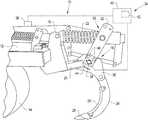
- FIG. 3illustrates a perspective view of a shank assembly as shown in FIGS. 1-2 ;
- FIG. 4illustrates a flowchart of a method for operating the float monitoring system, in accordance with an exemplary embodiment of the present invention.
- forwardwhen used in connection with the agricultural tillage implement and/or components thereof are usually determined with reference to the direction of forward operative travel of the agricultural vehicle, but they should not be construed as limiting.
- longitudinaland “transverse” are determined with reference to the fore-and-aft direction of the agricultural tillage implement and are equally not to be construed as limiting.
- an agricultural tillage implement 10that generally includes a frame 12 , wheels 14 supporting the frame 12 , and various ground engaging tools including primary and/or secondary tools, such as shank assemblies 16 , which are mounted to the frame 12 .
- the agricultural tillage implement 10may be in the form of any desired ground-engaging implement, such as a chisel plow, a field cultivator, or disk ripper.
- the agricultural tillage implement 10may also include other ground engaging tools such as such as a ganged disk harrow, spike tooth harrow, leveling blades, and/or rolling, i.e., crumbler, basket assemblies for finishing the soil.
- the agricultural tillage implement 10may be towed by any desired work vehicle, such as a tractor.
- the frame 12may be a single body frame or it may be a multi-section frame with one or more wing sections. In addition to supporting the ground engaging tools, the frame 12 may also support hydraulic and electrical systems which can adjust down pressure and/or fold and unfold the wing sections. For example, the frame 12 may also support one or more actuators for adjusting the depth of the shank assemblies 16 . It should be appreciated that the hydraulic and electrical systems of the agricultural tillage implement 10 may be controlled by a user via data transmitted to the agricultural vehicle via an ISOBUS connection.
- the frame 12may comprise any desired material, such as metal.
- the shank assemblies 16are configured for engaging the soil. Each shank assembly 16 is connected to and supported by the frame 12 .
- Each shank assembly 16generally includes a frame mount 18 , a support arm 20 rotatably connected to the frame 12 via the frame mount 18 , a compression spring 22 , a shank 24 , a sweep or point 26 , and a protective guard 28 coupled to the shank 24 .
- the frame mount 18may at least partially wrap around the frame 12 and may be fixedly attached to the frame 12 by one or more fasteners.
- the frame mount 18may include a shank stop that is affixed, e.g. welded, on the bottom side of the plates of the frame mount 18 (unnumbered).
- the support arm 20has a first end which is rotatably connected to the frame mount 18 and a second end with a curved, shank mounting bracket 30 which mounts the shank 24 .
- the mounting bracket 30may be a separate piece attached, e.g. welded or bolted, to the second end of the support arm 20 or integrally formed as part of the second end of the support arm 20 .
- the compression spring 22has a first end rotatably connected to the frame mount 18 and a second end rotatably connected to a spring mounting bracket 32 , which in turn is connected to the mounting bracket 30 .
- the compression spring 22may also include a pivot casting and retaining bolt assembly (unnumbered).
- the compression spring 22may be in the form of any desired biasing member.
- the shank 24 and point 26which may be removably attached thereto, may be in the form of any desired shank and point, respectively.
- the shanks 24 of the shank assemblies 16are designed to “trip” or break away upon contacting an object, e.g. an immovable rock.
- the shanks 24may rotate upwardly from a home position ( FIG. 1 ), wherein the shanks 24 are fully engaged with the soil at a desired depth, to a tripped position, wherein the shanks 24 are at least partially rotated upwardly above their home position operating depth.
- the shanks 24may float, i.e., at least partially rotate upwardly, for example when being pulled through hard ground such that the shanks 24 are positioned in a float or partially tripped position ( FIG. 2 ).
- the shanks 24may begin to create an undesired effect, e.g. unlevel seedbed or uneven soil compaction, if they remain in the partially tripped position throughout various sections of the field.
- the towing vehiclemay be decelerated, the down pressure on the frame 12 and/or shanks 24 may be adjusted, and/or the operating depth of the frame 12 and/or shanks 24 may be adjusted.
- the agricultural implement 10 and/or at least one of the shank assemblies 16may further include a float monitoring system 34 for monitoring the float of one or more shanks 24 .
- the float monitoring system 34includes a first, home sensor 36 connected to the frame 12 for sensing a home position of the frame, a second, shank sensor 38 respectively associated with at least one shank 24 , and an electronic control unit (ECU) 40 , e.g. a controller 40 with a memory 42 .
- the float monitoring system 34may monitor the angular position of a respective support arm 20 , which is indicative of the depth of the shank 24 and point 26 attached thereto.
- the float monitoring system 34may monitor the float of each shank 24 and may subsequently notify the operator of the towing vehicle so that one or more operating parameters, e.g. the speed of the towing vehicle, the depth of the shanks 24 , etc., may be adjusted. Therefore, the shanks 24 and points 26 can operate at a consistent depth for engaging the soil and eliminating, or at least reducing, soil compaction, or creating a level seedbed.
- the home sensor 36may be connected to the frame 12 at any desired location. Alternatively, the home sensor 36 may be connected to a given frame mount 18 .
- the float monitoring system 34may include only one shank sensor 38 that is connected to one respective support arm 20 out of the multiple shank assemblies 16 or multiple shank sensors 38 which are connected to a few or all of the support arms 20 of the multiple shank assemblies 16 .
- each shank sensor 38may be connected to a respective mounting bracket 30 of the support arm 20 via a mounting plate 44 .
- the shank sensor 38may be fastened to the mounting plate 44 , which in turn is mounted onto the mounting bracket 30 by the same fastener(s) 46 which mount the spring mounting bracket 32 onto the mounting bracket 30 .
- each shank sensor 38may be connected to a respective support arm 20 and/or mounting bracket 30 by way of brackets, plates, fasteners, and/or welding.
- the float monitoring system 34includes only one home sensor 36 ; however, the float monitoring system 34 may include multiple home sensors 36 .
- the float monitoring system 34includes only one shank sensor 38 for each shank 24 ; however, the monitoring system 34 may include multiple shank sensors 38 for each shank 24 .
- the home sensor 36senses a home position of the frame 12 , i.e., a relative horizontal or zero slope position.
- Each shank sensor 38senses an angular position of the support arm 20 relative to the frame 12 , i.e., as the support arm 20 rotates relative to the frame 12 .
- the initial position of the shanks 24 sensed by the shank sensor 38 in the home position of the shank assemblies 16need not match or be equal to the home position of the frame 12 sensed by the home sensor 36 ( FIG. 1 ).
- the home sensor 36may sense an approximately zero incline of the frame 12 , plus or minus 10 degrees; whereas each shank sensor 38 may sense an initial incline of the respective support arm 20 .
- an initial angular relationshipmay be established between the respective support arm 20 and the frame 12 .
- the sensors 36 , 38may sense any changes in the angles of the frame 12 and/or respective support arm 20 in order to determine how much each shank 24 has floated, e.g. at least partially rotated upwardly from its initial position in the home position of the shank assemblies 16 ( FIG. 2 ).
- the sensors 36 , 38may continually or periodically sense the angular position of the frame 12 and the support arm 20 , respectively.
- the sensors 36 , 38may each be in the form of inclinometer sensors 36 , 38 .
- each sensor 36 , 38may be in the form of an electronic inclinometer sensor 36 , 38 .
- the controller 40may be operably connected to the sensors 36 , 38 via a wired and/or wireless connection.
- the controller 40compares the incline signals from the sensors 36 , 38 and determines the float of a respective shank 24 by extrapolating a depth of the shank 24 from the angular position of the support arm 20 relative the initial position of the support arm 20 and the home position of the frame 12 sensed by the home sensor 36 .
- a set distance from the support arm 20 to the shank 24 and/or point 26may be known and stored in the memory 42 such that the as the shank sensor 38 indicates a particular float position of the support arm 20 the controller 40 may extrapolate the depth of the shank 24 and/or point 26 from this spatial relationship.
- the controller 40may also be operably connected to any desired control functionality of the towing vehicle and/or agricultural tillage implement 10 , e.g. the vehicle speed controller, actuator(s) for controlling the depth of the tillage agricultural implement 10 , etc.
- the controller 40may be in the form of any desired analog or digital control system or control unit. It should be appreciated that the controller 40 may be coupled with or integrated into the existing hardware and/or software of the agricultural implement 10 and/or towing vehicle.
- the monitoring system 34may also automatically control the speed of the towing vehicle and/or the depth of the frame 12 and/or shanks 24 .
- the controller 40may automatically decelerate the towing vehicle in order to alleviate some of the force acting on the shanks 24 and thereby allow the shanks 24 to return to their desired home position. Additionally, for example, the controller 40 may automatically raise or lower the actuator(s) which control the depth of the frame 12 and/or shank assemblies 16 .
- the method 50may include an initial step of providing the shank assembly 16 and the float monitoring system 34 , as discussed above (at block 52 ).
- the methodmay include a step of sensing the home position of the frame 12 by the home sensor 36 (at block 54 ).
- the methodmay include sensing the angular position of the support arm 20 by the shank sensor 38 (at block 56 ).
- the controller 40may then compare the sensed positions of the frame 12 and the support arm 20 (at block 58 ).
- the controller 40may compare the starting positions of the frame 12 and support arm 20 , store this first angular relationship, and subsequently compare a new, second angular relationship between the sensed positions of the frame 12 and support arm 20 . Thereafter, the controller 40 may determine the float of one or more shanks 24 by extrapolating a depth of each respective shank 24 from the angular position of the support arm 20 relative to the home position sensed by the home sensor 36 (at block 60 ).
- the method 50may include a step of communicating the float of each respective shank 24 to the operator of the agricultural tillage implement 10 (at block 62 ).
- the controller 40may communicate a float signal to an indicator, e.g. warning light and/or user interface within the towing vehicle, for alerting the operator that the shanks 24 have floated out of their desired depth position.
- the steps of the method 50are performed by the controller 40 upon loading and executing software code or instructions which are tangibly stored on the tangible computer readable medium 42 , such as on a magnetic medium, e.g., a computer hard drive, an optical medium, e.g., an optical disc, solid-state memory, e.g., flash memory, or other storage media known in the art.
- any of the functionality performed by the controller 40 described herein, such as the method 50is implemented in software code or instructions which are tangibly stored on a tangible computer readable medium.
- the controller 40loads the software code or instructions via a direct interface with the computer readable medium or via a wired and/or wireless network. Upon loading and executing such software code or instructions by the controller 40 , the controller 40 may perform any of the functionality of the controller 40 described herein, including any steps of the method 50 described herein.
- software codeor “code” used herein refers to any instructions or set of instructions that influence the operation of a computer or controller. They may exist in a computer-executable form, such as machine code, which is the set of instructions and data directly executed by a computer's central processing unit or by a controller, a human-understandable form, such as source code, which may be compiled in order to be executed by a computer's central processing unit or by a controller, or an intermediate form, such as object code, which is produced by a compiler.
- the term “software code” or “code”also includes any human-understandable computer instructions or set of instructions, e.g., a script, that may be executed on the fly with the aid of an interpreter executed by a computer's central processing unit or by a controller.
- the float monitoring system 34may be an aftermarket system, for example, installed after the manufacture of the agricultural implement 10 .
- the float monitoring system 34may be sold separately from the agricultural implement 10 .
- the float monitoring system 34may be a separate unit which is installed and subsequently integrated into the existing hardware and/or software of the agricultural implement 10 and/or towing vehicle.
- controller 40may determine the incline of the support arm 20 only by using the incline sensor readings of the shank sensor 38 .
- the controller 40may include a reset function wherein a desired operating depth of the shanks 24 is set to be the relative home, e.g. zero, angular position from which the change of further rotation is subsequently compared. For example, after setting a desired depth for the agricultural tillage implement 10 and/or shanks 24 , the operator may input a user command to the controller 40 , via a user interface, which resets the home angular position of the respective support arm 20 .
Landscapes
- Life Sciences & Earth Sciences (AREA)
- Engineering & Computer Science (AREA)
- Mechanical Engineering (AREA)
- Soil Sciences (AREA)
- Environmental Sciences (AREA)
- Soil Working Implements (AREA)
Abstract
Description
Claims (16)
Priority Applications (4)
| Application Number | Priority Date | Filing Date | Title |
|---|---|---|---|
| US16/555,398US11219153B2 (en) | 2019-08-29 | 2019-08-29 | System and method for monitoring shank float |
| EP20771385.0AEP4021159B1 (en) | 2019-08-29 | 2020-08-26 | System and method for monitoring shank float |
| CA3146887ACA3146887A1 (en) | 2019-08-29 | 2020-08-26 | System and method for monitoring shank float |
| PCT/US2020/047965WO2021041520A1 (en) | 2019-08-29 | 2020-08-26 | System and method for monitoring shank float |
Applications Claiming Priority (1)
| Application Number | Priority Date | Filing Date | Title |
|---|---|---|---|
| US16/555,398US11219153B2 (en) | 2019-08-29 | 2019-08-29 | System and method for monitoring shank float |
Publications (2)
| Publication Number | Publication Date |
|---|---|
| US20210059098A1 US20210059098A1 (en) | 2021-03-04 |
| US11219153B2true US11219153B2 (en) | 2022-01-11 |
Family
ID=72470590
Family Applications (1)
| Application Number | Title | Priority Date | Filing Date |
|---|---|---|---|
| US16/555,398Active2040-03-17US11219153B2 (en) | 2019-08-29 | 2019-08-29 | System and method for monitoring shank float |
Country Status (4)
| Country | Link |
|---|---|
| US (1) | US11219153B2 (en) |
| EP (1) | EP4021159B1 (en) |
| CA (1) | CA3146887A1 (en) |
| WO (1) | WO2021041520A1 (en) |
Cited By (1)
| Publication number | Priority date | Publication date | Assignee | Title |
|---|---|---|---|---|
| EP4298879A1 (en)* | 2022-06-27 | 2024-01-03 | CMN Maskintec A/S | Tine shank unit for cultivating implements and cultivating implements comprising such tine shanks |
Families Citing this family (4)
| Publication number | Priority date | Publication date | Assignee | Title |
|---|---|---|---|---|
| US11707010B2 (en) | 2019-06-14 | 2023-07-25 | Cnh Industrial America Llc | System and method for monitoring the operational status of tools of an agricultural implement |
| US12150397B2 (en)* | 2021-03-19 | 2024-11-26 | Cnh Industrial America Llc | System and method for monitoring an operational status of a shear pin for a ground-engaging assembly of an agricultural implement |
| BR102021006593A2 (en)* | 2021-04-06 | 2022-10-11 | Tma Maquinas E Equipamentos Agricolas Ltda | APPLICATION STEM WITH AUTOMATIC RESET AND TRIGGER SYSTEM, RESET METHOD OF AN APPLICATION STEM AND VEHICLES COMPRISING SUCH APPLICATION STEM |
| CN115191195B (en)* | 2022-09-05 | 2024-09-10 | 北京市农林科学院智能装备技术研究中心 | Large Tian Bianliang fertilizer device and variable rate fertilization control method |
Citations (49)
| Publication number | Priority date | Publication date | Assignee | Title |
|---|---|---|---|---|
| US4508178A (en) | 1981-09-28 | 1985-04-02 | Cowell Peter A | Tractor linkage with pitch altitude control connected to sensor ram |
| US5255756A (en) | 1992-04-22 | 1993-10-26 | Progressive Farm Products, Inc. | Caddy with guidance system for agricultural implements |
| US5499684A (en) | 1994-08-16 | 1996-03-19 | Caterpillar Inc. | Geographic surface altering implement control system |
| US6073070A (en) | 1996-11-16 | 2000-06-06 | Claas Kgaa | Agricultural vehicle with treatment device which is adjustable in its position and/or orientation relative to the vehicle |
| US6608672B1 (en) | 1999-03-15 | 2003-08-19 | Omron Corporation | Soil survey device and system for precision agriculture |
| US20070239338A1 (en)* | 2006-04-06 | 2007-10-11 | Dean Potts | Worksite preparation method using compaction response and mapping information |
| US7490678B2 (en) | 2005-04-21 | 2009-02-17 | A.I.L., Inc. | GPS controlled guidance system for farm tractor/implement combination |
| US20090187315A1 (en)* | 2008-01-23 | 2009-07-23 | Gradient Inc. | Pitch plow and method of controlling an elevation of a cutting edge of a pitch plow |
| US7580783B2 (en) | 2004-12-29 | 2009-08-25 | Cnh America Llc | Correction in position with hitch position sensor |
| US20090301367A1 (en)* | 2008-06-06 | 2009-12-10 | Martin Ronald S | Adjustable Row Cleaner |
| US20100300711A1 (en)* | 2007-12-08 | 2010-12-02 | Agco Sa | Implement Control Systems |
| US20130081830A1 (en)* | 2011-09-29 | 2013-04-04 | Thomas Tuttle | Method And Apparatus For Implement Control Of Tractor Hydraulics Via Isobus Connection |
| US20130081829A1 (en)* | 2011-09-29 | 2013-04-04 | Thomas Tuttle | Method And Apparatus For Automatic Positioning Of Gull Wings Of Stackerbar Planter Based On Tractor Hitch Position |
| US20130180742A1 (en)* | 2012-01-17 | 2013-07-18 | Cnh America Llc | Soil monitoring system |
| US20130248212A1 (en)* | 2010-09-15 | 2013-09-26 | Dawn Equipment Company | Agricultural systems |
| US8544397B2 (en)* | 2010-09-15 | 2013-10-01 | Dawn Equipment Company | Row unit for agricultural implement |
| US8565984B2 (en) | 2007-03-16 | 2013-10-22 | Deere & Comany | System and method of steering for a work vehicle towing a towed implement on lateral slopes |
| US8738244B2 (en) | 2012-01-31 | 2014-05-27 | Deere & Company | Agricultural machine having a system for automatic setting of a working parameter, and associated method |
| US8763713B2 (en)* | 2012-01-27 | 2014-07-01 | Dawn Equipment Company | Agricultural implement with automatic down pressure control |
| US20140251647A1 (en)* | 2013-03-05 | 2014-09-11 | John D. Isaacson | Agricultural tool with electronically controlled downpressure system |
| US9085261B2 (en) | 2011-01-26 | 2015-07-21 | Magna Electronics Inc. | Rear vision system with trailer angle detection |
| US20150201547A1 (en)* | 2013-12-23 | 2015-07-23 | Agco International Gmbh | Vehicle Control System |
| US20150264857A1 (en)* | 2014-03-21 | 2015-09-24 | Kinze Manufacturing, Inc. | Apparatuses, methods, and systems for providing down force for an agricultural implement |
| US20160143209A1 (en)* | 2014-11-21 | 2016-05-26 | Bourgault Industries Ltd. | Reducing wheel forces on a field surface |
| US20160157411A1 (en)* | 2013-07-18 | 2016-06-09 | Pant Detection Systems Limited | Improvements in, or Relating to, Plant Maintenance |
| US20160165789A1 (en)* | 2014-12-16 | 2016-06-16 | Cnh Industrial Canada Ltd. | Seed Implement Incorporating A Down Pressure Sensing And Adjustment System |
| US9433142B2 (en)* | 2011-11-08 | 2016-09-06 | Buhler Ezee-On Inc. | Tool control system for agricultural seeders |
| US9446713B2 (en) | 2012-09-26 | 2016-09-20 | Magna Electronics Inc. | Trailer angle detection system |
| US9585301B1 (en)* | 2013-04-15 | 2017-03-07 | Veris Technologies, Inc. | Agricultural planter with automatic depth and seeding rate control |
| US20170196160A1 (en)* | 2016-01-13 | 2017-07-13 | Precision Ag 360, Inc. | Agricultural ground penetrating tool sensor system |
| US20180014449A1 (en)* | 2016-07-18 | 2018-01-18 | Tribine Industries Llc | Soil Compaction Mitigation Assembly and Method |
| US20180054953A1 (en)* | 2016-08-29 | 2018-03-01 | Ronald S. Martin | Wireless control system for floating row cleaner |
| US20180092287A1 (en)* | 2016-09-30 | 2018-04-05 | Deere & Company | Planter row unit furrow depth sensing apparatus and method |
| US20180303022A1 (en)* | 2017-04-25 | 2018-10-25 | Cnh Industrial Canada, Ltd. | Automatic Fore/Aft Leveling Trim Function In A Towable Tillage Implement |
| US20180310465A1 (en)* | 2017-04-28 | 2018-11-01 | CNH Industrial America, LLC | System and method for monitoring soil conditions within a field |
| US20180310466A1 (en)* | 2017-04-28 | 2018-11-01 | CNH Industrial America, LLC | System and method for detecting ground engaging tool float for an agricultural implement |
| US20180368307A1 (en)* | 2017-06-21 | 2018-12-27 | Honey Bee Manufacturing Ltd. | Tillage apparatuses and related methods |
| US20190000005A1 (en)* | 2017-06-28 | 2019-01-03 | Cnh Industrial Canada, Ltd. | Cylinder Pressure Based Position Control of an Implement Stabilizer Wheel |
| US20190124824A1 (en)* | 2017-10-31 | 2019-05-02 | Deere & Company | Method of managing planter row unit downforce |
| US20190373797A1 (en)* | 2018-06-12 | 2019-12-12 | Cnh Industrial America Llc | Adjustable closing system with downforce control |
| US10537055B2 (en)* | 2017-10-13 | 2020-01-21 | Deere & Company | Actuated seed depth setting for a planter row unit |
| US20200077585A1 (en)* | 2016-06-21 | 2020-03-12 | Macdon Industries Ltd. | Crop Harvesting Machine with Variable Header Float |
| US20200093052A1 (en)* | 2017-04-24 | 2020-03-26 | Pottinger Landtechnik Gmbh | Agricultural soil cultivation unit |
| US10645865B2 (en)* | 2017-05-04 | 2020-05-12 | Dawn Equipment Company | Agricultural row unit with automatic control system for furrow closing device |
| US20200154627A1 (en)* | 2017-05-26 | 2020-05-21 | Precision Planting Llc | Method to prevent drift of an agricultural implement |
| US20200178454A1 (en)* | 2018-12-05 | 2020-06-11 | Cnh Industrial America Llc | Real-Time Seedbed Uniformity Detection And Improvement In An Agricultural Tillage Implement |
| US10701862B2 (en)* | 2018-02-01 | 2020-07-07 | Macdon Industries Ltd. | Agricultural header with float control |
| US20200260631A1 (en)* | 2019-02-19 | 2020-08-20 | Cnh Industrial America Llc | System and method for monitoring tool float on an agricultural implement |
| US10757854B2 (en)* | 2018-08-27 | 2020-09-01 | Cnh Industrial America Llc | Determining forces exerted on rolling agricultural components based on an applied braking force |
Family Cites Families (3)
| Publication number | Priority date | Publication date | Assignee | Title |
|---|---|---|---|---|
| DE102016124517A1 (en)* | 2016-12-15 | 2018-06-21 | Treffler Maschinenbau Gmbh & Co. Kg | Tine harrow penetration depth measuring device, tine harrow and penetration depth regulating device |
| DE102017222403A1 (en)* | 2017-12-11 | 2019-06-13 | Deere & Company | Method and device for mapping any foreign bodies present in a field |
| CN108377676B (en)* | 2018-02-26 | 2020-04-24 | 吉林大学 | Subsoiler and real-time control system and control method for subsoiling soil penetration angle thereof |
- 2019
- 2019-08-29USUS16/555,398patent/US11219153B2/enactiveActive
- 2020
- 2020-08-26EPEP20771385.0Apatent/EP4021159B1/enactiveActive
- 2020-08-26WOPCT/US2020/047965patent/WO2021041520A1/ennot_activeCeased
- 2020-08-26CACA3146887Apatent/CA3146887A1/enactivePending
Patent Citations (51)
| Publication number | Priority date | Publication date | Assignee | Title |
|---|---|---|---|---|
| US4508178A (en) | 1981-09-28 | 1985-04-02 | Cowell Peter A | Tractor linkage with pitch altitude control connected to sensor ram |
| US5255756A (en) | 1992-04-22 | 1993-10-26 | Progressive Farm Products, Inc. | Caddy with guidance system for agricultural implements |
| US5499684A (en) | 1994-08-16 | 1996-03-19 | Caterpillar Inc. | Geographic surface altering implement control system |
| US6073070A (en) | 1996-11-16 | 2000-06-06 | Claas Kgaa | Agricultural vehicle with treatment device which is adjustable in its position and/or orientation relative to the vehicle |
| US6608672B1 (en) | 1999-03-15 | 2003-08-19 | Omron Corporation | Soil survey device and system for precision agriculture |
| US7580783B2 (en) | 2004-12-29 | 2009-08-25 | Cnh America Llc | Correction in position with hitch position sensor |
| US7490678B2 (en) | 2005-04-21 | 2009-02-17 | A.I.L., Inc. | GPS controlled guidance system for farm tractor/implement combination |
| US20070239338A1 (en)* | 2006-04-06 | 2007-10-11 | Dean Potts | Worksite preparation method using compaction response and mapping information |
| US8565984B2 (en) | 2007-03-16 | 2013-10-22 | Deere & Comany | System and method of steering for a work vehicle towing a towed implement on lateral slopes |
| US20100300711A1 (en)* | 2007-12-08 | 2010-12-02 | Agco Sa | Implement Control Systems |
| US20090187315A1 (en)* | 2008-01-23 | 2009-07-23 | Gradient Inc. | Pitch plow and method of controlling an elevation of a cutting edge of a pitch plow |
| US8090507B2 (en) | 2008-01-23 | 2012-01-03 | Gradient Inc. | Pitch plow and method of controlling an elevation of a cutting edge of a pitch plow |
| US8352131B2 (en) | 2008-01-23 | 2013-01-08 | Ag Leader Technology, Inc. | Drainage plow control and method of controlling an elevation of a cutting edge of a drainage plow |
| US20090301367A1 (en)* | 2008-06-06 | 2009-12-10 | Martin Ronald S | Adjustable Row Cleaner |
| US8544397B2 (en)* | 2010-09-15 | 2013-10-01 | Dawn Equipment Company | Row unit for agricultural implement |
| US20130248212A1 (en)* | 2010-09-15 | 2013-09-26 | Dawn Equipment Company | Agricultural systems |
| US9085261B2 (en) | 2011-01-26 | 2015-07-21 | Magna Electronics Inc. | Rear vision system with trailer angle detection |
| US20130081829A1 (en)* | 2011-09-29 | 2013-04-04 | Thomas Tuttle | Method And Apparatus For Automatic Positioning Of Gull Wings Of Stackerbar Planter Based On Tractor Hitch Position |
| US20130081830A1 (en)* | 2011-09-29 | 2013-04-04 | Thomas Tuttle | Method And Apparatus For Implement Control Of Tractor Hydraulics Via Isobus Connection |
| US9433142B2 (en)* | 2011-11-08 | 2016-09-06 | Buhler Ezee-On Inc. | Tool control system for agricultural seeders |
| US20130180742A1 (en)* | 2012-01-17 | 2013-07-18 | Cnh America Llc | Soil monitoring system |
| US8763713B2 (en)* | 2012-01-27 | 2014-07-01 | Dawn Equipment Company | Agricultural implement with automatic down pressure control |
| US8738244B2 (en) | 2012-01-31 | 2014-05-27 | Deere & Company | Agricultural machine having a system for automatic setting of a working parameter, and associated method |
| US9446713B2 (en) | 2012-09-26 | 2016-09-20 | Magna Electronics Inc. | Trailer angle detection system |
| US20140251647A1 (en)* | 2013-03-05 | 2014-09-11 | John D. Isaacson | Agricultural tool with electronically controlled downpressure system |
| US9585301B1 (en)* | 2013-04-15 | 2017-03-07 | Veris Technologies, Inc. | Agricultural planter with automatic depth and seeding rate control |
| US20160157411A1 (en)* | 2013-07-18 | 2016-06-09 | Pant Detection Systems Limited | Improvements in, or Relating to, Plant Maintenance |
| US20150201547A1 (en)* | 2013-12-23 | 2015-07-23 | Agco International Gmbh | Vehicle Control System |
| US20150264857A1 (en)* | 2014-03-21 | 2015-09-24 | Kinze Manufacturing, Inc. | Apparatuses, methods, and systems for providing down force for an agricultural implement |
| US20160143209A1 (en)* | 2014-11-21 | 2016-05-26 | Bourgault Industries Ltd. | Reducing wheel forces on a field surface |
| US20160165789A1 (en)* | 2014-12-16 | 2016-06-16 | Cnh Industrial Canada Ltd. | Seed Implement Incorporating A Down Pressure Sensing And Adjustment System |
| US20170196160A1 (en)* | 2016-01-13 | 2017-07-13 | Precision Ag 360, Inc. | Agricultural ground penetrating tool sensor system |
| US20200077585A1 (en)* | 2016-06-21 | 2020-03-12 | Macdon Industries Ltd. | Crop Harvesting Machine with Variable Header Float |
| US20180014449A1 (en)* | 2016-07-18 | 2018-01-18 | Tribine Industries Llc | Soil Compaction Mitigation Assembly and Method |
| US20180054953A1 (en)* | 2016-08-29 | 2018-03-01 | Ronald S. Martin | Wireless control system for floating row cleaner |
| US20180092287A1 (en)* | 2016-09-30 | 2018-04-05 | Deere & Company | Planter row unit furrow depth sensing apparatus and method |
| US20200093052A1 (en)* | 2017-04-24 | 2020-03-26 | Pottinger Landtechnik Gmbh | Agricultural soil cultivation unit |
| US20180303022A1 (en)* | 2017-04-25 | 2018-10-25 | Cnh Industrial Canada, Ltd. | Automatic Fore/Aft Leveling Trim Function In A Towable Tillage Implement |
| US20180310465A1 (en)* | 2017-04-28 | 2018-11-01 | CNH Industrial America, LLC | System and method for monitoring soil conditions within a field |
| US20180310466A1 (en)* | 2017-04-28 | 2018-11-01 | CNH Industrial America, LLC | System and method for detecting ground engaging tool float for an agricultural implement |
| US10645865B2 (en)* | 2017-05-04 | 2020-05-12 | Dawn Equipment Company | Agricultural row unit with automatic control system for furrow closing device |
| US20200154627A1 (en)* | 2017-05-26 | 2020-05-21 | Precision Planting Llc | Method to prevent drift of an agricultural implement |
| US20180368307A1 (en)* | 2017-06-21 | 2018-12-27 | Honey Bee Manufacturing Ltd. | Tillage apparatuses and related methods |
| US20190000005A1 (en)* | 2017-06-28 | 2019-01-03 | Cnh Industrial Canada, Ltd. | Cylinder Pressure Based Position Control of an Implement Stabilizer Wheel |
| US10537055B2 (en)* | 2017-10-13 | 2020-01-21 | Deere & Company | Actuated seed depth setting for a planter row unit |
| US20190124824A1 (en)* | 2017-10-31 | 2019-05-02 | Deere & Company | Method of managing planter row unit downforce |
| US10701862B2 (en)* | 2018-02-01 | 2020-07-07 | Macdon Industries Ltd. | Agricultural header with float control |
| US20190373797A1 (en)* | 2018-06-12 | 2019-12-12 | Cnh Industrial America Llc | Adjustable closing system with downforce control |
| US10757854B2 (en)* | 2018-08-27 | 2020-09-01 | Cnh Industrial America Llc | Determining forces exerted on rolling agricultural components based on an applied braking force |
| US20200178454A1 (en)* | 2018-12-05 | 2020-06-11 | Cnh Industrial America Llc | Real-Time Seedbed Uniformity Detection And Improvement In An Agricultural Tillage Implement |
| US20200260631A1 (en)* | 2019-02-19 | 2020-08-20 | Cnh Industrial America Llc | System and method for monitoring tool float on an agricultural implement |
Cited By (1)
| Publication number | Priority date | Publication date | Assignee | Title |
|---|---|---|---|---|
| EP4298879A1 (en)* | 2022-06-27 | 2024-01-03 | CMN Maskintec A/S | Tine shank unit for cultivating implements and cultivating implements comprising such tine shanks |
Also Published As
| Publication number | Publication date |
|---|---|
| CA3146887A1 (en) | 2021-03-04 |
| WO2021041520A1 (en) | 2021-03-04 |
| EP4021159B1 (en) | 2024-07-24 |
| EP4021159A1 (en) | 2022-07-06 |
| US20210059098A1 (en) | 2021-03-04 |
Similar Documents
| Publication | Publication Date | Title |
|---|---|---|
| US11219153B2 (en) | System and method for monitoring shank float | |
| CN109068575B (en) | Method and system for measuring roughness of a ground surface | |
| EP3668302B1 (en) | A system for controlling soil compaction caused by wheels, and use of such system | |
| EP3729930B1 (en) | Agricultural plough | |
| CN108289407B (en) | Device, system and method for monitoring soil conditions during tilling operations and control of tilling tools | |
| US5964300A (en) | Wear shin for a tillage implement | |
| US10412878B2 (en) | Down pressure compensation for tillage baskets traveling at varying speeds | |
| US20200008337A1 (en) | Residue management based on topography by an agricultural tillage implement | |
| US20180220574A1 (en) | Gauge wheel and hitch force control | |
| US3692120A (en) | Tilling apparatus | |
| US10368474B2 (en) | Double rolling basket linkage | |
| US11039563B2 (en) | System for monitoring the condition of a seedbed within a field with a seedbed floor detection assembly | |
| US20230210037A1 (en) | Agricultural implement | |
| US10375874B2 (en) | Dual rate sweep load on field cultivator shank assembly | |
| EP3837936B1 (en) | Skimmer for an agricultural plough | |
| US10785902B2 (en) | Dynamic linkage for agricultural implement tool gang | |
| US11711994B2 (en) | System and method for monitoring the condition of a lateral swath of a seedbed with a seedbed floor detection assembly | |
| EP3837939A1 (en) | Method for controlling agricultural machinery | |
| JP6049507B2 (en) | Field work machine |
Legal Events
| Date | Code | Title | Description |
|---|---|---|---|
| AS | Assignment | Owner name:CNH INDUSTRIAL AMERICA, PENNSYLVANIA Free format text:ASSIGNMENT OF ASSIGNORS INTEREST;ASSIGNOR:KOVACH, MICHAEL;REEL/FRAME:050213/0884 Effective date:20190821 | |
| FEPP | Fee payment procedure | Free format text:ENTITY STATUS SET TO UNDISCOUNTED (ORIGINAL EVENT CODE: BIG.); ENTITY STATUS OF PATENT OWNER: LARGE ENTITY | |
| AS | Assignment | Owner name:CNH INDUSTRIAL AMERICA LLC, PENNSYLVANIA Free format text:CORRECTIVE ASSIGNMENT TO CORRECT THE ASSIGNEE NAME PREVIOUSLY RECORDED ON REEL 050213 FRAME 0884. ASSIGNOR(S) HEREBY CONFIRMS THE ASSIGNMENT;ASSIGNOR:KOVACH, MICHAEL G.;REEL/FRAME:050992/0962 Effective date:20190821 | |
| STPP | Information on status: patent application and granting procedure in general | Free format text:NON FINAL ACTION MAILED | |
| STPP | Information on status: patent application and granting procedure in general | Free format text:RESPONSE TO NON-FINAL OFFICE ACTION ENTERED AND FORWARDED TO EXAMINER | |
| STPP | Information on status: patent application and granting procedure in general | Free format text:NOTICE OF ALLOWANCE MAILED -- APPLICATION RECEIVED IN OFFICE OF PUBLICATIONS | |
| STPP | Information on status: patent application and granting procedure in general | Free format text:AWAITING TC RESP., ISSUE FEE NOT PAID | |
| STPP | Information on status: patent application and granting procedure in general | Free format text:NOTICE OF ALLOWANCE MAILED -- APPLICATION RECEIVED IN OFFICE OF PUBLICATIONS | |
| STPP | Information on status: patent application and granting procedure in general | Free format text:PUBLICATIONS -- ISSUE FEE PAYMENT VERIFIED | |
| STCF | Information on status: patent grant | Free format text:PATENTED CASE | |
| AS | Assignment | Owner name:INC., BLUE LEAF I, DELAWARE Free format text:ASSIGNMENT OF ASSIGNORS INTEREST;ASSIGNOR:CNH INDUSTRIAL AMERICA LLC;REEL/FRAME:060328/0428 Effective date:20220517 | |
| MAFP | Maintenance fee payment | Free format text:PAYMENT OF MAINTENANCE FEE, 4TH YEAR, LARGE ENTITY (ORIGINAL EVENT CODE: M1551); ENTITY STATUS OF PATENT OWNER: LARGE ENTITY Year of fee payment:4 |