US11218067B2 - Method and apparatus for power generation - Google Patents
Method and apparatus for power generationDownload PDFInfo
- Publication number
- US11218067B2 US11218067B2US16/810,920US202016810920AUS11218067B2US 11218067 B2US11218067 B2US 11218067B2US 202016810920 AUS202016810920 AUS 202016810920AUS 11218067 B2US11218067 B2US 11218067B2
- Authority
- US
- United States
- Prior art keywords
- magnetic
- core
- cylinder
- coil
- coils
- Prior art date
- Legal status (The legal status is an assumption and is not a legal conclusion. Google has not performed a legal analysis and makes no representation as to the accuracy of the status listed.)
- Active
Links
Images


Classifications
- H—ELECTRICITY
- H02—GENERATION; CONVERSION OR DISTRIBUTION OF ELECTRIC POWER
- H02K—DYNAMO-ELECTRIC MACHINES
- H02K35/00—Generators with reciprocating, oscillating or vibrating coil system, magnet, armature or other part of the magnetic circuit
- H02K35/04—Generators with reciprocating, oscillating or vibrating coil system, magnet, armature or other part of the magnetic circuit with moving coil systems and stationary magnets
- H—ELECTRICITY
- H02—GENERATION; CONVERSION OR DISTRIBUTION OF ELECTRIC POWER
- H02K—DYNAMO-ELECTRIC MACHINES
- H02K1/00—Details of the magnetic circuit
- H02K1/06—Details of the magnetic circuit characterised by the shape, form or construction
- H02K1/12—Stationary parts of the magnetic circuit
- H02K1/17—Stator cores with permanent magnets
- H—ELECTRICITY
- H02—GENERATION; CONVERSION OR DISTRIBUTION OF ELECTRIC POWER
- H02K—DYNAMO-ELECTRIC MACHINES
- H02K1/00—Details of the magnetic circuit
- H02K1/06—Details of the magnetic circuit characterised by the shape, form or construction
- H02K1/34—Reciprocating, oscillating or vibrating parts of the magnetic circuit
- H—ELECTRICITY
- H02—GENERATION; CONVERSION OR DISTRIBUTION OF ELECTRIC POWER
- H02K—DYNAMO-ELECTRIC MACHINES
- H02K7/00—Arrangements for handling mechanical energy structurally associated with dynamo-electric machines, e.g. structural association with mechanical driving motors or auxiliary dynamo-electric machines
- H02K7/06—Means for converting reciprocating motion into rotary motion or vice versa
- H02K7/075—Means for converting reciprocating motion into rotary motion or vice versa using crankshafts or eccentrics
Definitions
- the inventionrelates in general to power generation methods, and in particular to an improved method for generating electrical power using linear power generators.
- Generatorsare based on the principle of electromagnetic induction, which was discovered by Michael Faraday in 1831. Faraday discovered that when an electrical conducting material (such as copper) is moved through a magnetic field (or vice versa), an electric current will begin to flow through that material. This electromagnetic effect induces voltage or electric current into the moving conductors.
- rotary generatorsare essentially very large quantities of wire spinning around the inside of very large magnets.
- the coils of wireare called the armature because they are moving with respect to the stationary magnets (which are called the stators).
- the moving componentis called the armature and the stationary component is called the stator.
- Linear generatorsin contrast, usually have a magnetic core moving through coils of wire. As the magnetic core passes through the coils, electrical current is produced. In this situation, the magnetic core is the armature because it moves relative to the coils, which are now called the stators.
- Typical energy sourceis used to provide power to move the armature with respect to the stator.
- Typical sources of mechanical powerare a reciprocating or turbine steam engine, water falling through a turbine or waterwheel, an internal combustion engine, a wind turbine, or even a hand crank.
- the methodcomprises creating magnetic flux forces generally transverse to a face of a magnet facing a center of a cylinder, moving a coil of wound conductive material partially through the center opening of the cylinder to produce the electric current and, routing resistive forces generated from the moving coil through an iron core, wherein the first coil is positioned concentrically about a first portion of the core, and further routing the resistive forces around the cylinder.
- FIG. 1 ais a partial sectional isometric drawing of one embodiment of an electric power system.
- FIG. 1 bis a top view of magnetic disc which could be used in the electric power system illustrated in FIG. 1 a.
- FIG. 1 cis a conceptualized detail illustration of a coupling system between a portion of the coils and commutator segments which may be used in the electric power system of FIG. 1 a.
- FIG. 1 dis conceptualized detail illustration of another embodiment of a coupling system between a portion of the coils and commutator segments which may be used in the electric power system of FIG. 1 a.
- FIG. 2 ais a schematic section view of the magnetic cylinder which could be used in the power system of FIG. 1 a.
- FIG. 2 bis a schematic section illustration of the power system of FIG. 1 a where a coil assembly is at a first position.
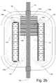
- FIG. 2 cis a schematic section illustration of the power system of FIG. 1 b where the coil assembly is at a second position.
- FIG. 1 athere is presented a partial sectional isometric drawing of one embodiment of an electric power system 100 , such as an electric power generator or electric motor.
- an electric power system 100such as an electric power generator or electric motor.
- the plurality of magnetsare positioned within an exterior retaining ring 108 .
- the retaining ring 108is structurally sufficient to overcome the magnetic repulsive forces of the magnetic devices and maintain the radial arrangement of the magnets 102 .
- the retaining ring 108may be formed from a variety of materials.
- the retaining ring 108is formed from iron or a relatively soft iron alloy.
- theymay be formed from non-ferrous metal if structural strength is the primary consideration for the use of the retaining ring.
- FIG. 1 billustrates a top view of one embodiment of the magnetic disc 110 which may be used by the system 100 .
- FIG. 1 billustrates the outer retaining ring 108 , and the plurality of magnets 102 arranged in a radial or circular pattern.
- an inner retaining ring 106is also positioned about the longitudinal axis 104 .
- the inner retaining ring 106may be formed from iron and may be added to strengthen the magnetic flux strength of the system or for additional structural stability.
- each individual magnet of the plurality of magnets 102for instance magnet 102 a is orientated such that a magnetic pole faces inward towards the longitudinal or center axis of the magnetic disc 110 . Consequently, the opposing pole faces outward from the center of the magnetic disc 110 .
- the magnets 102 aeach have their north poles facing inward and their south poles facing outward.
- the magnets 102 amay be made of out any suitable magnetic material, such as: neodymium, Alnico alloys, ceramic permanent magnets, or even electromagnets.
- the individual magnets 102 aare held in place by an appropriate securement method known in the art, such as casting the magnets in resin, epoxying the magnets to a substrate, or by securing the magnets with mechanical fasteners.
- fastening features 112such as screw holes, threaded studs, or interlocking rings are formed on the exterior of the outer retaining ring 108 to allow the magnetic disc 110 to be fastened to other magnetic discs or a support structure (not shown).
- FIG. 1 athere is shown a plurality of modular magnetic discs 110 a - 110 d which forms a magnetic cylinder 114 (a portion of which is cut away in FIG. 1 a ). Although four magnetic discs 110 a - 110 d are illustrated, depending on the required magnetic flux field strength of the magnetic cylinder 114 , any number of magnetic discs could be used to assemble the magnetic cylinder 114 .
- the power system 100is modular in this respect and multiple magnetic discs 110 may be added to meet specific requirements.
- the magnetic cylinder 114may comprise a single inner confinement ring, a single outer confinement ring, and predetermined number of rows of the plurality of magnets 102 positioned in a radial manner.
- the magnetic cylinder 114When incorporated into the system 100 , the magnetic cylinder 114 is concentrically centered about a core 116 having the same longitudinal axis 104 as the magnetic cylinder 114 .
- the core 114is elongated and rod-like in shape.
- the core 114may be made from iron or a ferrite compound with similar magnetic properties.
- the core 116becomes a carrier for some of the counter emf flux generated during the power generation process.
- a plurality of yolks 118 a - 118 care coupled to the core 116 at each end such that the yolks surround the magnetic cylinder 114 .
- the yolks 118 a - 118 cmay be coupled to the magnetic cylinder 114 and provide structural support for the magnetic cylinder.
- the yolks 118 a - 118 c and the core 116together create a carrier for counter emf forces to be routed away from the power generation area inside the magnetic cylinder 114 .
- the casing itselfmay serve as a yolk and/or structural support.
- the yolks 118 a - 118 cmay serve the dual function for providing structural support for an enclosure (not shown).
- the yolks 118 a - 118 cmay be formed from iron, a ferrite compound or an alloy having similar magnetic properties.
- each individual coil 120 a in the coil assemblyis made from a conductive material, such as copper (or a similar alloy) wire and is constructed using conventional winding techniques known in the art.
- the individual coils 120 aare essentially cylindrical in shape being wound around a coil core (not shown) having a center opening sized to allow the coils to freely travel longitudinally along the core 116 .
- the coil coremay be made from a Teflon, Teflon laminate, bakelight, or other suitable material to allow the coil to travel longitudinally along the stationary core 116 .
- coils 120 aAlthough a particular number of coils 120 a are illustrated in FIG. 1 a , depending on the power requirements, any number of coils could be used to assemble the coil assembly 120 .
- the systemis modular in this respect and individual coils may be added to the system to meet specific power requirements.
- the conductors or wires (not shown) in each of the coils 120 aterminate into separate commutator segments, for instance one conductor terminates into commutator segment 122 a .
- the commutator segmentsmay be formed from a material designed to produce minimal friction and low resistance, for instance a conductive copper alloy. The combination of commutator segments and coils allow the coils to be connected in series through the commutator segments. In yet other embodiments, current may be transferred through the use of flexible conductors.
- FIG. 1 cis a conceptualized illustration of the electrical communication between a portion of the coils and commutator segments.
- three individual coils 120 a - 120 care shown wound around a portion of the core 116 .
- Each end of the coilsis coupled to a commutator segment.
- the first or upper end 124 a of the coil 120 ais coupled to the commutator segment 122 a .
- the second or lower end 124 b of the coil 120 ais coupled to the commutator segment 122 b .
- the first or upper end 124 c of the coil 120 bis coupled to the commutator segment 122 b and the lower end 124 d is coupled to the commutator segment 122 c .
- the first or upper end 124 e of the coil 120 cis coupled to the commutator segment 122 c and the lower end 124 f is coupled to the commutator segment 122 d .
- the commutator segments 122 a - 122 delectrically connect the coils 120 a - 120 c in series to each other.
- there are parallel coil coupling combined with switching circuitry (not shown)which selectively utilizes individual coils within the coil assembly 120 . Selective utilization allows the effective removal of coils that are not actively producing power resulting in more efficient operation.
- each commutator segmentsuch as the commutator segment 122 b of FIG. 1 c , would actually be split into two commutator segments which would electrically couple together when the respective coils are assembled to form the coil assembly 120 .
- FIG. 1 dSuch an embodiment is illustrated in FIG. 1 d.
- each termination end of the coilsis coupled to a separate commutator segment.
- the first or upper end 124 a of the coil 120 ais coupled to the commutator segment 123 a .
- the second or lower end 124 b of the coil 120 ais coupled to the commutator segment 123 b .
- the first or upper end 124 c of the coil 120 bis coupled to the commutator segment 123 c and the lower end 124 d is coupled to the commutator segment 123 d , etc.
- the commutator segment 123 bis electrically coupled to commutator segment 123 c .
- commutator segment 123 dis electrically coupled to commutator segment 123 e .
- each commutator segment 122 ais electrically coupled to the commutator segment adjacent to it so that electric current flows between the commutator segments.
- the commutator assembly 122is in electrical communication with a plurality of brushes 126 a - 126 b .
- the brushes 126 a and 126 bare electrically coupled to conductors (not shown) which allow electrical current to flow into or out of the coil assembly 120 .
- conductorsnot shown
- two brushes 126 a and 126 bare shown in FIG. 1 a , other embodiments, may have any number of brushes positioned anywhere along the commutator assembly 122 .
- the permanent magnets 112 agenerate magnetic forces which can be visualized as magnetic flux lines.
- the flux lineswill form particular patterns.
- the shape, direction, and orientation of the flux linesdepend on factors such as the use of an interior retaining ring, or the use of ferrous or non-ferrous metallic end plate, or an end plate consisting of magnetic assemblies oriented to force the lines of flux out of one end of the magnetic cylinder.
- FIG. 2 ais a schematic section view of the magnetic cylinder 114 .
- the magnetic cylinder 114comprises a plurality of individual stacked magnetic discs, such as 10 magnetic discs 110 of FIG. 1 b .
- Each magnetic disc 110comprises a plurality of magnets radially arranged about an axis 104 as illustrated in FIG. 1 b and FIG. 2 a .
- the magnetic flux forceswill tend to develop a stacking effect and will split into groups of similar orientation.
- the magnetic flux forces or lines generated by the magnet 102 atends to exit its interior face (or its north pole), circle around the top end (or closest end) of the cylinder 114 and return to the south pole or exterior face of the magnet 102 a .
- the magnetic flux forcesare illustrated by the elliptical lines 128 which are meant to conceptually illustrate the magnetic flux forces and are not meant to be an actual depiction of the flux forces.
- the magnetic flux forces generated by magnet 102 btends to exit its interior face (or its north pole), circle around the top end of the cylinder 114 and return to the south pole or exterior face of the magnet 102 a .
- the magnetic flux forcestend to follow this pattern for each successive disc until the longitudinal halfway point of the magnetic cylinder 114 is reached.
- the magnetic flux forces for each successive magnetwill change its direction and exit its interior face (or its north pole), circle around the bottom end (i.e., the closest end) of the cylinder 114 and return to the south pole or exterior face of the respective magnet.
- the flux produced by the magnetshave an unobstructed path to exit through the center of the cylinder 114 and return to its opposing pole on the exterior of the cylinder.
- the individual magnetic discs 110can be coupled together to produce a field flux strength that is appropriate for the power rating of the system.
- the field flux strength and power ratingare based on conventional factors, such as Gauss strength, turns and size of coil conductors and speed at which core is moved.
- the poles of the magnetsare usually aligned longitudinally.
- the field flux lineswill “hug” or closely follow the surface of the magnets.
- the clearancesmust be extremely tight in order to be able to act on these lines of force.
- arranging the magnetic discs in this mannercreates a first stacked plurality of magnetic flux forces 128 about a first or top portion of the magnetic cylinder 114 such that each magnetic flux force travels between a first pole of an inward face of magnet of the magnetic cylinder, around a first or top end of the magnetic cylinder 114 , and back to a second pole of an exterior face of the magnet.
- This arrangementalso creates a second stacked plurality of magnetic flux forces 130 about a second portion of the magnetic cylinder 114 such that each magnetic flux force travels between a first pole of an inward face of magnet of the magnetic cylinder, around a second or bottom end of the magnetic cylinder, and back to a second pole of an exterior face of the magnet.
- FIGS. 2 b and 2 cthere are schematic illustrations of the power system 100 incorporating the magnetic cylinder 114 of FIG. 2 a .
- the core 116As previously discussed in relation to FIG. 1 a , there is the core 116 , the yolks 118 a - 118 b , and a coil assembly 120 .
- the core assembly 120comprises three individual coils 120 a , 120 b , and 120 c .
- the commutator assembly 122is positioned on one side of the coil assembly 120 .
- the brushes 126 a and 126 bcommunicate with the coil assembly 120 during a portion of the stroke.
- FIG. 2 arepresents the power system 100 when the coil assembly 120 is in a first position or at the top of the stroke.
- FIG. 2 brepresents the power system 100 when the coil assembly is at a second position or the bottom of the stroke.
- the coil assembly 120is designed to slidingly move longitudinally along the core 116 between the top of the stroke ( FIG. 2 b ) and the bottom of the stroke ( FIG. 2 c ).
- the core assemblywould be coupled to a shaft (not shown) of a power source, such as a wind mill or wave buoy.
- the coil assembly 120is coupled to the core 116 and the core 116 drives the coil assembly 120 between the top of the stroke and the bottom of the stroke.
- the core 116is coupled to a power source.
- the coil assembly 120When connected to a power source, the coil assembly 120 moves from the top of the stroke to the bottom of the stroke and passes through the first stacked plurality of magnetic flux forces 128 in a center area 132 of the magnetic cylinder 114 to produce electric current in the individual coils. As the coil assembly continues to move towards the second position, the coil assembly passes through the first stacked plurality of magnetic flux forces 128 and enters the magnetic stacked flux forces 130 until it reaches the end of the stroke at the second position represented by FIG. 2 c.
- the core 116acts as a carrier and creates a flux path through the center of the coil. Once the flux path is in the core 116 , the yolks 118 a and 118 b divert and carry the flux forces around the magnetic cylinder 114 and back into the core—completing the path. The magnetic forces are induced on the outside of the coil (where the opposing flux created from current flow is weakest).
- the current produced in the coil assembly 120is then routed along the commutator assembly 122 to the brushes 126 a and 126 b which are coupled to conductors (not shown) which carry the current out of the system.
- modular concept of magnetic discs and modular coilsenables additional choices in power output configuration during manufacturing by simply stacking components rather than having to design a generating machine for a specific horsepower or other power output.
- a method of producing an electric currentcomprising: creating magnetic flux forces generally transverse to a face of a magnet facing a center of a cylinder, moving a coil of wound conductive material partially through the center opening of the cylinder to produce the electric current and, routing resistive forces generated from the moving coil through an iron core, wherein the first coil is positioned concentrically about a first portion of the core, and further routing the resistive forces around the cylinder; further comprising adjusting the longitudinal position of the iron core with respect to the longitudinal axis of the magnetic cylinder to achieve a magnetic and gravitational equilibrium the magnetic cylinder and the iron core.
Landscapes
- Engineering & Computer Science (AREA)
- Power Engineering (AREA)
- Permanent Field Magnets Of Synchronous Machinery (AREA)
Abstract
Description
Claims (3)
Priority Applications (2)
| Application Number | Priority Date | Filing Date | Title |
|---|---|---|---|
| US16/810,920US11218067B2 (en) | 2010-07-22 | 2020-03-06 | Method and apparatus for power generation |
| US17/567,299US20220190700A1 (en) | 2010-07-22 | 2022-01-03 | Method and apparatus for power generation |
Applications Claiming Priority (4)
| Application Number | Priority Date | Filing Date | Title |
|---|---|---|---|
| US36671510P | 2010-07-22 | 2010-07-22 | |
| US13/185,109US9325232B1 (en) | 2010-07-22 | 2011-07-18 | Method and apparatus for power generation |
| US15/080,581US10587178B2 (en) | 2010-07-22 | 2016-03-24 | Method and apparatus for power generation |
| US16/810,920US11218067B2 (en) | 2010-07-22 | 2020-03-06 | Method and apparatus for power generation |
Related Parent Applications (1)
| Application Number | Title | Priority Date | Filing Date |
|---|---|---|---|
| US15/080,581DivisionUS10587178B2 (en) | 2010-07-22 | 2016-03-24 | Method and apparatus for power generation |
Related Child Applications (1)
| Application Number | Title | Priority Date | Filing Date |
|---|---|---|---|
| US17/567,299ContinuationUS20220190700A1 (en) | 2010-07-22 | 2022-01-03 | Method and apparatus for power generation |
Publications (2)
| Publication Number | Publication Date |
|---|---|
| US20200274433A1 US20200274433A1 (en) | 2020-08-27 |
| US11218067B2true US11218067B2 (en) | 2022-01-04 |
Family
ID=55754781
Family Applications (4)
| Application Number | Title | Priority Date | Filing Date |
|---|---|---|---|
| US13/185,109Active2034-09-06US9325232B1 (en) | 2010-07-22 | 2011-07-18 | Method and apparatus for power generation |
| US15/080,581Active2032-09-12US10587178B2 (en) | 2010-07-22 | 2016-03-24 | Method and apparatus for power generation |
| US16/810,920ActiveUS11218067B2 (en) | 2010-07-22 | 2020-03-06 | Method and apparatus for power generation |
| US17/567,299AbandonedUS20220190700A1 (en) | 2010-07-22 | 2022-01-03 | Method and apparatus for power generation |
Family Applications Before (2)
| Application Number | Title | Priority Date | Filing Date |
|---|---|---|---|
| US13/185,109Active2034-09-06US9325232B1 (en) | 2010-07-22 | 2011-07-18 | Method and apparatus for power generation |
| US15/080,581Active2032-09-12US10587178B2 (en) | 2010-07-22 | 2016-03-24 | Method and apparatus for power generation |
Family Applications After (1)
| Application Number | Title | Priority Date | Filing Date |
|---|---|---|---|
| US17/567,299AbandonedUS20220190700A1 (en) | 2010-07-22 | 2022-01-03 | Method and apparatus for power generation |
Country Status (1)
| Country | Link |
|---|---|
| US (4) | US9325232B1 (en) |
Families Citing this family (8)
| Publication number | Priority date | Publication date | Assignee | Title |
|---|---|---|---|---|
| US9325232B1 (en) | 2010-07-22 | 2016-04-26 | Linear Labs, Inc. | Method and apparatus for power generation |
| US8922070B2 (en)* | 2010-10-22 | 2014-12-30 | Linear Labs, Inc. | Magnetic motor |
| WO2014036567A1 (en) | 2012-09-03 | 2014-03-06 | Linear Labs, Inc. | An improved transducer and method of operation |
| KR101854034B1 (en)* | 2016-08-30 | 2018-05-02 | 세메스 주식회사 | Contactless driving module and transfer apparatus having the same |
| US20210044191A1 (en)* | 2019-08-07 | 2021-02-11 | Linear Labs, Inc. | Linear machine |
| US11437886B2 (en) | 2019-11-06 | 2022-09-06 | Positive Energy, a Gravity and Motion Company, Inc. | Methods and apparatus for kinetic energy harvesting |
| US11043889B2 (en)* | 2019-11-06 | 2021-06-22 | Positive Energy, a Gravity and Motion Company, Inc. | Methods and apparatus for kinetic energy harvesting |
| TWI880606B (en)* | 2024-01-24 | 2025-04-11 | 國立臺灣海洋大學 | Electromechanical energy conversion apparatus and ocean wave power generation system having the same |
Citations (107)
| Publication number | Priority date | Publication date | Assignee | Title |
|---|---|---|---|---|
| US1349100A (en) | 1918-05-04 | 1920-08-10 | William T Reynolds | Dynamo-electric machine |
| US3135880A (en) | 1958-11-10 | 1964-06-02 | Tronics Corp | Linear motion electromagnetic machines |
| US3656015A (en) | 1971-05-04 | 1972-04-11 | Information Magnetics Corp | Combined linear motor and carriage |
| US3666977A (en) | 1970-09-10 | 1972-05-30 | Sperry Rand Corp | Linear positioner |
| US3740594A (en) | 1971-08-30 | 1973-06-19 | Fema Corp | Permanent-electromagnetic reciprocating device |
| US3751693A (en) | 1972-02-14 | 1973-08-07 | Diablo Systems Inc | Moving coil motor with no stray flux |
| US3939367A (en) | 1975-08-04 | 1976-02-17 | Ramirez Juan A | Magnetically actuated reciprocating engine |
| US3949249A (en) | 1974-08-02 | 1976-04-06 | L. Z. Reece, Et Al | Electro-magnetic reciprocating motor |
| US3984706A (en) | 1971-12-27 | 1976-10-05 | Fujitsu Ltd. | Electromagnetic actuator for voice coil |
| US4217507A (en) | 1979-01-08 | 1980-08-12 | The Singer Company | Linear motor |
| US4243899A (en) | 1979-03-08 | 1981-01-06 | The Singer Company | Linear motor with ring magnet and non-magnetizable end caps |
| US4317058A (en) | 1979-12-28 | 1982-02-23 | Troy L. Cook | Electro-magnetic reciprocating engine |
| US4318038A (en) | 1978-11-15 | 1982-03-02 | Nippon Electric Co., Ltd. | Moving-coil linear motor |
| US4415821A (en) | 1982-05-10 | 1983-11-15 | Kollmorgen Technologies Corporation | Dynamic magnetic preload bearing structure for a linear motor |
| JPS58204761A (en) | 1982-05-25 | 1983-11-29 | Takahashi Yoshiteru | Linear drive device |
| US4445798A (en) | 1980-02-15 | 1984-05-01 | Nippon Electric Co., Ltd. | Serial printer with a linear motor printer carriage |
| US4518882A (en) | 1982-07-12 | 1985-05-21 | Nippon Soken, Inc. | Electromagnetic linear driving device |
| US4555797A (en) | 1983-09-15 | 1985-11-26 | U.S. Philips Corporation | Hybrid loudspeaker system for converting digital signals to acoustic signals |
| US4785210A (en) | 1987-05-18 | 1988-11-15 | Sony Corporation | Linear motor |
| US4845392A (en) | 1983-03-10 | 1989-07-04 | Eaton Corporation | Hybrid linear actuator |
| US4858452A (en) | 1986-12-22 | 1989-08-22 | United Technologies Electro Systems, Inc. | Non-commutated linear motor |
| US5099158A (en) | 1989-03-07 | 1992-03-24 | Aura Systems, Inc. | Electromagnetic actuator |
| US5177383A (en) | 1991-02-28 | 1993-01-05 | Samsung Electro-Mechanics Co., Ltd. | Voice coil motor |
| US5220223A (en) | 1990-02-16 | 1993-06-15 | Walter Mehnert | Dynamoelectric machine |
| US5231336A (en) | 1992-01-03 | 1993-07-27 | Harman International Industries, Inc. | Actuator for active vibration control |
| US5245238A (en) | 1991-04-30 | 1993-09-14 | Sundstrand Corporation | Axial gap dual permanent magnet generator |
| EP0566959A1 (en) | 1992-04-24 | 1993-10-27 | Cosmoss Energy Japan Company Limited | Magnet compressor and power extracting apparatus making use of the same |
| US5434458A (en) | 1991-08-05 | 1995-07-18 | Aura Systems, Inc. | Voice coil actuator |
| US5440183A (en)* | 1991-07-12 | 1995-08-08 | Denne Developments, Ltd. | Electromagnetic apparatus for producing linear motion |
| GB2286928A (en) | 1994-02-25 | 1995-08-30 | Solomos Foti Solomou | Magnetic piston motor |
| US5539262A (en) | 1994-08-03 | 1996-07-23 | Aura Systems, Inc. | Axially focused radial magnet voice coil actuator |
| JPH0918992A (en) | 1995-06-28 | 1997-01-17 | Sharp Corp | Speaker unit |
| US5631505A (en) | 1995-04-13 | 1997-05-20 | Eastman Kodak Company | Moving coil linear actuator |
| US5757093A (en) | 1997-03-13 | 1998-05-26 | Susliaev; Konstantin | Electromagnetically powered engine |
| US5777403A (en) | 1996-07-30 | 1998-07-07 | Nikon Corporation | Voice coil motor with air guide and air bellows |
| US5808379A (en) | 1997-05-16 | 1998-09-15 | Kulicke And Soffa Industries, Inc. | Bi-directional linear drive motor |
| US5818131A (en) | 1997-05-13 | 1998-10-06 | Zhang; Wei-Min | Linear motor compressor and its application in cooling system |
| US5821710A (en) | 1996-09-30 | 1998-10-13 | Hitachi Metals, Ltd. | Brushless motor having permanent magnets |
| US5825113A (en) | 1995-07-05 | 1998-10-20 | Electric Power Research Institute, Inc. | Doubly salient permanent magnet machine with field weakening (or boosting) capability |
| DE19839464A1 (en) | 1998-08-29 | 2000-03-09 | Contitech Formteile Gmbh | Electrodynamic actuator with oscillating spring-mass system |
| US6049146A (en) | 1995-12-25 | 2000-04-11 | Takara; Muneaki | Electromagnetic piston engine |
| US6066998A (en) | 1996-09-12 | 2000-05-23 | Massachusetts Institute Of Technology | Magnetic actuator with long travel in one direction |
| JP2000152558A (en) | 1998-11-04 | 2000-05-30 | Hideo Irisa | Motor |
| US6075297A (en) | 1995-12-20 | 2000-06-13 | Minolta Co., Ltd. | Linear motor |
| US6097125A (en) | 1997-04-29 | 2000-08-01 | Lg Electronics Inc. | Magnet fixed structure for compressor motor |
| WO2000046910A1 (en) | 1999-02-05 | 2000-08-10 | Advanced Technologies, L.L.C. | Linear electric machine |
| US6163091A (en) | 1999-07-06 | 2000-12-19 | Nikon Corporation | Linear motor with commutation coil |
| US6278204B1 (en) | 1999-06-18 | 2001-08-21 | Eugene Roland Frenette | Method of converting internal combustion engine into electrically driven engine |
| EP1191673A2 (en) | 2000-09-14 | 2002-03-27 | Denso Corporation | Compact and reliable structure of multi-rotor synchronous machine |
| US6365993B1 (en) | 2000-04-07 | 2002-04-02 | Eaton Corporation | Round linear actuator utilizing flat permanent magnets |
| US6462430B1 (en) | 1999-09-01 | 2002-10-08 | Hitachi, Ltd. | Hybrid car and dynamo-electric machine |
| JP2002369473A (en) | 2001-06-07 | 2002-12-20 | Nippon Steel Corp | Synchronous motor using permanent magnet |
| US20030102723A1 (en) | 2001-10-05 | 2003-06-05 | Canon Kabushiki Kaisha | Linear motor, stage apparatus, and exposure apparatus |
| US20040155536A1 (en) | 2000-12-07 | 2004-08-12 | Cordiale Frank J. | Brushless electric motor |
| US20040194286A1 (en) | 2001-08-06 | 2004-10-07 | Mitchell Rose | Method of making a ring-magnet assembly |
| US20040239199A1 (en) | 2003-05-30 | 2004-12-02 | Wisconsin Alumni Research Foundation | Dual-rotor, radial-flux, toroidally-wound, permanent-magnet machine |
| US20040245861A1 (en) | 2003-06-03 | 2004-12-09 | Canon Kabushiki Kaisha | Linear motor, stage device having this linear motor, exposure device, and device manufacturing method |
| US20050046282A1 (en) | 2003-08-27 | 2005-03-03 | Sanyo Denki Co., Ltd. | Movable assembly for cylinder type linear motor |
| US6952060B2 (en) | 2001-05-07 | 2005-10-04 | Trustees Of Tufts College | Electromagnetic linear generator and shock absorber |
| US20050285467A1 (en)* | 2004-06-29 | 2005-12-29 | Nissan Motor Co., Ltd. | Rotor of axial gap motor and method of producing same |
| US20060055251A1 (en)* | 2004-09-15 | 2006-03-16 | Shun-Hsing Hsian | Tubular linear motor for electrical discharge machine |
| US7078833B2 (en) | 2002-05-31 | 2006-07-18 | Minebea Co., Ltd. | Force motor with increased proportional stroke |
| US20060261680A1 (en) | 2005-05-04 | 2006-11-23 | Samsung Electro-Mechanics Co., Ltd. | Vibration type tilting device and image projection device having the tilting device |
| DE202007001534U1 (en) | 2007-02-02 | 2007-04-26 | Liu, Te-En | Driving force generating device for use in motor vehicle, has drive unit comprising magnet, and magnet unit comprising another two magnets for covering respective ends of housing, where drive unit is movable between two positions |
| KR100770590B1 (en) | 2004-11-11 | 2007-10-29 | 주성대학산학협력단 | Earphone Speakers & Earphones |
| US7288862B2 (en) | 2003-12-30 | 2007-10-30 | Lg Electronics Inc. | Reciprocating motor |
| WO2008006906A1 (en) | 2006-07-14 | 2008-01-17 | Nexxtdrive Limited | Permanent magnet rotating electric machine |
| US20080088195A1 (en)* | 2006-10-16 | 2008-04-17 | Dooley Kevin A | Outside rotor electric machine |
| US7439640B2 (en) | 2005-07-25 | 2008-10-21 | Seiko Epson Corporation | Electromagnetic actuator using permanent magnets |
| US20080308199A1 (en) | 2005-08-09 | 2008-12-18 | Christian Locker | Method and Device For the Technique of Cold Microforging Any Freely Formed 3-D Surfaces |
| US7476991B2 (en) | 2007-04-27 | 2009-01-13 | Elek Engine Corporation | Linear electromagnetic driving module and linear electromagnetic driving device |
| CN201206539Y (en) | 2008-05-28 | 2009-03-11 | 浙江大学 | Portable straight-line air compressor |
| US20090102305A1 (en) | 2005-06-29 | 2009-04-23 | Union Plastic (Hangzhou) Machinery Co., Ltd. | Brushless electric machine |
| US7528561B2 (en) | 2006-02-14 | 2009-05-05 | Fanuc Ltd | Linear drive apparatus |
| US7554241B2 (en) | 2006-03-31 | 2009-06-30 | Rao Dantam K | Three-gapped motor with outer rotor and stationary shaft |
| US7579722B1 (en) | 2005-08-16 | 2009-08-25 | Sean Borchert | Torque harnessing electric engine |
| US20090251021A1 (en)* | 2006-06-06 | 2009-10-08 | Hirofumi Atarashi | Motor and motor control device |
| US20090261675A1 (en) | 2008-04-19 | 2009-10-22 | Hsien-Wei Hsiao | High efficient magnetic energy shifting device |
| US20100001592A1 (en) | 2007-02-26 | 2010-01-07 | Olympus Medical Systems Corp. | Magnetic actuator, magnetic actuator operating method, and capsule endoscope using the same |
| US20100164422A1 (en) | 2008-12-26 | 2010-07-01 | Hitachi, Ltd. | Variable magnetic flux electric rotary machine |
| JP2010166741A (en) | 2009-01-17 | 2010-07-29 | Nissan Motor Co Ltd | Rotating electrical machine |
| EP2346149A1 (en) | 2008-11-05 | 2011-07-20 | Mitsubishi Heavy Industries, Ltd. | Linear actuator |
| US20110273789A1 (en) | 2010-05-05 | 2011-11-10 | Digital Imaging Systems Gmbh | Linear motor with integral position sensor |
| US8074579B1 (en) | 2005-08-22 | 2011-12-13 | Dumitru Bojiuc | Magnetically levitated transport system |
| DE102010024344A1 (en) | 2010-06-18 | 2011-12-22 | Ulrich Clauss | Direct current machine e.g. generator, has armature winding enclosing annular magnetic yoke as annular coil such that force- and movement effects occur between winding and permanent magnets or pole pieces |
| US8110950B2 (en) | 2003-12-09 | 2012-02-07 | Toshiba Kikai Kabushiki Kaisha | Coreless linear motor having a non-magnetic reinforcing member |
| US20120098357A1 (en) | 2010-10-22 | 2012-04-26 | Hunstable Fred E | Magnetic motor |
| US20120286616A1 (en) | 2010-03-08 | 2012-11-15 | Panasonic Corporation | Motor |
| US20130026279A1 (en) | 2010-04-12 | 2013-01-31 | Mehmet Agrikli | Direct traverse device |
| US8441158B2 (en) | 2010-02-16 | 2013-05-14 | Siemens Aktiengesellschaft | Linear motor with reduced force ripple |
| US20130249343A1 (en) | 2012-03-20 | 2013-09-26 | Linear Labs, Inc. | Dc electric motor/generator with enhanced permanent magnet flux densities |
| RU140346U1 (en) | 2014-01-13 | 2014-05-10 | Ян Владимирович Оробинский | ELECTRIC GENERATOR |
| US20140191612A1 (en) | 2013-01-09 | 2014-07-10 | Eurocopter | Electric machine with multiple air gaps and a 3d magnetic flux |
| US20150137647A1 (en) | 2012-03-20 | 2015-05-21 | Linear Labs, Inc. | Brushless electric motor/generator |
| US20150171694A1 (en) | 2013-02-20 | 2015-06-18 | Raymond James Walsh | Halbach motor and generator |
| US9219962B2 (en) | 2012-09-03 | 2015-12-22 | Linear Labs, Inc. | Transducer and method of operation |
| US20160020652A1 (en) | 2012-03-20 | 2016-01-21 | Linear Labs, Inc. | Brushless Electric Motor/Generator |
| US9312058B2 (en) | 2010-10-16 | 2016-04-12 | Msm Krystall Gbr | Electromagnetic linear actuator |
| US20160112805A1 (en) | 2012-09-03 | 2016-04-21 | Linear Labs, Inc. | Transducer and method of operation |
| US9325232B1 (en) | 2010-07-22 | 2016-04-26 | Linear Labs, Inc. | Method and apparatus for power generation |
| WO2017008085A1 (en) | 2015-07-09 | 2017-01-12 | Linear Labs, Inc. | An improved electric linear motor/generator |
| US9947448B2 (en) | 2013-05-29 | 2018-04-17 | Active Signal Technologies, Inc. | Electromagnetic opposing field actuators |
| US10125814B2 (en) | 2013-10-24 | 2018-11-13 | Raymond James Walsh | Passive magnetic bearing |
| US20190103793A1 (en) | 2013-02-20 | 2019-04-04 | Raymond J. Walsh | Magnetic-drive axial-flow fluid displacement pump and turbine |
| US10340768B2 (en) | 2013-02-20 | 2019-07-02 | Raymond James Walsh | Flywheel energy storage device with induction torque transfer |
| US20190312497A1 (en) | 2017-12-08 | 2019-10-10 | Raymond James Walsh | Ferromagnetic core toroid motor and generator |
| US20210044191A1 (en) | 2019-08-07 | 2021-02-11 | Linear Labs, Inc. | Linear machine |
- 2011
- 2011-07-18USUS13/185,109patent/US9325232B1/enactiveActive
- 2016
- 2016-03-24USUS15/080,581patent/US10587178B2/enactiveActive
- 2020
- 2020-03-06USUS16/810,920patent/US11218067B2/enactiveActive
- 2022
- 2022-01-03USUS17/567,299patent/US20220190700A1/ennot_activeAbandoned
Patent Citations (132)
| Publication number | Priority date | Publication date | Assignee | Title |
|---|---|---|---|---|
| US1349100A (en) | 1918-05-04 | 1920-08-10 | William T Reynolds | Dynamo-electric machine |
| US3135880A (en) | 1958-11-10 | 1964-06-02 | Tronics Corp | Linear motion electromagnetic machines |
| US3666977A (en) | 1970-09-10 | 1972-05-30 | Sperry Rand Corp | Linear positioner |
| US3656015A (en) | 1971-05-04 | 1972-04-11 | Information Magnetics Corp | Combined linear motor and carriage |
| US3740594A (en) | 1971-08-30 | 1973-06-19 | Fema Corp | Permanent-electromagnetic reciprocating device |
| US3984706A (en) | 1971-12-27 | 1976-10-05 | Fujitsu Ltd. | Electromagnetic actuator for voice coil |
| US3751693A (en) | 1972-02-14 | 1973-08-07 | Diablo Systems Inc | Moving coil motor with no stray flux |
| US3949249A (en) | 1974-08-02 | 1976-04-06 | L. Z. Reece, Et Al | Electro-magnetic reciprocating motor |
| US3939367A (en) | 1975-08-04 | 1976-02-17 | Ramirez Juan A | Magnetically actuated reciprocating engine |
| US4318038A (en) | 1978-11-15 | 1982-03-02 | Nippon Electric Co., Ltd. | Moving-coil linear motor |
| US4217507A (en) | 1979-01-08 | 1980-08-12 | The Singer Company | Linear motor |
| US4243899A (en) | 1979-03-08 | 1981-01-06 | The Singer Company | Linear motor with ring magnet and non-magnetizable end caps |
| US4317058A (en) | 1979-12-28 | 1982-02-23 | Troy L. Cook | Electro-magnetic reciprocating engine |
| US4445798A (en) | 1980-02-15 | 1984-05-01 | Nippon Electric Co., Ltd. | Serial printer with a linear motor printer carriage |
| US4415821A (en) | 1982-05-10 | 1983-11-15 | Kollmorgen Technologies Corporation | Dynamic magnetic preload bearing structure for a linear motor |
| JPS58204761A (en) | 1982-05-25 | 1983-11-29 | Takahashi Yoshiteru | Linear drive device |
| US4518882A (en) | 1982-07-12 | 1985-05-21 | Nippon Soken, Inc. | Electromagnetic linear driving device |
| US4845392A (en) | 1983-03-10 | 1989-07-04 | Eaton Corporation | Hybrid linear actuator |
| US4555797A (en) | 1983-09-15 | 1985-11-26 | U.S. Philips Corporation | Hybrid loudspeaker system for converting digital signals to acoustic signals |
| US4858452A (en) | 1986-12-22 | 1989-08-22 | United Technologies Electro Systems, Inc. | Non-commutated linear motor |
| US4785210A (en) | 1987-05-18 | 1988-11-15 | Sony Corporation | Linear motor |
| US5099158A (en) | 1989-03-07 | 1992-03-24 | Aura Systems, Inc. | Electromagnetic actuator |
| US5220223A (en) | 1990-02-16 | 1993-06-15 | Walter Mehnert | Dynamoelectric machine |
| US5177383A (en) | 1991-02-28 | 1993-01-05 | Samsung Electro-Mechanics Co., Ltd. | Voice coil motor |
| US5245238A (en) | 1991-04-30 | 1993-09-14 | Sundstrand Corporation | Axial gap dual permanent magnet generator |
| US5440183A (en)* | 1991-07-12 | 1995-08-08 | Denne Developments, Ltd. | Electromagnetic apparatus for producing linear motion |
| US5434458A (en) | 1991-08-05 | 1995-07-18 | Aura Systems, Inc. | Voice coil actuator |
| US5231336A (en) | 1992-01-03 | 1993-07-27 | Harman International Industries, Inc. | Actuator for active vibration control |
| EP0566959A1 (en) | 1992-04-24 | 1993-10-27 | Cosmoss Energy Japan Company Limited | Magnet compressor and power extracting apparatus making use of the same |
| GB2286928A (en) | 1994-02-25 | 1995-08-30 | Solomos Foti Solomou | Magnetic piston motor |
| US5539262A (en) | 1994-08-03 | 1996-07-23 | Aura Systems, Inc. | Axially focused radial magnet voice coil actuator |
| US5631505A (en) | 1995-04-13 | 1997-05-20 | Eastman Kodak Company | Moving coil linear actuator |
| JPH0918992A (en) | 1995-06-28 | 1997-01-17 | Sharp Corp | Speaker unit |
| US5825113A (en) | 1995-07-05 | 1998-10-20 | Electric Power Research Institute, Inc. | Doubly salient permanent magnet machine with field weakening (or boosting) capability |
| US6075297A (en) | 1995-12-20 | 2000-06-13 | Minolta Co., Ltd. | Linear motor |
| US6049146A (en) | 1995-12-25 | 2000-04-11 | Takara; Muneaki | Electromagnetic piston engine |
| US5777403A (en) | 1996-07-30 | 1998-07-07 | Nikon Corporation | Voice coil motor with air guide and air bellows |
| US6066998A (en) | 1996-09-12 | 2000-05-23 | Massachusetts Institute Of Technology | Magnetic actuator with long travel in one direction |
| US5821710A (en) | 1996-09-30 | 1998-10-13 | Hitachi Metals, Ltd. | Brushless motor having permanent magnets |
| US5757093A (en) | 1997-03-13 | 1998-05-26 | Susliaev; Konstantin | Electromagnetically powered engine |
| US6097125A (en) | 1997-04-29 | 2000-08-01 | Lg Electronics Inc. | Magnet fixed structure for compressor motor |
| US5818131A (en) | 1997-05-13 | 1998-10-06 | Zhang; Wei-Min | Linear motor compressor and its application in cooling system |
| US5808379A (en) | 1997-05-16 | 1998-09-15 | Kulicke And Soffa Industries, Inc. | Bi-directional linear drive motor |
| DE19839464A1 (en) | 1998-08-29 | 2000-03-09 | Contitech Formteile Gmbh | Electrodynamic actuator with oscillating spring-mass system |
| JP2000152558A (en) | 1998-11-04 | 2000-05-30 | Hideo Irisa | Motor |
| US20010007400A1 (en) | 1999-02-05 | 2001-07-12 | Wayne Griswold | Linear electric machine |
| US6242823B1 (en)* | 1999-02-05 | 2001-06-05 | Wayne Griswold | Linear electric machine |
| WO2000046910A1 (en) | 1999-02-05 | 2000-08-10 | Advanced Technologies, L.L.C. | Linear electric machine |
| US6278204B1 (en) | 1999-06-18 | 2001-08-21 | Eugene Roland Frenette | Method of converting internal combustion engine into electrically driven engine |
| US6163091A (en) | 1999-07-06 | 2000-12-19 | Nikon Corporation | Linear motor with commutation coil |
| US6462430B1 (en) | 1999-09-01 | 2002-10-08 | Hitachi, Ltd. | Hybrid car and dynamo-electric machine |
| US6365993B1 (en) | 2000-04-07 | 2002-04-02 | Eaton Corporation | Round linear actuator utilizing flat permanent magnets |
| EP1191673A2 (en) | 2000-09-14 | 2002-03-27 | Denso Corporation | Compact and reliable structure of multi-rotor synchronous machine |
| US20040155536A1 (en) | 2000-12-07 | 2004-08-12 | Cordiale Frank J. | Brushless electric motor |
| US6952060B2 (en) | 2001-05-07 | 2005-10-04 | Trustees Of Tufts College | Electromagnetic linear generator and shock absorber |
| JP2002369473A (en) | 2001-06-07 | 2002-12-20 | Nippon Steel Corp | Synchronous motor using permanent magnet |
| US20040194286A1 (en) | 2001-08-06 | 2004-10-07 | Mitchell Rose | Method of making a ring-magnet assembly |
| US20030102723A1 (en) | 2001-10-05 | 2003-06-05 | Canon Kabushiki Kaisha | Linear motor, stage apparatus, and exposure apparatus |
| US7078833B2 (en) | 2002-05-31 | 2006-07-18 | Minebea Co., Ltd. | Force motor with increased proportional stroke |
| US20040239199A1 (en) | 2003-05-30 | 2004-12-02 | Wisconsin Alumni Research Foundation | Dual-rotor, radial-flux, toroidally-wound, permanent-magnet machine |
| US20040245861A1 (en) | 2003-06-03 | 2004-12-09 | Canon Kabushiki Kaisha | Linear motor, stage device having this linear motor, exposure device, and device manufacturing method |
| US20050046282A1 (en) | 2003-08-27 | 2005-03-03 | Sanyo Denki Co., Ltd. | Movable assembly for cylinder type linear motor |
| US7501724B2 (en) | 2003-08-27 | 2009-03-10 | Sanyo Denki Co., Ltd. | Movable assembly for cylinder type linear motor |
| US7276820B2 (en) | 2003-08-27 | 2007-10-02 | Sanyo Denki Co., Ltd. | Movable assembly for cylinder type linear motor |
| US8110950B2 (en) | 2003-12-09 | 2012-02-07 | Toshiba Kikai Kabushiki Kaisha | Coreless linear motor having a non-magnetic reinforcing member |
| US7288862B2 (en) | 2003-12-30 | 2007-10-30 | Lg Electronics Inc. | Reciprocating motor |
| US20050285467A1 (en)* | 2004-06-29 | 2005-12-29 | Nissan Motor Co., Ltd. | Rotor of axial gap motor and method of producing same |
| US20060055251A1 (en)* | 2004-09-15 | 2006-03-16 | Shun-Hsing Hsian | Tubular linear motor for electrical discharge machine |
| KR100770590B1 (en) | 2004-11-11 | 2007-10-29 | 주성대학산학협력단 | Earphone Speakers & Earphones |
| US20060261680A1 (en) | 2005-05-04 | 2006-11-23 | Samsung Electro-Mechanics Co., Ltd. | Vibration type tilting device and image projection device having the tilting device |
| US20090102305A1 (en) | 2005-06-29 | 2009-04-23 | Union Plastic (Hangzhou) Machinery Co., Ltd. | Brushless electric machine |
| US7439640B2 (en) | 2005-07-25 | 2008-10-21 | Seiko Epson Corporation | Electromagnetic actuator using permanent magnets |
| US20080308199A1 (en) | 2005-08-09 | 2008-12-18 | Christian Locker | Method and Device For the Technique of Cold Microforging Any Freely Formed 3-D Surfaces |
| US7579722B1 (en) | 2005-08-16 | 2009-08-25 | Sean Borchert | Torque harnessing electric engine |
| US8074579B1 (en) | 2005-08-22 | 2011-12-13 | Dumitru Bojiuc | Magnetically levitated transport system |
| US7528561B2 (en) | 2006-02-14 | 2009-05-05 | Fanuc Ltd | Linear drive apparatus |
| US7554241B2 (en) | 2006-03-31 | 2009-06-30 | Rao Dantam K | Three-gapped motor with outer rotor and stationary shaft |
| US20090251021A1 (en)* | 2006-06-06 | 2009-10-08 | Hirofumi Atarashi | Motor and motor control device |
| WO2008006906A1 (en) | 2006-07-14 | 2008-01-17 | Nexxtdrive Limited | Permanent magnet rotating electric machine |
| US20080088195A1 (en)* | 2006-10-16 | 2008-04-17 | Dooley Kevin A | Outside rotor electric machine |
| DE202007001534U1 (en) | 2007-02-02 | 2007-04-26 | Liu, Te-En | Driving force generating device for use in motor vehicle, has drive unit comprising magnet, and magnet unit comprising another two magnets for covering respective ends of housing, where drive unit is movable between two positions |
| US20100001592A1 (en) | 2007-02-26 | 2010-01-07 | Olympus Medical Systems Corp. | Magnetic actuator, magnetic actuator operating method, and capsule endoscope using the same |
| US7476991B2 (en) | 2007-04-27 | 2009-01-13 | Elek Engine Corporation | Linear electromagnetic driving module and linear electromagnetic driving device |
| US20090261675A1 (en) | 2008-04-19 | 2009-10-22 | Hsien-Wei Hsiao | High efficient magnetic energy shifting device |
| CN201206539Y (en) | 2008-05-28 | 2009-03-11 | 浙江大学 | Portable straight-line air compressor |
| EP2346149A1 (en) | 2008-11-05 | 2011-07-20 | Mitsubishi Heavy Industries, Ltd. | Linear actuator |
| US20100164422A1 (en) | 2008-12-26 | 2010-07-01 | Hitachi, Ltd. | Variable magnetic flux electric rotary machine |
| JP2010166741A (en) | 2009-01-17 | 2010-07-29 | Nissan Motor Co Ltd | Rotating electrical machine |
| US8441158B2 (en) | 2010-02-16 | 2013-05-14 | Siemens Aktiengesellschaft | Linear motor with reduced force ripple |
| US20120286616A1 (en) | 2010-03-08 | 2012-11-15 | Panasonic Corporation | Motor |
| CN102792569A (en) | 2010-03-08 | 2012-11-21 | 松下电器产业株式会社 | Motor |
| US8816554B2 (en) | 2010-03-08 | 2014-08-26 | Panasonic Corporation | Motor |
| US20130026279A1 (en) | 2010-04-12 | 2013-01-31 | Mehmet Agrikli | Direct traverse device |
| US20110273789A1 (en) | 2010-05-05 | 2011-11-10 | Digital Imaging Systems Gmbh | Linear motor with integral position sensor |
| DE102010024344A1 (en) | 2010-06-18 | 2011-12-22 | Ulrich Clauss | Direct current machine e.g. generator, has armature winding enclosing annular magnetic yoke as annular coil such that force- and movement effects occur between winding and permanent magnets or pole pieces |
| US10587178B2 (en) | 2010-07-22 | 2020-03-10 | Linear Labs, Inc. | Method and apparatus for power generation |
| US20170025939A1 (en) | 2010-07-22 | 2017-01-26 | Linear Labs, Inc. | Method and apparatus for power generation |
| US9325232B1 (en) | 2010-07-22 | 2016-04-26 | Linear Labs, Inc. | Method and apparatus for power generation |
| US9312058B2 (en) | 2010-10-16 | 2016-04-12 | Msm Krystall Gbr | Electromagnetic linear actuator |
| US8922070B2 (en) | 2010-10-22 | 2014-12-30 | Linear Labs, Inc. | Magnetic motor |
| US20190267867A1 (en) | 2010-10-22 | 2019-08-29 | Linear Labs, LLC | Magnetic motor and method of use |
| BR112013009476B1 (en) | 2010-10-22 | 2021-06-22 | Linear Labs, Inc. | ELECTRIC MOTOR PAIRING AND METHOD FOR PRODUCING A MOTOR MECHANISM COURSE CYCLE |
| US20120098357A1 (en) | 2010-10-22 | 2012-04-26 | Hunstable Fred E | Magnetic motor |
| CA2814530C (en) | 2010-10-22 | 2019-09-10 | Linear Labs, Inc. | An improved magnetic motor |
| US10291096B2 (en) | 2010-10-22 | 2019-05-14 | Linear Labs, LLC | Magnetic motor and method of use |
| EP2630721B1 (en) | 2010-10-22 | 2018-06-20 | Fred E. Hunstable | An improved magnetic motor |
| CN103250330A (en) | 2010-10-22 | 2013-08-14 | 弗雷德·E·汉斯德堡 | An Improved Magneto |
| US20170025923A1 (en) | 2010-10-22 | 2017-01-26 | Linear Labs, Inc. | Magnetic Motor and Method of Use |
| US9325219B2 (en) | 2010-10-22 | 2016-04-26 | Linear Labs, Inc. | Magnetic motor and method of use |
| AU2011316872B2 (en) | 2010-10-22 | 2016-08-04 | Linear Labs, Inc. | An improved magnetic motor |
| CN103250330B (en) | 2010-10-22 | 2016-09-14 | 弗雷德·E·汉斯德堡 | Improved magneto |
| US20150137647A1 (en) | 2012-03-20 | 2015-05-21 | Linear Labs, Inc. | Brushless electric motor/generator |
| US20130249343A1 (en) | 2012-03-20 | 2013-09-26 | Linear Labs, Inc. | Dc electric motor/generator with enhanced permanent magnet flux densities |
| US20160020652A1 (en) | 2012-03-20 | 2016-01-21 | Linear Labs, Inc. | Brushless Electric Motor/Generator |
| US10263480B2 (en) | 2012-03-20 | 2019-04-16 | Linear Labs, LLC | Brushless electric motor/generator |
| US20200275211A1 (en) | 2012-09-03 | 2020-08-27 | Linear Labs, Inc. | Transducer and method of operation |
| US9936300B2 (en) | 2012-09-03 | 2018-04-03 | Linear Labs, Inc | Transducer and method of operation |
| US10575100B2 (en) | 2012-09-03 | 2020-02-25 | Linear Labs, LLC | Transducer and method of operation |
| US20160112805A1 (en) | 2012-09-03 | 2016-04-21 | Linear Labs, Inc. | Transducer and method of operation |
| US9219962B2 (en) | 2012-09-03 | 2015-12-22 | Linear Labs, Inc. | Transducer and method of operation |
| US20140191612A1 (en) | 2013-01-09 | 2014-07-10 | Eurocopter | Electric machine with multiple air gaps and a 3d magnetic flux |
| US20150171694A1 (en) | 2013-02-20 | 2015-06-18 | Raymond James Walsh | Halbach motor and generator |
| US20190103793A1 (en) | 2013-02-20 | 2019-04-04 | Raymond J. Walsh | Magnetic-drive axial-flow fluid displacement pump and turbine |
| US9876407B2 (en) | 2013-02-20 | 2018-01-23 | Raymond James Walsh | Halbach motor and generator |
| US10326343B2 (en) | 2013-02-20 | 2019-06-18 | Raymond J. Walsh | Magnetic-drive axial-flow fluid displacement pump and turbine |
| US10340768B2 (en) | 2013-02-20 | 2019-07-02 | Raymond James Walsh | Flywheel energy storage device with induction torque transfer |
| US9947448B2 (en) | 2013-05-29 | 2018-04-17 | Active Signal Technologies, Inc. | Electromagnetic opposing field actuators |
| US10125814B2 (en) | 2013-10-24 | 2018-11-13 | Raymond James Walsh | Passive magnetic bearing |
| RU140346U1 (en) | 2014-01-13 | 2014-05-10 | Ян Владимирович Оробинский | ELECTRIC GENERATOR |
| WO2017008085A1 (en) | 2015-07-09 | 2017-01-12 | Linear Labs, Inc. | An improved electric linear motor/generator |
| US20190312497A1 (en) | 2017-12-08 | 2019-10-10 | Raymond James Walsh | Ferromagnetic core toroid motor and generator |
| US20210044191A1 (en) | 2019-08-07 | 2021-02-11 | Linear Labs, Inc. | Linear machine |
Non-Patent Citations (12)
| Title |
|---|
| BR Office Action, dated Apr. 20, 2020, by the BIPO, re BR App No. BR112013009476. |
| BR Office Action, dated Nov. 17, 2020, by the BIPO, re BR App No. BR112013009476. |
| International Search Report and Written Opinion, dated Jan. 17, 2014, re PCT/US2013/057888, 15 pages. |
| International Search Report and Written Opinion, dated Jan. 25, 2012, re PCT/US2011/057318, 11 pages. |
| International Search Report and Written Opinion, dated Nov. 3, 2016, by the ISA/RU, re PCT/US2016/041818. |
| Notice of Allowance, dated Dec. 1, 2020, by the USPTO, re U.S. Appl. No. 16/410,986. |
| Notice of Allowance, dated Jun. 17, 2020, re U.S. Appl. No. 16/410,986. |
| Notice of Allowance, dated Jun. 30, 2021, by the USPTO, re U.S. Appl. No. 16/410,986. |
| Notice of Allowance, dated Mar. 24, 2021, by the USPTO, re U.S. Appl. No. 16/410,986. |
| Office Action, dated Jun. 11, 2020, by the USPTO, re U.S. Appl. No. 16/776,640. |
| Office Action—EXPQ, dated Jan. 13, 2020, by the USPTO, re U.S. Appl. No. 16/410,986. |
| Zhao et al.; Energy Harvesting from Vehicle Suspension System by Peizoelectric Harvester; Mathematical Problems in Engineering; vol. 2019, Article ID 1086983, Aug. 15, 2019. |
Also Published As
| Publication number | Publication date |
|---|---|
| US9325232B1 (en) | 2016-04-26 |
| US20170025939A1 (en) | 2017-01-26 |
| US20200274433A1 (en) | 2020-08-27 |
| US20220190700A1 (en) | 2022-06-16 |
| US10587178B2 (en) | 2020-03-10 |
Similar Documents
| Publication | Publication Date | Title |
|---|---|---|
| US11218067B2 (en) | Method and apparatus for power generation | |
| US10476362B2 (en) | Multi-tunnel electric motor/generator segment | |
| US11784523B2 (en) | Multi-tunnel electric motor/generator | |
| US11374442B2 (en) | Multi-tunnel electric motor/generator | |
| US11502570B2 (en) | Multi-tunnel electric machine | |
| US6844656B1 (en) | Electric multipole motor/generator with axial magnetic flux | |
| EP2630721B1 (en) | An improved magnetic motor | |
| US20230006484A1 (en) | Brushed electric motor/generator | |
| EP1391024B1 (en) | Transversal flux machine with stator made of e-shaped laminates | |
| US7915777B2 (en) | Ring coil motor | |
| CN105981262B (en) | Multipolar dynamo | |
| EP3281285B1 (en) | An improved multi-tunnel electric motor/generator | |
| US7982352B2 (en) | Electrical motor/generator having a number of stator pole cores being larger than a number of rotor pole shoes | |
| US20110169363A1 (en) | Variable Speed Electric Motor/Generator | |
| WO2020264413A1 (en) | Reluctance synchronous machines without permanent magnets | |
| WO2017008085A1 (en) | An improved electric linear motor/generator | |
| RU2130679C1 (en) | Permanent-magnet ac generator | |
| US20230412023A1 (en) | Multi-tunnel electric motor/generator |
Legal Events
| Date | Code | Title | Description |
|---|---|---|---|
| FEPP | Fee payment procedure | Free format text:ENTITY STATUS SET TO UNDISCOUNTED (ORIGINAL EVENT CODE: BIG.); ENTITY STATUS OF PATENT OWNER: SMALL ENTITY | |
| FEPP | Fee payment procedure | Free format text:ENTITY STATUS SET TO SMALL (ORIGINAL EVENT CODE: SMAL); ENTITY STATUS OF PATENT OWNER: SMALL ENTITY | |
| AS | Assignment | Owner name:LINEAR LABS, INC., TEXAS Free format text:ASSIGNMENT OF ASSIGNORS INTEREST;ASSIGNOR:HUNSTABLE, FRED E.;REEL/FRAME:053616/0194 Effective date:20130516 | |
| AS | Assignment | Owner name:LINEAR LABS, LLC, TEXAS Free format text:CONVERSION;ASSIGNOR:LINEAR LABS, INC.;REEL/FRAME:053639/0602 Effective date:20141003 | |
| AS | Assignment | Owner name:LINEAR LABS, INC., TEXAS Free format text:CONVERSION;ASSIGNOR:LINEAR LABS, LLC;REEL/FRAME:053677/0799 Effective date:20191231 | |
| STPP | Information on status: patent application and granting procedure in general | Free format text:FINAL REJECTION MAILED | |
| STPP | Information on status: patent application and granting procedure in general | Free format text:NOTICE OF ALLOWANCE MAILED -- APPLICATION RECEIVED IN OFFICE OF PUBLICATIONS | |
| STPP | Information on status: patent application and granting procedure in general | Free format text:DOCKETED NEW CASE - READY FOR EXAMINATION | |
| STPP | Information on status: patent application and granting procedure in general | Free format text:NOTICE OF ALLOWANCE MAILED -- APPLICATION RECEIVED IN OFFICE OF PUBLICATIONS | |
| STPP | Information on status: patent application and granting procedure in general | Free format text:PUBLICATIONS -- ISSUE FEE PAYMENT RECEIVED | |
| STPP | Information on status: patent application and granting procedure in general | Free format text:PUBLICATIONS -- ISSUE FEE PAYMENT VERIFIED | |
| STCF | Information on status: patent grant | Free format text:PATENTED CASE | |
| AS | Assignment | Owner name:VFP, LLC, CONNECTICUT Free format text:SECURITY INTEREST;ASSIGNOR:LINEAR LABS, INC.;REEL/FRAME:062992/0725 Effective date:20230217 | |
| FEPP | Fee payment procedure | Free format text:MAINTENANCE FEE REMINDER MAILED (ORIGINAL EVENT CODE: REM.); ENTITY STATUS OF PATENT OWNER: SMALL ENTITY |