US11215776B2 - Power and optical fiber interface - Google Patents
Power and optical fiber interfaceDownload PDFInfo
- Publication number
- US11215776B2 US11215776B2US16/704,964US201916704964AUS11215776B2US 11215776 B2US11215776 B2US 11215776B2US 201916704964 AUS201916704964 AUS 201916704964AUS 11215776 B2US11215776 B2US 11215776B2
- Authority
- US
- United States
- Prior art keywords
- power
- voltage
- converter
- electrical
- optical
- Prior art date
- Legal status (The legal status is an assumption and is not a legal conclusion. Google has not performed a legal analysis and makes no representation as to the accuracy of the status listed.)
- Active
Links
Images


Classifications
- G—PHYSICS
- G02—OPTICS
- G02B—OPTICAL ELEMENTS, SYSTEMS OR APPARATUS
- G02B6/00—Light guides; Structural details of arrangements comprising light guides and other optical elements, e.g. couplings
- G02B6/44—Mechanical structures for providing tensile strength and external protection for fibres, e.g. optical transmission cables
- G02B6/4401—Optical cables
- G02B6/4415—Cables for special applications
- G02B6/4416—Heterogeneous cables
- G—PHYSICS
- G02—OPTICS
- G02B—OPTICAL ELEMENTS, SYSTEMS OR APPARATUS
- G02B6/00—Light guides; Structural details of arrangements comprising light guides and other optical elements, e.g. couplings
- G02B6/24—Coupling light guides
- G02B6/42—Coupling light guides with opto-electronic elements
- G02B6/4201—Packages, e.g. shape, construction, internal or external details
- G02B6/4256—Details of housings
- G02B6/426—Details of housings mounting, engaging or coupling of the package to a board, a frame or a panel
- G—PHYSICS
- G02—OPTICS
- G02B—OPTICAL ELEMENTS, SYSTEMS OR APPARATUS
- G02B6/00—Light guides; Structural details of arrangements comprising light guides and other optical elements, e.g. couplings
- G02B6/24—Coupling light guides
- G02B6/42—Coupling light guides with opto-electronic elements
- G02B6/4201—Packages, e.g. shape, construction, internal or external details
- G02B6/4274—Electrical aspects
- G02B6/4278—Electrical aspects related to pluggable or demountable opto-electronic or electronic elements
- G—PHYSICS
- G02—OPTICS
- G02B—OPTICAL ELEMENTS, SYSTEMS OR APPARATUS
- G02B6/00—Light guides; Structural details of arrangements comprising light guides and other optical elements, e.g. couplings
- G02B6/24—Coupling light guides
- G02B6/42—Coupling light guides with opto-electronic elements
- G02B6/4201—Packages, e.g. shape, construction, internal or external details
- G02B6/4274—Electrical aspects
- G02B6/4284—Electrical aspects of optical modules with disconnectable electrical connectors
- G—PHYSICS
- G02—OPTICS
- G02B—OPTICAL ELEMENTS, SYSTEMS OR APPARATUS
- G02B6/00—Light guides; Structural details of arrangements comprising light guides and other optical elements, e.g. couplings
- G02B6/44—Mechanical structures for providing tensile strength and external protection for fibres, e.g. optical transmission cables
- G02B6/4439—Auxiliary devices
- G02B6/444—Systems or boxes with surplus lengths
- G02B6/4441—Boxes
- G02B6/4448—Electro-optic
- H—ELECTRICITY
- H04—ELECTRIC COMMUNICATION TECHNIQUE
- H04L—TRANSMISSION OF DIGITAL INFORMATION, e.g. TELEGRAPHIC COMMUNICATION
- H04L12/00—Data switching networks
- H04L12/02—Details
- H04L12/10—Current supply arrangements
- H—ELECTRICITY
- H05—ELECTRIC TECHNIQUES NOT OTHERWISE PROVIDED FOR
- H05K—PRINTED CIRCUITS; CASINGS OR CONSTRUCTIONAL DETAILS OF ELECTRIC APPARATUS; MANUFACTURE OF ASSEMBLAGES OF ELECTRICAL COMPONENTS
- H05K5/00—Casings, cabinets or drawers for electric apparatus
- H05K5/02—Details
- H05K5/0204—Mounting supporting structures on the outside of casings
- G—PHYSICS
- G02—OPTICS
- G02B—OPTICAL ELEMENTS, SYSTEMS OR APPARATUS
- G02B6/00—Light guides; Structural details of arrangements comprising light guides and other optical elements, e.g. couplings
- G02B6/24—Coupling light guides
- G02B6/36—Mechanical coupling means
- G02B6/38—Mechanical coupling means having fibre to fibre mating means
- G02B6/3807—Dismountable connectors, i.e. comprising plugs
- G02B6/381—Dismountable connectors, i.e. comprising plugs of the ferrule type, e.g. fibre ends embedded in ferrules, connecting a pair of fibres
- G02B6/3817—Dismountable connectors, i.e. comprising plugs of the ferrule type, e.g. fibre ends embedded in ferrules, connecting a pair of fibres containing optical and electrical conductors
- G—PHYSICS
- G02—OPTICS
- G02B—OPTICAL ELEMENTS, SYSTEMS OR APPARATUS
- G02B6/00—Light guides; Structural details of arrangements comprising light guides and other optical elements, e.g. couplings
- G02B6/44—Mechanical structures for providing tensile strength and external protection for fibres, e.g. optical transmission cables
- G02B6/4401—Optical cables
- G02B6/4429—Means specially adapted for strengthening or protecting the cables
- G02B6/443—Protective covering
- G02B6/4431—Protective covering with provision in the protective covering, e.g. weak line, for gaining access to one or more fibres, e.g. for branching or tapping
- G02B6/4495—
- H—ELECTRICITY
- H01—ELECTRIC ELEMENTS
- H01B—CABLES; CONDUCTORS; INSULATORS; SELECTION OF MATERIALS FOR THEIR CONDUCTIVE, INSULATING OR DIELECTRIC PROPERTIES
- H01B11/00—Communication cables or conductors
- H01B11/22—Cables including at least one electrical conductor together with optical fibres
Definitions
- the present disclosurerelates generally to hybrid optical fiber and electrical communication systems.
- FTTXfiber to the x
- Example FTTX networksinclude fiber-to-the-node (FTTN) networks, fiber-to-the-curb (FTTC) networks, fiber-to-the-home (FTTH), and more generally, fiber-to-the-wireless (FTTW).
- examples of a power and optical fiber interface systeminclude a housing having an interior.
- a cable inletis configured to receive a hybrid cable having an electrical conductor and an optical fiber.
- An insulation displacement connector (IDC)is situated in the interior of the housing configured to electrically terminate the conductor, and a cable outlet is configured to receive an output cable that is connectable to the IDC and configured to output signals received via the optical fiber.
- IDCinsulation displacement connector
- examples of the disclosed systeminclude a power converter, such as a DC-DC converter electrically connected to the IDC.
- An optical fiber management devicesuch as an optical splice device, is situated in the interior of the housing and configured to receive the optical fiber.
- a media boardis included in some embodiments that is configured to convert optical signals to electrical signals.
- the IDCincludes a housing with a fiber pass-through groove configured to route optical fibers through the housing of the IDC, and first and second conductor grooves are situated on either side of the fiber pass-through groove to receive first and second conductors.
- the powered fiber optic systemincludes a first location including a power source and fiber optic network access and a plurality of active devices remotely positioned with respect to the first location.
- the powered fiber optic systemfurther includes a plurality of hybrid cables routed from the first location toward the active devices.
- the hybrid cablesinclude optical fibers for transmitting optical signals and electrical conductors for carrying power.
- the powered fiber optic systemfurther includes interface devices mounted adjacent to the active devices for providing interfaces between the hybrid cables and the active devices.
- the interface devicesinclude electrical power management circuitry positioned within the closure for providing DC-to-DC voltage conversion within the closure and also include circuit protection circuitry for providing current surge protection.
- a further aspect of the present disclosurerelates to an interface device for providing an interface between a hybrid cable and an active device.
- the interface deviceincludes a closure adapted for outside environmental use and a cable anchoring structure for securing a hybrid cable to the closure.
- the hybrid cableis configured to carry both electrical power and optical signals.
- the interface devicealso includes electrical power management circuitry positioned within the closure for providing DC-to-DC voltage conversion within the closure.
- the electrical power management circuitryis customizable to output one of a plurality of different DC voltage levels such that the DC output level can be matched with a power requirement of the active device.
- the interface devicealso includes electrical protection circuitry positioned within the closure and an output configuration for outputting power and communications signals from the interface device to the active device.
- the output configurationhas a format that is customizable and selectable from a plurality of formats that include all of the following formats: a) a power over Ethernet format or a power over Ethernet plus format; and b) a format including one or more optical fibers for the optical signals and separate electrical conductors for power.
- FIG. 1is a system diagram showing an example distribution of wireless coverage areas deployed using a power and optical fiber interface system in accordance with principles of the present disclosure.
- FIG. 2is a transverse cross-sectional view of a power/optical fiber hybrid cable in accordance with principles of the present disclosure.
- FIG. 3is a perspective view of a portion of the hybrid cable of FIG. 2 with electrically conductive portions of the cable showing separated from a central optical fiber portion of the cable.
- FIG. 4is a plan view of the hybrid cable of FIGS. 2 and 3 with the electrically conductive portions of the hybrid cable trimmed relative to the central fiber optic portion of the hybrid cable.
- FIG. 5is a transverse cross-sectional view of another power/optical fiber hybrid cable in accordance with principles of the present disclosure.
- FIG. 6is a block diagram conceptually illustrating aspects of a communication and power distribution system in accordance with principles of the present disclosure.
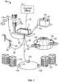
- FIG. 7is a top view of an interface device in accordance with principles of the present disclosure.
- FIG. 8is a perspective view of the interface device shown in FIG. 7 .
- FIG. 9is a partial top view of the interface device shown in FIG. 7 , illustrating aspects of an insulation displacement connector (IDC) in an open position.
- IDCinsulation displacement connector
- FIG. 10is another partial top view of the interface device shown in FIG. 7 , illustrating aspects of the IDC in a closed position.
- FIG. 11is a perspective view of the interface device shown in FIG. 7 , illustrating an embodiment that includes an optical splice device.
- FIG. 12is a top view of the interface device shown in FIG. 11 .
- FIG. 13is a top view of the interface device shown in FIG. 7 , illustrating an embodiment that includes a media board.
- FIG. 14is a circuit diagram illustrating an example power conditioning circuit.
- FIG. 15shows a system in accordance with the principles of the present disclosure having a rack mounted power supply.
- FIG. 16shows a hybrid cable system in accordance with the principles of the present disclosure.
- FIG. 1shows a system 10 in accordance with the principles of the present disclosure for enhancing the coverage areas provided by cellular technologies (e.g., GSM, CDMA, UMTS, LTE, WiMax, WiFi, etc.).
- the system 10includes a base location 11 (i.e., a hub) and a plurality of wireless coverage area defining equipment 12 a , 12 b , 12 c , 12 d , 12 e and 12 f (sometimes collectively referred to as equipment 12 herein) distributed about the base location 11 .
- a base location 11i.e., a hub
- equipment 12 a , 12 b , 12 c , 12 d , 12 e and 12 fsometimes collectively referred to as equipment 12 herein
- the base location 11can include a structure 14 (e.g., a closet, hut, building, housing, enclosure, cabinet, etc.) protecting telecommunications equipment such as racks, fiber optic adapter panels, passive optical splitters, wavelength division multiplexers, fiber splice locations, optical fiber patching and/or fiber interconnect structures and other active and/or passive equipment.
- a structure 14e.g., a closet, hut, building, housing, enclosure, cabinet, etc.
- telecommunications equipmentsuch as racks, fiber optic adapter panels, passive optical splitters, wavelength division multiplexers, fiber splice locations, optical fiber patching and/or fiber interconnect structures and other active and/or passive equipment.
- the base location 11is connected to a central office 16 or other remote location by a fiber optic cable such as a multi-fiber optical trunk cable 18 that provides high band-width two-way optical communication between the base location 11 and the central office 16 or other remote location.
- the base location 11is connected to the wireless coverage area defining equipment 12 a , 12 b , 12 c , 12 d , 12 e and 12 f by hybrid cables 20 .
- the hybrid cables 20are each capable of transmitting both power and communications between the base location 11 and the wireless coverage area defining equipment 12 a , 12 b , 12 c , 12 d , 12 e and 12 f.
- the wireless coverage area defining equipment 12 a , 12 b , 12 c , 12 d , 12 e and 12 fcan each include one or more wireless transceivers 22 .
- the transceivers 22can include single transceivers 22 or distributed arrays of transceivers 22 .
- a “wireless transceiver”is a device or arrangement of devices capable of transmitting and receiving wireless signals.
- a wireless transceivertypically includes an antenna for enhancing receiving and transmitting the wireless signals.
- Wireless coverage areasare defined around each of the wireless coverage area defining equipment 12 a , 12 b , 12 c , 12 d , 12 e and 12 f Wireless coverage areas can also be referred to as cells, cellular coverage areas, wireless coverage zones, or like terms. Examples of and/or alternative terms for wireless transceivers include radio-heads, wireless routers, cell sites, wireless nodes, etc.
- the base location 11is shown as a base transceiver station (BTS) located adjacent to a radio tower 24 supporting and elevating a plurality the wireless coverage area defining equipment 12 a .
- the equipment 12 acan define wireless coverage areas such as a macrocells or microcells (i.e., cells each having a coverage area less than or equal to about 2 kilometers wide).
- the wireless coverage area defining equipment 12 bis shown deployed at a suburban environment (e.g., on a light pole in a residential neighborhood) and the equipment 12 c is shown deployed at a roadside area (e.g., on a roadside power pole).
- the equipment 12 ccould also be installed at other locations such as tunnels, canyons, coastal areas, etc.
- the equipment 12 b , 12 ccan define wireless coverage areas such as microcells or picocells (i.e., cells each having a coverage area equal to or less than about 200 meters wide).
- the equipment 12 dis shown deployed at a campus location (e.g., a university or corporate campus), the equipment 12 e is shown deployed at a large public venue location (e.g., a stadium), and the equipment 12 f is shown installed at an in-building or near-building environment (e.g., multi-dwelling unit, high rise, school, etc.).
- the equipment 12 d , 12 e , and 12 fcan define wireless coverage areas such as microcells, picocells, or femtocells (i.e., cells each having a coverage area equal to or less than about 10 meters wide).
- FIG. 2is a transverse cross-sectional view taken through an example of one of the hybrid cables 20 of FIG. 1 .
- Hybrid cable 20includes an outer jacket 200 having a transverse cross-sectional profile that defines a major axis 202 and a minor axis 204 .
- the outer jackethas a height H measured along the minor axis 204 and a width W measured along the major axis 202 .
- the width Wis greater than the height H such that the transverse cross-sectional profile of the outer jacket 200 is elongated along the major axis 202 .
- the outer jacket 200can include a left portion 206 , a right portion 208 and a central portion 210 .
- the left portion 206 , the right portion 208 and the central portion 210can be positioned along the major axis 202 with the central portion 210 being disposed between the left portion 206 and the right portion 208 .
- the left portion 206can define a left passage 212
- the right portion 208can define a right passage 214
- the central portion 210can define a central passage 216 .
- the passages 212 , 214 and 216can have lengths that extend along a central longitudinal axis 218 of the cable 20 for the length of the cable.
- a left electrical conductor 220is shown positioned within the left passage 212
- a right electrical conductor 222is shown positioned within the right passage 214
- at least one optical fiber 224is shown positioned within the central passage 216 .
- Certain embodimentsinclude from 1 to 12 fibers 224 , for example.
- the left electrical conductor 220 , the right electrical conductor 222 and the optical fiber 224have lengths that extend along the central longitudinal axis 218 of the cable 20 .
- the hybrid cable 20includes a left pre-defined tear location 226 positioned between the central portion 210 and the left portion 206 of the outer jacket 200 , and a right pre-defined tear location 228 positioned between the central portion 210 and the right portion 208 of the outer jacket 200 .
- the left pre-defined tear location 226is weakened such that the left portion 206 of the outer jacket 200 can be manually torn from the central portion 210 of the outer jacket 200 .
- the right pre-defined tear location 228is weakened such that the right portion 208 of the outer jacket 200 can be manually torn from the central portion 210 of the outer jacket 200 .
- the left pre-defined tear location 226is configured such that the left portion 206 of the outer jacket 200 fully surrounds the left passage 212 and the central portion 210 of the outer jacket 200 fully surrounds the central passage 216 after the left portion 206 of the outer jacket 200 has been torn from the central portion 210 of the outer jacket 200 .
- the left electrical conductor 220remains fully insulated and the optical fiber 220 remains fully protected after the left portion 206 has been torn from the central portion 210 .
- the right pre-defined tear location 228is configured such that the right portion 208 of the outer jacket 200 fully surrounds the right passage 214 and the central portion 210 of the outer jacket 200 fully surrounds the central passage 219 after the right portion 208 of the outer jacket 200 has been torn from the central portion 210 of the outer jacket 200 .
- the right electrical conductor 222remains fully insulated and the optical fiber 224 remains fully protected after the right portion 208 has been torn from the central portion 210 .
- FIG. 3shows the hybrid cable 20 with both the left portion 206 and the right portion 208 torn away from the central portion 210 .
- both the left electrical conductor 220 and the right electrical conductor 222are fully insulated by their corresponding left and right portions 206 , 208 .
- the central portion 210has a rectangular transverse cross-sectional shape that fully surrounds the central passage 216 so as to protect the optical fiber or fibers 224 .
- left and right electrical conductors 220 , 222have a construction suitable for carrying electricity. It will be appreciated that the electrical conductors can have a solid or stranded construction. Example sizes of the electrical conductors include 12 gauge, 16 gauge, or other sizes.
- the outer jacket 200is preferably constructed of a polymeric material.
- the hybrid cable 20 and the outer jacket 200are plenum rated.
- the outer jacket 200can be manufactured of a fire-retardant plastic material.
- the outer jacket 200can be manufactured of a low smoke zero halogen material.
- Example materials for the outer jacketinclude polyvinyl chloride (PVC), fluorinated ethylene polymer (FEP), polyolefin formulations including, for example, polyethylene, and other materials.
- the central passage 216can contain one or more optical fibers 224 .
- the optical fibers 224can be coated optical fibers having cores less than 12 microns in diameter, cladding layers less than 240 microns in diameter, and coating layers less than 300 microns in diameter.
- the core and cladding layerstypically include a silica based material.
- the cladding layercan have an index of a refraction that is less than the index of refraction of the core to allow optical signals that are transmitted through the optical fibers to be confined generally to the core. It will be appreciated that in certain examples, multiple cladding layers can be provided.
- optical fiberscan include bend insensitive optical fibers having multiple cladding layers separated by trench layers.
- protective coatingscan form coating layers around the cladding layers.
- the coating layerscan have diameters less than 300 microns, or less than 260 microns, or in the range of 240 to 260 microns.
- the optical fibers 224can be unbuffered.
- the optical fiberscan include a tight buffer layer, a loose buffer layer, or a semi-tight buffer layer.
- the buffer layerscan have an outer diameter of about 800 to 1,000 microns.
- the optical fiberscan include single mode optical fibers, multi-mode optical fibers, bend insensitive fibers or other fibers.
- the optical fibers 224can be ribbonized.
- the left and right portions 206 , 208can be trimmed relative to the central portion 210 after the left and right portions 206 , 204 have been torn away from the central portion 210 .
- the central portion 210extends distally beyond the ends of the left and right portions 206 , 208 .
- insulation displacement connectorscan be used to pierce through the jacket materials of the left and right portions 206 , 208 to electrically connect the left and right electrical connectors 220 , 222 to an electrical power source, ground, active components or other structures.
- the optical fibers 224can be connected to other fibers with mechanical or fusion splices, or directly terminated with optical connectors.
- connectorized pigtailscan be spliced to the ends of the optical fibers 224 .
- the outer jacket 200includes a top side 230 and a bottom side 232 separated by the height H. As depicted, the top and bottom sides 230 , 232 are generally parallel to one another.
- Each of the left and right pre-defined tear locations 226 , 228includes an upper slit 234 that extends downwardly from the top side 230 , a lower slit 236 that extends upwardly from the bottom side 232 and a non-slitted portion 238 positioned between the upper and lower slits 234 , 236 .
- the upper and lower slits 234 , 236are partially re-closed slits.
- the left and right pre-defined tear locations 226 , 228also include jacket weakening members 240 that are imbedded in the non-slitted portions 238 .
- the jacket weakening members 240can include strands, monofilaments, threads, filaments or other members.
- the jacket weakening members 240extend along the central longitudinal axis 218 of the cable 20 for the length of the cable 20 .
- the jacket weakening members 240are aligned along the major axis 202 .
- the upper and lower slits 230 , 236 as well as the jacket weakening member 240 of the left pre-defined tear location 226are aligned along a left tearing plane PL that is oriented generally perpendicular relative to the major axis 202 .
- the upper and lower slits 234 , 236 as well as the jacket weakening member 240 of the right pre-defined tear location 228are aligned along a right tearing plane PR that is oriented generally perpendicular with respect to the major axis 202 .
- the hybrid cable 20can include a tensile strength structure 242 that provides tensile enforcement to the hybrid cable 20 so as to prevent tensile loads from being applied to the optical fibers 224 .
- the tensile strength structure 242can include reinforcing structures such as Aramid yarns or other reinforcing fibers.
- the tensile strength structure 242can have an oriented polymeric construction.
- a tensile strength structure 242can include a reinforcing tape.
- the reinforcing tapecan be bonded to the outer jacket 200 so as to line the central passage 216 .
- the tensile strength structure 242can include a reinforcing tape that extends along the length of the hybrid cable 20 and has longitudinal edges/ends 244 that are separated so as to define a gap 244 therein between.
- the tensile strength member 242can be anchored to a structure such as a fiber optic connector, housing or other structure so as to limit the transfer of tensile load to the optical fibers 224 . It will be appreciated that the tensile strength structure 242 can be anchored by techniques such as crimping, adhesives, fasteners, bands or other structures.
- FIG. 5shows an alternative hybrid cable 20 ′ having the same construction as the hybrid cable 20 except two tensile strength structures 242 A, 242 B have been provided within the central passage 216 .
- Tensile strength members 242 A, 242 Beach include a tensile reinforcing tape that is bonded to the central portion 210 of the outer jacket 200 .
- the tensile strength members 242 A, 242 Bcan include portions that circumferentially overlap one another within the central passage 216 . In certain examples, by stripping away an end portion of the central portion 210 , the tensile strength structures 242 A, 242 B can be exposed and readily secured to a structure such as a fiber optic connector, a panel, a housing or other structure.
- the tensile strength structures 242 A, 242 Bcan be crimped, adhesively secured or otherwise attached to rods (e.g., epoxy rods reinforced with fibers) that are in turn secured within a ruggedized fiber optic connector such as the fiber optic connector disclosed at U.S. Pat. No. 7,744,288 which is hereby incorporated by reference in its entirety, or the fiber optic connector disclosed at U.S. Pat. No. 7,918,609, which is hereby incorporated by reference in its entirety.
- the electrical conductors 220 , 222could be 12 gauge (AWG) or 16 gauge, for example.
- ABG12 gauge
- 16 gauge16 gauge
- a 12 gauge conductor 220 , 220provides up to 1175 meter reach at 15 W, and a 750 meter reach for 25 W devices.
- the 16 gauge implementationscan provide reduced cost for shorter reach applications or lower power devices, for example.
- FIG. 6conceptually illustrates an example of a communication signal and power distribution system 300 in accordance with aspects of the present disclosure.
- the system 300provides a simple, “universal” connection of the optical fiber 224 and electrical conductors 220 , 222 of the hybrid cable 20 to the equipment 12 .
- the system 300includes a fiber patch panel 302 that terminates optical fibers carrying signals to be distributed to the desired wireless coverage area defining equipment 12 via the optical fibers 224 of the hybrid cables 20 .
- a power supply 304connects to the conductors 220 , 222 of the desired hybrid cable 20 .
- the power supply 304receives 120/220 VAC and provides 48 VDC nominal.
- the fiber patch panel 302 and power supply 304are rack mounted.
- a first end 306 of the hybrid cable 20is connected to the appropriate optical fibers from the fiber patch panel 302 and to the power supply 304 .
- a second, distant end 308 of the cable 20is connected to an interface device 310 .
- the interface deviceis connected to the wireless equipment 12 , either directly or through a media converter 312 .
- Examples of the interface 310provide simplified termination of the hybrid cable 20 , allowing factory or field installation.
- a DC-DC converterprovides the desired voltage level for the particular device 12 to which it is connected and compensates for IR loss across variable link lengths.
- FIGS. 7-13illustrate various views of embodiments of the interface device 310 .
- the interface device 310includes a body 320 having an exterior 322 and an interior 324 .
- a cover 326is connected to the body 320 by a hinge 328 such that the interface device 310 can be opened to expose the interior 324 for access by an operator.
- a mounting bracket 340extends from the body 320 for mounting the interface device 310 as desired using screws or bolts, for example.
- the interface device 310defines footprint dimensions of about 55 mm ⁇ 125 mm ⁇ 190 mm.
- a cable clamp 342cooperates with the body 320 to fix the hybrid input cable 20 and an output cable 344 to the interface device 310 at a cable inlet 350 and a cable outlet 352 , respectively.
- the hybrid cable 20includes electrical conductors 220 , 220 for supplying power to the interface device 310 , and ultimately the remote device 12 .
- the interface device 310includes an insulation displacement connector (IDC) 360 situated in the interior 324 of the interface device body 320 for connecting the conductors 220 , 220 to the interface device 310 .
- IDCinsulation displacement connector
- an IDCalso sometimes referred to as insulation displacement termination and insulation piercing connector
- an IDCis an electrical connector that connects to one or more conductors of an insulated conductor by a connection process that forces a selectively sharpened blade or blades through the insulation to contact the conductor, eliminating the need to strip the insulation before connecting. Further, the connector blades cold weld to the conductors to form a gas-tight connection.
- FIGS. 9 and 10illustrate the IDC 360 in closed and open positions, respectively.
- the hybrid cable 20is configured such that the left portion 206 and the right portion 208 can be torn away from the central portion 210 .
- both the left electrical conductor 220 and the right electrical conductor 222are fully insulated by their corresponding left and right portions 206 , 208 .
- the IDC 360includes a housing 358 with first and second conductor grooves 362 , 364 positioned on either side of a fiber pass-through groove 366 .
- the electrical conductors 220 , 222 of the hybrid cable 20are situated on either side of the central portion 210 containing the optical fibers 224 .
- the conductors 220 , 222are received by the corresponding conductor grooves 362 , 364 , and insulator clamping ribs 368 are situated to press against the jacket 200 to hold the hybrid cable 20 in place.
- the IDC 360includes a cover 370 hingedly connected to the housing 358 that when closed presses IDC terminals 372 against the conductors 220 , 222 and through the left portion 206 and the right portion 208 of the outer jacket 200 to make an electrical connection with the conductors 220 , 222 .
- the illustrated IDC terminals 372are angled to provide a gas-tight connection. In the illustrated example, the left and right portions 206 , 208 are trimmed such that the conductors 220 , 222 extend beyond the IDC terminals 372 but remain within the housing 358 of the IDC 360 .
- the IDCis configured in a “pass-through” power arrangement, wherein the terminals 372 pierce the left and right portions 206 , 208 to contact the conductors 220 , 222 , but the left and right portions 206 , 208 are not trimmed so they extend through the IDC 360 to be routed to equipment 12 or another interface device 310 , such as via the cable outlet 352 .
- a power converter 376such as a DC-DC voltage converter, is situated in the interior 324 of the base 320 and electrically connected to the IDC 360 so as to electrically connect the conductors 220 , 220 of the hybrid cable 20 to the power converter 376 via the IDC 360 .
- the power converter 376is connectable to the output cable 344 to route the conditioned/converted power from the interface device 310 to the desired wireless equipment 12 .
- conductors of the output cable 344could connect directly to the power converter 376 using screw terminals 378 thereon.
- the power converter 376can be omitted or bypassed if the power received by the interface device 310 is appropriate for the particular end device 12 . Further power connection arrangements are discussed herein below.
- the optical fibers 224 from the hybrid cable 20are received by the centrally positioned fiber pass-through groove 366 to route the optical fibers 224 through the housing 358 of the IDC 360 .
- the fibers 224extend from the housing 358 and are routed along the perimeter of the interior 324 of the interface device 310 .
- the optical fibers 324are routed through the interior 324 directly to the cable outlet 352 , along with a separate power output cable. More typically, the fibers 324 would be routed to a fiber management device 380 .
- fiber guides 374are situated in the corners of the interior 324 for routing the optical fibers 324 in the interface device while maintaining a desired bend radius.
- the optical fibers 324are thus received at the cable inlet 350 , routed through the IDC housing 358 and the interior 324 of the interface device body 320 to the fiber management device 380 .
- FIGS. 11 and 12illustrate an example of the interface device 310 wherein the fiber management device 380 includes an optical splice device for making a mechanical or fusion splice, for example.
- the illustrated fiber management device 380thus includes furcation tubes 382 situated on splice holders 384 .
- other fiber optic management devicessuch as fiber optic connectors are provided.
- a strength member termination 386is further provided in the embodiment illustrated in FIGS. 11 and 12 .
- the optical fibers 224can thus be spliced, for example, to a fiber optic pig tail and routed to the cable outlet 352 .
- the output cable 244is also a hybrid cable including optical fibers that are spliced to the fibers 224 using the fiber management device 380 , and conductors that receive power from the power converter 376 .
- FIG. 13illustrates another embodiment where the fiber management device 380 includes a media board 390 that converts optical signals received via the optical fibers 224 to electrical signals.
- a fiber optic connector 392such as an LC duplex input connector, is connected to the media board 390 to terminate the optical fibers routed through the interior 324 of the interface device 310 and receive optical signals therefrom.
- the media board 390is electrically connected to the IDC 360 , either directly, or as in the illustrated embodiment, via the power converter 376 . In this manner, the media board is powered by power from the conductors 220 , 222 terminated by the IDC 360 . Additionally, in some embodiments, the media board 390 connects output power and electrical communication signals to a power over Ethernet (PoE) connection.
- PoEpower over Ethernet
- the output cable 344is a standard RJ-45 data/power cable that connects to a PoE jack 394 on the media board 390 .
- the RJ-45 cablecan then be connected to the desired wireless coverage area defining equipment 12 to provide both communication signals and power thereto.
- Some embodimentsinclude 12 fibers 224 situated in the central passage 216 .
- two optical fibers 224are terminated in a given interface device 310 . Since the two fibers 224 carrying signals for the desired wireless equipment 12 are to be terminated in the interface device 310 , they are cut downstream of the interface device 310 .
- a slitcan be cut in the central portion 216 providing an opening through which the desired fibers 224 can be pulled from the central portion and routed to the fiber management device 380 .
- the remaining optical fibers 224remain intact within the central portion 216 , and can be passed through the interface device 310 to another device, for example.
- the power converter 276provides DC/DC conversion, for example, as well as other power management functions such as circuit overload protection, mains cross protection, lightning protection, etc.
- a 30 W, 12V output DC-DC converter from CUI Inc. of Tualatin, Oreg.P/N VYC30W-Q48-S12-T) is used.
- Other DC-DC convertersmay be employed based on electrical requirements, packaging, etc.
- a conditioning circuitis integrated into the interface 310 to minimize voltage ripple.
- FIG. 14shows an example of a typical conditioning circuit 400 .
- overvoltage protectionsuch as a gas-tube, is incorporated between the IDC terminals and DC-DC converter input.
- the fiber patch panel 302can receive can receive optical signals from a remote location via a fiber optic trunk cable.
- Optical fibers of the trunk cable 110can be separated at a fan-out device, or optical power splitters or wavelength division multiplexers can be used to split optical communications signals from the trunk cable to multiple optical fibers.
- the fiberscan be routed to the patch panel 302 , and then to a desired one of the hybrid cables 20 , along with electrical power from the power supply 304 .
- the power supply 304receives 120 volt or 220 volt alternating current.
- power supply 302includes an AC/DC converter that converts the electrical power from alternating current to direct current.
- the power supply 304converts the electrical power from the first voltage (e.g., 120 v or 220 v) to a second voltage that is less than the first voltage.
- the second voltageis less than or equal to 60 volts and 100 Watts such that the output voltage complies with NEC Class II requirements.
- the hybrid cable 20can be used to transmit electrical power and optical communication signals from the fiber patch panel 302 and power supply 304 located at a first to the wireless equipment 12 located at a second location.
- the first end 306 of the hybrid cable 20can include a first interface for connecting the hybrid cable to electrical power and fiber optic communication at a connector, and the second end 308 of the hybrid cable 20 is received at the cable inlet 350 of the interface device 310 .
- the power converter 376 of the interface device 310converts electrical power carried by the hybrid cable 20 , for example, to a direct current third voltage that is less than the second voltage.
- the third voltagecorresponds to an electrical voltage requirement of the device 12 .
- the third voltageis 12V, 24V or 48V.
- a converter 312is associated with the equipment 12 for converting optical signals to electrical signals.
- the optical fibers and powerare provided from the interface device 310 to the converter 312 , which provides power and communication signals to the equipment 12 .
- the interface device 310converts the optical signals to electrical signals using the media board 390 , and provides power and electrical communication signals to the equipment 12 .
- aspects of the present disclosurerelate to powered fiber cable systems capable of simultaneously powering and communicating with wireless coverage area defining equipment (e.g., transceivers, wireless routers, WiFi access points/WiFi hot spots, small cell devices, or like devices).
- the powered fiber cable systemcan also be used to power and communicate with other devices such as digital signage, high definition surveillance cameras, and like devices.
- powered fiber cable systems in accordance with the principles of the present disclosurecan be incorporated into fiber optic networks (e.g., fiber-to-the-home (FTTH), fiber-to-the-premises (FTTP, fiber-to-the-anything (FTTX)) to provide back-up power or primary power to optical network terminals (ONT) including electronics for providing optical-to-electrical conversion at or near a subscriber location.
- fiber optic networkse.g., fiber-to-the-home (FTTH), fiber-to-the-premises (FTTP, fiber-to-the-anything (FTTX)
- ONToptical network terminals
- Powered fiber cable systems in accordance with the principles of the present disclosureare particularly well suited for supporting active devices at outdoor locations where power is not readily available.
- powered fiber cable systems in accordance of the principles of the present disclosurecan also be used to support indoor applications such as in local area networks where power and fiber are provided to desk-top locations (e.g., fiber-to-the-desk (FTTD)).
- FTTDfiber-to-the-desk
- Other applications for powered fiber cable systems in accordance with the principles of the present disclosurerelate to power-over-Ethernet extensions (PoE or PoE+).
- FIG. 15shows an example powered fiber cable system 400 in accordance with the principles of the present disclosure.
- the powered fiber cable system 400includes a rack 402 positioned at a location where power (e.g., a power system ⁇ grid that typically provides AC power such as a mains power system) and fiber network are available. Such locations where power and fiber optic network communications are available can be referred to as head ends.
- the power locationscan be co-located at a cell site base station, a base station on a building top, in a telecom closet or data center or anywhere where power and access to a fiber optic network are available.
- a patch panel 404is mounted on the rack 402 .
- the patch panel 404is coupled to a fiber optic network.
- optical fibers optically corresponding to fiber optic distribution or feed cablescan be connectorized and plugged into fiber optic adapters supported at the patch panel 404 .
- the rack 402is also shown supporting a power supply unit 406 that in certain examples provides a DC output of 48 volts or less.
- the power supplycan include a power express class II power converter shelf manufactured by General Electric.
- the power supplycan include and AC/DC transformer for transforming alternating current (AC) from a mains power supply into DC power for distribution to remotely located active devices.
- the power supply 406can power up to 32 hybrid cables 20 in a modular design with four modules and eight cables per module.
- the power supplyis configured to output relatively low voltage DC current (e.g., less than or equal to 48 volts DC).
- the power sourceis National Electric Code (NEC) class 2 (as specified by Article 725) and Safety Extra Low Voltage (SELV) compliant.
- NECNational Electric Code
- SELVSafety Extra Low Voltage
- the power supplyis limited to 100 VA. Such low voltage circuits are advantageous because electricians are not required to install such systems, such systems are inherently safe because of the low voltage limits, and such systems can be installed in a conduit-free manner.
- the power supplycan also include circuit protection electronics such as gas discharge tubes, metal oxide varistor components and transient voltage suppression structures/diodes.
- the patch panel 404 and the power supply 406are both rack mounted.
- Optical communication lines from the patch panel 404 and power lines from the power source 406are coupled to hybrid cables 20 routed to universal interface devices 310 that support active devices such as a picocell 408 , a metrocell 410 , a femtocell 412 and an ONT 414 .
- the ONT 414is shown connected to the corresponding interface device 310 by a power line 415 and a separate fiber line 417 .
- the picocell 408 , metrocell 410 and femtocell 412are coupled to their corresponding interface devices 310 by power lines 419 and two fiber lines 421 , 423 .
- the fiber lines 421 , 423can be replaced with twisted pair conductors for carrying electrical signals in cases where optical to electrical signal conversion occurs at the interface device 310 .
- a remote interface devicee.g., interface device 310 that is remote from the power supply
- the interface deviceincluding a closure that houses circuitry for providing electrical power management and including circuit protection electronics.
- the circuitry within the closureis adapted for providing an effective interface between a hybrid cable (e.g., hybrid cable 20 ) and a remote active device.
- the closureis designed for outdoor environmental use and includes an environmentally sealed construction.
- the electrical power management circuitryeliminates the need for line power system design.
- the electrical power management circuitrycan include a DC-to-DC converter suitable for converting power carried by one of the hybrid cables 20 to a voltage and power level compatible with an active device intended to be powered with power from the hybrid cable 20 .
- the DC-to-DC convertercan increase the voltage of the power carried by the hybrid cable 20 to a level compatible with the active device powered by the hybrid cable.
- the increase in voltage provided by the DC-to-DC convertercompensates for voltage loss that may occur over the length of the hybrid cable.
- the DC-to-DC converterraises the voltage level to 12 volts, 24 volts or 48 volts.
- the DC-to-DC converterdecreases the voltage level to a level compatible with the active device intended to be powered by the hybrid cable.
- the poweris converted so as to become compatible with a 25 watt device, a 30 watt device, or a 45 watt device.
- the closurealso houses an optical-to-electrical converter that converts optical signals from the hybrid cable to electrical signals that are transmitted to the active device.
- the electrical signals and the powercan be transmitted from the interface device to the active device by a twisted pair Ethernet cable so as to provide power-over-Ethernet or power-over-Ethernet-plus connectivity.
- the closure of the interface devicecan enclose circuit protection electronics.
- the circuit protection electronicscan include primary electrical protection that may include a gas discharge tube rated to at least 40 kAmp surge/overvoltage protection. Such structure can provide protection with respect to lightning strikes and line cross-overs.
- the electrical protectioncan also include secondary electrical protection that may be rated to 4.5 kAmp and that may include metal oxide varistor components that couple to ground in response to voltage surges.
- the electrical protectionmay also include tertiary protection that prevents voltage from rising above a predetermined level (e.g., 80 volts, or 100 volts).
- the tertiary protectioncan include a transient voltage suppression diode.
- fast acting fusescan be used.
- Cables in accordance with the principles of the present disclosurecan provide power over relatively long distances. For example, using 12 gauge conductors in the hybrid cable and using conversion circuitry in the interface device that converts the optical signals and power to a PoE format, the system can provide 10 Watts of power over a length of 3,000 meters, 15 Watts of power over 2,400 meters, 20 Watts of power over 1,900 meters and 25 Watts of power over 1,600 meters. If power is provided in a non-power over Ethernet format (e.g., via an M8 plug or other power lines separate from the communications lines), 30 watt power can be provided up to 1,600 meters and 45 watt power can be provided up to 1,000 meters.
- a non-power over Ethernet formate.g., via an M8 plug or other power lines separate from the communications lines
- a system that utilizes 16 gauge conductors and outputs power in a power over Ethernet formatcan provide 10 watts of power at 1,200 meters, 15 watts of power at 960 meters, 20 watts of power at 760 meters, and 25 watts of power at 640 meters.
- the 16 gauge wirecan provide 30 watts of power at 640 meters and 45 watts of power at 400 meters.
- the closurescan be environmentally sealed and can include clamps for clamping hybrid cables such as the hybrid cable 20 .
- the closurescan also include power management circuitry such as power converters (e.g., DC-to-DC power converters).
- the power converterscan be customized to comply with the power requirements of the remote device intended to be powered by the customer.
- the power conversion circuitrycan be modular and modules providing different levels of conversion can be selected and plugged into the circuit board of the closure to satisfy the customer requirement. For example, power converters capable of outputting 12, 24 or 48 volts can be used. It will be appreciated that the format of the power output from the interface closure can also be customized to meet customer needs.
- the interface closurecan be configured to output power and communications over a variety of formats such as: (a) power-over-Ethernet; (b) power-over-Ethernet-Plus; (c) separate power (e.g., via a cable terminated with an M8 plug or other configuration) and Ethernet lines (e.g., terminated with RJ45 connectors or other connectors); (d) separate fiber lines for communications and power lines for power (e.g., terminated with M8 connectors or other power connectors); (e) a hybrid cable having optical fibers for optical signals and electrical conductors for power that can be terminated with a hybrid connector or can have separate fiber and power pigtails; or (f) a cable having twisted pair conductors for carrying communication signals and separate electrical conductors for power that can be terminated by separate RJ-style connectors for communication signals and an M8 plug for power or other connector arrangements.
- formatssuch as: (a) power-over-Ethernet; (b) power-over-Ethernet-Plus
- the fiber linescan be terminated with different styles of fiber optic connectors such as LC connectors, SC connectors, or other fiber optic connectors.
- the fiber optic connectorscan be ruggedized and can include environmental sealing as well as twists-to-lock fastening elements such as threaded fasteners or bayonet-style fasteners.
- standard RJ-45 connectors or ruggedized RJ-45 connectorscan be used.
- stranded or solid conductorscan be used.
- the power pigtailscan be terminated with power connectors such as M8 connectors.
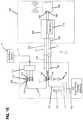
- FIG. 16shows a cable system 100 that can be used to transmit power and communications from a first location 102 to an active device 104 at a second location 106 .
- the second location 106is remote from the first location 102 .
- the first location 102can be a base location and the active device 104 can include wireless coverage area defining equipment. Examples of wireless coverage area defining equipment and locations where such equipment may be installed are described above. Examples of other types of active devices include cameras such as high definition video cameras.
- the first location 102receives optical signals from a remote location 108 via a fiber optic trunk cable 110 .
- Optical fibers of the trunk cable 110can be separated at a fan-out device 111 at the first location.
- optical power splitters or wavelength division multi-plexerscan be used to split optical communications signals from the trunk cable 110 to multiple optical fibers.
- the fiberscan be routed to a patch panel 112 having fiber optic adapters 114 (i.e., structures for optically and mechanically interconnecting two fiber optic connectors 115 ).
- the first location 102can also include a combined power/communication panel 116 having fiber optic adapters 117 paired with power adapters 118 (i.e., ports).
- Connectorized fiber optic patch cords 120can be routed from the fiber optic adapters 114 to the fiber optic adapters 117 .
- the first location 102can receive electrical power from a main power line 122 .
- the main power line 122can be part of a mains power system that provides 100-240 nominal volt alternating current (example frequencies include 50 and 60 Hertz).
- the first location 102can include a converter 124 for converting the electrical power from the first voltage (e.g., 100 v, 120 v, 220 v, 230 v, 240 v etc. nominal voltage) to a second voltage that is less than the first voltage.
- the second voltageis less than or equal to 60 volts and less than or equal to 100 Watts such that the output voltage complies with NEC Class II requirements.
- the converter 124is an AC/DC converter that converts the electrical power from alternating current to direct current.
- Connectorized power cords 126can be used to route electrical power having the second voltage from the converter 124 to the power adapters 118 .
- the combined power/communications panel 116can include at least 18, 24, 30 or 32 fiber optic adapters paired with corresponding power adapters 118 .
- the converter 124is large enough to provide NEC Class II compliant power through separate hybrid cables to at least 18, 24, 30 or 32 active devices. Of course, converter having smaller capacities could be used as well.
- the converter 124can be part of a voltage conversion package including overvoltage protection that provides protection/grounding in the event of lightning strikes and main crosses.
- a hybrid cable 20can be used to transmit electrical power and optical communication signals between the first and second locations 102 , 106 .
- the hybrid cable 20can include an outer jacket 150 containing at least one optical fiber 152 for carrying the optical communication signals and electrical conductors 154 (e.g., wires such as ground and power wires) for transmitting the electrical power having the second voltage.
- the hybrid cable 20can include a first end 156 and a second end 158 .
- the first end 156can include a first interface for connecting the hybrid cable to electrical power and fiber optic communication at the first location 102 .
- the first interfacecan include a power connector 160 (e.g., a plug) that connects the electrical conductors 154 to one of the connectorized power cords 126 at the power/communications panel 116 .
- the power connector 160can be plugged into the adapter 118 and can be provided at a free end of a cord that extends outwardly from the outer jacket 150 at the first end of the hybrid cable 20 .
- the cordcan contain the electrical conductors 154 .
- the first interfacecan also include a fiber optic connector 162 (e.g., an SC connector, LC connector, ST-style connector or other type of connector) that connects the optical fiber 152 to one of the patch cords 120 .
- the fiber optic connector 162can plug into one of the fiber optic adapters 117 and can be mounted at the free end of a cord that contains the optical fiber 152 and extends outwardly from the outer jacket 150 at the first end of the hybrid cable 20 .
- the second end 158 of the hybrid cable 20can include a second interface for connecting the hybrid cable 20 to the active device 104 such that electrical power is provided to the active device 104 and such that fiber optic communication signals can be transmitted between the first and second locations 102 , 106 .
- the second interfaceincludes an interface structure 164 including a power connection location 166 and a communication connection location 168 .
- the interface structure 164includes a power converter 170 for converting electrical power carried by the hybrid cable 20 to a direct current third voltage that is less than the second voltage.
- the third voltagecorresponds to an electrical voltage requirement of the active device 104 .
- the power converter 170is a DC/DC converter.
- the third voltageis 12V, 24V or 48V.
- the power converter 124can be an AC/AC converter and the power converter 170 can be an AC/DC converter.
- the interface structure 164can include an optical-to-electrical converter for converting the communications signals carried by the optical fiber 152 from an optical form to an electrical form. In other examples, optical-to-electrical conversion can be performed by the active device 104 or can take place between the active device 104 and the interface structure 164 .
- the interface structure 164includes a converter interface that allows power converters 170 with different conversion ratios to interface and be compatible with the interface structure 164 .
- the conversion ratio of the particular power converter 170 usedcan be selected based on factors such as the voltage requirement of the active device 104 and the length of the hybrid cable 20 .
- the power converters 170can have a modular configuration can be installed within the interface structure 168 in the field or in the factory. In one example, the power converters 170 can have a “plug-and-play” interface with the interface structure.
- the modular configurationalso allows the power converter 170 to be easily replaced with another power converter 170 , if necessary.
- the interface structure 164can include overvoltage protection and grounding arrangements such as fuses, metal oxide varistors, gas tubes or combinations thereof.
- the electrical power having the third voltagecan be output to the active device 104 through the power connection location 166 .
- the power connection location 166can include a power connector, a power port, a power cord or like structures for facilitating connecting power to the active device 104 .
- the power connection location 166can have a modular configuration that allows interface connectors having different form factors to be used.
- the communications signalscan be transferred between the hybrid cable 20 and the active device through the communication connection location 168 .
- the communication connection location 168can include a connector, a port, a cord or like structures for facilitating connecting to the active device 104 .
- the communication connection location 168can have a modular configuration that allows interface connectors having different form factors to be used.
- the connection locationcan include electrical communication type connectors (e.g., plugs or jacks) such as RJ style connectors.
- the communication connection location 168can include fiber optic connectors and or fiber optic adapters (e.g., SC connectors/adapters; LC connectors/adapters, etc.).
- fiber optic connectors and or fiber optic adapterse.g., SC connectors/adapters; LC connectors/adapters, etc.
- ruggedized, environmentally sealed connectors/adapterscan be used (e.g., see U.S. Pat. Nos. 8,556,520; 7,264,402; 7,090,407; and 7,744,286 which are hereby incorporated by reference in their entireties.
- the active devicesinclude wireless transceivers, the active devices can receive wireless signals from the coverage area and such signals can be carried from the active devices to the base station 11 via the hybrid cables. Also, the active devices can covert signals received from the hybrid cables into wireless signals that are broadcasted/transmitted over the coverage area.
- the second voltageis less than the first voltage and greater than the third voltage.
- the third voltageis the voltage required by the active device at the second location. In one example, the second voltage is sufficiently larger than the third voltage to account for inherent voltage losses that occur along the length of the hybrid cable.
Landscapes
- Physics & Mathematics (AREA)
- General Physics & Mathematics (AREA)
- Optics & Photonics (AREA)
- Engineering & Computer Science (AREA)
- Microelectronics & Electronic Packaging (AREA)
- Computer Networks & Wireless Communication (AREA)
- Signal Processing (AREA)
- Light Guides In General And Applications Therefor (AREA)
- Connector Housings Or Holding Contact Members (AREA)
- Installation Of Indoor Wiring (AREA)
Abstract
Description
Claims (34)
Priority Applications (4)
| Application Number | Priority Date | Filing Date | Title |
|---|---|---|---|
| US16/704,964US11215776B2 (en) | 2013-03-18 | 2019-12-05 | Power and optical fiber interface |
| US17/567,331US11656418B2 (en) | 2013-03-18 | 2022-01-03 | Power and optical fiber interface |
| US18/200,154US20240027717A1 (en) | 2013-03-18 | 2023-05-22 | Power and optical fiber interface |
| US18/750,567US12405435B2 (en) | 2013-03-18 | 2024-06-21 | Power and optical fiber interface |
Applications Claiming Priority (7)
| Application Number | Priority Date | Filing Date | Title |
|---|---|---|---|
| US201361802989P | 2013-03-18 | 2013-03-18 | |
| US201361846392P | 2013-07-15 | 2013-07-15 | |
| PCT/US2014/030969WO2014197103A2 (en) | 2013-03-18 | 2014-03-18 | Architecture for a wireless network |
| US14/331,873US9557505B2 (en) | 2013-03-18 | 2014-07-15 | Power and optical fiber interface |
| US15/373,709US9977208B2 (en) | 2013-03-18 | 2016-12-09 | Power and optical fiber interface |
| US15/985,068US10502912B2 (en) | 2013-03-18 | 2018-05-21 | Power and optical fiber interface |
| US16/704,964US11215776B2 (en) | 2013-03-18 | 2019-12-05 | Power and optical fiber interface |
Related Parent Applications (1)
| Application Number | Title | Priority Date | Filing Date |
|---|---|---|---|
| US15/985,068ContinuationUS10502912B2 (en) | 2013-03-18 | 2018-05-21 | Power and optical fiber interface |
Related Child Applications (1)
| Application Number | Title | Priority Date | Filing Date |
|---|---|---|---|
| US17/567,331ContinuationUS11656418B2 (en) | 2013-03-18 | 2022-01-03 | Power and optical fiber interface |
Publications (2)
| Publication Number | Publication Date |
|---|---|
| US20200209497A1 US20200209497A1 (en) | 2020-07-02 |
| US11215776B2true US11215776B2 (en) | 2022-01-04 |
Family
ID=59088348
Family Applications (7)
| Application Number | Title | Priority Date | Filing Date |
|---|---|---|---|
| US14/331,873Active2034-06-29US9557505B2 (en) | 2013-03-18 | 2014-07-15 | Power and optical fiber interface |
| US15/373,709ActiveUS9977208B2 (en) | 2013-03-18 | 2016-12-09 | Power and optical fiber interface |
| US15/985,068ActiveUS10502912B2 (en) | 2013-03-18 | 2018-05-21 | Power and optical fiber interface |
| US16/704,964ActiveUS11215776B2 (en) | 2013-03-18 | 2019-12-05 | Power and optical fiber interface |
| US17/567,331ActiveUS11656418B2 (en) | 2013-03-18 | 2022-01-03 | Power and optical fiber interface |
| US18/200,154AbandonedUS20240027717A1 (en) | 2013-03-18 | 2023-05-22 | Power and optical fiber interface |
| US18/750,567ActiveUS12405435B2 (en) | 2013-03-18 | 2024-06-21 | Power and optical fiber interface |
Family Applications Before (3)
| Application Number | Title | Priority Date | Filing Date |
|---|---|---|---|
| US14/331,873Active2034-06-29US9557505B2 (en) | 2013-03-18 | 2014-07-15 | Power and optical fiber interface |
| US15/373,709ActiveUS9977208B2 (en) | 2013-03-18 | 2016-12-09 | Power and optical fiber interface |
| US15/985,068ActiveUS10502912B2 (en) | 2013-03-18 | 2018-05-21 | Power and optical fiber interface |
Family Applications After (3)
| Application Number | Title | Priority Date | Filing Date |
|---|---|---|---|
| US17/567,331ActiveUS11656418B2 (en) | 2013-03-18 | 2022-01-03 | Power and optical fiber interface |
| US18/200,154AbandonedUS20240027717A1 (en) | 2013-03-18 | 2023-05-22 | Power and optical fiber interface |
| US18/750,567ActiveUS12405435B2 (en) | 2013-03-18 | 2024-06-21 | Power and optical fiber interface |
Country Status (1)
| Country | Link |
|---|---|
| US (7) | US9557505B2 (en) |
Cited By (2)
| Publication number | Priority date | Publication date | Assignee | Title |
|---|---|---|---|---|
| US11656418B2 (en) | 2013-03-18 | 2023-05-23 | Commscope Technologies Llc | Power and optical fiber interface |
| WO2024191563A1 (en)* | 2023-03-14 | 2024-09-19 | Outdoor Wireless Networks LLC | Access panels for a telecommunications cabinet and related assemblies |
Families Citing this family (50)
| Publication number | Priority date | Publication date | Assignee | Title |
|---|---|---|---|---|
| US10573433B2 (en) | 2009-12-09 | 2020-02-25 | Holland Electronics, Llc | Guarded coaxial cable assembly |
| US8837940B2 (en)* | 2010-04-14 | 2014-09-16 | Adc Telecommunications, Inc. | Methods and systems for distributing fiber optic telecommunication services to local areas and for supporting distributed antenna systems |
| CN105247805B (en) | 2013-03-18 | 2017-12-08 | 阿德斯电信公司 | Framework for wireless network |
| CN105247627B (en) | 2013-05-14 | 2018-08-10 | 阿德斯电信公司 | Power/Fiber Optic Hybrid Cable |
| US10171180B2 (en)* | 2013-09-19 | 2019-01-01 | Radius Universal, LLC | Fiber optic communications and power network |
| US10277330B2 (en)* | 2013-09-19 | 2019-04-30 | Radius Universal Llc | Fiber optic communications and power network |
| US11025345B2 (en) | 2013-09-19 | 2021-06-01 | Radius Universal Llc | Hybrid cable providing data transmission through fiber optic cable and low voltage power over copper wire |
| US12368615B2 (en) | 2013-09-19 | 2025-07-22 | Radius Universal Llc | Fiber optic communications and power network |
| US10855381B2 (en)* | 2013-09-19 | 2020-12-01 | Radius Universal Llc | Fiber optic communications and power network |
| WO2015163909A1 (en) | 2014-04-25 | 2015-10-29 | Halliburton Energy Services, Inc. | Mounted downhole fiber optics accessory carrier body |
| WO2015163910A1 (en)* | 2014-04-25 | 2015-10-29 | Halliburton Energy Services, Inc. | Hybrid electrical and optical fiber cable splice housings |
| US9584038B2 (en)* | 2014-06-02 | 2017-02-28 | Enphase Energy, Inc. | Ungrounded inverter enclosure and cabling |
| WO2016146848A2 (en)* | 2015-03-19 | 2016-09-22 | Commscope Connectivity Uk Limited | Thermally conductive closure for electronics |
| US9924245B2 (en)* | 2015-05-06 | 2018-03-20 | Crystal Instruments Corporation | Synchronized measurement device using local area network with ethernet messaging |
| ES2928470T3 (en)* | 2015-05-27 | 2022-11-18 | Prysmian Spa | Set of overhead electrical and optical cables |
| WO2017058568A1 (en)* | 2015-09-28 | 2017-04-06 | Commscope Technologies Llc | Directional wireless drop systems for broadband networks and related methods |
| US11101633B2 (en) | 2015-10-16 | 2021-08-24 | Frederick M. Foster | Circuit protection system and method |
| US10250027B2 (en)* | 2015-10-16 | 2019-04-02 | Frederick M. Foster | Circuit protection system and method |
| US9780871B2 (en) | 2015-11-12 | 2017-10-03 | Facebook, Inc. | Monitored patch panel system |
| US10146021B2 (en)* | 2015-11-12 | 2018-12-04 | Facebook, Inc. | Modular monitored patch panel system |
| EP3405826B1 (en)* | 2016-01-22 | 2022-04-20 | Prysmian S.p.A. | Termination module and termination assembly with said termination module |
| CN105871712B (en)* | 2016-06-21 | 2022-08-02 | 陈晓军 | Household multimedia photoelectric gateway box, network center box and mounting structure thereof |
| WO2018089623A1 (en) | 2016-11-09 | 2018-05-17 | Commscope, Inc. Of North Carolina | Exchangeable powered infrastructure module |
| EP3327732B1 (en) | 2016-11-23 | 2019-05-01 | Hexatronic Group AB | Hybrid cable and associated communication system |
| WO2018191123A1 (en)* | 2017-04-09 | 2018-10-18 | Holland Electronics, Llc | Guarded coaxial cable assembly |
| US10454581B2 (en)* | 2017-09-29 | 2019-10-22 | Verizon Patent And Licensing Inc. | System and method for plug and play fiber distribution panels |
| US10247893B1 (en)* | 2017-11-21 | 2019-04-02 | Corning Optical Communications Wireless Ltd | Optical connector assemblies and optical cable assemblies with supplemental input voltage |
| WO2019102254A1 (en) | 2017-11-24 | 2019-05-31 | Prysmian S.P.A. | Electrical power and optical distribution box for fiber to the antenna systems |
| EP3763131A4 (en)* | 2018-03-08 | 2021-12-15 | Radius Universal, A Limited Liability Company of the State of New York | FIBER OPTICAL COMMUNICATION AND POWER NETWORK |
| US10886716B2 (en)* | 2018-06-27 | 2021-01-05 | Metra Electronics Corporation | Expanded two-gang electrical box |
| US10770203B2 (en) | 2018-07-19 | 2020-09-08 | Commscope Technologies Llc | Plug-in power and data connectivity micro grids for information and communication technology infrastructure and related methods of deploying such micro grids |
| WO2020040913A1 (en) | 2018-08-24 | 2020-02-27 | Commscope Technologies Llc | Hybrid enclosures for power and optical fiber, and enclosures including multiple protective lids |
| US11546498B2 (en)* | 2018-08-24 | 2023-01-03 | Panavision International, L.P. | System for extended wireless use of cameras and ancillary devices |
| US10955635B2 (en) | 2018-09-10 | 2021-03-23 | Arris Enterprises Llc | Node fiber connectorization |
| US10788622B2 (en)* | 2018-10-03 | 2020-09-29 | Ofs Fitel, Llc | Optically conductive hybrid cable |
| WO2020097189A2 (en) | 2018-11-09 | 2020-05-14 | Corning Research & Development Corporation | Fiber optic networks and terminals having wireless connectivity |
| CN114946088A (en)* | 2019-11-18 | 2022-08-26 | 申泰公司 | Cable connector and board connector |
| US11320610B2 (en)* | 2020-04-07 | 2022-05-03 | Cisco Technology, Inc. | Integration of power and optics through cold plate for delivery to electronic and photonic integrated circuits |
| US11307368B2 (en) | 2020-04-07 | 2022-04-19 | Cisco Technology, Inc. | Integration of power and optics through cold plates for delivery to electronic and photonic integrated circuits |
| US11012156B1 (en)* | 2020-05-12 | 2021-05-18 | Dell Products L.P. | Hybrid electrical/optical data/power cabling system |
| US10938477B1 (en)* | 2020-05-12 | 2021-03-02 | Dell Products L.P. | Hybrid electrical/optical data/power cabling system |
| US11483077B2 (en)* | 2020-06-12 | 2022-10-25 | Subcom, Llc | Optical switching and electrical powering architecture for undersea mesh networking |
| EP4189454A4 (en) | 2020-07-28 | 2024-08-21 | CommScope Technologies LLC | HYBRID CABLE MANAGEMENT DEVICE |
| US11303311B1 (en)* | 2020-10-05 | 2022-04-12 | Raytheon Technologies Corporation | Radio frequency interface to sensor |
| US11493712B2 (en)* | 2021-04-06 | 2022-11-08 | Dell Products L.P. | Hybrid port to legacy port converter |
| WO2023055498A1 (en) | 2021-09-29 | 2023-04-06 | Commscope Technologies Llc | Hybrid pull apart cable with conforming overjacket |
| KR102649628B1 (en)* | 2021-11-30 | 2024-03-20 | 홈앤서비스 주식회사 | Optical terminal box to install optical devices |
| EP4500250A1 (en) | 2022-03-30 | 2025-02-05 | CommScope Technologies LLC | Bonded pair hybrid cable |
| WO2024211139A1 (en) | 2023-04-03 | 2024-10-10 | Commscope Technologies Llc | Round hybrid cable with sub-jacketed conductors |
| GB2639307A (en)* | 2023-09-21 | 2025-09-17 | Communications Res & Ip Holdings Ltd | A radio equipment assembly |
Citations (191)
| Publication number | Priority date | Publication date | Assignee | Title |
|---|---|---|---|---|
| US4089585A (en) | 1974-12-18 | 1978-05-16 | Bicc Limited | Optical guides |
| US4199225A (en) | 1978-04-07 | 1980-04-22 | Bicc Limited | Optical guides |
| US4220812A (en) | 1977-06-17 | 1980-09-02 | Lynenwerk Gmbh & Co. Kommanditgesellschaft | Electric cable for communication purposes |
| US4359598A (en) | 1977-05-13 | 1982-11-16 | Bicc Limited | Overhead electric transmission systems |
| US4365865A (en) | 1981-01-30 | 1982-12-28 | Sea-Log Corporation | Hybrid cable construction |
| US4401361A (en) | 1972-06-06 | 1983-08-30 | Bicc Limited | Optical guides |
| US4420220A (en) | 1979-06-25 | 1983-12-13 | Bicc Public Limited Company | Optical guides |
| US4467138A (en) | 1983-01-17 | 1984-08-21 | Gk Technologies, Inc. | Plural conductor communication wire |
| US4497537A (en) | 1983-06-09 | 1985-02-05 | Bicc Public Limited Company | Electric and/or optical cable |
| US4552432A (en) | 1983-04-21 | 1985-11-12 | Cooper Industries, Inc. | Hybrid cable |
| US4595839A (en) | 1982-09-30 | 1986-06-17 | Tetra-Tech, Inc. | Bidirectional optical electronic converting connector with integral preamplification |
| US4695127A (en) | 1985-03-27 | 1987-09-22 | Cooper Industries, Inc. | Hybrid coaxial-optical cable and method of use |
| US4723832A (en) | 1985-06-28 | 1988-02-09 | Fujikura Limited | Composite overhead cable structure for electric and optical transmission |
| US4729628A (en) | 1986-11-14 | 1988-03-08 | Siecor Corporation | Fiber optic dropwire |
| US4761053A (en) | 1985-08-28 | 1988-08-02 | American Telephone And Telegraph Company, At&T Bell Laboratories | Communications transmission media |
| US4787705A (en) | 1986-09-05 | 1988-11-29 | Fujikura Ltd. | Composite optical fiber and power cable |
| US4844575A (en) | 1987-04-10 | 1989-07-04 | American Telephone And Telegraph Company, At&T Bell Laboratories | Optical fiber cable |
| US4852965A (en) | 1987-02-27 | 1989-08-01 | American Telephone And Telegraph Company At&T Bell Laboratories | Composite service and distribution communications media |
| US4867527A (en) | 1987-03-31 | 1989-09-19 | Societa' Cavi Pirelli S.P.A. | Combined electrical power and optical fiber cable |
| US4895426A (en) | 1988-09-20 | 1990-01-23 | The Boeing Company | Electrically conducting reinforced optical fiber |
| US5109457A (en) | 1988-12-14 | 1992-04-28 | At&T Bell Laboratories | All-dielectric optical fiber cable having enhanced fiber access |
| US5138685A (en) | 1990-01-23 | 1992-08-11 | At&T Bell Laboratories | Communications cable having microbial resistant water blocking provisions |
| US5155304A (en) | 1990-07-25 | 1992-10-13 | At&T Bell Laboratories | Aerial service wire |
| US5268971A (en) | 1991-11-07 | 1993-12-07 | Alcatel Na Cable Systems, Inc. | Optical fiber/metallic conductor composite cable |
| EP0629889A1 (en) | 1993-06-17 | 1994-12-21 | Telia Ab | Optical cable design |
| US5448670A (en) | 1994-06-10 | 1995-09-05 | Commscope, Inc. | Elliptical aerial self-supporting fiber optic cable and associated apparatus and methods |
| US5469523A (en) | 1994-06-10 | 1995-11-21 | Commscope, Inc. | Composite fiber optic and electrical cable and associated fabrication method |
| US5494461A (en) | 1993-07-27 | 1996-02-27 | Krone Aktiengesellschaft | Terminal block for high transmission rates in the telecommunication and data technique |
| US5539851A (en) | 1995-04-17 | 1996-07-23 | Taylor; John A. | Hybrid optical fiber/copper coaxial data transmission cable |
| US5555336A (en) | 1994-12-27 | 1996-09-10 | Hughes Aircraft Company | Fiber optic ower distribution |
| US5555338A (en) | 1994-07-19 | 1996-09-10 | Alcatel Kabel Ag & Co. | Self-supporting electrical and optical overhead cable |
| US5557698A (en) | 1994-08-19 | 1996-09-17 | Belden Wire & Cable Company | Coaxial fiber optical cable |
| KR970060748A (en) | 1996-01-29 | 1997-08-12 | 이준 | Base station power supply method in a mobile communication system |
| US5677974A (en) | 1995-08-28 | 1997-10-14 | Southern New England Telephone Company | Hybrid communications and power cable and distribution method and network using the same |
| US5737470A (en) | 1996-03-12 | 1998-04-07 | Nippon Telegraph And Telephone Corporation | Flat optical fiber cable |
| US5745627A (en) | 1995-12-28 | 1998-04-28 | Lucent Technologies Inc. | Composite cable for fiber-to-the-curb architecture using centralized power |
| US5778116A (en) | 1997-01-23 | 1998-07-07 | Tomich; John L. | Photonic home area network fiber/power insertion apparatus |
| US5778652A (en) | 1995-07-12 | 1998-07-14 | Siemens Aktiengesellschaft | Cable with a sheath made of steel, and a method and apparatus for forming the cable |
| US5838858A (en) | 1996-05-14 | 1998-11-17 | Molex Incorporated | Fiber optic connection unit |
| US5896480A (en) | 1996-10-22 | 1999-04-20 | Stewart Connector Systems, Inc. | Optical interconnection system |
| US5913003A (en) | 1997-01-10 | 1999-06-15 | Lucent Technologies Inc. | Composite fiber optic distribution cable |
| US5982966A (en) | 1996-12-19 | 1999-11-09 | Alcatel | Asymmetric structure fiber optic cable |
| US6088499A (en) | 1997-09-30 | 2000-07-11 | Siecor Corporation | Fiber optic cable with ripcord |
| US6101305A (en) | 1997-12-15 | 2000-08-08 | Siecor Corporation | Fiber optic cable |
| US6142802A (en) | 1998-12-18 | 2000-11-07 | International Business Machines Corporation | Guide rail and cam system with integrated connector for removable transceiver |
| US6169834B1 (en) | 1998-05-13 | 2001-01-02 | Alcatel | Slotted composite cable having a cable housing with a tubular opening for copper pairs and a slot for an optical fiber |
| US6195487B1 (en) | 1998-06-30 | 2001-02-27 | Pirelli Cable Corporation | Composite cable for access networks |
| US6236789B1 (en) | 1999-12-22 | 2001-05-22 | Pirelli Cables And Systems Llc | Composite cable for access networks |
| US6343172B1 (en) | 1999-08-24 | 2002-01-29 | Corning Cable System Llc | Composite fiber optic/coaxial electrical cables |
| US20020015565A1 (en)* | 2000-03-17 | 2002-02-07 | Yoichi Imamura | Distribution board, junction box, outlet box, plug with electrical cord, outlet box terminal board, table tap in-building network system |
| US6347172B1 (en) | 2000-06-28 | 2002-02-12 | Alcatel | Cable having side-emitting fiber under transparent or translucent cable jacket |
| US6363192B1 (en) | 1998-12-23 | 2002-03-26 | Corning Cable Systems Llc | Composite cable units |
| US6370303B1 (en) | 2000-10-20 | 2002-04-09 | Pirelli Cables And Systems Llc | Optical fiber cable with support member for indoor and outdoor use |
| KR200273482Y1 (en) | 2002-01-15 | 2002-04-26 | 대한전선 주식회사 | Unified cable |
| US20020126967A1 (en) | 1996-03-29 | 2002-09-12 | Dominion Lasercom, Inc. | Hybrid electro-optic cable |
| US20020136510A1 (en) | 2001-03-23 | 2002-09-26 | Edgar Heinz | Hybrid cable with optical and electrical cores and hybrid cable arrangement |
| US6463198B1 (en) | 2000-03-30 | 2002-10-08 | Corning Cable Systems Llc | Micro composite fiber optic/electrical cables |
| US20020147978A1 (en) | 2001-04-04 | 2002-10-10 | Alex Dolgonos | Hybrid cable/wireless communications system |
| US6493491B1 (en) | 1999-09-28 | 2002-12-10 | Alcatel | Optical drop cable for aerial installation |
| US6501888B2 (en) | 1999-09-16 | 2002-12-31 | Corning Cable Systems Llc | Fiber optic cables with strength members and an apparatus for making the same |
| US6542674B1 (en) | 2000-08-25 | 2003-04-01 | Corning Cable Systems Llc | Fiber optic cables with strength members |
| US6563990B1 (en) | 1998-06-22 | 2003-05-13 | Corning Cable Systems, Llc | Self-supporting cables and an apparatus and methods for making the same |
| US6567592B1 (en) | 2000-09-29 | 2003-05-20 | Corning Cable Systems Llc | Optical cables with flexible strength sections |
| US20030108351A1 (en) | 2001-09-24 | 2003-06-12 | Feinberg Lee Daniel | Methods for ultra long-haul optical communications |
| US6599025B1 (en) | 1998-03-11 | 2003-07-29 | Ccs Technology, Inc. | Hybrid data plug |
| US6621964B2 (en) | 2001-05-21 | 2003-09-16 | Corning Cable Systems Llc | Non-stranded high strength fiber optic cable |
| US20030215197A1 (en) | 2002-05-14 | 2003-11-20 | Simon Jonathan N. | Combined optical and electrical transmission line |
| US6687437B1 (en) | 2000-06-05 | 2004-02-03 | Essex Group, Inc. | Hybrid data communications cable |
| US6719461B2 (en) | 2002-02-19 | 2004-04-13 | Fiber Systems International | Hybrid fiber optic and power connector |
| US6744954B1 (en) | 1998-11-20 | 2004-06-01 | Sumitomo Electric Industries, Ltd. | Submarine optical cable, optical fiber unit employed in the submarine optical cable, and method of making optical fiber unit |
| US6755575B2 (en) | 2000-07-12 | 2004-06-29 | Zarlink Semiconductor Ab | Self powered data communication optical fiber cable extender |
| US6758693B2 (en) | 2000-11-02 | 2004-07-06 | Ntt Advanced Technology Corporation | Optical active connector plug for LAN and its connector port |
| US6792184B2 (en) | 2002-05-31 | 2004-09-14 | Corning Cable Systems Llc | Optical fiber ribbons having a preferential separation sequence |
| US20040258165A1 (en) | 2001-11-29 | 2004-12-23 | Pentti Peltonen | Transmission system for transmiting data via current conducting branches |
| US6836603B1 (en) | 2003-08-14 | 2004-12-28 | Furukawa Electric North America, Inc. | Optical fiber cables |
| US20050002622A1 (en) | 2001-11-19 | 2005-01-06 | Ralph Sutehall | Optical fibre drop cables |
| US6845200B1 (en) | 2003-10-24 | 2005-01-18 | Corning Cable Systems Llc | Fiber optic assemblies, cable, and manufacturing methods therefor |
| US20050185903A1 (en) | 2004-02-20 | 2005-08-25 | Koertel Andreas H. | Apparatus and method for supplying power over an optical link |
| US7006740B1 (en) | 1999-05-28 | 2006-02-28 | Corning Cable Systems, Llc | Communication cable having a soft housing |
| US20060045443A1 (en) | 2004-08-30 | 2006-03-02 | Blazer Bradley J | Fiber optic ribbons having one or more preferential tear portions and method of making the same |
| EP1650888A1 (en) | 2004-10-25 | 2006-04-26 | Lucent Technologies Inc. | Terrestrial optical communication system having remotely powered nodes |
| US20060153516A1 (en) | 2005-01-13 | 2006-07-13 | Napiorkowski John J | Network interface device having integral slack storage compartment |
| US20060165355A1 (en) | 2002-12-19 | 2006-07-27 | Greenwood Jody L | Fiber optic cable having a dry insert and methods of making the same |
| US20060246772A1 (en)* | 2005-04-28 | 2006-11-02 | Sumitomo Electric Industries, Ltd. | Optical DVI cable, optical signal transmission equipment and optical signal transmission system which have the cable, and method of transmitting optical signal using the cable |
| US20060291787A1 (en) | 2005-06-27 | 2006-12-28 | Seddon David A | Fiber optic cable having strength component |
| US7158703B2 (en) | 2005-02-11 | 2007-01-02 | Nexans | Power umbilical for deep water |
| US7184634B2 (en) | 2004-03-25 | 2007-02-27 | Corning Cable Systems, Llc. | Fiber optic drop cables suitable for outdoor fiber to the subscriber applications |
| US7218821B2 (en) | 2004-08-20 | 2007-05-15 | Furukawa Electric North America Inc. | Optical fiber cables |
| US7225534B2 (en) | 2005-02-11 | 2007-06-05 | Adc Telecommunications, Inc. | Telecommunications cable jacket adapted for post-extrusion insertion of optical fiber and methods for manufacturing the same |
| US7272281B2 (en) | 2006-02-01 | 2007-09-18 | Sbc Knowledge Ventures, L.P. | Powered fiber cable |
| US20070248358A1 (en) | 2006-04-19 | 2007-10-25 | Michael Sauer | Electrical-optical cable for wireless systems |
| US20070269170A1 (en) | 2006-05-19 | 2007-11-22 | Easton Martyn N | Fiber optic cable and fiber optic cable assembly for wireless access |
| US7310430B1 (en) | 2006-06-02 | 2007-12-18 | Sbc Knowledge Ventures | Hybrid cables for communication networks |
| US7362936B2 (en) | 2006-03-01 | 2008-04-22 | Defense Photonics Group, Inc. | Optical harness assembly and method |
| US7371014B2 (en) | 2006-08-21 | 2008-05-13 | Intel Corporation | Monolithic active optical cable assembly for data device applications and various connector types |
| US20080131132A1 (en) | 2006-12-01 | 2008-06-05 | Solheid James J | Network interface device |
| US7387517B2 (en) | 2006-09-20 | 2008-06-17 | Fujitsu Limited | Connector mounting structure |
| US7401985B2 (en) | 2006-04-10 | 2008-07-22 | Finisar Corporation | Electrical-optical active optical cable |
| US20080219621A1 (en) | 2004-12-06 | 2008-09-11 | Pirelli & C. S.P.A. | Point-To-Point Optical Fibre Link |
| US20080260389A1 (en) | 2005-12-31 | 2008-10-23 | Huawei Technologies Co., Ltd. | Method And A System For Optimizing Radio Network Layer To Implement The Network Interconnection, And A Method For Interconnection Between The Radio Network And The Wired Network |
| US7445389B2 (en) | 2006-04-10 | 2008-11-04 | Finisar Corporation | Active optical cable with integrated eye safety |
| US7454107B2 (en) | 2005-11-01 | 2008-11-18 | Corning Cable Systems Llc | Fiber optic cables suitable for automated preconnectorization |
| US7467896B2 (en) | 2000-05-26 | 2008-12-23 | Corning Cable Systems Llc | Fiber optic drop cables and preconnectorized assemblies |
| US20090041413A1 (en) | 2007-08-08 | 2009-02-12 | Hurley William C | Retractable optical fiber tether assembly and associated fiber optic cable |
| US7494287B2 (en) | 2004-10-15 | 2009-02-24 | Emcore Corporation | Integrated optical fiber and electro-optical converter |
| US7499616B2 (en) | 2006-04-10 | 2009-03-03 | Finisar Corporation | Active optical cable with electrical connector |
| US7532796B2 (en) | 2006-09-29 | 2009-05-12 | Corning Cable Systems Llc | Fiber optic ribbons having one or more predetermined fracture regions |
| US7539380B1 (en) | 2007-11-26 | 2009-05-26 | Corning Cable Systems Llc | Fiber optic cables and assemblies for fiber toward the subscriber applications |
| CN101449189A (en) | 2007-04-13 | 2009-06-03 | 菲尼萨公司 | Active optical fiber cable with electric connector |
| AU2008309134A1 (en) | 2007-11-26 | 2009-06-11 | Corning Cable Systems Llc | Fiber optic cables and assemlies for fiber toward the subscriber applications |
| US20090297104A1 (en) | 2008-05-28 | 2009-12-03 | Kachmar Wayne M | Fiber optic cable |
| CN201359882Y (en) | 2009-02-20 | 2009-12-09 | 南京烽火藤仓光通信有限公司 | Non-metallic central tube-type optic/electric composite cable |
| US7643713B2 (en) | 2005-08-31 | 2010-01-05 | Nexans | Composite cable |
| US7643631B2 (en) | 2005-08-26 | 2010-01-05 | Adc Telecommunications, Inc. | Enclosure for broadband service delivery system |
| US20100080563A1 (en) | 2008-09-30 | 2010-04-01 | Apple Inc. | Magnetic connector with optical signal path |
| US7692098B2 (en) | 2002-07-10 | 2010-04-06 | Commscope Properties, Llc | Coaxial cable having wide continuous usable bandwidth |
| US7693375B2 (en) | 2002-12-19 | 2010-04-06 | Corning Cable Systems Llc | Fiber optic cable having a dry insert |
| US7712976B2 (en) | 2006-04-10 | 2010-05-11 | Finisar Corporation | Active optical cable with integrated retiming |
| US20100150556A1 (en) | 2005-03-01 | 2010-06-17 | Soto Alexander I | System and method for a subscriber powered network element |
| US7744288B2 (en) | 2007-12-11 | 2010-06-29 | Adc Telecommunications, Inc. | Hardened fiber optic connector compatible with hardened and non-hardened fiber optic adapters |
| US20100200270A1 (en) | 2009-02-12 | 2010-08-12 | Commscope, Inc. Of North Carolina | Communications cables having outer surface with reduced coefficient of friction and methods of making same |
| US7778510B2 (en) | 2006-04-10 | 2010-08-17 | Finisar Corporation | Active optical cable electrical connector |
| US20100209058A1 (en) | 2007-06-18 | 2010-08-19 | Ott Michael J | Fiber optic telecommunications system |
| WO2010102201A2 (en) | 2009-03-05 | 2010-09-10 | Adc Telecommunications, Inc. | Methods, systems and devices for integrating wireless technology into a fiber optic network |
| US20100290787A1 (en) | 2009-05-15 | 2010-11-18 | Cox Terry D | Power Distribution Devices, Systems, and Methods for Radio-Over-Fiber (RoF) Distributed Communication |
| US20100321591A1 (en) | 2009-06-17 | 2010-12-23 | Funai Electric Co., Ltd. | Cable for Display and Television System |
| US7876989B2 (en) | 2006-04-10 | 2011-01-25 | Finisar Corporation | Active optical cable with integrated power |
| US20110021069A1 (en) | 2009-07-21 | 2011-01-27 | Yiping Hu | Thin format crush resistant electrical cable |
| US7918609B2 (en) | 2000-05-26 | 2011-04-05 | Corning Cable Systems Llc | Fiber optic drop cables and preconnectorized assemblies |
| US20110091174A1 (en) | 2009-10-21 | 2011-04-21 | Adc Telecommunications, Inc. | Flat Drop Cable with Center Strength Member |
| CN201868149U (en) | 2010-07-19 | 2011-06-15 | 江苏中天科技股份有限公司 | Photoelectric composite cable for Fiber To The Home (FTTT) |
| US20110150401A1 (en) | 2009-12-18 | 2011-06-23 | Kabushiki Kaisha Toshiba | Optical wiring cable |
| CN102136649A (en) | 2009-11-09 | 2011-07-27 | 诺通公司 | Twisted pair cable and connector combination |
| US20110188815A1 (en) | 2010-02-04 | 2011-08-04 | Blackwell Jr Chois A | Optical interface cards, assemblies, and related methods, suited for installation and use in antenna system equipment |
| US20110217010A1 (en) | 2010-03-02 | 2011-09-08 | Adc Telecommunications, Inc. | Fiber optic cable assembly |
| US8041166B2 (en) | 2008-10-28 | 2011-10-18 | Adc Telecommunications, Inc. | Flat drop cable |
| US20110268446A1 (en) | 2010-05-02 | 2011-11-03 | Cune William P | Providing digital data services in optical fiber-based distributed radio frequency (rf) communications systems, and related components and methods |
| US20110268452A1 (en) | 2010-05-02 | 2011-11-03 | Beamon Hubert B | Digital data services and/or power distribution in optical fiber-based distributed communications systems providing digital data and radio frequency (rf) communications services, and related components and methods |
| US8059929B2 (en) | 2006-05-11 | 2011-11-15 | Corning Cable Systems Llc | Tools and methods for manufacturing fiber optic distribution cables |
| US20110280527A1 (en) | 2010-05-14 | 2011-11-17 | Sumitomo Electric Industries, Ltd. | Composite optical fiber cable and composite optical fiber cable assembly |
| WO2011146720A2 (en) | 2010-05-19 | 2011-11-24 | Adc Telecommunications, Inc. | Flat drop cable with medial bump |
| CN102263340A (en) | 2010-04-05 | 2011-11-30 | 安华高科技光纤Ip(新加坡)私人有限公司 | Modular connector assembly and system comprising the assembly |
| US20110293227A1 (en) | 2010-05-31 | 2011-12-01 | Hon Hai Precision Industry Co., Ltd. | Cable assembly with elecrical and optical transmitting |
| EP2393222A1 (en) | 2010-06-03 | 2011-12-07 | Alcatel Lucent | System and method for transporting electric power and providing optical fiber communications under sea water |
| EP2393220A1 (en) | 2010-06-03 | 2011-12-07 | Alcatel Lucent | Undersea optical and electrical distribution apparatus |
| US20110311191A1 (en) | 2010-06-22 | 2011-12-22 | Sumitomo Electric Industries, Ltd. | Opto-electro hybrid cable |
| US8083417B2 (en) | 2006-04-10 | 2011-12-27 | Finisar Corporation | Active optical cable electrical adaptor |
| US20120008905A1 (en) | 2010-07-06 | 2012-01-12 | Hon Hai Precision Industry Co., Ltd. | Optical-electrical hybrid transmission cable |
| US20120008904A1 (en) | 2010-07-06 | 2012-01-12 | Hon Hai Precision Industry Co., Ltd. | Optical-electrical hybrid transmission cable |
| US20120008906A1 (en) | 2010-07-06 | 2012-01-12 | Hon Hai Precision Industry Co., Ltd. | Optical-electrical hybrid transmission cable |
| US20120080225A1 (en) | 2010-09-30 | 2012-04-05 | Apple Inc. | Cable for electrical and optical transmission |
| US8175433B2 (en) | 2007-07-31 | 2012-05-08 | Corning Cable Systems Llc | Fiber optic cables coupling and methods therefor |
| US20120114288A1 (en) | 2010-11-05 | 2012-05-10 | Hon Hai Precision Industry Co., Ltd. | Cable assembly transmitting with electrical and optical signals |
| US20120141064A1 (en) | 2010-12-07 | 2012-06-07 | Walker Richard C | Integrated circuit for facilitating optical communication between electronic devices |
| US8204348B2 (en) | 2009-06-30 | 2012-06-19 | Nexans | Composite, optical fiber, power and signal tactical cable |
| US8224141B2 (en) | 2008-05-27 | 2012-07-17 | Adc Telecommunications, Inc. | Multi-jacketed fiber optic cable |
| US20120191997A1 (en) | 2011-01-25 | 2012-07-26 | Avago Technologies Fiber Ip (Singapore) Pte. Ltd. | Active optical cable (aoc) and a method and apparatus for performing power management in the aoc |
| US8244087B2 (en) | 2007-10-18 | 2012-08-14 | Prysmian Cables Y Sistemas S.L. | Hybrid cable |
| US8249410B2 (en) | 2008-04-25 | 2012-08-21 | Corning Cable Systems Llc | Connector housing for a communication network |
| WO2012112532A2 (en) | 2011-02-14 | 2012-08-23 | Adc Telecommunications, Inc. | Fiber optic cable with electrical conductors |
| US8301003B2 (en) | 2010-05-14 | 2012-10-30 | Corning Cable Systems Llc | Cable network interconnection system with connector package and cable package |
| US8297854B2 (en) | 2009-02-14 | 2012-10-30 | Corning Cable Systems Llc | Multimode fiber optic assemblies |
| US20120281953A1 (en) | 2011-05-03 | 2012-11-08 | Sehf-Korea Co., Ltd. | Optical electrical hybrid cable |
| US20120281952A1 (en) | 2011-05-03 | 2012-11-08 | Avago Technologies Fiber Ip (Singapore) Pte. Ltd. | Active optical cable (aoc) having a molded plastic leadframe that obviates the need for an optical connector, an aoc that incorporates the aoc connector, and a method of using the aoc |
| US20120288245A1 (en) | 2008-12-02 | 2012-11-15 | Hurley William C | Optical fiber array cables and associated fiber optic cables and systems |
| US20120295486A1 (en) | 2011-05-17 | 2012-11-22 | 3M Innovative Properties Company | Remote socket apparatus |
| US8328433B2 (en) | 2008-12-12 | 2012-12-11 | Kabushiki Kaisha Toshiba | Optical/electrical composite cable |
| US20120315004A1 (en) | 2011-06-10 | 2012-12-13 | Register Iii James A | Fiber optic cables allowing fiber translation to reduce bend attenuation |
| US20130011106A1 (en) | 2011-07-06 | 2013-01-10 | Tyco Electronics Corporation | Electrical cable with optical fiber |
| US20130022318A1 (en) | 2011-07-18 | 2013-01-24 | Fiber Connections Inc. | Field terminated fiber optic and electrical connection device |
| US8376630B2 (en) | 2010-04-05 | 2013-02-19 | Avago Technologies Fiber Ip (Singapore) Pte. Ltd. | Hybrid 8P8C RJ-45 modular plug configured with both optical and electrical connections for providing both optical and electrical communications capabilities, and a method |
| US20130058613A1 (en) | 2011-09-06 | 2013-03-07 | Stefan Jost | Compact, low-cost outside plant or indoor/outdoor cables |
| US20130094821A1 (en) | 2011-10-13 | 2013-04-18 | Eric R. Logan | Access features of armored flat fiber optic cable |
| US20130094823A1 (en) | 2011-10-13 | 2013-04-18 | Michael John Gimblet | Fiber optic cables with extruded access features for access to a cable cavity |
| US8480312B2 (en) | 2010-02-04 | 2013-07-09 | Adc Telecommunications, Inc. | Ruggedized fiber optic/electrical connection system |
| WO2013117598A2 (en) | 2012-02-07 | 2013-08-15 | Tyco Electronics Corporation | Optical fiber connection system including optical fiber alignment device |
| US8538216B2 (en) | 2008-09-23 | 2013-09-17 | Corning Cable Systems Llc | Fiber optic cables and assemblies for fiber toward the subscriber applications |
| US20130287349A1 (en) | 2012-04-27 | 2013-10-31 | Michael Todd Faulkner | Hybrid cable including fiber-optic and electrical-conductor elements |
| US20130330086A1 (en) | 2011-02-21 | 2013-12-12 | Coming Cable Systems Llc | Providing digital data services as electrical signals and radio-frequency (rf) communications over optical fiber in distributed communications systems, and related components and methods |
| US20140016527A1 (en)* | 2012-07-11 | 2014-01-16 | Adc Telecommunications, Inc. | Physical layer management at a wall plate device |
| US20140072264A1 (en) | 2012-09-10 | 2014-03-13 | Tellabs Bedford, Inc. | Delivery of gpon technology |
| US20140087742A1 (en) | 2012-09-25 | 2014-03-27 | Boyd Grant Brower | Power distribution module(s) for distributed antenna systems, and related power units, components, systems, and methods |
| US20140258742A1 (en) | 2013-03-05 | 2014-09-11 | Ching-Yun CHIEN | Hybrid fiber optic and power over ethernet |
| US20140314412A1 (en) | 2005-03-01 | 2014-10-23 | Alexander I. Soto | System and method for a subscriber-powered network element |
| US20140338968A1 (en) | 2013-05-14 | 2014-11-20 | Adc Telecommunications, Inc. | Power/Fiber Hybrid Cable |
| US20150125146A1 (en) | 2012-04-20 | 2015-05-07 | Tyco Electronics Raychem Bvba | Wireless drop in a fiber-to-the-home network |
| US20150309271A1 (en) | 2013-03-18 | 2015-10-29 | Adc Telecommunications, Inc. | Power and optical fiber interface |
| US20150378118A1 (en) | 2013-02-18 | 2015-12-31 | Thomas P. Huegerich | Hybrid power and optical fiber cable with conductive buffer tube |
| US20160020911A1 (en) | 2013-09-19 | 2016-01-21 | RADIUS UNIVERSAL, A Limited Liability Company of the State of New York | Fiber optic communications and power network |
| US20160294475A1 (en) | 2013-03-18 | 2016-10-06 | Eric Ryan CHAPPELL | Architecture fo ra wireless network |
| US10247893B1 (en)* | 2017-11-21 | 2019-04-02 | Corning Optical Communications Wireless Ltd | Optical connector assemblies and optical cable assemblies with supplemental input voltage |
Family Cites Families (25)
| Publication number | Priority date | Publication date | Assignee | Title |
|---|---|---|---|---|
| US5369518A (en)* | 1992-12-18 | 1994-11-29 | Automated Light Technologies, Inc. | Optical communication system and method electrical power transmission for thereof |
| FR2728977B1 (en) | 1995-01-02 | 1997-01-31 | Alcatel Cable | QUICK AND EASY STRIPPING OPTICAL FIBER CABLE |
| JPH10145299A (en)* | 1996-11-14 | 1998-05-29 | Sony Corp | Repeater |
| KR970060748U (en) | 1997-09-10 | 1997-12-10 | 박익교 | Folding pyramid structure for easy carrying and storage |
| US6110213A (en)* | 1997-11-06 | 2000-08-29 | Vlt Coporation | Fabrication rules based automated design and manufacturing system and method |
| KR19990040389A (en) | 1997-11-18 | 1999-06-05 | 김영환 | Bus device |
| US7625249B2 (en) | 2004-06-28 | 2009-12-01 | Dt Search & Designs Llc | Quad field data distribution system with fiber optic converter |
| WO2006114687A2 (en)* | 2005-04-26 | 2006-11-02 | Accedian Networks Inc. | Power over ethernet management devices and connection between ethernet devices |
| US20080290729A1 (en)* | 2007-05-24 | 2008-11-27 | Steve Alan Schoenberg | Ethernet interconnection apparatus and method |
| JP4962152B2 (en)* | 2007-06-15 | 2012-06-27 | 日立電線株式会社 | Opto-electric composite transmission assembly |
| US8175459B2 (en)* | 2007-10-12 | 2012-05-08 | Corning Cable Systems Llc | Hybrid wireless/wired RoF transponder and hybrid RoF communication system using same |
| CA2621016C (en) | 2008-02-13 | 2016-09-13 | Fiber Connections Inc. | Digital signal media conversion panel |
| TWM346992U (en)* | 2008-07-09 | 2008-12-11 | Chung-Peng Lo | Power management system |
| GB2468274B (en) | 2009-02-10 | 2013-07-24 | Fibrepoint Ltd | A modular optical data network and related system |
| US8358893B1 (en)* | 2010-01-14 | 2013-01-22 | Sandia Corporation | Photonic-powered cable assembly |
| US9052482B1 (en)* | 2010-08-24 | 2015-06-09 | Juniper Networks, Inc. | Power over Ethernet electrical to optical interface converter |
| GB201014782D0 (en)* | 2010-09-07 | 2010-10-20 | Fibrepoint Ltd | A modular optical data network and related system |
| CN103221862B (en) | 2010-10-28 | 2016-10-26 | 康宁光缆系统有限责任公司 | Fiber optic cable with extruded access features and method for making fiber optic cable |
| TWI487319B (en)* | 2011-03-23 | 2015-06-01 | Wistron Neweb Corp | Power-over-ethernet relay system, power injector and access point |
| TWI459758B (en)* | 2012-05-23 | 2014-11-01 | Pixord Corp | Vdsl network system and a vdsl repeater thereof |
| EP3518461B1 (en) | 2013-09-19 | 2022-03-02 | Radius Universal, A Limited Liability Company of the State of New York | Fiber optic communications network |
| US10855381B2 (en) | 2013-09-19 | 2020-12-01 | Radius Universal Llc | Fiber optic communications and power network |
| US11025345B2 (en) | 2013-09-19 | 2021-06-01 | Radius Universal Llc | Hybrid cable providing data transmission through fiber optic cable and low voltage power over copper wire |
| US10277330B2 (en) | 2013-09-19 | 2019-04-30 | Radius Universal Llc | Fiber optic communications and power network |
| EP3183782A1 (en)* | 2014-08-18 | 2017-06-28 | ADC Telecommunications Inc. | Hybrid dongle cable assembly |
- 2014
- 2014-07-15USUS14/331,873patent/US9557505B2/enactiveActive
- 2016
- 2016-12-09USUS15/373,709patent/US9977208B2/enactiveActive
- 2018
- 2018-05-21USUS15/985,068patent/US10502912B2/enactiveActive
- 2019
- 2019-12-05USUS16/704,964patent/US11215776B2/enactiveActive
- 2022
- 2022-01-03USUS17/567,331patent/US11656418B2/enactiveActive
- 2023
- 2023-05-22USUS18/200,154patent/US20240027717A1/ennot_activeAbandoned
- 2024
- 2024-06-21USUS18/750,567patent/US12405435B2/enactiveActive
Patent Citations (230)
| Publication number | Priority date | Publication date | Assignee | Title |
|---|---|---|---|---|
| US4401361A (en) | 1972-06-06 | 1983-08-30 | Bicc Limited | Optical guides |
| US4089585A (en) | 1974-12-18 | 1978-05-16 | Bicc Limited | Optical guides |
| US4359598A (en) | 1977-05-13 | 1982-11-16 | Bicc Limited | Overhead electric transmission systems |
| US4220812A (en) | 1977-06-17 | 1980-09-02 | Lynenwerk Gmbh & Co. Kommanditgesellschaft | Electric cable for communication purposes |
| US4199225A (en) | 1978-04-07 | 1980-04-22 | Bicc Limited | Optical guides |
| US4420220A (en) | 1979-06-25 | 1983-12-13 | Bicc Public Limited Company | Optical guides |
| US4365865A (en) | 1981-01-30 | 1982-12-28 | Sea-Log Corporation | Hybrid cable construction |
| US4595839A (en) | 1982-09-30 | 1986-06-17 | Tetra-Tech, Inc. | Bidirectional optical electronic converting connector with integral preamplification |
| US4467138A (en) | 1983-01-17 | 1984-08-21 | Gk Technologies, Inc. | Plural conductor communication wire |
| US4552432A (en) | 1983-04-21 | 1985-11-12 | Cooper Industries, Inc. | Hybrid cable |
| US4497537A (en) | 1983-06-09 | 1985-02-05 | Bicc Public Limited Company | Electric and/or optical cable |
| US4695127A (en) | 1985-03-27 | 1987-09-22 | Cooper Industries, Inc. | Hybrid coaxial-optical cable and method of use |
| US4723832A (en) | 1985-06-28 | 1988-02-09 | Fujikura Limited | Composite overhead cable structure for electric and optical transmission |
| US4761053A (en) | 1985-08-28 | 1988-08-02 | American Telephone And Telegraph Company, At&T Bell Laboratories | Communications transmission media |
| US4787705A (en) | 1986-09-05 | 1988-11-29 | Fujikura Ltd. | Composite optical fiber and power cable |
| US4729628A (en) | 1986-11-14 | 1988-03-08 | Siecor Corporation | Fiber optic dropwire |
| US4852965A (en) | 1987-02-27 | 1989-08-01 | American Telephone And Telegraph Company At&T Bell Laboratories | Composite service and distribution communications media |
| US4867527A (en) | 1987-03-31 | 1989-09-19 | Societa' Cavi Pirelli S.P.A. | Combined electrical power and optical fiber cable |
| US4844575A (en) | 1987-04-10 | 1989-07-04 | American Telephone And Telegraph Company, At&T Bell Laboratories | Optical fiber cable |
| US4895426A (en) | 1988-09-20 | 1990-01-23 | The Boeing Company | Electrically conducting reinforced optical fiber |
| US5109457A (en) | 1988-12-14 | 1992-04-28 | At&T Bell Laboratories | All-dielectric optical fiber cable having enhanced fiber access |
| US5138685A (en) | 1990-01-23 | 1992-08-11 | At&T Bell Laboratories | Communications cable having microbial resistant water blocking provisions |
| US5155304A (en) | 1990-07-25 | 1992-10-13 | At&T Bell Laboratories | Aerial service wire |
| US5268971A (en) | 1991-11-07 | 1993-12-07 | Alcatel Na Cable Systems, Inc. | Optical fiber/metallic conductor composite cable |
| EP0629889A1 (en) | 1993-06-17 | 1994-12-21 | Telia Ab | Optical cable design |
| US5494461A (en) | 1993-07-27 | 1996-02-27 | Krone Aktiengesellschaft | Terminal block for high transmission rates in the telecommunication and data technique |
| US5469523A (en) | 1994-06-10 | 1995-11-21 | Commscope, Inc. | Composite fiber optic and electrical cable and associated fabrication method |
| US5448670A (en) | 1994-06-10 | 1995-09-05 | Commscope, Inc. | Elliptical aerial self-supporting fiber optic cable and associated apparatus and methods |
| US5651081A (en) | 1994-06-10 | 1997-07-22 | Commscope, Inc. | Composite fiber optic and electrical cable and associated fabrication method |
| US5555338A (en) | 1994-07-19 | 1996-09-10 | Alcatel Kabel Ag & Co. | Self-supporting electrical and optical overhead cable |
| US5557698A (en) | 1994-08-19 | 1996-09-17 | Belden Wire & Cable Company | Coaxial fiber optical cable |
| US5555336A (en) | 1994-12-27 | 1996-09-10 | Hughes Aircraft Company | Fiber optic ower distribution |
| US5539851A (en) | 1995-04-17 | 1996-07-23 | Taylor; John A. | Hybrid optical fiber/copper coaxial data transmission cable |
| US5778652A (en) | 1995-07-12 | 1998-07-14 | Siemens Aktiengesellschaft | Cable with a sheath made of steel, and a method and apparatus for forming the cable |
| US5677974A (en) | 1995-08-28 | 1997-10-14 | Southern New England Telephone Company | Hybrid communications and power cable and distribution method and network using the same |
| US5745627A (en) | 1995-12-28 | 1998-04-28 | Lucent Technologies Inc. | Composite cable for fiber-to-the-curb architecture using centralized power |
| KR970060748A (en) | 1996-01-29 | 1997-08-12 | 이준 | Base station power supply method in a mobile communication system |
| US5737470A (en) | 1996-03-12 | 1998-04-07 | Nippon Telegraph And Telephone Corporation | Flat optical fiber cable |
| US20020126967A1 (en) | 1996-03-29 | 2002-09-12 | Dominion Lasercom, Inc. | Hybrid electro-optic cable |
| US6931183B2 (en) | 1996-03-29 | 2005-08-16 | Dominion Lasercom, Inc. | Hybrid electro-optic cable for free space laser antennas |
| US5838858A (en) | 1996-05-14 | 1998-11-17 | Molex Incorporated | Fiber optic connection unit |
| US5896480A (en) | 1996-10-22 | 1999-04-20 | Stewart Connector Systems, Inc. | Optical interconnection system |
| US5982966A (en) | 1996-12-19 | 1999-11-09 | Alcatel | Asymmetric structure fiber optic cable |
| US5913003A (en) | 1997-01-10 | 1999-06-15 | Lucent Technologies Inc. | Composite fiber optic distribution cable |
| US5778116A (en) | 1997-01-23 | 1998-07-07 | Tomich; John L. | Photonic home area network fiber/power insertion apparatus |
| US6088499A (en) | 1997-09-30 | 2000-07-11 | Siecor Corporation | Fiber optic cable with ripcord |
| US6101305A (en) | 1997-12-15 | 2000-08-08 | Siecor Corporation | Fiber optic cable |
| US6599025B1 (en) | 1998-03-11 | 2003-07-29 | Ccs Technology, Inc. | Hybrid data plug |
| US6169834B1 (en) | 1998-05-13 | 2001-01-02 | Alcatel | Slotted composite cable having a cable housing with a tubular opening for copper pairs and a slot for an optical fiber |
| US6847767B2 (en) | 1998-06-22 | 2005-01-25 | Corning Cable Systems Llc | Self-supporting cables and an apparatus and methods for making the same |
| US20030202756A1 (en) | 1998-06-22 | 2003-10-30 | Hurley William C. | Self-supporting cables and an apparatus and methods for making the same |
| US6563990B1 (en) | 1998-06-22 | 2003-05-13 | Corning Cable Systems, Llc | Self-supporting cables and an apparatus and methods for making the same |
| US6195487B1 (en) | 1998-06-30 | 2001-02-27 | Pirelli Cable Corporation | Composite cable for access networks |
| US6744954B1 (en) | 1998-11-20 | 2004-06-01 | Sumitomo Electric Industries, Ltd. | Submarine optical cable, optical fiber unit employed in the submarine optical cable, and method of making optical fiber unit |
| US6142802A (en) | 1998-12-18 | 2000-11-07 | International Business Machines Corporation | Guide rail and cam system with integrated connector for removable transceiver |
| US6738547B2 (en) | 1998-12-23 | 2004-05-18 | Corning Cable Systems Llc | Composite cable units |
| US6363192B1 (en) | 1998-12-23 | 2002-03-26 | Corning Cable Systems Llc | Composite cable units |
| US7006740B1 (en) | 1999-05-28 | 2006-02-28 | Corning Cable Systems, Llc | Communication cable having a soft housing |
| US6343172B1 (en) | 1999-08-24 | 2002-01-29 | Corning Cable System Llc | Composite fiber optic/coaxial electrical cables |
| US6501888B2 (en) | 1999-09-16 | 2002-12-31 | Corning Cable Systems Llc | Fiber optic cables with strength members and an apparatus for making the same |
| US6493491B1 (en) | 1999-09-28 | 2002-12-10 | Alcatel | Optical drop cable for aerial installation |
| US6236789B1 (en) | 1999-12-22 | 2001-05-22 | Pirelli Cables And Systems Llc | Composite cable for access networks |
| US20020015565A1 (en)* | 2000-03-17 | 2002-02-07 | Yoichi Imamura | Distribution board, junction box, outlet box, plug with electrical cord, outlet box terminal board, table tap in-building network system |
| US6463198B1 (en) | 2000-03-30 | 2002-10-08 | Corning Cable Systems Llc | Micro composite fiber optic/electrical cables |
| US7467896B2 (en) | 2000-05-26 | 2008-12-23 | Corning Cable Systems Llc | Fiber optic drop cables and preconnectorized assemblies |
| US7918609B2 (en) | 2000-05-26 | 2011-04-05 | Corning Cable Systems Llc | Fiber optic drop cables and preconnectorized assemblies |
| US6687437B1 (en) | 2000-06-05 | 2004-02-03 | Essex Group, Inc. | Hybrid data communications cable |
| US6347172B1 (en) | 2000-06-28 | 2002-02-12 | Alcatel | Cable having side-emitting fiber under transparent or translucent cable jacket |
| US6755575B2 (en) | 2000-07-12 | 2004-06-29 | Zarlink Semiconductor Ab | Self powered data communication optical fiber cable extender |
| US6714710B2 (en) | 2000-08-25 | 2004-03-30 | Corning Cable Systems, Llc | Fiber optic cables with strength members |
| US6542674B1 (en) | 2000-08-25 | 2003-04-01 | Corning Cable Systems Llc | Fiber optic cables with strength members |
| US6567592B1 (en) | 2000-09-29 | 2003-05-20 | Corning Cable Systems Llc | Optical cables with flexible strength sections |
| US6370303B1 (en) | 2000-10-20 | 2002-04-09 | Pirelli Cables And Systems Llc | Optical fiber cable with support member for indoor and outdoor use |
| US6758693B2 (en) | 2000-11-02 | 2004-07-06 | Ntt Advanced Technology Corporation | Optical active connector plug for LAN and its connector port |
| US20020136510A1 (en) | 2001-03-23 | 2002-09-26 | Edgar Heinz | Hybrid cable with optical and electrical cores and hybrid cable arrangement |
| US20020147978A1 (en) | 2001-04-04 | 2002-10-10 | Alex Dolgonos | Hybrid cable/wireless communications system |
| US6621964B2 (en) | 2001-05-21 | 2003-09-16 | Corning Cable Systems Llc | Non-stranded high strength fiber optic cable |
| US20030108351A1 (en) | 2001-09-24 | 2003-06-12 | Feinberg Lee Daniel | Methods for ultra long-haul optical communications |
| US20050002622A1 (en) | 2001-11-19 | 2005-01-06 | Ralph Sutehall | Optical fibre drop cables |
| US20040258165A1 (en) | 2001-11-29 | 2004-12-23 | Pentti Peltonen | Transmission system for transmiting data via current conducting branches |
| KR200273482Y1 (en) | 2002-01-15 | 2002-04-26 | 대한전선 주식회사 | Unified cable |
| US6719461B2 (en) | 2002-02-19 | 2004-04-13 | Fiber Systems International | Hybrid fiber optic and power connector |
| US20030215197A1 (en) | 2002-05-14 | 2003-11-20 | Simon Jonathan N. | Combined optical and electrical transmission line |
| US6792184B2 (en) | 2002-05-31 | 2004-09-14 | Corning Cable Systems Llc | Optical fiber ribbons having a preferential separation sequence |
| US7085459B2 (en) | 2002-05-31 | 2006-08-01 | Corning Cable Systems Llc | Optical fiber ribbons with subunits having preferential tear portions |
| US7692098B2 (en) | 2002-07-10 | 2010-04-06 | Commscope Properties, Llc | Coaxial cable having wide continuous usable bandwidth |
| US7693375B2 (en) | 2002-12-19 | 2010-04-06 | Corning Cable Systems Llc | Fiber optic cable having a dry insert |
| US20060165355A1 (en) | 2002-12-19 | 2006-07-27 | Greenwood Jody L | Fiber optic cable having a dry insert and methods of making the same |
| US6836603B1 (en) | 2003-08-14 | 2004-12-28 | Furukawa Electric North America, Inc. | Optical fiber cables |
| US6845200B1 (en) | 2003-10-24 | 2005-01-18 | Corning Cable Systems Llc | Fiber optic assemblies, cable, and manufacturing methods therefor |
| US6965718B2 (en) | 2004-02-20 | 2005-11-15 | Hewlett-Packard Development Company, L.P. | Apparatus and method for supplying power over an optical link |
| US20050185903A1 (en) | 2004-02-20 | 2005-08-25 | Koertel Andreas H. | Apparatus and method for supplying power over an optical link |
| US7184634B2 (en) | 2004-03-25 | 2007-02-27 | Corning Cable Systems, Llc. | Fiber optic drop cables suitable for outdoor fiber to the subscriber applications |
| US7218821B2 (en) | 2004-08-20 | 2007-05-15 | Furukawa Electric North America Inc. | Optical fiber cables |
| US20060045443A1 (en) | 2004-08-30 | 2006-03-02 | Blazer Bradley J | Fiber optic ribbons having one or more preferential tear portions and method of making the same |
| US7494287B2 (en) | 2004-10-15 | 2009-02-24 | Emcore Corporation | Integrated optical fiber and electro-optical converter |
| EP1650888A1 (en) | 2004-10-25 | 2006-04-26 | Lucent Technologies Inc. | Terrestrial optical communication system having remotely powered nodes |
| US20080219621A1 (en) | 2004-12-06 | 2008-09-11 | Pirelli & C. S.P.A. | Point-To-Point Optical Fibre Link |
| US20060153516A1 (en) | 2005-01-13 | 2006-07-13 | Napiorkowski John J | Network interface device having integral slack storage compartment |
| US7225534B2 (en) | 2005-02-11 | 2007-06-05 | Adc Telecommunications, Inc. | Telecommunications cable jacket adapted for post-extrusion insertion of optical fiber and methods for manufacturing the same |
| US7158703B2 (en) | 2005-02-11 | 2007-01-02 | Nexans | Power umbilical for deep water |
| US20140314412A1 (en) | 2005-03-01 | 2014-10-23 | Alexander I. Soto | System and method for a subscriber-powered network element |
| US20100150556A1 (en) | 2005-03-01 | 2010-06-17 | Soto Alexander I | System and method for a subscriber powered network element |
| US20060246772A1 (en)* | 2005-04-28 | 2006-11-02 | Sumitomo Electric Industries, Ltd. | Optical DVI cable, optical signal transmission equipment and optical signal transmission system which have the cable, and method of transmitting optical signal using the cable |
| US20060291787A1 (en) | 2005-06-27 | 2006-12-28 | Seddon David A | Fiber optic cable having strength component |
| US7643631B2 (en) | 2005-08-26 | 2010-01-05 | Adc Telecommunications, Inc. | Enclosure for broadband service delivery system |
| US7643713B2 (en) | 2005-08-31 | 2010-01-05 | Nexans | Composite cable |
| US7454107B2 (en) | 2005-11-01 | 2008-11-18 | Corning Cable Systems Llc | Fiber optic cables suitable for automated preconnectorization |
| US20080260389A1 (en) | 2005-12-31 | 2008-10-23 | Huawei Technologies Co., Ltd. | Method And A System For Optimizing Radio Network Layer To Implement The Network Interconnection, And A Method For Interconnection Between The Radio Network And The Wired Network |
| US7272281B2 (en) | 2006-02-01 | 2007-09-18 | Sbc Knowledge Ventures, L.P. | Powered fiber cable |
| US7362936B2 (en) | 2006-03-01 | 2008-04-22 | Defense Photonics Group, Inc. | Optical harness assembly and method |
| US7499616B2 (en) | 2006-04-10 | 2009-03-03 | Finisar Corporation | Active optical cable with electrical connector |
| US8083417B2 (en) | 2006-04-10 | 2011-12-27 | Finisar Corporation | Active optical cable electrical adaptor |
| US7445389B2 (en) | 2006-04-10 | 2008-11-04 | Finisar Corporation | Active optical cable with integrated eye safety |
| US7401985B2 (en) | 2006-04-10 | 2008-07-22 | Finisar Corporation | Electrical-optical active optical cable |
| US7712976B2 (en) | 2006-04-10 | 2010-05-11 | Finisar Corporation | Active optical cable with integrated retiming |
| US7762727B2 (en) | 2006-04-10 | 2010-07-27 | Finisar Corporation | Active optical cable with integrated control features |
| US7778510B2 (en) | 2006-04-10 | 2010-08-17 | Finisar Corporation | Active optical cable electrical connector |
| US20120057821A1 (en) | 2006-04-10 | 2012-03-08 | Finisar Corporation | Active optical cable |
| US7876989B2 (en) | 2006-04-10 | 2011-01-25 | Finisar Corporation | Active optical cable with integrated power |
| US20070248358A1 (en) | 2006-04-19 | 2007-10-25 | Michael Sauer | Electrical-optical cable for wireless systems |
| US8059929B2 (en) | 2006-05-11 | 2011-11-15 | Corning Cable Systems Llc | Tools and methods for manufacturing fiber optic distribution cables |
| US20070269170A1 (en) | 2006-05-19 | 2007-11-22 | Easton Martyn N | Fiber optic cable and fiber optic cable assembly for wireless access |
| US7310430B1 (en) | 2006-06-02 | 2007-12-18 | Sbc Knowledge Ventures | Hybrid cables for communication networks |
| US20080037941A1 (en) | 2006-06-02 | 2008-02-14 | Mallya Arvind R | Hybrid cables for communication networks |
| US7371014B2 (en) | 2006-08-21 | 2008-05-13 | Intel Corporation | Monolithic active optical cable assembly for data device applications and various connector types |
| US7387517B2 (en) | 2006-09-20 | 2008-06-17 | Fujitsu Limited | Connector mounting structure |
| US7532796B2 (en) | 2006-09-29 | 2009-05-12 | Corning Cable Systems Llc | Fiber optic ribbons having one or more predetermined fracture regions |
| US20080131132A1 (en) | 2006-12-01 | 2008-06-05 | Solheid James J | Network interface device |
| CN101449189A (en) | 2007-04-13 | 2009-06-03 | 菲尼萨公司 | Active optical fiber cable with electric connector |
| US20100209058A1 (en) | 2007-06-18 | 2010-08-19 | Ott Michael J | Fiber optic telecommunications system |
| US8175433B2 (en) | 2007-07-31 | 2012-05-08 | Corning Cable Systems Llc | Fiber optic cables coupling and methods therefor |
| US20090041413A1 (en) | 2007-08-08 | 2009-02-12 | Hurley William C | Retractable optical fiber tether assembly and associated fiber optic cable |
| US8244087B2 (en) | 2007-10-18 | 2012-08-14 | Prysmian Cables Y Sistemas S.L. | Hybrid cable |
| US7796853B2 (en) | 2007-11-26 | 2010-09-14 | Corning Cable Systems Llc | Fiber optic cables and assemblies for fiber toward the subscriber applications |
| AU2010235866A1 (en) | 2007-11-26 | 2010-11-11 | Corning Cable Systems Llc | Fiber optic cables and assemblies for fiber toward the subscriber applications |
| CN101925841A (en) | 2007-11-26 | 2010-12-22 | 康宁光缆系统有限公司 | Optical cable and assembly for fiber to the subscriber applications |
| AU2010201456A1 (en) | 2007-11-26 | 2010-05-06 | Corning Cable Systems Llc | Fiber optic cables and assemblies for fiber toward the subscriber applications |
| US7567741B2 (en) | 2007-11-26 | 2009-07-28 | Corning Cable Systems Llc | Fiber optic cables and assemblies for fiber toward the subscriber applications |
| AU2008309134A1 (en) | 2007-11-26 | 2009-06-11 | Corning Cable Systems Llc | Fiber optic cables and assemlies for fiber toward the subscriber applications |
| US7539380B1 (en) | 2007-11-26 | 2009-05-26 | Corning Cable Systems Llc | Fiber optic cables and assemblies for fiber toward the subscriber applications |
| US7744288B2 (en) | 2007-12-11 | 2010-06-29 | Adc Telecommunications, Inc. | Hardened fiber optic connector compatible with hardened and non-hardened fiber optic adapters |
| US8249410B2 (en) | 2008-04-25 | 2012-08-21 | Corning Cable Systems Llc | Connector housing for a communication network |
| US8224141B2 (en) | 2008-05-27 | 2012-07-17 | Adc Telecommunications, Inc. | Multi-jacketed fiber optic cable |
| US20090297104A1 (en) | 2008-05-28 | 2009-12-03 | Kachmar Wayne M | Fiber optic cable |
| US8538216B2 (en) | 2008-09-23 | 2013-09-17 | Corning Cable Systems Llc | Fiber optic cables and assemblies for fiber toward the subscriber applications |
| US8712200B1 (en) | 2008-09-23 | 2014-04-29 | Corning Cable Systems Llc | Fiber optic cables and assemblies for fiber toward the subscriber applications |
| US20100080563A1 (en) | 2008-09-30 | 2010-04-01 | Apple Inc. | Magnetic connector with optical signal path |
| US20110038582A1 (en) | 2008-09-30 | 2011-02-17 | Apple Inc. | Magnetic connector with optical signal path |
| US8290320B2 (en) | 2008-10-28 | 2012-10-16 | Adc Telecommunications, Inc. | Flat drop cable |
| US8041166B2 (en) | 2008-10-28 | 2011-10-18 | Adc Telecommunications, Inc. | Flat drop cable |
| US20120288245A1 (en) | 2008-12-02 | 2012-11-15 | Hurley William C | Optical fiber array cables and associated fiber optic cables and systems |
| US8328433B2 (en) | 2008-12-12 | 2012-12-11 | Kabushiki Kaisha Toshiba | Optical/electrical composite cable |
| US7897873B2 (en) | 2009-02-12 | 2011-03-01 | Commscope Inc. Of North Carolina | Communications cables having outer surface with reduced coefficient of friction and methods of making same |
| US20100200270A1 (en) | 2009-02-12 | 2010-08-12 | Commscope, Inc. Of North Carolina | Communications cables having outer surface with reduced coefficient of friction and methods of making same |
| US8297854B2 (en) | 2009-02-14 | 2012-10-30 | Corning Cable Systems Llc | Multimode fiber optic assemblies |
| CN201359882Y (en) | 2009-02-20 | 2009-12-09 | 南京烽火藤仓光通信有限公司 | Non-metallic central tube-type optic/electric composite cable |
| WO2010102201A2 (en) | 2009-03-05 | 2010-09-10 | Adc Telecommunications, Inc. | Methods, systems and devices for integrating wireless technology into a fiber optic network |
| US8270838B2 (en) | 2009-05-15 | 2012-09-18 | Corning Cable Systems Llc | Power distribution devices, systems, and methods for Radio-over-Fiber (RoF) distributed communication |
| US20100290787A1 (en) | 2009-05-15 | 2010-11-18 | Cox Terry D | Power Distribution Devices, Systems, and Methods for Radio-Over-Fiber (RoF) Distributed Communication |
| US8155525B2 (en) | 2009-05-15 | 2012-04-10 | Corning Cable Systems Llc | Power distribution devices, systems, and methods for radio-over-fiber (RoF) distributed communication |
| US20100321591A1 (en) | 2009-06-17 | 2010-12-23 | Funai Electric Co., Ltd. | Cable for Display and Television System |
| US8204348B2 (en) | 2009-06-30 | 2012-06-19 | Nexans | Composite, optical fiber, power and signal tactical cable |
| US20110021069A1 (en) | 2009-07-21 | 2011-01-27 | Yiping Hu | Thin format crush resistant electrical cable |
| US8184935B2 (en) | 2009-10-21 | 2012-05-22 | Adc Telecommunications, Inc. | Flat drop cable with center strength member |
| US20110091174A1 (en) | 2009-10-21 | 2011-04-21 | Adc Telecommunications, Inc. | Flat Drop Cable with Center Strength Member |
| CN102136649A (en) | 2009-11-09 | 2011-07-27 | 诺通公司 | Twisted pair cable and connector combination |
| US20110150401A1 (en) | 2009-12-18 | 2011-06-23 | Kabushiki Kaisha Toshiba | Optical wiring cable |
| US8480312B2 (en) | 2010-02-04 | 2013-07-09 | Adc Telecommunications, Inc. | Ruggedized fiber optic/electrical connection system |
| US20110188815A1 (en) | 2010-02-04 | 2011-08-04 | Blackwell Jr Chois A | Optical interface cards, assemblies, and related methods, suited for installation and use in antenna system equipment |
| US20110217010A1 (en) | 2010-03-02 | 2011-09-08 | Adc Telecommunications, Inc. | Fiber optic cable assembly |
| US8363994B2 (en) | 2010-03-02 | 2013-01-29 | Adc Telecommunications, Inc. | Fiber optic cable assembly |
| US8376630B2 (en) | 2010-04-05 | 2013-02-19 | Avago Technologies Fiber Ip (Singapore) Pte. Ltd. | Hybrid 8P8C RJ-45 modular plug configured with both optical and electrical connections for providing both optical and electrical communications capabilities, and a method |
| CN102263340A (en) | 2010-04-05 | 2011-11-30 | 安华高科技光纤Ip(新加坡)私人有限公司 | Modular connector assembly and system comprising the assembly |
| US8761564B2 (en) | 2010-04-05 | 2014-06-24 | Avago Technologies General Ip (Singapore) Pte. Ltd. | Modular plug and jack connector assembly |
| US20110268446A1 (en) | 2010-05-02 | 2011-11-03 | Cune William P | Providing digital data services in optical fiber-based distributed radio frequency (rf) communications systems, and related components and methods |
| US20110268452A1 (en) | 2010-05-02 | 2011-11-03 | Beamon Hubert B | Digital data services and/or power distribution in optical fiber-based distributed communications systems providing digital data and radio frequency (rf) communications services, and related components and methods |
| US20110280527A1 (en) | 2010-05-14 | 2011-11-17 | Sumitomo Electric Industries, Ltd. | Composite optical fiber cable and composite optical fiber cable assembly |
| US8301003B2 (en) | 2010-05-14 | 2012-10-30 | Corning Cable Systems Llc | Cable network interconnection system with connector package and cable package |
| WO2011146720A2 (en) | 2010-05-19 | 2011-11-24 | Adc Telecommunications, Inc. | Flat drop cable with medial bump |
| US8238706B2 (en) | 2010-05-19 | 2012-08-07 | Adc Telecommunications, Inc. | Flat drop cable with medial bump |
| US20110293227A1 (en) | 2010-05-31 | 2011-12-01 | Hon Hai Precision Industry Co., Ltd. | Cable assembly with elecrical and optical transmitting |
| CN102934377A (en) | 2010-06-03 | 2013-02-13 | 阿尔卡特朗讯 | System and method for transporting electric power and providing optical fiber communications under sea water |
| EP2393220A1 (en) | 2010-06-03 | 2011-12-07 | Alcatel Lucent | Undersea optical and electrical distribution apparatus |
| EP2393222A1 (en) | 2010-06-03 | 2011-12-07 | Alcatel Lucent | System and method for transporting electric power and providing optical fiber communications under sea water |
| US20110311191A1 (en) | 2010-06-22 | 2011-12-22 | Sumitomo Electric Industries, Ltd. | Opto-electro hybrid cable |
| US20120008905A1 (en) | 2010-07-06 | 2012-01-12 | Hon Hai Precision Industry Co., Ltd. | Optical-electrical hybrid transmission cable |
| US20120008904A1 (en) | 2010-07-06 | 2012-01-12 | Hon Hai Precision Industry Co., Ltd. | Optical-electrical hybrid transmission cable |
| US20120008906A1 (en) | 2010-07-06 | 2012-01-12 | Hon Hai Precision Industry Co., Ltd. | Optical-electrical hybrid transmission cable |
| CN201868149U (en) | 2010-07-19 | 2011-06-15 | 江苏中天科技股份有限公司 | Photoelectric composite cable for Fiber To The Home (FTTT) |
| US20120080225A1 (en) | 2010-09-30 | 2012-04-05 | Apple Inc. | Cable for electrical and optical transmission |
| US20120114288A1 (en) | 2010-11-05 | 2012-05-10 | Hon Hai Precision Industry Co., Ltd. | Cable assembly transmitting with electrical and optical signals |
| US20120141064A1 (en) | 2010-12-07 | 2012-06-07 | Walker Richard C | Integrated circuit for facilitating optical communication between electronic devices |
| US20120191997A1 (en) | 2011-01-25 | 2012-07-26 | Avago Technologies Fiber Ip (Singapore) Pte. Ltd. | Active optical cable (aoc) and a method and apparatus for performing power management in the aoc |
| EP2676161A2 (en) | 2011-02-14 | 2013-12-25 | ADC Telecommunications, INC. | Fiber optic cable with electrical conductors |
| US20120230637A1 (en) | 2011-02-14 | 2012-09-13 | Adc Telecommunications, Inc. | Fiber optic cable with electrical conductors |
| WO2012112532A2 (en) | 2011-02-14 | 2012-08-23 | Adc Telecommunications, Inc. | Fiber optic cable with electrical conductors |
| US20130330086A1 (en) | 2011-02-21 | 2013-12-12 | Coming Cable Systems Llc | Providing digital data services as electrical signals and radio-frequency (rf) communications over optical fiber in distributed communications systems, and related components and methods |
| US20120281953A1 (en) | 2011-05-03 | 2012-11-08 | Sehf-Korea Co., Ltd. | Optical electrical hybrid cable |
| US20120281952A1 (en) | 2011-05-03 | 2012-11-08 | Avago Technologies Fiber Ip (Singapore) Pte. Ltd. | Active optical cable (aoc) having a molded plastic leadframe that obviates the need for an optical connector, an aoc that incorporates the aoc connector, and a method of using the aoc |
| US20120295486A1 (en) | 2011-05-17 | 2012-11-22 | 3M Innovative Properties Company | Remote socket apparatus |
| US20120315004A1 (en) | 2011-06-10 | 2012-12-13 | Register Iii James A | Fiber optic cables allowing fiber translation to reduce bend attenuation |
| US20130011106A1 (en) | 2011-07-06 | 2013-01-10 | Tyco Electronics Corporation | Electrical cable with optical fiber |
| US20130022318A1 (en) | 2011-07-18 | 2013-01-24 | Fiber Connections Inc. | Field terminated fiber optic and electrical connection device |
| US20130058613A1 (en) | 2011-09-06 | 2013-03-07 | Stefan Jost | Compact, low-cost outside plant or indoor/outdoor cables |
| US9274302B2 (en) | 2011-10-13 | 2016-03-01 | Corning Cable Systems Llc | Fiber optic cables with extruded access features for access to a cable cavity |
| US8682124B2 (en) | 2011-10-13 | 2014-03-25 | Corning Cable Systems Llc | Access features of armored flat fiber optic cable |
| US20130094823A1 (en) | 2011-10-13 | 2013-04-18 | Michael John Gimblet | Fiber optic cables with extruded access features for access to a cable cavity |
| US20130094821A1 (en) | 2011-10-13 | 2013-04-18 | Eric R. Logan | Access features of armored flat fiber optic cable |
| WO2013117598A2 (en) | 2012-02-07 | 2013-08-15 | Tyco Electronics Corporation | Optical fiber connection system including optical fiber alignment device |
| US20150125146A1 (en) | 2012-04-20 | 2015-05-07 | Tyco Electronics Raychem Bvba | Wireless drop in a fiber-to-the-home network |
| US20130287349A1 (en) | 2012-04-27 | 2013-10-31 | Michael Todd Faulkner | Hybrid cable including fiber-optic and electrical-conductor elements |
| US20140016527A1 (en)* | 2012-07-11 | 2014-01-16 | Adc Telecommunications, Inc. | Physical layer management at a wall plate device |
| US20140072264A1 (en) | 2012-09-10 | 2014-03-13 | Tellabs Bedford, Inc. | Delivery of gpon technology |
| US20140087742A1 (en) | 2012-09-25 | 2014-03-27 | Boyd Grant Brower | Power distribution module(s) for distributed antenna systems, and related power units, components, systems, and methods |
| US20150378118A1 (en) | 2013-02-18 | 2015-12-31 | Thomas P. Huegerich | Hybrid power and optical fiber cable with conductive buffer tube |
| US20140258742A1 (en) | 2013-03-05 | 2014-09-11 | Ching-Yun CHIEN | Hybrid fiber optic and power over ethernet |
| US20170184799A1 (en) | 2013-03-18 | 2017-06-29 | Commscope Technologies Llc | Power and optical fiber interface |
| US20150309271A1 (en) | 2013-03-18 | 2015-10-29 | Adc Telecommunications, Inc. | Power and optical fiber interface |
| US20160294475A1 (en) | 2013-03-18 | 2016-10-06 | Eric Ryan CHAPPELL | Architecture fo ra wireless network |
| US9557505B2 (en) | 2013-03-18 | 2017-01-31 | Commscope Technologies Llc | Power and optical fiber interface |
| US9893811B2 (en) | 2013-03-18 | 2018-02-13 | Commscope Technologies Llc | Architecture for a wireless network |
| US9977208B2 (en) | 2013-03-18 | 2018-05-22 | Commscope Technologies Llc | Power and optical fiber interface |
| US20160300643A1 (en) | 2013-05-14 | 2016-10-13 | Commscope Technologies Llc | Power/fiber hybrid cable |
| US9472314B2 (en) | 2013-05-14 | 2016-10-18 | Commscope Technologies Llc | Power/fiber hybrid cable |
| US20140338968A1 (en) | 2013-05-14 | 2014-11-20 | Adc Telecommunications, Inc. | Power/Fiber Hybrid Cable |
| US9837186B2 (en) | 2013-05-14 | 2017-12-05 | Commscope Technologies Llc | Power/fiber hybrid cable |
| US20180061529A1 (en) | 2013-05-14 | 2018-03-01 | Commscope Technologies Llc | Power/fiber hybrid cable |
| US20160020911A1 (en) | 2013-09-19 | 2016-01-21 | RADIUS UNIVERSAL, A Limited Liability Company of the State of New York | Fiber optic communications and power network |
| US10247893B1 (en)* | 2017-11-21 | 2019-04-02 | Corning Optical Communications Wireless Ltd | Optical connector assemblies and optical cable assemblies with supplemental input voltage |
Non-Patent Citations (14)
| Title |
|---|
| "GE—Critical Power, DAS and Small Cell Powering Architectures," DAS and Small Cell Congress, May 1, 2013; 22 pages. |
| European Search Report for Application No. 14797917.3 dated Dec. 6, 2016. |
| European Search Report for Application No. 14808346.2 dated Oct. 26, 2016. |
| Extended European Search Report for Application No. 14751600.9 dated Mar. 22, 2017. |
| Extended European Search Report for Application No. 14825675.3 dated Jan. 30, 2017. |
| Extended European Search Report for Application No. 21168354.5 dated Aug. 23, 2021. |
| IEC 60603-7-7, Second Edition Jun. 2006, "Connectors for electronic equipment", Part 7-7. |
| International Search Report and Written Opinion for PCT/US2014/000115 dated Sep. 24, 2014. |
| International Search Report and Written Opinion for PCT/US2014/015969 dated Jul. 21, 2014. |
| International Search Report and Written Opinion for PCT/US2014/030969 dated Nov. 26, 2014. |
| International Search Report and Written Opinion for PCT/US2014/046678 dated Nov. 6, 2014. |
| Littelfuse Inc., "Transient Suppression Devices and Principles" application note AN9768, dated Jan. 1998. Retrieved from http://www.littelfuse.eom/˜/media/ electronics_technical/application_notes/varistors/littelfuse_transient_suppression_devices_and_principles_application_note.pdf. |
| OneReach PoE Extender System brochure from Berk-Tek, 8 pages (Jan. 2011). |
| Silvertel, "Ag5700 200W Powered Device Module" datasheet, dated Aug. 2012. Retrieved from http://www.silvertel.com/images/datasheets/Ag5700-datasheet-200W-Power-over-Ethernet-PoE-PD.pdf. |
Cited By (3)
| Publication number | Priority date | Publication date | Assignee | Title |
|---|---|---|---|---|
| US11656418B2 (en) | 2013-03-18 | 2023-05-23 | Commscope Technologies Llc | Power and optical fiber interface |
| US12405435B2 (en) | 2013-03-18 | 2025-09-02 | Commscope Technologies Llc | Power and optical fiber interface |
| WO2024191563A1 (en)* | 2023-03-14 | 2024-09-19 | Outdoor Wireless Networks LLC | Access panels for a telecommunications cabinet and related assemblies |
Also Published As
| Publication number | Publication date |
|---|---|
| US20170184799A1 (en) | 2017-06-29 |
| US9557505B2 (en) | 2017-01-31 |
| US9977208B2 (en) | 2018-05-22 |
| US10502912B2 (en) | 2019-12-10 |
| US20250060547A1 (en) | 2025-02-20 |
| US11656418B2 (en) | 2023-05-23 |
| US20200209497A1 (en) | 2020-07-02 |
| US20180372974A1 (en) | 2018-12-27 |
| US12405435B2 (en) | 2025-09-02 |
| US20240027717A1 (en) | 2024-01-25 |
| US20220196948A1 (en) | 2022-06-23 |
| US20150309271A1 (en) | 2015-10-29 |
Similar Documents
| Publication | Publication Date | Title |
|---|---|---|
| US12405435B2 (en) | Power and optical fiber interface | |
| US11927809B2 (en) | Hardened optical power connection system | |
| CA2918526C (en) | Power and optical fiber interface | |
| EP3661079B1 (en) | Architecture for a wireless network | |
| US10163548B2 (en) | Power/fiber hybrid cable |
Legal Events
| Date | Code | Title | Description |
|---|---|---|---|
| FEPP | Fee payment procedure | Free format text:ENTITY STATUS SET TO UNDISCOUNTED (ORIGINAL EVENT CODE: BIG.); ENTITY STATUS OF PATENT OWNER: LARGE ENTITY | |
| STPP | Information on status: patent application and granting procedure in general | Free format text:DOCKETED NEW CASE - READY FOR EXAMINATION | |
| STPP | Information on status: patent application and granting procedure in general | Free format text:NON FINAL ACTION MAILED | |
| STPP | Information on status: patent application and granting procedure in general | Free format text:RESPONSE TO NON-FINAL OFFICE ACTION ENTERED AND FORWARDED TO EXAMINER | |
| STPP | Information on status: patent application and granting procedure in general | Free format text:FINAL REJECTION MAILED | |
| STPP | Information on status: patent application and granting procedure in general | Free format text:RESPONSE AFTER FINAL ACTION FORWARDED TO EXAMINER | |
| STPP | Information on status: patent application and granting procedure in general | Free format text:NOTICE OF ALLOWANCE MAILED -- APPLICATION RECEIVED IN OFFICE OF PUBLICATIONS | |
| STPP | Information on status: patent application and granting procedure in general | Free format text:AWAITING TC RESP., ISSUE FEE NOT PAID | |
| STPP | Information on status: patent application and granting procedure in general | Free format text:NOTICE OF ALLOWANCE MAILED -- APPLICATION RECEIVED IN OFFICE OF PUBLICATIONS | |
| AS | Assignment | Owner name:JPMORGAN CHASE BANK, N.A., NEW YORK Free format text:ABL SECURITY AGREEMENT;ASSIGNORS:ARRIS ENTERPRISES LLC;COMMSCOPE TECHNOLOGIES LLC;COMMSCOPE, INC. OF NORTH CAROLINA;REEL/FRAME:058843/0712 Effective date:20211112 Owner name:JPMORGAN CHASE BANK, N.A., NEW YORK Free format text:TERM LOAN SECURITY AGREEMENT;ASSIGNORS:ARRIS ENTERPRISES LLC;COMMSCOPE TECHNOLOGIES LLC;COMMSCOPE, INC. OF NORTH CAROLINA;REEL/FRAME:058875/0449 Effective date:20211112 | |
| AS | Assignment | Owner name:WILMINGTON TRUST, DELAWARE Free format text:SECURITY INTEREST;ASSIGNORS:ARRIS SOLUTIONS, INC.;ARRIS ENTERPRISES LLC;COMMSCOPE TECHNOLOGIES LLC;AND OTHERS;REEL/FRAME:060752/0001 Effective date:20211115 | |
| STPP | Information on status: patent application and granting procedure in general | Free format text:PUBLICATIONS -- ISSUE FEE PAYMENT RECEIVED | |
| STPP | Information on status: patent application and granting procedure in general | Free format text:PUBLICATIONS -- ISSUE FEE PAYMENT VERIFIED | |
| STCF | Information on status: patent grant | Free format text:PATENTED CASE | |
| AS | Assignment | Owner name:APOLLO ADMINISTRATIVE AGENCY LLC, NEW YORK Free format text:SECURITY INTEREST;ASSIGNORS:ARRIS ENTERPRISES LLC;COMMSCOPE TECHNOLOGIES LLC;COMMSCOPE INC., OF NORTH CAROLINA;AND OTHERS;REEL/FRAME:069889/0114 Effective date:20241217 | |
| AS | Assignment | Owner name:COMMSCOPE TECHNOLOGIES LLC, NORTH CAROLINA Free format text:RELEASE OF SECURITY INTEREST AT REEL/FRAME 058875/0449;ASSIGNOR:JPMORGAN CHASE BANK, N.A., AS COLLATERAL AGENT;REEL/FRAME:069743/0057 Effective date:20241217 Owner name:COMMSCOPE, INC. OF NORTH CAROLINA, NORTH CAROLINA Free format text:RELEASE OF SECURITY INTEREST AT REEL/FRAME 058875/0449;ASSIGNOR:JPMORGAN CHASE BANK, N.A., AS COLLATERAL AGENT;REEL/FRAME:069743/0057 Effective date:20241217 Owner name:ARRIS ENTERPRISES LLC (F/K/A ARRIS ENTERPRISES, INC.), NORTH CAROLINA Free format text:RELEASE OF SECURITY INTEREST AT REEL/FRAME 058875/0449;ASSIGNOR:JPMORGAN CHASE BANK, N.A., AS COLLATERAL AGENT;REEL/FRAME:069743/0057 Effective date:20241217 | |
| MAFP | Maintenance fee payment | Free format text:PAYMENT OF MAINTENANCE FEE, 4TH YEAR, LARGE ENTITY (ORIGINAL EVENT CODE: M1551); ENTITY STATUS OF PATENT OWNER: LARGE ENTITY Year of fee payment:4 |