US11215610B2 - Reducing optical interference in a fluidic device - Google Patents
Reducing optical interference in a fluidic deviceDownload PDFInfo
- Publication number
- US11215610B2 US11215610B2US15/951,720US201815951720AUS11215610B2US 11215610 B2US11215610 B2US 11215610B2US 201815951720 AUS201815951720 AUS 201815951720AUS 11215610 B2US11215610 B2US 11215610B2
- Authority
- US
- United States
- Prior art keywords
- assembly
- assay
- sample
- fluidic device
- analyte
- Prior art date
- Legal status (The legal status is an assumption and is not a legal conclusion. Google has not performed a legal analysis and makes no representation as to the accuracy of the status listed.)
- Active
Links
- WWZNCOCLZRQJQD-UHFFFAOYSA-MNC1=CC=C(N=NC2=CC=C([Na])C=C2)C=C1S(=O)(=O)O[Na].O=[SH](=O)OChemical compoundNC1=CC=C(N=NC2=CC=C([Na])C=C2)C=C1S(=O)(=O)O[Na].O=[SH](=O)OWWZNCOCLZRQJQD-UHFFFAOYSA-M0.000description1
Images


Classifications
- G—PHYSICS
- G01—MEASURING; TESTING
- G01N—INVESTIGATING OR ANALYSING MATERIALS BY DETERMINING THEIR CHEMICAL OR PHYSICAL PROPERTIES
- G01N33/00—Investigating or analysing materials by specific methods not covered by groups G01N1/00 - G01N31/00
- G01N33/48—Biological material, e.g. blood, urine; Haemocytometers
- G01N33/50—Chemical analysis of biological material, e.g. blood, urine; Testing involving biospecific ligand binding methods; Immunological testing
- G01N33/53—Immunoassay; Biospecific binding assay; Materials therefor
- G01N33/5302—Apparatus specially adapted for immunological test procedures
- G01N33/5304—Reaction vessels, e.g. agglutination plates
- B—PERFORMING OPERATIONS; TRANSPORTING
- B01—PHYSICAL OR CHEMICAL PROCESSES OR APPARATUS IN GENERAL
- B01L—CHEMICAL OR PHYSICAL LABORATORY APPARATUS FOR GENERAL USE
- B01L3/00—Containers or dishes for laboratory use, e.g. laboratory glassware; Droppers
- B01L3/50—Containers for the purpose of retaining a material to be analysed, e.g. test tubes
- B01L3/502—Containers for the purpose of retaining a material to be analysed, e.g. test tubes with fluid transport, e.g. in multi-compartment structures
- B01L3/5027—Containers for the purpose of retaining a material to be analysed, e.g. test tubes with fluid transport, e.g. in multi-compartment structures by integrated microfluidic structures, i.e. dimensions of channels and chambers are such that surface tension forces are important, e.g. lab-on-a-chip
- B01L3/502715—Containers for the purpose of retaining a material to be analysed, e.g. test tubes with fluid transport, e.g. in multi-compartment structures by integrated microfluidic structures, i.e. dimensions of channels and chambers are such that surface tension forces are important, e.g. lab-on-a-chip characterised by interfacing components, e.g. fluidic, electrical, optical or mechanical interfaces
- G—PHYSICS
- G01—MEASURING; TESTING
- G01N—INVESTIGATING OR ANALYSING MATERIALS BY DETERMINING THEIR CHEMICAL OR PHYSICAL PROPERTIES
- G01N33/00—Investigating or analysing materials by specific methods not covered by groups G01N1/00 - G01N31/00
- G01N33/48—Biological material, e.g. blood, urine; Haemocytometers
- G01N33/50—Chemical analysis of biological material, e.g. blood, urine; Testing involving biospecific ligand binding methods; Immunological testing
- G01N33/53—Immunoassay; Biospecific binding assay; Materials therefor
- G01N33/536—Immunoassay; Biospecific binding assay; Materials therefor with immune complex formed in liquid phase
- B—PERFORMING OPERATIONS; TRANSPORTING
- B01—PHYSICAL OR CHEMICAL PROCESSES OR APPARATUS IN GENERAL
- B01L—CHEMICAL OR PHYSICAL LABORATORY APPARATUS FOR GENERAL USE
- B01L2200/00—Solutions for specific problems relating to chemical or physical laboratory apparatus
- B01L2200/16—Reagents, handling or storing thereof
- B—PERFORMING OPERATIONS; TRANSPORTING
- B01—PHYSICAL OR CHEMICAL PROCESSES OR APPARATUS IN GENERAL
- B01L—CHEMICAL OR PHYSICAL LABORATORY APPARATUS FOR GENERAL USE
- B01L2300/00—Additional constructional details
- B01L2300/06—Auxiliary integrated devices, integrated components
- B01L2300/069—Absorbents; Gels to retain a fluid
- B—PERFORMING OPERATIONS; TRANSPORTING
- B01—PHYSICAL OR CHEMICAL PROCESSES OR APPARATUS IN GENERAL
- B01L—CHEMICAL OR PHYSICAL LABORATORY APPARATUS FOR GENERAL USE
- B01L2300/00—Additional constructional details
- B01L2300/08—Geometry, shape and general structure
- B01L2300/0809—Geometry, shape and general structure rectangular shaped
- B01L2300/0816—Cards, e.g. flat sample carriers usually with flow in two horizontal directions
- B—PERFORMING OPERATIONS; TRANSPORTING
- B01—PHYSICAL OR CHEMICAL PROCESSES OR APPARATUS IN GENERAL
- B01L—CHEMICAL OR PHYSICAL LABORATORY APPARATUS FOR GENERAL USE
- B01L2300/00—Additional constructional details
- B01L2300/08—Geometry, shape and general structure
- B01L2300/0887—Laminated structure
- B—PERFORMING OPERATIONS; TRANSPORTING
- B01—PHYSICAL OR CHEMICAL PROCESSES OR APPARATUS IN GENERAL
- B01L—CHEMICAL OR PHYSICAL LABORATORY APPARATUS FOR GENERAL USE
- B01L2400/00—Moving or stopping fluids
- B01L2400/04—Moving fluids with specific forces or mechanical means
- B01L2400/0403—Moving fluids with specific forces or mechanical means specific forces
- B01L2400/0406—Moving fluids with specific forces or mechanical means specific forces capillary forces
- B—PERFORMING OPERATIONS; TRANSPORTING
- B01—PHYSICAL OR CHEMICAL PROCESSES OR APPARATUS IN GENERAL
- B01L—CHEMICAL OR PHYSICAL LABORATORY APPARATUS FOR GENERAL USE
- B01L2400/00—Moving or stopping fluids
- B01L2400/04—Moving fluids with specific forces or mechanical means
- B01L2400/0475—Moving fluids with specific forces or mechanical means specific mechanical means and fluid pressure
- B01L2400/0487—Moving fluids with specific forces or mechanical means specific mechanical means and fluid pressure fluid pressure, pneumatics
- Y—GENERAL TAGGING OF NEW TECHNOLOGICAL DEVELOPMENTS; GENERAL TAGGING OF CROSS-SECTIONAL TECHNOLOGIES SPANNING OVER SEVERAL SECTIONS OF THE IPC; TECHNICAL SUBJECTS COVERED BY FORMER USPC CROSS-REFERENCE ART COLLECTIONS [XRACs] AND DIGESTS
- Y10—TECHNICAL SUBJECTS COVERED BY FORMER USPC
- Y10T—TECHNICAL SUBJECTS COVERED BY FORMER US CLASSIFICATION
- Y10T156/00—Adhesive bonding and miscellaneous chemical manufacture
- Y10T156/10—Methods of surface bonding and/or assembly therefor
Definitions
- Point-of-care testingis particularly desirable because it rapidly delivers results to patients and medical practitioners and enables faster consultation between patients and health care providers. Early diagnosis allows a practitioner to begin treatment sooner and thus avoiding unattended deterioration of a patient's condition. Frequent monitoring of appropriate parameters such as biomarker levels and concentrations of therapeutic agents enables recognition of the effectiveness of drug therapy or early awareness that the patient is being harmed by the therapy. Examples of point-of-care analyses include tests for glucose, prothrombin time, drugs of abuse, serum cholesterol, pregnancy, and ovulation.
- Fluidic devicescan utilize a number of different assays to detect an analyte of interest in a sample of bodily fluid from a subject.
- ELISA assaysa preferred technique for clinical assays especially in a point-of care context, if assay reagents such as enzyme-antibody conjugates and enzyme substrates remain on-board the fluidic device after the assay is performed, reagents unbound to the assay capture surface or excess reagents, if collected in the same fluidic device, can react with one another and create a signal that can interfere with the signal of interest produced by the assay.
- luminogenic assaysin which the assay reagents generate light, in contrast to assays that measure, for example, absorbance or fluorescence.
- Many luminogenic assaysuse an enzyme to generate luminescence thus improving assay sensitivity by amplification of the measured species.
- assay systemsthat contain all assay components, including waste washes in a small housing the potential for glowing luminogenic waste materials is further enhanced.
- the excess or unbound enzyme-labeled reagentmay react with enzyme substrate, thus creating undesired interfering signals.
- Some fluidic device featuresmay mitigate the problem of an interfering signal to a certain degree.
- the body of the fluidic devicecan be opaque, optically isolating the undesired glow, or the detection system can be configured to reject light which does not originate from reaction sites within the fluidic device.
- These mitigating featuresmay not sufficiently eliminate the interference as light can still travel through transparent elements of the fluidic device and interfere with the signal of interest. This is especially the case in assays requiring high sensitivity where the ratio between the signal generated from the assay may represent only a small fraction, e.g., less than 1 part in 10,000, of the total signal generating reagent.
- the fluidic devicefor detecting an analyte in a sample of bodily fluid.
- the fluidic devicecomprises a sample collection unit adapted to provide a sample of bodily fluid into the fluidic device, an assay assembly in fluidic communication with the sample collection unit, wherein the assay assembly is adapted to yield an optical signal indicative of the presence or quantity of the analyte in the sample of bodily fluid, and a quencher assembly in fluidic communication with said assay assembly, wherein the quencher assembly is adapted to reduce interference of the optical signal.
- the assay assemblyincludes reagent chambers comprising reagents used in the assay and at least one reaction site comprising a reactant that binds the analyte.
- the reagentscan be an enzyme conjugate and an enzyme substrate.
- the quencher assemblycan include quenching site in fluidic communication with the reaction site and a quenching agent at the quenching site.
- the quencher assemblycan also include an absorbent material, which may be, for example, glass fiber, silica, paper, polyacrylamide gel, agarose, or agar.
- the absorbent materialcan be impregnated with the quenching agent.
- the quenching agentcan be adapted to inactivate at least one reagent from the assay and thereby reduce the interfering optical signal.
- the quenching agentis 4-amino-1,11-azobenzene-3,41-disulfonic acid.
- the assay assemblyis adapted to run an immunoassay, which can be a chemiluminescent assay.
- the quencher assemblycan be adapted to substantially eliminate the interference.
- the fluid devicehas a waste chamber, wherein the waste chamber includes the quenching site.
- Another aspect of the inventionis a system for detecting an analyte in a sample.
- the systemcomprises a fluidic device that has an assay assembly configured to yield an optical signal that is indicative of the presence of the analyte, and a quencher assembly in fluidic communication with said assay assembly, wherein said quencher assembly is adapted to reduce interference of said optical signal, and a detection assembly for detecting said optical signal.
- systemalso includes a communication assembly for transmitting said optical signal to an external device.
- the assay assemblycomprises reagent chambers that have at least one reagent used in the assay and at least one reaction site comprising a reactant that binds the analyte.
- the at least one reagentcan include an enzyme conjugate and an enzyme substrate.
- the quencher assemblycomprises a quenching site in fluidic communication with the reaction site and a quenching agent at the quenching site.
- the quencher assemblycan include an absorbent material such as glass fiber, silica, paper, polyacrylamide gel, agarose, or agar.
- the absorbent materialcan be impregnated with the quenching agent, which be adapted to inactivate at least one reagent from said assay, thereby reducing said interference of said optical signal.
- the quenching agentcan be, for example, 4-amino-1,11-azobenzene-3,41-disulfonic acid.
- the assay assemblyis adapted to run an immunoassay, and can further be a chemiluminescent assay.
- the quencher assemblycan be adapted to substantially eliminate the interference.
- the waste chambercomprises the quenching site.
- One aspect of the inventionis a method of detecting an analyte in a sample.
- the methodcomprises allowing a sample suspected to contain the analyte to react with reagents contained in a fluidic device that has an assay assembly configured to yield an optical signal that is indicative of the presence of the analyte, and a quencher assembly in fluidic communication with said assay assembly, wherein said quencher assembly is adapted to reduce interference of said optical signal, and detecting said optical signal thereby detecting the analyte in the sample.
- One aspect of the inventionis a method of manufacturing a fluidic device having a quencher assembly.
- the methodincludes providing a plurality of layers of the fluidic device, affixing said layers together to provide for a fluidic network between a sample collection unit, at least one reagent chamber, at least one reaction site, and at least one quencher assembly.
- the affixingcomprising ultrasonic welding the layers together.
- FIGS. 1 and 2show top and bottom views of an exemplary fluidic device, illustrating the fluid connectivity.
- FIGS. 3 and 4show a top and bottom view, respectively, of an exemplary fluidic of the present invention.
- FIG. 5illustrates the different components and layers of an exemplary fluidic device.
- FIG. 6shows an exemplary system of the present invention.
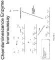
- FIG. 7shows a two-step assay.
- FIG. 8depicts an exemplary chemiluminescent assay.
- One aspect of the inventionis a fluidic device for detecting an analyte in a sample of bodily fluid.
- the fluidic deviceincludes an assay assembly configured to yield an optical signal that is indicative of the presence of the analyte in the sample and an quencher assembly adapted to reduce interference of the optical signal.
- the fluidic devicegenerally has a sample collection unit, an assay assembly, fluidic channels and one or more waste chambers.
- the sample collection unitcomprises an inlet for receiving a sample, e.g., a bodily fluid from a subject, such as blood or urine, optionally a receptacle for holding the sample, and an outlet to a fluidic channel that connects with the assay assembly.
- a samplee.g., a bodily fluid from a subject, such as blood or urine
- a receptaclefor holding the sample
- an outletto a fluidic channel that connects with the assay assembly.
- the assay assemblycomprises (a) at least one and optionally a plurality of reagent chambers, optionally containing reagents to perform a detection assay, (b) at least one and, optionally, a plurality of reaction sites, each site comprising a surface to which is immobilized a reactant that recognizes and binds an analyte, and (3) fluidic channels that connect the reaction sites with the sample collection unit and the reagent chambers.
- the assayprovides an optical signal indicative of the presence of an analyte of interest, which can then be detected by a detection assembly as described below. Unbound, or excess, sample and reagents remain on-board the fluidic device after the assay, and collect in a waste chamber within the fluidic device.
- a reactant immobilized at a reaction sitecan be anything useful for detecting an analyte of interest in a sample of bodily fluid.
- reactantsinclude without limitation nucleic acid probes, antibodies, cell membrane receptors, monoclonal antibodies and polyclonal antibodies reactive with a specific analyte.
- Various commercially available reactantssuch as a host of polyclonal and monoclonal antibodies specifically developed for specific analytes can be used.
- reaction sitesthere are more than one reaction sites which can allow for detection of multiple analytes of interest from the same sample of bodily fluid. In some embodiments there are 2, 3, 4, 5, 6, or more reaction sites, or any other number of reaction sites as may be necessary to carry out the present invention.
- each reaction sitemay be immobilized with a reactant different from a reactant on a different reaction site.
- a fluidic device with, for example, three reaction sitesthere may be three different reactants, each bound to a different reaction site to bind to three different analytes of interest in the sample.
- there may be different reactants bound to a single reaction siteif, for example, a CCD with multiple detection areas were used as the detection device, such that multiple different analytes could be detected in a single reaction site.
- Exemplary reaction sitesare more fully described in patent application Ser. No. 11/389,409, filed Mar. 24, 2006, which is incorporated by reference herein in its entirety.
- the assayemploys an enzyme conjugate comprising, e.g., a protein conjugated with an enzyme.
- the enzymecan react with a substrate to generate a luminescent signal.
- the assaycan be a direct assay, a competitive assay, in which a reactant not bound to an analyte is exposed to a reagent comprising an analyte molecule conjugated to the enzyme, or as described below for detecting small molecules, the two-step assay.
- Another preferred assay that can be performed using the subject deviceis an Enzyme-Linked ImmunoSorbent Assay (“ELISA”).
- ELISAEnzyme-Linked ImmunoSorbent Assay
- a fluorescent dyeis coupled to or used in tandem with a chemiluminescent reaction to further amplify the signal to obtain a wider range of linear response.
- the assay assemblypreferably comprises all of the reagents necessary to perform the assay in the fluidic device.
- Such reagentsare on-board, or housed within the fluidic device before, during, and after the assay.
- the only inlet for liquids from the fluidic deviceis preferably the bodily fluid sample initially provided to the fluidic device.
- An advantageis using such an on-board system is the easily disposable nature of the fluidic device, as well as attempting to prevent leakage from the fluidic device onto or into a detection device used to detect an optical signal produced during the assay which is indicative of the presence of an analyte of interest in the sample. Furthermore all potentially biohazardous materials are contained within the cartridge.
- the reagent chambers within the assay assemblyare preferably in fluidic communication with at least one reaction site, and when the fluidic device is actuated to initiate the flow of fluid as described herein, reagents contained in the reagent chambers are released into the fluidic channels.
- Reagents according to the present inventioninclude without limitation wash buffers, enzyme substrates, dilution buffers, conjugates, enzyme-labeled conjugates, DNA amplifiers, sample diluents, wash solutions, sample pre-treatment reagents including additives such as detergents, polymers, chelating agents, albumin-binding reagents, enzyme inhibitors, enzymes, anticoagulants, red-cell agglutinating agents, antibodies, or other materials necessary to run an assay on a fluidic device.
- An enzyme conjugatecan be a conjugate with a polyclonal antibody, monoclonal antibody, hapten or other member of a binding pair (MBP) label that can yield a detectable signal upon reaction with an appropriate enzyme substrate.
- Non-limiting examples of such enzymesare alkaline phosphatase and horseradish peroxidase.
- the reagentscomprise immunoassay reagents.
- Reagent chamberscan contain approximately about 50 ⁇ l to about 1 ml of fluid. In some embodiments the chamber may contain about 100 ⁇ l of fluid. The volume of liquid in a reagent chamber may vary depending on the type of assay being run or the sample of bodily fluid provided.
- Fluidic channels in the fluidic devicemay be created by, for example without limitation, dye cutting, machining, precision injection molding, laser etching, or any other techniques known in the art.
- the fluidic devicealso preferably includes a quencher assembly.
- the quencher assemblycomprises a quenching site in fluid communication with the reaction site and a quenching agent at the quenching site.
- the quenching assemblycan optionally comprise an absorbent material impregnated with the quenching agent.
- the quenching sitecomprises or is part of the waste chamber.
- the quencher assemblyis typically adapted to reduce an optical signal from the fluidic device that interferes with the optical signal indicative of the presence of the analyte in the sample.
- the quencher assemblyreduces the interfering optical signal by at least about 50%, at least about, 60%, at least about 70%, at least about 80%, at least about 90%, or more.
- the quencher assemblyreduces optical interference by at least about 99%.
- the quenching assemblyreduces interference by at least about 99.5%.
- the quencher assemblyreduces optical interference by about 99.9%.
- the quencher assemblycan be adapted to physically block optical interference from the waste liquid.
- the quencher assemblycan comprise a dark coating to absorb optical interference from the fluidic device.
- the quencher assemblycan comprise an absorbent material impregnated with the quenching agent.
- an absorbent materialis a material or substance that has the power or capacity or tendency to absorb or take up liquid.
- Absorption mechanismscan include capillary forces, osmotic forces, solvent or chemical action, or other similar mechanisms.
- An absorbent materialcan be a solid material, porous material, gel, porous or sintered polymer, high salt fluid, thermoplastic polymer (such as those available from Sigma, Aldrich, PorexTM, etc.), polyolefin resin, or porous plastic, including, e.g., PorexTM plastics.
- the absorbent materialmay also be an aerosol particulate spray, for example, comprising porous particulate matter.
- the absorbent materialcan be a cellulosic material such as paper, e.g., KimwipeTM, paper towel or the like.
- the absorbent materialcan also be, for example, polyacrylamide, agarose, agar, polyethylene, polypropylene, a high molecular weight polyethylene, polyvinylidene fluoride, ethylene-vinyl acetate, polytetrafluoroethylene, stryene-acrylonitrile, polysulfone, polycarbonate, dextran, dry sephadex, polyhthalate, silica, glass fiber, or other material similar to those included herein. Additionally, an absorbent material can be any combination of the materials described herein.
- the absorbent materialis bibulous and the volume fraction of air is generally about 10-70% of the absorbent material.
- the absorbent materialhelps absorb waste liquids used in the assay and therefore prevents leakage of fluid from the fluidic device, as may be desirable to prevent contamination on or into a detection device used in conjunction with the fluidic device to detect the optical signal.
- the absorbent materialcomprises at least one quenching agent which reacts with at least one reagent from said assay assembly to reduce interference of the optical signal indicative of the presence of the analyte in the sample.
- the quenching agentcan inhibit the binding between reagents, or in preferred embodiments the quenching agent inactivates at least one and more preferably all reagents which may contribute to an interfering optical signal.
- the reagent or reagents with which the quenching agent in the quencher assembly reacts to reduce the interferencecan be, for example without limitation, an unbound enzyme and/or an unbound substrate.
- the reagent with which the quenching agent reacts to reduce the interferenceis generally not as important as the reduction of the interference itself.
- the quenching agent in the quencher assemblycan vary depending on the type of assay that is being performed in the fluidic device.
- a subject quenching agentreduces an interfering optical signal by at least about 50%, at least about 60%, at least about 70%, at least about 80%, at least about 90%, or more. In a preferred embodiment the quenching agent reduces an interfering optical signal by about 99%.
- the quenching assemblyreduces optical interference by at least about 99.5%. In more preferred embodiments the quenching agent reduces optical interference by at least about 99.9%. In this way the quencher assembly can be produced with a specific assay or assays in mind and can comprise quenching agents which will satisfactorily reduce the interfering signal.
- the quenching agentcan be a chemical that is a strong non-volatile acid such as trichloroacetic acid or its salt sodium trichloroacetate.
- the substancecan also be a strong alkali such as sodium hydroxide.
- strong non-volatile acids and strong alkaliscan be used in accordance with the present invention.
- the quenching agentreduces the optical interference by inhibiting the enzyme.
- the quenching agentcan interfere with the enzyme's ability to convert the substrate to produce a luminescent signal.
- Exemplary enzyme inhibitorsinclude lactose which inhibits the action of ⁇ -galactosidase on luminogenic galactosides, and phosphate salts which inhibit phosphatases.
- the quenching agentcan reduce the interference by denaturing the enzyme.
- denaturantsinclude detergents such as sodium dodecyl sulfate (SDS), heavy metal salts such as mercuric acetate, or chelating agents such as EDTA which can sequester metal ions essential for activity of certain enzymes such as alkaline phosphatase. All types of surfactants may be used including cationic (CTMAB) and anionic (SDS).
- the quenching agentcan be a non-denaturing chemical that is incompatible with enzyme activity.
- exemplary chemicalsinclude buffers and the like that change the pH to a value where the enzyme becomes inactive and thus unable to catalyze the production of the interfering signal.
- the quenching agentcan be, for example, an organic charge-transfer molecule, including 7,7,8,8-tetracyanoquinodimethane (TCNQ), 2,3,5,6-tetrafluoro-7,7,8,8-tetracyanoquinodimethane (TFTCNQ), carbon nanotubes, mordant yellow 10 (MY) and 4-amino-1,1-azobenzene-3,4-disulfonic acid (AB).
- TCNQ7,7,8,8-tetracyanoquinodimethane
- TFTCNQ2,3,5,6-tetrafluoro-7,7,8,8-tetracyanoquinodimethane
- MYmordant yellow 10
- AB4-amino-1,1-azobenzene-3,4-disulfonic acid
- the azobenzene compoundsare MY and AB, as they are considerably more water-soluble than TCNQ, TFTCNQ and carbon nanotubes.
- the structure of ABis
- the quenching agentcan be heavy atoms such as iodine which reduces the interference by quenching a fluorescent species used to enhance a chemiluminescent signal.
- the quenching agentcan be an organic compound with an absorption spectrum overlapping the fluorescence emission spectrum of a fluorescent species used to enhance a chemiluminescent signal.
- such a quenching agentis a dark quencher such as a dispersion of carbon particles (e.g., carbon black, charcoal). Carbon can inactivate chemiluminescence by absorbing actives species, and it is also a very good quenching agent that is substantially incapable of emitting fluorescence.
- the quenching agentcan be an antioxidant, which can reduce the interference by disrupting the chemiluminescent reaction.
- Quenching agentsthat may be used in some embodiments of the invention include but are not limited to Trolox, butylated hydroxytoluene (BHT), ascorbic acid, citric acid, retinol, carotenoid terpenoids, non-carotenoid terpenoids, phenolic acids and their esters, and bioflavinoids.
- the quenching agentcan be a singlet oxygen quencher, which can reduce the interference by disrupting the chemiluminescent reaction.
- Some singlet oxygen quenchersinclude but are not limited to 1, 4 diazabicyclo [2,2,2] octane, thiol containing compounds such as methionine or cysteine, and carotenoids such as lycopene.
- the substance used to impregnate or saturate the absorbent materialis preferably highly concentrated, typically in large molar excess of the assay reagents.
- the quencher assemblypossesses desirable certain properties some of which, by way of example, are now described.
- the absorption of waste liquidsis preferably fast relative to the duration of the assay. In preferred embodiments the absorption of waste liquids occurs within a few minutes and more preferably within a few seconds.
- the absorbent materialpreferably absorbs substantially all of the liquid waste in the fluidic device. In preferred embodiments more than 99% of the liquid in the waste chamber is absorbed. In addition to reducing the optical interference, this helps prevent liquid from leaking from the fluidic device after the assay is complete, which helps prevent contamination of a detection device as may be used with the fluidic device as described herein.
- the quencher assembly's inhibition of enzyme activityshould preferably be rapid, typically within a few minutes and more preferably within a few seconds.
- the inhibitory enzyme reactionshould be as complete as possible to ensure the interference is reduced as much as possible.
- the inactivation of the enzyme reactionshould be more than 99% complete before the optical signal indicative of the presence of the analyte in the sample is detected by any detection mechanism that may be used with the fluidic device as described herein.
- the quencher assemblycomprises an absorbent material, and as such, the inactivating substance imbedded therein is preferably stable within the absorbent material. Furthermore, the quenching agent preferably dissolves within seconds to minutes of being exposed to the waste liquids.
- the quencher assemblycomprises the waste chamber.
- a waste chamberis generally a chamber or well in fluidic communication with the assay assembly in which assay reagents and sample which do not bind to the reaction site in the assay assembly collect after the assay.
- the waste chamberis generally the area of the fluidic device in which any unbound or excess reagents and sample collect after the assay.
- the quencher assemblycomprises an absorbent material
- the absorbent materialmay be adapted to be housed within the waste chamber. The absorbent material may or may not fill up the entire waste chamber, and may expand when a fluid enters the waste chamber.
- the quencher assemblymay also comprise a stabilizing feature adapted to stabilize or secure the absorbent material within the fluidic device.
- a waste chamber adapted to house the absorbent materialmay also comprise a pin or stake projecting from the top of the waste chamber to contact and stabilize or secure the absorbent pad.
- FIGS. 1 and 2show a top and bottom view, respectively, of an exemplary fluidic device after the device has been assembled.
- the different layersare designed and affixed to form a three dimensional fluidic channel network.
- a sample collection unit 4provides a sample of bodily fluid from a patient.
- a reader assemblycomprises actuating elements (not shown) can actuate the fluidic device to start and direct the flow of a bodily fluid sample and assay reagents in the fluidic device.
- actuating elementsfirst cause the flow of sample in the fluidic device 2 from sample collection unit 4 to reaction sites 6 , move the sample upward in the fluidic device from point G′ to point G, and then to waste chamber 8 in which absorbent material 9 is housed.
- the actuating elementsthen initiate the flow of reagents from reagent chambers 10 to point B′, point C′, and point D′, then upward to points B, C, and D, respectively, then to point A, down to point A′, and then to waste chamber 8 in the same manner as the sample.
- quencher assembly 9When the sample and the reagents enter the waste chamber 8 they encounter quencher assembly 9 .
- a fluidic devicehas a calibration assembly that mimics the assay assembly in components and design except that a sample is not introduced into the calibration assembly.
- a calibration assemblyoccupies about half of the fluidic device 2 and includes reagent chambers 32 , reactions sites 34 , a waste chamber 36 , fluidic channels 38 , and absorbent material 9 . Similar to the assay assembly, the number of reagent chambers and reaction sites may vary depending on the assay being run on the fluidic device and the number of analytes being detected.
- FIG. 3is a top view of another exemplary embodiment of a fluidic device. A plurality of absorbent materials 9 are shown.
- FIG. 4shows a bottom view of the embodiment from FIG. 3 .
- FIG. 5illustrates the plurality of layers of the exemplary fluidic device shown in FIGS. 3 and 4 .
- the position of absorbent material 9is shown relative to the other components and layers of the fluidic device.
- a detection assembly as shown in FIG. 6then detects the optical signal indicative of the presence of the analyte in the sample, and the detected signal can then be used to determine the concentration of the analyte in the sample.
- FIG. 6illustrates the position of an exemplary detection assembly that can be used to detect an optical signal from the fluidic device that is indicative of the presence of an analyte of interest in the sample.
- the detection assemblymay be above or below the fluidic device or at a different orientation in relation to the fluidic device based on, for example, the type of assay being performed and the detection mechanism being employed.
- an optical detectoris used as the detection device.
- Non-limiting examplesinclude a photomultiplier tube (PMT), photodiode, photon counting detector, or charge-coupled device (CCD).
- PMTphotomultiplier tube
- CCDcharge-coupled device
- Some assaysmay generate luminescence as described herein.
- chemiluminescenceis detected.
- a detection assemblycould include a plurality of fiber optic cables connected as a bundle to a CCD detector or to a PMT array.
- the fiber optic bundlecould be constructed of discrete fibers or of many small fibers fused together to form a solid bundle. Such solid bundles are commercially available and easily interfaced to CCD detectors.
- Interferencegenerally means an optical signal produced in the fluidic device which interferes with the optical signal produced by bound reactants, which is indicative of the presence of an analyte of interest.
- an interfering signalis produced in the waste chamber where the reagents which do not bind to the reaction sites accumulate and encounter one another.
- the accumulation of waste liquidscan produce such interference when, for example, an enzyme used in an assay to increase assay sensitivity reacts with an unbound substrate, creating an optical signal that interferes with the optical signal generated by bound reactants.
- Another aspect of the inventionis a method of detecting an analyte in a sample.
- the methodcomprises allowing a bodily fluid sample suspected to contain the analyte to react with reactants contained in a fluidic device which has an assay assembly configured to yield an optical signal that is indicative of the presence of the analyte and a quencher assembly adapted to reduce interference of said optical signal, and detecting the optical signal thereby detecting the analyte in the sample.
- any sample of bodily fluids suspected to contain an analyte of interestcan be used in conjunction with the subject system or devices.
- Commonly employed bodily fluidsinclude but are not limited to blood, serum, saliva, urine, gastric and digestive fluid, tears, stool, semen, vaginal fluid, interstitial fluids derived from tumorous tissue, and cerebrospinal fluid.
- the bodily fluidsare provided directly to the fluidic device without further processing.
- the bodily fluidscan be pre-treated before performing the analysis with the subject fluidic devices. The choice of pre-treatments will depend on the type of bodily fluid used and/or the nature of the analyte under investigation.
- the samplecan be concentrated via any conventional means to enrich the analyte.
- the analyteis a nucleic acid
- itcan be extracted using various lytic enzymes or chemical solutions according to the procedures set forth in Sambrook et al. (“Molecular Cloning: A Laboratory Manual”), or using nucleic acid binding resins following the accompanying instructions provided by manufactures.
- extractioncan be performed using lysing agents including but not limited to denaturing detergent such as SDS or non-denaturing detergent such as Thesit sodium deoxylate, triton X-100, and tween-20.
- a bodily fluidmay be drawn from a patient and brought into the fluidic device in a variety of ways, including but not limited to, lancing, injection, or pipetting.
- a lancetpunctures the skin and draws the sample into the fluidic device using, for example, gravity, capillary action, aspiration, or vacuum force.
- a patientcan simply provide a bodily fluid to the fluidic device, as for example, could occur with a blood or saliva sample.
- the collected fluidcan be placed in the sample collection unit within the fluidic device where the fluidic device can automatically detect the required volume of sample to be used in the assay.
- the fluidic devicecomprises at least one microneedle which punctures the skin.
- microneedlecan be used with a fluidic device alone, or can puncture the skin after the fluidic device is inserted into a reader assembly.
- Sample collections techniqueswhich may be used herein are described in patent application Ser. No. 11/389,409, filed Mar. 24, 2006, which is incorporated by reference herein in its entirety.
- a sample of bodily fluidcan first be provided to the fluidic device by any of the methods described herein.
- the fluidic devicecan then be inserted into a reader assembly as shown in FIG. 6 .
- An identification detector housed within the reader assemblycan detect an identifier of the fluidic device and communicate the identifier to a communication assembly, which is preferably housed within the reader assembly.
- the communication assemblythen transmits the identifier to an external device which transmits a protocol to run on the fluidic device based on the identifier to the communication assembly.
- a controllerpreferably housed within the reader assembly controls actuating elements including at least one pump and one valve which interact with the fluidic device to control and direct fluid movement within the device.
- the fluidic deviceis preferably initially calibrated using a calibration assembly by running the same reagents as will be used in the assay through the calibration reaction sites, and then an optical signal from the reactions sites is detected by the detection means, and the signal is used in calibrating the fluidic device.
- Calibration techniquesthat may be used in the fluidic device herein can be found in patent application Ser. No. 11/389,409, filed Mar. 24, 2006, which is incorporated by reference herein in its entirety.
- the sample containing an analyteis introduced into the fluidic channel.
- the samplemay be diluted, mixed, and/or and further separated into plasma or other desired component using a filter.
- the samplethen flows through the reaction sites and analytes present therein will bind to reactants bound thereon.
- the sample fluidis then flushed out of the reaction wells into a waste chamber.
- appropriate reagentsare directed through the reaction sites via the channels to carry out the assay.
- Any wash buffers and other reagents used in the various steps, including the calibration step,are collected in at least one waste chamber.
- the signal produced in the reaction sitesis then detected by any of the detection methods described herein.
- a variety of assaysmay be performed in a fluidic device according to the present invention to detect an analyte of interest in a sample.
- the detection assayrelies on luminescence and, in particular, chemiluminescence.
- the assayemploys an enzyme conjugate comprising, e.g., a protein conjugated with an enzyme.
- the enzymecan react with a substrate to generate a luminescent signal.
- the assaycan be a direct assay or a competitive assay, in which a reactant not bound to an analyte is exposed to a reagent comprising an analyte molecule conjugated to the enzyme.
- a fluorescent compoundmay be used in tandem or coupled with the chemiluminescent reaction, in order to linearly multiply the signal output of the reaction.
- the sample containing analyte(“Ag”) first flows over a reaction site containing antibodies (“Ab”).
- the antibodiesbind the analyte present in the sample.
- a solution with analyte conjugated to a marker (“labeled Ag”) at a high concentrationis passed over the surface.
- the conjugatesaturates any of the antibodies that have not yet bound the analyte.
- the high-concentration conjugate solutionis washed off.
- the amount of conjugate bound to the surfaceis then measured by the appropriate technique, and the detected conjugate is inversely proportional to the amount of analyte present in the sample.
- the markercan be a commercially available marker such as a dioxetane-phosphate, which is not luminescent but becomes luminescent after hydrolysis by, for example, alkaline phosphatase.
- An enzymesuch as alkaline phosphatase is exposed to the conjugate to cause the substrate to luminesce.
- the substrate solutionis supplemented with enhancing agents such as, without limitation, fluorescein in mixed micelles, soluble polymers, or PVC which create a much brighter signal than the luminophore alone.
- the mechanism by which the quencher assembly functions to reduce interferenceis not critical to the functionality of the present invention, as long as the interference is reduced by a sufficient amount.
- An ELISAis another exemplary assay for which an optical quencher can be used to remove an interfering signal generated by reactants to a reaction site.
- a sample containing an antigen of interestis passed over the reaction site, to which analytes of interest in the sample will bind by virtue of antibody molecules (directed to the antigen) adsorbed to the reaction site.
- enzyme-labeled antibody conjugate(directed to the antigen and selected such that the antibody bound to the reaction site does not block binding of the conjugate) is passed over the reaction site, allowed to bind, then displaced by the substrate.
- Enzymecauses the substrate to produce an optical signal. Unbound reagents which end up in the waste chamber can similarly produce interfering signals.
- the labelis coupled directly or indirectly to a molecule to be detected such as a product, substrate, or enzyme, according to methods well known in the art.
- a molecule to be detectedsuch as a product, substrate, or enzyme
- Non radioactive labelsare often attached by indirect means.
- a ligand moleculeis covalently bound to a polymer.
- the ligandthen binds to an anti-ligand molecule which is either inherently detectable or covalently bound to a signal system, such as a detectable enzyme, or a chemiluminescent compound.
- a number of ligands and anti-ligandscan be used.
- a ligandhas a natural anti-ligand, for example, biotin, thyroxine, and cortisol, it can be used in conjunction with labeled, anti-ligands.
- a haptenic or antigenic compoundcan be used in combination with an antibody.
- the labelcan also be conjugated directly to signal generating compounds, for example, by conjugation with an enzyme.
- Enzymes of interest as labelswill primarily be hydrolases, particularly phosphatases, esterases and glycosidases, or oxidoreductases, particularly peroxidases.
- Chemiluminescent compoundsinclude luciferin, and 2,3-dihydrophthalazinediones, such as luminol, dioxetanes and acridinium esters.
- detecting labelsare well known to those of skill in the art. Detection can be accomplished using of electronic detectors such as digital cameras, charge coupled devices (CCDs) or photomultipliers and phototubes, or other detection devices. Similarly, enzymatic labels are detected by providing appropriate substrates for the enzyme and detecting the resulting reaction product. Finally, simple colorimetric labels are often detected simply by observing the color associated with the label. For example, conjugated gold often appears pink, while various conjugated beads appear the color of the bead.
- Suitable chemiluminescent sourcesinclude a compound which becomes electronically excited by a chemical reaction and may then emit light which serves as the detectible signal.
- a diverse number of families of compoundshave been found to provide chemiluminescence under a variety or conditions.
- One family of compoundsis 2,3-dihydro-1,4-phthalazinedione.
- a frequently used compoundis luminol, which is a 5-amino compound.
- Other members of the familyinclude the 5-amino-6,7,8-trimethoxy- and the dimethylamino[ca]benz analog. These compounds can be made to luminesce with alkaline hydrogen peroxide or calcium hypochlorite and base.
- Chemiluminescent analogsinclude para-dimethylamino and -methoxy substituents. Chemiluminescence may also be obtained with oxalates, usually oxalyl active esters, for example, p-nitrophenyl and a peroxide such as hydrogen peroxide, under basic conditions. Other useful chemiluminescent compounds that are also known include —N-alkyl acridinum esters and dioxetanes. Alternatively, luciferins may be used in conjunction with luciferase or lucigenins to provide bioluminescence.
- immunoassaysare run on the fluidic device. While competitive binding assays, which are well known in the art, may be run in some embodiments, in some embodiments a two-step method is used which eliminates the need to mix a conjugate and a sample before exposing the mixture to an antibody, which may be desirable when very small volumes of sample and conjugate are used, as in the fluidic device of the present invention.
- a two-step assayhas additional advantages over the competitive binding assays when use with a fluidic device as described herein. It combines the ease of use and high sensitivity of a sandwich (competitive binding) immunoassay with the ability to assay small molecules.
- FIG. 8An exemplary two-step assay shown in FIG. 8 has been described herein, as has an exemplary measuring technique for the two-step assay—a chemiluminescence enzyme immunoassay as shown in FIG. 8 .
- analytesincludes without limitation drugs, prodrugs, pharmaceutical agents, drug metabolites, biomarkers such as expressed proteins and cell markers, antibodies, serum proteins, cholesterol, polysaccharides, nucleic acids, biological analytes, biomarkers, genes, protein, or hormones, or any combination thereof.
- biomarkerssuch as expressed proteins and cell markers, antibodies, serum proteins, cholesterol, polysaccharides, nucleic acids, biological analytes, biomarkers, genes, protein, or hormones, or any combination thereof.
- the analytescan be polypeptide, proteins, glycoprotein, polysaccharide, lipid, nucleic acid, and combinations thereof.
- One aspect of the inventionis a method of manufacturing a fluidic device having a quencher assembly.
- the methodcomprises providing a plurality of layers of the fluidic device, and affixing the layers to provide for a fluidic network between a sample collection unit, at least one reagent chamber, at least one reaction site, and at least one waste chamber comprising an quencher assembly.
- At least one of the different layers of the fluidic devicemay be constructed of polymeric substrates.
- polymeric materialsinclude polystyrene, polycarbonate, polypropylene, polydimethysiloxanes (PDMS), polyurethane, polyvinylchloride (PVC), polymethylmethacrylate and polysulfone.
- Manufacturing of the fluidic channelsmay generally be carried out by any number of microfabrication techniques that are well known in the art.
- lithographic techniquesare optionally employed in fabricating, for example, glass, quartz or silicon substrates, using methods well known in the semiconductor manufacturing industries such as photolithographic etching, plasma etching or wet chemical etching.
- micromachining methodssuch as laser drilling, micromilling and the like are optionally employed.
- polymeric substrateswell known manufacturing techniques may also be used. These techniques include injection molding. Stamp molding and embossing methods where large numbers of substrates are optionally produced using, for example, rolling stamps to produce large sheets of microscale substrates or polymer microcasting techniques where the substrate is polymerized within a micromachined mold. Dye casting may also be used.
- the different layers of the fluidic deviceare ultrasonically welded together according to methods known in the art.
- the layersmay also be coupled together using other methods, including without limitation, stamping, thermal bonding, adhesives or, in the case of certain substrates, e.g., glass, or semi-rigid and non-rigid polymeric substrates, a natural adhesion between the two components.
- FIG. 5shows an embodiment of the invention in which a fluidic device 2 is comprised of a plurality of different layers of material. Features as shown are, for example, cut in the polymeric substrate such that when the layers are properly positioned when assembly will form a fluidic network. In some embodiments more or fewer layers may be used to construct a fluidic device to carry out the purpose of the invention.
- the quencher assemblyhas been described herein and in some embodiments can comprise an absorbent material.
- the quencher assemblycan be produced by applying the quenching agent into the absorbent material. This can be accomplished by any number of techniques well known in the art, such as pipetting the liquid onto the absorbent material until the absorbent material is substantially imbedded in the absorbent material, or simply allowing the absorbent material to absorb the quenching agent.
- the amount of saturation of the absorbent materialmay vary, as long as a sufficient amount of the quenching agent is incorporated into the absorbent material to produce an inhibitory effect on at least assay reagent.
- the absorbent materialis then dried.
- the drying stepcan be accomplished by any suitable technique such as freeze drying, drying under flowing gas with temperature elevation, or simply passive drying by allowing water in the absorbent material to evaporate.
- the absorbent material incorporating the quenching agentcan then be placed into a fluidic device as described during the manufacturing process where it can be used to reduce optical interference in an assay performed within the fluidic device.
- the placement inside the fluidic devicecan be by any known technique and can simply be manually placing it into the fluidic device.
- the absorbent materialis preferably placed in a waste chamber adapted to collect unbound liquids used inside the fluidic device.
- a 1 ⁇ 0.5 inch piece of Whatman #32 glass fiber mat(item 10 372 968) was impregnated with 50 uL of 15% w/v 4-amino-1,1-azobenzene-3,4-disulfonic acid (0.4 M) in water then dried in a “dry box”.
- alkaline-phosphatasefrom bovine intestine
- Lumigen's LumiphosTM 530, or KPL PhosphoglowTM AP substratesboth are dioxetanes and have an esterified phosphate residue on which the enzyme acts
- the resultwas about 200 uL of enzyme and 200 uL of substrate in the waste chamber, thus exposed to the adsorbent material.
- the intensitydropped to about 100 counts/second within a few seconds after adding the adsorbent material (the noise level of the luminometer was about 100 counts/second). In other words, more than 99% of the optical interference was eliminated.
- the azobenzeneacted in an inhibitory manner on both the enzyme and the substrate.
- the enzymewas inactivated by the acidity of the reagent, and likely by other mechanisms as well.
- the substratewas chemically modified by the azobenzene such that it is no longer a substrate for alkaline phosphatase.
Landscapes
- Health & Medical Sciences (AREA)
- Chemical & Material Sciences (AREA)
- Immunology (AREA)
- Life Sciences & Earth Sciences (AREA)
- Hematology (AREA)
- Engineering & Computer Science (AREA)
- Analytical Chemistry (AREA)
- General Health & Medical Sciences (AREA)
- Chemical Kinetics & Catalysis (AREA)
- Molecular Biology (AREA)
- Biomedical Technology (AREA)
- Urology & Nephrology (AREA)
- Clinical Laboratory Science (AREA)
- Dispersion Chemistry (AREA)
- Biotechnology (AREA)
- Microbiology (AREA)
- Cell Biology (AREA)
- Food Science & Technology (AREA)
- Medicinal Chemistry (AREA)
- Physics & Mathematics (AREA)
- Biochemistry (AREA)
- General Physics & Mathematics (AREA)
- Pathology (AREA)
- Investigating Or Analysing Materials By The Use Of Chemical Reactions (AREA)
Abstract
Description

Claims (11)
Priority Applications (2)
| Application Number | Priority Date | Filing Date | Title |
|---|---|---|---|
| US15/951,720US11215610B2 (en) | 2006-10-13 | 2018-04-12 | Reducing optical interference in a fluidic device |
| US17/567,555US20220196639A1 (en) | 2006-10-13 | 2022-01-03 | Reducing optical interference in a fluidic device |
Applications Claiming Priority (4)
| Application Number | Priority Date | Filing Date | Title |
|---|---|---|---|
| US11/549,558US8012744B2 (en) | 2006-10-13 | 2006-10-13 | Reducing optical interference in a fluidic device |
| US13/188,288US8470524B2 (en) | 2006-10-13 | 2011-07-21 | Reducing optical interference in a fluidic device |
| US13/915,362US10067123B2 (en) | 2006-10-13 | 2013-06-11 | Reducing optical interference in a fluidic device |
| US15/951,720US11215610B2 (en) | 2006-10-13 | 2018-04-12 | Reducing optical interference in a fluidic device |
Related Parent Applications (1)
| Application Number | Title | Priority Date | Filing Date |
|---|---|---|---|
| US13/915,362ContinuationUS10067123B2 (en) | 2006-10-13 | 2013-06-11 | Reducing optical interference in a fluidic device |
Related Child Applications (1)
| Application Number | Title | Priority Date | Filing Date |
|---|---|---|---|
| US17/567,555DivisionUS20220196639A1 (en) | 2006-10-13 | 2022-01-03 | Reducing optical interference in a fluidic device |
Publications (2)
| Publication Number | Publication Date |
|---|---|
| US20180231534A1 US20180231534A1 (en) | 2018-08-16 |
| US11215610B2true US11215610B2 (en) | 2022-01-04 |
Family
ID=39303473
Family Applications (6)
| Application Number | Title | Priority Date | Filing Date |
|---|---|---|---|
| US11/549,558Active2028-07-15US8012744B2 (en) | 2006-10-13 | 2006-10-13 | Reducing optical interference in a fluidic device |
| US13/188,288ActiveUS8470524B2 (en) | 2006-10-13 | 2011-07-21 | Reducing optical interference in a fluidic device |
| US13/915,362Active2030-01-28US10067123B2 (en) | 2006-10-13 | 2013-06-11 | Reducing optical interference in a fluidic device |
| US15/951,769ActiveUS11442061B2 (en) | 2006-10-13 | 2018-04-12 | Reducing optical interference in a fluidic device |
| US15/951,720ActiveUS11215610B2 (en) | 2006-10-13 | 2018-04-12 | Reducing optical interference in a fluidic device |
| US17/567,555PendingUS20220196639A1 (en) | 2006-10-13 | 2022-01-03 | Reducing optical interference in a fluidic device |
Family Applications Before (4)
| Application Number | Title | Priority Date | Filing Date |
|---|---|---|---|
| US11/549,558Active2028-07-15US8012744B2 (en) | 2006-10-13 | 2006-10-13 | Reducing optical interference in a fluidic device |
| US13/188,288ActiveUS8470524B2 (en) | 2006-10-13 | 2011-07-21 | Reducing optical interference in a fluidic device |
| US13/915,362Active2030-01-28US10067123B2 (en) | 2006-10-13 | 2013-06-11 | Reducing optical interference in a fluidic device |
| US15/951,769ActiveUS11442061B2 (en) | 2006-10-13 | 2018-04-12 | Reducing optical interference in a fluidic device |
Family Applications After (1)
| Application Number | Title | Priority Date | Filing Date |
|---|---|---|---|
| US17/567,555PendingUS20220196639A1 (en) | 2006-10-13 | 2022-01-03 | Reducing optical interference in a fluidic device |
Country Status (2)
| Country | Link |
|---|---|
| US (6) | US8012744B2 (en) |
| CN (1) | CN101522885B (en) |
Cited By (1)
| Publication number | Priority date | Publication date | Assignee | Title |
|---|---|---|---|---|
| US20200171493A1 (en)* | 2018-11-29 | 2020-06-04 | Shenzhen Watmind Medical Co., Ltd. | Microfluidic chemiluminescence immunoassay analyzer |
Families Citing this family (24)
| Publication number | Priority date | Publication date | Assignee | Title |
|---|---|---|---|---|
| US8012744B2 (en) | 2006-10-13 | 2011-09-06 | Theranos, Inc. | Reducing optical interference in a fluidic device |
| US8008034B2 (en)* | 2006-10-13 | 2011-08-30 | Theranos, Inc. | Reducing optical interference in a fluidic device |
| US8790916B2 (en) | 2009-05-14 | 2014-07-29 | Genestream, Inc. | Microfluidic method and system for isolating particles from biological fluid |
| CN103140755B (en) | 2010-07-22 | 2016-03-16 | 哈希公司 | For the lab on A Chip of alkalinity analyzing |
| US11007528B2 (en) | 2010-10-08 | 2021-05-18 | Cellanyx Diagnostics, Llc | Systems, methods and devices for measuring growth/oncogenic and migration/metastatic potential |
| US20130149724A1 (en)* | 2010-10-08 | 2013-06-13 | Ashok Chander | Systems, devices and methods for microfluidic culturing, manipulation and analysis of tissues and cells |
| US9213043B2 (en) | 2012-05-15 | 2015-12-15 | Wellstat Diagnostics, Llc | Clinical diagnostic system including instrument and cartridge |
| US9625465B2 (en) | 2012-05-15 | 2017-04-18 | Defined Diagnostics, Llc | Clinical diagnostic systems |
| US9075042B2 (en) | 2012-05-15 | 2015-07-07 | Wellstat Diagnostics, Llc | Diagnostic systems and cartridges |
| US9180449B2 (en) | 2012-06-12 | 2015-11-10 | Hach Company | Mobile water analysis |
| US9500639B2 (en) | 2012-07-18 | 2016-11-22 | Theranos, Inc. | Low-volume coagulation assay |
| USD768872S1 (en) | 2012-12-12 | 2016-10-11 | Hach Company | Cuvette for a water analysis instrument |
| KR102557135B1 (en) | 2013-03-11 | 2023-07-19 | 큐 헬스 인코퍼레이티드 | Systems and methods for detection and quantification of analytes |
| US9623409B2 (en) | 2013-03-11 | 2017-04-18 | Cue Inc. | Cartridges, kits, and methods for enhanced mixing for detection and quantification of analytes |
| US10545161B2 (en) | 2013-03-11 | 2020-01-28 | Cue Health Inc. | Systems and methods for detection and quantification of analytes |
| USD745423S1 (en) | 2014-05-12 | 2015-12-15 | Cue Inc. | Automated analyzer test cartridge and sample collection device for analyte detection |
| EP2995937A1 (en)* | 2014-09-15 | 2016-03-16 | Sensirion AG | Integrated chemical sensor chip |
| AU2016296589B2 (en) | 2015-07-17 | 2021-11-18 | Cue Health Inc. | Systems and methods for enhanced detection and quantification of analytes |
| WO2018140540A1 (en) | 2017-01-25 | 2018-08-02 | Cue Health Inc. | Systems and methods for enhanced detection and quantification of analytes |
| US20220091031A1 (en)* | 2020-09-18 | 2022-03-24 | Salvus, Llc | Interferometric Detection and Quantification System and Methods of Use in Chemical Processing |
| US11994504B2 (en) | 2020-09-18 | 2024-05-28 | Salvus, Llc | Interferometric detection and quantification system and methods of use in food processing and food supply chain |
| US11740177B2 (en) | 2020-09-18 | 2023-08-29 | Salvus, Llc | Interferometric detection and quantification system and methods of use in aquatics |
| CN113649098B (en)* | 2021-10-18 | 2022-04-15 | 天津德祥生物技术有限公司 | Microfluidic detection assembly, sample mixing device and application thereof |
| CN115718195A (en)* | 2022-11-15 | 2023-02-28 | 北京惠中医疗器械有限公司 | Method and kit for improving alkaline phosphatase activity in detection of EDTA (ethylene diamine tetraacetic acid) plasma sample based on chemiluminescence method |
Citations (225)
| Publication number | Priority date | Publication date | Assignee | Title |
|---|---|---|---|---|
| US4582791A (en) | 1983-10-07 | 1986-04-15 | Syntex (U.S.A.) Inc. | Reducing non-specific background in immunofluorescence techniques |
| US5061381A (en) | 1990-06-04 | 1991-10-29 | Abaxis, Inc. | Apparatus and method for separating cells from biological fluids |
| EP0478319A1 (en) | 1990-09-28 | 1992-04-01 | Kabushiki Kaisha Toshiba | Gene detection method |
| US5122284A (en) | 1990-06-04 | 1992-06-16 | Abaxis, Inc. | Apparatus and method for optically analyzing biological fluids |
| US5130238A (en) | 1988-06-24 | 1992-07-14 | Cangene Corporation | Enhanced nucleic acid amplification process |
| US5173193A (en) | 1991-04-01 | 1992-12-22 | Schembri Carol T | Centrifugal rotor having flow partition |
| EP0541340A2 (en) | 1991-11-05 | 1993-05-12 | The Perkin-Elmer Corporation | Biopolymer synthesis apparatus and method |
| US5242606A (en) | 1990-06-04 | 1993-09-07 | Abaxis, Incorporated | Sample metering port for analytical rotor having overflow chamber |
| EP0564254A1 (en) | 1992-03-30 | 1993-10-06 | SUN COMPANY, INC. (R&M) | Polycyclic aromatic ring cleavage (parc) process |
| EP0571225A2 (en) | 1992-05-21 | 1993-11-24 | Puritan-Bennett Corporation | Measurement device and method of calibration |
| US5270184A (en) | 1991-11-19 | 1993-12-14 | Becton, Dickinson And Company | Nucleic acid target generation |
| US5273905A (en) | 1991-02-22 | 1993-12-28 | Amoco Corporation | Processing of slide mounted material |
| EP0576602A1 (en) | 1991-03-19 | 1994-01-05 | Minnesota Mining & Mfg | Device and method for separating liquid samples. |
| EP0587222A2 (en) | 1992-08-31 | 1994-03-16 | Johnson & Johnson Clinical Diagnostics, Inc. | Dry immunoassay elements with a separate absorbent layer |
| EP0631137A2 (en) | 1993-06-25 | 1994-12-28 | Edward W. Stark | Glucose related measurement method and apparatus |
| JPH0727700A (en) | 1993-07-14 | 1995-01-31 | Kyoto Daiichi Kagaku:Kk | Apparatus and method for optically measuring component concentration |
| EP0636685A2 (en) | 1993-07-29 | 1995-02-01 | Dow Corning S.A. | Particulate foam control agents and their use |
| EP0637998A1 (en) | 1992-05-01 | 1995-02-15 | Univ Pennsylvania | Fluid handling in microfabricated analytical devices. |
| EP0640826A1 (en) | 1993-08-27 | 1995-03-01 | Becton, Dickinson and Company | System for detecting bacterial growth in a plurality of culture vials |
| EP0640828A1 (en) | 1993-08-27 | 1995-03-01 | F. Hoffmann-La Roche AG | Monitoring multiple reactions simultaneously and analyzing same |
| US5403415A (en) | 1993-11-17 | 1995-04-04 | Abaxis, Inc. | Method and device for ultrasonic welding |
| JPH07103959A (en) | 1993-10-05 | 1995-04-21 | Hitachi Ltd | Chromatogram analysis method, chromatograph device, and data processing device used therein |
| EP0652600A1 (en) | 1993-11-02 | 1995-05-10 | Matsushita Electric Industrial Co., Ltd. | Aggregate of semiconductor micro-needles and method of manufacturing the same, and semiconductor apparatus and method of manufacturing the same |
| JPH07120393A (en) | 1993-10-13 | 1995-05-12 | Nippon Tectron Co Ltd | Fluorescence detection method |
| JPH07151101A (en) | 1993-11-29 | 1995-06-13 | Kazuo Sugimura | Vessel having spiral diaphragm contact surface |
| JPH07196314A (en) | 1993-12-28 | 1995-08-01 | Maruo Calcium Co Ltd | Tubular synthetic inorganic fine particle |
| US5441894A (en)* | 1993-04-30 | 1995-08-15 | Abbott Laboratories | Device containing a light absorbing element for automated chemiluminescent immunoassays |
| US5455166A (en) | 1991-01-31 | 1995-10-03 | Becton, Dickinson And Company | Strand displacement amplification |
| EP0684315A1 (en) | 1994-04-18 | 1995-11-29 | Becton, Dickinson and Company | Strand displacement amplification using thermophilic enzymes |
| US5472603A (en) | 1992-04-02 | 1995-12-05 | Abaxis, Inc. | Analytical rotor with dye mixing chamber |
| US5478750A (en) | 1993-03-31 | 1995-12-26 | Abaxis, Inc. | Methods for photometric analysis |
| EP0693560A2 (en) | 1994-07-19 | 1996-01-24 | Becton, Dickinson and Company | Method and apparatus for fully automated nucleic acid amplification, nucleic acid assay and immunoassay |
| US5527670A (en) | 1990-09-12 | 1996-06-18 | Scientific Generics Limited | Electrochemical denaturation of double-stranded nucleic acid |
| EP0723146A1 (en) | 1992-09-14 | 1996-07-24 | Sri International | Up-converting reporters for biological and other assays using laser excitation techniques |
| JPH08211071A (en) | 1994-10-27 | 1996-08-20 | Precision Syst Sci Kk | Automatic analyzer and method thereof |
| EP0734017A1 (en) | 1995-03-20 | 1996-09-25 | Hewlett-Packard Company | Storage device |
| JPH08334505A (en) | 1995-06-07 | 1996-12-17 | Hewlett Packard Co <Hp> | Miniaturized total analysis system |
| US5590052A (en) | 1994-04-14 | 1996-12-31 | Abaxis, Inc. | Error checking in blood analyzer |
| US5591643A (en) | 1993-09-01 | 1997-01-07 | Abaxis, Inc. | Simplified inlet channels |
| JPH0968533A (en) | 1995-08-31 | 1997-03-11 | Brother Ind Ltd | Biochemical substance measuring device capable of displaying drug dosage |
| CN1146017A (en) | 1995-01-19 | 1997-03-26 | 株式会社日立制作所 | Capillary array electrophoresis system |
| JPH0980021A (en) | 1995-09-18 | 1997-03-28 | Otsuka Pharmaceut Co Ltd | Multicapillary electrophoretic apparatus |
| US5618726A (en) | 1991-03-27 | 1997-04-08 | Idaho Research Foundation, Inc. | Biodegradable azo dyes |
| JPH09113511A (en) | 1995-10-18 | 1997-05-02 | Kdk Corp | Dry test piece for measuring glyco-albumin |
| JPH09192218A (en) | 1996-01-16 | 1997-07-29 | Hitachi Ltd | Blood sugar management system |
| JPH09244055A (en) | 1996-03-14 | 1997-09-19 | Hitachi Ltd | Liquid crystal display |
| JPH09253056A (en) | 1996-03-27 | 1997-09-30 | Nec Corp | Patient monitoring device and system therefor |
| US5674698A (en) | 1992-09-14 | 1997-10-07 | Sri International | Up-converting reporters for biological and other assays using laser excitation techniques |
| JPH09281078A (en) | 1996-04-09 | 1997-10-31 | Hitachi Electron Eng Co Ltd | DNA base sequencer |
| US5687716A (en) | 1995-11-15 | 1997-11-18 | Kaufmann; Peter | Selective differentiating diagnostic process based on broad data bases |
| WO1998000231A1 (en) | 1996-06-28 | 1998-01-08 | Caliper Technologies Corporation | High-throughput screening assay systems in microscale fluidic devices |
| CN1173776A (en) | 1996-01-27 | 1998-02-18 | 三星电子株式会社 | Apparatus and method for interlaced to sequential conversion using motion and space correlation |
| JPH1072628A (en) | 1996-07-10 | 1998-03-17 | Autoliv Asp Inc | Reuse of airbag inflator |
| US5744320A (en) | 1995-06-07 | 1998-04-28 | Promega Corporation | Quenching reagents and assays for enzyme-mediated luminescence |
| JPH10132712A (en) | 1996-04-26 | 1998-05-22 | Kdk Corp | Specimen analyzing tool and method and instrument for analyzing specimen using it |
| EP0844475A2 (en) | 1996-11-20 | 1998-05-27 | Microbial Systems Limited | Particle sizing apparatus |
| US5797898A (en) | 1996-07-02 | 1998-08-25 | Massachusetts Institute Of Technology | Microchip drug delivery devices |
| JPH10239240A (en) | 1997-02-25 | 1998-09-11 | Hitachi Ltd | Automatic DNA probe device |
| JPH10267888A (en) | 1997-03-24 | 1998-10-09 | Kokuritsu Shintai Shogaisha Rehabilitation Center Souchiyou | Biosensor |
| JPH10305016A (en) | 1997-05-08 | 1998-11-17 | Casio Comput Co Ltd | Behavior information provision system |
| US5842787A (en) | 1997-10-09 | 1998-12-01 | Caliper Technologies Corporation | Microfluidic systems incorporating varied channel dimensions |
| US5854033A (en) | 1995-11-21 | 1998-12-29 | Yale University | Rolling circle replication reporter systems |
| US5863502A (en) | 1996-01-24 | 1999-01-26 | Sarnoff Corporation | Parallel reaction cassette and associated devices |
| US5874046A (en) | 1996-10-30 | 1999-02-23 | Raytheon Company | Biological warfare agent sensor system employing ruthenium-terminated oligonucleotides complementary to target live agent DNA sequences |
| US5876675A (en) | 1997-08-05 | 1999-03-02 | Caliper Technologies Corp. | Microfluidic devices and systems |
| JPH1157560A (en) | 1997-08-27 | 1999-03-02 | Shin Meiwa Ind Co Ltd | Liquid sprayer |
| US5885470A (en) | 1997-04-14 | 1999-03-23 | Caliper Technologies Corporation | Controlled fluid transport in microfabricated polymeric substrates |
| US5891734A (en) | 1994-08-01 | 1999-04-06 | Abbott Laboratories | Method for performing automated analysis |
| US5939291A (en) | 1996-06-14 | 1999-08-17 | Sarnoff Corporation | Microfluidic method for nucleic acid amplification |
| US5942443A (en) | 1996-06-28 | 1999-08-24 | Caliper Technologies Corporation | High throughput screening assay systems in microscale fluidic devices |
| US5976896A (en) | 1994-06-06 | 1999-11-02 | Idexx Laboratories, Inc. | Immunoassays in capillary tubes |
| EP0962773A1 (en) | 1998-06-03 | 1999-12-08 | Mark Howard Jones | Electrochemical based assay processes instrument and labels |
| JPH11352094A (en) | 1998-06-11 | 1999-12-24 | Matsushita Electric Ind Co Ltd | Electrochemical analysis element |
| EP0971039A2 (en) | 1998-06-24 | 2000-01-12 | Enzo Diagnostics, Inc. | Processes useful for nucleic acid amplification and sequencing, and for the production of nucleic acid having decreased thermodynamic stability |
| CN1253625A (en) | 1997-04-25 | 2000-05-17 | 卡钳技术有限公司 | Microfluidic devices incorporating improved channel geometries |
| EP1002229A1 (en) | 1996-05-27 | 2000-05-24 | Yissum Research Development Company Of The Hebrew University Of Jerusalem | Electrochemical and photochemical electrodes and their use |
| CN1262606A (en) | 1996-12-06 | 2000-08-09 | 艾博特公司 | Method and apparatus for collecting blood for diagnostic testing |
| US6121055A (en) | 1987-12-01 | 2000-09-19 | Roche Diagnostics Corporation | Methods and devices for conducting specific binding assays |
| JP2000314719A (en) | 1999-04-30 | 2000-11-14 | Shimadzu Corp | Electrophoresis chip |
| WO2000078454A1 (en) | 1999-06-22 | 2000-12-28 | Agilent Technologies, Inc. | Apparatus for the operation of a microfluidic device |
| US6168948B1 (en) | 1995-06-29 | 2001-01-02 | Affymetrix, Inc. | Miniaturized genetic analysis systems and methods |
| US6174675B1 (en) | 1997-11-25 | 2001-01-16 | Caliper Technologies Corp. | Electrical current for controlling fluid parameters in microchannels |
| EP1081495A1 (en)* | 1999-09-01 | 2001-03-07 | Aurora Biosciences Corporation | Quenchers for fluorescence assays |
| JP2001065458A (en) | 1999-08-25 | 2001-03-16 | Matsushita Electric Ind Co Ltd | Compressor |
| EP1086719A1 (en) | 1999-09-24 | 2001-03-28 | Becton Dickinson and Company | Method and device for abrading skin |
| US6214629B1 (en) | 1998-08-06 | 2001-04-10 | Spectral Diagnostics, Inc. | Analytical test device and method for use in medical diagnoses |
| US6235531B1 (en) | 1993-09-01 | 2001-05-22 | Abaxis, Inc. | Modified siphons for improved metering precision |
| US6245057B1 (en) | 1997-04-23 | 2001-06-12 | Micronas Intermetall Gmbh | Device for treating malignant, tumorous tissue areas |
| JP2001157855A (en) | 1999-12-03 | 2001-06-12 | Inst Of Physical & Chemical Res | Microchip for capillary gel electrophoresis and method for producing the same |
| EP1106244A2 (en) | 1999-03-03 | 2001-06-13 | Symyx Technologies, Inc. | Chemical processing microsystems and controlling reaction conditions in same |
| JP2001165752A (en) | 1999-12-06 | 2001-06-22 | Hitachi Ltd | Serum amount measuring device and measuring method |
| US20010012612A1 (en) | 1999-05-28 | 2001-08-09 | Cepheid | Method for analyzing a fluid sample |
| US6295506B1 (en) | 1997-10-27 | 2001-09-25 | Nokia Mobile Phones Limited | Measurement apparatus |
| US20010031869A1 (en) | 1996-01-16 | 2001-10-18 | Hashem Akhavan-Tafti | Processes and synthetic intermediates for preparing N-arylacridancarboxylic acid derivatives |
| US6312929B1 (en) | 2000-12-22 | 2001-11-06 | Cepheid | Compositions and methods enabling a totally internally controlled amplification reaction |
| JP2001319560A (en) | 1999-10-12 | 2001-11-16 | Matsushita Electric Ind Co Ltd | Electron-emitting device, electron source using the same, field-emission image display device, fluorescent lamp, and methods of manufacturing the same |
| US20010045355A1 (en) | 2000-03-09 | 2001-11-29 | Clinical Analysis Corporation | Medical diagnostic system |
| US20010051766A1 (en) | 1999-03-01 | 2001-12-13 | Gazdzinski Robert F. | Endoscopic smart probe and method |
| JP2002010990A (en) | 2000-05-31 | 2002-01-15 | Given Imaging Ltd | Measurement of electric characteristics of tissue |
| US6340588B1 (en) | 1995-04-25 | 2002-01-22 | Discovery Partners International, Inc. | Matrices with memories |
| EP1174078A2 (en) | 2000-07-11 | 2002-01-23 | Bayer Corporation | Hollow microneedle patch |
| JP2002031055A (en) | 2000-07-14 | 2002-01-31 | Matsushita Electric Ind Co Ltd | Hermetic compressor |
| JP2002044007A (en) | 2000-07-26 | 2002-02-08 | Ricoh Elemex Corp | Portable telephone |
| JP2002041654A (en) | 2000-04-18 | 2002-02-08 | Roche Diagnostics Corp | Biosensor monitor system and method on contract base |
| US20020019059A1 (en) | 1999-01-28 | 2002-02-14 | Calvin Y.H. Chow | Devices, systems and methods for time domain multiplexing of reagents |
| US20020025576A1 (en) | 1998-03-17 | 2002-02-28 | Cepheid | Integrated sample analysis device |
| US6352862B1 (en) | 1989-02-17 | 2002-03-05 | Unilever Patent Holdings B.V. | Analytical test device for imuno assays and methods of using same |
| US6352854B1 (en) | 1995-04-25 | 2002-03-05 | Discovery Partners International, Inc. | Remotely programmable matrices with memories |
| US20020034757A1 (en) | 1998-05-20 | 2002-03-21 | Cubicciotti Roger S. | Single-molecule selection methods and compositions therefrom |
| US6361958B1 (en) | 1999-11-12 | 2002-03-26 | Motorola, Inc. | Biochannel assay for hybridization with biomaterial |
| US20020039783A1 (en) | 1998-12-24 | 2002-04-04 | Cepheid | Device and method for lysing cells, spores, or microorganisms |
| US6368871B1 (en) | 1997-08-13 | 2002-04-09 | Cepheid | Non-planar microstructures for manipulation of fluid samples |
| US6369893B1 (en) | 1998-05-19 | 2002-04-09 | Cepheid | Multi-channel optical detection system |
| US6368275B1 (en) | 1999-10-07 | 2002-04-09 | Acuson Corporation | Method and apparatus for diagnostic medical information gathering, hyperthermia treatment, or directed gene therapy |
| US20020042125A1 (en) | 1997-08-13 | 2002-04-11 | Cepheid | Method for separating analyte from a sample |
| US6372428B1 (en) | 1995-04-25 | 2002-04-16 | Discovery Partners International, Inc. | Remotely programmable matrices with memories |
| EP1202057A2 (en) | 2000-10-25 | 2002-05-02 | Micronix, Inc. | Solid state microcuvette using dry films |
| EP1203959A1 (en) | 1999-08-11 | 2002-05-08 | Asahi Kasei Kabushiki Kaisha | Analyzing cartridge and liquid feed control device |
| US20020059030A1 (en) | 2000-07-17 | 2002-05-16 | Otworth Michael J. | Method and apparatus for the processing of remotely collected electronic information characterizing properties of biological entities |
| JP2002161856A (en) | 2000-11-28 | 2002-06-07 | Matsushita Electric Ind Co Ltd | Shaft and method of manufacturing shaft |
| US6403338B1 (en) | 1997-04-04 | 2002-06-11 | Mountain View | Microfluidic systems and methods of genotyping |
| US20020090633A1 (en) | 1998-07-02 | 2002-07-11 | Becker Michael M. | Molecular torches |
| EP1225442A2 (en) | 2001-01-17 | 2002-07-24 | Bayer Corporation | Method and apparatus for using infrared readings to detect misidentification of a diagnostic test strip in a reflectance spectrometer |
| US20020098097A1 (en) | 2001-01-22 | 2002-07-25 | Angad Singh | Magnetically-actuated micropump |
| US20020106786A1 (en) | 2000-05-15 | 2002-08-08 | Carvalho Bruce L. | Microfluidics devices and methods for performing cell based assays |
| US20020111741A1 (en)* | 2001-02-15 | 2002-08-15 | Klaus Abraham-Fuchs | Network for evaluating data obtained in a biochip measurement device |
| WO2002064826A2 (en) | 2001-02-15 | 2002-08-22 | Siemens Aktiengesellschaft | Network for evaluating data obtained in a biochip measurement device |
| US20020114738A1 (en) | 2000-10-25 | 2002-08-22 | Wyzgol Raimund C. | Structures for precisely controlled transport of fluids |
| JP2002263185A (en) | 2001-03-12 | 2002-09-17 | Sanyo Electric Co Ltd | Medicine administration system and method and medicine administration device |
| JP2002266762A (en) | 2001-03-07 | 2002-09-18 | Matsushita Electric Ind Co Ltd | Refrigeration cycle device |
| US20020132226A1 (en) | 2000-07-24 | 2002-09-19 | Vijay Nair | Ingestible electronic capsule |
| JP2002282217A (en) | 2001-03-27 | 2002-10-02 | Sysmex Corp | Measuring device and result of measurement management system including the device |
| US20020143437A1 (en) | 2001-03-28 | 2002-10-03 | Kalyan Handique | Methods and systems for control of microfluidic devices |
| US6471916B1 (en) | 1999-11-09 | 2002-10-29 | Packard Instrument Company | Apparatus and method for calibration of a microarray scanning system |
| US6482593B2 (en) | 1997-05-05 | 2002-11-19 | Trustees Of Tufts College | Fiber optic biosensor for selectively detecting oligonucleotide species in a mixed fluid sample |
| WO2002097398A2 (en) | 2000-10-25 | 2002-12-05 | Exiqon A/S | Closed substrate platforms suitable for analysis of biomolecules |
| US6491666B1 (en) | 1999-11-17 | 2002-12-10 | Microchips, Inc. | Microfabricated devices for the delivery of molecules into a carrier fluid |
| US20020187074A1 (en) | 2001-06-07 | 2002-12-12 | Nanostream, Inc. | Microfluidic analytical devices and methods |
| JP2002371955A (en) | 2001-06-15 | 2002-12-26 | Sanuki Kogyo Kk | Reciprocating drive unit and liquid transfer pump using the reciprocating drive unit |
| JP2003057244A (en) | 2001-08-10 | 2003-02-26 | Nipro Corp | Recording medium and blood sugar measuring system using the same |
| US20030061687A1 (en) | 2000-06-27 | 2003-04-03 | California Institute Of Technology, A California Corporation | High throughput screening of crystallization materials |
| US20030064507A1 (en) | 2001-07-26 | 2003-04-03 | Sean Gallagher | System and methods for mixing within a microfluidic device |
| US6544732B1 (en) | 1999-05-20 | 2003-04-08 | Illumina, Inc. | Encoding and decoding of array sensors utilizing nanocrystals |
| US20030069560A1 (en) | 2001-05-03 | 2003-04-10 | Massachusetts Eye And Ear Infirmary | Implantable drug delivery device and use thereof |
| US6551838B2 (en) | 2000-03-02 | 2003-04-22 | Microchips, Inc. | Microfabricated devices for the storage and selective exposure of chemicals and devices |
| CN1415964A (en) | 2002-12-18 | 2003-05-07 | 陕西超英生物医学研究开发有限公司 | Albumen chip for detecting autoimmunity antibody of diabetes, as well as preparation and detection method |
| US6565815B1 (en) | 1997-02-28 | 2003-05-20 | Cepheid | Heat exchanging, optically interrogated chemical reaction assembly |
| JP2003167960A (en) | 2001-12-04 | 2003-06-13 | Ikuo Kondo | Health control system |
| JP2003166910A (en) | 2001-11-30 | 2003-06-13 | Asahi Kasei Corp | Liquid sending mechanism and analyzer provided with the liquid sending mechanism |
| US20030114735A1 (en) | 2000-05-15 | 2003-06-19 | Silver James H. | Implantable, retrievable sensors and immunosensors |
| US6591124B2 (en) | 2001-05-11 | 2003-07-08 | The Procter & Gamble Company | Portable interstitial fluid monitoring system |
| CN2559986Y (en) | 2002-08-23 | 2003-07-09 | 上海博昇微晶科技有限公司 | Integrated microfluid and microchip of microarray probe |
| JP2003207454A (en) | 2002-01-15 | 2003-07-25 | Minolta Co Ltd | Transmission light-detecting apparatus |
| WO2003061453A2 (en) | 2001-12-04 | 2003-07-31 | Lifepoint, Inc. | Device and method for the identification of analytes in bodily fluids |
| JP2003222611A (en) | 2001-11-20 | 2003-08-08 | Nec Corp | Separating apparatus and method therefor, and manufacturing method thereof |
| US20030153900A1 (en) | 2002-02-08 | 2003-08-14 | Sarnoff Corporation | Autonomous, ambulatory analyte monitor or drug delivery device |
| US20030152492A1 (en) | 2000-07-25 | 2003-08-14 | Cepheid | Apparatus and reaction vessel for controlling the temperature of a sample |
| EP1346686A2 (en) | 2002-03-05 | 2003-09-24 | Bayer Healthcare, LLC | Fluid collection apparatus having an integrated lancet and reaction area |
| US6632216B2 (en) | 1999-12-21 | 2003-10-14 | Phaeton Research Ltd. | Ingestible device |
| WO2003085379A2 (en) | 2002-04-01 | 2003-10-16 | Fluidigm Corporation | Microfluidic particle-analysis systems |
| US20030208133A1 (en) | 2000-06-07 | 2003-11-06 | Mault James R | Breath ketone analyzer |
| JP2003315348A (en) | 2002-04-22 | 2003-11-06 | Hitachi High-Technologies Corp | Sample processing system and sample test automation system using the same |
| EP1360931A1 (en) | 2002-05-09 | 2003-11-12 | Lifescan, Inc. | Physiological sample collection devices and method of using the same |
| US20030212379A1 (en) | 2002-02-26 | 2003-11-13 | Bylund Adam David | Systems and methods for remotely controlling medication infusion and analyte monitoring |
| JP2003322653A (en) | 2002-05-07 | 2003-11-14 | Toshiba Corp | Probe fixed support and probe fixed carrier |
| JP2003329696A (en) | 2002-05-15 | 2003-11-19 | Horiba Ltd | Chemiluminescent enzyme immunoassay |
| US20040005582A1 (en) | 2000-08-10 | 2004-01-08 | Nanobiodynamics, Incorporated | Biospecific desorption microflow systems and methods for studying biospecific interactions and their modulators |
| US20040014096A1 (en)* | 2002-04-12 | 2004-01-22 | Stratagene | Dual-labeled nucleotides |
| JP2004028589A (en) | 2002-06-21 | 2004-01-29 | Hitachi Ltd | Analysis chip and analyzer |
| US20040053290A1 (en)* | 2000-01-11 | 2004-03-18 | Terbrueggen Robert Henry | Devices and methods for biochip multiplexing |
| JP2004101381A (en) | 2002-09-10 | 2004-04-02 | Nittec Co Ltd | Double path cell for automatic analyzer, and analysis method using the double path cell |
| US20040078145A1 (en) | 2002-10-18 | 2004-04-22 | Ostoich Vladimir E. | Systems and methods for the detection of short and long samples |
| US20040086872A1 (en) | 2002-10-31 | 2004-05-06 | Childers Winthrop D. | Microfluidic system for analysis of nucleic acids |
| EP1415788A1 (en) | 2002-10-31 | 2004-05-06 | Agilent Technologies, Inc. | Integrated microfluidic array device |
| US20040096959A1 (en) | 2000-12-19 | 2004-05-20 | Matthias Stiene | Analyte measurement |
| US20040109793A1 (en) | 2002-02-07 | 2004-06-10 | Mcneely Michael R | Three-dimensional microfluidics incorporating passive fluid control structures |
| US20040122559A1 (en) | 1998-03-23 | 2004-06-24 | Cepheid | System and method for temperature control |
| CN1526074A (en) | 2001-05-09 | 2004-09-01 | ������˹-ϣ���¹�˾ | Assay system |
| JP2004317498A (en) | 2003-03-31 | 2004-11-11 | Canon Inc | Biochemical reaction cartridge and method of using the same |
| US6818185B1 (en) | 1999-05-28 | 2004-11-16 | Cepheid | Cartridge for conducting a chemical reaction |
| US20040228766A1 (en) | 2003-05-14 | 2004-11-18 | Witty Thomas R. | Point of care diagnostic platform |
| JP2004333452A (en) | 2003-05-12 | 2004-11-25 | Asahi Kasei Pharma Kk | Testing piece for measuring glycated protein |
| US20040241051A1 (en) | 2000-10-25 | 2004-12-02 | Steag Microparts | Structures for uniform capillary flow |
| US20040260204A1 (en) | 2001-10-16 | 2004-12-23 | Agilent Technologies, Inc. | Universal diagnostic platform |
| JP2004358261A (en) | 2003-06-06 | 2004-12-24 | Lifescan Inc | Device, system and method for extracting bodily fluid and monitoring analyte therein |
| US20050009191A1 (en) | 2003-07-08 | 2005-01-13 | Swenson Kirk D. | Point of care information management system |
| JP2005010179A (en) | 1995-07-31 | 2005-01-13 | Precision System Science Co Ltd | container |
| US20050009101A1 (en) | 2001-05-17 | 2005-01-13 | Motorola, Inc. | Microfluidic devices comprising biochannels |
| JP2005015243A (en) | 2003-06-23 | 2005-01-20 | Osaka Gas Co Ltd | Method of manufacturing high purity nanometer scale carbon tube-containing carbonaceous material |
| CN1572320A (en) | 1999-05-11 | 2005-02-02 | 奥索-麦克尼尔药物公司 | Method for erythropoietin administration using pharmacokinetic and pharmacodynamic modeling |
| JP2005030983A (en) | 2003-07-09 | 2005-02-03 | Matsushita Electric Ind Co Ltd | measuring device |
| US6858185B1 (en) | 1999-08-25 | 2005-02-22 | Caliper Life Sciences, Inc. | Dilutions in high throughput systems with a single vacuum source |
| US6861035B2 (en) | 1998-02-24 | 2005-03-01 | Aurora Discovery, Inc. | Multi-well platforms, caddies, lids and combinations thereof |
| CN1192567C (en) | 1999-09-09 | 2005-03-09 | 诺基亚公司 | Data Rate Determination Based on Power Spectral Density Estimation |
| US20050054078A1 (en) | 2003-09-10 | 2005-03-10 | Miller Cary James | Immunoassay device with improved sample closure |
| WO2005024437A1 (en) | 2003-09-05 | 2005-03-17 | Nec Corporation | Measuring system |
| JP2005104750A (en) | 2003-09-29 | 2005-04-21 | Matsushita Electric Ind Co Ltd | Nanotube purification method |
| US6887202B2 (en) | 2000-06-01 | 2005-05-03 | Science Applications International Corporation | Systems and methods for monitoring health and delivering drugs transdermally |
| US20050100937A1 (en) | 2003-09-11 | 2005-05-12 | Holmes Elizabeth A. | Medical device for analyte monitoring and drug delivery |
| US20050106713A1 (en) | 2003-09-03 | 2005-05-19 | Phan Brigitte C. | Personal diagnostic devices and related methods |
| JP2005140681A (en) | 2003-11-07 | 2005-06-02 | New Industry Research Organization | Minute flow channel device and its manufacturing method |
| WO2005074161A1 (en) | 2004-01-27 | 2005-08-11 | Altivera L.L.C. | Diagnostic radio frequency identififcation sensors and applications thereof |
| JP2005291954A (en) | 2004-03-31 | 2005-10-20 | Olympus Corp | Disposable reagent pack and analyzer using the reagent pack |
| US20050249633A1 (en)* | 2004-05-05 | 2005-11-10 | Omniquant Medical, Inc. | Analytical systems, devices, and cartridges therefor |
| US20050255600A1 (en) | 2004-05-14 | 2005-11-17 | Honeywell International Inc. | Portable sample analyzer cartridge |
| US6989128B2 (en) | 1999-01-21 | 2006-01-24 | Caliper Life Sciences, Inc. | Apparatus for continuous liquid flow in microscale channels using wicking |
| CN1746675A (en) | 2004-09-07 | 2006-03-15 | 李人 | Immune chromatograph testing strip and production thereof |
| US20060088895A1 (en) | 2004-01-30 | 2006-04-27 | Wanders Bart J | Systems, methods and reagents for the detection of biological and chemical agents using dynamic surface generation and imaging |
| WO2006121510A2 (en) | 2005-05-09 | 2006-11-16 | Theranos, Inc. | Point-of-care fluidic systems and uses thereof |
| US20060275852A1 (en)* | 2005-06-06 | 2006-12-07 | Montagu Jean I | Assays based on liquid flow over arrays |
| US7172897B2 (en) | 2000-01-11 | 2007-02-06 | Clinical Micro Sensors, Inc. | Devices and methods for biochip multiplexing |
| US20070054270A1 (en) | 2003-03-23 | 2007-03-08 | Gyros Patent Ab | Preloaded microfluidic devices |
| CN1318151C (en) | 2004-02-05 | 2007-05-30 | 东京毅力科创株式会社 | Device and method for forming coating film |
| WO2007111651A2 (en) | 2006-03-24 | 2007-10-04 | Theranos, Inc. | Systems and methods of sample processing and fluid control in a fluidic system |
| JP2007309889A (en) | 2006-05-22 | 2007-11-29 | Olympus Corp | Foreign matter detector and foreign matter detecting method |
| JP2008051542A (en) | 2006-08-22 | 2008-03-06 | Sysmex Corp | Analysis equipment |
| US20080124749A1 (en) | 2006-09-14 | 2008-05-29 | Farnam W Edward | Device and method for measuring properties of a sample |
| US20090018320A1 (en) | 2003-09-11 | 2009-01-15 | Japan Science And Technology Agency | Dna detection method using molecular beacon with the use of monomer emission/excimer emission switching of fluorescent molecule |
| US20100068706A1 (en) | 1998-12-24 | 2010-03-18 | Cepheid | Method for separating an analyte from a sample |
| US7759067B2 (en) | 2001-03-19 | 2010-07-20 | Gyros Patent Ab | Method for determining the amount of an analyte with a disc-shaped microfluidic device |
| US7771658B2 (en) | 2002-06-11 | 2010-08-10 | Chempaq A/S | Disposable cartridge for characterizing particles suspended in a liquid |
| US8008034B2 (en) | 2006-10-13 | 2011-08-30 | Theranos, Inc. | Reducing optical interference in a fluidic device |
| US8012744B2 (en) | 2006-10-13 | 2011-09-06 | Theranos, Inc. | Reducing optical interference in a fluidic device |
| US20120252005A1 (en) | 2008-03-20 | 2012-10-04 | Abaxis, Inc. | Multi-wavelength analyses of sol-particle specific binding assays |
| US8394608B2 (en) | 2005-05-09 | 2013-03-12 | Biofire Diagnostics, Inc. | Self-contained biological analysis |
Family Cites Families (4)
| Publication number | Priority date | Publication date | Assignee | Title |
|---|---|---|---|---|
| TW590982B (en)* | 2002-09-27 | 2004-06-11 | Agnitio Science & Technology I | Micro-fluid driving device |
| CA2511389C (en)* | 2002-12-26 | 2016-10-18 | Meso Scale Technologies, Llc. | Assay cartridges and methods of using the same |
| US7524464B2 (en)* | 2003-09-26 | 2009-04-28 | Ahn Chong H | Smart disposable plastic lab-on-a-chip for point-of-care testing |
| US8021629B2 (en)* | 2005-03-24 | 2011-09-20 | Konica Minolta Medical & Graphic, Inc. | Analyzer |
- 2006
- 2006-10-13USUS11/549,558patent/US8012744B2/enactiveActive
- 2007
- 2007-10-10CNCN200780037859.8Apatent/CN101522885B/enactiveActive
- 2011
- 2011-07-21USUS13/188,288patent/US8470524B2/enactiveActive
- 2013
- 2013-06-11USUS13/915,362patent/US10067123B2/enactiveActive
- 2018
- 2018-04-12USUS15/951,769patent/US11442061B2/enactiveActive
- 2018-04-12USUS15/951,720patent/US11215610B2/enactiveActive
- 2022
- 2022-01-03USUS17/567,555patent/US20220196639A1/enactivePending
Patent Citations (294)
| Publication number | Priority date | Publication date | Assignee | Title |
|---|---|---|---|---|
| US4582791A (en) | 1983-10-07 | 1986-04-15 | Syntex (U.S.A.) Inc. | Reducing non-specific background in immunofluorescence techniques |
| US6121055A (en) | 1987-12-01 | 2000-09-19 | Roche Diagnostics Corporation | Methods and devices for conducting specific binding assays |
| US5130238A (en) | 1988-06-24 | 1992-07-14 | Cangene Corporation | Enhanced nucleic acid amplification process |
| US6352862B1 (en) | 1989-02-17 | 2002-03-05 | Unilever Patent Holdings B.V. | Analytical test device for imuno assays and methods of using same |
| US5242606A (en) | 1990-06-04 | 1993-09-07 | Abaxis, Incorporated | Sample metering port for analytical rotor having overflow chamber |
| US5061381A (en) | 1990-06-04 | 1991-10-29 | Abaxis, Inc. | Apparatus and method for separating cells from biological fluids |
| US5122284A (en) | 1990-06-04 | 1992-06-16 | Abaxis, Inc. | Apparatus and method for optically analyzing biological fluids |
| US5527670A (en) | 1990-09-12 | 1996-06-18 | Scientific Generics Limited | Electrochemical denaturation of double-stranded nucleic acid |
| EP0478319A1 (en) | 1990-09-28 | 1992-04-01 | Kabushiki Kaisha Toshiba | Gene detection method |
| US5455166A (en) | 1991-01-31 | 1995-10-03 | Becton, Dickinson And Company | Strand displacement amplification |
| US5273905A (en) | 1991-02-22 | 1993-12-28 | Amoco Corporation | Processing of slide mounted material |
| EP0576602A1 (en) | 1991-03-19 | 1994-01-05 | Minnesota Mining & Mfg | Device and method for separating liquid samples. |
| US5618726A (en) | 1991-03-27 | 1997-04-08 | Idaho Research Foundation, Inc. | Biodegradable azo dyes |
| US5173193A (en) | 1991-04-01 | 1992-12-22 | Schembri Carol T | Centrifugal rotor having flow partition |
| EP0541340A2 (en) | 1991-11-05 | 1993-05-12 | The Perkin-Elmer Corporation | Biopolymer synthesis apparatus and method |
| US5270184A (en) | 1991-11-19 | 1993-12-14 | Becton, Dickinson And Company | Nucleic acid target generation |
| EP0564254A1 (en) | 1992-03-30 | 1993-10-06 | SUN COMPANY, INC. (R&M) | Polycyclic aromatic ring cleavage (parc) process |
| US5693233A (en) | 1992-04-02 | 1997-12-02 | Abaxis | Methods of transporting fluids within an analytical rotor |
| US5472603A (en) | 1992-04-02 | 1995-12-05 | Abaxis, Inc. | Analytical rotor with dye mixing chamber |
| EP0637998A1 (en) | 1992-05-01 | 1995-02-15 | Univ Pennsylvania | Fluid handling in microfabricated analytical devices. |
| EP0637996A1 (en) | 1992-05-01 | 1995-02-15 | Univ Pennsylvania | Microfabricated detection structures. |
| EP0639223A1 (en) | 1992-05-01 | 1995-02-22 | Univ Pennsylvania | Microfabricated sperm handling devices. |
| EP0571225A2 (en) | 1992-05-21 | 1993-11-24 | Puritan-Bennett Corporation | Measurement device and method of calibration |
| JPH06167496A (en) | 1992-08-31 | 1994-06-14 | Eastman Kodak Co | Dry immunoassay element provided with separative absorption layer |
| EP0587222A2 (en) | 1992-08-31 | 1994-03-16 | Johnson & Johnson Clinical Diagnostics, Inc. | Dry immunoassay elements with a separate absorbent layer |
| US5958339A (en) | 1992-08-31 | 1999-09-28 | Clinical Diagnostic Systems, Inc. | Format for immunoassay in thin film |
| EP0723146A1 (en) | 1992-09-14 | 1996-07-24 | Sri International | Up-converting reporters for biological and other assays using laser excitation techniques |
| US5674698A (en) | 1992-09-14 | 1997-10-07 | Sri International | Up-converting reporters for biological and other assays using laser excitation techniques |
| US5478750A (en) | 1993-03-31 | 1995-12-26 | Abaxis, Inc. | Methods for photometric analysis |
| US5441894A (en)* | 1993-04-30 | 1995-08-15 | Abbott Laboratories | Device containing a light absorbing element for automated chemiluminescent immunoassays |
| EP0631137A2 (en) | 1993-06-25 | 1994-12-28 | Edward W. Stark | Glucose related measurement method and apparatus |
| JPH0727700A (en) | 1993-07-14 | 1995-01-31 | Kyoto Daiichi Kagaku:Kk | Apparatus and method for optically measuring component concentration |
| EP0636685A2 (en) | 1993-07-29 | 1995-02-01 | Dow Corning S.A. | Particulate foam control agents and their use |
| EP0640826A1 (en) | 1993-08-27 | 1995-03-01 | Becton, Dickinson and Company | System for detecting bacterial growth in a plurality of culture vials |
| EP0640828A1 (en) | 1993-08-27 | 1995-03-01 | F. Hoffmann-La Roche AG | Monitoring multiple reactions simultaneously and analyzing same |
| US7998411B2 (en) | 1993-09-01 | 2011-08-16 | Abaxis, Inc. | Modified siphons for improving metering precision |
| US5591643A (en) | 1993-09-01 | 1997-01-07 | Abaxis, Inc. | Simplified inlet channels |
| US6752961B2 (en) | 1993-09-01 | 2004-06-22 | Abaxis, Inc. | Modified siphons for improving metering precision |
| US20040209374A1 (en) | 1993-09-01 | 2004-10-21 | Kopf-Sill Anne R. | Modified siphons for improving metering precision |
| US6235531B1 (en) | 1993-09-01 | 2001-05-22 | Abaxis, Inc. | Modified siphons for improved metering precision |
| US20030207457A1 (en) | 1993-09-01 | 2003-11-06 | Kopf-Sill Anne R. | Modified siphons for improving metering precision |
| JPH07103959A (en) | 1993-10-05 | 1995-04-21 | Hitachi Ltd | Chromatogram analysis method, chromatograph device, and data processing device used therein |
| JPH07120393A (en) | 1993-10-13 | 1995-05-12 | Nippon Tectron Co Ltd | Fluorescence detection method |
| EP0652600A1 (en) | 1993-11-02 | 1995-05-10 | Matsushita Electric Industrial Co., Ltd. | Aggregate of semiconductor micro-needles and method of manufacturing the same, and semiconductor apparatus and method of manufacturing the same |
| US5599411A (en) | 1993-11-17 | 1997-02-04 | Abaxis, Inc. | Method and device for ultrasonic welding |
| US5403415A (en) | 1993-11-17 | 1995-04-04 | Abaxis, Inc. | Method and device for ultrasonic welding |
| JPH07151101A (en) | 1993-11-29 | 1995-06-13 | Kazuo Sugimura | Vessel having spiral diaphragm contact surface |
| JPH07196314A (en) | 1993-12-28 | 1995-08-01 | Maruo Calcium Co Ltd | Tubular synthetic inorganic fine particle |
| US5590052A (en) | 1994-04-14 | 1996-12-31 | Abaxis, Inc. | Error checking in blood analyzer |
| EP0684315A1 (en) | 1994-04-18 | 1995-11-29 | Becton, Dickinson and Company | Strand displacement amplification using thermophilic enzymes |
| US5648211A (en) | 1994-04-18 | 1997-07-15 | Becton, Dickinson And Company | Strand displacement amplification using thermophilic enzymes |
| US5976896A (en) | 1994-06-06 | 1999-11-02 | Idexx Laboratories, Inc. | Immunoassays in capillary tubes |
| EP0693560A2 (en) | 1994-07-19 | 1996-01-24 | Becton, Dickinson and Company | Method and apparatus for fully automated nucleic acid amplification, nucleic acid assay and immunoassay |
| US5891734A (en) | 1994-08-01 | 1999-04-06 | Abbott Laboratories | Method for performing automated analysis |
| JPH08211071A (en) | 1994-10-27 | 1996-08-20 | Precision Syst Sci Kk | Automatic analyzer and method thereof |
| CN1146017A (en) | 1995-01-19 | 1997-03-26 | 株式会社日立制作所 | Capillary array electrophoresis system |
| EP0734017A1 (en) | 1995-03-20 | 1996-09-25 | Hewlett-Packard Company | Storage device |
| US6372428B1 (en) | 1995-04-25 | 2002-04-16 | Discovery Partners International, Inc. | Remotely programmable matrices with memories |
| US6352854B1 (en) | 1995-04-25 | 2002-03-05 | Discovery Partners International, Inc. | Remotely programmable matrices with memories |
| US6340588B1 (en) | 1995-04-25 | 2002-01-22 | Discovery Partners International, Inc. | Matrices with memories |
| US5744320A (en) | 1995-06-07 | 1998-04-28 | Promega Corporation | Quenching reagents and assays for enzyme-mediated luminescence |
| JPH08334505A (en) | 1995-06-07 | 1996-12-17 | Hewlett Packard Co <Hp> | Miniaturized total analysis system |
| US6168948B1 (en) | 1995-06-29 | 2001-01-02 | Affymetrix, Inc. | Miniaturized genetic analysis systems and methods |
| JP2005010179A (en) | 1995-07-31 | 2005-01-13 | Precision System Science Co Ltd | container |
| JPH0968533A (en) | 1995-08-31 | 1997-03-11 | Brother Ind Ltd | Biochemical substance measuring device capable of displaying drug dosage |
| JPH0980021A (en) | 1995-09-18 | 1997-03-28 | Otsuka Pharmaceut Co Ltd | Multicapillary electrophoretic apparatus |
| JPH09113511A (en) | 1995-10-18 | 1997-05-02 | Kdk Corp | Dry test piece for measuring glyco-albumin |
| US5687716A (en) | 1995-11-15 | 1997-11-18 | Kaufmann; Peter | Selective differentiating diagnostic process based on broad data bases |
| US5854033A (en) | 1995-11-21 | 1998-12-29 | Yale University | Rolling circle replication reporter systems |
| US20010031869A1 (en) | 1996-01-16 | 2001-10-18 | Hashem Akhavan-Tafti | Processes and synthetic intermediates for preparing N-arylacridancarboxylic acid derivatives |
| JPH09192218A (en) | 1996-01-16 | 1997-07-29 | Hitachi Ltd | Blood sugar management system |
| US5863502A (en) | 1996-01-24 | 1999-01-26 | Sarnoff Corporation | Parallel reaction cassette and associated devices |
| CN1173776A (en) | 1996-01-27 | 1998-02-18 | 三星电子株式会社 | Apparatus and method for interlaced to sequential conversion using motion and space correlation |
| JPH09244055A (en) | 1996-03-14 | 1997-09-19 | Hitachi Ltd | Liquid crystal display |
| JPH09253056A (en) | 1996-03-27 | 1997-09-30 | Nec Corp | Patient monitoring device and system therefor |
| JPH09281078A (en) | 1996-04-09 | 1997-10-31 | Hitachi Electron Eng Co Ltd | DNA base sequencer |
| US6156181A (en) | 1996-04-16 | 2000-12-05 | Caliper Technologies, Corp. | Controlled fluid transport microfabricated polymeric substrates |
| JPH10132712A (en) | 1996-04-26 | 1998-05-22 | Kdk Corp | Specimen analyzing tool and method and instrument for analyzing specimen using it |
| EP1002229A1 (en) | 1996-05-27 | 2000-05-24 | Yissum Research Development Company Of The Hebrew University Of Jerusalem | Electrochemical and photochemical electrodes and their use |
| US5939291A (en) | 1996-06-14 | 1999-08-17 | Sarnoff Corporation | Microfluidic method for nucleic acid amplification |
| CN1173776C (en) | 1996-06-28 | 2004-11-03 | 卡钳技术有限公司 | High-throughput screening assay systems in microscale fluidic devices |
| US6046056A (en) | 1996-06-28 | 2000-04-04 | Caliper Technologies Corporation | High throughput screening assay systems in microscale fluidic devices |
| US6267858B1 (en) | 1996-06-28 | 2001-07-31 | Caliper Technologies Corp. | High throughput screening assay systems in microscale fluidic devices |
| US5942443A (en) | 1996-06-28 | 1999-08-24 | Caliper Technologies Corporation | High throughput screening assay systems in microscale fluidic devices |
| WO1998000231A1 (en) | 1996-06-28 | 1998-01-08 | Caliper Technologies Corporation | High-throughput screening assay systems in microscale fluidic devices |
| US5797898A (en) | 1996-07-02 | 1998-08-25 | Massachusetts Institute Of Technology | Microchip drug delivery devices |
| JPH1072628A (en) | 1996-07-10 | 1998-03-17 | Autoliv Asp Inc | Reuse of airbag inflator |
| US5874046A (en) | 1996-10-30 | 1999-02-23 | Raytheon Company | Biological warfare agent sensor system employing ruthenium-terminated oligonucleotides complementary to target live agent DNA sequences |
| EP0844475A2 (en) | 1996-11-20 | 1998-05-27 | Microbial Systems Limited | Particle sizing apparatus |
| CN1262606A (en) | 1996-12-06 | 2000-08-09 | 艾博特公司 | Method and apparatus for collecting blood for diagnostic testing |
| JPH10239240A (en) | 1997-02-25 | 1998-09-11 | Hitachi Ltd | Automatic DNA probe device |
| US8029733B2 (en) | 1997-02-28 | 2011-10-04 | Cepheid | Thermal cycler with optical detector |
| US20080254532A1 (en) | 1997-02-28 | 2008-10-16 | Cepheid | Thermal cycler with optical detector |
| US6565815B1 (en) | 1997-02-28 | 2003-05-20 | Cepheid | Heat exchanging, optically interrogated chemical reaction assembly |
| JPH10267888A (en) | 1997-03-24 | 1998-10-09 | Kokuritsu Shintai Shogaisha Rehabilitation Center Souchiyou | Biosensor |
| US6403338B1 (en) | 1997-04-04 | 2002-06-11 | Mountain View | Microfluidic systems and methods of genotyping |
| US5885470A (en) | 1997-04-14 | 1999-03-23 | Caliper Technologies Corporation | Controlled fluid transport in microfabricated polymeric substrates |
| US6245057B1 (en) | 1997-04-23 | 2001-06-12 | Micronas Intermetall Gmbh | Device for treating malignant, tumorous tissue areas |
| CN1253625A (en) | 1997-04-25 | 2000-05-17 | 卡钳技术有限公司 | Microfluidic devices incorporating improved channel geometries |
| US6482593B2 (en) | 1997-05-05 | 2002-11-19 | Trustees Of Tufts College | Fiber optic biosensor for selectively detecting oligonucleotide species in a mixed fluid sample |
| JPH10305016A (en) | 1997-05-08 | 1998-11-17 | Casio Comput Co Ltd | Behavior information provision system |
| US5876675A (en) | 1997-08-05 | 1999-03-02 | Caliper Technologies Corp. | Microfluidic devices and systems |
| US20020175079A1 (en) | 1997-08-13 | 2002-11-28 | Cepheid | Device and method for the manipulation of a fluid sample |
| US6893879B2 (en) | 1997-08-13 | 2005-05-17 | Cepheid | Method for separating analyte from a sample |
| US20020042125A1 (en) | 1997-08-13 | 2002-04-11 | Cepheid | Method for separating analyte from a sample |
| US6368871B1 (en) | 1997-08-13 | 2002-04-09 | Cepheid | Non-planar microstructures for manipulation of fluid samples |
| US7135144B2 (en) | 1997-08-13 | 2006-11-14 | Cepheid | Method for the manipulation of a fluid sample |
| JPH1157560A (en) | 1997-08-27 | 1999-03-02 | Shin Meiwa Ind Co Ltd | Liquid sprayer |
| US5842787A (en) | 1997-10-09 | 1998-12-01 | Caliper Technologies Corporation | Microfluidic systems incorporating varied channel dimensions |
| US6295506B1 (en) | 1997-10-27 | 2001-09-25 | Nokia Mobile Phones Limited | Measurement apparatus |
| US6174675B1 (en) | 1997-11-25 | 2001-01-16 | Caliper Technologies Corp. | Electrical current for controlling fluid parameters in microchannels |
| US6440725B1 (en) | 1997-12-24 | 2002-08-27 | Cepheid | Integrated fluid manipulation cartridge |
| US7569346B2 (en) | 1997-12-24 | 2009-08-04 | Cepheid | Method for separating analyte from a sample |
| US20050194316A1 (en) | 1997-12-24 | 2005-09-08 | Cepheid | Method for separating analyte from a sample |
| US6861035B2 (en) | 1998-02-24 | 2005-03-01 | Aurora Discovery, Inc. | Multi-well platforms, caddies, lids and combinations thereof |
| US20020109844A1 (en) | 1998-03-02 | 2002-08-15 | Cepheid | Multi-channel optical detection system |
| US6940598B2 (en) | 1998-03-02 | 2005-09-06 | Cepheid | Multi-channel optical detection system |
| US6979424B2 (en) | 1998-03-17 | 2005-12-27 | Cepheid | Integrated sample analysis device |
| US20020025576A1 (en) | 1998-03-17 | 2002-02-28 | Cepheid | Integrated sample analysis device |
| US20040122559A1 (en) | 1998-03-23 | 2004-06-24 | Cepheid | System and method for temperature control |
| US7188001B2 (en) | 1998-03-23 | 2007-03-06 | Cepheid | System and method for temperature control |
| US6369893B1 (en) | 1998-05-19 | 2002-04-09 | Cepheid | Multi-channel optical detection system |
| US20020034757A1 (en) | 1998-05-20 | 2002-03-21 | Cubicciotti Roger S. | Single-molecule selection methods and compositions therefrom |
| EP0962773A1 (en) | 1998-06-03 | 1999-12-08 | Mark Howard Jones | Electrochemical based assay processes instrument and labels |
| JPH11352094A (en) | 1998-06-11 | 1999-12-24 | Matsushita Electric Ind Co Ltd | Electrochemical analysis element |
| EP0971039A2 (en) | 1998-06-24 | 2000-01-12 | Enzo Diagnostics, Inc. | Processes useful for nucleic acid amplification and sequencing, and for the production of nucleic acid having decreased thermodynamic stability |
| US20020090633A1 (en) | 1998-07-02 | 2002-07-11 | Becker Michael M. | Molecular torches |
| US6214629B1 (en) | 1998-08-06 | 2001-04-10 | Spectral Diagnostics, Inc. | Analytical test device and method for use in medical diagnoses |
| US20130236907A1 (en) | 1998-12-24 | 2013-09-12 | Cepheid | Composition, apparatus, and method for separating an analyte from a sample |
| US8247176B2 (en) | 1998-12-24 | 2012-08-21 | Cepheid | Method for separating an analyte from a sample |
| US8592157B2 (en) | 1998-12-24 | 2013-11-26 | Cepheid | Method for separating an analyte from a sample |
| US20100068706A1 (en) | 1998-12-24 | 2010-03-18 | Cepheid | Method for separating an analyte from a sample |
| US20020039783A1 (en) | 1998-12-24 | 2002-04-04 | Cepheid | Device and method for lysing cells, spores, or microorganisms |
| US7914994B2 (en) | 1998-12-24 | 2011-03-29 | Cepheid | Method for separating an analyte from a sample |
| US20130220931A1 (en) | 1998-12-24 | 2013-08-29 | Cepheid | Composition, apparatus, and method for separating an analyte from a sample |
| US20140141424A1 (en) | 1998-12-24 | 2014-05-22 | Cepheid | Method for separating an analyte from a sample |
| US6887693B2 (en) | 1998-12-24 | 2005-05-03 | Cepheid | Device and method for lysing cells, spores, or microorganisms |
| US20120295269A1 (en) | 1998-12-24 | 2012-11-22 | Cepheid | Method for separating an analyte from a sample |
| US6989128B2 (en) | 1999-01-21 | 2006-01-24 | Caliper Life Sciences, Inc. | Apparatus for continuous liquid flow in microscale channels using wicking |
| US20020019059A1 (en) | 1999-01-28 | 2002-02-14 | Calvin Y.H. Chow | Devices, systems and methods for time domain multiplexing of reagents |
| US20010051766A1 (en) | 1999-03-01 | 2001-12-13 | Gazdzinski Robert F. | Endoscopic smart probe and method |
| EP1106244A2 (en) | 1999-03-03 | 2001-06-13 | Symyx Technologies, Inc. | Chemical processing microsystems and controlling reaction conditions in same |
| JP2000314719A (en) | 1999-04-30 | 2000-11-14 | Shimadzu Corp | Electrophoresis chip |
| CN1572320A (en) | 1999-05-11 | 2005-02-02 | 奥索-麦克尼尔药物公司 | Method for erythropoietin administration using pharmacokinetic and pharmacodynamic modeling |
| US6544732B1 (en) | 1999-05-20 | 2003-04-08 | Illumina, Inc. | Encoding and decoding of array sensors utilizing nanocrystals |
| US6818185B1 (en) | 1999-05-28 | 2004-11-16 | Cepheid | Cartridge for conducting a chemical reaction |
| US9789481B2 (en) | 1999-05-28 | 2017-10-17 | Cepheid | Device for extracting nucleic acid from a sample |
| US20010012612A1 (en) | 1999-05-28 | 2001-08-09 | Cepheid | Method for analyzing a fluid sample |
| US20080057572A1 (en) | 1999-05-28 | 2008-03-06 | Cepheid | Device for extracting nucleic acid from a sample |
| US20020019060A1 (en) | 1999-05-28 | 2002-02-14 | Cepheid | Device for analyzing a fluid sample |
| US6881541B2 (en) | 1999-05-28 | 2005-04-19 | Cepheid | Method for analyzing a fluid sample |
| US8580559B2 (en) | 1999-05-28 | 2013-11-12 | Cepheid | Device for extracting nucleic acid from a sample |
| US20120171758A1 (en) | 1999-05-28 | 2012-07-05 | Cepheid | Device for extracting nucleic acid from a sample |
| US9156032B2 (en) | 1999-05-28 | 2015-10-13 | Cepheid | Apparatus and method for analyzing fluid sample |
| WO2000078454A1 (en) | 1999-06-22 | 2000-12-28 | Agilent Technologies, Inc. | Apparatus for the operation of a microfluidic device |
| US20020045246A1 (en) | 1999-06-25 | 2002-04-18 | Cepheid | Device for lysing cells, spores, or microorganisms |
| US6664104B2 (en) | 1999-06-25 | 2003-12-16 | Cepheid | Device incorporating a microfluidic chip for separating analyte from a sample |
| US6878540B2 (en) | 1999-06-25 | 2005-04-12 | Cepheid | Device for lysing cells, spores, or microorganisms |
| US20020055167A1 (en) | 1999-06-25 | 2002-05-09 | Cepheid | Device incorporating a microfluidic chip for separating analyte from a sample |
| EP1203959A1 (en) | 1999-08-11 | 2002-05-08 | Asahi Kasei Kabushiki Kaisha | Analyzing cartridge and liquid feed control device |
| US6858185B1 (en) | 1999-08-25 | 2005-02-22 | Caliper Life Sciences, Inc. | Dilutions in high throughput systems with a single vacuum source |
| JP2001065458A (en) | 1999-08-25 | 2001-03-16 | Matsushita Electric Ind Co Ltd | Compressor |
| EP1081495A1 (en)* | 1999-09-01 | 2001-03-07 | Aurora Biosciences Corporation | Quenchers for fluorescence assays |
| CN1192567C (en) | 1999-09-09 | 2005-03-09 | 诺基亚公司 | Data Rate Determination Based on Power Spectral Density Estimation |
| EP1086719A1 (en) | 1999-09-24 | 2001-03-28 | Becton Dickinson and Company | Method and device for abrading skin |
| US6368275B1 (en) | 1999-10-07 | 2002-04-09 | Acuson Corporation | Method and apparatus for diagnostic medical information gathering, hyperthermia treatment, or directed gene therapy |
| JP2001319560A (en) | 1999-10-12 | 2001-11-16 | Matsushita Electric Ind Co Ltd | Electron-emitting device, electron source using the same, field-emission image display device, fluorescent lamp, and methods of manufacturing the same |
| US6471916B1 (en) | 1999-11-09 | 2002-10-29 | Packard Instrument Company | Apparatus and method for calibration of a microarray scanning system |
| US6361958B1 (en) | 1999-11-12 | 2002-03-26 | Motorola, Inc. | Biochannel assay for hybridization with biomaterial |
| US6491666B1 (en) | 1999-11-17 | 2002-12-10 | Microchips, Inc. | Microfabricated devices for the delivery of molecules into a carrier fluid |
| JP2001157855A (en) | 1999-12-03 | 2001-06-12 | Inst Of Physical & Chemical Res | Microchip for capillary gel electrophoresis and method for producing the same |
| JP2001165752A (en) | 1999-12-06 | 2001-06-22 | Hitachi Ltd | Serum amount measuring device and measuring method |
| US6632216B2 (en) | 1999-12-21 | 2003-10-14 | Phaeton Research Ltd. | Ingestible device |
| US20040053290A1 (en)* | 2000-01-11 | 2004-03-18 | Terbrueggen Robert Henry | Devices and methods for biochip multiplexing |
| US7172897B2 (en) | 2000-01-11 | 2007-02-06 | Clinical Micro Sensors, Inc. | Devices and methods for biochip multiplexing |
| US20030104590A1 (en) | 2000-03-02 | 2003-06-05 | Santini, John T. | Microfabricated devices for the storage and selective exposure of chemicals and devices |
| US6551838B2 (en) | 2000-03-02 | 2003-04-22 | Microchips, Inc. | Microfabricated devices for the storage and selective exposure of chemicals and devices |
| US20010045355A1 (en) | 2000-03-09 | 2001-11-29 | Clinical Analysis Corporation | Medical diagnostic system |
| CN1416528A (en) | 2000-03-09 | 2003-05-07 | 医疗分析公司 | Medical diagnostic system |
| JP2002041654A (en) | 2000-04-18 | 2002-02-08 | Roche Diagnostics Corp | Biosensor monitor system and method on contract base |
| US20030114735A1 (en) | 2000-05-15 | 2003-06-19 | Silver James H. | Implantable, retrievable sensors and immunosensors |
| US20020106786A1 (en) | 2000-05-15 | 2002-08-08 | Carvalho Bruce L. | Microfluidics devices and methods for performing cell based assays |
| JP2002010990A (en) | 2000-05-31 | 2002-01-15 | Given Imaging Ltd | Measurement of electric characteristics of tissue |
| US6887202B2 (en) | 2000-06-01 | 2005-05-03 | Science Applications International Corporation | Systems and methods for monitoring health and delivering drugs transdermally |
| US20030208133A1 (en) | 2000-06-07 | 2003-11-06 | Mault James R | Breath ketone analyzer |
| US20030061687A1 (en) | 2000-06-27 | 2003-04-03 | California Institute Of Technology, A California Corporation | High throughput screening of crystallization materials |
| EP1174078A2 (en) | 2000-07-11 | 2002-01-23 | Bayer Corporation | Hollow microneedle patch |
| JP2002031055A (en) | 2000-07-14 | 2002-01-31 | Matsushita Electric Ind Co Ltd | Hermetic compressor |
| US20020059030A1 (en) | 2000-07-17 | 2002-05-16 | Otworth Michael J. | Method and apparatus for the processing of remotely collected electronic information characterizing properties of biological entities |
| US20020132226A1 (en) | 2000-07-24 | 2002-09-19 | Vijay Nair | Ingestible electronic capsule |
| US7255833B2 (en) | 2000-07-25 | 2007-08-14 | Cepheid | Apparatus and reaction vessel for controlling the temperature of a sample |
| US20030152492A1 (en) | 2000-07-25 | 2003-08-14 | Cepheid | Apparatus and reaction vessel for controlling the temperature of a sample |
| JP2002044007A (en) | 2000-07-26 | 2002-02-08 | Ricoh Elemex Corp | Portable telephone |
| US20040005582A1 (en) | 2000-08-10 | 2004-01-08 | Nanobiodynamics, Incorporated | Biospecific desorption microflow systems and methods for studying biospecific interactions and their modulators |
| EP1202057A2 (en) | 2000-10-25 | 2002-05-02 | Micronix, Inc. | Solid state microcuvette using dry films |
| US20030152927A1 (en) | 2000-10-25 | 2003-08-14 | Jakobsen Mogens Havsteen | Closed substrate platforms suitable for analysis of biomolecules |
| US20040241051A1 (en) | 2000-10-25 | 2004-12-02 | Steag Microparts | Structures for uniform capillary flow |
| US20020114738A1 (en) | 2000-10-25 | 2002-08-22 | Wyzgol Raimund C. | Structures for precisely controlled transport of fluids |
| JP2002243748A (en) | 2000-10-25 | 2002-08-28 | Microparts G Fuer Mikrostrukturtechnik Mbh | Device for analysis of fluid and controlled conveyance of fluid |
| WO2002097398A2 (en) | 2000-10-25 | 2002-12-05 | Exiqon A/S | Closed substrate platforms suitable for analysis of biomolecules |
| JP2002161856A (en) | 2000-11-28 | 2002-06-07 | Matsushita Electric Ind Co Ltd | Shaft and method of manufacturing shaft |
| CN1499949A (en) | 2000-12-19 | 2004-05-26 | ����˹ҽ������˾ | Analyte measurement |
| US20040096959A1 (en) | 2000-12-19 | 2004-05-20 | Matthias Stiene | Analyte measurement |
| US6312929B1 (en) | 2000-12-22 | 2001-11-06 | Cepheid | Compositions and methods enabling a totally internally controlled amplification reaction |
| EP1225442A2 (en) | 2001-01-17 | 2002-07-24 | Bayer Corporation | Method and apparatus for using infrared readings to detect misidentification of a diagnostic test strip in a reflectance spectrometer |
| US20020098097A1 (en) | 2001-01-22 | 2002-07-25 | Angad Singh | Magnetically-actuated micropump |
| US20020111741A1 (en)* | 2001-02-15 | 2002-08-15 | Klaus Abraham-Fuchs | Network for evaluating data obtained in a biochip measurement device |
| US6484104B2 (en) | 2001-02-15 | 2002-11-19 | Klaus Abraham-Fuchs | Network for evaluating data obtained in a biochip measurement device |
| WO2002064038A2 (en) | 2001-02-15 | 2002-08-22 | Siemens Aktiengesellschaft | System for evaluating data obtained in a biochip measurement device |
| US20020120183A1 (en) | 2001-02-15 | 2002-08-29 | Klaus Abraham-Fuchs | Network for evaluating data obtained in a biochip measurement device |
| WO2002064826A2 (en) | 2001-02-15 | 2002-08-22 | Siemens Aktiengesellschaft | Network for evaluating data obtained in a biochip measurement device |
| JP2002266762A (en) | 2001-03-07 | 2002-09-18 | Matsushita Electric Ind Co Ltd | Refrigeration cycle device |
| JP2002263185A (en) | 2001-03-12 | 2002-09-17 | Sanyo Electric Co Ltd | Medicine administration system and method and medicine administration device |
| US7759067B2 (en) | 2001-03-19 | 2010-07-20 | Gyros Patent Ab | Method for determining the amount of an analyte with a disc-shaped microfluidic device |
| JP2002282217A (en) | 2001-03-27 | 2002-10-02 | Sysmex Corp | Measuring device and result of measurement management system including the device |
| US20020143437A1 (en) | 2001-03-28 | 2002-10-03 | Kalyan Handique | Methods and systems for control of microfluidic devices |
| US20030069560A1 (en) | 2001-05-03 | 2003-04-10 | Massachusetts Eye And Ear Infirmary | Implantable drug delivery device and use thereof |
| CN1526074A (en) | 2001-05-09 | 2004-09-01 | ������˹-ϣ���¹�˾ | Assay system |
| US6591124B2 (en) | 2001-05-11 | 2003-07-08 | The Procter & Gamble Company | Portable interstitial fluid monitoring system |
| US20050009101A1 (en) | 2001-05-17 | 2005-01-13 | Motorola, Inc. | Microfluidic devices comprising biochannels |
| US20020187074A1 (en) | 2001-06-07 | 2002-12-12 | Nanostream, Inc. | Microfluidic analytical devices and methods |
| JP2002371955A (en) | 2001-06-15 | 2002-12-26 | Sanuki Kogyo Kk | Reciprocating drive unit and liquid transfer pump using the reciprocating drive unit |
| US20030064507A1 (en) | 2001-07-26 | 2003-04-03 | Sean Gallagher | System and methods for mixing within a microfluidic device |
| JP2003057244A (en) | 2001-08-10 | 2003-02-26 | Nipro Corp | Recording medium and blood sugar measuring system using the same |
| US20040260204A1 (en) | 2001-10-16 | 2004-12-23 | Agilent Technologies, Inc. | Universal diagnostic platform |
| JP2003222611A (en) | 2001-11-20 | 2003-08-08 | Nec Corp | Separating apparatus and method therefor, and manufacturing method thereof |
| JP2003166910A (en) | 2001-11-30 | 2003-06-13 | Asahi Kasei Corp | Liquid sending mechanism and analyzer provided with the liquid sending mechanism |
| JP2003167960A (en) | 2001-12-04 | 2003-06-13 | Ikuo Kondo | Health control system |
| WO2003061453A2 (en) | 2001-12-04 | 2003-07-31 | Lifepoint, Inc. | Device and method for the identification of analytes in bodily fluids |
| JP2003207454A (en) | 2002-01-15 | 2003-07-25 | Minolta Co Ltd | Transmission light-detecting apparatus |
| US20040109793A1 (en) | 2002-02-07 | 2004-06-10 | Mcneely Michael R | Three-dimensional microfluidics incorporating passive fluid control structures |
| US20030153900A1 (en) | 2002-02-08 | 2003-08-14 | Sarnoff Corporation | Autonomous, ambulatory analyte monitor or drug delivery device |
| US20030212379A1 (en) | 2002-02-26 | 2003-11-13 | Bylund Adam David | Systems and methods for remotely controlling medication infusion and analyte monitoring |
| EP1346686A2 (en) | 2002-03-05 | 2003-09-24 | Bayer Healthcare, LLC | Fluid collection apparatus having an integrated lancet and reaction area |
| WO2003085379A2 (en) | 2002-04-01 | 2003-10-16 | Fluidigm Corporation | Microfluidic particle-analysis systems |
| US20040014096A1 (en)* | 2002-04-12 | 2004-01-22 | Stratagene | Dual-labeled nucleotides |
| JP2003315348A (en) | 2002-04-22 | 2003-11-06 | Hitachi High-Technologies Corp | Sample processing system and sample test automation system using the same |
| JP2003322653A (en) | 2002-05-07 | 2003-11-14 | Toshiba Corp | Probe fixed support and probe fixed carrier |
| EP1360931A1 (en) | 2002-05-09 | 2003-11-12 | Lifescan, Inc. | Physiological sample collection devices and method of using the same |
| JP2003329696A (en) | 2002-05-15 | 2003-11-19 | Horiba Ltd | Chemiluminescent enzyme immunoassay |
| US7771658B2 (en) | 2002-06-11 | 2010-08-10 | Chempaq A/S | Disposable cartridge for characterizing particles suspended in a liquid |
| JP2004028589A (en) | 2002-06-21 | 2004-01-29 | Hitachi Ltd | Analysis chip and analyzer |
| CN2559986Y (en) | 2002-08-23 | 2003-07-09 | 上海博昇微晶科技有限公司 | Integrated microfluid and microchip of microarray probe |
| JP2004101381A (en) | 2002-09-10 | 2004-04-02 | Nittec Co Ltd | Double path cell for automatic analyzer, and analysis method using the double path cell |
| US7177767B2 (en) | 2002-10-18 | 2007-02-13 | Abaxis, Inc. | Systems and methods for the detection of short and long samples |
| US7765069B2 (en) | 2002-10-18 | 2010-07-27 | Abaxis, Inc. | Systems for the detection of short and long samples |
| US20040078145A1 (en) | 2002-10-18 | 2004-04-22 | Ostoich Vladimir E. | Systems and methods for the detection of short and long samples |
| US20050283318A1 (en) | 2002-10-18 | 2005-12-22 | Abaxis, Inc. | Systems for the detection of short and long samples |
| US20040086872A1 (en) | 2002-10-31 | 2004-05-06 | Childers Winthrop D. | Microfluidic system for analysis of nucleic acids |
| EP1415788A1 (en) | 2002-10-31 | 2004-05-06 | Agilent Technologies, Inc. | Integrated microfluidic array device |
| CN1415964A (en) | 2002-12-18 | 2003-05-07 | 陕西超英生物医学研究开发有限公司 | Albumen chip for detecting autoimmunity antibody of diabetes, as well as preparation and detection method |
| US20070054270A1 (en) | 2003-03-23 | 2007-03-08 | Gyros Patent Ab | Preloaded microfluidic devices |
| JP2004317498A (en) | 2003-03-31 | 2004-11-11 | Canon Inc | Biochemical reaction cartridge and method of using the same |
| JP2004333452A (en) | 2003-05-12 | 2004-11-25 | Asahi Kasei Pharma Kk | Testing piece for measuring glycated protein |
| US20070059204A1 (en)* | 2003-05-14 | 2007-03-15 | Witty Thomas R | Point of care diagnostic platform |
| US20040228766A1 (en) | 2003-05-14 | 2004-11-18 | Witty Thomas R. | Point of care diagnostic platform |
| JP2004358261A (en) | 2003-06-06 | 2004-12-24 | Lifescan Inc | Device, system and method for extracting bodily fluid and monitoring analyte therein |
| JP2005015243A (en) | 2003-06-23 | 2005-01-20 | Osaka Gas Co Ltd | Method of manufacturing high purity nanometer scale carbon tube-containing carbonaceous material |
| US20050009191A1 (en) | 2003-07-08 | 2005-01-13 | Swenson Kirk D. | Point of care information management system |
| JP2005030983A (en) | 2003-07-09 | 2005-02-03 | Matsushita Electric Ind Co Ltd | measuring device |
| US20050106713A1 (en) | 2003-09-03 | 2005-05-19 | Phan Brigitte C. | Personal diagnostic devices and related methods |
| US20060292039A1 (en) | 2003-09-05 | 2006-12-28 | Kazuhiro Iida | Measuring system |
| WO2005024437A1 (en) | 2003-09-05 | 2005-03-17 | Nec Corporation | Measuring system |
| US20050054078A1 (en) | 2003-09-10 | 2005-03-10 | Miller Cary James | Immunoassay device with improved sample closure |
| US20050100937A1 (en) | 2003-09-11 | 2005-05-12 | Holmes Elizabeth A. | Medical device for analyte monitoring and drug delivery |
| US20090018320A1 (en) | 2003-09-11 | 2009-01-15 | Japan Science And Technology Agency | Dna detection method using molecular beacon with the use of monomer emission/excimer emission switching of fluorescent molecule |
| JP2005104750A (en) | 2003-09-29 | 2005-04-21 | Matsushita Electric Ind Co Ltd | Nanotube purification method |
| JP2005140681A (en) | 2003-11-07 | 2005-06-02 | New Industry Research Organization | Minute flow channel device and its manufacturing method |
| WO2005074161A1 (en) | 2004-01-27 | 2005-08-11 | Altivera L.L.C. | Diagnostic radio frequency identififcation sensors and applications thereof |
| US20060088895A1 (en) | 2004-01-30 | 2006-04-27 | Wanders Bart J | Systems, methods and reagents for the detection of biological and chemical agents using dynamic surface generation and imaging |
| CN1318151C (en) | 2004-02-05 | 2007-05-30 | 东京毅力科创株式会社 | Device and method for forming coating film |
| JP2005291954A (en) | 2004-03-31 | 2005-10-20 | Olympus Corp | Disposable reagent pack and analyzer using the reagent pack |
| US7887750B2 (en) | 2004-05-05 | 2011-02-15 | Bayer Healthcare Llc | Analytical systems, devices, and cartridges therefor |
| US20050249633A1 (en)* | 2004-05-05 | 2005-11-10 | Omniquant Medical, Inc. | Analytical systems, devices, and cartridges therefor |
| US20050255600A1 (en) | 2004-05-14 | 2005-11-17 | Honeywell International Inc. | Portable sample analyzer cartridge |
| CN1746675A (en) | 2004-09-07 | 2006-03-15 | 李人 | Immune chromatograph testing strip and production thereof |
| US20060264782A1 (en) | 2005-05-09 | 2006-11-23 | Holmes Elizabeth A | Point-of-care fluidic systems and uses thereof |
| WO2006121510A2 (en) | 2005-05-09 | 2006-11-16 | Theranos, Inc. | Point-of-care fluidic systems and uses thereof |
| US8283155B2 (en) | 2005-05-09 | 2012-10-09 | Theranos, Inc. | Point-of-care fluidic systems and uses thereof |
| US8394608B2 (en) | 2005-05-09 | 2013-03-12 | Biofire Diagnostics, Inc. | Self-contained biological analysis |
| WO2006121510A3 (en) | 2005-05-09 | 2009-04-09 | Theranos Inc | Point-of-care fluidic systems and uses thereof |
| US20060264783A1 (en) | 2005-05-09 | 2006-11-23 | Holmes Elizabeth A | Systems and methods for monitoring pharmacological parameters |
| US20060275852A1 (en)* | 2005-06-06 | 2006-12-07 | Montagu Jean I | Assays based on liquid flow over arrays |
| US10533994B2 (en) | 2006-03-24 | 2020-01-14 | Theranos Ip Company, Llc | Systems and methods of sample processing and fluid control in a fluidic system |
| WO2007111651A2 (en) | 2006-03-24 | 2007-10-04 | Theranos, Inc. | Systems and methods of sample processing and fluid control in a fluidic system |
| WO2007111651A3 (en) | 2006-03-24 | 2009-05-14 | Theranos Inc | Systems and methods of sample processing and fluid control in a fluidic system |
| JP2007309889A (en) | 2006-05-22 | 2007-11-29 | Olympus Corp | Foreign matter detector and foreign matter detecting method |
| JP2008051542A (en) | 2006-08-22 | 2008-03-06 | Sysmex Corp | Analysis equipment |
| US20080124749A1 (en) | 2006-09-14 | 2008-05-29 | Farnam W Edward | Device and method for measuring properties of a sample |
| US8470524B2 (en) | 2006-10-13 | 2013-06-25 | Theranos, Inc. | Reducing optical interference in a fluidic device |
| US8008034B2 (en) | 2006-10-13 | 2011-08-30 | Theranos, Inc. | Reducing optical interference in a fluidic device |
| US8012744B2 (en) | 2006-10-13 | 2011-09-06 | Theranos, Inc. | Reducing optical interference in a fluidic device |
| US20120021433A1 (en) | 2006-10-13 | 2012-01-26 | Ian Gibbons | Reducing optical interference in a fluidic device |
| US20120252005A1 (en) | 2008-03-20 | 2012-10-04 | Abaxis, Inc. | Multi-wavelength analyses of sol-particle specific binding assays |
Non-Patent Citations (32)
| Title |
|---|
| "Cepheid Granted US Patent Covering Key Internal Control Method for Ensuring Accurate DNA Test Results," Cepheid Inc., Sunnyvale, California, United States, Nov. 27, 2001. |
| "Cepheid—Products," Cepheid, Inc., Sunnyvale, California, United States, https://web.archive.org/web/2004/0614174818/https://www.cepheid.com:80/Sites/cepheid/content.cfm?id=158, archived Jun. 14, 2004. |
| "Products," Cepheid, Inc., Sunnyvale, California, United States, https://web.archive.org/web/20040407201033/http://cepheid.com:80/pp./products.html, archived Apr. 7, 2004. |
| Apex Standards Enterprise; Pseudo Claim Charting; U.S. Appl. No. 10/533,994B2, linked to UnifiedPatents blog post dated May 7, 2020. |
| Apex Standards Enterprise; Pseudo Claim Charting; U.S. Pat. No. 8,283,155B2, linked to UnifiedPatents blog post dated May 7, 2020. |
| Belgrader, P., et al., "A microfluidic cartridge to prepare spores for PCR analysis," Biosensors & Bioelectronics, vol. 14: 849-852 (2000). |
| Cheng, S. B., et al., "Development of a Multichannel Microfluidic Analysis System Employing Affinity Capillary Electrophoresis for Immunoassay," Anal. Chem., vol. 73(7): 1472-1479 (2001). |
| Clayton, J., "Go with the microflow," Nature Methods, vol. 2(8): 621-622 (2005). |
| European Search Report for EP Application No. EP13161756.5, dated Jul. 15, 2013. |
| European Search Report for EP Application No. EP7868405.7, dated May 25, 2010. |
| HemoCue Hb 201+ Operating Manual, HomeCue AB, Angelholm Sweden, www.hemocue.com. |
| Hong, J. W., et al., "A nanoliter-scale nucleic acid processor with parallel architecture," Nature Biotechnology, vol. 22(4): 435-439 (2004). |
| Ingands, M., et al., "Integrated Microfluidic Compact Disc Device with Potential Use in Both Centralized and Point-of-Care Laboratory Settings," Clinical Chemistry, vol. 51(10): 1985-1987 (2005). |
| International Search Report for International Application No. PCT/US2007/80917, dated Sep. 9, 2008. |
| McMillan, W. A., "Real-time point-of-care molecular detection of infectious disease agents," American Clinical Laboratory, vol. 21(1): 29-31 (2002). |
| Meehan, P. J., et al., "Responding to Detection of Aerosolized Bacillus anthracis by Autonomous Detection Systems in the Workplace," Morbidity and Mortality Weekly Report: Recommendations and Reports, vol. 53 (7): 1-12 (2004). |
| Neufeld, L., et al., "Hemoglobin measured by Hemocue and a reference method in venous and capillary blood: A validation study," Salud Publica de Mexico, vol. 44(3): 219-227 (2002). |
| Notice of Opposition to European Patent No. EP1883341 B1, European Patent Office, Netherlands, dated May 20, 2021, 24 pages. |
| Office Action dated Feb. 25, 2013, in U.S. Appl. No. 13/188,288, Gibbons, I., et al., filed Jul. 21, 2011. |
| Office Action dated Mar. 3, 2010, in U.S. Appl. No. 11/549,558, Gibbons, I., et al., filed Oct. 13, 2006. |
| Office Action dated May 13, 2009, in U.S. Appl. No. 11/549,558, Gibbons, I., et al., filed Oct. 13, 2006. |
| Office Action dated Nov. 23, 2010, in U.S. Appl. No. 11/685,615, Gibbons, I., et al., filed Mar. 13, 2007. |
| Office Action dated Nov. 26, 2008, in U.S. Appl. No. 11/549,558, Gibbons, I., et al., filed Oct. 13, 2006. |
| Office Action dated Sep. 10, 2012, in U.S. Appl. No. 13/188,288, Gibbons, I., et al., filed Jul. 21, 2011. |
| Petersen, K., et al., "IVD systems in bioterrorism response," IVDT: Beyond Clinical Diagnostics, vol. 8(4): 35-40 (2002). |
| Piccolo® Operator's Manual, Abaxis, Inc., Union City, California, United States, Mar. 2001. |
| Sambrook, et al., Molecular Cloning: A Laboratory Manual, 3rd Edition, Cold Spring Harbor Laboratory Press, New York, United States (2001) (Cover pages and table of contents only). |
| Ulrich, M. P., et al., "Evaluation of the Cepheid GeneXpert® system for detecting Bacillu antracis," Journal of Applied Microbiology, vol. 100: 1011-1016 (2006). |
| UnifiedPatents blog post dated May 7, 2020, available at https://www.unifiedpatents.com/insights/2020/5/7/1/prior-art-theranos-covid. |
| UnifiedPatents PATROLL Winning Submission; (Holmes I), linked to UnifiedPatents blog post dated May 7, 2020. |
| UnifiedPatents PATROLL Winning Submission; (Holmes II), linked to UnifiedPatents blog post dated May 7, 2020. |
| von Schenck, H., et al., "Evaluation of "HemoCue," a New Device for Determining Hemoglobin," Clin. Chem., vol. 32(3): 526-529 (1986). |
Cited By (2)
| Publication number | Priority date | Publication date | Assignee | Title |
|---|---|---|---|---|
| US20200171493A1 (en)* | 2018-11-29 | 2020-06-04 | Shenzhen Watmind Medical Co., Ltd. | Microfluidic chemiluminescence immunoassay analyzer |
| US11779917B2 (en)* | 2018-11-29 | 2023-10-10 | Shenzhen Watmind Medical Co., Ltd. | Microfluidic chemiluminescence immunoassay analyzer |
Also Published As
| Publication number | Publication date |
|---|---|
| US8012744B2 (en) | 2011-09-06 |
| US8470524B2 (en) | 2013-06-25 |
| CN101522885A (en) | 2009-09-02 |
| US20140154708A1 (en) | 2014-06-05 |
| US20180231534A1 (en) | 2018-08-16 |
| US11442061B2 (en) | 2022-09-13 |
| US20080090256A1 (en) | 2008-04-17 |
| CN101522885B (en) | 2015-06-03 |
| US20180231535A1 (en) | 2018-08-16 |
| US20120021433A1 (en) | 2012-01-26 |
| US20220196639A1 (en) | 2022-06-23 |
| US10067123B2 (en) | 2018-09-04 |
Similar Documents
| Publication | Publication Date | Title |
|---|---|---|
| US20220196639A1 (en) | Reducing optical interference in a fluidic device | |
| US8008034B2 (en) | Reducing optical interference in a fluidic device | |
| AU2015221460B2 (en) | Reducing optical interference in a fluidic device | |
| AU2007324129B2 (en) | Reducing optical interference in a fluidic device | |
| HK40049823A (en) | Reducing optical interference in a fluidic device | |
| HK1132008B (en) | Reducing optical interference in a fluidic device |
Legal Events
| Date | Code | Title | Description |
|---|---|---|---|
| FEPP | Fee payment procedure | Free format text:ENTITY STATUS SET TO UNDISCOUNTED (ORIGINAL EVENT CODE: BIG.); ENTITY STATUS OF PATENT OWNER: LARGE ENTITY | |
| STPP | Information on status: patent application and granting procedure in general | Free format text:FINAL REJECTION MAILED | |
| STCT | Information on status: administrative procedure adjustment | Free format text:PROSECUTION SUSPENDED | |
| STPP | Information on status: patent application and granting procedure in general | Free format text:DOCKETED NEW CASE - READY FOR EXAMINATION | |
| STPP | Information on status: patent application and granting procedure in general | Free format text:NOTICE OF ALLOWANCE MAILED -- APPLICATION RECEIVED IN OFFICE OF PUBLICATIONS | |
| AS | Assignment | Owner name:THERANOS IP CO., LLC, CALIFORNIA Free format text:ASSIGNMENT OF ASSIGNORS INTEREST;ASSIGNOR:THERANOS, INC.;REEL/FRAME:052115/0033 Effective date:20171211 Owner name:THERANOS, INC., CALIFORNIA Free format text:ASSIGNMENT OF ASSIGNORS INTEREST;ASSIGNORS:GIBBONS, IAN;O'CONNELL, MICHAEL;SIGNING DATES FROM 20070129 TO 20070131;REEL/FRAME:052034/0756 | |
| AS | Assignment | Owner name:LABRADOR DIAGNOSTICS LLC, DELAWARE Free format text:CHANGE OF NAME;ASSIGNOR:THERANOS IP COMPANY LLC;REEL/FRAME:052329/0716 Effective date:20200305 | |
| STCT | Information on status: administrative procedure adjustment | Free format text:PROSECUTION SUSPENDED | |
| STPP | Information on status: patent application and granting procedure in general | Free format text:NOTICE OF ALLOWANCE MAILED -- APPLICATION RECEIVED IN OFFICE OF PUBLICATIONS | |
| STPP | Information on status: patent application and granting procedure in general | Free format text:DOCKETED NEW CASE - READY FOR EXAMINATION | |
| STPP | Information on status: patent application and granting procedure in general | Free format text:NOTICE OF ALLOWANCE MAILED -- APPLICATION RECEIVED IN OFFICE OF PUBLICATIONS | |
| STPP | Information on status: patent application and granting procedure in general | Free format text:PUBLICATIONS -- ISSUE FEE PAYMENT RECEIVED | |
| STPP | Information on status: patent application and granting procedure in general | Free format text:PUBLICATIONS -- ISSUE FEE PAYMENT VERIFIED | |
| STPP | Information on status: patent application and granting procedure in general | Free format text:PUBLICATIONS -- ISSUE FEE PAYMENT VERIFIED | |
| STCF | Information on status: patent grant | Free format text:PATENTED CASE | |
| CC | Certificate of correction | ||
| MAFP | Maintenance fee payment | Free format text:PAYMENT OF MAINTENANCE FEE, 4TH YEAR, LARGE ENTITY (ORIGINAL EVENT CODE: M1551); ENTITY STATUS OF PATENT OWNER: LARGE ENTITY Year of fee payment:4 |