US11215175B2 - Systems and methods for maintaining pool systems - Google Patents
Systems and methods for maintaining pool systemsDownload PDFInfo
- Publication number
- US11215175B2 US11215175B2US17/209,858US202117209858AUS11215175B2US 11215175 B2US11215175 B2US 11215175B2US 202117209858 AUS202117209858 AUS 202117209858AUS 11215175 B2US11215175 B2US 11215175B2
- Authority
- US
- United States
- Prior art keywords
- flow
- flow rate
- variable
- specified
- flow sensor
- Prior art date
- Legal status (The legal status is an assumption and is not a legal conclusion. Google has not performed a legal analysis and makes no representation as to the accuracy of the status listed.)
- Active
Links
Images


Classifications
- F—MECHANICAL ENGINEERING; LIGHTING; HEATING; WEAPONS; BLASTING
- F04—POSITIVE - DISPLACEMENT MACHINES FOR LIQUIDS; PUMPS FOR LIQUIDS OR ELASTIC FLUIDS
- F04B—POSITIVE-DISPLACEMENT MACHINES FOR LIQUIDS; PUMPS
- F04B49/00—Control, e.g. of pump delivery, or pump pressure of, or safety measures for, machines, pumps, or pumping installations, not otherwise provided for, or of interest apart from, groups F04B1/00 - F04B47/00
- F04B49/06—Control using electricity
- F04B49/065—Control using electricity and making use of computers
- F—MECHANICAL ENGINEERING; LIGHTING; HEATING; WEAPONS; BLASTING
- F04—POSITIVE - DISPLACEMENT MACHINES FOR LIQUIDS; PUMPS FOR LIQUIDS OR ELASTIC FLUIDS
- F04B—POSITIVE-DISPLACEMENT MACHINES FOR LIQUIDS; PUMPS
- F04B13/00—Pumps specially modified to deliver fixed or variable measured quantities
- E—FIXED CONSTRUCTIONS
- E04—BUILDING
- E04H—BUILDINGS OR LIKE STRUCTURES FOR PARTICULAR PURPOSES; SWIMMING OR SPLASH BATHS OR POOLS; MASTS; FENCING; TENTS OR CANOPIES, IN GENERAL
- E04H4/00—Swimming or splash baths or pools
- E04H4/12—Devices or arrangements for circulating water, i.e. devices for removal of polluted water, cleaning baths or for water treatment
- E04H4/1209—Treatment of water for swimming pools
- E04H4/1245—Recirculating pumps for swimming pool water
- F—MECHANICAL ENGINEERING; LIGHTING; HEATING; WEAPONS; BLASTING
- F04—POSITIVE - DISPLACEMENT MACHINES FOR LIQUIDS; PUMPS FOR LIQUIDS OR ELASTIC FLUIDS
- F04B—POSITIVE-DISPLACEMENT MACHINES FOR LIQUIDS; PUMPS
- F04B49/00—Control, e.g. of pump delivery, or pump pressure of, or safety measures for, machines, pumps, or pumping installations, not otherwise provided for, or of interest apart from, groups F04B1/00 - F04B47/00
- F04B49/06—Control using electricity
- F—MECHANICAL ENGINEERING; LIGHTING; HEATING; WEAPONS; BLASTING
- F04—POSITIVE - DISPLACEMENT MACHINES FOR LIQUIDS; PUMPS FOR LIQUIDS OR ELASTIC FLUIDS
- F04B—POSITIVE-DISPLACEMENT MACHINES FOR LIQUIDS; PUMPS
- F04B49/00—Control, e.g. of pump delivery, or pump pressure of, or safety measures for, machines, pumps, or pumping installations, not otherwise provided for, or of interest apart from, groups F04B1/00 - F04B47/00
- F04B49/20—Control, e.g. of pump delivery, or pump pressure of, or safety measures for, machines, pumps, or pumping installations, not otherwise provided for, or of interest apart from, groups F04B1/00 - F04B47/00 by changing the driving speed
- F—MECHANICAL ENGINEERING; LIGHTING; HEATING; WEAPONS; BLASTING
- F04—POSITIVE - DISPLACEMENT MACHINES FOR LIQUIDS; PUMPS FOR LIQUIDS OR ELASTIC FLUIDS
- F04D—NON-POSITIVE-DISPLACEMENT PUMPS
- F04D13/00—Pumping installations or systems
- F04D13/02—Units comprising pumps and their driving means
- F04D13/06—Units comprising pumps and their driving means the pump being electrically driven
- F—MECHANICAL ENGINEERING; LIGHTING; HEATING; WEAPONS; BLASTING
- F04—POSITIVE - DISPLACEMENT MACHINES FOR LIQUIDS; PUMPS FOR LIQUIDS OR ELASTIC FLUIDS
- F04D—NON-POSITIVE-DISPLACEMENT PUMPS
- F04D15/00—Control, e.g. regulation, of pumps, pumping installations or systems
- F04D15/0066—Control, e.g. regulation, of pumps, pumping installations or systems by changing the speed, e.g. of the driving engine
- F—MECHANICAL ENGINEERING; LIGHTING; HEATING; WEAPONS; BLASTING
- F04—POSITIVE - DISPLACEMENT MACHINES FOR LIQUIDS; PUMPS FOR LIQUIDS OR ELASTIC FLUIDS
- F04D—NON-POSITIVE-DISPLACEMENT PUMPS
- F04D15/00—Control, e.g. regulation, of pumps, pumping installations or systems
- F04D15/0077—Safety measures
- F—MECHANICAL ENGINEERING; LIGHTING; HEATING; WEAPONS; BLASTING
- F04—POSITIVE - DISPLACEMENT MACHINES FOR LIQUIDS; PUMPS FOR LIQUIDS OR ELASTIC FLUIDS
- F04D—NON-POSITIVE-DISPLACEMENT PUMPS
- F04D15/00—Control, e.g. regulation, of pumps, pumping installations or systems
- F04D15/0088—Testing machines
- F—MECHANICAL ENGINEERING; LIGHTING; HEATING; WEAPONS; BLASTING
- F04—POSITIVE - DISPLACEMENT MACHINES FOR LIQUIDS; PUMPS FOR LIQUIDS OR ELASTIC FLUIDS
- F04D—NON-POSITIVE-DISPLACEMENT PUMPS
- F04D15/00—Control, e.g. regulation, of pumps, pumping installations or systems
- F04D15/02—Stopping of pumps, or operating valves, on occurrence of unwanted conditions
- F04D15/0209—Stopping of pumps, or operating valves, on occurrence of unwanted conditions responsive to a condition of the working fluid
- F—MECHANICAL ENGINEERING; LIGHTING; HEATING; WEAPONS; BLASTING
- F04—POSITIVE - DISPLACEMENT MACHINES FOR LIQUIDS; PUMPS FOR LIQUIDS OR ELASTIC FLUIDS
- F04D—NON-POSITIVE-DISPLACEMENT PUMPS
- F04D15/00—Control, e.g. regulation, of pumps, pumping installations or systems
- F04D15/02—Stopping of pumps, or operating valves, on occurrence of unwanted conditions
- F04D15/0245—Stopping of pumps, or operating valves, on occurrence of unwanted conditions responsive to a condition of the pump
- F—MECHANICAL ENGINEERING; LIGHTING; HEATING; WEAPONS; BLASTING
- F04—POSITIVE - DISPLACEMENT MACHINES FOR LIQUIDS; PUMPS FOR LIQUIDS OR ELASTIC FLUIDS
- F04D—NON-POSITIVE-DISPLACEMENT PUMPS
- F04D27/00—Control, e.g. regulation, of pumps, pumping installations or pumping systems specially adapted for elastic fluids
- F04D27/004—Control, e.g. regulation, of pumps, pumping installations or pumping systems specially adapted for elastic fluids by varying driving speed
- F—MECHANICAL ENGINEERING; LIGHTING; HEATING; WEAPONS; BLASTING
- F04—POSITIVE - DISPLACEMENT MACHINES FOR LIQUIDS; PUMPS FOR LIQUIDS OR ELASTIC FLUIDS
- F04D—NON-POSITIVE-DISPLACEMENT PUMPS
- F04D29/00—Details, component parts, or accessories
- F04D29/70—Suction grids; Strainers; Dust separation; Cleaning
- F04D29/708—Suction grids; Strainers; Dust separation; Cleaning specially for liquid pumps
- F—MECHANICAL ENGINEERING; LIGHTING; HEATING; WEAPONS; BLASTING
- F16—ENGINEERING ELEMENTS AND UNITS; GENERAL MEASURES FOR PRODUCING AND MAINTAINING EFFECTIVE FUNCTIONING OF MACHINES OR INSTALLATIONS; THERMAL INSULATION IN GENERAL
- F16K—VALVES; TAPS; COCKS; ACTUATING-FLOATS; DEVICES FOR VENTING OR AERATING
- F16K37/00—Special means in or on valves or other cut-off apparatus for indicating or recording operation thereof, or for enabling an alarm to be given
- F16K37/0025—Electrical or magnetic means
- F16K37/0033—Electrical or magnetic means using a permanent magnet, e.g. in combination with a reed relays
- F—MECHANICAL ENGINEERING; LIGHTING; HEATING; WEAPONS; BLASTING
- F16—ENGINEERING ELEMENTS AND UNITS; GENERAL MEASURES FOR PRODUCING AND MAINTAINING EFFECTIVE FUNCTIONING OF MACHINES OR INSTALLATIONS; THERMAL INSULATION IN GENERAL
- F16K—VALVES; TAPS; COCKS; ACTUATING-FLOATS; DEVICES FOR VENTING OR AERATING
- F16K37/00—Special means in or on valves or other cut-off apparatus for indicating or recording operation thereof, or for enabling an alarm to be given
- F16K37/0025—Electrical or magnetic means
- F16K37/0041—Electrical or magnetic means for measuring valve parameters
- F—MECHANICAL ENGINEERING; LIGHTING; HEATING; WEAPONS; BLASTING
- F16—ENGINEERING ELEMENTS AND UNITS; GENERAL MEASURES FOR PRODUCING AND MAINTAINING EFFECTIVE FUNCTIONING OF MACHINES OR INSTALLATIONS; THERMAL INSULATION IN GENERAL
- F16K—VALVES; TAPS; COCKS; ACTUATING-FLOATS; DEVICES FOR VENTING OR AERATING
- F16K37/00—Special means in or on valves or other cut-off apparatus for indicating or recording operation thereof, or for enabling an alarm to be given
- F16K37/0025—Electrical or magnetic means
- F16K37/005—Electrical or magnetic means for measuring fluid parameters
- F—MECHANICAL ENGINEERING; LIGHTING; HEATING; WEAPONS; BLASTING
- F04—POSITIVE - DISPLACEMENT MACHINES FOR LIQUIDS; PUMPS FOR LIQUIDS OR ELASTIC FLUIDS
- F04B—POSITIVE-DISPLACEMENT MACHINES FOR LIQUIDS; PUMPS
- F04B2203/00—Motor parameters
- F04B2203/02—Motor parameters of rotating electric motors
- F04B2203/0209—Rotational speed
- F—MECHANICAL ENGINEERING; LIGHTING; HEATING; WEAPONS; BLASTING
- F04—POSITIVE - DISPLACEMENT MACHINES FOR LIQUIDS; PUMPS FOR LIQUIDS OR ELASTIC FLUIDS
- F04B—POSITIVE-DISPLACEMENT MACHINES FOR LIQUIDS; PUMPS
- F04B2205/00—Fluid parameters
- F04B2205/09—Flow through the pump
- F—MECHANICAL ENGINEERING; LIGHTING; HEATING; WEAPONS; BLASTING
- F16—ENGINEERING ELEMENTS AND UNITS; GENERAL MEASURES FOR PRODUCING AND MAINTAINING EFFECTIVE FUNCTIONING OF MACHINES OR INSTALLATIONS; THERMAL INSULATION IN GENERAL
- F16K—VALVES; TAPS; COCKS; ACTUATING-FLOATS; DEVICES FOR VENTING OR AERATING
- F16K15/00—Check valves
- F16K15/02—Check valves with guided rigid valve members
- F16K15/03—Check valves with guided rigid valve members with a hinged closure member or with a pivoted closure member
Definitions
- Pool systemse.g., swimming pools, hot tubs, spas, and the like
- maintenance systemsfor cleaning the pool water, such as a liquid filtration system, debris traps, and the like. Over time, these maintenance systems can become clogged or degrade.
- One aspect of the inventionprovides a system including: a liquid filter configured for fluidic communication with a fluid repository; a flow sensor in fluidic communication with the liquid filter; a variable-speed pump in fluidic communication with the liquid filter and the flow sensor; and a processor in electronic communication with the flow sensor and the variable-speed pump.
- the processoris configured to: activate the flow pump at a specified flow rate; monitor a positioning of the flow sensor during the specified flow rate; and determine a performance status of the system from the flow sensor positioning.
- the processorcan be further configured to identify the flow sensor is in a closed positioning during the monitoring.
- the statuscan be an underperforming status.
- the specified flow ratecan meet or falls below an underperforming status threshold.
- the processorcan be further configured to activate a calibration procedure, wherein the calibration procedure comprises: activating the variable-speed pump at a plurality of specified calibration flow rates and in a descending order; determining a specified calibration flow rate when the flow sensor is in a closed position; and identifying the underperforming status threshold from the specified calibration flow rate.
- the processorcan be further configured to identify that the flow sensor is in an open position during the monitoring.
- the statuscan be an adequately performing status.
- the specified flow ratecan meet or exceed an underperforming status threshold.
- the processorcan be further configured to activate the variable-speed pump at a plurality of specified flow rates, wherein the specified flow rate is one of the plurality of specified flow rates.
- the processorcan be further configured to activate the variable-speed pump for at least a subset of specified flow rates of the plurality of specified flow rates in an order of descending flow rate values, wherein the monitoring occurs for each of the subset of specified flow rates.
- the flow sensorcan include a paddle flow switch.
- the systemcan be selected from a group consisting of pool and spa maintenance system.
- the processorcan be further configured to transmit a system status alert corresponding to the status of the system.
- the system status alertcan be transmitted to an entity selected from a group consisting: of a user and a maintenance professional.
- the performance statuscan be indicative of a performance status of the liquid filter.
- the systemcan further include a subsystem including at least a valve configured for fluidic communication with another fluid repository, the liquid filter, the flow sensor, and the variable-speed pump, wherein the processor is further configured to: actuate the valve to fluidically connect the other fluid repository to the variable-speed pump; activate the flow pump at another specified flow rate; monitor the positioning of the flow sensor during the other specified flow rate; and determine a performance status of the subsystem from the flow sensor positioning.
- the processorcan be further configured to: compare the performance status of the subsystem with the performance status of the system; and identify a performance issue from the comparison.
- the systemcan further include: a subsystem including: another liquid filter configured for fluidic communication with the fluid repository; another flow sensor in fluidic communication with the other liquid filter; and another variable-speed pump in fluidic communication with the other liquid filter and the other flow sensor wherein the processor is further configured to: activate the other flow pump at another specified flow rate; monitor a positioning of the other flow sensor during the other specified flow rate; and determine a performance status of the subsystem from the other flow sensor positioning.
- the processorcan be further configured to: compare the performance status of the subsystem to the performance status of the system; and adjust a flow rate for the variable-speed pump, the other variable-speed pump, or both, from the comparison.
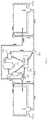
- FIG. 1depicts a maintenance system for a fluid repository according to embodiments of the claimed invention.
- FIG. 2depicts a control system according to embodiments of the claimed invention.
- FIG. 3depicts a maintenance system coupled to multiple fluid repositories according to an embodiment of the claimed invention.
- FIG. 4depicts a maintenance system with multiple variable-speed pumps according to an embodiment of the claimed invention.
- the term “about”is understood as within a range of normal tolerance in the art, for example within 2 standard deviations of the mean. “About” can be understood as within 10%, 9%, 8%, 7%, 6%, 5%, 4%, 3%, 2%, 1%, 0.5%, 0.1%, 0.05%, or 0.01% of the stated value. Unless otherwise clear from context, all numerical values provided herein are modified by the term about.
- Ranges provided hereinare understood to be shorthand for all of the values within the range.
- a range of 1 to 50is understood to include any number, combination of numbers, or sub-range from the group consisting 1, 2, 3, 4, 5, 6, 7, 8, 9, 10, 11, 12, 13, 14, 15, 16, 17, 18, 19, 20, 21, 22, 23, 24, 25, 26, 27, 28, 29, 30, 31, 32, 33, 34, 35, 36, 37, 38, 39, 40, 41, 42, 43, 44, 45, 46, 47, 48, 49, or 50 (as well as fractions thereof unless the context clearly dictates otherwise).
- a variable speed water pump and an in-line flow sensorcan be integrated into a pool maintenance system.
- the pool systemcan be tested for normal operating pressure when liquid filter elements (e.g., a liquid filter, skimmers, and the like) of the maintenance system are known to be clean and free of obstruction.
- a variable-speed pumpcan be activated at full power until the in-line flow sensor can register a flow rate. Once the flow sensor activates, the pump can continue to run at full speed for a short period of time to ensure flow is registered consistently. Pump speed can then be reduced incrementally. Again, the pump can run for a short period of time during which the flow sensor is monitored to see if the sensor is still registering flow.
- This cyclecan repeat with pump output being reduced in each iteration until the flow sensor can no longer register a flow rate. This condition can be achieved at pump power output greater than zero.
- the percentage at which flow stops registeringcan be saved (e.g., through dedicated memory). This value can be referred to as a clean system flow threshold.
- dirt and debriscan accumulate in filters, skimmer baskets, drain covers, pool pump baskets, etc.
- the obstruction in flowcan cause the flow sensor to stop registering flow at higher pump output levels than the previously recorded clean system flow threshold.
- This valuecan be recorded as a current system flow threshold.
- the maintenance systemcan identify the specified flow rate of the pump and the difference between power output of the clean system flow threshold and current system flow threshold. Based on this difference, the maintenance system can determine if filter elements must be serviced.
- the maintenance systemcan include a variable-speed pump 105 .
- the pump 105when activated, can flow water or other fluid through the maintenance system. Further, the pump 105 can be activated at variable flow rates. For example, a controller or control system can manage the rotations per minute (rpm) of a speed pump fan, which can be directly correlated to the power output of the pump. Additionally, as the pump 105 can include a maximum rpm or power output, a controller or control system can activate the pump 105 at rpm and/or power fractions of the pump's maximum output. Examples of variable-speed pumps can include, but are not limited to, HAYWARD ECOSTAR, HAYWARD TRISTAR, JANDY EPUMP, PENTAIR INTELLIFLO VS, and the like.
- the maintenance systemcan also include a flow rate sensor 115 .
- the flow rate sensor 115can be in fluidic communication with the variable-speed pump 105 , for example via a fluid channel such as piping.
- the flow rate sensor 115can receive flow rate measurement signals of a fluid flowing to the flow rate sensor 115 .
- the flow rate sensor 115can be “downstream” of the variable-speed pump 105 , such that fluid flowing from the variable-speed pump can flow towards the flow rate sensor 115 .
- the flow rate sensor 115can include a minimal flow rate registration threshold.
- the flow rate sensor 115can include a flow switch.
- the flow switchcan include a paddle positioned within the fluid channel. When the flow rate sensor experiences a sufficient flow rate of the flowing fluid, the paddle is “pushed” or deflected by the flowing fluid.
- An electronic circuitcan be completed (e.g., closed) when the paddle is in the pushed or deflected position, and can be open otherwise.
- the closed circuitcan transmit an electrical communication to a controller or control system, such that the controller or control system can determine when a fluid flow rate exceeds the flow rate sensor's minimal flow rate registration threshold.
- the controller or control systemcan determine when the fluid flow rate falls below the minimal flow rate registration threshold, as the controller or control system can determine that the system has not received an electrical communication from the flow rate sensor.
- the flow rate sensorcan be in electronic communication with another controller subsystem, such as a salt cell system.
- the salt cell systemcan be in electronic communication with the control system of the maintenance system, and can act as a relay for communications between the flow rate sensor and the control system.
- flow rate sensorscan include, but are not limited to, HAYWARD GLX-FLO-RP, HAYWARD AQUARITE, PENTAIR ITELLICHLOR, JANDY AQUAPURE, and the like
- the maintenance systemcan also include a fluid filter 110 .
- the fluid filter 110can filter particles, debris, and the like from a fluid flowing through the maintenance system. Further, the fluid filter 110 can be in fluidic communication with the pump 105 and the flow rate sensor 115 . As the fluid filter 110 traps or collects particles and other objects from the flowing fluid, the performance of the fluid filter 110 can degrade over time.
- fluid filters of the maintenance systemcan include, but are not limited to, HAYWARD PRO SERIES, HAYWARD SWIMCLEAR, JANDY PRO SERIES CV, JANDY CL CARTRIDGE FILTER, PENTAIR CLEAN and CLEAR PLUS, PENTAIR EASY CLEAN, and the like.
- the maintenance systemcan also include a control system 120 .
- a control system 200is depicted in FIG. 2 .
- the control system 120can be in electronic communication with the variable-speed pump 105 and the flow rate sensor 115 .
- the control system 120can transmit activation communications to the variable-speed pump 105 , such as a percentage of maximum power output or rpms for the pump to operate under.
- the control system 120can in some cases receive notification communications from the pump 105 , the flow rate sensor 115 , or both.
- the pump 105can transmit communications notifying the control system 120 of the pump 105 activating at a given power output or rpm.
- the flow rate sensor 115can transmit flow rate communications to the control system 120 , such as when the flow rate sensor 115 is in a deflected or pushed position.
- control system 200can be an electronic device programmed to control the operation of the maintenance system to achieve a desired result.
- the control system 200can be programmed to autonomously carry out a system performance status regimen without the need for input (either from feedback devices or users) or can incorporate such inputs.
- the principles of how to use feedback (e.g., from a flow rate sensor) in order to modulate operation of a componentare described, for example, in Karl Johan Astrom & Richard M. Murray, Feedback Systems: An Introduction for Engineers & Engineers (2008).
- the control system 200can be a computing device such as a microcontroller (e.g., available under the ARDUINO® OR IOIOTM trademarks), general purpose computer (e.g., a personal computer or PC), workstation, mainframe computer system, and so forth.
- the control system (“control unit”) 200can include a processor device (e.g., a central processing unit or “CPU”) 202 , a memory device 204 , a storage device 206 , a user interface 208 , a system bus 210 , and a communication interface 212 .
- the processor 202can be any type of processing device for carrying out instructions, processing data, and so forth.
- the memory device 204can be any type of memory device including any one or more of random access memory (“RAM”), read-only memory (“ROM”), Flash memory, Electrically Erasable Programmable Read Only Memory (“EEPROM”), and so forth.
- RAMrandom access memory
- ROMread-only memory
- Flash memoryFlash memory
- EEPROMElectrically Erasable Programmable Read Only Memory
- the storage device 206can be any data storage device for reading/writing from/to any removable and/or integrated optical, magnetic, and/or optical-magneto storage medium, and the like (e.g., a hard disk, a compact disc-read-only memory “CD-ROM”, CD-ReWritable CDRW,” Digital Versatile Disc-ROM “DVD-ROM”, DVD-RW, and so forth).
- the storage device 206can also include a controller/interface for connecting to the system bus 210 .
- the memory device 204 and the storage device 206are suitable for storing data as well as instructions for programmed processes for execution on the processor 202 .
- the user interface 208can include a touch screen, control panel, keyboard, keypad, display or any other type of interface, which can be connected to the system bus 210 through a corresponding input/output device interface/adapter.
- the communication interface 212can be adapted and configured to communicate with any type of external device, or with other components of the pool maintenance system.
- double-lined arrowssuch as the arrow 145
- the communication interface 212can further be adapted and configured to communicate with any system or network, such as one or more computing devices on a local area network (“LAN”), wide area network (“WAN”), the Internet, and so forth.
- the communication interface 212can be connected directly to the system bus 210 or can be connected through a suitable interface.
- the control system 200can, thus, provide for executing processes, by itself and/or in cooperation with one or more additional devices, that can include algorithms for controlling components of the pool maintenance system in accordance with the claimed invention.
- the control system 200can be programmed or instructed to perform these processes according to any communication protocol and/or programming language on any platform.
- the processescan be embodied in data as well as instructions stored in the memory device 204 and/or storage device 206 , or received at the user interface 208 and/or communication interface 212 for execution on the processor 202 .
- the maintenance systemcan be coupled to a liquid repository 125 , such as a pool basin, a spa basin, a hot tub basin, and the like.
- the couplingcan be via fluidic channels, such as water piping and the like.
- the dimensions and geometrical shapes of a coupled basincan vary, and one skilled in the art would understand different basin configurations can be coupled to the maintenance system.
- the maintenance systemcan be configured to couple to the fluid repository 125 via intake and outtake channels.
- fluid channelscan couple the fluid repository 125 to the fluid filter 110
- fluid channelscan couple the fluid repository to the flow rate sensor 115 and/or the variable-speed pump 105 .
- the maintenance systemcan be fluidically coupled to the fluid repository in a recycling configuration, such that fluid is recycled from the fluid repository, through the maintenance system, and back to the fluid repository (e.g., with fluid flow direction depicted with arrows 140 ).
- the control system 120can facilitate the execution of a performance determination procedure for the maintenance system.
- the control system 120can instruct the variable-speed pump 105 to activate at a specified power or rpm output.
- the variable-speed pump 105can transmit an activation notification to the control system 120 .
- the control systemcan then monitor the flow rate sensor 115 to determine the flow rate passing through the flow rate sensor 115 .
- the control system 120can monitor the switch to determine whether a flow rate is registered.
- the control system 120can activate the variable-speed pump 105 at a plurality of power outputs or rpms. For each activation, the control system 120 can monitor the flow rate sensor 115 for flow rate measurements and store flow rate measurements (or lack thereof), thereby executing a “cycle” of flow rate determination activations. The control system 120 can also determine a current system flow threshold from the activation cycle. For example, in the case of a flow switch, the current system flow threshold can be a power output or rpm value of the variable-speed pump 105 at which the switch registers a flow rate measurement (e.g., whereas an incrementally lower rpm value or power output results in no flow rate registration).
- the power output or rpm value of the variable-speed pump 105can be adjusted incrementally.
- the control system 120can perform a cycle of activations in a descending value order (e.g., starting at 100% pump capacity, then 99% capacity, then 98% capacity, and so on).
- the control system 120can perform a cycle of activations in an ascending order value (e.g., 80% capacity, 85% capacity, 90% capacity, and so on).
- Other patterns of activationscan occur in a cycle, and one skilled in the art would understand that the techniques described herein are not limited to the above cycle examples.
- the control system 120can also determine an optimal flow threshold for the maintenance system.
- the maintenance systemcan conduct an activation cycle similar to that described above. However, the maintenance system can determine that the maintenance is in an optimal or “clean” state. For example, the maintenance system can identify that the system has been recently cleaned (e.g., the fluid filter is cleaned or replaced, etc.). In some cases, the maintenance system can identify the optimal or clean state through user input (e.g., receiving a notice that the system has been cleaned).
- the control system 120can determine a clean system flow threshold.
- the control systemcan determine the power output or rpm value the flow switch registers a flow rate measurement (e.g., whereas an incrementally lower output power or rpm value fails to register a flow rate measurement).
- the maintenance systemcan then determine a performance status of the maintenance system.
- the control system 120can compare the current system flow threshold to the optimal flow threshold. Based on the difference, the control system 120 can determine the performance status of the maintenance system.
- the difference between the current system flow threshold and the clean system flow thresholdcan be represented as a difference in power output or rpm values of the variable-speed pump 105 .
- the control system 120can determine whether this difference meets or exceeds a predefined performance status value, which can be dependent upon the optimal operating capacity of the variable-speed pump 105 , the fluid filter 110 , dimensions of a coupled fluid repository 125 , and the like (e.g., the performance status threshold can equate to a 25% drop from optimal performance).
- control system 120can determine that the maintenance system is operating under suboptimal performance conditions. Conversely, if the control system 120 determines the difference falls below the performance status value, the control system 120 can determine the maintenance system is operating under satisfactory or adequate performance conditions.
- the maintenance systemcan degrade, become clogged, and the like, leading to suboptimal performance.
- the control system 120can identify that the fluid filter 110 is clogged and requires maintenance through the difference value between the current system flow and optimal system flow thresholds.
- the control system 120can determine that a float trap or other debris capture subsystem of a coupled fluid repository 125 is clogged through the determined difference.
- the control system 120can compare difference values between different activation cycles to further identify the cause of the suboptimal performance. For example, if difference values vary greatly over cycles run over a short time gap, the control system 120 can identify that a debris capture subsystem has become clogged.
- the control system 120can transmit a performance status notification to a user. For example, if the control system 120 determines that the performance of the maintenance system is suboptimal, the control system 120 can transmit a notification relaying this information to a user, a maintenance professional, and the like. The notification can be sent wirelessly, for example, through a user application to a variety of personal computing devices or mobile phones. Likewise, the control system 120 can transmit a notification corresponding to an adequate performance state.
- the maintenance systemcan be fluidically coupled to more than one fluid repository.
- An exemplary embodimentis depicted in FIG. 3 .
- the maintenance systemcan be coupled to a pool basin and a spa basin.
- the maintenance systemcan execute activation cycles separately for each of the coupled repositories 325 - a and 325 - b .
- input fluid channels into each fluid repositorycan diverge from a single intake channel, and can be individually coupled or decoupled to fluid flow from the variable-speed pump 305 through a channel valve 355 .
- output fluid channels into each fluid repositorycan diverge from a single intake channel, and can be individually coupled or decoupled to fluid flow from the variable-speed pump 305 through a channel valve 350 .
- the control system 320can be in electronic communication with the channel valves 350 and 355 , and can execute activation cycles separately for each of the fluid repositories.
- current system flows between the different fluid repositoriescan vary significantly (e.g., a difference of several output power or rpm values, etc.).
- the control system 320can determine that a performance condition apart from the fluid filter 310 , the pump 305 , and/or the flow rate sensor 315 , and unique to one of the fluid repositories can be affecting the maintenance performance.
- the control system 320can determine a difference of several rpm values between a spa basin and a pool basin coupled to the maintenance system.
- the control system 320can identify that the spa basin has the lower current system flow threshold, and further determine the spa basin includes a performance issue such as a clogged drain that is apart from the pool basin.
- the control system 320can in some cases transmit a performance notification indicative of this performance issue of the spa basin.
- the maintenance systemcan include multiple variable-speed pumps (e.g., as depicted in FIG. 4 ).
- Each pump 415 - a and 415 - bcan be coupled to a fluid filter 410 - a and 420 - b , and flow rate sensors 405 - a and 405 - b , respectively, and can be configured to couple to a fluid repository 425 .
- the control system 420can execute activation cycles for each of the variable-speed pumps. Through the determined current system flow thresholds for each pump, the control system 420 can identify performance issues unique to a subset of the pumps. For example, the control system 420 can determine that pump 405 - b has degraded (e.g., a mechanical or electrical component of the pump), or that fluidic channels unique to the pump 405 - b are obstructed, or the like.
- the maintenance systemcan alter the operation of the variable-speed pumps based on the determined performance statuses. For example, if the control system 420 determines that a variable-speed pump is performing sub-optimally compared to other speed pumps of the maintenance system, the control system 420 can instruct the sub-optimally performing pump to operate (e.g., during normal operation) under a lower power output or rpm value compared to other pumps.
- the maintenance system and techniques described hereincan be adaptable to the configurations of existing maintenance and fluid repository systems.
- the control systemcan be configured to communicate with conventional variable-speed pumps, flow rate sensors, valves, fluid channels, and fluid repositories.
- some maintenance systemscan be retrofitted to execute the techniques described herein.
- many conventional pool systemsinclude a fluid filter, a variable-speed pump, a flow switch, and a pool basin.
- FIGS.depict specific examples of configurations, one skilled in the art would understand that the maintenance system and associated techniques can be integrated into a multitude of fluid repository systems.
Landscapes
- Engineering & Computer Science (AREA)
- General Engineering & Computer Science (AREA)
- Mechanical Engineering (AREA)
- Architecture (AREA)
- Water Supply & Treatment (AREA)
- Civil Engineering (AREA)
- Structural Engineering (AREA)
- Computer Hardware Design (AREA)
- Control Of Non-Positive-Displacement Pumps (AREA)
- Control Of Positive-Displacement Pumps (AREA)
Abstract
Description
Claims (14)
Priority Applications (2)
| Application Number | Priority Date | Filing Date | Title |
|---|---|---|---|
| US17/209,858US11215175B2 (en) | 2020-04-17 | 2021-03-23 | Systems and methods for maintaining pool systems |
| PCT/US2021/026563WO2021211371A1 (en) | 2020-04-17 | 2021-04-09 | Systems and methods for maintaining pool systems |
Applications Claiming Priority (2)
| Application Number | Priority Date | Filing Date | Title |
|---|---|---|---|
| US202063011470P | 2020-04-17 | 2020-04-17 | |
| US17/209,858US11215175B2 (en) | 2020-04-17 | 2021-03-23 | Systems and methods for maintaining pool systems |
Publications (2)
| Publication Number | Publication Date |
|---|---|
| US20210324846A1 US20210324846A1 (en) | 2021-10-21 |
| US11215175B2true US11215175B2 (en) | 2022-01-04 |
Family
ID=78081492
Family Applications (1)
| Application Number | Title | Priority Date | Filing Date |
|---|---|---|---|
| US17/209,858ActiveUS11215175B2 (en) | 2020-04-17 | 2021-03-23 | Systems and methods for maintaining pool systems |
Country Status (2)
| Country | Link |
|---|---|
| US (1) | US11215175B2 (en) |
| WO (1) | WO2021211371A1 (en) |
Cited By (5)
| Publication number | Priority date | Publication date | Assignee | Title |
|---|---|---|---|---|
| US20200319621A1 (en) | 2016-01-22 | 2020-10-08 | Hayward Industries, Inc. | Systems and Methods for Providing Network Connectivity and Remote Monitoring, Optimization, and Control of Pool/Spa Equipment |
| US11573580B2 (en) | 2021-04-22 | 2023-02-07 | Hayward Industries, Inc. | Systems and methods for turning over fluid distribution systems |
| US11579637B2 (en) | 2021-02-25 | 2023-02-14 | Hayward Industries, Inc. | Systems and methods for controlling fluid flow with a fluid distribution manifold |
| US11946565B2 (en) | 2021-02-25 | 2024-04-02 | Hayward Industries, Inc. | Valve assembly |
| US12392152B2 (en) | 2019-09-11 | 2025-08-19 | Hayward Industries, Inc. | Swimming pool pressure and flow control pumping and water distribution systems and methods |
Citations (37)
| Publication number | Priority date | Publication date | Assignee | Title |
|---|---|---|---|---|
| US3819297A (en)* | 1972-09-11 | 1974-06-25 | Gen Gas Light Co | Centrifugal pump assembly |
| US4090532A (en) | 1976-12-06 | 1978-05-23 | Cla-Val Co. | Timer controlled valve |
| US4322297A (en) | 1980-08-18 | 1982-03-30 | Peter Bajka | Controller and control method for a pool system |
| US5483227A (en)* | 1994-03-07 | 1996-01-09 | Kuo; Teh-Chuan | Liquid level controller |
| US20030163865A1 (en) | 2001-11-19 | 2003-09-04 | Stone Huang | Warm/cold double-circulation water filter system and swimming pool arrangement |
| US6670584B1 (en) | 2002-04-10 | 2003-12-30 | Kareem I. Azizeh | Spa electric heater system using multiple spa heaters |
| US20040230344A1 (en) | 2002-12-31 | 2004-11-18 | Gallupe Gary W. | Swimming pool and spa heater control system and method |
| US20050222786A1 (en) | 2004-03-31 | 2005-10-06 | Tarpo James L | Method and system for testing spas |
| US20060272830A1 (en) | 2002-09-23 | 2006-12-07 | R. Giovanni Fima | Systems and methods for monitoring and controlling water consumption |
| US20070154319A1 (en) | 2004-08-26 | 2007-07-05 | Stiles Robert W Jr | Pumping system with power optimization |
| US20080078100A1 (en) | 2006-09-06 | 2008-04-03 | Ju-Hyun Kim | Dryer with clogging detecting function |
| US20080148592A1 (en) | 2006-12-26 | 2008-06-26 | Kim Yang-Hwan | Dryer with safety function |
| US20080313921A1 (en) | 2007-04-18 | 2008-12-25 | Chang Hun Oh | Clogging detection method for dryer |
| US20080313923A1 (en) | 2007-04-18 | 2008-12-25 | Chang Hun Oh | Clogging degree deciding method for dryer |
| US20090139110A1 (en) | 2007-04-18 | 2009-06-04 | Chang Hun Oh | Control apparatus for dryer |
| US20090151801A1 (en) | 2007-12-12 | 2009-06-18 | John Gorman | Method, system and apparatus for an efficient design and operation of a pump motor |
| US20090204263A1 (en) | 2008-02-08 | 2009-08-13 | Chris Love | Pool temperature controller |
| US7931447B2 (en) | 2006-06-29 | 2011-04-26 | Hayward Industries, Inc. | Drain safety and pump control device |
| US20110315262A1 (en) | 2010-05-14 | 2011-12-29 | Andy Butler | System and method for communication between filters and faucets |
| US8131497B2 (en) | 2007-09-17 | 2012-03-06 | Ecofactor, Inc. | System and method for calculating the thermal mass of a building |
| US20120073040A1 (en)* | 2010-09-27 | 2012-03-29 | Cohen Joseph D | Flow-rate activated safety vacuum release system |
| US20120123594A1 (en) | 2009-12-22 | 2012-05-17 | Finch Michael F | Temperature control based on energy price |
| US8313305B2 (en)* | 2006-08-25 | 2012-11-20 | Pentair Pump Group, Inc. | Fluid system with pump activation device |
| US20130327403A1 (en) | 2012-06-08 | 2013-12-12 | Kurtis Kevin Jensen | Methods and apparatus to control and/or monitor a pneumatic actuator |
| US8800473B1 (en)* | 2010-08-06 | 2014-08-12 | Richard DeVerse | Mass velocity sensor device and method for remote monitoring and visual verification of fluid velocity |
| US20140305525A1 (en) | 2013-04-16 | 2014-10-16 | Honeywell International Inc. | Autonomous valve control and monitoring |
| US20150107675A1 (en) | 2011-12-15 | 2015-04-23 | Honeywell International Inc. | Valve with actuator diagnostics |
| US9031702B2 (en) | 2013-03-15 | 2015-05-12 | Hayward Industries, Inc. | Modular pool/spa control system |
| US20150278930A1 (en) | 2014-03-27 | 2015-10-01 | Hayward Industries, Inc. | System and Method for Presenting a Sales Demonstration Using a Pool/Spa Controller User Interface |
| US20160153456A1 (en) | 2004-08-26 | 2016-06-02 | Pentair Water Pool And Spa, Inc. | Speed Control |
| US20170209338A1 (en) | 2016-01-22 | 2017-07-27 | Hayward Industries, Inc. | Systems and Methods for Providing Network Connectivity and Remote Monitoring, Optimization, and Control of Pool/Spa Equipment |
| US20180240322A1 (en) | 2016-01-22 | 2018-08-23 | Hayward Industries, Inc. | Systems and methods for providing network connectivity and remote monitoring, optimization, and control of pool/spa equipment |
| US20190204203A1 (en) | 2016-05-01 | 2019-07-04 | Sucxess LLC | Fluid circulation monitoring system |
| US20190331363A1 (en) | 2016-11-29 | 2019-10-31 | Rheem Australia Pty Limited | Location Based Temperature Limit Control For A Water Heater |
| US20200319621A1 (en) | 2016-01-22 | 2020-10-08 | Hayward Industries, Inc. | Systems and Methods for Providing Network Connectivity and Remote Monitoring, Optimization, and Control of Pool/Spa Equipment |
| US20210047853A1 (en) | 2019-08-16 | 2021-02-18 | Rheem Manufacturing Company | Systems And Methods For Managing Bodies Of Water |
| WO2021050932A1 (en) | 2019-09-11 | 2021-03-18 | Hayward Industries, Inc. | Swimming pool pressure and flow control pumping and water distribution systems and methods |
- 2021
- 2021-03-23USUS17/209,858patent/US11215175B2/enactiveActive
- 2021-04-09WOPCT/US2021/026563patent/WO2021211371A1/ennot_activeCeased
Patent Citations (38)
| Publication number | Priority date | Publication date | Assignee | Title |
|---|---|---|---|---|
| US3819297A (en)* | 1972-09-11 | 1974-06-25 | Gen Gas Light Co | Centrifugal pump assembly |
| US4090532A (en) | 1976-12-06 | 1978-05-23 | Cla-Val Co. | Timer controlled valve |
| US4322297A (en) | 1980-08-18 | 1982-03-30 | Peter Bajka | Controller and control method for a pool system |
| US5483227A (en)* | 1994-03-07 | 1996-01-09 | Kuo; Teh-Chuan | Liquid level controller |
| US20030163865A1 (en) | 2001-11-19 | 2003-09-04 | Stone Huang | Warm/cold double-circulation water filter system and swimming pool arrangement |
| US6670584B1 (en) | 2002-04-10 | 2003-12-30 | Kareem I. Azizeh | Spa electric heater system using multiple spa heaters |
| US20060272830A1 (en) | 2002-09-23 | 2006-12-07 | R. Giovanni Fima | Systems and methods for monitoring and controlling water consumption |
| US20040230344A1 (en) | 2002-12-31 | 2004-11-18 | Gallupe Gary W. | Swimming pool and spa heater control system and method |
| US20050222786A1 (en) | 2004-03-31 | 2005-10-06 | Tarpo James L | Method and system for testing spas |
| US20070154319A1 (en) | 2004-08-26 | 2007-07-05 | Stiles Robert W Jr | Pumping system with power optimization |
| US20160153456A1 (en) | 2004-08-26 | 2016-06-02 | Pentair Water Pool And Spa, Inc. | Speed Control |
| US7931447B2 (en) | 2006-06-29 | 2011-04-26 | Hayward Industries, Inc. | Drain safety and pump control device |
| US8313305B2 (en)* | 2006-08-25 | 2012-11-20 | Pentair Pump Group, Inc. | Fluid system with pump activation device |
| US20080078100A1 (en) | 2006-09-06 | 2008-04-03 | Ju-Hyun Kim | Dryer with clogging detecting function |
| US20080148592A1 (en) | 2006-12-26 | 2008-06-26 | Kim Yang-Hwan | Dryer with safety function |
| US20090139110A1 (en) | 2007-04-18 | 2009-06-04 | Chang Hun Oh | Control apparatus for dryer |
| US20080313923A1 (en) | 2007-04-18 | 2008-12-25 | Chang Hun Oh | Clogging degree deciding method for dryer |
| US20080313921A1 (en) | 2007-04-18 | 2008-12-25 | Chang Hun Oh | Clogging detection method for dryer |
| US8131497B2 (en) | 2007-09-17 | 2012-03-06 | Ecofactor, Inc. | System and method for calculating the thermal mass of a building |
| US20090151801A1 (en) | 2007-12-12 | 2009-06-18 | John Gorman | Method, system and apparatus for an efficient design and operation of a pump motor |
| US20090204263A1 (en) | 2008-02-08 | 2009-08-13 | Chris Love | Pool temperature controller |
| US20120123594A1 (en) | 2009-12-22 | 2012-05-17 | Finch Michael F | Temperature control based on energy price |
| US20110315262A1 (en) | 2010-05-14 | 2011-12-29 | Andy Butler | System and method for communication between filters and faucets |
| US8800473B1 (en)* | 2010-08-06 | 2014-08-12 | Richard DeVerse | Mass velocity sensor device and method for remote monitoring and visual verification of fluid velocity |
| US20120073040A1 (en)* | 2010-09-27 | 2012-03-29 | Cohen Joseph D | Flow-rate activated safety vacuum release system |
| US20150107675A1 (en) | 2011-12-15 | 2015-04-23 | Honeywell International Inc. | Valve with actuator diagnostics |
| US20130327403A1 (en) | 2012-06-08 | 2013-12-12 | Kurtis Kevin Jensen | Methods and apparatus to control and/or monitor a pneumatic actuator |
| US9031702B2 (en) | 2013-03-15 | 2015-05-12 | Hayward Industries, Inc. | Modular pool/spa control system |
| US20140305525A1 (en) | 2013-04-16 | 2014-10-16 | Honeywell International Inc. | Autonomous valve control and monitoring |
| US20150278930A1 (en) | 2014-03-27 | 2015-10-01 | Hayward Industries, Inc. | System and Method for Presenting a Sales Demonstration Using a Pool/Spa Controller User Interface |
| US20170209338A1 (en) | 2016-01-22 | 2017-07-27 | Hayward Industries, Inc. | Systems and Methods for Providing Network Connectivity and Remote Monitoring, Optimization, and Control of Pool/Spa Equipment |
| US20180240322A1 (en) | 2016-01-22 | 2018-08-23 | Hayward Industries, Inc. | Systems and methods for providing network connectivity and remote monitoring, optimization, and control of pool/spa equipment |
| US10219975B2 (en) | 2016-01-22 | 2019-03-05 | Hayward Industries, Inc. | Systems and methods for providing network connectivity and remote monitoring, optimization, and control of pool/spa equipment |
| US20200319621A1 (en) | 2016-01-22 | 2020-10-08 | Hayward Industries, Inc. | Systems and Methods for Providing Network Connectivity and Remote Monitoring, Optimization, and Control of Pool/Spa Equipment |
| US20190204203A1 (en) | 2016-05-01 | 2019-07-04 | Sucxess LLC | Fluid circulation monitoring system |
| US20190331363A1 (en) | 2016-11-29 | 2019-10-31 | Rheem Australia Pty Limited | Location Based Temperature Limit Control For A Water Heater |
| US20210047853A1 (en) | 2019-08-16 | 2021-02-18 | Rheem Manufacturing Company | Systems And Methods For Managing Bodies Of Water |
| WO2021050932A1 (en) | 2019-09-11 | 2021-03-18 | Hayward Industries, Inc. | Swimming pool pressure and flow control pumping and water distribution systems and methods |
Non-Patent Citations (1)
| Title |
|---|
| International Search Report and Written Opinion, International Patent Application No. PCT/US2021/026563, dated Jun. 22, 2021. |
Cited By (9)
| Publication number | Priority date | Publication date | Assignee | Title |
|---|---|---|---|---|
| US20200319621A1 (en) | 2016-01-22 | 2020-10-08 | Hayward Industries, Inc. | Systems and Methods for Providing Network Connectivity and Remote Monitoring, Optimization, and Control of Pool/Spa Equipment |
| US11720085B2 (en) | 2016-01-22 | 2023-08-08 | Hayward Industries, Inc. | Systems and methods for providing network connectivity and remote monitoring, optimization, and control of pool/spa equipment |
| US12392152B2 (en) | 2019-09-11 | 2025-08-19 | Hayward Industries, Inc. | Swimming pool pressure and flow control pumping and water distribution systems and methods |
| US11579637B2 (en) | 2021-02-25 | 2023-02-14 | Hayward Industries, Inc. | Systems and methods for controlling fluid flow with a fluid distribution manifold |
| US11698647B2 (en) | 2021-02-25 | 2023-07-11 | Hayward Industries, Inc. | Fluid distribution manifold |
| US11946565B2 (en) | 2021-02-25 | 2024-04-02 | Hayward Industries, Inc. | Valve assembly |
| US11573580B2 (en) | 2021-04-22 | 2023-02-07 | Hayward Industries, Inc. | Systems and methods for turning over fluid distribution systems |
| US11579635B2 (en) | 2021-04-22 | 2023-02-14 | Hayward Industries, Inc. | Systems and methods for controlling operations of a fluid distribution system |
| US11579636B2 (en) | 2021-04-22 | 2023-02-14 | Hayward Industries, Inc. | Systems and methods for controlling operations of multi-manifold fluid distribution systems |
Also Published As
| Publication number | Publication date |
|---|---|
| US20210324846A1 (en) | 2021-10-21 |
| WO2021211371A1 (en) | 2021-10-21 |
Similar Documents
| Publication | Publication Date | Title |
|---|---|---|
| US11215175B2 (en) | Systems and methods for maintaining pool systems | |
| US11523968B2 (en) | Methods for determining fluidic flow configurations in a pool system | |
| US11168911B2 (en) | Fluid circulation monitoring system | |
| US11150673B2 (en) | Method of monitoring a fluid level within a fluid volume | |
| CN207147845U (en) | Water sample preprocessor and water quality monitoring system | |
| WO2021221882A1 (en) | Systems and methods for maintaining pool systems | |
| CN208043160U (en) | Intellectual water meter | |
| CN116378480A (en) | Swimming pool cleaning robot | |
| KR20210048149A (en) | Water purifier | |
| CN205461311U (en) | Water heater with filter core self-cleaning function | |
| KR20180067813A (en) | Apparatus for automatic cleaning filter for pipe | |
| US9637941B2 (en) | Method of monitoring a low water volume within a water circulation system | |
| CN113926230A (en) | Flushing control method and control device | |
| CN222124832U (en) | Sampling device and water quality monitoring equipment | |
| JP2004232254A (en) | Submersible pump system and drive control method of the pump | |
| US10086320B2 (en) | Screen blockage measurement and flow performance optimization system | |
| KR20110086917A (en) | Vent for controlling wind direction | |
| JP2020146673A (en) | Fluid intake system and power generating system | |
| CN101519886B (en) | Sewage recovery device | |
| CN206020097U (en) | Flow cell and water quality monitoring system for water sampling | |
| CN114764018A (en) | Intelligent water meter with water quality cleaning and automatic flushing functions and control method thereof | |
| KR102692632B1 (en) | Smart pumping station monitoring and control system | |
| CN120738895A (en) | Water quality detection device, clothing processing equipment and control method thereof | |
| CN217815081U (en) | Adjusting ball valve | |
| CN215538875U (en) | Automatic cleaning filter |
Legal Events
| Date | Code | Title | Description |
|---|---|---|---|
| FEPP | Fee payment procedure | Free format text:ENTITY STATUS SET TO UNDISCOUNTED (ORIGINAL EVENT CODE: BIG.); ENTITY STATUS OF PATENT OWNER: SMALL ENTITY | |
| AS | Assignment | Owner name:POOLSIDE TECH, LLC, PENNSYLVANIA Free format text:ASSIGNMENT OF ASSIGNORS INTEREST;ASSIGNORS:DOAN, WILLIAM R.;REZNIK, STAN;SIGNING DATES FROM 20210215 TO 20210319;REEL/FRAME:055697/0067 | |
| FEPP | Fee payment procedure | Free format text:ENTITY STATUS SET TO SMALL (ORIGINAL EVENT CODE: SMAL); ENTITY STATUS OF PATENT OWNER: SMALL ENTITY | |
| STPP | Information on status: patent application and granting procedure in general | Free format text:NOTICE OF ALLOWANCE MAILED -- APPLICATION RECEIVED IN OFFICE OF PUBLICATIONS | |
| STPP | Information on status: patent application and granting procedure in general | Free format text:AWAITING TC RESP., ISSUE FEE NOT PAID | |
| STPP | Information on status: patent application and granting procedure in general | Free format text:NOTICE OF ALLOWANCE MAILED -- APPLICATION RECEIVED IN OFFICE OF PUBLICATIONS | |
| AS | Assignment | Owner name:POOLSIDE TECH, LLC, PENNSYLVANIA Free format text:ASSIGNMENT OF ASSIGNORS INTEREST;ASSIGNOR:IRWIN, CALVIN;REEL/FRAME:058100/0053 Effective date:20211112 | |
| STPP | Information on status: patent application and granting procedure in general | Free format text:PUBLICATIONS -- ISSUE FEE PAYMENT VERIFIED | |
| STPP | Information on status: patent application and granting procedure in general | Free format text:AWAITING TC RESP, ISSUE FEE PAYMENT VERIFIED | |
| STPP | Information on status: patent application and granting procedure in general | Free format text:PUBLICATIONS -- ISSUE FEE PAYMENT VERIFIED | |
| STCF | Information on status: patent grant | Free format text:PATENTED CASE | |
| MAFP | Maintenance fee payment | Free format text:PAYMENT OF MAINTENANCE FEE, 4TH YR, SMALL ENTITY (ORIGINAL EVENT CODE: M2551); ENTITY STATUS OF PATENT OWNER: SMALL ENTITY Year of fee payment:4 |