US11214317B2 - Systems and methods for joining nodes and other structures - Google Patents
Systems and methods for joining nodes and other structuresDownload PDFInfo
- Publication number
- US11214317B2 US11214317B2US15/961,767US201815961767AUS11214317B2US 11214317 B2US11214317 B2US 11214317B2US 201815961767 AUS201815961767 AUS 201815961767AUS 11214317 B2US11214317 B2US 11214317B2
- Authority
- US
- United States
- Prior art keywords
- node
- adhesive region
- seal member
- receptacle
- adhesive
- Prior art date
- Legal status (The legal status is an assumption and is not a legal conclusion. Google has not performed a legal analysis and makes no representation as to the accuracy of the status listed.)
- Active, expires
Links
Images


Classifications
- B—PERFORMING OPERATIONS; TRANSPORTING
- B62—LAND VEHICLES FOR TRAVELLING OTHERWISE THAN ON RAILS
- B62D—MOTOR VEHICLES; TRAILERS
- B62D29/00—Superstructures, understructures, or sub-units thereof, characterised by the material thereof
- B62D29/04—Superstructures, understructures, or sub-units thereof, characterised by the material thereof predominantly of synthetic material
- B62D29/046—Combined superstructure and frame, i.e. monocoque constructions
- B—PERFORMING OPERATIONS; TRANSPORTING
- B62—LAND VEHICLES FOR TRAVELLING OTHERWISE THAN ON RAILS
- B62D—MOTOR VEHICLES; TRAILERS
- B62D23/00—Combined superstructure and frame, i.e. monocoque constructions
- B62D23/005—Combined superstructure and frame, i.e. monocoque constructions with integrated chassis in the whole shell, e.g. meshwork, tubes, or the like
- B—PERFORMING OPERATIONS; TRANSPORTING
- B29—WORKING OF PLASTICS; WORKING OF SUBSTANCES IN A PLASTIC STATE IN GENERAL
- B29C—SHAPING OR JOINING OF PLASTICS; SHAPING OF MATERIAL IN A PLASTIC STATE, NOT OTHERWISE PROVIDED FOR; AFTER-TREATMENT OF THE SHAPED PRODUCTS, e.g. REPAIRING
- B29C65/00—Joining or sealing of preformed parts, e.g. welding of plastics materials; Apparatus therefor
- B29C65/48—Joining or sealing of preformed parts, e.g. welding of plastics materials; Apparatus therefor using adhesives, i.e. using supplementary joining material; solvent bonding
- B29C65/52—Joining or sealing of preformed parts, e.g. welding of plastics materials; Apparatus therefor using adhesives, i.e. using supplementary joining material; solvent bonding characterised by the way of applying the adhesive
- B29C65/524—Joining or sealing of preformed parts, e.g. welding of plastics materials; Apparatus therefor using adhesives, i.e. using supplementary joining material; solvent bonding characterised by the way of applying the adhesive by applying the adhesive from an outlet device in contact with, or almost in contact with, the surface of the part to be joined
- B—PERFORMING OPERATIONS; TRANSPORTING
- B29—WORKING OF PLASTICS; WORKING OF SUBSTANCES IN A PLASTIC STATE IN GENERAL
- B29C—SHAPING OR JOINING OF PLASTICS; SHAPING OF MATERIAL IN A PLASTIC STATE, NOT OTHERWISE PROVIDED FOR; AFTER-TREATMENT OF THE SHAPED PRODUCTS, e.g. REPAIRING
- B29C65/00—Joining or sealing of preformed parts, e.g. welding of plastics materials; Apparatus therefor
- B29C65/48—Joining or sealing of preformed parts, e.g. welding of plastics materials; Apparatus therefor using adhesives, i.e. using supplementary joining material; solvent bonding
- B29C65/52—Joining or sealing of preformed parts, e.g. welding of plastics materials; Apparatus therefor using adhesives, i.e. using supplementary joining material; solvent bonding characterised by the way of applying the adhesive
- B29C65/54—Joining or sealing of preformed parts, e.g. welding of plastics materials; Apparatus therefor using adhesives, i.e. using supplementary joining material; solvent bonding characterised by the way of applying the adhesive between pre-assembled parts
- B29C65/542—Joining or sealing of preformed parts, e.g. welding of plastics materials; Apparatus therefor using adhesives, i.e. using supplementary joining material; solvent bonding characterised by the way of applying the adhesive between pre-assembled parts by injection
- B—PERFORMING OPERATIONS; TRANSPORTING
- B29—WORKING OF PLASTICS; WORKING OF SUBSTANCES IN A PLASTIC STATE IN GENERAL
- B29C—SHAPING OR JOINING OF PLASTICS; SHAPING OF MATERIAL IN A PLASTIC STATE, NOT OTHERWISE PROVIDED FOR; AFTER-TREATMENT OF THE SHAPED PRODUCTS, e.g. REPAIRING
- B29C65/00—Joining or sealing of preformed parts, e.g. welding of plastics materials; Apparatus therefor
- B29C65/48—Joining or sealing of preformed parts, e.g. welding of plastics materials; Apparatus therefor using adhesives, i.e. using supplementary joining material; solvent bonding
- B29C65/52—Joining or sealing of preformed parts, e.g. welding of plastics materials; Apparatus therefor using adhesives, i.e. using supplementary joining material; solvent bonding characterised by the way of applying the adhesive
- B29C65/54—Joining or sealing of preformed parts, e.g. welding of plastics materials; Apparatus therefor using adhesives, i.e. using supplementary joining material; solvent bonding characterised by the way of applying the adhesive between pre-assembled parts
- B29C65/544—Joining or sealing of preformed parts, e.g. welding of plastics materials; Apparatus therefor using adhesives, i.e. using supplementary joining material; solvent bonding characterised by the way of applying the adhesive between pre-assembled parts by suction
- B—PERFORMING OPERATIONS; TRANSPORTING
- B62—LAND VEHICLES FOR TRAVELLING OTHERWISE THAN ON RAILS
- B62D—MOTOR VEHICLES; TRAILERS
- B62D27/00—Connections between superstructure or understructure sub-units
- B62D27/02—Connections between superstructure or understructure sub-units rigid
- B62D27/023—Assembly of structural joints
- B—PERFORMING OPERATIONS; TRANSPORTING
- B62—LAND VEHICLES FOR TRAVELLING OTHERWISE THAN ON RAILS
- B62D—MOTOR VEHICLES; TRAILERS
- B62D27/00—Connections between superstructure or understructure sub-units
- B62D27/02—Connections between superstructure or understructure sub-units rigid
- B62D27/026—Connections by glue bonding
- B—PERFORMING OPERATIONS; TRANSPORTING
- B62—LAND VEHICLES FOR TRAVELLING OTHERWISE THAN ON RAILS
- B62D—MOTOR VEHICLES; TRAILERS
- B62D29/00—Superstructures, understructures, or sub-units thereof, characterised by the material thereof
- B62D29/04—Superstructures, understructures, or sub-units thereof, characterised by the material thereof predominantly of synthetic material
- B62D29/048—Connections therefor, e.g. joints
- C—CHEMISTRY; METALLURGY
- C09—DYES; PAINTS; POLISHES; NATURAL RESINS; ADHESIVES; COMPOSITIONS NOT OTHERWISE PROVIDED FOR; APPLICATIONS OF MATERIALS NOT OTHERWISE PROVIDED FOR
- C09J—ADHESIVES; NON-MECHANICAL ASPECTS OF ADHESIVE PROCESSES IN GENERAL; ADHESIVE PROCESSES NOT PROVIDED FOR ELSEWHERE; USE OF MATERIALS AS ADHESIVES
- C09J5/00—Adhesive processes in general; Adhesive processes not provided for elsewhere, e.g. relating to primers
- F—MECHANICAL ENGINEERING; LIGHTING; HEATING; WEAPONS; BLASTING
- F16—ENGINEERING ELEMENTS AND UNITS; GENERAL MEASURES FOR PRODUCING AND MAINTAINING EFFECTIVE FUNCTIONING OF MACHINES OR INSTALLATIONS; THERMAL INSULATION IN GENERAL
- F16B—DEVICES FOR FASTENING OR SECURING CONSTRUCTIONAL ELEMENTS OR MACHINE PARTS TOGETHER, e.g. NAILS, BOLTS, CIRCLIPS, CLAMPS, CLIPS OR WEDGES; JOINTS OR JOINTING
- F16B11/00—Connecting constructional elements or machine parts by sticking or pressing them together, e.g. cold pressure welding
- F16B11/006—Connecting constructional elements or machine parts by sticking or pressing them together, e.g. cold pressure welding by gluing
- B—PERFORMING OPERATIONS; TRANSPORTING
- B29—WORKING OF PLASTICS; WORKING OF SUBSTANCES IN A PLASTIC STATE IN GENERAL
- B29C—SHAPING OR JOINING OF PLASTICS; SHAPING OF MATERIAL IN A PLASTIC STATE, NOT OTHERWISE PROVIDED FOR; AFTER-TREATMENT OF THE SHAPED PRODUCTS, e.g. REPAIRING
- B29C2791/00—Shaping characteristics in general
- B29C2791/004—Shaping under special conditions
- B29C2791/006—Using vacuum
- B—PERFORMING OPERATIONS; TRANSPORTING
- B29—WORKING OF PLASTICS; WORKING OF SUBSTANCES IN A PLASTIC STATE IN GENERAL
- B29C—SHAPING OR JOINING OF PLASTICS; SHAPING OF MATERIAL IN A PLASTIC STATE, NOT OTHERWISE PROVIDED FOR; AFTER-TREATMENT OF THE SHAPED PRODUCTS, e.g. REPAIRING
- B29C66/00—General aspects of processes or apparatus for joining preformed parts
- B29C66/01—General aspects dealing with the joint area or with the area to be joined
- B29C66/05—Particular design of joint configurations
- B29C66/10—Particular design of joint configurations particular design of the joint cross-sections
- B29C66/11—Joint cross-sections comprising a single joint-segment, i.e. one of the parts to be joined comprising a single joint-segment in the joint cross-section
- B29C66/112—Single lapped joints
- B29C66/1122—Single lap to lap joints, i.e. overlap joints
Definitions
- the present disclosurerelates generally to joints created between nodes and other structures, and more particularly, to joints that include an adhesive region for the application of adhesive between nodes and other structures.
- Space frame and monocoque construction techniquesare used in automotive, structural, marine, and many other applications.
- One example of space frame constructionis a welded tube frame chassis construction, often used in low-volume and high-performance vehicle designs due to the advantages of low tooling costs, design flexibility, and the ability to produce high-efficiency structures.
- Space framescan require the structures that make up the chassis to be connected at a wide variety of angles and may require the same connection point to accommodate a variety of structure geometries.
- Traditional methods of fabrication of joint members for connection of such tube frame chassismay incur high equipment and manufacturing costs.
- monocoque designmay lead to design inflexibility when using planar elements, or high tooling costs when shaped panels are incorporated.
- an additively manufactured nodecan include a node surface that has a receptacle extending into the node.
- the receptaclecan receive a structure, and a seal interface on the node surface can seat a seal member between the node surface and the structure to create an adhesive region between the node and the structure, the adhesive region being bounded by the node surface, the structure, and the seal member.
- the nodecan also include two channels connecting an exterior surface of the node to the adhesive region. In this way, for example, adhesive can be injected into the adhesive region between the node surface of the node and the structure, and the adhesive can be contained by the seal member.
- an apparatuscan include an additively manufactured node having a receptacle extending into the node, the receptacle including a first surface, and the node including an exterior surface, a first channel connecting the exterior surface to the first surface, and a second channel connecting the exterior surface to the first surface.
- the apparatuscan further include a structure inserted in the receptacle, the structure including a second surface opposing the first surface.
- the apparatuscan further include a seal member arranged between the node and the structure.
- An adhesive region between the node and the structurecan be bounded by the first surface, the second surface, and a surface of the seal member. The adhesive region can connect to each of the first and second channels.
- the apparatuscan further include an adhesive arranged in the adhesive region. The adhesive can adjoin the seal member surface and can attach the first surface to the second surface.
- a methodcan include arranging a seal member in a receptacle extending into an additively manufactured node, the receptacle including a first surface.
- the methodcan further include inserting a structure into the receptacle, the structure including a second surface opposing the first surface.
- An adhesive regioncan be formed between the node and the structure, the adhesive region being bounded by the first surface, the second surface, and the seal member.
- the methodcan further include applying an adhesive into the adhesive region, for example, by injecting the adhesive. In this way, for example, the adhesive can be applied into the adhesive region, and the applied adhesive can be contained by the seal member.
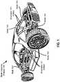
- FIG. 1shows an exemplary vehicle chassis, Blade supercar chassis, in which aspects of the disclosure may be implemented.
- FIGS. 2A-Billustrate two views of an exemplary node in accordance with various embodiments.
- FIGS. 3A-Billustrate two views of the exemplary node with a seal member seated on a seal interface.
- FIG. 4Aillustrates an exemplary structure
- FIG. 4Billustrates the structure inserted in a receptacle of the exemplary node.
- FIG. 5illustrates a more detailed view of the exemplary structure inserted in the exemplary node.
- FIGS. 6-11illustrate exemplary processes for adhesive application to adhere the exemplary node to the exemplary structure.
- FIG. 12illustrates an exemplary embodiment including a node, a structure, and a seal member seated on a seal interface.
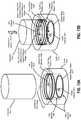
- FIG. 13illustrates another exemplary embodiment including a node, a structure, and a seal member seated on a seal interface.
- FIG. 14illustrates another exemplary embodiment including a node, a structure, and a seal member seated on a seal interface.
- FIGS. 15A-Billustrate an exemplary embodiment including a node, a structure, a seal member, and a second seal member.
- FIGS. 16A-Billustrate another exemplary embodiment including a node, a structure, and a seal member seated on a seal interface.
- FIG. 17is a flowchart that illustrates an exemplary process of adhering an additively manufactured node to a structure.
- a nodeis an additively manufactured (AM) structure that includes a feature, e.g., a socket, a receptacle, etc., for accepting another structure, e.g., a tube, a panel, etc.
- AMadditively manufactured
- Nodescan be formed by fusing a powder material. For example, a 3-D printer can melt and/or sinter at least a portion of the powder material in multiple layers to form the node.
- Nodesmay be formed of one or more metal and/or non-metal materials.
- the nodemay be formed of a substantially rigid material.
- the materials in a nodemay include a metallic material (e.g.
- Nodescan be particularly useful in joint designs for connecting various parts of complex structures, for example.
- nodescan allow for higher levels of dimensional tolerance acceptance that may be needed when assembling complex structures.
- Node-based designscan also allow for reduced weight, reduced post-processing, and increased ease of assembly.
- nodescan be used as sockets to adjust for tolerance in designs, and nodes can be co-printed with other parts, which takes advantage of a unique benefit of 3-D printing to simplify the assembly process.
- FIG. 1illustrates an exemplary car chassis, i.e., Blade supercar chassis 100 built by Divergent Technologies, Inc., that includes nodes and connecting structures, e.g., tubes, attached to the nodes.
- Automobile chassis, such as Blade supercar chassis 100are examples of structures in which aspects of the disclosure can be practiced. Although the examples described herein are directed primarily to vehicle structures, such as chassis, crush zones, etc., it should be understood that aspects of the disclosure can be applied to other structures that include node-structure connections.
- Blade supercar chassis 100includes structures 101 , which are tubes in this example, connected by one or more nodes 103 .
- Each node 103can include, for example, a central body and one or more ports that extend from the central body.
- a multi-port nodemay be provided to connect structures, such as structures 101 , to form a two or three-dimensional structure.
- the structuremay be a frame, for example.
- a structure having tubes with axes in substantially the same planecan be referred to as a planar frame, while a structure having tubes with axes in different planes may be referred to as a space frame.
- a space framemay define a volume.
- a three-dimensional space frame structuremay be a vehicle chassis.
- the vehicle chassismay be have a length, width, and height that define a space, such as a passenger compartment of the vehicle.
- a vehicle chassismay form the framework of a vehicle.
- a vehicle chassismay provide the structure for placement of body panels of a vehicle, such as door panels, roof panels, floor panels, or any other panels forming the vehicle enclosure. Furthermore the chassis may be the structural support for the wheels, drive train, engine block, electrical components, heating and cooling systems, seats, storage space, etc.
- a vehiclemay be a passenger vehicle, a cargo vehicle, etc. Examples of vehicles may include, but are not limited to sedans, trucks, buses, vans, minivans, station wagons, RVs, trailers, tractors, go-carts, automobiles, trains, or motorcycles, boats, spacecraft, or airplanes (e.g., winged aircraft, rotorcraft, gliders, lighter-than-air aerial vehicles).
- the vehiclesmay be land-based vehicles, aerial vehicles, water-based vehicles, or space-based vehicles. Any description herein of any type of vehicle or vehicle chassis may apply to any other type of vehicle or vehicle chassis.
- the vehicle chassismay provide a form factor that matches the form factor of the type of vehicle. Depending on the type of vehicle, the vehicle chassis may have varying configurations. The vehicle chassis may have varying levels of complexity.
- a three-dimensional space framemay be provided that may provide an outer framework for the vehicle. The outer framework may be configured to accept body panels to form a three-dimensional enclosure.
- inner supports or componentsmay be provided. The inner supports or components can be connected to the space frame through connection to the one or more joint members of the space frame. Different layouts of multi-port nodes and connecting tubes may be provided to accommodate different vehicle chassis configurations. In some cases, a set of nodes can be arranged to form a single unique chassis design.
- At least a subset of the set of nodescan be used to form multiple chassis designs. In some cases at least a subset of nodes in a set of nodes can be assembled into a first chassis design and then disassembled and reused to form a second chassis design.
- the first chassis design and the second chassis designcan be the same or they can be different.
- the connecting structuresmay be formed from rigid materials.
- the structuresmay be formed of metal, such as steel, aluminum, etc., composite materials, such as carbon fiber, etc., or other materials, such as plastics, polymers, etc.
- the connecting structuresmay have different cross-sectional shapes.
- the connecting tubesmay have a substantially circular shape, square shape, oval shape, hexagonal shape, or an irregular shape.
- the connecting tube cross-sectioncould be a closed cross-section.
- the connecting tube cross-sectioncould be an open cross-section, such as a C-channel, an I-beam, an angle, etc.
- node-to-structure connections presented in this disclosuremay be suitable for use in a vehicle chassis, such as Blade supercar chassis 100 shown in FIG. 1 .
- the nodes in the chassis 100may be designed to fit the connecting structure angles dictated by the chassis design.
- the nodesmay be fabricated to desired geometries to permit rapid and low cost assembly of the chassis.
- the nodesmay be fabricated using 3-D printing techniques. 3-D printing may permit the nodes to be formed in a wide array of geometries that may accommodate different frame configurations. 3-D printing may permit the nodes to be formed based on a computer generated design file that includes dimensions of the nodes.
- FIGS. 2A-B , 3 A-B, 4 A-B, 5 , 12 , 13 , 14 , 15 A-B, and 16 A-Billustrate exemplary nodes and node-structure joints (a.k.a., connections).
- FIGS. 6-11illustrate exemplary processes for adhesive application to adhere a node to a structure.
- FIG. 17is a flowchart that illustrates an exemplary process of adhering a node to a structure.
- the examples described belowinclude nodes that can have a receptacle with a seal interface configured to seat a seal member, such as an O-ring, a curable sealant, etc. Inserting a seal member and a structure in the node's receptacle can create a sealed adhesive region between the node and the structure.
- the adhesive regioncan be used to apply an adhesive, such as a glue, an epoxy, a thermoplastic, a thermoset, etc., between the node and the structure to create a joint.
- the seal membercan prevent the adhesive from leaking out of the adhesive region, which may allow the joint to be formed more efficiently and may provide a cleaner-looking joint.
- the seal membercan keep the node and the structure separated at a desired distance while the adhesive cures.
- the distance created by the seal member between the node and the structurecan be designed to prevent or reduce a reaction between the node and the structure, such as galvanic corrosion.
- the seal membercan remain after the adhesive cures to help protect the cured adhesive from the environment, e.g., air, water, etc., which may reduce damage or degradation of the adhesive caused by environmental factors.
- the seal membermay provide other benefits, such as adding rigidity, flexibility, durability, etc., to the joint.
- FIGS. 2A-Billustrate two views of an exemplary node 201 .
- FIG. 2Ashows a first view
- FIG. 2Bshows a view in which node 201 is rotated 180 degrees from its position in the first view.
- Node 201can include a receptacle 203 extending into the node that can receive a structure, a seal interface 205 for seating a seal member in the receptacle, and two channels (an inlet channel 207 and an outlet channel 209 ) for an adhesive application process to adhere the node to the structure.
- receptacle 203is a hole bound by a node surface 211 in node 201 and having a receptacle floor 212 .
- Node surface 211can include seal interface 205 .
- seal interface 205is a groove that can seat a rubber seal member in node surface 211 .
- Inlet channel 207can connect an opening (an inlet aperture 213 ) in node surface 211 to an opening (an inlet port 215 ) in an exterior surface 217 , of node 201 .
- outlet channel 209can connect an opening (an outlet aperture 219 ) in node surface 211 to an opening (an outlet port 221 ) in exterior surface 217 . Locating ports on an exterior surface, i.e., a surface of the node that is accessible after the structure is inserted, can allow easy access to the ports.
- a nodecan include an isolator interface that can accept an isolator.
- An isolatorcan maintain a desired distance between a surface of the node and a surface of a structure inserted into the node's receptacle.
- a nodesuch as node 203 can include an interface on a receptacle floor such as receptacle floor 212 on which an isolator such as a nylon disk can also be arranged.
- the nylon disk on the receptacle floorcan prevent the end of the structure from contacting the receptacle floor and can maintain a desired distance of separation. Maintaining a separation distance may be helpful to reduce or prevent galvanic corrosion, particularly in joints in which the node and the inserted structure are composed of materials with very different electrode potentials.
- FIGS. 3A-Billustrate two views of exemplary node 201 with a seal member 301 seated on seal interface 205 .
- FIG. 3Ashows a first view
- FIG. 3Bshows a view in which node 201 is rotated 180 degrees from its position in the first view.
- Seal interface 205can be any feature suitable for seating a seal member at a node surface of a node.
- a seal interfacecan include a feature of the node surface itself.
- a seal interfacecan be a recessed feature of the node surface, such as a groove, a protruding feature of the node surface, such as a protruding lip, or another feature of the node surface, such as a chamfered edge of the node surface, a polished portion of the node surface, etc.
- a chamfered edge and/or polished portion of the node surfacecan be used as a seal interface for seal members that are attached to the structure prior to insertion of the structure into the receptacle, such as in the examples illustrated by FIGS. 16A and 16B .
- a seal interfacecan be simply an unrefined node surface.
- a seal interfacecan be a feature that is added to the node surface.
- a seal interfacecan be an adhesive applied to the node surface, a flange that is welded to the node surface, a retaining collar that is inserted in the receptacle, etc.
- seal interface 205is a groove in node surface 211
- seal member 301is a rubber seal that is inserted into the groove. Part of seal member 301 rests in the groove, and part of the seal member protrudes from the groove into receptacle 203 . This protruding portion of the seal member can engage with the structure upon its insertion into the receptacle, thereby forming a seal between.
- FIG. 4Aillustrates an exemplary structure 401
- FIG. 4Billustrates the structure inserted in receptacle 203 of node 201
- Structure 401can be, for example a connecting structure in a space frame, such as a vehicle chassis.
- Structure 401may be formed from materials such as metal, composite materials, or other materials, such as plastics, polymers, etc.
- Structure 401has a structure surface 403 that can have a shape configured to fit into receptacle 203 , such that the structure surface opposes node surface 211 when the structure is inserted in the receptacle.
- different structuresmay have different shapes and, correspondingly, different nodes can have receptacles of different shapes.
- structures and node receptaclescan have substantially circular shapes, square shapes, oval shapes, hexagonal shapes, irregular shapes, etc.
- a node receptaclecan extend around a perimeter of the structure, such as in the present embodiment in which receptacle 203 is a hole in node 201 .
- the holecan have a bottom (i.e., does not extend completely through the node).
- the holecan extend completely through the node.
- the node receptaclecan extend only partway around a perimeter of the structure, an example of which is described with reference to FIG. 14 below.
- FIG. 4Bshows structure 401 inserted in receptacle 203 and also shows a direction of insertion 405 of the structure into the receptacle.
- structure surface 403contacts seal member 301 , thus creating a space bounded by the structure surface, node surface 211 , and the seal member.
- Structurescan be inserted into nodes using various manual or automated methods. For example, a node can be fixed in a fixture, and the structure can be inserted and allowed to float in the receptacle during the adhesion process. Floating a structure in a fixed node can allow the seal member to provide the primary forces that position the structure within the receptacle. In this way, for example, dimensional tolerances of the joint may be improved. This method can be particularly beneficial when creating larger, more complex space structures that have many joints because positioning errors in individual joints can add up to create larger positioning errors across the space structure.
- FIG. 5illustrates a more detailed view of structure 401 inserted in node 201 , and in particular, shows details of an exemplary sealed adhesive region 501 created by inserting the structure into the node.
- node 201 and structure 401are represented by dashed lines in FIG. 5 and subsequent figures to provide a clearer view of the corresponding sealed adhesive regions.
- FIG. 5shows a view of sealed adhesive region 501 between node 201 and structure 401 , and also shows an unobstructed, magnified view of the sealed adhesive region so that details of the sealed adhesive region may be easily seen.
- sealed adhesive region 501is a space bounded by node surface 203 , structure surface 403 , and a portion of the surface of seal member 301 , which is shown as seal member surface 503 in FIG. 5 .
- sealed adhesive region 501is an adhesive region that has a thin, rectangular cross-section and that extends around the perimeter of structure 401 with one end located at inlet aperture 213 and the other end located at outlet aperture 219 .
- seal interface 205 of node 201 and seal member 301are configured to extend around the perimeter of structure 401 inserted in receptacle 203 , such that sealed adhesive region 501 extends around the perimeter of the structure with a first end of the sealed adhesive region opposing a second end of the sealed adhesive region.
- Inlet channel 207connects to sealed adhesive region 501 proximate to the first end through inlet aperture 213
- outlet channel 209connects to the sealed adhesive region proximate to the second end through outlet aperture 219 .
- sealed adhesive region 501can be open to exterior surface 217 of node 201 through inlet channel 207 , and the other end of the sealed adhesive region can be open to the exterior surface of the node through outlet channel 209 . Therefore, sealed adhesive region 501 can be accessible through inlet port 215 and outlet port 221 for an adhesive application process that will now be described with reference to FIGS. 6-11 .
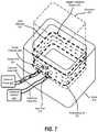
- FIGS. 6-11illustrate exemplary processes for adhesive application to adhere node 201 to structure 401 .
- an adhesive hose 601can be connected to inlet port 215 .
- the other end of adhesive hose 601can be connected to an adhesive injector 603 that can inject adhesive through the adhesive hose.
- a vacuum hose 605can be connected to outlet port 221 .
- the other end of vacuum hose 605can be connected to a vacuum pump 607 that can draw a vacuum through the vacuum hose.
- vacuum pump 607can operate to draw a vacuum in sealed adhesive region 501 through outlet channel 209 .
- Evacuating air 701can be drawn through sealed adhesive region 501 and out outlet channel 209 to establish a vacuum in the sealed adhesive region.
- the quality of the vacuumcan be just sufficient to aid the flow of adhesive through sealed adhesive region 501 .
- the inlet portcan include a mechanism, such as a valve, that can be shut in order to seal off the inlet channel while the sealed adhesive region is evacuated.
- the inlet portcan be a simple opening to which the adhesive hose can attach, and the air in the adhesive hose can be drawn through the inlet channel and evacuated along with the air in the sealed adhesive region.
- adhesive injector 603can operate to inject an adhesive 801 through inlet channel 207 into sealed adhesive region 501 .
- the vacuum pumpcan continue to operate while the adhesive is being injected into the sealed adhesive region, which may be helpful if the vacuum pump is not powerful enough to draw a substantial vacuum in the sealed adhesive region.
- the outlet portcan include a mechanism, such as a valve, that can be shut in order to seal off the outlet channel while the adhesive is injected.
- no vacuumis drawn in the sealed adhesive region, and the outlet channel can be open to the atmosphere to allow air to escape from the sealed adhesive region when the adhesive is injected.
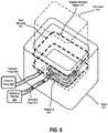
- FIG. 9shows the injection of adhesive 801 at a later time when the adhesive has flowed through more of sealed adhesive region 501 .
- FIG. 10shows the injection of adhesive 801 after the adhesive has travelled through the entire length of sealed adhesive region 501 .
- the proximity of inlet channel 207 to the first end and the proximity of outlet channel 209 to the second endcan be just sufficient to allow adhesive 801 to reach the first and second ends of sealed adhesive region 501 during the adhesive application process.
- FIG. 11illustrates an exemplary final product, joint 1101 , of the adhesive application process described above to adhere node 201 to structure 401 .
- fill material 1103is deposited in inlet channel 207 and outlet channel 209 , and adhesive 801 is allowed to cure.
- fill materialis not deposited in the adhesive and outlet channels, that is, the channels are left open.
- a vacuum pumpis not used.
- adhesivecan be applied through the inlet port using an adhesive injector without use of a vacuum pump, e.g., using the positive injection pressure of the injector to cause the adhesive to flow through the adhesive region to the outlet port.
- adhesivecan be applied by pouring a liquid adhesive into the inlet port, e.g., using gravity to cause the adhesive to flow through the adhesive region to the outlet port.
- seal memberscan be configured to meet specific design requirements of the joints.
- seal memberscan create a variety of separation distances between components of joints.
- seal memberscan create larger separation distances between components in order to reduce or prevent a reaction between the components.
- a larger separation distancemay be helpful to reduce or prevent galvanic corrosion, particularly in joints that have adjacent components with very different electrode potentials.
- Seal memberscan be made of a variety of materials, such as rubber, adhesive, plastic, etc. The material composition of a seal member can be designed to provide a particular benefit during assembly of the node and the structure prior to adhesive application, such as providing flexibility of movement among joint components, providing rigidity to reduce or prevent movement among joint components.
- seal memberscan make the joint water resistant or waterproof and improve the joint's resistant to other substances, such as oil, grease, dirt, etc.
- seal memberscan isolate structures from each other.
- FIGS. 15A-Billustrate an example including a seal member that is provided at the bottom of the node surface such that the structure rests on the seal member after insertion into the node's receptacle.
- seal memberscan be used as a measure to prevent galvanic corrosion between the node and the structure when they are made of dissimilar materials.
- FIGS. 12, 13, 14, 15A -B, and 16 A-Billustrate various other exemplary nodes and node-structure joints.
- FIGS. 12 and 13illustrate examples in which portions of the sealed adhesive region can overlap in a direction of insertion of the structure.
- FIG. 14illustrates an example in which the receptacle of the node can be a slot.
- FIGS. 15A-Billustrate an example in which an additional seal member can be included for the purpose of, for example, providing the adhesive with additional protection from environmental factors such as dust, humidity, etc.
- FIGS. 16A-Billustrate an example in which the seal member can include a portion attached to the structure, which can be seated on a chamfered edge of the node surface. In various embodiments, the entire seal member can be attached to the structure.
- seal members in the following figuresare represented by solid lines for the purpose of clarity.
- nodes and structures in FIGS. 12-14are represented by dashed lines to provide a clearer view of the sealed adhesive regions of these embodiments.
- FIG. 12illustrates an exemplary embodiment including a node 1201 , a structure 1203 , and a seal member 1205 seated on a seal interface 1207 .
- Node 1201 , structure 1203 , and seal member 1205can fit together to form a sealed adhesive region 1209 when the structure is inserted in a receptacle 1211 of the node in a direction of insertion 1213 .
- seal interface 1207can be configured to seat sealed adhesive region 1209 such that a first portion of the sealed adhesive region forms an overlap 1215 with a second portion of the sealed adhesive region in the direction of insertion 1213 . In this way, for example, overlap 1215 can provide additional strength of the attachment between node 1201 and structure 1203 .
- seal interface 1207can be configured to extend around a perimeter of structure 1203 , such that a portion of a first end of sealed adhesive region 1209 forms overlap 1215 with a portion of a second end of the sealed adhesive region in the direction of insertion 1213 .
- Node 1201can include an inlet channel 1217 that connects to sealed adhesive region 1209 proximate to the first end, and can include an outlet channel 1219 that connects to the sealed adhesive region proximate to the second end.
- the proximity of inlet channel 1217 to the first end and the proximity of outlet channel 1219 to the second endcan be just sufficient to allow an adhesive injected into the inlet channel to reach the first and second ends of sealed adhesive region 1209 during an adhesive application process, such as the process described above with respect to FIGS. 6-11 .
- inlet channel 1217can connect an opening in a node surface 1221 of receptacle 1211 to an opening in an exterior surface (not labeled) of node 1201 with a port and inlet similar to those described above with reference to node 201 .
- outlet channel 1219can connect an opening in node surface 1221 to an opening in the exterior surface of node 1201 with a port and inlet similar to those described above with reference to node 201 .
- Structure 1203can have a structure surface 1223 that opposes node surface 1221 when the structure is inserted in receptacle 1211 .
- structure surface 1223contacts seal member 1205 , thus creating a space bounded by the structure surface, node surface 1221 , and the seal member; this space is sealed adhesive region 1209 .
- sealed adhesive region 1209is a space bounded by node surface 1221 , structure surface 1223 , and a portion of the surface of seal member 1205 , which is shown as seal member surface 1225 in the unobstructed, magnified view of the sealed adhesive region in FIG. 12 .
- sealed adhesive region 1209is an adhesive region that has a thin, rectangular cross-section and that extends around the perimeter of structure 1203 with one end located at an inlet aperture 1227 , which is the opening in node surface 1221 to inlet channel 1217 , and the other end located at an outlet aperture 1229 , which is the opening in the node surface to outlet channel 1219 . Furthermore, a first portion of sealed adhesive region 1209 forms overlap 1215 with a second portion of the sealed adhesive region in the direction of insertion 1213 .
- seal interface 1207 of node 1201 and seal member 1205are configured to extend around the perimeter of structure 1203 inserted in receptacle 1211 , such that sealed adhesive region 1209 extends around the perimeter of the structure with a first end of the sealed adhesive region opposing a second end of the sealed adhesive region.
- Inlet channel 1217connects to sealed adhesive region 1209 proximate to the first end through inlet aperture 1227
- outlet channel 1219connects to the sealed adhesive region proximate to the second end through outlet aperture 1229 .
- sealed adhesive region 1209can be open to the exterior surface of node 1201 through inlet channel 1217 , and the other end of the sealed adhesive region can be open to the exterior surface of the node through outlet channel 1219 . Therefore, sealed adhesive region 1209 can be accessible through an inlet port (not labeled) of inlet channel 1217 and an outlet port (not labeled) of outlet channel 1219 for an adhesive application process such as the example process described above with reference to FIGS. 6-11 .
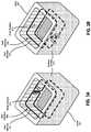
- FIG. 13illustrates an exemplary embodiment including a node 1301 , a structure 1303 , and a seal member 1305 seated on a seal interface 1307 .
- Node 1301 , structure 1303 , and seal member 1305can fit together to form a sealed adhesive region 1309 when the structure is inserted in a receptacle 1311 of the node in a direction of insertion 1313 .
- seal interface 1307can be configured to seat seal member 1305 , the seal member including a top ring portion 1315 around structure 1303 , a bottom ring portion 1317 around the structure, and a spiral portion 1318 extending from the top ring portion to the bottom ring portion and spiraling around the structure.
- sealed adhesive region 1309can overlap each other in direction of insertion 1313 .
- every portion of sealed adhesive region 1309overlaps with one or two other portions of the sealed adhesive region.
- the overlapping of sealed adhesive region 1309can provide additional strength of the attachment between node 1301 and structure 1303 .
- Node 1301can include an inlet channel 1319 that connects to sealed adhesive region 1309 proximate to a first end of the sealed adhesive region bounded by top ring portion 1315 , and can include an outlet channel 1321 that connects to the sealed adhesive region proximate to a second end of the sealed adhesive region bounded by bottom ring portion 1317 .
- the proximity of inlet channel 1319 to the first end and the proximity of outlet channel 1321 to the second endcan be just sufficient to allow an adhesive injected into the inlet channel to reach the first and second ends of sealed adhesive region 1309 during an adhesive application process, such as the process described above with respect to FIGS. 6-11 .
- inlet channel 1319can connect an opening in a node surface 1323 of receptacle 1311 to an opening in an exterior surface (not labeled) of node 1301 with a port and inlet similar to those described above with reference to node 201 .
- outlet channel 1321can connect an opening in node surface 1323 to an opening in the exterior surface of node 1301 with a port and inlet similar to those described above with reference to node 201 .
- Structure 1303can have a structure surface 1325 that opposes node surface 1323 when the structure is inserted in receptacle 1311 .
- structure surface 1325contacts seal member 1305 , thus creating a space bounded by the structure surface, node surface 1323 , and the seal member; this space is sealed adhesive region 1309 .
- sealed adhesive region 1309is a space bounded by node surface 1323 , structure surface 1325 , and a portion of the surface of seal member 1305 , which is shown as seal member surface 1327 in the unobstructed, magnified view of the sealed adhesive region in FIG. 13 .
- sealed adhesive region 1309is an adhesive region that has a thin, rectangular cross-section and that extends around the perimeter of structure 1303 as a spiral with one end located at an inlet aperture 1329 , which is the opening in node surface 1323 to inlet channel 1319 , and the other end located at an outlet aperture 1331 , which is the opening in the node surface to outlet channel 1321 .
- seal interface 1307 of node 1301 and seal member 1305are configured to form a spiral around the perimeter of structure 1203 and to form boundaries at the top and bottom of the spiral, such that sealed adhesive region 1309 extends around the perimeter of the structure as a spiral with a first end of the sealed adhesive region at the top of the spiral and a second end of the sealed adhesive region at the bottom of the spiral.
- Inlet channel 1319connects to sealed adhesive region 1309 proximate to the first end through inlet aperture 1329
- outlet channel 1321connects to the sealed adhesive region proximate to the second end through outlet aperture 1321 .
- sealed adhesive region 1309can be open to the exterior surface of node 1301 through inlet channel 1319 , and the other end of the sealed adhesive region can be open to the exterior surface of the node through outlet channel 1321 . Therefore, sealed adhesive region 1309 can be accessible through an inlet port (not labeled) of inlet channel 1319 and an outlet port (not labeled) of outlet channel 1321 for an adhesive application process such as the example process described above with reference to FIGS. 6-11 .
- FIG. 13includes arrows illustrating the direction of an adhesive flow 1333 through sealed adhesive region 1309 from inlet aperture 1329 to outlet aperture 1331 .
- FIG. 14illustrates an exemplary embodiment including a node 1401 , a structure 1403 , and a seal member 1405 seated on a seal interface 1407 .
- Node 1401 , structure 1403 , and seal member 1405can fit together to form a sealed adhesive region 1409 when the structure is inserted in a receptacle 1411 .
- receptacle 1411can be a slot in node 1401 .
- receptacle 1411extends only partway around a perimeter of structure 1403 .
- structure 1403can be inserted into node 1401 in different directions of insertion.
- Node 1401can include an inlet channel 1419 that connects to sealed adhesive region 1409 proximate to a first end of the sealed adhesive region, and can include an outlet channel 1421 that connects to the sealed adhesive region proximate to a second end of the sealed adhesive region.
- the proximity of inlet channel 1419 to the first end and the proximity of outlet channel 1421 to the second endcan be just sufficient to allow an adhesive injected into the inlet channel to reach the first and second ends of sealed adhesive region 1409 during an adhesive application process, such as the process described above with respect to FIGS. 6-11 .
- inlet channel 1419can connect an opening in a node surface 1423 of receptacle 1411 to an opening in an exterior surface (not labeled) of node 1401 with a port and inlet similar to those described above with reference to node 201 .
- outlet channel 1421can connect an opening in node surface 1423 to an opening in the exterior surface of node 1401 with a port and inlet similar to those described above with reference to node 201 .
- Structure 1403can have a structure surface 1425 that opposes node surface 1423 when the structure is inserted in receptacle 1411 .
- structure surface 1425contacts seal member 1405 , thus creating a space bounded by the structure surface, node surface 1423 , and the seal member; this space is sealed adhesive region 1409 .
- sealed adhesive region 1409is a space bounded by node surface 1423 , structure surface 1425 , and a portion of the surface of seal member 1405 , which is shown as seal member surface 1427 in the unobstructed, magnified view of the sealed adhesive region in FIG. 14 .
- sealed adhesive region 1409is an adhesive region that has a thin, rectangular cross-section and that extends only partway around the perimeter of structure 1403 with one end located at an inlet aperture 1429 , which is the opening in node surface 1423 to inlet channel 1419 , and the other end located at an outlet aperture 1431 , which is the opening in the node surface to outlet channel 1421 .
- Inlet channel 1419connects to sealed adhesive region 1409 proximate to a first end of the sealed adhesive region through inlet aperture 1429
- outlet channel 1421connects to the sealed adhesive region proximate to a second end of the sealed adhesive region through outlet aperture 1421 .
- sealed adhesive region 1409can be open to the exterior surface of node 1401 through inlet channel 1419 , and the other end of the sealed adhesive region can be open to the exterior surface of the node through outlet channel 1421 . Therefore, sealed adhesive region 1409 can be accessible through an inlet port (not labeled) of inlet channel 1419 and an outlet port (not labeled) of outlet channel 1421 for an adhesive application process such as the example process described above with reference to FIGS. 6-11 .
- FIG. 14includes arrows illustrating the direction of an adhesive flow 1433 through sealed adhesive region 1409 from inlet aperture 1429 to outlet aperture 1431 .
- FIGS. 15A-Billustrate an exemplary embodiment including a node 1501 , a structure 1503 , a seal member 1505 , and a second seal member 1506 .
- Seal member 1505 and second seal member 1506can be seated on a seal interface 1507 .
- Node 1501 , structure 1503 , and seal member 1505can fit together to form a sealed adhesive region 1509 when the structure is inserted in a receptacle 1511 in a direction of insertion 1513 .
- seal member 1505can include a top ring portion 1515 around structure 1503 and a bottom ring portion 1517 around the structure.
- Second seal member 1506can form a seal between node 1501 and structure 1503 to provide, for example, further protection of the adhesive bond from environmental conditions, additional guidance for insertion of the structure into receptacle 1511 , enhanced rigidity of the finished joint, a more rigid structure for keeping the node and the structure separated, etc.
- Node 1501can include an inlet channel 1519 that connects to sealed adhesive region 1509 proximate to a first end of the sealed adhesive region, and can include an outlet channel 1521 that connects to the sealed adhesive region proximate to a second end of the sealed adhesive region.
- sealed adhesive region 1509has two separate channels for adhesive to flow from inlet channel 1519 to outlet channel 1521 ; the channels are illustrated in FIG. 15B by arrows of a first path 1523 of adhesive flow in sealed adhesive region 1509 and a second path 1525 of adhesive flow in sealed adhesive region 1509 .
- inlet channel 1519 to the first end and the proximity of outlet channel 1521 to the second endcan be just sufficient to allow an adhesive injected into the inlet channel to reach the first and second ends of sealed adhesive region 1509 during an adhesive application process, such as the process described above with respect to FIGS. 6-11 .
- FIGS. 16A-Billustrate an exemplary embodiment including a node 1601 , a structure 1603 , and a seal member 1605 seated on a seal interface 1607 .
- Node 1601 , structure 1603 , and seal member 1605can fit together to form a sealed adhesive region 1609 when the structure is inserted in a receptacle 1611 of node 1601 in a direction of insertion 1613 .
- seal member 1605can include a top ring portion 1615 that is positioned on structure 1603 .
- top ring portion 1615can be inserted into a groove around structure 1603 , can be attached to the structure with an adhesive, can be held in place with a flange around the structure, etc.
- the surface of receptacle 1611can include a chamfered edge 1616 , and the chamfered edge can be a part of seal interface 1607 .
- chamfered edge 1616can receive top ring portion 1615 when structure 1603 is inserted in receptacle 1611 , such that the top ring portion is seated on the chamfered edge.
- chamfered edge 1616 and top ring portion 1615can be configured to stop the insertion of structure 1603 when the structure has reached a desired position in receptacle 1611 , at which point the top ring portion is seated on the chamfered edge.
- chamfered edge 1616can help to center structure 1603 within receptacle 1611 as top ring portion 1615 is guided by the configuration of the chamfered edge prior to settling in the seated position.
- Seal member 1605can also include a bottom ring portion 1617 positioned in receptacle 1611 of node 1601 .
- Node 1601can include an inlet channel 1619 that connects to sealed adhesive region 1609 proximate to a first end of the sealed adhesive region, and can include an outlet channel 1621 that connects to the sealed adhesive region proximate to a second end of the sealed adhesive region.
- sealed adhesive region 1609has two channels for adhesive to flow from inlet channel 1619 to outlet channel 1621 ; the channels are illustrated in FIG. 16B by arrows of a first path 1623 of adhesive flow in sealed adhesive region 1609 and a second path 1625 of adhesive flow in the sealed adhesive region.
- the proximity of inlet channel 1619 to the first end and the proximity of outlet channel 1621 to the second endcan be just sufficient to allow, during an adhesive injection process such as the process described above with respect to FIGS. 6-11 , the portion of the adhesive traveling through first path 1623 to reach outlet channel 1621 at substantially the same time as the portion of the adhesive traveling through second path 1625 .
- the bottom ring portioncan be positioned on the structure, instead of in the receptacle.
- both a top ring portion and a bottom ring portioncan be positioned on the structure prior to the structure's insertion into the receptacle of the node.
- the bottom ring portioncan be, for example, inserted into a groove around the structure, can be attached to the structure with an adhesive, can be held in place with a flange around the structure, etc.
- the bottom ring portioncan be configured to slide on the surface of the receptacle when the structure is inserted into the receptacle.
- the bottom ring portionWhen the top ring portion becomes seated on the chamfered edge, the bottom ring portion can come to rest and be seated on another part of the seal interface.
- the bottom ring portioncan come to rest on a polished portion of the node surface, can slide into a groove in the node surface and come to rest in the groove, can slide to abut a flange on the node surface and come to rest against the flange, etc.
- FIG. 17is a flowchart that illustrates an exemplary process of adhering an additively manufactured node to a structure.
- the nodecan include a receptacle extending into the node.
- a seal membercan be arranged ( 1701 ) in the receptacle, and the structure can be inserted ( 1702 ) into the receptacle.
- the structurecan include a surface that opposes a surface of the receptacle, such that an adhesive region can be formed between the node and the structure.
- the adhesive regioncan be bounded by the surface of the receptacle, the surface of the structure opposing the node surface, and the seal member.
- the seal membercan be arranged in the receptacle prior to insertion of the structure into the receptacle.
- the seal membercan be seated on a seal interface at a surface of the receptacle prior to insertion of the structure, as in the examples illustrated in FIGS. 2A-B , 3 A-B, 4 A-B, 5 , 12 - 14 , and 15 A-B.
- a portion of the seal member or the entire seal membercan be positioned on the structure prior to insertion of the structure into the receptacle, as in the example of FIG. 16A-B in which a portion of the seal member is positioned on the structure.
- the seal membercan be arranged in the receptacle after the structure is inserted into the receptacle and comes to rest at a final position, at which point the seal member can be seated on the seal interface of the node surface.
- the temporal order of arranging ( 1701 ) the seal member in the receptacle and inserting ( 1702 ) the structure into the receptaclecan be reversed, i.e., inserting the structure occurs before arranging the seal member in the receptacle.
- part of the seal membercan be attached to the structure and part of the seal member can be arranged in the receptacle of the node prior to insertion of the structure into the receptacle, as in the example illustrated in FIG. 16 .
- the arranging ( 1701 ) and the inserting ( 1702 ) in the flowchart of FIG. 17should not be interpreted as occurring in a particular temporal order, but should be interpreted as including various ways to achieve the arranging of the seal member in the receptacle.
- an adhesivecan be injected ( 1703 ) into the sealed adhesive region to adhere the node to the structure.
- a vacuumcan be created in the sealed adhesive region to evacuate the sealed adhesive region, and the adhesive can be injected into the evacuated sealed adhesive region. The quality of the vacuum can be just sufficient to aid the flow of adhesive through the sealed adhesive region.
- creating the vacuumcan include evacuating the sealed adhesive region through a channel (e.g., a vacuum channel described in the foregoing examples) that extends from an exterior of the node to the sealed adhesive region.
- injecting the adhesivecan include injecting the adhesive through a channel (e.g., an inlet channel described in the foregoing examples).
- the outlet channel and the inlet channelcan be the same channel.
- a vacuum pumpcan be attached to single channel to evacuate the sealed adhesive region, the single channel can be closed off, an adhesive injector can be attached to the single channel, the single channel can be opened, and the adhesive injector can inject adhesive into the evacuated sealed adhesive region.
- the vacuum channel and the inlet channelcan be separate channels.
- Combinations such as “at least one of A, B, or C,” “one or more of A, B, or C,” “at least one of A, B, and C,” “one or more of A, B, and C,” and “A, B, C, or any combination thereof”include any combination of A, B, and/or C, and may include multiples of A, multiples of B, and/or multiples of C.
- combinations such as “at least one of A, B, or C,” “one or more of A, B, or C,” “at least one of A, B, and C,” “one or more of A, B, and C,” and “A, B, C, or any combination thereof”may be A only, B only, C only, A and B, A and C, B and C, or A and B and C, where any such combinations may contain one or more member or members of A, B, or C.
- No claim elementis to be construed under the provisions of 35 U.S.C. ⁇ 112(f), or analogous law in applicable jurisdictions, unless the element is expressly recited using the phrase “means for” or, in the case of a method claim, the element is recited using the phrase “step for.”
Landscapes
- Engineering & Computer Science (AREA)
- Mechanical Engineering (AREA)
- Chemical & Material Sciences (AREA)
- Combustion & Propulsion (AREA)
- Transportation (AREA)
- Architecture (AREA)
- Structural Engineering (AREA)
- General Engineering & Computer Science (AREA)
- Organic Chemistry (AREA)
- Gasket Seals (AREA)
- Standing Axle, Rod, Or Tube Structures Coupled By Welding, Adhesion, Or Deposition (AREA)
Abstract
Description
Claims (11)
Priority Applications (6)
| Application Number | Priority Date | Filing Date | Title |
|---|---|---|---|
| US15/961,767US11214317B2 (en) | 2018-04-24 | 2018-04-24 | Systems and methods for joining nodes and other structures |
| EP19792654.6AEP3784479A4 (en) | 2018-04-24 | 2019-03-13 | SYSTEMS AND METHODS FOR JOINING KNOTS AND OTHER STRUCTURES |
| CN201980042233.9ACN112292255B (en) | 2018-04-24 | 2019-03-13 | System and method for joining nodes and other structures |
| PCT/US2019/022034WO2019209425A1 (en) | 2018-04-24 | 2019-03-13 | Systems and methods for joining nodes and other structures |
| US17/536,722US20220081045A1 (en) | 2018-04-24 | 2021-11-29 | Systems and methods for joining nodes and other structures |
| US17/540,151US20220194488A1 (en) | 2018-04-24 | 2021-12-01 | Systems and methods for joining nodes and other structures |
Applications Claiming Priority (1)
| Application Number | Priority Date | Filing Date | Title |
|---|---|---|---|
| US15/961,767US11214317B2 (en) | 2018-04-24 | 2018-04-24 | Systems and methods for joining nodes and other structures |
Related Child Applications (2)
| Application Number | Title | Priority Date | Filing Date |
|---|---|---|---|
| US17/536,722ContinuationUS20220081045A1 (en) | 2018-04-24 | 2021-11-29 | Systems and methods for joining nodes and other structures |
| US17/540,151DivisionUS20220194488A1 (en) | 2018-04-24 | 2021-12-01 | Systems and methods for joining nodes and other structures |
Publications (2)
| Publication Number | Publication Date |
|---|---|
| US20190322055A1 US20190322055A1 (en) | 2019-10-24 |
| US11214317B2true US11214317B2 (en) | 2022-01-04 |
Family
ID=68237326
Family Applications (3)
| Application Number | Title | Priority Date | Filing Date |
|---|---|---|---|
| US15/961,767Active2039-06-21US11214317B2 (en) | 2018-04-24 | 2018-04-24 | Systems and methods for joining nodes and other structures |
| US17/536,722AbandonedUS20220081045A1 (en) | 2018-04-24 | 2021-11-29 | Systems and methods for joining nodes and other structures |
| US17/540,151AbandonedUS20220194488A1 (en) | 2018-04-24 | 2021-12-01 | Systems and methods for joining nodes and other structures |
Family Applications After (2)
| Application Number | Title | Priority Date | Filing Date |
|---|---|---|---|
| US17/536,722AbandonedUS20220081045A1 (en) | 2018-04-24 | 2021-11-29 | Systems and methods for joining nodes and other structures |
| US17/540,151AbandonedUS20220194488A1 (en) | 2018-04-24 | 2021-12-01 | Systems and methods for joining nodes and other structures |
Country Status (4)
| Country | Link |
|---|---|
| US (3) | US11214317B2 (en) |
| EP (1) | EP3784479A4 (en) |
| CN (1) | CN112292255B (en) |
| WO (1) | WO2019209425A1 (en) |
Cited By (2)
| Publication number | Priority date | Publication date | Assignee | Title |
|---|---|---|---|---|
| US11352070B2 (en)* | 2019-09-26 | 2022-06-07 | Toyota Jidosha Kabushiki Kaisha | Body of electric vehicle |
| US20220194488A1 (en)* | 2018-04-24 | 2022-06-23 | Divergent Technologies, Inc. | Systems and methods for joining nodes and other structures |
Families Citing this family (4)
| Publication number | Priority date | Publication date | Assignee | Title |
|---|---|---|---|---|
| US11389816B2 (en)* | 2018-05-09 | 2022-07-19 | Divergent Technologies, Inc. | Multi-circuit single port design in additively manufactured node |
| EP4030070B1 (en)* | 2018-09-05 | 2024-01-03 | Stryker European Operations Holdings LLC | Connecting member and connecting method |
| EP4043737B1 (en)* | 2021-02-10 | 2024-11-27 | B/E Aerospace, Inc. | Bonding concentric elements |
| CN116619768B (en)* | 2023-05-26 | 2025-07-18 | 广州宁武科技股份有限公司 | A method for splicing a carbon fiber tube frame |
Citations (301)
| Publication number | Priority date | Publication date | Assignee | Title |
|---|---|---|---|---|
| US3920268A (en) | 1973-02-13 | 1975-11-18 | Albert Stewing | Synthetic-resin tube assembly |
| US4211259A (en)* | 1978-04-14 | 1980-07-08 | Butler James L | Plastic tube |
| US5203226A (en) | 1990-04-17 | 1993-04-20 | Toyoda Gosei Co., Ltd. | Steering wheel provided with luminous display device |
| WO1996036525A1 (en) | 1995-05-19 | 1996-11-21 | Edag Engineering + Design Ag | Process for automatically fitting a motor vehicle body component |
| WO1996036455A1 (en) | 1995-05-16 | 1996-11-21 | Edag Engineering + Design Ag | Device for feeding welding bolts to a welding gun |
| WO1996038260A1 (en) | 1995-05-30 | 1996-12-05 | Edag Engineering + Design Ag | Container changer |
| US5742385A (en) | 1996-07-16 | 1998-04-21 | The Boeing Company | Method of airplane interiors assembly using automated rotating laser technology |
| US5851036A (en) | 1995-12-14 | 1998-12-22 | Vanesky; Frank W. | Permanent fitting for fluid-tight connections |
| US5990444A (en) | 1995-10-30 | 1999-11-23 | Costin; Darryl J. | Laser method and system of scribing graphics |
| US6010155A (en) | 1996-12-31 | 2000-01-04 | Dana Corporation | Vehicle frame assembly and method for manufacturing same |
| US6096249A (en) | 1996-12-05 | 2000-08-01 | Teijin Limited | Method for molding fiber aggregate |
| US6140602A (en) | 1997-04-29 | 2000-10-31 | Technolines Llc | Marking of fabrics and other materials using a laser |
| US6252196B1 (en) | 1996-10-11 | 2001-06-26 | Technolines Llc | Laser method of scribing graphics |
| US6250533B1 (en) | 1999-02-18 | 2001-06-26 | Edag Engineering & Design Ag | Clamping device for use in motor vehicle production lines and production line having such a clamping device |
| US6318642B1 (en) | 1999-12-22 | 2001-11-20 | Visteon Global Tech., Inc | Nozzle assembly |
| US6365057B1 (en) | 1999-11-01 | 2002-04-02 | Bmc Industries, Inc. | Circuit manufacturing using etched tri-metal media |
| US6391251B1 (en) | 1999-07-07 | 2002-05-21 | Optomec Design Company | Forming structures from CAD solid models |
| US6409930B1 (en) | 1999-11-01 | 2002-06-25 | Bmc Industries, Inc. | Lamination of circuit sub-elements while assuring registration |
| US6468439B1 (en) | 1999-11-01 | 2002-10-22 | Bmc Industries, Inc. | Etching of metallic composite articles |
| WO2003024641A1 (en) | 2001-08-31 | 2003-03-27 | Edag Engineering + Design Aktiengesellschaft | Roller folding head and method for folding a flange |
| US6554345B2 (en) | 1997-10-23 | 2003-04-29 | Ssab Hardtech Ab | Lightweight beam |
| US6585151B1 (en) | 2000-05-23 | 2003-07-01 | The Regents Of The University Of Michigan | Method for producing microporous objects with fiber, wire or foil core and microporous cellular objects |
| US6644721B1 (en) | 2002-08-30 | 2003-11-11 | Ford Global Technologies, Llc | Vehicle bed assembly |
| US6811744B2 (en) | 1999-07-07 | 2004-11-02 | Optomec Design Company | Forming structures from CAD solid models |
| WO2004108343A1 (en) | 2003-06-05 | 2004-12-16 | Erwin Martin Heberer | Device for shielding coherent electromagnetic radiation and laser booth provided with such a device |
| US6866497B2 (en) | 2001-06-13 | 2005-03-15 | Kabushiki Kaisha Tokai Rika Denki Seisakusho | Molding apparatus having a projecting bulge located in a die half |
| US6919035B1 (en) | 2001-05-18 | 2005-07-19 | Ensci Inc. | Metal oxide coated polymer substrates |
| US6926970B2 (en) | 2001-11-02 | 2005-08-09 | The Boeing Company | Apparatus and method for forming weld joints having compressive residual stress patterns |
| WO2005093773A1 (en) | 2004-03-25 | 2005-10-06 | Audi Ag | System comprising an automotive fuse and an a/d converter |
| US20060108783A1 (en) | 2004-11-24 | 2006-05-25 | Chi-Mou Ni | Structural assembly for vehicles and method of making same |
| WO2007003375A1 (en) | 2005-06-30 | 2007-01-11 | Edag Engineering + Design Ag | Method and device for joining joining structures, particularly during the assembly of vehicle components |
| WO2007110235A1 (en) | 2006-03-28 | 2007-10-04 | Edag Gmbh & Co. Kgaa | Clamping device for holding and clamping components |
| WO2007110236A1 (en) | 2006-03-28 | 2007-10-04 | Edag Gmbh & Co. Kgaa | Clamping device for holding and clamping components |
| WO2007128586A2 (en) | 2006-05-10 | 2007-11-15 | Edag Gmbh & Co. Kgaa | Energy beam brazing or welding of components |
| WO2008019847A1 (en) | 2006-08-18 | 2008-02-21 | Fft Edag Produktionssysteme Gmbh & Co. Kg | Monitoring device for a laser machining device |
| US7344186B1 (en) | 2007-01-08 | 2008-03-18 | Ford Global Technologies, Llc | A-pillar structure for an automotive vehicle |
| WO2008068314A2 (en) | 2006-12-08 | 2008-06-12 | Edag Gmbh & Co. Kgaa | Flanging hand tool |
| WO2008086994A1 (en) | 2007-01-15 | 2008-07-24 | Edag Gmbh & Co. Kgaa | Sheet-metal composite, method for joining sheets and joining device |
| WO2008087024A1 (en) | 2007-01-18 | 2008-07-24 | Toyota Motor Corporation | Composite of sheet metal parts |
| WO2008107130A1 (en) | 2007-03-02 | 2008-09-12 | Edag Gmbh & Co. Kgaa | Automobile with facilitated passenger exit |
| WO2008138503A1 (en) | 2007-05-11 | 2008-11-20 | Edag Gmbh & Co. Kgaa | Crimping components in series production having short cycle times |
| WO2008145396A1 (en) | 2007-06-01 | 2008-12-04 | Edag Gmbh & Co. Kgaa | Edge curling tool |
| US7500373B2 (en) | 2004-09-24 | 2009-03-10 | Edag Gmbh & Co. Kgaa | Flanging device and flanging method with component protection |
| WO2009083609A2 (en) | 2008-01-03 | 2009-07-09 | Edag Gmbh & Co. Kgaa | Method for bending a workpiece |
| WO2009098285A1 (en) | 2008-02-07 | 2009-08-13 | Edag Gmbh & Co. Kgaa | Rotating table |
| WO2009112520A1 (en) | 2008-03-11 | 2009-09-17 | Edag Gmbh & Co. Kgaa | Tool, system and method for the manufacture of a cable harness |
| WO2009135938A1 (en) | 2008-05-09 | 2009-11-12 | Edag Gmbh & Co. Kgaa | Method and tool for producing a fixed connection to components joined in a form-fitted manner |
| WO2009140977A1 (en) | 2008-05-21 | 2009-11-26 | Edag Gmbh & Co. Kgaa | Clamping frame-less joining of components |
| US7637134B2 (en) | 2005-01-31 | 2009-12-29 | Edag Gmbh & Co. Kgaa | Flanging with a leading and following flanging die |
| US7710347B2 (en) | 2007-03-13 | 2010-05-04 | Raytheon Company | Methods and apparatus for high performance structures |
| US7716802B2 (en) | 2006-01-03 | 2010-05-18 | The Boeing Company | Method for machining using sacrificial supports |
| US7745293B2 (en) | 2004-06-14 | 2010-06-29 | Semiconductor Energy Laboratory Co., Ltd | Method for manufacturing a thin film transistor including forming impurity regions by diagonal doping |
| US7766123B2 (en) | 2006-03-29 | 2010-08-03 | Yamaha Hatsudoki Kabushiki Kaisha | Vehicle exhaust system |
| US20100259040A1 (en) | 2007-05-30 | 2010-10-14 | Trygve Kjolseth | Coupling and method for joining |
| WO2010125058A1 (en) | 2009-04-27 | 2010-11-04 | Edag Gmbh & Co. Kgaa | Clamping device, system, and method for processing changing component types |
| WO2010125057A2 (en) | 2009-04-27 | 2010-11-04 | Edag Gmbh & Co. Kgaa | Robot support |
| US7852388B2 (en) | 2006-05-23 | 2010-12-14 | Panasonic Corporation | Imaging device |
| WO2010142703A2 (en) | 2009-06-09 | 2010-12-16 | Edag Gmbh & Co. Kgaa | Method and tool for edging a workpiece |
| US7908922B2 (en) | 2008-01-24 | 2011-03-22 | Delphi Technologies, Inc. | Silicon integrated angular rate sensor |
| WO2011032533A1 (en) | 2009-09-15 | 2011-03-24 | Edag Gmbh & Co. Kgaa | Vehicle body component composed of an exterior element and a fibre-reinforced plastic structural component connected to the rear side of said exterior element |
| US7951324B2 (en) | 2006-09-14 | 2011-05-31 | Ibiden Co., Ltd. | Method for manufacturing honeycomb structure |
| US8163077B2 (en) | 2005-09-28 | 2012-04-24 | Yissum Research Development Company Of The Hebrew University Of Jerusalem | Ink providing etch-like effect for printing on ceramic surfaces |
| US8286236B2 (en) | 2007-12-21 | 2012-10-09 | The Invention Science Fund I, Llc | Manufacturing control system |
| US8289352B2 (en) | 2010-07-15 | 2012-10-16 | HJ Laboratories, LLC | Providing erasable printing with nanoparticles |
| US8297096B2 (en) | 2007-07-20 | 2012-10-30 | Nippon Steel Corporation | Method for hydroforming and hydroformed product |
| US8354170B1 (en) | 2009-10-06 | 2013-01-15 | Hrl Laboratories, Llc | Elastomeric matrix composites |
| US8383028B2 (en) | 2008-11-13 | 2013-02-26 | The Boeing Company | Method of manufacturing co-molded inserts |
| US8429754B2 (en) | 2007-12-21 | 2013-04-23 | The Invention Science Fund I, Llc | Control technique for object production rights |
| US8437513B1 (en) | 2012-08-10 | 2013-05-07 | EyeVerify LLC | Spoof detection for biometric authentication |
| US8444903B2 (en) | 2007-07-13 | 2013-05-21 | The Boeing Company | Method of fabricating three dimensional printed part |
| US8452073B2 (en) | 2009-04-08 | 2013-05-28 | The United States Of America As Represented By The Administrator Of The National Aeronautics And Space Administration | Closed-loop process control for electron beam freeform fabrication and deposition processes |
| US8599301B2 (en) | 2006-04-17 | 2013-12-03 | Omnivision Technologies, Inc. | Arrayed imaging systems having improved alignment and associated methods |
| US8606540B2 (en) | 2009-11-10 | 2013-12-10 | Projectionworks, Inc. | Hole measurement apparatuses |
| US8610761B2 (en) | 2009-11-09 | 2013-12-17 | Prohectionworks, Inc. | Systems and methods for optically projecting three-dimensional text, images and/or symbols onto three-dimensional objects |
| WO2014016437A1 (en) | 2012-07-27 | 2014-01-30 | Fft Edag Produktionssysteme Gmbh & Co. Kg | Hemming press |
| US8678060B2 (en) | 2011-03-04 | 2014-03-25 | Fft Edag Produktionssysteme Gmbh & Co. Kg | Joining surface treatment device and method |
| US8686997B2 (en) | 2009-12-18 | 2014-04-01 | Sassault Systemes | Method and system for composing an assembly |
| US8694284B2 (en) | 2010-04-02 | 2014-04-08 | Dassault Systemes | Part modeled by parallel geodesic curves |
| US8752166B2 (en) | 2007-12-21 | 2014-06-10 | The Invention Science Fund I, Llc | Security-activated operational components |
| US8755923B2 (en) | 2009-12-07 | 2014-06-17 | Engineering Technology Associates, Inc. | Optimization system |
| US8818771B2 (en) | 2010-06-21 | 2014-08-26 | Johan Gielis | Computer implemented tool box systems and methods |
| US20140277669A1 (en) | 2013-03-15 | 2014-09-18 | Sikorsky Aircraft Corporation | Additive topology optimized manufacturing for multi-functional components |
| US8873238B2 (en) | 2012-06-11 | 2014-10-28 | The Boeing Company | Chassis system and method for holding and protecting electronic modules |
| WO2014187720A1 (en) | 2013-05-22 | 2014-11-27 | Fft Edag Produktionssysteme Gmbh & Co. Kg | Joining a workpiece with a concealed joint seam |
| WO2014195340A1 (en) | 2013-06-07 | 2014-12-11 | Fft Produktionssyteme Gmbh & Co. Kg | Device for use in the handling of a load and method for producing such a device |
| US8978535B2 (en) | 2010-08-11 | 2015-03-17 | Massachusetts Institute Of Technology | Articulating protective system for resisting mechanical loads |
| US9071436B2 (en) | 2007-12-21 | 2015-06-30 | The Invention Science Fund I, Llc | Security-activated robotic system |
| US9101979B2 (en) | 2011-10-31 | 2015-08-11 | California Institute Of Technology | Methods for fabricating gradient alloy articles with multi-functional properties |
| US9126365B1 (en) | 2013-03-22 | 2015-09-08 | Markforged, Inc. | Methods for composite filament fabrication in three dimensional printing |
| US9128476B2 (en) | 2007-12-21 | 2015-09-08 | The Invention Science Fund I, Llc | Secure robotic operational system |
| US9138924B2 (en) | 2014-01-06 | 2015-09-22 | Prior Company Limited | Manufacturing method of decorated molding article and manufacturing method of decorated film |
| US9149988B2 (en) | 2013-03-22 | 2015-10-06 | Markforged, Inc. | Three dimensional printing |
| US9156205B2 (en) | 2013-03-22 | 2015-10-13 | Markforged, Inc. | Three dimensional printer with composite filament fabrication |
| US9186848B2 (en) | 2013-03-22 | 2015-11-17 | Markforged, Inc. | Three dimensional printing of composite reinforced structures |
| WO2015193331A1 (en) | 2014-06-17 | 2015-12-23 | Fft Produktionssysteme Gmbh & Co. Kg | Segmented retaining plate for a workpiece |
| US9244986B2 (en) | 2013-01-11 | 2016-01-26 | Buckyball Mobile, Inc. | Method and system for interactive geometric representations, configuration and control of data |
| US9248611B2 (en) | 2013-10-07 | 2016-02-02 | David A. Divine | 3-D printed packaging |
| US9254535B2 (en) | 2014-06-20 | 2016-02-09 | Velo3D, Inc. | Apparatuses, systems and methods for three-dimensional printing |
| US9266566B2 (en) | 2014-04-09 | 2016-02-23 | Hyundai Motor Company | Front body member for vehicle |
| US9269022B2 (en) | 2013-04-11 | 2016-02-23 | Digimarc Corporation | Methods for object recognition and related arrangements |
| US9329020B1 (en) | 2013-01-02 | 2016-05-03 | Lockheed Martin Corporation | System, method, and computer program product to provide wireless sensing based on an aggregate magnetic field reading |
| US9389315B2 (en) | 2012-12-19 | 2016-07-12 | Basf Se | Detector comprising a transversal optical sensor for detecting a transversal position of a light beam from an object and a longitudinal optical sensor sensing a beam cross-section of the light beam in a sensor region |
| WO2016116414A1 (en) | 2015-01-19 | 2016-07-28 | Fft Produktionssysteme Gmbh & Co. Kg | Flanging system, flanging unit and flanging method for autonomous flanging |
| US9457514B2 (en) | 2012-03-08 | 2016-10-04 | Klaus Schwärzler | Method and device for layered buildup of a shaped element |
| US9469057B2 (en) | 2012-05-18 | 2016-10-18 | 3D Systems, Inc. | Support structures and deposition techniques for 3D printing |
| US9481402B1 (en) | 2015-05-26 | 2016-11-01 | Honda Motor Co., Ltd. | Methods and apparatus for supporting vehicle components |
| US9486960B2 (en) | 2014-12-19 | 2016-11-08 | Palo Alto Research Center Incorporated | System for digital fabrication of graded, hierarchical material structures |
| US9502993B2 (en) | 2011-02-07 | 2016-11-22 | Ion Geophysical Corporation | Method and apparatus for sensing signals |
| US9525262B2 (en) | 2011-08-04 | 2016-12-20 | Martin A. Stuart | Slab laser and amplifier and method of use |
| US9533526B1 (en) | 2012-06-15 | 2017-01-03 | Joel Nevins | Game object advances for the 3D printing entertainment industry |
| US20170001368A1 (en) | 2015-06-04 | 2017-01-05 | Divergent Technologies, Inc. | Systems and methods for adhesive injection for node assembly |
| US9555315B2 (en) | 2013-12-05 | 2017-01-31 | Aaron Benjamin Aders | Technologies for transportation |
| US9555580B1 (en) | 2013-03-21 | 2017-01-31 | Temper Ip, Llc. | Friction stir welding fastener |
| US9557856B2 (en) | 2013-08-19 | 2017-01-31 | Basf Se | Optical detector |
| US9566758B2 (en) | 2010-10-19 | 2017-02-14 | Massachusetts Institute Of Technology | Digital flexural materials |
| US9566742B2 (en) | 2012-04-03 | 2017-02-14 | Massachusetts Institute Of Technology | Methods and apparatus for computer-assisted spray foam fabrication |
| US20170051791A1 (en)* | 2015-08-21 | 2017-02-23 | American Axle & Manufacturing, Inc. | Propshaft assembly with yoke adhesively coupled to propshaft tube |
| WO2017036461A1 (en) | 2015-09-04 | 2017-03-09 | Edag Engineering Gmbh | Mobile communication device and software code, and traffic entity |
| US9595795B2 (en) | 2014-12-09 | 2017-03-14 | Te Connectivity Corporation | Header assembly |
| US9600929B1 (en) | 2014-12-01 | 2017-03-21 | Ngrain (Canada) Corporation | System, computer-readable medium and method for 3D-differencing of 3D voxel models |
| US9597843B2 (en) | 2014-05-15 | 2017-03-21 | The Boeing Company | Method and apparatus for layup tooling |
| US9609755B2 (en) | 2013-01-17 | 2017-03-28 | Hewlett-Packard Development Company, L.P. | Nanosized particles deposited on shaped surface geometries |
| US9611667B2 (en) | 2015-05-05 | 2017-04-04 | West Virginia University | Durable, fire resistant, energy absorbing and cost-effective strengthening systems for structural joints and members |
| US9610737B2 (en) | 2015-03-04 | 2017-04-04 | Ebert Composites Corporation | 3D thermoplastic composite pultrusion system and method |
| US9626489B2 (en) | 2013-03-13 | 2017-04-18 | Intertrust Technologies Corporation | Object rendering systems and methods |
| US9626487B2 (en) | 2007-12-21 | 2017-04-18 | Invention Science Fund I, Llc | Security-activated production device |
| US20170113344A1 (en) | 2015-10-21 | 2017-04-27 | Fft Produktionssysteme Gmbh & Co. Kg | Absolute Robot-Assisted Positioning Method |
| US9643361B2 (en) | 2014-05-27 | 2017-05-09 | Jian Liu | Method and apparatus for three-dimensional additive manufacturing with a high energy high power ultrafast laser |
| US9662840B1 (en) | 2015-11-06 | 2017-05-30 | Velo3D, Inc. | Adept three-dimensional printing |
| US9665182B2 (en) | 2013-08-19 | 2017-05-30 | Basf Se | Detector for determining a position of at least one object |
| US9672389B1 (en) | 2012-06-26 | 2017-06-06 | The Mathworks, Inc. | Generic human machine interface for a graphical model |
| US9672550B2 (en) | 2010-09-24 | 2017-06-06 | Amazon Technologies, Inc. | Fulfillment of orders for items using 3D manufacturing on demand |
| US9684919B2 (en) | 2010-09-24 | 2017-06-20 | Amazon Technologies, Inc. | Item delivery using 3D manufacturing on demand |
| US9688032B2 (en) | 2013-07-01 | 2017-06-27 | GM Global Technology Operations LLC | Thermoplastic component repair |
| US9690286B2 (en) | 2012-06-21 | 2017-06-27 | Massachusetts Institute Of Technology | Methods and apparatus for digital material skins |
| US9703896B2 (en) | 2014-03-11 | 2017-07-11 | Microsoft Technology Licensing, Llc | Generation of custom modular objects |
| US9718302B2 (en) | 2015-09-22 | 2017-08-01 | The Boeing Company | Decorative laminate with non-visible light activated material and system and method for using the same |
| US9718434B2 (en) | 2015-01-21 | 2017-08-01 | GM Global Technology Operations LLC | Tunable energy absorbers |
| US9724877B2 (en) | 2013-06-23 | 2017-08-08 | Robert A. Flitsch | Methods and apparatus for mobile additive manufacturing of advanced structures and roadways |
| US9725178B2 (en) | 2015-05-08 | 2017-08-08 | Raymond R M Wang | Airflow modification apparatus and method |
| US9731773B2 (en) | 2015-03-11 | 2017-08-15 | Caterpillar Inc. | Node for a space frame |
| US9731730B2 (en) | 2014-09-24 | 2017-08-15 | Holland Lp | Grating connector and spacer apparatus, system, and methods of using the same |
| US9741954B2 (en) | 2013-06-13 | 2017-08-22 | Basf Se | Optical detector and method for manufacturing the same |
| US9764415B2 (en) | 2013-03-15 | 2017-09-19 | The United States Of America As Represented By The Administrator Of Nasa | Height control and deposition measurement for the electron beam free form fabrication (EBF3) process |
| US9765226B2 (en) | 2014-03-27 | 2017-09-19 | Disney Enterprises, Inc. | Ultraviolet printing with luminosity control |
| US9773393B2 (en) | 2015-10-07 | 2017-09-26 | Michael D. Velez | Flow alarm |
| US9782936B2 (en) | 2014-03-01 | 2017-10-10 | Anguleris Technologies, Llc | Method and system for creating composite 3D models for building information modeling (BIM) |
| US9783977B2 (en) | 2015-11-20 | 2017-10-10 | University Of South Florida | Shape-morphing space frame apparatus using unit cell bistable elements |
| US9783324B2 (en) | 2014-08-26 | 2017-10-10 | The Boeing Company | Vessel insulation assembly |
| US9789548B2 (en) | 2015-08-31 | 2017-10-17 | The Boeing Company | Geodesic structure forming systems and methods |
| US9789922B2 (en) | 2014-12-18 | 2017-10-17 | The Braun Corporation | Modified door opening of a motorized vehicle for accommodating a ramp system and method thereof |
| US9796137B2 (en) | 2015-06-08 | 2017-10-24 | The Boeing Company | Additive manufacturing methods |
| US9802108B2 (en) | 2013-12-05 | 2017-10-31 | Aaron Benjamin Aders | Technologies for transportation |
| US9809977B2 (en) | 2015-05-07 | 2017-11-07 | Massachusetts Institute Of Technology | Digital material assembly by passive means and modular isotropic lattice extruder system |
| US9817922B2 (en) | 2014-03-01 | 2017-11-14 | Anguleris Technologies, Llc | Method and system for creating 3D models from 2D data for building information modeling (BIM) |
| US9818071B2 (en) | 2007-12-21 | 2017-11-14 | Invention Science Fund I, Llc | Authorization rights for operational components |
| US9821339B2 (en) | 2014-12-19 | 2017-11-21 | Palo Alto Research Center Incorporated | System and method for digital fabrication of graded, hierarchical material structures |
| US9823143B2 (en) | 2013-10-07 | 2017-11-21 | United Technologies Corporation | Additively grown enhanced impact resistance features for improved structure and joint protection |
| US9829564B2 (en) | 2013-06-13 | 2017-11-28 | Basf Se | Detector for optically detecting at least one longitudinal coordinate of one object by determining a number of illuminated pixels |
| US20170341309A1 (en) | 2016-05-24 | 2017-11-30 | Airbus Operations Gmbh | System and method for handling a component |
| US9846933B2 (en) | 2015-11-16 | 2017-12-19 | General Electric Company | Systems and methods for monitoring components |
| US9854828B2 (en) | 2014-09-29 | 2018-01-02 | William Langeland | Method, system and apparatus for creating 3D-printed edible objects |
| US9858604B2 (en) | 2010-09-24 | 2018-01-02 | Amazon Technologies, Inc. | Vendor interface for item delivery via 3D manufacturing on demand |
| US9862833B2 (en) | 2014-09-09 | 2018-01-09 | Graphene Platform Corporation | Composite reinforcing material and method of producing a composite reinforcing material |
| US9863885B2 (en) | 2015-10-07 | 2018-01-09 | The Regents Of The University Of Californa | Graphene-based multi-modal sensors |
| US9870629B2 (en) | 2008-06-20 | 2018-01-16 | New Bis Safe Luxco S.À R.L | Methods, apparatus and systems for data visualization and related applications |
| US9879981B1 (en) | 2016-12-02 | 2018-01-30 | General Electric Company | Systems and methods for evaluating component strain |
| US9884663B2 (en) | 2014-05-16 | 2018-02-06 | Divergent Technologies, Inc. | Modular formed nodes for vehicle chassis and their methods of use |
| US9898776B2 (en) | 2010-09-24 | 2018-02-20 | Amazon Technologies, Inc. | Providing services related to item delivery via 3D manufacturing on demand |
| US9914150B2 (en) | 2010-09-22 | 2018-03-13 | Hexagon Technology Center Gmbh | Graphical application system |
| US9919360B2 (en) | 2016-02-18 | 2018-03-20 | Velo3D, Inc. | Accurate three-dimensional printing |
| US9933092B2 (en) | 2016-08-18 | 2018-04-03 | Deflecto, LLC | Tubular structures and knurling systems and methods of manufacture and use thereof |
| US9933031B2 (en) | 2015-11-21 | 2018-04-03 | Ats Mer, Llc | Systems and methods for forming a layer onto a surface of a solid substrate and products formed thereby |
| US9957031B2 (en) | 2015-08-31 | 2018-05-01 | The Boeing Company | Systems and methods for manufacturing a tubular structure |
| US9963978B2 (en) | 2015-06-09 | 2018-05-08 | Ebert Composites Corporation | 3D thermoplastic composite pultrusion system and method |
| US9962767B2 (en) | 2015-12-10 | 2018-05-08 | Velo3D, Inc. | Apparatuses for three-dimensional printing |
| US9976063B2 (en) | 2016-03-11 | 2018-05-22 | The Boeing Company | Polyarylether ketone imide sulfone adhesives |
| US9988136B2 (en) | 2014-11-06 | 2018-06-05 | Airbus Operations Gmbh | Structural component and method for producing a structural component |
| US9996890B1 (en) | 2017-07-14 | 2018-06-12 | Synapse Technology Corporation | Detection of items |
| US9996945B1 (en) | 2016-12-12 | 2018-06-12 | Fyusion, Inc. | Live augmented reality guides |
| US10006156B2 (en) | 2014-03-21 | 2018-06-26 | Goodrich Corporation | Systems and methods for calculated tow fiber angle |
| US10013777B2 (en) | 2013-11-25 | 2018-07-03 | 7D Surgical Inc. | System and method for generating partial surface from volumetric data for registration to surface topology image data |
| US10011685B2 (en) | 2016-03-11 | 2018-07-03 | The Boeing Company | Polyarylether ketone imide adhesives |
| US10015908B2 (en) | 2016-12-07 | 2018-07-03 | The Boeing Company | System and method for cryogenic cooling of electromagnetic induction filter |
| US10011089B2 (en) | 2011-12-31 | 2018-07-03 | The Boeing Company | Method of reinforcement for additive manufacturing |
| US10017384B1 (en) | 2017-01-06 | 2018-07-10 | Nanoclear Technologies Inc. | Property control of multifunctional surfaces |
| US10016852B2 (en) | 2014-11-13 | 2018-07-10 | The Boeing Company | Apparatuses and methods for additive manufacturing |
| US10018576B2 (en) | 2014-04-09 | 2018-07-10 | Texas Instruments Incorporated | Material detection and analysis using a dielectric waveguide |
| US10022912B2 (en) | 2015-11-13 | 2018-07-17 | GM Global Technology Operations LLC | Additive manufacturing of a unibody vehicle |
| US10022792B2 (en) | 2014-11-13 | 2018-07-17 | The Indian Institute of Technology | Process of dough forming of polymer-metal blend suitable for shape forming |
| US10027376B2 (en) | 2015-09-11 | 2018-07-17 | Texas Instruments Incorporated | Guided near field communication for short range data communication |
| US10029415B2 (en) | 2012-08-16 | 2018-07-24 | Stratasys, Inc. | Print head nozzle for use with additive manufacturing system |
| US10040239B2 (en) | 2015-03-20 | 2018-08-07 | Chevron Phillips Chemical Company Lp | System and method for writing an article of manufacture into bulk material |
| US10048769B2 (en) | 2015-11-18 | 2018-08-14 | Ted Selker | Three-dimensional computer-aided-design system user interface |
| US10046412B2 (en) | 2013-08-02 | 2018-08-14 | Rolls-Royce Plc | Method of manufacturing a component |
| US10052712B2 (en) | 2013-08-02 | 2018-08-21 | Rolls-Royce Plc | Method of manufacturing a component |
| US10055536B2 (en) | 2012-07-30 | 2018-08-21 | Materialise, Nv | Systems and methods for forming and utilizing bending maps for object design |
| US10052820B2 (en) | 2013-09-13 | 2018-08-21 | Made In Space, Inc. | Additive manufacturing of extended structures |
| US10065367B2 (en) | 2015-03-20 | 2018-09-04 | Chevron Phillips Chemical Company Lp | Phonon generation in bulk material for manufacturing |
| US10065361B2 (en) | 2017-02-07 | 2018-09-04 | Thermwood Corporation | Apparatus and method for printing long composite thermoplastic parts on a dual gantry machine during additive manufacturing |
| US10068316B1 (en) | 2017-03-03 | 2018-09-04 | Fyusion, Inc. | Tilts as a measure of user engagement for multiview digital media representations |
| US10074128B2 (en) | 2014-06-08 | 2018-09-11 | Shay C. Colson | Pre-purchase mechanism for autonomous vehicles |
| US10072179B2 (en) | 2013-04-26 | 2018-09-11 | Dsm Ip Assets B.V. | Vinyl functionalized urethane resins for powder coating compositions |
| US10076876B2 (en) | 2013-03-22 | 2018-09-18 | Markforged, Inc. | Three dimensional printing |
| US10081140B2 (en) | 2014-10-29 | 2018-09-25 | The Boeing Company | Apparatus for and method of compaction of a prepreg |
| US10081431B2 (en) | 2013-12-20 | 2018-09-25 | Airbus Operations Gmbh | Load bearing element and a method for manufacturing a load bearing element |
| US10087320B2 (en) | 2017-02-17 | 2018-10-02 | Polydrop, Llc | Conductive polymer-matrix compositions and uses thereof |
| US10086568B2 (en) | 2013-10-21 | 2018-10-02 | Made In Space, Inc. | Seamless scanning and production devices and methods |
| US10087556B2 (en) | 2013-11-21 | 2018-10-02 | Sabic Global Technologies B.V. | Reduced density article |
| US10108766B2 (en) | 2014-11-05 | 2018-10-23 | The Boeing Company | Methods and apparatus for analyzing fatigue of a structure and optimizing a characteristic of the structure based on the fatigue analysis |
| US10118579B2 (en) | 2015-01-28 | 2018-11-06 | Jaguar Land Rover Limited | Impact energy absorbing device for a vehicle |
| US10124570B2 (en) | 2015-07-31 | 2018-11-13 | The Boeing Company | Methods for additively manufacturing composite parts |
| US10124546B2 (en) | 2015-03-04 | 2018-11-13 | Ebert Composites Corporation | 3D thermoplastic composite pultrusion system and method |
| US10138354B2 (en) | 2014-12-10 | 2018-11-27 | Fraunhofer-Gesellschaft zur Förderung der angewandten Forschung e.V. | Polymer composition having delayed crystallization behavior, additive composition that influences the crystallization behavior, method for reducing the crystallization point and/or the crystallization speed, and use of an additive composition |
| US10137500B2 (en) | 2013-08-02 | 2018-11-27 | Rolls-Royce Plc | Method of manufacturing a component |
| US10144126B2 (en) | 2015-08-26 | 2018-12-04 | Airbus Operations Gmbh | Robot system and method of operating a robot system |
| US10152661B2 (en) | 2014-08-11 | 2018-12-11 | Brian Kieser | Structurally encoded component and method of manufacturing structurally encoded component |
| US10160278B2 (en) | 2014-12-16 | 2018-12-25 | Aktv8 LLC | System and method for vehicle stabilization |
| US10161021B2 (en) | 2016-04-20 | 2018-12-25 | Arconic Inc. | FCC materials of aluminum, cobalt and nickel, and products made therefrom |
| US10171578B1 (en) | 2017-06-29 | 2019-01-01 | Texas Instruments Incorporated | Tapered coax launch structure for a near field communication system |
| US10178800B2 (en) | 2017-03-30 | 2019-01-08 | Honeywell International Inc. | Support structure for electronics having fluid passageway for convective heat transfer |
| US10173255B2 (en) | 2016-06-09 | 2019-01-08 | Divergent Technologies, Inc. | Systems and methods for arc and node design and manufacture |
| US10179640B2 (en) | 2016-08-24 | 2019-01-15 | The Boeing Company | Wing and method of manufacturing |
| US10200677B2 (en) | 2017-05-22 | 2019-02-05 | Fyusion, Inc. | Inertial measurement unit progress estimation |
| US10197338B2 (en) | 2013-08-22 | 2019-02-05 | Kevin Hans Melsheimer | Building system for cascading flows of matter and energy |
| US10196539B2 (en) | 2013-11-21 | 2019-02-05 | Dsm Ip Assets B.V. | Thermosetting powder coating compositions comprising methyl-substituted benzoyl peroxide |
| US10202673B2 (en) | 2016-04-20 | 2019-02-12 | Arconic Inc. | Fcc materials of aluminum, cobalt, iron and nickel, and products made therefrom |
| US10204216B2 (en) | 2014-02-24 | 2019-02-12 | Singapore University Of Technology And Design | Verification methods and verification devices |
| US10201941B2 (en) | 2015-07-31 | 2019-02-12 | The Boeing Company | Systems for additively manufacturing composite parts |
| WO2019030248A1 (en) | 2017-08-09 | 2019-02-14 | Edag Engineering Gmbh | BEARING STORAGE FOR A VEHICLE |
| US10210662B2 (en) | 2016-12-09 | 2019-02-19 | Fyusion, Inc. | Live augmented reality using tracking |
| US10209065B2 (en) | 2014-11-17 | 2019-02-19 | The Boeing Company | Detachable protective coverings and protection methods |
| US10214275B2 (en) | 2013-06-13 | 2019-02-26 | Airbus Operations Gmbh | Method of installing a fixture |
| US10213837B2 (en) | 2014-01-24 | 2019-02-26 | Hi-Lex Corporation | Titanium powder containing solid-soluted nitrogen, titanium material, and method for producing titanium powder containing solid-soluted nitrogen |
| US10214248B2 (en) | 2016-11-14 | 2019-02-26 | Hall Labs Llc | Tripartite support mechanism for frame-mounted vehicle components |
| US10214252B2 (en) | 2014-11-13 | 2019-02-26 | Sabic Global Technologies B.V. | Drag reducing aerodynamic vehicle components and methods of making the same |
| US10221530B2 (en) | 2017-06-12 | 2019-03-05 | Driskell Holdings, LLC | Directional surface marking safety and guidance devices and systems |
| US10220881B2 (en) | 2016-08-26 | 2019-03-05 | Ford Global Technologies, Llc | Cellular structures with fourteen-cornered cells |
| US10220575B2 (en) | 2011-06-02 | 2019-03-05 | A. Raymond Et Cie | Method of making nut fasteners |
| WO2019042504A1 (en) | 2017-09-01 | 2019-03-07 | Fft Produktionssysteme Gmbh & Co. Kg | VEHICLE FOR CARRYING AND POSITIONING AN AIRCRAFT PARTS |
| WO2019048682A1 (en) | 2017-09-08 | 2019-03-14 | Edag Engineering Gmbh | GENERATED BATTERY MOUNT |
| WO2019048010A1 (en) | 2017-09-05 | 2019-03-14 | Fft Produktionssysteme Gmbh & Co. Kg | FILLING DEVICE FOR FILLING AIR CONDITIONING WITH CO2 |
| WO2019048498A1 (en) | 2017-09-05 | 2019-03-14 | Edag Engineering Gmbh | SWIVEL JOINT WITH ADDITIONAL FREEDOM |
| WO2019048680A1 (en) | 2017-09-08 | 2019-03-14 | Edag Engineering Gmbh | MATERIAL-OPTIMIZED CONNECTION NODES |
| US10234342B2 (en) | 2016-04-04 | 2019-03-19 | Xerox Corporation | 3D printed conductive compositions anticipating or indicating structural compromise |
| US10232550B2 (en) | 2015-07-31 | 2019-03-19 | The Boeing Company | Systems for additively manufacturing composite parts |
| US10237477B2 (en) | 2017-05-22 | 2019-03-19 | Fyusion, Inc. | Loop closure |
| US10252336B2 (en) | 2016-06-29 | 2019-04-09 | Velo3D, Inc. | Three-dimensional printing and three-dimensional printers |
| US10257499B2 (en) | 2015-01-08 | 2019-04-09 | Kenneth J Hintz | Motion sensor |
| US10254499B1 (en) | 2016-08-05 | 2019-04-09 | Southern Methodist University | Additive manufacturing of active devices using dielectric, conductive and magnetic materials |
| US10272862B2 (en) | 2015-08-14 | 2019-04-30 | Scrape Armor, Inc. | Vehicle protection apparatus |
| US10275564B2 (en) | 2016-06-17 | 2019-04-30 | The Boeing Company | System for analysis of a repair for a structure |
| US10272860B2 (en) | 2014-07-25 | 2019-04-30 | Sabic Global Technologies B.V. | Crushable polymeric rail extension, systems, and methods of making and using the same |
| US10285219B2 (en) | 2014-09-25 | 2019-05-07 | Aurora Flight Sciences Corporation | Electrical curing of composite structures |
| US10286961B2 (en) | 2015-08-28 | 2019-05-14 | Edag Engineering Gmbh | Lightweight vehicle structure flexibly manufactured |
| US10289263B2 (en) | 2016-01-08 | 2019-05-14 | The Boeing Company | Data acquisition and encoding process linking physical objects with virtual data for manufacturing, inspection, maintenance and repair |
| US10291193B2 (en) | 2016-09-02 | 2019-05-14 | Texas Instruments Incorporated | Combining power amplifiers at millimeter wave frequencies |
| US10289875B2 (en) | 2015-07-31 | 2019-05-14 | Portland State University | Embedding data on objects using surface modulation |
| US10294552B2 (en) | 2016-01-27 | 2019-05-21 | GM Global Technology Operations LLC | Rapidly solidified high-temperature aluminum iron silicon alloys |
| US10294982B2 (en) | 2014-03-28 | 2019-05-21 | The Boeing Company | Systems, methods, and apparatus for supported shafts |
| US10303159B2 (en) | 2016-05-24 | 2019-05-28 | Divergent Technologies, Inc. | Systems and methods for additive manufacturing of transport structures |
| US10310197B1 (en) | 2018-09-17 | 2019-06-04 | Waymo Llc | Transmitter devices having bridge structures |
| US10307824B2 (en) | 2014-01-10 | 2019-06-04 | Katsuyoshi Kondoh | Titanium powder, titanium material, and method for producing titanium powder containing solid-soluted oxygen |
| US10313651B2 (en) | 2017-05-22 | 2019-06-04 | Fyusion, Inc. | Snapshots at predefined intervals or angles |
| US10315252B2 (en) | 2017-03-02 | 2019-06-11 | Velo3D, Inc. | Three-dimensional printing of three-dimensional objects |
| US10339266B2 (en) | 2016-02-16 | 2019-07-02 | Board Of Regents Of The University Of Texas Systems | Mechanisms for constructing spline surfaces to provide inter-surface continuity |
| US10337542B2 (en) | 2017-02-28 | 2019-07-02 | The Boeing Company | Curtain retention bracket |
| US10336050B2 (en) | 2016-03-07 | 2019-07-02 | Thermwood Corporation | Apparatus and methods for fabricating components |
| US10337952B2 (en) | 2014-09-16 | 2019-07-02 | The Boeing Company | Systems and methods for icing flight tests |
| US10343355B2 (en) | 2015-07-31 | 2019-07-09 | The Boeing Company | Systems for additively manufacturing composite parts |
| US10343724B2 (en) | 2017-06-02 | 2019-07-09 | Gm Global Technology Operations Llc. | System and method for fabricating structures |
| US10343331B2 (en) | 2015-12-22 | 2019-07-09 | Carbon, Inc. | Wash liquids for use in additive manufacturing with dual cure resins |
| US10343725B2 (en) | 2017-03-03 | 2019-07-09 | GM Global Technology Operations LLC | Automotive structural component and method of manufacture |
| US10343330B2 (en) | 2015-07-31 | 2019-07-09 | The Boeing Company | Systems for additively manufacturing composite parts |
| US10356341B2 (en) | 2017-10-13 | 2019-07-16 | Fyusion, Inc. | Skeleton-based effects and background replacement |
| US10350823B2 (en) | 2015-12-22 | 2019-07-16 | Carbon, Inc. | Dual precursor resin systems for additive manufacturing with dual cure resins |
| US10356395B2 (en) | 2017-03-03 | 2019-07-16 | Fyusion, Inc. | Tilts as a measure of user engagement for multiview digital media representations |
| US10359756B2 (en) | 2016-08-23 | 2019-07-23 | Echostar Technologies Llc | Dynamic 3D object recognition and printing |
| US10382739B1 (en) | 2018-04-26 | 2019-08-13 | Fyusion, Inc. | Visual annotation using tagging sessions |
| US10384393B2 (en) | 2016-05-27 | 2019-08-20 | Florida State University Research Foundation, Inc. | Polymeric ceramic precursors, apparatuses, systems, and methods |
| US10389410B2 (en) | 2017-06-29 | 2019-08-20 | Texas Instruments Incorporated | Integrated artificial magnetic launch surface for near field communication system |
| US10392097B2 (en) | 2017-02-16 | 2019-08-27 | The Boeing Company | Efficient sub-structures |
| US10391710B2 (en) | 2017-06-27 | 2019-08-27 | Arevo, Inc. | Deposition of non-uniform non-overlapping curvilinear segments of anisotropic filament to form non-uniform layers |
| US10392131B2 (en) | 2016-08-26 | 2019-08-27 | The Boeing Company | Additive manufactured tool assembly |
| US10393315B2 (en) | 2016-04-26 | 2019-08-27 | Ford Global Technologies, Llc | Cellular structures with twelve-cornered cells |
| US10400080B2 (en) | 2015-03-16 | 2019-09-03 | Sabic Global Technologies B.V. | Fibrillated polymer compositions and methods of their manufacture |
| US10401832B2 (en) | 2013-10-21 | 2019-09-03 | Made In Space, Inc. | Terrestrial and space-based manufacturing systems |
| US10412283B2 (en) | 2015-09-14 | 2019-09-10 | Trinamix Gmbh | Dual aperture 3D camera and method using differing aperture areas |
| US10406750B2 (en) | 2016-08-04 | 2019-09-10 | The Regents Of The University Of Michigan | Fiber-reinforced 3D printing |
| US10425793B2 (en) | 2017-06-29 | 2019-09-24 | Texas Instruments Incorporated | Staggered back-to-back launch topology with diagonal waveguides for field confined near field communication system |
| US10421496B2 (en) | 2017-09-15 | 2019-09-24 | Honda Motor Co., Ltd. | Panoramic roof stiffener reinforcement |
| US10422478B2 (en) | 2014-08-04 | 2019-09-24 | Washington State University | Vapor cooled shielding liner for cryogenic storage in composite pressure vessels |
| US10429006B2 (en) | 2016-10-12 | 2019-10-01 | Ford Global Technologies, Llc | Cellular structures with twelve-cornered cells |
| US10427364B2 (en) | 2017-01-09 | 2019-10-01 | Ford Global Technologies, Llc | Smoothing of a surface of an article formed from a plastic |
| US10436038B2 (en) | 2015-12-07 | 2019-10-08 | General Electric Company | Turbine engine with an airfoil having a tip shelf outlet |
| US10438407B2 (en) | 2017-04-05 | 2019-10-08 | Aerion Intellectual Property Management Corporation | Solid modeler that provides spatial gradients of 3D CAD models of solid objects |
| US10440351B2 (en) | 2017-03-03 | 2019-10-08 | Fyusion, Inc. | Tilts as a measure of user engagement for multiview interactive digital media representations |
| US10442002B2 (en) | 2014-11-19 | 2019-10-15 | Airbus Operations Gmbh | Manufacturing of components of a vehicle using additive layer manufacturing |
| US10449696B2 (en) | 2017-03-28 | 2019-10-22 | Velo3D, Inc. | Material manipulation in three-dimensional printing |
| US10449737B2 (en) | 2015-03-04 | 2019-10-22 | Ebert Composites Corporation | 3D thermoplastic composite pultrusion system and method |
| US10461810B2 (en) | 2017-06-29 | 2019-10-29 | Texas Instruments Incorporated | Launch topology for field confined near field communication system |
Family Cites Families (4)
| Publication number | Priority date | Publication date | Assignee | Title |
|---|---|---|---|---|
| US978346A (en)* | 1907-10-02 | 1910-12-13 | Yarrow And Company Bolton Ltd | Device for forming joints in pipes or mains. |
| US3989281A (en)* | 1975-03-14 | 1976-11-02 | Hercules Incorporated | Joint system for filament wound aluminum pipe |
| JPH05346189A (en)* | 1992-06-10 | 1993-12-27 | Kandenko Co Ltd | GFRP pipe joining method and joining structure |
| US11214317B2 (en)* | 2018-04-24 | 2022-01-04 | Divergent Technologies, Inc. | Systems and methods for joining nodes and other structures |
- 2018
- 2018-04-24USUS15/961,767patent/US11214317B2/enactiveActive
- 2019
- 2019-03-13WOPCT/US2019/022034patent/WO2019209425A1/ennot_activeCeased
- 2019-03-13EPEP19792654.6Apatent/EP3784479A4/ennot_activeWithdrawn
- 2019-03-13CNCN201980042233.9Apatent/CN112292255B/enactiveActive
- 2021
- 2021-11-29USUS17/536,722patent/US20220081045A1/ennot_activeAbandoned
- 2021-12-01USUS17/540,151patent/US20220194488A1/ennot_activeAbandoned
Patent Citations (394)
| Publication number | Priority date | Publication date | Assignee | Title |
|---|---|---|---|---|
| US3920268A (en) | 1973-02-13 | 1975-11-18 | Albert Stewing | Synthetic-resin tube assembly |
| US4211259A (en)* | 1978-04-14 | 1980-07-08 | Butler James L | Plastic tube |
| US5203226A (en) | 1990-04-17 | 1993-04-20 | Toyoda Gosei Co., Ltd. | Steering wheel provided with luminous display device |
| WO1996036455A1 (en) | 1995-05-16 | 1996-11-21 | Edag Engineering + Design Ag | Device for feeding welding bolts to a welding gun |
| WO1996036525A1 (en) | 1995-05-19 | 1996-11-21 | Edag Engineering + Design Ag | Process for automatically fitting a motor vehicle body component |
| WO1996038260A1 (en) | 1995-05-30 | 1996-12-05 | Edag Engineering + Design Ag | Container changer |
| US5990444A (en) | 1995-10-30 | 1999-11-23 | Costin; Darryl J. | Laser method and system of scribing graphics |
| US5851036A (en) | 1995-12-14 | 1998-12-22 | Vanesky; Frank W. | Permanent fitting for fluid-tight connections |
| US5742385A (en) | 1996-07-16 | 1998-04-21 | The Boeing Company | Method of airplane interiors assembly using automated rotating laser technology |
| US6252196B1 (en) | 1996-10-11 | 2001-06-26 | Technolines Llc | Laser method of scribing graphics |
| US6096249A (en) | 1996-12-05 | 2000-08-01 | Teijin Limited | Method for molding fiber aggregate |
| US6010155A (en) | 1996-12-31 | 2000-01-04 | Dana Corporation | Vehicle frame assembly and method for manufacturing same |
| US6140602A (en) | 1997-04-29 | 2000-10-31 | Technolines Llc | Marking of fabrics and other materials using a laser |
| US6554345B2 (en) | 1997-10-23 | 2003-04-29 | Ssab Hardtech Ab | Lightweight beam |
| US6250533B1 (en) | 1999-02-18 | 2001-06-26 | Edag Engineering & Design Ag | Clamping device for use in motor vehicle production lines and production line having such a clamping device |
| US6391251B1 (en) | 1999-07-07 | 2002-05-21 | Optomec Design Company | Forming structures from CAD solid models |
| US6811744B2 (en) | 1999-07-07 | 2004-11-02 | Optomec Design Company | Forming structures from CAD solid models |
| US6365057B1 (en) | 1999-11-01 | 2002-04-02 | Bmc Industries, Inc. | Circuit manufacturing using etched tri-metal media |
| US6409930B1 (en) | 1999-11-01 | 2002-06-25 | Bmc Industries, Inc. | Lamination of circuit sub-elements while assuring registration |
| US6468439B1 (en) | 1999-11-01 | 2002-10-22 | Bmc Industries, Inc. | Etching of metallic composite articles |
| US6318642B1 (en) | 1999-12-22 | 2001-11-20 | Visteon Global Tech., Inc | Nozzle assembly |
| US6585151B1 (en) | 2000-05-23 | 2003-07-01 | The Regents Of The University Of Michigan | Method for producing microporous objects with fiber, wire or foil core and microporous cellular objects |
| US6919035B1 (en) | 2001-05-18 | 2005-07-19 | Ensci Inc. | Metal oxide coated polymer substrates |
| US6866497B2 (en) | 2001-06-13 | 2005-03-15 | Kabushiki Kaisha Tokai Rika Denki Seisakusho | Molding apparatus having a projecting bulge located in a die half |
| WO2003024641A1 (en) | 2001-08-31 | 2003-03-27 | Edag Engineering + Design Aktiengesellschaft | Roller folding head and method for folding a flange |
| US7152292B2 (en) | 2001-08-31 | 2006-12-26 | Edag Engineering + Design Ag | Roller folding head |
| US6926970B2 (en) | 2001-11-02 | 2005-08-09 | The Boeing Company | Apparatus and method for forming weld joints having compressive residual stress patterns |
| US6644721B1 (en) | 2002-08-30 | 2003-11-11 | Ford Global Technologies, Llc | Vehicle bed assembly |
| US7586062B2 (en) | 2003-06-05 | 2009-09-08 | Fft Edag Produktionssysteme Gmbh & Co. Kg | Laser booth with device for shielding coherent electromagnetic radiation |
| WO2004108343A1 (en) | 2003-06-05 | 2004-12-16 | Erwin Martin Heberer | Device for shielding coherent electromagnetic radiation and laser booth provided with such a device |
| WO2005093773A1 (en) | 2004-03-25 | 2005-10-06 | Audi Ag | System comprising an automotive fuse and an a/d converter |
| US7745293B2 (en) | 2004-06-14 | 2010-06-29 | Semiconductor Energy Laboratory Co., Ltd | Method for manufacturing a thin film transistor including forming impurity regions by diagonal doping |
| US7500373B2 (en) | 2004-09-24 | 2009-03-10 | Edag Gmbh & Co. Kgaa | Flanging device and flanging method with component protection |
| US20060108783A1 (en) | 2004-11-24 | 2006-05-25 | Chi-Mou Ni | Structural assembly for vehicles and method of making same |
| US7637134B2 (en) | 2005-01-31 | 2009-12-29 | Edag Gmbh & Co. Kgaa | Flanging with a leading and following flanging die |
| WO2007003375A1 (en) | 2005-06-30 | 2007-01-11 | Edag Engineering + Design Ag | Method and device for joining joining structures, particularly during the assembly of vehicle components |
| US8163077B2 (en) | 2005-09-28 | 2012-04-24 | Yissum Research Development Company Of The Hebrew University Of Jerusalem | Ink providing etch-like effect for printing on ceramic surfaces |
| US7716802B2 (en) | 2006-01-03 | 2010-05-18 | The Boeing Company | Method for machining using sacrificial supports |
| US8720876B2 (en) | 2006-03-28 | 2014-05-13 | Edag Gmbh & Co. Kgaa | Clamping device for holding and clamping components |
| WO2007110236A1 (en) | 2006-03-28 | 2007-10-04 | Edag Gmbh & Co. Kgaa | Clamping device for holding and clamping components |
| WO2007110235A1 (en) | 2006-03-28 | 2007-10-04 | Edag Gmbh & Co. Kgaa | Clamping device for holding and clamping components |
| US7766123B2 (en) | 2006-03-29 | 2010-08-03 | Yamaha Hatsudoki Kabushiki Kaisha | Vehicle exhaust system |
| US10002215B2 (en) | 2006-04-17 | 2018-06-19 | Omnivision Technologies, Inc. | Arrayed imaging systems having improved alignment and associated methods |
| US9418193B2 (en) | 2006-04-17 | 2016-08-16 | Omnivision Technologies, Inc. | Arrayed imaging systems having improved alignment and associated methods |
| US8599301B2 (en) | 2006-04-17 | 2013-12-03 | Omnivision Technologies, Inc. | Arrayed imaging systems having improved alignment and associated methods |
| WO2007128586A3 (en) | 2006-05-10 | 2008-06-05 | Edag Gmbh & Co Kgaa | Energy beam brazing or welding of components |
| WO2007128586A2 (en) | 2006-05-10 | 2007-11-15 | Edag Gmbh & Co. Kgaa | Energy beam brazing or welding of components |
| US8686314B2 (en) | 2006-05-10 | 2014-04-01 | Fft Edag Produktionssysteme Gmbh & Co. Kg | Method of soldering or welding components |
| US7852388B2 (en) | 2006-05-23 | 2010-12-14 | Panasonic Corporation | Imaging device |
| US8094036B2 (en) | 2006-08-18 | 2012-01-10 | Fft Edag Produktionssysteme Gmbh & Co. Kg | Monitoring device for a laser machining device |
| WO2008019847A1 (en) | 2006-08-18 | 2008-02-21 | Fft Edag Produktionssysteme Gmbh & Co. Kg | Monitoring device for a laser machining device |
| US7951324B2 (en) | 2006-09-14 | 2011-05-31 | Ibiden Co., Ltd. | Method for manufacturing honeycomb structure |
| WO2008068314A2 (en) | 2006-12-08 | 2008-06-12 | Edag Gmbh & Co. Kgaa | Flanging hand tool |
| US7344186B1 (en) | 2007-01-08 | 2008-03-18 | Ford Global Technologies, Llc | A-pillar structure for an automotive vehicle |
| US9006605B2 (en) | 2007-01-15 | 2015-04-14 | Fft Produktionssysteme Gmbh & Co. Kg | Sheet-metal composite, method for joining sheets and joining device |
| WO2008086994A1 (en) | 2007-01-15 | 2008-07-24 | Edag Gmbh & Co. Kgaa | Sheet-metal composite, method for joining sheets and joining device |
| US8631996B2 (en) | 2007-01-18 | 2014-01-21 | Toyota Motor Corporation | Composite of sheet metal parts |
| WO2008087024A1 (en) | 2007-01-18 | 2008-07-24 | Toyota Motor Corporation | Composite of sheet metal parts |
| WO2008107130A1 (en) | 2007-03-02 | 2008-09-12 | Edag Gmbh & Co. Kgaa | Automobile with facilitated passenger exit |
| US7710347B2 (en) | 2007-03-13 | 2010-05-04 | Raytheon Company | Methods and apparatus for high performance structures |
| WO2008138503A1 (en) | 2007-05-11 | 2008-11-20 | Edag Gmbh & Co. Kgaa | Crimping components in series production having short cycle times |
| US20100259040A1 (en) | 2007-05-30 | 2010-10-14 | Trygve Kjolseth | Coupling and method for joining |
| US8408036B2 (en) | 2007-06-01 | 2013-04-02 | Fft Edag Produktionssysteme Gmbh & Co. Kg | Edge curling tool |
| WO2008145396A1 (en) | 2007-06-01 | 2008-12-04 | Edag Gmbh & Co. Kgaa | Edge curling tool |
| US8444903B2 (en) | 2007-07-13 | 2013-05-21 | The Boeing Company | Method of fabricating three dimensional printed part |
| US8297096B2 (en) | 2007-07-20 | 2012-10-30 | Nippon Steel Corporation | Method for hydroforming and hydroformed product |
| US8429754B2 (en) | 2007-12-21 | 2013-04-23 | The Invention Science Fund I, Llc | Control technique for object production rights |
| US9818071B2 (en) | 2007-12-21 | 2017-11-14 | Invention Science Fund I, Llc | Authorization rights for operational components |
| US8286236B2 (en) | 2007-12-21 | 2012-10-09 | The Invention Science Fund I, Llc | Manufacturing control system |
| US8752166B2 (en) | 2007-12-21 | 2014-06-10 | The Invention Science Fund I, Llc | Security-activated operational components |
| US9128476B2 (en) | 2007-12-21 | 2015-09-08 | The Invention Science Fund I, Llc | Secure robotic operational system |
| US9071436B2 (en) | 2007-12-21 | 2015-06-30 | The Invention Science Fund I, Llc | Security-activated robotic system |
| US9626487B2 (en) | 2007-12-21 | 2017-04-18 | Invention Science Fund I, Llc | Security-activated production device |
| WO2009083609A2 (en) | 2008-01-03 | 2009-07-09 | Edag Gmbh & Co. Kgaa | Method for bending a workpiece |
| US7908922B2 (en) | 2008-01-24 | 2011-03-22 | Delphi Technologies, Inc. | Silicon integrated angular rate sensor |
| WO2009098285A1 (en) | 2008-02-07 | 2009-08-13 | Edag Gmbh & Co. Kgaa | Rotating table |
| WO2009112520A1 (en) | 2008-03-11 | 2009-09-17 | Edag Gmbh & Co. Kgaa | Tool, system and method for the manufacture of a cable harness |
| WO2009135938A1 (en) | 2008-05-09 | 2009-11-12 | Edag Gmbh & Co. Kgaa | Method and tool for producing a fixed connection to components joined in a form-fitted manner |
| WO2009140977A1 (en) | 2008-05-21 | 2009-11-26 | Edag Gmbh & Co. Kgaa | Clamping frame-less joining of components |
| US9870629B2 (en) | 2008-06-20 | 2018-01-16 | New Bis Safe Luxco S.À R.L | Methods, apparatus and systems for data visualization and related applications |
| US8383028B2 (en) | 2008-11-13 | 2013-02-26 | The Boeing Company | Method of manufacturing co-molded inserts |
| US8452073B2 (en) | 2009-04-08 | 2013-05-28 | The United States Of America As Represented By The Administrator Of The National Aeronautics And Space Administration | Closed-loop process control for electron beam freeform fabrication and deposition processes |
| WO2010125058A1 (en) | 2009-04-27 | 2010-11-04 | Edag Gmbh & Co. Kgaa | Clamping device, system, and method for processing changing component types |
| WO2010125057A2 (en) | 2009-04-27 | 2010-11-04 | Edag Gmbh & Co. Kgaa | Robot support |
| WO2010142703A2 (en) | 2009-06-09 | 2010-12-16 | Edag Gmbh & Co. Kgaa | Method and tool for edging a workpiece |
| WO2011032533A1 (en) | 2009-09-15 | 2011-03-24 | Edag Gmbh & Co. Kgaa | Vehicle body component composed of an exterior element and a fibre-reinforced plastic structural component connected to the rear side of said exterior element |
| US8354170B1 (en) | 2009-10-06 | 2013-01-15 | Hrl Laboratories, Llc | Elastomeric matrix composites |
| US8610761B2 (en) | 2009-11-09 | 2013-12-17 | Prohectionworks, Inc. | Systems and methods for optically projecting three-dimensional text, images and/or symbols onto three-dimensional objects |
| US9332251B2 (en) | 2009-11-09 | 2016-05-03 | Delta Sigma Company | Systems and methods for optically projecting three-dimensional text, images and/or symbols onto three-dimensional objects |
| US8606540B2 (en) | 2009-11-10 | 2013-12-10 | Projectionworks, Inc. | Hole measurement apparatuses |
| US8755923B2 (en) | 2009-12-07 | 2014-06-17 | Engineering Technology Associates, Inc. | Optimization system |
| US8686997B2 (en) | 2009-12-18 | 2014-04-01 | Sassault Systemes | Method and system for composing an assembly |
| US8694284B2 (en) | 2010-04-02 | 2014-04-08 | Dassault Systemes | Part modeled by parallel geodesic curves |
| US8818771B2 (en) | 2010-06-21 | 2014-08-26 | Johan Gielis | Computer implemented tool box systems and methods |
| US8289352B2 (en) | 2010-07-15 | 2012-10-16 | HJ Laboratories, LLC | Providing erasable printing with nanoparticles |
| US8978535B2 (en) | 2010-08-11 | 2015-03-17 | Massachusetts Institute Of Technology | Articulating protective system for resisting mechanical loads |
| US9914150B2 (en) | 2010-09-22 | 2018-03-13 | Hexagon Technology Center Gmbh | Graphical application system |
| US9684919B2 (en) | 2010-09-24 | 2017-06-20 | Amazon Technologies, Inc. | Item delivery using 3D manufacturing on demand |
| US9858604B2 (en) | 2010-09-24 | 2018-01-02 | Amazon Technologies, Inc. | Vendor interface for item delivery via 3D manufacturing on demand |
| US9898776B2 (en) | 2010-09-24 | 2018-02-20 | Amazon Technologies, Inc. | Providing services related to item delivery via 3D manufacturing on demand |
| US9672550B2 (en) | 2010-09-24 | 2017-06-06 | Amazon Technologies, Inc. | Fulfillment of orders for items using 3D manufacturing on demand |
| US10384416B2 (en) | 2010-10-19 | 2019-08-20 | Massachusetts Institute Of Technology | Digital flexural materials |
| US9566758B2 (en) | 2010-10-19 | 2017-02-14 | Massachusetts Institute Of Technology | Digital flexural materials |
| US9502993B2 (en) | 2011-02-07 | 2016-11-22 | Ion Geophysical Corporation | Method and apparatus for sensing signals |
| US8678060B2 (en) | 2011-03-04 | 2014-03-25 | Fft Edag Produktionssysteme Gmbh & Co. Kg | Joining surface treatment device and method |
| US10220575B2 (en) | 2011-06-02 | 2019-03-05 | A. Raymond Et Cie | Method of making nut fasteners |
| US9525262B2 (en) | 2011-08-04 | 2016-12-20 | Martin A. Stuart | Slab laser and amplifier and method of use |
| US9101979B2 (en) | 2011-10-31 | 2015-08-11 | California Institute Of Technology | Methods for fabricating gradient alloy articles with multi-functional properties |
| US10011089B2 (en) | 2011-12-31 | 2018-07-03 | The Boeing Company | Method of reinforcement for additive manufacturing |
| US9457514B2 (en) | 2012-03-08 | 2016-10-04 | Klaus Schwärzler | Method and device for layered buildup of a shaped element |
| US10189187B2 (en) | 2012-04-03 | 2019-01-29 | Massachusetts Institute Of Technology | Methods and apparatus for computer-assisted spray foam fabrication |
| US9566742B2 (en) | 2012-04-03 | 2017-02-14 | Massachusetts Institute Of Technology | Methods and apparatus for computer-assisted spray foam fabrication |
| US9469057B2 (en) | 2012-05-18 | 2016-10-18 | 3D Systems, Inc. | Support structures and deposition techniques for 3D printing |
| US8873238B2 (en) | 2012-06-11 | 2014-10-28 | The Boeing Company | Chassis system and method for holding and protecting electronic modules |
| US9533526B1 (en) | 2012-06-15 | 2017-01-03 | Joel Nevins | Game object advances for the 3D printing entertainment industry |
| US10295989B1 (en) | 2012-06-15 | 2019-05-21 | Joel Nevins | Surprise object advances for the 3D printing entertainment industry |
| US10268181B1 (en) | 2012-06-15 | 2019-04-23 | Joel Nevins | Advancing the 3D printing industry with temporarily-viewable content, including advertisements, sculptures, indicia, and dynamically-changing presentations |
| US10226900B1 (en) | 2012-06-15 | 2019-03-12 | Joel Nevins | Synchronizing instructional media with object builds to advance the 3D printing industry |
| US9690286B2 (en) | 2012-06-21 | 2017-06-27 | Massachusetts Institute Of Technology | Methods and apparatus for digital material skins |
| US9672389B1 (en) | 2012-06-26 | 2017-06-06 | The Mathworks, Inc. | Generic human machine interface for a graphical model |
| US9776234B2 (en) | 2012-07-27 | 2017-10-03 | Fft Produktionssysteme Gmbh & Co. Kg | Flanging press |
| WO2014016437A1 (en) | 2012-07-27 | 2014-01-30 | Fft Edag Produktionssysteme Gmbh & Co. Kg | Hemming press |
| US10055536B2 (en) | 2012-07-30 | 2018-08-21 | Materialise, Nv | Systems and methods for forming and utilizing bending maps for object design |
| US8787628B1 (en) | 2012-08-10 | 2014-07-22 | EyeVerify LLC | Spoof detection for biometric authentication |
| US8437513B1 (en) | 2012-08-10 | 2013-05-07 | EyeVerify LLC | Spoof detection for biometric authentication |
| US8675925B2 (en) | 2012-08-10 | 2014-03-18 | EyeVerify LLC | Spoof detection for biometric authentication |
| US9971920B2 (en) | 2012-08-10 | 2018-05-15 | EyeVerify LLC | Spoof detection for biometric authentication |
| US9104921B2 (en) | 2012-08-10 | 2015-08-11 | EyeVerify, LLC. | Spoof detection for biometric authentication |
| US10029415B2 (en) | 2012-08-16 | 2018-07-24 | Stratasys, Inc. | Print head nozzle for use with additive manufacturing system |
| US10120078B2 (en) | 2012-12-19 | 2018-11-06 | Basf Se | Detector having a transversal optical sensor and a longitudinal optical sensor |
| US9389315B2 (en) | 2012-12-19 | 2016-07-12 | Basf Se | Detector comprising a transversal optical sensor for detecting a transversal position of a light beam from an object and a longitudinal optical sensor sensing a beam cross-section of the light beam in a sensor region |
| US9329020B1 (en) | 2013-01-02 | 2016-05-03 | Lockheed Martin Corporation | System, method, and computer program product to provide wireless sensing based on an aggregate magnetic field reading |
| US9747352B2 (en) | 2013-01-11 | 2017-08-29 | Sharada Kalanidhi Karmarkar | Method and system for interactive geometric representations, configuration and control of data |
| US9244986B2 (en) | 2013-01-11 | 2016-01-26 | Buckyball Mobile, Inc. | Method and system for interactive geometric representations, configuration and control of data |
| US9609755B2 (en) | 2013-01-17 | 2017-03-28 | Hewlett-Packard Development Company, L.P. | Nanosized particles deposited on shaped surface geometries |
| US9626489B2 (en) | 2013-03-13 | 2017-04-18 | Intertrust Technologies Corporation | Object rendering systems and methods |
| US10061906B2 (en) | 2013-03-13 | 2018-08-28 | Intertrust Technologies Corporation | Object rendering systems and methods |
| US20140277669A1 (en) | 2013-03-15 | 2014-09-18 | Sikorsky Aircraft Corporation | Additive topology optimized manufacturing for multi-functional components |
| US9764415B2 (en) | 2013-03-15 | 2017-09-19 | The United States Of America As Represented By The Administrator Of Nasa | Height control and deposition measurement for the electron beam free form fabrication (EBF3) process |
| US9555580B1 (en) | 2013-03-21 | 2017-01-31 | Temper Ip, Llc. | Friction stir welding fastener |
| US9327452B2 (en) | 2013-03-22 | 2016-05-03 | Markforged, Inc. | Methods for composite filament fabrication in three dimensional printing |
| US10076875B2 (en) | 2013-03-22 | 2018-09-18 | Markforged, Inc. | Methods for composite filament fabrication in three dimensional printing |
| US9149988B2 (en) | 2013-03-22 | 2015-10-06 | Markforged, Inc. | Three dimensional printing |
| US9156205B2 (en) | 2013-03-22 | 2015-10-13 | Markforged, Inc. | Three dimensional printer with composite filament fabrication |
| US10099427B2 (en) | 2013-03-22 | 2018-10-16 | Markforged, Inc. | Three dimensional printer with composite filament fabrication |
| US10076876B2 (en) | 2013-03-22 | 2018-09-18 | Markforged, Inc. | Three dimensional printing |
| US9186848B2 (en) | 2013-03-22 | 2015-11-17 | Markforged, Inc. | Three dimensional printing of composite reinforced structures |
| US9126365B1 (en) | 2013-03-22 | 2015-09-08 | Markforged, Inc. | Methods for composite filament fabrication in three dimensional printing |
| US10016942B2 (en) | 2013-03-22 | 2018-07-10 | Markforged, Inc. | Three dimensional printing |
| US9478063B2 (en) | 2013-04-11 | 2016-10-25 | Digimarc Corporation | Methods for object recognition and related arrangements |
| US9990565B2 (en) | 2013-04-11 | 2018-06-05 | Digimarc Corporation | Methods for object recognition and related arrangements |
| US9269022B2 (en) | 2013-04-11 | 2016-02-23 | Digimarc Corporation | Methods for object recognition and related arrangements |
| US10072179B2 (en) | 2013-04-26 | 2018-09-11 | Dsm Ip Assets B.V. | Vinyl functionalized urethane resins for powder coating compositions |
| US9700966B2 (en) | 2013-05-22 | 2017-07-11 | Fft Produktionssysteme Gmbh & Co. Kg | Joining a workpiece in a concealed joining seam |
| WO2014187720A1 (en) | 2013-05-22 | 2014-11-27 | Fft Edag Produktionssysteme Gmbh & Co. Kg | Joining a workpiece with a concealed joint seam |
| US10173327B2 (en) | 2013-06-07 | 2019-01-08 | Fft Produktionssysteme Gmbh & Co. Kg | Device for use in the handling of a load and method for producing such a device |
| WO2014195340A1 (en) | 2013-06-07 | 2014-12-11 | Fft Produktionssyteme Gmbh & Co. Kg | Device for use in the handling of a load and method for producing such a device |
| US9829564B2 (en) | 2013-06-13 | 2017-11-28 | Basf Se | Detector for optically detecting at least one longitudinal coordinate of one object by determining a number of illuminated pixels |
| US10214275B2 (en) | 2013-06-13 | 2019-02-26 | Airbus Operations Gmbh | Method of installing a fixture |
| US9989623B2 (en) | 2013-06-13 | 2018-06-05 | Basf Se | Detector for determining a longitudinal coordinate of an object via an intensity distribution of illuminated pixels |
| US9741954B2 (en) | 2013-06-13 | 2017-08-22 | Basf Se | Optical detector and method for manufacturing the same |
| US10201932B2 (en) | 2013-06-23 | 2019-02-12 | Robert A. Flitsch | Methods and apparatus for mobile additive manufacturing |
| US9724877B2 (en) | 2013-06-23 | 2017-08-08 | Robert A. Flitsch | Methods and apparatus for mobile additive manufacturing of advanced structures and roadways |
| US9987792B2 (en) | 2013-06-23 | 2018-06-05 | Robert A. Flitsch | Methods and apparatus for mobile additive manufacturing |
| US9688032B2 (en) | 2013-07-01 | 2017-06-27 | GM Global Technology Operations LLC | Thermoplastic component repair |
| US10046412B2 (en) | 2013-08-02 | 2018-08-14 | Rolls-Royce Plc | Method of manufacturing a component |
| US10137500B2 (en) | 2013-08-02 | 2018-11-27 | Rolls-Royce Plc | Method of manufacturing a component |
| US10052712B2 (en) | 2013-08-02 | 2018-08-21 | Rolls-Royce Plc | Method of manufacturing a component |
| US9958535B2 (en) | 2013-08-19 | 2018-05-01 | Basf Se | Detector for determining a position of at least one object |
| US9665182B2 (en) | 2013-08-19 | 2017-05-30 | Basf Se | Detector for determining a position of at least one object |
| US9557856B2 (en) | 2013-08-19 | 2017-01-31 | Basf Se | Optical detector |
| US10012532B2 (en) | 2013-08-19 | 2018-07-03 | Basf Se | Optical detector |
| US10197338B2 (en) | 2013-08-22 | 2019-02-05 | Kevin Hans Melsheimer | Building system for cascading flows of matter and energy |
| US10052820B2 (en) | 2013-09-13 | 2018-08-21 | Made In Space, Inc. | Additive manufacturing of extended structures |
| US9823143B2 (en) | 2013-10-07 | 2017-11-21 | United Technologies Corporation | Additively grown enhanced impact resistance features for improved structure and joint protection |
| US10435185B2 (en) | 2013-10-07 | 2019-10-08 | David A. Divine | 3-D printed packaging |
| US9248611B2 (en) | 2013-10-07 | 2016-02-02 | David A. Divine | 3-D printed packaging |
| US9994339B2 (en) | 2013-10-07 | 2018-06-12 | Shay C. Colson | 3-D printed packaging |
| US10086568B2 (en) | 2013-10-21 | 2018-10-02 | Made In Space, Inc. | Seamless scanning and production devices and methods |
| US10401832B2 (en) | 2013-10-21 | 2019-09-03 | Made In Space, Inc. | Terrestrial and space-based manufacturing systems |
| US10196539B2 (en) | 2013-11-21 | 2019-02-05 | Dsm Ip Assets B.V. | Thermosetting powder coating compositions comprising methyl-substituted benzoyl peroxide |
| US10087556B2 (en) | 2013-11-21 | 2018-10-02 | Sabic Global Technologies B.V. | Reduced density article |
| US10013777B2 (en) | 2013-11-25 | 2018-07-03 | 7D Surgical Inc. | System and method for generating partial surface from volumetric data for registration to surface topology image data |
| US10403009B2 (en) | 2013-11-25 | 2019-09-03 | 7D Surgical Inc. | System and method for generating partial surface from volumetric data for registration to surface topology image data |
| US10058764B2 (en) | 2013-12-05 | 2018-08-28 | Aaron Benjamin Aders | Technologies for transportation |
| US9802108B2 (en) | 2013-12-05 | 2017-10-31 | Aaron Benjamin Aders | Technologies for transportation |
| US9555315B2 (en) | 2013-12-05 | 2017-01-31 | Aaron Benjamin Aders | Technologies for transportation |
| US10081431B2 (en) | 2013-12-20 | 2018-09-25 | Airbus Operations Gmbh | Load bearing element and a method for manufacturing a load bearing element |
| US9138924B2 (en) | 2014-01-06 | 2015-09-22 | Prior Company Limited | Manufacturing method of decorated molding article and manufacturing method of decorated film |
| US10307824B2 (en) | 2014-01-10 | 2019-06-04 | Katsuyoshi Kondoh | Titanium powder, titanium material, and method for producing titanium powder containing solid-soluted oxygen |
| US10213837B2 (en) | 2014-01-24 | 2019-02-26 | Hi-Lex Corporation | Titanium powder containing solid-soluted nitrogen, titanium material, and method for producing titanium powder containing solid-soluted nitrogen |
| US10204216B2 (en) | 2014-02-24 | 2019-02-12 | Singapore University Of Technology And Design | Verification methods and verification devices |
| US9817922B2 (en) | 2014-03-01 | 2017-11-14 | Anguleris Technologies, Llc | Method and system for creating 3D models from 2D data for building information modeling (BIM) |
| US9782936B2 (en) | 2014-03-01 | 2017-10-10 | Anguleris Technologies, Llc | Method and system for creating composite 3D models for building information modeling (BIM) |
| US9703896B2 (en) | 2014-03-11 | 2017-07-11 | Microsoft Technology Licensing, Llc | Generation of custom modular objects |
| US10006156B2 (en) | 2014-03-21 | 2018-06-26 | Goodrich Corporation | Systems and methods for calculated tow fiber angle |
| US9765226B2 (en) | 2014-03-27 | 2017-09-19 | Disney Enterprises, Inc. | Ultraviolet printing with luminosity control |
| US10294982B2 (en) | 2014-03-28 | 2019-05-21 | The Boeing Company | Systems, methods, and apparatus for supported shafts |
| US10416095B2 (en) | 2014-04-09 | 2019-09-17 | Texas Instruments Incorporated | Material detection and analysis using a dielectric waveguide |
| US9266566B2 (en) | 2014-04-09 | 2016-02-23 | Hyundai Motor Company | Front body member for vehicle |
| US10018576B2 (en) | 2014-04-09 | 2018-07-10 | Texas Instruments Incorporated | Material detection and analysis using a dielectric waveguide |
| US9597843B2 (en) | 2014-05-15 | 2017-03-21 | The Boeing Company | Method and apparatus for layup tooling |
| US10118347B2 (en) | 2014-05-15 | 2018-11-06 | The Boeing Company | Apparatuses for layup tooling |
| US9884663B2 (en) | 2014-05-16 | 2018-02-06 | Divergent Technologies, Inc. | Modular formed nodes for vehicle chassis and their methods of use |
| US9770760B2 (en) | 2014-05-27 | 2017-09-26 | Jian Liu | Method and apparatus for three-dimensional additive manufacturing with a high energy high power ultrafast laser |
| US9643361B2 (en) | 2014-05-27 | 2017-05-09 | Jian Liu | Method and apparatus for three-dimensional additive manufacturing with a high energy high power ultrafast laser |
| US10074128B2 (en) | 2014-06-08 | 2018-09-11 | Shay C. Colson | Pre-purchase mechanism for autonomous vehicles |
| WO2015193331A1 (en) | 2014-06-17 | 2015-12-23 | Fft Produktionssysteme Gmbh & Co. Kg | Segmented retaining plate for a workpiece |
| US10195693B2 (en) | 2014-06-20 | 2019-02-05 | Vel03D, Inc. | Apparatuses, systems and methods for three-dimensional printing |
| US9821411B2 (en) | 2014-06-20 | 2017-11-21 | Velo3D, Inc. | Apparatuses, systems and methods for three-dimensional printing |
| US9399256B2 (en) | 2014-06-20 | 2016-07-26 | Velo3D, Inc. | Apparatuses, systems and methods for three-dimensional printing |
| US9586290B2 (en) | 2014-06-20 | 2017-03-07 | Velo3D, Inc. | Systems for three-dimensional printing |
| US9573193B2 (en) | 2014-06-20 | 2017-02-21 | Velo3D, Inc. | Apparatuses, systems and methods for three-dimensional printing |
| US9346127B2 (en) | 2014-06-20 | 2016-05-24 | Velo3D, Inc. | Apparatuses, systems and methods for three-dimensional printing |
| US9573225B2 (en) | 2014-06-20 | 2017-02-21 | Velo3D, Inc. | Apparatuses, systems and methods for three-dimensional printing |
| US9254535B2 (en) | 2014-06-20 | 2016-02-09 | Velo3D, Inc. | Apparatuses, systems and methods for three-dimensional printing |
| US9403235B2 (en) | 2014-06-20 | 2016-08-02 | Velo3D, Inc. | Apparatuses, systems and methods for three-dimensional printing |
| US9486878B2 (en) | 2014-06-20 | 2016-11-08 | Velo3D, Inc. | Apparatuses, systems and methods for three-dimensional printing |
| US10272860B2 (en) | 2014-07-25 | 2019-04-30 | Sabic Global Technologies B.V. | Crushable polymeric rail extension, systems, and methods of making and using the same |
| US10422478B2 (en) | 2014-08-04 | 2019-09-24 | Washington State University | Vapor cooled shielding liner for cryogenic storage in composite pressure vessels |
| US10152661B2 (en) | 2014-08-11 | 2018-12-11 | Brian Kieser | Structurally encoded component and method of manufacturing structurally encoded component |
| US9783324B2 (en) | 2014-08-26 | 2017-10-10 | The Boeing Company | Vessel insulation assembly |
| US10421863B2 (en) | 2014-09-09 | 2019-09-24 | Graphene Platform Corporation | Composite reinforcing material and molding material |
| US9862833B2 (en) | 2014-09-09 | 2018-01-09 | Graphene Platform Corporation | Composite reinforcing material and method of producing a composite reinforcing material |
| US9862834B2 (en) | 2014-09-09 | 2018-01-09 | Graphene Platform Corporation | Composite reinforcing material and molding material |
| US10337952B2 (en) | 2014-09-16 | 2019-07-02 | The Boeing Company | Systems and methods for icing flight tests |
| US9731730B2 (en) | 2014-09-24 | 2017-08-15 | Holland Lp | Grating connector and spacer apparatus, system, and methods of using the same |
| US10285219B2 (en) | 2014-09-25 | 2019-05-07 | Aurora Flight Sciences Corporation | Electrical curing of composite structures |
| US9854828B2 (en) | 2014-09-29 | 2018-01-02 | William Langeland | Method, system and apparatus for creating 3D-printed edible objects |
| US10081140B2 (en) | 2014-10-29 | 2018-09-25 | The Boeing Company | Apparatus for and method of compaction of a prepreg |
| US10108766B2 (en) | 2014-11-05 | 2018-10-23 | The Boeing Company | Methods and apparatus for analyzing fatigue of a structure and optimizing a characteristic of the structure based on the fatigue analysis |
| US9988136B2 (en) | 2014-11-06 | 2018-06-05 | Airbus Operations Gmbh | Structural component and method for producing a structural component |
| US10022792B2 (en) | 2014-11-13 | 2018-07-17 | The Indian Institute of Technology | Process of dough forming of polymer-metal blend suitable for shape forming |
| US10214252B2 (en) | 2014-11-13 | 2019-02-26 | Sabic Global Technologies B.V. | Drag reducing aerodynamic vehicle components and methods of making the same |
| US10016852B2 (en) | 2014-11-13 | 2018-07-10 | The Boeing Company | Apparatuses and methods for additive manufacturing |
| US10209065B2 (en) | 2014-11-17 | 2019-02-19 | The Boeing Company | Detachable protective coverings and protection methods |
| US10442002B2 (en) | 2014-11-19 | 2019-10-15 | Airbus Operations Gmbh | Manufacturing of components of a vehicle using additive layer manufacturing |
| US9600929B1 (en) | 2014-12-01 | 2017-03-21 | Ngrain (Canada) Corporation | System, computer-readable medium and method for 3D-differencing of 3D voxel models |
| US9595795B2 (en) | 2014-12-09 | 2017-03-14 | Te Connectivity Corporation | Header assembly |
| US10138354B2 (en) | 2014-12-10 | 2018-11-27 | Fraunhofer-Gesellschaft zur Förderung der angewandten Forschung e.V. | Polymer composition having delayed crystallization behavior, additive composition that influences the crystallization behavior, method for reducing the crystallization point and/or the crystallization speed, and use of an additive composition |
| US10160278B2 (en) | 2014-12-16 | 2018-12-25 | Aktv8 LLC | System and method for vehicle stabilization |
| US9789922B2 (en) | 2014-12-18 | 2017-10-17 | The Braun Corporation | Modified door opening of a motorized vehicle for accommodating a ramp system and method thereof |
| US9486960B2 (en) | 2014-12-19 | 2016-11-08 | Palo Alto Research Center Incorporated | System for digital fabrication of graded, hierarchical material structures |
| US9713903B2 (en) | 2014-12-19 | 2017-07-25 | Palo Alto Research Center Incorporated | System for digital fabrication of graded, hierarchical material structures |
| US9821339B2 (en) | 2014-12-19 | 2017-11-21 | Palo Alto Research Center Incorporated | System and method for digital fabrication of graded, hierarchical material structures |
| US10257499B2 (en) | 2015-01-08 | 2019-04-09 | Kenneth J Hintz | Motion sensor |
| WO2016116414A1 (en) | 2015-01-19 | 2016-07-28 | Fft Produktionssysteme Gmbh & Co. Kg | Flanging system, flanging unit and flanging method for autonomous flanging |
| US9718434B2 (en) | 2015-01-21 | 2017-08-01 | GM Global Technology Operations LLC | Tunable energy absorbers |
| US10118579B2 (en) | 2015-01-28 | 2018-11-06 | Jaguar Land Rover Limited | Impact energy absorbing device for a vehicle |
| US9610737B2 (en) | 2015-03-04 | 2017-04-04 | Ebert Composites Corporation | 3D thermoplastic composite pultrusion system and method |
| US9724881B2 (en) | 2015-03-04 | 2017-08-08 | Ebert Composites Corporation | 3D thermoplastic composite pultrusion system and method |
| US10124546B2 (en) | 2015-03-04 | 2018-11-13 | Ebert Composites Corporation | 3D thermoplastic composite pultrusion system and method |
| US9764520B2 (en) | 2015-03-04 | 2017-09-19 | Ebert Composites Corporation | 3D thermoplastic composite pultrusion system and method |
| US9616623B2 (en) | 2015-03-04 | 2017-04-11 | Ebert Composites Corporation | 3D thermoplastic composite pultrusion system and method |
| US10449737B2 (en) | 2015-03-04 | 2019-10-22 | Ebert Composites Corporation | 3D thermoplastic composite pultrusion system and method |
| US9731773B2 (en) | 2015-03-11 | 2017-08-15 | Caterpillar Inc. | Node for a space frame |
| US10400080B2 (en) | 2015-03-16 | 2019-09-03 | Sabic Global Technologies B.V. | Fibrillated polymer compositions and methods of their manufacture |
| US10065367B2 (en) | 2015-03-20 | 2018-09-04 | Chevron Phillips Chemical Company Lp | Phonon generation in bulk material for manufacturing |
| US10040239B2 (en) | 2015-03-20 | 2018-08-07 | Chevron Phillips Chemical Company Lp | System and method for writing an article of manufacture into bulk material |
| US9611667B2 (en) | 2015-05-05 | 2017-04-04 | West Virginia University | Durable, fire resistant, energy absorbing and cost-effective strengthening systems for structural joints and members |
| US10100542B2 (en) | 2015-05-05 | 2018-10-16 | West Virginia University | Durable, fire resistant, energy absorbing and cost-effective strengthening systems for structural joints and members |
| US10145110B2 (en) | 2015-05-07 | 2018-12-04 | Massachusetts Institute Of Technology | Digital material assembly by passive means and modular isotropic lattice extruder system |
| US9809977B2 (en) | 2015-05-07 | 2017-11-07 | Massachusetts Institute Of Technology | Digital material assembly by passive means and modular isotropic lattice extruder system |
| US9725178B2 (en) | 2015-05-08 | 2017-08-08 | Raymond R M Wang | Airflow modification apparatus and method |
| US9481402B1 (en) | 2015-05-26 | 2016-11-01 | Honda Motor Co., Ltd. | Methods and apparatus for supporting vehicle components |
| US20170001368A1 (en) | 2015-06-04 | 2017-01-05 | Divergent Technologies, Inc. | Systems and methods for adhesive injection for node assembly |
| US9796137B2 (en) | 2015-06-08 | 2017-10-24 | The Boeing Company | Additive manufacturing methods |
| US10190424B2 (en) | 2015-06-09 | 2019-01-29 | Ebert Composites Corporation | 3D thermoplastic composite pultrusion system and method |
| US9963978B2 (en) | 2015-06-09 | 2018-05-08 | Ebert Composites Corporation | 3D thermoplastic composite pultrusion system and method |
| US10289875B2 (en) | 2015-07-31 | 2019-05-14 | Portland State University | Embedding data on objects using surface modulation |
| US10201941B2 (en) | 2015-07-31 | 2019-02-12 | The Boeing Company | Systems for additively manufacturing composite parts |
| US10343330B2 (en) | 2015-07-31 | 2019-07-09 | The Boeing Company | Systems for additively manufacturing composite parts |
| US10124570B2 (en) | 2015-07-31 | 2018-11-13 | The Boeing Company | Methods for additively manufacturing composite parts |
| US10279580B2 (en) | 2015-07-31 | 2019-05-07 | The Boeing Company | Method for additively manufacturing composite parts |
| US10343355B2 (en) | 2015-07-31 | 2019-07-09 | The Boeing Company | Systems for additively manufacturing composite parts |
| US10189240B2 (en) | 2015-07-31 | 2019-01-29 | The Boeing Company | Methods for additively manufacturing composite parts |
| US10189241B2 (en) | 2015-07-31 | 2019-01-29 | The Boeing Company | Methods for additively manufacturing composite parts |
| US10189242B2 (en) | 2015-07-31 | 2019-01-29 | The Boeing Company | Methods for additively manufacturing composite parts |
| US10232550B2 (en) | 2015-07-31 | 2019-03-19 | The Boeing Company | Systems for additively manufacturing composite parts |
| US10166752B2 (en) | 2015-07-31 | 2019-01-01 | The Boeing Company | Methods for additively manufacturing composite parts |
| US10183478B2 (en) | 2015-07-31 | 2019-01-22 | The Boeing Company | Methods for additively manufacturing composite parts |
| US10166753B2 (en) | 2015-07-31 | 2019-01-01 | The Boeing Company | Systems and methods for additively manufacturing composite parts |
| US10272862B2 (en) | 2015-08-14 | 2019-04-30 | Scrape Armor, Inc. | Vehicle protection apparatus |
| US20170051791A1 (en)* | 2015-08-21 | 2017-02-23 | American Axle & Manufacturing, Inc. | Propshaft assembly with yoke adhesively coupled to propshaft tube |
| US10144126B2 (en) | 2015-08-26 | 2018-12-04 | Airbus Operations Gmbh | Robot system and method of operating a robot system |
| US10286961B2 (en) | 2015-08-28 | 2019-05-14 | Edag Engineering Gmbh | Lightweight vehicle structure flexibly manufactured |
| US9789548B2 (en) | 2015-08-31 | 2017-10-17 | The Boeing Company | Geodesic structure forming systems and methods |
| US9957031B2 (en) | 2015-08-31 | 2018-05-01 | The Boeing Company | Systems and methods for manufacturing a tubular structure |
| WO2017036461A1 (en) | 2015-09-04 | 2017-03-09 | Edag Engineering Gmbh | Mobile communication device and software code, and traffic entity |
| US10027376B2 (en) | 2015-09-11 | 2018-07-17 | Texas Instruments Incorporated | Guided near field communication for short range data communication |
| US10412283B2 (en) | 2015-09-14 | 2019-09-10 | Trinamix Gmbh | Dual aperture 3D camera and method using differing aperture areas |
| US9718302B2 (en) | 2015-09-22 | 2017-08-01 | The Boeing Company | Decorative laminate with non-visible light activated material and system and method for using the same |
| US9773393B2 (en) | 2015-10-07 | 2017-09-26 | Michael D. Velez | Flow alarm |
| US10269225B2 (en) | 2015-10-07 | 2019-04-23 | Michael D. Velez | Flow alarm |
| US9863885B2 (en) | 2015-10-07 | 2018-01-09 | The Regents Of The University Of Californa | Graphene-based multi-modal sensors |
| US20170113344A1 (en) | 2015-10-21 | 2017-04-27 | Fft Produktionssysteme Gmbh & Co. Kg | Absolute Robot-Assisted Positioning Method |
| US10065270B2 (en) | 2015-11-06 | 2018-09-04 | Velo3D, Inc. | Three-dimensional printing in real time |
| US9662840B1 (en) | 2015-11-06 | 2017-05-30 | Velo3D, Inc. | Adept three-dimensional printing |
| US10357957B2 (en) | 2015-11-06 | 2019-07-23 | Velo3D, Inc. | Adept three-dimensional printing |
| US9676145B2 (en) | 2015-11-06 | 2017-06-13 | Velo3D, Inc. | Adept three-dimensional printing |
| US10022912B2 (en) | 2015-11-13 | 2018-07-17 | GM Global Technology Operations LLC | Additive manufacturing of a unibody vehicle |
| US9846933B2 (en) | 2015-11-16 | 2017-12-19 | General Electric Company | Systems and methods for monitoring components |
| US10048769B2 (en) | 2015-11-18 | 2018-08-14 | Ted Selker | Three-dimensional computer-aided-design system user interface |
| US9783977B2 (en) | 2015-11-20 | 2017-10-10 | University Of South Florida | Shape-morphing space frame apparatus using unit cell bistable elements |
| US9933031B2 (en) | 2015-11-21 | 2018-04-03 | Ats Mer, Llc | Systems and methods for forming a layer onto a surface of a solid substrate and products formed thereby |
| US10100890B2 (en) | 2015-11-21 | 2018-10-16 | Ats Mer, Llc | Systems and methods for forming a layer onto a surface of a solid substrate and products formed thereby |
| US10113600B2 (en) | 2015-11-21 | 2018-10-30 | Ats Mer, Llc | Systems and methods for forming a layer onto a surface of a solid substrate and products formed thereby |
| US10107344B2 (en) | 2015-11-21 | 2018-10-23 | Ats Mer, Llc | Systems and methods for forming a layer onto a surface of a solid substrate and products formed thereby |
| US10151363B2 (en) | 2015-11-21 | 2018-12-11 | Ats Mer, Llc | Systems and methods for forming a layer onto a surface of a solid substrate and products formed thereby |
| US10436038B2 (en) | 2015-12-07 | 2019-10-08 | General Electric Company | Turbine engine with an airfoil having a tip shelf outlet |
| US10058920B2 (en) | 2015-12-10 | 2018-08-28 | Velo3D, Inc. | Skillful three-dimensional printing |
| US10071422B2 (en) | 2015-12-10 | 2018-09-11 | Velo3D, Inc. | Skillful three-dimensional printing |
| US9962767B2 (en) | 2015-12-10 | 2018-05-08 | Velo3D, Inc. | Apparatuses for three-dimensional printing |
| US10207454B2 (en) | 2015-12-10 | 2019-02-19 | Velo3D, Inc. | Systems for three-dimensional printing |
| US10286603B2 (en) | 2015-12-10 | 2019-05-14 | Velo3D, Inc. | Skillful three-dimensional printing |
| US10183330B2 (en) | 2015-12-10 | 2019-01-22 | Vel03D, Inc. | Skillful three-dimensional printing |
| US10350823B2 (en) | 2015-12-22 | 2019-07-16 | Carbon, Inc. | Dual precursor resin systems for additive manufacturing with dual cure resins |
| US10343331B2 (en) | 2015-12-22 | 2019-07-09 | Carbon, Inc. | Wash liquids for use in additive manufacturing with dual cure resins |
| US10289263B2 (en) | 2016-01-08 | 2019-05-14 | The Boeing Company | Data acquisition and encoding process linking physical objects with virtual data for manufacturing, inspection, maintenance and repair |
| US10294552B2 (en) | 2016-01-27 | 2019-05-21 | GM Global Technology Operations LLC | Rapidly solidified high-temperature aluminum iron silicon alloys |
| US10435773B2 (en) | 2016-01-27 | 2019-10-08 | GM Global Technology Operations LLC | Rapidly solidified high-temperature aluminum iron silicon alloys |
| US10339266B2 (en) | 2016-02-16 | 2019-07-02 | Board Of Regents Of The University Of Texas Systems | Mechanisms for constructing spline surfaces to provide inter-surface continuity |
| US10252335B2 (en) | 2016-02-18 | 2019-04-09 | Vel03D, Inc. | Accurate three-dimensional printing |
| US9919360B2 (en) | 2016-02-18 | 2018-03-20 | Velo3D, Inc. | Accurate three-dimensional printing |
| US9931697B2 (en) | 2016-02-18 | 2018-04-03 | Velo3D, Inc. | Accurate three-dimensional printing |
| US10434573B2 (en) | 2016-02-18 | 2019-10-08 | Velo3D, Inc. | Accurate three-dimensional printing |
| US10336050B2 (en) | 2016-03-07 | 2019-07-02 | Thermwood Corporation | Apparatus and methods for fabricating components |
| US9976063B2 (en) | 2016-03-11 | 2018-05-22 | The Boeing Company | Polyarylether ketone imide sulfone adhesives |
| US10011685B2 (en) | 2016-03-11 | 2018-07-03 | The Boeing Company | Polyarylether ketone imide adhesives |
| US10234342B2 (en) | 2016-04-04 | 2019-03-19 | Xerox Corporation | 3D printed conductive compositions anticipating or indicating structural compromise |
| US10202673B2 (en) | 2016-04-20 | 2019-02-12 | Arconic Inc. | Fcc materials of aluminum, cobalt, iron and nickel, and products made therefrom |
| US10161021B2 (en) | 2016-04-20 | 2018-12-25 | Arconic Inc. | FCC materials of aluminum, cobalt and nickel, and products made therefrom |
| US10393315B2 (en) | 2016-04-26 | 2019-08-27 | Ford Global Technologies, Llc | Cellular structures with twelve-cornered cells |
| US20170341309A1 (en) | 2016-05-24 | 2017-11-30 | Airbus Operations Gmbh | System and method for handling a component |
| US10303159B2 (en) | 2016-05-24 | 2019-05-28 | Divergent Technologies, Inc. | Systems and methods for additive manufacturing of transport structures |
| US10384393B2 (en) | 2016-05-27 | 2019-08-20 | Florida State University Research Foundation, Inc. | Polymeric ceramic precursors, apparatuses, systems, and methods |
| US10173255B2 (en) | 2016-06-09 | 2019-01-08 | Divergent Technologies, Inc. | Systems and methods for arc and node design and manufacture |
| US10275564B2 (en) | 2016-06-17 | 2019-04-30 | The Boeing Company | System for analysis of a repair for a structure |
| US10252336B2 (en) | 2016-06-29 | 2019-04-09 | Velo3D, Inc. | Three-dimensional printing and three-dimensional printers |
| US10286452B2 (en) | 2016-06-29 | 2019-05-14 | Velo3D, Inc. | Three-dimensional printing and three-dimensional printers |
| US10259044B2 (en) | 2016-06-29 | 2019-04-16 | Velo3D, Inc. | Three-dimensional printing and three-dimensional printers |
| US10406750B2 (en) | 2016-08-04 | 2019-09-10 | The Regents Of The University Of Michigan | Fiber-reinforced 3D printing |
| US10254499B1 (en) | 2016-08-05 | 2019-04-09 | Southern Methodist University | Additive manufacturing of active devices using dielectric, conductive and magnetic materials |
| US9933092B2 (en) | 2016-08-18 | 2018-04-03 | Deflecto, LLC | Tubular structures and knurling systems and methods of manufacture and use thereof |
| US10359756B2 (en) | 2016-08-23 | 2019-07-23 | Echostar Technologies Llc | Dynamic 3D object recognition and printing |
| US10179640B2 (en) | 2016-08-24 | 2019-01-15 | The Boeing Company | Wing and method of manufacturing |
| US10392131B2 (en) | 2016-08-26 | 2019-08-27 | The Boeing Company | Additive manufactured tool assembly |
| US10220881B2 (en) | 2016-08-26 | 2019-03-05 | Ford Global Technologies, Llc | Cellular structures with fourteen-cornered cells |
| US10291193B2 (en) | 2016-09-02 | 2019-05-14 | Texas Instruments Incorporated | Combining power amplifiers at millimeter wave frequencies |
| US10429006B2 (en) | 2016-10-12 | 2019-10-01 | Ford Global Technologies, Llc | Cellular structures with twelve-cornered cells |
| US10214248B2 (en) | 2016-11-14 | 2019-02-26 | Hall Labs Llc | Tripartite support mechanism for frame-mounted vehicle components |
| US9879981B1 (en) | 2016-12-02 | 2018-01-30 | General Electric Company | Systems and methods for evaluating component strain |
| US10015908B2 (en) | 2016-12-07 | 2018-07-03 | The Boeing Company | System and method for cryogenic cooling of electromagnetic induction filter |
| US10210662B2 (en) | 2016-12-09 | 2019-02-19 | Fyusion, Inc. | Live augmented reality using tracking |
| US9996945B1 (en) | 2016-12-12 | 2018-06-12 | Fyusion, Inc. | Live augmented reality guides |
| US10017384B1 (en) | 2017-01-06 | 2018-07-10 | Nanoclear Technologies Inc. | Property control of multifunctional surfaces |
| US10427364B2 (en) | 2017-01-09 | 2019-10-01 | Ford Global Technologies, Llc | Smoothing of a surface of an article formed from a plastic |
| US10071525B2 (en) | 2017-02-07 | 2018-09-11 | Thermwood Corporation | Apparatus and method for printing long composite thermoplastic parts on a dual gantry machine during additive manufacturing |
| US10065361B2 (en) | 2017-02-07 | 2018-09-04 | Thermwood Corporation | Apparatus and method for printing long composite thermoplastic parts on a dual gantry machine during additive manufacturing |
| US10392097B2 (en) | 2017-02-16 | 2019-08-27 | The Boeing Company | Efficient sub-structures |
| US10087320B2 (en) | 2017-02-17 | 2018-10-02 | Polydrop, Llc | Conductive polymer-matrix compositions and uses thereof |
| US10337542B2 (en) | 2017-02-28 | 2019-07-02 | The Boeing Company | Curtain retention bracket |
| US10315252B2 (en) | 2017-03-02 | 2019-06-11 | Velo3D, Inc. | Three-dimensional printing of three-dimensional objects |
| US10442003B2 (en) | 2017-03-02 | 2019-10-15 | Velo3D, Inc. | Three-dimensional printing of three-dimensional objects |
| US10357829B2 (en) | 2017-03-02 | 2019-07-23 | Velo3D, Inc. | Three-dimensional printing of three-dimensional objects |
| US10369629B2 (en) | 2017-03-02 | 2019-08-06 | Veo3D, Inc. | Three-dimensional printing of three-dimensional objects |
| US10068316B1 (en) | 2017-03-03 | 2018-09-04 | Fyusion, Inc. | Tilts as a measure of user engagement for multiview digital media representations |
| US10440351B2 (en) | 2017-03-03 | 2019-10-08 | Fyusion, Inc. | Tilts as a measure of user engagement for multiview interactive digital media representations |
| US10343725B2 (en) | 2017-03-03 | 2019-07-09 | GM Global Technology Operations LLC | Automotive structural component and method of manufacture |
| US10356395B2 (en) | 2017-03-03 | 2019-07-16 | Fyusion, Inc. | Tilts as a measure of user engagement for multiview digital media representations |
| US10449696B2 (en) | 2017-03-28 | 2019-10-22 | Velo3D, Inc. | Material manipulation in three-dimensional printing |
| US10178800B2 (en) | 2017-03-30 | 2019-01-08 | Honeywell International Inc. | Support structure for electronics having fluid passageway for convective heat transfer |
| US10438407B2 (en) | 2017-04-05 | 2019-10-08 | Aerion Intellectual Property Management Corporation | Solid modeler that provides spatial gradients of 3D CAD models of solid objects |
| US10313651B2 (en) | 2017-05-22 | 2019-06-04 | Fyusion, Inc. | Snapshots at predefined intervals or angles |
| US10237477B2 (en) | 2017-05-22 | 2019-03-19 | Fyusion, Inc. | Loop closure |
| US10200677B2 (en) | 2017-05-22 | 2019-02-05 | Fyusion, Inc. | Inertial measurement unit progress estimation |
| US10343724B2 (en) | 2017-06-02 | 2019-07-09 | Gm Global Technology Operations Llc. | System and method for fabricating structures |
| US10221530B2 (en) | 2017-06-12 | 2019-03-05 | Driskell Holdings, LLC | Directional surface marking safety and guidance devices and systems |
| US10391710B2 (en) | 2017-06-27 | 2019-08-27 | Arevo, Inc. | Deposition of non-uniform non-overlapping curvilinear segments of anisotropic filament to form non-uniform layers |
| US10389410B2 (en) | 2017-06-29 | 2019-08-20 | Texas Instruments Incorporated | Integrated artificial magnetic launch surface for near field communication system |
| US10461810B2 (en) | 2017-06-29 | 2019-10-29 | Texas Instruments Incorporated | Launch topology for field confined near field communication system |
| US10171578B1 (en) | 2017-06-29 | 2019-01-01 | Texas Instruments Incorporated | Tapered coax launch structure for a near field communication system |
| US10425793B2 (en) | 2017-06-29 | 2019-09-24 | Texas Instruments Incorporated | Staggered back-to-back launch topology with diagonal waveguides for field confined near field communication system |
| US9996890B1 (en) | 2017-07-14 | 2018-06-12 | Synapse Technology Corporation | Detection of items |
| WO2019030248A1 (en) | 2017-08-09 | 2019-02-14 | Edag Engineering Gmbh | BEARING STORAGE FOR A VEHICLE |
| WO2019042504A1 (en) | 2017-09-01 | 2019-03-07 | Fft Produktionssysteme Gmbh & Co. Kg | VEHICLE FOR CARRYING AND POSITIONING AN AIRCRAFT PARTS |
| WO2019048010A1 (en) | 2017-09-05 | 2019-03-14 | Fft Produktionssysteme Gmbh & Co. Kg | FILLING DEVICE FOR FILLING AIR CONDITIONING WITH CO2 |
| WO2019048498A1 (en) | 2017-09-05 | 2019-03-14 | Edag Engineering Gmbh | SWIVEL JOINT WITH ADDITIONAL FREEDOM |
| WO2019048680A1 (en) | 2017-09-08 | 2019-03-14 | Edag Engineering Gmbh | MATERIAL-OPTIMIZED CONNECTION NODES |
| WO2019048682A1 (en) | 2017-09-08 | 2019-03-14 | Edag Engineering Gmbh | GENERATED BATTERY MOUNT |
| US10421496B2 (en) | 2017-09-15 | 2019-09-24 | Honda Motor Co., Ltd. | Panoramic roof stiffener reinforcement |
| US10356341B2 (en) | 2017-10-13 | 2019-07-16 | Fyusion, Inc. | Skeleton-based effects and background replacement |
| US10382739B1 (en) | 2018-04-26 | 2019-08-13 | Fyusion, Inc. | Visual annotation using tagging sessions |
| US10310197B1 (en) | 2018-09-17 | 2019-06-04 | Waymo Llc | Transmitter devices having bridge structures |
Non-Patent Citations (4)
| Title |
|---|
| International Search Report and Written Opinion dated May 17, 2019, regarding PCT/US2019/022034. |
| US 10,449,880 B2, 10/2019, Mizobata et al. (withdrawn) |
| US 9,202,136 B2, 12/2015, Schmidt et al. (withdrawn) |
| US 9,809,265 B2, 11/2017, Kinjo (withdrawn) |
Cited By (2)
| Publication number | Priority date | Publication date | Assignee | Title |
|---|---|---|---|---|
| US20220194488A1 (en)* | 2018-04-24 | 2022-06-23 | Divergent Technologies, Inc. | Systems and methods for joining nodes and other structures |
| US11352070B2 (en)* | 2019-09-26 | 2022-06-07 | Toyota Jidosha Kabushiki Kaisha | Body of electric vehicle |
Also Published As
| Publication number | Publication date |
|---|---|
| EP3784479A4 (en) | 2022-01-19 |
| EP3784479A1 (en) | 2021-03-03 |
| CN112292255A (en) | 2021-01-29 |
| US20220194488A1 (en) | 2022-06-23 |
| WO2019209425A1 (en) | 2019-10-31 |
| US20220081045A1 (en) | 2022-03-17 |
| CN112292255B (en) | 2024-02-13 |
| US20190322055A1 (en) | 2019-10-24 |
Similar Documents
| Publication | Publication Date | Title |
|---|---|---|
| US20220194488A1 (en) | Systems and methods for joining nodes and other structures | |
| US11174884B2 (en) | Systems and methods for joining node and tube structures | |
| US8672384B2 (en) | Motor vehicle having a chassis frame and a vehicle body | |
| US11110514B2 (en) | Apparatus and methods for connecting nodes to tubes in transport structures | |
| US11306751B2 (en) | Apparatus and methods for connecting tubes in transport structures | |
| US20160214666A1 (en) | Method for producing a motor vehicle body in a hybrid design | |
| US11441586B2 (en) | Apparatus for injecting fluids in node based connections | |
| US11535322B2 (en) | Omni-positional adhesion device | |
| US11904945B2 (en) | Outer panel and forming method thereof | |
| US20250196600A1 (en) | Joint structure of vehicle body | |
| US20250091662A1 (en) | Joint structure of vehicle body | |
| GB2506358A (en) | Forming bonded structures | |
| US20250091653A1 (en) | Joint structure of vehicle body | |
| JPH0539987Y2 (en) | ||
| US20250187676A1 (en) | Joint structure of vehicle body | |
| US20230202583A1 (en) | Vehicle Body Joint Structure | |
| HK40011045A (en) | Apparatus and methods for connecting nodes to tubes in transport structures | |
| JPS63265780A (en) | car assembly method | |
| JPS63265781A (en) | car assembly method |
Legal Events
| Date | Code | Title | Description |
|---|---|---|---|
| FEPP | Fee payment procedure | Free format text:ENTITY STATUS SET TO UNDISCOUNTED (ORIGINAL EVENT CODE: BIG.); ENTITY STATUS OF PATENT OWNER: SMALL ENTITY | |
| FEPP | Fee payment procedure | Free format text:ENTITY STATUS SET TO SMALL (ORIGINAL EVENT CODE: SMAL); ENTITY STATUS OF PATENT OWNER: SMALL ENTITY | |
| AS | Assignment | Owner name:DIVERGENT TECHNOLOGIES, INC., CALIFORNIA Free format text:ASSIGNMENT OF ASSIGNORS INTEREST;ASSIGNORS:MARTINEZ, ANTONIO BERNERD;TENHOUTEN, BROC WILLIAM;CZINGER, KEVIN ROBERT;AND OTHERS;SIGNING DATES FROM 20190501 TO 20190613;REEL/FRAME:049491/0639 | |
| AS | Assignment | Owner name:DIVERGENT TECHNOLOGIES, INC., CALIFORNIA Free format text:ASSIGNMENT OF ASSIGNORS INTEREST;ASSIGNOR:KREIG, WILLIAM DAVID;REEL/FRAME:050368/0240 Effective date:20190913 | |
| STPP | Information on status: patent application and granting procedure in general | Free format text:NON FINAL ACTION MAILED | |
| STPP | Information on status: patent application and granting procedure in general | Free format text:RESPONSE TO NON-FINAL OFFICE ACTION ENTERED AND FORWARDED TO EXAMINER | |
| STPP | Information on status: patent application and granting procedure in general | Free format text:RESPONSE TO NON-FINAL OFFICE ACTION ENTERED AND FORWARDED TO EXAMINER | |
| STPP | Information on status: patent application and granting procedure in general | Free format text:FINAL REJECTION MAILED | |
| STPP | Information on status: patent application and granting procedure in general | Free format text:DOCKETED NEW CASE - READY FOR EXAMINATION | |
| STPP | Information on status: patent application and granting procedure in general | Free format text:NOTICE OF ALLOWANCE MAILED -- APPLICATION RECEIVED IN OFFICE OF PUBLICATIONS | |
| STPP | Information on status: patent application and granting procedure in general | Free format text:PUBLICATIONS -- ISSUE FEE PAYMENT VERIFIED | |
| STCF | Information on status: patent grant | Free format text:PATENTED CASE | |
| AS | Assignment | Owner name:WESTERN ALLIANCE BANK, ARIZONA Free format text:SECURITY INTEREST;ASSIGNOR:DIVERGENT TECHNOLOGIES, INC.;REEL/FRAME:062152/0613 Effective date:20220629 | |
| AS | Assignment | Owner name:WESTERN ALLIANCE BANK, CALIFORNIA Free format text:SECURITY INTEREST;ASSIGNOR:DIVERGENT TECHNOLOGIES, INC.;REEL/FRAME:067569/0171 Effective date:20240529 | |
| AS | Assignment | Owner name:DIVERGENT TECHNOLOGIES, INC., DELAWARE Free format text:RELEASE BY SECURED PARTY;ASSIGNOR:WESTERN ALLIANCE BANK;REEL/FRAME:070048/0543 Effective date:20250128 | |
| MAFP | Maintenance fee payment | Free format text:PAYMENT OF MAINTENANCE FEE, 4TH YR, SMALL ENTITY (ORIGINAL EVENT CODE: M2551); ENTITY STATUS OF PATENT OWNER: SMALL ENTITY Year of fee payment:4 |