US11213653B2 - Systems and methods for reducing or preventing backflow in a delivery system - Google Patents
Systems and methods for reducing or preventing backflow in a delivery systemDownload PDFInfo
- Publication number
- US11213653B2 US11213653B2US16/523,357US201916523357AUS11213653B2US 11213653 B2US11213653 B2US 11213653B2US 201916523357 AUS201916523357 AUS 201916523357AUS 11213653 B2US11213653 B2US 11213653B2
- Authority
- US
- United States
- Prior art keywords
- tissue
- fluid
- fluid conduit
- outer sheath
- receiving space
- Prior art date
- Legal status (The legal status is an assumption and is not a legal conclusion. Google has not performed a legal analysis and makes no representation as to the accuracy of the status listed.)
- Active, expires
Links
Images


Classifications
- A—HUMAN NECESSITIES
- A61—MEDICAL OR VETERINARY SCIENCE; HYGIENE
- A61M—DEVICES FOR INTRODUCING MEDIA INTO, OR ONTO, THE BODY; DEVICES FOR TRANSDUCING BODY MEDIA OR FOR TAKING MEDIA FROM THE BODY; DEVICES FOR PRODUCING OR ENDING SLEEP OR STUPOR
- A61M25/00—Catheters; Hollow probes
- A61M25/0067—Catheters; Hollow probes characterised by the distal end, e.g. tips
- A61M25/0068—Static characteristics of the catheter tip, e.g. shape, atraumatic tip, curved tip or tip structure
- A—HUMAN NECESSITIES
- A61—MEDICAL OR VETERINARY SCIENCE; HYGIENE
- A61M—DEVICES FOR INTRODUCING MEDIA INTO, OR ONTO, THE BODY; DEVICES FOR TRANSDUCING BODY MEDIA OR FOR TAKING MEDIA FROM THE BODY; DEVICES FOR PRODUCING OR ENDING SLEEP OR STUPOR
- A61M25/00—Catheters; Hollow probes
- A61M25/0009—Making of catheters or other medical or surgical tubes
- A61M25/001—Forming the tip of a catheter, e.g. bevelling process, join or taper
- A—HUMAN NECESSITIES
- A61—MEDICAL OR VETERINARY SCIENCE; HYGIENE
- A61M—DEVICES FOR INTRODUCING MEDIA INTO, OR ONTO, THE BODY; DEVICES FOR TRANSDUCING BODY MEDIA OR FOR TAKING MEDIA FROM THE BODY; DEVICES FOR PRODUCING OR ENDING SLEEP OR STUPOR
- A61M25/00—Catheters; Hollow probes
- A61M25/0067—Catheters; Hollow probes characterised by the distal end, e.g. tips
- A61M25/0068—Static characteristics of the catheter tip, e.g. shape, atraumatic tip, curved tip or tip structure
- A61M25/0071—Multiple separate lumens
- A—HUMAN NECESSITIES
- A61—MEDICAL OR VETERINARY SCIENCE; HYGIENE
- A61M—DEVICES FOR INTRODUCING MEDIA INTO, OR ONTO, THE BODY; DEVICES FOR TRANSDUCING BODY MEDIA OR FOR TAKING MEDIA FROM THE BODY; DEVICES FOR PRODUCING OR ENDING SLEEP OR STUPOR
- A61M5/00—Devices for bringing media into the body in a subcutaneous, intra-vascular or intramuscular way; Accessories therefor, e.g. filling or cleaning devices, arm-rests
- A61M5/14—Infusion devices, e.g. infusing by gravity; Blood infusion; Accessories therefor
- A61M5/168—Means for controlling media flow to the body or for metering media to the body, e.g. drip meters, counters ; Monitoring media flow to the body
- A61M5/16804—Flow controllers
- A61M5/16813—Flow controllers by controlling the degree of opening of the flow line
- B—PERFORMING OPERATIONS; TRANSPORTING
- B29—WORKING OF PLASTICS; WORKING OF SUBSTANCES IN A PLASTIC STATE IN GENERAL
- B29C—SHAPING OR JOINING OF PLASTICS; SHAPING OF MATERIAL IN A PLASTIC STATE, NOT OTHERWISE PROVIDED FOR; AFTER-TREATMENT OF THE SHAPED PRODUCTS, e.g. REPAIRING
- B29C33/00—Moulds or cores; Details thereof or accessories therefor
- B29C33/0061—Moulds or cores; Details thereof or accessories therefor characterised by the configuration of the material feeding channel
- B—PERFORMING OPERATIONS; TRANSPORTING
- B29—WORKING OF PLASTICS; WORKING OF SUBSTANCES IN A PLASTIC STATE IN GENERAL
- B29C—SHAPING OR JOINING OF PLASTICS; SHAPING OF MATERIAL IN A PLASTIC STATE, NOT OTHERWISE PROVIDED FOR; AFTER-TREATMENT OF THE SHAPED PRODUCTS, e.g. REPAIRING
- B29C33/00—Moulds or cores; Details thereof or accessories therefor
- B29C33/12—Moulds or cores; Details thereof or accessories therefor with incorporated means for positioning inserts, e.g. labels
- B—PERFORMING OPERATIONS; TRANSPORTING
- B29—WORKING OF PLASTICS; WORKING OF SUBSTANCES IN A PLASTIC STATE IN GENERAL
- B29C—SHAPING OR JOINING OF PLASTICS; SHAPING OF MATERIAL IN A PLASTIC STATE, NOT OTHERWISE PROVIDED FOR; AFTER-TREATMENT OF THE SHAPED PRODUCTS, e.g. REPAIRING
- B29C39/00—Shaping by casting, i.e. introducing the moulding material into a mould or between confining surfaces without significant moulding pressure; Apparatus therefor
- B29C39/02—Shaping by casting, i.e. introducing the moulding material into a mould or between confining surfaces without significant moulding pressure; Apparatus therefor for making articles of definite length, i.e. discrete articles
- B29C39/10—Shaping by casting, i.e. introducing the moulding material into a mould or between confining surfaces without significant moulding pressure; Apparatus therefor for making articles of definite length, i.e. discrete articles incorporating preformed parts or layers, e.g. casting around inserts or for coating articles
- A—HUMAN NECESSITIES
- A61—MEDICAL OR VETERINARY SCIENCE; HYGIENE
- A61M—DEVICES FOR INTRODUCING MEDIA INTO, OR ONTO, THE BODY; DEVICES FOR TRANSDUCING BODY MEDIA OR FOR TAKING MEDIA FROM THE BODY; DEVICES FOR PRODUCING OR ENDING SLEEP OR STUPOR
- A61M25/00—Catheters; Hollow probes
- A61M25/0021—Catheters; Hollow probes characterised by the form of the tubing
- A61M2025/0042—Microcatheters, cannula or the like having outside diameters around 1 mm or less
- A—HUMAN NECESSITIES
- A61—MEDICAL OR VETERINARY SCIENCE; HYGIENE
- A61M—DEVICES FOR INTRODUCING MEDIA INTO, OR ONTO, THE BODY; DEVICES FOR TRANSDUCING BODY MEDIA OR FOR TAKING MEDIA FROM THE BODY; DEVICES FOR PRODUCING OR ENDING SLEEP OR STUPOR
- A61M25/00—Catheters; Hollow probes
- A61M25/0067—Catheters; Hollow probes characterised by the distal end, e.g. tips
- A61M25/0068—Static characteristics of the catheter tip, e.g. shape, atraumatic tip, curved tip or tip structure
- A61M2025/0073—Tip designed for influencing the flow or the flow velocity of the fluid, e.g. inserts for twisted or vortex flow
- A—HUMAN NECESSITIES
- A61—MEDICAL OR VETERINARY SCIENCE; HYGIENE
- A61M—DEVICES FOR INTRODUCING MEDIA INTO, OR ONTO, THE BODY; DEVICES FOR TRANSDUCING BODY MEDIA OR FOR TAKING MEDIA FROM THE BODY; DEVICES FOR PRODUCING OR ENDING SLEEP OR STUPOR
- A61M25/00—Catheters; Hollow probes
- A61M25/0067—Catheters; Hollow probes characterised by the distal end, e.g. tips
- A61M25/0082—Catheter tip comprising a tool
- A61M25/0084—Catheter tip comprising a tool being one or more injection needles
- A61M2025/0089—Single injection needle protruding axially, i.e. along the longitudinal axis of the catheter, from the distal tip
- A—HUMAN NECESSITIES
- A61—MEDICAL OR VETERINARY SCIENCE; HYGIENE
- A61M—DEVICES FOR INTRODUCING MEDIA INTO, OR ONTO, THE BODY; DEVICES FOR TRANSDUCING BODY MEDIA OR FOR TAKING MEDIA FROM THE BODY; DEVICES FOR PRODUCING OR ENDING SLEEP OR STUPOR
- A61M37/00—Other apparatus for introducing media into the body; Percutany, i.e. introducing medicines into the body by diffusion through the skin
- A61M37/0015—Other apparatus for introducing media into the body; Percutany, i.e. introducing medicines into the body by diffusion through the skin by using microneedles
- A61M2037/003—Other apparatus for introducing media into the body; Percutany, i.e. introducing medicines into the body by diffusion through the skin by using microneedles having a lumen
- A—HUMAN NECESSITIES
- A61—MEDICAL OR VETERINARY SCIENCE; HYGIENE
- A61M—DEVICES FOR INTRODUCING MEDIA INTO, OR ONTO, THE BODY; DEVICES FOR TRANSDUCING BODY MEDIA OR FOR TAKING MEDIA FROM THE BODY; DEVICES FOR PRODUCING OR ENDING SLEEP OR STUPOR
- A61M2210/00—Anatomical parts of the body
- A61M2210/06—Head
- A61M2210/0693—Brain, cerebrum
Definitions
- the present inventionrelates to systems and methods for reducing or preventing backflow in delivery systems, such as convection-enhanced delivery systems for delivering therapeutic agents to a patient.
- CEDconvection-enhanced delivery
- drugsare infused locally into tissue through a needle, cannula, or microcatheter inserted into the tissue. Transport of the infused material is dominated by convection, which enhances drug penetration into the target tissue compared with diffusion-mediated delivery or systemic delivery.
- CEDhas emerged as a leading investigational delivery technique for the treatment of several disorders.
- Clinical trials using existing devicesshow mixed results and suggest that the outcome of the therapy depends strongly on the extent of penetration and distribution of the drug into the target tissue, which is determined by infusion velocity, the relative rates of convection and elimination during CED, and various properties of the target tissue.
- CED devicesinclude a tissue-receiving space disposed proximal to a distal fluid outlet. Tissue can be compressed into or pinched/pinned by the tissue-receiving space as the device is inserted into a target region of a patient, thereby forming a seal that reduces or prevents proximal backflow of fluid ejected from the outlet beyond the tissue-receiving space.
- CED devicesinclude a bullet-shaped nose proximal to a distal fluid outlet. The bullet-shaped nose forms a good seal with surrounding tissue and helps reduce or prevent backflow of infused fluid.
- a convection-enhanced-delivery (CED) deviceincludes a micro-tip having a proximal portion, a central portion, a distal portion, and at least one fluid channel extending along said proximal, central, and distal portions, the at least one fluid channel having an outlet port at a distal end thereof and an inlet port at a proximal end thereof.
- CEDconvection-enhanced-delivery
- the devicealso includes a first outer sheath disposed coaxially over the distal portion of the micro-tip such that the distal portion of the micro-tip protrudes from a distal end of the first outer sheath, a first tissue-receiving space defined between an exterior surface of the micro-tip and an interior surface of the distal end of the first outer sheath, and a catheter body extending proximally from the micro-tip such that the at least one fluid channel of the micro-tip is in fluid communication with a respective inner lumen of the catheter body.
- the devicealso includes a nose portion disposed over at least the central portion of the micro-tip and extending between the first outer sheath and the catheter body such that the nose portion defines an exterior surface that tapers from a reduced distal diameter corresponding to the outside diameter of the first outer sheath to an enlarged proximal diameter corresponding to the outside diameter of the catheter body.
- the tissue-receiving spacecan be configured to compress tissue received therein as the device is advanced through the tissue. Tissue compressed by the tissue-receiving space can form a seal that reduces proximal backflow of fluid ejected from the outlet port of the at least one fluid channel beyond the tissue-receiving space.
- the devicecan include a second outer sheath disposed over the first outer sheath such that a second tissue-receiving space is defined between an exterior surface of the first outer sheath and an interior surface of a distal end of the second outer sheath.
- the interior surface of the distal end of the first outer sheathcan be shaped to compress tissue received therein as the device is advanced through the tissue.
- the interior surface of the distal end of the first outer sheathcan be conical, convex, and/or concave.
- An inside diameter of the distal end of the first outer sheathcan be about 1 ⁇ m to about 200 ⁇ m greater than an outside diameter of the distal portion of the micro-tip.
- An inside diameter of the distal end of the first outer sheathcan be about 10 percent to about 100 percent greater than an outside diameter of the distal portion of the micro-tip.
- the first outer sheathcan have a circular outside cross-section.
- the at least one fluid channelcan be formed from at least one of a parylene composition, a silastic composition, a polyurethane composition, and a PTFE composition.
- the devicecan include a fluid reservoir in fluid communication with the inner lumen of the catheter body and configured to supply a fluid thereto under positive pressure.
- the micro-tipcan be flexible.
- the micro-tipcan include an embedded microsensor.
- the embedded microsensorcan include at least one of an interrogatable sensor, a pressure sensor, a glutamate sensor, a pH sensor, a temperature sensor, an ion concentration sensor, a carbon dioxide sensor, an oxygen sensor, and a lactate sensor.
- the distal end of the micro-tipcan have an atraumatic shape configured to penetrate tissue without causing trauma.
- the micro-tipcan contain a quantity of a drug, can be coated with a drug, and/or can be impregnated with a drug.
- the drugcan include at least one of an antibacterial agent, an anti-inflammatory agent, a corticosteroid, and dexamethasone.
- the micro-tipcan include a substrate having the at least one fluid channel formed thereon. The substrate can have a rectangular transverse cross-section.
- the catheter bodycan be formed from a rigid material. Each inner lumen of the catheter body can be defined by a sleeve formed from a flexible material.
- the catheter bodycan be formed from at least one of ceramic, PEEK, and polyurethane.
- Each sleevecan be formed from at least one of polyimide, pebax, PEEK, polyurethane, silicone, and fused silica.
- the catheter bodycan be formed from a flexible material.
- the devicecan be assembled by forming the nose portion by molding the nose portion over the first outer sheath, inserting the micro-tip into a proximal end of the nose portion, coupling the proximal portion of the micro-tip to the catheter body, and injecting a flowable material through an inlet port formed in the nose portion to fill the interior of the nose portion and secure the micro-tip and catheter body to the nose portion.
- a convection-enhanced-delivery (CED) devicein some embodiments, includes a fluid conduit having proximal and distal ends, a first outer sheath disposed coaxially over the fluid conduit such that the fluid conduit extends out of a distal end of the first outer sheath, and a first tissue-receiving space defined between an exterior surface of the fluid conduit and an interior surface of the distal end of the first outer sheath.
- CEDconvection-enhanced-delivery
- a micro-molding devicein some embodiments, includes a mold cavity sized and configured to receive a catheter body and a catheter micro-tip therein such that at least one fluid channel of the micro-tip is at least partially disposed within a corresponding fluid line of the catheter body.
- the devicealso includes one or more mold channels though which a mold fluid can be injected to fill the mold cavity and secure the micro-tip to the catheter body such that the at least one fluid channel of the micro-tip is in fluid communication with the at least one fluid line of the catheter body.
- the devicecan be transparent to allow UV light to pass therethrough to cure mold fluid disposed within the mold cavity.
- the mold cavitycan be sized and configured to form a bullet nose portion over the micro-tip and over at least a portion of an outer sheath received in the mold cavity.
- a method of delivering a therapeutic agent to a patientincludes advancing a fluid conduit having a first outer sheath disposed therearound into tissue to compress tissue into a first tissue-receiving space defined between an exterior surface of the fluid conduit and an interior surface of the distal end of the first outer sheath.
- the methodalso includes delivering fluid containing the therapeutic agent under positive pressure through the fluid conduit and into a portion of the tissue adjacent to a distal end of the fluid conduit.
- the methodcan include delivering a sealing gel through the fluid conduit, before delivering the fluid containing the therapeutic agent, to fill one or more voids that exist between the fluid conduit and the tissue.
- Tissue compressed into the first tissue-receiving spacecan form a seal that reduces proximal backflow of fluid ejected from the distal end of the fluid conduit beyond the tissue-receiving space.
- the methodcan include advancing a second outer sheath disposed over the first outer sheath into the tissue such that tissue is compressed into a second tissue-receiving space defined between an exterior surface of the first outer sheath and an interior surface of the distal end of the second outer sheath.
- the interior surface of the distal end of the first outer sheathcan be at least one of cylindrical, conical, convex, and concave.
- the methodcan include controlling delivery of fluid through the fluid conduit based on an output of a microsensor embedded in the fluid conduit.
- the methodcan be used to treat at least one condition selected from central-nervous-system (CNS) neoplasm, intractable epilepsy, Parkinson's disease, Huntington's disease, stroke, lysosomal storage disease, chronic brain injury, Alzheimer's disease, amyotrophic lateral sclerosis, balance disorders, hearing disorders, and cavernous malformations.
- CNScentral-nervous-system
- Advancing the fluid conduitcan include urging a nose portion into contact with tissue, the nose portion extending between the first outer sheath and a proximal catheter body such that the nose portion tapers from a reduced distal diameter corresponding to the outside diameter of the first outer sheath to an enlarged proximal diameter corresponding to the outside diameter of the catheter body.
- the fluid conduitcan be coupled to a distal end of a flexible catheter and the method can include inserting the catheter through an incision, positioning the fluid conduit in proximity to the portion of the tissue using stereotactic targeting, removing a stylet inserted through the catheter, tunneling a proximal end of the catheter beneath the scalp of the patient, and coupling one or more proximal fluid connectors of the catheter to a fluid delivery system.
- the present inventionfurther provides devices, systems, and methods as claimed.
- FIG. 1is a perspective view of one exemplary embodiment of a CED device
- FIG. 2is a cross-sectional view of the device of FIG. 1 , taken in a plane normal to the longitudinal axis of the device;
- FIG. 3is a schematic view of a fluid delivery system that includes the device of FIG. 1 ;
- FIG. 4is a schematic view of the device of FIG. 1 inserted into tissue
- FIG. 5is a perspective view of another exemplary embodiment of a CED device
- FIG. 6Ais a plan view of another exemplary embodiment of a CED device
- FIG. 6Bis a plan view of another exemplary embodiment of a CED device
- FIG. 6Cis a plan view of another exemplary embodiment of a CED device.
- FIG. 7is a perspective view of another exemplary embodiment of a CED device.
- FIG. 8is another perspective view of the CED device of FIG. 7 ;
- FIG. 9is a perspective view of the CED device of FIG. 7 with a depth stop and tip protector
- FIG. 10is a plan view of the CED device of FIG. 7 with a length of extension tubing
- FIG. 11is a perspective view of a micro-tip of the CED device of FIG. 7 ;
- FIG. 12is a perspective view of an exemplary embodiment of a molding system
- FIG. 13is a perspective view of the CED device of FIG. 7 being manufactured using the molding system of FIG. 12 ;
- FIG. 14is a top view of the CED device of FIG. 7 being manufactured using the molding system of FIG. 12 ;
- FIG. 15is another perspective view of the CED device of FIG. 7 being manufactured using the molding system of FIG. 12 ;
- FIG. 16is a partially-exploded sectional perspective view of another exemplary embodiment of a CED device.
- FIG. 17is a partially-exploded perspective view of the CED device of FIG. 16 ;
- FIG. 18is a perspective view of the CED device of FIG. 16 ;
- FIG. 19is a map of mold filling time for the nose portion of the CED device of FIG. 16 ;
- FIG. 20is a perspective view of an exemplary embodiment of a molding system for forming the nose portion of the CED device of FIG. 16 ;
- FIG. 21is a scale drawing of an exemplary embodiment of the nose portion of the CED device of FIG. 16 ;
- FIG. 22is a series of images showing infusion of dye using a CED device into a gel designed to simulate tissue
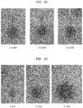
- FIG. 23is another series of images showing infusion of dye using a CED device into a gel designed to simulate tissue
- FIG. 24is a magnetic resonance image of a pig brain in which a CED device is inserted and a gadolinium dye is infused;
- FIG. 25is a series of magnetic resonance images showing infusion of gadolinium into white matter of a pig's brain at flow rates of 1, 3, 5, 10, and 20 ⁇ L/min using a CED device;
- FIG. 26is a series of magnetic resonance images showing infusion of gadolinium into the thalamus of a pig's brain at flow rates of 1, 3, 5, 10, and 20 ⁇ L/min using a CED device;
- FIG. 27is a series of magnetic resonance images showing infusion of gadolinium into the putamen of a pig's brain at flow rates of 1, 2, 5, 10, and 15 ⁇ L/min using a CED device;
- FIG. 28is a series of magnetic resonance images showing infusion of gadolinium into the white matter of a pig's brain at a flow rate of 5 ⁇ L/min using a CED device after infusion periods of 1, 9, 16, 24, and 50 minutes;
- FIG. 29is a magnetic resonance image and an in vivo imaging system image of the thalamus of a pig's brain when a CED device is used to simultaneously infuse galbumin and IVIS dye;
- FIG. 30is a comparison of infusate concentration using a CED device of the type described herein to simulated infusate concentration using a traditional catheter.
- FIG. 31is a comparison of tissue expansion using a CED device of the type described herein to simulated tissue expansion using a traditional catheter.
- CED devicesinclude a tissue-receiving space disposed proximal to a distal fluid outlet. Tissue can be compressed into or pinched/pinned by the tissue-receiving space as the device is inserted into a target region of a patient, thereby forming a seal that reduces or prevents proximal backflow of fluid ejected from the outlet beyond the tissue-receiving space.
- CED devicesinclude a bullet-shaped nose proximal to a distal fluid outlet. The bullet-shaped nose forms a good seal with surrounding tissue and helps reduce or prevent backflow of infused fluid.
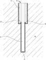
- FIG. 1illustrates one exemplary embodiment of a CED device 10 .
- the device 10generally includes a fluid conduit 12 and an outer sheath 14 .
- the outer sheath 14can be disposed coaxially over the fluid conduit 12 such that the fluid conduit 12 extends out of a distal end 16 of the outer sheath 14 .
- the fluid conduit 12 and the outer sheath 14can be sized and dimensioned such that a tissue-receiving space 18 is formed between an exterior surface of the fluid conduit 12 and an interior surface of the distal end 16 of the outer sheath 14 .
- the fluid conduit 12can define one or more fluid lumens that extend generally parallel to the central longitudinal axis of the device 10 .
- the fluid conduit 12can include a fluid inlet port (not shown in FIG. 1 ) and a fluid outlet port 20 . While a single fluid outlet port 20 is shown in the illustrated embodiment, it will be appreciated that the device can include a plurality of fluid outlet ports, as well as a plurality of fluid inlet ports and a plurality of fluid lumens extending therebetween.
- the fluid inlet portcan be positioned at a proximal end of the device 10 , and can allow the fluid conduit 12 to be placed in fluid communication with a fluid reservoir, e.g., via one or more catheters, pumps, meters, valves, or other suitable control devices. Such control devices can be used to regulate the pressure at which fluid is supplied to the device 10 , or the rate or volume of fluid that is supplied to the device 10 .
- Fluid supplied to the conduit 12 though the fluid inlet portcan be directed through one or more inner lumens of the conduit 12 and released through the one or more fluid outlet ports 20 .
- the fluid outlet ports 20can be sized, shaped, and/or positioned to control various release parameters of the fluid.
- the fluid outlet ports 20can be configured to control the direction in which fluid is released from the device 10 , the distribution of the fluid within the target tissue, and the velocity or pressure at which the fluid is released.
- the size of the fluid outlet portscan progressively increase towards the distal end of the device 10 , which can advantageously compensate for pressure loss that occurs along the length of the device such that fluid is released from each of the plurality of fluid outlet ports at substantially the same pressure.
- the fluid outlet portscan also be positioned at various points around the circumference of the fluid conduit 12 or can be shaped to control the release direction of the fluid.
- the fluid conduit 12 and/or the outer sheath 14can have circular outside cross-sections, which can advantageously allow the device 10 to rotate within the tissue without causing trauma or forming large gaps between the exterior of the device and the surrounding tissue that might increase backflow.
- the fluid conduit 12can also be flexible to allow it to move with the tissue in which it is inserted. While a generally-cylindrical fluid conduit 12 is shown, the fluid conduit 12 can also have a non-cylindrical or polygonal cross-section.
- the fluid conduit 12can be a microfabricated tip that includes a substrate having a square or rectangular cross-section with one or more fluid channels disposed thereon.
- the interior of the outer sheath 14can be shaped to substantially correspond to the cross-section of the fluid conduit 12 .
- the outer sheath 14can have an interior cross-sectional shape that differs from the exterior cross-sectional shape of the fluid conduit 12 .
- the outer sheath 14can have a substantially cylindrical interior cross-sectional shape at its distal end, while the fluid conduit 12 can have a substantially square or rectangular exterior cross-sectional shape, thereby defining the tissue-receiving space 18 between the exterior of the fluid conduit 12 and the interior of the outer sheath 14 .
- the outer sheath 14can be disposed coaxially over the fluid conduit 12 such that the fluid conduit 12 extends out of the distal end 16 of the outer sheath 14 .
- a clearance space between the exterior surface of the fluid conduit 12 and the interior surface of the sheath 14can define the tissue-receiving space 18 .
- the fluid conduit 12can have an outside diameter D 1 that is less than an inside diameter D 2 of the outer sheath 14 .
- the degree to which the diameter D 2 exceeds the diameter D 1can dictate the amount of tissue that is compressed into or pinched by the tissue-receiving space 18 .
- an adhesive or other fillercan be disposed between the fluid conduit 12 and the sheath 14 to hold the fluid conduit in a fixed longitudinal position relative to the sheath and to maintain the fluid conduit in the center of the sheath (e.g., such that the tissue-receiving space 18 has a uniform width about the circumference of the fluid conduit).
- the tissue-receiving space 18can extend proximally a first distance from the distal end 16 of the sheath 14 , after which point the clearance space between the fluid conduit 12 and the sheath 14 can be filled.
- the sheath 14can have a stepped, tapered, or other similarly-shaped interior such that a clearance space exists along a distal portion of the sheath 14 and no clearance space exists along a proximal portion of the sheath 14 .
- the inside diameter of the distal end 16 of the outer sheath 14can be about 1 ⁇ m to about 1000 ⁇ m, about 1 ⁇ m to about 500 ⁇ m, about 1 ⁇ m to about 200 ⁇ m, or about 1 ⁇ m to about 20 ⁇ m greater than the outside diameter of the fluid conduit 12 .
- the inside diameter of the distal end 16 of the outer sheath 14can be about 5 percent to about 500 percent, about 5 percent to about 250 percent, about 10 percent to about 100 percent, or about 10 percent to about 20 percent greater than the outside diameter of the fluid conduit 12 .
- the diameter D 1can be about 50 ⁇ m to about 2000 ⁇ m, about 50 ⁇ m to about 1000 ⁇ m, or about 50 ⁇ m to about 200 ⁇ m.
- diameter D 2can be about 51 ⁇ m to about 5000 ⁇ m, about 55 ⁇ m to about 1000 ⁇ m, or about 55 ⁇ m to about 200 ⁇ m.
- the tissue-receiving space 18can extend along the entire length of the outer sheath 14 , or along only a portion of the outer sheath (e.g., along about 1 mm to about 100 mm, about 1 mm to about 50 mm, or about 1 mm to about 10 mm of the distal-most portion of the outer sheath).
- the fluid conduit 12 and the outer sheath 14can be formed from any of a variety of materials, including parylene compositions, silastic compositions, polyurethane compositions, PTFE compositions, silicone compositions, and so forth.
- the device 10can be mounted on a support scaffold (not shown) to provide structural rigidity to the device and facilitate insertion into the target tissue.
- a support scaffold(not shown) to provide structural rigidity to the device and facilitate insertion into the target tissue.
- Exemplary support scaffoldsare illustrated and described in U.S. Publication No. 2013/0035560, filed on Aug. 1, 2012, entitled “MULTI-DIRECTIONAL MICROFLUIDIC DRUG DELIVERY DEVICE,” the entire contents of which are incorporated herein by reference.
- the distal end of the fluid conduit 12 and/or the distal end of the scaffoldcan be tapered, pointed, and/or sharpened.
- the fluid conduit 12 and/or the scaffoldcan be provided with a rounded atraumatic tip so as to facilitate insertion through tissue without causing trauma to the tissue.
- the support scaffoldcan be rigid or semi-rigid and can be formed from a degradable thermoplastic polymer, for example, a degradable thermoplastic polyester or a degradable thermoplastic polycarbonate.
- the support scaffoldcan be formed from poly(lactic-co-glycolic acid) (PLGA) and can be configured to biodegrade within the target tissue. This can advantageously eliminate the need to remove the support scaffold once the device 10 is positioned within target tissue, thereby avoiding the potential to disrupt the positioning of the fluid conduit 12 .
- PLGApoly(lactic-co-glycolic acid)
- Any of a variety of other materialscan also be used to form the support scaffold, including silicon or various ceramics, metals, and plastics known in the art.
- the scaffoldcan have a width of approximately 100 ⁇ m to approximately 200 ⁇ m and can have a length that varies depending on the target tissue (e.g., depending on the depth at which the target tissue is situated). In one embodiment, the scaffold is between 2 cm and 3 cm long.
- a variety of techniquescan be used to couple the fluid conduit 12 and/or the outer sheath 14 to the support scaffold, such as surface tension from a water drop, adhesives, and/or a biocompatible petroleum jelly.
- any of the fluid conduit 12 , the outer sheath 14 , and/or the support scaffoldcan contain or can be impregnated with a quantity of a drug.
- a surface of these componentscan be coated with a drug.
- exemplary drugsinclude anti-inflammatory components, drug permeability-increasing components, delayed-release coatings, and the like.
- one or more components of the device 10can be coated or impregnated with a corticosteroid such as dexamethasone which can prevent swelling around the injection site and disruptions to the fluid delivery pattern that can result from such swelling.
- the device 10can also include one or more sensors 22 mounted in or on the fluid conduit 12 , the sheath 14 , or the scaffold.
- the sensors 22can include temperature sensors, pH sensors, pressure sensors, oxygen sensors, tension sensors, interrogatable sensors, glutamate sensors, ion concentration sensors, carbon dioxide sensors, lactate sensors, neurotransmitter sensors, or any of a variety of other sensor types, and can provide feedback to a control circuit which can in turn regulate the delivery of fluid through the device 10 based on one or more sensed parameters.
- One or more electrodes 24can also be provided in or on the fluid conduit 12 , the sheath 14 , or the scaffold, which can be used to deliver electrical energy to target tissue, e.g., to stimulate the target tissue or to ablate the target tissue. In one embodiment, electrical energy is delivered through an electrode 24 while a drug is simultaneously delivered through the fluid conduit 12 .
- FIG. 3is a schematic illustration of a drug delivery system 26 that includes the device 10 .
- the system 26includes a reservoir 28 of a drug-containing fluid that is coupled to a pump 30 via a control valve 32 .
- a control valve 32When the control valve 32 is opened, fluid in the reservoir 28 is supplied under pressure by the pump 30 to a pressure regulator 34 , which can adjust a pressure at which the fluid is supplied to the device 10 .
- the control valve 32 , pump 30 , and regulator 34can be operatively coupled to a controller 36 which can include a microprocessor and a memory and can be configured to execute a drug-delivery control program stored in a non-transitory computer-readable storage medium.
- the controller 36can be configured to open or close the valve 32 , to turn the pump 30 on or off, to change an output pressure of the pump 30 , and/or to adjust a pressure set point of the regulator 34 .
- the controller 36can also receive information indicative of a sensed parameter via a feedback loop that includes one or more sensors 22 mounted in or on the device 10 .
- the controller 36can start or stop the flow of fluid to the device 10 , increase or decrease the pressure at which fluid is supplied to the device 10 , etc.
- the device 10includes a pressure sensor 22 that measures a fluid pressure in the vicinity of the device 10 and the controller 36 is configured to maintain the fluid supply pressure at a substantially constant level based on feedback from the pressure sensor 22 .
- the device 10can be used for CED of drugs to treat disorders of the brain, spine, ears, neural tissue, or other parts of a human or animal body.
- the device 10can circumvent the blood-brain barrier (BBB) by infusing drugs under positive pressure directly into tissue.
- BBBblood-brain barrier
- the device 10can provide a number of advantages, such as 1) a smaller cross-sectional area compared with conventional needles used in CED; 2) less disturbance to tissue when inserted into the brain than conventional needles; 3) the reduction or elimination of backflow or reflux along the outside of the inserted part, which in turn, permits higher rates of drug delivery in the device 10 compared with conventional needles; 4) minimal or no occlusion of the fluid delivery conduit 12 during insertion into the brain; 5) multiple lumens can be provided through the fluid conduit 12 , each conducting a distinct fluid (drug), which allows simultaneous, sequential, or programmed delivery of multiple agents; 6) the device 10 has the potential to serve simultaneously as a drug delivery system and as a sensor-equipped probe to measure local tissue characteristics such as, but not limited to, pressure, pH, ion-specific concentrations, location, and other parameters; and 7) the device 10 allows for directional control of the drug release pattern.
- the device 10can be functionally attached to the distal end of a long, thin insertion vehicle such as a cannula or a needle in or on which a fluid attachment can be made to the fluid inlet port of the device's fluid conduit 12 .
- a long, thin insertion vehiclesuch as a cannula or a needle in or on which a fluid attachment can be made to the fluid inlet port of the device's fluid conduit 12 .
- Thiscan be especially advantageous in applications involving penetration of relatively thick tissue, e.g., insertion through a human skull.
- the device 10can also be used to deliver enzymes or other materials to modify tissue permeability and improve drug distribution in the targeted tissue.
- penetration of drug-containing nanoparticles into brain tissuecan be enhanced by enzymatic digestion of at least one brain extracellular matrix component and intracranial infusion of the nanoparticle into the brain tissue.
- at least one enzymecan be immobilized to a surface of the nanoparticle during the step of enzymatic digestion.
- the device 10can provide the ability to deliver enzymatic and/or other materials that can, e.g., modify the drug delivery site, and therapeutic materials, in virtually any order, sequencing, and/or timing without the need to use different delivery devices and the potential complications involved in doing so.
- the device 10can also be used to biopsy tissue, for example by passing a stylet or a grasping tool through the fluid conduit 12 to a target site and then withdrawing the stylet or grasping tool from the target site with a biopsy specimen therein.
- the fluid conduit 12can have a larger-diameter lumen extending therethrough for biopsy purposes, with smaller fluid lumens formed therearound.
- the device 10can be used to deliver a drug-containing fluid under positive pressure to a target tissue region.
- FIG. 4illustrates an exemplary method for convection-enhanced delivery of a drug to target tissue 40 in a patient's brain. After appropriate site preparation and cleaning, a tissue opening can formed through the patient's scalp and skull to expose the brain tissue 40 . Before or after forming the tissue opening, a pedestal can optionally be mounted to the patient to support the device 10 while it is inserted, which can be particularly useful in long-term implantations.
- the device 10can optionally be coupled to a cannula (not shown) with a microfabricated interface for mating with the device 10 .
- a cannula(not shown) with a microfabricated interface for mating with the device 10 .
- Any of a variety of cannulascan be used, including standard cannulas configured to mate to a stereotactic frame in guided surgery.
- the cannulacan include a flexible catheter suitable for extended (e.g., 30 day) implantation.
- the cathetercan be about 15 cm long and about 2 cm in diameter.
- the cannulacan include a tubing portion that is approximately 6 feet in length with connectors for fluid and biosensor interface at the proximal end.
- the device 10can be advanced through the tissue opening and into the brain tissue 40 .
- the tissue-receiving space 18can be configured to compress or pinch tissue received therein as the device 10 is advanced through the tissue 40 .
- Tissue compressed by the tissue-receiving space 18can form a seal that reduces proximal backflow of fluid ejected from the outlet 20 of the fluid conduit 12 beyond the tissue-receiving space 18 .
- fluid ejected from the outlet 20 of the fluid conduit 12flows back proximally between the exterior surface of the fluid conduit 12 and the surrounding tissue 40 , it encounters a shoulder of tissue 38 that is compressed into the tissue-receiving space 18 . Compression of the tissue 38 against the walls of the tissue-receiving space 18 forms a seal that resists flow of the fluid further in the proximal direction, thereby reducing or preventing undesirable backflow of injected fluid away from the target region of the tissue.
- the device 10can include a support scaffold to facilitate penetration through the brain tissue towards the target region.
- One or more radiopaque markerscan be included in the device 10 to permit radiographic imaging (e.g., to confirm proper placement of the device 10 within or in proximity to the target tissue).
- the scaffoldcan degrade shortly after insertion to leave behind only the fluid conduit 12 and outer sheath 14 .
- the fluid conduit 12 and/or the sheath 14can be flexible to permit the device 10 to move with the brain tissue 40 if the brain tissue 40 shifts within the skull. This can advantageously prevent localized deformation of brain tissue adjacent to the device 10 that might otherwise occur with a rigid device. Such deformation can lead to backflow of the pressurized fluid along the surface of the device, undesirably preventing the fluid from reaching the target tissue.
- injected mediae.g., a drug-containing fluid
- the delivery profilecan be adjusted by varying parameters such as outlet port size, outlet port shape, fluid conduit size, fluid conduit shape, fluid supply pressure, fluid velocity, etc.
- the device 10can be configured to deliver fluid at a flow rate between about 5 ⁇ l per minute and about 20 ⁇ l per minute.
- the device 10can be configured to deliver 50-100 ⁇ l per minute per channel, and each channel can be configured to support greater than 100 psi of pressure.
- a gel or other materialcan be injected through the device 10 to augment the tissue seal.
- a sealing gelcan be injected through the device 10 and allowed to flow back along the exterior of the device, filling and sealing any voids that may exist between the device and the surrounding tissue, particularly within the tissue-receiving recess 18 .
- Exemplary sealing materialsinclude cyanoacrylate, protein glues, tissue sealants, coagulative glues (e.g., fibrin/thrombin/protein based coagulative glues), and materials such as those disclosed in U.S. Publication No. 2005/0277862, filed on Jun. 9, 2004, entitled “SPLITABLE TIP CATHETER WITH BIORESORBABLE ADHESIVE,” the entire contents of which are incorporated herein by reference.
- the methods and devices disclosed hereincan provide convection-enhanced delivery of functional agents directly to target tissue within a patient with little or no backflow.
- This convection-enhanced deliverycan be used to treat a broad spectrum of diseases, conditions, traumas, ailments, etc.
- drugrefers to any functional agent that can be delivered to a human or animal patient, including hormones, stem cells, gene therapies, chemicals, compounds, small and large molecules, dyes, antibodies, viruses, therapeutic agents, etc.
- central-nervous-system (CNS) neoplasmcan be treated by delivering an antibody (e.g., an anti-epidermal growth factor (EGF) receptor monoclonal antibody) or a nucleic acid construct (e.g., ribonucleic acid interference (RNAi) agents, antisense oligonucleotide, or an adenovirus, adeno-associated viral vector, or other viral vectors) to affected tissue.
- EGFanti-epidermal growth factor
- RNAiribonucleic acid interference
- Epilepsycan be treated by delivering an anti-convulsive agent to a target region within the brain.
- Parkinson's diseasecan be treated by delivering a protein such as glial cell-derived neurotrophic factor (GDNF) to the brain.
- GDNFglial cell-derived neurotrophic factor
- Huntington's diseasecan be treated by delivering a nucleic acid construct such as a ribonucleic acid interference (RNAi) agent or an antisense oligonucleotide to the brain.
- Neurotrophincan be delivered to the brain under positive pressure to treat stroke.
- a proteinsuch as a lysosomal enzyme can be delivered to the brain to treat lysosomal storage disease.
- Alzheimer's diseasecan be treated by delivering anti-amyloids and/or nerve growth factor (NGF) under positive pressure to the brain.
- Amyotrophic lateral sclerosiscan be treated by delivering a protein such as brain-derived neurotrophic factor (BDNF) or ciliary neurotrophic factor (CNTF) under positive pressure to the brain, spinal canal, or elsewhere in the central nervous system.
- Chronic brain injurycan be treated by delivering a protein such as brain-derived neurotrophic factor (BDNF) and/or fibroblast growth factor (FGF) under positive pressure to the brain.
- BDNFbrain-derived
- the devices disclosed herein and the various associated treatment methodsis not limited to the brain of a patient. Rather, these methods and devices can be used to deliver a drug to any portion of a patient's body, including the spine.
- balance or hearing disorderscan be treated by injecting a drug-containing fluid directly into a portion of a patient's ear. Any of a variety of drugs can be used to treat the ear, including human atonal gene.
- the methods and devices disclosed hereincan also be used to deliver therapeutics (such as stem cells) to a fetus or to a patient in which the fetus is disposed.
- the methods and devices disclosed hereincan be used to treat a cavernous malformation, for example by delivering one or more antiangiogenesis factors thereto.
- any of the various treatments described hereincan further include delivering a cofactor to the target tissue, such as a corticosteroid impregnated in the device, a corticosteroid coated onto the device, and/or a propagation enhancing enzyme.
- a cofactorsuch as a corticosteroid impregnated in the device, a corticosteroid coated onto the device, and/or a propagation enhancing enzyme.
- any of the various treatments described hereincan further include long-term implantation of the device (e.g., for several hours or days) to facilitate long-term treatments and therapies.
- the device 10can include a plurality of tissue-receiving spaces 18 .
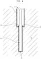
- FIG. 5illustrates an embodiment with a first tissue-receiving space 18 A and a second tissue-receiving space 18 B.
- a first outer sheath 14 Ais disposed over the fluid conduit 12 to define the first tissue-receiving space 18 A.
- a second outer sheath 14 Bis disposed over the first outer sheath 14 A to define the second tissue-receiving space 18 B.
- the second tissue-receiving space 18 Bis formed between an exterior surface of the first outer sheath 14 A and an interior surface of the distal end 16 B of the second outer sheath 14 B.
- tissue-receiving spacesany number of tissue-receiving spaces can be provided (e.g., three, four, five, or more) by adding additional sheath layers.
- a single sheath layercan also be configured to provide multiple tissue-receiving spaces, for example by forming the sheath layer with one or more stepped regions, each stepped region defining a tissue-receiving space therein.
- Multi-stage devicessuch as that shown in FIG. 5 can provide additional sealing regions proximal to the distal-most, primary sealing region. The provision of these secondary, tertiary, etc. sealing regions can augment the primary seal or act as a backup in case the primary seal is compromised.
- FIGS. 6A-6Cthe internal wall of the distal end 16 of the outer sheath 14 can be shaped to alter the dimensions of the tissue-receiving space 18 and the type of seal provided when tissue is compressed therein.
- FIG. 6Aillustrates a device 100 in which the interior surface of the distal end 116 of the sheath 114 has a concave curvature.
- FIG. 6Billustrates a device 200 in which the interior surface of the distal end 216 of the sheath 214 is conical.
- FIG. 6Cillustrates a device 300 in which the interior surface of the distal end 316 of the sheath 314 has a convex curvature.
- These configurationscan provide for a sharper leading edge at the periphery of the sheath as compared with the cylindrical tissue-receiving space 18 of the device 10 , and can increase the amount of tissue compressed into or pinched/pinned by the tissue-receiving space, as well as the degree of compression. A more-robust seal can thus be obtained in some instances using the configurations of FIGS. 6A-6C . It should be noted, however, that even in the case of a cylindrical tissue-receiving space, the leading edge of the sheath can be sharpened to deflect tissue into the tissue-receiving space and thereby form a better seal.
- the size and shape of the tissue-receiving spacecan be selected based on a variety of parameters, including the type of tissue in which the device is to be inserted.
- each of the tissue receiving spacescan have the same configuration (e.g., all cylindrical, all conical, all convex, or all concave).
- one or more of the plurality of tissue-receiving spacescan have a different configuration.
- one or more tissue-receiving spacescan be cylindrical while one or more other tissue receiving spaces are convex.
- tissue-receiving recesses of the devices disclosed hereincan include various surface features or treatments to enhance the seal formed between the device and the surrounding tissue or gel.
- the tissue-receiving recessescan be coated with a biocompatible adhesive or can have a textured surface to form a tighter seal with the tissue or gel.
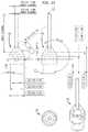
- FIG. 7illustrates an exemplary embodiment of a CED device 400 that generally includes a fluid conduit in the form of a micro-tip 412 and an outer sheath 414 .
- the micro-tip 412includes a substrate 442 , which can be formed from a variety of materials, including silicon.
- the substrate 442can have any of a variety of cross-sectional shapes, including a square or rectangular cross-section as shown.
- One or more fluid channels 444can be formed on the substrate 442 .
- the fluid channels 444can be formed from a variety of materials, including parylene. Additional details on the structure, operation, and manufacture of microfabricated tips such as that shown in FIG. 7 can be found in U.S. Publication No. 2013/0035560, filed on Aug. 1, 2012, entitled “MULTI-DIRECTIONAL MICROFLUIDIC DRUG DELIVERY DEVICE,” the entire contents of which are incorporated herein by reference.
- the outer sheath 414can be disposed coaxially over the micro-tip 412 so as to form a tissue-receiving space 418 therebetween.
- the micro-tip 412can have a substantially rectangular exterior cross-section and the outer sheath 414 can have a substantially cylindrical interior cross-section.
- the micro-tip 412 and the outer sheath 414can have corresponding cross-sectional shapes with a clearance space defined therebetween.
- the proximal end of the outer sheath 414can be coupled to a catheter 446 .
- the catheter 446can be rigid or flexible, or can include rigid portions and flexible portions.
- a nose portion 448(sometimes referred to herein as a “bullet nose” or a “bullet nose portion”) can be disposed between the outer sheath 414 and the catheter 446 , or can be disposed over a junction between the outer sheath 414 and the catheter 446 .
- the nose portion 448can taper from a reduced distal diameter corresponding to the outside diameter of the sheath 414 to an enlarged proximal diameter corresponding to the outside diameter of the catheter 446 .
- the tapered transition provided by the nose portion 448can advantageously provide stress-relief as it can act as a smooth transition from the sheath 414 to the catheter body 446 , avoiding any uneven stresses on the surrounding tissue that may create paths for fluid backflow.
- the nose portion 448can be conically tapered, as shown, or can taper along a convex or concave curve. Various compound shapes can also be used that include conical portions, convex portions, and/or concave portions.
- the nose portion 448can also be replaced with a blunt shoulder that extends perpendicular to the longitudinal axis of the device 400 . Any of a variety of taper angles can be used for the nose portion 448 .
- the nose portion 448can taper at an angle in a range of about 10 degrees to about 90 degrees relative to the longitudinal axis of the device 400 , in a range of about 20 degrees to about 70 degrees relative to the longitudinal axis of the device, and/or in a range of about 30 degrees to about 50 degrees relative to the longitudinal axis of the device.
- the nose portion 446can taper at an angle of approximately 33 degrees relative to the longitudinal axis of the device 400 .
- additional sheathscan be provided, e.g., as described above with respect to FIG. 5 .
- the catheter 446can include length markings or graduations 450 to indicate the insertion depth of the device 400 .
- the catheter 446can be a straight rigid catheter sized and configured for acute stereotactic targeting.
- the catheter 446can be formed from any of a variety of materials, including flexible materials, rigid materials, ceramics, plastics, polymeric materials, PEEK, polyurethane, etc. and combinations thereof.
- the catheter 446has length of about 10 cm to about 40 cm, e.g., about 25 cm.
- the catheter 446can include one or more fluid lines extending therethrough.
- the fluid linescan be defined by the catheter body itself or can be defined by one or more inner sleeves or linings disposed within the catheter body. Any of a variety of materials can be used to form the inner sleeves or linings, such as flexible materials, rigid materials, polyimide, pebax, PEEK, polyurethane, silicone, fused silica tubing, etc. and combinations thereof.
- one or more standard Luer or other connectors 452can be coupled to the proximal end of the catheter 446 to facilitate connection with a fluid delivery system of the type shown in FIG. 3 .
- the system 400includes two connectors 452 , one for each of the two fluid channels formed in the catheter 446 and the micro-tip 412 . It will be appreciated, however, that any number of fluid channels and corresponding proximal catheter connectors can be provided.
- the system 400can also include a collar 454 disposed over the catheter 446 to act as a depth stop for setting the desired insertion depth and preventing over-insertion.
- the collar 454can be longitudinally slidable with respect to the catheter 446 and can include a thumb screw 456 for engaging the catheter to secure the collar in a fixed longitudinal position with respect thereto.
- the system 400can also include a tip protector 458 for preventing damage to the micro-tip 412 during insertion into stereotactic frame fixtures. Exemplary tip protectors are disclosed in U.S. Provisional Application No. 61/835,905, filed on Jun. 17, 2013, entitled “METHODS AND DEVICES FOR PROTECTING CATHETER TIPS,” the entire contents of which are incorporated herein by reference.
- the system 400can include a length of extension tubing 460 to provide a fluid pathway between the proximal connectors 452 of the catheter 446 and a fluid delivery system of the type shown in FIG. 3 .
- dual-channel peel-away extension lines 460are shown.
- an incisioncan be formed in a patient and the catheter 446 can be inserted through the incision and implanted in a target region of tissue (e.g., a region of the patient's brain or central nervous system).
- the catheter 446can be left in the target region for minutes, hours, days, weeks, months, etc.
- the proximal end of the cathetercan be tunneled under the patient's scalp with the proximal connectors 452 extending out from the incision.
- the catheter 446can be inserted through a sheath to keep the catheter stiff and straight for stereotactic targeting.
- a styletcan be inserted through the catheter to keep the catheter stiff and straight for stereotactic targeting.
- the styletcan be inserted through an auxiliary lumen formed in the catheter such that the primary fluid delivery lumen(s) can be primed with fluid during catheter insertion.
- a third lumencan be included for receiving the stylet.
- FIG. 11is a close-up view of the exemplary micro-tip 412 .
- the micro-tip 412generally includes a central body portion 462 with first and second legs or tails 464 extending proximally therefrom and a tip portion 466 extending distally therefrom.
- First and second microfluidic channels 444are formed in or on the micro-tip 412 such that they extend along the proximal legs 464 , across the central body portion 462 , and down the distal tip portion 466 .
- the channels 444can each include one or more fluid inlet ports (e.g., at the proximal end) and one or more fluid outlet ports (e.g., at the distal end).
- FIGS. 12-15Systems and methods for manufacturing and/or assembling the CED device 400 are shown in FIGS. 12-15 .
- the micro-tip 412can be positioned in a molding or casting system to couple the one or more sheaths 414 to the micro-tip, to form the nose portion 448 , and/or to couple fluid lines in the catheter 446 to the fluid channels 444 of the micro-tip.
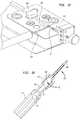
- FIG. 12illustrates an exemplary embodiment of a molding system 500 .
- the system 500includes a base plate 502 with a cradle 504 in which a proximal portion of the catheter 446 is supported.
- Upper and lower mold blocks 506 , 508are coupled to the base plate 502 by a clamping block 510 with one or more screws 512 .
- the screws 512can be tightened to lock the mold blocks 506 , 508 in position during an injection process and can be removed to allow the mold blocks to be opened for insertion or removal of the CED device components.
- the system 500also includes an inlet port 514 through which flowable material can be injected, pumped, etc. into the mold.
- the lower mold block 508includes a recess in which the lower half of the catheter body 446 can be disposed and a recess in which the lower half of the sheath 414 can be disposed.
- a mold cavity 516which is substantially a negative of the lower half of the nose portion 448 is formed between the recesses.
- the recessescan be sized such that the catheter body 446 and the sheath 414 form a seal with the mold block 508 to prevent flowable material injected into the mold cavity 516 from escaping.
- One or more injection ports or channels 514are formed in the mold block 508 to allow flowable material to be injected into the cavity 516 .
- the upper mold block 506is configured in a similar manner to the lower mold block 508 , with recesses that can receive the upper halves of the catheter body 446 and the sheath 414 and a mold cavity 516 which is substantially a negative of the upper half of the nose portion 448 .
- the micro-tip 412is positioned such that the proximal legs 464 are disposed within respective fluid lines formed in the catheter body 446 and such that the distal tip portion 466 of the micro-tip is positioned within the inner lumen of the sheath 414 .
- the catheter fluid linescan be formed by inner linings (e.g., fused silica tubes) encased in an outer housing (e.g., a ceramic housing) that defines the catheter body 446 .
- the inner liningscan prevent leaks and hold the catheter body 446 together in the event that the outer housing is cracked or damaged.
- micro-tip 412 , catheter body 446 , and sheath 414are sandwiched between the upper and lower mold blocks 506 , 508 and a flowable material is injected through the mold channels 514 to form the nose portion 448 within the mold cavity 516 , and to couple the fluid lines in the catheter 446 to the fluid channels 444 of the micro-tip.
- exemplary flowable materialsinclude UV resins, polymers such as polyurethanes, acrylics, PTFE, ePTFE, polyesters, and so forth.
- the flowable materialcan be injected at low rates to fill the cavity 516 .
- the upper and lower mold blocks 506 , 508can be made of a clear material to allow UV light to cure the UV resin.
- the UV resinAs the UV resin is injected into the micro-mold cavity 516 , it can start to wick/flow up over the micro-tip tails 464 and under the fluid lines that sit over the tails. Once the resin flows into the fluid lines, it can be flashed with UV light to “freeze” it in place and avoid wicking/flowing too much (and not completely encapsulating the tails 464 and the inlet holes on the tips of the tails).
- the mold blocks 506 , 508After the material cures, the mold blocks 506 , 508 can be separated and the CED device 400 can be removed from the molding system 500 .
- the molding processcan be used only for coupling the fluid lines, and the bullet nose portion can be formed using a different process once the fluid connections are made.
- wickingis described herein as the mechanism by which the fluid line bonds are formed, it will be appreciated that these bonds can also be controlled by fill pressure, timing, and other molding variables.
- the bullet nosecan be over-molded directly onto the micro-tip. While an exemplary micro-tip and an exemplary catheter body are shown, it will be appreciated that the micro-molding methods and devices disclosed herein can be used with any of a variety of tips and/or catheters.
- FIGS. 16-21Alternative systems and methods for manufacturing and/or assembling the CED device 400 are shown in FIGS. 16-21 .
- the bullet nose and the one or more sheaths or over tubescan be assembled separately using an over-molding process as described below to create a molded part 470 .
- the proximal legs 464 of the micro-tip 412are inserted into the distal end of the catheter body 446 (e.g., by inserting each leg into a respective lining disposed within an outer catheter housing).
- a flowable materiale.g., an adhesive such as a UV curable adhesive
- the molded part 470can then be slid over the distal end of the micro-tip 412 such that the central body portion 462 of the micro-tip is disposed in a hollow interior of the molded part and such that the tip portion 466 of the micro-tip extends through the molded part and protrudes from the distal end thereof.
- the molded part 470can include a shoulder that defines a proximal male portion 472 that mates into a female counterbore 474 formed in the distal tip of the catheter body 446 .
- the catheter body 446can define a male portion and the molded part 470 can include a female counterbore.
- other ways of mating the catheter body 446 to the molded part 470can be used, such as a threaded interface, a snap-fit interface, a key and slot interface, or any other interlocking interface that provides alignment and/or overlap between the molded part and the catheter body.
- the counterbore 474can be formed by machining a recess into the distal end of a ceramic catheter body 446 .
- the inner linings of the cathetercan then be inserted into the ceramic outer housing such that the terminal ends of the inner linings are flush with the floor of the counterbore 474 .
- the molded part 470can be attached to the catheter body 446 using a flowable material (e.g., a UV adhesive), which can be applied to the counterbore 474 and/or the male portion 472 prior to assembling the components or which can be applied through one or more openings 476 formed in the sidewall of the molded part after the components are assembled or dry fit.
- the flowable materialis allowed to cure to form a seal between the fluid lines and to secure the components of the CED device 400 to one another.
- the molding system 600includes upper and lower plates 602 , 604 that sandwich the one or more over-tubes and together define a negative of the bullet nose.
- the plates 602 , 604also define a plug for forming the bullet nose as a hollow structure which can later be filled as described above during final assembly.
- a flowable materialcan be injected through injection ports 606 formed in the plates 602 , 604 using a syringe or pump to form the hollow bullet nose over the one or more over-tubes.
- the flowable materialis a hot resin injected under pressure which forms a strong hold with the over-tube upon curing.
- the over-tubecan be formed from any of a variety of materials, including fused silica tubing.
- FIG. 21A scale drawing of an exemplary molded part 470 is shown with representative dimensions in FIG. 21 . Any of the nose portions and/or sheaths described herein can be formed to the same or similar external dimensions. Unless otherwise indicated, the dimensions shown in FIG. 21 are specified in inches.
- FIGS. 22-23illustrate exemplary results of a gel study conducted by infusing dye through a CED device of the type described herein having first and second fluid channels into a gel designed to simulate tissue.
- a flowrate of 5 ⁇ L/minresulted in a uniform distribution of the dye over time with little or no backflow.
- FIGS. 24-29illustrate exemplary results of an animal study conducted using an in-vivo pig model in which multiple anatomies were infused using CED devices of the type described herein. Little or no backflow along the catheter track was observed at flow rates which are much higher than typical clinical flow rates for CED. The study demonstrated the capability to infuse small, medium, and large molecules using CED devices of the type disclosed herein, and confirmed the functionality of independent flow channels. No blockages or introduction of air bubbles occurred during a multi-hour acute infusion. The device was found to be compatible with magnetic resonance imaging and other stereotactic surgical procedures. No leaks, bond breakages, or other catheter issues were observed.
- the ceramic catheter body and the bullet noseappear as a thick black line in a magnetic resonance (MR) image.
- Infused gadolinium (Gd)appears as a bright cloud in the MR image.
- the micro-tipis not readily visible in the MR image due to its small size.
- FIG. 25illustrates a series of MR images showing infusion of gadolinium into white matter of a pig's brain at flow rates of 1, 3, 5, 10, and 20 ⁇ L/min.
- no backflow of infusateoccurs along the ceramic catheter shaft track.
- the infusion cloudbecomes too large, the infusate overflows into surrounding anatomy, rather than flowing back along the catheter track, highlighting the capability for the system to reduce or prevent backflow.
- flow rates of up to 20 ⁇ L/minare shown, it is expected that similar results would be obtained for flow rates of 30 ⁇ L/min or more. These higher flow rates could not be tested during the animal study because the subject brain(s) became saturated with gadolinium.
- FIG. 26illustrates a series of MR images showing infusion of gadolinium into the thalamus of a pig's brain at flow rates of 1, 3, 5, 10, and 20 ⁇ L/min. As shown, no backflow of infusate occurs along the ceramic catheter shaft track. While there is slight backflow across the bullet nose at approximately 20 ⁇ L/min, this is a flowrate that is significantly higher than typical clinical CED flowrates (generally about 5 ⁇ L/min).
- FIG. 27illustrates a series of MR images showing infusion of gadolinium into the putamen of a pig's brain at flow rates of 1, 2, 5, 10, and 15 ⁇ L/min. As shown, no backflow of infusate occurs along the ceramic catheter shaft track as the infusate stays spherical throughout the ramped infusion.
- FIG. 28illustrates a series of MR images showing infusion of gadolinium into the white matter of a pig's brain at a flow rate of 5 ⁇ L/min after infusion periods of 1, 9, 16, 24, and 50 minutes.
- the lower set of imagesincludes a distribution overlay. As shown, a uniform distribution with no backflow is observed even for long-duration infusions and when a large volume of infusate is delivered. Similar results were observed in infusions into the thalamus and putamen of the pig's brain.
- FIG. 29illustrates an MR image and an in vivo imaging system (IVIS) image of the thalamus of a pig's brain when a CED device of the type described herein is used to simultaneously infuse galbumin (gadolinium-labeled albumin laced with europium) through a first fluid channel and IVIS dye through a second fluid channel.
- galbumingadolinium-labeled albumin laced with europium
- IVIS dyethrough a second fluid channel.
- the two different infusateswere successfully infused from the two independent channels.
- a uniform distribution of the two infusatesindicates mixing at the tip outlet as desired. No evidence of subarachnoid leakage was observed. This demonstrates that the system can be used to deliver Gd tracer and a drug or other molecule while monitoring the Gd tracer under MR to monitor the distribution of the drug or other molecule.
- FIGS. 30-31illustrate comparisons between measurements taken with CED devices of the type described herein and simulated measurements for a traditional 0.3 mm catheter.
- CED devices of the type described hereinachieve a more uniform concentration of infused colloidal Gd in white matter than traditional 0.3 mm catheters.
- FIG. 31when using CED devices of the type described herein, extracellular expansion of white matter tissue is confined to the tip area by the bullet nose and tube-step, which prevents backflow along the catheter track.
- traditional 0.3 mm catheterson the other hand, increased extracellular expansion occurs along the catheter track due to the infusion pressure and backflow results.
- the devices disclosed hereincan be manufactured using any of a variety of techniques.
- the devicescan be manufactured by assembling lengths of tubing over one another, by micro-machining lengths of tubing, by molding steps or nose features containing tissue-receiving spaces onto a fluid conduit, or by constructing one or more portions of the device on a substrate using a lithographic microfabrication process.
Landscapes
- Health & Medical Sciences (AREA)
- Life Sciences & Earth Sciences (AREA)
- Engineering & Computer Science (AREA)
- Anesthesiology (AREA)
- General Health & Medical Sciences (AREA)
- Biomedical Technology (AREA)
- Heart & Thoracic Surgery (AREA)
- Hematology (AREA)
- Veterinary Medicine (AREA)
- Animal Behavior & Ethology (AREA)
- Public Health (AREA)
- Biophysics (AREA)
- Pulmonology (AREA)
- Vascular Medicine (AREA)
- Mechanical Engineering (AREA)
- Infusion, Injection, And Reservoir Apparatuses (AREA)
- Media Introduction/Drainage Providing Device (AREA)
Abstract
Description
- U.S. Publication No. 2013/0035560, filed on Aug. 1, 2012, entitled MULTI-DIRECTIONAL MICROFLUIDIC DRUG DELIVERY DEVICE;
- U.S. Publication No. 2013/0035574, filed on Aug. 1, 2012, entitled MICROFLUIDIC DRUG DELIVERY DEVICES WITH VENTURI EFFECT;
- U.S. Publication No. 2013/0035660, filed on Aug. 1, 2012, entitled MULTIDIRECTIONAL MICROFLUIDIC DRUG DELIVERY DEVICES WITH CONFORMABLE BALLOONS;
- U.S. Provisional Application No. 61/835,905, filed on Jun. 17, 2013, entitled METHODS AND DEVICES FOR PROTECTING CATHETER TIPS;
- U.S. Provisional Application No. 61/860,402, filed on Jul. 31, 2013, entitled DRUG DELIVERY SYSTEMS;
- U.S. Publication No. 2010/0098767, filed on Jul. 31, 2009, entitled CONVECTION ENHANCED DELIVERY APPARATUS, METHOD, AND APPLICATION; and
- U.S. Publication No. 2013/0046230, filed on Nov. 7, 2012, entitled ULTRASOUND-ASSISTED CONVECTION ENHANCED DELIVERY OF COMPOUNDS IN VIVO WITH A TRANSDUCER CANNULA ASSEMBLY.
Claims (19)
Priority Applications (1)
| Application Number | Priority Date | Filing Date | Title |
|---|---|---|---|
| US16/523,357US11213653B2 (en) | 2012-12-18 | 2019-07-26 | Systems and methods for reducing or preventing backflow in a delivery system |
Applications Claiming Priority (5)
| Application Number | Priority Date | Filing Date | Title |
|---|---|---|---|
| US201261738850P | 2012-12-18 | 2012-12-18 | |
| US201361835912P | 2013-06-17 | 2013-06-17 | |
| US14/132,792US9919129B2 (en) | 2012-12-18 | 2013-12-18 | Systems and methods for reducing or preventing backflow in a delivery system |
| US15/709,657US10363394B2 (en) | 2012-12-18 | 2017-09-20 | Systems and methods for reducing or preventing backflow in a delivery system |
| US16/523,357US11213653B2 (en) | 2012-12-18 | 2019-07-26 | Systems and methods for reducing or preventing backflow in a delivery system |
Related Parent Applications (1)
| Application Number | Title | Priority Date | Filing Date |
|---|---|---|---|
| US15/709,657ContinuationUS10363394B2 (en) | 2012-12-18 | 2017-09-20 | Systems and methods for reducing or preventing backflow in a delivery system |
Publications (2)
| Publication Number | Publication Date |
|---|---|
| US20190344046A1 US20190344046A1 (en) | 2019-11-14 |
| US11213653B2true US11213653B2 (en) | 2022-01-04 |
Family
ID=50931691
Family Applications (6)
| Application Number | Title | Priority Date | Filing Date |
|---|---|---|---|
| US14/132,762Active - ReinstatedUS8992458B2 (en) | 2012-12-18 | 2013-12-18 | Systems and methods for reducing or preventing backflow in a delivery system |
| US14/132,792Active2035-04-29US9919129B2 (en) | 2012-12-18 | 2013-12-18 | Systems and methods for reducing or preventing backflow in a delivery system |
| US14/601,596Active2034-11-15US10065016B2 (en) | 2012-12-18 | 2015-01-21 | Systems and methods for reducing or preventing backflow in a delivery system |
| US15/709,657ActiveUS10363394B2 (en) | 2012-12-18 | 2017-09-20 | Systems and methods for reducing or preventing backflow in a delivery system |
| US16/119,240Active2034-03-01US11260201B2 (en) | 2012-12-18 | 2018-08-31 | Systems and methods for reducing or preventing backflow in a delivery system |
| US16/523,357Active2034-06-26US11213653B2 (en) | 2012-12-18 | 2019-07-26 | Systems and methods for reducing or preventing backflow in a delivery system |
Family Applications Before (5)
| Application Number | Title | Priority Date | Filing Date |
|---|---|---|---|
| US14/132,762Active - ReinstatedUS8992458B2 (en) | 2012-12-18 | 2013-12-18 | Systems and methods for reducing or preventing backflow in a delivery system |
| US14/132,792Active2035-04-29US9919129B2 (en) | 2012-12-18 | 2013-12-18 | Systems and methods for reducing or preventing backflow in a delivery system |
| US14/601,596Active2034-11-15US10065016B2 (en) | 2012-12-18 | 2015-01-21 | Systems and methods for reducing or preventing backflow in a delivery system |
| US15/709,657ActiveUS10363394B2 (en) | 2012-12-18 | 2017-09-20 | Systems and methods for reducing or preventing backflow in a delivery system |
| US16/119,240Active2034-03-01US11260201B2 (en) | 2012-12-18 | 2018-08-31 | Systems and methods for reducing or preventing backflow in a delivery system |
Country Status (8)
| Country | Link |
|---|---|
| US (6) | US8992458B2 (en) |
| EP (2) | EP3868541A1 (en) |
| JP (3) | JP6430397B2 (en) |
| CN (1) | CN105142696B (en) |
| AU (3) | AU2013361601B2 (en) |
| CA (2) | CA3123066A1 (en) |
| ES (1) | ES2869328T3 (en) |
| WO (1) | WO2014100157A1 (en) |
Families Citing this family (31)
| Publication number | Priority date | Publication date | Assignee | Title |
|---|---|---|---|---|
| GB0616411D0 (en) | 2006-08-18 | 2006-09-27 | Renishaw Plc | Neurosurgical instruments |
| US10105485B2 (en) | 2010-04-16 | 2018-10-23 | MRI Interventions, Inc. | MRI surgical systems including MRI-compatible surgical cannulae for transferring a substance to and/or from a patient |
| CA2843587C (en) | 2011-08-01 | 2020-03-24 | Alcyone Lifesciences, Inc. | Microfluidic drug delivery devices |
| US10751513B2 (en) | 2012-07-24 | 2020-08-25 | Renishaw Plc | Neurosurgical apparatus and methods |
| WO2014078506A2 (en)* | 2012-11-14 | 2014-05-22 | Ams Research Corporation | Cell delivery device and system with anti-clumping feature and methods for pelvic tissue treatment |
| ES2869328T3 (en) | 2012-12-18 | 2021-10-25 | Alcyone Lifesciences Inc | Devices and methods for reducing or preventing reflux in an administration system |
| CA3120114A1 (en) | 2013-06-17 | 2014-12-24 | Alcyone Lifesciences, Inc. | Methods and devices for protecting catheter tips and stereotactic fixtures for microcatheters |
| CA2920014C (en) | 2013-07-31 | 2021-11-09 | Alcyone Lifesciences, Inc. | Systems and methods for drug delivery, treatment, and monitoring |
| US9907941B2 (en) | 2014-07-21 | 2018-03-06 | The Cleveland Clinic Foundation | Convection enhanced delivery device and system |
| US9968765B2 (en) | 2014-07-21 | 2018-05-15 | The Cleveland Clinic Foundation | Convection enhanced delivery device and system |
| US10080877B2 (en) | 2014-07-25 | 2018-09-25 | Warsaw Orthopedic, Inc. | Drug delivery device and methods having a drug cartridge |
| US9775978B2 (en) | 2014-07-25 | 2017-10-03 | Warsaw Orthopedic, Inc. | Drug delivery device and methods having a retaining member |
| CA2960274A1 (en)* | 2014-09-10 | 2016-03-17 | Epizyme, Inc. | Isoxazole carboxamide compounds |
| WO2016077607A1 (en) | 2014-11-13 | 2016-05-19 | The Regents Of The University Of California | Adjustable stepped cannula |
| HK1246815A1 (en) | 2015-01-16 | 2018-09-14 | Voyager Therapeutics, Inc. | Central nervous system targeting polynucleotides |
| US10806396B2 (en) | 2015-01-26 | 2020-10-20 | Alcyone Lifesciences, Inc. | Drug delivery methods with tracer |
| US10076650B2 (en) | 2015-11-23 | 2018-09-18 | Warsaw Orthopedic, Inc. | Enhanced stylet for drug depot injector |
| JP2019502473A (en)* | 2016-01-04 | 2019-01-31 | アルキオーネ・ライフサイエンシズ・インコーポレイテッドAlcyone Lifesciences, Inc. | Method and apparatus for treating stroke |
| EP3393571B1 (en) | 2016-02-17 | 2024-03-06 | ClearPoint Neuro, Inc. | Intrabody surgical fluid transfer assemblies with adjustable exposed cannula to needle tip length, related systems and methods |
| USD802756S1 (en) | 2016-06-23 | 2017-11-14 | Warsaw Orthopedic, Inc. | Drug pellet cartridge |
| JP2019531787A (en) | 2016-08-30 | 2019-11-07 | ザ リージェンツ オブ ザ ユニバーシティ オブ カリフォルニア | Biomedical targeting and delivery method and apparatus and system for performing the same |
| US10434261B2 (en) | 2016-11-08 | 2019-10-08 | Warsaw Orthopedic, Inc. | Drug pellet delivery system and method |
| WO2018118967A1 (en) | 2016-12-21 | 2018-06-28 | Memgen, Llc | Armed replication-competent oncolytic adenoviruses |
| CN114887153A (en)* | 2016-12-21 | 2022-08-12 | 亚克安娜治疗学有限公司 | Drug delivery systems and methods |
| GB2563203A (en)* | 2017-06-01 | 2018-12-12 | Creo Medical Ltd | Electrosurgical apparatus |
| CN110603062A (en)* | 2017-06-19 | 2019-12-20 | 波士顿科学医学有限公司 | Automated fluid management system |
| CN111132626B (en) | 2017-07-17 | 2024-01-30 | 沃雅戈治疗公司 | track array guidance system |
| US20190314574A1 (en)* | 2018-04-13 | 2019-10-17 | Alcyone Lifesciences, Inc. | Devices and methods for percutaneous lung intratumoral therapy delivery |
| US20210207167A1 (en) | 2018-05-16 | 2021-07-08 | Voyager Therapeutics, Inc. | Aav serotypes for brain specific payload delivery |
| US11684750B2 (en) | 2019-10-08 | 2023-06-27 | Clearpoint Neuro, Inc. | Extension tube assembly and related medical fluid transfer systems and methods |
| WO2023191989A1 (en)* | 2022-03-29 | 2023-10-05 | Clearpoint Neuro, Inc. | Surgical systems including flexible mri-compatible surgical catheters for transferring a substance to and/or from a brain of a patient |
Citations (189)
| Publication number | Priority date | Publication date | Assignee | Title |
|---|---|---|---|---|
| US2830587A (en) | 1954-02-01 | 1958-04-15 | Everett Samuel James | Hypodermic needles |
| US3460537A (en) | 1966-09-26 | 1969-08-12 | Donald C Zeis | Stereotactic guide for use in the creation of destructive brain lesions |
| US3886948A (en) | 1972-08-14 | 1975-06-03 | Hakim Co Ltd | Ventricular shunt having a variable pressure valve |
| US4146029A (en) | 1974-04-23 | 1979-03-27 | Ellinwood Jr Everett H | Self-powered implanted programmable medication system and method |
| US4692146A (en) | 1985-10-24 | 1987-09-08 | Cormed, Inc. | Multiple vascular access port |
| US4885945A (en) | 1988-02-23 | 1989-12-12 | Activational Systems, Inc. | Micropipettes and fabrication thereof |
| US4917686A (en) | 1985-12-16 | 1990-04-17 | Colorado Biomedical, Inc. | Antimicrobial device and method |
| US4979284A (en) | 1987-12-05 | 1990-12-25 | Renishaw Plc | Apparatus for changing a sensing device |
| US5088208A (en) | 1988-10-11 | 1992-02-18 | Renishaw Plc | Measurement probe for position determining apparatus |
| US5190046A (en) | 1992-05-01 | 1993-03-02 | Shturman Cardiology Systems, Inc. | Ultrasound imaging balloon catheter |
| WO1995005864A1 (en) | 1993-08-27 | 1995-03-02 | Government Of The United States Of America, Represented By The Secretary Of The Department Of Health And Human Services | Convection-enhanced drug delivery |
| US5407431A (en) | 1989-07-11 | 1995-04-18 | Med-Design Inc. | Intravenous catheter insertion device with retractable needle |
| US5415648A (en) | 1993-07-08 | 1995-05-16 | Malay; Manuel R. | Multiple purpose syringe |
| US5509910A (en) | 1994-05-02 | 1996-04-23 | Medtronic, Inc. | Method of soft tip attachment for thin walled catheters |
| WO1997000442A1 (en) | 1995-06-16 | 1997-01-03 | The University Of Washington | Microfabricated differential extraction device and method |
| US5590657A (en) | 1995-11-06 | 1997-01-07 | The Regents Of The University Of Michigan | Phased array ultrasound system and method for cardiac ablation |
| US5620479A (en) | 1992-11-13 | 1997-04-15 | The Regents Of The University Of California | Method and apparatus for thermal therapy of tumors |
| US5624396A (en) | 1995-10-30 | 1997-04-29 | Micro Therapeutics, Inc. | Longitudinally extendable infusion device |
| WO1997017105A1 (en) | 1995-11-09 | 1997-05-15 | Femrx, Inc. | Needle myolysis system for uterine fibroids |
| WO1997040874A1 (en) | 1996-04-30 | 1997-11-06 | Medtronic, Inc. | Techniques of treating neurodegenerative disorders by brain infusion |
| US5695518A (en) | 1990-12-28 | 1997-12-09 | Laerum; Frode | Filtering device for preventing embolism and/or distension of blood vessel walls |
| WO1997048425A2 (en) | 1996-06-18 | 1997-12-24 | Paes Newton | Double lumen catheter for draining and irrigating of the intraventricular system and monitoring and controlling of the intracranial pressure |
| US5782645A (en) | 1994-10-18 | 1998-07-21 | Pi Medical Corporation | Percutaneous connector for multi-conductor electrical cables |
| WO1998052064A1 (en) | 1997-05-15 | 1998-11-19 | Regents Of The University Of Minnesota | Method and apparatus for targeted drug delivery into a living patient using magnetic resonance imaging |
| US5843150A (en) | 1997-10-08 | 1998-12-01 | Medtronic, Inc. | System and method for providing electrical and/or fluid treatment within a patient's brain |
| US5868711A (en) | 1991-04-29 | 1999-02-09 | Board Of Regents, The University Of Texas System | Implantable intraosseous device for rapid vascular access |
| US5954687A (en) | 1995-04-28 | 1999-09-21 | Medtronic, Inc. | Burr hole ring with catheter for use as an injection port |
| US5963367A (en) | 1997-09-23 | 1999-10-05 | Lucent Technologies, Inc. | Micromechanical xyz stage for use with optical elements |
| WO1999052585A1 (en) | 1998-04-16 | 1999-10-21 | Camino Neurocare, Inc. | Catheter having distal stylet opening and connector |
| US6061587A (en) | 1997-05-15 | 2000-05-09 | Regents Of The University Of Minnesota | Method and apparatus for use with MR imaging |
| WO2000051669A1 (en) | 1999-03-03 | 2000-09-08 | Uab Research Foundation | Direct central nervous system catheter and temperature control system |
| US6176842B1 (en) | 1995-03-08 | 2001-01-23 | Ekos Corporation | Ultrasound assembly for use with light activated drugs |
| US6193963B1 (en) | 1996-10-17 | 2001-02-27 | The Regents Of The University Of California | Method of treating tumor-bearing patients with human plasma hyaluronidase |
| US6200291B1 (en) | 1998-01-08 | 2001-03-13 | Antonio Di Pietro | Device for controlling the penetration depth of a needle, for application to an injection syringe |
| US6224566B1 (en) | 1999-05-04 | 2001-05-01 | Cardiodyne, Inc. | Method and devices for creating a trap for confining therapeutic drugs and/or genes in the myocardium |
| US20010005552A1 (en) | 1993-08-18 | 2001-06-28 | Scimed Life Systems, Inc. | Catheter having a high tensile strength braid wire constraint and method of manufacture |
| US6309634B1 (en) | 1998-05-27 | 2001-10-30 | Avigen, Inc. | Methods of treating Parkinson's disease using recombinant adeno-associated vector (rAAV) |
| US20020055731A1 (en) | 1997-10-24 | 2002-05-09 | Anthony Atala | Methods for promoting cell transfection in vivo |
| US20020055702A1 (en) | 1998-02-10 | 2002-05-09 | Anthony Atala | Ultrasound-mediated drug delivery |
| US20020099356A1 (en) | 2001-01-19 | 2002-07-25 | Unger Evan C. | Transmembrane transport apparatus and method |
| WO2002068036A1 (en) | 2000-12-27 | 2002-09-06 | The General Hospital Corporation | Dual balloon catheter with sensor for continuosu transvenous measurmentof intracranial pressure |
| US6454945B1 (en) | 1995-06-16 | 2002-09-24 | University Of Washington | Microfabricated devices and methods |
| US20020138036A1 (en) | 2001-03-21 | 2002-09-26 | Eilaz Babaev | Ultrasonic catheter drug delivery method and device |
| US6464687B1 (en) | 1999-03-09 | 2002-10-15 | Ball Semiconductor, Inc. | Implantable drug delivery system |
| US6464662B1 (en) | 2000-07-26 | 2002-10-15 | Image-Guided Neurologics, Inc. | Drug delivery and catheter systems, apparatus and processes |
| US6471993B1 (en) | 1997-08-01 | 2002-10-29 | Massachusetts Institute Of Technology | Three-dimensional polymer matrices |
| WO2002085431A2 (en) | 2001-04-24 | 2002-10-31 | Neuron Therapeutics, Inc. | Method of delivering liquid through cerebral spinal pathway |
| US20020193817A1 (en) | 2001-06-08 | 2002-12-19 | Amit Lal | Surgical tool with integrated pressure and flow sensors |
| US20030009153A1 (en) | 1998-07-29 | 2003-01-09 | Pharmasonics, Inc. | Ultrasonic enhancement of drug injection |
| US20030048969A1 (en) | 2000-08-05 | 2003-03-13 | Hunter Stephen Paul | Bearing arrangement |
| US6547779B2 (en) | 1998-07-22 | 2003-04-15 | Endovasix, Inc. | Flexible flow apparatus and method for the disruption of occlusions |
| US20030093032A1 (en) | 2001-11-14 | 2003-05-15 | Daniel Py | Intradermal delivery device and method |
| US20030138403A1 (en) | 2001-06-29 | 2003-07-24 | Maxygen Aps | Interferon formulations |
| US6599274B1 (en) | 2000-01-20 | 2003-07-29 | John Kucharczyk | Cell delivery catheter and method |
| US20030148539A1 (en) | 2001-11-05 | 2003-08-07 | California Institute Of Technology | Micro fabricated fountain pen apparatus and method for ultra high density biological arrays |
| US6610235B1 (en) | 1997-06-30 | 2003-08-26 | The Regents Of The University Of California | Method of fabricating epidermal abrasion device |
| US6626902B1 (en) | 2000-04-12 | 2003-09-30 | University Of Virginia Patent Foundation | Multi-probe system |
| US20030205947A1 (en) | 2002-05-01 | 2003-11-06 | Klee Mareike Katharine | Ultrasonic membrane transducer for an ultrasonic diagnostic probe |
| US20030216685A1 (en) | 2002-05-17 | 2003-11-20 | Scimed Life Systems, Inc. | Liquid embolic composition delivery devices and methods |
| US20030216714A1 (en) | 2002-04-30 | 2003-11-20 | Gill Steven Streatfield | Pump |
| US6706009B2 (en) | 2000-02-25 | 2004-03-16 | Disetronic Licensing Ag | Micro perfusion device |
| US20040073114A1 (en) | 2001-12-28 | 2004-04-15 | Oliver Leonard R. | Multi-resonant ultrasonic catheter |
| US20040106904A1 (en) | 2002-10-07 | 2004-06-03 | Gonnelli Robert R. | Microneedle array patch |
| WO2004060465A2 (en) | 2002-12-23 | 2004-07-22 | Boston Scientific Limited | Methods and apparatuses for performing procedures in the subarachnoid space |
| US20040176732A1 (en) | 2000-06-02 | 2004-09-09 | Frazier A Bruno | Active needle devices with integrated functionality |
| US20040186384A1 (en) | 2001-01-12 | 2004-09-23 | Eilaz Babaev | Ultrasonic method and device for wound treatment |
| US6803568B2 (en) | 2001-09-19 | 2004-10-12 | Predicant Biosciences, Inc. | Multi-channel microfluidic chip for electrospray ionization |
| US20040220543A1 (en) | 2002-12-23 | 2004-11-04 | Medtronic, Inc. | Trailing system for evaluation of the efficacy of the treatment |
| US20040260241A1 (en) | 2003-03-26 | 2004-12-23 | Terumo Kabushiki Kaisha | Catheter with puncture sensor |
| US20050035983A1 (en) | 2002-11-12 | 2005-02-17 | Nanoink, Inc. | Methods and apparatus for ink delivery to nanolithographic probe systems |
| US20050125007A1 (en) | 2002-03-12 | 2005-06-09 | Gill Steven S. | Stereoguide for clamping neurosurgical instruments |
| US20050137134A1 (en) | 2003-02-24 | 2005-06-23 | North Bristol N.H.S. Trust | Method of treating Parkinson's disease in humans by convection-enhanced infusion of glial cell-line derived neurotrophic factor to the putamen |
| US20050137531A1 (en) | 1999-11-23 | 2005-06-23 | Prausnitz Mark R. | Devices and methods for enhanced microneedle penetration of biological barriers |
| US20050143790A1 (en) | 2003-10-21 | 2005-06-30 | Kipke Daryl R. | Intracranial neural interface system |
| US20050154297A1 (en) | 2002-03-12 | 2005-07-14 | Gill Steven S. | Catheter and guide tube for intracerebral application |
| US20050177117A1 (en) | 2002-04-16 | 2005-08-11 | Crocker Peter J. | Needle with lateral aperture |
| US20050192560A1 (en) | 2003-09-26 | 2005-09-01 | Walls James A. | Urology catheter |
| US20050236566A1 (en) | 2004-04-26 | 2005-10-27 | Chang Liu | Scanning probe microscope probe with integrated capillary channel |
| US20050269251A1 (en) | 2000-07-07 | 2005-12-08 | Cork William H | Medical system, method and apparatus employing MEMS |
| US20050277862A1 (en) | 2004-06-09 | 2005-12-15 | Anand Pj | Splitable tip catheter with bioresorbable adhesive |
| US20060003310A1 (en) | 2002-02-05 | 2006-01-05 | Norbert Klauke | Device for performing cell assays |
| US20060025752A1 (en) | 2004-07-28 | 2006-02-02 | Broaddus William C | Coaxial catheter systems for transference of medium |
| US7029697B2 (en) | 2001-02-14 | 2006-04-18 | Northwestern University | Controlled surface-associated delivery of genes and oligonucleotides |
| US7048716B1 (en) | 1997-05-15 | 2006-05-23 | Stanford University | MR-compatible devices |
| US20060122677A1 (en) | 2004-10-21 | 2006-06-08 | Vardiman Arnold B | Various apparatus and methods for deep brain stimulating electrodes |
| US20060135945A1 (en) | 2004-10-05 | 2006-06-22 | Avigen, Inc., The Regents Of The University Of California | Stepped cannula |
| US20060211946A1 (en) | 2005-03-15 | 2006-09-21 | Codman & Shurtleff, Inc. | Pressure sensing valve |
| US20060211945A1 (en) | 2005-03-15 | 2006-09-21 | Codman & Shurtleff, Inc. | Pressure sensing methods |
| US20060211944A1 (en) | 2005-03-15 | 2006-09-21 | Codman & Shurtleff, Inc. | Pressure sensing devices |
| US20070005017A1 (en) | 2002-02-04 | 2007-01-04 | Becton, Dickinson And Company | Intradermal delivery device with crenellated skin engaging surface geometry |
| US20070016041A1 (en) | 2005-06-24 | 2007-01-18 | Henry Nita | Methods and apparatus for intracranial ultrasound delivery |
| US20070055180A1 (en) | 2005-09-07 | 2007-03-08 | Mark Deem | System for treating subcutaneous tissues |
| US20070088295A1 (en) | 2005-08-23 | 2007-04-19 | Bankiewicz Krystof S | Reflux resistant cannula and system for chronic delivery of therapeutic agents using convection-enhanced delivery |
| US20070128083A1 (en) | 2005-07-18 | 2007-06-07 | U.S. Genomics, Inc. | Microfluidic methods and apparatuses for sample preparation and analysis |
| US20070163137A1 (en) | 2003-10-21 | 2007-07-19 | Renishaw Plc | Metrology instruments |
| US20070191767A1 (en) | 2005-12-16 | 2007-08-16 | Medtronic Vascular, Inc. | Bifurcated Catheter Joints |
| WO2007093778A1 (en) | 2006-02-15 | 2007-08-23 | Renishaw Plc | Implantable fluid distribution device and method of fluid delivery |
| WO2007104953A1 (en) | 2006-03-13 | 2007-09-20 | Renishaw Plc | Apparatus for fluid delivery with implantable housing openable for providing access to a fluid connector |
| US20070250054A1 (en) | 2006-04-24 | 2007-10-25 | Sherwood Services Ag | System and method for ablating tissue |
| WO2007133545A2 (en) | 2006-05-11 | 2007-11-22 | Ceramoptec Industries, Inc. | Device and method for improved vascular laser treatment |
| US20070276340A1 (en) | 2006-05-15 | 2007-11-29 | David Poston | Active delivery and flow redirection: novel devices and method of delivery of materials to patients |
| US20080004572A1 (en) | 2002-04-23 | 2008-01-03 | Medtronic, Inc. | Catheter anchor system and method |
| US7316676B2 (en) | 2002-08-20 | 2008-01-08 | Gholam A. Peyman | Treatment of retinal detachment |
| CN101123919A (en) | 2004-10-05 | 2008-02-13 | 建新公司 | stepped intubation |
| US20080091104A1 (en) | 2006-10-12 | 2008-04-17 | Innoscion, Llc | Image guided catheters and methods of use |
| WO2008100930A2 (en) | 2007-02-13 | 2008-08-21 | Cornell University | Convection enhanced delivery apparatus, method and application |
| WO2008134509A1 (en) | 2007-05-01 | 2008-11-06 | Medtronic, Inc. | Dual cannula system and method for using same |
| US20080294096A1 (en) | 2005-11-04 | 2008-11-27 | Medrad Inc. | Delivery of Agents Such as Cells to Tissue |
| US20080302960A1 (en) | 2007-05-11 | 2008-12-11 | Andre Meister | Probe arrangement |
| US20090048508A1 (en) | 2005-06-14 | 2009-02-19 | Renishaw Plc | Rf coil assembly for use in magnetic resonance imaging |
| US20090071833A1 (en) | 2004-02-20 | 2009-03-19 | Vera Gorfinkel | Method and device for manipulating liquids in microfluidic systems |
| EP2042212A1 (en) | 2007-09-28 | 2009-04-01 | Codman & Shurtleff, Inc. | Catheter for reduced reflux in targeted tissue delivery of a therapeutic agent |
| US20090088730A1 (en) | 2007-09-28 | 2009-04-02 | Codman & Shurtleff, Inc. | Catheter for reduced reflux in targeted tissue delivery of a therapeutic agent |
| US20090112278A1 (en) | 2007-10-30 | 2009-04-30 | Neuropace, Inc. | Systems, Methods and Devices for a Skull/Brain Interface |
| US20090124976A1 (en) | 2007-11-14 | 2009-05-14 | Stephan Mittermeyer | Drug supply system for ced (convection-enhanced delivery) catheter infusions |
| US20090143764A1 (en) | 2007-11-30 | 2009-06-04 | Medtronic, Inc. | Infusion catheter assembly with reduced backflow |
| US20090143659A1 (en) | 2003-08-01 | 2009-06-04 | Dexcom, Inc. | Analyte sensor |
| US7549989B2 (en) | 2001-08-15 | 2009-06-23 | Nuortho Surgical, Inc. | Electrosurgery devices |
| US20090198218A1 (en) | 2006-08-18 | 2009-08-06 | Renishaw Plc | Neurosurgical instruments |
| US20090224529A1 (en) | 2006-03-13 | 2009-09-10 | Renishaw Plc | Fluid Connector for Fluid Delivery Apparatus |
| US7588574B2 (en) | 2003-10-23 | 2009-09-15 | Trans1 Inc. | Kits for enabling axial access and procedures in the spine |
| US20090279815A1 (en) | 2006-06-30 | 2009-11-12 | Stephen Paul Hunter | Gas bearings |
| US20090304314A1 (en) | 2006-06-30 | 2009-12-10 | Renishaw Plc | Gas Bearing Fabrication Method |
| WO2010006293A2 (en) | 2008-07-10 | 2010-01-14 | Cornell University | Ultrasound wave generating apparatus |
| US20100030102A1 (en) | 2006-05-15 | 2010-02-04 | David Poston | Active Delivery and Flow Redirections: Novel Devices and Method of Delivery of Materials to Patients |
| US20100042098A1 (en) | 2005-06-27 | 2010-02-18 | Boston Scientific Scimed, Inc. | Systems and methods for creating a lesion using transjugular approach |
| US20100042070A1 (en) | 2006-11-23 | 2010-02-18 | Renishaw Plc | Neurological apparatus comprising a percutaneous access device |
| US7690325B2 (en) | 2004-04-30 | 2010-04-06 | Bioforce Nanosciences, Inc. | Method and apparatus for depositing material onto a surface |
| US7713269B2 (en) | 2000-08-18 | 2010-05-11 | Nuortho Surgical, Inc. | Devices for electrosurgery |
| US20100121307A1 (en) | 2007-08-24 | 2010-05-13 | Microfabrica Inc. | Microneedles, Microneedle Arrays, Methods for Making, and Transdermal and/or Intradermal Applications |
| US20100130884A1 (en) | 2006-06-30 | 2010-05-27 | Andreas Linninger | Monitoring and controlling hydrocephalus |
| US20100145304A1 (en) | 2007-02-27 | 2010-06-10 | Cressman Erik N K | Thermochemical ablation of bodily tissue |
| US20100168583A1 (en) | 2006-11-03 | 2010-07-01 | Research Triangle Institute | Enhanced ultrasound imaging probes using flexure mode piezoelectric transducers |
| WO2010081072A2 (en) | 2009-01-12 | 2010-07-15 | Becton, Dickinson And Company | Optimized intracranial catheters for convection-enhanced delivery of therapeutics |
| US20100185179A1 (en) | 2009-01-21 | 2010-07-22 | Abbott Cardiovascular Systems Inc. | Needled cannula with filter device |
| US20100199788A1 (en) | 2007-09-29 | 2010-08-12 | Ayliffe Harold E | Instrumented pipette tip |
| US20100217228A1 (en) | 2007-05-17 | 2010-08-26 | Medgenesis Therapeutix, Inc. | Convection-Enhanced Delivery Catheter with Removable Stiffening Member and Method for Using Same |
| US20100217196A1 (en) | 2009-01-21 | 2010-08-26 | Nelson Brian D | Catheter systems having flow restrictors |
| US20100256549A1 (en) | 2006-01-31 | 2010-10-07 | Kralick Francis A | Implantable micro-system for treatment of hydrocephalus |
| US20100298163A1 (en) | 2008-01-04 | 2010-11-25 | The Royal Institution For The Advancement Of Learning/Mcgill University | Microfluidic microarray system and method for the multiplexed analysis of biomolecules |
| US7842006B2 (en) | 2006-11-17 | 2010-11-30 | Cfd Research Corporation | Thrombectomy microcatheter |
| US20100312193A1 (en) | 2007-10-08 | 2010-12-09 | Renishaw (Ireland) Limited | Neurosurgical cap |
| US20100318064A1 (en) | 2008-02-13 | 2010-12-16 | Renishaw (Ireland) Limited | Catheter |
| US20100318061A1 (en) | 2007-10-08 | 2010-12-16 | Renishaw (Ireland) Limited | Catheter |
| US20100324127A1 (en) | 2008-01-16 | 2010-12-23 | Kay Denis G | Treating neurodegenerative diseases with progranulin |
| US20110003330A1 (en) | 2009-07-06 | 2011-01-06 | Durack Gary P | Microfluidic device |
| US20110009879A1 (en) | 2007-10-08 | 2011-01-13 | Renishaw (Ireland) Limited | Apparatus for stereotactic neurosurgery |
| US20110098580A1 (en) | 2009-10-28 | 2011-04-28 | Megan Mikhail | Method and System for Treating Hypotension |
| US20110106054A1 (en) | 2009-10-29 | 2011-05-05 | Osborne Thomas A | Multi-lumen medical mixing device |
| US20110137289A1 (en) | 2003-04-22 | 2011-06-09 | Antisense Pharma Gmbh | Portable equipment for administration of fluids into tissues and tumors by convection enhanced delivery technique |
| US20110178505A1 (en) | 2008-06-16 | 2011-07-21 | Twin Star Medical, Inc. | Flexible catheter |
| US20110184503A1 (en) | 2008-06-16 | 2011-07-28 | Yong Xu | Method of making 3-dimensional neural probes having electrical and chemical interfaces |
| WO2011098769A1 (en) | 2010-02-12 | 2011-08-18 | Renishaw (Ireland) Limited | Percutaneous drug delivery apparatus |
| US20110200244A1 (en) | 2008-11-13 | 2011-08-18 | Renishaw (Ireland) Limited | Method, apparatus and phantom for measuring and correcting tomogram errors |
| US20110218494A1 (en) | 2008-11-12 | 2011-09-08 | Gerrans Lawrence J | Multi-Balloon Catheter for Extravasated Drug Delivery |
| WO2011109735A2 (en) | 2010-03-05 | 2011-09-09 | Cornell University | Ultrasound-assisted convection enhanced delivery of compounds in vivo with a transducer cannula assembly |
| JP2011212502A (en) | 2005-03-15 | 2011-10-27 | Codman & Shurtleff Inc | Pressure sensing device |
| US20110275994A1 (en) | 2009-01-30 | 2011-11-10 | Terumo Kabushiki Kaisha | Injection needle assembly and drug injection device |
| US20110301235A1 (en) | 2009-12-02 | 2011-12-08 | Alquest Therapeutics, Inc. | Organoselenium compounds and uses thereof |
| US20120019270A1 (en) | 2010-07-21 | 2012-01-26 | Amodei Dario G | Microfabricated pipette and method of manufacture |
| US20120046666A1 (en) | 2009-02-24 | 2012-02-23 | George Klein | Anchoring catheter sheath |
| US20120065496A1 (en) | 2009-05-21 | 2012-03-15 | Renishaw (Ireland) Limited | Apparatus for imaging a body part |
| US20120060847A1 (en) | 2009-05-21 | 2012-03-15 | Renishaw (Ireland) Limited | Head clamp for imaging and neurosurgery |
| US20120083742A1 (en) | 2010-10-05 | 2012-04-05 | Nelson Brian D | Cannula system and method for immobilizing an implanted catheter during catheter anchoring |
| US20120209303A1 (en) | 2007-06-29 | 2012-08-16 | Actuated Medical, Inc. | Medical tool with electromechanical control and feedback |
| US20120209110A1 (en) | 2009-08-25 | 2012-08-16 | Bankiewicz Krystof S | Optimized Placement of Cannula for Delivery of Therapeutics to the Brain |
| WO2012145652A1 (en) | 2011-04-20 | 2012-10-26 | Trustees Of Tufts College | Dynamic silk coatings for implantable devices |
| US20120310215A1 (en) | 2011-05-31 | 2012-12-06 | Stout Christopher A | Tip protector sleeve |
| US8347696B2 (en) | 2004-03-16 | 2013-01-08 | Northwestern University | Microchannel forming method and nanotipped dispensing device having a microchannel |
| US20130019488A1 (en) | 2010-04-30 | 2013-01-24 | Renishaw Plc | Metrology apparatus |
| US20130035560A1 (en) | 2011-08-01 | 2013-02-07 | Alcyone Lifesciences, Inc. | Multi-directional microfluidic drug delivery device |
| US20130072882A1 (en) | 2010-03-31 | 2013-03-21 | Terumo Kabishiki Kaisha | Prefilled syringe |
| US20130079596A1 (en) | 2011-09-23 | 2013-03-28 | Todd Edward Smith | Dynamic surgical fluid sensing |
| US20130079779A1 (en) | 2011-09-23 | 2013-03-28 | Todd Edward Smith | Dynamic orthoscopic sensing |
| US20130204202A1 (en) | 2012-02-08 | 2013-08-08 | Stmicroelectronics, Inc. | Wireless strain gauge/flow sensor |
| US8539905B2 (en) | 2008-11-07 | 2013-09-24 | The Research Foundation For The State University Of New York | Polymeric micro-cantilevers for ultra-low volume fluid and living cell deposition |
| US20130310767A1 (en) | 2010-11-16 | 2013-11-21 | C2C Developement, LLC | Seal tip catheter devices or methods |
| US8602644B2 (en) | 2009-05-08 | 2013-12-10 | University Of North Texas | Multifunctional micropipette biological sensor |
| WO2014016591A1 (en) | 2012-07-24 | 2014-01-30 | Renishaw Plc | Neurosurgical apparatus and methods |
| US20140039459A1 (en) | 2012-08-06 | 2014-02-06 | Tyco Healthcare Group Lp | Apparatus and method for delivering an embolic composition |
| US20140171760A1 (en) | 2012-12-18 | 2014-06-19 | Alcyone Lifesciences, Inc. | Systems and methods for reducing or preventing backflow in a delivery system |
| US8814853B2 (en) | 2009-10-29 | 2014-08-26 | Cook Medical Technologies Llc | Thermochemical ablation needle |
| US20140276417A1 (en) | 2013-03-12 | 2014-09-18 | Medtronic, Inc. | Stepped catheters with flow restrictors and infusion systems using the same |
| US20140371711A1 (en) | 2013-06-17 | 2014-12-18 | Alcyone Lifesciences, Inc. | Methods and devices for protecting catheter tips and stereotactic fixtures for microcatheters |
| US20150038949A1 (en) | 2013-07-31 | 2015-02-05 | Alcyone Lifesciences, Inc. | Systems and methods for drug delivery, treatment, and monitoring |
| US9255245B2 (en) | 2012-07-03 | 2016-02-09 | Agilent Technologies, Inc. | Sample probes and methods for sampling intracellular material |
| US20160213312A1 (en) | 2015-01-26 | 2016-07-28 | Alcyone Lifesciences, Inc. | Drug delivery methods with tracer |
| US9445838B2 (en) | 2009-03-03 | 2016-09-20 | Bection, Dickinson And Company | Pen needle assembly for delivering drug solutions |
| US20170258996A1 (en) | 2015-05-11 | 2017-09-14 | Alcyone Lifesciences, Inc. | Drug delivery systems and methods |
Family Cites Families (20)
| Publication number | Priority date | Publication date | Assignee | Title |
|---|---|---|---|---|
| US4210479A (en) | 1978-06-14 | 1980-07-01 | Baxter Travenol Laboratories, Inc. | Method for bonding a plastic tubing to a metal needle and the needle assembly formed thereby |
| US4877394A (en)* | 1981-09-16 | 1989-10-31 | Taut Inc. | Apparatus for molding parts having small diameter hole |
| US6273404B1 (en)* | 1995-06-05 | 2001-08-14 | Scimed Life Systems, Inc. | Method of making monolithic hub and strain relief |
| US6575959B1 (en)* | 1999-12-27 | 2003-06-10 | Scimed Life Systems, Inc. | Catheter incorporating an insert molded hub and method of manufacturing |
| GB0126098D0 (en)* | 2001-10-31 | 2001-12-19 | Aortech Europ Ltd | Catheter |
| WO2003098579A1 (en)* | 2002-05-22 | 2003-11-27 | Honda Giken Kogyo Kabushiki Kaisha | Label, method of using the same, method of sticking and apparatus therefor |
| AU2003299140B2 (en) | 2002-09-24 | 2008-07-17 | The Government Of The United States Of America As Represented By The Secretary Of The Department Of Health And Human Services | Method for convection enhanced delivery of therapeutic agents |
| WO2004091688A2 (en) | 2003-04-08 | 2004-10-28 | Medrad, Inc. | Fluid delivery systems, devices and methods for delivery of hazardous fluids |
| US7708544B2 (en)* | 2003-07-21 | 2010-05-04 | 10X Technology Llc | Apparatus and method for manufacturing microneedles |
| US20050033237A1 (en)* | 2003-08-08 | 2005-02-10 | James Fentress | Catheter assemblies and injection molding processes and equipment for making the same |
| US8391959B2 (en) | 2004-09-29 | 2013-03-05 | Tel Hashomer Medical Research Infrastructure And Services Ltd. | Composition for improving efficiency of drug delivery |
| US9901413B2 (en) | 2004-10-15 | 2018-02-27 | Brainlab Ag | Targeted infusion of agents for treatment of ALS |
| JP2006334991A (en) | 2005-06-03 | 2006-12-14 | Univ Kansai | Fine needle injection molding method |
| BRPI0619181B1 (en)* | 2005-11-29 | 2020-10-06 | Pioneer Corporation | APPARATUS AND METHOD OF REPRODUCTION OF INFORMATION |
| WO2008047550A1 (en)* | 2006-10-17 | 2008-04-24 | Idemitsu Kosan Co., Ltd. | Lubricating oil composition |
| DE602008003941D1 (en) | 2007-04-13 | 2011-01-27 | Brainlab Ag | Method and device for planning local administration of a drug |
| JP5911144B2 (en) | 2010-07-02 | 2016-04-27 | 国立研究開発法人産業技術総合研究所 | Micro mechanical system |
| US20130030389A1 (en)* | 2011-07-27 | 2013-01-31 | Teleflex Medical Incorporated | Method of insert molding a connection for catheter with varying diameters |
| EP2712721A1 (en)* | 2012-09-28 | 2014-04-02 | Hollister Incorporated | A method and apparatus for injection moulding of an elongated hollow article |
| WO2014052770A1 (en)* | 2012-09-28 | 2014-04-03 | Hollister Incorporated | A method and apparatus for injection moulding of an elongated hollow article |
- 2013
- 2013-12-18ESES13865917Tpatent/ES2869328T3/enactiveActive
- 2013-12-18CNCN201380073088.3Apatent/CN105142696B/enactiveActive
- 2013-12-18CACA3123066Apatent/CA3123066A1/ennot_activeAbandoned
- 2013-12-18WOPCT/US2013/076084patent/WO2014100157A1/enactiveApplication Filing
- 2013-12-18USUS14/132,762patent/US8992458B2/enactiveActive - Reinstated
- 2013-12-18USUS14/132,792patent/US9919129B2/enactiveActive
- 2013-12-18EPEP21166989.0Apatent/EP3868541A1/ennot_activeWithdrawn
- 2013-12-18JPJP2015549618Apatent/JP6430397B2/enactiveActive
- 2013-12-18EPEP13865917.2Apatent/EP2934627B1/enactiveActive
- 2013-12-18AUAU2013361601Apatent/AU2013361601B2/enactiveActive
- 2013-12-18CACA2895509Apatent/CA2895509C/enactiveActive
- 2015
- 2015-01-21USUS14/601,596patent/US10065016B2/enactiveActive
- 2017
- 2017-09-20USUS15/709,657patent/US10363394B2/enactiveActive
- 2018
- 2018-07-16AUAU2018206687Apatent/AU2018206687B2/ennot_activeCeased
- 2018-08-31USUS16/119,240patent/US11260201B2/enactiveActive
- 2018-10-30JPJP2018203668Apatent/JP6941088B2/enactiveActive
- 2019
- 2019-07-26USUS16/523,357patent/US11213653B2/enactiveActive
- 2020
- 2020-11-18AUAU2020273278Apatent/AU2020273278B2/ennot_activeCeased
- 2021
- 2021-09-03JPJP2021143858Apatent/JP7242789B2/enactiveActive
Patent Citations (238)
| Publication number | Priority date | Publication date | Assignee | Title |
|---|---|---|---|---|
| US2830587A (en) | 1954-02-01 | 1958-04-15 | Everett Samuel James | Hypodermic needles |
| US3460537A (en) | 1966-09-26 | 1969-08-12 | Donald C Zeis | Stereotactic guide for use in the creation of destructive brain lesions |
| US3886948A (en) | 1972-08-14 | 1975-06-03 | Hakim Co Ltd | Ventricular shunt having a variable pressure valve |
| US4146029A (en) | 1974-04-23 | 1979-03-27 | Ellinwood Jr Everett H | Self-powered implanted programmable medication system and method |
| US4692146A (en) | 1985-10-24 | 1987-09-08 | Cormed, Inc. | Multiple vascular access port |
| US4917686A (en) | 1985-12-16 | 1990-04-17 | Colorado Biomedical, Inc. | Antimicrobial device and method |
| US4979284A (en) | 1987-12-05 | 1990-12-25 | Renishaw Plc | Apparatus for changing a sensing device |
| US5101548A (en) | 1987-12-05 | 1992-04-07 | Renishaw Plc | Apparatus for changing a sensing device |
| US4885945A (en) | 1988-02-23 | 1989-12-12 | Activational Systems, Inc. | Micropipettes and fabrication thereof |
| US5088208A (en) | 1988-10-11 | 1992-02-18 | Renishaw Plc | Measurement probe for position determining apparatus |
| US5407431A (en) | 1989-07-11 | 1995-04-18 | Med-Design Inc. | Intravenous catheter insertion device with retractable needle |
| US5695518A (en) | 1990-12-28 | 1997-12-09 | Laerum; Frode | Filtering device for preventing embolism and/or distension of blood vessel walls |
| US5868711A (en) | 1991-04-29 | 1999-02-09 | Board Of Regents, The University Of Texas System | Implantable intraosseous device for rapid vascular access |
| US5190046A (en) | 1992-05-01 | 1993-03-02 | Shturman Cardiology Systems, Inc. | Ultrasound imaging balloon catheter |
| US5620479A (en) | 1992-11-13 | 1997-04-15 | The Regents Of The University Of California | Method and apparatus for thermal therapy of tumors |
| US5415648A (en) | 1993-07-08 | 1995-05-16 | Malay; Manuel R. | Multiple purpose syringe |
| US20010005552A1 (en) | 1993-08-18 | 2001-06-28 | Scimed Life Systems, Inc. | Catheter having a high tensile strength braid wire constraint and method of manufacture |
| US5720720A (en) | 1993-08-27 | 1998-02-24 | The United States Of America As Represented By The Department Of Health And Human Services | Convection-enhanced drug delivery |
| WO1995005864A1 (en) | 1993-08-27 | 1995-03-02 | Government Of The United States Of America, Represented By The Secretary Of The Department Of Health And Human Services | Convection-enhanced drug delivery |
| US5509910A (en) | 1994-05-02 | 1996-04-23 | Medtronic, Inc. | Method of soft tip attachment for thin walled catheters |
| US5782645A (en) | 1994-10-18 | 1998-07-21 | Pi Medical Corporation | Percutaneous connector for multi-conductor electrical cables |
| US6176842B1 (en) | 1995-03-08 | 2001-01-23 | Ekos Corporation | Ultrasound assembly for use with light activated drugs |
| US5954687A (en) | 1995-04-28 | 1999-09-21 | Medtronic, Inc. | Burr hole ring with catheter for use as an injection port |
| WO1997000442A1 (en) | 1995-06-16 | 1997-01-03 | The University Of Washington | Microfabricated differential extraction device and method |
| US6454945B1 (en) | 1995-06-16 | 2002-09-24 | University Of Washington | Microfabricated devices and methods |
| US5624396A (en) | 1995-10-30 | 1997-04-29 | Micro Therapeutics, Inc. | Longitudinally extendable infusion device |
| US5590657A (en) | 1995-11-06 | 1997-01-07 | The Regents Of The University Of Michigan | Phased array ultrasound system and method for cardiac ablation |
| WO1997017105A1 (en) | 1995-11-09 | 1997-05-15 | Femrx, Inc. | Needle myolysis system for uterine fibroids |
| WO1997040874A1 (en) | 1996-04-30 | 1997-11-06 | Medtronic, Inc. | Techniques of treating neurodegenerative disorders by brain infusion |
| WO1997048425A2 (en) | 1996-06-18 | 1997-12-24 | Paes Newton | Double lumen catheter for draining and irrigating of the intraventricular system and monitoring and controlling of the intracranial pressure |
| US6193963B1 (en) | 1996-10-17 | 2001-02-27 | The Regents Of The University Of California | Method of treating tumor-bearing patients with human plasma hyaluronidase |
| WO1998052064A1 (en) | 1997-05-15 | 1998-11-19 | Regents Of The University Of Minnesota | Method and apparatus for targeted drug delivery into a living patient using magnetic resonance imaging |
| US7048716B1 (en) | 1997-05-15 | 2006-05-23 | Stanford University | MR-compatible devices |
| US6061587A (en) | 1997-05-15 | 2000-05-09 | Regents Of The University Of Minnesota | Method and apparatus for use with MR imaging |
| US6610235B1 (en) | 1997-06-30 | 2003-08-26 | The Regents Of The University Of California | Method of fabricating epidermal abrasion device |
| US6471993B1 (en) | 1997-08-01 | 2002-10-29 | Massachusetts Institute Of Technology | Three-dimensional polymer matrices |
| US5963367A (en) | 1997-09-23 | 1999-10-05 | Lucent Technologies, Inc. | Micromechanical xyz stage for use with optical elements |
| US5843150A (en) | 1997-10-08 | 1998-12-01 | Medtronic, Inc. | System and method for providing electrical and/or fluid treatment within a patient's brain |
| US20020055731A1 (en) | 1997-10-24 | 2002-05-09 | Anthony Atala | Methods for promoting cell transfection in vivo |
| US6200291B1 (en) | 1998-01-08 | 2001-03-13 | Antonio Di Pietro | Device for controlling the penetration depth of a needle, for application to an injection syringe |
| US20020055702A1 (en) | 1998-02-10 | 2002-05-09 | Anthony Atala | Ultrasound-mediated drug delivery |
| WO1999052585A1 (en) | 1998-04-16 | 1999-10-21 | Camino Neurocare, Inc. | Catheter having distal stylet opening and connector |
| US6309634B1 (en) | 1998-05-27 | 2001-10-30 | Avigen, Inc. | Methods of treating Parkinson's disease using recombinant adeno-associated vector (rAAV) |
| US7534613B2 (en) | 1998-05-27 | 2009-05-19 | Genzyme Corporation | Methods of treating parkinson's disease using viral vectors |
| US8309355B2 (en) | 1998-05-27 | 2012-11-13 | Genzyme Corporation | Methods of treating Parkinson's disease using viral vectors |
| US6953575B2 (en) | 1998-05-27 | 2005-10-11 | Avigen, Inc. | Methods of treating central nervous system disorders using viral vectors |
| US6547779B2 (en) | 1998-07-22 | 2003-04-15 | Endovasix, Inc. | Flexible flow apparatus and method for the disruption of occlusions |
| US20030009153A1 (en) | 1998-07-29 | 2003-01-09 | Pharmasonics, Inc. | Ultrasonic enhancement of drug injection |
| WO2000051669A1 (en) | 1999-03-03 | 2000-09-08 | Uab Research Foundation | Direct central nervous system catheter and temperature control system |
| US6464687B1 (en) | 1999-03-09 | 2002-10-15 | Ball Semiconductor, Inc. | Implantable drug delivery system |
| US6224566B1 (en) | 1999-05-04 | 2001-05-01 | Cardiodyne, Inc. | Method and devices for creating a trap for confining therapeutic drugs and/or genes in the myocardium |
| US20050137531A1 (en) | 1999-11-23 | 2005-06-23 | Prausnitz Mark R. | Devices and methods for enhanced microneedle penetration of biological barriers |
| US6599274B1 (en) | 2000-01-20 | 2003-07-29 | John Kucharczyk | Cell delivery catheter and method |
| US6706009B2 (en) | 2000-02-25 | 2004-03-16 | Disetronic Licensing Ag | Micro perfusion device |
| US6626902B1 (en) | 2000-04-12 | 2003-09-30 | University Of Virginia Patent Foundation | Multi-probe system |
| US20040176732A1 (en) | 2000-06-02 | 2004-09-09 | Frazier A Bruno | Active needle devices with integrated functionality |
| US20050269251A1 (en) | 2000-07-07 | 2005-12-08 | Cork William H | Medical system, method and apparatus employing MEMS |
| US6464662B1 (en) | 2000-07-26 | 2002-10-15 | Image-Guided Neurologics, Inc. | Drug delivery and catheter systems, apparatus and processes |
| US20050190999A1 (en) | 2000-08-05 | 2005-09-01 | Renishaw Plc | Bearing arrangement |
| US20030048969A1 (en) | 2000-08-05 | 2003-03-13 | Hunter Stephen Paul | Bearing arrangement |
| US7713269B2 (en) | 2000-08-18 | 2010-05-11 | Nuortho Surgical, Inc. | Devices for electrosurgery |
| WO2002068036A1 (en) | 2000-12-27 | 2002-09-06 | The General Hospital Corporation | Dual balloon catheter with sensor for continuosu transvenous measurmentof intracranial pressure |
| US20040186384A1 (en) | 2001-01-12 | 2004-09-23 | Eilaz Babaev | Ultrasonic method and device for wound treatment |
| US20020099356A1 (en) | 2001-01-19 | 2002-07-25 | Unger Evan C. | Transmembrane transport apparatus and method |
| US7029697B2 (en) | 2001-02-14 | 2006-04-18 | Northwestern University | Controlled surface-associated delivery of genes and oligonucleotides |
| US20020138036A1 (en) | 2001-03-21 | 2002-09-26 | Eilaz Babaev | Ultrasonic catheter drug delivery method and device |
| WO2002085431A2 (en) | 2001-04-24 | 2002-10-31 | Neuron Therapeutics, Inc. | Method of delivering liquid through cerebral spinal pathway |
| US20020193817A1 (en) | 2001-06-08 | 2002-12-19 | Amit Lal | Surgical tool with integrated pressure and flow sensors |
| US20030138403A1 (en) | 2001-06-29 | 2003-07-24 | Maxygen Aps | Interferon formulations |
| US7549989B2 (en) | 2001-08-15 | 2009-06-23 | Nuortho Surgical, Inc. | Electrosurgery devices |
| US6803568B2 (en) | 2001-09-19 | 2004-10-12 | Predicant Biosciences, Inc. | Multi-channel microfluidic chip for electrospray ionization |
| US20030148539A1 (en) | 2001-11-05 | 2003-08-07 | California Institute Of Technology | Micro fabricated fountain pen apparatus and method for ultra high density biological arrays |
| US20030093032A1 (en) | 2001-11-14 | 2003-05-15 | Daniel Py | Intradermal delivery device and method |
| US20040073114A1 (en) | 2001-12-28 | 2004-04-15 | Oliver Leonard R. | Multi-resonant ultrasonic catheter |
| US20100030148A1 (en) | 2002-02-04 | 2010-02-04 | Alchas Paul G | Intradermal Delivery Device With Crenellated Skin Engaging Surface Geometry |
| US20070005017A1 (en) | 2002-02-04 | 2007-01-04 | Becton, Dickinson And Company | Intradermal delivery device with crenellated skin engaging surface geometry |
| US20060003310A1 (en) | 2002-02-05 | 2006-01-05 | Norbert Klauke | Device for performing cell assays |
| US20050125007A1 (en) | 2002-03-12 | 2005-06-09 | Gill Steven S. | Stereoguide for clamping neurosurgical instruments |
| US20050154297A1 (en) | 2002-03-12 | 2005-07-14 | Gill Steven S. | Catheter and guide tube for intracerebral application |
| US8128600B2 (en) | 2002-03-12 | 2012-03-06 | Renishaw (Ireland) Limited | Catheter and guide tube for intracerebral application |
| US20110282319A1 (en) | 2002-03-12 | 2011-11-17 | Renishaw (Ireland) Limited | Catheter and guide tube for intracerebral application |
| US20050177117A1 (en) | 2002-04-16 | 2005-08-11 | Crocker Peter J. | Needle with lateral aperture |
| US20080004572A1 (en) | 2002-04-23 | 2008-01-03 | Medtronic, Inc. | Catheter anchor system and method |
| US20070123843A1 (en) | 2002-04-30 | 2007-05-31 | Gill Steven S | Implantable drug delivery pump |
| US20030216714A1 (en) | 2002-04-30 | 2003-11-20 | Gill Steven Streatfield | Pump |
| US20030205947A1 (en) | 2002-05-01 | 2003-11-06 | Klee Mareike Katharine | Ultrasonic membrane transducer for an ultrasonic diagnostic probe |
| US20030216685A1 (en) | 2002-05-17 | 2003-11-20 | Scimed Life Systems, Inc. | Liquid embolic composition delivery devices and methods |
| US7771387B2 (en) | 2002-05-17 | 2010-08-10 | Boston Scientific Scimed, Inc. | Liquid embolic composition delivery devices and methods |
| US7316676B2 (en) | 2002-08-20 | 2008-01-08 | Gholam A. Peyman | Treatment of retinal detachment |
| US20040106904A1 (en) | 2002-10-07 | 2004-06-03 | Gonnelli Robert R. | Microneedle array patch |
| US20050035983A1 (en) | 2002-11-12 | 2005-02-17 | Nanoink, Inc. | Methods and apparatus for ink delivery to nanolithographic probe systems |
| WO2004060465A2 (en) | 2002-12-23 | 2004-07-22 | Boston Scientific Limited | Methods and apparatuses for performing procedures in the subarachnoid space |
| US20040220543A1 (en) | 2002-12-23 | 2004-11-04 | Medtronic, Inc. | Trailing system for evaluation of the efficacy of the treatment |
| US20050137134A1 (en) | 2003-02-24 | 2005-06-23 | North Bristol N.H.S. Trust | Method of treating Parkinson's disease in humans by convection-enhanced infusion of glial cell-line derived neurotrophic factor to the putamen |
| US20040260241A1 (en) | 2003-03-26 | 2004-12-23 | Terumo Kabushiki Kaisha | Catheter with puncture sensor |
| US20110137289A1 (en) | 2003-04-22 | 2011-06-09 | Antisense Pharma Gmbh | Portable equipment for administration of fluids into tissues and tumors by convection enhanced delivery technique |
| US20090143659A1 (en) | 2003-08-01 | 2009-06-04 | Dexcom, Inc. | Analyte sensor |
| US20050047969A1 (en) | 2003-08-26 | 2005-03-03 | Predicant Biosciences, Inc. | Microfluidic chip with enhanced tip for stable electrospray ionization |
| US20050192560A1 (en) | 2003-09-26 | 2005-09-01 | Walls James A. | Urology catheter |
| US20070163137A1 (en) | 2003-10-21 | 2007-07-19 | Renishaw Plc | Metrology instruments |
| US20050143790A1 (en) | 2003-10-21 | 2005-06-30 | Kipke Daryl R. | Intracranial neural interface system |
| US7588574B2 (en) | 2003-10-23 | 2009-09-15 | Trans1 Inc. | Kits for enabling axial access and procedures in the spine |
| US20090071833A1 (en) | 2004-02-20 | 2009-03-19 | Vera Gorfinkel | Method and device for manipulating liquids in microfluidic systems |
| US8347696B2 (en) | 2004-03-16 | 2013-01-08 | Northwestern University | Microchannel forming method and nanotipped dispensing device having a microchannel |
| US20050236566A1 (en) | 2004-04-26 | 2005-10-27 | Chang Liu | Scanning probe microscope probe with integrated capillary channel |
| US7690325B2 (en) | 2004-04-30 | 2010-04-06 | Bioforce Nanosciences, Inc. | Method and apparatus for depositing material onto a surface |
| US20050277862A1 (en) | 2004-06-09 | 2005-12-15 | Anand Pj | Splitable tip catheter with bioresorbable adhesive |
| WO2006015091A2 (en) | 2004-07-28 | 2006-02-09 | University Of Virginia Patent Foundation | Coaxial catheter systems for transference of medium |
| US20060025752A1 (en) | 2004-07-28 | 2006-02-02 | Broaddus William C | Coaxial catheter systems for transference of medium |
| US20060135945A1 (en) | 2004-10-05 | 2006-06-22 | Avigen, Inc., The Regents Of The University Of California | Stepped cannula |
| CN101123919A (en) | 2004-10-05 | 2008-02-13 | 建新公司 | stepped intubation |
| US20060122677A1 (en) | 2004-10-21 | 2006-06-08 | Vardiman Arnold B | Various apparatus and methods for deep brain stimulating electrodes |
| JP2011212502A (en) | 2005-03-15 | 2011-10-27 | Codman & Shurtleff Inc | Pressure sensing device |
| US20060211946A1 (en) | 2005-03-15 | 2006-09-21 | Codman & Shurtleff, Inc. | Pressure sensing valve |
| US20060211945A1 (en) | 2005-03-15 | 2006-09-21 | Codman & Shurtleff, Inc. | Pressure sensing methods |
| US8282566B2 (en) | 2005-03-15 | 2012-10-09 | Codman & Shurtleff, Inc. | Pressure sensing valve |
| US8192366B2 (en) | 2005-03-15 | 2012-06-05 | Codman & Shurtleff, Inc. | Method for measuring ventricular pressure using a pressure sensing valve |
| US20060211944A1 (en) | 2005-03-15 | 2006-09-21 | Codman & Shurtleff, Inc. | Pressure sensing devices |
| US20090048508A1 (en) | 2005-06-14 | 2009-02-19 | Renishaw Plc | Rf coil assembly for use in magnetic resonance imaging |
| US20070016041A1 (en) | 2005-06-24 | 2007-01-18 | Henry Nita | Methods and apparatus for intracranial ultrasound delivery |
| US20100042098A1 (en) | 2005-06-27 | 2010-02-18 | Boston Scientific Scimed, Inc. | Systems and methods for creating a lesion using transjugular approach |
| US20070128083A1 (en) | 2005-07-18 | 2007-06-07 | U.S. Genomics, Inc. | Microfluidic methods and apparatuses for sample preparation and analysis |
| JP2009507531A (en) | 2005-08-23 | 2009-02-26 | ザ リージェンツ オブ ユニヴァーシティ オブ カリフォルニア | Anti-reflux cannula and system for chronic delivery of therapeutic agents using enhanced convection delivery |
| US20070088295A1 (en) | 2005-08-23 | 2007-04-19 | Bankiewicz Krystof S | Reflux resistant cannula and system for chronic delivery of therapeutic agents using convection-enhanced delivery |
| US20070055180A1 (en) | 2005-09-07 | 2007-03-08 | Mark Deem | System for treating subcutaneous tissues |
| US20080294096A1 (en) | 2005-11-04 | 2008-11-27 | Medrad Inc. | Delivery of Agents Such as Cells to Tissue |
| US20070191767A1 (en) | 2005-12-16 | 2007-08-16 | Medtronic Vascular, Inc. | Bifurcated Catheter Joints |
| US20100256549A1 (en) | 2006-01-31 | 2010-10-07 | Kralick Francis A | Implantable micro-system for treatment of hydrocephalus |
| WO2007093778A1 (en) | 2006-02-15 | 2007-08-23 | Renishaw Plc | Implantable fluid distribution device and method of fluid delivery |
| JP2009526589A (en) | 2006-02-15 | 2009-07-23 | レニショウ パブリック リミテッド カンパニー | Implantable fluid dispensing device and fluid delivery method |
| US7984929B2 (en) | 2006-03-13 | 2011-07-26 | Renishaw Plc | Fluid connector for fluid delivery apparatus |
| US20090030373A1 (en) | 2006-03-13 | 2009-01-29 | Renishaw Plc | Method and Apparatus for Fluid Delivery |
| WO2007104953A1 (en) | 2006-03-13 | 2007-09-20 | Renishaw Plc | Apparatus for fluid delivery with implantable housing openable for providing access to a fluid connector |
| US20090224529A1 (en) | 2006-03-13 | 2009-09-10 | Renishaw Plc | Fluid Connector for Fluid Delivery Apparatus |
| US20070250054A1 (en) | 2006-04-24 | 2007-10-25 | Sherwood Services Ag | System and method for ablating tissue |
| WO2007133545A2 (en) | 2006-05-11 | 2007-11-22 | Ceramoptec Industries, Inc. | Device and method for improved vascular laser treatment |
| US20070276340A1 (en) | 2006-05-15 | 2007-11-29 | David Poston | Active delivery and flow redirection: novel devices and method of delivery of materials to patients |
| US20100030102A1 (en) | 2006-05-15 | 2010-02-04 | David Poston | Active Delivery and Flow Redirections: Novel Devices and Method of Delivery of Materials to Patients |
| US20090279815A1 (en) | 2006-06-30 | 2009-11-12 | Stephen Paul Hunter | Gas bearings |
| US20090304314A1 (en) | 2006-06-30 | 2009-12-10 | Renishaw Plc | Gas Bearing Fabrication Method |
| US20100130884A1 (en) | 2006-06-30 | 2010-05-27 | Andreas Linninger | Monitoring and controlling hydrocephalus |
| US20120257846A1 (en) | 2006-06-30 | 2012-10-11 | Renishaw Plc | Gas bearing fabrication method |
| US20090198218A1 (en) | 2006-08-18 | 2009-08-06 | Renishaw Plc | Neurosurgical instruments |
| US20160346505A1 (en) | 2006-08-18 | 2016-12-01 | Renishaw (Ireland) Limited | Neurosurgical instruments |
| US20120123391A1 (en) | 2006-08-18 | 2012-05-17 | Renishaw (Ireland) Limited | Neurological apparatus |
| US20100217236A1 (en) | 2006-08-18 | 2010-08-26 | Renishaw Plc | Neurological apparatus |
| JP2010501233A (en) | 2006-08-18 | 2010-01-21 | レニショウ パブリック リミテッド カンパニー | Neurosurgery instrument |
| US20080091104A1 (en) | 2006-10-12 | 2008-04-17 | Innoscion, Llc | Image guided catheters and methods of use |
| US20100168583A1 (en) | 2006-11-03 | 2010-07-01 | Research Triangle Institute | Enhanced ultrasound imaging probes using flexure mode piezoelectric transducers |
| US7842006B2 (en) | 2006-11-17 | 2010-11-30 | Cfd Research Corporation | Thrombectomy microcatheter |
| US20100042070A1 (en) | 2006-11-23 | 2010-02-18 | Renishaw Plc | Neurological apparatus comprising a percutaneous access device |
| WO2008100930A2 (en) | 2007-02-13 | 2008-08-21 | Cornell University | Convection enhanced delivery apparatus, method and application |
| US9844585B2 (en) | 2007-02-13 | 2017-12-19 | Yale University | Convection enhanced delivery apparatus, method, and application |
| US20100098767A1 (en) | 2007-02-13 | 2010-04-22 | Olbricht William L | Convection enhanced delivery apparatus, method, and application |
| CN101657189A (en) | 2007-02-13 | 2010-02-24 | 康奈尔大学 | Convection-Enhanced Delivery Devices, Methods and Uses |
| US8790317B2 (en) | 2007-02-13 | 2014-07-29 | Cornell University | Convection enhanced delivery apparatus, method, and application |
| US20140371712A1 (en) | 2007-02-13 | 2014-12-18 | Yale University | Convection enhanced delivery apparatus, method, and application |
| US20100145304A1 (en) | 2007-02-27 | 2010-06-10 | Cressman Erik N K | Thermochemical ablation of bodily tissue |
| WO2008134509A1 (en) | 2007-05-01 | 2008-11-06 | Medtronic, Inc. | Dual cannula system and method for using same |
| US20080275466A1 (en) | 2007-05-01 | 2008-11-06 | James Grant Skakoon | Dual cannula system and method for using same |
| US20080302960A1 (en) | 2007-05-11 | 2008-12-11 | Andre Meister | Probe arrangement |
| US20100217228A1 (en) | 2007-05-17 | 2010-08-26 | Medgenesis Therapeutix, Inc. | Convection-Enhanced Delivery Catheter with Removable Stiffening Member and Method for Using Same |
| US20120209303A1 (en) | 2007-06-29 | 2012-08-16 | Actuated Medical, Inc. | Medical tool with electromechanical control and feedback |
| US20100121307A1 (en) | 2007-08-24 | 2010-05-13 | Microfabrica Inc. | Microneedles, Microneedle Arrays, Methods for Making, and Transdermal and/or Intradermal Applications |
| EP2042212A1 (en) | 2007-09-28 | 2009-04-01 | Codman & Shurtleff, Inc. | Catheter for reduced reflux in targeted tissue delivery of a therapeutic agent |
| US20090088730A1 (en) | 2007-09-28 | 2009-04-02 | Codman & Shurtleff, Inc. | Catheter for reduced reflux in targeted tissue delivery of a therapeutic agent |
| US20100199788A1 (en) | 2007-09-29 | 2010-08-12 | Ayliffe Harold E | Instrumented pipette tip |
| US20100318061A1 (en) | 2007-10-08 | 2010-12-16 | Renishaw (Ireland) Limited | Catheter |
| US20110009879A1 (en) | 2007-10-08 | 2011-01-13 | Renishaw (Ireland) Limited | Apparatus for stereotactic neurosurgery |
| US20100312193A1 (en) | 2007-10-08 | 2010-12-09 | Renishaw (Ireland) Limited | Neurosurgical cap |
| US20090112278A1 (en) | 2007-10-30 | 2009-04-30 | Neuropace, Inc. | Systems, Methods and Devices for a Skull/Brain Interface |
| US20090124976A1 (en) | 2007-11-14 | 2009-05-14 | Stephan Mittermeyer | Drug supply system for ced (convection-enhanced delivery) catheter infusions |
| US20090143764A1 (en) | 2007-11-30 | 2009-06-04 | Medtronic, Inc. | Infusion catheter assembly with reduced backflow |
| US20100298163A1 (en) | 2008-01-04 | 2010-11-25 | The Royal Institution For The Advancement Of Learning/Mcgill University | Microfluidic microarray system and method for the multiplexed analysis of biomolecules |
| US20100324127A1 (en) | 2008-01-16 | 2010-12-23 | Kay Denis G | Treating neurodegenerative diseases with progranulin |
| US20100318064A1 (en) | 2008-02-13 | 2010-12-16 | Renishaw (Ireland) Limited | Catheter |
| US20110184503A1 (en) | 2008-06-16 | 2011-07-28 | Yong Xu | Method of making 3-dimensional neural probes having electrical and chemical interfaces |
| US20110178505A1 (en) | 2008-06-16 | 2011-07-21 | Twin Star Medical, Inc. | Flexible catheter |
| WO2010006293A2 (en) | 2008-07-10 | 2010-01-14 | Cornell University | Ultrasound wave generating apparatus |
| WO2010006293A3 (en) | 2008-07-10 | 2010-05-14 | Cornell University | Ultrasound wave generating apparatus |
| US8539905B2 (en) | 2008-11-07 | 2013-09-24 | The Research Foundation For The State University Of New York | Polymeric micro-cantilevers for ultra-low volume fluid and living cell deposition |
| US20110218494A1 (en) | 2008-11-12 | 2011-09-08 | Gerrans Lawrence J | Multi-Balloon Catheter for Extravasated Drug Delivery |
| US20110200244A1 (en) | 2008-11-13 | 2011-08-18 | Renishaw (Ireland) Limited | Method, apparatus and phantom for measuring and correcting tomogram errors |
| US20120041394A1 (en) | 2009-01-12 | 2012-02-16 | Becton, Dickinson And Company | Optimized intracranial catheters for convection-enhanced delivery of therapeutics |
| WO2010081072A2 (en) | 2009-01-12 | 2010-07-15 | Becton, Dickinson And Company | Optimized intracranial catheters for convection-enhanced delivery of therapeutics |
| US20100185179A1 (en) | 2009-01-21 | 2010-07-22 | Abbott Cardiovascular Systems Inc. | Needled cannula with filter device |
| US20100217196A1 (en) | 2009-01-21 | 2010-08-26 | Nelson Brian D | Catheter systems having flow restrictors |
| US20110275994A1 (en) | 2009-01-30 | 2011-11-10 | Terumo Kabushiki Kaisha | Injection needle assembly and drug injection device |
| US20120046666A1 (en) | 2009-02-24 | 2012-02-23 | George Klein | Anchoring catheter sheath |
| US9445838B2 (en) | 2009-03-03 | 2016-09-20 | Bection, Dickinson And Company | Pen needle assembly for delivering drug solutions |
| US8602644B2 (en) | 2009-05-08 | 2013-12-10 | University Of North Texas | Multifunctional micropipette biological sensor |
| US20120060847A1 (en) | 2009-05-21 | 2012-03-15 | Renishaw (Ireland) Limited | Head clamp for imaging and neurosurgery |
| US20120065496A1 (en) | 2009-05-21 | 2012-03-15 | Renishaw (Ireland) Limited | Apparatus for imaging a body part |
| US20110003330A1 (en) | 2009-07-06 | 2011-01-06 | Durack Gary P | Microfluidic device |
| US20120209110A1 (en) | 2009-08-25 | 2012-08-16 | Bankiewicz Krystof S | Optimized Placement of Cannula for Delivery of Therapeutics to the Brain |
| US20110098580A1 (en) | 2009-10-28 | 2011-04-28 | Megan Mikhail | Method and System for Treating Hypotension |
| US20110106054A1 (en) | 2009-10-29 | 2011-05-05 | Osborne Thomas A | Multi-lumen medical mixing device |
| US8814853B2 (en) | 2009-10-29 | 2014-08-26 | Cook Medical Technologies Llc | Thermochemical ablation needle |
| US20110301235A1 (en) | 2009-12-02 | 2011-12-08 | Alquest Therapeutics, Inc. | Organoselenium compounds and uses thereof |
| US20120310182A1 (en) | 2010-02-12 | 2012-12-06 | Renishaw (Ireland) Limited | Implantable fluid router |
| US20120302959A1 (en) | 2010-02-12 | 2012-11-29 | Renishaw (Ireland) Limited | Percutaneous drug delivery apparatus |
| WO2011098769A1 (en) | 2010-02-12 | 2011-08-18 | Renishaw (Ireland) Limited | Percutaneous drug delivery apparatus |
| US20130046230A1 (en) | 2010-03-05 | 2013-02-21 | Cornell University | Ultrasound-assisted convection enhanced delivery of compounds in vivo with a transducer cannula assembly |
| WO2011109735A2 (en) | 2010-03-05 | 2011-09-09 | Cornell University | Ultrasound-assisted convection enhanced delivery of compounds in vivo with a transducer cannula assembly |
| US20130072882A1 (en) | 2010-03-31 | 2013-03-21 | Terumo Kabishiki Kaisha | Prefilled syringe |
| US20130019488A1 (en) | 2010-04-30 | 2013-01-24 | Renishaw Plc | Metrology apparatus |
| US20120019270A1 (en) | 2010-07-21 | 2012-01-26 | Amodei Dario G | Microfabricated pipette and method of manufacture |
| US20120083739A1 (en) | 2010-10-05 | 2012-04-05 | Nelson Brian D | Retainer for immobilizing an implanted catheter during stylet retraction, and stylet holder for use with same |
| US20120083742A1 (en) | 2010-10-05 | 2012-04-05 | Nelson Brian D | Cannula system and method for immobilizing an implanted catheter during catheter anchoring |
| US20130310767A1 (en) | 2010-11-16 | 2013-11-21 | C2C Developement, LLC | Seal tip catheter devices or methods |
| WO2012145652A1 (en) | 2011-04-20 | 2012-10-26 | Trustees Of Tufts College | Dynamic silk coatings for implantable devices |
| US20120310215A1 (en) | 2011-05-31 | 2012-12-06 | Stout Christopher A | Tip protector sleeve |
| US10137244B2 (en) | 2011-08-01 | 2018-11-27 | Alcyone Lifesciences, Inc. | Microfluidic drug delivery devices with venturi effect |
| US20190117886A1 (en) | 2011-08-01 | 2019-04-25 | Alcyone Lifesciences, Inc. | Microfluidic drug delivery devices with venturi effect |
| WO2013019830A2 (en) | 2011-08-01 | 2013-02-07 | Alcyone Lifesciences, Inc. | Microfluidic drug delivery devices |
| US20130035660A1 (en) | 2011-08-01 | 2013-02-07 | Alcyone Lifesciences, Inc. | Multidirectional microfluidic drug delivery devices with conformable balloons |
| US20130035574A1 (en) | 2011-08-01 | 2013-02-07 | Alcyone Lifesciences, Inc. | Microfluidic drug delivery devices with venturi effect |
| US20130035560A1 (en) | 2011-08-01 | 2013-02-07 | Alcyone Lifesciences, Inc. | Multi-directional microfluidic drug delivery device |
| US20130079596A1 (en) | 2011-09-23 | 2013-03-28 | Todd Edward Smith | Dynamic surgical fluid sensing |
| US20130079779A1 (en) | 2011-09-23 | 2013-03-28 | Todd Edward Smith | Dynamic orthoscopic sensing |
| US20130204202A1 (en) | 2012-02-08 | 2013-08-08 | Stmicroelectronics, Inc. | Wireless strain gauge/flow sensor |
| US9255245B2 (en) | 2012-07-03 | 2016-02-09 | Agilent Technologies, Inc. | Sample probes and methods for sampling intracellular material |
| WO2014016591A1 (en) | 2012-07-24 | 2014-01-30 | Renishaw Plc | Neurosurgical apparatus and methods |
| US20140039459A1 (en) | 2012-08-06 | 2014-02-06 | Tyco Healthcare Group Lp | Apparatus and method for delivering an embolic composition |
| US20150133887A1 (en) | 2012-12-18 | 2015-05-14 | Alcyone Lifesciences, Inc. | Systems and methods for reducing or preventing backflow in a delivery system |
| US20140171902A1 (en) | 2012-12-18 | 2014-06-19 | Alcyone Lifesciences, Inc. | Systems and methods for reducing or preventing backflow in a delivery system |
| US10363394B2 (en) | 2012-12-18 | 2019-07-30 | Alcyone Lifesciences, Inc. | Systems and methods for reducing or preventing backflow in a delivery system |
| US20140171760A1 (en) | 2012-12-18 | 2014-06-19 | Alcyone Lifesciences, Inc. | Systems and methods for reducing or preventing backflow in a delivery system |
| US20190009055A1 (en) | 2012-12-18 | 2019-01-10 | Alcyone Lifesciences, Inc. | Systems and methods for reducing or preventing backflow in a delivery system |
| US8992458B2 (en) | 2012-12-18 | 2015-03-31 | Alcyone Lifesciences, Inc. | Systems and methods for reducing or preventing backflow in a delivery system |
| US10065016B2 (en) | 2012-12-18 | 2018-09-04 | Alcyone Lifesciences, Inc. | Systems and methods for reducing or preventing backflow in a delivery system |
| US9919129B2 (en) | 2012-12-18 | 2018-03-20 | Alcyone Lifesciences, Inc. | Systems and methods for reducing or preventing backflow in a delivery system |
| US20180193595A1 (en) | 2012-12-18 | 2018-07-12 | Alcyone Lifesciences, Inc. | Systems and methods for reducing or preventing backflow in a delivery system |
| US20140276417A1 (en) | 2013-03-12 | 2014-09-18 | Medtronic, Inc. | Stepped catheters with flow restrictors and infusion systems using the same |
| US20140371711A1 (en) | 2013-06-17 | 2014-12-18 | Alcyone Lifesciences, Inc. | Methods and devices for protecting catheter tips and stereotactic fixtures for microcatheters |
| US20150038949A1 (en) | 2013-07-31 | 2015-02-05 | Alcyone Lifesciences, Inc. | Systems and methods for drug delivery, treatment, and monitoring |
| US20160213312A1 (en) | 2015-01-26 | 2016-07-28 | Alcyone Lifesciences, Inc. | Drug delivery methods with tracer |
| US20170258996A1 (en) | 2015-05-11 | 2017-09-14 | Alcyone Lifesciences, Inc. | Drug delivery systems and methods |
Non-Patent Citations (71)
| Title |
|---|
| Bobo, RH, Laske, DW, Akbasak, A, Morrison, PF, Dedrick, RL, Oldfield, EH. Convection-enhanced delivery of macromolecules in the brain. Proc Natl Acad Sci U S A. Mar. 15, 1994; 91(6): 2076-2080. |
| Burmeister et al.; Improved Ceramic-Based Multisite Microelectrode for Rapid Measurements of L-Giutamate in the CNS; Journal of Neuroscience Methods 119 (2002) 163-171; Elsevier Science B.V. |
| Chinese Office Action for Application No. 201280046268.8, dated May 27, 2015 (45 pages). |
| Debinski, W., et al., "Convection-enhanced Delivery for the Treatment of Brain Tumors," Expert Rev Neurother. Oct. 2009; 9(10): 1519-1527. |
| Denk, W, Strickler, JH, Webb, WW. Two-photon laser scanning fluorescence microscopy. Science 248, 73-76 (1990). |
| Dombeck, DA, Kasischke, KA, Vishwasrao, HD, Ingelsson, M, Hyman BT, and Webb, WW. Uniform polarity microtubule assemblies imaged in native brain tissue by second-harmonic generation microscopy. Proc. Natl. Acad. Sci. 100, 7081-7086 (2003). |
| European Patent Application No. 21166989.0, Extended European Search Report, dated Jul. 14, 2021. |
| Extended European Search Report for Application No. 12819276.2, dated Mar. 23, 2015 (7 pages). |
| Extended European Search Report for Application No. 13865917.2, dated Aug. 17, 2016 (6 pages). |
| Extended European Search Report for Application No. 14814380.3, dated Nov. 11, 2016. (7 pages). |
| Extended European Search Report for Application No. 14831460.2, dated Mar. 2, 2017 (7 pages). |
| Fiandaca, M., et al., "Use of Convection-Enhanced Delivery with Liposomal Toxins in Neurooncology," Toxins 2011, 3(4), 369-397. |
| Foley, CP, Nishimura, N. Neeves, KB, Schaffer, CB, and Olbricht, WL. Flexible microfluidic devices supported by biodegradable insertion scaffolds for convection-enhanced neutral drug delivery. Biomed. Microdevices. 11, 1572-8781 (2009). |
| Guzman, HR, Nguyen, DX, McNamara, AJ Prausnitz, MR. Equilibrium loading of cells with macromolecules by ultrasound: effects of molecular size and acoustic energy. J. Pharm. Sci. 91,1693-1701 (2002). |
| Hall, WA, Sherr, GT. Convection-enhanced delivery: targeted toxin treatment of malignant glioma. Neurosurg Focus. 20, El 0 (2006). |
| Henderson, P, Lewis Jr., GK, Olbricht, WL, Spector, J, A portable high intensity focused ultrasound device for the non invasive treatment of varicose veins, J. Vas. Surg. In press (2009). |
| Hynynen et al. (2007). Clinical applications of focused ultrasound—The brain. Int. J Hyperth., 23, 193-202 (2007). |
| Hynynen K. Ultrasound for drug and gene delivery to the brain. Adv. Drug Deliv. Rev. 60, 1209-1217 (2008). |
| Hynynen, K, McDannold, N, Sheikov, NA, Jolesz, FA, Vykhodtseva, N. Local and reversible bloodbrain barrier disruption by noninvasive focused ultrasound at frequencies suitable for trans-skull sonications. Neuroimage. 24, 12-20 (2005). |
| Hynynen, K, McDannold, N, Vykhodtseva, N. Raymond, S. Weissleder, R, Jolesz, FA, Sheikov, N. Focal disruption of the blood-brain barrier due to 260-Khz ultrasound bursts: A method for molecular imaging and targeted drug delivery, J. Neurosurg. 105, 445-454 (2006). |
| International Search Report and Written Opinion for Application No. PCT/US2012/049100, dated Jan. 29, 2013. (12 pages). |
| International Search Report and Written Opinion for Application No. PCT/US2013/076084 dated Mar. 11, 2014 (13 Pages). |
| International Search Report and Written Opinion for Application No. PCT/US2014/042726 dated Oct. 28, 2014 (13 Pages). |
| International Search Report and Written Opinion for Application No. PCT/US2014/049031 dated Jan. 30, 2015 (16 pages). |
| International Search Report for International Application No. PCT/US2011/027238, dated Nov. 16, 2011. |
| Invitation to Pay Additonal Fees for Application No. PCT/US2014/049031, dated Nov. 24, 2014 (2 pages). |
| Japanese Office Action for Application No. 2015-549618, dated Sep. 5, 2017 (12 pages). |
| Japanese Office Action for Application No. 2016-531883, dated Jun. 5, 2018 (10 pages). |
| Keyhani, K. Guzman, HR. Parsons, A, Lewis, TN, Prausnitz, MR. Intracellular drug delivery using lowfrequency ultrasound: quantification of molecular uptake and cell viability. Pharm. Res. 18,1514-1520 (2001). |
| Krauze, MT, Forsayeth, J, Park, JW, Bankiewicz, KS. Real-time imaging and quantification of brain delivery of liposomes. Pharm. Res. 23, 2493-2504 (2006). |
| Kunwar S, Prados MD, Chang SM, Berger, MS, Laff, FF. Direct intracerebral delivery of cintredekin besudotox (fL13-PE38QQR) in recurrent malignant glioma: a report by the Cintredekin Besudotox Intraparenchymal Study Group. J Clin Oncol. 25, 837-844 (2007). |
| Levene, MJ, Dombeck, DA, Molloy, RP, Kasischke, R, Williams, Zipfel, WR, and Webb, WW. In vivo multiphoton microscopy of deep brain tissue. J. Neurophys. 91, 1908-1912 (2004). |
| Lewis et al., Design and characterization of a high-power ultrasound driver with ultralow-output impedance. Rev Sci Instrum. Nov. 2009;80(11):114704.1-114704.8. |
| Mitragotri, S, Blankschtein, D, Langer, R. Ultrasound-mediated transdermal protein delivery. Science. 269, 850-853 (1995). |
| Morrison, PF, Chen, MY, Chadwick, RS, Lonser, RR, Oldfield, EH. Focal delivery during direct infusion to brain: role of flow rate, catheter diameter, and tissue mechanics, Am. J. Physiol. Regul. Integr. Comp. Physiol. 277 R1218 R1229.1580-1596 (1999). |
| Murad, GJ, Walbridge, S, Morrison, PF, et al. Real-time, image-guided, convection-enhanced delivery of imerleukin 13 bound to pseudomonas exotoxin. Clin Cancer Res. 12, 3145-3151 (2006). |
| Neeves, KB, Sawyer, AJ, Foley, CP, Saltzman, WM, Olbricht, WL. Dilation and degradation of the brain extracellular matrix enhances penetration of infused polymer nanoparticles. Brain Res. 1180, 121-132 (2007). |
| Noble, CO, Krauze, MT, Drummond, DC, Yamashita, Y, Saito, R, Berger, MS, Kirpotin, DB, Bankiewicz, KS. Novel nanoliposomal CPT-11 infused by convection-enhanced delivery in intracranial tumors: pharmacology and efficacy. Cancer Res. 66, 2801-2806 (2006). |
| Ohl, CD, Arora M, kink R. Sonoporation from jetting caviation bubbles. Biophys J. 91, 4285-4295 (2006). |
| Olbricht, William L. et al., Microfluidic Probes in the Treatment of Brain-Related Diseases, Drug News and Perspectives, 2010, 23(8)—7 pages (Oct. 2010). |
| Park, EJ, Werner, J, Smith, NB. Ultrasound mediated transdermal insulin delivery in pigs using a lightweight transducer. Pharm Res. 24, 1396-1401 (2007). |
| Raghavan R, Brady ML, Rodriguez-Ponce MI, Hartlep A, Pedain C, Sampson JH. Convection-enhanced delivery of therapeutics for brain disease, and its optimization. Neurosurg Focus. 20, El 2 (2006). |
| Rapoport, S.I., "Osmotic opening of the blood-brain barrier: principles, mechanism, and therapeutic applications," Cell. Mol. Neurobiol. 20: 217-30 (2000). |
| Reddy, ST, Berk, DA, Jain, RK, Swartz, MA. A sensitive in vivo model for quantifying inteislilial convective transport of injected macromolecules and nanoparticles. J Appl Physiol. 101, 1162-1169 (2006). |
| Ren, H, Boulikas, T, Soling, A, Warnke, PC, Rainov, NG. Immunogene therapy of recurrent glioblastoma multiforme with a liposomally encapsulated replication-incompetent semliki forest virus vector carrying the human interleukin-12 gene a phase i/ii clinical protocol. J. Neuro-oncol. 64, 147-154 (2003). |
| Saltzman et al.; Building Drug Delivery Into Tissue Engineering; Nature Reviews/Drug Discovery; 2002 Macmillan Magazines Ltd.; vol. 1; Mar. 2002; pp. 177-186. |
| Sampson, JH, et al., Progress report of a phase i study of the intracerebral microinfusion of a recombinant chimeric protein composed of transforming growth factor (tgf)-a and a mutated form of the Pseudomonas exotoxin termed pe-38 (tp-38) for the treatment of malignant brain tumors. J. Neuro-oncol. 65, 27-35 (2003). |
| Sarntinoranont, M, Chen, X, Zhao, J, Mareci, TH. Computational model of interstitial transport in the spinal cord using diffusion tensor imaging. Aim, Biomed, En g. 34, 1304-1321 (2006). |
| Shimamura, T, Husain SR, Puri, RK. The IL-4 and IL-13 pseudomonas exotoxins: new hope for brain tumor therapy. Neurosurg Focus. 20, Ell (2006). |
| Smith, NB, Lee, S, Shung, K. Ultrasound-mediated transdermal in vivo transport of insulin with low-profile cymbal arrays. J. Ultra. Med. Bio. 29, 1205-1210 (2003). |
| Squirrell, JM, Wokosin, DL, White, JG, Bavister, BD. Long-term two-photon fluorescence imaging of mammalian embryos without compromising viability. Nat Biotechnol. 17, 763-7 (1999). |
| Sundaram, J, Mellein, BR, Mitragotri, S. An experimental and theoretical analysis of ultrasound-induced permeabilization of cell membranes. Biophys. J. 84, 3087-3101 (2003). |
| U.S. Appl. No. 12/525,393, filed Jul. 31, 2009, Convection Enhanced Delivery Appratus, Method, and Application. |
| U.S. Appl. No. 13/562,663, filed Nov. 7, 2012, Ultrasound-Assisted Convection Enhanced Delivery of Compounds In Vivo With a Transducer Cannula Assembly. |
| U.S. Appl. No. 13/563,785, filed Aug. 1, 2012, Multi-Directional Microfluidic Drug Delivery Device. |
| U.S. Appl. No. 13/563,786, filed Aug. 1, 2012, Microfluidic Drug Delivery Devices With Venturi Effect. |
| U.S. Appl. No. 13/563,787, filed Aug. 1, 2012, Multidirectional Microfluidic Drug Delivery Devices With Conformable Balloons. |
| U.S. Appl. No. 14/132,762, filed Dec. 18, 2013, Systems and Methods for Reducing or Preventing Backflow in a Delivery System. |
| U.S. Appl. No. 14/132,792, filed Dec. 18, 2013, Systems and Methods for Reducing or Preventing Backflow in a Delivery System. |
| U.S. Appl. No. 14/306,925, filed Jun. 17, 2014, Methods and Devices for Protecting Catheter Tips and Stereotactic Fixtures for Microcatheters. |
| U.S. Appl. No. 14/314,119, filed Jun. 25, 2014, Convection Enhanced Delivery Apparatus, Method, and Application. |
| U.S. Appl. No. 14/447,734, filed Jul. 31, 2014, Systems and Methods for Drug Delivery, Treatment, and Monitoring. |
| U.S. Appl. No. 14/601,596, filed Jan. 21, 2015, Systems and Methods for Reducing or Preventing Backflow in a Delivery System. |
| U.S. Appl. No. 14/604,826, filed Jan. 26, 2015, Drug Delivery Methods With Tracer. |
| U.S. Appl. No. 15/709,657, filed Sep. 20, 2017, Systems and Methods for Reducing or Preventing Backflow in a Delivery System. |
| U.S. Appl. No. 16/119,240, filed Aug. 31, 2018, Systems and Methods for Reducing or Preventing Backflow in a Delivery System. |
| U.S. Appl. No. 16/188,402, filed Nov. 13, 2018, Microfluidic Drug Delivery Devices With Venturi Effect. |
| Vogelbaum MA. Convection enhanced delivery for treating brain tumors and selected neurological disorders symposium review. J Neurooncol. 83, 97-109 (2007). |
| Yamashita, Y, Krauze, MT, Kawaguchi, T, Noble, CO, Drummond, DC, Park, JW, Bankiewicz, KS. Convection-enhanced delivery of a topoisomerase I inhibitor (nanoliposomal topotecan) and a topoisomerase II inhibitor (pegylated liposomal doxorubicin) in intracranial brain tumor xenografts. Neuro Oncol. 9, 20-28 (2007). |
| Yang, W, Barth, RF, Adams, DM, Ciesielski, MJ, Fenstermaker, RA, Shulda, S, Tjarks, W, Cligiuri, MA. Convection-enhanced delivery of boronated epidermal growth factor for molecular targeting of egf receptorpositive gliomas. Cancer Res. 62, 6552-6558 (2002). |
| Zipfel, WR, Williams, RM, Christie, R, Nikitin, AY, Hyman, BT, and Web, WW. Live tissue intrinsic emission microscopy using multiphoton-excited native fluorescence and second harmonic generation. Proc. Nat. Acad. Sci. 100, 7075-7080 (2003). |
Also Published As
| Publication number | Publication date |
|---|---|
| US20190344046A1 (en) | 2019-11-14 |
| US20140171902A1 (en) | 2014-06-19 |
| JP6941088B2 (en) | 2021-09-29 |
| US9919129B2 (en) | 2018-03-20 |
| CN105142696A (en) | 2015-12-09 |
| US20190009055A1 (en) | 2019-01-10 |
| AU2013361601B2 (en) | 2018-04-19 |
| JP2019048096A (en) | 2019-03-28 |
| US20180193595A1 (en) | 2018-07-12 |
| AU2018206687A1 (en) | 2018-08-02 |
| EP2934627A1 (en) | 2015-10-28 |
| US10363394B2 (en) | 2019-07-30 |
| AU2020273278B2 (en) | 2022-07-14 |
| CA2895509A1 (en) | 2014-06-26 |
| WO2014100157A1 (en) | 2014-06-26 |
| EP2934627B1 (en) | 2021-04-07 |
| US10065016B2 (en) | 2018-09-04 |
| US11260201B2 (en) | 2022-03-01 |
| AU2018206687B2 (en) | 2020-08-20 |
| EP3868541A1 (en) | 2021-08-25 |
| US20140171760A1 (en) | 2014-06-19 |
| JP7242789B2 (en) | 2023-03-20 |
| JP2021184855A (en) | 2021-12-09 |
| JP6430397B2 (en) | 2018-11-28 |
| CA2895509C (en) | 2021-08-17 |
| US8992458B2 (en) | 2015-03-31 |
| US20150133887A1 (en) | 2015-05-14 |
| AU2020273278A1 (en) | 2020-12-17 |
| ES2869328T3 (en) | 2021-10-25 |
| JP2016501110A (en) | 2016-01-18 |
| AU2013361601A1 (en) | 2015-07-16 |
| CN105142696B (en) | 2018-05-04 |
| CA3123066A1 (en) | 2014-06-26 |
| EP2934627A4 (en) | 2016-09-14 |
Similar Documents
| Publication | Publication Date | Title |
|---|---|---|
| US11213653B2 (en) | Systems and methods for reducing or preventing backflow in a delivery system | |
| US11534592B2 (en) | Systems and methods for drug delivery, treatment, and monitoring | |
| US20210030355A1 (en) | Drug delivery methods with tracer |
Legal Events
| Date | Code | Title | Description |
|---|---|---|---|
| FEPP | Fee payment procedure | Free format text:ENTITY STATUS SET TO UNDISCOUNTED (ORIGINAL EVENT CODE: BIG.); ENTITY STATUS OF PATENT OWNER: SMALL ENTITY | |
| FEPP | Fee payment procedure | Free format text:ENTITY STATUS SET TO SMALL (ORIGINAL EVENT CODE: SMAL); ENTITY STATUS OF PATENT OWNER: SMALL ENTITY | |
| STPP | Information on status: patent application and granting procedure in general | Free format text:DOCKETED NEW CASE - READY FOR EXAMINATION | |
| STPP | Information on status: patent application and granting procedure in general | Free format text:NON FINAL ACTION MAILED | |
| STPP | Information on status: patent application and granting procedure in general | Free format text:RESPONSE TO NON-FINAL OFFICE ACTION ENTERED AND FORWARDED TO EXAMINER | |
| STPP | Information on status: patent application and granting procedure in general | Free format text:NOTICE OF ALLOWANCE MAILED -- APPLICATION RECEIVED IN OFFICE OF PUBLICATIONS | |
| STPP | Information on status: patent application and granting procedure in general | Free format text:AWAITING TC RESP., ISSUE FEE NOT PAID | |
| STPP | Information on status: patent application and granting procedure in general | Free format text:NOTICE OF ALLOWANCE MAILED -- APPLICATION RECEIVED IN OFFICE OF PUBLICATIONS | |
| STPP | Information on status: patent application and granting procedure in general | Free format text:PUBLICATIONS -- ISSUE FEE PAYMENT RECEIVED | |
| STPP | Information on status: patent application and granting procedure in general | Free format text:PUBLICATIONS -- ISSUE FEE PAYMENT VERIFIED | |
| STCF | Information on status: patent grant | Free format text:PATENTED CASE | |
| AS | Assignment | Owner name:ALCYONE THERAPEUTICS, INC., MASSACHUSETTS Free format text:CHANGE OF NAME;ASSIGNOR:ALCYONE LIFESCIENCES, INC.;REEL/FRAME:058734/0707 Effective date:20201125 | |
| AS | Assignment | Owner name:ALCYONE LIFESCIENCES, INC., MASSACHUSETTS Free format text:ASSIGNMENT OF ASSIGNORS INTEREST;ASSIGNORS:SINGH, DEEP ARJUN;ANAND, PJ;SAMA, BLAKE;SIGNING DATES FROM 20140905 TO 20170918;REEL/FRAME:058785/0461 | |
| FEPP | Fee payment procedure | Free format text:SURCHARGE FOR LATE PAYMENT, SMALL ENTITY (ORIGINAL EVENT CODE: M2554); ENTITY STATUS OF PATENT OWNER: SMALL ENTITY | |
| MAFP | Maintenance fee payment | Free format text:PAYMENT OF MAINTENANCE FEE, 4TH YR, SMALL ENTITY (ORIGINAL EVENT CODE: M2551); ENTITY STATUS OF PATENT OWNER: SMALL ENTITY Year of fee payment:4 |