US11213628B2 - Bearing component for a piston rod of a drug delivery device, piston rod comprising the bearing component, and drug delivery device - Google Patents
Bearing component for a piston rod of a drug delivery device, piston rod comprising the bearing component, and drug delivery deviceDownload PDFInfo
- Publication number
- US11213628B2 US11213628B2US14/771,544US201414771544AUS11213628B2US 11213628 B2US11213628 B2US 11213628B2US 201414771544 AUS201414771544 AUS 201414771544AUS 11213628 B2US11213628 B2US 11213628B2
- Authority
- US
- United States
- Prior art keywords
- bearing component
- piston rod
- lead screw
- contact surface
- flexible arms
- Prior art date
- Legal status (The legal status is an assumption and is not a legal conclusion. Google has not performed a legal analysis and makes no representation as to the accuracy of the status listed.)
- Active, expires
Links
Images

Classifications
- A—HUMAN NECESSITIES
- A61—MEDICAL OR VETERINARY SCIENCE; HYGIENE
- A61M—DEVICES FOR INTRODUCING MEDIA INTO, OR ONTO, THE BODY; DEVICES FOR TRANSDUCING BODY MEDIA OR FOR TAKING MEDIA FROM THE BODY; DEVICES FOR PRODUCING OR ENDING SLEEP OR STUPOR
- A61M5/00—Devices for bringing media into the body in a subcutaneous, intra-vascular or intramuscular way; Accessories therefor, e.g. filling or cleaning devices, arm-rests
- A61M5/178—Syringes
- A61M5/31—Details
- A61M5/315—Pistons; Piston-rods; Guiding, blocking or restricting the movement of the rod or piston; Appliances on the rod for facilitating dosing ; Dosing mechanisms
- A61M5/31511—Piston or piston-rod constructions, e.g. connection of piston with piston-rod
- A61M5/31515—Connection of piston with piston rod
- A—HUMAN NECESSITIES
- A61—MEDICAL OR VETERINARY SCIENCE; HYGIENE
- A61M—DEVICES FOR INTRODUCING MEDIA INTO, OR ONTO, THE BODY; DEVICES FOR TRANSDUCING BODY MEDIA OR FOR TAKING MEDIA FROM THE BODY; DEVICES FOR PRODUCING OR ENDING SLEEP OR STUPOR
- A61M5/00—Devices for bringing media into the body in a subcutaneous, intra-vascular or intramuscular way; Accessories therefor, e.g. filling or cleaning devices, arm-rests
- A61M5/178—Syringes
- A61M5/31—Details
- A61M5/315—Pistons; Piston-rods; Guiding, blocking or restricting the movement of the rod or piston; Appliances on the rod for facilitating dosing ; Dosing mechanisms
- A61M5/31533—Dosing mechanisms, i.e. setting a dose
- A61M5/31545—Setting modes for dosing
- A61M5/31548—Mechanically operated dose setting member
- A61M5/3155—Mechanically operated dose setting member by rotational movement of dose setting member, e.g. during setting or filling of a syringe
- A61M5/31551—Mechanically operated dose setting member by rotational movement of dose setting member, e.g. during setting or filling of a syringe including axial movement of dose setting member
- A—HUMAN NECESSITIES
- A61—MEDICAL OR VETERINARY SCIENCE; HYGIENE
- A61M—DEVICES FOR INTRODUCING MEDIA INTO, OR ONTO, THE BODY; DEVICES FOR TRANSDUCING BODY MEDIA OR FOR TAKING MEDIA FROM THE BODY; DEVICES FOR PRODUCING OR ENDING SLEEP OR STUPOR
- A61M5/00—Devices for bringing media into the body in a subcutaneous, intra-vascular or intramuscular way; Accessories therefor, e.g. filling or cleaning devices, arm-rests
- A61M5/178—Syringes
- A61M5/31—Details
- A61M5/315—Pistons; Piston-rods; Guiding, blocking or restricting the movement of the rod or piston; Appliances on the rod for facilitating dosing ; Dosing mechanisms
- A61M5/31501—Means for blocking or restricting the movement of the rod or piston
- A61M2005/31508—Means for blocking or restricting the movement of the rod or piston provided on the piston-rod
- A—HUMAN NECESSITIES
- A61—MEDICAL OR VETERINARY SCIENCE; HYGIENE
- A61M—DEVICES FOR INTRODUCING MEDIA INTO, OR ONTO, THE BODY; DEVICES FOR TRANSDUCING BODY MEDIA OR FOR TAKING MEDIA FROM THE BODY; DEVICES FOR PRODUCING OR ENDING SLEEP OR STUPOR
- A61M5/00—Devices for bringing media into the body in a subcutaneous, intra-vascular or intramuscular way; Accessories therefor, e.g. filling or cleaning devices, arm-rests
- A61M5/178—Syringes
- A61M5/31—Details
- A61M5/315—Pistons; Piston-rods; Guiding, blocking or restricting the movement of the rod or piston; Appliances on the rod for facilitating dosing ; Dosing mechanisms
- A61M5/31565—Administration mechanisms, i.e. constructional features, modes of administering a dose
- A61M5/31576—Constructional features or modes of drive mechanisms for piston rods
- A61M5/31583—Constructional features or modes of drive mechanisms for piston rods based on rotational translation, i.e. movement of piston rod is caused by relative rotation between the user activated actuator and the piston rod
Definitions
- Bearing component for a piston rod of a drug delivery devicepiston rod comprising the bearing component, and drug delivery device.
- Drug delivery devicesin particular pen-type injection devices, comprise a bung, which serves to eject doses of a drug from a container like a drug cartridge and may be provided as part of a drug cartridge.
- the bungis driven by a piston rod, which may be provided with a mechanism for setting a dose and for advancing the piston rod to deliver the dose set.
- the piston rodcomprises a lead screw, which rotates when it is advanced during dose dispense.
- a rotation of the bungis preferably avoided, there will be a relative rotation of the piston rod with respect to the bung during dispense. In this case a direct contact between the piston rod and the bung may result in large frictional losses and in a rather strong driving force being required.
- a bearing componentis preferably arranged between the piston rod and the bung.
- the bearing componentcan be formed to engage a large surface area of the bung and to contact only a small surface area of the piston rod, in order to facilitate a relative rotation of a component of the piston rod, like a lead screw, with respect to the bearing component.
- the bearing componentmust be able to assemble to the lead screw at relatively low assembly forces and without risking component damage.
- the bearing componentmust not become detached from the lead screw following assembly or during the device life, as this can result in dose inaccuracies.
- the bearing featuresmust be robust enough to withstand the rigors of automated assembly and bulk packing.
- US 2007/0093761 A1discloses a drive mechanism suitable for use in drug delivery devices comprising a piston rod and a generally cylindrical drive sleeve surrounding the piston rod.
- a thread of the piston rodis adapted to work within a helical groove extending along the internal surface of the drive sleeve.
- a further thread of the piston rodextends through a threaded opening of an insert.
- a longitudinal axial movement of the drive sleevecauses the piston rod to rotate according to the thread of the insert, thereby advancing the piston rod and thus driving a piston in the cartridge.
- a bearingis provided on the piston rod by a pressure foot, which abuts the cartridge piston.
- the inventionrelates to a bearing component for a piston rod of a drug delivery device.
- the bearing componentcomprises a contact surface, a periphery, which surrounds a centre, and a coupling feature arranged inside the periphery for rotatably engaging a component of a piston rod perpendicular to the contact surface.
- the coupling featureincludes a flexible feature extending from the periphery towards the centre, and the flexible feature is arranged to be deflected towards the periphery by a force exerted on the flexible feature in a direction towards the contact surface and deflected towards the centre by a force exerted on the flexible feature in the opposite direction.
- the flexible featurehas sloping surfaces inclined with respect to the contact surface, the sloping surfaces approaching the contact surface towards the centre.
- the flexible featureis an integral part of the bearing component.
- the flexible featureis formed by at least one flexible arm, hook, prong, tooth or salient element.
- the centrecomprises an opening, and the flexible feature limits the opening.
- the openingis enlarged when the flexible feature is deflected towards the periphery.
- the flexible featureis arranged such that the bearing component is symmetrical with respect to rotations by 180° around the centre.
- the inventionin another aspect relates to a piston rod comprising such a bearing component.
- the component of the piston rod that is rotatably engaged by the flexible featureis a lead screw.
- the component of the piston rod that is rotatably engaged by the flexible featurecomprises a coupler having an overhanging flange, and the bearing component engages the coupler with the flexible feature stopping the flange.
- the component of the piston rod that is rotatably engaged by the flexible featurecontacts the bearing component at least in a contact area near the periphery of the bearing component.
- the inventionin another aspect relates to a drug delivery device comprising such a bearing component, which may be mounted to a component of a piston rod.
- the drug delivery devicemay be an injection device, a pen-type device, and especially a pen-type injection device.
- drugpreferably means a pharmaceutical formulation containing at least one pharmaceutically active compound
- the pharmaceutically active compoundhas a molecular weight up to 1500 Da and/or is a peptide, a proteine, a polysaccharide, a vaccine, a DNA, a RNA, an enzyme, an antibody or a fragment thereof, a hormone or an oligonucleotide, or a mixture of the above-mentioned pharmaceutically active compound,
- the pharmaceutically active compoundis useful for the treatment and/or prophylaxis of diabetes mellitus or complications associated with diabetes mellitus such as diabetic retinopathy, thromboembolism disorders such as deep vein or pulmonary thromboembolism, acute coronary syndrome (ACS), angina, myocardial infarction, cancer, macular degeneration, inflammation, hay fever, atherosclerosis and/or rheumatoid arthritis,
- diabetes mellitusor complications associated with diabetes mellitus such as diabetic retinopathy, thromboembolism disorders such as deep vein or pulmonary thromboembolism, acute coronary syndrome (ACS), angina, myocardial infarction, cancer, macular degeneration, inflammation, hay fever, atherosclerosis and/or rheumatoid arthritis,
- diabetes mellitusor complications associated with diabetes mellitus such as diabetic retinopathy, thromboembolism disorders such as deep vein or pulmonary thromboembolism, acute coronary
- the pharmaceutically active compoundcomprises at least one peptide for the treatment and/or prophylaxis of diabetes mellitus or complications associated with diabetes mellitus such as diabetic retinopathy,
- the pharmaceutically active compoundcomprises at least one human insulin or a human insulin analogue or derivative, glucagon-like peptide (GLP-1) or an analogue or derivative thereof, or exendin-3 or exendin-4 or an analogue or derivative of exendin-3 or exendin-4.
- GLP-1glucagon-like peptide
- exendin-3 or exendin-4or an analogue or derivative of exendin-3 or exendin-4.
- Insulin analoguesare for example Gly(A21), Arg(B31), Arg(B32) human insulin; Lys(B3), Glu(B29) human insulin; Lys(B28), Pro(B29) human insulin; Asp(B28) human insulin; human insulin, wherein proline in position B28 is replaced by Asp, Lys, Leu, Val or Ala and wherein in position B29 Lys may be replaced by Pro; Ala(B26) human insulin; Des(B28-B30) human insulin; Des(B27) human insulin and Des(B30) human insulin.
- Insulin derivatesare for example B29-N-myristoyl-des(B30) human insulin; B29-N-palmitoyl-des(B30) human insulin; B29-N-myristoyl human insulin; B29-N-palmitoyl human insulin; B28-N-myristoyl LysB28ProB29 human insulin; B28-N-palmitoyl-LysB28ProB29 human insulin; B30-N-myristoyl-ThrB29LysB30 human insulin; B30-N-palmitoyl-ThrB29LysB30 human insulin; B29-N-(N-palmitoyl-Y-glutamyl)-des(B30) human insulin; B29-N-(N-lithocholyl-Y-glutamyl)-des(B30) human insulin; B29-N-( ⁇ -carboxyheptadecanoyl)-des(B30) human insulin and B29-N-( ⁇ -carboxy
- Exendin-4for example means Exendin-4(1-39), a peptide of the sequence H-His-Gly-Glu-Gly-Thr-Phe-Thr-Ser-Asp-Leu-Ser-Lys-Gln-Met-Glu-Glu-Glu-Ala-Val-Arg-Leu-Phe-Ile-Glu-Trp-Leu-Lys-Asn-Gly-Gly-Pro-Ser- Ser-Gly-Ala-Pro-Pro-Pro-Ser-NH2.
- Exendin-4 derivativesare for example selected from the following list of compounds:
- Hormonesare for example hypophysis hormones or hypothalamus hormones or regulatory active peptides and their antagonists as listed in Rote Liste, ed. 2008, Chapter 50, such as Gonadotropine (Follitropin, Lutropin, Choriongonadotropin, Menotropin), Somatropine (Somatropin), Desmopressin, Terlipressin, Gonadorelin, Triptorelin, Leuprorelin, Buserelin, Nafarelin, Goserelin.
- GonadotropineFollitropin, Lutropin, Choriongonadotropin, Menotropin
- SomatropineSomatropin
- DesmopressinTerlipressin
- GonadorelinTriptorelin
- LeuprorelinBuserelin
- NafarelinGoserelin.
- a polysaccharideis for example a glucosaminoglycane, a hyaluronic acid, a heparin, a low molecular weight heparin or an ultra low molecular weight heparin or a derivative thereof, or a sulphated, e.g. a poly-sulphated form of the above-mentioned polysaccharides, and/or a pharmaceutically acceptable salt thereof.
- An example of a pharmaceutically acceptable salt of a poly-sulphated low molecular weight heparinis enoxaparin sodium.
- Antibodiesare globular plasma proteins ( ⁇ 150 kDa) that are also known as immunoglobulins which share a basic structure. As they have sugar chains added to amino acid residues, they are glycoproteins.
- the basic functional unit of each antibodyis an immunoglobulin (Ig) monomer (containing only one Igunit); secreted antibodies can also be dimeric with two Ig units as with IgA, tetrameric with four Ig units like teleost fish IgM, or pentameric with five Ig units, like mammalian IgM.
- Igimmunoglobulin
- the Ig monomeris a “Y”-shaped molecule that consists of four polypeptide chains; two identical heavy chains and two identical light chains connected by disulfide bonds between cysteine residues. Each heavy chain is about 440 amino acids long; each light chain is about 220 amino acids long. Heavy and light chains each contain intrachain disulfide bonds which stabilize their folding. Each chain is composed of structural domains called Ig domains. These domains contain about 70-110 amino acids and are classified into different categories (for example, variable or V, and constant or C) according to their size and function. They have a characteristic immunoglobulin fold in which two ⁇ sheets create a “sandwich” shape, held together by interactions between conserved cysteines and other charged amino acids.
- Ig heavy chainThere are five types of mammalian Ig heavy chain denoted by ⁇ , ⁇ , ⁇ , ⁇ , and ⁇ .
- the type of heavy chain presentdefines the isotype of antibody; these chains are found in IgA, IgD, IgE, IgG, and IgM antibodies, respectively.
- Distinct heavy chainsdiffer in size and composition; ⁇ and ⁇ contain approximately 450 amino acids and ⁇ approximately 500 amino acids, while ⁇ and ⁇ have approximately 550 amino acids.
- Each heavy chainhas two regions, the constant region (C H ) and the variable region (V H ).
- the constant regionis essentially identical in all antibodies of the same isotype, but differs in antibodies of different isotypes.
- Heavy chains ⁇ , ⁇ and ⁇have a constant region composed of three tandem Ig domains, and a hinge region for added flexibility; heavy chains ⁇ and ⁇ have a constant region composed of four immunoglobulin domains.
- the variable region of the heavy chaindiffers in antibodies produced by different B cells, but is the same for all antibodies produced by a single B cell or B cell clone.
- the variable region of each heavy chainis approximately 110 amino acids long and is composed of a single Ig domain.
- a light chainhas two successive domains: one constant domain (CL) and one variable domain (VL).
- CLconstant domain
- VLvariable domain
- the approximate length of a light chainis 211 to 217 amino acids.
- Each antibodycontains two light chains that are always identical; only one type of light chain, ⁇ or ⁇ , is present per antibody in mammals.
- variable (V) regionsare responsible for binding to the antigen, i.e. for its antigen specificity.
- VLvariable light
- VHvariable heavy chain
- CDRsComplementarity Determining Regions
- an “antibody fragment”contains at least one antigen binding fragment as defined above, and exhibits essentially the same function and specificity as the complete antibody of which the fragment is derived from.
- Limited proteolytic digestion with papaincleaves the Ig prototype into three fragments. Two identical amino terminal fragments, each containing one entire L chain and about half an H chain, are the antigen binding fragments (Fab).
- the Fccontains carbohydrates, complement-binding, and FcR-binding sites.
- F(ab′)2is divalent for antigen binding.
- the disulfide bond of F(ab′)2may be cleaved in order to obtain Fab′.
- the variable regions of the heavy and light chainscan be fused together to form a single chain variable fragment (scFv).
- Pharmaceutically acceptable saltsare for example acid addition salts and basic salts.
- Acid addition saltsare e.g. HCl or HBr salts.
- Basic saltsare e.g. salts having a cation selected from alkali or alkaline, e.g. Na+, or K+, or Ca2+, or an ammonium ion N+(R1)(R2)(R3)(R4), wherein R1 to R4 independently of each other mean: hydrogen, an optionally substituted C1-C6-alkyl group, an optionally substituted C2-C6-alkenyl group, an optionally substituted C6-C10-aryl group, or an optionally substituted C6-C10-heteroaryl group.
- solvatesare for example hydrates.
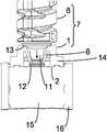
- FIG. 1is a top view of an embodiment of the bearing component.
- FIG. 2is a cross section of the embodiment according to FIG. 1 .
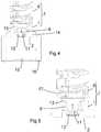
- FIG. 3shows a piston rod comprising the bearing component during assembly.
- FIG. 4shows the piston rod according to FIG. 3 after assembly.
- FIG. 5shows the piston rod according to FIG. 4 subjected to a disassembly force.
- FIG. 1shows an embodiment of the bearing component in a top view.
- the bearing component 1may have a generally circular shape, especially if the bearing component 1 is intended for a pen-type drug delivery device.
- At least one flexible feature 8extends from the periphery 3 to the centre 4 and forms a coupling feature 5 , which is used to fasten a further component of the piston rod.
- the coupling feature 5is formed by two flexible features 8 , which are arranged in a rotationally symmetrical fashion with respect to rotations by 180° around the centre 4 .
- a bearing 1 like thiscan be easily produced at lower cost.
- the two flexible features 8each cover an angle of about 120°-160°, preferably about 150°.
- each flexible feature 8is flexible enough to be resiliently movable during assembly, the inner edges of the flexible features 8 around opening 10 provide stability against twist.
- the stabilityincreases with the angle of coverage. This stability helps preventing an inclination of the bearing component 1 with respect to the axis of the piston rod 7 . Further, this ensures having an opening 10 large enough for a coupler 11 having an overhanging flange 12 to pass through.
- the coupling feature 5may leave an opening 10 in the centre 4 of the bearing component 1 . In this case the opening 10 is at least partially limited by the coupling feature 5 .
- FIG. 2is a cross section of the embodiment according to FIG. 1 .
- the plane of the cross sectionis perpendicular to the top view shown in FIG. 1 .
- the bearing component 1preferably comprises a solid outer ring 14 forming the periphery 3 and providing mechanical stability of the bearing component 1 .
- a contact surface 2 of the bearing component 1is provided to push against a corresponding surface of a bung.
- the contact surface 2may be on the front face of the outer ring 14 .
- At the periphery 3 there is a contact area 13which may partially cover the outer ring 14 , the flexible features 8 or both the outer ring 14 and the flexible features 8 .
- the flexible features 8 of this embodimenthave sloping surfaces 9 , which are inclined with respect to the plane of the contact surface 2 .
- the sloping surfaces 9approach the contact surface 2 towards the centre 4 , so that the coupling feature 5 grows narrower towards the plane of the contact surface 2 .
- the flexible features 8may be flexible arms, hooks, prongs, teeth or any other salient elements extending from the periphery 3 towards the centre 4 .
- the flexible features 8are preferably integral with the bearing component 1 .
- the sloping surfaces 9have the advantage that the assembly of the piston rod is facilitated, as will become apparent from the following description.
- FIG. 3shows a piston rod 7 comprising the bearing component 1 and a further component 6 in the state of being assembled.
- the bearing component 1is shown in the cross section according to FIG. 2 , whereas the further component 6 is shown in a perspective view.
- the further component 6may be a lead screw having a screw thread 17 , for example.
- the screw thread 17may be employed in a drive mechanism to advance the piston rod 7 .
- the further component 6is moved relative to the bearing component 1 in the direction of the vertical arrow pointing downwards in FIG. 3 .
- the end of the further component 6 facing the bearing component 1comprises a coupler 11 , which may resemble a spigot or pintle, for example.
- the coupler 11is preferably provided with an overhanging flange 12 .
- the coupler 11exerts a force on the sloping surfaces 9 of the flexible features 8 , as indicated with the oblique arrows in FIG. 3 .
- the flexible features 8are thus pushed radially outward, and the opening 10 widens sufficiently to let the coupler 11 pass the edges of the flexible features 8 .
- FIG. 4shows the piston rod 7 after the assembly.
- the flange 12has been shifted beyond the edges of the flexible features 8 , which have relaxed to their original position and axially lock the further component 6 by stopping the flange 12 .
- the bearing component 1can be brought into contact with a bung 15 of a drug cartridge 16 .
- the coupler 11can easily rotate within the bearing component 1 , while the bearing component 1 and the bung 15 do not rotate with respect to one another.
- the contact area 13 and hence the friction between the components 1 , 6 of the piston rod 7is relatively small.
- the frictionmay be further reduced if the force advancing the piston rod 7 is also exerted by the flange 12 immediately on the bung 15 , so that the pressure on the peripheral contact area 13 and hence the torque applied to the bearing component 1 by the further component 6 is reduced. Instead, the flange 12 may be kept at a distance from the bung 15 .
- the contact surface 2may be on the front face of the outer ring 14 facing the bung 15 .
- the flexible features 8are preferably arranged within the outer ring 14 of the bearing component 1 .
- the outer ring 14protects the flexible features 8 from side loads that could arise if the device is subjected to impact or vibration or from direct loading on the component that might occur during an automated assembly or bulk transport situation.
- the piston rod 7is pushed towards the bung 15 during dispense, and the bearing component 1 is in compression, no load acts on the flexible features 8 , so that the components 1 , 6 stay securely coupled.
- the main component 6 of the piston rod 7is pushed against contact area 13 on an outer ring 14 of the bearing component 1 .
- the contact area 13is small enough to keep the friction between the components 1 and 6 of the piston rod 7 at a low level and hence the torque applied to the bearing component 1 within tolerable limits. Reduced friction is particularly advantageous in case the piston rod is rotated during operation. It could be further reduced using low friction polymers.
- the contact area 13is inclined towards the axis of the piston rod and adapted to the shape of the corresponding contact surface of the main component 6 e.g., a shape of a circumferential surface of a truncated cone.
- the contact area 13prevents an inclination of the bearing component 1 with respect to the axis of the piston rod 7 , when advanced, e.g. during assembly and/or during dispense operation.
- an inclined contact surface area 13helps guiding the bearing component 1 to be and/or remain in line with the axis of the piston rod. This is particularly beneficial in case of a rotating piston rod 7 .
- Flange 12is kept at a distance from the bung 15 and has a contact surface 2 on the front face of the outer ring 14 facing the bung 15 . A force driving the piston rod 7 is thus transferred to the bung 15 via the bearing component 1 , in particular contact surface 2 .
- piston rod 7is free to rotate while its push force is transferred to the bung 15 via the contact surface 2 of bearing 1 .
- This embodimentmay therefore be preferred if the piston rod is rotated during operation.
- FIG. 5shows how a disassembly of the piston rod 7 is prevented. If an axial force is applied to the further component 6 relative to the bearing component 1 in the direction indicated with the vertical arrow in FIG. 5 , the components 1 , 6 are slightly separated.
- FIG. 5shows the contact area 13 on the bearing component 1 no longer covered by the further component 6 , owing to the action of the separating force, and the distance between the flange 12 and the plane of the contact area 2 being increased.
- the flexible features 8engage the flange 12 of the coupler 11 . If the flexible features 8 have a sloping shape as in the described embodiment, this engagement with the flange 12 forces the flexible features 8 to deform inwards and dig into the coupler 11 . This prevents a disassembly of the components 1 , 6 of the piston rod 7 , unless unusually great forces are applied.
Landscapes
- Health & Medical Sciences (AREA)
- Vascular Medicine (AREA)
- Engineering & Computer Science (AREA)
- Anesthesiology (AREA)
- Biomedical Technology (AREA)
- Heart & Thoracic Surgery (AREA)
- Hematology (AREA)
- Life Sciences & Earth Sciences (AREA)
- Animal Behavior & Ethology (AREA)
- General Health & Medical Sciences (AREA)
- Public Health (AREA)
- Veterinary Medicine (AREA)
- Infusion, Injection, And Reservoir Apparatuses (AREA)
Abstract
Description
Claims (21)
Applications Claiming Priority (4)
| Application Number | Priority Date | Filing Date | Title |
|---|---|---|---|
| EP13158513 | 2013-03-11 | ||
| EP13158513 | 2013-03-11 | ||
| EP13158513.5 | 2013-03-11 | ||
| PCT/EP2014/054525WO2014139913A1 (en) | 2013-03-11 | 2014-03-10 | Bearing component for a piston rod of a drug delivery device, piston rod comprising the bearing component, and drug delivery device |
Publications (2)
| Publication Number | Publication Date |
|---|---|
| US20160015901A1 US20160015901A1 (en) | 2016-01-21 |
| US11213628B2true US11213628B2 (en) | 2022-01-04 |
Family
ID=47844191
Family Applications (1)
| Application Number | Title | Priority Date | Filing Date |
|---|---|---|---|
| US14/771,544Active2035-07-18US11213628B2 (en) | 2013-03-11 | 2014-03-10 | Bearing component for a piston rod of a drug delivery device, piston rod comprising the bearing component, and drug delivery device |
Country Status (17)
| Country | Link |
|---|---|
| US (1) | US11213628B2 (en) |
| EP (1) | EP2968782B1 (en) |
| JP (1) | JP6541579B2 (en) |
| KR (1) | KR102293641B1 (en) |
| CN (1) | CN105025962B (en) |
| AR (1) | AR095181A1 (en) |
| AU (1) | AU2014230959B2 (en) |
| BR (1) | BR112015018944B1 (en) |
| DK (1) | DK2968782T3 (en) |
| ES (1) | ES2681421T3 (en) |
| HU (1) | HUE039598T2 (en) |
| IL (1) | IL240301B (en) |
| MX (1) | MX376493B (en) |
| PL (1) | PL2968782T3 (en) |
| RU (1) | RU2665028C2 (en) |
| TW (1) | TWI653069B (en) |
| WO (1) | WO2014139913A1 (en) |
Cited By (1)
| Publication number | Priority date | Publication date | Assignee | Title |
|---|---|---|---|---|
| WO2025014929A1 (en)* | 2023-07-11 | 2025-01-16 | Flextronics Ap, Llc | Leadscrew tip for an autoinjector |
Families Citing this family (15)
| Publication number | Priority date | Publication date | Assignee | Title |
|---|---|---|---|---|
| JP6917893B2 (en)* | 2014-12-22 | 2021-08-11 | ノボ・ノルデイスク・エー/エス | Injection device with removable cap |
| KR102035378B1 (en)* | 2015-06-08 | 2019-11-18 | 주식회사 엘지화학 | A laminate structure with metal wiring layer and a process for manufacturing same |
| JP6662916B2 (en)* | 2015-07-03 | 2020-03-11 | エス・ハー・エル・メディカル・アクチェンゲゼルシャフトShl Medical Ag | Drug delivery device |
| GB2541227A (en)* | 2015-08-13 | 2017-02-15 | Owen Mumford Ltd | Injector Device |
| WO2017032590A1 (en)* | 2015-08-26 | 2017-03-02 | Carebay Europe Ltd | Medicament delivery device and assembly of electronic device and the medicament delivery device |
| EP3141275A1 (en) | 2015-09-14 | 2017-03-15 | Carebay Europe Ltd. | Medicament delivery device |
| WO2017071909A1 (en)* | 2015-10-28 | 2017-05-04 | Carebay Europe Ltd | Medicament container holder |
| US9480797B1 (en)* | 2015-10-28 | 2016-11-01 | Bayer Healthcare Llc | System and method for syringe plunger engagement with an injector |
| US11116912B2 (en) | 2015-11-20 | 2021-09-14 | Shl Medical Ag | Needle shield mechanism and a medicament delivery device comprising the needle shield mechanism |
| EP3389746B1 (en) | 2015-12-14 | 2020-04-01 | SHL Medical AG | Medicament delivery device |
| TWI637762B (en) | 2016-06-23 | 2018-10-11 | 卡貝歐洲有限公司 | Medicament delivery device |
| HUE063479T2 (en) | 2017-01-06 | 2024-01-28 | Bayer Healthcare Llc | Syringe plunger with dynamic seal |
| CN107281585A (en)* | 2017-08-04 | 2017-10-24 | 王立峰 | A kind of Intravenous Anesthesia device of accurate control dosage |
| CH712459A2 (en) | 2017-08-31 | 2017-11-15 | Tecpharma Licensing Ag | Drive device for injection devices. |
| EP3598990A1 (en)* | 2018-07-23 | 2020-01-29 | Sanofi | Drug delivery device and assembly method for a drug delivery device |
Citations (67)
| Publication number | Priority date | Publication date | Assignee | Title |
|---|---|---|---|---|
| US533575A (en) | 1895-02-05 | wilkens | ||
| US2895773A (en)* | 1956-10-22 | 1959-07-21 | Robert K Mcconnaughey | Variable diameter tensed ring piston |
| US4865591A (en) | 1987-06-12 | 1989-09-12 | Hypoguard (Uk) Limited | Measured dose dispensing device |
| US5092842A (en) | 1987-05-08 | 1992-03-03 | Wilhelm Haselmeier Gmbh & Co. | Injection device with a cocking element and a second setting element |
| EP0496141A1 (en) | 1991-01-22 | 1992-07-29 | Eli Lilly And Company | Multiple dose injection pen |
| WO1993007922A1 (en) | 1991-10-18 | 1993-04-29 | Novo Nordisk A/S | Large dose pen |
| US5226895A (en) | 1989-06-05 | 1993-07-13 | Eli Lilly And Company | Multiple dose injection pen |
| US5226896A (en) | 1990-04-04 | 1993-07-13 | Eli Lilly And Company | Dose indicating injection pen |
| WO1993024160A1 (en) | 1992-06-01 | 1993-12-09 | Habley Medical Technology Corporation | Dose setting and repeating syringe |
| US5279586A (en) | 1992-02-04 | 1994-01-18 | Becton, Dickinson And Company | Reusable medication delivery pen |
| CA2138528A1 (en) | 1992-07-31 | 1994-02-17 | Terry M. Haber | Reusable Pharmaceutical Dispenser with Full Stroke Indicator |
| US5304152A (en) | 1990-03-29 | 1994-04-19 | Bernard Sams | Dispensing device |
| US5320609A (en) | 1992-12-07 | 1994-06-14 | Habley Medical Technology Corporation | Automatic pharmaceutical dispensing syringe |
| WO1994025090A1 (en) | 1993-04-30 | 1994-11-10 | Pharmacia Ab | A device for dosing a liquid preparation |
| US5378233A (en) | 1992-11-18 | 1995-01-03 | Habley Medical Technology Corporation | Selected dose pharmaceutical dispenser |
| US5383865A (en) | 1993-03-15 | 1995-01-24 | Eli Lilly And Company | Medication dispensing device |
| US5391157A (en) | 1992-10-20 | 1995-02-21 | Eli Lilly And Company | End of dose indicator |
| US5480387A (en) | 1991-07-24 | 1996-01-02 | Medico Development Investment Company | Injection device |
| US5505704A (en) | 1993-04-02 | 1996-04-09 | Eli Lilly And Company | Manifold medication injection apparatus and method |
| US5582598A (en) | 1994-09-19 | 1996-12-10 | Becton Dickinson And Company | Medication delivery pen with variable increment dose scale |
| US5674204A (en) | 1995-09-19 | 1997-10-07 | Becton Dickinson And Company | Medication delivery pen cap actuated dose delivery clutch |
| US5688252A (en)* | 1994-09-30 | 1997-11-18 | Takeda Chemical Industries, Ltd. | Syringe |
| US5688251A (en) | 1995-09-19 | 1997-11-18 | Becton Dickinson And Company | Cartridge loading and priming mechanism for a pen injector |
| US5735825A (en)* | 1996-03-22 | 1998-04-07 | Merit Medical Systems, Inc. | Syringe plunger tip |
| US5807346A (en) | 1993-02-08 | 1998-09-15 | Laboratoire Aguettant | Metering instrument, particularly for injecting medicinal liquid |
| US5820602A (en) | 1995-09-08 | 1998-10-13 | Visionary Medical Products, Inc. | Pen-type injector drive mechanism |
| US5851079A (en) | 1996-10-25 | 1998-12-22 | The Procter & Gamble Company | Simplified undirectional twist-up dispensing device with incremental dosing |
| EP0897729A2 (en) | 1997-08-11 | 1999-02-24 | Becton, Dickinson and Company | Medication delivery pen having a controlling means of the torque applied to the dosing elements |
| WO1999038554A1 (en) | 1998-01-30 | 1999-08-05 | Novo Nordisk A/S | An injection syringe |
| EP0937471A2 (en) | 1998-02-20 | 1999-08-25 | Becton Dickinson and Company | Medication delivery pen |
| EP0937476A2 (en) | 1998-02-23 | 1999-08-25 | Becton, Dickinson and Company | Low-cost medication delivery pen |
| US5961495A (en) | 1998-02-20 | 1999-10-05 | Becton, Dickinson And Company | Medication delivery pen having a priming mechanism |
| CA2359375A1 (en) | 1999-01-14 | 2000-07-20 | B D Medico S.A.R.L. | Injection device |
| WO2001010484A1 (en) | 1999-08-05 | 2001-02-15 | Becton, Dickinson And Company | Medication delivery pen |
| US6193698B1 (en) | 1997-07-18 | 2001-02-27 | Disetronic Licensing Ag | System for locking a dosing button in a device for the adminstration of a product to be injected |
| US6221046B1 (en) | 1995-03-07 | 2001-04-24 | Eli Lilly And Company | Recyclable medication dispensing device |
| WO2002030495A2 (en) | 2000-10-09 | 2002-04-18 | Eli Lilly And Company | Pen device for administration of parathyroid hormone |
| US20020052578A1 (en) | 2000-06-16 | 2002-05-02 | Moller Claus Schmidt | Injection device |
| US20020120235A1 (en) | 2001-01-05 | 2002-08-29 | Christian Enggaard | Automatic injection device with reset feature |
| WO2002092153A2 (en) | 2001-05-16 | 2002-11-21 | Eli Lilly And Company | Medication injector apparatus with drive assembly that facilitates reset |
| US20030050609A1 (en) | 2000-03-24 | 2003-03-13 | Bernard Sams | One-way clutch mechanisms and injector devices |
| US6562006B1 (en) | 1999-04-16 | 2003-05-13 | Pharmacia Ab | Injector device and method for its operation |
| US6613023B2 (en) | 1999-01-12 | 2003-09-02 | Disetronic Licensing Ag | Device for administering an injectable product in doses |
| WO2003080160A1 (en) | 2002-03-18 | 2003-10-02 | Eli Lilly And Company | Medication dispensing apparatus with gear set for mechanical advantage |
| US6699224B2 (en) | 1999-01-12 | 2004-03-02 | Disetronic Licensing Ag | Device for administering an injectable product |
| CN1547492A (en) | 2001-07-30 | 2004-11-17 | �ӳɹ� | Storage module including a piston rod |
| US20040267207A1 (en) | 2003-03-03 | 2004-12-30 | Veasey Robert Frederick | Drive mechanisms suitable for use in drug delivery devices |
| US6932794B2 (en) | 2003-04-03 | 2005-08-23 | Becton, Dickinson And Company | Medication delivery pen |
| CN1780652A (en) | 2003-03-03 | 2006-05-31 | Dca设计国际有限公司 | Drive mechanism for drug delivery device |
| US20060153693A1 (en) | 2004-12-31 | 2006-07-13 | Patrick Fiechter | Administering apparatus comprising a service life timer |
| WO2006084876A1 (en) | 2005-02-11 | 2006-08-17 | Novo Nordisk A/S | Injection device |
| WO2006114396A1 (en) | 2005-04-24 | 2006-11-02 | Novo Nordisk A/S | Injection device |
| US20070016143A1 (en) | 2003-12-08 | 2007-01-18 | Novo Nordisk A/S | Medical delivery device having air shot means |
| US7169132B2 (en) | 2002-10-01 | 2007-01-30 | Becton, Dickinson And Company | Medication delivery pen |
| WO2009039851A1 (en) | 2007-09-25 | 2009-04-02 | Claus Schmidt Moeller | Dose delivery device with gearing mechanism |
| US20090275916A1 (en) | 2008-05-02 | 2009-11-05 | Sanofi-Aventis Deutschland Gmbh | Medication Delivery Device |
| WO2010110712A1 (en) | 2009-03-24 | 2010-09-30 | Istvan Bartha | Device for delivering liquid medicament |
| WO2011006924A1 (en) | 2009-07-15 | 2011-01-20 | Sanofi-Aventis Deutschland Gmbh | Thrust bearing assembly, drive train, and medicament delivery device |
| WO2011039229A1 (en)* | 2009-09-30 | 2011-04-07 | Sanofi-Aventis Deutschland Gmbh | Assembly for a drug delivery device |
| WO2011042539A1 (en) | 2009-10-08 | 2011-04-14 | Sanofi-Aventis Deutschland Gmbh | Drive mechanism for drug delivery devices |
| WO2011121867A1 (en) | 2010-03-29 | 2011-10-06 | テルモ株式会社 | Prefilled syringe |
| US20110319835A1 (en) | 2008-12-22 | 2011-12-29 | Stefan Burren | Dose setting device for an injection device |
| JP2012045173A (en) | 2010-08-26 | 2012-03-08 | Terumo Corp | Prefilled syringe |
| EP2438949A1 (en) | 2010-10-06 | 2012-04-11 | Sanofi-Aventis Deutschland GmbH | Drive mechanism for a drug delivery device and drug delivery device |
| US8186233B2 (en) | 2009-06-15 | 2012-05-29 | Samsung Electro-Mechanics Co., Ltd. | Pressure sensing device |
| US20120136298A1 (en)* | 2009-06-04 | 2012-05-31 | Novo Nordisk Healthcare A/G | Mixing device with piston coupling arrangement |
| US20120265151A1 (en) | 2008-12-12 | 2012-10-18 | Sanofi-Aventis Deutschland Gmbh | Resettable Drive Mechanism for a Medication Delivery Device and Medication Delivery Device |
- 2014
- 2014-03-07TWTW103107805Apatent/TWI653069B/enactive
- 2014-03-10JPJP2015562055Apatent/JP6541579B2/enactiveActive
- 2014-03-10DKDK14708559.1Tpatent/DK2968782T3/enactive
- 2014-03-10AUAU2014230959Apatent/AU2014230959B2/enactiveActive
- 2014-03-10ESES14708559.1Tpatent/ES2681421T3/enactiveActive
- 2014-03-10ARARP140100799Apatent/AR095181A1/enactiveIP Right Grant
- 2014-03-10KRKR1020157023270Apatent/KR102293641B1/enactiveActive
- 2014-03-10CNCN201480012649.3Apatent/CN105025962B/enactiveActive
- 2014-03-10EPEP14708559.1Apatent/EP2968782B1/enactiveActive
- 2014-03-10USUS14/771,544patent/US11213628B2/enactiveActive
- 2014-03-10PLPL14708559Tpatent/PL2968782T3/enunknown
- 2014-03-10HUHUE14708559Apatent/HUE039598T2/enunknown
- 2014-03-10MXMX2015011824Apatent/MX376493B/enactiveIP Right Grant
- 2014-03-10BRBR112015018944-0Apatent/BR112015018944B1/enactiveIP Right Grant
- 2014-03-10RURU2015143043Apatent/RU2665028C2/enactive
- 2014-03-10WOPCT/EP2014/054525patent/WO2014139913A1/enactiveApplication Filing
- 2015
- 2015-08-02ILIL240301Apatent/IL240301B/enactiveIP Right Grant
Patent Citations (94)
| Publication number | Priority date | Publication date | Assignee | Title |
|---|---|---|---|---|
| US533575A (en) | 1895-02-05 | wilkens | ||
| US2895773A (en)* | 1956-10-22 | 1959-07-21 | Robert K Mcconnaughey | Variable diameter tensed ring piston |
| US5092842A (en) | 1987-05-08 | 1992-03-03 | Wilhelm Haselmeier Gmbh & Co. | Injection device with a cocking element and a second setting element |
| US4865591A (en) | 1987-06-12 | 1989-09-12 | Hypoguard (Uk) Limited | Measured dose dispensing device |
| US5226895A (en) | 1989-06-05 | 1993-07-13 | Eli Lilly And Company | Multiple dose injection pen |
| US5304152A (en) | 1990-03-29 | 1994-04-19 | Bernard Sams | Dispensing device |
| US5226896A (en) | 1990-04-04 | 1993-07-13 | Eli Lilly And Company | Dose indicating injection pen |
| EP0496141A1 (en) | 1991-01-22 | 1992-07-29 | Eli Lilly And Company | Multiple dose injection pen |
| US5480387A (en) | 1991-07-24 | 1996-01-02 | Medico Development Investment Company | Injection device |
| WO1993007922A1 (en) | 1991-10-18 | 1993-04-29 | Novo Nordisk A/S | Large dose pen |
| US5626566A (en)* | 1991-10-18 | 1997-05-06 | Novo Nordisk A/S | Large dose pen |
| US5279586A (en) | 1992-02-04 | 1994-01-18 | Becton, Dickinson And Company | Reusable medication delivery pen |
| WO1993024160A1 (en) | 1992-06-01 | 1993-12-09 | Habley Medical Technology Corporation | Dose setting and repeating syringe |
| CA2138528A1 (en) | 1992-07-31 | 1994-02-17 | Terry M. Haber | Reusable Pharmaceutical Dispenser with Full Stroke Indicator |
| US5391157A (en) | 1992-10-20 | 1995-02-21 | Eli Lilly And Company | End of dose indicator |
| US5378233A (en) | 1992-11-18 | 1995-01-03 | Habley Medical Technology Corporation | Selected dose pharmaceutical dispenser |
| US5320609A (en) | 1992-12-07 | 1994-06-14 | Habley Medical Technology Corporation | Automatic pharmaceutical dispensing syringe |
| US5807346A (en) | 1993-02-08 | 1998-09-15 | Laboratoire Aguettant | Metering instrument, particularly for injecting medicinal liquid |
| US5383865A (en) | 1993-03-15 | 1995-01-24 | Eli Lilly And Company | Medication dispensing device |
| US5505704A (en) | 1993-04-02 | 1996-04-09 | Eli Lilly And Company | Manifold medication injection apparatus and method |
| WO1994025090A1 (en) | 1993-04-30 | 1994-11-10 | Pharmacia Ab | A device for dosing a liquid preparation |
| RU2132703C1 (en) | 1993-04-30 | 1999-07-10 | Фармация энд Апджон АБ | Injection device for unrestrictedly-variable dosing |
| US5582598A (en) | 1994-09-19 | 1996-12-10 | Becton Dickinson And Company | Medication delivery pen with variable increment dose scale |
| US5688252A (en)* | 1994-09-30 | 1997-11-18 | Takeda Chemical Industries, Ltd. | Syringe |
| US6221046B1 (en) | 1995-03-07 | 2001-04-24 | Eli Lilly And Company | Recyclable medication dispensing device |
| US5820602A (en) | 1995-09-08 | 1998-10-13 | Visionary Medical Products, Inc. | Pen-type injector drive mechanism |
| US5674204A (en) | 1995-09-19 | 1997-10-07 | Becton Dickinson And Company | Medication delivery pen cap actuated dose delivery clutch |
| US5688251A (en) | 1995-09-19 | 1997-11-18 | Becton Dickinson And Company | Cartridge loading and priming mechanism for a pen injector |
| US5735825A (en)* | 1996-03-22 | 1998-04-07 | Merit Medical Systems, Inc. | Syringe plunger tip |
| US5851079A (en) | 1996-10-25 | 1998-12-22 | The Procter & Gamble Company | Simplified undirectional twist-up dispensing device with incremental dosing |
| US6193698B1 (en) | 1997-07-18 | 2001-02-27 | Disetronic Licensing Ag | System for locking a dosing button in a device for the adminstration of a product to be injected |
| EP0897729A2 (en) | 1997-08-11 | 1999-02-24 | Becton, Dickinson and Company | Medication delivery pen having a controlling means of the torque applied to the dosing elements |
| US5921966A (en) | 1997-08-11 | 1999-07-13 | Becton Dickinson And Company | Medication delivery pen having an improved clutch assembly |
| US5957896A (en) | 1997-08-11 | 1999-09-28 | Becton, Dickinson And Company | Medication delivery pen |
| US6235004B1 (en) | 1998-01-30 | 2001-05-22 | Novo Nordisk A/S | Injection syringe |
| WO1999038554A1 (en) | 1998-01-30 | 1999-08-05 | Novo Nordisk A/S | An injection syringe |
| US6004297A (en) | 1998-01-30 | 1999-12-21 | Novo Nordisk A/S | Injection syringe |
| EP0937471A2 (en) | 1998-02-20 | 1999-08-25 | Becton Dickinson and Company | Medication delivery pen |
| US5961495A (en) | 1998-02-20 | 1999-10-05 | Becton, Dickinson And Company | Medication delivery pen having a priming mechanism |
| EP0937476A2 (en) | 1998-02-23 | 1999-08-25 | Becton, Dickinson and Company | Low-cost medication delivery pen |
| US6248095B1 (en) | 1998-02-23 | 2001-06-19 | Becton, Dickinson And Company | Low-cost medication delivery pen |
| US6613023B2 (en) | 1999-01-12 | 2003-09-02 | Disetronic Licensing Ag | Device for administering an injectable product in doses |
| US6699224B2 (en) | 1999-01-12 | 2004-03-02 | Disetronic Licensing Ag | Device for administering an injectable product |
| CA2359375A1 (en) | 1999-01-14 | 2000-07-20 | B D Medico S.A.R.L. | Injection device |
| US6562006B1 (en) | 1999-04-16 | 2003-05-13 | Pharmacia Ab | Injector device and method for its operation |
| US6936032B1 (en) | 1999-08-05 | 2005-08-30 | Becton, Dickinson And Company | Medication delivery pen |
| WO2001010484A1 (en) | 1999-08-05 | 2001-02-15 | Becton, Dickinson And Company | Medication delivery pen |
| US6899698B2 (en) | 2000-03-24 | 2005-05-31 | Bernard Sams | One-way clutch mechanisms and injector devices |
| US20030050609A1 (en) | 2000-03-24 | 2003-03-13 | Bernard Sams | One-way clutch mechanisms and injector devices |
| US7241278B2 (en) | 2000-06-16 | 2007-07-10 | Novo Nordisk A/S | Injection device |
| US20020052578A1 (en) | 2000-06-16 | 2002-05-02 | Moller Claus Schmidt | Injection device |
| US20040059299A1 (en) | 2000-06-16 | 2004-03-25 | Moller Claus Schmidt | Injection device |
| WO2002030495A2 (en) | 2000-10-09 | 2002-04-18 | Eli Lilly And Company | Pen device for administration of parathyroid hormone |
| US20040097883A1 (en) | 2000-10-09 | 2004-05-20 | Roe Michael Joseph | Pen device for administration of parathyroid hormone |
| US20020120235A1 (en) | 2001-01-05 | 2002-08-29 | Christian Enggaard | Automatic injection device with reset feature |
| US20040210199A1 (en) | 2001-05-16 | 2004-10-21 | Atterbury William Goodwin | Medication injector apparatus with drive assembly that facilitates reset |
| EP1776975A2 (en) | 2001-05-16 | 2007-04-25 | Eli Lilly & Company | Medication injector apparatus with drive assembly that facilitates reset |
| WO2002092153A2 (en) | 2001-05-16 | 2002-11-21 | Eli Lilly And Company | Medication injector apparatus with drive assembly that facilitates reset |
| CN1547492A (en) | 2001-07-30 | 2004-11-17 | �ӳɹ� | Storage module including a piston rod |
| US20150151043A1 (en) | 2001-07-30 | 2015-06-04 | Tecpharma Licensing Ag | Reservoir module comprising a piston rod |
| US7678084B2 (en) | 2002-03-18 | 2010-03-16 | Eli Lilly And Company | Medication dispensing apparatus with gear set for mechanical advantage |
| WO2003080160A1 (en) | 2002-03-18 | 2003-10-02 | Eli Lilly And Company | Medication dispensing apparatus with gear set for mechanical advantage |
| US7169132B2 (en) | 2002-10-01 | 2007-01-30 | Becton, Dickinson And Company | Medication delivery pen |
| CN1780652A (en) | 2003-03-03 | 2006-05-31 | Dca设计国际有限公司 | Drive mechanism for drug delivery device |
| US7850662B2 (en) | 2003-03-03 | 2010-12-14 | Sanofi-Aventis Deutschland Gmbh | Drive mechanisms suitable for use in drug delivery devices |
| US20070093761A1 (en) | 2003-03-03 | 2007-04-26 | Dca Design International Ltd. | Drive mechanisms suitable for use in drug delivery devices |
| US20050113765A1 (en) | 2003-03-03 | 2005-05-26 | Veasey Robert F. | Pen-type injector |
| US20040267207A1 (en) | 2003-03-03 | 2004-12-30 | Veasey Robert Frederick | Drive mechanisms suitable for use in drug delivery devices |
| US6932794B2 (en) | 2003-04-03 | 2005-08-23 | Becton, Dickinson And Company | Medication delivery pen |
| US20070016143A1 (en) | 2003-12-08 | 2007-01-18 | Novo Nordisk A/S | Medical delivery device having air shot means |
| US20060153693A1 (en) | 2004-12-31 | 2006-07-13 | Patrick Fiechter | Administering apparatus comprising a service life timer |
| WO2006084876A1 (en) | 2005-02-11 | 2006-08-17 | Novo Nordisk A/S | Injection device |
| WO2006114396A1 (en) | 2005-04-24 | 2006-11-02 | Novo Nordisk A/S | Injection device |
| JP2008538719A (en) | 2005-04-24 | 2008-11-06 | ノボ・ノルデイスク・エー/エス | Injection device |
| WO2009039851A1 (en) | 2007-09-25 | 2009-04-02 | Claus Schmidt Moeller | Dose delivery device with gearing mechanism |
| US20090275916A1 (en) | 2008-05-02 | 2009-11-05 | Sanofi-Aventis Deutschland Gmbh | Medication Delivery Device |
| US20120265151A1 (en) | 2008-12-12 | 2012-10-18 | Sanofi-Aventis Deutschland Gmbh | Resettable Drive Mechanism for a Medication Delivery Device and Medication Delivery Device |
| US20110319835A1 (en) | 2008-12-22 | 2011-12-29 | Stefan Burren | Dose setting device for an injection device |
| WO2010110712A1 (en) | 2009-03-24 | 2010-09-30 | Istvan Bartha | Device for delivering liquid medicament |
| CN102448520A (en) | 2009-03-24 | 2012-05-09 | 赛诺菲-安万特德国有限公司 | Device for delivering liquid medicament |
| US20120136298A1 (en)* | 2009-06-04 | 2012-05-31 | Novo Nordisk Healthcare A/G | Mixing device with piston coupling arrangement |
| US8186233B2 (en) | 2009-06-15 | 2012-05-29 | Samsung Electro-Mechanics Co., Ltd. | Pressure sensing device |
| WO2011006924A1 (en) | 2009-07-15 | 2011-01-20 | Sanofi-Aventis Deutschland Gmbh | Thrust bearing assembly, drive train, and medicament delivery device |
| JP2012532720A (en) | 2009-07-15 | 2012-12-20 | サノフィ−アベンティス・ドイチュラント・ゲゼルシャフト・ミット・ベシュレンクテル・ハフツング | Thrust bearing assembly, drive train, and drug delivery device |
| WO2011039229A1 (en)* | 2009-09-30 | 2011-04-07 | Sanofi-Aventis Deutschland Gmbh | Assembly for a drug delivery device |
| WO2011042539A1 (en) | 2009-10-08 | 2011-04-14 | Sanofi-Aventis Deutschland Gmbh | Drive mechanism for drug delivery devices |
| CN102573961A (en) | 2009-10-08 | 2012-07-11 | 赛诺菲-安万特德国有限公司 | Drive mechanism for drug delivery devices |
| US20130023831A1 (en) | 2009-10-08 | 2013-01-24 | Sanofi-Aventis Deutschland Gmbh | Drive mechanism for drug delivery devices |
| CN102821803A (en) | 2010-03-29 | 2012-12-12 | 泰尔茂株式会社 | Prefilled syringe |
| US20130012888A1 (en)* | 2010-03-29 | 2013-01-10 | Terumo Kabushiki Kaisha | Prefilled Syringe |
| EP2554204A1 (en) | 2010-03-29 | 2013-02-06 | Terumo Kabushiki Kaisha | Prefilled syringe |
| WO2011121867A1 (en) | 2010-03-29 | 2011-10-06 | テルモ株式会社 | Prefilled syringe |
| JP2012045173A (en) | 2010-08-26 | 2012-03-08 | Terumo Corp | Prefilled syringe |
| EP2438949A1 (en) | 2010-10-06 | 2012-04-11 | Sanofi-Aventis Deutschland GmbH | Drive mechanism for a drug delivery device and drug delivery device |
Non-Patent Citations (5)
| Title |
|---|
| "Pen-injectors for medical use—Part 1: Pen-injectors—Requirements and test methods," International Standard, reference No. ISO 11608-1:2000(E), first edition Dec. 15, 2000, 32 pages. |
| Examination Report issued in Australian Patent Application No. 2014230959 dated Jul. 29, 2017. |
| Extended European Search Report issued in European Patent Application No. 13158513.5, dated Jul. 23, 2013. |
| International Preliminary Report on Patentability in International Application No. PCT/EP2014/054525, dated Sep. 15, 2015, 7 pages. |
| International Search Report and Written Opinion in International Application No. PCT/EP2014/054525, dated May 20, 2014, 11 pages. |
Cited By (1)
| Publication number | Priority date | Publication date | Assignee | Title |
|---|---|---|---|---|
| WO2025014929A1 (en)* | 2023-07-11 | 2025-01-16 | Flextronics Ap, Llc | Leadscrew tip for an autoinjector |
Also Published As
| Publication number | Publication date |
|---|---|
| WO2014139913A1 (en) | 2014-09-18 |
| EP2968782B1 (en) | 2018-04-25 |
| RU2665028C2 (en) | 2018-08-24 |
| BR112015018944A2 (en) | 2017-07-18 |
| DK2968782T3 (en) | 2018-08-06 |
| RU2015143043A3 (en) | 2018-02-28 |
| MX376493B (en) | 2025-03-07 |
| IL240301A0 (en) | 2015-09-24 |
| AU2014230959A1 (en) | 2015-09-24 |
| RU2015143043A (en) | 2017-04-18 |
| EP2968782A1 (en) | 2016-01-20 |
| AR095181A1 (en) | 2015-09-30 |
| MX2015011824A (en) | 2016-01-25 |
| ES2681421T3 (en) | 2018-09-13 |
| JP2016513506A (en) | 2016-05-16 |
| TW201509467A (en) | 2015-03-16 |
| HUE039598T2 (en) | 2019-01-28 |
| HK1213504A1 (en) | 2016-07-08 |
| KR20150126834A (en) | 2015-11-13 |
| BR112015018944B1 (en) | 2021-11-23 |
| CN105025962B (en) | 2019-04-19 |
| US20160015901A1 (en) | 2016-01-21 |
| AU2014230959B2 (en) | 2018-01-18 |
| PL2968782T3 (en) | 2018-09-28 |
| IL240301B (en) | 2019-09-26 |
| KR102293641B1 (en) | 2021-08-24 |
| TWI653069B (en) | 2019-03-11 |
| JP6541579B2 (en) | 2019-07-10 |
| CN105025962A (en) | 2015-11-04 |
Similar Documents
| Publication | Publication Date | Title |
|---|---|---|
| US11213628B2 (en) | Bearing component for a piston rod of a drug delivery device, piston rod comprising the bearing component, and drug delivery device | |
| US9844632B2 (en) | Cap assembly for a drug delivery device | |
| US10265474B2 (en) | Drug delivery device and cartridge holder for a drug delivery device | |
| US20150088079A1 (en) | Drive mechanism for a drug delivery device and drug delivery device | |
| US9597457B2 (en) | Piston rod for a drug delivery device and drug delivery device comprising a piston rod | |
| US10668222B2 (en) | Assembly for a drug delivery device and drug delivery device | |
| US20150018779A1 (en) | Spring assembly for a drug delivery device | |
| US9370623B2 (en) | Drive assembly for a medication delivery device and medication delivery device comprising a drive assembly | |
| US9849246B2 (en) | Housing of a drug delivery device | |
| HK1213504B (en) | Bearing component for a piston rod of a drug delivery device, piston rod comprising the bearing component, and drug delivery device | |
| US10342927B2 (en) | Operation member and mechanism for a drug delivery device, and drug delivery device | |
| US10369291B2 (en) | Mechanism for a drug delivery device | |
| HK1197896B (en) | Drive assembly for a medication delivery device and medication delivery device comprising a drive assembly | |
| HK1226015B (en) | Operation member and mechanism for a drug delivery device, and drug delivery device | |
| HK1191260B (en) | Drug delivery device and cartridge holder for a drug delivery device | |
| HK1191260A (en) | Drug delivery device and cartridge holder for a drug delivery device |
Legal Events
| Date | Code | Title | Description |
|---|---|---|---|
| AS | Assignment | Owner name:SANOFI-AVENTIS DEUTSCHLAND GMBH, GERMANY Free format text:ASSIGNMENT OF ASSIGNORS INTEREST;ASSIGNOR:PLUMPTRE, DAVID AUBREY;REEL/FRAME:036603/0939 Effective date:20140428 | |
| STPP | Information on status: patent application and granting procedure in general | Free format text:NON FINAL ACTION MAILED | |
| STPP | Information on status: patent application and granting procedure in general | Free format text:RESPONSE TO NON-FINAL OFFICE ACTION ENTERED AND FORWARDED TO EXAMINER | |
| STPP | Information on status: patent application and granting procedure in general | Free format text:FINAL REJECTION MAILED | |
| STPP | Information on status: patent application and granting procedure in general | Free format text:RESPONSE AFTER FINAL ACTION FORWARDED TO EXAMINER | |
| STPP | Information on status: patent application and granting procedure in general | Free format text:DOCKETED NEW CASE - READY FOR EXAMINATION | |
| STPP | Information on status: patent application and granting procedure in general | Free format text:NON FINAL ACTION MAILED | |
| STPP | Information on status: patent application and granting procedure in general | Free format text:RESPONSE TO NON-FINAL OFFICE ACTION ENTERED AND FORWARDED TO EXAMINER | |
| STPP | Information on status: patent application and granting procedure in general | Free format text:FINAL REJECTION MAILED | |
| STPP | Information on status: patent application and granting procedure in general | Free format text:NON FINAL ACTION MAILED | |
| STPP | Information on status: patent application and granting procedure in general | Free format text:RESPONSE TO NON-FINAL OFFICE ACTION ENTERED AND FORWARDED TO EXAMINER | |
| STPP | Information on status: patent application and granting procedure in general | Free format text:NOTICE OF ALLOWANCE MAILED -- APPLICATION RECEIVED IN OFFICE OF PUBLICATIONS | |
| STPP | Information on status: patent application and granting procedure in general | Free format text:PUBLICATIONS -- ISSUE FEE PAYMENT RECEIVED | |
| STPP | Information on status: patent application and granting procedure in general | Free format text:AWAITING TC RESP, ISSUE FEE PAYMENT VERIFIED | |
| STPP | Information on status: patent application and granting procedure in general | Free format text:PUBLICATIONS -- ISSUE FEE PAYMENT VERIFIED | |
| STCF | Information on status: patent grant | Free format text:PATENTED CASE | |
| MAFP | Maintenance fee payment | Free format text:PAYMENT OF MAINTENANCE FEE, 4TH YEAR, LARGE ENTITY (ORIGINAL EVENT CODE: M1551); ENTITY STATUS OF PATENT OWNER: LARGE ENTITY Year of fee payment:4 |