US11213441B2 - Suspension for wheeled vehicles - Google Patents
Suspension for wheeled vehiclesDownload PDFInfo
- Publication number
- US11213441B2 US11213441B2US16/726,562US201916726562AUS11213441B2US 11213441 B2US11213441 B2US 11213441B2US 201916726562 AUS201916726562 AUS 201916726562AUS 11213441 B2US11213441 B2US 11213441B2
- Authority
- US
- United States
- Prior art keywords
- frame
- caster
- pivot arm
- assembly
- wheelchair
- Prior art date
- Legal status (The legal status is an assumption and is not a legal conclusion. Google has not performed a legal analysis and makes no representation as to the accuracy of the status listed.)
- Expired - Lifetime, expires
Links
Images


Classifications
- A—HUMAN NECESSITIES
- A61—MEDICAL OR VETERINARY SCIENCE; HYGIENE
- A61G—TRANSPORT, PERSONAL CONVEYANCES, OR ACCOMMODATION SPECIALLY ADAPTED FOR PATIENTS OR DISABLED PERSONS; OPERATING TABLES OR CHAIRS; CHAIRS FOR DENTISTRY; FUNERAL DEVICES
- A61G5/00—Chairs or personal conveyances specially adapted for patients or disabled persons, e.g. wheelchairs
- A61G5/04—Chairs or personal conveyances specially adapted for patients or disabled persons, e.g. wheelchairs motor-driven
- A61G5/041—Chairs or personal conveyances specially adapted for patients or disabled persons, e.g. wheelchairs motor-driven having a specific drive-type
- A61G5/043—Mid wheel drive
- A—HUMAN NECESSITIES
- A61—MEDICAL OR VETERINARY SCIENCE; HYGIENE
- A61G—TRANSPORT, PERSONAL CONVEYANCES, OR ACCOMMODATION SPECIALLY ADAPTED FOR PATIENTS OR DISABLED PERSONS; OPERATING TABLES OR CHAIRS; CHAIRS FOR DENTISTRY; FUNERAL DEVICES
- A61G5/00—Chairs or personal conveyances specially adapted for patients or disabled persons, e.g. wheelchairs
- A61G5/10—Parts, details or accessories
- A—HUMAN NECESSITIES
- A61—MEDICAL OR VETERINARY SCIENCE; HYGIENE
- A61G—TRANSPORT, PERSONAL CONVEYANCES, OR ACCOMMODATION SPECIALLY ADAPTED FOR PATIENTS OR DISABLED PERSONS; OPERATING TABLES OR CHAIRS; CHAIRS FOR DENTISTRY; FUNERAL DEVICES
- A61G5/00—Chairs or personal conveyances specially adapted for patients or disabled persons, e.g. wheelchairs
- A61G5/06—Chairs or personal conveyances specially adapted for patients or disabled persons, e.g. wheelchairs with obstacle mounting facilities, e.g. for climbing stairs, kerbs or steps
- A—HUMAN NECESSITIES
- A61—MEDICAL OR VETERINARY SCIENCE; HYGIENE
- A61G—TRANSPORT, PERSONAL CONVEYANCES, OR ACCOMMODATION SPECIALLY ADAPTED FOR PATIENTS OR DISABLED PERSONS; OPERATING TABLES OR CHAIRS; CHAIRS FOR DENTISTRY; FUNERAL DEVICES
- A61G5/00—Chairs or personal conveyances specially adapted for patients or disabled persons, e.g. wheelchairs
- A61G5/10—Parts, details or accessories
- A61G5/1078—Parts, details or accessories with shock absorbers or other suspension arrangements between wheels and frame
- A—HUMAN NECESSITIES
- A61—MEDICAL OR VETERINARY SCIENCE; HYGIENE
- A61G—TRANSPORT, PERSONAL CONVEYANCES, OR ACCOMMODATION SPECIALLY ADAPTED FOR PATIENTS OR DISABLED PERSONS; OPERATING TABLES OR CHAIRS; CHAIRS FOR DENTISTRY; FUNERAL DEVICES
- A61G5/00—Chairs or personal conveyances specially adapted for patients or disabled persons, e.g. wheelchairs
- A61G5/10—Parts, details or accessories
- A61G5/1089—Anti-tip devices
- B—PERFORMING OPERATIONS; TRANSPORTING
- B60—VEHICLES IN GENERAL
- B60G—VEHICLE SUSPENSION ARRANGEMENTS
- B60G15/00—Resilient suspensions characterised by arrangement, location or type of combined spring and vibration damper, e.g. telescopic type
- B60G15/08—Resilient suspensions characterised by arrangement, location or type of combined spring and vibration damper, e.g. telescopic type having fluid spring
- B—PERFORMING OPERATIONS; TRANSPORTING
- B60—VEHICLES IN GENERAL
- B60G—VEHICLE SUSPENSION ARRANGEMENTS
- B60G17/00—Resilient suspensions having means for adjusting the spring or vibration-damper characteristics, for regulating the distance between a supporting surface and a sprung part of vehicle or for locking suspension during use to meet varying vehicular or surface conditions, e.g. due to speed or load
- B60G17/005—Suspension locking arrangements
- B—PERFORMING OPERATIONS; TRANSPORTING
- B60—VEHICLES IN GENERAL
- B60G—VEHICLE SUSPENSION ARRANGEMENTS
- B60G17/00—Resilient suspensions having means for adjusting the spring or vibration-damper characteristics, for regulating the distance between a supporting surface and a sprung part of vehicle or for locking suspension during use to meet varying vehicular or surface conditions, e.g. due to speed or load
- B60G17/015—Resilient suspensions having means for adjusting the spring or vibration-damper characteristics, for regulating the distance between a supporting surface and a sprung part of vehicle or for locking suspension during use to meet varying vehicular or surface conditions, e.g. due to speed or load the regulating means comprising electric or electronic elements
- B60G17/0152—Resilient suspensions having means for adjusting the spring or vibration-damper characteristics, for regulating the distance between a supporting surface and a sprung part of vehicle or for locking suspension during use to meet varying vehicular or surface conditions, e.g. due to speed or load the regulating means comprising electric or electronic elements characterised by the action on a particular type of suspension unit
- B—PERFORMING OPERATIONS; TRANSPORTING
- B60—VEHICLES IN GENERAL
- B60G—VEHICLE SUSPENSION ARRANGEMENTS
- B60G17/00—Resilient suspensions having means for adjusting the spring or vibration-damper characteristics, for regulating the distance between a supporting surface and a sprung part of vehicle or for locking suspension during use to meet varying vehicular or surface conditions, e.g. due to speed or load
- B60G17/015—Resilient suspensions having means for adjusting the spring or vibration-damper characteristics, for regulating the distance between a supporting surface and a sprung part of vehicle or for locking suspension during use to meet varying vehicular or surface conditions, e.g. due to speed or load the regulating means comprising electric or electronic elements
- B60G17/016—Resilient suspensions having means for adjusting the spring or vibration-damper characteristics, for regulating the distance between a supporting surface and a sprung part of vehicle or for locking suspension during use to meet varying vehicular or surface conditions, e.g. due to speed or load the regulating means comprising electric or electronic elements characterised by their responsiveness, when the vehicle is travelling, to specific motion, a specific condition, or driver input
- B—PERFORMING OPERATIONS; TRANSPORTING
- B60—VEHICLES IN GENERAL
- B60G—VEHICLE SUSPENSION ARRANGEMENTS
- B60G17/00—Resilient suspensions having means for adjusting the spring or vibration-damper characteristics, for regulating the distance between a supporting surface and a sprung part of vehicle or for locking suspension during use to meet varying vehicular or surface conditions, e.g. due to speed or load
- B60G17/02—Spring characteristics, e.g. mechanical springs and mechanical adjusting means
- B60G17/04—Spring characteristics, e.g. mechanical springs and mechanical adjusting means fluid spring characteristics
- B60G17/048—Spring characteristics, e.g. mechanical springs and mechanical adjusting means fluid spring characteristics with the regulating means inside the fluid springs
- B—PERFORMING OPERATIONS; TRANSPORTING
- B60—VEHICLES IN GENERAL
- B60G—VEHICLE SUSPENSION ARRANGEMENTS
- B60G17/00—Resilient suspensions having means for adjusting the spring or vibration-damper characteristics, for regulating the distance between a supporting surface and a sprung part of vehicle or for locking suspension during use to meet varying vehicular or surface conditions, e.g. due to speed or load
- B60G17/02—Spring characteristics, e.g. mechanical springs and mechanical adjusting means
- B60G17/04—Spring characteristics, e.g. mechanical springs and mechanical adjusting means fluid spring characteristics
- B60G17/056—Regulating distributors or valves for hydropneumatic systems
- B—PERFORMING OPERATIONS; TRANSPORTING
- B60—VEHICLES IN GENERAL
- B60G—VEHICLE SUSPENSION ARRANGEMENTS
- B60G17/00—Resilient suspensions having means for adjusting the spring or vibration-damper characteristics, for regulating the distance between a supporting surface and a sprung part of vehicle or for locking suspension during use to meet varying vehicular or surface conditions, e.g. due to speed or load
- B60G17/06—Characteristics of dampers, e.g. mechanical dampers
- B60G17/08—Characteristics of fluid dampers
- B—PERFORMING OPERATIONS; TRANSPORTING
- B60—VEHICLES IN GENERAL
- B60G—VEHICLE SUSPENSION ARRANGEMENTS
- B60G7/00—Pivoted suspension arms; Accessories thereof
- B60G7/005—Ball joints
- F—MECHANICAL ENGINEERING; LIGHTING; HEATING; WEAPONS; BLASTING
- F16—ENGINEERING ELEMENTS AND UNITS; GENERAL MEASURES FOR PRODUCING AND MAINTAINING EFFECTIVE FUNCTIONING OF MACHINES OR INSTALLATIONS; THERMAL INSULATION IN GENERAL
- F16F—SPRINGS; SHOCK-ABSORBERS; MEANS FOR DAMPING VIBRATION
- F16F9/00—Springs, vibration-dampers, shock-absorbers, or similarly-constructed movement-dampers using a fluid or the equivalent as damping medium
- F16F9/32—Details
- F16F9/53—Means for adjusting damping characteristics by varying fluid viscosity, e.g. electromagnetically
- F16F9/535—Magnetorheological [MR] fluid dampers
- A—HUMAN NECESSITIES
- A61—MEDICAL OR VETERINARY SCIENCE; HYGIENE
- A61G—TRANSPORT, PERSONAL CONVEYANCES, OR ACCOMMODATION SPECIALLY ADAPTED FOR PATIENTS OR DISABLED PERSONS; OPERATING TABLES OR CHAIRS; CHAIRS FOR DENTISTRY; FUNERAL DEVICES
- A61G2203/00—General characteristics of devices
- A61G2203/10—General characteristics of devices characterised by specific control means, e.g. for adjustment or steering
- A61G2203/14—Joysticks
- A—HUMAN NECESSITIES
- A61—MEDICAL OR VETERINARY SCIENCE; HYGIENE
- A61G—TRANSPORT, PERSONAL CONVEYANCES, OR ACCOMMODATION SPECIALLY ADAPTED FOR PATIENTS OR DISABLED PERSONS; OPERATING TABLES OR CHAIRS; CHAIRS FOR DENTISTRY; FUNERAL DEVICES
- A61G2203/00—General characteristics of devices
- A61G2203/30—General characteristics of devices characterised by sensor means
- A61G2203/32—General characteristics of devices characterised by sensor means for force
- A—HUMAN NECESSITIES
- A61—MEDICAL OR VETERINARY SCIENCE; HYGIENE
- A61G—TRANSPORT, PERSONAL CONVEYANCES, OR ACCOMMODATION SPECIALLY ADAPTED FOR PATIENTS OR DISABLED PERSONS; OPERATING TABLES OR CHAIRS; CHAIRS FOR DENTISTRY; FUNERAL DEVICES
- A61G5/00—Chairs or personal conveyances specially adapted for patients or disabled persons, e.g. wheelchairs
- A61G5/10—Parts, details or accessories
- A61G5/1005—Wheelchairs having brakes
- A61G5/101—Wheelchairs having brakes of the parking brake type, e.g. holding the wheelchair
- A—HUMAN NECESSITIES
- A61—MEDICAL OR VETERINARY SCIENCE; HYGIENE
- A61G—TRANSPORT, PERSONAL CONVEYANCES, OR ACCOMMODATION SPECIALLY ADAPTED FOR PATIENTS OR DISABLED PERSONS; OPERATING TABLES OR CHAIRS; CHAIRS FOR DENTISTRY; FUNERAL DEVICES
- A61G5/00—Chairs or personal conveyances specially adapted for patients or disabled persons, e.g. wheelchairs
- A61G5/10—Parts, details or accessories
- A61G5/1005—Wheelchairs having brakes
- A61G5/1032—Wheelchairs having brakes engaging an element of the drive or transmission, e.g. drive belt, electrodynamic brake
- B—PERFORMING OPERATIONS; TRANSPORTING
- B60—VEHICLES IN GENERAL
- B60G—VEHICLE SUSPENSION ARRANGEMENTS
- B60G2204/00—Indexing codes related to suspensions per se or to auxiliary parts
- B60G2204/40—Auxiliary suspension parts; Adjustment of suspensions
- B60G2204/46—Means for locking the suspension
- B60G2204/4604—Means for locking the suspension mechanically, e.g. using a hook as anticreep mechanism
- B—PERFORMING OPERATIONS; TRANSPORTING
- B60—VEHICLES IN GENERAL
- B60G—VEHICLE SUSPENSION ARRANGEMENTS
- B60G2204/00—Indexing codes related to suspensions per se or to auxiliary parts
- B60G2204/40—Auxiliary suspension parts; Adjustment of suspensions
- B60G2204/46—Means for locking the suspension
- B60G2204/4605—Means for locking the suspension hydraulically, e.g. interrupting communication between the chambers of a hydraulic cylinder
- B—PERFORMING OPERATIONS; TRANSPORTING
- B60—VEHICLES IN GENERAL
- B60G—VEHICLE SUSPENSION ARRANGEMENTS
- B60G2300/00—Indexing codes relating to the type of vehicle
- B60G2300/24—Wheelchairs
- B—PERFORMING OPERATIONS; TRANSPORTING
- B60—VEHICLES IN GENERAL
- B60G—VEHICLE SUSPENSION ARRANGEMENTS
- B60G2400/00—Indexing codes relating to detected, measured or calculated conditions or factors
- B60G2400/05—Attitude
- B—PERFORMING OPERATIONS; TRANSPORTING
- B60—VEHICLES IN GENERAL
- B60G—VEHICLE SUSPENSION ARRANGEMENTS
- B60G2500/00—Indexing codes relating to the regulated action or device
- B60G2500/10—Damping action or damper
- B—PERFORMING OPERATIONS; TRANSPORTING
- B60—VEHICLES IN GENERAL
- B60Y—INDEXING SCHEME RELATING TO ASPECTS CROSS-CUTTING VEHICLE TECHNOLOGY
- B60Y2200/00—Type of vehicle
- B60Y2200/80—Other vehicles not covered by groups B60Y2200/10 - B60Y2200/60
- B60Y2200/84—Wheelchairs
- Y—GENERAL TAGGING OF NEW TECHNOLOGICAL DEVELOPMENTS; GENERAL TAGGING OF CROSS-SECTIONAL TECHNOLOGIES SPANNING OVER SEVERAL SECTIONS OF THE IPC; TECHNICAL SUBJECTS COVERED BY FORMER USPC CROSS-REFERENCE ART COLLECTIONS [XRACs] AND DIGESTS
- Y10—TECHNICAL SUBJECTS COVERED BY FORMER USPC
- Y10S—TECHNICAL SUBJECTS COVERED BY FORMER USPC CROSS-REFERENCE ART COLLECTIONS [XRACs] AND DIGESTS
- Y10S180/00—Motor vehicles
- Y10S180/907—Motorized wheelchairs
- Y—GENERAL TAGGING OF NEW TECHNOLOGICAL DEVELOPMENTS; GENERAL TAGGING OF CROSS-SECTIONAL TECHNOLOGIES SPANNING OVER SEVERAL SECTIONS OF THE IPC; TECHNICAL SUBJECTS COVERED BY FORMER USPC CROSS-REFERENCE ART COLLECTIONS [XRACs] AND DIGESTS
- Y10—TECHNICAL SUBJECTS COVERED BY FORMER USPC
- Y10S—TECHNICAL SUBJECTS COVERED BY FORMER USPC CROSS-REFERENCE ART COLLECTIONS [XRACs] AND DIGESTS
- Y10S297/00—Chairs and seats
- Y10S297/04—Wheelchair
Definitions
- the inventionrelates generally to conveyances and, more particularly, to motorized conveyances (vehicles) such as wheelchairs and scooters.
- Wheelchairs and scootersare an important means of transportation for a significant portion of society. Whether manual or powered, these vehicles provide an important degree of independence for those they assist. However, this degree of independence can be limited if the wheelchair is required to traverse obstacles such as, for example, curbs that are commonly present at sidewalks, driveways, and other paved surface interfaces. This degree of independence can also be limited if the vehicle is required to ascend inclines or descend declines.
- U.S. Pat. No. 6,196,343 to Strautnieksalso describes a wheelchair having front and rear casters.
- the front castersare each connected to a pivot arm that is pivotally attached to the sides of the wheelchair frame. Springs bias each pivot arm to limit the vertical movement thereof. So constructed, each front caster can undergo vertical movement when running over an obstacle.
- An embodiment of a wheelchair suspensioncomprises a frame, at least one pivot arm, at least one front caster, at least one rear caster, a stabilizing system, and a sensor.
- the pivot armis coupled to the frame.
- the front casteris coupled to the pivot arm.
- the rear casteris coupled to the frame.
- the stabilizing systemis coupled to the frame and the pivot arm.
- the sensoris arranged such that tipping of the frame causes actuation of the stabilizing system to at least partially resist further movement of the frame.
- FIG. 1is a block diagram of a first embodiment of an electronic-based stabilization system.
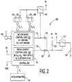
- FIG. 2is a block diagram of a second embodiment of an electronic-based stabilization system.
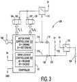
- FIG. 3is a block diagram of a third embodiment of an electronic-based stabilization system.
- FIG. 4is a side elevation overview of a first embodiment of a mechanically-based stabilization system.
- FIG. 5is a partial perspective view of a second embodiment of a mechanically-based stabilization system.
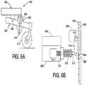
- FIGS. 6A and 6Billustrate a first embodiment of a locking member or assembly.
- FIGS. 7A and 7Billustrate a second embodiment of a locking member or assembly.
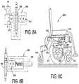
- FIGS. 8A, 8B, and 8Cillustrate a third embodiment of a locking member or assembly.
- FIG. 9illustrates a fourth embodiment of a locking member or assembly.
- FIGS. 10A, 10B, and 10Cillustrate a fifth embodiment of a locking member or assembly.
- FIGS. 11A and 11Billustrate a sixth embodiment of a locking member or assembly.
- FIGS. 12A through 121illustrate a seventh embodiment of a locking member or assembly.
- FIGS. 13-18Billustrate an eighth embodiment of a locking member or assembly.
- FIG. 19is a right side elevational view of a portion of a wheeled vehicle with an exemplary stabilization system having a self-aligning locking member.
- FIGS. 20A-20C and 21A-21Cillustrate other locking members.
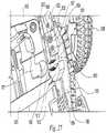
- FIGS. 22-28illustrate another exemplary wheeled vehicle with an exemplary stabilization system having a self-aligning locking member.
- a mid-wheel drive wheelchair or scooteris a vehicle used to assist those having an impaired ability to transport themselves.
- the mid-wheel drive wheelchairs and scooters of the present inventionhave at least two drive wheels that are positioned approximately below the center of gravity of the vehicle when loaded with a user. This results in a majority of the total wheelchair or scooter weight being on the two drive wheels.
- Mid-wheel drive wheelchairs and scootersalso include one or more casters for forward and rearward stability, respectively positioned forward and rearward of the drive wheels.
- One example of a mid-wheel drive wheelchaircan be found in U.S. Pat. No. 5,435,404 to Garin, which is hereby fully incorporated by reference.
- At least one motor or combination motor/gear boxis provided to drive the drive wheels.
- the motoris typically controlled by an electronic controller connected to one or more user control devices.
- the user control devicesgenerally provide selection of forward and reverse movement of the vehicle, as well as controlling the velocity or speed.
- a batterytypically supplies the controller and drive motors with an energy supply.
- Dynamic braking and an automatic park brakeare also incorporated into the vehicle. The dynamic brake allows the operator to proceed safely, even down a slope, without worrying that the vehicle will unreasonably increase in speed while going down the slope. Further, the park brake automatically engages to hold the vehicle in place when the vehicle is standing still.
- the present inventionprovides multiple embodiments of a stabilization system that provides mid-wheel drive vehicles with an anti-dive or lock out mechanism.
- the stabilization systemincludes a trigger or sensor for sensing when conditions exist that may cause the mid-wheel drive vehicle to exhibit a tipping behavior, which can be either forward or rearward, and a locking member or assembly that locks the suspension system to prevent any further tipping behavior.
- the trigger or sensoralso senses when the mid-wheel drive vehicle is no longer subject to conditions that may cause it to exhibit a tipping behavior and causes the locking member or assembly to no longer lock the suspension system.
- FIGS. 1 and 4a block diagram of a first embodiment 100 of an electronic-based stabilization system is shown and a representative mid-wheel drive wheelchair is shown, respectively.
- the mid-wheel drive wheelchairhas a frame 402 and pivot arm 404 .
- a pivotal connection 406connects frame 402 and pivot arm 404 .
- Attached to pivot arm 404is a drive wheel 410 .
- This attachmentis typically provided through a motor or motor/gear box that is attached to pivot arm 404 .
- Pivot arm 404further has a front caster 412 attached to a forward portion thereof, while the motor or motor/gear box is attached to a more distal opposite portion.
- pivot arm 404for connecting pivot arm 404 to frame 402 via pivotal connection 406 .
- a rear caster assembly 416is provided that includes a frame member 418 and caster 414 .
- a second pivot arm and assemblyis similarly provided on the opposite of the wheelchair, as shown in FIG. 5 .
- the stabilization systemtriggers a locking member or assembly whenever the summation of moments or torque about pivotal connection 406 exceeds a pre-loaded value or, in other words, causes the frame 402 of the wheelchair to tip forward.
- One of the moment arms that influences this loadingis the moment arm defined by the distance from the center of gravity Cg of the mass of the wheelchair occupant and seat 408 to pivotal connection 406 .
- the torque or moment acting on the center of gravity Cgis generally defined by: (mass of the wheelchair occupant and seat) ⁇ [(wheelchair acceleration)+(sine of the slope angle) ⁇ (acceleration of gravity)].
- the slope angleis the slope of the angle measured from a horizontal.
- the slope angleis zero (0) degrees. If the wheelchair is traveling up an incline, the slope angle may be, for example, five (5) degrees. If the wheelchair is traveling down a decline, the slope angle may be, for example, minus five ( ⁇ 5) degrees. As such, the present invention is configured to trigger the locking member or assembly sooner when traveling down declines (i.e., negative slope angle), compared to when traveling up inclines (i.e., positive slope angle).
- the system 100includes a controller 101 , dive lockout control logic 102 , and motor/brake logic 103 .
- Controller 101is any computer-based controller suitable for controlling a vehicle.
- controller 102generally has a processor, memory, and input/output components (not shown).
- Controller 101can also have electric motor drive circuitry associated therewith (not shown) that connects to drive motors 104 and 106 .
- a user input device 108such as, for example, a joystick, provides control information to the controller 101 for driving the wheelchair.
- a sensor 126is provided for sensing the force acting on the center of gravity Cg of the wheelchair occupant and seat and outputs a signal S to controller 102 .
- sensor 126can be any one of several embodiments.
- the remainder of system 100includes electronic switches 110 and 112 , nodes 114 , 118 , and 121 , diodes 116 and 120 , resistor 122 and solenoid coil 124 .
- Solenoid coil 124is part of an electronic locking member or assembly such that the state of the coil (i.e., energized or unenergized) defines the state of the locking member or assembly (i.e., locking or not locking the suspension system).
- controller 101receives driving command inputs from joystick 108 . This causes controller 101 to output voltages V.sub.L and V.sub.R and current I.sub.L and I.sub.R to the left and right motors 104 and 106 , respectively. Attached to each motor is a motor lock 105 and 107 , respectively. All the components of the system are typically powered by battery having a positive voltage potential B+ and a ground potential “Gnd.”
- the sensor 126is mounted on the wheelchair so as to generate a trigger signal S when the wheelchair is tipping forward.
- the trigger signal Sis an electronic signal. In other embodiments, this can be a mechanical signal such as that generated by a push-pull cable assembly.
- Solenoid coil 124is controlled by the state of electronic switch 112 .
- the locking member or assembly associated with solenoid coil 124is preferably in its unlocked state when solenoid coil 124 is energized and in its locked state when solenoid coil 124 is unenergized.
- the opposite configurationcan also be employed.
- Nodes 114 and 118 and diodes 116 and 120form an OR circuit that controls the state of electronic switch 112 and, hence, the energy state of solenoid coil 124 . More specifically, node 114 forms one input to the OR circuit and relates to the state of the motor brakes. For example, when the motors are being driven, the brakes disengage and motor/brake logic 103 causes node 114 to be at 5V. This, in turn, causes electronic switch 112 to close thereby energizing solenoid coil 124 and releasing the locking member or assembly from locking the wheelchair suspension. When the motors are not being driven, the brakes are engaged and motor/brake logic 103 causes node 114 to be at 0V. This causes electronic switch 112 to open, which de-energizes solenoid coil 124 thereby engaging the locking member or assembly to lock the suspension.
- Node 118forms the second input to the OR circuit and relates to input provided by sensor 126 for detecting when conditions may exist that indicate the wheelchair may start exhibiting a tipping behavior. More specifically, if sensor 126 is not indicating that conditions exist under which wheelchair may exhibit a tipping behavior, dive lockout control logic 102 interprets this state and causes node 118 to be at 5V. This, in turn, causes electronic switch 112 to close thereby energizing solenoid coil 124 and releasing the locking member or assembly from locking the wheelchair suspension. When sensor 126 senses that conditions exist for a tipping behavior, dive lockout control logic 102 interprets this state and causes node 118 to be at 0V. This, in turn, causes electronic switch 112 to open thereby de-energizing relay 124 and engaging the locking member or assembly to lock the wheelchair suspension.
- the sensor 126(of embodiment 100 ) includes an accelerometer 204 that produces an acceleration input signal A.sub.F to controller 101 .
- Accelerometer 204can be any convention accelerometer that provides an output signal that is proportional to the sensed acceleration.
- accelerometer 204can be an appropriately damped pendulum mercury switch.
- accelerometer 204can be an electronic accelerometer such model no. ADXL202 manufactured by Analog Devices of Norwood, Mass. Accelerometer 204 is preferably located on or near the wheelchair seat proximate the center of gravity Cg of the wheelchair seat and occupant.
- embodiment 200is substantially the same as embodiment 100 , except that the state of node 118 is dependent on acceleration signal A.sub.F.
- the acceleration signal A.sub.Fis compared by the dive lockout control logic 202 to a dive threshold acceleration parameter A.sub.D, which may be negative ( ⁇ A.sub.D) indicating wheelchair deceleration.
- the value of dive threshold acceleration parameter A.sub.Dcan be either calculated based on the weight of the wheelchair and occupant or determined experimentally with the actual wheelchair and a range of seat occupant weights.
- dive threshold acceleration parameter ⁇ A.sub.Dis a parameter that is used by the dive lockout control logic 202 to determine if conditions are present under which the wheelchair may exhibit a tipping behavior.
- dive lockout control logic 202determines that acceleration signal A.sub.F is more negative than dive threshold parameter ⁇ A.sub.D, it drives node 118 to 0V. This causes electronic switch 112 to open thereby de-energizing solenoid coil 124 and causing the locking member or assembly to lock the wheelchair suspension. Acceleration signal A.sub.F is negative when the wheelchair is decelerating or facing a downward slope or decline. Otherwise, node 118 is maintained at 5V thereby causing electronic switch to close. This, in turn, causes solenoid coil 124 to be energized thus releasing the locking member or assembly from locking the wheelchair suspension.
- Embodiment 300is substantially similar to embodiment 100 , except that sensor 126 includes a motor voltage and/or current sensor, which can be incorporated into controller 101 .
- controller 101can incorporate an analog-to-digital (A/D) converter circuit or can include an external A/D circuit.
- A/D circuitconverts analog signals such as, for example, voltage or current signals, to digital or binary signals for input into or interpretation by controller 101 .
- controller 101also includes dive lockout control logic 302 for interpreting these voltage and/or current signals.
- embodiment 300is substantially similar to embodiment 200 , except that dive lockout control logic 302 interprets how hard the motor is being driven and dynamically braked to determine whether the locking member or assembly will lock or release the suspension system.
- node 114behaves as earlier described.
- Node 118is driven to 0V when the wheelchair is traveling forward and there is a large amount of dynamic braking being generated by motors 104 and 106 .
- Node 118is also driven to 0V if the wheelchair is accelerating hard in the reverse direction of travel. Otherwise, node 118 is driven to 5V.
- dynamic brakinggenerally refers to the process by which a motor's windings are short-circuited when the motor is not being driven so that the residual rotational energy of the motor causes the motor to act as a generator that generates a voltage and current. By recirculating the current generated of this configuration, the motor dynamically brakes itself.
- V.sub.L, V.sub.R, I.sub.L, and I.sub.Rare the approximate terminal voltages and currents of motors 104 and 106 , respectively.
- Variable I.sub.Dis a threshold parameter representing a current level that is used to determine when the motors are being dynamically braked. The value of threshold parameter I.sub.D can be calculated based on the motor specification and weight of the wheelchair and occupant or determined experimentally based on the actual wheelchair weight and a range of seat occupant weights.
- Equation (1)causes node 118 to be driven to 0V when the wheelchair is traveling forward ((V.sub.L+V.sub.R)>0) and the motors are dynamically braking themselves ((I.sub.L+I.sub.R) ⁇ I.sub.D).
- Equation (2)also causes node 118 to be driven to 0V when the wheelchair is accelerating hard in the reverse direction ((V.sub.L+V.sub.R) ⁇ 0) and the motors are not dynamically braking themselves ((I.sub.L+I.sub.R)>I.sub.D).
- electronic switch 112opens thereby causing solenoid coil 124 to de-energize.
- De-energizing solenoid coil 124causes the locking member or assembly to lock the suspension system. Otherwise, node 118 is driven to 5V, which causes electronic switch 112 to close thereby energizing solenoid coil 124 .
- Energizing solenoid coil 124causes the locking member or assembly to unlock or release the suspension system.
- energizing solenoid coil 124can cause the locking member or assembly to unlock or release the suspension system and de-energizing solenoid coil 124 can cause the locking member to lock the suspension system.
- Push-pull cable 424has a first conduit portion attached to a bracket 430 on rear caster frame member 418 and a second portion attached to a locking member control bracket assembly 432 .
- Push-pull cable 424also has a first cable portion attached to a rear castor pivot bracket portion 428 and a second cable portion attached to a locking member control arm 422 .
- Locking member 420is pivotally connected to frame 402 and pivot arm 404 . This is accomplished through a conventional pivot assembly that includes pins or bolts extending through mounting brackets. A second similar locking member and push-pull cable are associated with a second pivot arm on the other side of frame 402 and identically configured to locking members 404 and push-pull cable 424 .
- locking member 420is preferably a lockable spring device.
- lockable gas or hydraulic springsthat include piston valve assemblies for locking the springs in a predetermined position.
- lockable gas or hydraulic springsinclude, for example, the BLOC-O-LIFT®, STAB-O-MAT®, and STAB-O-BLOC® models of gas springs as manufactured by STABILUS GMBH, Koblenz, Germany.
- arm 422is mechanically linked to the reciprocating rod that opens and closes the piston valve assembly of the locking member 404 .
- push-pull cable 424can be replaced by a limit switch designed to sense the motion of rear caster pivot bracket portion 428 and a solenoid actuator configured to act upon arm 422 upon movement of the rear caster pivot bracket portion 428 during a wheelchair tipping motion.
- a limit switchdesigned to sense the motion of rear caster pivot bracket portion 428 and a solenoid actuator configured to act upon arm 422 upon movement of the rear caster pivot bracket portion 428 during a wheelchair tipping motion.
- one or more wiresconnect the limit switch to the solenoid actuator.
- push-pull cable 424can be replaced with a plurality of mechanical linkages that provide the same effect on arm 422 .
- FIG. 5Illustrated in FIG. 5 is another alternate embodiment 500 to that FIG. 4 .
- the embodiments of FIGS. 4 and 5are substantially similar, except that the embodiment of FIG. 5 includes only one locking member 420 that is associated with both pivot arms 404 and 510 .
- a link 502is provided between the pivot arms 404 and 510 .
- Link 502has a first portion 504 that is pivotally connected to first pivot arm 404 and a second portion 506 that is pivotally connected to second pivot arm 510 .
- Link 502also has a third portion that is pivotally connected to a bottom portion of locking member 420 .
- a top portion of locking member 420is pivotally connected to frame 402 .
- a push-pull cablemechanically links locking member 420 to rear caster 414 or its parallel equivalent in the same fashion as that shown in FIG. 4 .
- the operation of embodiment 500is similar to that described for FIG. 4 , except that when locking member 420 is in the locked state, it prevents link 502 from displacement. This, in turn, prevents either pivot arm 404 or 510 from movement.
- FIGS. 6A and 6Ban embodiment 600 of a stabilization system having ratchet-type locking member or assembly 602 is shown.
- the locking member 602has a pawl member 614 , ratchet member 620 , and a solenoid actuator 608 .
- Pawl member 614 and solenoid actuator 608are rigidly fixed to frame 402 via a bracket 606 .
- Bracket 606also serves as a guide bracket for ratchet member 620 , though this function can be provided by a separate guide member.
- Solenoid actuator 608has a coil 124 , spring 612 and pin 613 .
- Pawl member 614has a first portion pivotally connected to bracket 606 and a second portion pivotally connected to pin 613 .
- Ratchet member 620has a plurality of cammed extensions 622 between which pawl member 614 is configured to engage and disengage.
- a bottom portion of ratchet member 620is pivotally connected to pivot arm 404 at connection 604 . So configured, ratchet member 620 is free to undergo reciprocating movement within the guide portion of bracket 606 as pivot arm 404 pivots about connection 406 .
- solenoid actuator 608can be controlled by any of the embodiments of FIGS. 1-4 .
- solenoid actuator 608is de-energized causing spring 612 to urge pin 613 and pawl member 614 against ratchet member 620 .
- Thiscauses pawl member 614 to be locked against ratchet member 620 so as to prevent ratchet member 620 from any further upward motion, which causes tipping of the wheelchair.
- This stateprevents the forward portion of pivot arm 404 from exhibiting any upward motion that is associated the wheelchair's tipping behavior.
- pivot arm 404is free to move in a direction that would lessen the tipping behavior of the wheelchair but not increase such behavior. If the wheelchair is not exhibiting a tipping behavior or has ceased to exhibit a tipping behavior, solenoid actuator 608 is energized causing pin 613 and pawl member 614 to disengage from ratchet member 620 . This allows pivot arm 404 to freely pivot about connection 406 . As described earlier in connection with FIGS. 4 and 5 , one or two or more locking members can be provided. Additionally, pawl member 614 can be triggered by a inertial switch or method instead of solenoid actuator 608 or one which actuates a solenoid actuator.
- FIGS. 7A and 7Ban embodiment 700 of a stabilization system having a caliper-type locking member or assembly 702 is shown.
- the locking member 702has a spring 712 , pin 714 , one or more friction plates 710 , and a linear reciprocating link 704 .
- Pin 714has a first portion connected to friction plate 710 and a second portion connected to either a solenoid actuator or push-pull cable, or equivalent, as described earlier for locking and unlocking the suspension system.
- Spring 712is located between these portions and biases pin 714 and friction plate 710 toward link 704 .
- the friction plates 710 , spring 712 , and pin 714are housed within a frame attachment 708 , which rigidly connects these components to frame 402 .
- Attachment 708also functions as a guide for link 704 so as to always maintain link 704 between friction plates 710 . This function can also be provided by a separate guide bracket.
- Link 704has a first portion that is pivotally connected to pivot arm 404 and a second portion that travels within attachment or guide 708 so as to be engagable by friction plates 710 .
- link 704exhibits a reciprocating up and down motion with respect to attachment 708 and friction plates 710 .
- two friction plates 710are provided facing each other with a gap therebetween. The space or gap exists between friction plates 710 so as to allow link 704 to freely move therethrough until such time as the friction plate 710 connected to pin 714 is moved toward link 704 and the opposing friction plate 710 . This movement causes both friction plates 710 to engage the link 704 and to lock it in position.
- embodiment 800has a locking member 804 and an actuator assembly 802 associated therewith.
- Locking member 804has a first portion 806 that is pivotally connected to pivot arm 404 and a second portion 808 that is pivotally connected to frame 402 .
- Locking member 802is a hydraulic piston assembly having a magnetic fluid. The piston within the assembly has a valve that allows the fluid to pass from one side of the piston to the other. However, when a magnetic field is brought near the proximity of the fluid, the magnetic field causes the fluid viscosity to greatly increase thereby not allowing the fluid to flow through the valve in the piston. This, in turn, locks the piston in position.
- FIG. 8AIllustrated in FIG. 8A is a first embodiment of the actuator assembly 802 .
- the assembly 802has a permanent magnet 810 that is fixed directly or indirectly to frame 802 , a solenoid coil 812 and a switch 814 .
- Solenoid coil 812can be the same component as solenoid coil 124 and switch 814 can be mechanical or electronic, as described in connection with FIGS. 1-4 .
- magnet 810causes the fluid in locking member 804 to have a very high viscosity and, hence, almost no ability to flow. This maintains locking member 804 in a locked stated thereby locking pivot arm 404 from pivoting about connection 406 .
- solenoid coil 812when solenoid coil 812 is energized by switch 814 , its magnetic field cancels with the magnetic field generated by magnet 810 and allows the fluid in locking member 812 to have a very low viscosity and, hence, the ability to flow relatively easily. This allows locking member 804 to move in accordance with the movement of pivot arm 404 about pivotal connection 406 . Hence, if power is lost, magnet 810 provides a failsafe condition which automatically locks locking member 804 . Therefore, it can be seen that when the wheelchair exhibits a tipping behavior, solenoid coil 812 is de-energized causing locking member 804 to lock pivot arm 404 . When no tipping behavior is exhibited by the wheelchair, solenoid coil 812 is energized and locking member 804 is not in its locked state.
- FIG. 8BIllustrated in FIG. 8B is a second embodiment of an actuator assembly 802 .
- This embodimenthas the earlier described push-pull cable 424 spring-loaded against magnet 810 .
- magnet 810moves either toward or away from the locking member 804 so as to either bring its magnetic field in operative proximity to the locking member or away from the locking member.
- push-pull cable 424provides for linear mechanical movement upon a tipping condition of the wheelchair. By having push-pull cable 424 fixed to magnet 810 , the linear movement of push-pull cable 424 can be used to move magnet 810 closer to locking member 804 so as place it in its locked state, or away from locking member 804 so as to place it in its unlocked state.
- Springis also provided so as to bias magnet 810 towards locking member 804 ensuring that locking member 804 is in its locked state should push-pull cable 424 break.
- an embodiment 900 of a suspension system having a sprag clutch locking member 902allows rotational movement in one direction and not in the other.
- locking member 902can be a bi-directional clutch. Bi-directional clutches allow their input to drive their output in either rotational directions, but do not allow the output to drive the input.
- FIGS. 10A, 10B and 10Cillustrate one embodiment 1000 of a suspension system having a direct acting pin locking member 1002 .
- Locking member 1002extends and retracts its pin 1008 so as to enter one of a plurality of slots or apertures in locking bracket 1004 .
- locking member 1002has a spring-loaded pin 1008 and an actuator cable 1006 .
- actuator cable 1006can be a push-pull cable, as described earlier.
- actuator cable 1006can be an electric cable that carries the signal that actuates the solenoid.
- the locking member 1002can also be pneumatically actuated through known means. So configured, locking member 1002 is affixed to the frame 402 through mounting brackets (not shown) or its housing.
- Locking bracket 1004is affixed to pivot arm 404 and moves therewith.
- locking bracket 1004preferably includes an arcuate shape so as to maintain alignment with locking member 1002 as pivot arm 404 pivots or rotates.
- Locking bracket 1004includes a plurality of apertures or slots that disposed along the bracket's arcuate body. The apertures can be any shape such that pin 1008 can enter thereinto.
- Pivot arm 510(not shown) would have a similar suspension system.
- FIG. 10CIllustrated in FIG. 10C is detail of an alternative embodiment of pin 1008 . More specifically, FIG. 10B shows pin 1008 having flat head portion at its engaging distal end. FIG. 10C shows an embodiment of pin 1008 having a cammed surface 1010 at its engaging distal end. Cammed surface 1010 is provided so that when pin 1008 is engaged in locking bracket 1004 , pivot arm 404 can pivot in the downward direction. This causes a ratcheting effect where cammed surface 1010 causes pin 1008 to retract under the downward tendency (i.e., clockwise rotation) of pivot arm 404 . However, configured as such, pin 1008 does not allow a corresponding ratcheting in the upward direction (i.e., counter-clockwise rotation) of pivot arm 404 .
- pin 1008 of locking member 1002is spring-engaged into an aperture of locking member 1004 .
- Actuator cable 1006when active, causes pin 1008 to retract from locking bracket 1004 . In this manner, a failsafe configuration is provided should actuator cable 1006 fail.
- the triggering of locking member 1002can be by any of the embodiments described in FIGS. 1-4 .
- locking member 1102has an actuator member 1108 .
- Actuator member 1108can be a spring-loaded pin, solenoid driven pin, or a mechanical clamp (not shown).
- Actuator member 1108is actuated by an actuator cable 1110 , which can be an electric cable, pneumatic hose, or push-pull cable.
- Locking member 1102further has a housing 1112 that includes a spring 1113 that axially receives a locking rod or tube 1106 therein. Locking member 1102 is rigidly affixed to frame 402 with mounting brackets (not shown).
- Spring 1113is a coil spring that includes first and second extensions 1114 and 1116 , respectively. Spring 1113 is arranged so that when extensions 1114 and 1116 are not acted upon by any force, spring 1113 is tightly coiled around locking rod or tube 1106 so as to prevent any axially movement of locking rod or tube 1106 within spring 1113 . Since locking rod or tube 1106 has one of its distal ends pivotally fixed to pivot arm 404 at 1104 , pivot arm 404 is also locked from any rotational movement. In this manner, a failsafe configuration is provided should actuator cable 1110 fail.
- the triggering of locking member 1102can be by any of the embodiments described in FIGS. 1-4 .
- extensions 1114 and 1116are acted upon by a force.
- extensions 1114 and 1116can be configured so that either a force that brings them closer together or a force that brings them farther apart causes spring 1113 to become loosely coiled around locking rod or tube 1106 .
- spring 1113allows locking rod or tube 1106 to axially move therein. This, in turn, allows pivot arm 404 to pivot about its connection at 403 .
- Pivot arm 510(not shown) would have a similar suspension system.
- FIGS. 12A, 12B, 12C, 12D, and 12Ean embodiment of a suspension system 1200 having an linear locking member 1202 is shown.
- FIG. 12Ashows the suspension system on a level driving surface.
- FIG. 12Billustrates the suspension system wherein front caster 412 is lifted by the suspension off of the driving surface.
- FIG. 12Cshows the suspension system wherein front caster 412 has been lowered onto a lower driving surface.
- FIG. 12Dillustrates the suspension 1200 with the drive wheel removed and
- FIG. 12Eis a partial perspective view of the suspension 1200 .
- Suspension system 1200further includes a four-bar pivoting assembly that includes pivot arms 1204 A and 1204 B, caster head tube bracket 1214 , and frame 402 .
- Bracket 1208while a separate component, can be considered as part of frame 402 .
- Pivot arms 1204 A and 1204 Bare pivotally connected to frame 402 via pivotal connections 1206 A and 1206 B.
- Pivot arms 1204 A and 1204 Bare also pivotally connected caster head tube bracket 1214 via pivotal connections 1207 A and 1207 B.
- Locking member 1202is shown having a first pivotal connection 1210 to pivot arm 1204 B and a second pivotal connection 1212 to bracket 1208 . So connected locking member is under the influence of pivot arms 1204 A and 1204 B. It should be noted that locking member 1202 pivotal connection 1210 can be alternatively located on pivot arm 1204 A or caster head tube bracket 1214 , as well.
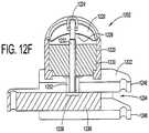
- FIG. 12Fillustrates a partial cross-section of locking member 1202 .
- Locking member 1202has a first housing 1220 and a second housing 1222 .
- First housing 1220retains therein a electric solenoid actuator 1230 that includes a coil and a plunger 1232 biased by leaf spring 1228 .
- a cover 1226is provided on housing 1220 that has an aperture that allows plunger 1232 to at least partially project there from.
- the projecting portion of plunger 1232has a pivotable lever 1224 connected thereto. Pivoting of the lever through manual actuation causes plunger 1232 to move without the need for electrical energy.
- Second housing 1222which is attached to first housing 1220 includes a channel or passage 1234 therein.
- a rod member 1236moves within passage 1234 and includes a notch 1238 therein.
- Notch 1238is configured such that when plunger 1232 is biased into passage 1234 , plunger 1232 will come into locking engagement with notch 1238 and remain there until withdrawn.
- notch 1238can be replaced by a ratcheting tooth configuration similar to that shown in FIG. 6B .
- Rod member 1236includes at one distal end an aperture 1240 , which accepts a pin or similar fastener in forming pivotal connection 1210 .
- second housing 1222includes at one distal end first and second extensions 1246 and 1248 , each of which have aligned apertures 1244 .
- Extension 1246 and 1248accept in the space between them a pivoting bracket member that is used secure the locking member 1202 to bracket 1208 .
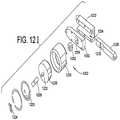
- locking member 1202Illustrated in FIG. 121 is an exploded perspective view of locking member 1202 .
- locking member 1202further includes a block 1252 that is affixed to plunger 1232 .
- Block 1252increases the effective cross-section of plunger 1238 which is responsible for locking engagement with rod member 1236 .
- Housing 1222has a cover portion 1250 that includes an aperture 1254 having substantially the same shape as block 1252 and allows block 1252 to reciprocate there within.
- locking member 1202locks the suspension system when, for example, the vehicle is not moving and motor parking brake or lock is actuated. This creates a stable platform for the user to transport in and out of the vehicle or wheelchair.
- Locking member 1202is also preferably configured to lock suspension system when the is no power or the power system has been shut off. This is achieved by always biasing plunger 1232 into locking engagement with rod member 1236 . Upon power-up, solenoid 1230 is actuated and plunger 1232 is withdrawn from the locking engagement.
- locking member 1202can be alternatively located among a plurality of positions the on suspension system 1200 .
- locking member 1202can be attached between the frame 402 and upper pivot arm 1204 A, attached between the upper and lower pivot arms 1204 A and 1204 B, or between any two components of the described four-bar pivoting assembly.
- locking member 1202can be triggered by any of the mechanisms described earlier electrical or mechanical.
- FIG. 13Illustrated in FIG. 13 is an eighth embodiment 1300 of a locking assembly of the present invention.
- the locking assemblyhas a motor rack bracket 1314 , first ratchet 1320 , second ratchet 1322 and a spring mount 1318 . So configured, the locking assembly is shown mounted on the vehicle frame 402 , which includes a four-bar linkage pivoting front caster assembly.
- the four-bar linkage pivoting caster assemblyincludes first and second linkages 1302 and 1304 .
- a third linkageis provided by frame 402 and its extension in the form of frame bracket 1306 .
- a fourth linkageis provided by caster head tube assembly 1311 .
- First linkage 1302is pivotally connected to frame 402 at pivot 1310 and second linkage 1304 is pivotally connected to frame 402 at pivot 1308 .
- second linkage 1304is pivotally connected to frame 402 at pivot 1308 .
- the locking assembly's motor rack bracket 1314is physically connected to first linkage 1302 through a motor/gearbox mount 1312 .
- the connectioncan also be made directly if desired.
- a gearbox 1316is also shown connected to motor/gearbox mount 1312 .
- First ratchet 1320is attached to motor rack bracket 1314 at an end portion opposite the connection to first linkage 1302 . So configured, motor rack bracket 1314 pivots when first linkage 1302 pivots.
- the locking assembly's spring mount 1318is pivotally connected to frame 402 through clevis 1325 .
- the second ratchet 1322is affixed to a side portion of the spring mount 1318 .
- Clevis 1325 and its pivotal connection 1324allow spring mount 1318 to pivot with respect to frame 402 .
- pivotal connections 1324 and 1332 and devises 1325 and 1334can be combined into a single integrated clevis and pivotal connection.
- clevis 1325can be eliminated and pivotal connection 1324 integrated into pivotal connection 1332 .
- an elastic membersuch as, for example, a spring
- spring mount 1318would include a bearing surface for bearing against one end of the spring and a spring holder.
- This configurationcan take the form of pin or bolt at least partially received within the spring, which such configuration may additionally be at least partially received within a recess in spring mount 1318 .
- the other end of the springwould bear against a bearing surface on frame 402 .
- such a configurationcan be reversed between the spring mount 1318 and frame 402 .
- a rear caster mount 1328pivotally connects rear caster 414 to frame 402 . More specifically, rear castor mount 1328 has an extension 1330 that includes a first distal end pivotally connected to clevis 1334 and a second distal end connected to a head tube portion for mounting the rear caster 414 .
- a spring 1326is situated between rear castor mount 1328 and spring mount 1318 . Spring 1326 compresses when rear caster mount 1328 pivots clockwise as shown in FIG. 13 toward frame 402 . In this manner, spring 1326 provides a degree of suspension for the rear caster mount 1328 .
- spring 1326can be replaced by a non-resilient member resulting in spring mount 1318 and rear caster mount 1328 being an integrated and rigid structure.
- spring mount 1318 and rear caster mount 1328being an integrated and rigid structure.
- such an integrated structurecan employ a single integrated pivot at pivotable connection 1332 , as opposed to pivotable connections at 1324 and 1332 .
- first and second ratchets 1320 and 1322engage each other in one of a plurality of releasable locking states whenever rear caster 414 is about to be lifted from its supporting surface. This condition occurs whenever the frame 402 pivots or tilts forward toward front caster 412 .
- first and second pivot arm linkages 1302 and 1304correspondingly pivot about their pivotal connection 1310 and 1308 , respectively. Any pivotal movement of linkages 1302 or 1304 translates to pivotal movement of motor rack bracket 1314 and first ratchet 1320 by virtue of their mechanical coupling.
- rear caster mount 1328pivots about its pivotal connection at 1332 causing spring mount 1318 to pivot about its pivotal connection at 1324 so that second ratchet 1322 comes into contact with first ratchet 1320 .
- pivot arm linkages 1302 and 1304are releasably locked thereby locking frame 402 from any additional pivoting or tilting forward.
- rear caster mount 1328pivots clockwise causing spring mount 1318 to pivot clockwise and disengage second ratchet 1322 from first ratchet 1320 . This releases first and second pivot arm linkages 1302 and 1304 from their locked state so that they may once again freely pivot.
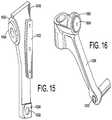
- FIGS. 14 through 16further illustrate the locking assembly and its components in perspective views.
- FIG. 15is a perspective view of the spring mount 1318 .
- Spring mount 1318further has a surface 1502 for bearing against spring 1326 and a structure 1504 holding spring 1326 in position relative spring mount 1318 .
- FIG. 16is a perspective view of rear caster mount 1328 .
- Rear caster mount 1328further has a surface 1602 for bearing against spring 1326 and a structure 1604 for holding spring 1326 in position relative to rear caster mount 1328 .
- Second ratchet 1322has a body 1702 that includes a plurality of mounting apertures 1706 that are used to fasten it to spring mount 1318 .
- Body 1702also includes a toothed surface 1704 .
- the toothed or undulating nature of surface 1704is configured to provide a plurality of releasable locking states when engaged with first ratchet 1320 .
- the number of releasable locking statescan vary from 1 to 2 or more.
- surface 1704can have a single tooth any where along its length for engagement with first ratchet 1320 .
- surface 1704can have first and second teeth disposed at the proximal ends of its curved or arcuate length. This configuration provides two locking states that permit a range of tipping motion by the frame, but place limits on the range. In yet another embodiment, surface 1704 can have first and second teeth disposed at the proximal ends of its length and at least one tooth somewhere intermediate the ends. This configuration provides two locking states that permit a range of tipping motion by the frame, but which place limits on the range, and a third discrete locking state intermediate the limits. As further illustrated in FIGS. 17A and 17B , surface 1704 is slightly curved or arcuate to compensate for the nature of the pivotal motion first ratchet 1320 experiences as it pivots with pivot arm linkages 1302 and 1304 .
- FIGS. 18A and 18Bare elevational and perspective views, respectively, of first ratchet 1320 .
- First ratchet 1320has a body 1804 that includes a plurality of mounting apertures 1806 , which are used to fasten first ratchet 1320 to motor rack bracket 1314 .
- Body 1804also has a toothed surface 1804 , which is slightly curved or arcuate to accommodate the pivotal motion experienced by second ratchet 1322 .
- the tooth configuration of surfaces 1804 and 1704are configured such that relative motion between first and second ratchets 1320 and 1322 is more or less permitted in one direction, but motion in the opposite direction is impeded.
- the toothed or undulating nature of surface 1804is configured to provide a plurality of releasable locking states when engaged with first ratchet 1320 .
- the number of releasable locking statescan vary from 1 to 2 or more.
- surface 1804can have a single tooth any where along its length for engagement with second ratchet 1322 .
- surface 1804can have first and second teeth disposed at the proximal ends of its curved or arcuate length. This configuration provides two locking states that permit a range of tipping motion by the frame, but place limits on the range.
- surface 1804can have first and second teeth disposed at the proximal ends of its length and at least one tooth somewhere intermediate the ends. This configuration provides two locking states that permit a range of tipping motion by the frame, but which place limits on the range, and a third discrete locking state intermediate the limits.
- one or more locking membersmay be movably connected to a respective pivot arm or assembly permitting one or both locking members to automatically align with the other locking member as they engage to lock the pivot arms or assemblies to limit further movement of the frame in at least one direction.
- One or more of such self-aligning locking membersmay permit solid engagement between locking members during much of the life of the vehicle, even as components of the vehicle wear and/or are deformed over time or as a result of collisions.
- the self-aligning locking member(s)may optionally be “floating” (e.g., freely movable in at least one direction or orientation) with respect to a respective pivot arm or assembly.
- the self-aligning locking member(s)may optionally include positional memory such that the relative position of the movable locking member(s) during an engagement with the other locking member with respect to at least one orientation or direction will be maintained after disengagement, but will also permit the movable locking member(s) to self-align in that direction for the next engagement, if necessary.
- a positional memorymay be provided by a biasing member (e.g., a spring or a plastic material) operatively connected to bias the locking member against a surface to provide positional memory to the locking member relative to its respective assembly.
- first ratchet 1320may be movably connected to motor rack bracket 1314 and/or second ratchet 1322 may be movably connected to spring mount 1318 .
- Thismay be accomplished, for example, by having any one or more bores used to fasten first ratchet 1320 to motor rack bracket 1314 and/or fasten second ratchet 1322 to spring mount 1318 be formed as slots or formed as bores significantly larger than fasteners passing therethrough.
- fasteners movably connecting the first ratchet 1320 to the motor rack bracket 1314 and/or fasteners movably connecting the second ratchet 1322 to the spring mount 1318may be shoulder screws that when mounted permit a gap between the first ratchet 1320 and the motor rack bracket 1314 and/or a gap between the second ratchet 1322 and the spring mount 1318 , which permits significant freedom of movement of the first ratchet 1320 and/or second ratchet 1322 .
- the first ratchet 1320 and/or second ratchet 1322may have positional memory (e.g., provided by a spring or other biasing member) in any one or more directions or orientations and may be “floating” in any one or more directions or orientations, as discussed herein.
- positional memorye.g., provided by a spring or other biasing member
- one or more pivot arms or assembliesmay have an associated link pivotally connected to the frame, operatively connected to at least one pivot arm, and operatively connected to the associated locking member.
- a linkmay cooperate with the at least one pivot arm to cause the first locking member to engage the second locking member responsive to movement of the frame relative to at least one of the first and second assemblies.
- the use of such a linkmay permit a relatively wide spacing between the locking members, e.g., spaced apart by 3 ⁇ 8 of an inch or more (e.g., a half-inch or more) when the vehicle is at rest on a flat, level surface.
- Such a linkmay also permit exaggerated movement of the locking members responsive to movement of the at least one pivot arm, e.g., responsive to a specific angular movement of the pivot arm causing a greater angular movement of the link and perhaps other links to move corresponding locking members toward each other, which may permit greater sensitivity.
- the geometry of the locking membersmay be such that one locking member is longer than the other and has a concave locking surface. Any combination of any two or more of these additional features—self-aligning locking members, a link, and/or different geometry—may be combined in a vehicle.
- FIG. 19a portion of another exemplary wheeled vehicle is shown as having a stabilization system with a self-aligning locking member, a link, and locking members with different geometry.
- This exemplary embodimentincludes an “anti-dive” stabilization system or “stability lock” that works in combination with the frame of the wheelchair to prevent the chair from tipping over in a forward direction under certain circumstances.
- FIG. 19shows an exemplary suspension for a wheeled vehicle, comprising a frame 1911 , a first assembly movably connected to the frame 1911 , a second assembly movably connected to the frame 1911 , a first locking member 1930 movably connected to the first assembly and a second locking member 1912 connected to the second assembly.
- FIGS. 20A-20Cshow various views of locking member 1912 , which has a generally concave shape at toothed surface 1913 that engages the other locking member 1930 .
- FIGS. 20A-20Cshow various views of locking member 1912 , which has a generally concave shape at toothed surface 1913 that engages the other locking member 1930 .
- 21A-21Cshow various views of locking member 1930 , which is movably connected to the first assembly.
- the second assembly-is shown as having an associated link 1914 that is pivotally connected to the frame 1911 , operatively connected to pivot arm 2102 , and operatively connected to the locking member 1912 .
- Such a link 1914cooperates with the at least one pivot arm 2102 to cause the locking members 1912 , 1930 to engage each other responsive to movement of the frame 1911 relative to at least one of the first and second assemblies.
- the suspension of FIG. 19may be used with an electric wheelchair, such as the Invacare M94 wheelchair or the Invacare TDX wheelchair (Invacare Corporation, Elyria, Ohio), both of which utilize frames that include multiple pivot points.
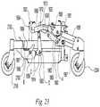
- FIGS. 22-28various views of a wheelchair base having the suspension of FIG. 19 are shown. As shown in these figures, this embodiment includes a self-aligning “anti-dive” stabilization system 1910 .
- FIGS. 22-28the upper portion of the exemplary wheelchair, including the seat and outer shroud, has been removed to better show relevant structural components.
- FIG. 22is a semi-exploded, front-right-top isometric view of the exemplary wheelchair base, with a motor, gear box, and drive wheel exploded to show certain relationships between various components.
- the exemplary wheelchair base of FIGS. 22-28comprises a frame 1911 .
- frame 1911includes left and right side portions 1950 , a front portion 1951 , a rear portion 1952 , shroud mounting brackets 1954 , and a front support bracket 1955 .
- First and second assembliesare pivotally connected to the left and right sides of frame 1911 respectively, and each assembly includes an associated surface-engaging portion.
- the assembliescomprise front pivot arms 1956 and rear pivot arms 2102 .
- the front pivot arms 1956each have an associated front caster 2104 and the rear pivot arms 2102 each have an associated rear caster 2100 .
- the front pivot arms 1956 and the rear pivot arms 2102are both pivotally connected to frame 1911 to increase overall maneuverability when the wheelchair travels across uneven surfaces or encounters street to curb interfaces or steps.
- the various attachments or connections described hereinmay accomplished with appropriate mounting screws, shoulder screws or similar attachment means, or by using other methods and devices known and accepted by those skilled in the art. Certain components are attached to one another by known welding techniques.
- a swing arm bracket 1960is used to attach each pivot arm 1956 to frame 1911 at pivot point A.
- Each pivot arm 1956may have an associated stabilization bar 1957 pivotally attached to the frame below and substantially parallel to the pivot arm 1956 to help keep front caster 2104 in a substantially vertical position as the pivot arm 1956 pivots about point A when the wheelchair is in use. This configuration is known as a “four bar linkage.”
- a motor bracket 1962may be attached to or formed as part of each front pivot arm 1956 .
- an electric motor 1990may be mounted on motor bracket 1962 .
- a drive wheel 1980may be mounted on each motor 1990 by attaching the drive wheel 1980 to axle 1992 of the motor or an associated gear box.
- the motors 1990are operated by an electronic controller which is connected to one or more user control devices (not shown in the Figures).
- the user control devicesgenerally provide selection of forward and reverse movement of the vehicle, as well as controlling the vehicle's velocity or speed.
- a battery 1972is seated in tray 1963 , held in position (kept from sliding from side to side) with battery brackets 1959 , and secured with a strap.
- the battery 1972typically supplies the various electric components with an energy supply.
- each of the stabilization systems 1910is installed between a drive wheel 1980 and the portion of base assembly 1911 that supports the electronic components of the wheelchair (see FIG. 27-28 ) and does not interfere with the placement or operation of other system components such as wire wrap 1970 , battery 1972 , charger 1974 , battery handle 1976 and terminal covers 1977 and 1978 .
- the drive wheels 1980may be positioned relative to the frame 1911 so that most (e.g., greater than 50%) of the weight of the user of the wheelchair is directly over the drive wheels 1980 .
- Each front pivot arm 1956may operate independently of the other front pivot arm and each allows its associated front caster 2104 and drive wheel 1980 to move with the pivot arm 1956 as the pivot arm pivots about point A when the wheelchair moves across an uneven surface.
- each rear pivot arm 2102may be pivotally attached to each side frame portion 1950 at the rear portion of frame 1911 .
- Each rear pivot arm 2102is operatively connected to a frame-mounted pivot bracket 1958 , which allows rear pivot arm 2102 to pivot around pivot point B.
- a tube-is welded to each rear pivot arm 2102 to confer lateral stability to the arm. If the wheelchair tips forward, each rear pivot arm 2102 will drop (i.e., rotate counterclockwise around pivot point B from the perspective of FIGS. 19 and 23-24 ) and each rear caster 2100 will drop or move in a downward direction.
- a stope.g., a plastic pad 1969
- a reinforcement flange 1967adds structural stability to the two sections of each rear pivot arm 2102 .
- each rear pivot arm 2102pivots independently of the other rear pivot arm when the wheelchair moves across an uneven surface.
- self-aligning stabilization system 1910comprises, on each side of the wheelchair, a locking apparatus.
- Each locking apparatusfurther includes a pivoting locking member 1912 having a toothed surface 1913 and a floating locking member 1930 having a toothed surface 1931 . Toothed surfaces 1913 and 1931 engage one another under certain operating conditions to prevent the wheelchair from tipping over in a forward direction, as discussed in more detail below.
- each locking apparatus of stabilization system 1910includes a pivoting locking member 1912 , also referred to as a “pivot rack” connected to or mounted on each side of the outer portion of the frame, and a floating locking member 1930 , also referred to as a “motor rack,” connected to or mounted on each of the front pivot arms 1956 .
- Each of these locking membersincludes a substantially solid body manufactured from metal or other suitably rigid and durable material that includes on one of its sides a toothed or ratcheted surface. When properly installed, the toothed surfaces of each locking member face one another and when stabilization system 1910 is in operation, these teeth engage one another or “lock” together to prevent further movement the components to which the locking members are attached.
- each pivot rack 1912typically includes an elongated piece of metal having slightly curved or arced front and rear edges (see FIG. 21A-C ).
- the toothed edge of pivot rack 1912is slightly concave and includes the aforementioned ratchets or teeth.
- the toothed edge 1913 of pivot rack 1912has a cross-sectional shape substantially like a section of a hypothetical circle, with the radius of the hypothetical circle being approximately the same length as a line segment (not shown) extending from a point (not shown) on pivot point A to a point (not shown) on the toothed surface 1932 of the other locking member 1930 .
- pivot rack 1912is attached to pivoting link 1914 with screws 1916 and 1918 .
- Pivot rack 1912may be rigidly attached to pivoting link 1914 .
- pivot rack 1912may be movably attached to pivoting link 1914 to provide additional self-alignment. This may be accomplished, for example, by having any one or more bores used to fasten pivot rack 1912 be formed as slots or formed as bores significantly larger than fasteners passing therethrough.
- the pivot rack 1912may have positional memory (e.g., provided by a spring or other biasing member) in any one or more directions or orientations and may be “floating” in any one or more directions or orientations, as discussed herein.
- Pivoting link 1914is pivotally attached to the frame 1911 at pivot point D via fastener 1920 and operatively connected to rear pivot arm 2102 at point C via fastener 1922 .
- pivot link 1914pivots about pivot point D, causing pivot rack 1912 to move into or out of contact with motor rack 1930 .
- a rack bracket 1932is utilized for attaching each motor rack 1930 to each front pivot arm 1956 .
- motor rack 1930Similar to pivot rack 1912 , and as previously described, one side of motor rack 1930 includes a series of ratchets or teeth that engage the teeth on the pivot rack 1912 when both components are properly oriented and stabilization system 1910 is in operation.
- motor rack 1930is movably attached to rack bracket 1932 by shoulder screws 1934 , 1936 fastened through bracket 1932 to threaded bores 2134 , 2136 ( FIGS. 21A-21B ) in motor rack 1930 .
- Slot 1939provides the motor rack 1930 with the ability to move laterally to some extent (i.e., the ability to rotate back and forth about a pivot point created by shoulder screw 1934 ).
- a washer 1937 between shoulder screw 1936 and bracket 1932provides a larger sliding surface as the motor rack 1930 moves back and forth, and provides a desired angle of the motor rack 1930 relative to the other locking member 1912 .
- Mounting motor rack 1930 to rack bracket 1932 in the described mannerallows motor rack 1930 to “float” as it hangs off of the bracket 1932 to which it is mounted.
- a biasing member or compression spring 1938is mounted between motor rack 1930 and bracket 1932 inside a bore and confers a degree of positional memory to motor rack 1930 .
- spring 1938biases the motor rack 1930 against a surface of the bracket 1932 so that the relative position of the motor rack 1930 during an engagement with the other locking member 1912 with respect to slot 1939 will be maintained after disengagement, and the motor rack 1930 also remains movably connected to the bracket 1932 permitting the motor rack 1930 to self-align in that slot for the next engagement, if necessary.
- the motor rack 1930is free to move up (e.g., rotate up) against the spring with each engagement with the other locking member 1912 and move down (e.g., rotate down) with each disengagement with the other locking member 1912 via the freedom of movement provided by shoulder screw 1934 .
- motor rack 1930is shown in the figures as being mounted from its top, motor rack 1930 (and pivot rack 1912 ) may be mounted in a manner other than as specifically shown.
- motor rack 1930may be movably mounted from its side via a bore and a slot and/or a pair of slots.
- pivot rack 1912 and motor rack 1930are triggered to engage each other whenever rear caster 2100 is lifted from (or about to be lifted from) its supporting surface (i.e., when one or both of the rear casters 2100 are “unloaded”), such as when the wheelchair's user leans significantly forward or perhaps on certain surfaces. That is, motion of the frame 1911 relative to the rear pivot arm 2102 permits the caster-end of the rear pivot arm to drop under the force of gravity. From the perspective of FIGS. 19, 23, and 24 , the rear pivot arm 2102 drops (i.e., rotates counterclockwise in those figures) responsive to being unloaded. Right rear pivot arm in FIG. 19 is shown as having dropped, causing right pivot rack to move forward to engage right motor rack.
- pivot link 1914is pivotally connected to the frame at pivot point D and connected to the rear pivot arm at pivot point C.
- pivot link 1914rotates in an opposite direction about its pivotal connection at pivot point D so that the pivot rack 1912 at the end of pivot link 1914 comes into contact with and engages motor rack 1930 .
- pivot rack 1912engages motor rack 1930
- the front pivot arm 1956 and rear pivot arm 2102engage, which prevents any additional motion of the frame 1911 relative to the front pivot arm 1956 in that direction, which will tend to prevent any further tipping in that direction.
- the pivot rack 1912disengages the motor rack 1930 , which permits the front pivot arm 1956 to once again freely pivot about pivot point A. More specifically, motion of the frame 1911 relative to the rear pivot arm 2102 in the opposite direction causes the pivot link 1914 to move in the opposite direction, which causes pivot rack 1912 to disengage from motor rack 1930 , which permits the front pivot arm 1956 to freely pivot about pivot point A.
- the motor rack 1930is essentially self-aligning with respect to the pivot rack 1912 . Such self-alignment is the result of the movable connection between motor rack 1930 and the front pivot arm 1956 via the bracket 1932 .
- the motor rack 1930has freedom of motion in several directions (the motor rack 1930 is capable of a certain degree of lateral rotation and vertical freedom of movement relative to front pivot arm 1956 (and ultimately freedom of movement relatively to pivot rack 1912 )).
- This self-aligning characteristicmay help compensate for various factors, such as component wear patterns, user weight, deformations as a result of collisions, and other factors, any one or more of which may cause the pivot rack 1912 and motor rack 1930 to be horizontally offset from nominal alignment and/or non-coplanar and/or vertically offset from nominal alignment.
- Some overlap between the two racks 1912 , 1930will permit self-alignment of the motor rack 1930 relative to the pivot rack 1912 and perhaps result in sufficient overlap between the two racks 1912 , 1930 to help prevent tipping, as discussed above.
- the ratcheted or toothed side of the pivot rack 1912is significantly longer than that of the motor rack 1930 , thereby providing multiple engagement points along its length (see FIG. 25 ).
- the relative vertical alignment of the two componentsneed not be exact for effective engagement of the pivot rack 1912 and the motor rack 1930 . Accordingly, precise lengthwise and widthwise alignment is not required for effective engagement or “locking” of these components. Additionally, in the exemplary embodiment shown, the motor rack 1930 and the pivot rack 1912 may be spaced further apart than other embodiments of this invention, e.g., spaced apart by about a half-inch or more.
- pivotal connectionscan be made of any number of structures including bearing assemblies, pins, nuts and bolts, and frictionless sleeve assemblies.
- springs or shock absorberscan be added between pivoting and non-pivoting components to limit, dampen, or somewhat resist the pivotal motions of these components.
- a brake-disc locking mechanismcould be integrated into pivotal connection 406 that locks pivotal connection 406 from rotation when actuated and freely allows pivotal motion about connection 406 when not actuated. Therefore, the invention, in its broader aspects, is not limited to the specific details, the representative apparatus, and illustrative examples shown and described. Accordingly, departures can be made from such details without departing from the spirit or scope of the applicant's general inventive concept.
Landscapes
- Engineering & Computer Science (AREA)
- Mechanical Engineering (AREA)
- Health & Medical Sciences (AREA)
- Life Sciences & Earth Sciences (AREA)
- Animal Behavior & Ethology (AREA)
- General Health & Medical Sciences (AREA)
- Public Health (AREA)
- Veterinary Medicine (AREA)
- General Engineering & Computer Science (AREA)
- Physics & Mathematics (AREA)
- Electromagnetism (AREA)
- Handcart (AREA)
Abstract
Description
Claims (20)
Priority Applications (1)
| Application Number | Priority Date | Filing Date | Title |
|---|---|---|---|
| US16/726,562US11213441B2 (en) | 2002-10-25 | 2019-12-24 | Suspension for wheeled vehicles |
Applications Claiming Priority (10)
| Application Number | Priority Date | Filing Date | Title |
|---|---|---|---|
| US42117802P | 2002-10-25 | 2002-10-25 | |
| US10/643,010US6851711B2 (en) | 2002-08-16 | 2003-08-18 | Vehicle having an anti-dive/lockout mechanism |
| US10/695,045US7083195B2 (en) | 2002-10-25 | 2003-10-27 | Suspension with releasable locking system |
| US11/077,483US7293801B2 (en) | 2003-08-18 | 2005-03-10 | Self-stabilizing suspension for wheeled vehicles |
| US11/472,509US8534679B2 (en) | 2002-10-25 | 2006-06-20 | Suspension for wheeled vehicles |
| US13/970,794US8833774B2 (en) | 2002-10-25 | 2013-08-20 | Suspension for wheeled vehicles |
| US14/486,766US9364377B2 (en) | 2002-10-25 | 2014-09-15 | Suspension for wheeled vehicles |
| US15/151,929US9925100B2 (en) | 2002-10-25 | 2016-05-11 | Suspension for wheeled vehicles |
| US15/935,538US10512572B2 (en) | 2002-10-25 | 2018-03-26 | Suspension for wheeled vehicles |
| US16/726,562US11213441B2 (en) | 2002-10-25 | 2019-12-24 | Suspension for wheeled vehicles |
Related Parent Applications (1)
| Application Number | Title | Priority Date | Filing Date |
|---|---|---|---|
| US15/935,538DivisionUS10512572B2 (en) | 2002-10-25 | 2018-03-26 | Suspension for wheeled vehicles |
Publications (2)
| Publication Number | Publication Date |
|---|---|
| US20200206047A1 US20200206047A1 (en) | 2020-07-02 |
| US11213441B2true US11213441B2 (en) | 2022-01-04 |
Family
ID=79166222
Family Applications (1)
| Application Number | Title | Priority Date | Filing Date |
|---|---|---|---|
| US16/726,562Expired - LifetimeUS11213441B2 (en) | 2002-10-25 | 2019-12-24 | Suspension for wheeled vehicles |
Country Status (1)
| Country | Link |
|---|---|
| US (1) | US11213441B2 (en) |
Cited By (3)
| Publication number | Priority date | Publication date | Assignee | Title |
|---|---|---|---|---|
| US11388859B2 (en)* | 2019-01-03 | 2022-07-19 | Ls Mtron Ltd. | Auxiliary wheel for lawn mower |
| US20230191863A1 (en)* | 2021-12-22 | 2023-06-22 | Futaijing Precision Electronics (Yantai) Co., Ltd. | Rocking arm structure providing additional-wheel support and device having the same |
| US20240326539A1 (en)* | 2023-03-29 | 2024-10-03 | Dr. Ing. H.C.F. Porsche Aktiengesellschaft | Motor vehicle |
Families Citing this family (5)
| Publication number | Priority date | Publication date | Assignee | Title |
|---|---|---|---|---|
| EP2111203B1 (en) | 2007-02-08 | 2011-01-05 | Invacare Corporation | Wheelchair suspension |
| CA2911675C (en)* | 2007-02-14 | 2018-09-18 | Invacare Corporation | Stability control system |
| EP2485698B1 (en) | 2009-10-09 | 2017-05-17 | Invacare Corporation | Wheelchair suspension |
| AU2013221283B2 (en) | 2012-02-15 | 2017-05-25 | Invacare Corporation | Wheelchair suspension |
| AU2021228590A1 (en) | 2020-02-25 | 2022-09-22 | Invacare Corporation | Wheelchair and suspension systems |
Citations (375)
| Publication number | Priority date | Publication date | Assignee | Title |
|---|---|---|---|---|
| DE1399822U (en) | ||||
| DE152186C (en) | ||||
| US865514A (en) | 1906-12-04 | 1907-09-10 | Paul Muellenmeister | Sick and invalid carriage. |
| US1116086A (en) | 1913-08-25 | 1914-11-03 | Clarence E Lewis | Table-caster. |
| US1151414A (en) | 1914-07-03 | 1915-08-24 | George P Steinbach | Child's sulky. |
| GB151915A (en) | 1920-06-18 | 1920-10-07 | Frank Townshend | Improvements in pillion seats for motor cycles |
| GB154369A (en) | 1919-09-11 | 1920-12-02 | Charles Herbert Lamb | Improvements in pillion seats for motor cycles, cycles, or the like |
| GB265885A (en) | 1926-10-06 | 1927-02-17 | Wittkop & Co Herforderstrasse | Saddle for bicycles, motor cycles and the like |
| US1773254A (en) | 1928-12-07 | 1930-08-19 | Joseph L Becker | Stabilizer for road-grading machines |
| US1973627A (en) | 1933-03-10 | 1934-09-11 | Evan C Harter | Chair |
| GB474349A (en) | 1937-04-23 | 1937-10-29 | Max Schubert | Improvements in or relating to cycle saddles |
| US2398211A (en) | 1944-06-26 | 1946-04-09 | Indian Motocycle Company | Spring suspension for saddles |
| US2427482A (en) | 1945-12-14 | 1947-09-16 | Weissman David | Attachment for baby carriages and the like |
| US2767995A (en) | 1953-06-08 | 1956-10-23 | Robert H Stout | Tractor anti-tilting attachment |
| GB841175A (en) | 1957-01-10 | 1960-07-13 | Maurice Francois Alexandre Jul | Improvements in suspension systems for automobile vehicles |
| US2949153A (en) | 1955-06-30 | 1960-08-16 | Hickman Ind Inc | Seat structure |
| US2986200A (en) | 1959-04-02 | 1961-05-30 | Nobile Frank | Wheel chair construction |
| US3104112A (en) | 1962-07-02 | 1963-09-17 | Jesse W Crail | Stair climbing wheel chair |
| US3174176A (en) | 1963-01-03 | 1965-03-23 | Lockheed Aircraft Corp | Lock for relatively pivoted structures |
| US3191990A (en) | 1962-05-31 | 1965-06-29 | Rugg Donald Edwin | Reclining mechanism for wheelchairs and the like |
| US3195670A (en) | 1962-08-17 | 1965-07-20 | Ford Motor Co | Torsion bar vehicle suspension |
| US3210092A (en) | 1962-05-29 | 1965-10-05 | Daimler Benz Ag | Pivotal wheel suspension for motor vehicles |
| US3282605A (en) | 1965-01-08 | 1966-11-01 | Russell E Nihlean | Runabout wheelchair |
| US3314672A (en) | 1965-05-10 | 1967-04-18 | Persson Bror Gote | Resilient support for seats, especially for motor vehicles |
| US3506079A (en) | 1968-10-10 | 1970-04-14 | Herman J Madler | Six-wheeled vehicle with independent wheel suspension |
| US3573877A (en) | 1969-05-19 | 1971-04-06 | Burton H Locke | Curb-climbing attachment for wheel chairs |
| US3580591A (en) | 1968-12-24 | 1971-05-25 | Lovelace Foundation For Medica | Wheelchair attachment |
| US3589700A (en) | 1967-05-17 | 1971-06-29 | Regie National Des Usines Renq | Flexibility corrector for vehicle suspension |
| US3592282A (en) | 1969-09-12 | 1971-07-13 | Robert L Soileau | Stair-traversing wheelchair apparatus |
| US3602522A (en) | 1969-02-14 | 1971-08-31 | Rodvinon I Zamotin | Wheel chair |
| US3618968A (en) | 1969-05-01 | 1971-11-09 | Edward M Greer | Patient-operated wheelchair |
| US3627157A (en) | 1968-07-01 | 1971-12-14 | Post Office | Lifting devices |
| US3661228A (en) | 1969-12-23 | 1972-05-09 | Jay L Glasser | Wheel chair lift |
| US3664450A (en) | 1969-06-02 | 1972-05-23 | Udden Edward Carl | Electrically powered four-wheeled single vehicle |
| US3682462A (en) | 1970-09-14 | 1972-08-08 | Robert D Papousek | Shock absorbers for vehicles |
| US3689103A (en) | 1970-11-27 | 1972-09-05 | Pneumo Dynamics Corp | Variable height vehicle suspension |
| US3709313A (en) | 1971-01-21 | 1973-01-09 | Walt Disney Prod | Articulated vehicle |
| US3709517A (en) | 1970-05-21 | 1973-01-09 | Fichtel & Sachs Ag | Apparatus for levelling a vehicle chassis |
| DE2256934A1 (en) | 1971-11-23 | 1973-05-30 | Smallfry Ltd | VEHICLE SUSPENSION, IN PARTICULAR FOR A MOTOR VEHICLE |
| FR2215054A5 (en) | 1973-01-23 | 1974-08-19 | Folco Zambelli Gian Matteo | |
| US3848883A (en) | 1973-08-08 | 1974-11-19 | S Breacain | Wheelchair anti-tip apparatus |
| US3862751A (en) | 1972-09-28 | 1975-01-28 | Bernard L Schwaller | Dual stage compressor spring |
| US3876012A (en) | 1972-01-18 | 1975-04-08 | Excel Ind | Anti-overturning implement vehicle |
| US3881773A (en) | 1974-06-03 | 1975-05-06 | Everest & Jennings | Reclining back wheelchair |
| US3883153A (en) | 1973-06-25 | 1975-05-13 | Bhupindar Singh | Apparatus for suppressing spring action between the wheel mounts and frame of a vehicle |
| US3893529A (en) | 1974-04-22 | 1975-07-08 | Jr Andrew Karchak | Wheelchair drive package |
| US3901337A (en) | 1971-11-24 | 1975-08-26 | Spastics Soc | Wheel chairs |
| US3901527A (en) | 1973-03-08 | 1975-08-26 | Uzi Danziger | Wheel chair with extensible wheel base to facilitate ingress and egress |
| US3905437A (en) | 1973-07-27 | 1975-09-16 | U M I Kk | Electrically drivable wheelchair |
| US3917312A (en) | 1974-07-29 | 1975-11-04 | Everst & Jennings Inc | Indoor/outdoor wheelchair frame |
| US3930551A (en) | 1973-06-09 | 1976-01-06 | Harold Cragg | Electric drive for wheel chairs |
| US3953054A (en) | 1973-03-19 | 1976-04-27 | Permobilstiftelsen | Hand operated wheel-chair |
| US3952822A (en) | 1973-03-19 | 1976-04-27 | Stiftelsen Teknisk Hjalp At Handikappade Permobilstiftelsen | Electrically powered wheel-chair for indoor and outdoor use |
| US3976152A (en) | 1973-12-05 | 1976-08-24 | Albert Bell | Wheelchair having pivotable ramp for climbing curbs |
| US4078817A (en) | 1976-06-10 | 1978-03-14 | Reme Enterprises, Inc. | Shock absorber attachment for wheelchairs or the like |
| GB1503910A (en) | 1974-11-07 | 1978-03-15 | Hanger & Co Ltd J E | Wheelchairs |
| US4108449A (en) | 1977-01-31 | 1978-08-22 | Rhodes Thomas J | Stair-climbing wheelchair |
| US4118020A (en) | 1977-08-10 | 1978-10-03 | Caterpillar Tractor Co. | Spring assembly and method of assembly thereof |
| US4119163A (en) | 1977-10-03 | 1978-10-10 | Douglas Ball | Curb climbing wheel chair |
| US4128137A (en) | 1976-02-24 | 1978-12-05 | National Research Development Corporation | Peripatetic vehicles |
| FR2399822A1 (en) | 1977-08-09 | 1979-03-09 | Dupont Lit Sa | Folding wheel chair for handicapped people - consists of frame on two drive wheels, with seat mounted by parallel arms raised and lowered by jack |
| US4190263A (en) | 1978-05-22 | 1980-02-26 | Albuquerque Patents, Ltd. | Wheelchair with shock absorber |
| GB2040237A (en) | 1978-11-16 | 1980-08-28 | Bergman P G | Dismountable wheel-chair |
| US4222449A (en) | 1978-06-08 | 1980-09-16 | Feliz Jack M | Step-climbing wheel chair |
| EP0018101A1 (en) | 1979-04-03 | 1980-10-29 | Vessa Limited | Wheelchair and method of manufacturing it |
| FR2455886A1 (en) | 1979-05-11 | 1980-12-05 | Freon Jean Francois | Electrically propelled wheelchair for handicapped person - has collapsible seat mounted on cantilever chassis with independent drive motors powering rear wheels |
| US4245847A (en) | 1979-05-24 | 1981-01-20 | Christopher Knott | Wheelchair |
| US4247125A (en) | 1978-05-08 | 1981-01-27 | Rayment Ena M | Wheelchair |
| US4264085A (en) | 1979-04-20 | 1981-04-28 | Frank Volin | Wheelchair convenience attachments |
| GB2061197A (en) | 1979-10-04 | 1981-05-13 | New Zealand Dev Finance | Modular wheel chair |
| US4310167A (en) | 1980-05-15 | 1982-01-12 | The University Of Virginia Alumni Patents Foundation | Center of gravity wheelchair with articulated chassis |
| WO1982000445A1 (en) | 1980-08-06 | 1982-02-18 | B Schultz | Vehicular suspension |
| US4333681A (en) | 1979-11-16 | 1982-06-08 | Nelson M Eugene | Power operated reclining wheelchair |
| US4337958A (en) | 1980-07-11 | 1982-07-06 | Kawasaki Motors Corp. U.S.A. | Suspension and stabilizing system for a snowmobile |
| US4341278A (en) | 1979-02-19 | 1982-07-27 | Wilhelm Meyer | Wheelchair |
| FR2498925A1 (en) | 1981-02-02 | 1982-08-06 | Guillon Andre | Attachment enabling wheelchair to climb kerb - has front and rear pairs of supplementary wheels raised and lowered by jacks and driven by endless chains |
| JPS57186589A (en) | 1981-05-08 | 1982-11-17 | Shinko Electric Co Ltd | Four-wheeled vehicle |
| US4375295A (en) | 1979-04-20 | 1983-03-01 | Frank Volin | Detachable wheelchair backrest |
| US4387325A (en) | 1981-04-15 | 1983-06-07 | Invacare Corporation | Electric wheelchair with speed control circuit |
| US4405142A (en) | 1981-03-09 | 1983-09-20 | Stainless Medical Products, Inc. | Knock down wheel chair |
| SE431393B (en) | 1982-05-03 | 1984-02-06 | Permobil Ab | STEERABLE, ENGINE DRIVE WHEEL |
| US4436320A (en) | 1981-03-25 | 1984-03-13 | Everest & Jennings, Inc. | Chassis for invalid wheelchairs |
| US4455031A (en) | 1981-11-27 | 1984-06-19 | Hosaka Wayne N | Wheelchair |
| US4455029A (en) | 1981-04-03 | 1984-06-19 | George Taylor | Wheel chairs |
| US4456295A (en) | 1981-11-12 | 1984-06-26 | Francu Nicholas J | Bicycle seat adapter |
| US4483407A (en) | 1982-03-26 | 1984-11-20 | Hitachi, Ltd. | Variable configuration track laying vehicle |
| WO1984004451A1 (en) | 1983-05-13 | 1984-11-22 | Mavispace Ltd | Stair climbing devices |
| EP0127929A1 (en) | 1983-03-16 | 1984-12-12 | CARTERS (J&A) LIMITED | Kerb-climbing device for a wheeled vehicle |
| GB2141980A (en) | 1983-06-23 | 1985-01-09 | Tuenkers Maschinenbau Gmbh | Adjustable wheelchair |
| US4500102A (en) | 1982-11-16 | 1985-02-19 | Invacare Corporation | Sports wheelchair |
| US4515385A (en) | 1981-06-08 | 1985-05-07 | Christian Dixon W | Wheelchair and attachment therefor |
| US4542918A (en) | 1981-10-27 | 1985-09-24 | The Spastics Scoiety | Foldable wheelchairs |
| US4545593A (en) | 1983-11-04 | 1985-10-08 | Farnam Jeffrey R | Enhanced mobility wheelchair |
| US4545616A (en) | 1983-02-25 | 1985-10-08 | National Research Development Corporation | Mobile chair with elevating seat |
| US4556229A (en) | 1982-07-09 | 1985-12-03 | Kleindienst Gmbh | Stair-climbing apparatus for wheelchair |
| US4565385A (en) | 1984-01-16 | 1986-01-21 | Morford Marvin A | Tiltable supporting wheelchair |
| US4592570A (en) | 1983-10-27 | 1986-06-03 | Everest & Jennings | Ultra light wheelchair |
| USRE32242E (en) | 1980-11-13 | 1986-09-09 | Quadra Wheelchairs, Inc. | Wheelchair construction |
| US4618155A (en) | 1985-11-13 | 1986-10-21 | Jayne Laurence I | Stair-climbing wheelchair |
| US4641848A (en) | 1985-04-15 | 1987-02-10 | Ayers Robert C | Wheelchair with rocking seat assembly |
| US4655471A (en) | 1986-01-13 | 1987-04-07 | Peek Gregory A | Wheelchair having adjustable backrest |
| US4687068A (en) | 1983-01-25 | 1987-08-18 | Australian Transcenders International Pty. Ltd. | Invalid's wheelchair and like conveyances |
| WO1987006205A1 (en) | 1986-04-09 | 1987-10-22 | Frost Magnus R | Chassis on wheels |
| US4720223A (en) | 1985-05-07 | 1988-01-19 | Rexnord Inc. | Controlled preload, self-retracting captive fastener assembly |
| US4721322A (en) | 1986-06-17 | 1988-01-26 | Hawkins Robert W | Anti-dive braking apparatus |
| US4721321A (en) | 1982-11-16 | 1988-01-26 | Invacare Corporation | Wheelchair with adjustable rear canes |
| US4730842A (en) | 1986-04-18 | 1988-03-15 | Wheel Ring, Inc. | Adjustable wheelchair |
| US4736983A (en) | 1986-11-26 | 1988-04-12 | Furbee Raymond D | Shock absorber for a bicycle seat |
| EP0268960A2 (en) | 1986-11-28 | 1988-06-01 | MEYRA WILHELM MEYER GmbH & Co KG | Wheel chair for the sick |
| US4759418A (en) | 1986-02-24 | 1988-07-26 | Goldenfeld Ilia V | Wheelchair drive |
| US4763910A (en) | 1985-08-23 | 1988-08-16 | Jd-Technologie Ag | Resiliently mounted, pivotable steering roll, especially for driverless vehicles |
| US4805712A (en) | 1986-04-01 | 1989-02-21 | The Spastics Society | Wheelchair |
| US4805925A (en) | 1982-11-16 | 1989-02-21 | Invacare Corporation | Adjustable rear wheel mounting assembly for wheelchairs |
| US4811966A (en) | 1987-01-13 | 1989-03-14 | The Spastics Society | Kerb climbing device |
| US4823900A (en) | 1984-05-01 | 1989-04-25 | Jeffrey Farnam | Four-wheel drive wheel-chair with compound wheels |
| EP0312969A2 (en) | 1987-10-19 | 1989-04-26 | Mulholland Designs, Inc. | Adjustable frame wheelchair |
| US4826194A (en) | 1987-10-26 | 1989-05-02 | Masami Sakita | Two-wheel vehicle with auxiliary support system |
| US4840394A (en) | 1988-04-21 | 1989-06-20 | The United States Of America As Represented By The Administrator Of The National Aeronautics And Space Administration | Articulated suspension system |
| WO1989006117A1 (en) | 1988-01-11 | 1989-07-13 | Anschütz & Co. Gmbh | Process for stabilizing a single-axle wheeled vehicle and vehicle so stabilized |
| US4861056A (en) | 1987-11-12 | 1989-08-29 | Iron Horse Productions, Inc. | Folding wheelchair with improved frame and suspension system |
| US4862983A (en) | 1984-11-26 | 1989-09-05 | Kreft Bruce W | Truck body mount |
| EP0339500A2 (en) | 1988-04-28 | 1989-11-02 | Günter Meier GmbH | Wheel chair |
| US4886294A (en) | 1988-05-12 | 1989-12-12 | Nahachewski Vladimir W | Anti-tip device for a vehicle |
| US4905972A (en) | 1985-01-10 | 1990-03-06 | The Secretary Of State For Trade And Industry In Her Britannic Majesty's Government Of The United Kingdom Of Great Britain And Northern Ireland | Damped spring |
| US4919441A (en) | 1985-04-15 | 1990-04-24 | Yamaha Hatsudoki Kabushiki Kaisha | Vehicle with steering-controlled torsion bar stabilizer |
| US4926952A (en) | 1984-05-01 | 1990-05-22 | Jeffrey Farnam | Four-wheel drive wheelchair with compound wheels |
| GB2224980A (en) | 1988-11-08 | 1990-05-23 | Peter James Rae Bradshaw | A wheelchair |
| EP0369791A1 (en) | 1988-11-16 | 1990-05-23 | Sunrise Medical Limited | Vehicle |
| WO1990006097A1 (en) | 1988-11-28 | 1990-06-14 | Mercado Medic Ab | A wheelchair with a six-wheel chassis |
| US4934626A (en) | 1988-06-07 | 1990-06-19 | Takata Corporation | Acceleration sensing device |
| US4951766A (en) | 1988-01-12 | 1990-08-28 | Octopedia Gmbh | Electric wheel-chair |
| US4962942A (en) | 1989-05-22 | 1990-10-16 | Triodyne Inc. | Minimum energy curb negotiating wheelchair |
| US4967864A (en) | 1988-10-05 | 1990-11-06 | Everest & Jennings, Inc. | Modular power drive wheelchair |
| JPH0311978A (en) | 1989-06-06 | 1991-01-21 | Electric Power Dev Co Ltd | Gas insulated water cooled thyristor valve |
| US4989890A (en) | 1986-09-30 | 1991-02-05 | Invacare Corporation | Length and width adjustable wheelchair |
| EP0419085A1 (en) | 1989-09-10 | 1991-03-27 | Propel Partnership 1987 | Electric drive attachment for wheelchairs |
| US5020816A (en) | 1987-10-19 | 1991-06-04 | Mulholland Designs, Inc. | Adjustable frame wheelchair |
| US5042607A (en) | 1987-06-22 | 1991-08-27 | Inm Industriteknik Ab | Power driven vehicle for disabled |
| US5044648A (en) | 1989-04-18 | 1991-09-03 | Knapp Thomas D | Bicycle suspension system |
| US5044647A (en) | 1989-11-17 | 1991-09-03 | Folio Products, Inc. | Stabilized reclining wheelchair seat |
| US5076390A (en) | 1990-07-03 | 1991-12-31 | Haskins John T | Multiple mode wheelchair construction |
| US5076602A (en) | 1990-04-27 | 1991-12-31 | Medical Composite Technology | Seating system for a wheel chair |
| JPH04158864A (en) | 1990-10-24 | 1992-06-01 | Yunikamu:Kk | Wheel chair |
| WO1992009463A1 (en) | 1990-11-27 | 1992-06-11 | Fortress Lite-Style, Inc. | Wheel lock mechanism for a wheelchair |
| US5123495A (en) | 1988-06-10 | 1992-06-23 | Quest Technologies, Inc. | Wheelchair stair climbing control system |
| US5125468A (en) | 1989-06-02 | 1992-06-30 | Coker Theodore R | Electric control for wheelchair drive unit |
| US5137295A (en) | 1991-02-28 | 1992-08-11 | Peek Gregory A | Wheelchair with anti-tip assembly |
| US5156226A (en) | 1988-10-05 | 1992-10-20 | Everest & Jennings, Inc. | Modular power drive wheelchair |
| EP0511113A2 (en) | 1991-04-26 | 1992-10-28 | Etablissements POIRIER Société anonyme | Personal vehicle usable in a handpropelled or motorised mode, especially a wheelchair or tricycle |
| US5176393A (en) | 1990-04-27 | 1993-01-05 | Medical Composite Technology | Modular wheelchair |
| US5180025A (en) | 1991-12-13 | 1993-01-19 | Yeh Bean Shung | Wheeled-chair chassis with a suspension mechanism |
| US5180275A (en) | 1991-05-28 | 1993-01-19 | The Braun Corporation | Rotary bus lift with power stowable platform |
| US5181133A (en) | 1991-05-15 | 1993-01-19 | Stereographics Corporation | Drive method for twisted nematic liquid crystal shutters for stereoscopic and other applications |
| US5181733A (en) | 1991-12-13 | 1993-01-26 | Tague George E | Anti-tip device for wheelchair |
| US5183133A (en) | 1991-03-13 | 1993-02-02 | Canadian Aging & Rehabilitation Product Development Corporation | Motor-driven chair |
| US5197559A (en) | 1990-09-04 | 1993-03-30 | Fortress Life-Style, Inc. | Foldable wheelchair with optional power or manual drive |
| US5203610A (en) | 1990-11-14 | 1993-04-20 | Invacare Corporation | Reclining lift chair having wheels for transport |
| US5209509A (en) | 1990-05-26 | 1993-05-11 | Gunnell, Inc. | Wheelchair footrest assembly |
| US5222567A (en) | 1991-04-26 | 1993-06-29 | Genus Inc. | Power assist device for a wheelchair |
| US5228709A (en) | 1992-09-10 | 1993-07-20 | Kung-Hsiung Wu | Wheelchair driving mechanism |
| US5230522A (en) | 1991-06-25 | 1993-07-27 | Gehlsen Paul R | Apparatus for moving a wheelchair over stepped obstacles |
| US5241876A (en) | 1991-12-17 | 1993-09-07 | Houser Carter, Inc. | Device for operating a wheelchair with one arm |
| US5248007A (en) | 1989-11-21 | 1993-09-28 | Quest Technologies, Inc. | Electronic control system for stair climbing vehicle |
| WO1993024342A1 (en) | 1992-06-02 | 1993-12-09 | Quickie Designs Inc. | Powered wheelchair with a detachable power drive assembly |
| US5290055A (en) | 1992-10-07 | 1994-03-01 | Treat Jr Merritt W | Wheelchair push bar and method |
| US5294141A (en) | 1990-11-14 | 1994-03-15 | Invacare Corporation | Attended to self propelled convertible pivoting wheelchair |
| US5297021A (en) | 1992-11-16 | 1994-03-22 | Koerlin James M | Zero shear recliner/tilt wheelchair seat |
| US5301964A (en) | 1993-03-29 | 1994-04-12 | Papac James B | Wheelchair |
| US5316328A (en) | 1993-06-14 | 1994-05-31 | Amigo Mobility International, Inc. | Bumper mounted anti-tip stabilizers for chair-mounting vehicles utilized by physically disadvantaged persons and others desiring mobility assistance, and methods of stabilizing such vehicles |
| WO1994013241A1 (en) | 1992-12-17 | 1994-06-23 | Richard Van Seenus Nederland B.V. | Wheelchair |
| WO1994015567A1 (en) | 1993-01-13 | 1994-07-21 | Ligtvoet Products B.V. | Wheelchair |
| US5341533A (en) | 1993-01-25 | 1994-08-30 | Jack Seitz | Modular ramp |
| US5366037A (en) | 1992-11-23 | 1994-11-22 | Invacare Corporation | Powered wheelchair having drive motors integrated into driven wheels |
| US5372211A (en) | 1992-10-01 | 1994-12-13 | The United States Of America As Represented By The Administrator Of The National Aeronautics And Space Administration | Method for surmounting an obstacle by a robot vehicle |
| US5403031A (en) | 1993-12-08 | 1995-04-04 | The Boler Company | Parallelogram lift axle suspension system with a control for axle caster adjustment |
| US5419571A (en) | 1993-03-08 | 1995-05-30 | Vaughan; Jack N. | Wheel chair with provisions for patient walker |
| US5435404A (en) | 1992-07-31 | 1995-07-25 | Garin, Iii; Paul V. | Powered mobility chair for individual |
| EP0677285A1 (en) | 1994-04-15 | 1995-10-18 | Invacare Corporation | Powered wheelchair with adjustable center of gravity and independent suspension |
| US5464271A (en) | 1994-04-04 | 1995-11-07 | Mcfarland; Ryan J. | Bicycle seatpost with pivotal suspension |
| US5467838A (en) | 1994-01-19 | 1995-11-21 | Wu; Donald P. H. | Automatically deployable vehicle stabilization system |
| JPH07328073A (en) | 1994-06-08 | 1995-12-19 | Haidorooritsuku:Kk | Step ascending/descending electric wheelchair |
| US5482261A (en) | 1995-02-15 | 1996-01-09 | Automatic Spring Coiling Co. | Nested spring assembly |
| US5485140A (en) | 1994-06-24 | 1996-01-16 | Bussin; George N. | Vehicle obstacle detector and alarm system |
| US5489139A (en) | 1995-04-27 | 1996-02-06 | Mcfarland; Ryan J. | Parallel link seatpost suspension |
| JPH0838552A (en) | 1994-08-02 | 1996-02-13 | Nisshin Iryoki Kk | Wheelchair |
| EP0702945A1 (en) | 1994-09-13 | 1996-03-27 | Ortopedia Gmbh | Wheelchair with adjustable frame |
| US5513875A (en) | 1991-09-09 | 1996-05-07 | Hitachi Construction Machinery Co., Ltd. | Lockable suspension system for a work vehicle having a stabilizing link |
| US5518081A (en) | 1993-07-15 | 1996-05-21 | Thibodeau; Bryan H. | All-terrain, all-weather wheelchair |
| WO1996015752A1 (en) | 1994-11-18 | 1996-05-30 | Degonda-Rehab S.A. | Wheel-chair for transporting or assisting the displacement of at least one user, particularly for a handicaped person |
| US5540297A (en) | 1994-06-15 | 1996-07-30 | Invacare (Deutschland) Gmbh | Two-motor wheelchair with battery space |
| US5562172A (en) | 1994-01-06 | 1996-10-08 | Mick; Jeffrey | Wheeled vehicle arrangement for distributing agricultural materials in fields having undulations such as soft walled levees and the like |
| FR2738147A3 (en) | 1995-08-29 | 1997-03-07 | Invacare Deutschland Gmbh | Wheelchair with interchangeable rear wheels |
| US5611555A (en) | 1993-01-04 | 1997-03-18 | Vidal; Carlos C. | Articulated balancer with an oscillating axle and having locking possibilities |
| US5628377A (en) | 1995-06-16 | 1997-05-13 | M I C, Societe Anonyme | Goods-handling cart with stabilizing wheels |
| WO1997044206A1 (en) | 1996-05-21 | 1997-11-27 | Teftec Corporation | Suspension system for powered wheelchair |
| FR2749502A1 (en) | 1996-06-05 | 1997-12-12 | Gainche Jean Pierre | Wheelchair for handicapped users |
| US5701122A (en) | 1996-10-04 | 1997-12-23 | Canedy; Thomas | Electronic curb feeler |
| US5727809A (en) | 1993-11-15 | 1998-03-17 | Ordelman; Hendrik Jan | Collapsible wheelchair |
| US5727802A (en) | 1994-07-14 | 1998-03-17 | Everest & Jennings International Ltd. | Suspension wheelchair and wheelchair frame |
| EP0829247A2 (en) | 1996-09-13 | 1998-03-18 | Hank G. Torres | Wheelchair seat |
| EP0841052A2 (en) | 1996-11-12 | 1998-05-13 | Invacare Corporation | Wheelchair with camber adjustment |
| US5762155A (en) | 1994-11-29 | 1998-06-09 | Richard Van Seenus Nederland B.V. | Wheelchair frame and castor assembly |
| US5772226A (en) | 1994-03-18 | 1998-06-30 | International Diffusion Consommateurs - I.D.C. | Lifting device for a stand-up wheelchair, and a wheelchair using the same |
| US5772048A (en) | 1996-04-22 | 1998-06-30 | Sopcisak; Michael Ivan | Quick-release bicycle stand |
| USD397645S (en) | 1996-07-03 | 1998-09-01 | Pride Health Care, Inc. | Motorized wheelchair |
| JPH10248877A (en) | 1997-03-13 | 1998-09-22 | Ibaraki Pref Gov | Drive unit for electric wheelchair and electric wheelchair |
| WO1998046184A1 (en) | 1997-04-15 | 1998-10-22 | Pride Health Care, Inc. | Curb-climbing front wheel drive power wheelchair |
| US5833248A (en) | 1996-05-23 | 1998-11-10 | Exedy Corporation | Stairway ascending/descending vehicle having an arm member with a torque transmitting configuration |
| US5848658A (en) | 1997-10-06 | 1998-12-15 | Invacare Corporation | Adjustable front wheel stabilizer for power wheelchair |
| US5851019A (en) | 1997-05-01 | 1998-12-22 | Caribbean Billing International, Ltd | Wheel chair with independent suspension |
| US5855387A (en) | 1997-05-01 | 1999-01-05 | Caribbean Billing International, Ltd. | Wheel chair with independent suspension |
| USD404693S (en) | 1997-01-31 | 1999-01-26 | Pride Health Care, Inc. | Power wheelchair |
| JPH1159506A (en) | 1997-08-22 | 1999-03-02 | Sanwa Seiki Co Ltd | Cab tilt device with cab lowering prevention device |
| EP0908166A2 (en) | 1997-10-06 | 1999-04-14 | Invacare Corporation | Anti-tip assembly for power wheelchair |
| WO1999017700A1 (en) | 1997-10-06 | 1999-04-15 | Invacare Corporation | Articulating seat/chassis interface for a wheelchair |
| US5899475A (en) | 1994-11-16 | 1999-05-04 | Sunrise Medical Limited | Vehicle having wheels and castors |
| US5904214A (en) | 1997-07-11 | 1999-05-18 | Lin; David Jung-Ching | Power assist anti-tip wheel system for invalid carriage |
| EP0927551A1 (en) | 1997-06-06 | 1999-07-07 | Misawahomu Kabushiki Kaisha | Wheelchair |
| US5921532A (en) | 1994-10-07 | 1999-07-13 | Neway Anchorlok International, Inc. | Air spring with internal support member |
| DE19806500A1 (en) | 1998-02-17 | 1999-08-26 | Mannesmann Sachs Ag | Lockable piston-cylinder aggregate, especially vibration damper, between car body and axle |
| US5944131A (en) | 1996-07-03 | 1999-08-31 | Pride Health Care, Inc. | Mid-wheel drive power wheelchair |
| US5954351A (en) | 1996-09-19 | 1999-09-21 | Otto Sauer Achsenfabrik Keilberg | Vehicle suspension system and assembly and mounting plate therefor |
| US5957474A (en) | 1997-02-24 | 1999-09-28 | Pdg Inc. | Wheelchair for large individuals |
| US5988304A (en) | 1994-06-22 | 1999-11-23 | Behrendts; Mickey J. | Wheelchair combination |
| US5996716A (en) | 1996-10-25 | 1999-12-07 | Orthofab | Adjustable wheelchair |
| US6003624A (en) | 1995-06-06 | 1999-12-21 | University Of Washington | Stabilizing wheeled passenger carrier capable of traversing stairs |
| WO2000009356A1 (en) | 1998-08-14 | 2000-02-24 | Sunrise Medical Hhg Inc. | Suspension system for a wheelchair |
| WO2000008910A2 (en) | 1998-08-14 | 2000-02-24 | Sunrise Medical Hhg Inc. | Resilient suspension system for a wheelchair |
| US6029763A (en) | 1997-08-27 | 2000-02-29 | Reliance Electric Industrial Company | Worm gear assembly for a medical mobility apparatus permitting manual reverse mobility |
| WO2000012040A1 (en) | 1998-08-28 | 2000-03-09 | Alu Rehab A/S | Wheelchair provided with jacking apparatus and anti-tip device |
| EP0988848A2 (en) | 1998-09-26 | 2000-03-29 | Sopur Medizintechnik GmbH | Electrically driven wheelchair |
| US6047979A (en) | 1998-04-03 | 2000-04-11 | Geer Products Ltd. | Wheelchair anti-tipping device |
| JP2000102569A (en) | 1998-09-30 | 2000-04-11 | Misawa Homes Co Ltd | Wheelchair |
| US6062600A (en) | 1996-07-17 | 2000-05-16 | Deka Products Limited Partnership | Anti-tipping mechanism |
| CA2254372A1 (en) | 1998-11-17 | 2000-05-17 | Everest & Jennings Canadian Limited | Motorized wheelchair |
| US6079698A (en) | 1997-08-18 | 2000-06-27 | Fmc Corporation | Isolation system for vibratory equipment |
| US6079725A (en) | 1997-07-24 | 2000-06-27 | Iron Horse Productions, Inc. | Folding wheelchair with improved suspension system |
| US6095271A (en) | 1997-10-06 | 2000-08-01 | Sunrise Medical Hhg Inc. | Battery mounting system for a powered wheelchair |
| USD429665S (en) | 1999-10-29 | 2000-08-22 | Sunrise Medical Hhg Inc. | Wheelchair suspension |
| WO2000054718A1 (en) | 1999-03-17 | 2000-09-21 | Permobil Ab | An anti-tip device for a wheelchair |
| US6129165A (en) | 1996-07-03 | 2000-10-10 | Pride Mobility Products, Corporation | Curb-climbing power wheelchair |
| JP2000288032A (en) | 1999-04-12 | 2000-10-17 | Toyota Auto Body Co Ltd | Wheelchair |
| US6131940A (en) | 1998-06-11 | 2000-10-17 | Arnoth; Frank W. | Tilt-in-space wheelchair |
| US6135222A (en) | 1998-09-11 | 2000-10-24 | Nissin Medical Industries Co., Ltd. | Installing structure for an electrically-driven wheelchair |
| WO2000066060A1 (en) | 1999-04-29 | 2000-11-09 | Tartan Rehab Ltd. | Anti-tip devices for wheeled conveyances including wheelchairs and methods related thereto |
| US6161856A (en) | 1998-11-13 | 2000-12-19 | Invacare Corporation | Wheelchair suspension system |
| US6168178B1 (en) | 1998-05-02 | 2001-01-02 | Sunrise Medical Hhg Inc. | Convertible wheelchair and a method for converting a wheelchair chassis |
| WO2001001914A1 (en) | 1999-07-02 | 2001-01-11 | Invacare Corporation | Mid-wheel drive wheelchair with rigid front wheel anti-tip stabilizer |
| US6176335B1 (en) | 1996-07-03 | 2001-01-23 | Pride Mobility Products, Corporation | Power wheelchair |
| US6179076B1 (en) | 1998-10-06 | 2001-01-30 | Sunnybrook & Women's College Health Sciences Centre | Motorized chair base |
| US6186252B1 (en) | 1996-07-03 | 2001-02-13 | Pride Mobility Products, Corporation | Foldable midwheel drive power chair |
| US6196343B1 (en) | 1998-10-23 | 2001-03-06 | Rollerchair Pty Ltd. | Mid-wheel drive wheelchair |
| JP2001070347A (en) | 1999-09-01 | 2001-03-21 | Kanayama Machinery Kk | Wheelchair |
| US6206119B1 (en) | 1999-05-05 | 2001-03-27 | Donald P. H. Wu | Electrical wheelchair with double frame structure |
| US6209670B1 (en) | 1998-11-16 | 2001-04-03 | Sunnybrook & Women's College Health Science Centre | Clutch for multi-directional transportation device |
| JP2001104391A (en) | 1999-10-08 | 2001-04-17 | Yamaha Motor Co Ltd | Wheelchair |
| US6217114B1 (en) | 1995-12-21 | 2001-04-17 | Degonda-Rehab Sa | Stationary or wheeled inclinable seat arrangement, in particular for the sick or handicapped |
| US6225894B1 (en) | 1998-09-24 | 2001-05-01 | Meritor Heavy Vehicle Systems, Llc | Roll-over detector for vehicles |
| US6234263B1 (en) | 1999-01-21 | 2001-05-22 | A & D Boivin Design | Recreational vehicle |
| US6241275B1 (en) | 1999-06-14 | 2001-06-05 | Sunrise Medical Hhg Inc. | Foldable wheelchair and link configuration for foldable wheelchair |
| US6264218B1 (en) | 1999-06-14 | 2001-07-24 | Sunrise Medical Hhg Inc. | Adjustable wheelchair frame |
| EP1118531A1 (en) | 2000-01-21 | 2001-07-25 | Ecole Polytechnique Federale De Lausanne | Uneven terrain vehicle |
| JP2001212181A (en) | 2000-02-01 | 2001-08-07 | Sadaji Kiyohara | Device of wheelchair for getting over step difference |
| US20010013437A1 (en) | 2000-02-12 | 2001-08-16 | Husted Royce H. | Removable battery for powered chairs and the like |
| JP2001258948A (en) | 2000-03-17 | 2001-09-25 | Yazaki Ind Chem Co Ltd | Wheelchair |
| EP1147969A1 (en) | 1999-10-18 | 2001-10-24 | Takenaka Kohmuten Company Limited | Traveling device |
| US6312000B1 (en) | 1999-10-29 | 2001-11-06 | Sunrise Medical Hhg Inc. | Wheelchair fender and method of mounting wheelchair fender |
| JP2001327545A (en) | 2000-05-25 | 2001-11-27 | Mimura Tekko Kk | wheelchair |
| US6322089B1 (en) | 1997-10-04 | 2001-11-27 | Otto Sauer Achsenfabrik Keilberg | Suspension for motor vehicles |
| US6341657B1 (en) | 1998-11-18 | 2002-01-29 | Electric Mobility Corporation | Suspension for central drive vehicle |
| US6341671B1 (en) | 2000-06-12 | 2002-01-29 | Douglas Ebersole | Wheelchair parking brake |
| US6347688B1 (en) | 2001-05-18 | 2002-02-19 | Steven R. Hall | Wheel chair rollback stop |
| US20020023787A1 (en) | 1999-06-03 | 2002-02-28 | Kamen Dean L. | Mechanical Improvements to a personal vehicle |
| US6357793B1 (en) | 1999-10-29 | 2002-03-19 | Sunrise Medical Hhg Inc. | Anti-tip wheel |
| US6375209B1 (en) | 1997-10-06 | 2002-04-23 | Kurt Manufacturing Company | Powered wheelchair |
| WO2002034190A2 (en) | 2000-10-27 | 2002-05-02 | Invacare Corporation | Obstacle traversing wheelchair |
| JP2002143223A (en) | 2000-11-06 | 2002-05-21 | Yasumasa Akita | Wheelchair |
| US6394738B1 (en) | 2000-02-01 | 2002-05-28 | Rite-Hite Holding Corporation | Automatic outrigger for a vehicle |
| JP2002165841A (en) | 2000-11-30 | 2002-06-11 | Yasumasa Akita | Wheelchair |
| US6412804B1 (en) | 1997-05-30 | 2002-07-02 | M. Yves Dignat | Wheelchair with improved suspension |
| US20020088657A1 (en) | 2001-01-11 | 2002-07-11 | Vincent Brett | Method and apparatus for motorizing a wheelchair |
| US6429541B2 (en) | 1999-12-27 | 2002-08-06 | Aisin Aw Co., Ltd. | Hybrid drive apparatus |
| US6428029B1 (en) | 2001-02-09 | 2002-08-06 | Advanced Mobility Systems Corporation | Wheelchair frame |
| US6428020B1 (en) | 1997-10-28 | 2002-08-06 | William David Steadman | Wheeled conveyance |
| US6460641B1 (en) | 2000-06-29 | 2002-10-08 | Invacare Corporation | Mid-wheel drive wheelchair with front wheel multiple bias suspension and anti-tip assembly |
| US6460869B1 (en) | 1998-08-19 | 2002-10-08 | Sollac | Transverse member for a motor vehicle rear axle assembly |
| US20020175027A1 (en) | 2001-04-10 | 2002-11-28 | Universal Medical Products, Inc. | Wheelchair brake system with anti-rollback and anti-tip capabilities |
| US6494474B1 (en) | 1999-11-01 | 2002-12-17 | Burke Mobility Products, Inc. | Adjustable wheelchair anti-tip assembly |
| EP1279392A2 (en) | 2001-07-26 | 2003-01-29 | Ulrich Alber GmbH & Co. KG | Small-sized vehicle, in particular wheelchair |
| EP1279391A2 (en) | 2001-07-26 | 2003-01-29 | Ulrich Alber GmbH & Co. KG | Small-sized vehicle, in particular wheelchair |
| US6533305B1 (en) | 2000-11-27 | 2003-03-18 | Randall G. Falk | Motorcycle front wheel suspension system having pneumatic springs and a dedicated pressure air source |
| US6533306B2 (en) | 2001-01-18 | 2003-03-18 | Pride Mobility Products Corporation | Adjustable height anti-tip wheels for a power wheelchair |
| US6543564B1 (en) | 1994-05-27 | 2003-04-08 | Deka Products Limited Partnership | Balancing personal vehicle |
| US6543798B2 (en) | 2000-04-04 | 2003-04-08 | Pride Mobility Products Corporation | Anti-tip caster suspension for a wheelchair |
| WO2003030800A1 (en) | 2001-10-10 | 2003-04-17 | Invacare Corporation | Wheelchair suspension |
| US20030075365A1 (en) | 2001-10-19 | 2003-04-24 | Fought Gerald E. | Wheelchair suspension having pivotal motor mount |
| US6568030B1 (en) | 1999-02-08 | 2003-05-27 | Kayaba Kogyo Kabushiki Kaisha | Caster |
| WO2003049664A2 (en) | 2001-12-11 | 2003-06-19 | Quigg Robert T | Stair-climbing wheelchair |
| US6581711B1 (en) | 2000-02-07 | 2003-06-24 | Robin Tuluie | Suspension assembly with compact design with low center of gravity application |
| US6588799B1 (en) | 2001-01-09 | 2003-07-08 | Angelo Sanchez | Vehicle anti-rollover device |
| US20030201632A1 (en) | 2002-04-30 | 2003-10-30 | Mulhern James P. | Power wheelchair |
| US20030205420A1 (en) | 2002-05-06 | 2003-11-06 | Mulhern James P. | Adjustable anti-tip wheels for power wheelchair |
| WO2003101364A2 (en) | 2002-05-29 | 2003-12-11 | Sunrise Medical Hhg Inc. | Control of an anti-tip wheel in wheelchairs |
| US20040004342A1 (en) | 2002-04-30 | 2004-01-08 | Mulhern James P. | Rear wheel drive power wheelchair with ground-contacting anti-tip wheels |
| US6684969B1 (en) | 2001-04-26 | 2004-02-03 | Electric Mobility Corporation | Changeable personal mobility vehicle |
| WO2004016451A2 (en) | 2002-08-16 | 2004-02-26 | Invacare Corporation | Vehicle having an anti-dive/lockout mechanism |
| US6702306B1 (en) | 1999-06-08 | 2004-03-09 | Andrew Ockwell | Pushchairs |
| US6712369B2 (en) | 2002-02-28 | 2004-03-30 | Pihsiang Machinery Mfg. Co., Ltd. | Anti-turnover mechanism of electrical wheelchair |
| US20040084230A1 (en) | 2002-10-28 | 2004-05-06 | Christopher Grymko | Transportable wheelchair |
| WO2004037569A2 (en) | 2002-10-25 | 2004-05-06 | Invacare Corporation | Suspension with releasable locking system |
| USD491115S1 (en) | 2003-07-14 | 2004-06-08 | Pride Mobility Products Corporation | Power wheelchair |
| JP2004202264A (en) | 2004-03-05 | 2004-07-22 | Kazuo Saito | Wheelchair |
| US20040144580A1 (en) | 2003-01-25 | 2004-07-29 | Wu Donald P H | Battery module structure of electrical vehicle |
| US20040150204A1 (en) | 2002-10-25 | 2004-08-05 | Gerald Goertzen | Suspension with releasable locking system |
| US6776430B2 (en) | 2002-09-09 | 2004-08-17 | Pride Mobility Products Corporation | Stabilizing system for a reclinable wheelchair |
| US20040168839A1 (en) | 2003-02-27 | 2004-09-02 | Wu Daniel P.H. | Wheel bracket mechanism for an electric wheelchair equipped with auxiliary wheels |
| US20040188152A1 (en) | 2003-03-25 | 2004-09-30 | Schaffner Walter E. | Power wheelchair |
| EP1479362A2 (en) | 2003-05-23 | 2004-11-24 | Pride Mobility Products, Corporation | Anti-tip wheel for a wheelchair |
| US20040262859A1 (en) | 2003-06-30 | 2004-12-30 | Turturiello George A. | Suspension system for a powered wheelchair |
| US20050034903A1 (en) | 2003-08-13 | 2005-02-17 | Wu Daniel P.H. | Suspension structure for wheelchair |
| EP1513479A1 (en) | 2002-06-20 | 2005-03-16 | Christopher James Mills | Wheeled conveyance |
| EP1522295A2 (en) | 2003-10-08 | 2005-04-13 | Pride Mobility Products, Corporation | Active anti-tip system for power wheelchairs |
| EP1522292A2 (en) | 2003-10-08 | 2005-04-13 | Pride Mobility Products Corporation | Active anti-tip wheels for power wheelchair |
| US20050077714A1 (en) | 2003-10-08 | 2005-04-14 | Mulhern James P. | Anti-tip system for wheelchairs |
| US20050127631A1 (en) | 2003-12-15 | 2005-06-16 | Schaffner Walter E. | Curb-climbing power wheelchair |
| US20050151360A1 (en) | 2003-08-18 | 2005-07-14 | Invacare Corporation | Self-stabilizing suspension for wheeled vehicles |
| US20050206124A1 (en) | 2004-03-16 | 2005-09-22 | Ronald Levi | Gear-driven anti-tip system for powered wheelchairs |
| US20050206149A1 (en) | 2004-03-16 | 2005-09-22 | Mulhern James P | Bi-directional anti-tip system for powered wheelchairs |
| EP1582189A1 (en) | 2004-03-30 | 2005-10-05 | Otto Bock HealthCare GmbH | Dismountable electric wheelchair |
| US20050225041A1 (en) | 1996-09-06 | 2005-10-13 | Longino Robert K | Independent suspension system for in-line skates having rocker arms and adjustable springs |
| US20060076747A1 (en) | 2004-10-08 | 2006-04-13 | Sunrise Medical Hhg Inc. | Wheelchair suspension system |
| US20060076748A1 (en) | 2004-10-08 | 2006-04-13 | Sunrise Medical Hhg Inc. | Wheelchair with damping mechanism |
| US20060082117A1 (en) | 2004-10-20 | 2006-04-20 | Turturiello George A | Power wheelchair |
| US20060086554A1 (en) | 2004-10-21 | 2006-04-27 | Sunrise Medical Hhg, Inc. | Wheelchair reversible between front wheel drive and rear wheel drive |
| US20060201723A1 (en) | 2005-03-10 | 2006-09-14 | Kwang Yang Motor Co., Ltd. | Wheelchair suspension |
| CN1839779A (en) | 2005-03-28 | 2006-10-04 | 光阳工业股份有限公司 | Chassis device for electric wheelchair |
| US20060266565A1 (en) | 2005-05-24 | 2006-11-30 | Fontecchio Bruce E | Articulating quad-drive wheelchair |
| US20070018418A1 (en) | 2005-07-25 | 2007-01-25 | Shao-Shih Huang | Electric wheelchair frame |
| WO2007011668A2 (en) | 2005-07-14 | 2007-01-25 | Pride Mobility Products Corporation | Powered wheelchair configurations and related methods of use |
| US20070023209A1 (en) | 2005-08-01 | 2007-02-01 | Pihsiang Machinery Mfg. Co. | Suspension structure for an electric wheelchair |
| US20070039766A1 (en) | 2005-08-18 | 2007-02-22 | Jackson Mark A | Midwheel drive wheelchair with independent front and rear suspension |
| US20070080003A1 (en) | 2005-10-11 | 2007-04-12 | Sunrise Medical Hhg, Inc. | Mode selection for wheelchairs |
| US20070095582A1 (en) | 2004-05-27 | 2007-05-03 | Exact Dynamics B.V. | Wheelchair with mechanical arm |
| US7234554B2 (en) | 2003-07-02 | 2007-06-26 | Pride Mobility Products Corporation | Rear wheel drive power wheelchair |
| WO2007079346A2 (en) | 2005-12-30 | 2007-07-12 | Olsen Christopher J | Articulated wheel assemblies and vehicles therewith |
| US20070181353A1 (en) | 2005-10-17 | 2007-08-09 | John Puskar-Pasewicz | Powered wheelchair having a side-access battery compartment |
| US20070209848A1 (en) | 2006-03-08 | 2007-09-13 | Chenghui Tang | Jointed mechanism of electric wheelchair |
| US20080053720A1 (en) | 2006-08-31 | 2008-03-06 | Kwang Yang Motor Co., Ltd. | Electric wheelchair suspension |
| US20080083573A1 (en) | 2006-10-04 | 2008-04-10 | P&F Brother Industrial Corporation | Vehicle |
| US20080087481A1 (en) | 2006-09-18 | 2008-04-17 | Pride Mobility Products Corporation | Powered wheelchair having an articulating beam and related methods of use |
| US7380824B2 (en) | 2006-03-09 | 2008-06-03 | Kwang Yang Motor Co., Ltd. | Wheelchair suspension |
| US20080157513A1 (en) | 2006-12-29 | 2008-07-03 | Merits Health Products Co., Ltd. | Anti-tip assembly for a power wheelchair |
| WO2008084462A1 (en) | 2007-01-12 | 2008-07-17 | Invacare International Sarl | A wheelchair with suspension arms for wheels |
| WO2008097879A1 (en) | 2007-02-08 | 2008-08-14 | Invacare Corporation | Wheelchair suspension |
| WO2008100759A2 (en) | 2007-02-14 | 2008-08-21 | Invacare Corporation | Stability control system |
| WO2008124953A1 (en) | 2007-04-13 | 2008-10-23 | Degonda Rehab Sa | Wheelchair having a center wheel drive |
| US7461897B2 (en) | 2003-12-05 | 2008-12-09 | Hoveround Corporation | Seat positioning and control system |
| US7506709B2 (en) | 2004-10-22 | 2009-03-24 | Frederick Kiwak | Personal mobility vehicle suspension system having a compensation mechanism |
| US20090145677A1 (en) | 2006-08-16 | 2009-06-11 | Sunrise Medical Hhg Inc. | Personal mobility vehicle having a pivoting suspension with a torque activated release mechanism |
| US20090295119A1 (en) | 2005-04-26 | 2009-12-03 | University Of Utah Research Foundation | Wheelchair advantage mobility system |
| US20100065346A1 (en) | 2007-05-23 | 2010-03-18 | 4Power4 Sprl | Steering mechanism, particularly for short vehicles |
| US7775307B2 (en) | 2007-04-25 | 2010-08-17 | Merite Health Products Co., Ltd. | Power wheelchair |
| EP2226048A1 (en) | 2009-03-02 | 2010-09-08 | Invacare International Sàrl | Motorized wheelchair |
| US7828310B2 (en) | 2009-02-25 | 2010-11-09 | Karma Medical Products Co., Ltd. | Chassis structure for mid-wheel drive power wheelchair |
| US20100301576A1 (en) | 2007-05-08 | 2010-12-02 | Eric Dugas | Wheelchair base |
| US7882909B2 (en) | 2006-09-14 | 2011-02-08 | University Of Pittsburgh | Personal vehicle |
| USD632229S1 (en) | 2009-04-14 | 2011-02-08 | Hoveround Corporation | Personal mobility vehicle |
| US20110083913A1 (en) | 2009-10-09 | 2011-04-14 | Invacare Corporation | Wheelchair suspension |
| US20110215540A1 (en) | 2007-08-24 | 2011-09-08 | Levo Ag Wohlen | Vehicle with central wheel drive, in particular a wheelchair or stand-up wheelchair |
| US20120012416A1 (en) | 2010-07-15 | 2012-01-19 | Permobil Ab | Electric mid-wheel drive wheelchair |
| US8186463B2 (en) | 2005-06-24 | 2012-05-29 | Degonda Rehab Sa | Wheelchair with middle wheel drive |
| US8286738B2 (en) | 2009-07-14 | 2012-10-16 | Merits Health Products Co., Ltd. | Wheel set structure of an electric wheelchair |
| US20130207364A1 (en) | 2012-02-15 | 2013-08-15 | Invacare Corporation | Wheelchair suspension |
| US20150196438A1 (en) | 2013-12-16 | 2015-07-16 | Pride Mobility Products Corporation | Elevated Height Wheelchair |
| US20180214325A1 (en) | 2017-01-31 | 2018-08-02 | Permobil Ab | Swing arm assembly for a mid-wheel drive wheelchair |
- 2019
- 2019-12-24USUS16/726,562patent/US11213441B2/ennot_activeExpired - Lifetime
Patent Citations (532)
| Publication number | Priority date | Publication date | Assignee | Title |
|---|---|---|---|---|
| DE1399822U (en) | ||||
| DE152186C (en) | ||||
| US865514A (en) | 1906-12-04 | 1907-09-10 | Paul Muellenmeister | Sick and invalid carriage. |
| US1116086A (en) | 1913-08-25 | 1914-11-03 | Clarence E Lewis | Table-caster. |
| US1151414A (en) | 1914-07-03 | 1915-08-24 | George P Steinbach | Child's sulky. |
| GB154369A (en) | 1919-09-11 | 1920-12-02 | Charles Herbert Lamb | Improvements in pillion seats for motor cycles, cycles, or the like |
| GB151915A (en) | 1920-06-18 | 1920-10-07 | Frank Townshend | Improvements in pillion seats for motor cycles |
| GB265885A (en) | 1926-10-06 | 1927-02-17 | Wittkop & Co Herforderstrasse | Saddle for bicycles, motor cycles and the like |
| US1773254A (en) | 1928-12-07 | 1930-08-19 | Joseph L Becker | Stabilizer for road-grading machines |
| US1973627A (en) | 1933-03-10 | 1934-09-11 | Evan C Harter | Chair |
| GB474349A (en) | 1937-04-23 | 1937-10-29 | Max Schubert | Improvements in or relating to cycle saddles |
| US2398211A (en) | 1944-06-26 | 1946-04-09 | Indian Motocycle Company | Spring suspension for saddles |
| US2427482A (en) | 1945-12-14 | 1947-09-16 | Weissman David | Attachment for baby carriages and the like |
| US2767995A (en) | 1953-06-08 | 1956-10-23 | Robert H Stout | Tractor anti-tilting attachment |
| US2949153A (en) | 1955-06-30 | 1960-08-16 | Hickman Ind Inc | Seat structure |
| GB841175A (en) | 1957-01-10 | 1960-07-13 | Maurice Francois Alexandre Jul | Improvements in suspension systems for automobile vehicles |
| US2986200A (en) | 1959-04-02 | 1961-05-30 | Nobile Frank | Wheel chair construction |
| US3210092A (en) | 1962-05-29 | 1965-10-05 | Daimler Benz Ag | Pivotal wheel suspension for motor vehicles |
| US3191990A (en) | 1962-05-31 | 1965-06-29 | Rugg Donald Edwin | Reclining mechanism for wheelchairs and the like |
| US3104112A (en) | 1962-07-02 | 1963-09-17 | Jesse W Crail | Stair climbing wheel chair |
| US3195670A (en) | 1962-08-17 | 1965-07-20 | Ford Motor Co | Torsion bar vehicle suspension |
| US3174176A (en) | 1963-01-03 | 1965-03-23 | Lockheed Aircraft Corp | Lock for relatively pivoted structures |
| US3282605A (en) | 1965-01-08 | 1966-11-01 | Russell E Nihlean | Runabout wheelchair |
| US3314672A (en) | 1965-05-10 | 1967-04-18 | Persson Bror Gote | Resilient support for seats, especially for motor vehicles |
| US3589700A (en) | 1967-05-17 | 1971-06-29 | Regie National Des Usines Renq | Flexibility corrector for vehicle suspension |
| US3627157A (en) | 1968-07-01 | 1971-12-14 | Post Office | Lifting devices |
| US3506079A (en) | 1968-10-10 | 1970-04-14 | Herman J Madler | Six-wheeled vehicle with independent wheel suspension |
| US3580591A (en) | 1968-12-24 | 1971-05-25 | Lovelace Foundation For Medica | Wheelchair attachment |
| US3602522A (en) | 1969-02-14 | 1971-08-31 | Rodvinon I Zamotin | Wheel chair |
| US3618968A (en) | 1969-05-01 | 1971-11-09 | Edward M Greer | Patient-operated wheelchair |
| US3573877A (en) | 1969-05-19 | 1971-04-06 | Burton H Locke | Curb-climbing attachment for wheel chairs |
| US3664450A (en) | 1969-06-02 | 1972-05-23 | Udden Edward Carl | Electrically powered four-wheeled single vehicle |
| US3592282A (en) | 1969-09-12 | 1971-07-13 | Robert L Soileau | Stair-traversing wheelchair apparatus |
| US3661228A (en) | 1969-12-23 | 1972-05-09 | Jay L Glasser | Wheel chair lift |
| US3709517A (en) | 1970-05-21 | 1973-01-09 | Fichtel & Sachs Ag | Apparatus for levelling a vehicle chassis |
| US3682462A (en) | 1970-09-14 | 1972-08-08 | Robert D Papousek | Shock absorbers for vehicles |
| US3689103A (en) | 1970-11-27 | 1972-09-05 | Pneumo Dynamics Corp | Variable height vehicle suspension |
| US3709313A (en) | 1971-01-21 | 1973-01-09 | Walt Disney Prod | Articulated vehicle |
| DE2256934A1 (en) | 1971-11-23 | 1973-05-30 | Smallfry Ltd | VEHICLE SUSPENSION, IN PARTICULAR FOR A MOTOR VEHICLE |
| US3901337A (en) | 1971-11-24 | 1975-08-26 | Spastics Soc | Wheel chairs |
| US3876012A (en) | 1972-01-18 | 1975-04-08 | Excel Ind | Anti-overturning implement vehicle |
| US3862751A (en) | 1972-09-28 | 1975-01-28 | Bernard L Schwaller | Dual stage compressor spring |
| FR2215054A5 (en) | 1973-01-23 | 1974-08-19 | Folco Zambelli Gian Matteo | |
| US3901527A (en) | 1973-03-08 | 1975-08-26 | Uzi Danziger | Wheel chair with extensible wheel base to facilitate ingress and egress |
| US3952822A (en) | 1973-03-19 | 1976-04-27 | Stiftelsen Teknisk Hjalp At Handikappade Permobilstiftelsen | Electrically powered wheel-chair for indoor and outdoor use |
| US3953054A (en) | 1973-03-19 | 1976-04-27 | Permobilstiftelsen | Hand operated wheel-chair |
| US3930551A (en) | 1973-06-09 | 1976-01-06 | Harold Cragg | Electric drive for wheel chairs |
| US3883153A (en) | 1973-06-25 | 1975-05-13 | Bhupindar Singh | Apparatus for suppressing spring action between the wheel mounts and frame of a vehicle |
| US3905437A (en) | 1973-07-27 | 1975-09-16 | U M I Kk | Electrically drivable wheelchair |
| US3848883A (en) | 1973-08-08 | 1974-11-19 | S Breacain | Wheelchair anti-tip apparatus |
| US3976152A (en) | 1973-12-05 | 1976-08-24 | Albert Bell | Wheelchair having pivotable ramp for climbing curbs |
| US3893529A (en) | 1974-04-22 | 1975-07-08 | Jr Andrew Karchak | Wheelchair drive package |
| US3881773A (en) | 1974-06-03 | 1975-05-06 | Everest & Jennings | Reclining back wheelchair |
| US3917312A (en) | 1974-07-29 | 1975-11-04 | Everst & Jennings Inc | Indoor/outdoor wheelchair frame |
| GB1503910A (en) | 1974-11-07 | 1978-03-15 | Hanger & Co Ltd J E | Wheelchairs |
| US4128137A (en) | 1976-02-24 | 1978-12-05 | National Research Development Corporation | Peripatetic vehicles |
| US4078817A (en) | 1976-06-10 | 1978-03-14 | Reme Enterprises, Inc. | Shock absorber attachment for wheelchairs or the like |
| US4108449A (en) | 1977-01-31 | 1978-08-22 | Rhodes Thomas J | Stair-climbing wheelchair |
| FR2399822A1 (en) | 1977-08-09 | 1979-03-09 | Dupont Lit Sa | Folding wheel chair for handicapped people - consists of frame on two drive wheels, with seat mounted by parallel arms raised and lowered by jack |
| US4118020A (en) | 1977-08-10 | 1978-10-03 | Caterpillar Tractor Co. | Spring assembly and method of assembly thereof |
| US4119163A (en) | 1977-10-03 | 1978-10-10 | Douglas Ball | Curb climbing wheel chair |
| US4247125A (en) | 1978-05-08 | 1981-01-27 | Rayment Ena M | Wheelchair |
| US4190263A (en) | 1978-05-22 | 1980-02-26 | Albuquerque Patents, Ltd. | Wheelchair with shock absorber |
| US4222449A (en) | 1978-06-08 | 1980-09-16 | Feliz Jack M | Step-climbing wheel chair |
| GB2040237A (en) | 1978-11-16 | 1980-08-28 | Bergman P G | Dismountable wheel-chair |
| US4341278A (en) | 1979-02-19 | 1982-07-27 | Wilhelm Meyer | Wheelchair |
| EP0018101A1 (en) | 1979-04-03 | 1980-10-29 | Vessa Limited | Wheelchair and method of manufacturing it |
| US4264085A (en) | 1979-04-20 | 1981-04-28 | Frank Volin | Wheelchair convenience attachments |
| US4375295A (en) | 1979-04-20 | 1983-03-01 | Frank Volin | Detachable wheelchair backrest |
| FR2455886A1 (en) | 1979-05-11 | 1980-12-05 | Freon Jean Francois | Electrically propelled wheelchair for handicapped person - has collapsible seat mounted on cantilever chassis with independent drive motors powering rear wheels |
| US4245847A (en) | 1979-05-24 | 1981-01-20 | Christopher Knott | Wheelchair |
| GB2061197A (en) | 1979-10-04 | 1981-05-13 | New Zealand Dev Finance | Modular wheel chair |
| US4333681A (en) | 1979-11-16 | 1982-06-08 | Nelson M Eugene | Power operated reclining wheelchair |
| US4310167A (en) | 1980-05-15 | 1982-01-12 | The University Of Virginia Alumni Patents Foundation | Center of gravity wheelchair with articulated chassis |
| US4337958A (en) | 1980-07-11 | 1982-07-06 | Kawasaki Motors Corp. U.S.A. | Suspension and stabilizing system for a snowmobile |
| WO1982000445A1 (en) | 1980-08-06 | 1982-02-18 | B Schultz | Vehicular suspension |
| US4437678A (en) | 1980-08-06 | 1984-03-20 | Schultz Barry J | Vehicular suspension |
| USRE32242E (en) | 1980-11-13 | 1986-09-09 | Quadra Wheelchairs, Inc. | Wheelchair construction |
| FR2498925A1 (en) | 1981-02-02 | 1982-08-06 | Guillon Andre | Attachment enabling wheelchair to climb kerb - has front and rear pairs of supplementary wheels raised and lowered by jacks and driven by endless chains |
| US4405142A (en) | 1981-03-09 | 1983-09-20 | Stainless Medical Products, Inc. | Knock down wheel chair |
| US4436320A (en) | 1981-03-25 | 1984-03-13 | Everest & Jennings, Inc. | Chassis for invalid wheelchairs |
| US4455029A (en) | 1981-04-03 | 1984-06-19 | George Taylor | Wheel chairs |
| US4387325A (en) | 1981-04-15 | 1983-06-07 | Invacare Corporation | Electric wheelchair with speed control circuit |
| JPS57186589A (en) | 1981-05-08 | 1982-11-17 | Shinko Electric Co Ltd | Four-wheeled vehicle |
| US4515385A (en) | 1981-06-08 | 1985-05-07 | Christian Dixon W | Wheelchair and attachment therefor |
| US4542918A (en) | 1981-10-27 | 1985-09-24 | The Spastics Scoiety | Foldable wheelchairs |
| US4456295A (en) | 1981-11-12 | 1984-06-26 | Francu Nicholas J | Bicycle seat adapter |
| US4455031A (en) | 1981-11-27 | 1984-06-19 | Hosaka Wayne N | Wheelchair |
| US4483407A (en) | 1982-03-26 | 1984-11-20 | Hitachi, Ltd. | Variable configuration track laying vehicle |
| US4513832A (en) | 1982-05-03 | 1985-04-30 | Permobil Ab | Wheeled chassis |
| SE431393B (en) | 1982-05-03 | 1984-02-06 | Permobil Ab | STEERABLE, ENGINE DRIVE WHEEL |
| US4556229A (en) | 1982-07-09 | 1985-12-03 | Kleindienst Gmbh | Stair-climbing apparatus for wheelchair |
| US4805925A (en) | 1982-11-16 | 1989-02-21 | Invacare Corporation | Adjustable rear wheel mounting assembly for wheelchairs |
| US4721321A (en) | 1982-11-16 | 1988-01-26 | Invacare Corporation | Wheelchair with adjustable rear canes |
| US4500102A (en) | 1982-11-16 | 1985-02-19 | Invacare Corporation | Sports wheelchair |
| US4687068A (en) | 1983-01-25 | 1987-08-18 | Australian Transcenders International Pty. Ltd. | Invalid's wheelchair and like conveyances |
| US4545616A (en) | 1983-02-25 | 1985-10-08 | National Research Development Corporation | Mobile chair with elevating seat |
| EP0127929A1 (en) | 1983-03-16 | 1984-12-12 | CARTERS (J&A) LIMITED | Kerb-climbing device for a wheeled vehicle |
| WO1984004451A1 (en) | 1983-05-13 | 1984-11-22 | Mavispace Ltd | Stair climbing devices |
| GB2141980A (en) | 1983-06-23 | 1985-01-09 | Tuenkers Maschinenbau Gmbh | Adjustable wheelchair |
| US4592570A (en) | 1983-10-27 | 1986-06-03 | Everest & Jennings | Ultra light wheelchair |
| US4545593A (en) | 1983-11-04 | 1985-10-08 | Farnam Jeffrey R | Enhanced mobility wheelchair |
| US4565385A (en) | 1984-01-16 | 1986-01-21 | Morford Marvin A | Tiltable supporting wheelchair |
| US4926952A (en) | 1984-05-01 | 1990-05-22 | Jeffrey Farnam | Four-wheel drive wheelchair with compound wheels |
| US4823900A (en) | 1984-05-01 | 1989-04-25 | Jeffrey Farnam | Four-wheel drive wheel-chair with compound wheels |
| US4862983A (en) | 1984-11-26 | 1989-09-05 | Kreft Bruce W | Truck body mount |
| US4905972A (en) | 1985-01-10 | 1990-03-06 | The Secretary Of State For Trade And Industry In Her Britannic Majesty's Government Of The United Kingdom Of Great Britain And Northern Ireland | Damped spring |
| US4919441A (en) | 1985-04-15 | 1990-04-24 | Yamaha Hatsudoki Kabushiki Kaisha | Vehicle with steering-controlled torsion bar stabilizer |
| US4641848A (en) | 1985-04-15 | 1987-02-10 | Ayers Robert C | Wheelchair with rocking seat assembly |
| US4720223A (en) | 1985-05-07 | 1988-01-19 | Rexnord Inc. | Controlled preload, self-retracting captive fastener assembly |
| US4763910A (en) | 1985-08-23 | 1988-08-16 | Jd-Technologie Ag | Resiliently mounted, pivotable steering roll, especially for driverless vehicles |
| US4618155A (en) | 1985-11-13 | 1986-10-21 | Jayne Laurence I | Stair-climbing wheelchair |
| US4655471A (en) | 1986-01-13 | 1987-04-07 | Peek Gregory A | Wheelchair having adjustable backrest |
| US4759418A (en) | 1986-02-24 | 1988-07-26 | Goldenfeld Ilia V | Wheelchair drive |
| US4805712A (en) | 1986-04-01 | 1989-02-21 | The Spastics Society | Wheelchair |
| WO1987006205A1 (en) | 1986-04-09 | 1987-10-22 | Frost Magnus R | Chassis on wheels |
| US4730842A (en) | 1986-04-18 | 1988-03-15 | Wheel Ring, Inc. | Adjustable wheelchair |
| US4721322A (en) | 1986-06-17 | 1988-01-26 | Hawkins Robert W | Anti-dive braking apparatus |
| US4989890A (en) | 1986-09-30 | 1991-02-05 | Invacare Corporation | Length and width adjustable wheelchair |
| US4736983A (en) | 1986-11-26 | 1988-04-12 | Furbee Raymond D | Shock absorber for a bicycle seat |
| EP0268960A2 (en) | 1986-11-28 | 1988-06-01 | MEYRA WILHELM MEYER GmbH & Co KG | Wheel chair for the sick |
| US4811966A (en) | 1987-01-13 | 1989-03-14 | The Spastics Society | Kerb climbing device |
| US5042607A (en) | 1987-06-22 | 1991-08-27 | Inm Industriteknik Ab | Power driven vehicle for disabled |
| US5020816A (en) | 1987-10-19 | 1991-06-04 | Mulholland Designs, Inc. | Adjustable frame wheelchair |
| EP0312969A2 (en) | 1987-10-19 | 1989-04-26 | Mulholland Designs, Inc. | Adjustable frame wheelchair |
| US4826194A (en) | 1987-10-26 | 1989-05-02 | Masami Sakita | Two-wheel vehicle with auxiliary support system |
| US4861056A (en) | 1987-11-12 | 1989-08-29 | Iron Horse Productions, Inc. | Folding wheelchair with improved frame and suspension system |
| WO1989006117A1 (en) | 1988-01-11 | 1989-07-13 | Anschütz & Co. Gmbh | Process for stabilizing a single-axle wheeled vehicle and vehicle so stabilized |
| US4951766A (en) | 1988-01-12 | 1990-08-28 | Octopedia Gmbh | Electric wheel-chair |
| US4840394A (en) | 1988-04-21 | 1989-06-20 | The United States Of America As Represented By The Administrator Of The National Aeronautics And Space Administration | Articulated suspension system |
| EP0339500A2 (en) | 1988-04-28 | 1989-11-02 | Günter Meier GmbH | Wheel chair |
| US4886294A (en) | 1988-05-12 | 1989-12-12 | Nahachewski Vladimir W | Anti-tip device for a vehicle |
| US4934626A (en) | 1988-06-07 | 1990-06-19 | Takata Corporation | Acceleration sensing device |
| US5123495A (en) | 1988-06-10 | 1992-06-23 | Quest Technologies, Inc. | Wheelchair stair climbing control system |
| US5156226A (en) | 1988-10-05 | 1992-10-20 | Everest & Jennings, Inc. | Modular power drive wheelchair |
| US4967864A (en) | 1988-10-05 | 1990-11-06 | Everest & Jennings, Inc. | Modular power drive wheelchair |
| GB2224980A (en) | 1988-11-08 | 1990-05-23 | Peter James Rae Bradshaw | A wheelchair |
| EP0369791A1 (en) | 1988-11-16 | 1990-05-23 | Sunrise Medical Limited | Vehicle |
| WO1990005515A1 (en) | 1988-11-16 | 1990-05-31 | Sunrise Medical Ltd | Vehicle |
| WO1990006097A1 (en) | 1988-11-28 | 1990-06-14 | Mercado Medic Ab | A wheelchair with a six-wheel chassis |
| EP0445171A1 (en) | 1988-11-28 | 1991-09-11 | Mercado Medic Ab | A wheelchair with a six-wheel chassis. |
| US5044648A (en) | 1989-04-18 | 1991-09-03 | Knapp Thomas D | Bicycle suspension system |
| US4962942A (en) | 1989-05-22 | 1990-10-16 | Triodyne Inc. | Minimum energy curb negotiating wheelchair |
| US5125468A (en) | 1989-06-02 | 1992-06-30 | Coker Theodore R | Electric control for wheelchair drive unit |
| JPH0311978A (en) | 1989-06-06 | 1991-01-21 | Electric Power Dev Co Ltd | Gas insulated water cooled thyristor valve |
| US5113959A (en) | 1989-09-10 | 1992-05-19 | Propel Partnership 1987 | Electric drive attachment for a wheelchair |
| EP0419085A1 (en) | 1989-09-10 | 1991-03-27 | Propel Partnership 1987 | Electric drive attachment for wheelchairs |
| US5044647A (en) | 1989-11-17 | 1991-09-03 | Folio Products, Inc. | Stabilized reclining wheelchair seat |
| US5248007A (en) | 1989-11-21 | 1993-09-28 | Quest Technologies, Inc. | Electronic control system for stair climbing vehicle |
| US5176393A (en) | 1990-04-27 | 1993-01-05 | Medical Composite Technology | Modular wheelchair |
| US5076602A (en) | 1990-04-27 | 1991-12-31 | Medical Composite Technology | Seating system for a wheel chair |
| US5209509A (en) | 1990-05-26 | 1993-05-11 | Gunnell, Inc. | Wheelchair footrest assembly |
| US5076390A (en) | 1990-07-03 | 1991-12-31 | Haskins John T | Multiple mode wheelchair construction |
| US5197559A (en) | 1990-09-04 | 1993-03-30 | Fortress Life-Style, Inc. | Foldable wheelchair with optional power or manual drive |
| JPH04158864A (en) | 1990-10-24 | 1992-06-01 | Yunikamu:Kk | Wheel chair |
| US5203610A (en) | 1990-11-14 | 1993-04-20 | Invacare Corporation | Reclining lift chair having wheels for transport |
| US5294141A (en) | 1990-11-14 | 1994-03-15 | Invacare Corporation | Attended to self propelled convertible pivoting wheelchair |
| WO1992009463A1 (en) | 1990-11-27 | 1992-06-11 | Fortress Lite-Style, Inc. | Wheel lock mechanism for a wheelchair |
| US5137295A (en) | 1991-02-28 | 1992-08-11 | Peek Gregory A | Wheelchair with anti-tip assembly |
| US5183133A (en) | 1991-03-13 | 1993-02-02 | Canadian Aging & Rehabilitation Product Development Corporation | Motor-driven chair |
| EP0511113A2 (en) | 1991-04-26 | 1992-10-28 | Etablissements POIRIER Société anonyme | Personal vehicle usable in a handpropelled or motorised mode, especially a wheelchair or tricycle |
| US5222567A (en) | 1991-04-26 | 1993-06-29 | Genus Inc. | Power assist device for a wheelchair |
| US5181133A (en) | 1991-05-15 | 1993-01-19 | Stereographics Corporation | Drive method for twisted nematic liquid crystal shutters for stereoscopic and other applications |
| US5180275A (en) | 1991-05-28 | 1993-01-19 | The Braun Corporation | Rotary bus lift with power stowable platform |
| US5230522A (en) | 1991-06-25 | 1993-07-27 | Gehlsen Paul R | Apparatus for moving a wheelchair over stepped obstacles |
| US5447317A (en) | 1991-06-25 | 1995-09-05 | Gehlsen; Paul R. | Method for moving a wheelchair over stepped obstacles |
| US5513875A (en) | 1991-09-09 | 1996-05-07 | Hitachi Construction Machinery Co., Ltd. | Lockable suspension system for a work vehicle having a stabilizing link |
| US5181733A (en) | 1991-12-13 | 1993-01-26 | Tague George E | Anti-tip device for wheelchair |
| US5180025A (en) | 1991-12-13 | 1993-01-19 | Yeh Bean Shung | Wheeled-chair chassis with a suspension mechanism |
| US5241876A (en) | 1991-12-17 | 1993-09-07 | Houser Carter, Inc. | Device for operating a wheelchair with one arm |
| WO1993024342A1 (en) | 1992-06-02 | 1993-12-09 | Quickie Designs Inc. | Powered wheelchair with a detachable power drive assembly |
| US5531284A (en) | 1992-06-02 | 1996-07-02 | Quickie Designs Inc. | Powered wheelchair with a detachable power drive assembly |
| US5351774A (en) | 1992-06-02 | 1994-10-04 | Quickie Designs Inc. | Powered wheelchair with a detachable power drive assembly |
| US5435404A (en) | 1992-07-31 | 1995-07-25 | Garin, Iii; Paul V. | Powered mobility chair for individual |
| US5228709A (en) | 1992-09-10 | 1993-07-20 | Kung-Hsiung Wu | Wheelchair driving mechanism |
| US5372211A (en) | 1992-10-01 | 1994-12-13 | The United States Of America As Represented By The Administrator Of The National Aeronautics And Space Administration | Method for surmounting an obstacle by a robot vehicle |
| US5290055A (en) | 1992-10-07 | 1994-03-01 | Treat Jr Merritt W | Wheelchair push bar and method |
| US5297021A (en) | 1992-11-16 | 1994-03-22 | Koerlin James M | Zero shear recliner/tilt wheelchair seat |
| US5366037A (en) | 1992-11-23 | 1994-11-22 | Invacare Corporation | Powered wheelchair having drive motors integrated into driven wheels |
| US5564512A (en) | 1992-12-17 | 1996-10-15 | Richard Van Seenus Nederland B.V. | Wheelchair |
| WO1994013241A1 (en) | 1992-12-17 | 1994-06-23 | Richard Van Seenus Nederland B.V. | Wheelchair |
| US5611555A (en) | 1993-01-04 | 1997-03-18 | Vidal; Carlos C. | Articulated balancer with an oscillating axle and having locking possibilities |
| WO1994015567A1 (en) | 1993-01-13 | 1994-07-21 | Ligtvoet Products B.V. | Wheelchair |
| US5341533A (en) | 1993-01-25 | 1994-08-30 | Jack Seitz | Modular ramp |
| US5419571A (en) | 1993-03-08 | 1995-05-30 | Vaughan; Jack N. | Wheel chair with provisions for patient walker |
| US5301964A (en) | 1993-03-29 | 1994-04-12 | Papac James B | Wheelchair |
| US5316328A (en) | 1993-06-14 | 1994-05-31 | Amigo Mobility International, Inc. | Bumper mounted anti-tip stabilizers for chair-mounting vehicles utilized by physically disadvantaged persons and others desiring mobility assistance, and methods of stabilizing such vehicles |
| US5518081A (en) | 1993-07-15 | 1996-05-21 | Thibodeau; Bryan H. | All-terrain, all-weather wheelchair |
| US5727809A (en) | 1993-11-15 | 1998-03-17 | Ordelman; Hendrik Jan | Collapsible wheelchair |
| US5403031A (en) | 1993-12-08 | 1995-04-04 | The Boler Company | Parallelogram lift axle suspension system with a control for axle caster adjustment |
| US5562172A (en) | 1994-01-06 | 1996-10-08 | Mick; Jeffrey | Wheeled vehicle arrangement for distributing agricultural materials in fields having undulations such as soft walled levees and the like |
| US5467838A (en) | 1994-01-19 | 1995-11-21 | Wu; Donald P. H. | Automatically deployable vehicle stabilization system |
| US5772226A (en) | 1994-03-18 | 1998-06-30 | International Diffusion Consommateurs - I.D.C. | Lifting device for a stand-up wheelchair, and a wheelchair using the same |
| US5464271A (en) | 1994-04-04 | 1995-11-07 | Mcfarland; Ryan J. | Bicycle seatpost with pivotal suspension |
| US5575348A (en) | 1994-04-15 | 1996-11-19 | Invacare Corporation | Powered wheelchair with adjustable center of gravity and independent suspension |
| EP0677285A1 (en) | 1994-04-15 | 1995-10-18 | Invacare Corporation | Powered wheelchair with adjustable center of gravity and independent suspension |
| US5853059A (en) | 1994-04-15 | 1998-12-29 | Invacare Corporation | Powered wheelchair with adjustable center of gravity and independent suspension |
| US6543564B1 (en) | 1994-05-27 | 2003-04-08 | Deka Products Limited Partnership | Balancing personal vehicle |
| JPH07328073A (en) | 1994-06-08 | 1995-12-19 | Haidorooritsuku:Kk | Step ascending/descending electric wheelchair |
| US5540297A (en) | 1994-06-15 | 1996-07-30 | Invacare (Deutschland) Gmbh | Two-motor wheelchair with battery space |
| US5988304A (en) | 1994-06-22 | 1999-11-23 | Behrendts; Mickey J. | Wheelchair combination |
| US5485140A (en) | 1994-06-24 | 1996-01-16 | Bussin; George N. | Vehicle obstacle detector and alarm system |
| US5727802A (en) | 1994-07-14 | 1998-03-17 | Everest & Jennings International Ltd. | Suspension wheelchair and wheelchair frame |
| JPH0838552A (en) | 1994-08-02 | 1996-02-13 | Nisshin Iryoki Kk | Wheelchair |
| EP0702945A1 (en) | 1994-09-13 | 1996-03-27 | Ortopedia Gmbh | Wheelchair with adjustable frame |
| US5921532A (en) | 1994-10-07 | 1999-07-13 | Neway Anchorlok International, Inc. | Air spring with internal support member |
| US5899475A (en) | 1994-11-16 | 1999-05-04 | Sunrise Medical Limited | Vehicle having wheels and castors |
| CN1138825A (en) | 1994-11-18 | 1996-12-25 | 德冈达-雷哈伯有限公司 | A wheelchair that transports or assists at least one user, especially a disabled person, to move |
| US5964473A (en) | 1994-11-18 | 1999-10-12 | Degonda-Rehab S.A. | Wheelchair for transporting or assisting the displacement of at least one user, particularly for handicapped person |
| WO1996015752A1 (en) | 1994-11-18 | 1996-05-30 | Degonda-Rehab S.A. | Wheel-chair for transporting or assisting the displacement of at least one user, particularly for a handicaped person |
| DE69519943T2 (en) | 1994-11-29 | 2001-08-16 | Richard Van Seenus Nederland N.V., Almere | Wheelchair frame |
| US5762155A (en) | 1994-11-29 | 1998-06-09 | Richard Van Seenus Nederland B.V. | Wheelchair frame and castor assembly |
| US5482261A (en) | 1995-02-15 | 1996-01-09 | Automatic Spring Coiling Co. | Nested spring assembly |
| US5489139A (en) | 1995-04-27 | 1996-02-06 | Mcfarland; Ryan J. | Parallel link seatpost suspension |
| US6003624A (en) | 1995-06-06 | 1999-12-21 | University Of Washington | Stabilizing wheeled passenger carrier capable of traversing stairs |
| US5628377A (en) | 1995-06-16 | 1997-05-13 | M I C, Societe Anonyme | Goods-handling cart with stabilizing wheels |
| FR2738147A3 (en) | 1995-08-29 | 1997-03-07 | Invacare Deutschland Gmbh | Wheelchair with interchangeable rear wheels |
| US6217114B1 (en) | 1995-12-21 | 2001-04-17 | Degonda-Rehab Sa | Stationary or wheeled inclinable seat arrangement, in particular for the sick or handicapped |
| US5772048A (en) | 1996-04-22 | 1998-06-30 | Sopcisak; Michael Ivan | Quick-release bicycle stand |
| US5772237A (en) | 1996-05-21 | 1998-06-30 | Teftec Corporation | Suspension system for powered wheelchair |
| WO1997044206A1 (en) | 1996-05-21 | 1997-11-27 | Teftec Corporation | Suspension system for powered wheelchair |
| US5833248A (en) | 1996-05-23 | 1998-11-10 | Exedy Corporation | Stairway ascending/descending vehicle having an arm member with a torque transmitting configuration |
| FR2749502A1 (en) | 1996-06-05 | 1997-12-12 | Gainche Jean Pierre | Wheelchair for handicapped users |
| US6199647B1 (en) | 1996-07-03 | 2001-03-13 | Pride Mobility Products Corporation | Mid-wheel drive power wheelchair |
| US6129165A (en) | 1996-07-03 | 2000-10-10 | Pride Mobility Products, Corporation | Curb-climbing power wheelchair |
| US20010011613A1 (en) | 1996-07-03 | 2001-08-09 | Pride Mobility Products, Corporation | Mid-wheel drive power wheelchair |
| US6176335B1 (en) | 1996-07-03 | 2001-01-23 | Pride Mobility Products, Corporation | Power wheelchair |
| US6186252B1 (en) | 1996-07-03 | 2001-02-13 | Pride Mobility Products, Corporation | Foldable midwheel drive power chair |
| US6640916B2 (en) | 1996-07-03 | 2003-11-04 | Pride Mobility Products, Corporation | Mid-wheel drive power wheelchair |
| USD397645S (en) | 1996-07-03 | 1998-09-01 | Pride Health Care, Inc. | Motorized wheelchair |
| US5944131A (en) | 1996-07-03 | 1999-08-31 | Pride Health Care, Inc. | Mid-wheel drive power wheelchair |
| US6062600A (en) | 1996-07-17 | 2000-05-16 | Deka Products Limited Partnership | Anti-tipping mechanism |
| US20050225041A1 (en) | 1996-09-06 | 2005-10-13 | Longino Robert K | Independent suspension system for in-line skates having rocker arms and adjustable springs |
| EP0829247A2 (en) | 1996-09-13 | 1998-03-18 | Hank G. Torres | Wheelchair seat |
| US6068280A (en) | 1996-09-13 | 2000-05-30 | Torres; Hank G. | Self-leveling seat for a wheelchair |
| US5954351A (en) | 1996-09-19 | 1999-09-21 | Otto Sauer Achsenfabrik Keilberg | Vehicle suspension system and assembly and mounting plate therefor |
| US5701122A (en) | 1996-10-04 | 1997-12-23 | Canedy; Thomas | Electronic curb feeler |
| US5996716A (en) | 1996-10-25 | 1999-12-07 | Orthofab | Adjustable wheelchair |
| US5851018A (en) | 1996-11-12 | 1998-12-22 | Invacare Corporation | Camber adjustment assembly for a wheelchair |
| EP0841052A2 (en) | 1996-11-12 | 1998-05-13 | Invacare Corporation | Wheelchair with camber adjustment |
| USD404693S (en) | 1997-01-31 | 1999-01-26 | Pride Health Care, Inc. | Power wheelchair |
| US5957474A (en) | 1997-02-24 | 1999-09-28 | Pdg Inc. | Wheelchair for large individuals |
| JPH10248877A (en) | 1997-03-13 | 1998-09-22 | Ibaraki Pref Gov | Drive unit for electric wheelchair and electric wheelchair |
| WO1998046184A1 (en) | 1997-04-15 | 1998-10-22 | Pride Health Care, Inc. | Curb-climbing front wheel drive power wheelchair |
| US5855387A (en) | 1997-05-01 | 1999-01-05 | Caribbean Billing International, Ltd. | Wheel chair with independent suspension |
| US5851019A (en) | 1997-05-01 | 1998-12-22 | Caribbean Billing International, Ltd | Wheel chair with independent suspension |
| US6412804B1 (en) | 1997-05-30 | 2002-07-02 | M. Yves Dignat | Wheelchair with improved suspension |
| EP0927551A1 (en) | 1997-06-06 | 1999-07-07 | Misawahomu Kabushiki Kaisha | Wheelchair |
| US6279927B1 (en) | 1997-06-06 | 2001-08-28 | Misawahomu Kabushiki Kaisha | Wheelchair |
| US5904214A (en) | 1997-07-11 | 1999-05-18 | Lin; David Jung-Ching | Power assist anti-tip wheel system for invalid carriage |
| US6079725A (en) | 1997-07-24 | 2000-06-27 | Iron Horse Productions, Inc. | Folding wheelchair with improved suspension system |
| US6079698A (en) | 1997-08-18 | 2000-06-27 | Fmc Corporation | Isolation system for vibratory equipment |
| JPH1159506A (en) | 1997-08-22 | 1999-03-02 | Sanwa Seiki Co Ltd | Cab tilt device with cab lowering prevention device |
| US6029763A (en) | 1997-08-27 | 2000-02-29 | Reliance Electric Industrial Company | Worm gear assembly for a medical mobility apparatus permitting manual reverse mobility |
| US6322089B1 (en) | 1997-10-04 | 2001-11-27 | Otto Sauer Achsenfabrik Keilberg | Suspension for motor vehicles |
| US6131679A (en) | 1997-10-06 | 2000-10-17 | Invacare Corporation | Anti-tip assembly for power wheelchair |
| US6041876A (en) | 1997-10-06 | 2000-03-28 | Invacare Corporation | Anti-tip assembly for power wheelchair |
| US6095271A (en) | 1997-10-06 | 2000-08-01 | Sunrise Medical Hhg Inc. | Battery mounting system for a powered wheelchair |
| US5848658A (en) | 1997-10-06 | 1998-12-15 | Invacare Corporation | Adjustable front wheel stabilizer for power wheelchair |
| US6601863B1 (en) | 1997-10-06 | 2003-08-05 | Invacare Corporation | Mid-wheel drive wheelchair with rigid front wheel anti-tip stabilizer |
| EP0908165A2 (en) | 1997-10-06 | 1999-04-14 | Invacare Corporation | Adjustable front wheel stabilizer for power wheelchair |
| EP0908166A2 (en) | 1997-10-06 | 1999-04-14 | Invacare Corporation | Anti-tip assembly for power wheelchair |
| WO1999017700A1 (en) | 1997-10-06 | 1999-04-15 | Invacare Corporation | Articulating seat/chassis interface for a wheelchair |
| US6375209B1 (en) | 1997-10-06 | 2002-04-23 | Kurt Manufacturing Company | Powered wheelchair |
| US6073951A (en) | 1997-10-06 | 2000-06-13 | Invacare Corporation | Articulating seat/chassis interface for a wheelchair |
| US6428020B1 (en) | 1997-10-28 | 2002-08-06 | William David Steadman | Wheeled conveyance |
| DE19806500A1 (en) | 1998-02-17 | 1999-08-26 | Mannesmann Sachs Ag | Lockable piston-cylinder aggregate, especially vibration damper, between car body and axle |
| US6047979A (en) | 1998-04-03 | 2000-04-11 | Geer Products Ltd. | Wheelchair anti-tipping device |
| US6168178B1 (en) | 1998-05-02 | 2001-01-02 | Sunrise Medical Hhg Inc. | Convertible wheelchair and a method for converting a wheelchair chassis |
| US6131940A (en) | 1998-06-11 | 2000-10-17 | Arnoth; Frank W. | Tilt-in-space wheelchair |
| US6070898A (en) | 1998-08-14 | 2000-06-06 | Sunrise Medical, Inc. | Suspension system for a wheelchair |
| WO2000008910A2 (en) | 1998-08-14 | 2000-02-24 | Sunrise Medical Hhg Inc. | Resilient suspension system for a wheelchair |
| US6234507B1 (en) | 1998-08-14 | 2001-05-22 | Sunrise Medical Hhg Inc. | Suspension system for a wheelchair |
| WO2000009356A1 (en) | 1998-08-14 | 2000-02-24 | Sunrise Medical Hhg Inc. | Suspension system for a wheelchair |
| US6460869B1 (en) | 1998-08-19 | 2002-10-08 | Sollac | Transverse member for a motor vehicle rear axle assembly |
| WO2000012040A1 (en) | 1998-08-28 | 2000-03-09 | Alu Rehab A/S | Wheelchair provided with jacking apparatus and anti-tip device |
| US6135222A (en) | 1998-09-11 | 2000-10-24 | Nissin Medical Industries Co., Ltd. | Installing structure for an electrically-driven wheelchair |
| US6225894B1 (en) | 1998-09-24 | 2001-05-01 | Meritor Heavy Vehicle Systems, Llc | Roll-over detector for vehicles |
| EP0988848A2 (en) | 1998-09-26 | 2000-03-29 | Sopur Medizintechnik GmbH | Electrically driven wheelchair |
| JP2000102569A (en) | 1998-09-30 | 2000-04-11 | Misawa Homes Co Ltd | Wheelchair |
| US6179076B1 (en) | 1998-10-06 | 2001-01-30 | Sunnybrook & Women's College Health Sciences Centre | Motorized chair base |
| US6196343B1 (en) | 1998-10-23 | 2001-03-06 | Rollerchair Pty Ltd. | Mid-wheel drive wheelchair |
| US6161856A (en) | 1998-11-13 | 2000-12-19 | Invacare Corporation | Wheelchair suspension system |
| US6425597B1 (en) | 1998-11-13 | 2002-07-30 | Invacare Corporation | Lightweight wheelchair frame |
| US6209670B1 (en) | 1998-11-16 | 2001-04-03 | Sunnybrook & Women's College Health Science Centre | Clutch for multi-directional transportation device |
| CA2254372A1 (en) | 1998-11-17 | 2000-05-17 | Everest & Jennings Canadian Limited | Motorized wheelchair |
| US6341657B1 (en) | 1998-11-18 | 2002-01-29 | Electric Mobility Corporation | Suspension for central drive vehicle |
| US6234263B1 (en) | 1999-01-21 | 2001-05-22 | A & D Boivin Design | Recreational vehicle |
| US6568030B1 (en) | 1999-02-08 | 2003-05-27 | Kayaba Kogyo Kabushiki Kaisha | Caster |
| WO2000054718A1 (en) | 1999-03-17 | 2000-09-21 | Permobil Ab | An anti-tip device for a wheelchair |
| JP2000288032A (en) | 1999-04-12 | 2000-10-17 | Toyota Auto Body Co Ltd | Wheelchair |
| WO2000066060A1 (en) | 1999-04-29 | 2000-11-09 | Tartan Rehab Ltd. | Anti-tip devices for wheeled conveyances including wheelchairs and methods related thereto |
| US6206119B1 (en) | 1999-05-05 | 2001-03-27 | Donald P. H. Wu | Electrical wheelchair with double frame structure |
| US20020023787A1 (en) | 1999-06-03 | 2002-02-28 | Kamen Dean L. | Mechanical Improvements to a personal vehicle |
| US6405816B1 (en) | 1999-06-03 | 2002-06-18 | Deka Products Limited Partnership | Mechanical improvements to a personal vehicle |
| US6715845B2 (en) | 1999-06-03 | 2004-04-06 | Deka Products Limited Partnership | Mechanical improvements to a personal vehicle |
| US6702306B1 (en) | 1999-06-08 | 2004-03-09 | Andrew Ockwell | Pushchairs |
| US6264218B1 (en) | 1999-06-14 | 2001-07-24 | Sunrise Medical Hhg Inc. | Adjustable wheelchair frame |
| US6241275B1 (en) | 1999-06-14 | 2001-06-05 | Sunrise Medical Hhg Inc. | Foldable wheelchair and link configuration for foldable wheelchair |
| WO2001001914A1 (en) | 1999-07-02 | 2001-01-11 | Invacare Corporation | Mid-wheel drive wheelchair with rigid front wheel anti-tip stabilizer |
| JP2001070347A (en) | 1999-09-01 | 2001-03-21 | Kanayama Machinery Kk | Wheelchair |
| JP2001104391A (en) | 1999-10-08 | 2001-04-17 | Yamaha Motor Co Ltd | Wheelchair |
| EP1147969A1 (en) | 1999-10-18 | 2001-10-24 | Takenaka Kohmuten Company Limited | Traveling device |
| US6454286B1 (en) | 1999-10-18 | 2002-09-24 | Takenaka Komuten Co., Ltd. | Traveling device for smooth and stable movement on uneven and inclined surfaces |
| US6312000B1 (en) | 1999-10-29 | 2001-11-06 | Sunrise Medical Hhg Inc. | Wheelchair fender and method of mounting wheelchair fender |
| US6357793B1 (en) | 1999-10-29 | 2002-03-19 | Sunrise Medical Hhg Inc. | Anti-tip wheel |
| USD429665S (en) | 1999-10-29 | 2000-08-22 | Sunrise Medical Hhg Inc. | Wheelchair suspension |
| US6494474B1 (en) | 1999-11-01 | 2002-12-17 | Burke Mobility Products, Inc. | Adjustable wheelchair anti-tip assembly |
| US6429541B2 (en) | 1999-12-27 | 2002-08-06 | Aisin Aw Co., Ltd. | Hybrid drive apparatus |
| EP1118531A1 (en) | 2000-01-21 | 2001-07-25 | Ecole Polytechnique Federale De Lausanne | Uneven terrain vehicle |
| JP2001212181A (en) | 2000-02-01 | 2001-08-07 | Sadaji Kiyohara | Device of wheelchair for getting over step difference |
| US6394738B1 (en) | 2000-02-01 | 2002-05-28 | Rite-Hite Holding Corporation | Automatic outrigger for a vehicle |
| US6581711B1 (en) | 2000-02-07 | 2003-06-24 | Robin Tuluie | Suspension assembly with compact design with low center of gravity application |
| US20010013437A1 (en) | 2000-02-12 | 2001-08-16 | Husted Royce H. | Removable battery for powered chairs and the like |
| JP2001258948A (en) | 2000-03-17 | 2001-09-25 | Yazaki Ind Chem Co Ltd | Wheelchair |
| US6543798B2 (en) | 2000-04-04 | 2003-04-08 | Pride Mobility Products Corporation | Anti-tip caster suspension for a wheelchair |
| JP2001327545A (en) | 2000-05-25 | 2001-11-27 | Mimura Tekko Kk | wheelchair |
| US6341671B1 (en) | 2000-06-12 | 2002-01-29 | Douglas Ebersole | Wheelchair parking brake |
| US6460641B1 (en) | 2000-06-29 | 2002-10-08 | Invacare Corporation | Mid-wheel drive wheelchair with front wheel multiple bias suspension and anti-tip assembly |
| US9987177B2 (en) | 2000-10-27 | 2018-06-05 | Invacare Corporation | Obstacle traversing wheelchair |
| US7219755B2 (en) | 2000-10-27 | 2007-05-22 | Invacre Corp. | Obstacle traversing wheelchair |
| US20060021806A1 (en) | 2000-10-27 | 2006-02-02 | Invacare Corporation | Obstacle traversing wheelchair |
| US20100013172A1 (en) | 2000-10-27 | 2010-01-21 | Invacare Corporation | Obstacle traversing wheelchair |
| US20050225040A1 (en) | 2000-10-27 | 2005-10-13 | Gerold Goertzen | Obstacle traversing wheelchair |
| WO2002034190A2 (en) | 2000-10-27 | 2002-05-02 | Invacare Corporation | Obstacle traversing wheelchair |
| US20060255581A1 (en) | 2000-10-27 | 2006-11-16 | Gerold Goertzen | Obstacle traversing wheelchair |
| US6935448B2 (en) | 2000-10-27 | 2005-08-30 | Invacare Corporation | Obstacle traversing wheelchair |
| US6923280B2 (en) | 2000-10-27 | 2005-08-02 | Invacare Corporation | Obstacle traversing wheelchair |
| US6554086B1 (en) | 2000-10-27 | 2003-04-29 | Invacare Corporation | Obstacle traversing wheelchair |
| US7597163B2 (en) | 2000-10-27 | 2009-10-06 | Invacare Corporation | Obstacle traversing wheelchair |
| US8172016B2 (en) | 2000-10-27 | 2012-05-08 | Invacare Corporation | Obstacle traversing wheelchair |
| US9149398B2 (en) | 2000-10-27 | 2015-10-06 | Invacare Corporation | Obstacle traversing wheelchair |
| EP2327572B1 (en) | 2000-10-27 | 2014-07-30 | Invacare Corporation | Obstacle traversing wheelchair |
| EP2332753B1 (en) | 2000-10-27 | 2014-01-01 | Invacare Corporation | Obstacle traversing wheelchair |
| US20030168265A1 (en) | 2000-10-27 | 2003-09-11 | Gerold Goertzen | Obstacle traversing wheelchair |
| US20120217070A1 (en) | 2000-10-27 | 2012-08-30 | Invacare Corp. | Obstacle traversing wheelchair |
| US20030168264A1 (en) | 2000-10-27 | 2003-09-11 | Gerold Goertzen | Obstacle traversing wheelchair |
| JP2002143223A (en) | 2000-11-06 | 2002-05-21 | Yasumasa Akita | Wheelchair |
| US6533305B1 (en) | 2000-11-27 | 2003-03-18 | Randall G. Falk | Motorcycle front wheel suspension system having pneumatic springs and a dedicated pressure air source |
| JP2002165841A (en) | 2000-11-30 | 2002-06-11 | Yasumasa Akita | Wheelchair |
| US6588799B1 (en) | 2001-01-09 | 2003-07-08 | Angelo Sanchez | Vehicle anti-rollover device |
| US20020088657A1 (en) | 2001-01-11 | 2002-07-11 | Vincent Brett | Method and apparatus for motorizing a wheelchair |
| US6533306B2 (en) | 2001-01-18 | 2003-03-18 | Pride Mobility Products Corporation | Adjustable height anti-tip wheels for a power wheelchair |
| US6428029B1 (en) | 2001-02-09 | 2002-08-06 | Advanced Mobility Systems Corporation | Wheelchair frame |
| US6688437B2 (en) | 2001-04-10 | 2004-02-10 | Universal Medical Products, Inc. | Wheelchair brake system with anti-rollback and anti-tip capabilities |
| US20020175027A1 (en) | 2001-04-10 | 2002-11-28 | Universal Medical Products, Inc. | Wheelchair brake system with anti-rollback and anti-tip capabilities |
| US6684969B1 (en) | 2001-04-26 | 2004-02-03 | Electric Mobility Corporation | Changeable personal mobility vehicle |
| US6347688B1 (en) | 2001-05-18 | 2002-02-19 | Steven R. Hall | Wheel chair rollback stop |
| EP1279391A2 (en) | 2001-07-26 | 2003-01-29 | Ulrich Alber GmbH & Co. KG | Small-sized vehicle, in particular wheelchair |
| US7100716B2 (en) | 2001-07-26 | 2006-09-05 | Ulrich Alber Gmbh | Modular wheel chair |
| DE10136368A1 (en) | 2001-07-26 | 2003-02-20 | Alber Ulrich Gmbh & Co Kg | Small vehicle, especially a wheelchair |
| US20030122332A1 (en) | 2001-07-26 | 2003-07-03 | Bernd Engels | Wheel chair with monocoque-type body |
| DE10136369A1 (en) | 2001-07-26 | 2003-02-20 | Alber Ulrich Gmbh & Co Kg | Small vehicle, especially a wheelchair |
| US20030030243A1 (en) | 2001-07-26 | 2003-02-13 | Bernd Engels | Modular wheel chair |
| EP1279392A2 (en) | 2001-07-26 | 2003-01-29 | Ulrich Alber GmbH & Co. KG | Small-sized vehicle, in particular wheelchair |
| WO2003030800A1 (en) | 2001-10-10 | 2003-04-17 | Invacare Corporation | Wheelchair suspension |
| US8172015B2 (en) | 2001-10-10 | 2012-05-08 | Invacare Corporation | Wheelchair suspension |
| US7472767B2 (en) | 2001-10-10 | 2009-01-06 | Invacare Corporation | Wheelchair suspension |
| EP1434545A1 (en) | 2001-10-10 | 2004-07-07 | Invacare Corporation | Wheelchair suspension |
| US20040060748A1 (en) | 2001-10-10 | 2004-04-01 | Molnar James H. | Wheelchair suspension |
| US20040159476A1 (en) | 2001-10-10 | 2004-08-19 | Molnar James H. | Wheelchair suspension |
| US9370455B2 (en) | 2001-10-10 | 2016-06-21 | Invacare Corporation | Wheelchair suspension |
| US20090091092A1 (en) | 2001-10-10 | 2009-04-09 | Invacare Corporation | Wheelchair suspension |
| US20120217713A1 (en) | 2001-10-10 | 2012-08-30 | Invacare Corp. | Wheelchair suspension |
| US7055634B2 (en) | 2001-10-10 | 2006-06-06 | Invacare Corporation | Wheelchair suspension |
| EP2409674B1 (en) | 2001-10-10 | 2015-12-02 | Invacare Corporation | Wheelchair suspension |
| US20060213705A1 (en) | 2001-10-10 | 2006-09-28 | Molnar James H | Wheelchair suspension |
| US8925943B2 (en) | 2001-10-10 | 2015-01-06 | Invacare Corp. | Wheelchair suspension |
| US7040429B2 (en) | 2001-10-10 | 2006-05-09 | Invacare Corporation | Wheelchair suspension |
| WO2003034969A1 (en) | 2001-10-19 | 2003-05-01 | Invacare Corporation | Wheelchair suspension having pivotal motor mount |
| US20030075365A1 (en) | 2001-10-19 | 2003-04-24 | Fought Gerald E. | Wheelchair suspension having pivotal motor mount |
| US7066290B2 (en) | 2001-10-19 | 2006-06-27 | Invacare Corp. | Wheelchair suspension having pivotal motor mount |
| US20060249317A1 (en) | 2001-10-19 | 2006-11-09 | Fought Gerald E | Wheelchair suspension |
| US20080208394A1 (en) | 2001-10-19 | 2008-08-28 | Invacare Corporation | Wheelchair suspension |
| US7374002B2 (en) | 2001-10-19 | 2008-05-20 | Invacare Corporation | Wheelchair suspension |
| US8573341B2 (en) | 2001-10-19 | 2013-11-05 | Invacare Corporation | Wheelchair suspension |
| US6857490B2 (en) | 2001-12-11 | 2005-02-22 | Robert T. Quigg | Stair-climbing wheelchair |
| WO2003049664A2 (en) | 2001-12-11 | 2003-06-19 | Quigg Robert T | Stair-climbing wheelchair |
| US6712369B2 (en) | 2002-02-28 | 2004-03-30 | Pihsiang Machinery Mfg. Co., Ltd. | Anti-turnover mechanism of electrical wheelchair |
| US7219924B2 (en) | 2002-04-30 | 2007-05-22 | Pride Mobility Products Corporation | Rear wheel drive power wheelchair with ground-contacting anti-tip wheels |
| US6938923B2 (en) | 2002-04-30 | 2005-09-06 | Pride Mobility Products Corporation | Power wheelchair |
| US20030201632A1 (en) | 2002-04-30 | 2003-10-30 | Mulhern James P. | Power wheelchair |
| US20040004342A1 (en) | 2002-04-30 | 2004-01-08 | Mulhern James P. | Rear wheel drive power wheelchair with ground-contacting anti-tip wheels |
| US20030205420A1 (en) | 2002-05-06 | 2003-11-06 | Mulhern James P. | Adjustable anti-tip wheels for power wheelchair |
| US6923278B2 (en) | 2002-05-06 | 2005-08-02 | Pride Mobility Products Corporation | Adjustable anti-tip wheels for power wheelchair |
| WO2003101364A2 (en) | 2002-05-29 | 2003-12-11 | Sunrise Medical Hhg Inc. | Control of an anti-tip wheel in wheelchairs |
| US20040032119A1 (en) | 2002-05-29 | 2004-02-19 | Sy Tran | Control of an anti-tip wheel in wheelchairs |
| EP1513479A1 (en) | 2002-06-20 | 2005-03-16 | Christopher James Mills | Wheeled conveyance |
| EP2364868A1 (en) | 2002-08-16 | 2011-09-14 | Invacare Corporation | Vehicle having an anti-dive/lockout mechanism |
| US6851711B2 (en) | 2002-08-16 | 2005-02-08 | Invacare Corporation | Vehicle having an anti-dive/lockout mechanism |
| WO2004016451A2 (en) | 2002-08-16 | 2004-02-26 | Invacare Corporation | Vehicle having an anti-dive/lockout mechanism |
| US20040094944A1 (en) | 2002-08-16 | 2004-05-20 | Gerald Goertzen | Vehicle having an anti-dive/lockout mechanism |
| US6776430B2 (en) | 2002-09-09 | 2004-08-17 | Pride Mobility Products Corporation | Stabilizing system for a reclinable wheelchair |
| WO2004037569A2 (en) | 2002-10-25 | 2004-05-06 | Invacare Corporation | Suspension with releasable locking system |
| EP2070744B1 (en) | 2002-10-25 | 2013-04-03 | Invacare Corporation | Suspension with releasable locking system |
| US8833774B2 (en) | 2002-10-25 | 2014-09-16 | Invacare Corporation | Suspension for wheeled vehicles |
| US9364377B2 (en) | 2002-10-25 | 2016-06-14 | Invacare Corporation | Suspension for wheeled vehicles |
| US8534679B2 (en) | 2002-10-25 | 2013-09-17 | Invacare Corporation | Suspension for wheeled vehicles |
| US7083195B2 (en) | 2002-10-25 | 2006-08-01 | Invacare Corporation | Suspension with releasable locking system |
| US9925100B2 (en) | 2002-10-25 | 2018-03-27 | Invacare Corporation | Suspension for wheeled vehicles |
| US20040150204A1 (en) | 2002-10-25 | 2004-08-05 | Gerald Goertzen | Suspension with releasable locking system |
| US10512572B2 (en) | 2002-10-25 | 2019-12-24 | Invacare Corporation | Suspension for wheeled vehicles |
| US20060244249A1 (en) | 2002-10-25 | 2006-11-02 | Gerold Goertzen | Suspension for wheeled vehicles |
| US20040084230A1 (en) | 2002-10-28 | 2004-05-06 | Christopher Grymko | Transportable wheelchair |
| US20040144580A1 (en) | 2003-01-25 | 2004-07-29 | Wu Donald P H | Battery module structure of electrical vehicle |
| US20040168839A1 (en) | 2003-02-27 | 2004-09-02 | Wu Daniel P.H. | Wheel bracket mechanism for an electric wheelchair equipped with auxiliary wheels |
| US7175193B2 (en) | 2003-02-27 | 2007-02-13 | Pi Hsiang Machinery Mfg. Co. | Wheel bracket mechanism for an electric wheelchair equipped with auxiliary wheels |
| US20040188152A1 (en) | 2003-03-25 | 2004-09-30 | Schaffner Walter E. | Power wheelchair |
| EP1479362A2 (en) | 2003-05-23 | 2004-11-24 | Pride Mobility Products, Corporation | Anti-tip wheel for a wheelchair |
| US20040232683A1 (en) | 2003-05-23 | 2004-11-25 | Mulhern James P. | Anti-tip wheel for a wheelchair |
| EP1493418A1 (en) | 2003-06-30 | 2005-01-05 | Pride Mobility Products Corporation | Suspension system for a powered wheelchair |
| US20040262859A1 (en) | 2003-06-30 | 2004-12-30 | Turturiello George A. | Suspension system for a powered wheelchair |
| US7234554B2 (en) | 2003-07-02 | 2007-06-26 | Pride Mobility Products Corporation | Rear wheel drive power wheelchair |
| USD491115S1 (en) | 2003-07-14 | 2004-06-08 | Pride Mobility Products Corporation | Power wheelchair |
| US7021641B2 (en) | 2003-08-13 | 2006-04-04 | Pi Hsiang Machinery Mfg. Co. | Suspension structure for wheelchair |
| US20050034903A1 (en) | 2003-08-13 | 2005-02-17 | Wu Daniel P.H. | Suspension structure for wheelchair |
| FR2858764A1 (en) | 2003-08-13 | 2005-02-18 | Pi Hsiang Machinery Mfg Co | Electrically powered wheel chair has main powered wheels attached to chassis and supported by trailing link arm |
| US7293801B2 (en) | 2003-08-18 | 2007-11-13 | Invacare Corporation | Self-stabilizing suspension for wheeled vehicles |
| US20050151360A1 (en) | 2003-08-18 | 2005-07-14 | Invacare Corporation | Self-stabilizing suspension for wheeled vehicles |
| EP1522295A2 (en) | 2003-10-08 | 2005-04-13 | Pride Mobility Products, Corporation | Active anti-tip system for power wheelchairs |
| US7316282B2 (en) | 2003-10-08 | 2008-01-08 | Pride Mobility Products Corporation | Anti-tip system for wheelchairs |
| US7389835B2 (en) | 2003-10-08 | 2008-06-24 | Pride Mobility Products Corporation | Active anti-tip system for power wheelchairs |
| US7413038B2 (en) | 2003-10-08 | 2008-08-19 | Pride Mobility Products Corporation | Anti-tip system for a power wheelchair |
| US7232008B2 (en) | 2003-10-08 | 2007-06-19 | Pride Mobility Products Corporation | Active anti-tip wheels for power wheelchair |
| US20050077694A1 (en) | 2003-10-08 | 2005-04-14 | Ronald Levi | Active anti-tip wheels for power wheelchair |
| US20050077715A1 (en) | 2003-10-08 | 2005-04-14 | Mulhern James P. | Active anti-tip system for power wheelchairs |
| EP1522292A2 (en) | 2003-10-08 | 2005-04-13 | Pride Mobility Products Corporation | Active anti-tip wheels for power wheelchair |
| US20050077714A1 (en) | 2003-10-08 | 2005-04-14 | Mulhern James P. | Anti-tip system for wheelchairs |
| US20060022445A1 (en) | 2003-10-08 | 2006-02-02 | Mulhern James P | Anti-tip system for a power wheelchair |
| US7461897B2 (en) | 2003-12-05 | 2008-12-09 | Hoveround Corporation | Seat positioning and control system |
| US20090121532A1 (en) | 2003-12-05 | 2009-05-14 | Thomas Kruse | Seat positioning and control system |
| US20050127631A1 (en) | 2003-12-15 | 2005-06-16 | Schaffner Walter E. | Curb-climbing power wheelchair |
| US7490683B2 (en) | 2003-12-15 | 2009-02-17 | Schaffner Walter E | Curb-climbing power wheelchair |
| JP2004202264A (en) | 2004-03-05 | 2004-07-22 | Kazuo Saito | Wheelchair |
| US20050206149A1 (en) | 2004-03-16 | 2005-09-22 | Mulhern James P | Bi-directional anti-tip system for powered wheelchairs |
| US20050206124A1 (en) | 2004-03-16 | 2005-09-22 | Ronald Levi | Gear-driven anti-tip system for powered wheelchairs |
| US7264272B2 (en) | 2004-03-16 | 2007-09-04 | Pride Mobility Products Corporation | Bi-directional anti-tip system for powered wheelchairs |
| EP1582189A1 (en) | 2004-03-30 | 2005-10-05 | Otto Bock HealthCare GmbH | Dismountable electric wheelchair |
| US20070095582A1 (en) | 2004-05-27 | 2007-05-03 | Exact Dynamics B.V. | Wheelchair with mechanical arm |
| US20060076748A1 (en) | 2004-10-08 | 2006-04-13 | Sunrise Medical Hhg Inc. | Wheelchair with damping mechanism |
| US20060076747A1 (en) | 2004-10-08 | 2006-04-13 | Sunrise Medical Hhg Inc. | Wheelchair suspension system |
| US20060082117A1 (en) | 2004-10-20 | 2006-04-20 | Turturiello George A | Power wheelchair |
| US20060086554A1 (en) | 2004-10-21 | 2006-04-27 | Sunrise Medical Hhg, Inc. | Wheelchair reversible between front wheel drive and rear wheel drive |
| US7506709B2 (en) | 2004-10-22 | 2009-03-24 | Frederick Kiwak | Personal mobility vehicle suspension system having a compensation mechanism |
| US20060201723A1 (en) | 2005-03-10 | 2006-09-14 | Kwang Yang Motor Co., Ltd. | Wheelchair suspension |
| US7370876B2 (en) | 2005-03-10 | 2008-05-13 | Kwang Yang Motor Co., Ltd. | Wheelchair suspension |
| CN1839779A (en) | 2005-03-28 | 2006-10-04 | 光阳工业股份有限公司 | Chassis device for electric wheelchair |
| US20090295119A1 (en) | 2005-04-26 | 2009-12-03 | University Of Utah Research Foundation | Wheelchair advantage mobility system |
| US20060266565A1 (en) | 2005-05-24 | 2006-11-30 | Fontecchio Bruce E | Articulating quad-drive wheelchair |
| US7398842B2 (en) | 2005-05-24 | 2008-07-15 | Fontecchio Bruce E | Articulating quad-drive wheelchair |
| US8186463B2 (en) | 2005-06-24 | 2012-05-29 | Degonda Rehab Sa | Wheelchair with middle wheel drive |
| WO2007011668A2 (en) | 2005-07-14 | 2007-01-25 | Pride Mobility Products Corporation | Powered wheelchair configurations and related methods of use |
| US20070107955A1 (en) | 2005-07-14 | 2007-05-17 | John Puskar-Pasewicz | Powered wheelchair configurations and related methods of use |
| US7766106B2 (en) | 2005-07-14 | 2010-08-03 | Pride Mobility Products Corporation | Powered wheelchair configurations and related methods of use |
| US20070018418A1 (en) | 2005-07-25 | 2007-01-25 | Shao-Shih Huang | Electric wheelchair frame |
| US7273118B2 (en) | 2005-07-25 | 2007-09-25 | Shao-Shih Huang | Electric wheelchair frame |
| US20070023209A1 (en) | 2005-08-01 | 2007-02-01 | Pihsiang Machinery Mfg. Co. | Suspension structure for an electric wheelchair |
| US20070039766A1 (en) | 2005-08-18 | 2007-02-22 | Jackson Mark A | Midwheel drive wheelchair with independent front and rear suspension |
| US8210556B2 (en) | 2005-08-18 | 2012-07-03 | Sunrise Medical Hhg, Inc. | Midwheel drive wheelchair with independent front and rear suspension |
| US7896394B2 (en) | 2005-08-18 | 2011-03-01 | Sunrise Medical Hhg, Inc. | Midwheel drive wheelchair with independent front and rear suspension |
| WO2007022387A2 (en) | 2005-08-18 | 2007-02-22 | Sunrise Medical Hhg Inc. | Midwheel drive wheelchair with independent front and rear suspension |
| US20070080003A1 (en) | 2005-10-11 | 2007-04-12 | Sunrise Medical Hhg, Inc. | Mode selection for wheelchairs |
| US20070181353A1 (en) | 2005-10-17 | 2007-08-09 | John Puskar-Pasewicz | Powered wheelchair having a side-access battery compartment |
| US8037953B2 (en) | 2005-10-17 | 2011-10-18 | Pride Mobility Products Corporation | Powered wheelchair having a side-access battery compartment |
| WO2007079346A2 (en) | 2005-12-30 | 2007-07-12 | Olsen Christopher J | Articulated wheel assemblies and vehicles therewith |
| US7516984B2 (en) | 2006-03-08 | 2009-04-14 | Chenghui Tang | Jointed mechanism of electric wheelchair |
| US20070209848A1 (en) | 2006-03-08 | 2007-09-13 | Chenghui Tang | Jointed mechanism of electric wheelchair |
| US7380824B2 (en) | 2006-03-09 | 2008-06-03 | Kwang Yang Motor Co., Ltd. | Wheelchair suspension |
| US8113531B2 (en) | 2006-08-16 | 2012-02-14 | Sunrise Medical Hhg, Inc. | Personal mobility vehicle having a pivoting suspension with a torque activated release mechanism |
| US20090145677A1 (en) | 2006-08-16 | 2009-06-11 | Sunrise Medical Hhg Inc. | Personal mobility vehicle having a pivoting suspension with a torque activated release mechanism |
| US7556109B2 (en) | 2006-08-31 | 2009-07-07 | Kwang Yang Motor Co., Ltd. | Electric wheelchair suspension |
| US20080053720A1 (en) | 2006-08-31 | 2008-03-06 | Kwang Yang Motor Co., Ltd. | Electric wheelchair suspension |
| US7882909B2 (en) | 2006-09-14 | 2011-02-08 | University Of Pittsburgh | Personal vehicle |
| US20080087481A1 (en) | 2006-09-18 | 2008-04-17 | Pride Mobility Products Corporation | Powered wheelchair having an articulating beam and related methods of use |
| US7735591B2 (en) | 2006-09-18 | 2010-06-15 | Pride Mobility Products Corporation | Powered wheelchair having an articulating beam and related methods of use |
| US20080083573A1 (en) | 2006-10-04 | 2008-04-10 | P&F Brother Industrial Corporation | Vehicle |
| US20080157513A1 (en) | 2006-12-29 | 2008-07-03 | Merits Health Products Co., Ltd. | Anti-tip assembly for a power wheelchair |
| WO2008084462A1 (en) | 2007-01-12 | 2008-07-17 | Invacare International Sarl | A wheelchair with suspension arms for wheels |
| US20100102529A1 (en) | 2007-01-12 | 2010-04-29 | Invacare International Sarl | Wheelchair with Suspension Arms for Wheels |
| US8297388B2 (en) | 2007-01-12 | 2012-10-30 | Invacare International Sarl | Wheelchair with suspension arms |
| US10265229B2 (en) | 2007-02-08 | 2019-04-23 | Invacare Corporation | Wheelchair suspension |
| EP2272478B1 (en) | 2007-02-08 | 2012-05-23 | Invacare Corporation | Wheelchair suspension |
| WO2008097879A1 (en) | 2007-02-08 | 2008-08-14 | Invacare Corporation | Wheelchair suspension |
| US8794359B2 (en) | 2007-02-08 | 2014-08-05 | Invacare Corporation | Wheelchair suspension |
| EP2295017B1 (en) | 2007-02-08 | 2012-05-09 | Invacare Corporation | Wheelchair suspension |
| EP2277490B1 (en) | 2007-02-08 | 2015-01-14 | Invacare Corporation | Wheelchair suspension |
| EP2111203B1 (en) | 2007-02-08 | 2011-01-05 | Invacare Corporation | Wheelchair suspension |
| US8272461B2 (en) | 2007-02-08 | 2012-09-25 | Invacare Corporation | Wheelchair suspension |
| US9603762B2 (en) | 2007-02-08 | 2017-03-28 | Invacare Corporation | Wheelchair suspension |
| US20100084209A1 (en) | 2007-02-08 | 2010-04-08 | Invacare Corporation | Wheelchair suspension |
| US20120299262A1 (en) | 2007-02-08 | 2012-11-29 | Invacare Corporation | Wheelchair suspension |
| CN101636139A (en) | 2007-02-08 | 2010-01-27 | 英瓦卡尔公司 | Wheelchair suspension device |
| US10912690B2 (en) | 2007-02-08 | 2021-02-09 | Invacare Corporation | Wheelchair suspension |
| EP2340800B1 (en) | 2007-02-14 | 2013-04-17 | Invacare Corporation | Stability control system |
| US8910975B2 (en) | 2007-02-14 | 2014-12-16 | Invacare Corporation | Wheelchair with suspension |
| EP2111204A2 (en) | 2007-02-14 | 2009-10-28 | Invacare Corporation | Stability control system |
| US20100004820A1 (en) | 2007-02-14 | 2010-01-07 | Invacare Corporation | Wheelchair with suspension |
| EP2332506B1 (en) | 2007-02-14 | 2012-08-22 | Invacare Corporation | Stability control system |
| US9827823B2 (en) | 2007-02-14 | 2017-11-28 | Invacare Corporation | Stability control system |
| WO2008100759A2 (en) | 2007-02-14 | 2008-08-21 | Invacare Corporation | Stability control system |
| US9346335B2 (en) | 2007-02-14 | 2016-05-24 | Invacare Corporation | Stability control system |
| US10532626B2 (en) | 2007-02-14 | 2020-01-14 | Invacare Corporation | Stability control system |
| US20160318367A1 (en) | 2007-02-14 | 2016-11-03 | Invacare Corporation | Stability control system |
| WO2008124953A1 (en) | 2007-04-13 | 2008-10-23 | Degonda Rehab Sa | Wheelchair having a center wheel drive |
| US7775307B2 (en) | 2007-04-25 | 2010-08-17 | Merite Health Products Co., Ltd. | Power wheelchair |
| US20100301576A1 (en) | 2007-05-08 | 2010-12-02 | Eric Dugas | Wheelchair base |
| US8177257B2 (en) | 2007-05-08 | 2012-05-15 | Eric Dugas | Wheelchair base |
| US20100065346A1 (en) | 2007-05-23 | 2010-03-18 | 4Power4 Sprl | Steering mechanism, particularly for short vehicles |
| US8118321B2 (en) | 2007-08-24 | 2012-02-21 | Levo Wohlen | Vehicle with central wheel drive, in particular a wheelchair or stand-up wheelchair |
| US20110215540A1 (en) | 2007-08-24 | 2011-09-08 | Levo Ag Wohlen | Vehicle with central wheel drive, in particular a wheelchair or stand-up wheelchair |
| US7828310B2 (en) | 2009-02-25 | 2010-11-09 | Karma Medical Products Co., Ltd. | Chassis structure for mid-wheel drive power wheelchair |
| EP2226048A1 (en) | 2009-03-02 | 2010-09-08 | Invacare International Sàrl | Motorized wheelchair |
| USD632229S1 (en) | 2009-04-14 | 2011-02-08 | Hoveround Corporation | Personal mobility vehicle |
| US8286738B2 (en) | 2009-07-14 | 2012-10-16 | Merits Health Products Co., Ltd. | Wheel set structure of an electric wheelchair |
| US20110083913A1 (en) | 2009-10-09 | 2011-04-14 | Invacare Corporation | Wheelchair suspension |
| EP2485698B1 (en) | 2009-10-09 | 2017-05-17 | Invacare Corporation | Wheelchair suspension |
| US9010470B2 (en) | 2009-10-09 | 2015-04-21 | Invacare Corporation | Wheelchair suspension |
| EP3238682A2 (en) | 2009-10-09 | 2017-11-01 | Invacare Corporation | Wheelchair suspension with opposite movement of anti-tip arms |
| US20180360678A1 (en) | 2009-10-09 | 2018-12-20 | Invacare Corporation | Wheelchair suspension |
| US9913768B2 (en) | 2009-10-09 | 2018-03-13 | Invacare Corporation | Wheelchair suspension |
| US20120012416A1 (en) | 2010-07-15 | 2012-01-19 | Permobil Ab | Electric mid-wheel drive wheelchair |
| US20130207364A1 (en) | 2012-02-15 | 2013-08-15 | Invacare Corporation | Wheelchair suspension |
| US20160287456A1 (en) | 2012-02-15 | 2016-10-06 | Invacare Corporation | Wheelchair suspension |
| US20180028379A1 (en) | 2012-02-15 | 2018-02-01 | Invacare Corporation | Wheelchair suspension |
| US9308143B2 (en) | 2012-02-15 | 2016-04-12 | Invacare Corporation | Wheelchair suspension |
| US10434019B2 (en) | 2012-02-15 | 2019-10-08 | Invacare Corporation | Wheelchair suspension |
| US9700470B2 (en) | 2012-02-15 | 2017-07-11 | Invacare Corporation | Wheelchair suspension |
| US20200155387A1 (en) | 2012-02-15 | 2020-05-21 | Invacare Corporation | Wheelchair suspension |
| EP2814441B1 (en) | 2012-02-15 | 2017-07-05 | Invacare Corporation | Wheelchair suspension |
| US20150196438A1 (en) | 2013-12-16 | 2015-07-16 | Pride Mobility Products Corporation | Elevated Height Wheelchair |
| US20200276065A1 (en) | 2013-12-16 | 2020-09-03 | Pride Mobility Products Corporation | Elevated Height Wheelchair |
| US20180214325A1 (en) | 2017-01-31 | 2018-08-02 | Permobil Ab | Swing arm assembly for a mid-wheel drive wheelchair |
Non-Patent Citations (334)
| Title |
|---|
| "All-Terrain Wheelchair, Designer's Corner", Design News, Feb. 24, 1992, cover page and p. 54. |
| "Bike" magazine article "Softride Contour", Mar. 1994, pp. 64-65. |
| "Bike" magazine article, "Ten Underrated Products You Probably Don't Own but Maybe Should" (in part), Jan. 1994, pp. 82 and 83. |
| "Bounder Plus Power Wheelchair: Convention "Tubular" Style Frame"; http://www.wheelchairs.com/plus.htm, Accessed on the World Wide Web on Dec. 17, 2003, p. 1-4. |
| "Bruno Independent Living Aids ISP 9001 Certified"; http://www.bruno.com/power_chairs.htm, Accessed on the World Wide Web on Dec. 17, 2003, p. 1-5. |
| "Frog Legs Tires", http://mdtap.org/tt/1999.09/prod.html, Accessed on the World Wide Web on Dec. 17, 2003, p. 1-3. |
| "Frog Legs: Smooth Ride Ahead"; http://www.froglegsinc.com/index.php, Accessed on the World Wide Web on Dec. 17, 2003, p. 105. |
| "Invacare pronto M7I jr. Power Wheelchair Manual"; Accessed on the World Wide Web on Dec. 17, 2003. |
| "Invacare Storm Series TDX Power Wheelchairs Manual"; Accessed on the World Wide Web on Dec. 17, 2003, p. 1-24. |
| "Invacare Xterra Series GT Power Wheelchair Manual", Accessed on the World Wide Web on Dec. 17, 2003, p. 1-4. |
| "Jazzy 1122", Pride Mobile Products Corp., Accessed on the World Wide Web on Dec. 17, 2003, p. 1-2. |
| "Jazzy 1133", Pride Mobile Products Corp., Accessed on the World Wide Web on Dec. 17, 2003, p. 1-2. |
| "Jazzy 1170XL", Pride Mobile Products Corp., Accessed on the World Wide Web on Dec. 17, 2003, p. 1-2. |
| "Mountain Bike Action", picture and caption describing "Body Shock", Jan. 1994, pp. 48. |
| "Top End Terminator SS Sports Wheelchair", http://phc-online.com/terminator_ss.htm, Accessed on the World Wide Web on Dec. 17, 2003, p. 1-5. |
| "TransActions of the Institute of Measurement and Control", The British Library of Science Technology and Business, vol. 24, Nov. 5, 2002, 15 pgs. |
| 10 photographs (8.5 x 11) of Quickie G-424 Wheelchair obtained Nov. 24, 2004. |
| Advisory Action from Control No. 90/007,491 dated Apr. 20, 2007. |
| Advisory Action from Control No. 90/007,491 dated Nov. 22, 2006. |
| Advisory Action from U.S. Appl. No. 09/974,348 dated Feb. 27, 2004. |
| Advisory Action from U.S. Appl. No. 15/159,264 dated Sep. 28, 2017. |
| Affidavit, executed Apr. 3, 2006 by Gerold Goertzen Invacare Corporation Director of Research & Development submitted in reexamination Control No. 90/007,491, 7 pgs. |
| Affidavit, executed Apr. 3, 2006 by Mark Sullivan, Invacare Corporation Vice President of Rehab submitted in ree. |
| Amended Appeal Brief from Control No. 90/007,491 dated Jun. 29, 2007. |
| Amendment for U.S. Appl. No. 09/698,481 dated Mar. 27, 2002. |
| Amendment from U.S. Appl. No. 12/522,837 dated Jun. 15, 2011. |
| Amendment from U.S. Appl. No. 14/690,678 dated Jul. 31, 2017. |
| Amendment from U.S. Appl. No. 14/875,110 dated Sep. 25, 2017. |
| Amendment from U.S. Appl. No. 15/146,260 dated Jun. 22, 2017. |
| Amendment from U.S. Appl. No. 15/159,264 dated Apr. 26, 2018. |
| Amendment from U.S. Appl. No. 15/447,988 dated Nov. 7, 2018. |
| Amendment from U.S. Appl. No. 15/822,967 dated Jul. 31, 2019. |
| Amendment in U.S. Appl. No. 12/524,476 dated Nov. 20, 2013. |
| Amendment with RCE, terminal disclaimer for U.S. Appl. No. 13,465,268 dated Oct. 15, 2013. |
| Amendments under Article 34(2)(b) PCT and Comments from PCT/IB08/050111 dated Oct. 2, 2008. |
| Appeal Brief from Control No. 90/007,491 dated Jan. 16, 2007. |
| Big Bounder Power Wheelchair: Conventional "Tubular Style Frame"; http://www.wheelchair.com/bigbounderpage.htm, Accessed on the World Wide Web on Dec. 17, 2003, p. 1-4. |
| Complaint for Patent Infringement Demand for Jury Trial, Case No. 1:06CV0517. |
| Complaint for patent Infringement demand for trial 1 06CV0517 dated Mar. 7, 2006 (9 pages). |
| Decision on Appeal from Control No. 90/007,491 dated Nov. 19, 2008. |
| English Translation of Nullity Suit filed by Sunrise Medical GmbH in European Publication No. 2070744 B1, dated Mar. 1, 2021, 53 pages. |
| Ex Parte Quayle Action from U.S. Appl. No. 15/151,929 dated Aug. 8, 2017. |
| Ex Parte Quayle Action from U.S. Appl. No. 15/645,749 dated Aug. 7, 2018. |
| Examiner-Initiated Interview Summary from U.S. Appl. No. 12/568,728 dated Dec. 8, 2011. |
| Examiner's Answer from Control No. 90/007,491 dated Sep. 24, 2007. |
| Final Office Action from U.S. Appl. No. 14/875,110 dated Dec. 11, 2017. |
| Final Office Action from U.S. Appl. No. 14/875,110 dated Feb. 15, 2017. |
| Final Office Action from U.S. Appl. No. 15/159,264 dated Aug. 10, 2018. |
| Final Office Action from U.S. Appl. No. 15/159,264 dated Jun. 13, 2017. |
| Final Office Action in U.S. Appl. No. 12/524,476 dated Feb. 27, 2014. |
| Final Office Action in U.S. Appl. No. 13/465,268 dated Apr. 15, 2013. |
| First Office Action in U.S. Appl. No. 13/566,473 dated Dec. 6, 2012. |
| Golden Technologies advertisement video http://youtu.be/TyEvrmoaHME. |
| Hearing Attendance Confirmation from Control No. 90/007,491 dated Sep. 17, 2008. |
| International Preliminary Examination Report from PCT/US02/29996 dated Dec. 11, 2003. |
| International Preliminary Examination Report from PCT/US02/29998 dated Jan. 13, 2004. |
| International Preliminary Examination Report from PCT/US03/34124 dated Aug. 25, 2006. |
| International Preliminary Report on Patentability for International Patent Application No. PCT/IB08/050111 dated Apr. 22, 2009. |
| International Search Report and Written Opinion for PCT/US13/026441 dated Apr. 23, 2013. |
| International Search Report and Written Opinion from PCT/IB08/050111 dated Jun. 4, 2008. |
| International Search Report and Written Opinion from PCT/US03/25736 dated Dec. 28, 2004. |
| International Search Report and Written Opinion from PCT/US08/52878 dated Jul. 3, 2008. |
| International Search Report and Written Opinion from PCT/US08/53242 dated Sep. 3, 2008. |
| International Search Report and Written Opinion from PCT/US10/51888 dated Dec. 6, 2010. |
| International Search Report and Written Opinion from PCT/US2021/018648 dated May 4, 2021. |
| International Search Report from PCT/US01/42656 dated Jan. 14, 2003. |
| International Search Report from PCT/US02/29996 dated Jun. 24, 2003, 2 pgs. |
| International Search Report from PCT/US02/29998 dated Dec. 12, 2002. |
| International Search Report from PCT/US03/34124 dated Dec. 28, 2004. |
| International Search Report from PCT/US98/07543 dated Aug. 19, 1998. |
| Interview Record from U.S. Appl. No. 09/974,348 dated Oct. 28, 2003. |
| Interview Summary from Control No. 90/007,491 dated Mar. 23, 2006. |
| Interview Summary from U.S. Appl. No. 08/228,584 dated Nov. 30, 1995. |
| Interview Summary from U.S. Appl. No. 11/472,509 dated Aug. 3, 2007. |
| Interview Summary from U.S. Appl. No. 11/472,509, filed Mar. 2, 2011. |
| Kauzlarich, J. et al., "Wheelchair Caster Shimmy II: Damping", Journal for Rehabilitative Research and Development, May/Jun. 2000, vol. 37, No. 3, pp. 305-314. |
| M.J. Lawn, et al., "Modeling of a Stair-Climbing Wheelchair Mechanism with High Single-Step Capability", IEEE TransActions on Neutral Systems and Rehabilitation Engineering, vol. 11, No. 3, Sep. 2003, pp. 323-332. |
| McLauren, C., "Future Developments—Current Directions in Wheelchair Research", Journal for Rehabilitative Research and Development, Jul./Aug. 1985, vol. 42, No. 4 Suppl. No. 2, pp. 88-99. |
| Nichtigkeitsklage re dt. Teil EP744 Sunrise Medical GmbH_01032021 (German Nullity Complaint) dated Mar. 1, 2021, 75 pages. |
| Non-Final Office Action in U.S. Appl. No. 13/465,268 dated Apr. 15, 2014. |
| Non-Final Rejection from U.S. Appl. No. 11/472,509 dated Apr. 7, 2011. |
| Non-Final Rejection from U.S. Appl. No. 11/472,509 dated Mar. 3, 2011. |
| Notice of Abandonment from U.S. Appl. No. 10/044,826 dated Nov. 18, 2003. |
| Notice of Abandonment from U.S. Appl. No. 11/209,001 dated Jul. 10, 2007. |
| Notice of Allowability from U.S. Appl. No. 10/044,826 dated Jun. 14, 2005. |
| Notice of Allowance for U.S. Appl. No. 13/465,268 dated Oct. 24, 2014. |
| Notice of Allowance for U.S. Appl. No. 13/768,878 dated Dec. 11, 2015. |
| Notice of Allowance from U.S. Appl. No. 08/228,584 dated Jun. 24, 1996. |
| Notice of Allowance from U.S. Appl. No. 08/694,484 dated Jul. 31, 1998. |
| Notice of Allowance from U.S. Appl. No. 09/191,332 dated Jul. 3, 2000. |
| Notice of Allowance from U.S. Appl. No. 09/426,369 dated Oct. 20, 2000. |
| Notice of Allowance from U.S. Appl. No. 09/607,468 dated Jun. 28, 2002. |
| Notice of Allowance from U.S. Appl. No. 09/698,481 dated Dec. 12, 2002. |
| Notice of Allowance from U.S. Appl. No. 09/712,547 dated Mar. 11, 2002. |
| Notice of Allowance from U.S. Appl. No. 09/974,348 dated May 11, 2004. |
| Notice of Allowance from U.S. Appl. No. 09/974,348 dated May 20, 2005. |
| Notice of Allowance from U.S. Appl. No. 10/044,826 dated Apr. 3, 2006. |
| Notice of Allowance from U.S. Appl. No. 10/390,133 dated Jan. 11, 2005. |
| Notice of Allowance from U.S. Appl. No. 10/390,386 dated Apr. 7, 2005. |
| Notice of Allowance from U.S. Appl. No. 10/643,010 dated Sep. 30, 2004. |
| Notice of Allowance from U.S. Appl. No. 10/695,045 dated Apr. 11, 2006. |
| Notice of Allowance from U.S. Appl. No. 10/762,977 dated Feb. 23, 2006. |
| Notice of Allowance from U.S. Appl. No. 11/077,483 dated Aug. 9, 2007. |
| Notice of Allowance from U.S. Appl. No. 11/145,477 dated Jan. 8, 2007. |
| Notice of Allowance from U.S. Appl. No. 11/429,687 dated Sep. 8, 2008. |
| Notice of Allowance from U.S. Appl. No. 11/472,509 dated Nov. 14, 2011. |
| Notice of Allowance from U.S. Appl. No. 11/472,509 dated Oct. 19, 2012. |
| Notice of Allowance from U.S. Appl. No. 11/474,834 dated Jan. 17, 2008. |
| Notice of Allowance from U.S. Appl. No. 11/490,899 dated Feb. 10, 2009. |
| Notice of Allowance from U.S. Appl. No. 11/490,899 dated Jun. 6, 2007. |
| Notice of Allowance from U.S. Appl. No. 11/490,899 dated May 26, 2009. |
| Notice of Allowance from U.S. Appl. No. 12/118,099 dated Jul. 28, 2011. |
| Notice of Allowance from U.S. Appl. No. 12/118,099 dated Jul. 3, 2013. |
| Notice of Allowance from U.S. Appl. No. 12/330,554 dated Feb. 14, 2012. |
| Notice of Allowance from U.S. Appl. No. 12/330,554 dated Nov. 15, 2011. |
| Notice of Allowance from U.S. Appl. No. 12/330,554 dated Sep. 23, 2011. |
| Notice of Allowance from U.S. Appl. No. 12/522,837 dated Jul. 26, 2011. |
| Notice of Allowance from U.S. Appl. No. 12/522,837 dated Jun. 28, 2012. |
| Notice of Allowance from U.S. Appl. No. 12/523,630 dated Jun. 11, 2012. |
| Notice of Allowance from U.S. Appl. No. 12/524,476 dated Aug. 15, 2014. |
| Notice of Allowance from U.S. Appl. No. 12/568,728 dated Jan. 24, 2012. |
| Notice of Allowance from U.S. Appl. No. 12/568,728 dated Oct. 26, 2011. |
| Notice of Allowance from U.S. Appl. No. 13/413,839 dated May 1, 2014. |
| Notice of Allowance from U.S. Appl. No. 14/162,955 dated May 26, 2015. |
| Notice of Allowance from U.S. Appl. No. 14/446,735 dated Jul. 15, 2016. |
| Notice of Allowance from U.S. Appl. No. 14/446,735 dated Nov. 16, 2016. |
| Notice of Allowance from U.S. Appl. No. 14/486,766 dated Feb. 9, 2016. |
| Notice of Allowance from U.S. Appl. No. 14/566,899 dated Jan. 21, 2016. |
| Notice of Allowance from U.S. Appl. No. 14/585,393 dated Feb. 22, 2016. |
| Notice of Allowance from U.S. Appl. No. 14/690,678 dated Oct. 26, 2017. |
| Notice of Allowance from U.S. Appl. No. 14/875,110 dated Feb. 16, 2018. |
| Notice of Allowance from U.S. Appl. No. 15/060,121 dated May 17, 2017. |
| Notice of Allowance from U.S. Appl. No. 15/146,260 dated Jul. 27, 2017. |
| Notice of Allowance from U.S. Appl. No. 15/151,929 dated Nov. 16, 2017. |
| Notice of Allowance from U.S. Appl. No. 15/447,988 dated Dec. 14, 2018. |
| Notice of Allowance from U.S. Appl. No. 15/645,749 dated Feb. 6, 2019. |
| Notice of Allowance from U.S. Appl. No. 15/645,749 dated May 28, 2019. |
| Notice of Allowance from U.S. Appl. No. 15/822,967 dated Aug. 28, 2019. |
| Notice of Allowance from U.S. Appl. No. 15/918,730 dated Apr. 28, 2021. |
| Notice of Allowance from U.S. Appl. No. 15/935,538 dated Aug. 9, 2019. |
| Notice of Allowance from U.S. Appl. No. 16/390,618 dated Oct. 9, 2020. |
| Notice of Allowance in U.S. Appl. No. 12/900,548 dated Dec. 18, 2014. |
| Notice of Allowance in U.S. Appl. No. 13/465,404 dated Sep. 27, 2013. |
| Notice of Allowance in U.S. Appl. No. 13/568,623 dated Apr. 2, 2014. |
| Notice of Allowance in U.S. Appl. No. 13/568,623 dated Oct. 9, 2013. |
| Notice of Appeal and Pre-Appeal Brief Request and Statement from U.S. Appl. No. 11/472,509, filed Mar. 2, 2011. |
| Notice of Appeal from Control No. 90/007,491 dated Nov. 9, 2006. |
| Notice of Hearing from Control No. 90/007,491 dated Aug. 22, 2008. |
| Oct. 1999 user manual for Quickie© S-626 (User Instruction Manual & Warranty) 51 pages. |
| Office Action dated Feb. 2, 2006 from Control No. 90/007,491. |
| Office Action dated Jul. 5, 2006 from Control No. 90/007,491. |
| Office Action dated Sep. 21, 2006 from Control No. 90/007,491. |
| Office Action from related U.S. Appl. No. 10/044,826, dated Apr. 29, 2003. |
| Office Action from U.S. Appl. No. 08/228,584 dated Apr. 14, 1995. |
| Office Action from U.S. Appl. No. 08/228,584 dated Mar. 29, 1996. |
| Office Action from U.S. Appl. No. 08/228,584 dated Sep. 28, 1995. |
| Office Action from U.S. Appl. No. 08/694,484 dated Dec. 2, 1996. |
| Office Action from U.S. Appl. No. 08/694,484 dated Dec. 3, 1997. |
| Office Action from U.S. Appl. No. 08/694,484 dated Feb. 10, 1998. |
| Office Action from U.S. Appl. No. 08/694,484 dated Jul. 7, 1997. |
| Office Action from U.S. Appl. No. 09/191,332 dated Jan. 19, 2000. |
| Office Action from U.S. Appl. No. 09/607,468 dated Apr. 18, 2002. |
| Office Action from U.S. Appl. No. 09/607,468 dated Sep. 26, 2001. |
| Office Action from U.S. Appl. No. 09/712,547 dated May 23, 2001. |
| Office Action from U.S. Appl. No. 09/712,547 dated Oct. 30, 2001. |
| Office Action from U.S. Appl. No. 09/974,348 dated Feb. 27, 2003. |
| Office Action from U.S. Appl. No. 09/974,348 dated Oct. 22, 2003. |
| Office Action from U.S. Appl. No. 10/695,045 dated Feb. 22, 2005. |
| Office Action from U.S. Appl. No. 10/695,045 dated Oct. 20, 2005. |
| Office Action from U.S. Appl. No. 10/762,977 dated Aug. 11, 2005. |
| Office Action from U.S. Appl. No. 10/762,977 dated Jan. 18, 2005. |
| Office Action from U.S. Appl. No. 10/762,977 dated Oct. 25, 2005. |
| Office Action from U.S. Appl. No. 11/145,477 dated Mar. 28, 2006. |
| Office Action from U.S. Appl. No. 11/145,477 dated Sep. 8, 2006. |
| Office Action from U.S. Appl. No. 11/209,001 dated Nov. 8, 2006. |
| Office Action from U.S. Appl. No. 11/429,687 dated Apr. 9, 2008. |
| Office Action from U.S. Appl. No. 11/472,509 dated May 15, 2009. |
| Office Action from U.S. Appl. No. 11/472,509 dated May 4, 2007. |
| Office Action from U.S. Appl. No. 11/472,509 dated Nov. 30, 2007. |
| Office Action from U.S. Appl. No. 11/472,509 dated Sep. 2, 2010. |
| Office Action from U.S. Appl. No. 11/474,834 dated Mar. 21, 2007. |
| Office Action from U.S. Appl. No. 11/474,834 dated Sep. 20, 2007. |
| Office Action from U.S. Appl. No. 11/490,899 dated Jan. 9, 2007. |
| Office Action from U.S. Appl. No. 11/490,899 dated Nov. 8, 2006. |
| Office Action from U.S. Appl. No. 12/118,099 dated Oct. 28, 2010. |
| Office Action from U.S. Appl. No. 12/330,554 dated Apr. 11, 2011. |
| Office Action from U.S. Appl. No. 12/522,837 dated Feb. 15, 2011. |
| Office Action from U.S. Appl. No. 12/523,630 dated Dec. 21, 2011. |
| Office Action from U.S. Appl. No. 12/524,476 dated May 22, 2013. |
| Office Action from U.S. Appl. No. 12/568,728 dated Jan. 24, 2011. |
| Office Action from U.S. Appl. No. 12/568,728 dated Jun. 10, 2010. |
| Office Action from U.S. Appl. No. 13/413,839 dated Sep. 26, 2013. |
| Office Action from U.S. Appl. No. 13/465,268 dated Jul. 19, 2012. |
| Office Action from U.S. Appl. No. 13/768,878 dated Dec. 3, 2014. |
| Office Action from U.S. Appl. No. 14/446,735 dated Jan. 14, 2016. |
| Office Action from U.S. Appl. No. 14/486,766 dated Sep. 16, 2015. |
| Office Action from U.S. Appl. No. 14/566,899 dated Sep. 17, 2015. |
| Office Action from U.S. Appl. No. 14/585,393 dated Sep. 3, 2015. |
| Office Action from U.S. Appl. No. 14/690,678 dated Jul. 15, 2016. |
| Office Action from U.S. Appl. No. 14/690,678 dated May 10, 2017. |
| Office Action from U.S. Appl. No. 14/690,678 dated Nov. 16, 2015. |
| Office Action from U.S. Appl. No. 14/875,110 dated May 20, 2016. |
| Office Action from U.S. Appl. No. 14/875,110 dated May 24, 2017. |
| Office Action from U.S. Appl. No. 15/060,121 dated Oct. 31, 2016. |
| Office Action from U.S. Appl. No. 15/146,260 dated Apr. 10, 2017. |
| Office Action from U.S. Appl. No. 15/159,264 dated Dec. 26, 2017. |
| Office Action from U.S. Appl. No. 15/159,264 dated Nov. 17, 2016. |
| Office Action from U.S. Appl. No. 15/447,988 dated Aug. 7, 2018. |
| Office Action from U.S. Appl. No. 15/822,967 dated Apr. 8, 2019. |
| Office Action from U.S. Appl. No. 15/935,538 dated Mar. 26, 2019. |
| Office Action from U.S. Appl. No. 16/390,618 dated Aug. 22, 2019. |
| Office Action from U.S. Appl. No. 16/390,618 dated Jun. 24, 2020. |
| Office Action from U.S. Appl. No. 16/390,618 dated Mar. 4, 2020. |
| Office Action from U.S. Appl. No. 16/594,544 dated May 27, 2021. |
| Office Action from U.S. Appl. No. 16/740,785 dated Sep. 14, 2020. |
| Office Action in U.S. Appl. No. 12/900,548 dated Jun. 2, 2014. |
| Office Action in U.S. Appl. No. 12/900,548 dated Sep. 9, 2013. |
| Office Action in U.S. Appl. No. 13/465,404 dated Apr. 11, 2013. |
| Office Action in U.S. Appl. No. 13/568,623 dated Feb. 1, 2013. |
| Office communication from Control No. 90/007,491 dated Jul. 3, 2008. |
| Office communication from Control No. 90/007,491 dated Mar. 14, 2008. |
| Permobil C400 Power Wheelchair, Owner's Manual, version 6, 2010, Permobil AB, Sweden, 100 pgs. |
| Permobil C500 Power Wheelchair, Owner's Manual, version 6, 2010, Permobil AB, Sweden, 100 pgs. |
| Permobil Chairman HD3 Owner's Manual dated May 2003, 52 pages. |
| Pre-Brief Appeal Conference Decision from U.S. Appl. No. 11/472,509 dated Mar. 23, 2011. |
| Pre-Brief Appeal Conference Decision from U.S. Appl. No. 14/690,678 dated Feb. 3, 2017. |
| Pre-Brief Conference Request and Notice of Appeal from U.S. Appl. No. 14/690,678 dated Dec. 19, 2016. |
| Pride Mobility, Jet 3 Ultra Owner's Manual dated Jun. 2007, 43 pages. |
| Quantum Series Owner's Manual dated Feb. 2009, 43 pages. |
| Quickie G-424 User Instruction Manual & Warranty, 930484 Rev. A (27 sheets) (alleged date not later than 2000). |
| Quickie G-424 User Instruction Manual & Warranty, 930484 Rev. A (27 sheets). |
| Quickie© S-626 figure compilation ( 2 pages). |
| Quickie© S-626 figure compilation (2 pages), provided as exhibit with Nullity Suit filed by Sunrise Medical GmbH in European Publication No. 2070744 B1, dated Mar. 1, 2021. |
| RCE and Amendment Filed in U.S. Appl. No. 12/900,548 dated Oct. 1, 2014. |
| RCE with Remarks (Amendments to Specification) from U.S. Appl. No. 12/568,728 dated Jan. 9, 2012. |
| Record of Oral Hearing from Control No. 90/007,491 dated Nov. 13, 2008. |
| Reply Brief from Control No. 90/007,491 dated Feb. 19, 2008. |
| Reply Brief from Control No. 90/007,491 dated Nov. 21, 2007. |
| Request for Oral Hearing from Control No. 90/007,491 dated Feb. 19, 2008. |
| Request for Reexamination of U.S. Pat. No. 6,196,343, filed Apr. 28, 2006, 17 pgs. |
| Response After Final from U.S. Appl. No. 15/159,264 dated Sep. 12, 2017. |
| Response from Control No. 90/007,491 dated Apr. 3, 2006. |
| Response from Control No. 90/007,491 dated Nov. 9, 2006. |
| Response from U.S. Appl. No. 08/228,584 dated Dec. 28, 1995. |
| Response from U.S. Appl. No. 08/228,584 dated Jul. 6, 1995. |
| Response from U.S. Appl. No. 08/228,584 dated Jun. 3, 1996. |
| Response from U.S. Appl. No. 08/694,484 dated Apr. 2, 1997. |
| Response from U.S. Appl. No. 08/694,484 dated May 4, 1998. |
| Response from U.S. Appl. No. 09/191,332 dated Apr. 18, 2000. |
| Response from U.S. Appl. No. 09/607,468 dated Dec. 21, 2001. |
| Response from U.S. Appl. No. 09/607,468 dated Jun. 21, 2002. |
| Response from U.S. Appl. No. 09/698,481 dated Mar. 27, 2002. |
| Response from U.S. Appl. No. 09/698,481 dated Oct. 29, 2002. |
| Response from U.S. Appl. No. 09/712,547 dated Aug. 23, 2001. |
| Response from U.S. Appl. No. 09/712,547 dated Jan. 28, 2002. |
| Response from U.S. Appl. No. 09/974,348 dated Apr. 16, 2004. |
| Response from U.S. Appl. No. 09/974,348 dated Jan. 26, 2004. |
| Response from U.S. Appl. No. 09/974,348 dated Jul. 28, 2003. |
| Response from U.S. Appl. No. 10/044,826 dated Aug. 16, 2004. |
| Response from U.S. Appl. No. 10/044,826 dated Jan. 20, 2004. |
| Response from U.S. Appl. No. 10/044,826 dated Oct. 29, 2003. |
| Response from U.S. Appl. No. 10/390,133 dated Dec. 20, 2004. |
| Response from U.S. Appl. No. 10/390,133 dated Feb. 11, 2004. |
| Response from U.S. Appl. No. 10/390,386 dated Mar. 16, 2005. |
| Response from U.S. Appl. No. 10/390,386 dated May 28, 2004. |
| Response from U.S. Appl. No. 10/390,386 dated Nov. 11, 2003. |
| Response from U.S. Appl. No. 10/695,045 dated Jan. 17, 2006. |
| Response from U.S. Appl. No. 10/695,045 dated Jul. 25, 2005. |
| Response from U.S. Appl. No. 10/762,977 dated May 18, 2005. |
| Response from U.S. Appl. No. 10/762,977 dated Oct. 3, 2005. |
| Response from U.S. Appl. No. 11/145,477 dated Dec. 12, 2006. |
| Response from U.S. Appl. No. 11/429,687 dated Jun. 17, 2008. |
| Response from U.S. Appl. No. 11/472,509 dated Apr. 30, 2008. |
| Response from U.S. Appl. No. 11/472,509 dated Aug. 3, 2007. |
| Response from U.S. Appl. No. 11/472,509 dated Aug. 8, 2011. |
| Response from U.S. Appl. No. 11/472,509 dated Jan. 3, 2011. |
| Response from U.S. Appl. No. 11/472,509 dated Jul. 22, 2008. |
| Response from U.S. Appl. No. 11/472,509 dated Nov. 15, 2009. |
| Response from U.S. Appl. No. 11/474,834 dated Jun. 28, 2007. |
| Response from U.S. Appl. No. 11/474,834 dated Nov. 20, 2007. |
| Response from U.S. Appl. No. 11/490,899 dated Mar. 20, 2007. |
| Response from U.S. Appl. No. 12/523,630 dated Mar. 15, 2012. |
| Response from U.S. Appl. No. 12/568,728 dated Nov. 5, 2010. |
| Response in U.S. Appl. No. 13/566,473 dated Apr. 8, 2013. |
| Response to Ex Parte Quayle Action from U.S. Appl. No. 15/151,929 dated Oct. 9, 2017. |
| Response to Ex Parte Quayle Action from U.S. Appl. No. 15/645,749 dated Oct. 24, 2018. |
| Response to Non-Final OA from U.S. Appl. No. 16/740,785 dated Dec. 14, 2020. |
| Response to Office Action from Control No. 90/007,491 dated Sep. 11, 2006. |
| Response to Office Action from U.S. Appl. No. 12/118,099 dated Apr. 25, 2011. |
| Response to Office Action from U.S. Appl. No. 12/330,554 dated Jul. 11, 2011. |
| Response to Office Action from U.S. Appl. No. 13/413,839 dated Feb. 26, 2014. |
| Response to Office Action from U.S. Appl. No. 13/465,268 dated Jan. 22, 2013. |
| Response to Office Action from U.S. Appl. No. 13/768,878 dated Jan. 21, 2015. |
| Response to Office Action from U.S. Appl. No. 14/446,735 dated Apr. 12, 2016. |
| Response to Office Action from U.S. Appl. No. 14/486,766 dated Dec. 8, 2015. |
| Response to Office Action from U.S. Appl. No. 14/566,899 dated Dec. 10, 2015. |
| Response to Office Action from U.S. Appl. No. 14/585,393 dated Jan. 21, 2016. |
| Response to Office Action from U.S. Appl. No. 14/690,678 dated Mar. 16, 2016. |
| Response to Office Action from U.S. Appl. No. 14/875,110 dated Jan. 23, 2018. |
| Response to Office Action from U.S. Appl. No. 14/875,110 dated May 15, 2017. |
| Response to Office Action from U.S. Appl. No. 14/875,110 dated Sep. 20, 2016. |
| Response to Office Action from U.S. Appl. No. 15/060,121 dated Jan. 31, 2017. |
| Response to Office Action from U.S. Appl. No. 15/159,264 dated Feb. 17, 2017. |
| Response to Office Action from U.S. Appl. No. 15/935,538 dated Jun. 26, 2019. |
| Response to Office Action from U.S. Appl. No. 16/390,618 dated Jun. 4, 2020. |
| Response to Office Action from U.S. Appl. No. 16/390,618 dated Nov. 22, 2019. |
| Response to Office Action from U.S. Appl. No. 16/390,618 dated Sep. 24, 2020. |
| Response to Office Action in U.S. Appl. No. 12/900,548 dated Jan. 28, 2014. |
| Response to Office Action in U.S. Appl. No. 13/465,404 dated Jul. 11, 2013. |
| Response to Office Action in U.S. Appl. No. 13/568,623 dated Jun. 19, 2013. |
| Response to Restriction Requirement from U.S. Appl. No. 14/486,766 dated Aug. 10, 2015. |
| Response to Restriction Requirement in U.S. Appl. No. 12/900,548 dated Jul. 29, 2013. |
| Response to Restriction Requirement in U.S. Appl. No. 13/465,404 dated Feb. 4, 2013. |
| Response to Restriction Requirement in U.S. Appl. No. 13/768,878 dated Sep. 4, 2014. |
| Restriction /Election Requirement for U.S. Appl. No. 12/524,476 dated Dec. 31, 2012. |
| Restriction Requirement from U.S. Appl. No. 13/768,878 dated Jun. 4, 2014. |
| Restriction Requirement from U.S. Appl. No. 14/486,766 dated Jun. 8, 2015. |
| Restriction Requirement in U.S. Appl. No. 12/900,548 dated Jun. 28, 2013. |
| Restriction Requirement in U.S. Appl. No. 13/465,404 dated Jan. 3, 2013. |
| Statement as to the substance of an Interview from Control No. 90/007,491, filed Apr. 3, 2006. |
| Sunrise Medical, Inc., Power Products Parts Manual, 930307 Rev. K (264 double sided sheets), Jul. 2004. (Note: various dates are alleged therein based on wheelchair products listed including the Quickie G-424). |
| Supplemental Amendment after Final from U.S. Appl. No. 09/698,481 dated Nov. 27, 2002. |
| Supplemental amendment identifying cross-references to related applications from U.S. Appl. No. 11/472,509 dated Aug. 7, 2012. |
| Supplemental Examiner's Answer from Control No. 90/007,491 dated Dec. 18, 2007. |
| Supplemental Notice of Allowance from U.S. Appl. No. 10/390,133 dated Mar. 30, 2005. |
| U.S. Patent Office Action from U.S. Appl. No. 09/698,481 dated Jun. 27, 2002. |
| U.S. Patent Office Action from U.S. Appl. No. 09/698,481 dated Nov. 27, 2001. |
| U.S. Patent Office Action from U.S. Appl. No. 10/390,133 dated Aug. 8, 2003. |
| U.S. Patent Office Action from U.S. Appl. No. 10/390,133 dated Jun. 16, 2004. |
| U.S. Patent Office Action from U.S. Appl. No. 10/390,386 dated Aug. 8, 2003. |
| U.S. Patent Office Action from U.S. Appl. No. 10/390,386 dated Jan. 28, 2004. |
| U.S. Patent Office Action from U.S. Appl. No. 10/390,386 dated Oct. 12, 2004. |
| U.S. Patent Office Action from U.S. Appl. No. 11/209,001 dated Jul. 25, 2006. |
| U.S. Patent Office Advisory Action from U.S. Appl. No. 09/698,481 dated Nov. 13, 2002. |
Cited By (3)
| Publication number | Priority date | Publication date | Assignee | Title |
|---|---|---|---|---|
| US11388859B2 (en)* | 2019-01-03 | 2022-07-19 | Ls Mtron Ltd. | Auxiliary wheel for lawn mower |
| US20230191863A1 (en)* | 2021-12-22 | 2023-06-22 | Futaijing Precision Electronics (Yantai) Co., Ltd. | Rocking arm structure providing additional-wheel support and device having the same |
| US20240326539A1 (en)* | 2023-03-29 | 2024-10-03 | Dr. Ing. H.C.F. Porsche Aktiengesellschaft | Motor vehicle |
Also Published As
| Publication number | Publication date |
|---|---|
| US20200206047A1 (en) | 2020-07-02 |
Similar Documents
| Publication | Publication Date | Title |
|---|---|---|
| US10512572B2 (en) | Suspension for wheeled vehicles | |
| US11213441B2 (en) | Suspension for wheeled vehicles | |
| US6851711B2 (en) | Vehicle having an anti-dive/lockout mechanism | |
| US7083195B2 (en) | Suspension with releasable locking system | |
| US11850906B2 (en) | Stability control system | |
| CA2495751C (en) | Vehicle having an anti-dive/lockout mechanism | |
| CA2838376C (en) | Vehicle having an anti-dive/lockout mechanism | |
| CA2793015C (en) | Vehicle having an anti-dive/lockout mechanism | |
| HK1132232B (en) | Suspension with releasable locking system |
Legal Events
| Date | Code | Title | Description |
|---|---|---|---|
| FEPP | Fee payment procedure | Free format text:ENTITY STATUS SET TO UNDISCOUNTED (ORIGINAL EVENT CODE: BIG.); ENTITY STATUS OF PATENT OWNER: LARGE ENTITY | |
| STPP | Information on status: patent application and granting procedure in general | Free format text:DOCKETED NEW CASE - READY FOR EXAMINATION | |
| AS | Assignment | Owner name:INVACARE CORPORATION, OHIO Free format text:ASSIGNMENT OF ASSIGNORS INTEREST;ASSIGNORS:GOERTZEN, GEROLD;NULL, WILLIAM A., JR.;CUSON, ROBERT L.;SIGNING DATES FROM 20031120 TO 20140806;REEL/FRAME:055313/0545 | |
| STPP | Information on status: patent application and granting procedure in general | Free format text:NON FINAL ACTION MAILED | |
| STPP | Information on status: patent application and granting procedure in general | Free format text:RESPONSE TO NON-FINAL OFFICE ACTION ENTERED AND FORWARDED TO EXAMINER | |
| STPP | Information on status: patent application and granting procedure in general | Free format text:NOTICE OF ALLOWANCE MAILED -- APPLICATION RECEIVED IN OFFICE OF PUBLICATIONS | |
| STPP | Information on status: patent application and granting procedure in general | Free format text:DOCKETED NEW CASE - READY FOR EXAMINATION | |
| STPP | Information on status: patent application and granting procedure in general | Free format text:NOTICE OF ALLOWANCE MAILED -- APPLICATION RECEIVED IN OFFICE OF PUBLICATIONS | |
| STPP | Information on status: patent application and granting procedure in general | Free format text:PUBLICATIONS -- ISSUE FEE PAYMENT RECEIVED | |
| STPP | Information on status: patent application and granting procedure in general | Free format text:PUBLICATIONS -- ISSUE FEE PAYMENT VERIFIED | |
| STCF | Information on status: patent grant | Free format text:PATENTED CASE | |
| AS | Assignment | Owner name:GLAS TRUST CORPORATION LIMITED, AS COLLATERAL AGENT, UNITED KINGDOM Free format text:PATENT SECURITY AGREEMENT (TRANCHE II NOTES);ASSIGNORS:INVACARE CORPORATION;FREEDOM DESIGNS, INC.;REEL/FRAME:061131/0852 Effective date:20220726 Owner name:GLAS TRUST CORPORATION LIMITED, AS COLLATERAL AGENT, UNITED KINGDOM Free format text:PATENT SECURITY AGREEMENT (TRANCHE I NOTES);ASSIGNORS:INVACARE CORPORATION;FREEDOM DESIGNS, INC.;REEL/FRAME:061131/0833 Effective date:20220726 Owner name:GLAS TRUST CORPORATION LIMITED, AS COLLATERAL AGENT, UNITED KINGDOM Free format text:PATENT SECURITY AGREEMENT (TERM LOAN);ASSIGNORS:INVACARE CORPORATION;FREEDOM DESIGNS, INC.;REEL/FRAME:061131/0814 Effective date:20220726 | |
| AS | Assignment | Owner name:GLAS TRUST CORPORATION LIMITED, AS COLLATERAL AGENT, UNITED KINGDOM Free format text:PATENT SECURITY AGREEMENT;ASSIGNORS:INVACARE CORPORATION;MOTION CONCEPTS L.P.;FREEDOM DESIGNS, INC.;REEL/FRAME:063090/0603 Effective date:20230202 Owner name:PNC BANK, NATIONAL ASSOCIATION, PENNSYLVANIA Free format text:SECURITY INTEREST;ASSIGNORS:INVACARE CORPORATION;ADAPTIVE SWITCH LABORATORIES, INC.;FREEDOM DESIGNS, INC.;AND OTHERS;REEL/FRAME:062739/0687 Effective date:20230202 | |
| AS | Assignment | Owner name:WHITE OAK COMMERCIAL FINANCE, LLC, AS COLLATERAL AGENT, CALIFORNIA Free format text:SECURITY INTEREST;ASSIGNORS:INVACARE CORPORATION;FREEDOM DESIGNS, INC.;MOTION CONCEPTS L.P.;REEL/FRAME:063553/0217 Effective date:20230505 | |
| AS | Assignment | Owner name:FREEDOM DESIGNS, INC., CALIFORNIA Free format text:INTELLECTUAL PROPERTY RELEASE (TRANCHE II NOTES);ASSIGNOR:GLAS TRUST CORPORATION LIMITED, AS COLLATERAL AGENT;REEL/FRAME:063601/0183 Effective date:20230505 Owner name:INVACARE CORPORATION, OHIO Free format text:INTELLECTUAL PROPERTY RELEASE (TRANCHE II NOTES);ASSIGNOR:GLAS TRUST CORPORATION LIMITED, AS COLLATERAL AGENT;REEL/FRAME:063601/0183 Effective date:20230505 Owner name:MOTION CONCEPTS L.P., CANADA Free format text:INTELLECTUAL PROPERTY RELEASE (DIP PAYOFF);ASSIGNOR:GLAS TRUST CORPORATION LIMITED, AS COLLATERAL AGENT;REEL/FRAME:063594/0272 Effective date:20230505 Owner name:FREEDOM DESIGNS, INC., CALIFORNIA Free format text:INTELLECTUAL PROPERTY RELEASE (DIP PAYOFF);ASSIGNOR:GLAS TRUST CORPORATION LIMITED, AS COLLATERAL AGENT;REEL/FRAME:063594/0272 Effective date:20230505 Owner name:INVACARE CORPORATION, OHIO Free format text:INTELLECTUAL PROPERTY RELEASE (DIP PAYOFF);ASSIGNOR:GLAS TRUST CORPORATION LIMITED, AS COLLATERAL AGENT;REEL/FRAME:063594/0272 Effective date:20230505 Owner name:FREEDOM DESIGNS, INC., CALIFORNIA Free format text:INTELLECTUAL PROPERTY RELEASE (TRANCHE I NOTES);ASSIGNOR:GLAS TRUST CORPORATION LIMITED, AS COLLATERAL AGENT;REEL/FRAME:063594/0906 Effective date:20230505 Owner name:INVACARE CORPORATION, OHIO Free format text:INTELLECTUAL PROPERTY RELEASE (TRANCHE I NOTES);ASSIGNOR:GLAS TRUST CORPORATION LIMITED, AS COLLATERAL AGENT;REEL/FRAME:063594/0906 Effective date:20230505 | |
| AS | Assignment | Owner name:GLAS TRUST COMPANY LLC, AS SUCCESSOR COLLATERAL AGENT, NEW JERSEY Free format text:ASSIGNMENT OF SECURITY INTEREST IN INTELLECTUAL PROPERTY RIGHTS;ASSIGNOR:GLAS TRUST CORPORATION LIMITED, AS EXISTING COLLATERAL AGENT;REEL/FRAME:063625/0607 Effective date:20230505 | |
| AS | Assignment | Owner name:GLAS TRUST COMPANY LLC, AS COLLATERAL AGENT, NEW JERSEY Free format text:PATENT SECURITY AGREEMENT (TRANCHE I NOTES);ASSIGNORS:INVACARE CORPORATION;MOTION CONCEPTS L.P;FREEDOM DESIGNS, INC.;REEL/FRAME:064005/0231 Effective date:20230505 | |
| AS | Assignment | Owner name:GLAS TRUST COMPANY LLC, AS COLLATERAL AGENT, NEW JERSEY Free format text:PATENT SECURITY AGREEMENT (TRANCHE II NOTES);ASSIGNORS:INVACARE CORPORATION;MOTION CONCEPTS L.P;FREEDOM DESIGNS, INC.;REEL/FRAME:063637/0705 Effective date:20230505 | |
| AS | Assignment | Owner name:INVAMEX HOLDINGS LLC, OHIO Free format text:RELEASE BY SECURED PARTY;ASSIGNOR:PNC BANK, NATIONAL ASSOCIATION;REEL/FRAME:063695/0106 Effective date:20230505 Owner name:INVACARE HOLDINGS, LLC, OHIO Free format text:RELEASE BY SECURED PARTY;ASSIGNOR:PNC BANK, NATIONAL ASSOCIATION;REEL/FRAME:063695/0106 Effective date:20230505 Owner name:INVACARE CREDIT CORPORATION, OHIO Free format text:RELEASE BY SECURED PARTY;ASSIGNOR:PNC BANK, NATIONAL ASSOCIATION;REEL/FRAME:063695/0106 Effective date:20230505 Owner name:MEDBLOC, INC., OHIO Free format text:RELEASE BY SECURED PARTY;ASSIGNOR:PNC BANK, NATIONAL ASSOCIATION;REEL/FRAME:063695/0106 Effective date:20230505 Owner name:FREEDOM DESIGNS, INC., OHIO Free format text:RELEASE BY SECURED PARTY;ASSIGNOR:PNC BANK, NATIONAL ASSOCIATION;REEL/FRAME:063695/0106 Effective date:20230505 Owner name:ADAPTIVE SWITCH LABORATORIES, INC., OHIO Free format text:RELEASE BY SECURED PARTY;ASSIGNOR:PNC BANK, NATIONAL ASSOCIATION;REEL/FRAME:063695/0106 Effective date:20230505 Owner name:INVACARE CORPORATION, OHIO Free format text:RELEASE BY SECURED PARTY;ASSIGNOR:PNC BANK, NATIONAL ASSOCIATION;REEL/FRAME:063695/0106 Effective date:20230505 | |
| AS | Assignment | Owner name:WILMINGTON SAVINGS FUND SOCIETY, FSB, DELAWARE Free format text:ASSIGNMENT OF PATENT SECURITY AGREEMENT;ASSIGNOR:WHITE OAK COMMERCIAL FINANCE, LLC;REEL/FRAME:068895/0111 Effective date:20240913 | |
| AS | Assignment | Owner name:MOTION CONCEPTS L.P., CANADA Free format text:RELEASE BY SECURED PARTY;ASSIGNOR:WILMINGTON SAVINGS FUND SOCIETY, FSB;REEL/FRAME:069352/0322 Effective date:20241104 Owner name:FREEDOM DESIGNS, INC, CALIFORNIA Free format text:RELEASE BY SECURED PARTY;ASSIGNOR:WILMINGTON SAVINGS FUND SOCIETY, FSB;REEL/FRAME:069352/0322 Effective date:20241104 Owner name:INVACARE CORPORATION, OHIO Free format text:RELEASE BY SECURED PARTY;ASSIGNOR:WILMINGTON SAVINGS FUND SOCIETY, FSB;REEL/FRAME:069352/0322 Effective date:20241104 | |
| AS | Assignment | Owner name:MOTION CONCEPTS L.P., CANADA Free format text:RELEASE BY SECURED PARTY;ASSIGNOR:GLAS TRUST COMPANY LLC;REEL/FRAME:069386/0475 Effective date:20241105 Owner name:FREEDOM DESIGNS, INC., CALIFORNIA Free format text:RELEASE BY SECURED PARTY;ASSIGNOR:GLAS TRUST COMPANY LLC;REEL/FRAME:069386/0475 Effective date:20241105 Owner name:INVACARE CORPORATION, OHIO Free format text:RELEASE BY SECURED PARTY;ASSIGNOR:GLAS TRUST COMPANY LLC;REEL/FRAME:069386/0475 Effective date:20241105 | |
| FEPP | Fee payment procedure | Free format text:MAINTENANCE FEE REMINDER MAILED (ORIGINAL EVENT CODE: REM.); ENTITY STATUS OF PATENT OWNER: LARGE ENTITY |