US11213328B2 - Spine plate implant with cam lock bone screw retention - Google Patents
Spine plate implant with cam lock bone screw retentionDownload PDFInfo
- Publication number
- US11213328B2 US11213328B2US16/293,429US201916293429AUS11213328B2US 11213328 B2US11213328 B2US 11213328B2US 201916293429 AUS201916293429 AUS 201916293429AUS 11213328 B2US11213328 B2US 11213328B2
- Authority
- US
- United States
- Prior art keywords
- bone screw
- setscrew
- head
- plate
- bore
- Prior art date
- Legal status (The legal status is an assumption and is not a legal conclusion. Google has not performed a legal analysis and makes no representation as to the accuracy of the status listed.)
- Active, expires
Links
Images


Classifications
- A—HUMAN NECESSITIES
- A61—MEDICAL OR VETERINARY SCIENCE; HYGIENE
- A61B—DIAGNOSIS; SURGERY; IDENTIFICATION
- A61B17/00—Surgical instruments, devices or methods
- A61B17/56—Surgical instruments or methods for treatment of bones or joints; Devices specially adapted therefor
- A61B17/58—Surgical instruments or methods for treatment of bones or joints; Devices specially adapted therefor for osteosynthesis, e.g. bone plates, screws or setting implements
- A61B17/68—Internal fixation devices, including fasteners and spinal fixators, even if a part thereof projects from the skin
- A61B17/80—Cortical plates, i.e. bone plates; Instruments for holding or positioning cortical plates, or for compressing bones attached to cortical plates
- A61B17/8033—Cortical plates, i.e. bone plates; Instruments for holding or positioning cortical plates, or for compressing bones attached to cortical plates having indirect contact with screw heads, or having contact with screw heads maintained with the aid of additional components, e.g. nuts, wedges or head covers
- A61B17/8047—Cortical plates, i.e. bone plates; Instruments for holding or positioning cortical plates, or for compressing bones attached to cortical plates having indirect contact with screw heads, or having contact with screw heads maintained with the aid of additional components, e.g. nuts, wedges or head covers wherein the additional element surrounds the screw head in the plate hole
- A—HUMAN NECESSITIES
- A61—MEDICAL OR VETERINARY SCIENCE; HYGIENE
- A61B—DIAGNOSIS; SURGERY; IDENTIFICATION
- A61B17/00—Surgical instruments, devices or methods
- A61B17/56—Surgical instruments or methods for treatment of bones or joints; Devices specially adapted therefor
- A61B17/58—Surgical instruments or methods for treatment of bones or joints; Devices specially adapted therefor for osteosynthesis, e.g. bone plates, screws or setting implements
- A61B17/68—Internal fixation devices, including fasteners and spinal fixators, even if a part thereof projects from the skin
- A61B17/70—Spinal positioners or stabilisers, e.g. stabilisers comprising fluid filler in an implant
- A61B17/7059—Cortical plates
- A—HUMAN NECESSITIES
- A61—MEDICAL OR VETERINARY SCIENCE; HYGIENE
- A61B—DIAGNOSIS; SURGERY; IDENTIFICATION
- A61B17/00—Surgical instruments, devices or methods
- A61B17/56—Surgical instruments or methods for treatment of bones or joints; Devices specially adapted therefor
- A61B17/58—Surgical instruments or methods for treatment of bones or joints; Devices specially adapted therefor for osteosynthesis, e.g. bone plates, screws or setting implements
- A61B17/68—Internal fixation devices, including fasteners and spinal fixators, even if a part thereof projects from the skin
- A61B17/80—Cortical plates, i.e. bone plates; Instruments for holding or positioning cortical plates, or for compressing bones attached to cortical plates
- A61B17/8033—Cortical plates, i.e. bone plates; Instruments for holding or positioning cortical plates, or for compressing bones attached to cortical plates having indirect contact with screw heads, or having contact with screw heads maintained with the aid of additional components, e.g. nuts, wedges or head covers
- A61B17/8042—Cortical plates, i.e. bone plates; Instruments for holding or positioning cortical plates, or for compressing bones attached to cortical plates having indirect contact with screw heads, or having contact with screw heads maintained with the aid of additional components, e.g. nuts, wedges or head covers the additional component being a cover over the screw head
- A—HUMAN NECESSITIES
- A61—MEDICAL OR VETERINARY SCIENCE; HYGIENE
- A61B—DIAGNOSIS; SURGERY; IDENTIFICATION
- A61B17/00—Surgical instruments, devices or methods
- A61B17/56—Surgical instruments or methods for treatment of bones or joints; Devices specially adapted therefor
- A61B17/58—Surgical instruments or methods for treatment of bones or joints; Devices specially adapted therefor for osteosynthesis, e.g. bone plates, screws or setting implements
- A61B17/68—Internal fixation devices, including fasteners and spinal fixators, even if a part thereof projects from the skin
- A61B17/80—Cortical plates, i.e. bone plates; Instruments for holding or positioning cortical plates, or for compressing bones attached to cortical plates
- A61B17/8052—Cortical plates, i.e. bone plates; Instruments for holding or positioning cortical plates, or for compressing bones attached to cortical plates immobilised relative to screws by interlocking form of the heads and plate holes, e.g. conical or threaded
- A61B17/8057—Cortical plates, i.e. bone plates; Instruments for holding or positioning cortical plates, or for compressing bones attached to cortical plates immobilised relative to screws by interlocking form of the heads and plate holes, e.g. conical or threaded the interlocking form comprising a thread
- A—HUMAN NECESSITIES
- A61—MEDICAL OR VETERINARY SCIENCE; HYGIENE
- A61B—DIAGNOSIS; SURGERY; IDENTIFICATION
- A61B17/00—Surgical instruments, devices or methods
- A61B17/56—Surgical instruments or methods for treatment of bones or joints; Devices specially adapted therefor
- A61B17/58—Surgical instruments or methods for treatment of bones or joints; Devices specially adapted therefor for osteosynthesis, e.g. bone plates, screws or setting implements
- A61B17/68—Internal fixation devices, including fasteners and spinal fixators, even if a part thereof projects from the skin
- A61B17/84—Fasteners therefor or fasteners being internal fixation devices
- A61B17/86—Pins or screws or threaded wires; nuts therefor
- A61B17/8605—Heads, i.e. proximal ends projecting from bone
Definitions
- the present inventionrelates to orthopedic implants such as plates and screws for the spine and, more particularly to spine plate implants having screw retention features.
- surgerymay include installing an orthopedic implant.
- One type of orthopedic implant for the spineis a plate or plate construct along with bone screws for attaching the plate/plate construct to vertebrae of the spine.
- Various spine plateshave been developed over the years for general, particular and specific use. However, with most, if not all of the spine plates there is an issue known as back out where one or more of the bone screws unscrews (backs out) from the plate. This compromises the integrity of the orthopedic implant and its ability to perform its intended function.
- the present inventionis a spine plate implant that utilizes cam lock setscrews to retain bone screws that are received in the spine plate.
- Each cam lock setscrewis situated adjacent a configured bone screw bore of the spine plate and is configured to allow a bone screw to pass by the cam lock setscrew and be received in the spine plate when in one rotational position (an unlocked, open, or neutral position), and to retain the bone screw received in the spine plate when in another rotational position (a locked, closed, or engaged position).
- the present spine plate implantincludes a spine plate, a plurality of cam lock setscrews, and a plurality of bone screws.
- the spine platehas a plurality of bone screw bores each one configured to receive a bone screw and a pocket adjacent each bone screw bore, each pocket configured to receive a cam lock setscrew.
- the bone screwis configured to allow engagement with the cam lock setscrew when the cam lock setscrew is rotated into a locked position. Once the cam lock setscrew is in the locked position, the bone screw is inhibited from backing out of the bone screw bore. When the cam lock setscrew is in an unlocked position, the bone screw may be backed out of the bone screw bore.
- Each cam lock setscrewhas external threads that engage with threading in the setscrew pocket to provide rotational stability, engagement, and positioning of the cam lock setscrew with the setscrew pocket.
- External teethare provided about a portion of the outer diameter of each cam lock setscrew for engagement with the bone screw when the cam lock setscrew is rotated into the locked position.
- An external flatis provided about a portion of the external teeth of the cam lock setscrew that allows the bone screw to be received in the spine plate when the cam lock setscrew is rotated into the unlocked position.
- the bone screwincludes one or more tangs, flanges, or the like about an upper area of the bone screw that provide engagement with the external teeth of the cam lock setscrew when the cam lock setscrew is in the locked position.
- the external flatis adjacent a tang, flange, or the like of the bone screw permitting the bone screw to pass by the cam lock setscrew for removal of the bone screw from the bone screw bore.
- FIG. 1is an exploded isometric view of an exemplary cervical plate implant fashioned in accordance with the present principles
- FIG. 2is an isometric view of the cervical plate implant of FIG. 1 , assembled, with the cam lock setscrews thereof situated in the plate thereof;
- FIG. 3is an isometric view of the plate of the cervical plate implant of FIG. 1 ;
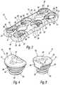
- FIG. 4is an enlarged isometric view of one side of the cam lock setscrew of the cervical plate implant of FIG. 1 ;
- FIG. 5is an enlarged isometric view of another side of the cam lock setscrew of FIG. 4 ;
- FIG. 6is an enlarged side view of the cam lock setscrew of FIG. 4 ;
- FIG. 7is an enlarged side view of the cam lock setscrew of FIG. 4 ;
- FIG. 8is an enlarged top view of the cam lock setscrew of FIG. 4 ;
- FIG. 9is an isometric view of the cervical plate implant of FIG. 1 with the cam lock setscrews situated in the plate along with several bone screws received in the plate with two bone screws thereof awaiting insertion into the plate, the cam lock setscrews all in an unlocked or neutral position;
- FIG. 10is a sectional view of the cervical plate implant as shown in FIG. 9 with bone screws received in the plate and the cam lock setscrews in the unlocked position;
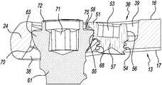
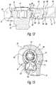
- FIG. 11is an enlarged sectional view of an end screw cavity of the plate of the cervical plate implant with a bone screw and cam lock setscrew received therein, the cam lock setscrew in an unlocked position;
- FIG. 12is an enlarged sectional view of the end screw cavity of the plate of the cervical plate implant with a bone screw and cam lock setscrew received therein of FIG. 11 , the cam lock setscrew in a locked position;
- FIG. 13is an enlarged top view of the end screw cavity of the plate of the cervical plate implant with a bone screw and cam lock setscrew received therein of FIG. 11 , the cam lock setscrew and bone screw in a locked position.
- the spine plate implant 10is made from a biocompatible material such as, but not limited to, titanium, stainless steel, an alloy of titanium or stainless steel, or other.
- the spine plate implant 10is characterized by a spine plate 12 , a plurality of cam lock setscrews 14 , and a plurality of bone screws 60 . While the spine plate implant 10 is particularly for the cervical portion of the spine, it can be used for other portions of the spine.
- FIG. 3depicts the spine plate 12 .
- the spine plate 12is characterized by an elongated body 13 having a generally planar upper surface 16 and a generally planar lower surface 17 .
- the body 13defines a first end 18 , a second end 19 , and a middle 20 , with the nomenclature first and second being arbitrary.
- the first end 18has a first boss 22 at one side thereof, and a second boss 23 at another side thereof opposite to the first boss 22 , the nomenclature first and second again being arbitrary.
- a notch 26is provided in the periphery of the first end 18 between the first boss 22 and the second boss 23 .
- a first configured cavity 30is provided at the first boss 22 while a second configured cavity 31 is provided at the second boss 23 , the nomenclature first and second again being arbitrary.
- the first configured cavity 30includes a bore 32 that is structured to receive a bone screw 60 , and a pocket 33 adjacent the bore 32 that is structured to receive a cam lock setscrew 14 .
- the bone screw bore 32is structured to angle a received bone screw 60 outwardly from the bottom of the body 13 as best seen in FIG. 10
- the cam lock setscrew pocket 33includes screw threads 64 about its inner lower periphery.
- the second configured cavity 31includes a bore 34 that is structured to receive a bone screw 60 , and a pocket 35 adjacent the bore 34 that is structured to receive a cam lock setscrew 14 .
- the bone screw bore 34is structured to angle a received bone screw 60 outwardly from the bottom of the body 13 in like manner as received bone screw 60 from the bone screw bore 32
- the cam lock setscrew pocket 35includes screw threads 65 about its inner lower periphery.
- the second end 19has a first boss 24 at one side thereof, and a second boss 25 at another side thereof opposite to the first boss 24 , the nomenclature first and second again being arbitrary.
- a notch 27is provided in the periphery of the second end 19 between the first boss 24 and the second boss 25 .
- a first configured cavity 36is provided at the first boss 24 while a second configured cavity 37 is provided at the second boss 25 , the nomenclature first and second again being arbitrary.
- the first configured cavity 36includes a bore 38 that is structured to receive a bone screw 60 , and a pocket 39 adjacent the bore 38 that is structured to receive a cam lock setscrew 14 .
- the bone screw bore 38is structured to angle a received bone screw 60 outwardly from the bottom of the body 13 as best seen in FIG. 10
- the cam lock setscrew pocket 39includes screw threads 68 about its inner lower periphery.
- the second configured cavity 37includes a bore 40 that is structured to receive a bone screw 60 , and a pocket 41 adjacent the bore 40 that is structured to receive a cam lock setscrew 14 .
- the bone screw bore 41is structured to angle a received bone screw 60 outwardly from the bottom of the body 13 in like manner as the bone screw 60 from the bone screw bore 34 of the first end 18
- the cam lock setscrew pocket 41includes screw threads 69 about its inner lower periphery.
- the middle 20 of the body 13has a first configured cavity 42 at a first side of the middle 20 while a second configured cavity 43 is provided at a second side of the middle 20 , the nomenclature first and second again being arbitrary.
- the first configured cavity 42includes a bore 44 that is structured to receive a bone screw 60 , and a pocket 45 adjacent the bore 44 that is structured to receive a cam lock setscrew 14 .
- the bone screw bore 44is structured to project a bone screw 60 downwardly from the bottom of the body 13 as best seen in FIG. 10
- the cam lock setscrew pocket 45includes screw threads 66 about its inner lower periphery.
- the second configured cavity 43includes a bore 46 that is structured to receive a bone screw 60 , and a pocket 47 adjacent the bore 46 that is structured to receive a cam lock setscrew 14 .
- the bone screw bore 46is structured to project a received bone screw 60 downwardly from the bottom of the body 13 in like manner as the received bone screw 60 from the bone screw bore 44 of the first side of the middle 20
- the cam lock setscrew pocket 47includes screw threads 67 about its inner lower periphery.
- the body 13also includes a first window or opening 28 situated between the middle 20 of the body 13 and the first end 18 , and a second window or opening 29 situated between the middle 20 and the second end 19 , the nomenclature first and second, again being arbitrary.
- the first and second windows 28 , 29have generally the same shape, but may be different if desired. As well, the particular shape of the first and second windows 28 , 29 may be changed as desired.
- the bone screw 60 of the present spine plate implant 10is depicted in various figures.
- the bone screw 60is characterized by an externally threaded shank 61 having a distal tip 62 and a proximal head 63 , the shank threading configured for reception in spinal bone.
- the underside 70 of the head 63is rounded to allow reception of the bone screw head 63 in the bone screw opening of the spine plate 12 .
- the bone screw 60has a socket 71 in the top of the head 63 for receipt of a driving tool (not shown). While the socket is shown as hexagonally configured, the socket may have other configurations.
- An annular wall 72extends from the upper surface 75 of the head 63 and about the socket 71 .
- a first tang, flange or the like 73extends from one side of the annular wall 72
- a second tang, flange or the like 74extends from another side of the annular wall 72 , preferably, but not necessarily, opposite to the first tang 73 , the nomenclature first and second being arbitrary. While two tangs are shown, the bone screw may have more tangs or in the alternative, have a single annular tang extending from the annular wall.
- the cam lock setscrew 14is shown.
- the cam lock setscrew 14is characterized by a generally cylindrical body 50 having a neck 57 and a head 51 .
- the head 51has a generally planar upper surface 52 with a socket 53 situated therein.
- the socket 53is configured as a geometric shape for receiving a like shaped tool or instrument (not shown) in order to install the cam lock setscrew 14 into a setscrew pocket of the spine plate, and to lock the cam lock setscrew 14 once a bone screw 60 has been installed onto the spine plate.
- the neck 57 of the cam lock setscrew 14has external threading 54 that is sized for reception by the threading of a setscrew pocket of the spine plate.
- the body 50has external teeth or the like 55 about a portion of its periphery underneath the head 51 and above the neck threading 54 .
- the head 51has a lip 58 situated generally above the teeth 55 .
- the teeth 55 and lip 58 of the cam lock setscrew 14cooperate to retain a bone screw 60 as/when the cam lock setscrew 14 is rotated in/into the locked position.
- the head 51further has a flat or the like 56 that is generally situated opposite the lip 58 .
- the flat 56extends through the teeth 55 and allows a bone screw 60 to pass by the cam lock setscrew 14 situated in a setscrew pocket of the spine plate 12 as the bone screw 60 is being received in the adjacent bone screw bore (i.e. the cam lock setscrew is in the open, unlocked, or neutral position).
- Rotation of the flat 56 away from the bone screw 60rotates the teeth 55 into the underside 70 of the head 63 of the bone screw 60 engaging the teeth 55 with the bone screw head 63 and positioning the lip 58 over the bone screw head 63 and preferably over a tang 73 , 74 (see, e.g. FIGS. 12,13 ) to lock the teeth 55 of the cam lock setscrew 14 into the bone screw 60 holding the bone screw 60 in place (the closed, locked, or engaged position).
- FIG. 1shows a plurality of cam lock setscrews 14 being inserted in respective cam lock setscrew pockets of the spine plate 12 .
- the cam lock setscrews 14are threadedly received in the respective cam lock setscrew pockets.
- FIG. 2shows the plurality of cam lock setscrews 14 received in their respective cam lock setscrew pockets, with each cam lock setscrew 14 in the unlocked position ready to accept a bone screw.
- FIGS. 10-11show bone screws 60 received in the spine plate 12 with the associated cam lock setscrews in the unlocked position.
- FIGS. 12-13show a bone screw 60 received and retained in the spine plate 12 with the associated cam lock setscrew in the locked position.
- the cam lock setscrews 14are initially in the neutral or open position to allow a bone screw 60 to pass through and into the associated bone screw opening. Once the bone screw is fully seated into the bone screw opening the cam lock setscrew is turned clockwise until it abuts against the head of the bone screw, thus locking the bone screw in place and preventing the bone screw from backing out.
Landscapes
- Health & Medical Sciences (AREA)
- Orthopedic Medicine & Surgery (AREA)
- Life Sciences & Earth Sciences (AREA)
- Surgery (AREA)
- Neurology (AREA)
- Heart & Thoracic Surgery (AREA)
- Engineering & Computer Science (AREA)
- Biomedical Technology (AREA)
- Nuclear Medicine, Radiotherapy & Molecular Imaging (AREA)
- Medical Informatics (AREA)
- Molecular Biology (AREA)
- Animal Behavior & Ethology (AREA)
- General Health & Medical Sciences (AREA)
- Public Health (AREA)
- Veterinary Medicine (AREA)
- Prostheses (AREA)
- Surgical Instruments (AREA)
Abstract
Description
Claims (14)
Priority Applications (2)
| Application Number | Priority Date | Filing Date | Title |
|---|---|---|---|
| US16/293,429US11213328B2 (en) | 2016-02-02 | 2019-03-05 | Spine plate implant with cam lock bone screw retention |
| US17/567,580US11813006B2 (en) | 2016-02-02 | 2022-01-03 | Spine plate implant with cam lock bone screw retention |
Applications Claiming Priority (3)
| Application Number | Priority Date | Filing Date | Title |
|---|---|---|---|
| US201662290027P | 2016-02-02 | 2016-02-02 | |
| US15/422,447US10265109B2 (en) | 2016-02-02 | 2017-02-01 | Spine plate implant with cam lock bone screw retention |
| US16/293,429US11213328B2 (en) | 2016-02-02 | 2019-03-05 | Spine plate implant with cam lock bone screw retention |
Related Parent Applications (1)
| Application Number | Title | Priority Date | Filing Date |
|---|---|---|---|
| US15/422,447ContinuationUS10265109B2 (en) | 2016-02-02 | 2017-02-01 | Spine plate implant with cam lock bone screw retention |
Related Child Applications (1)
| Application Number | Title | Priority Date | Filing Date |
|---|---|---|---|
| US17/567,580ContinuationUS11813006B2 (en) | 2016-02-02 | 2022-01-03 | Spine plate implant with cam lock bone screw retention |
Publications (2)
| Publication Number | Publication Date |
|---|---|
| US20190192202A1 US20190192202A1 (en) | 2019-06-27 |
| US11213328B2true US11213328B2 (en) | 2022-01-04 |
Family
ID=58044199
Family Applications (3)
| Application Number | Title | Priority Date | Filing Date |
|---|---|---|---|
| US15/422,447Active2037-07-10US10265109B2 (en) | 2016-02-02 | 2017-02-01 | Spine plate implant with cam lock bone screw retention |
| US16/293,429Active2037-08-24US11213328B2 (en) | 2016-02-02 | 2019-03-05 | Spine plate implant with cam lock bone screw retention |
| US17/567,580Active2037-02-12US11813006B2 (en) | 2016-02-02 | 2022-01-03 | Spine plate implant with cam lock bone screw retention |
Family Applications Before (1)
| Application Number | Title | Priority Date | Filing Date |
|---|---|---|---|
| US15/422,447Active2037-07-10US10265109B2 (en) | 2016-02-02 | 2017-02-01 | Spine plate implant with cam lock bone screw retention |
Family Applications After (1)
| Application Number | Title | Priority Date | Filing Date |
|---|---|---|---|
| US17/567,580Active2037-02-12US11813006B2 (en) | 2016-02-02 | 2022-01-03 | Spine plate implant with cam lock bone screw retention |
Country Status (4)
| Country | Link |
|---|---|
| US (3) | US10265109B2 (en) |
| EP (1) | EP3410968B1 (en) |
| CN (1) | CN108697448B (en) |
| WO (1) | WO2017136526A1 (en) |
Families Citing this family (14)
| Publication number | Priority date | Publication date | Assignee | Title |
|---|---|---|---|---|
| US9918750B2 (en)* | 2016-08-04 | 2018-03-20 | Osseus Fusion Systems, Llc | Method, system, and apparatus for temporary anterior cervical plate fixation |
| EP3579772B1 (en) | 2017-02-10 | 2023-06-28 | Zimmer Biomet CMF And Thoracic, LLC | Pectus bar and stabilizer devices |
| AU2018230818B2 (en) | 2017-03-08 | 2020-12-17 | Zimmer Biomet CMF and Thoracic, LLC | Pectus bar support devices |
| US10492912B2 (en)* | 2017-08-18 | 2019-12-03 | Innovasis, Inc. | Interbody spinal fusion implant having locking elements with lateral displacement |
| US10555764B2 (en)* | 2017-08-22 | 2020-02-11 | Innovasis, Inc. | Interbody spinal fusion implant having locking elements that outwardly displace for locking |
| US11304734B2 (en) | 2017-11-16 | 2022-04-19 | Globus Medical Inc. | Anterior cervical plate assembly |
| US11234742B2 (en) | 2017-11-16 | 2022-02-01 | Globus Medical, Inc. | Anterior cervical plate assembly |
| US11229460B2 (en) | 2017-11-16 | 2022-01-25 | Globus Medical, Inc. | Anterior cervical plate assembly |
| US11272963B2 (en) | 2017-11-16 | 2022-03-15 | Globus Medical, Inc. | Anterior cervical plate assembly |
| EP4108194A1 (en) | 2018-03-02 | 2022-12-28 | Stryker European Holdings I, LLC | Bone plates and associated screws |
| CN111544103A (en)* | 2019-02-12 | 2020-08-18 | 上海长征医院 | Spine fixing system |
| US11457957B2 (en)* | 2020-04-11 | 2022-10-04 | Life Spine, Inc. | Spine implant with an expandable cage and expandable vertebral attachment plate providing uniform rate movement |
| CN112022321B (en)* | 2020-09-12 | 2024-10-11 | 陈聚伍 | Fracture composite structure fixing nail and fracture nail plate assembly |
| CN112773490A (en)* | 2020-09-14 | 2021-05-11 | 江苏强圣医疗科技有限公司 | Locking type metal bone fracture plate for orthopedics |
Citations (14)
| Publication number | Priority date | Publication date | Assignee | Title |
|---|---|---|---|---|
| US20050187551A1 (en)* | 2002-12-02 | 2005-08-25 | Orbay Jorge L. | Bone plate system with bone screws fixed by secondary compression |
| US7288094B2 (en)* | 2005-06-10 | 2007-10-30 | Sdgi Holdings, Inc. | System and method for retaining screws relative to a vertebral plate |
| US20090163960A1 (en) | 2007-11-21 | 2009-06-25 | Lawrence Binder | Cervical spine stabilization system with extendable plates |
| US7875062B2 (en)* | 2006-03-07 | 2011-01-25 | Warsaw Orthopedic, Inc. | Methods and devices for retaining bone plate anchors |
| US20120277803A1 (en)* | 2011-04-26 | 2012-11-01 | Warsaw Orthopedic, Inc. | Bone plate & method for manufacturing |
| US20130060337A1 (en) | 2011-09-06 | 2013-03-07 | Samuel Petersheim | Spinal Plate |
| US20130165981A1 (en)* | 2009-12-22 | 2013-06-27 | Merete Medical Gmbh | Bone Plate System for Osteosynthesis |
| CN103565506A (en) | 2012-08-03 | 2014-02-12 | 索尔科生物医疗株式会社 | Apparatus for fixing a cervical spine having self tension part |
| US8702766B2 (en)* | 2011-06-28 | 2014-04-22 | Corelink, Llc | Locking device for fixation mechanism of medical implant |
| US20150094772A1 (en) | 2013-10-01 | 2015-04-02 | Degen Medical, Inc. | Osteosynthesis System, Assemblies and Components |
| US9119677B2 (en)* | 2005-12-09 | 2015-09-01 | DePuy Synthes Products, Inc. | Spinal plate and drill guide |
| US10098677B2 (en)* | 2011-09-06 | 2018-10-16 | Globus Medical, Inc. | Spinal plate |
| US10751098B2 (en)* | 2016-08-17 | 2020-08-25 | Globus Medical Inc. | Stabilization systems |
| US10828075B2 (en)* | 2015-09-25 | 2020-11-10 | Globus Medical Inc. | Bone fixation devices having a locking feature |
Family Cites Families (3)
| Publication number | Priority date | Publication date | Assignee | Title |
|---|---|---|---|---|
| US8454667B2 (en)* | 2010-12-16 | 2013-06-04 | Warsaw Orhtopedic, Inc. | Retaining mechanism |
| JP2014525776A (en)* | 2011-06-30 | 2014-10-02 | ロリオ,モーガン,パッカード | Spine plate and method of using the same |
| US9629664B2 (en)* | 2014-01-20 | 2017-04-25 | Neurostructures, Inc. | Anterior cervical plate |
- 2017
- 2017-02-01USUS15/422,447patent/US10265109B2/enactiveActive
- 2017-02-02CNCN201780012604.XApatent/CN108697448B/enactiveActive
- 2017-02-02EPEP17705257.8Apatent/EP3410968B1/enactiveActive
- 2017-02-02WOPCT/US2017/016177patent/WO2017136526A1/ennot_activeCeased
- 2019
- 2019-03-05USUS16/293,429patent/US11213328B2/enactiveActive
- 2022
- 2022-01-03USUS17/567,580patent/US11813006B2/enactiveActive
Patent Citations (14)
| Publication number | Priority date | Publication date | Assignee | Title |
|---|---|---|---|---|
| US20050187551A1 (en)* | 2002-12-02 | 2005-08-25 | Orbay Jorge L. | Bone plate system with bone screws fixed by secondary compression |
| US7288094B2 (en)* | 2005-06-10 | 2007-10-30 | Sdgi Holdings, Inc. | System and method for retaining screws relative to a vertebral plate |
| US9119677B2 (en)* | 2005-12-09 | 2015-09-01 | DePuy Synthes Products, Inc. | Spinal plate and drill guide |
| US7875062B2 (en)* | 2006-03-07 | 2011-01-25 | Warsaw Orthopedic, Inc. | Methods and devices for retaining bone plate anchors |
| US20090163960A1 (en) | 2007-11-21 | 2009-06-25 | Lawrence Binder | Cervical spine stabilization system with extendable plates |
| US20130165981A1 (en)* | 2009-12-22 | 2013-06-27 | Merete Medical Gmbh | Bone Plate System for Osteosynthesis |
| US20120277803A1 (en)* | 2011-04-26 | 2012-11-01 | Warsaw Orthopedic, Inc. | Bone plate & method for manufacturing |
| US8702766B2 (en)* | 2011-06-28 | 2014-04-22 | Corelink, Llc | Locking device for fixation mechanism of medical implant |
| US20130060337A1 (en) | 2011-09-06 | 2013-03-07 | Samuel Petersheim | Spinal Plate |
| US10098677B2 (en)* | 2011-09-06 | 2018-10-16 | Globus Medical, Inc. | Spinal plate |
| CN103565506A (en) | 2012-08-03 | 2014-02-12 | 索尔科生物医疗株式会社 | Apparatus for fixing a cervical spine having self tension part |
| US20150094772A1 (en) | 2013-10-01 | 2015-04-02 | Degen Medical, Inc. | Osteosynthesis System, Assemblies and Components |
| US10828075B2 (en)* | 2015-09-25 | 2020-11-10 | Globus Medical Inc. | Bone fixation devices having a locking feature |
| US10751098B2 (en)* | 2016-08-17 | 2020-08-25 | Globus Medical Inc. | Stabilization systems |
Non-Patent Citations (1)
| Title |
|---|
| Search Report for International Application No. PCT/US2017/016177, dated Apr. 20, 2017, 13 pages. |
Also Published As
| Publication number | Publication date |
|---|---|
| CN108697448A (en) | 2018-10-23 |
| US10265109B2 (en) | 2019-04-23 |
| US20190192202A1 (en) | 2019-06-27 |
| US11813006B2 (en) | 2023-11-14 |
| EP3410968B1 (en) | 2023-09-27 |
| US20170215930A1 (en) | 2017-08-03 |
| EP3410968A1 (en) | 2018-12-12 |
| WO2017136526A1 (en) | 2017-08-10 |
| HK1256458A1 (en) | 2019-09-27 |
| CN108697448B (en) | 2020-07-24 |
| US20220218398A1 (en) | 2022-07-14 |
Similar Documents
| Publication | Publication Date | Title |
|---|---|---|
| US11813006B2 (en) | Spine plate implant with cam lock bone screw retention | |
| US11903624B2 (en) | Orthopedic implants with variable angle bone screw locking | |
| US11871972B2 (en) | Spinal plate assembly having locking mechanism | |
| US9820790B2 (en) | Low profile fastening assembly | |
| US8882813B2 (en) | Locking mechanisms and associated methods | |
| US6689134B2 (en) | Longitudinal plate assembly having an adjustable length | |
| US8303633B2 (en) | Dynamic anterior vertebral plate | |
| US20140094856A1 (en) | Locking Screws and Plates | |
| US12064153B2 (en) | Lateral spine plate with set screw locking of bone screws | |
| US20080234750A1 (en) | Anterior vertebral plate with taper lock screw | |
| US10751100B2 (en) | Bone screws and surgical sets comprising bone screws | |
| HK1256458B (en) | Spine plate implant with cam lock bone screw retention |
Legal Events
| Date | Code | Title | Description |
|---|---|---|---|
| FEPP | Fee payment procedure | Free format text:ENTITY STATUS SET TO UNDISCOUNTED (ORIGINAL EVENT CODE: BIG.); ENTITY STATUS OF PATENT OWNER: SMALL ENTITY | |
| AS | Assignment | Owner name:LIFE SPINE, INC., ILLINOIS Free format text:ASSIGNMENT OF ASSIGNORS INTEREST;ASSIGNORS:LAUF, GARRETT D.;BUTLER, MICHAEL S.;REEL/FRAME:048521/0474 Effective date:20160210 | |
| FEPP | Fee payment procedure | Free format text:ENTITY STATUS SET TO SMALL (ORIGINAL EVENT CODE: SMAL); ENTITY STATUS OF PATENT OWNER: SMALL ENTITY | |
| AS | Assignment | Owner name:LIFE SPINE, INC., ILLINOIS Free format text:ASSIGNMENT OF ASSIGNORS INTEREST;ASSIGNORS:LAUF, GARRETT D.;BUTLER, MICHAEL S.;REEL/FRAME:050226/0186 Effective date:20160210 | |
| STPP | Information on status: patent application and granting procedure in general | Free format text:NON FINAL ACTION MAILED | |
| AS | Assignment | Owner name:LIFE SPINE, INC., ILLINOIS Free format text:RELEASE BY SECURED PARTY;ASSIGNOR:FIFTH THIRD BANK, NATIONAL ASSOCIATION;REEL/FRAME:054843/0755 Effective date:20201218 Owner name:GIZMO MEDICAL, LLC, ILLINOIS Free format text:RELEASE BY SECURED PARTY;ASSIGNOR:FIFTH THIRD BANK, NATIONAL ASSOCIATION;REEL/FRAME:054843/0755 Effective date:20201218 Owner name:ST. CLOUD CAPITAL PARTNERS III SBIC, LP, CALIFORNIA Free format text:SECURITY INTEREST;ASSIGNORS:LIFE SPINE, INC.;GIZMO MEDICAL, LLC;REEL/FRAME:054844/0239 Effective date:20201218 | |
| STPP | Information on status: patent application and granting procedure in general | Free format text:RESPONSE TO NON-FINAL OFFICE ACTION ENTERED AND FORWARDED TO EXAMINER | |
| AS | Assignment | Owner name:ASSOCIATED BANK, NATIONAL ASSOCIATION, AS AGENT, ILLINOIS Free format text:SECURITY INTEREST;ASSIGNOR:LIFE SPINE, INC.;REEL/FRAME:056728/0438 Effective date:20210630 | |
| STPP | Information on status: patent application and granting procedure in general | Free format text:FINAL REJECTION MAILED | |
| STPP | Information on status: patent application and granting procedure in general | Free format text:RESPONSE AFTER FINAL ACTION FORWARDED TO EXAMINER | |
| STPP | Information on status: patent application and granting procedure in general | Free format text:NOTICE OF ALLOWANCE MAILED -- APPLICATION RECEIVED IN OFFICE OF PUBLICATIONS | |
| STPP | Information on status: patent application and granting procedure in general | Free format text:AWAITING TC RESP., ISSUE FEE NOT PAID | |
| STPP | Information on status: patent application and granting procedure in general | Free format text:NOTICE OF ALLOWANCE MAILED -- APPLICATION RECEIVED IN OFFICE OF PUBLICATIONS | |
| STPP | Information on status: patent application and granting procedure in general | Free format text:PUBLICATIONS -- ISSUE FEE PAYMENT VERIFIED | |
| STCF | Information on status: patent grant | Free format text:PATENTED CASE | |
| AS | Assignment | Owner name:LIFE SPINE, INC., ILLINOIS Free format text:RELEASE BY SECURED PARTY;ASSIGNOR:ASSOCIATED BANK, NATIONAL ASSOCIATION;REEL/FRAME:064275/0446 Effective date:20230526 | |
| FEPP | Fee payment procedure | Free format text:MAINTENANCE FEE REMINDER MAILED (ORIGINAL EVENT CODE: REM.); ENTITY STATUS OF PATENT OWNER: SMALL ENTITY |