US11213326B2 - Systems and methods for performing spine surgery - Google Patents
Systems and methods for performing spine surgeryDownload PDFInfo
- Publication number
- US11213326B2 US11213326B2US16/655,172US201916655172AUS11213326B2US 11213326 B2US11213326 B2US 11213326B2US 201916655172 AUS201916655172 AUS 201916655172AUS 11213326 B2US11213326 B2US 11213326B2
- Authority
- US
- United States
- Prior art keywords
- elongated element
- elongated
- proximal
- distal
- proximal end
- Prior art date
- Legal status (The legal status is an assumption and is not a legal conclusion. Google has not performed a legal analysis and makes no representation as to the accuracy of the status listed.)
- Active, expires
Links
- 238000000034methodMethods0.000titledescription18
- 238000001356surgical procedureMethods0.000titledescription14
- 239000007943implantSubstances0.000claimsdescription22
- 210000000988bone and boneAnatomy0.000claimsdescription10
- 230000014759maintenance of locationEffects0.000claimsdescription10
- 238000013519translationMethods0.000abstractdescription14
- 238000005452bendingMethods0.000description20
- 241000722921Tulipa gesnerianaSpecies0.000description4
- 230000002159abnormal effectEffects0.000description3
- 210000003484anatomyAnatomy0.000description3
- 208000037265diseases, disorders, signs and symptomsDiseases0.000description3
- 210000000278spinal cordAnatomy0.000description3
- 206010023509KyphosisDiseases0.000description2
- 208000007623LordosisDiseases0.000description2
- 230000008901benefitEffects0.000description2
- 238000012937correctionMethods0.000description2
- 238000013461designMethods0.000description2
- 238000011161developmentMethods0.000description2
- 208000035475disorderDiseases0.000description2
- 238000002513implantationMethods0.000description2
- 230000013011matingEffects0.000description2
- 229910052751metalInorganic materials0.000description2
- 239000002184metalSubstances0.000description2
- 238000012986modificationMethods0.000description2
- 230000004048modificationEffects0.000description2
- 230000000284resting effectEffects0.000description2
- 210000001032spinal nerveAnatomy0.000description2
- 210000000115thoracic cavityAnatomy0.000description2
- 229910000684Cobalt-chromeInorganic materials0.000description1
- 208000003618Intervertebral Disc DisplacementDiseases0.000description1
- 206010061246Intervertebral disc degenerationDiseases0.000description1
- 230000010757Reduction ActivityEffects0.000description1
- 208000007103SpondylolisthesisDiseases0.000description1
- RTAQQCXQSZGOHL-UHFFFAOYSA-NTitaniumChemical compound[Ti]RTAQQCXQSZGOHL-UHFFFAOYSA-N0.000description1
- 230000005856abnormalityEffects0.000description1
- 230000015572biosynthetic processEffects0.000description1
- 239000010952cobalt-chromeSubstances0.000description1
- 238000004891communicationMethods0.000description1
- 238000011960computer-aided designMethods0.000description1
- 210000002808connective tissueAnatomy0.000description1
- 230000001054cortical effectEffects0.000description1
- 230000006837decompressionEffects0.000description1
- 208000018180degenerative disc diseaseDiseases0.000description1
- 230000003292diminished effectEffects0.000description1
- 201000010099diseaseDiseases0.000description1
- 238000006073displacement reactionMethods0.000description1
- 230000000694effectsEffects0.000description1
- 238000005755formation reactionMethods0.000description1
- 230000004927fusionEffects0.000description1
- 229910000078germaneInorganic materials0.000description1
- 238000011065in-situ storageMethods0.000description1
- 208000014674injuryDiseases0.000description1
- 208000021600intervertebral disc degenerative diseaseDiseases0.000description1
- 230000008376long-term healthEffects0.000description1
- 238000005259measurementMethods0.000description1
- 238000012544monitoring processMethods0.000description1
- 210000005036nerveAnatomy0.000description1
- 230000001537neural effectEffects0.000description1
- 238000013439planningMethods0.000description1
- 230000036316preloadEffects0.000description1
- 206010039722scoliosisDiseases0.000description1
- 238000007493shaping processMethods0.000description1
- 239000010935stainless steelSubstances0.000description1
- 229910001220stainless steelInorganic materials0.000description1
- 239000010936titaniumSubstances0.000description1
- 229910052719titaniumInorganic materials0.000description1
- 230000008733traumaEffects0.000description1
Images


Classifications
- A—HUMAN NECESSITIES
- A61—MEDICAL OR VETERINARY SCIENCE; HYGIENE
- A61B—DIAGNOSIS; SURGERY; IDENTIFICATION
- A61B17/00—Surgical instruments, devices or methods
- A61B17/56—Surgical instruments or methods for treatment of bones or joints; Devices specially adapted therefor
- A61B17/58—Surgical instruments or methods for treatment of bones or joints; Devices specially adapted therefor for osteosynthesis, e.g. bone plates, screws or setting implements
- A61B17/68—Internal fixation devices, including fasteners and spinal fixators, even if a part thereof projects from the skin
- A61B17/70—Spinal positioners or stabilisers, e.g. stabilisers comprising fluid filler in an implant
- A61B17/7074—Tools specially adapted for spinal fixation operations other than for bone removal or filler handling
- A61B17/7083—Tools for guidance or insertion of tethers, rod-to-anchor connectors, rod-to-rod connectors, or longitudinal elements
- A—HUMAN NECESSITIES
- A61—MEDICAL OR VETERINARY SCIENCE; HYGIENE
- A61B—DIAGNOSIS; SURGERY; IDENTIFICATION
- A61B17/00—Surgical instruments, devices or methods
- A61B17/56—Surgical instruments or methods for treatment of bones or joints; Devices specially adapted therefor
- A61B17/58—Surgical instruments or methods for treatment of bones or joints; Devices specially adapted therefor for osteosynthesis, e.g. bone plates, screws or setting implements
- A61B17/88—Osteosynthesis instruments; Methods or means for implanting or extracting internal or external fixation devices
- A61B17/8863—Apparatus for shaping or cutting osteosynthesis equipment by medical personnel
- A—HUMAN NECESSITIES
- A61—MEDICAL OR VETERINARY SCIENCE; HYGIENE
- A61B—DIAGNOSIS; SURGERY; IDENTIFICATION
- A61B90/00—Instruments, implements or accessories specially adapted for surgery or diagnosis and not covered by any of the groups A61B1/00 - A61B50/00, e.g. for luxation treatment or for protecting wound edges
- A61B90/06—Measuring instruments not otherwise provided for
- A—HUMAN NECESSITIES
- A61—MEDICAL OR VETERINARY SCIENCE; HYGIENE
- A61B—DIAGNOSIS; SURGERY; IDENTIFICATION
- A61B90/00—Instruments, implements or accessories specially adapted for surgery or diagnosis and not covered by any of the groups A61B1/00 - A61B50/00, e.g. for luxation treatment or for protecting wound edges
- A61B90/39—Markers, e.g. radio-opaque or breast lesions markers
- A—HUMAN NECESSITIES
- A61—MEDICAL OR VETERINARY SCIENCE; HYGIENE
- A61B—DIAGNOSIS; SURGERY; IDENTIFICATION
- A61B17/00—Surgical instruments, devices or methods
- A61B2017/00017—Electrical control of surgical instruments
- A61B2017/00221—Electrical control of surgical instruments with wireless transmission of data, e.g. by infrared radiation or radiowaves
- A—HUMAN NECESSITIES
- A61—MEDICAL OR VETERINARY SCIENCE; HYGIENE
- A61B—DIAGNOSIS; SURGERY; IDENTIFICATION
- A61B90/00—Instruments, implements or accessories specially adapted for surgery or diagnosis and not covered by any of the groups A61B1/00 - A61B50/00, e.g. for luxation treatment or for protecting wound edges
- A61B90/39—Markers, e.g. radio-opaque or breast lesions markers
- A61B2090/3987—Applicators for implanting markers
- A—HUMAN NECESSITIES
- A61—MEDICAL OR VETERINARY SCIENCE; HYGIENE
- A61B—DIAGNOSIS; SURGERY; IDENTIFICATION
- A61B90/00—Instruments, implements or accessories specially adapted for surgery or diagnosis and not covered by any of the groups A61B1/00 - A61B50/00, e.g. for luxation treatment or for protecting wound edges
- A61B90/39—Markers, e.g. radio-opaque or breast lesions markers
- A61B2090/3991—Markers, e.g. radio-opaque or breast lesions markers having specific anchoring means to fixate the marker to the tissue, e.g. hooks
- B—PERFORMING OPERATIONS; TRANSPORTING
- B21—MECHANICAL METAL-WORKING WITHOUT ESSENTIALLY REMOVING MATERIAL; PUNCHING METAL
- B21D—WORKING OR PROCESSING OF SHEET METAL OR METAL TUBES, RODS OR PROFILES WITHOUT ESSENTIALLY REMOVING MATERIAL; PUNCHING METAL
- B21D7/00—Bending rods, profiles, or tubes
- B21D7/02—Bending rods, profiles, or tubes over a stationary forming member; by use of a swinging forming member or abutment
- B21D7/021—Construction of forming members having more than one groove
- B—PERFORMING OPERATIONS; TRANSPORTING
- B21—MECHANICAL METAL-WORKING WITHOUT ESSENTIALLY REMOVING MATERIAL; PUNCHING METAL
- B21D—WORKING OR PROCESSING OF SHEET METAL OR METAL TUBES, RODS OR PROFILES WITHOUT ESSENTIALLY REMOVING MATERIAL; PUNCHING METAL
- B21D7/00—Bending rods, profiles, or tubes
- B21D7/02—Bending rods, profiles, or tubes over a stationary forming member; by use of a swinging forming member or abutment
- B21D7/024—Bending rods, profiles, or tubes over a stationary forming member; by use of a swinging forming member or abutment by a swinging forming member
- B—PERFORMING OPERATIONS; TRANSPORTING
- B21—MECHANICAL METAL-WORKING WITHOUT ESSENTIALLY REMOVING MATERIAL; PUNCHING METAL
- B21D—WORKING OR PROCESSING OF SHEET METAL OR METAL TUBES, RODS OR PROFILES WITHOUT ESSENTIALLY REMOVING MATERIAL; PUNCHING METAL
- B21D7/00—Bending rods, profiles, or tubes
- B21D7/04—Bending rods, profiles, or tubes over a movably-arranged forming menber
- B—PERFORMING OPERATIONS; TRANSPORTING
- B21—MECHANICAL METAL-WORKING WITHOUT ESSENTIALLY REMOVING MATERIAL; PUNCHING METAL
- B21D—WORKING OR PROCESSING OF SHEET METAL OR METAL TUBES, RODS OR PROFILES WITHOUT ESSENTIALLY REMOVING MATERIAL; PUNCHING METAL
- B21D7/00—Bending rods, profiles, or tubes
- B21D7/06—Bending rods, profiles, or tubes in press brakes or between rams and anvils or abutments; Pliers with forming dies
- B21D7/063—Pliers with forming dies
Definitions
- the present applicationpertains to spine surgery. More particularly, the present application pertains to systems and methods related to the planning, design, formation, and implantation of spinal implants.
- the spinal columnis a highly complex system of bones and connective tissues that provide support for the body and protect the delicate spinal cord and nerves.
- the spinal columnincludes a series of vertebral bodies stacked atop one another, each vertebral body including an inner or central portion of relatively weak cancellous bone and an outer portion of relatively strong cortical bone. Situated between each vertebral body is an intervertebral disc that cushions and dampens compressive forces exerted upon the spinal column.
- a vertebral canal containing the spinal cordis located behind the vertebral bodies.
- the spinehas a natural curvature (i.e., lordosis in the lumbar and cervical regions and kyphosis in the thoracic region) such that the endplates of the upper and lower vertebrae are inclined towards one another.
- spinal column disordersincluding scoliosis (abnormal lateral curvature of the spine), excess kyphosis (abnormal forward curvature of the spine), excess lordosis (abnormal backward curvature of the spine), spondylolisthesis (forward displacement of one vertebra over another), and other disorders caused by abnormalities, disease, or trauma (such as ruptured or slipped discs, degenerative disc disease, fractured vertebrae, and the like). Patients that suffer from such conditions often experience extreme and debilitating pain, as well as diminished nerve function. Posterior fixation for spinal fusions, decompression, deformity, and other reconstructions are performed to treat these patients. The aim of posterior fixation in lumbar, thoracic, and cervical procedures is to stabilize the spinal segments, correct multi-axis alignment, and aid in optimizing the long-term health of the spinal cord and nerves.
- Screws, hooks, and rodsare devices used to stabilize the spine during a spinal fixation procedure. Such procedures often require the instrumentation of many bony elements.
- the devices, for example rodscan be extremely challenging to design and implant into the patient.
- Spinal rodsare usually formed of stainless steel, titanium, cobalt chrome, or other similarly hard metal, and as such are difficult to bend without some sort of leverage-based bender.
- a spinal rodneeds to be oriented in six degrees of freedom to compensate for the anatomical structure of a patient's spine as well as the attachment points (screws, hooks) for securing the rod to the vertebrae. Additionally, the physiological problem being treated as well as the physician's preferences will determine the exact configuration necessary.
- the size, length, and particular bends of the spinal roddepends on the size, number, and position of each vertebrae to be constrained, the spatial relationship amongst vertebrae, as well as the screws and hooks used to hold the rods attached to the vertebrae.
- the bending of a spinal rodcan be accomplished by a number of methods.
- the most widely used methodis a three-point bender called a French Bender.
- the French benderis a pliers-like device that is manually operated to place one or more bends in a rod.
- the French benderrequires both handles to operate and provides leverage based on the length of the handle.
- the use of the French benderrequires a high degree of physician skill because the determination of the location, angle, and rotation of bends is often subjective and can be difficult to correlate to a patient's anatomy.
- Other methods of bending a rod to fit a screw and/or hook constructinclude the use of an in-situ rod bender and a keyhole bender.
- rod bending and reduction activitiescan be a time consuming and potentially frustrating step in the finalization of a complex and/or long spinal construct.
- Increased time in the operating room to achieve optimum bendingcan be costly to the patient and increase the chance of the morbidity.
- the rodcan preload the construct and increase the chance of failure of the fixation system.
- the bending and re-bending involvedcan also promote metal fatigue and the creation of stress risers in the rod.
- U.S. Pat. No. 7,957,831issued Jun. 7, 2011 to Isaacs, describes a rod bending system which includes a spatial measurement sub-system with a digitizer to obtain the three dimensional location of surgical implants (screws, hooks), software to convert the implant locations to a series of bend instructions, and a mechanical rod bender used to execute the bend instructions such that the rod will be bent precisely to custom fit within each of the screws.
- digitizer pointerconfigured for use as part of a surgical rod bending system. More specifically, digitizer pointer comprises a part of a spatial tracking system used to obtain the location of one or more surgical implants during a surgical procedure.
- the digitizer pointerincludes an adjustable offset feature to allow the user to digitize a point above the actual implant, a swivel feature that allows the distal end of the and the proximal end to swivel relative to one another and a translation feature that allows the distal end to mate with any number of instrumentation types in any number of surgical procedures.
- the digitizer pointerincludes a proximal portion, a middle portion, and a distal portion.
- the proximal portion, middle portion, and distal portioncomprise separate pieces that are assembled to form a single generally cylindrical elongated instrument.
- the proximal portionincludes an elongate tubular member and an inner piston.
- the inner pistonincludes a threaded post at the proximal end for mating with additional tracking instrumentation, for example an IR-reflective tracking array.
- the elongate tubular member and inner pistoncomprise the adjustable offset feature component of the digitizer pointer.
- the swivel featureincludes several elements positioned on the distal end of the elongated tubular member working in concert with several elements positioned on the proximal end of the middle portion.
- the distal end of the elongate tubular membercomprises a smooth cylindrical post.
- a circumferential recessis formed within the cylindrical post, and a raised lip is positioned at the proximal end of the cylindrical post.
- the proximal end of the middle portioncomprises a swivel housing including a cylindrical cavity sized and configured to receive the cylindrical post therein. Retention pins extend through pin apertures in the swivel housing and into the cavity.
- the retention pinsUpon assembly, the retention pins occupy space in the circumferential recess, and allow for rotational (swivel) movement of the cylindrical post while ensuring the cylindrical post remains within the cavity.
- the raised lipinterfaces with the rim of the cavity to form a swivel interface.
- the swivel featuremay be desirable, according to surgeon preference to re-orient a screw-tulip to align with the other screws (and eventual rod) within a construct.
- a spinal implante.g bone screw
- the usermay manually hold the distal portion of the digitizer pointer (e.g. any suitable place distal of the swivel interface) and swivel the proximal portion of the digitizer pointer (e.g. any suitable place proximal of the swivel interface) about the swivel feature.
- the proximal portion of the digital pointeris then rotated until the IR array (attached to the threaded post) comes in view of the camera.
- the translation featureincludes several elements positioned on the middle portion working in concert with several elements positioned on the distal portion.
- the middle portionincludes an elongate shaft extending distally from the swivel housing.
- the elongate shaftincludes a proximal segment and a distal segment.
- the proximal segmentmay have a different width dimension (e.g. diameter) than the distal segment.
- the proximal segmenthas a width diameter that is greater than the width dimension of the distal segment.
- the proximal segmenthas a smooth surface to facilitate translation of the distal portion.
- the proximal segmentfurther has a guide pin extending laterally away from the smooth surface positioned approximately in the middle of the proximal segment.
- the guide pinis received within the shaped track to help control translation of the distal portion, as will be explained.
- the distal segmentextends distally from the proximal segment and includes a hex lobe attachment feature positioned at the distal end.
- the hex lobe attachment featureis configured to engage a spinal implant, for example a bone screw head.
- a springis positioned about the proximal segment and is configured to exert a force on the distal portion to bias the distal portion in an extended position (in which the hex lobe attachment feature is positioned within the fork member.
- the distal portioncomprises an outer sleeve having a track housing at the proximal end, a fork member at the distal end, and an interior lumen extending through the entire length of the distal portion.
- the interior lumenis sized and configured to slideably receive the distal segment of the middle portion therein.
- the track housingincludes a shaped track configured to receive the pin therein.
- the trackhas a first lock slot positioned at the proximal end of the shaped track and a second lock slot positioned at the distal end of the shaped track.
- the fork memberincludes a pair of parallel extensions having shaped ends configured to engage a portion of a spinal implant, for example a tulip portion of a rod-receiving bone screw.
- the springexerts a force on the distal portion that biases the distal portion in an extended position.
- the guide pinIn this position, the guide pin is positioned within the first lock slot at the proximal end of the shaped track.
- a usermay manually engage (e.g. grab) the track housing and rotate the housing such that the guide pin is urged out of the first lock slot, along the main portion of the shaped track, and into the second lock slot.
- the distal portionwill be experience translation in a proximal direction.
- the guide pinis fully resting in the second lock slot after translation, the hex lobe attachment feature of the middle portion will extend beyond the fork member.
- the translating featureallows the surgeon to perform two digitizing methods depending on the surgical procedure and the goals of the surgical procedure.
- the first settingin which the guide pin is in the first lock slot
- the hex lobe attachment featureis in a retracted position (since the distal portion is extended), and the digitizer pointer can digitize all open, fixed, and connector tulips via engagement between the implanted device and the fork member.
- the second settingin which the pin is in the second lock slot
- the hex lobe attachment featureextends past the distal ends of the fork member, and the digitizer pointer can digitize when there has been a lock screw placed.
- the hex lobe attachment featuremates with a lock screw and allows the surgeon to digitize the location of the temporary rod placement.
- the surgeoncan digitize where the spine is during the temporary rod placement and when final rod bending is being achieved, for example during a pedicle subtraction osteotomy procedure.
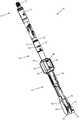
- FIG. 1is a perspective view of an example of a digitizer pointer according to one embodiment
- FIG. 2is an exploded perspective view of the digitizer pointer of FIG. 1 ;
- FIG. 3is a perspective view of the digitizer pointer of FIG. 1 in a translated position.
- the digitizer pointer 10 of the present disclosureis configured to be used as part of a surgical rod bending system, for example the surgical rod bending systems shown and described in commonly-owned U.S. Pat. No. 8,539,888, issued Oct. 8, 2013 and entitled “System and Device for Designing and Forming a Surgical Implant,” and commonly-owned and co-pending U.S. patent application Ser. No. 13/815,643, filed Mar. 12, 2013 and entitled “System and Method for Performing Spinal Surgery,” the entire contents of each of which are hereby incorporated by reference into this disclosure as if set forth fully herein. More specifically, digitizer pointer comprises a part of a spatial tracking system used to obtain the location of one or more surgical implants during a surgical procedure.
- the surgical bending systems described in the '888 patent and '643 applicationalso include a control unit containing software to convert the implant locations to a series of bend instructions, and a mechanical rod bender to receive the bend instructions and effect precise bends in the rod.
- the digitizer pointer 10 of the present disclosureincludes a swivel feature that allows the distal end and the proximal end to swivel relative to one another and a translation feature that allows the distal end to mate with any number of instrumentation types in any number of surgical procedures.
- the spatial tracking systemincludes an IR sensor, a digitizer pointer, as well as other components including Host USB converter.
- the spatial tracking systemis in communication with control unit.
- the control unithas spatial relation software and is communicatively linked to the display so that information relevant to the surgical procedure may be conveyed to the user in a meaningful manner.
- the relevant informationincludes, but is not limited to, spatial positioning data acquired by the IR sensor (e.g., translational data in the x, y, and z axes and orientation/rotational data R x , R y , and R z ).
- a neuromonitoring systemmay be communicatively linked to the spatial tracking system via the control unit.
- the neuromonitoring systemmay be the neuromonitoring system shown and described in U.S. Pat. No. 8,255,045, entitled “Neurophysiologic Monitoring System” and filed on Apr. 3, 2008, the entire contents of which are hereby incorporated by reference as if set forth fully herein.
- FIGS. 1-3illustrate an example of a digitizer pointer 10 according to one implementation.
- the digitizer pointer 10may be an all-in-one combination digitizer pointer for so-called “open” spine surgeries.
- the digitizer pointer 10includes a proximal portion 12 , a middle portion 14 , and a distal portion 16 .
- the proximal portion 12 , middle portion 14 , and distal portion 16comprise separate pieces that are assembled to form a single generally cylindrical elongated instrument.
- the proximal portion 12includes an elongate tubular member 18 and an inner piston 20 .
- the inner piston 20includes a threaded post 22 at the proximal end for mating with additional tracking instrumentation, for example an IR-reflective tracking array such as one shown and described in the above-referenced '643 application (incorporated by reference).
- additional tracking instrumentationfor example an IR-reflective tracking array such as one shown and described in the above-referenced '643 application (incorporated by reference).
- the elongate tubular member 18 and inner piston 20comprise the adjustable offset feature component of the digitizer pointer 10 .
- the adjustable offset featureallows the surgeon to add correction in the sagittal plane, and specific elements germane to the adjustable offset feature component are identical in form and function to the corresponding elements shown and described in the above-referenced '643 application (incorporated by reference) and will not be repeated here.
- the swivel featureincludes several elements positioned on the distal end 24 of the elongated tubular member 18 working in concert with several elements positioned on the proximal end 26 of the middle portion 14 .
- the distal end 24 of the elongate tubular member 18comprises a smooth cylindrical post 28 .
- a circumferential recess 30is formed within the cylindrical post 28 , and a raised lip 32 is positioned at the proximal end of the cylindrical post 28 .
- the proximal end 26 of the middle portion 14comprises a swivel housing 34 including a cylindrical cavity 36 sized and configured to receive the cylindrical post 28 therein.
- Retention pins 38extend through pin apertures 40 in the swivel housing 34 and into the cavity 36 . Upon assembly, the retention pins 38 occupy space in the circumferential recess 30 , and allow for rotational (swivel) movement of the cylindrical post 28 while ensuring the cylindrical post 28 remains within the cavity 36 .
- the raised lip 32interfaces with the rim of the cavity 36 to form a swivel interface location.
- the swivel featuremay be desirable, according to surgeon preference to re-orient a screw-tulip to align with the other screws (and eventual rod) within a construct.
- a spinal implante.g bone screw
- the usermay manually hold the distal portion of the digitizer pointer 10 (e.g. any suitable place distal of the swivel interface) and swivel the proximal portion of the digitizer pointer 10 (e.g. any suitable place proximal of the swivel interface) about the swivel feature.
- the proximal portion of the digital pointer 10is then rotated until the IR array (attached to the threaded post 22 ) comes in view of the camera.
- the translation featureincludes several elements positioned on the middle portion 14 working in concert with several elements positioned on the distal portion 16 .
- the middle portion 14includes a elongate shaft 42 extending distally from the swivel housing 34 .
- the elongate shaft 42includes a proximal segment 44 and a distal segment 46 .
- the proximal segment 44may have a different width dimension (e.g. diameter) than the distal segment 46 .
- the proximal segment 44has a width diameter that is greater than the width dimension of the distal segment 46 .
- the proximal segment 44has a smooth surface to facilitate translation of the distal portion 16 , as will be explained below.
- the proximal segment 44further has a guide pin 48 extending laterally away from the smooth surface positioned approximately in the middle of the proximal segment 44 .
- the guide pin 48is received within the shaped track 62 to help control translation of the distal portion 16 , as will be explained.
- the distal segment 46extends distally from the proximal segment 44 and includes a hex lobe attachment feature 50 positioned at the distal end.
- the hex lobe attachment feature 50is configured to engage a spinal implant, for example a bone screw head (not shown).
- a spring 52is positioned about the proximal segment 46 and is configured to exert a force on the distal portion 16 to bias the distal portion 16 in an extended position (in which the hex lobe attachment feature 50 is positioned within the fork member 58 .
- the distal portion 16comprises an outer sleeve 54 having a track housing 56 at the proximal end, a fork member 58 at the distal end, and an interior lumen 60 extending through the entire length of the distal portion 16 .
- the interior lumen 60is sized and configured to slideably receive the distal segment 46 of the middle portion 14 therein.
- the track housing 56includes a shaped track 62 configured to receive the pin 48 therein.
- the track 62may have any shape that facilitates self-locking, for example such the “C”-shape shown by way of example in FIGS. 1-3 .
- the track 62has a first lock slot 64 positioned at the proximal end of the shaped track 62 and a second lock slot 66 positioned at the distal end of the shaped track 62 .
- the fork member 58includes a pair of parallel extensions 68 having shaped ends 70 configured to engage a portion of a spinal implant, for example a tulip portion of a rod-receiving bone screw (not shown).
- the spring 52exerts a force on the distal portion 16 that biases the distal portion 16 in an extended position.
- the pin 48is positioned within the first lock slot 64 at the proximal end of the shaped track 62 .
- a usermay manually engage (e.g. grab) the track housing 56 and rotate the housing 56 such that the guide pin 48 is urged out of the first lock slot 64 , along the main portion of the shaped track 62 , and into the second lock slot 66 .
- the distal portion 16will be experience translation in a proximal direction.
- the hex lobe attachment feature 50 of the middle portion 14will extend beyond the fork member 58 , as shown in FIG. 3 .
- the translating featureallows the surgeon to perform two digitizing methods depending on the surgical procedure and the goals of the surgical procedure.
- the first settingin which the pin 48 is in the first lock slot 64
- the hex lobe attachment feature 50is in a retracted position (since the distal portion 16 is extended), and the digitizer pointer 10 can digitize all open, fixed, and connector tulips via engagement between the implanted device and the fork member 58 .
- the second settingin which the pin 48 is in the second lock slot 66
- the hex lobe attachment feature 50extends past the distal ends 70 of the fork member 58 , and the digitizer pointer 10 can digitize when there has been a lock screw placed.
- the hex lobe attachment feature 50mates with a lock screw (not shown) and allows the surgeon to digitize the location of the temporary rod placement.
- the surgeoncan digitize where the spine is during the temporary rod placement and when final rod bending is being achieved, for example during a pedicle subtraction osteotomy procedure.
Landscapes
- Health & Medical Sciences (AREA)
- Surgery (AREA)
- Life Sciences & Earth Sciences (AREA)
- Orthopedic Medicine & Surgery (AREA)
- Heart & Thoracic Surgery (AREA)
- Veterinary Medicine (AREA)
- Engineering & Computer Science (AREA)
- Biomedical Technology (AREA)
- Nuclear Medicine, Radiotherapy & Molecular Imaging (AREA)
- Medical Informatics (AREA)
- Molecular Biology (AREA)
- Animal Behavior & Ethology (AREA)
- General Health & Medical Sciences (AREA)
- Public Health (AREA)
- Neurology (AREA)
- Pathology (AREA)
- Oral & Maxillofacial Surgery (AREA)
- Surgical Instruments (AREA)
- Prostheses (AREA)
Abstract
Description
Claims (20)
Priority Applications (3)
| Application Number | Priority Date | Filing Date | Title |
|---|---|---|---|
| US16/655,172US11213326B2 (en) | 2014-10-17 | 2019-10-16 | Systems and methods for performing spine surgery |
| US17/532,645US12251142B2 (en) | 2014-10-17 | 2021-11-22 | Systems and methods for performing spine surgery |
| US19/081,202US20250213280A1 (en) | 2014-10-17 | 2025-03-17 | Systems and methods for performing spine surgery |
Applications Claiming Priority (4)
| Application Number | Priority Date | Filing Date | Title |
|---|---|---|---|
| US201462065531P | 2014-10-17 | 2014-10-17 | |
| US14/887,246US9913669B1 (en) | 2014-10-17 | 2015-10-19 | Systems and methods for performing spine surgery |
| US15/879,397US10485589B2 (en) | 2014-10-17 | 2018-01-24 | Systems and methods for performing spine surgery |
| US16/655,172US11213326B2 (en) | 2014-10-17 | 2019-10-16 | Systems and methods for performing spine surgery |
Related Parent Applications (1)
| Application Number | Title | Priority Date | Filing Date |
|---|---|---|---|
| US15/879,397ContinuationUS10485589B2 (en) | 2014-10-17 | 2018-01-24 | Systems and methods for performing spine surgery |
Related Child Applications (1)
| Application Number | Title | Priority Date | Filing Date |
|---|---|---|---|
| US17/532,645ContinuationUS12251142B2 (en) | 2014-10-17 | 2021-11-22 | Systems and methods for performing spine surgery |
Publications (2)
| Publication Number | Publication Date |
|---|---|
| US20200046409A1 US20200046409A1 (en) | 2020-02-13 |
| US11213326B2true US11213326B2 (en) | 2022-01-04 |
Family
ID=61526215
Family Applications (6)
| Application Number | Title | Priority Date | Filing Date |
|---|---|---|---|
| US14/887,245Active2037-09-01US10433893B1 (en) | 2014-10-17 | 2015-10-19 | Systems and methods for performing spine surgery |
| US14/887,246ActiveUS9913669B1 (en) | 2014-10-17 | 2015-10-19 | Systems and methods for performing spine surgery |
| US15/879,397ActiveUS10485589B2 (en) | 2014-10-17 | 2018-01-24 | Systems and methods for performing spine surgery |
| US16/655,172Active2036-05-31US11213326B2 (en) | 2014-10-17 | 2019-10-16 | Systems and methods for performing spine surgery |
| US17/532,645Active2037-08-05US12251142B2 (en) | 2014-10-17 | 2021-11-22 | Systems and methods for performing spine surgery |
| US19/081,202PendingUS20250213280A1 (en) | 2014-10-17 | 2025-03-17 | Systems and methods for performing spine surgery |
Family Applications Before (3)
| Application Number | Title | Priority Date | Filing Date |
|---|---|---|---|
| US14/887,245Active2037-09-01US10433893B1 (en) | 2014-10-17 | 2015-10-19 | Systems and methods for performing spine surgery |
| US14/887,246ActiveUS9913669B1 (en) | 2014-10-17 | 2015-10-19 | Systems and methods for performing spine surgery |
| US15/879,397ActiveUS10485589B2 (en) | 2014-10-17 | 2018-01-24 | Systems and methods for performing spine surgery |
Family Applications After (2)
| Application Number | Title | Priority Date | Filing Date |
|---|---|---|---|
| US17/532,645Active2037-08-05US12251142B2 (en) | 2014-10-17 | 2021-11-22 | Systems and methods for performing spine surgery |
| US19/081,202PendingUS20250213280A1 (en) | 2014-10-17 | 2025-03-17 | Systems and methods for performing spine surgery |
Country Status (1)
| Country | Link |
|---|---|
| US (6) | US10433893B1 (en) |
Families Citing this family (28)
| Publication number | Priority date | Publication date | Assignee | Title |
|---|---|---|---|---|
| US10758283B2 (en) | 2016-08-11 | 2020-09-01 | Mighty Oak Medical, Inc. | Fixation devices having fenestrations and methods for using the same |
| US8545505B2 (en)* | 2010-01-15 | 2013-10-01 | Pioneer Surgical Technology, Inc. | Low friction rod persuader |
| US8206395B2 (en)* | 2010-06-18 | 2012-06-26 | Spine Wave, Inc. | Surgical instrument and method for the distraction or compression of bones |
| US12357413B2 (en) | 2010-06-29 | 2025-07-15 | Mighty Oak Medical, Inc. | Patient-matched apparatus for use in spine related surgical procedures and methods for using the same |
| US11039889B2 (en) | 2010-06-29 | 2021-06-22 | Mighty Oak Medical, Inc. | Patient-matched apparatus and methods for performing surgical procedures |
| US11806197B2 (en) | 2010-06-29 | 2023-11-07 | Mighty Oak Medical, Inc. | Patient-matched apparatus for use in spine related surgical procedures and methods for using the same |
| US11376073B2 (en) | 2010-06-29 | 2022-07-05 | Mighty Oak Medical Inc. | Patient-matched apparatus and methods for performing surgical procedures |
| FR3010628B1 (en) | 2013-09-18 | 2015-10-16 | Medicrea International | METHOD FOR REALIZING THE IDEAL CURVATURE OF A ROD OF A VERTEBRAL OSTEOSYNTHESIS EQUIPMENT FOR STRENGTHENING THE VERTEBRAL COLUMN OF A PATIENT |
| FR3012030B1 (en) | 2013-10-18 | 2015-12-25 | Medicrea International | METHOD FOR REALIZING THE IDEAL CURVATURE OF A ROD OF A VERTEBRAL OSTEOSYNTHESIS EQUIPMENT FOR STRENGTHENING THE VERTEBRAL COLUMN OF A PATIENT |
| US10433893B1 (en)* | 2014-10-17 | 2019-10-08 | Nuvasive, Inc. | Systems and methods for performing spine surgery |
| WO2016088130A1 (en) | 2014-12-04 | 2016-06-09 | Mazor Robotics Ltd. | Shaper for vertebral fixation rods |
| EP4241709B1 (en) | 2016-06-23 | 2025-05-21 | Mazor Robotics Ltd. | Minimally invasive intervertebral rod insertion |
| US12016573B2 (en) | 2016-08-11 | 2024-06-25 | Mighty Oak Medical, Inc. | Drill apparatus and surgical fixation devices and methods for using the same |
| US10743890B2 (en) | 2016-08-11 | 2020-08-18 | Mighty Oak Medical, Inc. | Drill apparatus and surgical fixation devices and methods for using the same |
| WO2018109556A1 (en) | 2016-12-12 | 2018-06-21 | Medicrea International | Systems and methods for patient-specific spinal implants |
| EP3612122B1 (en) | 2017-04-21 | 2023-12-20 | Medicrea International | A system for developing one or more patient-specific spinal implants |
| US10918422B2 (en) | 2017-12-01 | 2021-02-16 | Medicrea International | Method and apparatus for inhibiting proximal junctional failure |
| USD895111S1 (en) | 2018-06-04 | 2020-09-01 | Mighty Oak Medical, Inc. | Sacro-iliac guide |
| USD948717S1 (en) | 2018-06-04 | 2022-04-12 | Mighty Oak Medical, Inc. | Sacro-iliac guide |
| JP7487222B2 (en) | 2019-03-26 | 2024-05-20 | マイティ オーク メディカル、インコーポレイテッド | Patient-adapted device for use in augmented reality assisted surgery and method for using same - Patents.com |
| US11925417B2 (en) | 2019-04-02 | 2024-03-12 | Medicrea International | Systems, methods, and devices for developing patient-specific spinal implants, treatments, operations, and/or procedures |
| US11877801B2 (en) | 2019-04-02 | 2024-01-23 | Medicrea International | Systems, methods, and devices for developing patient-specific spinal implants, treatments, operations, and/or procedures |
| US11944385B2 (en) | 2019-04-02 | 2024-04-02 | Medicrea International | Systems and methods for medical image analysis |
| US11769251B2 (en) | 2019-12-26 | 2023-09-26 | Medicrea International | Systems and methods for medical image analysis |
| US11730529B2 (en)* | 2020-03-26 | 2023-08-22 | Warsaw Orthopedic, Inc. | Powered modular head locker |
| US12318144B2 (en) | 2021-06-23 | 2025-06-03 | Medicrea International SA | Systems and methods for planning a patient-specific spinal correction |
| US11439444B1 (en)* | 2021-07-22 | 2022-09-13 | Globus Medical, Inc. | Screw tower and rod reduction tool |
| US12408955B2 (en) | 2021-12-28 | 2025-09-09 | Nuvasive, Inc. | Adapter for patient reference array and bone anchor assembly |
Citations (235)
| Publication number | Priority date | Publication date | Assignee | Title |
|---|---|---|---|---|
| US3365804A (en) | 1964-04-27 | 1968-01-30 | Fjellstrom Bengt Gottfrid | Pipe gauging device |
| US4282737A (en) | 1980-03-24 | 1981-08-11 | Maples Billy G | Hand operated bending apparatus and method for metal bar, tubing and the like |
| US4474046A (en) | 1982-06-18 | 1984-10-02 | Zimmer, Inc. | Rod bender |
| US4773402A (en) | 1985-09-13 | 1988-09-27 | Isola Implants, Inc. | Dorsal transacral surgical implant |
| US5113685A (en) | 1991-01-28 | 1992-05-19 | Acromed Corporation | Apparatus for contouring spine plates and/or rods |
| US5161404A (en) | 1991-10-23 | 1992-11-10 | Zimmer, Inc. | Rod bender |
| US5257184A (en) | 1990-04-10 | 1993-10-26 | Mushabac David R | Method and apparatus with multiple data input stylii for collecting curvilinear contour data |
| US5290289A (en) | 1990-05-22 | 1994-03-01 | Sanders Albert E | Nitinol spinal instrumentation and method for surgically treating scoliosis |
| US5365996A (en) | 1992-06-10 | 1994-11-22 | Amei Technologies Inc. | Method and apparatus for making customized fixation devices |
| US5389099A (en) | 1993-07-28 | 1995-02-14 | Hartmeister; Ruben | Keyhole rod bender |
| US5490409A (en) | 1994-11-07 | 1996-02-13 | K-Medic, Inc. | Adjustable cam action rod bender for surgical rods |
| US5548985A (en) | 1994-05-13 | 1996-08-27 | Yapp; Ronald A. | Rod bender for forming surgical implants in the operating room |
| US5658286A (en) | 1996-02-05 | 1997-08-19 | Sava; Garard A. | Fabrication of implantable bone fixation elements |
| US5672175A (en) | 1993-08-27 | 1997-09-30 | Martin; Jean Raymond | Dynamic implanted spinal orthosis and operative procedure for fitting |
| US5682886A (en) | 1995-12-26 | 1997-11-04 | Musculographics Inc | Computer-assisted surgical system |
| US5704937A (en) | 1993-08-27 | 1998-01-06 | Paulette Fairant | Operative equipment for fixing spinal instrumentation |
| US5768134A (en) | 1994-04-19 | 1998-06-16 | Materialise, Naamloze Vennootschap | Method for making a perfected medical model on the basis of digital image information of a part of the body |
| US5806521A (en) | 1996-03-26 | 1998-09-15 | Sandia Corporation | Composite ultrasound imaging apparatus and method |
| US5819571A (en) | 1997-02-10 | 1998-10-13 | Johnson; Stephen | Apparatus for bending surgical instruments |
| US5819580A (en) | 1998-04-13 | 1998-10-13 | Beere Precision Medical Instruments, Inc. | Bending tool |
| US5901600A (en) | 1997-08-06 | 1999-05-11 | Decker; Ronald R. | Rod bending device |
| US6006581A (en) | 1998-10-26 | 1999-12-28 | Hol-Med Corporation | Rod bending system |
| US6035691A (en) | 1999-08-10 | 2000-03-14 | Lin; Ruey-Mo | Adjustable rod bending device for a corrective spinal rod which is used in a surgical operation |
| US6205411B1 (en) | 1997-02-21 | 2001-03-20 | Carnegie Mellon University | Computer-assisted surgery planner and intra-operative guidance system |
| US6226548B1 (en) | 1997-09-24 | 2001-05-01 | Surgical Navigation Technologies, Inc. | Percutaneous registration apparatus and method for use in computer-assisted surgical navigation |
| US6236875B1 (en) | 1994-10-07 | 2001-05-22 | Surgical Navigation Technologies | Surgical navigation systems including reference and localization frames |
| US6301495B1 (en) | 1999-04-27 | 2001-10-09 | International Business Machines Corporation | System and method for intra-operative, image-based, interactive verification of a pre-operative surgical plan |
| US6327491B1 (en) | 1998-07-06 | 2001-12-04 | Neutar, Llc | Customized surgical fixture |
| US6332780B1 (en) | 1997-11-21 | 2001-12-25 | Synthes (U.S.A.) | Implant simulating device |
| US20020007294A1 (en) | 2000-04-05 | 2002-01-17 | Bradbury Thomas J. | System and method for rapidly customizing a design and remotely manufacturing biomedical devices using a computer system |
| US6347240B1 (en) | 1990-10-19 | 2002-02-12 | St. Louis University | System and method for use in displaying images of a body part |
| US20020133097A1 (en) | 2001-03-19 | 2002-09-19 | Orthoscan Technologies Inc. | Contour mapping system applicable as a spine analyzer, and probe useful therein |
| US20020183610A1 (en) | 1994-10-07 | 2002-12-05 | Saint Louis University And Surgical Navigation Technologies, Inc. | Bone navigation system |
| US6529765B1 (en) | 1998-04-21 | 2003-03-04 | Neutar L.L.C. | Instrumented and actuated guidance fixture for sterotactic surgery |
| US20030055502A1 (en) | 2001-05-25 | 2003-03-20 | Philipp Lang | Methods and compositions for articular resurfacing |
| US20030055435A1 (en) | 2000-11-27 | 2003-03-20 | Barrick Earl Frederick | Orthopaedic implant shaper |
| WO2003030787A1 (en) | 2001-10-05 | 2003-04-17 | Therics, Inc. | System and method for rapidly customizing design, manufacture and/or selection of biomedical devices |
| US6578280B2 (en) | 2000-09-20 | 2003-06-17 | Bridgestone Corporation | Hole center detecting apparatus, straightness measuring apparatus, and residual torsion measuring apparatus |
| US20030149351A1 (en) | 1996-02-27 | 2003-08-07 | Wieslaw Lucjan Nowinski | Curved surgical instruments and method of mapping a curved path for stereotactic surgery |
| US20030205075A1 (en) | 2002-05-02 | 2003-11-06 | Walter Strippgen | Spinal rod curving instrument and method for using same |
| US6644087B1 (en) | 2002-07-26 | 2003-11-11 | Third Millennium Engineering, Llc | Rod bender for bending surgical rods |
| US20030215122A1 (en) | 2002-04-03 | 2003-11-20 | Kabushiki Kaisha Toshiba | Medical image processing apparatus with a function of measurement on a medical image |
| US6701174B1 (en) | 2000-04-07 | 2004-03-02 | Carnegie Mellon University | Computer-aided bone distraction |
| US20040068187A1 (en) | 2000-04-07 | 2004-04-08 | Krause Norman M. | Computer-aided orthopedic surgery |
| EP1413257A1 (en) | 2002-10-25 | 2004-04-28 | BrainLAB AG | Device for positioning an element, for example in the spine |
| US20040097952A1 (en) | 2002-02-13 | 2004-05-20 | Sarin Vineet Kumar | Non-image, computer assisted navigation system for joint replacement surgery with modular implant system |
| EP1426023A1 (en) | 2002-11-22 | 2004-06-09 | Sulzer Markets and Technology AG | Method, system and computer program product for the determination of implantation parameters |
| US20040122549A1 (en) | 2002-08-16 | 2004-06-24 | Fanuc Ltd. | Curve interpolation method |
| US20040133276A1 (en) | 2002-10-07 | 2004-07-08 | Imaging Therapeutics, Inc. | Minimally invasive joint implant with 3-Dimensional geometry matching the articular surfaces |
| US20040147927A1 (en) | 2002-11-07 | 2004-07-29 | Imaging Therapeutics, Inc. | Methods for determining meniscal size and shape and for devising treatment |
| US20040152972A1 (en) | 2003-01-30 | 2004-08-05 | Mark Hunter | Method and apparatus for post-operative tuning of a spinal implant |
| US20040158260A1 (en) | 2002-10-25 | 2004-08-12 | Arno Blau | Device and method for calibrating an element and device and system for positioning an element |
| WO2004070581A2 (en) | 2003-02-04 | 2004-08-19 | Z-Kat, Inc. | System and method for providing computer assistance with spinal fixation procedures |
| US20040167637A1 (en) | 2000-12-04 | 2004-08-26 | Spineco, Inc. A Corporation Of Ohio | Molded surgical implant |
| DE10314882A1 (en) | 2003-04-01 | 2004-10-14 | Anders, Peter, Prof. Dr.-Ing. | Bending procedure for rod used in operatively treating scoliosis, by determining space curve or target curve using navigation system which dismantles the curve into part curves from which the bending of the rod takes place |
| DE102004008870A1 (en) | 2003-03-31 | 2004-10-14 | Anders, Peter, Prof. Dr.-Ing. | Bending method for a workpiece such as a rod or tube for use in e.g. spinal surgery where a target curve is defined about which the rod is bent |
| US20050054917A1 (en) | 2002-09-26 | 2005-03-10 | David Kitson | Orthopaedic surgery planning |
| US20050074304A1 (en)* | 2002-04-17 | 2005-04-07 | Pierre Couture | CAS drill guide and drill tracking system |
| US20050101966A1 (en) | 2000-11-06 | 2005-05-12 | Stephane Lavallee | System for determining the position of a knee prosthesis |
| US20050119593A1 (en) | 2002-03-05 | 2005-06-02 | Eurosurgical Sa | Method of viewing and controlling balance of the vertebral column |
| US6906724B2 (en) | 2001-10-17 | 2005-06-14 | Lntel Corporation | Generating a shadow for a three-dimensional model |
| US20050149050A1 (en) | 2002-05-21 | 2005-07-07 | Jan Stifter | Arrangement and method for the intra-operative determination of the position of a joint replacement implant |
| US20050182320A1 (en) | 2002-05-21 | 2005-08-18 | Jan Stifter | Arrangement for ascertaining function-determining geometric parameters of a joint of a vertebrate |
| US20050192575A1 (en) | 2004-02-20 | 2005-09-01 | Pacheco Hector O. | Method of improving pedicle screw placement in spinal surgery |
| US20050203511A1 (en) | 2004-03-02 | 2005-09-15 | Wilson-Macdonald James | Orthopaedics device and system |
| US20050245817A1 (en) | 2004-05-03 | 2005-11-03 | Clayton John B | Method and apparatus for implantation between two vertebral bodies |
| US20050251139A1 (en) | 2004-05-07 | 2005-11-10 | Roh Jeffrey S | Systems and methods that facilitate minimally invasive spine surgery |
| US20050262911A1 (en) | 2004-02-06 | 2005-12-01 | Harry Dankowicz | Computer-aided three-dimensional bending of spinal rod implants, other surgical implants and other articles, systems for three-dimensional shaping, and apparatuses therefor |
| US6978188B1 (en) | 2002-09-30 | 2005-12-20 | Medical Modeling, Llc | Method for contouring bone reconstruction plates |
| US20050288809A1 (en) | 2004-06-28 | 2005-12-29 | Spaeth John P | System and method for producing medical devices |
| US20060005601A1 (en) | 2004-07-12 | 2006-01-12 | Widmayer Joseph B | Apparatus and method for bending tubing |
| US20060015030A1 (en) | 2002-08-26 | 2006-01-19 | Orthosoft Inc. | Method for placing multiple implants during a surgery using a computer aided surgery system |
| US20060094951A1 (en) | 2003-06-11 | 2006-05-04 | David Dean | Computer-aided-design of skeletal implants |
| EP1657681A1 (en) | 2004-11-10 | 2006-05-17 | Agfa-Gevaert | Method of performing measurements on digital images |
| WO2006055998A1 (en) | 2004-11-24 | 2006-06-01 | Universität für Angewandte Kunst Wien | Method for controlling bending machines |
| US20060120583A1 (en) | 2004-11-10 | 2006-06-08 | Agfa-Gevaert | Method of performing measurements on digital images |
| US20060150699A1 (en) | 2005-01-12 | 2006-07-13 | Depuy Spine, Inc. | Instrument for bending spinal rods used in a spinal fixation system |
| US20060212158A1 (en) | 2004-12-23 | 2006-09-21 | Robert Miller | System for manufacturing an implant |
| US20060235338A1 (en) | 2005-03-07 | 2006-10-19 | Hector Pacheco | System and methods for improved access to vertebral bodies for kyphoplasty, vertebroplasty, vertebral body biopsy or screw placement |
| US20060247864A1 (en) | 2005-04-29 | 2006-11-02 | Jose Tamez-Pena | Method and system for assessment of biomarkers by measurement of response to surgical implant |
| US20060264973A1 (en) | 2005-05-23 | 2006-11-23 | Custom Spine, Inc. | Orthopedic implant bender |
| US20060264934A1 (en) | 2005-05-18 | 2006-11-23 | Medicinelodge, Inc. | System and method for orthopedic implant configuration |
| US20060282020A1 (en) | 2005-06-13 | 2006-12-14 | Rudolph Bertagnoli | Customizing an intervertebral implant |
| WO2007009263A1 (en) | 2005-07-22 | 2007-01-25 | Cedara Software Corp. | Implant inventory management system and method using digital image planning |
| US20070066917A1 (en) | 2005-09-20 | 2007-03-22 | Hodorek Robert A | Method for simulating prosthetic implant selection and placement |
| US7206626B2 (en) | 2002-03-06 | 2007-04-17 | Z-Kat, Inc. | System and method for haptic sculpting of physical objects |
| US20070093998A1 (en) | 2002-12-30 | 2007-04-26 | Fouad El-Baroudi | Method for biomehcanically simulating of a set of osseous joints |
| US20070093824A1 (en) | 2005-09-22 | 2007-04-26 | Hestad Hugh D | Pedicle fixation rod alignment system |
| US20070118243A1 (en) | 2005-10-14 | 2007-05-24 | Vantus Technology Corporation | Personal fit medical implants and orthopedic surgical instruments and methods for making |
| US20070118055A1 (en) | 2005-11-04 | 2007-05-24 | Smith & Nephew, Inc. | Systems and methods for facilitating surgical procedures involving custom medical implants |
| US20070142751A1 (en) | 2002-03-06 | 2007-06-21 | Hyosig Kang | Apparatus and method for haptic rendering |
| US20070198022A1 (en) | 2001-05-25 | 2007-08-23 | Conformis, Inc. | Patient Selectable Joint Arthroplasty Devices and Surgical Tools |
| US20070227216A1 (en) | 2006-02-16 | 2007-10-04 | Nabil Muhanna | Automated pedicle screw rod bender |
| US20070233246A1 (en) | 2006-03-31 | 2007-10-04 | Sdgi Holdings, Inc. | Spinal implants with improved mechanical response |
| US20070239159A1 (en) | 2005-07-22 | 2007-10-11 | Vertiflex, Inc. | Systems and methods for stabilization of bone structures |
| US20070250169A1 (en) | 2001-05-25 | 2007-10-25 | Philipp Lang | Joint arthroplasty devices formed in situ |
| US20070276501A1 (en) | 2006-05-25 | 2007-11-29 | Spinemedica Corp. | Patient-specific spinal implants and related systems and methods |
| US20080009945A1 (en) | 2006-06-28 | 2008-01-10 | Pacheco Hector O | Apparatus and methods for templating and placement of artificial discs |
| US20080039717A1 (en) | 2006-08-11 | 2008-02-14 | Robert Frigg | Simulated bone or tissue manipulation |
| WO2008021494A2 (en) | 2006-08-18 | 2008-02-21 | Smith & Nephew, Inc. | Systems and methods for designing, analyzing and using orthopaedic devices |
| US20080065067A1 (en) | 1999-03-07 | 2008-03-13 | Active Implants Corporation | Method and apparatus for computerized surgery |
| US20080154120A1 (en) | 2006-12-22 | 2008-06-26 | General Electric Company | Systems and methods for intraoperative measurements on navigated placements of implants |
| US20080167547A1 (en) | 2005-02-17 | 2008-07-10 | University Of Florida Research Foundation, Inc. | Systems and Methods For Planning Medical Procedures and Designing Medical Devices Based on Anatomical Scan Deformations |
| WO2008101090A2 (en) | 2007-02-14 | 2008-08-21 | Conformis, Inc. | Implant device and method for manufacture |
| US20080208080A1 (en) | 2004-11-01 | 2008-08-28 | Nihon University | Human Body Backbone Measuring/Displaying System |
| WO2008130355A1 (en) | 2007-04-24 | 2008-10-30 | Medtronic, Inc. | Method for performing multiple registrations in a navigated procedure |
| US20080269906A1 (en) | 2007-03-06 | 2008-10-30 | The Cleveland Clinic Foundation | Method and apparatus for preparing for a surgical procedure |
| US20080269898A1 (en) | 2007-04-25 | 2008-10-30 | Warsaw Orthopedic, Inc. | Device and method for image-based device performance measurement |
| US20080269596A1 (en) | 2004-03-10 | 2008-10-30 | Ian Revie | Orthpaedic Monitoring Systems, Methods, Implants and Instruments |
| US20080288229A1 (en) | 2006-09-27 | 2008-11-20 | Aldo Arvizo Arvizo | Apparatus and Method for Creating Solid Models for Clinical Diagnosis |
| US20080306490A1 (en) | 2007-05-18 | 2008-12-11 | Ryan Cameron Lakin | Trackable diagnostic scope apparatus and methods of use |
| EP2017785A1 (en) | 2007-07-17 | 2009-01-21 | BrainLAB AG | Imaging method for motion analysis |
| US20090024164A1 (en) | 2007-06-25 | 2009-01-22 | Neubardt Seth L | System for determining spinal implants |
| US20090043556A1 (en) | 2007-08-07 | 2009-02-12 | Axelson Stuart L | Method of and system for planning a surgery |
| WO2009035358A1 (en) | 2007-09-13 | 2009-03-19 | Universidade Do Minho | System for automatic and personalized modelling/bending of surgical prosthesis for correction of pectus excavatum based on pre-surgical imaging information |
| US20090082666A1 (en) | 2006-08-04 | 2009-03-26 | Wyatt Drake Geist | Magnetic targeting system for facilitating navigation |
| US20090089034A1 (en) | 2005-03-01 | 2009-04-02 | Graeme Penney | Surgical Planning |
| US20090093852A1 (en) | 2007-10-05 | 2009-04-09 | Hynes Richard A | Spinal stabilization treatment methods for maintaining axial spine height and sagital plane spine balance |
| US20090099605A1 (en) | 2006-02-06 | 2009-04-16 | Stryker Spine | Rod contouring apparatus for percutaneous pedicle screw extension |
| US20090132050A1 (en) | 2001-12-20 | 2009-05-21 | Sten Holm | Method and arrangement at implants preferably for a human intervertebral and such implant |
| US20090149977A1 (en) | 2007-11-06 | 2009-06-11 | Schendel Stephen A | Methods, systems, and computer program products for shaping medical implants directly from virtual reality models |
| US20090157083A1 (en) | 2007-12-18 | 2009-06-18 | Ilwhan Park | System and method for manufacturing arthroplasty jigs |
| US20090157185A1 (en) | 2007-12-18 | 2009-06-18 | Chong Chol Kim | Prosthetic Monolithic Spinal Discs and Method of Customizing and Constructing Discs |
| US20090209851A1 (en) | 2008-01-09 | 2009-08-20 | Stryker Leibinger Gmbh & Co. Kg | Stereotactic computer assisted surgery method and system |
| US20090209884A1 (en) | 2008-02-20 | 2009-08-20 | Mako Surgical Corp. | Implant planning using corrected captured joint motion information |
| US20090226068A1 (en) | 2008-03-05 | 2009-09-10 | Conformis, Inc. | Implants for Altering Wear Patterns of Articular Surfaces |
| US20090226055A1 (en) | 2004-12-10 | 2009-09-10 | Harry Dankowicz | Systems and methods for multi-dimensional characterization and classification of spinal shape |
| US20090249851A1 (en) | 2008-04-04 | 2009-10-08 | Vilaspine Ltd. | System and Device for Designing and Forming a Surgical Implant |
| US20090254097A1 (en) | 2008-04-04 | 2009-10-08 | Isaacs Robert E | System and device for designing and forming a surgical implant |
| US20090276045A1 (en) | 2001-05-25 | 2009-11-05 | Conformis, Inc. | Devices and Methods for Treatment of Facet and Other Joints |
| US20100030231A1 (en) | 2005-06-02 | 2010-02-04 | Ian Revie | Surgical system and method |
| US20100030232A1 (en) | 2006-09-25 | 2010-02-04 | Eli Zehavi | System for positioning of surgical inserts and tools |
| US20100076563A1 (en) | 2008-09-19 | 2010-03-25 | Smith & Nephew, Inc. | Operatively tuning implants for increased performance |
| US20100100011A1 (en) | 2008-10-22 | 2010-04-22 | Martin Roche | System and Method for Orthopedic Alignment and Measurement |
| US20100101295A1 (en) | 2008-10-28 | 2010-04-29 | Warsaw Orthopedic, Inc. | Isulated sheath for bending polymer-based rod |
| US20100111631A1 (en) | 2008-10-31 | 2010-05-06 | Warsaw Orthopedic, Inc. | Tool for Finishing the Ends of Surgical Rods and Methods of Use |
| US20100145663A1 (en) | 2006-12-07 | 2010-06-10 | Ecole Nationale Superieure D'arts Et Metiers | Method for simulating the behavior of an articulated set of bones |
| US20100177946A1 (en) | 2007-05-18 | 2010-07-15 | Marleen De Bruijne | Semi-automatic contour detection |
| US20100191088A1 (en) | 2009-01-23 | 2010-07-29 | Warsaw Orthopedic, Inc. | Methods and systems for diagnosing, treating, or tracking spinal disorders |
| US20100191071A1 (en) | 2009-01-23 | 2010-07-29 | Warsaw Orthopedic, Inc. | Methods and Systems for Diagnosing, Treating, or Tracking Spinal Disorders |
| US20100191100A1 (en) | 2009-01-23 | 2010-07-29 | Warsaw Orthopedic, Inc. | Methods and systems for diagnosing, treating, or tracking spinal disorders |
| WO2010099231A2 (en) | 2009-02-24 | 2010-09-02 | Conformis, Inc. | Automated systems for manufacturing patient-specific orthopedic implants and instrumentation |
| US20100234725A1 (en) | 2006-08-04 | 2010-09-16 | Wyatt Drake Geist | Method And Apparatus For Facilitating Navigation Of An Implant |
| US20100292963A1 (en) | 2009-04-15 | 2010-11-18 | James Schroeder | Personal fit medical implants and orthopedic surgical instruments and methods for making |
| US20100292795A1 (en) | 2009-05-13 | 2010-11-18 | Jensen Ole T | Biomedical implant surface topography |
| US7837467B2 (en) | 2001-04-13 | 2010-11-23 | Orametrix, Inc. | Robot and method for bending orthodontic archwires and other medical devices |
| US20100329530A1 (en) | 2001-05-25 | 2010-12-30 | Conformis, Inc. | Patient Selectable Knee Joint Arthroplasty Devices |
| US20100332197A1 (en) | 2005-08-19 | 2010-12-30 | Mark Melton | System for biomedical implant creation and procurement |
| US20100332248A1 (en) | 2007-10-12 | 2010-12-30 | Nobel Biocare Services Ag | Computer implemented planning and providing of mass customized bone structure |
| US20110010187A1 (en) | 2007-09-12 | 2011-01-13 | Nobel Biocare Services Ag | Method and system for planning a medical procedure and generating data related to said medical procedure |
| US20110015514A1 (en) | 2008-02-29 | 2011-01-20 | Ecole National Superieure D'arts Et Metiers (Ensam | Medical imaging method and system for providing a finite-element model |
| US20110040340A1 (en) | 2009-08-17 | 2011-02-17 | Warsaw Orthopedic, Inc. | Instruments and Methods for In Situ Bending of an Elongate Spinal Implant |
| US20110066193A1 (en) | 2001-05-25 | 2011-03-17 | Conformis, Inc. | Surgical Tools for Arthroplasty |
| US20110071802A1 (en) | 2009-02-25 | 2011-03-24 | Ray Bojarski | Patient-adapted and improved articular implants, designs and related guide tools |
| US20110093108A1 (en) | 2008-02-27 | 2011-04-21 | Depuy International Ltd | Customised surgical apparatus |
| US20110093023A1 (en) | 2009-10-21 | 2011-04-21 | Chang-Gung University | Surgical implant guide and method of manufacturing the same |
| US20110094278A1 (en) | 2008-02-12 | 2011-04-28 | Cml International S.P.A. | Method to check and control a roller bending machine for continuously bending an elongated workpiece at variable curvature radii, and machine so controlled |
| US20110107270A1 (en) | 2009-10-30 | 2011-05-05 | Bai Wang | Treatment planning in a virtual environment |
| US20110144752A1 (en) | 2008-08-14 | 2011-06-16 | Defelice Scott F | Customized implants for bone replacement |
| US20110196426A1 (en) | 2010-02-09 | 2011-08-11 | Andrea Peukert | Percutaneous rod insertion system and method |
| US20110245871A1 (en) | 2010-04-06 | 2011-10-06 | Williams Lytton A | Crosslink element and bender for spine surgery procedures |
| US20110257653A1 (en) | 2010-04-14 | 2011-10-20 | Smith & Nephew, Inc. | Systems and Methods for Patient-Based Computer Assisted Surgical Procedures |
| US20110265538A1 (en) | 2010-04-30 | 2011-11-03 | Warsaw Orthopedic, Inc. | Systems, Devices and Methods for Multi-Dimensional Bending of an Elongate Member |
| US20110266265A1 (en) | 2007-02-14 | 2011-11-03 | Conformis, Inc. | Implant Device and Method for Manufacture |
| US20110270262A1 (en) | 2010-04-30 | 2011-11-03 | Warsaw Orthopedic, Inc. | Systems, Devices and Methods for Bending an Elongate Member |
| US20110268325A1 (en) | 2010-04-30 | 2011-11-03 | Medtronic Navigation, Inc | Method and Apparatus for Image-Based Navigation |
| US20110295378A1 (en) | 2001-05-25 | 2011-12-01 | Conformis, Inc. | Patient-Adapted and Improved Orthopedic Implants, Designs and Related Tools |
| US20110307020A1 (en) | 2006-08-04 | 2011-12-15 | Wyatt Drake Geist | Magnetic targeting system and method of using the same |
| US20110305379A1 (en) | 2009-02-25 | 2011-12-15 | Mohamed Rashwan Mahfouz | DEFORMABLE ARTICULATING TEMPLATE (formerly: CUSTOMIZED ORTHOPAEDIC IMPLANTS & RELATED METHODS) |
| US20110319745A1 (en) | 2010-06-29 | 2011-12-29 | Frey George A | Patient Matching Surgical Guide and Method for Using the Same |
| US20120010710A1 (en) | 2010-07-08 | 2012-01-12 | Robert Frigg | Advanced Bone Marker and Custom Implants |
| US20120016423A1 (en) | 2008-10-01 | 2012-01-19 | Sherwin Hua | System and method for wire-guided pedicle screw stabilization of spinal vertebrae |
| US20120047980A1 (en) | 2010-08-26 | 2012-03-01 | Michael Harper | Compound Hinged Rod Bender |
| US20120063655A1 (en) | 1999-08-11 | 2012-03-15 | Case Western Reserve University | Methods and systems for producing an implant |
| US20120116203A1 (en) | 2010-11-10 | 2012-05-10 | Wilfried Vancraen | Additive manufacturing flow for the production of patient-specific devices comprising unique patient-specific identifiers |
| WO2012061452A1 (en) | 2010-11-02 | 2012-05-10 | Siemens Medical Solutions Usa, Inc. | Automatic image-based calculation of a geometric feature |
| WO2012062464A1 (en) | 2010-11-10 | 2012-05-18 | Spontech Spine Intelligence Group Ag | Spine fixation installation system |
| US20120141034A1 (en) | 2010-10-29 | 2012-06-07 | The Cleveland Clinic Foundation | System of preoperative planning and provision of patient-specific surgical aids |
| US20120178069A1 (en) | 2010-06-15 | 2012-07-12 | Mckenzie Frederic D | Surgical Procedure Planning and Training Tool |
| US20120186411A1 (en) | 2011-01-25 | 2012-07-26 | Sebstian Lodahi | Automated surgical rod cutter and bender including a power-base, assembly for rod cutting, and assembly for rod bending |
| US20120191192A1 (en) | 2009-09-30 | 2012-07-26 | Industry Foundation Of Chonnam National University | Image-based patient-specific medical spinal surgery method and spinal prosthesis |
| US20120209394A1 (en) | 1997-01-08 | 2012-08-16 | Conformis, Inc. | Patient-Adapted and Improved Articular Implants, Designs and Related Guide Tools |
| US20120230566A1 (en) | 1999-08-11 | 2012-09-13 | Case Western Reserve University | Producing a three dimensional model of an implant |
| WO2012135653A1 (en) | 2011-03-30 | 2012-10-04 | Avisar Mordechai | Method and system for simulating surgical procedures |
| US20120247173A1 (en) | 2011-04-01 | 2012-10-04 | Anthony James Paris | Bending instrument and methods of using same |
| US20120274631A1 (en) | 2011-04-28 | 2012-11-01 | Howmedica Osteonics Corp. | Surgical case planning platform |
| EP2522295A1 (en) | 2011-05-10 | 2012-11-14 | Loran S.r.l. | Vitual platform for pre-surgery simulation and relative bio-mechanic validation of prothesis surgery of the lumbo-sacral area of the human spine |
| US20120290272A1 (en) | 2011-05-11 | 2012-11-15 | Bryan Jason A | Generating patient specific instruments for use as surgical aids |
| WO2012152900A1 (en) | 2011-05-12 | 2012-11-15 | Materialise N.V. | Methods and devices for validating the position of patient-specific devices |
| US20120310364A1 (en) | 2011-05-06 | 2012-12-06 | Zimmer, Inc. | Patient-specific manufacturing of porous metal prostheses |
| US20120323279A1 (en) | 2011-06-16 | 2012-12-20 | Industrial Technology Research Institute | Minimally invasive spinal stabilization method |
| US20120325363A1 (en) | 2011-06-10 | 2012-12-27 | Knebl Juergen | Method for bending thermoplastic pipes |
| US20130053854A1 (en) | 2011-08-31 | 2013-02-28 | Biomet Manufacturing Corp. | Patient-specific sacroiliac guides and associated methods |
| US20130072982A1 (en)* | 2011-09-19 | 2013-03-21 | Peter Melott Simonson | Spinal assembly load gauge |
| US20130073315A1 (en) | 2010-04-19 | 2013-03-21 | Philip Cardamone | Data processing and transferring method relating to the placement of surgical implants |
| WO2013041618A1 (en) | 2011-09-20 | 2013-03-28 | Materialise N.V. | Multifunctional patient - specific guides |
| US20130090692A1 (en) | 2011-10-07 | 2013-04-11 | Regents Of The University Of Minnesota | Intraoperative spinal stabilization |
| US20130091921A1 (en) | 2011-10-13 | 2013-04-18 | Warsaw Orthopedic, Inc. | Rod benders and methods of use |
| US20130110174A1 (en) | 2011-10-31 | 2013-05-02 | Warsaw Orthopedic, Inc. | Methods for installing a vertebral construct |
| US20130123850A1 (en) | 2011-08-31 | 2013-05-16 | Biomet Manufacturing Corp. | Patient-specific sacroiliac and pedicle guides |
| US20130131486A1 (en) | 2010-02-26 | 2013-05-23 | Spontech Spine Intelligence Group Ag | Computer program for spine mobility simulation and spine simulation method |
| CN202982181U (en) | 2012-12-03 | 2013-06-12 | 中国人民解放军第二军医大学 | Bend rod device |
| WO2013087082A1 (en) | 2011-12-14 | 2013-06-20 | Stryker Leibinger Gmbh & Co. Kg | Technique for generating a bone plate design |
| US20130166256A1 (en) | 2011-12-23 | 2013-06-27 | Materialise Nv | Systems and methods for designing and generating devices using accuracy maps and stability analysis |
| US20130211531A1 (en) | 2001-05-25 | 2013-08-15 | Conformis, Inc. | Patient-adapted and improved articular implants, designs and related guide tools |
| US20130218163A1 (en) | 2010-06-29 | 2013-08-22 | George Frey | Patient matching surgical guide and method for using the same |
| WO2013134623A1 (en) | 2012-03-08 | 2013-09-12 | Neutar, Llc | Patient and procedure customized fixation and targeting devices for stereotactic frames |
| US20130238096A1 (en) | 2012-03-08 | 2013-09-12 | Hugomed Llc | 3d design and fabrication system for implants |
| US20130268007A1 (en) | 2012-04-05 | 2013-10-10 | Warsaw Orthopedic, Inc. | Spinal implant measuring system and method |
| WO2013150233A1 (en) | 2012-04-02 | 2013-10-10 | Safe Orthopaedics | Bending machine with a cam for an orthopaedic rod |
| US20130296954A1 (en) | 2012-05-02 | 2013-11-07 | Warsaw Orthopedic, Inc. | Surgical tool for bending a rod |
| US20130304217A1 (en) | 2012-05-14 | 2013-11-14 | Ali Cem Recber | Cutting/Bending Tool For Polymer Implant |
| JP2013230221A (en) | 2012-04-27 | 2013-11-14 | Medtronic Sofamor Danek Co Ltd | Bender connecting mechanism and vender device |
| US20130307955A1 (en) | 2010-12-13 | 2013-11-21 | Ortho Kinematics, Inc., | Methods, systems and devices for a clinical data reporting and surgical navigation |
| US20130325069A1 (en) | 2010-11-29 | 2013-12-05 | Javier Pereiro de Lamo | Method and System for the Treatment of Spinal Deformities |
| US20130332128A1 (en) | 2011-02-25 | 2013-12-12 | Optimized Ortho Pty Ltd | Computer-implemented method, a computing device and a computer readable storage medium for providing alignment information data for the alignment of an orthopaedic implant for a joint of a patient |
| US20130345757A1 (en) | 2012-06-22 | 2013-12-26 | Shawn D. Stad | Image Guided Intra-Operative Contouring Aid |
| US20140025181A1 (en) | 2012-07-20 | 2014-01-23 | Tom Vanasse | Metallic structures having porous regions from imaged bone at pre-defined anatomic locations |
| WO2014016824A1 (en) | 2012-07-24 | 2014-01-30 | Reuven Gepstein | Spine system and kit |
| US20140066994A1 (en) | 2012-09-06 | 2014-03-06 | Stryker Trauma Ag | Instrument for use in bending surgical devices |
| US20140074438A1 (en) | 2012-09-12 | 2014-03-13 | André Furrer | Method for producing patient-specific plate |
| WO2014037093A1 (en) | 2012-09-04 | 2014-03-13 | Sanpera Trigueros Ignacio | System and method for a global three-dimensional correction of the curvatures of the spine |
| US20140076883A1 (en) | 2012-09-20 | 2014-03-20 | Vladimir Brailovski | Apparatus and method for per-operative modification of medical device stiffness |
| US20140081400A1 (en) | 2010-08-25 | 2014-03-20 | Siemens Corporation | Semi-Automatic Customization Of Plates For Internal Fracture Fixation |
| WO2014048448A1 (en) | 2012-09-25 | 2014-04-03 | Brainlab Ag | Modular navigation reference |
| WO2014079812A1 (en) | 2012-11-23 | 2014-05-30 | Diers Engineering Gmbh | Determining the spatial position and orientation of the vertebrae in the spinal column |
| WO2014088801A1 (en) | 2012-12-05 | 2014-06-12 | Dignity Health | Surgical rod bending system and method |
| WO2014107144A1 (en) | 2013-01-03 | 2014-07-10 | Warsaw Orthopedic, Inc. | Surgical implant bending system and method |
| US20140213889A1 (en) | 2013-01-25 | 2014-07-31 | Medtronic Navigation, Inc. | System and Process of Utilizing Image Data to Place a Member |
| US20140244220A1 (en) | 2011-07-20 | 2014-08-28 | Smith & Nephew, Inc. | Systems and methods for optimizing fit of an implant to anatomy |
| US20140257508A1 (en) | 2011-10-14 | 2014-09-11 | Conformis, Inc. | Methods and Systems for Identification, Assessment, Modeling and Repair of Anatomical Disparities in Joint Replacement |
| US20140311203A1 (en) | 2011-12-05 | 2014-10-23 | Neil R. Crawford | Surgical rod bending system and method |
| US20140364916A1 (en) | 2011-11-07 | 2014-12-11 | Morgan Packard Lorio | Methods and apparatuses for delivering a rod to a plurality of pedicle screws |
| US9526537B2 (en)* | 2012-08-03 | 2016-12-27 | Alphatec Spine, Inc. | Instrument and method for reducing and securing spinal rods |
| US9913669B1 (en)* | 2014-10-17 | 2018-03-13 | Nuvasive, Inc. | Systems and methods for performing spine surgery |
Family Cites Families (15)
| Publication number | Priority date | Publication date | Assignee | Title |
|---|---|---|---|---|
| US1964550A (en)* | 1930-07-07 | 1934-06-26 | Greenlee Bros & Co | Bender |
| US2232819A (en)* | 1937-07-22 | 1941-02-25 | Greenlee Bros & Co | Tube bender |
| US3018818A (en)* | 1957-02-27 | 1962-01-30 | Greenlee Bros & Co | Pipe bender |
| US4691555A (en)* | 1984-11-15 | 1987-09-08 | Vaughan Donald R | Tube bending tool |
| US5615572A (en)* | 1995-01-12 | 1997-04-01 | Hunjohn, Inc. | Hydraulic tube bender |
| US5761950A (en)* | 1997-03-10 | 1998-06-09 | Chiu; Ching-Su | Tube bender |
| US6487889B1 (en)* | 2001-12-04 | 2002-12-03 | Stride Tool, Inc. | Tube bender |
| US6856828B2 (en)* | 2002-10-04 | 2005-02-15 | Orthosoft Inc. | CAS bone reference and less invasive installation method thereof |
| US9393039B2 (en)* | 2003-12-17 | 2016-07-19 | Brainlab Ag | Universal instrument or instrument set for computer guided surgery |
| US9179984B2 (en)* | 2007-02-19 | 2015-11-10 | Medtronic Navigation, Inc. | Multi-configuration tracking array and related method |
| WO2008124079A1 (en) | 2007-04-03 | 2008-10-16 | Nuvasive, Inc. | Neurophysiologic monitoring system |
| US7957831B2 (en)* | 2008-04-04 | 2011-06-07 | Isaacs Robert E | System and device for designing and forming a surgical implant |
| US8539888B2 (en) | 2011-03-11 | 2013-09-24 | Board Of Regents, The University Of Texas System | Table-board-partition |
| US11207132B2 (en) | 2012-03-12 | 2021-12-28 | Nuvasive, Inc. | Systems and methods for performing spinal surgery |
| WO2014093986A2 (en)* | 2012-12-14 | 2014-06-19 | Ssp Fittings Corp. | System including cartridge, catridge feed system, pre-swaging assembly, tube bender, cutting and deburring station, and air blower/ vacuum chip collector |
- 2015
- 2015-10-19USUS14/887,245patent/US10433893B1/enactiveActive
- 2015-10-19USUS14/887,246patent/US9913669B1/enactiveActive
- 2018
- 2018-01-24USUS15/879,397patent/US10485589B2/enactiveActive
- 2019
- 2019-10-16USUS16/655,172patent/US11213326B2/enactiveActive
- 2021
- 2021-11-22USUS17/532,645patent/US12251142B2/enactiveActive
- 2025
- 2025-03-17USUS19/081,202patent/US20250213280A1/enactivePending
Patent Citations (242)
| Publication number | Priority date | Publication date | Assignee | Title |
|---|---|---|---|---|
| US3365804A (en) | 1964-04-27 | 1968-01-30 | Fjellstrom Bengt Gottfrid | Pipe gauging device |
| US4282737A (en) | 1980-03-24 | 1981-08-11 | Maples Billy G | Hand operated bending apparatus and method for metal bar, tubing and the like |
| US4474046A (en) | 1982-06-18 | 1984-10-02 | Zimmer, Inc. | Rod bender |
| US4773402A (en) | 1985-09-13 | 1988-09-27 | Isola Implants, Inc. | Dorsal transacral surgical implant |
| US5257184A (en) | 1990-04-10 | 1993-10-26 | Mushabac David R | Method and apparatus with multiple data input stylii for collecting curvilinear contour data |
| US5290289A (en) | 1990-05-22 | 1994-03-01 | Sanders Albert E | Nitinol spinal instrumentation and method for surgically treating scoliosis |
| US6347240B1 (en) | 1990-10-19 | 2002-02-12 | St. Louis University | System and method for use in displaying images of a body part |
| US5113685A (en) | 1991-01-28 | 1992-05-19 | Acromed Corporation | Apparatus for contouring spine plates and/or rods |
| US5161404A (en) | 1991-10-23 | 1992-11-10 | Zimmer, Inc. | Rod bender |
| US5365996A (en) | 1992-06-10 | 1994-11-22 | Amei Technologies Inc. | Method and apparatus for making customized fixation devices |
| US5389099A (en) | 1993-07-28 | 1995-02-14 | Hartmeister; Ruben | Keyhole rod bender |
| US5672175A (en) | 1993-08-27 | 1997-09-30 | Martin; Jean Raymond | Dynamic implanted spinal orthosis and operative procedure for fitting |
| US5704937A (en) | 1993-08-27 | 1998-01-06 | Paulette Fairant | Operative equipment for fixing spinal instrumentation |
| US5768134A (en) | 1994-04-19 | 1998-06-16 | Materialise, Naamloze Vennootschap | Method for making a perfected medical model on the basis of digital image information of a part of the body |
| US5548985A (en) | 1994-05-13 | 1996-08-27 | Yapp; Ronald A. | Rod bender for forming surgical implants in the operating room |
| US20020183610A1 (en) | 1994-10-07 | 2002-12-05 | Saint Louis University And Surgical Navigation Technologies, Inc. | Bone navigation system |
| US6236875B1 (en) | 1994-10-07 | 2001-05-22 | Surgical Navigation Technologies | Surgical navigation systems including reference and localization frames |
| US5490409A (en) | 1994-11-07 | 1996-02-13 | K-Medic, Inc. | Adjustable cam action rod bender for surgical rods |
| US5682886A (en) | 1995-12-26 | 1997-11-04 | Musculographics Inc | Computer-assisted surgical system |
| US5658286A (en) | 1996-02-05 | 1997-08-19 | Sava; Garard A. | Fabrication of implantable bone fixation elements |
| US20030149351A1 (en) | 1996-02-27 | 2003-08-07 | Wieslaw Lucjan Nowinski | Curved surgical instruments and method of mapping a curved path for stereotactic surgery |
| US5806521A (en) | 1996-03-26 | 1998-09-15 | Sandia Corporation | Composite ultrasound imaging apparatus and method |
| US20120209394A1 (en) | 1997-01-08 | 2012-08-16 | Conformis, Inc. | Patient-Adapted and Improved Articular Implants, Designs and Related Guide Tools |
| US5819571A (en) | 1997-02-10 | 1998-10-13 | Johnson; Stephen | Apparatus for bending surgical instruments |
| US6205411B1 (en) | 1997-02-21 | 2001-03-20 | Carnegie Mellon University | Computer-assisted surgery planner and intra-operative guidance system |
| US5901600A (en) | 1997-08-06 | 1999-05-11 | Decker; Ronald R. | Rod bending device |
| US6226548B1 (en) | 1997-09-24 | 2001-05-01 | Surgical Navigation Technologies, Inc. | Percutaneous registration apparatus and method for use in computer-assisted surgical navigation |
| US6332780B1 (en) | 1997-11-21 | 2001-12-25 | Synthes (U.S.A.) | Implant simulating device |
| US5819580A (en) | 1998-04-13 | 1998-10-13 | Beere Precision Medical Instruments, Inc. | Bending tool |
| US6529765B1 (en) | 1998-04-21 | 2003-03-04 | Neutar L.L.C. | Instrumented and actuated guidance fixture for sterotactic surgery |
| US6327491B1 (en) | 1998-07-06 | 2001-12-04 | Neutar, Llc | Customized surgical fixture |
| US6006581A (en) | 1998-10-26 | 1999-12-28 | Hol-Med Corporation | Rod bending system |
| US20080065067A1 (en) | 1999-03-07 | 2008-03-13 | Active Implants Corporation | Method and apparatus for computerized surgery |
| US6301495B1 (en) | 1999-04-27 | 2001-10-09 | International Business Machines Corporation | System and method for intra-operative, image-based, interactive verification of a pre-operative surgical plan |
| US6035691A (en) | 1999-08-10 | 2000-03-14 | Lin; Ruey-Mo | Adjustable rod bending device for a corrective spinal rod which is used in a surgical operation |
| US20120063655A1 (en) | 1999-08-11 | 2012-03-15 | Case Western Reserve University | Methods and systems for producing an implant |
| US20120230566A1 (en) | 1999-08-11 | 2012-09-13 | Case Western Reserve University | Producing a three dimensional model of an implant |
| US20020007294A1 (en) | 2000-04-05 | 2002-01-17 | Bradbury Thomas J. | System and method for rapidly customizing a design and remotely manufacturing biomedical devices using a computer system |
| US6701174B1 (en) | 2000-04-07 | 2004-03-02 | Carnegie Mellon University | Computer-aided bone distraction |
| US20040068187A1 (en) | 2000-04-07 | 2004-04-08 | Krause Norman M. | Computer-aided orthopedic surgery |
| US6578280B2 (en) | 2000-09-20 | 2003-06-17 | Bridgestone Corporation | Hole center detecting apparatus, straightness measuring apparatus, and residual torsion measuring apparatus |
| US20050101966A1 (en) | 2000-11-06 | 2005-05-12 | Stephane Lavallee | System for determining the position of a knee prosthesis |
| US20030055435A1 (en) | 2000-11-27 | 2003-03-20 | Barrick Earl Frederick | Orthopaedic implant shaper |
| US20040167637A1 (en) | 2000-12-04 | 2004-08-26 | Spineco, Inc. A Corporation Of Ohio | Molded surgical implant |
| US20020133097A1 (en) | 2001-03-19 | 2002-09-19 | Orthoscan Technologies Inc. | Contour mapping system applicable as a spine analyzer, and probe useful therein |
| US7837467B2 (en) | 2001-04-13 | 2010-11-23 | Orametrix, Inc. | Robot and method for bending orthodontic archwires and other medical devices |
| US20030055502A1 (en) | 2001-05-25 | 2003-03-20 | Philipp Lang | Methods and compositions for articular resurfacing |
| US20070198022A1 (en) | 2001-05-25 | 2007-08-23 | Conformis, Inc. | Patient Selectable Joint Arthroplasty Devices and Surgical Tools |
| US20130245803A1 (en) | 2001-05-25 | 2013-09-19 | Conformis, Inc. | Implant device and method for manufacture |
| US20130211531A1 (en) | 2001-05-25 | 2013-08-15 | Conformis, Inc. | Patient-adapted and improved articular implants, designs and related guide tools |
| US20070250169A1 (en) | 2001-05-25 | 2007-10-25 | Philipp Lang | Joint arthroplasty devices formed in situ |
| US20090276045A1 (en) | 2001-05-25 | 2009-11-05 | Conformis, Inc. | Devices and Methods for Treatment of Facet and Other Joints |
| US20100329530A1 (en) | 2001-05-25 | 2010-12-30 | Conformis, Inc. | Patient Selectable Knee Joint Arthroplasty Devices |
| US20110066193A1 (en) | 2001-05-25 | 2011-03-17 | Conformis, Inc. | Surgical Tools for Arthroplasty |
| US20110295378A1 (en) | 2001-05-25 | 2011-12-01 | Conformis, Inc. | Patient-Adapted and Improved Orthopedic Implants, Designs and Related Tools |
| WO2003030787A1 (en) | 2001-10-05 | 2003-04-17 | Therics, Inc. | System and method for rapidly customizing design, manufacture and/or selection of biomedical devices |
| US6906724B2 (en) | 2001-10-17 | 2005-06-14 | Lntel Corporation | Generating a shadow for a three-dimensional model |
| US20090132050A1 (en) | 2001-12-20 | 2009-05-21 | Sten Holm | Method and arrangement at implants preferably for a human intervertebral and such implant |
| US20040097952A1 (en) | 2002-02-13 | 2004-05-20 | Sarin Vineet Kumar | Non-image, computer assisted navigation system for joint replacement surgery with modular implant system |
| US20050119593A1 (en) | 2002-03-05 | 2005-06-02 | Eurosurgical Sa | Method of viewing and controlling balance of the vertebral column |
| US20070142751A1 (en) | 2002-03-06 | 2007-06-21 | Hyosig Kang | Apparatus and method for haptic rendering |
| US7206626B2 (en) | 2002-03-06 | 2007-04-17 | Z-Kat, Inc. | System and method for haptic sculpting of physical objects |
| US20030215122A1 (en) | 2002-04-03 | 2003-11-20 | Kabushiki Kaisha Toshiba | Medical image processing apparatus with a function of measurement on a medical image |
| US20050074304A1 (en)* | 2002-04-17 | 2005-04-07 | Pierre Couture | CAS drill guide and drill tracking system |
| US20030205075A1 (en) | 2002-05-02 | 2003-11-06 | Walter Strippgen | Spinal rod curving instrument and method for using same |
| US20050149050A1 (en) | 2002-05-21 | 2005-07-07 | Jan Stifter | Arrangement and method for the intra-operative determination of the position of a joint replacement implant |
| US20050182320A1 (en) | 2002-05-21 | 2005-08-18 | Jan Stifter | Arrangement for ascertaining function-determining geometric parameters of a joint of a vertebrate |
| US6644087B1 (en) | 2002-07-26 | 2003-11-11 | Third Millennium Engineering, Llc | Rod bender for bending surgical rods |
| US20040122549A1 (en) | 2002-08-16 | 2004-06-24 | Fanuc Ltd. | Curve interpolation method |
| US20060015030A1 (en) | 2002-08-26 | 2006-01-19 | Orthosoft Inc. | Method for placing multiple implants during a surgery using a computer aided surgery system |
| US20050054917A1 (en) | 2002-09-26 | 2005-03-10 | David Kitson | Orthopaedic surgery planning |
| US6978188B1 (en) | 2002-09-30 | 2005-12-20 | Medical Modeling, Llc | Method for contouring bone reconstruction plates |
| US20040133276A1 (en) | 2002-10-07 | 2004-07-08 | Imaging Therapeutics, Inc. | Minimally invasive joint implant with 3-Dimensional geometry matching the articular surfaces |
| EP1413257A1 (en) | 2002-10-25 | 2004-04-28 | BrainLAB AG | Device for positioning an element, for example in the spine |
| US20040158260A1 (en) | 2002-10-25 | 2004-08-12 | Arno Blau | Device and method for calibrating an element and device and system for positioning an element |
| US20040147927A1 (en) | 2002-11-07 | 2004-07-29 | Imaging Therapeutics, Inc. | Methods for determining meniscal size and shape and for devising treatment |
| EP1426023A1 (en) | 2002-11-22 | 2004-06-09 | Sulzer Markets and Technology AG | Method, system and computer program product for the determination of implantation parameters |
| US20070093998A1 (en) | 2002-12-30 | 2007-04-26 | Fouad El-Baroudi | Method for biomehcanically simulating of a set of osseous joints |
| US20040152972A1 (en) | 2003-01-30 | 2004-08-05 | Mark Hunter | Method and apparatus for post-operative tuning of a spinal implant |
| WO2004070581A2 (en) | 2003-02-04 | 2004-08-19 | Z-Kat, Inc. | System and method for providing computer assistance with spinal fixation procedures |
| DE102004008870A1 (en) | 2003-03-31 | 2004-10-14 | Anders, Peter, Prof. Dr.-Ing. | Bending method for a workpiece such as a rod or tube for use in e.g. spinal surgery where a target curve is defined about which the rod is bent |
| DE10314882A1 (en) | 2003-04-01 | 2004-10-14 | Anders, Peter, Prof. Dr.-Ing. | Bending procedure for rod used in operatively treating scoliosis, by determining space curve or target curve using navigation system which dismantles the curve into part curves from which the bending of the rod takes place |
| US20060094951A1 (en) | 2003-06-11 | 2006-05-04 | David Dean | Computer-aided-design of skeletal implants |
| US20050262911A1 (en) | 2004-02-06 | 2005-12-01 | Harry Dankowicz | Computer-aided three-dimensional bending of spinal rod implants, other surgical implants and other articles, systems for three-dimensional shaping, and apparatuses therefor |
| US20050192575A1 (en) | 2004-02-20 | 2005-09-01 | Pacheco Hector O. | Method of improving pedicle screw placement in spinal surgery |
| US20050203511A1 (en) | 2004-03-02 | 2005-09-15 | Wilson-Macdonald James | Orthopaedics device and system |
| US20080269596A1 (en) | 2004-03-10 | 2008-10-30 | Ian Revie | Orthpaedic Monitoring Systems, Methods, Implants and Instruments |
| US20050245817A1 (en) | 2004-05-03 | 2005-11-03 | Clayton John B | Method and apparatus for implantation between two vertebral bodies |
| US20050251139A1 (en) | 2004-05-07 | 2005-11-10 | Roh Jeffrey S | Systems and methods that facilitate minimally invasive spine surgery |
| US20050288809A1 (en) | 2004-06-28 | 2005-12-29 | Spaeth John P | System and method for producing medical devices |
| US20060005601A1 (en) | 2004-07-12 | 2006-01-12 | Widmayer Joseph B | Apparatus and method for bending tubing |
| US20080208080A1 (en) | 2004-11-01 | 2008-08-28 | Nihon University | Human Body Backbone Measuring/Displaying System |
| EP1657681A1 (en) | 2004-11-10 | 2006-05-17 | Agfa-Gevaert | Method of performing measurements on digital images |
| US20060120583A1 (en) | 2004-11-10 | 2006-06-08 | Agfa-Gevaert | Method of performing measurements on digital images |
| WO2006055998A1 (en) | 2004-11-24 | 2006-06-01 | Universität für Angewandte Kunst Wien | Method for controlling bending machines |
| US20090226055A1 (en) | 2004-12-10 | 2009-09-10 | Harry Dankowicz | Systems and methods for multi-dimensional characterization and classification of spinal shape |
| US20060212158A1 (en) | 2004-12-23 | 2006-09-21 | Robert Miller | System for manufacturing an implant |
| US20060150699A1 (en) | 2005-01-12 | 2006-07-13 | Depuy Spine, Inc. | Instrument for bending spinal rods used in a spinal fixation system |
| US7454939B2 (en) | 2005-01-12 | 2008-11-25 | Depuy Spine, Inc. | Instrument for bending spinal rods used in a spinal fixation system |
| US20080167547A1 (en) | 2005-02-17 | 2008-07-10 | University Of Florida Research Foundation, Inc. | Systems and Methods For Planning Medical Procedures and Designing Medical Devices Based on Anatomical Scan Deformations |
| US20090089034A1 (en) | 2005-03-01 | 2009-04-02 | Graeme Penney | Surgical Planning |
| US20060235338A1 (en) | 2005-03-07 | 2006-10-19 | Hector Pacheco | System and methods for improved access to vertebral bodies for kyphoplasty, vertebroplasty, vertebral body biopsy or screw placement |
| US20060247864A1 (en) | 2005-04-29 | 2006-11-02 | Jose Tamez-Pena | Method and system for assessment of biomarkers by measurement of response to surgical implant |
| US20060264934A1 (en) | 2005-05-18 | 2006-11-23 | Medicinelodge, Inc. | System and method for orthopedic implant configuration |
| US20060264973A1 (en) | 2005-05-23 | 2006-11-23 | Custom Spine, Inc. | Orthopedic implant bender |
| US20100030231A1 (en) | 2005-06-02 | 2010-02-04 | Ian Revie | Surgical system and method |
| US20060282020A1 (en) | 2005-06-13 | 2006-12-14 | Rudolph Bertagnoli | Customizing an intervertebral implant |
| US20070239159A1 (en) | 2005-07-22 | 2007-10-11 | Vertiflex, Inc. | Systems and methods for stabilization of bone structures |
| WO2007009263A1 (en) | 2005-07-22 | 2007-01-25 | Cedara Software Corp. | Implant inventory management system and method using digital image planning |
| US20100332197A1 (en) | 2005-08-19 | 2010-12-30 | Mark Melton | System for biomedical implant creation and procurement |
| US20070066917A1 (en) | 2005-09-20 | 2007-03-22 | Hodorek Robert A | Method for simulating prosthetic implant selection and placement |
| US20070093824A1 (en) | 2005-09-22 | 2007-04-26 | Hestad Hugh D | Pedicle fixation rod alignment system |
| US20070118243A1 (en) | 2005-10-14 | 2007-05-24 | Vantus Technology Corporation | Personal fit medical implants and orthopedic surgical instruments and methods for making |
| US20070118055A1 (en) | 2005-11-04 | 2007-05-24 | Smith & Nephew, Inc. | Systems and methods for facilitating surgical procedures involving custom medical implants |
| US20090099605A1 (en) | 2006-02-06 | 2009-04-16 | Stryker Spine | Rod contouring apparatus for percutaneous pedicle screw extension |
| US20070227216A1 (en) | 2006-02-16 | 2007-10-04 | Nabil Muhanna | Automated pedicle screw rod bender |
| US20070233246A1 (en) | 2006-03-31 | 2007-10-04 | Sdgi Holdings, Inc. | Spinal implants with improved mechanical response |
| US20070276501A1 (en) | 2006-05-25 | 2007-11-29 | Spinemedica Corp. | Patient-specific spinal implants and related systems and methods |
| US20080009945A1 (en) | 2006-06-28 | 2008-01-10 | Pacheco Hector O | Apparatus and methods for templating and placement of artificial discs |
| US20100234725A1 (en) | 2006-08-04 | 2010-09-16 | Wyatt Drake Geist | Method And Apparatus For Facilitating Navigation Of An Implant |
| US20090082666A1 (en) | 2006-08-04 | 2009-03-26 | Wyatt Drake Geist | Magnetic targeting system for facilitating navigation |
| US20110307020A1 (en) | 2006-08-04 | 2011-12-15 | Wyatt Drake Geist | Magnetic targeting system and method of using the same |
| US20080039717A1 (en) | 2006-08-11 | 2008-02-14 | Robert Frigg | Simulated bone or tissue manipulation |
| WO2008021494A2 (en) | 2006-08-18 | 2008-02-21 | Smith & Nephew, Inc. | Systems and methods for designing, analyzing and using orthopaedic devices |
| US20100030232A1 (en) | 2006-09-25 | 2010-02-04 | Eli Zehavi | System for positioning of surgical inserts and tools |
| US20080288229A1 (en) | 2006-09-27 | 2008-11-20 | Aldo Arvizo Arvizo | Apparatus and Method for Creating Solid Models for Clinical Diagnosis |
| US20100145663A1 (en) | 2006-12-07 | 2010-06-10 | Ecole Nationale Superieure D'arts Et Metiers | Method for simulating the behavior of an articulated set of bones |
| US20080154120A1 (en) | 2006-12-22 | 2008-06-26 | General Electric Company | Systems and methods for intraoperative measurements on navigated placements of implants |
| US20110266265A1 (en) | 2007-02-14 | 2011-11-03 | Conformis, Inc. | Implant Device and Method for Manufacture |
| WO2008101090A2 (en) | 2007-02-14 | 2008-08-21 | Conformis, Inc. | Implant device and method for manufacture |
| US20080269906A1 (en) | 2007-03-06 | 2008-10-30 | The Cleveland Clinic Foundation | Method and apparatus for preparing for a surgical procedure |
| WO2008130355A1 (en) | 2007-04-24 | 2008-10-30 | Medtronic, Inc. | Method for performing multiple registrations in a navigated procedure |
| US20080269898A1 (en) | 2007-04-25 | 2008-10-30 | Warsaw Orthopedic, Inc. | Device and method for image-based device performance measurement |
| US20080306490A1 (en) | 2007-05-18 | 2008-12-11 | Ryan Cameron Lakin | Trackable diagnostic scope apparatus and methods of use |
| US20100177946A1 (en) | 2007-05-18 | 2010-07-15 | Marleen De Bruijne | Semi-automatic contour detection |
| US20090024164A1 (en) | 2007-06-25 | 2009-01-22 | Neubardt Seth L | System for determining spinal implants |
| US20090022382A1 (en) | 2007-07-17 | 2009-01-22 | Thomas Feilkas | Imaging method for motion analysis |
| EP2017785A1 (en) | 2007-07-17 | 2009-01-21 | BrainLAB AG | Imaging method for motion analysis |
| US20090043556A1 (en) | 2007-08-07 | 2009-02-12 | Axelson Stuart L | Method of and system for planning a surgery |
| US20110010187A1 (en) | 2007-09-12 | 2011-01-13 | Nobel Biocare Services Ag | Method and system for planning a medical procedure and generating data related to said medical procedure |
| WO2009035358A1 (en) | 2007-09-13 | 2009-03-19 | Universidade Do Minho | System for automatic and personalized modelling/bending of surgical prosthesis for correction of pectus excavatum based on pre-surgical imaging information |
| US20090093852A1 (en) | 2007-10-05 | 2009-04-09 | Hynes Richard A | Spinal stabilization treatment methods for maintaining axial spine height and sagital plane spine balance |
| US20100332248A1 (en) | 2007-10-12 | 2010-12-30 | Nobel Biocare Services Ag | Computer implemented planning and providing of mass customized bone structure |
| US20090149977A1 (en) | 2007-11-06 | 2009-06-11 | Schendel Stephen A | Methods, systems, and computer program products for shaping medical implants directly from virtual reality models |
| US20090157185A1 (en) | 2007-12-18 | 2009-06-18 | Chong Chol Kim | Prosthetic Monolithic Spinal Discs and Method of Customizing and Constructing Discs |
| US20090157083A1 (en) | 2007-12-18 | 2009-06-18 | Ilwhan Park | System and method for manufacturing arthroplasty jigs |
| US20090209851A1 (en) | 2008-01-09 | 2009-08-20 | Stryker Leibinger Gmbh & Co. Kg | Stereotactic computer assisted surgery method and system |
| US20110094278A1 (en) | 2008-02-12 | 2011-04-28 | Cml International S.P.A. | Method to check and control a roller bending machine for continuously bending an elongated workpiece at variable curvature radii, and machine so controlled |
| US20090209884A1 (en) | 2008-02-20 | 2009-08-20 | Mako Surgical Corp. | Implant planning using corrected captured joint motion information |
| US20110093108A1 (en) | 2008-02-27 | 2011-04-21 | Depuy International Ltd | Customised surgical apparatus |
| US20110015514A1 (en) | 2008-02-29 | 2011-01-20 | Ecole National Superieure D'arts Et Metiers (Ensam | Medical imaging method and system for providing a finite-element model |
| US20090226068A1 (en) | 2008-03-05 | 2009-09-10 | Conformis, Inc. | Implants for Altering Wear Patterns of Articular Surfaces |
| US20090249851A1 (en) | 2008-04-04 | 2009-10-08 | Vilaspine Ltd. | System and Device for Designing and Forming a Surgical Implant |
| US20140137618A1 (en) | 2008-04-04 | 2014-05-22 | Nuvasive, Inc. | Systems, Devices, and Methods for Designing and Forming a Surgical Implant |
| US20090254097A1 (en) | 2008-04-04 | 2009-10-08 | Isaacs Robert E | System and device for designing and forming a surgical implant |
| WO2009140294A1 (en) | 2008-05-12 | 2009-11-19 | Conformis, Inc. | Devices and methods for treatment of facet and other joints |
| US20110144752A1 (en) | 2008-08-14 | 2011-06-16 | Defelice Scott F | Customized implants for bone replacement |
| US20100076563A1 (en) | 2008-09-19 | 2010-03-25 | Smith & Nephew, Inc. | Operatively tuning implants for increased performance |
| US20120016423A1 (en) | 2008-10-01 | 2012-01-19 | Sherwin Hua | System and method for wire-guided pedicle screw stabilization of spinal vertebrae |
| US20100100011A1 (en) | 2008-10-22 | 2010-04-22 | Martin Roche | System and Method for Orthopedic Alignment and Measurement |
| US20100101295A1 (en) | 2008-10-28 | 2010-04-29 | Warsaw Orthopedic, Inc. | Isulated sheath for bending polymer-based rod |
| US20100111631A1 (en) | 2008-10-31 | 2010-05-06 | Warsaw Orthopedic, Inc. | Tool for Finishing the Ends of Surgical Rods and Methods of Use |
| US20100191088A1 (en) | 2009-01-23 | 2010-07-29 | Warsaw Orthopedic, Inc. | Methods and systems for diagnosing, treating, or tracking spinal disorders |
| US20100191071A1 (en) | 2009-01-23 | 2010-07-29 | Warsaw Orthopedic, Inc. | Methods and Systems for Diagnosing, Treating, or Tracking Spinal Disorders |
| US20100191100A1 (en) | 2009-01-23 | 2010-07-29 | Warsaw Orthopedic, Inc. | Methods and systems for diagnosing, treating, or tracking spinal disorders |
| WO2010099231A2 (en) | 2009-02-24 | 2010-09-02 | Conformis, Inc. | Automated systems for manufacturing patient-specific orthopedic implants and instrumentation |
| US20110071802A1 (en) | 2009-02-25 | 2011-03-24 | Ray Bojarski | Patient-adapted and improved articular implants, designs and related guide tools |
| US20110305379A1 (en) | 2009-02-25 | 2011-12-15 | Mohamed Rashwan Mahfouz | DEFORMABLE ARTICULATING TEMPLATE (formerly: CUSTOMIZED ORTHOPAEDIC IMPLANTS & RELATED METHODS) |
| US20100292963A1 (en) | 2009-04-15 | 2010-11-18 | James Schroeder | Personal fit medical implants and orthopedic surgical instruments and methods for making |
| US20100292795A1 (en) | 2009-05-13 | 2010-11-18 | Jensen Ole T | Biomedical implant surface topography |
| US20110040340A1 (en) | 2009-08-17 | 2011-02-17 | Warsaw Orthopedic, Inc. | Instruments and Methods for In Situ Bending of an Elongate Spinal Implant |
| US20120191192A1 (en) | 2009-09-30 | 2012-07-26 | Industry Foundation Of Chonnam National University | Image-based patient-specific medical spinal surgery method and spinal prosthesis |
| US20110093023A1 (en) | 2009-10-21 | 2011-04-21 | Chang-Gung University | Surgical implant guide and method of manufacturing the same |
| US20110107270A1 (en) | 2009-10-30 | 2011-05-05 | Bai Wang | Treatment planning in a virtual environment |
| US20110196426A1 (en) | 2010-02-09 | 2011-08-11 | Andrea Peukert | Percutaneous rod insertion system and method |
| US20130131486A1 (en) | 2010-02-26 | 2013-05-23 | Spontech Spine Intelligence Group Ag | Computer program for spine mobility simulation and spine simulation method |
| US20110245871A1 (en) | 2010-04-06 | 2011-10-06 | Williams Lytton A | Crosslink element and bender for spine surgery procedures |
| US20110257653A1 (en) | 2010-04-14 | 2011-10-20 | Smith & Nephew, Inc. | Systems and Methods for Patient-Based Computer Assisted Surgical Procedures |
| US20130073315A1 (en) | 2010-04-19 | 2013-03-21 | Philip Cardamone | Data processing and transferring method relating to the placement of surgical implants |
| US20110265538A1 (en) | 2010-04-30 | 2011-11-03 | Warsaw Orthopedic, Inc. | Systems, Devices and Methods for Multi-Dimensional Bending of an Elongate Member |
| US20110268325A1 (en) | 2010-04-30 | 2011-11-03 | Medtronic Navigation, Inc | Method and Apparatus for Image-Based Navigation |
| US20110270262A1 (en) | 2010-04-30 | 2011-11-03 | Warsaw Orthopedic, Inc. | Systems, Devices and Methods for Bending an Elongate Member |
| US20120178069A1 (en) | 2010-06-15 | 2012-07-12 | Mckenzie Frederic D | Surgical Procedure Planning and Training Tool |
| US20130218163A1 (en) | 2010-06-29 | 2013-08-22 | George Frey | Patient matching surgical guide and method for using the same |
| US20110319745A1 (en) | 2010-06-29 | 2011-12-29 | Frey George A | Patient Matching Surgical Guide and Method for Using the Same |
| US20120010710A1 (en) | 2010-07-08 | 2012-01-12 | Robert Frigg | Advanced Bone Marker and Custom Implants |
| US20140081400A1 (en) | 2010-08-25 | 2014-03-20 | Siemens Corporation | Semi-Automatic Customization Of Plates For Internal Fracture Fixation |
| US20120047980A1 (en) | 2010-08-26 | 2012-03-01 | Michael Harper | Compound Hinged Rod Bender |
| US20120141034A1 (en) | 2010-10-29 | 2012-06-07 | The Cleveland Clinic Foundation | System of preoperative planning and provision of patient-specific surgical aids |
| WO2012061452A1 (en) | 2010-11-02 | 2012-05-10 | Siemens Medical Solutions Usa, Inc. | Automatic image-based calculation of a geometric feature |
| US20120116203A1 (en) | 2010-11-10 | 2012-05-10 | Wilfried Vancraen | Additive manufacturing flow for the production of patient-specific devices comprising unique patient-specific identifiers |
| WO2012062464A1 (en) | 2010-11-10 | 2012-05-18 | Spontech Spine Intelligence Group Ag | Spine fixation installation system |
| US20130325069A1 (en) | 2010-11-29 | 2013-12-05 | Javier Pereiro de Lamo | Method and System for the Treatment of Spinal Deformities |
| US20130307955A1 (en) | 2010-12-13 | 2013-11-21 | Ortho Kinematics, Inc., | Methods, systems and devices for a clinical data reporting and surgical navigation |
| US20120186411A1 (en) | 2011-01-25 | 2012-07-26 | Sebstian Lodahi | Automated surgical rod cutter and bender including a power-base, assembly for rod cutting, and assembly for rod bending |
| US20130332128A1 (en) | 2011-02-25 | 2013-12-12 | Optimized Ortho Pty Ltd | Computer-implemented method, a computing device and a computer readable storage medium for providing alignment information data for the alignment of an orthopaedic implant for a joint of a patient |
| WO2012135653A1 (en) | 2011-03-30 | 2012-10-04 | Avisar Mordechai | Method and system for simulating surgical procedures |
| US20120247173A1 (en) | 2011-04-01 | 2012-10-04 | Anthony James Paris | Bending instrument and methods of using same |
| US20120274631A1 (en) | 2011-04-28 | 2012-11-01 | Howmedica Osteonics Corp. | Surgical case planning platform |
| US20120310364A1 (en) | 2011-05-06 | 2012-12-06 | Zimmer, Inc. | Patient-specific manufacturing of porous metal prostheses |
| EP2522295A1 (en) | 2011-05-10 | 2012-11-14 | Loran S.r.l. | Vitual platform for pre-surgery simulation and relative bio-mechanic validation of prothesis surgery of the lumbo-sacral area of the human spine |
| US20120290272A1 (en) | 2011-05-11 | 2012-11-15 | Bryan Jason A | Generating patient specific instruments for use as surgical aids |
| WO2012152900A1 (en) | 2011-05-12 | 2012-11-15 | Materialise N.V. | Methods and devices for validating the position of patient-specific devices |
| US20120325363A1 (en) | 2011-06-10 | 2012-12-27 | Knebl Juergen | Method for bending thermoplastic pipes |
| US20120323279A1 (en) | 2011-06-16 | 2012-12-20 | Industrial Technology Research Institute | Minimally invasive spinal stabilization method |
| US20140244220A1 (en) | 2011-07-20 | 2014-08-28 | Smith & Nephew, Inc. | Systems and methods for optimizing fit of an implant to anatomy |
| US20130053854A1 (en) | 2011-08-31 | 2013-02-28 | Biomet Manufacturing Corp. | Patient-specific sacroiliac guides and associated methods |
| US20130123850A1 (en) | 2011-08-31 | 2013-05-16 | Biomet Manufacturing Corp. | Patient-specific sacroiliac and pedicle guides |
| US20130072982A1 (en)* | 2011-09-19 | 2013-03-21 | Peter Melott Simonson | Spinal assembly load gauge |
| WO2013041618A1 (en) | 2011-09-20 | 2013-03-28 | Materialise N.V. | Multifunctional patient - specific guides |
| US20130090692A1 (en) | 2011-10-07 | 2013-04-11 | Regents Of The University Of Minnesota | Intraoperative spinal stabilization |
| US20130091921A1 (en) | 2011-10-13 | 2013-04-18 | Warsaw Orthopedic, Inc. | Rod benders and methods of use |
| US20140257508A1 (en) | 2011-10-14 | 2014-09-11 | Conformis, Inc. | Methods and Systems for Identification, Assessment, Modeling and Repair of Anatomical Disparities in Joint Replacement |
| US20130110174A1 (en) | 2011-10-31 | 2013-05-02 | Warsaw Orthopedic, Inc. | Methods for installing a vertebral construct |
| US20140364916A1 (en) | 2011-11-07 | 2014-12-11 | Morgan Packard Lorio | Methods and apparatuses for delivering a rod to a plurality of pedicle screws |
| US20140311203A1 (en) | 2011-12-05 | 2014-10-23 | Neil R. Crawford | Surgical rod bending system and method |
| WO2013087082A1 (en) | 2011-12-14 | 2013-06-20 | Stryker Leibinger Gmbh & Co. Kg | Technique for generating a bone plate design |
| US20130166256A1 (en) | 2011-12-23 | 2013-06-27 | Materialise Nv | Systems and methods for designing and generating devices using accuracy maps and stability analysis |
| US20130238096A1 (en) | 2012-03-08 | 2013-09-12 | Hugomed Llc | 3d design and fabrication system for implants |
| WO2013134623A1 (en) | 2012-03-08 | 2013-09-12 | Neutar, Llc | Patient and procedure customized fixation and targeting devices for stereotactic frames |
| WO2013150233A1 (en) | 2012-04-02 | 2013-10-10 | Safe Orthopaedics | Bending machine with a cam for an orthopaedic rod |
| US20130268007A1 (en) | 2012-04-05 | 2013-10-10 | Warsaw Orthopedic, Inc. | Spinal implant measuring system and method |
| JP2013230221A (en) | 2012-04-27 | 2013-11-14 | Medtronic Sofamor Danek Co Ltd | Bender connecting mechanism and vender device |
| US20130296954A1 (en) | 2012-05-02 | 2013-11-07 | Warsaw Orthopedic, Inc. | Surgical tool for bending a rod |
| US20130304217A1 (en) | 2012-05-14 | 2013-11-14 | Ali Cem Recber | Cutting/Bending Tool For Polymer Implant |
| US20130345757A1 (en) | 2012-06-22 | 2013-12-26 | Shawn D. Stad | Image Guided Intra-Operative Contouring Aid |
| US20140025181A1 (en) | 2012-07-20 | 2014-01-23 | Tom Vanasse | Metallic structures having porous regions from imaged bone at pre-defined anatomic locations |
| WO2014016824A1 (en) | 2012-07-24 | 2014-01-30 | Reuven Gepstein | Spine system and kit |
| US9526537B2 (en)* | 2012-08-03 | 2016-12-27 | Alphatec Spine, Inc. | Instrument and method for reducing and securing spinal rods |
| WO2014037093A1 (en) | 2012-09-04 | 2014-03-13 | Sanpera Trigueros Ignacio | System and method for a global three-dimensional correction of the curvatures of the spine |
| US20140066994A1 (en) | 2012-09-06 | 2014-03-06 | Stryker Trauma Ag | Instrument for use in bending surgical devices |
| US20140074438A1 (en) | 2012-09-12 | 2014-03-13 | André Furrer | Method for producing patient-specific plate |
| US20140076883A1 (en) | 2012-09-20 | 2014-03-20 | Vladimir Brailovski | Apparatus and method for per-operative modification of medical device stiffness |
| WO2014048448A1 (en) | 2012-09-25 | 2014-04-03 | Brainlab Ag | Modular navigation reference |
| WO2014070889A1 (en) | 2012-10-31 | 2014-05-08 | Biomet Manufacturing, Llc | Patient-specific sacroiliac and pedicle guides |
| WO2014079812A1 (en) | 2012-11-23 | 2014-05-30 | Diers Engineering Gmbh | Determining the spatial position and orientation of the vertebrae in the spinal column |
| CN202982181U (en) | 2012-12-03 | 2013-06-12 | 中国人民解放军第二军医大学 | Bend rod device |
| WO2014088801A1 (en) | 2012-12-05 | 2014-06-12 | Dignity Health | Surgical rod bending system and method |
| WO2014107144A1 (en) | 2013-01-03 | 2014-07-10 | Warsaw Orthopedic, Inc. | Surgical implant bending system and method |
| US20140213889A1 (en) | 2013-01-25 | 2014-07-31 | Medtronic Navigation, Inc. | System and Process of Utilizing Image Data to Place a Member |
| US9913669B1 (en)* | 2014-10-17 | 2018-03-13 | Nuvasive, Inc. | Systems and methods for performing spine surgery |
| US10485589B2 (en)* | 2014-10-17 | 2019-11-26 | Nuvasive, Inc. | Systems and methods for performing spine surgery |
Non-Patent Citations (8)
Also Published As
| Publication number | Publication date |
|---|---|
| US12251142B2 (en) | 2025-03-18 |
| US10485589B2 (en) | 2019-11-26 |
| US20220087723A1 (en) | 2022-03-24 |
| US9913669B1 (en) | 2018-03-13 |
| US10433893B1 (en) | 2019-10-08 |
| US20200046409A1 (en) | 2020-02-13 |
| US20180161078A1 (en) | 2018-06-14 |
| US20250213280A1 (en) | 2025-07-03 |
Similar Documents
| Publication | Publication Date | Title |
|---|---|---|
| US12251142B2 (en) | Systems and methods for performing spine surgery | |
| US9820779B2 (en) | Spinal stabilization system | |
| US10729472B2 (en) | Surgical connectors and instrumentation | |
| JP6062950B2 (en) | Reduction device for treatment of spinal cord abnormalities | |
| US9439684B2 (en) | Percutaneous modular head-to-head cross connector | |
| US8177817B2 (en) | System and method for orthopedic implant configuration | |
| EP2730242B1 (en) | Spine stabilization system | |
| US10368923B2 (en) | Bone fixation system | |
| EP2881054B1 (en) | Spinal stabilization system including shaped spinal rod | |
| CN103190948B (en) | Internal vertebra fixing device | |
| US11642157B2 (en) | Surgical rod bender | |
| US20160135845A1 (en) | Growing spinal rods and pedicle screws for securing multiple spinal rods | |
| AU2015203073B2 (en) | Spinal stabilization system |
Legal Events
| Date | Code | Title | Description |
|---|---|---|---|
| FEPP | Fee payment procedure | Free format text:ENTITY STATUS SET TO UNDISCOUNTED (ORIGINAL EVENT CODE: BIG.); ENTITY STATUS OF PATENT OWNER: LARGE ENTITY | |
| STPP | Information on status: patent application and granting procedure in general | Free format text:DOCKETED NEW CASE - READY FOR EXAMINATION | |
| AS | Assignment | Owner name:NUVASIVE, INC., CALIFORNIA Free format text:ASSIGNMENT OF ASSIGNORS INTEREST;ASSIGNORS:SCHOLL, THOMAS;GEIGER, DJ;SIGNING DATES FROM 20160113 TO 20160129;REEL/FRAME:051305/0374 | |
| AS | Assignment | Owner name:BANK OF AMERICA, N.A., AS ADMINISTRATIVE AGENT, NORTH CAROLINA Free format text:SECURITY INTEREST;ASSIGNORS:NUVASIVE, INC.;NUVASIVE CLINICAL SERVICES MONITORING, INC.;NUVASIVE CLINICAL SERVICES, INC.;AND OTHERS;REEL/FRAME:052918/0595 Effective date:20200224 | |
| STPP | Information on status: patent application and granting procedure in general | Free format text:NON FINAL ACTION MAILED | |
| STPP | Information on status: patent application and granting procedure in general | Free format text:RESPONSE TO NON-FINAL OFFICE ACTION ENTERED AND FORWARDED TO EXAMINER | |
| STPP | Information on status: patent application and granting procedure in general | Free format text:NOTICE OF ALLOWANCE MAILED -- APPLICATION RECEIVED IN OFFICE OF PUBLICATIONS | |
| STPP | Information on status: patent application and granting procedure in general | Free format text:PUBLICATIONS -- ISSUE FEE PAYMENT VERIFIED | |
| STCF | Information on status: patent grant | Free format text:PATENTED CASE | |
| MAFP | Maintenance fee payment | Free format text:PAYMENT OF MAINTENANCE FEE, 4TH YEAR, LARGE ENTITY (ORIGINAL EVENT CODE: M1551); ENTITY STATUS OF PATENT OWNER: LARGE ENTITY Year of fee payment:4 |