US11213196B2 - Proximal-end securement of a minimally invasive working channel - Google Patents
Proximal-end securement of a minimally invasive working channelDownload PDFInfo
- Publication number
- US11213196B2 US11213196B2US16/358,372US201916358372AUS11213196B2US 11213196 B2US11213196 B2US 11213196B2US 201916358372 AUS201916358372 AUS 201916358372AUS 11213196 B2US11213196 B2US 11213196B2
- Authority
- US
- United States
- Prior art keywords
- bar
- tube
- working channel
- rail
- arcuate
- Prior art date
- Legal status (The legal status is an assumption and is not a legal conclusion. Google has not performed a legal analysis and makes no representation as to the accuracy of the status listed.)
- Active, expires
Links
Images


Classifications
- A—HUMAN NECESSITIES
- A61—MEDICAL OR VETERINARY SCIENCE; HYGIENE
- A61B—DIAGNOSIS; SURGERY; IDENTIFICATION
- A61B1/00—Instruments for performing medical examinations of the interior of cavities or tubes of the body by visual or photographical inspection, e.g. endoscopes; Illuminating arrangements therefor
- A61B1/313—Instruments for performing medical examinations of the interior of cavities or tubes of the body by visual or photographical inspection, e.g. endoscopes; Illuminating arrangements therefor for introducing through surgical openings, e.g. laparoscopes
- A61B1/3135—Instruments for performing medical examinations of the interior of cavities or tubes of the body by visual or photographical inspection, e.g. endoscopes; Illuminating arrangements therefor for introducing through surgical openings, e.g. laparoscopes for examination of the epidural or the spinal space
- A—HUMAN NECESSITIES
- A61—MEDICAL OR VETERINARY SCIENCE; HYGIENE
- A61B—DIAGNOSIS; SURGERY; IDENTIFICATION
- A61B17/00—Surgical instruments, devices or methods
- A61B17/34—Trocars; Puncturing needles
- A61B17/3403—Needle locating or guiding means
- A—HUMAN NECESSITIES
- A61—MEDICAL OR VETERINARY SCIENCE; HYGIENE
- A61B—DIAGNOSIS; SURGERY; IDENTIFICATION
- A61B1/00—Instruments for performing medical examinations of the interior of cavities or tubes of the body by visual or photographical inspection, e.g. endoscopes; Illuminating arrangements therefor
- A61B1/00064—Constructional details of the endoscope body
- A61B1/00071—Insertion part of the endoscope body
- A61B1/00078—Insertion part of the endoscope body with stiffening means
- A—HUMAN NECESSITIES
- A61—MEDICAL OR VETERINARY SCIENCE; HYGIENE
- A61B—DIAGNOSIS; SURGERY; IDENTIFICATION
- A61B17/00—Surgical instruments, devices or methods
- A61B17/02—Surgical instruments, devices or methods for holding wounds open, e.g. retractors; Tractors
- A61B17/0218—Surgical instruments, devices or methods for holding wounds open, e.g. retractors; Tractors for minimally invasive surgery
- A—HUMAN NECESSITIES
- A61—MEDICAL OR VETERINARY SCIENCE; HYGIENE
- A61B—DIAGNOSIS; SURGERY; IDENTIFICATION
- A61B17/00—Surgical instruments, devices or methods
- A61B17/34—Trocars; Puncturing needles
- A61B17/3417—Details of tips or shafts, e.g. grooves, expandable, bendable; Multiple coaxial sliding cannulas, e.g. for dilating
- A61B17/3421—Cannulas
- A—HUMAN NECESSITIES
- A61—MEDICAL OR VETERINARY SCIENCE; HYGIENE
- A61B—DIAGNOSIS; SURGERY; IDENTIFICATION
- A61B17/00—Surgical instruments, devices or methods
- A61B17/56—Surgical instruments or methods for treatment of bones or joints; Devices specially adapted therefor
- A61B17/58—Surgical instruments or methods for treatment of bones or joints; Devices specially adapted therefor for osteosynthesis, e.g. bone plates, screws or setting implements
- A61B17/68—Internal fixation devices, including fasteners and spinal fixators, even if a part thereof projects from the skin
- A61B17/70—Spinal positioners or stabilisers, e.g. stabilisers comprising fluid filler in an implant
- A61B17/7062—Devices acting on, attached to, or simulating the effect of, vertebral processes, vertebral facets or ribs ; Tools for such devices
- A61B17/7067—Devices bearing against one or more spinous processes and also attached to another part of the spine; Tools therefor
- A—HUMAN NECESSITIES
- A61—MEDICAL OR VETERINARY SCIENCE; HYGIENE
- A61B—DIAGNOSIS; SURGERY; IDENTIFICATION
- A61B17/00—Surgical instruments, devices or methods
- A61B17/56—Surgical instruments or methods for treatment of bones or joints; Devices specially adapted therefor
- A61B17/58—Surgical instruments or methods for treatment of bones or joints; Devices specially adapted therefor for osteosynthesis, e.g. bone plates, screws or setting implements
- A61B17/68—Internal fixation devices, including fasteners and spinal fixators, even if a part thereof projects from the skin
- A61B17/70—Spinal positioners or stabilisers, e.g. stabilisers comprising fluid filler in an implant
- A61B17/7074—Tools specially adapted for spinal fixation operations other than for bone removal or filler handling
- A—HUMAN NECESSITIES
- A61—MEDICAL OR VETERINARY SCIENCE; HYGIENE
- A61B—DIAGNOSIS; SURGERY; IDENTIFICATION
- A61B90/00—Instruments, implements or accessories specially adapted for surgery or diagnosis and not covered by any of the groups A61B1/00 - A61B50/00, e.g. for luxation treatment or for protecting wound edges
- A61B90/50—Supports for surgical instruments, e.g. articulated arms
- A—HUMAN NECESSITIES
- A61—MEDICAL OR VETERINARY SCIENCE; HYGIENE
- A61B—DIAGNOSIS; SURGERY; IDENTIFICATION
- A61B17/00—Surgical instruments, devices or methods
- A61B17/00234—Surgical instruments, devices or methods for minimally invasive surgery
- A61B2017/00238—Type of minimally invasive operation
- A61B2017/00261—Discectomy
- A—HUMAN NECESSITIES
- A61—MEDICAL OR VETERINARY SCIENCE; HYGIENE
- A61B—DIAGNOSIS; SURGERY; IDENTIFICATION
- A61B17/00—Surgical instruments, devices or methods
- A61B2017/00477—Coupling
- A—HUMAN NECESSITIES
- A61—MEDICAL OR VETERINARY SCIENCE; HYGIENE
- A61B—DIAGNOSIS; SURGERY; IDENTIFICATION
- A61B17/00—Surgical instruments, devices or methods
- A61B2017/00831—Material properties
- A61B2017/0084—Material properties low friction
- A61B2017/00845—Material properties low friction of moving parts with respect to each other
- A—HUMAN NECESSITIES
- A61—MEDICAL OR VETERINARY SCIENCE; HYGIENE
- A61B—DIAGNOSIS; SURGERY; IDENTIFICATION
- A61B17/00—Surgical instruments, devices or methods
- A61B17/02—Surgical instruments, devices or methods for holding wounds open, e.g. retractors; Tractors
- A61B17/025—Joint distractors
- A61B2017/0256—Joint distractors for the spine
- A61B2017/0262—Joint distractors for the spine with a provision for protecting nerves
- A—HUMAN NECESSITIES
- A61—MEDICAL OR VETERINARY SCIENCE; HYGIENE
- A61B—DIAGNOSIS; SURGERY; IDENTIFICATION
- A61B17/00—Surgical instruments, devices or methods
- A61B17/34—Trocars; Puncturing needles
- A61B17/3403—Needle locating or guiding means
- A61B2017/3405—Needle locating or guiding means using mechanical guide means
- A—HUMAN NECESSITIES
- A61—MEDICAL OR VETERINARY SCIENCE; HYGIENE
- A61B—DIAGNOSIS; SURGERY; IDENTIFICATION
- A61B17/00—Surgical instruments, devices or methods
- A61B17/34—Trocars; Puncturing needles
- A61B2017/348—Means for supporting the trocar against the body or retaining the trocar inside the body
- A61B2017/3482—Means for supporting the trocar against the body or retaining the trocar inside the body inside
- A61B2017/3484—Anchoring means, e.g. spreading-out umbrella-like structure
- A61B2017/3488—Fixation to inner organ or inner body tissue
- A—HUMAN NECESSITIES
- A61—MEDICAL OR VETERINARY SCIENCE; HYGIENE
- A61B—DIAGNOSIS; SURGERY; IDENTIFICATION
- A61B17/00—Surgical instruments, devices or methods
- A61B17/56—Surgical instruments or methods for treatment of bones or joints; Devices specially adapted therefor
- A61B17/58—Surgical instruments or methods for treatment of bones or joints; Devices specially adapted therefor for osteosynthesis, e.g. bone plates, screws or setting implements
- A61B17/68—Internal fixation devices, including fasteners and spinal fixators, even if a part thereof projects from the skin
- A61B17/70—Spinal positioners or stabilisers, e.g. stabilisers comprising fluid filler in an implant
- A61B2017/7073—Spinal positioners or stabilisers, e.g. stabilisers comprising fluid filler in an implant with intervertebral connecting element crossing an imaginary spinal median surface
- A—HUMAN NECESSITIES
- A61—MEDICAL OR VETERINARY SCIENCE; HYGIENE
- A61B—DIAGNOSIS; SURGERY; IDENTIFICATION
- A61B90/00—Instruments, implements or accessories specially adapted for surgery or diagnosis and not covered by any of the groups A61B1/00 - A61B50/00, e.g. for luxation treatment or for protecting wound edges
- A61B90/50—Supports for surgical instruments, e.g. articulated arms
- A61B90/57—Accessory clamps
- A61B2090/571—Accessory clamps for clamping a support arm to a bed or other supports
Definitions
- a percutaneous approachmay be chosen within a working channel of 4-12 mm.
- the working channelserves as a safety barrier between the working instruments and the sensitive tissues (e.g. nerves and blood vessels) during the operation.
- the process of treatmentincluding disc removal, endplate preparation, implant insertion and graft material insertion should be performed through the working channel.
- the distal end portion of the working channel(from surgeon's perspective) should be secured/anchored onto desired points (see FIGS. 1A and 1B ).
- desired pointsare either bone or disc tissue.
- the proximal end portion of the working channelneeds to be able to either move laterally, move cranially/caudally, or be substantially fixed.
- the surgeonmight want to change the angle of the working channel in order to gain better access to more of the remaining disc tissue (see FIG. 1B ).
- this motionbe limited to a given range, and to be fixed in the axial direction.
- it might be desired for the proximal portion of the working channelto be fully fixed in order to create a two-point fixed channel between proximal and distal portion.
- the present inventionis directed at minimally invasive systems in which the proximal end portion of the working channel has either zero or a limited range of movement in the lateral direction.
- a minimally-invasive surgical access systemcomprising;
- a tubehaving an outer wall, a longitudinal bore, a proximal end portion and a distal end portion;
- a sliding tabcomprising a collar having a pair of opposed flanges extending therefrom, wherein the collar is slidable along the outer wall of the tube;
- annular framehaving a pair of substantially opposed slots, wherein the flanges of the collar respectively extend through the slots of the annular frame, and wherein the tube extends through the annular frame.
- a minimally-invasive surgical access systemcomprising;
- a tubehaving an outer wall, a longitudinal bore, a proximal end portion, a distal end portion, and a substantially spherical element radially surrounding a segment of the outer wall;
- a sliding tabhaving a base and a pair of opposed flanges extending therefrom; the base having a hole therethrough defining a rim having a static portion and a slidable portion,
- annular framehaving a pair of substantially opposed slots, wherein each flange of the sliding tab extends through a respective slot of the annular frame, wherein the tube extends through the annular frame, and wherein the static portion of the rim releasably contacts a first portion of the substantially spherical element and the slidable portion of the rim releasably contacts a second portion of the substantially spherical element.
- a minimally invasive surgical access systemcomprising;
- a tubehaving an outer wall having an attachment portion, a longitudinal bore, a proximal end portion, a distal end portion, wherein the upper cap and the lower cap are attached to and radially extend from the outer wall of the tube, wherein at least one of the upper cap and the lower cap is removably attached to the outer wall of the tube, wherein the tube is received in the central hole of the middle cap, and wherein the middle cap is received between the upper cap and the lower cap.
- the present inventionis directed at surgical systems for supporting an endoscope or other instrument.
- a surgical systemcomprising;
- an instrumenthaving an outer wall, a proximal end portion and a distal end portion;
- a sliding tabcomprising a collar having a pair of opposed flanges extending therefrom, wherein the collar is slidable along the outer wall of the instrument;
- annular framehaving a pair of substantially opposed slots, wherein the flanges of the collar respectively extend through the slots of the annular frame, and wherein the instrument extends through the annular frame.
- the instrumentcan be an endoscope or surgical visualization instrument.
- a surgical systemcomprising;
- an instrumenthaving an outer wall, a proximal end portion, a distal end portion, and a substantially spherical element radially surrounding a segment of the outer wall;
- a sliding tabhaving a base and a pair of opposed flanges extending therefrom; the base having a hole therethrough defining a rim having a static portion and a slidable portion,
- annular framehaving a pair of substantially opposed slots, wherein each flange of the sliding tab extends through a respective slot of the annular frame, wherein the instrument extends through the annular frame, and wherein the static portion of the rim releasably contacts a first portion of the substantially spherical element and the slidable portion of the rim releasably contacts a second portion of the substantially spherical element.
- the instrumentcan be an endoscope or surgical visualization instrument.
- a surgical systemcomprising;
- an instrumenthaving an outer wall having an attachment portion, a proximal end portion, a distal end portion, wherein the upper cap and the lower cap are attached to and radially extend from the outer wall of the instrument, wherein at least one of the upper cap and the lower cap is removably attached to the outer wall of the instrument, wherein the instrument is received in the central hole of the middle cap, and wherein the middle cap is received between the upper cap and the lower cap.
- the instrumentcan be an endoscope or surgical visualization instrument.
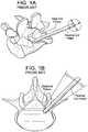
- FIGS. 1A and 1Bdisclose the desired ranges of motion for the systems of the present invention.
- FIG. 2discloses a first embodiment of the present invention having a slidable collar.
- FIG. 3discloses a second embodiment of the present invention having a substantially spherical element attached to the tube.
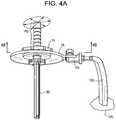
- FIGS. 4A-Bdiscloses a third embodiment of the present invention having a plurality of caps.
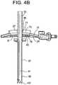
- FIGS. 5A-Cdisclose the different steps of mounting and securing the embodiment of FIG. 4 .
- FIG. 6Adiscloses an exploded view of the apparatus of the fourth embodiment of the present invention.
- FIG. 6Bdiscloses an assembled view of the apparatus of the fourth embodiment of the present invention.
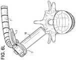
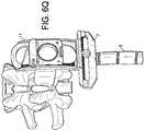
- FIGS. 6C, 6K, 6L, 6M, 6N and 6Odisclose various desirable orientations of the fourth apparatus embodiment relative to a functional spinal unit.
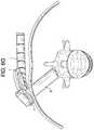
- FIGS. 6D-6Edisclose the possible cranial-caudal tilt angles of the fourth embodiment.
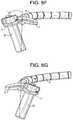
- FIGS. 6F-6Gdisclose the possible medial-lateral tilt angles of the fourth embodiment.
- FIGS. 6H-6Jdisclose respective side, perspective and top views of the fourth embodiment apparatus.
- FIGS. 6K-6Odisclose various views of the apparatus in relation to the spine.
- FIGS. 6P-6Qdisclose views of the fourth embodiment apparatus wherein the medial-lateral bar runs parallel to the spine.
- FIG. 7discloses an apparatus for supporting a surgical instrument, such as an endoscope, in relation to a patient.
- the “distal end portion of the tube”is the portion of the tube that is nearest to the patient and furthest from the surgeon when the tube is inserted into the patient
- the “proximal end portion of the tube”is the portion of the tube that is furthest from the patient and nearest to the surgeon when the tube is inserted into the patient.
- a working channel” and “a tube”are considered to be interchangeable.
- a surgical instrument, or surgical visualization instrumentcan be inserted through the tube, mounted to an interior or exterior of the tube, and/or movably or fixedly coupled to the tube. While tubes are described in many of the examples herein, the tube can be replaced with a surgical instrument, such as an endoscope or surgical visualization instrument.
- a minimally-invasive surgical access systemcomprising;
- a tube 1having an outer wall 3 , a longitudinal bore 5 , a proximal end portion 7 and a distal end portion 9 ;
- a sliding tab 11comprising a collar 13 having a pair of opposed flanges 15 extending therefrom, wherein the collar is slidable along the outer wall of the tube;
- annular frame 17having a pair of substantially opposed slots 19 , wherein the flanges of the collar respectively extend through the slots of the annular frame, and wherein the tube extends through the annular frame.
- the embodiment shown in FIG. 2includes an annular frame that can be fixed onto a stationary unit, such as the operating table, so as to anchor the system.
- the distal end portion of the tubecan be fixed onto the bony structures (such as a vertebral body) or soft tissues (such as disc cartilage) within the lumbar spine.
- the proximal end portion of the tubecan move in a substantially conical volume, with the distal end of the tube being its apex.
- the fixed-in-space annular frame of the embodiment of FIG. 2limits the range of the motion of the proximal end portion of the tube.
- the sliding tab component of the systemis comprised of a collar with a pair of opposed flanges extending therefrom.
- the shape of the flangesdescribes a portion of a spherical surface that mimics the limited motion of the tube.
- the outer annular framehas a pair of opposed matching slots that slidably receive their respective flanges.
- each slotis shaped as an arc that matches the arc-like transverse cross-section of the flange it receives.
- the working channelis mounted and fixed onto the sliding tab using a set screw 21 that is received in a threaded hole in the collar.
- the set screwcan extend through the collar and contact the outer wall of the tube in the proximal end portion of the tube so as to lock the collar to the tube, thereby preventing the motion of the tube channel in the axial direction.
- the limits of the lateral motion of the proximal end portionare defined by the outer annular frame.
- the outer annular framecan be fixed onto the operating table 24 using an extension arm 23 .
- the systemfurther comprises an arm extending from a stationary unit, wherein the arm is attached to the annular frame.
- the collarcomprises a threaded hole
- the systemfurther comprises a set screw received in the threaded hole of the collar.
- the set screwcan extend through the collar and contact the outer wall of the tube in the proximal end portion of the tube to lock the collar to the tube.
- each flangecomprises a portion of a spherical surface 25 and each slot describes an arc, wherein the flange mates with the slot.
- the distal end portion of the tubehas a docking feature (such as a plurality of distally-extending teeth 27 ) adapted to dock to bone or cartilage.
- the collardoes not contact the annular frame.
- the annular framehas a cutout 29 adapted to allow access by a screwdriver to the collar in order to tighten or loosen the set screw.
- this cutoutaligns radially with the set screw.
- the proximal end portion of the tubeis able to move in a substantially frustoconical volume when the distal end portion of the tube is fixed.
- the tubecan be a surgical instrument, can be replaced with a surgical instrument, and/or can include a surgical instrument, e.g., inserted therethrough.
- the surgical instrumentcan be an endoscope or other visualization instrument.
- the systemneed not necessarily provide surgical access, but rather can be used solely for supporting an endoscope or other surgical instrument, or for doing this in combination with other functions.
- a minimally-invasive surgical access systemcomprising;
- a tube 31having an outer wall 33 , a longitudinal bore 35 , a proximal end portion 37 , a distal end portion 39 , and a substantially spherical element 41 radially surrounding a segment of the outer wall;
- a sliding tab 43having a base 45 and a pair of opposed flanges 47 extending therefrom; the base having a hole 48 therethrough defining a rim 49 having a static portion 51 and a slidable portion 53 ,
- annular frame 55having a pair of substantially opposed slots 57 , wherein each flange of the sliding tab extends through a respective slot of the annular frame, wherein the tube extends through the annular frame, and wherein the static portion of the rim releasably contacts a first portion of the substantially spherical element and the slidable portion of the rim releasably contacts a second portion of the substantially spherical element.
- the second embodiment of FIG. 3includes an outer annular frame that could be fixed onto a stationary unit, such as the operating table.
- the distal end portion of the tubecan be fixed onto the bony structures or soft tissues of the spine, so that the proximal end portion of the tube can move in a substantially frustoconical volume with the distal tip being the apex.
- the sliding tabhas flat flanges, which are easier to manufacture.
- the outer annular framehas a pair of simple, linear slots to slidably receive the flanges.
- the sliding tabhas an axial hole therein defining a rim, the rim comprising a static hemispherical portion, as well as a movable hemispherical portion.
- the set screw 61can be turned to move the dynamic hemisphere to hold or release the spherical protrusion of the working channel, thereby fixing or release the angel of the sliding tab with respect to the tube. This allows for the movement on the desired range.
- the whole structureallows for sideways motion of the distal end in a given range (defined by the slot on the outer frame) and blocks the axial motion of the distal end.
- the systemfurther comprises an arm 63 extending from a stationary unit 64 , wherein the arm is attached to the annular frame.
- the basecomprises a first cutout 65 , and further comprises a sliding door 66 slidably received in the cutout.
- the sliding doorcomprises the second portion of the rim.
- the sliding doorfurther comprises a substantially hemispherical portion extending from the slidable portion of the rim, wherein the substantially hemispherical portion releasably contacts the second portion of the substantially spherical element to lock the sliding tab to the tube.
- the sliding dooris slidably actuated by a set screw.
- each flange of the sliding tabis flat and each respective slot is substantially rectangular, so that the flange mates with the slot.
- the distal end portion of the tubehas a docking feature (such as distally extending teeth 67 ) adapted to dock to bone or cartilage.
- the substantially spherical elementdoes not contact the annular frame.
- the annular framehas a second cutout 69 (designed to allow access by a screwdriver) that aligns radially with the set screw.
- the proximal end portion of the tubeis able to move in a substantially frustoconical volume when the distal end portion of the tube is fixed.
- the flat flanges of the sliding tabare not orthogonal to the tube.
- the tubecan be a surgical instrument, can be replaced with a surgical instrument, and/or can include a surgical instrument, e.g., inserted therethrough.
- the surgical instrumentcan be an endoscope or other visualization instrument.
- the systemneed not necessarily provide surgical access, but rather can be used solely for supporting an endoscope or other surgical instrument, or for doing this in combination with other functions.
- a minimally invasive surgical access systemcomprising;
- a tube 85having an outer wall 87 having an attachment portion 89 , a longitudinal bore 91 , a proximal end portion 93 , a distal end portion 95 , wherein the upper cap and the lower cap are attached to and radially extend from the outer wall of the tube, wherein at least one of the upper cap and the lower cap is removably attached to the outer wall of the tube, wherein the tube is received in the central hole of the middle cap, and wherein the middle cap is received between the upper cap and the lower cap.
- This conceptcomprises three spherical caps on top of each other.
- the middle capis the proximal point where the rigid arm is fixed.
- the lower capextends from the working channel and is preferably integral with the working channel. This lower cap helps to prevent the working channel from being pulled proximally through the hole of the middle cap.
- the middle caphas a hole of predetermined size that allows for limited lateral motion of the working channel, thereby defining the boundaries of allowed motion.
- the middle capis fixed to the operating table via attachments as described above. This middle cap may have a fixation element to help with the fixation.
- the upper caphas a threaded hole 97 and, when threaded onto the threaded 89 portion of the working channel, helps preventing the channel from advancing distally.
- this conceptallows for the motion of the working channel and at the same time allows for complete fixation of the distal and proximal ends of the working channel at desired direction.
- the upper capis located proximal to the lower cap.
- the middle caphas a fixation element 101 for fixation to a stationary unit.
- the systemfurther comprises an arm 103 extending from a stationary unit 105 , wherein the arm is attached to the fixation element.
- the proximal portion of the tubeis able to move in a substantially frustoconical volume when the distal end portion of the tube is fixed.
- the distal end portion of the tubehas a docking feature 107 adapted to dock to bone.
- the upper cap, middle cap, and lower capare located in a proximal-most quarter PQ of the tube.
- the upper caphas a threaded hole 97
- the outer wall of the working channelhas a threaded portion 89
- the upper capis threadably received on the threaded portion of the outer wall of the tube.
- the upper capis shown to be removable by virtue of its threadability upon the outer wall of the tube.
- removabilityis not restricted to threaded features.
- the tube and capmay provide a Morse taper lock.
- the capis made of an elastic material that snugly fits the outer wall of the tube.
- one of the upper cap and the lower capis removably attached to the outer wall of the tube, and the other is integrally attached to the outer wall of the tube.
- one of the upper or lower caphas a threaded hole
- the outer wallhas a threaded portion
- the cap having the threaded holeis threadably received on the threaded portion of the outer wall of the tube.
- both of the upper cap and the lower capare removably attached to the outer wall of the tube, preferably threadably attached.
- FIGS. 5A-CA functional prototype of this method is shown in FIGS. 5A-C , with different steps of mounting and securing.
- a tube having an upper threaded portion and a lower cap permanently attached theretois provided in FIG. 5A .
- FIG. 5Bthe middle cap is lowered onto the lower cap.
- FIG. 5Can upper cap with a threaded hole is placed over the middle cap and threaded onto the threaded portion of the tube, thereby trapping the middle cap between the upper and lower caps.
- the middle capis affixed to a stationary unit.
- the features of the upper and lower capsare reversed. Therefore, in accordance with the present invention, one of the upper cap and the lower cap is removably attached to the outer wall of the tube, and the other of the caps is integrally attached to the outer wall of the tube. Alternatively, both of the upper cap and the lower cap are removably attached to the outer wall of the tube.
- the tubecan be a surgical instrument, can be replaced with a surgical instrument, and/or can include a surgical instrument, e.g., inserted therethrough.
- the surgical instrumentcan be an endoscope or other visualization instrument.
- the systemneed not necessarily provide surgical access, but rather can be used solely for supporting an endoscope or other surgical instrument, or for doing this in combination with other functions.
- the tube of the working channel diameterto be larger-than-usual (e.g., from about 10 mm to about 30 mm in diameter), or
- an apparatuscomprising:
- an arm 1having a proximal end portion 3 connected to a stationary object and a distal end portion 5 ,
- a medial-lateral bar 7connected to the distal end portion of the arm and having a first rail 9 ;
- a cranial-caudal bar 11having:
- a working channel construct 17comprising:
- a tube 19having an outer surface 20 and a proximal end portion 22 , and
- a slider 21attached to the outer surface of the tube and having a first rail 23 in slidable engagement with the second rail of the cranial-caudal bar.
- This fourth embodimentfunctions substantially similarly to the previously-described embodiments.
- its working channel tubehas a restricted range of motion in the axial direction.
- the fourth embodimentalso allows for angular movement of the proximal end of the working channel construct, so as to always leave the tube's tip in the same position. See, for example, FIGS. 6D-6G .
- This fourth embodimentis especially suitable in direct decompression surgeries when a) the tube of the working channel diameter needs to be from about 10 mm to about 30 mm in diameter, or b) larger cranial-caudal and medial-lateral tilt angles are needed, so that a larger angular range of motion is needed.
- the working channel tubemay be attached to and detached from a slider.
- Various coupling or push-button mechanismscan be selected for this attachment.
- the slideris slidably connected to the cranial-caudal bar by mating rails.
- the mating rails of the slider and cranial-caudal barhave mating arcuate shapes. See FIGS. 6D-6E .
- the curvature of these arcuate railsis selected so that the common radius defined by their curves corresponds to the distance between the curve location and the tip of the working channel tube in the final assembly. In other words, the distal tip of the working channel tube defines the centerpoint of the circle described by the mating rails.
- the curved slider railcan smoothly glide along its mating curved rail of the cranial-caudal bar (thereby continuously changing the cranial-caudal angle of the working channel construct).
- the relative positions of these rails against each othercan be fixed.
- Various mechanismscan be selected to fix a relative position of these rails. For example, opposing teeth can be provided along each of the mating rails, as in FIG. 6A . These teeth can act as anchors when a fixation is desired. This fixation defines the cranial-caudal angle of the working channel tube.
- the first and second rails of the cranial-caudal barare each arcuate.
- the arcs of these railsare equal, so that the cranial-caudal bar defines a spherical surface.
- the center of the sphereis defined by the tip location of the working channel construct in the final assembly.
- the rail of the medial-lateral barmates with the first rail of the cranial-caudal bar and so also preferably has an arcuate shape of the same radius.
- the two bar componentsare slidably connected to each other by these arcuate rails.
- a bolt-slot connection or similar constructcan be used to slidably connect the two bars in order to assure that the cranial-caudal bar not only keeps its perpendicular orientation relative to the medial-lateral bar, but is also able to slide along the slot.
- the position of the cranial-caudal bar relative to the medial-lateral bardefines the medial-lateral angle of the working channel construct.
- the positioncan be fixed if desired.
- Various mechanismscan be considered to realize the position of fixation. For example, teeth can be provided along each rail that act as anchors.
- the medial-lateral baris attached to a rigid arm, whose position can be fixed relative to the operating room table during the surgery.
- the cranial-caudal baris shown in FIG. 6A as having four rails forming a rectangle with an internal window, in some embodiments, the cranial-caudal bar could potentially consist of 3 rails (defining a “U”-Shape) or 2 rails (defining an “L-” shape).
- the described “4-rail” configurationlikely provides for the highest stability of these embodiments against bending of the working channel construct around the axis along the bar, and can provide for the finest dimensions of the rails at the same time, an very stiff sliding/connection mechanism that only needs support from one rail, or without the stabilization of the closing-rod, can also be considered as well.
- the cranial-caudal barhas a release button 25 for releasable attachment to the medial-lateral bar.
- pressing this buttonreleases the engagement of a teeth-like element on the cranial-caudal bar within the tee engages the teeth of the rail of the medial-lateral bar.
- the sliderhas a release button 27 for releasable attachment to the cranial-caudal bar.
- this buttonengages the teeth of the second rail of the cranial-caudal bar.
- the medial-lateral barhas a first window 29 or slot therein for slidable reception of the cranial-caudal bar.
- the slotis adjacent the rail of the medial-lateral bar, and the first rail of the cranial-caudal bar has a bolt-like shape so as to provide a slidable bolt-slot connection with the medial-lateral bar.
- the cranial-caudal barhas a third rail 31 extending from the first rail of the cranial-caudal bar in a direction substantially parallel to the second rail of the cranial-caudal bar.
- This embodimentcan provide a cranial-caudal bar having a U-shape.
- stopscan be provided at the two ends of the U-shape so that the slider remains within the pocket of the U-shape.
- the sliderfurther comprises iii) a second rail (not shown) substantially parallel to the first rail of the slider, wherein the second rail of the slider is in slidable engagement with the third rail of the cranial-caudal bar.
- the tubeis disposed between the second and third rails of the cranial-caudal bar. This allows the forces that act upon the tube to be evenly supported by the pair of rails of the cranial-caudal bar.
- a fourth rail (connecting bar) 35connects the second and third rails of the cranial-caudal bar to form a second window 37 , and the tube extends through the second window. This ensures that the slider will remain slidably attached to the cranial-caudal bar.
- the first rail of the medial-lateral bar and the first rail of the cranial-caudal barhave mating teeth 39 thereon
- the second rail of the cranial-caudal bar and the first rail of the working channel constructhave mating teeth 41 thereon.
- a medical deviceis located within the tube.
- the medical deviceis an instrument, while in others the medical device is an implant.
- the medical deviceis passed from the proximal end portion of the tube to the distal end portion of the working tube.
- the first rail of the medial-lateral bar and the first rail of the cranial-caudal barhave matching arcuate shapes. This allows the tube to be tilted with respect to the patient in a first plane while maintaining the location of the distal end of the tube.
- the second rail of the cranial-caudal bar and the first rail of the sliderhave matching arcuate shapes. This allows the tube to be tilted with respect to the patient in a second plane while maintaining the location of the distal end of the tube.
- the slideris attachable and detachable from/to the outer surface of the tube at the proximal end portion of the tube. This allows a fine control of the location of the proximal end portion of the tube. This allows as well that the tube can be introduced into the patient at the right location in a first step of a surgery.
- the rest of the componentsare pre-assembled and can be attached to the tube at this attachment location of the slider, while the arm is in a flexible configuration. After attaching the tube to the rest of the assembly, the arm can be brought to a rigid configuration, leaving only the option of changing the position of the tube, with respect to the patient to the angular changes by the rail connections.
- the first rail of the cranial-caudalis in slidable engagement with the first rail of the medial-lateral bar by virtue of a bolt-slot connection. This arrangement helps maintain the orientation of the cranial-caudal bar vis-a-vis the medial-lateral bar.
- FIGS. 6K-6Ldisclose views of the fourth embodiment apparatus wherein the medial-lateral bar runs parallel to the spine.
- the tubecan be a surgical instrument, can be replaced with a surgical instrument, and/or can include a surgical instrument, e.g., inserted therethrough.
- the surgical instrumentcan be an endoscope or other visualization instrument.
- the systemneed not necessarily provide surgical access, but rather can be used solely for supporting an endoscope or other surgical instrument, or for doing this in combination with other functions.
- FIG. 7illustrates an exemplary embodiment in which the tube is replaced with an endoscope 59 .
- the endoscopecan be flexible or rigid.
- the endoscopecan include any one or more of a lens, a light source, a camera, an eyepiece, and a working channel.
- the endoscopecan be cystoscope, nephroscope, bronchoscope, arthroscope, colonoscope, and/or laparoscope.
- the endoscopecan be used to visualize a surgical site within a patient's body, such as the spine, abdomen, pelvis, joints, GI system, colon, bladder, kidney, throat, ear, cranium, or the like.
- the components of the present inventionare preferably made from a biocompatible metal such as stainless steel, titanium alloy or cobalt-chrome. However, it is contemplated that the components can be made from polymeric materials so as to provide an inexpensive, single use system.
Landscapes
- Health & Medical Sciences (AREA)
- Life Sciences & Earth Sciences (AREA)
- Surgery (AREA)
- Molecular Biology (AREA)
- Animal Behavior & Ethology (AREA)
- Veterinary Medicine (AREA)
- Nuclear Medicine, Radiotherapy & Molecular Imaging (AREA)
- Public Health (AREA)
- General Health & Medical Sciences (AREA)
- Medical Informatics (AREA)
- Heart & Thoracic Surgery (AREA)
- Engineering & Computer Science (AREA)
- Biomedical Technology (AREA)
- Orthopedic Medicine & Surgery (AREA)
- Pathology (AREA)
- Neurology (AREA)
- Radiology & Medical Imaging (AREA)
- Physics & Mathematics (AREA)
- Optics & Photonics (AREA)
- Biophysics (AREA)
- Oral & Maxillofacial Surgery (AREA)
- Endoscopes (AREA)
- Surgical Instruments (AREA)
Abstract
Description
This application is a continuation of U.S. application Ser. No. 15/695,046, filed on Sep. 5, 2017. U.S. application Ser. No. 15/695,046 is a continuation-in-part of U.S. application Ser. No. 14/546,620, filed on Nov. 18, 2014 (issued as U.S. Pat. No. 10,111,712). U.S. application Ser. No. 14/546,620 is a continuation-in-part of U.S. application Ser. No. 14/481,822, filed on Sep. 9, 2014 (issued as U.S. Pat. No. 9,924,979). The entire contents of each of these applications are hereby incorporated by reference.
The general trend in the treatment of the spinal pathologies is toward minimally invasive approaches to reduce the trauma on the surrounding tissues during the operation. For treatment of the lumbar spine pathologies, a percutaneous approach may be chosen within a working channel of 4-12 mm. The working channel serves as a safety barrier between the working instruments and the sensitive tissues (e.g. nerves and blood vessels) during the operation. The process of treatment including disc removal, endplate preparation, implant insertion and graft material insertion should be performed through the working channel.
In order to ensure the safety of these procedures, the distal end portion of the working channel (from surgeon's perspective) should be secured/anchored onto desired points (seeFIGS. 1A and 1B ). Typically, these points are either bone or disc tissue. In addition to the fixation of the distal end portion of the working channel, depending on the procedure that is being performed, the proximal end portion of the working channel needs to be able to either move laterally, move cranially/caudally, or be substantially fixed. For example, during disc removal, the surgeon might want to change the angle of the working channel in order to gain better access to more of the remaining disc tissue (seeFIG. 1B ). At the same time, it might be desired that this motion be limited to a given range, and to be fixed in the axial direction. Furthermore, in some instances, it might be desired for the proximal portion of the working channel to be fully fixed in order to create a two-point fixed channel between proximal and distal portion.
Therefore, the present invention is directed at minimally invasive systems in which the proximal end portion of the working channel has either zero or a limited range of movement in the lateral direction.
Therefore, in accordance with the present invention, there is provided a minimally-invasive surgical access system, comprising;
a) a tube having an outer wall, a longitudinal bore, a proximal end portion and a distal end portion;
b) a sliding tab comprising a collar having a pair of opposed flanges extending therefrom, wherein the collar is slidable along the outer wall of the tube; and
c) an annular frame having a pair of substantially opposed slots, wherein the flanges of the collar respectively extend through the slots of the annular frame, and wherein the tube extends through the annular frame.
Therefore, in accordance with the present invention, there is provided a minimally-invasive surgical access system, comprising;
a) a tube having an outer wall, a longitudinal bore, a proximal end portion, a distal end portion, and a substantially spherical element radially surrounding a segment of the outer wall;
b) a sliding tab having a base and a pair of opposed flanges extending therefrom; the base having a hole therethrough defining a rim having a static portion and a slidable portion,
c) an annular frame having a pair of substantially opposed slots, wherein each flange of the sliding tab extends through a respective slot of the annular frame, wherein the tube extends through the annular frame, and wherein the static portion of the rim releasably contacts a first portion of the substantially spherical element and the slidable portion of the rim releasably contacts a second portion of the substantially spherical element.
Therefore, in accordance with the present invention, there is provided a minimally invasive surgical access system, comprising;
a) an upper cap describing a first portion of a substantially spherical surface,
b) an middle cap describing a second portion of the substantially spherical surface and having a central hole,
c) a lower cap describing a third portion of the substantially spherical surface,
d) a tube having an outer wall having an attachment portion, a longitudinal bore, a proximal end portion, a distal end portion, wherein the upper cap and the lower cap are attached to and radially extend from the outer wall of the tube, wherein at least one of the upper cap and the lower cap is removably attached to the outer wall of the tube, wherein the tube is received in the central hole of the middle cap, and wherein the middle cap is received between the upper cap and the lower cap.
In some aspects, the present invention is directed at surgical systems for supporting an endoscope or other instrument.
Therefore, in accordance with the present invention, there is provided a surgical system, comprising;
a) an instrument having an outer wall, a proximal end portion and a distal end portion;
b) a sliding tab comprising a collar having a pair of opposed flanges extending therefrom, wherein the collar is slidable along the outer wall of the instrument; and
c) an annular frame having a pair of substantially opposed slots, wherein the flanges of the collar respectively extend through the slots of the annular frame, and wherein the instrument extends through the annular frame.
In some embodiments, the instrument can be an endoscope or surgical visualization instrument.
Therefore, in accordance with the present invention, there is provided a surgical system, comprising;
a) an instrument having an outer wall, a proximal end portion, a distal end portion, and a substantially spherical element radially surrounding a segment of the outer wall;
b) a sliding tab having a base and a pair of opposed flanges extending therefrom; the base having a hole therethrough defining a rim having a static portion and a slidable portion,
c) an annular frame having a pair of substantially opposed slots, wherein each flange of the sliding tab extends through a respective slot of the annular frame, wherein the instrument extends through the annular frame, and wherein the static portion of the rim releasably contacts a first portion of the substantially spherical element and the slidable portion of the rim releasably contacts a second portion of the substantially spherical element.
In some embodiments, the instrument can be an endoscope or surgical visualization instrument.
Therefore, in accordance with the present invention, there is provided a surgical system, comprising;
a) an upper cap describing a first portion of a substantially spherical surface,
b) an middle cap describing a second portion of the substantially spherical surface and having a central hole,
c) a lower cap describing a third portion of the substantially spherical surface,
d) an instrument having an outer wall having an attachment portion, a proximal end portion, a distal end portion, wherein the upper cap and the lower cap are attached to and radially extend from the outer wall of the instrument, wherein at least one of the upper cap and the lower cap is removably attached to the outer wall of the instrument, wherein the instrument is received in the central hole of the middle cap, and wherein the middle cap is received between the upper cap and the lower cap.
In some embodiments, the instrument can be an endoscope or surgical visualization instrument.
For the purposes of the present invention, the “distal end portion of the tube” is the portion of the tube that is nearest to the patient and furthest from the surgeon when the tube is inserted into the patient, and the “proximal end portion of the tube” is the portion of the tube that is furthest from the patient and nearest to the surgeon when the tube is inserted into the patient. Also, “a working channel” and “a tube” are considered to be interchangeable. In some embodiments, a surgical instrument, or surgical visualization instrument, can be inserted through the tube, mounted to an interior or exterior of the tube, and/or movably or fixedly coupled to the tube. While tubes are described in many of the examples herein, the tube can be replaced with a surgical instrument, such as an endoscope or surgical visualization instrument.
In the following description, several concepts are described covering the subjects of a) limiting lateral motion of the proximal end portion of the tube, b) eliminating the lateral motion of the proximal end portion of the tube, and c) eliminating the axial motion of the proximal end portion of the tube.
Now referring toFIG. 2 , there is provided a minimally-invasive surgical access system, comprising;
a) a tube1 having anouter wall 3, alongitudinal bore 5, aproximal end portion 7 and adistal end portion 9;
b) a slidingtab 11 comprising acollar 13 having a pair ofopposed flanges 15 extending therefrom, wherein the collar is slidable along the outer wall of the tube; and
c) anannular frame 17 having a pair of substantially opposedslots 19, wherein the flanges of the collar respectively extend through the slots of the annular frame, and wherein the tube extends through the annular frame.
The embodiment shown inFIG. 2 includes an annular frame that can be fixed onto a stationary unit, such as the operating table, so as to anchor the system. As previously described, the distal end portion of the tube can be fixed onto the bony structures (such as a vertebral body) or soft tissues (such as disc cartilage) within the lumbar spine. When the tube is so distally anchored, the proximal end portion of the tube can move in a substantially conical volume, with the distal end of the tube being its apex. The fixed-in-space annular frame of the embodiment ofFIG. 2 limits the range of the motion of the proximal end portion of the tube. The sliding tab component of the system is comprised of a collar with a pair of opposed flanges extending therefrom. Preferably, the shape of the flanges describes a portion of a spherical surface that mimics the limited motion of the tube. The outer annular frame has a pair of opposed matching slots that slidably receive their respective flanges. Preferably, each slot is shaped as an arc that matches the arc-like transverse cross-section of the flange it receives. The working channel is mounted and fixed onto the sliding tab using aset screw 21 that is received in a threaded hole in the collar. The set screw can extend through the collar and contact the outer wall of the tube in the proximal end portion of the tube so as to lock the collar to the tube, thereby preventing the motion of the tube channel in the axial direction. The limits of the lateral motion of the proximal end portion are defined by the outer annular frame. The outer annular frame can be fixed onto the operating table24 using anextension arm 23.
Therefore, in preferred embodiments of the first embodiment of the present invention, the system further comprises an arm extending from a stationary unit, wherein the arm is attached to the annular frame. Preferably, the collar comprises a threaded hole, and the system further comprises a set screw received in the threaded hole of the collar. Preferably, the set screw can extend through the collar and contact the outer wall of the tube in the proximal end portion of the tube to lock the collar to the tube. Preferably, each flange comprises a portion of aspherical surface 25 and each slot describes an arc, wherein the flange mates with the slot. Preferably, the distal end portion of the tube has a docking feature (such as a plurality of distally-extending teeth27) adapted to dock to bone or cartilage. In some embodiments, the collar does not contact the annular frame. In some embodiments, the annular frame has acutout 29 adapted to allow access by a screwdriver to the collar in order to tighten or loosen the set screw. Preferably, this cutout aligns radially with the set screw. Preferably, the proximal end portion of the tube is able to move in a substantially frustoconical volume when the distal end portion of the tube is fixed. The tube can be a surgical instrument, can be replaced with a surgical instrument, and/or can include a surgical instrument, e.g., inserted therethrough. The surgical instrument can be an endoscope or other visualization instrument. The system need not necessarily provide surgical access, but rather can be used solely for supporting an endoscope or other surgical instrument, or for doing this in combination with other functions.
Now referring toFIG. 3 , there is provided a minimally-invasive surgical access system, comprising;
a) atube 31 having anouter wall 33, alongitudinal bore 35, aproximal end portion 37, adistal end portion 39, and a substantiallyspherical element 41 radially surrounding a segment of the outer wall;
b) a slidingtab 43 having a base45 and a pair ofopposed flanges 47 extending therefrom; the base having ahole 48 therethrough defining arim 49 having astatic portion 51 and aslidable portion 53,
c) anannular frame 55 having a pair of substantially opposedslots 57, wherein each flange of the sliding tab extends through a respective slot of the annular frame, wherein the tube extends through the annular frame, and wherein the static portion of the rim releasably contacts a first portion of the substantially spherical element and the slidable portion of the rim releasably contacts a second portion of the substantially spherical element.
The second embodiment ofFIG. 3 includes an outer annular frame that could be fixed onto a stationary unit, such as the operating table. As previously described, the distal end portion of the tube can be fixed onto the bony structures or soft tissues of the spine, so that the proximal end portion of the tube can move in a substantially frustoconical volume with the distal tip being the apex. In this particular embodiment, the sliding tab has flat flanges, which are easier to manufacture. Likewise, the outer annular frame has a pair of simple, linear slots to slidably receive the flanges. The sliding tab has an axial hole therein defining a rim, the rim comprising a static hemispherical portion, as well as a movable hemispherical portion. As the working channel passes into the sliding-tab, theset screw 61 can be turned to move the dynamic hemisphere to hold or release the spherical protrusion of the working channel, thereby fixing or release the angel of the sliding tab with respect to the tube. This allows for the movement on the desired range. The whole structure allows for sideways motion of the distal end in a given range (defined by the slot on the outer frame) and blocks the axial motion of the distal end.
Preferably, in this second embodiment, the system further comprises anarm 63 extending from astationary unit 64, wherein the arm is attached to the annular frame. Preferably, the base comprises afirst cutout 65, and further comprises a slidingdoor 66 slidably received in the cutout. Preferably, the sliding door comprises the second portion of the rim. Preferably, the sliding door further comprises a substantially hemispherical portion extending from the slidable portion of the rim, wherein the substantially hemispherical portion releasably contacts the second portion of the substantially spherical element to lock the sliding tab to the tube. Preferably, the sliding door is slidably actuated by a set screw. Preferably, each flange of the sliding tab is flat and each respective slot is substantially rectangular, so that the flange mates with the slot. Preferably, the distal end portion of the tube has a docking feature (such as distally extending teeth67) adapted to dock to bone or cartilage. In some embodiments, the substantially spherical element does not contact the annular frame. Preferably, the annular frame has a second cutout69 (designed to allow access by a screwdriver) that aligns radially with the set screw. Preferably, the proximal end portion of the tube is able to move in a substantially frustoconical volume when the distal end portion of the tube is fixed. In some embodiments, the flat flanges of the sliding tab are not orthogonal to the tube. The tube can be a surgical instrument, can be replaced with a surgical instrument, and/or can include a surgical instrument, e.g., inserted therethrough. The surgical instrument can be an endoscope or other visualization instrument. The system need not necessarily provide surgical access, but rather can be used solely for supporting an endoscope or other surgical instrument, or for doing this in combination with other functions.
Now referring toFIGS. 4A-4B , there is provided a minimally invasive surgical access system, comprising;
a) anupper cap 71 describing afirst portion 73 of a substantially spherical surface,
b) anmiddle cap 75 describing a second portion77 of the substantially spherical surface and having acentral hole 79,
c) alower cap 81 describing athird portion 83 of the substantially spherical surface,
d) atube 85 having anouter wall 87 having anattachment portion 89, alongitudinal bore 91, aproximal end portion 93, adistal end portion 95, wherein the upper cap and the lower cap are attached to and radially extend from the outer wall of the tube, wherein at least one of the upper cap and the lower cap is removably attached to the outer wall of the tube, wherein the tube is received in the central hole of the middle cap, and wherein the middle cap is received between the upper cap and the lower cap.
This concept comprises three spherical caps on top of each other. The middle cap is the proximal point where the rigid arm is fixed. The lower cap extends from the working channel and is preferably integral with the working channel. This lower cap helps to prevent the working channel from being pulled proximally through the hole of the middle cap. The middle cap has a hole of predetermined size that allows for limited lateral motion of the working channel, thereby defining the boundaries of allowed motion. The middle cap is fixed to the operating table via attachments as described above. This middle cap may have a fixation element to help with the fixation. The upper cap has a threadedhole 97 and, when threaded onto the threaded89 portion of the working channel, helps preventing the channel from advancing distally. In this concept, if the upper cap is advanced distally, it will create friction between the caps and will prevent the motion of the caps relative to each other. In other words, this concept allows for the motion of the working channel and at the same time allows for complete fixation of the distal and proximal ends of the working channel at desired direction.
Preferably, in the embodiment ofFIG. 4 , the upper cap is located proximal to the lower cap. Preferably, the middle cap has afixation element 101 for fixation to a stationary unit. Preferably, the system further comprises anarm 103 extending from astationary unit 105, wherein the arm is attached to the fixation element. Preferably, the proximal portion of the tube is able to move in a substantially frustoconical volume when the distal end portion of the tube is fixed. Preferably, the distal end portion of the tube has adocking feature 107 adapted to dock to bone. Preferably, the upper cap, middle cap, and lower cap are located in a proximal-most quarter PQ of the tube.
In some embodiments, the upper cap has a threadedhole 97, the outer wall of the working channel has a threadedportion 89, and wherein the upper cap is threadably received on the threaded portion of the outer wall of the tube.
InFIG. 4 , the upper cap is shown to be removable by virtue of its threadability upon the outer wall of the tube. However, removability is not restricted to threaded features. For example, in some embodiments, the tube and cap may provide a Morse taper lock. In other embodiments, the cap is made of an elastic material that snugly fits the outer wall of the tube.
In some embodiments, one of the upper cap and the lower cap is removably attached to the outer wall of the tube, and the other is integrally attached to the outer wall of the tube.
In some embodiments, one of the upper or lower cap has a threaded hole, the outer wall has a threaded portion, and the cap having the threaded hole is threadably received on the threaded portion of the outer wall of the tube.
In some embodiments, both of the upper cap and the lower cap are removably attached to the outer wall of the tube, preferably threadably attached.
A functional prototype of this method is shown inFIGS. 5A-C , with different steps of mounting and securing. InFIG. 5A , a tube having an upper threaded portion and a lower cap permanently attached thereto is provided. InFIG. 5B , the middle cap is lowered onto the lower cap. InFIG. 5C , an upper cap with a threaded hole is placed over the middle cap and threaded onto the threaded portion of the tube, thereby trapping the middle cap between the upper and lower caps. Lastly, the middle cap is affixed to a stationary unit.
In some embodiments, the features of the upper and lower caps are reversed. Therefore, in accordance with the present invention, one of the upper cap and the lower cap is removably attached to the outer wall of the tube, and the other of the caps is integrally attached to the outer wall of the tube. Alternatively, both of the upper cap and the lower cap are removably attached to the outer wall of the tube.
The tube can be a surgical instrument, can be replaced with a surgical instrument, and/or can include a surgical instrument, e.g., inserted therethrough. The surgical instrument can be an endoscope or other visualization instrument. The system need not necessarily provide surgical access, but rather can be used solely for supporting an endoscope or other surgical instrument, or for doing this in combination with other functions.
It is believed that the above-described embodiments are generally suitable for use in typical percutaneous spinal surgeries, in conjunction with working channel diameters of only a few millimeters. However, there are certain spinal surgeries in which use of the above embodiments could require very large and bulky constructs. These certain surgeries (which include direct decompression surgeries performed through a mini-open posterior or para-medial approach) often require:
a) the tube of the working channel diameter to be larger-than-usual (e.g., from about 10 mm to about 30 mm in diameter), or
b) larger cranial-caudal and medial-lateral tilt angles, so that a larger angular range of motion is realized.
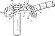
Therefore, in an effort to address these situations, in a fourth embodiment, and now referring toFIGS. 6A-6O , there is provided an apparatus comprising:
a) an arm1 having aproximal end portion 3 connected to a stationary object and adistal end portion 5,
b) a medial-lateral bar 7 connected to the distal end portion of the arm and having afirst rail 9;
c) a cranial-caudal bar 11 having:
i) afirst rail 13 in slidable engagement with the first rail of the medial-lateral bar in a first direction and
ii) asecond rail 15 extending substantially perpendicularly from the first rail of the cranial-caudal bar;
d) a workingchannel construct 17 comprising:
i) atube 19 having anouter surface 20 and aproximal end portion 22, and
ii) aslider 21 attached to the outer surface of the tube and having afirst rail 23 in slidable engagement with the second rail of the cranial-caudal bar.
This fourth embodiment functions substantially similarly to the previously-described embodiments. For example, its working channel tube has a restricted range of motion in the axial direction. Secondly, the fourth embodiment also allows for angular movement of the proximal end of the working channel construct, so as to always leave the tube's tip in the same position. See, for example,FIGS. 6D-6G .
This fourth embodiment is especially suitable in direct decompression surgeries when a) the tube of the working channel diameter needs to be from about 10 mm to about 30 mm in diameter, or b) larger cranial-caudal and medial-lateral tilt angles are needed, so that a larger angular range of motion is needed.
InFIG. 6A-6B of the present invention, during the surgery, the working channel tube may be attached to and detached from a slider. Various coupling or push-button mechanisms can be selected for this attachment.
InFIGS. 6A-6O , the slider is slidably connected to the cranial-caudal bar by mating rails. Preferably, the mating rails of the slider and cranial-caudal bar have mating arcuate shapes. SeeFIGS. 6D-6E . Preferably, the curvature of these arcuate rails is selected so that the common radius defined by their curves corresponds to the distance between the curve location and the tip of the working channel tube in the final assembly. In other words, the distal tip of the working channel tube defines the centerpoint of the circle described by the mating rails. In this way, it is insured that when the position of the slider along the rail of the cranial-caudal bar is changed in space, the location in space of the centerpoint tube distal end does not change, only the direction of the working channel tube central axis changes. Typically, the curved slider rail can smoothly glide along its mating curved rail of the cranial-caudal bar (thereby continuously changing the cranial-caudal angle of the working channel construct). However, in some embodiments, the relative positions of these rails against each other can be fixed. Various mechanisms can be selected to fix a relative position of these rails. For example, opposing teeth can be provided along each of the mating rails, as inFIG. 6A . These teeth can act as anchors when a fixation is desired. This fixation defines the cranial-caudal angle of the working channel tube.
InFIGS. 6A-6O , the first and second rails of the cranial-caudal bar are each arcuate. Preferably, the arcs of these rails are equal, so that the cranial-caudal bar defines a spherical surface. The center of the sphere is defined by the tip location of the working channel construct in the final assembly. The rail of the medial-lateral bar mates with the first rail of the cranial-caudal bar and so also preferably has an arcuate shape of the same radius. The two bar components are slidably connected to each other by these arcuate rails. A bolt-slot connection or similar construct can be used to slidably connect the two bars in order to assure that the cranial-caudal bar not only keeps its perpendicular orientation relative to the medial-lateral bar, but is also able to slide along the slot. The position of the cranial-caudal bar relative to the medial-lateral bar defines the medial-lateral angle of the working channel construct. The position can be fixed if desired. Various mechanisms can be considered to realize the position of fixation. For example, teeth can be provided along each rail that act as anchors.
InFIG. 6C , the medial-lateral bar is attached to a rigid arm, whose position can be fixed relative to the operating room table during the surgery.
Although the cranial-caudal bar is shown inFIG. 6A as having four rails forming a rectangle with an internal window, in some embodiments, the cranial-caudal bar could potentially consist of 3 rails (defining a “U”-Shape) or 2 rails (defining an “L-” shape). Although the described “4-rail” configuration likely provides for the highest stability of these embodiments against bending of the working channel construct around the axis along the bar, and can provide for the finest dimensions of the rails at the same time, an very stiff sliding/connection mechanism that only needs support from one rail, or without the stabilization of the closing-rod, can also be considered as well.
In some embodiments (as inFIG. 6B ), the cranial-caudal bar has arelease button 25 for releasable attachment to the medial-lateral bar. Typically, pressing this button releases the engagement of a teeth-like element on the cranial-caudal bar within the tee engages the teeth of the rail of the medial-lateral bar.
In some embodiments (as inFIG. 6B ), the slider has arelease button 27 for releasable attachment to the cranial-caudal bar. Typically, this button engages the teeth of the second rail of the cranial-caudal bar.
In some embodiments (as inFIG. 6A ), the medial-lateral bar has afirst window 29 or slot therein for slidable reception of the cranial-caudal bar. Typically, the slot is adjacent the rail of the medial-lateral bar, and the first rail of the cranial-caudal bar has a bolt-like shape so as to provide a slidable bolt-slot connection with the medial-lateral bar.
In some embodiments (as inFIG. 6A ), the cranial-caudal bar has athird rail 31 extending from the first rail of the cranial-caudal bar in a direction substantially parallel to the second rail of the cranial-caudal bar. This embodiment can provide a cranial-caudal bar having a U-shape. In this embodiment, stops can be provided at the two ends of the U-shape so that the slider remains within the pocket of the U-shape.
In some embodiments, the slider further comprises iii) a second rail (not shown) substantially parallel to the first rail of the slider, wherein the second rail of the slider is in slidable engagement with the third rail of the cranial-caudal bar.
In some embodiments (as inFIG. 6B ), the tube is disposed between the second and third rails of the cranial-caudal bar. This allows the forces that act upon the tube to be evenly supported by the pair of rails of the cranial-caudal bar.
In some embodiments (as inFIG. 6A ), a fourth rail (connecting bar)35 connects the second and third rails of the cranial-caudal bar to form asecond window 37, and the tube extends through the second window. This ensures that the slider will remain slidably attached to the cranial-caudal bar.
In some embodiments (as inFIG. 6B ), the first rail of the medial-lateral bar and the first rail of the cranial-caudal bar havemating teeth 39 thereon, and the second rail of the cranial-caudal bar and the first rail of the working channel construct havemating teeth 41 thereon. With the help of a member that is integrated to the component that is sliding along the rail with the teeth, and that can engage the teeth, this allows the relative positions of the components to be fixed, thereby insuring the location of the working channel tube relative to the patient.
In some embodiments, a medical device is located within the tube. In some embodiments, thereof, the medical device is an instrument, while in others the medical device is an implant. Typically, the medical device is passed from the proximal end portion of the tube to the distal end portion of the working tube.
In some embodiments, the first rail of the medial-lateral bar and the first rail of the cranial-caudal bar have matching arcuate shapes. This allows the tube to be tilted with respect to the patient in a first plane while maintaining the location of the distal end of the tube.
In some embodiments, the second rail of the cranial-caudal bar and the first rail of the slider have matching arcuate shapes. This allows the tube to be tilted with respect to the patient in a second plane while maintaining the location of the distal end of the tube.
In some embodiments, the slider is attachable and detachable from/to the outer surface of the tube at the proximal end portion of the tube. This allows a fine control of the location of the proximal end portion of the tube. This allows as well that the tube can be introduced into the patient at the right location in a first step of a surgery. The rest of the components are pre-assembled and can be attached to the tube at this attachment location of the slider, while the arm is in a flexible configuration. After attaching the tube to the rest of the assembly, the arm can be brought to a rigid configuration, leaving only the option of changing the position of the tube, with respect to the patient to the angular changes by the rail connections.
In some embodiments, the first rail of the cranial-caudal is in slidable engagement with the first rail of the medial-lateral bar by virtue of a bolt-slot connection. This arrangement helps maintain the orientation of the cranial-caudal bar vis-a-vis the medial-lateral bar.FIGS. 6K-6L disclose views of the fourth embodiment apparatus wherein the medial-lateral bar runs parallel to the spine.
The tube can be a surgical instrument, can be replaced with a surgical instrument, and/or can include a surgical instrument, e.g., inserted therethrough. The surgical instrument can be an endoscope or other visualization instrument. The system need not necessarily provide surgical access, but rather can be used solely for supporting an endoscope or other surgical instrument, or for doing this in combination with other functions.
For example,FIG. 7 illustrates an exemplary embodiment in which the tube is replaced with an endoscope59. The endoscope can be flexible or rigid. The endoscope can include any one or more of a lens, a light source, a camera, an eyepiece, and a working channel. The endoscope can be cystoscope, nephroscope, bronchoscope, arthroscope, colonoscope, and/or laparoscope. The endoscope can be used to visualize a surgical site within a patient's body, such as the spine, abdomen, pelvis, joints, GI system, colon, bladder, kidney, throat, ear, cranium, or the like.
The components of the present invention are preferably made from a biocompatible metal such as stainless steel, titanium alloy or cobalt-chrome. However, it is contemplated that the components can be made from polymeric materials so as to provide an inexpensive, single use system.
Claims (15)
1. An apparatus comprising:
a working channel tube having a proximal end and a distal end;
a generally rectangular first bar configured to form a window and defining a first arcuate path, wherein the window is bounded on one side by one end of the generally rectangular first bar;
a slider configured to attach to the working channel tube and slidably engaged within the window to the first bar such that the working channel tube is disposed through the window; and
a second bar configured to be stationary and defining a second arcuate path,
wherein the one end of the first bar slidably engages the second bar,
wherein the first bar is cantilevered from the second bar with a length of the first bar extending away from the one end and from the second bar such that the window and the working channel tube are disposed outside of the second bar,
wherein the slider is configured to control a tilt angle of the proximal end of the working channel tube in a first plane while maintaining a location of the distal end of the working channel tube by moving the slider within the window to a position along the first arcuate path defined by the first bar without moving or engaging the second bar, and
wherein the first bar is configured to control a tilt angle of the proximal end of the working channel tube in a second plane while maintaining the location of the distal end of the working channel tube by moving the first bar to a position along the second arcuate path defined by the second bar.
2. The apparatus ofclaim 1 , wherein the tilt angle in the first plane is a cranial-caudal tilt angle.
3. The apparatus ofclaim 1 , wherein the tilt angle in the second plane is a medial-lateral tilt angle.
4. The apparatus ofclaim 1 , further comprising:
an arm having a proximal end portion connected to a stationary object and a distal end portion connected to the second bar.
5. The apparatus ofclaim 1 , wherein the first bar includes at least one arcuate rail configured to define the first arcuate path.
6. The apparatus ofclaim 5 , wherein the slider includes at least one arcuate rail configured to slidably engage the at least one arcuate rail of the first bar that defines the first arcuate path.
7. The apparatus ofclaim 5 , wherein the at least one arcuate rail of the slider and the at least one arcuate rail of the first bar have a common radius of curvature.
8. The apparatus ofclaim 5 , wherein the at least one arcuate rail of the slider and the at least one arcuate rail of the first bar have mating teeth thereon.
9. The apparatus ofclaim 1 , wherein the second bar includes at least one arcuate rail configured to define the second arcuate path.
10. The apparatus ofclaim 9 , wherein the first bar includes at least one arcuate rail configured to slidably engage the at least one arcuate rail of the second bar that defines the second arcuate path.
11. The apparatus ofclaim 10 , wherein the at least one arcuate rail of the first bar and the at least one arcuate rail of the second bar have mating teeth thereon.
12. The apparatus ofclaim 1 , wherein the slider has a release mechanism for releasable attachment to the first bar.
13. The apparatus ofclaim 1 , wherein the first bar has a release button for releasable attachment to the second bar.
14. The apparatus ofclaim 1 , wherein the second bar defines a window therein for slidable reception of the first bar.
15. The apparatus ofclaim 1 , wherein the working channel tube has a diameter in the range of about 10 millimeters to about 30 millimeters.
Priority Applications (2)
| Application Number | Priority Date | Filing Date | Title |
|---|---|---|---|
| US16/358,372US11213196B2 (en) | 2014-09-09 | 2019-03-19 | Proximal-end securement of a minimally invasive working channel |
| US17/564,935US20220117482A1 (en) | 2014-09-09 | 2021-12-29 | Proximal-end securement of a minimally invasive working channel |
Applications Claiming Priority (4)
| Application Number | Priority Date | Filing Date | Title |
|---|---|---|---|
| US14/481,822US9924979B2 (en) | 2014-09-09 | 2014-09-09 | Proximal-end securement of a minimally invasive working channel |
| US14/546,620US10111712B2 (en) | 2014-09-09 | 2014-11-18 | Proximal-end securement of a minimally invasive working channel |
| US15/695,046US10264959B2 (en) | 2014-09-09 | 2017-09-05 | Proximal-end securement of a minimally invasive working channel |
| US16/358,372US11213196B2 (en) | 2014-09-09 | 2019-03-19 | Proximal-end securement of a minimally invasive working channel |
Related Parent Applications (1)
| Application Number | Title | Priority Date | Filing Date |
|---|---|---|---|
| US15/695,046ContinuationUS10264959B2 (en) | 2014-09-09 | 2017-09-05 | Proximal-end securement of a minimally invasive working channel |
Related Child Applications (1)
| Application Number | Title | Priority Date | Filing Date |
|---|---|---|---|
| US17/564,935ContinuationUS20220117482A1 (en) | 2014-09-09 | 2021-12-29 | Proximal-end securement of a minimally invasive working channel |
Publications (2)
| Publication Number | Publication Date |
|---|---|
| US20190209002A1 US20190209002A1 (en) | 2019-07-11 |
| US11213196B2true US11213196B2 (en) | 2022-01-04 |
Family
ID=60660996
Family Applications (3)
| Application Number | Title | Priority Date | Filing Date |
|---|---|---|---|
| US15/695,046ActiveUS10264959B2 (en) | 2014-09-09 | 2017-09-05 | Proximal-end securement of a minimally invasive working channel |
| US16/358,372Active2035-01-17US11213196B2 (en) | 2014-09-09 | 2019-03-19 | Proximal-end securement of a minimally invasive working channel |
| US17/564,935PendingUS20220117482A1 (en) | 2014-09-09 | 2021-12-29 | Proximal-end securement of a minimally invasive working channel |
Family Applications Before (1)
| Application Number | Title | Priority Date | Filing Date |
|---|---|---|---|
| US15/695,046ActiveUS10264959B2 (en) | 2014-09-09 | 2017-09-05 | Proximal-end securement of a minimally invasive working channel |
Family Applications After (1)
| Application Number | Title | Priority Date | Filing Date |
|---|---|---|---|
| US17/564,935PendingUS20220117482A1 (en) | 2014-09-09 | 2021-12-29 | Proximal-end securement of a minimally invasive working channel |
Country Status (1)
| Country | Link |
|---|---|
| US (3) | US10264959B2 (en) |
Families Citing this family (9)
| Publication number | Priority date | Publication date | Assignee | Title |
|---|---|---|---|---|
| EP3142541A4 (en)* | 2014-05-13 | 2017-04-26 | Vycor Medical, Inc. | Guidance system mounts for surgical introducers |
| US10264959B2 (en) | 2014-09-09 | 2019-04-23 | Medos International Sarl | Proximal-end securement of a minimally invasive working channel |
| US10111712B2 (en) | 2014-09-09 | 2018-10-30 | Medos International Sarl | Proximal-end securement of a minimally invasive working channel |
| US10258861B2 (en)* | 2016-06-03 | 2019-04-16 | Kendall SIERAKOWSKI | Sport board binding system |
| US10376258B2 (en) | 2016-11-07 | 2019-08-13 | Vycor Medical, Inc. | Surgical introducer with guidance system receptacle |
| US10543016B2 (en) | 2016-11-07 | 2020-01-28 | Vycor Medical, Inc. | Surgical introducer with guidance system receptacle |
| US12178469B2 (en) | 2016-11-07 | 2024-12-31 | Vycor Medical Inc. | Surgical introducer with guidance system receptacle |
| JP2023533863A (en)* | 2020-07-14 | 2023-08-04 | エンドゥー,インコーポレイテッド | Apparatus and method for performing immersion endoscopy |
| US12245354B2 (en) | 2020-12-24 | 2025-03-04 | Hypertherm, Inc. | Swirl control through electrode geometry |
Citations (299)
| Publication number | Priority date | Publication date | Assignee | Title |
|---|---|---|---|---|
| US2697433A (en) | 1951-12-04 | 1954-12-21 | Max A Zehnder | Device for accurately positioning and guiding guide wires used in the nailing of thefemoral neck |
| US3135263A (en)* | 1960-10-05 | 1964-06-02 | Smiths America Corp | Surgical instrument positioning device |
| USRE32021E (en) | 1979-05-14 | 1985-11-05 | Lone Star Medical Products, Inc. | Surgical retractor utilizing elastic tubes frictionally held in spaced notches |
| US4573448A (en) | 1983-10-05 | 1986-03-04 | Pilling Co. | Method for decompressing herniated intervertebral discs |
| US4646738A (en) | 1985-12-05 | 1987-03-03 | Concept, Inc. | Rotary surgical tool |
| US4678459A (en) | 1984-07-23 | 1987-07-07 | E-Z-Em, Inc. | Irrigating, cutting and aspirating system for percutaneous surgery |
| US4863430A (en) | 1987-08-26 | 1989-09-05 | Surgical Dynamics, Inc. | Introduction set with flexible trocar with curved cannula |
| US4888146A (en) | 1988-05-19 | 1989-12-19 | Dandeneau James V | Method and apparatus of forming extruded article |
| US5080662A (en) | 1989-11-27 | 1992-01-14 | Paul Kamaljit S | Spinal stereotaxic device and method |
| US5195541A (en) | 1991-10-18 | 1993-03-23 | Obenchain Theodore G | Method of performing laparoscopic lumbar discectomy |
| EP0537116A1 (en) | 1991-10-11 | 1993-04-14 | Mauro Caponi | Double duct surgical instrument |
| US5213567A (en) | 1989-12-20 | 1993-05-25 | Nobuyuki Masaki | Device for preventing abrasive injury from skin and fat aspirating device and fat aspirating method |
| US5285795A (en) | 1991-09-12 | 1994-02-15 | Surgical Dynamics, Inc. | Percutaneous discectomy system having a bendable discectomy probe and a steerable cannula |
| DE9415039U1 (en) | 1994-09-16 | 1994-11-03 | Kernforschungszentrum Karlsruhe Gmbh, 76133 Karlsruhe | Device for guiding surgical instruments |
| US5395317A (en) | 1991-10-30 | 1995-03-07 | Smith & Nephew Dyonics, Inc. | Unilateral biportal percutaneous surgical procedure |
| US5439464A (en) | 1993-03-09 | 1995-08-08 | Shapiro Partners Limited | Method and instruments for performing arthroscopic spinal surgery |
| US5529580A (en) | 1987-10-30 | 1996-06-25 | Olympus Optical Co., Ltd. | Surgical resecting tool |
| US5540706A (en) | 1993-01-25 | 1996-07-30 | Aust; Gilbert M. | Surgical instrument |
| WO1996029014A1 (en) | 1995-03-22 | 1996-09-26 | Evi Corporation | Intra-artery obstruction clearing apparatus and methods |
| US5569290A (en) | 1995-01-30 | 1996-10-29 | Paul C. McAfee | Method of and apparatus for laparoscopic or endoscopic spinal surgery using an unsealed anteriorly inserted transparent trochar |
| US5591187A (en) | 1995-07-14 | 1997-01-07 | Dekel; Moshe | Laparoscopic tissue retrieval device and method |
| US5601569A (en) | 1993-06-15 | 1997-02-11 | Pisharodi; Madhavan | Stereotactic frame and localization method |
| US5662300A (en) | 1993-07-26 | 1997-09-02 | Michelson; Gary Karlin | Gooseneck surgical instrument holder |
| US5688222A (en) | 1995-06-02 | 1997-11-18 | Olympus Winter & Ibe Gmbh | Endoscopic instrument |
| EP0807415A2 (en) | 1996-05-09 | 1997-11-19 | Olympus Optical Co., Ltd. | A cavity retaining tool for bone surgery, a cavity retaining tool for general surgery, an endoscopic surgery system involving the use of a cavity retaining tool, and a procedure for surgery |
| US5695500A (en) | 1991-06-13 | 1997-12-09 | International Business Machines Corporation | System for manipulating movement of a surgical instrument with computer controlled brake |
| US5730754A (en) | 1995-01-10 | 1998-03-24 | Obenchain; Theodore G. | Nerve deflecting conduit needle and method |
| US5733242A (en) | 1996-02-07 | 1998-03-31 | Rayburn; Robert L. | Intubation system having an axially moveable memory cylinder |
| US5735792A (en) | 1992-11-25 | 1998-04-07 | Clarus Medical Systems, Inc. | Surgical instrument including viewing optics and an atraumatic probe |
| US5820623A (en) | 1995-06-20 | 1998-10-13 | Ng; Wan Sing | Articulated arm for medical procedures |
| US5885300A (en) | 1996-04-01 | 1999-03-23 | Asahi Kogaku Kogyo Kabushiki Kaisha | Guide apparatus of intervertebral implant |
| US5894369A (en) | 1996-11-15 | 1999-04-13 | Fuji Photo Optical Co., Ltd. | Lens device with anti-fogging |
| US5899425A (en) | 1997-05-02 | 1999-05-04 | Medtronic, Inc. | Adjustable supporting bracket having plural ball and socket joints |
| US5954635A (en) | 1996-03-22 | 1999-09-21 | Sdgi Holdings Inc. | Devices and methods for percutaneous surgery |
| DE29916026U1 (en) | 1999-09-11 | 1999-11-18 | Aesculap AG & Co. KG, 78532 Tuttlingen | Holding device for a surgical instrument |
| US6007486A (en) | 1997-10-07 | 1999-12-28 | Ethicon Endo-Surgery, Inc. | Tissue stabilization device for use during surgery having a segmented shaft |
| US6033105A (en) | 1996-11-15 | 2000-03-07 | Barker; Donald | Integrated bone cement mixing and dispensing system |
| US6053907A (en) | 1998-08-13 | 2000-04-25 | Endius Incorporated | Surgical instruments with flexible drive shaft |
| US6063021A (en) | 1998-07-31 | 2000-05-16 | Pilling Weck Incorporated | Stabilizer for surgery |
| JP2000152944A (en) | 1998-10-22 | 2000-06-06 | Depuy Acromed Inc | Bone plate latch compressor |
| US6110182A (en) | 1998-06-22 | 2000-08-29 | Ohio Medical Instruments Company, Inc. | Target socket |
| US6200322B1 (en) | 1999-08-13 | 2001-03-13 | Sdgi Holdings, Inc. | Minimal exposure posterior spinal interbody instrumentation and technique |
| US6234961B1 (en) | 1998-04-15 | 2001-05-22 | Pineridge Holding Pty. Ltd. | Ball and socket interconnection and retractor assembly employing the same |
| WO2001056490A1 (en) | 2000-02-01 | 2001-08-09 | Universitair Medisch Centrum Utrecht | Supporting arm for surgical purposes |
| US6283966B1 (en) | 1999-07-07 | 2001-09-04 | Sulzer Spine-Tech Inc. | Spinal surgery tools and positioning method |
| US6286179B1 (en) | 1998-10-19 | 2001-09-11 | Donny M. Byrne | Apparatus and method for removing debris from the lens-cleaning nozzle of an endoscope |
| US6296644B1 (en) | 1998-08-26 | 2001-10-02 | Jean Saurat | Spinal instrumentation system with articulated modules |
| US6322498B1 (en) | 1996-10-04 | 2001-11-27 | University Of Florida | Imaging scope |
| WO2001089371A1 (en) | 2000-05-19 | 2001-11-29 | A.M.I. Agency For Medical Innovations Gmbh | Lens cleaning device for an endoscope |
| WO2002002016A1 (en) | 2000-06-30 | 2002-01-10 | Abbott Laboratories | Surgical support clamp |
| US20020022762A1 (en) | 2000-02-18 | 2002-02-21 | Richard Beane | Devices and methods for warming and cleaning lenses of optical surgical instruments |
| US6354992B1 (en) | 1999-11-08 | 2002-03-12 | Daniel T. Kato | Automated laparoscopic lens cleaner |
| US20020042607A1 (en) | 2000-10-11 | 2002-04-11 | Popcab, Llc | Instrument stabilizer for through-a-port surgery |
| US6383191B1 (en) | 2000-03-15 | 2002-05-07 | Sdgi Holdings, Inc. | Laparoscopic instrument sleeve |
| US6447446B1 (en) | 1999-11-02 | 2002-09-10 | Medtronic Xomed, Inc. | Method and apparatus for cleaning an endoscope lens |
| US20020138020A1 (en) | 2001-03-23 | 2002-09-26 | Devonrex, Inc. | Micro-invasive breast biopsy device |
| US6468289B1 (en) | 1990-06-28 | 2002-10-22 | Peter M. Bonutti | Apparatus and method for tissue removal |
| US20030083555A1 (en) | 2001-10-29 | 2003-05-01 | Scott Hunt | Segmented arm support system and method for stabilizing tissue |
| US6558407B1 (en) | 2000-10-24 | 2003-05-06 | Tyco Healthcare Group Lp | Breast stabilizer with instrument guide |
| US6575899B1 (en) | 1999-10-20 | 2003-06-10 | Sdgi Holdings, Inc. | Methods and instruments for endoscopic interbody surgical techniques |
| US20030171744A1 (en) | 2002-03-05 | 2003-09-11 | Baylis Medical Co. Inc. | Intradiscal lesioning device |
| US6626830B1 (en) | 1999-05-04 | 2003-09-30 | Cardiothoracic Systems, Inc. | Methods and devices for improved tissue stabilization |
| US20030191474A1 (en) | 2000-02-16 | 2003-10-09 | Cragg Andrew H. | Apparatus for performing a discectomy through a trans-sacral axial bore within the vertebrae of the spine |
| US6648915B2 (en) | 1999-12-23 | 2003-11-18 | John A. Sazy | Intervertebral cage and method of use |
| US6676597B2 (en) | 2001-01-13 | 2004-01-13 | Medtronic, Inc. | Method and device for organ positioning |
| US6688564B2 (en) | 2000-04-19 | 2004-02-10 | Karl Storz Gmbh & Co. Kg | Flexible tensioning device, especially for medical purposes |
| WO2004021898A1 (en) | 2002-09-05 | 2004-03-18 | Radi Medical Systems Ab | Guide for a medical device |
| US20040122446A1 (en) | 2002-12-20 | 2004-06-24 | Solar Matthew S. | Organ access device and method |
| US20040127992A1 (en) | 2002-12-31 | 2004-07-01 | Serhan Hassan A. | Annular nucleus pulposus replacement |
| US6758809B2 (en) | 2002-06-06 | 2004-07-06 | Medtronic, Inc. | Surgical tool for engagement of body tissue |
| US20040143165A1 (en) | 2000-01-21 | 2004-07-22 | Neville Alleyne | Intervertebral disc repair methods and apparatus |
| US6808505B2 (en) | 2000-02-01 | 2004-10-26 | Kadan Jeffrey S | Diagnostic needle arthroscopy and lavage system |
| WO2004103430A2 (en) | 2003-05-19 | 2004-12-02 | Usgi Medical Inc. | Endoluminal tool deployment system |
| US20050085692A1 (en) | 2003-10-17 | 2005-04-21 | Ralf Kiehn | Endoscope |
| US20050090848A1 (en) | 2003-10-22 | 2005-04-28 | Adams Kenneth M. | Angled tissue cutting instruments and method of fabricating angled tissue cutting instruments having flexible inner tubular members of tube and sleeve construction |
| US6887198B2 (en) | 2001-10-05 | 2005-05-03 | Burns P. Phillips | Gooseneck surgical retractor positioner and method of its use |
| US20050187570A1 (en) | 2004-02-19 | 2005-08-25 | Applied Medical Resources Corporation | Embolectomy capture sheath |
| US20050256525A1 (en) | 2002-11-14 | 2005-11-17 | Brad Culbert | Dilation introducer for orthopedic surgery |
| US6983930B1 (en) | 2004-10-28 | 2006-01-10 | Christopher Louis La Mendola | Clamping device with flexible arm |
| US7087058B2 (en) | 2000-02-16 | 2006-08-08 | Trans1, Inc. | Method and apparatus for providing posterior or anterior trans-sacral access to spinal vertebrae |
| US7104986B2 (en) | 1996-07-16 | 2006-09-12 | Arthrocare Corporation | Intervertebral disc replacement method |
| US20060206118A1 (en) | 2005-03-11 | 2006-09-14 | Kim Daniel H | Percutaneous endoscopic access tools for the spinal epidural space and related methods of treatment |
| US7137949B2 (en) | 2001-07-13 | 2006-11-21 | United States Surgical Corporation | Surgical instrument |
| US7182731B2 (en) | 2002-01-23 | 2007-02-27 | Genesee Biomedical, Inc. | Support arm for cardiac surgery |
| US20070055259A1 (en) | 2005-08-17 | 2007-03-08 | Norton Britt K | Apparatus and methods for removal of intervertebral disc tissues |
| US20070129634A1 (en) | 2005-10-17 | 2007-06-07 | Hickey Katherine M | Biomedical positioning and stabilization system |
| US20070149975A1 (en) | 2005-11-29 | 2007-06-28 | Oliver Dana A | Method and apparatus for removing material from an intervertebral disc space, such as in performing a nucleotomy |
| US20070203396A1 (en) | 2006-02-28 | 2007-08-30 | Mccutcheon John G | Endoscopic Tool |
| US20070225556A1 (en) | 2006-03-23 | 2007-09-27 | Ethicon Endo-Surgery, Inc. | Disposable endoscope devices |
| US20070260113A1 (en) | 2005-01-07 | 2007-11-08 | Takashi Otawara | Endoscope insertion portion |
| US7313430B2 (en) | 2003-08-28 | 2007-12-25 | Medtronic Navigation, Inc. | Method and apparatus for performing stereotactic surgery |
| US20080015621A1 (en) | 1997-09-04 | 2008-01-17 | Smith & Nephew, Inc. | Surgical endoscopic cutting device and method for its use |
| JP2008017903A (en) | 2006-07-11 | 2008-01-31 | Gifu Univ | Endoscope holding device |
| US20080033251A1 (en) | 2006-06-30 | 2008-02-07 | Ali Araghi | Surgical retractor and method of use |
| US7341556B2 (en) | 2001-06-11 | 2008-03-11 | M.S. Vision Ltd. | Endoscope with cleaning optics |
| US20080081951A1 (en) | 2006-09-29 | 2008-04-03 | Depuy Spine, Inc. | Inflatable retractor |
| US20080188714A1 (en) | 2007-02-07 | 2008-08-07 | Boston Scientific Scimed, Inc. | Electromechanical in-situ cleaning of optical elements |
| JP2008229167A (en) | 2007-03-22 | 2008-10-02 | Casio Comput Co Ltd | Endoscope support device |
| WO2008121162A1 (en) | 2006-11-29 | 2008-10-09 | Mi4Spine, Llc | Disc space preparation device for spinal surgery |
| US7434325B2 (en) | 2004-07-26 | 2008-10-14 | Warsaw Orthopedic, Inc. | Systems and methods for determining optimal retractor length in minimally invasive procedures |
| US20090018566A1 (en) | 2006-06-30 | 2009-01-15 | Artheromed, Inc. | Atherectomy devices, systems, and methods |
| US20090024158A1 (en) | 2007-07-16 | 2009-01-22 | Zimmer Spine, Inc. | Access Port Expander And Method |
| US20090062871A1 (en) | 2007-08-27 | 2009-03-05 | Singfatt Chin | Balloon cannula system for accessing and visualizing spine and related methods |
| WO2009033207A1 (en) | 2007-09-12 | 2009-03-19 | Columna Pty Ltd | Equipment for, and a method of, removing tissue from a site in a patient's body |
| US20090105543A1 (en) | 2007-10-19 | 2009-04-23 | Miller Eric C | Endoscope Lens Cleaner |
| US20090156898A1 (en) | 2006-08-30 | 2009-06-18 | Hironobu Ichimura | Distal end hood for endoscope and endoscope with hood |
| US20090187080A1 (en) | 2004-08-15 | 2009-07-23 | Kevin Seex | Distraction and retraction assemblies |
| US20090240111A1 (en) | 2008-03-18 | 2009-09-24 | Joshua Kessler | Light Source and Lens Cleaner for Laparoscopic Surgery |
| US7594888B2 (en) | 2004-10-29 | 2009-09-29 | Depuy Spine, Inc. | Expandable ports and methods for minimally invasive surgery |
| US7618431B2 (en) | 2002-09-19 | 2009-11-17 | Warsaw Orthopedic, Inc. | Oval dilator and retractor set and method |
| US20090287061A1 (en) | 2007-10-01 | 2009-11-19 | Gft Technologies | Surgical access device for minimally invasive surgery |
| US20090318765A1 (en) | 2008-06-23 | 2009-12-24 | Torii Yuuichi | Endoscope |
| US7637905B2 (en) | 2003-01-15 | 2009-12-29 | Usgi Medical, Inc. | Endoluminal tool deployment system |
| US7641659B2 (en) | 2003-03-13 | 2010-01-05 | Zimmer Spine, Inc. | Spinal access instrument |
| US20100004651A1 (en) | 2008-06-13 | 2010-01-07 | The University Of Toledo | Transpedicular access to the intervertebral disc space for discectomy, end plate preparation, and interbody fusion |
| US20100022841A1 (en) | 2008-07-22 | 2010-01-28 | Fujifilm Corporation | Endoscope optical system device and endoscope with the same |
| US20100076476A1 (en) | 2008-07-25 | 2010-03-25 | To John T | Systems and methods for cable-based tissue removal |
| US20100114147A1 (en) | 2008-10-30 | 2010-05-06 | The University Of Toledo | Directional soft tissue dilator and docking pin with integrated light source for optimization of retractor placement in minimally invasive spine surgery |
| WO2010059383A2 (en) | 2008-10-30 | 2010-05-27 | Warsaw Orthopedic, Inc. | Retractor assemblies for surgery in a patient |
| US20100151161A1 (en) | 2005-10-05 | 2010-06-17 | Orlando Da Rolo | Flexible hollow shaft |
| US20100161060A1 (en) | 2008-12-23 | 2010-06-24 | Benvenue Medical, Inc. | Tissue Removal Tools And Methods Of Use |
| US7771384B2 (en) | 2003-08-20 | 2010-08-10 | Biagio Ravo | Trocar with integral irrigation and suction tube |
| US20100210916A1 (en) | 1999-05-04 | 2010-08-19 | Hu Lawrence W | Surgical Instruments for Accessing and Stabilizing a Localized Portion of a Beating Heart |
| US7794456B2 (en) | 2003-05-13 | 2010-09-14 | Arthrocare Corporation | Systems and methods for electrosurgical intervertebral disc replacement |
| US20100256446A1 (en) | 2007-05-11 | 2010-10-07 | Board Of Regents, The University Of Texas System | Medical scope carrier and scope as system and method |
| US7811303B2 (en) | 2003-08-26 | 2010-10-12 | Medicine Lodge Inc | Bodily tissue dilation systems and methods |
| US7824332B2 (en)* | 2006-01-11 | 2010-11-02 | Mehdi Fakhrai | Retractor |
| US20100280325A1 (en) | 2009-04-30 | 2010-11-04 | Tamer Ibrahim | Retractors and surgical systems including the same |
| US20100286477A1 (en) | 2009-05-08 | 2010-11-11 | Ouyang Xiaolong | Internal tissue visualization system comprising a rf-shielded visualization sensor module |
| US20100284580A1 (en) | 2009-05-07 | 2010-11-11 | Ouyang Xiaolong | Tissue visualization systems and methods for using the same |
| US20100312053A1 (en) | 2006-04-13 | 2010-12-09 | Larsen Dane M | Resectoscopic device and method |
| US20110028791A1 (en) | 2009-07-28 | 2011-02-03 | Marino James F | Arcuate surgical guidance system and methods |
| US20110054507A1 (en) | 2009-04-17 | 2011-03-03 | David Batten | Devices and methods for arched roof cutters |
| US20110071537A1 (en)* | 2004-03-31 | 2011-03-24 | Yoshio Koga | Intramedullary Rod for Assisting Total Knee Joint Replacing Operation and Method for Controle Operation Using the Rod |
| US7931579B2 (en) | 2003-07-29 | 2011-04-26 | Endoscopic Technologies, Inc. | Tissue positioner |
| US20110098706A1 (en) | 2007-09-27 | 2011-04-28 | Mullaney Michael W | Method and clamping apparatus for external fixation and stabilization |
| US20110106261A1 (en) | 2009-10-30 | 2011-05-05 | Spinefrontier, Inc | System and method for an intervertebral implant assembly |
| US7946981B1 (en) | 2003-10-23 | 2011-05-24 | Anthony Cubb | Two-piece video laryngoscope |
| US20110125158A1 (en) | 2008-05-01 | 2011-05-26 | Ashish Dhar Diwan | Systems, methods and apparatuses for formation and insertion of tissue prostheses |
| US20110130634A1 (en) | 2009-05-20 | 2011-06-02 | Synthes Usa, Llc | Patient-mounted retraction |
| US7959564B2 (en) | 2006-07-08 | 2011-06-14 | Stephen Ritland | Pedicle seeker and retractor, and methods of use |
| US7988623B2 (en) | 2002-10-25 | 2011-08-02 | Zimmer Spine, Inc. | Apparatus and methods for shielding body structures during surgery |
| US8007492B2 (en) | 2001-05-15 | 2011-08-30 | Zimmer Spine, Inc. | Cannula for receiving surgical instruments |
| US8038606B2 (en) | 2005-01-07 | 2011-10-18 | Olympus Medical Systems Corp. | Endoscope insertion portion |
| US8043381B2 (en) | 2007-10-29 | 2011-10-25 | Zimmer Spine, Inc. | Minimally invasive interbody device and method |
| US8062218B2 (en) | 2009-02-27 | 2011-11-22 | Warsaw Orthopedic, Inc. | Surgical access instrument |
| US20110295070A1 (en) | 2010-05-26 | 2011-12-01 | Olympus Corporation | Endoscope apparatus |
| US20110319941A1 (en) | 2008-12-01 | 2011-12-29 | Yossef Bar | Robot Guided Oblique Spinal Stabilization |
| GB2481727A (en) | 2009-10-12 | 2012-01-04 | Endoguard Ltd | Flow guide for cleaning an endoscope |
| US8092464B2 (en) | 2005-04-30 | 2012-01-10 | Warsaw Orthopedic, Inc. | Syringe devices and methods useful for delivering osteogenic material |
| US8096944B2 (en) | 2007-10-26 | 2012-01-17 | Harrel Stephen K | Air shield for videoscope imagers |
| US20120046526A1 (en)* | 2010-08-21 | 2012-02-23 | New York Society For The Ruptured And Crippled Maintaining The Hospital For Special Surgery | Instruments for use in femoroacetabular impingement procedures |
| EP2422722A1 (en) | 2010-08-31 | 2012-02-29 | Elekta AB (PUBL) | Surgical apparatus |
| US20120095296A1 (en) | 2010-10-19 | 2012-04-19 | Warsaw Orthopedic | Expandable Spinal Access Instruments and Methods of Use |
| US20120101338A1 (en) | 2010-10-20 | 2012-04-26 | O'prey Cormac | Endoscope wiper blade cleaner |
| US8202216B2 (en) | 2007-03-08 | 2012-06-19 | Warsaw Orthopedic, Inc. | Tissue retractor |
| US8236006B2 (en) | 2008-01-17 | 2012-08-07 | Life Spine, Inc. | One step entry pedicular preparation device and disc access system |
| US20120209273A1 (en) | 2010-11-15 | 2012-08-16 | Zaretzka Gary D | Tissue removal system with retention mechanism |
| US20120221007A1 (en) | 2010-12-20 | 2012-08-30 | David Batten | Articulating tissue removal systems and methods |
| US20120232350A1 (en) | 2009-08-31 | 2012-09-13 | Kevin Seex | Retractor blade including a flexible member for anchorage engagement |
| US20120232552A1 (en) | 2011-03-10 | 2012-09-13 | Interventional Spine, Inc. | Method and apparatus for minimally invasive insertion of intervertebral implants |
| GB2489492A (en) | 2011-03-31 | 2012-10-03 | Surgical Innovations Ltd | Positioning assembly for a surgical instrument |
| CN102727309A (en) | 2011-04-11 | 2012-10-17 | 上海优益基医疗器械有限公司 | Surgical navigation system combined with endoscope image and surgical navigation method |
| US20120298820A1 (en) | 2011-05-25 | 2012-11-29 | Spiros Manolidis | Surgical tool holder |
| US20120316400A1 (en) | 2011-06-10 | 2012-12-13 | Vijayanagar R | Surgical tissue retractor |
| US8333690B2 (en) | 2008-02-15 | 2012-12-18 | Fujifilm Corporation | Endoscopic fluid feed system |
| US8360970B2 (en) | 2005-06-22 | 2013-01-29 | Vycor Medical, Inc. | Surgical access instruments for use with spinal or orthopedic surgery |
| US8374677B2 (en)* | 2007-06-07 | 2013-02-12 | MRI Interventions, Inc. | MRI-guided medical interventional systems and methods |
| US8372131B2 (en) | 2007-07-16 | 2013-02-12 | Power Ten , LLC | Surgical site access system and deployment device for same |
| US8382048B2 (en) | 2009-03-20 | 2013-02-26 | Aesculap Ag | Surgical holding arm and surgical holding device |
| WO2013033426A2 (en) | 2011-09-01 | 2013-03-07 | Covidien Lp | Catheter with helical drive shaft and methods of manufacture |
| US8397335B2 (en) | 2006-10-03 | 2013-03-19 | Virtual Ports Ltd. | Device and method for lens cleaning for surgical procedures |
| US20130072937A1 (en)* | 2010-06-04 | 2013-03-21 | Spineart Sa | Instruments for mini-invasive spinal column surgery and uses thereof |
| US20130103067A1 (en) | 2011-07-28 | 2013-04-25 | Myra I. L. Fabro | Discectomy devices and related methods |
| WO2013059640A1 (en) | 2011-10-21 | 2013-04-25 | Specialty Surgical Instrumentation Inc. | Universal arm system |
| US20130103103A1 (en) | 2011-10-24 | 2013-04-25 | Warsaw Orthopedic, Inc | Surgical system methods for spinal access |
| US8435174B2 (en) | 2009-12-11 | 2013-05-07 | Ethicon Endo-Surgery, Inc. | Methods and devices for accessing a body cavity |
| US8460310B2 (en) | 2004-08-04 | 2013-06-11 | Leslie Stern | Surgical base unit and retractor support mechanism |
| US8460180B1 (en) | 2010-04-16 | 2013-06-11 | Hector Zarate | Endoscopic lens cleaner |
| US8460186B2 (en) | 2009-12-11 | 2013-06-11 | Ethicon Endo-Surgery, Inc. | Methods and devices for providing access through tissue to a surgical site |
| US20130150674A1 (en) | 2011-12-07 | 2013-06-13 | Covidien Lp | Thoracic scope port sponge cleaner |
| US20130150670A1 (en) | 2011-12-07 | 2013-06-13 | Covidien Lp | Thoracic scope port cleaner |
| US20130172676A1 (en) | 2010-09-20 | 2013-07-04 | Peer Medical Ltd. | Multi-camera endoscope having fluid channels |
| US8491599B2 (en) | 2008-12-19 | 2013-07-23 | Lower Extremity Innovations, Llc | Apparatus and method for aiming a surgical tool |
| US8491595B2 (en)* | 2006-10-30 | 2013-07-23 | Depuy Mitek, Llc | Methods and devices for ligament repair |
| US8535220B2 (en) | 2007-02-16 | 2013-09-17 | Robert MONDSCHEIN | Laparoscope cleaning system |
| US20130282022A1 (en) | 2012-04-18 | 2013-10-24 | Basem Fayez Yousef | Manipulator For Surgical Tools |
| US20130289399A1 (en) | 2012-04-27 | 2013-10-31 | Vertiflex, Inc. | Decompression systems and methods of using the same |
| US20130303846A1 (en) | 2008-07-22 | 2013-11-14 | Trice Orthopedics, Inc. | Tissue modification devices and methods of using the same |
| US8585726B2 (en) | 2012-01-31 | 2013-11-19 | Globus Medical, Inc. | Surgical disc removal tool |
| US20130325011A1 (en)* | 2012-06-04 | 2013-12-05 | Depuy Mitek, Inc. | Methods and Devices for Forming Bone Tunnels |
| US8602979B2 (en) | 2011-03-31 | 2013-12-10 | Fujifilm Corporation | Electronic endoscope having front-view and side-view image capturing |
| US8622894B2 (en) | 2003-04-01 | 2014-01-07 | Boston Scientific Scimed, Inc. | Articulation joint |
| US8636655B1 (en) | 2010-01-19 | 2014-01-28 | Ronald Childs | Tissue retraction system and related methods |
| US20140066940A1 (en) | 2012-08-31 | 2014-03-06 | National Cheng Kung University | Assistant device and guiding assembly for percutaneous surgery |
| US20140074170A1 (en) | 2012-02-10 | 2014-03-13 | Herbert H. Mertens | Delivery Device With Interior Dilation Element Channel |
| WO2014050236A1 (en) | 2012-09-28 | 2014-04-03 | オリンパスメディカルシステムズ株式会社 | Endoscope device having cleaning mechanism |
| US8690764B2 (en) | 2010-10-20 | 2014-04-08 | Covidien Lp | Endoscope cleaner |
| US20140142584A1 (en) | 2012-11-16 | 2014-05-22 | Spinal Generations, Llc | Multichannel cannula and methods for using same |
| US20140148647A1 (en) | 2011-08-03 | 2014-05-29 | Olympus Corporation | Endoscope |
| US8740779B2 (en) | 2010-09-06 | 2014-06-03 | Fujifilm Corporation | Imaging device and method of cleaning an illumination window of the imaging device |
| WO2014100761A2 (en) | 2012-12-20 | 2014-06-26 | Spine View, Inc. | Discectomy devices and methods |
| US8784421B2 (en) | 2004-03-03 | 2014-07-22 | Boston Scientific Scimed, Inc. | Apparatus and methods for removing vertebral bone and disc tissue |
| US20140215736A1 (en) | 2013-02-05 | 2014-08-07 | Next Wave Surgical LLC | Minimally invasive apparatus and method for cleaning endoscope lenses |
| US8821378B2 (en) | 2006-11-27 | 2014-09-02 | Joimax Gmbh | Device and method for minimally invasive spinal intervention |
| US20140257489A1 (en) | 2013-03-11 | 2014-09-11 | Interventional Spine, Inc. | Method and apparatus for minimally invasive insertion of intervertebral implants |
| US8834507B2 (en) | 2011-05-17 | 2014-09-16 | Warsaw Orthopedic, Inc. | Dilation instruments and methods |
| US20140275799A1 (en) | 2013-03-15 | 2014-09-18 | Pro Med Instruments Gmbh | Flexible Arm and Method of Using |
| US20140277204A1 (en) | 2013-03-14 | 2014-09-18 | Interventional Spine, Inc. | Method and apparatus for minimally invasive insertion of intervertebral implants |
| US20140276840A1 (en) | 2013-03-15 | 2014-09-18 | DePuy Synthes Products, LLC | Tools and methods for tissue removal |
| US8845734B2 (en) | 2010-09-03 | 2014-09-30 | Globus Medical, Inc. | Expandable fusion device and method of installation thereof |
| US8852242B2 (en) | 2011-03-10 | 2014-10-07 | Interventional Spine, Inc. | Method and apparatus for minimally invasive insertion of intervertebral implants |
| US8870756B2 (en) | 2010-10-08 | 2014-10-28 | ERBE-USA, Inc. | Hybrid apparatus for fluid supply for endoscopic irrigation and lens cleaning |
| US8870753B2 (en) | 2006-04-20 | 2014-10-28 | Boston Scientific Scimed, Inc. | Imaging assembly with transparent distal cap |
| US20140318582A1 (en) | 2013-04-26 | 2014-10-30 | Medtronic-Xomed, Inc. | Endoscope lens cleaning device |
| US8876712B2 (en) | 2009-07-29 | 2014-11-04 | Edwards Lifesciences Corporation | Intracardiac sheath stabilizer |
| WO2014185334A1 (en) | 2013-05-16 | 2014-11-20 | アドバンストヘルスケア株式会社 | Trocar, port and surgical support system |
| US8894573B2 (en) | 2009-08-05 | 2014-11-25 | Thomas Stuart Loftus | Retractor component system and method comprising same |
| US8894653B2 (en) | 2005-07-29 | 2014-11-25 | Vertos Medical, Inc. | Percutaneous tissue excision devices and methods |
| US20140357945A1 (en) | 2013-05-30 | 2014-12-04 | Edward Duckworth | Laparoscopic Trocar with Ventriculoperitoneal Shunt Entry Port |
| US8926502B2 (en) | 2011-03-07 | 2015-01-06 | Endochoice, Inc. | Multi camera endoscope having a side service channel |
| US8932360B2 (en) | 2011-11-15 | 2015-01-13 | Baxano Surgical, Inc. | Implants for spinal therapy |
| US8932207B2 (en) | 2008-07-10 | 2015-01-13 | Covidien Lp | Integrated multi-functional endoscopic tool |
| US20150018623A1 (en) | 2013-07-09 | 2015-01-15 | Adam Friedrich | Surgical Access Systems and Methods |
| US8936605B2 (en) | 2011-12-30 | 2015-01-20 | Blackstone Medical, Inc. | Direct vertebral rotation tool and method of using same |
| US20150065795A1 (en) | 2011-02-16 | 2015-03-05 | The General Hospital Corporation | Optical Coupler for an Endoscope |
| US8974381B1 (en) | 2011-04-26 | 2015-03-10 | Nuvasive, Inc. | Cervical retractor |
| US8986199B2 (en) | 2012-02-17 | 2015-03-24 | Ethicon Endo-Surgery, Inc. | Apparatus and methods for cleaning the lens of an endoscope |
| US9028522B1 (en) | 2011-11-15 | 2015-05-12 | Seaspine, Inc. | Tissue dilator and retractor system and method of use |
| US9050146B2 (en) | 2009-11-10 | 2015-06-09 | Nuvasive, Inc. | Method and apparatus for performing spinal surgery |
| US9055936B2 (en) | 2010-07-08 | 2015-06-16 | Warsaw Orthopedic, Inc. | Over dilation |
| US20150164496A1 (en) | 2006-06-06 | 2015-06-18 | Globus Medical, Inc. | Surgical retractor system |
| US9072431B2 (en) | 2009-11-13 | 2015-07-07 | Hologic, Inc. | Access system with removable outflow channel |
| US9078562B2 (en) | 2010-01-11 | 2015-07-14 | Minimally Invasive Devices, Inc. | Systems and methods for optimizing and maintaining visualization of a surgical field during the use of surgical scopes |
| US20150223676A1 (en) | 2005-12-13 | 2015-08-13 | Avantis Medical Systems, Inc. | Detachable imaging device, endoscope having a detachable imaging device, and method of configuring such an endoscope |
| US20150230697A1 (en) | 2012-09-19 | 2015-08-20 | Nanyang Technological University | Flexible master - slave robotic endoscopy system |
| US9198674B2 (en) | 2012-12-14 | 2015-12-01 | Warsaw Orthopedic, Inc. | Surgical instrument and method |
| US20150342621A1 (en) | 2014-05-29 | 2015-12-03 | Avery M. Jackson, III | Illuminated endoscopic pedicle probe with dynamic real time monitoring for proximity to nerves |
| US9211059B2 (en) | 2007-06-19 | 2015-12-15 | Minimally Invasive Devices, Inc. | Systems and methods for optimizing and maintaining visualization of a surgical field during the use of surgical scopes |
| US9216016B2 (en) | 2012-09-06 | 2015-12-22 | Medacta International Sa | Surgical device for minimally invasive spinal fusion and surgical system comprising the same |
| US9216125B2 (en) | 2011-07-22 | 2015-12-22 | Frederick H. Sklar | Surgical head holder and surgical accessories for use with same |
| US9232935B2 (en) | 2011-08-01 | 2016-01-12 | Misder, Llc | Handle for actuating a device |
| US20160015467A1 (en) | 2014-05-22 | 2016-01-21 | Invuity, Inc. | Medical device featuring cladded waveguide |
| US9247997B2 (en) | 2011-09-30 | 2016-02-02 | Ethicon Endo-Surgery, Inc. | Patient-referenced surgical support frame |
| US20160030061A1 (en) | 2014-08-04 | 2016-02-04 | DePuy Synthes Products, LLC | Flexible transport auger |
| US9265491B2 (en) | 2004-12-29 | 2016-02-23 | U.S. Spine, Inc. | Minimally-invasive portal methods for performing lumbar decompression, instrumented fusion/stabilization, and the like |
| US9277928B2 (en) | 2013-03-11 | 2016-03-08 | Interventional Spine, Inc. | Method and apparatus for minimally invasive insertion of intervertebral implants |
| US20160066965A1 (en) | 2014-09-09 | 2016-03-10 | DePuy Synthes Products, LLC | Proximal-End Securement of a Minimally Invasive Working Channel |
| US20160067003A1 (en) | 2014-09-09 | 2016-03-10 | DePuy Synthes Products, LLC | Proximal-End Securement of a Minimally Invasive Working Channel |
| US20160074029A1 (en) | 2014-08-13 | 2016-03-17 | Nuvasive, Inc. | Minimally disruptive retractor and associated methods for spinal surgery |
| US20160095505A1 (en) | 2013-11-22 | 2016-04-07 | Massachusetts Institute Of Technology | Instruments for minimally invasive surgical procedures |
| US9307972B2 (en) | 2011-05-10 | 2016-04-12 | Nuvasive, Inc. | Method and apparatus for performing spinal fusion surgery |
| US20160106408A1 (en) | 2014-10-21 | 2016-04-21 | Globus Medical, Inc. | Orthopedic Tools for Implantation |
| US9320419B2 (en) | 2010-12-09 | 2016-04-26 | Endochoice Innovation Center Ltd. | Fluid channeling component of a multi-camera endoscope |
| USRE46007E1 (en) | 2004-09-30 | 2016-05-24 | Boston Scientific Scimed, Inc. | Automated control of irrigation and aspiration in a single-use endoscope |
| US20160166135A1 (en) | 2014-12-12 | 2016-06-16 | Medix3d LLC | Cleaning Device for Cleaning a Scope, Laparoscope or Microscope Used in Surgery or Other Medical Procedures and a Method of Using the Device During Surgical or Other Medical Procedures |
| US20160174814A1 (en) | 2013-08-31 | 2016-06-23 | Morena Medical Applications Ltd. | Endoscope with shared working channel |
| US9387313B2 (en) | 2004-08-03 | 2016-07-12 | Interventional Spine, Inc. | Telescopic percutaneous tissue dilation systems and related methods |
| USRE46062E1 (en) | 2009-10-12 | 2016-07-12 | Endoguard Limited | Flow guide |
| US9386971B1 (en) | 2011-08-31 | 2016-07-12 | Nuvasive, Inc. | Systems and methods for performing spine surgery |
| WO2016111373A1 (en) | 2015-01-09 | 2016-07-14 | 東レ・メディカル株式会社 | Endoscope lens cleaning device, and endoscope provided with said cleaning device |
| US20160213500A1 (en) | 2015-01-22 | 2016-07-28 | Aesculap Ag | Stent retractor/distractor |
| US20160228280A1 (en) | 2015-02-05 | 2016-08-11 | Pro Med Instruments Gmbh | System and method for invasive and non-invasive head fixation |
| US9414828B2 (en) | 2014-05-01 | 2016-08-16 | Blackstone Medical, Inc. | Integrated retractor-distractor system for use with modular bone screws |
| US20160235284A1 (en) | 2013-09-30 | 2016-08-18 | Nagase Medicals Co., Ltd. | Endoscope lens cleaner |
| WO2016131077A1 (en) | 2015-02-16 | 2016-08-25 | Eftekhar Behzad | Surgical rectractor blade with distal end formation for engaging anchor pin |
| US20160287264A1 (en) | 2015-03-31 | 2016-10-06 | DePuy Synthes Products, Inc. | Percutaneous Disc Clearing Device |
| US20160296220A1 (en) | 2011-08-31 | 2016-10-13 | Zimmer Biomet Spine, Inc. | Lateral retractor system and methods of use |
| WO2016168673A1 (en) | 2015-04-15 | 2016-10-20 | Trustees Of Boston University | Retractable endoscopic suction tube |
| US9486296B2 (en) | 2010-07-08 | 2016-11-08 | Warsaw Orthopedic, Inc. | Surgical assembly with flexible arm |
| US9510853B2 (en) | 2009-03-06 | 2016-12-06 | Procept Biorobotics Corporation | Tissue resection and treatment with shedding pulses |
| US20160353978A1 (en) | 2015-06-02 | 2016-12-08 | GI Scientific, LLC | Conductive optical element |
| US9526401B2 (en) | 2005-02-02 | 2016-12-27 | Intuitive Surgical Operations, Inc. | Flow reduction hood systems |
| US20170003493A1 (en) | 2014-03-21 | 2017-01-05 | Olympus Winter & Ibe Gmbh | Endoscope objective, method for cleaning an endoscope objective and for repairing an endoscope |
| WO2017006684A1 (en) | 2015-07-07 | 2017-01-12 | 株式会社カネカ | Lens cleaner for endoscope |
| US20170007226A1 (en) | 2013-11-18 | 2017-01-12 | Fehling Medical Corporation | Retractor for cranial surgery |
| WO2017015480A1 (en) | 2015-07-21 | 2017-01-26 | GI Scientific, LLC | Endoscope accessory with angularly adjustable exit portal |
| US20170027606A1 (en) | 2015-07-31 | 2017-02-02 | Purdue Research Foundation | Systems and methods for performing a surgical procedure |
| US20170042411A1 (en) | 2015-02-10 | 2017-02-16 | Yoon Sik Kang | Endoscope and endoscope system comprising same |
| US20170042408A1 (en) | 2015-08-11 | 2017-02-16 | Trice Medical, Inc. | Fully integrated, disposable tissue visualization device |
| US9579012B2 (en) | 2009-02-06 | 2017-02-28 | Endoclear Llc | Visualized endotracheal tube placement systems |
| US20170065287A1 (en) | 2013-04-28 | 2017-03-09 | Octavio Cesar Silva | Infrared Endoscopic Probe |
| US20170065269A1 (en) | 2015-09-04 | 2017-03-09 | DePuy Synthes Products, Inc. | Multi-Shield Spinal Access System |
| US9603510B2 (en) | 2011-05-17 | 2017-03-28 | Mario Ammirati | Method and apparatus for delivering an endoscope via microsurgical instruments while performing microscopic surgery |
| US20170086939A1 (en) | 2009-11-10 | 2017-03-30 | Invuity, Inc. | Illuminated suction apparatus |
| US9610007B2 (en) | 2014-01-13 | 2017-04-04 | Trice Medical, Inc. | Fully integrated, disposable tissue visualization device |
| US9610095B2 (en) | 2008-08-27 | 2017-04-04 | Spine View, Inc. | Retractor cannula system for accessing and visualizing spine and related methods |
| US9629521B2 (en) | 2004-10-11 | 2017-04-25 | Nitesh Ratnakar | Dual view endoscope |
| US20170135699A1 (en) | 2015-05-27 | 2017-05-18 | University Of Maryland, Baltimore | Apparatus and Method for Placement of Device along Wall of a Body Lumen |
| WO2017083648A1 (en) | 2015-11-13 | 2017-05-18 | Bodner Daryl | Endoscope |
| US9655605B2 (en) | 2010-06-14 | 2017-05-23 | Maquet Cardiovascular Llc | Surgical instruments, systems and methods of use |
| US9655639B2 (en) | 2008-12-16 | 2017-05-23 | Nico Corporation | Tissue removal device for use with imaging devices in neurosurgical and spinal surgery applications |
| US9668643B2 (en) | 2011-12-29 | 2017-06-06 | Cook Medical Technologies Llc | Space-optimized visualization catheter with oblong shape |
| US20170156755A1 (en) | 2010-12-03 | 2017-06-08 | Wayne L. Poll | Devices, systems, and methods for performing endoscopic surgical procedures |
| US9675235B2 (en) | 2005-03-21 | 2017-06-13 | Jonas V. Lieponis | Multi-purpose surgical instrument with removable component |
| US20170196549A1 (en) | 2009-12-16 | 2017-07-13 | Boston Scientific Scimed, Inc. | Substantially rigid and stable endoluminal surgical suite for treating a gastrointestinal lesion |
| US9706905B2 (en) | 2009-06-18 | 2017-07-18 | Endochoice Innovation Center Ltd. | Multi-camera endoscope |
| US20170224391A1 (en) | 2016-02-05 | 2017-08-10 | DePuy Synthes Products, Inc. | Method and instruments for interbody fusion and posterior fixation through a single incision |
| US20170360291A1 (en) | 2014-09-09 | 2017-12-21 | Medos International Sarl | Proximal-End Securement of a Minimally Invasive Working Channel |
Family Cites Families (4)
| Publication number | Priority date | Publication date | Assignee | Title |
|---|---|---|---|---|
| US5334205A (en)* | 1993-06-30 | 1994-08-02 | The United States Of America As Represented By The Secretary Of The Air Force | Sacroiliac joint fixation guide |
| JP2004516044A (en)* | 2000-08-08 | 2004-06-03 | エスディージーアイ・ホールディングス・インコーポレーテッド | Method and apparatus for improving stereotactic body transplantation |
| US9474538B2 (en)* | 2012-07-18 | 2016-10-25 | Warsaw Orthopedic, Inc. | Systems and methods for guiding anchors for facet fixation |
| KR20240172766A (en)* | 2014-08-15 | 2024-12-10 | 어플라이드 메디컬 리소시스 코포레이션 | Natural orifice surgery system |
- 2017
- 2017-09-05USUS15/695,046patent/US10264959B2/enactiveActive
- 2019
- 2019-03-19USUS16/358,372patent/US11213196B2/enactiveActive
- 2021
- 2021-12-29USUS17/564,935patent/US20220117482A1/enactivePending
Patent Citations (326)
| Publication number | Priority date | Publication date | Assignee | Title |
|---|---|---|---|---|
| US2697433A (en) | 1951-12-04 | 1954-12-21 | Max A Zehnder | Device for accurately positioning and guiding guide wires used in the nailing of thefemoral neck |
| US3135263A (en)* | 1960-10-05 | 1964-06-02 | Smiths America Corp | Surgical instrument positioning device |
| USRE32021E (en) | 1979-05-14 | 1985-11-05 | Lone Star Medical Products, Inc. | Surgical retractor utilizing elastic tubes frictionally held in spaced notches |
| US4573448A (en) | 1983-10-05 | 1986-03-04 | Pilling Co. | Method for decompressing herniated intervertebral discs |
| US4678459A (en) | 1984-07-23 | 1987-07-07 | E-Z-Em, Inc. | Irrigating, cutting and aspirating system for percutaneous surgery |
| US4646738A (en) | 1985-12-05 | 1987-03-03 | Concept, Inc. | Rotary surgical tool |
| US4863430A (en) | 1987-08-26 | 1989-09-05 | Surgical Dynamics, Inc. | Introduction set with flexible trocar with curved cannula |
| US5529580A (en) | 1987-10-30 | 1996-06-25 | Olympus Optical Co., Ltd. | Surgical resecting tool |
| US4888146A (en) | 1988-05-19 | 1989-12-19 | Dandeneau James V | Method and apparatus of forming extruded article |
| US5080662A (en) | 1989-11-27 | 1992-01-14 | Paul Kamaljit S | Spinal stereotaxic device and method |
| US5213567A (en) | 1989-12-20 | 1993-05-25 | Nobuyuki Masaki | Device for preventing abrasive injury from skin and fat aspirating device and fat aspirating method |
| US6468289B1 (en) | 1990-06-28 | 2002-10-22 | Peter M. Bonutti | Apparatus and method for tissue removal |
| US5695500A (en) | 1991-06-13 | 1997-12-09 | International Business Machines Corporation | System for manipulating movement of a surgical instrument with computer controlled brake |
| US5285795A (en) | 1991-09-12 | 1994-02-15 | Surgical Dynamics, Inc. | Percutaneous discectomy system having a bendable discectomy probe and a steerable cannula |
| EP0537116A1 (en) | 1991-10-11 | 1993-04-14 | Mauro Caponi | Double duct surgical instrument |
| US5195541A (en) | 1991-10-18 | 1993-03-23 | Obenchain Theodore G | Method of performing laparoscopic lumbar discectomy |
| US5395317A (en) | 1991-10-30 | 1995-03-07 | Smith & Nephew Dyonics, Inc. | Unilateral biportal percutaneous surgical procedure |
| US5735792A (en) | 1992-11-25 | 1998-04-07 | Clarus Medical Systems, Inc. | Surgical instrument including viewing optics and an atraumatic probe |
| US5540706A (en) | 1993-01-25 | 1996-07-30 | Aust; Gilbert M. | Surgical instrument |
| US5439464A (en) | 1993-03-09 | 1995-08-08 | Shapiro Partners Limited | Method and instruments for performing arthroscopic spinal surgery |
| US5601569A (en) | 1993-06-15 | 1997-02-11 | Pisharodi; Madhavan | Stereotactic frame and localization method |
| US5662300A (en) | 1993-07-26 | 1997-09-02 | Michelson; Gary Karlin | Gooseneck surgical instrument holder |
| DE9415039U1 (en) | 1994-09-16 | 1994-11-03 | Kernforschungszentrum Karlsruhe Gmbh, 76133 Karlsruhe | Device for guiding surgical instruments |
| US5730754A (en) | 1995-01-10 | 1998-03-24 | Obenchain; Theodore G. | Nerve deflecting conduit needle and method |
| US5569290A (en) | 1995-01-30 | 1996-10-29 | Paul C. McAfee | Method of and apparatus for laparoscopic or endoscopic spinal surgery using an unsealed anteriorly inserted transparent trochar |
| WO1996029014A1 (en) | 1995-03-22 | 1996-09-26 | Evi Corporation | Intra-artery obstruction clearing apparatus and methods |
| US5688222A (en) | 1995-06-02 | 1997-11-18 | Olympus Winter & Ibe Gmbh | Endoscopic instrument |
| US5820623A (en) | 1995-06-20 | 1998-10-13 | Ng; Wan Sing | Articulated arm for medical procedures |
| US5591187A (en) | 1995-07-14 | 1997-01-07 | Dekel; Moshe | Laparoscopic tissue retrieval device and method |
| US5733242A (en) | 1996-02-07 | 1998-03-31 | Rayburn; Robert L. | Intubation system having an axially moveable memory cylinder |
| US5954635A (en) | 1996-03-22 | 1999-09-21 | Sdgi Holdings Inc. | Devices and methods for percutaneous surgery |
| US5885300A (en) | 1996-04-01 | 1999-03-23 | Asahi Kogaku Kogyo Kabushiki Kaisha | Guide apparatus of intervertebral implant |
| US6371968B1 (en) | 1996-05-09 | 2002-04-16 | Olympus Optical Co., Ltd. | Cavity retaining tool for bone surgery, a cavity retaining tool for general surgery, an endoscopic surgery system involving the use of a cavity retaining tool, and a procedure for surgery |
| EP0807415A2 (en) | 1996-05-09 | 1997-11-19 | Olympus Optical Co., Ltd. | A cavity retaining tool for bone surgery, a cavity retaining tool for general surgery, an endoscopic surgery system involving the use of a cavity retaining tool, and a procedure for surgery |
| US7104986B2 (en) | 1996-07-16 | 2006-09-12 | Arthrocare Corporation | Intervertebral disc replacement method |
| US6322498B1 (en) | 1996-10-04 | 2001-11-27 | University Of Florida | Imaging scope |
| US5894369A (en) | 1996-11-15 | 1999-04-13 | Fuji Photo Optical Co., Ltd. | Lens device with anti-fogging |
| US6033105A (en) | 1996-11-15 | 2000-03-07 | Barker; Donald | Integrated bone cement mixing and dispensing system |
| US5899425A (en) | 1997-05-02 | 1999-05-04 | Medtronic, Inc. | Adjustable supporting bracket having plural ball and socket joints |
| US20080015621A1 (en) | 1997-09-04 | 2008-01-17 | Smith & Nephew, Inc. | Surgical endoscopic cutting device and method for its use |
| US6007486A (en) | 1997-10-07 | 1999-12-28 | Ethicon Endo-Surgery, Inc. | Tissue stabilization device for use during surgery having a segmented shaft |
| US6234961B1 (en) | 1998-04-15 | 2001-05-22 | Pineridge Holding Pty. Ltd. | Ball and socket interconnection and retractor assembly employing the same |
| US6110182A (en) | 1998-06-22 | 2000-08-29 | Ohio Medical Instruments Company, Inc. | Target socket |
| US6063021A (en) | 1998-07-31 | 2000-05-16 | Pilling Weck Incorporated | Stabilizer for surgery |
| US6053907A (en) | 1998-08-13 | 2000-04-25 | Endius Incorporated | Surgical instruments with flexible drive shaft |
| US6296644B1 (en) | 1998-08-26 | 2001-10-02 | Jean Saurat | Spinal instrumentation system with articulated modules |
| US6286179B1 (en) | 1998-10-19 | 2001-09-11 | Donny M. Byrne | Apparatus and method for removing debris from the lens-cleaning nozzle of an endoscope |
| JP2000152944A (en) | 1998-10-22 | 2000-06-06 | Depuy Acromed Inc | Bone plate latch compressor |
| US20100210916A1 (en) | 1999-05-04 | 2010-08-19 | Hu Lawrence W | Surgical Instruments for Accessing and Stabilizing a Localized Portion of a Beating Heart |
| US6626830B1 (en) | 1999-05-04 | 2003-09-30 | Cardiothoracic Systems, Inc. | Methods and devices for improved tissue stabilization |
| US6283966B1 (en) | 1999-07-07 | 2001-09-04 | Sulzer Spine-Tech Inc. | Spinal surgery tools and positioning method |
| US6200322B1 (en) | 1999-08-13 | 2001-03-13 | Sdgi Holdings, Inc. | Minimal exposure posterior spinal interbody instrumentation and technique |
| DE29916026U1 (en) | 1999-09-11 | 1999-11-18 | Aesculap AG & Co. KG, 78532 Tuttlingen | Holding device for a surgical instrument |
| US6575899B1 (en) | 1999-10-20 | 2003-06-10 | Sdgi Holdings, Inc. | Methods and instruments for endoscopic interbody surgical techniques |
| US6447446B1 (en) | 1999-11-02 | 2002-09-10 | Medtronic Xomed, Inc. | Method and apparatus for cleaning an endoscope lens |
| US6354992B1 (en) | 1999-11-08 | 2002-03-12 | Daniel T. Kato | Automated laparoscopic lens cleaner |
| US6648915B2 (en) | 1999-12-23 | 2003-11-18 | John A. Sazy | Intervertebral cage and method of use |
| US20040143165A1 (en) | 2000-01-21 | 2004-07-22 | Neville Alleyne | Intervertebral disc repair methods and apparatus |
| WO2001056490A1 (en) | 2000-02-01 | 2001-08-09 | Universitair Medisch Centrum Utrecht | Supporting arm for surgical purposes |
| US6808505B2 (en) | 2000-02-01 | 2004-10-26 | Kadan Jeffrey S | Diagnostic needle arthroscopy and lavage system |
| US7087058B2 (en) | 2000-02-16 | 2006-08-08 | Trans1, Inc. | Method and apparatus for providing posterior or anterior trans-sacral access to spinal vertebrae |
| US20030191474A1 (en) | 2000-02-16 | 2003-10-09 | Cragg Andrew H. | Apparatus for performing a discectomy through a trans-sacral axial bore within the vertebrae of the spine |
| US20020022762A1 (en) | 2000-02-18 | 2002-02-21 | Richard Beane | Devices and methods for warming and cleaning lenses of optical surgical instruments |
| US6383191B1 (en) | 2000-03-15 | 2002-05-07 | Sdgi Holdings, Inc. | Laparoscopic instrument sleeve |
| US6688564B2 (en) | 2000-04-19 | 2004-02-10 | Karl Storz Gmbh & Co. Kg | Flexible tensioning device, especially for medical purposes |
| WO2001089371A1 (en) | 2000-05-19 | 2001-11-29 | A.M.I. Agency For Medical Innovations Gmbh | Lens cleaning device for an endoscope |
| WO2002002016A1 (en) | 2000-06-30 | 2002-01-10 | Abbott Laboratories | Surgical support clamp |
| US20020042607A1 (en) | 2000-10-11 | 2002-04-11 | Popcab, Llc | Instrument stabilizer for through-a-port surgery |
| US6579281B2 (en) | 2000-10-11 | 2003-06-17 | Popcab, Llc | Instrument stabilizer for through-a-port surgery |
| US6558407B1 (en) | 2000-10-24 | 2003-05-06 | Tyco Healthcare Group Lp | Breast stabilizer with instrument guide |
| US6676597B2 (en) | 2001-01-13 | 2004-01-13 | Medtronic, Inc. | Method and device for organ positioning |
| US7591790B2 (en) | 2001-03-23 | 2009-09-22 | Stryker Puerto Rico Limited | Micro-invasive device |
| US20020138020A1 (en) | 2001-03-23 | 2002-09-26 | Devonrex, Inc. | Micro-invasive breast biopsy device |
| US8007492B2 (en) | 2001-05-15 | 2011-08-30 | Zimmer Spine, Inc. | Cannula for receiving surgical instruments |
| US7341556B2 (en) | 2001-06-11 | 2008-03-11 | M.S. Vision Ltd. | Endoscope with cleaning optics |
| US7137949B2 (en) | 2001-07-13 | 2006-11-21 | United States Surgical Corporation | Surgical instrument |
| US6887198B2 (en) | 2001-10-05 | 2005-05-03 | Burns P. Phillips | Gooseneck surgical retractor positioner and method of its use |
| US20030083555A1 (en) | 2001-10-29 | 2003-05-01 | Scott Hunt | Segmented arm support system and method for stabilizing tissue |
| US7182731B2 (en) | 2002-01-23 | 2007-02-27 | Genesee Biomedical, Inc. | Support arm for cardiac surgery |
| US20030171744A1 (en) | 2002-03-05 | 2003-09-11 | Baylis Medical Co. Inc. | Intradiscal lesioning device |
| US6758809B2 (en) | 2002-06-06 | 2004-07-06 | Medtronic, Inc. | Surgical tool for engagement of body tissue |
| WO2004021898A1 (en) | 2002-09-05 | 2004-03-18 | Radi Medical Systems Ab | Guide for a medical device |
| US7618431B2 (en) | 2002-09-19 | 2009-11-17 | Warsaw Orthopedic, Inc. | Oval dilator and retractor set and method |
| US7988623B2 (en) | 2002-10-25 | 2011-08-02 | Zimmer Spine, Inc. | Apparatus and methods for shielding body structures during surgery |
| US20050256525A1 (en) | 2002-11-14 | 2005-11-17 | Brad Culbert | Dilation introducer for orthopedic surgery |
| US7636596B2 (en) | 2002-12-20 | 2009-12-22 | Medtronic, Inc. | Organ access device and method |
| US20040122446A1 (en) | 2002-12-20 | 2004-06-24 | Solar Matthew S. | Organ access device and method |
| US20040127992A1 (en) | 2002-12-31 | 2004-07-01 | Serhan Hassan A. | Annular nucleus pulposus replacement |
| US7637905B2 (en) | 2003-01-15 | 2009-12-29 | Usgi Medical, Inc. | Endoluminal tool deployment system |
| US7641659B2 (en) | 2003-03-13 | 2010-01-05 | Zimmer Spine, Inc. | Spinal access instrument |
| US8622894B2 (en) | 2003-04-01 | 2014-01-07 | Boston Scientific Scimed, Inc. | Articulation joint |
| US7794456B2 (en) | 2003-05-13 | 2010-09-14 | Arthrocare Corporation | Systems and methods for electrosurgical intervertebral disc replacement |
| US7951141B2 (en) | 2003-05-13 | 2011-05-31 | Arthrocare Corporation | Systems and methods for electrosurgical intervertebral disc replacement |
| WO2004103430A2 (en) | 2003-05-19 | 2004-12-02 | Usgi Medical Inc. | Endoluminal tool deployment system |
| US7931579B2 (en) | 2003-07-29 | 2011-04-26 | Endoscopic Technologies, Inc. | Tissue positioner |
| US7771384B2 (en) | 2003-08-20 | 2010-08-10 | Biagio Ravo | Trocar with integral irrigation and suction tube |
| US7811303B2 (en) | 2003-08-26 | 2010-10-12 | Medicine Lodge Inc | Bodily tissue dilation systems and methods |
| US7313430B2 (en) | 2003-08-28 | 2007-12-25 | Medtronic Navigation, Inc. | Method and apparatus for performing stereotactic surgery |
| US20050085692A1 (en) | 2003-10-17 | 2005-04-21 | Ralf Kiehn | Endoscope |
| US20050090848A1 (en) | 2003-10-22 | 2005-04-28 | Adams Kenneth M. | Angled tissue cutting instruments and method of fabricating angled tissue cutting instruments having flexible inner tubular members of tube and sleeve construction |
| US7946981B1 (en) | 2003-10-23 | 2011-05-24 | Anthony Cubb | Two-piece video laryngoscope |
| US20050187570A1 (en) | 2004-02-19 | 2005-08-25 | Applied Medical Resources Corporation | Embolectomy capture sheath |
| US8784421B2 (en) | 2004-03-03 | 2014-07-22 | Boston Scientific Scimed, Inc. | Apparatus and methods for removing vertebral bone and disc tissue |
| US20110071537A1 (en)* | 2004-03-31 | 2011-03-24 | Yoshio Koga | Intramedullary Rod for Assisting Total Knee Joint Replacing Operation and Method for Controle Operation Using the Rod |
| US7434325B2 (en) | 2004-07-26 | 2008-10-14 | Warsaw Orthopedic, Inc. | Systems and methods for determining optimal retractor length in minimally invasive procedures |
| US9387313B2 (en) | 2004-08-03 | 2016-07-12 | Interventional Spine, Inc. | Telescopic percutaneous tissue dilation systems and related methods |
| US8460310B2 (en) | 2004-08-04 | 2013-06-11 | Leslie Stern | Surgical base unit and retractor support mechanism |
| US20140194697A1 (en) | 2004-08-15 | 2014-07-10 | Kevin Seex | Distraction and retraction assembly |
| US20090187080A1 (en) | 2004-08-15 | 2009-07-23 | Kevin Seex | Distraction and retraction assemblies |
| USRE46007E1 (en) | 2004-09-30 | 2016-05-24 | Boston Scientific Scimed, Inc. | Automated control of irrigation and aspiration in a single-use endoscope |
| US9629521B2 (en) | 2004-10-11 | 2017-04-25 | Nitesh Ratnakar | Dual view endoscope |
| US6983930B1 (en) | 2004-10-28 | 2006-01-10 | Christopher Louis La Mendola | Clamping device with flexible arm |
| US7594888B2 (en) | 2004-10-29 | 2009-09-29 | Depuy Spine, Inc. | Expandable ports and methods for minimally invasive surgery |
| US9265491B2 (en) | 2004-12-29 | 2016-02-23 | U.S. Spine, Inc. | Minimally-invasive portal methods for performing lumbar decompression, instrumented fusion/stabilization, and the like |
| US20070260113A1 (en) | 2005-01-07 | 2007-11-08 | Takashi Otawara | Endoscope insertion portion |
| US8038606B2 (en) | 2005-01-07 | 2011-10-18 | Olympus Medical Systems Corp. | Endoscope insertion portion |
| US9526401B2 (en) | 2005-02-02 | 2016-12-27 | Intuitive Surgical Operations, Inc. | Flow reduction hood systems |
| US20060206118A1 (en) | 2005-03-11 | 2006-09-14 | Kim Daniel H | Percutaneous endoscopic access tools for the spinal epidural space and related methods of treatment |
| US9675235B2 (en) | 2005-03-21 | 2017-06-13 | Jonas V. Lieponis | Multi-purpose surgical instrument with removable component |
| US8092464B2 (en) | 2005-04-30 | 2012-01-10 | Warsaw Orthopedic, Inc. | Syringe devices and methods useful for delivering osteogenic material |
| US8360970B2 (en) | 2005-06-22 | 2013-01-29 | Vycor Medical, Inc. | Surgical access instruments for use with spinal or orthopedic surgery |
| US8894653B2 (en) | 2005-07-29 | 2014-11-25 | Vertos Medical, Inc. | Percutaneous tissue excision devices and methods |
| US20070055259A1 (en) | 2005-08-17 | 2007-03-08 | Norton Britt K | Apparatus and methods for removal of intervertebral disc tissues |
| US20100151161A1 (en) | 2005-10-05 | 2010-06-17 | Orlando Da Rolo | Flexible hollow shaft |
| US20070129634A1 (en) | 2005-10-17 | 2007-06-07 | Hickey Katherine M | Biomedical positioning and stabilization system |
| US20070149975A1 (en) | 2005-11-29 | 2007-06-28 | Oliver Dana A | Method and apparatus for removing material from an intervertebral disc space, such as in performing a nucleotomy |
| US20150223676A1 (en) | 2005-12-13 | 2015-08-13 | Avantis Medical Systems, Inc. | Detachable imaging device, endoscope having a detachable imaging device, and method of configuring such an endoscope |
| US7824332B2 (en)* | 2006-01-11 | 2010-11-02 | Mehdi Fakhrai | Retractor |
| US20070203396A1 (en) | 2006-02-28 | 2007-08-30 | Mccutcheon John G | Endoscopic Tool |
| US20070225556A1 (en) | 2006-03-23 | 2007-09-27 | Ethicon Endo-Surgery, Inc. | Disposable endoscope devices |
| US20100312053A1 (en) | 2006-04-13 | 2010-12-09 | Larsen Dane M | Resectoscopic device and method |
| US8870753B2 (en) | 2006-04-20 | 2014-10-28 | Boston Scientific Scimed, Inc. | Imaging assembly with transparent distal cap |
| US20150164496A1 (en) | 2006-06-06 | 2015-06-18 | Globus Medical, Inc. | Surgical retractor system |
| US20090018566A1 (en) | 2006-06-30 | 2009-01-15 | Artheromed, Inc. | Atherectomy devices, systems, and methods |
| US20080033251A1 (en) | 2006-06-30 | 2008-02-07 | Ali Araghi | Surgical retractor and method of use |
| US7959564B2 (en) | 2006-07-08 | 2011-06-14 | Stephen Ritland | Pedicle seeker and retractor, and methods of use |
| JP2008017903A (en) | 2006-07-11 | 2008-01-31 | Gifu Univ | Endoscope holding device |
| US20090156898A1 (en) | 2006-08-30 | 2009-06-18 | Hironobu Ichimura | Distal end hood for endoscope and endoscope with hood |
| US20080081951A1 (en) | 2006-09-29 | 2008-04-03 | Depuy Spine, Inc. | Inflatable retractor |
| US8397335B2 (en) | 2006-10-03 | 2013-03-19 | Virtual Ports Ltd. | Device and method for lens cleaning for surgical procedures |
| US8491595B2 (en)* | 2006-10-30 | 2013-07-23 | Depuy Mitek, Llc | Methods and devices for ligament repair |
| US8821378B2 (en) | 2006-11-27 | 2014-09-02 | Joimax Gmbh | Device and method for minimally invasive spinal intervention |
| WO2008121162A1 (en) | 2006-11-29 | 2008-10-09 | Mi4Spine, Llc | Disc space preparation device for spinal surgery |
| US20080188714A1 (en) | 2007-02-07 | 2008-08-07 | Boston Scientific Scimed, Inc. | Electromechanical in-situ cleaning of optical elements |
| US8535220B2 (en) | 2007-02-16 | 2013-09-17 | Robert MONDSCHEIN | Laparoscope cleaning system |
| US8202216B2 (en) | 2007-03-08 | 2012-06-19 | Warsaw Orthopedic, Inc. | Tissue retractor |
| JP2008229167A (en) | 2007-03-22 | 2008-10-02 | Casio Comput Co Ltd | Endoscope support device |
| US20100256446A1 (en) | 2007-05-11 | 2010-10-07 | Board Of Regents, The University Of Texas System | Medical scope carrier and scope as system and method |
| US8374677B2 (en)* | 2007-06-07 | 2013-02-12 | MRI Interventions, Inc. | MRI-guided medical interventional systems and methods |
| US9211059B2 (en) | 2007-06-19 | 2015-12-15 | Minimally Invasive Devices, Inc. | Systems and methods for optimizing and maintaining visualization of a surgical field during the use of surgical scopes |
| US20090024158A1 (en) | 2007-07-16 | 2009-01-22 | Zimmer Spine, Inc. | Access Port Expander And Method |
| US8372131B2 (en) | 2007-07-16 | 2013-02-12 | Power Ten , LLC | Surgical site access system and deployment device for same |
| US20090062871A1 (en) | 2007-08-27 | 2009-03-05 | Singfatt Chin | Balloon cannula system for accessing and visualizing spine and related methods |
| WO2009033207A1 (en) | 2007-09-12 | 2009-03-19 | Columna Pty Ltd | Equipment for, and a method of, removing tissue from a site in a patient's body |
| US20110098706A1 (en) | 2007-09-27 | 2011-04-28 | Mullaney Michael W | Method and clamping apparatus for external fixation and stabilization |
| US20090287061A1 (en) | 2007-10-01 | 2009-11-19 | Gft Technologies | Surgical access device for minimally invasive surgery |
| US20090105543A1 (en) | 2007-10-19 | 2009-04-23 | Miller Eric C | Endoscope Lens Cleaner |
| US8096944B2 (en) | 2007-10-26 | 2012-01-17 | Harrel Stephen K | Air shield for videoscope imagers |
| US8043381B2 (en) | 2007-10-29 | 2011-10-25 | Zimmer Spine, Inc. | Minimally invasive interbody device and method |
| US8236006B2 (en) | 2008-01-17 | 2012-08-07 | Life Spine, Inc. | One step entry pedicular preparation device and disc access system |
| US8333690B2 (en) | 2008-02-15 | 2012-12-18 | Fujifilm Corporation | Endoscopic fluid feed system |
| US20090240111A1 (en) | 2008-03-18 | 2009-09-24 | Joshua Kessler | Light Source and Lens Cleaner for Laparoscopic Surgery |
| US20110125158A1 (en) | 2008-05-01 | 2011-05-26 | Ashish Dhar Diwan | Systems, methods and apparatuses for formation and insertion of tissue prostheses |
| US20150216593A1 (en) | 2008-06-13 | 2015-08-06 | The University Of Toledo | Transpedicular access to the intervertebral disc space for discectomy, end plate preparation, and interbody fusion |
| US20100004651A1 (en) | 2008-06-13 | 2010-01-07 | The University Of Toledo | Transpedicular access to the intervertebral disc space for discectomy, end plate preparation, and interbody fusion |
| US20090318765A1 (en) | 2008-06-23 | 2009-12-24 | Torii Yuuichi | Endoscope |
| US8932207B2 (en) | 2008-07-10 | 2015-01-13 | Covidien Lp | Integrated multi-functional endoscopic tool |
| US20130303846A1 (en) | 2008-07-22 | 2013-11-14 | Trice Orthopedics, Inc. | Tissue modification devices and methods of using the same |
| US20100022841A1 (en) | 2008-07-22 | 2010-01-28 | Fujifilm Corporation | Endoscope optical system device and endoscope with the same |
| US20100076476A1 (en) | 2008-07-25 | 2010-03-25 | To John T | Systems and methods for cable-based tissue removal |
| US9610095B2 (en) | 2008-08-27 | 2017-04-04 | Spine View, Inc. | Retractor cannula system for accessing and visualizing spine and related methods |
| US20100114147A1 (en) | 2008-10-30 | 2010-05-06 | The University Of Toledo | Directional soft tissue dilator and docking pin with integrated light source for optimization of retractor placement in minimally invasive spine surgery |
| WO2010059383A2 (en) | 2008-10-30 | 2010-05-27 | Warsaw Orthopedic, Inc. | Retractor assemblies for surgery in a patient |
| US8992580B2 (en) | 2008-12-01 | 2015-03-31 | Mazor Robotics Ltd. | Robot guided oblique spinal stabilization |
| US20110319941A1 (en) | 2008-12-01 | 2011-12-29 | Yossef Bar | Robot Guided Oblique Spinal Stabilization |
| US9655639B2 (en) | 2008-12-16 | 2017-05-23 | Nico Corporation | Tissue removal device for use with imaging devices in neurosurgical and spinal surgery applications |
| US8491599B2 (en) | 2008-12-19 | 2013-07-23 | Lower Extremity Innovations, Llc | Apparatus and method for aiming a surgical tool |
| US20100161060A1 (en) | 2008-12-23 | 2010-06-24 | Benvenue Medical, Inc. | Tissue Removal Tools And Methods Of Use |
| US9579012B2 (en) | 2009-02-06 | 2017-02-28 | Endoclear Llc | Visualized endotracheal tube placement systems |
| US8062218B2 (en) | 2009-02-27 | 2011-11-22 | Warsaw Orthopedic, Inc. | Surgical access instrument |
| US9510853B2 (en) | 2009-03-06 | 2016-12-06 | Procept Biorobotics Corporation | Tissue resection and treatment with shedding pulses |
| US8382048B2 (en) | 2009-03-20 | 2013-02-26 | Aesculap Ag | Surgical holding arm and surgical holding device |
| US20110054507A1 (en) | 2009-04-17 | 2011-03-03 | David Batten | Devices and methods for arched roof cutters |
| US20100280325A1 (en) | 2009-04-30 | 2010-11-04 | Tamer Ibrahim | Retractors and surgical systems including the same |
| US20100284580A1 (en) | 2009-05-07 | 2010-11-11 | Ouyang Xiaolong | Tissue visualization systems and methods for using the same |
| US20100286477A1 (en) | 2009-05-08 | 2010-11-11 | Ouyang Xiaolong | Internal tissue visualization system comprising a rf-shielded visualization sensor module |
| US20110130634A1 (en) | 2009-05-20 | 2011-06-02 | Synthes Usa, Llc | Patient-mounted retraction |
| US9706905B2 (en) | 2009-06-18 | 2017-07-18 | Endochoice Innovation Center Ltd. | Multi-camera endoscope |
| US20110028791A1 (en) | 2009-07-28 | 2011-02-03 | Marino James F | Arcuate surgical guidance system and methods |
| US8721536B2 (en) | 2009-07-28 | 2014-05-13 | Trinity Orthopedics, Llc | Arcuate surgical guidance system and methods |
| US8876712B2 (en) | 2009-07-29 | 2014-11-04 | Edwards Lifesciences Corporation | Intracardiac sheath stabilizer |
| US8894573B2 (en) | 2009-08-05 | 2014-11-25 | Thomas Stuart Loftus | Retractor component system and method comprising same |
| US20120232350A1 (en) | 2009-08-31 | 2012-09-13 | Kevin Seex | Retractor blade including a flexible member for anchorage engagement |
| USRE46062E1 (en) | 2009-10-12 | 2016-07-12 | Endoguard Limited | Flow guide |
| GB2481727A (en) | 2009-10-12 | 2012-01-04 | Endoguard Ltd | Flow guide for cleaning an endoscope |
| US20110106261A1 (en) | 2009-10-30 | 2011-05-05 | Spinefrontier, Inc | System and method for an intervertebral implant assembly |
| US9050146B2 (en) | 2009-11-10 | 2015-06-09 | Nuvasive, Inc. | Method and apparatus for performing spinal surgery |
| US20170086939A1 (en) | 2009-11-10 | 2017-03-30 | Invuity, Inc. | Illuminated suction apparatus |
| US9072431B2 (en) | 2009-11-13 | 2015-07-07 | Hologic, Inc. | Access system with removable outflow channel |
| US8460186B2 (en) | 2009-12-11 | 2013-06-11 | Ethicon Endo-Surgery, Inc. | Methods and devices for providing access through tissue to a surgical site |
| US8435174B2 (en) | 2009-12-11 | 2013-05-07 | Ethicon Endo-Surgery, Inc. | Methods and devices for accessing a body cavity |
| US20170196549A1 (en) | 2009-12-16 | 2017-07-13 | Boston Scientific Scimed, Inc. | Substantially rigid and stable endoluminal surgical suite for treating a gastrointestinal lesion |
| US9078562B2 (en) | 2010-01-11 | 2015-07-14 | Minimally Invasive Devices, Inc. | Systems and methods for optimizing and maintaining visualization of a surgical field during the use of surgical scopes |
| US8636655B1 (en) | 2010-01-19 | 2014-01-28 | Ronald Childs | Tissue retraction system and related methods |
| US8460180B1 (en) | 2010-04-16 | 2013-06-11 | Hector Zarate | Endoscopic lens cleaner |
| US20110295070A1 (en) | 2010-05-26 | 2011-12-01 | Olympus Corporation | Endoscope apparatus |
| US20130072937A1 (en)* | 2010-06-04 | 2013-03-21 | Spineart Sa | Instruments for mini-invasive spinal column surgery and uses thereof |
| US9655605B2 (en) | 2010-06-14 | 2017-05-23 | Maquet Cardiovascular Llc | Surgical instruments, systems and methods of use |
| US9055936B2 (en) | 2010-07-08 | 2015-06-16 | Warsaw Orthopedic, Inc. | Over dilation |
| US9486296B2 (en) | 2010-07-08 | 2016-11-08 | Warsaw Orthopedic, Inc. | Surgical assembly with flexible arm |
| US20120046526A1 (en)* | 2010-08-21 | 2012-02-23 | New York Society For The Ruptured And Crippled Maintaining The Hospital For Special Surgery | Instruments for use in femoroacetabular impingement procedures |
| EP2422722A1 (en) | 2010-08-31 | 2012-02-29 | Elekta AB (PUBL) | Surgical apparatus |
| US8845734B2 (en) | 2010-09-03 | 2014-09-30 | Globus Medical, Inc. | Expandable fusion device and method of installation thereof |
| US8740779B2 (en) | 2010-09-06 | 2014-06-03 | Fujifilm Corporation | Imaging device and method of cleaning an illumination window of the imaging device |
| US20130172676A1 (en) | 2010-09-20 | 2013-07-04 | Peer Medical Ltd. | Multi-camera endoscope having fluid channels |
| US9144374B2 (en) | 2010-10-08 | 2015-09-29 | ERBE-USA, Inc. | Hybrid apparatus for fluid supply for endoscopic irrigation and lens cleaning |
| US20150374213A1 (en) | 2010-10-08 | 2015-12-31 | ERBE-USA, Inc. | Hybrid apparatus for fluid supply for endoscopic irrigation and lens cleaning |
| US8870756B2 (en) | 2010-10-08 | 2014-10-28 | ERBE-USA, Inc. | Hybrid apparatus for fluid supply for endoscopic irrigation and lens cleaning |
| US20120095296A1 (en) | 2010-10-19 | 2012-04-19 | Warsaw Orthopedic | Expandable Spinal Access Instruments and Methods of Use |
| US8690764B2 (en) | 2010-10-20 | 2014-04-08 | Covidien Lp | Endoscope cleaner |
| US20120101338A1 (en) | 2010-10-20 | 2012-04-26 | O'prey Cormac | Endoscope wiper blade cleaner |
| US20120209273A1 (en) | 2010-11-15 | 2012-08-16 | Zaretzka Gary D | Tissue removal system with retention mechanism |
| US20170156755A1 (en) | 2010-12-03 | 2017-06-08 | Wayne L. Poll | Devices, systems, and methods for performing endoscopic surgical procedures |
| US9320419B2 (en) | 2010-12-09 | 2016-04-26 | Endochoice Innovation Center Ltd. | Fluid channeling component of a multi-camera endoscope |
| US20120221007A1 (en) | 2010-12-20 | 2012-08-30 | David Batten | Articulating tissue removal systems and methods |
| US20150065795A1 (en) | 2011-02-16 | 2015-03-05 | The General Hospital Corporation | Optical Coupler for an Endoscope |
| US8926502B2 (en) | 2011-03-07 | 2015-01-06 | Endochoice, Inc. | Multi camera endoscope having a side service channel |
| US20120232552A1 (en) | 2011-03-10 | 2012-09-13 | Interventional Spine, Inc. | Method and apparatus for minimally invasive insertion of intervertebral implants |
| US8852242B2 (en) | 2011-03-10 | 2014-10-07 | Interventional Spine, Inc. | Method and apparatus for minimally invasive insertion of intervertebral implants |
| US20150112398A1 (en) | 2011-03-10 | 2015-04-23 | Interventional Spine, Inc. | Method and apparatus for minimally invasive insertion of intervertebral implants |
| US9492194B2 (en) | 2011-03-10 | 2016-11-15 | Interventional Spine, Inc. | Method and apparatus for minimally invasive insertion of intervertebral implants |
| US8518087B2 (en) | 2011-03-10 | 2013-08-27 | Interventional Spine, Inc. | Method and apparatus for minimally invasive insertion of intervertebral implants |
| US8602979B2 (en) | 2011-03-31 | 2013-12-10 | Fujifilm Corporation | Electronic endoscope having front-view and side-view image capturing |
| GB2489492A (en) | 2011-03-31 | 2012-10-03 | Surgical Innovations Ltd | Positioning assembly for a surgical instrument |
| CN102727309A (en) | 2011-04-11 | 2012-10-17 | 上海优益基医疗器械有限公司 | Surgical navigation system combined with endoscope image and surgical navigation method |
| CN102727309B (en) | 2011-04-11 | 2014-11-26 | 上海优益基医疗器械有限公司 | Surgical navigation system combined with endoscope image and surgical navigation method |
| US8974381B1 (en) | 2011-04-26 | 2015-03-10 | Nuvasive, Inc. | Cervical retractor |
| US9307972B2 (en) | 2011-05-10 | 2016-04-12 | Nuvasive, Inc. | Method and apparatus for performing spinal fusion surgery |
| US8834507B2 (en) | 2011-05-17 | 2014-09-16 | Warsaw Orthopedic, Inc. | Dilation instruments and methods |
| US9603510B2 (en) | 2011-05-17 | 2017-03-28 | Mario Ammirati | Method and apparatus for delivering an endoscope via microsurgical instruments while performing microscopic surgery |
| US20120298820A1 (en) | 2011-05-25 | 2012-11-29 | Spiros Manolidis | Surgical tool holder |
| US8556809B2 (en) | 2011-06-10 | 2013-10-15 | Raghavendra Rao Vijayanagar | Surgical tissue retractor |
| US20120316400A1 (en) | 2011-06-10 | 2012-12-13 | Vijayanagar R | Surgical tissue retractor |
| US9216125B2 (en) | 2011-07-22 | 2015-12-22 | Frederick H. Sklar | Surgical head holder and surgical accessories for use with same |
| US20130103067A1 (en) | 2011-07-28 | 2013-04-25 | Myra I. L. Fabro | Discectomy devices and related methods |
| US9232935B2 (en) | 2011-08-01 | 2016-01-12 | Misder, Llc | Handle for actuating a device |
| US20140148647A1 (en) | 2011-08-03 | 2014-05-29 | Olympus Corporation | Endoscope |
| US9386971B1 (en) | 2011-08-31 | 2016-07-12 | Nuvasive, Inc. | Systems and methods for performing spine surgery |
| US20160296220A1 (en) | 2011-08-31 | 2016-10-13 | Zimmer Biomet Spine, Inc. | Lateral retractor system and methods of use |
| WO2013033426A2 (en) | 2011-09-01 | 2013-03-07 | Covidien Lp | Catheter with helical drive shaft and methods of manufacture |
| US9247997B2 (en) | 2011-09-30 | 2016-02-02 | Ethicon Endo-Surgery, Inc. | Patient-referenced surgical support frame |
| WO2013059640A1 (en) | 2011-10-21 | 2013-04-25 | Specialty Surgical Instrumentation Inc. | Universal arm system |
| US20130103103A1 (en) | 2011-10-24 | 2013-04-25 | Warsaw Orthopedic, Inc | Surgical system methods for spinal access |
| US8932360B2 (en) | 2011-11-15 | 2015-01-13 | Baxano Surgical, Inc. | Implants for spinal therapy |
| US9028522B1 (en) | 2011-11-15 | 2015-05-12 | Seaspine, Inc. | Tissue dilator and retractor system and method of use |
| US20130150670A1 (en) | 2011-12-07 | 2013-06-13 | Covidien Lp | Thoracic scope port cleaner |
| US20130150674A1 (en) | 2011-12-07 | 2013-06-13 | Covidien Lp | Thoracic scope port sponge cleaner |
| US9668643B2 (en) | 2011-12-29 | 2017-06-06 | Cook Medical Technologies Llc | Space-optimized visualization catheter with oblong shape |
| US8936605B2 (en) | 2011-12-30 | 2015-01-20 | Blackstone Medical, Inc. | Direct vertebral rotation tool and method of using same |
| US8585726B2 (en) | 2012-01-31 | 2013-11-19 | Globus Medical, Inc. | Surgical disc removal tool |
| US20140074170A1 (en) | 2012-02-10 | 2014-03-13 | Herbert H. Mertens | Delivery Device With Interior Dilation Element Channel |
| US8986199B2 (en) | 2012-02-17 | 2015-03-24 | Ethicon Endo-Surgery, Inc. | Apparatus and methods for cleaning the lens of an endoscope |
| US20130282022A1 (en) | 2012-04-18 | 2013-10-24 | Basem Fayez Yousef | Manipulator For Surgical Tools |
| US20130289399A1 (en) | 2012-04-27 | 2013-10-31 | Vertiflex, Inc. | Decompression systems and methods of using the same |
| US20130325011A1 (en)* | 2012-06-04 | 2013-12-05 | Depuy Mitek, Inc. | Methods and Devices for Forming Bone Tunnels |
| US9131948B2 (en) | 2012-08-31 | 2015-09-15 | National Cheng Kung University | Assistant device and guiding assembly for percutaneous surgery |
| US20140066940A1 (en) | 2012-08-31 | 2014-03-06 | National Cheng Kung University | Assistant device and guiding assembly for percutaneous surgery |
| US9216016B2 (en) | 2012-09-06 | 2015-12-22 | Medacta International Sa | Surgical device for minimally invasive spinal fusion and surgical system comprising the same |
| US20150230697A1 (en) | 2012-09-19 | 2015-08-20 | Nanyang Technological University | Flexible master - slave robotic endoscopy system |
| US20150073218A1 (en) | 2012-09-28 | 2015-03-12 | Olympus Medical Systems Corp. | Endoscopic device including cleaning mechanism |
| WO2014050236A1 (en) | 2012-09-28 | 2014-04-03 | オリンパスメディカルシステムズ株式会社 | Endoscope device having cleaning mechanism |
| US20140142584A1 (en) | 2012-11-16 | 2014-05-22 | Spinal Generations, Llc | Multichannel cannula and methods for using same |
| US9198674B2 (en) | 2012-12-14 | 2015-12-01 | Warsaw Orthopedic, Inc. | Surgical instrument and method |
| US20140180321A1 (en) | 2012-12-20 | 2014-06-26 | Spine View, Inc. | Discectomy devices and methods |
| WO2014100761A2 (en) | 2012-12-20 | 2014-06-26 | Spine View, Inc. | Discectomy devices and methods |
| US20140215736A1 (en) | 2013-02-05 | 2014-08-07 | Next Wave Surgical LLC | Minimally invasive apparatus and method for cleaning endoscope lenses |
| US20140257489A1 (en) | 2013-03-11 | 2014-09-11 | Interventional Spine, Inc. | Method and apparatus for minimally invasive insertion of intervertebral implants |
| US9277928B2 (en) | 2013-03-11 | 2016-03-08 | Interventional Spine, Inc. | Method and apparatus for minimally invasive insertion of intervertebral implants |
| US20140277204A1 (en) | 2013-03-14 | 2014-09-18 | Interventional Spine, Inc. | Method and apparatus for minimally invasive insertion of intervertebral implants |
| US20140276840A1 (en) | 2013-03-15 | 2014-09-18 | DePuy Synthes Products, LLC | Tools and methods for tissue removal |
| US9603610B2 (en) | 2013-03-15 | 2017-03-28 | DePuy Synthes Products, Inc. | Tools and methods for tissue removal |
| US20140275799A1 (en) | 2013-03-15 | 2014-09-18 | Pro Med Instruments Gmbh | Flexible Arm and Method of Using |
| US20140318582A1 (en) | 2013-04-26 | 2014-10-30 | Medtronic-Xomed, Inc. | Endoscope lens cleaning device |
| US9700378B2 (en) | 2013-04-26 | 2017-07-11 | Medtronic Xomed, Inc. | Endoscope lens cleaning device |
| US20170065287A1 (en) | 2013-04-28 | 2017-03-09 | Octavio Cesar Silva | Infrared Endoscopic Probe |
| WO2014185334A1 (en) | 2013-05-16 | 2014-11-20 | アドバンストヘルスケア株式会社 | Trocar, port and surgical support system |
| US20140357945A1 (en) | 2013-05-30 | 2014-12-04 | Edward Duckworth | Laparoscopic Trocar with Ventriculoperitoneal Shunt Entry Port |
| US20150018623A1 (en) | 2013-07-09 | 2015-01-15 | Adam Friedrich | Surgical Access Systems and Methods |
| US20160174814A1 (en) | 2013-08-31 | 2016-06-23 | Morena Medical Applications Ltd. | Endoscope with shared working channel |
| US20160235284A1 (en) | 2013-09-30 | 2016-08-18 | Nagase Medicals Co., Ltd. | Endoscope lens cleaner |
| US20170007226A1 (en) | 2013-11-18 | 2017-01-12 | Fehling Medical Corporation | Retractor for cranial surgery |
| US20160095505A1 (en) | 2013-11-22 | 2016-04-07 | Massachusetts Institute Of Technology | Instruments for minimally invasive surgical procedures |
| US9610007B2 (en) | 2014-01-13 | 2017-04-04 | Trice Medical, Inc. | Fully integrated, disposable tissue visualization device |
| US20170003493A1 (en) | 2014-03-21 | 2017-01-05 | Olympus Winter & Ibe Gmbh | Endoscope objective, method for cleaning an endoscope objective and for repairing an endoscope |
| US9414828B2 (en) | 2014-05-01 | 2016-08-16 | Blackstone Medical, Inc. | Integrated retractor-distractor system for use with modular bone screws |
| US20160015467A1 (en) | 2014-05-22 | 2016-01-21 | Invuity, Inc. | Medical device featuring cladded waveguide |
| US20150342621A1 (en) | 2014-05-29 | 2015-12-03 | Avery M. Jackson, III | Illuminated endoscopic pedicle probe with dynamic real time monitoring for proximity to nerves |
| US20160030061A1 (en) | 2014-08-04 | 2016-02-04 | DePuy Synthes Products, LLC | Flexible transport auger |
| US20160074029A1 (en) | 2014-08-13 | 2016-03-17 | Nuvasive, Inc. | Minimally disruptive retractor and associated methods for spinal surgery |
| US10786330B2 (en) | 2014-09-09 | 2020-09-29 | Medos International Sarl | Proximal-end securement of a minimally invasive working channel |
| US10264959B2 (en)* | 2014-09-09 | 2019-04-23 | Medos International Sarl | Proximal-end securement of a minimally invasive working channel |
| US20190110860A1 (en) | 2014-09-09 | 2019-04-18 | Medos International Sarl | Proximal-end securement of a minimally invasive working channel |
| US10111712B2 (en)* | 2014-09-09 | 2018-10-30 | Medos International Sarl | Proximal-end securement of a minimally invasive working channel |
| US9924979B2 (en) | 2014-09-09 | 2018-03-27 | Medos International Sarl | Proximal-end securement of a minimally invasive working channel |
| US20170360291A1 (en) | 2014-09-09 | 2017-12-21 | Medos International Sarl | Proximal-End Securement of a Minimally Invasive Working Channel |
| US20160066965A1 (en) | 2014-09-09 | 2016-03-10 | DePuy Synthes Products, LLC | Proximal-End Securement of a Minimally Invasive Working Channel |
| US20160067003A1 (en) | 2014-09-09 | 2016-03-10 | DePuy Synthes Products, LLC | Proximal-End Securement of a Minimally Invasive Working Channel |
| US20160106408A1 (en) | 2014-10-21 | 2016-04-21 | Globus Medical, Inc. | Orthopedic Tools for Implantation |
| US20160166135A1 (en) | 2014-12-12 | 2016-06-16 | Medix3d LLC | Cleaning Device for Cleaning a Scope, Laparoscope or Microscope Used in Surgery or Other Medical Procedures and a Method of Using the Device During Surgical or Other Medical Procedures |
| WO2016111373A1 (en) | 2015-01-09 | 2016-07-14 | 東レ・メディカル株式会社 | Endoscope lens cleaning device, and endoscope provided with said cleaning device |
| US20160213500A1 (en) | 2015-01-22 | 2016-07-28 | Aesculap Ag | Stent retractor/distractor |
| US20160228280A1 (en) | 2015-02-05 | 2016-08-11 | Pro Med Instruments Gmbh | System and method for invasive and non-invasive head fixation |
| US20170042411A1 (en) | 2015-02-10 | 2017-02-16 | Yoon Sik Kang | Endoscope and endoscope system comprising same |
| WO2016131077A1 (en) | 2015-02-16 | 2016-08-25 | Eftekhar Behzad | Surgical rectractor blade with distal end formation for engaging anchor pin |
| US20160287264A1 (en) | 2015-03-31 | 2016-10-06 | DePuy Synthes Products, Inc. | Percutaneous Disc Clearing Device |
| WO2016168673A1 (en) | 2015-04-15 | 2016-10-20 | Trustees Of Boston University | Retractable endoscopic suction tube |
| US20170135699A1 (en) | 2015-05-27 | 2017-05-18 | University Of Maryland, Baltimore | Apparatus and Method for Placement of Device along Wall of a Body Lumen |
| US20160353978A1 (en) | 2015-06-02 | 2016-12-08 | GI Scientific, LLC | Conductive optical element |
| WO2017006684A1 (en) | 2015-07-07 | 2017-01-12 | 株式会社カネカ | Lens cleaner for endoscope |
| WO2017015480A1 (en) | 2015-07-21 | 2017-01-26 | GI Scientific, LLC | Endoscope accessory with angularly adjustable exit portal |
| US20170027606A1 (en) | 2015-07-31 | 2017-02-02 | Purdue Research Foundation | Systems and methods for performing a surgical procedure |
| US20170042408A1 (en) | 2015-08-11 | 2017-02-16 | Trice Medical, Inc. | Fully integrated, disposable tissue visualization device |
| US20170065269A1 (en) | 2015-09-04 | 2017-03-09 | DePuy Synthes Products, Inc. | Multi-Shield Spinal Access System |
| US20170156814A1 (en) | 2015-09-04 | 2017-06-08 | Medos International Sarl | Multi-Shield Spinal Access System |
| WO2017083648A1 (en) | 2015-11-13 | 2017-05-18 | Bodner Daryl | Endoscope |
| US20170224391A1 (en) | 2016-02-05 | 2017-08-10 | DePuy Synthes Products, Inc. | Method and instruments for interbody fusion and posterior fixation through a single incision |
Non-Patent Citations (14)
| Title |
|---|
| European Office Action dated Nov. 27, 2019 for Application No. 15766321.2 (10 pages). |
| International Search Report and Written Opinion for Application No. PCT/US2015/043554, dated Nov. 19, 2015 (8 pages). |
| International Search Report and Written Opinion for Application No. PCT/US2015/048485, dated Feb. 9, 2016. (16 pages). |
| International Search Report and Written Opinion for Application No. PCT/US2015/060978, dated Feb. 15, 2016 (8 pages). |
| International Search Report and Written Opinion for Application No. PCT/US2016/050022, dated Feb. 1, 2017 (19 pages). |
| International Search Report for Application No. PCT/US2018/047133, dated Dec. 20, 2018 (6 Pages). |
| Invitation to Pay Additional Fees for Application No. PCT/US2016/050022, dated Nov. 3, 2016 (2 pages). |
| Iprenburg, M, "Percutaneous Transforaminal Endoscopic Discectomy: The Thessys Method," in Lewandrowski, K., et al, Minimally Invasive Spinal Fusion Techniques, Summit Communications, 2008 pp. 65-81. |
| Japanese Office Action for Application No. 2017-544858, dated May 28, 2019 (5 pages). |
| Jung, K., et al., "A hands-free region-of-interest selection interface for solo surgery with a wide-angle endoscope: preclinical proof of concept," Surg Endosc, 2017, v. 31, pp. 974-980. |
| U.S. Appl. No. 14/481,822, filed Sep. 9, 2014, Proximal-End Securement of a Minimally Invasive Working Channel. |
| U.S. Appl. No. 14/546,620, filed Nov. 18, 2014, Proximal-End Securement of a Minimally Invasive Working Channel. |
| U.S. Appl. No. 15/695,046, filed Sep. 5, 2017, Proximal-End Securement of a Minimally Invasive Working Channel. |
| U.S. Appl. No. 16/156,022, filed Oct. 10, 2018, Proximal-End Securement of a Minimally Invasive Working Channel. |
Also Published As
| Publication number | Publication date |
|---|---|
| US20170360291A1 (en) | 2017-12-21 |
| US20190209002A1 (en) | 2019-07-11 |
| US20220117482A1 (en) | 2022-04-21 |
| US10264959B2 (en) | 2019-04-23 |
Similar Documents
| Publication | Publication Date | Title |
|---|---|---|
| US10786330B2 (en) | Proximal-end securement of a minimally invasive working channel | |
| US20220117482A1 (en) | Proximal-end securement of a minimally invasive working channel | |
| US9924979B2 (en) | Proximal-end securement of a minimally invasive working channel | |
| US11154322B2 (en) | Endoscopic surgical systems and methods | |
| US8932210B2 (en) | Minimally invasive retraction device having detachable blades | |
| US8097026B2 (en) | Minimally invasive retraction device having removable blades | |
| US8808172B2 (en) | Method and apparatus for laterally accessing an intervertebral disc space | |
| US7691120B2 (en) | Access systems and methods for minimally invasive surgery | |
| EP4461246A2 (en) | Multipoint fixation implants | |
| US20060069404A1 (en) | Access device having discrete visualization locations | |
| AU2018329468B2 (en) | Proximal-end securement of a minimally invasive working channel | |
| AU2015350170B2 (en) | Proximal-end securement of a minimally invasive working channel |
Legal Events
| Date | Code | Title | Description |
|---|---|---|---|
| FEPP | Fee payment procedure | Free format text:ENTITY STATUS SET TO UNDISCOUNTED (ORIGINAL EVENT CODE: BIG.); ENTITY STATUS OF PATENT OWNER: LARGE ENTITY | |
| STPP | Information on status: patent application and granting procedure in general | Free format text:DOCKETED NEW CASE - READY FOR EXAMINATION | |
| STPP | Information on status: patent application and granting procedure in general | Free format text:NON FINAL ACTION MAILED | |
| STPP | Information on status: patent application and granting procedure in general | Free format text:FINAL REJECTION MAILED | |
| STPP | Information on status: patent application and granting procedure in general | Free format text:DOCKETED NEW CASE - READY FOR EXAMINATION | |
| STPP | Information on status: patent application and granting procedure in general | Free format text:NOTICE OF ALLOWANCE MAILED -- APPLICATION RECEIVED IN OFFICE OF PUBLICATIONS | |
| STPP | Information on status: patent application and granting procedure in general | Free format text:PUBLICATIONS -- ISSUE FEE PAYMENT VERIFIED | |
| STCF | Information on status: patent grant | Free format text:PATENTED CASE | |
| MAFP | Maintenance fee payment | Free format text:PAYMENT OF MAINTENANCE FEE, 4TH YEAR, LARGE ENTITY (ORIGINAL EVENT CODE: M1551); ENTITY STATUS OF PATENT OWNER: LARGE ENTITY Year of fee payment:4 |