US11213177B2 - Hand-held surface cleaning device - Google Patents
Hand-held surface cleaning deviceDownload PDFInfo
- Publication number
- US11213177B2 US11213177B2US16/136,934US201816136934AUS11213177B2US 11213177 B2US11213177 B2US 11213177B2US 201816136934 AUS201816136934 AUS 201816136934AUS 11213177 B2US11213177 B2US 11213177B2
- Authority
- US
- United States
- Prior art keywords
- hand
- surface cleaning
- dust cup
- cleaning device
- held surface
- Prior art date
- Legal status (The legal status is an assumption and is not a legal conclusion. Google has not performed a legal analysis and makes no representation as to the accuracy of the status listed.)
- Active, expires
Links
Images


Classifications
- A—HUMAN NECESSITIES
- A47—FURNITURE; DOMESTIC ARTICLES OR APPLIANCES; COFFEE MILLS; SPICE MILLS; SUCTION CLEANERS IN GENERAL
- A47L—DOMESTIC WASHING OR CLEANING; SUCTION CLEANERS IN GENERAL
- A47L5/00—Structural features of suction cleaners
- A47L5/12—Structural features of suction cleaners with power-driven air-pumps or air-compressors, e.g. driven by motor vehicle engine vacuum
- A47L5/22—Structural features of suction cleaners with power-driven air-pumps or air-compressors, e.g. driven by motor vehicle engine vacuum with rotary fans
- A47L5/24—Hand-supported suction cleaners
- A—HUMAN NECESSITIES
- A47—FURNITURE; DOMESTIC ARTICLES OR APPLIANCES; COFFEE MILLS; SPICE MILLS; SUCTION CLEANERS IN GENERAL
- A47L—DOMESTIC WASHING OR CLEANING; SUCTION CLEANERS IN GENERAL
- A47L11/00—Machines for cleaning floors, carpets, furniture, walls, or wall coverings
- A47L11/24—Floor-sweeping machines, motor-driven
- A—HUMAN NECESSITIES
- A47—FURNITURE; DOMESTIC ARTICLES OR APPLIANCES; COFFEE MILLS; SPICE MILLS; SUCTION CLEANERS IN GENERAL
- A47L—DOMESTIC WASHING OR CLEANING; SUCTION CLEANERS IN GENERAL
- A47L5/00—Structural features of suction cleaners
- A47L5/12—Structural features of suction cleaners with power-driven air-pumps or air-compressors, e.g. driven by motor vehicle engine vacuum
- A47L5/22—Structural features of suction cleaners with power-driven air-pumps or air-compressors, e.g. driven by motor vehicle engine vacuum with rotary fans
- A47L5/225—Convertible suction cleaners, i.e. convertible between different types thereof, e.g. from upright suction cleaners to sledge-type suction cleaners
- A—HUMAN NECESSITIES
- A47—FURNITURE; DOMESTIC ARTICLES OR APPLIANCES; COFFEE MILLS; SPICE MILLS; SUCTION CLEANERS IN GENERAL
- A47L—DOMESTIC WASHING OR CLEANING; SUCTION CLEANERS IN GENERAL
- A47L5/00—Structural features of suction cleaners
- A47L5/12—Structural features of suction cleaners with power-driven air-pumps or air-compressors, e.g. driven by motor vehicle engine vacuum
- A47L5/22—Structural features of suction cleaners with power-driven air-pumps or air-compressors, e.g. driven by motor vehicle engine vacuum with rotary fans
- A47L5/24—Hand-supported suction cleaners
- A47L5/26—Hand-supported suction cleaners with driven dust-loosening tools
- A—HUMAN NECESSITIES
- A47—FURNITURE; DOMESTIC ARTICLES OR APPLIANCES; COFFEE MILLS; SPICE MILLS; SUCTION CLEANERS IN GENERAL
- A47L—DOMESTIC WASHING OR CLEANING; SUCTION CLEANERS IN GENERAL
- A47L9/00—Details or accessories of suction cleaners, e.g. mechanical means for controlling the suction or for effecting pulsating action; Storing devices specially adapted to suction cleaners or parts thereof; Carrying-vehicles specially adapted for suction cleaners
- A47L9/0009—Storing devices ; Supports, stands or holders
- A47L9/0018—Storing devices ; Supports, stands or holders integrated in or removably mounted upon the suction cleaner for storing parts of said suction cleaner
- A—HUMAN NECESSITIES
- A47—FURNITURE; DOMESTIC ARTICLES OR APPLIANCES; COFFEE MILLS; SPICE MILLS; SUCTION CLEANERS IN GENERAL
- A47L—DOMESTIC WASHING OR CLEANING; SUCTION CLEANERS IN GENERAL
- A47L9/00—Details or accessories of suction cleaners, e.g. mechanical means for controlling the suction or for effecting pulsating action; Storing devices specially adapted to suction cleaners or parts thereof; Carrying-vehicles specially adapted for suction cleaners
- A47L9/009—Carrying-vehicles; Arrangements of trollies or wheels; Means for avoiding mechanical obstacles
- A—HUMAN NECESSITIES
- A47—FURNITURE; DOMESTIC ARTICLES OR APPLIANCES; COFFEE MILLS; SPICE MILLS; SUCTION CLEANERS IN GENERAL
- A47L—DOMESTIC WASHING OR CLEANING; SUCTION CLEANERS IN GENERAL
- A47L9/00—Details or accessories of suction cleaners, e.g. mechanical means for controlling the suction or for effecting pulsating action; Storing devices specially adapted to suction cleaners or parts thereof; Carrying-vehicles specially adapted for suction cleaners
- A47L9/02—Nozzles
- A47L9/04—Nozzles with driven brushes or agitators
- A47L9/0461—Dust-loosening tools, e.g. agitators, brushes
- A47L9/0466—Rotating tools
- A47L9/0477—Rolls
- A—HUMAN NECESSITIES
- A47—FURNITURE; DOMESTIC ARTICLES OR APPLIANCES; COFFEE MILLS; SPICE MILLS; SUCTION CLEANERS IN GENERAL
- A47L—DOMESTIC WASHING OR CLEANING; SUCTION CLEANERS IN GENERAL
- A47L9/00—Details or accessories of suction cleaners, e.g. mechanical means for controlling the suction or for effecting pulsating action; Storing devices specially adapted to suction cleaners or parts thereof; Carrying-vehicles specially adapted for suction cleaners
- A47L9/10—Filters; Dust separators; Dust removal; Automatic exchange of filters
- A47L9/106—Dust removal
- A—HUMAN NECESSITIES
- A47—FURNITURE; DOMESTIC ARTICLES OR APPLIANCES; COFFEE MILLS; SPICE MILLS; SUCTION CLEANERS IN GENERAL
- A47L—DOMESTIC WASHING OR CLEANING; SUCTION CLEANERS IN GENERAL
- A47L9/00—Details or accessories of suction cleaners, e.g. mechanical means for controlling the suction or for effecting pulsating action; Storing devices specially adapted to suction cleaners or parts thereof; Carrying-vehicles specially adapted for suction cleaners
- A47L9/10—Filters; Dust separators; Dust removal; Automatic exchange of filters
- A47L9/12—Dry filters
- A—HUMAN NECESSITIES
- A47—FURNITURE; DOMESTIC ARTICLES OR APPLIANCES; COFFEE MILLS; SPICE MILLS; SUCTION CLEANERS IN GENERAL
- A47L—DOMESTIC WASHING OR CLEANING; SUCTION CLEANERS IN GENERAL
- A47L9/00—Details or accessories of suction cleaners, e.g. mechanical means for controlling the suction or for effecting pulsating action; Storing devices specially adapted to suction cleaners or parts thereof; Carrying-vehicles specially adapted for suction cleaners
- A47L9/10—Filters; Dust separators; Dust removal; Automatic exchange of filters
- A47L9/16—Arrangement or disposition of cyclones or other devices with centrifugal action
- A47L9/165—Construction of inlets
- A—HUMAN NECESSITIES
- A47—FURNITURE; DOMESTIC ARTICLES OR APPLIANCES; COFFEE MILLS; SPICE MILLS; SUCTION CLEANERS IN GENERAL
- A47L—DOMESTIC WASHING OR CLEANING; SUCTION CLEANERS IN GENERAL
- A47L9/00—Details or accessories of suction cleaners, e.g. mechanical means for controlling the suction or for effecting pulsating action; Storing devices specially adapted to suction cleaners or parts thereof; Carrying-vehicles specially adapted for suction cleaners
- A47L9/10—Filters; Dust separators; Dust removal; Automatic exchange of filters
- A47L9/16—Arrangement or disposition of cyclones or other devices with centrifugal action
- A47L9/1691—Mounting or coupling means for cyclonic chamber or dust receptacles
- A—HUMAN NECESSITIES
- A47—FURNITURE; DOMESTIC ARTICLES OR APPLIANCES; COFFEE MILLS; SPICE MILLS; SUCTION CLEANERS IN GENERAL
- A47L—DOMESTIC WASHING OR CLEANING; SUCTION CLEANERS IN GENERAL
- A47L9/00—Details or accessories of suction cleaners, e.g. mechanical means for controlling the suction or for effecting pulsating action; Storing devices specially adapted to suction cleaners or parts thereof; Carrying-vehicles specially adapted for suction cleaners
- A47L9/20—Means for cleaning filters
- A—HUMAN NECESSITIES
- A47—FURNITURE; DOMESTIC ARTICLES OR APPLIANCES; COFFEE MILLS; SPICE MILLS; SUCTION CLEANERS IN GENERAL
- A47L—DOMESTIC WASHING OR CLEANING; SUCTION CLEANERS IN GENERAL
- A47L9/00—Details or accessories of suction cleaners, e.g. mechanical means for controlling the suction or for effecting pulsating action; Storing devices specially adapted to suction cleaners or parts thereof; Carrying-vehicles specially adapted for suction cleaners
- A47L9/28—Installation of the electric equipment, e.g. adaptation or attachment to the suction cleaner; Controlling suction cleaners by electric means
- A47L9/2868—Arrangements for power supply of vacuum cleaners or the accessories thereof
- A47L9/2873—Docking units or charging stations
- A—HUMAN NECESSITIES
- A47—FURNITURE; DOMESTIC ARTICLES OR APPLIANCES; COFFEE MILLS; SPICE MILLS; SUCTION CLEANERS IN GENERAL
- A47L—DOMESTIC WASHING OR CLEANING; SUCTION CLEANERS IN GENERAL
- A47L9/00—Details or accessories of suction cleaners, e.g. mechanical means for controlling the suction or for effecting pulsating action; Storing devices specially adapted to suction cleaners or parts thereof; Carrying-vehicles specially adapted for suction cleaners
- A47L9/28—Installation of the electric equipment, e.g. adaptation or attachment to the suction cleaner; Controlling suction cleaners by electric means
- A47L9/2868—Arrangements for power supply of vacuum cleaners or the accessories thereof
- A47L9/2884—Details of arrangements of batteries or their installation
- A—HUMAN NECESSITIES
- A47—FURNITURE; DOMESTIC ARTICLES OR APPLIANCES; COFFEE MILLS; SPICE MILLS; SUCTION CLEANERS IN GENERAL
- A47L—DOMESTIC WASHING OR CLEANING; SUCTION CLEANERS IN GENERAL
- A47L9/00—Details or accessories of suction cleaners, e.g. mechanical means for controlling the suction or for effecting pulsating action; Storing devices specially adapted to suction cleaners or parts thereof; Carrying-vehicles specially adapted for suction cleaners
- A47L9/32—Handles
- A47L9/322—Handles for hand-supported suction cleaners
- A—HUMAN NECESSITIES
- A47—FURNITURE; DOMESTIC ARTICLES OR APPLIANCES; COFFEE MILLS; SPICE MILLS; SUCTION CLEANERS IN GENERAL
- A47L—DOMESTIC WASHING OR CLEANING; SUCTION CLEANERS IN GENERAL
- A47L9/00—Details or accessories of suction cleaners, e.g. mechanical means for controlling the suction or for effecting pulsating action; Storing devices specially adapted to suction cleaners or parts thereof; Carrying-vehicles specially adapted for suction cleaners
- A47L9/32—Handles
- A47L9/325—Handles for wheeled suction cleaners with steering handle
- A—HUMAN NECESSITIES
- A47—FURNITURE; DOMESTIC ARTICLES OR APPLIANCES; COFFEE MILLS; SPICE MILLS; SUCTION CLEANERS IN GENERAL
- A47L—DOMESTIC WASHING OR CLEANING; SUCTION CLEANERS IN GENERAL
- A47L2201/00—Robotic cleaning machines, i.e. with automatic control of the travelling movement or the cleaning operation
- A47L2201/02—Docking stations; Docking operations
- A47L2201/022—Recharging of batteries
- A—HUMAN NECESSITIES
- A47—FURNITURE; DOMESTIC ARTICLES OR APPLIANCES; COFFEE MILLS; SPICE MILLS; SUCTION CLEANERS IN GENERAL
- A47L—DOMESTIC WASHING OR CLEANING; SUCTION CLEANERS IN GENERAL
- A47L9/00—Details or accessories of suction cleaners, e.g. mechanical means for controlling the suction or for effecting pulsating action; Storing devices specially adapted to suction cleaners or parts thereof; Carrying-vehicles specially adapted for suction cleaners
- A47L9/10—Filters; Dust separators; Dust removal; Automatic exchange of filters
- A47L9/102—Dust separators
- A—HUMAN NECESSITIES
- A47—FURNITURE; DOMESTIC ARTICLES OR APPLIANCES; COFFEE MILLS; SPICE MILLS; SUCTION CLEANERS IN GENERAL
- A47L—DOMESTIC WASHING OR CLEANING; SUCTION CLEANERS IN GENERAL
- A47L9/00—Details or accessories of suction cleaners, e.g. mechanical means for controlling the suction or for effecting pulsating action; Storing devices specially adapted to suction cleaners or parts thereof; Carrying-vehicles specially adapted for suction cleaners
- A47L9/10—Filters; Dust separators; Dust removal; Automatic exchange of filters
- A47L9/16—Arrangement or disposition of cyclones or other devices with centrifugal action
- A47L9/1683—Dust collecting chambers; Dust collecting receptacles
Definitions
- This specificationgenerally relates to surface cleaning apparatuses, and more particularly, to a hand-held surface cleaning device and vacuum systems implementing the same.
- Vacuum cleaners and other surfaces devicescan have multiple components that each receive electrical power from one or more power sources (e.g., one or more batteries or electrical mains).
- a vacuum cleanermay include a suction motor to generate a vacuum within a cleaning head. The generated vacuum collects debris from a surface to be cleaned and deposits the debris in a debris collector.
- the vacuummay also include a motor to rotate a brush roll within the cleaning head. The rotation of the brush roll agitates debris that has adhered to the surface to be cleaned such that the generated vacuum is capable of removing the debris from the surface.
- the vacuum cleanermay include one or more light sources to illuminate an area to be cleaned.
- Vacuum cleanersgenerally occupy a relatively large amount of space in a closet or other storage location. For instance, up-right vacuums tend to be kept an in-use, up-right position when stored away for future use. To this end, storage of a vacuum cleaner requires a space that can accommodate the overall height and width of the vacuum. This often relegates vacuums to storage locations in unseen places such as a closet, garage, or other out-of-the-way place. Such locations may be some distance from rooms and other locations that may require periodic cleaning, which may thus result in less cleaning of those locations because hauling a vacuum to and from storage may be impractical or otherwise inconvenient.
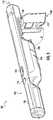
- FIG. 1shows an example embodiment of a hand-held surface cleaning device consistent with an embodiment of the present disclosure.
- FIG. 2shows a top view of the hand-held surface cleaning device of FIG. 1 consistent with an embodiment of the present disclosure.
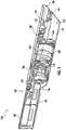
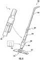
- FIG. 3shows a side perspective of the hand-held surface cleaning device of FIG. 1 consistent with an embodiment of the present disclosure.
- FIG. 4shows a cross-sectional view of the hand-held surface cleaning device of FIG. 1 taken along line 4 - 4 consistent with an embodiment of the present disclosure.
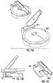
- FIG. 5shows an example dust cup suitable for use in the hand-held surface cleaning device of FIG. 1 .
- FIG. 6shows another cross-sectional view of hand-held surface cleaning device of FIG. 1 consistent with an embodiment of the present disclosure.
- FIG. 7shows another cross-sectional view of hand-held surface cleaning device of FIG. 1 consistent with an embodiment of the present disclosure.
- FIG. 8shows an example vacuum cleaner frame with a receptacle to receive a hand-held surface cleaning device consistent with embodiments of the present disclosure.
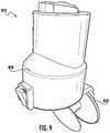
- FIG. 9shows an example dust cup for use by the example vacuum cleaner frame of FIG. 8 consistent with an embodiment of the present disclosure.
- FIG. 10shows an example of a hand-held surface cleaning device coupled to a dock, consistent with embodiments of the present disclosure.
- FIG. 11shows another example of a hand-held surface cleaning device coupled to a dock, consistent with embodiments of the present disclosure.
- FIG. 12shows another example of a hand-held surface cleaning device coupled to a dock, consistent with embodiments of the present disclosure.
- FIGS. 13A-13Dshow another example of a hand-held surface cleaning device coupled to a dock, consistent with embodiments of the present disclosure.
- FIGS. 14A-14Cshow another example of a hand-held surface cleaning device coupled to a dock, consistent with embodiments of the present disclosure.
- FIGS. 15A-15Cshow another example of a hand-held surface cleaning device coupled to a dock, consistent with embodiments of the present disclosure.
- FIGS. 16A-16Cshow another example of a hand-held surface cleaning device coupled to a dock, consistent with embodiments of the present disclosure.
- FIGS. 17A-17Cshow another example of a hand-held surface cleaning device coupled to a dock, consistent with embodiments of the present disclosure.
- FIGS. 18A-18Cshow another example of a hand-held surface cleaning device coupled to a dock, consistent with embodiments of the present disclosure.
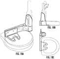
- FIGS. 19A-19Bshow another example of a hand-held surface cleaning device coupled to a dock, consistent with embodiments of the present disclosure.
- FIGS. 20A-20Bshow another example of a hand-held surface cleaning device coupled to a dock, consistent with embodiments of the present disclosure.
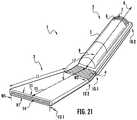
- FIG. 21shows a perspective view of a hand-held surface cleaning device in accordance with an embodiment of the present disclosure.
- FIG. 22Ashows a perspective view of a body portion of the hand-held surface cleaning device of FIG. 21 in isolation, in accordance with an embodiment of the present disclosure.
- FIG. 22Bshows another perspective view of a body portion of the hand-held surface cleaning device of FIG. 21 in isolation, in accordance with an embodiment of the present disclosure.
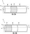
- FIG. 23Ashows an example power source suitable for use in the hand-held surface cleaning device of FIG. 21 in accordance with an embodiment of the present disclosure.
- FIG. 23Bshows another example power source suitable for use in the hand-hand surface cleaning device of FIG. 21 in accordance with an embodiment of the present disclosure.
- FIG. 23Cshows a cross-sectional view of the hand-held surface cleaning device of FIG. 21 in accordance with an embodiment of the present disclosure.
- FIG. 23Dshows an example motor suitable for use in the hand-held surface cleaning device of FIG. 21 in accordance with an embodiment of the present disclosure.
- FIGS. 24A-24Cshow additional example embodiments consistent with the present disclosure.
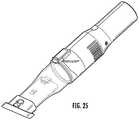
- FIG. 25shows an example hand-held surface cleaning device consistent with the present disclosure.
- FIG. 26Ashows a cross-sectional view of the hand-held surface cleaning device of FIG. 25 in accordance with an embodiment of the present disclosure.
- FIG. 26Bshows an example cleaning head of the hand-held surface cleaning device of FIG. 25 in isolation, in accordance with an embodiment of the present disclosure.
- FIG. 26Cshows an example handle of the hand-held surface cleaning device of FIG. 25 in isolation, in accordance with an embodiment of the present disclosure.
- FIG. 27shows another example hand-held surface cleaning device consistent with the present disclosure.
- FIGS. 28A-28Cshow additional example embodiments of a surface cleaning device consistent with embodiments of the present disclosure.
- FIGS. 29A-29Hshow additional example embodiments of a surface cleaning device consistent with embodiments of the present disclosure.
- FIGS. 30A-30Cshow additional example embodiments of a surface cleaning device consistent with embodiments of the present disclosure.
- FIG. 31Ashows an additional example of a surface cleaning device in a closed/docked position, in accordance with embodiments of the present disclosure.
- FIG. 31Bshows an additional example of a surface cleaning device in an open position, in accordance with embodiments of the present disclosure.
- FIG. 31Cshows a cross-sectional view of the surface cleaning device of FIG. 31A taken along line C-C.
- FIG. 31Dshows a cross-sectional view of the surface cleaning device of FIG. 31B taken along the line D-D.
- FIGS. 32A-32Dshows additional example embodiments of a surface cleaning device consistent with embodiments of the present disclosure.
- FIG. 33shows an additional example embodiment of a surface cleaning device consistent with an embodiment of the present disclosure.
- FIGS. 34A-34Cshow additional example embodiments of a surface cleaning device consistent with embodiments of the present disclosure.
- FIGS. 35A-35Bshows additional example embodiments of a surface cleaning device consistent with embodiments of the present disclosure.
- FIGS. 36A-36Cshows an additional example embodiment of a surface cleaning device consistent with an embodiment of the present disclosure.
- FIG. 37shows an additional example embodiment of a surface cleaning device consistent with an embodiment of the present disclosure.
- FIG. 38shows a perspective view of the example embodiment of FIG. 37 consistent with embodiments of the present disclosure.
- FIG. 39shows a cross-sectional view of the example embodiment of FIG. 37 consistent with embodiments of the present disclosure.
- FIG. 40shows another perspective view of the example embodiment of FIG. 37 consistent with embodiments of the present disclosure.
- FIG. 41shows another cross-sectional view of the example embodiment of FIG. 37 consistent with embodiments of the present disclosure.
- FIG. 42shows another perspective view of the example embodiment of FIG. 37 consistent with embodiments of the present disclosure.
- FIG. 43shows an exploded view of the example embodiment of FIG. 37 consistent with embodiments of the present disclosure.
- FIG. 44shows another exploded view of the example embodiment of FIG. 37 consistent with embodiments of the present disclosure.
- FIG. 45shows another cross-sectional view of the example embodiment of FIG. 37 consistent with embodiments of the present disclosure.
- the present disclosureis directed to a hand-held surface cleaning device that includes a relatively compact form-factor to allow users to store the same in a nearby location (e.g., in a drawer, in an associated charging dock, on a table top) for easy access to perform relatively small cleaning tasks that would otherwise require retrieving a full-size vacuum from storage.
- a hand-held surface cleaning device consistent with aspects of the present disclosureincludes a body (or body portion) with a motor, power source and dust cup disposed therein.
- the body portionalso functions as a handgrip to allow the hand-held surface cleaning device to be operated by one hand, for example. Therefore, the body portion may also be referred to as a handgrip, handle portion, or simply a handle.
- a hand-held surface cleaning apparatusconsistent with the present disclosure includes a body defining a handle portion and a dirty air passageway.
- the bodymay define a cavity for holding a motor for generating suction to draw dirt and debris into the dirty air passageway, a power source for powering the motor, and a dust cup for receiving and storing dirt.
- Each of the components within the bodycan be disposed in a coaxial manner.
- Each of power source, motor, and dust cupmay include a shape that generally corresponds with the body of the hand-held surface cleaning apparatus, e.g., a substantially cylindrical shape, rectangular shape, and so on.
- the bodymay include a relatively continuous width about its length to allow a user to comfortably grip the body in-hand during cleaning operations.
- the hand-held surface cleaning devicealso includes a cleaning head (or nozzle) that includes a longitudinal axis in parallel with the body to allow the hand-held surface cleaning device, in a general sense, to be operated similar to a wand of a conventional full-size vacuum to target various surfaces to clean without the added bulk of a trailing hose.
- a cleaning heador nozzle
- dust and debrisrefers to dirt, dust, water, or any other particle that may be pulled by suction into a hand-held surface cleaning device.
- FIGS. 1-4show a hand-held surface cleaning device 100 in accordance with an embodiment of the present disclosure.
- the hand-held surface cleaning device 100includes a body 102 that extends from a first end 140 to a second end 142 along a longitudinal axis 116 .
- the body 102 of the hand-held surface cleaning device 100includes a handle portion 104 adjacent the first end 140 followed by a motor portion (or section) 106 , a filter portion 108 , a dust cup 110 and a nozzle 114 disposed adjacent the second end 142 .
- the body 102can include a substantially flat and continuous surface 180 that extends from the first end 140 to the second end 142 to form a “wand” like apparatus.
- the handle portion 104 , motor portion 106 , filter portion 108 and nozzle 114may be formed as a single, monolithic piece. In other cases portions such as the nozzle 114 and/or filter portion 108 may be removable.
- the handle portion 104 of the hand-held surface cleaning device 100is contoured to comfortably fit within the hand of a user during operation.
- the tapered region 146may advantageously allow for a user's hand and fingers to more comfortably grip and operate the hand-held surface cleaning device 100 .
- the body 102 of the hand-held surface cleaning device 100further includes an on/off button 118 and a dust-cup release button 112 .
- the on/off button 118 and the dust-cup release 112may be actuated by, for example, the thumb of a user's hand when the handle portion 104 is held by the same.
- the dust-cup release 112may be slidably engaged, e.g., displaced by a user's thumb, to unlock the dust cup 110 , which will be described in greater detail below.
- the dust-cup release 112may be spring-biased to return to a rearward position in the absence of a user-supplied force.
- the motor section 106 of the body 102may include circuitry (not shown) for selectively supplying power to a motor 126 (see FIG. 4 ) disposed therein.
- the motor 126may be a DC motor or other suitable motor for generating suction.
- the hand-held surface cleaning device 100may include a vortex arrangement, so the illustrated embodiment is not intended to limit the present disclosure.
- the motor 126generates suction to draw air into the dirty air inlet 120 .
- the amount of power supplied to the motor 126may vary to proportionally adjust the amount of suction power.
- the on/off button 118may simply cause a constant amount of power to be supplied to the motor 126 .
- the dust cup 110may be configured to receive and store dirt and debris received via the dirty air inlet 120 .
- the dust cup 110is rotatably coupled to the body 102 , and more particularly, to a portion of the dirty air inlet 120 by way of a hinge 149 , with the hinge 149 being formed by a pin extending through the body 102 substantially transverse relative to the longitudinal axis 116 .
- the nozzle 114may provide the hinge 149 . In some cases the nozzle 114 may be removable.
- the dust cup 110may therefore rotate along a first rotational axis when released, e.g., via the dust-cup release 112 . For example, as shown in FIG.
- the dust cup 110may rotate in a direction generally indicated as D and come to a stop at an angle of about 90 degrees relative to the longitudinal axis 116 of the body 102 .
- This position of the dust cup 110may be accurately referred to as an open, release or disposal orientation.
- the opening 148may then be used to allow dust and debris to exit the dust cup 110 into a trash bin, for example.
- the dust cup 110may be transitioned between a locked/close orientation, e.g., as shown in FIG. 1 , to an open/disposal orientation as shown in FIG. 3 .
- the dust cup 110When in the closed orientation, the dust cup 110 is in fluid communication with the filter of the filter section 108 by way of the opening 148 .
- the dust cup 110decouples from fluid communication with the filter of the filter section 108 and permits the opening 148 to release/evacuate dust and debris stored within the dust cup 110 .
- the dust cup 110may include a cleaning or agitation element, e.g., bristles, that agitate a filter within the filter section 108 .
- a cleaning or agitation elemente.g., bristles
- the agitation of the filter within the filter section 108may free trapped/stuck dirt and debris and generally promote increased fluid communication of air to ensure that clogs are minimized or otherwise prevented from reducing suction power.
- FIG. 4shows an example cross-sectional view of the hand-held surface cleaning device 100 taken along the line 4 - 4 of FIG. 1 .
- body 102and in particular the handle portion 104 , defines a cavity 150 that can house one or more power sources such as batteries.
- the cavitycan include a battery holder 128 or battery cradle 128 to position and align the batteries with associated electrical contacts (not shown) to electrically couple the batteries to the motor 126 .
- the handle portion 104provides a tapered region 146 , with the tapered region 146 providing a transition between the handle portion 104 and the motor section 106 .
- the cavity 150 defined by the body 102continues through the motor section 106 .
- the motor sectionincludes the motor 126 disposed in the cavity 150 .
- the cavity 150continues through the filter section 108 .
- the filter 124may then be disposed in the cavity 150 of the filter section.
- the filter 124is a cone-type filter, but other filter devices are within the scope of this disclosure.
- the cavity 150may extend from the first end 140 at a base of the handle portion 104 to the second end by way of the dirty air inlet 120 .
- the dust cup 110Adjacent the filter section 108 , the dust cup 110 couples to the filter 124 .
- the dust cup 110may therefore fluidly couple with the filter section 108 by way of the opening 148 .
- a screen 154(see FIG. 6 ) may cover the opening 148 to prevent ingress of dirt and debris into the motor section 106 , which is discussed in further detail below.
- the dirty air inlet 120is in fluid communication with the dust cup 110 for purposes of receiving and storing dirt and debris.
- a valve body 122 formed from a flexible or resilient materialmay be disposed between the dust cup 110 and the dirty air inlet 120 . In the absence of suction forced provided by the motor 126 , the valve body 122 may remain in a valve seat position such as shown in FIG. 4 . The valve body 122 may be biased towards the dirty air inlet 120 based on spring tension, e.g., based on a bend introduced into the material or other suitable arrangement.
- the seat position of the valve body 122can form a seal, e.g., an air-tight seal that prevents 100% of air flow, or a partially air-tight seal that restricts at least 80% of air flow, between an opening of the dust cup 110 that aligns with an opening of the dirty air inlet 120 , each of which is generally shown at 170 .
- the seated position of the valve body 122can prevent dust and debris from exiting the dust cup 110 by way of the aligned openings at 170 when the surface cleaning device 100 is “off”, e.g., suction from the motor 126 isn't present.
- the valve body 122may be configured to be displaced/bent into a cavity 152 of the dust cup 110 when suction force generated by the motor 126 to draw air into the dirty air inlet, and ultimately, the dust cup 110 .
- the valve body 122 in the seated positioncontinues to seal off the cavity of the dust cup 110 , e.g., based on a spring force that biases the valve body 122 away from the dust cup 110 to hold the same against one or more surfaces that define the cavity of the dust cup 110 , to ensure that dust and debris exits the dust cup 110 only via opening 145 .
- the dust cupincludes an agitator member 155 in the form of a plurality of bristles.
- the bristlesmay be formed from, for example, plastic or other suitably rigid material.
- the bristles 155When in the closed position, such as shown in FIG. 6 , the bristles 155 may be disposed adjacent the upper surface 180 of the body 102 of the hand-held surface cleaning device 100 .
- the agitator member 155makes contact with a screen 154 of the filter section 106 .
- the screen 154 and the filter 124may be referred to collectively herein as a filter arrangement. This contact, in a general sense, “scrapes” the screen 154 which may advantageously dislodge or otherwise displace debris stuck to the screen 154 to minimize or otherwise reduce loss of suction power between the motor, filter and dirty air inlet 120 .
- each cleaning operation of the dust cup 110 performed by the usermay result in a two-stage cleaning action whereby the first stage includes scraping the screen 154 along a first direction D 1 as the dust cup 110 is released and a second stage includes scraping the screen 154 along a second direction D 2 (see FIG. 7 ) as the dust cup 110 is transitioned to the closed position.
- a usermay release and close the dust cup 110 multiple times to cause the two-stage cleaning action to clear obstructions.
- the filter section 106can include a removable filter carriage 107 to allow for the filter 124 to be replaced or otherwise cleaned. As shown, this embodiment includes the dust cup 110 being in the release orientation prior to removal of the removable filter carriage 107 . Alternatively, or in addition, the entire filter carriage 107 and filter 124 may be replaced as a single unit for ease of use.
- FIG. 8shows an example of a vacuum cleaner apparatus 800 being configured to removably couple to a hand-held surface cleaning device 1 .
- the hand-held surface cleaning device 1may be implemented as the hand-held surface cleaning device 100 of FIG. 1 , and this disclosure is not intended to be limiting this this regard.
- the vacuum cleaning apparatus 800includes a vacuum frame 802 (o simply a frame 802 ), collapsible joint 804 , a hand-held surface cleaner receptacle 806 , a dust cup receptacle 808 , a removable dust cup 810 , and a cleaning head 812 with dirty air inlet 814 .
- the frame 802defines the hand-held surface cleaner receptacle 806 or hand-held receptacle, with the hand-held receptacle being configured to securely hold the hand-held surface cleaning device 1 .
- the dirty air inlet 120may be aligned with and in fluid communication with a dirty air channel (not shown) that fluidly couples the dirty air inlet 814 with the dust cup 810 . Therefore, the suction generated by the motor of the hand-held surface cleaning device 1 may be used to draw air into the dirty air inlet 814 . From there, dirt and debris may then be stored in the dust cup 810 (or first dust cup) and/or the dust cup 110 (or second dust cup) of the hand-held surface cleaning device 1 .
- the presence of the dust cup 810effectively increases (e.g., doubles or more) the overall amount of storage for dust and debris relative to using the dust cup 110 alone, although in some embodiments the dust cup 110 may be utilized exclusively.
- the frame 802includes an optional collapsible joint 804 that allows for the upper handle portion of the frame 802 to be bent parallel to the lower portion having the hand-held receptacle 806 for storage purposes (See also FIGS. 34A-34C ).
- FIG. 9shows an example of a dust cup 810 having a door 850 that may be hinged to the body 840 of the dust cup 810 .
- a buttonmay be pressed to release the door 850 and allow the same to swing/rotate open to allow stored dirt and debris to exit the body 840 of the dust cup 810 .
- FIG. 10shows an example embodiment of a docking system 4400 that includes a dock 4401 , a hand-held surface cleaning device 4402 and a robotic vacuum 4403 .
- the hand-held surface cleaning device 4402is implemented as the hand-held surface cleaning device 100 of FIG. 1 or the hand-held surface cleaning device 1 of FIG. 21 , for example.
- the dock 4401includes a robotic vacuum coupling section defined at least in part by a base 4404 , with the base 4404 being configured to removably couple to the robotic vacuum 4403 .
- the base 4404may further include electrical contacts/terminals for electrically coupling with the robotic vacuum 4403 for recharging purposes.
- the dock 4401further includes a hand-held surface cleaning device coupling section 4405 , which may also be referred to as simply a wand coupling section.
- the wand coupling section 4405may include a wand receptacle 4406 and a wand release 4410 (or wand release pedal 4410 ).
- the wand receptacle 4406(or receptacle) may be a recess/opening defined by sidewalls of the wand coupling section 4405 .
- the wand receptacle 4406may extend substantially perpendicular relative to a longitudinal axis 4408 of the dock 4401 .
- the wand receptacle 4406may be configured to at least partially receive the hand-held surface cleaning device 4402 .
- the wand receptable 4406may include electrical contacts to electrically couple to the hand-held surface cleaning device 4402 .
- the wand receptacle 4406includes a depth that allows an upper surface 4409 of the hand-held surface cleaning device 4402 to mount flush with a surface 4401 defining the wand receptacle 4406 .
- the hand-held surface cleaning device 4402may be relatively hidden when mounted into the wand receptacle 4406 and have contours that generally correspond with shape of the wand coupling section 4405 .
- Insertion of the hand-held surface cleaning device 4402 into the wand receptacle 4406may include inserting the hand-held surface cleaning device 4402 at a first angle, e.g., approximately 80 degrees, with the nozzle of the hand-held surface cleaning device 4402 being used to bias and engage spring-loaded mechanism (not shown). Once inserted, the hand-held surface cleaning device 4402 may be locked into position via a detent (not shown) or other suitable locking mechanism.
- a user-supplied force(e.g., by a user's foot or hand) provided against the wand release 4410 disengages the locking mechanism and may allow the spring-loaded mechanism to transition the hand-held surface cleaning device 4402 from a storage position to an extended/release position. As shown, this transition may include the hand-held surface cleaning device 4402 rotating about a first axis of rotation 4412 which extends substantially parallel with the longitudinal axis 4408 . At the release position, a user may simply grip the hand-held surface cleaning device 4402 and supply a force in a direction vertically away from the wand receptacle 4406 to decouple the same for use.
- FIG. 11shows another example embodiment of a docking system 4400 a consistent with the present disclosure.
- the embodiment of FIG. 11may also be accurately referred to as an upright configuration, wherein the hand-held surface cleaning device 4402 extends vertically from the dock 4401 a .
- the dock 4401 aincludes a base 4404 a and wand coupling section 4405 a .
- the base 4404 aincludes release buttons 4501 and 4502 .
- the release buttons 4501 and 4502may allow for decoupling of the robotic vacuum 4403 and hand-held surface cleaning device 4402 , respectively, based on a user-supplied force (e.g., from a user's foot).
- the release buttons 4501 and 4502may at least partially define a ramp by which a robotic vacuum may travel over to couple to the dock 4401 a.
- the wand coupling section 4405 amay include a wand receptacle 4406 a that is configured to at least partially receive the hand-held surface cleaning device 4402 .
- the wand receptacle 4406 amay include an elongated cavity with a longitudinal axis that may extend substantially perpendicular with the longitudinal axis of the hand-held surface cleaning device 4402 .
- a handle section/region of the hand-held surface cleaning device 4402may at least partially extend from the wand receptacle 4406 a when in the storage position.
- the wand coupling section 4405 amay include a taper adjacent the robotic vacuum coupling section to provide a recess to at least partially receive a robotic vacuum. Therefore, the taper may form at least a portion of the robotic vacuum coupling section.
- the robotic vacuum 4403is coupled to the base 4404 a
- at least a portion 4503 of the wand coupling section 4405 amay extend over the robotic vacuum 4403 . This may advantageously reduce the overall footprint of the docking system 4400 a when the robotic vacuum is the storage position, i.e., coupled to the base 4404 a.
- a usermay then grip the handle section/region of the hand-held surface cleaning device 4402 and supply a force generally along direction D 2 to decouple the same from the wand receptacle 4406 a .
- the usermust first engage the release button 4502 to unlock the hand-held surface cleaning device 4402 from the wand receptacle 4406 a .
- the wand receptacle 4406 amay include a spring-loaded mechanism that, in response to the user supplying a force to release button 4502 , causes the hand-held surface cleaning device 4402 to travel upwards along direction D 2 while remaining at least partially within the wand receptacle 4406 a .
- Direction D 2may extend substantially perpendicular relative to the longitudinal axis 4408 a of the dock 4401 a . This may advantageously reduce how far down a user must reach down to grip the hand-held surface cleaning device 4402 .
- FIG. 12shows another example embodiment of a docking system 4400 b in an upright configuration consistent with the present disclosure. As shown, this embodiment is substantially similar to that of the docking system 4400 a , and for purpose of brevity the description of which will not be repeated.
- the docking system of 4400 aincludes a wand receptacle 4406 b without a locking mechanism and instead may utilize a friction-fit or simply gravity.
- the hand-held surface cleaning device 4402may be inserted/removed from the dock 4401 b without actuating a release, e.g., release button 4502 ( FIG. 45 ).
- FIG. 13 a - dshows another example embodiment of a docking system 4400 c consistent with aspects of the present disclosure.
- the docking system 4400 cincludes a dock 4401 c , a hand-held surface cleaning device 4402 , and a robotic vacuum 4403 .
- the dock 4401 cincludes a base 4404 b that defines a robotic vacuum coupling section.
- the wand coupling section 4401 cincludes fixed portion 4703 rotatably coupled to a wand receptacle 4407 b by way of a hinge 4702 .
- the wand receptacle 4407 bmay therefore rotate about a second rotational axis 4412 a between a storage position ( FIG. 13 /c/d ) and a release position, which are each discussed in greater detail below.
- the wand receptacle 4407 bmay at least partially surround the hand-held surface cleaning device 4402 .
- the wand receptacle 4407 bmay form a cradle that holds the hand-held surface cleaning device 4402 in a fixed position based on a friction-fit connection, gravity, or both.
- the wand receptacle 4407 bis in a release position, wherein the wand receptacle 4407 b extends at about 45 ⁇ 20 degrees relative to the longitudinal axis 4408 b of the base.
- the wand receptacle 4407 bextends substantially parallel with the longitudinal axis 4408 b of the base when in a storage position, such as shown in FIG. 13 c.
- the wand receptacle 4407 bmay transition between the storage and release position by way of the hinge 4702 or other suitable coupling device that allows for rotation about the second rotational axis 4412 a .
- the dock 4401 cmay include a mechanical mechanism (e.g., gears, belt drive, or other suitable mechanism) for causing rotation of the wand receptacle 4407 b between storage and release positions.
- the fixed portion 4703may include a proximity sensor 4711 such as an infrared (IR) sensor.
- the proximity sensor 4711may induce a vertical IR field that when breached by a hand (or other part) of a user the wand receptacle 4407 b may automatically rotate to the release position to allow for easy detachment of the hand-held surface cleaning device 4402 .
- the release positionmay also “reveal” or otherwise provide access to controls on an upper surface of the robotic vacuum 4403 (see FIGS. 14 a - c ).
- FIGS. 14 a - cshows the embodiment of FIGS. 13 a -13 d in additional detail.
- the dock 4401 cmay include elongatesd legs 4802 that extend from the fixed section 4799 to a distance D 1 that is at least 1.5 ⁇ the height H 2 of the fixed section 4799 .
- the elongated legs 4802may therefore advantageously support the wand receptacle 4407 b (and the hand-held surface cleaning device 4402 ) in the absence of the robotic vacuum 4403 .
- FIG. 15shows another embodiment of a docking system 4400 d consistent with aspects of the present disclosure.
- the docking system 4400 dis similar to that of the docking system 4400 a ( FIG. 11 ), the disclosure of which will not be repeated for brevity.
- the wand coupling section 4405 bincludes an IR sensor (or other suitable proximity sensor) and a wand receptacle 4407 c with a tooth/detent (not shown), an elevator/extender mechanism.
- the IR sensormay emit a IR beam adjacent the dock 4401 d .
- a signalmay be sent to the elevator/extender mechanism to cause the same to extend upwards along vertical direction D 3 .
- the tooth/detentmay engage a guide/track disposed along the length of the hand-held surface cleaning device 4402 to allow the same to travel vertically along a relatively straight path. In an embodiment, this may cause the hand-held surface cleaning device 4402 to rise six (6) to eight (8) inches, although other configurations are within the scope of this disclosure.
- the IR sensormay further include a visual indicator, e.g., an LED, to draw a user's attention to the location of the sensor.
- the wand coupling section 4405 bmay be tapered (as shown in the side profile) to offset the wand receptacle 4407 c from adjacent wall by distance D 4 . This may advantageously allow for a user to more easily reach a hand around the hand-held surface cleaning device 4402 to grip the same even if the dock 4401 d is disposed flush against a wall.
- FIGS. 16 a -16 ccollectively show another embodiment of a docking system 4400 e consistent with aspects of the present disclosure.
- the dock 4401 eincludes a wand receptacle 4407 d adjacent a first end 5001 of the dock 4401 e .
- the wand receptacle 4407 dis integrally formed with the dock 4401 e as a single, monolithic piece.
- the wand receptacle 4407 d and the dock 4401 emay be formed as separate pieces depending on a desired configuration.
- the wand receptacle 4407 dmay include a curvilinear profile/shape to increase aesthetic appeal and to form a shape which generally corresponds with the shape of the hand-held surface cleaning device 4402 .
- the wand receptacle 4407 dhas a fixed orientation wherein the hand-held surface cleaning device 4402 disposed therein is held at about a 45 degree angle relative to an upper surface 5002 defining the dock 4401 e .
- Other anglesare within the scope of this disclosure.
- the embodiment of FIGS. 16 a - cmay accurately be referred to as a side-by-side configuration whereby the wand receptacle 4407 d is adjacent (e.g., disposed laterally) to the region that a robotic vacuum couples to the dock 4401 e .
- the hand-held surface cleaning device 4402when inserted into the wand receptacle 4407 d , includes a longitudinal center line 4408 d disposed horizontally offset by distance of D 5 from a center line 4408 e of the robotic vacuum drawn tangent to the dock 4401 e , with the distance D 5 being at least equal to the radius R 1 of the robotic vacuum.
- FIG. 17shows another embodiment of a docking system 4400 f consistent with aspects of the present disclosure.
- the embodiment of FIG. 51is similar to that of the docking system 4400 e of FIG. 50 and for this reason the description of which will not be repeated for brevity.
- the dock 4401 fincludes a wand coupling section 4405 c that includes a wand receptacle 4407 e in a side-by-side configuration with the robotic coupling section 4420 c .
- the wand coupling section 4405 cfurther includes an IR sensor 5102 (or other suitable proximity sensor).
- a signalmay be sent to the wand receptacle 4407 e .
- a lift and tilt mechanism(not shown) may then receive the signal and transition the hand-held surface cleaning device 4402 from a storage position 5105 to a release position 5106 .
- transition to the release position 5106causes the hand-held vacuum device 4402 to first travel along a vertical path relative to an upper surface of the robotic vacuum (e.g., away from the robotic vacuum) followed by “tilting” of the hand-held vacuum device 4402 towards the robotic vacuum, e.g., at about a 70 ⁇ 15 degree angle relative to the robotic vacuum.
- transition to the storage position 5105causes the reverse of the transition to the release position 5106 , e.g., tilt back to a vertical orientation followed by downward travel towards the robotic vacuum device.
- the lift and tilt mechanismmay then automatically transition the hand-held surface cleaning device back to the storage position 5105 .
- Thismay advantageously allow a user to insert the hand-held surface cleaning device 4402 into the wand receptacle 4407 e and simply walk away while the wand receptacle 4407 e transitions back to the storage position 5105 .
- the hand-held surface cleaning device 1 of FIG. 21may be utilized in the various embodiments disclosed above including, for instance, the base (see FIGS. 10-20 b ) that may be utilized to both to couple to robotic cleaning devices and hand-held cleaning device.
- FIG. 21illustrates a perspective view of hand-held surface cleaning device 1 in accordance with an embodiment of the present disclosure.
- the hand-held surface cleaning device 1includes a body 2 coupled to a cleaning head 3 .
- An optional flexible region 4which may also be referred to as a flexible conduit, may couple the body 2 to the cleaning head 3 , and allow for rotation of the cleaning head 3 relative to the body 2 during cleaning operation.
- a dirty air passageway 14may extend from a dirty air inlet 11 provided by the cleaning head 3 through the cleaning head 3 and the body 2 to a dust cup 23 (see FIGS. 22A and 22B ) disposed adjacent a distal end of the body relative to the cleaning head 3 .
- the body 2 and the cleaning head 3may be in fluid communication to receive dirt and debris via the dirty air passageway.
- the body 2extends from a first end 10 - 1 to a second end 10 - 2 along a first longitudinal axis 9 .
- the body 2may have a substantially cylindrical shape, such as shown, although other shapes (e.g., rectangular, square, irregular, and so on) and configurations are within the scope of this disclosure.
- the body 2may be formed from a plastic or other suitably rigid material.
- the body 2may comprise multiple pieces, or may be formed from a single piece. As shown, the body 2 includes removable pieces to separate the dust cup portion 6 from the power and motor portion 8 .
- the body 2may be defined by a surface 5 , which may also be referred to as a handgrip surface 5 .
- the body 2and may contoured to fit comfortably within a user's hand during use.
- the handgrip surface 5may extend at least partially around the power and motor portion 8 and the dust cup portion 6 .
- the body 2may include a power and motor portion 8 disposed proximal the first end 10 - 1 followed by a dust cup portion 6 .
- components within the power and motor portion 8e.g., one or more motors and one or more power sources such as batteries
- the power and motor portion 8may be disposed coaxially with the dust cup portion 6 of the body 2 .
- components of the power and motor portion 8may collectively define a cavity that extends therethrough to allow dirty air traveling along the dirty air passageway 14 to reach the dust cup portion 6 for storage purposes.
- the body 2may include a plurality of vents 7 disposed proximal to the second end 10 - 2 to allow for filtered/clean air to exit the body 2 .
- the plurality of vents 7may be disposed proximal the second end 10 - 2 to ensure that a user's hand does not inadvertently cover the plurality of vents 7 during operation.
- Other locations for the plurality of vents 7is within the scope of this disclosure and the example illustrated in FIG. 21 should not be construed as limiting.
- the cleaning head 3may extend from a first end 12 - 1 to a second end 12 - 2 along a second longitudinal axis 15 .
- the cleaning head 3may be formed from the same material as the body 2 , or may comprise a different material.
- the cleaning head 3is formed from a bendable material, e.g., a material that may bend/unbend based on a user-supplied force.
- the cleaning head 3is formed from a relatively rigid material that resists bending.
- the cleaning head 3is formed from multiple materials. For instance, the first end 12 - 1 adjacent the dirty air inlet 11 may be formed from a relatively rigid material and the second end 12 - 2 may be formed from a relatively rigid material.
- first longitudinal axis 9 of the body 2may be substantially parallel relative to the second longitudinal axis 15 , e.g., for storage purposes, docking purposes, or when a user desires the cleaning head 3 to extend straight from the body 2 .
- the second longitudinal axis 15 of the cleaning head 3may extend at an angle 17 relative to the first longitudinal axis 9 , with angle 17 being between 1 degrees and 180 degrees, and preferably, 30 to 90 degrees.
- a dirty air inlet 11is disposed at the first end 12 - 1 .
- the dirty air inlet 11may define an opening having a width W 1 and a height H 1 .
- the ratio of W 1 to H 1may measure about 2:1, 3:1, 4:1, 10:1, 15:1 including all ranges therebetween, for example.
- the ratio of the overall length L 1 relative to the width W 1may measure about 1:1, 1.25:1, 1.5:1, 2:1, including all ranges therebetween. Other ratios are within the scope of this disclosure and the provided examples are not intended to be limiting.
- the width W 1 of the dirty air inlet 11may be greater than the width W 2 of the cleaning head 3 proximal to the second end 12 - 2 .
- the cleaning head 3may taper inwards from the first end 12 - 1 to the second end 12 - 2 .
- the cleaning head 3may not necessarily taper, as shown, and may include a substantially continuous width along longitudinal axis 15 .
- the hand-held surface cleaning apparatusmay further optionally include a flexible region 4 (or flexible conduit) disposed between the body 2 and the cleaning head 3 .
- a first end of the flexible region 4may couple to the second end 12 - 2 of the cleaning head 3 .
- a second end of the flexible region 4 opposite of the first endmay couple to the first end 10 - 1 of the body 2 .
- the flexible region 4may include a cavity that defines at least a portion of the dirty air passageway 14 .
- the flexible region 4may be formed from a plastic or other bendable material that allows for bending based on a user-supplied force.
- the flexible region 4may be configured to return to a particular resting state in the absence of a user-supplied force. For instance, the flexible region 4 may return to an unbent state that causes the first and second longitudinal axis 9 and 15 of the body 2 and cleaning head 3 , respectively, to extend substantially in parallel.
- the flexible region 4may be configured to remain in a bent position, e.g., via a clips or other mechanical retaining features, until a user supplies a force to transition the cleaning head to a different position relative to the body 2 .
- the flexible region 4allows the cleaning head 3 to rotate relative to the body 2 .
- the flexible region 4may allow for an angle 17 that measures between 0 degrees and 180 degrees, as discussed above.
- the flexible region 4allows for up to 90 degrees of rotation.
- rotation of cleaning head 3 relative to the body 2may cause the hand-held surface cleaning apparatus to switch ON.
- the usermay automatically switch on the hand-held surface cleaning apparatus 1 simply by supplying a force that causes the cleaning head 3 to engage a surface and cause bending of the flexible region 4 .
- the hand-held surface cleaning apparatus 1may supply power to a motor to introduce suction along the dirty air passageway 14 .
- the absence of the user-supplied forcemay cause the hand-held surface cleaning apparatus 1 to switch OFF.
- the body 2may include a button or other suitable control (not shown) to allow for manual switching of the hand-held surface apparatus 1 ON/OFF.
- the flexible region 4is optional.
- the body 2may simply couple directly to the cleaning head 3 .
- the flexible region 4may be replaced with a rigid portion (or rigid conduit) that does not bend based on a user-supplied force.
- the body 2 and/or the cleaning head 3may be removably coupled to the flexible region 4 .
- a usermay therefore remove the body 2 and/or cleaning head 3 from the flexible region 4 to, for example, unclog the dirty air passageway 14 or to attach a different type of cleaning head 3 such as a cleaning head configured with bristles.
- the body 2is shown isolated from the cleaning head 3 and flexible region 4 , in accordance with an embodiment of the present disclosure.
- the body 2is shown in a highly-simplified form and other components may be disposed within the body 2 .
- the bodydefines a cavity 19 .
- the body 2further includes a motor 20 , a power source 22 and a dust cup 23 disposed within the cavity 19 .
- Each of the motor 20 , the power source 22 and the dust cup 23may include a longitudinal axis that is substantially parallel with the longitudinal axis 9 .
- the motor 20 , power source 22 and dust cup 23may be disposed coaxially within the cavity 19 .
- this coaxial arrangementallows the motor 20 , the power source 22 , and the dust-cup 23 to have their respective cavities align to collectively form a single dirty-air passageway, e.g., dirty-air passageway 14 .
- the coaxial arrangementmay form a plurality of dirty-air passageways depending on a desired configuration, and this disclosure should not be construed as limited to a single passageway.
- the motor 20may comprise, for example, a brushless DC motor, although other types of motors are within the scope of this disclosure.
- the motor 20may electrically couple to the power source 22 and/or AC mains via a charging circuit, as discussed further below.
- the motor 20may include a cavity 52 (see FIG. 23C ) to allow the dirty air passageway 14 to extend therethrough.
- the motor 20may include an impeller/fan 50 that introduces air flow/suction towards the dust cup 23 .
- FIGS. 23C and 23Bshow the motor 20 in further detail in accordance with an embodiment of the present disclosure.
- the motor 20may include a built in fan 50 that is disposed in the cavity 52 .
- the motor 20may further optionally include openings/vents 51 along sidewall 53 to regulate air flow.
- the power source 22may comprise a plurality of battery cells 29 .
- each of the battery cellsis a lithium-ion battery cell, although other types of battery cells are within the scope of this disclosure.
- each of the plurality of battery cells 29may form an annular arrangement.
- the annular arrangementmay include a cavity 32 extending therethrough.
- each of the battery cellsmay have a respective longitudinal axis that is substantially in parallel with the longitudinal axis 9 of the body 2 when the power source 22 A is disposed in the same.
- FIG. 23Bshows another example power source 22 B configured as a ring-shaped capacitor.
- the ring-shaped capacitormay also include cavity 33 extending therethrough.
- the power source 22may at least partially define the dirty air passageway 14 based on an associated cavity.
- the cavity of the power source 22e.g., cavity 32 or 33 , may therefore align with the cavity 52 of the motor when the power source 22 and the cavity 52 are disposed within the cavity 19 of the body 2 .
- the power source 22may be charged via an associated charging circuit (not shown).
- the charging circuitmay include, for example, an inductive coil to receive a charge for purposes of charging the power source 22 .
- the charging circuitmay include terminals or other suitable interconnects (e.g., a USB-C port) to couple to a base/docking station for charging purposes, for example.
- the charging circuitmay also allow for power from mains to be used directly by the hand-held surface cleaning device 1 while also charging the power source 22 .
- FIG. 22Bshows a body 2 ′ in a substantially similar configuration to that of the body 2 of FIG. 22A , and for this reason the foregoing description is equally applicable to the body 2 ′ and will not be repeated for brevity.
- the body 2 ′includes the power source 22 disposed prior to the motor 20 .
- the body 2 ′includes the power source 22 disposed proximal to the first end 10 - 1 of the body 2 followed by the motor 20 and then the dust cup 23 .
- the body 2 and 2 ′ of FIGS. 22A and 22Bmay include multiple power sources 22 and/or multiple motors 20 disposed and aligned within the cavity 19 to form dirty air passageway 14 . Therefore, while the above examples illustrate a single motor and power source, this disclosure is not limited in this regard. Likewise, although each motor, power source and dust cup are shown have a substantially cylindrical shape, this disclosure is not limited in this regard. Other shapes and configurations are within the scope of this disclosure.
- the dust cup 23may be configured to receive and store dust and debris received from the dirty air passageway 14 .
- the dust cupmay define a cavity 40 to store the dust and debris.
- the dust cupmay further include a statically-charged accumulator 41 to help attract and trap dust and debris.
- the statically-charged accumulator 41is formed from a material that naturally tends to hold a static charge.
- the statically-charged accumulator 41may be energized via, for example, the power source 22 .
- FIGS. 24A-24Cshow additional example embodiments consistent with the present disclosure.
- the hand-held surface cleaning devicemay be docked into a base for recharging purposes.
- FIG. 25shows an example hand-held surface cleaning device consistent with the present disclosure.
- FIG. 26Ashows a cross-sectional view of the hand-held surface cleaning device of FIG. 25 in accordance with an embodiment of the present disclosure.
- FIG. 26Bshows an example cleaning head of the hand-held surface cleaning device of FIG. 25 in isolation, in accordance with an embodiment of the present disclosure.
- FIG. 26Cshows an example handle of the hand-held surface cleaning device of FIG. 25 in isolation, in accordance with an embodiment of the present disclosure.
- FIG. 27shows another example hand-held surface cleaning device consistent with the present disclosure.
- a handle portionmay rotate relative to a body to transition/articulate to one or more positions.
- Batteriesmay be disposed in the handle portion, such as shown in the cross-section taken along A-A. This arrangement may allow the handle portion to have a relatively small form-factor throughout its length.
- FIGS. 28A-28Cshow additional example embodiments of a surface cleaning device consistent with embodiments of the present disclosure.
- FIGS. 29A-29Hshow additional example embodiments of a surface cleaning device consistent with embodiments of the present disclosure.
- a hand-held surface cleaning device consistent with the present disclosuremay include an arrangement for wiping/dislodging dust during dust cup emptying procedures.
- FIGS. 30A-30Cshow additional example embodiments of a surface cleaning device consistent with embodiments of the present disclosure. As shown, the dust cup may be extended to increase storage capacity.
- the surface cleaning device 1300includes a body 1301 and a dust cup 1302 coupled to a first end 1319 the body 1301 .
- the aspects and embodiments shown and described above with reference to FIGS. 1-20B and FIGS. 21-30Care equally applicable to the surface cleaning device 1300 and will not be repeated for brevity.
- the terms “closed position” and “docked position”may be used interchangeably and refer to a position of the dust cup 1302 relative to the body 1301 whereby the dust cup 1302 is coupled to and in fluid communication with the body 1301 , and more particularly, with a motor 1322 disposed within a cavity of the body 1301 that generates suction to draw dirt and debris into the dust cup 1302 .
- the closed positionmay result in the dust cup 1302 having a longitudinal axis that extends substantially in parallel with a longitudinal axis of the body 1301 , such as shown in FIG. 31A .
- the term “open position” or “emptying position”may be used interchangeably and refer to a position of the dust cup 1302 relative to the body 1301 whereby the dust cup 1302 is angled substantially perpendicular relative to the body 1301 to allow for emptying of the dust cup.
- the dust cup 1302may be rotably/pivotably coupled to the body 1301 to allow the dust cup 1302 to transition to the open position. This transition may be initiated by, for example, button(s) 1305 disposed on the body 1301 , which will be discussed in greater detail below.
- the dust cupwhen in the open position, the dust cup may be fluidly decoupled from the motor 1322 while remaining pivotably/rotatably coupled to the housing.
- the dust cup 1302may be spring-loaded to cause the same to “spring”/launch into the open position.
- the body 1301may provide a stop, e.g., a sidewall 1340 ( FIG. 31B ) or other surface feature, to engage the dust cup 1302 while the same is rotating due to the release of spring tension. Engagement with the stop may then cause the dust cup 1302 to abruptly stop rotational movement, with the impact advantageously dislodging dirt and debris stored within the dust cup 1302 .
- Gravitymay then be used to allow the dislodged dirt and debris to empty from an opening of the dust cup located at an opposite end from that of an inlet for receiving dirty air.
- the spring biasmay then hold the dust cup 1302 in the open position until a user desires transitioning the dust cup 1302 back to the closed position.
- a usermay simply angle the hand-held surface cleaning device 1300 over the mouth of a trash can and transition the dust cup 1302 , e.g., via actuation of the button(s) 1305 , to the open position to empty the dust cup 1302 .
- a filter arrangement 1314may be at least partially disposed within the body 1301 .
- the filter arrangement 1314may also be spring-loaded and “spring” forward (see FIGS. 31B and 31D ) to extend at least partially from the body 1301 and stop at a predetermined distance D 1 .
- the filter arrangement 1314may travel away from the body 1301 to distance D 1 (after the dust cup 1302 rotates away from the filter arrangement 1314 ) before encountering a stop, e.g., a lap, catch or other protrusion, provided within or external to the body 1301 , e.g., protrusion 1398 (see FIG. 31 B).
- the spring biasmay then hold the filter arrangement 1314 in the extended position until the dust cup 1302 displaces the filter arrangement 1314 when the same brought back into the closed position, e.g., based on a user-supplied force.
- the surface cleaning device 1300may be accurately described as having a multi-phase (or multi-stage) opening sequence based on a single user-supplied motion, wherein in response to the single user-supplied motion (e.g., a button press), the dust cup first snaps/springs/launches forward (longitudinally) and then rotates to a vertical/upright position, followed by the filter arrangement snapping/springing out either simultaneously as the dust cup transitions or shortly thereafter (e.g., based on the springs of the filter arrangement 1314 having a different spring constant/configuration than that of the springs associated with the dust cup 1302 ).
- the dust cup 1302may be weight to cause the up-right position (see FIG. 31B ).
- the dust cup 1302may be brought into the up-right position based on a track provided by the body 1301 that causes the rotation to occur.
- the dust cup 1302may be configured with an agitating device, e.g., bristles, similar to that of dust cup 110 of FIG. 5 , and the embodiments disclosed above are equally applicable to the hand-held surface cleaning cleaning device of FIGS. 31A-31D .
- a motor 1322is disposed within the body 1301 and generates suction to draw dirty air into the inlet 1309 (or nozzle) via a dirty air passageway 1330 (see FIG. 31C ) during use.
- the dust cup 1302and more particularly, the dirty air passageway 1330 may be in fluid communication with the motor 1322 when the dust cup 1302 is in the closed position, such as shown in FIG. 13A .
- a filter 1311 disposed between the body 1301 and the dust cup 1302may prevent/reduce dust and debris from entering the body 1301 and ultimately clogging the motor 1322 . Dust and debris may then be stored in dust storage area 1331 ( FIG. 31C ) within the cavity of the dust cup 1302 during operation of the surface cleaning device 1300 .
- the dust cup 1302may be decoupled from the suction of the motor 1322 when in the open position based on rotation of the dust cup 1302 relative to the body 1301 .
- an end of the dust cup 1302may be decoupled from the body 1301 and rotated to angle the dust cup 1302 substantially transverse relative to the body 1301 .
- the open position of the dust cup 1302may result in the dust cup 1302 having a longitudinal axis 1316 that is substantially transverse relative to the longitudinal axis 1315 of the body.
- the angle at which the dust cup 1302 extends relative to the body 1301may vary, e.g., from 15 degrees to 180 degrees, and preferably 15 degrees to 90 degrees, depending on a desired configuration.
- the body 1301may be formed from a plastic, metal, and/or any other suitably rigid material.
- the body 1301may be formed from a single piece of material, or from multiple pieces.
- the body 1301may be defined by walls that extend along longitudinal axis 1315 from a first end 1319 , which may be referred to as a dust coupling end 1319 , to a second end 1320 .
- the wallsmay be defined by a surface 1306 , with the surface 1306 providing a handle portion, or handle, that may be comfortably gripped within the hand of a user during operation of the surface cleaning device 1300 .
- the body 1301further includes button(s) 1305 for causing the dust cup 1302 to transition from a closed position, e.g., as shown in FIG. 31A , to an open position, e.g., as shown in FIG. 31B .
- the button(s) 1305are not necessarily limited to a mechanical button whereby a user depresses the same to cause the surface cleaning device 1300 to transition from the closed to open position.
- the button 1305may also be any other suitable user input device such as a slider button, a capacitive touch button, and a rotatable ring that extends around the diameter of the body 1301 .
- the body 1301may define a cavity 1321 ( FIG. 31C ).
- the cavitymay include the filter arrangement 1314 , the motor 1322 and a power source 1323 disposed therein.
- the motor 1322may comprise, for example, a brushless DC motor although other types of motors are within the scope of this disclosure.
- the motor 1322may electrically couple to the power source 1323 and generate suction for drawing dirt and debris into the dust cup 1302 .
- the dust cup 1302may comprise plastic, metal, or any other suitably rigid material.
- the dust cup 1302may be defined by one or more walls that extend from a first end 1309 (or nozzle) to a second end 1350 (suction coupling end or suction coupling section) along a longitudinal axis 1316 ( FIG. 31D ).
- the dust cup 1302may further define a cavity with a dirty air passageway 1330 extending at least partially therethrough, with the dirty air passageway extending substantially in parallel with the longitudinal axis 1316 .
- the dust cup 1302further includes a dust storage area 1331 within the cavity to receive and store dirt and debris.
- the walls surrounding the dust storage area 1331may be light transmissive, e.g., allowing 80% or more of incident visible wavelengths, to allow a user to visibly examine the current amount of dirt and debris stored in the dust storage area through the walls.
- the suction coupling end 1350also provides an opening for emptying dirt and debris when the dust cup 1302 is oriented upright/vertically in the open position.
- the filter arrangement 1314comprises a cylindrical housing that generally corresponds with the shape of the body 1301 . Other shapes and configurations for the filter arrangement 1314 are also within the scope of this disclosure.
- the filter arrangement 1314may include one or more filters, such as the pleated filter 1311 shown in FIG. 31C .
- the one or more filtersmay comprise, for example, a polyester material, PTFE, fiberglass, or any other suitable filter material.
- the one or more filtersmay include a cartridge body for easy removal and replacement of filters.
- the filter arrangement 1314may further include springs 1324 to bias the filter arrangement 1314 away from the body 1301 and towards the dust cup 1302 .
- the springs 1324may be compressed based on the dust cup 1302 displacing the filter arrangement 1314 towards the cavity 1321 of the body 1301 .
- the springs 1324may include more of fewer springs, e.g., a single spring, depending on a desired configuration.
- arms 1308 - 1 and 1308 - 2may extend from the body 1301 along the longitudinal axis 1315 .
- the arms 1308 - 1 , 1308 - 2may be integrally formed with the body 1301 as a single, monolithic piece, or may be formed from multiple pieces.
- the arms 1308 - 1 and 1308 - 2may be formed from the same material as the body 1301 , e.g., formed from a plastic or other suitably rigid material.
- the arms 1308 - 1 and 1308 - 2may be formed from a different material from that of the body 1301 .
- the arms 1308 - 1 and 1308 - 2may be formed at least in part with a metal or metal alloy to reinforce the arms.
- the arms 1308 - 1 and 1308 - 2may each be pivotally coupled to the dust cup 1302 to allow rotational movement along a direction/path generally indicated as D ( FIG. 31B ).
- the dust cup 1302may pivot/rotate relative to arms 1308 - 1 and 1308 - 2 based on rotational axis 1325 , with rotational axis 1325 being substantially perpendicular with the longitudinal axis 1315 .
- the arms 1308 - 1 and 1308 - 2may further define a cavity.
- the cavity defined by the arms 1308 - 1 and 1308 - 2may include spring(s) 1307 .
- Each of the spring(s) 1307may bias the dust cup 1302 away from the body 1301 , e.g., by supplying force against a dust cup carrier 1326 or other mechanism coupled to the dust cup 1302 .
- the dust cup carrier 1326may be formed integrally, i.e., as a single, monolithic piece, with the dust cup 1302 or may be formed from multiple pieces.
- the dust cup carrier 1326be configured to travel longitudinally along a track/guide provided by arms 1308 - 1 and 1308 - 2 . Thus, the dust cup carrier 1326 may be used to transition/displace the dust cup 1302 from the closed position to the open position.
- a detent 1399( FIG. 31B ) or other suitable locking mechanism may extend from a surface of the arms 1308 - 1 and 1308 - 2 .
- the detent 1399may be spring-biased and configured to engage a corresponding surface feature of the dust cup 1302 such as catch/recess 1327 .
- the detent 1399may engage with the catch 1327 of the dust cup 1302 to securely hold the dust cup 1302 in position relative to the body 1301 .
- a usermay depress button(s) 1305 .
- Depressing button(s) 1305may include using a thumb and index finger in a pinching motion against buttons disposed on opposite sides of the body 1301 .
- the button(s) 1305may mechanically actuate the detent 1399 to disengage the same from the catch of the dust cup 1302 .
- the button 1305may provide an electrical signal that may be utilized to cause, for instance, a motor or other mechanical actuator to disengage the detent 1399 .
- the button 1305may therefore allow a user to cause the dust cup 1302 to transition to an open position to empty out the dust cup and clear the filter of dust and debris.
- the dust cup 1302may include a recessed surface 1339 (see FIG. 31B ) or recessed region 1339 that defines a sidewall 1341 , with the sidewall 1341 extending substantially perpendicular relative to the surface 1339 .
- the sidewall 1341may be configured to engage a stop surface 1340 of the arms 1308 - 1 and 1308 - 2 to prevent rotational movement of the dust cup 1302 beyond a predefined limit, e.g., 90 degrees.
- the impact of the dust cup 1302 encountering the stop surface 1340may advantageously dislodge dirt and debris within the dust cup 1302 .
- the filter arrangement 1314may include a protrusion/catch/surface 1344 to engage a corresponding stop/protrusion 1398 of the body 1301 .
- the dust cup 1302may include a recessed region/guide 1340 to engage the protrusion 1398 .
- the protrusion 1398may be used to align and guide the dust cup 1302 into alignment with the body 1301 .
- the surface cleaning device 1300may be held in a single hand and transitioned from a closed to an open position with the same hand.
- FIGS. 324A-32Dcollectively show the hand-held surface cleaning device 1300 transitioning from a closed position to an open position.
- FIG. 32Ashows the hand-held surface cleaning device 1300 in a closed position whereby the dust cup 1302 is in fluid communication with the motor disposed in the body 1301 , in accordance with an embodiment of the present disclosure.
- FIG. 32Bshows the hand-held surface cleaning device 1300 after one or both of button(s) 1305 on either side of the body 1301 have been depressed by a user, in accordance with an embodiment of the present disclosure.
- the detent 1399FIG. 31B
- the dust cup 1302 and filter arrangement 1314may travel longitudinally away from the body 1301 . In some cases, there may be a momentary pause between the rotational movement of the dust cup 1302 and the movement of the filter arrangement 1314 , depending on the desired configuration.
- the dust cup 1302may then rotate/pivot relative to the body 1301 and stop at a position which holds the dust cup 1302 at an orientation which is substantially transverse relative to the body 1301 .
- the dust cup 1302may pivot based on a track/guide provided by the arms 1308 - 1 and 1308 - 2 .
- weightingmay be added to the dust cup 1302 to cause the same to naturally tend towards a vertical/upright orientation.
- the dust cup 1302may be held in this position based at least in part on the spring(s) 1307 disposed in the first and second arms 1308 - 1 and 1308 - 2 (see FIG. 31B ). Likewise, the filter arrangement 1314 may be held in the extended position based on spring bias from the spring(s) 1324 . Accordingly, a user may then shake the hand-held surface cleaning device 1300 to cause dust and debris to empty from the dust cup 1302 .
- a usermay simply rotate the dust cup 1302 into alignment with the body 1301 and then slide the dust cup 1302 towards the body 1301 to displace the filter arrangement 1314 and “lock” into the closed position based on detent 1399 engaging with a sidewall feature, e.g., recess 1327 , of the dust cup 1302 .
- FIG. 33shows an additional example embodiment of a surface cleaning device consistent with an embodiment of the present disclosure.
- FIGS. 34A-34Cshows additional example embodiments of a surface cleaning device consistent with embodiments of the present disclosure. Note the example aspects shown in FIGS. 34A-34C are equally applicable to the embodiment shown in FIG. 8 .
- FIGS. 35A-35Bshows additional example embodiments of a surface cleaning device consistent with embodiments of the present disclosure.
- FIGS. 36A-36Bshows an additional example embodiment of a surface cleaning device consistent with embodiment of the present disclosure.
- FIGS. 37-45show an additional example embodiment of a hand-held surface cleaning device 1900 having a body 1901 that includes a handle 1907 , an extendable crevice tool 1902 , a cyclone assembly 1904 , and a motor 1912 electrically coupled to at least one battery 1905 .
- the battery 1905can be stored in the handle 1907 .
- the cyclone assembly 1904includes an inlet 1906 that is fluidly coupled to the crevice tool 1902 , a vortex finder 1908 , a collection area 1910 , and a filter 1914 .
- airis drawn from a crevice tool inlet 1916 and into the cyclone assembly 1904 .
- the airmay include debris collected, for example, during a cleaning operation.
- the debris carried in the airmay collect within the cyclone assembly 1904 (e.g., within the collection area 1910 ).
- an operatormay empty the debris by causing a door 1918 to be opened. Once the door 1918 has been opened the debris may exit the cyclone assembly 1904 (e.g., by the force of gravity).
- An operatormay cause the door 1918 to be opened by actuating a button (or trigger) 1920 .
- the actuation of the button 1920may result in the movement of a push rod 1922 .
- the push rod 1922When the push rod 1922 is moved between a first and second position, the push rod 1922 may engage a latch 1924 holding the door 1918 in a closed position. As shown, when the latch 1924 is moved out of engagement with the door 1918 , the door 1918 rotates about an axis 1926 .
- an operatormay reclose the door 1918 by pushing the door 1918 back into engagement with the latch 1924 . Additionally, or alternatively, the user may actuate the button 1920 a second time (or actuate a different button or trigger) to cause the door 1918 to close.
- the latch 1924may include a biasing member (e.g., a spring) that urges the latch 1924 towards an engagement position (e.g., a position in which the latch 1924 is capable of engaging the door 1918 ).
- the crevice tool 1902may be extendable from a first to a second position. For example, an operator may manually grasp the crevice tool 1902 and pull (or push) the crevice tool 1902 to cause the crevice tool 1902 to transition between the first and second positions. Additionally, or alternatively, the crevice tool 1902 may transition between the first and second positions in response to the actuation of a button (or trigger).
- the cyclone assembly 1904may be removably coupled to the body 1901 of the hand-held surface cleaning device 1900 .
- removal of the cyclone assembly 1904may allow a user to clean and/or replace the filter 1914 .
- the vortex finder 1908may be removable.
- a toe in feature 1917may be provided to couple the cyclone assembly 1904 to the body 1901 .
- the hand-held surface cleaning device 1900may be used in a robot vacuum cleaner system.
- the hand-held surface cleaning device 1900may be used to remove debris from a robotic vacuum cleaner.
- a hand-held surface cleaning devicecomprising a body that extends from a first end to a second end, a handle portion defined by the body adjacent the first end, a nozzle with a dirty air inlet defined by the body adjacent the second end, a motor for generating suction and drawing air into the dirty air inlet, and a dust cup for receiving and storing dust and debris, the dust cup being rotatably coupled to the body of the hand-held surface cleaning device and configured to transition between a closed orientation to fluidly couple the dust cup with the dirty air inlet and the motor, and a release orientation to decouple the dust cup from the dirty air inlet and the motor to allow dirt and debris stored in the dust cup to exit from an opening of the dust cup.
- a docking systemcomprising a dock including a robotic vacuum coupling section, and a hand-held surface cleaning device comprising a body that extends from a first end to a second end, a handle portion defined by the body adjacent the first end, a nozzle with a dirty air inlet defined by the body adjacent the second end, a motor for generating suction and drawing air into the dirty air inlet; and a dust cup for receiving and storing dust and debris, the dust cup being rotatably coupled to the body of the hand-held surface cleaning device and configured to transition between a closed orientation to fluidly couple the dust cup with the dirty air inlet and the motor and a release orientation to decouple the dust cup from the dirty air inlet and the motor to allow dirt and debris stored in the dust cup to exit from an opening of the dust cup, a receptacle defined by the dock to receive and couple to the first end of the hand-held surface cleaning device and to cause the second end defining the handle portion to extend away from the dock
Landscapes
- Engineering & Computer Science (AREA)
- Mechanical Engineering (AREA)
- Robotics (AREA)
- Nozzles For Electric Vacuum Cleaners (AREA)
- Electric Vacuum Cleaner (AREA)
- Cleaning In General (AREA)
- Filters For Electric Vacuum Cleaners (AREA)
- Electric Suction Cleaners (AREA)
- Drawers Of Furniture (AREA)
- Cleaning Implements For Floors, Carpets, Furniture, Walls, And The Like (AREA)
- Telephone Function (AREA)
- Brushes (AREA)
Abstract
Description
Claims (16)
Priority Applications (7)
| Application Number | Priority Date | Filing Date | Title |
|---|---|---|---|
| US16/136,934US11213177B2 (en) | 2017-09-22 | 2018-09-20 | Hand-held surface cleaning device |
| US29/726,897USD1015660S1 (en) | 2017-09-22 | 2020-03-06 | Wand vacuum |
| US17/224,092US11930988B2 (en) | 2017-09-22 | 2021-04-06 | Hand-held surface cleaning device |
| US17/224,090US11864714B2 (en) | 2017-09-22 | 2021-04-06 | Hand-held surface cleaning device |
| US18/387,907US12029375B2 (en) | 2017-09-22 | 2023-11-08 | Hand-held surface cleaning device |
| US18/732,030US12336681B2 (en) | 2017-09-22 | 2024-06-03 | Hand-held surface cleaning device |
| US19/024,937US20250151962A1 (en) | 2017-09-22 | 2025-01-16 | Hand-held surface cleaning device |
Applications Claiming Priority (5)
| Application Number | Priority Date | Filing Date | Title |
|---|---|---|---|
| US201762561851P | 2017-09-22 | 2017-09-22 | |
| US201762585320P | 2017-11-13 | 2017-11-13 | |
| US201862616908P | 2018-01-12 | 2018-01-12 | |
| US201862619309P | 2018-01-19 | 2018-01-19 | |
| US16/136,934US11213177B2 (en) | 2017-09-22 | 2018-09-20 | Hand-held surface cleaning device |
Related Child Applications (3)
| Application Number | Title | Priority Date | Filing Date |
|---|---|---|---|
| US29/726,897ContinuationUSD1015660S1 (en) | 2017-09-22 | 2020-03-06 | Wand vacuum |
| US17/224,092DivisionUS11930988B2 (en) | 2017-09-22 | 2021-04-06 | Hand-held surface cleaning device |
| US17/224,090DivisionUS11864714B2 (en) | 2017-09-22 | 2021-04-06 | Hand-held surface cleaning device |
Publications (2)
| Publication Number | Publication Date |
|---|---|
| US20190090701A1 US20190090701A1 (en) | 2019-03-28 |
| US11213177B2true US11213177B2 (en) | 2022-01-04 |
Family
ID=65807034
Family Applications (8)
| Application Number | Title | Priority Date | Filing Date |
|---|---|---|---|
| US16/649,469ActiveUS11672388B2 (en) | 2017-09-22 | 2018-09-20 | Hand-held surface cleaning device |
| US16/136,934Active2039-10-07US11213177B2 (en) | 2017-09-22 | 2018-09-20 | Hand-held surface cleaning device |
| US29/726,897ActiveUSD1015660S1 (en) | 2017-09-22 | 2020-03-06 | Wand vacuum |
| US17/224,090Active2038-11-13US11864714B2 (en) | 2017-09-22 | 2021-04-06 | Hand-held surface cleaning device |
| US17/224,092Active2039-03-16US11930988B2 (en) | 2017-09-22 | 2021-04-06 | Hand-held surface cleaning device |
| US18/387,907ActiveUS12029375B2 (en) | 2017-09-22 | 2023-11-08 | Hand-held surface cleaning device |
| US18/732,030ActiveUS12336681B2 (en) | 2017-09-22 | 2024-06-03 | Hand-held surface cleaning device |
| US19/024,937PendingUS20250151962A1 (en) | 2017-09-22 | 2025-01-16 | Hand-held surface cleaning device |
Family Applications Before (1)
| Application Number | Title | Priority Date | Filing Date |
|---|---|---|---|
| US16/649,469ActiveUS11672388B2 (en) | 2017-09-22 | 2018-09-20 | Hand-held surface cleaning device |
Family Applications After (6)
| Application Number | Title | Priority Date | Filing Date |
|---|---|---|---|
| US29/726,897ActiveUSD1015660S1 (en) | 2017-09-22 | 2020-03-06 | Wand vacuum |
| US17/224,090Active2038-11-13US11864714B2 (en) | 2017-09-22 | 2021-04-06 | Hand-held surface cleaning device |
| US17/224,092Active2039-03-16US11930988B2 (en) | 2017-09-22 | 2021-04-06 | Hand-held surface cleaning device |
| US18/387,907ActiveUS12029375B2 (en) | 2017-09-22 | 2023-11-08 | Hand-held surface cleaning device |
| US18/732,030ActiveUS12336681B2 (en) | 2017-09-22 | 2024-06-03 | Hand-held surface cleaning device |
| US19/024,937PendingUS20250151962A1 (en) | 2017-09-22 | 2025-01-16 | Hand-held surface cleaning device |
Country Status (10)
| Country | Link |
|---|---|
| US (8) | US11672388B2 (en) |
| EP (5) | EP3684237B1 (en) |
| JP (4) | JP6857283B2 (en) |
| KR (8) | KR102789119B1 (en) |
| CN (5) | CN109602326B (en) |
| AU (3) | AU2018336913B2 (en) |
| CA (3) | CA3201669A1 (en) |
| ES (1) | ES2974416T3 (en) |
| GB (3) | GB2581647B (en) |
| WO (1) | WO2019060564A1 (en) |
Cited By (11)
| Publication number | Priority date | Publication date | Assignee | Title |
|---|---|---|---|---|
| US20220167822A1 (en)* | 2020-12-01 | 2022-06-02 | Airplove (Xiamen) Electronic Co., Ltd. | Self-cleaning dust cylinder assembly and hand-held vacuum cleaner with the same |
| USD971533S1 (en)* | 2021-03-23 | 2022-11-29 | Black & Decker, Inc. | Vacuum cleaner |
| US11672388B2 (en) | 2017-09-22 | 2023-06-13 | Sharkninja Operating Llc | Hand-held surface cleaning device |
| US11687092B2 (en) | 2018-04-23 | 2023-06-27 | Sharkninja Operating Llc | Techniques for bounding cleaning operations of a robotic surface cleaning device within a region of interest |
| USD1000735S1 (en)* | 2021-09-29 | 2023-10-03 | Black & Decker, Inc. | Handheld vacuum |
| USD1006357S1 (en)* | 2023-06-28 | 2023-11-28 | Yongquan Wu | Vacuum cleaner with mobile power supply |
| US11896190B1 (en) | 2022-09-15 | 2024-02-13 | Sharkninja Operating Llc | Vacuum cleaner and docking station configured to cooperate with the same |
| US11998150B2 (en) | 2019-05-01 | 2024-06-04 | Sharkninja Operating Llc | Vacuum cleaner and docking station for use with the same |
| WO2025043328A1 (en)* | 2023-08-25 | 2025-03-06 | Omachron Intellectual Property Inc. | Hand vacuum cleaner |
| USD1074098S1 (en)* | 2020-07-29 | 2025-05-06 | Sharkninja Operating Llc | Vacuum cleaner with a wand |
| US12376722B2 (en) | 2021-08-13 | 2025-08-05 | Sharkninja Operating Llc | Robotic cleaner |
Families Citing this family (72)
| Publication number | Priority date | Publication date | Assignee | Title |
|---|---|---|---|---|
| US11751733B2 (en) | 2007-08-29 | 2023-09-12 | Omachron Intellectual Property Inc. | Portable surface cleaning apparatus |
| US11445871B2 (en) | 2014-12-17 | 2022-09-20 | Omachron Intellectual Property Inc. | Surface cleaning apparatus |
| US11647881B2 (en) | 2015-10-21 | 2023-05-16 | Sharkninja Operating Llc | Cleaning apparatus with combing unit for removing debris from cleaning roller |
| US10786126B2 (en) | 2015-11-10 | 2020-09-29 | Techtronic Industries Co. Ltd. | Handheld vacuum cleaner |
| WO2018049169A1 (en) | 2016-09-09 | 2018-03-15 | Sharkninja Operating Llc | Agitator with hair removal |
| US11285495B2 (en)* | 2016-12-27 | 2022-03-29 | Omachron Intellectual Property Inc. | Multistage cyclone and surface cleaning apparatus having same |
| CN114403741B (en) | 2017-03-10 | 2024-02-27 | 尚科宁家运营有限公司 | Agitator with a hair remover and hair removal |
| US11202542B2 (en) | 2017-05-25 | 2021-12-21 | Sharkninja Operating Llc | Robotic cleaner with dual cleaning rollers |
| US11219906B2 (en)* | 2019-01-23 | 2022-01-11 | Omachron Intellectual Property Inc. | Surface cleaning apparatus, cyclonic air treatment member and surface cleaning apparatus including the same |
| US11730327B2 (en)* | 2020-03-18 | 2023-08-22 | Omachron Intellectual Property Inc. | Surface cleaning apparatus with removable air treatment assembly |
| US11745190B2 (en) | 2019-01-23 | 2023-09-05 | Omachron Intellectual Property Inc. | Surface cleaning apparatus |
| US11122945B2 (en)* | 2017-12-04 | 2021-09-21 | Transform Sr Brands Llc | Two-in-one upright vacuum |
| US10959585B2 (en)* | 2018-03-16 | 2021-03-30 | Omachron Intellectual Property Inc. | Hand vacuum cleaner |
| US10959588B2 (en)* | 2018-03-16 | 2021-03-30 | Omachron Intellectual Property Inc. | Hand vacuum cleaner |
| US11439285B2 (en)* | 2018-03-16 | 2022-09-13 | Omachron Intellectual Property Inc. | Hand vacuum cleaner |
| US10952583B2 (en)* | 2018-03-16 | 2021-03-23 | Omachron Intellectual Property Inc. | Hand vacuum cleaner |
| US20190282052A1 (en)* | 2018-03-16 | 2019-09-19 | Omachron Intellectual Property Inc. | Hand vacuum cleaner |
| US11672395B2 (en) | 2021-01-06 | 2023-06-13 | Omachron Intellectual Property Inc. | Surface cleaning apparatus |
| KR102073618B1 (en)* | 2018-05-31 | 2020-02-05 | 엘지전자 주식회사 | Cleaning Appliance |
| US11399675B2 (en) | 2018-07-31 | 2022-08-02 | Sharkninja Operating Llc | Upright surface treatment apparatus having removable pod |
| US11154169B2 (en) | 2018-08-13 | 2021-10-26 | Omachron Intellectual Property Inc. | Cyclonic air treatment member and surface cleaning apparatus including the same |
| US10882059B2 (en)* | 2018-09-21 | 2021-01-05 | Omachron Intellectual Property Inc. | Multi cyclone array for surface cleaning apparatus and a surface cleaning apparatus having same |
| CN109645881B (en)* | 2019-01-31 | 2024-05-28 | 莱克电气股份有限公司 | Dust suction device |
| WO2020186342A1 (en)* | 2019-03-15 | 2020-09-24 | Omachron Intellectual Property Inc. | Surface cleaning apparatus |
| DE102019002827A1 (en)* | 2019-04-18 | 2020-10-22 | Vorwerk & Co. Interholding Gmbh | Base station and method of assembling a base station |
| ES2956793T3 (en)* | 2019-04-18 | 2023-12-28 | Vorwerk Co Interholding | Operating procedure of a cleaning system, base station and filtration device |
| CN110123202B (en)* | 2019-05-27 | 2024-05-03 | 东莞优乐家智能家电有限公司 | Dustbin type dust collector |
| CN110179387B (en)* | 2019-06-04 | 2024-05-28 | 莱克电气股份有限公司 | A handheld cleaning device |
| GB2616963B (en)* | 2019-06-13 | 2023-12-27 | Omachron Intellectual Property Inc | Surface cleaning apparatus |
| CN110250991A (en)* | 2019-07-08 | 2019-09-20 | 炬大科技有限公司 | A handheld vacuum cleaner |
| CN114126463B (en) | 2019-07-11 | 2023-07-18 | 尚科宁家运营有限公司 | Smart nozzle and surface cleaning device implementing the smart nozzle |
| CN112386159A (en)* | 2019-08-11 | 2021-02-23 | 苏州谷为电器有限公司 | Hand-held type surface cleaning device |
| CN112438653B (en)* | 2019-08-29 | 2024-05-31 | 苏州爱普电器有限公司 | Hand-held dust collector |
| CN110558897B (en)* | 2019-08-30 | 2024-04-09 | 追觅创新科技(苏州)有限公司 | A portable vacuum cleaner |
| CN112438652B (en)* | 2019-09-05 | 2024-05-28 | 苏州市春菊电器有限公司 | Dust cup of dust collector with self-locking function handle |
| CN110584531A (en)* | 2019-09-10 | 2019-12-20 | 北京众清科技有限公司 | Portable dust collector and method for enabling portable dust collector to be compatible with various motors |
| CN110477800B (en)* | 2019-09-11 | 2024-07-02 | 宁波富佳实业股份有限公司 | Handheld dust collector and handheld vertical integrated dust collector |
| USD938675S1 (en) | 2019-09-16 | 2021-12-14 | Techtronic Cordless Gp | Handheld cleaner |
| US11350806B2 (en) | 2020-01-03 | 2022-06-07 | Techtronic Cordless Gp | Handheld vacuum cleaner |
| IT202000004126A1 (en)* | 2020-02-27 | 2020-05-27 | Dongguan Lize Tech Co Ltd | Cordless handheld vacuum cleaner |
| WO2021207139A1 (en) | 2020-04-06 | 2021-10-14 | Sharkninja Operating Llc | Allergen reduction device |
| JP7437687B2 (en)* | 2020-04-24 | 2024-02-26 | パナソニックIpマネジメント株式会社 | dust collector |
| KR20230041777A (en)* | 2020-07-29 | 2023-03-24 | 샤크닌자 오퍼레이팅 엘엘씨 | surface cleaning device |
| EP4188182A4 (en)* | 2020-07-29 | 2024-12-25 | SharkNinja Operating LLC | Surface cleaning apparatus |
| KR102387678B1 (en) | 2020-10-28 | 2022-04-19 | 레이캅코리아 주식회사 | handheld cleaner |
| CN112656291B (en)* | 2020-12-28 | 2024-04-09 | 追创科技(苏州)有限公司 | Cleaning device |
| CN112842131B (en)* | 2021-01-15 | 2022-06-14 | 深圳市杉川机器人有限公司 | Hand-held vacuum cleaner |
| US11607096B2 (en) | 2021-02-03 | 2023-03-21 | Black & Decker, Inc. | Vacuum cleaner |
| JP2022146259A (en)* | 2021-03-22 | 2022-10-05 | 日立グローバルライフソリューションズ株式会社 | vacuum cleaner |
| KR20220135545A (en)* | 2021-03-30 | 2022-10-07 | 삼성전자주식회사 | Cleaner |
| EP4322812A4 (en) | 2021-04-12 | 2025-04-23 | SharkNinja Operating LLC | Robotic cleaner |
| JP7539705B2 (en) | 2021-04-21 | 2024-08-26 | アイリスオーヤマ株式会社 | Vacuum Cleaner System |
| GB2620092A (en) | 2021-04-23 | 2023-12-27 | Sharkninja Operating Llc | Determining state of charge for battery powered devices including battery powered surface treatment apparatuses |
| US12108920B2 (en) | 2021-07-13 | 2024-10-08 | Omachron Intellectual Property Inc. | Hand vacuum cleaner |
| US12433461B2 (en) | 2022-07-05 | 2025-10-07 | Sharkninja Operating Llc | Vacuum cleaner |
| US12075966B2 (en) | 2021-08-05 | 2024-09-03 | Omachron Intellectual Property Inc. | Household appliance having an improved cyclone and a cyclone for same |
| US11779178B2 (en) | 2021-08-05 | 2023-10-10 | Omachron Intellectual Property Inc. | Household appliance having an improved cyclone and a cyclone for same |
| USD1092892S1 (en)* | 2021-08-13 | 2025-09-09 | Sharkninja Operating Llc | Docking station |
| USD1078202S1 (en)* | 2021-08-13 | 2025-06-03 | Sharkninja Operating Llc | Wand vacuum assembly |
| US12358169B2 (en) | 2021-09-07 | 2025-07-15 | Sharkninja Operating Llc | Robotic cleaner |
| USD1032121S1 (en)* | 2021-09-29 | 2024-06-18 | Shenzhen Carku Technology Co., Limited | Vehicle vacuum cleaner |
| CN220144215U (en) | 2021-11-05 | 2023-12-08 | 尚科宁家运营有限公司 | Surface cleaning device |
| USD1014881S1 (en)* | 2022-01-25 | 2024-02-13 | Shenzhen WoMei Tech Co., Ltd. | Cordless handheld vacuum cleaner |
| CN116236102A (en)* | 2022-02-21 | 2023-06-09 | 北京顺造科技有限公司 | Surface cleaning apparatus and method of assembly thereof |
| US12329350B2 (en) | 2022-05-09 | 2025-06-17 | Sharkninja Operating Llc | Robotic cleaner |
| GB2635620A (en)* | 2022-06-17 | 2025-05-21 | Origyn LLC | Waste receptacle and vacuum cleaner |
| WO2024003813A1 (en)* | 2022-06-29 | 2024-01-04 | Dyson Technology Limited | Vacuum cleaner |
| US20240180381A1 (en)* | 2022-12-01 | 2024-06-06 | Tineco Intelligent Technology Co., Ltd. | Cleaning device and combined cleaning system |
| CN116898322A (en)* | 2023-07-19 | 2023-10-20 | 苏州利飞特新能源电气有限公司 | Filter assembly and dust collector |
| JP2025051178A (en)* | 2023-09-25 | 2025-04-04 | アイリスオーヤマ株式会社 | Vacuum cleaner |
| WO2025065085A1 (en)* | 2023-09-26 | 2025-04-03 | Omachron Intellectual Property Inc. | Surface cleaning apparatus with rotatable component |
| US20250235063A1 (en)* | 2024-01-23 | 2025-07-24 | The Noco Company | Portable Vacuum Cleaner |
Citations (84)
| Publication number | Priority date | Publication date | Assignee | Title |
|---|---|---|---|---|
| JPS4820449U (en) | 1971-07-14 | 1973-03-08 | ||
| JPS4925163Y2 (en) | 1971-03-03 | 1974-07-06 | ||
| DE2401429A1 (en) | 1973-01-16 | 1974-07-18 | Electrolux Ab | HAND VACUUM CLEANER |
| JPS53145375A (en) | 1977-05-24 | 1978-12-18 | Toshiba Corp | Fluorescent lamp |
| EP0008117A1 (en) | 1978-08-11 | 1980-02-20 | Black & Decker Inc. | Hand-held, electric vacuum cleaner |
| JPS5927063A (en) | 1982-08-06 | 1984-02-13 | 山陽国策パルプ株式会社 | Ageing of building foundation material |
| JPS608814A (en) | 1983-06-29 | 1985-01-17 | Minorikawa Kojo:Kk | Converging device of light beam or electromagnetic wave |
| JPS60188124A (en) | 1984-03-07 | 1985-09-25 | シ−アイシ− インタ−ナシヨナル コ−ポレ−シヨン | Vacuum cleaner |
| US4573234A (en) | 1984-01-30 | 1986-03-04 | The Scott & Fetzer Company | Hand-held vacuum cleaner |
| JPS61222431A (en) | 1985-03-28 | 1986-10-02 | シャープ株式会社 | Small-sized cleaner |
| JPS6210850A (en) | 1985-07-08 | 1987-01-19 | Matsushita Electric Ind Co Ltd | Electron beam electrostatic lens |
| EP0215165A1 (en) | 1985-09-09 | 1987-03-25 | Black & Decker Inc. | Wet-dry vacuum cleaner |
| JPS62142532A (en) | 1985-12-17 | 1987-06-25 | 松下電器産業株式会社 | rechargeable vacuum cleaner |
| JPS63127734A (en) | 1986-11-18 | 1988-05-31 | 松下電器産業株式会社 | Upright electric cleaner |
| JPS63129551A (en) | 1986-11-19 | 1988-06-01 | Matsushita Electric Ind Co Ltd | Cassette loading control device |
| US5020187A (en) | 1990-03-19 | 1991-06-04 | Black & Decker, Inc. | Filter assembly for a vacuum cleaner |
| KR930011949A (en) | 1991-12-18 | 1993-07-20 | 이헌조 | Cyclone vacuum cleaner |
| US5379483A (en) | 1992-07-21 | 1995-01-10 | Bissell, Inc. | Vacuum cleaner having a tool attached to the nozzle |
| US5561885A (en) | 1995-01-13 | 1996-10-08 | Royal Appliance Mfg. Co. | Portable hand-held vacuum cleaner |
| JPH0925163A (en) | 1995-07-07 | 1997-01-28 | Sumitomo Electric Ind Ltd | Diamond sintered body and method for manufacturing the same |
| US6108864A (en) | 1998-01-09 | 2000-08-29 | White Consolidated Industries, Inc. | Vacuum cleaner having a reusable dirt cup |
| KR20010027468A (en) | 1999-09-14 | 2001-04-06 | 배길성 | Portable vacuum cleaner |
| US6459955B1 (en) | 1999-11-18 | 2002-10-01 | The Procter & Gamble Company | Home cleaning robot |
| US6493903B1 (en) | 2001-05-18 | 2002-12-17 | Quest Industries, Inc. | Hand-held vacuum cleaner with headlamp |
| US20040216264A1 (en) | 2003-02-26 | 2004-11-04 | Shaver David M. | Hand vacuum with filter indicator |
| KR20050001766A (en) | 2003-06-26 | 2005-01-07 | 삼성광주전자 주식회사 | A vacuum cleaner for many purposes |
| EP1523916A2 (en) | 2003-10-15 | 2005-04-20 | BLACK & DECKER INC. | Hand-held cordless vacuum cleaner |
| US20060090290A1 (en) | 2004-11-01 | 2006-05-04 | Lau Ying W | Handheld vacuum with accelerated cyclonic flow and air freshener |
| US20060162117A1 (en)* | 2005-01-24 | 2006-07-27 | Euro-Pro Operating Llc | Vacuum cleaner and floor dustpan system |
| JP2006333925A (en) | 2005-05-31 | 2006-12-14 | Sanyo Electric Co Ltd | Vertical type cleaner |
| US7163568B2 (en) | 2000-01-14 | 2007-01-16 | Electrolux Home Care Products Ltd. | Bagless dustcup |
| WO2007117196A1 (en) | 2006-04-10 | 2007-10-18 | Aktiebolaget Electrolux | Vacuum cleaner with filter cleaning means |
| EP1969988A2 (en) | 2003-02-10 | 2008-09-17 | Aktiebolaget Electrolux | Hand held vacuum cleaner |
| US7507269B2 (en) | 2003-01-10 | 2009-03-24 | Royal Appliance Mfg. Co. | Bagless stick type vacuum cleaner |
| CN201299513Y (en) | 2008-10-23 | 2009-09-02 | 耀川电子(深圳)有限公司 | Remote operated handheld dust collector for emptying dust in duct chamber |
| US20100115726A1 (en) | 2008-10-22 | 2010-05-13 | Timothy Groff | Handheld vacuum cleaner |
| US7882593B2 (en) | 2007-01-19 | 2011-02-08 | Ab Electrolux | Dirt separator system for a vacuum cleaner |
| US7958597B2 (en) | 2006-03-24 | 2011-06-14 | Ab Electrolux | Handheld vacuum cleaner |
| US20110289720A1 (en) | 2010-05-31 | 2011-12-01 | Samsung Electronics Co., Ltd. | Cyclone dust collecting apparatus and hand-held cleaner having the same |
| US20110314630A1 (en) | 2009-03-11 | 2011-12-29 | G. B. D. Corp. | Hand vacuum cleaner with removable dirt chamber |
| KR20120003054A (en) | 2010-07-02 | 2012-01-10 | (주)마미로봇 | Handy Vacuum Cleaner |
| CN202173358U (en) | 2011-08-17 | 2012-03-28 | 苏州市伊塔电器科技有限公司 | Handheld dust collector |
| US8156609B2 (en) | 2006-07-18 | 2012-04-17 | Dyson Technology Limited | Handheld cleaning appliance |
| US8387204B2 (en) | 2006-07-18 | 2013-03-05 | Dyson Technology Limited | Handheld cleaning appliance |
| CN202776167U (en) | 2012-08-31 | 2013-03-13 | 莱克电气股份有限公司 | Multifunctional dust collector with cyclone assembly |
| WO2013071190A1 (en) | 2011-11-11 | 2013-05-16 | Evolution Robotics, Inc. | Scaling vector field slam to large environments |
| DE102012100050A1 (en) | 2012-01-04 | 2013-07-04 | Miele & Cie. Kg | Detachable dust collection container for battery-powered suction cleaner, e.g. handheld cleaner, has airflow filter element connected with container and removable via opposite end of container from opening used to discharge accumulated dust |
| JP2013202212A (en) | 2012-03-28 | 2013-10-07 | Twinbird Corp | Vacuum cleaner |
| US8595894B1 (en) | 2011-05-09 | 2013-12-03 | Issa Kakish | Hand-held pest vacuum |
| US20130335900A1 (en) | 2010-12-20 | 2013-12-19 | Seung Rak Jang | Multi-functional Charger for a Wireless Cleaner |
| US20140129170A1 (en) | 2012-11-02 | 2014-05-08 | Qualcomm Incorporated | Method for aligning a mobile device surface with the coordinate system of a sensor |
| US8769764B2 (en) | 2010-08-05 | 2014-07-08 | Panasonic Corporation Of North America | Hand-held and conversion vacuum cleaner with adapter |
| WO2014113806A1 (en) | 2013-01-18 | 2014-07-24 | Irobot Corporation | Mobile robot providing environmental mapping for household environmental control |
| US8806702B2 (en) | 2012-03-30 | 2014-08-19 | Shop Vac Corporation | Portable vacuum cleaner |
| US20150223651A1 (en) | 2011-01-07 | 2015-08-13 | Irobot Corporation | Evacuation Station System |
| JP2015202410A (en) | 2014-04-11 | 2015-11-16 | ブラック アンド デッカー インクBlack & Decker Inc. | vacuum cleaner |
| US9211046B2 (en) | 2011-12-22 | 2015-12-15 | Dyson Technology Limited | Vacuum cleaner |
| US20160106284A1 (en) | 2013-11-18 | 2016-04-21 | Canplas Industries Ltd. | Handheld vacuum cleaner and docking assembly for connecting to a central vacuum system |
| JP2016131777A (en) | 2015-01-21 | 2016-07-25 | 三菱電機株式会社 | Electric vacuum cleaner |
| US9499134B2 (en) | 2014-04-25 | 2016-11-22 | Amber Camiller | Hand-held cleaning device and vehicle configured to equip the same |
| US20170105591A1 (en) | 2015-10-14 | 2017-04-20 | Tammy Bernhard-Tanis | Small Portable Handheld Vacuum Device |
| CN206295328U (en) | 2016-10-09 | 2017-07-04 | 苏州克林威尔电器有限公司 | Hand-held Efficient dust collector |
| US20170188763A1 (en) | 2016-01-04 | 2017-07-06 | Jiangsu Midea Cleaning Appliances Co., Ltd. | Handheld vacuum cleaner |
| CN106923739A (en) | 2017-01-17 | 2017-07-07 | 苏州爱普电器有限公司 | Surface cleaning system |
| EP3195778A1 (en) | 2016-01-20 | 2017-07-26 | Jiangsu Midea Cleaning Appliances Co., Ltd. | Cleaner |
| CN107049138A (en) | 2017-03-29 | 2017-08-18 | 江苏美的清洁电器股份有限公司 | Hand-held cleaners |
| CN207152536U (en) | 2017-03-29 | 2018-03-30 | 江苏美的清洁电器股份有限公司 | Hand-held cleaners |
| CN107928544A (en) | 2017-12-01 | 2018-04-20 | 莱克电气股份有限公司 | Handheld vacuum cleaner and assembly method thereof |
| US9980620B2 (en) | 2014-03-12 | 2018-05-29 | Aktiebolaget Electrolux | Bagless vacuum cleaner with filter cleaning member |
| US20180177363A1 (en) | 2015-06-02 | 2018-06-28 | Kingclean Electric Co., Ltd. | Rod handheld two-in-one split-type vacuum cleaner having independent dust-air separation and dust storage device |
| CN208211971U (en) | 2017-07-31 | 2018-12-11 | 江苏美的清洁电器股份有限公司 | The storage dirt cup locking structure and dust catcher of dust catcher |
| CN209826545U (en) | 2018-04-13 | 2019-12-24 | 添可电器有限公司 | Hand-held vacuum cleaner |
| CN210354542U (en) | 2019-06-13 | 2020-04-21 | 江门市贝尔斯顿电器有限公司 | Shell structure of handheld dust collector |
| JP6706715B2 (en) | 2016-08-25 | 2020-06-10 | エルジー エレクトロニクス インコーポレイティド | Vacuum cleaner |
| CN111466820A (en) | 2017-09-22 | 2020-07-31 | 尚科宁家运营有限公司 | Handheld Surface Cleaning Unit |
| CN211324705U (en) | 2019-12-02 | 2020-08-25 | 珠海格力电器股份有限公司 | Cleaning equipment and dust collector |
| CN211609590U (en) | 2020-01-10 | 2020-10-02 | 宁波市美斯凯电器有限公司 | Hand-held cleaning device |
| CN211862669U (en) | 2019-10-25 | 2020-11-06 | 苏州意达产品设计有限公司 | Handheld dust collector with dust cup and cup cover opened by one key |
| CN212015446U (en) | 2019-12-25 | 2020-11-27 | 浙江东亿磁业有限公司 | Two-in-one split dust collector |
| CN212037365U (en) | 2019-12-25 | 2020-12-01 | 浙江东亿磁业有限公司 | Dust collector with detachable connecting mechanism |
| CN212234298U (en) | 2020-02-18 | 2020-12-29 | 苏州图途智能科技有限公司 | Dust collector |
| CN212661752U (en) | 2020-05-08 | 2021-03-09 | 苏州市利飞特电器有限公司 | Handheld dust collector convenient for cleaning filter screen |
| CN212879123U (en) | 2020-07-09 | 2021-04-06 | 苏州腾普电气科技有限公司 | Desktop dust collector |
| CN213155648U (en) | 2020-06-03 | 2021-05-11 | 尚科宁家(中国)科技有限公司 | Handheld dust collector and cleaning equipment |
Family Cites Families (229)
| Publication number | Priority date | Publication date | Assignee | Title |
|---|---|---|---|---|
| FR1094603A (en) | 1955-05-23 | |||
| CA161428A (en) | 1915-01-07 | 1915-03-23 | The Vulcan Metals Company | Vacuum cleaner |
| FR497856A (en) | 1915-07-16 | 1919-12-19 | Lux Ab | Improvements to dust vacuum cleaners |
| GB194963A (en) | 1922-04-21 | 1923-03-22 | Gustav Oscar Lehmann | Improvements in vacuum cleaning and dusting apparatus |
| GB283179A (en) | 1927-01-06 | 1928-08-09 | Inventia Patent Verwert Ges | Improvements in dust suction apparatus |
| US1940609A (en) | 1928-09-17 | 1933-12-19 | Arthur Koenreich | Vacuum cleaner |
| US2149135A (en) | 1936-01-03 | 1939-02-28 | Electrolux Corp | Vacuum cleaner |
| BE425021A (en) | 1936-12-05 | |||
| CH203675A (en) | 1938-05-27 | 1939-03-31 | Joerg Peter | Vacuum cleaner. |
| US2477685A (en) | 1945-12-19 | 1949-08-02 | Electrolux Corp | Latch for vacuum cleaner covers |
| JPS4820449Y1 (en)* | 1970-06-15 | 1973-06-13 | ||
| JPS5524870B2 (en) | 1972-06-27 | 1980-07-02 | ||
| GB2035787B (en) | 1978-11-11 | 1982-10-13 | L & H Designs Ltd & Merritt H | Suction cleaning device |
| USD273146S (en) | 1981-09-04 | 1984-03-20 | Grace Farr | Vacuum cleaner intake member |
| US4473923A (en) | 1982-05-10 | 1984-10-02 | Dayco Corporation | Vacuum cleaning tool adapter with electrical control means |
| KR870001812A (en)* | 1985-08-08 | 1987-03-28 | 이노우에 가오루 | Mini Portable Electric Cleaner |
| JPH07100052B2 (en)* | 1987-01-13 | 1995-11-01 | 三洋電機株式会社 | Vacuum cleaner |
| JPS63129551U (en)* | 1987-02-13 | 1988-08-24 | ||
| JPS6445023A (en) | 1987-08-14 | 1989-02-17 | Univ Tokai | Heat treatment method for superconductive film |
| USD315043S (en) | 1988-08-01 | 1991-02-26 | Hayden Theodore R | Central vacuum system hose handle |
| USD334447S (en) | 1990-01-22 | 1993-03-30 | Rexair, Inc. | Vacuum cleaner handle |
| USD333023S (en) | 1990-10-10 | 1993-02-02 | Ryobi Motor Products Corp. | Vacuum cleaner hose handle |
| CH682801A5 (en) | 1990-11-16 | 1993-11-30 | Radwulf Sa | Appliance appliances. |
| US5267371A (en) | 1992-02-19 | 1993-12-07 | Iona Appliances Inc. | Cyclonic back-pack vacuum cleaner |
| US5323510A (en) | 1993-07-09 | 1994-06-28 | Redding Glenn K | Vacuum cleaner having improved steering features |
| US5926909A (en)* | 1996-08-28 | 1999-07-27 | Mcgee; Daniel | Remote control vacuum cleaner and charging system |
| US5794305A (en) | 1996-12-17 | 1998-08-18 | Weger; Kenneth J. | Articulation device for a vacuum cleaner |
| US6055703A (en) | 1997-10-14 | 2000-05-02 | Oreck Holdings Llc | Upright vacuum cleaner having improved steering apparatus with a lock out feature |
| USD419731S (en)* | 1998-08-24 | 2000-01-25 | Rexair, Inc. | Combined wet-dry vacuum cleaner |
| USD431335S (en) | 1998-12-10 | 2000-09-26 | Matsushita Electric Corporation Of America | Vacuum cleaner handle |
| CN1143652C (en) | 1999-02-24 | 2004-03-31 | Lg电子株式会社 | Cyclone dust collector in vacuum cleaner |
| JP3476066B2 (en) | 1999-07-19 | 2003-12-10 | シャープ株式会社 | Electric vacuum cleaner |
| US6295692B1 (en) | 2000-05-10 | 2001-10-02 | Pro-Team, Inc. | Convertible vacuum cleaner |
| US6485536B1 (en) | 2000-11-08 | 2002-11-26 | Proteam, Inc. | Vortex particle separator |
| GB0104678D0 (en) | 2001-02-24 | 2001-04-11 | Dyson Ltd | A vacuum cleaner |
| GB0104680D0 (en) | 2001-02-24 | 2001-04-11 | Dyson Ltd | A collecting chamber for a vacuum cleaner |
| GB2385292B (en) | 2002-02-16 | 2006-01-11 | Dyson Ltd | Cyclonic separating apparatus |
| US6829804B2 (en) | 2002-03-26 | 2004-12-14 | White Consolidated, Ltd. | Filtration arrangement of a vacuum cleaner |
| GB2391459A (en) | 2002-08-09 | 2004-02-11 | Dyson Ltd | A surface treating appliance with increased manoeuverability |
| CN101390726A (en)* | 2003-02-26 | 2009-03-25 | 布莱克和戴克公司 | Hand-held vacuum cleaner with filter indicator |
| GB2399780A (en) | 2003-03-28 | 2004-09-29 | Dyson Ltd | Arrangement of cyclones for noise damping |
| US7003846B2 (en) | 2003-04-01 | 2006-02-28 | Holtz Engineering, Ltd. | Vacuum and disposal system for animal feces |
| USD510465S1 (en) | 2003-04-25 | 2005-10-04 | Sanyo Electric Co., Ltd. | Electric vacuum cleaner |
| KR100474078B1 (en) | 2003-06-02 | 2005-03-14 | 삼성광주전자 주식회사 | A cyclone dust-collecting apparatus of vacuum cleaner |
| KR100536506B1 (en) | 2003-09-09 | 2005-12-14 | 삼성광주전자 주식회사 | A cyclone separating apparatus and vacumm cleaner equipped whth such a device |
| EP1658003B1 (en) | 2003-08-22 | 2011-07-13 | Bissell Homecare, Inc. | Wet/dry bare floor cleaner |
| US20050086762A1 (en) | 2003-10-27 | 2005-04-28 | Paris Kenneth S. | Bagless portable backpack vacuum cleaner with bottom-mounted inlet hose |
| US7351269B2 (en) | 2003-12-22 | 2008-04-01 | Lau Kwok Yau | Self cleaning filter and vacuum incorporating same |
| US20050198769A1 (en) | 2004-03-11 | 2005-09-15 | Lg Electronics Inc. | Vacuum cleaner |
| KR100549990B1 (en) | 2004-04-16 | 2006-02-08 | 삼성광주전자 주식회사 | Dust collector for vacuum cleaner |
| USD510066S1 (en) | 2004-05-05 | 2005-09-27 | Irobot Corporation | Base station for robot |
| GB2416483B (en) | 2004-07-23 | 2007-12-27 | Dyson Ltd | A surface-treating appliance |
| US20060026788A1 (en) | 2004-08-06 | 2006-02-09 | Fischer Richard J | Upright vacuum cleaner incorporating telescopic handle and wand assembly with electrified hose |
| DE102004052306A1 (en) | 2004-10-16 | 2006-04-20 | Stein & Co Gmbh | Device for arranging a suction attachment |
| KR20060037980A (en) | 2004-10-29 | 2006-05-03 | 엘지전자 주식회사 | Main body of vacuum cleaner |
| US7805804B2 (en) | 2004-12-21 | 2010-10-05 | Royal Appliance Mfg. Co. | Steerable upright vacuum cleaner |
| US7645309B2 (en) | 2004-12-27 | 2010-01-12 | Lg Electronics Inc. | Dust collection unit and vacuum cleaner with the same |
| US20060156508A1 (en) | 2005-01-14 | 2006-07-20 | Royal Appliance Mfg. Co. | Vacuum cleaner with cyclonic separating dirt cup and dirt cup door |
| GB2422094B8 (en) | 2005-01-18 | 2008-06-05 | Dyson Technology Ltd | Surface-treating appliance |
| USD545511S1 (en) | 2005-04-08 | 2007-06-26 | Vax Limited | Dry only canister machine |
| USD565266S1 (en) | 2005-08-25 | 2008-03-25 | Shop Vac Corporation | Canister vacuum |
| WO2007084543A2 (en) | 2006-01-17 | 2007-07-26 | Electrolux Home Care Products North America | Stair cleaning vacuum cleaner |
| US20070209334A1 (en) | 2006-03-10 | 2007-09-13 | Gbd Corp. | Vacuum cleaner with a removable screen |
| US20080040883A1 (en) | 2006-04-10 | 2008-02-21 | Jonas Beskow | Air Flow Losses in a Vacuum Cleaners |
| CN101061932A (en) | 2006-04-28 | 2007-10-31 | 光荣电业有限公司 | Cyclone Handheld Vacuums |
| GB2441300B (en) | 2006-09-01 | 2011-10-12 | Dyson Technology Ltd | A collecting chamber for a vacuum cleaner |
| US9301666B2 (en) | 2006-12-12 | 2016-04-05 | Omachron Intellectual Property Inc. | Surface cleaning apparatus |
| US9888817B2 (en) | 2014-12-17 | 2018-02-13 | Omachron Intellectual Property Inc. | Surface cleaning apparatus |
| US9192269B2 (en) | 2006-12-15 | 2015-11-24 | Omachron Intellectual Property Inc. | Surface cleaning apparatus |
| EP1955630A3 (en)* | 2007-02-12 | 2009-10-07 | Black & Decker, Inc. | Motor, fan and filter arrangement for a vacuum cleaner |
| USD573759S1 (en) | 2007-02-27 | 2008-07-22 | Matsushita Electric Industrial Co., Ltd. | Electric vacuum cleaner |
| USD580116S1 (en) | 2007-03-09 | 2008-11-04 | Bissell Homecare, Inc. | Wand grip |
| ATE514367T1 (en) | 2007-04-04 | 2011-07-15 | Black & Decker Inc | FILTER CLEANING MECHANISMS |
| US8032983B2 (en) | 2007-05-17 | 2011-10-11 | Bissell Homecare, Inc. | Dust cup latch for cyclone separator vacuum |
| CA121151S (en) | 2007-06-21 | 2008-12-23 | Gbd Corp | Vacuum cleaner |
| EP2173226B1 (en) | 2007-07-09 | 2014-11-19 | S. C. Johnson & Son, Inc. | Handheld portable devices for touchless particulate matter removal |
| DE102007040957A1 (en) | 2007-08-30 | 2009-03-05 | Miele & Cie. Kg | Upright vacuum cleaner |
| DE102007040958A1 (en) | 2007-08-30 | 2009-03-05 | Miele & Cie. Kg | Upright vacuum cleaner |
| DE102007040961A1 (en) | 2007-08-30 | 2009-03-05 | Miele & Cie. Kg | Upright vacuum cleaner |
| KR101462952B1 (en) | 2007-12-20 | 2014-11-20 | 삼성전자주식회사 | A handle assembly rotatable in all directions and a cleaner having the same |
| GB2468797B (en) | 2008-03-14 | 2011-12-07 | Bissell Homecare Inc | Handheld vacuum cleaner with deployable suction arm |
| USD587870S1 (en) | 2008-07-28 | 2009-03-03 | Samsung Electronics Co., Ltd. | Vacuum cleaner |
| USD635728S1 (en) | 2008-10-21 | 2011-04-05 | Aktiebolaget Electrolux | Vacuum cleaner |
| US8533907B2 (en) | 2009-01-06 | 2013-09-17 | Emerson Electric Co. | Flexible crevice tool attachment for vacuum appliances |
| CA2658019A1 (en) | 2009-03-11 | 2010-09-11 | G.B.D. Corp. | Configuration of a hand vacuum cleaner |
| US9265395B2 (en) | 2010-03-12 | 2016-02-23 | Omachron Intellectual Property Inc. | Surface cleaning apparatus |
| US9427122B2 (en) | 2009-03-13 | 2016-08-30 | Omachron Intellectual Property Inc. | Surface cleaning apparatus |
| KR101672787B1 (en) | 2009-06-19 | 2016-11-17 | 삼성전자주식회사 | Robot cleaner and docking station and robot cleaner system having the same and control method thereof |
| US8082624B2 (en) | 2009-11-10 | 2011-12-27 | Oreck Holdings Llc | Rotatable coupling for steering vacuum cleaner |
| CN201658325U (en)* | 2009-12-16 | 2010-12-01 | 耀川电子(深圳)有限公司 | Handheld dust collector capable of cleaning dust collection box through operation the front end |
| USD633264S1 (en) | 2010-02-12 | 2011-02-22 | Samsung Electronics Co., Ltd. | Vacuum cleaner |
| US8448295B2 (en) | 2010-03-12 | 2013-05-28 | Electrolux Home Care Products, Inc. | Vacuum cleaner with rotating handle |
| USD644385S1 (en) | 2010-05-12 | 2011-08-30 | Dyson Limited | Part of a vacuum cleaner |
| USD640194S1 (en) | 2010-07-22 | 2011-06-21 | Samsung Electronics Co., Ltd. | Charger for vacuum cleaner |
| USD641114S1 (en) | 2010-08-19 | 2011-07-05 | Samsung Electronics Co., Ltd. | Handle for vacuum cleaner |
| USD675154S1 (en) | 2010-08-31 | 2013-01-29 | Lg Electronics Inc. | Charger for robot cleaner |
| USD670458S1 (en) | 2010-09-03 | 2012-11-06 | Lg Electronics Inc. | Combined vacuum cleaner and charger |
| USD645403S1 (en) | 2010-09-03 | 2011-09-20 | Lg Electronics Inc. | Charger for vacuum cleaners |
| USD662272S1 (en) | 2010-12-09 | 2012-06-19 | G.B.D Corp. | Vacuum cleaner |
| USD662271S1 (en) | 2010-12-09 | 2012-06-19 | G.B.D. Corp. | Vacuum cleaner |
| USD639735S1 (en) | 2011-01-05 | 2011-06-14 | Samsung Electronics Co., Ltd. | Charger for vacuum cleaner |
| USD639237S1 (en) | 2011-01-05 | 2011-06-07 | Samsung Electronics Co., Ltd. | Charger for vacuum cleaner |
| USD659923S1 (en) | 2011-01-27 | 2012-05-15 | Dyson Limited | Part of a vacuum cleaner |
| USD670056S1 (en) | 2011-02-02 | 2012-10-30 | Dyson Limited | Part of a vacuum cleaner |
| CN106108808B (en) | 2011-02-03 | 2019-08-16 | 尚科宁家运营有限公司 | Steam appliance |
| CN202184686U (en)* | 2011-08-17 | 2012-04-11 | 苏州市伊塔电器科技有限公司 | Handheld dust collector provided with dust collecting box and filtering mechanism separated from each other |
| US9964299B2 (en) | 2011-09-02 | 2018-05-08 | Sharkninja Operating Llc | Steam generator |
| USD680288S1 (en) | 2011-09-26 | 2013-04-16 | Euro-Pro Operating Llc | Vacuum cleaner |
| USD684326S1 (en) | 2011-10-28 | 2013-06-11 | Panasonic Corporation | Vacuum cleaner |
| TWM425634U (en) | 2011-11-14 | 2012-04-01 | Agait Technology Corp | Automatic walking device and electric charging base |
| US10016107B2 (en) | 2011-12-14 | 2018-07-10 | Sharkninja Operating Llc | Surface cleaning apparatus with a sideways pivoting handle |
| USD681894S1 (en) | 2012-01-12 | 2013-05-07 | Telebrands Corp. | Vacuum adapter for lint removal |
| USD695980S1 (en) | 2012-03-08 | 2013-12-17 | Euro-Pro Operating Llc | Vacuum cleaner |
| USD686377S1 (en) | 2012-03-08 | 2013-07-16 | Euro-Pro Operating Llc | Cleaning apparatus |
| US9955831B2 (en) | 2012-03-09 | 2018-05-01 | Sharkninja Operating Llc | Surface cleaning apparatus with an adjustable handle |
| USD685961S1 (en) | 2012-03-09 | 2013-07-09 | Euro-Pro Operating Llc | Vacuum cleaner |
| US9814361B2 (en) | 2012-03-09 | 2017-11-14 | Sharkninja Operating Llc | Surface cleaning apparatus |
| US8918947B2 (en) | 2012-06-12 | 2014-12-30 | Michael N. Schwartz | Crevice tool for vacuum cleaners |
| USD691553S1 (en) | 2012-08-30 | 2013-10-15 | Samsung Electronics Co., Ltd. | Charger for vacuum cleaner |
| USD698310S1 (en) | 2012-11-21 | 2014-01-28 | Samsung Electronics Co., Ltd. | Charger for vacuum cleaner |
| GB201509668D0 (en) | 2012-11-29 | 2015-07-22 | Euro Pro Operating Llc | Steam cleaning appliance |
| USD693975S1 (en) | 2013-01-18 | 2013-11-19 | Bissell Homecare, Inc. | Vacuum cleaner module |
| US9314138B2 (en) | 2013-02-28 | 2016-04-19 | Omachron Intellectual Property Inc. | Surface cleaning apparatus |
| US9451855B2 (en) | 2013-02-28 | 2016-09-27 | Omachron Intellectual Property Inc. | Surface cleaning apparatus |
| WO2015009717A1 (en) | 2013-07-17 | 2015-01-22 | Euro-Pro Operating Llc | Variable flow rate mechanical pump assembly |
| US9516979B2 (en) | 2013-11-21 | 2016-12-13 | Sharkninja Operating Llc | Surface cleaning apparatus configurable in a storage position |
| KR101771869B1 (en) | 2013-12-13 | 2017-08-25 | 도시바 라이프스타일 가부시키가이샤 | Traveling body device |
| USD743125S1 (en)* | 2014-01-14 | 2015-11-10 | Samsung Electronics Co., Ltd. | Cleaner |
| USD762932S1 (en) | 2014-02-10 | 2016-08-02 | Dyson Technology Limited | Tool for a vacuum cleaner |
| US9844308B2 (en) | 2014-04-08 | 2017-12-19 | Sharkninja Operating Llc | Surface cleaning apparatus |
| US9962049B2 (en) | 2014-06-06 | 2018-05-08 | Sharkninja Operating Llc | Surface cleaning apparatus |
| USD764125S1 (en) | 2014-06-30 | 2016-08-16 | Sharkninja Operating Llc | Duster |
| US9314139B2 (en) | 2014-07-18 | 2016-04-19 | Omachron Intellectual Property Inc. | Portable surface cleaning apparatus |
| US10584868B2 (en) | 2014-11-04 | 2020-03-10 | Sharkninja Operating Llc | Steam generator |
| US11992172B2 (en) | 2018-10-19 | 2024-05-28 | Sharkninja Operating Llc | Agitator for a surface treatment apparatus and a surface treatment apparatus having the same |
| USD782412S1 (en) | 2014-11-28 | 2017-03-28 | Samsung Electronics Co., Ltd. | Charger for cleaner |
| US11445873B2 (en)* | 2014-12-17 | 2022-09-20 | Omachron Intellectual Property Inc. | Hand carryable surface cleaning apparatus |
| WO2016100964A2 (en) | 2014-12-19 | 2016-06-23 | Sharkninja Operating Llc | Vacuum cleaner attachment with floating cleaning element and surface cleaning apparatus including the same |
| DE102014119192A1 (en)* | 2014-12-19 | 2016-06-23 | Vorwerk & Co. Interholding Gmbh | Base station for a vacuum cleaner |
| US9456723B2 (en) | 2015-01-30 | 2016-10-04 | Sharkninja Operating Llc | Surface cleaning head including openable agitator chamber and a removable rotatable agitator |
| US9955832B2 (en) | 2015-01-30 | 2018-05-01 | Sharkninja Operating Llc | Surface cleaning head with removable non-driven agitator having cleaning pad |
| US9655486B2 (en) | 2015-01-30 | 2017-05-23 | Sharkninja Operating Llc | Surface cleaning head including removable rotatable driven agitator |
| US10130237B2 (en) | 2015-05-28 | 2018-11-20 | Sharkninja Operating Llc | Systems for steam cleaning |
| EP3316752B1 (en) | 2015-06-30 | 2022-01-12 | Techtronic Industries Co. Ltd. | Vacuum cleaner with brushroll control |
| USD801923S1 (en) | 2015-07-01 | 2017-11-07 | Samsung Electronics Co., Ltd | Charger for vacuum cleaner |
| USD789634S1 (en) | 2015-07-09 | 2017-06-13 | Oneida Air Systems, Inc. | Vacuum assist scraper tool |
| USD796135S1 (en) | 2015-07-31 | 2017-08-29 | Samsung Electronics Co., Ltd. | Intake for vacuum cleaner |
| US10966584B2 (en) | 2015-08-06 | 2021-04-06 | Sharkninja Operating Llc | Low profile surface cleaning head |
| US10076183B2 (en) | 2015-08-14 | 2018-09-18 | Sharkninja Operating Llc | Surface cleaning head |
| USD812829S1 (en)* | 2015-09-15 | 2018-03-13 | Lg Electronics Inc. | Clothes cleaning machine |
| GB2542387B (en) | 2015-09-17 | 2017-11-01 | Dyson Technology Ltd | Vacuum cleaner |
| GB2542385B (en) | 2015-09-17 | 2018-10-10 | Dyson Technology Ltd | Vacuum Cleaner |
| US10702108B2 (en) | 2015-09-28 | 2020-07-07 | Sharkninja Operating Llc | Surface cleaning head for vacuum cleaner |
| US11647881B2 (en) | 2015-10-21 | 2023-05-16 | Sharkninja Operating Llc | Cleaning apparatus with combing unit for removing debris from cleaning roller |
| WO2017070492A1 (en) | 2015-10-21 | 2017-04-27 | Sharkninja Operating Llc | Surface cleaning head with dual rotating agitators |
| US10966581B2 (en) | 2015-10-22 | 2021-04-06 | Sharkninja Operating Llc | Vacuum cleaning device with foldable wand to provide storage configuration |
| US10398279B2 (en) | 2015-11-19 | 2019-09-03 | Sharkninja Operating Llc | Dispensing enclosure for a container |
| USD779753S1 (en) | 2015-11-20 | 2017-02-21 | Bissell Homecare, Inc. | Accessory tool for a floor care appliance |
| GB2546541B (en)* | 2016-01-22 | 2018-07-04 | Dyson Technology Ltd | Vacuum cleaning apparatus |
| USD805267S1 (en) | 2016-01-25 | 2017-12-12 | Russell Maune | Water heater clean-out device |
| US10568477B2 (en) | 2016-04-11 | 2020-02-25 | Omachron Intellectual Property Inc. | Surface cleaning apparatus |
| CN105919515B (en)* | 2016-04-15 | 2018-08-28 | 苏州腾普电气科技有限公司 | Hand held cleaner host |
| CN205671986U (en)* | 2016-04-18 | 2016-11-09 | 苏州诚河清洁设备有限公司 | A kind of hand held cleaner |
| USD796133S1 (en) | 2016-04-18 | 2017-08-29 | CPA Pool Products, Inc. | Swimming pool telescoping pole |
| CN205849380U (en)* | 2016-05-16 | 2017-01-04 | 广东金莱特电器股份有限公司 | A kind of improved hand-held vacuum cleaner |
| US10531771B2 (en) | 2016-08-08 | 2020-01-14 | Sharkninja Operating Llc | Surface cleaning apparatus with cordless convertible handheld configuration |
| CN206280276U (en)* | 2016-11-29 | 2017-06-27 | 苏州宝时得电动工具有限公司 | Hand-held air-blast device |
| CA3035827C (en) | 2016-09-02 | 2021-06-08 | Sharkninja Operating Llc | Multifunction switch for use with cleaning device and/or other powered devices |
| CA3035828C (en) | 2016-09-02 | 2021-10-19 | Sharkninja Operating Llc | A hose clip arrangement for use with cleaning device and/or other devices |
| WO2018049169A1 (en) | 2016-09-09 | 2018-03-15 | Sharkninja Operating Llc | Agitator with hair removal |
| CN109890258A (en) | 2016-11-01 | 2019-06-14 | 尚科宁家运营有限公司 | Multi-mode cleaning device with suction |
| CN106923745B (en) | 2017-01-17 | 2022-09-27 | 苏州爱普电器有限公司 | Multifunctional surface cleaning system |
| CN114403741B (en) | 2017-03-10 | 2024-02-27 | 尚科宁家运营有限公司 | Agitator with a hair remover and hair removal |
| US11284702B2 (en) | 2017-05-15 | 2022-03-29 | Sharkninja Operating Llc | Side brush with bristles at different lengths and/or angles for use in a robot cleaner and side brush deflectors |
| US11202542B2 (en) | 2017-05-25 | 2021-12-21 | Sharkninja Operating Llc | Robotic cleaner with dual cleaning rollers |
| EP3629866B1 (en) | 2017-05-26 | 2022-01-19 | SharkNinja Operating LLC | Hair cutting brushroll |
| EP3638088B1 (en) | 2017-06-12 | 2023-11-08 | SharkNinja Operating LLC | Surface cleaning device with compact storage configuration |
| USD854767S1 (en) | 2017-07-25 | 2019-07-23 | Sharkninja Operating Llc | Vacuum cleaner tool |
| CN110996736A (en) | 2017-08-02 | 2020-04-10 | 尚科宁家运营有限公司 | Flexible hose with compact storage configuration and cleaning device using flexible hose |
| CA3073151C (en) | 2017-08-16 | 2021-02-16 | Sharkninja Operating Llc | Robotic vacuum |
| US11458771B2 (en) | 2017-08-31 | 2022-10-04 | Sharkninja Operating Llc | Wheels having shock absorbing characteristics and a surface treatment apparatus using the same |
| US11234567B2 (en) | 2017-09-01 | 2022-02-01 | Sharkninja Operating Llc | Vacuum cleaner tool having a rotatable duct for moving between a use position and storage position on a vacuum cleaner |
| EP3678902B1 (en) | 2017-09-07 | 2023-06-21 | SharkNinja Operating LLC | Robotic cleaner |
| CN111787836B (en) | 2017-12-27 | 2022-10-14 | 尚科宁家运营有限公司 | End cap assembly |
| US11672393B2 (en) | 2017-12-27 | 2023-06-13 | Sharkninja Operating Llc | Cleaning apparatus with selectable combing unit for removing debris from cleaning roller |
| CN111885951B (en) | 2018-02-09 | 2022-10-11 | 尚科宁家运营有限公司 | Accessory for surface treatment equipment |
| US11160427B2 (en) | 2018-03-07 | 2021-11-02 | Sharkninja Operating Llc | Cover for a fluff screen in a surface treatment apparatus |
| CN112204486B (en) | 2018-04-03 | 2024-08-09 | 尚科宁家运营有限公司 | Time-of-flight sensor arrangement for robot navigation and method for positioning using the same |
| US11687092B2 (en) | 2018-04-23 | 2023-06-27 | Sharkninja Operating Llc | Techniques for bounding cleaning operations of a robotic surface cleaning device within a region of interest |
| GB2586193B (en) | 2018-04-23 | 2021-09-15 | Sharkninja Operating Llc | Assisted drive for surface cleaning devices |
| CN112004449B (en) | 2018-05-01 | 2021-05-25 | 尚科宁家运营有限公司 | Docking station for robot cleaner |
| EP3790436B1 (en) | 2018-05-09 | 2023-07-19 | SharkNinja Operating LLC | Upright vacuum cleaner including main body moving independently of wand to reduce movement of main body center of gravity |
| US11051668B2 (en) | 2018-05-25 | 2021-07-06 | Sharkninja Operating Llc | Vacuum cleaner having reconfigurable weight distribution |
| GB2589774B (en) | 2018-07-02 | 2022-11-30 | Sharkninja Operating Llc | Vacuum pod configured to couple to one or more accessories |
| CN115089055B (en) | 2018-07-20 | 2024-02-13 | 尚科宁家运营有限公司 | Docking station and cleaning system for robotic cleaner |
| USD873516S1 (en)* | 2018-07-30 | 2020-01-21 | Sharkninja Operating Llc | Wand vacuum |
| US11399675B2 (en) | 2018-07-31 | 2022-08-02 | Sharkninja Operating Llc | Upright surface treatment apparatus having removable pod |
| CN211933894U (en) | 2018-08-01 | 2020-11-17 | 尚科宁家运营有限公司 | Robot vacuum cleaner |
| US11503968B2 (en) | 2018-08-10 | 2022-11-22 | Sharkninja Operating Llc | System and method for reducing noise and/or vibration in a cleaning apparatus with combing unit for removing debris |
| WO2020051433A1 (en) | 2018-09-07 | 2020-03-12 | Sharkninja Operating Llc | Battery and suction motor assembly for a surface treatment apparatus and a surface treatment apparatus having the same |
| JP7200362B2 (en) | 2018-09-19 | 2023-01-06 | シャークニンジャ オペレーティング エルエルシー | Cleaning head for surface treatment apparatus having one or more stabilizers and surface treatment apparatus having the same |
| CA3114587C (en) | 2018-10-02 | 2022-06-21 | Sharkninja Operating Llc | Surface cleaning apparatus illumination system |
| CN116158688A (en) | 2018-10-19 | 2023-05-26 | 尚科宁家运营有限公司 | Vacuum cleaner and agitator for a vacuum cleaner |
| AU2019365813B2 (en) | 2018-10-22 | 2023-02-02 | Sharkninja Operating Llc | Docking station for robotic cleaner |
| CN212368885U (en) | 2018-11-07 | 2021-01-19 | 尚科宁家运营有限公司 | Robot cleaner and illuminator subassembly thereof |
| CA3121163C (en) | 2018-11-28 | 2023-09-05 | Sharkninja Operating Llc | Optical beacon for autonomous device and autonomous device configured to use the same |
| CN113365535B (en) | 2018-12-03 | 2023-01-06 | 尚科宁家运营有限公司 | Optical marker for communicating information to autonomous device |
| WO2020132466A1 (en) | 2018-12-20 | 2020-06-25 | Sharkninja Operating Llc | Robotic cleaner having distance sensors for use in estimating a velocity of the robotic cleaner |
| WO2020139996A1 (en) | 2018-12-28 | 2020-07-02 | Sharkninja Operating Llc | Wheel assembly for robotic cleaner and robotic cleaner having the same |
| USD891014S1 (en)* | 2019-07-25 | 2020-07-21 | Suzhou Sheng Jiajie Intelligent Technology Co., Ltd. | Vacuum cleaner |
| CN110558897B (en)* | 2019-08-30 | 2024-04-09 | 追觅创新科技(苏州)有限公司 | A portable vacuum cleaner |
| USD942721S1 (en)* | 2019-09-03 | 2022-02-01 | Samsung Electronics Co., Ltd. | Cleaner |
| USD938675S1 (en)* | 2019-09-16 | 2021-12-14 | Techtronic Cordless Gp | Handheld cleaner |
| JP1668589S (en)* | 2019-10-25 | 2020-09-23 | ||
| USD998917S1 (en)* | 2020-02-28 | 2023-09-12 | Sharkninja Operating Llc | Vacuum cleaner |
| USD898219S1 (en)* | 2020-03-30 | 2020-10-06 | Fanzhida Technology (Shenzhen) Co., Ltd. | Handheld UV sanitizer lamp |
| MX2022013967A (en)* | 2020-05-07 | 2023-04-19 | Dreame Innovation Tech Suzhou Co Ltd | Handheld vacuum cleaner. |
| USD948817S1 (en)* | 2020-06-02 | 2022-04-12 | Fine Dragon Technology Limited | Handheld vacuum cleaner |
| USD995019S1 (en)* | 2020-07-29 | 2023-08-08 | Sharkninja Operating Llc | Vacuum cleaner |
| USD995016S1 (en)* | 2020-07-29 | 2023-08-08 | Sharkninja Operating Llc | Vacuum cleaner |
| USD963268S1 (en)* | 2020-08-21 | 2022-09-06 | Dongguan San Long Electronic Technology Co., Ltd. | Vacuum cleaner |
| USD967573S1 (en)* | 2020-10-23 | 2022-10-18 | Anker Innovations Technology Co., Ltd. | Handheld vacuum cleaner |
| USD943848S1 (en)* | 2021-01-22 | 2022-02-15 | Songqing Liu | Handheld vacuum cleaner |
| US11607096B2 (en)* | 2021-02-03 | 2023-03-21 | Black & Decker, Inc. | Vacuum cleaner |
| JP1693557S (en)* | 2021-02-04 | 2021-08-23 | ||
| USD971533S1 (en)* | 2021-03-23 | 2022-11-29 | Black & Decker, Inc. | Vacuum cleaner |
| USD961868S1 (en)* | 2021-10-12 | 2022-08-23 | Shantou Mankol Toys Industrial Co., Ltd. | Vacuum cleaner |
| USD965239S1 (en)* | 2021-11-03 | 2022-09-27 | Liang Jun Chen | Vacuum cleaner |
| USD988623S1 (en)* | 2023-03-09 | 2023-06-06 | Fuzhou Fireegg Electrical Appliances Co., LTD. | Handheld vacuum cleaner |
- 2018
- 2018-09-20EPEP18857772.0Apatent/EP3684237B1/enactiveActive
- 2018-09-20KRKR1020247032345Apatent/KR102789119B1/enactiveActive
- 2018-09-20EPEP23185652.7Apatent/EP4248824B1/enactiveActive
- 2018-09-20KRKR1020207005226Apatent/KR102294008B1/enactiveActive
- 2018-09-20CACA3201669Apatent/CA3201669A1/enactivePending
- 2018-09-20JPJP2020516621Apatent/JP6857283B2/enactiveActive
- 2018-09-20EPEP20217725.9Apatent/EP3831260B1/enactiveActive
- 2018-09-20GBGB2005612.3Apatent/GB2581647B/enactiveActive
- 2018-09-20KRKR1020247018123Apatent/KR102712806B1/enactiveActive
- 2018-09-20KRKR1020227033255Apatent/KR102671830B1/enactiveActive
- 2018-09-20KRKR1020207014700Apatent/KR20200064151A/ennot_activeCeased
- 2018-09-20KRKR1020217019325Apatent/KR20210081446A/ennot_activeCeased
- 2018-09-20AUAU2018336913Apatent/AU2018336913B2/enactiveActive
- 2018-09-20CACA3076636Apatent/CA3076636C/enactiveActive
- 2018-09-20KRKR1020257009985Apatent/KR20250057853A/enactivePending
- 2018-09-20EPEP21181376.1Apatent/EP3909486B1/enactiveActive
- 2018-09-20WOPCT/US2018/051978patent/WO2019060564A1/ennot_activeCeased
- 2018-09-20GBGB2109060.0Apatent/GB2595780B/enactiveActive
- 2018-09-20ESES21181376Tpatent/ES2974416T3/enactiveActive
- 2018-09-20USUS16/649,469patent/US11672388B2/enactiveActive
- 2018-09-20EPEP25151856.9Apatent/EP4516183A3/enactivePending
- 2018-09-20GBGB2109055.0Apatent/GB2595779B/enactiveActive
- 2018-09-20KRKR1020217014892Apatent/KR102422500B1/enactiveActive
- 2018-09-20USUS16/136,934patent/US11213177B2/enactiveActive
- 2018-09-20CACA3118406Apatent/CA3118406C/enactiveActive
- 2018-09-25CNCN201811114067.2Apatent/CN109602326B/enactiveActive
- 2018-09-25CNCN201821563814.6Upatent/CN210144592U/enactiveActive
- 2018-09-25CNCN202020166985.6Upatent/CN214073134U/enactiveActive
- 2018-09-25CNCN202110525107.8Apatent/CN113331727B/enactiveActive
- 2018-09-25CNCN202010302794.2Apatent/CN111466820B/enactiveActive
- 2020
- 2020-03-06USUS29/726,897patent/USD1015660S1/enactiveActive
- 2020-12-23AUAU2020294284Apatent/AU2020294284B2/enactiveActive
- 2021
- 2021-01-06JPJP2021000867Apatent/JP7229279B2/enactiveActive
- 2021-04-06USUS17/224,090patent/US11864714B2/enactiveActive
- 2021-04-06USUS17/224,092patent/US11930988B2/enactiveActive
- 2022
- 2022-04-28JPJP2022074011Apatent/JP2022093517A/enactivePending
- 2023
- 2023-03-29AUAU2023201902Apatent/AU2023201902B2/enactiveActive
- 2023-11-08USUS18/387,907patent/US12029375B2/enactiveActive
- 2024
- 2024-06-03USUS18/732,030patent/US12336681B2/enactiveActive
- 2024-09-26JPJP2024166819Apatent/JP2024174048A/enactivePending
- 2025
- 2025-01-16USUS19/024,937patent/US20250151962A1/enactivePending
Patent Citations (95)
| Publication number | Priority date | Publication date | Assignee | Title |
|---|---|---|---|---|
| JPS4925163Y2 (en) | 1971-03-03 | 1974-07-06 | ||
| JPS4820449U (en) | 1971-07-14 | 1973-03-08 | ||
| DE2401429A1 (en) | 1973-01-16 | 1974-07-18 | Electrolux Ab | HAND VACUUM CLEANER |
| JPS53145375A (en) | 1977-05-24 | 1978-12-18 | Toshiba Corp | Fluorescent lamp |
| EP0008117A1 (en) | 1978-08-11 | 1980-02-20 | Black & Decker Inc. | Hand-held, electric vacuum cleaner |
| JPS5927063A (en) | 1982-08-06 | 1984-02-13 | 山陽国策パルプ株式会社 | Ageing of building foundation material |
| JPS608814A (en) | 1983-06-29 | 1985-01-17 | Minorikawa Kojo:Kk | Converging device of light beam or electromagnetic wave |
| US4573234A (en) | 1984-01-30 | 1986-03-04 | The Scott & Fetzer Company | Hand-held vacuum cleaner |
| GB2155314A (en) | 1984-03-07 | 1985-09-25 | Cic Int Corp | Wet-dry vacuum cleaner |
| JPS60188124A (en) | 1984-03-07 | 1985-09-25 | シ−アイシ− インタ−ナシヨナル コ−ポレ−シヨン | Vacuum cleaner |
| JPS61222431A (en) | 1985-03-28 | 1986-10-02 | シャープ株式会社 | Small-sized cleaner |
| JPS6210850A (en) | 1985-07-08 | 1987-01-19 | Matsushita Electric Ind Co Ltd | Electron beam electrostatic lens |
| EP0215165A1 (en) | 1985-09-09 | 1987-03-25 | Black & Decker Inc. | Wet-dry vacuum cleaner |
| JPS62142532A (en) | 1985-12-17 | 1987-06-25 | 松下電器産業株式会社 | rechargeable vacuum cleaner |
| JPS63127734A (en) | 1986-11-18 | 1988-05-31 | 松下電器産業株式会社 | Upright electric cleaner |
| JPS63129551A (en) | 1986-11-19 | 1988-06-01 | Matsushita Electric Ind Co Ltd | Cassette loading control device |
| US5020187A (en) | 1990-03-19 | 1991-06-04 | Black & Decker, Inc. | Filter assembly for a vacuum cleaner |
| KR930011949A (en) | 1991-12-18 | 1993-07-20 | 이헌조 | Cyclone vacuum cleaner |
| US5379483A (en) | 1992-07-21 | 1995-01-10 | Bissell, Inc. | Vacuum cleaner having a tool attached to the nozzle |
| US5561885A (en) | 1995-01-13 | 1996-10-08 | Royal Appliance Mfg. Co. | Portable hand-held vacuum cleaner |
| JPH0925163A (en) | 1995-07-07 | 1997-01-28 | Sumitomo Electric Ind Ltd | Diamond sintered body and method for manufacturing the same |
| US6108864A (en) | 1998-01-09 | 2000-08-29 | White Consolidated Industries, Inc. | Vacuum cleaner having a reusable dirt cup |
| KR20010027468A (en) | 1999-09-14 | 2001-04-06 | 배길성 | Portable vacuum cleaner |
| US6459955B1 (en) | 1999-11-18 | 2002-10-01 | The Procter & Gamble Company | Home cleaning robot |
| US7422614B2 (en) | 2000-01-14 | 2008-09-09 | Electrolux Home Care Products, Inc. | Bagless dustcup |
| US7628832B2 (en) | 2000-01-14 | 2009-12-08 | Electrolux Home Care Products, Inc. | Bagless dustcup |
| US7163568B2 (en) | 2000-01-14 | 2007-01-16 | Electrolux Home Care Products Ltd. | Bagless dustcup |
| US6493903B1 (en) | 2001-05-18 | 2002-12-17 | Quest Industries, Inc. | Hand-held vacuum cleaner with headlamp |
| US7507269B2 (en) | 2003-01-10 | 2009-03-24 | Royal Appliance Mfg. Co. | Bagless stick type vacuum cleaner |
| US8607406B2 (en) | 2003-02-10 | 2013-12-17 | Ab Electrolux | Hand held vacuum cleaner |
| EP1969988A2 (en) | 2003-02-10 | 2008-09-17 | Aktiebolaget Electrolux | Hand held vacuum cleaner |
| US20040216264A1 (en) | 2003-02-26 | 2004-11-04 | Shaver David M. | Hand vacuum with filter indicator |
| KR20050001766A (en) | 2003-06-26 | 2005-01-07 | 삼성광주전자 주식회사 | A vacuum cleaner for many purposes |
| EP1523916A2 (en) | 2003-10-15 | 2005-04-20 | BLACK & DECKER INC. | Hand-held cordless vacuum cleaner |
| US20090144931A1 (en) | 2003-10-15 | 2009-06-11 | Black & Decker Inc. | Hand-Held Cordless Vacuum Cleaner |
| US8549704B2 (en) | 2003-10-15 | 2013-10-08 | Black & Decker Inc. | Hand-held cordless vacuum cleaner |
| US20060090290A1 (en) | 2004-11-01 | 2006-05-04 | Lau Ying W | Handheld vacuum with accelerated cyclonic flow and air freshener |
| US20060162117A1 (en)* | 2005-01-24 | 2006-07-27 | Euro-Pro Operating Llc | Vacuum cleaner and floor dustpan system |
| JP2006333925A (en) | 2005-05-31 | 2006-12-14 | Sanyo Electric Co Ltd | Vertical type cleaner |
| US7958597B2 (en) | 2006-03-24 | 2011-06-14 | Ab Electrolux | Handheld vacuum cleaner |
| WO2007117196A1 (en) | 2006-04-10 | 2007-10-18 | Aktiebolaget Electrolux | Vacuum cleaner with filter cleaning means |
| US8424154B2 (en) | 2006-04-10 | 2013-04-23 | Ab Electrolux | Vacuum cleaner with filter cleaning means |
| US8156609B2 (en) | 2006-07-18 | 2012-04-17 | Dyson Technology Limited | Handheld cleaning appliance |
| US8387204B2 (en) | 2006-07-18 | 2013-03-05 | Dyson Technology Limited | Handheld cleaning appliance |
| US8444731B2 (en) | 2006-07-18 | 2013-05-21 | Dyson Technology Limited | Handheld cleaning appliance |
| US7882593B2 (en) | 2007-01-19 | 2011-02-08 | Ab Electrolux | Dirt separator system for a vacuum cleaner |
| US8069529B2 (en) | 2008-10-22 | 2011-12-06 | Techtronic Floor Care Technology Limited | Handheld vacuum cleaner |
| US20100115726A1 (en) | 2008-10-22 | 2010-05-13 | Timothy Groff | Handheld vacuum cleaner |
| CN201299513Y (en) | 2008-10-23 | 2009-09-02 | 耀川电子(深圳)有限公司 | Remote operated handheld dust collector for emptying dust in duct chamber |
| US20110314630A1 (en) | 2009-03-11 | 2011-12-29 | G. B. D. Corp. | Hand vacuum cleaner with removable dirt chamber |
| US9591952B2 (en) | 2009-03-11 | 2017-03-14 | Omachron Intellectual Property Inc. | Hand vacuum cleaner with removable dirt chamber |
| US20110289720A1 (en) | 2010-05-31 | 2011-12-01 | Samsung Electronics Co., Ltd. | Cyclone dust collecting apparatus and hand-held cleaner having the same |
| KR20120003054A (en) | 2010-07-02 | 2012-01-10 | (주)마미로봇 | Handy Vacuum Cleaner |
| US8769764B2 (en) | 2010-08-05 | 2014-07-08 | Panasonic Corporation Of North America | Hand-held and conversion vacuum cleaner with adapter |
| US20130335900A1 (en) | 2010-12-20 | 2013-12-19 | Seung Rak Jang | Multi-functional Charger for a Wireless Cleaner |
| US20150223651A1 (en) | 2011-01-07 | 2015-08-13 | Irobot Corporation | Evacuation Station System |
| US8595894B1 (en) | 2011-05-09 | 2013-12-03 | Issa Kakish | Hand-held pest vacuum |
| CN202173358U (en) | 2011-08-17 | 2012-03-28 | 苏州市伊塔电器科技有限公司 | Handheld dust collector |
| WO2013071190A1 (en) | 2011-11-11 | 2013-05-16 | Evolution Robotics, Inc. | Scaling vector field slam to large environments |
| US9211046B2 (en) | 2011-12-22 | 2015-12-15 | Dyson Technology Limited | Vacuum cleaner |
| DE102012100050A1 (en) | 2012-01-04 | 2013-07-04 | Miele & Cie. Kg | Detachable dust collection container for battery-powered suction cleaner, e.g. handheld cleaner, has airflow filter element connected with container and removable via opposite end of container from opening used to discharge accumulated dust |
| JP2013202212A (en) | 2012-03-28 | 2013-10-07 | Twinbird Corp | Vacuum cleaner |
| US8806702B2 (en) | 2012-03-30 | 2014-08-19 | Shop Vac Corporation | Portable vacuum cleaner |
| CN202776167U (en) | 2012-08-31 | 2013-03-13 | 莱克电气股份有限公司 | Multifunctional dust collector with cyclone assembly |
| US20140129170A1 (en) | 2012-11-02 | 2014-05-08 | Qualcomm Incorporated | Method for aligning a mobile device surface with the coordinate system of a sensor |
| WO2014113806A1 (en) | 2013-01-18 | 2014-07-24 | Irobot Corporation | Mobile robot providing environmental mapping for household environmental control |
| US20160106284A1 (en) | 2013-11-18 | 2016-04-21 | Canplas Industries Ltd. | Handheld vacuum cleaner and docking assembly for connecting to a central vacuum system |
| US9980620B2 (en) | 2014-03-12 | 2018-05-29 | Aktiebolaget Electrolux | Bagless vacuum cleaner with filter cleaning member |
| JP2015202410A (en) | 2014-04-11 | 2015-11-16 | ブラック アンド デッカー インクBlack & Decker Inc. | vacuum cleaner |
| US9499134B2 (en) | 2014-04-25 | 2016-11-22 | Amber Camiller | Hand-held cleaning device and vehicle configured to equip the same |
| JP2016131777A (en) | 2015-01-21 | 2016-07-25 | 三菱電機株式会社 | Electric vacuum cleaner |
| US20180177363A1 (en) | 2015-06-02 | 2018-06-28 | Kingclean Electric Co., Ltd. | Rod handheld two-in-one split-type vacuum cleaner having independent dust-air separation and dust storage device |
| US20170105591A1 (en) | 2015-10-14 | 2017-04-20 | Tammy Bernhard-Tanis | Small Portable Handheld Vacuum Device |
| US20170188763A1 (en) | 2016-01-04 | 2017-07-06 | Jiangsu Midea Cleaning Appliances Co., Ltd. | Handheld vacuum cleaner |
| EP3195778A1 (en) | 2016-01-20 | 2017-07-26 | Jiangsu Midea Cleaning Appliances Co., Ltd. | Cleaner |
| JP6706715B2 (en) | 2016-08-25 | 2020-06-10 | エルジー エレクトロニクス インコーポレイティド | Vacuum cleaner |
| US11013382B2 (en) | 2016-08-25 | 2021-05-25 | Lg Electronics Inc. | Cleaner |
| CN206295328U (en) | 2016-10-09 | 2017-07-04 | 苏州克林威尔电器有限公司 | Hand-held Efficient dust collector |
| CN106923739A (en) | 2017-01-17 | 2017-07-07 | 苏州爱普电器有限公司 | Surface cleaning system |
| CN107049138A (en) | 2017-03-29 | 2017-08-18 | 江苏美的清洁电器股份有限公司 | Hand-held cleaners |
| CN207152536U (en) | 2017-03-29 | 2018-03-30 | 江苏美的清洁电器股份有限公司 | Hand-held cleaners |
| CN208211971U (en) | 2017-07-31 | 2018-12-11 | 江苏美的清洁电器股份有限公司 | The storage dirt cup locking structure and dust catcher of dust catcher |
| CN111466820A (en) | 2017-09-22 | 2020-07-31 | 尚科宁家运营有限公司 | Handheld Surface Cleaning Unit |
| CN107928544A (en) | 2017-12-01 | 2018-04-20 | 莱克电气股份有限公司 | Handheld vacuum cleaner and assembly method thereof |
| CN209826545U (en) | 2018-04-13 | 2019-12-24 | 添可电器有限公司 | Hand-held vacuum cleaner |
| CN210354542U (en) | 2019-06-13 | 2020-04-21 | 江门市贝尔斯顿电器有限公司 | Shell structure of handheld dust collector |
| CN211862669U (en) | 2019-10-25 | 2020-11-06 | 苏州意达产品设计有限公司 | Handheld dust collector with dust cup and cup cover opened by one key |
| CN211324705U (en) | 2019-12-02 | 2020-08-25 | 珠海格力电器股份有限公司 | Cleaning equipment and dust collector |
| CN212015446U (en) | 2019-12-25 | 2020-11-27 | 浙江东亿磁业有限公司 | Two-in-one split dust collector |
| CN212037365U (en) | 2019-12-25 | 2020-12-01 | 浙江东亿磁业有限公司 | Dust collector with detachable connecting mechanism |
| CN211609590U (en) | 2020-01-10 | 2020-10-02 | 宁波市美斯凯电器有限公司 | Hand-held cleaning device |
| CN212234298U (en) | 2020-02-18 | 2020-12-29 | 苏州图途智能科技有限公司 | Dust collector |
| CN212661752U (en) | 2020-05-08 | 2021-03-09 | 苏州市利飞特电器有限公司 | Handheld dust collector convenient for cleaning filter screen |
| CN213155648U (en) | 2020-06-03 | 2021-05-11 | 尚科宁家(中国)科技有限公司 | Handheld dust collector and cleaning equipment |
| CN212879123U (en) | 2020-07-09 | 2021-04-06 | 苏州腾普电气科技有限公司 | Desktop dust collector |
Non-Patent Citations (29)
| Title |
|---|
| Australian Examination Report dated May 1, 2020, received in Australian Application No. 2018336913, 8 pgs. |
| Chinese Office Action dated Jul. 1, 2020, received in Chinese Application No. 201811114067.2, 16 pgs. |
| Chinese Office Action with English translation dated Jan. 8, 2021, received in Chinese Patent Application No. 202020166985.6, 3 pages. |
| Chinese Office Action with translation dated Apr. 22, 2021, received in CN Application No. 202010302794.2, 22 pgs. |
| Chinese Office Action with translation dated May 7, 2021, received in CN Application No. 2021042902881440, 17 pgs. |
| EP Search Report dated May 7, 2021, received in EP Application No. 20217725.0, 7 pgs. |
| Extended European Search Report dated Aug. 18, 2021 received in European Patent Application No. 18857772.0, 9 pages. |
| Extended European Search Report dated Oct. 6, 2021 received in European Patent Application No. 21181376.1, 7 pages. |
| Japanese Office Action with translation, dated Oct. 14, 2020, received in JP Application No. 2020-516621, 6 pgs. |
| Japanese Submission for Publication submitted Aug. 24, 2021 in Japanese Patent Application No. 2021-000867, with machine translation, 41 pages. |
| Japanese Submission for Publication submitted Sep. 21, 2021 in Japanese Patent Application No. 2021-000867, with machine translation, 27 pages. |
| Korean Notice of Final Rejection with English translation dated Feb. 25, 2021, received in Korean Patent Application No. 10-2020-7014700, 7 pages. |
| Korean Office Action dated Apr. 15, 2021 received in Korean Patent Application No. 10-2020-7014700, with English translation, 7 pages. |
| Korean Office Action dated Feb. 24, 2021 received in Korean Patent Application No. 10-2020-7005226, with English translation, 26 pages. |
| Korean Office Action with English translation dated Jun. 18, 2021, received in Korean Patent Application No. 10-2020-7005226, 8 pages. |
| Korean Office Action with English translation dated Nov. 1, 2021, received in Korean Patent Application No. 10-2021-7019325, 24 pages. |
| Korean Office Action with English translation, dated Nov. 1, 2021, received in Korean Patent Application No. 10-2021-7014892, 15 pages. |
| Korean Preliminary Rejection dated Aug. 31, 2020, received in Korean Application No. 10-2020-7005226, 15 pgs. |
| Korean Preliminary Rejection dated Aug. 31, 2020, received in Korean Application No. 10-2020-7014700, 15 pgs. |
| PCT International Search Report and Written Opinion dated Dec. 7, 2018, received in corresponding PCT Application No. PCT/US18/51978, 10 pgs. |
| PCT Search Report and Written Opinion dated Jul. 25, 2019, received in PCT Application No. PCT/US19/29796, 10 pgs. |
| Supplemental EP Search Report dated May 7, 2021, received in EP Application No. 18857772.0, 11 pgs. |
| U.K. Examination Report dated Oct. 1, 2021, received in U.K. Patent Application No. GB2109055.0, 5 pages. |
| U.K. Examination Report dated Oct. 1, 2021, received in U.K. Patent Application No. GB2109060.0, 5 pages. |
| U.K. Examination Report dated Oct. 5, 2021, received in U.K. Patent Application No. GB2005612.3, 3 pages. |
| U.S. Office Action dated Jul. 9, 2021, received in U.S. Appl. No. 16/649,469, 14 pages. |
| U.S. Office Action dated Nov. 3, 2021, received in U.S. Appl. No. 16/649,469, 17 pages. |
| U.S. Office Action dated Sep. 17, 2020, received in U.S. Appl. No. 16/649,469, 17 pgs. |
| United States Office Action dated Feb. 5, 2021, received in U.S. Appl. No. 16/649,469, 23 pages. |
Cited By (17)
| Publication number | Priority date | Publication date | Assignee | Title |
|---|---|---|---|---|
| US11672388B2 (en) | 2017-09-22 | 2023-06-13 | Sharkninja Operating Llc | Hand-held surface cleaning device |
| US11864714B2 (en) | 2017-09-22 | 2024-01-09 | Sharkninja Operating Llc | Hand-held surface cleaning device |
| US12336681B2 (en) | 2017-09-22 | 2025-06-24 | Sharkninja Operating Llc | Hand-held surface cleaning device |
| USD1015660S1 (en)* | 2017-09-22 | 2024-02-20 | Sharkninja Operating Llc | Wand vacuum |
| US11930988B2 (en) | 2017-09-22 | 2024-03-19 | Sharkninja Operating Llc | Hand-held surface cleaning device |
| US12029375B2 (en) | 2017-09-22 | 2024-07-09 | Sharkninja Operating Llc | Hand-held surface cleaning device |
| US11687092B2 (en) | 2018-04-23 | 2023-06-27 | Sharkninja Operating Llc | Techniques for bounding cleaning operations of a robotic surface cleaning device within a region of interest |
| US11998150B2 (en) | 2019-05-01 | 2024-06-04 | Sharkninja Operating Llc | Vacuum cleaner and docking station for use with the same |
| USD1074098S1 (en)* | 2020-07-29 | 2025-05-06 | Sharkninja Operating Llc | Vacuum cleaner with a wand |
| US20220167822A1 (en)* | 2020-12-01 | 2022-06-02 | Airplove (Xiamen) Electronic Co., Ltd. | Self-cleaning dust cylinder assembly and hand-held vacuum cleaner with the same |
| USD971533S1 (en)* | 2021-03-23 | 2022-11-29 | Black & Decker, Inc. | Vacuum cleaner |
| US12376722B2 (en) | 2021-08-13 | 2025-08-05 | Sharkninja Operating Llc | Robotic cleaner |
| USD1000735S1 (en)* | 2021-09-29 | 2023-10-03 | Black & Decker, Inc. | Handheld vacuum |
| US12185900B2 (en) | 2022-09-15 | 2025-01-07 | Sharkninja Operating Llc | Vacuum cleaner and docking station configured to cooperate with the same |
| US11896190B1 (en) | 2022-09-15 | 2024-02-13 | Sharkninja Operating Llc | Vacuum cleaner and docking station configured to cooperate with the same |
| USD1006357S1 (en)* | 2023-06-28 | 2023-11-28 | Yongquan Wu | Vacuum cleaner with mobile power supply |
| WO2025043328A1 (en)* | 2023-08-25 | 2025-03-06 | Omachron Intellectual Property Inc. | Hand vacuum cleaner |
Also Published As
Similar Documents
| Publication | Publication Date | Title |
|---|---|---|
| US12336681B2 (en) | Hand-held surface cleaning device |
Legal Events
| Date | Code | Title | Description |
|---|---|---|---|
| FEPP | Fee payment procedure | Free format text:ENTITY STATUS SET TO UNDISCOUNTED (ORIGINAL EVENT CODE: BIG.); ENTITY STATUS OF PATENT OWNER: LARGE ENTITY | |
| AS | Assignment | Owner name:SHARKNINJA OPERATING LLC, MASSACHUSETTS Free format text:ASSIGNMENT OF ASSIGNORS INTEREST;ASSIGNORS:TONDERYS, DANIEL;BROWN, ANDRE D.;INNES, DANIEL;AND OTHERS;SIGNING DATES FROM 20180927 TO 20181222;REEL/FRAME:048532/0730 | |
| STPP | Information on status: patent application and granting procedure in general | Free format text:DOCKETED NEW CASE - READY FOR EXAMINATION | |
| STPP | Information on status: patent application and granting procedure in general | Free format text:NON FINAL ACTION MAILED | |
| STPP | Information on status: patent application and granting procedure in general | Free format text:RESPONSE TO NON-FINAL OFFICE ACTION ENTERED AND FORWARDED TO EXAMINER | |
| STPP | Information on status: patent application and granting procedure in general | Free format text:NOTICE OF ALLOWANCE MAILED -- APPLICATION RECEIVED IN OFFICE OF PUBLICATIONS | |
| STPP | Information on status: patent application and granting procedure in general | Free format text:DOCKETED NEW CASE - READY FOR EXAMINATION | |
| STPP | Information on status: patent application and granting procedure in general | Free format text:EX PARTE QUAYLE ACTION MAILED | |
| STPP | Information on status: patent application and granting procedure in general | Free format text:RESPONSE TO EX PARTE QUAYLE ACTION ENTERED AND FORWARDED TO EXAMINER | |
| STPP | Information on status: patent application and granting procedure in general | Free format text:FINAL REJECTION MAILED | |
| AS | Assignment | Owner name:SHARKNINJA OPERATING LLC, MASSACHUSETTS Free format text:ASSIGNMENT OF ASSIGNORS INTEREST;ASSIGNOR:UDY, ADAM;REEL/FRAME:057519/0300 Effective date:20210907 | |
| STPP | Information on status: patent application and granting procedure in general | Free format text:ADVISORY ACTION MAILED | |
| STPP | Information on status: patent application and granting procedure in general | Free format text:DOCKETED NEW CASE - READY FOR EXAMINATION | |
| STPP | Information on status: patent application and granting procedure in general | Free format text:NOTICE OF ALLOWANCE MAILED -- APPLICATION RECEIVED IN OFFICE OF PUBLICATIONS | |
| STPP | Information on status: patent application and granting procedure in general | Free format text:AWAITING TC RESP, ISSUE FEE PAYMENT VERIFIED | |
| STPP | Information on status: patent application and granting procedure in general | Free format text:PUBLICATIONS -- ISSUE FEE PAYMENT VERIFIED | |
| STCF | Information on status: patent grant | Free format text:PATENTED CASE | |
| AS | Assignment | Owner name:BANK OF AMERICA, N.A., AS ADMINISTRATIVE AGENT, TEXAS Free format text:NOTICE OF GRANT OF SECURITY INTEREST IN PATENTS;ASSIGNOR:SHARKNINJA OPERATING LLC;REEL/FRAME:064600/0098 Effective date:20230720 | |
| MAFP | Maintenance fee payment | Free format text:PAYMENT OF MAINTENANCE FEE, 4TH YEAR, LARGE ENTITY (ORIGINAL EVENT CODE: M1551); ENTITY STATUS OF PATENT OWNER: LARGE ENTITY Year of fee payment:4 |