US11209000B2 - Compressor having capacity modulation - Google Patents
Compressor having capacity modulationDownload PDFInfo
- Publication number
- US11209000B2 US11209000B2US16/508,894US201916508894AUS11209000B2US 11209000 B2US11209000 B2US 11209000B2US 201916508894 AUS201916508894 AUS 201916508894AUS 11209000 B2US11209000 B2US 11209000B2
- Authority
- US
- United States
- Prior art keywords
- piston
- compressor
- retention member
- shell assembly
- teeth
- Prior art date
- Legal status (The legal status is an assumption and is not a legal conclusion. Google has not performed a legal analysis and makes no representation as to the accuracy of the status listed.)
- Active, expires
Links
Images


Classifications
- F—MECHANICAL ENGINEERING; LIGHTING; HEATING; WEAPONS; BLASTING
- F04—POSITIVE - DISPLACEMENT MACHINES FOR LIQUIDS; PUMPS FOR LIQUIDS OR ELASTIC FLUIDS
- F04C—ROTARY-PISTON, OR OSCILLATING-PISTON, POSITIVE-DISPLACEMENT MACHINES FOR LIQUIDS; ROTARY-PISTON, OR OSCILLATING-PISTON, POSITIVE-DISPLACEMENT PUMPS
- F04C18/00—Rotary-piston pumps specially adapted for elastic fluids
- F04C18/02—Rotary-piston pumps specially adapted for elastic fluids of arcuate-engagement type, i.e. with circular translatory movement of co-operating members, each member having the same number of teeth or tooth-equivalents
- F04C18/0207—Rotary-piston pumps specially adapted for elastic fluids of arcuate-engagement type, i.e. with circular translatory movement of co-operating members, each member having the same number of teeth or tooth-equivalents both members having co-operating elements in spiral form
- F04C18/0215—Rotary-piston pumps specially adapted for elastic fluids of arcuate-engagement type, i.e. with circular translatory movement of co-operating members, each member having the same number of teeth or tooth-equivalents both members having co-operating elements in spiral form where only one member is moving
- F—MECHANICAL ENGINEERING; LIGHTING; HEATING; WEAPONS; BLASTING
- F04—POSITIVE - DISPLACEMENT MACHINES FOR LIQUIDS; PUMPS FOR LIQUIDS OR ELASTIC FLUIDS
- F04C—ROTARY-PISTON, OR OSCILLATING-PISTON, POSITIVE-DISPLACEMENT MACHINES FOR LIQUIDS; ROTARY-PISTON, OR OSCILLATING-PISTON, POSITIVE-DISPLACEMENT PUMPS
- F04C27/00—Sealing arrangements in rotary-piston pumps specially adapted for elastic fluids
- F04C27/005—Axial sealings for working fluid
- F—MECHANICAL ENGINEERING; LIGHTING; HEATING; WEAPONS; BLASTING
- F04—POSITIVE - DISPLACEMENT MACHINES FOR LIQUIDS; PUMPS FOR LIQUIDS OR ELASTIC FLUIDS
- F04C—ROTARY-PISTON, OR OSCILLATING-PISTON, POSITIVE-DISPLACEMENT MACHINES FOR LIQUIDS; ROTARY-PISTON, OR OSCILLATING-PISTON, POSITIVE-DISPLACEMENT PUMPS
- F04C28/00—Control of, monitoring of, or safety arrangements for, pumps or pumping installations specially adapted for elastic fluids
- F04C28/24—Control of, monitoring of, or safety arrangements for, pumps or pumping installations specially adapted for elastic fluids characterised by using valves controlling pressure or flow rate, e.g. discharge valves or unloading valves
- F04C28/26—Control of, monitoring of, or safety arrangements for, pumps or pumping installations specially adapted for elastic fluids characterised by using valves controlling pressure or flow rate, e.g. discharge valves or unloading valves using bypass channels
- F04C28/265—Control of, monitoring of, or safety arrangements for, pumps or pumping installations specially adapted for elastic fluids characterised by using valves controlling pressure or flow rate, e.g. discharge valves or unloading valves using bypass channels being obtained by displacing a lateral sealing face
- F—MECHANICAL ENGINEERING; LIGHTING; HEATING; WEAPONS; BLASTING
- F04—POSITIVE - DISPLACEMENT MACHINES FOR LIQUIDS; PUMPS FOR LIQUIDS OR ELASTIC FLUIDS
- F04C—ROTARY-PISTON, OR OSCILLATING-PISTON, POSITIVE-DISPLACEMENT MACHINES FOR LIQUIDS; ROTARY-PISTON, OR OSCILLATING-PISTON, POSITIVE-DISPLACEMENT PUMPS
- F04C23/00—Combinations of two or more pumps, each being of rotary-piston or oscillating-piston type, specially adapted for elastic fluids; Pumping installations specially adapted for elastic fluids; Multi-stage pumps specially adapted for elastic fluids
- F04C23/008—Hermetic pumps
Definitions
- the present disclosurerelates to a compressor having capacity modulation.
- a climate-control systemmay include a fluid circuit having an outdoor heat exchanger, an indoor heat exchanger, an expansion device disposed between the indoor and outdoor heat exchangers, and a compressor circulating a working fluid (e.g., carbon dioxide or any other refrigerant) between the indoor and outdoor heat exchangers.
- a working fluide.g., carbon dioxide or any other refrigerant
- the present disclosureprovides a compressor that may include a shell assembly, a first scroll, a second scroll, a piston, and a piston-retention member.
- the shell assemblymay define a discharge chamber.
- the first scrollis disposed within the shell assembly and includes a first end plate and a first spiral wrap extending from the first end plate.
- the second scrollis disposed within the shell assembly and includes a second end plate and a second spiral wrap extending from the second end plate.
- the first and second spiral wrapsmesh with each other to form a plurality of fluid pockets therebetween.
- the pistonengages the first scroll and may cooperate with the shell assembly to define a pressure chamber therebetween.
- the pistonmay be partially received within a recess defined by the shell assembly, and the pressure chamber may be disposed within the recess.
- the pressure chambermay be in selective fluid communication with a first source of working fluid to control movement of the piston relative to the shell assembly.
- the piston-retention membermay engage the piston and a rotationally fixed structure. The piston-retention member allows rotation of the piston relative to the first scroll in a first rotational direction and restricts rotation of the piston relative to the first scroll in a second rotational direction that is opposite the first rotational direction.
- the pressure chambermay be in selective fluid communication with a second source of working fluid.
- the first source of working fluidmay be a source of working fluid at a first pressure (e.g., suction pressure).
- the second source of working fluidmay be a source of working fluid at a second pressure (e.g., discharge pressure) that is higher than the first pressure.
- the rotationally fixed structureis a partition of the shell assembly.
- the partitiondefines the discharge chamber and a suction chamber.
- the piston-retention memberis pivotably mounted to the partition and selectively engages one of a plurality of notches formed on the piston.
- the piston-retention memberis pivotably mounted to a wear ring of the partition.
- the piston-retention memberis pivotably mounted to the piston and selectively engages one of a plurality of notches formed on the partition.
- the plurality of notchesare formed on a wear ring of the partition.
- the rotationally fixed structureis the shell assembly.
- the rotationally fixed structureis an end cap of the shell assembly.
- the end capmay define the pressure chamber and the discharge chamber.
- the piston-retention memberis pivotably mounted to the piston and selectively engages one of a plurality of notches formed on the end cap.
- the piston-retention memberis disposed in the pressure chamber.
- a springengages the piston-retention member and the rotationally fixed structure.
- the springbiases the piston-retention member into engagement with a selected one of a plurality of notches.
- the rotationally fixed structureincludes the first scroll.
- the piston-retention memberincludes a first locking ring and a second locking ring.
- the first and second locking ringsare disposed axially between an axial end of the piston and a surface of the first end plate.
- each of the first and second locking ringsinclude a plurality of first teeth and a plurality of second teeth.
- the second teeth of the first locking ringengage the second teeth of the second locking ring.
- the first teeth of the first locking ringengage the axial end of the piston.
- the rotationally fixed structureincludes a discharge valve disposed axially between the axial end of the piston and the surface of the first end plate.
- the first teeth of the second locking ringengage the discharge valve.
- the first end platedefines a recess that receives a portion of the piston and includes internal threads that threadably engage external threads of the piston.
- the internal threadsinclude a wedge ramp that engages a crest of the external threads of the piston.
- the present disclosureprovides a compressor that may include a shell assembly, a non-orbiting scroll, an orbiting scroll, a piston, and a piston-retention member.
- the shell assemblymay include an end cap at least partially defining a discharge chamber and a pressure chamber.
- the non-orbiting scrollis disposed within the shell assembly and include a first end plate and a first spiral wrap extending from the first end plate.
- the orbiting scrollis disposed within the shell assembly and includes a second end plate and a second spiral wrap extending from the second end plate. The first and second spiral wraps mesh with each other to form a plurality of fluid pockets therebetween.
- the pistonmay include a main body and a flange portion extending from the main body.
- the main bodymay threadably engage the non-orbiting scroll.
- the flange portionmay be received within a recess defined by the end cap such that the piston cooperates with the end cap to define the pressure chamber.
- the pressure chambermay be in selective fluid communication with a source of working fluid that is at a lower pressure than working fluid in the discharge chamber to control movement of the piston relative to the shell assembly.
- the piston-retention membermay engage the piston and a rotationally fixed structure. The piston-retention member allows threadable rotation of the piston relative to the non-orbiting scroll in a first rotational direction and restricts rotation of the piston relative to the non-orbiting scroll in a second rotational direction that is opposite the first rotational direction.
- the rotationally fixed structureis a partition of the shell assembly.
- the partitionmay define the discharge chamber and a suction chamber.
- the piston-retention memberis pivotably mounted to the partition and selectively engages one of a plurality of notches formed on the piston.
- the piston-retention memberis pivotably mounted to a wear ring of the partition.
- the piston-retention memberis pivotably mounted to the piston and selectively engages one of a plurality of notches formed on the partition.
- the plurality of notchesare formed on a wear ring of the partition.
- the rotationally fixed structureis the end cap of the shell assembly.
- the piston-retention memberis pivotably mounted to the piston and selectively engages one of a plurality of notches formed on the end cap.
- the piston-retention memberis disposed in the pressure chamber.
- a springengages the piston-retention member and the rotationally fixed structure.
- the springmay bias the piston-retention member into engagement with a selected one of a plurality of notches.
- the rotationally fixed structureincludes the non-orbiting scroll.
- the piston-retention memberincludes a first locking ring and a second locking ring.
- the first and second locking ringsare disposed axially between an axial end of the piston and a surface of the first end plate.
- each of the first and second locking ringsinclude a plurality of first teeth and a plurality of second teeth.
- the second teeth of the first locking ringengage the second teeth of the second locking ring.
- the first teeth of the first locking ringengage the axial end of the piston.
- the rotationally fixed structureincludes a discharge valve disposed axially between the axial end of the piston and the surface of the first end plate.
- the first teeth of the second locking ringengage the discharge valve.
- the first end platedefines a recess that receives a portion of the piston and includes internal threads that threadably engage external threads of the piston.
- the internal threadsinclude a wedge ramp that engages a crest of the external threads of the piston.
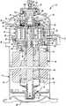
- FIG. 1is a cross-sectional view of a compressor according to the principles of the present disclosure
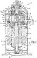
- FIG. 2is a partial cross-sectional view of the compressor of FIG. 1 ;
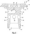
- FIG. 3is a cross-sectional view of a piston of a capacity modulation assembly of the compressor
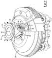
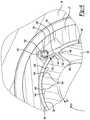
- FIG. 4is a partially cut away perspective view of the piston, a partition, a non-orbiting scroll, and a piston-retention member according to the principles of the present disclosure
- FIG. 5is an exploded view of the piston, piston-retention member, wear ring, and partition;
- FIG. 6is a partial cross-sectional view of the piston, the wear ring, and the piston-retention member engaging a notch in the piston;
- FIG. 7is a schematic representation of a climate-control system in which the compressor is installed
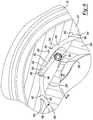
- FIG. 8is a partially cut away perspective view of an alternative piston, alternative partition, the non-orbiting scroll, and an alternative piston-retention member according to the principles of the present disclosure
- FIG. 9is a partial cross-sectional view of the piston, the wear ring, and the piston-retention member of FIG. 8 ;
- FIG. 10is a partial cross sectional view of the compressor having another alternative piston, another alternative partition, an alternative end cap, and another alternative piston-retention member according to the principles of the present disclosure
- FIG. 11is a partial cross-sectional view of the compressor having yet another alternative piston and locking rings according to the principles of the present disclosure
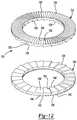
- FIG. 12is a perspective view of the locking rings
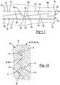
- FIG. 13is a side view of the locking rings engaging the piston and a discharge valve
- FIG. 14is a partial cross-sectional view of an embodiment of a piston and an embodiment of a non-orbiting scroll according to the principles of the present disclosure.
- Example embodimentsare provided so that this disclosure will be thorough, and will fully convey the scope to those who are skilled in the art. Numerous specific details are set forth such as examples of specific components, devices, and methods, to provide a thorough understanding of embodiments of the present disclosure. It will be apparent to those skilled in the art that specific details need not be employed, that example embodiments may be embodied in many different forms and that neither should be construed to limit the scope of the disclosure. In some example embodiments, well-known processes, well-known device structures, and well-known technologies are not described in detail.
- first, second, third, etc.may be used herein to describe various elements, components, regions, layers and/or sections, these elements, components, regions, layers and/or sections should not be limited by these terms. These terms may be only used to distinguish one element, component, region, layer or section from another region, layer or section. Terms such as “first,” “second,” and other numerical terms when used herein do not imply a sequence or order unless clearly indicated by the context. Thus, a first element, component, region, layer or section discussed below could be termed a second element, component, region, layer or section without departing from the teachings of the example embodiments.
- Spatially relative termssuch as “inner,” “outer,” “beneath,” “below,” “lower,” “above,” “upper,” and the like, may be used herein for ease of description to describe one element or feature's relationship to another element(s) or feature(s) as illustrated in the figures. Spatially relative terms may be intended to encompass different orientations of the device in use or operation in addition to the orientation depicted in the figures. For example, if the device in the figures is turned over, elements described as “below” or “beneath” other elements or features would then be oriented “above” the other elements or features. Thus, the example term “below” can encompass both an orientation of above and below. The device may be otherwise oriented (rotated 90 degrees or at other orientations) and the spatially relative descriptors used herein interpreted accordingly.
- a compressor 10may include a hermetic shell assembly 12 , a first bearing housing assembly 14 , a second bearing housing assembly 15 , a motor assembly 16 , a compression mechanism 18 , a floating seal assembly 20 , and a capacity modulation assembly 22 .
- the shell assembly 12may generally form a compressor housing and may include a cylindrical shell 21 , an end cap 24 at the upper end of the shell 21 , a transversely extending partition 26 , and a base 28 at a lower end of the shell 21 .
- the end cap 24 and partition 26may generally define a discharge chamber 30 .
- a discharge gas outlet fitting 32may be attached to the shell assembly 12 at an opening in the end cap 24 .
- a suction gas inlet fitting 34may be attached to the shell assembly 12 at another opening and may communicate with a suction chamber 35 defined by the shell 21 and the partition 26 .
- the partition 26may include a discharge passage 36 that provides fluid communication between the compression mechanism 18 (which is disposed in the suction chamber 35 ) and the discharge chamber 30 .
- the first bearing housing assembly 14may be affixed to the shell 21 and may include a first bearing housing 38 and a first bearing 40 .
- the first bearing housing 38may house the first bearing 40 therein and may define an annular flat thrust bearing surface 42 on an axial end surface thereof.
- the second bearing housing assembly 15may be affixed to the shell 21 and may include a second bearing housing 39 and a second bearing 41 .
- the second bearing housing 39may house the second bearing 41 therein.
- the motor assembly 16may include a motor stator 44 and a rotor 46 .
- the motor stator 44may be attached to the shell 21 (e.g., via press fit, staking, and/or welding).
- the rotor 46may be attached to a driveshaft 48 (e.g., via press fit, staking, and/or welding).
- the driveshaft 48may be driven by the rotor 46 and may be supported by the first and second bearings 40 , 41 for rotation relative to the shell assembly 12 .
- the motor assembly 16is a variable-speed motor. In other configurations, the motor assembly 16 could be a multi-speed motor or a fixed-speed motor.
- the compression mechanism 18may generally include an orbiting scroll 52 , a non-orbiting scroll 54 and an Oldham coupling 56 .
- the orbiting scroll 52may include an end plate 58 having a spiral wrap 60 on the upper surface thereof and an annular flat thrust surface 62 on the lower surface.
- the thrust surface 62may interface with the annular flat thrust bearing surface 42 on the first bearing housing 38 .
- a cylindrical hub 64may project downwardly from the thrust surface 62 and may have a drive bushing 66 rotatably disposed therein.
- a drive bearing 67may be disposed within the hub 64 and may surround the drive bushing 66 .
- the drive bushing 66may include an inner bore in which an eccentric crank pin 50 of the driveshaft 48 is drivingly disposed.
- crankpin 50may drivingly engage a flat surface in a portion of the inner bore of the drive bushing 66 to provide a radially compliant driving arrangement.
- the Oldham coupling 56may be engaged with the orbiting and non-orbiting scrolls 52 , 54 or with the orbiting scroll 52 and the first bearing housing 38 to prevent relative rotation therebetween.
- the non-orbiting scroll 54may include an end plate 68 and a spiral wrap 70 projecting downwardly from the end plate 68 .
- the spiral wrap 70may meshingly engage the spiral wrap 60 of the orbiting scroll 52 , thereby creating a series of moving compression pockets.
- the compression pockets defined by the spiral wraps 60 , 70may decrease in volume as they move from a radially outer position (at a suction pressure) to a radially intermediate position (at an intermediate pressure) to a radially inner position (at a discharge pressure) throughout a compression cycle of the compression mechanism 18 .
- the end plate 68may include a discharge passage 72 ( FIG. 2 ), an intermediate passage 74 ( FIG. 1 ), a central recess 75 ( FIGS. 1 and 2 ), and an annular recess 76 ( FIGS. 1 and 2 ) that surrounds the central recess 75 .
- the discharge passage 72is in communication with one of the fluid pockets at the radially inner position and allows compressed working fluid (e.g., at the discharge pressure) to flow into the discharge chamber 30 .
- the intermediate passage 74may provide fluid communication between one of the fluid pockets at the radially intermediate position and the annular recess 76 .
- the annular recess 76may receive the floating seal assembly 20 and cooperate with the floating seal assembly 20 to define an axial biasing chamber 78 therebetween.
- the axial biasing chamber 78receives fluid from the fluid pocket in the intermediate position through the intermediate passage 74 .
- a pressure differential between the intermediate-pressure fluid in the biasing chamber 78 and fluid in the suction chamber 35exerts an axial biasing force on the non-orbiting scroll 54 urging the non-orbiting scroll 54 in an axial direction (i.e., in a direction along a rotational axis of the driveshaft 48 ) toward the orbiting scroll 52 to sealingly engage the scrolls 52 , 54 with each other.
- one or more springs 79may be disposed within the axial biasing chamber 78 between the floating seal assembly 20 and the end plate 68 and may urge the non-orbiting scroll 54 in the axial direction toward the orbiting scroll 52 to sealingly engage the scrolls 52 , 54 with each other.
- the floating seal assembly 20may be at least partially disposed within the annular recess 76 and may seal off the axial biasing chamber 78 from the discharge chamber 30 and the suction chamber 35 and seal off the suction chamber 35 from the discharge chamber 30 will still allowing the non-orbiting scroll 54 to move in the axial direction relative to the orbiting scroll 52 .
- the floating seal assembly 20may include an annular base plate 80 , a first annular sealing member 82 , and a second annular sealing member 84 .
- the annular base plate 80may be fixed to the first annular sealing member 82 with the second annular sealing member 84 sandwiched therebetween.
- the first annular sealing member 82may sealingly engage the partition 26 (e.g., a wear ring 27 of the partition 26 that defines the discharge passage 36 ).
- the second annular sealing member 84may sealingly engage surfaces of the non-orbiting scroll 54 that define radially inner and outer diameters of the annular recess 76 .
- the floating seal assembly 20could be configured in a variety of other ways that are known in the art.
- the floating seal assembly 20could be a one-piece annular member.
- the capacity modulation assembly 22may be operable to selectively switch the compressor 10 between a full capacity mode and a reduced capacity mode. To operate the compressor 10 in the full capacity mode, the capacity modulation assembly 22 may axially bias the non-orbiting scroll 54 into sealing engagement with the orbiting scroll 52 . To operate the compressor 10 in the reduced capacity mode, the capacity modulation assembly 22 may cause the non-orbiting scroll 54 to move axially away from the orbiting scroll 52 to axially separate the non-orbiting scroll 54 from the orbiting scroll 52 to allow compression pockets to leak into the suction chamber 35 .
- the capacity modulation assembly 22may include a piston 86 and a capacity-modulation fitting 90 .
- the piston 86may include a generally cylindrical main body 92 and a flange portion 94 .
- the flange portion 94may be disposed at a first axial end 95 of the main body 92 and may extend radially outward from the first axial end 95 .
- Threads 96may be formed on an outer diametrical surface 99 of the main body 92 at or proximate a second axial end 97 of the main body 92 .
- the main body 92may include an axially extending discharge passage 98 that extends in an axial direction (i.e., along a longitudinal axis of the main body 92 ) through the first axial end 95 and through a portion of the main body 92 .
- One or more radially extending passages 100may extend from the axially extending discharge passage 98 through the outer diametrical surface 99 of the main body 92 .
- a first aperture 102may extend through the first axial end 95 of the main body 92 .
- a second aperture 104may extend radially through the outer diametrical surface 99 of the main body 92 at a location axially between the passages 100 and the first aperture 102 .
- An orifice 106may provide fluid communication between the first and second apertures 102 , 104 .
- the orifice 106may have a diameter that is substantially smaller than diameters of the first and second apertures 102 , 104 .
- the diameter of the orifice 106may be selected to limit a flow rate of fluid flowing between the first and second apertures 102 , 104 .
- the main body 92 of the piston 86extends through the discharge passage 36 (defined by the wear ring 27 of the partition 26 ) and the second axial end 97 of the main body 92 of the piston 86 is threadably received in the central recess 75 of the non-orbiting scroll 54 (i.e., the threads 96 of the piston 86 are engaged with corresponding threads 77 on the non-orbiting scroll 54 ).
- a discharge valve 108(including, for example, a reed valve 109 and a valve backer 110 ) may be disposed within the central recess 75 between the discharge passage 72 of the non-orbiting scroll 54 and the second axial end 97 of the main body 92 of the piston 86 .
- the valve backer 110may be attached to the end plate 68 by pins and/or threaded fasteners, for example.
- the discharge valve 108allows fluid flow from the discharge passage 72 of the non-orbiting scroll 54 to the discharge passage 98 of the piston 86 and restricts fluid flow from the discharge passage 98 to the discharge passage 72 .
- the discharge passage 98 of the piston 86is in fluid communication with the discharge chamber 30 via the passages 100 . In this manner, compressed working fluid can be discharged from the compression mechanism 18 by flowing through the discharge passage 72 , through the discharge valve 108 , through the discharge passage 98 , through the passages 100 , and into the discharge chamber 30 .
- An annular seal assembly 112may engage the flange portion 94 of the piston 86 .
- the seal assembly 112may include an annular lip seal 114 and one or more annular retainers 116 .
- the lip seal 114 and retainer 116may encircle the first axial end 95 of the main body 92 of the piston 86 .
- the retainer 116may engage the piston 86 (e.g., by press fit, shrink fit, and/or fasteners) and the lip seal 114 may be sandwiched between the retainer 116 and the flange portion 94 of the piston 86 .
- the end cap 24 of the shell assembly 12may define a generally cylindrical recess 118 that fixedly receives an annular recess fitting 120 .
- the first axial end 95 of the main body 92 of the piston 86 and the flange portion 94 of the piston 86may be slidably received in the recess 118 (e.g., slidably received in the recess fitting 120 so that the piston 86 can move in an axial direction (i.e., a direction along or parallel to the longitudinal axis of the piston 86 ) relative to the end cap 24 and recess fitting 120 ).
- the seal assembly 112sealingly engages the recess fitting 120 and the piston 86 so that a pressure chamber 122 is formed within the recess 118 between the first axial end 95 of the piston 86 and an end wall 124 of the end cap 24 .
- the capacity-modulation fitting 90may extend through the end wall 124 of the end cap 24 and may be in fluid communication with the pressure chamber 122 .
- the pressure chamber 122may also be in fluid communication with the discharge chamber 30 via the first and second apertures 102 , 104 and the orifice 106 .
- FIG. 7shows an example of a climate-control system in which the compressor 10 may be installed.
- the climate-control systemmay include an outdoor heat exchanger (e.g., a condenser) 11 , a first expansion device (e.g., an expansion valve or capillary tube) 13 , a flash tank or an economizer 9 , a second expansion device (e.g., an expansion valve or capillary tube) 17 , and an indoor heat exchanger (e.g. an evaporator) 19 .
- working fluidis compressed by the compression mechanism 18 and is discharged from the compressor 10 through the discharge fitting 32 .
- the compressed working fluidmay flow from the discharge fitting 32 to the outdoor heat exchanger 11 , where heat from the working fluid may be transferred to ambient air (or to another cooling fluid). From the outdoor heat exchanger 11 , the working fluid may flow through the first expansion device 13 , where the pressure of the working fluid is reduced.
- the working fluidmay flow into the flash tank 9 .
- a first portion of the fluid in the flash tank 9(e.g., vapor working fluid) may flow through a fluid-injection conduit 23 that may be coupled to a fluid-injection inlet fitting 37 of the compressor 10 .
- the fluid-injection inlet fitting 37may be in fluid communication with an intermediate-pressure compression pocket (i.e., a pocket that is at a radially intermediate position) of the compression mechanism 18 .
- a control valve 25e.g., a solenoid valve
- a second portion of the fluid in the flash tank 9may flow through the second expansion device 17 , wherein its pressure is further reduced.
- the working fluidmay flow through the indoor heat exchanger 19 , where the working fluid may absorb heat from a space to be cooled. From the indoor heat exchanger 19 , the working fluid may flow back into the compressor 10 through the suction gas inlet fitting 34 .
- the capacity-modulation fitting 90 of the compressor 10may be in fluid communication with a source of reduced-pressure working fluid (e.g., working fluid at a lower pressure than discharge pressure).
- the source of reduced-pressure working fluidmay be a source of intermediate-pressure working fluid (e.g., the flash tank or economizer 9 or the fluid-injection conduit 23 or fitting 37 ) or a source of suction-pressure working fluid (e.g., the suction chamber 35 , suction gas inlet fitting 34 , or a suction conduit extending between the indoor heat exchanger 19 and the suction gas inlet fitting 34 ).
- a capacity-modulation control valve 91FIG.
- the 7may be fluidly coupled to the capacity-modulation fitting 90 and may be selectively opened and closed to allow and prevent fluid communication between the pressure chamber 122 ( FIGS. 1 and 2 ) and the source of reduced-pressure working fluid to switch the compressor 10 between the full capacity mode and the reduced capacity mode.
- the capacity-modulation control valve 91may be moved to a first position by a control module to block fluid flow between the pressure chamber 122 and the source of reduced-pressure working fluid.
- a control moduleBy blocking fluid communication between the pressure chamber 122 and the source of reduced-pressure working fluid, the fluid pressure within the pressure chamber 122 will raise to that of the discharge chamber 30 due to the fluid communication between the pressure chamber 122 and the discharge chamber 30 via the first and second apertures 102 , 104 and orifice 106 .
- the capacity-modulation control valve 91may be moved to a second position by the control module to allow fluid communication between the pressure chamber 122 and the source of reduced-pressure working fluid. By allowing fluid communication between the pressure chamber 122 and the source of reduced-pressure working fluid, the fluid pressure within the pressure chamber 122 will be reduced due to the fluid communication between the pressure chamber 122 and the source of reduced-pressure working fluid.
- a piston-retention member 130may engage the piston 86 and a rotationally fixed structure within the compressor 10 , such as a component of the shell assembly 12 (e.g., the partition 26 or end cap 24 ) or the non-orbiting scroll 54 in a manner that (a) allows the piston 86 to be rotated relative to the non-orbiting scroll 54 in a first rotational direction R 1 to threadably inserted the piston 86 into the central recess 75 , and (b) restricts rotation of the piston 86 relative to the non-orbiting scroll 54 in a second rotational direction R 2 (opposite the first rotational direction) that threadably loosens the piston 86 relative to the non-orbiting scroll 54 .
- a rotationally fixed structure within the compressor 10such as a component of the shell assembly 12 (e.g., the partition 26 or end cap 24 ) or the non-orbiting scroll 54 in a manner that (a) allows the piston 86 to be rotated relative to the non-orbiting scroll 54 in a first
- the piston-retention member 130allows the piston 86 to be threaded into the non-orbiting scroll 54 while preventing the piston 86 from threadably loosening or backing out of the non-orbiting scroll 54 .
- the piston-retention member 130also allows the piston 86 to move in the axial direction to switch the compressor 10 between the full capacity and reduced capacity modes, as described above.
- the piston-retention member 130may be a tab, lever, or protrusion that is hingedly mounted to the partition 26 (e.g., the wear ring 27 of the partition 26 ).
- a first end 131 of the piston-retention member 130may include an aperture 132 ( FIGS. 5 and 6 ) that receives a pin 134 or other fastener.
- the pin 134may also be received in an aperture 136 formed in the wear ring 27 to attach the piston-retention member 130 to the wear ring 27 .
- the piston-retention member 130is rotatable relative to the wear ring 27 about a rotational axis defined by the pin 134 .
- the wear ring 27may include a recess 138 that can movably receive at least a portion of the piston-retention member 130 .
- the first end 131 of the piston-retention member 130 and the pin 134may be received in the recess 138 .
- a torsion spring 139( FIGS. 5 and 6 ) may engage the piston-retention member 130 and a wall of the recess 138 and may rotationally bias a second end 140 of the piston-retention member 130 into engagement with the piston 86 .
- the main body 92 of the piston 86may include a plurality of detents or notches 142 formed in the outer diametrical surface 99 of the main body 92 .
- the notches 142may be arranged in a circular pattern that extends around the circumference of the main body 92 . As shown in FIG. 6 , each of the notches 142 may include a ramped or sloped surface 144 and an end wall 146 .
- the second end 140 of the piston-retention member 130can be received in any of the notches 142 and may abut the end wall 146 . Interference between the piston-retention member 130 and the end wall 146 prevents the piston 86 from rotating relative to the wear ring 27 (and relative to the non-orbiting scroll 54 ) in the second rotational direction R 2 .
- the piston-retention member 130allows the piston 86 to rotate relative to the wear ring 27 and non-orbiting scroll 54 in the first rotational direction R 1 because as the piston 86 rotates in the first rotational direction R 1 , the ramped surface 144 slides along the piston-retention member 130 and pushes the second end 140 of the piston-retention member 130 outward toward the wear ring 27 .
- the piston-retention member 130 and notches 142function as a ratchet to allow threaded tightening of the piston 86 within the non-orbiting scroll 54 and restrict threaded loosening of the piston 86 relative to the non-orbiting scroll 54 .
- the piston 86could include teeth or ramped protrusions that extend outward to engage the piston-retention member 130 .
- an alternative piston 286 , an alternative wear ring 227 , and an alternative piston-retention member 330are provided that can be incorporated into the compressor 10 instead of the piston 86 , wear ring 27 , and piston-retention member 130 described above.
- the structure and function of the piston 286 , wear ring 227 , and piston-retention member 330may be similar or identical to that of the piston 86 , wear ring 27 , and piston-retention member 130 described above, apart from differences described below and/or shown in the drawings. Therefore, some similar features will not be described again in detail.
- the piston 286includes a main body 292 that extends through a discharge passage 236 defined by the wear ring 227 .
- the main body 292includes threads that threadably engage mating threads of the non-orbiting scroll 54 , as described above.
- a recess 238may be formed in an outer diametrical surface 299 of the main body 292 .
- the piston-retention member 330may be at least partially received in the recess 238 and may be pivotably mounted (e.g., via pin 334 (like pin 134 )) to the main body 292 .
- a spring 339(like spring 139 ) engages the main body 292 and the piston-retention member 330 and rotationally biases an end 340 of the piston-retention member 330 outward toward the wear ring 227 .
- the wear ring 227may include a plurality of detents or notches 342 .
- the notches 342may include a sloped or ramped surface 344 and an end wall 346 .
- the notches 342may be arranged in a circular pattern that extends around the inner diametrical surface of the wear ring 227 .
- the end 340 of the piston-retention member 330can be received in any of the notches 342 and may abut the end wall 346 . Interference between the piston-retention member 330 and the end wall 346 prevents the piston 286 from rotating relative to the wear ring 227 (and relative to the non-orbiting scroll 54 ) in the second rotational direction R 2 .
- the piston-retention member 330allows the piston 286 to rotate relative to the wear ring 227 and non-orbiting scroll 54 in the first rotational direction R 1 because as the piston 286 rotates in the first rotational direction R 1 , the piston-retention member 330 slides along the ramped surface 344 and the ramped surface 344 pushes the second end 340 of the piston-retention member 330 inward toward the main body 292 .
- the piston-retention member 330 and notches 342function as a ratchet to allow threaded tightening of the piston 286 within the non-orbiting scroll 54 and restrict threaded loosening of the piston 286 relative to the non-orbiting scroll 54 .
- the wear ring 227could include teeth or ramped protrusions that extend inward to engage the piston-retention member 330 .
- an alternative piston 486 , an alternative wear ring 427 , an alternative piston-retention member 530 , and an alternative end cap 424are provided that can be incorporated into the compressor 10 instead of the piston 86 , wear ring 27 , piston-retention member 130 , and end cap 24 described above.
- the structure and function of the piston 486 , wear ring 427 , piston-retention member 530 , and end cap 424may be similar or identical to that of the piston 86 , wear ring 27 , piston-retention member 130 , and end cap 24 described above, apart from differences described below and/or shown in the drawings. Therefore, some similar features will not be described again in detail.
- the piston 486includes a main body 492 that extends through a discharge passage 436 defined by the wear ring 427 .
- the main body 492includes threads that threadably engage mating threads of the non-orbiting scroll 54 , as described above.
- the piston-retention member 530may be pivotably mounted to a flange portion 494 (like the flange portion 94 ) of the piston 486 (as shown in FIG. 10 ) or to an axial end 495 of the piston 486 adjacent the flange portion 494 .
- a first end 531 of the piston-retention member 530may be attached to the piston 486 via a pin (like the pin 134 ).
- the piston-retention member 530may extend from the piston 486 toward an end wall 524 of the end cap 424 (e.g., the end wall defining pressure chamber 522 (like pressure chamber 122 )).
- a second end 540 of the piston-retention member 530may selectively engage one of a plurality of detents or notches 542 (like notches 142 , 342 ) formed in the end wall 524 of the end cap 424 .
- the plurality of notches 542may be arranged in a circular pattern that is centered on a longitudinal axis of the main body 492 of the piston 486 .
- the piston-retention member 530allows the piston 486 to rotate relative to the end cap 424 and non-orbiting scroll 54 in the first rotational direction R 1 because as the piston 486 rotates in the first rotational direction R 1 , the piston-retention member 530 slides along a ramped surface (like ramped surface 144 , 344 ) of the notch 542 and the ramped surface pushes the second end 540 of the piston-retention member 530 toward the piston 486 .
- a ramped surfacelike ramped surface 144 , 344
- the piston-retention member 530 and notches 542function as a ratchet to allow threaded tightening of the piston 486 within the non-orbiting scroll 54 and restrict threaded loosening of the piston 486 relative to the non-orbiting scroll 54 .
- the end cap 424could include teeth or ramped protrusions that engage the piston-retention member 530 .
- the piston-retention member 530could be pivotably mounted to the end cap 424 and selectively engage notches 542 formed in the piston 486 to restrict rotation of the piston 486 in the second rotational direction R 2 while allowing rotation of the piston in the first rotational direction R 1 .
- an alternative piston 686 , an alternative wear ring 627 , and an alternative piston-retention member 730are provided that can be incorporated into the compressor 10 instead of the piston 86 , wear ring 27 , and piston-retention member 130 described above.
- the structure and function of the piston 686 , wear ring 627 , and piston-retention member 730may be similar or identical to that of the piston 86 , wear ring 27 , and piston-retention member 130 described above, apart from differences described below and/or shown in the drawings. Therefore, some similar features will not be described again in detail.
- the piston 686includes a main body 692 and a flange portion 694 .
- the main body 692extends through a discharge passage 636 defined by the wear ring 627 .
- the main body 692includes threads 696 that threadably engage mating threads 77 of the non-orbiting scroll 54 , as described above.
- An annular seal assembly 712(similar or identical to seal assembly 112 ) may sealingly engage the flange portion 694 of the piston 686 and sealingly engage a recess fitting 720 so that a pressure chamber 722 is formed within the recess 118 of the end cap 24 , as described above.
- the piston-retention member 730may include a first locking ring 732 and a second locking ring 734 .
- the first and second locking rings 732 , 734may be sandwiched between the valve backer 110 of the discharge valve 108 and an axial end 697 (i.e., an axial end opposite the flange portion 694 ) of the main body 692 of the piston 686 .
- the first and second locking rings 732 , 734may be identical to each other and may each include a first side 736 and a second side 738 .
- the first side 736 of each of the locking rings 732 , 734may include a plurality of first teeth 740 arranged in a circular pattern extending around a longitudinal axis of the locking rings 732 , 734 .
- Each of the first teeth 740may include a ramped surface 742 and a ledge 744 .
- the second side 738 of each of the locking rings 732 , 734may include a plurality of second teeth (or cams) 746 arranged in a circular pattern extending around the longitudinal axis of the locking rings 732 , 734 .
- Each of the second teeth 746may include a ramped surface 748 and a ledge 750 .
- the first side 736 of the first locking ring 732is engaged with the axial end 697 of the piston 686
- the first side 736 of the second locking ring 734is engaged with an axial end of the valve backer 110 of the discharge valve 108
- the second sides 738 of the locking rings 732 , 734are engaged with each other.
- the first teeth 740 of the first locking ring 732may engage (e.g., dig into) the axial end 697 of the piston 686
- the first teeth 740 of the second locking ring 734may engage (e.g., dig into) the valve backer 110
- the ledges 750 of the second teeth 746 of the first locking ring 732may engage the ledges 750 of the second teeth 746 of the second locking ring 734 .
- Such engagement among the locking rings 732 , 734 , the piston 686 and the valve backer 110may restrict or prevent the piston 686 from unthreading (threadably loosening) from the central recess 75 of the non-orbiting scroll 54 .
- first teeth 740 of the second locking ring 734are described above as engaging the discharge valve 108 , in some configurations of the compressor 10 (e.g., configurations that do not include the discharge valve 108 in the central recess 75 ), the first teeth 740 of the second locking ring 734 may engage a surface 73 of the end plate 68 of the non-orbiting scroll 54 . As shown in FIG. 11 , the surface 73 may define an axial end of the central recess 75 , and the discharge passage 72 may extend through the surface 73 .
- the piston-retention member 130 , 330 , 530 , 730may reduce or eliminate rattling or vibration of the piston 86 , 286 , 486 , 686 and/or discharge valve 108 , which produces undesirable noises during operation of the compressor 10 . Furthermore, the piston-retention member 130 , 330 , 530 , 730 can prevent the piston 86 , 286 , 486 , 686 from disengaging the non-orbiting scroll 54 , which could prevent the compressor 10 from modulating between the full capacity and reduced capacity modes.
- the internal (female) threads 77 of the central recess 75 of the non-orbiting scroll 54may be self-locking threads.
- the threads 77may include change in pitch at or adjacent a root 81 of the threads 77 . That is, a first portion 83 of the threads 77 at or adjacent the root 81 may have a first pitch, and a second portion 85 of the thread 77 adjacent a crest 87 of the thread 77 may have a second pitch that is different than the first pitch.
- the first portion 83 having a different pitch than the second portion 85forms a wedge ramp 89 against which the crest of the threads 96 , 696 of the piston 86 , 286 , 486 , 686 is drawn as the piston 86 , 286 , 486 , 686 is threadably tightened within the central recess 75 .
- the threads 77 with wedge ramp 89can be included in any of the configurations of the compressor 10 described above instead of or in addition to the piston-retention members 130 , 330 , 530 , 730 .
Landscapes
- Engineering & Computer Science (AREA)
- Mechanical Engineering (AREA)
- General Engineering & Computer Science (AREA)
- Physics & Mathematics (AREA)
- Fluid Mechanics (AREA)
- Rotary Pumps (AREA)
- Applications Or Details Of Rotary Compressors (AREA)
Abstract
Description
Claims (21)
Priority Applications (5)
| Application Number | Priority Date | Filing Date | Title |
|---|---|---|---|
| US16/508,894US11209000B2 (en) | 2019-07-11 | 2019-07-11 | Compressor having capacity modulation |
| EP20837441.3AEP3997341A4 (en) | 2019-07-11 | 2020-07-10 | Compressor having capacity modulation |
| CN202080057177.9ACN114270046B (en) | 2019-07-11 | 2020-07-10 | Compressor with capacity modulation |
| PCT/US2020/041629WO2021007528A1 (en) | 2019-07-11 | 2020-07-10 | Compressor having capacity modulation |
| US17/498,817US12018683B2 (en) | 2019-07-11 | 2021-10-12 | Compressor having capacity modulation |
Applications Claiming Priority (1)
| Application Number | Priority Date | Filing Date | Title |
|---|---|---|---|
| US16/508,894US11209000B2 (en) | 2019-07-11 | 2019-07-11 | Compressor having capacity modulation |
Related Child Applications (1)
| Application Number | Title | Priority Date | Filing Date |
|---|---|---|---|
| US17/498,817ContinuationUS12018683B2 (en) | 2019-07-11 | 2021-10-12 | Compressor having capacity modulation |
Publications (2)
| Publication Number | Publication Date |
|---|---|
| US20210010472A1 US20210010472A1 (en) | 2021-01-14 |
| US11209000B2true US11209000B2 (en) | 2021-12-28 |
Family
ID=74102998
Family Applications (2)
| Application Number | Title | Priority Date | Filing Date |
|---|---|---|---|
| US16/508,894Active2040-02-13US11209000B2 (en) | 2019-07-11 | 2019-07-11 | Compressor having capacity modulation |
| US17/498,817ActiveUS12018683B2 (en) | 2019-07-11 | 2021-10-12 | Compressor having capacity modulation |
Family Applications After (1)
| Application Number | Title | Priority Date | Filing Date |
|---|---|---|---|
| US17/498,817ActiveUS12018683B2 (en) | 2019-07-11 | 2021-10-12 | Compressor having capacity modulation |
Country Status (4)
| Country | Link |
|---|---|
| US (2) | US11209000B2 (en) |
| EP (1) | EP3997341A4 (en) |
| CN (1) | CN114270046B (en) |
| WO (1) | WO2021007528A1 (en) |
Cited By (6)
| Publication number | Priority date | Publication date | Assignee | Title |
|---|---|---|---|---|
| US11965507B1 (en) | 2022-12-15 | 2024-04-23 | Copeland Lp | Compressor and valve assembly |
| US12163523B1 (en) | 2023-12-15 | 2024-12-10 | Copeland Lp | Compressor and valve assembly |
| US12173708B1 (en) | 2023-12-07 | 2024-12-24 | Copeland Lp | Heat pump systems with capacity modulation |
| US12188470B2 (en) | 2022-08-11 | 2025-01-07 | Copeland Lp | Scroll compressor with center hub |
| US12259163B2 (en) | 2022-06-01 | 2025-03-25 | Copeland Lp | Climate-control system with thermal storage |
| US12416308B2 (en) | 2022-12-28 | 2025-09-16 | Copeland Lp | Compressor with shutdown assembly |
Families Citing this family (2)
| Publication number | Priority date | Publication date | Assignee | Title |
|---|---|---|---|---|
| US11209000B2 (en) | 2019-07-11 | 2021-12-28 | Emerson Climate Technologies, Inc. | Compressor having capacity modulation |
| US11767846B2 (en) | 2021-01-21 | 2023-09-26 | Copeland Lp | Compressor having seal assembly |
Citations (93)
| Publication number | Priority date | Publication date | Assignee | Title |
|---|---|---|---|---|
| US3978382A (en) | 1974-12-16 | 1976-08-31 | Lennox Industries Inc. | Control apparatus for two-speed, single phase compressor |
| US4041542A (en) | 1974-01-24 | 1977-08-09 | Lennox Industries, Inc. | Control apparatus for two-speed compressor |
| US4105374A (en) | 1977-03-28 | 1978-08-08 | Copeland Corporation | Integrated multi-unit refrigeration motor-compressor assembly |
| US4205537A (en) | 1978-12-11 | 1980-06-03 | General Electric Company | Multiple hermetic-motor compressor in common shell |
| US4252506A (en) | 1978-09-01 | 1981-02-24 | Tecumseh Products Company | Variable capacity compressor |
| US4277955A (en) | 1979-09-13 | 1981-07-14 | Lennox Industries, Inc. | Twin compressor mechanism in one enclosure |
| JPS56165701A (en) | 1980-05-23 | 1981-12-19 | Hitachi Ltd | Power generator |
| JPS5738690A (en) | 1980-08-14 | 1982-03-03 | Matsushita Electric Ind Co Ltd | Scroll two-cylinder compressor |
| US4332144A (en) | 1981-03-26 | 1982-06-01 | Shaw David N | Bottoming cycle refrigerant scavenging for positive displacement compressor, refrigeration and heat pump systems |
| US4358254A (en) | 1978-09-01 | 1982-11-09 | Tecumseh Products Company | Variable capacity compressor |
| US4396360A (en) | 1981-02-03 | 1983-08-02 | Copeland Corporation | Dual compressors |
| JPS6053601A (en) | 1983-09-01 | 1985-03-27 | Mitsubishi Electric Corp | Scroll type hydraulic machine |
| US4745777A (en) | 1986-03-31 | 1988-05-24 | Mitsubishi Denki Kabushiki Kaisha | Refrigerating cycle apparatus |
| US4747756A (en) | 1985-08-10 | 1988-05-31 | Sanden Corporation | Scroll compressor with control device for variable displacement mechanism |
| US4818198A (en) | 1986-11-26 | 1989-04-04 | Hitachi, Ltd. | Scroll fluid machine with oil feed passages |
| JPH01294987A (en) | 1988-05-23 | 1989-11-28 | Mitsubishi Electric Corp | Multi-cylinder type rotary compressor |
| JPH0211882A (en) | 1988-06-29 | 1990-01-16 | Matsushita Electric Ind Co Ltd | Variable displacement scroll compressor |
| JPH02140477A (en) | 1988-11-18 | 1990-05-30 | Hitachi Ltd | two stage compressor |
| US4946361A (en) | 1989-03-06 | 1990-08-07 | Carrier Corporation | Horizontal scroll compressor with oil pump |
| US4982572A (en) | 1989-05-02 | 1991-01-08 | 810296 Ontario Inc. | Vapor injection system for refrigeration units |
| US5002470A (en) | 1989-12-14 | 1991-03-26 | Carrier Corporation | Internal stator rolling rotor motor driven scroll compressor |
| US5059098A (en) | 1989-02-02 | 1991-10-22 | Kabushiki Kaisha Toyoda Jidoshokki Seisakusho | Apparatus for varying capacity of scroll type compressor |
| GB2246451A (en) | 1990-04-24 | 1992-01-29 | Toshiba Kk | Heat exchanger |
| JPH0431689A (en) | 1990-05-24 | 1992-02-03 | Hitachi Ltd | Scroll compressor and refrigeration cycle using it |
| JPH04121478A (en) | 1990-09-12 | 1992-04-22 | Toshiba Corp | scroll compressor |
| JPH04121474A (en) | 1990-09-10 | 1992-04-22 | Toshiba Corp | Scroll type compressor |
| US5123818A (en) | 1989-04-03 | 1992-06-23 | Carrier Corporation | Rolling rotor motor driven scroll compressor |
| JPH04203489A (en) | 1990-11-30 | 1992-07-24 | Mitsubishi Electric Corp | Multi-cylinder rotary compressor |
| JPH0599164A (en) | 1991-10-11 | 1993-04-20 | Mitsubishi Heavy Ind Ltd | Scroll type fluid machine |
| US5240389A (en) | 1991-07-26 | 1993-08-31 | Kabushiki Kaisha Toshiba | Scroll type compressor |
| JPH062670A (en) | 1992-06-17 | 1994-01-11 | Hitachi Ltd | Rotary scroll fluid machine |
| US5328344A (en) | 1992-06-22 | 1994-07-12 | Mitsubishi Denki Kabushiki Kaisha | Enclosed type rotary compressor |
| US5329788A (en) | 1992-07-13 | 1994-07-19 | Copeland Corporation | Scroll compressor with liquid injection |
| US5342186A (en) | 1993-06-02 | 1994-08-30 | General Motors Corporation | Axial actuator for unloading an orbital scroll type fluid material handling machine |
| US5345785A (en) | 1991-10-30 | 1994-09-13 | Hitachi, Ltd. | Scroll compressor and air conditioner using the same |
| US5385453A (en) | 1993-01-22 | 1995-01-31 | Copeland Corporation | Multiple compressor in a single shell |
| JPH0791385A (en) | 1993-09-22 | 1995-04-04 | Hitachi Ltd | Refrigerant pump |
| JPH08200247A (en) | 1995-01-27 | 1996-08-06 | Iwata Air Compressor Mfg Co Ltd | Twin type total system rotating scroll fluid machine |
| EP0747597A2 (en) | 1995-06-07 | 1996-12-11 | Copeland Corporation | Capacity modulated scroll machine |
| US5609478A (en) | 1995-11-06 | 1997-03-11 | Alliance Compressors | Radial compliance mechanism for corotating scroll apparatus |
| US5611674A (en) | 1995-06-07 | 1997-03-18 | Copeland Corporation | Capacity modulated scroll machine |
| US5613841A (en)* | 1995-06-07 | 1997-03-25 | Copeland Corporation | Capacity modulated scroll machine |
| US5678985A (en) | 1995-12-19 | 1997-10-21 | Copeland Corporation | Scroll machine with capacity modulation |
| JPH1037866A (en) | 1996-07-25 | 1998-02-13 | Mitsubishi Electric Corp | Scroll compressor |
| US5800141A (en) | 1996-11-21 | 1998-09-01 | Copeland Corporation | Scroll machine with reverse rotation protection |
| WO1999017066A1 (en) | 1997-09-29 | 1999-04-08 | Copeland Corporation | An adaptive control for a refrigeration system using pulse width modulated duty cycle scroll compressor |
| JPH11141483A (en) | 1997-11-06 | 1999-05-25 | Matsushita Electric Ind Co Ltd | Electric gas compressor |
| CN1219648A (en) | 1997-12-09 | 1999-06-16 | 运载器有限公司 | Optimized location for scroll compressor economizer injection ports |
| US5931649A (en) | 1986-08-22 | 1999-08-03 | Copeland Corporation | Scroll-type machine having a bearing assembly for the drive shaft |
| US6027321A (en) | 1996-02-09 | 2000-02-22 | Kyungwon-Century Co. Ltd. | Scroll-type compressor having an axially displaceable scroll plate |
| EP0980978A1 (en) | 1998-08-17 | 2000-02-23 | Carrier Corporation | Scroll compressor with liquid injection |
| US6053715A (en) | 1997-09-30 | 2000-04-25 | Matsushita Electric Industrial Co., Ltd. | Scroll type compressor |
| US6106253A (en) | 1997-06-04 | 2000-08-22 | Denso Corporation | Scroll type compressor for gas-injection type refrigerating cycle |
| US6120255A (en) | 1998-01-16 | 2000-09-19 | Copeland Corporation | Scroll machine with capacity modulation |
| US6123517A (en) | 1997-11-24 | 2000-09-26 | Copeland Corporation | Scroll machine with capacity modulation |
| US6171076B1 (en) | 1998-06-10 | 2001-01-09 | Tecumseh Products Company | Hermetic compressor assembly having a suction chamber and twin axially disposed discharge chambers |
| US6193473B1 (en) | 1999-03-31 | 2001-02-27 | Cooper Turbocompressor, Inc. | Direct drive compressor assembly with switched reluctance motor drive |
| US6206652B1 (en) | 1998-08-25 | 2001-03-27 | Copeland Corporation | Compressor capacity modulation |
| EP1087142A2 (en) | 1999-09-21 | 2001-03-28 | Copeland Corporation | Scroll compressor capacity control |
| US6220839B1 (en) | 1999-07-07 | 2001-04-24 | Copeland Corporation | Scroll compressor discharge muffler |
| US6264446B1 (en) | 2000-02-02 | 2001-07-24 | Copeland Corporation | Horizontal scroll compressor |
| US6267572B1 (en) | 1998-10-30 | 2001-07-31 | Tokico Ltd. | Scroll fluid machine having scroll members at each end of a rotating hollow shaft |
| US6280154B1 (en) | 2000-02-02 | 2001-08-28 | Copeland Corporation | Scroll compressor |
| KR20010081651A (en) | 2000-02-17 | 2001-08-29 | 구자홍 | Apparatus for preventing inversion of scroll compressor |
| US6290472B2 (en) | 1998-06-10 | 2001-09-18 | Tecumseh Products Company | Rotary compressor with vane body immersed in lubricating fluid |
| US6293776B1 (en) | 2000-07-12 | 2001-09-25 | Scroll Technologies | Method of connecting an economizer tube |
| US6322339B1 (en) | 1997-09-17 | 2001-11-27 | Sanyo Electric Co., Ltd. | Scroll compressor |
| US6412293B1 (en) | 2000-10-11 | 2002-07-02 | Copeland Corporation | Scroll machine with continuous capacity modulation |
| US20020085939A1 (en) | 2000-09-08 | 2002-07-04 | Zili Sun | Scroll compressor with unique mounting of non-orbiting scroll |
| US6478550B2 (en) | 1998-06-12 | 2002-11-12 | Daikin Industries, Ltd. | Multi-stage capacity-controlled scroll compressor |
| US6519958B1 (en) | 2000-06-07 | 2003-02-18 | Samsung Electronics Co., Ltd. | Control system for starting of air conditioner and control method thereof |
| US20030033823A1 (en) | 2001-03-16 | 2003-02-20 | Pham Hung M. | Digital scroll condensing unit controller |
| US6619062B1 (en) | 1999-12-06 | 2003-09-16 | Daikin Industries, Ltd. | Scroll compressor and air conditioner |
| US6619936B2 (en) | 2002-01-16 | 2003-09-16 | Copeland Corporation | Scroll compressor with vapor injection |
| US6672846B2 (en) | 2001-04-25 | 2004-01-06 | Copeland Corporation | Capacity modulation for plural compressors |
| US6821092B1 (en) | 2003-07-15 | 2004-11-23 | Copeland Corporation | Capacity modulated scroll compressor |
| US20040265140A1 (en) | 2003-06-26 | 2004-12-30 | Zili Sun | Two-step self-modulating scroll compressor |
| US20050142017A1 (en) | 2003-12-25 | 2005-06-30 | Kun-Yi Liang | Scroll compressor with backflow-proof mechanism |
| US6929455B2 (en) | 2002-10-15 | 2005-08-16 | Tecumseh Products Company | Horizontal two stage rotary compressor |
| KR20050088765A (en) | 2004-03-03 | 2005-09-07 | 주식회사 우리회사 | Compressor |
| US20050244277A1 (en) | 2004-04-30 | 2005-11-03 | Hurst Ernest P Jr | Fixed and variable compressor system capacity control |
| US6988876B2 (en) | 2002-11-04 | 2006-01-24 | Enjiu Ke | Scroll type fluid machinery |
| US7094043B2 (en) | 2002-09-23 | 2006-08-22 | Tecumseh Products Company | Compressor having counterweight shield |
| WO2006132638A1 (en) | 2005-06-07 | 2006-12-14 | Carrier Corporation | Variable speed compressor motor control for low speed operation |
| US20060280627A1 (en) | 2005-05-24 | 2006-12-14 | Nagaraj Jayanth | Control and protection system for a variable capacity compressor |
| US7201567B2 (en) | 2003-06-20 | 2007-04-10 | Emerson Climate Technologies, Inc. | Plural compressors |
| WO2007050063A1 (en) | 2005-10-26 | 2007-05-03 | Carrier Corporation | Refrigerant system with pulse width modulated components and variable speed compressor |
| US20070130973A1 (en) | 2005-05-04 | 2007-06-14 | Scroll Technologies | Refrigerant system with multi-speed scroll compressor and economizer circuit |
| US20080175737A1 (en) | 2005-03-04 | 2008-07-24 | Grassbaugh Walter T | Scroll machine with seal |
| US20080250812A1 (en) | 2005-11-30 | 2008-10-16 | Alexander Lifson | Multi-Circuit Refrigerant System Utilizing Pulse Width Modulation Techniques |
| US8485789B2 (en)* | 2007-05-18 | 2013-07-16 | Emerson Climate Technologies, Inc. | Capacity modulated scroll compressor system and method |
| US8517703B2 (en) | 2010-02-23 | 2013-08-27 | Emerson Climate Technologies, Inc. | Compressor including valve assembly |
| US8628316B2 (en) | 2008-05-30 | 2014-01-14 | Emerson Climate Technologies, Inc. | Compressor having capacity modulation system |
Family Cites Families (6)
| Publication number | Priority date | Publication date | Assignee | Title |
|---|---|---|---|---|
| US4095494A (en)* | 1977-04-13 | 1978-06-20 | Castoe John H | Gear-operated ratchet wrench |
| US20070036661A1 (en)* | 2005-08-12 | 2007-02-15 | Copeland Corporation | Capacity modulated scroll compressor |
| US7735581B2 (en)* | 2007-04-30 | 2010-06-15 | Smith International, Inc. | Locking clutch for downhole motor |
| US8813930B2 (en)* | 2011-10-17 | 2014-08-26 | Needle Roller Bearing Co., Ltd. | One-way clutch |
| US10378540B2 (en) | 2015-07-01 | 2019-08-13 | Emerson Climate Technologies, Inc. | Compressor with thermally-responsive modulation system |
| US11209000B2 (en) | 2019-07-11 | 2021-12-28 | Emerson Climate Technologies, Inc. | Compressor having capacity modulation |
- 2019
- 2019-07-11USUS16/508,894patent/US11209000B2/enactiveActive
- 2020
- 2020-07-10EPEP20837441.3Apatent/EP3997341A4/enactivePending
- 2020-07-10CNCN202080057177.9Apatent/CN114270046B/enactiveActive
- 2020-07-10WOPCT/US2020/041629patent/WO2021007528A1/ennot_activeCeased
- 2021
- 2021-10-12USUS17/498,817patent/US12018683B2/enactiveActive
Patent Citations (130)
| Publication number | Priority date | Publication date | Assignee | Title |
|---|---|---|---|---|
| US4041542A (en) | 1974-01-24 | 1977-08-09 | Lennox Industries, Inc. | Control apparatus for two-speed compressor |
| US3978382A (en) | 1974-12-16 | 1976-08-31 | Lennox Industries Inc. | Control apparatus for two-speed, single phase compressor |
| US4105374A (en) | 1977-03-28 | 1978-08-08 | Copeland Corporation | Integrated multi-unit refrigeration motor-compressor assembly |
| US4358254A (en) | 1978-09-01 | 1982-11-09 | Tecumseh Products Company | Variable capacity compressor |
| US4252506A (en) | 1978-09-01 | 1981-02-24 | Tecumseh Products Company | Variable capacity compressor |
| US4205537A (en) | 1978-12-11 | 1980-06-03 | General Electric Company | Multiple hermetic-motor compressor in common shell |
| US4277955A (en) | 1979-09-13 | 1981-07-14 | Lennox Industries, Inc. | Twin compressor mechanism in one enclosure |
| JPS56165701A (en) | 1980-05-23 | 1981-12-19 | Hitachi Ltd | Power generator |
| JPS5738690A (en) | 1980-08-14 | 1982-03-03 | Matsushita Electric Ind Co Ltd | Scroll two-cylinder compressor |
| US4396360A (en) | 1981-02-03 | 1983-08-02 | Copeland Corporation | Dual compressors |
| US4332144A (en) | 1981-03-26 | 1982-06-01 | Shaw David N | Bottoming cycle refrigerant scavenging for positive displacement compressor, refrigeration and heat pump systems |
| JPS6053601A (en) | 1983-09-01 | 1985-03-27 | Mitsubishi Electric Corp | Scroll type hydraulic machine |
| US4515539A (en) | 1983-09-01 | 1985-05-07 | Mitsubishi Denki Kabushiki Kaisha | Scroll-type hydraulic machine with two axially spaced scroll mechanisms |
| US4747756A (en) | 1985-08-10 | 1988-05-31 | Sanden Corporation | Scroll compressor with control device for variable displacement mechanism |
| US4745777A (en) | 1986-03-31 | 1988-05-24 | Mitsubishi Denki Kabushiki Kaisha | Refrigerating cycle apparatus |
| US5931649A (en) | 1986-08-22 | 1999-08-03 | Copeland Corporation | Scroll-type machine having a bearing assembly for the drive shaft |
| US4818198A (en) | 1986-11-26 | 1989-04-04 | Hitachi, Ltd. | Scroll fluid machine with oil feed passages |
| JPH01294987A (en) | 1988-05-23 | 1989-11-28 | Mitsubishi Electric Corp | Multi-cylinder type rotary compressor |
| JPH0211882A (en) | 1988-06-29 | 1990-01-16 | Matsushita Electric Ind Co Ltd | Variable displacement scroll compressor |
| JPH02140477A (en) | 1988-11-18 | 1990-05-30 | Hitachi Ltd | two stage compressor |
| US5059098A (en) | 1989-02-02 | 1991-10-22 | Kabushiki Kaisha Toyoda Jidoshokki Seisakusho | Apparatus for varying capacity of scroll type compressor |
| US4946361A (en) | 1989-03-06 | 1990-08-07 | Carrier Corporation | Horizontal scroll compressor with oil pump |
| US5123818A (en) | 1989-04-03 | 1992-06-23 | Carrier Corporation | Rolling rotor motor driven scroll compressor |
| US4982572A (en) | 1989-05-02 | 1991-01-08 | 810296 Ontario Inc. | Vapor injection system for refrigeration units |
| US5002470A (en) | 1989-12-14 | 1991-03-26 | Carrier Corporation | Internal stator rolling rotor motor driven scroll compressor |
| GB2246451A (en) | 1990-04-24 | 1992-01-29 | Toshiba Kk | Heat exchanger |
| JPH0431689A (en) | 1990-05-24 | 1992-02-03 | Hitachi Ltd | Scroll compressor and refrigeration cycle using it |
| US5211031A (en) | 1990-05-24 | 1993-05-18 | Hitachi, Ltd. | Scroll type compressor and refrigeration cycle using the same |
| JPH04121474A (en) | 1990-09-10 | 1992-04-22 | Toshiba Corp | Scroll type compressor |
| JPH04121478A (en) | 1990-09-12 | 1992-04-22 | Toshiba Corp | scroll compressor |
| JPH04203489A (en) | 1990-11-30 | 1992-07-24 | Mitsubishi Electric Corp | Multi-cylinder rotary compressor |
| US5240389A (en) | 1991-07-26 | 1993-08-31 | Kabushiki Kaisha Toshiba | Scroll type compressor |
| JPH0599164A (en) | 1991-10-11 | 1993-04-20 | Mitsubishi Heavy Ind Ltd | Scroll type fluid machine |
| US5345785A (en) | 1991-10-30 | 1994-09-13 | Hitachi, Ltd. | Scroll compressor and air conditioner using the same |
| JPH062670A (en) | 1992-06-17 | 1994-01-11 | Hitachi Ltd | Rotary scroll fluid machine |
| US5328344A (en) | 1992-06-22 | 1994-07-12 | Mitsubishi Denki Kabushiki Kaisha | Enclosed type rotary compressor |
| US5329788A (en) | 1992-07-13 | 1994-07-19 | Copeland Corporation | Scroll compressor with liquid injection |
| US5447420A (en) | 1992-07-13 | 1995-09-05 | Copeland Corporation | Scroll compressor with liquid injection |
| US5385453A (en) | 1993-01-22 | 1995-01-31 | Copeland Corporation | Multiple compressor in a single shell |
| US5342186A (en) | 1993-06-02 | 1994-08-30 | General Motors Corporation | Axial actuator for unloading an orbital scroll type fluid material handling machine |
| JPH0791385A (en) | 1993-09-22 | 1995-04-04 | Hitachi Ltd | Refrigerant pump |
| JPH08200247A (en) | 1995-01-27 | 1996-08-06 | Iwata Air Compressor Mfg Co Ltd | Twin type total system rotating scroll fluid machine |
| US5611674A (en) | 1995-06-07 | 1997-03-18 | Copeland Corporation | Capacity modulated scroll machine |
| US6047557A (en) | 1995-06-07 | 2000-04-11 | Copeland Corporation | Adaptive control for a refrigeration system using pulse width modulated duty cycle scroll compressor |
| US5613841A (en)* | 1995-06-07 | 1997-03-25 | Copeland Corporation | Capacity modulated scroll machine |
| US6662578B2 (en) | 1995-06-07 | 2003-12-16 | Copeland Corporation | Refrigeration system and method for controlling defrost |
| US6449972B2 (en) | 1995-06-07 | 2002-09-17 | Copeland Corporation | Adaptive control for a refrigeration system using pulse width modulated duty cycle scroll compressor |
| US5741120A (en) | 1995-06-07 | 1998-04-21 | Copeland Corporation | Capacity modulated scroll machine |
| US6438974B1 (en) | 1995-06-07 | 2002-08-27 | Copeland Corporation | Adaptive control for a refrigeration system using pulse width modulated duty cycle scroll compressor |
| US20020178737A1 (en) | 1995-06-07 | 2002-12-05 | Pham Hung M. | Adaptive control for a refrigeration system using pulse width modulated duty cycle scroll compressor |
| US6408635B1 (en) | 1995-06-07 | 2002-06-25 | Copeland Corporation | Adaptive control for a refrigeration system using pulse width modulated duty cycle scroll compressor |
| US6393852B2 (en) | 1995-06-07 | 2002-05-28 | Copeland Corporation | Adaptive control for a refrigeration system using pulse width modulated duty cycle scroll compressor |
| US6679072B2 (en) | 1995-06-07 | 2004-01-20 | Copeland Corporation | Diagnostic system and method for a cooling system |
| US6467280B2 (en) | 1995-06-07 | 2002-10-22 | Copeland Corporation | Adaptive control for a refrigeration system using pulse width modulated duty cycle scroll compressor |
| US20010049942A1 (en) | 1995-06-07 | 2001-12-13 | Pham Hung M. | Adaptive control for a refrigeration system using pulse width modulated duty cycle scroll compressor |
| US20010002239A1 (en) | 1995-06-07 | 2001-05-31 | Copeland Corporation | Adaptive control for a refrigeration system using pulse width modulated duty cycle scroll compressor |
| US20010045097A1 (en) | 1995-06-07 | 2001-11-29 | Pham Hung M. | Adaptive control for a refrigeration system using pulse width modulated duty cycle scroll compressor |
| US6086335A (en) | 1995-06-07 | 2000-07-11 | Copeland Corporation | Capacity modulated scroll machine having one or more pin members movably disposed for restricting the radius of the orbiting scroll member |
| US6499305B2 (en) | 1995-06-07 | 2002-12-31 | Copeland Corporation | Adaptive control for a refrigeration system using pulse width modulated duty cycle scroll compressor |
| US20030084672A1 (en) | 1995-06-07 | 2003-05-08 | Pham Hung M. | Refrigeration system and method for controlling defrost |
| US20030089119A1 (en) | 1995-06-07 | 2003-05-15 | Pham Hung M. | Diagnostic system and method for a cooling system |
| US20030094004A1 (en) | 1995-06-07 | 2003-05-22 | Pham Hung M. | Adaptive control for a cooling system |
| USRE40554E1 (en) | 1995-06-07 | 2008-10-28 | Emerson Climate Technologies, Inc. | Capacity modulated scroll machine having one or more pin members movably disposed for restricting the radius of the orbiting scroll member |
| US6662583B2 (en) | 1995-06-07 | 2003-12-16 | Copeland Corporation | Adaptive control for a cooling system |
| EP0747597A2 (en) | 1995-06-07 | 1996-12-11 | Copeland Corporation | Capacity modulated scroll machine |
| US20070022771A1 (en) | 1995-06-07 | 2007-02-01 | Pham Hung M | Cooling system with variable capacity control |
| US20060288715A1 (en) | 1995-06-07 | 2006-12-28 | Pham Hung M | Compressor with capacity control |
| US20040123612A1 (en) | 1995-06-07 | 2004-07-01 | Pham Hung M. | Cooling system with variable duty cycle capacity control |
| US5609478A (en) | 1995-11-06 | 1997-03-11 | Alliance Compressors | Radial compliance mechanism for corotating scroll apparatus |
| US5678985A (en) | 1995-12-19 | 1997-10-21 | Copeland Corporation | Scroll machine with capacity modulation |
| US6027321A (en) | 1996-02-09 | 2000-02-22 | Kyungwon-Century Co. Ltd. | Scroll-type compressor having an axially displaceable scroll plate |
| JPH1037866A (en) | 1996-07-25 | 1998-02-13 | Mitsubishi Electric Corp | Scroll compressor |
| US5800141A (en) | 1996-11-21 | 1998-09-01 | Copeland Corporation | Scroll machine with reverse rotation protection |
| US6106253A (en) | 1997-06-04 | 2000-08-22 | Denso Corporation | Scroll type compressor for gas-injection type refrigerating cycle |
| US6322339B1 (en) | 1997-09-17 | 2001-11-27 | Sanyo Electric Co., Ltd. | Scroll compressor |
| WO1999017066A1 (en) | 1997-09-29 | 1999-04-08 | Copeland Corporation | An adaptive control for a refrigeration system using pulse width modulated duty cycle scroll compressor |
| US6053715A (en) | 1997-09-30 | 2000-04-25 | Matsushita Electric Industrial Co., Ltd. | Scroll type compressor |
| JPH11141483A (en) | 1997-11-06 | 1999-05-25 | Matsushita Electric Ind Co Ltd | Electric gas compressor |
| US6123517A (en) | 1997-11-24 | 2000-09-26 | Copeland Corporation | Scroll machine with capacity modulation |
| CN1219648A (en) | 1997-12-09 | 1999-06-16 | 运载器有限公司 | Optimized location for scroll compressor economizer injection ports |
| US6120255A (en) | 1998-01-16 | 2000-09-19 | Copeland Corporation | Scroll machine with capacity modulation |
| US6290472B2 (en) | 1998-06-10 | 2001-09-18 | Tecumseh Products Company | Rotary compressor with vane body immersed in lubricating fluid |
| US6171076B1 (en) | 1998-06-10 | 2001-01-09 | Tecumseh Products Company | Hermetic compressor assembly having a suction chamber and twin axially disposed discharge chambers |
| US6478550B2 (en) | 1998-06-12 | 2002-11-12 | Daikin Industries, Ltd. | Multi-stage capacity-controlled scroll compressor |
| US6196816B1 (en) | 1998-08-17 | 2001-03-06 | Carrier Corporation | Unequal injection ports for scroll compressors |
| EP0980978A1 (en) | 1998-08-17 | 2000-02-23 | Carrier Corporation | Scroll compressor with liquid injection |
| US6206652B1 (en) | 1998-08-25 | 2001-03-27 | Copeland Corporation | Compressor capacity modulation |
| USRE40830E1 (en) | 1998-08-25 | 2009-07-07 | Emerson Climate Technologies, Inc. | Compressor capacity modulation |
| US6267572B1 (en) | 1998-10-30 | 2001-07-31 | Tokico Ltd. | Scroll fluid machine having scroll members at each end of a rotating hollow shaft |
| US6193473B1 (en) | 1999-03-31 | 2001-02-27 | Cooper Turbocompressor, Inc. | Direct drive compressor assembly with switched reluctance motor drive |
| US6220839B1 (en) | 1999-07-07 | 2001-04-24 | Copeland Corporation | Scroll compressor discharge muffler |
| US6213731B1 (en) | 1999-09-21 | 2001-04-10 | Copeland Corporation | Compressor pulse width modulation |
| EP1087142A2 (en) | 1999-09-21 | 2001-03-28 | Copeland Corporation | Scroll compressor capacity control |
| CN1289011A (en) | 1999-09-21 | 2001-03-28 | 科普兰公司 | Compressor Pulse Width Modulation |
| JP2001099078A (en) | 1999-09-21 | 2001-04-10 | Copeland Corp | Scroll type machine with capacity adjusting mechanism |
| US6619062B1 (en) | 1999-12-06 | 2003-09-16 | Daikin Industries, Ltd. | Scroll compressor and air conditioner |
| US6280154B1 (en) | 2000-02-02 | 2001-08-28 | Copeland Corporation | Scroll compressor |
| US6264446B1 (en) | 2000-02-02 | 2001-07-24 | Copeland Corporation | Horizontal scroll compressor |
| KR20010081651A (en) | 2000-02-17 | 2001-08-29 | 구자홍 | Apparatus for preventing inversion of scroll compressor |
| US6519958B1 (en) | 2000-06-07 | 2003-02-18 | Samsung Electronics Co., Ltd. | Control system for starting of air conditioner and control method thereof |
| US6293776B1 (en) | 2000-07-12 | 2001-09-25 | Scroll Technologies | Method of connecting an economizer tube |
| US20020085939A1 (en) | 2000-09-08 | 2002-07-04 | Zili Sun | Scroll compressor with unique mounting of non-orbiting scroll |
| US6412293B1 (en) | 2000-10-11 | 2002-07-02 | Copeland Corporation | Scroll machine with continuous capacity modulation |
| US20030033823A1 (en) | 2001-03-16 | 2003-02-20 | Pham Hung M. | Digital scroll condensing unit controller |
| US6672846B2 (en) | 2001-04-25 | 2004-01-06 | Copeland Corporation | Capacity modulation for plural compressors |
| USRE41955E1 (en) | 2001-04-25 | 2010-11-23 | Emerson Climate Technologies, Inc. | Capacity modulation for plural compressors |
| US6619936B2 (en) | 2002-01-16 | 2003-09-16 | Copeland Corporation | Scroll compressor with vapor injection |
| US7094043B2 (en) | 2002-09-23 | 2006-08-22 | Tecumseh Products Company | Compressor having counterweight shield |
| US6929455B2 (en) | 2002-10-15 | 2005-08-16 | Tecumseh Products Company | Horizontal two stage rotary compressor |
| US6988876B2 (en) | 2002-11-04 | 2006-01-24 | Enjiu Ke | Scroll type fluid machinery |
| US7201567B2 (en) | 2003-06-20 | 2007-04-10 | Emerson Climate Technologies, Inc. | Plural compressors |
| US6884042B2 (en) | 2003-06-26 | 2005-04-26 | Scroll Technologies | Two-step self-modulating scroll compressor |
| US20040265140A1 (en) | 2003-06-26 | 2004-12-30 | Zili Sun | Two-step self-modulating scroll compressor |
| US6821092B1 (en) | 2003-07-15 | 2004-11-23 | Copeland Corporation | Capacity modulated scroll compressor |
| US20050142017A1 (en) | 2003-12-25 | 2005-06-30 | Kun-Yi Liang | Scroll compressor with backflow-proof mechanism |
| KR20050088765A (en) | 2004-03-03 | 2005-09-07 | 주식회사 우리회사 | Compressor |
| US20050244277A1 (en) | 2004-04-30 | 2005-11-03 | Hurst Ernest P Jr | Fixed and variable compressor system capacity control |
| US20080175737A1 (en) | 2005-03-04 | 2008-07-24 | Grassbaugh Walter T | Scroll machine with seal |
| US20080314057A1 (en) | 2005-05-04 | 2008-12-25 | Alexander Lifson | Refrigerant System With Variable Speed Scroll Compressor and Economizer Circuit |
| US20070130973A1 (en) | 2005-05-04 | 2007-06-14 | Scroll Technologies | Refrigerant system with multi-speed scroll compressor and economizer circuit |
| US7721562B2 (en) | 2005-05-04 | 2010-05-25 | Scroll Technologies | Refrigerant system with multi-speed scroll compressor and economizer circuit |
| US20060280627A1 (en) | 2005-05-24 | 2006-12-14 | Nagaraj Jayanth | Control and protection system for a variable capacity compressor |
| WO2006132638A1 (en) | 2005-06-07 | 2006-12-14 | Carrier Corporation | Variable speed compressor motor control for low speed operation |
| US20080196445A1 (en) | 2005-06-07 | 2008-08-21 | Alexander Lifson | Variable Speed Compressor Motor Control for Low Speed Operation |
| WO2007050063A1 (en) | 2005-10-26 | 2007-05-03 | Carrier Corporation | Refrigerant system with pulse width modulated components and variable speed compressor |
| US20080223057A1 (en) | 2005-10-26 | 2008-09-18 | Alexander Lifson | Refrigerant System with Pulse Width Modulated Components and Variable Speed Compressor |
| US20080250812A1 (en) | 2005-11-30 | 2008-10-16 | Alexander Lifson | Multi-Circuit Refrigerant System Utilizing Pulse Width Modulation Techniques |
| US8485789B2 (en)* | 2007-05-18 | 2013-07-16 | Emerson Climate Technologies, Inc. | Capacity modulated scroll compressor system and method |
| US8628316B2 (en) | 2008-05-30 | 2014-01-14 | Emerson Climate Technologies, Inc. | Compressor having capacity modulation system |
| US8517703B2 (en) | 2010-02-23 | 2013-08-27 | Emerson Climate Technologies, Inc. | Compressor including valve assembly |
Non-Patent Citations (4)
| Title |
|---|
| International Search Report regarding Application No. PCT/US2020/041629 dated Oct. 30, 2020. |
| Nord-Lock Group, "Nord-Lock X-series." 70203EN, Jan. 2017 (2 pages). |
| Stanley Engineered Fastening, "Spiralock® Self-Locking Threaded Solutions: Fasteners & Threading Tools." Stanley Black & Decker, Inc., 2017 (44 pages). |
| Written Opinion of the ISA regarding Application No. PCT/US2020/041629 dated Oct. 30, 2020. |
Cited By (6)
| Publication number | Priority date | Publication date | Assignee | Title |
|---|---|---|---|---|
| US12259163B2 (en) | 2022-06-01 | 2025-03-25 | Copeland Lp | Climate-control system with thermal storage |
| US12188470B2 (en) | 2022-08-11 | 2025-01-07 | Copeland Lp | Scroll compressor with center hub |
| US11965507B1 (en) | 2022-12-15 | 2024-04-23 | Copeland Lp | Compressor and valve assembly |
| US12416308B2 (en) | 2022-12-28 | 2025-09-16 | Copeland Lp | Compressor with shutdown assembly |
| US12173708B1 (en) | 2023-12-07 | 2024-12-24 | Copeland Lp | Heat pump systems with capacity modulation |
| US12163523B1 (en) | 2023-12-15 | 2024-12-10 | Copeland Lp | Compressor and valve assembly |
Also Published As
| Publication number | Publication date |
|---|---|
| CN114270046A (en) | 2022-04-01 |
| WO2021007528A1 (en) | 2021-01-14 |
| EP3997341A4 (en) | 2023-07-12 |
| EP3997341A1 (en) | 2022-05-18 |
| CN114270046B (en) | 2024-04-12 |
| US20210010472A1 (en) | 2021-01-14 |
| US20220034317A1 (en) | 2022-02-03 |
| US12018683B2 (en) | 2024-06-25 |
Similar Documents
| Publication | Publication Date | Title |
|---|---|---|
| US12018683B2 (en) | Compressor having capacity modulation | |
| US11434910B2 (en) | Scroll compressor having hub plate | |
| US10962008B2 (en) | Variable volume ratio compressor | |
| US10323639B2 (en) | Variable volume ratio compressor | |
| US11022119B2 (en) | Variable volume ratio compressor | |
| US11656003B2 (en) | Climate-control system having valve assembly | |
| US12188470B2 (en) | Scroll compressor with center hub | |
| US11767846B2 (en) | Compressor having seal assembly | |
| US11939979B2 (en) | Compressor having floating seal assembly | |
| US20250052244A1 (en) | Compressor Having Shutdown Valve Assembly | |
| US12180966B2 (en) | Compressor with funnel assembly |
Legal Events
| Date | Code | Title | Description |
|---|---|---|---|
| AS | Assignment | Owner name:EMERSON CLIMATE TECHNOLOGIES, INC., OHIO Free format text:ASSIGNMENT OF ASSIGNORS INTEREST;ASSIGNORS:MOORE, PHILLIP M.;MCBEAN, JAMES W.;EYINK, ROBERT V.;AND OTHERS;REEL/FRAME:049728/0272 Effective date:20190710 | |
| FEPP | Fee payment procedure | Free format text:ENTITY STATUS SET TO UNDISCOUNTED (ORIGINAL EVENT CODE: BIG.); ENTITY STATUS OF PATENT OWNER: LARGE ENTITY | |
| STPP | Information on status: patent application and granting procedure in general | Free format text:NON FINAL ACTION MAILED | |
| STPP | Information on status: patent application and granting procedure in general | Free format text:RESPONSE TO NON-FINAL OFFICE ACTION ENTERED AND FORWARDED TO EXAMINER | |
| STPP | Information on status: patent application and granting procedure in general | Free format text:NOTICE OF ALLOWANCE MAILED -- APPLICATION RECEIVED IN OFFICE OF PUBLICATIONS | |
| STPP | Information on status: patent application and granting procedure in general | Free format text:PUBLICATIONS -- ISSUE FEE PAYMENT RECEIVED | |
| STPP | Information on status: patent application and granting procedure in general | Free format text:PUBLICATIONS -- ISSUE FEE PAYMENT VERIFIED | |
| STCF | Information on status: patent grant | Free format text:PATENTED CASE | |
| AS | Assignment | Owner name:COPELAND LP, OHIO Free format text:ENTITY CONVERSION;ASSIGNOR:EMERSON CLIMATE TECHNOLOGIES, INC.;REEL/FRAME:064058/0724 Effective date:20230503 | |
| AS | Assignment | Owner name:WELLS FARGO BANK, NATIONAL ASSOCIATION, AS COLLATERAL AGENT, CALIFORNIA Free format text:SECURITY INTEREST;ASSIGNOR:COPELAND LP;REEL/FRAME:064280/0695 Effective date:20230531 Owner name:U.S. BANK TRUST COMPANY, NATIONAL ASSOCIATION, AS NOTES COLLATERAL AGENT, MINNESOTA Free format text:SECURITY INTEREST;ASSIGNOR:COPELAND LP;REEL/FRAME:064279/0327 Effective date:20230531 Owner name:ROYAL BANK OF CANADA, AS COLLATERAL AGENT, CANADA Free format text:SECURITY INTEREST;ASSIGNOR:COPELAND LP;REEL/FRAME:064278/0598 Effective date:20230531 | |
| AS | Assignment | Owner name:U.S. BANK TRUST COMPANY, NATIONAL ASSOCIATION, AS NOTES COLLATERAL AGENT, MINNESOTA Free format text:SECURITY INTEREST;ASSIGNOR:COPELAND LP;REEL/FRAME:068241/0264 Effective date:20240708 | |
| MAFP | Maintenance fee payment | Free format text:PAYMENT OF MAINTENANCE FEE, 4TH YEAR, LARGE ENTITY (ORIGINAL EVENT CODE: M1551); ENTITY STATUS OF PATENT OWNER: LARGE ENTITY Year of fee payment:4 |