US11207549B2 - System and method for delivering energy to tissue - Google Patents
System and method for delivering energy to tissueDownload PDFInfo
- Publication number
- US11207549B2 US11207549B2US16/439,805US201916439805AUS11207549B2US 11207549 B2US11207549 B2US 11207549B2US 201916439805 AUS201916439805 AUS 201916439805AUS 11207549 B2US11207549 B2US 11207549B2
- Authority
- US
- United States
- Prior art keywords
- energy
- energy source
- ultrasound
- ablation
- target tissue
- Prior art date
- Legal status (The legal status is an assumption and is not a legal conclusion. Google has not performed a legal analysis and makes no representation as to the accuracy of the status listed.)
- Active, expires
Links
Images


Classifications
- A—HUMAN NECESSITIES
- A61—MEDICAL OR VETERINARY SCIENCE; HYGIENE
- A61B—DIAGNOSIS; SURGERY; IDENTIFICATION
- A61B17/00—Surgical instruments, devices or methods
- A61B17/22—Implements for squeezing-off ulcers or the like on inner organs of the body; Implements for scraping-out cavities of body organs, e.g. bones; for invasive removal or destruction of calculus using mechanical vibrations; for removing obstructions in blood vessels, not otherwise provided for
- A61B17/22004—Implements for squeezing-off ulcers or the like on inner organs of the body; Implements for scraping-out cavities of body organs, e.g. bones; for invasive removal or destruction of calculus using mechanical vibrations; for removing obstructions in blood vessels, not otherwise provided for using mechanical vibrations, e.g. ultrasonic shock waves
- A61B17/22012—Implements for squeezing-off ulcers or the like on inner organs of the body; Implements for scraping-out cavities of body organs, e.g. bones; for invasive removal or destruction of calculus using mechanical vibrations; for removing obstructions in blood vessels, not otherwise provided for using mechanical vibrations, e.g. ultrasonic shock waves in direct contact with, or very close to, the obstruction or concrement
- A61B17/2202—Implements for squeezing-off ulcers or the like on inner organs of the body; Implements for scraping-out cavities of body organs, e.g. bones; for invasive removal or destruction of calculus using mechanical vibrations; for removing obstructions in blood vessels, not otherwise provided for using mechanical vibrations, e.g. ultrasonic shock waves in direct contact with, or very close to, the obstruction or concrement the ultrasound transducer being inside patient's body at the distal end of the catheter
- A—HUMAN NECESSITIES
- A61—MEDICAL OR VETERINARY SCIENCE; HYGIENE
- A61B—DIAGNOSIS; SURGERY; IDENTIFICATION
- A61B17/00—Surgical instruments, devices or methods
- A61B17/32—Surgical cutting instruments
- A61B17/320068—Surgical cutting instruments using mechanical vibrations, e.g. ultrasonic
- A—HUMAN NECESSITIES
- A61—MEDICAL OR VETERINARY SCIENCE; HYGIENE
- A61B—DIAGNOSIS; SURGERY; IDENTIFICATION
- A61B18/00—Surgical instruments, devices or methods for transferring non-mechanical forms of energy to or from the body
- A61B18/04—Surgical instruments, devices or methods for transferring non-mechanical forms of energy to or from the body by heating
- A61B18/12—Surgical instruments, devices or methods for transferring non-mechanical forms of energy to or from the body by heating by passing a current through the tissue to be heated, e.g. high-frequency current
- A61B18/14—Probes or electrodes therefor
- A61B18/148—Probes or electrodes therefor having a short, rigid shaft for accessing the inner body transcutaneously, e.g. for neurosurgery or arthroscopy
- A—HUMAN NECESSITIES
- A61—MEDICAL OR VETERINARY SCIENCE; HYGIENE
- A61B—DIAGNOSIS; SURGERY; IDENTIFICATION
- A61B18/00—Surgical instruments, devices or methods for transferring non-mechanical forms of energy to or from the body
- A61B18/18—Surgical instruments, devices or methods for transferring non-mechanical forms of energy to or from the body by applying electromagnetic radiation, e.g. microwaves
- A—HUMAN NECESSITIES
- A61—MEDICAL OR VETERINARY SCIENCE; HYGIENE
- A61B—DIAGNOSIS; SURGERY; IDENTIFICATION
- A61B17/00—Surgical instruments, devices or methods
- A61B2017/00017—Electrical control of surgical instruments
- A61B2017/00022—Sensing or detecting at the treatment site
- A61B2017/00106—Sensing or detecting at the treatment site ultrasonic
- A—HUMAN NECESSITIES
- A61—MEDICAL OR VETERINARY SCIENCE; HYGIENE
- A61B—DIAGNOSIS; SURGERY; IDENTIFICATION
- A61B17/00—Surgical instruments, devices or methods
- A61B17/22—Implements for squeezing-off ulcers or the like on inner organs of the body; Implements for scraping-out cavities of body organs, e.g. bones; for invasive removal or destruction of calculus using mechanical vibrations; for removing obstructions in blood vessels, not otherwise provided for
- A61B2017/22051—Implements for squeezing-off ulcers or the like on inner organs of the body; Implements for scraping-out cavities of body organs, e.g. bones; for invasive removal or destruction of calculus using mechanical vibrations; for removing obstructions in blood vessels, not otherwise provided for with an inflatable part, e.g. balloon, for positioning, blocking, or immobilisation
- A—HUMAN NECESSITIES
- A61—MEDICAL OR VETERINARY SCIENCE; HYGIENE
- A61B—DIAGNOSIS; SURGERY; IDENTIFICATION
- A61B17/00—Surgical instruments, devices or methods
- A61B17/32—Surgical cutting instruments
- A61B17/320068—Surgical cutting instruments using mechanical vibrations, e.g. ultrasonic
- A61B2017/320069—Surgical cutting instruments using mechanical vibrations, e.g. ultrasonic for ablating tissue
- A—HUMAN NECESSITIES
- A61—MEDICAL OR VETERINARY SCIENCE; HYGIENE
- A61B—DIAGNOSIS; SURGERY; IDENTIFICATION
- A61B18/00—Surgical instruments, devices or methods for transferring non-mechanical forms of energy to or from the body
- A61B2018/00005—Cooling or heating of the probe or tissue immediately surrounding the probe
- A61B2018/00011—Cooling or heating of the probe or tissue immediately surrounding the probe with fluids
- A61B2018/00023—Cooling or heating of the probe or tissue immediately surrounding the probe with fluids closed, i.e. without wound contact by the fluid
- A—HUMAN NECESSITIES
- A61—MEDICAL OR VETERINARY SCIENCE; HYGIENE
- A61B—DIAGNOSIS; SURGERY; IDENTIFICATION
- A61B18/00—Surgical instruments, devices or methods for transferring non-mechanical forms of energy to or from the body
- A61B2018/00571—Surgical instruments, devices or methods for transferring non-mechanical forms of energy to or from the body for achieving a particular surgical effect
- A61B2018/00577—Ablation
- A—HUMAN NECESSITIES
- A61—MEDICAL OR VETERINARY SCIENCE; HYGIENE
- A61B—DIAGNOSIS; SURGERY; IDENTIFICATION
- A61B18/00—Surgical instruments, devices or methods for transferring non-mechanical forms of energy to or from the body
- A61B18/02—Surgical instruments, devices or methods for transferring non-mechanical forms of energy to or from the body by cooling, e.g. cryogenic techniques
- A61B2018/0231—Characteristics of handpieces or probes
- A61B2018/0262—Characteristics of handpieces or probes using a circulating cryogenic fluid
- A—HUMAN NECESSITIES
- A61—MEDICAL OR VETERINARY SCIENCE; HYGIENE
- A61B—DIAGNOSIS; SURGERY; IDENTIFICATION
- A61B18/00—Surgical instruments, devices or methods for transferring non-mechanical forms of energy to or from the body
- A61B18/18—Surgical instruments, devices or methods for transferring non-mechanical forms of energy to or from the body by applying electromagnetic radiation, e.g. microwaves
- A61B2018/1807—Surgical instruments, devices or methods for transferring non-mechanical forms of energy to or from the body by applying electromagnetic radiation, e.g. microwaves using light other than laser radiation
- A—HUMAN NECESSITIES
- A61—MEDICAL OR VETERINARY SCIENCE; HYGIENE
- A61N—ELECTROTHERAPY; MAGNETOTHERAPY; RADIATION THERAPY; ULTRASOUND THERAPY
- A61N7/00—Ultrasound therapy
- A61N2007/0052—Ultrasound therapy using the same transducer for therapy and imaging
- A—HUMAN NECESSITIES
- A61—MEDICAL OR VETERINARY SCIENCE; HYGIENE
- A61N—ELECTROTHERAPY; MAGNETOTHERAPY; RADIATION THERAPY; ULTRASOUND THERAPY
- A61N7/00—Ultrasound therapy
- A61N2007/0086—Beam steering
- A61N2007/0091—Beam steering with moving parts, e.g. transducers, lenses, reflectors
- A—HUMAN NECESSITIES
- A61—MEDICAL OR VETERINARY SCIENCE; HYGIENE
- A61N—ELECTROTHERAPY; MAGNETOTHERAPY; RADIATION THERAPY; ULTRASOUND THERAPY
- A61N7/00—Ultrasound therapy
- A61N7/02—Localised ultrasound hyperthermia
- A61N7/022—Localised ultrasound hyperthermia intracavitary
Definitions
- the present inventionrelates generally to medical devices, systems and methods, and more specifically to improved devices, systems and methods for creating an ablation zone in tissue.
- the devicemay be used to treat atrial fibrillation.
- AFatrial fibrillation
- SA nodesino-atrial node
- PVpulmonary veins
- microwave energyAnother source used in ablation is microwave energy.
- One such deviceis described by Dr. Mark Levinson [(Endocardial Microwave Ablation: A New Surgical Approach for Atrial Fibrillation; The Heart Surgery Forum, 2006] and Maessen et al. [Beating heart surgical treatment of atrial fibrillation with microwave ablation. Ann Thorac Surg 74: 1160-8, 2002].
- This intraoperative deviceconsists of a probe with a malleable antenna which has the ability to ablate the atrial tissue.
- Other microwave based cathetersare described in U.S. Pat. No. 4,641,649 to Walinsky; U.S. Pat. No. 5,246,438 to Langberg; U.S. Pat. No. 5,405,346 to Grundy et al.; and U.S. Pat. No. 5,314,466 to Stem et al.
- Another catheter based methodutilizes the cryogenic technique where the tissue of the atrium is frozen below a temperature of ⁇ 60 degrees C. This results in killing of the tissue in the vicinity of the PV thereby eliminating the pathway for the aberrant signals causing the AF [A. M. Gillinov, E. H. Blackstone and P. M. McCarthy, Atrial fibrillation: current surgical options and their assessment, Annals of Thoracic Surgery 2002; 74:2210-7].
- Cryo-based techniqueshave been a part of the partial Maze procedures [Sueda T., Nagata H., Orihashi K.
- cryoprobescryo-Maze
- Other cryo-based devicesare described in U.S. Pat. Nos. 6,929,639 and 6,666,858 to Lafintaine and U.S. Pat. No. 6,161,543 to Cox et al.
- More recent approaches for the AF treatmentinvolve the use of ultrasound energy.
- the target tissue of the region surrounding the pulmonary veinis heated with ultrasound energy emitted by one or more ultrasound transducers.
- One such approachis described by Lesh et al. in U.S. Pat. No. 6,502,576.
- the catheter distal tip portionis equipped with a balloon which contains an ultrasound element.
- the balloonserves as an anchoring means to secure the tip of the catheter in the pulmonary vein.
- the balloon portion of the catheteris positioned in the selected pulmonary vein and the balloon is inflated with a fluid which is transparent to ultrasound energy.
- the transduceremits the ultrasound energy which travels to the target tissue in or near the pulmonary vein and ablates it.
- the intended therapyis to destroy the electrical conduction path around a pulmonary vein and thereby restore the normal sinus rhythm.
- the therapyinvolves the creation of a multiplicity of lesions around individual pulmonary veins as required.
- the inventorsdescribe various configurations for the energy emitter and the anchoring mechanisms.
- catheter tipis made of an array of ultrasound elements in a grid pattern for the purpose of creating a three dimensional image of the target tissue.
- An ablating ultrasound transduceris provided which is in the shape of a ring which encircles the imaging grid. The ablating transducer emits a ring of ultrasound energy at 10 MHz frequency.
- the present inventionrelates generally to medical devices and methods, and more specifically to medical devices and methods used to deliver energy to tissue as a treatment for atrial fibrillation and other medical conditions.
- an ablation system for treating atrial fibrillation in a patientcomprises an elongate shaft having a proximal end, a distal end, and lumens therebetween.
- a housingis adjacent the distal end of the elongate shaft and an energy source is coupled to the housing.
- the energy sourceis adapted to deliver energy to a target tissue so as to create a zone of ablation in the target tissue that blocks abnormal electrical activity thereby reducing or eliminating the atrial fibrillation in the patient.
- the systemalso has a reflecting element operably coupled with the energy source and adapted to redirect energy emitted from the energy source in a desired direction or pattern.
- the housingmay be rotatable about its longitudinal axis and the energy may be redirected by the reflecting element in a generally circular pattern.
- the energy sourcemay be recessed from a distal end of the housing such that the energy source does not contact the target tissue in operation.
- the energy sourcemay comprise an ultrasound transducer that is adapted to emit a beam of ultrasound energy.
- the beammay have a frequency in the range of 5 to 20 MHz and a generator may be electrically coupled with the ultrasound transducer.
- the generatormay provide an excitation voltage of 5 to 300 volts peak-to-peak to the ultrasound transducer.
- the excitation voltagemay have a duty cycle ranging from 0% to 100%, and may have a repetition frequency of about 40 KHz.
- the energy sourcemay be adapted to deliver one of radiofrequency energy, microwaves, photonic energy, thermal energy, and cryogenic energy.
- the energy sourcemay comprise a flat face, a concave face or a convex face. The face may be adapted to act as a lens for focusing the energy delivered by the energy source.
- the systemmay comprise a sensor adjacent the energy source and that is adapted to detect relative position of the energy source to the target tissue or characteristics of the target tissue.
- the sensormay be adapted to detect a gap between a surface of the target tissue and the energy source.
- the sensormay be adapted to determine characteristics of the target tissue such as tissue thickness or ablation zone depth.
- the sensormay comprise an ultrasound transducer.
- the energy sourcemay comprise the same ultrasound transducer as the sensor.
- Other sensorsmay comprise an infrared sensor or strain gage.
- the reflecting elementmay be non-expandable. It may redirect the energy in a collimated beam through a portion of the housing or it may redirect the energy in a focused beam that converges toward a focal point or a focal ring, or it may alter the focus of the beam to provide a more uniformly collimated beam.
- the reflecting elementmay comprise an angled outer surface that is adapted to redirect the energy. The angle of the outer surface may range from 30 to 60 degrees relative to a longitudinal axis of the housing. The angled face may comprise a flat surface.
- the reflecting elementmay comprise a curved outer surface that redirects the energy. The reflecting element may redirect the energy through a sidewall of the housing.
- the reflecting elementmay be movable relative to the energy source so that the energy exits the housing at varying angles or so that the energy is reflected outward away from the housing in a circular pattern.
- the reflecting elementmay be adapted to redirect the energy from the energy source to form a ring shaped beam of energy.
- the reflecting elementmay comprise a liquid-gas interface or a bowl-shaped reflector that is centered around a longitudinal axis of the housing.
- the liquid-gas interfacemay comprise a plurality of expandable reflectors positioned adjacent one another.
- the reflecting elementmay comprise two reflecting portions each having a different shape or angle relative to the energy source so that the energy is redirected in two or more directions or patterns.
- the energymay be redirected in a first pattern comprising a collimated beam and the energy may be redirected in a second pattern comprising a focused beam.
- the systemmay further comprise a processor that is adapted to control the energy provided by the energy source based on information received from the sensor.
- the systemmay have a lens adjacent the energy source and that is adapted to adjust beam pattern of the energy emitted from the energy source.
- the target tissuemay comprise left atrial tissue, a pulmonary vein or tissue adjacent thereto.
- the zone of ablationmay comprise a linear ablation path or an arcuate ablation path.
- the zone of ablationmay comprise a transmural ablation zone.
- a method for treating atrial fibrillation by ablating tissue in a patientcomprises providing an ablation system comprising an elongate shaft having a distal tip assembly.
- the distal tip assemblycomprises an energy source and a reflecting element.
- the distal tip assemblyis advanced adjacent the tissue and energy is delivered from the energy source to the tissue.
- Energy from the energy sourceis reflected off of the reflecting element so as to redirect the energy emitted from the energy source in a desired direction or pattern.
- a partial or complete zone of ablationis created in the tissue, thereby blocking abnormal electrical activity and reducing or eliminating the atrial fibrillation.
- the step of advancing the distal tip assemblymay comprise passing the distal tip through an atrial septal wall.
- the energy sourcemay comprise an ultrasound transducer and the step of delivering the energy may comprise delivering a beam of ultrasound.
- the beammay comprise a frequency in the range of 5 to 20 MHz.
- Delivering the energymay comprise providing an excitation voltage ranging from 5 to 300 volts peak-to-peak to the ultrasound transducer.
- Delivering energymay comprise delivering one of radiofrequency energy, microwaves, photonic energy, thermal energy and cryogenic energy.
- the step of reflecting the energymay comprise redirecting the energy in a collimated beam of energy or focusing the energy so that it converges toward a focal point or a focal ring. Reflecting the energy may comprise redirecting the energy so that it exits a sidewall of the housing.
- the reflecting elementmay be non-expandable or it may comprise an expandable member such as a balloon or collapsible nested reflectors (e.g. similar to a collapsible parabolic dish used in satellite communications), and the step of reflecting the energy may comprise expanding the expandable member.
- Reflecting the energymay comprise moving the reflecting element relative to the housing such as by rotating it.
- the reflecting elementmay comprise a first reflecting portion and a second reflecting portion. The energy reflected off the first portion may be redirected in a first direction, and the energy reflected off the second portion may be redirected in a second direction different than the first direction.
- the zone of ablationmay comprise a linear or arcuate zone of ablation.
- the step of creating the zone of ablationmay comprise encircling the zone of ablation around a pulmonary vein or left atrial tissue.
- the zone of ablationmay comprise a transmural lesion.
- the methodmay further comprise cooling the energy source with a cooling fluid.
- the systemmay further comprise a sensor that is adapted to sense relative position of the energy source to the target tissue or characteristics of the target tissue.
- the ablation systemmay further comprise a processor, and the method may further comprise controlling energy delivery based on information from the sensor.
- the methodmay comprise sensing a gap distance between the energy source and a surface of the tissue with the sensor.
- the methodmay also include sensing characteristics of the tissue such as tissue thickness or depth of the ablation zone, with the sensor.
- the sensormay comprise an ultrasound sensor and the energy source may also comprise the same ultrasound transducer.
- the methodmay include switching modes between delivering energy with the ultrasound transducer and sensing tissue characteristics with the ultrasound transducer sensor.
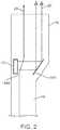
- FIGS. 1 and 2are drawings of the system of the preferred embodiments of the invention.
- FIGS. 3A-3Billustrate the reflecting surface of the system and energy beam of the preferred embodiments of the invention.
- FIG. 4-5are drawings of the energy beam and the zone of ablation of the preferred embodiment of the invention.
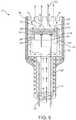
- FIG. 6illustrates an embodiment of the system.
- FIG. 7illustrates the energy source having a backing.
- FIGS. 8A-8Billustrate other embodiments of the energy source.
- the energy delivery system 10 of the preferred embodimentsincludes an energy source 12 that functions to provide a source of ablation energy; a reflecting surface 100 that functions to redirect the ablation energy from the energy source 12 ; a sensor; and a processor (not shown), coupled to the sensor and to the energy source 12 , which may controls the energy source 12 based on the information from the sensor.
- the energy delivery system 10is preferably designed for delivering energy to tissue, more specifically, for delivering ablation energy to tissue, such as heart tissue, to create a conduction block—isolation and/or block of conduction pathways of abnormal electrical activity, which typically originate from the pulmonary veins in the left atrium—for treatment of atrial fibrillation in a patient.
- the system 10may be alternatively used with any suitable tissue in any suitable environment and for any suitable reason.
- the Energy SourceAs shown in FIG. 1 , the energy source 12 of the preferred embodiments functions to provide a source of ablation energy.
- the ablation energyis preferably in the form of an energy beam 20 emitted from the energy source 12 .
- the energy source 12is preferably an ultrasound transducer that emits an ultrasound beam, but may alternatively be any suitable energy source that functions to provide a source of ablation energy.
- Some suitable sources of ablation energymay include radio frequency (RF) energy, microwaves, photonic energy, and thermal energy.
- RFradio frequency
- the therapycould alternatively be achieved using cooled fluids (e.g., cryogenic fluid).
- the energy delivery system 10preferably includes a single energy source 12 , but may alternatively include any suitable number of energy sources 12 .
- the system 10may include multiple energy sources configured in a ring, such that in combination they emit an annular shaped energy beam 20 .
- the energy source 12is preferably an ultrasound transducer that is preferably made of a piezoelectric material such as PZT (lead zirconate titanate) or PVDF (polyvinylidine difluoride), or any other suitable ultrasound beam emitting material.
- the transducermay further include coating layers such as a thin layer of a metal.
- Some suitable transducer coating metalsmay include gold, stainless steel, nickel-cadmium, silver, plastic, metal-filled graphite, a metal alloy, and any other suitable material that functions to increase the efficiency of coupling of the energy beam 20 into the surrounding fluid 28 or performs any other suitable functions.
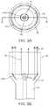
- the transduceris preferably a cylindrical transducer, as shown in FIGS.
- the transducermay alternatively be a generally flat transducer, such as a disc, as shown in FIGS. 1 and 2 .
- the disc transducerpreferably emits energy beam 20 from at least one of the faces of the disc.
- the faces of the disc that emit the energy beam 20are preferably flat, but may alternatively be either concave or convex to achieve an effect of a lens.
- the disc transducerpreferably has a circular geometry, but may alternatively be elliptical, polygonal, doughnut shaped, or any other suitable shape.
- the energy source 12 of the preferred embodimentsis preferably coupled to at least one electrical attachment 14 .
- the electrical attachment 14 of the preferred embodimentsfunctions to energize the energy source 12 such that it emits an energy beam 20 .
- the energy delivery system 10preferably includes two electrical attachments 14 and 14 ′, but may alternatively include any suitable number of electrical attachments to energize the energy source 12 .
- the energy delivery system 10 of the preferred embodimentsalso includes an electrical generator (not shown) that functions to provide power to the energy source 12 via the electrical attachment(s) 14 . When energized by the generator the energy source 12 emits an energy beam 20 .
- the generatorprovides the appropriate frequency and voltage to the energy source 12 to create the desired energy beam 20 .
- the ultrasound frequencyis preferably in the range of 1 to 25 MHz and more preferably in the range of 5 to 20 MHz.
- the energy of the energy beam 20is determined by the excitation voltage applied to the energy source 12 .
- the voltageis preferably in the range of 5 to 300 volts peak-to-peak.
- a variable duty cycleis preferably used to control the average power delivered to the energy source 12 .
- the duty cyclepreferably ranges from 0% to 100%, with a repetition frequency of approximately 40 kHz, which is preferably faster than the time constant of thermal conduction in the tissue.
- the energy source 12When energized with an electrical pulse or pulse train by the electrical attachment 14 and/or 14 ′, the energy source 12 emits an energy beam 20 (such as a sound wave).
- the properties of the energy beam 20are determined by the characteristics of the energy source 12 , the matching layer, the backing (described below), and the electrical pulse from electrical attachment 14 . These elements determine the frequency, bandwidth, and amplitude of the energy beam 20 (such as a sound wave) propagated into the tissue.
- the energy source 12emits energy beam 20 such that it interacts with tissue 276 and forms a lesion (zone of ablation 278 ).
- the energy beam 20is preferably an ultrasound beam.
- the tissue 276is preferably presented to the energy beam 20 within the collimated length L.
- the front surface 280 of the tissue 276is at a distance d ( 282 ) away from the face of a housing 16 .
- d282
- the energy beam 20travels through the tissue 276 , its energy is absorbed by the tissue 276 and converted to thermal energy. This thermal energy heats the tissue to temperatures higher than the surrounding tissue resulting in a heated zone 278 .
- the tissue cellsare preferably rendered dead due to heat.
- the temperatures of the tissueare preferably above the temperature where cell death occurs in the heated zone 278 and therefore, the tissue is said to be ablated.
- the zone 278is preferably referenced as the ablation zone or lesion.
- the shape of the lesion or ablation zone 278 formed by the energy beam 20depends on the characteristics of suitable combination factors such as the energy beam 20 , the energy source 12 (including the material, the geometry, the portions of the energy source 12 that are energized and/or not energized, etc.), the matching layer, the backing, the electrical pulse from electrical attachment 14 (including the frequency, the voltage, the duty cycle, the length of the pulse, etc.), and the characteristics of target tissue that the beam 20 contacts and the length of contact or dwell time. These characteristics can be changed based on the information detected by the sensor (as described below), thereby changing the physical characteristics of the lesion.
- the housing 16also functions to provide a barrier between the face of the energy source 12 and blood or tissue.
- the fluidmay flow past the energy source thereby preventing blood from coagulating thereon.
- the coolantflows past the energy source at approximately 1 ml/minute, but may be increased or decreased as desired. Additionally, since the energy source is disposed in the housing, the energy source will not directly contact tissue, thereby also preventing coagulation on the energy source.
- the energy source 12is preferably one of several variations.
- the energy source 12is a disc with a flat front surface.
- the energy source 12 ′includes an inactive portion 42 .
- the inactive portion 42does not emit an energy beam when the energy source 12 is energized, or may alternatively emit an energy beam with a very low (substantially zero) energy.
- the inactive portion 42preferably functions to aid in the temperature regulation of the energy source, i. e. preventing the energy source from becoming too hot.
- a full disk transduceras shown in FIG.
- the center portion of the transducergenerally becomes the hottest portion of the transducer while energized.
- the energy emitted from the transduceris preferably distributed differently across the transducer, and the heat of the transducer is preferably more easily dissipated.
- the inactive portion 42is preferably a hole or gap defined by the energy source 12 ′.
- a coolant sourcemay be coupled to, or in the case of a coolant fluid, it may flow through the hole or gap defined by the energy source 12 ′ to further cool and regulate the temperature of the energy source 12 ′.
- the inactive portion 42may alternatively be made of a material with different material properties from that of the energy source 12 ′.
- the materialis preferably a metal, such as copper, which functions to draw or conduct heat away from the energy source 12 .
- the inactive portionis made from the same material as the energy source 12 , but with the electrode plating removed or disconnected from the electrical attachments 14 and or the generator.
- the inactive portion 42is preferably disposed along the full thickness of the energy source 12 ′, but may alternatively be a layer of material on or within the energy source 12 ′ that has a thickness less than the full thickness of the energy source 12 ′.
- the energy source 12 ′is preferably a doughnut-shaped transducer.
- the transducerpreferably defines a hole (or inactive portion 42 ) in the center portion of the transducer.
- the energy source 12 ′ of this variationpreferably has a circular geometry, but may alternatively be elliptical, polygonal ( FIG. 8B ), or any other suitable shape.
- the energy source 12 ′preferably includes a singular, circular inactive portion 42 , but may alternatively include any suitable number of inactive portions 42 of any suitable geometry, as shown in FIG. 8B .
- the total energy emitted from the energy source 12is related to the surface area of the energy source 12 that is active (ke. emits energy beam 20 ). Therefore, the size and location of inactive portions 42 preferably reduce heat build-up in the energy source 12 , while allowing the energy source 12 to provide as much output energy as possible or as desired.
- the energy delivery system 10 of the preferred embodimentsalso includes a backing 22 , coupled to the energy source 12 .
- the energy source 12is preferably bonded to the end of a backing 22 by means of an adhesive ring 24 .
- Backing 22is preferably made of a metal or a plastic, such that it provides a heat sink for the energy source 12 .
- the attachment of the energy source 12 to the backing 22is such that there is a pocket 26 between the back surface of the energy source 12 and the backing 22 .
- This pocketpreferably contains a material with acoustic impedance significantly different than the material of the energy source 12 , and preferably creates an acoustically reflective surface.
- the material in the pocketis also preferably a good thermal conductor, so that heat can be removed from the energy source, and electrically conductive such that it may connect the electrical wires to the rear surface of the energy source.
- the pocketis preferably one of several variations.
- the backing 22couples to the energy source at multiple points.
- the backingpreferably includes three posts that preferably couple to the outer portion such that the majority of the energy source 12 is not touching a portion of the backing.
- a fluid or gelpreferably flows past the energy source 12 , bathing preferably both the front and back surfaces of the energy source 12 .
- the pocketis an air pocket 26 between the back surface of the energy source 12 and the backing 22 .
- the air pocket 26functions such that when the energy source 12 is energized by the application of electrical energy, the emitted energy beam 20 is reflected by the air pocket 26 and directed outwards from the energy source 12 .
- the backing 22preferably defines an air pocket of a cylindrical shape, and more preferably defines an air pocket 26 that has an annular shape.
- the backingdefines an annular air pocket by further including a center post such that the backing is substantially tripod shaped when viewed in cross section, wherein the backing is coupled to the energy source 12 towards both the outer portion of the energy source and towards the center portion of the energy source.
- the air pocket 26may alternatively be replaced by any other suitable material such that a substantial portion of the energy beam 20 is directed outwards from the energy source 12 .
- the energy source 12While the energy source 12 is emitting an energy beam 20 , the energy source may become heated.
- the energy source 12is preferably maintained within a safe operating temperature range by cooling the energy source 12 . Cooling of the energy source 12 is preferably accomplished by contacting the energy source 12 with a fluid, for example, saline or any other physiologically compatible fluid, preferably having a lower temperature relative to the temperature of the energy source 12 .
- the temperature of the fluidis preferably cold enough that it both cools the transducer and the target tissue.
- the temperature of the fluid or gelis preferably between ⁇ 5 and 5 degrees Celsius and more preferably substantially equal to zero degrees Celsius.
- the temperature of the fluidis within a temperature range such that the fluid cools the energy source 12 , but it does not cool the target tissue however, and may actually warm the target tissue.
- the fluidmay alternatively be any suitable temperature to sufficiently cool the energy source 12 .
- the backing 22preferably has a series of grooves 36 disposed longitudinally along the outside wall that function to provide for the flow of a cooling fluid 2 S substantially along the outer surface of backing 22 and past the face of the energy source 12 .
- the series of groovesmay alternatively be disposed along the backing in any other suitable configuration, such as helical.
- the resulting fluid flow linesare depicted as 30 in FIG. 6 .
- the flow of the cooling fluidis achieved through a lumen 32 .
- the fluid used for cooling the transducerpreferably exits the housing 16 through the end of the housing 16 or through one or more apertures.
- the aperturesare preferably a grating, screen, holes, drip holes, weeping structure or any of a number of suitable apertures.
- the fluidpreferably exits the housing 16 to contact the target tissue and to cool the tissue.
- the reflector 100 of the preferred embodimentsfunctions to redirect the energy beam 20 from the energy source 12 .
- the reflecting surface 100preferably redirects the energy beam 20 from the energy source 12 out of housing 16 and preferably towards the target tissue.
- the reflecting surface 100preferably redirects the energy beam 20 such that it is a collimated beam exiting the housing 16 (as shown in FIGS. 2 and 3 ), the reflecting surface 22 may alternatively redirect the energy beam 20 such that it is a focused beam that preferably converges towards a substantially single focal point or towards focal point ring.
- the reflecting surfaceis preferably one of several variations. In a first variation, as shown in FIG. 1 , the reflecting surface 100 is an angled reflector device.
- the reflector deviceis preferably a cylindrical reflector with a face of the reflector at an angle to the longitudinal axis of the housing 16 .
- the energy source 12is preferably positioned towards the distal end of the housing 16 with the front face pointing towards the reflector device, which is preferably positioned along the same axis (the longitudinal axis of the housing 16 ) as the energy source 12 .
- the energy beam 20 from the energy source 12is preferably redirected from the reflecting surface such that it exits the housing 16 through a side portion of the housing.
- the reflector deviceis preferably made from a material that reflects the energy beam 20 , such as metal, but may alternatively be a gas filled reflector device such as a gas filled balloon.
- the angled face of the reflectoris preferably flat, but may alternatively be a non-planar face, such as a curved, convex or concave surface.
- the angle of the reflectorpreferably ranges between substantially 0 degrees, more preferably substantially 30-60 degrees, and most preferably substantially 45 degrees.
- the reflector deviceis preferably set at a fixed angle with respect to the energy source 12 , but may alternatively be movable, such as rotated or pivoted, to alter the angle that the energy beam 20 will exit the housing 16 . Referring to FIG.
- the reflector deviceis preferably secured to the housing 16 by means of a distal adhesive band 1418 , but may alternatively be coupled to the housing 16 with any other suitable chemical and/or mechanical connection such as adhesive, welding, pins and/or screws.
- the adhesive band 1418preferably includes a passageway 1445 for the flow of a cooling fluid (as described below).
- the energy beam 20 exiting from the housing 16is preferably directed along an ablation path such that it propagates into tissue.
- the energy beam 20propagates into the tissue along the ablation path, it preferably provides a partial or complete zone of ablation along the ablation path.
- the zone of ablation along the ablation pathpreferably has any suitable geometry to provide therapy, such as providing a conduction block for treatment of atrial fibrillation in a patient.
- the zone of ablation along the ablation pathmay alternatively provide any other suitable therapy for a patient.
- a linear ablation pathis preferably created by moving the system 10 , and the energy source 12 within it, in an X, Y, and/or Z direction.
- a generally circular or elliptical ablation pathis preferably created by rotating the energy source 12 about an axis.
- the reflecting surface 100is preferably rotated within the housing 16 and about the longitudinal axis of the housing 16 , such that as the energy source 12 is energized and emitting the energy beam 20 , the beam will be reflected out of the housing in 360 degrees.
- the energy beam 20 that is redirected by the reflecting surface 100preferably exits a side portion of the housing though a window located around the circumference of the distal tip assembly 16 .
- the windowis preferably made of a material that is transparent to ultrasound waves such as a poly 4-methyl, 1-pentene (PMP) material or may alternatively be an open window.
- PMPpoly 4-methyl, 1-pentene
- the entire system 10will rotate, rotating the energy beam 20 that exits from at least one single portion of the housing 16 .
- the system 10is preferably rotated about the longitudinal axis of the housing 16 , but may alternatively be rotated about an axis off set from the longitudinal axis of the housing 16 .
- the energy beam 20preferably sweeps a generally circular path.
- the reflecting surface 100is also an angled reflector device.
- the reflector deviceis preferably a substantially flat reflecting device, with an inside face of the reflector at an angle to the front face of the energy source 12 .
- the energy source 12is preferably positioned adjacent to a side wall of the housing 16 with the front face the energy source 12 pointing towards the reflector device.
- the energy beam 20 from the energy source 12is preferably redirected from the reflecting surface such that it exits the housing 16 through an end portion of the housing.
- the energy beam 20 that is redirected by the reflecting surface 100preferably exits the end portion of the housing though a window.
- the windowis preferably an open window, but may alternatively be made of a material that is transparent to ultrasound waves such as a poly 4-methyl, 1-pentene (PMP) material.
- the reflector deviceis preferably made from a material that reflects the energy beam 20 , such as metal, but may alternatively be a gas filled reflector device such as a gas filled balloon.
- the angled face of the reflectoris preferably flat, but may alternatively be a nonplanar face, such as a curved, convex or concave surface. The angle of the reflector preferably ranges between substantially 0-90 degrees, more preferably substantially 30-60 degrees, and most preferably substantially 45 degrees.
- the reflector deviceis preferably set at a fixed angle with respect to the energy source 12 , but may alternatively be movable, such as rotated or pivoted, to alter the angle that the energy beam 20 will exit the housing 16 .
- the reflecting surface 22preferably includes a passageway 1445 for the flow 28 of a cooling fluid (as described below).
- the energy beam 20 exiting from the housing 16is preferably directed along an ablation path such that it propagates into tissue.
- the energy beam 20propagates into the tissue along the ablation path, it preferably provides a partial or complete zone of ablation along the ablation path.
- a linear ablation pathis preferably created by moving the system 10 , and the energy source 12 within it, in an X, Y, and/or Z direction.
- a generally circular or elliptical ablation pathis preferably created by rotating the housing 16 about an axis.
- the housing 16is preferably rotated about its longitudinal axis. Because the energy beam 20 is redirected by the reflecting surface 100 , as shown in FIG.
- the energy beam 20exits the housing at a distance from the longitudinal axis of the housing. Therefore, as the housing 16 is moved in a circular or elliptical path, the energy beam 20 will contact the tissue, creating a corresponding generally circular or elliptical ablation path.
- the reflecting surface 100is also an angled, bowl-shaped reflector device centered around the longitudinal axis of the housing 16 .
- the inside surface of the reflector deviceis preferably a substantially linear surface (in cross section, as shown in FIG. 3B ) at an angle to the front face of the energy source 12 .
- the angled face of the reflectoris preferably flat, but may alternatively be a non-planar face, such as a curved, convex or concave surface, or combinations thereof.
- the energy source 12is preferably a cylindrical energy source 12 , positioned along the longitudinal axis of the housing 16 .
- the energy beam 20 from the energy source 12preferably exits the energy source radially and is preferably redirected from the reflecting surface such that it exits the housing 16 as a ring shaped energy beam (as shown in FIG. 3A ) through an end portion of the housing.
- the energy beam 20 that is redirected by the reflecting surface 100preferably exits the end portion of the housing though a window.
- the windowis preferably an open window, but may alternatively be made of a material that is transparent to ultrasound waves such as a poly 4-methyl, 1-pentene (PMP) material.
- the reflector deviceis preferably made from a material that reflects the energy beam 20 , such as metal, but may alternatively be a gas filled reflector device such as a gas filled balloon.
- the angle of the reflectorpreferably ranges between substantially 0-90 degrees, more preferably substantially 30-60 degrees, and most preferably substantially 45 degrees.
- the reflector deviceis preferably set at a fixed angle with respect to the energy source 12 , but may alternatively be movable, such as rotated or pivoted, to alter the angle that the energy beam 20 will exit the housing 16 .
- the energy beam 20 exiting from the housing 16is preferably ring-shaped, as shown in FIG. 3A , and therefore preferably creates a ring shaped ablation path when it interacts with tissue and preferably provides a partial or complete zone of ablation along the ablation path.
- a linear ablation pathis alternatively created by the energy source 12 emitting energy beam 20 from only a partial radial portion of the energy source and/or by moving the system 10 , and the energy source 12 within it, in an X, Y, and/or Z direction.
- the energy source of the third variation reflecting surface 100may be a flat energy source (rather than a cylindrical one) with the front face towards a portion of the reflecting surface.
- the energy source 12is preferably rotated about the longitudinal axis of the housing such that the energy beam 20 will be redirected by various portions of the reflecting surface, creating a circular ablation path.
- the energy delivery system 10 of the preferred embodimentsalso includes a sensor that functions to detect the gap (e.g., the distance of the tissue surface from the energy source 12 ), the thickness of the tissue targeted for ablation, and the characteristics of the ablated tissue.
- the sensoris preferably an ultrasound transducer, but may alternatively be any suitable sensor, such as a strain gage, feeler gage, or IR sensor, to detect information with respect to the gap, the thickness of the tissue targeted for ablation, the characteristics of the ablated tissue, the location of elements of the system 10 , and/or any other suitable parameter or characteristic.
- the sensoris preferably the same transducer as the transducer of the energy source 12 operating in a different mode (such as A-mode, defined below), but may alternatively be a separate ultrasound transducer or an additional sensor 40 ′ as shown in FIG. 3A coupled to a top portion of the cylindrical energy source 12 .
- the system 10may include multiple sensors such as a first sensor to detect information with respect to the target tissue, and a second sensor to detect information with respect to the location of the elements of the system 10 . By detecting information on the gap, the thickness of the tissue targeted for ablation, the characteristics of the ablated tissue, and/or the locations of the elements of the system 10 , the sensor preferably functions to guide the therapy provided by the ablation of the tissue.
- the senorpreferably utilizes a pulse of ultrasound of short duration, which is generally not sufficient for heating of the tissue.
- Thisis a simple ultrasound imaging technique, referred to in the art as A Mode, or Amplitude Mode imaging.
- sensor 40preferably sends a pulse 290 of ultrasound towards the tissue 276 .
- a portion of the beamis reflected and backscattered as 292 from the front surface 280 of the tissue 276 .
- This reflected beam 292is detected by the sensor 40 a short time later and converted to an electrical signal, which is sent to the electrical receiver (not shown).
- the reflected beam 292is delayed by the amount of time it takes for the sound to travel from the sensor 40 to the front boundary 280 of the tissue 276 and back to the sensor 40 .
- This travel timerepresents a delay in receiving the electrical signal from the sensor 40 .
- the gap distance d282
- the sensor 40converts this sound energy into electrical signals and a processor (described below) converts this information into characteristics of the lesion formation such as thickness, etc.
- the sensor 40converts this sound energy into electrical signals and the processor converts this information into the thickness t ( 300 ) of the tissue 276 at the point of the incidence of the ultrasound pulse 290 .
- the sensor 40detects the gap distance d ( 282 ), lesion characteristics, and the tissue thickness t ( 300 ).
- the sensorpreferably detects these parameters continuously, but may alternatively detect them periodically or in any other suitable fashion. This information is used in delivering continuous ablation of the tissue 276 during therapy as discussed below.
- the energy delivery system 10 of the preferred embodimentsalso includes a processor, coupled to the sensor 40 and to the electrical attachment 14 , that controls the electrical pulse delivered to the electrical attachment 14 and may modify the electrical pulse delivered based on the information from the sensor 40 .
- the processoris preferably a conventional processor or logic machine that can execute computer programs including a microprocessor or integrated circuit, but may alternatively be any suitable device to perform the desired functions.
- the processorpreferably receives information from the sensor such as information related to the gap distance, the thickness of the tissue targeted for ablation, the characteristics of the ablated tissue, and any other suitable parameter or characteristic. Based on this information, the processor converts this information into a gap distance, a thickness of the tissue targeted for ablation, a characteristic of the ablated tissue, and any other suitable parameter or characteristic and/or controls the energy beam 20 emitted from the energy source 12 by modifying the electrical pulse sent to the energy source 12 via the electrical attachment 14 such as the frequency, the voltage, the duty cycle, the length of the pulse, and/or any other suitable parameter. The processor preferably also controls the energy beam 20 by controlling which portions of the energy source 12 are energized and/or at which frequency, voltage, duty cycle, etc.
- the processormay further be coupled to a fluid flow controller.
- the processorpreferably controls the fluid flow controller to increase or decrease fluid flow based on the sensor detecting characteristics of the ablated tissue, of the unablated or target tissue, and/or any other suitable condition.
- the shape of the ablation zone 278is controlled.
- the depth 288 of the ablation zoneis preferably controlled such that a transmural (through the thickness of the tissue) lesion is achieved.
- the processorpreferably functions to minimize the possibility of creating a lesion beyond the targeted tissue, for example, beyond the outer atrial wall. If the sensor detects the lesion extending beyond the outer wall of the atrium or that the depth of the lesion has reached or exceeded a preset depth, the processor preferably turns off the generator and/or ceases to send electrical pulses to the electrical attachment(s) 14 .
- the processormay either turn off the generator and/or cease to send electrical pulses to the electrical attachment(s) 14 , may alter the pulses sent to the electrical attachment, and/or may alter the operator or motor drive unit to reposition the system with respect to the target tissue.
- the energy delivery system 10 of the preferred embodimentsmay also include an elongate member 18 , coupled to the energy source 12 .
- the elongate member 18is preferably a catheter made of a flexible multi-lumen tube, but may alternatively be a cannula, tube or any other suitable elongate structure having one or more lumens.
- the elongate member 18 of the preferred embodimentsfunctions to accommodate pull wires, fluids, gases, energy delivery structures, electrical connections, therapy catheters, navigation catheters, pacing catheters, and/or any other suitable device or element. As shown in FIG.
- the elongate member 18preferably includes a housing 16 positioned at a distal portion of the elongate member 18 that functions to enclose the energy source 12 and the reflection surface 100 .
- the elongate member 18further functions to move and position the energy source 12 and/or the housing 16 within a patient, such that the emitted energy beam 20 contacts the target tissue at an appropriate angle and the energy source 12 and/or the housing 16 is moved along an ablation path such that the energy source 12 provides a partial or complete zone of ablation along the ablation path.
- the energy delivery system 10 of the preferred embodimentsmay also include a lens or mirror, operably coupled to the energy source 12 , that functions to provide additional flexibility in adjusting the beam pattern of the energy beam 20 .
- the lensis preferably a standard acoustic lens, but may alternatively be any suitable lens to adjust the energy beam 20 in any suitable fashion.
- the lensmay be used to focus or defocus the energy beam.
- an acoustic lenscould create a beam that is more uniformly collimated, such that the minimum beam width D.sub. 1 approaches the diameter D of the energy source 12 . This will provide a more uniform energy density in the ablation window, and therefore more uniform lesions as the tissue depth varies within the window.
- a lenscould also be used to move the position of the minimum beam width D.sub.
- This lenscould be fabricated from plastic or other material with the appropriate acoustic properties, and bonded to the face of energy source 12 .
- the energy source 12itself may have a geometry such that it functions as a lens, or the matching layer or coating of the energy source 12 may function as a lens.
- the preferred embodimentsinclude every combination and permutation of the various energy sources 12 , electrical attachments 14 , energy beams 20 , sensors 40 , and processors.
Landscapes
- Health & Medical Sciences (AREA)
- Engineering & Computer Science (AREA)
- Life Sciences & Earth Sciences (AREA)
- Surgery (AREA)
- Biomedical Technology (AREA)
- Veterinary Medicine (AREA)
- Public Health (AREA)
- General Health & Medical Sciences (AREA)
- Animal Behavior & Ethology (AREA)
- Nuclear Medicine, Radiotherapy & Molecular Imaging (AREA)
- Medical Informatics (AREA)
- Heart & Thoracic Surgery (AREA)
- Molecular Biology (AREA)
- Mechanical Engineering (AREA)
- Neurology (AREA)
- Physics & Mathematics (AREA)
- Neurosurgery (AREA)
- Plasma & Fusion (AREA)
- Otolaryngology (AREA)
- Orthopedic Medicine & Surgery (AREA)
- Vascular Medicine (AREA)
- Dentistry (AREA)
- Radiology & Medical Imaging (AREA)
- Surgical Instruments (AREA)
- Laser Surgery Devices (AREA)
Abstract
Description
Claims (20)
Priority Applications (1)
| Application Number | Priority Date | Filing Date | Title |
|---|---|---|---|
| US16/439,805US11207549B2 (en) | 2008-07-18 | 2019-06-13 | System and method for delivering energy to tissue |
Applications Claiming Priority (4)
| Application Number | Priority Date | Filing Date | Title |
|---|---|---|---|
| US8206408P | 2008-07-18 | 2008-07-18 | |
| US12/505,335US10363057B2 (en) | 2008-07-18 | 2009-07-17 | System and method for delivering energy to tissue |
| US13/630,674US10368891B2 (en) | 2008-07-18 | 2012-09-28 | System and method for delivering energy to tissue |
| US16/439,805US11207549B2 (en) | 2008-07-18 | 2019-06-13 | System and method for delivering energy to tissue |
Related Parent Applications (1)
| Application Number | Title | Priority Date | Filing Date |
|---|---|---|---|
| US13/630,674ContinuationUS10368891B2 (en) | 2008-07-18 | 2012-09-28 | System and method for delivering energy to tissue |
Publications (2)
| Publication Number | Publication Date |
|---|---|
| US20200155192A1 US20200155192A1 (en) | 2020-05-21 |
| US11207549B2true US11207549B2 (en) | 2021-12-28 |
Family
ID=41530927
Family Applications (3)
| Application Number | Title | Priority Date | Filing Date |
|---|---|---|---|
| US12/505,335ActiveUS10363057B2 (en) | 2008-07-18 | 2009-07-17 | System and method for delivering energy to tissue |
| US13/630,674ActiveUS10368891B2 (en) | 2008-07-18 | 2012-09-28 | System and method for delivering energy to tissue |
| US16/439,805Active2030-04-30US11207549B2 (en) | 2008-07-18 | 2019-06-13 | System and method for delivering energy to tissue |
Family Applications Before (2)
| Application Number | Title | Priority Date | Filing Date |
|---|---|---|---|
| US12/505,335ActiveUS10363057B2 (en) | 2008-07-18 | 2009-07-17 | System and method for delivering energy to tissue |
| US13/630,674ActiveUS10368891B2 (en) | 2008-07-18 | 2012-09-28 | System and method for delivering energy to tissue |
Country Status (7)
| Country | Link |
|---|---|
| US (3) | US10363057B2 (en) |
| EP (2) | EP2307098B1 (en) |
| JP (3) | JP2011528580A (en) |
| AU (1) | AU2009270716B2 (en) |
| CA (1) | CA2730781A1 (en) |
| ES (2) | ES2578405T3 (en) |
| WO (1) | WO2010009472A1 (en) |
Families Citing this family (69)
| Publication number | Priority date | Publication date | Assignee | Title |
|---|---|---|---|---|
| US8241274B2 (en) | 2000-01-19 | 2012-08-14 | Medtronic, Inc. | Method for guiding a medical device |
| US8974446B2 (en) | 2001-10-11 | 2015-03-10 | St. Jude Medical, Inc. | Ultrasound ablation apparatus with discrete staggered ablation zones |
| US7617005B2 (en) | 2002-04-08 | 2009-11-10 | Ardian, Inc. | Methods and apparatus for thermally-induced renal neuromodulation |
| US8150519B2 (en) | 2002-04-08 | 2012-04-03 | Ardian, Inc. | Methods and apparatus for bilateral renal neuromodulation |
| US20040082859A1 (en) | 2002-07-01 | 2004-04-29 | Alan Schaer | Method and apparatus employing ultrasound energy to treat body sphincters |
| US10499937B2 (en) | 2006-05-19 | 2019-12-10 | Recor Medical, Inc. | Ablation device with optimized input power profile and method of using the same |
| US20080039746A1 (en) | 2006-05-25 | 2008-02-14 | Medtronic, Inc. | Methods of using high intensity focused ultrasound to form an ablated tissue area containing a plurality of lesions |
| US9119633B2 (en) | 2006-06-28 | 2015-09-01 | Kardium Inc. | Apparatus and method for intra-cardiac mapping and ablation |
| US11389232B2 (en) | 2006-06-28 | 2022-07-19 | Kardium Inc. | Apparatus and method for intra-cardiac mapping and ablation |
| US8906011B2 (en) | 2007-11-16 | 2014-12-09 | Kardium Inc. | Medical device for use in bodily lumens, for example an atrium |
| US10363057B2 (en) | 2008-07-18 | 2019-07-30 | Vytronus, Inc. | System and method for delivering energy to tissue |
| US9192789B2 (en) | 2008-10-30 | 2015-11-24 | Vytronus, Inc. | System and method for anatomical mapping of tissue and planning ablation paths therein |
| US11298568B2 (en) | 2008-10-30 | 2022-04-12 | Auris Health, Inc. | System and method for energy delivery to tissue while monitoring position, lesion depth, and wall motion |
| US9220924B2 (en) | 2008-10-30 | 2015-12-29 | Vytronus, Inc. | System and method for energy delivery to tissue while monitoring position, lesion depth, and wall motion |
| US8414508B2 (en)* | 2008-10-30 | 2013-04-09 | Vytronus, Inc. | System and method for delivery of energy to tissue while compensating for collateral tissue |
| US9033885B2 (en)* | 2008-10-30 | 2015-05-19 | Vytronus, Inc. | System and method for energy delivery to tissue while monitoring position, lesion depth, and wall motion |
| US8475379B2 (en)* | 2008-11-17 | 2013-07-02 | Vytronus, Inc. | Systems and methods for ablating body tissue |
| AU2009313687B2 (en) | 2008-11-17 | 2015-11-26 | Vytronus, Inc. | Systems and methods for ablating body tissue |
| KR101673574B1 (en) | 2009-10-30 | 2016-11-07 | 레코 메디컬, 인코포레이티드 | Method and apparatus for treatment of hypertension through percutaneous ultrasound renal denervation |
| JP6013186B2 (en) | 2009-11-13 | 2016-10-25 | セント ジュード メディカル インコーポレイテッド | Staggered arrangement of shochu elements |
| US8909316B2 (en) | 2011-05-18 | 2014-12-09 | St. Jude Medical, Cardiology Division, Inc. | Apparatus and method of assessing transvascular denervation |
| US9427579B2 (en) | 2011-09-29 | 2016-08-30 | Pacesetter, Inc. | System and method for performing renal denervation verification |
| JP2015511137A (en)* | 2012-01-30 | 2015-04-16 | ビトロンユーエス, インコーポレイテッド | Tissue necrosis method and apparatus |
| US8934988B2 (en) | 2012-03-16 | 2015-01-13 | St. Jude Medical Ab | Ablation stent with meander structure |
| US9113929B2 (en) | 2012-04-19 | 2015-08-25 | St. Jude Medical, Cardiology Division, Inc. | Non-electric field renal denervation electrode |
| WO2013157208A1 (en)* | 2012-04-20 | 2013-10-24 | テルモ株式会社 | Vascular insertion type treatment device |
| US9017321B2 (en) | 2012-05-21 | 2015-04-28 | Kardium, Inc. | Systems and methods for activating transducers |
| US10827977B2 (en) | 2012-05-21 | 2020-11-10 | Kardium Inc. | Systems and methods for activating transducers |
| US9198592B2 (en) | 2012-05-21 | 2015-12-01 | Kardium Inc. | Systems and methods for activating transducers |
| US9179997B2 (en) | 2013-03-06 | 2015-11-10 | St. Jude Medical, Cardiology Division, Inc. | Thermochromic polyvinyl alcohol based hydrogel artery |
| US10716914B2 (en) | 2013-03-12 | 2020-07-21 | St. Jude Medical, Cardiology Division, Inc. | Catheter system |
| US9775966B2 (en) | 2013-03-12 | 2017-10-03 | St. Jude Medical, Cardiology Division, Inc. | Catheter system |
| US10328238B2 (en) | 2013-03-12 | 2019-06-25 | St. Jude Medical, Cardiology Division, Inc. | Catheter system |
| US9510902B2 (en) | 2013-03-13 | 2016-12-06 | St. Jude Medical, Cardiology Division, Inc. | Ablation catheters and systems including rotational monitoring means |
| WO2014159276A1 (en) | 2013-03-14 | 2014-10-02 | Recor Medical, Inc. | Ultrasound-based neuromodulation system |
| US9131982B2 (en) | 2013-03-14 | 2015-09-15 | St. Jude Medical, Cardiology Division, Inc. | Mediguide-enabled renal denervation system for ensuring wall contact and mapping lesion locations |
| US8876813B2 (en) | 2013-03-14 | 2014-11-04 | St. Jude Medical, Inc. | Methods, systems, and apparatus for neural signal detection |
| EP2971232A1 (en) | 2013-03-14 | 2016-01-20 | ReCor Medical, Inc. | Methods of plating or coating ultrasound transducers |
| US9186212B2 (en) | 2013-03-15 | 2015-11-17 | St. Jude Medical, Cardiology Division, Inc. | Feedback systems and methods utilizing two or more sites along denervation catheter |
| US9974477B2 (en) | 2013-03-15 | 2018-05-22 | St. Jude Medical, Cardiology Division, Inc. | Quantification of renal denervation via alterations in renal blood flow pre/post ablation |
| US9179973B2 (en) | 2013-03-15 | 2015-11-10 | St. Jude Medical, Cardiology Division, Inc. | Feedback systems and methods for renal denervation utilizing balloon catheter |
| US9561070B2 (en) | 2013-03-15 | 2017-02-07 | St. Jude Medical, Cardiology Division, Inc. | Ablation system, methods, and controllers |
| EP3345564A1 (en) | 2013-03-15 | 2018-07-11 | St. Jude Medical, Cardiology Division, Inc. | Multi-electrode ablation system with a controller for determining a thermal gain of each electrode |
| WO2014176205A1 (en) | 2013-04-25 | 2014-10-30 | St. Jude Medical, Cardiology Division, Inc. | Electrode assembly for catheter system |
| US9872728B2 (en) | 2013-06-28 | 2018-01-23 | St. Jude Medical, Cardiology Division, Inc. | Apparatuses and methods for affixing electrodes to an intravascular balloon |
| US20150011991A1 (en) | 2013-07-03 | 2015-01-08 | St. Jude Medical, Cardiology Division, Inc. | Electrode Assembly For Catheter System |
| US10856936B2 (en) | 2013-10-23 | 2020-12-08 | St. Jude Medical, Cardiology Division, Inc. | Electrode assembly for catheter system including thermoplastic-based struts |
| USD747491S1 (en) | 2013-10-23 | 2016-01-12 | St. Jude Medical, Cardiology Division, Inc. | Ablation generator |
| USD774043S1 (en) | 2013-10-23 | 2016-12-13 | St. Jude Medical, Cardiology Division, Inc. | Display screen with graphical user interface for ablation generator |
| USD914883S1 (en) | 2013-10-23 | 2021-03-30 | St. Jude Medical, Cardiology Division, Inc. | Ablation generator |
| US10034705B2 (en) | 2013-10-24 | 2018-07-31 | St. Jude Medical, Cardiology Division, Inc. | High strength electrode assembly for catheter system including novel electrode |
| WO2015061034A1 (en) | 2013-10-24 | 2015-04-30 | St. Jude Medical, Cardiology Division, Inc. | Flexible catheter shaft and method of manufacture |
| US9913961B2 (en) | 2013-10-24 | 2018-03-13 | St. Jude Medical, Cardiology Division, Inc. | Flexible catheter shaft and method of manufacture |
| US10420604B2 (en) | 2013-10-28 | 2019-09-24 | St. Jude Medical, Cardiology Division, Inc. | Electrode assembly for catheter system including interlinked struts |
| US9861433B2 (en) | 2013-11-05 | 2018-01-09 | St. Jude Medical, Cardiology Division, Inc. | Helical-shaped ablation catheter and methods of use |
| US10398501B2 (en) | 2014-04-24 | 2019-09-03 | St. Jude Medical, Cardiology Division, Inc. | Ablation systems including pulse rate detector and feedback mechanism and methods of use |
| US10722184B2 (en) | 2014-11-17 | 2020-07-28 | Kardium Inc. | Systems and methods for selecting, activating, or selecting and activating transducers |
| US10368936B2 (en) | 2014-11-17 | 2019-08-06 | Kardium Inc. | Systems and methods for selecting, activating, or selecting and activating transducers |
| US10549128B2 (en) | 2015-11-04 | 2020-02-04 | Vytronus, Inc. | Systems and methods for imaging and ablating tissue |
| WO2017223264A1 (en) | 2016-06-23 | 2017-12-28 | St. Jude Medical, Cardiology Division, Inc. | Catheter system and electrode assembly for intraprocedural evaluation of renal denervation |
| US11266840B2 (en) | 2018-06-27 | 2022-03-08 | Arizona Board Of Regents On Behalf Of Arizona State University | Wireless cardiac pace making |
| EP3829500A4 (en)* | 2018-08-02 | 2022-05-04 | Sofwave Medical Ltd. | Devices and methods for vaginal treatments |
| CN112638272B (en) | 2018-08-22 | 2024-07-02 | 希利姆医疗有限公司 | Vessel of ultrasonic transducer for catheter |
| US11696713B2 (en) | 2019-03-15 | 2023-07-11 | Arizona Board Of Regents On Behalf Of Arizona State University | Contour electrocorticography (ECoG) array |
| US11428588B2 (en) | 2019-03-28 | 2022-08-30 | Arizona Board Of Regents On Behalf Of Arizona State University | Fully-passive pressure sensors and methods for their use |
| CN111759453B (en)* | 2019-04-01 | 2025-08-12 | 广州迪克医疗器械有限公司 | Power supply for tissue ablation, cutting and fusion system and tissue ablation, cutting and fusion system |
| CN118648971A (en) | 2019-05-09 | 2024-09-17 | 捷锐士阿希迈公司(以奥林巴斯美国外科技术名义) | Surgical System |
| US20220079671A1 (en)* | 2020-09-14 | 2022-03-17 | Covidien Lp | System and methods for insertion depth tracking |
| WO2022144695A2 (en)* | 2020-12-31 | 2022-07-07 | Ethicon, Inc. | Systems and methods for liquid flooding of lung to enhance endobronchial energy transfer for use in imaging, diagnosis and/or treatment |
Citations (137)
| Publication number | Priority date | Publication date | Assignee | Title |
|---|---|---|---|---|
| US4641649A (en) | 1985-10-30 | 1987-02-10 | Rca Corporation | Method and apparatus for high frequency catheter ablation |
| US4708127A (en) | 1985-10-24 | 1987-11-24 | The Birtcher Corporation | Ultrasonic generating system with feedback control |
| US4757820A (en) | 1985-03-15 | 1988-07-19 | Kabushiki Kaisha Toshiba | Ultrasound therapy system |
| US4858613A (en) | 1988-03-02 | 1989-08-22 | Laboratory Equipment, Corp. | Localization and therapy system for treatment of spatially oriented focal disease |
| US5010886A (en) | 1989-08-18 | 1991-04-30 | Intertherapy, Inc. | Medical probe assembly having combined ultrasonic imaging and laser ablation capabilities |
| US5024234A (en) | 1989-10-17 | 1991-06-18 | Cardiovascular Imaging Systems, Inc. | Ultrasonic imaging catheter with guidewire channel |
| US5029588A (en) | 1989-06-15 | 1991-07-09 | Cardiovascular Imaging Systems, Inc. | Laser catheter with imaging capability |
| US5246438A (en) | 1988-11-25 | 1993-09-21 | Sensor Electronics, Inc. | Method of radiofrequency ablation |
| US5295484A (en) | 1992-05-19 | 1994-03-22 | Arizona Board Of Regents For And On Behalf Of The University Of Arizona | Apparatus and method for intra-cardiac ablation of arrhythmias |
| US5314466A (en) | 1992-04-13 | 1994-05-24 | Ep Technologies, Inc. | Articulated unidirectional microwave antenna systems for cardiac ablation |
| US5405346A (en) | 1993-05-14 | 1995-04-11 | Fidus Medical Technology Corporation | Tunable microwave ablation catheter |
| US5647367A (en) | 1996-05-31 | 1997-07-15 | Hewlett-Packard Company | Scanning ultrasonic probe with locally-driven sweeping ultrasonic source |
| US5718241A (en) | 1995-06-07 | 1998-02-17 | Biosense, Inc. | Apparatus and method for treating cardiac arrhythmias with no discrete target |
| US5735811A (en) | 1995-11-30 | 1998-04-07 | Pharmasonics, Inc. | Apparatus and methods for ultrasonically enhanced fluid delivery |
| WO1999002096A1 (en) | 1997-07-08 | 1999-01-21 | The Regents Of The University Of California | Circumferential ablation device assembly and method |
| US6012457A (en) | 1997-07-08 | 2000-01-11 | The Regents Of The University Of California | Device and method for forming a circumferential conduction block in a pulmonary vein |
| US6024740A (en) | 1997-07-08 | 2000-02-15 | The Regents Of The University Of California | Circumferential ablation device assembly |
| US6052576A (en) | 1996-07-09 | 2000-04-18 | Matra Communication | Radiocommunications equipment with a security calls mode, and extension unit forming part of such equipment |
| US6050943A (en) | 1997-10-14 | 2000-04-18 | Guided Therapy Systems, Inc. | Imaging, therapy, and temperature monitoring ultrasonic system |
| US6064902A (en) | 1998-04-16 | 2000-05-16 | C.R. Bard, Inc. | Pulmonary vein ablation catheter |
| US6117101A (en) | 1997-07-08 | 2000-09-12 | The Regents Of The University Of California | Circumferential ablation device assembly |
| US6161543A (en) | 1993-02-22 | 2000-12-19 | Epicor, Inc. | Methods of epicardial ablation for creating a lesion around the pulmonary veins |
| US6164283A (en) | 1997-07-08 | 2000-12-26 | The Regents Of The University Of California | Device and method for forming a circumferential conduction block in a pulmonary vein |
| US6237605B1 (en) | 1996-10-22 | 2001-05-29 | Epicor, Inc. | Methods of epicardial ablation |
| US6245064B1 (en) | 1997-07-08 | 2001-06-12 | Atrionix, Inc. | Circumferential ablation device assembly |
| US6245095B1 (en) | 1998-03-24 | 2001-06-12 | Innercool Therapies, Inc. | Method and apparatus for location and temperature specific drug action such as thrombolysis |
| US6251130B1 (en) | 1998-03-24 | 2001-06-26 | Innercool Therapies, Inc. | Device for applications of selective organ cooling |
| US6251129B1 (en) | 1998-03-24 | 2001-06-26 | Innercool Therapies, Inc. | Method for low temperature thrombolysis and low temperature thrombolytic agent with selective organ temperature control |
| US6261312B1 (en) | 1998-06-23 | 2001-07-17 | Innercool Therapies, Inc. | Inflatable catheter for selective organ heating and cooling and method of using the same |
| US6277116B1 (en) | 1994-05-06 | 2001-08-21 | Vidaderm | Systems and methods for shrinking collagen in the dermis |
| US20010025185A1 (en) | 1998-09-30 | 2001-09-27 | Laufer Michael D. | Ultrasonic device for providing reversible tissue damage to heart muscle |
| US6311090B1 (en) | 1995-05-05 | 2001-10-30 | Thermage, Inc. | Method and apparatus for controlled contraction of collagen tissue |
| US6311692B1 (en) | 1996-10-22 | 2001-11-06 | Epicor, Inc. | Apparatus and method for diagnosis and therapy of electrophysiological disease |
| US6315732B1 (en) | 1999-07-20 | 2001-11-13 | Scimed Life Systems, Inc. | Imaging catheter and methods of use for ultrasound-guided ablation |
| DE10037660A1 (en) | 2000-07-31 | 2002-02-21 | Curative Ag | Ablation catheter for alveolar separation forms adjustable contact pattern treats auricular arrhythmia |
| US20020045895A1 (en) | 1996-10-22 | 2002-04-18 | Epicor, Inc. | Methods and devices for ablation |
| US6379378B1 (en) | 2000-03-03 | 2002-04-30 | Innercool Therapies, Inc. | Lumen design for catheter |
| US6387089B1 (en) | 1995-09-15 | 2002-05-14 | Lumenis Ltd. | Method and apparatus for skin rejuvination and wrinkle smoothing |
| US20020065512A1 (en) | 2000-07-13 | 2002-05-30 | Todd Fjield | Thermal treatment methods and apparatus with focused energy application |
| US20020087151A1 (en) | 2000-12-29 | 2002-07-04 | Afx, Inc. | Tissue ablation apparatus with a sliding ablation instrument and method |
| US6491039B1 (en) | 1998-01-23 | 2002-12-10 | Innercool Therapies, Inc. | Medical procedure |
| US6491716B2 (en) | 1998-03-24 | 2002-12-10 | Innercool Therapies, Inc. | Method and device for applications of selective organ cooling |
| US6500121B1 (en) | 1997-10-14 | 2002-12-31 | Guided Therapy Systems, Inc. | Imaging, therapy, and temperature monitoring ultrasonic system |
| US6500174B1 (en) | 1997-07-08 | 2002-12-31 | Atrionix, Inc. | Circumferential ablation device assembly and methods of use and manufacture providing an ablative circumferential band along an expandable member |
| US6514249B1 (en) | 1997-07-08 | 2003-02-04 | Atrionix, Inc. | Positioning system and method for orienting an ablation element within a pulmonary vein ostium |
| US6514244B2 (en) | 1999-01-29 | 2003-02-04 | Candela Corporation | Dynamic cooling of tissue for radiation treatment |
| US6517536B2 (en) | 2000-04-27 | 2003-02-11 | Atricure, Inc. | Transmural ablation device and method |
| US20030036729A1 (en) | 1990-12-17 | 2003-02-20 | Yue-Teh Jang | Vascular catheter having low-profile distal end |
| US6529756B1 (en) | 1999-11-22 | 2003-03-04 | Scimed Life Systems, Inc. | Apparatus for mapping and coagulating soft tissue in or around body orifices |
| US20030060815A1 (en) | 2001-09-27 | 2003-03-27 | Jean-Pierre Lalonde | Cryogenic medical device with high pressure resistance tip |
| US6542781B1 (en) | 1999-11-22 | 2003-04-01 | Scimed Life Systems, Inc. | Loop structures for supporting diagnostic and therapeutic elements in contact with body tissue |
| US6547788B1 (en) | 1997-07-08 | 2003-04-15 | Atrionx, Inc. | Medical device with sensor cooperating with expandable member |
| US6551349B2 (en) | 1998-03-24 | 2003-04-22 | Innercool Therapies, Inc. | Selective organ cooling apparatus |
| US6585752B2 (en) | 1998-06-23 | 2003-07-01 | Innercool Therapies, Inc. | Fever regulation method and apparatus |
| US20030125726A1 (en) | 1997-07-08 | 2003-07-03 | Maguire Mark A. | Tissue ablation device assembly and method for electrically isolating a pulmonary vein ostium from an atrial wall |
| US6592576B2 (en) | 2000-03-06 | 2003-07-15 | Plc Medical Systems, Inc. | Myocardial revascularization |
| US6595989B1 (en) | 1999-05-11 | 2003-07-22 | Atrionix, Inc. | Balloon anchor wire |
| US6599288B2 (en) | 2000-05-16 | 2003-07-29 | Atrionix, Inc. | Apparatus and method incorporating an ultrasound transducer onto a delivery member |
| US6602276B2 (en) | 1998-03-31 | 2003-08-05 | Innercool Therapies, Inc. | Method and device for performing cooling- or cryo-therapies for, e.g., angioplasty with reduced restenosis or pulmonary vein cell necrosis to inhibit atrial fibrillation |
| US6605084B2 (en) | 2000-03-24 | 2003-08-12 | Transurgical, Inc. | Apparatus and methods for intrabody thermal treatment |
| US20030153907A1 (en) | 1999-01-06 | 2003-08-14 | Scimed Life Systems, Inc. | Ultrasound-guided ablation catheter and methods of use |
| US6607527B1 (en) | 2000-10-17 | 2003-08-19 | Luis Antonio Ruiz | Method and apparatus for precision laser surgery |
| US6607502B1 (en) | 1998-11-25 | 2003-08-19 | Atrionix, Inc. | Apparatus and method incorporating an ultrasound transducer onto a delivery member |
| US20030163128A1 (en) | 2000-12-29 | 2003-08-28 | Afx, Inc. | Tissue ablation system with a sliding ablating device and method |
| US6613046B1 (en) | 1999-11-22 | 2003-09-02 | Scimed Life Systems, Inc. | Loop structures for supporting diagnostic and therapeutic elements in contact with body tissue |
| US6645144B1 (en) | 1998-10-19 | 2003-11-11 | The United States Of America As Represented By The Department Of Health And Human Services | Electroacoustic imaging methods and apparatus |
| US6645199B1 (en) | 1999-11-22 | 2003-11-11 | Scimed Life Systems, Inc. | Loop structures for supporting diagnostic and therapeutic elements contact with body tissue and expandable push devices for use with same |
| US6645202B1 (en) | 1996-10-22 | 2003-11-11 | Epicor Medical, Inc. | Apparatus and method for ablating tissue |
| US6652517B1 (en) | 2000-04-25 | 2003-11-25 | Uab Research Foundation | Ablation catheter, system, and method of use thereof |
| US6666614B2 (en) | 2001-08-13 | 2003-12-23 | Weasler Engineering, Inc. | Automatic latching lockout shaft sensing coupler |
| US6666858B2 (en) | 2001-04-12 | 2003-12-23 | Scimed Life Systems, Inc. | Cryo balloon for atrial ablation |
| US6669687B1 (en) | 1999-06-25 | 2003-12-30 | Vahid Saadat | Apparatus and methods for treating tissue |
| US6669655B1 (en) | 1999-10-20 | 2003-12-30 | Transurgical, Inc. | Sonic element and catheter incorporating same |
| US6676690B2 (en) | 1999-10-07 | 2004-01-13 | Innercool Therapies, Inc. | Inflatable heat transfer apparatus |
| US6676688B2 (en) | 1998-01-23 | 2004-01-13 | Innercool Therapies, Inc. | Method of making selective organ cooling catheter |
| US20040015106A1 (en) | 2000-01-19 | 2004-01-22 | Coleman R. Glen | Focused ultrasound ablation devices having selectively actuatable emitting elements and methods of using the same |
| US6685732B2 (en) | 1998-03-31 | 2004-02-03 | Innercool Therapies, Inc. | Method and device for performing cooling- or cryo-therapies for, e.g., angioplasty with reduced restenosis or pulmonary vein cell necrosis to inhibit atrial fibrillation employing microporous balloon |
| US6692488B2 (en) | 1998-01-23 | 2004-02-17 | Innercool Therapies, Inc. | Apparatus for cell necrosis |
| US6702842B2 (en) | 1998-01-23 | 2004-03-09 | Innercool Therapies, Inc. | Selective organ cooling apparatus and method |
| US6711444B2 (en) | 1999-11-22 | 2004-03-23 | Scimed Life Systems, Inc. | Methods of deploying helical diagnostic and therapeutic element supporting structures within the body |
| US20040082948A1 (en) | 1999-04-05 | 2004-04-29 | Medtronic, Inc. | Ablation catheter assembly and method for isolating a pulmonary vein |
| US6745080B2 (en) | 1999-11-22 | 2004-06-01 | Scimed Life Systems, Inc. | Helical and pre-oriented loop structures for supporting diagnostic and therapeutic elements in contact with body tissue |
| US6752805B2 (en) | 2000-06-13 | 2004-06-22 | Atrionix, Inc. | Surgical ablation probe for forming a circumferential lesion |
| US6763722B2 (en) | 2001-07-13 | 2004-07-20 | Transurgical, Inc. | Ultrasonic transducers |
| US6780183B2 (en) | 2002-09-16 | 2004-08-24 | Biosense Webster, Inc. | Ablation catheter having shape-changing balloon |
| US20040176757A1 (en) | 2003-02-20 | 2004-09-09 | Transurgical, Inc. | Cardiac ablation devices |
| US6805128B1 (en) | 1996-10-22 | 2004-10-19 | Epicor Medical, Inc. | Apparatus and method for ablating tissue |
| US6814733B2 (en) | 2002-01-31 | 2004-11-09 | Biosense, Inc. | Radio frequency pulmonary vein isolation |
| WO2004110258A2 (en) | 2003-06-10 | 2004-12-23 | Cardiofocus, Inc. | Guided cardiac ablation catheters |
| US6840936B2 (en) | 1996-10-22 | 2005-01-11 | Epicor Medical, Inc. | Methods and devices for ablation |
| US20050043726A1 (en) | 2001-03-07 | 2005-02-24 | Mchale Anthony Patrick | Device II |
| US20050049582A1 (en) | 2001-12-12 | 2005-03-03 | Debenedictis Leonard C. | Method and apparatus for fractional photo therapy of skin |
| US6869431B2 (en) | 1997-07-08 | 2005-03-22 | Atrionix, Inc. | Medical device with sensor cooperating with expandable member |
| US20050070961A1 (en) | 2003-07-15 | 2005-03-31 | Terumo Kabushiki Kaisha | Energy treatment apparatus |
| US6889694B2 (en) | 2000-04-27 | 2005-05-10 | Atricure Inc. | Transmural ablation device |
| US6899711B2 (en) | 1999-04-05 | 2005-05-31 | Medtronic, Inc. | Ablation catheter and method for isolating a pulmonary vein |
| US6905494B2 (en) | 1998-03-31 | 2005-06-14 | Innercool Therapies, Inc. | Method and device for performing cooling- or cryo-therapies for, e.g., angioplasty with reduced restenosis or pulmonary vein cell necrosis to inhibit atrial fibrillation employing tissue protection |
| US6905509B2 (en) | 1998-01-23 | 2005-06-14 | Innercool Therapies, Inc. | Selective organ cooling catheter with guidewire apparatus and temperature-monitoring device |
| US6905498B2 (en) | 2000-04-27 | 2005-06-14 | Atricure Inc. | Transmural ablation device with EKG sensor and pacing electrode |
| US20050131468A1 (en) | 2003-11-06 | 2005-06-16 | Ebr Systems, Inc. | Vibrational therapy device used for resynchronization pacing in a treatment for heart failure |
| US6920883B2 (en) | 2001-11-08 | 2005-07-26 | Arthrocare Corporation | Methods and apparatus for skin treatment |
| US20050165388A1 (en) | 2003-12-31 | 2005-07-28 | Sumita Bhola | Circumferential ablation device assembly with dual expandable members |
| US6923808B2 (en) | 2003-02-24 | 2005-08-02 | Boston Scientific Scimed, Inc. | Probes having helical and loop shaped inflatable therapeutic elements |
| US6929639B2 (en) | 2002-08-30 | 2005-08-16 | Scimed Life Systems, Inc. | Cryo ablation coil |
| US6932811B2 (en) | 2000-04-27 | 2005-08-23 | Atricure, Inc. | Transmural ablation device with integral EKG sensor |
| WO2005102199A1 (en) | 2004-04-19 | 2005-11-03 | Prorhythm, Inc. | Ablation devices with sensor structures |
| US20050256518A1 (en) | 2004-05-15 | 2005-11-17 | Rama Alan D L | Non-contact tissue ablation device and methods thereof |
| US6966908B2 (en) | 1997-07-08 | 2005-11-22 | Atrionix, Inc. | Tissue ablation device assembly and method for electrically isolating a pulmonary vein ostium from an atrial wall |
| WO2005117734A2 (en) | 2004-05-27 | 2005-12-15 | The Board Of Trustees Of The Leland Stanford Junior University | High intensity focused ultrasound for imaging and teatment of arrhythmias |
| US6997925B2 (en) | 1997-07-08 | 2006-02-14 | Atrionx, Inc. | Tissue ablation device assembly and method for electrically isolating a pulmonary vein ostium from an atrial wall |
| US7001378B2 (en) | 1998-03-31 | 2006-02-21 | Innercool Therapies, Inc. | Method and device for performing cooling or cryo-therapies, for, e.g., angioplasty with reduced restenosis or pulmonary vein cell necrosis to inhibit atrial fibrillation employing tissue protection |
| US20060058707A1 (en) | 2004-09-16 | 2006-03-16 | Guided Therapy Systems, Inc. | Method and system for ultrasound treatment with a multi-directional transducer |
| WO2006044662A2 (en) | 2004-10-14 | 2006-04-27 | Prorhythm, Inc. | Ablation devices and methods with ultrasonic imaging |
| US20060122508A1 (en) | 2004-10-06 | 2006-06-08 | Guided Therapy Systems, L.L.C. | Method and system for noninvasive face lifts and deep tissue tightening |
| US7063682B1 (en) | 1996-12-19 | 2006-06-20 | Ep Technologies, Inc. | Catheter distal assembly with pull wires |
| US20060155269A1 (en) | 2005-01-12 | 2006-07-13 | Prorhythm, Inc. | Epicardial ablation using focused ultrasound |
| US7142905B2 (en) | 2000-12-28 | 2006-11-28 | Guided Therapy Systems, Inc. | Visual imaging system for ultrasonic probe |
| US20060287650A1 (en) | 2005-06-21 | 2006-12-21 | Hong Cao | Ablation catheter with fluid distribution structures |
| US20070016072A1 (en) | 2005-05-06 | 2007-01-18 | Sorin Grunwald | Endovenous access and guidance system utilizing non-image based ultrasound |
| US20070015998A1 (en) | 1986-02-28 | 2007-01-18 | Yock Paul G | Method And Apparatus For Intravascular Two-Dimensional Ultrasonography |
| US20070027445A1 (en) | 2003-06-10 | 2007-02-01 | Gifford Hanson S | Methods and apparatus for non-invasively treating patent foramen ovale using high intensity focused ultrasound |
| US20070083168A1 (en) | 2004-09-30 | 2007-04-12 | Whiting James S | Transmembrane access systems and methods |
| JP2007152094A (en) | 2005-11-23 | 2007-06-21 | General Electric Co <Ge> | Ablation array with independently operated ablation elements |
| US7275450B2 (en) | 2004-07-08 | 2007-10-02 | Maeda Metal Industries, Ltd. | Tightening torque measuring unit and torque indicating tightening device |
| US20070265610A1 (en) | 2006-05-12 | 2007-11-15 | Thapliyal Hira V | Device for Ablating Body Tissue |
| US7306593B2 (en) | 2002-10-21 | 2007-12-11 | Biosense, Inc. | Prediction and assessment of ablation of cardiac tissue |
| US20070299496A1 (en) | 2006-06-23 | 2007-12-27 | Podmore Jonathan L | Ablation device and method with connector |
| US20080039746A1 (en) | 2006-05-25 | 2008-02-14 | Medtronic, Inc. | Methods of using high intensity focused ultrasound to form an ablated tissue area containing a plurality of lesions |
| US20080077200A1 (en) | 2006-09-21 | 2008-03-27 | Aculight Corporation | Apparatus and method for stimulation of nerves and automated control of surgical instruments |
| US20080161785A1 (en) | 2006-12-29 | 2008-07-03 | Crowe John E | Medical device having a bimaterial valve |
| US20090312693A1 (en) | 2008-06-13 | 2009-12-17 | Vytronus, Inc. | System and method for delivering energy to tissue |
| US20090312673A1 (en) | 2008-06-14 | 2009-12-17 | Vytronus, Inc. | System and method for delivering energy to tissue |
| US20100016762A1 (en) | 2008-07-18 | 2010-01-21 | Vytronus, Inc. | System and method for delivering energy to tissue |
| US20100152582A1 (en) | 2008-06-13 | 2010-06-17 | Vytronus, Inc. | Handheld system and method for delivering energy to tissue |
| WO2010120883A2 (en) | 2009-04-14 | 2010-10-21 | Cardiofocus, Inc. | Cardiac ablation catheters for forming overlapping lesions |
| US9033885B2 (en) | 2008-10-30 | 2015-05-19 | Vytronus, Inc. | System and method for energy delivery to tissue while monitoring position, lesion depth, and wall motion |
| US9220924B2 (en) | 2008-10-30 | 2015-12-29 | Vytronus, Inc. | System and method for energy delivery to tissue while monitoring position, lesion depth, and wall motion |
Family Cites Families (3)
| Publication number | Priority date | Publication date | Assignee | Title |
|---|---|---|---|---|
| US5471988A (en) | 1993-12-24 | 1995-12-05 | Olympus Optical Co., Ltd. | Ultrasonic diagnosis and therapy system in which focusing point of therapeutic ultrasonic wave is locked at predetermined position within observation ultrasonic scanning range |
| EP2430997A3 (en)* | 2000-07-13 | 2014-05-07 | ReCor Medical, Inc. | Ultrasonic emitter with reflective interface |
| US20040015166A1 (en) | 2002-07-22 | 2004-01-22 | Gorek Josef E. | System and method for stabilizing the spine by securing spine stabilization rods in crossed disposition |
- 2009
- 2009-07-17USUS12/505,335patent/US10363057B2/enactiveActive
- 2009-07-20WOPCT/US2009/051164patent/WO2010009472A1/enactiveApplication Filing
- 2009-07-20JPJP2011518958Apatent/JP2011528580A/ennot_activeWithdrawn
- 2009-07-20AUAU2009270716Apatent/AU2009270716B2/ennot_activeCeased
- 2009-07-20ESES12186735.2Tpatent/ES2578405T3/enactiveActive
- 2009-07-20EPEP09798856.2Apatent/EP2307098B1/ennot_activeNot-in-force
- 2009-07-20ESES09798856.2Tpatent/ES2534504T3/enactiveActive
- 2009-07-20CACA2730781Apatent/CA2730781A1/ennot_activeAbandoned
- 2009-07-20EPEP12186735.2Apatent/EP2540348B1/ennot_activeNot-in-force
- 2012
- 2012-09-28JPJP2012217113Apatent/JP2013031679A/ennot_activeWithdrawn
- 2012-09-28USUS13/630,674patent/US10368891B2/enactiveActive
- 2014
- 2014-11-17JPJP2014232351Apatent/JP2015051308A/enactivePending
- 2019
- 2019-06-13USUS16/439,805patent/US11207549B2/enactiveActive
Patent Citations (201)
| Publication number | Priority date | Publication date | Assignee | Title |
|---|---|---|---|---|
| US4757820A (en) | 1985-03-15 | 1988-07-19 | Kabushiki Kaisha Toshiba | Ultrasound therapy system |
| US4708127A (en) | 1985-10-24 | 1987-11-24 | The Birtcher Corporation | Ultrasonic generating system with feedback control |
| US4641649A (en) | 1985-10-30 | 1987-02-10 | Rca Corporation | Method and apparatus for high frequency catheter ablation |
| US20070015998A1 (en) | 1986-02-28 | 2007-01-18 | Yock Paul G | Method And Apparatus For Intravascular Two-Dimensional Ultrasonography |
| US4858613A (en) | 1988-03-02 | 1989-08-22 | Laboratory Equipment, Corp. | Localization and therapy system for treatment of spatially oriented focal disease |
| US5246438A (en) | 1988-11-25 | 1993-09-21 | Sensor Electronics, Inc. | Method of radiofrequency ablation |
| US5029588A (en) | 1989-06-15 | 1991-07-09 | Cardiovascular Imaging Systems, Inc. | Laser catheter with imaging capability |
| US5010886A (en) | 1989-08-18 | 1991-04-30 | Intertherapy, Inc. | Medical probe assembly having combined ultrasonic imaging and laser ablation capabilities |
| US5024234A (en) | 1989-10-17 | 1991-06-18 | Cardiovascular Imaging Systems, Inc. | Ultrasonic imaging catheter with guidewire channel |
| US20030036729A1 (en) | 1990-12-17 | 2003-02-20 | Yue-Teh Jang | Vascular catheter having low-profile distal end |
| US5314466A (en) | 1992-04-13 | 1994-05-24 | Ep Technologies, Inc. | Articulated unidirectional microwave antenna systems for cardiac ablation |
| US5295484A (en) | 1992-05-19 | 1994-03-22 | Arizona Board Of Regents For And On Behalf Of The University Of Arizona | Apparatus and method for intra-cardiac ablation of arrhythmias |
| US6161543A (en) | 1993-02-22 | 2000-12-19 | Epicor, Inc. | Methods of epicardial ablation for creating a lesion around the pulmonary veins |
| US5405346A (en) | 1993-05-14 | 1995-04-11 | Fidus Medical Technology Corporation | Tunable microwave ablation catheter |
| US6277116B1 (en) | 1994-05-06 | 2001-08-21 | Vidaderm | Systems and methods for shrinking collagen in the dermis |
| US6311090B1 (en) | 1995-05-05 | 2001-10-30 | Thermage, Inc. | Method and apparatus for controlled contraction of collagen tissue |
| US5718241A (en) | 1995-06-07 | 1998-02-17 | Biosense, Inc. | Apparatus and method for treating cardiac arrhythmias with no discrete target |
| US6387089B1 (en) | 1995-09-15 | 2002-05-14 | Lumenis Ltd. | Method and apparatus for skin rejuvination and wrinkle smoothing |
| US5735811A (en) | 1995-11-30 | 1998-04-07 | Pharmasonics, Inc. | Apparatus and methods for ultrasonically enhanced fluid delivery |
| US5647367A (en) | 1996-05-31 | 1997-07-15 | Hewlett-Packard Company | Scanning ultrasonic probe with locally-driven sweeping ultrasonic source |
| US6052576A (en) | 1996-07-09 | 2000-04-18 | Matra Communication | Radiocommunications equipment with a security calls mode, and extension unit forming part of such equipment |
| US6858026B2 (en) | 1996-10-22 | 2005-02-22 | Epicor Medical, Inc. | Methods and devices for ablation |
| US6805129B1 (en) | 1996-10-22 | 2004-10-19 | Epicor Medical, Inc. | Apparatus and method for ablating tissue |
| US6237605B1 (en) | 1996-10-22 | 2001-05-29 | Epicor, Inc. | Methods of epicardial ablation |
| US6645202B1 (en) | 1996-10-22 | 2003-11-11 | Epicor Medical, Inc. | Apparatus and method for ablating tissue |
| US6474340B1 (en) | 1996-10-22 | 2002-11-05 | Epicor, Inc. | Apparatus and method for diagnosis and therapy of electrophysiological disease |
| US6484727B1 (en) | 1996-10-22 | 2002-11-26 | Epicor, Inc. | Apparatus and method for diagnosis and therapy of electrophysiological disease |
| US6689128B2 (en) | 1996-10-22 | 2004-02-10 | Epicor Medical, Inc. | Methods and devices for ablation |
| US20020045895A1 (en) | 1996-10-22 | 2002-04-18 | Epicor, Inc. | Methods and devices for ablation |
| US6971394B2 (en) | 1996-10-22 | 2005-12-06 | Epicor Medical, Inc. | Methods and devices for ablation |
| US6701931B2 (en) | 1996-10-22 | 2004-03-09 | Epicor Medical, Inc. | Methods and devices for ablation |
| US6719755B2 (en) | 1996-10-22 | 2004-04-13 | Epicor Medical, Inc. | Methods and devices for ablation |
| US6949095B2 (en) | 1996-10-22 | 2005-09-27 | Epicor Medical, Inc. | Apparatus and method for diagnosis and therapy of electrophysiological disease |
| US6805128B1 (en) | 1996-10-22 | 2004-10-19 | Epicor Medical, Inc. | Apparatus and method for ablating tissue |
| US6311692B1 (en) | 1996-10-22 | 2001-11-06 | Epicor, Inc. | Apparatus and method for diagnosis and therapy of electrophysiological disease |
| US6314962B1 (en) | 1996-10-22 | 2001-11-13 | Epicor, Inc. | Method of ablating tissue around the pulmonary veins |
| US6840936B2 (en) | 1996-10-22 | 2005-01-11 | Epicor Medical, Inc. | Methods and devices for ablation |
| US6314963B1 (en) | 1996-10-22 | 2001-11-13 | Epicor, Inc. | Method of ablating tissue from an epicardial location |
| US7063682B1 (en) | 1996-12-19 | 2006-06-20 | Ep Technologies, Inc. | Catheter distal assembly with pull wires |
| US6955173B2 (en) | 1997-05-09 | 2005-10-18 | The Regents Of The University Of California | Device and method for forming a circumferential conduction block in a pulmonary vein |
| US6254599B1 (en) | 1997-05-09 | 2001-07-03 | Atrionix, Inc. | Circumferential ablation device assembly |
| US7044135B2 (en) | 1997-05-09 | 2006-05-16 | The Regents Of The University Of California | Device and method for forming a circumferential conduction block in a pulmonary vein |
| US6872205B2 (en) | 1997-05-09 | 2005-03-29 | The Regents Of The University Of California | Circumferential ablation device assembly |
| US6416511B1 (en) | 1997-05-09 | 2002-07-09 | The Regents Of The University Of California | Circumferential ablation device assembly |
| US6012457A (en) | 1997-07-08 | 2000-01-11 | The Regents Of The University Of California | Device and method for forming a circumferential conduction block in a pulmonary vein |
| US6305378B1 (en) | 1997-07-08 | 2001-10-23 | The Regents Of The University Of California | Device and method for forming a circumferential conduction block in a pulmonary vein |
| US6245064B1 (en) | 1997-07-08 | 2001-06-12 | Atrionix, Inc. | Circumferential ablation device assembly |
| US6652515B1 (en) | 1997-07-08 | 2003-11-25 | Atrionix, Inc. | Tissue ablation device assembly and method for electrically isolating a pulmonary vein ostium from an atrial wall |
| US6024740A (en) | 1997-07-08 | 2000-02-15 | The Regents Of The University Of California | Circumferential ablation device assembly |
| US6164283A (en) | 1997-07-08 | 2000-12-26 | The Regents Of The University Of California | Device and method for forming a circumferential conduction block in a pulmonary vein |
| US6997925B2 (en) | 1997-07-08 | 2006-02-14 | Atrionx, Inc. | Tissue ablation device assembly and method for electrically isolating a pulmonary vein ostium from an atrial wall |
| US6383151B1 (en) | 1997-07-08 | 2002-05-07 | Chris J. Diederich | Circumferential ablation device assembly |
| US6954977B2 (en) | 1997-07-08 | 2005-10-18 | Maguire Mark A | Circumferential ablation device assembly and methods of use and manufacture providing an ablative circumferential band along an expandable member |
| US20030125726A1 (en) | 1997-07-08 | 2003-07-03 | Maguire Mark A. | Tissue ablation device assembly and method for electrically isolating a pulmonary vein ostium from an atrial wall |
| US6869431B2 (en) | 1997-07-08 | 2005-03-22 | Atrionix, Inc. | Medical device with sensor cooperating with expandable member |
| US6547788B1 (en) | 1997-07-08 | 2003-04-15 | Atrionx, Inc. | Medical device with sensor cooperating with expandable member |
| US6500174B1 (en) | 1997-07-08 | 2002-12-31 | Atrionix, Inc. | Circumferential ablation device assembly and methods of use and manufacture providing an ablative circumferential band along an expandable member |
| US6502576B1 (en) | 1997-07-08 | 2003-01-07 | The Regents Of The University Of California | Device and method for forming a circumferential conduction block in a pulmonary vein |
| US6514249B1 (en) | 1997-07-08 | 2003-02-04 | Atrionix, Inc. | Positioning system and method for orienting an ablation element within a pulmonary vein ostium |
| US20030176816A1 (en) | 1997-07-08 | 2003-09-18 | Maguire Mark A. | Medical device with sensor cooperating with expandable member |
| US6964660B2 (en) | 1997-07-08 | 2005-11-15 | Atrionix, Inc. | Tissue ablation device assembly and method of electrically isolating a pulmonary vein ostium from an atrial wall |
| WO1999002096A1 (en) | 1997-07-08 | 1999-01-21 | The Regents Of The University Of California | Circumferential ablation device assembly and method |
| US6117101A (en) | 1997-07-08 | 2000-09-12 | The Regents Of The University Of California | Circumferential ablation device assembly |
| US6953460B2 (en) | 1997-07-08 | 2005-10-11 | Maguire Mark A | Medical device with sensor cooperating with expandable member |
| US6966908B2 (en) | 1997-07-08 | 2005-11-22 | Atrionix, Inc. | Tissue ablation device assembly and method for electrically isolating a pulmonary vein ostium from an atrial wall |
| US6758847B2 (en) | 1997-07-08 | 2004-07-06 | Atrionix, Inc. | Circumferential ablation device assembly and methods of use and manufacture providing an ablative circumferential band along an expandable member |
| US6050943A (en) | 1997-10-14 | 2000-04-18 | Guided Therapy Systems, Inc. | Imaging, therapy, and temperature monitoring ultrasonic system |
| US6500121B1 (en) | 1997-10-14 | 2002-12-31 | Guided Therapy Systems, Inc. | Imaging, therapy, and temperature monitoring ultrasonic system |
| US6695873B2 (en) | 1998-01-23 | 2004-02-24 | Innercool Therapies, Inc. | Inflatable catheter for selective organ heating and cooling and method of using the same |
| US6540771B2 (en) | 1998-01-23 | 2003-04-01 | Innercool Therapies, Inc. | Inflatable catheter for selective organ heating and cooling and method of using the same |
| US6786218B2 (en) | 1998-01-23 | 2004-09-07 | Innercool Therapies, Inc. | Medical procedure |
| US6702842B2 (en) | 1998-01-23 | 2004-03-09 | Innercool Therapies, Inc. | Selective organ cooling apparatus and method |
| US6533804B2 (en) | 1998-01-23 | 2003-03-18 | Innercool Therapies, Inc. | Inflatable catheter for selective organ heating and cooling and method of using the same |
| US6692488B2 (en) | 1998-01-23 | 2004-02-17 | Innercool Therapies, Inc. | Apparatus for cell necrosis |
| US6491039B1 (en) | 1998-01-23 | 2002-12-10 | Innercool Therapies, Inc. | Medical procedure |
| US6478811B1 (en) | 1998-01-23 | 2002-11-12 | Innercool Therapies, Inc | Method for low temperature thrombolysis and low temperature thrombolytic agent with selective organ temperature control |
| US6676688B2 (en) | 1998-01-23 | 2004-01-13 | Innercool Therapies, Inc. | Method of making selective organ cooling catheter |
| US6676689B2 (en) | 1998-01-23 | 2004-01-13 | Innercool Therapies, Inc. | Inflatable catheter for selective organ heating and cooling and method of using the same |
| US6468296B1 (en) | 1998-01-23 | 2002-10-22 | Innercool Therapies, Inc. | Method for low temperature thrombolysis and low temperature thrombolytic agent with selective organ temperature control |
| US6648908B2 (en) | 1998-01-23 | 2003-11-18 | Innercool Therapies, Inc. | Inflatable catheter for selective organ heating and cooling and method of using the same |
| US6905509B2 (en) | 1998-01-23 | 2005-06-14 | Innercool Therapies, Inc. | Selective organ cooling catheter with guidewire apparatus and temperature-monitoring device |
| US6475231B2 (en) | 1998-03-24 | 2002-11-05 | Innercool Therapies, Inc. | Method and device for applications of selective organ cooling |
| US6251129B1 (en) | 1998-03-24 | 2001-06-26 | Innercool Therapies, Inc. | Method for low temperature thrombolysis and low temperature thrombolytic agent with selective organ temperature control |
| US6478812B2 (en) | 1998-03-24 | 2002-11-12 | Innercool Therapies, Inc. | Method and device for applications of selective organ cooling |
| US6491716B2 (en) | 1998-03-24 | 2002-12-10 | Innercool Therapies, Inc. | Method and device for applications of selective organ cooling |
| US6251130B1 (en) | 1998-03-24 | 2001-06-26 | Innercool Therapies, Inc. | Device for applications of selective organ cooling |
| US6551349B2 (en) | 1998-03-24 | 2003-04-22 | Innercool Therapies, Inc. | Selective organ cooling apparatus |
| US6245095B1 (en) | 1998-03-24 | 2001-06-12 | Innercool Therapies, Inc. | Method and apparatus for location and temperature specific drug action such as thrombolysis |
| US6685732B2 (en) | 1998-03-31 | 2004-02-03 | Innercool Therapies, Inc. | Method and device for performing cooling- or cryo-therapies for, e.g., angioplasty with reduced restenosis or pulmonary vein cell necrosis to inhibit atrial fibrillation employing microporous balloon |
| US6905494B2 (en) | 1998-03-31 | 2005-06-14 | Innercool Therapies, Inc. | Method and device for performing cooling- or cryo-therapies for, e.g., angioplasty with reduced restenosis or pulmonary vein cell necrosis to inhibit atrial fibrillation employing tissue protection |
| US6602276B2 (en) | 1998-03-31 | 2003-08-05 | Innercool Therapies, Inc. | Method and device for performing cooling- or cryo-therapies for, e.g., angioplasty with reduced restenosis or pulmonary vein cell necrosis to inhibit atrial fibrillation |
| US7001378B2 (en) | 1998-03-31 | 2006-02-21 | Innercool Therapies, Inc. | Method and device for performing cooling or cryo-therapies, for, e.g., angioplasty with reduced restenosis or pulmonary vein cell necrosis to inhibit atrial fibrillation employing tissue protection |
| US6064902A (en) | 1998-04-16 | 2000-05-16 | C.R. Bard, Inc. | Pulmonary vein ablation catheter |
| US6585752B2 (en) | 1998-06-23 | 2003-07-01 | Innercool Therapies, Inc. | Fever regulation method and apparatus |
| US6261312B1 (en) | 1998-06-23 | 2001-07-17 | Innercool Therapies, Inc. | Inflatable catheter for selective organ heating and cooling and method of using the same |
| US20010025185A1 (en) | 1998-09-30 | 2001-09-27 | Laufer Michael D. | Ultrasonic device for providing reversible tissue damage to heart muscle |
| US6645144B1 (en) | 1998-10-19 | 2003-11-11 | The United States Of America As Represented By The Department Of Health And Human Services | Electroacoustic imaging methods and apparatus |
| US6607502B1 (en) | 1998-11-25 | 2003-08-19 | Atrionix, Inc. | Apparatus and method incorporating an ultrasound transducer onto a delivery member |
| US20030153907A1 (en) | 1999-01-06 | 2003-08-14 | Scimed Life Systems, Inc. | Ultrasound-guided ablation catheter and methods of use |
| US6514244B2 (en) | 1999-01-29 | 2003-02-04 | Candela Corporation | Dynamic cooling of tissue for radiation treatment |
| US6899711B2 (en) | 1999-04-05 | 2005-05-31 | Medtronic, Inc. | Ablation catheter and method for isolating a pulmonary vein |
| US20040082948A1 (en) | 1999-04-05 | 2004-04-29 | Medtronic, Inc. | Ablation catheter assembly and method for isolating a pulmonary vein |
| US6949097B2 (en) | 1999-04-05 | 2005-09-27 | Medtronic, Inc. | Ablation catheter and method for isolating a pulmonary vein |
| US6595989B1 (en) | 1999-05-11 | 2003-07-22 | Atrionix, Inc. | Balloon anchor wire |
| US6669687B1 (en) | 1999-06-25 | 2003-12-30 | Vahid Saadat | Apparatus and methods for treating tissue |
| US6315732B1 (en) | 1999-07-20 | 2001-11-13 | Scimed Life Systems, Inc. | Imaging catheter and methods of use for ultrasound-guided ablation |
| US6676690B2 (en) | 1999-10-07 | 2004-01-13 | Innercool Therapies, Inc. | Inflatable heat transfer apparatus |
| US6669655B1 (en) | 1999-10-20 | 2003-12-30 | Transurgical, Inc. | Sonic element and catheter incorporating same |
| US6904303B2 (en) | 1999-11-22 | 2005-06-07 | Boston Scientific Scimed, Inc. | Apparatus for mapping and coagulating soft tissue in or around body orifices |
| US6529756B1 (en) | 1999-11-22 | 2003-03-04 | Scimed Life Systems, Inc. | Apparatus for mapping and coagulating soft tissue in or around body orifices |
| US6711444B2 (en) | 1999-11-22 | 2004-03-23 | Scimed Life Systems, Inc. | Methods of deploying helical diagnostic and therapeutic element supporting structures within the body |
| US6745080B2 (en) | 1999-11-22 | 2004-06-01 | Scimed Life Systems, Inc. | Helical and pre-oriented loop structures for supporting diagnostic and therapeutic elements in contact with body tissue |
| US6542781B1 (en) | 1999-11-22 | 2003-04-01 | Scimed Life Systems, Inc. | Loop structures for supporting diagnostic and therapeutic elements in contact with body tissue |
| US6613046B1 (en) | 1999-11-22 | 2003-09-02 | Scimed Life Systems, Inc. | Loop structures for supporting diagnostic and therapeutic elements in contact with body tissue |
| US6908464B2 (en) | 1999-11-22 | 2005-06-21 | Boston Scientific Scimed, Inc. | Loop structures for supporting diagnostic and therapeutic elements in contact with body tissue and expandable push devices for use with same |
| US6645199B1 (en) | 1999-11-22 | 2003-11-11 | Scimed Life Systems, Inc. | Loop structures for supporting diagnostic and therapeutic elements contact with body tissue and expandable push devices for use with same |
| US20040015106A1 (en) | 2000-01-19 | 2004-01-22 | Coleman R. Glen | Focused ultrasound ablation devices having selectively actuatable emitting elements and methods of using the same |
| US6576001B2 (en) | 2000-03-03 | 2003-06-10 | Innercool Therapies, Inc. | Lumen design for catheter |
| US6379378B1 (en) | 2000-03-03 | 2002-04-30 | Innercool Therapies, Inc. | Lumen design for catheter |
| US6592576B2 (en) | 2000-03-06 | 2003-07-15 | Plc Medical Systems, Inc. | Myocardial revascularization |
| US6605084B2 (en) | 2000-03-24 | 2003-08-12 | Transurgical, Inc. | Apparatus and methods for intrabody thermal treatment |
| US6652517B1 (en) | 2000-04-25 | 2003-11-25 | Uab Research Foundation | Ablation catheter, system, and method of use thereof |
| US6893438B2 (en) | 2000-04-25 | 2005-05-17 | Uab Research Foundation | Ablation catheter, system, and method of use thereof |
| US6899710B2 (en) | 2000-04-27 | 2005-05-31 | Atricure Inc. | Combination ablation and visualization apparatus for ablating cardiac tissue |
| US6905498B2 (en) | 2000-04-27 | 2005-06-14 | Atricure Inc. | Transmural ablation device with EKG sensor and pacing electrode |
| US7001415B2 (en) | 2000-04-27 | 2006-02-21 | Atricure, Inc. | Transmural ablation device |
| US6517536B2 (en) | 2000-04-27 | 2003-02-11 | Atricure, Inc. | Transmural ablation device and method |
| US6932811B2 (en) | 2000-04-27 | 2005-08-23 | Atricure, Inc. | Transmural ablation device with integral EKG sensor |
| US6923806B2 (en) | 2000-04-27 | 2005-08-02 | Atricure Inc. | Transmural ablation device with spring loaded jaws |
| US6889694B2 (en) | 2000-04-27 | 2005-05-10 | Atricure Inc. | Transmural ablation device |
| US6974454B2 (en) | 2000-04-27 | 2005-12-13 | Atricure, Inc. | Transmural ablation device with thermocouple for measuring tissue temperature |
| US6896673B2 (en) | 2000-04-27 | 2005-05-24 | Atricure, Inc. | Method for transmural ablation |
| US6984233B2 (en) | 2000-04-27 | 2006-01-10 | Atricure, Inc. | Transmural ablation device with parallel electrodes |
| US6546935B2 (en) | 2000-04-27 | 2003-04-15 | Atricure, Inc. | Method for transmural ablation |
| US6599288B2 (en) | 2000-05-16 | 2003-07-29 | Atrionix, Inc. | Apparatus and method incorporating an ultrasound transducer onto a delivery member |
| US6752805B2 (en) | 2000-06-13 | 2004-06-22 | Atrionix, Inc. | Surgical ablation probe for forming a circumferential lesion |
| US20020065512A1 (en) | 2000-07-13 | 2002-05-30 | Todd Fjield | Thermal treatment methods and apparatus with focused energy application |
| US6635054B2 (en) | 2000-07-13 | 2003-10-21 | Transurgical, Inc. | Thermal treatment methods and apparatus with focused energy application |
| DE10037660A1 (en) | 2000-07-31 | 2002-02-21 | Curative Ag | Ablation catheter for alveolar separation forms adjustable contact pattern treats auricular arrhythmia |
| US6607527B1 (en) | 2000-10-17 | 2003-08-19 | Luis Antonio Ruiz | Method and apparatus for precision laser surgery |
| US7142905B2 (en) | 2000-12-28 | 2006-11-28 | Guided Therapy Systems, Inc. | Visual imaging system for ultrasonic probe |
| US20030163128A1 (en) | 2000-12-29 | 2003-08-28 | Afx, Inc. | Tissue ablation system with a sliding ablating device and method |
| WO2003053259A2 (en) | 2000-12-29 | 2003-07-03 | Afx, Inc. | A tissue ablation apparatus with a sliding ablation instrument and method |
| US20030050630A1 (en) | 2000-12-29 | 2003-03-13 | Afx, Inc. | Tissue ablation apparatus with a sliding ablation instrument and method |
| JP2005137916A (en) | 2000-12-29 | 2005-06-02 | Afx Inc | Tissue ablation device using slide ablation device |
| US20020087151A1 (en) | 2000-12-29 | 2002-07-04 | Afx, Inc. | Tissue ablation apparatus with a sliding ablation instrument and method |
| US20030050631A1 (en) | 2000-12-29 | 2003-03-13 | Afx, Inc. | Tissue ablation apparatus with a sliding ablation instrument and method |
| US20020128636A1 (en) | 2000-12-29 | 2002-09-12 | Chin Sing Fatt | Medical instrument positioning tool and method |
| US20050043726A1 (en) | 2001-03-07 | 2005-02-24 | Mchale Anthony Patrick | Device II |
| US6666858B2 (en) | 2001-04-12 | 2003-12-23 | Scimed Life Systems, Inc. | Cryo balloon for atrial ablation |
| US6763722B2 (en) | 2001-07-13 | 2004-07-20 | Transurgical, Inc. | Ultrasonic transducers |
| US6666614B2 (en) | 2001-08-13 | 2003-12-23 | Weasler Engineering, Inc. | Automatic latching lockout shaft sensing coupler |
| US20030060815A1 (en) | 2001-09-27 | 2003-03-27 | Jean-Pierre Lalonde | Cryogenic medical device with high pressure resistance tip |
| US6920883B2 (en) | 2001-11-08 | 2005-07-26 | Arthrocare Corporation | Methods and apparatus for skin treatment |
| US20050049582A1 (en) | 2001-12-12 | 2005-03-03 | Debenedictis Leonard C. | Method and apparatus for fractional photo therapy of skin |
| US6814733B2 (en) | 2002-01-31 | 2004-11-09 | Biosense, Inc. | Radio frequency pulmonary vein isolation |
| US6929639B2 (en) | 2002-08-30 | 2005-08-16 | Scimed Life Systems, Inc. | Cryo ablation coil |
| US6780183B2 (en) | 2002-09-16 | 2004-08-24 | Biosense Webster, Inc. | Ablation catheter having shape-changing balloon |
| US7306593B2 (en) | 2002-10-21 | 2007-12-11 | Biosense, Inc. | Prediction and assessment of ablation of cardiac tissue |
| US20040176757A1 (en) | 2003-02-20 | 2004-09-09 | Transurgical, Inc. | Cardiac ablation devices |
| US6923808B2 (en) | 2003-02-24 | 2005-08-02 | Boston Scientific Scimed, Inc. | Probes having helical and loop shaped inflatable therapeutic elements |
| WO2004110258A2 (en) | 2003-06-10 | 2004-12-23 | Cardiofocus, Inc. | Guided cardiac ablation catheters |
| WO2004110258A3 (en) | 2003-06-10 | 2005-08-25 | Cardiofocus Inc | Guided cardiac ablation catheters |
| US20070027445A1 (en) | 2003-06-10 | 2007-02-01 | Gifford Hanson S | Methods and apparatus for non-invasively treating patent foramen ovale using high intensity focused ultrasound |
| US20050070961A1 (en) | 2003-07-15 | 2005-03-31 | Terumo Kabushiki Kaisha | Energy treatment apparatus |
| US20050131468A1 (en) | 2003-11-06 | 2005-06-16 | Ebr Systems, Inc. | Vibrational therapy device used for resynchronization pacing in a treatment for heart failure |
| US20050165388A1 (en) | 2003-12-31 | 2005-07-28 | Sumita Bhola | Circumferential ablation device assembly with dual expandable members |
| WO2005102199A1 (en) | 2004-04-19 | 2005-11-03 | Prorhythm, Inc. | Ablation devices with sensor structures |
| US7285116B2 (en) | 2004-05-15 | 2007-10-23 | Irvine Biomedical Inc. | Non-contact tissue ablation device and methods thereof |
| US20050256518A1 (en) | 2004-05-15 | 2005-11-17 | Rama Alan D L | Non-contact tissue ablation device and methods thereof |
| WO2005117734A2 (en) | 2004-05-27 | 2005-12-15 | The Board Of Trustees Of The Leland Stanford Junior University | High intensity focused ultrasound for imaging and teatment of arrhythmias |
| WO2005117734A3 (en) | 2004-05-27 | 2006-12-14 | Univ Leland Stanford Junior | High intensity focused ultrasound for imaging and teatment of arrhythmias |
| US7275450B2 (en) | 2004-07-08 | 2007-10-02 | Maeda Metal Industries, Ltd. | Tightening torque measuring unit and torque indicating tightening device |
| US7393325B2 (en) | 2004-09-16 | 2008-07-01 | Guided Therapy Systems, L.L.C. | Method and system for ultrasound treatment with a multi-directional transducer |
| US20060058707A1 (en) | 2004-09-16 | 2006-03-16 | Guided Therapy Systems, Inc. | Method and system for ultrasound treatment with a multi-directional transducer |
| US20070083168A1 (en) | 2004-09-30 | 2007-04-12 | Whiting James S | Transmembrane access systems and methods |
| US20060122508A1 (en) | 2004-10-06 | 2006-06-08 | Guided Therapy Systems, L.L.C. | Method and system for noninvasive face lifts and deep tissue tightening |
| WO2006044662A3 (en) | 2004-10-14 | 2006-07-27 | Prorhythm Inc | Ablation devices and methods with ultrasonic imaging |
| WO2006044662A2 (en) | 2004-10-14 | 2006-04-27 | Prorhythm, Inc. | Ablation devices and methods with ultrasonic imaging |
| US20060155269A1 (en) | 2005-01-12 | 2006-07-13 | Prorhythm, Inc. | Epicardial ablation using focused ultrasound |
| US20070016072A1 (en) | 2005-05-06 | 2007-01-18 | Sorin Grunwald | Endovenous access and guidance system utilizing non-image based ultrasound |
| US20060287650A1 (en) | 2005-06-21 | 2006-12-21 | Hong Cao | Ablation catheter with fluid distribution structures |
| JP2007152094A (en) | 2005-11-23 | 2007-06-21 | General Electric Co <Ge> | Ablation array with independently operated ablation elements |
| US20070265610A1 (en) | 2006-05-12 | 2007-11-15 | Thapliyal Hira V | Device for Ablating Body Tissue |
| US20070265609A1 (en) | 2006-05-12 | 2007-11-15 | Thapliyal Hira V | Method for Ablating Body Tissue |
| US20080039746A1 (en) | 2006-05-25 | 2008-02-14 | Medtronic, Inc. | Methods of using high intensity focused ultrasound to form an ablated tissue area containing a plurality of lesions |
| US20070299496A1 (en) | 2006-06-23 | 2007-12-27 | Podmore Jonathan L | Ablation device and method with connector |
| US20080077200A1 (en) | 2006-09-21 | 2008-03-27 | Aculight Corporation | Apparatus and method for stimulation of nerves and automated control of surgical instruments |
| US20080161785A1 (en) | 2006-12-29 | 2008-07-03 | Crowe John E | Medical device having a bimaterial valve |
| US20100152582A1 (en) | 2008-06-13 | 2010-06-17 | Vytronus, Inc. | Handheld system and method for delivering energy to tissue |
| US20090312693A1 (en) | 2008-06-13 | 2009-12-17 | Vytronus, Inc. | System and method for delivering energy to tissue |
| US20090312673A1 (en) | 2008-06-14 | 2009-12-17 | Vytronus, Inc. | System and method for delivering energy to tissue |
| EP2307098B1 (en) | 2008-07-18 | 2015-03-04 | Vytronus, Inc. | System for ultrasonic ablation |
| WO2010009472A1 (en) | 2008-07-18 | 2010-01-21 | Vytronus, Inc. | System and method for delivering energy to tissue |
| EP2540348A1 (en) | 2008-07-18 | 2013-01-02 | Vytronus, Inc. | System for delivering energy to tissue |
| US20100016762A1 (en) | 2008-07-18 | 2010-01-21 | Vytronus, Inc. | System and method for delivering energy to tissue |
| US10368891B2 (en) | 2008-07-18 | 2019-08-06 | Vytronus, Inc. | System and method for delivering energy to tissue |
| US9033885B2 (en) | 2008-10-30 | 2015-05-19 | Vytronus, Inc. | System and method for energy delivery to tissue while monitoring position, lesion depth, and wall motion |
| US9220924B2 (en) | 2008-10-30 | 2015-12-29 | Vytronus, Inc. | System and method for energy delivery to tissue while monitoring position, lesion depth, and wall motion |
| WO2010120883A2 (en) | 2009-04-14 | 2010-10-21 | Cardiofocus, Inc. | Cardiac ablation catheters for forming overlapping lesions |
| WO2010120883A3 (en) | 2009-04-14 | 2011-03-24 | Cardiofocus, Inc. | Cardiac ablation catheters for forming overlapping lesions |
Non-Patent Citations (45)
| Title |
|---|
| "Office action dated Jan. 25, 2018 for U.S. Appl. No. 13/630,674.". |
| "Office action dated Jul. 23, 2015 for U.S. Appl. No. 12/505,335.". |
| "Office action dated Jul. 23, 2015 for U.S. Appl. No. 13/630,674.". |
| A new treatment for atrial fibrillation? Feb. 2006, Medical Device & Diagnostic Industry, Medical Device Link, http://www.devicelink.com/mddi/archive/06/02/013.html (2 pgs.). |
| Bushberg, et al. The essential physics of medical imaging. 2nd Ed.; Lippincott Williams & Wilkins; 2002; p. 491. |
| Cox, et al. Current status of the Maze procedure for the treatment of atrial fibrillation. Seminars in Thoracic & Cardiovascular Surgery. 2000; 12:15-19. |
| Cox, et al. Electrophysiologic basis, surgical development, and clinical results of the maze procedure for atrial flutter and atrial fibrillation. Advances in Cardiac Surgery. 1995; 6:1-67. |
| Cox, et al. Modification of the maze procedure for atrial flutter and atrial fibrillation. II, Surgical technique of the maze III procedure. Journal of Thoracic & Cardiovascular Surgery. 1995;110:485-95. |
| Cox, et al. The development of the Maze procedure for the treatment of atrial fibrillation. Seminars in Thoracic & Cardiovascular Surgery. 2000; 12:2-14. |
| Ehrenstein, D. New technique maps the body electric. Science 276. No. 5313 (1997): 681-681. |
| European search report and opinion dated Sep. 17, 2012 for EP Application No. 09798856.2. |
| European search report dated Oct. 30, 2012 for EP Application No. 12186735.2. |
| Gentry, et al. Integrated Catheter for 3-D Intracardiac Echocardiography and Ultrasound Ablation. IEEE Transactions on Ultrasonics, Ferroelectrics, and Frequency Control. 2004;51(7):800-808. |
| Gill. How to perform pulmonary vein isolation. Europace. 2004; 6(2):83-91. |
| Gillinov, et al. Atrial fibrillation: current surgical options and their assessment. Annals of Thoracic Surgery. 2002;74:2210-7. |
| Haissaguerre, et al. Spontaneous Initiation of Atrial Fibrillation by Ectopic Beats Originating in the Pulmonary Veins. New England J Med. 1998; 339:659-666. |
| International search report and written opinion dated Nov. 17, 2009 for PCT/US2009/051166. |
| Levinson. Endocardial Microwave Ablation: A New Surgical Approach for Atrial Fibrillation. The Heart urgery Forum. 2006 (5 pgs). |
| Maessen, et al. Beating heart surgical treatment of atrial fibrillation with microwave ablation. Ann Thorac Surg. 2002; 74: 1160-8. |
| Mosby's Medical Dictionary. Definition of term "duty cycle". 8th Edition. 2009. Retrieved Mar. 16, 2017. URL:< http://medical-dictionary.thefreedictionary.com/duty+cycle>. |
| Nathan, et al. The junction between the left atrium and the pulmonary veins, an anatomic study of human hearts. Circulation. 1966; 34:412-422. |
| Office action dated Aug. 6, 2012 for U.S. Appl. No. 12/505,335. |
| Office action dated Dec. 17, 2014 for U.S. Appl. No. 12/505,335. |
| Office action dated Dec. 17, 2014 for U.S. Appl. No. 13/630,674. |
| Office action dated Feb. 22, 2013 for U.S. Appl. No. 12/505,335. |
| Office action dated Feb. 28, 2014 for U.S. Appl. No. 13/630,674. |
| Office action dated Jul. 24, 2014 for U.S. Appl. No. 13/630,674. |
| Office Action dated Jun. 26, 2017 for U.S. Appl. No. 13/630,674. |
| Office action dated Jun. 6, 2016 for U.S. Appl. No. 13/630,674. |
| Office action dated Mar. 18, 2014 for U.S. Appl. No. 12/505,335. |
| Office Action dated Mar. 23, 2017 for U.S. Appl. No. 12/505,335. |
| Office action dated May 11, 2011 for U.S. Appl. No. 12/505,335. |
| Office action dated Oct. 22, 2013 for U.S. Appl. No. 12/505,335. |
| Office action dated Oct. 27, 2011 for U.S. Appl. No. 12/505,335. |
| Office action dated Sep. 4, 2013 for U.S. Appl. No. 13/630,674. |
| Sueda, et al. Efficacy of a simple left atrial procedure for chronic atrial fibrillation in mitral valve operations. Ann Thorac Surg. 1997; 63:1070-1075. |
| Sueda, et al. Simple left atrial procedure for chronic atrial fibrillation associated with mitral valve disease. Ann Thorac Surg 1996; 62:1796-1800. |
| Svilainis, et al. Power amplifier for ultrasonic transducer excitation. Ultragarsas, Ultrasound. 58.1. 2006: 30-36. |
| Ter Haar. Acoustic surgery. Physics Today. Dec. 2001; 54(12):29-34. |
| U.S. Appl. No. 12/505,335 Notice of Allowance dated Feb. 27, 2019. |
| U.S. Appl. No. 12/505,335 Notice of Allowance dated Mar. 13, 2019. |
| U.S. Appl. No. 12/505,335 Office Action dated Oct. 4, 2018. |
| U.S. Appl. No. 13/360,674 Notice of Allowance dated Mar. 13, 2019. |
| U.S. Appl. No. 13/630,674 Office Action dated Sep. 9, 2018. |
| U.S. Appl. No. 13/630,674, filed Sep. 28, 2012. |
Also Published As
| Publication number | Publication date |
|---|---|
| EP2307098B1 (en) | 2015-03-04 |
| JP2011528580A (en) | 2011-11-24 |
| EP2307098A1 (en) | 2011-04-13 |
| JP2015051308A (en) | 2015-03-19 |
| WO2010009472A1 (en) | 2010-01-21 |
| EP2540348B1 (en) | 2016-03-30 |
| JP2013031679A (en) | 2013-02-14 |
| EP2540348A1 (en) | 2013-01-02 |
| ES2534504T3 (en) | 2015-04-23 |
| US20100016762A1 (en) | 2010-01-21 |
| US10363057B2 (en) | 2019-07-30 |
| CA2730781A1 (en) | 2010-01-21 |
| US20130261647A1 (en) | 2013-10-03 |
| AU2009270716A1 (en) | 2010-01-21 |
| US20200155192A1 (en) | 2020-05-21 |
| EP2307098A4 (en) | 2012-10-17 |
| ES2578405T3 (en) | 2016-07-26 |
| AU2009270716B2 (en) | 2014-01-16 |
| US10368891B2 (en) | 2019-08-06 |
Similar Documents
| Publication | Publication Date | Title |
|---|---|---|
| US11207549B2 (en) | System and method for delivering energy to tissue | |
| EP2296573B1 (en) | System for delivering energy to tissue | |
| US9907983B2 (en) | System and method for ultrasound ablation of tissue while compensating for collateral tissue | |
| US9737325B2 (en) | Method for ablating body tissue | |
| US20100152582A1 (en) | Handheld system and method for delivering energy to tissue | |
| AU2012232971B2 (en) | System and method for delivering energy to tissue |
Legal Events
| Date | Code | Title | Description |
|---|---|---|---|
| FEPP | Fee payment procedure | Free format text:ENTITY STATUS SET TO UNDISCOUNTED (ORIGINAL EVENT CODE: BIG.); ENTITY STATUS OF PATENT OWNER: LARGE ENTITY | |
| FEPP | Fee payment procedure | Free format text:ENTITY STATUS SET TO SMALL (ORIGINAL EVENT CODE: SMAL); ENTITY STATUS OF PATENT OWNER: LARGE ENTITY | |
| STPP | Information on status: patent application and granting procedure in general | Free format text:DOCKETED NEW CASE - READY FOR EXAMINATION | |
| AS | Assignment | Owner name:AURIS HEALTH, INC., CALIFORNIA Free format text:ASSIGNMENT OF ASSIGNORS INTEREST;ASSIGNOR:VYTRONUS, INC.;REEL/FRAME:052830/0938 Effective date:20191227 | |
| STPP | Information on status: patent application and granting procedure in general | Free format text:NON FINAL ACTION MAILED | |
| FEPP | Fee payment procedure | Free format text:ENTITY STATUS SET TO UNDISCOUNTED (ORIGINAL EVENT CODE: BIG.); ENTITY STATUS OF PATENT OWNER: LARGE ENTITY | |
| STPP | Information on status: patent application and granting procedure in general | Free format text:RESPONSE TO NON-FINAL OFFICE ACTION ENTERED AND FORWARDED TO EXAMINER | |
| STPP | Information on status: patent application and granting procedure in general | Free format text:NOTICE OF ALLOWANCE MAILED -- APPLICATION RECEIVED IN OFFICE OF PUBLICATIONS | |
| STPP | Information on status: patent application and granting procedure in general | Free format text:PUBLICATIONS -- ISSUE FEE PAYMENT RECEIVED | |
| STPP | Information on status: patent application and granting procedure in general | Free format text:PUBLICATIONS -- ISSUE FEE PAYMENT VERIFIED | |
| STCF | Information on status: patent grant | Free format text:PATENTED CASE | |
| MAFP | Maintenance fee payment | Free format text:PAYMENT OF MAINTENANCE FEE, 4TH YEAR, LARGE ENTITY (ORIGINAL EVENT CODE: M1551); ENTITY STATUS OF PATENT OWNER: LARGE ENTITY Year of fee payment:4 |