US11207505B2 - Balloon catheter and fluid management system thereof - Google Patents
Balloon catheter and fluid management system thereofDownload PDFInfo
- Publication number
- US11207505B2 US11207505B2US15/863,264US201815863264AUS11207505B2US 11207505 B2US11207505 B2US 11207505B2US 201815863264 AUS201815863264 AUS 201815863264AUS 11207505 B2US11207505 B2US 11207505B2
- Authority
- US
- United States
- Prior art keywords
- balloon
- conduit
- way valve
- fill media
- pump
- Prior art date
- Legal status (The legal status is an assumption and is not a legal conclusion. Google has not performed a legal analysis and makes no representation as to the accuracy of the status listed.)
- Active, expires
Links
Images


Classifications
- A—HUMAN NECESSITIES
- A61—MEDICAL OR VETERINARY SCIENCE; HYGIENE
- A61M—DEVICES FOR INTRODUCING MEDIA INTO, OR ONTO, THE BODY; DEVICES FOR TRANSDUCING BODY MEDIA OR FOR TAKING MEDIA FROM THE BODY; DEVICES FOR PRODUCING OR ENDING SLEEP OR STUPOR
- A61M25/00—Catheters; Hollow probes
- A61M25/10—Balloon catheters
- A61M25/1018—Balloon inflating or inflation-control devices
- A61M25/10184—Means for controlling or monitoring inflation or deflation
- A—HUMAN NECESSITIES
- A61—MEDICAL OR VETERINARY SCIENCE; HYGIENE
- A61B—DIAGNOSIS; SURGERY; IDENTIFICATION
- A61B18/00—Surgical instruments, devices or methods for transferring non-mechanical forms of energy to or from the body
- A61B18/04—Surgical instruments, devices or methods for transferring non-mechanical forms of energy to or from the body by heating
- A61B18/12—Surgical instruments, devices or methods for transferring non-mechanical forms of energy to or from the body by heating by passing a current through the tissue to be heated, e.g. high-frequency current
- A61B18/14—Probes or electrodes therefor
- A61B18/1492—Probes or electrodes therefor having a flexible, catheter-like structure, e.g. for heart ablation
- A—HUMAN NECESSITIES
- A61—MEDICAL OR VETERINARY SCIENCE; HYGIENE
- A61M—DEVICES FOR INTRODUCING MEDIA INTO, OR ONTO, THE BODY; DEVICES FOR TRANSDUCING BODY MEDIA OR FOR TAKING MEDIA FROM THE BODY; DEVICES FOR PRODUCING OR ENDING SLEEP OR STUPOR
- A61M25/00—Catheters; Hollow probes
- A61M25/10—Balloon catheters
- A61M25/1018—Balloon inflating or inflation-control devices
- A61M25/10181—Means for forcing inflation fluid into the balloon
- A—HUMAN NECESSITIES
- A61—MEDICAL OR VETERINARY SCIENCE; HYGIENE
- A61B—DIAGNOSIS; SURGERY; IDENTIFICATION
- A61B18/00—Surgical instruments, devices or methods for transferring non-mechanical forms of energy to or from the body
- A61B18/18—Surgical instruments, devices or methods for transferring non-mechanical forms of energy to or from the body by applying electromagnetic radiation, e.g. microwaves
- A61B18/20—Surgical instruments, devices or methods for transferring non-mechanical forms of energy to or from the body by applying electromagnetic radiation, e.g. microwaves using laser
- A61B18/22—Surgical instruments, devices or methods for transferring non-mechanical forms of energy to or from the body by applying electromagnetic radiation, e.g. microwaves using laser the beam being directed along or through a flexible conduit, e.g. an optical fibre; Couplings or hand-pieces therefor
- A61B18/24—Surgical instruments, devices or methods for transferring non-mechanical forms of energy to or from the body by applying electromagnetic radiation, e.g. microwaves using laser the beam being directed along or through a flexible conduit, e.g. an optical fibre; Couplings or hand-pieces therefor with a catheter
- A—HUMAN NECESSITIES
- A61—MEDICAL OR VETERINARY SCIENCE; HYGIENE
- A61B—DIAGNOSIS; SURGERY; IDENTIFICATION
- A61B18/00—Surgical instruments, devices or methods for transferring non-mechanical forms of energy to or from the body
- A61B2018/00005—Cooling or heating of the probe or tissue immediately surrounding the probe
- A61B2018/00011—Cooling or heating of the probe or tissue immediately surrounding the probe with fluids
- A61B2018/00023—Cooling or heating of the probe or tissue immediately surrounding the probe with fluids closed, i.e. without wound contact by the fluid
- A—HUMAN NECESSITIES
- A61—MEDICAL OR VETERINARY SCIENCE; HYGIENE
- A61B—DIAGNOSIS; SURGERY; IDENTIFICATION
- A61B18/00—Surgical instruments, devices or methods for transferring non-mechanical forms of energy to or from the body
- A61B2018/00053—Mechanical features of the instrument of device
- A61B2018/00214—Expandable means emitting energy, e.g. by elements carried thereon
- A61B2018/0022—Balloons
- A—HUMAN NECESSITIES
- A61—MEDICAL OR VETERINARY SCIENCE; HYGIENE
- A61B—DIAGNOSIS; SURGERY; IDENTIFICATION
- A61B18/00—Surgical instruments, devices or methods for transferring non-mechanical forms of energy to or from the body
- A61B2018/00571—Surgical instruments, devices or methods for transferring non-mechanical forms of energy to or from the body for achieving a particular surgical effect
- A61B2018/00577—Ablation
- A—HUMAN NECESSITIES
- A61—MEDICAL OR VETERINARY SCIENCE; HYGIENE
- A61M—DEVICES FOR INTRODUCING MEDIA INTO, OR ONTO, THE BODY; DEVICES FOR TRANSDUCING BODY MEDIA OR FOR TAKING MEDIA FROM THE BODY; DEVICES FOR PRODUCING OR ENDING SLEEP OR STUPOR
- A61M25/00—Catheters; Hollow probes
- A61M25/10—Balloon catheters
- A61M25/1018—Balloon inflating or inflation-control devices
- A61M25/10184—Means for controlling or monitoring inflation or deflation
- A61M25/10185—Valves
Definitions
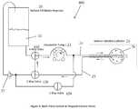
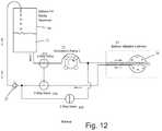
- the volumetric pump 22is run in reverse.
- a check valve 27is provided to prevent air from entering the balloon 26 during balloon deflation.
- separate pathwaysare used to withdraw inflation media 21 from the reservoir 20 and to return it to the reservoir 20 . In this way any air in the balloon 26 or fluid pathways is expelled from the system during the initial phase when inflation media 21 is introduced into a new dry catheter 10 . Any air in the catheter fluid passages returns to the reservoir 20 along with the inflation media 21 and is dissipated as is exits the return tube shown in the figure returning drops of inflation media 21 to the reservoir 20 .
- balloon inflation pressure of 0.2 PSI to 1 PSIwill be achieved with pump flow rates of 2 ml/minute to 10 ml/minute.
- the minimum flow rate necessary to achieve the required level of coolingis 10 ml/minute.
- the balloon 26is inflated to the desired pressure or volume, trapped volume mode is then entered and then the pump speed is increased to at least 10 ml/minute.
Landscapes
- Health & Medical Sciences (AREA)
- Life Sciences & Earth Sciences (AREA)
- Heart & Thoracic Surgery (AREA)
- Engineering & Computer Science (AREA)
- Animal Behavior & Ethology (AREA)
- Veterinary Medicine (AREA)
- Public Health (AREA)
- Biomedical Technology (AREA)
- General Health & Medical Sciences (AREA)
- Surgery (AREA)
- Pulmonology (AREA)
- Hematology (AREA)
- Anesthesiology (AREA)
- Biophysics (AREA)
- Child & Adolescent Psychology (AREA)
- Cardiology (AREA)
- Physics & Mathematics (AREA)
- Plasma & Fusion (AREA)
- Nuclear Medicine, Radiotherapy & Molecular Imaging (AREA)
- Otolaryngology (AREA)
- Medical Informatics (AREA)
- Molecular Biology (AREA)
- Media Introduction/Drainage Providing Device (AREA)
Abstract
Description
- a) Providing a balloon with more compliant material properties.
- b) Providing a system that allows the balloon to be inflated such that the pressure in the balloon is substantially lower than prior art allows.
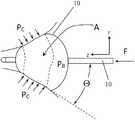
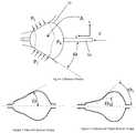
- c) Providing a balloon shape that achieves a more stable balloon position when the balloon is placed at the ostium of a pulmonary vein.
- d) Providing a balloon shape that more readily conforms to the geometry of the pulmonary vein ostium.
A=F/PBSin Θ (1)
Claims (12)
Priority Applications (2)
| Application Number | Priority Date | Filing Date | Title |
|---|---|---|---|
| US15/863,264US11207505B2 (en) | 2017-01-06 | 2018-01-05 | Balloon catheter and fluid management system thereof |
| US17/532,434US11957856B2 (en) | 2017-01-06 | 2021-11-22 | Balloon catheter and fluid management system thereof |
Applications Claiming Priority (2)
| Application Number | Priority Date | Filing Date | Title |
|---|---|---|---|
| US201762443270P | 2017-01-06 | 2017-01-06 | |
| US15/863,264US11207505B2 (en) | 2017-01-06 | 2018-01-05 | Balloon catheter and fluid management system thereof |
Related Child Applications (1)
| Application Number | Title | Priority Date | Filing Date |
|---|---|---|---|
| US17/532,434DivisionUS11957856B2 (en) | 2017-01-06 | 2021-11-22 | Balloon catheter and fluid management system thereof |
Publications (2)
| Publication Number | Publication Date |
|---|---|
| US20180193612A1 US20180193612A1 (en) | 2018-07-12 |
| US11207505B2true US11207505B2 (en) | 2021-12-28 |
Family
ID=62782058
Family Applications (2)
| Application Number | Title | Priority Date | Filing Date |
|---|---|---|---|
| US15/863,264Active2039-06-02US11207505B2 (en) | 2017-01-06 | 2018-01-05 | Balloon catheter and fluid management system thereof |
| US17/532,434Active2038-01-10US11957856B2 (en) | 2017-01-06 | 2021-11-22 | Balloon catheter and fluid management system thereof |
Family Applications After (1)
| Application Number | Title | Priority Date | Filing Date |
|---|---|---|---|
| US17/532,434Active2038-01-10US11957856B2 (en) | 2017-01-06 | 2021-11-22 | Balloon catheter and fluid management system thereof |
Country Status (1)
| Country | Link |
|---|---|
| US (2) | US11207505B2 (en) |
Cited By (1)
| Publication number | Priority date | Publication date | Assignee | Title |
|---|---|---|---|---|
| US20220152365A1 (en)* | 2017-01-06 | 2022-05-19 | Cardiofocus, Inc. | Balloon catheter and fluid management system thereof |
Citations (32)
| Publication number | Priority date | Publication date | Assignee | Title |
|---|---|---|---|---|
| US3570672A (en)* | 1969-08-28 | 1971-03-16 | Bert Bach | Artificial kidney |
| US3794026A (en)* | 1970-07-29 | 1974-02-26 | H Jacobs | Ventilating apparatus embodying selective volume or pressure operation and catheter means for use therewith |
| US4093545A (en)* | 1975-02-14 | 1978-06-06 | Baxter Travenol Laboratories, Inc. | Method and apparatus for determining the amount of ultrafiltration during dialysis |
| US5496311A (en)* | 1988-10-28 | 1996-03-05 | Boston Scientific Corporation | Physiologic low stress angioplasty |
| US5746717A (en)* | 1993-03-30 | 1998-05-05 | Aigner; Karl R. | Balloon catheter and device for perfusion with the balloon catheter |
| US5759148A (en)* | 1995-10-18 | 1998-06-02 | Sipin; Anatole J. | Controlled pneumatic driving system |
| US5861005A (en)* | 1997-02-11 | 1999-01-19 | X-Site, L.L.C. | Arterial stapling device |
| US6082105A (en)* | 1995-11-21 | 2000-07-04 | Nippon Zeon Co., Ltd. | Drive device for medical appliances |
| US6135991A (en)* | 1997-03-06 | 2000-10-24 | Percusurge, Inc. | Aspiration method |
| US6241706B1 (en)* | 1999-07-16 | 2001-06-05 | Datascope Investment Corporation | Fast response intra-aortic balloon pump |
| US20060200191A1 (en)* | 1996-05-20 | 2006-09-07 | Gholam-Reza Zadno-Azizi | Method and apparatuses for treating an intravascular occlusion |
| US20060265041A1 (en)* | 2005-05-23 | 2006-11-23 | Arashmidos Sanati | Apparatus and methods for delivering a stent into an ostium |
| US20060293734A1 (en)* | 2005-04-27 | 2006-12-28 | Scott David J | Apparatus and method for providing enhanced heat transfer from a body |
| US20090012460A1 (en)* | 2007-07-05 | 2009-01-08 | Baxter International Inc. | Dialysis cassette having multiple outlet valve |
| US20090088735A1 (en)* | 2004-03-23 | 2009-04-02 | Cryocath Technologies Inc. | Method and apparatus for inflating and deflating balloon catheters |
| US20090112151A1 (en)* | 2007-10-30 | 2009-04-30 | Baxter International Inc. | Dialysis system having integrated pneumatic manifold |
| US20090299356A1 (en)* | 2008-05-29 | 2009-12-03 | Boston Scientific Scimed, Inc. | Regulating internal pressure of a cryotherapy balloon catheter |
| US20100049184A1 (en)* | 2008-08-22 | 2010-02-25 | Boston Scientific Scimed, Inc. | Regulating Pressure to Lower Temperature in a Cryotherapy Balloon Catheter |
| US20100280451A1 (en)* | 2008-11-03 | 2010-11-04 | Atlanta Catheter Therapies, Inc. | Occlusion Perfusion Catheter |
| US20110190751A1 (en)* | 2010-02-01 | 2011-08-04 | Boston Scientific Scimed, Inc. | Nested balloon cryotherapy |
| US20110202084A1 (en)* | 2010-02-16 | 2011-08-18 | Miracor Medical Systems Gmbh | Operating A Vessel Occlusion Catheter |
| US20120152842A1 (en)* | 2010-12-20 | 2012-06-21 | Gambro Lundia Ab | Method and system for providing priming and restitution liquids for an extracorporeal blood treatment |
| US20130345688A1 (en)* | 2010-08-26 | 2013-12-26 | Cryomedix, Llc | Cryoablation balloon catheter and related method |
| US20140012368A1 (en)* | 2006-11-07 | 2014-01-09 | Dc Devices, Inc. | Devices and methods for retrievable intra-atrial implants |
| US20160015947A1 (en)* | 2014-03-25 | 2016-01-21 | Philip Avevor | Device for independently inflating, deflating, supplying contrast media to and monitoring up to two balloon catheters for angioplasty |
| US20160029998A1 (en)* | 2013-12-04 | 2016-02-04 | Obalon Therapeutics, Inc. | Systems and methods for locating and/or characterizing intragastric devices |
| US20160114281A1 (en)* | 2012-01-10 | 2016-04-28 | Buffalo Filter Llc | Fluid Filtration Device and System |
| US20170021076A1 (en)* | 2015-07-24 | 2017-01-26 | Medtronic, Inc. | Fluid connectors and fluid flow paths for an infusate caddy |
| US20180110342A1 (en)* | 2016-10-25 | 2018-04-26 | Daniel Moss | Inflatable mattress bumper system |
| US20180296807A1 (en)* | 2017-04-14 | 2018-10-18 | Cardiofocus, Inc. | Balloon catheter and fluid management system thereof |
| US20180318543A1 (en)* | 2016-04-27 | 2018-11-08 | Suspended Animation, Inc. | Apparatus and method for delivering fluids and/or gases to the lungs |
| US20200171226A1 (en)* | 2006-04-14 | 2020-06-04 | Deka Products Limited Partnership | Automated control mechanisms and methods for controlling fluid flow in a hemodialysis apparatus |
Family Cites Families (26)
| Publication number | Priority date | Publication date | Assignee | Title |
|---|---|---|---|---|
| US5833619A (en)* | 1997-05-15 | 1998-11-10 | L. Vad Technology, Inc. | External blood pressure sensor apparatus and method |
| US9033961B2 (en)* | 1999-07-14 | 2015-05-19 | Cardiofocus, Inc. | Cardiac ablation catheters for forming overlapping lesions |
| EP1408746B1 (en)* | 2000-10-06 | 2015-07-01 | Dancu, Michael B. | System and method to simulate hemodynamics |
| US7326564B2 (en)* | 2001-02-20 | 2008-02-05 | St. Jude Medical, Inc. | Flow system for medical device evaluation and production |
| US6887263B2 (en)* | 2002-10-18 | 2005-05-03 | Radiant Medical, Inc. | Valved connector assembly and sterility barriers for heat exchange catheters and other closed loop catheters |
| AU2011203584B2 (en)* | 2003-09-09 | 2013-07-11 | Convatec Technologies Inc. | Fecal management appliance and method and apparatus for introducing same |
| US7189253B2 (en)* | 2004-03-16 | 2007-03-13 | Quickcool Ab | Cerebral temperature control |
| US8491636B2 (en)* | 2004-03-23 | 2013-07-23 | Medtronic Cryopath LP | Method and apparatus for inflating and deflating balloon catheters |
| US20060271087A1 (en)* | 2005-05-25 | 2006-11-30 | Bowel Management Systems, Llc | Fixed-volume inflation system for balloon catheters |
| US20070149922A1 (en)* | 2005-12-28 | 2007-06-28 | Bowel Management Systems, Llc | Combined fixed volume retention cuff and relief valve |
| US10413284B2 (en)* | 2006-11-07 | 2019-09-17 | Corvia Medical, Inc. | Atrial pressure regulation with control, sensing, monitoring and therapy delivery |
| US20080140001A1 (en)* | 2006-12-12 | 2008-06-12 | By-Pass Inc. | Fluid Delivery Apparatus And Methods |
| WO2008089264A1 (en)* | 2007-01-16 | 2008-07-24 | Reviveflow, Inc. | Arterial-venous switching |
| US9597145B2 (en)* | 2008-08-20 | 2017-03-21 | Prostacare Pty Ltd | Non-thermal ablation system for treating tissue |
| US10064697B2 (en)* | 2008-10-06 | 2018-09-04 | Santa Anna Tech Llc | Vapor based ablation system for treating various indications |
| AU2010210385A1 (en)* | 2009-02-06 | 2011-08-18 | Velomedix, Inc. | Method and apparatus for inducing therapeutic hypothermia |
| US9078655B2 (en)* | 2009-04-17 | 2015-07-14 | Domain Surgical, Inc. | Heated balloon catheter |
| WO2011136815A1 (en)* | 2010-04-30 | 2011-11-03 | Abbott Cardiovascular Systems Inc. | Catheter system having a fluid circuit |
| US9943353B2 (en)* | 2013-03-15 | 2018-04-17 | Tsunami Medtech, Llc | Medical system and method of use |
| CN203107397U (en)* | 2013-03-15 | 2013-08-07 | 成都嘉逸科技有限公司 | Intravascular temperature automatic regulating device |
| CN103736154B (en)* | 2013-12-26 | 2015-06-17 | 先健科技(深圳)有限公司 | Medicinal coating balloon catheter |
| US11419656B2 (en)* | 2014-04-04 | 2022-08-23 | Cpsi Holdings Llc | Thermal regulation catheter system |
| US20150367036A1 (en)* | 2014-06-23 | 2015-12-24 | Biotronik Ag | Method for manufacturing a balloon catheter and balloon |
| CN107835704B (en)* | 2015-03-27 | 2020-12-15 | 项目莫里股份有限公司 | Fluid drive system for catheter articulation and other uses |
| EP3316813B1 (en)* | 2015-07-01 | 2023-12-20 | Fractyl Health, Inc. | Systems and devices for performing medical procedures in the intestine |
| US11207505B2 (en)* | 2017-01-06 | 2021-12-28 | Cardiofocus, Inc. | Balloon catheter and fluid management system thereof |
- 2018
- 2018-01-05USUS15/863,264patent/US11207505B2/enactiveActive
- 2021
- 2021-11-22USUS17/532,434patent/US11957856B2/enactiveActive
Patent Citations (32)
| Publication number | Priority date | Publication date | Assignee | Title |
|---|---|---|---|---|
| US3570672A (en)* | 1969-08-28 | 1971-03-16 | Bert Bach | Artificial kidney |
| US3794026A (en)* | 1970-07-29 | 1974-02-26 | H Jacobs | Ventilating apparatus embodying selective volume or pressure operation and catheter means for use therewith |
| US4093545A (en)* | 1975-02-14 | 1978-06-06 | Baxter Travenol Laboratories, Inc. | Method and apparatus for determining the amount of ultrafiltration during dialysis |
| US5496311A (en)* | 1988-10-28 | 1996-03-05 | Boston Scientific Corporation | Physiologic low stress angioplasty |
| US5746717A (en)* | 1993-03-30 | 1998-05-05 | Aigner; Karl R. | Balloon catheter and device for perfusion with the balloon catheter |
| US5759148A (en)* | 1995-10-18 | 1998-06-02 | Sipin; Anatole J. | Controlled pneumatic driving system |
| US6082105A (en)* | 1995-11-21 | 2000-07-04 | Nippon Zeon Co., Ltd. | Drive device for medical appliances |
| US20060200191A1 (en)* | 1996-05-20 | 2006-09-07 | Gholam-Reza Zadno-Azizi | Method and apparatuses for treating an intravascular occlusion |
| US5861005A (en)* | 1997-02-11 | 1999-01-19 | X-Site, L.L.C. | Arterial stapling device |
| US6135991A (en)* | 1997-03-06 | 2000-10-24 | Percusurge, Inc. | Aspiration method |
| US6241706B1 (en)* | 1999-07-16 | 2001-06-05 | Datascope Investment Corporation | Fast response intra-aortic balloon pump |
| US20090088735A1 (en)* | 2004-03-23 | 2009-04-02 | Cryocath Technologies Inc. | Method and apparatus for inflating and deflating balloon catheters |
| US20060293734A1 (en)* | 2005-04-27 | 2006-12-28 | Scott David J | Apparatus and method for providing enhanced heat transfer from a body |
| US20060265041A1 (en)* | 2005-05-23 | 2006-11-23 | Arashmidos Sanati | Apparatus and methods for delivering a stent into an ostium |
| US20200171226A1 (en)* | 2006-04-14 | 2020-06-04 | Deka Products Limited Partnership | Automated control mechanisms and methods for controlling fluid flow in a hemodialysis apparatus |
| US20140012368A1 (en)* | 2006-11-07 | 2014-01-09 | Dc Devices, Inc. | Devices and methods for retrievable intra-atrial implants |
| US20090012460A1 (en)* | 2007-07-05 | 2009-01-08 | Baxter International Inc. | Dialysis cassette having multiple outlet valve |
| US20090112151A1 (en)* | 2007-10-30 | 2009-04-30 | Baxter International Inc. | Dialysis system having integrated pneumatic manifold |
| US20090299356A1 (en)* | 2008-05-29 | 2009-12-03 | Boston Scientific Scimed, Inc. | Regulating internal pressure of a cryotherapy balloon catheter |
| US20100049184A1 (en)* | 2008-08-22 | 2010-02-25 | Boston Scientific Scimed, Inc. | Regulating Pressure to Lower Temperature in a Cryotherapy Balloon Catheter |
| US20100280451A1 (en)* | 2008-11-03 | 2010-11-04 | Atlanta Catheter Therapies, Inc. | Occlusion Perfusion Catheter |
| US20110190751A1 (en)* | 2010-02-01 | 2011-08-04 | Boston Scientific Scimed, Inc. | Nested balloon cryotherapy |
| US20110202084A1 (en)* | 2010-02-16 | 2011-08-18 | Miracor Medical Systems Gmbh | Operating A Vessel Occlusion Catheter |
| US20130345688A1 (en)* | 2010-08-26 | 2013-12-26 | Cryomedix, Llc | Cryoablation balloon catheter and related method |
| US20120152842A1 (en)* | 2010-12-20 | 2012-06-21 | Gambro Lundia Ab | Method and system for providing priming and restitution liquids for an extracorporeal blood treatment |
| US20160114281A1 (en)* | 2012-01-10 | 2016-04-28 | Buffalo Filter Llc | Fluid Filtration Device and System |
| US20160029998A1 (en)* | 2013-12-04 | 2016-02-04 | Obalon Therapeutics, Inc. | Systems and methods for locating and/or characterizing intragastric devices |
| US20160015947A1 (en)* | 2014-03-25 | 2016-01-21 | Philip Avevor | Device for independently inflating, deflating, supplying contrast media to and monitoring up to two balloon catheters for angioplasty |
| US20170021076A1 (en)* | 2015-07-24 | 2017-01-26 | Medtronic, Inc. | Fluid connectors and fluid flow paths for an infusate caddy |
| US20180318543A1 (en)* | 2016-04-27 | 2018-11-08 | Suspended Animation, Inc. | Apparatus and method for delivering fluids and/or gases to the lungs |
| US20180110342A1 (en)* | 2016-10-25 | 2018-04-26 | Daniel Moss | Inflatable mattress bumper system |
| US20180296807A1 (en)* | 2017-04-14 | 2018-10-18 | Cardiofocus, Inc. | Balloon catheter and fluid management system thereof |
Cited By (2)
| Publication number | Priority date | Publication date | Assignee | Title |
|---|---|---|---|---|
| US20220152365A1 (en)* | 2017-01-06 | 2022-05-19 | Cardiofocus, Inc. | Balloon catheter and fluid management system thereof |
| US11957856B2 (en)* | 2017-01-06 | 2024-04-16 | Cardiofocus, Inc. | Balloon catheter and fluid management system thereof |
Also Published As
| Publication number | Publication date |
|---|---|
| US20180193612A1 (en) | 2018-07-12 |
| US20220152365A1 (en) | 2022-05-19 |
| US11957856B2 (en) | 2024-04-16 |
Similar Documents
| Publication | Publication Date | Title |
|---|---|---|
| US11872363B2 (en) | Irrigation devices, methods, and systems | |
| TWI580446B (en) | Selective movable valve element for suction and flush circuits | |
| EP2928420B1 (en) | Inflatable obstruction device for the pyloric sphincter | |
| US9155869B2 (en) | Catheter having inflation and deflation lumen useful for preventing or reducing reperfusion injury | |
| EP3565626B1 (en) | Balloon catheter and fluid management system thereof | |
| US20050085792A1 (en) | Retrograde cannula having automatically inflatable balloon | |
| US11957856B2 (en) | Balloon catheter and fluid management system thereof | |
| BRPI0614120A2 (en) | control system optimized to provide fluid medium to endoscope | |
| US20210386980A1 (en) | Balloon catheter and fluid management system thereof | |
| US11684403B2 (en) | System and method for inflating a cryoablation balloon catheter | |
| US11484692B2 (en) | Balloon catheter and fluid management system thereof | |
| WO1999015227A1 (en) | Main stage catheterization instrument | |
| KR102325058B1 (en) | Negative pressure drain device with flow control valve | |
| JPWO2020072837A5 (en) | ||
| US20180361115A1 (en) | Device for removing air from an anatomical cavity in a surgical intervention | |
| US20120239029A1 (en) | Apparatus for endobronchial ablation of a tumor | |
| US20090171279A1 (en) | Balloon catheter assembly and controller therefor | |
| US20230141641A1 (en) | Balloon catheter | |
| US20240008723A1 (en) | Water line air purge for an endoscope | |
| US20240389843A1 (en) | Devices, systems, and methods to supply fluids to an endoscope | |
| US20240366078A1 (en) | Devices, systems, and methods to supply fluids to an endoscope | |
| US20220072214A1 (en) | Medical Instrument for Minimally Invasive Therapy, Comprising at Least Two Separate Suction Lines | |
| CN120458670A (en) | A thrombolytic balloon catheter for intracranial perforating blood vessels |
Legal Events
| Date | Code | Title | Description |
|---|---|---|---|
| FEPP | Fee payment procedure | Free format text:ENTITY STATUS SET TO UNDISCOUNTED (ORIGINAL EVENT CODE: BIG.); ENTITY STATUS OF PATENT OWNER: SMALL ENTITY | |
| FEPP | Fee payment procedure | Free format text:ENTITY STATUS SET TO SMALL (ORIGINAL EVENT CODE: SMAL); ENTITY STATUS OF PATENT OWNER: SMALL ENTITY | |
| AS | Assignment | Owner name:CARDIOFOCUS, INC., MASSACHUSETTS Free format text:ASSIGNMENT OF ASSIGNORS INTEREST;ASSIGNORS:MELSKY, GERALD;ESTABROOK, BRIAN;BAXTER, LINCOLN;REEL/FRAME:045292/0652 Effective date:20180319 | |
| AS | Assignment | Owner name:GPB DEBT HOLDINGS II LLC, NEW YORK Free format text:SECURITY INTEREST;ASSIGNOR:CARDIOFOCUS, INC.;REEL/FRAME:045478/0532 Effective date:20180404 | |
| STPP | Information on status: patent application and granting procedure in general | Free format text:DOCKETED NEW CASE - READY FOR EXAMINATION | |
| AS | Assignment | Owner name:CARDIOFOCUS, INC., MASSACHUSETTS Free format text:RELEASE BY SECURED PARTY;ASSIGNORS:SILICON VALLEY BANK;OXFORD FINANCE LLC;REEL/FRAME:049133/0474 Effective date:20190509 | |
| AS | Assignment | Owner name:CARDIOFOCUS, INC., MASSACHUSETTS Free format text:RELEASE BY SECURED PARTY;ASSIGNORS:SILICON VALLEY BANK;SOLAR CAPITAL LTD.;REEL/FRAME:049138/0362 Effective date:20190509 Owner name:CARDIOFOCUS, INC., MASSACHUSETTS Free format text:RELEASE BY SECURED PARTY;ASSIGNORS:SILICON VALLEY BANK;OXFORD FINANCE LLC;REEL/FRAME:049138/0233 Effective date:20190509 Owner name:KENNEDY LEWIS INVESTMENT MANAGEMENT LLC, NEW YORK Free format text:INTELLECTUAL PROPERTY SECURITY AGREEMENT;ASSIGNOR:CARDIOFOCUS, INC.;REEL/FRAME:049149/0356 Effective date:20190510 | |
| AS | Assignment | Owner name:CARDIOFOCUS, INC., MASSACHUSETTS Free format text:RELEASE BY SECURED PARTY;ASSIGNOR:GPB DEBT HOLDINGS II, LLC;REEL/FRAME:049200/0597 Effective date:20190510 | |
| STPP | Information on status: patent application and granting procedure in general | Free format text:NON FINAL ACTION MAILED | |
| STPP | Information on status: patent application and granting procedure in general | Free format text:NON FINAL ACTION MAILED | |
| STPP | Information on status: patent application and granting procedure in general | Free format text:FINAL REJECTION MAILED | |
| STPP | Information on status: patent application and granting procedure in general | Free format text:DOCKETED NEW CASE - READY FOR EXAMINATION | |
| STPP | Information on status: patent application and granting procedure in general | Free format text:NOTICE OF ALLOWANCE MAILED -- APPLICATION RECEIVED IN OFFICE OF PUBLICATIONS | |
| STPP | Information on status: patent application and granting procedure in general | Free format text:PUBLICATIONS -- ISSUE FEE PAYMENT VERIFIED | |
| STCF | Information on status: patent grant | Free format text:PATENTED CASE | |
| MAFP | Maintenance fee payment | Free format text:PAYMENT OF MAINTENANCE FEE, 4TH YR, SMALL ENTITY (ORIGINAL EVENT CODE: M2551); ENTITY STATUS OF PATENT OWNER: SMALL ENTITY Year of fee payment:4 |