US11207494B2 - Medical device delivery member with flexible stretch resistant distal portion - Google Patents
Medical device delivery member with flexible stretch resistant distal portionDownload PDFInfo
- Publication number
- US11207494B2 US11207494B2US16/502,767US201916502767AUS11207494B2US 11207494 B2US11207494 B2US 11207494B2US 201916502767 AUS201916502767 AUS 201916502767AUS 11207494 B2US11207494 B2US 11207494B2
- Authority
- US
- United States
- Prior art keywords
- hypotube
- distal
- proximal
- medical device
- wire
- Prior art date
- Legal status (The legal status is an assumption and is not a legal conclusion. Google has not performed a legal analysis and makes no representation as to the accuracy of the status listed.)
- Active, expires
Links
Images


Classifications
- A—HUMAN NECESSITIES
- A61—MEDICAL OR VETERINARY SCIENCE; HYGIENE
- A61B—DIAGNOSIS; SURGERY; IDENTIFICATION
- A61B17/00—Surgical instruments, devices or methods
- A61B17/12—Surgical instruments, devices or methods for ligaturing or otherwise compressing tubular parts of the body, e.g. blood vessels or umbilical cord
- A61B17/12022—Occluding by internal devices, e.g. balloons or releasable wires
- A—HUMAN NECESSITIES
- A61—MEDICAL OR VETERINARY SCIENCE; HYGIENE
- A61M—DEVICES FOR INTRODUCING MEDIA INTO, OR ONTO, THE BODY; DEVICES FOR TRANSDUCING BODY MEDIA OR FOR TAKING MEDIA FROM THE BODY; DEVICES FOR PRODUCING OR ENDING SLEEP OR STUPOR
- A61M25/00—Catheters; Hollow probes
- A61M25/0043—Catheters; Hollow probes characterised by structural features
- A61M25/005—Catheters; Hollow probes characterised by structural features with embedded materials for reinforcement, e.g. wires, coils, braids
- A61M25/0052—Localized reinforcement, e.g. where only a specific part of the catheter is reinforced, for rapid exchange guidewire port
- A—HUMAN NECESSITIES
- A61—MEDICAL OR VETERINARY SCIENCE; HYGIENE
- A61B—DIAGNOSIS; SURGERY; IDENTIFICATION
- A61B17/00—Surgical instruments, devices or methods
- A61B17/12—Surgical instruments, devices or methods for ligaturing or otherwise compressing tubular parts of the body, e.g. blood vessels or umbilical cord
- A61B17/12022—Occluding by internal devices, e.g. balloons or releasable wires
- A61B17/12027—Type of occlusion
- A61B17/12031—Type of occlusion complete occlusion
- A—HUMAN NECESSITIES
- A61—MEDICAL OR VETERINARY SCIENCE; HYGIENE
- A61B—DIAGNOSIS; SURGERY; IDENTIFICATION
- A61B17/00—Surgical instruments, devices or methods
- A61B17/12—Surgical instruments, devices or methods for ligaturing or otherwise compressing tubular parts of the body, e.g. blood vessels or umbilical cord
- A61B17/12022—Occluding by internal devices, e.g. balloons or releasable wires
- A61B17/12099—Occluding by internal devices, e.g. balloons or releasable wires characterised by the location of the occluder
- A61B17/12109—Occluding by internal devices, e.g. balloons or releasable wires characterised by the location of the occluder in a blood vessel
- A61B17/12113—Occluding by internal devices, e.g. balloons or releasable wires characterised by the location of the occluder in a blood vessel within an aneurysm
- A—HUMAN NECESSITIES
- A61—MEDICAL OR VETERINARY SCIENCE; HYGIENE
- A61B—DIAGNOSIS; SURGERY; IDENTIFICATION
- A61B17/00—Surgical instruments, devices or methods
- A61B17/12—Surgical instruments, devices or methods for ligaturing or otherwise compressing tubular parts of the body, e.g. blood vessels or umbilical cord
- A61B17/12022—Occluding by internal devices, e.g. balloons or releasable wires
- A61B17/12131—Occluding by internal devices, e.g. balloons or releasable wires characterised by the type of occluding device
- A61B17/1214—Coils or wires
- A61B17/12154—Coils or wires having stretch limiting means
- A—HUMAN NECESSITIES
- A61—MEDICAL OR VETERINARY SCIENCE; HYGIENE
- A61F—FILTERS IMPLANTABLE INTO BLOOD VESSELS; PROSTHESES; DEVICES PROVIDING PATENCY TO, OR PREVENTING COLLAPSING OF, TUBULAR STRUCTURES OF THE BODY, e.g. STENTS; ORTHOPAEDIC, NURSING OR CONTRACEPTIVE DEVICES; FOMENTATION; TREATMENT OR PROTECTION OF EYES OR EARS; BANDAGES, DRESSINGS OR ABSORBENT PADS; FIRST-AID KITS
- A61F2/00—Filters implantable into blood vessels; Prostheses, i.e. artificial substitutes or replacements for parts of the body; Appliances for connecting them with the body; Devices providing patency to, or preventing collapsing of, tubular structures of the body, e.g. stents
- A61F2/95—Instruments specially adapted for placement or removal of stents or stent-grafts
- A61F2/962—Instruments specially adapted for placement or removal of stents or stent-grafts having an outer sleeve
- A—HUMAN NECESSITIES
- A61—MEDICAL OR VETERINARY SCIENCE; HYGIENE
- A61M—DEVICES FOR INTRODUCING MEDIA INTO, OR ONTO, THE BODY; DEVICES FOR TRANSDUCING BODY MEDIA OR FOR TAKING MEDIA FROM THE BODY; DEVICES FOR PRODUCING OR ENDING SLEEP OR STUPOR
- A61M25/00—Catheters; Hollow probes
- A61M25/0043—Catheters; Hollow probes characterised by structural features
- A61M25/005—Catheters; Hollow probes characterised by structural features with embedded materials for reinforcement, e.g. wires, coils, braids
- A—HUMAN NECESSITIES
- A61—MEDICAL OR VETERINARY SCIENCE; HYGIENE
- A61M—DEVICES FOR INTRODUCING MEDIA INTO, OR ONTO, THE BODY; DEVICES FOR TRANSDUCING BODY MEDIA OR FOR TAKING MEDIA FROM THE BODY; DEVICES FOR PRODUCING OR ENDING SLEEP OR STUPOR
- A61M25/00—Catheters; Hollow probes
- A61M25/01—Introducing, guiding, advancing, emplacing or holding catheters
- A61M25/0105—Steering means as part of the catheter or advancing means; Markers for positioning
- A61M25/0108—Steering means as part of the catheter or advancing means; Markers for positioning using radio-opaque or ultrasound markers
- A—HUMAN NECESSITIES
- A61—MEDICAL OR VETERINARY SCIENCE; HYGIENE
- A61M—DEVICES FOR INTRODUCING MEDIA INTO, OR ONTO, THE BODY; DEVICES FOR TRANSDUCING BODY MEDIA OR FOR TAKING MEDIA FROM THE BODY; DEVICES FOR PRODUCING OR ENDING SLEEP OR STUPOR
- A61M25/00—Catheters; Hollow probes
- A61M25/01—Introducing, guiding, advancing, emplacing or holding catheters
- A61M25/0105—Steering means as part of the catheter or advancing means; Markers for positioning
- A61M25/0133—Tip steering devices
- A61M25/0138—Tip steering devices having flexible regions as a result of weakened outer material, e.g. slots, slits, cuts, joints or coils
- A—HUMAN NECESSITIES
- A61—MEDICAL OR VETERINARY SCIENCE; HYGIENE
- A61M—DEVICES FOR INTRODUCING MEDIA INTO, OR ONTO, THE BODY; DEVICES FOR TRANSDUCING BODY MEDIA OR FOR TAKING MEDIA FROM THE BODY; DEVICES FOR PRODUCING OR ENDING SLEEP OR STUPOR
- A61M25/00—Catheters; Hollow probes
- A61M25/01—Introducing, guiding, advancing, emplacing or holding catheters
- A61M25/0105—Steering means as part of the catheter or advancing means; Markers for positioning
- A61M25/0133—Tip steering devices
- A61M25/0147—Tip steering devices with movable mechanical means, e.g. pull wires
- A—HUMAN NECESSITIES
- A61—MEDICAL OR VETERINARY SCIENCE; HYGIENE
- A61M—DEVICES FOR INTRODUCING MEDIA INTO, OR ONTO, THE BODY; DEVICES FOR TRANSDUCING BODY MEDIA OR FOR TAKING MEDIA FROM THE BODY; DEVICES FOR PRODUCING OR ENDING SLEEP OR STUPOR
- A61M25/00—Catheters; Hollow probes
- A61M25/01—Introducing, guiding, advancing, emplacing or holding catheters
- A61M25/06—Body-piercing guide needles or the like
- A61M25/0662—Guide tubes
- A—HUMAN NECESSITIES
- A61—MEDICAL OR VETERINARY SCIENCE; HYGIENE
- A61M—DEVICES FOR INTRODUCING MEDIA INTO, OR ONTO, THE BODY; DEVICES FOR TRANSDUCING BODY MEDIA OR FOR TAKING MEDIA FROM THE BODY; DEVICES FOR PRODUCING OR ENDING SLEEP OR STUPOR
- A61M25/00—Catheters; Hollow probes
- A61M25/01—Introducing, guiding, advancing, emplacing or holding catheters
- A61M25/09—Guide wires
- A—HUMAN NECESSITIES
- A61—MEDICAL OR VETERINARY SCIENCE; HYGIENE
- A61B—DIAGNOSIS; SURGERY; IDENTIFICATION
- A61B17/00—Surgical instruments, devices or methods
- A61B17/12—Surgical instruments, devices or methods for ligaturing or otherwise compressing tubular parts of the body, e.g. blood vessels or umbilical cord
- A61B17/12022—Occluding by internal devices, e.g. balloons or releasable wires
- A61B17/12099—Occluding by internal devices, e.g. balloons or releasable wires characterised by the location of the occluder
- A61B17/12109—Occluding by internal devices, e.g. balloons or releasable wires characterised by the location of the occluder in a blood vessel
- A—HUMAN NECESSITIES
- A61—MEDICAL OR VETERINARY SCIENCE; HYGIENE
- A61B—DIAGNOSIS; SURGERY; IDENTIFICATION
- A61B17/00—Surgical instruments, devices or methods
- A61B17/12—Surgical instruments, devices or methods for ligaturing or otherwise compressing tubular parts of the body, e.g. blood vessels or umbilical cord
- A61B17/12022—Occluding by internal devices, e.g. balloons or releasable wires
- A61B17/12131—Occluding by internal devices, e.g. balloons or releasable wires characterised by the type of occluding device
- A61B17/12181—Occluding by internal devices, e.g. balloons or releasable wires characterised by the type of occluding device formed by fluidized, gelatinous or cellular remodelable materials, e.g. embolic liquids, foams or extracellular matrices
- A—HUMAN NECESSITIES
- A61—MEDICAL OR VETERINARY SCIENCE; HYGIENE
- A61B—DIAGNOSIS; SURGERY; IDENTIFICATION
- A61B17/00—Surgical instruments, devices or methods
- A61B17/00234—Surgical instruments, devices or methods for minimally invasive surgery
- A61B2017/00292—Surgical instruments, devices or methods for minimally invasive surgery mounted on or guided by flexible, e.g. catheter-like, means
- A61B2017/00336—Surgical instruments, devices or methods for minimally invasive surgery mounted on or guided by flexible, e.g. catheter-like, means with a protective sleeve, e.g. retractable or slidable
- A—HUMAN NECESSITIES
- A61—MEDICAL OR VETERINARY SCIENCE; HYGIENE
- A61B—DIAGNOSIS; SURGERY; IDENTIFICATION
- A61B17/00—Surgical instruments, devices or methods
- A61B2017/00526—Methods of manufacturing
- A—HUMAN NECESSITIES
- A61—MEDICAL OR VETERINARY SCIENCE; HYGIENE
- A61B—DIAGNOSIS; SURGERY; IDENTIFICATION
- A61B17/00—Surgical instruments, devices or methods
- A61B2017/00831—Material properties
- A61B2017/00853—Material properties low friction, hydrophobic and corrosion-resistant fluorocarbon resin coating (ptf, ptfe, polytetrafluoroethylene)
- A—HUMAN NECESSITIES
- A61—MEDICAL OR VETERINARY SCIENCE; HYGIENE
- A61B—DIAGNOSIS; SURGERY; IDENTIFICATION
- A61B17/00—Surgical instruments, devices or methods
- A61B2017/00831—Material properties
- A61B2017/00902—Material properties transparent or translucent
- A61B2017/00915—Material properties transparent or translucent for radioactive radiation
- A61B2017/0092—Material properties transparent or translucent for radioactive radiation for X-rays
- A—HUMAN NECESSITIES
- A61—MEDICAL OR VETERINARY SCIENCE; HYGIENE
- A61B—DIAGNOSIS; SURGERY; IDENTIFICATION
- A61B17/00—Surgical instruments, devices or methods
- A61B2017/00831—Material properties
- A61B2017/00942—Material properties hydrophilic
- A—HUMAN NECESSITIES
- A61—MEDICAL OR VETERINARY SCIENCE; HYGIENE
- A61B—DIAGNOSIS; SURGERY; IDENTIFICATION
- A61B17/00—Surgical instruments, devices or methods
- A61B17/12—Surgical instruments, devices or methods for ligaturing or otherwise compressing tubular parts of the body, e.g. blood vessels or umbilical cord
- A61B17/12022—Occluding by internal devices, e.g. balloons or releasable wires
- A61B2017/1205—Introduction devices
- A61B2017/12054—Details concerning the detachment of the occluding device from the introduction device
- A—HUMAN NECESSITIES
- A61—MEDICAL OR VETERINARY SCIENCE; HYGIENE
- A61F—FILTERS IMPLANTABLE INTO BLOOD VESSELS; PROSTHESES; DEVICES PROVIDING PATENCY TO, OR PREVENTING COLLAPSING OF, TUBULAR STRUCTURES OF THE BODY, e.g. STENTS; ORTHOPAEDIC, NURSING OR CONTRACEPTIVE DEVICES; FOMENTATION; TREATMENT OR PROTECTION OF EYES OR EARS; BANDAGES, DRESSINGS OR ABSORBENT PADS; FIRST-AID KITS
- A61F2/00—Filters implantable into blood vessels; Prostheses, i.e. artificial substitutes or replacements for parts of the body; Appliances for connecting them with the body; Devices providing patency to, or preventing collapsing of, tubular structures of the body, e.g. stents
- A61F2/95—Instruments specially adapted for placement or removal of stents or stent-grafts
- A61F2002/9505—Instruments specially adapted for placement or removal of stents or stent-grafts having retaining means other than an outer sleeve, e.g. male-female connector between stent and instrument
- A—HUMAN NECESSITIES
- A61—MEDICAL OR VETERINARY SCIENCE; HYGIENE
- A61M—DEVICES FOR INTRODUCING MEDIA INTO, OR ONTO, THE BODY; DEVICES FOR TRANSDUCING BODY MEDIA OR FOR TAKING MEDIA FROM THE BODY; DEVICES FOR PRODUCING OR ENDING SLEEP OR STUPOR
- A61M25/00—Catheters; Hollow probes
- A61M2025/0004—Catheters; Hollow probes having two or more concentrically arranged tubes for forming a concentric catheter system
- A61M2025/0006—Catheters; Hollow probes having two or more concentrically arranged tubes for forming a concentric catheter system which can be secured against axial movement, e.g. by using a locking cuff
- A—HUMAN NECESSITIES
- A61—MEDICAL OR VETERINARY SCIENCE; HYGIENE
- A61M—DEVICES FOR INTRODUCING MEDIA INTO, OR ONTO, THE BODY; DEVICES FOR TRANSDUCING BODY MEDIA OR FOR TAKING MEDIA FROM THE BODY; DEVICES FOR PRODUCING OR ENDING SLEEP OR STUPOR
- A61M25/00—Catheters; Hollow probes
- A61M25/01—Introducing, guiding, advancing, emplacing or holding catheters
- A61M25/0105—Steering means as part of the catheter or advancing means; Markers for positioning
- A61M25/0133—Tip steering devices
- A61M2025/0163—Looped catheters
- A—HUMAN NECESSITIES
- A61—MEDICAL OR VETERINARY SCIENCE; HYGIENE
- A61M—DEVICES FOR INTRODUCING MEDIA INTO, OR ONTO, THE BODY; DEVICES FOR TRANSDUCING BODY MEDIA OR FOR TAKING MEDIA FROM THE BODY; DEVICES FOR PRODUCING OR ENDING SLEEP OR STUPOR
- A61M25/00—Catheters; Hollow probes
- A61M25/01—Introducing, guiding, advancing, emplacing or holding catheters
- A61M2025/018—Catheters having a lateral opening for guiding elongated means lateral to the catheter
- A—HUMAN NECESSITIES
- A61—MEDICAL OR VETERINARY SCIENCE; HYGIENE
- A61M—DEVICES FOR INTRODUCING MEDIA INTO, OR ONTO, THE BODY; DEVICES FOR TRANSDUCING BODY MEDIA OR FOR TAKING MEDIA FROM THE BODY; DEVICES FOR PRODUCING OR ENDING SLEEP OR STUPOR
- A61M25/00—Catheters; Hollow probes
- A61M25/01—Introducing, guiding, advancing, emplacing or holding catheters
- A61M25/09—Guide wires
- A61M2025/09058—Basic structures of guide wires
- A61M2025/09083—Basic structures of guide wires having a coil around a core
- A—HUMAN NECESSITIES
- A61—MEDICAL OR VETERINARY SCIENCE; HYGIENE
- A61M—DEVICES FOR INTRODUCING MEDIA INTO, OR ONTO, THE BODY; DEVICES FOR TRANSDUCING BODY MEDIA OR FOR TAKING MEDIA FROM THE BODY; DEVICES FOR PRODUCING OR ENDING SLEEP OR STUPOR
- A61M25/00—Catheters; Hollow probes
- A61M25/01—Introducing, guiding, advancing, emplacing or holding catheters
- A61M25/09—Guide wires
- A61M2025/0915—Guide wires having features for changing the stiffness
- A—HUMAN NECESSITIES
- A61—MEDICAL OR VETERINARY SCIENCE; HYGIENE
- A61M—DEVICES FOR INTRODUCING MEDIA INTO, OR ONTO, THE BODY; DEVICES FOR TRANSDUCING BODY MEDIA OR FOR TAKING MEDIA FROM THE BODY; DEVICES FOR PRODUCING OR ENDING SLEEP OR STUPOR
- A61M25/00—Catheters; Hollow probes
- A61M25/01—Introducing, guiding, advancing, emplacing or holding catheters
- A61M25/09—Guide wires
- A61M2025/09166—Guide wires having radio-opaque features
- A—HUMAN NECESSITIES
- A61—MEDICAL OR VETERINARY SCIENCE; HYGIENE
- A61M—DEVICES FOR INTRODUCING MEDIA INTO, OR ONTO, THE BODY; DEVICES FOR TRANSDUCING BODY MEDIA OR FOR TAKING MEDIA FROM THE BODY; DEVICES FOR PRODUCING OR ENDING SLEEP OR STUPOR
- A61M25/00—Catheters; Hollow probes
- A61M25/01—Introducing, guiding, advancing, emplacing or holding catheters
- A61M25/09—Guide wires
- A61M2025/09175—Guide wires having specific characteristics at the distal tip
- A61M2025/09183—Guide wires having specific characteristics at the distal tip having tools at the distal tip
- A—HUMAN NECESSITIES
- A61—MEDICAL OR VETERINARY SCIENCE; HYGIENE
- A61M—DEVICES FOR INTRODUCING MEDIA INTO, OR ONTO, THE BODY; DEVICES FOR TRANSDUCING BODY MEDIA OR FOR TAKING MEDIA FROM THE BODY; DEVICES FOR PRODUCING OR ENDING SLEEP OR STUPOR
- A61M2207/00—Methods of manufacture, assembly or production
- A—HUMAN NECESSITIES
- A61—MEDICAL OR VETERINARY SCIENCE; HYGIENE
- A61M—DEVICES FOR INTRODUCING MEDIA INTO, OR ONTO, THE BODY; DEVICES FOR TRANSDUCING BODY MEDIA OR FOR TAKING MEDIA FROM THE BODY; DEVICES FOR PRODUCING OR ENDING SLEEP OR STUPOR
- A61M25/00—Catheters; Hollow probes
- A61M25/0009—Making of catheters or other medical or surgical tubes
- A61M25/0012—Making of catheters or other medical or surgical tubes with embedded structures, e.g. coils, braids, meshes, strands or radiopaque coils
Definitions
- This inventiongenerally relates to intravascular medical device systems navigable through body vessels of a human subject. More particularly, this invention relates to delivery systems and delivery members for delivering and deploying an implantable medical device to a target location of a body vessel and methods of using the same.
- catheter delivery systemsfor positioning and deploying therapeutic devices, such as dilation balloons, stents and embolic coils, in the vasculature of the human body has become a standard procedure for treating endovascular diseases. It has been found that such devices are particularly useful in treating areas where traditional operational procedures are impossible or pose a great risk to the patient, for example in the treatment of aneurysms in cranial blood vessels. Due to the delicate tissue surrounding cranial blood vessels, e.g. brain tissue, it can be difficult and often risky to perform surgical procedures to treat defects of the cranial blood vessels. Advancements in catheter-based implant delivery systems have provided an alternative treatment in such cases. Some of the advantages of catheter delivery systems are that they provide methods for treating blood vessels by an approach that has been found to reduce the risk of trauma to the surrounding tissue, and they also allow for treatment of blood vessels that in the past would have been considered inoperable.
- a vascular occlusion devicesuch as an embolic coil
- a vascular occlusion devicecan be attached to an implant engagement/deployment system (referred to herein equivalently as an “engagement system” or “deployment system”) at a distal end a of a delivery member (e.g. micro-catheter) which pushes the coil through the delivery catheter and out of the distal end of the delivery catheter into the delivery site.
- a delivery membere.g. micro-catheter
- Some of the challenges that have been associated with properly executing such treatment proceduresinclude ensuring the delivery member and engagement system remain in a stable position throughout a treatment.
- the delivery membercan tend to shift due to increasing pushback from the embolic material being implanted. If the delivery member shifts during treatment, a physician may not be able to accurately control placement of embolic material and may choose to cease packing the aneurysm. In such an example, the aneurysm may not be sufficiently packed, which can lead to recanalization. Further, excessive movement or stretching of the delivery member and/or engagement system thereon can result in premature detachment of the embolic coil.
- Stiffness of the distal portion of the delivery membercan cause the microcatheter used for delivery of the embolic material to pull back out of the aneurysm as the distal end of the delivery member is advanced through the tortuous distal anatomy. If the microcatheter pulls back while advancing the embolic material, the microcatheter may come out of the aneurysm and the physician may lose control of the embolic coil and not be able to accurately control placement of embolic material and may not be able to complete treatment.
- Flexibilitycan be provided by incorporating a length of wound coil along the distal portion of the delivery member.
- the wound coilcan be protected by a flexible polymer sleeve positioned around the outside of the coil.
- the wound coilcan be inhibited from elongating by a stretch resistant tube affixed to hypotubes on either end of the wound coil.
- An example delivery member for delivering an implantable medical device to a target location of a body vesselcan include a distal hypotube, a support coil section, a proximal hypotube, a flexible sleeve covering the support coil section, and a stretch resistant member extending across the support coil section.
- the distal hypotube, support coil section, and proximal hypotubecan form a contiguous tubular structure having a lumen therethrough.
- the flexible sleevecan cover some or all of the support coil section to prevent radial expansion of the support coil section and to promote the ability of the support coil section to slide through vasculature.
- the stretch resistant membercan be affixed to the proximal hypotube and the distal hypotube, thereby extending across the entirety of the support coil section.
- the delivery membercan also include an engagement system that can move to engage and deploy the implantable medical device.
- the engagement systemcan include a loop wire and a pull wire.
- the loop wirecan extend through an opening in the implantable medical device and the pull wire can be engaged to the loop wire, thereby engaging the engagement system to the implantable medical device.
- the pull wirecan be positioned within the lumen of the delivery member and can be retracted proximally to disengage the loop wire. Once disengaged from the pull wire, the loop wire can be movable to retract from the opening in the implantable medical device, thereby deploying the implantable medical device.
- At least a portion of the distal hypotubecan be compressed and can elongate upon movement of the engagement system, when the engagement system is moved to deploy the implantable medical device.
- the support coil sectioncan include a non-radiopaque proximal coil, a non-radiopaque distal coil, and a radiopaque central coil positioned between the non-radiopaque coils.
- the support coil sectioncan be made from a wire wound to define a portion of the lumen of the delivery member.
- the wire from which the support coil is madecan have a cross-sectional diameter measuring from about 0.8 mil to about 5 mil (about 20 nm to about 130 nm).
- the flexible sleevecan include a polymer.
- the flexible sleevecan include additives to increase lubricity of the polymer.
- the flexible sleevecan be affixed to the proximal hypotube and the distal hypotube.
- the flexible sleeveconfigured thusly can thereby cover the entirety of the coiled section and at least a portion of the proximal hypotube and/or at least a portion of the distal hypotube.
- the stretch resistant membercan be an extruded tube.
- the support coil section and the distal hypotubecan have a length measured from the proximal end of the support coil to the distal end of the distal hypotube that measures between about 30 cm and about 50 cm, or more specifically, about 40 cm.
- the proximal hypotubecan include a spiral cut portion near its distal end.
- An example method for designing or constructing a delivery membersuch as the example above can include the steps of selecting a first hypotube and a second hypotube, forming a wire coil section between the two hypotubes, extending a stretch resistant member through the lumen of the wire coil section, affixing the stretch resistant member to the first and second hypotubes, selecting a flexible sleeve, covering the support coil section with the flexible sleeve, and attaching the implantable medical device to the distal end of the first hypotube such that the implantable medical device can be detached from the first hypotube during a treatment.
- the step of forming the wire coil sectioncan include forming a non-radiopaque proximal coil, forming a non-radiopaque distal coil, and forming a radiopaque central coil extending between the non-radiopaque proximal coil and non-radiopaque distal coil.
- the wire coil sectionneed not include a radiopaque section.
- the step of forming the wire coil sectioncan additionally or alternatively include selecting a wire having a diameter measuring about 0.8 mil to about 5 mil (about 20 nm to about 130 mm) and winding the wire to form the wire coil section and to define the lumen of the wire coil section.
- the step of selecting the flexible sleevecan include selecting a polymer sleeve having additives to increase lubricity of the polymer.
- the step of extending the stretch resistant member through the wire coil lumencan include extending a substantially tubular stretch resistant member through the wire coil lumen.
- the step of attaching the implantable medical device to the first hypotubecan include compressing the first hypotube and attaching the implantable medical device to the distal end of the compressed first hypotube.
- the example method for designing or constructing a delivery membercan further include positioning a loop wire within the lumen of the first hypotube and positioning a pull wire to extend through lumens of the first hypotube, wire coil section, and the second hypotube.
- the step of attaching the implantable medical devicecan additionally or alternatively include extending the loop wire through an opening in the implantable medical device and engaging the pull wire to a portion of the loop wire extended through the opening of the implantable medical device.
- the step of attaching the implantable medical devicecan additionally or alternatively include positioning the pull wire to extend proximally from a proximal end of the second hypotube.
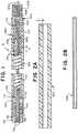
- FIG. 1is an illustration of a cross section of a delivery member according to aspects of the present invention
- FIG. 2Ais an illustration of a cross section of a flexible sleeve according to aspects of the present invention.
- FIG. 2Bis an illustration of a cross section of a stretch resistant tube according to aspects of the present invention.
- FIG. 2Cis an illustration of a cross section of a wire coil affixed to a distal hypotube and a proximal hypotube according to aspects of the present invention
- FIGS. 3A through 3Dare illustrations of an engagement system illustrating a sequence for deploying an implant according to aspects of the present invention
- FIG. 4is a flow diagram illustrating a method for designing or constructing a delivery member according to aspects of the present invention.
- FIG. 5is a flow diagram illustrating a method for using a delivery system including an example delivery member according to aspects of the present invention.
- an intravascular treatmentfor instance, an aneurysm occlusion treatment
- lack of flexibility of a distal portion of a treatment device delivery membercan cause the delivery member to pull back from the treatment site or otherwise move out of position while an implant or other medical treatment device is being placed in an aneurysm or other treatment site.
- a delivery member and engagement system having a more flexible distal portioncan therefore provide a stable system for delivering medical devices in neurovascular anatomy in addition to other applications facing a similar challenge.
- Flexible structurescan tend to deform, extend, or expand when navigating tortuous anatomy. Deformation of the delivery member can inhibit the delivery member's ability to navigate to a treatment site and/or effectively deploy the medical device. Elongation of the delivery member can result in premature deployment of the medical device.
- An object of the present inventionis to provide a delivery member having a highly flexible distal portion that is stretch resistant and structurally stable throughout delivery and deployment of a medical treatment device.
- medical treatment devicesare generally referred to herein as an “implant” although, as will be appreciated and understood by a person of ordinary skill in the art, aspects of the present invention can be applied to deliver and deploy medical treatment devices that are not left implanted.
- the highly flexible distal portion of the delivery membercan include a coiled wire, an outer sleeve, and an inner stretch resistant member.
- the coiled wirecan be formed of a substantially linear wire that is wound in a coil shape and/or a hypotube that is laser cut in a spiral pattern. If the coiled wire is formed from a laser cut hypotube, the spiral can be absent interference cuts connecting windings in the coil so as to provide a more flexible coil.
- the outer sleevecan inhibit the coiled wire from deforming radially and/or provide a smooth surface against which vascular walls can slide during delivery of an implant.
- the stretch resistant membercan inhibit elongation of the coiled wire during delivery of the implant.
- the combination of the coiled wire, outer sleeve, and stretch resistant membercan therefore provide a distal portion of a delivery member having greater flexibility and greater stability than at least some known delivery members.
- an example delivery member 10can include a proximal tube 100 , a coiled section 200 , a distal tube 300 , a sleeve 500 surrounding the coiled section, and a stretch resistant member 600 within the lumen of the coiled section 200 .
- the proximal tube 100can extend a majority of the length of the delivery member 10 with the coiled section 200 and distal tube 300 forming a length sufficient to absorb a majority of push-back that can occur during placement of an implant at a treatment site.
- the lengthcan measure between about 30 cm and about 50 cm, or more specifically, about 40 cm.
- the proximal tube 100can have a distal end 104 that is connected to a proximal end 202 of the coiled section 200
- the coiled section 200can have a distal end 204 that is connected to a proximal end 302 of the distal coil 300 .
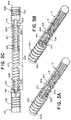
- FIG. 2Ais a cross sectional view of the sleeve 500 .
- FIG. 2Bis a cross sectional view of the stretch resistant member 600 .
- FIG. 2Cis a cross sectional view of the assembled proximal tube 100 , coiled section 200 , and distal tube 300 .
- the coiled section 200can be formed separately from the proximal hypotube 100 and/or the distal hypotube 300 .
- the separately formed coiled section 200can be affixed with welds 712 , 714 or other appropriate attachment to the proximal tube 100 and/or the distal tube 300 .
- at least a portion of the coiled sectioncan be formed from a spiral laser cut portion of a hypotube.
- a separately formed coiled section 200can be made more flexible compared to a spiral cut tube by selecting a wire with a particular cross section (e.g. circular) with a particular diameter D, or by selecting a wire with material properties to increase flexibility.
- a laser cut portioncan be more easily fabricated by cutting a single hypotube to form the proximal tube 100 , coiled section 200 , and distal hypotube 300 , reducing or eliminating welds 712 , 714 or other attachments.
- the wire of the coil 200can have a diameter D measuring within a range including about 0.8 mils and 5 mils (about 20 nm to about 130 nm).
- the coiled sectioncan be formed primarily of a non-radiopaque material such as steel and can include a radiopaque section 216 made of a radiopaque material such as platinum and/or tungsten.
- the radiopaque section 216can be positioned between a proximal, non-radiopaque section of the coil 212 and a distal, non-radiopaque section of the coil 214 .
- the radiopaque section 216can be positioned a predetermined distance from a distal end 304 of the delivery member 10 so that a physician can readily visualize the placement of the distal portion of the delivery member during a treatment procedure.
- the proximal section 212 , radiopaque section 216 , and distal section 214can be concentrically welded.
- the coiled section 200can be surrounded by a flexible sleeve or fused jacket 500 , referred generically herein as a “sleeve”.
- the sleevecan inhibit the coil 200 from expanding radially and/or from engaging vascular walls during navigation.
- the sleeve 500can include a polymer.
- the polymercan include additives to increase the lubricity of the sleeve 500 so that the sleeve can easily slide through a body vessel.
- the sleeve 500can have a wall thickness T measuring within a range including about 0.5 mils and about 2 mils (about 0.01 mm to about 0.05 mm).
- the sleeve 500can further be coated with a hydrophilic coating to further minimize friction during intravascular navigation.
- the sleeve 500can be fused or glued to the coil 200 , the proximal hypotube 100 , and/or the distal hypotube 300 .
- the stretch resistant member 600can be positioned to inhibit elongation of the coil 200 during intravascular navigation.
- the stretch resistant member 600can include a tube sized to fit within the lumen 208 of the coil 200 .
- the stretch resistant tube 600can also be sized to extend through the entirety of the length of the coil 200 , extend with a lumen 108 of the proximal tube 100 and within the lumen 308 of the distal coil 300 .
- the stretch resistant member 600can be attached to the proximal tube 100 and the distal tube 300 at adhesive joints 702 , 704 or other appropriate attachment.
- the stretch resistant member 600can remain unattached to the coiled section 200 such that the stretch resistant member 600 and coiled section 200 are able to move independently from each other to some extent.
- the delivery member 10can include a mechanical engagement system for engaging a medical treatment device during delivery to a treatment site that can be actuated mechanically to deploy the treatment device.
- Mechanically actuated engagement systemsoften include one or more inner elongated members or pull wires extending through the delivery member that can be manipulated at the proximal end by a physician to deploy a medical treatment device.
- Such a wire or inner elongated memberis referred to herein generically as a “pull wire”.
- FIGS. 3A through 3Dillustrate the delivery member 10 including a mechanical engagement system including a pull wire 140 and a loop wire 400 that can be positioned to secure an implant or other medical treatment device to the delivery member 10 and can be moved to release the medical treatment device from the delivery member 10 .
- the loop wire 400can be affixed to the distal tube 300 with a weld 408 or other or other suitable attachment (see FIG. 1 ).
- the stretch resistant member 600can be sized to allow a pull wire 140 to pass through the lumens 108 , 208 , 308 of the proximal tube 100 , coiled section 200 , and distal tube 300 .
- the stretch resistant member 600can be tubular, having a lumen therethrough, and the pull wire 140 can extend through the lumen of the tubular stretch resistant member 600 .
- the stretch resistant member 600can be extruded over the pull wire 140 .
- the combination of the coil 200 , sleeve 500 , and stretch resistant member 600can provide a highly flexible distal portion of a delivery member 10 suitable for navigating tortuous anatomy, including neurovascular blood vessels.
- the stretch resistant member 600can support the coil 200 to prevent the coil 200 from significantly extending during navigation of a blood vessel, thereby reducing tension on a pull wire 140 extending therethrough and reducing the likelihood of premature deployment of an attached medical treatment device.
- the proximal tube 100can include a flexible section 106 having material removed to increase flexibility of the flexible section 106 .
- the flexible section 106can be cut in a spiral pattern.
- the spiral pattern of the flexible section 106can lack interference cuts connecting windings within the spiral.
- the stretch resistant member 600can extend through the flexible section 106 and be attached to the proximal tube 100 in the proximal direction from the flexible section 106 .
- the stretch resistant member 600can thereby inhibit elongation of the flexible section 106 of the proximal tube 100 and coiled section 200 .
- the sleeve 500can cover at least a portion of the flexible section 106 to inhibit deformation of the flexible section and/or reduce friction with vasculature and the flexible section 106 during intravascular navigation. In some examples, the sleeve 500 can cover about 10 cm of the proximal tube 100 approximate and/or including the distal end 104 of the proximal tube 100 .
- the distal tube 300can include a compressible portion 306 .
- the compressible portion 306can be axially adjustable between an elongated condition and a compressed condition.
- the compressed portion 306can be formed from a spiral-cut portion of the tube 300 , formed by a laser cutting operation. Additionally, or alternatively, the compressible portion can be formed of a wound wire, spiral ribbon, or other arrangement allowing axial adjustment according to the present invention.
- the compressible portion 306is in the elongated condition at rest and automatically or resiliently returns to the elongated condition from a compressed condition, unless otherwise constrained.
- FIGS. 3A-3Dillustrate the detachment of the medical device 12 using a mechanical engagement/deployment system.
- FIG. 3Aillustrates the engagement system 140 , 400 locked into the locking portion 18 of the medical device 12 .
- the compressible portion 306 of the distal tube 300can be compressed and the loop wire 400 opening 405 at a distal end 404 of the loop wire 400 can be placed through the locking portion 18 .
- FIG. 3Billustrates the pull wire 140 being drawn proximally to begin the release sequence for the medical device 12 .
- FIG. 3Cillustrates the instant the pull wire 140 exits the opening 405 and is pulled free of the loop wire 400 .
- FIG. 3Dillustrates the end of the release sequence.
- the compressible portion 306has extended/returned to its original shape and “sprung” forward.
- An elastic force Eis imparted by the distal end 304 of the distal tube 300 to the medical device 12 to “push” it away to ensure a clean separation and delivery of the medical device 12 .
- tubularand “tube” are to be construed broadly and are not limited to a structure that is a right cylinder or strictly circumferential in cross-section or of a uniform cross-section throughout its length.
- the tubular structure or systemis generally illustrated as a substantially right cylindrical structure.
- the tubular systemmay have a tapered or curved outer surface without departing from the scope of the present invention.
- FIG. 4is a flow diagram including method steps for constructing or designing a delivery member such as the example delivery members described herein.
- a first hypotube, a second hypotube, a flexible sleeve, a wire coil, and a stretch resistant membercan be selected.
- the first hypotubecan be a proximal hypotube 100 as described herein or as would otherwise be known to a person of ordinary skill in the art.
- the second hypotubecan be a distal hypotube 300 as described herein or as would otherwise be known to a person of ordinary skill in the art.
- the flexible sleevecan be a sleeve or fused jacket 500 as described herein or as otherwise known to a person of ordinary skill in the art.
- the wire coilcan include the support coil, coiled section 200 as described herein or as otherwise known to a person of ordinary skill in the art.
- the stretch resistant membercan be a stretch resistant member 600 as described herein or as otherwise known to a person of ordinary skill in the art.
- the stretch resistant membercan be positioned in the lumen of the wire coil.
- the stretch resistant member that is positionedcan be substantially tubular.
- the first hypotube, wire coil, and second hypotubecan be attached to each other.
- the stretch resistant memberis attached to the first hypotube and the second hypotube.
- the first hypotube, wire coil, and second hypotubecan be attached as illustrated and described herein or by other means as would be understood by a person of ordinary skill in the art. Steps 820 , 830 , and 840 need not be performed in that order and can be performed simultaneously.
- the stretch resistant membercan be attached to one of the first and second hypotubes as indicated in step 840 , then the hypotube to which the stretch resistant member is attached can be attached to the wire coil as indicated in step 830 , then the stretch resistant member can be positioned through the wire coil as indicated in step 820 , then the other of the hypotubes can be attached to the wire coil as indicated in step 830 , then the stretch resistant member can be attached to that other hypotube as indicated in step 840 .
- the wire coilcan be covered with the flexible sleeve.
- the flexible sleevecan cover some or all of the outer surface of the wire coil.
- Step 850can also include the step of fusing the flexible sleeve to the wire coil and/or otherwise affixing the flexible sleeve to the delivery member. If the second hypotube has a flexible section, in step 850 , the flexible sleeve can also be positioned to cover at least a portion of the flexible section.
- an implantcan be detachably attached to the distal end of the first hypotube.
- the implantcan be attached by positioning a loop wire within the first hypotube, positioning a pull wire to extend through the first hypotube, coiled wire, and second hypotube, and securing the implant with the loop wire and the pull wire.
- the pull wirecan be extended from the proximal end of the second hypotube. If the first hypotube has a compressible portion, in step 860 , the compressible portion can be compressed, and the implant can be attached to delivery member while the compressible portion is compressed.
- FIG. 5is a flow diagram including method steps for administering an intravascular treatment using a system including a delivery member such as the example delivery members described herein.
- a systemhaving a distal hypotube, proximal hypotube, coiled section co-axially positioned in between the hypotubes, a flexible sleeve covering the coiled section, a stretch resistant member positioned within the coiled section, and a medical treatment device attached to or near the distal hypotube can be selected.
- the systemcan be suitable for intravascular treatments such as described and illustrated herein or as otherwise known to a person of ordinary skill in the art.
- the systemcan be moved through a catheter to a treatment site such as the site of an aneurysm or other abnormality in a blood vessel.
- the systemcan be flexed as it is moved through the catheter.
- the coiled section of the systemcan be prevented from deforming by the flexible sleeve and the stretch resistant member; the flexible sleeve can inhibit the coiled section from deforming radially while the stretch resistant member can inhibit the coil from extending longitudinally.
- the medical treatment devicecan be deployed.
- the implantin step 950 the implant can be detached.
- the distal tubecan extend to push the medical treatment device away from the distal tube.
- the detached implantin step 960 , can be ejected away from the distal tube in response to the expansion of the distal tube.
- the inventioncontemplates many variations and modifications of the delivery system, delivery member, and engagement system, including alternative configurations of components, alternative materials, alternative medical treatment devices, alternative means for deploying the medical treatment device, alternative geometries of individual components, alternative means for attaching component parts, etc. These modifications would be apparent to those having ordinary skill in the art to which this invention relates and are intended to be within the scope of the claims which follow.
Landscapes
- Health & Medical Sciences (AREA)
- Life Sciences & Earth Sciences (AREA)
- Engineering & Computer Science (AREA)
- Biomedical Technology (AREA)
- Surgery (AREA)
- Veterinary Medicine (AREA)
- Heart & Thoracic Surgery (AREA)
- Animal Behavior & Ethology (AREA)
- General Health & Medical Sciences (AREA)
- Public Health (AREA)
- Vascular Medicine (AREA)
- Molecular Biology (AREA)
- Medical Informatics (AREA)
- Nuclear Medicine, Radiotherapy & Molecular Imaging (AREA)
- Reproductive Health (AREA)
- Biophysics (AREA)
- Anesthesiology (AREA)
- Pulmonology (AREA)
- Hematology (AREA)
- Neurosurgery (AREA)
- Mechanical Engineering (AREA)
- Transplantation (AREA)
- Oral & Maxillofacial Surgery (AREA)
- Cardiology (AREA)
- Surgical Instruments (AREA)
- Media Introduction/Drainage Providing Device (AREA)
Abstract
Description
Claims (20)
Priority Applications (9)
| Application Number | Priority Date | Filing Date | Title |
|---|---|---|---|
| US16/502,767US11207494B2 (en) | 2019-07-03 | 2019-07-03 | Medical device delivery member with flexible stretch resistant distal portion |
| ES20181340TES2923603T3 (en) | 2019-07-03 | 2020-06-22 | Medical device proportion member with a stretch-resistant flexible distal portion |
| EP20181340.9AEP3760139B1 (en) | 2019-07-03 | 2020-06-22 | Medical device delivery member with flexible stretch resistant distal portion |
| KR1020200080220AKR102871582B1 (en) | 2019-07-03 | 2020-06-30 | Medical device delivery member with flexible stretch resistant distal portion |
| JP2020114720AJP7532117B2 (en) | 2019-07-03 | 2020-07-02 | Medical device delivery member having a flexible stretch-resistant distal portion - Patents.com |
| CN202010630877.4ACN112168263B (en) | 2019-07-03 | 2020-07-03 | Medical device delivery member having a flexible, stretch-resistant distal portion |
| US17/218,801US20210213252A1 (en) | 2019-07-03 | 2021-03-31 | Medical device delivery member with flexible stretch resistant distal portion |
| US17/379,276US20210346002A1 (en) | 2019-07-03 | 2021-07-19 | Medical device delivery member with flexible stretch resistant distal portion |
| US17/562,529US20220118220A1 (en) | 2019-07-03 | 2021-12-27 | Medical device delivery member with flexible stretch resistant distal portion |
Applications Claiming Priority (1)
| Application Number | Priority Date | Filing Date | Title |
|---|---|---|---|
| US16/502,767US11207494B2 (en) | 2019-07-03 | 2019-07-03 | Medical device delivery member with flexible stretch resistant distal portion |
Related Parent Applications (1)
| Application Number | Title | Priority Date | Filing Date |
|---|---|---|---|
| US16/592,320Continuation-In-PartUS11426174B2 (en) | 2019-07-03 | 2019-10-03 | Medical device delivery member with flexible stretch resistant mechanical release |
Related Child Applications (2)
| Application Number | Title | Priority Date | Filing Date |
|---|---|---|---|
| US17/218,801Continuation-In-PartUS20210213252A1 (en) | 2019-07-03 | 2021-03-31 | Medical device delivery member with flexible stretch resistant distal portion |
| US17/562,529ContinuationUS20220118220A1 (en) | 2019-07-03 | 2021-12-27 | Medical device delivery member with flexible stretch resistant distal portion |
Publications (2)
| Publication Number | Publication Date |
|---|---|
| US20210001082A1 US20210001082A1 (en) | 2021-01-07 |
| US11207494B2true US11207494B2 (en) | 2021-12-28 |
Family
ID=71120054
Family Applications (3)
| Application Number | Title | Priority Date | Filing Date |
|---|---|---|---|
| US16/502,767Active2039-11-30US11207494B2 (en) | 2019-07-03 | 2019-07-03 | Medical device delivery member with flexible stretch resistant distal portion |
| US17/218,801PendingUS20210213252A1 (en) | 2019-07-03 | 2021-03-31 | Medical device delivery member with flexible stretch resistant distal portion |
| US17/562,529PendingUS20220118220A1 (en) | 2019-07-03 | 2021-12-27 | Medical device delivery member with flexible stretch resistant distal portion |
Family Applications After (2)
| Application Number | Title | Priority Date | Filing Date |
|---|---|---|---|
| US17/218,801PendingUS20210213252A1 (en) | 2019-07-03 | 2021-03-31 | Medical device delivery member with flexible stretch resistant distal portion |
| US17/562,529PendingUS20220118220A1 (en) | 2019-07-03 | 2021-12-27 | Medical device delivery member with flexible stretch resistant distal portion |
Country Status (4)
| Country | Link |
|---|---|
| US (3) | US11207494B2 (en) |
| EP (1) | EP3760139B1 (en) |
| JP (1) | JP7532117B2 (en) |
| ES (1) | ES2923603T3 (en) |
Cited By (1)
| Publication number | Priority date | Publication date | Assignee | Title |
|---|---|---|---|---|
| WO2023199147A1 (en) | 2022-04-15 | 2023-10-19 | DePuy Synthes Products, Inc. | Medical device delivery member with positioning window |
Families Citing this family (24)
| Publication number | Priority date | Publication date | Assignee | Title |
|---|---|---|---|---|
| US9918718B2 (en) | 2014-08-08 | 2018-03-20 | DePuy Synthes Products, Inc. | Embolic coil delivery system with retractable mechanical release mechanism |
| US10806462B2 (en) | 2017-12-21 | 2020-10-20 | DePuy Synthes Products, Inc. | Implantable medical device detachment system with split tube and cylindrical coupling |
| US11147562B2 (en) | 2018-12-12 | 2021-10-19 | DePuy Synthes Products, Inc. | Systems and methods for embolic implant detachment |
| US11253265B2 (en) | 2019-06-18 | 2022-02-22 | DePuy Synthes Products, Inc. | Pull wire detachment for intravascular devices |
| US11207494B2 (en) | 2019-07-03 | 2021-12-28 | DePuy Synthes Products, Inc. | Medical device delivery member with flexible stretch resistant distal portion |
| US11426174B2 (en) | 2019-10-03 | 2022-08-30 | DePuy Synthes Products, Inc. | Medical device delivery member with flexible stretch resistant mechanical release |
| US12376859B2 (en) | 2019-09-17 | 2025-08-05 | DePuy Synthes Products, Inc. | Embolic coil proximal connecting element and stretch resistant fiber |
| US11439403B2 (en) | 2019-09-17 | 2022-09-13 | DePuy Synthes Products, Inc. | Embolic coil proximal connecting element and stretch resistant fiber |
| US11376013B2 (en) | 2019-11-18 | 2022-07-05 | DePuy Synthes Products, Inc. | Implant delivery system with braid cup formation |
| US11457922B2 (en) | 2020-01-22 | 2022-10-04 | DePuy Synthes Products, Inc. | Medical device delivery member with flexible stretch resistant distal portion |
| US11432822B2 (en) | 2020-02-14 | 2022-09-06 | DePuy Synthes Products, Inc. | Intravascular implant deployment system |
| US11951026B2 (en) | 2020-06-30 | 2024-04-09 | DePuy Synthes Products, Inc. | Implantable medical device detachment system with flexible braid section |
| EP4066752B1 (en)* | 2021-03-31 | 2025-04-30 | DePuy Synthes Products, Inc. | Medical device delivery member with flexible stretch resistant distal portion |
| US11998213B2 (en) | 2021-07-14 | 2024-06-04 | DePuy Synthes Products, Inc. | Implant delivery with modified detachment feature and pull wire engagement |
| KR20230011880A (en)* | 2021-07-14 | 2023-01-25 | 디퍼이 신테스 프로덕츠, 인코포레이티드 | Embolic coil proximal connecting element and stretch resistant fiber |
| US11844490B2 (en)* | 2021-12-30 | 2023-12-19 | DePuy Synthes Products, Inc. | Suture linkage for inhibiting premature embolic implant deployment |
| US11937824B2 (en)* | 2021-12-30 | 2024-03-26 | DePuy Synthes Products, Inc. | Implant detachment systems with a modified pull wire |
| US12011171B2 (en) | 2022-01-06 | 2024-06-18 | DePuy Synthes Products, Inc. | Systems and methods for inhibiting premature embolic implant deployment |
| CN114404116B (en)* | 2022-01-25 | 2025-07-25 | 北京领健医疗科技有限公司 | Sheath tube bending adjusting handle, conveying device and valve repair system |
| US11937825B2 (en) | 2022-03-02 | 2024-03-26 | DePuy Synthes Products, Inc. | Hook wire for preventing premature embolic implant detachment |
| US12137915B2 (en) | 2022-03-03 | 2024-11-12 | DePuy Synthes Products, Inc. | Elongating wires for inhibiting premature implant detachment |
| US11937826B2 (en) | 2022-03-14 | 2024-03-26 | DePuy Synthes Products, Inc. | Proximal link wire for preventing premature implant detachment |
| US12402886B2 (en) | 2022-06-23 | 2025-09-02 | DePuy Synthes Products, Inc. | Detachment indicator for implant deployment |
| US12396730B2 (en) | 2022-09-28 | 2025-08-26 | DePuy Synthes Products, Inc. | Braided implant with detachment mechanism |
Citations (218)
| Publication number | Priority date | Publication date | Assignee | Title |
|---|---|---|---|---|
| US3429408A (en) | 1967-04-25 | 1969-02-25 | Associated Spring Corp | Actuator sleeves for spring clutch |
| US5108407A (en) | 1990-06-08 | 1992-04-28 | Rush-Presbyterian St. Luke's Medical Center | Method and apparatus for placement of an embolic coil |
| US5122136A (en) | 1990-03-13 | 1992-06-16 | The Regents Of The University Of California | Endovascular electrolytically detachable guidewire tip for the electroformation of thrombus in arteries, veins, aneurysms, vascular malformations and arteriovenous fistulas |
| US5250071A (en) | 1992-09-22 | 1993-10-05 | Target Therapeutics, Inc. | Detachable embolic coil assembly using interlocking clasps and method of use |
| US5263964A (en) | 1992-05-06 | 1993-11-23 | Coil Partners Ltd. | Coaxial traction detachment apparatus and method |
| US5334210A (en) | 1993-04-09 | 1994-08-02 | Cook Incorporated | Vascular occlusion assembly |
| US5350397A (en) | 1992-11-13 | 1994-09-27 | Target Therapeutics, Inc. | Axially detachable embolic coil assembly |
| US5382259A (en) | 1992-10-26 | 1995-01-17 | Target Therapeutics, Inc. | Vasoocclusion coil with attached tubular woven or braided fibrous covering |
| US5484409A (en) | 1989-08-25 | 1996-01-16 | Scimed Life Systems, Inc. | Intravascular catheter and method for use thereof |
| US5569221A (en) | 1994-07-07 | 1996-10-29 | Ep Technologies, Inc. | Catheter component bond and method |
| US5899935A (en) | 1997-08-04 | 1999-05-04 | Schneider (Usa) Inc. | Balloon expandable braided stent with restraint |
| US5925059A (en) | 1993-04-19 | 1999-07-20 | Target Therapeutics, Inc. | Detachable embolic coil assembly |
| US6113622A (en) | 1998-03-10 | 2000-09-05 | Cordis Corporation | Embolic coil hydraulic deployment system |
| US6203547B1 (en) | 1997-12-19 | 2001-03-20 | Target Therapeutics, Inc. | Vaso-occlusion apparatus having a manipulable mechanical detachment joint and a method for using the apparatus |
| US20010049519A1 (en)* | 1995-06-05 | 2001-12-06 | Holman Thomas J. | Integral hub and strain relief |
| US6391037B1 (en) | 2000-03-02 | 2002-05-21 | Prodesco, Inc. | Bag for use in the intravascular treatment of saccular aneurysms |
| US20020072705A1 (en)* | 2000-12-08 | 2002-06-13 | Vrba Anthony C. | Balloon catheter with radiopaque distal tip |
| US6454780B1 (en) | 2001-06-21 | 2002-09-24 | Scimed Life Systems, Inc. | Aneurysm neck obstruction device |
| US20020165569A1 (en) | 1998-12-21 | 2002-11-07 | Kamal Ramzipoor | Intravascular device deployment mechanism incorporating mechanical detachment |
| US6506204B2 (en) | 1996-01-24 | 2003-01-14 | Aga Medical Corporation | Method and apparatus for occluding aneurysms |
| US6561988B1 (en) | 1994-02-01 | 2003-05-13 | Symbiosis Corporation | Endoscopic multiple sample bioptome with enhanced biting action |
| US20040034363A1 (en) | 2002-07-23 | 2004-02-19 | Peter Wilson | Stretch resistant therapeutic device |
| US20040059367A1 (en) | 2002-09-20 | 2004-03-25 | Champ Davis | Reattachable introducer for a medical device deployment system |
| US20040087964A1 (en) | 2001-01-10 | 2004-05-06 | Roberto Diaz | Embolic coil introducer system |
| US20060025801A1 (en) | 2004-07-30 | 2006-02-02 | Robert Lulo | Embolic device deployment system with filament release |
| US20060064151A1 (en) | 2004-09-22 | 2006-03-23 | Guterman Lee R | Cranial aneurysm treatment arrangement |
| US20060116714A1 (en) | 2004-11-26 | 2006-06-01 | Ivan Sepetka | Coupling and release devices and methods for their assembly and use |
| US20060116711A1 (en)* | 2004-12-01 | 2006-06-01 | Elliott Christopher J | Embolic coils |
| US20060135986A1 (en) | 2004-12-22 | 2006-06-22 | Scimed Life Systems, Inc. | Vaso-occlusive device having pivotable coupling |
| US20060206139A1 (en) | 2005-01-19 | 2006-09-14 | Tekulve Kurt J | Vascular occlusion device |
| US20060247677A1 (en) | 2003-10-08 | 2006-11-02 | Eric Cheng | Method for placing a medical agent into a vessel of the body |
| US20060276824A1 (en) | 2005-06-02 | 2006-12-07 | Vladimir Mitelberg | Stretch resistant embolic coil delivery system with mechanical release mechanism |
| US20060276827A1 (en) | 2005-06-02 | 2006-12-07 | Vladimir Mitelberg | Stretch resistant embolic coil delivery system with mechanical release mechanism |
| US20060276830A1 (en) | 2005-06-02 | 2006-12-07 | Keith Balgobin | Stretch resistant embolic coil delivery system with mechanical release mechanism |
| US20060276825A1 (en) | 2005-06-02 | 2006-12-07 | Vladimir Mitelberg | Stretch resistant embolic coil delivery system with mechanical release mechanism |
| US20060276833A1 (en) | 2005-06-02 | 2006-12-07 | Keith Balgobin | Stretch resistant embolic coil delivery system with spring assisted release mechanism |
| US20070010850A1 (en) | 2005-06-02 | 2007-01-11 | Keith Balgobin | Stretch resistant embolic coil delivery system with mechanical release mechanism |
| US20070055302A1 (en) | 2005-06-14 | 2007-03-08 | Boston Scientific Scimed, Inc. | Vaso-occlusive delivery device with kink resistant, flexible distal end |
| US20070083132A1 (en) | 2005-10-11 | 2007-04-12 | Sharrow James S | Medical device coil |
| US20070233168A1 (en)* | 2006-03-31 | 2007-10-04 | Davis Richard C Iii | Stretch resistant design for embolic coils with stabilization bead |
| US20070270903A1 (en) | 2005-06-02 | 2007-11-22 | Davis Iii Richard C | Stretch resistant embolic coil delivery system with combined mechanical and pressure release mechanism |
| US20080027561A1 (en) | 2006-07-31 | 2008-01-31 | Vladimir Mitelberg | Interventional medical device system having an elongation retarding portion and method of using the same |
| US20080045997A1 (en) | 2005-06-02 | 2008-02-21 | Keith Balgobin | Stretch resistant embolic coil delivery system with mechanical release mechanism |
| US20080097462A1 (en) | 2006-07-31 | 2008-04-24 | Vladimir Mitelberg | Implantable medical device detachment system and methods of using the same |
| US7367987B2 (en) | 2005-06-02 | 2008-05-06 | Cordis Neurovascular, Inc. | Stretch resistant embolic coil delivery system with mechanical release mechanism |
| US7371252B2 (en) | 2005-06-02 | 2008-05-13 | Cordis Neurovascular, Inc. | Stretch resistant embolic coil delivery system with mechanical release mechanism |
| US7377932B2 (en) | 2005-06-02 | 2008-05-27 | Cordis Neurovascular, Inc. | Embolic coil delivery system with mechanical release mechanism |
| EP1985244A2 (en) | 2007-04-27 | 2008-10-29 | Cordis Development Corporation | Interventional medical device system having a slotted section and radiopaque marker and method of making the same |
| US20080281350A1 (en) | 2006-12-13 | 2008-11-13 | Biomerix Corporation | Aneurysm Occlusion Devices |
| US20080300616A1 (en) | 2006-11-20 | 2008-12-04 | Like Que | Mechanically detachable vaso-occlusive device |
| US20080306503A1 (en) | 2006-11-20 | 2008-12-11 | Boston Scientific Scimed, Inc. | Mechanically detachable vaso-occlusive device |
| US20090062726A1 (en)* | 2007-05-18 | 2009-03-05 | Bsoton Scientific Scimed, Inc. | Medical implant detachment systems and methods |
| WO2009132045A2 (en) | 2008-04-21 | 2009-10-29 | Nfocus Neuromedical, Inc. | Braid-ball embolic devices and delivery systems |
| US20090312748A1 (en) | 2008-06-11 | 2009-12-17 | Johnson Kirk L | Rotational detachment mechanism |
| US20100114017A1 (en) | 2002-07-23 | 2010-05-06 | Reverse Medical Corporation | Systems and methods for removing obstructive matter from body lumens and treating vascular defects |
| US7811305B2 (en) | 2005-06-02 | 2010-10-12 | Codman & Shurtleff, Inc. | Stretch resistant embolic coil delivery system with spring release mechanism |
| US7819891B2 (en) | 2005-06-02 | 2010-10-26 | Codman & Shurtleff, Inc. | Stretch resistant embolic coil delivery system with spring release mechanism |
| US7819892B2 (en) | 2005-06-02 | 2010-10-26 | Codman & Shurtleff, Inc. | Embolic coil delivery system with spring wire release mechanism |
| US20100324649A1 (en) | 2009-06-18 | 2010-12-23 | Graftcraft I Goteborg Ab | Device and method for treating ruptured aneurysms |
| US7901444B2 (en) | 2006-09-29 | 2011-03-08 | Codman & Shurtleff, Inc. | Embolic coil delivery system with mechanical release mechanism |
| US7985238B2 (en) | 2005-06-02 | 2011-07-26 | Codman & Shurtleff, Inc. | Embolic coil delivery system with spring wire release mechanism |
| US20110202085A1 (en) | 2009-11-09 | 2011-08-18 | Siddharth Loganathan | Braid Ball Embolic Device Features |
| US20110295303A1 (en) | 2007-08-14 | 2011-12-01 | Franz Freudenthal | Embolization Device |
| US20120041472A1 (en) | 2009-04-20 | 2012-02-16 | Achieva Medical Limited | Delivery assembly for occlusion device using mechanical interlocking coupling mechanism |
| US20120283768A1 (en) | 2011-05-05 | 2012-11-08 | Sequent Medical Inc. | Method and apparatus for the treatment of large and giant vascular defects |
| WO2012158152A1 (en)* | 2011-05-13 | 2012-11-22 | Spiration, Inc. | Deployment catheter |
| US8333796B2 (en) | 2008-07-15 | 2012-12-18 | Penumbra, Inc. | Embolic coil implant system and implantation method |
| US20130066413A1 (en) | 2010-03-02 | 2013-03-14 | Shanghai Microport Medical (Group) Co., Ltd. | Surgical apparatus for aneurysms |
| JP2013078584A (en) | 2011-09-30 | 2013-05-02 | Tyco Healthcare Group Lp | System and method for mechanically positioning intravascular implants |
| US20140058435A1 (en) | 2012-08-21 | 2014-02-27 | Donald K. Jones | Implant delivery and release system |
| US20140135812A1 (en) | 2012-11-13 | 2014-05-15 | Covidien Lp | Occlusive devices |
| US20140200607A1 (en) | 2013-01-14 | 2014-07-17 | Microvention, Inc. | Occlusive Device |
| US20140277084A1 (en) | 2013-03-14 | 2014-09-18 | Incumedx Llc | Implants, methods of manufacturing the same, and devices and methods for delivering the implants to a vascular disorder of a patient |
| US20140277092A1 (en) | 2013-03-14 | 2014-09-18 | Stryker Nv Operations Limited | Vaso-occlusive device delivery system |
| US20140277093A1 (en) | 2013-03-14 | 2014-09-18 | Stryker Nv Operations Limited | Vaso-occlusive device delivery system |
| US20150005808A1 (en) | 2013-06-26 | 2015-01-01 | W. L. Gore & Associates, Inc. | Medical device deployment system |
| US20150182227A1 (en) | 2013-12-27 | 2015-07-02 | Blockade Medical, LLC | Coil system |
| US20150230802A1 (en) | 2014-02-14 | 2015-08-20 | Cook Medical Technologies Llc | Stable screw-type detachment mechanism |
| US9155540B2 (en) | 2012-03-30 | 2015-10-13 | DePuy Synthes Products, Inc. | Embolic coil detachment mechanism with heating element and kicker |
| US20150335333A1 (en) | 2013-01-03 | 2015-11-26 | Donald K. Jones | Detachable Coil Release System and Handle System |
| US9232992B2 (en) | 2008-07-24 | 2016-01-12 | Aga Medical Corporation | Multi-layered medical device for treating a target site and associated method |
| US20160008003A1 (en) | 2013-03-15 | 2016-01-14 | Covidien Lp | Delivery and detachment mechanisms for vascular |
| US20160022275A1 (en)* | 2014-07-25 | 2016-01-28 | Incumedx, Inc. | Covered Embolic Coils |
| US9314326B2 (en) | 2002-04-12 | 2016-04-19 | Stryker Corporation | System and method for retaining vaso-occlusive devices within an aneurysm |
| US20160157869A1 (en) | 2014-12-08 | 2016-06-09 | Cook Medical Technologies Llc | Medical implant detachment mechanism and introducer assembly |
| US20160228125A1 (en) | 2015-02-10 | 2016-08-11 | Boston Scientific Scimed, Inc. | Active release of embolic coils |
| US20160310304A1 (en) | 2003-04-04 | 2016-10-27 | Claude Mialhe | Device for placing a vascular implant |
| EP3092956A1 (en) | 2015-05-11 | 2016-11-16 | Covidien LP | Electrolytic detachment for implant delivery systems |
| US20160346508A1 (en)* | 2015-05-29 | 2016-12-01 | Covidien Lp | Catheter distal tip configuration |
| US9532792B2 (en) | 2008-07-14 | 2017-01-03 | Medtronic, Inc. | Aspiration catheters for thrombus removal |
| US9533344B2 (en) | 2005-11-17 | 2017-01-03 | Microvention, Inc. | Three-dimensional complex coil |
| US9532873B2 (en) | 2008-09-17 | 2017-01-03 | Medtronic CV Luxembourg S.a.r.l. | Methods for deployment of medical devices |
| US9539011B2 (en) | 2013-03-14 | 2017-01-10 | Stryker Corporation | Vaso-occlusive device delivery system |
| US9539382B2 (en) | 2013-03-12 | 2017-01-10 | Medtronic, Inc. | Stepped catheters with flow restrictors and infusion systems using the same |
| US9539122B2 (en) | 2001-07-20 | 2017-01-10 | Microvention, Inc. | Aneurysm treatment device and method of use |
| US9539022B2 (en) | 2012-11-28 | 2017-01-10 | Microvention, Inc. | Matter conveyance system |
| US20170007264A1 (en) | 2007-12-21 | 2017-01-12 | Microvention, Inc. | Implantation devices including hydrogel filaments |
| US9549830B2 (en) | 2008-03-25 | 2017-01-24 | Medtronic Vascular, Inc. | Eversible branch stent-graft and deployment method |
| US20170020670A1 (en) | 2011-05-12 | 2017-01-26 | Medtronic, Inc. | Delivery Catheter System With Micro and Macro Movement Control |
| US20170020700A1 (en) | 2010-09-17 | 2017-01-26 | Medtronic Vascular, Inc. | Method of Forming a Drug-Eluting Medical Device |
| US20170027725A1 (en) | 2013-05-30 | 2017-02-02 | Medtronic Vascular, Inc. | Delivery System Having a Single Handed Deployment Handle for a Retractable Outer Sheath |
| US20170027640A1 (en) | 2005-06-20 | 2017-02-02 | Medtronic Ablation Frontiers Llc | Ablation catheter |
| US20170027692A1 (en) | 2004-11-19 | 2017-02-02 | Medtronic, Inc. | Apparatus for treatment of cardiac valves and method of its manufacture |
| US9561125B2 (en) | 2010-04-14 | 2017-02-07 | Microvention, Inc. | Implant delivery device |
| US20170035567A1 (en) | 2015-08-07 | 2017-02-09 | Medtronic Vascular, Inc. | System and method for deflecting a delivery catheter |
| US20170035436A1 (en) | 2015-08-07 | 2017-02-09 | Microvention, Inc. | Complex Coil And Manufacturing Techniques |
| US20170042548A1 (en) | 2015-08-11 | 2017-02-16 | Microvention, Inc. | System And Method For Implant Delivery |
| US9572982B2 (en) | 2008-04-30 | 2017-02-21 | Medtronic, Inc. | Techniques for placing medical leads for electrical stimulation of nerve tissue |
| US20170049596A1 (en) | 2014-04-30 | 2017-02-23 | Stryker Corporation | Implant delivery system and method of use |
| US9579484B2 (en) | 2014-09-19 | 2017-02-28 | Medtronic Vascular, Inc. | Sterile molded dispenser |
| US9585642B2 (en) | 2012-12-07 | 2017-03-07 | Medtronic, Inc. | Minimally invasive implantable neurostimulation system |
| US20170079820A1 (en) | 2015-09-18 | 2017-03-23 | Microvention, Inc. | Pushable Implant Delivery System |
| US20170079812A1 (en) | 2015-09-18 | 2017-03-23 | Microvention, Inc. | Vessel Prosthesis |
| US20170079671A1 (en) | 2015-09-22 | 2017-03-23 | Medtronic Vascular, Inc. | Occlusion Bypassing Apparatus With a Re-Entry Needle and a Stabilization Tube |
| US20170079767A1 (en) | 2015-09-21 | 2017-03-23 | Stryker Corporation | Embolectomy devices |
| US20170079817A1 (en) | 2015-09-18 | 2017-03-23 | Microvention, Inc. | Implant Retention, Detachment, And Delivery System |
| US20170079819A1 (en) | 2015-09-18 | 2017-03-23 | Microvention, Inc. | Releasable Delivery System |
| US20170079766A1 (en) | 2015-09-21 | 2017-03-23 | Stryker Corporation | Embolectomy devices |
| US20170086996A1 (en) | 2012-04-26 | 2017-03-30 | Medtronic Vascular, Inc. | Apparatus and methods for filling a drug eluting medical device via capillary action |
| US20170086851A1 (en) | 2014-05-28 | 2017-03-30 | Stryker European Holdings I, Llc | Vaso-occlusive devices and methods of use |
| US20170095258A1 (en) | 2015-10-06 | 2017-04-06 | Boston Scientific Scimed, Inc. | Pusher arm and ball release mechanism for embolic coils |
| US9615832B2 (en) | 2006-04-07 | 2017-04-11 | Penumbra, Inc. | Aneurysm occlusion system and method |
| US9615951B2 (en) | 2009-09-22 | 2017-04-11 | Penumbra, Inc. | Manual actuation system for deployment of implant |
| US20170100183A1 (en) | 2015-10-09 | 2017-04-13 | Medtronic, Inc. | Method for closure and ablation of atrial appendage |
| US20170100141A1 (en) | 2015-10-07 | 2017-04-13 | Medtronic Vascular, Inc. | Occlusion Bypassing Apparatus With A Re-Entry Needle and a Distal Stabilization Balloon |
| US20170100143A1 (en) | 2015-10-07 | 2017-04-13 | Stryker Corporation | Multiple barrel clot removal devices |
| US9622753B2 (en) | 2001-07-20 | 2017-04-18 | Microvention, Inc. | Aneurysm treatment device and method of use |
| WO2017066386A1 (en) | 2015-10-14 | 2017-04-20 | Three Rivers Medical Inc. | Mechanical embolization delivery apparatus and methods |
| US20170113023A1 (en) | 2015-10-26 | 2017-04-27 | Medtronic Vascular, Inc. | Sheathless Guide Catheter Assembly |
| US9636439B2 (en) | 2003-09-19 | 2017-05-02 | Medtronic Vascular, Inc. | Delivery of therapeutics to treat aneurysms |
| US9642675B2 (en) | 2004-10-14 | 2017-05-09 | Medtronic Ablation Frontiers Llc | Ablation catheter |
| US9655633B2 (en) | 2004-09-10 | 2017-05-23 | Penumbra, Inc. | System and method for treating ischemic stroke |
| US9655989B2 (en) | 2012-10-15 | 2017-05-23 | Microvention, Inc. | Polymeric treatment compositions |
| US9655645B2 (en) | 2011-05-27 | 2017-05-23 | Stryker Corporation | Assembly for percutaneously inserting an implantable medical device, steering the device to a target location and deploying the device |
| US20170147765A1 (en) | 2015-11-19 | 2017-05-25 | Penumbra, Inc. | Systems and methods for treatment of stroke |
| US9662425B2 (en) | 2013-04-22 | 2017-05-30 | Stryker European Holdings I, Llc | Method for drug loading hydroxyapatite coated implant surfaces |
| US9662238B2 (en) | 2010-07-23 | 2017-05-30 | Medtronic, Inc. | Attachment mechanism for stent release |
| US9662120B2 (en) | 2013-08-23 | 2017-05-30 | Cook Medical Technologies Llc | Detachable treatment device delivery system utilizing compression at attachment zone |
| US20170151032A1 (en) | 2015-11-30 | 2017-06-01 | Penumbra, Inc. | System for endoscopic intracranial procedures |
| US9668898B2 (en) | 2014-07-24 | 2017-06-06 | Medtronic Vascular, Inc. | Stent delivery system having dynamic deployment and methods of manufacturing same |
| US9675477B2 (en) | 2013-03-15 | 2017-06-13 | Medtronic Vascular, Inc. | Welded stent having a welded soluble core |
| US9675782B2 (en) | 2013-10-10 | 2017-06-13 | Medtronic Vascular, Inc. | Catheter pull wire actuation mechanism |
| US9676022B2 (en) | 2012-04-03 | 2017-06-13 | Medtronic Vascular, Inc. | Apparatus for creating formed elements used to make wound stents |
| US20170165065A1 (en) | 2015-12-14 | 2017-06-15 | Medtronic, Inc. | Delivery system having retractable wires as a coupling mechanism and a deployment mechanism for a self-expanding prosthesis |
| US20170165062A1 (en) | 2015-12-14 | 2017-06-15 | Medtronic, Inc. | Delivery system having retractable wires as a coupling mechanism and a deployment mechanism for a self-expanding prosthesis |
| US20170165454A1 (en) | 2015-12-09 | 2017-06-15 | Medtronic Vascular, Inc. | Catheter with a lumen shaped as an identification symbol |
| US20170172766A1 (en) | 2012-03-16 | 2017-06-22 | Microvention, Inc. | Stent And Stent Delivery Device |
| US20170172772A1 (en) | 2014-04-08 | 2017-06-22 | Stryker Corporation | Implant delivery system and method of use |
| US9692557B2 (en) | 2015-02-04 | 2017-06-27 | Stryker European Holdings I, Llc | Apparatus and methods for administering treatment within a bodily duct of a patient |
| US9693852B2 (en) | 2013-03-15 | 2017-07-04 | Microvention, Inc. | Embolic protection device |
| US20170189033A1 (en) | 2016-01-06 | 2017-07-06 | Microvention, Inc. | Occlusive Embolic Coil |
| US20170189035A1 (en) | 2015-12-30 | 2017-07-06 | Stryker Corporation | Embolic devices and methods of manufacturing same |
| US9700262B2 (en) | 2011-05-17 | 2017-07-11 | Stryker Corporation | Method of fabricating implantable medical devices from a polymer coupon that is bonded to rigid substrate |
| US9700399B2 (en) | 2012-04-26 | 2017-07-11 | Medtronic Vascular, Inc. | Stopper to prevent graft material slippage in a closed web stent-graft |
| US9717421B2 (en) | 2012-03-26 | 2017-08-01 | Medtronic, Inc. | Implantable medical device delivery catheter with tether |
| US9717500B2 (en) | 2009-04-15 | 2017-08-01 | Microvention, Inc. | Implant delivery system |
| US9724103B2 (en) | 2006-06-15 | 2017-08-08 | Microvention, Inc. | Embolization device constructed from expansile polymer |
| US9724526B2 (en) | 2004-06-10 | 2017-08-08 | Medtronic Urinary Solutions, Inc. | Implantable pulse generator systems and methods for operating the same |
| US20170224350A1 (en) | 2016-02-10 | 2017-08-10 | Microvention, Inc. | Devices for Vascular Occlusion |
| US20170224467A1 (en) | 2016-02-09 | 2017-08-10 | Medtronic Vascular, Inc. | Endoluminal prosthetic assemblies, and associated systems and methods for percutaneous repair of a vascular tissue defect |
| US20170224953A1 (en) | 2016-02-10 | 2017-08-10 | Microvention, Inc. | Intravascular Treatment Site Access |
| US20170231749A1 (en) | 2016-02-12 | 2017-08-17 | Medtronic Vascular, Inc. | Stent graft with external scaffolding and method |
| US20170245864A1 (en) | 2014-09-17 | 2017-08-31 | Metactive Medical, Inc. | Expandable body device and method of use |
| US20170245885A1 (en) | 2016-02-25 | 2017-08-31 | Indian Wells Medical, Inc. | Steerable endoluminal punch |
| US9750565B2 (en) | 2011-09-30 | 2017-09-05 | Medtronic Advanced Energy Llc | Electrosurgical balloons |
| US9757260B2 (en) | 2006-03-30 | 2017-09-12 | Medtronic Vascular, Inc. | Prosthesis with guide lumen |
| US20170258476A1 (en) | 2016-03-08 | 2017-09-14 | Terumo Kabushiki Kaisha | Blood vessel treatment method |
| US9764111B2 (en) | 2012-10-01 | 2017-09-19 | Microvention, Inc. | Catheter markers |
| US9770577B2 (en) | 2014-09-15 | 2017-09-26 | Medtronic Xomed, Inc. | Pressure relief for a catheter balloon device |
| US9770251B2 (en) | 2012-08-13 | 2017-09-26 | Microvention, Inc. | Shaped removal device |
| US9775706B2 (en) | 2010-04-20 | 2017-10-03 | Medtronic Vascular, Inc. | Controlled tip release stent graft delivery system and method |
| US20170281331A1 (en) | 2016-03-31 | 2017-10-05 | Medtronic Vascular, Inc. | Endoluminal prosthetic devices having fluid-absorbable compositions for repair of a vascular tissue defect |
| US20170281912A1 (en) | 2016-04-04 | 2017-10-05 | Medtronic Vascular, Inc. | Drug coated balloon |
| US20170281909A1 (en) | 2016-04-05 | 2017-10-05 | Stryker Corporation | Medical devices and methods of manufacturing same |
| US20170281344A1 (en) | 2016-03-31 | 2017-10-05 | Medtronic Vascular, Inc. | Expandable introducer sheath having a steering mechanism |
| US20170290654A1 (en) | 2016-04-12 | 2017-10-12 | Medtronic Vascular, Inc. | Gutter filling stent-graft and method |
| US9788800B2 (en) | 2012-07-17 | 2017-10-17 | Stryker Corporation | Notification system of deviation from predefined conditions |
| US20170296325A1 (en) | 2016-04-18 | 2017-10-19 | Medtronic Vascular, Inc. | Stent-graft prosthesis and method of manufacture |
| US20170296324A1 (en) | 2016-04-13 | 2017-10-19 | Medtronic Vascular, Inc. | Iliac branch device and method |
| US9795391B2 (en) | 2013-10-25 | 2017-10-24 | Medtronic Vascular, Inc. | Tissue compression device with tension limiting strap retainer |
| US20170304595A1 (en) | 2016-04-25 | 2017-10-26 | Medtronic Vascular, Inc. | Balloon catheter including a drug delivery sheath |
| US20170304041A1 (en) | 2016-04-25 | 2017-10-26 | Medtronic Vascular, Inc. | Dissection prosthesis system and method |
| US20170304097A1 (en) | 2016-04-21 | 2017-10-26 | Medtronic Vascular, Inc. | Stent-graft delivery system having an inner shaft component with a loading pad or covering on a distal segment thereof for stent retention |
| US20170303939A1 (en) | 2016-04-25 | 2017-10-26 | Stryker Corporation | Methods for advancing inverting mechanical thrombectomy apparatuses in the vasculature |
| US20170303942A1 (en) | 2016-04-25 | 2017-10-26 | Stryker Corporation | Pre-loaded inverting tractor thrombectomy apparatuses and methods |
| US20170303948A1 (en) | 2016-04-25 | 2017-10-26 | Stryker Corporation | Anti-jamming and macerating thrombectomy apparatuses and methods |
| US9801980B2 (en) | 2010-12-20 | 2017-10-31 | Microvention, Inc. | Polymer stents and methods of manufacture |
| US20170312109A1 (en) | 2016-04-28 | 2017-11-02 | Medtronic Vascular, Inc. | Implantable medical device delivery system |
| US20170312484A1 (en) | 2016-04-28 | 2017-11-02 | Medtronic Vascular, Inc. | Drug coated inflatable balloon having a thermal dependent release layer |
| US20170316561A1 (en) | 2016-04-28 | 2017-11-02 | Medtronic Navigation, Inc. | Method and Apparatus for Image-Based Navigation |
| US9808599B2 (en) | 2013-12-20 | 2017-11-07 | Microvention, Inc. | Device delivery system |
| US20170333228A1 (en) | 2016-05-17 | 2017-11-23 | Medtronic Vascular, Inc. | Tool and method for compressing a stented prosthesis |
| US9833625B2 (en) | 2012-03-26 | 2017-12-05 | Medtronic, Inc. | Implantable medical device delivery with inner and outer sheaths |
| US9833604B2 (en) | 2013-12-20 | 2017-12-05 | Microvention, Inc. | Delivery adapter |
| US9833252B2 (en) | 2013-03-15 | 2017-12-05 | Microvention, Inc. | Multi-component obstruction removal system and method |
| US20170348514A1 (en) | 2016-06-01 | 2017-12-07 | Microvention, Inc. | Reinforced Balloon Catheter |
| US20170348014A1 (en) | 2016-06-03 | 2017-12-07 | Stryker Corporation | Inverting thrombectomy apparatuses and methods |
| US20170367712A1 (en)* | 2016-06-24 | 2017-12-28 | Boston Scientific Scimed, Inc. | Stretch-resistant coil |
| WO2018022186A1 (en) | 2016-07-29 | 2018-02-01 | Wallaby Medical, Inc. | Implant delivery systems and methods |
| US20180028779A1 (en)* | 2016-07-29 | 2018-02-01 | Randolf Von Oepen | Mechanical interlock for catheters |
| US20180036508A1 (en) | 2015-03-03 | 2018-02-08 | Kaneka Medix Corporation | Vascular embolization device and production method therefor |
| US9918718B2 (en) | 2014-08-08 | 2018-03-20 | DePuy Synthes Products, Inc. | Embolic coil delivery system with retractable mechanical release mechanism |
| US20180228493A1 (en) | 2015-10-30 | 2018-08-16 | Incumedx, Inc. | Devices and methods for delivering an implant to a vascular disorder |
| US20180250150A1 (en) | 2017-03-03 | 2018-09-06 | Cook Medical Technologies Llc | Prosthesis delivery system with axially collapsible sheath |
| US20180280667A1 (en) | 2015-05-07 | 2018-10-04 | The Medical Research, Infrastructure And Health Services Fund Of The Tel-Aviv Medical Center | Temporary Interatrial Shunts |
| US20180325706A1 (en) | 2015-01-20 | 2018-11-15 | Neurogami Medical, Inc. | Vascular implant |
| US10282851B2 (en) | 2016-10-31 | 2019-05-07 | Samsung Sds Co., Ltd. | Video analysis method and apparatus and computer program |
| US10285710B2 (en) | 2016-06-01 | 2019-05-14 | DePuy Synthes Products, Inc. | Endovascular detachment system with flexible distal end and heater activated detachment |
| US10292851B2 (en) | 2016-09-30 | 2019-05-21 | DePuy Synthes Products, Inc. | Self-expanding device delivery apparatus with dual function bump |
| US20190159784A1 (en) | 2016-05-02 | 2019-05-30 | Université De Strasbourg | Inflatable and detachable balloon, designed to be implanted in a body cavity, associated treatment kit and draining method |
| EP3501427A1 (en) | 2017-12-21 | 2019-06-26 | DePuy Synthes Products, Inc. | Implantable medical device detachment system with split tube and cylindrical coupling |
| US20190255290A1 (en) | 2018-02-22 | 2019-08-22 | Scientia Vascular, Llc | Microfabricated catheter having an intermediate preferred bending section |
| US20190314033A1 (en) | 2016-09-16 | 2019-10-17 | Endoshape, Inc. | Occlusive implants with fiber-based release structures |
| US20190328398A1 (en) | 2018-04-27 | 2019-10-31 | DePuy Synthes Products, Inc. | Implantable medical device detachment system with split tube |
| US20200138448A1 (en) | 2018-11-01 | 2020-05-07 | Terumo Corporation | Occlusion Systems |
| US20200187951A1 (en) | 2018-12-12 | 2020-06-18 | DePuy Synthes Products, Inc. | Systems and methods for embolic implant detachment |
| US10806402B2 (en) | 2018-06-25 | 2020-10-20 | Caption Health, Inc. | Video clip selector for medical imaging and diagnosis |
| US20210001082A1 (en) | 2019-07-03 | 2021-01-07 | DePuy Synthes Products, Inc. | Medical device delivery member with flexible stretch resistant distal portion |
Family Cites Families (1)
| Publication number | Priority date | Publication date | Assignee | Title |
|---|---|---|---|---|
| CN109770985B (en)* | 2018-07-12 | 2024-07-26 | 上海沃比医疗科技有限公司 | Implant, implant delivery system and medical assembly thereof |
- 2019
- 2019-07-03USUS16/502,767patent/US11207494B2/enactiveActive
- 2020
- 2020-06-22EPEP20181340.9Apatent/EP3760139B1/enactiveActive
- 2020-06-22ESES20181340Tpatent/ES2923603T3/enactiveActive
- 2020-07-02JPJP2020114720Apatent/JP7532117B2/enactiveActive
- 2021
- 2021-03-31USUS17/218,801patent/US20210213252A1/enactivePending
- 2021-12-27USUS17/562,529patent/US20220118220A1/enactivePending
Patent Citations (258)
| Publication number | Priority date | Publication date | Assignee | Title |
|---|---|---|---|---|
| US3429408A (en) | 1967-04-25 | 1969-02-25 | Associated Spring Corp | Actuator sleeves for spring clutch |
| US5484409A (en) | 1989-08-25 | 1996-01-16 | Scimed Life Systems, Inc. | Intravascular catheter and method for use thereof |
| US5122136A (en) | 1990-03-13 | 1992-06-16 | The Regents Of The University Of California | Endovascular electrolytically detachable guidewire tip for the electroformation of thrombus in arteries, veins, aneurysms, vascular malformations and arteriovenous fistulas |
| US5108407A (en) | 1990-06-08 | 1992-04-28 | Rush-Presbyterian St. Luke's Medical Center | Method and apparatus for placement of an embolic coil |
| US5263964A (en) | 1992-05-06 | 1993-11-23 | Coil Partners Ltd. | Coaxial traction detachment apparatus and method |
| US5250071A (en) | 1992-09-22 | 1993-10-05 | Target Therapeutics, Inc. | Detachable embolic coil assembly using interlocking clasps and method of use |
| US5382259A (en) | 1992-10-26 | 1995-01-17 | Target Therapeutics, Inc. | Vasoocclusion coil with attached tubular woven or braided fibrous covering |
| US5350397A (en) | 1992-11-13 | 1994-09-27 | Target Therapeutics, Inc. | Axially detachable embolic coil assembly |
| US5334210A (en) | 1993-04-09 | 1994-08-02 | Cook Incorporated | Vascular occlusion assembly |
| US5925059A (en) | 1993-04-19 | 1999-07-20 | Target Therapeutics, Inc. | Detachable embolic coil assembly |
| US6561988B1 (en) | 1994-02-01 | 2003-05-13 | Symbiosis Corporation | Endoscopic multiple sample bioptome with enhanced biting action |
| US5569221A (en) | 1994-07-07 | 1996-10-29 | Ep Technologies, Inc. | Catheter component bond and method |
| US20010049519A1 (en)* | 1995-06-05 | 2001-12-06 | Holman Thomas J. | Integral hub and strain relief |
| US6506204B2 (en) | 1996-01-24 | 2003-01-14 | Aga Medical Corporation | Method and apparatus for occluding aneurysms |
| US5899935A (en) | 1997-08-04 | 1999-05-04 | Schneider (Usa) Inc. | Balloon expandable braided stent with restraint |
| US6203547B1 (en) | 1997-12-19 | 2001-03-20 | Target Therapeutics, Inc. | Vaso-occlusion apparatus having a manipulable mechanical detachment joint and a method for using the apparatus |
| US6113622A (en) | 1998-03-10 | 2000-09-05 | Cordis Corporation | Embolic coil hydraulic deployment system |
| US20020165569A1 (en) | 1998-12-21 | 2002-11-07 | Kamal Ramzipoor | Intravascular device deployment mechanism incorporating mechanical detachment |
| US6391037B1 (en) | 2000-03-02 | 2002-05-21 | Prodesco, Inc. | Bag for use in the intravascular treatment of saccular aneurysms |
| US20020072705A1 (en)* | 2000-12-08 | 2002-06-13 | Vrba Anthony C. | Balloon catheter with radiopaque distal tip |
| US20040087964A1 (en) | 2001-01-10 | 2004-05-06 | Roberto Diaz | Embolic coil introducer system |
| US6454780B1 (en) | 2001-06-21 | 2002-09-24 | Scimed Life Systems, Inc. | Aneurysm neck obstruction device |
| US9622753B2 (en) | 2001-07-20 | 2017-04-18 | Microvention, Inc. | Aneurysm treatment device and method of use |
| US9539122B2 (en) | 2001-07-20 | 2017-01-10 | Microvention, Inc. | Aneurysm treatment device and method of use |
| US9314326B2 (en) | 2002-04-12 | 2016-04-19 | Stryker Corporation | System and method for retaining vaso-occlusive devices within an aneurysm |
| US20040034363A1 (en) | 2002-07-23 | 2004-02-19 | Peter Wilson | Stretch resistant therapeutic device |
| US20100114017A1 (en) | 2002-07-23 | 2010-05-06 | Reverse Medical Corporation | Systems and methods for removing obstructive matter from body lumens and treating vascular defects |
| US20040059367A1 (en) | 2002-09-20 | 2004-03-25 | Champ Davis | Reattachable introducer for a medical device deployment system |
| US20160310304A1 (en) | 2003-04-04 | 2016-10-27 | Claude Mialhe | Device for placing a vascular implant |
| US9636439B2 (en) | 2003-09-19 | 2017-05-02 | Medtronic Vascular, Inc. | Delivery of therapeutics to treat aneurysms |
| US20060247677A1 (en) | 2003-10-08 | 2006-11-02 | Eric Cheng | Method for placing a medical agent into a vessel of the body |
| US9724526B2 (en) | 2004-06-10 | 2017-08-08 | Medtronic Urinary Solutions, Inc. | Implantable pulse generator systems and methods for operating the same |
| US20060025801A1 (en) | 2004-07-30 | 2006-02-02 | Robert Lulo | Embolic device deployment system with filament release |
| US9655633B2 (en) | 2004-09-10 | 2017-05-23 | Penumbra, Inc. | System and method for treating ischemic stroke |
| US20060064151A1 (en) | 2004-09-22 | 2006-03-23 | Guterman Lee R | Cranial aneurysm treatment arrangement |
| US9642675B2 (en) | 2004-10-14 | 2017-05-09 | Medtronic Ablation Frontiers Llc | Ablation catheter |
| US20170027692A1 (en) | 2004-11-19 | 2017-02-02 | Medtronic, Inc. | Apparatus for treatment of cardiac valves and method of its manufacture |
| US20060116714A1 (en) | 2004-11-26 | 2006-06-01 | Ivan Sepetka | Coupling and release devices and methods for their assembly and use |
| US20060116711A1 (en)* | 2004-12-01 | 2006-06-01 | Elliott Christopher J | Embolic coils |
| US20060135986A1 (en) | 2004-12-22 | 2006-06-22 | Scimed Life Systems, Inc. | Vaso-occlusive device having pivotable coupling |
| US20060206139A1 (en) | 2005-01-19 | 2006-09-14 | Tekulve Kurt J | Vascular occlusion device |
| US7799052B2 (en) | 2005-06-02 | 2010-09-21 | Codman & Shurtleff, Inc. | Stretch resistant embolic coil delivery system with mechanical release mechanism |
| US20060276833A1 (en) | 2005-06-02 | 2006-12-07 | Keith Balgobin | Stretch resistant embolic coil delivery system with spring assisted release mechanism |
| US20060276824A1 (en) | 2005-06-02 | 2006-12-07 | Vladimir Mitelberg | Stretch resistant embolic coil delivery system with mechanical release mechanism |
| US20080045997A1 (en) | 2005-06-02 | 2008-02-21 | Keith Balgobin | Stretch resistant embolic coil delivery system with mechanical release mechanism |
| US20060276827A1 (en) | 2005-06-02 | 2006-12-07 | Vladimir Mitelberg | Stretch resistant embolic coil delivery system with mechanical release mechanism |
| US7367987B2 (en) | 2005-06-02 | 2008-05-06 | Cordis Neurovascular, Inc. | Stretch resistant embolic coil delivery system with mechanical release mechanism |
| US7371252B2 (en) | 2005-06-02 | 2008-05-13 | Cordis Neurovascular, Inc. | Stretch resistant embolic coil delivery system with mechanical release mechanism |
| US7371251B2 (en) | 2005-06-02 | 2008-05-13 | Cordis Neurovascular, Inc. | Stretch resistant embolic coil delivery system with mechanical release mechanism |
| US7377932B2 (en) | 2005-06-02 | 2008-05-27 | Cordis Neurovascular, Inc. | Embolic coil delivery system with mechanical release mechanism |
| US20060276830A1 (en) | 2005-06-02 | 2006-12-07 | Keith Balgobin | Stretch resistant embolic coil delivery system with mechanical release mechanism |
| US20060276825A1 (en) | 2005-06-02 | 2006-12-07 | Vladimir Mitelberg | Stretch resistant embolic coil delivery system with mechanical release mechanism |
| US20070270903A1 (en) | 2005-06-02 | 2007-11-22 | Davis Iii Richard C | Stretch resistant embolic coil delivery system with combined mechanical and pressure release mechanism |
| US20060276826A1 (en) | 2005-06-02 | 2006-12-07 | Vladimir Mitelberg | Stretch resistant embolic coil delivery system with mechanical release mechanism |
| JP2006334408A (en) | 2005-06-02 | 2006-12-14 | Cordis Neurovascular Inc | Stretch-resistant embolic coil delivery system with mechanical release mechanism |
| US20070010850A1 (en) | 2005-06-02 | 2007-01-11 | Keith Balgobin | Stretch resistant embolic coil delivery system with mechanical release mechanism |
| US7985238B2 (en) | 2005-06-02 | 2011-07-26 | Codman & Shurtleff, Inc. | Embolic coil delivery system with spring wire release mechanism |
| US7708755B2 (en) | 2005-06-02 | 2010-05-04 | Codman & Shurtleff Inc. | Stretch resistant embolic coil delivery system with combined mechanical and pressure release mechanism |
| US7708754B2 (en) | 2005-06-02 | 2010-05-04 | Codman & Shurtleff, Pc | Stretch resistant embolic coil delivery system with mechanical release mechanism |
| US7819892B2 (en) | 2005-06-02 | 2010-10-26 | Codman & Shurtleff, Inc. | Embolic coil delivery system with spring wire release mechanism |
| US7819891B2 (en) | 2005-06-02 | 2010-10-26 | Codman & Shurtleff, Inc. | Stretch resistant embolic coil delivery system with spring release mechanism |
| US7811305B2 (en) | 2005-06-02 | 2010-10-12 | Codman & Shurtleff, Inc. | Stretch resistant embolic coil delivery system with spring release mechanism |
| US20070055302A1 (en) | 2005-06-14 | 2007-03-08 | Boston Scientific Scimed, Inc. | Vaso-occlusive delivery device with kink resistant, flexible distal end |
| US9636115B2 (en) | 2005-06-14 | 2017-05-02 | Stryker Corporation | Vaso-occlusive delivery device with kink resistant, flexible distal end |
| US20170027640A1 (en) | 2005-06-20 | 2017-02-02 | Medtronic Ablation Frontiers Llc | Ablation catheter |
| US20070083132A1 (en) | 2005-10-11 | 2007-04-12 | Sharrow James S | Medical device coil |
| US9533344B2 (en) | 2005-11-17 | 2017-01-03 | Microvention, Inc. | Three-dimensional complex coil |
| US20170072452A1 (en) | 2005-11-17 | 2017-03-16 | Microvention, Inc. | Three-dimensional complex coil |
| US20170333236A1 (en) | 2006-03-30 | 2017-11-23 | Medtronic Vascular, Inc. | Prosthesis with guide lumen |
| US9757260B2 (en) | 2006-03-30 | 2017-09-12 | Medtronic Vascular, Inc. | Prosthesis with guide lumen |
| US20070233168A1 (en)* | 2006-03-31 | 2007-10-04 | Davis Richard C Iii | Stretch resistant design for embolic coils with stabilization bead |
| US9615832B2 (en) | 2006-04-07 | 2017-04-11 | Penumbra, Inc. | Aneurysm occlusion system and method |
| US20170172581A1 (en) | 2006-04-07 | 2017-06-22 | Penumbra, Inc. | Aneursym occlusion system and method |
| US9724103B2 (en) | 2006-06-15 | 2017-08-08 | Microvention, Inc. | Embolization device constructed from expansile polymer |
| US20170290593A1 (en) | 2006-06-15 | 2017-10-12 | Microvention, Inc. | Embolization device constructed from expansile polymer |
| US20120035707A1 (en) | 2006-07-31 | 2012-02-09 | Vladimir Mitelberg | Methods of using implantable medical device detachment system |
| US20080097462A1 (en) | 2006-07-31 | 2008-04-24 | Vladimir Mitelberg | Implantable medical device detachment system and methods of using the same |
| US20080027561A1 (en) | 2006-07-31 | 2008-01-31 | Vladimir Mitelberg | Interventional medical device system having an elongation retarding portion and method of using the same |
| US8062325B2 (en) | 2006-07-31 | 2011-11-22 | Codman & Shurtleff, Inc. | Implantable medical device detachment system and methods of using the same |
| US7901444B2 (en) | 2006-09-29 | 2011-03-08 | Codman & Shurtleff, Inc. | Embolic coil delivery system with mechanical release mechanism |
| US20080306503A1 (en) | 2006-11-20 | 2008-12-11 | Boston Scientific Scimed, Inc. | Mechanically detachable vaso-occlusive device |
| US20080300616A1 (en) | 2006-11-20 | 2008-12-04 | Like Que | Mechanically detachable vaso-occlusive device |
| US20080281350A1 (en) | 2006-12-13 | 2008-11-13 | Biomerix Corporation | Aneurysm Occlusion Devices |
| EP1985244A2 (en) | 2007-04-27 | 2008-10-29 | Cordis Development Corporation | Interventional medical device system having a slotted section and radiopaque marker and method of making the same |
| US20090062726A1 (en)* | 2007-05-18 | 2009-03-05 | Bsoton Scientific Scimed, Inc. | Medical implant detachment systems and methods |
| US20110295303A1 (en) | 2007-08-14 | 2011-12-01 | Franz Freudenthal | Embolization Device |
| US20170007264A1 (en) | 2007-12-21 | 2017-01-12 | Microvention, Inc. | Implantation devices including hydrogel filaments |
| US9549830B2 (en) | 2008-03-25 | 2017-01-24 | Medtronic Vascular, Inc. | Eversible branch stent-graft and deployment method |
| WO2009132045A2 (en) | 2008-04-21 | 2009-10-29 | Nfocus Neuromedical, Inc. | Braid-ball embolic devices and delivery systems |
| US9572982B2 (en) | 2008-04-30 | 2017-02-21 | Medtronic, Inc. | Techniques for placing medical leads for electrical stimulation of nerve tissue |
| US20090312748A1 (en) | 2008-06-11 | 2009-12-17 | Johnson Kirk L | Rotational detachment mechanism |
| US9532792B2 (en) | 2008-07-14 | 2017-01-03 | Medtronic, Inc. | Aspiration catheters for thrombus removal |
| US9662129B2 (en) | 2008-07-14 | 2017-05-30 | Medtronic Inc. | Aspiration catheters for thrombus removal |
| US8333796B2 (en) | 2008-07-15 | 2012-12-18 | Penumbra, Inc. | Embolic coil implant system and implantation method |
| US9775621B2 (en) | 2008-07-15 | 2017-10-03 | Penumbra, Inc. | Embolic coil implant system and implantation method |
| US20170095259A1 (en) | 2008-07-15 | 2017-04-06 | Penumbra, Inc. | Embolic coil implant system and implantation method |
| US9554805B2 (en) | 2008-07-15 | 2017-01-31 | Penumbra, Inc. | Embolic coil implant system and implantation method |
| US9232992B2 (en) | 2008-07-24 | 2016-01-12 | Aga Medical Corporation | Multi-layered medical device for treating a target site and associated method |
| US20170071737A1 (en) | 2008-09-17 | 2017-03-16 | Medtronic CV Luxembourg S.a.r.l. | Delivery system for deployment of medical devices |
| US9532873B2 (en) | 2008-09-17 | 2017-01-03 | Medtronic CV Luxembourg S.a.r.l. | Methods for deployment of medical devices |
| US9717500B2 (en) | 2009-04-15 | 2017-08-01 | Microvention, Inc. | Implant delivery system |
| US20170281192A1 (en) | 2009-04-15 | 2017-10-05 | Microvention, Inc. | Implant delivery system |
| US20120041472A1 (en) | 2009-04-20 | 2012-02-16 | Achieva Medical Limited | Delivery assembly for occlusion device using mechanical interlocking coupling mechanism |
| JP2012523943A (en) | 2009-04-20 | 2012-10-11 | アチーバ メディカル リミテッド | Occlusion device delivery assembly using a mechanically interlocking coupling mechanism |
| US20100324649A1 (en) | 2009-06-18 | 2010-12-23 | Graftcraft I Goteborg Ab | Device and method for treating ruptured aneurysms |
| US9615951B2 (en) | 2009-09-22 | 2017-04-11 | Penumbra, Inc. | Manual actuation system for deployment of implant |
| US20110202085A1 (en) | 2009-11-09 | 2011-08-18 | Siddharth Loganathan | Braid Ball Embolic Device Features |
| EP2498691A2 (en) | 2009-11-09 | 2012-09-19 | NFocus Neuromedical, Inc. | Braid ball embolic device features |
| US20130066413A1 (en) | 2010-03-02 | 2013-03-14 | Shanghai Microport Medical (Group) Co., Ltd. | Surgical apparatus for aneurysms |
| US20170100126A1 (en) | 2010-04-14 | 2017-04-13 | Microvention, Inc. | Implant delivery device |
| US10517604B2 (en) | 2010-04-14 | 2019-12-31 | Microvention, Inc. | Implant delivery device |
| US9561125B2 (en) | 2010-04-14 | 2017-02-07 | Microvention, Inc. | Implant delivery device |
| US9775706B2 (en) | 2010-04-20 | 2017-10-03 | Medtronic Vascular, Inc. | Controlled tip release stent graft delivery system and method |
| US9662238B2 (en) | 2010-07-23 | 2017-05-30 | Medtronic, Inc. | Attachment mechanism for stent release |
| US20170224511A1 (en) | 2010-07-23 | 2017-08-10 | Medtronic, Inc. | Attachment mechanism for stent release |
| US20170020700A1 (en) | 2010-09-17 | 2017-01-26 | Medtronic Vascular, Inc. | Method of Forming a Drug-Eluting Medical Device |
| US9801980B2 (en) | 2010-12-20 | 2017-10-31 | Microvention, Inc. | Polymer stents and methods of manufacture |
| US20120283768A1 (en) | 2011-05-05 | 2012-11-08 | Sequent Medical Inc. | Method and apparatus for the treatment of large and giant vascular defects |
| US20170020670A1 (en) | 2011-05-12 | 2017-01-26 | Medtronic, Inc. | Delivery Catheter System With Micro and Macro Movement Control |
| WO2012158152A1 (en)* | 2011-05-13 | 2012-11-22 | Spiration, Inc. | Deployment catheter |
| US9700262B2 (en) | 2011-05-17 | 2017-07-11 | Stryker Corporation | Method of fabricating implantable medical devices from a polymer coupon that is bonded to rigid substrate |
| US20170252064A1 (en) | 2011-05-27 | 2017-09-07 | Stryker Corporation | Steerable introducer assembly for first percutaneously identifying target tissue and then defining a percutaneous path to the target tissue for an implantable medical device |
| US9655645B2 (en) | 2011-05-27 | 2017-05-23 | Stryker Corporation | Assembly for percutaneously inserting an implantable medical device, steering the device to a target location and deploying the device |
| JP2013078584A (en) | 2011-09-30 | 2013-05-02 | Tyco Healthcare Group Lp | System and method for mechanically positioning intravascular implants |
| US20170340383A1 (en) | 2011-09-30 | 2017-11-30 | Medtronic Advanced Energy Llc | Electrosurgical balloons |
| US9750565B2 (en) | 2011-09-30 | 2017-09-05 | Medtronic Advanced Energy Llc | Electrosurgical balloons |
| US20170215902A1 (en) | 2011-10-05 | 2017-08-03 | Penumbra, Inc. | System and method for treating ischemic stroke |
| US20170172766A1 (en) | 2012-03-16 | 2017-06-22 | Microvention, Inc. | Stent And Stent Delivery Device |
| US9833625B2 (en) | 2012-03-26 | 2017-12-05 | Medtronic, Inc. | Implantable medical device delivery with inner and outer sheaths |
| US9717421B2 (en) | 2012-03-26 | 2017-08-01 | Medtronic, Inc. | Implantable medical device delivery catheter with tether |
| US9155540B2 (en) | 2012-03-30 | 2015-10-13 | DePuy Synthes Products, Inc. | Embolic coil detachment mechanism with heating element and kicker |
| US9676022B2 (en) | 2012-04-03 | 2017-06-13 | Medtronic Vascular, Inc. | Apparatus for creating formed elements used to make wound stents |
| US20170086996A1 (en) | 2012-04-26 | 2017-03-30 | Medtronic Vascular, Inc. | Apparatus and methods for filling a drug eluting medical device via capillary action |
| US9700399B2 (en) | 2012-04-26 | 2017-07-11 | Medtronic Vascular, Inc. | Stopper to prevent graft material slippage in a closed web stent-graft |
| US9788800B2 (en) | 2012-07-17 | 2017-10-17 | Stryker Corporation | Notification system of deviation from predefined conditions |
| US9770251B2 (en) | 2012-08-13 | 2017-09-26 | Microvention, Inc. | Shaped removal device |
| US20140058435A1 (en) | 2012-08-21 | 2014-02-27 | Donald K. Jones | Implant delivery and release system |
| US9764111B2 (en) | 2012-10-01 | 2017-09-19 | Microvention, Inc. | Catheter markers |
| US20170216484A1 (en) | 2012-10-15 | 2017-08-03 | Microvention, Inc. | Polymeric treatment compositions |
| US9655989B2 (en) | 2012-10-15 | 2017-05-23 | Microvention, Inc. | Polymeric treatment compositions |
| US20140135812A1 (en) | 2012-11-13 | 2014-05-15 | Covidien Lp | Occlusive devices |
| US20170079680A1 (en) | 2012-11-28 | 2017-03-23 | Microvention, Inc. | Matter conveyance system |
| US9539022B2 (en) | 2012-11-28 | 2017-01-10 | Microvention, Inc. | Matter conveyance system |
| US9585642B2 (en) | 2012-12-07 | 2017-03-07 | Medtronic, Inc. | Minimally invasive implantable neurostimulation system |
| US20150335333A1 (en) | 2013-01-03 | 2015-11-26 | Donald K. Jones | Detachable Coil Release System and Handle System |
| US20140200607A1 (en) | 2013-01-14 | 2014-07-17 | Microvention, Inc. | Occlusive Device |
| US9539382B2 (en) | 2013-03-12 | 2017-01-10 | Medtronic, Inc. | Stepped catheters with flow restrictors and infusion systems using the same |
| US9717502B2 (en) | 2013-03-14 | 2017-08-01 | Stryker Corporation | Vaso-occlusive device delivery system |
| US9539011B2 (en) | 2013-03-14 | 2017-01-10 | Stryker Corporation | Vaso-occlusive device delivery system |
| US20140277084A1 (en) | 2013-03-14 | 2014-09-18 | Incumedx Llc | Implants, methods of manufacturing the same, and devices and methods for delivering the implants to a vascular disorder of a patient |
| US20170007265A1 (en) | 2013-03-14 | 2017-01-12 | Stryker Corporation | Vaso-occlusive device delivery system |
| US20140277093A1 (en) | 2013-03-14 | 2014-09-18 | Stryker Nv Operations Limited | Vaso-occlusive device delivery system |
| US20140277085A1 (en)* | 2013-03-14 | 2014-09-18 | Incumedx Llc | Implants, methods of manufacturing the same, and devices and methods for delivering the implants to a vascular disorder of a patient |
| US20140277092A1 (en) | 2013-03-14 | 2014-09-18 | Stryker Nv Operations Limited | Vaso-occlusive device delivery system |
| US9693852B2 (en) | 2013-03-15 | 2017-07-04 | Microvention, Inc. | Embolic protection device |
| US20170265983A1 (en) | 2013-03-15 | 2017-09-21 | Microvention, Inc. | Embolic Protection Device |
| US9833252B2 (en) | 2013-03-15 | 2017-12-05 | Microvention, Inc. | Multi-component obstruction removal system and method |
| US9675477B2 (en) | 2013-03-15 | 2017-06-13 | Medtronic Vascular, Inc. | Welded stent having a welded soluble core |
| US20160008003A1 (en) | 2013-03-15 | 2016-01-14 | Covidien Lp | Delivery and detachment mechanisms for vascular |
| US9662425B2 (en) | 2013-04-22 | 2017-05-30 | Stryker European Holdings I, Llc | Method for drug loading hydroxyapatite coated implant surfaces |
| US20170027725A1 (en) | 2013-05-30 | 2017-02-02 | Medtronic Vascular, Inc. | Delivery System Having a Single Handed Deployment Handle for a Retractable Outer Sheath |
| US20150005808A1 (en) | 2013-06-26 | 2015-01-01 | W. L. Gore & Associates, Inc. | Medical device deployment system |
| US9662120B2 (en) | 2013-08-23 | 2017-05-30 | Cook Medical Technologies Llc | Detachable treatment device delivery system utilizing compression at attachment zone |
| US9675782B2 (en) | 2013-10-10 | 2017-06-13 | Medtronic Vascular, Inc. | Catheter pull wire actuation mechanism |
| US9795391B2 (en) | 2013-10-25 | 2017-10-24 | Medtronic Vascular, Inc. | Tissue compression device with tension limiting strap retainer |
| US9808599B2 (en) | 2013-12-20 | 2017-11-07 | Microvention, Inc. | Device delivery system |
| US20170333678A1 (en) | 2013-12-20 | 2017-11-23 | Microvention, Inc. | Segmented embolic system |
| US9833604B2 (en) | 2013-12-20 | 2017-12-05 | Microvention, Inc. | Delivery adapter |
| US20170319826A1 (en) | 2013-12-20 | 2017-11-09 | Microvention, Inc. | Steerable guidewire system |
| US20150182227A1 (en) | 2013-12-27 | 2015-07-02 | Blockade Medical, LLC | Coil system |
| US20150230802A1 (en) | 2014-02-14 | 2015-08-20 | Cook Medical Technologies Llc | Stable screw-type detachment mechanism |
| US9775732B2 (en) | 2014-04-08 | 2017-10-03 | Stryker Corporation | Implant delivery system and method of use |
| US20170172772A1 (en) | 2014-04-08 | 2017-06-22 | Stryker Corporation | Implant delivery system and method of use |
| US20170049596A1 (en) | 2014-04-30 | 2017-02-23 | Stryker Corporation | Implant delivery system and method of use |
| US20170086851A1 (en) | 2014-05-28 | 2017-03-30 | Stryker European Holdings I, Llc | Vaso-occlusive devices and methods of use |
| US9668898B2 (en) | 2014-07-24 | 2017-06-06 | Medtronic Vascular, Inc. | Stent delivery system having dynamic deployment and methods of manufacturing same |
| US20160022275A1 (en)* | 2014-07-25 | 2016-01-28 | Incumedx, Inc. | Covered Embolic Coils |
| US9918718B2 (en) | 2014-08-08 | 2018-03-20 | DePuy Synthes Products, Inc. | Embolic coil delivery system with retractable mechanical release mechanism |
| US9770577B2 (en) | 2014-09-15 | 2017-09-26 | Medtronic Xomed, Inc. | Pressure relief for a catheter balloon device |
| US20170245864A1 (en) | 2014-09-17 | 2017-08-31 | Metactive Medical, Inc. | Expandable body device and method of use |
| US9579484B2 (en) | 2014-09-19 | 2017-02-28 | Medtronic Vascular, Inc. | Sterile molded dispenser |
| US20160157869A1 (en) | 2014-12-08 | 2016-06-09 | Cook Medical Technologies Llc | Medical implant detachment mechanism and introducer assembly |
| US20180325706A1 (en) | 2015-01-20 | 2018-11-15 | Neurogami Medical, Inc. | Vascular implant |
| US9692557B2 (en) | 2015-02-04 | 2017-06-27 | Stryker European Holdings I, Llc | Apparatus and methods for administering treatment within a bodily duct of a patient |
| US20160228125A1 (en) | 2015-02-10 | 2016-08-11 | Boston Scientific Scimed, Inc. | Active release of embolic coils |
| US20180036508A1 (en) | 2015-03-03 | 2018-02-08 | Kaneka Medix Corporation | Vascular embolization device and production method therefor |
| US20180280667A1 (en) | 2015-05-07 | 2018-10-04 | The Medical Research, Infrastructure And Health Services Fund Of The Tel-Aviv Medical Center | Temporary Interatrial Shunts |
| EP3092956A1 (en) | 2015-05-11 | 2016-11-16 | Covidien LP | Electrolytic detachment for implant delivery systems |
| US20160346508A1 (en)* | 2015-05-29 | 2016-12-01 | Covidien Lp | Catheter distal tip configuration |
| US20170035567A1 (en) | 2015-08-07 | 2017-02-09 | Medtronic Vascular, Inc. | System and method for deflecting a delivery catheter |
| US20170035436A1 (en) | 2015-08-07 | 2017-02-09 | Microvention, Inc. | Complex Coil And Manufacturing Techniques |
| US20170042548A1 (en) | 2015-08-11 | 2017-02-16 | Microvention, Inc. | System And Method For Implant Delivery |
| US20170079820A1 (en) | 2015-09-18 | 2017-03-23 | Microvention, Inc. | Pushable Implant Delivery System |
| US20170079812A1 (en) | 2015-09-18 | 2017-03-23 | Microvention, Inc. | Vessel Prosthesis |
| US20170079817A1 (en) | 2015-09-18 | 2017-03-23 | Microvention, Inc. | Implant Retention, Detachment, And Delivery System |
| US20170079819A1 (en) | 2015-09-18 | 2017-03-23 | Microvention, Inc. | Releasable Delivery System |
| US20170079766A1 (en) | 2015-09-21 | 2017-03-23 | Stryker Corporation | Embolectomy devices |
| US20170079767A1 (en) | 2015-09-21 | 2017-03-23 | Stryker Corporation | Embolectomy devices |
| US20170079671A1 (en) | 2015-09-22 | 2017-03-23 | Medtronic Vascular, Inc. | Occlusion Bypassing Apparatus With a Re-Entry Needle and a Stabilization Tube |
| US20170095258A1 (en) | 2015-10-06 | 2017-04-06 | Boston Scientific Scimed, Inc. | Pusher arm and ball release mechanism for embolic coils |
| US20170100141A1 (en) | 2015-10-07 | 2017-04-13 | Medtronic Vascular, Inc. | Occlusion Bypassing Apparatus With A Re-Entry Needle and a Distal Stabilization Balloon |
| US20170100143A1 (en) | 2015-10-07 | 2017-04-13 | Stryker Corporation | Multiple barrel clot removal devices |
| US20170100183A1 (en) | 2015-10-09 | 2017-04-13 | Medtronic, Inc. | Method for closure and ablation of atrial appendage |
| WO2017066386A1 (en) | 2015-10-14 | 2017-04-20 | Three Rivers Medical Inc. | Mechanical embolization delivery apparatus and methods |
| US20170113023A1 (en) | 2015-10-26 | 2017-04-27 | Medtronic Vascular, Inc. | Sheathless Guide Catheter Assembly |
| US20180228493A1 (en) | 2015-10-30 | 2018-08-16 | Incumedx, Inc. | Devices and methods for delivering an implant to a vascular disorder |
| US20170147765A1 (en) | 2015-11-19 | 2017-05-25 | Penumbra, Inc. | Systems and methods for treatment of stroke |
| US20170151032A1 (en) | 2015-11-30 | 2017-06-01 | Penumbra, Inc. | System for endoscopic intracranial procedures |
| US20170165454A1 (en) | 2015-12-09 | 2017-06-15 | Medtronic Vascular, Inc. | Catheter with a lumen shaped as an identification symbol |
| US20170165062A1 (en) | 2015-12-14 | 2017-06-15 | Medtronic, Inc. | Delivery system having retractable wires as a coupling mechanism and a deployment mechanism for a self-expanding prosthesis |
| US20170165065A1 (en) | 2015-12-14 | 2017-06-15 | Medtronic, Inc. | Delivery system having retractable wires as a coupling mechanism and a deployment mechanism for a self-expanding prosthesis |
| US20170189035A1 (en) | 2015-12-30 | 2017-07-06 | Stryker Corporation | Embolic devices and methods of manufacturing same |
| US20170189033A1 (en) | 2016-01-06 | 2017-07-06 | Microvention, Inc. | Occlusive Embolic Coil |
| US20170224467A1 (en) | 2016-02-09 | 2017-08-10 | Medtronic Vascular, Inc. | Endoluminal prosthetic assemblies, and associated systems and methods for percutaneous repair of a vascular tissue defect |
| US20170224355A1 (en) | 2016-02-10 | 2017-08-10 | Microvention, Inc. | Devices for Vascular Occlusion |
| US20170224953A1 (en) | 2016-02-10 | 2017-08-10 | Microvention, Inc. | Intravascular Treatment Site Access |
| US20170224350A1 (en) | 2016-02-10 | 2017-08-10 | Microvention, Inc. | Devices for Vascular Occlusion |
| US20170231749A1 (en) | 2016-02-12 | 2017-08-17 | Medtronic Vascular, Inc. | Stent graft with external scaffolding and method |
| US20170245885A1 (en) | 2016-02-25 | 2017-08-31 | Indian Wells Medical, Inc. | Steerable endoluminal punch |
| US20170258476A1 (en) | 2016-03-08 | 2017-09-14 | Terumo Kabushiki Kaisha | Blood vessel treatment method |
| US20170281331A1 (en) | 2016-03-31 | 2017-10-05 | Medtronic Vascular, Inc. | Endoluminal prosthetic devices having fluid-absorbable compositions for repair of a vascular tissue defect |
| US20170281344A1 (en) | 2016-03-31 | 2017-10-05 | Medtronic Vascular, Inc. | Expandable introducer sheath having a steering mechanism |
| US20170281912A1 (en) | 2016-04-04 | 2017-10-05 | Medtronic Vascular, Inc. | Drug coated balloon |
| US20170281909A1 (en) | 2016-04-05 | 2017-10-05 | Stryker Corporation | Medical devices and methods of manufacturing same |
| US20170290654A1 (en) | 2016-04-12 | 2017-10-12 | Medtronic Vascular, Inc. | Gutter filling stent-graft and method |
| US20170296324A1 (en) | 2016-04-13 | 2017-10-19 | Medtronic Vascular, Inc. | Iliac branch device and method |
| US20170296325A1 (en) | 2016-04-18 | 2017-10-19 | Medtronic Vascular, Inc. | Stent-graft prosthesis and method of manufacture |
| US20170304097A1 (en) | 2016-04-21 | 2017-10-26 | Medtronic Vascular, Inc. | Stent-graft delivery system having an inner shaft component with a loading pad or covering on a distal segment thereof for stent retention |
| US20170304595A1 (en) | 2016-04-25 | 2017-10-26 | Medtronic Vascular, Inc. | Balloon catheter including a drug delivery sheath |
| US20170303948A1 (en) | 2016-04-25 | 2017-10-26 | Stryker Corporation | Anti-jamming and macerating thrombectomy apparatuses and methods |
| US20170303939A1 (en) | 2016-04-25 | 2017-10-26 | Stryker Corporation | Methods for advancing inverting mechanical thrombectomy apparatuses in the vasculature |
| US20170303942A1 (en) | 2016-04-25 | 2017-10-26 | Stryker Corporation | Pre-loaded inverting tractor thrombectomy apparatuses and methods |
| US20170304041A1 (en) | 2016-04-25 | 2017-10-26 | Medtronic Vascular, Inc. | Dissection prosthesis system and method |
| US20170303947A1 (en) | 2016-04-25 | 2017-10-26 | Stryker Corporation | Clot-engulfing mechanical thrombectomy apparatuses |
| US20170312109A1 (en) | 2016-04-28 | 2017-11-02 | Medtronic Vascular, Inc. | Implantable medical device delivery system |
| US20170312484A1 (en) | 2016-04-28 | 2017-11-02 | Medtronic Vascular, Inc. | Drug coated inflatable balloon having a thermal dependent release layer |
| US20170316561A1 (en) | 2016-04-28 | 2017-11-02 | Medtronic Navigation, Inc. | Method and Apparatus for Image-Based Navigation |
| US20190159784A1 (en) | 2016-05-02 | 2019-05-30 | Université De Strasbourg | Inflatable and detachable balloon, designed to be implanted in a body cavity, associated treatment kit and draining method |
| US20170333228A1 (en) | 2016-05-17 | 2017-11-23 | Medtronic Vascular, Inc. | Tool and method for compressing a stented prosthesis |
| US20170348514A1 (en) | 2016-06-01 | 2017-12-07 | Microvention, Inc. | Reinforced Balloon Catheter |
| US10285710B2 (en) | 2016-06-01 | 2019-05-14 | DePuy Synthes Products, Inc. | Endovascular detachment system with flexible distal end and heater activated detachment |
| US20170348014A1 (en) | 2016-06-03 | 2017-12-07 | Stryker Corporation | Inverting thrombectomy apparatuses and methods |
| US20170367712A1 (en)* | 2016-06-24 | 2017-12-28 | Boston Scientific Scimed, Inc. | Stretch-resistant coil |
| WO2018022186A1 (en) | 2016-07-29 | 2018-02-01 | Wallaby Medical, Inc. | Implant delivery systems and methods |
| US20180028779A1 (en)* | 2016-07-29 | 2018-02-01 | Randolf Von Oepen | Mechanical interlock for catheters |
| US20190314033A1 (en) | 2016-09-16 | 2019-10-17 | Endoshape, Inc. | Occlusive implants with fiber-based release structures |
| US10292851B2 (en) | 2016-09-30 | 2019-05-21 | DePuy Synthes Products, Inc. | Self-expanding device delivery apparatus with dual function bump |
| US10282851B2 (en) | 2016-10-31 | 2019-05-07 | Samsung Sds Co., Ltd. | Video analysis method and apparatus and computer program |
| US20180250150A1 (en) | 2017-03-03 | 2018-09-06 | Cook Medical Technologies Llc | Prosthesis delivery system with axially collapsible sheath |
| EP3501427A1 (en) | 2017-12-21 | 2019-06-26 | DePuy Synthes Products, Inc. | Implantable medical device detachment system with split tube and cylindrical coupling |
| US20190192162A1 (en) | 2017-12-21 | 2019-06-27 | DePuy Synthes Products, Inc. | Implantable medical device detachment system with split tube and cylindrical coupling |
| US20190255290A1 (en) | 2018-02-22 | 2019-08-22 | Scientia Vascular, Llc | Microfabricated catheter having an intermediate preferred bending section |
| US20190328398A1 (en) | 2018-04-27 | 2019-10-31 | DePuy Synthes Products, Inc. | Implantable medical device detachment system with split tube |
| US10806461B2 (en) | 2018-04-27 | 2020-10-20 | DePuy Synthes Products, Inc. | Implantable medical device detachment system with split tube |
| US10806402B2 (en) | 2018-06-25 | 2020-10-20 | Caption Health, Inc. | Video clip selector for medical imaging and diagnosis |
| US20200138448A1 (en) | 2018-11-01 | 2020-05-07 | Terumo Corporation | Occlusion Systems |
| US20200187951A1 (en) | 2018-12-12 | 2020-06-18 | DePuy Synthes Products, Inc. | Systems and methods for embolic implant detachment |
| US20210001082A1 (en) | 2019-07-03 | 2021-01-07 | DePuy Synthes Products, Inc. | Medical device delivery member with flexible stretch resistant distal portion |
Non-Patent Citations (8)
| Title |
|---|
| "Affixed, 2011, Houghton Mifflin Harcourt Publishing Company, American Heritage® Dictionary of the English Language, Fifth Edition" (Year: 2011).* |
| "Approximate, 2014, HarperCollins Publishers, Collins English Dictionary—Complete and Unabridged, 12th Edition" (Year: 2014).* |
| "Loop, 2011, Houghton Mifflin Harcourt Publishing Company, American Heritage® Dictionary of the English Language, Fifth Edition" (Year: 2011).* |
| "Sleeve, 2011, Houghton Mifflin Harcourt Publishing Company, American Heritage® Dictionary of the English Language, Fifth Edition" (Year: 2011).* |
| Extended European Search Report dated Dec. 18, 2020 in European Patent Application No. 20181340. |
| Extended European Search Report dated Nov. 18, 2020 in European Patent Application No. 20178690. |
| Extended European Search Report issued in corresponding European Patent Application No. 20 21 2970 dated May 28, 2021. |
| Extended European Search Report issued in European Patent Application No. 21 15 6857 dated Jun. 22, 2021. |
Cited By (1)
| Publication number | Priority date | Publication date | Assignee | Title |
|---|---|---|---|---|
| WO2023199147A1 (en) | 2022-04-15 | 2023-10-19 | DePuy Synthes Products, Inc. | Medical device delivery member with positioning window |
Also Published As
| Publication number | Publication date |
|---|---|
| US20210001082A1 (en) | 2021-01-07 |
| JP7532117B2 (en) | 2024-08-13 |
| EP3760139A3 (en) | 2021-01-20 |
| KR20210004853A (en) | 2021-01-13 |
| ES2923603T3 (en) | 2022-09-28 |
| EP3760139B1 (en) | 2022-06-01 |
| US20220118220A1 (en) | 2022-04-21 |
| US20210213252A1 (en) | 2021-07-15 |
| CN112168263A (en) | 2021-01-05 |
| EP3760139A2 (en) | 2021-01-06 |
| JP2021010730A (en) | 2021-02-04 |
Similar Documents
| Publication | Publication Date | Title |
|---|---|---|
| US20220118220A1 (en) | Medical device delivery member with flexible stretch resistant distal portion | |
| US11457922B2 (en) | Medical device delivery member with flexible stretch resistant distal portion | |
| US12419646B2 (en) | Medical device delivery member with flexible stretch resistant mechanical release | |
| US20210346002A1 (en) | Medical device delivery member with flexible stretch resistant distal portion | |
| US11951026B2 (en) | Implantable medical device detachment system with flexible braid section | |
| EP4066752B1 (en) | Medical device delivery member with flexible stretch resistant distal portion | |
| WO2023199147A1 (en) | Medical device delivery member with positioning window | |
| KR102871582B1 (en) | Medical device delivery member with flexible stretch resistant distal portion | |
| US20220240977A1 (en) | Medical device delivery member with positioning window | |
| CN112168263B (en) | Medical device delivery member having a flexible, stretch-resistant distal portion | |
| ES3033856T3 (en) | Medical device delivery member with flexible stretch resistant distal portion |
Legal Events
| Date | Code | Title | Description |
|---|---|---|---|
| AS | Assignment | Owner name:DEPUY SYNTHES PRODUCTS, INC., MASSACHUSETTS Free format text:ASSIGNMENT OF ASSIGNORS INTEREST;ASSIGNORS:LORENZO, JUAN;MONTIDORO, TYSON;SOLAUN, DANIEL;AND OTHERS;REEL/FRAME:049664/0957 Effective date:20190612 | |
| FEPP | Fee payment procedure | Free format text:ENTITY STATUS SET TO UNDISCOUNTED (ORIGINAL EVENT CODE: BIG.); ENTITY STATUS OF PATENT OWNER: LARGE ENTITY | |
| STPP | Information on status: patent application and granting procedure in general | Free format text:DOCKETED NEW CASE - READY FOR EXAMINATION | |
| STPP | Information on status: patent application and granting procedure in general | Free format text:NON FINAL ACTION MAILED | |
| STPP | Information on status: patent application and granting procedure in general | Free format text:RESPONSE TO NON-FINAL OFFICE ACTION ENTERED AND FORWARDED TO EXAMINER | |
| STPP | Information on status: patent application and granting procedure in general | Free format text:NOTICE OF ALLOWANCE MAILED -- APPLICATION RECEIVED IN OFFICE OF PUBLICATIONS | |
| STPP | Information on status: patent application and granting procedure in general | Free format text:AWAITING TC RESP., ISSUE FEE NOT PAID | |
| STPP | Information on status: patent application and granting procedure in general | Free format text:NOTICE OF ALLOWANCE MAILED -- APPLICATION RECEIVED IN OFFICE OF PUBLICATIONS | |
| STPP | Information on status: patent application and granting procedure in general | Free format text:PUBLICATIONS -- ISSUE FEE PAYMENT VERIFIED | |
| STCF | Information on status: patent grant | Free format text:PATENTED CASE | |
| MAFP | Maintenance fee payment | Free format text:PAYMENT OF MAINTENANCE FEE, 4TH YEAR, LARGE ENTITY (ORIGINAL EVENT CODE: M1551); ENTITY STATUS OF PATENT OWNER: LARGE ENTITY Year of fee payment:4 |