US11207488B2 - Local cooling anesthesia device, method of controlling local cooling anesthesia device, and cooling temperature regulator of local cooling anesthesia device - Google Patents
Local cooling anesthesia device, method of controlling local cooling anesthesia device, and cooling temperature regulator of local cooling anesthesia deviceDownload PDFInfo
- Publication number
- US11207488B2 US11207488B2US16/412,296US201916412296AUS11207488B2US 11207488 B2US11207488 B2US 11207488B2US 201916412296 AUS201916412296 AUS 201916412296AUS 11207488 B2US11207488 B2US 11207488B2
- Authority
- US
- United States
- Prior art keywords
- coolant
- temperature
- adjuster
- nozzle
- cooling
- Prior art date
- Legal status (The legal status is an assumption and is not a legal conclusion. Google has not performed a legal analysis and makes no representation as to the accuracy of the status listed.)
- Active
Links
Images


Classifications
- A—HUMAN NECESSITIES
- A61—MEDICAL OR VETERINARY SCIENCE; HYGIENE
- A61M—DEVICES FOR INTRODUCING MEDIA INTO, OR ONTO, THE BODY; DEVICES FOR TRANSDUCING BODY MEDIA OR FOR TAKING MEDIA FROM THE BODY; DEVICES FOR PRODUCING OR ENDING SLEEP OR STUPOR
- A61M19/00—Local anaesthesia; Hypothermia
- A—HUMAN NECESSITIES
- A61—MEDICAL OR VETERINARY SCIENCE; HYGIENE
- A61B—DIAGNOSIS; SURGERY; IDENTIFICATION
- A61B18/00—Surgical instruments, devices or methods for transferring non-mechanical forms of energy to or from the body
- A61B18/02—Surgical instruments, devices or methods for transferring non-mechanical forms of energy to or from the body by cooling, e.g. cryogenic techniques
- A61B18/0218—Surgical instruments, devices or methods for transferring non-mechanical forms of energy to or from the body by cooling, e.g. cryogenic techniques with open-end cryogenic probe, e.g. for spraying fluid directly on tissue or via a tissue-contacting porous tip
- A—HUMAN NECESSITIES
- A61—MEDICAL OR VETERINARY SCIENCE; HYGIENE
- A61B—DIAGNOSIS; SURGERY; IDENTIFICATION
- A61B90/00—Instruments, implements or accessories specially adapted for surgery or diagnosis and not covered by any of the groups A61B1/00 - A61B50/00, e.g. for luxation treatment or for protecting wound edges
- A61B90/04—Protection of tissue around surgical sites against effects of non-mechanical surgery, e.g. laser surgery
- A—HUMAN NECESSITIES
- A61—MEDICAL OR VETERINARY SCIENCE; HYGIENE
- A61F—FILTERS IMPLANTABLE INTO BLOOD VESSELS; PROSTHESES; DEVICES PROVIDING PATENCY TO, OR PREVENTING COLLAPSING OF, TUBULAR STRUCTURES OF THE BODY, e.g. STENTS; ORTHOPAEDIC, NURSING OR CONTRACEPTIVE DEVICES; FOMENTATION; TREATMENT OR PROTECTION OF EYES OR EARS; BANDAGES, DRESSINGS OR ABSORBENT PADS; FIRST-AID KITS
- A61F7/00—Heating or cooling appliances for medical or therapeutic treatment of the human body
- A61F7/0085—Devices for generating hot or cold treatment fluids
- A—HUMAN NECESSITIES
- A61—MEDICAL OR VETERINARY SCIENCE; HYGIENE
- A61F—FILTERS IMPLANTABLE INTO BLOOD VESSELS; PROSTHESES; DEVICES PROVIDING PATENCY TO, OR PREVENTING COLLAPSING OF, TUBULAR STRUCTURES OF THE BODY, e.g. STENTS; ORTHOPAEDIC, NURSING OR CONTRACEPTIVE DEVICES; FOMENTATION; TREATMENT OR PROTECTION OF EYES OR EARS; BANDAGES, DRESSINGS OR ABSORBENT PADS; FIRST-AID KITS
- A61F7/00—Heating or cooling appliances for medical or therapeutic treatment of the human body
- A61F7/10—Cooling bags, e.g. ice-bags
- A61F7/106—Cooling bags, e.g. ice-bags self-cooling, e.g. using a chemical reaction
- A—HUMAN NECESSITIES
- A61—MEDICAL OR VETERINARY SCIENCE; HYGIENE
- A61M—DEVICES FOR INTRODUCING MEDIA INTO, OR ONTO, THE BODY; DEVICES FOR TRANSDUCING BODY MEDIA OR FOR TAKING MEDIA FROM THE BODY; DEVICES FOR PRODUCING OR ENDING SLEEP OR STUPOR
- A61M11/00—Sprayers or atomisers specially adapted for therapeutic purposes
- A61M11/02—Sprayers or atomisers specially adapted for therapeutic purposes operated by air or other gas pressure applied to the liquid or other product to be sprayed or atomised
- A—HUMAN NECESSITIES
- A61—MEDICAL OR VETERINARY SCIENCE; HYGIENE
- A61M—DEVICES FOR INTRODUCING MEDIA INTO, OR ONTO, THE BODY; DEVICES FOR TRANSDUCING BODY MEDIA OR FOR TAKING MEDIA FROM THE BODY; DEVICES FOR PRODUCING OR ENDING SLEEP OR STUPOR
- A61M35/00—Devices for applying media, e.g. remedies, on the human body
- A61M35/20—Non-portable devices, e.g. spraying booths
- A—HUMAN NECESSITIES
- A61—MEDICAL OR VETERINARY SCIENCE; HYGIENE
- A61N—ELECTROTHERAPY; MAGNETOTHERAPY; RADIATION THERAPY; ULTRASOUND THERAPY
- A61N5/00—Radiation therapy
- A61N5/06—Radiation therapy using light
- A—HUMAN NECESSITIES
- A61—MEDICAL OR VETERINARY SCIENCE; HYGIENE
- A61B—DIAGNOSIS; SURGERY; IDENTIFICATION
- A61B90/00—Instruments, implements or accessories specially adapted for surgery or diagnosis and not covered by any of the groups A61B1/00 - A61B50/00, e.g. for luxation treatment or for protecting wound edges
- A61B90/04—Protection of tissue around surgical sites against effects of non-mechanical surgery, e.g. laser surgery
- A61B2090/0481—Protection of tissue around surgical sites against effects of non-mechanical surgery, e.g. laser surgery against EM radiation, e.g. microwave
- A—HUMAN NECESSITIES
- A61—MEDICAL OR VETERINARY SCIENCE; HYGIENE
- A61F—FILTERS IMPLANTABLE INTO BLOOD VESSELS; PROSTHESES; DEVICES PROVIDING PATENCY TO, OR PREVENTING COLLAPSING OF, TUBULAR STRUCTURES OF THE BODY, e.g. STENTS; ORTHOPAEDIC, NURSING OR CONTRACEPTIVE DEVICES; FOMENTATION; TREATMENT OR PROTECTION OF EYES OR EARS; BANDAGES, DRESSINGS OR ABSORBENT PADS; FIRST-AID KITS
- A61F7/00—Heating or cooling appliances for medical or therapeutic treatment of the human body
- A61F2007/0059—Heating or cooling appliances for medical or therapeutic treatment of the human body with an open fluid circuit
- A61F2007/0063—Heating or cooling appliances for medical or therapeutic treatment of the human body with an open fluid circuit for cooling
- A61F2007/0064—Heating or cooling appliances for medical or therapeutic treatment of the human body with an open fluid circuit for cooling of gas
- A—HUMAN NECESSITIES
- A61—MEDICAL OR VETERINARY SCIENCE; HYGIENE
- A61F—FILTERS IMPLANTABLE INTO BLOOD VESSELS; PROSTHESES; DEVICES PROVIDING PATENCY TO, OR PREVENTING COLLAPSING OF, TUBULAR STRUCTURES OF THE BODY, e.g. STENTS; ORTHOPAEDIC, NURSING OR CONTRACEPTIVE DEVICES; FOMENTATION; TREATMENT OR PROTECTION OF EYES OR EARS; BANDAGES, DRESSINGS OR ABSORBENT PADS; FIRST-AID KITS
- A61F7/00—Heating or cooling appliances for medical or therapeutic treatment of the human body
- A61F2007/0086—Heating or cooling appliances for medical or therapeutic treatment of the human body with a thermostat
- A—HUMAN NECESSITIES
- A61—MEDICAL OR VETERINARY SCIENCE; HYGIENE
- A61F—FILTERS IMPLANTABLE INTO BLOOD VESSELS; PROSTHESES; DEVICES PROVIDING PATENCY TO, OR PREVENTING COLLAPSING OF, TUBULAR STRUCTURES OF THE BODY, e.g. STENTS; ORTHOPAEDIC, NURSING OR CONTRACEPTIVE DEVICES; FOMENTATION; TREATMENT OR PROTECTION OF EYES OR EARS; BANDAGES, DRESSINGS OR ABSORBENT PADS; FIRST-AID KITS
- A61F7/00—Heating or cooling appliances for medical or therapeutic treatment of the human body
- A61F2007/0087—Hand-held applicators
- A—HUMAN NECESSITIES
- A61—MEDICAL OR VETERINARY SCIENCE; HYGIENE
- A61F—FILTERS IMPLANTABLE INTO BLOOD VESSELS; PROSTHESES; DEVICES PROVIDING PATENCY TO, OR PREVENTING COLLAPSING OF, TUBULAR STRUCTURES OF THE BODY, e.g. STENTS; ORTHOPAEDIC, NURSING OR CONTRACEPTIVE DEVICES; FOMENTATION; TREATMENT OR PROTECTION OF EYES OR EARS; BANDAGES, DRESSINGS OR ABSORBENT PADS; FIRST-AID KITS
- A61F7/00—Heating or cooling appliances for medical or therapeutic treatment of the human body
- A61F2007/0093—Heating or cooling appliances for medical or therapeutic treatment of the human body programmed
- A—HUMAN NECESSITIES
- A61—MEDICAL OR VETERINARY SCIENCE; HYGIENE
- A61F—FILTERS IMPLANTABLE INTO BLOOD VESSELS; PROSTHESES; DEVICES PROVIDING PATENCY TO, OR PREVENTING COLLAPSING OF, TUBULAR STRUCTURES OF THE BODY, e.g. STENTS; ORTHOPAEDIC, NURSING OR CONTRACEPTIVE DEVICES; FOMENTATION; TREATMENT OR PROTECTION OF EYES OR EARS; BANDAGES, DRESSINGS OR ABSORBENT PADS; FIRST-AID KITS
- A61F7/00—Heating or cooling appliances for medical or therapeutic treatment of the human body
- A61F2007/0095—Heating or cooling appliances for medical or therapeutic treatment of the human body with a temperature indicator
- A—HUMAN NECESSITIES
- A61—MEDICAL OR VETERINARY SCIENCE; HYGIENE
- A61M—DEVICES FOR INTRODUCING MEDIA INTO, OR ONTO, THE BODY; DEVICES FOR TRANSDUCING BODY MEDIA OR FOR TAKING MEDIA FROM THE BODY; DEVICES FOR PRODUCING OR ENDING SLEEP OR STUPOR
- A61M11/00—Sprayers or atomisers specially adapted for therapeutic purposes
- A61M11/006—Sprayers or atomisers specially adapted for therapeutic purposes operated by applying mechanical pressure to the liquid to be sprayed or atomised
- A—HUMAN NECESSITIES
- A61—MEDICAL OR VETERINARY SCIENCE; HYGIENE
- A61M—DEVICES FOR INTRODUCING MEDIA INTO, OR ONTO, THE BODY; DEVICES FOR TRANSDUCING BODY MEDIA OR FOR TAKING MEDIA FROM THE BODY; DEVICES FOR PRODUCING OR ENDING SLEEP OR STUPOR
- A61M2205/00—General characteristics of the apparatus
- A61M2205/33—Controlling, regulating or measuring
- A61M2205/3368—Temperature
- A—HUMAN NECESSITIES
- A61—MEDICAL OR VETERINARY SCIENCE; HYGIENE
- A61M—DEVICES FOR INTRODUCING MEDIA INTO, OR ONTO, THE BODY; DEVICES FOR TRANSDUCING BODY MEDIA OR FOR TAKING MEDIA FROM THE BODY; DEVICES FOR PRODUCING OR ENDING SLEEP OR STUPOR
- A61M2205/00—General characteristics of the apparatus
- A61M2205/36—General characteristics of the apparatus related to heating or cooling
- A61M2205/3606—General characteristics of the apparatus related to heating or cooling cooled
- A—HUMAN NECESSITIES
- A61—MEDICAL OR VETERINARY SCIENCE; HYGIENE
- A61M—DEVICES FOR INTRODUCING MEDIA INTO, OR ONTO, THE BODY; DEVICES FOR TRANSDUCING BODY MEDIA OR FOR TAKING MEDIA FROM THE BODY; DEVICES FOR PRODUCING OR ENDING SLEEP OR STUPOR
- A61M2205/00—General characteristics of the apparatus
- A61M2205/36—General characteristics of the apparatus related to heating or cooling
- A61M2205/366—General characteristics of the apparatus related to heating or cooling by liquid heat exchangers
- A—HUMAN NECESSITIES
- A61—MEDICAL OR VETERINARY SCIENCE; HYGIENE
- A61M—DEVICES FOR INTRODUCING MEDIA INTO, OR ONTO, THE BODY; DEVICES FOR TRANSDUCING BODY MEDIA OR FOR TAKING MEDIA FROM THE BODY; DEVICES FOR PRODUCING OR ENDING SLEEP OR STUPOR
- A61M2205/00—General characteristics of the apparatus
- A61M2205/36—General characteristics of the apparatus related to heating or cooling
- A61M2205/368—General characteristics of the apparatus related to heating or cooling by electromagnetic radiation, e.g. IR waves
- A—HUMAN NECESSITIES
- A61—MEDICAL OR VETERINARY SCIENCE; HYGIENE
- A61M—DEVICES FOR INTRODUCING MEDIA INTO, OR ONTO, THE BODY; DEVICES FOR TRANSDUCING BODY MEDIA OR FOR TAKING MEDIA FROM THE BODY; DEVICES FOR PRODUCING OR ENDING SLEEP OR STUPOR
- A61M2205/00—General characteristics of the apparatus
- A61M2205/50—General characteristics of the apparatus with microprocessors or computers
- A61M2205/502—User interfaces, e.g. screens or keyboards
- A—HUMAN NECESSITIES
- A61—MEDICAL OR VETERINARY SCIENCE; HYGIENE
- A61M—DEVICES FOR INTRODUCING MEDIA INTO, OR ONTO, THE BODY; DEVICES FOR TRANSDUCING BODY MEDIA OR FOR TAKING MEDIA FROM THE BODY; DEVICES FOR PRODUCING OR ENDING SLEEP OR STUPOR
- A61M2210/00—Anatomical parts of the body
- A61M2210/12—Blood circulatory system
- A61M2210/125—Heart
- A—HUMAN NECESSITIES
- A61—MEDICAL OR VETERINARY SCIENCE; HYGIENE
- A61M—DEVICES FOR INTRODUCING MEDIA INTO, OR ONTO, THE BODY; DEVICES FOR TRANSDUCING BODY MEDIA OR FOR TAKING MEDIA FROM THE BODY; DEVICES FOR PRODUCING OR ENDING SLEEP OR STUPOR
- A61M2230/00—Measuring parameters of the user
- A61M2230/50—Temperature
Definitions
- the described technologygenerally relates to a local cooling anesthesia device, control methods of the local cooling anesthesia device, and an adjuster of cooling temperature of the local cooling anesthesia device.
- a device used in cooling anesthesiamay render a local area to an anesthetized state in a short time and is useful for local anesthesia necessary in a variety of medical procedures.
- anestheticsuch as lidocaine and the like
- limitationssuch as the long onset time of anesthetics required to reach a pain receptor through an outer skin layer and a limited effect of anesthesia without direct hypodermic injection.
- laser treatment used for various therapies, beauty treatment, and the likecan accompany with death of a large quantity of cells, and hence cause severe pain, making a great need for effective local anesthesia.
- a method of anesthesia using an anesthetic such as lidocaine and the like used as a standard method of anesthesia before laser treatmenttypically requires 30 minutes or more for onset of anesthesia, which lengthens both patient waiting time and workflow at clinics.
- an effect thereofcan be largely limited without direct injection, patient satisfaction can be poor, and particularly, laser treatment for children has great practical difficulties.
- a cooling anesthesia devicecan not only provide a significantly quicker anesthetic effect in comparison to an anesthetic, but also, as the cooling device uses low temperatures to induce anesthesia, can protect the peripheral cells from thermal burn in laser treatment and thereby minimize a risk of erythema, purpura, crusting, and the like, which are general side effects of laser treatment.
- a rapid cooling anesthesia devicemay be useful in a variety of medical procedures such as painless blood collection, painless injection, simple resection, and the like.
- cryogenic coolantssuch as liquid nitrogen, CO2, and the like provide a strong and rapid cooling effect due to its efficient heat absorption process with a large latent heat during a phase change of the coolant.
- a predetermined evaporation point or a liquefaction point of the cryogenic coolantis typically lower than the temperature of necrosis of the target cells, the aforementioned cryogenic cooling is generally used in a procedure which requires cell destruction, such as destruction of cancel cells and the like.
- absence of precise control of the temperature of the cryogenic coolantmay lead to a temperature at the target area below a safe temperature range and cause destruction of healthy normal cells.
- a spray amount or a spray time of the coolantmay be adjusted to prevent excessive cooling
- a temperature of the coolant itself, which is applied to the treatment arearemains at a dangerous temperature, which causes cytoclasis, such that it is difficult to reduce a risk caused by excessive cooling.
- a temperature of epidermal cellsis excessively lowered such that additional pain is caused due to cytoclasis.
- the coolantis applied for a short time in order to prevent destruction of skin cells, it is impossible to adequately cool the sensory nerve plexus such that an anesthetic effect can be insignificant.
- One aspectis a local cooling anesthesia device, which rapidly and accurately adjusts a temperature of a coolant provided to a treatment area, measures the temperature of the coolant and the target area, and therefore applies the coolant for an adequate time enough to induce an anesthesia effect without the risk of cytoclasis and the like, a method of controlling the local cooling anesthesia device, and a cooling temperature adjuster of the local cooling anesthesia device.
- the local cooling anesthesia devicewhich performs cooling anesthesia on a treatment area by spraying a coolant on the treatment area.
- the local cooling anesthesia deviceincludes a housing which forms an exterior and from which the coolant is sprayed, a sprayer installed in the housing to spray the coolant, a cooling temperature adjuster which is connected to the sprayer and applies heat energy to the coolant being sprayed to adjust a temperature, and a controller connected to the cooling temperature adjuster to control the cooling temperature adjuster.
- the local cooling anesthesia devicemay further include a supplier installed in the housing to supply the coolant to the sprayer.
- the suppliermay further include a compressor which compresses the coolant to provide a supply pressure of the coolant.
- the coolantmay be CO2, liquid nitrogen, or air.
- the coolantmay reduce its temperature through an endothermic reaction in the air.
- the local cooling anesthesia devicemay further include a power supply installed in the housing to supply power to an inside of the housing.
- the sprayermay include a nozzle installed on a transfer line, through which the coolant is transferred, to spray the coolant and a valve installed on the transfer line to adjust an amount of the coolant supplied through the transfer line.
- the sprayermay include a nozzle, through which the coolant is sprayed, and a valve installed on a transfer line of the coolant transferred to the nozzle to open or close the transfer line.
- the controllermay include a temperature measurer for detecting a temperature of the treatment area and a temperature sensor installed in the cooling temperature adjuster to detect a temperature of the cooling temperature adjuster, and may have a structure in which equations for controlling a temperature of a heat source installed at the cooling temperature adjuster are embedded, which can calculate the proper heat energy applied to the cooling temperature adjuster or the proper spray amount of the sprayer and adjusted the heat energy or the spray amount based on the difference between the target cooling temperature and the measured temperature at the target area.
- the temperature measurermay be disposed while being spaced apart from a position of spraying the coolant on the treatment area.
- the controllermay further include an input portion for inputting a setting value and a display portion for externally displaying a signal applied to the controller.
- the display portionmay include a display for displaying information and a warning light for displaying a visual warning or an alarm for an aural warning.
- the cooling temperature adjustermay include a heat source for heating the coolant and a heat exchanger for transferring heat of the heat source to the coolant.
- the local cooling anesthesia devicemay further include a cooling structure which is installed at a front end of the housing, connected to and cooled by the heat exchanger of the cooling temperature adjuster, and cools the treatment area through surface contact with the treatment area.
- cooling temperature adjusterof a local cooling anesthesia device spraying a coolant on a treatment area to perform cooling anesthesia thereon, which is installed in the local cooling anesthesia device to adjust a temperature of the coolant sprayed on the treatment area.
- the cooling temperature adjusterincludes a heat source for heating the coolant and a heat exchanger for transferring heat of the heat source to the coolant.
- the cooling temperature adjustermay include a structure, of which heat is exchanged with the coolant, and quickly approaches the temperature of the coolant to measure the temperature of the coolant through the cooling temperature adjuster.
- the heat exchangermay include a heating plate, in which the heat source is installed, and a plurality of heat dissipation fins which are installed on the heating plate and come into contact with the coolant.
- the plurality of heat dissipation finsmay have a plate shape, which protrudes from the heating plate and extends longitudinally in the direction of the coolant flow, and may be arranged with spatial gaps to increase a contact area of the heat dissipation fins with the coolant.
- the cooling temperature adjustermay have a structure in which the heating plate of the heat exchanger has a hollow and cylindrical shape, the heat dissipation fins are installed to be arranged along an outer circumferential surface of the heating plate such that heat of the coolant is exchanged with that of the heat dissipation fins while the coolant passes outside the heating plate, and the heat source is installed to be inserted into a center of the heating plate.
- the cooling temperature adjustermay have a structure in which the heating plate of the heat exchanger has a hollow polygonal prism shape, the heat dissipation fins are installed to be arranged on an inner circumferential surface of the heating plate such that heat of the coolant is exchanged with that of the heat dissipation fins while the coolant passes through an inside of the heating plate, and the heat source is installed on at least one surface of the heating plate.
- the heat exchangermay have a structure in which a diameter gradually decreases toward an end along a coolant spray direction.
- the heat sourcemay be one of an electric heater, a thermoelectric element, and a structure which applies heat by emitting light or electromagnetic waves.
- the heat exchangermay include a metal material having high thermal conductivity.
- the cooling temperature adjustermay have a structure in which a sealant for heat insulation is further installed on an outside thereof to prevent heat transfer with the outside.
- Another aspectis a method of controlling a local cooling anesthesia device, which includes a sprayer for spraying a coolant on a treatment area, a cooling temperature adjuster for adjusting a temperature of the coolant, and a controller connected to the cooling temperature adjuster to control the cooling temperature adjuster and perform cooling anesthesia on the treatment area by spraying the coolant thereon.
- the methodincludes setting a target cooling temperature for the treatment area, cooling the treatment area by spraying the coolant thereon, detecting a real temperature of the treatment area, comparing the detected real temperature value with the target cooling temperature, and controlling a temperature of the coolant by adjusting a heat source of the cooling temperature adjuster or a coolant spray amount such that the real temperature value reaches the target cooling temperature.
- the setting of the target cooling temperaturemay further include setting the coolant spray amount.
- the controlling of the temperaturemay include comparing the detected real temperature value with the target cooling temperature and calculating whether an absolute value of a difference between the real temperature value and the target cooling temperature is smaller than a preset arbitrary alpha value ⁇ , a primary calculation operation of controlling the temperature of the coolant by controlling a heat source of the cooling temperature adjuster according to precise cooling control when the absolute value of the difference between the real temperature value and the target cooling temperature is smaller than the alpha value, and a secondary calculation operation of controlling the temperature of the coolant by controlling the heat source of the cooling temperature adjuster according to quick cooling control when the absolute value of the difference between the real temperature value and the target cooling temperature is greater than or equal to the alpha value.
- the primary calculation operationmay be performed through a primary equation 1 for precise cooling control and the secondary calculation operation is performed through a secondary equation 2 for quick cooling control,
- P(t)is a digital or analog type output value output at a certain time t from the controller
- error (t)is a difference between a temperature measured at the time t and a target cooling temperature.
- Cp, Ci, and Cdare proportional (P), integral (I), and differential (D) constants, which are used in proportional integral differential (PID) control, respectively.
- Constants of the primary equation 1 and the secondary equation 2have different values such that a value of P(t) that is a value obtained by applying the secondary equation 2 may be greater than a value of P(t) obtained by applying the primary equation 1.
- the controlling of the temperaturemay further include calculating whether an absolute value of the difference between the real temperature value, which is detected after the cooling temperature adjuster is driven, and the target cooling temperature is preset and is smaller than a preset arbitrary beta value ⁇ , which is smaller than the alpha value ⁇ , by comparing the real temperature value with the target cooling temperature, driving a timer when the absolute value of the difference between the real temperature value and the target cooling temperature is smaller than the beta value, and completing cooling anesthesia after a setting time of the timer has passed.
- temperature controlmay be performed including three or more stages of calculation.
- the constant of the secondary equation 2may be set such that power applied to the heat source of the cooling temperature adjuster becomes zero.
- the constant of the secondary equation 2may set a power value applied to the heat source of the cooling temperature adjuster such that the temperature of the coolant changes at a speed of 1° C./sec.
- the controlling of the temperaturemay further include decreasing a temperature of the cooling temperature adjuster in advance by spraying the coolant in advance when high-speed cooling is necessary in an early stage.
- a coolantmay be applied to a treatment area at a temperature within a safe range in accordance with a treatment purpose by having a function of measuring and adjusting a temperature of the coolant. Accordingly, a desirable treatment purpose such as local anesthesia and the like may be safely and quickly performed without side effects such as cytoclasis and the like.
- the coolantmay be applied for a long time without destruction of epidermal cells, skin and a sensory nerve plexus may be safely cooled through an adequate application time. Accordingly, a strong local anesthesia effect may be obtained.
- FIG. 1is a schematic perspective view illustrating a local cooling anesthesia device including a cooling temperature adjuster according to an embodiment.
- FIG. 2is a schematic diagram illustrating components of the local cooling anesthesia device according to the embodiment.
- FIG. 3is a schematic diagram illustrating a state in which the cooling temperature adjuster is installed in the local cooling anesthesia device according to the embodiment.
- FIG. 4is a schematic diagram illustrating the cooling temperature adjuster according to the embodiment.
- FIG. 5is a schematic diagram illustrating a cooling temperature adjuster according to another embodiment.
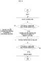
- FIG. 6is a flowchart illustrating a cooling temperature controlling process according to the embodiment.
- a local cooling anesthesia deviceis not limited to local anesthesia in treatment purposes and is applicable to all various cases of treatment such as cancer treatment, of which a treatment purpose is cytoclasis as necessary.
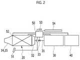
- FIGS. 1 and 2illustrate components of a local cooling anesthesia device including a cooling temperature adjuster according to an embodiment
- FIG. 3schematically illustrates a state in which the cooling temperature adjuster according to the embodiment is installed.
- a local cooling anesthesia device 10includes a housing 12 , which forms an exterior, and a sprayer, a cooling temperature adjuster 20 , a controller 50 , a supplier 30 , and a power supply 40 , which are installed in the housing 12 .
- both the supplier 30 for supplying a coolant and the power supply 40 for providing powerare included in the housing 12 so as to form a portable device in which the housing 12 itself may be driven independently.
- the supplier 30 or the power supply 40may be separately disposed outside the housing 12 and a coolant or power may be supplied from the outside to the inside of the housing 12 through additional lines.
- the housing 12may protect internal components by forming the exterior of the device and include an insulating material to prevent the cold of the coolant or heat energy of the cooling temperature adjuster 20 from being transferred to the outside.
- the housing 12may have an ergonomic shape so as to be easily gripped by a user.
- an external shape of the housing 12is shown in FIG. 1 , the housing 12 is not limited thereto and may be modified into a variety of shapes to be easily usable by a user.
- a spray hole 14 for spraying the coolant on a treatment areais formed at a proximal end of the housing 12 .
- a temperature measurer 51 for measuring a temperature of the treatment areais installed while spaced a certain distance apart and below the spray hole 14 .
- an input portion 53 and a display portion 54 for controlling and operating the deviceare installed on a certain side of the housing 12 . The temperature measurer, the input portion, and the display portion will be described below in detail.
- the spray hole 14is smoothly connected to the cooling temperature adjuster 20 disposed inside the housing 12 . Accordingly, the coolant, of which temperature is adjusted while passing through the cooling temperature adjuster 20 , may be easily sprayed through the spray hole 14 .
- the spray hole 14may be further combined with a lighting portion to emit light toward the treatment area. For example, light emitting diodes (LEDs), which emit light, are installed along an outside of the spray hole 14 such that light of the LEDs may be emitted toward the treatment area.
- LEDslight emitting diodes
- the supplier 30may be a pressure container which is installed in the housing 12 and filled with a coolant.
- the pressure containermay be filled with a compressed coolant.
- the supplier 30may further include a compressor for compressing a coolant to provide a supply pressure of the coolant.
- the pressure container that is the supplier 30may be filled with the coolant at high pressure through the compressor.
- the coolanta variety of materials such as liquid nitrogen, CO2, low-temperature cooled air, and the like may be used. Also, the coolant may be a material capable of lowering a temperature of a treatment area through endothermic reaction in the air.
- the pressure containeris a container filled with CO2 at a high pressure and is connected to the sprayer and supplies high-pressure CO2 to the sprayer.
- the pressure containermay withstand a pressure of 600 kPa and store 50 g of CO2.
- the suppliermay include a high-capacity pressure container of 1 kg or more which stores CO2 and which may be disposed outside the housing.
- CO2may be supplied from an external pressure container to the sprayer through a long tube.
- the sprayerincludes a nozzle 32 installed on a transfer line 31 , through which a coolant is transferred, to spray the coolant and a valve 33 installed on the transfer line 31 to adjust an amount of the coolant supplied through the transfer line 31 .
- the transfer line 31is installed to be connected to the supplier 30 . CO2 transferred along the transfer line 31 is sprayed through the nozzle 32 installed on a front end of the transfer line 31 .
- the nozzle 32has a hole about 500 ⁇ m in diameter and jets a high pressure CO2 coolant to the outside thereof.
- the valve 33is controlled and driven according to a signal of the controller 50 and adjusts the amount of the coolant supplied through the transfer line 31 .
- a spray amount of the coolant sprayed through the nozzle 32 to the outsideis adjusted by driving of the valve 33 .
- the power supply 40is for supplying power necessary for operating components in the housing 12 and, for example, may be a repeatedly-usable secondary battery such as a lithium-ion battery or a replaceable primary battery.
- the power supply 40may be detachably installed at the front end of the housing 12 .
- the cooling temperature adjuster 20adjusts a temperature of a coolant sprayed on a treatment area by applying heat energy to the coolant sprayed through the nozzle 32 of the sprayer.
- the cooling temperature adjuster 20is disposed at the front end of the housing 12 , that is, on a coolant movement path between the nozzle 32 of the sprayer and the spray hole 14 at the front end of the housing 12 and exchanges heat with the coolant sprayed from the nozzle 32 to the spray hole 14 .
- the nozzle 32 and the cooling temperature adjuster 20may be joined to each other using a joining method having high heat transfer.
- the nozzle 32 and the cooling temperature adjuster 20may be joined using a medium of a thermal paste.
- the cooling temperature adjuster 20includes a heat source 21 for heating a coolant and a heat exchanger for transferring heat of the heat source 21 to the coolant.
- the heat exchangeris disposed lengthwise in the housing 12 along a coolant spray direction.
- the heat exchangerincludes a heating plate 22 , in which the heat source 21 is installed, and a plurality of heat dissipation fins 23 which are installed to the heating plate 22 and contact with the coolant.
- the heat exchangermay include a metal material having a high thermal conductivity.
- the heating plate and the heat dissipation fins 23may be integrally formed.
- the heat exchangermay be formed of an aluminum or copper material.
- Heat exchange with a coolantis performed through the heat dissipation fins 23 .
- the plurality of heat dissipation fins 23have a structure of protruding from the heating plate 22 , having a plate shape extending lengthwise along a coolant spray direction, and being arranged at intervals to increase a contact area with the coolant. Accordingly, the contact area with the coolant is further increased by the heat dissipation fins 23 so as to maximize heat transfer efficiency.
- the heat source 21may be an electric heater, a thermoelectric element, or a structure of applying heat by emitting light or electromagnetic waves such as infrared rays or microwaves, and the like. In the embodiment, the heat source 21 may have a maximum output of 0.1 to 10 W.
- the devicemay include a discrete cooling structure, which comes into contact with and cools the treatment area, and may spray a coolant not directly on a treatment area, which has passed through the heat exchanger of the cooling temperature adjuster 20 .
- a method of spraying a coolant directly on a treatment area to cool the treatment areamay be inadequate.
- a discrete structureis installed with the cooling temperature adjuster such that the cooling temperature adjuster may adjust a temperature of the discrete structure and the discrete structure may come in to direct contact with the treatment area and reduce a temperature of the treatment area.
- a discrete cooling structure 15which is connected to the heat exchanger of the cooling temperature adjuster 20 and comes into contact with a treatment area, may be installed at the front end of the housing.
- the cooling structure 15may be understood as a structure of blocking plate with a certain area, which has a surface of contacting a treatment area.
- the cooling structure 15may be installed at the front end of the housing instead of the spray hole, which sprays a coolant, or may be additionally installed at the spray hole.
- the cooling structure 15blocks the coolant sprayed through the front end of the housing and comes into contact with a treatment area to cool the treatment area.
- the heat exchanger of the cooling temperature adjuster 20may be connected to the cooling structure installed at the front end of the housing and adjust a temperature of the cooling structure 15 by applying a coolant, which has passed through the heat exchanger, to the cooling structure.
- the cooling structure 15is cooled by the coolant, which is sprayed and passed through the heat exchanger of the cooling temperature adjuster, and contacts a treatment area to transfer the coolness of the coolant thereto. Accordingly, the coolant is not sprayed directly on the treatment area, and cooling is performed by the cooling structure.
- the cooling temperature adjuster 20may have a structure in which a front end of the heat exchanger is blocked to prevent a coolant from being sprayed and may protrude from the front end of the housing 12 .
- a front end of the cooling temperature adjuster 20may come into direct contact with a treatment area and reduce a temperature of the treatment area.
- the heat exchangermay protrude from the front end of the housing 12 to a spray hole directly.
- the front end of the heat exchangermay come into direct contact with a treatment area to reduce a temperature of the treatment area.
- the cooling temperature adjuster 20has a structure in which the heating plate 22 of the heat exchanger has a hollow quadrangular shape, the heat dissipation fins 23 are installed to be arranged on an inner circumferential surface of the heating plate 22 such that a coolant exchanges heat with the heat dissipation fins 23 while passing through the inside of the heating plate 22 , and the heat source 21 is installed on at least one surface of the heating plate 22 .
- the heat exchanger of the cooling temperature adjuster 20has a hollow quadrangular pipe such that a coolant sprayed by the nozzle 32 of the sprayer passes through an empty inside of the heat exchanger. Since the plurality of heat dissipation fins 23 connected to the heating plate 22 are installed to be arranged in the empty inside of the heat exchanger, the coolant passing through the inside of the heating plate 22 of the heat exchanger passes through the heat dissipation fins 23 installed in the heating plate 22 to exchange heat with the heat dissipation fins 23 .
- the heating plate 22may be formed in the housing 12 to have an adequate size to allow all the coolant sprayed by the nozzle 32 of the sprayer to pass through the inside of the heating plate 22 . Accordingly, heat of the coolant sprayed by the nozzle 32 may be exchanged while all the coolant passes through the heat exchanger and efficiency in controlling a temperature may be increased.
- the heat exchangermay be formed such that the heating plates 22 may have the same width along a coolant spray direction as shown in FIG. 4 .
- the heating plate 22may be formed in a parallelepiped shape in which the diameter gradually decreases toward the spray hole 14 at the front end of the housing 12 along the coolant spray direction.
- the coolant passing through the inside of the heating plate 22remains in a process of passing through an outlet of the heating plate 22 longer, which gradually narrows, in the heating plate 22 such that a heat exchange time between the heat exchanger and the coolant may be further increased.
- An arrangement structure of the heat dissipation fins 23 installed in the heating plate 22may be modified into a variety of shapes.
- a sealant for heat insulationmay be further installed outside the heat exchanger of the cooling temperature adjuster.
- the sealantsurrounds the heating plate 22 and prevents heat from being transferred to the heat exchanger from the outside. Accordingly, when heat is exchanged between the heat exchanger and the coolant, a heat loss may be minimized.
- the housing 12since the cooling temperature adjuster is installed in the housing such that the heat exchanger is surrounded by the housing 12 , the housing 12 may perform a function of the sealant.
- the front end of the housing at which the cooling temperature adjuster is disposedmay be formed of a separate heat insulation material unlike the material used for another part of the housing. Accordingly, in an area of the cooling temperature adjuster in which heat exchange is performed, heat insulation may be performed more effectively.
- the heat source 21may include an electric heater which is installed to be attached to an outer surface of the heating plate 22 .
- the electric heatermay be installed on each side surface of the quadrangular heating plate 22 or may be installed on only some of the side surfaces.
- the electric heateris a structure which converts electrical energy into thermal energy and receives power from the power supply 40 and generates heat energy.
- the electric heaterhas, for example, a film shape having a size corresponding to the side surface of the heating plate 22 and may be attached to the side surface of the heating plate 22 .
- FIG. 5illustrates another embodiment of the cooling temperature adjuster 20 .
- the cooling temperature adjuster 20 of the embodimentincludes a heat source 21 for heating a coolant and a heat exchanger installed between the heat source 21 and the coolant to transfer heat.
- the heat exchangerincludes the heating plate 22 , in which a heat source 21 is installed, and a plurality of heat dissipation fins 23 which are installed in the heating plate 22 and come into contact with the coolant to dissipate heat of the heating plate 22 to the coolant.
- the heating plate 22 of the heat exchangerhas a hollow and cylindrical shape and the heat dissipation fins 23 are installed to be arranged along an outer circumferential surface of the heating plate 22 such that heat of the coolant may be exchanged with that of the heat dissipation fins 23 while passing outside the heating plate 22 , and the heat source 21 may be inserted to be installed into a center of the heating plate 22 .
- the heat dissipation fins 23have a structure of protruding from the heating plate 22 , having a plate shape extending lengthwise along a coolant spray direction, and being arranged at intervals to increase a contact area with the coolant. Accordingly, a contact area with the coolant is further increased by the heat dissipation fins 23 so as to maximize heat transfer efficiency.
- heat exchangeis performed while the coolant sprayed by the nozzle 32 of a sprayer passes outside the heating plate 22 . Since the plurality of heat dissipation fins 23 connected to the heating plate 22 are installed to be arranged outside the heating plate 22 , the coolant passing outside the heating plate 22 passes by the heat dissipation fins to exchange heat with the heat dissipation fins 23 .
- the heat exchangermay have a structure in which a protrusion length of the heat dissipation fins 23 gradually decreases toward the spray hole 14 at the front of the housing 12 along the coolant spray direction such that the heat exchanger may have an overall conic shape along the coolant spray direction.
- a flow of the coolant passing the heat dissipation fins 23 and flowing through the spray hole 14may be easily maintained by flexibly connecting a front end of the heat exchanger to the spray hole 14 .
- An arrangement structure of the heat dissipation fins 23 installed in the heating plate 22may be modified into a variety of shapes.
- the heat source 21may include a bar-shaped electric heater. Since a hollow groove is formed in a center of the heating plate 22 to install the electric heater therein, the bar-shaped electric heater is inserted into the hollow groove and is coupled with the heating plate 22 .
- the shape or number of the hollow groove formed in the heating plate 22 and the shape or number of the electric heater installed to be inserted in the hollow groovemay be variously modified.
- the controller 50includes the temperature measurer 51 for detecting a temperature of a treatment area and a temperature sensor 52 installed in the cooling temperature adjuster 20 to detect a temperature of the cooling temperature adjuster 20 to have a structure in which heat energy of the cooling temperature adjuster 20 or a spray amount of the sprayer is adjusted by comparing a real temperature of the treatment area, a real temperature of the coolant passing through the cooling temperature adjuster 20 , and a target cooling temperature with one another.
- the controller 50controls the heat source 21 of the cooling temperature adjuster 20 to adjust a temperature of the coolant while passing through the cooling temperature adjuster 20 , such that the treatment area is cooling-anesthetized by spraying the coolant, of which the temperature is ultimately adjusted to comply with a treatment purpose.
- the controller 50further includes the input portion 53 for inputting a setting value and the display portion 54 for externally displaying a signal applied to the controller 50 .
- the display portion 54may include a display for displaying information and a warning light for displaying a visual warning or an alarm for an aural warning.
- the controller 50includes an equation for controlling a temperature of the heat source 21 of the cooling temperature adjuster 20 therein, calculates a value for controlling the temperature of the heat source 21 by comparing a target cooling temperature with a real temperature value according to the equation, and controls the cooling temperature adjuster 20 according to a result of calculation.
- the controller 50may adjust power applied to the heat source 21 installed in the cooling temperature adjuster 20 in the mean of electric feedback control based on the equation included therein.
- the electric feedback controlmay include a proportional integral differential (PID) control and a pulsed width modulation (PWM) control.
- PIDproportional integral differential
- PWMpulsed width modulation
- the controller 50may perform multiple calculations for the electric feedback control through a plurality of stages.
- the controller of the embodimentmay control a temperature of the heat source by performing two stages of PID calculation using a primary equation and a secondary equation.
- the controller 50may use a portable power supply device, for example, a secondary battery as a power supply, but is not limited thereto.
- the controller 50may apply a temperature of a coolant and a treatment time, which are necessary and input in advance according to a treatment purpose of a user, for example, local anesthesia, cytoclasis, and the like.
- the heat source 21 of the cooling temperature adjuster 20is driven by a signal output by the controller 50 and applies calculated heat energy to the coolant to heat the coolant.
- the input portion 53may be connected to the controller 50 and installed outside the housing 12 so as to input a setting value to the controller 50 as necessary.
- the input portion 53may input, for example, a target cooling temperature, a coolant spray amount, and the like, according to a treatment purpose to the controller 50 .
- the input portion 53may include a treatment input portion and a control input portion.
- the treatment input portionmay be disposed, for example, at an area adjacent to the spray hole 14 to control spraying of the coolant.
- the treatment input portionmay include a spray switch and may determine whether to spray the coolant by turning the spray switch on or off.
- the control input portionmay be disposed to be adjacent to the sprayer or adjacent to the controller.
- the control input portionmay determine a temperature of a coolant or a treatment area to be within a range of ⁇ 50° C. to 15° C. for local anesthesia.
- the control input portionmay determine a treatment time to be within a range of one second to ten minutes for local anesthesia.
- the control input portionmay include a push button switch and a control switch having an encoder function.
- a treatment temperaturemay be increased or a treatment type may be selected.
- the treatment temperaturemay be decreased or the treatment type may be selected.
- a treatment timemay be increased.
- the treatment timemay be decreased.
- the display portion 54may be disposed to be close to the treatment input portion.
- the display portion 54may display a current temperature of a treatment area, a current temperature of a coolant, or current temperatures of the coolant and the treatment area may be displayed through a display and the like.
- the display portionmay display a set point determined by the control input portion, that is, a target temperature of the coolant, a target temperature of the treatment area, or target temperatures of the treatment area and the coolant using the display and the like.
- the display portion 54may display a treatment time, a currently remaining time, or the treatment time and the currently remaining time, which are determined by the control input portion.
- the display portionmay perform some or an entirety of functions of the input portion at the same time using a touch screen and the like.
- the display of the display portion 54is installed outside the housing 12 and displays information according to a signal of the controller 50 .
- the display portion 54may display information related to treatment such as a real temperature value of the treatment area, a temperature value of the coolant, the treatment time, and the like through the display.
- the warning light and the alarm of the display portion 54externally display a warning signal applied from the controller 50 when the device is driven by using a visual light or an aural sound.
- the display portion 54may warn a user when a temperature of the coolant deviates from a safe range, when a pressure of the coolant deviates from a determined range, when a temperature of the treatment area deviates from a safe range, or when performance of the device, such as power performance, deviates from a determined range.
- the temperature sensor 52may be installed inside or outside the cooling temperature adjuster 20 .
- the temperature sensor 52may be, for example, a thermistor which detects a temperature through a physical contact.
- the temperature sensor 52may be installed at a position as far from the heat source 21 as possible in order to detect an accurate temperature of the coolant which is heat-exchanged through the cooling temperature adjuster 20 and is discharged.
- the temperature measurer 51may be spaced apart from a coolant spray position with respect to the treatment area to measure a temperature using a non-contact method.
- the temperature measurer 51may be a non-contact temperature-measuring infrared sensor.
- the temperature measurer 51may be disposed at an angle capable of minimizing an effect of the coolant in measuring the temperature of the treatment area.
- the temperature measurer 51may be disposed toward the treatment area while tilting at an angle of 2 to 20° with respect to a coolant spray direction to measure a temperature. Accordingly, heat exchange is performed on the coolant while the coolant passes through the cooling temperature adjuster 20 , which is controlled by the controller 50 , and the coolant is adjusted to be at a desirable temperature value.
- the coolanthas an adequately adjusted temperature value and then is sprayed on the treatment area such that a degree of risk with respect to epidermal cells of the treatment area, with which the coolant comes into direct contact, may be minimized.
- the controlling processincludes setting a target cooling temperature with respect to a treatment area, cooling the treatment area by spraying a coolant thereon, detecting a real temperature of the treatment area, and comparing a detected real temperature value with a target cooling temperature and controlling a temperature of the coolant by adjusting a heat source of a cooling temperature adjuster or a coolant spray amount such that the real temperature value reaches the target cooling temperature.
- the target cooling temperatureis set and the coolant spray amount is adjusted according to a treatment purpose according to a command of the input portion 53 .
- the temperature of the coolant supplied from the supplier 30is adjusted while passing through the cooling temperature adjuster 20 such that the coolant can be provided to the treatment area at a temperature, which is ultimately adjusted in compliance with a treatment purpose. Accordingly, the treatment area may be prevented from being damaged by over cooling.
- the controller 50receives power from the power supply and controls the heat source 21 installed in the cooling temperature adjuster 20 according to a real temperature value of the treatment area, which is received from the temperature measurer 51 , and a target cooling temperature set through the input portion 53 .
- the real temperature valuemay be a temperature value obtained through the temperature measurer 51 or a temperature value of a coolant, which is obtained through the temperature sensor 52 installed in the cooling temperature adjuster.
- the coolantWhen an initial value according to the treatment purpose is set, the coolant is sprayed to the treatment area.
- the coolantpasses from the supplier 30 through the cooling temperature adjuster 20 and is sprayed to the treatment area through the spray hole 14 at the front end of the housing 12 to cool the treatment area.
- a real temperature value of the treatment area cooled by the coolantis detected through the temperature measurer 51 .
- the controller 50compares the detected real temperature value with the target cooling temperature and controls the temperature of the coolant by adjusting the heat source 21 of the cooling temperature adjuster 20 or the coolant spray amount such that the real temperature value reaches the target cooling temperature.
- the controller 50controls power applied to the heat source 21 of the cooling temperature adjuster 20 in a two-stage process by calculating using PID control through the two equations which are prestored in the controller 50 . Accordingly, the temperature of the coolant which passes through the cooling temperature adjuster 20 may be quickly or precisely adjusted through the temperature controlling process.
- the temperaturemay be quickly controlled when the real temperature value is far from the target cooling temperature, and the temperature may be precisely controlled when the real temperature value is close to the target cooling temperature.
- the temperature controlling processis not limited to the two-stage PID calculation using the primary equation 1 and the secondary equation 2 and may perform three or more-stages of PID calculation as necessary.
- a temperature of the heat source after cooling is finishedmay be adequately controlled through three stages of calculation.
- the primary equation 1is for precise temperature control and the secondary equation 2 is for rapid temperature control.
- the equationsare as follows.
- P(t)is a digital or analog type output value output at a certain time t from the controller
- error (t)is a difference between a temperature measured at the time t and a target cooling temperature.
- Cp, Ci, and Cdare constants of proportional (P), integral (I), and differential (D), which are used in PID control, respectively.
- constants of the primary equation 1 and the secondary equation 2have different values such that a value of P(t) that is a value obtained by applying the secondary equation 2 may be greater than a value of P(t) obtained by applying the primary equation 1 (for example, Cp,1 ⁇ Cp,2, Ci,1 ⁇ Ci,2, and Cd,1 ⁇ Cd,2).
- the constants Cp,2, Ci,2, and Cd,2 used in the secondary equation 2are set to be large so as to increase P(t) from same error(t) such that cooling may be quickly performed in an early stage of treatment, and the constants Cp,1, Ci,1, and Cd,1 used in the primary equation 1 are adjusted to be small such that a temperature may be precisely adjusted when error (t) is small.
- the controller 50controls the temperature through PID calculation using an alpha value as a first stage.
- the controllercompares a detected real temperature value with a target cooling temperature and calculates whether an absolute value of the difference between the real temperature value and the target cooling temperature is smaller than an alpha value ⁇ that is a predetermined arbitrary range.
- the alpha value ⁇refers to a primary limit range which recedes from the target cooling temperature. Accordingly, the controller calculates whether the real temperature value deviates from the target cooling temperature more than the alpha value ⁇ that is the primary limit through the above process.
- the controller 50heats the coolant by controlling power which is applied to the heat source 21 of the cooling temperature adjuster 20 according to the primary equation 1 for precise cooling control, which is one of the equations included in the controller.
- heat of the coolant which passes through the cooling temperature adjuster 20is exchanged with heat energy of the heat source 21 .
- the coolant, which is heated by the heat source 21 such that a temperature thereof increases,is sprayed on the treatment area such that a real cooling temperature of the treatment area is adjusted to approximate to a target cooling temperature.
- the controller 50heats the coolant by controlling power which is applied to the heat source 21 of the cooling temperature adjuster 20 according to the secondary equation 2 for quick cooling control, which is one of the equations included in the controller.
- the controller 50may set the constant of the secondary equation 2 such that power which is applied to the heat source 21 becomes zero. Accordingly, the heat source 21 of the cooling temperature adjuster 20 is not operated such that heat of the coolant is not exchanged with heat of the cooling temperature adjuster 20 and the coolant is sprayed on the treatment area through the spray hole 14 to quickly cool the treatment area.
- the constant of the secondary equation 2may set a power value applied to the heat source 21 such that the temperature of the coolant changes at a speed of, for example, 1° C./sec for relatively slow cooling.
- a temperature of the cooling temperature adjustermay be decreased in advance by spraying the coolant in advance. Accordingly, the temperature of the cooling temperature adjuster is decreased before treatment such that time consumed for cooling the treatment area may be further reduced to be minimized.
- the controllercalculates whether the real temperature value of the treatment area adequately approaches the target cooling temperature by comparing the real temperature value with the target cooling temperature.
- a detected real temperature valueis compared with a target cooling temperature and whether an absolute value of the difference between the real temperature value and the target cooling temperature is smaller than a preset arbitrary beta value ⁇ is calculated.
- the beta value ⁇refers to a secondary limit range which recedes from the target cooling temperature and may be set to be a value closer to a target cooling temperature than the alpha value ⁇ . Accordingly, the controller calculates whether the real temperature value deviates from the target cooling temperature more than the beta value ⁇ that is the secondary limit through the above process.
- the cooling temperature adjuster 20is controlled and the two values are compared by repetitively performing the process.
- the absolute value of the difference between the real temperature value and the target cooling temperatureis smaller than the beta value ⁇ , that is, when the real temperature value adequately approaches the target cooling temperature, a timer is driven and cooling treatment is completed after a setting time of the timer has passed.
- the alpha value ⁇ and the beta value ⁇may be understood as certain temperature values which are arbitrarily applied to the target cooling temperature.
- the alpha value ⁇has an absolute value which is relatively greater than the beta value ⁇
- the beta value ⁇refers to an absolute value which is relatively smaller than the alpha value.
- the target cooling temperatureis ⁇ 10° C.
- the alpha value ⁇is 2° C.
- the beta value ⁇may be set to be 1° C. smaller than 2° C.
- the alpha value and the beta value ⁇are not specified values and may be adequately set according to a treatment purpose.
- the real temperature valuemay be effectively adjusted to the target cooling temperature by performing quick temperature control when the real temperature value is far from the target cooling temperature and performing precise temperature control when the real temperature value is close to the target cooling temperature.
- the controllerperforms PID calculation through the two stages but is not limited thereto and may perform three or more stages of control by further refining the temperature controlling process as necessary.
- the controller 50may inform a user that cooling anesthesia of the treatment area is completed by externally displayed notification.
- the coolantexperiences heat exchange while passing through the cooling temperature adjuster 20 , and thereby the temperature of the coolant is adjusted to a desirable temperature. Accordingly, the temperature of the treatment area cooled by the coolant can be kept within a safe range. Also, as the coolant passes through the cooling temperature adjuster 20 controlled according to a treatment purpose, the temperature of the coolant is adjusted in compliance with the treatment purpose and is sprayed on the treatment area. The increased temperature of the coolant enables smooth start of cooling treatment such that a degree of risk with respect to epidermal cells that comes into direct contact with the coolant may be minimized.
- the coolantpasses through the cooling temperature adjuster 20 in advance before starting the treatment such that a temperature of the cooling temperature adjuster 20 may be adjusted to a temperature according to a treatment purpose.
- the controller 50may precisely adjust the temperatures of the coolant and the cooling temperature adjuster 20 using coolant-based heat absorption and heating of the heat source 21 of the cooling temperature adjuster 20 at the same time.
- At least one of the disclosed embodimentsmay be applied to a local cooling anesthesia device, a method of controlling the local cooling anesthesia device, and a cooling temperature adjuster of the local cooling anesthesia device.
Landscapes
- Health & Medical Sciences (AREA)
- Life Sciences & Earth Sciences (AREA)
- Engineering & Computer Science (AREA)
- Biomedical Technology (AREA)
- Animal Behavior & Ethology (AREA)
- Veterinary Medicine (AREA)
- Public Health (AREA)
- General Health & Medical Sciences (AREA)
- Heart & Thoracic Surgery (AREA)
- Anesthesiology (AREA)
- Surgery (AREA)
- Hematology (AREA)
- Vascular Medicine (AREA)
- Nuclear Medicine, Radiotherapy & Molecular Imaging (AREA)
- Molecular Biology (AREA)
- Medical Informatics (AREA)
- Otolaryngology (AREA)
- Pathology (AREA)
- Oral & Maxillofacial Surgery (AREA)
- Chemical & Material Sciences (AREA)
- Chemical Kinetics & Catalysis (AREA)
- General Chemical & Material Sciences (AREA)
- Physics & Mathematics (AREA)
- Thermal Sciences (AREA)
- Radiology & Medical Imaging (AREA)
- Thermotherapy And Cooling Therapy Devices (AREA)
- Pharmaceuticals Containing Other Organic And Inorganic Compounds (AREA)
- Medicines Containing Plant Substances (AREA)
Abstract
Description
Claims (15)
Priority Applications (2)
| Application Number | Priority Date | Filing Date | Title |
|---|---|---|---|
| US17/455,628US12178965B2 (en) | 2016-11-15 | 2021-11-18 | Local cooling anesthesia device, method of controlling local cooling anesthesia device, and cooling temperature regulator of local cooling anesthesia device |
| US18/958,246US20250082890A1 (en) | 2016-11-15 | 2024-11-25 | Local cooling anesthesia device, method of controlling local cooling anesthesia device, and cooling temperature regulator of local cooling anesthesia device |
Applications Claiming Priority (3)
| Application Number | Priority Date | Filing Date | Title |
|---|---|---|---|
| KR1020160151947AKR101905830B1 (en) | 2016-11-15 | 2016-11-15 | Cryoanesthesia device, method for controlling cryoanesthesia device and temperature controller of coolant in cryoanesthesia device |
| KR10-2016-0151947 | 2016-11-15 | ||
| PCT/KR2017/012935WO2018093141A2 (en) | 2016-11-15 | 2017-11-15 | Local cryoanesthesia device, method of controlling local cryoanesthesia device, and cooling temperature regulator of local cryoanesthesia device |
Related Parent Applications (1)
| Application Number | Title | Priority Date | Filing Date |
|---|---|---|---|
| PCT/KR2017/012935ContinuationWO2018093141A2 (en) | 2016-11-15 | 2017-11-15 | Local cryoanesthesia device, method of controlling local cryoanesthesia device, and cooling temperature regulator of local cryoanesthesia device |
Related Child Applications (1)
| Application Number | Title | Priority Date | Filing Date |
|---|---|---|---|
| US17/455,628ContinuationUS12178965B2 (en) | 2016-11-15 | 2021-11-18 | Local cooling anesthesia device, method of controlling local cooling anesthesia device, and cooling temperature regulator of local cooling anesthesia device |
Publications (2)
| Publication Number | Publication Date |
|---|---|
| US20190290881A1 US20190290881A1 (en) | 2019-09-26 |
| US11207488B2true US11207488B2 (en) | 2021-12-28 |
Family
ID=62146659
Family Applications (3)
| Application Number | Title | Priority Date | Filing Date |
|---|---|---|---|
| US16/412,296ActiveUS11207488B2 (en) | 2016-11-15 | 2019-05-14 | Local cooling anesthesia device, method of controlling local cooling anesthesia device, and cooling temperature regulator of local cooling anesthesia device |
| US17/455,628Active2037-12-23US12178965B2 (en) | 2016-11-15 | 2021-11-18 | Local cooling anesthesia device, method of controlling local cooling anesthesia device, and cooling temperature regulator of local cooling anesthesia device |
| US18/958,246PendingUS20250082890A1 (en) | 2016-11-15 | 2024-11-25 | Local cooling anesthesia device, method of controlling local cooling anesthesia device, and cooling temperature regulator of local cooling anesthesia device |
Family Applications After (2)
| Application Number | Title | Priority Date | Filing Date |
|---|---|---|---|
| US17/455,628Active2037-12-23US12178965B2 (en) | 2016-11-15 | 2021-11-18 | Local cooling anesthesia device, method of controlling local cooling anesthesia device, and cooling temperature regulator of local cooling anesthesia device |
| US18/958,246PendingUS20250082890A1 (en) | 2016-11-15 | 2024-11-25 | Local cooling anesthesia device, method of controlling local cooling anesthesia device, and cooling temperature regulator of local cooling anesthesia device |
Country Status (4)
| Country | Link |
|---|---|
| US (3) | US11207488B2 (en) |
| KR (1) | KR101905830B1 (en) |
| CN (4) | CN116077793A (en) |
| WO (1) | WO2018093141A2 (en) |
Cited By (4)
| Publication number | Priority date | Publication date | Assignee | Title |
|---|---|---|---|---|
| US11938188B2 (en) | 2014-08-28 | 2024-03-26 | The General Hospital Corporation | Injectable slurries and methods of manufacturing and using the same |
| US12076269B2 (en) | 2018-04-27 | 2024-09-03 | Recensmedical, Inc. | Hand-held cryotherapy device including cryogen temperature pressure controller and method thereof |
| US12097282B2 (en) | 2014-08-28 | 2024-09-24 | The General Hospital Corporation | Injectable slurries and methods of manufacturing the same |
| US12138200B2 (en) | 2018-12-07 | 2024-11-12 | Recensmedical, Inc. | Cooling apparatus and cooling method |
Families Citing this family (21)
| Publication number | Priority date | Publication date | Assignee | Title |
|---|---|---|---|---|
| KR101905830B1 (en) | 2016-11-15 | 2018-10-08 | 울산과학기술원 | Cryoanesthesia device, method for controlling cryoanesthesia device and temperature controller of coolant in cryoanesthesia device |
| KR20180131357A (en) | 2017-05-30 | 2018-12-10 | 주식회사 리센스메디컬 | Medical cooling apparatus |
| WO2018221848A1 (en) | 2017-05-30 | 2018-12-06 | 주식회사 리센스메디컬 | Medical cooling device |
| KR102517065B1 (en) | 2017-12-29 | 2023-04-03 | 주식회사 리센스메디컬 | Cooling generator |
| KR20200012675A (en)* | 2018-07-27 | 2020-02-05 | 주식회사 리센스메디컬 | Medical cooling apparatus |
| CN112955099B (en) | 2018-07-27 | 2024-04-26 | 雷森斯医疗有限公司 | Medical cooling device and cooling method using same |
| EP3831346B1 (en)* | 2018-07-27 | 2024-02-07 | Recensmedical, Inc. | Medical cooling device |
| US11666479B2 (en) | 2018-08-19 | 2023-06-06 | Recensmedical, Inc. | Device for cooling anesthesia by chilled fluidic cooling medium |
| USD921911S1 (en) | 2019-06-21 | 2021-06-08 | Recensmedical, Inc. | Medical cooling device |
| USD921211S1 (en) | 2019-06-21 | 2021-06-01 | Recensmedical, Inc. | Medical cooling device |
| JP1656838S (en)* | 2019-08-26 | 2020-04-06 | ||
| CN110507292B (en)* | 2019-09-24 | 2023-08-15 | 中国人民解放军陆军军医大学第一附属医院 | Skin cold-temperature sensing pen and temperature control method thereof |
| US11278341B2 (en) | 2020-07-14 | 2022-03-22 | Recensmedical, Inc. | Method of safely using controlled cooling systems and devices |
| USD968627S1 (en) | 2020-08-07 | 2022-11-01 | Recensmedical, Inc. | Medical cooling device |
| USD968626S1 (en) | 2020-08-07 | 2022-11-01 | Recensmedical, Inc. | Medical cooling device |
| USD977633S1 (en) | 2020-08-07 | 2023-02-07 | Recensmedical, Inc. | Cradle for a medical cooling device |
| US12364531B2 (en) | 2021-02-16 | 2025-07-22 | RecensMedical, Inc.; | Methods for treating skin disorders using precision cooling technology |
| USD1065551S1 (en) | 2021-09-10 | 2025-03-04 | Hydrafacial Llc | Skin treatment device |
| USD1084369S1 (en) | 2023-02-10 | 2025-07-15 | Hydrafacial Llc | Skin treatment tip |
| WO2024233567A1 (en)* | 2023-05-08 | 2024-11-14 | Hydrafacial Llc | Devices, systems and methods for treating the skin |
| KR102650380B1 (en)* | 2023-08-31 | 2024-03-25 | 주식회사 리센스메디컬 | A method of controliing cooling speed |
Citations (138)
| Publication number | Priority date | Publication date | Assignee | Title |
|---|---|---|---|---|
| US2044823A (en) | 1934-04-16 | 1936-06-23 | Howard A Whiteside | Motorized handpiece |
| US4646735A (en)* | 1985-10-04 | 1987-03-03 | Seney John S | Pain-alleviating tissue treatment assembly |
| JPH0492663A (en) | 1990-08-09 | 1992-03-25 | Matsushita Electric Works Ltd | Cooling facial device |
| JPH0686818A (en) | 1992-09-08 | 1994-03-29 | Tetsuya Suzuki | Anesthetic vaporizer |
| KR980005117U (en) | 1996-06-26 | 1998-03-30 | Speaker angle adjuster of video equipment | |
| JPH10230435A (en) | 1997-02-22 | 1998-09-02 | Hitachi Seiki Co Ltd | Heating / cooling method using an electronic cooling element, its heating / cooling device, and machine tool attitude control device |
| KR100200669B1 (en) | 1996-10-09 | 1999-06-15 | 윤종용 | Laser handpiece with water spray |
| US6099521A (en) | 1998-05-26 | 2000-08-08 | Shadduck; John H. | Semiconductor contact lens cooling system and technique for light-mediated eye therapies |
| US6141985A (en) | 1998-03-06 | 2000-11-07 | Societe Cryonic Medical | Self-contained and portable cryogenic apparatus using carbon dioxide in liquid/solid phases |
| KR20030068633A (en) | 2002-02-15 | 2003-08-25 | 이엠씨테크(주) | Integrated circuit cooler using thermoelectric element |
| US6632219B1 (en) | 1998-10-16 | 2003-10-14 | Eugene Baranov | Tissue cooling rod for laser surgery |
| US6669688B2 (en) | 2000-01-25 | 2003-12-30 | The Regents Of The University Of California | Method and apparatus for measuring the heat transfer coefficient during cryogen spray cooling of tissue |
| US20040102768A1 (en) | 2000-10-13 | 2004-05-27 | Christian Cluzeau | Hand-held apparatus for spray cryotherapy |
| US20040111087A1 (en) | 1999-03-09 | 2004-06-10 | Stern Roger A. | Handpiece for treatment of tissue |
| EP1030611B1 (en) | 1997-09-26 | 2004-09-01 | CoolTouch, Incorporated | Handpiece with coolant reservoir |
| CN2660834Y (en) | 2003-10-13 | 2004-12-01 | 高卫国 | Auto temp controlled electric heater |
| US20050005626A1 (en) | 2003-07-08 | 2005-01-13 | Mcmahon Richard | Cooling device for pain relief |
| US20050059940A1 (en) | 1999-01-20 | 2005-03-17 | Pearl Technology Holdings, Llc. | Skin resurfacing and treatment using biocompatible materials |
| JP2005080832A (en) | 2003-09-08 | 2005-03-31 | Terumo Corp | Needleless syringe and temperature regulator for syringe |
| US20050261753A1 (en) | 2003-01-15 | 2005-11-24 | Mediphysics Llp | Methods and systems for cryogenic cooling |
| US7037326B2 (en) | 2003-03-14 | 2006-05-02 | Hee-Young Lee | Skin cooling device using thermoelectric element |
| US20060200117A1 (en) | 2002-11-18 | 2006-09-07 | Erik Hermans | Instrument for cryogenic treatments in the medical, paramedical and cosmetic field |
| US20060213509A1 (en) | 2003-07-31 | 2006-09-28 | Denis Marin | Device and method for dispensing a fluid |
| US20070005048A1 (en) | 2005-06-30 | 2007-01-04 | Niedbala R S | Method and apparatus for cryogenically treating lesions on biological tissue |
| KR100786539B1 (en) | 2007-06-27 | 2007-12-21 | 주식회사 루트로닉 | Cooling Temperature Control Skin Cooling Handpiece |
| KR100790758B1 (en) | 2007-01-22 | 2008-01-03 | 주식회사 루트로닉 | Cold Supply Integral Medical Laser Handpiece Tip Assembly |
| KR20080045022A (en) | 2006-11-17 | 2008-05-22 | 강승주 | Medical skin quenching equipment |
| US20080164296A1 (en) | 2007-01-10 | 2008-07-10 | Shelton Frederick E | Prevention of cartridge reuse in a surgical instrument |
| KR100851274B1 (en) | 2007-03-08 | 2008-08-08 | 주식회사 엘바이오 | Probes for Local Skin Anesthesia |
| US20080221561A1 (en) | 2005-07-18 | 2008-09-11 | Jorg Geiger | Spray Device for Dispensing a Cooling Fluid |
| JP2008545462A (en) | 2005-05-20 | 2008-12-18 | ミオサイエンス インコーポレーティッド | Subcutaneous cryogenic remodeling |
| US20090036846A1 (en) | 2006-05-17 | 2009-02-05 | Bruno Dacquay | Ophthalmic Injection System |
| JP2009034273A (en) | 2007-07-31 | 2009-02-19 | Mayekawa Mfg Co Ltd | Peltier cautery |
| US20090062751A1 (en) | 2007-09-01 | 2009-03-05 | Newman Jr Lionel | Medical apparatus for suction and combination irrigation and suction |
| JP2009056320A (en) | 2008-10-20 | 2009-03-19 | Seiko Epson Corp | Fluid ejecting apparatus and surgical instrument |
| US20090124972A1 (en) | 2007-11-09 | 2009-05-14 | Afreeze Gmbh | Cooling System for a Catheter |
| US20090149930A1 (en)* | 2007-12-07 | 2009-06-11 | Thermage, Inc. | Apparatus and methods for cooling a treatment apparatus configured to non-invasively deliver electromagnetic energy to a patient's tissue |
| US20090163902A1 (en) | 2007-12-21 | 2009-06-25 | Sanarus Medical, Inc. | Cryoprobe With Automatic Purge Bypass Valve |
| US20100010480A1 (en)* | 2008-07-14 | 2010-01-14 | Primaeva Medical, Inc. | Devices and methods for percutaneous energy delivery |
| US20100087805A1 (en) | 2007-01-31 | 2010-04-08 | Sixtem Life S.R.L. | Dispensing device for pressurized containers for the application of cryogenic coolant |
| KR20100041207A (en) | 2008-10-13 | 2010-04-22 | 윤희철 | A medical skin temperature adjuster |
| KR20100060222A (en) | 2008-11-27 | 2010-06-07 | 김양수 | Device for skin beauty and medical treatment |
| US20100196343A1 (en) | 2008-09-16 | 2010-08-05 | O'neil Michael P | Compositions, methods, devices, and systems for skin care |
| US7780656B2 (en) | 2004-12-10 | 2010-08-24 | Reliant Technologies, Inc. | Patterned thermal treatment using patterned cryogen spray and irradiation by light |
| KR20100135863A (en) | 2008-04-01 | 2010-12-27 | 더 제너럴 하스피탈 코포레이션 | Cooling method and cooling device of biological tissue |
| US20110072834A1 (en) | 2009-09-30 | 2011-03-31 | Hitachi, Ltd. | Cooling structure of electronic equipment |
| US20110137268A1 (en) | 2009-12-04 | 2011-06-09 | Mt Industries, Inc. | Hand held skin treatment spray system with proportional air and liquid control |
| US7963959B2 (en) | 2008-10-07 | 2011-06-21 | Vandolay, Inc. | Automated cryogenic skin treatment |
| US20110152850A1 (en) | 2009-06-23 | 2011-06-23 | Niedbala R Sam | Devices and methods for dispensing a cryogenic fluid |
| US20110177474A1 (en) | 2008-03-18 | 2011-07-21 | Hu-Friedy Mfg. Co., Inc | Handpiece for a Magnetostrictive Power Generator |
| KR101053835B1 (en) | 2010-04-29 | 2011-08-03 | 에스티플렉스 주식회사 | LED heat dissipation structure |
| EP1401347B1 (en) | 2001-05-23 | 2011-08-24 | Palomar Medical Technologies, Inc. | Cooling system for a photocosmetic device |
| KR20110119640A (en) | 2008-12-22 | 2011-11-02 | 마이오우사이언스, 인크. | Cold Surgery System Integrating Refrigerant Source and Power Source |
| US8083734B2 (en) | 2004-06-27 | 2011-12-27 | Dieter Steinfatt | Coolant dosing device |
| USD658775S1 (en) | 2011-02-15 | 2012-05-01 | Genesis Health Light Corporation | Hand held heat light |
| US8177827B2 (en) | 2008-04-04 | 2012-05-15 | Oleg Shapiro | Cooling device for locally anesthetizing an area on the surface of the body |
| US20120130458A1 (en)* | 2010-10-26 | 2012-05-24 | Medtronic Ardian Luxembourg S.A.R.L. | Neuromodulation cryotherapeutic devices and associated systems and methods |
| US20120191166A1 (en)* | 2002-09-12 | 2012-07-26 | Zoll Circulation, Inc. | System and method for determining and controlling core body temperatue |
| JP2012143279A (en) | 2011-01-07 | 2012-08-02 | Seiko Epson Corp | Liquid injection device and medical instrument |
| US8256233B2 (en) | 2008-10-31 | 2012-09-04 | The Invention Science Fund I, Llc | Systems, devices, and methods for making or administering frozen particles |
| US20120232549A1 (en) | 2011-03-09 | 2012-09-13 | Vivant Medical, Inc. | Systems for thermal-feedback-controlled rate of fluid flow to fluid-cooled antenna assembly and methods of directing energy to tissue using same |
| KR20120115703A (en) | 2011-04-11 | 2012-10-19 | 주식회사 루트로닉 | Laser theraphy apparatus and control method of laser theraphy apparatus |
| US8409184B2 (en) | 2009-09-09 | 2013-04-02 | Cpsi Holdings Llc | Cryo-medical injection device and method of use |
| US20130116719A1 (en) | 2011-11-09 | 2013-05-09 | Flextronics Ap, Llc | Lancing device with integrated thermoelectric cooler |
| US20130184694A1 (en) | 2012-01-13 | 2013-07-18 | Myoscience, Inc. | Cryogenic Probe Filtration System |
| JP2013142410A (en) | 2012-01-06 | 2013-07-22 | Fujii Gokin Seisakusho Co Ltd | Protective cap for gas cock |
| KR20130087770A (en) | 2012-01-30 | 2013-08-07 | (주)세신정밀 | Handpiece |
| US20130296811A1 (en) | 2012-05-02 | 2013-11-07 | Mahalaxmi Gita Bangera | Fluid spraying apparatuses, and related systems and methods |
| US20130315924A1 (en) | 2008-03-07 | 2013-11-28 | Myoscience, Inc. | Subdermal Tissue Remodeling Using Myostatin, Methods and Related Systems |
| US20140012226A1 (en) | 2012-07-03 | 2014-01-09 | Milestone Scientific, Inc. | Drug infusion with pressure sensing and non-continuous flow for identification of and injection into fluid-filled anatomic spaces |
| US8652131B2 (en) | 2007-07-19 | 2014-02-18 | Avedro, Inc. | Eye therapy system |
| KR101366126B1 (en) | 2012-11-06 | 2014-02-24 | (주)유 바이오메드 | Handle skin care device |
| US8672879B2 (en) | 2005-10-13 | 2014-03-18 | Argos Therapeutics, Inc. | Devices, systems and related methods suitable for delivery of a liquid medicament stored at cryogenic temperatures |
| KR101386137B1 (en) | 2013-11-21 | 2014-04-29 | 연세대학교 원주산학협력단 | Laser theraphy apparatus, control method thereof, and handpiece apparatus being used for the laser theraphy apparatus |
| KR20140052667A (en) | 2012-10-25 | 2014-05-07 | 주식회사 엘라코리아 | Massager using thermoelement |
| KR20140069431A (en) | 2012-11-29 | 2014-06-10 | 주식회사 네오바이오텍 | Drill bit for implant having good injection of cooling water |
| US20140200511A1 (en) | 2009-10-30 | 2014-07-17 | Searete Llc | Systems, devices, and methods for making or administering frozen particles |
| US8788060B2 (en) | 2009-07-16 | 2014-07-22 | Solta Medical, Inc. | Tissue treatment systems with high powered functional electrical stimulation and methods for reducing pain during tissue treatments |
| US20140277023A1 (en) | 2013-03-15 | 2014-09-18 | Seiko Epson Corporation | Fluid ejection device |
| US20140303608A1 (en) | 2013-04-08 | 2014-10-09 | Scientific Image Center Management, Inc. | System and method for providing treatment feedback for a thermal treatment device |
| EP2010087B1 (en) | 2006-04-07 | 2014-11-05 | The General Hospital Corporation | Apparatus for producing thermal damage within the skin |
| US20150051545A1 (en) | 2012-03-22 | 2015-02-19 | Sanofi-Aventis Deutschland Gmbh | Medical injection device with injection site pain reduction device |
| US9017318B2 (en) | 2012-01-20 | 2015-04-28 | Myoscience, Inc. | Cryogenic probe system and method |
| US9039688B2 (en) | 2010-12-13 | 2015-05-26 | Myoscience, Inc. | Method for reducing hyperdynamic facial wrinkles |
| KR20150062492A (en) | 2013-11-29 | 2015-06-08 | 주식회사 오션 | Laser treatment device |
| US9113855B2 (en) | 2007-02-16 | 2015-08-25 | Myoscience, Inc. | Replaceable and/or easily removable needle systems for dermal and transdermal cryogenic remodeling |
| EP2910276A1 (en) | 2014-02-21 | 2015-08-26 | Sharon Hilditch | Skin treatment device |
| KR20160048425A (en) | 2014-10-24 | 2016-05-04 | 박장원 | The massage machine with the handle to be positioned at the center of gravity |
| US20160135864A1 (en) | 2014-11-13 | 2016-05-19 | Adagio Medical, Inc. | Pressure modulated cryoablation system and related methods |
| US20160143802A1 (en) | 2012-10-25 | 2016-05-26 | Promoitalia Group S.P.A. | Medical device |
| US20160183996A1 (en) | 2006-12-21 | 2016-06-30 | Myoscience, Inc. | Dermal and Transdermal Cryogenic Microprobe Systems |
| US9398975B2 (en) | 2010-04-15 | 2016-07-26 | Stefan Müller | Hand-operated cooling device for cryotherapy |
| US20160242956A1 (en)* | 2015-02-25 | 2016-08-25 | Jennifer Marie Pilby Gomez | Pre and post anesthetic cooling device and method |
| US20160262820A1 (en) | 2015-03-12 | 2016-09-15 | Myoscience, Inc. | Methods and Systems for Preventing Neuroma Formations |
| US20160279350A1 (en) | 2015-03-26 | 2016-09-29 | The Regents Of The University Of Michigan | Applicator for cryoanesthesia and analgesia |
| US9522031B2 (en) | 2008-08-07 | 2016-12-20 | The General Hospital Corporation | Method and apparatus for dermatological hypopigmentation |
| KR20160146337A (en) | 2015-06-12 | 2016-12-21 | 예림엔지니어링 주식회사 | Raser cooling gas control method for skin treatment and apparatus performing the same |
| US20170014174A1 (en) | 2015-07-17 | 2017-01-19 | Candela Corporation | Cryogenic Cylinder |
| KR101707659B1 (en) | 2010-12-26 | 2017-02-20 | 주식회사 하이로닉 | Irradiating Device for Medical Purpose controlling Temperature of High-Power Density Laser Diode and Touching Tip |
| US20170062793A1 (en) | 2015-08-24 | 2017-03-02 | Elitise Llc | Contactor assembly for battery module |
| KR101719459B1 (en) | 2016-08-19 | 2017-03-23 | 정관석 | auto injection system with cooler hand piece |
| KR20170041776A (en) | 2014-08-06 | 2017-04-17 | 리플리셀 라이프 사이언시스 인크. | Injection devices |
| US9642741B2 (en) | 2010-07-23 | 2017-05-09 | Yusheng Feng | Surgical cooling device |
| KR20170083399A (en) | 2016-01-08 | 2017-07-18 | 주식회사 리빙케어 | Cooling Unit Using Ice Thermal Storage |
| US20170231816A1 (en) | 2016-02-16 | 2017-08-17 | Edwin Ryan | Ophthalmic injection device and method |
| US20170232243A1 (en) | 2014-07-01 | 2017-08-17 | Jan Philip Herweijer | Device for treatment of a cutaneous surface or mucous membrane |
| US20170354451A1 (en)* | 2015-01-13 | 2017-12-14 | Cryobeauty | Method and device for cosmetically treating dark spots on the skin by means of cryo-cyto-selective cryogenics |
| KR101813652B1 (en) | 2017-08-03 | 2017-12-29 | 주식회사 비엠텍월드와이드 | Cryogenic therapeutic device having double cooling system |
| US9855166B2 (en) | 2011-11-16 | 2018-01-02 | The General Hospital Corporation | Method and apparatus for cryogenic treatment of skin tissue |
| KR101819204B1 (en) | 2017-07-28 | 2018-01-16 | 주식회사 비엠텍월드와이드 | Cryogenic therapeutic device having multi skin protection system |
| US20180116705A1 (en) | 2016-05-13 | 2018-05-03 | Myoscience, Inc. | Methods and Systems for Locating and Treating Nerves with Cold Therapy |
| KR101840346B1 (en) | 2017-08-08 | 2018-05-04 | 주식회사 비엠텍월드와이드 | Cryogenic therapeutic device having regeneration device for cold gas and the controlling method for the same |
| US9974684B2 (en) | 2011-11-16 | 2018-05-22 | The General Hospital Corporation | Method and apparatus for cryogenic treatment of skin tissue |
| KR20180054247A (en) | 2016-11-15 | 2018-05-24 | 울산과학기술원 | Cryoanesthesia device, method for controlling cryoanesthesia device and temperature controller of coolant in cryoanesthesia device |
| KR101862127B1 (en) | 2017-08-09 | 2018-05-29 | 주식회사 비엠텍월드와이드 | Cryogenic pimple therapeutic device having nozzle control function |
| USD822841S1 (en) | 2016-06-29 | 2018-07-10 | HUNTKEY JAPAN Inc. | Thermal therapeutic apparatus |
| US20180235805A1 (en) | 2007-11-14 | 2018-08-23 | Myoscience, Inc. | Pain management using cryogenic remodeling |
| US10085881B2 (en) | 2013-03-15 | 2018-10-02 | Myoscience, Inc. | Methods, systems, and devices for treating neuromas, fibromas, nerve entrapment, and/or pain associated therewith |
| KR20180109828A (en) | 2018-10-01 | 2018-10-08 | 울산과학기술원 | Cryoanesthesia device and method for controlling cryoanesthesia device |
| US20180310979A1 (en) | 2015-11-13 | 2018-11-01 | Omer Peled | Method and apparatus for use of ice crystals in aesthetic and cosmetic procedures |
| EP2759272B1 (en) | 2013-01-25 | 2018-11-28 | YouMedical Brands B.V. | Device for non-surgical cold treatment of disorders |
| US10154870B2 (en) | 2012-11-30 | 2018-12-18 | Sixtem Life S.R.L. | Dispenser of cryogenic substances, and a process for dispensing the cryogentic substances |
| WO2018231868A1 (en) | 2017-06-13 | 2018-12-20 | Irenix Medical, Inc. | Active agent delivery devices and methods for using the same |
| US20190000524A1 (en) | 2017-06-30 | 2019-01-03 | R2 Dermatology, Inc. | Dermatological cryospray devices having linear array of nozzles and methods of use |
| KR101936890B1 (en) | 2018-03-08 | 2019-01-11 | 주식회사 요즈마비엠텍 | Cryogenic therapeutic device having real time distance control and temperature function |
| US20190015146A1 (en) | 2017-07-13 | 2019-01-17 | Brian R. DuBois | Devices and Methods for Endoscopic Cryogenic Surgery |
| US10188444B2 (en) | 2012-01-13 | 2019-01-29 | Myoscience, Inc. | Skin protection for subdermal cryogenic remodeling for cosmetic and other treatments |
| US10213244B2 (en) | 2012-01-13 | 2019-02-26 | Myoscience, Inc. | Cryogenic needle with freeze zone regulation |
| US20190175395A1 (en) | 2017-05-30 | 2019-06-13 | Recensmedical.Inc | Device and method for cooling living tissue |
| KR20190074150A (en) | 2017-12-19 | 2019-06-27 | 주식회사 하이로닉 | Handpiece for laser operation and fat reduction apparatus with the same |
| US10349997B1 (en) | 2017-11-27 | 2019-07-16 | Lewis O'Reilly | Cryogenic treatment system |
| US20190239938A1 (en) | 2018-02-05 | 2019-08-08 | Fotona D.O.O. | Micro-pulsed liquid spray for cooling |
| US20190254866A1 (en)* | 2016-10-28 | 2019-08-22 | The Whiteley Clinic Limited | Cooling Device |
| US20200007882A1 (en) | 2017-08-22 | 2020-01-02 | Panasonic Intellectual Property Corporation Of America | Image encoder, image decoder, image encoding method, and image decoding method |
| US20200007883A1 (en) | 2018-07-02 | 2020-01-02 | Axis Ab | Method and system for encoding video with overlay |
| US20200054483A1 (en) | 2018-08-19 | 2020-02-20 | Recensmedical, Inc. | Device for cooling anesthesia by chilled fluidic cooling medium |
| US20200100934A1 (en) | 2018-09-28 | 2020-04-02 | Anthony Ariano | Skin cooling apparatus and methods |
| US20200309436A1 (en) | 2017-12-29 | 2020-10-01 | Recensmedical, Inc. | Apparatus for generating refrigeration |
Family Cites Families (39)
| Publication number | Priority date | Publication date | Assignee | Title |
|---|---|---|---|---|
| FR600451A (en)* | 1924-09-30 | 1926-02-08 | Radiator for central heating | |
| FR777286A (en)* | 1933-11-08 | 1935-02-15 | Sitsa | Device for local anesthesia |
| BE508404A (en)* | 1951-01-13 | |||
| FR1510727A (en)* | 1967-02-09 | 1968-01-19 | Device to achieve selective and general hypothermia and warming of the human body and the animal through the integuments | |
| JPS5843098B2 (en)* | 1980-07-10 | 1983-09-24 | テイサン株式会社 | Low-temperature gas injection device for local cooling |
| FR2579888A1 (en)* | 1985-04-05 | 1986-10-10 | Charton Michel | Method and apparatus for regulating the temperature of a coolant fluid to a predetermined temperature level, and utilisation of this method or of the apparatus for producing medical hypo/hyperthermia |
| US5447190A (en)* | 1993-02-04 | 1995-09-05 | Nokia-Maillefer Sa | Device and method for cooling an extrusion cylinder |
| DE19645299A1 (en)* | 1995-12-15 | 1998-04-30 | Helga Steinfatt | Heat exchanger for cold therapy appliance |
| JP4148482B2 (en)* | 1998-06-03 | 2008-09-10 | 株式会社ディード | Fine ice jet spray facial device |
| FR2795629A1 (en)* | 1999-06-11 | 2001-01-05 | Dmds | Portable instrument for producing local anesthesia by effect of cold or heat has thermoelectric elements to cool or heat conducting tip |
| US7008445B2 (en)* | 2002-04-29 | 2006-03-07 | Medcool, Inc. | Method and device for rapidly inducing hypothermia |
| US7588559B2 (en)* | 2004-07-01 | 2009-09-15 | W&H Dentalwerk Bürmoos GmbH | Injection systems |
| CN101245958B (en)* | 2005-05-24 | 2010-06-16 | 株式会社电装 | Ejector and ejector cycle device |
| CN2861867Y (en)* | 2005-11-28 | 2007-01-24 | 张红星 | Electromagnetic inverter heater |
| EP1892484A1 (en) | 2006-08-22 | 2008-02-27 | Chin-Kuang Luo | Air cooling/heating device |
| KR20090128499A (en)* | 2007-03-19 | 2009-12-15 | 인슐린 메디컬 엘티디 | Drug delivery devices |
| US8202308B2 (en) | 2007-06-29 | 2012-06-19 | Matthew D. Smyth | Depth cooling implant system |
| JP5576292B2 (en) | 2007-12-27 | 2014-08-20 | ボストン サイエンティフィック サイムド,インコーポレイテッド | System for controllably delivering liquid coolant to a cryoablation device |
| US9115919B2 (en) | 2009-01-28 | 2015-08-25 | Micro Q Technologies | Thermo-electric heat pump systems |
| US8758419B1 (en)* | 2008-01-31 | 2014-06-24 | Thermotek, Inc. | Contact cooler for skin cooling applications |
| CN201233093Y (en)* | 2008-06-26 | 2009-05-06 | 邱忠金 | Energy saving water heater |
| US8535276B2 (en)* | 2008-06-26 | 2013-09-17 | Bellanovus Development Company Llc | Syringe-attached topical anesthetic dispenser |
| US20090321044A1 (en)* | 2008-06-30 | 2009-12-31 | Alcatel-Lucent Technologies Inc. | Active heat sink designs |
| US20100192947A1 (en)* | 2009-02-04 | 2010-08-05 | Jeff Mandel | Anesthetic delivery system and methods of use |
| US8088108B2 (en)* | 2009-08-22 | 2012-01-03 | Joseph Wayne Kraft | Rapid local anesthesia injection cone |
| CA2789466C (en)* | 2010-02-16 | 2022-03-29 | The Johns Hopkins University | Method and device for non-invasive anatomical and systemic cooling and neuroprotection |
| US20120055657A1 (en)* | 2010-09-02 | 2012-03-08 | George Moser | Compact heat exchanger |
| CN201876179U (en)* | 2010-11-25 | 2011-06-22 | 刘胜平 | Heat exchange tube and energy-saving radiator |
| CN102755190B (en)* | 2011-04-26 | 2014-12-31 | 中国科学院理化技术研究所 | Full-functional wide-temperature-range low-temperature treatment equipment |
| KR101208655B1 (en) | 2012-04-06 | 2012-12-05 | (주)세원웰빙공조 | A cooling spray thermal shock type of temperature control therapeutic apparatus and its control method thereof |
| JP6199375B2 (en)* | 2012-05-09 | 2017-09-20 | ベーリンガー インゲルハイム インターナショナル ゲゼルシャフト ミット ベシュレンクテル ハフツング | Nebulizer |
| NL2013186B1 (en)* | 2014-07-15 | 2016-09-09 | Dutch Renewable Energy B V | Atomizing device and spacer for locally applying a liquid and / or solid on a surface. |
| KR20160033282A (en) | 2014-09-17 | 2016-03-28 | 주식회사 디더블유메디팜 | Skin cooling stick and apparatus for cooling using skin cooling stick |
| KR101650155B1 (en)* | 2016-03-17 | 2016-08-22 | 정성재 | Device for lipolysis using cooling and control method thereof |
| WO2018022610A1 (en)* | 2016-07-26 | 2018-02-01 | Csa Medical, Inc. | Apparatus to perform cryotherapy |
| WO2018221848A1 (en) | 2017-05-30 | 2018-12-06 | 주식회사 리센스메디컬 | Medical cooling device |
| US20190105234A1 (en) | 2017-10-10 | 2019-04-11 | Meditab Software, Inc. | Method and Apparatus for a Pill Container with Removable Tabs |
| EP4154832B1 (en) | 2018-04-27 | 2024-05-22 | Recensmedical, Inc. | Cooling apparatus and cooling method |
| KR102735829B1 (en) | 2018-12-07 | 2024-11-29 | 주식회사 리센스메디컬 | Cooling device and cooling method |
- 2016
- 2016-11-15KRKR1020160151947Apatent/KR101905830B1/enactiveActive
- 2017
- 2017-11-15WOPCT/KR2017/012935patent/WO2018093141A2/ennot_activeCeased
- 2017-11-15CNCN202310209699.1Apatent/CN116077793A/enactivePending
- 2017-11-15CNCN202310237308.7Apatent/CN116099097A/enactivePending
- 2017-11-15CNCN202310209716.1Apatent/CN116077794A/enactivePending
- 2017-11-15CNCN201780083128.0Apatent/CN110177593B/enactiveActive
- 2019
- 2019-05-14USUS16/412,296patent/US11207488B2/enactiveActive
- 2021
- 2021-11-18USUS17/455,628patent/US12178965B2/enactiveActive
- 2024
- 2024-11-25USUS18/958,246patent/US20250082890A1/enactivePending
Patent Citations (171)
| Publication number | Priority date | Publication date | Assignee | Title |
|---|---|---|---|---|
| US2044823A (en) | 1934-04-16 | 1936-06-23 | Howard A Whiteside | Motorized handpiece |
| US4646735A (en)* | 1985-10-04 | 1987-03-03 | Seney John S | Pain-alleviating tissue treatment assembly |
| JPH0492663A (en) | 1990-08-09 | 1992-03-25 | Matsushita Electric Works Ltd | Cooling facial device |
| JPH0686818A (en) | 1992-09-08 | 1994-03-29 | Tetsuya Suzuki | Anesthetic vaporizer |
| KR980005117U (en) | 1996-06-26 | 1998-03-30 | Speaker angle adjuster of video equipment | |
| KR100200669B1 (en) | 1996-10-09 | 1999-06-15 | 윤종용 | Laser handpiece with water spray |
| JPH10230435A (en) | 1997-02-22 | 1998-09-02 | Hitachi Seiki Co Ltd | Heating / cooling method using an electronic cooling element, its heating / cooling device, and machine tool attitude control device |
| EP1030611B1 (en) | 1997-09-26 | 2004-09-01 | CoolTouch, Incorporated | Handpiece with coolant reservoir |
| US6141985A (en) | 1998-03-06 | 2000-11-07 | Societe Cryonic Medical | Self-contained and portable cryogenic apparatus using carbon dioxide in liquid/solid phases |
| JP2002505155A (en) | 1998-03-06 | 2002-02-19 | クリオニック メディカル | Self-contained and portable cryogenic device using liquid / solid phase carbon dioxide |
| JP4049358B2 (en) | 1998-03-06 | 2008-02-20 | クリオニック メディカル | Self-contained and portable cryogenic equipment using liquid / solid phase carbon dioxide |
| US6099521A (en) | 1998-05-26 | 2000-08-08 | Shadduck; John H. | Semiconductor contact lens cooling system and technique for light-mediated eye therapies |
| US6632219B1 (en) | 1998-10-16 | 2003-10-14 | Eugene Baranov | Tissue cooling rod for laser surgery |
| US20050059940A1 (en) | 1999-01-20 | 2005-03-17 | Pearl Technology Holdings, Llc. | Skin resurfacing and treatment using biocompatible materials |
| US20040111087A1 (en) | 1999-03-09 | 2004-06-10 | Stern Roger A. | Handpiece for treatment of tissue |
| US6669688B2 (en) | 2000-01-25 | 2003-12-30 | The Regents Of The University Of California | Method and apparatus for measuring the heat transfer coefficient during cryogen spray cooling of tissue |
| JP2004515270A (en) | 2000-10-13 | 2004-05-27 | クリオニック メディカル | Hand-held device for spray-type cryotherapy |
| US20040102768A1 (en) | 2000-10-13 | 2004-05-27 | Christian Cluzeau | Hand-held apparatus for spray cryotherapy |
| EP1401347B1 (en) | 2001-05-23 | 2011-08-24 | Palomar Medical Technologies, Inc. | Cooling system for a photocosmetic device |
| KR20040093706A (en) | 2002-02-06 | 2004-11-08 | 써메이쥐, 인크. | Handpiece for rf treatment of tissue |
| KR20030068633A (en) | 2002-02-15 | 2003-08-25 | 이엠씨테크(주) | Integrated circuit cooler using thermoelectric element |
| US20120191166A1 (en)* | 2002-09-12 | 2012-07-26 | Zoll Circulation, Inc. | System and method for determining and controlling core body temperatue |
| US20060200117A1 (en) | 2002-11-18 | 2006-09-07 | Erik Hermans | Instrument for cryogenic treatments in the medical, paramedical and cosmetic field |
| US20050261753A1 (en) | 2003-01-15 | 2005-11-24 | Mediphysics Llp | Methods and systems for cryogenic cooling |
| US7037326B2 (en) | 2003-03-14 | 2006-05-02 | Hee-Young Lee | Skin cooling device using thermoelectric element |
| US20050005626A1 (en) | 2003-07-08 | 2005-01-13 | Mcmahon Richard | Cooling device for pain relief |
| US20060213509A1 (en) | 2003-07-31 | 2006-09-28 | Denis Marin | Device and method for dispensing a fluid |
| JP2005080832A (en) | 2003-09-08 | 2005-03-31 | Terumo Corp | Needleless syringe and temperature regulator for syringe |
| CN2660834Y (en) | 2003-10-13 | 2004-12-01 | 高卫国 | Auto temp controlled electric heater |
| US8083734B2 (en) | 2004-06-27 | 2011-12-27 | Dieter Steinfatt | Coolant dosing device |
| US7780656B2 (en) | 2004-12-10 | 2010-08-24 | Reliant Technologies, Inc. | Patterned thermal treatment using patterned cryogen spray and irradiation by light |
| US20100198207A1 (en) | 2005-05-20 | 2010-08-05 | Myoscience, Inc. | Subdermal cryogenic remodeling of muscles, nerves, connective tissue, and/or adipose tissue (fat) |
| JP2008545462A (en) | 2005-05-20 | 2008-12-18 | ミオサイエンス インコーポレーティッド | Subcutaneous cryogenic remodeling |
| US10363080B2 (en) | 2005-05-20 | 2019-07-30 | Pacira Cryotech, Inc. | Subdermal cryogenic remodeling of muscles, nerves, connective tissue, and/or adipose tissue (fat) |
| US20070005048A1 (en) | 2005-06-30 | 2007-01-04 | Niedbala R S | Method and apparatus for cryogenically treating lesions on biological tissue |
| US20080221561A1 (en) | 2005-07-18 | 2008-09-11 | Jorg Geiger | Spray Device for Dispensing a Cooling Fluid |
| US8672879B2 (en) | 2005-10-13 | 2014-03-18 | Argos Therapeutics, Inc. | Devices, systems and related methods suitable for delivery of a liquid medicament stored at cryogenic temperatures |
| EP2010087B1 (en) | 2006-04-07 | 2014-11-05 | The General Hospital Corporation | Apparatus for producing thermal damage within the skin |
| US20090036846A1 (en) | 2006-05-17 | 2009-02-05 | Bruno Dacquay | Ophthalmic Injection System |
| KR20080045022A (en) | 2006-11-17 | 2008-05-22 | 강승주 | Medical skin quenching equipment |
| US20160183996A1 (en) | 2006-12-21 | 2016-06-30 | Myoscience, Inc. | Dermal and Transdermal Cryogenic Microprobe Systems |
| JP2008212638A (en) | 2007-01-10 | 2008-09-18 | Ethicon Endo Surgery Inc | Prevent reuse of cartridges in surgical instruments |
| US20080164296A1 (en) | 2007-01-10 | 2008-07-10 | Shelton Frederick E | Prevention of cartridge reuse in a surgical instrument |
| KR100790758B1 (en) | 2007-01-22 | 2008-01-03 | 주식회사 루트로닉 | Cold Supply Integral Medical Laser Handpiece Tip Assembly |
| US20100087805A1 (en) | 2007-01-31 | 2010-04-08 | Sixtem Life S.R.L. | Dispensing device for pressurized containers for the application of cryogenic coolant |
| US9113855B2 (en) | 2007-02-16 | 2015-08-25 | Myoscience, Inc. | Replaceable and/or easily removable needle systems for dermal and transdermal cryogenic remodeling |
| KR100851274B1 (en) | 2007-03-08 | 2008-08-08 | 주식회사 엘바이오 | Probes for Local Skin Anesthesia |
| US20110098791A1 (en) | 2007-03-08 | 2011-04-28 | Elbio Co., Ltd | Probe for local anaesthetic system |
| KR100786539B1 (en) | 2007-06-27 | 2007-12-21 | 주식회사 루트로닉 | Cooling Temperature Control Skin Cooling Handpiece |
| US8652131B2 (en) | 2007-07-19 | 2014-02-18 | Avedro, Inc. | Eye therapy system |
| JP2009034273A (en) | 2007-07-31 | 2009-02-19 | Mayekawa Mfg Co Ltd | Peltier cautery |
| US20090062751A1 (en) | 2007-09-01 | 2009-03-05 | Newman Jr Lionel | Medical apparatus for suction and combination irrigation and suction |
| US20090124972A1 (en) | 2007-11-09 | 2009-05-14 | Afreeze Gmbh | Cooling System for a Catheter |
| US20180235805A1 (en) | 2007-11-14 | 2018-08-23 | Myoscience, Inc. | Pain management using cryogenic remodeling |
| US20090149930A1 (en)* | 2007-12-07 | 2009-06-11 | Thermage, Inc. | Apparatus and methods for cooling a treatment apparatus configured to non-invasively deliver electromagnetic energy to a patient's tissue |
| US20090163902A1 (en) | 2007-12-21 | 2009-06-25 | Sanarus Medical, Inc. | Cryoprobe With Automatic Purge Bypass Valve |
| US20130315924A1 (en) | 2008-03-07 | 2013-11-28 | Myoscience, Inc. | Subdermal Tissue Remodeling Using Myostatin, Methods and Related Systems |
| US20110177474A1 (en) | 2008-03-18 | 2011-07-21 | Hu-Friedy Mfg. Co., Inc | Handpiece for a Magnetostrictive Power Generator |
| KR20100135863A (en) | 2008-04-01 | 2010-12-27 | 더 제너럴 하스피탈 코포레이션 | Cooling method and cooling device of biological tissue |
| US20110224761A1 (en) | 2008-04-01 | 2011-09-15 | The General Hospital Corporation | Method and apparatus for cooling biological tissue |
| US8177827B2 (en) | 2008-04-04 | 2012-05-15 | Oleg Shapiro | Cooling device for locally anesthetizing an area on the surface of the body |
| US20100010480A1 (en)* | 2008-07-14 | 2010-01-14 | Primaeva Medical, Inc. | Devices and methods for percutaneous energy delivery |
| US9549773B2 (en) | 2008-08-07 | 2017-01-24 | The General Hospital Corporation | Method and apparatus for dermatological hypopigmentation |
| US9801677B2 (en) | 2008-08-07 | 2017-10-31 | The General Hospital Corporation | Method and apparatus for dermatological hypopigmentation |
| US9522031B2 (en) | 2008-08-07 | 2016-12-20 | The General Hospital Corporation | Method and apparatus for dermatological hypopigmentation |
| US20100196343A1 (en) | 2008-09-16 | 2010-08-05 | O'neil Michael P | Compositions, methods, devices, and systems for skin care |
| US7963959B2 (en) | 2008-10-07 | 2011-06-21 | Vandolay, Inc. | Automated cryogenic skin treatment |
| KR20100041207A (en) | 2008-10-13 | 2010-04-22 | 윤희철 | A medical skin temperature adjuster |
| JP2009056320A (en) | 2008-10-20 | 2009-03-19 | Seiko Epson Corp | Fluid ejecting apparatus and surgical instrument |
| US8256233B2 (en) | 2008-10-31 | 2012-09-04 | The Invention Science Fund I, Llc | Systems, devices, and methods for making or administering frozen particles |
| KR20100060222A (en) | 2008-11-27 | 2010-06-07 | 김양수 | Device for skin beauty and medical treatment |
| US20120265278A1 (en)* | 2008-12-22 | 2012-10-18 | Myoscience, Inc. | Integrated cryosurgical system with refrigerant and electrical power source |
| KR20110119640A (en) | 2008-12-22 | 2011-11-02 | 마이오우사이언스, 인크. | Cold Surgery System Integrating Refrigerant Source and Power Source |
| US9066712B2 (en) | 2008-12-22 | 2015-06-30 | Myoscience, Inc. | Integrated cryosurgical system with refrigerant and electrical power source |
| US20110152850A1 (en) | 2009-06-23 | 2011-06-23 | Niedbala R Sam | Devices and methods for dispensing a cryogenic fluid |
| US8788060B2 (en) | 2009-07-16 | 2014-07-22 | Solta Medical, Inc. | Tissue treatment systems with high powered functional electrical stimulation and methods for reducing pain during tissue treatments |
| US8747397B2 (en) | 2009-09-09 | 2014-06-10 | Cpsi Holdings Llc | Cryotreatment pellet |
| US8409184B2 (en) | 2009-09-09 | 2013-04-02 | Cpsi Holdings Llc | Cryo-medical injection device and method of use |
| US20110072834A1 (en) | 2009-09-30 | 2011-03-31 | Hitachi, Ltd. | Cooling structure of electronic equipment |
| JP2011077314A (en) | 2009-09-30 | 2011-04-14 | Hitachi Ltd | Cooling structure of electronic apparatus |
| US20140200511A1 (en) | 2009-10-30 | 2014-07-17 | Searete Llc | Systems, devices, and methods for making or administering frozen particles |
| US20110137268A1 (en) | 2009-12-04 | 2011-06-09 | Mt Industries, Inc. | Hand held skin treatment spray system with proportional air and liquid control |
| US9398975B2 (en) | 2010-04-15 | 2016-07-26 | Stefan Müller | Hand-operated cooling device for cryotherapy |
| KR101053835B1 (en) | 2010-04-29 | 2011-08-03 | 에스티플렉스 주식회사 | LED heat dissipation structure |
| US9642741B2 (en) | 2010-07-23 | 2017-05-09 | Yusheng Feng | Surgical cooling device |
| US20120130458A1 (en)* | 2010-10-26 | 2012-05-24 | Medtronic Ardian Luxembourg S.A.R.L. | Neuromodulation cryotherapeutic devices and associated systems and methods |
| US9039688B2 (en) | 2010-12-13 | 2015-05-26 | Myoscience, Inc. | Method for reducing hyperdynamic facial wrinkles |
| KR101707659B1 (en) | 2010-12-26 | 2017-02-20 | 주식회사 하이로닉 | Irradiating Device for Medical Purpose controlling Temperature of High-Power Density Laser Diode and Touching Tip |
| JP2012143279A (en) | 2011-01-07 | 2012-08-02 | Seiko Epson Corp | Liquid injection device and medical instrument |
| USD658775S1 (en) | 2011-02-15 | 2012-05-01 | Genesis Health Light Corporation | Hand held heat light |
| US20120232549A1 (en) | 2011-03-09 | 2012-09-13 | Vivant Medical, Inc. | Systems for thermal-feedback-controlled rate of fluid flow to fluid-cooled antenna assembly and methods of directing energy to tissue using same |
| JP2017113635A (en) | 2011-03-09 | 2017-06-29 | コビディエン エルピー | System for thermal feedback controlled flow fluid flow to a fluid cooled antenna assembly and method of using it to direct energy to tissue |
| KR20120115703A (en) | 2011-04-11 | 2012-10-19 | 주식회사 루트로닉 | Laser theraphy apparatus and control method of laser theraphy apparatus |
| US8858583B2 (en) | 2011-11-09 | 2014-10-14 | Flextronics Ap, Llc | Lancing device with integrated thermoelectric cooler |
| US20130116719A1 (en) | 2011-11-09 | 2013-05-09 | Flextronics Ap, Llc | Lancing device with integrated thermoelectric cooler |
| US9974684B2 (en) | 2011-11-16 | 2018-05-22 | The General Hospital Corporation | Method and apparatus for cryogenic treatment of skin tissue |
| US9855166B2 (en) | 2011-11-16 | 2018-01-02 | The General Hospital Corporation | Method and apparatus for cryogenic treatment of skin tissue |
| JP2013142410A (en) | 2012-01-06 | 2013-07-22 | Fujii Gokin Seisakusho Co Ltd | Protective cap for gas cock |
| US10188444B2 (en) | 2012-01-13 | 2019-01-29 | Myoscience, Inc. | Skin protection for subdermal cryogenic remodeling for cosmetic and other treatments |
| US10213244B2 (en) | 2012-01-13 | 2019-02-26 | Myoscience, Inc. | Cryogenic needle with freeze zone regulation |
| US20130184694A1 (en) | 2012-01-13 | 2013-07-18 | Myoscience, Inc. | Cryogenic Probe Filtration System |
| US9155584B2 (en) | 2012-01-13 | 2015-10-13 | Myoscience, Inc. | Cryogenic probe filtration system |
| US20160058488A1 (en) | 2012-01-13 | 2016-03-03 | Myoscience, Inc. | Cryogenic Probe Filtration System |
| US9017318B2 (en) | 2012-01-20 | 2015-04-28 | Myoscience, Inc. | Cryogenic probe system and method |
| KR20130087770A (en) | 2012-01-30 | 2013-08-07 | (주)세신정밀 | Handpiece |
| JP2015510802A (en) | 2012-03-22 | 2015-04-13 | サノフィ−アベンティス・ドイチュラント・ゲゼルシャフト・ミット・ベシュレンクテル・ハフツング | Medical injection device with injection site pain relief device |
| US20150051545A1 (en) | 2012-03-22 | 2015-02-19 | Sanofi-Aventis Deutschland Gmbh | Medical injection device with injection site pain reduction device |
| US20130296811A1 (en) | 2012-05-02 | 2013-11-07 | Mahalaxmi Gita Bangera | Fluid spraying apparatuses, and related systems and methods |
| KR20150030264A (en) | 2012-07-03 | 2015-03-19 | 마일스톤 사이언티픽 인코포레이티드 | Drug infusion with pressure sensing and non-continuous flow with indentification of and injection into fluid-filled anatomic spaces |
| US20140012226A1 (en) | 2012-07-03 | 2014-01-09 | Milestone Scientific, Inc. | Drug infusion with pressure sensing and non-continuous flow for identification of and injection into fluid-filled anatomic spaces |
| US20160143802A1 (en) | 2012-10-25 | 2016-05-26 | Promoitalia Group S.P.A. | Medical device |
| KR20140052667A (en) | 2012-10-25 | 2014-05-07 | 주식회사 엘라코리아 | Massager using thermoelement |
| KR101366126B1 (en) | 2012-11-06 | 2014-02-24 | (주)유 바이오메드 | Handle skin care device |
| KR20140069431A (en) | 2012-11-29 | 2014-06-10 | 주식회사 네오바이오텍 | Drill bit for implant having good injection of cooling water |
| US10154870B2 (en) | 2012-11-30 | 2018-12-18 | Sixtem Life S.R.L. | Dispenser of cryogenic substances, and a process for dispensing the cryogentic substances |
| EP2759272B1 (en) | 2013-01-25 | 2018-11-28 | YouMedical Brands B.V. | Device for non-surgical cold treatment of disorders |
| US20140277023A1 (en) | 2013-03-15 | 2014-09-18 | Seiko Epson Corporation | Fluid ejection device |
| US20190038459A1 (en) | 2013-03-15 | 2019-02-07 | Myoscience, Inc. | Methods, systems, and devices for treating neuromas, fibromas, nerve entrapment, and/or pain associated therewith |
| US10085881B2 (en) | 2013-03-15 | 2018-10-02 | Myoscience, Inc. | Methods, systems, and devices for treating neuromas, fibromas, nerve entrapment, and/or pain associated therewith |
| JP2014198238A (en) | 2013-03-15 | 2014-10-23 | セイコーエプソン株式会社 | Fluid ejection device |
| US20140303608A1 (en) | 2013-04-08 | 2014-10-09 | Scientific Image Center Management, Inc. | System and method for providing treatment feedback for a thermal treatment device |
| KR101386137B1 (en) | 2013-11-21 | 2014-04-29 | 연세대학교 원주산학협력단 | Laser theraphy apparatus, control method thereof, and handpiece apparatus being used for the laser theraphy apparatus |
| KR20150062492A (en) | 2013-11-29 | 2015-06-08 | 주식회사 오션 | Laser treatment device |
| EP2910276A1 (en) | 2014-02-21 | 2015-08-26 | Sharon Hilditch | Skin treatment device |
| US20170232243A1 (en) | 2014-07-01 | 2017-08-17 | Jan Philip Herweijer | Device for treatment of a cutaneous surface or mucous membrane |
| KR20170041776A (en) | 2014-08-06 | 2017-04-17 | 리플리셀 라이프 사이언시스 인크. | Injection devices |
| KR20160048425A (en) | 2014-10-24 | 2016-05-04 | 박장원 | The massage machine with the handle to be positioned at the center of gravity |
| US20160135864A1 (en) | 2014-11-13 | 2016-05-19 | Adagio Medical, Inc. | Pressure modulated cryoablation system and related methods |
| KR20170089842A (en) | 2014-11-13 | 2017-08-04 | 아다지오 메디컬, 인크. | Pressure modulated cryoablation system and related methods |
| US10543032B2 (en) | 2014-11-13 | 2020-01-28 | Adagio Medical, Inc. | Pressure modulated cryoablation system and related methods |
| US20170354451A1 (en)* | 2015-01-13 | 2017-12-14 | Cryobeauty | Method and device for cosmetically treating dark spots on the skin by means of cryo-cyto-selective cryogenics |
| US20160242956A1 (en)* | 2015-02-25 | 2016-08-25 | Jennifer Marie Pilby Gomez | Pre and post anesthetic cooling device and method |
| US20160262820A1 (en) | 2015-03-12 | 2016-09-15 | Myoscience, Inc. | Methods and Systems for Preventing Neuroma Formations |
| US10322248B2 (en) | 2015-03-26 | 2019-06-18 | The Regents Of The University Of Michigan | Applicator for cryoanesthesia and analgesia |
| KR20170130470A (en) | 2015-03-26 | 2017-11-28 | 더 리젠츠 오브 더 유니버시티 오브 미시건 | Applicators for cooling anesthesia and pain relief |
| US9956355B2 (en) | 2015-03-26 | 2018-05-01 | The Regents Of The University Of Michigan | Applicator for cryoanesthesia and analgesia |
| US20160279350A1 (en) | 2015-03-26 | 2016-09-29 | The Regents Of The University Of Michigan | Applicator for cryoanesthesia and analgesia |
| US20170304558A1 (en) | 2015-03-26 | 2017-10-26 | The Regents Of The University Of Michigan | Applicator for cryoanesthesia and analgesia |
| WO2016154399A1 (en) | 2015-03-26 | 2016-09-29 | The Regents Of The University Of Michigan | Applicator for cryoanesthesia and analgesia |
| KR20160146337A (en) | 2015-06-12 | 2016-12-21 | 예림엔지니어링 주식회사 | Raser cooling gas control method for skin treatment and apparatus performing the same |
| US20170014174A1 (en) | 2015-07-17 | 2017-01-19 | Candela Corporation | Cryogenic Cylinder |
| US20170062793A1 (en) | 2015-08-24 | 2017-03-02 | Elitise Llc | Contactor assembly for battery module |
| US20180310979A1 (en) | 2015-11-13 | 2018-11-01 | Omer Peled | Method and apparatus for use of ice crystals in aesthetic and cosmetic procedures |
| KR20170083399A (en) | 2016-01-08 | 2017-07-18 | 주식회사 리빙케어 | Cooling Unit Using Ice Thermal Storage |
| US20170231816A1 (en) | 2016-02-16 | 2017-08-17 | Edwin Ryan | Ophthalmic injection device and method |
| US20180116705A1 (en) | 2016-05-13 | 2018-05-03 | Myoscience, Inc. | Methods and Systems for Locating and Treating Nerves with Cold Therapy |
| USD822841S1 (en) | 2016-06-29 | 2018-07-10 | HUNTKEY JAPAN Inc. | Thermal therapeutic apparatus |
| KR101719459B1 (en) | 2016-08-19 | 2017-03-23 | 정관석 | auto injection system with cooler hand piece |
| US20190254866A1 (en)* | 2016-10-28 | 2019-08-22 | The Whiteley Clinic Limited | Cooling Device |
| US20190290881A1 (en) | 2016-11-15 | 2019-09-26 | Unist (Ulsan National Institute Of Science And Technology) | Local cooling anesthesia device, method of controlling local cooling anesthesia device, and cooling temperature regulator of local cooling anesthesia device |
| KR20180054247A (en) | 2016-11-15 | 2018-05-24 | 울산과학기술원 | Cryoanesthesia device, method for controlling cryoanesthesia device and temperature controller of coolant in cryoanesthesia device |
| US20190175396A1 (en) | 2017-05-30 | 2019-06-13 | Recensmedical.Inc | Device and method for cooling living tissue |
| US20190175394A1 (en) | 2017-05-30 | 2019-06-13 | Recensmedical.Inc | Device and method for cooling living tissue |
| US20190175395A1 (en) | 2017-05-30 | 2019-06-13 | Recensmedical.Inc | Device and method for cooling living tissue |
| WO2018231868A1 (en) | 2017-06-13 | 2018-12-20 | Irenix Medical, Inc. | Active agent delivery devices and methods for using the same |
| US20190000524A1 (en) | 2017-06-30 | 2019-01-03 | R2 Dermatology, Inc. | Dermatological cryospray devices having linear array of nozzles and methods of use |
| US20190015146A1 (en) | 2017-07-13 | 2019-01-17 | Brian R. DuBois | Devices and Methods for Endoscopic Cryogenic Surgery |
| KR101819204B1 (en) | 2017-07-28 | 2018-01-16 | 주식회사 비엠텍월드와이드 | Cryogenic therapeutic device having multi skin protection system |
| KR101813652B1 (en) | 2017-08-03 | 2017-12-29 | 주식회사 비엠텍월드와이드 | Cryogenic therapeutic device having double cooling system |
| KR101840346B1 (en) | 2017-08-08 | 2018-05-04 | 주식회사 비엠텍월드와이드 | Cryogenic therapeutic device having regeneration device for cold gas and the controlling method for the same |
| KR101862127B1 (en) | 2017-08-09 | 2018-05-29 | 주식회사 비엠텍월드와이드 | Cryogenic pimple therapeutic device having nozzle control function |
| US20200007882A1 (en) | 2017-08-22 | 2020-01-02 | Panasonic Intellectual Property Corporation Of America | Image encoder, image decoder, image encoding method, and image decoding method |
| US10349997B1 (en) | 2017-11-27 | 2019-07-16 | Lewis O'Reilly | Cryogenic treatment system |
| KR20190074150A (en) | 2017-12-19 | 2019-06-27 | 주식회사 하이로닉 | Handpiece for laser operation and fat reduction apparatus with the same |
| US20200309436A1 (en) | 2017-12-29 | 2020-10-01 | Recensmedical, Inc. | Apparatus for generating refrigeration |
| US20190239938A1 (en) | 2018-02-05 | 2019-08-08 | Fotona D.O.O. | Micro-pulsed liquid spray for cooling |
| KR101936890B1 (en) | 2018-03-08 | 2019-01-11 | 주식회사 요즈마비엠텍 | Cryogenic therapeutic device having real time distance control and temperature function |
| US20200007883A1 (en) | 2018-07-02 | 2020-01-02 | Axis Ab | Method and system for encoding video with overlay |
| US20200054483A1 (en) | 2018-08-19 | 2020-02-20 | Recensmedical, Inc. | Device for cooling anesthesia by chilled fluidic cooling medium |
| US20200100934A1 (en) | 2018-09-28 | 2020-04-02 | Anthony Ariano | Skin cooling apparatus and methods |
| KR20180109828A (en) | 2018-10-01 | 2018-10-08 | 울산과학기술원 | Cryoanesthesia device and method for controlling cryoanesthesia device |
Non-Patent Citations (49)
| Title |
|---|
| Chinese First Office Action dated Dec. 22, 2020 for CN 201780083128.0. |
| European (EUIPO) Examination Report dated Feb. 5, 2021 for 008309504-003. |
| European (EUIPO) Examination Report dated Jan. 11, 2021 for 008309504-003. |
| Final Office Action dated Jan. 31, 2020 for U.S. Appl. No. 16/412,296. |
| Final Office Action dated Oct. 28, 2020 for U.S. Appl. No. 16/412,296. |
| International Search Report and Written Opinion dated Aug. 14, 2019 for PCT/KR2019/005105. |
| International Search Report and Written Opinion dated Nov. 15, 2019 for PCT/KR2019/009411. |
| International Search Report dated Aug. 8, 2018 for PCT/KR2017/013901. |
| International Search Report dated Jul. 6, 2018 for PCT/KR2018/003773. |
| International Search Report dated Mar. 27, 2020, for PCT/KR2019/017328. |
| International Search Report dated Mar. 4, 2021, for PCT/KR2020/012886. |
| International Search Report dated May 30, 2019 for PCT/KR2018/016491. |
| International Search Report of corresponding PCT Patent Application No. PCT/KR2017/012935—6 pages (dated Jun. 4, 2018). |
| International Written Opinion dated Mar. 4, 2021, for PCT/KR2020/012886. |
| Korean Final Office Action dated Jan. 17, 2020 for KR 10-2017-0162717 with Translation. |
| Korean Final Office Action dated May 10, 2020 for KR 10-2018-0049110—w/ Trans. |
| Korean Final Office Action dated May 10, 2020, for KR 10-2018-0049109 with Translation. |
| Korean Notice of Allowance dated Apr. 2, 2020 for KR 10-2018-0052601 with Eng. Translation. |
| Korean Notice of Allowance dated Aug. 29, 2019 for KR 10-2017-0162715. |
| Korean Notice of Allowance dated Jul. 21, 2020 for KR 10-2018-0049115—w/ Trans. |
| Korean Notice of Allowance dated Jul. 29, 2019 for KR 10-2017-0162716. |
| Korean Notice of Allowance dated Jun. 22, 2020 for KR 10-2018-0049110—w/ Trans. |
| Korean Notice of Allowance dated Jun. 24, 2020 for KR 10-2018-0049109—w/ Trans. |
| Korean Notice of Allowance dated May 10, 2020 for KR 10-2018-0049117. |
| Korean Office Action dated Dec. 10, 2019 for KR 10-2018-0049117. |
| Korean Office Action dated Dec. 6, 2019 for KR 10-2018-0049110. |
| Korean Office Action dated Dec. 9, 2019 for KR 10-2018-0049115. |
| Korean Office Action dated Jul. 29, 2019 for KR 10-2017-0162717. |
| Korean Office Action dated May 10, 2020 for KR10-2018-0049115, with Eng. Translation. |
| Korean Office Action dated Nov. 26, 2019 for KR 10-2018-0049108. |
| Korean Office Action dated Nov. 27, 2019 for KR 10-2018-0049109. |
| Korean Office Action dated Oct. 22, 2018 for KR 10-2017-0162715. |
| Korean Office Action dated Oct. 22, 2018 for KR 10-2017-0162716. |
| Korean Office Action dated Oct. 22, 2018, for KR 10-2018-0117138. |
| Korean Office Action dated Oct. 8, 2019 for KR 10-2018-0052601—no translation avail. |
| Korean Second Office Action, with translation, dated Oct. 28, 2019 for KR 10-2018-0052601. |
| Notice of Allowance dated Feb. 22, 2021 for U.S. Appl. No. 17/036,311. |
| Notice of Allowance dated Feb. 3, 2021 for U.S. Appl. No. 29/701,630. |
| Notice of Allowance dated Feb. 3, 2021 for U.S. Appl. No. 29/701,631. |
| Notice of Allowance of Korean Patent Application No. 10-2016-0151947—2 pages (dated Jun. 30, 2018). |
| Office Action dated Dec. 24, 2020 for U.S. Appl. No. 17/036,269. |
| Office Action dated Dec. 8, 2020 for U.S. Appl. No. 17/036,311. |
| Office Action dated May 15, 2020 for U.S. Appl. No. 15/828,449. |
| Office Action dated Nov. 5, 2020 for U.S. Appl. No. 29/701,630. |
| Office Action dated Nov. 5, 2020 for U.S. Appl. No. 29/701,631. |
| Office Action dated Oct. 2, 2019 for U.S. Appl. No. 15/828,449. |
| Office Action dated Sep. 13, 2019 for U.S. Appl. No. 16/412,296. |
| Sarifakioglu, et al., "Evaluating the Effects of Ice Application on the Pain Felt During Botulinum Toxin Type-A Injections," Annals of Plastic Surgery, vol. 53, No. 6, Dec. 2004. |
| Smith et al., "Ice Anesthesia for Injection of Dermal Fillers," The American Society for Dermatologic Surgery Inc., Dermatol. Surg 2010;36:812-814, 2010. |
Cited By (6)
| Publication number | Priority date | Publication date | Assignee | Title |
|---|---|---|---|---|
| US11938188B2 (en) | 2014-08-28 | 2024-03-26 | The General Hospital Corporation | Injectable slurries and methods of manufacturing and using the same |
| US11964017B2 (en) | 2014-08-28 | 2024-04-23 | The General Hospital Corporation | Compositions and methods for treatment of neurological disorders |
| US12097282B2 (en) | 2014-08-28 | 2024-09-24 | The General Hospital Corporation | Injectable slurries and methods of manufacturing the same |
| US12076269B2 (en) | 2018-04-27 | 2024-09-03 | Recensmedical, Inc. | Hand-held cryotherapy device including cryogen temperature pressure controller and method thereof |
| US12419780B2 (en) | 2018-04-27 | 2025-09-23 | Recensmedical, Inc. | Hand-held cryotherapy device including cryogen temperature pressure controller and method thereof |
| US12138200B2 (en) | 2018-12-07 | 2024-11-12 | Recensmedical, Inc. | Cooling apparatus and cooling method |
Also Published As
| Publication number | Publication date |
|---|---|
| CN110177593A (en) | 2019-08-27 |
| CN116077794A (en) | 2023-05-09 |
| US20250082890A1 (en) | 2025-03-13 |
| CN110177593B (en) | 2023-04-04 |
| US20220072265A1 (en) | 2022-03-10 |
| KR20180054247A (en) | 2018-05-24 |
| CN116099097A (en) | 2023-05-12 |
| CN116077793A (en) | 2023-05-09 |
| US20190290881A1 (en) | 2019-09-26 |
| US12178965B2 (en) | 2024-12-31 |
| KR101905830B1 (en) | 2018-10-08 |
| WO2018093141A2 (en) | 2018-05-24 |
| WO2018093141A3 (en) | 2018-07-19 |
Similar Documents
| Publication | Publication Date | Title |
|---|---|---|
| US12178965B2 (en) | Local cooling anesthesia device, method of controlling local cooling anesthesia device, and cooling temperature regulator of local cooling anesthesia device | |
| KR101961872B1 (en) | Cryoanesthesia device and method for controlling cryoanesthesia device | |
| KR102652190B1 (en) | Disposable cooling tip | |
| US11154417B2 (en) | Hand-held cryotherapy device including cryogen temperature controller and method thereof | |
| US7722600B2 (en) | System and method for heating skin using light to provide tissue treatment | |
| US8915906B2 (en) | Method for treatment of post-partum abdominal skin redundancy or laxity | |
| KR102506676B1 (en) | Cryoanesthesia device, method for controlling cryoanesthesia device and temperature controller of coolant in cryoanesthesia device | |
| KR20240051082A (en) | Medical cooling system and medical cooling device using the same | |
| KR102668974B1 (en) | Cryoanesthesia device, method for controlling cryoanesthesia device and temperature controller of coolant in cryoanesthesia device | |
| CN116113383A (en) | Laser surgery device and surgical method thereof | |
| EP4183378A1 (en) | Medical cooling system and medical cooling device using same | |
| KR102276540B1 (en) | Whole-body cryotherapy device with stirling cooler and method thereof | |
| HK40036937A (en) | Cooling apparatus and cooling method | |
| HK40036937B (en) | Cooling apparatus and cooling method |
Legal Events
| Date | Code | Title | Description |
|---|---|---|---|
| AS | Assignment | Owner name:UNIST (ULSAN NATIONAL INSTITUTE OF SCIENCE AND TECHNOLOGY), KOREA, REPUBLIC OF Free format text:ASSIGNMENT OF ASSIGNORS INTEREST;ASSIGNOR:KIM, GUN HO;REEL/FRAME:049178/0067 Effective date:20190508 Owner name:UNIST (ULSAN NATIONAL INSTITUTE OF SCIENCE AND TEC Free format text:ASSIGNMENT OF ASSIGNORS INTEREST;ASSIGNOR:KIM, GUN HO;REEL/FRAME:049178/0067 Effective date:20190508 | |
| FEPP | Fee payment procedure | Free format text:ENTITY STATUS SET TO UNDISCOUNTED (ORIGINAL EVENT CODE: BIG.); ENTITY STATUS OF PATENT OWNER: SMALL ENTITY | |
| FEPP | Fee payment procedure | Free format text:ENTITY STATUS SET TO SMALL (ORIGINAL EVENT CODE: SMAL); ENTITY STATUS OF PATENT OWNER: SMALL ENTITY | |
| STPP | Information on status: patent application and granting procedure in general | Free format text:NON FINAL ACTION MAILED | |
| STPP | Information on status: patent application and granting procedure in general | Free format text:FINAL REJECTION MAILED | |
| STPP | Information on status: patent application and granting procedure in general | Free format text:DOCKETED NEW CASE - READY FOR EXAMINATION | |
| STPP | Information on status: patent application and granting procedure in general | Free format text:NON FINAL ACTION MAILED | |
| STPP | Information on status: patent application and granting procedure in general | Free format text:RESPONSE TO NON-FINAL OFFICE ACTION ENTERED AND FORWARDED TO EXAMINER | |
| STPP | Information on status: patent application and granting procedure in general | Free format text:FINAL REJECTION MAILED | |
| AS | Assignment | Owner name:RECENSMEDICAL, INC., KOREA, REPUBLIC OF Free format text:ASSIGNMENT OF ASSIGNORS INTEREST;ASSIGNOR:UNIST (ULSAN NATIONAL INSTITUTE OF SCIENCE AND TECHNOLOGY);REEL/FRAME:054597/0069 Effective date:20201023 | |
| STPP | Information on status: patent application and granting procedure in general | Free format text:DOCKETED NEW CASE - READY FOR EXAMINATION | |
| STPP | Information on status: patent application and granting procedure in general | Free format text:NOTICE OF ALLOWANCE MAILED -- APPLICATION RECEIVED IN OFFICE OF PUBLICATIONS | |
| STPP | Information on status: patent application and granting procedure in general | Free format text:PUBLICATIONS -- ISSUE FEE PAYMENT VERIFIED | |
| STCF | Information on status: patent grant | Free format text:PATENTED CASE | |
| MAFP | Maintenance fee payment | Free format text:PAYMENT OF MAINTENANCE FEE, 4TH YR, SMALL ENTITY (ORIGINAL EVENT CODE: M2551); ENTITY STATUS OF PATENT OWNER: SMALL ENTITY Year of fee payment:4 |