US11207463B2 - Apparatuses, systems, and methods for identifying an infusate in a reservoir of an infusion device - Google Patents
Apparatuses, systems, and methods for identifying an infusate in a reservoir of an infusion deviceDownload PDFInfo
- Publication number
- US11207463B2 US11207463B2US15/438,612US201715438612AUS11207463B2US 11207463 B2US11207463 B2US 11207463B2US 201715438612 AUS201715438612 AUS 201715438612AUS 11207463 B2US11207463 B2US 11207463B2
- Authority
- US
- United States
- Prior art keywords
- infusate
- chamber
- reservoir
- fluid
- indicator
- Prior art date
- Legal status (The legal status is an assumption and is not a legal conclusion. Google has not performed a legal analysis and makes no representation as to the accuracy of the status listed.)
- Active, expires
Links
Images


Classifications
- A—HUMAN NECESSITIES
- A61—MEDICAL OR VETERINARY SCIENCE; HYGIENE
- A61M—DEVICES FOR INTRODUCING MEDIA INTO, OR ONTO, THE BODY; DEVICES FOR TRANSDUCING BODY MEDIA OR FOR TAKING MEDIA FROM THE BODY; DEVICES FOR PRODUCING OR ENDING SLEEP OR STUPOR
- A61M5/00—Devices for bringing media into the body in a subcutaneous, intra-vascular or intramuscular way; Accessories therefor, e.g. filling or cleaning devices, arm-rests
- A61M5/14—Infusion devices, e.g. infusing by gravity; Blood infusion; Accessories therefor
- A61M5/168—Means for controlling media flow to the body or for metering media to the body, e.g. drip meters, counters ; Monitoring media flow to the body
- A61M5/172—Means for controlling media flow to the body or for metering media to the body, e.g. drip meters, counters ; Monitoring media flow to the body electrical or electronic
- A61M5/1723—Means for controlling media flow to the body or for metering media to the body, e.g. drip meters, counters ; Monitoring media flow to the body electrical or electronic using feedback of body parameters, e.g. blood-sugar, pressure
- A—HUMAN NECESSITIES
- A61—MEDICAL OR VETERINARY SCIENCE; HYGIENE
- A61M—DEVICES FOR INTRODUCING MEDIA INTO, OR ONTO, THE BODY; DEVICES FOR TRANSDUCING BODY MEDIA OR FOR TAKING MEDIA FROM THE BODY; DEVICES FOR PRODUCING OR ENDING SLEEP OR STUPOR
- A61M5/00—Devices for bringing media into the body in a subcutaneous, intra-vascular or intramuscular way; Accessories therefor, e.g. filling or cleaning devices, arm-rests
- A61M5/14—Infusion devices, e.g. infusing by gravity; Blood infusion; Accessories therefor
- A61M5/142—Pressure infusion, e.g. using pumps
- A61M5/14244—Pressure infusion, e.g. using pumps adapted to be carried by the patient, e.g. portable on the body
- A61M5/14248—Pressure infusion, e.g. using pumps adapted to be carried by the patient, e.g. portable on the body of the skin patch type
- A—HUMAN NECESSITIES
- A61—MEDICAL OR VETERINARY SCIENCE; HYGIENE
- A61M—DEVICES FOR INTRODUCING MEDIA INTO, OR ONTO, THE BODY; DEVICES FOR TRANSDUCING BODY MEDIA OR FOR TAKING MEDIA FROM THE BODY; DEVICES FOR PRODUCING OR ENDING SLEEP OR STUPOR
- A61M5/00—Devices for bringing media into the body in a subcutaneous, intra-vascular or intramuscular way; Accessories therefor, e.g. filling or cleaning devices, arm-rests
- A61M5/14—Infusion devices, e.g. infusing by gravity; Blood infusion; Accessories therefor
- A61M5/142—Pressure infusion, e.g. using pumps
- A61M5/145—Pressure infusion, e.g. using pumps using pressurised reservoirs, e.g. pressurised by means of pistons
- A—HUMAN NECESSITIES
- A61—MEDICAL OR VETERINARY SCIENCE; HYGIENE
- A61M—DEVICES FOR INTRODUCING MEDIA INTO, OR ONTO, THE BODY; DEVICES FOR TRANSDUCING BODY MEDIA OR FOR TAKING MEDIA FROM THE BODY; DEVICES FOR PRODUCING OR ENDING SLEEP OR STUPOR
- A61M5/00—Devices for bringing media into the body in a subcutaneous, intra-vascular or intramuscular way; Accessories therefor, e.g. filling or cleaning devices, arm-rests
- A61M5/14—Infusion devices, e.g. infusing by gravity; Blood infusion; Accessories therefor
- A61M5/168—Means for controlling media flow to the body or for metering media to the body, e.g. drip meters, counters ; Monitoring media flow to the body
- A—HUMAN NECESSITIES
- A61—MEDICAL OR VETERINARY SCIENCE; HYGIENE
- A61M—DEVICES FOR INTRODUCING MEDIA INTO, OR ONTO, THE BODY; DEVICES FOR TRANSDUCING BODY MEDIA OR FOR TAKING MEDIA FROM THE BODY; DEVICES FOR PRODUCING OR ENDING SLEEP OR STUPOR
- A61M2205/00—General characteristics of the apparatus
- A61M2205/33—Controlling, regulating or measuring
- A61M2205/3306—Optical measuring means
- A—HUMAN NECESSITIES
- A61—MEDICAL OR VETERINARY SCIENCE; HYGIENE
- A61M—DEVICES FOR INTRODUCING MEDIA INTO, OR ONTO, THE BODY; DEVICES FOR TRANSDUCING BODY MEDIA OR FOR TAKING MEDIA FROM THE BODY; DEVICES FOR PRODUCING OR ENDING SLEEP OR STUPOR
- A61M2205/00—General characteristics of the apparatus
- A61M2205/35—Communication
- A61M2205/3576—Communication with non implanted data transmission devices, e.g. using external transmitter or receiver
- A61M2205/3584—Communication with non implanted data transmission devices, e.g. using external transmitter or receiver using modem, internet or bluetooth
- A—HUMAN NECESSITIES
- A61—MEDICAL OR VETERINARY SCIENCE; HYGIENE
- A61M—DEVICES FOR INTRODUCING MEDIA INTO, OR ONTO, THE BODY; DEVICES FOR TRANSDUCING BODY MEDIA OR FOR TAKING MEDIA FROM THE BODY; DEVICES FOR PRODUCING OR ENDING SLEEP OR STUPOR
- A61M2205/00—General characteristics of the apparatus
- A61M2205/35—Communication
- A61M2205/3576—Communication with non implanted data transmission devices, e.g. using external transmitter or receiver
- A61M2205/3592—Communication with non implanted data transmission devices, e.g. using external transmitter or receiver using telemetric means, e.g. radio or optical transmission
- A—HUMAN NECESSITIES
- A61—MEDICAL OR VETERINARY SCIENCE; HYGIENE
- A61M—DEVICES FOR INTRODUCING MEDIA INTO, OR ONTO, THE BODY; DEVICES FOR TRANSDUCING BODY MEDIA OR FOR TAKING MEDIA FROM THE BODY; DEVICES FOR PRODUCING OR ENDING SLEEP OR STUPOR
- A61M2205/00—General characteristics of the apparatus
- A61M2205/50—General characteristics of the apparatus with microprocessors or computers
- A61M2205/52—General characteristics of the apparatus with microprocessors or computers with memories providing a history of measured variating parameters of apparatus or patient
- A—HUMAN NECESSITIES
- A61—MEDICAL OR VETERINARY SCIENCE; HYGIENE
- A61M—DEVICES FOR INTRODUCING MEDIA INTO, OR ONTO, THE BODY; DEVICES FOR TRANSDUCING BODY MEDIA OR FOR TAKING MEDIA FROM THE BODY; DEVICES FOR PRODUCING OR ENDING SLEEP OR STUPOR
- A61M2205/00—General characteristics of the apparatus
- A61M2205/60—General characteristics of the apparatus with identification means
- A61M2205/6063—Optical identification systems
- A61M2205/6081—Colour codes
- A—HUMAN NECESSITIES
- A61—MEDICAL OR VETERINARY SCIENCE; HYGIENE
- A61M—DEVICES FOR INTRODUCING MEDIA INTO, OR ONTO, THE BODY; DEVICES FOR TRANSDUCING BODY MEDIA OR FOR TAKING MEDIA FROM THE BODY; DEVICES FOR PRODUCING OR ENDING SLEEP OR STUPOR
- A61M2230/00—Measuring parameters of the user
- A61M2230/005—Parameter used as control input for the apparatus
- A—HUMAN NECESSITIES
- A61—MEDICAL OR VETERINARY SCIENCE; HYGIENE
- A61M—DEVICES FOR INTRODUCING MEDIA INTO, OR ONTO, THE BODY; DEVICES FOR TRANSDUCING BODY MEDIA OR FOR TAKING MEDIA FROM THE BODY; DEVICES FOR PRODUCING OR ENDING SLEEP OR STUPOR
- A61M2230/00—Measuring parameters of the user
- A61M2230/20—Blood composition characteristics
- A61M2230/201—Glucose concentration
Definitions
- Embodiments of the subject matter described hereinrelate generally to medical devices, and more particularly, embodiments of the subject matter relate to the identification of fluids for delivery from infusion devices.
- Infusion pump devices and systemsare relatively well known in the medical arts, for use in delivering or dispensing a fluid agent or infusate, such as insulin or another prescribed medication, to a patient.
- a typical infusion pumpincludes a pump drive system which typically includes a small motor and drive train components that convert rotational motor motion to a translational displacement of a plunger (or stopper) in a reservoir that delivers medication from the reservoir to the body of a user via a fluid path created between the reservoir and the body of a user.
- Use of infusion pump therapyhas been increasing, especially for delivering insulin for diabetics.
- infusate preparationit is desirable to facilitate preparation of infusate for delivery to a patient or user.
- a usermust transfer the infusate from a vial to a device reservoir and then couple the device reservoir to a fluid delivery device.
- Different concentrations of infusatesare increasingly common commercially.
- accidental use of a higher concentration than intendedmay cause severe injury or death to the patient.
- An exemplary apparatus for identifying an infusate in a reservoir of an infusion deviceincludes a chamber in selective fluid communication with the reservoir. Further, the apparatus includes an indicator located in the chamber. The indicator exhibits a visual change when contacted by a selected infusate. The apparatus also includes a detector arrangement to identify the infusate by detecting the visual change in the indicator.
- An exemplary detector arrangementmay include a camera to capture an image of the infusate and indicator in the chamber, and an identifier element to compare image data to a library of stored image data.
- a system for use in filling a fluid delivery deviceincludes a reservoir to hold a fluid and adapted for connection to the fluid delivery device.
- the systemfurther includes a one-way valve interconnecting the reservoir and a chamber.
- the one-way valveselectively allows fluid flow from the reservoir to the chamber.
- the systemincludes a camera to capture an image of the fluid in the chamber and to generate a signal including image data.
- the systemincludes an identifier element in electronic communication with the camera to analyze the signal to identify the fluid.
- Another embodimentprovides a method for identifying an infusate in a reservoir of an infusion device.
- the methodincludes filling the reservoir with the infusate. A portion of the infusate flows through a one-way valve into a chamber and contacts an indicator located in the chamber. The indicator exhibits a visual change when contacted by the infusate.
- the methodincludes capturing an image of the infusate and indicator in the chamber. Also, the method includes generating a signal including data associated with the image. Further, the method includes analyzing the signal to identify the infusate.
- FIG. 1depicts an infusion media delivery system for use by a patient in accordance with an embodiment herein;
- FIG. 2depicts a plan view of an exemplary embodiment of a fluid infusion device suitable for use in the infusion system of FIG. 1 ;
- FIG. 3depicts a plan view of an exemplary embodiment of another fluid infusion device suitable for use in the infusion system of FIG. 1 ;
- FIG. 4depicts a plan view of an exemplary embodiment of an apparatus for identifying a fluid in the reservoir of the fluid infusion device of FIG. 2 or 3 ;
- FIG. 5depicts a plan view of another exemplary embodiment of an apparatus for identifying a fluid in the reservoir of the fluid infusion device of FIG. 2 or 3 ;
- FIG. 6is a flow chart illustrating a method for identifying a fluid for delivery in accordance with an embodiment
- FIG. 7is a flow chart illustrating an additional method for identifying a fluid for delivery in accordance with an embodiment.
- Embodiments of the subject matter described hereingenerally relate to infusion systems including a fluid infusion device having an apparatus for identifying the infusate or infusion media that is prepared for delivery to the user or patient.
- Embodimentsprovide for automated examination of the infusate to ensure that the proper infusate and the proper concentration of the infusate are coupled to the fluid infusion device.
- Exemplary embodimentsutilize an indicator that exhibits a visual change when contacted by a selected infusate.
- the indicatormay change color and may cause a portion of the infusate to change color.
- the resulting coloris indicative of a specific infusate and concentration of the infusate.
- a concentration of U-100, U-200, U-300, and U-500 insulinsreact differently to the indicator and form differently colored solutions.
- a portion of the infusateis selectively separated from the reservoir and is contacted with the indicator.
- a one-way valvemay be utilized to transfer a portion of the infusate from the reservoir to a testing chamber. The one-way valve prevents flow of the indicator or of infusate mixed with the indicator from the testing chamber into the reservoir.
- Exemplary embodimentsfurther include an image capture device, such as a camera, for recording the color of the indicator and the portion of the infusate in the chamber. A signal including image data is then analyzed, such as by comparison with image data from previously tested infusates, to determine the identity of the infusate received in the reservoir.
- an image capture devicesuch as a camera
- a delivery deviceincludes a disposable portion that secures to the recipient and that may be readily disposed of after it has been in use for a period of time.
- Such embodimentsmay be configured to provide a reliable, user-friendly mechanism to secure the delivery device to a patient for delivery of fluidic infusion media to the patient.
- Embodimentsmay be configured with feature that enhance the ease by which patients may secure the delivery device to the patient's skin and further features that enhance the ease by which patients may fill, re-fill or replace spent infusion media.
- While embodimentsare described herein with reference to an insulin delivery example for treating diabetes, other embodiments may be employed for delivering other infusion media to a patient for other purposes.
- further embodimentsmay be employed for delivering other types of drugs to treat diseases or medical conditions other than diabetes, including, but not limited to drugs for treating pain or certain types of cancers, pulmonary disorders or HIV.
- the infusatemay be insulin, HIV drugs, drugs to treat pulmonary hypertension, iron chelation drugs, pain medications, anti-cancer treatments, medications, vitamins, hormones, or the like.
- Further embodimentsmay be employed for delivering media other than drugs, including, but not limited to, nutritional media including nutritional supplements, dyes or other tracing media, saline or other hydration media, or the like.
- FIG. 1A generalized representation of an infusion media delivery system 10 is shown in FIG. 1 , wherein the system includes a delivery device 12 configured according to embodiments described herein.
- the infusion device 12is designed as a portable medical device suitable for infusing an infusate, i.e., a fluid, a liquid, a gel, or other agent, into the body of a user.
- the infusion media delivery system 10may also include other components coupled for communication with the delivery device 12 , including, but not limited to, a sensing arrangement 14 such as a sensor or monitor, a command control device (CCD) 16 and a computer 18 .
- a sensing arrangement 14such as a sensor or monitor
- CCDcommand control device
- Each of the CCD 16 , the computer 18 and the delivery device 12may include receiver or transceiver electronics that allow communication with other components of the system.
- the delivery device 12may include electronics and software for analyzing sensor data and for delivering infusion media according to sensed data and/or pre-programmed delivery routines. Some of the processing, delivery routine storage and control functions may be carried out by the CCD 16 and/or the computer 18 , to allow the delivery device 12 to be made with more simplified electronics.
- the infusion media delivery system 10may comprise delivery device 12 without any one or more of the other components of the infusion media delivery system 10 shown in FIG. 1 .
- the elements of the infusion system 10may be similar to those described in U.S. Pat. No. 8,674,288, the subject matter of which is hereby incorporated by reference in its entirety.
- the delivery device 12 and sensor or monitor 14are secured to a patient-user.
- the locations at which those components are secured to the patient-user in FIG. 1are provided only as a representative, non-limiting example.
- the delivery device 12 and sensor or monitor 14may be secured at other locations on the patient, and such locations may depend upon the type of treatment to be administered by the infusion media delivery system 10 .
- the delivery device 12contains a reservoir of infusate or infusion media and delivers the infusate into the patient's body in a controlled manner.
- the sensing arrangement 14generally represents the components of the fluid delivery or infusion system 10 configured to sense, detect, measure or otherwise quantify a condition of the user, and may include a sensor, a monitor, or the like, for providing data indicative of the condition that is sensed, detected, measured or otherwise monitored by the sensing arrangement.
- the sensing arrangement 14may include electronics and enzymes reactive to a biological or physiological condition of the user, such as a blood glucose level, or the like, and provide data indicative of the blood glucose level to the infusion device 12 , the CCD 16 and/or the computer 18 .
- the infusion device 12 , the CCD 16 and/or the computer 18may include a display for presenting information or data to the user based on the sensor data received from the sensing arrangement 14 , such as, for example, a current glucose level of the user, a graph or chart of the user's glucose level versus time, device status indicators, alert messages, or the like.
- the infusion device 12 , the CCD 16 and/or the computer 18may include electronics and software that are configured to analyze sensor data and operate the infusion device 12 to deliver fluid to the body of the user based on the sensor data and/or preprogrammed delivery routines.
- one or more of the infusion device 12 , the sensing arrangement 14 , the CCD 16 , and/or the computer 18includes a transmitter, a receiver, and/or other transceiver electronics that allow for communication with other components of the infusion system 10 , so that the sensing arrangement 14 may transmit sensor data or monitor data to one or more of the infusion device 12 , the CCD 16 and/or the computer 18 .
- the sensing arrangement 14may be secured to the body of the user or embedded in the body of the user at a location that is remote from the location at which the infusion device 12 is secured to the body of the user. In various other embodiments, the sensing arrangement 14 may be incorporated within the infusion device 12 . In other embodiments, the sensing arrangement 14 may be separate and apart from the infusion device 12 , and may be, for example, part of the CCD 16 . In such embodiments, the sensing arrangement 14 may be configured to receive a biological sample, analyte, or the like, to measure a condition of the user.
- the CCD 16 and/or the computer 18may include electronics and other components configured to perform processing, delivery routine storage, and to control the infusion device 12 in a manner that is influenced by sensor data measured by and/or received from the sensing arrangement 14 .
- the infusion device 12may be made with more simplified electronics.
- the infusion device 12may include all control functions, and may operate without the CCD 16 and/or the computer 18 .
- the CCD 16may be a portable electronic device.
- the infusion device 12 and/or the sensing arrangement 14may be configured to transmit data to the CCD 16 and/or the computer 18 for display or processing of the data by the CCD 16 and/or the computer 18 .
- the CCD 16 and/or the computer 18may provide information to the user that facilitates the user's subsequent use of the infusion device 12 .
- the CCD 16may provide information to the user to allow the user to determine the rate or dose of medication to be administered into the user's body.
- the CCD 16may provide information to the infusion device 12 to autonomously control the rate or dose of medication administered into the body of the user.
- the sensing arrangement 14may be integrated into the CCD 16 . Such embodiments may allow the user to monitor a condition by providing, for example, a sample of his or her blood to the sensing arrangement 14 to assess his or her condition.
- the sensing arrangement 14 and the CCD 16may be used for determining glucose levels in the blood and/or body fluids of the user without the use of, or necessity of, a wire or cable connection between the infusion device 12 and the sensing arrangement 14 and/or the CCD 16 .
- the sensing arrangement 14 and/or the infusion device 12are cooperatively configured to utilize a closed-loop system for delivering fluid to the user.
- a closed-loop systemfor delivering fluid to the user.
- Examples of sensing devices and/or infusion pumps utilizing closed-loop systemsmay be found at, but are not limited to, the following U.S. Pat. Nos. 6,088,608, 6,119,028, 6,589,229, 6,740,072, 6,827,702, 7,323,142, and 7,402,153, all of which are incorporated herein by reference in their entirety.
- the sensing arrangement 14is configured to sense or measure a condition of the user, such as, blood glucose level or the like.
- the infusion device 12is configured to deliver fluid in response to the condition sensed by the sensing arrangement 14 .
- the sensing arrangement 14continues to sense or otherwise quantify a current condition of the user, thereby allowing the infusion device 12 to deliver fluid continuously in response to the condition currently (or most recently) sensed by the sensing arrangement 14 indefinitely.
- the sensing arrangement 14 and/or the infusion device 12may be configured to utilize the closed-loop system only for a portion of the day, for example only when the user is asleep or awake.
- FIG. 2An example of a patch-like delivery device 12 according to an embodiment is shown in FIG. 2 .
- the delivery device 12 in FIG. 2includes a disposable base portion 20 and a durable portion 22 .
- the disposable base portion 20may include structural elements that ordinarily contact the patient's skin or infusion media, during operation of the delivery device 12 .
- the durable portion 22may have elements (including electronics, motor components, linkage components, and the like) that do not ordinarily contact the patient or infusion media during operation of the delivery device 12 .
- elements in the durable portion 22 of the delivery device 12are typically not contaminated from contact with the patient or infusion media during normal operation of the delivery device 12 .
- the disposable portion of the delivery device 12comprises a disposable base portion 20 that supports a reservoir 24 .
- the durable portion 22may comprise a housing that secures onto the base portion 20 and covers the reservoir 24 .
- the durable portion 22may house a suitable drive device, such as an electrically operated motor (not shown in FIG. 2 ), and drive linkage components (not shown in FIG. 2 ) for driving fluid out of the reservoir 24 .
- the durable portion 22also may house suitable control electronics (not shown in FIG. 2 ) for controlling the operation of the drive device to drive fluid from the reservoir 24 in a controlled manner. Further embodiments may include communication electronics (not shown in FIG. 2 ) within the durable portion 22 , for communicating with the sensor or monitor 14 , the CCD 16 , the computer 18 and/or other components of the infusion media delivery system 10 .
- the disposable base portion 20has a bottom surface (facing downward and into the page in FIG. 2 ) that is configured to secure to a patient's skin at a desired location on the patient.
- a suitable adhesivemay be employed at the interface between the bottom surface of the base portion 20 and the patient's skin, to adhere the base portion 20 to the patient's skin.
- the adhesivemay be provided on the bottom surface of the base portion 20 , with a removable cover layer covering the adhesive material. In this manner, a patient-user may peel off the cover layer to expose the adhesive material and then place the adhesive side of the base portion 20 against the patient's skin.
- the base portion 20may include a suitable opening or port 23 for connecting a hollow tube 25 to the reservoir 24 , to convey infusion media from the reservoir 24 .
- One end of the tube 25may have a suitable connector 26 , such as, but not limited to a Luer connector or a threaded cap connector having a hollow needle for coupling (in fluid-flow communication) to a corresponding connector 27 on the reservoir 24 .
- the reservoir 24may include a septum as part of the connector 27 , for receiving an end of a hollow needle.
- the opening or port on the base portion 20may be provided with corresponding connector structure, such as, but not limited to a Luer connector receptacle or a threaded receptacle shaped to receive a threaded cap connector.
- Other embodimentsmay employ other suitable connectors or connection arrangements for connecting one end of the tube 25 in fluid-flow communication with the reservoir 24 .
- the other end of the tube 25may connected to a hollow needle 21 for piercing the patient's skin and conveying infusion media into the patient.
- the hollow needle 21may be secured to the patient's skin, for example, by manual application or with the assistance of an insertion tool, such as, but not limited to the insertion tool described in U.S. Patent Application Publication No. 2002/0022855, titled “Insertion Device For An Insertion Set And Method Of Using The Same.”
- a hollow needle and insertion mechanismmay be included within the delivery device 12 , so as to avoid the need for a port 23 , tube 25 and connector 26 .
- the durable portion 22 of the delivery device 12includes a housing shell configured to mate with and secure to the disposable base portion 20 .
- the durable portion 22 and base portion 20may be provided with correspondingly shaped grooves, notches, tabs or other suitable features that allow the two parts to easily snap together, by manually pressing the two portions together in a manner well known in the mechanical arts.
- the durable portion 22 and base portion 20may be separated from each other by manually applying sufficient force to unsnap the two parts from each other.
- a suitable sealsuch as an o-ring seal, may be placed along the peripheral edge of the base portion 20 and/or the durable portion 22 , so as to provide a seal against water between the base portion 20 and the durable portion 22 .
- the durable portion 22 and base portion 20may be made of suitably rigid materials that maintain their shape, yet provide sufficient flexibility and resilience to effectively snap together and apart, as described above.
- the base portion 20 materialmay be selected for suitable compatibility with the patient's skin.
- the base portion 20 and the durable portion 22 of the delivery device 12may be made of any suitable plastic, metal, composite material or the like.
- the base portion 20may be made of the same type of material or a different material relative to the durable portion 22 .
- the base portion and durable portionsmay be manufactured by injection molding or other molding processes, machining processes or combinations thereof.
- the base portion 20may be made of a relatively flexible material, such as a flexible silicon, plastic, rubber, synthetic rubber or the like.
- a relatively flexible materialsuch as a flexible silicon, plastic, rubber, synthetic rubber or the like.
- the durable portion 22 of the delivery device 12is connected to sensor 14 , through a sensor lead 29 .
- Sensor 14may comprise any suitable biological or environmental sensing device, depending upon the nature of the treatment to be administered by the delivery device 12 .
- the sensor 14may comprise a blood glucose sensor.
- the sensor 14may be an external sensor that secures to the patient's skin or, in other embodiments, may be an implantable sensor that is located in an implant site within the patient.
- the sensor 14is an external sensor having a disposable needle pad 14 ′ that includes a needle for piercing the patient's skin and enzymes and/or electronics reactive to a biological condition, such as blood glucose level, of the patient.
- the disposable needle pad 14 ′may electrically contact electrical conductors in the lead 29 , to convey electrical signals from the sensor 14 to suitable sensor electronics located within the durable portion 22 of the delivery device 12 .
- the lead 29may have any suitable length.
- the delivery device 12may be provided with sensor data from a sensor secured to the patient, at a site remote from the location at which the delivery device 12 is secured to the patient.
- FIG. 2While the embodiment shown in FIG. 2 includes a sensor 14 connected by a lead 29 for providing sensor data to sensor electronics located within the durable portion 22 of the delivery device 12 , other embodiments may employ a sensor 14 located within the delivery device 12 . Yet other embodiments may employ a sensor 14 having a transmitter for communicating sensor data by a wireless communication link with to receiver electronics located within the durable portion 22 of the delivery device 12 .
- the wireless connection between the sensor 14 and the receiver electronics in the durable portion 22 of the delivery device 12may comprise a radio frequency RF connection, an optical connection, or another wireless suitable communication link. Further embodiments need not employ a sensor and, instead, provide infusion media delivery functions without the use of sensor data.
- the disposable elementsmay be arranged on the disposable base portion 20 , while durable elements may be arranged within a separable durable portion 22 .
- the disposable base portion 20may be separated from the durable portion 22 , so that the disposable base portion 20 may be disposed of in a proper manner.
- the durable portion 22may, then, be mated with a new (un-used) disposable base portion 20 for further delivery operation with a patient.
- the reservoir 24may be supported by the disposable base portion 20 in any suitable manner.
- the reservoir 24may be provided as a cartridge or generally cylindrical canister for containing fluidic infusion media.
- the base portion 20may be provided with projections or struts, or a trough feature for holding a cartridge-type reservoir in a manner that allows a user to readily remove the reservoir from the base portion and re-install a new or refilled reservoir, when replacement or re-filling is needed, as described with respect to further embodiments below.
- the reservoir 24may be secured to the base portion 20 by a suitable adhesive or other coupling structure.
- the reservoir 24has a port and may be supported by the base portion 20 in a position at which a connector 26 may engage or otherwise come into fluid flow communication with the reservoir port, when the connector 26 is connected to the port 23 on the base portion 20 .
- the durable portion 22 of the delivery device 12may include a motor or other force-applying mechanism, for applying a force to the infusion media within the reservoir 24 to force fluidic infusion media out of the reservoir 24 and into the needle 27 , for delivery to the patient.
- a motor or other force-applying mechanismfor applying a force to the infusion media within the reservoir 24 to force fluidic infusion media out of the reservoir 24 and into the needle 27 , for delivery to the patient.
- an electrically driven motormay be mounted within the durable portion 22 with appropriate linkage for causing the motor to operably engage a piston of the reservoir and drive the reservoir piston in a direction to cause the fluidic pressure within the reservoir 24 to increase and thereby force fluidic infusion media out of the reservoir port, into the tube 25 and needle 27 .
- the motormay be arranged within the durable portion 22 and the reservoir may be correspondingly arranged on the disposable base portion 20 , such that the operable engagement of the motor with the reservoir piston (e.g., through appropriate linkage) occurs automatically upon the patient-user snap fitting the durable portion 22 onto the disposable base portion 20 of the delivery device 12 .
- FIG. 2illustrates an embodiment of a patch-like delivery device 12 for use in the fluid delivery system 10
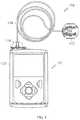
- FIG. 3illustrates an exemplary embodiment of a fluid infusion delivery device 12 coupled with an infusion set 104 with a fluid conduit assembly for use in the fluid delivery system 10 of FIG. 1
- the fluid infusion delivery device 12accommodates a fluid reservoir (hidden from view in FIG. 3 ) for the infusate to be delivered to the user.
- the illustrated embodiment of the infusion set 104includes, without limitation: a length of tubing 110 ; an infusion unit 112 coupled to the distal end of the tubing 110 ; and a connector 114 coupled to the proximal end of the tubing 110 .
- the fluid infusion delivery device 12is designed to be carried or worn by the patient, and the infusion set 104 terminates at the infusion unit 112 such that the fluid infusion delivery device 12 can deliver fluid to the body of the patient via the tubing 110 .
- the infusion unit 112includes a cannula (hidden from view in FIG. 3 ) that is coupled to the distal end of the tubing 110 . The cannula is inserted into the skin and is held in place during use of the fluid infusion delivery device 12 .
- the infusion set 104defines a fluid flow path that fluidly couples a fluid reservoir to the infusion unit 112 .
- the connector 114mates with and couples to a section of the fluid reservoir (not shown), which in turn is coupled to a housing 120 of the fluid infusion delivery device 12 .
- the connector 114establishes the fluid path from the fluid reservoir to the tubing 110 .
- Actuation of the fluid infusion delivery device 12causes the medication fluid to be expelled from the fluid reservoir, through the infusion set 104 , and into the body of the patient via the infusion unit 112 and cannula at the distal end of the tubing 110 .
- the tubing 110extends from the fluid infusion delivery device 12 to the infusion unit 112 , which in turn provides a fluid pathway to the body of the patient.
- the fluid infusion delivery device 12includes a radio frequency (RF) antenna to support wireless data communication with other devices, systems, and/or components.
- the RF antennacan be located inside the housing 120 or it can be integrally formed with the housing 120 . Accordingly, the RF antenna is hidden from view in FIG. 3 .
- each embodiment of the fluid delivery device 12includes a reservoir for holding an infusate and a fluid path for delivering the infusate from the reservoir to the patient.
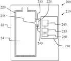
- FIG. 4illustrates an embodiment of an apparatus and system for identifying the infusate in the reservoir.
- an identifying system 200is provided for use with the fluid delivery device of FIGS. 1-3 .
- the identifying system 200includes a detector arrangement 210 to identify the infusate by detecting a visual change in the indicator.
- a fluid reservoir 24is received by a portion 22 of the delivery device.
- the reservoir 24is bounded by a wall 220 .
- a testing chamber 225is provided in the identifying system 200 .
- the testing chamber 225is bound by a wall 230 .
- at least a portion of the wall 230is transparent.
- the wall 230may be formed from a transparent material such as clear polycarbonate, polypropylene, polyurethane/polypropylene, or other clear polymeric material.
- the wall 230may be formed with a transparent window formed from clear polycarbonate, polypropylene, polyurethane/polypropylene, or other clear polymeric material.
- the wall 220 of the reservoir 24 and the wall 230 of the testing chamber 225are integrally formed.
- the testing chamber 225in certain embodiments is realized as an extension or a pocket of the reservoir 24 .
- Suitable one-way valvesmay include ball check valves, diaphragm check valves, swing/tilting check valves, stop-check valves, lift-check valves, in-line check valves, duckbill valves, pneumatic non-return valves, or others.
- an indicator 240is located in the testing chamber 225 .
- the indicatoris an indicator chemical, such as dithizone, pseudoisocyanin compounds, aldehyde fuchsin, Victoria 4R blue, various chromophore/fluorophore labelled insulin antibodies, and others.
- the indicator 240can be a small piece of carrier material having an indicator chemical applied to it and/or having an indicator chemical impregnated therein.
- the indicator 240can be realized as or attached to an inner surface of the chamber 225 .
- the indicator 240may be provided in solid or fluid phase. During manufacture of the reservoir 24 and testing chamber 225 , the indicator 240 is sealed in the testing chamber 225 by the one-way valve.
- An exemplary indicator 240exhibits and/or causes the infusate to exhibit a visual change when the indicator 240 is contacted by the infusate.
- the indicator 240may exhibit and/or cause the infusate to exhibit a color change when the indicator 240 is contacted by the infusate.
- the indicatorcauses a change to a first color when contacted with a first infusate, such as U-100 insulin, a change to a second color when contacted with a second infusate, such as U-200 insulin, a change to a third color when contacted with a third infusate, such as U-300 insulin, or a change to a fourth color when contacted with a fourth infusate, such as U-500 insulin.
- concentration of the indicatore.g. dithizone, a light blue color
- the concentration of the indicatore.g. dithizone, a light blue color
- the detector arrangement 210is shown to include a receiver element 245 for receiving light from the testing chamber 225 .
- the receiver element 245may be aligned with a window in the wall 230 , if provided.
- An exemplary receiver element 245is a camera, a color sensitive light sensor, or a photosensor (such as a charge coupled device array as commonly found in digital cameras).
- An exemplary camera 245is configured to capture images of the fluid and indicator 240 in the testing chamber 225 . Further, the exemplary camera 245 generates a signal, such as a signal including image data. For example, the exemplary camera 245 may generate a digital file of the image.
- the detector arrangement 210further includes a printed circuit board (PCB) 250 .
- the receiver element 245is coupled to the PCB 250 .
- the PCB 250may be part of receiver electronics.
- the PCB 250may be in communication with sensing arrangement 14 , CCD 16 or computer 18 of FIG. 1 through the receiver electronics.
- the detector arrangement 210further includes an identifier element 255 electronically connected to the receiver element 245 .
- the identifier element 255may receive and analyze the signal from the receiver element 245 .
- the sensing arrangement 14 , CCD 16 or computer 18may include an identifier element for analyzing the signal from the receiver element 245 .
- the identifier element 255analyses the signal received from the receiver element 245 by comparing the image data therein with image data from a library of previously tested infusates and their associated image data. For this reason, the identifier element 255 may include or be in electronic communication with a memory storage or library 260 storing the image data of known infusates and concentrations of infusates.
- the receiver element 245 , identifier element 255 and memory storage 260are coupled to the PCB 250 such that the PCB 250 may activate and identification operation.
- the PCB 250may active an identification operation when the reservoir is filled, when the user prompts the delivery device, or during preset time intervals.
- the PCB 250may verify that the identified infusate is the proper infusate, i.e., the expected infusate.
- the PCB 250may communicate the identity of the infusate and the infusate concentration to the sensing arrangement 14 , CCD 16 or computer 18 so that a fluid delivery regime may be modified for use with the identified infusate.
- FIG. 5illustrates an embodiment in which the identifying apparatus 200 includes more than one detector arrangement.
- the identifying apparatus 200includes a detector arrangement 210 and the elements thereof as described in relation to FIG. 4 . Also, the identifying apparatus 200 includes a detector arrangement 310 that performs orthogonal identification.
- the detector arrangement 310includes a transceiver 340 provided with both a transmitter element and a receiver element.
- the transceiver 340may be aligned with a window in the wall 230 , if provided, so that the transceiver 340 may transmit a beam of energy through the window, or through a transparent or translucent portion of wall 230 , and into contact with an infusate located in the testing chamber 225 , and may receive a reflected beam of energy from the infusate back to the transceiver 340 .
- the transceiver 340is mounted to a printed circuit board (PCB) 350 that may be part of receiver electronics located within the durable portion 22 .
- the PCB 350may be an additional PCB, or may be part of PCB 250 .
- the PCB 350may be in communication with sensing arrangement 14 , CCD 16 or computer 18 of FIG. 1 through the receiver electronics.
- the PCB 350may serve as an identifier element for analyzing a signal received by a receiver element of the transceiver 340 .
- the sensing arrangement 14 , CCD 16 or computer 18may include an identifier element for analyzing a signal received by a receiver element of the transceiver 340 .
- the identifier elementmay analyze an electronic representation of the signal that may include electric or intensity readings at one or more wavelengths or a spectra over an selected range of wavelengths, such as from 0.2 to 16 ⁇ m.
- FIG. 5illustrates an embodiment in which the detector arrangement 310 includes a transceiver 340 that is mounted to a durable portion 22
- the transmitter element and receiver element of the transceiver 340may be physically decoupled from the conduit where analysis is to be performed.
- the transmitter and receiver elements of the transceiver 340may be mounted to the wall 230 of the conduit where analysis is to be performed.
- transmitter and receiver elements of the transceiver 340may be located within the conduit where analysis is to be performed.
- transmitter and receiver elements of the transceiver 340could be formed as parts of other components within the fluid delivery device.
- the detector arrangement 310may be located in any suitable location along the fluid path of a fluid delivery device 12 .
- the detector arrangement 310could be provided to transmit a beam of energy into contact with an infusate located in the reservoir 24 and to receive a reflected beam of energy from the infusate back to the transceiver 340 .
- any of the components containing or delivering a flow of an infusateare considered a conduit where a detector arrangement 310 may be located.
- a fluid delivery device 12may be provided with more than one detector arrangements 310 and/or more than one detector arrangements 210 .
- each of the detector arrangements 310transmits a beam of energy into the fluid orthogonally to the direction of fluid flow or to the wall of the vessel through which the fluid flows.
- Detector arrangements 310may identify the composition and concentration of a fluid or infusate within a conduit, such as a reservoir, hollow tube, or other fluid path, that is bound by a wall.
- the wallmay be transparent and not include a separate distinct window.
- a beam of energysuch as IR, NIR, or UV energy, is transmitted into the conduit from a transmitter element of the transceiver 340 and interacts with the infusate and any foreign matter therein. For example, different portions or wavelength ranges of the beam of energy may be absorbed, refracted or reflected.
- a resulting beam of energypasses out of the conduit and is received by a receiver element of the transceiver 340 as a signal. The signal can be analyzed to determine the composition and concentration of the infusate and whether foreign matter is present in the infusate.
- FIG. 6illustrates an exemplary method 400 for identifying a fluid for delivery to a body of a user.
- an initial manufacturing step 402provides for packaging the reservoir 24 and testing chamber 225 with the indicator 240 .
- the indicator 240is sealed in the testing chamber 225 by the one-way valve 235 .
- a manufacturing processmay form and package the compound bundled reservoir 24 and testing chamber 225 with the indicator 240 . Therefore, a user may remove the bundled reservoir 24 and testing chamber 225 from packaging and fill the reservoir with the desired infusate for infusion from a delivery device such as at step 404 .
- the one-way valveUpon filling the reservoir 24 with infusate, the one-way valve permits a portion of the infusate to enter the testing chamber 225 and contact the indicator. Upon contact therebetween, a visual change such as a color change is exhibited, such as at step 406 .
- the usermay couple the infusate reservoir with the fluid delivery device at step 408 .
- the identification processmay be automatically initiated to confirm that the correct infusate is loaded in the fluid delivery device.
- the identification processmay be initiated by the user or during preset time intervals.
- the identification processincludes capturing an image of the testing chamber including the indicator and infusate, or a solution thereof, at step 410 .
- the method 400includes generating a signal including image data at step 412 . The signal may be generated by the receiver element or camera and then communicated to the identifier element.
- the methodanalyzes the image data, such as by comparing the image data with stored image data associated with known infusates at known concentrations. In this manner, the identity of the infusate and concentration of the infusate received in the reservoir can be identified.
- the methodqueries whether, based on the image data comparison, the proper or expected infusate is loaded in the fluid delivery device. If not, the PCB, sensing arrangement, CCD or computer may automatically alert the user and/or disable infusion of the infusate from the fluid delivery device or modify fluid delivery to an appropriate process for the identified infusate at step 418 . On the other hand, if the correct infusate is loaded, the PCB, sensing arrangement, CCD or computer may confirm that the correct infusate is loaded and allow the fluid delivery device to proceed with an infusion process at step 420 .
- FIG. 7illustrates an exemplary method 500 for identifying a fluid for delivery to a body of a user.
- an infusate reservoir or other container with a conduit holding an infusateis coupled to a fluid delivery device at step 502 .
- the identification processmay be initiated to confirm that the correct infusate is loaded in the fluid delivery device.
- the identification processmay be initiated when fluid is forced out of the reservoir and through a testing location elsewhere in the fluid conduit.
- a beam of energyis transmitted from the transmitter element into the conduit holding the infusate.
- the beam of energyinteracts with the infusate and exits the conduit as a resulting beam of energy.
- a beam of energy reflected at the interface of the conduit and wall bounding the conduitis considered to have passed through the wall and exits the conduit upon reflection with the interface.
- the resulting beam of energyis received by the receiver element.
- the signal of the resulting beam of energyis communicated from the receiver element to an identifier element.
- the signalmay be wirelessly communicated from the receiver element to the identifier element.
- the identifier elementmay be contained within a PCB, sensing arrangement, CCD or computer.
- the signalis or includes spectroscopic data that may be represented by a spectrum that may be plotted as a graph of energy absorbance (or transmittance) on the vertical axis vs. frequency or wavelength on the horizontal axis.
- the identifier elementincludes or is coupled to a memory storage or library of spectra of known, i.e., previously tested compositions and concentrations.
- the memorystores data associated with selected fluids for comparison with detected characteristics of the signal.
- the spectrum of the signalis compared to the spectra of known compositions and concentrations.
- the identifier elementmay use the stored data to identify the infusate based on the received signal.
- different compositions and different concentrations of those compositionsexhibit unique spectra or signature spectra. For example, differing values of intensity of radiation at specific wavelengths or frequencies or over specific ranges of wavelengths or frequencies may indicate that the beam of energy passed through a specific concentration of a specific composition.
- Spectral different regions of a reflective NIR/IR spectra graph of fluid-path materials and infusatesmay be used for infusate/bubble tracking.
- Spectroscopic signals at various wavelengthsmay be orthogonally used for better identification accuracy.
- the methodqueries whether, based on the signal spectrum comparison, the proper or expected infusate is loaded in the fluid delivery device. If not, the PCB, sensing arrangement, CCD or computer may automatically alert the user and/or disable infusion of the infusate from the fluid delivery device at step 514 . On the other hand, if the correct infusate is loaded, the PCB, sensing arrangement, CCD or computer may confirm that the correct infusate is loaded and allow the fluid delivery device to proceed with an infusion process at step 516 .
- any electronic devicecould be configured to analyze and identify the composition and concentration of a fluid contained in a reservoir through selective contact with an indicator, image capture of the fluid and indicator, and image analysis.
Landscapes
- Health & Medical Sciences (AREA)
- Engineering & Computer Science (AREA)
- General Health & Medical Sciences (AREA)
- Public Health (AREA)
- Veterinary Medicine (AREA)
- Anesthesiology (AREA)
- Biomedical Technology (AREA)
- Heart & Thoracic Surgery (AREA)
- Hematology (AREA)
- Life Sciences & Earth Sciences (AREA)
- Animal Behavior & Ethology (AREA)
- Vascular Medicine (AREA)
- Diabetes (AREA)
- Dermatology (AREA)
- Computer Vision & Pattern Recognition (AREA)
- Physics & Mathematics (AREA)
- General Physics & Mathematics (AREA)
- Theoretical Computer Science (AREA)
- Infusion, Injection, And Reservoir Apparatuses (AREA)
- Multimedia (AREA)
- Signal Processing (AREA)
- Medical Informatics (AREA)
- Nuclear Medicine, Radiotherapy & Molecular Imaging (AREA)
- Radiology & Medical Imaging (AREA)
- Quality & Reliability (AREA)
Abstract
Description
Claims (19)
Priority Applications (1)
| Application Number | Priority Date | Filing Date | Title |
|---|---|---|---|
| US15/438,612US11207463B2 (en) | 2017-02-21 | 2017-02-21 | Apparatuses, systems, and methods for identifying an infusate in a reservoir of an infusion device |
Applications Claiming Priority (1)
| Application Number | Priority Date | Filing Date | Title |
|---|---|---|---|
| US15/438,612US11207463B2 (en) | 2017-02-21 | 2017-02-21 | Apparatuses, systems, and methods for identifying an infusate in a reservoir of an infusion device |
Publications (2)
| Publication Number | Publication Date |
|---|---|
| US20180240236A1 US20180240236A1 (en) | 2018-08-23 |
| US11207463B2true US11207463B2 (en) | 2021-12-28 |
Family
ID=63168012
Family Applications (1)
| Application Number | Title | Priority Date | Filing Date |
|---|---|---|---|
| US15/438,612Active2039-02-23US11207463B2 (en) | 2017-02-21 | 2017-02-21 | Apparatuses, systems, and methods for identifying an infusate in a reservoir of an infusion device |
Country Status (1)
| Country | Link |
|---|---|
| US (1) | US11207463B2 (en) |
Families Citing this family (2)
| Publication number | Priority date | Publication date | Assignee | Title |
|---|---|---|---|---|
| EP3787715B1 (en) | 2018-05-02 | 2023-11-08 | Cequr SA | Devices and methods for providing a bolus dose in a microfluidic circuit of a pump |
| CA3223473A1 (en)* | 2021-06-24 | 2022-12-29 | Nitish Kumar Varma KUNAPARAJU | User removable fill closure tab with integrated membrane |
Citations (229)
| Publication number | Priority date | Publication date | Assignee | Title |
|---|---|---|---|---|
| US3631847A (en) | 1966-03-04 | 1972-01-04 | James C Hobbs | Method and apparatus for injecting fluid into the vascular system |
| US4212738A (en) | 1977-03-28 | 1980-07-15 | Akzo N.V. | Artificial kidney |
| US4270532A (en) | 1977-12-28 | 1981-06-02 | Siemens Aktiengesellschaft | Device for the pre-programmable infusion of liquids |
| US4282872A (en) | 1977-12-28 | 1981-08-11 | Siemens Aktiengesellschaft | Device for the pre-programmable infusion of liquids |
| US4373527A (en) | 1979-04-27 | 1983-02-15 | The Johns Hopkins University | Implantable, programmable medication infusion system |
| US4395259A (en) | 1980-09-22 | 1983-07-26 | Siemens Aktiengesellschaft | Device for the infusion of fluids into the human or animal body |
| US4433072A (en) | 1978-12-15 | 1984-02-21 | Hospal-Sodip, S.A. | Mixtures of polymers for medical use |
| US4443218A (en) | 1982-09-09 | 1984-04-17 | Infusaid Corporation | Programmable implantable infusate pump |
| US4494950A (en) | 1982-01-19 | 1985-01-22 | The Johns Hopkins University | Plural module medication delivery system |
| US4542532A (en) | 1984-03-09 | 1985-09-17 | Medtronic, Inc. | Dual-antenna transceiver |
| US4550731A (en) | 1984-03-07 | 1985-11-05 | Cordis Corporation | Acquisition circuit for cardiac pacer |
| US4559037A (en) | 1977-12-28 | 1985-12-17 | Siemens Aktiengesellschaft | Device for the pre-programmable infusion of liquids |
| US4562751A (en) | 1984-01-06 | 1986-01-07 | Nason Clyde K | Solenoid drive apparatus for an external infusion pump |
| US4671288A (en) | 1985-06-13 | 1987-06-09 | The Regents Of The University Of California | Electrochemical cell sensor for continuous short-term use in tissues and blood |
| US4678408A (en) | 1984-01-06 | 1987-07-07 | Pacesetter Infusion, Ltd. | Solenoid drive apparatus for an external infusion pump |
| US4685903A (en) | 1984-01-06 | 1987-08-11 | Pacesetter Infusion, Ltd. | External infusion pump apparatus |
| US4731726A (en) | 1986-05-19 | 1988-03-15 | Healthware Corporation | Patient-operated glucose monitor and diabetes management system |
| US4731051A (en) | 1979-04-27 | 1988-03-15 | The Johns Hopkins University | Programmable control means for providing safe and controlled medication infusion |
| US4781798A (en) | 1985-04-19 | 1988-11-01 | The Regents Of The University Of California | Transparent multi-oxygen sensor array and method of using same |
| US4803625A (en) | 1986-06-30 | 1989-02-07 | Buddy Systems, Inc. | Personal health monitor |
| US4809697A (en) | 1987-10-14 | 1989-03-07 | Siemens-Pacesetter, Inc. | Interactive programming and diagnostic system for use with implantable pacemaker |
| US4826810A (en) | 1983-12-16 | 1989-05-02 | Aoki Thomas T | System and method for treating animal body tissues to improve the dietary fuel processing capabilities thereof |
| EP0319268A2 (en) | 1987-12-04 | 1989-06-07 | IVAC MEDICAL SYSTEMS, Inc. | Clinical configuration of multimode medication infusion system |
| US4871351A (en) | 1984-09-28 | 1989-10-03 | Vladimir Feingold | Implantable medication infusion system |
| GB2218831A (en) | 1988-05-17 | 1989-11-22 | Mark John Newland | Personal medical apparatus |
| US4898578A (en) | 1988-01-26 | 1990-02-06 | Baxter International Inc. | Drug infusion system with calculator |
| US5003298A (en) | 1986-01-15 | 1991-03-26 | Karel Havel | Variable color digital display for emphasizing position of decimal point |
| US5011468A (en) | 1987-05-29 | 1991-04-30 | Retroperfusion Systems, Inc. | Retroperfusion and retroinfusion control apparatus, system and method |
| US5019974A (en) | 1987-05-01 | 1991-05-28 | Diva Medical Systems Bv | Diabetes management system and apparatus |
| US5050612A (en) | 1989-09-12 | 1991-09-24 | Matsumura Kenneth N | Device for computer-assisted monitoring of the body |
| US5078683A (en) | 1990-05-04 | 1992-01-07 | Block Medical, Inc. | Programmable infusion system |
| US5080653A (en) | 1990-04-16 | 1992-01-14 | Pacesetter Infusion, Ltd. | Infusion pump with dual position syringe locator |
| US5097122A (en) | 1990-04-16 | 1992-03-17 | Pacesetter Infusion, Ltd. | Medication infusion system having optical motion sensor to detect drive mechanism malfunction |
| US5100380A (en) | 1984-02-08 | 1992-03-31 | Abbott Laboratories | Remotely programmable infusion system |
| US5101814A (en) | 1989-08-11 | 1992-04-07 | Palti Yoram Prof | System for monitoring and controlling blood glucose |
| US5108819A (en) | 1990-02-14 | 1992-04-28 | Eli Lilly And Company | Thin film electrical component |
| US5153827A (en) | 1989-01-30 | 1992-10-06 | Omni-Flow, Inc. | An infusion management and pumping system having an alarm handling system |
| US5165407A (en) | 1990-04-19 | 1992-11-24 | The University Of Kansas | Implantable glucose sensor |
| US5247434A (en) | 1991-04-19 | 1993-09-21 | Althin Medical, Inc. | Method and apparatus for kidney dialysis |
| US5262035A (en) | 1989-08-02 | 1993-11-16 | E. Heller And Company | Enzyme electrodes |
| US5262305A (en) | 1991-03-04 | 1993-11-16 | E. Heller & Company | Interferant eliminating biosensors |
| US5264104A (en) | 1989-08-02 | 1993-11-23 | Gregg Brian A | Enzyme electrodes |
| US5264105A (en) | 1989-08-02 | 1993-11-23 | Gregg Brian A | Enzyme electrodes |
| US5284140A (en) | 1992-02-11 | 1994-02-08 | Eli Lilly And Company | Acrylic copolymer membranes for biosensors |
| US5299571A (en) | 1993-01-22 | 1994-04-05 | Eli Lilly And Company | Apparatus and method for implantation of sensors |
| US5307263A (en) | 1992-11-17 | 1994-04-26 | Raya Systems, Inc. | Modular microprocessor-based health monitoring system |
| US5320725A (en) | 1989-08-02 | 1994-06-14 | E. Heller & Company | Electrode and method for the detection of hydrogen peroxide |
| US5322063A (en) | 1991-10-04 | 1994-06-21 | Eli Lilly And Company | Hydrophilic polyurethane membranes for electrochemical glucose sensors |
| US5338157A (en) | 1992-09-09 | 1994-08-16 | Pharmacia Deltec, Inc. | Systems and methods for communicating with ambulatory medical devices such as drug delivery devices |
| US5339821A (en) | 1992-02-13 | 1994-08-23 | Seta Co., Ltd. | Home medical system and medical apparatus for use therewith |
| US5341291A (en) | 1987-12-09 | 1994-08-23 | Arch Development Corporation | Portable medical interactive test selector having plug-in replaceable memory |
| US5350411A (en) | 1993-06-28 | 1994-09-27 | Medtronic, Inc. | Pacemaker telemetry system |
| US5356786A (en) | 1991-03-04 | 1994-10-18 | E. Heller & Company | Interferant eliminating biosensor |
| US5357427A (en) | 1993-03-15 | 1994-10-18 | Digital Equipment Corporation | Remote monitoring of high-risk patients using artificial intelligence |
| US5368562A (en) | 1993-07-30 | 1994-11-29 | Pharmacia Deltec, Inc. | Systems and methods for operating ambulatory medical devices such as drug delivery devices |
| US5370622A (en) | 1994-04-28 | 1994-12-06 | Minimed Inc. | Proctective case for a medication infusion pump |
| US5371687A (en) | 1992-11-20 | 1994-12-06 | Boehringer Mannheim Corporation | Glucose test data acquisition and management system |
| US5376070A (en) | 1992-09-29 | 1994-12-27 | Minimed Inc. | Data transfer system for an infusion pump |
| US5391250A (en) | 1994-03-15 | 1995-02-21 | Minimed Inc. | Method of fabricating thin film sensors |
| US5390671A (en) | 1994-03-15 | 1995-02-21 | Minimed Inc. | Transcutaneous sensor insertion set |
| DE4329229A1 (en) | 1993-08-25 | 1995-03-09 | Meditech Medizintechnik Gmbh | Adaptive controlled pump control, in particular for adaptive patient-controlled analgesia (APCA) |
| US5411647A (en) | 1992-11-23 | 1995-05-02 | Eli Lilly And Company | Techniques to improve the performance of electrochemical sensors |
| US5482473A (en) | 1994-05-09 | 1996-01-09 | Minimed Inc. | Flex circuit connector |
| US5497772A (en) | 1993-11-19 | 1996-03-12 | Alfred E. Mann Foundation For Scientific Research | Glucose monitoring system |
| US5505709A (en) | 1994-09-15 | 1996-04-09 | Minimed, Inc., A Delaware Corporation | Mated infusion pump and syringe |
| WO1996020745A1 (en) | 1995-01-06 | 1996-07-11 | Abbott Laboratories | Medicinal fluid pump having multiple stored protocols |
| US5543326A (en) | 1994-03-04 | 1996-08-06 | Heller; Adam | Biosensor including chemically modified enzymes |
| US5569187A (en) | 1994-08-16 | 1996-10-29 | Texas Instruments Incorporated | Method and apparatus for wireless chemical supplying |
| US5569186A (en) | 1994-04-25 | 1996-10-29 | Minimed Inc. | Closed loop infusion pump system with removable glucose sensor |
| US5573506A (en) | 1994-11-25 | 1996-11-12 | Block Medical, Inc. | Remotely programmable infusion system |
| WO1996036389A1 (en) | 1995-05-15 | 1996-11-21 | Ivac Medical Systems, Inc. | Automated infusion system with dose rate calculator |
| WO1996037246A1 (en) | 1995-05-26 | 1996-11-28 | Minimed Inc. | Medication infusion device with blood glucose data input |
| US5582593A (en) | 1994-07-21 | 1996-12-10 | Hultman; Barry W. | Ambulatory medication delivery system |
| US5586553A (en) | 1995-02-16 | 1996-12-24 | Minimed Inc. | Transcutaneous sensor insertion set |
| US5593390A (en) | 1994-03-09 | 1997-01-14 | Visionary Medical Products, Inc. | Medication delivery device with a microprocessor and characteristic monitor |
| US5593852A (en) | 1993-12-02 | 1997-01-14 | Heller; Adam | Subcutaneous glucose electrode |
| US5594638A (en) | 1993-12-29 | 1997-01-14 | First Opinion Corporation | Computerized medical diagnostic system including re-enter function and sensitivity factors |
| US5609060A (en) | 1995-04-28 | 1997-03-11 | Dentsleeve Pty Limited | Multiple channel perfused manometry apparatus and a method of operation of such a device |
| US5626144A (en) | 1994-05-23 | 1997-05-06 | Enact Health Management Systems | System for monitoring and reporting medical measurements |
| US5630710A (en) | 1994-03-09 | 1997-05-20 | Baxter International Inc. | Ambulatory infusion pump |
| WO1997021456A1 (en) | 1995-12-12 | 1997-06-19 | The University Of Melbourne | Field programmable intravenous infusion system |
| US5660176A (en) | 1993-12-29 | 1997-08-26 | First Opinion Corporation | Computerized medical diagnostic and treatment advice system |
| US5665222A (en) | 1995-10-11 | 1997-09-09 | E. Heller & Company | Soybean peroxidase electrochemical sensor |
| EP0806738A1 (en) | 1996-05-07 | 1997-11-12 | Société D'Etudes Techniques - S E T | Neural networks arrangement for the determination of a substance dosage to administer to a patient |
| US5687734A (en) | 1994-10-20 | 1997-11-18 | Hewlett-Packard Company | Flexible patient monitoring system featuring a multiport transmitter |
| US5750926A (en) | 1995-08-16 | 1998-05-12 | Alfred E. Mann Foundation For Scientific Research | Hermetically sealed electrical feedthrough for use with implantable electronic devices |
| WO1998020439A1 (en) | 1996-11-08 | 1998-05-14 | Roman Linda L | System for providing comprehensive health care and support |
| US5754111A (en) | 1995-09-20 | 1998-05-19 | Garcia; Alfredo | Medical alerting system |
| US5764159A (en) | 1994-02-16 | 1998-06-09 | Debiotech S.A. | Apparatus for remotely monitoring controllable devices |
| WO1998024358A2 (en) | 1996-12-04 | 1998-06-11 | Enact Health Management Systems | System for downloading and reporting medical information |
| US5779665A (en) | 1997-05-08 | 1998-07-14 | Minimed Inc. | Transdermal introducer assembly |
| US5788669A (en) | 1995-11-22 | 1998-08-04 | Sims Deltec, Inc. | Pump tracking system |
| US5791344A (en) | 1993-11-19 | 1998-08-11 | Alfred E. Mann Foundation For Scientific Research | Patient monitoring system |
| US5800420A (en) | 1994-11-04 | 1998-09-01 | Elan Medical Technologies Limited | Analyte-controlled liquid delivery device and analyte monitor |
| US5807336A (en) | 1996-08-02 | 1998-09-15 | Sabratek Corporation | Apparatus for monitoring and/or controlling a medical device |
| US5814015A (en) | 1995-02-24 | 1998-09-29 | Harvard Clinical Technology, Inc. | Infusion pump for at least one syringe |
| WO1998042407A1 (en) | 1997-03-27 | 1998-10-01 | Medtronic, Inc. | Concepts to implement medconnect |
| US5822715A (en) | 1997-01-10 | 1998-10-13 | Health Hero Network | Diabetes management system and method for controlling blood glucose |
| US5832448A (en) | 1996-10-16 | 1998-11-03 | Health Hero Network | Multiple patient monitoring system for proactive health management |
| WO1998049659A2 (en) | 1997-04-25 | 1998-11-05 | Sekura Ronald D | Prescription compliance device and method of using device |
| US5840020A (en) | 1996-02-12 | 1998-11-24 | Nokia Mobile Phones, Ltd. | Monitoring method and a monitoring equipment |
| EP0880936A2 (en) | 1997-05-29 | 1998-12-02 | Koji Akai | Monitoring physical condition of a patient by telemetry |
| WO1998059487A1 (en) | 1997-06-23 | 1998-12-30 | Enact Health Management Systems | Improved system for downloading and reporting medical information |
| US5861018A (en) | 1996-05-28 | 1999-01-19 | Telecom Medical Inc. | Ultrasound transdermal communication system and method |
| WO1999008183A1 (en) | 1997-08-11 | 1999-02-18 | Electronic Monitoring Systems, Inc. | Remote monitoring system |
| WO1999010801A1 (en) | 1997-08-22 | 1999-03-04 | Apex Inc. | Remote computer control system |
| US5879163A (en) | 1996-06-24 | 1999-03-09 | Health Hero Network, Inc. | On-line health education and feedback system using motivational driver profile coding and automated content fulfillment |
| US5885245A (en) | 1996-08-02 | 1999-03-23 | Sabratek Corporation | Medical apparatus with remote virtual input device |
| WO1999018532A1 (en) | 1997-10-07 | 1999-04-15 | Health Hero Network, Inc. | Networked system for interactive communication and remote monitoring of individuals |
| US5897493A (en) | 1997-03-28 | 1999-04-27 | Health Hero Network, Inc. | Monitoring system for remotely querying individuals |
| US5899855A (en) | 1992-11-17 | 1999-05-04 | Health Hero Network, Inc. | Modular microprocessor-based health monitoring system |
| WO1999022236A1 (en) | 1997-10-27 | 1999-05-06 | Nokia Mobile Phones Limited | Calibration of measured physical parameters |
| US5904708A (en) | 1998-03-19 | 1999-05-18 | Medtronic, Inc. | System and method for deriving relative physiologic signals |
| US5913310A (en) | 1994-05-23 | 1999-06-22 | Health Hero Network, Inc. | Method for diagnosis and treatment of psychological and emotional disorders using a microprocessor-based video game |
| US5917346A (en) | 1997-09-12 | 1999-06-29 | Alfred E. Mann Foundation | Low power current to frequency converter circuit for use in implantable sensors |
| US5918603A (en) | 1994-05-23 | 1999-07-06 | Health Hero Network, Inc. | Method for treating medical conditions using a microprocessor-based video game |
| US5933136A (en) | 1996-12-23 | 1999-08-03 | Health Hero Network, Inc. | Network media access control system for encouraging patient compliance with a treatment plan |
| US5935099A (en) | 1992-09-09 | 1999-08-10 | Sims Deltec, Inc. | Drug pump systems and methods |
| US5940801A (en) | 1994-04-26 | 1999-08-17 | Health Hero Network, Inc. | Modular microprocessor-based diagnostic measurement apparatus and method for psychological conditions |
| US5960403A (en) | 1992-11-17 | 1999-09-28 | Health Hero Network | Health management process control system |
| US5972199A (en) | 1995-10-11 | 1999-10-26 | E. Heller & Company | Electrochemical analyte sensors using thermostable peroxidase |
| US5978236A (en) | 1997-01-31 | 1999-11-02 | Silverline Power Conversion Llc | Uninterruptible power supply with direction of DC electrical energy depending on predetermined ratio |
| US5999848A (en) | 1997-09-12 | 1999-12-07 | Alfred E. Mann Foundation | Daisy chainable sensors and stimulators for implantation in living tissue |
| US5999849A (en) | 1997-09-12 | 1999-12-07 | Alfred E. Mann Foundation | Low power rectifier circuit for implantable medical device |
| US6009339A (en) | 1997-02-27 | 1999-12-28 | Terumo Cardiovascular Systems Corporation | Blood parameter measurement device |
| US6032119A (en) | 1997-01-16 | 2000-02-29 | Health Hero Network, Inc. | Personalized display of health information |
| WO2000010628A2 (en) | 1998-08-18 | 2000-03-02 | Minimed Inc. | External infusion device with remote programming, bolus estimator and/or vibration alarm capabilities |
| US6043437A (en) | 1996-12-20 | 2000-03-28 | Alfred E. Mann Foundation | Alumina insulation for coating implantable components and other microminiature devices |
| WO2000019887A1 (en) | 1998-10-08 | 2000-04-13 | Minimed Inc. | Telemetered characteristic monitor system |
| US6081736A (en) | 1997-10-20 | 2000-06-27 | Alfred E. Mann Foundation | Implantable enzyme-based monitoring systems adapted for long term use |
| US6088608A (en) | 1997-10-20 | 2000-07-11 | Alfred E. Mann Foundation | Electrochemical sensor and integrity tests therefor |
| US6101478A (en) | 1997-04-30 | 2000-08-08 | Health Hero Network | Multi-user remote health monitoring system |
| US6103033A (en) | 1998-03-04 | 2000-08-15 | Therasense, Inc. | Process for producing an electrochemical biosensor |
| WO2000048112A2 (en) | 1999-02-10 | 2000-08-17 | Baxter International, Inc. | Medical apparatus using selective graphical interface |
| US6119028A (en) | 1997-10-20 | 2000-09-12 | Alfred E. Mann Foundation | Implantable enzyme-based monitoring systems having improved longevity due to improved exterior surfaces |
| US6120676A (en) | 1997-02-06 | 2000-09-19 | Therasense, Inc. | Method of using a small volume in vitro analyte sensor |
| US6134461A (en) | 1998-03-04 | 2000-10-17 | E. Heller & Company | Electrochemical analyte |
| US6175752B1 (en) | 1998-04-30 | 2001-01-16 | Therasense, Inc. | Analyte monitoring device and methods of use |
| US6183412B1 (en) | 1997-10-02 | 2001-02-06 | Micromed Technology, Inc. | Implantable pump system |
| US6259937B1 (en) | 1997-09-12 | 2001-07-10 | Alfred E. Mann Foundation | Implantable substrate sensor |
| US20010044731A1 (en) | 2000-05-18 | 2001-11-22 | Coffman Damon J. | Distributed remote asset and medication management drug delivery system |
| US20020013518A1 (en) | 2000-05-19 | 2002-01-31 | West Kenneth G. | Patient monitoring system |
| US20020022855A1 (en) | 1997-12-31 | 2002-02-21 | Bobroff Randa M. | Insertion device for an insertion set and method of using the same |
| US20020055857A1 (en) | 2000-10-31 | 2002-05-09 | Mault James R. | Method of assisting individuals in lifestyle control programs conducive to good health |
| US6408330B1 (en) | 1997-04-14 | 2002-06-18 | Delahuerga Carlos | Remote data collecting and address providing method and apparatus |
| US20020082665A1 (en) | 1999-07-07 | 2002-06-27 | Medtronic, Inc. | System and method of communicating between an implantable medical device and a remote computer system or health care provider |
| US6424847B1 (en) | 1999-02-25 | 2002-07-23 | Medtronic Minimed, Inc. | Glucose monitor calibration methods |
| WO2002058537A2 (en) | 2001-01-02 | 2002-08-01 | Therasense, Inc. | Analyte monitoring device and methods of use |
| US20020137997A1 (en) | 1999-02-25 | 2002-09-26 | Minimed Inc. | Test plug and cable for a glucose monitor |
| US20020161288A1 (en) | 2000-02-23 | 2002-10-31 | Medtronic Minimed, Inc. | Real time self-adjusting calibration algorithm |
| US6484045B1 (en) | 2000-02-10 | 2002-11-19 | Medtronic Minimed, Inc. | Analyte sensor and method of making the same |
| US6485465B2 (en) | 2000-03-29 | 2002-11-26 | Medtronic Minimed, Inc. | Methods, apparatuses, and uses for infusion pump fluid pressure and force detection |
| WO2003001329A2 (en) | 2001-06-20 | 2003-01-03 | Power Medical Interventions, Inc. | A method and system for integrated medical tracking |
| US6503381B1 (en) | 1997-09-12 | 2003-01-07 | Therasense, Inc. | Biosensor |
| US20030060765A1 (en) | 2000-02-16 | 2003-03-27 | Arthur Campbell | Infusion device menu structure and method of using the same |
| US6553263B1 (en) | 1999-07-30 | 2003-04-22 | Advanced Bionics Corporation | Implantable pulse generators using rechargeable zero-volt technology lithium-ion batteries |
| US20030078560A1 (en) | 2001-09-07 | 2003-04-24 | Miller Michael E. | Method and system for non-vascular sensor implantation |
| US6560741B1 (en) | 1999-02-24 | 2003-05-06 | Datastrip (Iom) Limited | Two-dimensional printed code for storing biometric information and integrated off-line apparatus for reading same |
| US6558320B1 (en) | 2000-01-20 | 2003-05-06 | Medtronic Minimed, Inc. | Handheld personal data assistant (PDA) with a medical device and method of using the same |
| US6558351B1 (en) | 1999-06-03 | 2003-05-06 | Medtronic Minimed, Inc. | Closed loop system for controlling insulin infusion |
| US6579690B1 (en) | 1997-12-05 | 2003-06-17 | Therasense, Inc. | Blood analyte monitoring through subcutaneous measurement |
| US6589229B1 (en) | 2000-07-31 | 2003-07-08 | Becton, Dickinson And Company | Wearable, self-contained drug infusion device |
| US6591125B1 (en) | 2000-06-27 | 2003-07-08 | Therasense, Inc. | Small volume in vitro analyte sensor with diffusible or non-leachable redox mediator |
| US6592745B1 (en) | 1998-10-08 | 2003-07-15 | Therasense, Inc. | Method of using a small volume in vitro analyte sensor with diffusible or non-leachable redox mediator |
| US20030144581A1 (en) | 1999-02-12 | 2003-07-31 | Cygnus, Inc. | Devices and methods for frequent measurement of an analyte present in a biological system |
| US6605200B1 (en) | 1999-11-15 | 2003-08-12 | Therasense, Inc. | Polymeric transition metal complexes and uses thereof |
| US20030152823A1 (en) | 1998-06-17 | 2003-08-14 | Therasense, Inc. | Biological fuel cell and methods |
| EP1338295A1 (en) | 2002-02-26 | 2003-08-27 | Lifescan, Inc. | Systems for remotely controlling medication infusion and analyte monitoring |
| US6616819B1 (en) | 1999-11-04 | 2003-09-09 | Therasense, Inc. | Small volume in vitro analyte sensor and methods |
| US20030176183A1 (en) | 2001-04-02 | 2003-09-18 | Therasense, Inc. | Blood glucose tracking apparatus and methods |
| US6623501B2 (en) | 2000-04-05 | 2003-09-23 | Therasense, Inc. | Reusable ceramic skin-piercing device |
| US20030208113A1 (en) | 2001-07-18 | 2003-11-06 | Mault James R | Closed loop glycemic index system |
| WO2003094090A2 (en) | 2002-04-30 | 2003-11-13 | Baxter International Inc. | System and method for identifying data streams associated with medical equipment |
| US6654625B1 (en) | 1999-06-18 | 2003-11-25 | Therasense, Inc. | Mass transport limited in vivo analyte sensor |
| US20030220552A1 (en) | 1999-07-01 | 2003-11-27 | Medtronic Minimed, Inc. | Reusable analyte sensor site and method of using the same |
| US6671554B2 (en) | 2001-09-07 | 2003-12-30 | Medtronic Minimed, Inc. | Electronic lead for a medical implant device, method of making same, and method and apparatus for inserting same |
| US6676816B2 (en) | 2001-05-11 | 2004-01-13 | Therasense, Inc. | Transition metal complexes with (pyridyl)imidazole ligands and sensors using said complexes |
| US6689265B2 (en) | 1995-10-11 | 2004-02-10 | Therasense, Inc. | Electrochemical analyte sensors using thermostable soybean peroxidase |
| US20040061234A1 (en) | 2002-09-27 | 2004-04-01 | Medtronic Minimed, Inc. | High reliability multlayer circuit substrates and methods for their formation |
| US20040064133A1 (en) | 2002-09-27 | 2004-04-01 | Medtronic-Minimed | Implantable sensor method and system |
| US20040064156A1 (en) | 2002-09-27 | 2004-04-01 | Medtronic Minimed, Inc. | Method and apparatus for enhancing the integrity of an implantable sensor device |
| US20040061232A1 (en) | 2002-09-27 | 2004-04-01 | Medtronic Minimed, Inc. | Multilayer substrate |
| US20040074785A1 (en) | 2002-10-18 | 2004-04-22 | Holker James D. | Analyte sensors and methods for making them |
| US6728576B2 (en) | 2001-10-31 | 2004-04-27 | Medtronic, Inc. | Non-contact EKG |
| US6733471B1 (en) | 1998-03-16 | 2004-05-11 | Medtronic, Inc. | Hemostatic system and components for extracorporeal circuit |
| US20040093167A1 (en) | 2002-11-08 | 2004-05-13 | Braig James R. | Analyte detection system with software download capabilities |
| US20040097796A1 (en) | 2001-04-27 | 2004-05-20 | Medoptix | Method and system of monitoring a patient |
| US6740072B2 (en) | 2001-09-07 | 2004-05-25 | Medtronic Minimed, Inc. | System and method for providing closed loop infusion formulation delivery |
| US20040102683A1 (en) | 2002-04-16 | 2004-05-27 | Khanuja Sukhwant Singh | Method and apparatus for remotely monitoring the condition of a patient |
| US6746582B2 (en) | 2000-05-12 | 2004-06-08 | Therasense, Inc. | Electrodes with multilayer membranes and methods of making the electrodes |
| US6747556B2 (en) | 2001-07-31 | 2004-06-08 | Medtronic Physio-Control Corp. | Method and system for locating a portable medical device |
| US6752787B1 (en) | 1999-06-08 | 2004-06-22 | Medtronic Minimed, Inc., | Cost-sensitive application infusion device |
| US20040122353A1 (en) | 2002-12-19 | 2004-06-24 | Medtronic Minimed, Inc. | Relay device for transferring information between a sensor system and a fluid delivery system |
| US20040167465A1 (en) | 2002-04-30 | 2004-08-26 | Mihai Dan M. | System and method for medical device authentication |
| US20040193453A1 (en) | 2003-03-28 | 2004-09-30 | Butterfield Robert D. | Infusion data communication system |
| US6817990B2 (en) | 1998-10-29 | 2004-11-16 | Medtronic Minimed, Inc. | Fluid reservoir piston |
| US6827702B2 (en) | 2001-09-07 | 2004-12-07 | Medtronic Minimed, Inc. | Safety limits for closed-loop infusion pump control |
| US20050038680A1 (en) | 2002-12-19 | 2005-02-17 | Mcmahon Kevin Lee | System and method for glucose monitoring |
| US20050038331A1 (en) | 2003-08-14 | 2005-02-17 | Grayson Silaski | Insertable sensor assembly having a coupled inductor communicative system |
| US6892085B2 (en) | 1999-02-25 | 2005-05-10 | Medtronic Minimed, Inc. | Glucose sensor package system |
| US6916159B2 (en) | 2002-10-09 | 2005-07-12 | Therasense, Inc. | Device and method employing shape memory alloy |
| US20050154271A1 (en) | 2003-11-19 | 2005-07-14 | Andrew Rasdal | Integrated receiver for continuous analyte sensor |
| WO2005065538A2 (en) | 2003-12-31 | 2005-07-21 | Medtronic Minimed, Inc. | System for monitoring physiological characteristics |
| US6932894B2 (en) | 2001-05-15 | 2005-08-23 | Therasense, Inc. | Biosensor membranes composed of polymers containing heterocyclic nitrogens |
| US6932584B2 (en) | 2002-12-26 | 2005-08-23 | Medtronic Minimed, Inc. | Infusion device and driving mechanism and process for same with actuator for multiple infusion uses |
| US20050192557A1 (en) | 2004-02-26 | 2005-09-01 | Dexcom | Integrated delivery device for continuous glucose sensor |
| EP1631036A2 (en) | 2004-08-27 | 2006-03-01 | NTT DoCoMo, Inc. | Device authentication in a service control system |
| US20060238333A1 (en) | 2003-03-21 | 2006-10-26 | Welch Allyn Protocol, Inc. | Personal status physiologic monitor system and architecture and related monitoring methods |
| US7153289B2 (en) | 1994-11-25 | 2006-12-26 | I-Flow Corporation | Remotely programmable infusion system |
| US7153263B2 (en) | 2000-07-13 | 2006-12-26 | Ge Medical Systems Information Technologies, Inc. | Wireless LAN architecture for integrated time-critical and non-time-critical services within medical facilities |
| US20060293571A1 (en) | 2005-06-23 | 2006-12-28 | Skanda Systems | Distributed architecture for remote patient monitoring and caring |
| US20070088521A1 (en) | 2003-04-08 | 2007-04-19 | Ram Shmueli | Portable wireless gateway for remote medical examination |
| US20070135866A1 (en) | 2005-12-14 | 2007-06-14 | Welch Allyn Inc. | Medical device wireless adapter |
| US7323142B2 (en) | 2001-09-07 | 2008-01-29 | Medtronic Minimed, Inc. | Sensor substrate and method of fabricating same |
| US7365847B2 (en)* | 1999-02-17 | 2008-04-29 | Kevin Auton | Method and apparatus for automated excision of samples from two-dimensional electrophoresis gels |
| US20080154503A1 (en) | 2004-02-19 | 2008-06-26 | Koninklijke Philips Electronics N.V. | Method and Associated System for Wireless Medical Monitoring and Patient Monitoring Device |
| US7396330B2 (en) | 2003-01-07 | 2008-07-08 | Triage Data Networks | Wireless, internet-based medical-diagnostic system |
| US7402153B2 (en) | 1997-06-09 | 2008-07-22 | Medtronic Minimed, Inc. | Closed-loop method for controlling insulin infusion |
| US20090081951A1 (en) | 2004-11-16 | 2009-03-26 | Koninklijke Philips Electronics N.V. | Time synchronization in wireless ad hoc networks of medical devices and sensors |
| US20090082635A1 (en) | 2004-11-12 | 2009-03-26 | Koninklijke Philips Electronics N.V. | Message integrity for secure communication of wireless medical devices |
| US7621893B2 (en) | 1998-10-29 | 2009-11-24 | Medtronic Minimed, Inc. | Methods and apparatuses for detecting occlusions in an ambulatory infusion pump |
| US20100121170A1 (en) | 2008-09-12 | 2010-05-13 | Optiscan Biomedical Corporation | Fluid component analysis system and method for glucose monitoring and control |
| US20110105952A1 (en)* | 2009-10-30 | 2011-05-05 | Seventh Sense Biosystems, Inc. | Relatively small devices applied to the skin, modular systems, and methods of use thereof |
| US20120184907A1 (en)* | 2010-11-20 | 2012-07-19 | Smith Roger E | Infusion Pumps |
| US20120232362A1 (en) | 2005-03-02 | 2012-09-13 | Gable Jennifer H | Bodily fluid composition analyzer with disposable cassette |
| US8674288B2 (en) | 2010-03-24 | 2014-03-18 | Medtronic Minimed, Inc. | Motor assembly sensor capture systems and methods |
| US20140128960A1 (en)* | 2011-03-10 | 2014-05-08 | Hitomi Greenslet | Anti thrombogenic heart valve and medical implements |
| US20150314068A1 (en)* | 2014-05-01 | 2015-11-05 | Medtronic Minimed, Inc. | Detecting blockage of a reservoir cavity during a seating operation of a fluid infusion device |
| US20160346456A1 (en)* | 2014-01-30 | 2016-12-01 | Cellnovo Ltd | Actuator and Actuation Method |
- 2017
- 2017-02-21USUS15/438,612patent/US11207463B2/enactiveActive
Patent Citations (276)
| Publication number | Priority date | Publication date | Assignee | Title |
|---|---|---|---|---|
| US3631847A (en) | 1966-03-04 | 1972-01-04 | James C Hobbs | Method and apparatus for injecting fluid into the vascular system |
| US4212738A (en) | 1977-03-28 | 1980-07-15 | Akzo N.V. | Artificial kidney |
| US4282872A (en) | 1977-12-28 | 1981-08-11 | Siemens Aktiengesellschaft | Device for the pre-programmable infusion of liquids |
| US4270532A (en) | 1977-12-28 | 1981-06-02 | Siemens Aktiengesellschaft | Device for the pre-programmable infusion of liquids |
| US4559037A (en) | 1977-12-28 | 1985-12-17 | Siemens Aktiengesellschaft | Device for the pre-programmable infusion of liquids |
| US4433072A (en) | 1978-12-15 | 1984-02-21 | Hospal-Sodip, S.A. | Mixtures of polymers for medical use |
| US4731051A (en) | 1979-04-27 | 1988-03-15 | The Johns Hopkins University | Programmable control means for providing safe and controlled medication infusion |
| US4373527A (en) | 1979-04-27 | 1983-02-15 | The Johns Hopkins University | Implantable, programmable medication infusion system |
| US4373527B1 (en) | 1979-04-27 | 1995-06-27 | Univ Johns Hopkins | Implantable programmable medication infusion system |
| US4395259A (en) | 1980-09-22 | 1983-07-26 | Siemens Aktiengesellschaft | Device for the infusion of fluids into the human or animal body |
| US4494950A (en) | 1982-01-19 | 1985-01-22 | The Johns Hopkins University | Plural module medication delivery system |
| US4443218A (en) | 1982-09-09 | 1984-04-17 | Infusaid Corporation | Programmable implantable infusate pump |
| US4826810A (en) | 1983-12-16 | 1989-05-02 | Aoki Thomas T | System and method for treating animal body tissues to improve the dietary fuel processing capabilities thereof |
| US4562751A (en) | 1984-01-06 | 1986-01-07 | Nason Clyde K | Solenoid drive apparatus for an external infusion pump |
| US4678408A (en) | 1984-01-06 | 1987-07-07 | Pacesetter Infusion, Ltd. | Solenoid drive apparatus for an external infusion pump |
| US4685903A (en) | 1984-01-06 | 1987-08-11 | Pacesetter Infusion, Ltd. | External infusion pump apparatus |
| US5100380A (en) | 1984-02-08 | 1992-03-31 | Abbott Laboratories | Remotely programmable infusion system |
| US4550731A (en) | 1984-03-07 | 1985-11-05 | Cordis Corporation | Acquisition circuit for cardiac pacer |
| US4542532A (en) | 1984-03-09 | 1985-09-17 | Medtronic, Inc. | Dual-antenna transceiver |
| US4871351A (en) | 1984-09-28 | 1989-10-03 | Vladimir Feingold | Implantable medication infusion system |
| US4781798A (en) | 1985-04-19 | 1988-11-01 | The Regents Of The University Of California | Transparent multi-oxygen sensor array and method of using same |
| US4671288A (en) | 1985-06-13 | 1987-06-09 | The Regents Of The University Of California | Electrochemical cell sensor for continuous short-term use in tissues and blood |
| US5003298A (en) | 1986-01-15 | 1991-03-26 | Karel Havel | Variable color digital display for emphasizing position of decimal point |
| US4731726A (en) | 1986-05-19 | 1988-03-15 | Healthware Corporation | Patient-operated glucose monitor and diabetes management system |
| US4803625A (en) | 1986-06-30 | 1989-02-07 | Buddy Systems, Inc. | Personal health monitor |
| US5019974A (en) | 1987-05-01 | 1991-05-28 | Diva Medical Systems Bv | Diabetes management system and apparatus |
| US5011468A (en) | 1987-05-29 | 1991-04-30 | Retroperfusion Systems, Inc. | Retroperfusion and retroinfusion control apparatus, system and method |
| US4809697A (en) | 1987-10-14 | 1989-03-07 | Siemens-Pacesetter, Inc. | Interactive programming and diagnostic system for use with implantable pacemaker |
| EP0319268A2 (en) | 1987-12-04 | 1989-06-07 | IVAC MEDICAL SYSTEMS, Inc. | Clinical configuration of multimode medication infusion system |
| US5341291A (en) | 1987-12-09 | 1994-08-23 | Arch Development Corporation | Portable medical interactive test selector having plug-in replaceable memory |
| US4898578A (en) | 1988-01-26 | 1990-02-06 | Baxter International Inc. | Drug infusion system with calculator |
| GB2218831A (en) | 1988-05-17 | 1989-11-22 | Mark John Newland | Personal medical apparatus |
| US5643212A (en) | 1989-01-30 | 1997-07-01 | Coutre; James E. | Infusion pump management system for suggesting an adapted course of therapy |
| US5317506A (en) | 1989-01-30 | 1994-05-31 | Abbott Laboratories | Infusion fluid management system |
| US5153827A (en) | 1989-01-30 | 1992-10-06 | Omni-Flow, Inc. | An infusion management and pumping system having an alarm handling system |
| US5262035A (en) | 1989-08-02 | 1993-11-16 | E. Heller And Company | Enzyme electrodes |
| US5264104A (en) | 1989-08-02 | 1993-11-23 | Gregg Brian A | Enzyme electrodes |
| US5264105A (en) | 1989-08-02 | 1993-11-23 | Gregg Brian A | Enzyme electrodes |
| US5320725A (en) | 1989-08-02 | 1994-06-14 | E. Heller & Company | Electrode and method for the detection of hydrogen peroxide |
| US5101814A (en) | 1989-08-11 | 1992-04-07 | Palti Yoram Prof | System for monitoring and controlling blood glucose |
| US5050612A (en) | 1989-09-12 | 1991-09-24 | Matsumura Kenneth N | Device for computer-assisted monitoring of the body |
| US5108819A (en) | 1990-02-14 | 1992-04-28 | Eli Lilly And Company | Thin film electrical component |
| US5403700A (en) | 1990-02-14 | 1995-04-04 | Eli Lilly And Company | Method of making a thin film electrical component |
| US5097122A (en) | 1990-04-16 | 1992-03-17 | Pacesetter Infusion, Ltd. | Medication infusion system having optical motion sensor to detect drive mechanism malfunction |
| US5080653A (en) | 1990-04-16 | 1992-01-14 | Pacesetter Infusion, Ltd. | Infusion pump with dual position syringe locator |
| US5165407A (en) | 1990-04-19 | 1992-11-24 | The University Of Kansas | Implantable glucose sensor |
| US5078683A (en) | 1990-05-04 | 1992-01-07 | Block Medical, Inc. | Programmable infusion system |
| US5356786A (en) | 1991-03-04 | 1994-10-18 | E. Heller & Company | Interferant eliminating biosensor |
| US6514718B2 (en) | 1991-03-04 | 2003-02-04 | Therasense, Inc. | Subcutaneous glucose electrode |
| US6881551B2 (en) | 1991-03-04 | 2005-04-19 | Therasense, Inc. | Subcutaneous glucose electrode |
| US5262305A (en) | 1991-03-04 | 1993-11-16 | E. Heller & Company | Interferant eliminating biosensors |
| US5247434A (en) | 1991-04-19 | 1993-09-21 | Althin Medical, Inc. | Method and apparatus for kidney dialysis |
| US5322063A (en) | 1991-10-04 | 1994-06-21 | Eli Lilly And Company | Hydrophilic polyurethane membranes for electrochemical glucose sensors |
| US5284140A (en) | 1992-02-11 | 1994-02-08 | Eli Lilly And Company | Acrylic copolymer membranes for biosensors |
| US5339821A (en) | 1992-02-13 | 1994-08-23 | Seta Co., Ltd. | Home medical system and medical apparatus for use therewith |
| US5935099A (en) | 1992-09-09 | 1999-08-10 | Sims Deltec, Inc. | Drug pump systems and methods |
| US5338157B1 (en) | 1992-09-09 | 1999-11-02 | Sims Deltec Inc | Systems and methods for communicating with ambulat |
| US5485408A (en) | 1992-09-09 | 1996-01-16 | Sims Deltec, Inc. | Pump simulation apparatus |
| US5338157A (en) | 1992-09-09 | 1994-08-16 | Pharmacia Deltec, Inc. | Systems and methods for communicating with ambulatory medical devices such as drug delivery devices |
| US5376070A (en) | 1992-09-29 | 1994-12-27 | Minimed Inc. | Data transfer system for an infusion pump |
| US5960403A (en) | 1992-11-17 | 1999-09-28 | Health Hero Network | Health management process control system |
| US5307263A (en) | 1992-11-17 | 1994-04-26 | Raya Systems, Inc. | Modular microprocessor-based health monitoring system |
| US5899855A (en) | 1992-11-17 | 1999-05-04 | Health Hero Network, Inc. | Modular microprocessor-based health monitoring system |
| US5371687A (en) | 1992-11-20 | 1994-12-06 | Boehringer Mannheim Corporation | Glucose test data acquisition and management system |
| US5411647A (en) | 1992-11-23 | 1995-05-02 | Eli Lilly And Company | Techniques to improve the performance of electrochemical sensors |
| US5299571A (en) | 1993-01-22 | 1994-04-05 | Eli Lilly And Company | Apparatus and method for implantation of sensors |
| US5357427A (en) | 1993-03-15 | 1994-10-18 | Digital Equipment Corporation | Remote monitoring of high-risk patients using artificial intelligence |
| US5350411A (en) | 1993-06-28 | 1994-09-27 | Medtronic, Inc. | Pacemaker telemetry system |
| US5368562A (en) | 1993-07-30 | 1994-11-29 | Pharmacia Deltec, Inc. | Systems and methods for operating ambulatory medical devices such as drug delivery devices |
| DE4329229A1 (en) | 1993-08-25 | 1995-03-09 | Meditech Medizintechnik Gmbh | Adaptive controlled pump control, in particular for adaptive patient-controlled analgesia (APCA) |
| US5660163A (en) | 1993-11-19 | 1997-08-26 | Alfred E. Mann Foundation For Scientific Research | Glucose sensor assembly |
| US5497772A (en) | 1993-11-19 | 1996-03-12 | Alfred E. Mann Foundation For Scientific Research | Glucose monitoring system |
| US5791344A (en) | 1993-11-19 | 1998-08-11 | Alfred E. Mann Foundation For Scientific Research | Patient monitoring system |
| US6083710A (en) | 1993-12-02 | 2000-07-04 | E. Heller & Company | Electrochemical analyte measurement system |
| US5965380A (en) | 1993-12-02 | 1999-10-12 | E. Heller & Company | Subcutaneous glucose electrode |
| US6329161B1 (en) | 1993-12-02 | 2001-12-11 | Therasense, Inc. | Subcutaneous glucose electrode |
| US6162611A (en) | 1993-12-02 | 2000-12-19 | E. Heller & Company | Subcutaneous glucose electrode |
| US5593852A (en) | 1993-12-02 | 1997-01-14 | Heller; Adam | Subcutaneous glucose electrode |
| US6121009A (en) | 1993-12-02 | 2000-09-19 | E. Heller & Company | Electrochemical analyte measurement system |
| US5660176A (en) | 1993-12-29 | 1997-08-26 | First Opinion Corporation | Computerized medical diagnostic and treatment advice system |
| US5594638A (en) | 1993-12-29 | 1997-01-14 | First Opinion Corporation | Computerized medical diagnostic system including re-enter function and sensitivity factors |
| US5868669A (en) | 1993-12-29 | 1999-02-09 | First Opinion Corporation | Computerized medical diagnostic and treatment advice system |
| US5764159A (en) | 1994-02-16 | 1998-06-09 | Debiotech S.A. | Apparatus for remotely monitoring controllable devices |
| US5543326A (en) | 1994-03-04 | 1996-08-06 | Heller; Adam | Biosensor including chemically modified enzymes |
| US5925021A (en) | 1994-03-09 | 1999-07-20 | Visionary Medical Products, Inc. | Medication delivery device with a microprocessor and characteristic monitor |
| US5630710A (en) | 1994-03-09 | 1997-05-20 | Baxter International Inc. | Ambulatory infusion pump |
| US5593390A (en) | 1994-03-09 | 1997-01-14 | Visionary Medical Products, Inc. | Medication delivery device with a microprocessor and characteristic monitor |
| US5390671A (en) | 1994-03-15 | 1995-02-21 | Minimed Inc. | Transcutaneous sensor insertion set |
| US5391250A (en) | 1994-03-15 | 1995-02-21 | Minimed Inc. | Method of fabricating thin film sensors |
| US5569186A (en) | 1994-04-25 | 1996-10-29 | Minimed Inc. | Closed loop infusion pump system with removable glucose sensor |
| US5940801A (en) | 1994-04-26 | 1999-08-17 | Health Hero Network, Inc. | Modular microprocessor-based diagnostic measurement apparatus and method for psychological conditions |
| US5370622A (en) | 1994-04-28 | 1994-12-06 | Minimed Inc. | Proctective case for a medication infusion pump |
| US5482473A (en) | 1994-05-09 | 1996-01-09 | Minimed Inc. | Flex circuit connector |
| US5704366A (en) | 1994-05-23 | 1998-01-06 | Enact Health Management Systems | System for monitoring and reporting medical measurements |
| US5913310A (en) | 1994-05-23 | 1999-06-22 | Health Hero Network, Inc. | Method for diagnosis and treatment of psychological and emotional disorders using a microprocessor-based video game |
| US5918603A (en) | 1994-05-23 | 1999-07-06 | Health Hero Network, Inc. | Method for treating medical conditions using a microprocessor-based video game |
| US5626144A (en) | 1994-05-23 | 1997-05-06 | Enact Health Management Systems | System for monitoring and reporting medical measurements |
| US5582593A (en) | 1994-07-21 | 1996-12-10 | Hultman; Barry W. | Ambulatory medication delivery system |
| US5569187A (en) | 1994-08-16 | 1996-10-29 | Texas Instruments Incorporated | Method and apparatus for wireless chemical supplying |
| US5505709A (en) | 1994-09-15 | 1996-04-09 | Minimed, Inc., A Delaware Corporation | Mated infusion pump and syringe |
| US5687734A (en) | 1994-10-20 | 1997-11-18 | Hewlett-Packard Company | Flexible patient monitoring system featuring a multiport transmitter |
| US5800420A (en) | 1994-11-04 | 1998-09-01 | Elan Medical Technologies Limited | Analyte-controlled liquid delivery device and analyte monitor |
| US5573506A (en) | 1994-11-25 | 1996-11-12 | Block Medical, Inc. | Remotely programmable infusion system |
| US7153289B2 (en) | 1994-11-25 | 2006-12-26 | I-Flow Corporation | Remotely programmable infusion system |
| US5871465A (en) | 1994-11-25 | 1999-02-16 | I-Flow Corporation | Remotely programmable infusion system |
| WO1996020745A1 (en) | 1995-01-06 | 1996-07-11 | Abbott Laboratories | Medicinal fluid pump having multiple stored protocols |
| US5685844A (en) | 1995-01-06 | 1997-11-11 | Abbott Laboratories | Medicinal fluid pump having multiple stored protocols |
| US5586553A (en) | 1995-02-16 | 1996-12-24 | Minimed Inc. | Transcutaneous sensor insertion set |
| US5814015A (en) | 1995-02-24 | 1998-09-29 | Harvard Clinical Technology, Inc. | Infusion pump for at least one syringe |
| US5609060A (en) | 1995-04-28 | 1997-03-11 | Dentsleeve Pty Limited | Multiple channel perfused manometry apparatus and a method of operation of such a device |
| US5772635A (en) | 1995-05-15 | 1998-06-30 | Alaris Medical Systems, Inc. | Automated infusion system with dose rate calculator |
| WO1996036389A1 (en) | 1995-05-15 | 1996-11-21 | Ivac Medical Systems, Inc. | Automated infusion system with dose rate calculator |
| WO1996037246A1 (en) | 1995-05-26 | 1996-11-28 | Minimed Inc. | Medication infusion device with blood glucose data input |
| US5665065A (en) | 1995-05-26 | 1997-09-09 | Minimed Inc. | Medication infusion device with blood glucose data input |
| US5750926A (en) | 1995-08-16 | 1998-05-12 | Alfred E. Mann Foundation For Scientific Research | Hermetically sealed electrical feedthrough for use with implantable electronic devices |
| US5754111A (en) | 1995-09-20 | 1998-05-19 | Garcia; Alfredo | Medical alerting system |
| US5665222A (en) | 1995-10-11 | 1997-09-09 | E. Heller & Company | Soybean peroxidase electrochemical sensor |
| US6689265B2 (en) | 1995-10-11 | 2004-02-10 | Therasense, Inc. | Electrochemical analyte sensors using thermostable soybean peroxidase |
| US5972199A (en) | 1995-10-11 | 1999-10-26 | E. Heller & Company | Electrochemical analyte sensors using thermostable peroxidase |
| US5788669A (en) | 1995-11-22 | 1998-08-04 | Sims Deltec, Inc. | Pump tracking system |
| WO1997021456A1 (en) | 1995-12-12 | 1997-06-19 | The University Of Melbourne | Field programmable intravenous infusion system |
| US5840020A (en) | 1996-02-12 | 1998-11-24 | Nokia Mobile Phones, Ltd. | Monitoring method and a monitoring equipment |
| EP0806738A1 (en) | 1996-05-07 | 1997-11-12 | Société D'Etudes Techniques - S E T | Neural networks arrangement for the determination of a substance dosage to administer to a patient |
| US5861018A (en) | 1996-05-28 | 1999-01-19 | Telecom Medical Inc. | Ultrasound transdermal communication system and method |
| US5879163A (en) | 1996-06-24 | 1999-03-09 | Health Hero Network, Inc. | On-line health education and feedback system using motivational driver profile coding and automated content fulfillment |
| US5807336A (en) | 1996-08-02 | 1998-09-15 | Sabratek Corporation | Apparatus for monitoring and/or controlling a medical device |
| US5885245A (en) | 1996-08-02 | 1999-03-23 | Sabratek Corporation | Medical apparatus with remote virtual input device |
| US6246992B1 (en) | 1996-10-16 | 2001-06-12 | Health Hero Network, Inc. | Multiple patient monitoring system for proactive health management |
| US5832448A (en) | 1996-10-16 | 1998-11-03 | Health Hero Network | Multiple patient monitoring system for proactive health management |
| WO1998020439A1 (en) | 1996-11-08 | 1998-05-14 | Roman Linda L | System for providing comprehensive health care and support |
| WO1998024358A2 (en) | 1996-12-04 | 1998-06-11 | Enact Health Management Systems | System for downloading and reporting medical information |
| US6043437A (en) | 1996-12-20 | 2000-03-28 | Alfred E. Mann Foundation | Alumina insulation for coating implantable components and other microminiature devices |
| US6472122B1 (en) | 1996-12-20 | 2002-10-29 | Medtronic Minimed, Inc. | Method of applying insulation for coating implantable components and other microminiature devices |
| US5933136A (en) | 1996-12-23 | 1999-08-03 | Health Hero Network, Inc. | Network media access control system for encouraging patient compliance with a treatment plan |
| US5956501A (en) | 1997-01-10 | 1999-09-21 | Health Hero Network, Inc. | Disease simulation system and method |
| US5822715A (en) | 1997-01-10 | 1998-10-13 | Health Hero Network | Diabetes management system and method for controlling blood glucose |
| US6032119A (en) | 1997-01-16 | 2000-02-29 | Health Hero Network, Inc. | Personalized display of health information |
| US5978236A (en) | 1997-01-31 | 1999-11-02 | Silverline Power Conversion Llc | Uninterruptible power supply with direction of DC electrical energy depending on predetermined ratio |
| US6120676A (en) | 1997-02-06 | 2000-09-19 | Therasense, Inc. | Method of using a small volume in vitro analyte sensor |
| US6607658B1 (en) | 1997-02-06 | 2003-08-19 | Therasense, Inc. | Integrated lancing and measurement device and analyte measuring methods |
| US6143164A (en) | 1997-02-06 | 2000-11-07 | E. Heller & Company | Small volume in vitro analyte sensor |
| US6009339A (en) | 1997-02-27 | 1999-12-28 | Terumo Cardiovascular Systems Corporation | Blood parameter measurement device |
| WO1998042407A1 (en) | 1997-03-27 | 1998-10-01 | Medtronic, Inc. | Concepts to implement medconnect |
| US5997476A (en) | 1997-03-28 | 1999-12-07 | Health Hero Network, Inc. | Networked system for interactive communication and remote monitoring of individuals |
| US5897493A (en) | 1997-03-28 | 1999-04-27 | Health Hero Network, Inc. | Monitoring system for remotely querying individuals |
| US6408330B1 (en) | 1997-04-14 | 2002-06-18 | Delahuerga Carlos | Remote data collecting and address providing method and apparatus |
| WO1998049659A2 (en) | 1997-04-25 | 1998-11-05 | Sekura Ronald D | Prescription compliance device and method of using device |
| US6101478A (en) | 1997-04-30 | 2000-08-08 | Health Hero Network | Multi-user remote health monitoring system |
| US5779665A (en) | 1997-05-08 | 1998-07-14 | Minimed Inc. | Transdermal introducer assembly |
| EP0880936A2 (en) | 1997-05-29 | 1998-12-02 | Koji Akai | Monitoring physical condition of a patient by telemetry |
| US7402153B2 (en) | 1997-06-09 | 2008-07-22 | Medtronic Minimed, Inc. | Closed-loop method for controlling insulin infusion |
| WO1998059487A1 (en) | 1997-06-23 | 1998-12-30 | Enact Health Management Systems | Improved system for downloading and reporting medical information |
| WO1999008183A1 (en) | 1997-08-11 | 1999-02-18 | Electronic Monitoring Systems, Inc. | Remote monitoring system |
| WO1999010801A1 (en) | 1997-08-22 | 1999-03-04 | Apex Inc. | Remote computer control system |
| US5917346A (en) | 1997-09-12 | 1999-06-29 | Alfred E. Mann Foundation | Low power current to frequency converter circuit for use in implantable sensors |
| US6503381B1 (en) | 1997-09-12 | 2003-01-07 | Therasense, Inc. | Biosensor |
| US5999848A (en) | 1997-09-12 | 1999-12-07 | Alfred E. Mann Foundation | Daisy chainable sensors and stimulators for implantation in living tissue |
| US6893545B2 (en) | 1997-09-12 | 2005-05-17 | Therasense, Inc. | Biosensor |
| US6259937B1 (en) | 1997-09-12 | 2001-07-10 | Alfred E. Mann Foundation | Implantable substrate sensor |
| US20060229694A1 (en) | 1997-09-12 | 2006-10-12 | Alfred E. Mann Foundation For Scientific Research | Substrate sensor |
| US5999849A (en) | 1997-09-12 | 1999-12-07 | Alfred E. Mann Foundation | Low power rectifier circuit for implantable medical device |
| US6183412B1 (en) | 1997-10-02 | 2001-02-06 | Micromed Technology, Inc. | Implantable pump system |
| WO1999018532A1 (en) | 1997-10-07 | 1999-04-15 | Health Hero Network, Inc. | Networked system for interactive communication and remote monitoring of individuals |
| US6119028A (en) | 1997-10-20 | 2000-09-12 | Alfred E. Mann Foundation | Implantable enzyme-based monitoring systems having improved longevity due to improved exterior surfaces |
| US6088608A (en) | 1997-10-20 | 2000-07-11 | Alfred E. Mann Foundation | Electrochemical sensor and integrity tests therefor |
| US6081736A (en) | 1997-10-20 | 2000-06-27 | Alfred E. Mann Foundation | Implantable enzyme-based monitoring systems adapted for long term use |
| WO1999022236A1 (en) | 1997-10-27 | 1999-05-06 | Nokia Mobile Phones Limited | Calibration of measured physical parameters |
| US6579690B1 (en) | 1997-12-05 | 2003-06-17 | Therasense, Inc. | Blood analyte monitoring through subcutaneous measurement |
| US20020022855A1 (en) | 1997-12-31 | 2002-02-21 | Bobroff Randa M. | Insertion device for an insertion set and method of using the same |
| US6103033A (en) | 1998-03-04 | 2000-08-15 | Therasense, Inc. | Process for producing an electrochemical biosensor |
| US20030188427A1 (en) | 1998-03-04 | 2003-10-09 | Therasense, Inc. | Process for producing an electrochemical biosensor |
| US6484046B1 (en) | 1998-03-04 | 2002-11-19 | Therasense, Inc. | Electrochemical analyte sensor |
| US20030088166A1 (en) | 1998-03-04 | 2003-05-08 | Therasense, Inc. | Electrochemical analyte sensor |
| US6134461A (en) | 1998-03-04 | 2000-10-17 | E. Heller & Company | Electrochemical analyte |
| US6733471B1 (en) | 1998-03-16 | 2004-05-11 | Medtronic, Inc. | Hemostatic system and components for extracorporeal circuit |
| US5904708A (en) | 1998-03-19 | 1999-05-18 | Medtronic, Inc. | System and method for deriving relative physiologic signals |
| US6175752B1 (en) | 1998-04-30 | 2001-01-16 | Therasense, Inc. | Analyte monitoring device and methods of use |
| US6565509B1 (en) | 1998-04-30 | 2003-05-20 | Therasense, Inc. | Analyte monitoring device and methods of use |
| US20030152823A1 (en) | 1998-06-17 | 2003-08-14 | Therasense, Inc. | Biological fuel cell and methods |
| US20040073095A1 (en) | 1998-08-18 | 2004-04-15 | Minimed Inc. | Handheld personal data assistant (PDA) with a medical device and method of using the same |
| US6554798B1 (en) | 1998-08-18 | 2003-04-29 | Medtronic Minimed, Inc. | External infusion device with remote programming, bolus estimator and/or vibration alarm capabilities |
| WO2000010628A2 (en) | 1998-08-18 | 2000-03-02 | Minimed Inc. | External infusion device with remote programming, bolus estimator and/or vibration alarm capabilities |
| US6641533B2 (en) | 1998-08-18 | 2003-11-04 | Medtronic Minimed, Inc. | Handheld personal data assistant (PDA) with a medical device and method of using the same |
| WO2000019887A1 (en) | 1998-10-08 | 2000-04-13 | Minimed Inc. | Telemetered characteristic monitor system |
| US20030199744A1 (en) | 1998-10-08 | 2003-10-23 | Therasense, Inc. | Small volume in vitro analyte sensor with diffusible or non-leachable redox mediator |
| US6618934B1 (en) | 1998-10-08 | 2003-09-16 | Therasense, Inc. | Method of manufacturing small volume in vitro analyte sensor |
| US20040263354A1 (en) | 1998-10-08 | 2004-12-30 | Minimed, Inc. | Telemetered characteristic monitor system and method of using the same |
| US6809653B1 (en) | 1998-10-08 | 2004-10-26 | Medtronic Minimed, Inc. | Telemetered characteristic monitor system and method of using the same |
| US6592745B1 (en) | 1998-10-08 | 2003-07-15 | Therasense, Inc. | Method of using a small volume in vitro analyte sensor with diffusible or non-leachable redox mediator |
| US6817990B2 (en) | 1998-10-29 | 2004-11-16 | Medtronic Minimed, Inc. | Fluid reservoir piston |
| US7621893B2 (en) | 1998-10-29 | 2009-11-24 | Medtronic Minimed, Inc. | Methods and apparatuses for detecting occlusions in an ambulatory infusion pump |
| WO2000048112A2 (en) | 1999-02-10 | 2000-08-17 | Baxter International, Inc. | Medical apparatus using selective graphical interface |
| US20030144581A1 (en) | 1999-02-12 | 2003-07-31 | Cygnus, Inc. | Devices and methods for frequent measurement of an analyte present in a biological system |
| US7365847B2 (en)* | 1999-02-17 | 2008-04-29 | Kevin Auton | Method and apparatus for automated excision of samples from two-dimensional electrophoresis gels |
| US6560741B1 (en) | 1999-02-24 | 2003-05-06 | Datastrip (Iom) Limited | Two-dimensional printed code for storing biometric information and integrated off-line apparatus for reading same |
| US20020137997A1 (en) | 1999-02-25 | 2002-09-26 | Minimed Inc. | Test plug and cable for a glucose monitor |
| US6424847B1 (en) | 1999-02-25 | 2002-07-23 | Medtronic Minimed, Inc. | Glucose monitor calibration methods |
| US6892085B2 (en) | 1999-02-25 | 2005-05-10 | Medtronic Minimed, Inc. | Glucose sensor package system |
| US6558351B1 (en) | 1999-06-03 | 2003-05-06 | Medtronic Minimed, Inc. | Closed loop system for controlling insulin infusion |
| US6752787B1 (en) | 1999-06-08 | 2004-06-22 | Medtronic Minimed, Inc., | Cost-sensitive application infusion device |
| US6654625B1 (en) | 1999-06-18 | 2003-11-25 | Therasense, Inc. | Mass transport limited in vivo analyte sensor |
| US20040111017A1 (en) | 1999-06-18 | 2004-06-10 | Therasense, Inc. | Mass transport limited in vivo analyte sensor |
| US20030220552A1 (en) | 1999-07-01 | 2003-11-27 | Medtronic Minimed, Inc. | Reusable analyte sensor site and method of using the same |
| US20020082665A1 (en) | 1999-07-07 | 2002-06-27 | Medtronic, Inc. | System and method of communicating between an implantable medical device and a remote computer system or health care provider |
| US6553263B1 (en) | 1999-07-30 | 2003-04-22 | Advanced Bionics Corporation | Implantable pulse generators using rechargeable zero-volt technology lithium-ion batteries |
| US6616819B1 (en) | 1999-11-04 | 2003-09-09 | Therasense, Inc. | Small volume in vitro analyte sensor and methods |
| US6942518B2 (en) | 1999-11-04 | 2005-09-13 | Therasense, Inc. | Small volume in vitro analyte sensor and methods |
| US6749740B2 (en) | 1999-11-04 | 2004-06-15 | Therasense, Inc. | Small volume in vitro analyte sensor and methods |
| US6605201B1 (en) | 1999-11-15 | 2003-08-12 | Therasense, Inc. | Transition metal complexes with bidentate ligand having an imidazole ring and sensor constructed therewith |
| US6605200B1 (en) | 1999-11-15 | 2003-08-12 | Therasense, Inc. | Polymeric transition metal complexes and uses thereof |
| US6558320B1 (en) | 2000-01-20 | 2003-05-06 | Medtronic Minimed, Inc. | Handheld personal data assistant (PDA) with a medical device and method of using the same |
| US6484045B1 (en) | 2000-02-10 | 2002-11-19 | Medtronic Minimed, Inc. | Analyte sensor and method of making the same |
| US20030060765A1 (en) | 2000-02-16 | 2003-03-27 | Arthur Campbell | Infusion device menu structure and method of using the same |
| US6895263B2 (en) | 2000-02-23 | 2005-05-17 | Medtronic Minimed, Inc. | Real time self-adjusting calibration algorithm |
| US20020161288A1 (en) | 2000-02-23 | 2002-10-31 | Medtronic Minimed, Inc. | Real time self-adjusting calibration algorithm |
| US6485465B2 (en) | 2000-03-29 | 2002-11-26 | Medtronic Minimed, Inc. | Methods, apparatuses, and uses for infusion pump fluid pressure and force detection |
| US6659980B2 (en) | 2000-03-29 | 2003-12-09 | Medtronic Minimed Inc | Methods, apparatuses, and uses for infusion pump fluid pressure and force detection |
| US6623501B2 (en) | 2000-04-05 | 2003-09-23 | Therasense, Inc. | Reusable ceramic skin-piercing device |
| US6746582B2 (en) | 2000-05-12 | 2004-06-08 | Therasense, Inc. | Electrodes with multilayer membranes and methods of making the electrodes |
| US20010044731A1 (en) | 2000-05-18 | 2001-11-22 | Coffman Damon J. | Distributed remote asset and medication management drug delivery system |
| US6544173B2 (en) | 2000-05-19 | 2003-04-08 | Welch Allyn Protocol, Inc. | Patient monitoring system |
| US20020013518A1 (en) | 2000-05-19 | 2002-01-31 | West Kenneth G. | Patient monitoring system |
| US6591125B1 (en) | 2000-06-27 | 2003-07-08 | Therasense, Inc. | Small volume in vitro analyte sensor with diffusible or non-leachable redox mediator |
| US7153263B2 (en) | 2000-07-13 | 2006-12-26 | Ge Medical Systems Information Technologies, Inc. | Wireless LAN architecture for integrated time-critical and non-time-critical services within medical facilities |
| US6589229B1 (en) | 2000-07-31 | 2003-07-08 | Becton, Dickinson And Company | Wearable, self-contained drug infusion device |
| US20020055857A1 (en) | 2000-10-31 | 2002-05-09 | Mault James R. | Method of assisting individuals in lifestyle control programs conducive to good health |
| WO2002058537A2 (en) | 2001-01-02 | 2002-08-01 | Therasense, Inc. | Analyte monitoring device and methods of use |
| US20030176183A1 (en) | 2001-04-02 | 2003-09-18 | Therasense, Inc. | Blood glucose tracking apparatus and methods |
| US20040097796A1 (en) | 2001-04-27 | 2004-05-20 | Medoptix | Method and system of monitoring a patient |
| US6676816B2 (en) | 2001-05-11 | 2004-01-13 | Therasense, Inc. | Transition metal complexes with (pyridyl)imidazole ligands and sensors using said complexes |
| US6932894B2 (en) | 2001-05-15 | 2005-08-23 | Therasense, Inc. | Biosensor membranes composed of polymers containing heterocyclic nitrogens |
| WO2003001329A2 (en) | 2001-06-20 | 2003-01-03 | Power Medical Interventions, Inc. | A method and system for integrated medical tracking |
| US20030208113A1 (en) | 2001-07-18 | 2003-11-06 | Mault James R | Closed loop glycemic index system |
| US6747556B2 (en) | 2001-07-31 | 2004-06-08 | Medtronic Physio-Control Corp. | Method and system for locating a portable medical device |
| US6671554B2 (en) | 2001-09-07 | 2003-12-30 | Medtronic Minimed, Inc. | Electronic lead for a medical implant device, method of making same, and method and apparatus for inserting same |
| US20030078560A1 (en) | 2001-09-07 | 2003-04-24 | Miller Michael E. | Method and system for non-vascular sensor implantation |
| US6827702B2 (en) | 2001-09-07 | 2004-12-07 | Medtronic Minimed, Inc. | Safety limits for closed-loop infusion pump control |
| US7323142B2 (en) | 2001-09-07 | 2008-01-29 | Medtronic Minimed, Inc. | Sensor substrate and method of fabricating same |
| US6740072B2 (en) | 2001-09-07 | 2004-05-25 | Medtronic Minimed, Inc. | System and method for providing closed loop infusion formulation delivery |
| US6728576B2 (en) | 2001-10-31 | 2004-04-27 | Medtronic, Inc. | Non-contact EKG |
| EP1338295A1 (en) | 2002-02-26 | 2003-08-27 | Lifescan, Inc. | Systems for remotely controlling medication infusion and analyte monitoring |
| US20040102683A1 (en) | 2002-04-16 | 2004-05-27 | Khanuja Sukhwant Singh | Method and apparatus for remotely monitoring the condition of a patient |
| WO2003094090A2 (en) | 2002-04-30 | 2003-11-13 | Baxter International Inc. | System and method for identifying data streams associated with medical equipment |
| US20040167465A1 (en) | 2002-04-30 | 2004-08-26 | Mihai Dan M. | System and method for medical device authentication |
| US20040064156A1 (en) | 2002-09-27 | 2004-04-01 | Medtronic Minimed, Inc. | Method and apparatus for enhancing the integrity of an implantable sensor device |
| US20040064133A1 (en) | 2002-09-27 | 2004-04-01 | Medtronic-Minimed | Implantable sensor method and system |
| US20040061232A1 (en) | 2002-09-27 | 2004-04-01 | Medtronic Minimed, Inc. | Multilayer substrate |
| US20040061234A1 (en) | 2002-09-27 | 2004-04-01 | Medtronic Minimed, Inc. | High reliability multlayer circuit substrates and methods for their formation |
| US6916159B2 (en) | 2002-10-09 | 2005-07-12 | Therasense, Inc. | Device and method employing shape memory alloy |
| US20040074785A1 (en) | 2002-10-18 | 2004-04-22 | Holker James D. | Analyte sensors and methods for making them |
| US20040093167A1 (en) | 2002-11-08 | 2004-05-13 | Braig James R. | Analyte detection system with software download capabilities |
| US20050038680A1 (en) | 2002-12-19 | 2005-02-17 | Mcmahon Kevin Lee | System and method for glucose monitoring |
| US20040122353A1 (en) | 2002-12-19 | 2004-06-24 | Medtronic Minimed, Inc. | Relay device for transferring information between a sensor system and a fluid delivery system |
| US6932584B2 (en) | 2002-12-26 | 2005-08-23 | Medtronic Minimed, Inc. | Infusion device and driving mechanism and process for same with actuator for multiple infusion uses |
| US7396330B2 (en) | 2003-01-07 | 2008-07-08 | Triage Data Networks | Wireless, internet-based medical-diagnostic system |
| US20060238333A1 (en) | 2003-03-21 | 2006-10-26 | Welch Allyn Protocol, Inc. | Personal status physiologic monitor system and architecture and related monitoring methods |
| US20040193453A1 (en) | 2003-03-28 | 2004-09-30 | Butterfield Robert D. | Infusion data communication system |
| US20070088521A1 (en) | 2003-04-08 | 2007-04-19 | Ram Shmueli | Portable wireless gateway for remote medical examination |
| US20050038331A1 (en) | 2003-08-14 | 2005-02-17 | Grayson Silaski | Insertable sensor assembly having a coupled inductor communicative system |
| US20050154271A1 (en) | 2003-11-19 | 2005-07-14 | Andrew Rasdal | Integrated receiver for continuous analyte sensor |
| WO2005065538A2 (en) | 2003-12-31 | 2005-07-21 | Medtronic Minimed, Inc. | System for monitoring physiological characteristics |
| US20080154503A1 (en) | 2004-02-19 | 2008-06-26 | Koninklijke Philips Electronics N.V. | Method and Associated System for Wireless Medical Monitoring and Patient Monitoring Device |
| US20050192557A1 (en) | 2004-02-26 | 2005-09-01 | Dexcom | Integrated delivery device for continuous glucose sensor |
| EP1631036A2 (en) | 2004-08-27 | 2006-03-01 | NTT DoCoMo, Inc. | Device authentication in a service control system |
| US20090082635A1 (en) | 2004-11-12 | 2009-03-26 | Koninklijke Philips Electronics N.V. | Message integrity for secure communication of wireless medical devices |
| US20090081951A1 (en) | 2004-11-16 | 2009-03-26 | Koninklijke Philips Electronics N.V. | Time synchronization in wireless ad hoc networks of medical devices and sensors |
| US20120232362A1 (en) | 2005-03-02 | 2012-09-13 | Gable Jennifer H | Bodily fluid composition analyzer with disposable cassette |
| US20060293571A1 (en) | 2005-06-23 | 2006-12-28 | Skanda Systems | Distributed architecture for remote patient monitoring and caring |
| US20070135866A1 (en) | 2005-12-14 | 2007-06-14 | Welch Allyn Inc. | Medical device wireless adapter |
| US20100121170A1 (en) | 2008-09-12 | 2010-05-13 | Optiscan Biomedical Corporation | Fluid component analysis system and method for glucose monitoring and control |
| US20110105952A1 (en)* | 2009-10-30 | 2011-05-05 | Seventh Sense Biosystems, Inc. | Relatively small devices applied to the skin, modular systems, and methods of use thereof |
| US8674288B2 (en) | 2010-03-24 | 2014-03-18 | Medtronic Minimed, Inc. | Motor assembly sensor capture systems and methods |
| US20120184907A1 (en)* | 2010-11-20 | 2012-07-19 | Smith Roger E | Infusion Pumps |
| US20140128960A1 (en)* | 2011-03-10 | 2014-05-08 | Hitomi Greenslet | Anti thrombogenic heart valve and medical implements |
| US20160346456A1 (en)* | 2014-01-30 | 2016-12-01 | Cellnovo Ltd | Actuator and Actuation Method |
| US20150314068A1 (en)* | 2014-05-01 | 2015-11-05 | Medtronic Minimed, Inc. | Detecting blockage of a reservoir cavity during a seating operation of a fluid infusion device |
Non-Patent Citations (92)
| Title |
|---|
| (Animas Corporation, 1999). Animas . . . bringing new life to insulin therapy. |
| (Intensive Diabetes Management, 1995). Insulin Infusion Pump Therapy. pp. 66-78. |
| (Medtronic MiniMed, 2002). Medtronic MiniMed Meal Bolus Calculator and Correction Bolus Calculator. International Version. |
| (Medtronic MiniMed, 2002). The 508 Insulin Pump A Tradition of Excellence. |
| (MiniMed Inc., 1999). Insulin Pump Comparison / Pump Therapy Will Change Your Life. |
| (MiniMed Inc., 1999). MiniMed 508 Flipchart Guide to Insulin Pump Therapy. |
| (MiniMed Inc., 2000). MiniMed® Now [I] Can Meal Bolus Calculator / MiniMed® Now [I] Can Correction Bolus Calculator. |
| (MiniMed Inc., 2000). Now [I] Can MiniMed Diabetes Management. |
| (MiniMed Inc., 2000). Now [I] Can MiniMed Pump Therapy. |
| (MiniMed International, 1998). MiniMed 507C Insulin Pump For those who appreciate the difference. |
| (MiniMed Technologies, 1994). MiniMed 506 Insulin Pump User's Guide. |
| (MiniMed Technologies, 1994). MiniMed™ Dosage Calculator Initial Meal Bolus Guidelines/MiniMed™ Dosage Calculator Initial Basal Rate Guidelines Percentage Method. 4 pages. |
| (Minimed, 1996). FAQ: The Practical Things . . . pp. 1-4. Retrieved on Sep. 16, 2003 from the World Wide Web: http://web.archive.org/web/19961111054546/www.minimed.com/files/faq_pract.htm. |
| (Minimed, 1996). FAQ: The Practical Things . . . pp. 1-4. Retrieved on Sep. 16, 2003 from the World Wide Web: http://web.archive.org/web/19961111054546/www.minimed.com/files/faq_pract.htm. |
| (Minimed, 1996). MiniMed™ 507 Insulin Pump User's Guide. |
| (MiniMed, 1996). The MiniMed 506. 7 pages. Retrieved on Sep. 16, 2003 from the World Wide Web: http://web.archive.org/web/19961111054527/www.minimed.com/files/506_pic.htm. |
| (Minimed, 1997). MiniMed 507 Specifications. 2 pages. Retrieved on Sep. 16, 2003 from the World Wide Web: http://web.archive.org/web/19970124234841/www.minimed.com/files/mmn075.htm. |
| (Minimed, 1997). MiniMed™ 507 Insulin Pump User's Guide. |
| (MiniMed, 1997). Wanted: a Few Good Belt Clips! 1 page. Retrieved on Sep. 16, 2003 from the World Wide Web: http://web.archive.org/web/19970124234559/www.minimed.com/files/mmn002.htm. |
| (Minimed, 1998). MiniMed 507C Insulin Pump User's Guide. |
| (Minimed, 2000). MiniMed® 508 User's Guide. |
| Abel, P., et al., "Experience with an implantable glucose sensor as a prerequiste of an artificial beta cell," Biomed. Biochim. Acta 43 (1984) 5, pp. 577-584. |
| Bindra, Dilbir S., et al., "Design and in Vitro Studies of a Needle-Type Glucose Sensor for a Subcutaneous Monitoring," American Chemistry Society, 1991, 63, pp. 1692-1696. |
| Bode B W, et al. (1996). Reduction in Severe Hypoglycemia with Long-Term Continuous Subcutaneous Insulin Infusion in Type I Diabetes. Diabetes Care, vol. 19, No. 4, 324-327. |
| Boguslavsky, Leonid, et al., "Applications of redox polymers in biosensors," Sold State Ionics 60, 1993, pp. 189-197. |
| Boland E (1998). Teens Pumping it Up! Insulin Pump Therapy Guide for Adolescents. 2nd Edition. |
| Brackenridge B P (1992). Carbohydrate Gram Counting A Key to Accurate Mealtime Boluses in Intensive Diabetes Therapy. Practical Diabetology, vol. 11, No. 2, pp. 22-28. |
| Brackenridge, B P et al. (1995). Counting Carbohydrates How to Zero in on Good Control. MiniMed Technologies Inc. |
| Disetronic H-TRON® plus Quick Start Manual. (Publication or release date no later than Nov. 2007). |
| Disetronic H-TRON® plus Reference Manual. (Publication or release date no later than Nov. 2007). |
| Disetronic My Choice H-TRONplus Insulin Pump Reference Manual. (Publication or release date no later than Nov. 2007). |
| Disetronic My Choice™ D-TRON™ Insulin Pump Reference Manual. (Publication or release date no later than Nov. 2007). |
| Farkas-Hirsch R et al. (1994). Continuous Subcutaneous Insulin Infusion: A Review of the Past and Its Implementation for the Future. Diabetes Spectrum From Research to Practice, vol. 7, No. 2, pp. 80-84, 136-138. |
| Geise, Robert J., et al., "Electropolymerized 1,3-diaminobenzene for the construction of a 1,1′-dimethylferrocene mediated glucose biosensor," Analytica Chimica Acta, 281, 1993, pp. 467-473. |
| Gernet, S., et al., "A Planar Glucose Enzyme Electrode," Sensors and Actuators, 17, 1989, pp. 537-540. |
| Gernet, S., et al., "Fabrication and Characterization of a Planar Electromechanical Cell and its Application as a Glucose Sensor," Sensors and Actuators, 18, 1989, pp. 59-70. |
| Gorton, L., et al., "Amperometric Biosensors Based on an Apparent Direct Electron Transfer Between Electrodes and Immobilized Peroxiases," Analyst, Aug. 1991, vol. 117, pp. 1235-1241. |
| Gorton, L., et al., "Amperometric Glucose Sensors Based on Immobilized Glucose-Oxidizing Enymes and Chemically Modified Electrodes," Analytica Chimica Acta, 249, 1991, pp. 43-54. |
| Gough, D. A., et al., "Two-Dimensional Enzyme Electrode Sensor for Glucose," Analytical Chemistry, vol. 57, No. 5, 1985, pp. 2351-2357. |
| Gregg, Brian A., et al., "Cross-Linked Redox Gels Containing Glucose Oxidase for Amperometric Biosensor Applications," Analytical Chemistry, 62, pp. 258-263. (Publication or release date no later than Nov. 2007). |
| Gregg, Brian A., et al., "Redox Polymer Films Containing Enzymes. 1. A Redox-Conducting Epoxy Cement: Synthesis, Characterization, and Electrocatalytic Oxidation of Hydroquinone," The Journal of Physical Chemistry, vol. 95, No. 15, 1991, pp. 5970-5975. |
| Hashiguchi, Yasuhiro, MD, et al., "Development of a Miniaturized Glucose Monitoring System by Combining a Needle-Type Glucose Sensor With Microdialysis Sampling Method," Diabetes Care, vol. 17, No. 5, May 1994, pp. 387-389. |
| Heller, Adam, "Electrical Wiring of Redox Enzymes," Acc. Chem. Res., vol. 23, No. 5, May 1990, pp. 128-134. |
| Hirsch I B et al. (1990). Intensive Insulin Therapy for Treatment of Type I Diabetes. Diabetes Care, vol. 13, No. 12, pp. 1265-1283. |
| Jobst, Gerhard, et al., "Thin-Film Microbiosensors for Glucose-Lactate Monitoring," Analytical Chemistry, vol. 68, No. 18, Sep. 15, 1996, pp. 3173-3179. |
| Johnson, K.W., et al., "In vivo evaluation of an electroenzymatic glucose sensor implanted in subcutaneous tissue," Biosensors & Bioelectronics, 7, 1992, pp. 709-714. |
| Jönsson, G., et al., "An Electromechanical Sensor for Hydrogen Peroxide Based on Peroxidase Adsorbed on a Spectrographic Graphite Electrode," Electroanalysis, 1989, pp. 465-468. |
| Kanapieniene, J. J., et al., "Miniature Glucose Biosensor with Extended Lineality," Sensors and Actuators, B. 10, 1992, pp. 37-40. |
| Kawamori, Ryuzo, et al., "Perfect Normalization of Excessive Glucagon Responses to Intraveneous Arginine in Human Diabetes Mellitus With the Artificial Beta-Cell," Diabetes vol. 29, Sep. 1980, pp. 762-765. |
| Kimura, J., et al., "An Immobilized Enzyme Membrane Fabrication Method," Biosensors 4, 1988, pp. 41-52. |
| Koudelka, M., et al., "In-vivo Behaviour of Hypodermically Implanted Microfabricated Glucose Sensors," Biosensors & Bioelectronics 6, 1991, pp. 31-36. |
| Koudelka, M., et al., "Planar Amperometric Enzyme-Based Glucose Microelectrode," Sensors & Actuators, 18, 1989, pp. 157-165. |
| Kulkarni K et al. (1999). Carbohydrate Counting A Primer for Insulin Pump Users to Zero in on Good Control. MiniMed Inc. |
| Marcus A O et al. (1996). Insulin Pump Therapy Acceptable Alternative to Injection Therapy. Postgraduate Medicine, vol. 99, No. 3, pp. 125-142. |
| Mastrototaro, John J., et al., "An electroenzymatic glucose sensor fabricated on a flexible substrate," Sensors & Actuators, B. 5, 1991, pp. 139-144. |
| Mastrototaro, John J., et al., "An Electroenzymatic Sensor Capable of 72 Hour Continuous Monitoring of Subcutaneous Glucose," 14th Annual International Diabetes Federation Congress, Washington D.C., Jun. 23-28, 1991. |
| McKean, Brian D., et al., "A Telemetry-Instrumentation System for Chronically Implanted Glucose and Oxygen Sensors," IEEE Transactions on Biomedical Engineering, Vo. 35, No. 7, Jul. 1988, pp. 526-532. |
| Monroe, D., "Novel Implantable Glucose Sensors," ACL, Dec. 1989, pp. 8-16. |
| Morff, Robert J., et al., "Microfabrication of Reproducible, Economical, Electroenzymatic Glucose Sensors," Annuaal International Conference of teh IEEE Engineering in Medicine and Biology Society, Vo. 12, No. 2, 1990, pp. 483-484. |
| Moussy, Francis, et al., "Performance of Subcutaneously Implanted Needle-Type Glucose Sensors Employing a Novel Trilayer Coating," Analytical Chemistry, vol. 65, No. 15, Aug. 1, 1993, pp. 2072-2077. |
| Nakamoto, S., et al., "A Lift-Off Method for Patterning Enzyme-Immobilized Membranes in Multi-Biosensors," Sensors and Actuators 13, 1988, pp. 165-172. |
| Nishida, Kenro, et al., "Clinical applications of teh wearable artifical endocrine pancreas with the newly designed needle-type glucose sensor," Elsevier Sciences B.V., 1994, pp. 353-358. |
| Nishida, Kenro, et al., "Development of a ferrocene-mediated needle-type glucose sensor covereed with newly designd biocompatible membrane, 2-methacryloyloxyethylphosphorylcholine-co-n-butyl nethacrylate," Medical Progress Through Technology, vol. 21, 1995, pp. 91-103. |
| Poitout, V., et al., "A glucose monitoring system for on line estimation oin man of blood glucose concentration using a miniaturized glucose sensor implanted in the subcutaneous tissue adn a wearable control unit," Diabetologia, vol. 36, 1991, pp. 658-663. |
| Reach, G., "A Method for Evaluating in vivo the Functional Characteristics of Glucose Sensors," Biosensors 2, 1986, pp. 211-220. |
| Reed J et al. (1996). Voice of the Diabetic, vol. 11, No. 3, pp. 1-38. |
| Shaw, G. W., et al., "In vitro testing of a simply constructed, highly stable glucose sensor suitable for implantation in diabetic patients," Biosensors & Bioelectronics 6, 1991, pp. 401-406. |
| Shichiri, M., "A Needle-Type Glucose Sensor—A Valuable Tool Not Only For a Self-Blood Glucose Monitoring but for a Wearable Artifiical Pancreas," Life Support Systems Proceedings, XI Annual Meeting ESAO, Alpbach-Innsbruck, Austria, Sep. 1984, pp. 7-9. |
| Shichiri, M., et al., "In Vivo Characteristics of Neddle-Type Glucose Sensor—Measurements of Subcutaneous Glucose Concentrations in Human Volunteers," Hormone and Metabolic Research, Supplement Series vol. No. 20, 1988, pp. 17-20. |
| Shichiri, M., et al., "Membrane design for extending the long-life of an implantable glucose sensor," Diab. Nutr. Metab., vol. 2, No. 4, 1989, pp. 309-313. |
| Shichiri, Motoaki, el al., "Closed-Loop Glycemic Control with a Wearable Artificial Endocrine Pancreas—Variations in Daily Insulin Requirements to Glycemic Response," Diabetes, vol. 33, Dec. 1984, pp. 1200-1202. |
| Shichiri, Motoaki, et al., "An artificial endocrine pancreas—problems awaiting solution for long-term clinical applications of a glucose sensor," Frontiers Med. Biol. Engng., 1991, vol. 3, No. 4, pp. 283-292. |
| Shichiri, Motoaki, et al., "Glycaemic Control in a Pacreatectomized Dogs with a Wearable Artificial Endocrine Pancreas," Diabetologia, vol. 24, 1983, pp. 179-184. |
| Shichiri, Motoaki, et al., "Normalization of the Paradoxic Secretion of Glucagon in Diabetes Who Were Controlled by the Artificial Beta Cell," Diabetes, vol. 28, Apr. 1979, pp. 272-275. |
| Shichiri, Motoaki, et al., "Telemetry Glucose Monitoring Device with Needle-Type Glucose Sensor: A useful Tool for Blood Glucose Monitoring in Diabetic Individuals," Diabetes Care, vol. 9, No. 3, May-Jun. 1986, pp. 298-301. |
| Shichiri, Motoaki, et al., "Wearable Artificial Endocrine Pancreas with Needle-Type Glucose Sensor," The Lancet, Nov. 20, 1982, pp. 1129-1131. |
| Shichiri; Motoaki, et al., "The Wearable Artificial Endocrine Pancreas with a Needle-Type Glucose Sensor: Perfect Glycemic Control in Ambulatory Diabetes," Acta Paediatr Jpn 1984, vol. 26, pp. 359-370. |
| Shinkai, Seiji, "Molecular Recognitiion of Mono- and Di-saccharides by Phenylboronic Acids in Solvent Extraction and as a Monolayer," J. Chem. Soc., Chem. Commun., 1991, pp. 1039-1041. |
| Shults, Mark C., "A Telemetry-Instrumentation System for Monitoring Multiple Subcutaneously Implanted Glucose Sensors," IEEE Transactions on Biomedical Engineering, vol. 41, No. 10, Oct. 1994, pp. 937-942. |
| Skyler J S (1989). Continuous Subcutaneous Insulin Infusion [CSII] With External Devices: Current Status. Update in Drug Delivery Systems, Chapter 13, pp. 163-183. Futura Publishing Company. |
| Skyler J S et al. (1995). The Insulin Pump Therapy Book Insights from the Experts. MiniMed⋅Technologies. |
| Sternberg, Robert, et al., "Study and Development of Multilayer Needle-type Enzyme-based Glucose Microsensors," Biosensors, vol. 4, 1988, pp. 27-40. |
| Strowig S M (1993). Initiation and Management of Insulin Pump Therapy. The Diabetes Educator, vol. 19, No. 1, pp. 50-60. |
| Tamiya, E., et al., "Micro Glucose Sensors using Electron Mediators Immobilized on a Polypyrrole-Modified Electrode," Sensors and Actuators, vol. 18, 1989, pp. 297-307. |
| Tsukagoshi, Kazuhiko, et al., "Specific Complexation with Mono- and Disaccharides that can be Detected by Circular Dichroism," J. Org. Chem., vol. 56, 1991, pp. 4089-4091. |
| Ubran, G., et al., "Miniaturized thin-film biosensors using covalently immobilized glucose oxidase," Biosensors & Bioelectronics, vol. 6, 1991, pp. 555-562. |
| Urban, G,, et al., "Miniaturized multi-enzyme biosensors integrated with pH sensors on flexible polymer carriers for in vivo applciations," Biosensors & Bioelectronics, vol. 7, 1992, pp. 733-739. |
| Velho, G., et al., "In vivo calibration of a subcutaneous glucose sensor for determination of subcutaneous glucose kinetics," Diab. Nutr. Metab., vol. 3, 1988, pp. 227-233. |
| Walsh J, et al. (1989). Pumping Insulin: The Art of Using an Insulin Pump. Published by MiniMed⋅Technologies. |
| Wang, Joseph, et al., "Needle-Type Dual Microsensor for the Simultaneous Monitoring of Glucose and Insulin," Analytical Chemistry, vol. 73, 2001, pp. 844-847. |
| Yamasaki, Yoshimitsu, et al., "Direct Measurement of Whole Blood Glucose by a Needle-Type Sensor," Clinics Chimica Acta, vol. 93, 1989, pp. 93-98. |
| Yokoyama, K., "Integrated Biosensor for Glucose and Galactose," Analytica Chimica Acta, vol. 218, 1989, pp. 137-142. |
Also Published As
| Publication number | Publication date |
|---|---|
| US20180240236A1 (en) | 2018-08-23 |
Similar Documents
| Publication | Publication Date | Title |
|---|---|---|
| US11801340B2 (en) | Infusion set component with modular fluid channel element | |
| US11793930B2 (en) | Fluid infusion systems | |
| US9518813B2 (en) | Sensing systems and methods | |
| US7608042B2 (en) | Blood monitoring system | |
| US5243982A (en) | Device for determining the concentration of at least one substance in organic tissue | |
| US8356645B2 (en) | Transfer guard systems and methods | |
| US9295776B2 (en) | Reservoir plunger head systems and methods | |
| US8523797B2 (en) | Automated point-of-care fluid testing device and method of using the same | |
| TW202107082A (en) | Physiological signal monitoring device and sensor holder thereof | |
| US20070191716A1 (en) | Blood monitoring system | |
| US20100020309A1 (en) | Blood monitoring system | |
| DK2865325T3 (en) | STANDING ON THE SKIN OF INFUSION PUMP OR CONTINUOUS BLOOD SUGAR MONITOR WITH OPTICAL INDICATION ORGANIZATION | |
| US20100211011A1 (en) | Infusion system | |
| CN101925372A (en) | Analyte Monitoring and Fluid Distribution Systems | |
| CN102835007A (en) | Motor assembly sensor capture systems and methods | |
| US11672910B2 (en) | Infusion devices and fluid identification apparatuses and methods | |
| US11207463B2 (en) | Apparatuses, systems, and methods for identifying an infusate in a reservoir of an infusion device | |
| CN101010030A (en) | Micro-analysis system |
Legal Events
| Date | Code | Title | Description |
|---|---|---|---|
| AS | Assignment | Owner name:MEDTRONIC MINIMED, INC., CALIFORNIA Free format text:ASSIGNMENT OF ASSIGNORS INTEREST;ASSIGNORS:BAZARGAN, AFSHIN;CHATTARAJ, SARNATH;FUSSELMAN, HSI CHUNG;AND OTHERS;SIGNING DATES FROM 20170201 TO 20170214;REEL/FRAME:041374/0060 | |
| STPP | Information on status: patent application and granting procedure in general | Free format text:NON FINAL ACTION MAILED | |
| STPP | Information on status: patent application and granting procedure in general | Free format text:RESPONSE TO NON-FINAL OFFICE ACTION ENTERED AND FORWARDED TO EXAMINER | |
| STPP | Information on status: patent application and granting procedure in general | Free format text:NON FINAL ACTION MAILED | |
| STPP | Information on status: patent application and granting procedure in general | Free format text:FINAL REJECTION MAILED | |
| STPP | Information on status: patent application and granting procedure in general | Free format text:ADVISORY ACTION MAILED | |
| STPP | Information on status: patent application and granting procedure in general | Free format text:NON FINAL ACTION MAILED | |
| STPP | Information on status: patent application and granting procedure in general | Free format text:RESPONSE TO NON-FINAL OFFICE ACTION ENTERED AND FORWARDED TO EXAMINER | |
| STPP | Information on status: patent application and granting procedure in general | Free format text:NOTICE OF ALLOWANCE MAILED -- APPLICATION RECEIVED IN OFFICE OF PUBLICATIONS | |
| STPP | Information on status: patent application and granting procedure in general | Free format text:NOTICE OF ALLOWANCE MAILED -- APPLICATION RECEIVED IN OFFICE OF PUBLICATIONS | |
| STPP | Information on status: patent application and granting procedure in general | Free format text:PUBLICATIONS -- ISSUE FEE PAYMENT VERIFIED | |
| STCF | Information on status: patent grant | Free format text:PATENTED CASE | |
| MAFP | Maintenance fee payment | Free format text:PAYMENT OF MAINTENANCE FEE, 4TH YEAR, LARGE ENTITY (ORIGINAL EVENT CODE: M1551); ENTITY STATUS OF PATENT OWNER: LARGE ENTITY Year of fee payment:4 |