US11206988B2 - Power-efficient pressure-sensor implant - Google Patents
Power-efficient pressure-sensor implantDownload PDFInfo
- Publication number
- US11206988B2 US11206988B2US16/066,690US201516066690AUS11206988B2US 11206988 B2US11206988 B2US 11206988B2US 201516066690 AUS201516066690 AUS 201516066690AUS 11206988 B2US11206988 B2US 11206988B2
- Authority
- US
- United States
- Prior art keywords
- capacitance
- calibration
- capacitors
- circuitry
- ambient pressure
- Prior art date
- Legal status (The legal status is an assumption and is not a legal conclusion. Google has not performed a legal analysis and makes no representation as to the accuracy of the status listed.)
- Active, expires
Links
Images


Classifications
- A—HUMAN NECESSITIES
- A61—MEDICAL OR VETERINARY SCIENCE; HYGIENE
- A61B—DIAGNOSIS; SURGERY; IDENTIFICATION
- A61B5/00—Measuring for diagnostic purposes; Identification of persons
- A61B5/02—Detecting, measuring or recording for evaluating the cardiovascular system, e.g. pulse, heart rate, blood pressure or blood flow
- A61B5/021—Measuring pressure in heart or blood vessels
- A61B5/0215—Measuring pressure in heart or blood vessels by means inserted into the body
- A61B5/02156—Calibration means
- A—HUMAN NECESSITIES
- A61—MEDICAL OR VETERINARY SCIENCE; HYGIENE
- A61B—DIAGNOSIS; SURGERY; IDENTIFICATION
- A61B5/00—Measuring for diagnostic purposes; Identification of persons
- A61B5/68—Arrangements of detecting, measuring or recording means, e.g. sensors, in relation to patient
- A61B5/6846—Arrangements of detecting, measuring or recording means, e.g. sensors, in relation to patient specially adapted to be brought in contact with an internal body part, i.e. invasive
- A61B5/6867—Arrangements of detecting, measuring or recording means, e.g. sensors, in relation to patient specially adapted to be brought in contact with an internal body part, i.e. invasive specially adapted to be attached or implanted in a specific body part
- A61B5/6869—Heart
- A—HUMAN NECESSITIES
- A61—MEDICAL OR VETERINARY SCIENCE; HYGIENE
- A61B—DIAGNOSIS; SURGERY; IDENTIFICATION
- A61B5/00—Measuring for diagnostic purposes; Identification of persons
- A61B5/0002—Remote monitoring of patients using telemetry, e.g. transmission of vital signals via a communication network
- A61B5/0031—Implanted circuitry
- A—HUMAN NECESSITIES
- A61—MEDICAL OR VETERINARY SCIENCE; HYGIENE
- A61B—DIAGNOSIS; SURGERY; IDENTIFICATION
- A61B5/00—Measuring for diagnostic purposes; Identification of persons
- A61B5/02—Detecting, measuring or recording for evaluating the cardiovascular system, e.g. pulse, heart rate, blood pressure or blood flow
- A61B5/021—Measuring pressure in heart or blood vessels
- A61B5/0215—Measuring pressure in heart or blood vessels by means inserted into the body
- A—HUMAN NECESSITIES
- A61—MEDICAL OR VETERINARY SCIENCE; HYGIENE
- A61B—DIAGNOSIS; SURGERY; IDENTIFICATION
- A61B5/00—Measuring for diagnostic purposes; Identification of persons
- A61B5/07—Endoradiosondes
- A61B5/076—Permanent implantation
- A—HUMAN NECESSITIES
- A61—MEDICAL OR VETERINARY SCIENCE; HYGIENE
- A61B—DIAGNOSIS; SURGERY; IDENTIFICATION
- A61B5/00—Measuring for diagnostic purposes; Identification of persons
- A61B5/72—Signal processing specially adapted for physiological signals or for diagnostic purposes
- A61B5/7225—Details of analogue processing, e.g. isolation amplifier, gain or sensitivity adjustment, filtering, baseline or drift compensation
- H—ELECTRICITY
- H02—GENERATION; CONVERSION OR DISTRIBUTION OF ELECTRIC POWER
- H02J—CIRCUIT ARRANGEMENTS OR SYSTEMS FOR SUPPLYING OR DISTRIBUTING ELECTRIC POWER; SYSTEMS FOR STORING ELECTRIC ENERGY
- H02J50/00—Circuit arrangements or systems for wireless supply or distribution of electric power
- H02J50/10—Circuit arrangements or systems for wireless supply or distribution of electric power using inductive coupling
- H02J50/12—Circuit arrangements or systems for wireless supply or distribution of electric power using inductive coupling of the resonant type
- H—ELECTRICITY
- H02—GENERATION; CONVERSION OR DISTRIBUTION OF ELECTRIC POWER
- H02J—CIRCUIT ARRANGEMENTS OR SYSTEMS FOR SUPPLYING OR DISTRIBUTING ELECTRIC POWER; SYSTEMS FOR STORING ELECTRIC ENERGY
- H02J50/00—Circuit arrangements or systems for wireless supply or distribution of electric power
- H02J50/80—Circuit arrangements or systems for wireless supply or distribution of electric power involving the exchange of data, concerning supply or distribution of electric power, between transmitting devices and receiving devices
- H04B5/0031—
- H04B5/0043—
- H—ELECTRICITY
- H04—ELECTRIC COMMUNICATION TECHNIQUE
- H04B—TRANSMISSION
- H04B5/00—Near-field transmission systems, e.g. inductive or capacitive transmission systems
- H04B5/20—Near-field transmission systems, e.g. inductive or capacitive transmission systems characterised by the transmission technique; characterised by the transmission medium
- H04B5/24—Inductive coupling
- H—ELECTRICITY
- H04—ELECTRIC COMMUNICATION TECHNIQUE
- H04B—TRANSMISSION
- H04B5/00—Near-field transmission systems, e.g. inductive or capacitive transmission systems
- H04B5/70—Near-field transmission systems, e.g. inductive or capacitive transmission systems specially adapted for specific purposes
- H04B5/73—Near-field transmission systems, e.g. inductive or capacitive transmission systems specially adapted for specific purposes for taking measurements, e.g. using sensing coils
- A—HUMAN NECESSITIES
- A61—MEDICAL OR VETERINARY SCIENCE; HYGIENE
- A61B—DIAGNOSIS; SURGERY; IDENTIFICATION
- A61B2560/00—Constructional details of operational features of apparatus; Accessories for medical measuring apparatus
- A61B2560/02—Operational features
- A61B2560/0204—Operational features of power management
- A61B2560/0214—Operational features of power management of power generation or supply
- A61B2560/0219—Operational features of power management of power generation or supply of externally powered implanted units
- A—HUMAN NECESSITIES
- A61—MEDICAL OR VETERINARY SCIENCE; HYGIENE
- A61B—DIAGNOSIS; SURGERY; IDENTIFICATION
- A61B2560/00—Constructional details of operational features of apparatus; Accessories for medical measuring apparatus
- A61B2560/02—Operational features
- A61B2560/0223—Operational features of calibration, e.g. protocols for calibrating sensors
- A—HUMAN NECESSITIES
- A61—MEDICAL OR VETERINARY SCIENCE; HYGIENE
- A61B—DIAGNOSIS; SURGERY; IDENTIFICATION
- A61B2560/00—Constructional details of operational features of apparatus; Accessories for medical measuring apparatus
- A61B2560/02—Operational features
- A61B2560/0242—Operational features adapted to measure environmental factors, e.g. temperature, pollution
- A61B2560/0247—Operational features adapted to measure environmental factors, e.g. temperature, pollution for compensation or correction of the measured physiological value
- A61B2560/0252—Operational features adapted to measure environmental factors, e.g. temperature, pollution for compensation or correction of the measured physiological value using ambient temperature
- A—HUMAN NECESSITIES
- A61—MEDICAL OR VETERINARY SCIENCE; HYGIENE
- A61B—DIAGNOSIS; SURGERY; IDENTIFICATION
- A61B2562/00—Details of sensors; Constructional details of sensor housings or probes; Accessories for sensors
- A61B2562/02—Details of sensors specially adapted for in-vivo measurements
- A61B2562/0247—Pressure sensors
- A—HUMAN NECESSITIES
- A61—MEDICAL OR VETERINARY SCIENCE; HYGIENE
- A61B—DIAGNOSIS; SURGERY; IDENTIFICATION
- A61B2562/00—Details of sensors; Constructional details of sensor housings or probes; Accessories for sensors
- A61B2562/02—Details of sensors specially adapted for in-vivo measurements
- A61B2562/0271—Thermal or temperature sensors
- H—ELECTRICITY
- H02—GENERATION; CONVERSION OR DISTRIBUTION OF ELECTRIC POWER
- H02J—CIRCUIT ARRANGEMENTS OR SYSTEMS FOR SUPPLYING OR DISTRIBUTING ELECTRIC POWER; SYSTEMS FOR STORING ELECTRIC ENERGY
- H02J2310/00—The network for supplying or distributing electric power characterised by its spatial reach or by the load
- H02J2310/10—The network having a local or delimited stationary reach
- H02J2310/20—The network being internal to a load
- H02J2310/23—The load being a medical device, a medical implant, or a life supporting device
- H—ELECTRICITY
- H02—GENERATION; CONVERSION OR DISTRIBUTION OF ELECTRIC POWER
- H02J—CIRCUIT ARRANGEMENTS OR SYSTEMS FOR SUPPLYING OR DISTRIBUTING ELECTRIC POWER; SYSTEMS FOR STORING ELECTRIC ENERGY
- H02J50/00—Circuit arrangements or systems for wireless supply or distribution of electric power
- H02J50/10—Circuit arrangements or systems for wireless supply or distribution of electric power using inductive coupling
- H—ELECTRICITY
- H02—GENERATION; CONVERSION OR DISTRIBUTION OF ELECTRIC POWER
- H02J—CIRCUIT ARRANGEMENTS OR SYSTEMS FOR SUPPLYING OR DISTRIBUTING ELECTRIC POWER; SYSTEMS FOR STORING ELECTRIC ENERGY
- H02J7/00—Circuit arrangements for charging or depolarising batteries or for supplying loads from batteries
- H02J7/00032—Circuit arrangements for charging or depolarising batteries or for supplying loads from batteries characterised by data exchange
- H02J7/00034—Charger exchanging data with an electronic device, i.e. telephone, whose internal battery is under charge
- H—ELECTRICITY
- H04—ELECTRIC COMMUNICATION TECHNIQUE
- H04B—TRANSMISSION
- H04B5/00—Near-field transmission systems, e.g. inductive or capacitive transmission systems
- H04B5/40—Near-field transmission systems, e.g. inductive or capacitive transmission systems characterised by components specially adapted for near-field transmission
- H04B5/45—Transponders
Definitions
- Embodiments of the presentrelate generally to pressure-sensor implants, e.g., for sensing intracardiac pressure.
- Some subjectsmay chronically suffer from abnormal intracardiac pressures. In some cases, intervention may be needed to treat such subjects.
- WO 2014/076620whose disclosure is incorporated herein by reference, describes a method that includes, in a living organ in which an ambient pressure varies as a function of time, sensing the ambient pressure using a pressure sensor.
- the pressure sensorhas a capacitance that varies in response to the ambient pressure, so as to produce a time-varying waveform.
- a calibration voltagewhich modifies the capacitance and thus the time-varying waveform, is applied to the pressure sensor.
- the time-varying waveformis processed so as to isolate and measure a contribution of the calibration voltage to the waveform.
- a dependence of the capacitance on the ambient pressureis calibrated using the measured contribution of the calibration voltage.
- WO 2014/170771whose disclosure is incorporated herein by reference, describes an implant that includes an antenna unit and an encapsulation.
- the antenna unitincludes an elongated ferrite core having a first length and an antenna coil wound around the ferrite core, and is configured to communicate with an external unit using inductive coupling of a magnetic field.
- the encapsulationencapsulates the antenna unit, and includes one or more openings that are aligned with the ferrite core and have respective second lengths that are equal to or greater than the first length of the ferrite core.
- U.S. Pat. No. 6,051,853whose disclosure is incorporated herein by reference, describes a semiconductor pressure sensor utilizing electrostatic capacitance that has a plurality of pressure sensing electrostatic capacitances and a reference electrostatic capacitance formed on one side of a silicon chip.
- the pressure sensing electrostatic capacitanceseach have a diaphragm, which may have a displacement portion composed of a central area thereof, and a peripheral portion which is more deformable than the central portion.
- apparatusthat includes an antenna configured to, by drawing energy from a magnetic field, provide a main supply voltage.
- the apparatusfurther includes (a) operational circuitry configured to operate only if a derived supply voltage, derived from the main supply voltage and supplied to the operational circuitry, is greater than a threshold value, and (b) modulating circuitry, configured to modulate a load of the antenna by alternatingly (i) connecting current-drawing circuitry to the main supply voltage, thus causing the main supply voltage to drop below the threshold value, and (ii) disconnecting the current-drawing circuitry from the main supply voltage without disconnecting the operational circuitry from the main supply voltage.
- the apparatusfurther includes circuitry configured to reduce variations in the main supply voltage that are caused by variations in an amount of current drawn by the current-drawing circuitry, by drawing an amount of current that varies inversely with the amount of current drawn by the current-drawing circuitry.
- the current-drawing circuitryincludes at least part of the modulating circuitry.
- the modulating circuitryincludes a switch, and is configured to connect the current-drawing circuitry to the main supply voltage by closing the switch.
- the apparatusfurther includes a backup voltage source, configured to:
- the backup voltage sourceis a first backup voltage source
- the backup voltageis a first backup voltage
- the apparatusfurther includes a second backup voltage source, configured to:
- the operational circuitryincludes a sensor configured to sense a parameter, the modulating circuitry being configured to modulate the load of the antenna in response to sensing of the sensor.
- the apparatusincludes an implant that includes the antenna, the sensor, and the modulating circuitry, the implant being for use with an external unit configured to generate the magnetic field.
- the apparatusfurther includes the external unit.
- the external unitis configured to compute, based on modulations of the load of the antenna, the value of the parameter.
- the senorincludes a pressure sensor, and the parameter includes an ambient pressure.
- the pressure sensorincludes a capacitive pressure sensor having a capacitance that varies in response to the ambient pressure.
- the apparatusfurther includes conversion circuitry configured to generate an output having a property that is a function of the capacitance of the capacitive pressure sensor, wherein the modulating circuitry is configured to modulate the load of the antenna in response to the output.
- a frequency of the output of the conversion circuitryis a function of the capacitance of the capacitive pressure sensor.
- the main supply voltageis less than 5 V when the current-drawing circuitry is connected to the main supply voltage.
- the main supply voltageis less than 22 V when the current-drawing circuitry is disconnected from the main supply voltage.
- a method for modulating a load of an antennaBy using an antenna to draw energy from a magnetic field, a main supply voltage is provided. A derived supply voltage is derived from the main supply voltage, and supplied to operational circuitry that is configured to operate only if the derived supply voltage is greater than a threshold value.
- the load of the antennais modulated by alternatingly (i) connecting current-drawing circuitry to the main supply voltage, thus causing the main supply voltage to drop below the threshold value, and (ii) disconnecting the current-drawing circuitry from the main supply voltage without disconnecting the operational circuitry from the main supply voltage.
- apparatusincluding a sensor, configured to vary a capacitance of the sensor in response to a parameter.
- the apparatusfurther includes (a) conversion circuitry, configured to convert an input capacitance into an output that is indicative of the input capacitance, (b) a set of calibration capacitors, (c) a first switching unit having multiple first-switching-unit settings that (i) connect respective subsets of the calibration capacitors to the conversion circuitry, and further (ii) have respective first-switching-unit effects on the output, and (d) a second switching unit connected to the sensor and having multiple second-switching-unit settings that (i) connect the sensor to the conversion circuitry, and further (ii) have respective second-switching-unit effects on the output that are the same as the first-switching-unit effects.
- the conversion circuitryis configured to convert the input capacitance into an output-signal frequency that is indicative of the input capacitance.
- the senoris configured to vary the capacitance of the sensor in response to an ambient pressure.
- the apparatusfurther includes circuitry configured to:
- the calibration outputs and the sensing outputsbeing collectively indicative of the capacitance of the sensor.
- the circuitryis further configured to:
- the circuitryis configured to compute the capacitance of the sensor by repeatedly setting the second switching unit to another one of the second-switching-unit settings, until (i) the sensing output from the conversion circuitry converges to a particular one of the calibration outputs, and (ii) per the correspondence, the particular calibration output corresponds to a current setting of the second switching unit.
- the apparatusfurther includes:
- a reference capacitorconfigured not to vary a capacitance of the reference capacitor in response to the parameter
- a third switching unitconnected to the reference capacitor and having multiple third-switching-unit settings that (i) connect the reference capacitor to the conversion circuitry, and further (ii) have respective third-switching-unit effects on the output that are the same as the first-switching-unit effects.
- a method for computing a capacitance of a sensorincludes providing (a) conversion circuitry, configured to convert an input capacitance into an output that is indicative of the input capacitance, (b) a set of calibration capacitors, (c) a first switching unit having multiple first-switching-unit settings that (i) connect respective subsets of the calibration capacitors to the conversion circuitry, and further (ii) have respective first-switching-unit effects on the output, and (d) a second switching unit connected to a sensor and having multiple second-switching-unit settings that (i) connect the sensor to the conversion circuitry, and further (ii) have respective second-switching-unit effects on the output that are the same as the first-switching-unit effects.
- the conversion circuitryBy setting the first switching unit to each of the first-switching-unit settings, the conversion circuitry is driven to generate multiple calibration outputs. Subsequently, by setting the second switching unit to one or more of the second-switching-unit settings, the conversion circuitry is driven to generate one or more sensing outputs. A correspondence between the calibration outputs and the first-switching-unit settings is ascertained. The capacitance of the sensor is computed, based on the sensing outputs and the correspondence.
- the senoris configured to vary a capacitance of the sensor in response to a parameter, and the method further includes:
- a reference capacitorconfigured not to vary a capacitance of the reference capacitor in response to the parameter
- a third switching unitconnected to the reference capacitor and having multiple third-switching-unit settings that (i) connect the reference capacitor to the conversion circuitry, and further (ii) have respective third-switching-unit effects on the output that are the same as the first-switching-unit effects
- a sensing capacitoris formed from a first portion of a wafer, the sensing capacitor having at least one terminal that is sensitive to an ambient pressure.
- a first set of electrical connectionsis connected to the sensing capacitor.
- a reference capacitoris formed from a second portion of the wafer that is adjacent to the first portion, the reference capacitor not having any terminal that is sensitive to the ambient pressure.
- a second set of electrical connections that is identical to the first setis connected to the reference capacitor.
- the methodfurther includes implanting the sensing capacitor and the reference capacitor in a subject.
- implanting the sensing capacitor and the reference capacitor in the subjectincludes implanting the sensing capacitor and the reference capacitor in a heart of the subject.
- the methodfurther includes separating the sensing capacitor and the reference capacitor from one another.
- forming the sensing capacitor and the reference capacitorincludes forming the sensing capacitor and reference capacitor such that one or more portions of the sensing capacitor protrude into the reference capacitor.
- forming the sensing capacitor and the reference capacitorincludes forming the sensing capacitor and reference capacitor such that one or more portions of the reference capacitor protrude into the sensing capacitor.
- forming the sensing capacitor and the reference capacitorincludes forming the sensing capacitor and reference capacitor such that the protruding portions of the reference capacitor are interleaved with portions of the sensing capacitor.
- apparatusthat includes a sensing capacitor formed from a first portion of a wafer, the sensing capacitor having at least one terminal that is sensitive to an ambient pressure.
- the apparatusfurther includes (i) a first set of electrical connections connected to the sensing capacitor, (ii) a reference capacitor formed from a second portion of the wafer that is adjacent to the first portion, the reference capacitor not having any terminal that is sensitive to the ambient pressure, and (iii) a second set of electrical connections, which is identical to the first set, connected to the reference capacitor.
- the sensing capacitor and the reference capacitorare detached from one another.
- a calibration of the pressure sensoris performed, using one or more known input capacitances. For each input capacitance of the one or more known input capacitances, for each ambient temperature of a plurality of controlled ambient temperatures, a respective first calibration output of conversion circuitry that is output responsively to the input capacitance is measured. For each ambient temperature of the plurality of controlled ambient temperatures, for each ambient pressure of a plurality of controlled ambient pressures, a respective second calibration output of the conversion circuitry that is output responsively to input from the pressure sensor is measured.
- the unknown ambient pressureis ascertained, based on the first calibration outputs, the second calibration outputs, a measured ambient temperature, a first real-time output of the conversion circuitry that is output responsively to a given one of the known input capacitances, and a second real-time output of the conversion circuitry that is output responsively to an input from the pressure sensor.
- a first switching unitconnects the conversion circuitry to a set of calibration capacitors and has a plurality of settings
- a second switching unitconnects the conversion circuitry to the pressure sensor and has at least some of the settings of the first switching unit
- the methodfurther includes:
- performing the calibrationfurther includes, for each input capacitance, for each ambient pressure, for each ambient temperature, computing a calibration ratio between (i) one of the first calibration outputs that was measured for the input capacitance and the ambient temperature, and (ii) one of the second calibration outputs that was measured for the ambient pressure and the ambient temperature, and
- ascertaining the unknown ambient pressureincludes:
- the methodfurther includes selecting the given one of the known input capacitances in response to comparing (i) one or more first pre-real-time outputs of the conversion circuitry that are output responsively to respective inputs from the pressure sensor to, respectively, (ii) one or more second pre-real-time outputs of the conversion circuitry that are output responsively to respective ones of the known input capacitances.
- apparatusthat includes a pressure sensor, conversion circuitry, and control circuitry.
- the control circuitryis configured to perform a calibration of the pressure sensor using one or more known input capacitances, by, (i) for each input capacitance of the one or more known input capacitances, for each ambient temperature of a plurality of controlled ambient temperatures, measuring a respective first calibration output of the conversion circuitry that is output responsively to the input capacitance, and (ii) for each ambient temperature of the plurality of controlled ambient temperatures, for each ambient pressure of a plurality of controlled ambient pressures, measuring a respective second calibration output of the conversion circuitry that is output responsively to input from the pressure sensor.
- the control circuitryis further configured to subsequently ascertain an unknown ambient pressure, based on the first calibration outputs, the second calibration outputs, a measured ambient temperature, a first real-time output of the conversion circuitry that is output responsively to a given one of the known input capacitances, and a second real-time output of the conversion circuitry that is output responsively to an input from the pressure sensor.
- FIG. 1is a schematic illustration of an implant and an external unit, in accordance with some embodiments of the present invention
- FIG. 2is a block diagram showing circuitry contained inside the implant of FIG. 1 , in accordance with some embodiments of the present invention
- FIGS. 3A-Bshow respective example voltage waveforms, in accordance with some embodiments of the present invention.
- FIG. 4is a block diagram that schematically illustrates an input-selecting-and-converting unit, in accordance with some embodiments of the present invention
- FIG. 5shows an example calibration map, used in accordance with some embodiments of the present invention.
- FIGS. 6A-Bare schematic illustrations of a sensing capacitor and reference capacitor, in accordance with some embodiments of the present invention.
- Embodiments of the present inventionprovide an implant comprising a capacitive pressure sensor (or “sensing capacitor”), an antenna, and other circuitry.
- the implantmay be implanted, for example, in a subject's heart.
- the implantis powered, via electromagnetic inductive coupling, by an external unit. That is, the external unit provides a magnetic field, and the antenna of the implant, by drawing energy from the magnetic field, provides a main supply voltage that supplies the implant.
- the load of the antenna of the implantis modulated, by alternatingly connecting and disconnecting a logic processing unit (LPU) from the main supply voltage, in a manner that is indicative of the ambient pressure sensed by the sensor.
- the modulationis sensed by the external unit as temporal variations in the amount of magnetic-field energy consumed by the implant.
- the external unitcomputes the ambient pressure sensed by the sensor.
- Embodiments described hereinprovide a superior solution, whereby the LPU is alternatingly connected to and disconnected from the main supply voltage, but the sensor remains connected to the main supply voltage.
- the modulation switchis placed between the antenna and the LPU, but not between the antenna and the sensor.
- This solutionallows the main supply voltage to be lower than in the above-described inferior implementation.
- this solutionprovides for sufficient variations in the antenna load, or “modulation depth,” such that the modulation may be properly detected by the external unit.
- the implantcomprises a converter configured to generate an output signal having a frequency that is a function of the capacitance of the capacitive pressure sensor, and the load of the antenna is modulated in response to the output signal.
- a converterconfigured to generate an output signal having a frequency that is a function of the capacitance of the capacitive pressure sensor, and the load of the antenna is modulated in response to the output signal.
- embodiments of the present inventionfurther provide a calibration procedure that facilitates the learning of this mapping.
- a set of calibration capacitorsis provided, along with a first switching unit that has multiple first-switching-unit settings. Each of the settings connects a respective subset of the calibration capacitors to the converter.
- various input capacitancesmay be obtained.
- the frequency of the output signal from the converteris recorded, such that the input-capacitance-to-output-frequency mapping of the converter is obtained.
- the inverse of the mappingmay be used to compute the capacitance of the sensor, given the output of the converter.
- each of the first-switching-unit settingshas a different respective effect on the output of the converter.
- the resistance of the first switching unitmay vary, depending on the selected setting of the switching unit, such that the respective outputs observed during calibration are a function not only of the respective input capacitances, but also of the respective “input resistances” provided by the first switching unit.
- Embodiments of the present inventionaddress the above challenge, by providing a second switching unit, connected to the sensor that is effectively a duplicate of the first switching unit. By controlling the second switching unit, the input resistance provided by the second switching unit may be “matched” to an input resistance provided by the first switching unit during calibration, thus allowing the capacitance of the sensor to be accurately computed from the output of the converter.
- the implantfurther comprises a reference capacitor, the capacitance of which does not vary in response to the ambient pressure.
- the reference capacitoris formed adjacent to the sensing capacitor, on a shared wafer, and the respective sets of electrical connections connected to the two capacitors are identical to one another. This allows the reference capacitor to have properties very similar to those of the sensing capacitor, such that the reference capacitor and sensing capacitor are affected by various factors other than pressure (e.g., age, radiofrequency noise, etc.) in the same way.
- the reference capacitorallows for compensating for such factors, thus allowing for a more accurate computation of the intracardiac pressure.
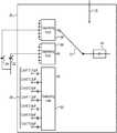
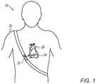
- FIG. 1is a schematic illustration of apparatus 20 comprising an implant 24 and an external unit 32 , in accordance with some embodiments of the present invention.
- implant 24may be implanted in the heart 28 of a subject 30 , e.g., within the left atrium of heart 28 .
- external unit 32wirelessly supplies power to implant 24 , and the implant provides feedback to the external unit.
- An apparatus of this sortis described, for example, in PCT International Publications WO 2014/076620 and WO 2014/170771, which are both assigned to the assignee of the present patent application and whose disclosures are incorporated herein by reference.
- Implant 24comprises an antenna 34 , configured to, by drawing energy from the magnetic field generated by the external unit, provide a main supply voltage.
- Implant 24further comprises a capacitive pressure sensor 22 , configured to vary its capacitance in response to the ambient pressure within the heart of subject 30 (i.e., the subject's intracardiac pressure).
- a voltage regulator 46converts a high voltage supply, which is derived from the main supply voltage, into a direct current (DC) sensor-supply voltage, which supplies sensor 22 .
- DCdirect current
- Voltage regulator 46requires a certain minimum supply voltage in order to effectively supply voltage to the sensor. For example, in some embodiments, voltage regulator 46 requires at least 15.5 V. (Since this threshold is relatively high, relative to respective voltages required by other components of implant 24 , the voltage regulator supply voltage is referred to as a high voltage supply.) Voltage regulator 46 and sensor 22 may be collectively referred to as “operational circuitry.”
- Implant 24further comprises modulating circuitry that modulates the load of antenna 34 .
- the modulating circuitrymay comprise an input-selecting-and-converting unit 36 , LPU 40 , and a modulation switch 42 . These components will now be described.
- Input-selecting-and-converting unit 36comprises conversion circuitry, which generates an output having a property that is a function of the capacitance that is input to the circuitry.
- the conversion circuitrymay comprise a capacitance-to-frequency converter 44 .
- Converter 44is an oscillator whose oscillation frequency depends on the capacitance that is input to the converter, such that the converter outputs a “sensor clock out” clock signal whose frequency is a function of the input. Stated differently, converter 44 converts the input capacitance into an output frequency.
- Input-selecting-and-converting unit 36further comprises an analog selector 72 configured to, in response to control signals 70 delivered over control lines from LPU 40 , select an input to converter 44 .
- FIG. 2shows several possible inputs, as follows:
- the capacitance of sensor 22may be input to converter 44 , such that converter 44 converts the capacitance of the sensor into the output frequency.
- the capacitance of a reference capacitor 26may be input to converter 44 , such that the converter converts the capacitance of the reference capacitor into the output frequency. (The function of reference capacitor 26 is described below, with reference to FIG. 4 .)
- the capacitance of one or more calibration capacitors “Cref”may be input to converter 44 , such that the converter converts the capacitance of the reference capacitor(s) into the output frequency. (The function of the calibration capacitors is described below, with reference to FIG. 4 .)
- LPU 40modulates the load of the antenna, by alternatingly connecting current-drawing circuitry to, and disconnecting the current-drawing circuitry from, the main supply voltage.
- the load of the antennais increased.
- the load of the antennais decreased.
- the modulation in the load of the antennacauses variations in the amount of energy from the magnetic field consumed by the implant.
- the external unitsenses these variations, and computes, based on the variations, the input to converter 44 .
- LPU 40may modulate the load of the antenna such as to indicate to the external unit the capacitance of—and hence, the pressure sensed by—sensor 22 .
- the modulation in the load of the antennaalso cause the main supply voltage to vary between a first, higher value, and a second, lower value. That is, when the current-drawing circuitry is disconnected from the main supply voltage, the main supply voltage has the first, higher value; conversely, when the current-drawing circuitry is connected to the main supply voltage, the main supply voltage has the second, lower value.
- the current-drawing circuitrycomprises at least part of the modulating circuitry.
- the modulating circuitrymodulates the load of the antenna by alternatingly connecting the modulating circuitry to, and disconnecting the modulating circuitry from, the main supply voltage.
- LPU 40modulates the load of the antenna by alternatingly connecting itself to, and disconnecting itself from, the main supply voltage, by controlling a modulation switch 42 .
- LPU 40increases the load of the antenna by connecting the LPU (and/or the input-selecting-and-converting unit) to the main supply voltage; conversely, by opening the switch, LPU 40 decreases the load of the antenna by disconnecting the LPU (and/or the input-selecting-and-converting unit) from the main supply voltage.
- FIG. 3Ashows an example waveform for the voltage across antenna 34 , i.e., the output voltage of the antenna.
- the voltageoscillates at a characteristic frequency of, for example, 6.78 MHz, which is the frequency of the magnetic field generated by external unit 32 .
- This output voltage of antenna 34is modulated with an outer modulating envelope that is established by the controlling of switch 42 by LPU 40 .
- the information contained in the feedback provided by the antennais a function of the number and timing of the “cycles” of load modulation (and hence, voltage variation), one such cycle being labelled in FIG. 3A .
- a diode Dext1shown in FIG. 2 , detects the envelope, thus deriving, from the voltage across the antenna, the main supply voltage shown in FIG. 3B .
- the threshold supply voltage for the voltage regulatoris assumed to be approximately 15.5 V, and correspondingly, the amplitude of the voltage across the antenna varies between approximately 3.5 V and 20 V. Due to a small voltage drop across diode Dext1, the amplitude of the main supply voltage, as shown in FIG. 3B , varies between approximately 3 V and 19.5 V. (It is again noted that the voltage values in FIGS. 3A-B are provided by way of example only.)
- Antenna 34may be modelled, simplistically, as an input voltage source providing an input voltage, and facing a particular output impedance. Hence, the more current flows across the antenna, the lower the output voltage of the antenna (shown in FIG. 3A ) will be, due to a drop in voltage as current flows across the output impedance.
- switch 42When switch 42 is open, the load of the antenna is relatively small, such that relatively little current flows across the antenna; hence, the output voltage of the antenna is close to the input voltage.
- switch 42is closed, the load of the antenna is increased, such that more current flows across the antenna.
- LPU 40may consume a relatively large amount of current, such that, when the switch is closed and LPU is connected to the main supply voltage, there is a relatively large increase in current across the antenna.
- the output voltagedrops below (e.g., significantly below) the input voltage.
- the circuitry within implant 24further comprises a backup voltage source, such as a capacitor Cext3.
- a backup voltage sourcesuch as a capacitor Cext3.
- the backup voltage sourcederives a backup voltage from the main supply voltage.
- Cext3may derive the backup voltage, by charging.
- the backup voltage sourcesupplies the backup voltage to the voltage regulator.
- the voltage across the antennawould need to be significantly higher.
- the voltage across the antenna when loaded with the current-drawing circuitrywould need to be approximately 20 V, and hence, the voltage across the antenna when unloaded might need to be approximately 40 V.
- the voltage across the antenna when unloadedis approximately 20 V.
- the antennawould need to be supplied with a large amount of energy.
- the placement of the modulation switch as shown in FIG. 2is advantageous, in that (i) the voltage across the antenna may be relatively low (e.g., less than 22 V, such as approximately 20 V, as shown in FIG. 3B ) when the current-drawing circuitry is disconnected from the main supply voltage, and/or (ii) when the current-drawing circuitry is connected to the main supply voltage, a much lower voltage—e.g., less than 5 V, such as approximately 3 V, as shown in FIG. 3B —may be supplied to the LPU.
- the voltage across the antennamay be relatively low (e.g., less than 22 V, such as approximately 20 V, as shown in FIG. 3B ) when the current-drawing circuitry is disconnected from the main supply voltage, and/or (ii) when the current-drawing circuitry is connected to the main supply voltage, a much lower voltage—e.g., less than 5 V, such as approximately 3 V, as shown in FIG. 3B —may be supplied to the LPU.
- apparatus and techniques described hereinmay be applied to any alternative form of operational circuitry, any alternative form of modulating circuitry, and/or any alternative form of current-drawing circuitry.
- the scope of the present inventionis not limited to the particular embodiments described herein, but rather, includes any relevant application in which there is a need to power both a relatively-high-voltage consumer (referred to herein as operational circuitry) and a lower-voltage-but-relatively-high-current consumer (referred to herein as current-drawing circuitry), while achieving sufficient antenna-modulation depth.
- sensor 22As a capacitive pressure sensor, it is noted that the principles described herein may be applied to operational circuitry that comprises any type of sensor that is configured to sense any type of parameter. Similarly, the principles described herein may be applied to a sensor that is implanted in some portion of the anatomy other than the heart, to a sensor that is not implanted at all, as well as to operational circuitry that does not include a sensor at all.
- Embodiments of the present inventionalso facilitate the operation of the current-drawing circuitry, even while the current-drawing circuitry is disconnected from the main supply voltage.
- the LPUmay operate on a DC voltage Vcc that is supplied by a low dropoff oscillator (LDO) 38 , which rectifies and regulates the main supply voltage.
- LDO 38When switch 42 is open, LDO 38 is disconnected from the main supply voltage.
- a second backup voltage sourcederives a second backup voltage from the main supply voltage, and, while the switch is open, supplies the second backup voltage to the LDO.
- a capacitor Cext1may charge, and subsequently, while the switch is open, supply voltage to the LDO.
- LDO 38is analogous to voltage regulator 46
- the second backup voltage sourcee.g., Cext1
- the first backup voltage sourcesupplies the voltage regulator
- the second backup voltage sourcesupplies the LDO.
- the scope of the present inventionincludes the use of a backup voltage source for supplying voltage to the operational circuitry, as described above, even without the use of a backup voltage source for supplying voltage to the current-drawing circuitry.
- the scope of the present inventionincludes the use of a backup voltage source for supplying voltage to the current-drawing circuitry, as described above, even without the use of a backup voltage source for supplying voltage to the operational circuitry.
- implant 24further comprises a voltage clamper 50 , which reduces variations in the second value of the main supply voltage that are caused by variations in the amount of current drawn by the current-drawing circuitry.
- LPU 40may draw varying amounts of current, depending on the current mode of operation of the LPU.
- the second value of the main supply voltagewould vary, depending on the current mode of operation of the LPU.
- the voltage clamperdraws an amount of current that varies inversely with the amount of current drawn by the LPU, such that, for example, the total amount of current drawn by the LPU and voltage clamper together, while the switch is closed, is constant.
- the voltage clampermay comprise, for example, a Zener diode.
- FIG. 2Various other components of implant 24 are shown in FIG. 2 , as follows:
- a diode Dext2inhibits the discharging of Cext3, except for the purpose of supplying the voltage regulator.
- a diode DZext1provides overvoltage protection.
- a capacitor Cext2filters out noise from the voltage Vcc.
- a capacitor Cext4stabilizes the DC voltage supplied to the sensor.
- a “main clock/data in” signalwhich is derived from the raw signal received from the external unit, provides a clock signal to the LPU, and further communicates data from the external unit. For example, via the “data in” signal, the external unit may request particular information from the LPU, which the LPU then provides, e.g., by selecting the appropriate input to capacitance-to-frequency converter 44 , and then modulating the load of the antenna in response to the “sensor clock out” signal, as described above.
- the “main clock/data in” signalpasses though a buffer 56 , which adjusts the voltage of the signal to a level that is appropriate for the LPU.
- An internal oscillatorprovides a clock signal to the LPU while the external unit is not transmitting.
- a programmable resonance capacitor array 58(depicted in FIG. 2 , for simplicity, by only one capacitor) tunes the resonance capacitor in antenna 34 , in response to signals 60 .
- a buffer 52adjusts the voltage of the switch-controlling signal from the LPU to a level that is appropriate for switch 42 .
- a buffer 54provides an indication to the LPU in the event that the voltage supply to voltage regulator 46 is not high enough. In response to the indication, the LPU communicates a signal to the external unit.
- FIG. 4is a schematic illustration of input-selecting-and-converting unit 36 , in accordance with some embodiments of the present invention.
- FIG. 4shows several aspects of unit 36 that are not shown in FIG. 2 .
- FIG. 4shows a set 64 of calibration capacitors, a first switching unit 62 , a second switching unit 66 , and a third switching unit 68 .
- Set 64is roughly indicated in FIG. 2 by a single capacitor symbol labeled “Cref,” while the switching units are not shown in FIG. 2 .
- Set 64is used to calibrate the conversion circuitry in converter 44 , i.e., set 64 is used to ascertain the manner in which the frequency of the “sensor clock out” signal at the output of converter 44 varies as a function of the input capacitance to the converter.
- Switching unit 62has multiple first-switching-unit settings that connect respective subsets of the calibration capacitors to the conversion circuitry.
- switching unit 62may comprise multiple switches, and for each first-switching-unit setting, a respective subset of the switches may be closed, thus connecting a respective subset of the calibration capacitors to the converter.
- various input capacitancesmay be obtained.
- the frequency of the output signal from the converteris recorded, such that the “input-capacitance-to-output-frequency” mapping of the converter is obtained. Subsequently, the inverse of the mapping may be used to compute the capacitance of sensor 22 , given the output of the converter.
- FIG. 4shows seven calibration capacitors: (i) Cref1, having a capacitance of 0.15 pF, (ii) Cref2, having a capacitance of 0.3 pF, (iii) Cref3, having a capacitance of 0.6 pF, (iv) Cref4, having a capacitance of 1.2 pF, (v) Cref5, having a capacitance of 2.4 pF, (vi) Cref6, having a capacitance of 4.8 pF, and (vii) Cref1, having a capacitance of 9.6 pF.
- Cref1, Cref2, Cref3, Cref4, Cref5, Cref6, and Cref7lBy connecting various subsets of capacitors Cref1, Cref2, Cref3, Cref4, Cref5, Cref6, and Cref7l to the converter, various input capacitances may be obtained.
- the above-described calibration procedureis performed prior to every capacitance/pressure measurement, since fluctuations in body temperature and/or voltage supply Vcc, and/or aging of the system, may influence the manner in which the output of the converter depends on the input capacitance.
- the switching unittypically has a further setting-dependent effect on the output of converter 44 , beyond the mere selection of input capacitance.
- the resistance of switching unit 62may vary depending on the selected setting of the switching unit, such that each of the first-switching-unit settings has a respective first-switching-unit resistive effect on the output of converter 44 .
- the respective outputs observed during calibrationare a function not only of the respective input capacitances, but also of the respective “input resistances” provided by the first switching unit.
- Second switching unit 66which is connected to the sensor, addresses the above challenge.
- Second switching unit 66has multiple second-switching-unit settings that (i) connect the sensor to the converter, and (ii) have respective second-switching-unit effects on the output of the converter that are the same as the first-switching-unit effects.
- the second switching unitis effectively a duplicate of the first switching unit.
- unit 66always connects the same capacitance—that of sensor 22 —to the input of converter 44 , regardless of the selected setting.
- the effect (e.g., the resistive effect) of the second switching unitmay be “matched” to an effect (e.g., a resistive effect) provided by the first switching unit during calibration, thus allowing the capacitance of sensor 22 to be accurately computed from the output of the converter.
- LPU 40via control signals 70 , controls analog selector 72 , which varies the source of the input to the converter. Furthermore, LPU 40 (via control signals 70 ), and/or other circuitry in the implant, controls switching units 62 and 66 .
- the first switching unitis set to each of the first-switching-unit settings, thus driving the conversion circuitry to generate multiple calibration outputs, such that the correspondence between the calibration outputs and the first-switching-unit settings may be ascertained.
- the external unitmay store a “correspondence table” (or other analogous data-storage object) in which each first-switching-unit setting is “mapped” to a particular output.
- the analog selectorconnects the converter to second switching unit 66 .
- the LPU, and/or other circuitryin response to instructions from the external unit, then sets the second switching unit to one or more of the second-switching-unit settings, thus varying the input resistance to the converter.
- the LPUdrives the converter to generate one or more sensing outputs, which the LPU then communicates to the external unit.
- the external unitcomputes the capacitance of the sensor (and hence, the pressure sensed by the sensor).
- the LPUmay vary the setting of the second switching unit, i.e., set the second switching unit to another one of the second-switching-unit settings, until (as determined by the external unit) the output converges to a calibration output that corresponds to the current setting of the second switching unit.
- the LPUmay vary the setting of the second switching unit until (i) the difference between the sensing output and a particular calibration output is within a predefined threshold (and/or the difference between the sensing output and the particular calibration output is a minimum—i.e., it is locally or globally less than respective differences between the sensing output and other calibration outputs), and (ii) per the correspondence that was ascertained during calibration, the particular calibration output corresponds to the current setting of the second switching unit.
- C_sis the (unknown) capacitance of the sensor.
- the external unitstores the correspondence.
- the external unitmay store a correspondence table having a form similar to Table 1 below:
- the setting of the second switching unitis varied over one or more of settings ⁇ S2_i ⁇ , until, for example, (a) the difference between the sensing output from the converter and a particular calibration output O_j is within a predefined threshold, and/or is a local or global minimum, and (b) O_j corresponds to the current setting of the second switching unit.
- C_sis then computed to be equal to, or approximately equal to, C_j, the input capacitance of S1_j.
- C_sis computed to be equal to, or approximately equal to, C_2.
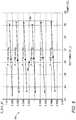
- FIG. 5shows an example calibration map 84 , used in accordance with some embodiments of the present invention.
- an alternative calibration to the above-described calibrationis performed, whereby one or more calibration maps such as calibration map 84 are constructed, by obtaining various outputs of capacitance-to-frequency converter 44 while controlling the ambient temperature and pressure.
- calibration data shown in FIG. 5roughly corresponds to real calibration data obtained by the inventors of the present application. (Typically, the calibration procedure described below is performed separately for each individual sensor.)
- Each of the calibration mapsis constructed for a respective setting of the first switching unit; for example, calibration map 84 corresponds to a particular setting S1_k of the first switching unit.
- Each calibration mapincludes (i) various first calibration outputs (O_IC) of the conversion circuitry that are output responsively to the known input capacitance (“IC”) corresponding to the setting of the first switching unit, and (ii) various second calibration outputs (O_S) of the conversion circuitry that are output responsively to input from the pressure sensor (“S”).
- the first calibration outputsare measured for different respective ambient temperatures, while the second calibration outputs are measured for different respective ambient temperatures and ambient pressures. (In some embodiments, the first calibration outputs are also measured for different respective controlled ambient pressures.
- the first calibration outputsdo not vary with ambient pressure, and hence, a first calibration output measured for one particular ambient pressure may be extrapolated to other ambient pressures.) As further described below, the first and second calibration outputs are later used in real-time, while the sensor is implanted, to ascertain the ambient pressure within the subject.
- the outputs from the conversion circuitryare typically expressed in units of frequency, such as in units of “counts,” referring to the number of peaks in the output signal counted within a particular window of time.
- each calibration mapincludes the ratio O_S/O_IC plotted against temperature (Temp) in degrees Celsius (C), for a plurality of ambient pressures P in mm Hg. (It is noted that the temperatures are decreasing from left to right.)
- each calibration mapincludes a plurality of temperature-sensitivity curves 88 , each of which reflects the sensitivity of the conversion circuitry, the sensor, and/or the switching units to temperature at a different respective pressure.
- Each data point on a particular curve 88is obtained during calibration, by (i) measuring O_S for a particular ambient pressure and temperature of interest, (ii) measuring O_IC for the same particular ambient temperature (and, if the first calibration output is deemed to be sensitive to the ambient pressure, also for the same particular ambient pressure), and (iii) subsequently, computing the ratio O_S/O_IC (or alternatively, O_IC/O_S).
- the unknown ambient pressure within the subjectis ascertained, as follows:
- one of the calibration mapscorresponding to a given one of the first-switching-unit settings (and hence, a given one of the known input capacitances of the calibration capacitors), is selected, as further described below.
- a first real-time output of the conversion circuitry, O_IC_RTwhich is output responsively to the given one of the input capacitances. For example, if calibration map 84 as shown in FIG. 5 is the selected calibration map, O_IC_RT is measured while the first switching unit is set to S1_k.
- the conversion circuitryis connected to the pressure sensor (e.g., via the second switching unit), and a second real-time output of the conversion circuitry, O_S_RT, which is output responsively to the input from the pressure sensor, is measured.
- the unknown ambient pressureis ascertained, based on O_IC_RT, O_S_RT, the measured ambient temperature, and the calibration information contained in the calibration map. For example, this may be done by comparing the ratio between the first and second real-time outputs to the ratios obtained during calibration.
- the above-described methoduses the calibration capacitors, which help “normalize” the calibration output across different supplied voltages.
- the ratio between O_S and O_ICis invariant to the supplied voltage, at least if the input capacitance from the calibration capacitors is approximately the same as the input capacitance from the sensor.
- O_ICwill also change by a factor of k, such that the ratio between O_S and O_IC will remain the same.
- the above-described methodthus helps overcome the temperature sensitivity of the conversion circuitry, more effectively than does the hypothetical na ⁇ ve method.
- the desired calibration maptypically corresponds to the input calibration capacitance that is closest to the current capacitance of the sensor.
- the desired calibration mapis selected during a “pre-real-time” stage, typically immediately prior to the real-time ascertaining of the unknown ambient pressure.
- pre-real-timerespective pairs of “calibration” and “sensor” outputs are obtained for one or more of the switching-unit settings for which calibration maps were obtained, and the minimum difference between the pairs is identified.
- the selected calibration mapthen corresponds to the minimum difference. This may be expressed in the following notation:
- the second switching unitfacilitates the selection of the most appropriate calibration map. If not for the second switching unit, it would be impossible, or at least very difficult, to identify the input calibration capacitance that is closest to the current capacitance of the sensor, since the first switching unit also affects the output of the conversion circuitry. (In other words, due to the effect of the first switching unit on O_IC, the fact that O_S_j is close to O_IC_j would not necessarily indicate that the capacitance of the sensor is close to the input calibration capacitance.) Since, however, the second switching unit is used, a small difference between the outputs indicates that the input capacitance of the sensor and the input capacitance of the calibration capacitors are approximately the same.
- the second switching unitis also typically used during calibration, and during real-time. That is, during calibration, when constructing the respective calibration map for each S1_i, the second switching unit is set to S2_i, and during real-time, the second switching unit is set to the setting S2_j, which is identical to the selected setting S1_j.
- the external unitdrives the LPU to control the input to the conversion circuitry, in order to execute all of the above-described calibration, pre-real-time, and real-time tasks.
- the LPUthen communicates the output from the conversion circuitry to the external unit, as described above.
- the external unitalone or in combination with the LPU, may be referred to as an example embodiment of “control circuitry” that controls the execution of the various tasks described herein.
- an internal temperature sensor(not shown in the figures) is used.
- the temperature sensoralso inputs to the conversion circuitry, such that, to obtain a temperature reading, the external unit drives the LPU to connect the conversion circuitry to the temperature sensor, and the LPU then communicates the output from the conversion circuitry to the external unit.
- the temperatureis thus measured in frequency units, such as units of counts, like other output from the conversion circuitry. (Nonetheless, to make FIG. 5 more readily understandable, the temperature axis in calibration map 84 is marked in units of degrees Celsius, rather than units of counts.)
- the implantfurther comprises reference capacitor 26 , the capacitance of which does not vary in response to the ambient pressure.
- Reference capacitor 26allows for compensating for factors, other than pressure, that may affect the capacitance of the sensor. For example, as the sensor ages, the manner in which the capacitance of the sensor varies in response to variations in the ambient pressure may change. Alternatively or additionally, radiofrequency (RF) noise may affect the capacitance of the sensor.
- RFradiofrequency
- reference capacitor 26by manufacturing reference capacitor 26 at the same time, and from the same wafer, as sensor 22 , with identical electrical connections, and placing the reference capacitor near the sensor within the heart, the reference capacitor can be made to respond to these factors in the same manner in which the sensor responds.
- outputs from the reference capacitormay be used to adjust the computation of the capacitance of the sensor, to compensate for the above-mentioned factors.
- third switching unit 68is typically connected to the reference capacitor.
- Third switching unit 68has multiple third-switching-unit settings that (i) connect the reference capacitor to the converter, and (ii) have respective third-switching-unit effects (e.g., resistive effects) on the output that are the same as the first-switching-unit effects.
- third-switching-unit effectse.g., resistive effects
- an accurate computation of the capacitance of the reference capacitormay be obtained, as described hereinabove for the second switching unit.
- the capacitance of the reference capacitormay then be used to more accurately compute the ambient pressure, based on the computed capacitance of the sensor.
- FIGS. 6A-Bare schematic illustrations of sensing capacitor 22 and reference capacitor 26 , in accordance with some embodiments of the present invention.
- the sensing capacitoris formed from a first portion of a wafer 74
- the reference capacitoris formed from a second portion of wafer 74 that is adjacent to the first portion.
- the set 78 of electrical connections connected to the reference capacitoris identical to the set 77 of electrical connections connected to the sensing capacitor.
- the sets of electrical connectionsinclude, for example, wiring, vias connecting between conductive layers, and/or connection pads.
- the setsare “identical” to one another, in that the properties of one set—such as the material(s) from which the set is manufactured, and the geometrical layout of set—are the same as the properties of the other set.
- the only significant difference between the two capacitorsis that while the sensing capacitor has at least one terminal 76 (e.g., capacitor plate) that is sensitive to the ambient pressure, the reference capacitor does not have any terminal that is sensitive to the ambient pressure.
- the sensing capacitor and the reference capacitorare contained within implant 24 , which is implanted in subject 30 , such as within the subject's heart.
- implant 24which is implanted in subject 30 , such as within the subject's heart.
- the two capacitorsprior to implantation (e.g., prior to being placed within the implant), are separated (e.g., partly or completely detached) from one another.
- the two capacitorsare typically placed near one another inside the implant, so that they are exposed to the same ambient environment within the subject.
- one or more portions 80 of the sensing capacitorprotrude into the reference capacitor, and/or one or more portions 82 of the reference capacitor protrude into the sensing capacitor.
- portions 82 of the reference capacitormay be interleaved with portions 80 of the sensing capacitor. The protruding of one capacitor into the other further helps the two capacitors have similar properties.
Landscapes
- Health & Medical Sciences (AREA)
- Life Sciences & Earth Sciences (AREA)
- Engineering & Computer Science (AREA)
- Public Health (AREA)
- Molecular Biology (AREA)
- Veterinary Medicine (AREA)
- General Health & Medical Sciences (AREA)
- Physics & Mathematics (AREA)
- Animal Behavior & Ethology (AREA)
- Biophysics (AREA)
- Pathology (AREA)
- Biomedical Technology (AREA)
- Heart & Thoracic Surgery (AREA)
- Medical Informatics (AREA)
- Surgery (AREA)
- Cardiology (AREA)
- Computer Networks & Wireless Communication (AREA)
- Signal Processing (AREA)
- Physiology (AREA)
- Power Engineering (AREA)
- Vascular Medicine (AREA)
- Artificial Intelligence (AREA)
- Computer Vision & Pattern Recognition (AREA)
- Psychiatry (AREA)
- Measuring Fluid Pressure (AREA)
Abstract
Description
- when the current-drawing circuitry is connected to the main supply voltage, derive a second backup voltage from the main supply voltage, and
- when the current-drawing circuitry is disconnected from the main supply voltage, supply the second backup voltage to the current-drawing circuitry.
- measuring the first real-time output, by setting the first switching unit to a given one of the settings, and
- measuring the second real-time output, by setting the second switching unit to the given one of the settings.
- computing a real-time ratio between the first real-time output and second real-time output, and
- ascertaining the unknown ambient pressure, by comparing the real-time ratio to the calibration ratios that were computed for the given one of the known input capacitances.
| TABLE 1 | |||
| S1_1 | O_1 | ||
| S1_2 | O_2 | ||
| S1_3 | O_3 | ||
| . . . | . . . | ||
| S1_N | O_N | ||
Claims (10)
Applications Claiming Priority (1)
| Application Number | Priority Date | Filing Date | Title |
|---|---|---|---|
| PCT/IB2015/060054WO2017115112A1 (en) | 2015-12-30 | 2015-12-30 | Power-efficient pressure-sensor implant |
Publications (2)
| Publication Number | Publication Date |
|---|---|
| US20190008401A1 US20190008401A1 (en) | 2019-01-10 |
| US11206988B2true US11206988B2 (en) | 2021-12-28 |
Family
ID=59224751
Family Applications (1)
| Application Number | Title | Priority Date | Filing Date |
|---|---|---|---|
| US16/066,690Active2037-03-27US11206988B2 (en) | 2015-12-30 | 2015-12-30 | Power-efficient pressure-sensor implant |
Country Status (3)
| Country | Link |
|---|---|
| US (1) | US11206988B2 (en) |
| EP (1) | EP3398237B1 (en) |
| WO (1) | WO2017115112A1 (en) |
Cited By (7)
| Publication number | Priority date | Publication date | Assignee | Title |
|---|---|---|---|---|
| US11461568B2 (en) | 2017-02-24 | 2022-10-04 | Endotronix, Inc. | Wireless sensor reader assembly |
| US11589773B2 (en) | 2011-06-30 | 2023-02-28 | Endotronix, Inc. | MEMS device for an implant assembly |
| US11615257B2 (en) | 2017-02-24 | 2023-03-28 | Endotronix, Inc. | Method for communicating with implant devices |
| US11622684B2 (en) | 2017-07-19 | 2023-04-11 | Endotronix, Inc. | Physiological monitoring system |
| US11707230B2 (en) | 2011-06-30 | 2023-07-25 | Endotronix, Inc. | Pressure sensing implant |
| US11896365B2 (en) | 2011-06-30 | 2024-02-13 | Endotronix, Inc. | MEMS device for an implant assembly |
| WO2025144800A1 (en)* | 2023-12-29 | 2025-07-03 | Tc1 Llc | Implantable sensor system |
Families Citing this family (3)
| Publication number | Priority date | Publication date | Assignee | Title |
|---|---|---|---|---|
| WO2019220232A1 (en)* | 2018-05-17 | 2019-11-21 | Vectorious Medical Technologies Ltd. | Low-power high-accuracy clock harvesting in inductive coupling systems |
| US11642084B2 (en) | 2020-03-05 | 2023-05-09 | Vectorious Medical Technologies Ltd. | Measurement of body fluid retention using inductive coupling |
| AU2022206249A1 (en)* | 2021-01-06 | 2023-07-27 | Endotronix, Inc. | Hemodynamic monitoring system and method and harness for same |
Citations (146)
| Publication number | Priority date | Publication date | Assignee | Title |
|---|---|---|---|---|
| US3264861A (en) | 1964-06-08 | 1966-08-09 | Lockheed Aircraft Corp | Dynamic pressure generator |
| US4127110A (en) | 1976-05-24 | 1978-11-28 | Huntington Institute Of Applied Medical Research | Implantable pressure transducer |
| US4206761A (en) | 1976-06-21 | 1980-06-10 | Cosman Eric R | Pressure-balanced telemetric pressure sensing method |
| US4237900A (en) | 1979-02-14 | 1980-12-09 | Pacesetter Systems, Inc. | Implantable calibration means and calibration method for an implantable body transducer |
| US4256094A (en) | 1979-06-18 | 1981-03-17 | Kapp John P | Arterial pressure control system |
| US4377851A (en) | 1980-12-22 | 1983-03-22 | Ford Motor Company | Method for calibrating a transducer for converting pressure variation to frequency variation |
| US4432372A (en) | 1981-08-28 | 1984-02-21 | Medtronic, Inc. | Two-lead power/signal multiplexed transducer |
| JPS5973747A (en) | 1982-10-20 | 1984-04-26 | Yokogawa Hokushin Electric Corp | Apparatus for transmitting differential pressure |
| US4519401A (en) | 1983-09-20 | 1985-05-28 | Case Western Reserve University | Pressure telemetry implant |
| US4669485A (en)* | 1984-02-17 | 1987-06-02 | Cortronic Corporation | Apparatus and method for continuous non-invasive cardiovascular monitoring |
| US4743836A (en) | 1985-12-06 | 1988-05-10 | United Technologies Corporation | Capacitive circuit for measuring a parameter having a linear output voltage |
| US4791934A (en) | 1986-08-07 | 1988-12-20 | Picker International, Inc. | Computer tomography assisted stereotactic surgery system and method |
| US4881939A (en) | 1985-02-19 | 1989-11-21 | The Johns Hopkins University | Implantable helical cuff |
| US5105190A (en) | 1986-04-22 | 1992-04-14 | N.V. Nederlandsche Apparatenfabriek Nedap | Electromagnetic identification system |
| US5113868A (en) | 1987-06-01 | 1992-05-19 | The Regents Of The University Of Michigan | Ultraminiature pressure sensor with addressable read-out circuit |
| US5300093A (en)* | 1992-09-14 | 1994-04-05 | Telectronics Pacing Systems, Inc. | Apparatus and method for measuring, formatting and transmitting combined intracardiac impedance data and electrograms |
| US5480412A (en) | 1993-11-16 | 1996-01-02 | Pacesetter, Inc. | System and method for deriving hemodynamic signals from a cardiac wall motion sensor |
| US5493470A (en) | 1989-01-13 | 1996-02-20 | Kopin Corporation | SOI diaphragm sensor |
| US5514171A (en) | 1993-07-07 | 1996-05-07 | Siemens Elema Ab | Pressure and heart movement sensor for heart stimulators |
| US5549646A (en) | 1994-12-06 | 1996-08-27 | Pacesetter, Inc. | Periodic electrical lead intergrity testing system and method for implantable cardiac stimulating devices |
| US5564434A (en) | 1995-02-27 | 1996-10-15 | Medtronic, Inc. | Implantable capacitive absolute pressure and temperature sensor |
| US5942692A (en) | 1997-04-10 | 1999-08-24 | Mks Instruments, Inc. | Capacitive pressure sensing method and apparatus avoiding interelectrode capacitance by driving with in-phase excitation signals |
| US6015386A (en) | 1998-05-07 | 2000-01-18 | Bpm Devices, Inc. | System including an implantable device and methods of use for determining blood pressure and other blood parameters of a living being |
| US6025725A (en) | 1996-12-05 | 2000-02-15 | Massachusetts Institute Of Technology | Electrically active resonant structures for wireless monitoring and control |
| US6051853A (en) | 1996-10-03 | 2000-04-18 | Hitachi, Ltd. | Semiconductor pressure sensor including reference capacitor on the same substrate |
| US6111520A (en) | 1997-04-18 | 2000-08-29 | Georgia Tech Research Corp. | System and method for the wireless sensing of physical properties |
| US6113553A (en) | 1996-03-05 | 2000-09-05 | Lifesensors, Inc. | Telemetric intracranial pressure monitoring system |
| US6171252B1 (en) | 1999-04-29 | 2001-01-09 | Medtronic, Inc. | Pressure sensor with increased sensitivity for use with an implantable medical device |
| US6275681B1 (en) | 1998-04-16 | 2001-08-14 | Motorola, Inc. | Wireless electrostatic charging and communicating system |
| US20010018596A1 (en) | 1997-02-28 | 2001-08-30 | Selmon Matthew R. | Methods and apparatus for treating vascular occlusions |
| US6309350B1 (en) | 1999-05-03 | 2001-10-30 | Tricardia, L.L.C. | Pressure/temperature/monitor device for heart implantation |
| US20020045921A1 (en) | 2000-10-16 | 2002-04-18 | Remon Medical Technologies Ltd. | Implantable pressure sensors and methods for making and using them |
| US6389371B1 (en) | 1998-04-14 | 2002-05-14 | Nagano Keiki Co., Ltd. | Signal processing circuit of sensor |
| US20020077556A1 (en) | 2000-12-18 | 2002-06-20 | Yitzhack Schwartz | Anchoring mechanism for implantable telemetric medical sensor |
| US6409674B1 (en) | 1998-09-24 | 2002-06-25 | Data Sciences International, Inc. | Implantable sensor with wireless communication |
| US20020120200A1 (en) | 1997-10-14 | 2002-08-29 | Brian Brockway | Devices, systems and methods for endocardial pressure measurement |
| US20030045781A1 (en)* | 2001-08-13 | 2003-03-06 | Rosenheimer Michael N. | Device for processing signals for medical sensors |
| US20030097073A1 (en) | 2001-11-16 | 2003-05-22 | Apex Medical, Inc. | Pressure cuff |
| US20030139677A1 (en) | 2002-01-22 | 2003-07-24 | Michael Fonseca | Implantable wireless sensor for pressure measurement within the heart |
| US6622041B2 (en) | 2001-08-21 | 2003-09-16 | Cyberonics, Inc. | Treatment of congestive heart failure and autonomic cardiovascular drive disorders |
| US6667725B1 (en) | 2002-08-20 | 2003-12-23 | The United States Of America As Represented By The Administrator Of The National Aeronautics And Space Administration | Radio frequency telemetry system for sensors and actuators |
| US20040103906A1 (en) | 1997-02-26 | 2004-06-03 | Schulman Joseph H. | Battery-powered patient implantable device |
| KR20040060577A (en) | 2002-12-30 | 2004-07-06 | 주식회사 하이닉스반도체 | voltage limit circuit layout for use in RF-ID card based on CMOS |
| US6772070B2 (en) | 1998-08-13 | 2004-08-03 | U.S. Genomics, Inc. | Methods of analyzing polymers using a spatial network of fluorophores and fluorescence resonance energy transfer |
| US20040158167A1 (en) | 2002-11-27 | 2004-08-12 | Smith Kenneth Carless | Apparatus and method for performing impedance measurements |
| US6778070B1 (en) | 1998-03-31 | 2004-08-17 | Commissariat A L'energie Atomique | Remote transmission apparatus operating by inductive coupling |
| US20050004644A1 (en) | 2003-05-06 | 2005-01-06 | Enpath Medical, Inc. | Rotatable lead introducer |
| US20050065589A1 (en) | 2003-07-25 | 2005-03-24 | Schneider Richard Lee | Method and anchor for medical implant placement, and method of anchor manufacture |
| US20050088184A1 (en) | 2001-10-26 | 2005-04-28 | Welch Allyn, Inc. | Capacitive sensor |
| US6926670B2 (en) | 2001-01-22 | 2005-08-09 | Integrated Sensing Systems, Inc. | Wireless MEMS capacitive sensor for physiologic parameter measurement |
| US6936053B1 (en) | 1998-07-02 | 2005-08-30 | Jeffrey N. Weiss | Ocular implant needle |
| US20050288596A1 (en) | 2002-09-26 | 2005-12-29 | Eigler Neal L | Implantable pressure transducer system optimized for reduced thrombosis effect |
| WO2006042280A2 (en) | 2004-10-12 | 2006-04-20 | Alexander Shaknovich | System and method for assisted partitioning of body conduits |
| US20060116572A1 (en) | 2004-12-01 | 2006-06-01 | Case Brian C | Sensing delivery system for intraluminal medical devices |
| US20060161364A1 (en) | 2004-12-30 | 2006-07-20 | Tzu-Yu Wang | Calibrated pressure sensor |
| US7086270B2 (en) | 2004-02-24 | 2006-08-08 | Analog Devices, Inc. | Method for continuous sensor self-test |
| US20060206178A1 (en) | 2005-03-11 | 2006-09-14 | Kim Daniel H | Percutaneous endoscopic access tools for the spinal epidural space and related methods of treatment |
| US20060229488A1 (en) | 2003-07-18 | 2006-10-12 | Ayre Peter J | Blood pressure detecting device and system |
| US7149587B2 (en) | 2002-09-26 | 2006-12-12 | Pacesetter, Inc. | Cardiovascular anchoring device and method of deploying same |
| US20060287602A1 (en) | 2005-06-21 | 2006-12-21 | Cardiomems, Inc. | Implantable wireless sensor for in vivo pressure measurement |
| US20070049984A1 (en) | 2005-08-31 | 2007-03-01 | Peter Osypka | Implantable device for measuring biometric blood parameters |
| US20070049980A1 (en) | 2005-08-30 | 2007-03-01 | Zielinski Todd M | Trans-septal pressure sensor |
| US20070118038A1 (en) | 2005-11-23 | 2007-05-24 | Vital Sensors Inc. | Implantable device for telemetric measurement of blood pressure/temperature within the heart |
| US20070135826A1 (en) | 2005-12-01 | 2007-06-14 | Steve Zaver | Method and apparatus for delivering an implant without bias to a left atrial appendage |
| US20070142727A1 (en) | 2005-12-15 | 2007-06-21 | Cardiac Pacemakers, Inc. | System and method for analyzing cardiovascular pressure measurements made within a human body |
| US20070179583A1 (en) | 2003-07-25 | 2007-08-02 | Integrated Sensing Systems, Inc. | Delivery system, method, and anchor for medical implant placement |
| US7256695B2 (en) | 2002-09-23 | 2007-08-14 | Microstrain, Inc. | Remotely powered and remotely interrogated wireless digital sensor telemetry system |
| US20070255144A1 (en) | 2004-06-07 | 2007-11-01 | Radi Medical Systems Ab | Powering a Guide Wire Mounted Sensor for Intra-Vascular Measurements of Physiological Variables by Means of Inductive Coupling |
| US20070261496A1 (en) | 2004-02-12 | 2007-11-15 | Gambro Lundia Ab | Pressure sensing |
| US20070293779A1 (en) | 1999-11-16 | 2007-12-20 | Bardy Gust H | System and method for managing respiratory insufficiency in conjunction with heart failure assessment |
| US20080004673A1 (en) | 2006-04-03 | 2008-01-03 | Cvrx, Inc. | Implantable extravascular electrostimulation system having a resilient cuff |
| US20080033527A1 (en) | 2006-07-07 | 2008-02-07 | Anthony Nunez | Methods and systems for monitoring an endoprosthetic implant |
| US20080045242A1 (en) | 1999-04-19 | 2008-02-21 | Dekock Bruce W | System for providing traffic information |
| US7335161B2 (en) | 2004-08-20 | 2008-02-26 | Cardiac Pacemakers, Inc. | Techniques for blood pressure measurement by implantable device |
| WO2008042229A2 (en) | 2006-09-28 | 2008-04-10 | Nmt Medical, Inc. | Implant-catheter attachment mechanism using snare and method of use |
| US20080092663A1 (en) | 2006-10-20 | 2008-04-24 | Kevin Corcoran | Method and Apparatus for Measuring Pressure Inside a Fluid System |
| US20080139959A1 (en) | 2005-04-30 | 2008-06-12 | Aesculap Ag & Co. Kg | Implantable device for recording intracranial pressures |
| US20080154101A1 (en) | 2006-09-27 | 2008-06-26 | Faquir Jain | Implantable Biosensor and Methods of Use Thereof |
| US7413547B1 (en) | 2004-11-08 | 2008-08-19 | Transoma Medical, Inc. | Reference sensor correction for implantable sensors |
| US7425749B2 (en) | 2002-04-23 | 2008-09-16 | Sharp Laboratories Of America, Inc. | MEMS pixel sensor |
| US20080227487A1 (en) | 2007-03-12 | 2008-09-18 | Melanie Daniels | Multiple radios communication device and a method thereof |
| WO2008127525A1 (en) | 2007-04-12 | 2008-10-23 | Boston Scientific Limited | Instantaneous mechanical detachment mechanism for vaso-occlusive devices |
| US20080269573A1 (en) | 2007-04-30 | 2008-10-30 | Integrated Sensing Systems, Inc. | Procedure and system for monitoring a physiological parameter within an internal organ of a living body |
| US20080281212A1 (en) | 2007-03-15 | 2008-11-13 | Nunez Anthony I | Transseptal monitoring device |
| US20090005859A1 (en) | 1997-10-14 | 2009-01-01 | Cardiometrix, Inc. | Endoluminal implant with therapeutic and diagnostic capability |
| US20090013791A1 (en) | 2003-12-11 | 2009-01-15 | Mark Zdeblick | Pressure sensor circuits |
| US20090024042A1 (en) | 2007-07-03 | 2009-01-22 | Endotronix, Inc. | Method and system for monitoring ventricular function of a heart |
| US20090030291A1 (en) | 2003-09-16 | 2009-01-29 | Cardiomems, Inc. | Implantable Wireless Sensor |
| US20090036754A1 (en) | 2007-07-31 | 2009-02-05 | Captomed Eurl | Self-calibrating pressure sensor |
| US20090069648A1 (en) | 2007-08-23 | 2009-03-12 | Purdue Research Foundation | Intra-occular pressure sensor |
| US7515971B1 (en) | 2005-09-09 | 2009-04-07 | Pacesetter, Inc. | Left atrial pressure sensor lead |
| US20090093729A1 (en) | 2007-10-03 | 2009-04-09 | Yunlong Zhang | Devices and Methods for Measurement of Vessel Elasticity and Blood Pressure |
| US20090192381A1 (en) | 2008-01-30 | 2009-07-30 | Brockway Brian P | Minimally Invasive Physiologic Parameter Recorder and Introducer System |
| WO2009097485A1 (en) | 2008-02-01 | 2009-08-06 | Smith & Nephew, Inc. | System and method for communicating with an implant |
| US20090275924A1 (en) | 2006-04-26 | 2009-11-05 | Eastern Virginia Medical School | Systems and Methods for Monitoring and Controlling Internal Pressure of an Eye or Body Part |
| US20090281520A1 (en) | 2007-11-08 | 2009-11-12 | Brian Highley | Ocular Implantation Device |
| US20090299216A1 (en) | 2008-06-02 | 2009-12-03 | Po-Jui Chen | System, apparatus and method for biomedical wireless pressure sensing |
| US7628054B2 (en) | 2006-11-09 | 2009-12-08 | Abbott Medical Optics Inc. | Calibration utility for non-linear measurement system |
| US7635338B2 (en) | 2004-07-21 | 2009-12-22 | Sensometrics As | Processing of continuous pressure-related signals derivable from a human or animal body or body cavity: methods, devices and systems |
| US7677107B2 (en) | 2007-07-03 | 2010-03-16 | Endotronix, Inc. | Wireless pressure sensor and method for fabricating wireless pressure sensor for integration with an implantable device |
| US7678123B2 (en) | 2003-07-14 | 2010-03-16 | Nmt Medical, Inc. | Tubular patent foramen ovale (PFO) closure device with catch system |
| US7684872B2 (en) | 2006-04-26 | 2010-03-23 | Medtronic, Inc. | Contactless interconnect for transducers |
| US20100179449A1 (en) | 2009-01-12 | 2010-07-15 | Purdue Research Foundation | Miniature stent-based implantable wireless monitoring devices |
| US20100179618A1 (en) | 2009-01-15 | 2010-07-15 | Boston Scientific Neuromodulation Corporation | Signaling Error Conditions in an Implantable Medical Device System Using Simple Charging Coil Telemetry |
| US20100249756A1 (en) | 2009-03-25 | 2010-09-30 | Pacesetter, Inc. | System and method for monitoring cardiopulmonary fluid transfer rates using an implantable medical device |
| US20100280330A1 (en) | 2006-11-20 | 2010-11-04 | St. Jude Medical Systems Ab | Transceiver unit in a measurement system |
| US20110021887A1 (en) | 2009-07-27 | 2011-01-27 | Codman Neuro Sciences Sarl | Method for the calibration of an implantable sensor |
| US20110040206A1 (en) | 2009-08-12 | 2011-02-17 | Medos International Sarl | In situ offset compensation for pressure sensors |
| US20110043336A1 (en) | 2008-02-18 | 2011-02-24 | Aalborg Universitet | Power efficiency of the load-shift keying technique |
| US7899550B1 (en) | 2006-08-21 | 2011-03-01 | Pacesetter, Inc. | Apparatus and method for transseptal fixation |
| US20110066046A1 (en)* | 2009-09-16 | 2011-03-17 | Young Darrin J | Implantable flat blood pressure sensing cuff structure and implantable blood pressure monitoring device using the cuff structure |
| WO2011053246A1 (en) | 2009-10-30 | 2011-05-05 | Agency For Science, Technology And Research | Implantable device for detecting variation in fluid flow rate |
| US20110133894A1 (en) | 2009-12-03 | 2011-06-09 | Fraunhofer-Gesellschaft Zur Foerderung Der Angewandten Forschung E.V. | Passive transponder for an rfid system, and method of transmitting data from/to a data source of such a passive transponder |
| US20110160560A1 (en) | 2009-12-29 | 2011-06-30 | Stone Robert T | Pressure sensor apparatus, system and method |
| US8021307B2 (en) | 2005-03-03 | 2011-09-20 | Cardiomems, Inc. | Apparatus and method for sensor deployment and fixation |
| US20110264217A1 (en) | 2010-04-27 | 2011-10-27 | Adnan Iqbal Qureshi | Intraspinal Device Deployed Through Percutaneous Approach Into Subarachnoid or Intradural Space of Vertebral Canal to Protect Spinal Cord From External Compression |
| US20110303229A1 (en) | 2009-12-05 | 2011-12-15 | Integrated Sensing Systems, Inc. | Delivery system, method, and anchor for medical implant placement |
| US20120022507A1 (en) | 2009-12-05 | 2012-01-26 | Integrated Sensing Systems Inc. | Delivery system, method, and anchor for medical implant placement |
| US8118749B2 (en) | 2005-03-03 | 2012-02-21 | Cardiomems, Inc. | Apparatus and method for sensor deployment and fixation |
| US8154389B2 (en) | 2007-03-15 | 2012-04-10 | Endotronix, Inc. | Wireless sensor reader |
| WO2012078861A2 (en) | 2010-12-10 | 2012-06-14 | Neurodx Development, Llc | Implantable pressure sensor |
| WO2012090206A2 (en) | 2010-12-30 | 2012-07-05 | Vectorious Medical Technologies Ltd. | Method and systems for delivering and deploying a sensory implant in situ |
| US8285204B2 (en) | 2006-05-05 | 2012-10-09 | Inside Secure | Method and device for transmitting data by charge modulation |
| US20120319862A1 (en) | 2011-04-25 | 2012-12-20 | Michael Nagy | Wireless sensor reader |
| US8406358B1 (en) | 2008-02-14 | 2013-03-26 | Marvell International Ltd. | Radio-frequency apparatus with programmable performance and associated methods |
| US20130107913A1 (en) | 2011-10-26 | 2013-05-02 | Qualcomm Incorporated | Clock and data recovery for nfc transceivers |
| US8493187B2 (en) | 2007-03-15 | 2013-07-23 | Endotronix, Inc. | Wireless sensor reader |
| US20130215979A1 (en) | 2012-01-04 | 2013-08-22 | The Board Of Trustees Of The Leland Stanford Junior University | Method and Apparatus for Efficient Communication with Implantable Devices |
| US20130233086A1 (en) | 2012-03-08 | 2013-09-12 | Nxp B. V. | Mems capacitive pressure sensor |
| WO2014006471A2 (en) | 2012-07-04 | 2014-01-09 | Vectorious Medical Technologies Ltd | Organ wall retention mechanism for implants |
| US20140062717A1 (en) | 2012-08-31 | 2014-03-06 | The University Of Iowa Research Foundation | Method for RFID Communication Using Inductive Orthogonal Coupling For Wireless Medical Implanted Sensors and Other Short-Range Communication Applications |
| US20140155710A1 (en) | 2011-06-30 | 2014-06-05 | Endotronix, Inc. | Implantable sensor enclosure with thin sidewalls |
| US8810405B2 (en) | 2006-01-25 | 2014-08-19 | Greatbatch Ltd. | Miniature hermetically sealed RFID microelectronic chip connected to a biocompatible RFID antenna for use in conjunction with an AIMD |
| WO2014145012A2 (en) | 2013-03-15 | 2014-09-18 | Covidien Lp | Delivery and detachment mechanisms for vascular implants |
| US20140306807A1 (en) | 2007-03-15 | 2014-10-16 | Endotronix, Inc. | Wireless sensor reader |
| WO2014170771A1 (en) | 2013-04-18 | 2014-10-23 | Vectorious Medical Technologies Ltd. | Remotely powered sensory implant |
| US8894582B2 (en) | 2007-01-26 | 2014-11-25 | Endotronix, Inc. | Cardiac pressure monitoring device |
| US20150282720A1 (en) | 2012-11-14 | 2015-10-08 | Vectorious Medical Technologies Ltd. | Drift compensation for implanted capacitance-based pressure transducer |
| US20150290465A1 (en) | 2012-07-26 | 2015-10-15 | Adi Mashiach | Sleep disordered breathing treatment apparatus |
| US20160058324A1 (en) | 2014-07-01 | 2016-03-03 | Ariel Cao | Ultra low power charging implant sensors with wireless interface for patient monitoring |
| US9513609B2 (en) | 2013-02-01 | 2016-12-06 | Nxp B.V. | Wireless communications using active modulation |
| US20170018172A1 (en) | 2012-12-20 | 2017-01-19 | Abbott Diabetes Care Inc. | Wireless communication authentication for medical monitoring device |
| US20170118543A1 (en) | 2014-06-09 | 2017-04-27 | The Regents Of The University Of California | Wireless data and power transfer over an inductive telemetry link |
| US9662066B2 (en) | 2012-02-07 | 2017-05-30 | Io Surgical, Llc | Sensor system, implantable sensor and method for remote sensing of a stimulus in vivo |
| US20170155429A1 (en) | 2015-12-01 | 2017-06-01 | Maxim Integrated Products, Inc. | Power adaptive dual mode card emulation system for nfc and rfid application |
| US9730764B2 (en) | 2015-10-02 | 2017-08-15 | Elucent Medical, Inc. | Signal tag detection components, devices, and systems |
- 2015
- 2015-12-30EPEP15912057.5Apatent/EP3398237B1/enactiveActive
- 2015-12-30WOPCT/IB2015/060054patent/WO2017115112A1/ennot_activeCeased
- 2015-12-30USUS16/066,690patent/US11206988B2/enactiveActive
Patent Citations (161)
| Publication number | Priority date | Publication date | Assignee | Title |
|---|---|---|---|---|
| US3264861A (en) | 1964-06-08 | 1966-08-09 | Lockheed Aircraft Corp | Dynamic pressure generator |
| US4127110A (en) | 1976-05-24 | 1978-11-28 | Huntington Institute Of Applied Medical Research | Implantable pressure transducer |
| US4206761A (en) | 1976-06-21 | 1980-06-10 | Cosman Eric R | Pressure-balanced telemetric pressure sensing method |
| US4237900A (en) | 1979-02-14 | 1980-12-09 | Pacesetter Systems, Inc. | Implantable calibration means and calibration method for an implantable body transducer |
| US4256094A (en) | 1979-06-18 | 1981-03-17 | Kapp John P | Arterial pressure control system |
| US4377851A (en) | 1980-12-22 | 1983-03-22 | Ford Motor Company | Method for calibrating a transducer for converting pressure variation to frequency variation |
| US4432372A (en) | 1981-08-28 | 1984-02-21 | Medtronic, Inc. | Two-lead power/signal multiplexed transducer |
| JPS5973747A (en) | 1982-10-20 | 1984-04-26 | Yokogawa Hokushin Electric Corp | Apparatus for transmitting differential pressure |
| US4519401A (en) | 1983-09-20 | 1985-05-28 | Case Western Reserve University | Pressure telemetry implant |
| US4669485A (en)* | 1984-02-17 | 1987-06-02 | Cortronic Corporation | Apparatus and method for continuous non-invasive cardiovascular monitoring |
| US4881939A (en) | 1985-02-19 | 1989-11-21 | The Johns Hopkins University | Implantable helical cuff |
| US4743836A (en) | 1985-12-06 | 1988-05-10 | United Technologies Corporation | Capacitive circuit for measuring a parameter having a linear output voltage |
| US5105190A (en) | 1986-04-22 | 1992-04-14 | N.V. Nederlandsche Apparatenfabriek Nedap | Electromagnetic identification system |
| US4791934A (en) | 1986-08-07 | 1988-12-20 | Picker International, Inc. | Computer tomography assisted stereotactic surgery system and method |
| US5113868A (en) | 1987-06-01 | 1992-05-19 | The Regents Of The University Of Michigan | Ultraminiature pressure sensor with addressable read-out circuit |
| US5493470A (en) | 1989-01-13 | 1996-02-20 | Kopin Corporation | SOI diaphragm sensor |
| US5300093A (en)* | 1992-09-14 | 1994-04-05 | Telectronics Pacing Systems, Inc. | Apparatus and method for measuring, formatting and transmitting combined intracardiac impedance data and electrograms |
| US5514171A (en) | 1993-07-07 | 1996-05-07 | Siemens Elema Ab | Pressure and heart movement sensor for heart stimulators |
| US5480412A (en) | 1993-11-16 | 1996-01-02 | Pacesetter, Inc. | System and method for deriving hemodynamic signals from a cardiac wall motion sensor |
| US5549646A (en) | 1994-12-06 | 1996-08-27 | Pacesetter, Inc. | Periodic electrical lead intergrity testing system and method for implantable cardiac stimulating devices |
| US5564434A (en) | 1995-02-27 | 1996-10-15 | Medtronic, Inc. | Implantable capacitive absolute pressure and temperature sensor |
| US6113553A (en) | 1996-03-05 | 2000-09-05 | Lifesensors, Inc. | Telemetric intracranial pressure monitoring system |
| US6051853A (en) | 1996-10-03 | 2000-04-18 | Hitachi, Ltd. | Semiconductor pressure sensor including reference capacitor on the same substrate |
| US6025725A (en) | 1996-12-05 | 2000-02-15 | Massachusetts Institute Of Technology | Electrically active resonant structures for wireless monitoring and control |
| US20040103906A1 (en) | 1997-02-26 | 2004-06-03 | Schulman Joseph H. | Battery-powered patient implantable device |
| US20010018596A1 (en) | 1997-02-28 | 2001-08-30 | Selmon Matthew R. | Methods and apparatus for treating vascular occlusions |
| US5942692A (en) | 1997-04-10 | 1999-08-24 | Mks Instruments, Inc. | Capacitive pressure sensing method and apparatus avoiding interelectrode capacitance by driving with in-phase excitation signals |
| US6111520A (en) | 1997-04-18 | 2000-08-29 | Georgia Tech Research Corp. | System and method for the wireless sensing of physical properties |
| US20020120200A1 (en) | 1997-10-14 | 2002-08-29 | Brian Brockway | Devices, systems and methods for endocardial pressure measurement |
| US20080064966A1 (en) | 1997-10-14 | 2008-03-13 | Transoma Medical, Inc. | Devices, systems and methods for endocardial pressure measurement |
| US20090005859A1 (en) | 1997-10-14 | 2009-01-01 | Cardiometrix, Inc. | Endoluminal implant with therapeutic and diagnostic capability |
| US6778070B1 (en) | 1998-03-31 | 2004-08-17 | Commissariat A L'energie Atomique | Remote transmission apparatus operating by inductive coupling |
| US6389371B1 (en) | 1998-04-14 | 2002-05-14 | Nagano Keiki Co., Ltd. | Signal processing circuit of sensor |
| US6275681B1 (en) | 1998-04-16 | 2001-08-14 | Motorola, Inc. | Wireless electrostatic charging and communicating system |
| US6015386A (en) | 1998-05-07 | 2000-01-18 | Bpm Devices, Inc. | System including an implantable device and methods of use for determining blood pressure and other blood parameters of a living being |
| US6936053B1 (en) | 1998-07-02 | 2005-08-30 | Jeffrey N. Weiss | Ocular implant needle |
| US6772070B2 (en) | 1998-08-13 | 2004-08-03 | U.S. Genomics, Inc. | Methods of analyzing polymers using a spatial network of fluorophores and fluorescence resonance energy transfer |
| US6409674B1 (en) | 1998-09-24 | 2002-06-25 | Data Sciences International, Inc. | Implantable sensor with wireless communication |
| US20080045242A1 (en) | 1999-04-19 | 2008-02-21 | Dekock Bruce W | System for providing traffic information |
| US6171252B1 (en) | 1999-04-29 | 2001-01-09 | Medtronic, Inc. | Pressure sensor with increased sensitivity for use with an implantable medical device |
| US6309350B1 (en) | 1999-05-03 | 2001-10-30 | Tricardia, L.L.C. | Pressure/temperature/monitor device for heart implantation |
| US20070293779A1 (en) | 1999-11-16 | 2007-12-20 | Bardy Gust H | System and method for managing respiratory insufficiency in conjunction with heart failure assessment |
| US20020045921A1 (en) | 2000-10-16 | 2002-04-18 | Remon Medical Technologies Ltd. | Implantable pressure sensors and methods for making and using them |
| US20020077556A1 (en) | 2000-12-18 | 2002-06-20 | Yitzhack Schwartz | Anchoring mechanism for implantable telemetric medical sensor |
| US6926670B2 (en) | 2001-01-22 | 2005-08-09 | Integrated Sensing Systems, Inc. | Wireless MEMS capacitive sensor for physiologic parameter measurement |
| US20030045781A1 (en)* | 2001-08-13 | 2003-03-06 | Rosenheimer Michael N. | Device for processing signals for medical sensors |
| US6622041B2 (en) | 2001-08-21 | 2003-09-16 | Cyberonics, Inc. | Treatment of congestive heart failure and autonomic cardiovascular drive disorders |
| US20050088184A1 (en) | 2001-10-26 | 2005-04-28 | Welch Allyn, Inc. | Capacitive sensor |
| US20030097073A1 (en) | 2001-11-16 | 2003-05-22 | Apex Medical, Inc. | Pressure cuff |
| US20030139677A1 (en) | 2002-01-22 | 2003-07-24 | Michael Fonseca | Implantable wireless sensor for pressure measurement within the heart |
| US7425749B2 (en) | 2002-04-23 | 2008-09-16 | Sharp Laboratories Of America, Inc. | MEMS pixel sensor |
| US6667725B1 (en) | 2002-08-20 | 2003-12-23 | The United States Of America As Represented By The Administrator Of The National Aeronautics And Space Administration | Radio frequency telemetry system for sensors and actuators |
| US7256695B2 (en) | 2002-09-23 | 2007-08-14 | Microstrain, Inc. | Remotely powered and remotely interrogated wireless digital sensor telemetry system |
| US20050288596A1 (en) | 2002-09-26 | 2005-12-29 | Eigler Neal L | Implantable pressure transducer system optimized for reduced thrombosis effect |
| US7509169B2 (en) | 2002-09-26 | 2009-03-24 | Pacesetter, Inc. | Implantable pressure transducer system optimized for anchoring and positioning |
| US7149587B2 (en) | 2002-09-26 | 2006-12-12 | Pacesetter, Inc. | Cardiovascular anchoring device and method of deploying same |
| US20040158167A1 (en) | 2002-11-27 | 2004-08-12 | Smith Kenneth Carless | Apparatus and method for performing impedance measurements |
| KR20040060577A (en) | 2002-12-30 | 2004-07-06 | 주식회사 하이닉스반도체 | voltage limit circuit layout for use in RF-ID card based on CMOS |
| US20050004644A1 (en) | 2003-05-06 | 2005-01-06 | Enpath Medical, Inc. | Rotatable lead introducer |
| US7678123B2 (en) | 2003-07-14 | 2010-03-16 | Nmt Medical, Inc. | Tubular patent foramen ovale (PFO) closure device with catch system |
| US20060229488A1 (en) | 2003-07-18 | 2006-10-12 | Ayre Peter J | Blood pressure detecting device and system |
| US20070179583A1 (en) | 2003-07-25 | 2007-08-02 | Integrated Sensing Systems, Inc. | Delivery system, method, and anchor for medical implant placement |
| US7634319B2 (en) | 2003-07-25 | 2009-12-15 | Integrated Sensing Systems, Inc. | Method and anchor for medical implant placement, and method of anchor manufacture |
| US20050065589A1 (en) | 2003-07-25 | 2005-03-24 | Schneider Richard Lee | Method and anchor for medical implant placement, and method of anchor manufacture |
| US7860579B2 (en) | 2003-07-25 | 2010-12-28 | Integrated Sensing Systems, Inc. | Delivery system, method, and anchor for medical implant placement |
| US7317951B2 (en) | 2003-07-25 | 2008-01-08 | Integrated Sensing Systems, Inc. | Anchor for medical implant placement and method of manufacture |
| US20090030291A1 (en) | 2003-09-16 | 2009-01-29 | Cardiomems, Inc. | Implantable Wireless Sensor |
| US20090013791A1 (en) | 2003-12-11 | 2009-01-15 | Mark Zdeblick | Pressure sensor circuits |
| US7762138B2 (en) | 2003-12-11 | 2010-07-27 | Proteus Biomedical, Inc. | Pressure sensor circuits |
| US20070261496A1 (en) | 2004-02-12 | 2007-11-15 | Gambro Lundia Ab | Pressure sensing |
| US7086270B2 (en) | 2004-02-24 | 2006-08-08 | Analog Devices, Inc. | Method for continuous sensor self-test |
| US20070255144A1 (en) | 2004-06-07 | 2007-11-01 | Radi Medical Systems Ab | Powering a Guide Wire Mounted Sensor for Intra-Vascular Measurements of Physiological Variables by Means of Inductive Coupling |
| US7635338B2 (en) | 2004-07-21 | 2009-12-22 | Sensometrics As | Processing of continuous pressure-related signals derivable from a human or animal body or body cavity: methods, devices and systems |
| US7335161B2 (en) | 2004-08-20 | 2008-02-26 | Cardiac Pacemakers, Inc. | Techniques for blood pressure measurement by implantable device |
| WO2006042280A2 (en) | 2004-10-12 | 2006-04-20 | Alexander Shaknovich | System and method for assisted partitioning of body conduits |
| US7413547B1 (en) | 2004-11-08 | 2008-08-19 | Transoma Medical, Inc. | Reference sensor correction for implantable sensors |
| US20060116572A1 (en) | 2004-12-01 | 2006-06-01 | Case Brian C | Sensing delivery system for intraluminal medical devices |
| US7216048B2 (en) | 2004-12-30 | 2007-05-08 | Honeywell International Inc. | Calibrated pressure sensor |
| US20060161364A1 (en) | 2004-12-30 | 2006-07-20 | Tzu-Yu Wang | Calibrated pressure sensor |
| US8118749B2 (en) | 2005-03-03 | 2012-02-21 | Cardiomems, Inc. | Apparatus and method for sensor deployment and fixation |
| US8355777B2 (en) | 2005-03-03 | 2013-01-15 | Cardiomems, Inc. | Apparatus and method for sensor deployment and fixation |
| US8021307B2 (en) | 2005-03-03 | 2011-09-20 | Cardiomems, Inc. | Apparatus and method for sensor deployment and fixation |
| US8353841B2 (en) | 2005-03-03 | 2013-01-15 | Cardiomems, Inc. | Apparatus and method for sensor deployment and fixation |
| US20060206178A1 (en) | 2005-03-11 | 2006-09-14 | Kim Daniel H | Percutaneous endoscopic access tools for the spinal epidural space and related methods of treatment |
| US20080139959A1 (en) | 2005-04-30 | 2008-06-12 | Aesculap Ag & Co. Kg | Implantable device for recording intracranial pressures |
| US20060287602A1 (en) | 2005-06-21 | 2006-12-21 | Cardiomems, Inc. | Implantable wireless sensor for in vivo pressure measurement |
| US20070049980A1 (en) | 2005-08-30 | 2007-03-01 | Zielinski Todd M | Trans-septal pressure sensor |
| US20070049984A1 (en) | 2005-08-31 | 2007-03-01 | Peter Osypka | Implantable device for measuring biometric blood parameters |
| US7515971B1 (en) | 2005-09-09 | 2009-04-07 | Pacesetter, Inc. | Left atrial pressure sensor lead |
| US20070118038A1 (en) | 2005-11-23 | 2007-05-24 | Vital Sensors Inc. | Implantable device for telemetric measurement of blood pressure/temperature within the heart |
| US7686768B2 (en) | 2005-11-23 | 2010-03-30 | Vital Sensors Holding Company, Inc. | Implantable pressure monitor |
| US20070135826A1 (en) | 2005-12-01 | 2007-06-14 | Steve Zaver | Method and apparatus for delivering an implant without bias to a left atrial appendage |
| US20070142727A1 (en) | 2005-12-15 | 2007-06-21 | Cardiac Pacemakers, Inc. | System and method for analyzing cardiovascular pressure measurements made within a human body |
| US8810405B2 (en) | 2006-01-25 | 2014-08-19 | Greatbatch Ltd. | Miniature hermetically sealed RFID microelectronic chip connected to a biocompatible RFID antenna for use in conjunction with an AIMD |
| US20080004673A1 (en) | 2006-04-03 | 2008-01-03 | Cvrx, Inc. | Implantable extravascular electrostimulation system having a resilient cuff |
| US20090275924A1 (en) | 2006-04-26 | 2009-11-05 | Eastern Virginia Medical School | Systems and Methods for Monitoring and Controlling Internal Pressure of an Eye or Body Part |
| US7684872B2 (en) | 2006-04-26 | 2010-03-23 | Medtronic, Inc. | Contactless interconnect for transducers |
| US8285204B2 (en) | 2006-05-05 | 2012-10-09 | Inside Secure | Method and device for transmitting data by charge modulation |
| US20080033527A1 (en) | 2006-07-07 | 2008-02-07 | Anthony Nunez | Methods and systems for monitoring an endoprosthetic implant |
| US7899550B1 (en) | 2006-08-21 | 2011-03-01 | Pacesetter, Inc. | Apparatus and method for transseptal fixation |
| US20080154101A1 (en) | 2006-09-27 | 2008-06-26 | Faquir Jain | Implantable Biosensor and Methods of Use Thereof |
| WO2008042229A2 (en) | 2006-09-28 | 2008-04-10 | Nmt Medical, Inc. | Implant-catheter attachment mechanism using snare and method of use |
| US7647831B2 (en) | 2006-10-20 | 2010-01-19 | Cardiomems, Inc. | Method for measuring pressure inside an anatomical fluid system |
| US20080092663A1 (en) | 2006-10-20 | 2008-04-24 | Kevin Corcoran | Method and Apparatus for Measuring Pressure Inside a Fluid System |
| US7628054B2 (en) | 2006-11-09 | 2009-12-08 | Abbott Medical Optics Inc. | Calibration utility for non-linear measurement system |
| US20100280330A1 (en) | 2006-11-20 | 2010-11-04 | St. Jude Medical Systems Ab | Transceiver unit in a measurement system |
| US8894582B2 (en) | 2007-01-26 | 2014-11-25 | Endotronix, Inc. | Cardiac pressure monitoring device |
| US20080227487A1 (en) | 2007-03-12 | 2008-09-18 | Melanie Daniels | Multiple radios communication device and a method thereof |
| US20140028467A1 (en) | 2007-03-15 | 2014-01-30 | Endotronix, Inc. | Wireless sensor reader |
| US20140306807A1 (en) | 2007-03-15 | 2014-10-16 | Endotronix, Inc. | Wireless sensor reader |
| US8432265B2 (en) | 2007-03-15 | 2013-04-30 | Endotronix, Inc. | Wireless sensor reader |
| US20080281212A1 (en) | 2007-03-15 | 2008-11-13 | Nunez Anthony I | Transseptal monitoring device |
| US8493187B2 (en) | 2007-03-15 | 2013-07-23 | Endotronix, Inc. | Wireless sensor reader |
| US20130222153A1 (en) | 2007-03-15 | 2013-08-29 | Endotronix, Inc. | Wireless sensor reader |
| US8154389B2 (en) | 2007-03-15 | 2012-04-10 | Endotronix, Inc. | Wireless sensor reader |
| WO2008127525A1 (en) | 2007-04-12 | 2008-10-23 | Boston Scientific Limited | Instantaneous mechanical detachment mechanism for vaso-occlusive devices |
| US20080269573A1 (en) | 2007-04-30 | 2008-10-30 | Integrated Sensing Systems, Inc. | Procedure and system for monitoring a physiological parameter within an internal organ of a living body |
| US7677107B2 (en) | 2007-07-03 | 2010-03-16 | Endotronix, Inc. | Wireless pressure sensor and method for fabricating wireless pressure sensor for integration with an implantable device |
| US20090024042A1 (en) | 2007-07-03 | 2009-01-22 | Endotronix, Inc. | Method and system for monitoring ventricular function of a heart |
| US20090036754A1 (en) | 2007-07-31 | 2009-02-05 | Captomed Eurl | Self-calibrating pressure sensor |
| US20090069648A1 (en) | 2007-08-23 | 2009-03-12 | Purdue Research Foundation | Intra-occular pressure sensor |
| US20090093729A1 (en) | 2007-10-03 | 2009-04-09 | Yunlong Zhang | Devices and Methods for Measurement of Vessel Elasticity and Blood Pressure |
| US20090281520A1 (en) | 2007-11-08 | 2009-11-12 | Brian Highley | Ocular Implantation Device |
| US20090192381A1 (en) | 2008-01-30 | 2009-07-30 | Brockway Brian P | Minimally Invasive Physiologic Parameter Recorder and Introducer System |
| WO2009097485A1 (en) | 2008-02-01 | 2009-08-06 | Smith & Nephew, Inc. | System and method for communicating with an implant |
| US8406358B1 (en) | 2008-02-14 | 2013-03-26 | Marvell International Ltd. | Radio-frequency apparatus with programmable performance and associated methods |
| US20110043336A1 (en) | 2008-02-18 | 2011-02-24 | Aalborg Universitet | Power efficiency of the load-shift keying technique |
| US20090299216A1 (en) | 2008-06-02 | 2009-12-03 | Po-Jui Chen | System, apparatus and method for biomedical wireless pressure sensing |
| US20100179449A1 (en) | 2009-01-12 | 2010-07-15 | Purdue Research Foundation | Miniature stent-based implantable wireless monitoring devices |
| US20100179618A1 (en) | 2009-01-15 | 2010-07-15 | Boston Scientific Neuromodulation Corporation | Signaling Error Conditions in an Implantable Medical Device System Using Simple Charging Coil Telemetry |
| US20100249756A1 (en) | 2009-03-25 | 2010-09-30 | Pacesetter, Inc. | System and method for monitoring cardiopulmonary fluid transfer rates using an implantable medical device |
| US20110021887A1 (en) | 2009-07-27 | 2011-01-27 | Codman Neuro Sciences Sarl | Method for the calibration of an implantable sensor |
| US20110040206A1 (en) | 2009-08-12 | 2011-02-17 | Medos International Sarl | In situ offset compensation for pressure sensors |
| US20110066046A1 (en)* | 2009-09-16 | 2011-03-17 | Young Darrin J | Implantable flat blood pressure sensing cuff structure and implantable blood pressure monitoring device using the cuff structure |
| WO2011053246A1 (en) | 2009-10-30 | 2011-05-05 | Agency For Science, Technology And Research | Implantable device for detecting variation in fluid flow rate |
| US20110133894A1 (en) | 2009-12-03 | 2011-06-09 | Fraunhofer-Gesellschaft Zur Foerderung Der Angewandten Forschung E.V. | Passive transponder for an rfid system, and method of transmitting data from/to a data source of such a passive transponder |
| US20120022507A1 (en) | 2009-12-05 | 2012-01-26 | Integrated Sensing Systems Inc. | Delivery system, method, and anchor for medical implant placement |
| US20110303229A1 (en) | 2009-12-05 | 2011-12-15 | Integrated Sensing Systems, Inc. | Delivery system, method, and anchor for medical implant placement |
| US20110160560A1 (en) | 2009-12-29 | 2011-06-30 | Stone Robert T | Pressure sensor apparatus, system and method |
| US20110264217A1 (en) | 2010-04-27 | 2011-10-27 | Adnan Iqbal Qureshi | Intraspinal Device Deployed Through Percutaneous Approach Into Subarachnoid or Intradural Space of Vertebral Canal to Protect Spinal Cord From External Compression |
| WO2012078861A2 (en) | 2010-12-10 | 2012-06-14 | Neurodx Development, Llc | Implantable pressure sensor |
| WO2012090206A2 (en) | 2010-12-30 | 2012-07-05 | Vectorious Medical Technologies Ltd. | Method and systems for delivering and deploying a sensory implant in situ |
| US20120319862A1 (en) | 2011-04-25 | 2012-12-20 | Michael Nagy | Wireless sensor reader |
| US20140155710A1 (en) | 2011-06-30 | 2014-06-05 | Endotronix, Inc. | Implantable sensor enclosure with thin sidewalls |
| US20130107913A1 (en) | 2011-10-26 | 2013-05-02 | Qualcomm Incorporated | Clock and data recovery for nfc transceivers |
| US20130215979A1 (en) | 2012-01-04 | 2013-08-22 | The Board Of Trustees Of The Leland Stanford Junior University | Method and Apparatus for Efficient Communication with Implantable Devices |
| US9662066B2 (en) | 2012-02-07 | 2017-05-30 | Io Surgical, Llc | Sensor system, implantable sensor and method for remote sensing of a stimulus in vivo |
| US20130233086A1 (en) | 2012-03-08 | 2013-09-12 | Nxp B. V. | Mems capacitive pressure sensor |
| WO2014006471A2 (en) | 2012-07-04 | 2014-01-09 | Vectorious Medical Technologies Ltd | Organ wall retention mechanism for implants |
| US20150290465A1 (en) | 2012-07-26 | 2015-10-15 | Adi Mashiach | Sleep disordered breathing treatment apparatus |
| US20140062717A1 (en) | 2012-08-31 | 2014-03-06 | The University Of Iowa Research Foundation | Method for RFID Communication Using Inductive Orthogonal Coupling For Wireless Medical Implanted Sensors and Other Short-Range Communication Applications |
| US20150282720A1 (en) | 2012-11-14 | 2015-10-08 | Vectorious Medical Technologies Ltd. | Drift compensation for implanted capacitance-based pressure transducer |
| US20170018172A1 (en) | 2012-12-20 | 2017-01-19 | Abbott Diabetes Care Inc. | Wireless communication authentication for medical monitoring device |
| US9513609B2 (en) | 2013-02-01 | 2016-12-06 | Nxp B.V. | Wireless communications using active modulation |
| WO2014145012A2 (en) | 2013-03-15 | 2014-09-18 | Covidien Lp | Delivery and detachment mechanisms for vascular implants |
| WO2014170771A1 (en) | 2013-04-18 | 2014-10-23 | Vectorious Medical Technologies Ltd. | Remotely powered sensory implant |
| US20160022216A1 (en) | 2013-04-18 | 2016-01-28 | Vectorious Medical Technologies Ltd. | Remotely powered sensory implant |
| US20170118543A1 (en) | 2014-06-09 | 2017-04-27 | The Regents Of The University Of California | Wireless data and power transfer over an inductive telemetry link |
| US20160058324A1 (en) | 2014-07-01 | 2016-03-03 | Ariel Cao | Ultra low power charging implant sensors with wireless interface for patient monitoring |
| US9730764B2 (en) | 2015-10-02 | 2017-08-15 | Elucent Medical, Inc. | Signal tag detection components, devices, and systems |
| US20170155429A1 (en) | 2015-12-01 | 2017-06-01 | Maxim Integrated Products, Inc. | Power adaptive dual mode card emulation system for nfc and rfid application |
Non-Patent Citations (15)
| Title |
|---|
| Bradford et al., "Wireless Power and Data Transmission for a Pressure Sensing Medical Implant", Proceedings BMT 2010, Rostock, Germany, 4 pages, Oct. 6-8, 2010. |
| Cleven et al., "A Novel Fully Implantable Wireless Sensor System for Monitoring Hypertension Patients", IEEE Transactions on Biomedical Engineering vol. 59, No. 11, pp. 3124-3130, Nov. 2012. |
| Coosemans., "An autonomous bladder pressure monitoring system", Katholike Universiteit Leuven, Department ESAT-MICAS, Kasteelpark Arenberg, Belgium, Sensorsand Actuators A: Physical, Elsevier BV, vol. 123-124, pp. 155-161, Sep. 23, 2005. |
| Dai et al., "Capacitive Micro Pressure Sensor Integrated with a Ring Oscillator Circuit on Chip", Sensors 2009, vol. 9, chapter 12, pp. 10158-10170, Jan. 1, 2009. |
| Hershko et al., U.S. Appl. No. 15/981,914, filed May 17, 2018. |
| Jiang., "Design challenges of implantable pressure monitoring system", Frontiers of Neuroscience, vol. 4, Art 29, pp. 1-4, Feb. 26, 2010. |
| Mandal et al., "Power-Efficient Impedance-Modulation Wireless Data Links for Biomedical Implants", IEEE Transactions on Biomedical Circuits and Systems, vol. 2, No. 4, pp. 301-315, Dec. 4, 2008. |
| Maxim, "Approaches for Compensating Span and Offset in Pressure Sensors", Application Note 743, 5 pages, Mar. 27, 2001. |
| Olivo et al., "Electronic implants: Power delivery and management", Integrated Systems Laboratory—EPFL, 6 pages, Mar. 22, 2013. |
| Simons et al., "Spiral chip implantable radiator and printed loop external receptor for RF telemetry in bio-sensor systems", In Radion and Wireless Conference IEEE, 12 pages, 2004. |
| Simons et al., "Wearable wireless telemetry system for implantable bio-MEMS sensors", In Engineering in Medicine and Biology Society Conference, IEEE, 12 pages, 2006. |
| U.S. Appl. No. 14/437,198 office action dated Jan. 4, 2019. |
| U.S. Appl. No. 14/437,198 office action dated Jul. 31, 2019. |
| Yameogo et al., "Self Calibrating pressure sensor for biomedical applications", IEEE Sensors Conference, pp. 691-694, Oct. 25-28, 2009. |
| Ziaie et al., "An Implantable Microsystem for Tonometric Blood Pressure Measurement", Biomedical Microdevices, vol. 3, Issue 4, pp. 285-292, Dec. 2001. |
Cited By (9)
| Publication number | Priority date | Publication date | Assignee | Title |
|---|---|---|---|---|
| US11589773B2 (en) | 2011-06-30 | 2023-02-28 | Endotronix, Inc. | MEMS device for an implant assembly |
| US11707230B2 (en) | 2011-06-30 | 2023-07-25 | Endotronix, Inc. | Pressure sensing implant |
| US11896365B2 (en) | 2011-06-30 | 2024-02-13 | Endotronix, Inc. | MEMS device for an implant assembly |
| US12201414B2 (en) | 2011-06-30 | 2025-01-21 | Endotronix, Inc. | Pressure sensing implant |
| US11461568B2 (en) | 2017-02-24 | 2022-10-04 | Endotronix, Inc. | Wireless sensor reader assembly |
| US11615257B2 (en) | 2017-02-24 | 2023-03-28 | Endotronix, Inc. | Method for communicating with implant devices |
| US11622684B2 (en) | 2017-07-19 | 2023-04-11 | Endotronix, Inc. | Physiological monitoring system |
| US12213760B2 (en) | 2017-07-19 | 2025-02-04 | Endotronix, Inc. | Physiological monitoring system |
| WO2025144800A1 (en)* | 2023-12-29 | 2025-07-03 | Tc1 Llc | Implantable sensor system |
Also Published As
| Publication number | Publication date |
|---|---|
| EP3398237B1 (en) | 2020-12-02 |
| WO2017115112A1 (en) | 2017-07-06 |
| EP3398237A4 (en) | 2019-08-28 |
| US20190008401A1 (en) | 2019-01-10 |
| EP3398237A1 (en) | 2018-11-07 |
Similar Documents
| Publication | Publication Date | Title |
|---|---|---|
| US11206988B2 (en) | Power-efficient pressure-sensor implant | |
| CN103402165B (en) | Use the hearing instrument of the receptor with different performance characteristics | |
| US10105103B2 (en) | Remotely powered sensory implant | |
| US10228396B2 (en) | Self-sensing dielectric elastomer device | |
| US9782588B2 (en) | Sample and hold circuitry for monitoring voltages in an implantable neurostimulator | |
| US9381365B2 (en) | Implantable medical device, medical system and method for data communication | |
| CN104024870B (en) | Variable Resistor Arrangement, Measurement Bridge Circuit And Method For Calibrating A Measurement Bridge Circuit | |
| US5080096A (en) | Method and apparatus for accessing a nonvolatile memory | |
| US10687716B2 (en) | Drift compensation for implanted capacitance-based pressure transducer | |
| US9760748B2 (en) | Calibration circuit and method of use | |
| US11642084B2 (en) | Measurement of body fluid retention using inductive coupling | |
| JP2016516509A5 (en) | ||
| US20230181047A1 (en) | Medical device provided with sensors | |
| CN107405071A (en) | Equipped with the medical treatment device of the sensor with variable impedance | |
| EP3131625A1 (en) | Methods, implantable medical devices, and systems that abort a high voltage charge when a transformer is impaired | |
| US10620261B2 (en) | Built-in self-test method and apparatus for single-pin crystal oscillators | |
| CN107535019A (en) | For the method for the power control circuit for calibrating induced cooking utensils | |
| CN207636750U (en) | A kind of user's adjustable sensor structure | |
| CN104083168B (en) | A kind of survey fat circuit and Human fat balance | |
| US20220369947A1 (en) | Estimation of distally-located multiport network parameters using multiple two-wire proximal measurements | |
| CN107329102A (en) | A kind of sensor calibrating method and user's adjustable sensor construction | |
| US10564217B2 (en) | Built-in self-test method and apparatus for single-pin crystal oscillators | |
| US8656230B2 (en) | Driving method of electronic device | |
| CN107847170A (en) | Analyte sensor | |
| CN117938146A (en) | Correction device and method for correcting frequency drift, and electronic device using the same |
Legal Events
| Date | Code | Title | Description |
|---|---|---|---|
| FEPP | Fee payment procedure | Free format text:ENTITY STATUS SET TO UNDISCOUNTED (ORIGINAL EVENT CODE: BIG.); ENTITY STATUS OF PATENT OWNER: SMALL ENTITY | |
| AS | Assignment | Owner name:VECTORIOUS MEDICAL TECHNOLOGIES LTD., ISRAEL Free format text:ASSIGNMENT OF ASSIGNORS INTEREST;ASSIGNORS:GOLDSHTEIN, OREN;AZARIA, TAL;DAFFAN, AHARON;AND OTHERS;SIGNING DATES FROM 20180429 TO 20180507;REEL/FRAME:046247/0664 | |
| FEPP | Fee payment procedure | Free format text:ENTITY STATUS SET TO SMALL (ORIGINAL EVENT CODE: SMAL); ENTITY STATUS OF PATENT OWNER: SMALL ENTITY | |
| STPP | Information on status: patent application and granting procedure in general | Free format text:DOCKETED NEW CASE - READY FOR EXAMINATION | |
| STPP | Information on status: patent application and granting procedure in general | Free format text:NON FINAL ACTION MAILED | |
| STPP | Information on status: patent application and granting procedure in general | Free format text:NON FINAL ACTION MAILED | |
| STPP | Information on status: patent application and granting procedure in general | Free format text:RESPONSE TO NON-FINAL OFFICE ACTION ENTERED AND FORWARDED TO EXAMINER | |
| STPP | Information on status: patent application and granting procedure in general | Free format text:FINAL REJECTION MAILED | |
| STPP | Information on status: patent application and granting procedure in general | Free format text:RESPONSE AFTER FINAL ACTION FORWARDED TO EXAMINER | |
| STPP | Information on status: patent application and granting procedure in general | Free format text:ADVISORY ACTION MAILED | |
| STPP | Information on status: patent application and granting procedure in general | Free format text:DOCKETED NEW CASE - READY FOR EXAMINATION | |
| STPP | Information on status: patent application and granting procedure in general | Free format text:NOTICE OF ALLOWANCE MAILED -- APPLICATION RECEIVED IN OFFICE OF PUBLICATIONS | |
| STPP | Information on status: patent application and granting procedure in general | Free format text:PUBLICATIONS -- ISSUE FEE PAYMENT VERIFIED | |
| STCF | Information on status: patent grant | Free format text:PATENTED CASE | |
| MAFP | Maintenance fee payment | Free format text:PAYMENT OF MAINTENANCE FEE, 4TH YR, SMALL ENTITY (ORIGINAL EVENT CODE: M2551); ENTITY STATUS OF PATENT OWNER: SMALL ENTITY Year of fee payment:4 |