US11202628B2 - Surgical stapler with tissue engagement features around tissue containment pin - Google Patents
Surgical stapler with tissue engagement features around tissue containment pinDownload PDFInfo
- Publication number
- US11202628B2 US11202628B2US16/234,727US201816234727AUS11202628B2US 11202628 B2US11202628 B2US 11202628B2US 201816234727 AUS201816234727 AUS 201816234727AUS 11202628 B2US11202628 B2US 11202628B2
- Authority
- US
- United States
- Prior art keywords
- deck
- cartridge
- stand
- staple
- arcuate slot
- Prior art date
- Legal status (The legal status is an assumption and is not a legal conclusion. Google has not performed a legal analysis and makes no representation as to the accuracy of the status listed.)
- Active, expires
Links
Images


Classifications
- A—HUMAN NECESSITIES
- A61—MEDICAL OR VETERINARY SCIENCE; HYGIENE
- A61B—DIAGNOSIS; SURGERY; IDENTIFICATION
- A61B17/00—Surgical instruments, devices or methods
- A61B17/068—Surgical staplers, e.g. containing multiple staples or clamps
- A61B17/072—Surgical staplers, e.g. containing multiple staples or clamps for applying a row of staples in a single action, e.g. the staples being applied simultaneously
- A—HUMAN NECESSITIES
- A61—MEDICAL OR VETERINARY SCIENCE; HYGIENE
- A61B—DIAGNOSIS; SURGERY; IDENTIFICATION
- A61B17/00—Surgical instruments, devices or methods
- A61B2017/00743—Type of operation; Specification of treatment sites
- A61B2017/00818—Treatment of the gastro-intestinal system
- A—HUMAN NECESSITIES
- A61—MEDICAL OR VETERINARY SCIENCE; HYGIENE
- A61B—DIAGNOSIS; SURGERY; IDENTIFICATION
- A61B17/00—Surgical instruments, devices or methods
- A61B17/068—Surgical staplers, e.g. containing multiple staples or clamps
- A61B17/072—Surgical staplers, e.g. containing multiple staples or clamps for applying a row of staples in a single action, e.g. the staples being applied simultaneously
- A61B2017/07214—Stapler heads
- A61B2017/07221—Stapler heads curved
- A—HUMAN NECESSITIES
- A61—MEDICAL OR VETERINARY SCIENCE; HYGIENE
- A61B—DIAGNOSIS; SURGERY; IDENTIFICATION
- A61B17/00—Surgical instruments, devices or methods
- A61B17/068—Surgical staplers, e.g. containing multiple staples or clamps
- A61B17/072—Surgical staplers, e.g. containing multiple staples or clamps for applying a row of staples in a single action, e.g. the staples being applied simultaneously
- A61B2017/07214—Stapler heads
- A61B2017/0725—Stapler heads with settable gap between anvil and cartridge, e.g. for different staple heights at different shots
- A—HUMAN NECESSITIES
- A61—MEDICAL OR VETERINARY SCIENCE; HYGIENE
- A61B—DIAGNOSIS; SURGERY; IDENTIFICATION
- A61B17/00—Surgical instruments, devices or methods
- A61B17/068—Surgical staplers, e.g. containing multiple staples or clamps
- A61B17/072—Surgical staplers, e.g. containing multiple staples or clamps for applying a row of staples in a single action, e.g. the staples being applied simultaneously
- A61B2017/07214—Stapler heads
- A61B2017/07257—Stapler heads characterised by its anvil
- A61B2017/07264—Stapler heads characterised by its anvil characterised by its staple forming cavities, e.g. geometry or material
- A—HUMAN NECESSITIES
- A61—MEDICAL OR VETERINARY SCIENCE; HYGIENE
- A61B—DIAGNOSIS; SURGERY; IDENTIFICATION
- A61B17/00—Surgical instruments, devices or methods
- A61B17/068—Surgical staplers, e.g. containing multiple staples or clamps
- A61B17/072—Surgical staplers, e.g. containing multiple staples or clamps for applying a row of staples in a single action, e.g. the staples being applied simultaneously
- A61B2017/07214—Stapler heads
- A61B2017/07271—Stapler heads characterised by its cartridge
- A—HUMAN NECESSITIES
- A61—MEDICAL OR VETERINARY SCIENCE; HYGIENE
- A61B—DIAGNOSIS; SURGERY; IDENTIFICATION
- A61B17/00—Surgical instruments, devices or methods
- A61B17/068—Surgical staplers, e.g. containing multiple staples or clamps
- A61B17/072—Surgical staplers, e.g. containing multiple staples or clamps for applying a row of staples in a single action, e.g. the staples being applied simultaneously
- A61B2017/07214—Stapler heads
- A61B2017/07285—Stapler heads characterised by its cutter
Definitions
- An exemplary stapling instrumentmay include a pair of cooperating elongate jaw members, where each jaw member may be adapted to be inserted into a patient and positioned relative to tissue that is to be stapled and/or incised.
- One of the jaw membersmay support a staple cartridge with at least two laterally spaced rows of staples contained therein, and the other jaw member may support an anvil with staple-forming pockets aligned with the rows of staples in the staple cartridge.
- the stapling instrumentmay further include a pusher bar and a knife blade that are slidable relative to the jaw members to sequentially or simultaneously eject the staples from the staple cartridge via camming surfaces on the pusher bar and/or camming surfaces on a wedge sled that is pushed by the pusher bar.
- the camming surfacesmay be configured to activate one or more staple drivers carried by the cartridge and associated with the staples in order to push the staples against the anvil and form laterally spaced rows of deformed staples in the tissue gripped between the jaw members.
- Such rowsmay be arranged as linear rows and/or arcuate rows for sequentially or simultaneously stapling and cutting the tissue of the patient in the form of a predetermined pattern.
- the knife blademay trail the camming surfaces and cut the tissue along a linear or arcuate line between the rows of staples formed in the tissue.
- a surgical staplermay be inserted into a patient to perform colorectal surgery. Such procedures may include the use of the stapler to operatively seal, sever, and remove the colon of the patient, in whole or in part. For instance, a proctocolectomy may be performed during a lower anterior resection (“LAR”) for treating and inhibiting the spread of colorectal cancer cells.
- LARanterior resection
- surgical staplersmay be used in various other settings and procedures.
- FIG. 1Adepicts a right front perspective view of an exemplary surgical stapling instrument with a pin actuation mechanism in an open position and a staple cartridge in open position;
- FIG. 1Bdepicts a right front perspective view of the surgical stapling instrument of FIG. 1A with the pin actuation mechanism in a closed position and the staple cartridge in the open position;
- FIG. 1Cdepicts a right front perspective view of the surgical stapling instrument of FIG. 1A with the pin actuation mechanism in the closed position and the staple cartridge in a closed position via actuation of a closure mechanism;
- FIG. 1Ddepicts a right front perspective view of the surgical stapling instrument of FIG. 1A with the pin actuation mechanism and the staple cartridge in the closed positions and a firing trigger in a fired position for stapling and cutting tissue of a patient;
- FIG. 2depicts a partially exploded front perspective view of the surgical stapling instrument of FIG. 1A , showing the staple cartridge removed from a remainder of an end effector;
- FIG. 3depicts a front perspective view of the staple cartridge of FIG. 2 ;
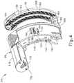
- FIG. 4depicts a rear perspective view of the staple cartridge of FIG. 2 ;
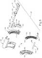
- FIG. 5depicts an exploded rear perspective view of the staple cartridge of FIG. 2 ;
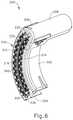
- FIG. 6depicts a front perspective view of another exemplary cartridge housing configured for use with the surgical stapling unit of FIG. 1A ;
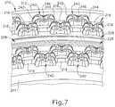
- FIG. 7depicts an enlarged perspective view of a medial portion of a deck of the cartridge housing of FIG. 6 , showing details of tissue engagement features formed on the medial portion of the deck;
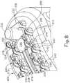
- FIG. 8depicts an enlarged perspective view of a first end portion of the deck of the cartridge housing of FIG. 6 , showing details of tissue engagement features formed on the first end portion of the deck;
- FIG. 9depicts an enlarged perspective view of an opposed second end portion of the deck of the cartridge housing of FIG. 6 , showing details of tissue engagement features formed on the second end portion of the deck;
- FIG. 10depicts a side elevational view the second end portion of the deck of the cartridge housing of FIG. 6 , showing additional details of the tissue engagement features formed on the second end portion of the deck.
- proximal and distalare defined herein relative to a human or robotic operator of the surgical instrument.
- proximalrefers the position of an element closer to the human or robotic operator of the surgical instrument and further away from the surgical end effector of the surgical instrument.
- distalrefers to the position of an element closer to the surgical end effector of the surgical instrument and further away from the human or robotic operator of the surgical instrument.
- FIGS. 1A-1Ddepict an exemplary surgical stapler ( 10 ) that includes a handle assembly ( 12 ), a shaft assembly ( 14 ) extending distally from handle assembly ( 12 ), and an end effector ( 16 ) at a distal end of shaft assembly ( 14 ).
- proximaldistal
- distaldistal
- end effector16
- surgical stapler ( 10 )may be configured and operable in accordance with at least some of the teachings of U.S. Pat. Pub. No.
- Handle assembly ( 12 )includes several actuation mechanisms for operating end effector ( 16 ) during the surgical procedure.
- exemplary handle assembly ( 12 )includes a saddle shaped slide ( 18 ), a closure trigger ( 20 ), and a firing trigger ( 22 ) in communication with end effector ( 16 ) via shaft assembly ( 14 ).
- FIG. 1Ashows slide ( 18 ) and closure trigger ( 20 ) in open configurations such that end effector ( 16 ) is configured to receive tissue laterally within a gap ( 25 ) of a replaceable cartridge unit ( 24 ) mounted within end effector ( 16 ), between an anvil ( 26 ) and a cartridge housing ( 28 ) of cartridge unit ( 24 ).
- translating slide ( 18 ) distally toward end effector ( 16 )slides a retaining pin ( 30 ) of end effector ( 16 ) distally, as shown in FIG. 1B , for capturing the tissue between anvil ( 26 ) and cartridge housing ( 28 ).
- sequentially actuating closure trigger ( 20 ) and firing trigger ( 22 )respectively compresses the tissue between anvil ( 26 ) and cartridge housing ( 28 ) in a closed configuration, and then forms a plurality of staples (not shown) within the tissue and severs the tissue with a curved knife ( 32 ) (see FIG. 6 ).
- handle assembly ( 12 ) of surgical stapler ( 10 )includes a handle housing ( 34 ) and a pair of handle frame plates ( 35 , 36 ) having proximal portions (not shown) housed within handle housing ( 34 ) and elongate distal portions that extend distally along shaft assembly ( 14 ).
- handle assembly ( 12 )further includes saddle shaped slide ( 18 ), closure trigger ( 20 ), and firing trigger ( 22 ).
- Handle housing ( 34 )defines a hand grip ( 38 ), which the operator may grasp with the palm of at least one hand.
- Handle housing ( 34 ) of the present exampleis formed by a right shroud handle portion ( 40 ) and a left shroud handle portion ( 42 ).
- Closure trigger ( 20 )is proximally positioned relative to firing trigger ( 22 ), and each trigger ( 20 , 22 ) is pivotally mounted to frame plates ( 35 , 36 ) and are exposed through an underside of handle housing ( 34 ) to be manipulated by the fingers of the operator.
- FIG. 1Ashows closure and firing triggers ( 20 , 22 ) in unactuated positions prior to the closing of end effector ( 16 ) and firing of staples (not shown) and curved knife ( 32 ). Accordingly, cartridge housing ( 28 ) is spaced from anvil ( 26 ) for receiving tissue within gap ( 25 ) therebetween.
- Surgical stapler ( 10 )is operable to capture tissue via a tissue retaining pin actuation mechanism ( 37 ) prior to actuation of the closure and firing triggers ( 20 , 22 ).
- Tissue retaining pin actuation mechanism ( 37 )includes slide ( 18 ) of handle assembly ( 12 ), a tissue retaining pin ( 30 ) of end effector ( 16 ), and an elongate pushrod ( 50 ) of shaft assembly ( 14 ).
- Slide ( 18 )is mounted on an upper surface of handle housing ( 34 ) and is configured to linearly translate between proximal and distal positions.
- Pushrod ( 50 )operatively couples slide ( 18 ) with tissue retaining pin ( 30 ), such that longitudinal translation of slide ( 18 ) drives longitudinal actuation of tissue retaining pin ( 30 ) between a proximal open position (see FIG. 1A ) and a distal closed position (see FIG. 1B ), via pushrod ( 50 ).
- a closure mechanism ( 52 ) of surgical stapler ( 10 )is configured to selectively actuate cartridge housing ( 28 ) of cartridge unit ( 24 ) between a proximal open position ( FIG. 1A ) and a distal closed position ( FIG. 1C ) for clamping tissue between cartridge housing ( 28 ) and anvil ( 26 ).
- Closure mechanism ( 52 )includes closure trigger ( 20 ) of handle assembly ( 12 ) and an elongate closure member ( 54 ) coupled at its proximal end with closure trigger ( 20 ).
- Closure member ( 54 )has a generally U-shaped cross-section and extends distally from handle assembly ( 12 ), through shaft assembly ( 14 ), and into end effector ( 16 ), such that a distal end of closure member ( 54 ) is configured to receive cartridge unit ( 24 ) within end effector ( 16 ), as shown in FIG. 2 .
- a proximal end of closure member ( 54 )is operatively connected with closure trigger ( 20 ) by a plurality of linkages (not shown) configured to convert pivoting motion of closure trigger ( 20 ) into translation of closure member ( 54 ). Accordingly, pivoting of closure trigger ( 20 ) toward pistol grip ( 38 ) to a closed position ( FIG.
- closure member ( 54 )drives closure member ( 54 ) distally, which in turn drives cartridge housing ( 28 ) distally toward anvil ( 26 ) for clamping tissue therebetween. Subsequently, pivoting of closure trigger ( 20 ) away from pistol grip ( 38 ) to an open position ( FIG. 1A ) drives closure member ( 54 ) proximally, which in turn drives cartridge housing ( 28 ) proximally away from anvil ( 26 ) for releasing stapled tissue.
- closure member ( 54 )may be further configured to cooperate with tissue retaining pin actuation mechanism ( 37 ) to automatically actuate retaining pin ( 30 ) distally to its closed position when the operator squeezes closure trigger ( 20 ).
- tissue retaining pin actuation mechanism ( 37 )may be used to automatically actuate retaining pin ( 30 ) distally to its closed position when the operator squeezes closure trigger ( 20 ).
- Such automationmay be useful in the event that the operator did not manually actuate retaining pin ( 30 ) distally via slide ( 18 ) prior to squeezing closure trigger ( 20 ).
- Closure trigger ( 20 )may be biased toward the open position by a resilient member (not shown) housed within handle housing ( 34 ).
- a firing mechanism ( 80 ) of surgical stapler ( 10 )is configured to actuate end effector ( 16 ) to staple and sever tissue clamped between anvil ( 26 ) and cartridge housing ( 28 ) in response to manipulation of firing trigger ( 22 ) of handle assembly ( 12 ).
- firing mechanism ( 80 )includes firing trigger ( 22 ), cartridge unit ( 24 ), and an elongate firing bar (not shown) that extends longitudinally through shaft assembly ( 14 ) and operatively couples firing trigger ( 22 ) with cartridge unit ( 24 ).
- Firing trigger ( 22 )is positioned distally of closure trigger ( 20 ) such that firing trigger ( 22 ) may be pivoted closed only once closure trigger ( 20 ) has first been pivoted closed.
- Pivoting of firing trigger ( 22 ) from an open position ( FIG. 1C ) toward a closed (or “fired”) position ( FIG. 1D )drives the firing bar distally, which in turn drives internal components of cartridge housing ( 28 ) distally to thereby staple and sever the tissue clamped by end effector ( 16 ), as described in greater detail below.
- closure trigger ( 20 ) and firing trigger ( 22 )may be configured to releasably lock in one or more pivot positions, such as a fully closed position and/or one or more intermediate positions between fully open (i.e., unactuated) and fully closed (i.e., fully actuated), for example. Accordingly, and advantageously, the operator may release one or more hands from the trigger ( 20 , 22 ) and hand grip ( 38 ) to perform another task during the surgical procedure, while the trigger ( 20 , 22 ) maintains its position. The operator may then release the trigger ( 20 , 22 ) from its locked state by depressing a release button ( 23 ) arranged on a proximal end of handle assembly ( 12 ).
- shaft assembly ( 14 ) of surgical stapler ( 10 )may include various additional components, such as an articulating joint, or may include a rearrangement of various components such that shaft assembly ( 14 ) may be modular relative to handle assembly ( 12 ).
- end effector ( 16 ) of the present exampleincludes a C-shaped support structure ( 128 ) and replaceable cartridge unit ( 24 ) removably received by C-shaped support structure ( 128 ).
- Support structure ( 128 ) of the present exampleis secured to the distal ends of handle frame plates ( 35 , 36 ) at the distal end of shaft assembly ( 14 ) by a shoulder rivet ( 129 ) and a pair of posts ( 130 ).
- the term “C-shaped”is used herein as reference to the curvature of support structure ( 128 ) and cartridge unit ( 24 ), each of which has a concave first lateral side and a convex second lateral side opposed from one another.
- Such a configurationprovides enhanced functionality and access to tissue within the patient.
- the C-shaped construction of support structure ( 128 ) and cartridge unit ( 24 )may enable end effector ( 16 ) to easily access the lower colon within the pelvic bowl of a patient, for example for performing a lower anterior resection (“LAR”) in a proctocolectomy procedure.
- LARanterior resection
- the term “C-shaped” as used hereinshould be construed to include a variety of concave shapes that would similarly enhance the functionality of surgical stapling and cutting instruments.
- Replaceable cartridge unit ( 24 )includes anvil ( 26 ) and cartridge housing ( 28 ), movably coupled to one another by a guide pin ( 166 ) and an anvil arm ( 196 ), as described in greater detail below.
- a distal end of cartridge housing ( 28 )defines a distally facing staple deck ( 134 ) configured to contact tissue.
- Staple deck ( 134 )includes a plurality of staple openings ( 136 ) arranged in staggered formation in a pair of rows on each side of an arcuate knife slot ( 152 ).
- Various other quantities of rows of staple openings ( 136 )may be provided in other versions.
- Cartridge housing ( 28 )houses a plurality of staples (not shown) configured to be driven distally through staple openings ( 136 ) and against anvil ( 26 ) to thereby form the staples in patient tissues.
- cartridge unit ( 24 )may further include a retainer configured to removable couple to staple deck ( 134 ) to cover staple openings ( 136 ) and knife slot ( 152 ) before use of cartridge unit ( 24 ), for instance when cartridge unit ( 24 ) is stored, and optionally also after use of cartridge unit ( 24 ).
- cartridge housing ( 28 )additionally houses retaining pin ( 30 ), a staple driver assembly ( 140 ), and a knife holder ( 142 ).
- Staple driver assembly ( 140 )is positioned just proximally of the staples (not shown) housed within cartridge housing ( 28 ) and distally of knife holder ( 142 ).
- Staple driver assembly ( 140 ) of the present exampleis formed as a unitary structure defining a plurality of staple drivers ( 141 ).
- the term “assembly,” as used in connection with staple driver assembly ( 140 )is not intended to be limited to an assembly of individual components, but may also include integrally formed components with unitary structures.
- Driver assembly ( 140 )is configured to translate distally within cartridge housing ( 28 ) so that staple drivers ( 141 ) drive staples distally from respective staple openings ( 136 ) and toward anvil ( 26 ) for formation within tissue clamped between anvil ( 26 ) and cartridge housing ( 28 ).
- Knife holder ( 142 )is movably disposed within cartridge housing ( 8 ) just proximally of staple driver assembly ( 140 ). Knife holder ( 142 ) supports curved knife ( 32 ) along a distal side thereof, and knife holder ( 142 ) is configured to translate within cartridge housing ( 28 ) such that curved knife ( 32 ) extends distally through an arcuate slot ( 150 ) of driver assembly ( 140 ) and arcuate slot ( 152 ) of staple deck ( 134 ).
- a proximal side of knife holder ( 142 )includes a slot ( 144 ) and a ledge ( 146 ) configured to couple with a knife retractor hook (not shown) for retraction of curved knife ( 32 ) after firing of cartridge unit ( 24 ), for example as disclosed in U.S. Pat. No. 10,045,780, entitled “Method of Applying Staples in Lower Anterior Bowel Resection,” issued Aug. 14, 2018, the disclosure of which is incorporated by reference herein.
- a lateral side of cartridge housing ( 28 )includes a longitudinally extending detent slot ( 155 ) defined between a confronting pair of resilient members.
- a first side of detent slot ( 155 )includes a first proximal detent protrusion ( 156 ), and an opposed second side of detent slot ( 155 ) includes a second proximal detent protrusion ( 159 ) and a distal detent protrusion ( 160 ).
- Detent slot ( 155 )is configured to slidably receive a detent post ( 154 ) of knife holder ( 142 ) and a detent post ( 158 ) of staple driver assembly ( 140 ).
- detent post ( 154 )resiliently engages detent protrusion ( 156 ), and detent post ( 158 ) resiliently engages detent protrusions ( 159 , 160 ).
- cartridge housing ( 28 )includes two longitudinally extending, generally circular holes ( 162 , 164 ) at respective upper and lower ends of arcuate knife slot ( 152 ) on staple deck ( 134 ). Holes ( 162 , 164 ) of the present example are positioned such that staple openings ( 136 ), and the staples ejected therefrom, extend beyond holes ( 162 , 164 ) at the upper and lower ends of staple deck ( 134 ). Lower hole ( 162 ) is shaped and dimensioned to slidably receive a guide pin ( 166 ) that extends longitudinally between cartridge housing ( 28 ) and anvil ( 26 ).
- Upper hole ( 164 )is shaped and dimensioned to slidably receive retaining pin ( 30 ) therethrough, such that retaining pin ( 30 ) may actuate longitudinally relative to cartridge housing ( 28 ) and anvil ( 26 ) between the proximal retracted position ( FIG. 1A ) and the distal extended position ( FIG. 1B ).
- a proximal end of retaining pin ( 30 )includes a first coupling feature ( 172 ) (e.g., a projection) configured to couple with a corresponding coupling feature (not shown) (e.g., a groove) of a couplet ( 170 ), so that retaining pin ( 30 ) is secured to couplet ( 170 ).
- Couplet ( 170 ) and retaining pin ( 30 )are slidably disposed within an upper arm ( 176 ) of cartridge housing ( 28 ), and are captured proximally therein by an end cap ( 178 ) secured to upper arm ( 176 ) proximally of couplet ( 170 ).
- Anvil ( 26 ) of the present exampleincludes a plastic cutting washer ( 168 ) and a metallic staple-forming surface ( 138 ) secured to a proximal side of cutting washer ( 168 ).
- Staple-forming surface ( 138 )includes an elongate arcuate slot ( 192 ) configured to receive an arcuate projection ( 169 ) of cutting washer ( 168 ) therethrough to secure staple-forming surface ( 138 ) relative to cutting washer ( 168 ).
- Staple-forming surface ( 138 )further includes a plurality of pockets arranged in rows along either side of arcuate slot ( 192 ). These pockets are configured to receive and form the legs of staples driven distally from staple openings ( 136 ) of staple deck ( 134 ). Accordingly, anvil ( 26 ) is spaced distally from and is aligned with staple deck ( 134 ) such that each pocket of staple-forming surface ( 138 ) aligns with a respective staple opening ( 136 ).
- Staple-forming surface ( 138 ) of anvil ( 26 )further includes a first circular opening ( 194 ) disposed at an upper end of arcuate slot ( 192 ), and a second circular opening (see FIG. 4 ) disposed at a lower end of arcuate slot ( 192 ).
- First opening ( 194 )is configured to slidably receive a pointed distal tip of tissue retaining pin ( 30 ) when tissue retaining pin ( 30 ) is actuated distally to capture tissue positioned between anvil ( 26 ) and cartridge housing ( 28 ).
- the lower second opening of staple-forming surface ( 138 )receives a distal end ( 190 ) of guide pin ( 166 ) therethrough, which extends into and fixedly couples to a lower end of cutting washer ( 168 ), such that guide pin ( 166 ) is longitudinally fixed relative to anvil ( 26 ).
- a proximal end ( 188 ) of guide pin ( 166 )is slidably received through lower hole ( 162 ) formed in staple deck ( 134 ) of cartridge housing ( 28 ), as described above.
- An anvil arm ( 196 ) projecting proximally from a lower end of staple-forming surface ( 138 )is movably received through an open lower end of cartridge housing ( 28 ) to thereby trap proximal end ( 188 ) of guide pin ( 166 ) within cartridge housing ( 28 ), while still permitting cartridge housing ( 28 ) to actuate toward anvil ( 26 ).
- cartridge housing ( 28 )is configured to slide longitudinally along guide pin ( 166 ) (and tissue retaining pin ( 30 )) relative to anvil ( 26 ) in response to actuation of closure trigger ( 20 ), described above.
- an interior side of guide pin ( 166 )includes a longitudinal slot ( 180 ) configured to slidably receive a corresponding lower end ( 184 ) of curved knife ( 32 ) as cartridge housing ( 28 ) actuates longitudinally relative to anvil ( 26 ).
- tissue retaining pin ( 30 )may include a similar longitudinal slot (not shown) configured to slidably receive a corresponding upper end ( 186 ) of curved knife ( 32 ) as cartridge housing ( 28 ) actuates longitudinally relative to anvil ( 26 ).
- Surgical stapler ( 10 )is first suitably manipulated within a body cavity of a patient to position patient tissue within gap ( 25 ) (see FIG. 1A ) between anvil ( 26 ) and cartridge housing ( 28 ). As shown in FIG. 1B , slide ( 18 ) is then actuated distally to drive pushrod ( 50 ) distally, thereby driving tissue retaining pin ( 30 ) distally from cartridge housing ( 28 ) toward anvil ( 26 ). The pointed distal tip of tissue retaining pin ( 30 ) securely engages (e.g., pierces) the tissue and thereby captures the tissue within gap ( 25 ).
- closure trigger ( 20 )is then squeezed toward pistol grip ( 38 ) to drive closure member ( 54 ) distally, thereby driving cartridge housing ( 28 ) distally toward anvil ( 26 ) along tissue retaining pin ( 30 ) and guide pin ( 166 ) to clamp the tissue between cartridge deck ( 134 ) and anvil ( 26 ).
- Cartridge housing ( 28 )may be maintained in this closed position relative to anvil ( 26 ) by an internal locking mechanism (not shown) of handle assembly ( 12 ) that holds closure trigger ( 20 ) in the squeezed position, as described above.
- FIG. 1Cclosure trigger ( 20 ) is then squeezed toward pistol grip ( 38 ) to drive closure member ( 54 ) distally, thereby driving cartridge housing ( 28 ) distally toward anvil ( 26 ) along tissue retaining pin ( 30 ) and guide pin ( 166 ) to clamp the tissue between cartridge deck ( 134 ) and anvil ( 26 ).
- Cartridge housing ( 28 )may be maintained in this closed position relative to anvil ( 26
- firing trigger ( 22 )is then squeezed toward closure trigger ( 20 ) and pistol grip ( 38 ) to drive the elongate firing bar (not shown) distally, thereby driving staple driver assembly ( 140 ) and knife holder ( 142 ) distally within cartridge housing ( 28 ).
- Stapler drivers ( 141 ) of driver assembly ( 140 )drive staples (not shown) distally through the captured tissue and against staple-forming surface ( 138 ) of anvil ( 26 ) to form the staples within the tissue and thereby fluidly seal the tissue.
- curved knife ( 32 )is driven distally by knife holder ( 142 ) through arcuate slots ( 150 , 152 ) and into the clamped tissue to thereby sever the tissue along an arcuate path extending between the two innermost rows of the formed staples.
- firing trigger ( 22 )may be held in its squeezed position by the internal locking mechanism (not shown) of handle assembly ( 12 ).
- surgical stapler ( 10 )may be configured in some versions such that the tissue clamped by end effector ( 16 ) within gap ( 25 ) is stapled and cut simultaneously; and be alternatively configured in other versions such that the tissue is fully stapled and subsequently cut in sequential steps.
- curved knife ( 32 )may be retracted proximally back into cartridge housing ( 28 ), and cartridge housing ( 28 ) may be retracted proximally along pins ( 30 , 166 ) to thereby release the newly stapled and severed tissue from between anvil ( 26 ) and cartridge deck ( 134 ).
- the fired cartridge unit ( 24 )may then be removed from support structure ( 128 ) of end effector ( 16 ), discarded, and replaced for further treatment if so desired.
- Surgical stapler ( 10 )may be further configured and operable in accordance with any of the teachings of the references cited herein, including U.S. Pat. No. 10,045,780, incorporated by reference above.
- FIG. 6shows an exemplary alternative cartridge housing ( 200 ) configured in such a manner, and which may be readily incorporated into cartridge unit ( 24 ) described above in place of cartridge housing ( 28 ).
- Cartridge housing ( 200 )is configured and operable in a manner similar to cartridge housing ( 28 ), except as otherwise described below.
- Cartridge housing ( 200 )includes a curved body ( 202 ) that extends along an arcuate path and has an open lower body end ( 204 ), a closed upper body end ( 206 ), and an upper arm ( 208 ) extending proximally from upper body end ( 206 ).
- Curved body ( 202 ) and upper arm ( 208 ) of the present examplehave hollow interiors that communicate with one another and are configured to house respective moveable components similar to cartridge housing ( 28 ) described above.
- curved body ( 202 )is configured to movably house staple driver assembly ( 140 ), a plurality of staples (not shown), knife holder ( 142 ), and curved knife ( 32 ), shown in FIG. 5 .
- Upper arm ( 208 )is configured to movably house tissue retaining pin ( 30 ) and couplet ( 170 ), which are retained within upper arm ( 208 ) by end cap ( 178 ), also shown in FIG. 5 .
- Cartridge housing ( 200 )is configured to couple with anvil ( 26 ) in a manner similar to cartridge housing ( 28 ) described above to define a cartridge unit similar to cartridge unit ( 24 ).
- the resulting cartridge unitis configured to be removably received by C-shaped support structure ( 128 ) of end effector ( 16 ) such that curved body ( 202 ) couples with the distal ends of frame plates ( 35 , 36 ) of closure mechanism ( 52 ); such that couplet ( 170 ) couples with the distal end of pushrod ( 50 ) of tissue retaining pin actuation mechanism ( 37 ); and such that staple driver assembly ( 140 ) and knife holder ( 142 ) couple with the distal end of the firing bar (not shown) of firing mechanism ( 80 ).
- a distal face of curved body ( 202 ) of cartridge housing ( 200 )defines a distally-facing staple deck ( 210 ) that extends along the arcuate path of curved body ( 202 ) and has a first elongate side edge ( 212 ) that extends along a convex side of curved body ( 202 ), and an opposed second elongate side edge ( 214 ) that extends along a concave side of curved body ( 202 ).
- staple deck ( 210 )is configured to clamp tissue against staple-forming surface ( 138 ) of anvil ( 26 ) when cartridge housing ( 200 ) is actuated distally toward anvil ( 26 ).
- Staple deck ( 210 )includes a plurality of staple openings ( 216 ) configured to house a plurality of staples (not shown) that are driven distally through staple openings ( 216 ) by staple drivers ( 141 ) of staple driver assembly ( 140 ) for stapling clamped tissue in response to actuation of firing mechanism ( 80 ).
- staple deck ( 210 )further includes an arcuate knife slot ( 218 ) extending along an arcuate centerline of deck ( 210 ) so as to divide deck ( 210 ) into first and second elongate side portions.
- Arcuate knife slot ( 218 )is configured to slidably receive curved knife ( 32 ) distally therethrough for cutting clamped tissue in response to actuation of firing mechanism ( 80 ).
- Staple openings ( 216 )are arranged in a plurality of rows extending along arcuate paths parallel to arcuate knife slot ( 218 ) on the first and second side portions of deck ( 210 ).
- each side portion of deck ( 210 )includes an inner row and an outer row of staple openings ( 216 ), such that two rows of staple openings are arranged on each side of arcuate knife slot ( 218 ).
- Staple openings ( 216 ) of adjacent inner and outer rowsare arranged in a staggered formation relative to one another. It will be appreciated that staple openings ( 216 ) may be arranged in various other row quantities and configurations in other versions.
- Each side portion of staple deck ( 210 )may be sloped away from arcuate knife slot ( 218 ) in a downward direction toward the respective deck side edge ( 212 , 214 ).
- Such a configurationadvantageously provides varying compression of tissue across a width of deck ( 210 ), and is disclosed in greater detail in U.S. patent application Ser. No. 16/234,740, entitled “Surgical Stapler with Sloped Staple Deck for Varying Tissue Compression,” filed on Dec. 28, 2018, published as U.S. Pub. No. 2020/0205811 on Jul. 2, 2020, the disclosure of which is incorporated by reference herein.
- staple deck ( 210 )further includes a first circular opening ( 220 ) arranged at a first end of arcuate knife slot ( 218 ) adjacent to upper body end ( 206 ).
- First circular opening ( 220 )is aligned with and communicates directly with the first end of arcuate knife slot ( 218 ), and is configured to slidably receive tissue retaining pin ( 30 ) (see FIG. 5 ) therethrough.
- An end pair of staple openings ( 216 )extends beyond first circular opening ( 220 ) in a direction toward upper body end ( 206 ).
- staple deck ( 210 )further includes a second circular opening ( 222 ) arranged at a second end of arcuate knife slot ( 218 ) adjacent to lower body end ( 204 ). Second circular opening ( 222 ) is aligned with and communicates directly with the second end of arcuate knife slot ( 218 ), and is configured to receive a proximal portion of guide pin ( 166 ) (see FIG. 5 ) therethrough.
- staple deck ( 210 ) of the present examplefurther includes an annular wall ( 224 ) that substantially encircles first circular opening ( 220 ) and protrudes away from deck ( 210 ) to define a raised annular surface ( 226 ) offset from deck ( 210 ).
- annular wall ( 224 )is integrally connected with an adjacent pair of cleats ( 240 ), described below, disposed on opposed lateral sides of annular wall ( 224 ).
- Deck ( 210 )further includes a pair of elongate ridges ( 228 ) that extend along opposing sides of arcuate knife slot ( 218 ) and project away from deck ( 210 ) to define raised ridge surfaces ( 230 ).
- Raised ridge surfaces ( 230 )interconnect flush with raised annular surface ( 226 ) of annular wall ( 224 ) at the corresponding first end of arcuate knife slot ( 218 ).
- Elongate ridges ( 228 )terminate at the opposed second end of arcuate knife slot ( 218 ), as shown in FIG. 9 .
- Raised annular surface ( 226 )is configured to clamp tissue against anvil ( 26 ) and thereby fix the tissue relative to first circular opening ( 220 ) to minimize tissue flow around tissue retaining pin ( 30 ) during cutting and stapling of tissue, and during subsequent proximal retraction of tissue retaining pin ( 30 ) into cartridge housing ( 200 ).
- raised ridge surfaces ( 230 )are configured to clamp tissue against anvil ( 26 ) and thereby fix the tissue relative to arcuate knife slot ( 218 ) to minimize tissue flow around knife slot ( 218 ) during cutting and stapling of the tissue.
- tissue gap post ( 232 )is disposed on staple deck ( 210 ) just beyond first circular opening ( 220 ) in a direction toward upper body end ( 206 ), and in alignment with first circular opening ( 220 ) and arcuate knife slot ( 218 ).
- Tissue gap post ( 232 )projects away from deck ( 210 ) and is configured to abut a first end of anvil ( 26 ) when cartridge housing ( 200 ) is driven distally against anvil ( 26 ). In this manner, tissue gap post ( 232 ) defines a minimum tissue gap between staple deck ( 210 ) and staple-forming surface ( 138 ) of anvil ( 26 ).
- a tissue stop tab ( 234 )is disposed on staple deck ( 210 ) just beyond second circular opening ( 222 ) in a direction toward lower body end ( 204 ), and in alignment with second circular opening ( 222 ) and arcuate knife slot ( 218 ).
- Tissue stop tab ( 234 )projects away from deck ( 210 ) and functions as a stop feature that prevents tissue from flowing beyond lower body end ( 204 ) during cutting and stapling of the tissue.
- tissue stop tab ( 234 )is further configured to abut a second end of anvil ( 26 ) when cartridge housing ( 200 ) is driven distally, such that tissue stop tab ( 234 ) cooperates with tissue gap post ( 232 ) to define the minimum tissue gap between staple deck ( 210 ) and staple-forming surface ( 138 ) of anvil ( 26 ).
- staple deck ( 210 ) of cartridge housing ( 200 )further includes a plurality of tissue engagement features in the form of stand-off members ( 240 , 250 , 252 , 254 ) that project away from deck ( 210 ).
- Stand-off members ( 240 , 250 , 252 , 254 )are distributed along a length of deck ( 210 ) and are laterally offset from arcuate knife slot ( 218 ) to align with and open to a respective one or more staple openings ( 216 ).
- stand-off members ( 240 , 250 , 252 , 254 )are configured to grip and thereby stabilize tissue when deck ( 210 ) is clamped against anvil ( 26 ); and, moreover, optimize tissue compression at the staple locations to facilitate effective stapling and cutting of the tissue.
- a first set of stand-off members on staple deck ( 210 )is shown in the form of cleats ( 240 ) arranged discretely along the length of arcuate knife slot ( 218 ) in alignment with staple openings ( 216 ).
- Each cleat ( 240 )includes a first end feature ( 242 ) that wraps partially around an end portion of a first staple opening ( 216 ) within a given row of staple openings ( 216 ), and an opposed second end feature ( 244 ) that wraps partially around an end portion of an adjacent second staple opening ( 216 ) within the row of staple openings ( 216 ).
- First and second end features ( 242 , 244 )are integrally connected by a recessed bridge portion ( 246 ).
- Each end feature ( 242 , 244 ) of a cleat ( 240 )is generally U-shaped and defines an inner wall that joins with and protrudes outwardly from an inner wall of the respective staple opening ( 216 ). In this manner, each end feature ( 242 , 244 ) opens to and communicates with a respective staple opening ( 216 ). Accordingly, each end feature ( 242 , 244 ) is configured to guide a respective staple leg of a corresponding staple (not shown) as the staple is ejected distally from the staple opening ( 216 ) by a staple driver ( 141 ).
- Each end feature ( 242 , 244 )thus cooperates with a confronting end feature ( 242 , 244 ) of an adjacent cleat ( 240 ), or with an endcap ( 250 , 252 , 254 ) described below, to provide such guidance of the staples.
- the lateral side of each end feature ( 242 , 244 ) that laterally confronts an end feature ( 242 , 244 ) of an adjacent row of cleats ( 240 )is formed with a reduced wall thickness relative to an opposed lateral side of the same end feature ( 242 , 244 ).
- cleats ( 240 ) of the present exampleare discretely formed relative to one another such that each cleat ( 240 ) is freestanding and is spaced apart from adjacent cleats ( 240 ), in other examples cleats ( 240 ) may be interconnected with one another along one or more portions of staple deck ( 210 ).
- staple deck ( 210 )includes additional stand-off members in the form of outer row endcaps ( 250 ) disposed at both ends of the outer rows of staple openings ( 216 ).
- each outer row endcap ( 250 )has a U-shape similar to end features ( 242 , 244 ) of cleats ( 240 ), and wraps partially around an end portion of a respective staple opening ( 216 ) at the end of a respective outer row of staple openings ( 216 ).
- each outer row endcap ( 250 )cooperates with a confronting end feature ( 242 , 244 ) of an adjacent cleat ( 240 ) within the same row to guide a respective staple (not shown) distally into tissue as the staple is being ejected.
- an inner surface of each outer row end cap ( 250 )is integrally connected with an end feature ( 242 , 244 ) of an adjacent cleat ( 240 ) of the adjacent inner row of cleats ( 240 ).
- first end inner row endcaps ( 252 )is disposed at the ends of the inner rows of staple openings ( 216 ) at upper body end ( 206 ).
- First end inner row endcaps ( 252 ) of the present exampleare disposed on opposed lateral sides of tissue gap post ( 232 ) and are integrally joined with tissue gap post ( 232 ) (with only one endcap ( 252 ) being shown in FIG. 8 ).
- First end inner row endcaps ( 252 )are otherwise similar to outer row endcaps ( 250 ) in that each endcap ( 252 ) has a U-shaped opening that wraps partially around an end portion of an end-most staple opening ( 216 ) and cooperates with a confronting end feature ( 242 , 244 ) of a cleat ( 240 ) within the same row to guide a staple during distal ejection.
- a pair of second end inner row endcaps ( 254 )is disposed at the ends of the inner rows of staple openings ( 216 ) at lower body end ( 204 ).
- Second end inner row endcaps ( 254 ) of the present exampleare disposed on opposed lateral sides of tissue stop tab ( 234 ) and are integrally joined with tissue stop tab ( 234 ).
- Second end inner row endcaps ( 254 )are similar to outer row endcaps ( 250 ) in that each endcap ( 254 ) has a U-shaped opening that wraps partially around an end portion of an end-most staple opening ( 216 ) and cooperates with a confronting ( 242 , 244 ) of a cleat ( 240 ) within the same row to guide a staple during distal ejection.
- cleats ( 240 ), outer row endcaps ( 250 ), and first end inner row endcaps ( 252 )each protrude from deck ( 210 ) with a similar first maximum height.
- second end inner row endcaps ( 254 )each protrude from deck ( 210 ) with a second maximum height that is greater than the first maximum height.
- the second maximum height defined by second end inner row endcaps ( 254 )is greater than the first maximum height defined by cleats ( 240 ), outer row endcaps ( 250 ), and first end inner row endcaps ( 252 ) by a distance (X) measured perpendicularly outwardly from deck ( 210 ).
- second end inner row endcaps ( 254 )enables these endcaps ( 254 ) to more securely engage tissue at lower body end ( 204 ) and thus ensure robust staple formation at lower body end ( 204 ).
- the increased heightalso enables endcaps ( 254 ) to cooperate with tissue stop tab ( 234 ) to prevent tissue from flowing beyond lower body end ( 204 ) during cutting and stapling of the tissue.
- one or more other endcaps ( 250 , 252 )may be provided with increased heights relative to cleats ( 240 ), and/or cleats ( 240 ) themselves may be provided with varying heights relative to staple deck ( 210 ).
- stand-off members ( 240 , 250 , 252 , 254 )provides multiple advantages.
- portions of the compressed tissuewill enter the recessed areas in and around stand-off members ( 240 , 250 , 252 , 254 ) (e.g., recessed bridge portions ( 246 ) and separation gaps).
- tissue compressionis optimized at the staple locations corresponding to stand-off members ( 240 , 250 , 252 , 254 ) while the total pressure applied to the compressed tissue is decreased relative to a theoretical alternative configuration in which staple deck ( 210 ) is flat.
- tissue compressionis optimized at the staple locations corresponding to stand-off members ( 240 , 250 , 252 , 254 ) while the total pressure applied to the compressed tissue is decreased relative to a theoretical alternative configuration in which staple deck ( 210 ) is flat.
- the enhanced gripping of tissuemay promote cleaner cutting by knife ( 32 ) and more effective deployment of staples into the tissue.
- the provision of stand-off members ( 240 , 250 , 252 , 254 )may both reduce the risk of over-compression of tissue and promote greater success in cutting and stapling the tissue.
- a cartridge for use with a surgical instrumentcomprising: (a) a curved body; (b) a deck defined by the curved body, wherein the deck is configured to clamp tissue against an anvil; (c) a plurality of staple openings formed in the deck, wherein the staple openings are configured to house a plurality of staples; (d) an arcuate slot formed in the deck, wherein the arcuate slot is configured to slidably receive a cutting member therethrough; (e) an opening formed in the deck adjacent to an end of the arcuate slot, wherein the opening is configured to slidably receive a pin therethrough; and (f) a raised surface offset from the deck and extending circumferentially about at least a portion of the opening, wherein the raised surface is configured to clamp tissue against the anvil to thereby fix the tissue relative to the opening.
- Example 1The cartridge of Example 1, wherein the raised surface is defined by an annular structure disposed on the deck, wherein the annular structure at least partially encircles the opening.
- each ridgehas an upper surface that interconnects with the raised surface.
- the cartridge of any of the preceding Examplesfurther comprising a second opening formed in the deck adjacent to a second end of the arcuate slot, wherein the second opening is configured to receive a second pin therethrough.
- the staple openingsare arranged in a plurality of rows comprising a first row extending along a first side of the arcuate slot and a second row extending along a second side of the arcuate slot.
- the openingis located between the end of the arcuate slot and a corresponding end of the deck, wherein at least one of the staple openings extends beyond the opening in a direction toward the corresponding end of the deck.
- the cartridge of any of the preceding Examplesfurther comprising a plurality of stand-off members arranged on the deck, wherein the stand-off members are laterally offset from the arcuate slot and are configured to engage tissue.
- each of the stand-off memberswraps around at least a portion of an adjacent staple opening.
- the stand-off membersinclude a first end feature that wraps at least partially around an end portion of a first staple opening, and an opposed second end feature that wraps at least partially around an end portion of a second staple opening.
- the plurality of stand-off memberscomprises a plurality of first stand-off members and at least one second stand-off member, wherein the at least one second stand-off member has a greater maximum height relative to the deck than the first stand-off members,
- a cartridge for use with a surgical instrumentcomprising: (a) a curved body; (b) a deck defined by the curved body, wherein the deck is configured to clamp tissue against an anvil; (c) a plurality of staple openings formed in the deck, wherein the staple openings are configured to house a plurality of staples; (d) an arcuate slot formed in the deck, wherein the arcuate slot is configured to slidably receive a cutting member therethrough; (e) a plurality of first stand-off members arranged on the deck along a length of the arcuate slot, wherein each first stand-off member opens to at least one of the staple openings, wherein the first stand-off members have a first maximum height relative to the deck; (f) a second stand-off member arranged on the deck at an end of the plurality of first stand-off members, wherein the second stand-off member opens to at least one of the staple openings, wherein the second stand-off member has a second maximum height relative to the deck that is
- Example 16wherein the deck has a first deck end and an opposed second deck end, wherein the arcuate slot extends longitudinally between the first and second deck ends, wherein the second stand-off member is disposed between the first deck end and a corresponding end of the arcuate slot.
- the cartridge of any of Examples 16 through 17,further comprising: (a) a projection disposed adjacent to an end of the arcuate slot and in alignment with the arcuate slot; and (b) a pair of second stand-off members disposed at opposed lateral sides of the projection, wherein each second stand-off member opens to a respective one of the staple openings and defines a maximum height that is greater than the first maximum height.
- a surgical instrumentcomprising: (a) a body; (b) a shaft assembly extending distally from the body; and (c) an end effector at a distal end of the shaft assembly, wherein the end effector comprises: (i) a support structure, (ii) an anvil fixed relative to the support structure, wherein the anvil includes a plurality of staple-forming pockets, and (iii) a cartridge housing, wherein the cartridge housing is movable relative to the support structure to clamp tissue against the anvil, wherein the cartridge housing comprises: (A) a curved body, (B) a deck defined by the curved body, (C) a plurality of staple openings formed in the deck, wherein the staple openings are configured to house a plurality of staples, (D) an arcuate slot formed in the deck, wherein the arcuate slot is configured to slidably receive a cutting member therethrough, and (E) a plurality of stand-off members arranged on the deck along a length of the arcuate slot,
- an end effector in accordance with various embodimentscan comprise electrodes configured to heat and seal the tissue.
- an end effector in accordance with certain embodimentscan apply vibrational energy to seal the tissue.
- Versions of the devices described abovemay be designed to be disposed of after a single use, or they can be designed to be used multiple times. Versions may, in either or both cases, be reconditioned for reuse after at least one use. Reconditioning may include any combination of the steps of disassembly of the device, followed by cleaning or replacement of particular pieces, and subsequent reassembly. In particular, some versions of the device may be disassembled, and any number of the particular pieces or parts of the device may be selectively replaced or removed in any combination. Upon cleaning and/or replacement of particular parts, some versions of the device may be reassembled for subsequent use either at a reconditioning facility, or by an operator immediately prior to a procedure.
- reconditioning of a devicemay utilize a variety of techniques for disassembly, cleaning/replacement, and reassembly. Use of such techniques, and the resulting reconditioned device, are all within the scope of the present application.
- versions described hereinmay be sterilized before and/or after a procedure.
- the deviceis placed in a closed and sealed container, such as a plastic or TYVEK bag.
- the container and devicemay then be placed in a field of radiation that can penetrate the container, such as gamma radiation, x-rays, or high-energy electrons.
- the radiationmay kill bacteria on the device and in the container.
- the sterilized devicemay then be stored in the sterile container for later use.
- a devicemay also be sterilized using any other technique known in the art, including but not limited to beta or gamma radiation, ethylene oxide, or steam.
Landscapes
- Health & Medical Sciences (AREA)
- Life Sciences & Earth Sciences (AREA)
- Surgery (AREA)
- Heart & Thoracic Surgery (AREA)
- Engineering & Computer Science (AREA)
- Biomedical Technology (AREA)
- Nuclear Medicine, Radiotherapy & Molecular Imaging (AREA)
- Medical Informatics (AREA)
- Molecular Biology (AREA)
- Animal Behavior & Ethology (AREA)
- General Health & Medical Sciences (AREA)
- Public Health (AREA)
- Veterinary Medicine (AREA)
- Surgical Instruments (AREA)
Abstract
Description
Claims (20)
Priority Applications (12)
| Application Number | Priority Date | Filing Date | Title |
|---|---|---|---|
| US16/234,727US11202628B2 (en) | 2018-12-28 | 2018-12-28 | Surgical stapler with tissue engagement features around tissue containment pin |
| PCT/IB2019/061243WO2020136542A2 (en) | 2018-12-28 | 2019-12-21 | Surgical stapler with tissue engagement features around tissue containment pin |
| JP2021537823AJP7480153B2 (en) | 2018-12-28 | 2019-12-21 | Surgical stapler having tissue-engaging features about tissue-receiving pins - Patents.com |
| CN201980086994.4ACN113260319B (en) | 2018-12-28 | 2019-12-21 | Surgical stapler having tissue engaging features around a tissue receiving pin |
| BR112021012634-1ABR112021012634A2 (en) | 2018-12-28 | 2019-12-21 | SURGICAL STAPLER WITH TISSUE ENGAGEMENT FEATURES AROUND A TISSUE CONFINING PIN |
| MX2021007858AMX2021007858A (en) | 2018-12-28 | 2019-12-21 | Surgical stapler with tissue engagement features around tissue containment pin. |
| EP24153168.0AEP4331504A3 (en) | 2018-12-28 | 2019-12-23 | Surgical stapler with tissue engagement features around tissue containment pin |
| ES19219408TES2974441T3 (en) | 2018-12-28 | 2019-12-23 | Surgical stapler with tissue attachment elements around tissue retention pin |
| PL19219408.2TPL3673824T3 (en) | 2018-12-28 | 2019-12-23 | Surgical stapler with tissue engagement features around tissue containment pin |
| EP19219408.2AEP3673824B1 (en) | 2018-12-28 | 2019-12-23 | Surgical stapler with tissue engagement features around tissue containment pin |
| US17/458,899US11998196B2 (en) | 2018-12-28 | 2021-08-27 | Surgical stapler with tissue engagement features around tissue containment pin |
| US18/642,985US20240268821A1 (en) | 2018-12-28 | 2024-04-23 | Surgical stapler with tissue engagement features around tissue containment pin |
Applications Claiming Priority (1)
| Application Number | Priority Date | Filing Date | Title |
|---|---|---|---|
| US16/234,727US11202628B2 (en) | 2018-12-28 | 2018-12-28 | Surgical stapler with tissue engagement features around tissue containment pin |
Related Child Applications (1)
| Application Number | Title | Priority Date | Filing Date |
|---|---|---|---|
| US17/458,899ContinuationUS11998196B2 (en) | 2018-12-28 | 2021-08-27 | Surgical stapler with tissue engagement features around tissue containment pin |
Publications (2)
| Publication Number | Publication Date |
|---|---|
| US20200205810A1 US20200205810A1 (en) | 2020-07-02 |
| US11202628B2true US11202628B2 (en) | 2021-12-21 |
Family
ID=69005613
Family Applications (3)
| Application Number | Title | Priority Date | Filing Date |
|---|---|---|---|
| US16/234,727Active2039-07-12US11202628B2 (en) | 2018-12-28 | 2018-12-28 | Surgical stapler with tissue engagement features around tissue containment pin |
| US17/458,899Active2039-03-28US11998196B2 (en) | 2018-12-28 | 2021-08-27 | Surgical stapler with tissue engagement features around tissue containment pin |
| US18/642,985PendingUS20240268821A1 (en) | 2018-12-28 | 2024-04-23 | Surgical stapler with tissue engagement features around tissue containment pin |
Family Applications After (2)
| Application Number | Title | Priority Date | Filing Date |
|---|---|---|---|
| US17/458,899Active2039-03-28US11998196B2 (en) | 2018-12-28 | 2021-08-27 | Surgical stapler with tissue engagement features around tissue containment pin |
| US18/642,985PendingUS20240268821A1 (en) | 2018-12-28 | 2024-04-23 | Surgical stapler with tissue engagement features around tissue containment pin |
Country Status (9)
| Country | Link |
|---|---|
| US (3) | US11202628B2 (en) |
| EP (2) | EP4331504A3 (en) |
| JP (1) | JP7480153B2 (en) |
| CN (1) | CN113260319B (en) |
| BR (1) | BR112021012634A2 (en) |
| ES (1) | ES2974441T3 (en) |
| MX (1) | MX2021007858A (en) |
| PL (1) | PL3673824T3 (en) |
| WO (1) | WO2020136542A2 (en) |
Cited By (9)
| Publication number | Priority date | Publication date | Assignee | Title |
|---|---|---|---|---|
| US11602347B2 (en) | 2018-12-28 | 2023-03-14 | Cilag Gmbh International | Method of applying buttresses to surgically cut and stapled sites |
| USD983971S1 (en) | 2018-12-28 | 2023-04-18 | Cilag Gmbh International | Surgical stapler deck with tissue engagement recess features |
| USD983972S1 (en) | 2018-12-28 | 2023-04-18 | Cilag Gmbh International | Surgical stapler deck with tissue engagement cleat features |
| US11903584B2 (en) | 2016-11-14 | 2024-02-20 | Cilag Gmbh International | Atraumatic stapling head features for circular surgical stapler |
| US11998196B2 (en) | 2018-12-28 | 2024-06-04 | Cilag Gmbh International | Surgical stapler with tissue engagement features around tissue containment pin |
| US12016555B2 (en) | 2020-11-10 | 2024-06-25 | Cilag Gmbh International | Method of forming an anvil for a surgical stapler |
| US20250049436A1 (en)* | 2022-04-08 | 2025-02-13 | Cilag Gmbh International | End effector and open linear stapler having the same |
| US12232725B2 (en) | 2018-12-28 | 2025-02-25 | Cilag Gmbh International | Surgical stapler with sloped staple deck for varying tissue compression |
| US12426880B2 (en) | 2023-05-19 | 2025-09-30 | Cilag Gmbh International | Surgical stapler cartridge having intermediate raised tissue engagement protrusions |
Families Citing this family (228)
| Publication number | Priority date | Publication date | Assignee | Title |
|---|---|---|---|---|
| US20070084897A1 (en) | 2003-05-20 | 2007-04-19 | Shelton Frederick E Iv | Articulating surgical stapling instrument incorporating a two-piece e-beam firing mechanism |
| US9060770B2 (en) | 2003-05-20 | 2015-06-23 | Ethicon Endo-Surgery, Inc. | Robotically-driven surgical instrument with E-beam driver |
| US9072535B2 (en) | 2011-05-27 | 2015-07-07 | Ethicon Endo-Surgery, Inc. | Surgical stapling instruments with rotatable staple deployment arrangements |
| US11890012B2 (en) | 2004-07-28 | 2024-02-06 | Cilag Gmbh International | Staple cartridge comprising cartridge body and attached support |
| US11998198B2 (en) | 2004-07-28 | 2024-06-04 | Cilag Gmbh International | Surgical stapling instrument incorporating a two-piece E-beam firing mechanism |
| US7669746B2 (en) | 2005-08-31 | 2010-03-02 | Ethicon Endo-Surgery, Inc. | Staple cartridges for forming staples having differing formed staple heights |
| US10159482B2 (en) | 2005-08-31 | 2018-12-25 | Ethicon Llc | Fastener cartridge assembly comprising a fixed anvil and different staple heights |
| US11246590B2 (en) | 2005-08-31 | 2022-02-15 | Cilag Gmbh International | Staple cartridge including staple drivers having different unfired heights |
| US20070106317A1 (en) | 2005-11-09 | 2007-05-10 | Shelton Frederick E Iv | Hydraulically and electrically actuated articulation joints for surgical instruments |
| US8820603B2 (en) | 2006-01-31 | 2014-09-02 | Ethicon Endo-Surgery, Inc. | Accessing data stored in a memory of a surgical instrument |
| US8186555B2 (en) | 2006-01-31 | 2012-05-29 | Ethicon Endo-Surgery, Inc. | Motor-driven surgical cutting and fastening instrument with mechanical closure system |
| US8708213B2 (en) | 2006-01-31 | 2014-04-29 | Ethicon Endo-Surgery, Inc. | Surgical instrument having a feedback system |
| US20120292367A1 (en) | 2006-01-31 | 2012-11-22 | Ethicon Endo-Surgery, Inc. | Robotically-controlled end effector |
| US7845537B2 (en) | 2006-01-31 | 2010-12-07 | Ethicon Endo-Surgery, Inc. | Surgical instrument having recording capabilities |
| US20110295295A1 (en) | 2006-01-31 | 2011-12-01 | Ethicon Endo-Surgery, Inc. | Robotically-controlled surgical instrument having recording capabilities |
| US11793518B2 (en) | 2006-01-31 | 2023-10-24 | Cilag Gmbh International | Powered surgical instruments with firing system lockout arrangements |
| US8992422B2 (en) | 2006-03-23 | 2015-03-31 | Ethicon Endo-Surgery, Inc. | Robotically-controlled endoscopic accessory channel |
| US10568652B2 (en) | 2006-09-29 | 2020-02-25 | Ethicon Llc | Surgical staples having attached drivers of different heights and stapling instruments for deploying the same |
| US11980366B2 (en) | 2006-10-03 | 2024-05-14 | Cilag Gmbh International | Surgical instrument |
| US8684253B2 (en) | 2007-01-10 | 2014-04-01 | Ethicon Endo-Surgery, Inc. | Surgical instrument with wireless communication between a control unit of a robotic system and remote sensor |
| US8632535B2 (en) | 2007-01-10 | 2014-01-21 | Ethicon Endo-Surgery, Inc. | Interlock and surgical instrument including same |
| US20080169333A1 (en) | 2007-01-11 | 2008-07-17 | Shelton Frederick E | Surgical stapler end effector with tapered distal end |
| US8931682B2 (en) | 2007-06-04 | 2015-01-13 | Ethicon Endo-Surgery, Inc. | Robotically-controlled shaft based rotary drive systems for surgical instruments |
| US11564682B2 (en) | 2007-06-04 | 2023-01-31 | Cilag Gmbh International | Surgical stapler device |
| US7753245B2 (en) | 2007-06-22 | 2010-07-13 | Ethicon Endo-Surgery, Inc. | Surgical stapling instruments |
| US11849941B2 (en) | 2007-06-29 | 2023-12-26 | Cilag Gmbh International | Staple cartridge having staple cavities extending at a transverse angle relative to a longitudinal cartridge axis |
| US11986183B2 (en) | 2008-02-14 | 2024-05-21 | Cilag Gmbh International | Surgical cutting and fastening instrument comprising a plurality of sensors to measure an electrical parameter |
| US8636736B2 (en) | 2008-02-14 | 2014-01-28 | Ethicon Endo-Surgery, Inc. | Motorized surgical cutting and fastening instrument |
| JP5410110B2 (en) | 2008-02-14 | 2014-02-05 | エシコン・エンド−サージェリィ・インコーポレイテッド | Surgical cutting / fixing instrument with RF electrode |
| US8573465B2 (en) | 2008-02-14 | 2013-11-05 | Ethicon Endo-Surgery, Inc. | Robotically-controlled surgical end effector system with rotary actuated closure systems |
| US9585657B2 (en) | 2008-02-15 | 2017-03-07 | Ethicon Endo-Surgery, Llc | Actuator for releasing a layer of material from a surgical end effector |
| US8210411B2 (en) | 2008-09-23 | 2012-07-03 | Ethicon Endo-Surgery, Inc. | Motor-driven surgical cutting instrument |
| US9386983B2 (en) | 2008-09-23 | 2016-07-12 | Ethicon Endo-Surgery, Llc | Robotically-controlled motorized surgical instrument |
| US11648005B2 (en) | 2008-09-23 | 2023-05-16 | Cilag Gmbh International | Robotically-controlled motorized surgical instrument with an end effector |
| US9005230B2 (en) | 2008-09-23 | 2015-04-14 | Ethicon Endo-Surgery, Inc. | Motorized surgical instrument |
| US8608045B2 (en) | 2008-10-10 | 2013-12-17 | Ethicon Endo-Sugery, Inc. | Powered surgical cutting and stapling apparatus with manually retractable firing system |
| US8220688B2 (en) | 2009-12-24 | 2012-07-17 | Ethicon Endo-Surgery, Inc. | Motor-driven surgical cutting instrument with electric actuator directional control assembly |
| US9016542B2 (en) | 2010-09-30 | 2015-04-28 | Ethicon Endo-Surgery, Inc. | Staple cartridge comprising compressible distortion resistant components |
| US12213666B2 (en) | 2010-09-30 | 2025-02-04 | Cilag Gmbh International | Tissue thickness compensator comprising layers |
| US11812965B2 (en) | 2010-09-30 | 2023-11-14 | Cilag Gmbh International | Layer of material for a surgical end effector |
| US10945731B2 (en) | 2010-09-30 | 2021-03-16 | Ethicon Llc | Tissue thickness compensator comprising controlled release and expansion |
| US9386988B2 (en) | 2010-09-30 | 2016-07-12 | Ethicon End-Surgery, LLC | Retainer assembly including a tissue thickness compensator |
| US11925354B2 (en) | 2010-09-30 | 2024-03-12 | Cilag Gmbh International | Staple cartridge comprising staples positioned within a compressible portion thereof |
| US9788834B2 (en) | 2010-09-30 | 2017-10-17 | Ethicon Llc | Layer comprising deployable attachment members |
| US9629814B2 (en) | 2010-09-30 | 2017-04-25 | Ethicon Endo-Surgery, Llc | Tissue thickness compensator configured to redistribute compressive forces |
| AU2012250197B2 (en) | 2011-04-29 | 2017-08-10 | Ethicon Endo-Surgery, Inc. | Staple cartridge comprising staples positioned within a compressible portion thereof |
| US11207064B2 (en) | 2011-05-27 | 2021-12-28 | Cilag Gmbh International | Automated end effector component reloading system for use with a robotic system |
| MX358135B (en) | 2012-03-28 | 2018-08-06 | Ethicon Endo Surgery Inc | Tissue thickness compensator comprising a plurality of layers. |
| BR112014024098B1 (en) | 2012-03-28 | 2021-05-25 | Ethicon Endo-Surgery, Inc. | staple cartridge |
| US9101358B2 (en) | 2012-06-15 | 2015-08-11 | Ethicon Endo-Surgery, Inc. | Articulatable surgical instrument comprising a firing drive |
| US9289256B2 (en) | 2012-06-28 | 2016-03-22 | Ethicon Endo-Surgery, Llc | Surgical end effectors having angled tissue-contacting surfaces |
| US20140001231A1 (en) | 2012-06-28 | 2014-01-02 | Ethicon Endo-Surgery, Inc. | Firing system lockout arrangements for surgical instruments |
| US9408606B2 (en) | 2012-06-28 | 2016-08-09 | Ethicon Endo-Surgery, Llc | Robotically powered surgical device with manually-actuatable reversing system |
| US9282974B2 (en) | 2012-06-28 | 2016-03-15 | Ethicon Endo-Surgery, Llc | Empty clip cartridge lockout |
| US12383267B2 (en) | 2012-06-28 | 2025-08-12 | Cilag Gmbh International | Robotically powered surgical device with manually-actuatable reversing system |
| RU2672520C2 (en) | 2013-03-01 | 2018-11-15 | Этикон Эндо-Серджери, Инк. | Hingedly turnable surgical instruments with conducting ways for signal transfer |
| BR112015021082B1 (en) | 2013-03-01 | 2022-05-10 | Ethicon Endo-Surgery, Inc | surgical instrument |
| US9629629B2 (en) | 2013-03-14 | 2017-04-25 | Ethicon Endo-Surgey, LLC | Control systems for surgical instruments |
| BR112015026109B1 (en) | 2013-04-16 | 2022-02-22 | Ethicon Endo-Surgery, Inc | surgical instrument |
| US9775609B2 (en) | 2013-08-23 | 2017-10-03 | Ethicon Llc | Tamper proof circuit for surgical instrument battery pack |
| MX369672B (en) | 2013-12-17 | 2019-11-15 | Standard Bariatrics Inc | Resection line guide for a medical procedure and method of using same. |
| US10013049B2 (en) | 2014-03-26 | 2018-07-03 | Ethicon Llc | Power management through sleep options of segmented circuit and wake up control |
| US12232723B2 (en) | 2014-03-26 | 2025-02-25 | Cilag Gmbh International | Systems and methods for controlling a segmented circuit |
| US20150272580A1 (en) | 2014-03-26 | 2015-10-01 | Ethicon Endo-Surgery, Inc. | Verification of number of battery exchanges/procedure count |
| WO2015153324A1 (en) | 2014-03-29 | 2015-10-08 | Standard Bariatrics, Inc. | End effectors, surgical stapling devices, and methods of using same |
| AU2015241193B2 (en) | 2014-03-29 | 2020-01-02 | Standard Bariatrics, Inc. | End effectors surgical stapling devices, and methods of using same |
| CN106456159B (en) | 2014-04-16 | 2019-03-08 | 伊西康内外科有限责任公司 | Fastener Cartridge Assembly and Nail Retainer Cover Arrangement |
| US10327764B2 (en) | 2014-09-26 | 2019-06-25 | Ethicon Llc | Method for creating a flexible staple line |
| US20150297225A1 (en) | 2014-04-16 | 2015-10-22 | Ethicon Endo-Surgery, Inc. | Fastener cartridges including extensions having different configurations |
| BR112016023825B1 (en) | 2014-04-16 | 2022-08-02 | Ethicon Endo-Surgery, Llc | STAPLE CARTRIDGE FOR USE WITH A SURGICAL STAPLER AND STAPLE CARTRIDGE FOR USE WITH A SURGICAL INSTRUMENT |
| CN106456176B (en) | 2014-04-16 | 2019-06-28 | 伊西康内外科有限责任公司 | Fastener Cartridge Including Extensions With Different Configurations |
| BR112017004361B1 (en) | 2014-09-05 | 2023-04-11 | Ethicon Llc | ELECTRONIC SYSTEM FOR A SURGICAL INSTRUMENT |
| US10135242B2 (en) | 2014-09-05 | 2018-11-20 | Ethicon Llc | Smart cartridge wake up operation and data retention |
| US11311294B2 (en) | 2014-09-05 | 2022-04-26 | Cilag Gmbh International | Powered medical device including measurement of closure state of jaws |
| US10105142B2 (en) | 2014-09-18 | 2018-10-23 | Ethicon Llc | Surgical stapler with plurality of cutting elements |
| US11523821B2 (en) | 2014-09-26 | 2022-12-13 | Cilag Gmbh International | Method for creating a flexible staple line |
| US9924944B2 (en) | 2014-10-16 | 2018-03-27 | Ethicon Llc | Staple cartridge comprising an adjunct material |
| US10517594B2 (en) | 2014-10-29 | 2019-12-31 | Ethicon Llc | Cartridge assemblies for surgical staplers |
| US11141153B2 (en) | 2014-10-29 | 2021-10-12 | Cilag Gmbh International | Staple cartridges comprising driver arrangements |
| US10736636B2 (en) | 2014-12-10 | 2020-08-11 | Ethicon Llc | Articulatable surgical instrument system |
| MX389118B (en) | 2014-12-18 | 2025-03-20 | Ethicon Llc | SURGICAL INSTRUMENT WITH AN ANVIL THAT CAN BE SELECTIVELY MOVED ON A DISCRETE, NON-MOBILE AXIS RELATIVE TO A STAPLE CARTRIDGE. |
| US9943309B2 (en) | 2014-12-18 | 2018-04-17 | Ethicon Llc | Surgical instruments with articulatable end effectors and movable firing beam support arrangements |
| US10085748B2 (en) | 2014-12-18 | 2018-10-02 | Ethicon Llc | Locking arrangements for detachable shaft assemblies with articulatable surgical end effectors |
| US9987000B2 (en) | 2014-12-18 | 2018-06-05 | Ethicon Llc | Surgical instrument assembly comprising a flexible articulation system |
| US11154301B2 (en) | 2015-02-27 | 2021-10-26 | Cilag Gmbh International | Modular stapling assembly |
| JP2020121162A (en) | 2015-03-06 | 2020-08-13 | エシコン エルエルシーEthicon LLC | Time dependent evaluation of sensor data to determine stability element, creep element and viscoelastic element of measurement |
| US10441279B2 (en) | 2015-03-06 | 2019-10-15 | Ethicon Llc | Multiple level thresholds to modify operation of powered surgical instruments |
| US10433844B2 (en) | 2015-03-31 | 2019-10-08 | Ethicon Llc | Surgical instrument with selectively disengageable threaded drive systems |
| US10285837B1 (en) | 2015-09-16 | 2019-05-14 | Standard Bariatrics, Inc. | Systems and methods for measuring volume of potential sleeve in a sleeve gastrectomy |
| US10105139B2 (en) | 2015-09-23 | 2018-10-23 | Ethicon Llc | Surgical stapler having downstream current-based motor control |
| US10299878B2 (en) | 2015-09-25 | 2019-05-28 | Ethicon Llc | Implantable adjunct systems for determining adjunct skew |
| US11890015B2 (en) | 2015-09-30 | 2024-02-06 | Cilag Gmbh International | Compressible adjunct with crossing spacer fibers |
| US10478188B2 (en) | 2015-09-30 | 2019-11-19 | Ethicon Llc | Implantable layer comprising a constricted configuration |
| US10433846B2 (en) | 2015-09-30 | 2019-10-08 | Ethicon Llc | Compressible adjunct with crossing spacer fibers |
| US10292704B2 (en) | 2015-12-30 | 2019-05-21 | Ethicon Llc | Mechanisms for compensating for battery pack failure in powered surgical instruments |
| US10265068B2 (en) | 2015-12-30 | 2019-04-23 | Ethicon Llc | Surgical instruments with separable motors and motor control circuits |
| US11213293B2 (en) | 2016-02-09 | 2022-01-04 | Cilag Gmbh International | Articulatable surgical instruments with single articulation link arrangements |
| US10448948B2 (en) | 2016-02-12 | 2019-10-22 | Ethicon Llc | Mechanisms for compensating for drivetrain failure in powered surgical instruments |
| US10357247B2 (en) | 2016-04-15 | 2019-07-23 | Ethicon Llc | Surgical instrument with multiple program responses during a firing motion |
| US10828028B2 (en) | 2016-04-15 | 2020-11-10 | Ethicon Llc | Surgical instrument with multiple program responses during a firing motion |
| US20170296173A1 (en) | 2016-04-18 | 2017-10-19 | Ethicon Endo-Surgery, Llc | Method for operating a surgical instrument |
| US10363037B2 (en) | 2016-04-18 | 2019-07-30 | Ethicon Llc | Surgical instrument system comprising a magnetic lockout |
| US10500000B2 (en) | 2016-08-16 | 2019-12-10 | Ethicon Llc | Surgical tool with manual control of end effector jaws |
| US10973516B2 (en) | 2016-12-21 | 2021-04-13 | Ethicon Llc | Surgical end effectors and adaptable firing members therefor |
| US10813638B2 (en) | 2016-12-21 | 2020-10-27 | Ethicon Llc | Surgical end effectors with expandable tissue stop arrangements |
| US11090048B2 (en) | 2016-12-21 | 2021-08-17 | Cilag Gmbh International | Method for resetting a fuse of a surgical instrument shaft |
| US20180168615A1 (en) | 2016-12-21 | 2018-06-21 | Ethicon Endo-Surgery, Llc | Method of deforming staples from two different types of staple cartridges with the same surgical stapling instrument |
| JP2020501815A (en) | 2016-12-21 | 2020-01-23 | エシコン エルエルシーEthicon LLC | Surgical stapling system |
| US10582928B2 (en) | 2016-12-21 | 2020-03-10 | Ethicon Llc | Articulation lock arrangements for locking an end effector in an articulated position in response to actuation of a jaw closure system |
| US20180168625A1 (en) | 2016-12-21 | 2018-06-21 | Ethicon Endo-Surgery, Llc | Surgical stapling instruments with smart staple cartridges |
| JP7010957B2 (en) | 2016-12-21 | 2022-01-26 | エシコン エルエルシー | Shaft assembly with lockout |
| JP7010956B2 (en) | 2016-12-21 | 2022-01-26 | エシコン エルエルシー | How to staple tissue |
| US11653914B2 (en) | 2017-06-20 | 2023-05-23 | Cilag Gmbh International | Systems and methods for controlling motor velocity of a surgical stapling and cutting instrument according to articulation angle of end effector |
| US10881399B2 (en) | 2017-06-20 | 2021-01-05 | Ethicon Llc | Techniques for adaptive control of motor velocity of a surgical stapling and cutting instrument |
| US10779820B2 (en) | 2017-06-20 | 2020-09-22 | Ethicon Llc | Systems and methods for controlling motor speed according to user input for a surgical instrument |
| US10307170B2 (en) | 2017-06-20 | 2019-06-04 | Ethicon Llc | Method for closed loop control of motor velocity of a surgical stapling and cutting instrument |
| US11266405B2 (en) | 2017-06-27 | 2022-03-08 | Cilag Gmbh International | Surgical anvil manufacturing methods |
| US10993716B2 (en) | 2017-06-27 | 2021-05-04 | Ethicon Llc | Surgical anvil arrangements |
| US11484310B2 (en) | 2017-06-28 | 2022-11-01 | Cilag Gmbh International | Surgical instrument comprising a shaft including a closure tube profile |
| USD906355S1 (en) | 2017-06-28 | 2020-12-29 | Ethicon Llc | Display screen or portion thereof with a graphical user interface for a surgical instrument |
| EP3420947B1 (en) | 2017-06-28 | 2022-05-25 | Cilag GmbH International | Surgical instrument comprising selectively actuatable rotatable couplers |
| US10765427B2 (en) | 2017-06-28 | 2020-09-08 | Ethicon Llc | Method for articulating a surgical instrument |
| US11564686B2 (en) | 2017-06-28 | 2023-01-31 | Cilag Gmbh International | Surgical shaft assemblies with flexible interfaces |
| US10932772B2 (en) | 2017-06-29 | 2021-03-02 | Ethicon Llc | Methods for closed loop velocity control for robotic surgical instrument |
| US11974742B2 (en) | 2017-08-03 | 2024-05-07 | Cilag Gmbh International | Surgical system comprising an articulation bailout |
| US11944300B2 (en) | 2017-08-03 | 2024-04-02 | Cilag Gmbh International | Method for operating a surgical system bailout |
| US10912562B2 (en) | 2017-08-14 | 2021-02-09 | Standard Bariatrics, Inc. | End effectors, surgical stapling devices, and methods of using same |
| US11134944B2 (en) | 2017-10-30 | 2021-10-05 | Cilag Gmbh International | Surgical stapler knife motion controls |
| US10842490B2 (en) | 2017-10-31 | 2020-11-24 | Ethicon Llc | Cartridge body design with force reduction based on firing completion |
| US10779826B2 (en) | 2017-12-15 | 2020-09-22 | Ethicon Llc | Methods of operating surgical end effectors |
| US10835330B2 (en) | 2017-12-19 | 2020-11-17 | Ethicon Llc | Method for determining the position of a rotatable jaw of a surgical instrument attachment assembly |
| US12336705B2 (en) | 2017-12-21 | 2025-06-24 | Cilag Gmbh International | Continuous use self-propelled stapling instrument |
| US11179151B2 (en) | 2017-12-21 | 2021-11-23 | Cilag Gmbh International | Surgical instrument comprising a display |
| US11207065B2 (en) | 2018-08-20 | 2021-12-28 | Cilag Gmbh International | Method for fabricating surgical stapler anvils |
| US20200054321A1 (en) | 2018-08-20 | 2020-02-20 | Ethicon Llc | Surgical instruments with progressive jaw closure arrangements |
| US11291440B2 (en) | 2018-08-20 | 2022-04-05 | Cilag Gmbh International | Method for operating a powered articulatable surgical instrument |
| USD901686S1 (en) | 2018-12-28 | 2020-11-10 | Ethicon Llc | Applicator for surgical stapler buttress |
| US11696761B2 (en) | 2019-03-25 | 2023-07-11 | Cilag Gmbh International | Firing drive arrangements for surgical systems |
| US11903581B2 (en) | 2019-04-30 | 2024-02-20 | Cilag Gmbh International | Methods for stapling tissue using a surgical instrument |
| US20200345359A1 (en) | 2019-04-30 | 2020-11-05 | Ethicon Llc | Tissue stop for a surgical instrument |
| US11553971B2 (en) | 2019-06-28 | 2023-01-17 | Cilag Gmbh International | Surgical RFID assemblies for display and communication |
| US11684434B2 (en) | 2019-06-28 | 2023-06-27 | Cilag Gmbh International | Surgical RFID assemblies for instrument operational setting control |
| US11241235B2 (en) | 2019-06-28 | 2022-02-08 | Cilag Gmbh International | Method of using multiple RFID chips with a surgical assembly |
| US11478241B2 (en)* | 2019-06-28 | 2022-10-25 | Cilag Gmbh International | Staple cartridge including projections |
| US11660163B2 (en) | 2019-06-28 | 2023-05-30 | Cilag Gmbh International | Surgical system with RFID tags for updating motor assembly parameters |
| US12004740B2 (en) | 2019-06-28 | 2024-06-11 | Cilag Gmbh International | Surgical stapling system having an information decryption protocol |
| US11627959B2 (en) | 2019-06-28 | 2023-04-18 | Cilag Gmbh International | Surgical instruments including manual and powered system lockouts |
| US11771419B2 (en) | 2019-06-28 | 2023-10-03 | Cilag Gmbh International | Packaging for a replaceable component of a surgical stapling system |
| US11638587B2 (en) | 2019-06-28 | 2023-05-02 | Cilag Gmbh International | RFID identification systems for surgical instruments |
| US11229433B2 (en)* | 2019-08-09 | 2022-01-25 | Cilag Gmbh International | Linear surgical stapler |
| US12274635B2 (en) | 2019-11-04 | 2025-04-15 | Standard Bariatrics, Inc. | Systems and methods of performing surgery using laplace's law tension retraction during surgery |
| BR112022008009A2 (en) | 2019-11-04 | 2022-07-12 | Standard Bariatrics Inc | SYSTEMS AND METHODS OF PERFORMING SURGERY USING LAPLACE'S LAW TENSION RETRACTION DURING SURGERY |
| US11844520B2 (en) | 2019-12-19 | 2023-12-19 | Cilag Gmbh International | Staple cartridge comprising driver retention members |
| US11701111B2 (en) | 2019-12-19 | 2023-07-18 | Cilag Gmbh International | Method for operating a surgical stapling instrument |
| US11559304B2 (en) | 2019-12-19 | 2023-01-24 | Cilag Gmbh International | Surgical instrument comprising a rapid closure mechanism |
| US11529137B2 (en) | 2019-12-19 | 2022-12-20 | Cilag Gmbh International | Staple cartridge comprising driver retention members |
| US11911032B2 (en) | 2019-12-19 | 2024-02-27 | Cilag Gmbh International | Staple cartridge comprising a seating cam |
| US11576672B2 (en) | 2019-12-19 | 2023-02-14 | Cilag Gmbh International | Surgical instrument comprising a closure system including a closure member and an opening member driven by a drive screw |
| US12035913B2 (en) | 2019-12-19 | 2024-07-16 | Cilag Gmbh International | Staple cartridge comprising a deployable knife |
| USD974560S1 (en) | 2020-06-02 | 2023-01-03 | Cilag Gmbh International | Staple cartridge |
| USD975851S1 (en) | 2020-06-02 | 2023-01-17 | Cilag Gmbh International | Staple cartridge |
| USD975850S1 (en) | 2020-06-02 | 2023-01-17 | Cilag Gmbh International | Staple cartridge |
| USD976401S1 (en) | 2020-06-02 | 2023-01-24 | Cilag Gmbh International | Staple cartridge |
| CN115955943A (en) | 2020-06-30 | 2023-04-11 | 标准肥胖病研究公司 | Systems, devices, and methods for preventing or reducing insufflation loss during laparoscopic procedures |
| US11871925B2 (en) | 2020-07-28 | 2024-01-16 | Cilag Gmbh International | Surgical instruments with dual spherical articulation joint arrangements |
| US11931025B2 (en) | 2020-10-29 | 2024-03-19 | Cilag Gmbh International | Surgical instrument comprising a releasable closure drive lock |
| USD1013170S1 (en) | 2020-10-29 | 2024-01-30 | Cilag Gmbh International | Surgical instrument assembly |
| US11896217B2 (en) | 2020-10-29 | 2024-02-13 | Cilag Gmbh International | Surgical instrument comprising an articulation lock |
| USD980425S1 (en) | 2020-10-29 | 2023-03-07 | Cilag Gmbh International | Surgical instrument assembly |
| US11534259B2 (en) | 2020-10-29 | 2022-12-27 | Cilag Gmbh International | Surgical instrument comprising an articulation indicator |
| US11617577B2 (en) | 2020-10-29 | 2023-04-04 | Cilag Gmbh International | Surgical instrument comprising a sensor configured to sense whether an articulation drive of the surgical instrument is actuatable |
| US12053175B2 (en) | 2020-10-29 | 2024-08-06 | Cilag Gmbh International | Surgical instrument comprising a stowed closure actuator stop |
| US11779330B2 (en) | 2020-10-29 | 2023-10-10 | Cilag Gmbh International | Surgical instrument comprising a jaw alignment system |
| US11844518B2 (en) | 2020-10-29 | 2023-12-19 | Cilag Gmbh International | Method for operating a surgical instrument |
| US11717289B2 (en) | 2020-10-29 | 2023-08-08 | Cilag Gmbh International | Surgical instrument comprising an indicator which indicates that an articulation drive is actuatable |
| US11737751B2 (en) | 2020-12-02 | 2023-08-29 | Cilag Gmbh International | Devices and methods of managing energy dissipated within sterile barriers of surgical instrument housings |
| US11890010B2 (en) | 2020-12-02 | 2024-02-06 | Cllag GmbH International | Dual-sided reinforced reload for surgical instruments |
| US11744581B2 (en) | 2020-12-02 | 2023-09-05 | Cilag Gmbh International | Powered surgical instruments with multi-phase tissue treatment |
| US11653915B2 (en) | 2020-12-02 | 2023-05-23 | Cilag Gmbh International | Surgical instruments with sled location detection and adjustment features |
| US11944296B2 (en) | 2020-12-02 | 2024-04-02 | Cilag Gmbh International | Powered surgical instruments with external connectors |
| US11653920B2 (en) | 2020-12-02 | 2023-05-23 | Cilag Gmbh International | Powered surgical instruments with communication interfaces through sterile barrier |
| US11627960B2 (en) | 2020-12-02 | 2023-04-18 | Cilag Gmbh International | Powered surgical instruments with smart reload with separately attachable exteriorly mounted wiring connections |
| US11849943B2 (en) | 2020-12-02 | 2023-12-26 | Cilag Gmbh International | Surgical instrument with cartridge release mechanisms |
| US11678882B2 (en) | 2020-12-02 | 2023-06-20 | Cilag Gmbh International | Surgical instruments with interactive features to remedy incidental sled movements |
| US11793514B2 (en) | 2021-02-26 | 2023-10-24 | Cilag Gmbh International | Staple cartridge comprising sensor array which may be embedded in cartridge body |
| US11723657B2 (en) | 2021-02-26 | 2023-08-15 | Cilag Gmbh International | Adjustable communication based on available bandwidth and power capacity |
| US11744583B2 (en) | 2021-02-26 | 2023-09-05 | Cilag Gmbh International | Distal communication array to tune frequency of RF systems |
| US11730473B2 (en) | 2021-02-26 | 2023-08-22 | Cilag Gmbh International | Monitoring of manufacturing life-cycle |
| US11980362B2 (en) | 2021-02-26 | 2024-05-14 | Cilag Gmbh International | Surgical instrument system comprising a power transfer coil |
| US11950779B2 (en) | 2021-02-26 | 2024-04-09 | Cilag Gmbh International | Method of powering and communicating with a staple cartridge |
| US11701113B2 (en) | 2021-02-26 | 2023-07-18 | Cilag Gmbh International | Stapling instrument comprising a separate power antenna and a data transfer antenna |
| US11950777B2 (en) | 2021-02-26 | 2024-04-09 | Cilag Gmbh International | Staple cartridge comprising an information access control system |
| US11751869B2 (en) | 2021-02-26 | 2023-09-12 | Cilag Gmbh International | Monitoring of multiple sensors over time to detect moving characteristics of tissue |
| US12108951B2 (en) | 2021-02-26 | 2024-10-08 | Cilag Gmbh International | Staple cartridge comprising a sensing array and a temperature control system |
| US11925349B2 (en) | 2021-02-26 | 2024-03-12 | Cilag Gmbh International | Adjustment to transfer parameters to improve available power |
| US12324580B2 (en) | 2021-02-26 | 2025-06-10 | Cilag Gmbh International | Method of powering and communicating with a staple cartridge |
| US11696757B2 (en) | 2021-02-26 | 2023-07-11 | Cilag Gmbh International | Monitoring of internal systems to detect and track cartridge motion status |
| US11749877B2 (en) | 2021-02-26 | 2023-09-05 | Cilag Gmbh International | Stapling instrument comprising a signal antenna |
| US11812964B2 (en) | 2021-02-26 | 2023-11-14 | Cilag Gmbh International | Staple cartridge comprising a power management circuit |
| US11826012B2 (en) | 2021-03-22 | 2023-11-28 | Cilag Gmbh International | Stapling instrument comprising a pulsed motor-driven firing rack |
| US11806011B2 (en) | 2021-03-22 | 2023-11-07 | Cilag Gmbh International | Stapling instrument comprising tissue compression systems |
| US11737749B2 (en) | 2021-03-22 | 2023-08-29 | Cilag Gmbh International | Surgical stapling instrument comprising a retraction system |
| US11759202B2 (en) | 2021-03-22 | 2023-09-19 | Cilag Gmbh International | Staple cartridge comprising an implantable layer |
| US11826042B2 (en) | 2021-03-22 | 2023-11-28 | Cilag Gmbh International | Surgical instrument comprising a firing drive including a selectable leverage mechanism |
| US11717291B2 (en) | 2021-03-22 | 2023-08-08 | Cilag Gmbh International | Staple cartridge comprising staples configured to apply different tissue compression |
| US11723658B2 (en) | 2021-03-22 | 2023-08-15 | Cilag Gmbh International | Staple cartridge comprising a firing lockout |
| AU2022242751B2 (en) | 2021-03-23 | 2024-05-02 | Standard Bariatrics, Inc. | Systems and methods for preventing tissue migration in surgical staplers |
| US11793516B2 (en) | 2021-03-24 | 2023-10-24 | Cilag Gmbh International | Surgical staple cartridge comprising longitudinal support beam |
| US11849945B2 (en) | 2021-03-24 | 2023-12-26 | Cilag Gmbh International | Rotary-driven surgical stapling assembly comprising eccentrically driven firing member |
| US11849944B2 (en) | 2021-03-24 | 2023-12-26 | Cilag Gmbh International | Drivers for fastener cartridge assemblies having rotary drive screws |
| US11944336B2 (en) | 2021-03-24 | 2024-04-02 | Cilag Gmbh International | Joint arrangements for multi-planar alignment and support of operational drive shafts in articulatable surgical instruments |
| US11786243B2 (en) | 2021-03-24 | 2023-10-17 | Cilag Gmbh International | Firing members having flexible portions for adapting to a load during a surgical firing stroke |
| US11786239B2 (en) | 2021-03-24 | 2023-10-17 | Cilag Gmbh International | Surgical instrument articulation joint arrangements comprising multiple moving linkage features |
| US11903582B2 (en) | 2021-03-24 | 2024-02-20 | Cilag Gmbh International | Leveraging surfaces for cartridge installation |
| US11857183B2 (en) | 2021-03-24 | 2024-01-02 | Cilag Gmbh International | Stapling assembly components having metal substrates and plastic bodies |
| US11896219B2 (en) | 2021-03-24 | 2024-02-13 | Cilag Gmbh International | Mating features between drivers and underside of a cartridge deck |
| US11832816B2 (en) | 2021-03-24 | 2023-12-05 | Cilag Gmbh International | Surgical stapling assembly comprising nonplanar staples and planar staples |
| US11896218B2 (en) | 2021-03-24 | 2024-02-13 | Cilag Gmbh International | Method of using a powered stapling device |
| US11744603B2 (en) | 2021-03-24 | 2023-09-05 | Cilag Gmbh International | Multi-axis pivot joints for surgical instruments and methods for manufacturing same |
| US12102323B2 (en) | 2021-03-24 | 2024-10-01 | Cilag Gmbh International | Rotary-driven surgical stapling assembly comprising a floatable component |
| US11826047B2 (en) | 2021-05-28 | 2023-11-28 | Cilag Gmbh International | Stapling instrument comprising jaw mounts |
| US20230000495A1 (en)* | 2021-06-30 | 2023-01-05 | Covidien Lp | Circular stapling device with tissue grasping members |
| US11980363B2 (en) | 2021-10-18 | 2024-05-14 | Cilag Gmbh International | Row-to-row staple array variations |
| US12089841B2 (en) | 2021-10-28 | 2024-09-17 | Cilag CmbH International | Staple cartridge identification systems |
| US12432790B2 (en) | 2021-10-28 | 2025-09-30 | Cilag Gmbh International | Method and device for transmitting UART communications over a security short range wireless communication |
| US11937816B2 (en) | 2021-10-28 | 2024-03-26 | Cilag Gmbh International | Electrical lead arrangements for surgical instruments |
| CN116919499A (en)* | 2022-04-08 | 2023-10-24 | 西拉格国际有限公司 | Surgical staple cartridge and surgical end effector assembly with bumps |
| WO2024187342A1 (en)* | 2023-03-13 | 2024-09-19 | Covidien Lp | Surgical stapling apparatus with pivotable cam inserts, break-away trigger, and tissue gripping structure |
Citations (113)
| Publication number | Priority date | Publication date | Assignee | Title |
|---|---|---|---|---|
| US4805823A (en) | 1988-03-18 | 1989-02-21 | Ethicon, Inc. | Pocket configuration for internal organ staplers |
| US5415334A (en) | 1993-05-05 | 1995-05-16 | Ethicon Endo-Surgery | Surgical stapler and staple cartridge |
| US5465895A (en) | 1994-02-03 | 1995-11-14 | Ethicon Endo-Surgery, Inc. | Surgical stapler instrument |
| US5597107A (en) | 1994-02-03 | 1997-01-28 | Ethicon Endo-Surgery, Inc. | Surgical stapler instrument |
| US5632432A (en) | 1994-12-19 | 1997-05-27 | Ethicon Endo-Surgery, Inc. | Surgical instrument |
| US5704534A (en) | 1994-12-19 | 1998-01-06 | Ethicon Endo-Surgery, Inc. | Articulation assembly for surgical instruments |
| US5792135A (en) | 1996-05-20 | 1998-08-11 | Intuitive Surgical, Inc. | Articulated surgical instrument for performing minimally invasive surgery with enhanced dexterity and sensitivity |
| US5814055A (en) | 1995-09-19 | 1998-09-29 | Ethicon Endo-Surgery, Inc. | Surgical clamping mechanism |
| US5817084A (en) | 1993-05-14 | 1998-10-06 | Sri International | Remote center positioning device with flexible drive |
| US5878193A (en) | 1992-08-10 | 1999-03-02 | Computer Motion, Inc. | Automated endoscope system for optimal positioning |
| US6231565B1 (en) | 1997-06-18 | 2001-05-15 | United States Surgical Corporation | Robotic arm DLUs for performing surgical tasks |
| US6364888B1 (en) | 1996-09-09 | 2002-04-02 | Intuitive Surgical, Inc. | Alignment of master and slave in a minimally invasive surgical apparatus |
| US6783524B2 (en) | 2001-04-19 | 2004-08-31 | Intuitive Surgical, Inc. | Robotic surgical tool with ultrasound cauterizing and cutting instrument |
| US20050143759A1 (en) | 2003-12-30 | 2005-06-30 | Kelly William D. | Curved cutter stapler shaped for male pelvis |
| US20050139634A1 (en)* | 2003-12-30 | 2005-06-30 | Schwemberger Richard F. | Knife retraction arm for a curved cutter stapler |
| US20050139629A1 (en)* | 2003-12-30 | 2005-06-30 | Schwemberger Richard F. | Retaining pin leaver advancement mechanism for a curved cutter stapler |
| US20050139636A1 (en) | 2003-12-30 | 2005-06-30 | Schwemberger Richard F. | Replaceable cartridge module for a surgical stapling and cutting instrument |
| US20050145672A1 (en)* | 2003-12-30 | 2005-07-07 | Schwemberger Richard F. | Curved cutter stapler with aligned tissue retention feature |
| US6978921B2 (en) | 2003-05-20 | 2005-12-27 | Ethicon Endo-Surgery, Inc. | Surgical stapling instrument incorporating an E-beam firing mechanism |
| US7143923B2 (en) | 2003-05-20 | 2006-12-05 | Ethicon Endo-Surgery, Inc. | Surgical stapling instrument having a firing lockout for an unclosed anvil |
| US7147139B2 (en) | 2003-12-30 | 2006-12-12 | Ethicon Endo-Surgery, Inc | Closure plate lockout for a curved cutter stapler |
| US7147140B2 (en) | 2003-12-30 | 2006-12-12 | Ethicon Endo - Surgery, Inc. | Cartridge retainer for a curved cutter stapler |
| US20070034667A1 (en)* | 2005-08-15 | 2007-02-15 | Holsten Henry E | Surgical stapling instruments including a cartridge having multiple staple sizes |
| US7204404B2 (en) | 2003-12-30 | 2007-04-17 | Ethicon Endo-Surgery, Inc. | Slotted pins guiding knife in a curved cutter stapler |
| US7207472B2 (en) | 2003-12-30 | 2007-04-24 | Ethicon Endo-Surgery, Inc. | Cartridge with locking knife for a curved cutter stapler |
| US7303108B2 (en) | 2003-09-29 | 2007-12-04 | Ethicon Endo-Surgery, Inc. | Surgical stapling instrument incorporating a multi-stroke firing mechanism with a flexible rack |
| US7367485B2 (en) | 2004-06-30 | 2008-05-06 | Ethicon Endo-Surgery, Inc. | Surgical stapling instrument incorporating a multistroke firing mechanism having a rotary transmission |
| US7380695B2 (en) | 2003-05-20 | 2008-06-03 | Ethicon Endo-Surgery, Inc. | Surgical stapling instrument having a single lockout mechanism for prevention of firing |
| US7380696B2 (en) | 2003-05-20 | 2008-06-03 | Ethicon Endo-Surgery, Inc. | Articulating surgical stapling instrument incorporating a two-piece E-beam firing mechanism |
| US20080169328A1 (en) | 2007-01-11 | 2008-07-17 | Shelton Frederick E | Buttress material for use with a surgical stapler |
| US7404508B2 (en) | 2005-07-26 | 2008-07-29 | Ethicon Endo-Surgery, Inc. | Surgical stapling and cutting device |
| US7434715B2 (en) | 2003-09-29 | 2008-10-14 | Ethicon Endo-Surgery, Inc. | Surgical stapling instrument having multistroke firing with opening lockout |
| US7524320B2 (en) | 1998-12-08 | 2009-04-28 | Intuitive Surgical, Inc. | Mechanical actuator interface system for robotic surgical tools |
| US7644848B2 (en) | 2006-01-31 | 2010-01-12 | Ethicon Endo-Surgery, Inc. | Electronic lockouts and surgical instrument including same |
| US7691098B2 (en) | 2001-06-29 | 2010-04-06 | Intuitive Surgical, Inc. | Platform link wrist mechanism |
| US7721930B2 (en) | 2006-11-10 | 2010-05-25 | Thicon Endo-Surgery, Inc. | Disposable cartridge with adhesive for use with a stapling device |
| US7806891B2 (en) | 1998-11-20 | 2010-10-05 | Intuitive Surgical Operations, Inc. | Repositioning and reorientation of master/slave relationship in minimally invasive telesurgery |
| US8141762B2 (en) | 2009-10-09 | 2012-03-27 | Ethicon Endo-Surgery, Inc. | Surgical stapler comprising a staple pocket |
| US8210411B2 (en) | 2008-09-23 | 2012-07-03 | Ethicon Endo-Surgery, Inc. | Motor-driven surgical cutting instrument |
| US20120241493A1 (en) | 2010-09-30 | 2012-09-27 | Ethicon Endo-Surgery, Inc. | Tissue thickness compensator comprising controlled release and expansion |
| US8371491B2 (en) | 2008-02-15 | 2013-02-12 | Ethicon Endo-Surgery, Inc. | Surgical end effector having buttress retention features |
| US20130068816A1 (en) | 2011-09-15 | 2013-03-21 | Venkataramanan Mandakolathur Vasudevan | Surgical instrument and buttress material |
| US20130075447A1 (en) | 2011-09-22 | 2013-03-28 | II William B. Weisenburgh | Adjunct therapy device for applying hemostatic agent |
| US8408439B2 (en) | 2007-06-22 | 2013-04-02 | Ethicon Endo-Surgery, Inc. | Surgical stapling instrument with an articulatable end effector |
| US8453914B2 (en) | 2009-12-24 | 2013-06-04 | Ethicon Endo-Surgery, Inc. | Motor-driven surgical cutting instrument with electric actuator directional control assembly |
| US8479969B2 (en) | 2007-01-10 | 2013-07-09 | Ethicon Endo-Surgery, Inc. | Drive interface for operably coupling a manipulatable surgical tool to a robot |
| US20130206813A1 (en) | 2012-02-14 | 2013-08-15 | Ethicon Endo-Surgery, Inc. | Linear stapler |
| US8573461B2 (en) | 2008-02-14 | 2013-11-05 | Ethicon Endo-Surgery, Inc. | Surgical stapling instruments with cam-driven staple deployment arrangements |
| US8573465B2 (en) | 2008-02-14 | 2013-11-05 | Ethicon Endo-Surgery, Inc. | Robotically-controlled surgical end effector system with rotary actuated closure systems |
| US8579990B2 (en) | 2011-03-30 | 2013-11-12 | Ethicon, Inc. | Tissue repair devices of rapid therapeutic absorbency |
| US8602288B2 (en) | 2008-09-23 | 2013-12-10 | Ethicon Endo-Surgery. Inc. | Robotically-controlled motorized surgical end effector system with rotary actuated closure systems having variable actuation speeds |
| US8616431B2 (en) | 2007-06-04 | 2013-12-31 | Ethicon Endo-Surgery, Inc. | Shiftable drive interface for robotically-controlled surgical tool |
| US8783541B2 (en) | 2003-05-20 | 2014-07-22 | Frederick E. Shelton, IV | Robotically-controlled surgical end effector system |
| US8800838B2 (en) | 2005-08-31 | 2014-08-12 | Ethicon Endo-Surgery, Inc. | Robotically-controlled cable-based surgical end effectors |
| US8801735B2 (en) | 2010-07-30 | 2014-08-12 | Ethicon Endo-Surgery, Inc. | Surgical circular stapler with tissue retention arrangements |
| US8814025B2 (en) | 2011-09-15 | 2014-08-26 | Ethicon Endo-Surgery, Inc. | Fibrin pad matrix with suspended heat activated beads of adhesive |
| US20140239037A1 (en) | 2013-02-28 | 2014-08-28 | Ethicon Endo-Surgery, Inc. | Staple forming features for surgical stapling instrument |
| US8820605B2 (en) | 2006-01-31 | 2014-09-02 | Ethicon Endo-Surgery, Inc. | Robotically-controlled surgical instruments |
| US8844789B2 (en) | 2006-01-31 | 2014-09-30 | Ethicon Endo-Surgery, Inc. | Automated end effector component reloading system for use with a robotic system |
| US8899464B2 (en) | 2011-10-03 | 2014-12-02 | Ethicon Endo-Surgery, Inc. | Attachment of surgical staple buttress to cartridge |
| US8992060B2 (en) | 2013-05-08 | 2015-03-31 | Ford Global Technologies, Llc | Uniform illumination of lamps |
| US8998060B2 (en) | 2011-09-13 | 2015-04-07 | Ethicon Endo-Surgery, Inc. | Resistive heated surgical staple cartridge with phase change sealant |
| US9101359B2 (en) | 2011-09-13 | 2015-08-11 | Ethicon Endo-Surgery, Inc. | Surgical staple cartridge with self-dispensing staple buttress |
| US20150297236A1 (en)* | 2014-04-16 | 2015-10-22 | Ethicon Endo-Surgery, Inc. | Surgical stapling buttresses and adjunct materials |
| US20150297223A1 (en) | 2014-04-16 | 2015-10-22 | Ethicon Endo-Surgery, Inc. | Fastener cartridges including extensions having different configurations |
| US20150297228A1 (en)* | 2014-04-16 | 2015-10-22 | Ethicon Endo-Surgery, Inc. | Fastener cartridges including extensions having different configurations |
| US9186142B2 (en) | 2013-02-28 | 2015-11-17 | Ethicon Endo-Surgery, Inc. | Surgical instrument end effector articulation drive with pinion and opposing racks |
| US9198644B2 (en) | 2011-09-22 | 2015-12-01 | Ethicon Endo-Surgery, Inc. | Anvil cartridge for surgical fastening device |
| US20150342606A1 (en)* | 2011-09-23 | 2015-12-03 | Ethicon Endo-Surgery, Inc. | Staple cartridge including collapsible deck arrangement |
| US20150351758A1 (en) | 2014-06-10 | 2015-12-10 | Ethicon Endo-Surgery, Inc. | Adjunct materials and methods of using same in surgical methods for tissue sealing |
| US9211120B2 (en) | 2011-04-29 | 2015-12-15 | Ethicon Endo-Surgery, Inc. | Tissue thickness compensator comprising a plurality of medicaments |
| US9301759B2 (en) | 2006-03-23 | 2016-04-05 | Ethicon Endo-Surgery, Llc | Robotically-controlled surgical instrument with selectively articulatable end effector |
| US9393018B2 (en) | 2011-09-22 | 2016-07-19 | Ethicon Endo-Surgery, Inc. | Surgical staple assembly with hemostatic feature |
| US9398911B2 (en) | 2013-03-01 | 2016-07-26 | Ethicon Endo-Surgery, Llc | Rotary powered surgical instruments with multiple degrees of freedom |
| US20160278774A1 (en) | 2015-03-25 | 2016-09-29 | Ethicon Endo-Surgery, Llc | Method of applying a buttress to a surgical stapler |
| US9492170B2 (en) | 2011-08-10 | 2016-11-15 | Ethicon Endo-Surgery, Inc. | Device for applying adjunct in endoscopic procedure |
| US9517065B2 (en) | 2013-02-28 | 2016-12-13 | Ethicon Endo-Surgery, Llc | Integrated tissue positioning and jaw alignment features for surgical stapler |
| US20170027571A1 (en) | 2015-07-30 | 2017-02-02 | Ethicon Endo-Surgery, Llc | Surgical instrument comprising systems for assuring the proper sequential operation of the surgical instrument |
| US20170049444A1 (en) | 2015-08-17 | 2017-02-23 | Ethicon Endo-Surgery, Llc | Implantable layers for a surgical instrument |
| US20170055980A1 (en) | 2015-08-24 | 2017-03-02 | Ethicon Endo-Surgery, Llc | Surgical stapler buttress applicator with spent staple cartridge lockout |
| US20170056017A1 (en) | 2015-08-24 | 2017-03-02 | Ethicon Endo-Surgery, Llc | Surgical stapler buttress applicator with multi-zone platform for pressure focused release |
| US20170055982A1 (en) | 2015-08-24 | 2017-03-02 | Ethicon Endo-Surgery, Llc | Surgical stapler buttress applicator with multi-point actuated release mechanism |
| US20170055981A1 (en) | 2015-08-24 | 2017-03-02 | Ethicon Endo-Surgery, Llc | Method of applying a buttress to a surgical stapler end effector |
| US20170056016A1 (en) | 2015-08-24 | 2017-03-02 | Ethicon Endo-Surgery, Llc | Surgical stapler buttress applicator with end effector actuated release mechanism |
| US20170055986A1 (en) | 2015-08-31 | 2017-03-02 | Ethicon Endo-Surgery, Llc | Medicant Eluting Adjuncts and Methods of Using Medicant Eluting Adjuncts |
| US20170056018A1 (en) | 2015-08-24 | 2017-03-02 | Ethicon Endo-Surgery, Llc | Surgical stapler buttress applicator with state indicator |
| US9597082B2 (en) | 2013-03-14 | 2017-03-21 | Ethicon Endo-Surgery, Llc | Method and apparatus for sealing end-to-end anastomosis |
| US20170086842A1 (en) | 2015-09-30 | 2017-03-30 | Ethicon Endo-Surgery, Llc | Method for applying an implantable layer to a fastener cartridge |
| US20170086823A1 (en) | 2015-09-29 | 2017-03-30 | Ethicon Endo-Surgery, Llc | Surgical stapling instrument with shaft release, powered firing, and powered articulation |
| US20170086837A1 (en) | 2015-09-30 | 2017-03-30 | Ethicon Endo-Surgey, LLC | Compressible adjunct with crossing spacer fibers |
| US9622746B2 (en) | 2013-02-28 | 2017-04-18 | Ethicon Endo-Surgery, Llc | Distal tip features for end effector of surgical instrument |
| EP3187128A1 (en) | 2015-12-31 | 2017-07-05 | Ethicon Endo-Surgery, LLC | Surgical stapler with locking translatable pin |
| US9717497B2 (en) | 2013-02-28 | 2017-08-01 | Ethicon Llc | Lockout feature for movable cutting member of surgical instrument |
| EP3225179A1 (en) | 2016-04-01 | 2017-10-04 | Ethicon LLC | Surgical stapling instrument comprising multiple lockouts |
| EP3225176A1 (en) | 2016-04-01 | 2017-10-04 | Ethicon LLC | Modular surgical stapling system comprising a display |
| US9795379B2 (en) | 2013-02-28 | 2017-10-24 | Ethicon Llc | Surgical instrument with multi-diameter shaft |
| US9808248B2 (en) | 2013-02-28 | 2017-11-07 | Ethicon Llc | Installation features for surgical instrument end effector cartridge |
| US9839421B2 (en) | 2013-02-28 | 2017-12-12 | Ethicon Llc | Jaw closure feature for end effector of surgical instrument |
| US9848871B2 (en) | 2014-06-10 | 2017-12-26 | Ethicon Llc | Woven and fibrous materials for reinforcing a staple line |
| US9867615B2 (en) | 2013-02-28 | 2018-01-16 | Ethicon Llc | Surgical instrument with articulation lock having a detenting binary spring |
| US9913642B2 (en) | 2014-03-26 | 2018-03-13 | Ethicon Llc | Surgical instrument comprising a sensor system |
| US9936954B2 (en) | 2014-06-10 | 2018-04-10 | Ethicon Llc | Devices and methods for sealing staples in tissue |
| EP3320860A1 (en) | 2016-11-14 | 2018-05-16 | Ethicon LLC | Atraumatic stapling head features for circular surgical stapler |
| EP3329862A2 (en) | 2016-12-02 | 2018-06-06 | Covidien LP | Surgical stapling instrument with curved end effector |
| US9999408B2 (en) | 2011-09-14 | 2018-06-19 | Ethicon Endo-Surgery, Inc. | Surgical instrument with fluid fillable buttress |
| US10045780B2 (en) | 2015-12-31 | 2018-08-14 | Ethicon Llc | Method of applying staples in lower anterior bowel resection |
| US20180235611A1 (en) | 2017-02-17 | 2018-08-23 | Ethicon Llc | Surgical stapler with cooperating distal tip features on anvil and staple cartridge |
| US20180235619A1 (en) | 2017-02-17 | 2018-08-23 | Ethicon Llc | Surgical stapler with bent anvil tip, angled staple cartridge tip, and tissue gripping features |
| US20180235610A1 (en) | 2017-02-17 | 2018-08-23 | Ethicon Llc | Surgical stapler with insertable distal anvil tip |
| USD833010S1 (en) | 2017-02-17 | 2018-11-06 | Ethicon Llc | Stapling head feature for a surgical stapler |
| USD836198S1 (en) | 2017-02-17 | 2018-12-18 | Ethicon Llc | Staple cartridge for a surgical stapler |
| USD836199S1 (en) | 2017-02-17 | 2018-12-18 | Ethicon Llc | End effector for a surgical stapler |
| US20190000481A1 (en) | 2017-02-17 | 2019-01-03 | Ethicon Llc | Method of Surgical Stapling with End Effector Component Having a Curved Tip |
Family Cites Families (23)
| Publication number | Priority date | Publication date | Assignee | Title |
|---|---|---|---|---|
| CN106456176B (en)* | 2014-04-16 | 2019-06-28 | 伊西康内外科有限责任公司 | Fastener Cartridge Including Extensions With Different Configurations |
| US9924944B2 (en)* | 2014-10-16 | 2018-03-27 | Ethicon Llc | Staple cartridge comprising an adjunct material |
| BR112018003705B1 (en) | 2015-08-26 | 2021-08-17 | Ethicon Llc | STAPLE CARTRIDGE SET |
| US10610219B2 (en)* | 2015-12-31 | 2020-04-07 | Ethicon Llc | Surgical stapler with curved outer surface on anvil |
| US10258334B2 (en)* | 2015-12-31 | 2019-04-16 | Ethicon Llc | Surgical stapler with variable height drivers for uniform staple formation |
| US11033269B2 (en) | 2018-12-28 | 2021-06-15 | Cilag Gmbh International | Method of applying buttresses to surgically cut and stapled sites |
| US11166724B2 (en) | 2018-12-28 | 2021-11-09 | Cilag Gmbh International | Adhesive distribution on buttress for surgical stapler |
| US11202628B2 (en) | 2018-12-28 | 2021-12-21 | Cilag Gmbh International | Surgical stapler with tissue engagement features around tissue containment pin |
| US11103243B2 (en) | 2018-12-28 | 2021-08-31 | Cilag Gmbh International | Curved tip surgical stapler buttress assembly applicator with compression layer pocket feature |
| USD932621S1 (en) | 2018-12-28 | 2021-10-05 | Cilag Gmbh International | Buttress assembly for a surgical stapler |
| USD926317S1 (en) | 2018-12-28 | 2021-07-27 | Cilag Gmbh International | Surgical stapler deck with tissue engagement cleat features |
| USD922576S1 (en) | 2018-12-28 | 2021-06-15 | Cilag Gmbh International | Applicator tray for a buttress applicator for a surgical stapler |
| US11432817B2 (en) | 2018-12-28 | 2022-09-06 | Cilag Gmbh International | Packaging for surgical stapler buttress |
| USD926318S1 (en) | 2018-12-28 | 2021-07-27 | Cilag Gmbh International | Surgical stapler deck with tissue engagement recess features |
| US20200205822A1 (en) | 2018-12-28 | 2020-07-02 | Ethicon Llc | Surgical stapler buttress with tissue in-growth promotion |
| US10905424B2 (en) | 2018-12-28 | 2021-02-02 | Ethicon Llc | Curved tip surgical stapler buttress assembly applicator with proximal alignment features |
| US11272935B2 (en) | 2018-12-28 | 2022-03-15 | Cilag Gmbh International | Curved tip surgical stapler buttress assembly applicator with opening feature for curved tip alignment |
| USD901686S1 (en) | 2018-12-28 | 2020-11-10 | Ethicon Llc | Applicator for surgical stapler buttress |
| USD903115S1 (en) | 2018-12-28 | 2020-11-24 | Ethicon Llc | Applicator for a surgical stapler buttress |
| USD933220S1 (en) | 2018-12-28 | 2021-10-12 | Cilag Gmbh International | Buttress assembly for a surgical stapler |
| US11166725B2 (en) | 2018-12-28 | 2021-11-09 | Cilag Gmbh International | Configuration of buttress for surgical stapler |
| US11116505B2 (en) | 2018-12-28 | 2021-09-14 | Cilag Gmbh International | Applicator for surgical stapler buttress |
| US11701109B2 (en) | 2018-12-28 | 2023-07-18 | Cilag Gmbh International | Surgical stapler with sloped staple deck for varying tissue compression |
- 2018
- 2018-12-28USUS16/234,727patent/US11202628B2/enactiveActive
- 2019
- 2019-12-21MXMX2021007858Apatent/MX2021007858A/enunknown
- 2019-12-21JPJP2021537823Apatent/JP7480153B2/enactiveActive
- 2019-12-21CNCN201980086994.4Apatent/CN113260319B/enactiveActive
- 2019-12-21BRBR112021012634-1Apatent/BR112021012634A2/enactiveSearch and Examination
- 2019-12-21WOPCT/IB2019/061243patent/WO2020136542A2/ennot_activeCeased
- 2019-12-23EPEP24153168.0Apatent/EP4331504A3/enactivePending
- 2019-12-23ESES19219408Tpatent/ES2974441T3/enactiveActive
- 2019-12-23EPEP19219408.2Apatent/EP3673824B1/enactiveActive
- 2019-12-23PLPL19219408.2Tpatent/PL3673824T3/enunknown
- 2021
- 2021-08-27USUS17/458,899patent/US11998196B2/enactiveActive
- 2024
- 2024-04-23USUS18/642,985patent/US20240268821A1/enactivePending
Patent Citations (122)
| Publication number | Priority date | Publication date | Assignee | Title |
|---|---|---|---|---|
| US4805823A (en) | 1988-03-18 | 1989-02-21 | Ethicon, Inc. | Pocket configuration for internal organ staplers |
| US5878193A (en) | 1992-08-10 | 1999-03-02 | Computer Motion, Inc. | Automated endoscope system for optimal positioning |
| US5415334A (en) | 1993-05-05 | 1995-05-16 | Ethicon Endo-Surgery | Surgical stapler and staple cartridge |
| US5817084A (en) | 1993-05-14 | 1998-10-06 | Sri International | Remote center positioning device with flexible drive |
| US5465895A (en) | 1994-02-03 | 1995-11-14 | Ethicon Endo-Surgery, Inc. | Surgical stapler instrument |
| US5597107A (en) | 1994-02-03 | 1997-01-28 | Ethicon Endo-Surgery, Inc. | Surgical stapler instrument |
| US5632432A (en) | 1994-12-19 | 1997-05-27 | Ethicon Endo-Surgery, Inc. | Surgical instrument |
| US5673840A (en) | 1994-12-19 | 1997-10-07 | Ethicon Endo-Surgery, Inc. | Surgical instrument |
| US5704534A (en) | 1994-12-19 | 1998-01-06 | Ethicon Endo-Surgery, Inc. | Articulation assembly for surgical instruments |
| US5814055A (en) | 1995-09-19 | 1998-09-29 | Ethicon Endo-Surgery, Inc. | Surgical clamping mechanism |
| US5792135A (en) | 1996-05-20 | 1998-08-11 | Intuitive Surgical, Inc. | Articulated surgical instrument for performing minimally invasive surgery with enhanced dexterity and sensitivity |
| US6364888B1 (en) | 1996-09-09 | 2002-04-02 | Intuitive Surgical, Inc. | Alignment of master and slave in a minimally invasive surgical apparatus |
| US6231565B1 (en) | 1997-06-18 | 2001-05-15 | United States Surgical Corporation | Robotic arm DLUs for performing surgical tasks |
| US7806891B2 (en) | 1998-11-20 | 2010-10-05 | Intuitive Surgical Operations, Inc. | Repositioning and reorientation of master/slave relationship in minimally invasive telesurgery |
| US7524320B2 (en) | 1998-12-08 | 2009-04-28 | Intuitive Surgical, Inc. | Mechanical actuator interface system for robotic surgical tools |
| US6783524B2 (en) | 2001-04-19 | 2004-08-31 | Intuitive Surgical, Inc. | Robotic surgical tool with ultrasound cauterizing and cutting instrument |
| US7691098B2 (en) | 2001-06-29 | 2010-04-06 | Intuitive Surgical, Inc. | Platform link wrist mechanism |
| US8783541B2 (en) | 2003-05-20 | 2014-07-22 | Frederick E. Shelton, IV | Robotically-controlled surgical end effector system |
| US6978921B2 (en) | 2003-05-20 | 2005-12-27 | Ethicon Endo-Surgery, Inc. | Surgical stapling instrument incorporating an E-beam firing mechanism |
| US7000818B2 (en) | 2003-05-20 | 2006-02-21 | Ethicon, Endo-Surger, Inc. | Surgical stapling instrument having separate distinct closing and firing systems |
| US7380696B2 (en) | 2003-05-20 | 2008-06-03 | Ethicon Endo-Surgery, Inc. | Articulating surgical stapling instrument incorporating a two-piece E-beam firing mechanism |
| US7143923B2 (en) | 2003-05-20 | 2006-12-05 | Ethicon Endo-Surgery, Inc. | Surgical stapling instrument having a firing lockout for an unclosed anvil |
| US7380695B2 (en) | 2003-05-20 | 2008-06-03 | Ethicon Endo-Surgery, Inc. | Surgical stapling instrument having a single lockout mechanism for prevention of firing |
| US7303108B2 (en) | 2003-09-29 | 2007-12-04 | Ethicon Endo-Surgery, Inc. | Surgical stapling instrument incorporating a multi-stroke firing mechanism with a flexible rack |
| US7434715B2 (en) | 2003-09-29 | 2008-10-14 | Ethicon Endo-Surgery, Inc. | Surgical stapling instrument having multistroke firing with opening lockout |
| US20050139629A1 (en)* | 2003-12-30 | 2005-06-30 | Schwemberger Richard F. | Retaining pin leaver advancement mechanism for a curved cutter stapler |
| US20050139636A1 (en) | 2003-12-30 | 2005-06-30 | Schwemberger Richard F. | Replaceable cartridge module for a surgical stapling and cutting instrument |
| US7204404B2 (en) | 2003-12-30 | 2007-04-17 | Ethicon Endo-Surgery, Inc. | Slotted pins guiding knife in a curved cutter stapler |
| US7207472B2 (en) | 2003-12-30 | 2007-04-24 | Ethicon Endo-Surgery, Inc. | Cartridge with locking knife for a curved cutter stapler |
| US7147140B2 (en) | 2003-12-30 | 2006-12-12 | Ethicon Endo - Surgery, Inc. | Cartridge retainer for a curved cutter stapler |
| US20050139634A1 (en)* | 2003-12-30 | 2005-06-30 | Schwemberger Richard F. | Knife retraction arm for a curved cutter stapler |
| US7147139B2 (en) | 2003-12-30 | 2006-12-12 | Ethicon Endo-Surgery, Inc | Closure plate lockout for a curved cutter stapler |
| US7134587B2 (en) | 2003-12-30 | 2006-11-14 | Ethicon Endo-Surgery, Inc. | Knife retraction arm for a curved cutter stapler |
| US20050143759A1 (en) | 2003-12-30 | 2005-06-30 | Kelly William D. | Curved cutter stapler shaped for male pelvis |
| US20050145672A1 (en)* | 2003-12-30 | 2005-07-07 | Schwemberger Richard F. | Curved cutter stapler with aligned tissue retention feature |
| US6988650B2 (en) | 2003-12-30 | 2006-01-24 | Ethicon Endo-Surgery, Inc. | Retaining pin lever advancement mechanism for a curved cutter stapler |
| US7367485B2 (en) | 2004-06-30 | 2008-05-06 | Ethicon Endo-Surgery, Inc. | Surgical stapling instrument incorporating a multistroke firing mechanism having a rotary transmission |
| US7404508B2 (en) | 2005-07-26 | 2008-07-29 | Ethicon Endo-Surgery, Inc. | Surgical stapling and cutting device |
| US20070034667A1 (en)* | 2005-08-15 | 2007-02-15 | Holsten Henry E | Surgical stapling instruments including a cartridge having multiple staple sizes |
| US8800838B2 (en) | 2005-08-31 | 2014-08-12 | Ethicon Endo-Surgery, Inc. | Robotically-controlled cable-based surgical end effectors |
| US7644848B2 (en) | 2006-01-31 | 2010-01-12 | Ethicon Endo-Surgery, Inc. | Electronic lockouts and surgical instrument including same |
| US8844789B2 (en) | 2006-01-31 | 2014-09-30 | Ethicon Endo-Surgery, Inc. | Automated end effector component reloading system for use with a robotic system |
| US8820605B2 (en) | 2006-01-31 | 2014-09-02 | Ethicon Endo-Surgery, Inc. | Robotically-controlled surgical instruments |
| US9301759B2 (en) | 2006-03-23 | 2016-04-05 | Ethicon Endo-Surgery, Llc | Robotically-controlled surgical instrument with selectively articulatable end effector |
| US7721930B2 (en) | 2006-11-10 | 2010-05-25 | Thicon Endo-Surgery, Inc. | Disposable cartridge with adhesive for use with a stapling device |
| US8479969B2 (en) | 2007-01-10 | 2013-07-09 | Ethicon Endo-Surgery, Inc. | Drive interface for operably coupling a manipulatable surgical tool to a robot |
| US20080169328A1 (en) | 2007-01-11 | 2008-07-17 | Shelton Frederick E | Buttress material for use with a surgical stapler |
| US8616431B2 (en) | 2007-06-04 | 2013-12-31 | Ethicon Endo-Surgery, Inc. | Shiftable drive interface for robotically-controlled surgical tool |
| US8408439B2 (en) | 2007-06-22 | 2013-04-02 | Ethicon Endo-Surgery, Inc. | Surgical stapling instrument with an articulatable end effector |
| US8573461B2 (en) | 2008-02-14 | 2013-11-05 | Ethicon Endo-Surgery, Inc. | Surgical stapling instruments with cam-driven staple deployment arrangements |
| US8573465B2 (en) | 2008-02-14 | 2013-11-05 | Ethicon Endo-Surgery, Inc. | Robotically-controlled surgical end effector system with rotary actuated closure systems |
| US8371491B2 (en) | 2008-02-15 | 2013-02-12 | Ethicon Endo-Surgery, Inc. | Surgical end effector having buttress retention features |
| US8210411B2 (en) | 2008-09-23 | 2012-07-03 | Ethicon Endo-Surgery, Inc. | Motor-driven surgical cutting instrument |
| US8602288B2 (en) | 2008-09-23 | 2013-12-10 | Ethicon Endo-Surgery. Inc. | Robotically-controlled motorized surgical end effector system with rotary actuated closure systems having variable actuation speeds |
| US8141762B2 (en) | 2009-10-09 | 2012-03-27 | Ethicon Endo-Surgery, Inc. | Surgical stapler comprising a staple pocket |
| US8453914B2 (en) | 2009-12-24 | 2013-06-04 | Ethicon Endo-Surgery, Inc. | Motor-driven surgical cutting instrument with electric actuator directional control assembly |
| US8801735B2 (en) | 2010-07-30 | 2014-08-12 | Ethicon Endo-Surgery, Inc. | Surgical circular stapler with tissue retention arrangements |
| US10123798B2 (en) | 2010-09-30 | 2018-11-13 | Ethicon Llc | Tissue thickness compensator comprising controlled release and expansion |
| US20120241493A1 (en) | 2010-09-30 | 2012-09-27 | Ethicon Endo-Surgery, Inc. | Tissue thickness compensator comprising controlled release and expansion |
| US8579990B2 (en) | 2011-03-30 | 2013-11-12 | Ethicon, Inc. | Tissue repair devices of rapid therapeutic absorbency |
| US9211120B2 (en) | 2011-04-29 | 2015-12-15 | Ethicon Endo-Surgery, Inc. | Tissue thickness compensator comprising a plurality of medicaments |
| US9492170B2 (en) | 2011-08-10 | 2016-11-15 | Ethicon Endo-Surgery, Inc. | Device for applying adjunct in endoscopic procedure |
| US8998060B2 (en) | 2011-09-13 | 2015-04-07 | Ethicon Endo-Surgery, Inc. | Resistive heated surgical staple cartridge with phase change sealant |
| US9101359B2 (en) | 2011-09-13 | 2015-08-11 | Ethicon Endo-Surgery, Inc. | Surgical staple cartridge with self-dispensing staple buttress |
| US9999408B2 (en) | 2011-09-14 | 2018-06-19 | Ethicon Endo-Surgery, Inc. | Surgical instrument with fluid fillable buttress |
| US8814025B2 (en) | 2011-09-15 | 2014-08-26 | Ethicon Endo-Surgery, Inc. | Fibrin pad matrix with suspended heat activated beads of adhesive |
| US20130068816A1 (en) | 2011-09-15 | 2013-03-21 | Venkataramanan Mandakolathur Vasudevan | Surgical instrument and buttress material |
| US20130075447A1 (en) | 2011-09-22 | 2013-03-28 | II William B. Weisenburgh | Adjunct therapy device for applying hemostatic agent |
| US9393018B2 (en) | 2011-09-22 | 2016-07-19 | Ethicon Endo-Surgery, Inc. | Surgical staple assembly with hemostatic feature |
| US9198644B2 (en) | 2011-09-22 | 2015-12-01 | Ethicon Endo-Surgery, Inc. | Anvil cartridge for surgical fastening device |
| US20150342606A1 (en)* | 2011-09-23 | 2015-12-03 | Ethicon Endo-Surgery, Inc. | Staple cartridge including collapsible deck arrangement |
| US8899464B2 (en) | 2011-10-03 | 2014-12-02 | Ethicon Endo-Surgery, Inc. | Attachment of surgical staple buttress to cartridge |
| US20130206813A1 (en) | 2012-02-14 | 2013-08-15 | Ethicon Endo-Surgery, Inc. | Linear stapler |
| US9795379B2 (en) | 2013-02-28 | 2017-10-24 | Ethicon Llc | Surgical instrument with multi-diameter shaft |
| US9808248B2 (en) | 2013-02-28 | 2017-11-07 | Ethicon Llc | Installation features for surgical instrument end effector cartridge |
| US9867615B2 (en) | 2013-02-28 | 2018-01-16 | Ethicon Llc | Surgical instrument with articulation lock having a detenting binary spring |
| US20140239037A1 (en) | 2013-02-28 | 2014-08-28 | Ethicon Endo-Surgery, Inc. | Staple forming features for surgical stapling instrument |
| US9186142B2 (en) | 2013-02-28 | 2015-11-17 | Ethicon Endo-Surgery, Inc. | Surgical instrument end effector articulation drive with pinion and opposing racks |
| US9622746B2 (en) | 2013-02-28 | 2017-04-18 | Ethicon Endo-Surgery, Llc | Distal tip features for end effector of surgical instrument |
| US10092292B2 (en) | 2013-02-28 | 2018-10-09 | Ethicon Llc | Staple forming features for surgical stapling instrument |
| US9717497B2 (en) | 2013-02-28 | 2017-08-01 | Ethicon Llc | Lockout feature for movable cutting member of surgical instrument |
| US9517065B2 (en) | 2013-02-28 | 2016-12-13 | Ethicon Endo-Surgery, Llc | Integrated tissue positioning and jaw alignment features for surgical stapler |
| US9839421B2 (en) | 2013-02-28 | 2017-12-12 | Ethicon Llc | Jaw closure feature for end effector of surgical instrument |
| US9398911B2 (en) | 2013-03-01 | 2016-07-26 | Ethicon Endo-Surgery, Llc | Rotary powered surgical instruments with multiple degrees of freedom |
| US9597082B2 (en) | 2013-03-14 | 2017-03-21 | Ethicon Endo-Surgery, Llc | Method and apparatus for sealing end-to-end anastomosis |
| US8992060B2 (en) | 2013-05-08 | 2015-03-31 | Ford Global Technologies, Llc | Uniform illumination of lamps |
| US9913642B2 (en) | 2014-03-26 | 2018-03-13 | Ethicon Llc | Surgical instrument comprising a sensor system |
| US20150297223A1 (en) | 2014-04-16 | 2015-10-22 | Ethicon Endo-Surgery, Inc. | Fastener cartridges including extensions having different configurations |
| US20150297228A1 (en)* | 2014-04-16 | 2015-10-22 | Ethicon Endo-Surgery, Inc. | Fastener cartridges including extensions having different configurations |
| US20150297236A1 (en)* | 2014-04-16 | 2015-10-22 | Ethicon Endo-Surgery, Inc. | Surgical stapling buttresses and adjunct materials |
| US9936954B2 (en) | 2014-06-10 | 2018-04-10 | Ethicon Llc | Devices and methods for sealing staples in tissue |
| US9848871B2 (en) | 2014-06-10 | 2017-12-26 | Ethicon Llc | Woven and fibrous materials for reinforcing a staple line |
| US20150351758A1 (en) | 2014-06-10 | 2015-12-10 | Ethicon Endo-Surgery, Inc. | Adjunct materials and methods of using same in surgical methods for tissue sealing |
| US20160089146A1 (en) | 2014-09-26 | 2016-03-31 | Ethicon Endo-Surgery, Inc. | Circular fastener cartridges for applying radially expandable fastener lines |
| US10349939B2 (en) | 2015-03-25 | 2019-07-16 | Ethicon Llc | Method of applying a buttress to a surgical stapler |
| US20160278774A1 (en) | 2015-03-25 | 2016-09-29 | Ethicon Endo-Surgery, Llc | Method of applying a buttress to a surgical stapler |
| US20170027571A1 (en) | 2015-07-30 | 2017-02-02 | Ethicon Endo-Surgery, Llc | Surgical instrument comprising systems for assuring the proper sequential operation of the surgical instrument |
| US20170049444A1 (en) | 2015-08-17 | 2017-02-23 | Ethicon Endo-Surgery, Llc | Implantable layers for a surgical instrument |
| US20170056018A1 (en) | 2015-08-24 | 2017-03-02 | Ethicon Endo-Surgery, Llc | Surgical stapler buttress applicator with state indicator |
| US20170056016A1 (en) | 2015-08-24 | 2017-03-02 | Ethicon Endo-Surgery, Llc | Surgical stapler buttress applicator with end effector actuated release mechanism |
| US20170055981A1 (en) | 2015-08-24 | 2017-03-02 | Ethicon Endo-Surgery, Llc | Method of applying a buttress to a surgical stapler end effector |
| US20170055982A1 (en) | 2015-08-24 | 2017-03-02 | Ethicon Endo-Surgery, Llc | Surgical stapler buttress applicator with multi-point actuated release mechanism |
| US20170056017A1 (en) | 2015-08-24 | 2017-03-02 | Ethicon Endo-Surgery, Llc | Surgical stapler buttress applicator with multi-zone platform for pressure focused release |
| US20170055980A1 (en) | 2015-08-24 | 2017-03-02 | Ethicon Endo-Surgery, Llc | Surgical stapler buttress applicator with spent staple cartridge lockout |
| US20170055986A1 (en) | 2015-08-31 | 2017-03-02 | Ethicon Endo-Surgery, Llc | Medicant Eluting Adjuncts and Methods of Using Medicant Eluting Adjuncts |
| US20170086823A1 (en) | 2015-09-29 | 2017-03-30 | Ethicon Endo-Surgery, Llc | Surgical stapling instrument with shaft release, powered firing, and powered articulation |
| US20170086842A1 (en) | 2015-09-30 | 2017-03-30 | Ethicon Endo-Surgery, Llc | Method for applying an implantable layer to a fastener cartridge |
| US20170086837A1 (en) | 2015-09-30 | 2017-03-30 | Ethicon Endo-Surgey, LLC | Compressible adjunct with crossing spacer fibers |
| EP3187128A1 (en) | 2015-12-31 | 2017-07-05 | Ethicon Endo-Surgery, LLC | Surgical stapler with locking translatable pin |
| US10045780B2 (en) | 2015-12-31 | 2018-08-14 | Ethicon Llc | Method of applying staples in lower anterior bowel resection |
| EP3225176A1 (en) | 2016-04-01 | 2017-10-04 | Ethicon LLC | Modular surgical stapling system comprising a display |
| EP3225179A1 (en) | 2016-04-01 | 2017-10-04 | Ethicon LLC | Surgical stapling instrument comprising multiple lockouts |
| US20170281188A1 (en)* | 2016-04-01 | 2017-10-05 | Ethicon Endo-Surgery, Llc | Surgical stapling system comprising a grooved forming pocket |
| EP3320860A1 (en) | 2016-11-14 | 2018-05-16 | Ethicon LLC | Atraumatic stapling head features for circular surgical stapler |
| EP3329862A2 (en) | 2016-12-02 | 2018-06-06 | Covidien LP | Surgical stapling instrument with curved end effector |
| US20180235610A1 (en) | 2017-02-17 | 2018-08-23 | Ethicon Llc | Surgical stapler with insertable distal anvil tip |
| USD833010S1 (en) | 2017-02-17 | 2018-11-06 | Ethicon Llc | Stapling head feature for a surgical stapler |
| US20180235619A1 (en) | 2017-02-17 | 2018-08-23 | Ethicon Llc | Surgical stapler with bent anvil tip, angled staple cartridge tip, and tissue gripping features |
| USD836198S1 (en) | 2017-02-17 | 2018-12-18 | Ethicon Llc | Staple cartridge for a surgical stapler |
| USD836199S1 (en) | 2017-02-17 | 2018-12-18 | Ethicon Llc | End effector for a surgical stapler |
| US20190000481A1 (en) | 2017-02-17 | 2019-01-03 | Ethicon Llc | Method of Surgical Stapling with End Effector Component Having a Curved Tip |
| US20180235611A1 (en) | 2017-02-17 | 2018-08-23 | Ethicon Llc | Surgical stapler with cooperating distal tip features on anvil and staple cartridge |
Non-Patent Citations (21)
| Title |
|---|
| Design U.S. Appl. No. 29/675,045, entitled "Surgical Stapler Deck with Tissue Engagement Cleat Features," filed Dec. 28, 2018. |
| Design U.S. Appl. No. 29/675,047, entitled "Surgical Stapler Deck with Tissue Engagement Recess Features," filed Dec. 28, 2018. |
| Design U.S. Appl. No. 29/675,168, entitled "Applicator for Surgical Stapler Buttress," filed Dec. 28, 2018. |
| Design U.S. Appl. No. 29/675,170, entitled "Buttress for Surgical Stapler," filed Dec. 28, 2018. |
| Design U.S. Appl. No. 29/675,172, entitled "Tray for Surgical Stapler Buttress Applicator," filed Dec. 28, 2018. |
| Design U.S. Appl. No. 29/675,197, entitled "Applicator for a Stapler Buttress," filed Dec. 28, 2018. |
| Design U.S. Appl. No. 29/675,199, entitled "Buttress Assembly for a Surgical Stapler," filed Dec. 28, 2018. |
| European Search Report, Extended, and Written Opinion dated Jun. 29, 2020 for Application No. EP 19219408.2, 15 pgs. |
| European Search Report, Partial, and Provisional Written Opinion dated Mar. 30, 2020 for Application No. EP 19219408.2, 13 pgs. |
| International Search Report and Written Opinion dated Jul. 7, 2020 for Application No. PCT/IB2019/061243, 17 pgs. |
| U.S. Appl. No. 16/234,740, entitled "Surgical Stapler with Sloped Staple Deck for Varying Tissue Compression," filed Dec. 28, 2018. |
| U.S. Appl. No. 16/235,473, entitled "Adhesive Distribution on Buttress for Surgical Stapler," filed Dec. 28, 2018. |
| U.S. Appl. No. 16/235,488, entitled "Configuration of Buttress for Surgical Stapler," filed Dec. 28, 2018. |
| U.S. Appl. No. 16/235,503, entitled "Surgical Stapler Buttress with Tissue In-Growth Promotion," filed Dec. 28, 2018. |
| U.S. Appl. No. 16/235,522, entitled "Applicator for Surgical Stapler Buttress," filed Dec. 28, 2018. |
| U.S. Appl. No. 16/235,541, entitled "Packaging for Surgical Stapler Buttress," filed Dec. 28, 2018. |
| U.S. Appl. No. 16/235,617, entitled "Method of Applying Buttresses to Surgically Cut and Stapled Sites," filed Dec. 28, 2018. |
| U.S. Appl. No. 16/235,630, entitled "Curved Tip Surgical Stapler Buttress Assembly Applicator with Opening Feature for Curved Tip Alignment," filed Dec. 28, 2018. |
| U.S. Appl. No. 16/235,670, entitled "Curved Tip Surgical Stapler Buttress Assembly Applicator with Proximal Alignment Features," filed Dec. 28, 2018. |
| U.S. Appl. No. 16/235,681, entitled "Curved Tip Surgical Buttress Assembly Applicator with Compression Layer Pocket Features," filed Dec. 28, 2018. |
| U.S. Appl. No. 62/209,041, entitled "Method and Apparatus for Applying a Buttress to End Effector of a Surgical Stapler," filed Aug. 24, 2015. |
Cited By (14)
| Publication number | Priority date | Publication date | Assignee | Title |
|---|---|---|---|---|
| US12161327B2 (en) | 2016-11-14 | 2024-12-10 | Cilag Gmbh International | Atraumatic stapling head features for circular surgical stapler |
| US11903584B2 (en) | 2016-11-14 | 2024-02-20 | Cilag Gmbh International | Atraumatic stapling head features for circular surgical stapler |
| US12274444B2 (en) | 2018-12-28 | 2025-04-15 | Cilag Gmbh International | Method of applying buttresses to surgically cut and stapled sites |
| USD983972S1 (en) | 2018-12-28 | 2023-04-18 | Cilag Gmbh International | Surgical stapler deck with tissue engagement cleat features |
| US11998196B2 (en) | 2018-12-28 | 2024-06-04 | Cilag Gmbh International | Surgical stapler with tissue engagement features around tissue containment pin |
| US12076014B2 (en) | 2018-12-28 | 2024-09-03 | Cilag Gmbh International | Method of applying buttresses to surgically cut and stapled sites |
| USD1035875S1 (en)* | 2018-12-28 | 2024-07-16 | Cilag Gmbh International | Surgical stapler deck with tissue engagement cleat features |
| USD983971S1 (en) | 2018-12-28 | 2023-04-18 | Cilag Gmbh International | Surgical stapler deck with tissue engagement recess features |
| US11602347B2 (en) | 2018-12-28 | 2023-03-14 | Cilag Gmbh International | Method of applying buttresses to surgically cut and stapled sites |
| US12232725B2 (en) | 2018-12-28 | 2025-02-25 | Cilag Gmbh International | Surgical stapler with sloped staple deck for varying tissue compression |
| USD1035876S1 (en)* | 2018-12-28 | 2024-07-16 | Cilag Gmbh International | Surgical stapler deck with tissue engagement recess features |
| US12016555B2 (en) | 2020-11-10 | 2024-06-25 | Cilag Gmbh International | Method of forming an anvil for a surgical stapler |
| US20250049436A1 (en)* | 2022-04-08 | 2025-02-13 | Cilag Gmbh International | End effector and open linear stapler having the same |
| US12426880B2 (en) | 2023-05-19 | 2025-09-30 | Cilag Gmbh International | Surgical stapler cartridge having intermediate raised tissue engagement protrusions |
Also Published As
| Publication number | Publication date |
|---|---|
| JP2022516718A (en) | 2022-03-02 |
| EP4331504A2 (en) | 2024-03-06 |
| EP3673824B1 (en) | 2024-02-21 |
| CN113260319A (en) | 2021-08-13 |
| ES2974441T3 (en) | 2024-06-27 |
| JP7480153B2 (en) | 2024-05-09 |
| EP3673824A2 (en) | 2020-07-01 |
| WO2020136542A2 (en) | 2020-07-02 |
| PL3673824T3 (en) | 2024-06-03 |
| MX2021007858A (en) | 2021-10-26 |
| US20200205810A1 (en) | 2020-07-02 |
| US20240268821A1 (en) | 2024-08-15 |
| BR112021012634A2 (en) | 2021-09-08 |
| US20220047263A1 (en) | 2022-02-17 |
| WO2020136542A3 (en) | 2020-08-06 |
| EP3673824A3 (en) | 2020-07-29 |
| EP3673824C0 (en) | 2024-02-21 |
| CN113260319B (en) | 2023-01-03 |
| US11998196B2 (en) | 2024-06-04 |
| EP4331504A3 (en) | 2024-05-08 |
Similar Documents
| Publication | Publication Date | Title |
|---|---|---|
| US11998196B2 (en) | Surgical stapler with tissue engagement features around tissue containment pin | |
| US12232725B2 (en) | Surgical stapler with sloped staple deck for varying tissue compression | |
| US10973521B2 (en) | Surgical stapler with variable height drivers for uniform staple formation | |
| CN108472036B (en) | Surgical stapler having curved outer surface on anvil | |
| CN113727662B (en) | Tissue cutting washers for right angle surgical staplers | |
| US12364475B2 (en) | Features to enhance staple height consistency in curved surgical stapler | |
| US10285693B2 (en) | Surgical stapler with locking translatable pin | |
| CN108472040B (en) | Surgical stapler with fixed jaw support pin |
Legal Events
| Date | Code | Title | Description |
|---|---|---|---|
| FEPP | Fee payment procedure | Free format text:ENTITY STATUS SET TO UNDISCOUNTED (ORIGINAL EVENT CODE: BIG.); ENTITY STATUS OF PATENT OWNER: LARGE ENTITY | |
| AS | Assignment | Owner name:ETHICON LLC, PUERTO RICO Free format text:ASSIGNMENT OF ASSIGNORS INTEREST;ASSIGNORS:POSEY, RYAN P.;COURTWRIGHT, NICHOLAS D.;GERESY, STEPHEN D.;AND OTHERS;SIGNING DATES FROM 20190117 TO 20190121;REEL/FRAME:048500/0174 | |
| STPP | Information on status: patent application and granting procedure in general | Free format text:RESPONSE TO NON-FINAL OFFICE ACTION ENTERED AND FORWARDED TO EXAMINER | |
| STPP | Information on status: patent application and granting procedure in general | Free format text:FINAL REJECTION MAILED | |
| STPP | Information on status: patent application and granting procedure in general | Free format text:RESPONSE AFTER FINAL ACTION FORWARDED TO EXAMINER | |
| AS | Assignment | Owner name:CILAG GMBH INTERNATIONAL, SWITZERLAND Free format text:ASSIGNMENT OF ASSIGNORS INTEREST;ASSIGNOR:ETHICON LLC;REEL/FRAME:056983/0569 Effective date:20210405 | |
| STPP | Information on status: patent application and granting procedure in general | Free format text:NOTICE OF ALLOWANCE MAILED -- APPLICATION RECEIVED IN OFFICE OF PUBLICATIONS | |
| STPP | Information on status: patent application and granting procedure in general | Free format text:DOCKETED NEW CASE - READY FOR EXAMINATION | |
| STPP | Information on status: patent application and granting procedure in general | Free format text:NOTICE OF ALLOWANCE MAILED -- APPLICATION RECEIVED IN OFFICE OF PUBLICATIONS | |
| STPP | Information on status: patent application and granting procedure in general | Free format text:AWAITING TC RESP., ISSUE FEE NOT PAID | |
| STPP | Information on status: patent application and granting procedure in general | Free format text:AWAITING TC RESP, ISSUE FEE PAYMENT VERIFIED | |
| STPP | Information on status: patent application and granting procedure in general | Free format text:PUBLICATIONS -- ISSUE FEE PAYMENT VERIFIED | |
| STCF | Information on status: patent grant | Free format text:PATENTED CASE | |
| MAFP | Maintenance fee payment | Free format text:PAYMENT OF MAINTENANCE FEE, 4TH YEAR, LARGE ENTITY (ORIGINAL EVENT CODE: M1551); ENTITY STATUS OF PATENT OWNER: LARGE ENTITY Year of fee payment:4 |