US11202626B2 - Bone implant with means for multi directional force and means of insertion - Google Patents
Bone implant with means for multi directional force and means of insertionDownload PDFInfo
- Publication number
- US11202626B2 US11202626B2US15/623,284US201715623284AUS11202626B2US 11202626 B2US11202626 B2US 11202626B2US 201715623284 AUS201715623284 AUS 201715623284AUS 11202626 B2US11202626 B2US 11202626B2
- Authority
- US
- United States
- Prior art keywords
- implant
- inserter
- engaging
- configuration
- bone
- Prior art date
- Legal status (The legal status is an assumption and is not a legal conclusion. Google has not performed a legal analysis and makes no representation as to the accuracy of the status listed.)
- Active, expires
Links
Images


Classifications
- A—HUMAN NECESSITIES
- A61—MEDICAL OR VETERINARY SCIENCE; HYGIENE
- A61B—DIAGNOSIS; SURGERY; IDENTIFICATION
- A61B17/00—Surgical instruments, devices or methods
- A61B17/064—Surgical staples, i.e. penetrating the tissue
- A61B17/0642—Surgical staples, i.e. penetrating the tissue for bones, e.g. for osteosynthesis or connecting tendon to bone
- A—HUMAN NECESSITIES
- A61—MEDICAL OR VETERINARY SCIENCE; HYGIENE
- A61B—DIAGNOSIS; SURGERY; IDENTIFICATION
- A61B17/00—Surgical instruments, devices or methods
- A61B17/068—Surgical staplers, e.g. containing multiple staples or clamps
- A61B17/0682—Surgical staplers, e.g. containing multiple staples or clamps for applying U-shaped staples or clamps, e.g. without a forming anvil
- A—HUMAN NECESSITIES
- A61—MEDICAL OR VETERINARY SCIENCE; HYGIENE
- A61B—DIAGNOSIS; SURGERY; IDENTIFICATION
- A61B17/00—Surgical instruments, devices or methods
- A61B17/16—Instruments for performing osteoclasis; Drills or chisels for bones; Trepans
- A61B17/17—Guides or aligning means for drills, mills, pins or wires
- A61B17/1728—Guides or aligning means for drills, mills, pins or wires for holes for bone plates or plate screws
- A—HUMAN NECESSITIES
- A61—MEDICAL OR VETERINARY SCIENCE; HYGIENE
- A61B—DIAGNOSIS; SURGERY; IDENTIFICATION
- A61B17/00—Surgical instruments, devices or methods
- A61B17/16—Instruments for performing osteoclasis; Drills or chisels for bones; Trepans
- A61B17/17—Guides or aligning means for drills, mills, pins or wires
- A61B17/1739—Guides or aligning means for drills, mills, pins or wires specially adapted for particular parts of the body
- A61B17/1775—Guides or aligning means for drills, mills, pins or wires specially adapted for particular parts of the body for the foot or ankle
- A—HUMAN NECESSITIES
- A61—MEDICAL OR VETERINARY SCIENCE; HYGIENE
- A61B—DIAGNOSIS; SURGERY; IDENTIFICATION
- A61B17/00—Surgical instruments, devices or methods
- A61B17/56—Surgical instruments or methods for treatment of bones or joints; Devices specially adapted therefor
- A61B17/58—Surgical instruments or methods for treatment of bones or joints; Devices specially adapted therefor for osteosynthesis, e.g. bone plates, screws or setting implements
- A61B17/68—Internal fixation devices, including fasteners and spinal fixators, even if a part thereof projects from the skin
- A61B17/80—Cortical plates, i.e. bone plates; Instruments for holding or positioning cortical plates, or for compressing bones attached to cortical plates
- A61B17/8004—Cortical plates, i.e. bone plates; Instruments for holding or positioning cortical plates, or for compressing bones attached to cortical plates with means for distracting or compressing the bone or bones
- A61B17/8019—Cortical plates, i.e. bone plates; Instruments for holding or positioning cortical plates, or for compressing bones attached to cortical plates with means for distracting or compressing the bone or bones where the means are a separate tool rather than being part of the plate
- A—HUMAN NECESSITIES
- A61—MEDICAL OR VETERINARY SCIENCE; HYGIENE
- A61B—DIAGNOSIS; SURGERY; IDENTIFICATION
- A61B17/00—Surgical instruments, devices or methods
- A61B17/56—Surgical instruments or methods for treatment of bones or joints; Devices specially adapted therefor
- A61B17/58—Surgical instruments or methods for treatment of bones or joints; Devices specially adapted therefor for osteosynthesis, e.g. bone plates, screws or setting implements
- A61B17/68—Internal fixation devices, including fasteners and spinal fixators, even if a part thereof projects from the skin
- A61B17/80—Cortical plates, i.e. bone plates; Instruments for holding or positioning cortical plates, or for compressing bones attached to cortical plates
- A61B17/8052—Cortical plates, i.e. bone plates; Instruments for holding or positioning cortical plates, or for compressing bones attached to cortical plates immobilised relative to screws by interlocking form of the heads and plate holes, e.g. conical or threaded
- A—HUMAN NECESSITIES
- A61—MEDICAL OR VETERINARY SCIENCE; HYGIENE
- A61B—DIAGNOSIS; SURGERY; IDENTIFICATION
- A61B17/00—Surgical instruments, devices or methods
- A61B17/56—Surgical instruments or methods for treatment of bones or joints; Devices specially adapted therefor
- A61B17/58—Surgical instruments or methods for treatment of bones or joints; Devices specially adapted therefor for osteosynthesis, e.g. bone plates, screws or setting implements
- A61B17/68—Internal fixation devices, including fasteners and spinal fixators, even if a part thereof projects from the skin
- A61B17/80—Cortical plates, i.e. bone plates; Instruments for holding or positioning cortical plates, or for compressing bones attached to cortical plates
- A61B17/8061—Cortical plates, i.e. bone plates; Instruments for holding or positioning cortical plates, or for compressing bones attached to cortical plates specially adapted for particular bones
- A—HUMAN NECESSITIES
- A61—MEDICAL OR VETERINARY SCIENCE; HYGIENE
- A61B—DIAGNOSIS; SURGERY; IDENTIFICATION
- A61B17/00—Surgical instruments, devices or methods
- A61B17/56—Surgical instruments or methods for treatment of bones or joints; Devices specially adapted therefor
- A61B17/58—Surgical instruments or methods for treatment of bones or joints; Devices specially adapted therefor for osteosynthesis, e.g. bone plates, screws or setting implements
- A61B17/68—Internal fixation devices, including fasteners and spinal fixators, even if a part thereof projects from the skin
- A61B17/80—Cortical plates, i.e. bone plates; Instruments for holding or positioning cortical plates, or for compressing bones attached to cortical plates
- A61B17/808—Instruments for holding or positioning bone plates, or for adjusting screw-to-plate locking mechanisms
- A—HUMAN NECESSITIES
- A61—MEDICAL OR VETERINARY SCIENCE; HYGIENE
- A61B—DIAGNOSIS; SURGERY; IDENTIFICATION
- A61B17/00—Surgical instruments, devices or methods
- A61B17/56—Surgical instruments or methods for treatment of bones or joints; Devices specially adapted therefor
- A61B17/58—Surgical instruments or methods for treatment of bones or joints; Devices specially adapted therefor for osteosynthesis, e.g. bone plates, screws or setting implements
- A61B17/68—Internal fixation devices, including fasteners and spinal fixators, even if a part thereof projects from the skin
- A61B17/80—Cortical plates, i.e. bone plates; Instruments for holding or positioning cortical plates, or for compressing bones attached to cortical plates
- A61B17/809—Cortical plates, i.e. bone plates; Instruments for holding or positioning cortical plates, or for compressing bones attached to cortical plates with bone-penetrating elements, e.g. blades or prongs
- A—HUMAN NECESSITIES
- A61—MEDICAL OR VETERINARY SCIENCE; HYGIENE
- A61B—DIAGNOSIS; SURGERY; IDENTIFICATION
- A61B17/00—Surgical instruments, devices or methods
- A61B17/56—Surgical instruments or methods for treatment of bones or joints; Devices specially adapted therefor
- A61B17/58—Surgical instruments or methods for treatment of bones or joints; Devices specially adapted therefor for osteosynthesis, e.g. bone plates, screws or setting implements
- A61B17/68—Internal fixation devices, including fasteners and spinal fixators, even if a part thereof projects from the skin
- A61B17/84—Fasteners therefor or fasteners being internal fixation devices
- A61B17/846—Nails or pins, i.e. anchors without movable parts, holding by friction only, with or without structured surface
- A—HUMAN NECESSITIES
- A61—MEDICAL OR VETERINARY SCIENCE; HYGIENE
- A61B—DIAGNOSIS; SURGERY; IDENTIFICATION
- A61B17/00—Surgical instruments, devices or methods
- A61B17/56—Surgical instruments or methods for treatment of bones or joints; Devices specially adapted therefor
- A61B17/58—Surgical instruments or methods for treatment of bones or joints; Devices specially adapted therefor for osteosynthesis, e.g. bone plates, screws or setting implements
- A61B17/68—Internal fixation devices, including fasteners and spinal fixators, even if a part thereof projects from the skin
- A61B17/84—Fasteners therefor or fasteners being internal fixation devices
- A61B17/86—Pins or screws or threaded wires; nuts therefor
- A—HUMAN NECESSITIES
- A61—MEDICAL OR VETERINARY SCIENCE; HYGIENE
- A61B—DIAGNOSIS; SURGERY; IDENTIFICATION
- A61B17/00—Surgical instruments, devices or methods
- A61B17/56—Surgical instruments or methods for treatment of bones or joints; Devices specially adapted therefor
- A61B17/58—Surgical instruments or methods for treatment of bones or joints; Devices specially adapted therefor for osteosynthesis, e.g. bone plates, screws or setting implements
- A61B17/88—Osteosynthesis instruments; Methods or means for implanting or extracting internal or external fixation devices
- A61B17/8863—Apparatus for shaping or cutting osteosynthesis equipment by medical personnel
- A—HUMAN NECESSITIES
- A61—MEDICAL OR VETERINARY SCIENCE; HYGIENE
- A61B—DIAGNOSIS; SURGERY; IDENTIFICATION
- A61B17/00—Surgical instruments, devices or methods
- A61B2017/00831—Material properties
- A61B2017/00867—Material properties shape memory effect
- A—HUMAN NECESSITIES
- A61—MEDICAL OR VETERINARY SCIENCE; HYGIENE
- A61B—DIAGNOSIS; SURGERY; IDENTIFICATION
- A61B17/00—Surgical instruments, devices or methods
- A61B17/064—Surgical staples, i.e. penetrating the tissue
- A61B2017/0645—Surgical staples, i.e. penetrating the tissue being elastically deformed for insertion
- A—HUMAN NECESSITIES
- A61—MEDICAL OR VETERINARY SCIENCE; HYGIENE
- A61F—FILTERS IMPLANTABLE INTO BLOOD VESSELS; PROSTHESES; DEVICES PROVIDING PATENCY TO, OR PREVENTING COLLAPSING OF, TUBULAR STRUCTURES OF THE BODY, e.g. STENTS; ORTHOPAEDIC, NURSING OR CONTRACEPTIVE DEVICES; FOMENTATION; TREATMENT OR PROTECTION OF EYES OR EARS; BANDAGES, DRESSINGS OR ABSORBENT PADS; FIRST-AID KITS
- A61F2/00—Filters implantable into blood vessels; Prostheses, i.e. artificial substitutes or replacements for parts of the body; Appliances for connecting them with the body; Devices providing patency to, or preventing collapsing of, tubular structures of the body, e.g. stents
- A61F2/02—Prostheses implantable into the body
- A61F2/08—Muscles; Tendons; Ligaments
- A61F2/0811—Fixation devices for tendons or ligaments
Definitions
- the present disclosureis in the technical field of medical devices. More particularly, the present disclosure is in the technical field of bone fixation or arthrodesis or deformity correction.
- the technologyrelates to a fixation system for bones of all types with an assembly comprised of an inserter and implant.
- Such systemsare used in osteosynthesis (bone fusion), wherein the implant bridges the fracture generating compression (or distraction) across the bone members.
- the compression (or distraction)is generated by the properties of the implant and the different configurations of the implant.
- the implantmay have a first configuration when in freestate and a second configuration required for insertion. It is desirable for optimal implant placement and function to be able to pre-assemble or attach the implant to an inserter to facilitate placement of the implant on or in the bone.
- the implantmay be indicated for the various bones of the entire skeleton.
- a “bone fixation device” or implantmay include any of a variety of devices that secure an object to a bone, including but not limited to staples, bone plates, modular staples, bone screws, pins, blades, suture anchors, and the like.
- the present disclosurerelates to an implant and a corresponding inserter. More specifically, the present disclosure is made in the context of a bone staple and a corresponding inserter. However, the disclosed technology is broadly applicable outside this context, as will be apparent to one of skill in the art.
- the staplehas a free state, or relaxed state, which is its shape when no external forces are acting upon the staple, other than gravity; in the free state, the staple legs converge at their tips.
- the stapleis made from high elasticity materials such as nitinol and/or polyetheretherketone (PEEK) so that the staple may be elastically deformed by an external force, and then resume the free state when the external force is removed.
- PEEKpolyetheretherketone
- the insertersecurely and releasably couples to the staple.
- the inserterurges the staple out of the free state into a continuum of elastically deformed states in which the staple legs a) progressively approach a parallel condition, b) achieve a parallel condition, or c) progressively diverge at their free ends.
- the inserteris uncoupled from the bone staple, the bone staple resumes the free state, or attempts to do so.
- the staplemay only be able to partially relax toward the free state due to the resistance of the bone.
- the present technologyis in the technical field of medical devices. More particularly, the present technology is in the technical field of bone fixation or arthrodesis or deformity correction.
- the technologyrelates to a fixation system for bones of all types. Such systems are used in osteosynthesis (bone fusion), wherein the implant bridges the fracture generating a force across the bone members.
- the forcee.g. compression or distraction
- the implantmay have a first configuration for insertion/implantation and a second or third configuration required for generating/creating a particular force magnitude and vector. It may be desirable for improved fusion to provide a force across a majority of the bone surfaces to be fused, not just a particular region.
- the implantmay be indicated for the various bones of the entire skeleton.
- a “bone fixation device” or “implant”may include any of a variety of devices that secure an object to a bone, including but not limited to staples, bone plates, modular staples, bone screws, pins, blades, suture anchors, and the like.
- the present technologyseeks to remedy the problems of the prior art.
- the technologyproduces a system that allows placement of an implant in its final required position with or without additional manipulation.
- the present technologywill maintain an implant in a first configuration allowing the implant to assume at least a second configuration once placed in its final position.
- the current technologymay not require additional implant positioning manipulation once the inserter is removed or it may be manipulated after insertion.
- the current technologymay incorporate other necessary features into the inserter and implant that are required for final placement. For example the inserter may allow preparation for drill holes, bone screws, etc. and or act to position to the implant in a particular location or position.
- the present technologyalso produces a system that allows use of an implant that may provide a force (e.g. a compressive force) uniformly across bones to be fused.
- a forcee.g. a compressive force
- the present technologyincludes instrumentation necessary for proper placement and function of the implant.
- the technologyincludes an implant that provides a means for generating a force in more than one direction.
- the technologyincorporates other necessary features into the inserter and implant that are required for final placement. For example the inserter may allow preparation for drill holes, bone screws, etc. and or act to position to the implant in a particular location or position.
- the present technologyincludes a fastening device or implant and a means of insertion and or manipulation.
- the fastening devicemay be a bone staple, bone plate, modular staple, or the like.
- the fastening devicehas elastic properties or other material properties that allow the device to have at least two configurations or configurable to various positions placed on the bone.
- the free-state or implanted-state of the devicemay provide compression and or distraction across two or more bone members.
- the insertermay hold the fastening device (or implant) in a configuration that is different than the free-state or implanted-state configuration. This first configuration may be useful in placement of the implant onto or into bone members.
- Fastening device and implantare used interchangeably in this application and are not intended to be limiting in nature.
- the means of insertion or manipulationmay be referred to herein as the inserter and or the delivery instrument.
- the present technologymay have the inserter pre-assembled to the implant or affixed to the implant at the time of use.
- the insertermay be temporarily attached to the implant to facilitate the final implantation of the implant device.
- the insertermay have features that engage the implant to facilitate the inserter maintaining the first implant configuration.
- the implantmay have features for engaging the inserter.
- the inserteris attached to or engaged with the implant in such a way that allows removal of the inserter once the implant is in its final position on or in the bone. Once the inserter is removed, additional manipulation may not be needed to position the implant in its final placement.
- the implantmay be manipulated to achieve final orientation (e.g. compression).
- the inserterpreferably engages the implant such that it does not interfere with final implant placement.
- the present technologyhas an implant or portion of an implant that is made of an elastic material or a material that allows the implant to have multiple configurations.
- the ability of the implant to have multiple configurationsmay be a result of the material properties that have shape memory or super elastic properties or it may be a result of manipulation (mechanical, physical, chemical or otherwise) of the implant to create a second configuration.
- the implantmay be held in one configuration during insertion or removal and returns to or is placed in another configuration in its free-state or implanted-state.
- the implantmay have features for engaging the bone. These features may include bone screws, leg members, or other features for attaching the implant to bone.
- the implantmay have features for engaging the inserter.
- the engagement between the implant and insertermay allow the implant to be placed in its final position without the inserter interfering with this final positioning.
- the implantmay be placed in its final position while the inserter is still engaged to the implant eliminating the need for final/secondary seating.
- the inserteris preferably removed from the implant in a direction or manner that is conducive to the surgical procedure. For example, this removal may be from the top, side or any other direction or motion. Once the inserter is removed, the implant may take on the free-state or implanted-state configuration.
- the engaging features of the inserter and or implantmay also be used to remove or revise the implant should such a need arise. While the implant is in its implanted position, the inserter may be re-engaged to the implant.
- the inserter devicenormally engages the implant in such a way that it maintains the implant in a first configuration.
- the implantmay have at least a second configuration after the inserter is removed, which is different from the first configuration either via material properties or deformation to a final shape.
- the insertermay have a feature or features such as guide means that allow use of drills, screws, drivers, depth gages, etc. while the inserter is still attached to the implant.
- the insertermay have a feature or features that allow for preparation of the bone for the implant while the implant is attached to the inserter.
- the insertermay have features and/or mechanisms that allow manipulation of the implant to achieve at least a second configuration.
- the insertermay also have members or features that engage some aspect of the implant for maintaining a first configuration.
- the membersmay be stationary, non-stationary or movable (retractable, etc.).
- the inserteris preferably attached to the implant in such a way that it does not interfere with the final placement or seating of the implant.
- the insertermay not be attached in such a way that it will inhibit the final positioning or placement of the implant on or into the bone.
- the insertermay be “top loading” or able to be removed in a direction away from the bone.
- the insertermay allow for a change in the relative position of for example the fastening member(s) or leg or legs to the bridge member to achieve a desired effect such as compression. This relative change or changes in position should not interfere with the final seating of the bridge member or legs on or into the bone.
- the insertermay be a one piece construct, two piece construct, etc. or an assembly.
- the constructmay separate into multiple pieces to facilitate attachment to or removal from the implant.
- the implant and insertermay be assembled to each other by the manufacturer or may be assembled at the time of use.
- the material properties of the current technologymay be appropriate for allowing manipulation other than shape memory of the implant features to generate the desired outcome or final configuration of the implant.
- the leg member(s)may be configured to receive members from the inserter to hold the implant in its first configuration or to allow manipulation of the implant to another configuration.
- the first configurationmay hold the implant in such a way to facilitate final seating of the implant in its final position against the bone.
- the inserter/implant assemblypreferably is such that there is no interference of the inserter features between the implant and the bone. Removal of the inserter may allow the implant to take on a second or third or additional configuration. Alternatively, the inserter may be used to manipulate the implant into a second or third or additional configuration.
- the present technologyincludes an implant and a means of insertion and or manipulation.
- the implantmay be a bone staple, bone plate, modular staple, or the like.
- the implantmay have elastic properties or other material properties or geometries that allow the device to have more than one configuration or configurable to various positions when placed on or in the bone.
- the implantprovides a force or forces (e.g. compression or distraction) across two or more bone segments.
- the inserter or delivery deviceholds the implant in a configuration that is different from the implanted or final configuration.
- the implant of the present technologymay be constructed of an elastic material or a material that allows the implant to have multiple configurations, such as nitinol.
- the ability of the implant to have multiple configurationsmay be a result of the material properties that have shape memory or elastic properties or it may be a result of manipulation (rnechani ⁇ .;al, ⁇ hysical, chemical, temperature, electrical or otherwise) of the implant to create multiple configurations.
- the implanthas features for engaging the bone. These features may include bone screws, leg members, or other features for attaching the implant to bone.
- the implantmay have features for engaging with an inserter or delivery device as instruments for implantation.
- the implanthas a first configuration for insertion, a second configuration for generating a force magnitude and vector in one direction, and a third configuration for generating a force magnitude and vector in the same or a second direction while maintaining the first force generated by the second configuration.
- the implantmay also have a second configuration that generates a force or compression in one or more directions simultaneously.
- the implantmay be attached to the inserting apparatus in such a way to allow the user to determine the order and or timing of providing force in one or more directions.
- the insertion apparatusmay have a feature or features that allow use of drills, screws, drivers, depth gages, etc. while being attached to the implant.
- the insertermay have a feature or features that allow for preparation of the bone for the implant while the implant is attached to the inserter.
- the implantmay have multiple configurations, for example one for inserting into the bone and at least a second configuration for compressing, distracting, controlling spatial orientation or the like of one or more bone segments and a third configuration that may generate a force in the same or different direction than the second configuration.
- the force generatedmay be used for compressing, distracting, controlling spatial orientation or the like of one or more bone segments.
- a compressive forcemay be used for discussion, but should not be considered limiting. Other applications for the current technology exist that may require a force other than a compressive force.
- the implantmay have one or more bridge members of varying configurations.
- the implantmay have protruding members for engaging the bone.
- the implantmay have modular members for engaging bone, such as bone screws or pegs.
- connecting members or featuresmay not necessarily be of the same material as the bridge component.
- the ability of the current technology to generate a force or forces in the same or different directionsmay result from movement of the bridge member(s), the connecting member(s) or other member(s) of the implant or fixation device or a combination of different member(s) or feature(s) of the implant.
- FIG. 1Ais a perspective view of a first embodiment of the current technology depicting a multiple component inserter attached to a modular implant or fixation device;
- FIG. 1Bis a frontal view of the first embodiment shown in FIG. 1A ;
- FIG. 1Cis a top view of the first embodiment showing a section line A-A;
- FIG. 1Dis the section view A-A shown in FIG. 1C ;
- FIG. 1Eis the section view A-A but with bone screws inserted as a means of fixating the implant to the bone;
- FIG. 2Ais a perspective view of the first embodiment of the current technology, depicting a multiple component inserter attached to a modular implant or fixation device;
- FIG. 2Bis a cross a front view of the first embodiment shown in FIG. 2A ;
- FIG. 2Cis a top view of FIG. 2B showing a section line B-B; and
- FIG. 2Dis the section view B-B shown in FIG. 2C ;
- FIG. 3is a perspective view of the implant of the first embodiment in a second configuration with bone screws assembled
- FIG. 4is a perspective view of the first embodiment of FIG. 1 on a bone
- FIG. 5is a perspective view of the first embodiment of FIG. 1 on a bone and showing preparation of the bone with a drill bit;
- FIG. 6is a perspective view of the first embodiment of FIG. 1 on a bone and showing preparation of the bone with a drill bit;
- FIG. 7is a perspective view of the first embodiment of FIG. 1 on a bone after the final placement of the implant has been completed;
- FIG. 8is a perspective view of the first embodiment of FIG. 1 on a bone after the final placement of the implant has been completed;
- FIG. 9is a perspective view of the implant of the first embodiment of FIG. 1 on the bone after the final placement of the implant has been completed;
- FIG. 10Ais a perspective view of the first embodiment of FIG. 1 not shown on a bone showing the use of a drill
- FIG. 10Bis a perspective view of the first embodiment showing the drill abutted against the drill guide
- FIG. 10Cis a front view of the first embodiment of FIG. 1 not shown on a bone showing a drill abutted against the drill guide;
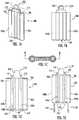
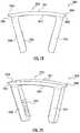
- FIG. 11is a perspective view of second embodiment of an implant or fixation device shown in a first configuration with parallel leg members;
- FIG. 12is a perspective view of the second implant embodiment of FIG. 11 shown in a second configuration with the legs converging;
- FIG. 13is a perspective view of a second embodiment of an inserter
- FIG. 14is a perspective view of a second embodiment of an implant or fixation device shown in a first configuration with parallel leg members on the inserter of FIG. 13 ;
- FIG. 15Ais a front view of a third embodiment of an implant or fixation device in a first configuration
- FIG. 15Bis a front view of the third implant embodiment in FIG. 15A in a second configuration
- FIG. 16Ais a perspective view of the third implant embodiment in FIG. 15A ; and FIG. 16B is a perspective view of the third implant embodiment in FIG. 15B ;
- FIG. 17Ais a front view of the third embodiment of an implant assembled to the third embodiment of the inserter
- FIG. 17Bis a front view of the third embodiment of the implant at the end of engagement to the third embodiment of the inserter
- FIG. 17Cis a front view of the third embodiment of the implant separated from the third embodiment of the inserter
- FIG. 18Ais a perspective view of FIG. 17A
- FIG. 18Bis a perspective view of FIG. 17B
- FIG. 18Cis a perspective view of FIG. 17C ;
- FIG. 19is a perspective view of a fourth embodiment of the current technology depicting an implant preassembled to an inserter with retractable engagement pins;
- FIG. 20is a close up view of the working tip of the fourth embodiment depicted in FIG. 19 ;
- FIG. 21is a perspective view of a fifth embodiment of an implant in an alternate configuration with the legs or fixation members out of plane relative to each other;
- FIG. 22is another perspective view of the implant in FIG. 21 showing an alternate configuration with the legs or fixation members out of plane relative to each other;
- FIG. 23Ais a front view of an implant of a sixth embodiment assembled to an implant carrier; and FIG. 23B is a side view of the implant and implant carrier of FIG. 23A ;
- FIG. 24is an isometric view of the sixth embodiment of the implant and implant carrier assembly shown in FIGS. 23A and 23B ;
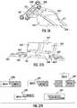
- FIG. 25is a front view of the implant carrier of the sixth embodiment shown in FIG. 24 without the implant assembled to it;
- FIG. 26Ais an isometric view showing the inserter and an implant/carrier assembly of the sixth embodiment prior to installing the carrier to the inserter; and FIG. 26B is an isometric view of the sixth embodiment shown in FIG. 26A further showing the implant/carrier assembled to the inserter;
- FIG. 27Ais an isometric view showing the sixth embodiment of FIG. 26 prior to releasing the implant from the inserter and carrier; and FIG. 27B is an isometric view showing the sixth embodiment of FIG. 26 after releasing the implant from the carrier, further showing the implant released from the carrier and the carrier still engaged with the inserter;
- FIG. 28shows the sixth embodiment further depicting the implant, assembled to the inserter via the carrier, being fully seated on the bone, further showing that the inserter and carrier do not interfere with the placement of the implant in its final position;
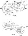
- FIG. 29is a close-up view of the implant/inserter interface of a seventh embodiment depicting an implant assembled to the inserter further showing the inserter engaging the periphery of the implant thereby not interfering with the final seating of the implant;
- FIG. 30shows the seventh embodiment of FIG. 29 depicting the inserter being released from the implant by rotating the inserter off the implant
- FIG. 31shows an eighth embodiment of the current technology with engaging members extending through an implant for provisional fixation on the bone surface
- FIG. 32is a bottom view of an implant of the ninth embodiment of the current technology depicting an implant with a means for connection to bone engaging features and a means for engaging an inserter;
- FIG. 33is a bottom perspective view of the embodiment shown in FIG. 32 ;
- FIG. 34is a perspective view of the ninth embodiment depicting the implant depicted in FIG. 32 assembled to an inserter of the current technology.
- the implantis held in a first configuration;
- FIG. 35is a perspective view of the ninth embodiment depicting of the implant depicted in FIG. 32 assembled to an inserter of the current technology.
- the implantis shown in a second configuration;
- FIG. 36is a bottom perspective view of the implant-inserter assembly depicted in FIG. 34 ;
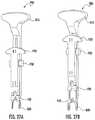
- FIG. 37Ais a section view of the implant-inserter assembly depicted in FIG. 34 ; and FIG. 37B depicts alternate geometries for various means of insertion;
- FIG. 38is a top view an of an implant of a tenth embodiment of the current technology depicting a “T” shaped implant with a means for connection to bone engaging features and various means for engaging an inserter;
- FIG. 39is a perspective view of the implant of the tenth embodiment of the current technology.
- FIG. 40is a bottom perspective view of an inserter of the tenth embodiment of the current technology depicting an inserter with means for engaging the implant depicted in FIG. 38 ;
- FIG. 41is a top perspective view of an inserter of the tenth embodiment of the current technology depicting an inserter with means for engaging the implant depicted in FIG. 38 ;
- FIG. 42is a top perspective view of a tenth embodiment of the current technology depicting a partial implant-inserter assembly of the implant depicted in FIG. 38 and the inserter depicted in FIG. 40 .
- the implantis shown in a first configuration;
- FIG. 43is a top perspective view of a tenth embodiment of the current technology depicting a completed implant-inserter assembly of the implant depicted in FIG. 38 and the inserter depicted in FIG. 40 .
- the implantis shown in a first configuration;
- FIG. 44is a top perspective view of the tenth embodiment depicting the implant-inserter combination depicted in FIG. 43 depicting a partial disassembly of the implant-inserter combination.
- the implantis shown in a second configuration;
- FIG. 45is a perspective view of one of the implant-inserter connection means of the assembly shown in FIG. 43 ;
- FIG. 46is a perspective view of one of the implant-inserter connection means of the assembly shown in FIG. 43 ;
- FIG. 47is a side view of an eleventh embodiment of the current technology depicting an implant with a means for engaging an inserter
- FIG. 48is a perspective view of the embodiment depicted in FIG. 47 illustrating the means for engaging an inserter
- FIG. 49is a top perspective view of an eleventh embodiment of the current technology depicting an inserter with means for engaging an implant of the current technology;
- FIG. 50is a top view of the inserter depicted in FIG. 49 ;
- FIG. 51is a front view of the inserter depicted in FIG. 49 ;
- FIG. 52is a bottom view of the inserter depicted in FIG. 49 ;
- FIG. 53is a top perspective view of the eleventh embodiment of the current technology depicting a partial implant-inserter assembly of an implant and the inserter depicted in FIG. 49 .
- the implantis shown in a first configuration;
- FIG. 54is a bottom perspective view of the implant-inserter combination depicted in FIG. 53 ;
- FIG. 56is a bottom a perspective view the implant-inserter combination depicted in FIG. 55 ;
- FIG. 57is a perspective view of the eleventh embodiment depicting the implant-inserter connection means of the assembly shown in FIG. 55 .
- the implantis shown in a first configuration
- FIG. 58is a top perspective view of the eleventh embodiment depicting the implant-inserter combination depicted in FIG. 55 depicting a partial disassembly of the implant-inserter assembly of an implant and the inserter depicted in FIG. 49 .
- the implantis shown in a second configuration;
- FIG. 59is a front view of partial disassembly of the implant-inserter assembly represented in FIG. 58 .
- the implantis shown in a second configuration
- FIG. 61is a perspective view of the embodiment shown in FIG. 60 ;
- FIG. 64is a perspective view of the embodiment depicted in FIG. 62 illustrating the means for connection to bone engaging features and the means for engaging an inserter;
- FIG. 67is a perspective view of the embodiment shown in FIG. 65 ;
- FIG. 68is a section view of the embodiment shown in FIG. 65 ;
- FIG. 70is a perspective view of the embodiment shown in FIG. 69 ;
- FIG. 71is a section view of the embodiment shown in FIG. 69 ;
- FIG. 72is a top view of a sixteenth embodiment of the current technology depicting an implant with a means for connection to bone engaging features and a means for engaging an inserter;
- FIG. 73is a front view of the embodiment shown in FIG. 72 ;
- FIG. 74is a bottom view of the embodiment shown in FIG. 72 ;
- FIG. 75is a perspective view of the embodiment shown in FIG. 72 ;
- FIG. 76is a perspective view of a seventeenth embodiment of the current technology depicting an implant with a means for connection to bone engaging features and a means for engaging an inserter;
- FIG. 77is a side view of the implant depicted in FIG. 76 ;
- FIG. 78is a front view of an eighteenth of the current technology depicting an implant with bone engaging features and a means for engaging an inserter;
- FIG. 79is a perspective view of the embodiment depicted in FIG. 78 ;
- FIG. 80is a perspective view of a first embodiment of the current technology depicting an implant with bone screws generating compression by two different actions as indicated by the arrows;
- FIG. 81is a perspective view of a first embodiment of the current technology depicting an implant without bone screws generating compression by two different actions;
- FIG. 82Ais a top view of a first embodiment of the current technology depicting an implant without the bone screws inserted in a first configuration showing no compressive force generated
- FIG. 82Bis a top view of a first embodiment of the current technology depicting an implant without the bone screws in a second configuration showing a first compressive force being generated
- FIG. 82Cis a top view of a first embodiment of the current technology depicting an implant without the bone screws in a third configuration showing a second compressive force being generated while maintaining the first compressive force;
- FIG. 83Ais a perspective view of a first embodiment of the current technology depicting an implant without the bone screws inserted in a first configuration showing no compressive force generated
- FIG. 83Bis a perspective view of a first embodiment of the current technology depicting an implant with bone screws inserted in a second configuration showing a first compressive force being generated by convergence of the bone screws
- FIG. 83Cis a perspective view of a first embodiment of the current technology depicting an implant with bone screws inserted in a third configuration showing a second compressive force being generated by displacement of the bridge member while maintaining the first compressive force;
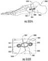
- FIG. 85Ais a top perspective view of FIG. 84A ; and FIG. 85B is a bottom perspective view of a first embodiment of FIG. 84A ;
- FIG. 86Ais a perspective view of the first embodiment of the implant attached to the insertion/holding device, shown with bone screws inserted and prior to generation of the first compressive force
- FIG. 86Bis a perspective view of the first embodiment of the implant attached to the insertion/holding device shown with bone screws inserted and after generation of the first compressive force as a result of allowing the bone screws to converge but prior to generation of the second compressive force
- FIG. 86Ais a perspective view of the first embodiment of the implant attached to the insertion/holding device, shown with bone screws inserted and prior to generation
- 86Cis a perspective view of the first embodiment of the implant attached to the insertion/holding device, shown with bone screws inserted and after generation of the first compressive force as a result of allowing the bone screws to converge and after generation of a second compressive force as a result of allowing the ends of the implant to displace closer together generating a second compressive force at the bridge of the implant;
- FIG. 87is a top view of an implant kit that may be provided for inserting the implant of the current technology into bone segments;
- FIG. 89is a top view of the foot shown in FIGS. 88A and 88B showing in section one embodiment of the current technology in one possible location on the bones of the foot;
- FIG. 90is a top view of a second embodiment of the current technology depicting an implant with means for attaching to instrumentation and a means for attaching to one or more bone engaging means;
- FIG. 91is a side view of the second embodiment of FIG. 90 depicting regions and or features for controlling at least one direction of force;
- FIG. 92is a perspective view of the second embodiment shown in FIGS. 90 and 91 ;
- FIG. 93is a top view of a third embodiment of the current technology depicting an implant with integral bone engaging means
- FIG. 94is a side view of the third embodiment of FIG. 93 depicting regions and or features for controlling at least one direction of force;
- FIG. 95is a perspective exploded view of a fourth embodiment of the current technology depicting an implant with at least one means for attaching a bone engaging means and a least one integral bone engaging means;
- FIG. 96is a perspective assembled view of a fourth embodiment of the current technology depicting an implant with at least one means for attaching a bone engaging means and a least one integral bone engaging means;
- FIG. 97is an isometric view of an implant coupled to an inserter
- FIG. 98is another isometric view of the implant and inserter of FIG. 97 from a different direction;
- FIG. 99is a cross sectional view of the implant and inserter of FIG. 97 , taken along section line 99 - 99 of FIG. 112 ;
- FIG. 100is a cross sectional view of the implant and inserter of FIG. 97 , taken along section line 100 - 100 of FIG. 113 ;
- FIG. 101is an exploded isometric view of the implant and inserter of FIG. 97 ;
- FIG. 102is another exploded isometric view of the implant and inserter of FIG. 101 from a different direction;
- FIG. 103is an isometric view of a body of the inserter of FIG. 97 ;
- FIG. 104is another isometric view of the body of FIG. 103 from a different direction;
- FIG. 105is yet another isometric view of the body of FIG. 103 from another different direction;
- FIG. 106is a detail view of a portion of the body of FIG. 105 ;
- FIG. 107is an isometric view of a first arm of the inserter of FIG. 97 ;
- FIG. 108is another isometric view of the first arm of FIG. 107 from a different direction;
- FIG. 109is an isometric view of a second arm of the inserter of FIG. 97 ;
- FIG. 110is another isometric view of the second arm of FIG. 109 from a different direction;
- FIG. 111is a front view of the implant and inserter of FIG. 97 , the implant uncoupled from the inserter, the implant in its free state;
- FIG. 112is a front view of the implant and inserter of FIG. 97 , the implant coupled to the inserter, the implant in its free state;
- FIG. 113is a side view of the implant and inserter of FIG. 112 ;
- FIG. 114is a front view of the implant and inserter of FIG. 97 , the implant coupled to the inserter, the implant in an elastically deformed state in which the legs converge;
- FIG. 115is a front view of the implant and inserter of FIG. 97 , the implant coupled to the inserter, the implant in an elastically deformed state in which the legs are parallel;
- FIG. 116is a front view of the implant and inserter of FIG. 97 , the implant coupled to the inserter, the implant in an elastically deformed state in which the legs diverge;
- FIG. 117is a front view of the implant and inserter of FIG. 116 , the implant coupled to the inserter, the implant in the elastically deformed state in which the legs diverge, the inserter modified to include an interlock component;
- FIG. 118is a side view of the implant and inserter of FIG. 117 ;
- FIG. 119is a cross sectional view of the implant and inserter of FIG. 117 , taken along section line 119 - 119 of FIG. 117 ;
- FIG. 120is a cross sectional view of the implant and inserter of FIG. 118 , taken along section line 120 - 120 of FIG. 118 .
- phrases “connected to,” “coupled to” and “in communication with”refer to any form of interaction between two or more entities, including mechanical, electrical, magnetic, electromagnetic, fluid, and thermal interaction. Two components may be functionally coupled to each other even though they are not in direct contact with each other.
- the term “abutting”refers to items that are in direct physical contact with each other, although the items may not necessarily be attached together.
- the phrase “fluid communication”refers to two features that are connected such that a fluid within one feature is able to pass into the other feature.
- the present technologymay include a fastening device and an inserter. Exemplary embodiments of the fastening device and inserter are shown in FIGS. 1, 14 and 19 .
- the fastening devicemay be of a configuration similar to a modular staple or bone plate as shown in FIG. 3 .
- the fastening devicemay also have a configuration resembling a bone staple as shown in FIGS. 11, 12, 15 and 16 .
- the present technologymay have the inserter pre-assembled or affixed to the implant as shown in FIGS. 1 and 14 .
- the implant or implantsmay not be pre-assembled to the inserter.
- the implant or implantscould be held in a particular configuration in the packaging that facilitates engagement with the inserter.
- FIGS. 11 and 12depict an embodiment of the fastening device or implant that shows one possible combination of implant configurations.
- FIGS. 11 and 14show this embodiment maintained in a first configuration for insertion.
- FIG. 12shows this embodiment in its free-state or implanted-state configuration.
- inventions described hereinmay be used in connection with any type of inserter or fixation device, including but not limited to various bone staples, bone plates, etc. that have more than one implant configuration where the insertion device does not interfere with the final placement of the implant.
- the inserter 100is assembled to the implant 120 .
- the implant 120is shown in a first configuration that may or may be flat.
- the inserter 100may or may not have features that allow preparation of the bone for receiving other members of the implant.
- the inserter 100has two tube members 102 a and 102 b that allow the bone to be prepared through the internal diameters 106 .
- the tube members 102 a and 102 balso serve as drill guides.
- Implant 120is temporarily connected to the tubes 102 a and 102 b by the engagement pins 104 a and 104 b.
- the two independent tubes 102 a and 102 bare individually connected to the implant 120 by the engagement pins 104 a and 104 b.
- the engagement pinsmay or may not extend completely through the implant.
- the engagement pinscould also be temporarily or permanently attached to the implant as opposed to being part of the inserter assembly.
- the engagement pinsmay extend through the implant with features that engage the bone for provisional fixation during the procedure.
- this embodimentshows the use of circular pins, however, to those skilled in the art the use of other attachment means will be obvious and may or may not be separate pieces from the tube members.
- the means of attaching the plate to the inserteris shown on the bridge area of the plate, but could occur anywhere on or around the periphery of the plate.
- FIG. 1Edepicts the inserter with the bone screws 130 inserted into the implant 120 while the implant is maintained in its first configuration.
- FIGS. 1C and 1Dshow an engagement 119 where the engagement pins 104 a and 104 b controllably interface with the engagement holes 122 shown in FIG. 3 .
- Implant 120is shown in a first configuration in FIGS. 1A, 1B, 1D and 1E .
- the inserter 100may be used for implant manipulation or for holding the implant in a first configuration with or without a means for preparing for other implant members, e.g. bone screws.
- the bone preparationmay or may not be distinct from the inserter. Bone preparation may be done in the implant first configuration and/or in a second configuration.
- FIGS. 2A, 2B, 2C and 2Ddepict the inserter 100 without the clip 110 .
- the inserter assembly 100is shown in a manner depicting an initial release step that may or may not allow the implant 120 to have a second configuration.
- the bone screws 130have been prepared and placed into the implant 120 .
- the inserter tubes 102 a and 102 bare still engaged in the implant 120 via the engagement pins 104 a and 104 b.
- the implant 120is shown in a second configuration and is achieved either by the intrinsic mechanical properties of the material or secondary mechanical manipulation of one or more areas of the plate.
- FIGS. 2A, 2B, 2C and 2Dshow the inserter temporarily attached to the implant after preparation of the bone and placement of the bone screws 130 .
- the inserter 100is shown just prior to removal of the inserter 100 from the implant 120 .
- the independent inserter tubes 102 a and 102 baccommodate the second configuration of the implant 120 .
- FIG. 3depicts the implant 120 in its second configuration after removal of the inserter 100 or possibly after secondary mechanical manipulation/deformation.
- the bone screws 130may be prepared and positioned through the internal diameter 106 while the inserter 100 was still attached to the implant 120 .
- FIG. 3shows one embodiment of the engagement hole 122 that accepts the engagement pins 104 a and 104 b of the inserter tube 102 a and 102 b.
- FIG. 4depicts one embodiment of the inserter 100 assembled to implant 120 on a foot 140 .
- clip 110maintains the tubes 102 a and 102 b in a relative position to each other.
- Clip 110may or may not be a separate assembly; the functionality could be achieved via an integral feature, molded-in for example, to the tube(s).
- Clip 110is shown to provide a rigid, static connection between the tubes 102 a and 102 b.
- connection mechanism between the tubes 102 a and 102 bmay also have a dynamic, moveable connection (e.g. application of springs) so that the tubes will allow the plate to conform in some way to the bone prior to complete removable of clip 110 .
- the tubes 102 a and 102 bare controllably engaged in implant 120 via engagement pins 104 a and 104 b and engagement features 122 .
- the clip 110 , the tubes 102 a and 102 b, engagement pins 104 a and 104 b and engagement holes 122act together to maintain the implant 120 in a first configuration. In alternate embodiments more components or fewer may be needed to maintain the implant in a first configuration.
- FIG. 7depicts one embodiment of the inserter 100 assembled to implant 120 on a foot 140 .
- This figuredepicts the first removal step for this particular embodiment of the inserter 100 .
- the bonehas been prepared accordingly and the implant 120 is in its final position on the bone and in its first configuration.
- FIG. 7shows removal of clip 110 from inserter 100 .
- FIG. 8removal of the clip 110 from the inserter 100 after completing the appropriate bone preparation allows the implant 120 to adapt to a second configuration while the implant 120 is in its final implant position.
- Bone screws 130(not shown in FIG. 7 or 8 ) may or may not have been prepared and positioned while the inserter assembly 100 was engaged to the implant 120 .
- FIG. 9shows implant 120 on bone 141 after removal of the inserter assembly 100 after the implant 120 is in its final position either before or after the implant achieves its second configuration.
- FIG. 10Adepicts an exemplary embodiment of the inserter assembly 100 and implant 120 while also showing preparation steps with drill 150 lined up with the internal diameter 106 of the tubes 102 a and/or 102 b.
- FIGS. 10A, 10B and 10Cfurther show implant 120 controllably engaged to the tubes 102 a and 102 b with engagement pins 104 a and 104 b (pins not shown in image) engaged in engagement holes 122 .
- Clip 110is controllably maintaining the tubes relative to each other with the engagement pins 112 engaged in the tubes 102 a and 102 b.
- Drill 150has a fluted region 152 , a shaft 154 and a stop 156 .
- FIGS. 10Cshow the drill stop 156 abutted against the top surface of the drill tube 102 a or 102 b.
- the stop 156may be used to prevent the drill from extending too far into the bone during preparation.
- the stop 156may be used to control the drill depth so the fluted region 152 only protrudes through the drill guide/tubes 102 a and/or 102 b to a predetermined depth.
- the implant 120may be made of a material that may have elastic or spring properties that allow the implant to have more than one configuration.
- FIG. 3shows the implant 120 in a possible free-state or implanted-state of the device. The free-state or implanted-state may provide compression (or distraction) across bone members.
- FIG. 3shows the implant 120 having a thickness 126 and a bridge member 124 . It further shows the implant 120 having an arc or radius 128 while in its second configuration.
- FIG. 3also shows an example of a bone attachment device 130 , which in this case resembles a bone screw.
- the attachment device 130is rigidly attached to the implant 120 through the attachment feature 129 .
- the attachment feature 129is such that it allows the bone attachment device to be locked to the material that may have elastic properties.
- the bridge member 124 depicted in FIG. 3also has an engagement feature 122 for controllably engaging the inserter for maintaining the first configuration.
- the embodiment depictedthus far allows the implant 120 to be fully seated to the bone in its final position without the inserter interfering with this final position.
- the implantWhen the implant is placed in its final position, it may or may not be in its second configuration. The implant may remain in a first configuration until the inserter is removed or further manipulation is performed.
- FIG. 11shows an exemplary embodiment of an implant 200 that resembles a bone staple.
- the implantis shown in a first configuration where the legs 220 are relatively parallel to each other.
- This first configurationmay be useful in facilitating implantation of the implant 200 into bone.
- the first configurationmay be the configuration that is maintained by an inserter.
- FIG. 11depicts implant 200 having a bridge member 210 with a thickness 202 . Thickness 202 may or may not be more or less than thickness 204 .
- This particular embodimentshows the bridge member 210 has a radius 206 . Radius 206 may or may not be present.
- FIG. 11further shows legs 220 having a feature 230 for engaging an inserter.
- the engaging feature 230may be an internal feature, external feature, may be positioned on the interior or exterior of the legs 220 . It is also reasonable to have an engagement feature similar to engaging holes 122 in this type of device.
- Implant 200has bone engagement means in the form of barbs 225 which engage the bone in order to maintain the implant in the bone.
- FIG. 12shows the implant 200 of FIG. 11 in a second configuration. In this particular configuration of FIG. 12 , the legs 220 converge towards each other. Either one or multiple legs may move to create this convergence or distraction.
- the second configurationmay be the free-state or implanted-state.
- FIG. 13shows another embodiment of an inserter 240 .
- Inserter 240has a holding piece 242 and at least one engaging pin 244 .
- the engaging pins 244are spaced and oriented appropriately to interact with an implant to maintain a first configuration.
- FIG. 14shows the inserter 240 assembled to an implant 200 .
- the engaging pins 244 of inserter 240engage the internal diameter of engaging feature 230 of implant 200 to maintain the implant 200 in a first configuration.
- the implantassumes a second configuration as shown in FIG. 12 .
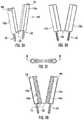
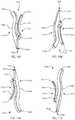
- FIG. 15Ashows yet another embodiment of an implant or fixation device 300 .
- the implant 300has a bridge member 310 and leg members 325 .
- the bridge member 310has a thickness 315 that may or may not be the same as the leg thickness 320 .
- FIG. 15Ashows the implant in a first configuration.
- FIG. 15Bshows the implant 300 in a second configuration.
- the implant of FIGS. 15A and 15Bis also shown in FIGS. 16A and 16B depicting an internal diameter 330 .
- Opening 340is generated by the internal diameter 330 breaking out into the inside of the leg.
- the opening 340may or may not be needed for this current technology.
- the internal diameter 330may be used to engage the inserter and maintain the implant in a particular configuration.
- the internal diameter 330may also be used to manipulate the implant into another configuration whereas the relationship between the implant legs 325 is changed by creating convergence, divergence or some other out of plane relationship.
- Alternate embodimentsmay include an inserter and implant that work in conjunction to create a first and second configuration.
- FIG. 17Ashows an embodiment of an implant 300 on an inserter 400 with the implant being in a first configuration.
- FIG. 17Bshows the same embodiment with the implant 300 at the end of the engagement pins 410 of the inserter 400 .
- the implant in FIG. 17Bis transitioning to a second configuration.
- FIG. 17Cshows the implant 300 fully disengaged from the inserter 400 .
- the implant 300is in a second configuration.
- FIGS. 18A, 18B and 18Cdepict the embodiments in FIGS. 17A, 17B and 17C in a perspective view.
- FIGS. 19 and 20depict an embodiment of an inserter 500 that is preassembled to an implant 300 .
- the inserter 500has a holding means 510 and an impact or seating means 530 .
- Handle 520is slide-ably engaged in the body 505 .
- the inserter assembly 500has means for engaging an implant, 515 .
- the engaging meansare pins 515 .
- Pins 515are connected to handle 520 such that the pins will retract from implant 300 thereby ejecting or releasing the implant from the inserter assembly 500 .
- the pins or engagement meansare retractable.
- FIGS. 21 and 22show an embodiment of an implant 600 in an alternate configuration.
- This embodimentresembles a bone staple, but those skilled in the art will appreciated that this embodiment could also be achieved with modular fixation means such as bone screws.
- the implant 600has a bridge member 610 with thickness 615 .
- the bridge member 610is connected to fixation members or legs 620 .
- Legs 620are out of plane relative to each other.
- Legs 620may or may not be out of plane relative to the bridge member 610 .
- the implant 600may have engaging features 630 to control and/or manipulate the implant into alternate configurations.
- the engaging features 630may or may not extend through the entire implant.
- the engaging features 630may be positive or negative features in the implant or inserter.
- Nitinolfor example, possess material properties, such as shape memory and/or super elasticity that may provide the inherent properties to allow an embodiment to have multiple configurations with or without an external mechanical manipulation.
- Stainless steel and/or titaniumalso have desirable material properties for the embodiments described herein.
- Stainless steel and/or titaniummay not possess shape memory or super elasticity, but may possess the mechanical properties for embodiments that may benefit from mechanical manipulation to achieve multiple configurations.
- Still other materialssuch as PEEK or other polymers may also possess material properties beneficial for the embodiment described herein.
- a combination of materialsmay also be preferred.
- a nitinol plate with titanium screwsmay be the materials of choice for some embodiments.
- Yet another embodiment of this technologymay have the implant assembled onto a holding means such as an apparatus or carrier that may be assembled to an inserter at the time of surgery, as shown in FIGS. 23A, 23B, 24, and 25-28 .
- FIGS. 23A and 23Bshow an exemplary embodiment of an implant carrier, 700 , assembled to an implant embodiment, 800 .
- FIG. 23Ais a front view of the assembly and FIG. 23B is a side view of the assembly.
- FIG. 24shows the carrier, 700 , slidably engaged to the implant, 800 .
- Implant 800has features 810 for receiving the engaging features 710 of the carrier.
- the carrier 700may have features and/or geometries 720 for engaging the inserter.
- the carrier 700may have features and/or geometries 730 for additionally engaging the inserter.
- the engaging features and or geometries 720 and 730may be used separately or in combination to provide a poka-yoke feature that prevents incorrect assembly of the carrier to the inserter.
- FIGS. 26A and 26Bshow an exemplary embodiment of an inserter 900 and the implant 800 assembled to the carrier 700 .
- FIG. 26Ashows the inserter 900 with the implant carrier 700 prior to assembling the carrier 700 to the inserter 900 .
- FIG. 26Bshows the carrier 700 with the attached implant 800 assembled to the inserter 900 .
- the inserter 900has a base component 910 , a handle component 920 and a locking means 930 .
- the inserteralso may have a retaining member 940 that may be used for assisting in maintaining the carrier 700 in a specified position. Retaining member 940 may or may not be integrated into the handle component 920 .
- This inserter embodimenthas features 950 for engaging with the carrier 700 in a poka-yoke means.
- the locking means 930may be used to secure the handle component 920 to the base component 910 .
- FIG. 28demonstrates the exemplary embodiments of the inserter 900 , the carrier 700 and the implant 800 allowing the implant 800 to be seated flush against a bone surface 1000 .
- the inserter 900does not interfere with the final placement of the implant 800 .
- the parallel legsare allowed to converge after releasing from the inserter 900 and carrier 700 , not having to perform a secondary final seating of the implant after release from an inserting device is beneficial.
- FIG. 29shows a close-up view of the implant/inserter interface of another exemplary embodiment of an inserter 1100 and an implant 1200 .
- the inserter 1100has means 1120 , 1130 and 1110 for attaching to the implant. These attachment means engage the implant 1200 in such a way to not prohibit final seating of the implant 1200 in its final desired position.
- FIG. 30shows one possible means for releasing the implant 1200 from the inserter 1100 .
- This embodimentdemonstrates a rotation of the inserter 1100 relative to the implant 1200 . This rotation releasing the engaging means 1120 and 1130 while rotating about the pin 1110 . Once fully rotated and released the inserter 1100 can be removed from implant 1200 .
- FIG. 31shows the previously described inserter embodiment 100 and clip 110 assembled to implant 120 . It further shows an embodiment of the engaging means 190 that may purposely extend beyond the implant 120 .
- the engaging means 190 shownmay have tips that are configured to penetrate into a bone surface to provide provisional fixation.
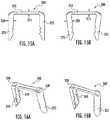
- FIG. 34depicts an inserter 1650 that is engaged with the implant 1600 .
- Inserter 1650has two members 1652 and 1651 with a space 1655 therein.
- FIG. 34shows the implant 1600 held in a first configuration which may or may not be flat. This first configuration may facilitate the surgical implantation. This first configuration may act to store a compressive force or other force.
- FIG. 35shows the inserter 1650 partially disengaged from implant 1600 .
- the members 1651 and 1652may come together thereby reducing the space 1655 that may enable or facilitate assembly and or disassembly of the inserter 1650 and implant 1600 .
- the implantis allowed to take on a second configuration.
- This second configurationmay be achieved by the design of the implant 1600 and or in combination with the intrinsic material properties of the implant and or in combination with the processing of the implant 1600 .
- This second configurationmay act to create a compressive force or other force across one or two bone or tissue segments.
- the implantmay be predisposed by various means to achieve this alternate configuration for assembly with an inserter or other delivery instrument which may include physical deformation of the implant such as bending or mechanical manipulation, for example applying a force to the implant on a flat surface or other surface to temporarily hold the implant in a shape for assembly to the inserter.
- the implantmay be predisposed by various means to achieve this alternate configuration for assembly with an inserter which may include application of an external temperature change, either by heating, cooling and or freezing the implant that may create a change in the physical properties of the material such as to facilitate an alternate configuration for assembly.
- the implantmay be predisposed by various means to achieve this alternate configuration for assembly or re-assembly with an inserter which may include assembly or re-assembly at the time of use.
- the instrumentmay include features such as chamfers, ramps, steps, shoulders, mechanical levers, mechanical interfaces, complementary geometries, etc. for manipulating an implant from an alternate configuration to a first configuration for means of assembly and maintaining a first configuration.
- the means of assemblymay be achieved by a single feature or multiple features on a single inserter or delivery instrument.
- the means of assemblymay be achieved by a single feature or multiple features on a single inserter or delivery instrument or by the use of multiple delivery instruments used sequentially or simultaneously in combination.
- FIG. 38depicts an embodiment of an implant 1900 of the current technology in a “T” shape. Implants may take on many various configurations. The merits of the current technology are not limited by the shape or style of the implant.
- implant 1900is shown in a first configuration.
- the implant 1900may include multiple connection means for bone engaging members.
- the bone engaging membersmay be bone screws, pegs, blades or other means suitable for engaging bone or soft tissue.
- the connection means 1930may be of the same or varying styles or geometries for a particular implant. For example, some of the connection means 1930 in implant 1900 may be threaded and or locking while others may be non-threaded or non-locking.
- Implant 1900may include a connection for a means for insertion 1925 that is an external feature and may also include a connection for a means for insertion 1920 that is internal. Implant 1900 may include multiple connections 1920 and or 1925 for a means of insertion that may vary in size, geometry, orientation and or configuration. Implant 1900 as depicted in FIG. 38 has a top surface 1910 that may be of uniform shape, size, geometry and or configuration. The perspective view of implant 1900 is shown in FIG. 39 . Implant 1900 may include a top surface 1910 and a bottom surface 1901 . In FIG. 39 implant 1900 may have a rail or bridge member 1911 that may be of varying size, geometry and or configuration. Bridge member 1911 may or may not be similar in size, shape, geometry and or orientation as top surface 1910 or bottom surface 1901 .
- FIGS. 40 and 41depict one embodiment of an inserter of the current technology.
- Inserter 1950is configured to interact and or engage implant 1900 shown in FIG. 39 .
- the inserter 1950may hold an implant in a first configuration.
- Inserter 1950has a connection means 1954 that may be used for engaging a separate handle or other holding means.
- This exemplary embodimentmay also have feature 1951 in various locations, orientations or configurations.
- One or more features 1951may be present in a particular implant.
- Feature 1951may be used to provisionally or temporarily attach the inserter and implant combination to a surface such as bone or tissue.
- a pin or other meansmay be used to pass through features 1951 for maintaining a relative position of the inserter or inserter-implant combination on the bone or tissue.
- the current technologymay include an inserter and inserter-implant combination that may be used with an implant that has one or more configurations.
- the inserter 1950may have an implant connection means 1955 for releasably and or rotatably engaging an implant.
- Inserter 1950may include at least a second implant connection means 1965 for releasably engaging an implant.
- Connection means 1965 and 1955may or may not be of the same size, shape, geometry, orientation or configuration.
- FIG. 41depicts a top side perspective view showing how a temporary fixation means 1951 may extend from the upper surfaces 1952 and 1953 through the bottom surfaces 1971 and 1970 .
- Surfaces 1970 and 1971may or may not be in the same plane or of the same configuration.
- a combination of surfaces and means of insertionmay be used on the entire implant or portions of an implant to create or maintain a particular configuration of an implant or portions of an implant.
- a tabsuch as 1925 and surface, such as 1910 , may be used to maintain one arm or projection such as 1902 of an implant in a particular configuration. When disassembled, that arm may have a configuration that is different from or the same as the configuration of the rest of the implant.
- FIG. 45depicts the interaction 1980 between the implant 1900 and the inserter 1950 .
- the surface 1965may releasably engage or interact with the connection means 1925 of implant 1900 .
- Interaction or interface 1980may work in combination with the interaction or interface 1981 to maintain an implant in a first configuration.
- Feature 1955 of inserter 1950may releasably engage feature 1920 of implant 1900 .
- This interaction or interfacemay allow rotation, pivoting, latching or other motion to facilitate the assembly or interaction between the implant and inserter.
- the embodiment of the current technology depicted in FIG. 47is an implant 2100 having a top surface 2110 and one or more connection means 2101 for bone engaging members.
- the bone engaging membersmay be bone screws, pegs, blades or other means suitable for engaging bone or soft tissue.
- the connection means 2101may be of the same or varying styles or geometries for a particular implant. For example, some of the connection means 2101 in implant 2100 may be threaded and or locking while others may be non-threaded or non-locking.
- Implant 2100may have one or more means 2140 and 2120 for connecting to an inserter or other means of insertion.
- One embodiment of means 2140may include a top surface 2141 and a bottom surface 2145 as depicted in FIG. 48 . Means 2140 may or may not be in close proximity to connection means 2101 .
- the embodiment of implant 2100 in FIG. 47is shown is a first configuration.
- FIGS. 42-46The advantages of the current technology and embodiment shown in FIGS. 42-46 are numerous and may include the ability of the means of insertion to maintain an implant in a first configuration. These embodiments may also allow the implant-inserter combination to be provisionally fixed or temporarily fixed to bone segment or tissue segments while maintaining the implant in a first configuration during the method of implantation.
- the insertermay be releasably engaged to the implant to facilitate assembly and disassembly of the implant and inserter. The assembly and disassembly is in a direction or movement that is conducive to the surgical procedure. Once the implant and inserter are fully disassembled the implant may achieve a second configuration.
- This second configurationmay be achieved by the design of the implant and or in combination with the intrinsic material properties of the implant and or in combination with the processing of the implant 1600 .
- This second configurationmay act to create a compressive force or other force across one or two bone or tissue segments.
- the implantmay or may not be pre-assembled to the inserter in the final packaging.
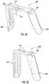
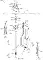
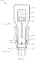
- FIGS. 49, 50, 51 and 52depict an inserter 2000 of the current technology.
- Inserter 2000may or may not have a connection means 2060 for attaching to a handle or other holding means.
- the inserter 2000may have one or more features 2011 and 2012 for temporarily attaching the inserter to one or more bone or tissue segments.
- the insertermay have means 2040 and 2041 for releasably engaging an implant to maintain an implant in a first configuration or a configuration that is different than the implant configuration of the implant.
- Inserter 2000may have one or more projections or arms 2020 and 2010 for facilitating connection to an implant.
- Inserter 2000may have bottom surfaces 2030 , 2042 and 2050 for engaging and or facilitating connection to an implant.
- FIGS. 53 and 54depict inserter 2000 partially assembled to an implant 2100 .
- the implantmay be held or maintained in a first configuration.
- Top surface 2110 of implant 2100may slidably interface with bottom surfaces 2030 and 2042 of inserter 2000 . These surfaces may be coplanar and may or may not physically engage one another.
- Surface 2040 of inserter 2000may releasably engage bottom surface 2145 of means 2140 on implant 2100 .
- Surface 2041 of inserter 2000may releasably engage bottom surface 2125 of means 2120 on implant 2100 . The engagement of surface 2041 with surface 2125 may occur simultaneously with engagement of surface 2040 and surface 2145 . This interaction may maintain implant 2100 in a first configuration.
- the engagement of surface 2041 with surface 2125 and the engagement of surface 2040 with surface 2145may occur from opposite directions which may require inserter 2000 to pivot relative to implant 2100 . This engagement may occur from the same direction as a sliding motion or top load motion. The merits of the current technology are maintained regardless of the direction of assembly.
- FIGS. 55 and 56depict inserter 2000 fully or completely assembled to an implant 2100 .
- the implantmay be held or maintained in this first configuration.
- FIG. 55depicts the implant 2100 held in a first configuration which may or may not be flat.
- the first configurationmay be flat, angled, arched, bent or some combination thereof.
- This first configurationmay facilitate the surgical implantation.
- This first configurationmay act to store a compressive force or other force.
- Top surface 2110 of implant 2100may slidably interface with bottom surfaces 2030 and 2042 of inserter 2000 . These surfaces may be coplanar and may or may not physically engage one another.
- Surface 2040 of inserter 2000may releasably engage bottom surface 2145 of means 2140 on implant 2100 .
- Surface 2041 of inserter 2000may releasably engage bottom surface 2125 of means 2120 on implant 2100 .
- the engagement of surface 2041 with surface 2125may occur simultaneously with engagement of surface 2040 and surface 2145 . This interaction may maintain implant 2100 in a first configuration.
- the engagement of surface 2041 with surface 2125 and the engagement of surface 2040 with surface 2145may occur from opposite directions which may require inserter 2000 to pivot relative to implant 2100 . This engagement may occur from the same direction as a sliding motion or top load motion. The merits of the current technology are maintained regardless of the direction of assembly.
- FIG. 57depicts the interaction of the holding means between inserter 2000 and implant 2100 .
- Surface 2041slidably engages with bottom surface 2125 of implant 2100 . This may provide the necessary support to maintain an implant in a first configuration or a configuration may be different than the implanted configuration.
- the general shape of the engagementis depicted as an “L” shape interface.
- alternate geometries and or configurationsmay be used. However to those skilled in the art it is apparent that numerous geometries and configuration or combination of geometries and configurations are possible and may be encompassed by the current technology. Other possible alternative embodiment of geometries for connection to a means of insertion have been described herein. The means of insertion may or may not be flush with the implant.
- the connection between an implant and inserter and the means of insertionmy hold the implant in a first configuration and or an alternate configuration.
- the disassemblymay allow the implant to achieve a second or alternative configuration.
- This disassemblymay allow the implant to achieve multiple alternative configurations.
- step 1 of the disassemblymay allow the implant to achieve a second configuration
- step 2may allow the implant to achieve a third configuration
- step 3 of the disassemblymay allow the implant to achieve a fourth configuration.
- This disassemblymay allow the implant or portions of the implant to achieve multiple alternative configurations.
- step 1 of the disassemblymay allow the portion A of the implant to achieve a second configuration and step 2 may allow portion B of the implant to achieve an alternate configuration and step 3 of the disassembly may allow portion C of the implant to achieve an alternate configuration.
- Certain alternate configurationsmay be intermediate configurations that will revert to a previous configuration or may proceed to a final configuration once fully disassembled from the inserter. The embodiments described herein do not limit the scope of the current technology.
- FIGS. 58 and 59depict the implant 2100 disengaged or released from the inserter 2000 .
- the implant 2100is allowed to achieve a second configuration or a configuration different than the one maintained by the inserter.
- This second configurationmay be achieved by the design of the implant 2100 and or in combination with the intrinsic material properties of the implant and or in combination with the processing of the implant.
- This second configurationmay act to create a compressive force or other force across one or two bone or tissue segments.
- the connection between an implant and inserter and the means of insertionmy hold the implant in a first configuration and or an alternate configuration.
- the disassemblymay allow the implant to achieve a second or alternative configuration. This disassembly may allow the implant to achieve multiple alternative configurations.
- step 1 of the disassemblymay allow the implant to achieve a second configuration and step 2 may allow the implant to achieve a third configuration and step 3 of the disassembly may allow the implant to achieve a fourth configuration.
- This disassemblymay allow the implant or portions of the implant to achieve multiple alternative configurations.
- step 1 of the disassemblymay allow the portion A of the implant to achieve a second configuration and step 2 may allow portion B of the implant to achieve an alternate configuration and step 3 of the disassembly may allow portion C of the implant to achieve an alternate configuration.
- step 1 of the disassemblymay allow the portion A of the implant to achieve a second configuration and step 2 may allow portion B of the implant to achieve an alternate configuration and step 3 of the disassembly may allow portion C of the implant to achieve an alternate configuration.
- Certain alternate configurationsmay be intermediate configurations that will revert to a previous configuration or may proceed to a final configuration once fully disassembled from the inserter.
- the embodiments described hereindo not limit the scope of the current technology. Further embodiments and combinations of embodiment may be possible and will become evident to those skilled in the art.
- the current technologymay include an inserter and inserter-implant combination that may be used with an implant that has one or more configurations.
- FIGS. 60 and 61depict yet another embodiment of an implant 1400 with multiple means of connecting to an inserter.
- This embodiment of the implant 1400may combine an internal means of connection 1410 with one or more external means of connection 1412 .
- the means of connecting to an insertermay or may not be in close proximity to the means of connecting to bone engaging features 1420 .
- Various means of connecting to an insertermay be used in combination with various implant configurations.
- FIGS. 62, 63 and 64depict a means of connection 1710 to an inserter that may include a tab consisting of a top element 1720 and a bottom element 1730 that may create a space 1725 .
- the implant 1700has a top surface 1701 and a bottom surface 1702 that may include at least one or more thinner sections 1703 .
- the combination of surfaces 1701 , 1702 and 1703may constitute a bridge or rail member that may be designed to achieve a second configuration or predict or determine the geometry of the second configuration.
- the means of insertionmay utilize features similar to 1710 as described herein in combination with other surfaces such as top surface 1701 .
- This combination of means of insertionmay be used to maintain one or more features or arms or projections.
- This combination of means of insertionmay create a bending modality, such as a three point or four point bend, to maintain a specific implant configuration or combination of configurations.
- a combination of surfaces and means of insertion, such as 1710may be used on the entire implant or portions of an implant to create or maintain a particular configuration of an implant or portions of an implant.
- the passage ways for 1210 and 1211may work with the lower surface 1245 to engage a mating geometry of an inserter for holding the implant in a first configuration that may be flat or may have some non linear geometry.
- the features of this embodimentare further depicted in FIG. 68 by the section view.
- the lower surface 1245 of the inserter connection means 1210 and 1211may not be at the same level or orientation as the lower surface 1240 of the implant 1200 .
- FIGS. 72, 73, 74 and 75depict an implant embodiment 1500 of the current technology.
- the implant 1500may utilize the geometry of the rail or bridge member 1501 as the means for connecting to an inserter.
- the rail or bridge membermay be used to determine or predict the second configuration and may also be used as the connection means for an inserter.
- the bridge member 1501has a top surface 1530 that may not have a uniform perimeter.
- the bridge member 1501has a perimeter that may include edges 1511 , 1512 , 1513 , 1521 , 1522 and 1523 .
- the perimeter of the bridge membermay or may not be consistent or uniform with the top surface 1530 .
- the bridge memberhas a bottom surface 1541 , 1542 , 1543 , and 1544 that may be used to releasably engage an inserter. Engagement between the bridge member geometry and the inserter may maintain the implant 1500 in a first configuration.
- FIGS. 78 and 79depict an implant embodiment 2200 that may have bone engaging members 2230 and 2235 integral to the implant bridge 2210 .
- Implant bridge 2210has an upper surface 2211 and a lower surface 2212 .
- the bone engaging members 2230 and 2235may have features 2220 that may improve bone purchase or improve pull out strength of the implant 2200 from bone or soft tissue.
- the implant 2200may have projections or other connecting means 2250 and 2260 for connection with a means of insertion.
- the connecting means 2250 and 2260may have a lower surface 2255 and 2265 respectively that may releasably engage with a means of insertion that may allow the inserter or other means of insertion to be side loading, top loading or pivotably loaded.
- the means of insertionmay maintain a one piece implant in a first configuration thereby allowing a second implant configuration once the implant is disassembled from the implant.
- the means of insertionmay utilize features similar to 2250 and 2260 as described herein in combination with other surfaces such as top surface 2211 .
- This combination of means of insertionmay be used to maintain one or more features or arms or projections.
- This combination of means of insertionmay create a bending modality, such as a three point or four point bend, to maintain a specific implant configuration or combination of configurations.
- a combination of surfaces and means of insertion, such as 2250may be used on the entire implant or portions of an implant to create or maintain a particular configuration of an implant.
- a tab such as 2250 and top surface, such as 2211may be used to maintain one side of an implant or one arm of an implant in a particular configuration. When disassembled, that arm may have a configuration that is different from or the same as the configuration of the rest of the implant.
- the present technologyincludes an implant for generating a multidirectional or multicomponent force across bone or tissue segments. Exemplary embodiments of the current technology are shown in the drawings and discussed below.
- the implantmay be of a configuration similar to a modular staple or bone plate as discussed in the figures.
- the present technologymay employ an apparatus or instrument for inserting the implant that may be pre-assembled or affixed to the implant as shown in FIGS. 84 and 85 .
- the implant or implantscould be held in a particular configuration in the packaging that facilitates engagement with the inserter at time of use.
- Certain embodiments of the current technologymay not require the use of an inserter tool, for example an embodiment made of shape memory nitinol may rely on the ability of the user to activate the shape memory nitinol to generate the multidirectional or multicomponent forces.
- FIGS. 80 and 81show implant 4200 .
- FIG. 80shows the bone screws 4100 assembled to implant 4200 .
- the implant 4200is shown in a state that exerts forces shown in the direction of 4300 and 4310 .
- the implant 4200has screw holes 4230 for attaching a bone screw 4100 or other fixation elements.
- the implantmay have integral staple legs that may be used instead of or in combination with screw holes 4230 . (See for example FIGS. 94-96 .)
- tabs 4240may have a slot 4250 to facilitate attachment to an insertion device. This attachment tab 4240 may be used to hold the implant 4200 with the flexing region 4220 in a neutral position, i.e.
- Implant 4200has a flexing region 4220 that is located between the screw hole 4230 and the bridge member(s) 4210 .
- This flexing region 4220may have a nonsymmetrical geometry or other features, such as cutout, slots, embossments, ridges, etc., strategically placed to assist in controlling the direction, force and predictability of the flexing region 4220 .
- the bridge members 4210 and the flexing regions 4220define a space 4215 .
- the forcesmay be generated simultaneously or as separate actions. In the exemplary embodiment the forces are generated as separate actions and will simplify the description herein.
- the first compressive force 4300may be generated when the flexing region 4220 is allowed to move thereby allowing the screw holes 4230 and bone screws 4100 to converge relative to one another.
- the compressive force 4300may be generated by having a superelastic implant with the screw hole regions 4230 manufactured such that they are converging relative to one another when the implant is at rest. Holding the screw hole regions 4230 flat may store the compressive (i.e. converging) energy until they are released and allowed to resume the converged orientation. With the bone screw hole regions 4230 held flat or relatively parallel to the bone, the bone screws 4100 may be inserted into the bone and maintained parallel relative to one another.
- the screw holes 4230may be released from their flat orientation and allowed to resume their converging orientation due to the superelastic aspects of nitinol. In another embodiment, this same effect may be achieved with the shape memory aspects of the nitinol material.
- the screw holes 4230may be activated using for example the appropriate activation temperature (e.g. body heat or an external temperature source) and allowed to resume their converging orientation due to the shape memory aspects of nitinol.
- the magnitude of the force 4300may be dependent on the material of choice, the overall geometry of the implant and or the surgical technique.
- This compressive force 4300may generate a compressive force that is higher in magnitude at the level of the tips of the screws 4100 than at the level of the bone plate 4225 .
- Compressive force 4310may be generated when the bridge members 4210 are allowed to displace, in this case outwardly, to an open position. This displacement may change the shape of the space 4215 thereby creating force 4310 which may draw the screw holes 4230 closer together generating a compressive force that may have a greater magnitude at the level of the bone plate 4225 than the level of the tips of the bone screws 4100 .
- force 4310may be generated by having a superelastic implant with the bridge members 4210 manufactured such that they may be in an outward or open position when the implant is at rest. Holding the bridge members 4210 in a closed position may store the compressive (i.e. displacement) energy until they are released and allowed to resume the open position or outward orientation. With the bone screws 4100 fully seated and secured in bone, the bridge members 4210 may be released from their closed orientation and allowed to resume their open orientation due to the superelastic aspects of nitinol. This movement from the closed position to the open position may create a change in the relative spacing between the bone screws 4100 thereby generating a displacement that may result in a compressive force 4310 .
- this same effectmay be achieved with the shape memory aspects of the nitinol material.
- the bridge members 4210may be activated using the appropriate activation temperature (e.g. body heat or an external temperature source) and allowed to resume their open position or outward orientation due to the shape memory aspects of nitinol.
- the magnitude of the force 4310may be dependent on the material of choice, the overall geometry of the implant (e.g. thickness, width, height, etc.) and or the surgical technique.
- the unique combination of the forces 4300 and 4310may create a more uniform and overall greater compressive force than the forces would individually.
- the current state of the artis to have an implant device that will generate only one compressive force.
- the description of the compressive forces 4300 and 4310is not intended to be limiting.
- the forces generatedmay or may not be uniform or may have varying magnitudes.
- the particular order of forces generatedis also not limiting.
- the current technologyalso includes any order or combination of more than one force magnitude and vector.
- FIG. 81shows the implant 4200 in the same condition as FIG. 80 but without bone screws 4100 in place.
- This figureshows screw holes 4230 that are locking screw holes in this particular embodiment.
- This embodimenthas two bridge members 4210 that create a space 4215 . Based on the description of the technology herein, those skilled in the art will understand that there are numerous shapes that may be created by the bridge members.
- an implant 4200may have multiple bridge members or a single bridge member.
- the single bridge membermay be manipulated such that the fixation means (i.e. bone screw, staple legs, etc.) may be brought closer together to create, in this case, a compressive force.
- space 4215may or may not exist.
- the positioning and or orientation and or geometry of opening 4215 relative to the bridge members 4210 and flexing regions 4220may provide a means for distributing the required stresses within the implant 4200 to achieve a desired compressive force.
- the position and geometry of opening 4215may be altered within the scope of this technology to manipulate the stress distribution to achieve the desired performance.
- the position and geometry of opening 4215may be altered in combination with the thicknesses 4205 to manipulate the stress distribution to achieve the desired performance.
- the amount of desired force generated by the current technologymay be accomplished by manipulating individual aspects of the implant geometry and their relative orientations to one another.
- the geometry and relative orientation of thicknesses 4205may be altered to manipulate the stress distribution within the implant bridges 4210 to achieve the desired performance.
- the geometry and relative orientation of thicknesses 4205may be altered in combination with altering the geometry and relative orientation of the flex regions 4220 to manipulate the stress distribution within the implant 4200 to achieve the desired performance or force generated.
- the geometry and relative orientation of thicknesses 4205may be altered in combination with altering the geometry and relative orientation of flex region 4220 and may be in combination with altering the geometry and relative orientation of opening 4215 to manipulate the stress distribution within the implant 4200 to achieve the desired performance and force generation.
- the implant widths 4208 , 4209 , 4211 , 4212 , 4213 and or 4214 as shown in FIG. 82Amay also be manipulated in geometry and or orientation either as independent variables or in combination with the previously described aspect or aspects of the implant to manipulate the stress distribution within the implant 4200 to achieve the desired performance or force generation.
- FIG. 82Adepicts a top view of the implant 4200 for this particular embodiment.
- the implant 4200is shown as it would be held prior to releasing and or activating any of the superelastic and or shape memory mechanisms, i.e. in this case shown with no generated forces as it may be held in an inserter for implantation, for clarity the inserter is not shown in this particular view.
- the fixation means bone screws 4100are not included in FIGS. 82A, 82B or 82C .
- the implant 4200may have tabs 4240 or other means for holding the implant in a flat, non-force generating geometry.
- This particular embodimentdepicts attachment means 4230 as locking holes for bone screws 4100 .
- fixation meansmay be integral to the implant 4200 , e.g. staple legs, or may include other fixation means such as pegs, blades or other types of bone screws.
- the flexing region 4220may or may not be of uniform width and or thickness. Flexing region 4220 and or the bridge members 4210 may have certain features, such as holes, slots, keyways, ribs, bosses, etc. to facilitate and assist in a predictable means and method of flexing.
- the space 4215is adjacent to the bridge member(s) 4210 that have widths 4211 and 4212 .
- the width of the bridge member 4210may or may not be uniform.
- Width 4211may be greater than or less than width 4212 .
- the bridge member widths 4208 and 4209 and widths 4213 and 4214may or may not be the same. It is possible that some bridge member widths may be the same while others are greater than or less than the remaining widths.
- the current embodimentis considered to be made from nitinol or other materials with shape memory or super-elastic material properties, although other materials may achieve the same effect.
- FIG. 82Bis a top view of implant 4200 in a second configuration showing the first compressive force 4300 .
- Compressive force 4300may be in a direction that causes the flexing region(s) 4220 and or the fixation means, such as bone screws 4100 or other such fixation means, to converge (i.e. the tips of the bone screws 4100 are brought closer together).
- FIG. 82Cis a top view of implant 4300 in a third configuration showing the second compressive force 4310 and the first compressive force 4300 .
- the distance 4216 between bridge members 4210has increased while the overall width 4400 of implant 4200 has decreased. In alternate embodiments, the distance 4216 may increase or decrease as needed to generate a particular force.
- Compressive force 4310may be in a direction that shortens the distance between the flexing region(s) 4220 and or the fixation means, such as bone screws 4100 or other such means.
- the order in which the implant generates the various forcesmay be irrelevant.
- force 4300is generated before force 4310 .
- the oppositeis also possible.
- the relative magnitudes of the forces generatedis not limiting in nature.
- One forcemay be more or less than the other forces generated.
- the relative magnitude and direction of the force or forces generatedmay depend on the orientation of the implant, the material or combination of materials used in construction, the geometry of the various features of the implant and or the surgical technique.
- the relative magnitude and direction of the force or forces generatedmay also be a product of the superelastic and or shape memory properties of a material such as nitinol.
- the superelastic and or shape memory properties of the materialmay allow energy to be stored in one configuration only to be released when the implant is allowed to resume or attempt to resume it's at rest or zero stress configuration.
- One embodiment of the current technologymay combine the use of the superelastic and shape memory properties of the nitinol material. For example one force may be generated using the superelastic properties and a second force may be generated using the shape memory properties. In this embodiment the first force 4300 and the second force 4310 both remain present in the final state or configuration of the implant.
- FIG. 83Adepicts a perspective view of the implant 4200 for this particular embodiment.
- the implant 4200is shown as it would be held prior to releasing and or activating any of the superelastic and or shape memory mechanisms, i.e. in this case shown with no generated forces for example as it may be held in or by an inserter for implantation, for clarity the inserter is not shown in this particular view.
- the fixation means bone screws 4100are not included in FIG. 83A .
- FIG. 83Bis a perspective view of implant 4200 shown with the bone fixation means, bone screws 4100 .
- the implant 4200 and bone screws 4100are shown with force 4300 that results in the bone screws 4100 converging relative to each other to generate a compressive force.
- fixation meansmay converge more or less than another, or one or more may not converge at all.
- the force 4300generates a net convergence that may or may not be equally distributed between the fixation means.
- three or more fixation meansmay be utilized. This could be bone screws, staple legs, pegs, blades, or some combination thereof. It may be desirable to have some or all of the fixation means converge. It's possible to have certain fixation members move in a particular direction, while others may or may not move in an alternate direction.
- FIG. 83Bis a perspective view of implant 4200 in a second configuration showing the first compressive force 4300 .
- Compressive force 4300may be in a direction that causes convergence of the flexing region(s) 4220 and or the fixation means, such as bone screws 4100 or other such fixation means.
- FIG. 83Cis a perspective view of implant 4200 in a third configuration showing the second compressive force 4310 and the first compressive force 4300 .
- the distance 4216 between bridge members 4210has increased while the overall width 4400 of implant 4200 has decreased. In alternate embodiments, the distance 4216 may increase or decrease as needed to generate a particular force.
- force 4310may be in a direction that shortens the distance between the flexing region(s) 4220 and or the fixation means, such as bone screws 4100 or other such means.
- the order in which the implant generates the various forcesmay be irrelevant. In this exemplary embodiment, force 4300 is generated before force 4310 . The opposite is also possible.
- the relative magnitudes of the forces generatedis not limiting in nature. One force may be more or less than the other forces generated. In this embodiment the first force 4300 and the second force 4310 both remain present in the final state or configuration of the implant.
- FIG. 84Ais a front view of implant 4200 assembled to an inserter 4500 .
- FIG. 84Ashows implant 4200 assembled to inserter 4500 .
- the inserter 4500may have a top 4510 and a base 4520 .
- the inserter 4500is releasably engaged to the implant 4200 .
- the inserter 4500has a means 4540 that attaches to the implant tab 4240 in slot 4250 for maintaining the implant 4200 in a flat configuration.
- Inserter 4500has a means 4550 for engaging implant 4200 to maintain the distance 4216 in closed state.
- FIG. 84Bis a bottom view illustrating the implant 4200 releasably attached to inserter 4500 .
- the inserter base 4520has an attachment means 4540 that engages slot 4250 in the implant attachment means 4240 .
- the inserter engagement means 4540may be withdrawn from the slot 4250 (not shown) in the implant attachment means 4240 .
- the superelastic properties of the implant 4200will allow the flexing regions 4220 of the implant 4200 to move towards their zero stress condition or in other words, will allow regions 4220 of the implant 4200 to flex which may cause the bone screw holes 4230 and attached bone screws 4100 (not shown) to converge.
- inserter base 4520has a retractable means 4550 that may maintain the implant bridges 4210 in their closed or loaded configuration.
- the attachment means 4550When the attachment means 4550 is retracted or disengaged from the implant bridge members 4210 , in this embodiment, the superelastic properties allow the bridge members 4210 to open or move to their outward configuration. This action may cause the screw holes 4230 to move relatively closer to each other thereby generating the compressive force 4310 .
- the order in which the implant may be released from the inserter instrumentis not limiting. Attachment means 4550 may be released first which may cause the implant bridge members 4210 to open or move to their outward configuration.
- This actionmay cause the screw holes 4230 to move relatively closer to each other thereby generating a displacement.
- This displacementmay shorten the overall width 4400 of implant 4200 .
- This shorteningmay be of sufficient magnitude to withdraw the inserter attachment means 4540 from the slots 4250 of the implant attachment means 4240 which may obviate the need to rotate the inserter 4500 in a way that would release inserter attachment means 4540 from the slots 4250 of the implant attachment means 4240 .
- FIG. 85Ais a top perspective view of implant 4200 assembled to inserter 4500 .
- the inserter 4500may have a top 4510 and a base 4520 .
- the inserter 4500is releasably engaged to the implant 4200 .
- the inserter 4500has a means 4540 that attaches to the implant tab 4240 in slot 4250 for maintaining the implant 4200 in a flat configuration.
- Inserter 4500has a means 4550 for engaging implant 4200 to maintain the distance 4216 in closed state.
- FIG. 85Bis a bottom perspective view further describing one possible embodiment of the inserter 4500 attached to implant 4200 . This view shows inserter attachment means 4550 engaged with the implant bridges 4210 and maintaining them in a first configuration or closed state. Also described in FIG.
- FIG. 85Bis the inserter attachment means 4540 which may be slidably engaged in slot 4250 of implant attachment means 4240 maintaining regions 4220 and bone screw holes 4230 in a flat orientation or configuration.
- FIG. 85Ashows holes 4530 that permit insertion of the bone screws 4100 or other fixation means.
- FIG. 86Ais a perspective view of the inserter 4500 shown releasably attached to implant 4200 with bone screws 4100 in place. As shown, the inserter 4500 maintains the implant in a neutral state with the fixation means, bone screws 4100 , in a parallel, non-force generating configuration.
- FIG. 86Bshows inserter 4500 being released from implant 4200 by a twisting motion 4600 . This motion 4600 releases the engagement means 4540 from the implant attachment tabs 4240 while maintaining attachment means 4550 with the implant. Once the engagement means 4540 releases the implant, the flexing region 4220 is permitted to flex thereby generating force 4300 .
- the force 4300causes the bone screws 4100 to converge thereby generating a compressive force across the bone segments.
- FIG. 86Billustrates the implant 4200 and inserter 4500 prior to fully releasing the implant 4200 from inserter 4500 .
- FIG. 86Cis a perspective view of the first embodiment of the implant 4200 detached from the insertion/holding device 4500 .
- the first releasing action 4600has already been completed and as shown a second releasing action 4610 is used to fully disengage the inserter 4500 from the implant 4200 thereby allowing the bridge members 4210 to move, increasing the distance 4216 and drawing the bone fixation means 4100 closer together which decreases the overall width 4400 of the implant resulting in a force 4310 .
- the releasing action 4610may allow the inserter attachment means 4550 to be retracted within the inserter base 4520 .
- force 4310is an additional compressive force further compressing the bone segments.
- the specific details of the insertermay vary greatly depending of the chosen embodiment.
- the exemplary embodiment described hereinexpands on a two force configuration. Those skilled in the art will find it obvious based on the description of the technology herein that multiple forces may or may not be beneficial depending on the intended application. They will also find it obvious that the magnitude and direction of the resulting force vectors may or may not be equivalent or may or may not be additive. It may be beneficial to have multiple forces generated to create more uniform and predictable forces than those currently available in the state of the art devices. Still further, the exemplary embodiment described herein considers a design with two fixation means or bone screws.
- fixation meansmay be of the same style (such as bone screws, bone pegs, blades, staple legs, etc.) or of varying styles or some combination thereof.
- fixation meansthat are modular in nature, they may or may not be made of the same material as the implant described herein.
- the implant of the current technologymay be packaged as an implant kit with the associated instruments needed for a successful implantation.
- a kit of this sortmay be provided as a sterile single use kit for efficiency and cost effectiveness.
- Such a kitmay include the implant or implants, bone screws or other means for fixing the plate to the bone, the necessary drills or reamers for preparing the bone for receiving the implant and bone screws, any necessary drill guides and drivers and an inserter for facilitating implantation of the implant into the bone.
- FIG. 87shows one embodiment of an implant kit 5000 that may be used to provide the end user with the implants and necessary associated instruments for successfully implanting an implant of the current technology.
- Such a kitmay include one or more implants 5100 similar to the embodiments described herein preassembled to an inserter 5150 .
- the kitmay also include bone screws 5125 of various lengths and or diameters, a drill 5200 , a drill guide 5300 , a driver 5250 and a provisional fixation pin 5400 .
- the kitmay also include an insertion tool or inserter 5150 for facilitating insertion of the implant 5100 into a bone segment(s).
- One embodiment of the kitmay have the implant 5100 preassembled to the insertion tool 5150 .
- the kitmay be assembled in a tray 5500 . Once the end user opens the kit, the surgical technique may include the following steps. After exposure of the operative site, the osteotomy or fracture may be reduced and held in place.
- the drill guide or reamer guidemay be placed across the fusion site with both guide tubes against the bone.
- the first holeis drilled to final depth by advancing the drill or reamer to a predetermined depth or until a depth stop hits the top of the guide.
- a provisional fixation pinmay be placed in the prepared hole to help maintain reduction while the additional holes are prepared.
- Another optionmay allow the holes to be prepared directly through the inserter 5150 obviating the need for an ancillary drill guide. This step of preparing the bone may include the need or use of a depth gage to select the appropriate sized bone screw.
- the implant 5100may be pre-assembled or loaded onto the inserter tool 5150 .
- the implant 5100 and bone screws 5125should be fully inserted until flush against the surface of the bone.
- the implantmay then be released from the inserter tool thereby generating the prescribed forces and generating compression across the bone segments. Once implantation is complete the inserter and remaining instruments may be discarded or recycled.
- FIGS. 88A and 88Billustrate one embodiment of the current technology 5800 in one possible location on the bones of the foot 5850 that may have been positioned according to the technique described herein.
- FIG. 88Aillustrates a side view of foot 5850 with the implant 5800 spanning the joint line or fracture line 5851 .
- the implant 5800may be fastened to the bones 5855 and 5856 with bone screws 5810 .
- FIG. 88Bis a close up view of bones 5855 and 5856 illustrating the implant 5800 spanning joint line or fracture line 5851 .
- the implant 5800may be fastened to the bones 5855 and 5856 with bone screws 5810 .
- the implant 5800may have bridge members 5821 in an open configuration that may cause a shortening or displacement between the relative positions of bone screws 5810 which may bring the two bones 5855 and 5856 in apposition for possible fusion of joint line or fracture line 5851 .
- the figurefurther shows flex region 5820 of implant 5800 in a flexed position that may bring the bone screws 5810 in a converging position relative to one another thereby possibly bringing bones 5855 and 5856 even further into apposition for possible fusion of joint line or fracture line 5851 .
- FIG. 89is a top view of foot 5850 and bones 5855 and 5856 .
- This figureshows flex regions 5820 of implant 5800 in a flexed position that may bring the bone screws 5810 in a converging position relative to one another thereby possibly bringing bones 5855 and 5856 into apposition for possible fusion of joint line or fracture line 5851 .
- FIG. 90shows a top view of a second embodiment of the current technology, implant 6000 , having a top surface 6041 and a space 6040 .
- FIGS. 90, 91 and 92show the implant 6000 in a flat configuration.
- Space 6040is defined by bridge members 6042 and flexing regions 6055 .
- the shape of space 6040may vary by either contracting or expanding to create a movement or force in a predetermined direction.
- Implant 6000has means 6030 for engaging bone fixation means of varying sorts.
- means 6030may be non-locking holes, threaded locking holes, interference holes, tapered holes or other mechanical means for connecting bone engagement means such as pegs, screws, blades, etc.
- Implant 6000may have one or more means 6020 for engaging a means of insertion as previously described herein.
- Implant 6000may have means 6010 for engaging or indexing the implant with an inserter, driver or other means of insertion or holding.
- Means 6010may also be used to change the shape of space 6040 .
- means 6010may be used to compress the space 6040 thereby creating a force that will maintain means 6030 apart relative to one another. This configuration may be maintained while the bone fixation means are inserted into bone. Once the implant 6000 is affixed to the bone with the bone fixation means, the means by which the means 6010 are maintained apart may be released thereby allowing the distance between means 6030 to shorten creating a compressive force.
- FIGS. 93 and 94show a third embodiment of the current technology, implant 6100 , having a top surface 6105 and a bottom surface 6106 .
- FIG. 94shows implant 6100 in a closed or compressed state.
- Implant 6100has a space 6140 that may be defined by bridge members 6142 and flexing regions 6120 . As previously described herein, the shape of space 6140 may vary by either contracting or expanding to create a movement or force in a predetermined direction.
- Implant 6100has means 6150 for engaging bone or other tissue.
- Means 6150is integral with the implant 6100 .
- the fixation means 6150may be varying geometries. For example means 6150 may be circular, rectangular, square, or other cross-sectional geometries.
- Means 6150may be uniform in shape across the entire feature or may taper or may possess grooves, ridges, teeth, etc.
- Implant 6100may have one or more means 6155 for engaging a means of insertion and or for creating bending regions positioned to provide a predetermined region for predictably controlling a motion and or direction of a second action or configuration of implant 6100 .
- means 6155is shown positioned between the space 6140 and bone fixation means 6150 but may be positioned at any place on the implant where it is desirable to control the direction and or motion of a first and or second configuration and or other alternate configurations.
- means 6155may perform a combination of functions which may include acting as a connection point for an inserter, holder, driver or other instrument and or acting as a predetermined region to control the direction and or motion of a first and or second implant configuration and or other alternate configurations.
- Implant 6100may or may not have a means similar to the previously described means 6010 for engaging or indexing the implant with an inserter, driver or other means of insertion or holding.
- space 6140may compress or expand thereby creating a force that will maintain means 6150 apart. This configuration may be maintained while the implant is also held in a second configuration for insertion into bone.
- means 6150may be held parallel relative to one another while space 6140 is compressed.
- Maintaining implant 6100 in these multiple configurations prior to insertionwould maintain the means 6150 parallel and at a fixed separation distance.
- the space 6140may be allowed to change or expand thereby shortening the distance between the fixation means 6150 creating a compressing force and or action.
- the engaging means 6150may no longer be maintained parallel and may be allowed to resume a compressed or closed configuration.
- Bending region 6120 and 6155may be allowed to revert to a closed and or converging state thereby creating an alternate configuration that will create compression.
- FIGS. 95 and 96show a fourth embodiment of implant 6200 that combines a means 6230 for connecting to a bone engaging means 6210 and an integral bone engaging means 6250 .
- FIG. 95is an exploded view of the construct where bone engaging means 6210 is a typical bone screw, but may be a peg, blade, nonlocking screw, locking screw, etc.
- Integral bone fixation means 6250is shown as a square cross-section similar to a typical staple leg but could be any shape or configuration as previously described herein.
- FIG. 96shows the assembled construct in a closed or compressed configuration.
- a system 7100includes an implant 7200 and an inserter 7300 .
- the implant 7200is shown coupled to the inserter 7300 , the implant in its free state.
- the illustrated implant 7200is a compression bone staple, although the system 7100 may be adapted for implants 120 , 200 , 300 , 600 , 800 , 1200 , 1300 , 1400 , 1500 , 1600 , 1700 , 1800 , 1900 , 2100 , 2200 , 4200 , 5100 , 5800 , 6000 , 6100 , 6200 .
- the implant 7200may be identical to the implant embodiment 2200 illustrated in FIGS. 78 and 79 herein, and in International Patent Application Serial No. PCT/US2015/039551.
- FIGS. 97-102depict an implant 7200 that may have bone engaging members 7202 and 7204 integral to the implant bridge 7206 .
- the bone engaging members 7202 and 7204may be referred to as legs.
- the bone engaging member 7202extends from a left end of the implant bridge 7206 and the bone engaging member 7204 extends from an opposite right end of the implant bridge 7206 .
- Bone engaging member 7204extends beside bone engaging member 7202 .
- Implant bridge 7206has an upper surface 7208 and a lower surface 7210 .
- the lower surface 7210may be referred to as a bone facing surface.
- the bone engaging members 7202 and 7204may have features 7212 that may improve bone purchase or improve pull out strength of the implant 7200 from bone or soft tissue.
- the features 7212may be referred to as teeth or serrations.
- the implant 7200may have projections or other connecting means 7214 and 7216 for connection with a means of insertion, such as inserter 7300 .
- the connecting means 7214 and 7216are shown extending outwardly from the left and right ends of the bridge 7206 , respectively.
- the connecting means 7214 and 7216may have a lower surface 7218 and 7220 respectively that may releasably engage with a means of insertion that may allow the inserter or other means of insertion to be side loading, top loading or pivotably loaded.
- the inserter 7300may be described as top loading. Referring to FIGS.
- the lower surfaces 7218 , 7220are spaced apart from, or offset from, from the lower surface 7210 .
- the dashed extension lines 7210 ′ and 7210 ′′show the level of the lower surface 7210 versus the lower surfaces 7218 , 7220 .
- the means of insertionmay maintain an implant, such as the illustrated one piece implant, in a first configuration thereby allowing a second implant configuration once the implant is disassembled from the implant.
- the first configurationmay be an elastically deformed state, for example an insertion state.
- the second configurationmay be a free state or an implanted state.
- the means of insertionmay utilize features similar to connecting means 7214 and 7216 in combination with other surfaces such as top surface 7208 .
- This combination of means of insertionmay be used to maintain one or more features or arms or projections in a particular configuration.
- This combination of means of insertionmay create a bending modality, such as a three point or four point bend, to maintain a specific implant configuration or combination of configurations.
- a combination of surfaces and means of insertion, such as connecting means 7214may be used on the entire implant or portions of an implant to create or maintain a particular configuration of an implant.
- a tab such as 7214 and top surface, such as 7208may be used to maintain one side of an implant or one arm of an implant in a particular configuration. When disassembled, that arm may have a configuration that is different from or the same as the configuration of the rest of the implant.
- the inserter 7300may include a body 7400 , a first arm 7500 , a first arm pin 7598 , a second arm 7600 , a second arm pin 7698 , a rod 7700 , a slider 7800 , a slider pin 7898 , a knob 7900 , and a knob pin 7998 .
- the illustrated inserter 7300may have a first plane of symmetry along section line 99 - 99 of FIG. 112 and may have a second plane of symmetry along section line 100 - 100 of FIG. 113 .
- the first plane of symmetrydivides the inserter 7300 into substantially identical left and right halves.
- the second plane of symmetrydivides the inserter 7300 into substantially identical front and back halves.
- the first and second planes of symmetrymay be perpendicular to each other.
- the first and second planes of symmetrymay also apply to the implant 7200 , the body 7400 , and the slider 7800 .
- the body 7400is an elongated part that extends between a distal end 7402 and an opposite proximal end 7404 .
- the distal end 7402may be referred to as a working portion and the proximal end 7404 may be referred to as a handle.
- the body 7400has a front side 7406 , an opposite back side 7408 , a left side 7410 , and an opposite right side 7412 .
- the body 7400may include a left arm recess 7414 , a left arm hole 7416 , a right arm recess 7418 , and a right arm hole 7420 .
- the left arm recess 7414may include a proximal portion 7422 which extends into the left side 7410 to a first depth, and a distal portion 7424 which extends into the left side 7410 to a second depth which is greater than the first depth.
- the right arm recess 7418is a mirror image of the left arm recess 7414 in this example.
- the right arm recess 7418may include a proximal portion 7426 which extends into the right side 7412 to a first depth, and a distal portion 7428 which extends into the right side 7412 to a second depth which is greater than the first depth.
- the left arm hole 7416 and the right arm hole 7420may extend through the front side 7406 and the back side 7408 .
- the body 7400may include a central longitudinal passageway 7430 with an internally threaded proximal portion 7432 .
- the central longitudinal passageway 7430may extend through the distal end 7402 and the proximal end 7404 .
- the body 7400may include a proximal window 7434 and a distal window 7436 , both of which may extend through the front side 7406 and the back side 7408 .
- An optional middle window 7438is also shown.
- the body 7400may include a distal slot 7440 which extends into the distal end 7402 and may intersect the left side 7410 and the right side 7412 .
- the distal slot 7440may become wider where it intersects the left side 7410 and the right side 7412 , thus forming ledges 7442 .
- the first arm 7500is an elongated part that extends between a distal end 7502 and an opposite proximal end 7504 .
- the distal end 7502may be referred to as a jaw and the proximal end 7504 may be referred to as a lever.
- the first arm 7500has a front side 7506 , an opposite back side 7508 , an outer side 7510 , and an opposite inner side 7512 .
- the first arm 7500may include a spring element 7514 , which is a cantilever beam in this example.
- the spring element 7514may protrude from the inner side 7512 , extend beside the proximal end 7504 , and terminate in a free end 7516 .
- the spring element 7514may be replaced by a separate spring.
- the first arm 7500may include a hole 7518 that may extend through the front side 7506 and the back side 7508 .
- the distal end 7502may terminate in a small hook 7520 that may protrude from the inner
- the first arm pin 7598may extend through the left arm hole 7416 of the body 7400 and the hole 7518 of the first arm 7500 to couple the first arm to the body so that the distal end 7402 and the distal end 7502 face the same direction, the front side 7406 and the front side 7506 face the same direction, the inner side 7512 faces into the left arm recess 7414 , and the free end 7516 rests against the proximal portion 7422 of the left arm recess 7414 .
- the spring element 7514may bias the first arm 7500 so that the distal end 7502 is close to the first plane of symmetry. In other words, the first arm 7500 may be biased so that the jaw is normally closed.
- the second arm 7600 in this exampleis identical to the first arm 7500 . However, to differentiate the two parts, the second arm is given reference number series 7600 .
- the second arm 7600is an elongated part that extends between a distal end 7602 and an opposite proximal end 7604 .
- the distal end 7602may be referred to as a jaw and the proximal end 7604 may be referred to as a lever.
- the second arm 7600has a front side 7606 , an opposite back side 7608 , an outer side 7610 , and an opposite inner side 7612 .
- the second arm 7600may include a spring element 7614 , which is a cantilever beam in this example.
- the spring element 7614may protrude from the inner side 7612 , extend beside the proximal end 7604 , and terminate in a free end 7616 .
- the spring element 7614may be replaced by a separate spring.
- the second arm 7600may include a hole 7618 that may extend through the front side 7606 and the back side 7608 .
- the distal end 7602may terminate in a small hook 7620 that protrudes from the inner side 7612 .
- the second arm pin 7698may extend through the right arm hole 7420 of the body 7400 and the hole 7618 of the second arm 7600 to couple the second arm to the body so that the distal end 7402 and the distal end 7602 face the same direction, the front side 7406 and the back side 7608 face the same direction, the inner side 7612 faces into the right arm recess 7418 , and the free end 7616 rests against the proximal portion 7426 of the right arm recess 7418 .
- the spring element 7614may bias the second arm 7600 so that the distal end 7602 is close to the first plane of symmetry. In other words, the second arm 7600 may be biased so that the jaw is normally closed.
- the rod 7700is an elongated shaft that extends between a distal end 7702 and an opposite proximal end 7704 .
- the proximal end 7704may include an externally threaded portion 7706 .
- a hole 7708may extend transversely through the rod 7700 .
- the hole 7708may be located between the externally threaded portion 7706 and the distal end 7702 .
- the rod 7700may fit into the passageway 7430 of the body 7400 so that the distal end 7402 and the distal end 7702 face the same direction, the externally threaded portion 7706 threads into the internally threaded proximal portion 7432 , and the hole 7708 is exposed in the proximal window 7434 .
- the slider 7800extends between a distal end 7802 and an opposite proximal end 7804 .
- the slider 7800may include a distal body 7806 and a proximal shaft 7808 that extends from the body 7806 .
- the body 7806may include a distal surface 7810 which is convex, although the distal surface 7810 may be flat or concave in other examples.
- a hole 7812may extend transversely through the shaft.
- the slidermay fit into the distal slot 7440 of the body 7400 so that the distal end 7402 and the distal end 7802 face the same direction, the body 7806 is in the slot 7440 , the shaft 7808 extends into the passageway 7430 , and the hole 7812 is exposed in the distal window 7436 .
- the slider pin 7898may extend through the distal window 7436 and the hole 7812 to couple the slider 7800 to the body 7400 so that the slider is free to translate between a distal position and a proximal position.
- the limits of distal and proximal travelmay be established by the distal-to-proximal size, or length, of the distal window 7436 and the size, or diameter, of the slider pin 7898 .
- the slider pin 7898may be used as an indicator of implant deformation, in which case indicia may be marked on the body 7400 in the vicinity of the distal window 7436 .
- the indiciamay be lines, tick marks, dots, icons, or the like.
- the indiciamay correspond to the bone engaging members 7202 , 7204 being convergent, parallel, and divergent.
- the slider pin 7898may align with each mark in turn as the slider pin translates between the distal and proximal positions.
- the knob pin 7998may extend through the hole 7906 and the hole 7708 to couple the knob 7900 to the rod 7700 .
- the body 7400 , rod 7700 , and knob 7900may be assembled by positioning the knob 7900 in the proximal window 7434 ; advancing the distal end 7702 of the rod sequentially into the internally threaded proximal portion 7432 of the body, the central longitudinal hole 7904 , and the distal portion of the central longitudinal passageway 7430 ; and inserting the knob pin 7998 through the holes 7906 and 7708 .
- the rod 7700may be moved distally and proximally within the passageway 7430 by turning the knob 7900 clockwise or counterclockwise.
- the limits of distal and proximal travelmay be established by the distal-to-proximal size of the proximal window 7434 and the distal-to-proximal size of the knob 7900 .
- the distal end 7702 of the rodmay eventually contact the proximal end 7804 of the shaft 7808 of the slider 7800 . If the rod 7700 continues to move distally, it may push the slider distally until the slider pin 7898 contacts the distal side of the distal window 7436 . If the rod 7700 is moved proximally, the distal end 7702 may separate from the proximal end 7804 so that there is a gap between the distal end 7702 and the proximal end 7804 . The slider 7800 may then be free to slide distally and proximally between its distal and proximal positions. Advantageously, the separation of the distal end 7702 from the proximal end 7804 may make cleaning the inserter 7300 easier and more reliable.
- the bridge 7206in the free state, may be straight or curved in another orientation, for example so that the upper surface 7208 , the front surface, or the back surface is concave.
- the bone engaging members 7202 and 7204in the free state, may be substantially parallel or they may diverge as they extend away from the bridge 7206 .
- the implant 7200is shown coupled to the inserter 7300 .
- the implantis in the free state.
- the rod 7700is not pushing the slider 7800 distally against the bridge 7206 .
- the implant 7200may be coupled to the inserter 7300 by inserting the bridge 7206 of the implant 7200 into the distal slot 7440 of the body 7400 and engaging the hooks 7520 , 7620 of the first and second arms 7500 , 7600 under the connecting means 7214 , 7216 of the implant 7200 .
- the implant 7200may be pre-loaded on the inserter 7300 in a package, such as a sterile package, with the implant in the free state.
- the hooks 7520 , 7620when the implant 7200 is coupled to the inserter 7300 , the hooks 7520 , 7620 preferably do not extend below, or distal to, the lower surface 7210 .
- the hooks 7520 , 7620may be even with, or flush with, the lower surface 7210 ; or spaced apart from, or offset from, the lower surface 7210 .
- the distal-most aspect of each hook 7520 , 7620may preferably be at the same level as, or proximal to, the lower surface 7210 . This is significant because the lower surface 7210 may rest against a bone surface, or the surface of another type of tissue, when the implant 7200 is implanted.
- the implant 7200may be fully seated against the tissue surface without the hooks 7520 , 7620 interfering with the tissue surface.
- the dashed extension lines 7210 ′ and 7210 ′′show the level of the lower surface 7210 when the implant 7200 is in the free state and various elastically deformed states.
- the distal-most aspect of the hooks 7520 , 7620are proximal to the lower surface 7210 in the illustrated example.
- the distal surface 7810may contact the upper surface 7208 of the bridge 7206 and may push the bridge distally against the resistance provided by the hooks 7520 , 7620 under the connecting means 7214 , 7216 .
- the example slider 7800contacts and pushes against the center of the upper surface 7208 to put the bridge into three point bending.
- the distal end 7802 of the slidermay be designed to contact and push against a different location along the upper surface 7208 , or multiple locations. A two-prong slider that contacts and pushes against two separate locations along the upper surface 7208 would put the bridge into four point bending, for example.
- the distal and proximal travel of the slider 7800may be limited by impingement of the slider pin 7898 against the distal and proximal sides of the distal window 7436 .
- the distal travel limit of the slider 7800may be selected so that the stress in the bridge 7206 remains in the elastic zone.
- Mechanical advantagemay be achieved via the internally threaded proximal portion 7432 and the externally threaded portion 7706 , an over-center cam, a scotch yoke, or other mechanism that provides mechanical advantage to push the slider 7800 or equivalent structure against the bridge 7206 .
- FIG. 115illustrates one example of a second elastically deformed state in which the bone engaging members 7202 and 7204 are parallel, or substantially parallel.
- the slider 7800is visible contacting the bridge 7206 .
- An angle 7226is formed between the bone engaging members 7202 and 7204 in the second elastically deformed state. When the bone engaging members 7202 and 7204 are parallel, the angle 7226 is zero.
- the bone engaging members 7202 and 7204may converge slightly or diverge slightly as they extend away from the bridge 7206 .
- the magnitude of angle 7226may be 0 degrees ⁇ 10 degrees, 0 degrees ⁇ 7 degrees, 0 degrees ⁇ 5 degrees, 0 degrees ⁇ 3 degrees, or 0 degrees ⁇ 1 degrees.
- substantially parallelrefers to any of these magnitudes and tolerances.
- the angle 7226opens toward the bridge 7206 .
- the angle 7226opens away from the bridge 7206 .
- the angle 7226is less than the free state angle 7222 and the angle 7224 .
- FIG. 116illustrates one example of a third elastically deformed state in which the bone engaging members 7202 and 7204 diverge as they extend away from the bridge 7206 .
- the slider 7800is visible contacting the bridge 7206 .
- An angle 7228is formed between the bone engaging members 7202 and 7204 in the third elastically deformed state.
- the angle 7228opens away from the bridge 7206 .
- the angle 7228is greater than the angle 7226 .
- the angle 7228may be as large as 20 degrees. Thus, the full range of motion of the bone engaging members 7202 , 7204 may go from 35 degrees convergent to 20 degrees divergent, including the zero degree parallel state.
- the inserter 7300may include an optional interlock component 7920 and interlock pin 7922 to prevent the implant 7200 from being decoupled from the inserter 7300 when the implant is in an elastically deformed state, particularly a state with significant potential energy.
- “significant potential energy”is potential energy sufficient to cause harm or injury to a person if suddenly released as kinetic energy.
- the interlock component 7920may be pinned to the rod 7700 like slider 7800 or knob 7900 .
- the interlock component 7920may be positioned longitudinally along the rod 7700 so that as the shaft moves distally, the interlock component engages the first and second arms 7500 , 7600 to prevent the proximal ends 7504 , 7604 from squeezing together and to prevent the hooks 7520 , 7620 from spreading apart inadvertently. Furthermore, the interlock component 7920 may be positioned along the rod 7700 so that when the shaft is proximally positioned, the interlock component is disengaged from the first and second arms 7500 , 7600 so that they are free to move. For example, referring to FIGS.
- the interlock component 7920may be positioned next to the proximal ends 7504 , 7506 or next to the first and second arm pins 7598 , 7698 .
- the body 7400may include one or more additional windows 7444 , 7446 to provide access for the interlock component to engage the first and second arms 7500 , 7600 and the rod 7700 .
- the body 7400may include indicia to indicate when the interlock component 7920 is engaged (locked) and/or disengaged (unlocked). The indicia may reference the interlock component 7920 or the interlock pin 7922 , for example.
- a surgical method for stabilizing first and second bone fragmentsmay include any or all of the following steps in any order: preparing a first hole in the first bone fragment; inserting a temporary fixation pin in the first hole; preparing a second hole in the second bone fragment; removing the temporary fixation pin from the first hole; determining an implant size corresponding to the first and second holes; selecting the proper size implant 7200 from a group of implants of various sizes; coupling the selected implant 7200 to the inserter 7300 , the implant 7200 in the free state; urging the implant 7200 into an elastically deformed state; inserting the bone engaging member 7202 into the first hole; inserting the bone engaging member 7204 into the second hole; allowing the implant 7200 to relax toward the free state; and decoupling the inserter 7300 from the implant 7200 .
- Coupling the implant 7200 to the inserter 7300may comprise squeezing the proximal ends 7504 , 7604 of the first and second arms 7500 , 7600 together, inserting the bridge 7206 of the implant 7200 into the distal slot 7440 of the body 7400 , and releasing the proximal ends 7504 , 7604 to engage the hooks 7520 , 7620 of the first and second arms 7500 , 7600 under the connecting means 7214 , 7216 of the implant 7200 .
- Urging the implant 7200 into an elastically deformed statemay comprise actuating the knob 7900 clockwise to move the rod 7700 distally to apply pressure to the slider 7800 to deflect the bridge 7206 of the implant.
- allowing the implant 7200 to relax toward the free state and decoupling the inserter 7300 from the implant 7200may occur in a single step, and may comprise squeezing the proximal ends 7504 , 7604 of the first and second arms 7500 , 7600 together, particularly if the interlock component 7920 is absent or is inactive due to the implant 7200 being in an elastically deformed state with low potential energy.
- an implantmay have one or more integral bone engaging means in combination with one or more means for connecting to a bone engaging feature.
- the embodiments described hereinare shown with two means for connecting to bone engaging devices but based on the description contained herein, it will be apparent to those skilled in the art that various combinations and or numbers of connection means to bone engaging features are within the scope of the current technology.
- the implantmay be made of a material that may have elastic or spring properties that allow the implant to have more than one configuration.
- the current technologymay or may not be achieved through the inherent material properties of the implant material.
- the implantmay achieve this alternate configuration by transitioning from, for example, a first configuration to a second configuration to a third configuration.
- first configurationmay be that as attached to the inserter or delivery device and the second configuration may be a configuration that generates a first force
- third configurationmay be a configuration that generates a second force that may or may not be of the same magnitude and or direction as the first force.
- the embodiments described hereinare not intended to be limiting.
- the transition from one configuration to another configuration or configurationsmay be one distinct transition or more than one distinct transition and there may be multiple forces of the same or different magnitudes and directions as will be apparent to those having skill in the art based on the disclosures herein.
- the transitionmay be due to the inherent material properties or achieved by a manipulation of the material or a combination thereof.
- Nitinolfor example, possesses material properties, such as shape memory and or super elasticity that may provide the inherent properties to allow an embodiment to have multiple configurations with or without an external mechanical manipulation.
- Still other materialssuch as PEEK or other polymers may also possess material properties beneficial for the embodiment described herein.
- a combination of materialsmay also be preferred.
- a nitinol plate with titanium or PEEK screwsmay be the materials of choice for some embodiments.
Landscapes
- Health & Medical Sciences (AREA)
- Orthopedic Medicine & Surgery (AREA)
- Surgery (AREA)
- Life Sciences & Earth Sciences (AREA)
- Heart & Thoracic Surgery (AREA)
- Veterinary Medicine (AREA)
- Engineering & Computer Science (AREA)
- Biomedical Technology (AREA)
- Nuclear Medicine, Radiotherapy & Molecular Imaging (AREA)
- Medical Informatics (AREA)
- Molecular Biology (AREA)
- Animal Behavior & Ethology (AREA)
- General Health & Medical Sciences (AREA)
- Public Health (AREA)
- Neurology (AREA)
- Dentistry (AREA)
- Oral & Maxillofacial Surgery (AREA)
- Rheumatology (AREA)
- Prostheses (AREA)
Abstract
Description
Claims (12)
Priority Applications (3)
| Application Number | Priority Date | Filing Date | Title |
|---|---|---|---|
| US15/623,284US11202626B2 (en) | 2014-07-10 | 2017-06-14 | Bone implant with means for multi directional force and means of insertion |
| US17/359,284US11284887B2 (en) | 2014-07-10 | 2021-06-25 | Bone implant with means for multi directional force and means of insertion |
| US17/700,338US11998191B2 (en) | 2014-07-10 | 2022-03-21 | Bone implant with means for multi directional force and means of insertion |
Applications Claiming Priority (7)
| Application Number | Priority Date | Filing Date | Title |
|---|---|---|---|
| US201462022811P | 2014-07-10 | 2014-07-10 | |
| US201462036235P | 2014-08-12 | 2014-08-12 | |
| PCT/US2015/039551WO2016007624A1 (en) | 2014-07-10 | 2015-07-08 | Bone implant and means of insertion |
| PCT/US2015/042390WO2016025162A1 (en) | 2014-08-12 | 2015-07-28 | Bone implant with means for multi directional force |
| US201662349991P | 2016-06-14 | 2016-06-14 | |
| US15/430,442US20170209193A1 (en) | 2014-07-10 | 2017-02-10 | Bone implant with means for multi directional force and means of insertion |
| US15/623,284US11202626B2 (en) | 2014-07-10 | 2017-06-14 | Bone implant with means for multi directional force and means of insertion |
Related Parent Applications (1)
| Application Number | Title | Priority Date | Filing Date |
|---|---|---|---|
| US15/430,442Continuation-In-PartUS20170209193A1 (en) | 2014-07-10 | 2017-02-10 | Bone implant with means for multi directional force and means of insertion |
Related Child Applications (1)
| Application Number | Title | Priority Date | Filing Date |
|---|---|---|---|
| US17/359,284DivisionUS11284887B2 (en) | 2014-07-10 | 2021-06-25 | Bone implant with means for multi directional force and means of insertion |
Publications (2)
| Publication Number | Publication Date |
|---|---|
| US20170281157A1 US20170281157A1 (en) | 2017-10-05 |
| US11202626B2true US11202626B2 (en) | 2021-12-21 |
Family
ID=59958418
Family Applications (3)
| Application Number | Title | Priority Date | Filing Date |
|---|---|---|---|
| US15/623,284Active2037-01-19US11202626B2 (en) | 2014-07-10 | 2017-06-14 | Bone implant with means for multi directional force and means of insertion |
| US17/359,284ActiveUS11284887B2 (en) | 2014-07-10 | 2021-06-25 | Bone implant with means for multi directional force and means of insertion |
| US17/700,338ActiveUS11998191B2 (en) | 2014-07-10 | 2022-03-21 | Bone implant with means for multi directional force and means of insertion |
Family Applications After (2)
| Application Number | Title | Priority Date | Filing Date |
|---|---|---|---|
| US17/359,284ActiveUS11284887B2 (en) | 2014-07-10 | 2021-06-25 | Bone implant with means for multi directional force and means of insertion |
| US17/700,338ActiveUS11998191B2 (en) | 2014-07-10 | 2022-03-21 | Bone implant with means for multi directional force and means of insertion |
Country Status (1)
| Country | Link |
|---|---|
| US (3) | US11202626B2 (en) |
Cited By (1)
| Publication number | Priority date | Publication date | Assignee | Title |
|---|---|---|---|---|
| US12023075B2 (en) | 2022-03-21 | 2024-07-02 | Ryan J. Niver | Bone fixation systems and methods for fixating bones |
Families Citing this family (56)
| Publication number | Priority date | Publication date | Assignee | Title |
|---|---|---|---|---|
| US8584853B2 (en) | 2012-02-16 | 2013-11-19 | Biomedical Enterprises, Inc. | Method and apparatus for an orthopedic fixation system |
| US10363140B2 (en) | 2012-03-09 | 2019-07-30 | Si-Bone Inc. | Systems, device, and methods for joint fusion |
| WO2014028981A1 (en)* | 2012-08-23 | 2014-02-27 | Curtin University Of Technology | An orthopaedic stabilisation device |
| US11147688B2 (en) | 2013-10-15 | 2021-10-19 | Si-Bone Inc. | Implant placement |
| AU2014365821B2 (en) | 2013-12-20 | 2019-10-03 | Crossroads Extremity Systems, Llc | Polyaxial locking hole |
| US10456131B2 (en) | 2014-05-07 | 2019-10-29 | Biomedical Enterprises, Inc. | Method and apparatus for loading and implanting a shape memory implant |
| US10456130B2 (en)* | 2014-05-07 | 2019-10-29 | Biomedical Enterprises, Inc. | Method and apparatus for loading and implanting a shape memory implant |
| JP2017529886A (en) | 2014-07-10 | 2017-10-12 | クロスローズ エクストリミティ システムズ リミテッド ライアビリティ カンパニー | Bone implant and means of insertion |
| US11202626B2 (en) | 2014-07-10 | 2021-12-21 | Crossroads Extremity Systems, Llc | Bone implant with means for multi directional force and means of insertion |
| JP6542362B2 (en) | 2014-09-18 | 2019-07-10 | エスアイ−ボーン・インコーポレイテッドSi−Bone, Inc. | Matrix implant |
| US10166033B2 (en) | 2014-09-18 | 2019-01-01 | Si-Bone Inc. | Implants for bone fixation or fusion |
| WO2017011589A1 (en) | 2015-07-13 | 2017-01-19 | Crossroads Extremity Systems, Llc | Bone plates with dynamic elements |
| WO2017040732A2 (en) | 2015-09-03 | 2017-03-09 | Biomedical Enterprises, Inc. | Elastic orthopedic implant and method of manufacture thereof |
| US11864753B2 (en)* | 2017-02-06 | 2024-01-09 | Crossroads Extremity Systems, Llc | Implant inserter |
| EP3579762B1 (en)* | 2017-02-07 | 2024-06-26 | Crossroads Extremity Systems, LLC | Counter-torque implant |
| US11116519B2 (en) | 2017-09-26 | 2021-09-14 | Si-Bone Inc. | Systems and methods for decorticating the sacroiliac joint |
| US10842487B2 (en)* | 2017-10-20 | 2020-11-24 | Biomedical Enterprises, Inc. | Method and apparatus for loading and implanting a shape memory implant |
| US11000281B2 (en) | 2017-12-22 | 2021-05-11 | Ortho Solutions Holdings Limited | Bone staple inserter |
| US10987101B2 (en) | 2017-12-22 | 2021-04-27 | Ortho Solutions Holdings Limited | Superelastic bone compression staple |
| FR3078481B1 (en)* | 2018-03-05 | 2022-03-18 | Novastep | INSERTION PLIERS FOR SURGICAL CLIPS HAVING AN ELASTIC DISTANCE FROM THEIR LEGS |
| ES3011907T3 (en) | 2018-03-28 | 2025-04-08 | Si Bone Inc | Threaded implants for use across bone segments |
| WO2019231622A1 (en)* | 2018-05-29 | 2019-12-05 | In2Bones Usa, Llc | Surgical bending instrument |
| US11000323B2 (en) | 2018-06-01 | 2021-05-11 | Ortho Solutions Holdings Limited | Claw foot bone plate and plate inserter system with fixed and active compression, and method for its use |
| US11051804B2 (en)* | 2018-07-02 | 2021-07-06 | DePuy Synthes Products, Inc. | Orthopedic fixation system and method of use thereof |
| WO2020018751A1 (en)* | 2018-07-19 | 2020-01-23 | International Life Sciences Llc D/B/A Artelon | Methods and kits of using an implant for tissue repair |
| US11504172B2 (en)* | 2018-11-01 | 2022-11-22 | Arthrex, Inc. | Variable stiffness hammertoe K-wire and methods for use |
| US20220008106A1 (en)* | 2018-12-27 | 2022-01-13 | Wright Medical Technology, Inc. | Bone fixation implants |
| EP4613244A2 (en) | 2019-02-14 | 2025-09-10 | SI-Bone Inc. | Implants for spinal fixation and or fusion |
| US11439445B2 (en)* | 2019-03-19 | 2022-09-13 | Dynorif, Llc | Methods of bone reduction and fixation |
| AU2020241370A1 (en) | 2019-03-19 | 2021-10-14 | Crossroads Extremity Systems, Llc | Modular bone implant devices and means of insertion |
| WO2021016418A1 (en)* | 2019-07-23 | 2021-01-28 | Coleman Robert Glen | Tibial plateau leveling osteotomy systems and methods |
| JP7646654B2 (en) | 2019-11-21 | 2025-03-17 | エスアイ-ボーン・インコーポレイテッド | Rod coupling assembly for bone stabilization construct - Patent application |
| AU2020392121B2 (en) | 2019-11-27 | 2025-05-22 | Si-Bone, Inc. | Bone stabilizing implants and methods of placement across SI joints |
| EP4072452A4 (en) | 2019-12-09 | 2023-12-20 | SI-Bone, Inc. | Sacro-iliac joint stabilizing implants and methods of implantation |
| US11523820B2 (en) | 2020-01-29 | 2022-12-13 | DePuy Synthes Products, Inc. | Shape memory implants and a method and apparatus for the loading and implanting thereof |
| US12042386B2 (en) | 2020-01-29 | 2024-07-23 | DePuy Synthes Products, Inc. | Shape memory implants and methods and apparatus for the loading and implanting thereof |
| US11559341B2 (en)* | 2020-02-25 | 2023-01-24 | Aesculap Ag | Surgical instrumentation for cervical-occipito fixation |
| WO2021202008A1 (en) | 2020-03-30 | 2021-10-07 | Wright Medical Technology, Inc. | Orthopedic staple and related instruments |
| EP4161415A4 (en)* | 2020-06-08 | 2024-07-10 | In2Bones USA, LLC | ARCHED PLATE FOR FIXING OSTEOTOMIES AND ARTICLE ARTHRODESES |
| US11642124B2 (en) | 2020-06-16 | 2023-05-09 | Ortho Solutions Holdings Limited | Reinforced bridge superelastic bone compression staple and inserter system |
| US11806059B2 (en) | 2020-07-14 | 2023-11-07 | DePuy Synthes Products, Inc. | Shape memory implants and methods and apparatus for the loading and implanting thereof |
| US12059183B2 (en) | 2020-07-31 | 2024-08-13 | Crossroads Extremity Systems, Llc | Bone plates with dynamic elements and screws |
| USD961081S1 (en) | 2020-11-18 | 2022-08-16 | Crossroads Extremity Systems, Llc | Orthopedic implant |
| EP4259015A4 (en) | 2020-12-09 | 2024-09-11 | SI-Bone, Inc. | SACROILIAC JOINT STABILIZATION IMPLANTS AND METHODS OF IMPLANTATION |
| US11331130B1 (en) | 2020-12-10 | 2022-05-17 | DePuy Synthes Products, Inc. | Sternal closure systems and methods of use thereof |
| USD1027176S1 (en)* | 2021-05-17 | 2024-05-14 | Medline Industries, Lp | Staple instrument |
| USD1027175S1 (en)* | 2021-05-17 | 2024-05-14 | Medline Industries, Lp | Staple instrument |
| US11911036B2 (en) | 2021-05-17 | 2024-02-27 | Medline Industries, Lp | Staple instrument |
| US11944352B2 (en)* | 2021-05-28 | 2024-04-02 | William Casey Fox | Extracorporeal bone compressing link and apparatus and method using same |
| WO2022272089A1 (en)* | 2021-06-24 | 2022-12-29 | Tack Surgical, LLC | Flexible surgical stapler and staple insertion device |
| WO2024028384A1 (en)* | 2022-08-03 | 2024-02-08 | Novastep | Staples and insertion devices |
| US11937819B2 (en) | 2022-08-30 | 2024-03-26 | Medline Industries, Lp | Staple instrument |
| US20240293118A1 (en)* | 2023-03-02 | 2024-09-05 | Medartis Ag | Compression fastener, instruments and methods |
| PL444244A1 (en)* | 2023-03-30 | 2024-10-07 | Pomorski Uniwersytet Medyczny W Szczecinie | Dispenser for the implementation of compression staples for orthopedic fixations and a set containing it |
| CN116650085A (en)* | 2023-06-09 | 2023-08-29 | 梅海波 | Memory alloy epiphysis pulls eight characters nail and appurtenance |
| WO2025038769A1 (en) | 2023-08-15 | 2025-02-20 | Si-Bone Inc. | Pelvic stabilization implants, methods of use and manufacture |
Citations (378)
| Publication number | Priority date | Publication date | Assignee | Title |
|---|---|---|---|---|
| US2010913A (en) | 1934-04-12 | 1935-08-13 | Greenfield Tap & Die Corp | Double purpose threading die |
| US2133859A (en) | 1938-03-31 | 1938-10-18 | Louis J Padula | Bone setting |
| US2544492A (en) | 1947-03-20 | 1951-03-06 | Downing Francis Harold | Staple holder |
| US2811073A (en) | 1950-10-31 | 1957-10-29 | Lindsay Stevens Carstairs | Three legged staple |
| US3741205A (en) | 1971-06-14 | 1973-06-26 | K Markolf | Bone fixation plate |
| US4263903A (en) | 1979-01-08 | 1981-04-28 | Richards Manufacturing Co., Inc. | Medical staple means |
| US4278091A (en) | 1980-02-01 | 1981-07-14 | Howmedica, Inc. | Soft tissue retainer for use with bone implants, especially bone staples |
| DE3119550A1 (en) | 1981-05-16 | 1982-12-09 | Aesculap-Werke Ag Vormals Jetter & Scheerer, 7200 Tuttlingen | Surgical forceps |
| EP0092383A2 (en) | 1982-04-15 | 1983-10-26 | Ethicon, Inc. | Silicone coated surgical staple |
| GB2118474A (en) | 1982-04-15 | 1983-11-02 | Techmedica Inc | Medical staple device |
| US4415111A (en) | 1980-04-22 | 1983-11-15 | Mcharrie John C | Stapling devices |
| US4454875A (en) | 1982-04-15 | 1984-06-19 | Techmedica, Inc. | Osteal medical staple |
| US4484570A (en) | 1980-05-28 | 1984-11-27 | Synthes Ltd. | Device comprising an implant and screws for fastening said implant to a bone, and a device for connecting two separated pieces of bone |
| US4655222A (en) | 1984-07-30 | 1987-04-07 | Ethicon, Inc. | Coated surgical staple |
| EP0253629A1 (en) | 1986-07-14 | 1988-01-20 | Minnesota Mining And Manufacturing Company | Staple |
| US4805617A (en) | 1987-11-05 | 1989-02-21 | Ethicon, Inc. | Surgical fastening systems made from polymeric materials |
| US4848328A (en) | 1986-05-20 | 1989-07-18 | Laboureau Jacques P | Agraffe for osteosynthesis |
| US4852558A (en) | 1987-07-29 | 1989-08-01 | Outerbridge Howard K G | Compressible bone staple |
| US5013315A (en) | 1985-07-12 | 1991-05-07 | Minnesota Mining And Manufacturing Company | Semiabsorbable bone plate spacer |
| US5044540A (en) | 1990-03-05 | 1991-09-03 | Micro Precision, Inc. | Surgical stapling instrument |
| WO1992017122A2 (en) | 1991-03-27 | 1992-10-15 | Rainer Baumgart | Elastic clamp |
| EP0509513A1 (en) | 1991-04-17 | 1992-10-21 | United States Surgical Corporation | Fasciaclip and instrument |
| US5209756A (en) | 1989-11-03 | 1993-05-11 | Bahaa Botros Seedhom | Ligament fixation staple |
| CA2063484A1 (en) | 1992-03-19 | 1993-09-20 | Christian Mai | Osteosynthesis plate and fastener with dynamic compressive restraint characteristics |
| US5246443A (en) | 1990-10-30 | 1993-09-21 | Christian Mai | Clip and osteosynthesis plate with dynamic compression and self-retention |
| US5258012A (en) | 1992-06-30 | 1993-11-02 | Ethicon, Inc. | Surgical fasteners |
| FR2694696A1 (en) | 1992-08-14 | 1994-02-18 | Memometal Ind | Shape-memory alloy clip for bone fractures - is made from nickel@-titanium@ alloy, and is in form of staple with two branches having contact zones and connection piece |
| US5352229A (en) | 1993-05-12 | 1994-10-04 | Marlowe Goble E | Arbor press staple and washer and method for its use |
| US5395372A (en) | 1993-09-07 | 1995-03-07 | Danek Medical, Inc. | Spinal strut graft holding staple |
| US5449359A (en) | 1991-09-05 | 1995-09-12 | Groiso; Jorge A. | Elastic clip for osteosynthesis |
| US5454814A (en) | 1992-09-02 | 1995-10-03 | Orthomed Sarl | Surgical clamp and clamp driving device |
| US5456400A (en) | 1993-04-22 | 1995-10-10 | United States Surgical Corporation | Apparatus and clip for fastening body tissue |
| EP0682920A1 (en) | 1994-02-15 | 1995-11-22 | Amp Developpement | Packaging for object made of shape memory metal |
| US5490409A (en) | 1994-11-07 | 1996-02-13 | K-Medic, Inc. | Adjustable cam action rod bender for surgical rods |
| US5498749A (en) | 1993-10-22 | 1996-03-12 | Eastman Chemical Company | Process for separating cyclohexane dimethanol from dimethyl terephthalate |
| FR2725126A1 (en) | 1994-10-04 | 1996-04-05 | Mai Christian | LIGAMENT IMPLANT WITH SHAPE MEMORY |
| US5520700A (en) | 1992-11-13 | 1996-05-28 | Technion Research & Development Foundation, Ltd. | Stapler device particularly useful in medical suturing |
| US5578034A (en) | 1995-06-07 | 1996-11-26 | Danek Medical, Inc. | Apparatus for preventing screw backout in a bone plate fixation system |
| US5607425A (en) | 1993-10-08 | 1997-03-04 | Rogozinski; Chaim | Apparatus, method and system for the treatment of spinal conditions |
| EP0768062A1 (en) | 1995-10-11 | 1997-04-16 | Dae-Kyung Bae | A plate-staple for use in osteotomy on proximal portion of tibia |
| US5628740A (en) | 1993-12-23 | 1997-05-13 | Mullane; Thomas S. | Articulating toggle bolt bone screw |
| US5634926A (en) | 1995-04-25 | 1997-06-03 | Jobe; Richard P. | Surgical bone fixation apparatus |
| US5662655A (en) | 1992-07-24 | 1997-09-02 | Laboureau; Jacques Philippe | Osteosynthesis plate-staple |
| DE29721858U1 (en) | 1997-12-10 | 1998-02-05 | Aesculap AG & Co. KG, 78532 Tuttlingen | Fastening element for bone plates with associated application tool |
| US5716357A (en) | 1993-10-08 | 1998-02-10 | Rogozinski; Chaim | Spinal treatment and long bone fixation apparatus and method |
| EP0826340A2 (en) | 1996-09-03 | 1998-03-04 | Medinov-Amp | Support for surgical staple of elastic, superelastic or shape memory type |
| US5749564A (en) | 1996-09-04 | 1998-05-12 | Malek; Shahin Shane | Staple removing device |
| US5779707A (en) | 1992-11-13 | 1998-07-14 | Bertholet; Maurice | Link piece for bony elements |
| FR2758252A1 (en) | 1997-01-16 | 1998-07-17 | Memometal Ind | SUPPORT FOR CONTAINMENT OR OSTEOSYNTHESIS STAPLE |
| US5788698A (en) | 1993-04-19 | 1998-08-04 | Savornin; Claude | Osteosynthesis clip and ancillary material for its emplacement |
| EP0867149A1 (en) | 1995-04-25 | 1998-09-30 | Richard P. Jobe | Surgical bone fixation apparatus |
| US5931839A (en) | 1995-01-27 | 1999-08-03 | Medoff; Robert J. | Pin plate for fixation of bone fractures |
| DE19821680C1 (en) | 1998-05-14 | 1999-08-19 | Aesculap Ag & Co Kg | Bone plate mounting to hold fractured bones together for healing |
| US5947968A (en) | 1997-11-03 | 1999-09-07 | Rogozinski; Chaim | Graft anchor and method |
| US5947999A (en) | 1996-12-03 | 1999-09-07 | Groiso; Jorge A. | Surgical clip and method |
| US5972000A (en) | 1992-11-13 | 1999-10-26 | Influence Medical Technologies, Ltd. | Non-linear anchor inserter device and bone anchors |
| US6019759A (en) | 1996-07-29 | 2000-02-01 | Rogozinski; Chaim | Multi-Directional fasteners or attachment devices for spinal implant elements |
| DE20001879U1 (en) | 2000-02-03 | 2000-03-30 | Aesculap AG & Co. KG, 78532 Tuttlingen | Bone plate |
| US6059787A (en) | 1999-04-26 | 2000-05-09 | Allen; Drew | Compression bone staple apparatus and method |
| US6089435A (en) | 1996-09-04 | 2000-07-18 | Malek; Shahin S. | Combination stapler and staple remover |
| US6105936A (en) | 1997-09-04 | 2000-08-22 | Malek; Shahin S. | Staple remover |
| CN2404495Y (en) | 1999-11-11 | 2000-11-08 | 顺德市乐从医院 | Shape memory teethed arm locking type composite and pressing steel bone plate |
| US6179840B1 (en) | 1999-07-23 | 2001-01-30 | Ethicon, Inc. | Graft fixation device and method |
| US6187009B1 (en) | 1997-02-28 | 2001-02-13 | Synthes (U.S.A.) | Osteosynthesis implant |
| WO2001056489A1 (en) | 2000-02-03 | 2001-08-09 | Aesculap Ag & Co. Kg | Bone plate |
| US6281262B1 (en) | 1998-11-12 | 2001-08-28 | Takiron Co., Ltd. | Shape-memory, biodegradable and absorbable material |
| US20010028148A1 (en) | 1999-05-14 | 2001-10-11 | White Patrick Michel | Stress induced connecting assembly |
| US6322562B1 (en) | 1998-12-19 | 2001-11-27 | Dietmar Wolter | Fixation system for bones |
| US6364884B1 (en) | 1999-07-23 | 2002-04-02 | Ethicon, Inc. | Method of securing a graft using a graft fixation device |
| US6387041B1 (en) | 1999-01-08 | 2002-05-14 | Boaz Harari | Tack device |
| US6402765B1 (en) | 2000-06-12 | 2002-06-11 | Niti Alloys Technologies Ltd. | Surgical clip |
| US6402766B2 (en) | 1999-07-23 | 2002-06-11 | Ethicon, Inc. | Graft fixation device combination |
| US6406480B1 (en) | 1992-11-13 | 2002-06-18 | American Med Syst | Bone anchor inserter with retractable shield |
| US6423073B2 (en) | 1999-07-23 | 2002-07-23 | Ethicon, Inc. | Instrument for inserting graft fixation device |
| US20020111641A1 (en) | 2001-01-08 | 2002-08-15 | Incisive Surgical, Inc. | Bioabsorbable surgical clip with engageable expansion structure |
| US6436110B2 (en) | 1999-07-23 | 2002-08-20 | Ethicon, Inc. | Method of securing a graft using a graft fixation device |
| US6447517B1 (en) | 1999-07-23 | 2002-09-10 | Ethicon, Inc. | Instrument for inserting graft fixation device |
| US6497707B1 (en) | 1999-07-23 | 2002-12-24 | Ethicon, Inc. | Graft fixation device combination |
| US6544273B1 (en) | 1999-01-08 | 2003-04-08 | Ams Research Corporation | Tack device with shield |
| US20030083663A1 (en) | 2000-04-20 | 2003-05-01 | Jorg Goldhahn | Device for fixing implants on or in a bone |
| US6582435B2 (en) | 2001-11-29 | 2003-06-24 | Bioplate, Inc. | Bone alignment and fixation device and installation method, using guide tab |
| WO2003068081A1 (en) | 2002-02-11 | 2003-08-21 | Tri-Med, Inc. | A fracture fixation device in which a fixation pin is axially restrained |
| US20030158553A1 (en) | 1988-06-13 | 2003-08-21 | Michelson Gary Karlin | Instrumentation for the surgical correction of spinal disease |
| WO2003071962A2 (en) | 2002-02-25 | 2003-09-04 | Yeung Jeffrey E | Expandable fastener with compressive grips |
| US6635058B2 (en) | 1992-11-13 | 2003-10-21 | Ams Research Corporation | Bone anchor |
| US6652531B2 (en) | 2001-11-29 | 2003-11-25 | Bioplate, Inc. | Bone alignment and fixation device and installation method, using attachment structure |
| US20030225409A1 (en) | 2002-02-01 | 2003-12-04 | Freid James M. | Spinal plate extender system and method |
| US6679885B2 (en) | 2001-11-29 | 2004-01-20 | Bioplate, Inc. | Bone alignment and fixation device and installation method, using multiple clip section attachment structure |
| US6709437B2 (en) | 2001-11-26 | 2004-03-23 | Bioplate, Inc. | Bone alignment and fixation device and installation method, using bowed strut attachment structure |
| US20040073222A1 (en) | 2000-11-28 | 2004-04-15 | Tomoaki Koseki | Ligament fixing system |
| US20040127896A1 (en) | 2002-10-28 | 2004-07-01 | Alan Lombardo | Bone plate assembly provided with screw locking mechanisms |
| US20040172040A1 (en) | 2001-10-19 | 2004-09-02 | Heggeness Michael H. | Bone compression devices and systems and methods of contouring and using same |
| US20040220570A1 (en) | 1998-05-19 | 2004-11-04 | Synthes (Usa) | Osteosynthetic implant with an embedded hinge joint |
| US20050021035A1 (en) | 2002-01-22 | 2005-01-27 | Groiso Jorge Abel | Bone staple and methods for correcting bone deficiencies by controllably suppressing and/or inducing the growth of the epiphyseal plate |
| US20050021032A1 (en) | 2003-07-22 | 2005-01-27 | Ja-Kyo Koo | Cervical spine fixator and screwdriver used therefor |
| US20050043757A1 (en) | 2000-06-12 | 2005-02-24 | Michael Arad | Medical devices formed from shape memory alloys displaying a stress-retained martensitic state and method for use thereof |
| US20050049600A1 (en) | 2003-08-05 | 2005-03-03 | Groiso Jorge A. | Osteosynthesis clip and insertion tool for inserting an osteosynthesis clip into bone tissue fragments |
| US20050085818A1 (en) | 2003-10-17 | 2005-04-21 | Huebner Randall J. | Systems for distal radius fixation |
| US20050101961A1 (en) | 2003-11-12 | 2005-05-12 | Huebner Randall J. | Bone screws |
| US20050107796A1 (en) | 2003-09-29 | 2005-05-19 | Darin Gerlach | Bone plates and methods for provisional fixation using same |
| US6896684B2 (en) | 2000-06-12 | 2005-05-24 | Niti Medical Technologies Ltd. | Surgical clip applicator device |
| US20050119667A1 (en) | 2003-12-02 | 2005-06-02 | Eurosurgical Sa | Clip-type surgical instrument for spinal implant |
| WO2005055027A2 (en) | 2003-11-26 | 2005-06-16 | Intel Corporation | Methods and apparatus for generating a delay using a counter |
| US20050165400A1 (en) | 2004-01-26 | 2005-07-28 | Fernandez Alberto A. | Variable angle locked bone fixation system |
| US20050171544A1 (en) | 2004-02-02 | 2005-08-04 | Acumed Llc | Bone plate with toothed aperture |
| DE102004015223A1 (en) | 2004-03-24 | 2005-10-06 | Otten, Gert, Prof. Dr.med. | Surgical staple assembled of two elements and appropriate stapler in particular for joining outer ends of intestine segments |
| US20050234458A1 (en) | 2004-04-19 | 2005-10-20 | Huebner Randall J | Expanded stabilization of bones |
| US20050240187A1 (en) | 2004-04-22 | 2005-10-27 | Huebner Randall J | Expanded fixation of bones |
| US6974461B1 (en) | 1999-09-14 | 2005-12-13 | Dietmar Wolter | Fixation system for bones |
| FR2874166A1 (en) | 2004-08-11 | 2006-02-17 | Surge Foot | SURGICAL CLIP |
| FR2874316A1 (en) | 2004-08-23 | 2006-02-24 | Medicrea Sa | Cervical vertebral column osteosynthesis or arthrodesis material, has plate fixing screw and intervertebral screw mounting screw that comprise of hexagonal portions with facets near band`s smooth surface in screws` angular positions |
| US20060058802A1 (en) | 2004-09-06 | 2006-03-16 | Hakon Kofoed | Fixation implant for a bone graft within a joint for the purpose of ensuring arthrodesis of the joint |
| US20060058796A1 (en) | 2004-09-14 | 2006-03-16 | Hartdegen Vernon R | Compression brace |
| US20060106391A1 (en) | 2004-11-12 | 2006-05-18 | Huebner Randall J | Wire systems for fixing bones |
| US20060122604A1 (en) | 2004-12-08 | 2006-06-08 | Depuy Spine, Inc. | Locking bone screw and spinal plate system |
| US20060122605A1 (en) | 2004-12-06 | 2006-06-08 | Suh Sean S | Translational plate with cover blocking system |
| US20060129151A1 (en) | 2002-08-28 | 2006-06-15 | Allen C W | Systems and methods for securing fractures using plates and cable clamps |
| US7090676B2 (en) | 2002-11-19 | 2006-08-15 | Acumed Llc | Adjustable bone plates |
| US20060200147A1 (en) | 2005-02-18 | 2006-09-07 | Ensign Michael D | Orthopedic plate system and method for using the same |
| US20060241618A1 (en) | 2003-02-03 | 2006-10-26 | Stryker Trauma S.A. | Implantable orthopaedic device |
| US20060241612A1 (en) | 2005-04-12 | 2006-10-26 | Robert J. Medoff | Bearing plate for use in fracture fixation having a spherical bearing hole with yielding expandability |
| US20060264936A1 (en) | 2004-11-30 | 2006-11-23 | Partin Jason I | Systems and methods for bone fixation |
| US7147640B2 (en) | 2003-03-12 | 2006-12-12 | Acumed Llc | External fixator |
| US7153309B2 (en) | 2002-11-19 | 2006-12-26 | Acumed Llc | Guide system for bone-repair devices |
| US20070055249A1 (en) | 2003-06-20 | 2007-03-08 | Jensen David G | Bone plates with intraoperatively tapped apertures |
| US7189237B2 (en) | 2002-11-19 | 2007-03-13 | Acumed Llc | Deformable bone plates |
| US7214232B2 (en) | 1999-07-23 | 2007-05-08 | Ethicon, Inc. | Graft fixation device |
| US7229452B2 (en) | 2002-04-22 | 2007-06-12 | Tyco Healthcare Group Lp | Tack and tack applier |
| US7235079B2 (en) | 2004-11-18 | 2007-06-26 | Acumed Llc | Composite bone fasteners |
| US20070173840A1 (en) | 2006-01-11 | 2007-07-26 | Huebner Randall J | Bone plate with cover |
| US7250054B2 (en) | 2002-08-28 | 2007-07-31 | Smith & Nephew, Inc. | Systems, methods, and apparatuses for clamping and reclamping an orthopedic surgical cable |
| AU2002322567B2 (en) | 2001-07-16 | 2007-09-06 | Depuy Products, Inc. | Devices form naturally occurring biologically derived |
| US20070233116A1 (en) | 2006-03-17 | 2007-10-04 | Sven Olerud | Bone fixation assembly |
| US7311712B2 (en) | 2004-02-26 | 2007-12-25 | Aesculap Implant Systems, Inc. | Polyaxial locking screw plate assembly |
| EP1870042A1 (en) | 2006-06-21 | 2007-12-26 | Textile Hi-Tec (T.H.T.) | Surgical assembly for applying a compression staple |
| WO2008007196A2 (en) | 2006-07-07 | 2008-01-17 | Precimed, S.A. | Bone plate with complex, adjacent holes joined by a relief-space |
| US20080147125A1 (en) | 2006-12-12 | 2008-06-19 | Dennis Colleran | Active Settling Plate and Method of Use |
| US20080195099A1 (en) | 2007-02-13 | 2008-08-14 | The Brigham And Women's Hospital, Inc. | Osteotomy system |
| US20080200955A1 (en) | 2005-02-22 | 2008-08-21 | Kyon | Plate and Screws for Treatment of Bone Fractures |
| US20080255620A1 (en) | 2007-03-30 | 2008-10-16 | Strauss Kevin R | Anterior Vertebral Plate With Spike Fixation |
| US7438209B1 (en) | 2007-03-15 | 2008-10-21 | Ethicon Endo-Surgery, Inc. | Surgical stapling instruments having a releasable staple-forming pocket |
| WO2008129061A1 (en) | 2007-04-24 | 2008-10-30 | Small Bone Innovations International | Instrument for manipulating a surgical staple and method for producing this instrument |
| US20080275510A1 (en) | 2007-05-03 | 2008-11-06 | Medartis Ag | Fixation Device, Combination of a Fixation Device with an Elongate Element, Arrangment with Such a Combination and Osteosynthesis Set |
| US20080288000A1 (en) | 2007-05-18 | 2008-11-20 | U.S. Spinal Technologies, L.L.C. | Cervical plate locking mechanism and associated surgical method |
| US20080319443A1 (en) | 2007-06-19 | 2008-12-25 | Nexa Orthopedics, Inc. | Bone staple with compressible deformation region |
| US7473257B2 (en) | 2003-01-17 | 2009-01-06 | Stryker Leibinger Gmbh & Co. Kg | Bending pliers for perforated bone plates and bending-pliers system |
| US7473255B2 (en) | 2006-02-08 | 2009-01-06 | Synthes (U.S.A.) | Transbuccal plate holding cannula |
| US20090054930A1 (en) | 2007-08-20 | 2009-02-26 | Kamran Aflatoon | Anterior cervical staple |
| US7500979B2 (en) | 2005-08-31 | 2009-03-10 | Ethicon Endo-Surgery, Inc. | Surgical stapling device with multiple stacked actuator wedge cams for driving staple drivers |
| US7506791B2 (en) | 2006-09-29 | 2009-03-24 | Ethicon Endo-Surgery, Inc. | Surgical stapling instrument with mechanical mechanism for limiting maximum tissue compression |
| US7537604B2 (en) | 2002-11-19 | 2009-05-26 | Acumed Llc | Bone plates with slots |
| US7537596B2 (en) | 2003-06-20 | 2009-05-26 | Acumed Llc | Bone plates with intraoperatively tapped apertures |
| US7537603B2 (en) | 2002-07-22 | 2009-05-26 | Acumed Llc | Bone fusion system |
| US20090138082A1 (en) | 2007-11-19 | 2009-05-28 | Nuvasive, Inc. | Textile-Based Plate Implant and Related Methods |
| US7556647B2 (en) | 2003-10-08 | 2009-07-07 | Arbor Surgical Technologies, Inc. | Attachment device and methods of using the same |
| US20090177203A1 (en) | 2008-01-04 | 2009-07-09 | Inbone Technologies, Inc. | Devices, systems and methods for re-alignment of bone |
| US20090182383A1 (en) | 2008-01-14 | 2009-07-16 | Amedica Corporation | Bone fixation plate with anchor retaining member |
| FR2927527A1 (en) | 2008-02-14 | 2009-08-21 | Small Bone Innovations Interna | Handling instrument for surgical osteosynthesis agrafe, has middle stud projected perpendicular to plane in which slideway is extended, and displacement unit i.e. mounting pad, displacing agrafe in slideway |
| US7578825B2 (en) | 2004-04-19 | 2009-08-25 | Acumed Llc | Placement of fasteners into bone |
| US20090254090A1 (en) | 2008-04-02 | 2009-10-08 | Tornier Sas | Compression staple |
| US20090254126A1 (en) | 2008-04-04 | 2009-10-08 | Skeletal Dynamics Llc | Compression/distraction osteotomy system, plate, method, drill guide and saw guide |
| US20090281543A1 (en) | 2008-05-09 | 2009-11-12 | Skeletal Dynamics Llc | Formable bone plate, clamping apparatus, osteotomy system and method for reconstructing a bone |
| US7618441B2 (en) | 2002-01-22 | 2009-11-17 | Jorge Abel Groiso | Bone staple and methods for correcting spine disorders |
| WO2010004602A1 (en) | 2008-06-16 | 2010-01-14 | Ntplast S.R.L. | Elastic fixing device for closing the sternum after a sternotomy, process and instruments for applying such device |
| US7651498B2 (en) | 2003-03-09 | 2010-01-26 | Edward G. Shifrin | Sternal closure system, method and apparatus therefor |
| US7669746B2 (en) | 2005-08-31 | 2010-03-02 | Ethicon Endo-Surgery, Inc. | Staple cartridges for forming staples having differing formed staple heights |
| FR2935256A1 (en) | 2008-09-04 | 2010-03-05 | Tornier Sa | Impactor for positioning surgical staplers to maintain bony parts in position, has immobilization unit i.e. end portion, immobilizing bridges of staplers relative to elastic strip when arms of staplers distally project with respect to strip |
| US7673781B2 (en) | 2005-08-31 | 2010-03-09 | Ethicon Endo-Surgery, Inc. | Surgical stapling device with staple driver that supports multiple wire diameter staples |
| US20100076448A1 (en) | 2003-12-29 | 2010-03-25 | Abdou M Samy | Plating system for bone fixation and method of implantation |
| US20100082065A1 (en) | 2008-10-01 | 2010-04-01 | Butler Michael S | Spinal Facet Fastener |
| US20100100138A1 (en) | 2005-09-21 | 2010-04-22 | Reynolds Joseph E | Endoscopic Insturments and Mehod for Delivery of Spinal Implant |
| US7704279B2 (en) | 2005-04-12 | 2010-04-27 | Moskowitz Mosheh T | Bi-directional fixating transvertebral body screws, zero-profile horizontal intervertebral miniplates, expansile intervertebral body fusion devices, and posterior motion-calibrating interarticulating joint stapling device for spinal fusion |
| US20100106196A1 (en) | 2008-10-24 | 2010-04-29 | Paul Lawrence Erickson | Method and system for attaching a plate to a bone |
| US7717945B2 (en) | 2002-07-22 | 2010-05-18 | Acumed Llc | Orthopedic systems |
| US20100133316A1 (en) | 2008-11-28 | 2010-06-03 | Emmanuel Lizee | Instrument and assembly for fitting a compression staple |
| US7740634B2 (en) | 2006-03-20 | 2010-06-22 | Depuy Products, Inc. | Method of bone plate shaping |
| US7766948B1 (en) | 2005-05-05 | 2010-08-03 | Ebi, Llc | Bone fixation assembly |
| US7766209B2 (en) | 2008-02-13 | 2010-08-03 | Ethicon Endo-Surgery, Inc. | Surgical stapling instrument with improved firing trigger arrangement |
| US7771433B2 (en) | 2004-12-14 | 2010-08-10 | Depuy Products, Inc. | Bone fracture fixation plate shaping system |
| US20100211116A1 (en) | 2009-02-13 | 2010-08-19 | Sean Suh | Orthopedic Anchor Assembly |
| EP2231044A1 (en) | 2008-01-17 | 2010-09-29 | Warsaw Orthopedic, Inc. | Spinal osteosynthesis device |
| US20100256765A1 (en) | 2009-04-01 | 2010-10-07 | Butler Michael S | Spinal Implants and Deployment Instruments For Covering Traumatized Spinal Disc Areas |
| US7832612B2 (en) | 2008-09-19 | 2010-11-16 | Ethicon Endo-Surgery, Inc. | Lockout arrangement for a surgical stapler |
| US20100292715A1 (en)* | 2009-05-12 | 2010-11-18 | Ethicon, Inc. | Surgical fasteners, applicator instruments, and methods for deploying surgical fasteners |
| US7846188B2 (en) | 2005-04-12 | 2010-12-07 | Moskowitz Nathan C | Bi-directional fixating transvertebral body screws, zero-profile horizontal intervertebral miniplates, total intervertebral body fusion devices, and posterior motion-calibrating interarticulating joint stapling device for spinal fusion |
| US20100312275A1 (en)* | 2009-06-04 | 2010-12-09 | Euteneuer Charles L | Methods and apparatus for fixing sheet-like materials to a target tissue |
| US20100312280A1 (en) | 2008-12-05 | 2010-12-09 | Synthes Usa, Llc | Anchor-in-anchor system for use in bone fixation |
| US7857836B2 (en) | 2005-07-13 | 2010-12-28 | Acumed Llc | Bone plates with movable locking elements |
| US7867265B2 (en) | 2003-06-11 | 2011-01-11 | Synthes Usa, Llc | Bone clamp |
| GB2471648A (en) | 2009-06-18 | 2011-01-12 | Osteotec Ltd | Resiliently deformable bone staple for osteosynthesis |
| US20110022099A1 (en) | 2006-08-18 | 2011-01-27 | Ashman Richard B | Shape-Transforming Implant Device |
| US20110029023A1 (en) | 2009-07-30 | 2011-02-03 | Clariance | Slide-type anti-backout device for prosthesis |
| WO2011014547A1 (en) | 2009-07-31 | 2011-02-03 | Medoff Robert J | Locking pin plate assembly adapted for fracture fixation |
| US20110054542A1 (en) | 2009-08-31 | 2011-03-03 | Warsaw Orthopedic, Inc. | System with integral locking mechanism |
| US7914532B2 (en) | 2005-10-21 | 2011-03-29 | Acumed Llc | Orthopedic rod with locking aperture |
| US7927332B2 (en) | 2004-11-12 | 2011-04-19 | Acumed Llc | Bone reamer |
| US20110092981A1 (en) | 2009-10-15 | 2011-04-21 | Ho-Kin Ng | Bending tool and method for reshaping a bone plate |
| US20110098754A1 (en) | 2009-05-26 | 2011-04-28 | Urs Hulliger | Variable Angle Screw Plate Systems |
| US7934630B2 (en) | 2005-08-31 | 2011-05-03 | Ethicon Endo-Surgery, Inc. | Staple cartridges for forming staples having differing formed staple heights |
| US7935126B2 (en) | 2006-03-20 | 2011-05-03 | Depuy Products, Inc. | Bone plate shaping system |
| US7942903B2 (en) | 2005-04-12 | 2011-05-17 | Moskowitz Ahmnon D | Bi-directional fixating transvertebral body screws and posterior cervical and lumbar interarticulating joint calibrated stapling devices for spinal fusion |
| US20110118840A1 (en) | 2009-11-18 | 2011-05-19 | Innovasis, Inc. | Spinal implant with staples |
| US20110118796A1 (en) | 2004-08-09 | 2011-05-19 | Reiley Mark A | Systems and methods for the fixation or fusion of bone |
| US7955388B2 (en) | 2006-11-01 | 2011-06-07 | Acumed Llc | Orthopedic connector system |
| US7963982B2 (en) | 2007-07-16 | 2011-06-21 | X-Spine Systems, Inc. | Implant plate screw locking system and screw having a locking member |
| US7972363B2 (en) | 2005-04-12 | 2011-07-05 | Moskowitz Ahmnon D | Bi-directional fixating/locking transvertebral body screw/intervertebral cage stand-alone constructs and posterior cervical and lumbar interarticulating joint stapling guns and devices for spinal fusion |
| US20110202092A1 (en) | 2008-06-03 | 2011-08-18 | Synthes Usa, Llc | Variable Angle Fixation Element System |
| WO2011110916A1 (en) | 2010-03-08 | 2011-09-15 | Miami Device Solutions, Llc | Locking element for a polyaxial bone anchor, bone plate assembly and tool |
| US8043346B2 (en) | 2007-05-18 | 2011-10-25 | Custom Spine, Inc. | Anterior cervical plate with independent spring-loaded locking slides for each screw |
| US20110270326A1 (en) | 2010-04-30 | 2011-11-03 | Michael Black | Locking Bone Screws and Methods of Use Thereof |
| US20110295324A1 (en) | 2010-03-19 | 2011-12-01 | Brian Donley | Tabbed compression plate and method of use |
| US20110313421A1 (en) | 2010-06-17 | 2011-12-22 | Chris Sidebotham | Low profile medical locking plate and bone screw design for bone fractures |
| US20110319942A1 (en) | 2010-06-23 | 2011-12-29 | Apex Biomedical Company Llc | Flexible plate fixation of bone fractures |
| US20120022600A1 (en) | 2008-09-18 | 2012-01-26 | Synthes Usa, Llc | Anterior transpedicular screw-and-plate system |
| US8105367B2 (en) | 2003-09-29 | 2012-01-31 | Smith & Nephew, Inc. | Bone plate and bone plate assemblies including polyaxial fasteners |
| US8114139B2 (en) | 2006-04-27 | 2012-02-14 | Medicrea Technologies | Osteosynthesis plate |
| US20120053638A1 (en) | 2009-04-20 | 2012-03-01 | Creaholic S.A. | Fastening apparatus for surgical retaining systems |
| US20120065690A1 (en) | 2004-02-26 | 2012-03-15 | Scott Perrow | Bone Plate System |
| US8137351B2 (en) | 2004-04-16 | 2012-03-20 | Memometal Technologies | Clamp for positioning a superelastic osteosynthesis clip |
| US8141762B2 (en) | 2009-10-09 | 2012-03-27 | Ethicon Endo-Surgery, Inc. | Surgical stapler comprising a staple pocket |
| US20120078371A1 (en) | 2010-09-23 | 2012-03-29 | Thomas Gamache | Fusion cage with in-line single piece fixation |
| US20120095513A1 (en) | 2010-10-15 | 2012-04-19 | Wasaw Orthopedic, Inc. | Retaining mechanism |
| US8172886B2 (en) | 2004-12-14 | 2012-05-08 | Depuy Products, Inc. | Bone plate with pre-assembled drill guide tips |
| US8182518B2 (en) | 2003-12-22 | 2012-05-22 | Life Spine, Inc. | Static and dynamic cervical plates and cervical plate constructs |
| US20120130374A1 (en) | 2010-11-23 | 2012-05-24 | Nicolas Bouduban | Surgical implant |
| US20120136396A1 (en) | 2009-05-15 | 2012-05-31 | Smith & Nephew, Inc. | Polyaxial fastener systems and methods |
| US20120143193A1 (en) | 2010-07-21 | 2012-06-07 | Urs Hulliger | Device for Osteosynthesis |
| US20120179207A1 (en) | 2011-01-10 | 2012-07-12 | Anis Mekhail | Surgical plate system and method |
| US20120191141A1 (en) | 2011-01-20 | 2012-07-26 | Alphatec Spine, Inc. | Bone fixation systems and methods |
| US8231662B2 (en) | 2006-10-17 | 2012-07-31 | Acumed Llc | Bone fixation with a strut-stabilized bone plate |
| US8231627B2 (en) | 2007-07-19 | 2012-07-31 | Acumed Llc | Insertion tool for bone plates |
| US8257370B2 (en) | 2005-04-12 | 2012-09-04 | Moskowitz Ahmnon D | Posterior cervical and lumbar interarticulating joint staples, stapling guns, and devices for spinal fusion |
| US8262711B2 (en) | 2009-03-13 | 2012-09-11 | Spinal Simplicity Llc | Dynamic vertebral column plate system |
| US20120323284A1 (en) | 2011-06-15 | 2012-12-20 | Smith & Nephew, Inc. | Variable angle locking implant |
| US20130006247A1 (en) | 2011-06-29 | 2013-01-03 | Nextremity Solutions, Llc | Bone plate hybrid device |
| WO2013006833A1 (en) | 2011-07-07 | 2013-01-10 | Tornier, Inc. | Bone plate and keel systems |
| US20130023940A1 (en) | 2011-07-19 | 2013-01-24 | Noah Hansell | Locking Confirmation Mechanism For a Bone Screw and Plate Assembly |
| WO2013010282A1 (en) | 2011-07-18 | 2013-01-24 | Woodwelding Ag | Method and implant for stabilizing separated bone portions relative to each other |
| US20130023938A1 (en) | 2011-07-20 | 2013-01-24 | Acumed Llc | Bone fixation with overlapping bone plates |
| US20130026206A1 (en) | 2011-07-27 | 2013-01-31 | William Casey Fox | Bone staple, instrument and method of use and manufacturing |
| US20130046346A1 (en) | 2011-08-16 | 2013-02-21 | Goetz Thorwarth | Thermoplastic Multilayer Article |
| US8382807B2 (en) | 2005-07-25 | 2013-02-26 | Smith & Nephew, Inc. | Systems and methods for using polyaxial plates |
| US8393517B2 (en) | 2009-06-26 | 2013-03-12 | QuickRing Medical Technologies, Ltd. | Surgical stapler and method of surgical stapling |
| US8398717B2 (en) | 2008-11-10 | 2013-03-19 | Acumed Llc | Partial or complete prosthetic replacement arthroplasty of the distal radioulnar joint |
| US8413872B2 (en) | 2009-10-28 | 2013-04-09 | Covidien Lp | Surgical fastening apparatus |
| FR2980966A1 (en) | 2011-10-10 | 2013-04-12 | S B M | Osteosynthesis staple for joining bones during orthopedic surgery, has hook elements joined to each other during impaction of anchoring tabs into bone bodies, where locking unit produces compression effect of bone bodies against each other |
| WO2013055824A1 (en) | 2011-10-10 | 2013-04-18 | William Casey Fox | Shape changing bone implant for enhanced healing |
| US8425575B2 (en) | 2010-09-27 | 2013-04-23 | Acumed Llc | Bone plate supported by a leg member and used as a lever |
| US8425576B2 (en) | 2010-01-26 | 2013-04-23 | Westmark Medical, Llc. | Bone screw retention mechanism |
| US8430292B2 (en) | 2009-10-28 | 2013-04-30 | Covidien Lp | Surgical fastening apparatus |
| US20130109910A1 (en) | 2009-12-30 | 2013-05-02 | James A. Alexander | Systems, implants, tools, and methods for treatments of pelvic conditions |
| US8449561B2 (en) | 1999-07-23 | 2013-05-28 | Depuy Mitek, Llc | Graft fixation device combination |
| US8453908B2 (en) | 2008-02-13 | 2013-06-04 | Ethicon Endo-Surgery, Inc. | Surgical stapling instrument with improved firing trigger arrangement |
| US20130150900A1 (en) | 2011-12-09 | 2013-06-13 | Dr. Steven L. Haddad | Orthopedic plate, orthopedic device, method of coupling bone segments, and method of assembling an orthopedic plate |
| US20130153627A1 (en)* | 2011-12-19 | 2013-06-20 | Charles L. Euteneuer | Fasteners and fastener delivery devices for affixing sheet-like materials to bone or tissue |
| US8486116B2 (en) | 2010-01-08 | 2013-07-16 | Biomet Manufacturing Ring Corporation | Variable angle locking screw |
| US8496693B2 (en) | 2007-10-16 | 2013-07-30 | Amendia Inc. | Bone screw retaining and removal system |
| US8518090B2 (en) | 2010-10-05 | 2013-08-27 | Acumed Llc | Fastener with serrated thread for attachment to a bone plate at a selectable angle |
| US8523919B2 (en) | 2010-09-27 | 2013-09-03 | Acumed Llc | Targeting guide with a radiopaque marker to facilitate positioning a bone plate on bone |
| US20130231667A1 (en) | 2012-03-01 | 2013-09-05 | Solana Surgical, Llc | Surgical staple |
| US20130238035A1 (en) | 2009-07-31 | 2013-09-12 | Robert J. Medoff | Locking pin plate assembly adapted for fracture fixation |
| US8540133B2 (en) | 2008-09-19 | 2013-09-24 | Ethicon Endo-Surgery, Inc. | Staple cartridge |
| US20130267956A1 (en) | 2012-03-26 | 2013-10-10 | Imds Corporation | Blade anchor for foot and ankle |
| US8561870B2 (en) | 2008-02-13 | 2013-10-22 | Ethicon Endo-Surgery, Inc. | Surgical stapling instrument |
| US8574270B2 (en) | 2009-03-13 | 2013-11-05 | Spinal Simplicity Llc | Bone plate assembly with bone screw retention features |
| US20130303071A1 (en) | 2012-05-09 | 2013-11-14 | Suzuki Motor Corporation | Air feed structure for vehicle |
| US8585743B2 (en) | 2008-09-15 | 2013-11-19 | Biomet C.V. | Low profile screw and washer system for bone plating |
| US8584853B2 (en) | 2012-02-16 | 2013-11-19 | Biomedical Enterprises, Inc. | Method and apparatus for an orthopedic fixation system |
| US8596514B2 (en) | 2009-03-19 | 2013-12-03 | Ot Medical, Llc | Method and apparatus for delivering a shape memory article to a surgical site |
| US20130325074A1 (en) | 2012-06-05 | 2013-12-05 | Blackstone Medical, Inc. | Orthopedic devices with a locking mechanism |
| WO2013186205A1 (en) | 2012-06-12 | 2013-12-19 | Spineart Sa | Fixing system for articular facets and applications thereof |
| US20130345752A1 (en) | 2005-11-02 | 2013-12-26 | Med-Innovation, LLC | Medical Affixation Device |
| US20140018809A1 (en) | 2012-01-20 | 2014-01-16 | Dallen Medical, Inc. | Compression bone staple |
| US20140018862A1 (en) | 2012-06-27 | 2014-01-16 | DePuy Synthes Products, LLC | Variable angle bone fixation device |
| WO2014014453A1 (en) | 2012-07-18 | 2014-01-23 | Hewlett-Packard Development Company, L.P. | Fabric print media |
| US8652142B2 (en) | 2006-04-28 | 2014-02-18 | Acumed Llc | Osteotomy systems |
| US20140058461A1 (en) | 2012-08-27 | 2014-02-27 | Michael Black | Fenestrated Bone Screw |
| US8679123B2 (en) | 2008-11-20 | 2014-03-25 | Mbrace, Llc | Surgical device, system and method of use thereof |
| US8728128B2 (en) | 2006-03-21 | 2014-05-20 | Nexus Spine, L.L.C. | Cervical pop rivet locking mechanism |
| US8728129B2 (en) | 2011-01-07 | 2014-05-20 | Biomet Manufacturing, Llc | Variable angled locking screw |
| US20140142628A1 (en) | 2012-11-19 | 2014-05-22 | Warsaw Orthopedic, Inc. | Surgical implant system and method |
| US8740915B2 (en) | 2010-04-27 | 2014-06-03 | DePuy Synthes Products, LLC | Bone fixation systems and methods of use |
| US20140163683A1 (en) | 2012-12-11 | 2014-06-12 | Jody L. Seifert | Expandable Vertebral Implant |
| US20140163682A1 (en) | 2012-12-11 | 2014-06-12 | Expandable Vertebral Implant | Expandable Vertebral Implant |
| US20140172026A1 (en) | 2012-12-05 | 2014-06-19 | Lutz Biedermann | Dynamic bone anchor and method of manufacturing a dynamic bone anchor |
| US8777969B2 (en) | 2001-10-23 | 2014-07-15 | Covidien Lp | Surgical fasteners |
| US8779927B2 (en) | 2010-09-07 | 2014-07-15 | Grid Net, Inc. | Power outage notification |
| US20140200670A1 (en) | 2013-01-16 | 2014-07-17 | Spinefrontier Inc | System and method for a spinal stabilization implant assembly |
| US8784450B2 (en) | 2005-04-12 | 2014-07-22 | Mosheh T. MOSKOWITZ | Interarticulating spinous and transverse process staples for spinal fusion |
| US20140207195A1 (en) | 2007-12-17 | 2014-07-24 | DePuy Synthes Products, LLC | Dynamic bone fixation element and method of using the same |
| US20140222086A1 (en) | 2011-09-14 | 2014-08-07 | Markus Kuster | Implantable device |
| US8800838B2 (en) | 2005-08-31 | 2014-08-12 | Ethicon Endo-Surgery, Inc. | Robotically-controlled cable-based surgical end effectors |
| US20140277516A1 (en)* | 2013-03-15 | 2014-09-18 | Orthohelix Surgical Designs, Inc. | Bone staple storage, inserter, and method for use therewith |
| US20140276830A1 (en) | 2013-03-14 | 2014-09-18 | Daniel F. Cheney | Bone staples and methods of use therefor and manufacturing thereof |
| US20140296925A1 (en) | 2009-02-13 | 2014-10-02 | Globus Medical, Inc | Orthopedic Anchor Assembly |
| US8870882B2 (en) | 2008-12-05 | 2014-10-28 | Jeffrey KLEINER | Apparatus and method of spinal implant and fusion |
| US8888826B2 (en) | 2008-11-20 | 2014-11-18 | Mbrace, Llc | Surgical device, system and method of use thereof |
| US8894651B2 (en) | 2007-09-11 | 2014-11-25 | Kamran Aflatoon | Method of lateral facet approach, decompression and fusion using screws and staples as well as arthroplasty |
| US20140358187A1 (en) | 2013-06-03 | 2014-12-04 | Biomedical Enterprises, Inc. | Method and apparatus for loading and implanting a shape memory implant |
| US8906046B2 (en) | 2008-09-20 | 2014-12-09 | Microkoll Inc. | Apparatus and method for tissue adhesion |
| US20150012003A1 (en) | 2013-07-03 | 2015-01-08 | Acumed Llc | Instrument for bending a bone fixation device |
| WO2015004391A1 (en) | 2013-07-12 | 2015-01-15 | Neosteo | Surgical staple placement assembly |
| US8940028B2 (en) | 2005-07-25 | 2015-01-27 | Smith & Nephew, Inc. | Systems and methods for using polyaxial plates |
| US8974504B2 (en) | 2012-05-10 | 2015-03-10 | Spinal Simplicity Llc | Dynamic bone fracture plates |
| US20150080914A1 (en) | 2013-09-16 | 2015-03-19 | Oregon Health & Science University | Bioabsorbable clips and applicator for tissue closure |
| US20150080969A1 (en) | 2013-09-19 | 2015-03-19 | Warsaw Orthopedic, Inc. | Surgical implant system and method |
| US8986305B2 (en) | 2007-09-11 | 2015-03-24 | Kamran Aflatoon | Method of lateral facet approach, decompression and fusion using screws and staples as well as arthroplasty |
| US9017380B2 (en) | 2006-04-03 | 2015-04-28 | Woodwelding Ag | Surgical method, kit of parts, and implant |
| US20150133940A1 (en) | 2013-11-13 | 2015-05-14 | Mx Orthopedics, Corp. | Staples for generating and applying compression within a body |
| US9034037B2 (en) | 2005-05-12 | 2015-05-19 | Medicrea International | Vertebral osteosynthesis equipment |
| US20150173750A1 (en) | 2013-12-23 | 2015-06-25 | Ethicon Endo-Surgery, Inc. | Surgical staples and methods for making the same |
| US20150173756A1 (en) | 2013-12-23 | 2015-06-25 | Ethicon Endo-Surgery, Inc. | Surgical cutting and stapling methods |
| WO2015095126A1 (en) | 2013-12-20 | 2015-06-25 | Hartdegen Vernon | Polyaxial locking hole |
| US9072554B2 (en) | 2005-09-21 | 2015-07-07 | Children's Hospital Medical Center | Orthopedic implant |
| WO2015107311A1 (en) | 2014-01-20 | 2015-07-23 | Arthroplastie Diffusion | Surgical instrument for fitting an osteosynthesis clip |
| US9095338B2 (en) | 2012-10-09 | 2015-08-04 | Wright Medical Technology, Inc. | Surgical staple insertion device |
| US20150216573A1 (en) | 2013-01-16 | 2015-08-06 | Spinefrontier, Inc | Bone fastener for a spinal fixation assembly |
| US9107661B2 (en) | 2011-12-19 | 2015-08-18 | Rotation Medical, Inc. | Fasteners and fastener delivery devices for affixing sheet-like materials to bone or tissue |
| US20150238191A1 (en) | 2014-02-24 | 2015-08-27 | Ethicon Endo-Surgery, Inc. | Implantable layers comprising a pressed region |
| US20150238238A1 (en) | 2014-02-27 | 2015-08-27 | Biomedical Enterprises, Inc. | Method and apparatus for use of a compressing plate |
| US9125650B2 (en) | 2011-12-19 | 2015-09-08 | Rotation Medical, Inc. | Apparatus and method for forming pilot holes in bone and delivering fasteners therein for retaining an implant |
| US9138233B2 (en) | 2011-03-17 | 2015-09-22 | Micokoll Inc. | Apparatus and method for tissue adhesion |
| US20150282819A1 (en) | 2014-04-03 | 2015-10-08 | Neutin Orthopedics, LLC | One piece handheld staple holder and drill guide for application of a medical shape memory, elastic or superelastic nitinol memory bone staple |
| US20150313592A1 (en)* | 2012-12-06 | 2015-11-05 | In2Bones | Compression Clip Having Convergent Legs |
| US9180022B2 (en) | 2013-06-28 | 2015-11-10 | DePuy Synthes Products, Inc. | Spinal alignment clip |
| US20150320462A1 (en) | 2014-04-17 | 2015-11-12 | Markku Biedermann | Bone plate with enlarged angle of inclination for a bone anchor to a favored side |
| US20150351762A1 (en) | 2014-06-10 | 2015-12-10 | Ethicon Endo-Surgery, Inc. | Devices and methods for sealing staples in tissue |
| WO2016007624A1 (en) | 2014-07-10 | 2016-01-14 | Orthodiscovery Group Llc | Bone implant and means of insertion |
| WO2016007626A1 (en) | 2014-07-10 | 2016-01-14 | Orthodiscovery Group Llc | Bone implant with anti-rotation |
| US9237891B2 (en) | 2005-08-31 | 2016-01-19 | Ethicon Endo-Surgery, Inc. | Robotically-controlled surgical stapling devices that produce formed staples having different lengths |
| US20160015384A1 (en) | 2013-04-04 | 2016-01-21 | Merete Medical Gmbh | Staple Implant for Influencing the Growth in Bone Regions Bordering an Epiphyseal Plate |
| WO2016025162A1 (en) | 2014-08-12 | 2016-02-18 | Orthodiscovery Group Llc | Bone implant with means for multi directional force |
| US9265649B2 (en) | 2010-12-13 | 2016-02-23 | Quiescence Medical, Inc. | Apparatus and methods for treating sleep apnea |
| US9271726B2 (en) | 2011-12-19 | 2016-03-01 | Rotation Medical, Inc. | Fasteners and fastener delivery devices for affixing sheet-like materials to bone or tissue |
| WO2016033426A1 (en) | 2014-08-28 | 2016-03-03 | Nextremity Solutions, Inc. | Bone fixation devices and methods |
| US20160066907A1 (en) | 2014-05-07 | 2016-03-10 | Biomedical Enterprises, Inc. | Method and apparatus for loading and implanting a shape memory implant |
| US9283006B2 (en) | 2011-09-22 | 2016-03-15 | Mx Orthopedics, Corp. | Osteosynthetic shape memory material intramedullary bone stent and method for treating a bone fracture using the same |
| US20160074037A1 (en) | 2014-05-07 | 2016-03-17 | Biomedical Enterprises, Inc. | Method and apparatus for loading and implanting a shape memory implant |
| USD752219S1 (en) | 2015-01-02 | 2016-03-22 | Incisive Surgical, Inc. | Tissue fastening instrument |
| US20160089191A1 (en) | 2014-09-25 | 2016-03-31 | Stryker European Holdings I, Llc | Bone plate locking mechanism |
| US20160100835A1 (en) | 2012-07-30 | 2016-04-14 | Conextions, Inc. | Devices, systems, and methods for repairing soft tissue and attaching soft tissue to bone |
| US20160157906A1 (en) | 2011-11-01 | 2016-06-09 | Engage Medical Holdings, Llc | Blade anchor systems for bone fusion |
| US9387116B2 (en) | 2010-12-13 | 2016-07-12 | Quiescence Medical, Inc. | Apparatus and methods for treating sleep apnea |
| WO2016110760A1 (en) | 2015-01-05 | 2016-07-14 | Strait Access Technologies Holdings (Pty) Ltd | Heart valve leaflet capture device |
| US20160199060A1 (en) | 2014-11-13 | 2016-07-14 | Mx Orthopedics, Corp. | Staples for generating and applying compression within a body |
| US9402624B1 (en) | 2013-03-14 | 2016-08-02 | Ascension Orthopedics, Inc. | Bone fixation staple |
| US20160235460A1 (en) | 2015-02-14 | 2016-08-18 | ln2Bones USA, LLC | Surgical bending instrument |
| US20160242927A1 (en) | 2012-12-11 | 2016-08-25 | Globus Medical, Inc. | Expandable vertebral implant |
| US20160242771A1 (en) | 2015-02-24 | 2016-08-25 | Orthovestments, Llc | Orthopedic bone staple with polyaxial compression capability |
| US9445808B2 (en) | 2012-12-11 | 2016-09-20 | Ethicon Endo-Surgery, Llc | Electrosurgical end effector with tissue tacking features |
| US9451957B2 (en) | 2011-07-27 | 2016-09-27 | William Casey Fox | Bone staple extrusion instrument and method of use and manufacturing |
| US9463015B2 (en) | 2011-09-09 | 2016-10-11 | Cardica, Inc. | Surgical stapler for aortic anastomosis |
| US20160338697A1 (en) | 2015-05-20 | 2016-11-24 | Lutz Biedermann | Surgical staple and instrument for holding and implanting the surgical staple |
| US20160354117A1 (en) | 2011-05-10 | 2016-12-08 | Peter Nakaji | Cranial plating and bur hole cover system and methods of use |
| US9532821B2 (en) | 2005-04-12 | 2017-01-03 | Nathan C. Moskowitz | Bi-directional fixating/locking transvertebral body screw/intervertebral cage stand-alone constructs with vertical hemi-bracket screw locking mechanism |
| US20170000533A1 (en) | 2015-07-02 | 2017-01-05 | First Ray, LLC | Compression implants, instruments and methods |
| US9539023B2 (en) | 2012-05-17 | 2017-01-10 | Jeffrey Marotte | Circumcision tool |
| US20170007305A1 (en) | 2013-12-20 | 2017-01-12 | Crossroads Extremity Systems, Llc | Bone plates with dynamic elements |
| US20170065312A1 (en) | 2015-09-05 | 2017-03-09 | Centric Medical, LLC | Orthopedic Implants With Variable Angle Bone Screw Locking |
| US9615856B2 (en) | 2011-11-01 | 2017-04-11 | Imds Llc | Sacroiliac fusion cage |
| US20170119443A1 (en) | 2007-05-18 | 2017-05-04 | Us Spine, Inc. | Medical device locking mechanisms and related methods and systems |
| US20170156776A1 (en) | 2010-03-03 | 2017-06-08 | Globus Medical, Inc. | Low profile fastening assembly |
| US20170181779A1 (en) | 2015-12-29 | 2017-06-29 | Orthohelix Surgical Designs, Inc. | Active compression plate and method for its use |
| US20170196606A1 (en) | 2016-01-12 | 2017-07-13 | Globus Medical, Inc. | Spinal plate assembly having locking mechanism |
| US20170202585A1 (en) | 2015-11-13 | 2017-07-20 | Leith Medical LLC | Bone Fixation Systems, Apparatuses, and Methods with Anti-Back-Out Feature |
| US20170209193A1 (en) | 2014-07-10 | 2017-07-27 | Crossroads Extremity Systems, Llc | Bone implant with means for multi directional force and means of insertion |
| WO2017139315A1 (en) | 2016-02-08 | 2017-08-17 | Crossroads Extremity Systems, Llc | Fixation staples for use in surgical procedures |
| WO2017139328A1 (en) | 2016-02-08 | 2017-08-17 | Crossroads Extremity Systems, Llc | Implant inserter |
| US20170238974A1 (en) | 2004-12-08 | 2017-08-24 | DePuy Synthes Products, Inc. | Hybrid spinal plates |
| US20170245901A1 (en) | 2014-10-06 | 2017-08-31 | Implantable Design, Llc | Distraction plate system |
| US20170354509A1 (en) | 2015-03-18 | 2017-12-14 | Biomet C.V. | Implant configured for hammertoe and small bone fixation |
| US20180000592A1 (en) | 2008-10-21 | 2018-01-04 | Ww Technology Ag | Method for fusing a human or animal joint as well as fusion device and tool set for carrying out the method |
| US9918762B2 (en) | 2015-04-23 | 2018-03-20 | Acumed Llc | System for deforming plate members on bone |
| WO2018145064A1 (en) | 2017-02-06 | 2018-08-09 | Crossroads Extremity Systems, Llc | Implant inserter |
| WO2018148284A1 (en) | 2017-02-07 | 2018-08-16 | Crossroads Extremity Systems, Llc | Counter-torque implant |
| US20180296257A1 (en) | 2017-04-06 | 2018-10-18 | Raymond Penzimer | Orthopedic Plate with Modular Peg and Compression Screw |
| US10166022B2 (en) | 2014-09-29 | 2019-01-01 | Biomet C.V. | Method and apparatus for bone fixation |
| US10186402B2 (en) | 2014-11-19 | 2019-01-22 | Tokyo Electron Limited | Measurement system and measurement method |
Family Cites Families (13)
| Publication number | Priority date | Publication date | Assignee | Title |
|---|---|---|---|---|
| US2199025A (en) | 1936-06-08 | 1940-04-30 | Carl E Conn | Means and method of closing surgical incisions |
| US2108325A (en)* | 1936-11-02 | 1938-02-15 | Charles E Ziegler | Funis clamp |
| US5053038A (en) | 1989-08-17 | 1991-10-01 | Tenstaple, Inc. | Compression bone staple |
| US6325805B1 (en) | 1999-04-23 | 2001-12-04 | Sdgi Holdings, Inc. | Shape memory alloy staple |
| DE20321551U1 (en) | 2003-08-26 | 2007-12-27 | Synthes Gmbh | bone plate |
| US8062294B2 (en) | 2005-09-15 | 2011-11-22 | Spineform Llc | Implant with integral fastener retention |
| WO2010132252A1 (en) | 2009-05-12 | 2010-11-18 | Synthes Usa, Llc | Readjustable locking plate hole |
| USD734853S1 (en) | 2009-10-14 | 2015-07-21 | Nuvasive, Inc. | Bone plate |
| US9078672B1 (en)* | 2010-11-05 | 2015-07-14 | Greatbatch Medical S.A. | Carbon reamer handle |
| US8771324B2 (en) | 2011-05-27 | 2014-07-08 | Globus Medical, Inc. | Securing fasteners |
| CN102879660B (en) | 2011-07-11 | 2016-08-31 | 富泰华工业(深圳)有限公司 | Electronic product test device and method |
| US11202626B2 (en)* | 2014-07-10 | 2021-12-21 | Crossroads Extremity Systems, Llc | Bone implant with means for multi directional force and means of insertion |
| US10130358B2 (en) | 2015-10-07 | 2018-11-20 | Arthrex, Inc. | Devices for controlling the unloading of superelastic and shape memory orthopedic implants |
- 2017
- 2017-06-14USUS15/623,284patent/US11202626B2/enactiveActive
- 2021
- 2021-06-25USUS17/359,284patent/US11284887B2/enactiveActive
- 2022
- 2022-03-21USUS17/700,338patent/US11998191B2/enactiveActive
Patent Citations (555)
| Publication number | Priority date | Publication date | Assignee | Title |
|---|---|---|---|---|
| US2010913A (en) | 1934-04-12 | 1935-08-13 | Greenfield Tap & Die Corp | Double purpose threading die |
| US2133859A (en) | 1938-03-31 | 1938-10-18 | Louis J Padula | Bone setting |
| US2544492A (en) | 1947-03-20 | 1951-03-06 | Downing Francis Harold | Staple holder |
| US2811073A (en) | 1950-10-31 | 1957-10-29 | Lindsay Stevens Carstairs | Three legged staple |
| US3741205A (en) | 1971-06-14 | 1973-06-26 | K Markolf | Bone fixation plate |
| US4263903A (en) | 1979-01-08 | 1981-04-28 | Richards Manufacturing Co., Inc. | Medical staple means |
| US4278091A (en) | 1980-02-01 | 1981-07-14 | Howmedica, Inc. | Soft tissue retainer for use with bone implants, especially bone staples |
| US4415111A (en) | 1980-04-22 | 1983-11-15 | Mcharrie John C | Stapling devices |
| US4484570A (en) | 1980-05-28 | 1984-11-27 | Synthes Ltd. | Device comprising an implant and screws for fastening said implant to a bone, and a device for connecting two separated pieces of bone |
| DE3119550A1 (en) | 1981-05-16 | 1982-12-09 | Aesculap-Werke Ag Vormals Jetter & Scheerer, 7200 Tuttlingen | Surgical forceps |
| EP0092383A2 (en) | 1982-04-15 | 1983-10-26 | Ethicon, Inc. | Silicone coated surgical staple |
| GB2118474A (en) | 1982-04-15 | 1983-11-02 | Techmedica Inc | Medical staple device |
| US4438769A (en) | 1982-04-15 | 1984-03-27 | Pratt Clyde R | Medical staple device |
| US4454875A (en) | 1982-04-15 | 1984-06-19 | Techmedica, Inc. | Osteal medical staple |
| US4655222A (en) | 1984-07-30 | 1987-04-07 | Ethicon, Inc. | Coated surgical staple |
| US5013315A (en) | 1985-07-12 | 1991-05-07 | Minnesota Mining And Manufacturing Company | Semiabsorbable bone plate spacer |
| US4848328A (en) | 1986-05-20 | 1989-07-18 | Laboureau Jacques P | Agraffe for osteosynthesis |
| EP0253629A1 (en) | 1986-07-14 | 1988-01-20 | Minnesota Mining And Manufacturing Company | Staple |
| US4852558A (en) | 1987-07-29 | 1989-08-01 | Outerbridge Howard K G | Compressible bone staple |
| US4805617A (en) | 1987-11-05 | 1989-02-21 | Ethicon, Inc. | Surgical fastening systems made from polymeric materials |
| US20030158553A1 (en) | 1988-06-13 | 2003-08-21 | Michelson Gary Karlin | Instrumentation for the surgical correction of spinal disease |
| US5209756A (en) | 1989-11-03 | 1993-05-11 | Bahaa Botros Seedhom | Ligament fixation staple |
| US5044540A (en) | 1990-03-05 | 1991-09-03 | Micro Precision, Inc. | Surgical stapling instrument |
| US5246443A (en) | 1990-10-30 | 1993-09-21 | Christian Mai | Clip and osteosynthesis plate with dynamic compression and self-retention |
| WO1992017122A2 (en) | 1991-03-27 | 1992-10-15 | Rainer Baumgart | Elastic clamp |
| EP0509513A1 (en) | 1991-04-17 | 1992-10-21 | United States Surgical Corporation | Fasciaclip and instrument |
| US5853414A (en) | 1991-05-09 | 1998-12-29 | Groiso; Jorge A. | Elastic clip for osteosynthesis |
| US5660188A (en) | 1991-05-09 | 1997-08-26 | Groiso; Jorge A. | Procedure for applying an elastic clip |
| US5449359A (en) | 1991-09-05 | 1995-09-12 | Groiso; Jorge A. | Elastic clip for osteosynthesis |
| CA2063484A1 (en) | 1992-03-19 | 1993-09-20 | Christian Mai | Osteosynthesis plate and fastener with dynamic compressive restraint characteristics |
| US5258012A (en) | 1992-06-30 | 1993-11-02 | Ethicon, Inc. | Surgical fasteners |
| US5662655A (en) | 1992-07-24 | 1997-09-02 | Laboureau; Jacques Philippe | Osteosynthesis plate-staple |
| FR2694696A1 (en) | 1992-08-14 | 1994-02-18 | Memometal Ind | Shape-memory alloy clip for bone fractures - is made from nickel@-titanium@ alloy, and is in form of staple with two branches having contact zones and connection piece |
| US5454814A (en) | 1992-09-02 | 1995-10-03 | Orthomed Sarl | Surgical clamp and clamp driving device |
| US6575984B2 (en) | 1992-11-13 | 2003-06-10 | Ams Research Corporation | Medical sling procedures and anchor insertion methods and devices |
| US6334446B1 (en) | 1992-11-13 | 2002-01-01 | American Medical Systems, Inc. | Medical sling procedures and anchor insertion methods and devices |
| US6575998B2 (en) | 1992-11-13 | 2003-06-10 | Ams Research Corporation | Medical sling procedures and anchor insertion methods and devices |
| US5520700A (en) | 1992-11-13 | 1996-05-28 | Technion Research & Development Foundation, Ltd. | Stapler device particularly useful in medical suturing |
| US6746455B2 (en) | 1992-11-13 | 2004-06-08 | Ams Research Corporation | Bone anchor inserter with retractable shield |
| US20020095181A1 (en) | 1992-11-13 | 2002-07-18 | Mordechay Beyar | Medical sling procedures and anchor insertion methods and devices |
| US6406480B1 (en) | 1992-11-13 | 2002-06-18 | American Med Syst | Bone anchor inserter with retractable shield |
| US6592610B2 (en) | 1992-11-13 | 2003-07-15 | Ams Research Corporation | Medical sling procedures and anchor insertion methods and devices |
| US5972000A (en) | 1992-11-13 | 1999-10-26 | Influence Medical Technologies, Ltd. | Non-linear anchor inserter device and bone anchors |
| US6635058B2 (en) | 1992-11-13 | 2003-10-21 | Ams Research Corporation | Bone anchor |
| US6663642B2 (en) | 1992-11-13 | 2003-12-16 | Ams Research Corporation | System for bone screw insertion |
| US5779707A (en) | 1992-11-13 | 1998-07-14 | Bertholet; Maurice | Link piece for bony elements |
| US5807403A (en) | 1992-11-13 | 1998-09-15 | Technion Research And Development Foundation, Ltd. | Medical anchor device with suture thread and method for implantation into bone |
| US5788698A (en) | 1993-04-19 | 1998-08-04 | Savornin; Claude | Osteosynthesis clip and ancillary material for its emplacement |
| US5456400A (en) | 1993-04-22 | 1995-10-10 | United States Surgical Corporation | Apparatus and clip for fastening body tissue |
| US5352229A (en) | 1993-05-12 | 1994-10-04 | Marlowe Goble E | Arbor press staple and washer and method for its use |
| US5395372A (en) | 1993-09-07 | 1995-03-07 | Danek Medical, Inc. | Spinal strut graft holding staple |
| US5607425A (en) | 1993-10-08 | 1997-03-04 | Rogozinski; Chaim | Apparatus, method and system for the treatment of spinal conditions |
| US6379354B1 (en) | 1993-10-08 | 2002-04-30 | Chaim Rogozinski | Spinal implant and method |
| US6017343A (en) | 1993-10-08 | 2000-01-25 | Rogozinski; Chaim | Apparatus, method and system for the treatment of spinal conditions and fixation of pelvis and long bones |
| US5716357A (en) | 1993-10-08 | 1998-02-10 | Rogozinski; Chaim | Spinal treatment and long bone fixation apparatus and method |
| US6336927B2 (en) | 1993-10-08 | 2002-01-08 | Chaim Rogozinski | Apparatus, method and system for the treatment of spinal conditions and fixation of pelvis and long bones |
| US5904682A (en) | 1993-10-08 | 1999-05-18 | Rogozinski; Chaim | Apparatus, method and system for the treatment of spinal conditions and fixation of pelvis and long bones |
| US6010504A (en) | 1993-10-08 | 2000-01-04 | Rogozinski; Chaim | Apparatus, method and system for the treatment of spinal conditions and fixation of pelvis and long bones |
| US5498749A (en) | 1993-10-22 | 1996-03-12 | Eastman Chemical Company | Process for separating cyclohexane dimethanol from dimethyl terephthalate |
| US5628740A (en) | 1993-12-23 | 1997-05-13 | Mullane; Thomas S. | Articulating toggle bolt bone screw |
| EP0682920A1 (en) | 1994-02-15 | 1995-11-22 | Amp Developpement | Packaging for object made of shape memory metal |
| FR2725126A1 (en) | 1994-10-04 | 1996-04-05 | Mai Christian | LIGAMENT IMPLANT WITH SHAPE MEMORY |
| US5490409A (en) | 1994-11-07 | 1996-02-13 | K-Medic, Inc. | Adjustable cam action rod bender for surgical rods |
| US5931839A (en) | 1995-01-27 | 1999-08-03 | Medoff; Robert J. | Pin plate for fixation of bone fractures |
| US5634926A (en) | 1995-04-25 | 1997-06-03 | Jobe; Richard P. | Surgical bone fixation apparatus |
| EP0867149A1 (en) | 1995-04-25 | 1998-09-30 | Richard P. Jobe | Surgical bone fixation apparatus |
| US5785713A (en) | 1995-04-25 | 1998-07-28 | Jobe; Richard P. | Surgical fixation apparatus |
| US5578034A (en) | 1995-06-07 | 1996-11-26 | Danek Medical, Inc. | Apparatus for preventing screw backout in a bone plate fixation system |
| EP0768062A1 (en) | 1995-10-11 | 1997-04-16 | Dae-Kyung Bae | A plate-staple for use in osteotomy on proximal portion of tibia |
| US6019759A (en) | 1996-07-29 | 2000-02-01 | Rogozinski; Chaim | Multi-Directional fasteners or attachment devices for spinal implant elements |
| EP0826340A2 (en) | 1996-09-03 | 1998-03-04 | Medinov-Amp | Support for surgical staple of elastic, superelastic or shape memory type |
| US6089435A (en) | 1996-09-04 | 2000-07-18 | Malek; Shahin S. | Combination stapler and staple remover |
| US5749564A (en) | 1996-09-04 | 1998-05-12 | Malek; Shahin Shane | Staple removing device |
| US5993476A (en) | 1996-12-03 | 1999-11-30 | Groiso; Jorge A. | Surgical clip and method |
| US5947999A (en) | 1996-12-03 | 1999-09-07 | Groiso; Jorge A. | Surgical clip and method |
| FR2758252A1 (en) | 1997-01-16 | 1998-07-17 | Memometal Ind | SUPPORT FOR CONTAINMENT OR OSTEOSYNTHESIS STAPLE |
| EP0857462A1 (en) | 1997-01-16 | 1998-08-12 | Memometal Industries | Support for compression or osteosynthesis staple |
| US6187009B1 (en) | 1997-02-28 | 2001-02-13 | Synthes (U.S.A.) | Osteosynthesis implant |
| US6105936A (en) | 1997-09-04 | 2000-08-22 | Malek; Shahin S. | Staple remover |
| US5947968A (en) | 1997-11-03 | 1999-09-07 | Rogozinski; Chaim | Graft anchor and method |
| DE29721858U1 (en) | 1997-12-10 | 1998-02-05 | Aesculap AG & Co. KG, 78532 Tuttlingen | Fastening element for bone plates with associated application tool |
| DE19821680C1 (en) | 1998-05-14 | 1999-08-19 | Aesculap Ag & Co Kg | Bone plate mounting to hold fractured bones together for healing |
| US20040220570A1 (en) | 1998-05-19 | 2004-11-04 | Synthes (Usa) | Osteosynthetic implant with an embedded hinge joint |
| US6281262B1 (en) | 1998-11-12 | 2001-08-28 | Takiron Co., Ltd. | Shape-memory, biodegradable and absorbable material |
| US6322562B1 (en) | 1998-12-19 | 2001-11-27 | Dietmar Wolter | Fixation system for bones |
| US6730110B1 (en) | 1999-01-08 | 2004-05-04 | Ams Research Corporation | Tack device |
| US8241326B2 (en) | 1999-01-08 | 2012-08-14 | Ams Research Corporation | Tack device |
| US8672828B2 (en) | 1999-01-08 | 2014-03-18 | Ams Research Corporation | Tack device with shield |
| US7226408B2 (en) | 1999-01-08 | 2007-06-05 | Ams Research Corporation | Tack device with shield |
| US6387041B1 (en) | 1999-01-08 | 2002-05-14 | Boaz Harari | Tack device |
| US6544273B1 (en) | 1999-01-08 | 2003-04-08 | Ams Research Corporation | Tack device with shield |
| US6348054B1 (en) | 1999-04-26 | 2002-02-19 | Drew Allen | Stapling method for fastening a first bone segment to a second bone segment |
| US6059787A (en) | 1999-04-26 | 2000-05-09 | Allen; Drew | Compression bone staple apparatus and method |
| US6783531B2 (en) | 1999-04-26 | 2004-08-31 | Drew Allen, DPM | Compression bone staple, apparatus and method |
| US20120024937A1 (en) | 1999-04-26 | 2012-02-02 | Dallen Medical, Inc. | Compression bone staple, apparatus and method of the invention |
| US20050096660A1 (en) | 1999-04-26 | 2005-05-05 | Drew Allen | Compression bone staple, apparatus and method |
| US20010028148A1 (en) | 1999-05-14 | 2001-10-11 | White Patrick Michel | Stress induced connecting assembly |
| US6179840B1 (en) | 1999-07-23 | 2001-01-30 | Ethicon, Inc. | Graft fixation device and method |
| US6402766B2 (en) | 1999-07-23 | 2002-06-11 | Ethicon, Inc. | Graft fixation device combination |
| US6423073B2 (en) | 1999-07-23 | 2002-07-23 | Ethicon, Inc. | Instrument for inserting graft fixation device |
| US6364884B1 (en) | 1999-07-23 | 2002-04-02 | Ethicon, Inc. | Method of securing a graft using a graft fixation device |
| US8016867B2 (en) | 1999-07-23 | 2011-09-13 | Depuy Mitek, Inc. | Graft fixation device and method |
| US6497707B1 (en) | 1999-07-23 | 2002-12-24 | Ethicon, Inc. | Graft fixation device combination |
| US6436110B2 (en) | 1999-07-23 | 2002-08-20 | Ethicon, Inc. | Method of securing a graft using a graft fixation device |
| US7214232B2 (en) | 1999-07-23 | 2007-05-08 | Ethicon, Inc. | Graft fixation device |
| US8449561B2 (en) | 1999-07-23 | 2013-05-28 | Depuy Mitek, Llc | Graft fixation device combination |
| US6447517B1 (en) | 1999-07-23 | 2002-09-10 | Ethicon, Inc. | Instrument for inserting graft fixation device |
| US6974461B1 (en) | 1999-09-14 | 2005-12-13 | Dietmar Wolter | Fixation system for bones |
| CN2404495Y (en) | 1999-11-11 | 2000-11-08 | 顺德市乐从医院 | Shape memory teethed arm locking type composite and pressing steel bone plate |
| DE20001879U1 (en) | 2000-02-03 | 2000-03-30 | Aesculap AG & Co. KG, 78532 Tuttlingen | Bone plate |
| WO2001056489A1 (en) | 2000-02-03 | 2001-08-09 | Aesculap Ag & Co. Kg | Bone plate |
| US20030083663A1 (en) | 2000-04-20 | 2003-05-01 | Jorg Goldhahn | Device for fixing implants on or in a bone |
| US6402765B1 (en) | 2000-06-12 | 2002-06-11 | Niti Alloys Technologies Ltd. | Surgical clip |
| US6896684B2 (en) | 2000-06-12 | 2005-05-24 | Niti Medical Technologies Ltd. | Surgical clip applicator device |
| US20050043757A1 (en) | 2000-06-12 | 2005-02-24 | Michael Arad | Medical devices formed from shape memory alloys displaying a stress-retained martensitic state and method for use thereof |
| US20040073222A1 (en) | 2000-11-28 | 2004-04-15 | Tomoaki Koseki | Ligament fixing system |
| US20020111641A1 (en) | 2001-01-08 | 2002-08-15 | Incisive Surgical, Inc. | Bioabsorbable surgical clip with engageable expansion structure |
| US7044951B2 (en) | 2001-02-12 | 2006-05-16 | Robert J. Medoff | Fracture fixation device in which a fixation pin is axially restrained |
| AU2002322567B2 (en) | 2001-07-16 | 2007-09-06 | Depuy Products, Inc. | Devices form naturally occurring biologically derived |
| US20040172040A1 (en) | 2001-10-19 | 2004-09-02 | Heggeness Michael H. | Bone compression devices and systems and methods of contouring and using same |
| US9402623B2 (en) | 2001-10-23 | 2016-08-02 | Covidien Lp | Surgical fasteners |
| US8777969B2 (en) | 2001-10-23 | 2014-07-15 | Covidien Lp | Surgical fasteners |
| US6709437B2 (en) | 2001-11-26 | 2004-03-23 | Bioplate, Inc. | Bone alignment and fixation device and installation method, using bowed strut attachment structure |
| US6652531B2 (en) | 2001-11-29 | 2003-11-25 | Bioplate, Inc. | Bone alignment and fixation device and installation method, using attachment structure |
| US6582435B2 (en) | 2001-11-29 | 2003-06-24 | Bioplate, Inc. | Bone alignment and fixation device and installation method, using guide tab |
| US6679885B2 (en) | 2001-11-29 | 2004-01-20 | Bioplate, Inc. | Bone alignment and fixation device and installation method, using multiple clip section attachment structure |
| US6966911B2 (en) | 2002-01-22 | 2005-11-22 | Jorge Abel Groiso | Bone staple and methods for correcting bone deficiencies by controllably suppressing and/or inducing the growth of the epiphyseal plate |
| US20050021035A1 (en) | 2002-01-22 | 2005-01-27 | Groiso Jorge Abel | Bone staple and methods for correcting bone deficiencies by controllably suppressing and/or inducing the growth of the epiphyseal plate |
| US7618441B2 (en) | 2002-01-22 | 2009-11-17 | Jorge Abel Groiso | Bone staple and methods for correcting spine disorders |
| US20030225409A1 (en) | 2002-02-01 | 2003-12-04 | Freid James M. | Spinal plate extender system and method |
| WO2003068081A1 (en) | 2002-02-11 | 2003-08-21 | Tri-Med, Inc. | A fracture fixation device in which a fixation pin is axially restrained |
| US7918879B2 (en) | 2002-02-25 | 2011-04-05 | Jeffrey Eric Yeung | Expandable fastener with compressive grips |
| WO2003071962A2 (en) | 2002-02-25 | 2003-09-04 | Yeung Jeffrey E | Expandable fastener with compressive grips |
| US20110029016A1 (en) | 2002-02-25 | 2011-02-03 | Yeung Jeffrey E | Elastic tissue closure with elastic staple |
| US7229452B2 (en) | 2002-04-22 | 2007-06-12 | Tyco Healthcare Group Lp | Tack and tack applier |
| US20070208358A1 (en) | 2002-04-22 | 2007-09-06 | Tyco Healthcare Group Lp | Tack and tack applier |
| US20110022049A1 (en) | 2002-07-22 | 2011-01-27 | Acumed Llc | Adjustable bone plates |
| US8425574B2 (en) | 2002-07-22 | 2013-04-23 | Acumed, Llc | Bone fixation with a bone plate attached to a fastener assembly |
| US7537603B2 (en) | 2002-07-22 | 2009-05-26 | Acumed Llc | Bone fusion system |
| US7717945B2 (en) | 2002-07-22 | 2010-05-18 | Acumed Llc | Orthopedic systems |
| US9308033B2 (en) | 2002-07-22 | 2016-04-12 | Acumed Llc | Adjustable bone plates |
| US9414871B2 (en) | 2002-07-22 | 2016-08-16 | Acumed Llc | Bone plates with movable locking elements |
| US7255701B2 (en) | 2002-08-28 | 2007-08-14 | Smith & Nephew, Inc. | System, methods, and apparatuses for clamping and reclamping an orthopedic surgical cable |
| US20060129151A1 (en) | 2002-08-28 | 2006-06-15 | Allen C W | Systems and methods for securing fractures using plates and cable clamps |
| US7250054B2 (en) | 2002-08-28 | 2007-07-31 | Smith & Nephew, Inc. | Systems, methods, and apparatuses for clamping and reclamping an orthopedic surgical cable |
| US20040127896A1 (en) | 2002-10-28 | 2004-07-01 | Alan Lombardo | Bone plate assembly provided with screw locking mechanisms |
| US7537604B2 (en) | 2002-11-19 | 2009-05-26 | Acumed Llc | Bone plates with slots |
| US7153309B2 (en) | 2002-11-19 | 2006-12-26 | Acumed Llc | Guide system for bone-repair devices |
| US7326212B2 (en) | 2002-11-19 | 2008-02-05 | Acumed Llc | Bone plates with reference marks |
| US7189237B2 (en) | 2002-11-19 | 2007-03-13 | Acumed Llc | Deformable bone plates |
| US7090676B2 (en) | 2002-11-19 | 2006-08-15 | Acumed Llc | Adjustable bone plates |
| US7704251B2 (en) | 2002-11-19 | 2010-04-27 | Acumed Llc | Adjustable bone plates |
| US7473257B2 (en) | 2003-01-17 | 2009-01-06 | Stryker Leibinger Gmbh & Co. Kg | Bending pliers for perforated bone plates and bending-pliers system |
| US20060241618A1 (en) | 2003-02-03 | 2006-10-26 | Stryker Trauma S.A. | Implantable orthopaedic device |
| US7651498B2 (en) | 2003-03-09 | 2010-01-26 | Edward G. Shifrin | Sternal closure system, method and apparatus therefor |
| US7147640B2 (en) | 2003-03-12 | 2006-12-12 | Acumed Llc | External fixator |
| US7867265B2 (en) | 2003-06-11 | 2011-01-11 | Synthes Usa, Llc | Bone clamp |
| US20070055249A1 (en) | 2003-06-20 | 2007-03-08 | Jensen David G | Bone plates with intraoperatively tapped apertures |
| US7537596B2 (en) | 2003-06-20 | 2009-05-26 | Acumed Llc | Bone plates with intraoperatively tapped apertures |
| US20050021032A1 (en) | 2003-07-22 | 2005-01-27 | Ja-Kyo Koo | Cervical spine fixator and screwdriver used therefor |
| US20050049600A1 (en) | 2003-08-05 | 2005-03-03 | Groiso Jorge A. | Osteosynthesis clip and insertion tool for inserting an osteosynthesis clip into bone tissue fragments |
| US7905910B2 (en) | 2003-09-29 | 2011-03-15 | Smith & Nephew, Inc. | Bone plates and bone plate assemblies |
| US8105367B2 (en) | 2003-09-29 | 2012-01-31 | Smith & Nephew, Inc. | Bone plate and bone plate assemblies including polyaxial fasteners |
| US20150196333A1 (en) | 2003-09-29 | 2015-07-16 | Smith & Nephew, Inc. | Bone plate and bone plate assemblies including polyaxial fasteners |
| US8992581B2 (en) | 2003-09-29 | 2015-03-31 | Smith & Nephew, Inc. | Bone plate and bone plate assemblies including polyaxial fasteners |
| US7179260B2 (en) | 2003-09-29 | 2007-02-20 | Smith & Nephew, Inc. | Bone plates and bone plate assemblies |
| US7909858B2 (en) | 2003-09-29 | 2011-03-22 | Smith & Nephew, Inc. | Bone plate systems using provisional fixation |
| US20050107796A1 (en) | 2003-09-29 | 2005-05-19 | Darin Gerlach | Bone plates and methods for provisional fixation using same |
| US20110282393A1 (en) | 2003-09-29 | 2011-11-17 | Smith & Nephew, Inc. | Bone plate systems using provisional fixation |
| US20140100652A1 (en) | 2003-10-08 | 2014-04-10 | Medtronic, Inc. | Attachment device and methods of using the same |
| US8603161B2 (en) | 2003-10-08 | 2013-12-10 | Medtronic, Inc. | Attachment device and methods of using the same |
| US7556647B2 (en) | 2003-10-08 | 2009-07-07 | Arbor Surgical Technologies, Inc. | Attachment device and methods of using the same |
| US20050085818A1 (en) | 2003-10-17 | 2005-04-21 | Huebner Randall J. | Systems for distal radius fixation |
| US20050101961A1 (en) | 2003-11-12 | 2005-05-12 | Huebner Randall J. | Bone screws |
| WO2005055027A2 (en) | 2003-11-26 | 2005-06-16 | Intel Corporation | Methods and apparatus for generating a delay using a counter |
| US20050119667A1 (en) | 2003-12-02 | 2005-06-02 | Eurosurgical Sa | Clip-type surgical instrument for spinal implant |
| US8182518B2 (en) | 2003-12-22 | 2012-05-22 | Life Spine, Inc. | Static and dynamic cervical plates and cervical plate constructs |
| US20100076448A1 (en) | 2003-12-29 | 2010-03-25 | Abdou M Samy | Plating system for bone fixation and method of implantation |
| US20050165400A1 (en) | 2004-01-26 | 2005-07-28 | Fernandez Alberto A. | Variable angle locked bone fixation system |
| US20050171544A1 (en) | 2004-02-02 | 2005-08-04 | Acumed Llc | Bone plate with toothed aperture |
| US20120065690A1 (en) | 2004-02-26 | 2012-03-15 | Scott Perrow | Bone Plate System |
| US7311712B2 (en) | 2004-02-26 | 2007-12-25 | Aesculap Implant Systems, Inc. | Polyaxial locking screw plate assembly |
| DE102004015223A1 (en) | 2004-03-24 | 2005-10-06 | Otten, Gert, Prof. Dr.med. | Surgical staple assembled of two elements and appropriate stapler in particular for joining outer ends of intestine segments |
| US8137351B2 (en) | 2004-04-16 | 2012-03-20 | Memometal Technologies | Clamp for positioning a superelastic osteosynthesis clip |
| US20050234458A1 (en) | 2004-04-19 | 2005-10-20 | Huebner Randall J | Expanded stabilization of bones |
| US7578825B2 (en) | 2004-04-19 | 2009-08-25 | Acumed Llc | Placement of fasteners into bone |
| US20050240187A1 (en) | 2004-04-22 | 2005-10-27 | Huebner Randall J | Expanded fixation of bones |
| US8177819B2 (en) | 2004-04-22 | 2012-05-15 | Acumed Llc | Expanded fixation of bones |
| US20110118796A1 (en) | 2004-08-09 | 2011-05-19 | Reiley Mark A | Systems and methods for the fixation or fusion of bone |
| FR2874166A1 (en) | 2004-08-11 | 2006-02-17 | Surge Foot | SURGICAL CLIP |
| FR2874316A1 (en) | 2004-08-23 | 2006-02-24 | Medicrea Sa | Cervical vertebral column osteosynthesis or arthrodesis material, has plate fixing screw and intervertebral screw mounting screw that comprise of hexagonal portions with facets near band`s smooth surface in screws` angular positions |
| US20060058802A1 (en) | 2004-09-06 | 2006-03-16 | Hakon Kofoed | Fixation implant for a bone graft within a joint for the purpose of ensuring arthrodesis of the joint |
| US20100036430A1 (en) | 2004-09-14 | 2010-02-11 | Wright Medical Technology, Inc. | Compression brace |
| US20140316470A1 (en) | 2004-09-14 | 2014-10-23 | Wright Medical Technology, Inc. | Compression brace |
| US20060058796A1 (en) | 2004-09-14 | 2006-03-16 | Hartdegen Vernon R | Compression brace |
| US7927332B2 (en) | 2004-11-12 | 2011-04-19 | Acumed Llc | Bone reamer |
| US20060106391A1 (en) | 2004-11-12 | 2006-05-18 | Huebner Randall J | Wire systems for fixing bones |
| US7235079B2 (en) | 2004-11-18 | 2007-06-26 | Acumed Llc | Composite bone fasteners |
| US20060264936A1 (en) | 2004-11-30 | 2006-11-23 | Partin Jason I | Systems and methods for bone fixation |
| US20060122605A1 (en) | 2004-12-06 | 2006-06-08 | Suh Sean S | Translational plate with cover blocking system |
| US20060122604A1 (en) | 2004-12-08 | 2006-06-08 | Depuy Spine, Inc. | Locking bone screw and spinal plate system |
| US20170238974A1 (en) | 2004-12-08 | 2017-08-24 | DePuy Synthes Products, Inc. | Hybrid spinal plates |
| US8172886B2 (en) | 2004-12-14 | 2012-05-08 | Depuy Products, Inc. | Bone plate with pre-assembled drill guide tips |
| US9370376B2 (en) | 2004-12-14 | 2016-06-21 | Biomet C.V. | Drill guides and extension therefor for simultaneous use on a bone plate |
| US8834537B2 (en) | 2004-12-14 | 2014-09-16 | Biomet C.V. | Drill guides for bone plate |
| US8545540B2 (en) | 2004-12-14 | 2013-10-01 | Biomet C.V. | Bone plate with pre-assembled drill guide tips |
| US9220515B2 (en) | 2004-12-14 | 2015-12-29 | Biomet C.V. | Bone plate with pre-assembled drill guide tips |
| US8241338B2 (en) | 2004-12-14 | 2012-08-14 | Biomet C.V. | Bone plate with pre-assembled drill guide tips |
| US7771433B2 (en) | 2004-12-14 | 2010-08-10 | Depuy Products, Inc. | Bone fracture fixation plate shaping system |
| US20060200147A1 (en) | 2005-02-18 | 2006-09-07 | Ensign Michael D | Orthopedic plate system and method for using the same |
| US20080200955A1 (en) | 2005-02-22 | 2008-08-21 | Kyon | Plate and Screws for Treatment of Bone Fractures |
| US8784450B2 (en) | 2005-04-12 | 2014-07-22 | Mosheh T. MOSKOWITZ | Interarticulating spinous and transverse process staples for spinal fusion |
| US7846188B2 (en) | 2005-04-12 | 2010-12-07 | Moskowitz Nathan C | Bi-directional fixating transvertebral body screws, zero-profile horizontal intervertebral miniplates, total intervertebral body fusion devices, and posterior motion-calibrating interarticulating joint stapling device for spinal fusion |
| US7704279B2 (en) | 2005-04-12 | 2010-04-27 | Moskowitz Mosheh T | Bi-directional fixating transvertebral body screws, zero-profile horizontal intervertebral miniplates, expansile intervertebral body fusion devices, and posterior motion-calibrating interarticulating joint stapling device for spinal fusion |
| US7951180B2 (en) | 2005-04-12 | 2011-05-31 | Moskowitz Mosheh T | Bi-directional fixating transvertebral body screws, zero-profile horizontal intervertebral miniplates, expansile intervertebral body fusion devices, and posterior motion-calibrating interarticulating joint stapling device for spinal fusion |
| US8353913B2 (en) | 2005-04-12 | 2013-01-15 | Moskowitz Ahmnon D | Bi-directional fixating transvertebral body screws and posterior cervical and lumbar interarticulating joint calibrated stapling devices for spinal fusion |
| US9301854B2 (en) | 2005-04-12 | 2016-04-05 | Ahmnon D. Moskowitz | Bi-directional fixating transvertebral body screws and posterior cervical and lumbar interarticulating joint calibrated stapling devices for spinal fusion |
| US8257370B2 (en) | 2005-04-12 | 2012-09-04 | Moskowitz Ahmnon D | Posterior cervical and lumbar interarticulating joint staples, stapling guns, and devices for spinal fusion |
| US7972363B2 (en) | 2005-04-12 | 2011-07-05 | Moskowitz Ahmnon D | Bi-directional fixating/locking transvertebral body screw/intervertebral cage stand-alone constructs and posterior cervical and lumbar interarticulating joint stapling guns and devices for spinal fusion |
| US9532821B2 (en) | 2005-04-12 | 2017-01-03 | Nathan C. Moskowitz | Bi-directional fixating/locking transvertebral body screw/intervertebral cage stand-alone constructs with vertical hemi-bracket screw locking mechanism |
| US20060241612A1 (en) | 2005-04-12 | 2006-10-26 | Robert J. Medoff | Bearing plate for use in fracture fixation having a spherical bearing hole with yielding expandability |
| US9005293B2 (en) | 2005-04-12 | 2015-04-14 | Ahmnon D. Moskowitz | Bi-directional fixating transvertebral body screws and posterior cervical and lumbar interarticulating joint calibrated stapling devices for spinal fusion |
| US7942903B2 (en) | 2005-04-12 | 2011-05-17 | Moskowitz Ahmnon D | Bi-directional fixating transvertebral body screws and posterior cervical and lumbar interarticulating joint calibrated stapling devices for spinal fusion |
| US8734516B2 (en) | 2005-04-12 | 2014-05-27 | Ahmnon D. Moskowitz | Bi-directional fixating/locking transvertebral body screw/intervertebral cage stand-alone constructs having a central screw locking lever, and pliers and devices for spinal fusion |
| US7766948B1 (en) | 2005-05-05 | 2010-08-03 | Ebi, Llc | Bone fixation assembly |
| US9034037B2 (en) | 2005-05-12 | 2015-05-19 | Medicrea International | Vertebral osteosynthesis equipment |
| US7857836B2 (en) | 2005-07-13 | 2010-12-28 | Acumed Llc | Bone plates with movable locking elements |
| US8382807B2 (en) | 2005-07-25 | 2013-02-26 | Smith & Nephew, Inc. | Systems and methods for using polyaxial plates |
| US8888824B2 (en) | 2005-07-25 | 2014-11-18 | Smith & Nephew, Inc. | Systems and methods for using polyaxial plates |
| US8940028B2 (en) | 2005-07-25 | 2015-01-27 | Smith & Nephew, Inc. | Systems and methods for using polyaxial plates |
| US20150142063A1 (en) | 2005-07-25 | 2015-05-21 | Smith & Nephew, Inc. | Systems and methods for using polyaxial plates |
| US20150066095A1 (en) | 2005-07-25 | 2015-03-05 | Smith & Nephew, Inc. | Systems and methods for using polyaxial plates |
| US8747444B2 (en) | 2005-08-23 | 2014-06-10 | Nathan Moskowitz | Bi-directional fixating transvertebral body screws, zero-profile horizontal intervertebral miniplates, total intervertebral body fusion devices, and posterior motion-calibrating interarticulating joint stapling device for spinal fusion |
| US8317070B2 (en) | 2005-08-31 | 2012-11-27 | Ethicon Endo-Surgery, Inc. | Surgical stapling devices that produce formed staples having different lengths |
| US8464923B2 (en) | 2005-08-31 | 2013-06-18 | Ethicon Endo-Surgery, Inc. | Surgical stapling devices for forming staples with different formed heights |
| US7500979B2 (en) | 2005-08-31 | 2009-03-10 | Ethicon Endo-Surgery, Inc. | Surgical stapling device with multiple stacked actuator wedge cams for driving staple drivers |
| US8567656B2 (en) | 2005-08-31 | 2013-10-29 | Ethicon Endo-Surgery, Inc. | Staple cartridges for forming staples having differing formed staple heights |
| US7669746B2 (en) | 2005-08-31 | 2010-03-02 | Ethicon Endo-Surgery, Inc. | Staple cartridges for forming staples having differing formed staple heights |
| US9561032B2 (en) | 2005-08-31 | 2017-02-07 | Ethicon Endo-Surgery, Llc | Staple cartridge comprising a staple driver arrangement |
| US9307988B2 (en) | 2005-08-31 | 2016-04-12 | Ethicon Endo-Surgery, Llc | Staple cartridges for forming staples having differing formed staple heights |
| US9326768B2 (en) | 2005-08-31 | 2016-05-03 | Ethicon Endo-Surgery, Llc | Staple cartridges for forming staples having differing formed staple heights |
| US7673781B2 (en) | 2005-08-31 | 2010-03-09 | Ethicon Endo-Surgery, Inc. | Surgical stapling device with staple driver that supports multiple wire diameter staples |
| US8636187B2 (en) | 2005-08-31 | 2014-01-28 | Ethicon Endo-Surgery, Inc. | Surgical stapling systems that produce formed staples having different lengths |
| US9237891B2 (en) | 2005-08-31 | 2016-01-19 | Ethicon Endo-Surgery, Inc. | Robotically-controlled surgical stapling devices that produce formed staples having different lengths |
| US7934630B2 (en) | 2005-08-31 | 2011-05-03 | Ethicon Endo-Surgery, Inc. | Staple cartridges for forming staples having differing formed staple heights |
| US8800838B2 (en) | 2005-08-31 | 2014-08-12 | Ethicon Endo-Surgery, Inc. | Robotically-controlled cable-based surgical end effectors |
| US9072554B2 (en) | 2005-09-21 | 2015-07-07 | Children's Hospital Medical Center | Orthopedic implant |
| US20100100138A1 (en) | 2005-09-21 | 2010-04-22 | Reynolds Joseph E | Endoscopic Insturments and Mehod for Delivery of Spinal Implant |
| US7914532B2 (en) | 2005-10-21 | 2011-03-29 | Acumed Llc | Orthopedic rod with locking aperture |
| US20130345752A1 (en) | 2005-11-02 | 2013-12-26 | Med-Innovation, LLC | Medical Affixation Device |
| US20070173840A1 (en) | 2006-01-11 | 2007-07-26 | Huebner Randall J | Bone plate with cover |
| US7473255B2 (en) | 2006-02-08 | 2009-01-06 | Synthes (U.S.A.) | Transbuccal plate holding cannula |
| US20070233116A1 (en) | 2006-03-17 | 2007-10-04 | Sven Olerud | Bone fixation assembly |
| US20150045804A1 (en) | 2006-03-20 | 2015-02-12 | Biomet C.V. | Bone Plate Shaping System |
| US7935126B2 (en) | 2006-03-20 | 2011-05-03 | Depuy Products, Inc. | Bone plate shaping system |
| US20150148850A1 (en) | 2006-03-20 | 2015-05-28 | Biomet C.V. | Method of Bone Plate Reshaping |
| US8858562B2 (en) | 2006-03-20 | 2014-10-14 | Biomet C.V. | Bone plate shaping system |
| US7740634B2 (en) | 2006-03-20 | 2010-06-22 | Depuy Products, Inc. | Method of bone plate shaping |
| US8728128B2 (en) | 2006-03-21 | 2014-05-20 | Nexus Spine, L.L.C. | Cervical pop rivet locking mechanism |
| US9017380B2 (en) | 2006-04-03 | 2015-04-28 | Woodwelding Ag | Surgical method, kit of parts, and implant |
| US8114139B2 (en) | 2006-04-27 | 2012-02-14 | Medicrea Technologies | Osteosynthesis plate |
| US8652142B2 (en) | 2006-04-28 | 2014-02-18 | Acumed Llc | Osteotomy systems |
| EP1870042A1 (en) | 2006-06-21 | 2007-12-26 | Textile Hi-Tec (T.H.T.) | Surgical assembly for applying a compression staple |
| US8252032B2 (en) | 2006-07-07 | 2012-08-28 | Swiss Pro Orthopedic Sa | Bone plate with complex, adjacent holes joined by a relief-space |
| US8100953B2 (en) | 2006-07-07 | 2012-01-24 | Swiss Pro Orthpedic SA | Bone plate with complex, adjacent holes joined by a relief-space |
| WO2008007196A2 (en) | 2006-07-07 | 2008-01-17 | Precimed, S.A. | Bone plate with complex, adjacent holes joined by a relief-space |
| US20110022099A1 (en) | 2006-08-18 | 2011-01-27 | Ashman Richard B | Shape-Transforming Implant Device |
| US8763875B2 (en) | 2006-09-29 | 2014-07-01 | Ethicon Endo-Surgery, Inc. | End effector for use with a surgical fastening instrument |
| US7966799B2 (en) | 2006-09-29 | 2011-06-28 | Ethicon Endo-Surgery, Inc. | Method of manufacturing staples |
| US8360297B2 (en) | 2006-09-29 | 2013-01-29 | Ethicon Endo-Surgery, Inc. | Surgical cutting and stapling instrument with self adjusting anvil |
| US8720766B2 (en) | 2006-09-29 | 2014-05-13 | Ethicon Endo-Surgery, Inc. | Surgical stapling instruments and staples |
| US7506791B2 (en) | 2006-09-29 | 2009-03-24 | Ethicon Endo-Surgery, Inc. | Surgical stapling instrument with mechanical mechanism for limiting maximum tissue compression |
| US7665647B2 (en) | 2006-09-29 | 2010-02-23 | Ethicon Endo-Surgery, Inc. | Surgical cutting and stapling device with closure apparatus for limiting maximum tissue compression force |
| US8499993B2 (en) | 2006-09-29 | 2013-08-06 | Ethicon Endo-Surgery, Inc. | Surgical staple cartridge |
| US8485412B2 (en) | 2006-09-29 | 2013-07-16 | Ethicon Endo-Surgery, Inc. | Surgical staples having attached drivers and stapling instruments for deploying the same |
| US8808325B2 (en) | 2006-09-29 | 2014-08-19 | Ethicon Endo-Surgery, Inc. | Surgical stapling instrument with staples having crown features for increasing formed staple footprint |
| US8365976B2 (en) | 2006-09-29 | 2013-02-05 | Ethicon Endo-Surgery, Inc. | Surgical staples having dissolvable, bioabsorbable or biofragmentable portions and stapling instruments for deploying the same |
| US8973804B2 (en) | 2006-09-29 | 2015-03-10 | Ethicon Endo-Surgery, Inc. | Cartridge assembly having a buttressing member |
| US8348131B2 (en) | 2006-09-29 | 2013-01-08 | Ethicon Endo-Surgery, Inc. | Surgical stapling instrument with mechanical indicator to show levels of tissue compression |
| US7794475B2 (en) | 2006-09-29 | 2010-09-14 | Ethicon Endo-Surgery, Inc. | Surgical staples having compressible or crushable members for securing tissue therein and stapling instruments for deploying the same |
| US8899465B2 (en) | 2006-09-29 | 2014-12-02 | Ethicon Endo-Surgery, Inc. | Staple cartridge comprising drivers for deploying a plurality of staples |
| US9408604B2 (en) | 2006-09-29 | 2016-08-09 | Ethicon Endo-Surgery, Llc | Surgical instrument comprising a firing system including a compliant portion |
| US8220690B2 (en) | 2006-09-29 | 2012-07-17 | Ethicon Endo-Surgery, Inc. | Connected surgical staples and stapling instruments for deploying the same |
| US9179911B2 (en) | 2006-09-29 | 2015-11-10 | Ethicon Endo-Surgery, Inc. | End effector for use with a surgical fastening instrument |
| US8231662B2 (en) | 2006-10-17 | 2012-07-31 | Acumed Llc | Bone fixation with a strut-stabilized bone plate |
| US7955388B2 (en) | 2006-11-01 | 2011-06-07 | Acumed Llc | Orthopedic connector system |
| US20080147125A1 (en) | 2006-12-12 | 2008-06-19 | Dennis Colleran | Active Settling Plate and Method of Use |
| US20080195099A1 (en) | 2007-02-13 | 2008-08-14 | The Brigham And Women's Hospital, Inc. | Osteotomy system |
| US8186560B2 (en) | 2007-03-15 | 2012-05-29 | Ethicon Endo-Surgery, Inc. | Surgical stapling systems and staple cartridges for deploying surgical staples with tissue compression features |
| US7735703B2 (en) | 2007-03-15 | 2010-06-15 | Ethicon Endo-Surgery, Inc. | Re-loadable surgical stapling instrument |
| US8668130B2 (en) | 2007-03-15 | 2014-03-11 | Ethicon Endo-Surgery, Inc. | Surgical stapling systems and staple cartridges for deploying surgical staples with tissue compression features |
| US8991676B2 (en) | 2007-03-15 | 2015-03-31 | Ethicon Endo-Surgery, Inc. | Surgical staple having a slidable crown |
| US7673782B2 (en) | 2007-03-15 | 2010-03-09 | Ethicon Endo-Surgery, Inc. | Surgical stapling instrument having a releasable buttress material |
| US8925788B2 (en) | 2007-03-15 | 2015-01-06 | Ethicon Endo-Surgery, Inc. | End effectors for surgical stapling instruments |
| US7604151B2 (en) | 2007-03-15 | 2009-10-20 | Ethicon Endo-Surgery, Inc. | Surgical stapling systems and staple cartridges for deploying surgical staples with tissue compression features |
| US7669747B2 (en) | 2007-03-15 | 2010-03-02 | Ethicon Endo-Surgery, Inc. | Washer for use with a surgical stapling instrument |
| US8590762B2 (en) | 2007-03-15 | 2013-11-26 | Ethicon Endo-Surgery, Inc. | Staple cartridge cavity configurations |
| US7438209B1 (en) | 2007-03-15 | 2008-10-21 | Ethicon Endo-Surgery, Inc. | Surgical stapling instruments having a releasable staple-forming pocket |
| US8672208B2 (en) | 2007-03-15 | 2014-03-18 | Ethicon Endo-Surgery, Inc. | Surgical stapling instrument having a releasable buttress material |
| US9289206B2 (en) | 2007-03-15 | 2016-03-22 | Ethicon Endo-Surgery, Llc | Lateral securement members for surgical staple cartridges |
| US8727197B2 (en) | 2007-03-15 | 2014-05-20 | Ethicon Endo-Surgery, Inc. | Staple cartridge cavity configuration with cooperative surgical staple |
| US20080255620A1 (en) | 2007-03-30 | 2008-10-16 | Strauss Kevin R | Anterior Vertebral Plate With Spike Fixation |
| WO2008129061A1 (en) | 2007-04-24 | 2008-10-30 | Small Bone Innovations International | Instrument for manipulating a surgical staple and method for producing this instrument |
| US20080275510A1 (en) | 2007-05-03 | 2008-11-06 | Medartis Ag | Fixation Device, Combination of a Fixation Device with an Elongate Element, Arrangment with Such a Combination and Osteosynthesis Set |
| US8043346B2 (en) | 2007-05-18 | 2011-10-25 | Custom Spine, Inc. | Anterior cervical plate with independent spring-loaded locking slides for each screw |
| US20080288000A1 (en) | 2007-05-18 | 2008-11-20 | U.S. Spinal Technologies, L.L.C. | Cervical plate locking mechanism and associated surgical method |
| US20170119443A1 (en) | 2007-05-18 | 2017-05-04 | Us Spine, Inc. | Medical device locking mechanisms and related methods and systems |
| US20080319443A1 (en) | 2007-06-19 | 2008-12-25 | Nexa Orthopedics, Inc. | Bone staple with compressible deformation region |
| US7963982B2 (en) | 2007-07-16 | 2011-06-21 | X-Spine Systems, Inc. | Implant plate screw locking system and screw having a locking member |
| US8231627B2 (en) | 2007-07-19 | 2012-07-31 | Acumed Llc | Insertion tool for bone plates |
| US8475504B2 (en) | 2007-07-19 | 2013-07-02 | Acumed Llc | Method of bone fixation with slender spanning members disposed outside bone |
| US20090054930A1 (en) | 2007-08-20 | 2009-02-26 | Kamran Aflatoon | Anterior cervical staple |
| US8986305B2 (en) | 2007-09-11 | 2015-03-24 | Kamran Aflatoon | Method of lateral facet approach, decompression and fusion using screws and staples as well as arthroplasty |
| US8894651B2 (en) | 2007-09-11 | 2014-11-25 | Kamran Aflatoon | Method of lateral facet approach, decompression and fusion using screws and staples as well as arthroplasty |
| US8496693B2 (en) | 2007-10-16 | 2013-07-30 | Amendia Inc. | Bone screw retaining and removal system |
| US20090138082A1 (en) | 2007-11-19 | 2009-05-28 | Nuvasive, Inc. | Textile-Based Plate Implant and Related Methods |
| US20140207195A1 (en) | 2007-12-17 | 2014-07-24 | DePuy Synthes Products, LLC | Dynamic bone fixation element and method of using the same |
| US9861404B2 (en) | 2008-01-04 | 2018-01-09 | Inbone Technologies, Inc. | Devices, systems and methods for re-alignment of bone |
| US20150164564A1 (en) | 2008-01-04 | 2015-06-18 | Inbone Medical Technologies, Inc. | Devices, systems and methods for re-alignment of bone |
| US20090177203A1 (en) | 2008-01-04 | 2009-07-09 | Inbone Technologies, Inc. | Devices, systems and methods for re-alignment of bone |
| US20130138154A1 (en) | 2008-01-04 | 2013-05-30 | Inbone Medical Technologies, Inc. | Devices, systems and methods for re-alignment of bone |
| US20090182383A1 (en) | 2008-01-14 | 2009-07-16 | Amedica Corporation | Bone fixation plate with anchor retaining member |
| EP2231044A1 (en) | 2008-01-17 | 2010-09-29 | Warsaw Orthopedic, Inc. | Spinal osteosynthesis device |
| US8540129B2 (en) | 2008-02-13 | 2013-09-24 | Ethicon Endo-Surgery, Inc. | Surgical stapling instrument with improved firing trigger arrangement |
| US8453908B2 (en) | 2008-02-13 | 2013-06-04 | Ethicon Endo-Surgery, Inc. | Surgical stapling instrument with improved firing trigger arrangement |
| US8561870B2 (en) | 2008-02-13 | 2013-10-22 | Ethicon Endo-Surgery, Inc. | Surgical stapling instrument |
| US7766209B2 (en) | 2008-02-13 | 2010-08-03 | Ethicon Endo-Surgery, Inc. | Surgical stapling instrument with improved firing trigger arrangement |
| FR2927527A1 (en) | 2008-02-14 | 2009-08-21 | Small Bone Innovations Interna | Handling instrument for surgical osteosynthesis agrafe, has middle stud projected perpendicular to plane in which slideway is extended, and displacement unit i.e. mounting pad, displacing agrafe in slideway |
| US20090254090A1 (en) | 2008-04-02 | 2009-10-08 | Tornier Sas | Compression staple |
| US20090254126A1 (en) | 2008-04-04 | 2009-10-08 | Skeletal Dynamics Llc | Compression/distraction osteotomy system, plate, method, drill guide and saw guide |
| US20090281543A1 (en) | 2008-05-09 | 2009-11-12 | Skeletal Dynamics Llc | Formable bone plate, clamping apparatus, osteotomy system and method for reconstructing a bone |
| US20110202092A1 (en) | 2008-06-03 | 2011-08-18 | Synthes Usa, Llc | Variable Angle Fixation Element System |
| WO2010004602A1 (en) | 2008-06-16 | 2010-01-14 | Ntplast S.R.L. | Elastic fixing device for closing the sternum after a sternotomy, process and instruments for applying such device |
| FR2935256A1 (en) | 2008-09-04 | 2010-03-05 | Tornier Sa | Impactor for positioning surgical staplers to maintain bony parts in position, has immobilization unit i.e. end portion, immobilizing bridges of staplers relative to elastic strip when arms of staplers distally project with respect to strip |
| US9005206B2 (en) | 2008-09-15 | 2015-04-14 | Biomet C.V. | Screw and washer dispenser system |
| US8585743B2 (en) | 2008-09-15 | 2013-11-19 | Biomet C.V. | Low profile screw and washer system for bone plating |
| US20120022600A1 (en) | 2008-09-18 | 2012-01-26 | Synthes Usa, Llc | Anterior transpedicular screw-and-plate system |
| US7954686B2 (en) | 2008-09-19 | 2011-06-07 | Ethicon Endo-Surgery, Inc. | Surgical stapler with apparatus for adjusting staple height |
| US7905381B2 (en) | 2008-09-19 | 2011-03-15 | Ethicon Endo-Surgery, Inc. | Surgical stapling instrument with cutting member arrangement |
| US8540133B2 (en) | 2008-09-19 | 2013-09-24 | Ethicon Endo-Surgery, Inc. | Staple cartridge |
| US7857186B2 (en) | 2008-09-19 | 2010-12-28 | Ethicon Endo-Surgery, Inc. | Surgical stapler having an intermediate closing position |
| US7832612B2 (en) | 2008-09-19 | 2010-11-16 | Ethicon Endo-Surgery, Inc. | Lockout arrangement for a surgical stapler |
| US9289210B2 (en) | 2008-09-19 | 2016-03-22 | Ethicon Endo-Surgery, Llc | Surgical stapler with apparatus for adjusting staple height |
| US9326771B2 (en) | 2008-09-19 | 2016-05-03 | Ethicon Endo-Surgery, Llc | Staple cartridge |
| US8205781B2 (en) | 2008-09-19 | 2012-06-26 | Ethicon Endo-Surgery, Inc. | Surgical stapler with apparatus for adjusting staple height |
| US8906046B2 (en) | 2008-09-20 | 2014-12-09 | Microkoll Inc. | Apparatus and method for tissue adhesion |
| US20100082065A1 (en) | 2008-10-01 | 2010-04-01 | Butler Michael S | Spinal Facet Fastener |
| US20180000592A1 (en) | 2008-10-21 | 2018-01-04 | Ww Technology Ag | Method for fusing a human or animal joint as well as fusion device and tool set for carrying out the method |
| US20100106196A1 (en) | 2008-10-24 | 2010-04-29 | Paul Lawrence Erickson | Method and system for attaching a plate to a bone |
| US20130218285A1 (en) | 2008-11-10 | 2013-08-22 | Acumed Llc | Partial or complete prosthetic replacement arthroplasty of the distal radiolulnar joint |
| US8398717B2 (en) | 2008-11-10 | 2013-03-19 | Acumed Llc | Partial or complete prosthetic replacement arthroplasty of the distal radioulnar joint |
| US9078757B2 (en) | 2008-11-10 | 2015-07-14 | Acumed Llc | Partial or complete prosthetic replacement arthroplasty of the distal radioulnar joint |
| US8679123B2 (en) | 2008-11-20 | 2014-03-25 | Mbrace, Llc | Surgical device, system and method of use thereof |
| US8888826B2 (en) | 2008-11-20 | 2014-11-18 | Mbrace, Llc | Surgical device, system and method of use thereof |
| US20100133316A1 (en) | 2008-11-28 | 2010-06-03 | Emmanuel Lizee | Instrument and assembly for fitting a compression staple |
| US8870882B2 (en) | 2008-12-05 | 2014-10-28 | Jeffrey KLEINER | Apparatus and method of spinal implant and fusion |
| US20100312280A1 (en) | 2008-12-05 | 2010-12-09 | Synthes Usa, Llc | Anchor-in-anchor system for use in bone fixation |
| US20140296925A1 (en) | 2009-02-13 | 2014-10-02 | Globus Medical, Inc | Orthopedic Anchor Assembly |
| US20100211116A1 (en) | 2009-02-13 | 2010-08-19 | Sean Suh | Orthopedic Anchor Assembly |
| US8814915B2 (en) | 2009-03-13 | 2014-08-26 | Spinal Simplicity Llc | Dynamic vertebral column plate system |
| US8262711B2 (en) | 2009-03-13 | 2012-09-11 | Spinal Simplicity Llc | Dynamic vertebral column plate system |
| US8882812B2 (en) | 2009-03-13 | 2014-11-11 | Spinal Simplicity Llc | Bone plate assembly with plates that ratchet together |
| US8574270B2 (en) | 2009-03-13 | 2013-11-05 | Spinal Simplicity Llc | Bone plate assembly with bone screw retention features |
| US9095388B2 (en) | 2009-03-13 | 2015-08-04 | Spinal Simplicity Llc | Bone plate assembly with plates that ratchet together |
| US20140034702A1 (en) | 2009-03-19 | 2014-02-06 | Ot Medical, Llc | Method and apparatus for delivering a shape memory article to a surgical site |
| US8596514B2 (en) | 2009-03-19 | 2013-12-03 | Ot Medical, Llc | Method and apparatus for delivering a shape memory article to a surgical site |
| US20100256765A1 (en) | 2009-04-01 | 2010-10-07 | Butler Michael S | Spinal Implants and Deployment Instruments For Covering Traumatized Spinal Disc Areas |
| US20120053638A1 (en) | 2009-04-20 | 2012-03-01 | Creaholic S.A. | Fastening apparatus for surgical retaining systems |
| US20100292715A1 (en)* | 2009-05-12 | 2010-11-18 | Ethicon, Inc. | Surgical fasteners, applicator instruments, and methods for deploying surgical fasteners |
| US20120136396A1 (en) | 2009-05-15 | 2012-05-31 | Smith & Nephew, Inc. | Polyaxial fastener systems and methods |
| US20110098754A1 (en) | 2009-05-26 | 2011-04-28 | Urs Hulliger | Variable Angle Screw Plate Systems |
| US20100312275A1 (en)* | 2009-06-04 | 2010-12-09 | Euteneuer Charles L | Methods and apparatus for fixing sheet-like materials to a target tissue |
| GB2471648A (en) | 2009-06-18 | 2011-01-12 | Osteotec Ltd | Resiliently deformable bone staple for osteosynthesis |
| US8393517B2 (en) | 2009-06-26 | 2013-03-12 | QuickRing Medical Technologies, Ltd. | Surgical stapler and method of surgical stapling |
| US20110029023A1 (en) | 2009-07-30 | 2011-02-03 | Clariance | Slide-type anti-backout device for prosthesis |
| US20130238035A1 (en) | 2009-07-31 | 2013-09-12 | Robert J. Medoff | Locking pin plate assembly adapted for fracture fixation |
| US20110029025A1 (en) | 2009-07-31 | 2011-02-03 | Medoff Robert J | Locking pin plate assembly adapted for fracture fixation |
| WO2011014547A1 (en) | 2009-07-31 | 2011-02-03 | Medoff Robert J | Locking pin plate assembly adapted for fracture fixation |
| US20120150240A1 (en) | 2009-07-31 | 2012-06-14 | Medoff Robert J | Locking pin plate assembly adapted for fracture fixation |
| US20110054542A1 (en) | 2009-08-31 | 2011-03-03 | Warsaw Orthopedic, Inc. | System with integral locking mechanism |
| US8348129B2 (en) | 2009-10-09 | 2013-01-08 | Ethicon Endo-Surgery, Inc. | Surgical stapler having a closure mechanism |
| US8141762B2 (en) | 2009-10-09 | 2012-03-27 | Ethicon Endo-Surgery, Inc. | Surgical stapler comprising a staple pocket |
| US20110092981A1 (en) | 2009-10-15 | 2011-04-21 | Ho-Kin Ng | Bending tool and method for reshaping a bone plate |
| US8413872B2 (en) | 2009-10-28 | 2013-04-09 | Covidien Lp | Surgical fastening apparatus |
| US9408603B2 (en) | 2009-10-28 | 2016-08-09 | Covidien Lp | Surgical fastening apparatus |
| US9421013B2 (en) | 2009-10-28 | 2016-08-23 | Covidien Lp | Surgical Fastening Apparatus |
| US8430292B2 (en) | 2009-10-28 | 2013-04-30 | Covidien Lp | Surgical fastening apparatus |
| US20110118840A1 (en) | 2009-11-18 | 2011-05-19 | Innovasis, Inc. | Spinal implant with staples |
| US20130109910A1 (en) | 2009-12-30 | 2013-05-02 | James A. Alexander | Systems, implants, tools, and methods for treatments of pelvic conditions |
| US8486116B2 (en) | 2010-01-08 | 2013-07-16 | Biomet Manufacturing Ring Corporation | Variable angle locking screw |
| US8425576B2 (en) | 2010-01-26 | 2013-04-23 | Westmark Medical, Llc. | Bone screw retention mechanism |
| US20170156776A1 (en) | 2010-03-03 | 2017-06-08 | Globus Medical, Inc. | Low profile fastening assembly |
| US8808335B2 (en) | 2010-03-08 | 2014-08-19 | Miami Device Solutions, Llc | Locking element for a polyaxial bone anchor, bone plate assembly and tool |
| US20120059425A1 (en) | 2010-03-08 | 2012-03-08 | Markku Biedermann | Locking Element for a Polyaxial Bone Anchor, Bone Plate Assembly and Tool |
| WO2011110916A1 (en) | 2010-03-08 | 2011-09-15 | Miami Device Solutions, Llc | Locking element for a polyaxial bone anchor, bone plate assembly and tool |
| US20110295324A1 (en) | 2010-03-19 | 2011-12-01 | Brian Donley | Tabbed compression plate and method of use |
| US8740915B2 (en) | 2010-04-27 | 2014-06-03 | DePuy Synthes Products, LLC | Bone fixation systems and methods of use |
| US20110270326A1 (en) | 2010-04-30 | 2011-11-03 | Michael Black | Locking Bone Screws and Methods of Use Thereof |
| US20110313421A1 (en) | 2010-06-17 | 2011-12-22 | Chris Sidebotham | Low profile medical locking plate and bone screw design for bone fractures |
| US20110319942A1 (en) | 2010-06-23 | 2011-12-29 | Apex Biomedical Company Llc | Flexible plate fixation of bone fractures |
| US20120143193A1 (en) | 2010-07-21 | 2012-06-07 | Urs Hulliger | Device for Osteosynthesis |
| US9603641B2 (en) | 2010-07-21 | 2017-03-28 | DePuy Synthes Products, Inc. | Device for osteosynthesis |
| US8779927B2 (en) | 2010-09-07 | 2014-07-15 | Grid Net, Inc. | Power outage notification |
| US20120078371A1 (en) | 2010-09-23 | 2012-03-29 | Thomas Gamache | Fusion cage with in-line single piece fixation |
| US8652180B2 (en) | 2010-09-27 | 2014-02-18 | Acumed Llc | Handle assembly having a radiopaque region to facilitate positioning a bone plate on bone |
| US20140163621A1 (en) | 2010-09-27 | 2014-06-12 | Acumed Llc | Targeting guide with a radiopaque marker to facilitate positioning a bone plate on bone |
| US8523919B2 (en) | 2010-09-27 | 2013-09-03 | Acumed Llc | Targeting guide with a radiopaque marker to facilitate positioning a bone plate on bone |
| US8425575B2 (en) | 2010-09-27 | 2013-04-23 | Acumed Llc | Bone plate supported by a leg member and used as a lever |
| US8518090B2 (en) | 2010-10-05 | 2013-08-27 | Acumed Llc | Fastener with serrated thread for attachment to a bone plate at a selectable angle |
| US20120095513A1 (en) | 2010-10-15 | 2012-04-19 | Wasaw Orthopedic, Inc. | Retaining mechanism |
| US9839458B2 (en) | 2010-11-23 | 2017-12-12 | Cc Innovation | Surgical implant |
| US20120130374A1 (en) | 2010-11-23 | 2012-05-24 | Nicolas Bouduban | Surgical implant |
| WO2012071129A2 (en) | 2010-11-23 | 2012-05-31 | Synthes Gmbh | Surgical implant |
| US9265649B2 (en) | 2010-12-13 | 2016-02-23 | Quiescence Medical, Inc. | Apparatus and methods for treating sleep apnea |
| US9387116B2 (en) | 2010-12-13 | 2016-07-12 | Quiescence Medical, Inc. | Apparatus and methods for treating sleep apnea |
| US8728129B2 (en) | 2011-01-07 | 2014-05-20 | Biomet Manufacturing, Llc | Variable angled locking screw |
| US9763715B2 (en) | 2011-01-10 | 2017-09-19 | Spinecraft, LLC | Surgical plate system and method |
| US20120179207A1 (en) | 2011-01-10 | 2012-07-12 | Anis Mekhail | Surgical plate system and method |
| US20120191141A1 (en) | 2011-01-20 | 2012-07-26 | Alphatec Spine, Inc. | Bone fixation systems and methods |
| US9138233B2 (en) | 2011-03-17 | 2015-09-22 | Micokoll Inc. | Apparatus and method for tissue adhesion |
| US9370355B2 (en) | 2011-03-17 | 2016-06-21 | Micokoll Inc. | Apparatus and method for tissue adhesion |
| US20160354117A1 (en) | 2011-05-10 | 2016-12-08 | Peter Nakaji | Cranial plating and bur hole cover system and methods of use |
| US20120323284A1 (en) | 2011-06-15 | 2012-12-20 | Smith & Nephew, Inc. | Variable angle locking implant |
| US20130006247A1 (en) | 2011-06-29 | 2013-01-03 | Nextremity Solutions, Llc | Bone plate hybrid device |
| WO2013006833A1 (en) | 2011-07-07 | 2013-01-10 | Tornier, Inc. | Bone plate and keel systems |
| US9955964B2 (en) | 2011-07-18 | 2018-05-01 | Woodwelding Ag | Method and implant for stabilizing separated bone portions relative to each other |
| WO2013010282A1 (en) | 2011-07-18 | 2013-01-24 | Woodwelding Ag | Method and implant for stabilizing separated bone portions relative to each other |
| US20170112553A1 (en) | 2011-07-19 | 2017-04-27 | Globus Medical, Inc. | Locking Confirmation Mechanism for a bone Screw and plate assembly |
| US20130023940A1 (en) | 2011-07-19 | 2013-01-24 | Noah Hansell | Locking Confirmation Mechanism For a Bone Screw and Plate Assembly |
| US20130023938A1 (en) | 2011-07-20 | 2013-01-24 | Acumed Llc | Bone fixation with overlapping bone plates |
| US9017331B2 (en) | 2011-07-27 | 2015-04-28 | William Casey Fox | Bone staple, instrument and method of use and manufacturing |
| US9451957B2 (en) | 2011-07-27 | 2016-09-27 | William Casey Fox | Bone staple extrusion instrument and method of use and manufacturing |
| US20130030437A1 (en) | 2011-07-27 | 2013-01-31 | William Casey Fox | Bone staple, instrument and method of use and manufacturing |
| US20130030438A1 (en)* | 2011-07-27 | 2013-01-31 | William Casey Fox | Bone staple, instrument and method of use and manufacturing |
| US20130026206A1 (en) | 2011-07-27 | 2013-01-31 | William Casey Fox | Bone staple, instrument and method of use and manufacturing |
| US9339268B2 (en) | 2011-07-27 | 2016-05-17 | William Casey Fox | Bone staple, instrument and method of use and manufacturing |
| US20130046346A1 (en) | 2011-08-16 | 2013-02-21 | Goetz Thorwarth | Thermoplastic Multilayer Article |
| US9463015B2 (en) | 2011-09-09 | 2016-10-11 | Cardica, Inc. | Surgical stapler for aortic anastomosis |
| US20140222086A1 (en) | 2011-09-14 | 2014-08-07 | Markus Kuster | Implantable device |
| US9283006B2 (en) | 2011-09-22 | 2016-03-15 | Mx Orthopedics, Corp. | Osteosynthetic shape memory material intramedullary bone stent and method for treating a bone fracture using the same |
| FR2980966A1 (en) | 2011-10-10 | 2013-04-12 | S B M | Osteosynthesis staple for joining bones during orthopedic surgery, has hook elements joined to each other during impaction of anchoring tabs into bone bodies, where locking unit produces compression effect of bone bodies against each other |
| US20140257420A1 (en) | 2011-10-10 | 2014-09-11 | William Casey Fox | Shape changing bone implant and method of use for enhancing healing |
| WO2013055824A1 (en) | 2011-10-10 | 2013-04-18 | William Casey Fox | Shape changing bone implant for enhanced healing |
| US20160157906A1 (en) | 2011-11-01 | 2016-06-09 | Engage Medical Holdings, Llc | Blade anchor systems for bone fusion |
| US9615856B2 (en) | 2011-11-01 | 2017-04-11 | Imds Llc | Sacroiliac fusion cage |
| US20130150900A1 (en) | 2011-12-09 | 2013-06-13 | Dr. Steven L. Haddad | Orthopedic plate, orthopedic device, method of coupling bone segments, and method of assembling an orthopedic plate |
| US9107661B2 (en) | 2011-12-19 | 2015-08-18 | Rotation Medical, Inc. | Fasteners and fastener delivery devices for affixing sheet-like materials to bone or tissue |
| US9370356B2 (en) | 2011-12-19 | 2016-06-21 | Rotation Medical, Inc. | Fasteners and fastener delivery devices for affixing sheet-like materials to bone or tissue |
| US9566063B2 (en) | 2011-12-19 | 2017-02-14 | Rotation Medical, Inc. | Fasteners and fastener delivery devices for affixing sheet-like materials to bone or tissue |
| US9271726B2 (en) | 2011-12-19 | 2016-03-01 | Rotation Medical, Inc. | Fasteners and fastener delivery devices for affixing sheet-like materials to bone or tissue |
| US9125650B2 (en) | 2011-12-19 | 2015-09-08 | Rotation Medical, Inc. | Apparatus and method for forming pilot holes in bone and delivering fasteners therein for retaining an implant |
| US9247978B2 (en) | 2011-12-19 | 2016-02-02 | Rotation Medical, Inc. | Apparatus and method for forming pilot holes in bone and delivering fasteners therein for retaining an implant |
| US9414841B2 (en) | 2011-12-19 | 2016-08-16 | Rotation Medical, Inc. | Fasteners and fastener delivery devices for affixing sheet-like materials to bone or tissue |
| US20130153627A1 (en)* | 2011-12-19 | 2013-06-20 | Charles L. Euteneuer | Fasteners and fastener delivery devices for affixing sheet-like materials to bone or tissue |
| US20140018809A1 (en) | 2012-01-20 | 2014-01-16 | Dallen Medical, Inc. | Compression bone staple |
| US9101349B2 (en) | 2012-02-16 | 2015-08-11 | Biomedical Enterprises, Inc. | Apparatus for an orthopedic fixation system |
| US20140020333A1 (en) | 2012-02-16 | 2014-01-23 | Adam T. Knight | Method and apparatus for an orthopedic fixation system |
| US9204932B2 (en) | 2012-02-16 | 2015-12-08 | Biomedical Enterprises, Inc. | Apparatus for an orthopedic fixation system |
| US20140024002A1 (en) | 2012-02-16 | 2014-01-23 | Adam T. Knight | Method and apparatus for an orthopedic fixation system |
| US8584853B2 (en) | 2012-02-16 | 2013-11-19 | Biomedical Enterprises, Inc. | Method and apparatus for an orthopedic fixation system |
| US20140014553A1 (en) | 2012-02-16 | 2014-01-16 | Adam T. Knight | Method and apparatus for an orthopedic fixation system |
| US10292743B2 (en) | 2012-03-01 | 2019-05-21 | Wright Medical Technology, Inc. | Surgical staple |
| WO2013130978A2 (en) | 2012-03-01 | 2013-09-06 | Solana Surgical, Llc | Surgical staple |
| US20130231667A1 (en) | 2012-03-01 | 2013-09-05 | Solana Surgical, Llc | Surgical staple |
| US20130267956A1 (en) | 2012-03-26 | 2013-10-10 | Imds Corporation | Blade anchor for foot and ankle |
| US20130303071A1 (en) | 2012-05-09 | 2013-11-14 | Suzuki Motor Corporation | Air feed structure for vehicle |
| US20150216570A1 (en) | 2012-05-10 | 2015-08-06 | Spinal Simplicity Llc | Dynamic bone fracture plates |
| US8974504B2 (en) | 2012-05-10 | 2015-03-10 | Spinal Simplicity Llc | Dynamic bone fracture plates |
| US9539023B2 (en) | 2012-05-17 | 2017-01-10 | Jeffrey Marotte | Circumcision tool |
| US20130325074A1 (en) | 2012-06-05 | 2013-12-05 | Blackstone Medical, Inc. | Orthopedic devices with a locking mechanism |
| WO2013186205A1 (en) | 2012-06-12 | 2013-12-19 | Spineart Sa | Fixing system for articular facets and applications thereof |
| US20140018862A1 (en) | 2012-06-27 | 2014-01-16 | DePuy Synthes Products, LLC | Variable angle bone fixation device |
| WO2014014453A1 (en) | 2012-07-18 | 2014-01-23 | Hewlett-Packard Development Company, L.P. | Fabric print media |
| US20160100835A1 (en) | 2012-07-30 | 2016-04-14 | Conextions, Inc. | Devices, systems, and methods for repairing soft tissue and attaching soft tissue to bone |
| US20140058461A1 (en) | 2012-08-27 | 2014-02-27 | Michael Black | Fenestrated Bone Screw |
| US9095338B2 (en) | 2012-10-09 | 2015-08-04 | Wright Medical Technology, Inc. | Surgical staple insertion device |
| US20140142628A1 (en) | 2012-11-19 | 2014-05-22 | Warsaw Orthopedic, Inc. | Surgical implant system and method |
| US20140172026A1 (en) | 2012-12-05 | 2014-06-19 | Lutz Biedermann | Dynamic bone anchor and method of manufacturing a dynamic bone anchor |
| US20150313592A1 (en)* | 2012-12-06 | 2015-11-05 | In2Bones | Compression Clip Having Convergent Legs |
| US20160242927A1 (en) | 2012-12-11 | 2016-08-25 | Globus Medical, Inc. | Expandable vertebral implant |
| US20140163683A1 (en) | 2012-12-11 | 2014-06-12 | Jody L. Seifert | Expandable Vertebral Implant |
| US9445808B2 (en) | 2012-12-11 | 2016-09-20 | Ethicon Endo-Surgery, Llc | Electrosurgical end effector with tissue tacking features |
| US20140163682A1 (en) | 2012-12-11 | 2014-06-12 | Expandable Vertebral Implant | Expandable Vertebral Implant |
| US20140200670A1 (en) | 2013-01-16 | 2014-07-17 | Spinefrontier Inc | System and method for a spinal stabilization implant assembly |
| US20150216573A1 (en) | 2013-01-16 | 2015-08-06 | Spinefrontier, Inc | Bone fastener for a spinal fixation assembly |
| US9402624B1 (en) | 2013-03-14 | 2016-08-02 | Ascension Orthopedics, Inc. | Bone fixation staple |
| US20140276830A1 (en) | 2013-03-14 | 2014-09-18 | Daniel F. Cheney | Bone staples and methods of use therefor and manufacturing thereof |
| US20140277516A1 (en)* | 2013-03-15 | 2014-09-18 | Orthohelix Surgical Designs, Inc. | Bone staple storage, inserter, and method for use therewith |
| US9486212B2 (en) | 2013-03-15 | 2016-11-08 | Orthohelix Surgical Designs, Inc. | Bone staple storage, inserter, and method for use therewith |
| US20160015384A1 (en) | 2013-04-04 | 2016-01-21 | Merete Medical Gmbh | Staple Implant for Influencing the Growth in Bone Regions Bordering an Epiphyseal Plate |
| US20140358187A1 (en) | 2013-06-03 | 2014-12-04 | Biomedical Enterprises, Inc. | Method and apparatus for loading and implanting a shape memory implant |
| US9180022B2 (en) | 2013-06-28 | 2015-11-10 | DePuy Synthes Products, Inc. | Spinal alignment clip |
| US20150012003A1 (en) | 2013-07-03 | 2015-01-08 | Acumed Llc | Instrument for bending a bone fixation device |
| WO2015004391A1 (en) | 2013-07-12 | 2015-01-15 | Neosteo | Surgical staple placement assembly |
| US20150080914A1 (en) | 2013-09-16 | 2015-03-19 | Oregon Health & Science University | Bioabsorbable clips and applicator for tissue closure |
| US20150080969A1 (en) | 2013-09-19 | 2015-03-19 | Warsaw Orthopedic, Inc. | Surgical implant system and method |
| US20150133940A1 (en) | 2013-11-13 | 2015-05-14 | Mx Orthopedics, Corp. | Staples for generating and applying compression within a body |
| WO2015095126A1 (en) | 2013-12-20 | 2015-06-25 | Hartdegen Vernon | Polyaxial locking hole |
| US10299842B2 (en) | 2013-12-20 | 2019-05-28 | Crossroads Extremity Systems, Llc | Bone plates with dynamic elements |
| US20180206892A1 (en) | 2013-12-20 | 2018-07-26 | Crossroads Extremity Systems, Llc | Polyaxial locking hole |
| EP3082632A1 (en) | 2013-12-20 | 2016-10-26 | Crossroads Extremity Systems, LLC | Polyaxial locking hole |
| US20160317199A1 (en) | 2013-12-20 | 2016-11-03 | Crossroads Extremity Systems ,LLC | Polyaxial locking hole |
| US20170007305A1 (en) | 2013-12-20 | 2017-01-12 | Crossroads Extremity Systems, Llc | Bone plates with dynamic elements |
| US20150173750A1 (en) | 2013-12-23 | 2015-06-25 | Ethicon Endo-Surgery, Inc. | Surgical staples and methods for making the same |
| US20150173756A1 (en) | 2013-12-23 | 2015-06-25 | Ethicon Endo-Surgery, Inc. | Surgical cutting and stapling methods |
| US20150173751A1 (en) | 2013-12-23 | 2015-06-25 | Ethicon Endo-Surgery, Inc. | Surgical staples, staple cartridges and surgical end effectors |
| US20150173749A1 (en) | 2013-12-23 | 2015-06-25 | Ethicon Endo-Surgery, Inc. | Surgical staples and staple cartridges |
| US9549735B2 (en) | 2013-12-23 | 2017-01-24 | Ethicon Endo-Surgery, Llc | Fastener cartridge comprising a firing member including fastener transfer surfaces |
| WO2015107311A1 (en) | 2014-01-20 | 2015-07-23 | Arthroplastie Diffusion | Surgical instrument for fitting an osteosynthesis clip |
| US20150238191A1 (en) | 2014-02-24 | 2015-08-27 | Ethicon Endo-Surgery, Inc. | Implantable layers comprising a pressed region |
| US9408647B2 (en) | 2014-02-27 | 2016-08-09 | Biomedical Enterprises, Inc. | Method and apparatus for use of a compressing plate |
| US20150238238A1 (en) | 2014-02-27 | 2015-08-27 | Biomedical Enterprises, Inc. | Method and apparatus for use of a compressing plate |
| WO2015130609A2 (en) | 2014-02-27 | 2015-09-03 | Biomedical Enterprises, Inc. | Method and apparatus for use of a compressing plate |
| US20150282819A1 (en) | 2014-04-03 | 2015-10-08 | Neutin Orthopedics, LLC | One piece handheld staple holder and drill guide for application of a medical shape memory, elastic or superelastic nitinol memory bone staple |
| US20150320462A1 (en) | 2014-04-17 | 2015-11-12 | Markku Biedermann | Bone plate with enlarged angle of inclination for a bone anchor to a favored side |
| US20160066907A1 (en) | 2014-05-07 | 2016-03-10 | Biomedical Enterprises, Inc. | Method and apparatus for loading and implanting a shape memory implant |
| US20160074037A1 (en) | 2014-05-07 | 2016-03-17 | Biomedical Enterprises, Inc. | Method and apparatus for loading and implanting a shape memory implant |
| US20150351764A1 (en) | 2014-06-10 | 2015-12-10 | Ethicon Endo-Surgery, Inc. | Devices and methods for sealing staples in tissue |
| US20150351763A1 (en) | 2014-06-10 | 2015-12-10 | Ethicon Endo-Surgery, Inc. | Devices and Methods for Sealing Staples in Tisue |
| US20150351762A1 (en) | 2014-06-10 | 2015-12-10 | Ethicon Endo-Surgery, Inc. | Devices and methods for sealing staples in tissue |
| EP3166522A1 (en) | 2014-07-10 | 2017-05-17 | Crossroads Extremity Systems, LLC | Bone implant and means of insertion |
| US20170196604A1 (en) | 2014-07-10 | 2017-07-13 | Crossroads Extremity Systems, Llc | Bone implant and means of insertion |
| WO2016007624A1 (en) | 2014-07-10 | 2016-01-14 | Orthodiscovery Group Llc | Bone implant and means of insertion |
| US20170209193A1 (en) | 2014-07-10 | 2017-07-27 | Crossroads Extremity Systems, Llc | Bone implant with means for multi directional force and means of insertion |
| EP3166505A1 (en) | 2014-07-10 | 2017-05-17 | Crossroads Extremity Systems, LLC | Bone implant with anti-rotation |
| WO2016007626A1 (en) | 2014-07-10 | 2016-01-14 | Orthodiscovery Group Llc | Bone implant with anti-rotation |
| US20170202552A1 (en) | 2014-07-10 | 2017-07-20 | Crossroads Extremity Systems, Llc | Bone implant with anti-rotation |
| EP3179939A1 (en) | 2014-08-12 | 2017-06-21 | Crossroads Extremity Systems, LLC | Bone implant with means for multi directional force |
| WO2016025162A1 (en) | 2014-08-12 | 2016-02-18 | Orthodiscovery Group Llc | Bone implant with means for multi directional force |
| WO2016033426A1 (en) | 2014-08-28 | 2016-03-03 | Nextremity Solutions, Inc. | Bone fixation devices and methods |
| US20160089191A1 (en) | 2014-09-25 | 2016-03-31 | Stryker European Holdings I, Llc | Bone plate locking mechanism |
| US10166022B2 (en) | 2014-09-29 | 2019-01-01 | Biomet C.V. | Method and apparatus for bone fixation |
| US20170245901A1 (en) | 2014-10-06 | 2017-08-31 | Implantable Design, Llc | Distraction plate system |
| US20160199060A1 (en) | 2014-11-13 | 2016-07-14 | Mx Orthopedics, Corp. | Staples for generating and applying compression within a body |
| US10186402B2 (en) | 2014-11-19 | 2019-01-22 | Tokyo Electron Limited | Measurement system and measurement method |
| USD752219S1 (en) | 2015-01-02 | 2016-03-22 | Incisive Surgical, Inc. | Tissue fastening instrument |
| WO2016110760A1 (en) | 2015-01-05 | 2016-07-14 | Strait Access Technologies Holdings (Pty) Ltd | Heart valve leaflet capture device |
| US20160235460A1 (en) | 2015-02-14 | 2016-08-18 | ln2Bones USA, LLC | Surgical bending instrument |
| US20160242771A1 (en) | 2015-02-24 | 2016-08-25 | Orthovestments, Llc | Orthopedic bone staple with polyaxial compression capability |
| US20170354509A1 (en) | 2015-03-18 | 2017-12-14 | Biomet C.V. | Implant configured for hammertoe and small bone fixation |
| US9918762B2 (en) | 2015-04-23 | 2018-03-20 | Acumed Llc | System for deforming plate members on bone |
| US20160338697A1 (en) | 2015-05-20 | 2016-11-24 | Lutz Biedermann | Surgical staple and instrument for holding and implanting the surgical staple |
| US20170000533A1 (en) | 2015-07-02 | 2017-01-05 | First Ray, LLC | Compression implants, instruments and methods |
| WO2017011589A1 (en) | 2015-07-13 | 2017-01-19 | Crossroads Extremity Systems, Llc | Bone plates with dynamic elements |
| US20170065312A1 (en) | 2015-09-05 | 2017-03-09 | Centric Medical, LLC | Orthopedic Implants With Variable Angle Bone Screw Locking |
| US20170202585A1 (en) | 2015-11-13 | 2017-07-20 | Leith Medical LLC | Bone Fixation Systems, Apparatuses, and Methods with Anti-Back-Out Feature |
| US20170181779A1 (en) | 2015-12-29 | 2017-06-29 | Orthohelix Surgical Designs, Inc. | Active compression plate and method for its use |
| US20170196606A1 (en) | 2016-01-12 | 2017-07-13 | Globus Medical, Inc. | Spinal plate assembly having locking mechanism |
| WO2017139328A1 (en) | 2016-02-08 | 2017-08-17 | Crossroads Extremity Systems, Llc | Implant inserter |
| WO2017139315A1 (en) | 2016-02-08 | 2017-08-17 | Crossroads Extremity Systems, Llc | Fixation staples for use in surgical procedures |
| WO2018145064A1 (en) | 2017-02-06 | 2018-08-09 | Crossroads Extremity Systems, Llc | Implant inserter |
| US20180317906A1 (en) | 2017-02-06 | 2018-11-08 | Crossroads Extremity Systems, Llc | Implant inserter |
| WO2018148284A1 (en) | 2017-02-07 | 2018-08-16 | Crossroads Extremity Systems, Llc | Counter-torque implant |
| US20180353172A1 (en) | 2017-02-07 | 2018-12-13 | Crossroads Extremity Systems, Llc | Counter-torque implant |
| US20180296257A1 (en) | 2017-04-06 | 2018-10-18 | Raymond Penzimer | Orthopedic Plate with Modular Peg and Compression Screw |
Cited By (1)
| Publication number | Priority date | Publication date | Assignee | Title |
|---|---|---|---|---|
| US12023075B2 (en) | 2022-03-21 | 2024-07-02 | Ryan J. Niver | Bone fixation systems and methods for fixating bones |
Also Published As
| Publication number | Publication date |
|---|---|
| US20220202416A1 (en) | 2022-06-30 |
| US11284887B2 (en) | 2022-03-29 |
| US20170281157A1 (en) | 2017-10-05 |
| US11998191B2 (en) | 2024-06-04 |
| US20210315567A1 (en) | 2021-10-14 |
Similar Documents
| Publication | Publication Date | Title |
|---|---|---|
| US11284887B2 (en) | Bone implant with means for multi directional force and means of insertion | |
| US20170209193A1 (en) | Bone implant with means for multi directional force and means of insertion | |
| EP3166522B1 (en) | Bone implant and means of insertion | |
| JP6560434B2 (en) | Bone plate with dynamic elements | |
| WO2016025162A1 (en) | Bone implant with means for multi directional force | |
| US9775656B2 (en) | Method and appparatus for an intramedullary implant and method of implantation therefor | |
| US9451957B2 (en) | Bone staple extrusion instrument and method of use and manufacturing | |
| EP3166505B1 (en) | Bone implant with anti-rotation | |
| EP2736421B1 (en) | Sterile package comprising a bone staple device and method of making the same | |
| US11000281B2 (en) | Bone staple inserter | |
| US8048134B2 (en) | Active compression to facilitate healing of bones | |
| US20180085228A1 (en) | Laminoplasty implant, method and instrumentation | |
| US20130238037A1 (en) | System and Method for Manipulating a Spinal Construct | |
| US20230255623A1 (en) | Orthopedic compression implants and devices for installing and retaining same | |
| WO2021108711A1 (en) | Spinal surgery devices and systems | |
| US20250134676A1 (en) | Implant insertion apparatus and method of use | |
| JP7068234B2 (en) | Bone implants and means of insertion | |
| US8535328B2 (en) | Medical device insertion instrument |
Legal Events
| Date | Code | Title | Description |
|---|---|---|---|
| AS | Assignment | Owner name:CROSSROADS EXTREMITY SYSTEMS, LLC, TENNESSEE Free format text:ASSIGNMENT OF ASSIGNORS INTEREST;ASSIGNORS:HARTDEGEN, VERNON R.;HOLLIS, MICHAEL CHAD;COLEMAN, GLEN;AND OTHERS;REEL/FRAME:042712/0046 Effective date:20170614 | |
| STPP | Information on status: patent application and granting procedure in general | Free format text:DOCKETED NEW CASE - READY FOR EXAMINATION | |
| STPP | Information on status: patent application and granting procedure in general | Free format text:NON FINAL ACTION MAILED | |
| STPP | Information on status: patent application and granting procedure in general | Free format text:NON FINAL ACTION MAILED | |
| STPP | Information on status: patent application and granting procedure in general | Free format text:RESPONSE TO NON-FINAL OFFICE ACTION ENTERED AND FORWARDED TO EXAMINER | |
| STPP | Information on status: patent application and granting procedure in general | Free format text:FINAL REJECTION MAILED | |
| STPP | Information on status: patent application and granting procedure in general | Free format text:RESPONSE AFTER FINAL ACTION FORWARDED TO EXAMINER | |
| STPP | Information on status: patent application and granting procedure in general | Free format text:NOTICE OF ALLOWANCE MAILED -- APPLICATION RECEIVED IN OFFICE OF PUBLICATIONS | |
| STPP | Information on status: patent application and granting procedure in general | Free format text:PUBLICATIONS -- ISSUE FEE PAYMENT RECEIVED | |
| STPP | Information on status: patent application and granting procedure in general | Free format text:PUBLICATIONS -- ISSUE FEE PAYMENT VERIFIED | |
| STCF | Information on status: patent grant | Free format text:PATENTED CASE | |
| FEPP | Fee payment procedure | Free format text:ENTITY STATUS SET TO UNDISCOUNTED (ORIGINAL EVENT CODE: BIG.); ENTITY STATUS OF PATENT OWNER: LARGE ENTITY | |
| MAFP | Maintenance fee payment | Free format text:PAYMENT OF MAINTENANCE FEE, 4TH YEAR, LARGE ENTITY (ORIGINAL EVENT CODE: M1551); ENTITY STATUS OF PATENT OWNER: LARGE ENTITY Year of fee payment:4 |