US11201994B2 - Vehicular multi-camera surround view system using image data transmission and power supply via coaxial cables - Google Patents
Vehicular multi-camera surround view system using image data transmission and power supply via coaxial cablesDownload PDFInfo
- Publication number
- US11201994B2 US11201994B2US17/086,541US202017086541AUS11201994B2US 11201994 B2US11201994 B2US 11201994B2US 202017086541 AUS202017086541 AUS 202017086541AUS 11201994 B2US11201994 B2US 11201994B2
- Authority
- US
- United States
- Prior art keywords
- coaxial cable
- single core
- core coaxial
- ecu
- camera
- Prior art date
- Legal status (The legal status is an assumption and is not a legal conclusion. Google has not performed a legal analysis and makes no representation as to the accuracy of the status listed.)
- Active
Links
Images


Classifications
- H—ELECTRICITY
- H04—ELECTRIC COMMUNICATION TECHNIQUE
- H04N—PICTORIAL COMMUNICATION, e.g. TELEVISION
- H04N23/00—Cameras or camera modules comprising electronic image sensors; Control thereof
- H04N23/60—Control of cameras or camera modules
- H04N23/66—Remote control of cameras or camera parts, e.g. by remote control devices
- H04N5/23203—
- H—ELECTRICITY
- H04—ELECTRIC COMMUNICATION TECHNIQUE
- H04N—PICTORIAL COMMUNICATION, e.g. TELEVISION
- H04N7/00—Television systems
- H04N7/18—Closed-circuit television [CCTV] systems, i.e. systems in which the video signal is not broadcast
- H04N7/183—Closed-circuit television [CCTV] systems, i.e. systems in which the video signal is not broadcast for receiving images from a single remote source
- B—PERFORMING OPERATIONS; TRANSPORTING
- B60—VEHICLES IN GENERAL
- B60R—VEHICLES, VEHICLE FITTINGS, OR VEHICLE PARTS, NOT OTHERWISE PROVIDED FOR
- B60R16/00—Electric or fluid circuits specially adapted for vehicles and not otherwise provided for; Arrangement of elements of electric or fluid circuits specially adapted for vehicles and not otherwise provided for
- B60R16/02—Electric or fluid circuits specially adapted for vehicles and not otherwise provided for; Arrangement of elements of electric or fluid circuits specially adapted for vehicles and not otherwise provided for electric constitutive elements
- G—PHYSICS
- G08—SIGNALLING
- G08G—TRAFFIC CONTROL SYSTEMS
- G08G1/00—Traffic control systems for road vehicles
- G08G1/16—Anti-collision systems
- G08G1/165—Anti-collision systems for passive traffic, e.g. including static obstacles, trees
- H—ELECTRICITY
- H01—ELECTRIC ELEMENTS
- H01B—CABLES; CONDUCTORS; INSULATORS; SELECTION OF MATERIALS FOR THEIR CONDUCTIVE, INSULATING OR DIELECTRIC PROPERTIES
- H01B1/00—Conductors or conductive bodies characterised by the conductive materials; Selection of materials as conductors
- H01B1/02—Conductors or conductive bodies characterised by the conductive materials; Selection of materials as conductors mainly consisting of metals or alloys
- H—ELECTRICITY
- H01—ELECTRIC ELEMENTS
- H01B—CABLES; CONDUCTORS; INSULATORS; SELECTION OF MATERIALS FOR THEIR CONDUCTIVE, INSULATING OR DIELECTRIC PROPERTIES
- H01B11/00—Communication cables or conductors
- H01B11/18—Coaxial cables; Analogous cables having more than one inner conductor within a common outer conductor
- H—ELECTRICITY
- H01—ELECTRIC ELEMENTS
- H01B—CABLES; CONDUCTORS; INSULATORS; SELECTION OF MATERIALS FOR THEIR CONDUCTIVE, INSULATING OR DIELECTRIC PROPERTIES
- H01B3/00—Insulators or insulating bodies characterised by the insulating materials; Selection of materials for their insulating or dielectric properties
- H01B3/18—Insulators or insulating bodies characterised by the insulating materials; Selection of materials for their insulating or dielectric properties mainly consisting of organic substances
- H01B3/30—Insulators or insulating bodies characterised by the insulating materials; Selection of materials for their insulating or dielectric properties mainly consisting of organic substances plastics; resins; waxes
- H01B3/44—Insulators or insulating bodies characterised by the insulating materials; Selection of materials for their insulating or dielectric properties mainly consisting of organic substances plastics; resins; waxes vinyl resins; acrylic resins
- H01B3/443—Insulators or insulating bodies characterised by the insulating materials; Selection of materials for their insulating or dielectric properties mainly consisting of organic substances plastics; resins; waxes vinyl resins; acrylic resins from vinylhalogenides or other halogenoethylenic compounds
- H01B3/445—Insulators or insulating bodies characterised by the insulating materials; Selection of materials for their insulating or dielectric properties mainly consisting of organic substances plastics; resins; waxes vinyl resins; acrylic resins from vinylhalogenides or other halogenoethylenic compounds from vinylfluorides or other fluoroethylenic compounds
- H—ELECTRICITY
- H01—ELECTRIC ELEMENTS
- H01B—CABLES; CONDUCTORS; INSULATORS; SELECTION OF MATERIALS FOR THEIR CONDUCTIVE, INSULATING OR DIELECTRIC PROPERTIES
- H01B7/00—Insulated conductors or cables characterised by their form
- H01B7/02—Disposition of insulation
- H01B7/0208—Cables with several layers of insulating material
- H01B7/0216—Two layers
- H—ELECTRICITY
- H04—ELECTRIC COMMUNICATION TECHNIQUE
- H04N—PICTORIAL COMMUNICATION, e.g. TELEVISION
- H04N23/00—Cameras or camera modules comprising electronic image sensors; Control thereof
- H04N23/60—Control of cameras or camera modules
- H04N23/63—Control of cameras or camera modules by using electronic viewfinders
- H—ELECTRICITY
- H04—ELECTRIC COMMUNICATION TECHNIQUE
- H04N—PICTORIAL COMMUNICATION, e.g. TELEVISION
- H04N23/00—Cameras or camera modules comprising electronic image sensors; Control thereof
- H04N23/60—Control of cameras or camera modules
- H04N23/65—Control of camera operation in relation to power supply
- H04N5/23241—
- H04N5/23293—
- H—ELECTRICITY
- H04—ELECTRIC COMMUNICATION TECHNIQUE
- H04N—PICTORIAL COMMUNICATION, e.g. TELEVISION
- H04N7/00—Television systems
- H04N7/10—Adaptations for transmission by electrical cable
- H—ELECTRICITY
- H04—ELECTRIC COMMUNICATION TECHNIQUE
- H04N—PICTORIAL COMMUNICATION, e.g. TELEVISION
- H04N7/00—Television systems
- H04N7/18—Closed-circuit television [CCTV] systems, i.e. systems in which the video signal is not broadcast
- H04N7/181—Closed-circuit television [CCTV] systems, i.e. systems in which the video signal is not broadcast for receiving images from a plurality of remote sources
Definitions
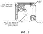
- FIG. 12shows a front view of a common (FAKRATM) single core coaxial cable connector interface according to the present invention, as applied on an automotive camera printed circuit board (PCB);
- FAKRATMcommon
- PCBautomotive camera printed circuit board
- Asymmetric signal transfer with LVDS + and ⁇ driver stages with one driver side set to ground over 50 ohmsshow the disadvantage of a 50 percent signal strength loss.
- State of the art coaxial cableshardly meet automotive requirements in combination of bending capability and attenuation performance.
- the disabled transceiver outputsare high impedance or have filters making sure that the signals of the enabled transmitter are not influenced by the driver stages circuits of disabled transmitters, which share the same connector nodes.
- the rear facing image sensoris connected to the MCU by a monodirectional data line or bus 124 , and the display device 116 is connected to the control device 122 via a data line or bus 126 (the image giving devices 114 b , 114 c , 114 d may also be connected to the control device 122 but their data lines are not shown in FIG. 14 ).
- the control or processor of the vision systemmay process captured image data to detect objects, such as objects to the rear of the subject or equipped vehicle during a reversing maneuver, or such as approaching or following vehicles or vehicles at a side lane adjacent to the subject or equipped vehicle or the like.
- the camera identification, parameters and calibration sets of vision system camerascan be stored in an internal non-volatile memory, such as a bitmap or bitmap like pattern.
- the calibration set or setsis/are transferred to an image processing device through the image channel, such as a NTSC, NTFS, PAL or SECAM channel or protocol.
- the calibration set that is transferred through the image channelgets coded by a specific manner of coding.
- the transferred or transmitted calibration setmay be coded by an image pattern from which the camera's calibration can be restored by the receiving image processing device.
- the calibration codemay be transferred or transmitted or communicated at any time.
- the calibration codemay be transferred in the first image's line or frame, and/or the calibration code may be transferred in the last image's line or frame, and/or the calibration code may be transferred in the first and last images' lines or frames.
- the calibration code overlaymay be placed or located in a corner of an image (or elsewhere in the image).
Landscapes
- Engineering & Computer Science (AREA)
- Multimedia (AREA)
- Signal Processing (AREA)
- Physics & Mathematics (AREA)
- Spectroscopy & Molecular Physics (AREA)
- Mechanical Engineering (AREA)
- General Physics & Mathematics (AREA)
- Closed-Circuit Television Systems (AREA)
- Studio Devices (AREA)
Abstract
Description
The present application is a continuation of U.S. patent application Ser. No. 16/792,422, filed Feb. 17, 2020, now U.S. Pat. No. 10,827,108, which is a continuation of U.S. patent application Ser. No. 16/401,163, filed May 2, 2019, now U.S. Pat. No. 10,567,633, which is a continuation of U.S. patent application Ser. No. 15/899,111, filed Feb. 19, 2018, now U.S. Pat. No. 10,284,764, which is a continuation of U.S. patent application Ser. No. 15/438,825, filed Feb. 22, 2017, now U.S. Pat. No. 9,900,490, which is a continuation of U.S. patent application Ser. No. 14/343,936, filed Mar. 10, 2014, which is a 371 national phase filing of PCT Application No. PCT/US2012/056014, filed Sep. 19, 2012, which claims the filing benefit of U.S. provisional applications, Ser. No. 61/653,664, filed May 31, 2012, Ser. No. 61/567,150, filed Dec. 6, 2011, Ser. No. 61/567,446, filed Dec. 6, 2011, and Ser. No. 61/537,279, filed Sep. 21, 2011, which are hereby incorporated herein by reference in their entireties.
The present invention relates to imaging systems or vision systems for vehicles and, more particularly, to a vision system that includes at least one imaging device or camera and high resolution camera data signal transfer.
Use of imaging sensors in vehicle imaging systems is common and known. Examples of such known systems are described in U.S. Pat. Nos. 5,949,331; 5,670,935 and/or 5,550,677, which are hereby incorporated herein by reference in their entireties.
The present invention provides a vision system or imaging system for a vehicle that utilizes one or more cameras to capture images exterior of the vehicle, and provides the communication/data signals, including camera data or image data (main channel), communication data (back channel) and the power supply, over a single or common coaxial cable.
Optionally, a system that modulates the signals (including power supply) without reduction in the amplitude may be used to provide enhanced signals over the single or common coaxial cable, may be implemented between the camera and control or ECU or the like.
Optionally, a vision system according to the present invention may include a control disposed at the vehicle, and when initially powering up the vision system, a transceiver of the imaging sensor is tuned to an initial communication mode, which is suitable for communication with the control and/or a communication interface of the vision system and/or a display device of the vision system.
The present invention also provides a vision system or imaging system for a vehicle that utilizes one or more cameras to capture images exterior of the vehicle, and provides the communication/data signals, including camera data or image data, that may be processed and, responsive to such image processing, the system may detect an object at or near the vehicle and in the path of travel of the vehicle, such as when the vehicle is backing up. In order to calibrate the system and camera or cameras, the present invention provides camera side band data transmission by overlay of calibration data or codes to the sent or communicated image or image data.
According to another aspect of the present invention, a vision system for a vehicle includes a camera or image sensor disposed at a vehicle and having a field of view exterior of the vehicle, and a processor operable to process data transmitted by the camera. The camera is operable to automatically transmit calibration data or codes and the processor is operable to receive the calibration data or codes transmitted by the camera. The camera automatically transmits the calibration data or codes when the camera is triggered to transmit the calibration data or codes. The vision system, responsive to receipt of the calibration data or codes, is operable to identify the camera and associated calibration codes or data. The calibration data or codes may comprise an overlay or graphic or pattern overlay in the image data captured by the camera and transmitted by the camera to the processor.
Optionally, the camera may automatically transmit the calibration data or codes responsive to an initial activation of the camera and/or the vision system. Optionally, the camera may automatically transmit the calibration data or codes responsive to detection of a particular pattern or the like in the field of view of the camera.
These and other objects, advantages, purposes and features of the present invention will become apparent upon review of the following specification in conjunction with the drawings.
Low-voltage differential signaling (LVDS) is known, such as described in U.S. Pat. No. 7,843,235 (and such as shown inFIG. 1 ), and EP Publication No. EP000002247047A1 (asymmetric LVDS, such as shown inFIGS. 2 and 3 ), and asymmetric LVDS drive stage chips and automotive applications have been proposed, such as by EQCOLOGIC® (see http://www.eqcologic.com, LVDS driver via coax application examples for automotive cameras), which are all hereby incorporated herein by reference in their entireties.
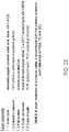
Coaxial cables used for LVDS are known from Figures in EP000002247047A1 and the cable itself by cable supplier specifications, such as, for example, a POLYFLEX® type of cable commercially available as FL09YHBC11Y (seeFIGS. 5 and 6 and Table 1 ofFIG. 19 ).
Automotive high resolution camera data signal (stream) transfer for cameras in automotive doors (side mirrors) and hatches cables must be robust due to bending. The data signal transfer and the screening attenuation must be sufficient to cope with automotive EMC tests and must attain a high enough data rate. The non-coaxial HSD-cables may provide a good screening attenuation (seeFIG. 9 ), but are typically much more expansive, are typically hard to assemble connectors, are typically hard to maintain in workshops, and are typically worse in bending capabilities (the twisted pair multi core wires tend to lose their arrangement, so the dielectric performance diminishes).
Single core coaxial cables are highly symmetric. Because of this, such a cable provides enhanced bending capabilities than those of multi-core coaxial cables and (non-coaxial) HSD-cables because it's structural geometrics do not get out of order as readily. The attenuation performance is comparable to that of HSD cables. The connectors are easy to apply and are readily maintained. Thus, there is a reduced desire to use coaxial cables for automotive high resolution camera data signal transfer.
Asymmetric signal transfer with LVDS + and − driver stages with one driver side set to ground over 50 ohms (such as shown inFIG. 3 ) show the disadvantage of a 50 percent signal strength loss. State of the art coaxial cables hardly meet automotive requirements in combination of bending capability and attenuation performance.
Thus, enhanced signal transfer is desired, and this may be achieved by using a single side driver stage for asymmetric signal line transfer, such as shown inFIG. 4A . As shown inFIG. 4A , the negative line driver has been eliminated, which simplifies the circuit. Thus, thee signal to noise ratio of the transmitter gets improved substantially (such as by nearly 100 percent or thereabouts).
To divide data (AC) from supply currents (DC) decoupling filters are in use. The may filter both the ground/negative signal line (coaxial cable shield) and the power/positive signal line as to be seen inFIG. 4A ) or more simplified just one node as to be seen inFIG. 4B .
The decoupling filters maintain inductors. As higher the signal frequency becomes chosen as smaller the filter inductors can be chosen according following equations:
Z=ωL
ω=2*π*f
Z=2*π*f*L
Z=ωL
ω=2*π*f
Z=2*π*f*L
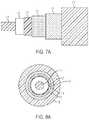
It is also desirable to provide enhanced bending capability and attenuation performance for automotive applications. This can be achieved by using a fluorinated ethylene propylene (FEP) perfluoroethylene-propylene plastic in the insulation layer of LVDS coaxial cables. Such a construction provides enhanced elasticity, and has comparable dielectric performance (such as shown inFIG. 10 ), and makes the cable more robust on repeated bending. Additionally, when combined by using a PUR-PVC material in the sheath, the cable construction also makes the cable easier to bend and mechanically more robust (seeFIGS. 7A and 8A and Table 2 ofFIG. 20 ).
Enhanced bending capability and attenuation can also become achieved by using a PP (poly-propylene) foam skin as a dielectric medium and optionally an aluminum foil instead of a separating fleece. Such a construction provides enhanced elasticity, and improves the attenuation further due to the additional shielding layer1.5 (seeFIGS. 7B and 8B and Table 3 ofFIG. 21 ). Optionally, and with reference toFIGS. 7C and 8C and Table 4 ofFIG. 22 , another schematic of layer build-ups of coaxial cable is shown, using another set of advanced materials for improved bending capabilities and having automotive compatible signal attenuation, in accordance with the present invention.
Such cables achieve high bending when the bending radius is higher than about 10 times the diameter, and are automotive temperature (such as about −40 degrees C. to about 125 degrees C.) capable. The attenuation stays below around 100 dB (nominal) at about 1 GHz, and about 150 dB at about 2 GHz and about 180 dB at about 3 GHz per 100 m cable or thereabouts.
Thus, and with reference toFIGS. 4A and 4B , a vehicle may an imaging system orvision system 10 that includes at least one imaging sensor orcamera 12, which capture images (such as images interior or exterior of the vehicle), and which communicates image data to a control system or control or processor ordisplay system 14 via acommunication link 16. Thecommunication link 16 comprises a single coaxial cable that communicates power supply to thecamera 12 and camera or image data from thecamera 12 to thecontrol 14. The present invention thus provides a means to communicate or send all data, including camera data or captured image data (main channel), communication data (back channel) and the power supply over a single or common link or coaxial cable.
Devices or systems supporting coaxial cables are developing. With full duplex devices, the system can send just over the low-voltage differential signaling (LVDS)+pin with LVDS−pin over 50 Ohm to ground. Thus, the system may provide only about half of the signal amplitude, but this is sufficient to send at least about 1.6 Gbps over about a 15 m coaxial cable without any errors. Various suitable coaxial cables may be used to pass the OEM requirements. For example, the system may include serial link chipsets at the ends of the cable or link, such as, for example, a MAX9259 chipset at the camera end of the link and a MAX9260 deserializer chipset at the display end of the link, such as are commercially available from Maxim of Sunnyvale, Calif., which provides a gigabit multimedia serial link (GMSL) technology. The MAX9259 serializer may pair with the MAX9260 deserializer to form a complete digital serial link for joint transmission of high-speed video, audio, and control data.
The chipsets may be implemented with a suitable coaxial cable, such as, for example, a 50 Ohm coaxial cable that provides up to about a 12 dB loss. Suitable cables include, for example, a Leoni Dacar 037 cable, a Leoni Dacar 320 cable, a Leoni Dacar 642 cable, a Leoni Dacar 380 cable, a LEONI DACAR® 4xx-KOAX-C-50-1.52-2.8/T125 cable, a Kroschu 64918930 cable, a Kroschu 64924651 cable or a Gebauer & Griller FL09YHBC11Y 0.35(0.26)2.1KX 50/1 cable, or the like.
Optionally, a vision system may incorporate a system that provides bidirectional full duplex communication over a single coax cable. For example, the system may comprise an EQCO850SC single coax transceiver/system (commercially available from Eqcologic USA of Flower Mound, Tex. Such a system is designed to simultaneously transmit and receive signals on a single 75 Ohm coax cable up to about 1.25 Gbps in both directions. The power supply can be delivered in parallel over the same coax by a current up to about 900 mA. Such a system is compatible with LVDS, CML and other NRZ differential signaling means. Such a device or system may modulate all signals inclusive of power supply to one signal which can be communicated or sent over a single or common coax cable with low or minimal loss of signal amplitude (about 100 dB (nominal) at about 1 GHz, about 150 dB at about 2 GHz and about 180 dB at about 3 GHz per 100 m cable or thereabouts) and without any requirement to have a full duplex system. Optionally, the vision system may incorporate any suitable coax cable, such as a 75 Ohm coax cable or a 50 Ohm coax cable or the like. The present invention thus supplies DC power and image data over the same coaxial line in an automotive vision system.
In automotive vision and safety cameras, it is known to provide a single data communication transmitter/transceiver (-type) for transmitting images and/or control data to a receiving unit, which may comprise a display, a mobile device, a head unit or any other image processing device or the like. The image processing device typically has one corresponding interface matching to the transmitting interface (bus) type. The vision system may include a digital bus or an analog interface or both.
Typically, an expensive part of an automotive vision system's hardware supply is the logistics. Instead of adapting the interfaces of equal cameras or visual detecting devices or the like (such as cameras or imaging sensors or the like) to different image processing device's (different) interfaces or having two interface plugs on one camera (which takes a lot of precious space, limits design flexibility and is more costly), a more lean and cheaper solution is on demand.
The present invention provides a vision system that has a camera that is adaptable for interfacing with different processors and/or control devices or the like.
(1) It is acknowledged that there are a number (“n”) of video standards (digital and analog) and a number (“m”) of kinds of video cables and connectors. Putting m×n into relation there is a finite amount of combinations which cover all demands for a camera interface. The present invention provides a solution that has a small amount of camera variants which differ in the kind of connectors. Cameras typically have in common that they need at least two different transceiver chips on board or transceivers which are capable of maintaining more than one transmission protocol (or transmission standard or norm) or a mix of these, both analog and/or digital. Also, all kinds of emulating of protocols meant by that.
(2) Because of this, the cameras can be common or kept identical or substantially identical, if the cameras have modes that are switched by parameters and that are adjusted to adapt a camera to a specific display device, image controller or head unit or the like. The present invention provides a vision system that, when powering up the vision system, such as in an initial phase, preferably at the first activation of the camera or system or after replacing a camera, the camera's transceiver (or transmitter) gets tuned into an initial or primitive communication mode, which can be maintained by every display device and camera's communication interface (hardware and software).
(3) According to (2), above, the parameters needed for setting up the vision system's camera(s), especially the setup of the chosen communication protocol, may be transmitted in the primitive mode initial phase.
(4) According to (3), above, after receiving the code for the chosen communication protocol (mode), the camera and the display device continue to communicate via the chosen communication protocol using the according transceiver hardware mentioned above.
(5) According to (2), above, the cameras parameters or a part of it, may get held and/or updated in the display device.
(6) According to (2), above, in the initial phase, the camera is (or the cameras are) running a self-configuring routine and are initializing itself/themselves by image data or other preset parameters or sensing data or data transmitted to them by any kind of data transmission. The cameras may communicate between each other and/or over the display device for that.
(7) According to (6), above, the result of the self-configuration is to determine on which place the camera is mounted (at the vehicle).
(8) According to (7), above, the result of the self-configuration is furthermore to do a stitching and alignment calibration, especially for calibrating means of determining magnitude and distances.
(9) According to (1), above, the different connectors may comprise coaxial cable connectors (Interfaces) or RJ45 or the like.
(10) According to (1), above, the different cables may comprise coaxial cable, shielded twisted pair (STP), unshielded twisted pair, USB cable, HDMI cable or the like.
(11) According to (1), above, the different transmission protocols or standards may comprise NTSC, PAL, SECAM, Ethernet, Gigabit Multimedia Serial Link (GMSL), FDP-Link I, FDP-Link II, FDP-Link III, Pixel Link, USB, CAN, LIN, Flexray, Devicenet, Interbus, Modbus, Profibus, ASI, composite video, S-Video, SCART, component video, D-Terminal, VGA, HDMI, DVI, HDCP or other according the EIA/CEA-861 standard, or the like.
(12) According to (1), above, when enabling one transceiver on the camera, the other transceiver may be disabled.
(13) According to (12), above, the disabled transceiver outputs are high impedance or have filters making sure that the signals of the enabled transmitter are not influenced by the driver stages circuits of disabled transmitters, which share the same connector nodes.
(14) According to (10), above, the transmission cable may also be used as power line for supplying the camera and/or other devices or sensors.
(15) According to (10), above, the transmission cable grid between camera(s) display device(s), power sources, sensor(s), actuators, and the like may be set up as a ring, a star, or a mixture of both.
(16) According to (15), above, there may be also wireless cameras, mobile infotainment and other devices on the grid.
(17) According to (16), above, there may be also bus gateways in between the grids nodes.
Thus, the present invention provides an interface, connector and transmission cable standardization on automotive camera systems. The vision system of the present invention incorporates one or more cameras that are configured or adapted to communicate with various types of communication or data transfer cables and various types of transmission protocols. The cameras for a given system and/or for various systems on different vehicles, can be common or kept identical or substantially identical, and the modes are switched by parameters becoming adjusted to adapt a camera to a specific display device, image controller or head unit or the like.
The present invention also provides a vehicle vision system and/or driver assist system and/or object detection system and/or alert system operates that is operable to capture images exterior of the vehicle and to process the captured image data to detect objects at or near the vehicle and in the predicted path of the vehicle, such as to assist a driver of the vehicle in maneuvering the vehicle in a rearward direction. The vision system includes a processor that is operable to receive image data from a camera and may receive calibration data or codes from the camera when the camera is initially powered or activated or when the camera is otherwise triggered to send or transmit the calibration data (such as responsive to a triggering event such as an initial activation of the camera or system or an input to the camera or system or a detection of a particular pattern or the like in the field of view of the camera), such that the system can identify the camera and its calibration codes such that the vision system may be automatically calibrated for operation, without any manual inputs or reading of physical labels or the like at the camera.
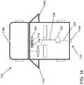
Referring now toFIG. 14 , avehicle 110 includes an imaging system orvision system 112 that includes one or more imaging sensors or cameras (such as a rearward facing imaging sensor orcamera 114aand/or a forwardly facingcamera 114bat the front (or at the windshield) of the vehicle, and/or a sidewardly/rearwardly facingcamera FIG. 14 ). Thevision system 112 includes a control orprocessor 118 that is operable to process image data captured by the cameras and may provide displayed images at adisplay device 116 for viewing by the driver of the vehicle (although shown inFIG. 14 as being part of or incorporated in or at an interiorrearview mirror assembly 120 of the vehicle, the control and/or the display device may be disposed elsewhere at or in the vehicle) and a control device (MCU)122. The rear facing image sensor is connected to the MCU by a monodirectional data line orbus 124, and thedisplay device 116 is connected to thecontrol device 122 via a data line or bus126 (theimage giving devices control device 122 but their data lines are not shown inFIG. 14 ). Optionally, the control or processor of the vision system may process captured image data to detect objects, such as objects to the rear of the subject or equipped vehicle during a reversing maneuver, or such as approaching or following vehicles or vehicles at a side lane adjacent to the subject or equipped vehicle or the like.
Vehicle vision system cameras have interfaces to send or transmit or communicate image data and further channels to communicate control and configuration data to image processing units, head units or display units or the like. These units may be part of the vehicle's sensor cluster or driver assistance system or the like.
In order to enhance cost efficiency, vision system cameras typically have as few interfaces as possible. Some known cameras have just an image output, such as an NTSC output or the like, but no further data output. Such cameras are typically calibrated during their assembly (by the supplier). The calibration data may be provided to the OEM installing those cameras on vehicles. For example, the data may be labeled onto the housing of the camera, such as by lasering, sticking, printing and/or the like, or in the bar codes in a one dimensional (1D) code or a two dimensional (2D) matrix and/or the like. These can be read by scanners at the OEM's vehicle assembly line when installing the cameras on or at the vehicles. Alternatively, every camera's calibration data set can be stored in a database which may be accessed by the OEM to read the according data set at the time the camera is assembled to a vehicle on the OEM's vehicle assembly line. Such a process necessitates identifying every camera. Hence, at least the serial number must be identified on each camera that is installed on a vehicle.
In cases where a vehicle vision system's camera has to be replaced by a repair service, the calibration set up of the old camera has to be replaced by a calibration set up of the new camera. This is typically to be done manually at the vehicle service station or repair shop.
The data handling of vision system camera's calibration sets is simplified by the present invention. The necessity for printing, installing or sticking labels to identify each camera or its specific data set may be obviated or eliminated. The camera of the vehicle vision system of the present invention is enabled to automatically transfer its calibration data set to a vision processing unit, head unit or display device or the like, especially after servicing of the camera or vehicle vision system.
Vehicle vision system's cameras that have just one port, such as an NTFS image channel, shall communicate over the port and communication link with the vision head unit or the like. Identification of the camera and parameters of the camera and especially the calibration data sets, which may be stored in a camera internal non-volatile memory as a bitmap, will be transferred to and received and understood by the head unit or control or processor. By that, the camera calibration can be transmitted automatically on the customer (OEM) line or after replacing or servicing the vision system and/or individual camera or cameras.
In accordance with the present invention, the camera identification, parameters and calibration sets of vision system cameras can be stored in an internal non-volatile memory, such as a bitmap or bitmap like pattern. The calibration set or sets is/are transferred to an image processing device through the image channel, such as a NTSC, NTFS, PAL or SECAM channel or protocol. The calibration set that is transferred through the image channel gets coded by a specific manner of coding. For example, the transferred or transmitted calibration set may be coded by an image pattern from which the camera's calibration can be restored by the receiving image processing device.
Optionally, the transferred or transmitted calibration set may be coded by using bar codes which appear as an overlay to the image. For example, the calibration code may be coded by a 1D bar code, or by a 2D matrix code or the like. Optionally, the calibration code overlay may comprise a color value or color tone or color pattern or the like.
The calibration data set is coded by data conjuncted, bound or added to the image or image data picked up or captured by the camera. The calibration is bound to the image picked up by the camera via any suitable means, such as by a steganography algorithm or the like. Symmetric steganography finds use here, having private keys on the coding/encrypting side and on the uncoding/uncrypting side. Asymmetric steganography finds use here, having a private key on the coding/encrypting side and a public key on the uncoding/uncrypting side.
The calibration code may be transferred or transmitted or communicated at any time. For example, the calibration code may be transferred in the first image's line or frame, and/or the calibration code may be transferred in the last image's line or frame, and/or the calibration code may be transferred in the first and last images' lines or frames. Optionally, the calibration code overlay may be placed or located in a corner of an image (or elsewhere in the image).
Optionally, the code may be transferred instead of an image picked up by the camera. For example, the code may be transferred instead of an image for a specific time or the code may be transferred instead of an image at a specific time. Optionally, the calibration code image may comprise a color code, such as a color value or color tone or color pattern or the like.
Optionally, the calibration code may be transferred within the ‘vertical blanking interval’ (pause time between two frames) or separated in parts within several blanking intervals, which may be consecutive, repeated by a certain number of intervals or with gaps in between. Typical systems may be able to transfer about 6 bytes during one vertical blanking interval and about 900 bytes may be transferred when replacing one image frame by one data frame.
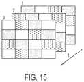
Optionally, the calibration code may be transferred as or within the first image or frame captured or transmitted by the camera, such as when the camera is initially powered up. The code may be transferred from the first image for a specific time or may be transferred as or within one image at a specific time. Optionally, the calibration code may be transferred as or within several images. Optionally, the same pattern or code may be transferred as or within several consecutive images or frames (such as shown inFIG. 15 ), such as transferred as or within several consecutive images at a specific time or transferred as or within several consecutive images at several specific times of a time pattern.
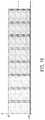
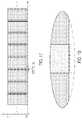
Optionally, and with reference toFIG. 16 , a time scheme transfers camera data within the first three frames, such as, for example, during initialization. As shown inFIG. 16 , the dark gray portions represent camera data, the light gray portions represent image data and the white portions represent no data. Optionally, and with reference toFIG. 17 , a time scheme transferring camera data during a vertical blanking interval is shown, with the time of the blanking interval being relatively small compared to the time it takes to transfer an image frame. As shown inFIG. 17 , the dark gray portions represent camera data, the light gray portions represent image data and the white portions represent no data. Optionally, and with reference toFIG. 18 , an enlarged timeframe of the vertical blanking time interval ofFIG. 17 is shown, with 16 data bit being transferred within one interval. As shown inFIG. 18 , the dark gray portions represent camera data, the light gray portions represent image data, the very dark gray portions represent high pulse (positive bits) within the vertical blanking interval and the white portions represent no data.
Optionally, the same calibration code may be transferred as or within several images (such as non-consecutive images) at a specific time pattern. Optionally, the code may be divided up into several consecutive images so the code images are different to each other. Optionally, the coded consecutive images are embedded to a flick.
The code may be transferred via any suitable protocol or signal. For example, the code may be transferred as a non NTFS signal, such as a non NTFS signal that is out of the NTFS bandwidth, or such as a non NTFS superpositioned to the NTFS signal. Optionally, the code may be transferred instead of the NTFS signal. Optionally, the code may be transferred as a side band of the NTFS signal.
Optionally, the camera may be set to its calibration mode responsive to triggering event, such as an input or detection of a code or pattern placed in the field of view of the camera via processing of image data captured by the camera. For example, the camera may be set to its calibration mode (and not exclusively set into the calibration mode) by being shown an optical code. Such an optical code may comprise any suitable pattern or code, such as a specific pattern, such as a bar code or a two dimensional (2D) matrix code or a color code or a color value or color tone or the image's mean value color value or color. The code may be transferred within several images. Optionally, the camera may be set to its calibration mode (and not exclusively set into the calibration mode) by a signal or on/off switch pattern at its power line.
Therefore, the present invention provides a vision system for a vehicle that includes a processor or head unit and a camera or cameras mounted at the vehicle. The processor or head unit is operable to receive calibration data or codes from the camera that are automatically transmitted by the camera when the camera is activated or when the camera is otherwise triggered to send or transmit the calibration data (such as responsive to an input or responsive to detection of a particular pattern or the like in the field of view of the camera). The vision system thus is operable to identify the camera or cameras and associated calibration codes such that the vision system may be automatically calibrated for operation, without any manual inputs or reading of physical labels or the like at the camera.
The camera or sensor may comprise any suitable camera or sensor. Optionally, the camera may comprise a “smart camera” that includes the imaging sensor array and associated circuitry and image processing circuitry and electrical connectors and the like as part of a camera module, such as by utilizing aspects of the vision systems described in U.S. provisional applications, Ser. No. 61/563,965, filed Nov. 28, 2011, and/or Ser. No. 61/565,713, filed Dec. 1, 2011, which are hereby incorporated herein by reference in their entireties.
The vehicle may include any type of sensor or sensors, such as imaging sensors or radar sensors or lidar sensors or ultrasonic sensors or the like. The imaging sensor or camera may capture image data for image processing and may comprise any suitable camera or sensing device, such as, for example, an array of a plurality of photosensor elements arranged in 640 columns and 480 rows (a 640×480 imaging array), with a respective lens focusing images onto respective portions of the array. The photosensor array may comprise a plurality of photosensor elements arranged in a photosensor array having rows and columns. The logic and control circuit of the imaging sensor may function in any known manner, such as in the manner described in U.S. Pat. Nos. 5,550,677; 5,877,897; 6,498,620; 5,670,935; 5,796,094 and/or 6,396,397, and/or U.S. provisional applications, Ser. No. 61/696,416, filed Sep. 4, 2012; Ser. No. 61/682,995, filed Aug. 14, 2012; Ser. No. 61/682,486, filed Aug. 13, 2012; Ser. No. 61/680,883, filed Aug. 8, 2012; Ser. No. 61/678,375, filed Aug. 1, 2012; Ser. No. 61/676,405, filed Jul. 27, 2012; Ser. No. 61/666,146, filed Jun. 29, 2012; Ser. No. 61/653,665, filed May 31, 2012; Ser. No. 61/653,664, filed May 31, 2012; Ser. No. 61/648,744, filed May 18, 2012; Ser. No. 61/624,507, filed Apr. 16, 2012; Ser. No. 61/616,126, filed Mar. 27, 2012; Ser. No. 61/615,410, filed Mar. 26, 2012; Ser. No. 61/613,651, filed Mar. 21, 2012; Ser. No. 61/607,229, filed Mar. 6, 2012; Ser. No. 61/605,409, filed Mar. 1, 2012; Ser. No. 61/602,878, filed Feb. 24, 2012; Ser. No. 61/602,876, filed Feb. 24, 2012; Ser. No. 61/600,205, filed Feb. 17, 2012; Ser. No. 61/588,833, filed Jan. 20, 2012; Ser. No. 61/583,381, filed Jan. 5, 2012; Ser. No. 61/579,682, filed Dec. 23, 2011; Ser. No. 61/570,017, filed Dec. 13, 2011; Ser. No. 61/568,791, filed Dec. 9, 2011; Ser. No. 61/567,446, filed Dec. 6, 2011; Ser. No. 61/559,970, filed Nov. 15, 2011; and/or Ser. No. 61/552,167, filed Oct. 27, 2011, and/or PCT Application No. PCT/CA2012/000378, filed Apr. 25, 2012, and published Nov. 1, 2012 as International Publication No. WO 2012/145822, and/or PCT Application No. PCT/US2012/048800, filed Jul. 30, 2012, and published Feb. 7, 2013 as International Publication No. WO 2013/019707, and/or PCT Application No. PCT/US2012/048110, filed Jul. 25, 2012, and published Jan. 31, 2013 as International Publication No. WO 2013/016409, and/or U.S. patent application Ser. No. 13/534,657, filed Jun. 27, 2012, and published Jan. 3, 2013 as U.S. Publication No. US-2013-0002873, which are all hereby incorporated herein by reference in their entireties. The system may communicate with other communication systems via any suitable means, such as by utilizing aspects of the systems described in PCT Application No. PCT/US10/038477, filed Jun. 14, 2010, and/or U.S. patent application Ser. No. 13/202,005, filed Aug. 17, 2011, now U.S. Pat. No. 9,126,525, and/or U.S. provisional applications, Ser. No. 61/650,667, filed May 23, 2012; Ser. No. 61/579,682, filed Dec. 23, 2011; Ser. No. 61/565,713, filed Dec. 1, 2011, which are hereby incorporated herein by reference in their entireties.
The imaging device and control and image processor and any associated illumination source, if applicable, may comprise any suitable components, and may utilize aspects of the cameras and vision systems described in U.S. Pat. Nos. 5,550,677; 5,877,897; 6,498,620; 5,670,935; 5,796,094; 6,396,397; 6,806,452; 6,690,268; 7,005,974; 7,123,168; 7,004,606; 6,946,978; 7,038,577; 6,353,392; 6,320,176; 6,313,454 and 6,824,281, and/or International Publication No. WO 2010/099416, published Sep. 2, 2010, and/or PCT Application No. PCT/US10/47256, filed Aug. 31, 2010, and/or U.S. patent application Ser. No. 12/508,840, filed Jul. 24, 2009, and published Jan. 28, 2010 as U.S. Pat. Publication No. US 2010-0020170, and/or PCT Application No. PCT/US2012/048110, filed Jul. 25, 2012, and published Jan. 31, 2013 as International Publication No. WO 2013/016409, and/or U.S. patent application Ser. No. 13/534,657, filed Jun. 27, 2012, and published Jan. 3, 2013 as U.S. Publication No. US-2013-0002873, which are all hereby incorporated herein by reference in their entireties. The camera or cameras may comprise any suitable cameras or imaging sensors or camera modules, and may utilize aspects of the cameras or sensors described in U.S. patent applications, Ser. No. 12/091,359, filed Apr. 24, 2008 and published Oct. 1, 2009 as U.S. Publication No. US-2009-0244361, and/or Ser. No. 13/260,400, filed Sep. 26, 2011, now U.S. Pat. Nos. 8,542,451, 7,965,336 and/or 7,480,149, which are hereby incorporated herein by reference in their entireties. The imaging array sensor may comprise any suitable sensor, and may utilize various imaging sensors or imaging array sensors or cameras or the like, such as a CMOS imaging array sensor, a CCD sensor or other sensors or the like, such as the types described in U.S. Pat. Nos. 5,550,677; 5,670,935; 5,760,962; 5,715,093; 5,877,897; 6,922,292; 6,757,109; 6,717,610; 6,590,719; 6,201,642; 6,498,620; 5,796,094; 6,097,023; 6,320,176; 6,559,435; 6,831,261; 6,806,452; 6,396,397; 6,822,563; 6,946,978; 7,339,149; 7,038,577; 7,004,606 and/or 7,720,580, and/or U.S. patent application Ser. No. 10/534,632, filed May 11, 2005, now U.S. Pat. No. 7,965,336, and/or PCT Application No. PCT/US2008/076022, filed Sep. 11, 2008 and published Mar. 19, 2009 as International Publication No. WO 2009/036176, and/or PCT Application No. PCT/US2008/078700, filed Oct. 3, 2008 and published Apr. 9, 2009 as International Publication No. WO 2009/046268, which are all hereby incorporated herein by reference in their entireties.
The camera module and circuit chip or board and imaging sensor may be implemented and operated in connection with various vehicular vision-based systems, and/or may be operable utilizing the principles of such other vehicular systems, such as a vehicle headlamp control system, such as the type disclosed in U.S. Pat. Nos. 5,796,094; 6,097,023; 6,320,176; 6,559,435; 6,831,261; 7,004,606; 7,339,149 and/or 7,526,103, which are all hereby incorporated herein by reference in their entireties, a rain sensor, such as the types disclosed in commonly assigned U.S. Pat. Nos. 6,353,392; 6,313,454; 6,320,176 and/or 7,480,149, which are hereby incorporated herein by reference in their entireties, a vehicle vision system, such as a forwardly, sidewardly or rearwardly directed vehicle vision system utilizing principles disclosed in U.S. Pat. Nos. 5,550,677; 5,670,935; 5,760,962; 5,877,897; 5,949,331; 6,222,447; 6,302,545; 6,396,397; 6,498,620; 6,523,964; 6,611,202; 6,201,642; 6,690,268; 6,717,610; 6,757,109; 6,802,617; 6,806,452; 6,822,563; 6,891,563; 6,946,978 and/or 7,859,565, which are all hereby incorporated herein by reference in their entireties, a trailer hitching aid or tow check system, such as the type disclosed in U.S. Pat. No. 7,005,974, which is hereby incorporated herein by reference in its entirety, a reverse or sideward imaging system, such as for a lane change assistance system or lane departure warning system or for a blind spot or object detection system, such as imaging or detection systems of the types disclosed in U.S. Pat. Nos. 7,720,580; 7,038,577; 5,929,786 and/or 5,786,772, and/or U.S. patent applications, Ser. No. 11/239,980, filed Sep. 30, 2005, now U.S. Pat. No. 7,881,496, and/or U.S. provisional applications, Ser. No. 60/628,709, filed Nov. 17, 2004; Ser. No. 60/614,644, filed Sep. 30, 2004; Ser. No. 60/618,686, filed Oct. 14, 2004; Ser. No. 60/638,687, filed Dec. 23, 2004, which are hereby incorporated herein by reference in their entireties, a video device for internal cabin surveillance and/or video telephone function, such as disclosed in U.S. Pat. Nos. 5,760,962; 5,877,897; 6,690,268 and/or 7,370,983, and/or U.S. patent application Ser. No. 10/538,724, filed Jun. 13, 2005 and published Mar. 9, 2006 as U.S. Publication No. US-2006-0050018, which are hereby incorporated herein by reference in their entireties, a traffic sign recognition system, a system for determining a distance to a leading or trailing vehicle or object, such as a system utilizing the principles disclosed in U.S. Pat. Nos. 6,396,397 and/or 7,123,168, which are hereby incorporated herein by reference in their entireties, and/or the like.
Optionally, the circuit board or chip may include circuitry for the imaging array sensor and or other electronic accessories or features, such as by utilizing compass-on-a-chip or EC driver-on-a-chip technology and aspects such as described in U.S. Pat. Nos. 7,255,451 and/or 7,480,149, and/or U.S. patent applications, Ser. No. 11/226,628, filed Sep. 14, 2005 and published Mar. 23, 2006 as U.S. Publication No. US-2006-0061008, and/or Ser. No. 12/578,732, filed Oct. 14, 2009, now U.S. Pat. No. 9,487,144, which are hereby incorporated herein by reference in their entireties.
Optionally, the vision system may include a display for displaying images captured by one or more of the imaging sensors for viewing by the driver of the vehicle while the driver is normally operating the vehicle. Optionally, for example, the vision system may include a video display device disposed at or in the interior rearview mirror assembly of the vehicle, such as by utilizing aspects of the video mirror display systems described in U.S. Pat. No. 6,690,268 and/or U.S. patent application Ser. No. 13/333,337, filed Dec. 21, 2011, now U.S. Pat. No. 9,264,672, which are hereby incorporated herein by reference in their entireties. The video mirror display may comprise any suitable devices and systems and optionally may utilize aspects of the compass display systems described in U.S. Pat. Nos. 7,370,983; 7,329,013; 7,308,341; 7,289,037; 7,249,860; 7,004,593; 4,546,551; 5,699,044; 4,953,305; 5,576,687; 5,632,092; 5,677,851; 5,708,410; 5,737,226; 5,802,727; 5,878,370; 6,087,953; 6,173,508; 6,222,460; 6,513,252 and/or 6,642,851, and/or European patent application, published Oct. 11, 2000 under Publication No.EP 0 1043566, and/or U.S. patent application Ser. No. 11/226,628, filed Sep. 14, 2005 and published Mar. 23, 2006 as U.S. Publication No. US-2006-0061008, which are all hereby incorporated herein by reference in their entireties. Optionally, the video mirror display screen or device may be operable to display images captured by a rearward viewing camera of the vehicle during a reversing maneuver of the vehicle (such as responsive to the vehicle gear actuator being placed in a reverse gear position or the like) to assist the driver in backing up the vehicle, and optionally may be operable to display the compass heading or directional heading character or icon when the vehicle is not undertaking a reversing maneuver, such as when the vehicle is being driven in a forward direction along a road (such as by utilizing aspects of the display system described in PCT Application No. PCT/US2011/056295, filed Oct. 14, 2011 and published Apr. 19, 2012 as International Publication No. WO 2012/051500, which is hereby incorporated herein by reference in its entirety). Optionally, the vision system may provide a display of a top-down view or birds-eye view of the vehicle or a surround view at the vehicle, such as by utilizing aspects of the vision systems described in PCT Application No. PCT/US10/25545, filed Feb. 26, 2010 and published on Sep. 2, 2010 as International Publication No. WO 2010/099416, and/or PCT Application No. PCT/US10/47256, filed Aug. 31, 2010 and published Mar. 10, 2011 as International Publication No. WO 2011/028686, and/or U.S. patent application Ser. No. 13/333,337, filed Dec. 21, 2011, now U.S. Pat. No. 9,264,672, and/or PCT Application No. PCT/CA2012/000378, filed Apr. 25, 2012, and published Nov. 1, 2012 as International Publication No. WO 2012/145822, and/or U.S. provisional application Ser. No. 61/559,970, filed Nov. 15, 2011, which are hereby incorporated herein by reference in their entireties.
Optionally, the video mirror display may be disposed rearward of and behind the reflective element assembly and may comprise a display such as the types disclosed in U.S. Pat. Nos. 5,530,240; 6,329,925; 7,626,749; 7,581,859; 7,338,177; 7,274,501; 7,255,451; 7,195,381; 7,184,190; 5,668,663; 5,724,187 and/or 6,690,268, and/or in U.S. patent applications, Ser. No. 12/091,525, filed Apr. 25, 2008, now U.S. Pat. No. 7,855,755; Ser. No. 11/226,628, filed Sep. 14, 2005 and published Mar. 23, 2006 as U.S. Publication No. US-2006-0061008, and/or Ser. No. 10/538,724, filed Jun. 13, 2005 and published Mar. 9, 2006 as U.S. Publication No. US-2006-0050018, which are all hereby incorporated herein by reference in their entireties. The display is viewable through the reflective element when the display is activated to display information. The display element may be any type of display element, such as a vacuum fluorescent (VF) display element, a light emitting diode (LED) display element, such as an organic light emitting diode (OLED) or an inorganic light emitting diode, an electroluminescent (EL) display element, a liquid crystal display (LCD) element, a video screen display element or backlit thin film transistor (TFT) display element or the like, and may be operable to display various information (as discrete characters, icons or the like, or in a multi-pixel manner) to the driver of the vehicle, such as passenger side inflatable restraint (PSIR) information, tire pressure status, and/or the like. The mirror assembly and/or display may utilize aspects described in U.S. Pat. Nos. 7,184,190; 7,255,451; 7,446,924 and/or 7,338,177, which are all hereby incorporated herein by reference in their entireties. The thicknesses and materials of the coatings on the substrates of the reflective element may be selected to provide a desired color or tint to the mirror reflective element, such as a blue colored reflector, such as is known in the art and such as described in U.S. Pat. Nos. 5,910,854; 6,420,036 and/or 7,274,501, which are hereby incorporated herein by reference in their entireties.
Optionally, the display or displays and any associated user inputs may be associated with various accessories or systems, such as, for example, a tire pressure monitoring system or a passenger air bag status or a garage door opening system or a telematics system or any other accessory or system of the mirror assembly or of the vehicle or of an accessory module or console of the vehicle, such as an accessory module or console of the types described in U.S. Pat. Nos. 7,289,037; 6,877,888; 6,824,281; 6,690,268; 6,672,744; 6,386,742 and 6,124,886, and/or U.S. patent application Ser. No. 10/538,724, filed Jun. 13, 2005 and published Mar. 9, 2006 as U.S. Publication No. US-2006-0050018, which are hereby incorporated herein by reference in their entireties.
The display or displays may comprise a video display and may utilize aspects of the video display devices or modules described in U.S. Pat. Nos. 6,690,268; 7,184,190; 7,274,501; 7,370,983 and/or 7,446,650, and/or U.S. patent applications, Ser. No. 12/091,525, filed Apr. 25, 2008, now U.S. Pat. No. 7,855,755, and/or Ser. No. 10/538,724, filed Jun. 13, 2005 and published Mar. 9, 2006 as U.S. Publication No. US-2006-0050018, which are all hereby incorporated herein by reference in their entireties. The video display may be operable to display images captured by one or more imaging sensors or cameras at the vehicle.
Changes and modifications to the specifically described embodiments may be carried out without departing from the principles of the present invention, which is intended to be limited only by the scope of the appended claims as interpreted according to the principles of patent law.
Claims (36)
1. A vehicular multi-camera surround view system, said vehicular multi-camera surround view system comprising:
a front camera disposed at a front portion of a vehicle equipped with said vehicular multi-camera surround view system, said front camera having a field of view exterior and at least forward of the equipped vehicle;
said front camera comprising a first imaging sensor operable to capture image data;
a driver-side camera disposed at a driver side exterior sideview mirror assembly of the equipped vehicle, said driver-side camera having a field of view exterior and at least sideward of the equipped vehicle;
said driver-side camera comprising a second imaging sensor operable to capture image data;
a passenger-side camera disposed at a passenger side exterior sideview mirror assembly of the equipped vehicle, said passenger-side camera having a field of view exterior and at least sideward of the equipped vehicle;
said passenger-side camera comprising a third imaging sensor operable to capture image data;
a rear backup camera disposed at a rear portion of the equipped vehicle, said rear backup camera having a field of view exterior and at least rearward of the equipped vehicle;
said rear backup camera comprising a fourth imaging sensor operable to capture image data;
an electronic control unit (ECU) disposed at the vehicle and comprising (i) a data processor and (ii) a DC power supply;
wherein image data captured by the first imaging sensor of said front camera is conveyed to the ECU via a first single core coaxial cable;
wherein said front camera is in full duplex bidirectional communication with the ECU over the first single core coaxial cable;
wherein the first single core coaxial cable commonly carries (i) image data captured by the first imaging sensor of said front camera to the ECU for processing at the data processor of the ECU and (ii) power from the DC power supply of the ECU to said front camera;
wherein power carried by the first single core coaxial cable from the DC power supply of the ECU to said front camera is at an electrical current less than or equal to 900 mA;
wherein image data captured by the second imaging sensor of said driver-side camera is conveyed to the ECU via a second single core coaxial cable;
wherein said driver-side camera is in full duplex bidirectional communication with the ECU over the second single core coaxial cable;
wherein the second single core coaxial cable commonly carries (i) image data captured by the second imaging sensor of said driver-side camera to the ECU for processing at the data processor of the ECU and (ii) power from the DC power supply of the ECU to said driver-side camera;
wherein power carried by the second single core coaxial cable from the DC power supply of the ECU to said driver-side camera is at an electrical current less than or equal to 900 mA;
wherein image data captured by the third imaging sensor of said passenger-side camera is conveyed to the ECU via a third single core coaxial cable;
wherein said passenger-side camera is in full duplex bidirectional communication with the ECU over the third single core coaxial cable;
wherein the third single core coaxial cable commonly carries (i) image data captured by the third imaging sensor of said passenger-side camera to the ECU for processing at the data processor of the ECU and (ii) power from the DC power supply of the ECU to said passenger-side camera;
wherein power carried by the third single core coaxial cable from the DC power supply of the ECU to said passenger-side camera is at an electrical current less than or equal to 900 mA;
wherein image data captured by the fourth imaging sensor of said rear backup camera is conveyed to the ECU via a fourth single core coaxial cable;
wherein said rear backup camera is in full duplex bidirectional communication with the ECU over the fourth single core coaxial cable;
wherein the fourth single core coaxial cable commonly carries (i) image data captured by the fourth imaging sensor of said rear backup camera to the ECU for processing at the data processor of the ECU and (ii) power from the DC power supply of the ECU to said rear backup camera;
wherein power carried by the fourth single core coaxial cable from the DC power supply of the ECU to said rear backup camera is at an electrical current less than or equal to 900 mA;
wherein the ECU is operable to combine image data conveyed from said front camera, said driver-side camera, said passenger-side camera and said rear backup camera to form composite video images (i) derived from image data captured by the fourth imaging sensor of said rear backup camera, (ii) derived from image data captured by the second imaging sensor of said driver-side camera, (iii) derived from image data captured by the third imaging sensor of said passenger-side camera and (iv) derived from image data captured by the first imaging sensor of said front camera;
wherein the ECU is operable to output the composite video images formed at the ECU to a display device comprising a video display screen disposed in an interior cabin of the equipped vehicle and viewable by a driver of the equipped vehicle; and
wherein the composite video images as displayed on said video display screen provide a bird's eye view that enhances the driver's understanding of areas surrounding the equipped vehicle.
2. The vehicular multi-camera surround view system ofclaim 1 , wherein the first single core coaxial cable comprises a 50 ohm single core coaxial cable, and wherein the second single core coaxial cable comprises a 50 ohm single core coaxial cable, and wherein the third single core coaxial cable comprises a 50 ohm single core coaxial cable, and wherein the fourth single core coaxial cable comprises a 50 ohm single core coaxial cable.
3. The vehicular multi-camera surround view system ofclaim 1 , wherein the first single core coaxial cable comprises a 75 ohm single core coaxial cable, and wherein the second single core coaxial cable comprises a 75 ohm single core coaxial cable, and wherein the third single core coaxial cable comprises a 75 ohm single core coaxial cable, and wherein the fourth single core coaxial cable comprises a 75 ohm single core coaxial cable.
4. The vehicular multi-camera surround view system ofclaim 1 , wherein signal attenuation by the first single core coaxial cable is below 100 dB at a frequency of 1 GHz per 100 m length of the first single core coaxial cable, and wherein signal attenuation by the second single core coaxial cable is below 100 dB at a frequency of 1 GHz per 100 m length of the second single core coaxial cable, and wherein signal attenuation by the third single core coaxial cable is below 100 dB at a frequency of 1 GHz per 100 m length of the third single core coaxial cable, and wherein signal attenuation by the fourth single core coaxial cable is below 100 dB at a frequency of 1 GHz per 100 m length of the fourth single core coaxial cable.
5. The vehicular multi-camera surround view system ofclaim 4 , wherein signal attenuation by the first single core coaxial cable is below 150 dB at a frequency of 2 GHz per 100 m length of the first single core coaxial cable, and wherein signal attenuation by the second single core coaxial cable is below 150 dB at a frequency of 2 GHz per 100 m length of the second single core coaxial cable, and wherein signal attenuation by the third single core coaxial cable is below 150 dB at a frequency of 2 GHz per 100 m length of the third single core coaxial cable, and wherein signal attenuation by the fourth single core coaxial cable is below 150 dB at a frequency of 2 GHz per 100 m length of the fourth single core coaxial cable.
6. The vehicular multi-camera surround view system ofclaim 5 , wherein signal attenuation by the first single core coaxial cable is below 180 dB at a frequency of 3 GHz per 100 m length of the first single core coaxial cable, and wherein signal attenuation by the second single core coaxial cable is below 180 dB at a frequency of 3 GHz per 100 m length of the second single core coaxial cable, and wherein signal attenuation by the third single core coaxial cable is below 180 dB at a frequency of 3 GHz per 100 m length of the third single core coaxial cable, and wherein signal attenuation by the fourth single core coaxial cable is below 180 dB at a frequency of 3 GHz per 100 m length of the fourth single core coaxial cable.
7. The vehicular multi-camera surround view system ofclaim 1 , wherein the first single core coaxial cable transmits calibration data to the ECU, and wherein the second single core coaxial cable transmits calibration data to the ECU, and wherein the third single core coaxial cable transmits calibration data to the ECU, and wherein the fourth single core coaxial cable transmits calibration data to the ECU.
8. The vehicular multi-camera surround view system ofclaim 1 , wherein the first single core coaxial cable transmits calibration data to the ECU at initiation of said front camera, and wherein the second single core coaxial cable transmits calibration data to the ECU at initiation of said driver-side camera, and wherein the third single core coaxial cable transmits calibration data to the ECU at initiation of said passenger-side camera, and wherein the fourth single core coaxial cable transmits calibration data to the ECU at initiation of said rear backup camera.
9. The vehicular multi-camera surround view system ofclaim 1 , wherein the first single core coaxial cable transmits calibration data to the ECU responsive to a triggering event of said front camera, and wherein the second single core coaxial cable transmits calibration data to the ECU responsive to a triggering event of said driver-side camera, and wherein the third single core coaxial cable transmits calibration data to the ECU responsive to a triggering event of said passenger-side camera, and wherein the fourth single core coaxial cable transmits calibration data to the ECU responsive to a triggering event of said rear backup camera.
10. The vehicular multi-camera surround view system ofclaim 1 , wherein the first single core coaxial cable transmits calibration data to the ECU at an initial activation of said front camera, and wherein the second single core coaxial cable transmits calibration data to the ECU at an initial activation of said driver-side camera, and wherein the third single core coaxial cable transmits calibration data to the ECU at an initial activation of said passenger-side camera, and wherein the fourth single core coaxial cable transmits calibration data to the ECU at an initial activation of said rear backup camera.
11. The vehicular multi-camera surround view system ofclaim 1 , wherein the first single core coaxial cable comprises (i) an inner metallic core, (ii) a dielectric medium, (iii) a foil screen, (iv) an outer metallic conductor and (v) an outer sheath, and wherein the second single core coaxial cable comprises (i) an inner metallic core, (ii) a dielectric medium, (iii) a foil screen, (iv) an outer metallic conductor and (v) an outer sheath, and wherein the third single core coaxial cable comprises (i) an inner metallic core, (ii) a dielectric medium, (iii) a foil screen, (iv) an outer metallic conductor and (v) an outer sheath, and wherein the fourth single core coaxial cable comprises (i) an inner metallic core, (ii) a dielectric medium, (iii) a foil screen, (iv) an outer metallic conductor and (v) an outer sheath.
12. The vehicular multi-camera surround view system ofclaim 1 , wherein said front camera comprises a first gigabyte data serializer and the ECU comprises a first gigabyte data deserializer, and wherein image data captured by the first imaging sensor is serialized at the first gigabyte data serializer and is transmitted to the ECU via the first single core coaxial cable and is deserialized at the ECU by the first gigabyte data deserializer, and wherein said driver-side camera comprises a second gigabyte data serializer and the ECU comprises a second gigabyte data deserializer, and wherein image data captured by the second imaging sensor is serialized at the second gigabyte data serializer and is transmitted to the ECU via the second single core coaxial cable and is deserialized at the ECU by the second gigabyte data deserializer, and wherein said passenger-side camera comprises a third gigabyte data serializer and the ECU comprises a third gigabyte data deserializer, and wherein image data captured by the third imaging sensor is serialized at the third gigabyte data serializer and is transmitted to the ECU via the third single core coaxial cable and is deserialized at the ECU by the third gigabyte data deserializer, wherein said rear backup camera comprises a fourth gigabyte data serializer and the ECU comprises a fourth gigabyte data deserializer, and wherein image data captured by the fourth imaging sensor is serialized at the fourth gigabyte data serializer and is transmitted to the ECU via the fourth single core coaxial cable and is deserialized at the ECU by the fourth gigabyte data deserializer.
13. The vehicular multi-camera surround view system ofclaim 1 , wherein image data captured by the first imaging sensor of said front camera is transmitted via the first single core coaxial cable at a data transmission rate of at least 1.6 Gbps, and wherein image data captured by the second imaging sensor of said driver-side camera is transmitted via the second single core coaxial cable at a data transmission rate of at least 1.6 Gbps, and wherein image data captured by the third imaging sensor of said passenger-side camera is transmitted via the third single core coaxial cable at a data transmission rate of at least 1.6 Gbps, and wherein image data captured by the fourth imaging sensor of said rear backup camera is transmitted via the fourth single core coaxial cable at a data transmission rate of at least 1.6 Gbps.
14. A vehicular multi-camera surround view system, said vehicular multi-camera surround view system comprising:
a front camera disposed at a front portion of a vehicle equipped with said vehicular multi-camera surround view system, said front camera having a field of view exterior and at least forward of the equipped vehicle;
said front camera comprising a first CMOS imaging sensor operable to capture image data;
a driver-side camera disposed at a driver side exterior sideview mirror assembly of the equipped vehicle, said driver-side camera having a field of view exterior and at least sideward of the equipped vehicle;
said driver-side camera comprising a second CMOS imaging sensor operable to capture image data;
a passenger-side camera disposed at a passenger side exterior sideview mirror assembly of the equipped vehicle, said passenger-side camera having a field of view exterior and at least sideward of the equipped vehicle;
said passenger-side camera comprising a third CMOS imaging sensor operable to capture image data;
a rear backup camera disposed at a rear portion of the equipped vehicle, said rear backup camera having a field of view exterior and at least rearward of the equipped vehicle;
said rear backup camera comprising a fourth CMOS imaging sensor operable to capture image data;
an electronic control unit (ECU) disposed at the vehicle and comprising (i) a data processor and (ii) a DC power supply;
wherein image data captured by the first CMOS imaging sensor of said front camera is conveyed to the ECU via a first single core coaxial cable;
wherein said front camera is in full duplex bidirectional communication with the ECU over the first single core coaxial cable;
wherein the first single core coaxial cable commonly carries (i) image data captured by the first CMOS imaging sensor of said front camera to the ECU for processing at the data processor of the ECU and (ii) power from the DC power supply of the ECU to said front camera;
wherein image data captured by the second CMOS imaging sensor of said driver-side camera is conveyed to the ECU via a second single core coaxial cable;
wherein said driver-side camera is in full duplex bidirectional communication with the ECU over the second single core coaxial cable;
wherein the second single core coaxial cable commonly carries (i) image data captured by the second CMOS imaging sensor of said driver-side camera to the ECU for processing at the data processor of the ECU and (ii) power from the DC power supply of the ECU to said driver-side camera;
wherein image data captured by the third CMOS imaging sensor of said passenger-side camera is conveyed to the ECU via a third single core coaxial cable;
wherein said passenger-side camera is in full duplex bidirectional communication with the ECU over the third single core coaxial cable;
wherein the third single core coaxial cable commonly carries (i) image data captured by the third CMOS imaging sensor of said passenger-side camera to the ECU for processing at the data processor of the ECU and (ii) power from the DC power supply of the ECU to said passenger-side camera;
wherein image data captured by the fourth CMOS imaging sensor of said rear backup camera is conveyed to the ECU via a fourth single core coaxial cable;
wherein said rear backup camera is in full duplex bidirectional communication with the ECU over the fourth single core coaxial cable;
wherein the fourth single core coaxial cable commonly carries (i) image data captured by the fourth CMOS imaging sensor of said rear backup camera to the ECU for processing at the data processor of the ECU and (ii) power from the DC power supply of the ECU to said rear backup camera;
wherein said front camera comprises a first gigabyte data serializer and the ECU comprises a first gigabyte data deserializer;
wherein image data captured by the first CMOS imaging sensor is serialized at the first gigabyte data serializer and is transmitted to the ECU via the first single core coaxial cable and is deserialized at the ECU by the first gigabyte data deserializer;
wherein said driver-side camera comprises a second gigabyte data serializer and the ECU comprises a second gigabyte data deserializer;
wherein image data captured by the second CMOS imaging sensor is serialized at the second gigabyte data serializer and is transmitted to the ECU via the second single core coaxial cable and is deserialized at the ECU by the second gigabyte data deserializer;
wherein said passenger-side camera comprises a third gigabyte data serializer and the ECU comprises a third gigabyte data deserializer;
wherein image data captured by the third CMOS imaging sensor is serialized at the third gigabyte data serializer and is transmitted to the ECU via the third single core coaxial cable and is deserialized at the ECU by the third gigabyte data deserializer;
wherein said rear backup camera comprises a fourth gigabyte data serializer and the ECU comprises a fourth gigabyte data deserializer;
wherein image data captured by the fourth CMOS imaging sensor is serialized at the fourth gigabyte data serializer and is transmitted to the ECU via the fourth single core coaxial cable and is deserialized at the ECU by the fourth gigabyte data deserializer;
wherein the ECU is operable to combine image data conveyed from said front camera, said driver-side camera, said passenger-side camera and said rear backup camera to form composite video images (i) derived from image data captured by the fourth CMOS imaging sensor of said rear backup camera, (ii) derived from image data captured by the second CMOS imaging sensor of said driver-side camera, (iii) derived from image data captured by the third CMOS imaging sensor of said passenger-side camera and (iv) derived from image data captured by the first CMOS imaging sensor of said front camera;
wherein the ECU is operable to output the composite video images formed at the ECU to a display device comprising a video display screen disposed in an interior cabin of the equipped vehicle and viewable by a driver of the equipped vehicle; and
wherein the composite video images as displayed on said video display screen provide a bird's eye view that enhances the driver's understanding of areas surrounding the equipped vehicle.
15. The vehicular multi-camera surround view system ofclaim 14 , wherein the first single core coaxial cable comprises a 50 ohm single core coaxial cable, and wherein the second single core coaxial cable comprises a 50 ohm single core coaxial cable, and wherein the third single core coaxial cable comprises a 50 ohm single core coaxial cable, and wherein the fourth single core coaxial cable comprises a 50 ohm single core coaxial cable.
16. The vehicular multi-camera surround view system ofclaim 15 , wherein power carried by the first single core coaxial cable from the DC power supply of the ECU to said front camera is at an electrical current less than or equal to 900 mA, and wherein power carried by the second single core coaxial cable from the DC power supply of the ECU to said driver-side camera is at an electrical current less than or equal to 900 mA, and wherein power carried by the third single core coaxial cable from the DC power supply of the ECU to said passenger-side camera is at an electrical current less than or equal to 900 mA, and wherein power carried by the fourth single core coaxial cable from the DC power supply of the ECU to said rear backup camera is at an electrical current less than or equal to 900 mA.
17. The vehicular multi-camera surround view system ofclaim 15 , wherein signal attenuation by the first single core coaxial cable is below 100 dB at a frequency of 1 GHz per 100 m length of the first single core coaxial cable, and wherein signal attenuation by the second single core coaxial cable is below 100 dB at a frequency of 1 GHz per 100 m length of the second single core coaxial cable, and wherein signal attenuation by the third single core coaxial cable is below 100 dB at a frequency of 1 GHz per 100 m length of the third single core coaxial cable, and wherein signal attenuation by the fourth single core coaxial cable is below 100 dB at a frequency of 1 GHz per 100 m length of the fourth single core coaxial cable.
18. The vehicular multi-camera surround view system ofclaim 15 , wherein signal attenuation by the first single core coaxial cable is below 150 dB at a frequency of 2 GHz per 100 m length of the first single core coaxial cable, and wherein signal attenuation by the second single core coaxial cable is below 150 dB at a frequency of 2 GHz per 100 m length of the second single core coaxial cable, and wherein signal attenuation by the third single core coaxial cable is below 150 dB at a frequency of 2 GHz per 100 m length of the third single core coaxial cable, and wherein signal attenuation by the fourth single core coaxial cable is below 150 dB at a frequency of 2 GHz per 100 m length of the fourth single core coaxial cable.
19. The vehicular multi-camera surround view system ofclaim 15 , wherein signal attenuation by the first single core coaxial cable is below 180 dB at a frequency of 3 GHz per 100 m length of the first single core coaxial cable, and wherein signal attenuation by the second single core coaxial cable is below 180 dB at a frequency of 3 GHz per 100 m length of the second single core coaxial cable, and wherein signal attenuation by the third single core coaxial cable is below 180 dB at a frequency of 3 GHz per 100 m length of the third single core coaxial cable, and wherein signal attenuation by the fourth single core coaxial cable is below 180 dB at a frequency of 3 GHz per 100 m length of the fourth single core coaxial cable.
20. The vehicular multi-camera surround view system ofclaim 15 , wherein the first single core coaxial cable comprises (i) an inner metallic core, (ii) a dielectric medium, (iii) a foil screen, (iv) an outer metallic conductor and (v) an outer sheath, and wherein the second single core coaxial cable comprises (i) an inner metallic core, (ii) a dielectric medium, (iii) a foil screen, (iv) an outer metallic conductor and (v) an outer sheath, and wherein the third single core coaxial cable comprises (i) an inner metallic core, (ii) a dielectric medium, (iii) a foil screen, (iv) an outer metallic conductor and (v) an outer sheath, and wherein the fourth single core coaxial cable comprises (i) an inner metallic core, (ii) a dielectric medium, (iii) a foil screen, (iv) an outer metallic conductor and (v) an outer sheath.
21. The vehicular multi-camera surround view system ofclaim 15 , wherein image data captured by the first CMOS imaging sensor of said front camera is transmitted via the first single core coaxial cable at a data transmission rate of at least 1.6 Gbps, and wherein image data captured by the second CMOS imaging sensor of said driver-side camera is transmitted via the second single core coaxial cable at a data transmission rate of at least 1.6 Gbps, and wherein image data captured by the third CMOS imaging sensor of said passenger-side camera is transmitted via the third single core coaxial cable at a data transmission rate of at least 1.6 Gbps, and wherein image data captured by the fourth CMOS imaging sensor of said rear backup camera is transmitted via the fourth single core coaxial cable at a data transmission rate of at least 1.6 Gbps.
22. The vehicular multi-camera surround view system ofclaim 14 , wherein the first single core coaxial cable transmits calibration data to the ECU, and wherein the second single core coaxial cable transmits calibration data to the ECU, and wherein the third single core coaxial cable transmits calibration data to the ECU, and wherein the fourth single core coaxial cable transmits calibration data to the ECU.
23. The vehicular multi-camera surround view system ofclaim 14 , wherein the first single core coaxial cable transmits calibration data to the ECU at initiation of said front camera, and wherein the second single core coaxial cable transmits calibration data to the ECU at initiation of said driver-side camera, and wherein the third single core coaxial cable transmits calibration data to the ECU at initiation of said passenger-side camera, and wherein the fourth single core coaxial cable transmits calibration data to the ECU at initiation of said rear backup camera.
24. The vehicular multi-camera surround view system ofclaim 14 , wherein the first single core coaxial cable transmits calibration data to the ECU responsive to a triggering event of said front camera, and wherein the second single core coaxial cable transmits calibration data to the ECU responsive to a triggering event of said driver-side camera, and wherein the third single core coaxial cable transmits calibration data to the ECU responsive to a triggering event of said passenger-side camera, and wherein the fourth single core coaxial cable transmits calibration data to the ECU responsive to a triggering event of said rear backup camera.
25. The vehicular multi-camera surround view system ofclaim 14 , wherein the first single core coaxial cable transmits calibration data to the ECU at an initial activation of said front camera, and wherein the second single core coaxial cable transmits calibration data to the ECU at an initial activation of said driver-side camera, and wherein the third single core coaxial cable transmits calibration data to the ECU at an initial activation of said passenger-side camera, and wherein the fourth single core coaxial cable transmits calibration data to the ECU at an initial activation of said rear backup camera.
26. A vehicular multi-camera surround view system, said vehicular multi-camera surround view system comprising:
a front camera disposed at a front portion of a vehicle equipped with said vehicular multi-camera surround view system, said front camera having a field of view exterior and at least forward of the equipped vehicle;
said front camera comprising a first CMOS imaging sensor operable to capture image data;
a driver-side camera disposed at a driver side exterior sideview mirror assembly of the equipped vehicle, said driver-side camera having a field of view exterior and at least sideward of the equipped vehicle;
said driver-side camera comprising a second CMOS imaging sensor operable to capture image data;
a passenger-side camera disposed at a passenger side exterior sideview mirror assembly of the equipped vehicle, said passenger-side camera having a field of view exterior and at least sideward of the equipped vehicle;
said passenger-side camera comprising a third CMOS imaging sensor operable to capture image data;
a rear backup camera disposed at a rear portion of the equipped vehicle, said rear backup camera having a field of view exterior and at least rearward of the equipped vehicle;
said rear backup camera comprising a fourth CMOS imaging sensor operable to capture image data;
an electronic control unit (ECU) disposed at the vehicle and comprising (i) a data processor and (ii) a DC power supply;
wherein image data captured by the first CMOS imaging sensor of said front camera is conveyed to the ECU via a first single core coaxial cable;
wherein said front camera is in full duplex bidirectional communication with the ECU over the first single core coaxial cable;
wherein the first single core coaxial cable commonly carries (i) image data captured by the first CMOS imaging sensor of said front camera to the ECU for processing at the data processor of the ECU and (ii) power from the DC power supply of the ECU to said front camera;
wherein image data captured by the second CMOS imaging sensor of said driver-side camera is conveyed to the ECU via a second single core coaxial cable;
wherein said driver-side camera is in full duplex bidirectional communication with the ECU over the second single core coaxial cable;
wherein the second single core coaxial cable commonly carries (i) image data captured by the second CMOS imaging sensor of said driver-side camera to the ECU for processing at the data processor of the ECU and (ii) power from the DC power supply of the ECU to said driver-side camera;
wherein image data captured by the third CMOS imaging sensor of said passenger-side camera is conveyed to the ECU via a third single core coaxial cable;
wherein said passenger-side camera is in full duplex bidirectional communication with the ECU over the third single core coaxial cable;
wherein the third single core coaxial cable commonly carries (i) image data captured by the third CMOS imaging sensor of said passenger-side camera to the ECU for processing at the data processor of the ECU and (ii) power from the DC power supply of the ECU to said passenger-side camera;
wherein image data captured by the fourth CMOS imaging sensor of said rear backup camera is conveyed to the ECU via a fourth single core coaxial cable;
wherein said rear backup camera is in full duplex bidirectional communication with the ECU over the fourth single core coaxial cable;
wherein the fourth single core coaxial cable commonly carries (i) image data captured by the fourth CMOS imaging sensor of said rear backup camera to the ECU for processing at the data processor of the ECU and (ii) power from the DC power supply of the ECU to said rear backup camera;
wherein the first single core coaxial cable comprises (i) an inner metallic core, (ii) a dielectric medium, (iii) a foil screen, (iv) an outer metallic conductor and (v) an outer sheath;
wherein the second single core coaxial cable comprises (i) an inner metallic core, (ii) a dielectric medium, (iii) a foil screen, (iv) an outer metallic conductor and (v) an outer sheath;
wherein the third single core coaxial cable comprises (i) an inner metallic core, (ii) a dielectric medium, (iii) a foil screen, (iv) an outer metallic conductor and (v) an outer sheath;
wherein the fourth single core coaxial cable comprises (i) an inner metallic core, (ii) a dielectric medium, (iii) a foil screen, (iv) an outer metallic conductor and (v) an outer sheath;
wherein the ECU is operable to combine image data conveyed from said front camera, said driver-side camera, said passenger-side camera and said rear backup camera to form composite video images (i) derived from image data captured by the fourth CMOS imaging sensor of said rear backup camera, (ii) derived from image data captured by the second CMOS imaging sensor of said driver-side camera, (iii) derived from image data captured by the third CMOS imaging sensor of said passenger-side camera and (iv) derived from image data captured by the first CMOS imaging sensor of said front camera;
wherein the ECU is operable to output the composite video images formed at the ECU to a display device comprising a video display screen disposed in an interior cabin of the equipped vehicle and viewable by a driver of the equipped vehicle; and
wherein the composite video images as displayed on said video display screen provide a bird's eye view that enhances the driver's understanding of areas surrounding the equipped vehicle.
27. The vehicular multi-camera surround view system ofclaim 26 , wherein image data captured by the first CMOS imaging sensor of said front camera is transmitted via the first single core coaxial cable at a data transmission rate of at least 1.6 Gbps, and wherein image data captured by the second CMOS imaging sensor of said driver-side camera is transmitted via the second single core coaxial cable at a data transmission rate of at least 1.6 Gbps, and wherein image data captured by the third CMOS imaging sensor of said passenger-side camera is transmitted via the third single core coaxial cable at a data transmission rate of at least 1.6 Gbps, and wherein image data captured by the fourth CMOS imaging sensor of said rear backup camera is transmitted via the fourth single core coaxial cable at a data transmission rate of at least 1.6 Gbps.
28. The vehicular multi-camera surround view system ofclaim 27 , wherein the first single core coaxial cable comprises a 50 ohm single core coaxial cable, and wherein the second single core coaxial cable comprises a 50 ohm single core coaxial cable, and wherein the third single core coaxial cable comprises a 50 ohm single core coaxial cable, and wherein the fourth single core coaxial cable comprises a 50 ohm single core coaxial cable.
29. The vehicular multi-camera surround view system ofclaim 28 , wherein signal attenuation by the first single core coaxial cable is below 100 dB at a frequency of 1 GHz per 100 m length of the first single core coaxial cable, and wherein signal attenuation by the second single core coaxial cable is below 100 dB at a frequency of 1 GHz per 100 m length of the second single core coaxial cable, and wherein signal attenuation by the third single core coaxial cable is below 100 dB at a frequency of 1 GHz per 100 m length of the third single core coaxial cable, and wherein signal attenuation by the fourth single core coaxial cable is below 100 dB at a frequency of 1 GHz per 100 m length of the fourth single core coaxial cable.
30. The vehicular multi-camera surround view system ofclaim 28 , wherein signal attenuation by the first single core coaxial cable is below 150 dB at a frequency of 2 GHz per 100 m length of the first single core coaxial cable, and wherein signal attenuation by the second single core coaxial cable is below 150 dB at a frequency of 2 GHz per 100 m length of the second single core coaxial cable, and wherein signal attenuation by the third single core coaxial cable is below 150 dB at a frequency of 2 GHz per 100 m length of the third single core coaxial cable, and wherein signal attenuation by the fourth single core coaxial cable is below 150 dB at a frequency of 2 GHz per 100 m length of the fourth single core coaxial cable.
31. The vehicular multi-camera surround view system ofclaim 28 , wherein signal attenuation by the first single core coaxial cable is below 180 dB at a frequency of 3 GHz per 100 m length of the first single core coaxial cable, and wherein signal attenuation by the second single core coaxial cable is below 180 dB at a frequency of 3 GHz per 100 m length of the second single core coaxial cable, and wherein signal attenuation by the third single core coaxial cable is below 180 dB at a frequency of 3 GHz per 100 m length of the third single core coaxial cable, and wherein signal attenuation by the fourth single core coaxial cable is below 180 dB at a frequency of 3 GHz per 100 m length of the fourth single core coaxial cable.
32. The vehicular multi-camera surround view system ofclaim 27 , wherein power carried by the first single core coaxial cable from the DC power supply of the ECU to said front camera is at an electrical current less than or equal to 900 mA, and wherein power carried by the second single core coaxial cable from the DC power supply of the ECU to said driver-side camera is at an electrical current less than or equal to 900 mA, and wherein power carried by the third single core coaxial cable from the DC power supply of the ECU to said passenger-side camera is at an electrical current less than or equal to 900 mA, and wherein power carried by the fourth single core coaxial cable from the DC power supply of the ECU to said rear backup camera is at an electrical current less than or equal to 900 mA.
33. The vehicular multi-camera surround view system ofclaim 26 , wherein the first single core coaxial cable transmits calibration data to the ECU, and wherein the second single core coaxial cable transmits calibration data to the ECU, and wherein the third single core coaxial cable transmits calibration data to the ECU, and wherein the fourth single core coaxial cable transmits calibration data to the ECU.
34. The vehicular multi-camera surround view system ofclaim 26 , wherein the first single core coaxial cable transmits calibration data to the ECU at initiation of said front camera, and wherein the second single core coaxial cable transmits calibration data to the ECU at initiation of said driver-side camera, and wherein the third single core coaxial cable transmits calibration data to the ECU at initiation of said passenger-side camera, and wherein the fourth single core coaxial cable transmits calibration data to the ECU at initiation of said rear backup camera.
35. The vehicular multi-camera surround view system ofclaim 26 , wherein the first single core coaxial cable transmits calibration data to the ECU responsive to a triggering event of said front camera, and wherein the second single core coaxial cable transmits calibration data to the ECU responsive to a triggering event of said driver-side camera, and wherein the third single core coaxial cable transmits calibration data to the ECU responsive to a triggering event of said passenger-side camera, and wherein the fourth single core coaxial cable transmits calibration data to the ECU responsive to a triggering event of said rear backup camera.
36. The vehicular multi-camera surround view system ofclaim 26 , wherein said front camera comprises a first gigabyte data serializer and the ECU comprises a first gigabyte data deserializer, and wherein image data captured by the first CMOS imaging sensor is serialized at the first gigabyte data serializer and is transmitted to the ECU via the first single core coaxial cable and is deserialized at the ECU by the first gigabyte data deserializer, and wherein said driver-side camera comprises a second gigabyte data serializer and the ECU comprises a second gigabyte data deserializer, and wherein image data captured by the second CMOS imaging sensor is serialized at the second gigabyte data serializer and is transmitted to the ECU via the second single core coaxial cable and is deserialized at the ECU by the second gigabyte data deserializer, and wherein said passenger-side camera comprises a third gigabyte data serializer and the ECU comprises a third gigabyte data deserializer, and wherein image data captured by the third CMOS imaging sensor is serialized at the third gigabyte data serializer and is transmitted to the ECU via the third single core coaxial cable and is deserialized at the ECU by the third gigabyte data deserializer, wherein said rear backup camera comprises a fourth gigabyte data serializer and the ECU comprises a fourth gigabyte data deserializer, and wherein image data captured by the fourth CMOS imaging sensor is serialized at the fourth gigabyte data serializer and is transmitted to the ECU via the fourth single core coaxial cable and is deserialized at the ECU by the fourth gigabyte data deserializer.
Priority Applications (5)
| Application Number | Priority Date | Filing Date | Title |
|---|---|---|---|
| US17/086,541US11201994B2 (en) | 2011-09-21 | 2020-11-02 | Vehicular multi-camera surround view system using image data transmission and power supply via coaxial cables |
| US17/643,874US11638070B2 (en) | 2011-09-21 | 2021-12-13 | Vehicular vision system using image data transmission and power supply via a coaxial cable |
| US18/305,490US11877054B2 (en) | 2011-09-21 | 2023-04-24 | Vehicular vision system using image data transmission and power supply via a coaxial cable |
| US18/411,326US12143712B2 (en) | 2011-09-21 | 2024-01-12 | Vehicular vision system using image data transmission and power supply via a coaxial cable |
| US18/942,949US20250071416A1 (en) | 2011-09-21 | 2024-11-11 | Vehicular vision system using image data transmission and power supply via a coaxial cable |
Applications Claiming Priority (10)
| Application Number | Priority Date | Filing Date | Title |
|---|---|---|---|
| US201161537279P | 2011-09-21 | 2011-09-21 | |
| US201161567150P | 2011-12-06 | 2011-12-06 | |
| US201161567446P | 2011-12-06 | 2011-12-06 | |
| US201261653664P | 2012-05-31 | 2012-05-31 | |
| PCT/US2012/056014WO2013043661A1 (en) | 2011-09-21 | 2012-09-19 | Vehicle vision system using image data transmission and power supply via a coaxial cable |
| US15/438,825US9900490B2 (en) | 2011-09-21 | 2017-02-22 | Vehicle vision system using image data transmission and power supply via a coaxial cable |
| US15/899,111US10284764B2 (en) | 2011-09-21 | 2018-02-19 | Vehicle vision using image data transmission and power supply via a coaxial cable |
| US16/401,163US10567633B2 (en) | 2011-09-21 | 2019-05-02 | Vehicle vision system using image data transmission and power supply via a coaxial cable |
| US16/792,422US10827108B2 (en) | 2011-09-21 | 2020-02-17 | Vehicular vision system using image data transmission and power supply via a coaxial cable |
| US17/086,541US11201994B2 (en) | 2011-09-21 | 2020-11-02 | Vehicular multi-camera surround view system using image data transmission and power supply via coaxial cables |
Related Parent Applications (1)
| Application Number | Title | Priority Date | Filing Date |
|---|---|---|---|
| US16/792,422ContinuationUS10827108B2 (en) | 2011-09-21 | 2020-02-17 | Vehicular vision system using image data transmission and power supply via a coaxial cable |
Related Child Applications (1)
| Application Number | Title | Priority Date | Filing Date |
|---|---|---|---|
| US17/643,874ContinuationUS11638070B2 (en) | 2011-09-21 | 2021-12-13 | Vehicular vision system using image data transmission and power supply via a coaxial cable |
Publications (2)
| Publication Number | Publication Date |
|---|---|
| US20210084214A1 US20210084214A1 (en) | 2021-03-18 |
| US11201994B2true US11201994B2 (en) | 2021-12-14 |
Family
ID=47914814
Family Applications (10)
| Application Number | Title | Priority Date | Filing Date |
|---|---|---|---|
| US14/343,936AbandonedUS20140218535A1 (en) | 2011-09-21 | 2012-09-19 | Vehicle vision system using image data transmission and power supply via a coaxial cable |
| US15/438,825ActiveUS9900490B2 (en) | 2011-09-21 | 2017-02-22 | Vehicle vision system using image data transmission and power supply via a coaxial cable |
| US15/899,111ActiveUS10284764B2 (en) | 2011-09-21 | 2018-02-19 | Vehicle vision using image data transmission and power supply via a coaxial cable |
| US16/401,163ActiveUS10567633B2 (en) | 2011-09-21 | 2019-05-02 | Vehicle vision system using image data transmission and power supply via a coaxial cable |
| US16/792,422ActiveUS10827108B2 (en) | 2011-09-21 | 2020-02-17 | Vehicular vision system using image data transmission and power supply via a coaxial cable |
| US17/086,541ActiveUS11201994B2 (en) | 2011-09-21 | 2020-11-02 | Vehicular multi-camera surround view system using image data transmission and power supply via coaxial cables |
| US17/643,874ActiveUS11638070B2 (en) | 2011-09-21 | 2021-12-13 | Vehicular vision system using image data transmission and power supply via a coaxial cable |
| US18/305,490ActiveUS11877054B2 (en) | 2011-09-21 | 2023-04-24 | Vehicular vision system using image data transmission and power supply via a coaxial cable |
| US18/411,326ActiveUS12143712B2 (en) | 2011-09-21 | 2024-01-12 | Vehicular vision system using image data transmission and power supply via a coaxial cable |
| US18/942,949PendingUS20250071416A1 (en) | 2011-09-21 | 2024-11-11 | Vehicular vision system using image data transmission and power supply via a coaxial cable |
Family Applications Before (5)
| Application Number | Title | Priority Date | Filing Date |
|---|---|---|---|
| US14/343,936AbandonedUS20140218535A1 (en) | 2011-09-21 | 2012-09-19 | Vehicle vision system using image data transmission and power supply via a coaxial cable |
| US15/438,825ActiveUS9900490B2 (en) | 2011-09-21 | 2017-02-22 | Vehicle vision system using image data transmission and power supply via a coaxial cable |
| US15/899,111ActiveUS10284764B2 (en) | 2011-09-21 | 2018-02-19 | Vehicle vision using image data transmission and power supply via a coaxial cable |
| US16/401,163ActiveUS10567633B2 (en) | 2011-09-21 | 2019-05-02 | Vehicle vision system using image data transmission and power supply via a coaxial cable |
| US16/792,422ActiveUS10827108B2 (en) | 2011-09-21 | 2020-02-17 | Vehicular vision system using image data transmission and power supply via a coaxial cable |
Family Applications After (4)
| Application Number | Title | Priority Date | Filing Date |
|---|---|---|---|
| US17/643,874ActiveUS11638070B2 (en) | 2011-09-21 | 2021-12-13 | Vehicular vision system using image data transmission and power supply via a coaxial cable |
| US18/305,490ActiveUS11877054B2 (en) | 2011-09-21 | 2023-04-24 | Vehicular vision system using image data transmission and power supply via a coaxial cable |
| US18/411,326ActiveUS12143712B2 (en) | 2011-09-21 | 2024-01-12 | Vehicular vision system using image data transmission and power supply via a coaxial cable |
| US18/942,949PendingUS20250071416A1 (en) | 2011-09-21 | 2024-11-11 | Vehicular vision system using image data transmission and power supply via a coaxial cable |
Country Status (3)
| Country | Link |
|---|---|
| US (10) | US20140218535A1 (en) |
| DE (1) | DE112012003931T5 (en) |
| WO (1) | WO2013043661A1 (en) |
Cited By (6)
| Publication number | Priority date | Publication date | Assignee | Title |
|---|---|---|---|---|
| US11638070B2 (en) | 2011-09-21 | 2023-04-25 | Magna Electronics Inc. | Vehicular vision system using image data transmission and power supply via a coaxial cable |
| US11639134B1 (en) | 2021-03-01 | 2023-05-02 | Magna Mirrors Of America, Inc. | Interior rearview mirror assembly with driver monitoring system |
| US11780372B2 (en) | 2021-03-01 | 2023-10-10 | Magna Mirrors Of America, Inc. | Vehicular driver monitoring system with driver monitoring camera and near IR light emitter at interior rearview mirror assembly |
| US12115915B2 (en) | 2015-12-17 | 2024-10-15 | Magna Electronics Inc. | Vehicle vision system with electrical noise filtering circuitry |
| US12134358B2 (en) | 2022-05-16 | 2024-11-05 | Magna Mirrors Of America, Inc. | Vehicular driver monitoring system |
| US12333770B2 (en) | 2022-05-13 | 2025-06-17 | Magna Electronics Inc. | Vehicular camera with polarization filter |
Families Citing this family (72)
| Publication number | Priority date | Publication date | Assignee | Title |
|---|---|---|---|---|
| US9487144B2 (en) | 2008-10-16 | 2016-11-08 | Magna Mirrors Of America, Inc. | Interior mirror assembly with display |
| US8308505B2 (en)* | 2009-12-09 | 2012-11-13 | Scott Hatton | Guarded coaxial cable assembly |
| WO2012116043A1 (en) | 2011-02-25 | 2012-08-30 | Magna Electronics Inc. | Vehicular camera with aligned housing members and electrical connection between aligned housing members |
| US9264673B2 (en) | 2011-11-20 | 2016-02-16 | Magna Electronics, Inc. | Vehicle vision system with enhanced functionality |
| US10099614B2 (en) | 2011-11-28 | 2018-10-16 | Magna Electronics Inc. | Vision system for vehicle |
| US9565342B2 (en) | 2012-03-06 | 2017-02-07 | Magna Electronics Inc. | Vehicle camera with tolerance compensating connector |
| US10089537B2 (en) | 2012-05-18 | 2018-10-02 | Magna Electronics Inc. | Vehicle vision system with front and rear camera integration |
| US10057544B2 (en) | 2013-03-04 | 2018-08-21 | Magna Electronics Inc. | Vehicle vision system camera with integrated physical layer components |
| US10232797B2 (en) | 2013-04-29 | 2019-03-19 | Magna Electronics Inc. | Rear vision system for vehicle with dual purpose signal lines |
| US9280202B2 (en) | 2013-05-10 | 2016-03-08 | Magna Electronics Inc. | Vehicle vision system |
| US10567705B2 (en) | 2013-06-10 | 2020-02-18 | Magna Electronics Inc. | Coaxial cable with bidirectional data transmission |
| US9988047B2 (en) | 2013-12-12 | 2018-06-05 | Magna Electronics Inc. | Vehicle control system with traffic driving control |
| US10017114B2 (en) | 2014-02-19 | 2018-07-10 | Magna Electronics Inc. | Vehicle vision system with display |
| DE102014004553B4 (en) | 2014-03-31 | 2020-07-09 | Iav Gmbh Ingenieurgesellschaft Auto Und Verkehr | Procedure for testing a control unit |
| US9509339B2 (en)* | 2014-06-03 | 2016-11-29 | GM Global Technology Operations LLC | High speed data communication in a vehicle |
| US9971947B2 (en) | 2014-07-31 | 2018-05-15 | Magna Electronics Inc. | Vehicle vision system with camera power control |
| CN104702879B (en)* | 2015-02-09 | 2016-09-21 | 杭州海康威视数字技术股份有限公司 | A kind of rear end, the process circuit of front end and supply power coaxially circuit |
| US10484587B2 (en) | 2015-03-09 | 2019-11-19 | Magna Electronics Inc. | Vehicle camera with connector system for high speed transmission |
| US10286855B2 (en) | 2015-03-23 | 2019-05-14 | Magna Electronics Inc. | Vehicle vision system with video compression |
| DE102015217499A1 (en)* | 2015-09-14 | 2017-03-16 | Conti Temic Microelectronic Gmbh | Connection device for a camera module, camera module and method for contacting a camera module |
| US10132971B2 (en) | 2016-03-04 | 2018-11-20 | Magna Electronics Inc. | Vehicle camera with multiple spectral filters |
| US10863335B2 (en) | 2016-03-04 | 2020-12-08 | Magna Electronics Inc. | Vehicle trailer angle detection system using short range communication devices |
| US10694150B2 (en) | 2016-04-12 | 2020-06-23 | Magna Electronics Inc. | Multi-camera vehicle vision system with distributed processing, data connection and power supply |
| KR102475304B1 (en)* | 2016-06-03 | 2022-12-07 | 삼성전자 주식회사 | Electronic device and cable and operation method thereof |
| US10154185B2 (en) | 2016-06-17 | 2018-12-11 | Magna Electronics Inc. | Vehicle camera with SMD pad for coaxial cable connection |
| US10380439B2 (en) | 2016-09-06 | 2019-08-13 | Magna Electronics Inc. | Vehicle sensing system for detecting turn signal indicators |
| US10750119B2 (en) | 2016-10-17 | 2020-08-18 | Magna Electronics Inc. | Vehicle camera LVDS repeater |
| JP6740868B2 (en) | 2016-11-11 | 2020-08-19 | 株式会社デンソー | Imaging device and image processing system |
| WO2018233268A1 (en) | 2017-06-21 | 2018-12-27 | Zhejiang Dahua Technology Co., Ltd. | SYSTEM AND METHOD FOR MIXED TRANSMISSION OF SIGNALS AND POWER SUPPLY THROUGH A SINGLE CABLE |
| US11554727B2 (en) | 2017-11-06 | 2023-01-17 | Magna Electronics Inc. | Multi-camera vehicle vision system with data synchronization |
| US10926714B2 (en) | 2017-11-10 | 2021-02-23 | Magna Electronics Inc. | Vehicle camera with EMI shielding |
| CN108040214B (en)* | 2017-12-08 | 2023-09-22 | 延锋伟世通电子科技(南京)有限公司 | Architecture for realizing interconnection of vehicle-mounted entertainment system and instrument double screens through SPI channel in FPD-Link III |
| US11115623B2 (en)* | 2018-05-07 | 2021-09-07 | Maxim Integrated Products, Inc. | Systems and methods for asymmetric image splitter with line mark memory |
| GB2574059B (en)* | 2018-05-25 | 2023-03-08 | Knorr Bremse Systeme Fuer Nutzfahrzeuge Gmbh | Truck trailer interface |
| CN108924455B (en)* | 2018-06-19 | 2021-03-26 | 深圳市麦积电子科技有限公司 | Overlay transmission system based on FPD-Link bus |
| US20200039448A1 (en)* | 2018-08-01 | 2020-02-06 | Magna Electronics Inc. | Vehicular camera system with dual video outputs |
| EP3641292A1 (en)* | 2018-10-18 | 2020-04-22 | Aptiv Technologies Limited | Camera for a vehicle vision system |
| US11683911B2 (en) | 2018-10-26 | 2023-06-20 | Magna Electronics Inc. | Vehicular sensing device with cooling feature |
| US10735716B2 (en)* | 2018-12-04 | 2020-08-04 | Ford Global Technologies, Llc | Vehicle sensor calibration |
| DE102018132867A1 (en)* | 2018-12-19 | 2020-06-25 | Wabco Gmbh | Connector device for a vehicle for transmitting data between coupled vehicles and system and vehicle with it |
| KR102613098B1 (en)* | 2019-01-23 | 2023-12-12 | 한화비전 주식회사 | Image Sensor module |
| US11609304B2 (en) | 2019-02-07 | 2023-03-21 | Magna Electronics Inc. | Vehicular front camera testing system |
| EP3935694B1 (en) | 2019-03-08 | 2024-04-03 | Huber+Suhner Ag | Coaxial connector and cable assembly |
| US11205083B2 (en) | 2019-04-02 | 2021-12-21 | Magna Electronics Inc. | Vehicular driver monitoring system |
| US11135883B2 (en) | 2019-05-13 | 2021-10-05 | Magna Electronics Inc. | Vehicular sensing system with ultrasonic sensor at trailer hitch |
| EP4078434A2 (en)* | 2019-12-20 | 2022-10-26 | ZF Friedrichshafen AG | Control unit for a driver assistance system, and driver assistance system |
| US11508156B2 (en) | 2019-12-27 | 2022-11-22 | Magna Electronics Inc. | Vehicular vision system with enhanced range for pedestrian detection |
| US11745749B2 (en) | 2019-12-30 | 2023-09-05 | Magna Electronics Inc. | Vehicular system for testing performance of object detection algorithms |
| US11242008B2 (en) | 2020-02-07 | 2022-02-08 | Magna Mirrors Of America, Inc. | Vehicular vision system with center stack display and mirror display for surround view and CMS cameras |
| DE102021203783B4 (en) | 2020-04-17 | 2022-04-28 | Magna Mirrors Of America, Inc. | INTERNAL REARVIEW MIRROR ARRANGEMENT WITH DRIVER MONITORING SYSTEM |
| US11958424B2 (en) | 2020-05-06 | 2024-04-16 | Magna Electronics Inc. | Vehicular collision detection system with safety feature control functions responsive to estimation of collision severity |
| WO2021247406A1 (en)* | 2020-06-04 | 2021-12-09 | Advanced Farm Technologies, Inc. | Color stereo camera systems with global shutter synchronization |
| US11823395B2 (en) | 2020-07-02 | 2023-11-21 | Magna Electronics Inc. | Vehicular vision system with road contour detection feature |
| US11750905B2 (en) | 2020-08-14 | 2023-09-05 | Magna Electronics Inc. | Vehicular camera with inductive lens heater |
| US11801795B2 (en) | 2020-09-18 | 2023-10-31 | Magna Electronics Inc. | Vehicular camera with lens heater with connectors |
| US11749105B2 (en) | 2020-10-01 | 2023-09-05 | Magna Electronics Inc. | Vehicular communication system with turn signal identification |
| US11884216B2 (en) | 2020-10-16 | 2024-01-30 | Magna Mirrors Of America, Inc. | Vehicular full mirror display system with auxiliary forward and rearward views |
| US12384295B2 (en) | 2021-01-05 | 2025-08-12 | Magna Electronics Inc. | Vehicular trailer angle detection system for fifth-wheel trailers |
| US12136270B2 (en) | 2021-01-05 | 2024-11-05 | Magna Electronics Inc. | Vehicular trailer angle detection system for fifth-wheel trailers |
| US12071132B2 (en) | 2021-01-07 | 2024-08-27 | Magna Electronics Inc. | Vehicular trailer hitching assist system |
| US11787342B2 (en) | 2021-01-13 | 2023-10-17 | Magna Electronics Inc. | Vehicular cabin monitoring camera system with dual function |
| US11851080B2 (en) | 2021-02-03 | 2023-12-26 | Magna Mirrors Of America, Inc. | Vehicular driver monitoring system with posture detection and alert |
| US11972597B2 (en) | 2021-02-09 | 2024-04-30 | Magna Electronics Inc. | Vehicular driver monitoring system with camera view optimization |
| US11930264B2 (en) | 2021-05-18 | 2024-03-12 | Magna Electronics Inc. | Vehicular driver monitoring system with camera view optimization |
| US11766968B2 (en) | 2021-05-18 | 2023-09-26 | Magna Mirrors Of America, Inc. | Vehicular interior rearview mirror assembly with video mirror display and VRLC stack |
| US11813990B2 (en)* | 2021-07-06 | 2023-11-14 | Robert Bosch Gmbh | Vehicle mounted virtual visor system with optimized blocker pattern |
| EP4396037A4 (en) | 2021-09-03 | 2025-02-26 | Magna Electronics Inc. | Vehicular interior cabin monitoring system with light emitter that is selectively operable for dms and oms functions |
| US20230098018A1 (en)* | 2021-09-27 | 2023-03-30 | Fxt Technology Co., Limited | Onboard vehicle-powered wireless rearview ahd transmission apparatus |
| US12262103B2 (en) | 2021-10-25 | 2025-03-25 | Magna Electronics Inc. | Vehicular camera with enhanced EMI shielding |
| US12115918B2 (en) | 2022-01-31 | 2024-10-15 | Magna Mirrors Of America, Inc. | Vehicular trailering assist system with auxiliary side trailer cameras |
| US12286102B2 (en) | 2022-04-27 | 2025-04-29 | Magna Electronics Inc. | Vehicular driving assist system with collision avoidance |
| US12342106B2 (en) | 2023-01-01 | 2025-06-24 | Magna Mirrors Of America, Inc. | Vehicular driver monitoring system |
Citations (308)
| Publication number | Priority date | Publication date | Assignee | Title |
|---|---|---|---|---|
| US4443769A (en) | 1981-04-27 | 1984-04-17 | Rca Corporation | Frequency search system for a phase locked loop |
| US4485398A (en) | 1981-11-27 | 1984-11-27 | Aquavision International Ltd. | Underwater camera |
| US4987357A (en) | 1989-12-18 | 1991-01-22 | General Motors Corporation | Adaptive motor vehicle cruise control |
| US4991054A (en) | 1988-05-13 | 1991-02-05 | Pacific Scientific Company | Time-delay outdoor lighting control systems |
| US5001558A (en) | 1985-06-11 | 1991-03-19 | General Motors Corporation | Night vision system with color video camera |
| US5003288A (en) | 1988-10-25 | 1991-03-26 | Nartron Corporation | Ambient light sensing method and apparatus |
| US5012082A (en) | 1989-03-01 | 1991-04-30 | Hamamatsu Photonics K.K. | Two-dimensional incident position detector device for light or radiation |
| US5016977A (en) | 1989-02-06 | 1991-05-21 | Essilor International-Compagnie Generale | Optical lens for correcting astigmatism |
| US5027001A (en) | 1989-08-29 | 1991-06-25 | Torbert William F | Moisture sensitive automatic windshield wiper and headlight control device |
| US5027200A (en) | 1990-07-10 | 1991-06-25 | Edward Petrossian | Enhanced viewing at side and rear of motor vehicles |
| US5044706A (en) | 1990-02-06 | 1991-09-03 | Hughes Aircraft Company | Optical element employing aspherical and binary grating optical surfaces |
| US5055668A (en) | 1989-05-24 | 1991-10-08 | Nissan Motor Co., Ltd. | Photo-sensor cell suitable for IC chip |
| US5059877A (en) | 1989-12-22 | 1991-10-22 | Libbey-Owens-Ford Co. | Rain responsive windshield wiper control |
| US5064274A (en) | 1987-08-26 | 1991-11-12 | Siegel-Robert, Inc. | Automatic automobile rear view mirror assembly |
| US5072154A (en) | 1990-03-13 | 1991-12-10 | Chen Min Hsiung | Automatic luminosity control device for car and motor bicycle headlamps |
| US5086253A (en) | 1990-10-15 | 1992-02-04 | Lawler Louis N | Automatic headlight dimmer apparatus |
| US5097362A (en) | 1989-07-19 | 1992-03-17 | Lynas Robert M | Rearview mirror targeting and repositioning system |
| US5096287A (en) | 1990-03-15 | 1992-03-17 | Aisin Seiki K.K. | Video camera for an automobile |
| US5121200A (en) | 1990-07-06 | 1992-06-09 | Choi Seung Lyul | Travelling monitoring system for motor vehicles |
| US5124549A (en) | 1990-10-15 | 1992-06-23 | Lectron Products, Inc. | Automatic headlamp dimmer with optical baffle |
| US5130709A (en) | 1987-12-28 | 1992-07-14 | Aisin Aw Co., Ltd. | Navigation apparatus for vehicle |
| US5168378A (en) | 1992-02-10 | 1992-12-01 | Reliant Laser Corporation | Mirror with dazzle light attenuation zone |
| US5170374A (en) | 1981-05-13 | 1992-12-08 | Hitachi, Ltd. | Semiconductor memory |
| US5172235A (en) | 1990-04-23 | 1992-12-15 | Volkswagen Ag | Imaging system for simultaneous viewing of two images |
| US5177685A (en) | 1990-08-09 | 1993-01-05 | Massachusetts Institute Of Technology | Automobile navigation system using real time spoken driving instructions |
| US5182502A (en) | 1991-05-06 | 1993-01-26 | Lectron Products, Inc. | Automatic headlamp dimmer |
| US5184956A (en) | 1990-02-20 | 1993-02-09 | Codes Rousseau | Method and device for training in the driving of vehicles |
| US5189561A (en) | 1991-03-28 | 1993-02-23 | Hong Sun T | Automatic oscillating vehicle mirror |
| US5193000A (en) | 1991-08-28 | 1993-03-09 | Stereographics Corporation | Multiplexing technique for stereoscopic video system |
| US5204778A (en) | 1992-04-06 | 1993-04-20 | Gentex Corporation | Control system for automatic rearview mirrors |
| US5208701A (en) | 1991-12-24 | 1993-05-04 | Xerox Corporation | Wobble correction lens with binary diffractive optic surface and refractive cylindrical surface |
| US5245422A (en) | 1991-06-28 | 1993-09-14 | Zexel Corporation | System and method for automatically steering a vehicle within a lane in a road |
| US5276389A (en) | 1991-12-14 | 1994-01-04 | Leopold Kostal Gmbh & Co. Kg | Method of controlling a windshield wiper system |
| US5285060A (en) | 1992-12-15 | 1994-02-08 | Donnelly Corporation | Display for automatic rearview mirror |
| US5289182A (en) | 1991-10-16 | 1994-02-22 | Ii Bc-Sys | Electronic anti-collison device carried on board a vehicle |
| US5289321A (en) | 1993-02-12 | 1994-02-22 | Secor James O | Consolidated rear view camera and display system for motor vehicle |
| US5305012A (en) | 1992-04-15 | 1994-04-19 | Reveo, Inc. | Intelligent electro-optical system and method for automatic glare reduction |
| US5307136A (en) | 1991-10-22 | 1994-04-26 | Fuji Jukogyo Kabushiki Kaisha | Distance detection system for vehicles |
| US5309137A (en) | 1991-02-26 | 1994-05-03 | Mitsubishi Denki Kabushiki Kaisha | Motor car traveling control device |
| US5313072A (en) | 1993-02-16 | 1994-05-17 | Rockwell International Corporation | Optical detector for windshield wiper control |
| US5325096A (en) | 1992-08-14 | 1994-06-28 | Vorad Safety Systems, Inc. | Smart blind spot sensor |
| US5325386A (en) | 1992-04-21 | 1994-06-28 | Bandgap Technology Corporation | Vertical-cavity surface emitting laser assay display system |
| US5331312A (en) | 1991-08-23 | 1994-07-19 | Matsushita Electric Industrial Co., Ltd. | Obstacle-detecting apparatus |
| US5336980A (en) | 1992-12-10 | 1994-08-09 | Leopold Kostal Gmbh & Co. | Apparatus and method for controlling a windshield wiping system |
| US5341437A (en) | 1989-12-22 | 1994-08-23 | Honda Giken Kogyo Kabushiki Kaisha | Method of determining the configuration of a path for motor vehicle |
| US5351044A (en) | 1992-08-12 | 1994-09-27 | Rockwell International Corporation | Vehicle lane position detection system |
| US5355118A (en) | 1991-07-11 | 1994-10-11 | Nissan Motor Co., Ltd. | Vehicle collision alert system |
| US5374852A (en) | 1993-09-17 | 1994-12-20 | Parkes; Walter B. | Motor vehicle headlight activation apparatus for inclement weather conditions |
| US5386285A (en) | 1992-02-28 | 1995-01-31 | Mitsubishi Denki Kabushiki Kaisha | Obstacle detecting device for a vehicle |
| US5394333A (en) | 1991-12-23 | 1995-02-28 | Zexel Usa Corp. | Correcting GPS position in a hybrid naviation system |
| US5406395A (en) | 1993-11-01 | 1995-04-11 | Hughes Aircraft Company | Holographic parking assistance device |
| US5410346A (en) | 1992-03-23 | 1995-04-25 | Fuji Jukogyo Kabushiki Kaisha | System for monitoring condition outside vehicle using imaged picture by a plurality of television cameras |
| US5414257A (en) | 1991-04-23 | 1995-05-09 | Introlab Pty Limited | Moisture sensor for detecting moisture on a windshield |
| US5414461A (en) | 1991-11-15 | 1995-05-09 | Nissan Motor Co., Ltd. | Vehicle navigation apparatus providing simultaneous forward and rearward views |
| US5416318A (en) | 1991-10-03 | 1995-05-16 | Hegyi; Dennis J. | Combined headlamp and climate control sensor having a light diffuser and a light modulator |
| US5416478A (en) | 1992-03-12 | 1995-05-16 | Funai Electric Co., Ltd. | Car navigation system |
| US5424952A (en) | 1993-03-26 | 1995-06-13 | Mitsubishi Denki Kabushiki Kaisha | Vehicle-surroundings monitoring apparatus |
| US5426294A (en) | 1992-05-27 | 1995-06-20 | Koito Manufacturing Co., Ltd. | Glare sensor for a vehicle |
| US5430431A (en) | 1994-01-19 | 1995-07-04 | Nelson; Louis J. | Vehicle protection system and method |
| US5434407A (en) | 1993-08-23 | 1995-07-18 | Gentex Corporation | Automatic rearview mirror incorporating light pipe |
| US5440428A (en) | 1993-09-30 | 1995-08-08 | Hughes Aircraft Company | Automotive instrument 3-D virtual image display |
| US5444478A (en) | 1992-12-29 | 1995-08-22 | U.S. Philips Corporation | Image processing method and device for constructing an image from adjacent images |
| US5451822A (en) | 1991-03-15 | 1995-09-19 | Gentex Corporation | Electronic control system |
| US5457493A (en) | 1993-09-15 | 1995-10-10 | Texas Instruments Incorporated | Digital micro-mirror based image simulation system |
| US5461361A (en) | 1994-03-11 | 1995-10-24 | Chrysler Corporation | Automotive instrument panel apparatus |
| US5461357A (en) | 1992-01-29 | 1995-10-24 | Mazda Motor Corporation | Obstacle detection device for vehicle |
| US5469298A (en) | 1991-08-14 | 1995-11-21 | Prince Corporation | Reflective display at infinity |
| US5471515A (en) | 1994-01-28 | 1995-11-28 | California Institute Of Technology | Active pixel sensor with intra-pixel charge transfer |
| US5475494A (en) | 1992-12-22 | 1995-12-12 | Mitsubishi Denki Kabushiki Kaisha | Driving environment surveillance apparatus |
| US5498866A (en) | 1993-06-01 | 1996-03-12 | Leopold Kostal Gmbh & Co. Kg | Optoelectronic sensor for detecting moisture on a windshield with means to compensate for a metallic layer in the windshield |
| US5500766A (en) | 1995-05-04 | 1996-03-19 | Stonecypher; Bob | Blind spot side mirror |
| US5510983A (en) | 1992-11-13 | 1996-04-23 | Yazaki Corporation | On-vehicle display |
| US5515448A (en) | 1992-07-28 | 1996-05-07 | Yazaki Corporation | Distance measuring apparatus of a target tracking type |
| US5521633A (en) | 1992-09-25 | 1996-05-28 | Yazaki Corporation | Motor vehicle obstacle monitoring system using optical flow processing |
| US5528698A (en) | 1995-03-27 | 1996-06-18 | Rockwell International Corporation | Automotive occupant sensing device |
| US5530420A (en) | 1993-12-27 | 1996-06-25 | Fuji Jukogyo Kabushiki Kaisha | Running guide apparatus for vehicle capable of keeping safety at passing through narrow path and the method thereof |
| US5529138A (en) | 1993-01-22 | 1996-06-25 | Shaw; David C. H. | Vehicle collision avoidance system |
| US5535314A (en) | 1991-11-04 | 1996-07-09 | Hughes Aircraft Company | Video image processor and method for detecting vehicles |
| US5537003A (en) | 1994-04-08 | 1996-07-16 | Gentex Corporation | Control system for automotive vehicle headlamps and other vehicle equipment |
| US5539397A (en) | 1993-03-26 | 1996-07-23 | Honda Giken Kogyo Kabushiki Kaisha | Driving control system for vehicle |
| US5541590A (en) | 1992-08-04 | 1996-07-30 | Takata Corporation | Vehicle crash predictive and evasive operation system by neural networks |
| US5550677A (en) | 1993-02-26 | 1996-08-27 | Donnelly Corporation | Automatic rearview mirror system using a photosensor array |
| US5555555A (en) | 1993-01-19 | 1996-09-10 | Aisin Seiki Kabushiki Kaisha | Apparatus which detects lines approximating an image by repeatedly narrowing an area of the image to be analyzed and increasing the resolution in the analyzed area |
| US5568027A (en) | 1995-05-19 | 1996-10-22 | Libbey-Owens-Ford Co. | Smooth rain-responsive wiper control |
| US5574443A (en) | 1994-06-22 | 1996-11-12 | Hsieh; Chi-Sheng | Vehicle monitoring apparatus with broadly and reliably rearward viewing |
| US5581464A (en) | 1992-08-14 | 1996-12-03 | Vorad Safety Systems, Inc. | Recording of operational events in an automotive vehicle |
| US5594222A (en) | 1994-10-25 | 1997-01-14 | Integrated Controls | Touch sensor and control circuit therefor |
| US5614788A (en) | 1995-01-31 | 1997-03-25 | Autosmart Light Switches, Inc. | Automated ambient condition responsive daytime running light system |
| US5619370A (en) | 1994-03-28 | 1997-04-08 | Guinosso; Patrick J. | Optical system for viewing a remote location |
| US5632092A (en) | 1991-12-20 | 1997-05-27 | Donnelly Corporation | Compensation system for electronic compass |
| US5634709A (en) | 1994-12-27 | 1997-06-03 | Murakami Corporation | Inner mirror of a vehicle having a display device |
| US5642299A (en) | 1993-09-01 | 1997-06-24 | Hardin; Larry C. | Electro-optical range finding and speed detection system |
| US5648835A (en) | 1992-09-22 | 1997-07-15 | Olympus Optical Co., Ltd. | Optical system for monitor cameras to be mounted on vehicles |
| US5650944A (en) | 1993-03-24 | 1997-07-22 | Fuji Jukogyo Kabushiki Kaisha | Shutter speed control method and system |
| US5661303A (en) | 1996-05-24 | 1997-08-26 | Libbey-Owens-Ford Co. | Compact moisture sensor with collimator lenses and prismatic coupler |
| US5660454A (en) | 1992-08-28 | 1997-08-26 | Toyota Jidosha Kabushiki Kaisha | Apparatus and method for controlling light distribution of headlamp |
| US5666028A (en) | 1994-04-06 | 1997-09-09 | Gentex Corporation | Automobile headlamp and running light control system |
| US5670935A (en) | 1993-02-26 | 1997-09-23 | Donnelly Corporation | Rearview vision system for vehicle including panoramic view |
| US5677851A (en) | 1994-12-15 | 1997-10-14 | Novell, Inc. | Method and apparatus to secure digital directory object changes |
| US5699044A (en) | 1988-12-05 | 1997-12-16 | Prince Corporation | Electrical control system for vehicle options |
| US5724316A (en) | 1995-09-26 | 1998-03-03 | Delco Electronics Corporation | GPS based time determining system and method |
| US5732379A (en) | 1994-11-25 | 1998-03-24 | Itt Automotive Europe Gmbh | Brake system for a motor vehicle with yaw moment control |
| US5737226A (en) | 1995-06-05 | 1998-04-07 | Prince Corporation | Vehicle compass system with automatic calibration |
| US5760828A (en) | 1994-06-03 | 1998-06-02 | Idesa Accesorios, S.A. | Back-vision system for vehicles |
| US5760931A (en) | 1992-12-14 | 1998-06-02 | Nippondenso Co., Ltd. | Image display unit |
| US5761094A (en) | 1996-01-18 | 1998-06-02 | Prince Corporation | Vehicle compass system |
| US5765118A (en) | 1995-03-30 | 1998-06-09 | Toyota Jidosha Kabushiki Kaisha | Estimation method of movement state variable in turning of automotive vehicle |
| US5765116A (en) | 1993-08-28 | 1998-06-09 | Lucas Industries Public Limited Company | Driver assistance system for a vehicle |
| US5781437A (en) | 1992-04-21 | 1998-07-14 | Ibp Pietzsch Gmbh | Control system for controlling vehicles |
| US5786772A (en) | 1996-03-22 | 1998-07-28 | Donnelly Corporation | Vehicle blind spot detection display system |
| US5790403A (en) | 1994-07-12 | 1998-08-04 | Honda Giken Kogyo Kabushiki Kaisha | Lane image processing system for vehicle |
| US5790973A (en) | 1995-12-19 | 1998-08-04 | Prince Corporation | Last exit warning system |
| US5793308A (en) | 1992-07-02 | 1998-08-11 | Sensorvision Technologies, L.L.C. | Vehicular position monitoring system with integral mirror video display |
| US5793420A (en) | 1994-10-28 | 1998-08-11 | Schmidt; William P. | Video recording system for vehicle |
| US5796094A (en) | 1993-02-26 | 1998-08-18 | Donnelly Corporation | Vehicle headlight control using imaging sensor |
| US5835255A (en) | 1986-04-23 | 1998-11-10 | Etalon, Inc. | Visible spectrum modulator arrays |
| US5837994A (en) | 1997-04-02 | 1998-11-17 | Gentex Corporation | Control system to automatically dim vehicle head lamps |
| US5844505A (en) | 1997-04-01 | 1998-12-01 | Sony Corporation | Automobile navigation system |
| US5845000A (en) | 1992-05-05 | 1998-12-01 | Automotive Technologies International, Inc. | Optical identification and monitoring system using pattern recognition for use with vehicles |
| US5844682A (en) | 1994-03-25 | 1998-12-01 | Omron Corporation | Optical sensor device |
| US5848802A (en) | 1992-05-05 | 1998-12-15 | Automotive Technologies International, Inc. | Vehicle occupant position and velocity sensor |
| US5850254A (en) | 1994-07-05 | 1998-12-15 | Hitachi, Ltd. | Imaging system for a vehicle which compares a reference image which includes a mark which is fixed to said vehicle to subsequent images |
| US5850176A (en) | 1996-07-10 | 1998-12-15 | Fuji Jukogyo Kabushiki Kaisha | Drive assist system for vehicle |
| US5867591A (en) | 1995-04-21 | 1999-02-02 | Matsushita Electric Industrial Co., Ltd. | Method of matching stereo images and method of measuring disparity between these image |
| US5877897A (en) | 1993-02-26 | 1999-03-02 | Donnelly Corporation | Automatic rearview mirror, vehicle lighting control and vehicle interior monitoring system using a photosensor array |
| US5877707A (en) | 1997-01-17 | 1999-03-02 | Kowalick; Thomas M. | GPS based seat belt monitoring system & method for using same |
| US5878370A (en) | 1995-12-01 | 1999-03-02 | Prince Corporation | Vehicle compass system with variable resolution |
| US5878357A (en) | 1996-09-03 | 1999-03-02 | Ford Global Technologies, Inc. | Method and apparatus for vehicle yaw rate estimation |
| US5884212A (en) | 1994-04-15 | 1999-03-16 | Thomson-Csf | Process for monitoring traffic for automatic vehicle incident detection |
| US5883739A (en) | 1993-10-04 | 1999-03-16 | Honda Giken Kogyo Kabushiki Kaisha | Information display device for vehicle |
| US5890021A (en) | 1996-12-05 | 1999-03-30 | Canon Kabushiki Kaisha | Distance detecting device, focus state detecting device and camera having same |
| US5896085A (en) | 1995-09-07 | 1999-04-20 | Toyota Jidosha Kabushiki Kaisha | Apparatus for controlling light distributions of head lamps |
| US5899956A (en) | 1998-03-31 | 1999-05-04 | Advanced Future Technologies, Inc. | Vehicle mounted navigation device |
| US5915800A (en) | 1995-06-19 | 1999-06-29 | Fuji Jukogyo Kabushiki Kaisha | System for controlling braking of an automotive vehicle |
| US5923027A (en) | 1997-09-16 | 1999-07-13 | Gentex Corporation | Moisture sensor and windshield fog detector using an image sensor |
| US5924212A (en) | 1996-10-09 | 1999-07-20 | Donnelly Corporation | Electronic compass |
| US5959555A (en) | 1996-08-23 | 1999-09-28 | Furuta; Yoshihisa | Apparatus for checking blind spots of vehicle |
| US5963247A (en) | 1994-05-31 | 1999-10-05 | Banitt; Shmuel | Visual display systems and a system for producing recordings for visualization thereon and methods therefor |
| US5990649A (en) | 1997-07-01 | 1999-11-23 | Murakami Corporation | Control device for quick angle adjustment of rearview mirror |
| US5990469A (en) | 1997-04-02 | 1999-11-23 | Gentex Corporation | Control circuit for image array sensors |
| US6020704A (en) | 1997-12-02 | 2000-02-01 | Valeo Electrical Systems, Inc. | Windscreen sensing and wiper control system |
| US6049171A (en) | 1998-09-18 | 2000-04-11 | Gentex Corporation | Continuously variable headlamp control |
| US6066933A (en) | 1998-10-02 | 2000-05-23 | Ponziana; Richard L. | Rain sensing system and method having automatically registered and oriented rain sensor |
| US6084519A (en) | 1993-05-07 | 2000-07-04 | Control Devices, Inc. | Multi-function light sensor for vehicle |
| US6100799A (en) | 1996-06-17 | 2000-08-08 | Bayerische Motoren Werke Aktiengesellschaft | Process and device for indicating braking power or delay in cars |
| US6115159A (en) | 1997-03-27 | 2000-09-05 | Telecast Fiber Systems, Inc. | Apparatus for fiber optic triaxial camera interface |
| US6144022A (en) | 1999-03-15 | 2000-11-07 | Valeo Electrical Systems, Inc. | Rain sensor using statistical analysis |
| US6175300B1 (en) | 1998-09-03 | 2001-01-16 | Byron K. Kendrick | Blind spot viewing system |
| US6178034B1 (en) | 1996-04-10 | 2001-01-23 | Donnelly Corporation | Electrochromic devices |
| US6201642B1 (en) | 1999-07-27 | 2001-03-13 | Donnelly Corporation | Vehicular vision system with a wide angle lens including a diffractive element |
| US6223114B1 (en) | 1998-03-20 | 2001-04-24 | Daimlerchrysler Ag | Process for controlling driving dynamics of a street vehicle |
| US6227689B1 (en) | 1999-09-28 | 2001-05-08 | Donnelly Corporation | Illumination device for exterior mirror |
| US6266082B1 (en) | 1995-12-19 | 2001-07-24 | Canon Kabushiki Kaisha | Communication apparatus image processing apparatus communication method and image processing method |
| US6266442B1 (en) | 1998-10-23 | 2001-07-24 | Facet Technology Corp. | Method and apparatus for identifying objects depicted in a videostream |
| US6285393B1 (en) | 1993-09-08 | 2001-09-04 | Sumitomo Electric Industries, Ltd. | Object recognition apparatus and method |
| US6294989B1 (en) | 1998-12-16 | 2001-09-25 | Donnelly Corporation | Tire inflation assistance monitoring system |
| US6297781B1 (en) | 1999-02-16 | 2001-10-02 | Gentex Corporation | Rearview mirror with integrated microwave receiver |
| US6310611B1 (en) | 1996-12-10 | 2001-10-30 | Touchsensor Technologies, Llc | Differential touch sensor and control circuit therefor |
| US6317057B1 (en) | 2000-04-03 | 2001-11-13 | Hyundai Motor Company | Method for detecting lane deviation of vehicle |
| US6320282B1 (en) | 1999-01-19 | 2001-11-20 | Touchsensor Technologies, Llc | Touch switch with integral control circuit |
| US6333759B1 (en) | 1999-03-16 | 2001-12-25 | Joseph J. Mazzilli | 360 ° automobile video camera system |
| US20020015153A1 (en) | 2000-07-27 | 2002-02-07 | Downs Michael John | Jamin-type interferometers and components therefor |
| DE10036875A1 (en) | 2000-07-28 | 2002-02-28 | Mekra Lang Gmbh & Co Kg | Rearview mirror for vehicle, has monitor connected to camera which captures fields before, laterally and behind vehicle |
| US6353392B1 (en) | 1997-10-30 | 2002-03-05 | Donnelly Corporation | Rain sensor with fog discrimination |
| US20020037054A1 (en) | 2000-01-31 | 2002-03-28 | Schurig Alma K. | Combination power and full duplex data cable |
| US6370329B1 (en) | 1999-01-20 | 2002-04-09 | Zeiss Optronik Gmbh | Stabilized camera |
| US6392315B1 (en) | 1999-04-05 | 2002-05-21 | Delphi Technologies, Inc. | Compensation circuit for an automotive ignition sensing system |
| US6396397B1 (en) | 1993-02-26 | 2002-05-28 | Donnelly Corporation | Vehicle imaging system with stereo imaging |
| US6411204B1 (en) | 1999-11-15 | 2002-06-25 | Donnelly Corporation | Deceleration based anti-collision safety light control for vehicle |
| US6424273B1 (en) | 2001-03-30 | 2002-07-23 | Koninklijke Philips Electronics N.V. | System to aid a driver to determine whether to change lanes |
| US6430303B1 (en) | 1993-03-31 | 2002-08-06 | Fujitsu Limited | Image processing apparatus |
| US20020113873A1 (en) | 2001-02-20 | 2002-08-22 | Williams Michael R. | Rear vision system for large vehicles |
| US6442465B2 (en) | 1992-05-05 | 2002-08-27 | Automotive Technologies International, Inc. | Vehicular component control systems and methods |
| US20020149679A1 (en) | 1994-06-28 | 2002-10-17 | Deangelis Douglas J. | Line object scene generation apparatus |
| US6477464B2 (en) | 2000-03-09 | 2002-11-05 | Donnelly Corporation | Complete mirror-based global-positioning system (GPS) navigation solution |
| US20020167589A1 (en) | 1993-02-26 | 2002-11-14 | Kenneth Schofield | Rearview vision system for vehicle including panoramic view |
| US6497503B1 (en) | 2001-06-21 | 2002-12-24 | Ford Global Technologies, Inc. | Headlamp system with selectable beam pattern |
| US6534884B2 (en) | 1998-12-16 | 2003-03-18 | Donnelly Corporation | Proximity sensing system for vehicles |
| US6539306B2 (en) | 2001-06-15 | 2003-03-25 | Gentex Corporation | Automotive mirror with integrated Loran components |
| US6547133B1 (en) | 1998-04-08 | 2003-04-15 | Donnelly Corporation | Vehicle mounted remote transaction interface system |
| US6553130B1 (en) | 1993-08-11 | 2003-04-22 | Jerome H. Lemelson | Motor vehicle warning and control system and method |
| US20030081120A1 (en) | 2001-10-30 | 2003-05-01 | Steven Klindworth | Method and system for providing power and signals in an audio/video security system |
| US6574033B1 (en) | 2002-02-27 | 2003-06-03 | Iridigm Display Corporation | Microelectromechanical systems device and method for fabricating same |
| US20030103141A1 (en) | 1997-12-31 | 2003-06-05 | Bechtel Jon H. | Vehicle vision system |
| US6589625B1 (en) | 2001-08-01 | 2003-07-08 | Iridigm Display Corporation | Hermetic seal and method to create the same |
| US6594583B2 (en) | 2000-01-31 | 2003-07-15 | Yazaki Corporation | Side-monitoring apparatus for motor vehicle |
| US20030137586A1 (en) | 2002-01-22 | 2003-07-24 | Infinite Innovations, Inc. | Vehicle video switching system and method |
| US6611610B1 (en) | 1997-04-02 | 2003-08-26 | Gentex Corporation | Vehicle lamp control |
| US6636258B2 (en) | 2001-10-19 | 2003-10-21 | Ford Global Technologies, Llc | 360° vision system for a vehicle |
| US6650455B2 (en) | 1994-05-05 | 2003-11-18 | Iridigm Display Corporation | Photonic mems and structures |
| US20030222982A1 (en) | 2002-03-28 | 2003-12-04 | Hamdan Majil M. | Integrated video/data information system and method for application to commercial vehicles to enhance driver awareness |
| US6672731B2 (en) | 2000-11-20 | 2004-01-06 | Donnelly Corporation | Vehicular rearview mirror with blind spot viewing system |
| US6674562B1 (en) | 1994-05-05 | 2004-01-06 | Iridigm Display Corporation | Interferometric modulation of radiation |
| US6680792B2 (en) | 1994-05-05 | 2004-01-20 | Iridigm Display Corporation | Interferometric modulation of radiation |
| US6690268B2 (en) | 2000-03-02 | 2004-02-10 | Donnelly Corporation | Video mirror systems incorporating an accessory module |
| US6700605B1 (en) | 1998-05-15 | 2004-03-02 | Matsushita Electric Industrial Co., Ltd. | Apparatus for monitoring |
| US6704621B1 (en) | 1999-11-26 | 2004-03-09 | Gideon P. Stein | System and method for estimating ego-motion of a moving vehicle using successive images recorded along the vehicle's path of motion |
| US6711474B1 (en) | 2000-01-24 | 2004-03-23 | G. Victor Treyz | Automobile personal computer systems |
| US6710908B2 (en) | 1994-05-05 | 2004-03-23 | Iridigm Display Corporation | Controlling micro-electro-mechanical cavities |
| US6714331B2 (en) | 2001-04-20 | 2004-03-30 | Microvision, Inc. | Scanned imaging apparatus with switched feeds |
| US6717610B1 (en) | 1998-11-25 | 2004-04-06 | Donnelly Corporation | Wide angle image capture system for vehicle |
| US6735506B2 (en) | 1992-05-05 | 2004-05-11 | Automotive Technologies International, Inc. | Telematics system |
| US6741377B2 (en) | 2002-07-02 | 2004-05-25 | Iridigm Display Corporation | Device having a light-absorbing mask and a method for fabricating same |
| US6744353B2 (en) | 1999-12-15 | 2004-06-01 | Sjoenell Goeran | Blind spot detector |
| US20040114381A1 (en) | 2002-12-13 | 2004-06-17 | Ford Global Technologies, Llc | Adaptive vehicle communication controlled lighting system |
| US6762867B2 (en) | 1999-08-05 | 2004-07-13 | Microvision, Inc. | Scanned display with plurality of scanning assemblies |
| US6795221B1 (en) | 1999-08-05 | 2004-09-21 | Microvision, Inc. | Scanned display with switched feeds and distortion correction |
| US6794119B2 (en) | 2002-02-12 | 2004-09-21 | Iridigm Display Corporation | Method for fabricating a structure for a microelectromechanical systems (MEMS) device |
| US6806452B2 (en) | 1997-09-22 | 2004-10-19 | Donnelly Corporation | Interior rearview mirror system including a forward facing video device |
| US6819231B2 (en) | 2002-02-05 | 2004-11-16 | Donnelly Hohe Gmbh & Co. Kg | Parking and/or maneuvering assistance device |
| US6823241B2 (en) | 2000-10-02 | 2004-11-23 | Nissan Motor Co., Ltd. | Lane recognition apparatus for vehicle |
| US6824281B2 (en) | 2002-01-31 | 2004-11-30 | Donnelly Corporation | Vehicle accessory module |
| US6889161B2 (en) | 2001-04-12 | 2005-05-03 | Robert Bosch Gmbh | Method for recognizing a change in lane of a vehicle |
| US6909753B2 (en) | 2001-12-05 | 2005-06-21 | Koninklijke Philips Electronics, N.V. | Combined MPEG-4 FGS and modulation algorithm for wireless video transmission |
| US20050200467A1 (en) | 2004-03-15 | 2005-09-15 | Anita Au | Automatic signaling systems for vehicles |
| US6946978B2 (en) | 2002-04-25 | 2005-09-20 | Donnelly Corporation | Imaging system for vehicle |
| US6975775B2 (en) | 2002-03-06 | 2005-12-13 | Radiant Imaging, Inc. | Stray light correction method for imaging light and color measurement system |
| US6989736B2 (en) | 2002-09-25 | 2006-01-24 | Donnelly Hohe Gmbh & Co. Kg | Monitoring device for a motor vehicle |
| US20060017807A1 (en) | 2004-07-26 | 2006-01-26 | Silicon Optix, Inc. | Panoramic vision system and method |
| US20060018511A1 (en) | 2000-03-20 | 2006-01-26 | Stam Joseph S | System for controlling vehicle equipment |
| US20060023105A1 (en) | 2003-07-03 | 2006-02-02 | Kostrzewski Andrew A | Panoramic video system with real-time distortion-free imaging |
| US7004606B2 (en) | 2002-04-23 | 2006-02-28 | Donnelly Corporation | Automatic headlamp control |
| US7038577B2 (en) | 2002-05-03 | 2006-05-02 | Donnelly Corporation | Object detection system for vehicle |
| US20060103727A1 (en) | 2004-11-17 | 2006-05-18 | Huan-Chin Tseng | Vehicle back up camera |
| US7062300B1 (en) | 2000-11-09 | 2006-06-13 | Ki Il Kim | Cellular phone holder with charger mounted to vehicle dashboard |
| US7065432B2 (en) | 2003-10-02 | 2006-06-20 | Daimlerchrysler Ag | Device for improving the visibility conditions in a motor vehicle |
| US7079017B2 (en) | 2001-04-23 | 2006-07-18 | Lang-Mekra North America, Llc | Warning device in motor vehicles |
| US20060164221A1 (en) | 2005-01-18 | 2006-07-27 | Jensen John M | Sensor-activated controlled safety or warning light mounted on or facing toward rear of vehicle |
| US7085637B2 (en) | 1997-10-22 | 2006-08-01 | Intelligent Technologies International, Inc. | Method and system for controlling a vehicle |
| US20060184297A1 (en) | 2004-12-23 | 2006-08-17 | Higgins-Luthman Michael J | Object detection system for vehicle |
| US20060212624A1 (en) | 2005-03-21 | 2006-09-21 | Pantech Co., Ltd. | Data transceiver using LVDS and a portable terminal employing the same and method therefor |
| US7111968B2 (en) | 1998-09-15 | 2006-09-26 | Gentex Corporation | Systems and components for enhancing rear vision from a vehicle |
| US7116246B2 (en) | 2001-10-03 | 2006-10-03 | Maryann Winter | Apparatus and method for sensing the occupancy status of parking spaces in a parking lot |
| US7123168B2 (en) | 2002-04-25 | 2006-10-17 | Donnelly Corporation | Driving separation distance indicator |
| US20060250501A1 (en) | 2005-05-06 | 2006-11-09 | Widmann Glenn R | Vehicle security monitor system and method |
| US7136753B2 (en) | 2002-12-05 | 2006-11-14 | Denso Corporation | Object recognition apparatus for vehicle, inter-vehicle control apparatus, and distance measurement apparatus |
| US20060254805A1 (en) | 2005-05-25 | 2006-11-16 | 3M Innovative Properties Company | Low profile high speed transmission cable |
| US7145519B2 (en) | 2002-04-18 | 2006-12-05 | Nissan Motor Co., Ltd. | Image display apparatus, method, and program for automotive vehicle |
| US7149613B2 (en) | 2001-03-05 | 2006-12-12 | Gentex Corporation | Image processing system to control vehicle headlamps or other vehicle equipment |
| US20060290479A1 (en) | 2005-06-28 | 2006-12-28 | Honda Motor Co., Ltd. | Driver-assistance vehicle |
| US7161616B1 (en) | 1999-04-16 | 2007-01-09 | Matsushita Electric Industrial Co., Ltd. | Image processing device and monitoring system |
| US7195381B2 (en) | 2001-01-23 | 2007-03-27 | Donnelly Corporation | Vehicle interior LED lighting system |
| US7202776B2 (en) | 1997-10-22 | 2007-04-10 | Intelligent Technologies International, Inc. | Method and system for detecting objects external to a vehicle |
| US20070104476A1 (en) | 2005-11-04 | 2007-05-10 | Konica Minolta Photo Imaging, Inc. | Camera system and controller |
| US7227611B2 (en) | 2004-08-23 | 2007-06-05 | The Boeing Company | Adaptive and interactive scene illumination |
| US20070206835A1 (en) | 2006-03-02 | 2007-09-06 | Koichi Abe | Method of Processing Images Photographed by Plural Cameras And Apparatus For The Same |
| CN101082489A (en) | 2007-07-11 | 2007-12-05 | 武汉立得空间信息技术发展有限公司 | railroad clearance high speed dynamic detecting device |
| US20070297784A1 (en) | 2006-06-22 | 2007-12-27 | Sony Corporation | Method of and apparatus for generating a depth map utilized in autofocusing |
| US20080042812A1 (en) | 2006-08-16 | 2008-02-21 | Dunsmoir John W | Systems And Arrangements For Providing Situational Awareness To An Operator Of A Vehicle |
| US7365769B1 (en) | 2000-07-06 | 2008-04-29 | Donald Mager | Activating a vehicle's own brake lights and/or brakes when brake lights are sensed in front of the vehicle, including responsively to the proximity of, and/or rate of closure with, a forward vehicle |
| US7381089B2 (en) | 2004-08-31 | 2008-06-03 | Itt Manufacturing Enterprises, Inc. | Coaxial cable-connector termination |
| US7460951B2 (en) | 2005-09-26 | 2008-12-02 | Gm Global Technology Operations, Inc. | System and method of target tracking using sensor fusion |
| US7490007B2 (en) | 2000-03-02 | 2009-02-10 | Donnelly Corporation | Video mirror system for a vehicle |
| US20090093938A1 (en) | 2007-10-09 | 2009-04-09 | Denso Corporation | Speed control system for vehicles |
| US7526103B2 (en) | 2004-04-15 | 2009-04-28 | Donnelly Corporation | Imaging system for vehicle |
| US20090113509A1 (en) | 2007-10-30 | 2009-04-30 | Av Tech Corporation | Video system, video transmitter, video receiver and control method for the same |
| US20090177347A1 (en) | 2008-01-04 | 2009-07-09 | Karsten Breuer | Vehicle driver assistance system and method |
| US20090174765A1 (en) | 2006-08-01 | 2009-07-09 | Takaaki Namba | Camera device, liquid lens, and image pickup method |
| US7592928B2 (en) | 2005-06-07 | 2009-09-22 | Nissan Motor Co., Ltd. | Image display device and method |
| US20090243824A1 (en) | 2008-03-31 | 2009-10-01 | Magna Mirrors Of America, Inc. | Interior rearview mirror system |
| US20090244361A1 (en) | 2005-10-28 | 2009-10-01 | Magna Electronics Inc. | Camera module for vehicle vision system |
| US20090265069A1 (en) | 2008-04-17 | 2009-10-22 | Herman Desbrunes | Land vehicle braking system |
| US7639149B2 (en) | 2006-05-09 | 2009-12-29 | Denso Corporation | Automatic lighting device and method for controlling light |
| US20100020170A1 (en) | 2008-07-24 | 2010-01-28 | Higgins-Luthman Michael J | Vehicle Imaging System |
| US20100045799A1 (en) | 2005-02-04 | 2010-02-25 | Bangjun Lei | Classifying an Object in a Video Frame |
| US7681960B2 (en) | 2003-10-28 | 2010-03-23 | Continental Teves Ag & Co. Ohg | Method and system for improving the driving behavior of a vehicle |
| US20100076621A1 (en) | 2007-04-02 | 2010-03-25 | Panasonic Corporation | Safety driving support apparatus |
| US7724962B2 (en) | 2006-07-07 | 2010-05-25 | Siemens Corporation | Context adaptive approach in vehicle detection under various visibility conditions |
| US20100194886A1 (en) | 2007-10-18 | 2010-08-05 | Sanyo Electric Co., Ltd. | Camera Calibration Device And Method, And Vehicle |
| US20100228437A1 (en) | 2005-12-27 | 2010-09-09 | Daisuke Hanzawa | Vehicle and steering control device for vehicle |
| WO2010110957A2 (en) | 2009-03-27 | 2010-09-30 | Qualcomm Incorporated | System and method of managing displays at a portable computing device and a portable computing device docking station |
| EP2247047A1 (en) | 2009-04-30 | 2010-11-03 | EqcoLogic N.V. | Asymmetric full duplex communication including device power communication |
| US7843235B2 (en) | 2006-12-05 | 2010-11-30 | Integrated Device Technology, Inc. | Output slew rate control in low voltage differential signal (LVDS) driver |
| WO2010144900A1 (en) | 2009-06-12 | 2010-12-16 | Magna Electronics Inc. | Scalable integrated electronic control unit for vehicle |
| US7855755B2 (en) | 2005-11-01 | 2010-12-21 | Donnelly Corporation | Interior rearview mirror assembly with display |
| US7881496B2 (en) | 2004-09-30 | 2011-02-01 | Donnelly Corporation | Vision system for vehicle |
| US20110025489A1 (en) | 2009-08-03 | 2011-02-03 | Kenichi Shimoda | Vehicle-Surrounding Image Display Apparatus And Vehicle-Surrounding Image Display Method |
| WO2011028686A1 (en) | 2009-09-01 | 2011-03-10 | Magna Mirrors Of America, Inc. | Imaging and display system for vehicle |
| US20110074916A1 (en) | 2009-09-29 | 2011-03-31 | Toyota Motor Engin. & Manufact. N.A. (TEMA) | Electronic control system, electronic control unit and associated methodology of adapting 3d panoramic views of vehicle surroundings by predicting driver intent |
| US20110095908A1 (en) | 2009-10-22 | 2011-04-28 | Nadeem Tamer M | Mobile sensing for road safety, traffic management, and road maintenance |
| US20110103650A1 (en) | 2009-11-02 | 2011-05-05 | Industrial Technology Research Institute | Method and system for assisting driver |
| US7952490B2 (en) | 2005-02-22 | 2011-05-31 | Continental Temic Microelectronic GmbH | Method for identifying the activation of the brake lights of preceding vehicles |
| US7965336B2 (en) | 2002-11-14 | 2011-06-21 | Donnelly Corporation | Imaging system for vehicle |
| US8013780B2 (en) | 2007-01-25 | 2011-09-06 | Magna Electronics Inc. | Radar sensing system for vehicle |
| US8027029B2 (en) | 2007-11-07 | 2011-09-27 | Magna Electronics Inc. | Object detection and tracking system |
| US20110286544A1 (en) | 2010-05-21 | 2011-11-24 | Atheros Communications, Inc. | Link adaptation in multi-carrier communication systems |
| US20120044066A1 (en) | 2010-08-23 | 2012-02-23 | Harman Becker Automotive Systems Gmbh | System for vehicle braking detection |
| US20120050550A1 (en) | 2010-08-27 | 2012-03-01 | Eiji Oba | Camera device, camera system and camera control method |
| US20120062743A1 (en) | 2009-02-27 | 2012-03-15 | Magna Electronics Inc. | Alert system for vehicle |
| US20120186447A1 (en) | 2009-09-14 | 2012-07-26 | Emitec Gesellschaft Fuer Emissionstechnologie Mbh | Exhaust gas treatment device having two honeycomb bodies for generating an electric potential, method for treating exhaust gas and motor vehicle having the device |
| US20120262340A1 (en) | 2011-04-12 | 2012-10-18 | Magna Electronics Inc. | Step filter for estimating distance in a time-of-flight ranging system |
| WO2013043661A1 (en) | 2011-09-21 | 2013-03-28 | Magna Electronics, Inc. | Vehicle vision system using image data transmission and power supply via a coaxial cable |
| US20130124052A1 (en) | 2011-11-10 | 2013-05-16 | GM Global Technology Operations LLC | Method for operating a motor vehicle safety system and a safety system for a motor vehicle |
| US20130131918A1 (en) | 2011-11-10 | 2013-05-23 | GM Global Technology Operations LLC | System and method for an information and entertainment system of a motor vehicle |
| US20130129150A1 (en) | 2011-11-17 | 2013-05-23 | Fuji Jukogyo Kabushiki Kaisha | Exterior environment recognition device and exterior environment recognition method |
| US20130134964A1 (en) | 2010-05-26 | 2013-05-30 | Imego Ab | Coil comprising a winding comprising a multi-axial cable |
| WO2013081985A1 (en) | 2011-11-28 | 2013-06-06 | Magna Electronics, Inc. | Vision system for vehicle |
| US20130187445A1 (en) | 2012-01-20 | 2013-07-25 | Intersil Americas LLC | Power over coaxial cable |
| US20140067206A1 (en) | 2012-09-04 | 2014-03-06 | Magna Electronics Inc. | Driver assistant system using influence mapping for conflict avoidance path determination |
| US20140156157A1 (en) | 2012-11-19 | 2014-06-05 | Magna Electronics Inc. | Braking control system for vehicle |
| US20140160291A1 (en) | 2012-12-05 | 2014-06-12 | Magna Electronics Inc. | Vehicle vision system utilizing camera synchronization |
| US20140176711A1 (en) | 2012-12-21 | 2014-06-26 | Wabtec Holding Corp. | Track Data Determination System and Method |
| US20140222280A1 (en) | 2013-02-04 | 2014-08-07 | Magna Electronics Inc. | Vehicular vision system |
| US8849495B2 (en) | 2012-03-01 | 2014-09-30 | Magna Electronics Inc. | Vehicle vision system with yaw rate determination |
| US8908039B2 (en) | 2000-03-02 | 2014-12-09 | Donnelly Corporation | Vehicular video mirror system |
| US20140362209A1 (en) | 2013-06-10 | 2014-12-11 | Magna Electronics Inc. | Coaxial cable with bidirectional data transmission |
| US20140379233A1 (en) | 2013-06-19 | 2014-12-25 | Magna Electronics Inc. | Vehicle vision system with collision mitigation |
| US9210307B2 (en) | 2010-11-04 | 2015-12-08 | Magna Electronics, Inc. | Vehicular camera system with reduced number of pins and conduits |
Family Cites Families (175)
| Publication number | Priority date | Publication date | Assignee | Title |
|---|---|---|---|---|
| US6856873B2 (en) | 1995-06-07 | 2005-02-15 | Automotive Technologies International, Inc. | Vehicular monitoring systems using image processing |
| US4720790A (en) | 1984-05-21 | 1988-01-19 | Kabushiki Kaisha Toyota Chuo Kenkyusho | Apparatus for controlling steer angle of rear wheels of vehicle |
| US5208750A (en) | 1987-06-17 | 1993-05-04 | Nissan Motor Co., Ltd. | Control system for unmanned automotive vehicle |
| JPH01278848A (en) | 1988-05-02 | 1989-11-09 | Nissan Motor Co Ltd | Vehicle headlight device |
| US4970653A (en) | 1989-04-06 | 1990-11-13 | General Motors Corporation | Vision method of detecting lane boundaries and obstacles |
| JP2844240B2 (en) | 1990-03-15 | 1999-01-06 | 本田技研工業株式会社 | Automatic traveling device |
| DE69123212T2 (en) | 1990-09-28 | 1997-04-10 | Isuzu Motors Ltd | Image detection system for cars |
| EP0482604B1 (en) | 1990-10-25 | 1997-02-19 | Mitsubishi Denki Kabushiki Kaisha | Distance detecting apparatus for a vehicle |
| US5446576A (en) | 1990-11-26 | 1995-08-29 | Donnelly Corporation | Electrochromic mirror for vehicles with illumination and heating control |
| JP2901112B2 (en) | 1991-09-19 | 1999-06-07 | 矢崎総業株式会社 | Vehicle periphery monitoring device |
| US5193029A (en) | 1991-11-19 | 1993-03-09 | Donnelly Corporation | Single sensor adaptive drive circuit for rearview mirror system |
| US5255442A (en) | 1991-12-20 | 1993-10-26 | Donnelly Corporation | Vehicle compass with electronic sensor |
| US5497306A (en) | 1993-02-01 | 1996-03-05 | Donnelly Corporation | Exterior vehicle security light |
| US6822563B2 (en) | 1997-09-22 | 2004-11-23 | Donnelly Corporation | Vehicle imaging system with accessory control |
| US7339149B1 (en) | 1993-02-26 | 2008-03-04 | Donnelly Corporation | Vehicle headlight control using imaging sensor |
| US5408346A (en) | 1993-10-20 | 1995-04-18 | Kaiser Electro-Optics, Inc. | Optical collimating device employing cholesteric liquid crystal and a non-transmissive reflector |
| JPH08205306A (en) | 1995-01-27 | 1996-08-09 | Fuji Heavy Ind Ltd | Alarm device for car |
| US6891563B2 (en) | 1996-05-22 | 2005-05-10 | Donnelly Corporation | Vehicular vision system |
| US5760826A (en) | 1996-05-10 | 1998-06-02 | The Trustees Of Columbia University | Omnidirectional imaging apparatus |
| US6091833A (en) | 1996-08-28 | 2000-07-18 | Matsushita Electric Industrial Co., Ltd. | Local positioning apparatus, and a method therefor |
| JP3466433B2 (en) | 1996-11-12 | 2003-11-10 | シャープ株式会社 | Liquid crystal display |
| US6052124A (en) | 1997-02-03 | 2000-04-18 | Yissum Research Development Company | System and method for directly estimating three-dimensional structure of objects in a scene and camera motion from three two-dimensional views of the scene |
| US6226061B1 (en) | 1997-03-25 | 2001-05-01 | Sharp Kabushiki Kaisha | Liquid crystal display device having phase different plates |
| US5956181A (en) | 1997-07-18 | 1999-09-21 | Lin; William | Two way mirror with dual functions of rear view mirror and video displayer |
| JPH1168538A (en) | 1997-08-19 | 1999-03-09 | Fujitsu Ltd | Starting circuit and semiconductor integrated circuit device |
| US6250148B1 (en) | 1998-01-07 | 2001-06-26 | Donnelly Corporation | Rain sensor mount for use in a vehicle |
| JPH1167448A (en) | 1997-08-26 | 1999-03-09 | Toyota Central Res & Dev Lab Inc | Display device |
| US6100811A (en) | 1997-12-22 | 2000-08-08 | Trw Inc. | Fingerprint actuation of customized vehicle features |
| GB9804112D0 (en) | 1998-02-27 | 1998-04-22 | Lucas Ind Plc | Road profile prediction |
| JP4042829B2 (en) | 1998-04-01 | 2008-02-06 | 矢崎総業株式会社 | Liquid crystal display |
| US6420975B1 (en) | 1999-08-25 | 2002-07-16 | Donnelly Corporation | Interior rearview mirror sound processing system |
| JP3307335B2 (en) | 1998-07-22 | 2002-07-24 | 日本電気株式会社 | Vehicle region detection device and vehicle region verification method |
| EP2309453A3 (en) | 1998-07-31 | 2012-09-26 | Panasonic Corporation | Image displaying apparatus and image displaying method |
| US6578017B1 (en) | 1999-02-26 | 2003-06-10 | Information Decision Technologies, Llc | Method to aid object detection in images by incorporating contextual information |
| US6757109B2 (en) | 1999-07-27 | 2004-06-29 | Donnelly Corporation | Plastic lens system for vehicle imaging system |
| DE10003643A1 (en) | 2000-01-28 | 2001-08-02 | Reitter & Schefenacker Gmbh | Surveillance device for automobile uses camera behind mirror glass which reflects light in visible wavelength spectrum |
| US7480149B2 (en) | 2004-08-18 | 2009-01-20 | Donnelly Corporation | Accessory module for vehicle |
| US7224324B2 (en) | 2000-03-27 | 2007-05-29 | Donnelly Corporation | Interactive automotive rearvision system |
| WO2001080068A1 (en) | 2000-04-14 | 2001-10-25 | Mobileye, Inc. | Generating a model of the path of a roadway from an image recorded by a camera |
| WO2001085491A1 (en) | 2000-05-08 | 2001-11-15 | Automotive Technologies International, Inc. | Vehicular blind spot identification and monitoring system |
| JP3727543B2 (en) | 2000-05-10 | 2005-12-14 | 三菱電機株式会社 | Image display device |
| US6648477B2 (en) | 2000-07-06 | 2003-11-18 | Donnelly Corporation | Rearview mirror assembly with information display |
| US20020011611A1 (en) | 2000-07-07 | 2002-01-31 | Sen-Huang Huang | CMOS image sensor and method of manufacture |
| US6477326B1 (en) | 2000-08-31 | 2002-11-05 | Recon/Optical, Inc. | Dual band framing reconnaissance camera |
| JP3820342B2 (en) | 2000-08-31 | 2006-09-13 | 株式会社日立製作所 | In-vehicle imaging device |
| US6627918B2 (en) | 2000-09-22 | 2003-09-30 | Donnelly Corporation | Spacer elements for interactive information devices and method for making same |
| JP3773433B2 (en) | 2000-10-11 | 2006-05-10 | シャープ株式会社 | Ambient monitoring device for moving objects |
| US7113867B1 (en) | 2000-11-26 | 2006-09-26 | Mobileye Technologies Limited | System and method for detecting obstacles to vehicle motion and determining time to contact therewith using sequences of images |
| US7581859B2 (en) | 2005-09-14 | 2009-09-01 | Donnelly Corp. | Display device for exterior rearview mirror |
| EP1233387A2 (en) | 2001-02-19 | 2002-08-21 | Hitachi Kokusai Electric Inc. | Vehicle emergency reporting system and method |
| DE10114932B4 (en) | 2001-03-26 | 2005-09-15 | Daimlerchrysler Ag | Three-dimensional environment detection |
| CN1180489C (en) | 2001-06-27 | 2004-12-15 | 光宝科技股份有限公司 | Light emitting diode and method for manufacturing the same |
| US6882287B2 (en) | 2001-07-31 | 2005-04-19 | Donnelly Corporation | Automotive lane change aid |
| JP3607994B2 (en) | 2001-11-12 | 2005-01-05 | トヨタ自動車株式会社 | Vehicle periphery monitoring device |
| JP3854499B2 (en) | 2001-12-03 | 2006-12-06 | 株式会社村上開明堂 | Rear mirror for camera built-in outer |
| US7005974B2 (en) | 2002-04-19 | 2006-02-28 | Donnelly Corporation | Vehicle imaging system |
| US6605775B1 (en) | 2002-05-13 | 2003-08-12 | Igc-Medical Advances, Inc. | Floating radio frequency trap for shield currents |
| US20060061008A1 (en) | 2004-09-14 | 2006-03-23 | Lee Karner | Mounting assembly for vehicle interior mirror |
| CA2494723C (en) | 2002-08-21 | 2011-11-08 | Gentex Corporation | Image acquisition and processing methods for automatic vehicular exterior lighting control |
| US7360932B2 (en) | 2004-06-01 | 2008-04-22 | Donnelly Corporation | Mirror assembly for vehicle |
| US7151454B2 (en) | 2003-01-02 | 2006-12-19 | Covi Technologies | Systems and methods for location of objects |
| MXPA05008702A (en) | 2003-02-21 | 2005-10-05 | Gentex Corp | ASSEMBLIES OF AUTOMATIC SYSTEM OF CONTROL OF EXTERNAL LIGHTS OF THE VEHICLE. |
| WO2004106856A1 (en) | 2003-05-29 | 2004-12-09 | Olympus Corporation | Device and method of supporting stereo camera, device and method of detecting calibration, and stereo camera system |
| US7249860B2 (en) | 2003-09-05 | 2007-07-31 | Donnelly Corporation | Interior rearview mirror assembly |
| JP4766841B2 (en) | 2003-09-08 | 2011-09-07 | 株式会社オートネットワーク技術研究所 | Camera device and vehicle periphery monitoring device mounted on vehicle |
| US7338177B2 (en) | 2003-11-26 | 2008-03-04 | Donnelly Corporation | Mirror reflective element for a vehicle |
| EP2068269A3 (en) | 2004-04-08 | 2009-10-07 | Mobileye Technologies Limited | Collision warning system |
| JP2006050246A (en) | 2004-08-04 | 2006-02-16 | Auto Network Gijutsu Kenkyusho:Kk | Vehicle periphery visual recognition device |
| US20060232670A1 (en) | 2004-10-19 | 2006-10-19 | Fu-Lai Chu | Vehicle monitoring apparatus |
| US20060133476A1 (en) | 2004-11-12 | 2006-06-22 | Page Warren S | Digital in-car video surveillance system |
| WO2006063827A1 (en) | 2004-12-15 | 2006-06-22 | Magna Donnelly Electronics Naas Limited | An accessory module system for a vehicle window |
| DE102004062275A1 (en) | 2004-12-23 | 2006-07-13 | Aglaia Gmbh | Method and device for determining a calibration parameter of a stereo camera |
| JP4657765B2 (en) | 2005-03-09 | 2011-03-23 | 三菱自動車工業株式会社 | Nose view system |
| JP4659631B2 (en) | 2005-04-26 | 2011-03-30 | 富士重工業株式会社 | Lane recognition device |
| JP2006341839A (en) | 2005-05-10 | 2006-12-21 | Aisin Seiki Co Ltd | Vehicle alarm device and vehicle alarm device |
| WO2007005942A2 (en) | 2005-07-06 | 2007-01-11 | Donnelly Corporation | Vehicle exterior mirror assembly with blind spot indicator |
| EP1748644A3 (en) | 2005-07-25 | 2008-04-23 | MobilEye Technologies, Ltd. | A gain control method for a camera to support multiple conflicting applications concurrently |
| JP4517972B2 (en) | 2005-08-02 | 2010-08-04 | 日産自動車株式会社 | Obstacle determination device and method |
| EP1764940A1 (en) | 2005-09-20 | 2007-03-21 | Istituto Superiore Mario Boella | A media converter and a system for converting a packet-based data stream into a serial data stream und vice versa |
| WO2007049266A1 (en) | 2005-10-28 | 2007-05-03 | Hi-Key Limited | A method and apparatus for calibrating an image capturing device, and a method and apparatus for outputting image frames from sequentially captured image frames with compensation for image capture device offset |
| US8553088B2 (en) | 2005-11-23 | 2013-10-08 | Mobileye Technologies Limited | Systems and methods for detecting obstructions in a camera field of view |
| US8164628B2 (en) | 2006-01-04 | 2012-04-24 | Mobileye Technologies Ltd. | Estimating distance to an object using a sequence of images recorded by a monocular camera |
| US20070257923A1 (en) | 2006-03-15 | 2007-11-08 | Colin Whitby-Strevens | Methods and apparatus for harmonization of interface profiles |
| JPWO2007108535A1 (en) | 2006-03-23 | 2009-08-06 | パナソニック株式会社 | Communication control apparatus and method |
| US7423821B2 (en) | 2006-03-24 | 2008-09-09 | Gentex Corporation | Vision system |
| EP1837803A3 (en) | 2006-03-24 | 2008-05-14 | MobilEye Technologies, Ltd. | Headlight, taillight and streetlight detection |
| US20070242339A1 (en) | 2006-04-17 | 2007-10-18 | James Roy Bradley | System and Method for Vehicular Communications |
| US7375803B1 (en) | 2006-05-18 | 2008-05-20 | Canesta, Inc. | RGBZ (red, green, blue, z-depth) filter system usable with sensor systems, including sensor systems with synthetic mirror enhanced three-dimensional imaging |
| US20080147321A1 (en) | 2006-12-18 | 2008-06-19 | Damian Howard | Integrating Navigation Systems |
| US7786898B2 (en) | 2006-05-31 | 2010-08-31 | Mobileye Technologies Ltd. | Fusion of far infrared and visible images in enhanced obstacle detection in automotive applications |
| GB0612892D0 (en) | 2006-06-29 | 2006-08-09 | Ibm | Error correction for digital systems |
| US20080043099A1 (en) | 2006-08-10 | 2008-02-21 | Mobileye Technologies Ltd. | Symmetric filter patterns for enhanced performance of single and concurrent driver assistance applications |
| US7722199B2 (en) | 2006-08-23 | 2010-05-25 | Donnelly Corporation | Vehicle interior rearview mirror assembly with actuator |
| JP5276983B2 (en) | 2006-09-01 | 2013-08-28 | 株式会社フジクラ | Antennas and electronics |
| US20080063129A1 (en) | 2006-09-11 | 2008-03-13 | Nokia Corporation | System and method for pre-defined wake-up of high speed serial link |
| US8058977B2 (en) | 2006-10-24 | 2011-11-15 | Donnelly Corporation | Exterior mirror having a display that can be viewed by a host driver or drivers of other vehicles |
| FR2908201B1 (en) | 2006-11-03 | 2009-02-06 | Raisonance Soc Par Actions Sim | RADIO FREQUENCY COMMUNICATION ANALYSIS SYSTEM |
| US7777611B2 (en) | 2006-11-06 | 2010-08-17 | Donnelly Corporation | Display device for exterior rearview mirror |
| EP1930863B1 (en) | 2006-12-06 | 2011-08-03 | Mobileye Technologies Limited | Detecting and recognizing traffic signs |
| US7930160B1 (en) | 2006-12-29 | 2011-04-19 | The Mathworks, Inc. | Electronic markup of executable models |
| JP4967666B2 (en) | 2007-01-10 | 2012-07-04 | オムロン株式会社 | Image processing apparatus and method, and program |
| US8305471B2 (en) | 2007-02-09 | 2012-11-06 | Gentex Corporation | High dynamic range imaging device |
| US8289430B2 (en) | 2007-02-09 | 2012-10-16 | Gentex Corporation | High dynamic range imaging device |
| WO2008106804A1 (en) | 2007-03-07 | 2008-09-12 | Magna International Inc. | Vehicle interior classification system and method |
| US20100088021A1 (en) | 2007-04-26 | 2010-04-08 | Marcus Rishi Leonard Viner | Collection methods and devices |
| US7855778B2 (en) | 2007-04-27 | 2010-12-21 | Robert Bosch Company Limited | Method and apparatus for locating and measuring the distance to a target |
| EP2150437B1 (en) | 2007-04-30 | 2014-06-18 | Mobileye Technologies Limited | Rear obstruction detection |
| US7843451B2 (en) | 2007-05-25 | 2010-11-30 | Google Inc. | Efficient rendering of panoramic images, and applications thereof |
| US7914187B2 (en) | 2007-07-12 | 2011-03-29 | Magna Electronics Inc. | Automatic lighting system with adaptive alignment function |
| US8233045B2 (en) | 2007-07-16 | 2012-07-31 | Trw Automotive U.S. Llc | Method and apparatus for distortion correction and image enhancing of a vehicle rear viewing system |
| US8017898B2 (en) | 2007-08-17 | 2011-09-13 | Magna Electronics Inc. | Vehicular imaging system in an automatic headlamp control system |
| WO2009073806A2 (en) | 2007-12-05 | 2009-06-11 | Johnson Controls Technology Company | Vehicle user interface systems and methods |
| US8254635B2 (en) | 2007-12-06 | 2012-08-28 | Gideon Stein | Bundling of driver assistance systems |
| US8629927B2 (en) | 2008-04-09 | 2014-01-14 | Gentex Corporation | Imaging device |
| US8587706B2 (en) | 2008-01-30 | 2013-11-19 | Gentex Corporation | Imaging device |
| US8126643B2 (en) | 2007-12-28 | 2012-02-28 | Core Wireless Licensing S.A.R.L. | Method, apparatus and computer program product for providing instructions to a destination that is revealed upon arrival |
| US8373763B2 (en) | 2008-05-22 | 2013-02-12 | GM Global Technology Operations LLC | Self calibration of extrinsic camera parameters for a vehicle camera |
| JP5221765B2 (en) | 2008-10-01 | 2013-06-26 | ハイ キー リミテッド | Image capturing apparatus calibration method and calibration system |
| US9487144B2 (en) | 2008-10-16 | 2016-11-08 | Magna Mirrors Of America, Inc. | Interior mirror assembly with display |
| US8482664B2 (en) | 2008-10-16 | 2013-07-09 | Magna Electronics Inc. | Compact camera and cable system for vehicular applications |
| EP2179892A1 (en) | 2008-10-24 | 2010-04-28 | Magna Electronics Europe GmbH & Co. KG | Method for automatic calibration of a virtual camera |
| JP4877312B2 (en) | 2008-11-05 | 2012-02-15 | ソニー株式会社 | Information processing apparatus and full-duplex transmission method |
| US8570374B2 (en) | 2008-11-13 | 2013-10-29 | Magna Electronics Inc. | Camera for vehicle |
| DE102008061760A1 (en) | 2008-12-12 | 2010-06-17 | Daimler Ag | Device for monitoring an environment of a vehicle |
| EP2246825B1 (en) | 2009-04-28 | 2014-10-08 | Banqit AB | Method for a banknote detector device, and a banknote detector device |
| US20100296519A1 (en) | 2009-05-21 | 2010-11-25 | Micrel, Inc., | Ethernet Physical Layer Repeater |
| US8633810B2 (en) | 2009-11-19 | 2014-01-21 | Robert Bosch Gmbh | Rear-view multi-functional camera system |
| US8836888B2 (en) | 2009-12-15 | 2014-09-16 | Gentex Corporation | Modular light source/electronics and automotive rearview assemblies using the same |
| US20110157322A1 (en) | 2009-12-31 | 2011-06-30 | Broadcom Corporation | Controlling a pixel array to support an adaptable light manipulator |
| WO2011085489A1 (en) | 2010-01-13 | 2011-07-21 | Magna Electronics Inc. | Vehicular camera and method for periodic calibration of vehicular camera |
| US8890955B2 (en) | 2010-02-10 | 2014-11-18 | Magna Mirrors Of America, Inc. | Adaptable wireless vehicle vision system based on wireless communication error |
| JP2011186351A (en) | 2010-03-11 | 2011-09-22 | Sony Corp | Information processor, information processing method, and program |
| EP2431226B1 (en) | 2010-09-17 | 2016-07-27 | SMR Patents S.à.r.l. | Rear view device for a motor vehicle |
| US9280711B2 (en) | 2010-09-21 | 2016-03-08 | Mobileye Vision Technologies Ltd. | Barrier and guardrail detection using a single camera |
| US9118816B2 (en) | 2011-12-06 | 2015-08-25 | Mobileye Vision Technologies Ltd. | Road vertical contour detection |
| US9304319B2 (en) | 2010-11-18 | 2016-04-05 | Microsoft Technology Licensing, Llc | Automatic focus improvement for augmented reality displays |
| JP5664172B2 (en) | 2010-11-25 | 2015-02-04 | ソニー株式会社 | Optical unit and imaging device |
| WO2012116043A1 (en) | 2011-02-25 | 2012-08-30 | Magna Electronics Inc. | Vehicular camera with aligned housing members and electrical connection between aligned housing members |
| US8880289B2 (en) | 2011-03-17 | 2014-11-04 | Toyota Motor Engineering & Manufacturing North America, Inc. | Vehicle maneuver application interface |
| WO2012129437A2 (en) | 2011-03-23 | 2012-09-27 | Tk Holdings Inc. | Driver assistance system |
| US20120245817A1 (en) | 2011-03-23 | 2012-09-27 | Tk Holdings Inc. | Driver assistance system |
| WO2012139636A1 (en) | 2011-04-13 | 2012-10-18 | Connaught Electronics Limited | Online vehicle camera calibration based on road surface texture tracking and geometric properties |
| WO2012139660A1 (en) | 2011-04-15 | 2012-10-18 | Connaught Electronics Limited | Online vehicle camera calibration based on road marking extractions |
| WO2012143036A1 (en) | 2011-04-18 | 2012-10-26 | Connaught Electronics Limited | Online vehicle camera calibration based on continuity of features |
| US9357208B2 (en) | 2011-04-25 | 2016-05-31 | Magna Electronics Inc. | Method and system for dynamically calibrating vehicular cameras |
| US9233659B2 (en) | 2011-04-27 | 2016-01-12 | Mobileye Vision Technologies Ltd. | Pedestrian collision warning system |
| TW201246157A (en) | 2011-05-13 | 2012-11-16 | Novatek Microelectronics Corp | Display interface circuit |
| US10793067B2 (en) | 2011-07-26 | 2020-10-06 | Magna Electronics Inc. | Imaging system for vehicle |
| US10235575B2 (en) | 2011-08-26 | 2019-03-19 | Panasonic Intellectual Property Management Co., Ltd. | Driving assistance apparatus |
| US9533539B2 (en) | 2011-10-20 | 2017-01-03 | GM Global Technology Operations LLC | Vehicle suspension system and method of using the same |
| US9146898B2 (en) | 2011-10-27 | 2015-09-29 | Magna Electronics Inc. | Driver assist system with algorithm switching |
| US9491451B2 (en) | 2011-11-15 | 2016-11-08 | Magna Electronics Inc. | Calibration system and method for vehicular surround vision system |
| US9264673B2 (en) | 2011-11-20 | 2016-02-16 | Magna Electronics, Inc. | Vehicle vision system with enhanced functionality |
| WO2013086249A2 (en) | 2011-12-09 | 2013-06-13 | Magna Electronics, Inc. | Vehicle vision system with customized display |
| US9297641B2 (en) | 2011-12-12 | 2016-03-29 | Mobileye Vision Technologies Ltd. | Detection of obstacles at night by analysis of shadows |
| US10457209B2 (en) | 2012-02-22 | 2019-10-29 | Magna Electronics Inc. | Vehicle vision system with multi-paned view |
| US20130286193A1 (en) | 2012-03-21 | 2013-10-31 | Magna Electronics Inc. | Vehicle vision system with object detection via top view superposition |
| US10609335B2 (en) | 2012-03-23 | 2020-03-31 | Magna Electronics Inc. | Vehicle vision system with accelerated object confirmation |
| US10089537B2 (en) | 2012-05-18 | 2018-10-02 | Magna Electronics Inc. | Vehicle vision system with front and rear camera integration |
| EP2667325A1 (en) | 2012-05-22 | 2013-11-27 | Connaught Electronics Ltd. | Method for determining an analysis region in a camera image, camera system and motor vehicle with a camera system |
| US8686754B2 (en) | 2012-07-05 | 2014-04-01 | Stmicroelectronics International N.V. | Configurable lane architecture in source synchronous systems |
| US9723272B2 (en) | 2012-10-05 | 2017-08-01 | Magna Electronics Inc. | Multi-camera image stitching calibration system |
| US20140218529A1 (en) | 2013-02-04 | 2014-08-07 | Magna Electronics Inc. | Vehicle data recording system |
| US10179543B2 (en) | 2013-02-27 | 2019-01-15 | Magna Electronics Inc. | Multi-camera dynamic top view vision system |
| US10057544B2 (en) | 2013-03-04 | 2018-08-21 | Magna Electronics Inc. | Vehicle vision system camera with integrated physical layer components |
| US9688200B2 (en) | 2013-03-04 | 2017-06-27 | Magna Electronics Inc. | Calibration system and method for multi-camera vision system |
| US9563951B2 (en) | 2013-05-21 | 2017-02-07 | Magna Electronics Inc. | Vehicle vision system with targetless camera calibration |
| US9205776B2 (en) | 2013-05-21 | 2015-12-08 | Magna Electronics Inc. | Vehicle vision system using kinematic model of vehicle motion |
| US9609757B2 (en) | 2013-06-24 | 2017-03-28 | Magna Electronics Inc. | Vehicle vision system camera assembly with coaxial connector |
| US20150042807A1 (en) | 2013-08-12 | 2015-02-12 | Magna Electronics Inc. | Head unit with uniform vision processing unit interface |
| US20150156383A1 (en) | 2013-12-04 | 2015-06-04 | Magna Electronics Inc. | Vehicle vision system with camera having liquid lens optic |
| US10298823B2 (en) | 2014-02-03 | 2019-05-21 | Magna Electronics Inc. | Vehicle camera housing with tolerance compensating connector |
| US10017114B2 (en) | 2014-02-19 | 2018-07-10 | Magna Electronics Inc. | Vehicle vision system with display |
| US20150296135A1 (en) | 2014-04-10 | 2015-10-15 | Magna Electronics Inc. | Vehicle vision system with driver monitoring |
| US20150294169A1 (en) | 2014-04-10 | 2015-10-15 | Magna Electronics Inc. | Vehicle vision system with driver monitoring |
- 2012
- 2012-09-19USUS14/343,936patent/US20140218535A1/ennot_activeAbandoned
- 2012-09-19WOPCT/US2012/056014patent/WO2013043661A1/enactiveApplication Filing
- 2012-09-19DEDE112012003931.9Tpatent/DE112012003931T5/ennot_activeWithdrawn
- 2017
- 2017-02-22USUS15/438,825patent/US9900490B2/enactiveActive
- 2018
- 2018-02-19USUS15/899,111patent/US10284764B2/enactiveActive
- 2019
- 2019-05-02USUS16/401,163patent/US10567633B2/enactiveActive
- 2020
- 2020-02-17USUS16/792,422patent/US10827108B2/enactiveActive
- 2020-11-02USUS17/086,541patent/US11201994B2/enactiveActive
- 2021
- 2021-12-13USUS17/643,874patent/US11638070B2/enactiveActive
- 2023
- 2023-04-24USUS18/305,490patent/US11877054B2/enactiveActive
- 2024
- 2024-01-12USUS18/411,326patent/US12143712B2/enactiveActive
- 2024-11-11USUS18/942,949patent/US20250071416A1/enactivePending
Patent Citations (335)
| Publication number | Priority date | Publication date | Assignee | Title |
|---|---|---|---|---|
| US4443769A (en) | 1981-04-27 | 1984-04-17 | Rca Corporation | Frequency search system for a phase locked loop |
| US5170374A (en) | 1981-05-13 | 1992-12-08 | Hitachi, Ltd. | Semiconductor memory |
| US4485398A (en) | 1981-11-27 | 1984-11-27 | Aquavision International Ltd. | Underwater camera |
| US5001558A (en) | 1985-06-11 | 1991-03-19 | General Motors Corporation | Night vision system with color video camera |
| US5835255A (en) | 1986-04-23 | 1998-11-10 | Etalon, Inc. | Visible spectrum modulator arrays |
| US5064274A (en) | 1987-08-26 | 1991-11-12 | Siegel-Robert, Inc. | Automatic automobile rear view mirror assembly |
| US5130709A (en) | 1987-12-28 | 1992-07-14 | Aisin Aw Co., Ltd. | Navigation apparatus for vehicle |
| US4991054A (en) | 1988-05-13 | 1991-02-05 | Pacific Scientific Company | Time-delay outdoor lighting control systems |
| US5003288A (en) | 1988-10-25 | 1991-03-26 | Nartron Corporation | Ambient light sensing method and apparatus |
| US5699044A (en) | 1988-12-05 | 1997-12-16 | Prince Corporation | Electrical control system for vehicle options |
| US5016977A (en) | 1989-02-06 | 1991-05-21 | Essilor International-Compagnie Generale | Optical lens for correcting astigmatism |
| US5012082A (en) | 1989-03-01 | 1991-04-30 | Hamamatsu Photonics K.K. | Two-dimensional incident position detector device for light or radiation |
| US5055668A (en) | 1989-05-24 | 1991-10-08 | Nissan Motor Co., Ltd. | Photo-sensor cell suitable for IC chip |
| US5097362A (en) | 1989-07-19 | 1992-03-17 | Lynas Robert M | Rearview mirror targeting and repositioning system |
| US5027001A (en) | 1989-08-29 | 1991-06-25 | Torbert William F | Moisture sensitive automatic windshield wiper and headlight control device |
| US4987357A (en) | 1989-12-18 | 1991-01-22 | General Motors Corporation | Adaptive motor vehicle cruise control |
| US5059877A (en) | 1989-12-22 | 1991-10-22 | Libbey-Owens-Ford Co. | Rain responsive windshield wiper control |
| US5341437A (en) | 1989-12-22 | 1994-08-23 | Honda Giken Kogyo Kabushiki Kaisha | Method of determining the configuration of a path for motor vehicle |
| US5044706A (en) | 1990-02-06 | 1991-09-03 | Hughes Aircraft Company | Optical element employing aspherical and binary grating optical surfaces |
| US5184956A (en) | 1990-02-20 | 1993-02-09 | Codes Rousseau | Method and device for training in the driving of vehicles |
| US5072154A (en) | 1990-03-13 | 1991-12-10 | Chen Min Hsiung | Automatic luminosity control device for car and motor bicycle headlamps |
| US5096287A (en) | 1990-03-15 | 1992-03-17 | Aisin Seiki K.K. | Video camera for an automobile |
| US5172235A (en) | 1990-04-23 | 1992-12-15 | Volkswagen Ag | Imaging system for simultaneous viewing of two images |
| US5121200A (en) | 1990-07-06 | 1992-06-09 | Choi Seung Lyul | Travelling monitoring system for motor vehicles |
| US5027200A (en) | 1990-07-10 | 1991-06-25 | Edward Petrossian | Enhanced viewing at side and rear of motor vehicles |
| US5177685A (en) | 1990-08-09 | 1993-01-05 | Massachusetts Institute Of Technology | Automobile navigation system using real time spoken driving instructions |
| US5086253A (en) | 1990-10-15 | 1992-02-04 | Lawler Louis N | Automatic headlight dimmer apparatus |
| US5124549A (en) | 1990-10-15 | 1992-06-23 | Lectron Products, Inc. | Automatic headlamp dimmer with optical baffle |
| US5309137A (en) | 1991-02-26 | 1994-05-03 | Mitsubishi Denki Kabushiki Kaisha | Motor car traveling control device |
| US5451822A (en) | 1991-03-15 | 1995-09-19 | Gentex Corporation | Electronic control system |
| US5189561A (en) | 1991-03-28 | 1993-02-23 | Hong Sun T | Automatic oscillating vehicle mirror |
| US5414257A (en) | 1991-04-23 | 1995-05-09 | Introlab Pty Limited | Moisture sensor for detecting moisture on a windshield |
| US5329206A (en) | 1991-05-06 | 1994-07-12 | Lectron Products, Inc. | Automatic headlamp dimmer having improved signal discrimination and signal processing |
| US5182502A (en) | 1991-05-06 | 1993-01-26 | Lectron Products, Inc. | Automatic headlamp dimmer |
| US5245422A (en) | 1991-06-28 | 1993-09-14 | Zexel Corporation | System and method for automatically steering a vehicle within a lane in a road |
| US5355118A (en) | 1991-07-11 | 1994-10-11 | Nissan Motor Co., Ltd. | Vehicle collision alert system |
| US5469298A (en) | 1991-08-14 | 1995-11-21 | Prince Corporation | Reflective display at infinity |
| US5331312A (en) | 1991-08-23 | 1994-07-19 | Matsushita Electric Industrial Co., Ltd. | Obstacle-detecting apparatus |
| US5193000A (en) | 1991-08-28 | 1993-03-09 | Stereographics Corporation | Multiplexing technique for stereoscopic video system |
| US5416318A (en) | 1991-10-03 | 1995-05-16 | Hegyi; Dennis J. | Combined headlamp and climate control sensor having a light diffuser and a light modulator |
| US5289182A (en) | 1991-10-16 | 1994-02-22 | Ii Bc-Sys | Electronic anti-collison device carried on board a vehicle |
| US5307136A (en) | 1991-10-22 | 1994-04-26 | Fuji Jukogyo Kabushiki Kaisha | Distance detection system for vehicles |
| US5535314A (en) | 1991-11-04 | 1996-07-09 | Hughes Aircraft Company | Video image processor and method for detecting vehicles |
| US5414461A (en) | 1991-11-15 | 1995-05-09 | Nissan Motor Co., Ltd. | Vehicle navigation apparatus providing simultaneous forward and rearward views |
| US5276389A (en) | 1991-12-14 | 1994-01-04 | Leopold Kostal Gmbh & Co. Kg | Method of controlling a windshield wiper system |
| US5632092A (en) | 1991-12-20 | 1997-05-27 | Donnelly Corporation | Compensation system for electronic compass |
| US5394333A (en) | 1991-12-23 | 1995-02-28 | Zexel Usa Corp. | Correcting GPS position in a hybrid naviation system |
| US5208701A (en) | 1991-12-24 | 1993-05-04 | Xerox Corporation | Wobble correction lens with binary diffractive optic surface and refractive cylindrical surface |
| US5461357A (en) | 1992-01-29 | 1995-10-24 | Mazda Motor Corporation | Obstacle detection device for vehicle |
| US5168378A (en) | 1992-02-10 | 1992-12-01 | Reliant Laser Corporation | Mirror with dazzle light attenuation zone |
| US5386285A (en) | 1992-02-28 | 1995-01-31 | Mitsubishi Denki Kabushiki Kaisha | Obstacle detecting device for a vehicle |
| US5416478A (en) | 1992-03-12 | 1995-05-16 | Funai Electric Co., Ltd. | Car navigation system |
| US5410346A (en) | 1992-03-23 | 1995-04-25 | Fuji Jukogyo Kabushiki Kaisha | System for monitoring condition outside vehicle using imaged picture by a plurality of television cameras |
| US5204778A (en) | 1992-04-06 | 1993-04-20 | Gentex Corporation | Control system for automatic rearview mirrors |
| US5305012A (en) | 1992-04-15 | 1994-04-19 | Reveo, Inc. | Intelligent electro-optical system and method for automatic glare reduction |
| US5781437A (en) | 1992-04-21 | 1998-07-14 | Ibp Pietzsch Gmbh | Control system for controlling vehicles |
| US5325386A (en) | 1992-04-21 | 1994-06-28 | Bandgap Technology Corporation | Vertical-cavity surface emitting laser assay display system |
| US5848802A (en) | 1992-05-05 | 1998-12-15 | Automotive Technologies International, Inc. | Vehicle occupant position and velocity sensor |
| US5845000A (en) | 1992-05-05 | 1998-12-01 | Automotive Technologies International, Inc. | Optical identification and monitoring system using pattern recognition for use with vehicles |
| US6735506B2 (en) | 1992-05-05 | 2004-05-11 | Automotive Technologies International, Inc. | Telematics system |
| US6442465B2 (en) | 1992-05-05 | 2002-08-27 | Automotive Technologies International, Inc. | Vehicular component control systems and methods |
| US5426294A (en) | 1992-05-27 | 1995-06-20 | Koito Manufacturing Co., Ltd. | Glare sensor for a vehicle |
| US5793308A (en) | 1992-07-02 | 1998-08-11 | Sensorvision Technologies, L.L.C. | Vehicular position monitoring system with integral mirror video display |
| US5515448A (en) | 1992-07-28 | 1996-05-07 | Yazaki Corporation | Distance measuring apparatus of a target tracking type |
| US5541590A (en) | 1992-08-04 | 1996-07-30 | Takata Corporation | Vehicle crash predictive and evasive operation system by neural networks |
| US5351044A (en) | 1992-08-12 | 1994-09-27 | Rockwell International Corporation | Vehicle lane position detection system |
| US5581464A (en) | 1992-08-14 | 1996-12-03 | Vorad Safety Systems, Inc. | Recording of operational events in an automotive vehicle |
| US5325096A (en) | 1992-08-14 | 1994-06-28 | Vorad Safety Systems, Inc. | Smart blind spot sensor |
| US5581464B1 (en) | 1992-08-14 | 1999-02-09 | Vorad Safety Systems Inc | Recording of operational events in an automotive vehicle |
| US5660454A (en) | 1992-08-28 | 1997-08-26 | Toyota Jidosha Kabushiki Kaisha | Apparatus and method for controlling light distribution of headlamp |
| US5648835A (en) | 1992-09-22 | 1997-07-15 | Olympus Optical Co., Ltd. | Optical system for monitor cameras to be mounted on vehicles |
| US5521633A (en) | 1992-09-25 | 1996-05-28 | Yazaki Corporation | Motor vehicle obstacle monitoring system using optical flow processing |
| US5510983A (en) | 1992-11-13 | 1996-04-23 | Yazaki Corporation | On-vehicle display |
| US5336980A (en) | 1992-12-10 | 1994-08-09 | Leopold Kostal Gmbh & Co. | Apparatus and method for controlling a windshield wiping system |
| US5760931A (en) | 1992-12-14 | 1998-06-02 | Nippondenso Co., Ltd. | Image display unit |
| US5285060A (en) | 1992-12-15 | 1994-02-08 | Donnelly Corporation | Display for automatic rearview mirror |
| US5530240A (en) | 1992-12-15 | 1996-06-25 | Donnelly Corporation | Display for automatic rearview mirror |
| US5416313A (en) | 1992-12-15 | 1995-05-16 | Donnelly Corporation | Display for automatic rearview mirror |
| US5475494A (en) | 1992-12-22 | 1995-12-12 | Mitsubishi Denki Kabushiki Kaisha | Driving environment surveillance apparatus |
| US5444478A (en) | 1992-12-29 | 1995-08-22 | U.S. Philips Corporation | Image processing method and device for constructing an image from adjacent images |
| US5555555A (en) | 1993-01-19 | 1996-09-10 | Aisin Seiki Kabushiki Kaisha | Apparatus which detects lines approximating an image by repeatedly narrowing an area of the image to be analyzed and increasing the resolution in the analyzed area |
| US5529138A (en) | 1993-01-22 | 1996-06-25 | Shaw; David C. H. | Vehicle collision avoidance system |
| US5289321A (en) | 1993-02-12 | 1994-02-22 | Secor James O | Consolidated rear view camera and display system for motor vehicle |
| US5313072A (en) | 1993-02-16 | 1994-05-17 | Rockwell International Corporation | Optical detector for windshield wiper control |
| US5550677A (en) | 1993-02-26 | 1996-08-27 | Donnelly Corporation | Automatic rearview mirror system using a photosensor array |
| US5670935A (en) | 1993-02-26 | 1997-09-23 | Donnelly Corporation | Rearview vision system for vehicle including panoramic view |
| US5877897A (en) | 1993-02-26 | 1999-03-02 | Donnelly Corporation | Automatic rearview mirror, vehicle lighting control and vehicle interior monitoring system using a photosensor array |
| US5949331A (en) | 1993-02-26 | 1999-09-07 | Donnelly Corporation | Display enhancements for vehicle vision system |
| US6498620B2 (en) | 1993-02-26 | 2002-12-24 | Donnelly Corporation | Vision system for a vehicle including an image capture device and a display system having a long focal length |
| US20020167589A1 (en) | 1993-02-26 | 2002-11-14 | Kenneth Schofield | Rearview vision system for vehicle including panoramic view |
| US6396397B1 (en) | 1993-02-26 | 2002-05-28 | Donnelly Corporation | Vehicle imaging system with stereo imaging |
| US5796094A (en) | 1993-02-26 | 1998-08-18 | Donnelly Corporation | Vehicle headlight control using imaging sensor |
| US5986796A (en) | 1993-03-17 | 1999-11-16 | Etalon Inc. | Visible spectrum modulator arrays |
| US5650944A (en) | 1993-03-24 | 1997-07-22 | Fuji Jukogyo Kabushiki Kaisha | Shutter speed control method and system |
| US5539397A (en) | 1993-03-26 | 1996-07-23 | Honda Giken Kogyo Kabushiki Kaisha | Driving control system for vehicle |
| US5424952A (en) | 1993-03-26 | 1995-06-13 | Mitsubishi Denki Kabushiki Kaisha | Vehicle-surroundings monitoring apparatus |
| US6430303B1 (en) | 1993-03-31 | 2002-08-06 | Fujitsu Limited | Image processing apparatus |
| US6084519A (en) | 1993-05-07 | 2000-07-04 | Control Devices, Inc. | Multi-function light sensor for vehicle |
| US5498866A (en) | 1993-06-01 | 1996-03-12 | Leopold Kostal Gmbh & Co. Kg | Optoelectronic sensor for detecting moisture on a windshield with means to compensate for a metallic layer in the windshield |
| US6553130B1 (en) | 1993-08-11 | 2003-04-22 | Jerome H. Lemelson | Motor vehicle warning and control system and method |
| US5434407A (en) | 1993-08-23 | 1995-07-18 | Gentex Corporation | Automatic rearview mirror incorporating light pipe |
| US5765116A (en) | 1993-08-28 | 1998-06-09 | Lucas Industries Public Limited Company | Driver assistance system for a vehicle |
| US5642299A (en) | 1993-09-01 | 1997-06-24 | Hardin; Larry C. | Electro-optical range finding and speed detection system |
| US6285393B1 (en) | 1993-09-08 | 2001-09-04 | Sumitomo Electric Industries, Ltd. | Object recognition apparatus and method |
| US5457493A (en) | 1993-09-15 | 1995-10-10 | Texas Instruments Incorporated | Digital micro-mirror based image simulation system |
| US5374852A (en) | 1993-09-17 | 1994-12-20 | Parkes; Walter B. | Motor vehicle headlight activation apparatus for inclement weather conditions |
| US5440428A (en) | 1993-09-30 | 1995-08-08 | Hughes Aircraft Company | Automotive instrument 3-D virtual image display |
| US5883739A (en) | 1993-10-04 | 1999-03-16 | Honda Giken Kogyo Kabushiki Kaisha | Information display device for vehicle |
| US5406395A (en) | 1993-11-01 | 1995-04-11 | Hughes Aircraft Company | Holographic parking assistance device |
| US5530420A (en) | 1993-12-27 | 1996-06-25 | Fuji Jukogyo Kabushiki Kaisha | Running guide apparatus for vehicle capable of keeping safety at passing through narrow path and the method thereof |
| US5430431A (en) | 1994-01-19 | 1995-07-04 | Nelson; Louis J. | Vehicle protection system and method |
| US5471515A (en) | 1994-01-28 | 1995-11-28 | California Institute Of Technology | Active pixel sensor with intra-pixel charge transfer |
| US5461361A (en) | 1994-03-11 | 1995-10-24 | Chrysler Corporation | Automotive instrument panel apparatus |
| US5844682A (en) | 1994-03-25 | 1998-12-01 | Omron Corporation | Optical sensor device |
| US5619370A (en) | 1994-03-28 | 1997-04-08 | Guinosso; Patrick J. | Optical system for viewing a remote location |
| US5666028A (en) | 1994-04-06 | 1997-09-09 | Gentex Corporation | Automobile headlamp and running light control system |
| US5537003A (en) | 1994-04-08 | 1996-07-16 | Gentex Corporation | Control system for automotive vehicle headlamps and other vehicle equipment |
| US5884212A (en) | 1994-04-15 | 1999-03-16 | Thomson-Csf | Process for monitoring traffic for automatic vehicle incident detection |
| US6680792B2 (en) | 1994-05-05 | 2004-01-20 | Iridigm Display Corporation | Interferometric modulation of radiation |
| US6650455B2 (en) | 1994-05-05 | 2003-11-18 | Iridigm Display Corporation | Photonic mems and structures |
| US6674562B1 (en) | 1994-05-05 | 2004-01-06 | Iridigm Display Corporation | Interferometric modulation of radiation |
| US6710908B2 (en) | 1994-05-05 | 2004-03-23 | Iridigm Display Corporation | Controlling micro-electro-mechanical cavities |
| US5963247A (en) | 1994-05-31 | 1999-10-05 | Banitt; Shmuel | Visual display systems and a system for producing recordings for visualization thereon and methods therefor |
| US5760828A (en) | 1994-06-03 | 1998-06-02 | Idesa Accesorios, S.A. | Back-vision system for vehicles |
| US5574443A (en) | 1994-06-22 | 1996-11-12 | Hsieh; Chi-Sheng | Vehicle monitoring apparatus with broadly and reliably rearward viewing |
| US20020149679A1 (en) | 1994-06-28 | 2002-10-17 | Deangelis Douglas J. | Line object scene generation apparatus |
| US5850254A (en) | 1994-07-05 | 1998-12-15 | Hitachi, Ltd. | Imaging system for a vehicle which compares a reference image which includes a mark which is fixed to said vehicle to subsequent images |
| US5790403A (en) | 1994-07-12 | 1998-08-04 | Honda Giken Kogyo Kabushiki Kaisha | Lane image processing system for vehicle |
| US5594222A (en) | 1994-10-25 | 1997-01-14 | Integrated Controls | Touch sensor and control circuit therefor |
| US5793420A (en) | 1994-10-28 | 1998-08-11 | Schmidt; William P. | Video recording system for vehicle |
| US5732379A (en) | 1994-11-25 | 1998-03-24 | Itt Automotive Europe Gmbh | Brake system for a motor vehicle with yaw moment control |
| US5677851A (en) | 1994-12-15 | 1997-10-14 | Novell, Inc. | Method and apparatus to secure digital directory object changes |
| US5634709A (en) | 1994-12-27 | 1997-06-03 | Murakami Corporation | Inner mirror of a vehicle having a display device |
| US5614788A (en) | 1995-01-31 | 1997-03-25 | Autosmart Light Switches, Inc. | Automated ambient condition responsive daytime running light system |
| US5528698A (en) | 1995-03-27 | 1996-06-18 | Rockwell International Corporation | Automotive occupant sensing device |
| US5765118A (en) | 1995-03-30 | 1998-06-09 | Toyota Jidosha Kabushiki Kaisha | Estimation method of movement state variable in turning of automotive vehicle |
| US5867591A (en) | 1995-04-21 | 1999-02-02 | Matsushita Electric Industrial Co., Ltd. | Method of matching stereo images and method of measuring disparity between these image |
| US5500766A (en) | 1995-05-04 | 1996-03-19 | Stonecypher; Bob | Blind spot side mirror |
| US5568027A (en) | 1995-05-19 | 1996-10-22 | Libbey-Owens-Ford Co. | Smooth rain-responsive wiper control |
| US5737226A (en) | 1995-06-05 | 1998-04-07 | Prince Corporation | Vehicle compass system with automatic calibration |
| US5915800A (en) | 1995-06-19 | 1999-06-29 | Fuji Jukogyo Kabushiki Kaisha | System for controlling braking of an automotive vehicle |
| US5896085A (en) | 1995-09-07 | 1999-04-20 | Toyota Jidosha Kabushiki Kaisha | Apparatus for controlling light distributions of head lamps |
| US5724316A (en) | 1995-09-26 | 1998-03-03 | Delco Electronics Corporation | GPS based time determining system and method |
| US5878370A (en) | 1995-12-01 | 1999-03-02 | Prince Corporation | Vehicle compass system with variable resolution |
| US6266082B1 (en) | 1995-12-19 | 2001-07-24 | Canon Kabushiki Kaisha | Communication apparatus image processing apparatus communication method and image processing method |
| US5790973A (en) | 1995-12-19 | 1998-08-04 | Prince Corporation | Last exit warning system |
| US5761094A (en) | 1996-01-18 | 1998-06-02 | Prince Corporation | Vehicle compass system |
| US5786772A (en) | 1996-03-22 | 1998-07-28 | Donnelly Corporation | Vehicle blind spot detection display system |
| US6178034B1 (en) | 1996-04-10 | 2001-01-23 | Donnelly Corporation | Electrochromic devices |
| US5661303A (en) | 1996-05-24 | 1997-08-26 | Libbey-Owens-Ford Co. | Compact moisture sensor with collimator lenses and prismatic coupler |
| US6100799A (en) | 1996-06-17 | 2000-08-08 | Bayerische Motoren Werke Aktiengesellschaft | Process and device for indicating braking power or delay in cars |
| US5850176A (en) | 1996-07-10 | 1998-12-15 | Fuji Jukogyo Kabushiki Kaisha | Drive assist system for vehicle |
| US5959555A (en) | 1996-08-23 | 1999-09-28 | Furuta; Yoshihisa | Apparatus for checking blind spots of vehicle |
| US5878357A (en) | 1996-09-03 | 1999-03-02 | Ford Global Technologies, Inc. | Method and apparatus for vehicle yaw rate estimation |
| US5924212A (en) | 1996-10-09 | 1999-07-20 | Donnelly Corporation | Electronic compass |
| US5890021A (en) | 1996-12-05 | 1999-03-30 | Canon Kabushiki Kaisha | Distance detecting device, focus state detecting device and camera having same |
| US6310611B1 (en) | 1996-12-10 | 2001-10-30 | Touchsensor Technologies, Llc | Differential touch sensor and control circuit therefor |
| US5877707A (en) | 1997-01-17 | 1999-03-02 | Kowalick; Thomas M. | GPS based seat belt monitoring system & method for using same |
| US6115159A (en) | 1997-03-27 | 2000-09-05 | Telecast Fiber Systems, Inc. | Apparatus for fiber optic triaxial camera interface |
| US5844505A (en) | 1997-04-01 | 1998-12-01 | Sony Corporation | Automobile navigation system |
| US20060091813A1 (en) | 1997-04-02 | 2006-05-04 | Stam Joseph S | Control system to automatically control vehicle headlamps |
| US5837994A (en) | 1997-04-02 | 1998-11-17 | Gentex Corporation | Control system to automatically dim vehicle head lamps |
| US6611610B1 (en) | 1997-04-02 | 2003-08-26 | Gentex Corporation | Vehicle lamp control |
| US5990469A (en) | 1997-04-02 | 1999-11-23 | Gentex Corporation | Control circuit for image array sensors |
| US20060018512A1 (en) | 1997-04-02 | 2006-01-26 | Stam Joseph S | Vehicle automatic exterior light control |
| US5837994C1 (en) | 1997-04-02 | 2001-10-16 | Gentex Corp | Control system to automatically dim vehicle head lamps |
| US5990649A (en) | 1997-07-01 | 1999-11-23 | Murakami Corporation | Control device for quick angle adjustment of rearview mirror |
| US6097024A (en) | 1997-09-16 | 2000-08-01 | Gentex Corporation | Moisture sensor and windshield fog detector |
| US5923027A (en) | 1997-09-16 | 1999-07-13 | Gentex Corporation | Moisture sensor and windshield fog detector using an image sensor |
| US6806452B2 (en) | 1997-09-22 | 2004-10-19 | Donnelly Corporation | Interior rearview mirror system including a forward facing video device |
| US7202776B2 (en) | 1997-10-22 | 2007-04-10 | Intelligent Technologies International, Inc. | Method and system for detecting objects external to a vehicle |
| US7085637B2 (en) | 1997-10-22 | 2006-08-01 | Intelligent Technologies International, Inc. | Method and system for controlling a vehicle |
| US6353392B1 (en) | 1997-10-30 | 2002-03-05 | Donnelly Corporation | Rain sensor with fog discrimination |
| US6020704A (en) | 1997-12-02 | 2000-02-01 | Valeo Electrical Systems, Inc. | Windscreen sensing and wiper control system |
| US20030103141A1 (en) | 1997-12-31 | 2003-06-05 | Bechtel Jon H. | Vehicle vision system |
| US6223114B1 (en) | 1998-03-20 | 2001-04-24 | Daimlerchrysler Ag | Process for controlling driving dynamics of a street vehicle |
| US5899956A (en) | 1998-03-31 | 1999-05-04 | Advanced Future Technologies, Inc. | Vehicle mounted navigation device |
| US6547133B1 (en) | 1998-04-08 | 2003-04-15 | Donnelly Corporation | Vehicle mounted remote transaction interface system |
| US6700605B1 (en) | 1998-05-15 | 2004-03-02 | Matsushita Electric Industrial Co., Ltd. | Apparatus for monitoring |
| US6175300B1 (en) | 1998-09-03 | 2001-01-16 | Byron K. Kendrick | Blind spot viewing system |
| US7111968B2 (en) | 1998-09-15 | 2006-09-26 | Gentex Corporation | Systems and components for enhancing rear vision from a vehicle |
| US6049171A (en) | 1998-09-18 | 2000-04-11 | Gentex Corporation | Continuously variable headlamp control |
| US6066933A (en) | 1998-10-02 | 2000-05-23 | Ponziana; Richard L. | Rain sensing system and method having automatically registered and oriented rain sensor |
| US7092548B2 (en) | 1998-10-23 | 2006-08-15 | Facet Technology Corporation | Method and apparatus for identifying objects depicted in a videostream |
| US6266442B1 (en) | 1998-10-23 | 2001-07-24 | Facet Technology Corp. | Method and apparatus for identifying objects depicted in a videostream |
| US6717610B1 (en) | 1998-11-25 | 2004-04-06 | Donnelly Corporation | Wide angle image capture system for vehicle |
| US6534884B2 (en) | 1998-12-16 | 2003-03-18 | Donnelly Corporation | Proximity sensing system for vehicles |
| US6294989B1 (en) | 1998-12-16 | 2001-09-25 | Donnelly Corporation | Tire inflation assistance monitoring system |
| US6320282B1 (en) | 1999-01-19 | 2001-11-20 | Touchsensor Technologies, Llc | Touch switch with integral control circuit |
| US6370329B1 (en) | 1999-01-20 | 2002-04-09 | Zeiss Optronik Gmbh | Stabilized camera |
| US6297781B1 (en) | 1999-02-16 | 2001-10-02 | Gentex Corporation | Rearview mirror with integrated microwave receiver |
| US6144022A (en) | 1999-03-15 | 2000-11-07 | Valeo Electrical Systems, Inc. | Rain sensor using statistical analysis |
| US6333759B1 (en) | 1999-03-16 | 2001-12-25 | Joseph J. Mazzilli | 360 ° automobile video camera system |
| US6392315B1 (en) | 1999-04-05 | 2002-05-21 | Delphi Technologies, Inc. | Compensation circuit for an automotive ignition sensing system |
| US7161616B1 (en) | 1999-04-16 | 2007-01-09 | Matsushita Electric Industrial Co., Ltd. | Image processing device and monitoring system |
| US6201642B1 (en) | 1999-07-27 | 2001-03-13 | Donnelly Corporation | Vehicular vision system with a wide angle lens including a diffractive element |
| US6795221B1 (en) | 1999-08-05 | 2004-09-21 | Microvision, Inc. | Scanned display with switched feeds and distortion correction |
| US6762867B2 (en) | 1999-08-05 | 2004-07-13 | Microvision, Inc. | Scanned display with plurality of scanning assemblies |
| US6227689B1 (en) | 1999-09-28 | 2001-05-08 | Donnelly Corporation | Illumination device for exterior mirror |
| US6411204B1 (en) | 1999-11-15 | 2002-06-25 | Donnelly Corporation | Deceleration based anti-collision safety light control for vehicle |
| US6850156B2 (en) | 1999-11-15 | 2005-02-01 | Donnelly Corporation | Anti-collision safety system for vehicle |
| US6704621B1 (en) | 1999-11-26 | 2004-03-09 | Gideon P. Stein | System and method for estimating ego-motion of a moving vehicle using successive images recorded along the vehicle's path of motion |
| US6744353B2 (en) | 1999-12-15 | 2004-06-01 | Sjoenell Goeran | Blind spot detector |
| US6711474B1 (en) | 2000-01-24 | 2004-03-23 | G. Victor Treyz | Automobile personal computer systems |
| US20020037054A1 (en) | 2000-01-31 | 2002-03-28 | Schurig Alma K. | Combination power and full duplex data cable |
| US6594583B2 (en) | 2000-01-31 | 2003-07-15 | Yazaki Corporation | Side-monitoring apparatus for motor vehicle |
| US8908039B2 (en) | 2000-03-02 | 2014-12-09 | Donnelly Corporation | Vehicular video mirror system |
| US7490007B2 (en) | 2000-03-02 | 2009-02-10 | Donnelly Corporation | Video mirror system for a vehicle |
| US6690268B2 (en) | 2000-03-02 | 2004-02-10 | Donnelly Corporation | Video mirror systems incorporating an accessory module |
| US6477464B2 (en) | 2000-03-09 | 2002-11-05 | Donnelly Corporation | Complete mirror-based global-positioning system (GPS) navigation solution |
| US20060018511A1 (en) | 2000-03-20 | 2006-01-26 | Stam Joseph S | System for controlling vehicle equipment |
| US6317057B1 (en) | 2000-04-03 | 2001-11-13 | Hyundai Motor Company | Method for detecting lane deviation of vehicle |
| US7365769B1 (en) | 2000-07-06 | 2008-04-29 | Donald Mager | Activating a vehicle's own brake lights and/or brakes when brake lights are sensed in front of the vehicle, including responsively to the proximity of, and/or rate of closure with, a forward vehicle |
| US20020015153A1 (en) | 2000-07-27 | 2002-02-07 | Downs Michael John | Jamin-type interferometers and components therefor |
| DE10036875A1 (en) | 2000-07-28 | 2002-02-28 | Mekra Lang Gmbh & Co Kg | Rearview mirror for vehicle, has monitor connected to camera which captures fields before, laterally and behind vehicle |
| US6823241B2 (en) | 2000-10-02 | 2004-11-23 | Nissan Motor Co., Ltd. | Lane recognition apparatus for vehicle |
| US7062300B1 (en) | 2000-11-09 | 2006-06-13 | Ki Il Kim | Cellular phone holder with charger mounted to vehicle dashboard |
| US6672731B2 (en) | 2000-11-20 | 2004-01-06 | Donnelly Corporation | Vehicular rearview mirror with blind spot viewing system |
| US7195381B2 (en) | 2001-01-23 | 2007-03-27 | Donnelly Corporation | Vehicle interior LED lighting system |
| US20020113873A1 (en) | 2001-02-20 | 2002-08-22 | Williams Michael R. | Rear vision system for large vehicles |
| US7149613B2 (en) | 2001-03-05 | 2006-12-12 | Gentex Corporation | Image processing system to control vehicle headlamps or other vehicle equipment |
| US6424273B1 (en) | 2001-03-30 | 2002-07-23 | Koninklijke Philips Electronics N.V. | System to aid a driver to determine whether to change lanes |
| US6889161B2 (en) | 2001-04-12 | 2005-05-03 | Robert Bosch Gmbh | Method for recognizing a change in lane of a vehicle |
| US6714331B2 (en) | 2001-04-20 | 2004-03-30 | Microvision, Inc. | Scanned imaging apparatus with switched feeds |
| US7079017B2 (en) | 2001-04-23 | 2006-07-18 | Lang-Mekra North America, Llc | Warning device in motor vehicles |
| US6539306B2 (en) | 2001-06-15 | 2003-03-25 | Gentex Corporation | Automotive mirror with integrated Loran components |
| US6497503B1 (en) | 2001-06-21 | 2002-12-24 | Ford Global Technologies, Inc. | Headlamp system with selectable beam pattern |
| US6589625B1 (en) | 2001-08-01 | 2003-07-08 | Iridigm Display Corporation | Hermetic seal and method to create the same |
| US7116246B2 (en) | 2001-10-03 | 2006-10-03 | Maryann Winter | Apparatus and method for sensing the occupancy status of parking spaces in a parking lot |
| US6636258B2 (en) | 2001-10-19 | 2003-10-21 | Ford Global Technologies, Llc | 360° vision system for a vehicle |
| US20030081120A1 (en) | 2001-10-30 | 2003-05-01 | Steven Klindworth | Method and system for providing power and signals in an audio/video security system |
| US6909753B2 (en) | 2001-12-05 | 2005-06-21 | Koninklijke Philips Electronics, N.V. | Combined MPEG-4 FGS and modulation algorithm for wireless video transmission |
| US20030137586A1 (en) | 2002-01-22 | 2003-07-24 | Infinite Innovations, Inc. | Vehicle video switching system and method |
| US6824281B2 (en) | 2002-01-31 | 2004-11-30 | Donnelly Corporation | Vehicle accessory module |
| US6819231B2 (en) | 2002-02-05 | 2004-11-16 | Donnelly Hohe Gmbh & Co. Kg | Parking and/or maneuvering assistance device |
| US6794119B2 (en) | 2002-02-12 | 2004-09-21 | Iridigm Display Corporation | Method for fabricating a structure for a microelectromechanical systems (MEMS) device |
| US6574033B1 (en) | 2002-02-27 | 2003-06-03 | Iridigm Display Corporation | Microelectromechanical systems device and method for fabricating same |
| US6975775B2 (en) | 2002-03-06 | 2005-12-13 | Radiant Imaging, Inc. | Stray light correction method for imaging light and color measurement system |
| US20030222982A1 (en) | 2002-03-28 | 2003-12-04 | Hamdan Majil M. | Integrated video/data information system and method for application to commercial vehicles to enhance driver awareness |
| US7145519B2 (en) | 2002-04-18 | 2006-12-05 | Nissan Motor Co., Ltd. | Image display apparatus, method, and program for automotive vehicle |
| US7004606B2 (en) | 2002-04-23 | 2006-02-28 | Donnelly Corporation | Automatic headlamp control |
| US7123168B2 (en) | 2002-04-25 | 2006-10-17 | Donnelly Corporation | Driving separation distance indicator |
| US6946978B2 (en) | 2002-04-25 | 2005-09-20 | Donnelly Corporation | Imaging system for vehicle |
| US20060206243A1 (en) | 2002-05-03 | 2006-09-14 | Donnelly Corporation, A Corporation Of The State Michigan | Object detection system for vehicle |
| US7038577B2 (en) | 2002-05-03 | 2006-05-02 | Donnelly Corporation | Object detection system for vehicle |
| US20100002081A1 (en) | 2002-05-03 | 2010-01-07 | Donnelly Corporation | Object detection system for vehicle |
| US6741377B2 (en) | 2002-07-02 | 2004-05-25 | Iridigm Display Corporation | Device having a light-absorbing mask and a method for fabricating same |
| US6989736B2 (en) | 2002-09-25 | 2006-01-24 | Donnelly Hohe Gmbh & Co. Kg | Monitoring device for a motor vehicle |
| US7965336B2 (en) | 2002-11-14 | 2011-06-21 | Donnelly Corporation | Imaging system for vehicle |
| US7136753B2 (en) | 2002-12-05 | 2006-11-14 | Denso Corporation | Object recognition apparatus for vehicle, inter-vehicle control apparatus, and distance measurement apparatus |
| US20040114381A1 (en) | 2002-12-13 | 2004-06-17 | Ford Global Technologies, Llc | Adaptive vehicle communication controlled lighting system |
| US20060023105A1 (en) | 2003-07-03 | 2006-02-02 | Kostrzewski Andrew A | Panoramic video system with real-time distortion-free imaging |
| US7065432B2 (en) | 2003-10-02 | 2006-06-20 | Daimlerchrysler Ag | Device for improving the visibility conditions in a motor vehicle |
| US7681960B2 (en) | 2003-10-28 | 2010-03-23 | Continental Teves Ag & Co. Ohg | Method and system for improving the driving behavior of a vehicle |
| US20050200467A1 (en) | 2004-03-15 | 2005-09-15 | Anita Au | Automatic signaling systems for vehicles |
| US7526103B2 (en) | 2004-04-15 | 2009-04-28 | Donnelly Corporation | Imaging system for vehicle |
| US20060017807A1 (en) | 2004-07-26 | 2006-01-26 | Silicon Optix, Inc. | Panoramic vision system and method |
| US7227611B2 (en) | 2004-08-23 | 2007-06-05 | The Boeing Company | Adaptive and interactive scene illumination |
| US7381089B2 (en) | 2004-08-31 | 2008-06-03 | Itt Manufacturing Enterprises, Inc. | Coaxial cable-connector termination |
| US7881496B2 (en) | 2004-09-30 | 2011-02-01 | Donnelly Corporation | Vision system for vehicle |
| US20060103727A1 (en) | 2004-11-17 | 2006-05-18 | Huan-Chin Tseng | Vehicle back up camera |
| US7720580B2 (en) | 2004-12-23 | 2010-05-18 | Donnelly Corporation | Object detection system for vehicle |
| US20060184297A1 (en) | 2004-12-23 | 2006-08-17 | Higgins-Luthman Michael J | Object detection system for vehicle |
| US20060164221A1 (en) | 2005-01-18 | 2006-07-27 | Jensen John M | Sensor-activated controlled safety or warning light mounted on or facing toward rear of vehicle |
| US20100045799A1 (en) | 2005-02-04 | 2010-02-25 | Bangjun Lei | Classifying an Object in a Video Frame |
| US7952490B2 (en) | 2005-02-22 | 2011-05-31 | Continental Temic Microelectronic GmbH | Method for identifying the activation of the brake lights of preceding vehicles |
| US20060212624A1 (en) | 2005-03-21 | 2006-09-21 | Pantech Co., Ltd. | Data transceiver using LVDS and a portable terminal employing the same and method therefor |
| US20060250501A1 (en) | 2005-05-06 | 2006-11-09 | Widmann Glenn R | Vehicle security monitor system and method |
| US20060254805A1 (en) | 2005-05-25 | 2006-11-16 | 3M Innovative Properties Company | Low profile high speed transmission cable |
| US7592928B2 (en) | 2005-06-07 | 2009-09-22 | Nissan Motor Co., Ltd. | Image display device and method |
| US20060290479A1 (en) | 2005-06-28 | 2006-12-28 | Honda Motor Co., Ltd. | Driver-assistance vehicle |
| US7460951B2 (en) | 2005-09-26 | 2008-12-02 | Gm Global Technology Operations, Inc. | System and method of target tracking using sensor fusion |
| US20090244361A1 (en) | 2005-10-28 | 2009-10-01 | Magna Electronics Inc. | Camera module for vehicle vision system |
| US7855755B2 (en) | 2005-11-01 | 2010-12-21 | Donnelly Corporation | Interior rearview mirror assembly with display |
| US20070104476A1 (en) | 2005-11-04 | 2007-05-10 | Konica Minolta Photo Imaging, Inc. | Camera system and controller |
| US20100228437A1 (en) | 2005-12-27 | 2010-09-09 | Daisuke Hanzawa | Vehicle and steering control device for vehicle |
| US20070206835A1 (en) | 2006-03-02 | 2007-09-06 | Koichi Abe | Method of Processing Images Photographed by Plural Cameras And Apparatus For The Same |
| US7639149B2 (en) | 2006-05-09 | 2009-12-29 | Denso Corporation | Automatic lighting device and method for controlling light |
| US20070297784A1 (en) | 2006-06-22 | 2007-12-27 | Sony Corporation | Method of and apparatus for generating a depth map utilized in autofocusing |
| US7724962B2 (en) | 2006-07-07 | 2010-05-25 | Siemens Corporation | Context adaptive approach in vehicle detection under various visibility conditions |
| US20090174765A1 (en) | 2006-08-01 | 2009-07-09 | Takaaki Namba | Camera device, liquid lens, and image pickup method |
| US20080042812A1 (en) | 2006-08-16 | 2008-02-21 | Dunsmoir John W | Systems And Arrangements For Providing Situational Awareness To An Operator Of A Vehicle |
| US7843235B2 (en) | 2006-12-05 | 2010-11-30 | Integrated Device Technology, Inc. | Output slew rate control in low voltage differential signal (LVDS) driver |
| US8013780B2 (en) | 2007-01-25 | 2011-09-06 | Magna Electronics Inc. | Radar sensing system for vehicle |
| US20100076621A1 (en) | 2007-04-02 | 2010-03-25 | Panasonic Corporation | Safety driving support apparatus |
| CN101082489A (en) | 2007-07-11 | 2007-12-05 | 武汉立得空间信息技术发展有限公司 | railroad clearance high speed dynamic detecting device |
| US20090093938A1 (en) | 2007-10-09 | 2009-04-09 | Denso Corporation | Speed control system for vehicles |
| US20100194886A1 (en) | 2007-10-18 | 2010-08-05 | Sanyo Electric Co., Ltd. | Camera Calibration Device And Method, And Vehicle |
| US20090113509A1 (en) | 2007-10-30 | 2009-04-30 | Av Tech Corporation | Video system, video transmitter, video receiver and control method for the same |
| US8027029B2 (en) | 2007-11-07 | 2011-09-27 | Magna Electronics Inc. | Object detection and tracking system |
| US20090177347A1 (en) | 2008-01-04 | 2009-07-09 | Karsten Breuer | Vehicle driver assistance system and method |
| US20090243824A1 (en) | 2008-03-31 | 2009-10-01 | Magna Mirrors Of America, Inc. | Interior rearview mirror system |
| US20090265069A1 (en) | 2008-04-17 | 2009-10-22 | Herman Desbrunes | Land vehicle braking system |
| US20100020170A1 (en) | 2008-07-24 | 2010-01-28 | Higgins-Luthman Michael J | Vehicle Imaging System |
| US9126525B2 (en) | 2009-02-27 | 2015-09-08 | Magna Electronics Inc. | Alert system for vehicle |
| US20120062743A1 (en) | 2009-02-27 | 2012-03-15 | Magna Electronics Inc. | Alert system for vehicle |
| WO2010110957A2 (en) | 2009-03-27 | 2010-09-30 | Qualcomm Incorporated | System and method of managing displays at a portable computing device and a portable computing device docking station |
| EP2247047A1 (en) | 2009-04-30 | 2010-11-03 | EqcoLogic N.V. | Asymmetric full duplex communication including device power communication |
| WO2010144900A1 (en) | 2009-06-12 | 2010-12-16 | Magna Electronics Inc. | Scalable integrated electronic control unit for vehicle |
| US20120218412A1 (en) | 2009-06-12 | 2012-08-30 | Magna Electronics Inc. | Scalable integrated electronic control unit for vehicle |
| US20110025489A1 (en) | 2009-08-03 | 2011-02-03 | Kenichi Shimoda | Vehicle-Surrounding Image Display Apparatus And Vehicle-Surrounding Image Display Method |
| WO2011028686A1 (en) | 2009-09-01 | 2011-03-10 | Magna Mirrors Of America, Inc. | Imaging and display system for vehicle |
| US20120154591A1 (en) | 2009-09-01 | 2012-06-21 | Magna Mirrors Of America, Inc. | Imaging and display system for vehicle |
| US20120186447A1 (en) | 2009-09-14 | 2012-07-26 | Emitec Gesellschaft Fuer Emissionstechnologie Mbh | Exhaust gas treatment device having two honeycomb bodies for generating an electric potential, method for treating exhaust gas and motor vehicle having the device |
| US20110074916A1 (en) | 2009-09-29 | 2011-03-31 | Toyota Motor Engin. & Manufact. N.A. (TEMA) | Electronic control system, electronic control unit and associated methodology of adapting 3d panoramic views of vehicle surroundings by predicting driver intent |
| US20110095908A1 (en) | 2009-10-22 | 2011-04-28 | Nadeem Tamer M | Mobile sensing for road safety, traffic management, and road maintenance |
| US20110103650A1 (en) | 2009-11-02 | 2011-05-05 | Industrial Technology Research Institute | Method and system for assisting driver |
| US20110286544A1 (en) | 2010-05-21 | 2011-11-24 | Atheros Communications, Inc. | Link adaptation in multi-carrier communication systems |
| US20130134964A1 (en) | 2010-05-26 | 2013-05-30 | Imego Ab | Coil comprising a winding comprising a multi-axial cable |
| US20120044066A1 (en) | 2010-08-23 | 2012-02-23 | Harman Becker Automotive Systems Gmbh | System for vehicle braking detection |
| US20120050550A1 (en) | 2010-08-27 | 2012-03-01 | Eiji Oba | Camera device, camera system and camera control method |
| US9210307B2 (en) | 2010-11-04 | 2015-12-08 | Magna Electronics, Inc. | Vehicular camera system with reduced number of pins and conduits |
| US20120262340A1 (en) | 2011-04-12 | 2012-10-18 | Magna Electronics Inc. | Step filter for estimating distance in a time-of-flight ranging system |
| WO2013043661A1 (en) | 2011-09-21 | 2013-03-28 | Magna Electronics, Inc. | Vehicle vision system using image data transmission and power supply via a coaxial cable |
| US10827108B2 (en) | 2011-09-21 | 2020-11-03 | Magna Electronics Inc. | Vehicular vision system using image data transmission and power supply via a coaxial cable |
| US10567633B2 (en) | 2011-09-21 | 2020-02-18 | Magna Electronics Inc. | Vehicle vision system using image data transmission and power supply via a coaxial cable |
| US10284764B2 (en) | 2011-09-21 | 2019-05-07 | Magna Electronics Inc. | Vehicle vision using image data transmission and power supply via a coaxial cable |
| US9900490B2 (en) | 2011-09-21 | 2018-02-20 | Magna Electronics Inc. | Vehicle vision system using image data transmission and power supply via a coaxial cable |
| US20140218535A1 (en) | 2011-09-21 | 2014-08-07 | Magna Electronics Inc. | Vehicle vision system using image data transmission and power supply via a coaxial cable |
| US20130131918A1 (en) | 2011-11-10 | 2013-05-23 | GM Global Technology Operations LLC | System and method for an information and entertainment system of a motor vehicle |
| US20130124052A1 (en) | 2011-11-10 | 2013-05-16 | GM Global Technology Operations LLC | Method for operating a motor vehicle safety system and a safety system for a motor vehicle |
| US20130129150A1 (en) | 2011-11-17 | 2013-05-23 | Fuji Jukogyo Kabushiki Kaisha | Exterior environment recognition device and exterior environment recognition method |
| US20140313339A1 (en) | 2011-11-28 | 2014-10-23 | Magna Electronics Inc. | Vision system for vehicle |
| US20140340510A1 (en) | 2011-11-28 | 2014-11-20 | Magna Electronics Inc. | Vision system for vehicle |
| WO2013081985A1 (en) | 2011-11-28 | 2013-06-06 | Magna Electronics, Inc. | Vision system for vehicle |
| US20130187445A1 (en) | 2012-01-20 | 2013-07-25 | Intersil Americas LLC | Power over coaxial cable |
| US8849495B2 (en) | 2012-03-01 | 2014-09-30 | Magna Electronics Inc. | Vehicle vision system with yaw rate determination |
| US20140067206A1 (en) | 2012-09-04 | 2014-03-06 | Magna Electronics Inc. | Driver assistant system using influence mapping for conflict avoidance path determination |
| US20140156157A1 (en) | 2012-11-19 | 2014-06-05 | Magna Electronics Inc. | Braking control system for vehicle |
| US20140160291A1 (en) | 2012-12-05 | 2014-06-12 | Magna Electronics Inc. | Vehicle vision system utilizing camera synchronization |
| US20140176711A1 (en) | 2012-12-21 | 2014-06-26 | Wabtec Holding Corp. | Track Data Determination System and Method |
| US20140222280A1 (en) | 2013-02-04 | 2014-08-07 | Magna Electronics Inc. | Vehicular vision system |
| US10567705B2 (en) | 2013-06-10 | 2020-02-18 | Magna Electronics Inc. | Coaxial cable with bidirectional data transmission |
| US20140362209A1 (en) | 2013-06-10 | 2014-12-11 | Magna Electronics Inc. | Coaxial cable with bidirectional data transmission |
| US20140379233A1 (en) | 2013-06-19 | 2014-12-25 | Magna Electronics Inc. | Vehicle vision system with collision mitigation |
Non-Patent Citations (2)
| Title |
|---|
| Foresight CCTV, Inc., "Two Video with Alarm Signals Transmission Set", 2003. |
| International Search Report and Written Opinion dated Feb. 7, 2013 from corresponding PCT Application No. PCT/US2012/056014. |
Cited By (12)
| Publication number | Priority date | Publication date | Assignee | Title |
|---|---|---|---|---|
| US11638070B2 (en) | 2011-09-21 | 2023-04-25 | Magna Electronics Inc. | Vehicular vision system using image data transmission and power supply via a coaxial cable |
| US11877054B2 (en) | 2011-09-21 | 2024-01-16 | Magna Electronics Inc. | Vehicular vision system using image data transmission and power supply via a coaxial cable |
| US12143712B2 (en) | 2011-09-21 | 2024-11-12 | Magna Electronics Inc. | Vehicular vision system using image data transmission and power supply via a coaxial cable |
| US12115915B2 (en) | 2015-12-17 | 2024-10-15 | Magna Electronics Inc. | Vehicle vision system with electrical noise filtering circuitry |
| US11639134B1 (en) | 2021-03-01 | 2023-05-02 | Magna Mirrors Of America, Inc. | Interior rearview mirror assembly with driver monitoring system |
| US11780372B2 (en) | 2021-03-01 | 2023-10-10 | Magna Mirrors Of America, Inc. | Vehicular driver monitoring system with driver monitoring camera and near IR light emitter at interior rearview mirror assembly |
| EP4301626A1 (en) | 2021-03-01 | 2024-01-10 | Magna Mirrors Of America, Inc. | Interior rearview mirror assembly with driver monitoring system |
| US11890990B2 (en) | 2021-03-01 | 2024-02-06 | Magna Mirrors Of America, Inc. | Interior rearview mirror assembly with driver monitoring system |
| US12065081B2 (en) | 2021-03-01 | 2024-08-20 | Magna Mirrors Of America, Inc. | Vehicular cabin monitoring system with camera and near IR light emitter at interior rearview mirror assembly |
| US12128827B2 (en) | 2021-03-01 | 2024-10-29 | Magna Mirrors Of America, Inc. | Vehicular interior rearview mirror assembly |
| US12333770B2 (en) | 2022-05-13 | 2025-06-17 | Magna Electronics Inc. | Vehicular camera with polarization filter |
| US12134358B2 (en) | 2022-05-16 | 2024-11-05 | Magna Mirrors Of America, Inc. | Vehicular driver monitoring system |
Also Published As
| Publication number | Publication date |
|---|---|
| US20240155228A1 (en) | 2024-05-09 |
| US12143712B2 (en) | 2024-11-12 |
| US20180176447A1 (en) | 2018-06-21 |
| US20250071416A1 (en) | 2025-02-27 |
| US11877054B2 (en) | 2024-01-16 |
| US11638070B2 (en) | 2023-04-25 |
| DE112012003931T5 (en) | 2014-07-10 |
| US20140218535A1 (en) | 2014-08-07 |
| US20190260922A1 (en) | 2019-08-22 |
| US20170163867A1 (en) | 2017-06-08 |
| US10284764B2 (en) | 2019-05-07 |
| US9900490B2 (en) | 2018-02-20 |
| US20230262325A1 (en) | 2023-08-17 |
| US20200186698A1 (en) | 2020-06-11 |
| US10827108B2 (en) | 2020-11-03 |
| WO2013043661A1 (en) | 2013-03-28 |
| US20220103742A1 (en) | 2022-03-31 |
| US20210084214A1 (en) | 2021-03-18 |
| US10567633B2 (en) | 2020-02-18 |
Similar Documents
| Publication | Publication Date | Title |
|---|---|---|
| US12143712B2 (en) | Vehicular vision system using image data transmission and power supply via a coaxial cable | |
| US12149867B2 (en) | Vehicular vision system with electronic control unit | |
| US12244963B2 (en) | Vehicular vision system | |
| US11812563B2 (en) | Method for assembling a camera for a vision system of a vehicle | |
| US20150042807A1 (en) | Head unit with uniform vision processing unit interface | |
| WO2013081985A1 (en) | Vision system for vehicle |
Legal Events
| Date | Code | Title | Description |
|---|---|---|---|
| FEPP | Fee payment procedure | Free format text:ENTITY STATUS SET TO UNDISCOUNTED (ORIGINAL EVENT CODE: BIG.); ENTITY STATUS OF PATENT OWNER: LARGE ENTITY | |
| STPP | Information on status: patent application and granting procedure in general | Free format text:DOCKETED NEW CASE - READY FOR EXAMINATION | |
| STPP | Information on status: patent application and granting procedure in general | Free format text:PUBLICATIONS -- ISSUE FEE PAYMENT RECEIVED | |
| STPP | Information on status: patent application and granting procedure in general | Free format text:PUBLICATIONS -- ISSUE FEE PAYMENT VERIFIED | |
| STCF | Information on status: patent grant | Free format text:PATENTED CASE | |
| MAFP | Maintenance fee payment | Free format text:PAYMENT OF MAINTENANCE FEE, 4TH YEAR, LARGE ENTITY (ORIGINAL EVENT CODE: M1551); ENTITY STATUS OF PATENT OWNER: LARGE ENTITY Year of fee payment:4 |