US11197672B2 - Buttress systems and methods for surgical stapling devices and end effectors - Google Patents
Buttress systems and methods for surgical stapling devices and end effectorsDownload PDFInfo
- Publication number
- US11197672B2 US11197672B2US16/126,702US201816126702AUS11197672B2US 11197672 B2US11197672 B2US 11197672B2US 201816126702 AUS201816126702 AUS 201816126702AUS 11197672 B2US11197672 B2US 11197672B2
- Authority
- US
- United States
- Prior art keywords
- anvil
- cartridge
- end effector
- jaw
- face
- Prior art date
- Legal status (The legal status is an assumption and is not a legal conclusion. Google has not performed a legal analysis and makes no representation as to the accuracy of the status listed.)
- Active
Links
Images


Classifications
- A—HUMAN NECESSITIES
- A61—MEDICAL OR VETERINARY SCIENCE; HYGIENE
- A61B—DIAGNOSIS; SURGERY; IDENTIFICATION
- A61B17/00—Surgical instruments, devices or methods
- A61B17/068—Surgical staplers, e.g. containing multiple staples or clamps
- A61B17/072—Surgical staplers, e.g. containing multiple staples or clamps for applying a row of staples in a single action, e.g. the staples being applied simultaneously
- A61B17/07207—Surgical staplers, e.g. containing multiple staples or clamps for applying a row of staples in a single action, e.g. the staples being applied simultaneously the staples being applied sequentially
- A—HUMAN NECESSITIES
- A61—MEDICAL OR VETERINARY SCIENCE; HYGIENE
- A61B—DIAGNOSIS; SURGERY; IDENTIFICATION
- A61B17/00—Surgical instruments, devices or methods
- A61B17/064—Surgical staples, i.e. penetrating the tissue
- A61B17/0644—Surgical staples, i.e. penetrating the tissue penetrating the tissue, deformable to closed position
- A—HUMAN NECESSITIES
- A61—MEDICAL OR VETERINARY SCIENCE; HYGIENE
- A61B—DIAGNOSIS; SURGERY; IDENTIFICATION
- A61B17/00—Surgical instruments, devices or methods
- A61B17/068—Surgical staplers, e.g. containing multiple staples or clamps
- A61B17/0682—Surgical staplers, e.g. containing multiple staples or clamps for applying U-shaped staples or clamps, e.g. without a forming anvil
- A61B17/0686—Surgical staplers, e.g. containing multiple staples or clamps for applying U-shaped staples or clamps, e.g. without a forming anvil having a forming anvil staying below the tissue during stapling
- A—HUMAN NECESSITIES
- A61—MEDICAL OR VETERINARY SCIENCE; HYGIENE
- A61B—DIAGNOSIS; SURGERY; IDENTIFICATION
- A61B17/00—Surgical instruments, devices or methods
- A61B17/068—Surgical staplers, e.g. containing multiple staples or clamps
- A61B17/072—Surgical staplers, e.g. containing multiple staples or clamps for applying a row of staples in a single action, e.g. the staples being applied simultaneously
- A61B17/07292—Reinforcements for staple line, e.g. pledgets
- A—HUMAN NECESSITIES
- A61—MEDICAL OR VETERINARY SCIENCE; HYGIENE
- A61B—DIAGNOSIS; SURGERY; IDENTIFICATION
- A61B17/00—Surgical instruments, devices or methods
- A61B17/11—Surgical instruments, devices or methods for performing anastomosis; Buttons for anastomosis
- A61B17/115—Staplers for performing anastomosis, e.g. in a single operation
- A61B17/1155—Circular staplers comprising a plurality of staples
- A—HUMAN NECESSITIES
- A61—MEDICAL OR VETERINARY SCIENCE; HYGIENE
- A61B—DIAGNOSIS; SURGERY; IDENTIFICATION
- A61B17/00—Surgical instruments, devices or methods
- A61B17/24—Surgical instruments, devices or methods for use in the oral cavity, larynx, bronchial passages or nose; Tongue scrapers
- A61B17/26—Tonsillotomes, with or without means for stopping bleeding
- A—HUMAN NECESSITIES
- A61—MEDICAL OR VETERINARY SCIENCE; HYGIENE
- A61B—DIAGNOSIS; SURGERY; IDENTIFICATION
- A61B17/00—Surgical instruments, devices or methods
- A61B17/28—Surgical forceps
- A—HUMAN NECESSITIES
- A61—MEDICAL OR VETERINARY SCIENCE; HYGIENE
- A61B—DIAGNOSIS; SURGERY; IDENTIFICATION
- A61B17/00—Surgical instruments, devices or methods
- A61B17/32—Surgical cutting instruments
- A—HUMAN NECESSITIES
- A61—MEDICAL OR VETERINARY SCIENCE; HYGIENE
- A61B—DIAGNOSIS; SURGERY; IDENTIFICATION
- A61B1/00—Instruments for performing medical examinations of the interior of cavities or tubes of the body by visual or photographical inspection, e.g. endoscopes; Illuminating arrangements therefor
- A61B1/313—Instruments for performing medical examinations of the interior of cavities or tubes of the body by visual or photographical inspection, e.g. endoscopes; Illuminating arrangements therefor for introducing through surgical openings, e.g. laparoscopes
- A61B1/3132—Instruments for performing medical examinations of the interior of cavities or tubes of the body by visual or photographical inspection, e.g. endoscopes; Illuminating arrangements therefor for introducing through surgical openings, e.g. laparoscopes for laparoscopy
- A—HUMAN NECESSITIES
- A61—MEDICAL OR VETERINARY SCIENCE; HYGIENE
- A61B—DIAGNOSIS; SURGERY; IDENTIFICATION
- A61B17/00—Surgical instruments, devices or methods
- A61B2017/00017—Electrical control of surgical instruments
- A—HUMAN NECESSITIES
- A61—MEDICAL OR VETERINARY SCIENCE; HYGIENE
- A61B—DIAGNOSIS; SURGERY; IDENTIFICATION
- A61B17/00—Surgical instruments, devices or methods
- A61B2017/00017—Electrical control of surgical instruments
- A61B2017/00115—Electrical control of surgical instruments with audible or visual output
- A—HUMAN NECESSITIES
- A61—MEDICAL OR VETERINARY SCIENCE; HYGIENE
- A61B—DIAGNOSIS; SURGERY; IDENTIFICATION
- A61B17/00—Surgical instruments, devices or methods
- A61B2017/00017—Electrical control of surgical instruments
- A61B2017/00199—Electrical control of surgical instruments with a console, e.g. a control panel with a display
- A—HUMAN NECESSITIES
- A61—MEDICAL OR VETERINARY SCIENCE; HYGIENE
- A61B—DIAGNOSIS; SURGERY; IDENTIFICATION
- A61B17/00—Surgical instruments, devices or methods
- A61B2017/00367—Details of actuation of instruments, e.g. relations between pushing buttons, or the like, and activation of the tool, working tip, or the like
- A61B2017/00389—Button or wheel for performing multiple functions, e.g. rotation of shaft and end effector
- A61B2017/00393—Button or wheel for performing multiple functions, e.g. rotation of shaft and end effector with means for switching between functions
- A—HUMAN NECESSITIES
- A61—MEDICAL OR VETERINARY SCIENCE; HYGIENE
- A61B—DIAGNOSIS; SURGERY; IDENTIFICATION
- A61B17/00—Surgical instruments, devices or methods
- A61B2017/00367—Details of actuation of instruments, e.g. relations between pushing buttons, or the like, and activation of the tool, working tip, or the like
- A61B2017/00398—Details of actuation of instruments, e.g. relations between pushing buttons, or the like, and activation of the tool, working tip, or the like using powered actuators, e.g. stepper motors, solenoids
- A—HUMAN NECESSITIES
- A61—MEDICAL OR VETERINARY SCIENCE; HYGIENE
- A61B—DIAGNOSIS; SURGERY; IDENTIFICATION
- A61B17/00—Surgical instruments, devices or methods
- A61B2017/00367—Details of actuation of instruments, e.g. relations between pushing buttons, or the like, and activation of the tool, working tip, or the like
- A61B2017/00407—Ratchet means
- A—HUMAN NECESSITIES
- A61—MEDICAL OR VETERINARY SCIENCE; HYGIENE
- A61B—DIAGNOSIS; SURGERY; IDENTIFICATION
- A61B17/00—Surgical instruments, devices or methods
- A61B2017/0046—Surgical instruments, devices or methods with a releasable handle; with handle and operating part separable
- A—HUMAN NECESSITIES
- A61—MEDICAL OR VETERINARY SCIENCE; HYGIENE
- A61B—DIAGNOSIS; SURGERY; IDENTIFICATION
- A61B17/00—Surgical instruments, devices or methods
- A61B2017/00477—Coupling
- A—HUMAN NECESSITIES
- A61—MEDICAL OR VETERINARY SCIENCE; HYGIENE
- A61B—DIAGNOSIS; SURGERY; IDENTIFICATION
- A61B17/00—Surgical instruments, devices or methods
- A61B2017/00743—Type of operation; Specification of treatment sites
- A61B2017/00818—Treatment of the gastro-intestinal system
- A—HUMAN NECESSITIES
- A61—MEDICAL OR VETERINARY SCIENCE; HYGIENE
- A61B—DIAGNOSIS; SURGERY; IDENTIFICATION
- A61B17/00—Surgical instruments, devices or methods
- A61B17/068—Surgical staplers, e.g. containing multiple staples or clamps
- A61B17/072—Surgical staplers, e.g. containing multiple staples or clamps for applying a row of staples in a single action, e.g. the staples being applied simultaneously
- A61B2017/07214—Stapler heads
- A61B2017/07235—Stapler heads containing different staples, e.g. staples of different shapes, sizes or materials
- A—HUMAN NECESSITIES
- A61—MEDICAL OR VETERINARY SCIENCE; HYGIENE
- A61B—DIAGNOSIS; SURGERY; IDENTIFICATION
- A61B17/00—Surgical instruments, devices or methods
- A61B17/068—Surgical staplers, e.g. containing multiple staples or clamps
- A61B17/072—Surgical staplers, e.g. containing multiple staples or clamps for applying a row of staples in a single action, e.g. the staples being applied simultaneously
- A61B2017/07214—Stapler heads
- A61B2017/07242—Stapler heads achieving different staple heights during the same shot, e.g. using an anvil anvil having different heights or staples of different sizes
- A—HUMAN NECESSITIES
- A61—MEDICAL OR VETERINARY SCIENCE; HYGIENE
- A61B—DIAGNOSIS; SURGERY; IDENTIFICATION
- A61B17/00—Surgical instruments, devices or methods
- A61B17/068—Surgical staplers, e.g. containing multiple staples or clamps
- A61B17/072—Surgical staplers, e.g. containing multiple staples or clamps for applying a row of staples in a single action, e.g. the staples being applied simultaneously
- A61B2017/07214—Stapler heads
- A61B2017/07257—Stapler heads characterised by its anvil
- A61B2017/07264—Stapler heads characterised by its anvil characterised by its staple forming cavities, e.g. geometry or material
- A—HUMAN NECESSITIES
- A61—MEDICAL OR VETERINARY SCIENCE; HYGIENE
- A61B—DIAGNOSIS; SURGERY; IDENTIFICATION
- A61B17/00—Surgical instruments, devices or methods
- A61B17/068—Surgical staplers, e.g. containing multiple staples or clamps
- A61B17/072—Surgical staplers, e.g. containing multiple staples or clamps for applying a row of staples in a single action, e.g. the staples being applied simultaneously
- A61B2017/07214—Stapler heads
- A61B2017/07271—Stapler heads characterised by its cartridge
- A—HUMAN NECESSITIES
- A61—MEDICAL OR VETERINARY SCIENCE; HYGIENE
- A61B—DIAGNOSIS; SURGERY; IDENTIFICATION
- A61B17/00—Surgical instruments, devices or methods
- A61B17/068—Surgical staplers, e.g. containing multiple staples or clamps
- A61B17/072—Surgical staplers, e.g. containing multiple staples or clamps for applying a row of staples in a single action, e.g. the staples being applied simultaneously
- A61B2017/07214—Stapler heads
- A61B2017/07285—Stapler heads characterised by its cutter
- A—HUMAN NECESSITIES
- A61—MEDICAL OR VETERINARY SCIENCE; HYGIENE
- A61B—DIAGNOSIS; SURGERY; IDENTIFICATION
- A61B17/00—Surgical instruments, devices or methods
- A61B17/28—Surgical forceps
- A61B17/29—Forceps for use in minimally invasive surgery
- A61B17/2909—Handles
- A61B2017/2912—Handles transmission of forces to actuating rod or piston
- A61B2017/2913—Handles transmission of forces to actuating rod or piston cams or guiding means
- A61B2017/2916—Handles transmission of forces to actuating rod or piston cams or guiding means pins in guiding slots
- A—HUMAN NECESSITIES
- A61—MEDICAL OR VETERINARY SCIENCE; HYGIENE
- A61F—FILTERS IMPLANTABLE INTO BLOOD VESSELS; PROSTHESES; DEVICES PROVIDING PATENCY TO, OR PREVENTING COLLAPSING OF, TUBULAR STRUCTURES OF THE BODY, e.g. STENTS; ORTHOPAEDIC, NURSING OR CONTRACEPTIVE DEVICES; FOMENTATION; TREATMENT OR PROTECTION OF EYES OR EARS; BANDAGES, DRESSINGS OR ABSORBENT PADS; FIRST-AID KITS
- A61F5/00—Orthopaedic methods or devices for non-surgical treatment of bones or joints; Nursing devices ; Anti-rape devices
- A61F5/0003—Apparatus for the treatment of obesity; Anti-eating devices
- A61F5/0013—Implantable devices or invasive measures
- A61F5/0083—Reducing the size of the stomach, e.g. gastroplasty
Definitions
- Embodiments of the technologyrelate, in general, to surgical stapling technology, and in particular to end effectors and stapling devices and methods of using those devices in surgical procedures.
- Embodimentsinclude an end effector for use by a surgeon to staple an anatomical structure of a patient, the end effector including a first jaw having a first end, a second end, a longitudinal axis, and an anvil having an anvil face; a second jaw having a first end, a second end, a longitudinal axis, and a cartridge operably configured to house a plurality of staples, the cartridge having a cartridge face; a first coupling that couples the first end of the first jaw to the first end of the second jaw; and a second coupling that movably couples the second end of the first jaw to the second end of the second jaw, where the second coupling includes a rigid link connected to the first jaw and the second jaw.
- the first end of the first jawis a distal end of the first jaw and the second end of the first jaw is a proximal end of the first jaw.
- the first couplingcomprises a pin having a pin axis, the pin axis being transverse to the longitudinal axis of the first jaw and the longitudinal axis of the second jaw, wherein the pin pivotally couples the first end of the first jaw to the first end of the second jaw.
- the second couplingcomprises a slot defined by the first jaw or the second jaw that retains the rigid link such that the rigid link is slidable within the slot.
- the slothas a length of from 3 millimeters to 8 millimeters.
- Certain embodimentsinclude a plurality of staples at least partially retained by the cartridge of the second jaw. In certain embodiments, the plurality of staples retained at least partially by the cartridge are positioned between the first coupling and the second coupling. Certain embodiments include a blade having a cutting surface and at least one lateral arm. Certain embodiments include a channel defined by the first jaw or the second jaw to retain the at least one lateral arm of the blade. In certain embodiments, the blade is transitioned from a first position at a distal end of the end effector to a second position at a proximal end of the end effector such that the anatomical structure is resected.
- Embodiments of a method of stapling an anatomical structure of a patient during a minimally invasive procedure, the anatomical structure having a first side and a second sideinclude the steps of providing an end effector including a first jaw having a first end, a second end, a longitudinal axis, and an anvil, the anvil having an anvil face; a second jaw having a first end, a second end, a longitudinal axis, and a cartridge retaining a plurality of staples, the cartridge having a cartridge face; a first coupling that couples the first end of the first jaw to the first end of the second jaw; a second coupling that movably couples the second end of the first jaw to the second end of the second jaw, where the second coupling includes a rigid link connected to the first jaw and the second jaw; and a knife coupled with and slidable relative to the first jaw or the second jaw; inserting the end effector through a trocar to access the anatomical structure; positioning the cartridge face on the first side of
- Embodimentsinclude a surgical instrument to staple and resect an anatomical structure of a patient, the surgical instrument including an end effector, the end effector including a first jaw having a first end, a second end, a longitudinal axis, and an anvil, the anvil having an anvil face positionable on the first side of the anatomical structure; a second jaw having a first end, a second end, a longitudinal axis, and a cartridge operably configured to house a plurality of staples, the cartridge having a cartridge face positionable on the second side of the anatomical structure; a first coupling that couples the first end of the first jaw to the first end of the second jaw; and a second coupling that movably couples the second end of the first jaw to the second end of the second jaw, where the second coupling includes a rigid link connected to the first jaw and the second jaw; an elongate tube, the elongate tube having a proximal end and a distal end, where the distal end is coupled with the
- Embodimentsinclude a method of stapling an anatomical structure of a patient during a minimally invasive procedure, the anatomical structure having a first side and a second side, the method including the steps of providing an end effector including an anvil having a first end, a second end, an anvil face, a length, and a width, where the length of the anvil is at least ten times the width of the anvil; a cartridge having a first end, a second end, a cartridge face, a length, and a width, where the length of the cartridge is at least ten times the width of the anvil, the cartridge retaining a plurality of staples, where the first end of the anvil is coupled with the first end of the cartridge and the second end of the anvil is movably coupled to the second end of the cartridge; and a rigid link having a distal portion and a proximal portion, where the rigid link movably couples the second end of the anvil to the second end of the cartridge; inserting the end effector through
- Embodimentsinclude a surgical instrument to staple and resect an anatomical structure of a patient, the surgical instrument including an end effector, the end effector including an anvil having a first end, a second end, an anvil face, a length, and a width, wherein the length of the anvil is at least ten times the width of the anvil; a cartridge having a first end, a second end, a cartridge face, a length, and a width, where the length of the cartridge is at least ten times the width of the anvil, the cartridge being operably configured to house a plurality of staples, where the first end of the anvil is coupled with the first end of the cartridge and the second end of the anvil is movably coupled to the second end of the cartridge; and a rigid link having a distal portion and a proximal portion, where the rigid link movably couples the second end of the anvil to the second end of the cartridge; an elongate tube, the elongate tube having a proximal end
- Embodimentsinclude a method of stapling an anatomical structure of a patient during a minimally invasive procedure, the anatomical structure having a first side and a second side, the method including the steps of providing an end effector including an anvil that includes a first end, a second end, and an anvil face; a cartridge retaining a plurality of staples, the cartridge having a first end, a second end, and a cartridge face, the cartridge face including a channel extending from the first end of the cartridge to the second end of the cartridge, where the first end of the cartridge is pivotally coupled with the first end of the anvil; a blade, the blade having a cutting surface and at least one elongated arm, where the at least one elongated arm is slidably engaged with the channel; and a rigid link that movably couples the second end of the anvil to the second end of the cartridge; inserting the end effector through a trocar to access the anatomical structure; positioning the cartridge face on the first side of the anatomical
- Embodimentsinclude a surgical instrument to staple and resect an anatomical structure of a patient, the surgical instrument including an end effector, the end effector including an anvil that includes a first end, a second end, and an anvil face positionable on the first side of the anatomical structure; a cartridge operably configured to house a plurality of staples, the cartridge comprising a first end, a second end, and a cartridge face positionable on the second side of the anatomical structure, the cartridge face including a channel extending from the first end of the cartridge to the second end of the cartridge, where the first end of the cartridge is pivotally coupled with the first end of the anvil; a blade, the blade having a cutting surface and at least one elongated arm, where the at least one elongated arm is slidably engaged with the channel; and a rigid link that movably couples the second end of the anvil to the second end of the cartridge; an elongate tube, the elongate tube having a proximal end and
- Embodimentsinclude a method of stapling an anatomical structure of a patient during a minimally invasive procedure, the anatomical structure having a first side and a second side, the method including the steps of providing an end effector including a first jaw having a first end, a second end, an anvil having an anvil face, and a first channel; a second jaw having a first end, a second end, a cartridge having a cartridge face, and a second channel; a first coupling that couples the first end of the first jaw to the first end of the second jaw; a second coupling that movably couples the second end of the first jaw to the second end of the second jaw, where the second coupling includes a rigid link; and an I-shaped blade, the I-shaped blade including a blade portion having a cutting edge, at least one upper lateral arm, where the at least one upper lateral arm is slidably positioned in the first channel, and at least one lower lateral arm, where the at least one lower lateral arm is slidably
- Embodimentsinclude a surgical instrument to staple and resect an anatomical structure of a patient, the surgical instrument including an end effector, the end effector including a first jaw having a first end, a second end, an anvil having an anvil face, and a first channel; a second jaw having a first end, a second end, a cartridge having a cartridge face, and a second channel; a first coupling that couples the first end of the first jaw to the first end of the second jaw; a second coupling that movably couples the second end of the first jaw to the second end of the second jaw, where the second coupling includes a rigid link; and an I-shaped blade, the I-shaped blade including a blade portion having a cutting edge, at least one upper lateral arm, where the at least one upper lateral arm is slidably positioned in the first channel, and at least one lower lateral arm, where the at least one lower lateral arm is slidably positioned in the second channel; and an elongate tube, the elong
- Embodimentsinclude an end effector for use by a surgeon to staple an anatomical structure of a patient during a minimally invasive procedure, the end effector including an anvil having a first end, a second end, and an anvil face; a cartridge having a first end, a second end, and a cartridge face, the cartridge housing a plurality of staples, where the first end of the anvil is coupled with the first end of the cartridge and the second end of the anvil is coupled to the second end of the cartridge; and a buttress, the buttress including a first buttress member, the first buttress member being coupled with the anvil face such that the first buttress member covers a portion of the anvil face; and a second buttress member, the second buttress member being coupled with the cartridge face such that the second buttress member covers a portion of the anvil face.
- Embodimentsinclude an end effector for use by a surgeon to staple an anatomical structure of a patient during a minimally invasive procedure, the end effector including an anvil that includes a first end, a second end, and an anvil face positionable on the first side of the anatomical structure; a cartridge housing a plurality of staples, the cartridge having a first end, a second end, and a cartridge face positionable on the second side of the anatomical structure, where the first end of the cartridge is coupled with the first end of the anvil and the second end of the cartridge is coupled with the second end of the anvil; a blade, the blade having a cutting surface, where the blade is engageable with the anvil and the cartridge; and a buttress, the buttress being a planar section of material coupled with the anvil face or the cartridge face.
- Embodimentsinclude an end effector including a first jaw having a first end, a second end, an anvil having an anvil face, and a first channel; a second jaw having a first end, a second end, a cartridge having a cartridge face, and a second channel; a first coupling that couples the first end of the first jaw to the first end of the second jaw; a second coupling that couples the second end of the first jaw to the second end of the second jaw; an I-shaped blade, the I-shaped blade including a blade portion having a cutting edge; at least one upper lateral arm, where the at least one upper lateral arm is slidably positioned in the first channel; and at least one lower lateral arm, where the at least one lower lateral arm is slidably positioned in the second channel; and a buttress, the buttress being a planar section of material coupled with the anvil face or the cartridge face.
- Embodimentsinclude an end effector for use by a surgeon to staple an anatomical structure of a patient during a minimally invasive procedure, the anatomical structure having a first side and a second side, the end effector including a first jaw having a first end, a second end, a longitudinal axis, and an anvil, the anvil having an anvil face positionable on the first side of the anatomical structure; a second jaw having a first end, a second end, a longitudinal axis, and a cartridge housing a plurality of staples, the cartridge having a cartridge face positionable on the second side of the anatomical structure; a first coupling that couples the first end of the first jaw to the first end of the second jaw; a second coupling that couples the second end of the first jaw to the second end of the second jaw; and a buttress, the buttress including a first buttress member, the first buttress member being positioned adjacent the anvil face such that the first buttress member covers a portion of the anvil face; and
- Embodimentsinclude a method of stapling an anatomical structure of a patient during a minimally invasive procedure, the anatomical structure having a first side and a second side, the method including the steps of providing an end effector, the end effector including a first jaw having a first end, a second end, a longitudinal axis, and an anvil, the anvil comprising an anvil face positionable on the first side of the anatomical structure; a second jaw having a first end, a second end, a longitudinal axis, and a cartridge housing a plurality of staples, the cartridge having a cartridge face positionable on the second side of the anatomical structure; a first coupling that couples the first end of the first jaw to the first end of the second jaw; and a second coupling that couples the second end of the first jaw to the second end of the second jaw; providing a buttress, the buttress including a first buttress member and a second buttress member; attaching the first buttress member to the anvil face; attaching
- Embodimentsinclude a method of stapling an anatomical structure of a patient during a minimally invasive procedure, the anatomical structure having a first side and a second side, the method including the steps of providing an end effector, the end effector including an anvil having a first end, a second end, and an anvil face; a cartridge having a first end, a second end, and a cartridge face, the cartridge housing a plurality of staples, where the first end of the anvil is coupled with the first end of the cartridge and the second end of the anvil is coupled to the second end of the cartridge; and providing a buttress, the buttress having a first buttress member and a second buttress member; attaching the first buttress member to the anvil face; attaching the second buttress member to the cartridge face; positioning the end effector proximate the anatomical structure; deploying the plurality of staples to puncture the first buttress member and the second buttress member; coupling the first buttress member and the second buttress member to the an
- Embodimentsinclude an end effector for stapling an anatomical structure, the anatomical structure having a first side and a second side, the end effector including an anvil, the anvil including a proximal end, a distal end, and an anvil face; an anvil blade channel defined by the anvil face, where the anvil blade channel is positioned to bisect the anvil face into a first half and a second half; a first pocket row including a plurality of first row staple pockets positioned on the first half of the anvil face; a second pocket row including a plurality of second row staple pockets positioned on the first half of the anvil face; a third pocket row including a plurality of third row staple pockets positioned on the first half of the anvil face; a fourth pocket row including a plurality of fourth row staple pockets positioned on the second half of the anvil face; a fifth pocket row including a plurality of fifth row staple pockets positioned on the second half of the anvil face; and a sixth pocket row including a
- Embodiments of the end effectorcan include a staple driver ramp operably configured to urge the plurality of staples from the cartridge towards the anvil face, where the staple driver ramp is movable from the distal end of the end effector to the proximal end of the end effector such that the end effector is operably configured to deploy the plurality of staples from the cartridge as the blade is moved from the distal end to the proximal end.
- the proximal end of the anvilis coupled with the proximal end of the cartridge and the distal end of the anvil is coupled with the distal end of the cartridge.
- the plurality of first row staple pocketshas a uniform first depth
- the plurality of second row staple pocketshas a uniform second depth
- the uniform first depthis different from the uniform second depth.
- the uniform first depthis shallower than the uniform second depth.
- the first pocket rowis spaced apart a first distance from the second pocket row
- the second pocket rowis spaced apart a second distance from the third pocket row
- the second distanceis greater than the first distance.
- the first pocket rowis offset from the second pocket row.
- the plurality of first row staple pocketsincludes a first portion having a first pocket depth and a second portion having a second pocket depth.
- the first portionis a proximal portion
- the second portionis a distal portion
- the first pocket depthis deeper than the second pocket depth.
- each of the plurality of first row staple pocketshas a different pocket depth.
- the plurality of first row staple pocketshave a first depth corresponding with the plurality of fourth row staple pockets
- the plurality of second row staple pocketshave a second depth corresponding with the plurality of fifth row staple pockets
- the plurality of third row staple pocketshave a third depth corresponding with the plurality of sixth row staple pockets.
- the first depthis shallower than the second depth and the second depth is shallower than the third depth.
- each of the plurality of first row staple pocketsis sized to form a B-shaped staple, having a symmetrical configuration, in cooperation with the cartridge face. In certain embodiments, at least a portion of the plurality of first row staple pockets are sized to form a staple having an asymmetrical configuration. In certain embodiments, each of the plurality of first row staple pockets is sized to form a staple having a three-dimensional geometry. In certain embodiments, each of the plurality of first row staple pockets includes a first cavity having a first depth and a second cavity having a second depth, where the first depth is greater than the second depth.
- Certain embodimentsinclude an end effector for stapling an anatomical structure, the anatomical structure having a first side and a second side, the end effector including an anvil, the anvil including a proximal end, a distal end, and an anvil face; an anvil blade channel defined by the anvil face, where the anvil blade channel is positioned to bisect the anvil face into a first half and a second half; a first pocket row including a plurality of first row staple pockets positioned on the first half of the anvil face, where a first portion of the plurality of first row staple pockets has a first pocket depth and a second portion of the plurality of first row staple pockets has a second pocket depth different from the first pocket depth; a second pocket row including a plurality of second row staple pockets positioned on the first half of the anvil face, where a first portion of the plurality of second row staple pockets has the first pocket depth and a second portion of the plurality of second row staple pockets has the second pocket depth; a third pocket row
- Embodimentsinclude an end effector for stapling an anatomical structure, the anatomical structure having a first side and a second side, the end effector including an anvil, the anvil having a proximal end, a distal end, and an anvil face; an anvil blade channel defined by the anvil face, where the knife channel bisects the anvil face into a first half and a second half; a first inner pocket row including a plurality of first row staple pockets positioned on the first half of the anvil face, where each of the plurality of first row staple pockets has a depth of from 0.010 inches to 0.015 inches; a second middle pocket row including a plurality of second row staple pockets positioned on the first half of the anvil face, where each of the plurality of second row staple pockets has a depth of from 0.020 inches to 0.025 inches; a third outer pocket row including a plurality of third row staple pockets positioned on the first half of the anvil face, where each of the plurality of third row staple pockets
- Embodimentsinclude an end effector for use by a surgeon to staple an anatomical structure of a patient during a minimally invasive procedure, the anatomical structure having a first side and a second side, the end effector including an anvil comprising a first end, a second end, an anvil face, a length, and a width, where the length of the anvil is at least ten times the width of the anvil; a cartridge having a first end, a second end, a cartridge face, a length, and a width, where the length of the cartridge is at least ten times the width of the anvil, the cartridge being operably configured to house a plurality of staples, where the first end of the anvil is coupled with the first end of the cartridge and the second end of the anvil is movably coupled to the second end of the cartridge; and a rigid link having a distal portion and a proximal portion, where the rigid link movably couples the second end of the anvil to the second end of the cartridge.
- Embodimentsinclude an end effector for use by a surgeon to staple an anatomical structure of a patient during a minimally invasive procedure, the anatomical structure having a first side and a second side, the end effector including an anvil that includes a first end, a second end, and an anvil face positionable on the first side of the anatomical structure, a cartridge operably configured to house a plurality of staples, the cartridge including a first end, a second end, and a cartridge face positionable on the second side of the anatomical structure, the cartridge face including a channel extending from the first end of the cartridge to the second end of the cartridge, where the first end of the cartridge is pivotally coupled with the first end of the anvil; a blade, the blade including a cutting surface and at least one elongated arm, where the at least one elongated arm is slidably engaged with the channel; and a rigid link that movably couples the second end of the anvil to the second end of the cartridge.
- Embodimentsinclude an end effector including a first jaw having a first end, a second end, an anvil having an anvil face, and a first channel; a second jaw having a first end, a second end, a cartridge having a cartridge face, and a second channel; a first coupling that couples the first end of the first jaw to the first end of the second jaw; a second coupling that movably couples the second end of the first jaw to the second end of the second jaw, where the second coupling includes a rigid link; and an I-shaped blade, the I-shaped blade including a blade portion having a cutting edge, at least one upper lateral arm, where the at least one upper lateral arm is slidably positioned in the first channel, and at least one lower lateral arm, where the at least one lower lateral arm is slidably positioned in the second channel.
- Embodimentsare directed to an end effector for use by a surgeon to staple an anatomical structure of a patient during a minimally invasive procedure, the anatomical structure having a first side and a second side.
- the end effectorincludes a first jaw having a first end, a second end, a longitudinal axis, and an anvil, the anvil having an anvil face positionable on the first side of the anatomical structure.
- a second jawhas a first end, a second end, a longitudinal axis, and a cartridge operably configured to house a plurality of staples, the cartridge having a cartridge face positionable on the second side of the anatomical structure.
- a first couplingcouples the first end of the first jaw to the first end of the second jaw, and a second coupling movably couples the second end of the first jaw to the second end of the second jaw, wherein the second coupling includes a rigid link.
- the first end of the first jawmay be a distal end of the first jaw and the second end of the first jaw may be a proximal end of the first jaw.
- the first couplingmay include a pin having a pin axis, the pin axis being transverse to the longitudinal axis of the first jaw and the longitudinal axis of the second jaw, wherein the pin pivotally couples the first end of the first jaw to the first end of the second jaw.
- the second couplingmay include a slot within the first jaw or the second jaw that retains the rigid link such that the rigid link may be slidable within the slot.
- the slotmay have a length of from 3 millimeters to 8 millimeters.
- a plurality of staplesmay be at least partially retained by the cartridge of the second jaw.
- the plurality of staples retained at least partially by the cartridgemay be positioned between the first coupling and the second coupling.
- the end effectormay further have a blade with a cutting surface and at least one lateral arm. There may also be a channel defined by the first jaw or the second jaw to retain the lateral arm of the blade.
- the blademay be transition from a first position at a distal end of the end effector to a second position at a proximal end of the end effector such that the anatomical structure may be resected.
- an end effectorfor use by a surgeon to staple an anatomical structure of a patient having a first side and a second side during a minimally invasive procedure.
- the end effectorincludes an anvil having a first end, a second end, an anvil face, a length, and a width, wherein the length of the anvil may be at least ten times the width of the anvil.
- the end effectoralso includes a cartridge having a first end, a second end, a cartridge face, a length, and a width, wherein the length of the cartridge may be at least ten times the width of the anvil.
- the cartridgemay be operably configured to house a plurality of staples, wherein the first end of the anvil may be coupled with the first end of the cartridge and the second end of the anvil may be movably coupled to the second end of the cartridge.
- a rigid link having a distal portion and a proximal portionmay movably couple the second end of the anvil to the second end of the cartridge.
- the end effectormay further have a control unit that is operable to move the rigid link in a first direction such that the anvil and the cartridge are spaced apart a first distance in a first position.
- the control unitmay also be operable to move the rigid link a second direction such that the anvil and the cartridge are spaced apart a second distance in a second position, wherein the first distance may be greater than the second distance.
- the first directionmay be a distal direction and the second direction may be a proximal direction.
- the distal portion of the rigid linkmay be connected to the end effector, and the proximal portion of the rigid link may be connected to a control unit.
- the end effectormay further have a ramp
- the rigid linkmay include a ramp surface operably configured such that when the ramp surface of the rigid link engages the ramp, the end effector transitions from a closed position to an open position.
- the rigid linkmay include an angled surface operably configured such that when the angled surface of the rigid link engages an elongate tube coupled with the end effector, the end effector transitions from an open position to a closed position.
- the end effectormay further have an elongated slot defined by the anvil or cartridge that slidably retains the rigid link.
- the end effectormay further have a blade with a cutting surface and at least one lateral arm, wherein the lateral arm may be slidably engaged with a channel defined by the anvil or cartridge.
- the blademay be transitioned from a first position at a distal end of the end effector to a second position at a proximal end of the end effector such that the anatomical structure may be resected.
- an end effector for use by a surgeon to staple an anatomical structure of a patienthas an anvil that includes a first end, a second end, and an anvil face positionable on the first side of the anatomical structure.
- a cartridgemay be provided on the end-effector that is operably configured to house a plurality of staples, where the cartridge has a first end, a second end, and a cartridge face positionable on the second side of the anatomical structure.
- the cartridge facemay include a channel extending from the first end of the cartridge to the second end of the cartridge, wherein the first end of the cartridge may be pivotally coupled with the first end of the anvil.
- a blademay have a cutting surface and at least one elongated arm, wherein the elongated arm may be slidably engaged with the channel.
- a rigid linkmay movably couple the second end of the anvil to the second end of the cartridge.
- At least one elongated arm of the bladeurges each of a plurality of staples from the cartridge as the blade is advanced from a first position at a distal end of the cartridge to a second position at a proximal end of the cartridge.
- the blademay be I-shaped such that the blade compresses the anvil and the cartridge together during use.
- the first end of the cartridgemay be a distal end and the second end of the cartridge may be a proximal end.
- the rigid linkmay be a monolithically formed unitary structure. The first end of the cartridge may be pivotally coupled with the first end of the anvil.
- an end effectorin another embodiment, is disclosed as having a first jaw having a first end, a second end, an anvil having an anvil face, and a first channel; a second jaw having a first end, a second end, a cartridge having a cartridge face, and a second channel; a first coupling that couples the first end of the first jaw to the first end of the second jaw; a second coupling that movably couples the second end of the first jaw to the second end of the second jaw, wherein the second coupling includes a rigid link; and an I-shaped blade.
- the I-shaped bladehas a blade portion having a cutting edge; at least one upper lateral arm, wherein the at least one upper lateral arm may be slidably positioned in the first channel; and at least one lower lateral arm, wherein the at least one lower lateral arm may be slidably positioned in the second channel.
- the cartridgemay include a plurality of staples.
- a surgical instrument to staple and resect an anatomical structure of a patienthaving: an end effector having; a first jaw having a first end, a second end, a longitudinal axis, and an anvil, the anvil having an anvil face positionable on the first side of the anatomical structure; a second jaw having a first end, a second end, a longitudinal axis, and a cartridge operably configured to house a plurality of staples, the cartridge having a cartridge face positionable on the second side of the anatomical structure; a first coupling that couples the first end of the first jaw to the first end of the second jaw; and a second coupling that movably couples the second end of the first jaw to the second end of the second jaw, wherein the second coupling includes a rigid link connected to the first jaw and the second jaw.
- the devicemay include a drive assembly having a motor that actuates the end effector.
- the devicemay further include an elongate tube, the elongate tube having a proximal end and a distal end, wherein the distal end may be coupled with the end effector; and a handle, the handle having a proximal end and a distal end, wherein the distal end of the handle may be coupled with the proximal end of the elongate tube.
- the first end of the first jawmay be a distal end of the first jaw and the second end of the first jaw may be a proximal end of the first jaw.
- the first couplingmay include a pin having a pin axis, the pin axis being transverse to the longitudinal axis of the first jaw and the longitudinal axis of the second jaw, wherein the pin pivotally couples the first end of the first jaw to the first end of the second jaw.
- the second couplingmay include a slot defined by the first jaw or the second jaw that retains the rigid link such that the rigid link may be slidable within the slot.
- the slotmay have a length of from 3 millimeters to 8 millimeters.
- a plurality of staplesmay be at least partially retained by the cartridge of the second jaw, and may be positioned between the first coupling and the second coupling.
- the blademay have a cutting surface and at least one lateral arm, and a channel may be defined by the first jaw or the second jaw to retain the lateral arm of the blade.
- the blademay be transitioned from a first position at a distal end of the end effector to a second position at a proximal end of the end effector such that the anatomical structure may be resected.
- a surgical instrument to staple and resect an anatomical structure of a patienthaving an end effector with an anvil having a first end, a second end, an anvil face, a length, and a width, wherein the length of the anvil may be at least ten times the width of the anvil; a cartridge having a first end, a second end, a cartridge face, a length, and a width, wherein the length of the cartridge may be at least ten times the width of the anvil, the cartridge being operably configured to house a plurality of staples, wherein the first end of the anvil may be coupled with the first end of the cartridge and the second end of the anvil may be movably coupled to the second end of the cartridge; and a rigid link having a distal portion and a proximal portion, wherein the rigid link movably couples the second end of the anvil to the second end of the cartridge.
- the instrumentmay include an elongate tube, the elongate tube having a proximal end and a distal end, wherein the distal end may be coupled with the end effector; and a handle, the handle having a proximal end and a distal end, wherein the distal end of the handle may be coupled with the proximal end of the elongate tube.
- the instrumentmay include a drive assembly having a motor that actuates the end effector.
- the instrumentmay further have a control unit connected to the end effector, wherein the control unit may be operable to move the rigid link a first direction such that the anvil and the cartridge are spaced apart a first distance in a first position, and the control unit may be operable to move the rigid link a second direction such that the anvil and the cartridge are spaced apart a second distance in a second position, wherein the first distance may be greater than the second distance.
- the control unitmay include a drive assembly having a motor that actuates the end effector.
- the first directionmay be a distal direction and the second direction may be a proximal direction.
- a distal portion of the rigid linkmay be connected to the end effector and the proximal portion of the rigid link may be connected to the control unit.
- the surgical instrumentmay further have a ramp, wherein the rigid link may include a ramp surface operably configured such that when the ramp surface of the rigid link engages the ramp the end effector transitions from a closed position to an open position.
- the rigid linkmay also include an angled surface operably configured such that when the angled surface of the rigid link engages the elongate tube coupled with the end effector, the end effector transitions from an open position to a closed position.
- the surgical instrumentmay further have an elongated slot defined by the anvil or cartridge that slidably retains the rigid link, and a blade having a cutting surface and at least one lateral arm, wherein the at least one lateral arm may be slidably engaged with a channel defined by the anvil or cartridge.
- the blademay be transitioned from a first position at a distal end of the end effector to a second position at a proximal end of the end effector such that the anatomical structure may be resected.
- a surgical instrument to staple and resect an anatomical structure of a patienthaving an end effector with: an anvil that includes a first end, a second end, and an anvil face positionable on the first side of the anatomical structure; a cartridge operably configured to house a plurality of staples, the cartridge having a first end, a second end, and a cartridge face positionable on the second side of the anatomical structure, the cartridge face including a channel extending from the first end of the cartridge to the second end of the cartridge, wherein the first end of the cartridge may be pivotally coupled with the first end of the anvil; a blade, the blade having a cutting surface and at least one elongated arm, wherein the at least one elongated arm may be slidably engaged with the channel; and a rigid link that movably couples the second end of the anvil to the second end of the cartridge.
- the instrumentmay further include an elongate tube, the elongate tube having a proximal end and a distal end, wherein the distal end may be coupled with the end effector; and a handle, the handle having a proximal end and a distal end, wherein the distal end of the handle may be coupled with the proximal end of the elongate tube.
- a plurality of staplesmay be housed at least partially by the cartridge.
- At least one elongated arm of the blademay be used to urge each of the plurality of staples from the cartridge as the blade advances from a first position at a distal end of the cartridge to a second position at a proximal end of the cartridge.
- the blademay be I-shaped such that the blade compresses the anvil and the cartridge during use.
- a surgical instrument useful to staple and resect an anatomical structure of a patienthaving an end effector with: a first jaw having a first end, a second end, an anvil having an anvil face, and a first channel; a second jaw having a first end, a second end, a cartridge having a cartridge face, and a second channel; a first coupling that couples the first end of the first jaw to the first end of the second jaw; a second coupling that movably couples the second end of the first jaw to the second end of the second jaw, wherein the second coupling includes a rigid link; and an I-shaped blade, the I-shaped blade having a blade portion with a cutting edge, at least one upper lateral arm, wherein the at least one upper lateral arm may be slidably positioned in the first channel, and at least one lower lateral arm, wherein the at least one lower lateral arm may be slidably positioned in the second channel.
- the surgical instrumentmay further have an elongate tube with a proximal end and a distal end, wherein the distal end may be coupled with the end effector; and a handle, the handle having a proximal end and a distal end, wherein the distal end of the handle may be coupled with the proximal end of the elongate tube.
- At least one lower lateral armmay be operably configured to urge each of a plurality of staples from the cartridge when the I-shaped blade is actuated from a first position at a distal end of the end effector to a second position at a proximal end of the end effector.
- a method of stapling an anatomical structure of a patient during a minimally invasive procedurehaving the steps of: providing an end effector having; a first jaw having a first end, a second end, a longitudinal axis, and an anvil, the anvil having an anvil face; a second jaw having a first end, a second end, a longitudinal axis, and a cartridge retaining a plurality of staples, the cartridge having a cartridge face; a first coupling that couples the first end of the first jaw to the first end of the second jaw; a second coupling that movably couples the second end of the first jaw to the second end of the second jaw, wherein the second coupling includes a rigid link connected to the first jaw and the second jaw; and a knife coupled with and slidable relative to the first jaw or the second jaw.
- the methodfurther includes the steps of: inserting the end effector through a trocar to access the anatomical structure; positioning the cartridge face on the first side of the anatomical structure; positioning the anvil face on the second side of the anatomical structure; operating the end effector to move the rigid link such that the first jaw may be urged towards the second jaw to clamp the end effector on the anatomical structure; operating the end effector to urge the plurality of staples from the cartridge to staple the anatomical structure; and actuating the knife to cut the anatomical structure.
- the first end of the first jawmay be a distal end of the first jaw and the second end of the first jaw may be a proximal end of the first jaw.
- the first couplingmay include a pin having a pin axis, the pin axis being transverse to the longitudinal axis of the first jaw and the longitudinal axis of the second jaw, wherein the pin pivotally couples the first end of the first jaw to the first end of the second jaw.
- the second couplingmay include a slot defined by the first jaw or the second jaw that retains the rigid link such that the rigid link may be slidable within the slot.
- Operating the end effector to urge the plurality of staples from the cartridge and actuating the knife to cut the anatomical structuremay occur simultaneously. Actuating the knife to cut the anatomical structure may include advancing the knife from a first distal position to a second proximal position. Operating the end effector to urge the plurality of staples from the cartridge to staple the anatomical structure may include urging the plurality of staples from the cartridge between the first coupling and the second coupling. Actuating the knife to cut the anatomical structure may include advancing at least a portion of the knife through a channel defined by the first jaw or the second jaw. The knife may be transitioned from a first position at a distal end of the end effector to a second position at a proximal end of the end effector such that the anatomical structure may be resected.
- a method of stapling an anatomical structure of a patient during a minimally invasive procedureis described as having the steps of: providing an end effector having; an anvil having a first end, a second end, an anvil face, a length, and a width, wherein the length of the anvil may be at least ten times the width of the anvil; a cartridge having a first end, a second end, a cartridge face, a length, and a width, wherein the length of the cartridge may be at least ten times the width of the anvil, the cartridge retaining a plurality of staples, wherein the first end of the anvil may be coupled with the first end of the cartridge and the second end of the anvil may be movably coupled to the second end of the cartridge; and a rigid link having a distal portion and a proximal portion, wherein the rigid link movably couples the second end of the anvil to the second end of the cartridge; inserting the end effector through a trocar to access the an end effector
- the methodmay further utilize a control unit connected to the end effector, wherein the control unit may be operable to move the rigid link a first direction such that the anvil and the cartridge are spaced apart a first distance in a first position.
- the control unitmay be operable to move the rigid link a second direction such that the anvil and the cartridge are spaced apart a second distance in a second position, wherein the first distance may be greater than the second distance.
- the first directionmay be a distal direction and the second direction may be a proximal direction.
- the distal portion of the rigid linkmay be connected to the end effector and the proximal portion of the rigid link may be connected to a control unit.
- a method of stapling an anatomical structure of a patient during a minimally invasive procedurehaving the steps of: providing an end effector having; an anvil that includes a first end, a second end, and an anvil face; a cartridge retaining a plurality of staples, the cartridge having a first end, a second end, and a cartridge face, the cartridge face including a channel extending from the first end of the cartridge to the second end of the cartridge, wherein the first end of the cartridge may be pivotally coupled with the first end of the anvil; a blade, the blade having a cutting surface and at least one elongated arm, wherein the at least one elongated arm may be slidably engaged with the channel; and a rigid link that movably couples the second end of the anvil to the second end of the cartridge.
- the methodfurther includes the steps of: inserting the end effector through a trocar to access the anatomical structure; positioning the cartridge face on the first side of the anatomical structure; positioning the anvil face on the second side of the anatomical structure; operating the end effector to move the rigid link such that the anvil may be urged towards the cartridge to clamp the end effector on the anatomical structure; operating the end effector to urge the plurality of staples from the cartridge to staple the anatomical structure; and actuating the blade to cut the anatomical structure.
- a method of stapling an anatomical structure of a patient during a minimally invasive procedureinvolves the steps of: providing an end effector having; a first jaw having a first end, a second end, an anvil having an anvil face, and a first channel; a second jaw having a first end, a second end, a cartridge having a cartridge face, and a second channel; a first coupling that couples the first end of the first jaw to the first end of the second jaw; a second coupling that movably couples the second end of the first jaw to the second end of the second jaw, wherein the second coupling includes a rigid link; and an I-shaped blade, the I-shaped blade having; a blade portion having a cutting edge; at least one upper lateral arm, wherein the at least one upper lateral arm may be slidably positioned in the first channel; and at least one lower lateral arm, wherein the at least one lower lateral arm may be slidably positioned in the second channel.
- the methodfurther involves the steps of: inserting the end effector through a trocar to access the anatomical structure; positioning the cartridge face on the first side of the anatomical structure; positioning the anvil face on the second side of the anatomical structure; operating the end effector to move the rigid link such that the anvil may be urged towards the cartridge to clamp the end effector on the anatomical structure; operating the end effector to urge the plurality of staples from the cartridge to staple the anatomical structure; and actuating the I-shaped blade to cut the anatomical structure.
- the anatomical structuremay be a stomach and actuating the I-shaped blade to cut the anatomical structure may include forming a sleeve in accordance with a sleeve gastrectomy procedure.
- At least one lower lateral armmay be operably configured to urge each of the plurality of staples from the cartridge when the I-shaped blade is actuated from a first position at a distal end of the end effector to a second position at a proximal end of the end effector. At least one lower lateral arm may be operably configured to urge each of the plurality of staples from the cartridge when the I-shaped blade is actuated from a first position at a distal end of the end effector to a second position at a proximal end of the end effector.
- an end effectorfor use by a surgeon to staple an anatomical structure of a patient during a minimally invasive procedure.
- the anatomical structurehas a first side and a second side.
- the end effectorincludes a first jaw having a first end, a second end and an anvil having an anvil face that may be positionable on the first side of the anatomical structure.
- a second jaw having a first end, a second end and a cartridge housing a plurality of staplesis also included, the cartridge having a cartridge face that may be positionable on the second side of the anatomical structure.
- a first couplingcouples the first end of the first jaw to the first end of the second jaw, and a second coupling is included that movably couples the second end of the first jaw to the second end of the second jaw, wherein the second coupling includes a rigid link that is movably coupled to the first and second jaws.
- the end effectormay have a longitudinal axis, wherein the first coupling includes a pin that rotatably couples the first jaw to the second jaw, wherein the rotation about the pin is transverse to the longitudinal axis.
- the pin that rotatably couples the first jaw to the second jawmay be slidably received within a slot in at least one of the first jaw or the second jaw.
- At least one of the first jaw or the second jawmay slidably receive the rigid link within a slot as the first jaw is moved toward the second jaw.
- the rigid linkmay be coupled to the first jaw using a slot that allows motion of the rigid link in a first direction but limits motion of the rigid link in a direction perpendicular to the first direction. In one embodiment, the rigid link pushes the anvil open in the perpendicular direction.
- the slotmay have a length of about 3 to about 8 millimeters, and preferably has a length of about 6 to about 7 millimeters.
- the plurality of staplesmay be positioned between the first coupling and the second coupling.
- the end effectormay include a blade having a cutting surface and an elongated arm, the elongated arm extending at least from the blade positionable near the second end of the cartridge to the first end of the cartridge, where the arm slidably engages a cartridge channel.
- a surgical instrumentis used to staple an anatomical structure of a patient, the anatomical structure having a first side and a second side.
- the surgical instrumentmay include an elongated end effector having a length and a width, wherein the length is at least ten times the width, the length defining a longitudinal axis, the longitudinal axis defining an axial direction perpendicular to the longitudinal axis.
- An anvil of the instrumentmay include a first end, a second end, and an anvil face.
- the instrumentmay also have a cartridge housing a plurality of staples that includes a first end, a second end, and a cartridge face, wherein the second end of the anvil may be movably coupled to the second end of the cartridge, wherein at least one of the anvil and the cartridge may include an elongated slot having its direction of elongation along the longitudinal axis.
- a rigid linkmay movably couple the first end of the anvil to the first end of the cartridge, wherein the rigid link may be retained within the elongated slot such that the rigid link is slidable along the elongated slot but limited in motion of the rigid link within the elongated slot in the axial direction.
- the surgical instrumentmay further include a control unit connected to the end effector by a tube along the longitudinal direction, wherein the control unit is operable to move the rigid link and separate the anvil and cartridge apart in the axial direction.
- the elongated slotmay allow longitudinal movement of the rigid link relative to the tube.
- the handlemay operate to push the rigid link out of the tube and pull the rigid link into the tube.
- the rigid linkmay include a distal portion connected to the end effector and a proximal portion connected to the handle, wherein the end effector includes a ramp adjacent to the distal portion of the rigid link, the ramp being positioned to urge the rigid link in the axial direction as the rigid link moves distally.
- the rigid linkmay include a ramp surface that slides along the ramp as the rigid link moves distally.
- the rigid linkmay include a distal portion connected to the end effector and a proximal portion connected to the handle, wherein the rigid link includes an angled surface between the distal portion and the proximal portion that engages the tube as the rigid link is pulled proximally by the handle, the tube engagement moving the anvil face and the cartridge face relative to one another.
- the elongated slotmay be offset from the longitudinal axis. Further, the elongated slot may have an elongation axis that intersects the longitudinal axis.
- the end effectormay include a blade having a cutting surface and an elongated arm, the elongated arm extending at least from the blade positionable near the second end of the cartridge to the first end of the cartridge, where the arm slidably engages with a cartridge channel.
- an end effector for use by a surgeon to staple an anatomical structure of a patient during a minimally invasive procedureincludes an anvil that includes a first end, a second end, and an anvil face that may be positionable on the first side of the anatomical structure.
- the end effectorfurther includes a cartridge housing a plurality of staples that include a first end, a second end, and a cartridge face that may be positionable on the second side of the anatomical structure.
- the cartridge facemay include a channel extending from the second end to the first end, where a blade having a cutting surface and an elongated arm extending at least from the blade positionable near the second end of the cartridge to the first end of the cartridge engages with the cartridge channel.
- a rigid linkmay movably couple the first end of the anvil to the first end of the cartridge, wherein the second end of the anvil may be movably coupled to the second end of the cartridge.
- Each of the anvil and the cartridgemay be insertable through a trocar and the end effector may be remotely operable from outside the patient with at least a portion of one of the anvil and the cartridge being movable toward the other to clamp the end effector to the anatomical structure.
- the elongated arm of the blademay fill the cartridge channel proximally from the blade as the blade is moved from the second end to the first end, thereby forming staples in the anatomical structure as the blade cuts the anatomical structure.
- the blademay include an I-shaped portion having a top portion and a bottom portion connected by a middle blade portion, where the middle blade portion has a sharp cutting edge.
- the anvilincludes a first opening near its first end and a second opening near its second end, each of the first opening and second opening operable to removably receive the top portion of the I-shaped portion when the anvil is approached to or departed from the cartridge.
- the elongated arm of the blademay fill the cartridge channel proximally from the blade as the blade is moved from the second end to the first end thereby forming staples in the anatomical structure as the blade cuts the anatomical structure.
- the surgical instrumentmay further include a control unit connected to the end effector by a tube along the longitudinal direction, wherein the control unit is operable to move the rigid link and separate the anvil and cartridge apart in the axial direction.
- the rigid linkmay include a distal portion connected to the end effector and a proximal portion connected to the handle, wherein the end effector may include a ramp adjacent to the distal portion of the rigid link, the ramp positioned to urge the link in the axial direction as the link moves distally.
- the rigid linkmay include a ramp surface that slides along the ramp as the rigid link moves distally.
- a staplerin a further embodiment, includes a first jaw having a first end, a second end and an anvil having an anvil face, a second jaw having a first end, a second end and a cartridge housing a plurality of staples, the cartridge having a cartridge face and a cartridge channel along the length of the cartridge.
- a blademay be included that has an I-shaped portion having a top portion and a bottom portion connected by a middle blade portion, the middle blade portion having a sharp cutting edge, wherein the anvil has a first opening near its first end and a second opening near its second end, each of the first opening and second opening operable to removably receive the top portion of the I-shaped portion when the anvil is approached to or departed from the cartridge.
- a method of stapling an anatomical structure of a patient during a minimally invasive procedureis disclosed, where the anatomical structure has a first side and a second side.
- the methodmay include the steps of: providing a stapler with an end effector having a first jaw having a first end, a second end and an anvil having an anvil face; a second jaw having a first end, a second end and a cartridge housing a plurality of staples, the cartridge having a cartridge face; a first coupling that couples the first jaw to the second jaw; and a second coupling that movably couples the second end of the first jaw to the second end of the second jaw, wherein the second coupling includes a link that is movably coupled to the first and second jaws; inserting the end effector through a trocar to access the anatomical structure; positioning the cartridge face on the first side of the anatomical structure; positioning the anvil face on the second side of the anatomical structure; remotely operating the stapler from outside the patient
- the rigid linkmay be movable within the slot in the first direction over a length of about 3 to about 8 millimeters, and preferably the rigid link may be movable within the slot in the first direction through a length of about 7 millimeters.
- the first couplingis distal to the second coupling and the method further includes the step of compressing the anatomical structure between the first coupling and the second coupling.
- a method of using a surgical instrument to staple an anatomical structure of a patientwhere the anatomical structure has a first side and a second side, and the method includes the steps of: providing an elongated end effector having a length and a width, wherein the length is at least ten times the width, the length defining a longitudinal direction, the longitudinal direction defining an axial direction substantially perpendicular to the longitudinal direction; providing an anvil on the end effector that includes a first end, a second end, and an anvil face; providing a cartridge on the end effector that houses a plurality of staples and that includes a first end, a second end, and a cartridge face, wherein the second end of the anvil is movably coupled to the second end of the cartridge, wherein at least one of the anvil and the cartridge includes an elongated slot having its direction of elongation substantially along the longitudinal direction; actuating a rigid link that movably couples the first end of the anvil to the first end
- the methodmay further include using a handle connected to the end effector by a tube along the longitudinal direction, wherein the method further includes the step of operating the handle to move the rigid link and separate the anvil and cartridge apart in the axial direction.
- the handlemay operate to push the rigid link out of the tube and pull the rigid link into the tube.
- the rigid linkmay include a distal portion connected to the end effector and a proximal portion connected to the handle, wherein the end effector includes a ramp adjacent to the distal portion of the rigid link, wherein the method further includes the step of pushing the rigid link onto the ramp urging the rigid link in the axial direction as the rigid link is pushed.
- the rigid linkmay include a ramp surface, wherein the method further may include the step of sliding the ramp surface along the ramp as the rigid link moves.
- the rigid linkmay alternately include a distal portion connected to the end effector and a proximal portion connected to the handle, wherein the rigid link includes an angled surface between the distal portion and the proximal portion, wherein the method further includes the step of engaging the tube to compress the rigid link along the angled surface as the rigid link is pulled proximally by the handle, the tube engagement moving the anvil face and the cartridge face relative to one another.
- a method of stapling an anatomical structure of a patient during a minimally invasive procedureincludes the steps of: providing an anvil that includes a first end, a second end, and a face; positioning the anvil face on the first side of an anatomical structure; providing a cartridge housing a plurality of staples, the cartridge including a first end, a second end, and a face, the face including a channel extending from the second end to the first end, wherein the second end of the anvil is movably coupled to the second end of the cartridge; positioning the cartridge face on the second side of the anatomical structure; providing a blade having a cutting surface and an elongated arm, the elongated arm extending at least from the blade positionable near the second end of the cartridge to the first end of the cartridge, the arm slidably engaged with the cartridge channel; providing a rigid link that movably couples the first end of the anvil to
- an end effectorfor use by a surgeon to staple an anatomical structure of a patient during a minimally invasive procedure, where the anatomical structure has a first side and a second side.
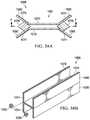
- the end effectorincludes an anvil that includes a first end, a second end, and an anvil face that may be positionable on the first side of the anatomical structure, the anvil having a plurality of anvil-side cord supports; a cartridge housing a plurality of staples and that includes a first end, a second end, and a cartridge face that may be positionable on the second side of the anatomical structure, the cartridge having a plurality of cartridge-side cord supports; and a link that movably couples the first end of the anvil to the first end of the cartridge, wherein the second end of the anvil is movably coupled to the second end of the cartridge, each of the anvil and the cartridge is insertable through a trocar and the end effector may be remotely operable from outside the patient to move at least a portion of one of
- the plurality of anvil-side cord supportsmay have an opening facing away from the cartridge, and the plurality of cartridge-side cord supports may have an opening facing away from the anvil.
- the plurality of anvil-side cord supports and the plurality of cartridge-side cord supportsmay have an open tubular structure with a substantially C-shaped cross-sectional shape.
- the plurality of anvil-side cord supports and the plurality of cartridge-side cord supportshave an open tubular structure with a substantially C-shaped cross-sectional shape, the opening of the C facing away from the cartridge on the plurality of anvil-side cord supports and the opening of the C facing away from the anvil on the plurality of cartridge-side cord supports.
- the plurality of anvil-side cord supports and the plurality of cartridge-side cord supportsmay have a hollow tubular structure and the end effector may include a buttress material, the buttress material having a plurality of openings with a cord slidably positioned within the plurality of openings of the buttress material.
- the cordIn a preponderance of the plurality of openings of the buttress material, the cord may be slidably positioned within at least one of the plurality of anvil-side cord supports and the plurality of cartridge-side cord supports.
- the cartridge-side cord supportsmay be mounted to the cartridge frame.
- At least one of the anvil and the cartridgemay include an elongated slot wherein the end effector has a rigid link that movably couples the first end of the anvil to the first end of the cartridge, wherein the rigid link is retained within the elongated slot such that the rigid link is slidable along the elongated slot in a first direction but limited in motion of the rigid link within the elongated slot in a second direction.
- a surgical instrument to staple an anatomical structure of a patientwhere the anatomical structure has a first side and a second side.
- the surgical instrumentincludes an elongated end effector having a length and a width, wherein the length is at least ten times the width, the length defining a longitudinal direction, the longitudinal direction defining an axial direction substantially perpendicular to the longitudinal direction.
- the surgical instrumenthas an anvil that includes a first end, a second end, a plurality of anvil-side cord supports arranged from about the first end to about the second end, and an anvil face that may be positionable on the first side of the anatomical structure.
- the surgical instrumentfurther includes a cartridge housing a plurality of staples and that includes a first end, a second end, a plurality of cartridge-side cord supports arranged from about the first end to about the second end, and a cartridge face that may be positionable on the second side of the anatomical structure, wherein the second end of the anvil is movably coupled to the second end of the cartridge.
- At least one of the anvil and the cartridgeincludes an elongated slot having its direction of elongation substantially along the longitudinal direction, and a rigid link that movably couples the first end of the anvil to the first end of the cartridge, wherein the rigid link is retained within the elongated slot such that the rigid link is slidable along the elongated slot but substantially limited in motion of the rigid link within the elongated slot in the axial direction.
- the plurality of anvil-side cord supportshave an opening facing substantially away from the cartridge, and the plurality of cartridge-side cord supports have an opening facing substantially away from the anvil.
- the plurality of anvil-side cord supports and the plurality of cartridge-side cord supportsmay have an open tubular structure with a substantially C-shaped cross-sectional shape, where the opening of the C may be facing away from the cartridge on the plurality of anvil-side cord supports and the opening of the C may be facing away from the anvil on the plurality of cartridge-side cord supports.
- the plurality of anvil-side cord supports and the plurality of cartridge-side cord supportsmay have a hollow tubular structure and wherein the end effector may include a buttress material, the buttress material having a plurality of openings with a cord slidably positioned within the plurality of openings.
- the cordIn a preponderance of the plurality of openings of the buttress material, the cord may be slidably positioned within at least one of the plurality of anvil-side cord supports and the plurality of cartridge-side cord supports.
- the plurality of cartridge-side cord supportsmay be mounted to the cartridge frame.
- the buttress materialmay include an adhesive that removably adheres the buttress material to one of the anvil face and the cartridge face.
- a method of using a buttress material with an end effectorincludes the steps of: providing an end effector having an anvil that includes a first end, a second end, and an anvil face, a cartridge housing a plurality of staples and that includes a first end, a second end, and a cartridge face, and a rigid link that movably couples the first end of the anvil to the first end of the cartridge, wherein the second end of the anvil is movably coupled to the second end of the cartridge; providing a buttress material; moving the rigid link to open the anvil face away from the cartridge face; attaching the buttress material to at least one of the anvil face and the cartridge face; moving the rigid link to close the anvil face towards the cartridge after attaching the buttress material; driving the plurality of staples from the cartridge, through the buttress material, and towards the anvil to form the staples; moving the rigid link to open the anvil face away from the cartridge face after driving the staples; and removing the buttress material from the end effect
- the buttress materialmay be formed from a bio-absorbable material.
- the buttress materialmay be attached to at least one of the anvil face and the cartridge face using an adhesive.
- the anvilmay include a plurality of anvil-side cord supports arranged from about the first end to about the second end, the cartridge including a plurality of cartridge-side cord supports arranged from about the first end to about the second end, and the buttress material including a plurality of openings, with a cord slidably positioned within the plurality of openings.
- the methodmay further include one or more of the steps of: sliding the cord from the buttress material into a preponderance of the cord supports when attaching the buttress material to at least one of the anvil face and the cartridge face, and sliding the cord from the buttress material out of the preponderance of the cord supports when removing the buttress material from the end effector; tensioning the cord to align the buttress material with the end effector; and pulling the cord to disengage the buttress material from the end effector by sliding the cord out of the plurality of cord supports and out of the plurality of openings of the buttress material.
- a devicein another embodiment, includes a first jaw having an anvil that includes a first end, a second end, and an anvil face, the anvil having a plurality of anvil-side cord supports; a second jaw having a cartridge housing a plurality of staples and that includes a first end, a second end, and a cartridge face, the cartridge having a plurality of cartridge-side cord supports; a first coupling that couples the first end of the first jaw to the first end of the second jaw; and a second coupling that movably couples the second end of the first jaw to the second end of the second jaw, wherein the second coupling includes a rigid link that is movably coupled to the first and second jaws.
- An outer tubemay extend from the first jaw and the second jaw to an actuator, wherein the actuator moves the outer tube from a first position to a second position, wherein the first position of the tube allows the rigid link to maintain the jaws in an open position, and the second position of the tube moves the rigid link to move the first jaw towards the second jaw.
- the second jawmay have a longitudinal axis, wherein the first coupling includes a pin that rotatably couples the first jaw to the second jaw, wherein the rotation about the pin is transverse to the longitudinal axis.
- the pin that rotatably couples the first jaw to the second jawmay be slidably received within a slot in at least one of the first jaw or the second jaw.
- At least one of the first jaw or the second jawslidably receives the rigid link within a slot as the first jaw is moved toward the second jaw.
- the rigid linkmay be coupled to the first jaw using a slot that allows motion of the rigid link in a first direction but limits motion of the rigid link in a direction perpendicular to the first direction.
- an end effector useful to staple an anatomical structurehaving a first side and a second side.
- the end effectorincludes: an anvil that includes a first end, a second end, and an anvil face that may be positionable on the first side of the anatomical structure, the anvil face including a plurality of rows of staple forming pockets, where a first row of the plurality of rows of staple forming pockets has a first pocket depth and the second row of the plurality of rows of staple forming pockets has a second pocket depth, where the first pocket depth is different from the second pocket depth; a cartridge housing a plurality of staples and that includes a first end, a second end, and a cartridge face that may be positionable on the second side of the anatomical structure; and a staple driver ramp and tissue cutting assembly having a staple driver ramp that moves from the first end of the cartridge to the second end of the cartridge and drives staples from the cartridge towards the anvil to form the staples, the staple driver ramp and tissue cutting assembly further including
- the cartridge facemay include a channel extending from about the second end to about the first end, the channel defining the path of a cutting blade, wherein the pocket depth of the first row of the plurality of rows of staple forming pockets has a first pocket depth that is shallower than the pocket depth of the second row of the plurality of rows, wherein the first row of the plurality of rows of staple forming pockets is closer to the slot than the second row of the plurality of rows of staple forming pockets.
- the anvilmay have an anvil length extending from about the first end of the anvil to about the second end of the anvil, the plurality of rows of the plurality of staple forming pockets extending along the anvil length, wherein in at least one row of the plurality of rows of the plurality of staple forming pockets, a first pocket depth at a first location along the length is different from a second pocket depth at a second location along the length.
- the anvilmay include at least 3 rows of the plurality of staple forming pockets, each one of the at least three rows having the plurality of pocket depths different from the other two of the at least three rows.
- the row of staple forming pockets closest to the channelmay be shallower than row of staple forming pockets farthest from the channel.
- the rows of staple forming pocketsare substantially circular.
- the plurality of staples in a first row of the plurality of rows of staplesmay be manufactured from a first material and the plurality of staples in a second row of the plurality of rows of staples may be manufactured from a second material, wherein the first material is different from the second material.
- the anvilhas an anvil length extending from about the first end of the anvil to about the second end of the anvil, wherein in at least one row of the plurality of rows of the plurality of staple forming pockets, a first pocket depth at a first location along the length is different from a second pocket depth at a second location along the length.
- the pocket depthmay vary continuously along the anvil length.
- the pocket depthin at least one row of the plurality of rows of staple forming pockets, has a first depth for a first portion of the length of the row and a second depth for a second portion of the length of the row. In another embodiment, in at least one row of the plurality of rows of staple forming pockets the pocket depth has a first depth for a first portion of the length of the row and a second depth, deeper than the first depth, for a second portion of the length of the row adjacent the first portion of the length of the row and a third depth for a third portion of the length of the row, shallower than the second depth, the third portion of the length of the row adjacent the second portion of the length of the row.
- the rows of staple forming pocketsmay be substantially circular such as for use in a circular stapler useful for bowel resection, may be linear for a linear cutter, or may be another desired shape.
- the pocket depth variation along the length of a first row of the plurality of rowsvaries in pocket depth at a different scale or rate than a second row of the plurality of rows.
- an end effectorfor stapling an anatomical structure, the anatomical structure having a first side and a second side.
- the end effectorincludes: an anvil that includes a first end, a second end, and an anvil face that may be positionable on the first side of the anatomical structure, the anvil face including a plurality of rows of staple forming pockets, wherein a first row of the plurality of rows of staple forming pockets has a first pocket depth and the second row of the plurality of rows of staple forming pockets has a second pocket depth, wherein the first pocket depth is different from the second pocket depth; a cartridge housing a plurality of staples and that includes a first end, a second end, and a cartridge face that may be positionable on the second side of the anatomical structure; and a staple driver ramp and tissue cutting assembly, wherein the staple driver ramp moves from the first end of the cartridge to the second end of the cartridge and drives staples from the cartridge towards the anvil to form the staples, the staple driver ramp and tissue
- the first row of the plurality of rows of staple forming pocketsmay produce bow-tie shaped staples and the second row of the plurality of rows of staple forming pockets may produce rectangular shaped staples after forming, in one example.
- a first row of the plurality of rows of staplesmay be manufactured from a first material and the plurality of staples in a second row of the plurality of rows of staples may be manufactured from a second material, wherein the first material is different from the second material in another example.
- the first materialmay contain greater than 95% by weight of Titanium and the second material may be an alloy of less than 95% by weight of titanium alloyed with aluminum.
- the first materialmay contain greater than 96% by weight of titanium and the second material may be an alloy of less than 96% by weight of titanium alloyed with aluminum and vanadium.
- the plurality of staples in a first location along the lengthmay be manufactured from a material greater than 95% by weight of titanium and the plurality of staples in a second location along the length may be manufactured from an alloy of less than 95% by weight titanium alloyed with aluminum.
- the row of the plurality of staples closer to the channelhas staples with less springback than the row of the plurality of staples further from the channel.
- an anvilthat includes a first end, a second end, and an anvil face that may be positionable on the first side of an anatomical structure.
- a cartridgehousing a plurality of staples and that includes a first end, a second end, a cartridge length extending from about the first end of the cartridge to about the second end of the cartridge, and a cartridge face that may be positionable on the second side of the anatomical structure.
- the cartridgemay include a plurality of rows of a plurality of staples, wherein the plurality of staples in a first portion of a first row of the plurality of rows of staples may be manufactured from a first material and the plurality of staples in a second portion of the first row of the plurality of rows of staples may be manufactured from a second material, wherein the first material is different from the second material.
- a staple driver ramp and tissue cutting assemblymay have a staple driver ramp that moves from the first end of the cartridge to the second end of the cartridge and drives staples from the cartridge towards the anvil to form the staples.
- the staple driver ramp and tissue cutting assemblymay further include a blade that cuts the anatomical structure after the staples have been formed, with at least a portion of one of the anvil and the cartridge being movable toward the other to clamp the end effector on the anatomical structure.
- the first materialmay contain greater than 96% by weight of titanium, for example, and the second material may be an alloy of less than 96% by weight of titanium alloyed with aluminum and vanadium.
- an end effectoris disclosed that is useful to staple an anatomical structure during a surgical procedure, the anatomical structure having a first side and a second side.
- the end effectorincludes an anvil that has a first end, a second end, and an anvil face that may be positionable on the first side of the anatomical structure, the anvil face including a plurality of rows of staple forming pockets, wherein a first row of the plurality of rows of staple forming pockets has a first pocket shape and a second row of the plurality of rows of staple forming pockets has a second pocket shape, wherein the first pocket shape is different from the second pocket shape.
- a cartridge housing a plurality of staples and that includes a first end, a second end, and a cartridge face that may be positionable on the second side of the anatomical structureis also disclosed.
- a staple driver ramp and tissue cutting assemblyis disclosed as having a staple driver ramp that moves from the first end of the cartridge to the second end of the cartridge and drives staples from the cartridge towards the anvil to form the staples, the staple driver ramp and tissue cutting assembly further including a blade that cuts the anatomical structure after the staples have been formed, with at least a portion of one of the anvil and the cartridge being movable toward the other to clamp the end effector on the anatomical structure.
- the first row of the plurality of rows of staple forming pocketsmay produce bow-tie shaped staples after forming and the second row of the plurality of rows of staple forming pockets may produce rectangular shaped staples after forming, for example.
- a first pocket shape at a first location along the lengthis different from a second pocket shape at a second location along the length in another example.
- a first row of the plurality of rows of staple forming pocketsmay produce bow-tie shaped staples after forming and a second row of the plurality of rows of staple forming pockets may produce rectangular shaped staples after forming in another example.
- the plurality of staples in a first portion of the first row of the plurality of rows of staplesmay be manufactured from a first material and the plurality of staples in a second portion of the first row of the plurality of rows of staples may be manufactured from a second material, wherein the first material is different from the second material.
- FIG. 1depicts the anatomy of a stomach
- FIG. 2Adepicts a perspective view of a stapling device, shown in an open position, having an end effector, an elongated tube, and a handle portion in accordance with one embodiment
- FIG. 2Bdepicts a perspective view of the stapling device of FIG. 2A , shown in a closed position, in accordance with one embodiment
- FIG. 3Ais a partially exploded perspective view of the stapling device shown in FIGS. 2A and 2B ;
- FIG. 3Bis an exploded perspective view of the stapling device shown in FIGS. 2A and 2B ;
- FIG. 4depicts an axial cross-sectional view of the end effector shown in FIG. 2B , taken along section A-A, showing the relationship between a blade, an anvil assembly, and a cartridge assembly of the end effector;
- FIG. 5Adepicts a cross-sectional side view of the handle portion, taken along section B-B, of the stapling device shown in FIG. 2B in a first position;
- FIG. 5Bdepicts a cross-sectional side view of the handle portion, taken along section B-B, of the stapling device shown in FIG. 2B in a second position;
- FIG. 5Cdepicts a cross-sectional side view of the handle portion, taken along section B-B, of the stapling device shown in FIG. 2B in a third position;
- FIG. 5Ddepicts a cross-sectional side view of the handle portion, taken along section B-B, of the stapling device shown in FIG. 2B in a fourth position;
- FIG. 5Edepicts a cross-sectional side view of the handle portion, taken along section B-B, of the stapling device shown in FIG. 2B in a fifth position;
- FIG. 6is a partial perspective view of a blade assembly and a drive mechanism for a surgical device according to one embodiment
- FIG. 7depicts a cross-sectional view of the elongated support tube shown in FIG. 2B , taken along section C-C, illustrating the relationship between the blade assembly and the drive mechanism shown in FIG. 6 , according to one embodiment;
- FIG. 8depicts a partial cross-sectional side view of the handle portion shown in FIG. 2B illustrating the relationship between the blade assembly and the drive mechanism, shown in FIG. 6 , according to one embodiment
- FIG. 9depicts a side view of a proximal end of the end effector shown in FIG. 2A ;
- FIG. 10depicts a partial bottom plan view of an anvil assembly according to one embodiment
- FIG. 11depicts a perspective view of a stapling device, shown in an open position, having an end effector, an elongated tube, a handle portion, and a motor in accordance with an alternate embodiment
- FIG. 12is a partially exploded perspective view of the end effector, elongated tube, and handle portion of the stapling device shown in FIG. 11 ;
- FIG. 13is a partially exploded perspective view of the motor of the stapling device shown in FIG. 11 ;
- FIG. 14Adepicts a side view of the stapling device of FIG. 11 shown in an open position
- FIG. 14Bdepicts a side view of the stapling device of FIG. 11 shown in a closed position
- FIG. 15depicts a side cross-sectional view, taken along section D-D, of the handle portion and the motor shown in FIG. 14A ;
- FIG. 16depicts a side view of the end effector shown in FIG. 14A ;
- FIG. 17depicts a side cross-sectional view, taken along section E-E, of the handle portion and the motor shown in FIG. 14B ;
- FIG. 18depicts a side view of the end effector shown in FIG. 14B ;
- FIG. 19is a sectioned side view of a blade assembly and a drive assembly for a stapling device according to one embodiment
- FIG. 20is a sectioned side view of a blade assembly and a drive assembly for a stapling device according to an alternate embodiment
- FIG. 21is a sectioned side view of a blade assembly and a drive assembly for a stapling device according to an alternate embodiment
- FIG. 22is a partial perspective view of an anvil assembly having an anvil chamfer according to one embodiment
- FIG. 23is a perspective view of a motor controller according to one embodiment
- FIG. 24is an exploded perspective view of the motor controller shown in FIG. 23 ;
- FIG. 25is a partial cross-sectional perspective view of an end effector for a stapling device showing a blade assembly in relationship with a cartridge assembly having a plurality of drivers and staples;
- FIG. 26Ais a side cross-sectional view of an end effector for a stapling device, including an anvil assembly and a cartridge assembly, having a plurality of staple drivers having variable heights combined with a plurality of staples having variable heights according to one embodiment;
- FIG. 26Bis a side cross-sectional view of an end effector for a stapling device, including an anvil assembly and a cartridge assembly, having a plurality of staple drivers having variable heights combined with a plurality of staples having variable heights according to an alternate embodiment;
- FIG. 26Cis a cross-sectional view of an end effector for a stapling device, including an anvil assembly and a cartridge assembly, having a plurality of staple drivers with a first height associated with a plurality of staples having a first height and a plurality of drivers having a second height associated with a plurality of staples having a second height according to one embodiment;
- FIG. 26Dis a cross-sectional view of an end effector for a stapling device, including an anvil assembly and a cartridge assembly, having a plurality of staple drivers having a uniform height combined with a plurality of staples having variable heights according to one embodiment;
- FIG. 26Eis a cross-sectional view of an end effector for a stapling device, including an anvil assembly having an angled anvil plate and a cartridge assembly, the stapling device having a plurality of staple drivers with a uniform height and a plurality of staples having a uniform height;
- FIG. 27is a flow chart depicting a method of operating a stapling device according to one embodiment
- FIG. 28is a partial flow chart depicting a method of operating a stapling device according to one embodiment
- FIG. 29is a partial flow chart depicting the method of operating a stapling device continuing the method of FIG. 28 ;
- FIG. 30is a partial flow chart depicting the method of operating a stapling device continuing the method of FIG. 29 ;
- FIG. 31depicts a perspective view of a stapling device, shown in an open position, having an end effector, an elongated tube, a handle portion, and a motor in accordance with an one embodiment
- FIG. 32depicts a partial exploded perspective view of the stapling device of FIG. 31 shown with a buttress;
- FIG. 33Ais a side view of the stapling device of FIG. 31 shown in an open position
- FIG. 33Bis a side view of the stapling device of FIG. 31 shown in a closed position
- FIG. 34Ais a top view of the buttress shown in FIG. 32 ;
- FIG. 34Bis a partial perspective view of the buttress shown in FIG. 32 ;
- FIG. 35Adepicts a bottom plan view of an anvil assembly of the end effector shown in FIG. 31 ;
- FIG. 35Bdepicts a bottom plan view of the anvil assembly, shown in FIG. 31 , with the buttress of FIG. 32 attached, according to one embodiment
- FIG. 36depicts a perspective view of the stapling device of FIG. 31 , shown with the buttress of FIG. 32 attached, according to one embodiment.
- FIG. 37depicts a partial exploded perspective view of a stapling device, shown in an open position, having an end effector, an elongated tube, a handle portion, and an adhesive-type buttress in accordance with one embodiment
- FIG. 38Ais a cross-sectional view of the adhesive-type buttress, taken along section F-F, shown in FIG. 37 ;
- FIG. 38Bis a perspective view of the adhesive-type buttress, shown in FIG. 37 , with a removable portion removed;
- FIG. 38Cis a front view of the adhesive-type buttress shown in FIG. 38B ;
- FIG. 38Ddepicts a side view of the end-effector of FIG. 37 shown with the adhesive-type buttress attached to the end effector according to one embodiment
- FIG. 38Edepicts a front view of a stomach shown resected with a staple line, coupled with a buttress material, forming a sleeve gastrectomy.
- FIG. 39Ais a bottom view of an anvil assembly for an end effector of a stapling device in accordance with one embodiment
- FIG. 39Bis a cross-sectional view of the anvil assembly illustrated in FIG. 39A , taken along section G-G, in accordance with one embodiment;
- FIG. 39Cis a cross-sectional view of the anvil assembly illustrated in FIG. 39A , taken along section H-H, in accordance with one embodiment
- FIG. 40is a side cross-sectional view of an end effector having an anvil plate with with varying pocket depths according to one embodiment
- FIG. 41is an axial cross-sectional view of an anvil assembly with an anvil plate, shown with a plurality of staples, in accordance with one embodiment
- FIG. 42Ais a side view of a staple formed by the anvil plate of FIG. 40 ;
- FIG. 42Bis a side view of a staple formed by the anvil of FIG. 40 ;
- FIG. 42Cis a side view of a staple formed by the anvil of FIG. 40 ;
- FIG. 43Ais a partial bottom plan view of an anvil assembly having a plurality of anvil pockets in accordance with one embodiment
- FIG. 43Bis a more detailed view of a section of the anvil assembly shown in FIG. 43A ;
- FIG. 43Cis an partial bottom plan view of an anvil for an end effector in having a plurality of anvil pockets in accordance with an alternate embodiment
- FIG. 44is a side view of a staple formed by an anvil assembly in accordance with one embodiment
- FIG. 45is a top view of a staple formed by an anvil assembly in accordance with an alternate embodiment
- FIG. 46is a perspective view of a staple formed by an anvil assembly in accordance with an alternate embodiment.
- FIG. 47is a perspective view of a stapler in accordance with one embodiment having a circular anvil.
- an end effector and/or an endocutter stapling device(collectively referred to as “devices” herein) is disclosed for forming a resection line during resection of an organ, tissue, or other anatomical structure.
- the devicesmay be used during minimally invasive surgical procedures. This application is related to U.S. patent application Ser. No. 15/129,385, which is hereby incorporated herein by reference in its entirety.
- Surgical staplers in accordance with embodiments described hereincan include a handle, an actuator, and an end effector including a clamping mechanism.
- the clamping mechanismcan include a cartridge and an anvil.
- the surgeoncan clamp two members (e.g., the anvil and the cartridge) on the organ and compress the organ therebetween. Once the organ has been compressed, the surgeon can use the stapler to drive or fire staples through the organ.
- a plurality of B-shaped staplescan be formed.
- the stapling devicecan be fired multiple times using multiple cartridges, or in an alternate embodiment a single cartridge can be used with a single firing to complete resection of an organ.
- the integrity of a staple linecan depend, in part, on the proper formation of B-shaped staples when such a staple configuration is desirable.
- Providing a single cartridge and single firing stapling devicemay improve the quality of staple formation over a device or system using multiple cartridges to complete the same procedure. For example, when using an end effector multiple times to staple and resect tissue the previously deployed staples may be contacted by the new staples and/or cutting knife in subsequent applications.
- Providing a single cartridge and staple firingmay help insure that the staple line, and shape of the staples, is consistent.
- a single cartridge and single firing stapling devicemay also provide compression benefits relative to a device and system requiring the use of multiple cartridges. It may be advantageous to provide a single firing stapling device that provide for desirable compression along the length of the tissue to be resected while also providing for a single staple line with properly formed staples.
- a B-shaped stapleis the standard of care for gastrointestinal, vascular, pulmonary, and hepatic applications of surgical tissue fastening devices. Alignment in each of the X, Y, and Z axes of the clamping mechanism with itself (e.g., alignment of the anvil with the cartridge) on each side of the organ may improve staple delivery and formation. It will be appreciated that any suitable structure or mechanism may be incorporated into the stapling devices described herein to provide for such alignment.
- Embodiments of stapling devices described hereinmay include multiple rows of staples such that there is less chance of leaking of lumenal contents between each of the staples and the staple rows.
- a stapling devicemay have from two to six rows of staples, where the staple rows can be bisected by a knife or blade configured to pass between the rows to resect stapled tissue.
- the staple rowscan be spaced apart and/or staggered to reduce the likelihood of leakage.
- Embodiments of stapling devicescan include an anvil and a cartridge, where the cartridge can include recesses retaining a plurality of staples.
- the staplescan be retained above one or more staple drivers that, during operation, can urge each of the plurality of staples upward through tissue into the face of the anvil.
- the anvilwhich can include pockets having any suitable size, number, and dimensions, can cooperate with the cartridge drivers to form, for example, a B-shape within tissue.
- the pockets of the anvilin one embodiment, can be sized to provide a desirable closed staple height that can be determined by the gap between the anvil and cartridge, the depth of the pocket and the height of the staple, and/or the staple driver and the driver mechanism.
- a support or buttress materialthrough which the staples can be deployed.
- the buttress or support materialmay help distribute the pressure of multiple rows of staples, to improve the purchase of the staples in tissue, or to maintain the integrity of a staple line.
- a biodegradable materialcan be provided on the faces of the anvil and/or cartridge through which the staples can be deployed during use. This buttress material, retaining the staples, can then be cut by a blade or knife and, in one embodiment, can be left within a patient.
- Any suitable support or buttress materialsuch as those composed of polymers (both permanent and bioabsorbable) as well as biologic films can be used in accordance with embodiments described herein. These materials can be reversibly coupled to the anvil, the cartridge, or both.
- Methods of attaching the buttress or support material to the anvil or cartridgecan include adhesives, such as hydrogel polymers, where the buttress can be pulled away from the end effector after it has been secured with staples to tissue.
- the end effectormay also include mechanical structures or elements to retain the buttress, such as projections or the like.
- the anvil and/or cartridgecan include a plurality of spaced apart projections, the buttress material can define a plurality of apertures, and a cord or suture can be used to threadedly secure the buttress material with the projections of the anvil and/or cartridge.
- Embodiments of stapling devices described herein, in accordance with a laparoscopic approach,can include inserting the end effector of the stapler through a trocar to perform the surgical procedure.
- minimally invasive surgical proceduresmay include a laparoscopic vertical sleeve gastrectomy. Because the spatial environment for such procedures is limited, surgical stapling devices in accordance with embodiments described herein may have a relative low profile.
- Minimally invasive devices in the prior artare generally long (e.g., 35 mm to 60 mm) and thin (e.g., 5 mm to 15 mm diameter) devices. This long and thin configuration may be necessary to fit through the trocar into the body cavity.
- the limited sizecan present a mechanical issue as B-shaped staple formation typically requires a pressure of about 100 psi. Under these pressures, small, less rigid, staplers may deform and thus prevent proper B-shaped staple formation.
- Prior art devices used in minimally invasive surgical proceduresoften have a fixed hinge at a proximal end. This hinge allows the anvil and cartridge to separate into a V-shaped configuration. Once separated, the surgeon may place the open anvil and cartridge around the organ and then collapse the V onto the organ.
- the length of the anvil and cartridgeincrease, it may be more difficult to maintain alignment between the anvil and cartridge across the length of the tissue. Poor alignment with such designs can be exacerbated at the most distant ends of such devices can be deflected because of the forces necessary to compress the tissue. Because of this deflection, the length of current V-shaped staplers for minimally invasive procedures is limited. As a result of this limitation, the anvil and the cartridge are correspondingly limited in length.
- This limitation on lengthrequires, for larger organs like the stomach, multiple staple reloads and firings to complete a procedure such as a sleeve gastrectomy.
- Each reloadmay require the surgeon to withdraw the stapler from the trocar, reload the cartridge, reinsert, and then reposition the stapler on the organ.
- Such systemsmay require more surgical time, may be more costly, may have an increased likelihood of resulting in an adverse patient event, and may result in a staple line having less integrity.
- Example embodiments described hereincan be used, for example, in a sleeve gastrectomy procedure or resection of the stomach. It will be appreciated, however, that the devices may be used in other procedures involving other anatomical structures. For example, the devices may be used in a parencymal resection, lung volume reduction surgery, or other procedures involving the lung. Further, embodiments described herein may be useful in an anatomic resection, such as, a lobectomy, a non-anatomic parencymal resection, or other procedures involving the liver, or in a partial nephrectomy, total nephrectomy, or other procedures involving the kidney.
- the stomach 10generally includes an inferior end 14 , a superior end 16 , an anterior side 18 , and a posterior side 20 .
- a gastroesophageal junction 22opens into the stomach 10 and is a common landmark in bariatric surgeries.
- a fundus 24 and the section of the stomach 10 defined by a greater curvature 26are generally the parts of the stomach 10 removed during a vertical sleeve gastrectomy.
- the remaining pouch or sleevemay be generally defined by a lesser curvature 28 and the resection line 12 , which presents a stomach with a significantly reduced volume.
- the desired location of the resection line 12may be about 0.5 cm to about 2 cm away from the gastroesophageal junction 22 and about 2 cm to about 10 cm away from a pylorus 30 .
- endocutter stapling devicesmay be utilized to form high quality, consistent resection lines during a vertical sleeve gastrectomy.
- Embodiments of the devicesmay be advantageous because they may be easily positionable laparoscopically, can accommodate different thicknesses of tissue along the resection line length, can be capable of providing uniform compressive pressure on the tissue along the resection line, and can enable a low staple firing force.
- FIG. 2Adepicts a perspective view of a stapling device 100 including an end effector 121 , a support tube 140 , and a handle portion 123 , shown in an open position.
- FIG. 2Bdepicts a perspective view of the stapling device 100 shown in a closed position.
- FIGS. 3A and 3Bdepict an exploded perspective view of the stapling device 100 illustrated in accordance with at least one embodiment.
- the end effector 121 of the stapling device 100can include an anvil assembly 101 and a cartridge assembly 103 .
- the anvil assembly 101can include an anvil frame 102 and an anvil plate 112 .
- the anvil plate 112may be welded to the anvil frame 102 , or may be otherwise attached to the anvil frame 102 or end effector 121 such as by gluing, brazing, sintering, machining, 3D printing or the like.
- the anvil assembly 101can include a longitudinal axis along which the anvil frame 102 and the anvil plate 112 are oriented.
- the anvil plate 112can define an anvil plate channel 137 aligned with the longitudinal axis that can be sized to receive a blade 107 associated with a blade assembly 108 .
- the anvil frame 102 and the anvil plate 112can cooperate to define an anvil blade channel 139 that can be sized to accept a top portion 228 of the blade 107 .
- the anvil blade channel 139can guide the blade 107 as it moves, for example, from a distal first position to a proximal second position within the anvil plate channel 137 .
- the blade 107can transition from a proximal first position to a distal second position.
- the distal end of the end effector 121is coupled in certain embodiments, rather than open, it permits the ability to initially position the blade 107 at the distal end of the end effector prior to use or cutting. Such a position may be advantageous because the blade 107 associated with the blade assembly 108 can be pulled, rather than pushed, to prevent buckling.
- Providing a blade assembly 108 with an elongate beam 226may be beneficial because, as the beam 226 is within the channels of the anvil and the cartridge it can prevent the cartridge from deflecting into the cavity of the channel. Such deflection into the channel may cause staples to be malformed. I-beam portions of the blade may correct for the deflection of the anvil and cartridge structural members that can happen during loading to enable the proper gap for staple formation to be achieved.
- the anvil plate 112can be, for example, from 20 cm to 26 cm in length, from 10 cm to 30 cm in length, from 5 cm to 32 cm in length, from 21 cm to 24 cm in length, or any other suitable length.
- the length of the anvil plate 112is sized such that it can traverse the length of an organ, such as the stomach, for use in a sleeve gastrectomy procedure.
- the anvil plate 112can be 23 cm in length such that it can be used in combination with the cartridge assembly 103 to provide a staple line in accordance with a single firing, single cartridge sleeve gastrectomy procedure.
- the cartridge assembly 103can include a cartridge frame 116 that can retain a cartridge plate 114 and a cartridge 110 .
- the cartridge plate 114may be welded to the cartridge frame 116 , or may be otherwise attached to the cartridge frame 116 or end effector 121 such as by gluing, brazing, sintering, machining, 3D printing or the like.
- the cartridge assembly 103can include a longitudinal axis along which the cartridge frame 116 and cartridge plate 114 can be oriented.
- the cartridge plate 114can define a cartridge channel 143 aligned with the longitudinal axis that can be sized to receive the blade 107 associated with the blade assembly 108 . As illustrated in FIG.
- the cartridge 110can be attached to the cartridge frame 116 by a first cartridge pin 136 at a first end and a second cartridge pin 118 at a second end or, alternately, the cartridge 110 can be attached to the cartridge frame 116 via snap fit, gluing, or other attachment methods.
- the cartridge 110can be, for example, from 20 cm to 26 cm in length, from 10 cm to 30 cm in length, from 5 cm to 32 cm in length, from 21 cm to 24 cm in length, or any other suitable length.
- the length of the cartridge 110is sized such that it can traverse the length of an organ, such as the stomach, for use in a sleeve gastrectomy procedure.
- the cartridge 110can be 23 cm in length such that it can be used in combination with the anvil assembly 101 to provide a staple line in accordance with a single firing, single cartridge sleeve gastrectomy procedure.
- the end effector 121can include a master link 106 that can be used to transition the end effector 121 from a closed position (see, for example, FIG. 2B ), to an open position ( FIG. 2A ), back to a closed position.
- the master link 106can be attached to a first end of the anvil frame 102 , which may be a proximal end of the anvil frame 102 , by a first master link pin 104 such that the first master link pin 104 pivotally and slidably engages a master link slot 105 defined by the anvil frame 102 .
- the master link slot 105can be a channel parallel to the longitudinal axis of the anvil frame 102 , or the master link slot 105 can be angled up or down, or otherwise offset relative to the longitudinal axis of the anvil frame. In certain embodiments, the master link slot 105 can be angled or offset to achieve more (angled away from) or less (angled toward) gap between the anvil assembly 101 and the cartridge assembly 103 . In certain embodiments, where the master link slot 105 is angled or offset, the master link 106 can be configured to stop at any point along the master link slot 105 to change the gap and thus the angle of the anvil assembly 101 relative to the cartridge assembly 103 . Angling the master link slot 105 may also improve closing efficiency for the end effector 121 .
- a second master link pin 138can be used to pivotally couple the master link 106 to a platform 142 as will be described further herein below.
- the cartridge frame 116can be insertable at its proximal end into a support tube 140 , thereby aligning and connecting the end effector 121 of the stapling device 100 to the handle portion 123 of the stapling device 100 .
- the support tube 140can be an elongated member, having a proximal end and a distal end, that can be configured to extend through a trocar (not shown) such that the end effector 121 of the stapling device 100 can access the organ of a patient.
- the support tube 140can be any suitable length such as, for example, from 50 mm to 350 mm, from 100 mm to 350 mm, from 100 mm to 200 mm, from 150 mm to 300 mm, or 100 mm.
- the support tube 140can have an outer diameter from 5 mm to 22 mm and can have a wall thickness from 0.25 mm to 1.5 mm, for example.
- the handle portion 123 of the stapling device 100can be used to facilitate insertion of the end effector 121 into the body cavity of a patient.
- the handle portion 123can include mechanical or motorized components to facilitate actuation of the end effector 121 .
- the handle portion 123can include a right handle half 120 and a left handle half 122 that can be coupled together in a clamshell-like fashion.
- the right handle half 120 and left handle half 122may be joined, for example, by handle nuts 168 , 170 and handle screws 160 , 162 , 164 , or may be ultrasonically welded, press fit, glued, screwed together with self-tapping screws into holes molded into the right handle half 120 , or otherwise assembled.
- the handle portion 123can include a trigger 146 that can be used to actuate and activate the stapling device 100 .
- the trigger 146can include a first mounting feature 148 and a second mounting feature 150 that can be used to attach the trigger 146 such that it is pivotable or moveable relative to the right handle half 120 and left handle half 122 .
- a trigger stop 158can be positioned in handle portion 123 , adjacent the trigger 146 , and can include centering springs 152 , 154 and a reset spring 156 that can be used, respectively, to center and reset the trigger stop 158 in coordination with the use of the trigger 146 .
- One embodiment of the operation of the handle portion 123 and the trigger 146is shown in more detail in FIGS. 5A-5B .
- the tube mount 174 of the support tube 140can engage features in the right handle half 120 and left handle half 122 to couple the support tube 140 to the handle portion 123 .
- the platform 142can be coupled through the support tube 140 to a rack 176 of teeth or other engagement features that can engage a pawl arm 128 .
- the pawl arm 128can be biased toward the rack 176 using a pawl spring 130 .
- the pawl arm 128can be retained at least partially within the handle portion 123 and can include a left release lever 126 and a right release lever 124 that can be used ambidextrously to overcome the bias of the pawl spring 130 and lift a pawl 208 of the pawl arm 128 from the rack 176 .
- an electric motor 192 containing an armature 193can be insertable into a motor mount 194 and can be attached via screws 190 to be used as a driver or actuator.
- the electric motor 192can be selectively removable from the motor mount 194 for reuse by an operator, where the end effector 121 and/or support tube 140 may be single use and disposable.
- the electric motor 192 and a switch 196can be held in the motor mount 194 using a cap 197 and an outer cap 198 .
- the armature 193can be coupled to a rotating member 180 using a gear 186 and a hub 188 .
- a thrust washer 184can be used to provide an abutment for a trigger return spring 181 .
- a switch 134 associated with a switch pad 132can be used in coordination with the switch 196 to engage the electric motor 192 to activate the rotating member 180 .
- the motor mount 194can be mountable into the handle portion 123 using a left mount arm 195 and a right mount arm 199 and can be fixed in place via pins formed in the left handle half 122 and left release lever 126 , using screws such as handle screw 164 , or other holding structures or methods.
- FIG. 5Ais a cross-sectional side view of the handle portion 123 of the stapling device 100 shown in a first open position (see, for example, FIG. 2A ).
- FIG. 5Bis a cross-sectional side view of the handle portion 123 transitioned to a second closed position (see, for example, FIG. 2B ).
- the second mounting feature 150 of the trigger 146can include an elongated slot such that a trigger pin 204 can move within the second mounting feature 150 in a non-load bearing direction while the trigger 146 applies a load to the platform 142 as the trigger 146 is pulled proximally.
- the second mounting feature 150can correspondingly apply a force to the trigger pin 204 that urges the platform 142 proximally.
- the rack 176can be rigidly attached to a proximal end of the platform 142 such that as the trigger 146 is urged proximally the teeth 206 of the rack 176 engage the pawl 208 on the pawl arm 128 to prevent distal movement of the rack 176 and platform 142 .
- the rack 176 and platform 142can be prevented from moving distally until, for example, a left release lever 126 ( FIG. 3 ) or a right release lever 124 ( FIG. 3 ) is pressed to release the pawl 208 from the teeth 206 of the rack 176 .
- the handle portion 123can include a trigger stop 158 having a trigger stop tip 210 .
- the trigger 146can be urged proximally until a trigger edge 212 on the trigger 146 touches the trigger stop tip 210 , which can prevent further proximal movement of the trigger 146 .
- the stapling device 100is in the fully closed position (see, for example, FIG. 2B ).
- the endocuttercan be used to deploy staples and/or transect tissue.
- the stapling device 100can be transitioned to a third pre-firing position.
- the stapling device 100can be fired only after the trigger stop 158 is moved laterally relative to the trigger 146 such that the trigger stop tip 210 is aligned with a trigger release recess 202 .
- the trigger 146can be urged further proximally such that the trigger stop tip 210 enters the trigger release recess 202 .
- the trigger stop 158can be urged laterally by a clinician, for example, by compressing the centering spring 152 or centering spring 154 , to permit the trigger stop tip 210 to move laterally relative to the trigger edge 212 until the trigger stop tip 210 engages the trigger release recess 202 .
- the trigger 146can be urged more proximally to a fourth firing position to actuate a switch 172 that engages the electric motor 192 to drive the blade assembly 108 .
- Driving the blade assembly 108can correspondingly cause the stapling device 100 to provide a staple line while simultaneously cutting tissue.
- a nut 109FIGS. 6 and 7 ) can be coupled to the blade assembly 108 and can transfer a force to the blade assembly 108 from the rotating member 180 as the rotating member 180 is actuated by the electric motor 192 .
- the reset spring 156can urge the trigger stop 158 distally such that the switch 172 disengaged the electric motor 192 is turned off.
- the centering spring 152 and centering spring 154can then re-center the trigger stop 158 and reset the stapling device 100 such that the electric motor 192 cannot be inadvertently reengaged.
- FIG. 6shown is a perspective view of the blade assembly 108 illustrating that the nut 109 can be attached to the blade assembly 108 via a pin 145 , a spot weld, or can be formed monolithically as a unitary construction with the blade assembly 108 .
- the blade 107can be affixed to a distal end of the blade assembly 108 and can be urged, for example, from a distal position to a proximal position to cut tissue during staple formation.
- FIG. 7illustrates a cross-sectional view of one example of the relationship between the support tube 140 , the platform 142 , the nut 109 , and the rotating member 180 . It will be appreciated that any suitable coupling that facilitates the transfer of force from the rotating member 180 to the blade assembly 108 is contemplated.
- the blade 107can be urged proximally to cut tissue while at the same time deploying the staples from the cartridge 110 . It may be advantageous for the blade 107 , supported by an elongate beam 226 , to be positioned at the distal end of the end effector 121 prior to delivering staples and cutting the tissue.
- the elongate beam 226may provide additional support to the cartridge frame 116 during positioning and transition of the end effector 121 from the open position to the closed position.
- the blade 107can include a top portion 228 that can be sized to slidably move within the anvil blade channel 139 and the blade 107 can include a bottom portion 230 that can be sized to slidably move within the cartridge blade channel 141 .
- the top portion 228 and the bottom portion 230 of the blade 107can compress the end effector 121 to provide advantageous compression to the tissue.
- the handle of the stapling device 100can be a control unit from a surgical robot and the stapling device 100 can be actuated remotely using a surgical robot or other electromechanical systems, such as by electric motor, cable and pulley, pneumatic or hydraulic mechanisms.
- FIG. 8is a cross-sectional side view of selected components of the handle portion 123 of the stapling device 100 in accordance with at least one embodiment.
- the rotating member 180can include threaded or spiral cut grooves 214 that can be used to actuate the stapling device 100 . As the rotating member 180 is actuated, corresponding threads on the nut 109 can urge the nut 109 in a proximal or distal direction. The nut 109 , being coupled to the elongate beam 226 of the blade assembly 108 , can advance the blade 107 in a proximal or distal direction.
- FIG. 9is a side view of one end of the end effector 121 in accordance with at least one embodiment.
- the cartridge frame 116is illustrated extending into the support tube 140 , which may provide advantageous stiffness and support for the end effector 121 .
- the cartridge frame 116can include a ramp 216 that can be unitarily formed as a monolithic structure with the cartridge assembly 103 , or may be a separate component that can be affixed to the cartridge frame 116 .
- the ramp 216can be positioned to interfere with a ramp surface 220 of the master link 106 . As the platform 142 is advanced distally, the ramp surface 220 can engage the ramp 216 to urge the master link 106 upward to open the end effector 121 .
- the ramp 216can have any suitable shape and configuration that can cause the master link 106 to open or otherwise space apart the cartridge assembly 103 and the anvil assembly 101 .
- the rampcan be replaced with a spring to bias the master link in an open, or up, position.
- the master link slot 105can be an elongated channel that can be sized such that the platform 142 and master link 106 can move proximally and distally along a longitudinal axis to allow the master link 106 to apply an opening and closing force to the anvil frame 102 .
- the master link slot 105can be sized such that, after the end effector 121 is fully closed and the master link 106 is horizontal within the support tube 140 , the master link slot 105 can permit the trigger 146 to be advanced farther proximally to engage the trigger edge 212 with the switch 172 .
- the master link 106can include a second surface 221 that can contact a tube edge 223 of the support tube 140 as the trigger 146 is actuated.
- the second surface 221can be pushed by the tube edge 223 to move the anvil frame 102 towards the cartridge assembly 103 .
- the ramp surface 220can facilitate opening the stapling device 100 and the second surface 221 can facilitate closing the stapling device 100 for improved action of the stapling device 100 during use.
- coupling the first end of the master link 106 to the platform 142 and the second end of the master link 106 to the anvil frame 102can facilitate actuation of the end effector 121 without requiring actuation of the support tube 140 .
- the master link 106can be pivotally attached at a first end by the first master link pin 104 at a second end of by the second master link pin 138 .
- the master link 106can have a linear configuration or, as shown in FIG. 9 , the master link can have a first linear portion originating at about the second master link pin 138 and a second linear portion connected to the anvil frame 102 via the first master link pin 104 .
- the first linear portion and the second linear portioncan be offset, for example, between 1.5 and 10.0 millimeters, and may be offset by 2.5 millimeters.
- the included angle between the linear portions and the ramp surface 220 and second surface 221can be, for example, from 20 degrees to 50 degrees, or 37 degrees.
- the distance between the first master link pin 104 and the second master link pin 138can be from 10 mm to 50 mm, from 15 mm to 20 mm, or 18 mm.
- the length of the second surface 221can be from 15 mm to 22 mm, from 10 mm to 30 mm, or 18 millimeters from the top of the first linear portion to the top of the second linear portion.
- the master link slot 105can have a length of 4 mm to 9 mm, 3 mm to 8 mm, or 6 mm to provide for desirable movement of the first master link pin 104 within the master link slot 105 .
- the height and width of the master link 106can be from 3 mm to 13 mm, or 6 mm, for example, to provide for strength and rigidity while still fitting within the profile of the end effector 121 .
- the material of the master link 106in combination with the size of the master link 106 , can be selected to ensure the master link 106 can withstand closure loads of, for example, from 10 lbs to 100 lbs.
- the width of the master link 106is 8 mm
- the height of the master link 106is 4.6 mm
- the material of construction for the master link 106is stainless steel.
- FIG. 10depicts a bottom plan view of the anvil assembly 101 according to one embodiment.
- the blade 107is shown positioned at one end of the anvil frame 102 in a first opening 234 .
- the cutting 107can enter the anvil plate channel 137 to cut tissue between the staples.
- the blade 107can enter a second opening 236 that can allow the end effector 121 to be opened.
- the blade 107can be guided through the anvil plate channel 137 to keep the blade 107 centered.
- FIG. 11is a perspective view of a stapling device 300 in accordance with one embodiment.
- the stapling device 300can include an endocutter 308 and a motor assembly 315 .
- the stapling device 300comprising an end effector 321 including an anvil assembly 301 and a cartridge assembly 303 , a support tube 340 and a handle portion 323 .
- the anvil assembly 301can function as a first jaw of the end effector 321 and the cartridge assembly can function as a second jaw of the end effector 321 .
- the end effector 321can be connected to the handle portion 123 via a support tube 340 .
- the handle portion 323can include a handle 311 and a trigger 304 for actuating the stapling device 300 .
- the handle portion 323can include a mode button 324 for switching between operational modes.
- the trigger 304in a first mode, can be pressed upwards to open the jaws (e.g., the anvil and cartridge) or pressed downward to close the jaws.
- the mode button 324can be depressed to transition the stapling device 300 into a firing mode.
- depressing the trigger 304can fire the stapling device 300 to simultaneously form a staple line comprising of one or a plurality of rows of staples while cutting tissue.
- depressing the trigger 304 in the firing modecan deploy a staple line including six rows of staples, where a knife 232 can simultaneously cut tissue between a third and a forth row of the staples.
- FIG. 12depicts an exploded perspective view of the endocutter 308 in accordance with at least one embodiment.
- the anvil assembly 301can include an anvil frame 302 and an anvil plate 312 .
- the anvil plate 312can be welded to the anvil frame 302 , or may be otherwise attached such as by gluing, brazing, sintering, machining, 3D printing or the like.
- a cartridge 310 containing a plurality of staplescan be attached to the cartridge frame 316 by a first cartridge pin 341 at a first end and a second cartridge pin 318 at a second end, or alternately the cartridge 310 can be attached to the cartridge frame 116 via snap fit, gluing, or other attachment methods.
- the cartridge frame 316can be insertable at its proximal end into the support tube 340 to align and connect the end effector 321 of the endocutter 308 to the handle portion 323 .
- a blade assembly 322can include a knife or blade 307 that can be coupled to a rotating member 380 via a bushing.
- the handle portion 323can include a right handle half 320 and a left handle half 322 that can be held together in a clamshell-like fashion.
- the right handle half 320 and left handle half 322can be joined by, for example, ultrasonic welding, glue, screws, gripper pins or press-fit pins fit into holes molded into the handle, or other assembly methods.
- a left handle shell 350 and a right handle shell 352can be used to provide a pleasing aesthetic look to the exterior of the handle portion 323 by covering the left handle half 322 and the right handle half 320 .
- a drive screw 354can be used to drive a control arm 351 via a control arm nut 353 .
- the drive screw 354can be connected to a second drive gear coupler 345 that can engage the motor assembly 315 .
- the rotating member 380can be coupled to the motor assembly 315 via a firing drive gear 366 and a second firing drive gear 369 , where the second firing drive gear 369 can engage the first drive gear coupler 356 that can be coupled with the motor assembly 315 .
- the second firing drive gear 369 and the first drive gear coupler 356can be a single component or feature.
- FIG. 13is a perspective view of the motor assembly 315 in accordance with one embodiment.
- a first electric motor 335 and a second electric motor 337can be provided in a motor housing 313 .
- the first motor gear 363can be coupled with the first drive gear coupler 356 ( FIG. 12 ) and a second motor gear 365 can be coupled with the second drive gear coupler 345 ( FIG. 12 ).
- the motor housing 313can include a left motor housing half 327 and a right motor housing half 316 .
- the motor housing 313can include snaps 317 to couple the motor assembly 315 with the handle portion 323 .
- a strain relief 319can be provided to support wiring to the motor assembly 315 .
- a connector 325can provide for electrically coupling the trigger 304 ( FIG. 12 ) and other electrical components between the motor assembly 315 and the stapling device 300 .
- FIG. 14Ais a side view of the stapling device 300 in accordance with one embodiment showing the end effector 321 in an open position.
- the end effector 321can include a first jaw comprising the anvil assembly 301 and a second jaw comprising the cartridge assembly 303 .
- the end effector 321can include a master link 306 operably coupled with the motor assembly 315 .
- FIG. 14Bis a side view of the stapling device 300 showing the end effector 321 in a closed position.
- the end effector 321in its closed position, can be ready for firing, which can include deploying staples and/or cutting tissue.
- the end effector 321can include a blade 307 ( FIG. 12 ) to cut tissue while deploying staples.
- FIG. 15depicts a cross-sectional side view of the handle portion 323 of the stapling device 300 in the open position (e.g., the position shown in FIG. 14A ).
- a second drive gear coupler 345 for opening and closing the end effector 321can be coupled to the second motor gear 365 ( FIG. 13 ) associated with the second electric motor 337 .
- the second drive gear coupler 345can rotate the drive screw 354 to open and close the end effector 321 to transition the end effector 321 between an open position to a close position, and vice versa.
- the control arm nut 353is shown in its distal-most position on the drive screw 354 such that the master link 306 is fully extended and the end effector 321 is in the open position.
- a control arm distal limit switch 368can be contacted by the control arm nut 353 in the illustrated position, when the end effector 321 is in the fully open position, to interrupt power to the second electric motor 337 .
- the first drive gear coupler 356can be coupled to the second motor gear 365 to deploy staples from the stapling device 300 while simultaneously cutting tissue.
- FIG. 16depicts a side view of the end effector 321 of the stapling device 300 shown in the open position.
- the master link 306can be attached to a first end of the anvil frame 302 by a first master link pin 320 such that the first master link pin 320 can pivotally and slidably engage master link slot 305 .
- the master link slot 305can be a channel parallel to the longitudinal axis of the anvil assembly 301 , or the master link slot 305 can be angled up or down relative to this longitudinal axis.
- a second master link pin 338can be used to pivotally couple the master link 306 to the control arm 351 .
- FIG. 17depicts a cross-sectional side view of the handle portion 323 of the stapling device 300 shown in the closed position.
- the control arm nut 353is illustrated in its proximal-most position on the drive screw 354 such that the anvil assembly 301 is closed relative to the cartridge assembly 303 .
- the control arm nut 353can travel proximally until it contacts a proximal limit switch 355 .
- the control arm nut 353 contacts the proximal limit switch 355it can interrupt power to the second electric motor 337 .
- the stapling device 300can be configured such that it cannot transition into a firing mode until the control arm nut 353 engages the proximal limit switch 355 to ensure that the stapling device 300 is in the closed position before firing.
- FIG. 18depicts a side view of the end effector 321 of the stapling device 300 shown in the closed position.
- the master link 306is illustrated as inserted partially into the support tube 340 such that the anvil assembly 301 and the cartridge assembly 303 are in a closed position ready for firing.
- FIG. 19is a side view of a drive assembly 460 for simultaneously stapling and cutting tissue.
- the drive assembly 460can include a blade assembly 408 including a blade 407 coupled to a beam 426 .
- the beam 426can include a nut 409 that can threadedly engage a rotating member 480 .
- the rotating member 480can be operably coupled with the first electric motor 412 such that rotation of the rotating member 480 urges the nut 409 proximally.
- activating the first electric motor 412can urge the nut 409 proximally such that the beam 426 and blade assembly 408 are correspondingly moved in a proximal direction.
- a cutting edge 432 on a blade 407can transection tissue.
- the blade 407can include a top portion 428 and a lower portion 430 that can compress an anvil and a cartridge of an end effector when urged proximally.
- the nut 409when the blade assembly 408 is pulled to its proximal-most position the nut 409 can engage a firing complete limit switch 468 .
- power to first electric motor 412can be interrupted.
- the nut 409can be attached to the blade assembly 408 or beam 426 in any suitable fashion such as via a pin, a spot weld or other attachment method.
- the nut 409can be formed monolithically as a unitary structure with the blade assembly 408 or the beam 426 .
- FIG. 20is a side view of a drive assembly 560 for opening and closing an anvil assembly 501 according to one embodiment.
- Anvil assembly 501can be moveably coupled with a master link 506 , where the master link 506 can be pivotally coupled with a distal end of a platform 542 .
- the master link 506includes a first master link pin 504 that can engage a master link slot 505 positioned at the proximal end of the anvil assembly 501 .
- the first master link pin 504can translate within the master link slot 505 to facilitate opening and closing of the anvil assembly 501 .
- a proximal end of the platform 542can include a drive nut 567 that can threadedly engage a drive screw 554 .
- the drive nut 567 and the drive screw 554can be coupled such that rotation of the drive screw 554 in a first direction urges the drive nut 567 proximally and rotation of the drive screw 554 in a second direction urges the drive nut 567 distally.
- a proximal end of the drive screw 554can be coupled with a second motor gear 565 that is rotationally coupled with a second electric motor 514 .
- the second electric motor 514can rotate the drive screw 554 clockwise or counterclockwise to open and close the anvil assembly 501 , respectively.
- the drive assembly 560can include a distal limit switch 557 and a proximal limit switch 555 .
- the drive nut 567can be in its distal-most position such that it contacts the distal limit switch 557 to interrupt power to the second electric motor 514 .
- the drive nut 567can be in its proximal-most position such that it contacts the proximal limit switch 555 to interrupt power to the second electric motor 514 .
- FIG. 21is a side view of a drive assembly 660 for opening and closing an anvil assembly 601 according to an alternate embodiment.
- Anvil assembly 601can be moveably coupled with a master link 606 , where the master link 606 can be pivotally coupled with a distal end of a platform 642 .
- the anvil assembly 601can include a distal slot 669 that can engage a pin (not shown) positioned at the distal end of the anvil assembly 601 to allow for movement of the pin within the distal slot 669 to facilitate opening and closing of the drive assembly 660 .
- the proximal end of the anvil assembly 601can include a fixed pin 604 that can pivotally couple the anvil assembly 601 and the master link 606 .
- a proximal end of the platform 642can include a drive nut 667 that can threadedly engage a drive screw 654 .
- the drive nut 667 and the drive screw 654can be coupled such that rotation of the drive screw 654 in a first direction urges the drive nut 667 proximally and rotation of the drive screw 654 in a second direction urges the drive nut 667 distally.
- a proximal end of the drive screw 654can be coupled with a second motor gear 665 that is rotationally coupled with a first electric motor 614 .
- the first electric motor 614can rotate the drive screw 654 clockwise or counterclockwise to open and close the anvil assembly 601 , respectively.
- the drive assembly 660can include a distal limit switch 657 and a proximal limit switch 655 .
- the drive nut 667can be in its distal-most position such that it contacts the distal limit switch 657 to interrupt power to the first electric motor 614 .
- the drive nut 667can be in its proximal-most position such that it contacts the proximal limit switch 655 to interrupt power to the first electric motor 614 .
- FIG. 22is a perspective view of a distal portion of an anvil frame 701 according to one embodiment.
- the anvil frame 701can include a bevel feature, such as an anvil chamfer 771 , that can guide the anvil frame into a channel 702 in a cartridge assembly 703 to help ensure alignment during closure.
- Tissue between the jawsmay be thicker on one side than the other of the end effector, where the anvil chamfer 771 may assist with alignment if non-uniform tissue causes slight miss-alignment before closing the jaws of the end effector.
- One or a plurality of bevelscan act as a lead-in feature that can work to align the end effector to help ensure that staples are properly deployed in varying tissue thicknesses.
- FIG. 23is a perspective view of a motor controller 870 according to one embodiment.
- the motor controller 870can include a controller housing 872 having an on/off switch 874 , a display 875 and a device cable connector 876 .
- the on/off switch 874may provide for wall power, such as 110 Volt or 220 Volt AC power from a wall outlet, or may provide for battery power to the motor controller 870 .
- the device cable connector 876may connect multiple wires from the motor assembly of a stapling device to the motor controller 870 .
- the device cable connector 876may provide positive and negative voltage wires to a first electric motor (e.g. first electric motor 335 shown in FIG.
- a second electric motor 337e.g., second electric motor 337 shown in FIG. 13
- wires to a triggere.g., trigger 304 shown in FIG. 12
- FIG. 24is an exploded perspective view of the motor controller 870 according to one embodiment.
- a lid 873which can be part of the controller housing 872 , can contain the components inside the controller housing 872 .
- wall powercan be brought into the controller housing 872 via an electrical inlet 878 .
- a fan 880may also be included to cool the interior of the controller housing 872 .
- a pair of speakers 882can be provided to inform the user of the stapling device conditions, such as, for example, jaws open, jaws closed, firing complete, ready to fire or other useful information.
- the display 875can be used to provide visual directions, data, error conditions, instrument identification, or other useful data.
- a motor controller board 828can provide electrical power to the first electric motor 335 ( FIG. 13 ) or the second electric motor 337 ( FIG. 13 ) when appropriate.
- the motor controller board 828can be directed by a processor board 830 to turn on or off the first electric motor 335 or the second electric motor 337 .
- the processor board 830can contain a processor, such as an ARM processor or other processor, useful in controlling a stapling device.
- the processor board 830can contain software that reads the condition of the limit switches 555 , 557 , 368 ( FIGS. 15 and 20 ) and the trigger 304 ( FIG. 12 ) and can control the motor controller board 828 to, for example, open and close the jaws, fire the system, or perform other useful functions.
- the ARM processorcan be used to communicate with an endocutter (for example, stapling device 100 shown in FIGS. 2A and 2B ).
- the stapling device 100may include an EEPROM or other memory retaining device that can be encoded with a serial number during manufacturing.
- the memorycan be used to provide information to the motor controller.
- the processorcan be capable of measuring and recording opening and closing motor amperage during activation on the manufacturing line; firing motor amperage during activation on the manufacturing line; opening and closing motor amperage in clinical use; firing motor amperage during activation in clinical use, or other data useful to the manufacturer or operator. This data can also be relayed to the motor controller 870 and stored.
- Such informationcan also be displayed during firing to the user by way of a connection of the motor controller 870 to a screen or display that can be incorporated into the stapling device 100 , in the motor controller 870 , or the data may be transmittable to a monitor used by a laparoscopic camera in a minimally invasive procedure.
- FIG. 25depicts a sectioned perspective view of a portion of the end effector 321 of the stapling device 300 shown in FIG. 11 .
- a plurality of staple drivers 332can be positioned in a cartridge 310 beneath a plurality of staples 334 in a plurality of staple pockets 336 .
- the anvil frame 302can include an anvil channel 344 that can accept a top portion 328 of blade 307 .
- a staple driver ramp 343can slide or otherwise move past a plurality of driver ramp slots 342 . As the stapling device 300 is fired, the staple driver ramp 343 can engage the staple drivers 332 to drive the staples 334 into the anvil assembly 301 .
- the cutting edge 339 of the blade 307can transect the tissue retained between the anvil assembly 301 and the cartridge assembly 303 .
- Staple driver 332 heightscan range from 1.5 mm to 4.5 mm, for example, and staple 334 lengths can range from 3.0 mm to 5.0 mm, for example.
- relatively tall drivers and short staplescan be used for thin tissue and relatively short drivers can be used with long staples for thick tissue.
- FIG. 26Ais a cross-sectional side view of an end effector 321 of a stapling device 300 according to one embodiment.
- an anvil plate 312is flat and a cartridge 310 includes three staple driver 332 heights in sections 390 , 391 , and 392 , that are sized to drive equal length staples 334 .
- Providing section 390e.g., 2.2 mm driver height to form a 1.2 mm formed staple
- section 391e.g., 2.7 mm driver height to form a 1.7 mm formed staple
- section 392e.g., 3.2 mm driver height to form a 2.2 mm formed staple
- a taller driver heightcan create a staple through a thinner tissue thickness while a shorter driver height can provide a staple appropriate for thicker tissue.
- the cartridge 310 clamping surfacecan be angled relative to the anvil, such as from 0.1 degrees to 0.35 degrees, or 0.25 degrees, to provide uniform compression on the stomach, which has non-uniform tissue thickness.
- FIG. 26Bis a cross-sectional side view of the end effector 321 assembly of the stapling device 300 according to an alternate embodiment.
- the anvil plate 312is flat and the cartridge 310 can include three staple driver 332 heights in sections 390 , 391 , and 392 that can drive three or more different length staples 334 .
- FIG. 26Cis a cross-sectional side view of the end effector 321 of the stapling device 300 according to an alternate embodiment.
- the anvil plate 312can be angled and the cartridge 310 can include identical staple driver 332 heights.
- the cartridge 310can include two different staple 334 lengths, where longer leg length staples (e.g., 4.4 mm) can be provided in a proximal portion of the cartridge 310 and shorter leg length staples (e.g., 3.8 mm) can be provided in a distal portion of the cartridge 310 .
- equal length staplescan used along the entire length of the cartridge 310 .
- different staple lengthscan be used in different rows or within a row at different locations along the length of the stapling device 300 to accommodate tissue thickness.
- Row to row variationscan account for variation in tissue thickness on a patient-to-patient basis.
- Changing staple height within a rowcan account for the change in tissue thickness that can occur from one end of the stomach to the other.
- Providing an anvil plate 312 that is angledmay be advantageous when stapling different thickness tissue to provide uniform tissue compression from the distal-most portion to the proximal-most portion of the cartridge 310 as the stapling device 300 is fired.
- FIG. 26Dis a cross-sectional side view of the end effector 321 of the stapling device 300 according to an alternate embodiment.
- the anvil plate 312is angled and the cartridge 310 includes a single staple driver 332 height to drive variable length staples 334 .
- Any suitable number of different staple heightscan be combined with the anvil plate 312 having a slope to provide desirable tissue compression and a staple line with high integrity.
- the cartridgecan include three different staple heights positioned along thirds of the cartridge 310 .
- FIG. 26Eis a cross-sectional side view of the end effector 321 of the stapling device 300 according to an alternate embodiment.
- the anvil plate 312is angled and the cartridge 310 can include staples having a uniform length. Any suitable combination of anvil plate angle, driver height, and staple heights is contemplated.
- FIG. 27depicts a Method 250 of operating the end-effector portion of an endocutter (for example, stapling device 300 ) according to one embodiment.
- Method 251may provide for safe and effective activation and use of the stapling device. Steps illustrated in FIG. 27 may be implemented in software on the processor board 830 ( FIG. 24 ), in firmware, using a programmable gate array, or by other suitable methods for implementing logic control.
- the Method 251includes an On/Off Mode 205 , a Closure System Mode 207 , a Firing System Mode 209 , an Idle System Mode 211 and a Manufacturing Knife Reset Mode 213 .
- the On/Off Mode 205can include delivering or eliminating power to the stapling device 100 .
- the Closure System Mode 207can provide for opening and closing of the end effector, jaws, or anvil and/or anvil and cartridge of a stapling device to provide for placement and adjustment of the endocutter on tissue.
- the Firing System Mode 209can include safety and detection steps to provide for complete and effective firing of the staples.
- the Idle System Mode 211can communicate function and options to the user, as well as waiting for user direction.
- the Idle System Mode 211can include use of a programmable memory, such as an EEPROM provided in the connector or handle that communicates information about the instrument to the controller.
- the Manufacturing Knife Reset Mode 213may be useful during the testing and manufacturing of an endocutter to verify functionality during manufacturing and to position components properly for use.
- the Firing System Mode 209can include feedback to the operator regarding exceeding limits, such as compression limits, motor drive limits, tissue thickness limits or other limits useful to the operator.
- motor currentmay be monitored by the controller, and when a predetermined motor current level is reached, the controller may provide feedback to the operator that the motor is reaching its load limit such that the operator can make a decision to alter the procedure or perform some other action.
- an endocutter or stapling device system in accordance with embodiments described hereinmay have a unique serial number or other identifier to allow the operator to record the particular serial number of the instrument used in a patient's record.
- the controllerWhen an instrument is plugged into the controller, such as motor controller 870 , the controller may communicate with the memory and provide the serial number on a display of the controller.
- the memorymay also be used to record information regarding the use of the instrument. For example, an event log may be recorded into the memory from the controller that records motor load, number of openings or closings of the instrument, number of firings of the instrument, error codes or other useful information onto the memory for later review.
- FIG. 28is a flow chart illustrating a Method 251 according to one embodiment.
- Method 251can include a System Ready State 252 leading to a Closure Switch Active/All Other Switches Inactive Decision 253 .
- Switchesmay include, for example, mode button 324 , proximal limit switch 555 , distal limit switch 557 , or other useful switches. If the closure switch is active and any other switch is also active, then the system can enter an Error State 254 . If no switches other than the closure open switch are active, then the system can enter a Closure System Mode 255 . From the Closure System Mode 255 , the Method 251 can then perform a Trigger Read 256 , and determines whether the trigger is in a trigger up or trigger down state.
- a Closure-Open Switch Activated Decision 257can occur. If the Closure-Open Switch Activated Decision 257 is NO, a Motor Opens Device Condition 259 can occur and then another Trigger Read 256 can occur. If the Closure-Open Switch Activated Decision 257 is YES, then a Device Open Condition 258 can occur.
- a Closure Closed Switch Activated Decision 261can be made. If the Closure Closed Switch Activated Decision 261 is NO, then a Motor Closes Device 260 condition can occur, and another Trigger Read 256 can follow. If the Closure Closed Switch Activated Decision 261 is YES, then a Device Closed Condition 262 can occur. Many conditions, such as, for example, the Device Closed Condition 262 , can provide feedback to the operator regarding the device, such as by blinking an LED light, providing an audible sound, or other feedback type. For example, audio files may be created and provided at times during the Method 251 to provide information to the user regarding system states, conditions, errors, or functionality of the stapling device 100 . The Method 251 in FIG. 25 can continue at Link 263 to FIG. 29 .
- FIG. 29is a flow chart illustrating the Method 251 , starting at the Link 263 that links the portion of the Method 251 from FIG. 28 to the portion of the Method 251 illustrated in FIG. 29 .
- the Method 251can utilize a Safety Switch 264 to make sure that the operator intends to fire the endocutter before a Firing System Mode 265 is enabled.
- a suitable Safety Switch 264may be, for example, mode button 324 shown in FIG. 11 . If the Firing System Mode 265 is enabled, then a Firing Started Decision 266 can be made.
- Firing Started Decision 266If the Firing Started Decision 266 is NO, then both a Safety Switch 268 active condition and a Trigger Up 267 condition are both met before a Closure System Mode 271 can be entered. If the Firing Started Decision 266 is YES, then a Trigger Down Condition 269 can precede a Firing Limit Switch Activated Decision 283 . If the Firing Started Decision 266 is YES, then a Trigger Down Double-Click 270 can precede an Activate Firing Motor Condition 272 . During the Activate Firing Motor Condition 272 , the endocutter can fire and resect tissue until a Firing Limit Switch Activated Decision 283 determines that the firing limit switch is active.
- Firing Limit Switch Activated Decision 283is YES, then a Firing Motor Stops Condition 274 can be entered, the firing motor stops, and the Method 251 can enter a Firing Completion Mode 279 and then enter an Idle System Mode 280 . If the Firing Limit Switch Activated Decision 283 is NO then Firing Motor Continues Condition 273 can occur until the firing limit switch activates, such as, for example, proximal limit switch 555 .
- the Idle System Mode 280is further described below with reference to FIG. 30 .
- FIG. 30is a flow chart illustrating the Method 251 , beginning at the Idle System Mode 280 .
- the systemcan idle until a Trigger Up Condition 281 or a Trigger Down Condition 282 occurs.
- a Trigger Up Condition 281can prompt a Closure-Open Switch Activated Decision 284 . If the Closure-Open Switch Activated Decision 284 is YES, the closure motor is stopped and a Device Open Condition 289 can occur. If the Closure-Open Switch Activated Decision 284 is NO, then the motor can continue to open the endocutter until the trigger is released or the closure open switch is activated.
- a Trigger Down Condition 282can prompt a Closure-Closed Switch Activated Decision 286 .
- the Closure-Closed Switch Activated Decision 286is YES, the losure motor can be stopped and a Device Closed Condition 290 can occur. If the Closure-Closed Switch Activated Decision 286 is NO, then the motor can continue to close the endocutter until the trigger is released or the closure closed switch is activated.
- FIG. 31is a perspective view of a stapling device 900 in accordance with one embodiment.
- the stapling device 900can include an endocutter 908 and a motor assembly 915 .
- the endocutter 908can include an end effector 921 including an anvil assembly 901 and a cartridge assembly 903 , or a first jaw and a second jaw respectively, for the clamping, stapling, and/or resection of tissue.
- the end effector 321can be connected to a handle portion 923 via a support tube 940 .
- the handle portion 923can include a handle 905 including a trigger 904 for actuating the stapling device 900 .
- the handle portion 923can include a mode button 924 for switching between operational modes.
- the trigger 904in a first mode, can be pressed upwards to open the jaws or pressed downwards to close the jaws.
- the mode button 924can be depressed, changing the trigger 904 function from and open/closed mode to a firing mode.
- depressing the trigger 904can fire the stapling device 900 to simultaneously form a staple line while cutting tissue between the staple line.
- the stapling device 900can include a buttress assembly comprising, in part, a plurality of cord supports 988 positioned on the cartridge assembly 903 and the anvil assembly 901 to provide for the attachment of a buttress material 991 ( FIG. 32 ) to the stapling device 900 .
- the cord supports 988may be useful for attaching the buttress material 991 before or during surgery.
- the buttress material 991can be used to add support and purchase to the staple line to provide improved sealing to the cut tissue as the staples are formed.
- the buttress material 991may be formed from absorbable or non-absorbable material for either temporary or permanent applications.
- the cord supports 988can be used to hold the buttress material 991 on the stapling device 900 until after the staple line is formed, at which point a cord 387 ( FIG. 32 ) can be released to allow the buttress material 991 to separate from the cord supports 988 and the stapling device 900 .
- the cord supports 988can be built into the anvil assembly 901 or cartridge assembly 903 such that the buttress material 991 can be attached to the stapling device 900 prior to or during a procedure by, for example, threading a suture material or cord 987 through loops 999 in the buttress material 991 and over or around the cord supports 988 .
- FIG. 32depicts an exploded perspective view of the stapling device 900 in accordance with one embodiment.
- the anvil assembly 901can include an anvil frame 902 and an anvil plate 912 .
- the cartridge assembly 903can include a cartridge frame 916 and a cartridge 910 .
- the cartridge 910may be attached to the cartridge frame 916 by a first cartridge pin 936 at a first end and a second cartridge pin 918 at a second end, or alternately the cartridge 910 may be attached to the cartridge frame 916 via snap fit, gluing, or other attachment methods.
- the cartridge frame 916can be insertable at its proximal end into a support tube 940 to align and connect the end effector 921 of the stapling device 900 to a handle portion 923 of the stapling device 900 .
- a blade assembly 922can include a blade 907 coupled to a rotating member 980 via a nut 909 .
- the handle portion 923can include a right handle half 920 and a left handle half 922 that can be held together in a clamshell-like fashion.
- the right handle half 920 and left handle half 922can be joined by, for example, ultrasonic welding, glued, screwed together with self-tapping screws, gripper pins or press-fit pins into holes molded into the handle or other assembly method.
- a left handle shell 950 and a right handle shell 952can be used to provide a pleasing aesthetic look to the exterior of the handle portion 923 by covering the left handle half 922 and the right handle half 920 .
- a drive screw 954can be used to drive a control arm 951 via a control arm nut 953 .
- the drive screw 954can be connected to a drive gear coupler 955 that can engage the motor assembly 915 ( FIG. 31 ).
- the rotating member 980is illustrated as coupled to a drive gear coupler 956 via a first firing drive gear 966 and a second firing drive gear 969 .
- the drive gear coupler 956can be coupled with the motor assembly 915 .
- the cord supports 988can be attached to the cartridge 910 , or to the cartridge frame 916 as illustrated in FIG. 31 .
- the cord supports 388can include lateral projections, hoops, tabs, hooks, loops, or other suitable structure to retain the buttress material 991 .
- the buttress material 991can have the cord 987 integrated into the buttress material 991 to provide support and to hold the buttress material 991 onto the cartridge 910 .
- the cord supportsmay be tubular shaped, having a “C” shaped cross-section (not shown), such that the cord supports are not completely closed.
- the open “C” shapecan allow for the attachment of the buttress material to the end effector by pulling the cord over the tubular shape and allowing the cord to slip into the opening of the “C” to hold the buttress material in place.
- Cord supports 988can be provided on the anvil frame 902 or on the anvil plate 112 .
- the cord 987can be, for example, suture material, wire cable, wire strand, individual wire, rope, monofilament, thread or other suitable material.
- FIG. 33Ais a side view of the stapling device 900 in accordance with one embodiment having an open end effector 921 .
- the end effector 921can include the anvil assembly 901 , the cartridge assembly 903 , and the master link 906 .
- the end effector 921is illustrated before installation of the buttress material 991 .
- the buttress material 991can be provided already attached to the end effector 921 from the supplier, or the buttress material 991 can be placed on the end effector 921 , in the open position, during the surgical procedure.
- the buttress material 991can be provided in a sterile package and can be opened in the sterile field during the surgical procedure.
- the cliniciancan then apply the buttress material 991 to the anvil or cartridge with the stapling device 900 in the fully open position and thread or loop the cord 987 on or through the cord supports 988 to hold the buttress material 991 in place.
- the stapling device 900can be closed such that the end effector 921 can fit through a trocar into the operative site.
- FIGS. 34A and 34Billustrate the buttress material 991 shown with the cord 987 engaged with the plurality of loops 999 .
- the apertures 984 defined by the buttress material 991can be spaced between the loops 999 and can be sized and positioned to correspond with the cord supports 988 on the end effector 921 .
- the buttress material 991can have any suitable size and shape to engage with and selectively retain the cord 987 or any other suitable buttress material retention mechanism or structure.
- the cord 987can be a single suture threaded through the loops 999 , or the use of multiple cords or sutures to secure the buttress material is also contemplated.
- FIG. 35Aillustrates the anvil assembly 901 shown with a plurality of cord supports 988 prior to attachment of the buttress material 991 .
- FIG. 35Billustrates the anvil assembly 901 with the buttress material 991 attached to the cord supports 988 with the cord 987 according to one embodiment.
- FIG. 36illustrates a perspective view of the stapling device 900 with the buttress material 991 attached to the anvil assembly 901 and the cartridge assembly 903 with the cord 987 .
- the stapling device 1000can include a buttress 1088 having an adhesive that can be positioned on the cartridge assembly 1003 and the anvil assembly 1001 .
- the buttress 1088can include a buttress material 1091 and one or a plurality of adhesive portions 1090 that can be used to couple the buttress material 1091 to the anvil assembly 1001 or cartridge assembly 1003 .
- the buttress 1088can be used to add support and purchase to the staple line to provide improved sealing to the transected tissue as the staples are formed.
- the buttress material 1091can be formed from absorbable or non-absorbable material for either temporary or permanent applications.
- the adhesive portions 1090can be used to hold the buttress material 1091 on the stapling device 1000 until after the staple line is formed, at which point the staple line can retain all or a portion of the buttress material 1091 on the tissue.
- the buttress material 1091can be two-ply such that it includes an anvil buttress portion 1070 and a cartridge buttress portion 1072 .
- the buttress 1088can include a pair of removable portions 1076 that can couple the anvil buttress portion 1070 to the cartridge buttress portion 1072 prior to use.
- the removable portions 1076can be adhesively attached to the buttress 1088 , or can be attached with frangible portions or the like.
- the removable portions 1076are pliable such that by pushing laterally inward on each of the removable portions 1076 the adhesive portions 1090 can pivot radially inward to contact the sides of the end effector 1021 (see, for example, FIGS. 38B-38C ).
- the buttress 1088can be positioned in the end effector 1021 , a backing material 1074 can be removed to expose the adhesive portions 1090 , the removable portions 1076 can be urged inward such that the adhesive portions 1090 are adhesively coupled with the end effector 1021 , and the removable portions 1076 can then be removed such that the anvil buttress portion 1070 is separated from the cartridge buttress portion 1072 .
- the removable portions 1076can be removed to allow adhesive portions 1090 to flex such that each adhesive portion 1090 can engage a side of the end effector 1021 for attachment.
- the buttress material 1091can include four adhesive portions 1090 that can flank the buttress material 1091 .
- the anvil buttress portion 1070 and the cartridge buttress portion 1072can be sized such that each covers all or a portion of an anvil face 1012 and a cartridge face 1014 , respectively, of the end effector 1021 .
- the adhesive portions 1090can be sized such that each can be folded to adhere to the sides of the anvil assembly 1001 or the cartridge assembly 1003 as shown in FIG. 38D .
- each of the adhesive portions 1090can include the backing material 1074 .
- the backing material 1074can be coupled with one or more removal threads 1093 ( FIG.
- a portion of the staple linecan form a sleeve gastrectomy in cooperation with the buttress material.
- Varying pocket depthmay improve the ability to achieve a minimum acceptable level of compression without over-compressing tissue. Varying pocket depth may also mitigate the risk associated with the malformation of staples which can occur when there is a tissue thickness and staple height mismatch.
- FIG. 39Ais a bottom view of an anvil assembly 1101 in accordance with one embodiment.
- an anvil plate 1112is illustrated with six rows of anvil pockets including first pocket row 1115 , second pocket row 1117 , third pocket row 1119 , fourth pocket row 1159 , fifth pocket row 1161 , and sixth pocket row 1163 .
- the staple pockets 1134 in the anvil plate 1112can be shaped to receive and shape the tips of staples as the staples are driven into the anvil plate 1112 . When the staples engage with the anvil plate 1112 , the tips of each staple can be directed until each has a substantially B-shaped configuration (see, for example, FIGS. 42A-42C ).
- the staple pockets 1134can be machined into the anvil plate 1112 , eroded into the anvil plate 1112 using an EDM process, created using a precise electrochemical machining (PEM) process, formed using a sintering process, molded using a metal injection molding process, or otherwise manufactured.
- EDMelectrochemical machining
- the anvil plate 1112can be divided into a left anvil half 1111 and a right anvil half 1113 separated by a knife channel 1138 . It will be appreciated that any suitable number of pocket rows having any suitable size, shape, and orientation are contemplated. In the illustrated example of FIG. 39A , the first pocket row 1115 and the second pocket row 1117 are spaced more closely together than the third pocket row 1119 . Similarly, the fourth pocket row 1159 and the fifth pocket row 1161 are spaced more closely together than the sixth pocket row 1163 . It is understood that any spacing may be used between the rows, and that the spacing on the left anvil half 1111 may differ from the spacing on the right anvil half 1113 .
- each of the staple rowsis parallel to a longitudinal axis of the anvil assembly 1101 , and extends from a proximal end to distal end of the anvil assembly 1101 , but one or more rows may be offset and have any suitable length.
- Staple rowscan be staggered relative to each other in an overlapping fashion such that the middle of the staple in one row is between two staples in an adjacent row.
- a non-symmetrical stagger (not shown) of the staple rows on the left anvil half 1111 and the right anvil half 1113may be useful in some procedures, such as in a sleeve gastrectomy procedure, where tissue is removed along one side of a cut and a gastric sleeve is formed on the other side of the cut.
- the integrity of the portion of the staple line along the newly formed sleevemay be more critical and, as such, may include additional staple rows, a different orientation of staples, or be otherwise configured.
- one half of an anvilhas three staple rows and the other half includes two staple rows.
- FIG. 39Bis a cross-sectional view of the anvil assembly 1101 illustrated in FIG. 39A at section G-G.
- each of the pocket rowsin addition to having variable sizing and position relative to other pocket rows, can include variable pocket depths that can result in different staple formation.
- a first pocket 1125 from fourth pocket row 1159can have a first depth 1165 .
- a second pocket 1127 from fifth pocket row 1161can have a second pocket depth 1166 .
- a third pocket 1129 from sixth pocket row 1163can have a third pocket depth 167 .
- the first pocket 1125 depthis shallower than the second pocket 1127 depth
- the second pocket 1127 depthis shallower than the third pocket 1129 depth.
- Varying the pocket depth by rowmay be advantageous because it can allow tissue farther from the knife channel 1138 to expand more than tissue closer to the knife channel 1138 when the procedure is complete. It should be understood, however, that any depth of the pockets and relationship between the rows of pockets is contemplated.
- FIG. 39Cis a cross-sectional view of the anvil assembly 1101 illustrated in FIG. 35 at section H-H in accordance with one embodiment.
- the depths of the pockets associated with each rowcan also vary along the length of the anvil assembly 1101 .
- a fourth pocket 1131 from fourth pocket row 1159has a fourth pocket depth 1177
- a fifth pocket 1133 from fifth pocket row 1161has a fifth pocket depth 1178
- a sixth pocket 1135 from sixth pocket row 1163has a sixth pocket depth 1179 .
- the fourth pocket 1131 depthis shallower than the fifth pocket 1133 depth
- the fifth pocket 1133 depthis shallower than the sixth pocket 1135 depth.
- a single staple rowcan include any desirable pocket depth to form staples of any suitable shape or size.
- Pocket sizecan vary from larger at the proximal end of the anvil assembly 1101 to smaller at the distal end of the anvil assembly 1101 , or vice versa. It will be appreciated that differently sized staples can be used in accordance with various pocket depths and pocket rows to create a desirable tissue effect.
- the depth of the second pocket row 1117 and the fifth pocket row 1161can have a depth that corresponds to the median thickness of the stomach for the derived human population.
- the first pocket row 1115 and the fourth pocket row 1159can have a shallower depth that can correspond to the 25th percentile of stomach thickness for the human population.
- the third pocket row 1119 and the sixth pocket row 1163can have a depth that can correspond to the 75th percentile of stomach thickness for the human population. Varying pocket depth in this way to provide varying staple height in the rows may eliminate cartridge selection issues such that a universally applicable cartridge can be provided. Varying pocket depth along the length or width of the staple line may account for variations in the human population. It will be appreciated that such embodiments can be combined with any suitable cartridge having any suitable size and shape of staples and any suitable shape and size of staple drivers.
- FIG. 40depicts a side cross-sectional view the end effector 1121 shown in an open position.
- a row 1180 of staple pockets 1134is illustrated in sectioned view extending from a most proximal staple pocket 1182 to a most distal staple pocket 1183 .
- the depths of the staple pockets 1134can vary continuously in depth from the most proximal staple pocket 1182 , the deepest pocket, to the most distal staple pocket 1183 , the shallowest pocket. As disclosed previously, the depths may vary continuously along the length of the staple row or vary discretely at one or more points along the length of the anvil assembly 1101 .
- depths of the staple pockets 1134may vary only along the length of the anvil assembly 1101 , only axially across the width of the anvil assembly 1101 , or both along the length and the width of anvil assembly 1101 . It is further contemplated that the pocket depth variation along a row closer to the knife channel 1138 can vary at a different scale or rate than another row positioned farther from the knife channel 1138 .
- FIG. 41is an axial cross-sectional view of an anvil assembly 1201 having an anvil plate 1212 in accordance with one embodiment.
- the anvil plate 1212can include a plurality of anvil pockets 1234 having any suitable shape.
- the anvil plate 1212can define a frustoconical cavity for each of the anvil pockets 1234 , as illustrated, or the anvil pockets can have any shape such as curved, bowl-shaped, or the like.
- FIGS. 42A-42Cillustrate embodiments of formed staples 1332 that can be formed by an anvil plate 1312 having pockets 1334 with different depths.
- a stapling devicecan be configured to provide asymmetrical staples to achieve a desired tissue effect.
- an anvil plate 1412can include a first pocket 1466 having a first shape and a second pocket 1488 having a second shape.
- the first pocketcan include a first cavity 1423 to receive the first tip 1426 of a staple 1332 (see, for example, FIG. 44 ) and a second cavity 1424 to accept a second tip 1427 of the staple, where the first cavity 1423 has a different geometry than the second cavity 1424 .
- the first cavity 1423can have a first depth 1478 and the second cavity 1424 can have a second depth 1481 , where the first depth 1478 can be shallower than the second depth 1481 .
- the formed staple 1432can be asymmetrical, which may be advantageous for providing uniform compression or maintaining the integrity of a staple line. Pockets having any suitable cavities with any suitable geometry, angels, or sizing are contemplated.
- altering the geometry of the pocketscan produce staples that are two-dimensional, along a single plane, or three-dimensional, where the formed staple legs lie in different planes.
- the pocket shapesmay produce varying amounts of offset in the staple legs making three-dimensional staples of varying offset in the axial direction.
- the pocket shapesmay produce varying amounts of offset in one row versus another row of a multi-row endocutter.
- a three-dimensional staple provided along the cut tissue edgemay provide better hemostasis with a larger compressive zone.
- FIG. 45is a top view of a formed staple 1532 produced by an endocutter in accordance with one embodiment.
- the formed staple 1532is illustrated as a three-dimensional formed staple with a first formed staple leg 1537 offset from a staple base 1541 at an angle 1531 , while a second formed staple leg 1539 is offset in the other direction from the staple base 1541 at an angle 1533 .
- These opposed angle offsetscan create a three-dimensional staple having tissue compression characteristics that may be beneficial.
- FIG. 46is a perspective view of the formed staple 1632 produced by an endocutter in accordance with one embodiment having a three-dimensional shape.
- FIG. 47is a perspective view of a surgical stapling instrument 1725 in accordance with one embodiment having a circular anvil assembly 1760 .
- the surgical stapling instrument 1725is illustrated as another type of stapling instrument that may advantageously utilize the embodiments described herein.
- Other instruments that may advantageously utilize the embodiments described hereininclude linear staplers, linear cutters, endocutters or other surgical stapling and cutting instruments.
- the anvil assembly 1760can include a first circular anvil pocket row, and a second circular anvil pocket row.
- a circular staplertypically there are concentric circles of staple lines. It may be advantageous to provide the inner-most circular row having a shallower or deeper staple pocket depth than the pocket depths on circular staple rows outside the inner-most circular row. It may also be useful to provide varying pocket depths within a row as a function of position in the row. It may further be useful to provide staples manufactured from different materials in an inner-row versus an outer row when there are two or more rows of staples in the circular configuration.
- the surgical stapling instrument 1725can include a handle 1730 for the surgeon to grasp, a shaft 1735 extending distally from the handle 1730 , and a distal stapling end effector 1737 for the end-to-end anastomosis of cylindrical tissue.
- a firing trigger 1732can be pivotably connected to the handle 1730 . Firing trigger 1732 is shown in the open position extending from the handle 1730 and can be moveable to a closed position adjacent to the handle 1730 .
- the shaft 1735can be slightly curved for anatomical placement of the stapling end effector 1737 into hard to reach lower anatomical positions.
- the stapling end effector 1737can have a fixed stapling head assembly 1740 and the anvil assembly 1760 can be moveably connected to an anvil closure knob 1731 . Rotation of the anvil closure knob 1731 can move the anvil assembly 1760 from the spaced away position to a position adjacent to the stapling head assembly.
- the anvil assembly 1760can be detachably connected to the stapling head assembly 1740 and can be easily removed from the surgical stapling instrument 1725 in the full open position.
- a firing trigger 1732can be moveable from an open position to a closed position to staple and cut two sections of colon or bowel together within the stapling end effector 1737 .
- a safety latch 1733is shown in the locked position to lock the firing trigger 1732 in the open position to prevent accidental firing.
- pocket shapesin the different rows laterally, longitudinally in different segments or both laterally and longitudinally.
- a stronger staple that resists deformationmay be provided in the lateral most position by varying the pocket shape as well as the pocket depth, to provide a bow tie or rectangular shaped staple leg after forming the staple in the pocket.
- Pocket depths and pocket shapesmay both be varied as described herein either individually or in combination.
- Pocket depthmay range, for example, from about 0.010 inches to about 0.050 inches.
- an inner row near the cut linemay have a pocket depth of about 0.012 inches
- a middle rowmay have a pocket depth of about 0.022 inches
- an outer rowmay have a pocket depth of about 0.032 inches.
- pocket depthsmay vary from, for example, 0.012 inches at the shallowest pocket depth to 0.052 inches at the deepest pocket depth.
- Useful pocket depthsmay range, for example, from about 0.010 inches to about 0.060 inches.
- Any suitable staplemay be used having any suitable materials.
- the material composition of the staplemay be changed as a function of location as described herein. Using alloys with a higher concentration of vanadium and aluminum may make each staple more resistant to deformation and increase spring back, where this material can be used in the outermost rows, for example, to provide the most mechanical strength and the tallest staple to allow for improved blood flow to tissue. Using pure titanium on the innermost row, for example, may provide for the least amount of springback, which may be better for hemostasis.
- an alloy of titanium with vanadium 6% and aluminum 4%can be used for an outer row of staples
- an alloy of titanium with vanadium 4% and aluminum 2.5%can be used in a middle row of staples
- pure titaniumcan be used for an inner row of staples to vary springback for each row and improve the staple line outcome.
- varying one or more of staple anvil pocket depth, pocket shape, or staple composition as a function of location laterally or longitudinallymay provide for improved outcomes when using surgical staplers.
- a rectangular deeper pocket shape that produces an overformed staple with a tight bend radius using a stronger materialmay be provided in the lateral position (furthest from cut edge.)
- An offset pocket shape, with a shallower pocket using a weaker staple material,may be used adjacent to the cut edge for improved hemostasis.
- the middle rowmay use a combination of the lateral row and cut edge row to blend such characteristics.
- a single componentcan be replaced by multiple components and multiple components can be replaced by a single component to perform a given function or functions. Except where such substitution would not be operative, such substitution is within the intended scope of the embodiments.
- staple leg heights, staple material of manufacture, anvil pocket depths, anvil pocket shapes and anvil pocket asymmetrymay all be varied in any combination.
Landscapes
- Health & Medical Sciences (AREA)
- Life Sciences & Earth Sciences (AREA)
- Surgery (AREA)
- General Health & Medical Sciences (AREA)
- Veterinary Medicine (AREA)
- Biomedical Technology (AREA)
- Heart & Thoracic Surgery (AREA)
- Medical Informatics (AREA)
- Molecular Biology (AREA)
- Animal Behavior & Ethology (AREA)
- Nuclear Medicine, Radiotherapy & Molecular Imaging (AREA)
- Public Health (AREA)
- Engineering & Computer Science (AREA)
- Ophthalmology & Optometry (AREA)
- Hematology (AREA)
- Dentistry (AREA)
- Oral & Maxillofacial Surgery (AREA)
- Otolaryngology (AREA)
- Pulmonology (AREA)
- Surgical Instruments (AREA)
Abstract
Description
Claims (31)
Priority Applications (1)
| Application Number | Priority Date | Filing Date | Title |
|---|---|---|---|
| US16/126,702US11197672B2 (en) | 2017-08-14 | 2018-09-10 | Buttress systems and methods for surgical stapling devices and end effectors |
Applications Claiming Priority (7)
| Application Number | Priority Date | Filing Date | Title |
|---|---|---|---|
| US201762545324P | 2017-08-14 | 2017-08-14 | |
| US201762579703P | 2017-10-31 | 2017-10-31 | |
| US201862662517P | 2018-04-25 | 2018-04-25 | |
| US201862672996P | 2018-05-17 | 2018-05-17 | |
| US201862676493P | 2018-05-25 | 2018-05-25 | |
| US16/103,644US10912562B2 (en) | 2017-08-14 | 2018-08-14 | End effectors, surgical stapling devices, and methods of using same |
| US16/126,702US11197672B2 (en) | 2017-08-14 | 2018-09-10 | Buttress systems and methods for surgical stapling devices and end effectors |
Related Parent Applications (1)
| Application Number | Title | Priority Date | Filing Date |
|---|---|---|---|
| US16/103,644ContinuationUS10912562B2 (en) | 2017-08-14 | 2018-08-14 | End effectors, surgical stapling devices, and methods of using same |
Publications (2)
| Publication Number | Publication Date |
|---|---|
| US20190046192A1 US20190046192A1 (en) | 2019-02-14 |
| US11197672B2true US11197672B2 (en) | 2021-12-14 |
Family
ID=65273889
Family Applications (11)
| Application Number | Title | Priority Date | Filing Date |
|---|---|---|---|
| US16/103,644ActiveUS10912562B2 (en) | 2017-08-14 | 2018-08-14 | End effectors, surgical stapling devices, and methods of using same |
| US16/112,222ActiveUS10966721B2 (en) | 2017-08-14 | 2018-08-24 | End effectors, surgical stapling devices, and methods of using same |
| US16/126,647ActiveUS10548597B2 (en) | 2017-08-14 | 2018-09-10 | Surgical stapling devices and methods of using same |
| US16/126,604ActiveUS10687814B2 (en) | 2017-08-14 | 2018-09-10 | Stapling systems and methods for surgical devices and end effectors |
| US16/126,702ActiveUS11197672B2 (en) | 2017-08-14 | 2018-09-10 | Buttress systems and methods for surgical stapling devices and end effectors |
| US16/126,731ActiveUS10849623B2 (en) | 2017-08-14 | 2018-09-10 | Buttress systems and methods for surgical stapling devices and end effectors |
| US16/872,609ActiveUS11871927B2 (en) | 2017-08-14 | 2020-05-12 | End effectors, surgical stapling devices, and methods of using same |
| US16/898,247ActiveUS11559305B2 (en) | 2017-08-14 | 2020-06-10 | Stapling systems and methods for surgical devices and end effectors |
| US16/900,900ActiveUS11911033B2 (en) | 2017-08-14 | 2020-06-13 | Stapling systems and methods for surgical devices and end effectors |
| US18/081,128Active2038-08-15US12029424B2 (en) | 2017-08-14 | 2022-12-14 | Surgical end effector with buttress cord supports |
| US18/734,528PendingUS20240358369A1 (en) | 2017-08-14 | 2024-06-05 | Stapling systems and methods for surgical devices and end effectors |
Family Applications Before (4)
| Application Number | Title | Priority Date | Filing Date |
|---|---|---|---|
| US16/103,644ActiveUS10912562B2 (en) | 2017-08-14 | 2018-08-14 | End effectors, surgical stapling devices, and methods of using same |
| US16/112,222ActiveUS10966721B2 (en) | 2017-08-14 | 2018-08-24 | End effectors, surgical stapling devices, and methods of using same |
| US16/126,647ActiveUS10548597B2 (en) | 2017-08-14 | 2018-09-10 | Surgical stapling devices and methods of using same |
| US16/126,604ActiveUS10687814B2 (en) | 2017-08-14 | 2018-09-10 | Stapling systems and methods for surgical devices and end effectors |
Family Applications After (6)
| Application Number | Title | Priority Date | Filing Date |
|---|---|---|---|
| US16/126,731ActiveUS10849623B2 (en) | 2017-08-14 | 2018-09-10 | Buttress systems and methods for surgical stapling devices and end effectors |
| US16/872,609ActiveUS11871927B2 (en) | 2017-08-14 | 2020-05-12 | End effectors, surgical stapling devices, and methods of using same |
| US16/898,247ActiveUS11559305B2 (en) | 2017-08-14 | 2020-06-10 | Stapling systems and methods for surgical devices and end effectors |
| US16/900,900ActiveUS11911033B2 (en) | 2017-08-14 | 2020-06-13 | Stapling systems and methods for surgical devices and end effectors |
| US18/081,128Active2038-08-15US12029424B2 (en) | 2017-08-14 | 2022-12-14 | Surgical end effector with buttress cord supports |
| US18/734,528PendingUS20240358369A1 (en) | 2017-08-14 | 2024-06-05 | Stapling systems and methods for surgical devices and end effectors |
Country Status (2)
| Country | Link |
|---|---|
| US (11) | US10912562B2 (en) |
| WO (1) | WO2019036490A1 (en) |
Cited By (197)
| Publication number | Priority date | Publication date | Assignee | Title |
|---|---|---|---|---|
| US20200297343A1 (en)* | 2017-09-01 | 2020-09-24 | RevMedica, Inc. | Loadable power pack for surgical instruments |
| US20200297344A1 (en)* | 2017-08-14 | 2020-09-24 | Standard Bariatrics, Inc. | Stapling systems and methods for surgical devices and end effectors |
| US11540830B2 (en) | 2017-09-01 | 2023-01-03 | RevMedica, Inc. | Surgical stapler with removable power pack |
| US11547411B2 (en)* | 2019-02-22 | 2023-01-10 | Covidien Lp | Anastomosis wound protector |
| US11564685B2 (en) | 2019-07-19 | 2023-01-31 | RevMedica, Inc. | Surgical stapler with removable power pack |
| US11602449B2 (en) | 2019-11-04 | 2023-03-14 | Standard Bariatrics, Inc. | Systems and methods of performing surgery using Laplace's law tension retraction during surgery |
| US11617580B2 (en) | 2017-09-01 | 2023-04-04 | RevMedica, Inc. | Surgical stapler with removable power pack and interchangeable battery pack |
| US11622785B2 (en) | 2006-09-29 | 2023-04-11 | Cilag Gmbh International | Surgical staples having attached drivers and stapling instruments for deploying the same |
| US11627960B2 (en) | 2020-12-02 | 2023-04-18 | Cilag Gmbh International | Powered surgical instruments with smart reload with separately attachable exteriorly mounted wiring connections |
| US11633183B2 (en) | 2013-04-16 | 2023-04-25 | Cilag International GmbH | Stapling assembly comprising a retraction drive |
| US11633184B2 (en) | 2014-03-29 | 2023-04-25 | Standard Bariatrics, Inc. | End effectors, surgical stapling devices, and methods of using same |
| US11648008B2 (en) | 2006-01-31 | 2023-05-16 | Cilag Gmbh International | Surgical instrument having force feedback capabilities |
| US11648006B2 (en) | 2007-06-04 | 2023-05-16 | Cilag Gmbh International | Robotically-controlled shaft based rotary drive systems for surgical instruments |
| US11648005B2 (en) | 2008-09-23 | 2023-05-16 | Cilag Gmbh International | Robotically-controlled motorized surgical instrument with an end effector |
| US11653920B2 (en) | 2020-12-02 | 2023-05-23 | Cilag Gmbh International | Powered surgical instruments with communication interfaces through sterile barrier |
| US11653915B2 (en) | 2020-12-02 | 2023-05-23 | Cilag Gmbh International | Surgical instruments with sled location detection and adjustment features |
| US11653918B2 (en) | 2014-09-05 | 2023-05-23 | Cilag Gmbh International | Local display of tissue parameter stabilization |
| US11660110B2 (en) | 2006-01-31 | 2023-05-30 | Cilag Gmbh International | Motor-driven surgical cutting and fastening instrument with tactile position feedback |
| US11660163B2 (en) | 2019-06-28 | 2023-05-30 | Cilag Gmbh International | Surgical system with RFID tags for updating motor assembly parameters |
| US11672532B2 (en) | 2017-06-20 | 2023-06-13 | Cilag Gmbh International | Techniques for adaptive control of motor velocity of a surgical stapling and cutting instrument |
| US11672536B2 (en) | 2010-09-30 | 2023-06-13 | Cilag Gmbh International | Layer of material for a surgical end effector |
| US11678880B2 (en) | 2017-06-28 | 2023-06-20 | Cilag Gmbh International | Surgical instrument comprising a shaft including a housing arrangement |
| US11678877B2 (en) | 2014-12-18 | 2023-06-20 | Cilag Gmbh International | Surgical instrument including a flexible support configured to support a flexible firing member |
| US11684361B2 (en) | 2008-09-23 | 2023-06-27 | Cilag Gmbh International | Motor-driven surgical cutting instrument |
| US11684434B2 (en) | 2019-06-28 | 2023-06-27 | Cilag Gmbh International | Surgical RFID assemblies for instrument operational setting control |
| US11684369B2 (en) | 2019-06-28 | 2023-06-27 | Cilag Gmbh International | Method of using multiple RFID chips with a surgical assembly |
| US11696757B2 (en) | 2021-02-26 | 2023-07-11 | Cilag Gmbh International | Monitoring of internal systems to detect and track cartridge motion status |
| US11696761B2 (en) | 2019-03-25 | 2023-07-11 | Cilag Gmbh International | Firing drive arrangements for surgical systems |
| US11701113B2 (en) | 2021-02-26 | 2023-07-18 | Cilag Gmbh International | Stapling instrument comprising a separate power antenna and a data transfer antenna |
| US11701115B2 (en) | 2016-12-21 | 2023-07-18 | Cilag Gmbh International | Methods of stapling tissue |
| US11701110B2 (en) | 2013-08-23 | 2023-07-18 | Cilag Gmbh International | Surgical instrument including a drive assembly movable in a non-motorized mode of operation |
| US11701111B2 (en) | 2019-12-19 | 2023-07-18 | Cilag Gmbh International | Method for operating a surgical stapling instrument |
| US11707273B2 (en) | 2012-06-15 | 2023-07-25 | Cilag Gmbh International | Articulatable surgical instrument comprising a firing drive |
| US11712244B2 (en) | 2015-09-30 | 2023-08-01 | Cilag Gmbh International | Implantable layer with spacer fibers |
| US11717291B2 (en) | 2021-03-22 | 2023-08-08 | Cilag Gmbh International | Staple cartridge comprising staples configured to apply different tissue compression |
| US11717294B2 (en) | 2014-04-16 | 2023-08-08 | Cilag Gmbh International | End effector arrangements comprising indicators |
| US11717297B2 (en) | 2014-09-05 | 2023-08-08 | Cilag Gmbh International | Smart cartridge wake up operation and data retention |
| US11723657B2 (en) | 2021-02-26 | 2023-08-15 | Cilag Gmbh International | Adjustable communication based on available bandwidth and power capacity |
| US11723662B2 (en) | 2021-05-28 | 2023-08-15 | Cilag Gmbh International | Stapling instrument comprising an articulation control display |
| US11723658B2 (en) | 2021-03-22 | 2023-08-15 | Cilag Gmbh International | Staple cartridge comprising a firing lockout |
| US11730471B2 (en) | 2016-02-09 | 2023-08-22 | Cilag Gmbh International | Articulatable surgical instruments with single articulation link arrangements |
| US11730474B2 (en) | 2005-08-31 | 2023-08-22 | Cilag Gmbh International | Fastener cartridge assembly comprising a movable cartridge and a staple driver arrangement |
| US11730477B2 (en) | 2008-10-10 | 2023-08-22 | Cilag Gmbh International | Powered surgical system with manually retractable firing system |
| US11730473B2 (en) | 2021-02-26 | 2023-08-22 | Cilag Gmbh International | Monitoring of manufacturing life-cycle |
| US11737749B2 (en) | 2021-03-22 | 2023-08-29 | Cilag Gmbh International | Surgical stapling instrument comprising a retraction system |
| US11737754B2 (en) | 2010-09-30 | 2023-08-29 | Cilag Gmbh International | Surgical stapler with floating anvil |
| US11737751B2 (en) | 2020-12-02 | 2023-08-29 | Cilag Gmbh International | Devices and methods of managing energy dissipated within sterile barriers of surgical instrument housings |
| US11749877B2 (en) | 2021-02-26 | 2023-09-05 | Cilag Gmbh International | Stapling instrument comprising a signal antenna |
| US11744581B2 (en) | 2020-12-02 | 2023-09-05 | Cilag Gmbh International | Powered surgical instruments with multi-phase tissue treatment |
| US11744583B2 (en) | 2021-02-26 | 2023-09-05 | Cilag Gmbh International | Distal communication array to tune frequency of RF systems |
| US11744588B2 (en) | 2015-02-27 | 2023-09-05 | Cilag Gmbh International | Surgical stapling instrument including a removably attachable battery pack |
| US11744603B2 (en) | 2021-03-24 | 2023-09-05 | Cilag Gmbh International | Multi-axis pivot joints for surgical instruments and methods for manufacturing same |
| US11751867B2 (en) | 2017-12-21 | 2023-09-12 | Cilag Gmbh International | Surgical instrument comprising sequenced systems |
| US11751869B2 (en) | 2021-02-26 | 2023-09-12 | Cilag Gmbh International | Monitoring of multiple sensors over time to detect moving characteristics of tissue |
| US11759208B2 (en) | 2015-12-30 | 2023-09-19 | Cilag Gmbh International | Mechanisms for compensating for battery pack failure in powered surgical instruments |
| US11759202B2 (en) | 2021-03-22 | 2023-09-19 | Cilag Gmbh International | Staple cartridge comprising an implantable layer |
| US11771419B2 (en) | 2019-06-28 | 2023-10-03 | Cilag Gmbh International | Packaging for a replaceable component of a surgical stapling system |
| US11771426B2 (en) | 2007-01-10 | 2023-10-03 | Cilag Gmbh International | Surgical instrument with wireless communication |
| US11779420B2 (en) | 2012-06-28 | 2023-10-10 | Cilag Gmbh International | Robotic surgical attachments having manually-actuated retraction assemblies |
| US11779330B2 (en) | 2020-10-29 | 2023-10-10 | Cilag Gmbh International | Surgical instrument comprising a jaw alignment system |
| US11779336B2 (en) | 2016-02-12 | 2023-10-10 | Cilag Gmbh International | Mechanisms for compensating for drivetrain failure in powered surgical instruments |
| US11786243B2 (en) | 2021-03-24 | 2023-10-17 | Cilag Gmbh International | Firing members having flexible portions for adapting to a load during a surgical firing stroke |
| US11786239B2 (en) | 2021-03-24 | 2023-10-17 | Cilag Gmbh International | Surgical instrument articulation joint arrangements comprising multiple moving linkage features |
| US11793513B2 (en) | 2017-06-20 | 2023-10-24 | Cilag Gmbh International | Systems and methods for controlling motor speed according to user input for a surgical instrument |
| US11793512B2 (en) | 2005-08-31 | 2023-10-24 | Cilag Gmbh International | Staple cartridges for forming staples having differing formed staple heights |
| US11793516B2 (en) | 2021-03-24 | 2023-10-24 | Cilag Gmbh International | Surgical staple cartridge comprising longitudinal support beam |
| US11793514B2 (en) | 2021-02-26 | 2023-10-24 | Cilag Gmbh International | Staple cartridge comprising sensor array which may be embedded in cartridge body |
| US11793509B2 (en) | 2012-03-28 | 2023-10-24 | Cilag Gmbh International | Staple cartridge including an implantable layer |
| US11793518B2 (en) | 2006-01-31 | 2023-10-24 | Cilag Gmbh International | Powered surgical instruments with firing system lockout arrangements |
| US11801047B2 (en) | 2008-02-14 | 2023-10-31 | Cilag Gmbh International | Surgical stapling system comprising a control circuit configured to selectively monitor tissue impedance and adjust control of a motor |
| US11806013B2 (en) | 2012-06-28 | 2023-11-07 | Cilag Gmbh International | Firing system arrangements for surgical instruments |
| US11806011B2 (en) | 2021-03-22 | 2023-11-07 | Cilag Gmbh International | Stapling instrument comprising tissue compression systems |
| US11811253B2 (en) | 2016-04-18 | 2023-11-07 | Cilag Gmbh International | Surgical robotic system with fault state detection configurations based on motor current draw |
| US11812962B2 (en) | 2014-03-29 | 2023-11-14 | Standard Bariatrics, Inc. | End effectors, surgical stapling devices, and methods of using same |
| US11812958B2 (en) | 2014-12-18 | 2023-11-14 | Cilag Gmbh International | Locking arrangements for detachable shaft assemblies with articulatable surgical end effectors |
| US11812954B2 (en) | 2008-09-23 | 2023-11-14 | Cilag Gmbh International | Robotically-controlled motorized surgical instrument with an end effector |
| US11812964B2 (en) | 2021-02-26 | 2023-11-14 | Cilag Gmbh International | Staple cartridge comprising a power management circuit |
| US11826042B2 (en) | 2021-03-22 | 2023-11-28 | Cilag Gmbh International | Surgical instrument comprising a firing drive including a selectable leverage mechanism |
| US11826012B2 (en) | 2021-03-22 | 2023-11-28 | Cilag Gmbh International | Stapling instrument comprising a pulsed motor-driven firing rack |
| US11832816B2 (en) | 2021-03-24 | 2023-12-05 | Cilag Gmbh International | Surgical stapling assembly comprising nonplanar staples and planar staples |
| US11839375B2 (en) | 2005-08-31 | 2023-12-12 | Cilag Gmbh International | Fastener cartridge assembly comprising an anvil and different staple heights |
| US11839352B2 (en) | 2007-01-11 | 2023-12-12 | Cilag Gmbh International | Surgical stapling device with an end effector |
| US11844518B2 (en) | 2020-10-29 | 2023-12-19 | Cilag Gmbh International | Method for operating a surgical instrument |
| US11844520B2 (en) | 2019-12-19 | 2023-12-19 | Cilag Gmbh International | Staple cartridge comprising driver retention members |
| US11850310B2 (en) | 2010-09-30 | 2023-12-26 | Cilag Gmbh International | Staple cartridge including an adjunct |
| US11849941B2 (en) | 2007-06-29 | 2023-12-26 | Cilag Gmbh International | Staple cartridge having staple cavities extending at a transverse angle relative to a longitudinal cartridge axis |
| US11849943B2 (en) | 2020-12-02 | 2023-12-26 | Cilag Gmbh International | Surgical instrument with cartridge release mechanisms |
| US11849952B2 (en) | 2010-09-30 | 2023-12-26 | Cilag Gmbh International | Staple cartridge comprising staples positioned within a compressible portion thereof |
| US11849945B2 (en) | 2021-03-24 | 2023-12-26 | Cilag Gmbh International | Rotary-driven surgical stapling assembly comprising eccentrically driven firing member |
| US11849944B2 (en) | 2021-03-24 | 2023-12-26 | Cilag Gmbh International | Drivers for fastener cartridge assemblies having rotary drive screws |
| US11849946B2 (en) | 2015-09-23 | 2023-12-26 | Cilag Gmbh International | Surgical stapler having downstream current-based motor control |
| US11857187B2 (en) | 2010-09-30 | 2024-01-02 | Cilag Gmbh International | Tissue thickness compensator comprising controlled release and expansion |
| US11857183B2 (en) | 2021-03-24 | 2024-01-02 | Cilag Gmbh International | Stapling assembly components having metal substrates and plastic bodies |
| US11871939B2 (en) | 2017-06-20 | 2024-01-16 | Cilag Gmbh International | Method for closed loop control of motor velocity of a surgical stapling and cutting instrument |
| US11871925B2 (en) | 2020-07-28 | 2024-01-16 | Cilag Gmbh International | Surgical instruments with dual spherical articulation joint arrangements |
| US11871923B2 (en) | 2008-09-23 | 2024-01-16 | Cilag Gmbh International | Motorized surgical instrument |
| US11877748B2 (en) | 2006-10-03 | 2024-01-23 | Cilag Gmbh International | Robotically-driven surgical instrument with E-beam driver |
| US11883025B2 (en) | 2010-09-30 | 2024-01-30 | Cilag Gmbh International | Tissue thickness compensator comprising a plurality of layers |
| US11883026B2 (en) | 2014-04-16 | 2024-01-30 | Cilag Gmbh International | Fastener cartridge assemblies and staple retainer cover arrangements |
| USD1013170S1 (en) | 2020-10-29 | 2024-01-30 | Cilag Gmbh International | Surgical instrument assembly |
| US11883020B2 (en) | 2006-01-31 | 2024-01-30 | Cilag Gmbh International | Surgical instrument having a feedback system |
| US11882987B2 (en) | 2004-07-28 | 2024-01-30 | Cilag Gmbh International | Articulating surgical stapling instrument incorporating a two-piece E-beam firing mechanism |
| US11890012B2 (en) | 2004-07-28 | 2024-02-06 | Cilag Gmbh International | Staple cartridge comprising cartridge body and attached support |
| US11890010B2 (en) | 2020-12-02 | 2024-02-06 | Cllag GmbH International | Dual-sided reinforced reload for surgical instruments |
| US11890015B2 (en) | 2015-09-30 | 2024-02-06 | Cilag Gmbh International | Compressible adjunct with crossing spacer fibers |
| US11890005B2 (en) | 2017-06-29 | 2024-02-06 | Cilag Gmbh International | Methods for closed loop velocity control for robotic surgical instrument |
| US11896219B2 (en) | 2021-03-24 | 2024-02-13 | Cilag Gmbh International | Mating features between drivers and underside of a cartridge deck |
| US11896222B2 (en) | 2017-12-15 | 2024-02-13 | Cilag Gmbh International | Methods of operating surgical end effectors |
| US11896217B2 (en) | 2020-10-29 | 2024-02-13 | Cilag Gmbh International | Surgical instrument comprising an articulation lock |
| US11896218B2 (en) | 2021-03-24 | 2024-02-13 | Cilag Gmbh International | Method of using a powered stapling device |
| US11903582B2 (en) | 2021-03-24 | 2024-02-20 | Cilag Gmbh International | Leveraging surfaces for cartridge installation |
| US11903581B2 (en) | 2019-04-30 | 2024-02-20 | Cilag Gmbh International | Methods for stapling tissue using a surgical instrument |
| US11911044B2 (en) | 2013-12-17 | 2024-02-27 | Standard Bariatrics, Inc. | Resection line guide for a medical procedure and method of using same |
| US11911027B2 (en) | 2010-09-30 | 2024-02-27 | Cilag Gmbh International | Adhesive film laminate |
| US11918210B2 (en) | 2014-10-16 | 2024-03-05 | Cilag Gmbh International | Staple cartridge comprising a cartridge body including a plurality of wells |
| US11918215B2 (en) | 2016-12-21 | 2024-03-05 | Cilag Gmbh International | Staple cartridge with array of staple pockets |
| US11918212B2 (en) | 2015-03-31 | 2024-03-05 | Cilag Gmbh International | Surgical instrument with selectively disengageable drive systems |
| US11918222B2 (en) | 2014-04-16 | 2024-03-05 | Cilag Gmbh International | Stapling assembly having firing member viewing windows |
| US11918208B2 (en) | 2011-05-27 | 2024-03-05 | Cilag Gmbh International | Robotically-controlled shaft based rotary drive systems for surgical instruments |
| US11918220B2 (en) | 2012-03-28 | 2024-03-05 | Cilag Gmbh International | Tissue thickness compensator comprising tissue ingrowth features |
| US11925349B2 (en) | 2021-02-26 | 2024-03-12 | Cilag Gmbh International | Adjustment to transfer parameters to improve available power |
| US11931025B2 (en) | 2020-10-29 | 2024-03-19 | Cilag Gmbh International | Surgical instrument comprising a releasable closure drive lock |
| USD1018577S1 (en) | 2017-06-28 | 2024-03-19 | Cilag Gmbh International | Display screen or portion thereof with a graphical user interface for a surgical instrument |
| US11931210B2 (en) | 2021-03-23 | 2024-03-19 | Standard Bariatrics, Inc. | Systems and methods for preventing tissue migration in surgical staplers |
| US11931034B2 (en) | 2016-12-21 | 2024-03-19 | Cilag Gmbh International | Surgical stapling instruments with smart staple cartridges |
| US11931038B2 (en) | 2014-10-29 | 2024-03-19 | Cilag Gmbh International | Cartridge assemblies for surgical staplers |
| US11931028B2 (en) | 2016-04-15 | 2024-03-19 | Cilag Gmbh International | Surgical instrument with multiple program responses during a firing motion |
| US11937816B2 (en) | 2021-10-28 | 2024-03-26 | Cilag Gmbh International | Electrical lead arrangements for surgical instruments |
| US11944338B2 (en) | 2015-03-06 | 2024-04-02 | Cilag Gmbh International | Multiple level thresholds to modify operation of powered surgical instruments |
| US11944296B2 (en) | 2020-12-02 | 2024-04-02 | Cilag Gmbh International | Powered surgical instruments with external connectors |
| US11944300B2 (en) | 2017-08-03 | 2024-04-02 | Cilag Gmbh International | Method for operating a surgical system bailout |
| US11950777B2 (en) | 2021-02-26 | 2024-04-09 | Cilag Gmbh International | Staple cartridge comprising an information access control system |
| US11957339B2 (en) | 2018-08-20 | 2024-04-16 | Cilag Gmbh International | Method for fabricating surgical stapler anvils |
| US11957345B2 (en) | 2013-03-01 | 2024-04-16 | Cilag Gmbh International | Articulatable surgical instruments with conductive pathways for signal communication |
| US11963680B2 (en) | 2017-10-31 | 2024-04-23 | Cilag Gmbh International | Cartridge body design with force reduction based on firing completion |
| US11974746B2 (en) | 2014-04-16 | 2024-05-07 | Cilag Gmbh International | Anvil for use with a surgical stapling assembly |
| US11974742B2 (en) | 2017-08-03 | 2024-05-07 | Cilag Gmbh International | Surgical system comprising an articulation bailout |
| US11974747B2 (en) | 2011-05-27 | 2024-05-07 | Cilag Gmbh International | Surgical stapling instruments with rotatable staple deployment arrangements |
| US11980362B2 (en) | 2021-02-26 | 2024-05-14 | Cilag Gmbh International | Surgical instrument system comprising a power transfer coil |
| US11980366B2 (en) | 2006-10-03 | 2024-05-14 | Cilag Gmbh International | Surgical instrument |
| US11980363B2 (en) | 2021-10-18 | 2024-05-14 | Cilag Gmbh International | Row-to-row staple array variations |
| US11986183B2 (en) | 2008-02-14 | 2024-05-21 | Cilag Gmbh International | Surgical cutting and fastening instrument comprising a plurality of sensors to measure an electrical parameter |
| US11992213B2 (en) | 2016-12-21 | 2024-05-28 | Cilag Gmbh International | Surgical stapling instruments with replaceable staple cartridges |
| US11992214B2 (en) | 2013-03-14 | 2024-05-28 | Cilag Gmbh International | Control systems for surgical instruments |
| US11998206B2 (en) | 2008-02-14 | 2024-06-04 | Cilag Gmbh International | Detachable motor powered surgical instrument |
| US11998194B2 (en) | 2008-02-15 | 2024-06-04 | Cilag Gmbh International | Surgical stapling assembly comprising an adjunct applicator |
| US11998198B2 (en) | 2004-07-28 | 2024-06-04 | Cilag Gmbh International | Surgical stapling instrument incorporating a two-piece E-beam firing mechanism |
| US12004740B2 (en) | 2019-06-28 | 2024-06-11 | Cilag Gmbh International | Surgical stapling system having an information decryption protocol |
| US12011166B2 (en) | 2016-12-21 | 2024-06-18 | Cilag Gmbh International | Articulatable surgical stapling instruments |
| US12016564B2 (en) | 2014-09-26 | 2024-06-25 | Cilag Gmbh International | Circular fastener cartridges for applying radially expandable fastener lines |
| US12023022B2 (en) | 2014-03-26 | 2024-07-02 | Cilag Gmbh International | Systems and methods for controlling a segmented circuit |
| US12035913B2 (en) | 2019-12-19 | 2024-07-16 | Cilag Gmbh International | Staple cartridge comprising a deployable knife |
| US12053175B2 (en) | 2020-10-29 | 2024-08-06 | Cilag Gmbh International | Surgical instrument comprising a stowed closure actuator stop |
| US12064142B2 (en) | 2020-06-30 | 2024-08-20 | Standard Bariatrics, Inc. | Systems, devices, and methods for preventing or reducing loss of insufflation during a laparoscopic surgical procedure |
| US12076008B2 (en) | 2018-08-20 | 2024-09-03 | Cilag Gmbh International | Method for operating a powered articulatable surgical instrument |
| US12076011B2 (en) | 2017-10-30 | 2024-09-03 | Cilag Gmbh International | Surgical stapler knife motion controls |
| US12076017B2 (en) | 2014-09-18 | 2024-09-03 | Cilag Gmbh International | Surgical instrument including a deployable knife |
| US12076096B2 (en) | 2017-12-19 | 2024-09-03 | Cilag Gmbh International | Method for determining the position of a rotatable jaw of a surgical instrument attachment assembly |
| US12082806B2 (en) | 2007-01-10 | 2024-09-10 | Cilag Gmbh International | Surgical instrument with wireless communication between control unit and sensor transponders |
| US12089841B2 (en) | 2021-10-28 | 2024-09-17 | Cilag CmbH International | Staple cartridge identification systems |
| US12102323B2 (en) | 2021-03-24 | 2024-10-01 | Cilag Gmbh International | Rotary-driven surgical stapling assembly comprising a floatable component |
| US12108950B2 (en) | 2014-12-18 | 2024-10-08 | Cilag Gmbh International | Surgical instrument assembly comprising a flexible articulation system |
| US12108951B2 (en) | 2021-02-26 | 2024-10-08 | Cilag Gmbh International | Staple cartridge comprising a sensing array and a temperature control system |
| US12114859B2 (en) | 2014-12-10 | 2024-10-15 | Cilag Gmbh International | Articulatable surgical instrument system |
| US12137912B2 (en) | 2015-09-30 | 2024-11-12 | Cilag Gmbh International | Compressible adjunct with attachment regions |
| US12144500B2 (en) | 2016-04-15 | 2024-11-19 | Cilag Gmbh International | Surgical instrument with multiple program responses during a firing motion |
| US12156653B2 (en) | 2015-12-30 | 2024-12-03 | Cilag Gmbh International | Surgical instruments with motor control circuits |
| US12171508B2 (en) | 2006-03-23 | 2024-12-24 | Cilag Gmbh International | Robotically-controlled surgical instrument with selectively articulatable end effector |
| US12171507B2 (en) | 2016-08-16 | 2024-12-24 | Cilag Gmbh International | Surgical tool with manual control of end effector jaws |
| US12178535B2 (en) | 2021-03-01 | 2024-12-31 | RevMedica, Inc. | Power pack for activating surgical instruments |
| US20250025168A1 (en)* | 2023-07-21 | 2025-01-23 | Cilag Gmbh International | Systems and subsystems for firing a surgical instrument |
| US12207835B2 (en) | 2009-12-24 | 2025-01-28 | Cilag Gmbh International | Motor-driven surgical cutting instrument with electric actuator directional control assembly |
| US12213671B2 (en) | 2008-02-14 | 2025-02-04 | Cilag Gmbh International | Motorized system having a plurality of power sources |
| US12213666B2 (en) | 2010-09-30 | 2025-02-04 | Cilag Gmbh International | Tissue thickness compensator comprising layers |
| US12232723B2 (en) | 2014-03-26 | 2025-02-25 | Cilag Gmbh International | Systems and methods for controlling a segmented circuit |
| US12239316B2 (en) | 2011-05-27 | 2025-03-04 | Cilag Gmbh International | Automated end effector component reloading system for use with a robotic system |
| US12245901B2 (en) | 2015-09-25 | 2025-03-11 | Cilag Gmbh International | Implantable layer comprising boundary indicators |
| US12245764B2 (en) | 2016-12-21 | 2025-03-11 | Cilag Gmbh International | Shaft assembly comprising a lockout |
| US12262888B2 (en) | 2018-08-20 | 2025-04-01 | Cilag Gmbh International | Surgical instruments with progressive jaw closure arrangements |
| US12274635B2 (en) | 2019-11-04 | 2025-04-15 | Standard Bariatrics, Inc. | Systems and methods of performing surgery using laplace's law tension retraction during surgery |
| US12279770B2 (en) | 2019-07-19 | 2025-04-22 | RevMedica, Inc. | Power pack for activating surgical instruments and providing user feedback |
| US12279771B2 (en) | 2019-07-19 | 2025-04-22 | RevMedica, Inc. | Power pack for activating surgical instruments and providing user feedback |
| US12285166B2 (en) | 2014-03-26 | 2025-04-29 | Cilag Gmbh International | Feedback algorithms for manual bailout systems for surgical instruments |
| US12290257B2 (en) | 2019-07-19 | 2025-05-06 | RevMedica, Inc. | Surgical clip applier with removable power pack |
| US12324580B2 (en) | 2021-02-26 | 2025-06-10 | Cilag Gmbh International | Method of powering and communicating with a staple cartridge |
| US12324581B2 (en) | 2017-06-28 | 2025-06-10 | Cilag Gmbh International | Surgical instrument comprising selectively actuatable rotatable couplers |
| US12329381B2 (en) | 2019-04-30 | 2025-06-17 | Cilag Gmbh International | Stapling instrument comprising a mounted shaft orientation sensor |
| US12329668B2 (en) | 2015-09-16 | 2025-06-17 | Standard Bariatrics, Inc. | Systems and methods for measuring volume of potential sleeve in a sleeve gastrectomy |
| US12336705B2 (en) | 2017-12-21 | 2025-06-24 | Cilag Gmbh International | Continuous use self-propelled stapling instrument |
| US12357307B2 (en) | 2022-05-13 | 2025-07-15 | RevMedica, Inc. | Power pack for activating surgical instruments and providing user feedback |
| US12383267B2 (en) | 2012-06-28 | 2025-08-12 | Cilag Gmbh International | Robotically powered surgical device with manually-actuatable reversing system |
| US12383259B2 (en) | 2014-09-26 | 2025-08-12 | Cilag Gmbh International | Method for creating a flexible staple line |
| US12414768B2 (en) | 2014-09-05 | 2025-09-16 | Cilag Gmbh International | Staple cartridge electrical contacts |
| US12432790B2 (en) | 2021-10-28 | 2025-09-30 | Cilag Gmbh International | Method and device for transmitting UART communications over a security short range wireless communication |
| US12433584B2 (en) | 2006-01-31 | 2025-10-07 | Cilag Gmbh International | Robotically-controlled end effector |
| US12433627B2 (en) | 2013-03-01 | 2025-10-07 | Cilag Gmbh International | Surgical instrument soft stop |
| US12440208B2 (en) | 2023-08-23 | 2025-10-14 | Cilag Gmbh International | Powered surgical instrument |
Families Citing this family (184)
| Publication number | Priority date | Publication date | Assignee | Title |
|---|---|---|---|---|
| US8215531B2 (en) | 2004-07-28 | 2012-07-10 | Ethicon Endo-Surgery, Inc. | Surgical stapling instrument having a medical substance dispenser |
| US7934630B2 (en) | 2005-08-31 | 2011-05-03 | Ethicon Endo-Surgery, Inc. | Staple cartridges for forming staples having differing formed staple heights |
| US11484312B2 (en) | 2005-08-31 | 2022-11-01 | Cilag Gmbh International | Staple cartridge comprising a staple driver arrangement |
| US9237891B2 (en) | 2005-08-31 | 2016-01-19 | Ethicon Endo-Surgery, Inc. | Robotically-controlled surgical stapling devices that produce formed staples having different lengths |
| US20070106317A1 (en) | 2005-11-09 | 2007-05-10 | Shelton Frederick E Iv | Hydraulically and electrically actuated articulation joints for surgical instruments |
| US11278279B2 (en) | 2006-01-31 | 2022-03-22 | Cilag Gmbh International | Surgical instrument assembly |
| US20110295295A1 (en) | 2006-01-31 | 2011-12-01 | Ethicon Endo-Surgery, Inc. | Robotically-controlled surgical instrument having recording capabilities |
| US11224427B2 (en) | 2006-01-31 | 2022-01-18 | Cilag Gmbh International | Surgical stapling system including a console and retraction assembly |
| US8820603B2 (en) | 2006-01-31 | 2014-09-02 | Ethicon Endo-Surgery, Inc. | Accessing data stored in a memory of a surgical instrument |
| US7753904B2 (en) | 2006-01-31 | 2010-07-13 | Ethicon Endo-Surgery, Inc. | Endoscopic surgical instrument with a handle that can articulate with respect to the shaft |
| US8322455B2 (en) | 2006-06-27 | 2012-12-04 | Ethicon Endo-Surgery, Inc. | Manually driven surgical cutting and fastening instrument |
| US11291441B2 (en) | 2007-01-10 | 2022-04-05 | Cilag Gmbh International | Surgical instrument with wireless communication between control unit and remote sensor |
| US11039836B2 (en) | 2007-01-11 | 2021-06-22 | Cilag Gmbh International | Staple cartridge for use with a surgical stapling instrument |
| US7673782B2 (en) | 2007-03-15 | 2010-03-09 | Ethicon Endo-Surgery, Inc. | Surgical stapling instrument having a releasable buttress material |
| US7753245B2 (en) | 2007-06-22 | 2010-07-13 | Ethicon Endo-Surgery, Inc. | Surgical stapling instruments |
| US7819298B2 (en) | 2008-02-14 | 2010-10-26 | Ethicon Endo-Surgery, Inc. | Surgical stapling apparatus with control features operable with one hand |
| US7866527B2 (en) | 2008-02-14 | 2011-01-11 | Ethicon Endo-Surgery, Inc. | Surgical stapling apparatus with interlockable firing system |
| US9179912B2 (en) | 2008-02-14 | 2015-11-10 | Ethicon Endo-Surgery, Inc. | Robotically-controlled motorized surgical cutting and fastening instrument |
| US8517239B2 (en) | 2009-02-05 | 2013-08-27 | Ethicon Endo-Surgery, Inc. | Surgical stapling instrument comprising a magnetic element driver |
| RU2525225C2 (en) | 2009-02-06 | 2014-08-10 | Этикон Эндо-Серджери, Инк. | Improvement of drive surgical suturing instrument |
| US8851354B2 (en) | 2009-12-24 | 2014-10-07 | Ethicon Endo-Surgery, Inc. | Surgical cutting instrument that analyzes tissue thickness |
| US8783543B2 (en) | 2010-07-30 | 2014-07-22 | Ethicon Endo-Surgery, Inc. | Tissue acquisition arrangements and methods for surgical stapling devices |
| US9351730B2 (en) | 2011-04-29 | 2016-05-31 | Ethicon Endo-Surgery, Llc | Tissue thickness compensator comprising channels |
| US9016542B2 (en) | 2010-09-30 | 2015-04-28 | Ethicon Endo-Surgery, Inc. | Staple cartridge comprising compressible distortion resistant components |
| US11298125B2 (en) | 2010-09-30 | 2022-04-12 | Cilag Gmbh International | Tissue stapler having a thickness compensator |
| US8695866B2 (en) | 2010-10-01 | 2014-04-15 | Ethicon Endo-Surgery, Inc. | Surgical instrument having a power control circuit |
| JP6224070B2 (en) | 2012-03-28 | 2017-11-01 | エシコン・エンド−サージェリィ・インコーポレイテッドEthicon Endo−Surgery,Inc. | Retainer assembly including tissue thickness compensator |
| US9408606B2 (en) | 2012-06-28 | 2016-08-09 | Ethicon Endo-Surgery, Llc | Robotically powered surgical device with manually-actuatable reversing system |
| US11278284B2 (en) | 2012-06-28 | 2022-03-22 | Cilag Gmbh International | Rotary drive arrangements for surgical instruments |
| US9282974B2 (en) | 2012-06-28 | 2016-03-15 | Ethicon Endo-Surgery, Llc | Empty clip cartridge lockout |
| BR112014032776B1 (en) | 2012-06-28 | 2021-09-08 | Ethicon Endo-Surgery, Inc | SURGICAL INSTRUMENT SYSTEM AND SURGICAL KIT FOR USE WITH A SURGICAL INSTRUMENT SYSTEM |
| JP6290201B2 (en) | 2012-06-28 | 2018-03-07 | エシコン・エンド−サージェリィ・インコーポレイテッドEthicon Endo−Surgery,Inc. | Lockout for empty clip cartridge |
| US9826976B2 (en) | 2013-04-16 | 2017-11-28 | Ethicon Llc | Motor driven surgical instruments with lockable dual drive shafts |
| MX369362B (en) | 2013-08-23 | 2019-11-06 | Ethicon Endo Surgery Llc | Firing member retraction devices for powered surgical instruments. |
| BR112016021943B1 (en) | 2014-03-26 | 2022-06-14 | Ethicon Endo-Surgery, Llc | SURGICAL INSTRUMENT FOR USE BY AN OPERATOR IN A SURGICAL PROCEDURE |
| WO2016037158A1 (en) | 2014-09-05 | 2016-03-10 | Standard Bariatrics, Inc. | Sleeve gastrectomy calibration tube and method of using same |
| CN107427300B (en) | 2014-09-26 | 2020-12-04 | 伊西康有限责任公司 | Surgical suture buttresses and auxiliary materials |
| US11141153B2 (en) | 2014-10-29 | 2021-10-12 | Cilag Gmbh International | Staple cartridges comprising driver arrangements |
| US9844376B2 (en) | 2014-11-06 | 2017-12-19 | Ethicon Llc | Staple cartridge comprising a releasable adjunct material |
| US9844374B2 (en) | 2014-12-18 | 2017-12-19 | Ethicon Llc | Surgical instrument systems comprising an articulatable end effector and means for adjusting the firing stroke of a firing member |
| US9943309B2 (en) | 2014-12-18 | 2018-04-17 | Ethicon Llc | Surgical instruments with articulatable end effectors and movable firing beam support arrangements |
| US9844375B2 (en) | 2014-12-18 | 2017-12-19 | Ethicon Llc | Drive arrangements for articulatable surgical instruments |
| US10245033B2 (en) | 2015-03-06 | 2019-04-02 | Ethicon Llc | Surgical instrument comprising a lockable battery housing |
| JP2020121162A (en) | 2015-03-06 | 2020-08-13 | エシコン エルエルシーEthicon LLC | Time dependent evaluation of sensor data to determine stability element, creep element and viscoelastic element of measurement |
| US9993248B2 (en) | 2015-03-06 | 2018-06-12 | Ethicon Endo-Surgery, Llc | Smart sensors with local signal processing |
| US10548504B2 (en) | 2015-03-06 | 2020-02-04 | Ethicon Llc | Overlaid multi sensor radio frequency (RF) electrode system to measure tissue compression |
| US10238386B2 (en) | 2015-09-23 | 2019-03-26 | Ethicon Llc | Surgical stapler having motor control based on an electrical parameter related to a motor current |
| US10441286B2 (en)* | 2015-10-29 | 2019-10-15 | Ethicon Llc | Multi-layer surgical stapler buttress assembly |
| US10368865B2 (en) | 2015-12-30 | 2019-08-06 | Ethicon Llc | Mechanisms for compensating for drivetrain failure in powered surgical instruments |
| BR112018016098B1 (en) | 2016-02-09 | 2023-02-23 | Ethicon Llc | SURGICAL INSTRUMENT |
| US11224426B2 (en) | 2016-02-12 | 2022-01-18 | Cilag Gmbh International | Mechanisms for compensating for drivetrain failure in powered surgical instruments |
| US11607239B2 (en) | 2016-04-15 | 2023-03-21 | Cilag Gmbh International | Systems and methods for controlling a surgical stapling and cutting instrument |
| US11179150B2 (en) | 2016-04-15 | 2021-11-23 | Cilag Gmbh International | Systems and methods for controlling a surgical stapling and cutting instrument |
| US10335145B2 (en) | 2016-04-15 | 2019-07-02 | Ethicon Llc | Modular surgical instrument with configurable operating mode |
| US10492783B2 (en) | 2016-04-15 | 2019-12-03 | Ethicon, Llc | Surgical instrument with improved stop/start control during a firing motion |
| US10426467B2 (en) | 2016-04-15 | 2019-10-01 | Ethicon Llc | Surgical instrument with detection sensors |
| US10456137B2 (en) | 2016-04-15 | 2019-10-29 | Ethicon Llc | Staple formation detection mechanisms |
| US10363037B2 (en) | 2016-04-18 | 2019-07-30 | Ethicon Llc | Surgical instrument system comprising a magnetic lockout |
| US11317917B2 (en) | 2016-04-18 | 2022-05-03 | Cilag Gmbh International | Surgical stapling system comprising a lockable firing assembly |
| US10542982B2 (en) | 2016-12-21 | 2020-01-28 | Ethicon Llc | Shaft assembly comprising first and second articulation lockouts |
| US11134942B2 (en) | 2016-12-21 | 2021-10-05 | Cilag Gmbh International | Surgical stapling instruments and staple-forming anvils |
| JP6983893B2 (en) | 2016-12-21 | 2021-12-17 | エシコン エルエルシーEthicon LLC | Lockout configuration for surgical end effectors and replaceable tool assemblies |
| US10582928B2 (en) | 2016-12-21 | 2020-03-10 | Ethicon Llc | Articulation lock arrangements for locking an end effector in an articulated position in response to actuation of a jaw closure system |
| US20180168615A1 (en) | 2016-12-21 | 2018-06-21 | Ethicon Endo-Surgery, Llc | Method of deforming staples from two different types of staple cartridges with the same surgical stapling instrument |
| US11419606B2 (en) | 2016-12-21 | 2022-08-23 | Cilag Gmbh International | Shaft assembly comprising a clutch configured to adapt the output of a rotary firing member to two different systems |
| US10980536B2 (en) | 2016-12-21 | 2021-04-20 | Ethicon Llc | No-cartridge and spent cartridge lockout arrangements for surgical staplers |
| MX2019007295A (en) | 2016-12-21 | 2019-10-15 | Ethicon Llc | Surgical instrument system comprising an end effector lockout and a firing assembly lockout. |
| JP2020501815A (en) | 2016-12-21 | 2020-01-23 | エシコン エルエルシーEthicon LLC | Surgical stapling system |
| CN110087565A (en) | 2016-12-21 | 2019-08-02 | 爱惜康有限责任公司 | Surgical stapling system |
| US10765442B2 (en)* | 2017-04-14 | 2020-09-08 | Ethicon Llc | Surgical devices and methods for biasing an end effector to a closed configuration |
| US10390826B2 (en)* | 2017-05-08 | 2019-08-27 | Covidien Lp | Surgical stapling device with elongated tool assembly and methods of use |
| US11382638B2 (en) | 2017-06-20 | 2022-07-12 | Cilag Gmbh International | Closed loop feedback control of motor velocity of a surgical stapling and cutting instrument based on measured time over a specified displacement distance |
| US11517325B2 (en) | 2017-06-20 | 2022-12-06 | Cilag Gmbh International | Closed loop feedback control of motor velocity of a surgical stapling and cutting instrument based on measured displacement distance traveled over a specified time interval |
| US11071554B2 (en) | 2017-06-20 | 2021-07-27 | Cilag Gmbh International | Closed loop feedback control of motor velocity of a surgical stapling and cutting instrument based on magnitude of velocity error measurements |
| US11653914B2 (en) | 2017-06-20 | 2023-05-23 | Cilag Gmbh International | Systems and methods for controlling motor velocity of a surgical stapling and cutting instrument according to articulation angle of end effector |
| US11090046B2 (en) | 2017-06-20 | 2021-08-17 | Cilag Gmbh International | Systems and methods for controlling displacement member motion of a surgical stapling and cutting instrument |
| US11266405B2 (en) | 2017-06-27 | 2022-03-08 | Cilag Gmbh International | Surgical anvil manufacturing methods |
| US11090049B2 (en) | 2017-06-27 | 2021-08-17 | Cilag Gmbh International | Staple forming pocket arrangements |
| US11324503B2 (en) | 2017-06-27 | 2022-05-10 | Cilag Gmbh International | Surgical firing member arrangements |
| US10993716B2 (en) | 2017-06-27 | 2021-05-04 | Ethicon Llc | Surgical anvil arrangements |
| US11259805B2 (en) | 2017-06-28 | 2022-03-01 | Cilag Gmbh International | Surgical instrument comprising firing member supports |
| US10765427B2 (en) | 2017-06-28 | 2020-09-08 | Ethicon Llc | Method for articulating a surgical instrument |
| US10758232B2 (en) | 2017-06-28 | 2020-09-01 | Ethicon Llc | Surgical instrument with positive jaw opening features |
| US11246592B2 (en) | 2017-06-28 | 2022-02-15 | Cilag Gmbh International | Surgical instrument comprising an articulation system lockable to a frame |
| US11564686B2 (en) | 2017-06-28 | 2023-01-31 | Cilag Gmbh International | Surgical shaft assemblies with flexible interfaces |
| US11304695B2 (en) | 2017-08-03 | 2022-04-19 | Cilag Gmbh International | Surgical system shaft interconnection |
| US11471155B2 (en) | 2017-08-03 | 2022-10-18 | Cilag Gmbh International | Surgical system bailout |
| US10743872B2 (en) | 2017-09-29 | 2020-08-18 | Ethicon Llc | System and methods for controlling a display of a surgical instrument |
| US11399829B2 (en) | 2017-09-29 | 2022-08-02 | Cilag Gmbh International | Systems and methods of initiating a power shutdown mode for a surgical instrument |
| US11090075B2 (en) | 2017-10-30 | 2021-08-17 | Cilag Gmbh International | Articulation features for surgical end effector |
| US11207068B2 (en)* | 2017-11-03 | 2021-12-28 | Ethicon, Inc. | Anvil assembly for use with surgical stapling instruments |
| US11071543B2 (en) | 2017-12-15 | 2021-07-27 | Cilag Gmbh International | Surgical end effectors with clamping assemblies configured to increase jaw aperture ranges |
| US11197670B2 (en) | 2017-12-15 | 2021-12-14 | Cilag Gmbh International | Surgical end effectors with pivotal jaws configured to touch at their respective distal ends when fully closed |
| US11076853B2 (en) | 2017-12-21 | 2021-08-03 | Cilag Gmbh International | Systems and methods of displaying a knife position during transection for a surgical instrument |
| US11311290B2 (en) | 2017-12-21 | 2022-04-26 | Cilag Gmbh International | Surgical instrument comprising an end effector dampener |
| USD884892S1 (en) | 2018-04-20 | 2020-05-19 | Intuitive Surgical Operations, Inc. | Surgical instrument backend housing |
| US11253256B2 (en) | 2018-08-20 | 2022-02-22 | Cilag Gmbh International | Articulatable motor powered surgical instruments with dedicated articulation motor arrangements |
| US11324501B2 (en) | 2018-08-20 | 2022-05-10 | Cilag Gmbh International | Surgical stapling devices with improved closure members |
| US11045192B2 (en) | 2018-08-20 | 2021-06-29 | Cilag Gmbh International | Fabricating techniques for surgical stapler anvils |
| US11039834B2 (en) | 2018-08-20 | 2021-06-22 | Cilag Gmbh International | Surgical stapler anvils with staple directing protrusions and tissue stability features |
| US11103245B2 (en) | 2018-12-31 | 2021-08-31 | Cilag Gmbh International | Knife for surgical stapler and associated method of manufacture with MIM and hip |
| US11291450B2 (en) | 2018-12-31 | 2022-04-05 | Cilag Gmbh International | Anvil for circular surgical stapler and associated method of manufacture with MIM |
| US11376000B2 (en)* | 2019-03-13 | 2022-07-05 | Covidien Lp | Surgical stapler anvil with directionally biased staple pockets |
| US11147551B2 (en) | 2019-03-25 | 2021-10-19 | Cilag Gmbh International | Firing drive arrangements for surgical systems |
| US11147553B2 (en) | 2019-03-25 | 2021-10-19 | Cilag Gmbh International | Firing drive arrangements for surgical systems |
| US11172929B2 (en) | 2019-03-25 | 2021-11-16 | Cilag Gmbh International | Articulation drive arrangements for surgical systems |
| US12148575B2 (en)* | 2019-04-25 | 2024-11-19 | KYOCERA AVX Components Corporation | Integrated component including a capacitor and discrete varistor |
| US11452528B2 (en) | 2019-04-30 | 2022-09-27 | Cilag Gmbh International | Articulation actuators for a surgical instrument |
| US11648009B2 (en) | 2019-04-30 | 2023-05-16 | Cilag Gmbh International | Rotatable jaw tip for a surgical instrument |
| US11432816B2 (en) | 2019-04-30 | 2022-09-06 | Cilag Gmbh International | Articulation pin for a surgical instrument |
| US11426251B2 (en) | 2019-04-30 | 2022-08-30 | Cilag Gmbh International | Articulation directional lights on a surgical instrument |
| US11471157B2 (en) | 2019-04-30 | 2022-10-18 | Cilag Gmbh International | Articulation control mapping for a surgical instrument |
| US11253254B2 (en) | 2019-04-30 | 2022-02-22 | Cilag Gmbh International | Shaft rotation actuator on a surgical instrument |
| US11853835B2 (en) | 2019-06-28 | 2023-12-26 | Cilag Gmbh International | RFID identification systems for surgical instruments |
| US11219455B2 (en) | 2019-06-28 | 2022-01-11 | Cilag Gmbh International | Surgical instrument including a lockout key |
| US11376098B2 (en) | 2019-06-28 | 2022-07-05 | Cilag Gmbh International | Surgical instrument system comprising an RFID system |
| US11361176B2 (en) | 2019-06-28 | 2022-06-14 | Cilag Gmbh International | Surgical RFID assemblies for compatibility detection |
| US11426167B2 (en) | 2019-06-28 | 2022-08-30 | Cilag Gmbh International | Mechanisms for proper anvil attachment surgical stapling head assembly |
| US11298132B2 (en) | 2019-06-28 | 2022-04-12 | Cilag GmbH Inlernational | Staple cartridge including a honeycomb extension |
| US11246678B2 (en) | 2019-06-28 | 2022-02-15 | Cilag Gmbh International | Surgical stapling system having a frangible RFID tag |
| US11259803B2 (en) | 2019-06-28 | 2022-03-01 | Cilag Gmbh International | Surgical stapling system having an information encryption protocol |
| US11627959B2 (en) | 2019-06-28 | 2023-04-18 | Cilag Gmbh International | Surgical instruments including manual and powered system lockouts |
| US11523822B2 (en) | 2019-06-28 | 2022-12-13 | Cilag Gmbh International | Battery pack including a circuit interrupter |
| US11399837B2 (en) | 2019-06-28 | 2022-08-02 | Cilag Gmbh International | Mechanisms for motor control adjustments of a motorized surgical instrument |
| US11553971B2 (en) | 2019-06-28 | 2023-01-17 | Cilag Gmbh International | Surgical RFID assemblies for display and communication |
| US11291451B2 (en) | 2019-06-28 | 2022-04-05 | Cilag Gmbh International | Surgical instrument with battery compatibility verification functionality |
| US11051807B2 (en) | 2019-06-28 | 2021-07-06 | Cilag Gmbh International | Packaging assembly including a particulate trap |
| US11464601B2 (en) | 2019-06-28 | 2022-10-11 | Cilag Gmbh International | Surgical instrument comprising an RFID system for tracking a movable component |
| US11478241B2 (en) | 2019-06-28 | 2022-10-25 | Cilag Gmbh International | Staple cartridge including projections |
| US11638587B2 (en) | 2019-06-28 | 2023-05-02 | Cilag Gmbh International | RFID identification systems for surgical instruments |
| US11497492B2 (en) | 2019-06-28 | 2022-11-15 | Cilag Gmbh International | Surgical instrument including an articulation lock |
| US11298127B2 (en) | 2019-06-28 | 2022-04-12 | Cilag GmbH Interational | Surgical stapling system having a lockout mechanism for an incompatible cartridge |
| US11224497B2 (en) | 2019-06-28 | 2022-01-18 | Cilag Gmbh International | Surgical systems with multiple RFID tags |
| US11123068B2 (en)* | 2019-11-08 | 2021-09-21 | Covidien Lp | Surgical staple cartridge |
| US11234698B2 (en) | 2019-12-19 | 2022-02-01 | Cilag Gmbh International | Stapling system comprising a clamp lockout and a firing lockout |
| US11931033B2 (en) | 2019-12-19 | 2024-03-19 | Cilag Gmbh International | Staple cartridge comprising a latch lockout |
| US11464512B2 (en) | 2019-12-19 | 2022-10-11 | Cilag Gmbh International | Staple cartridge comprising a curved deck surface |
| US11446029B2 (en) | 2019-12-19 | 2022-09-20 | Cilag Gmbh International | Staple cartridge comprising projections extending from a curved deck surface |
| US11504122B2 (en) | 2019-12-19 | 2022-11-22 | Cilag Gmbh International | Surgical instrument comprising a nested firing member |
| US11529139B2 (en) | 2019-12-19 | 2022-12-20 | Cilag Gmbh International | Motor driven surgical instrument |
| US11911032B2 (en) | 2019-12-19 | 2024-02-27 | Cilag Gmbh International | Staple cartridge comprising a seating cam |
| US11559304B2 (en) | 2019-12-19 | 2023-01-24 | Cilag Gmbh International | Surgical instrument comprising a rapid closure mechanism |
| US11576672B2 (en) | 2019-12-19 | 2023-02-14 | Cilag Gmbh International | Surgical instrument comprising a closure system including a closure member and an opening member driven by a drive screw |
| US11529137B2 (en) | 2019-12-19 | 2022-12-20 | Cilag Gmbh International | Staple cartridge comprising driver retention members |
| US11607219B2 (en) | 2019-12-19 | 2023-03-21 | Cilag Gmbh International | Staple cartridge comprising a detachable tissue cutting knife |
| US11291447B2 (en) | 2019-12-19 | 2022-04-05 | Cilag Gmbh International | Stapling instrument comprising independent jaw closing and staple firing systems |
| US11304696B2 (en) | 2019-12-19 | 2022-04-19 | Cilag Gmbh International | Surgical instrument comprising a powered articulation system |
| US11844519B2 (en)* | 2020-03-03 | 2023-12-19 | Boston Scientific Scimed, Inc. | Systems, devices, and related methods for fastening tissue |
| US11191537B1 (en)* | 2020-05-12 | 2021-12-07 | Covidien Lp | Stapling device with continuously parallel jaws |
| USD975278S1 (en) | 2020-06-02 | 2023-01-10 | Cilag Gmbh International | Staple cartridge |
| USD976401S1 (en) | 2020-06-02 | 2023-01-24 | Cilag Gmbh International | Staple cartridge |
| USD966512S1 (en) | 2020-06-02 | 2022-10-11 | Cilag Gmbh International | Staple cartridge |
| USD967421S1 (en) | 2020-06-02 | 2022-10-18 | Cilag Gmbh International | Staple cartridge |
| USD975851S1 (en) | 2020-06-02 | 2023-01-17 | Cilag Gmbh International | Staple cartridge |
| USD975850S1 (en) | 2020-06-02 | 2023-01-17 | Cilag Gmbh International | Staple cartridge |
| USD974560S1 (en) | 2020-06-02 | 2023-01-03 | Cilag Gmbh International | Staple cartridge |
| US11707276B2 (en)* | 2020-09-08 | 2023-07-25 | Covidien Lp | Surgical buttress assemblies and techniques for surgical stapling |
| US11617577B2 (en) | 2020-10-29 | 2023-04-04 | Cilag Gmbh International | Surgical instrument comprising a sensor configured to sense whether an articulation drive of the surgical instrument is actuatable |
| US11517390B2 (en) | 2020-10-29 | 2022-12-06 | Cilag Gmbh International | Surgical instrument comprising a limited travel switch |
| US11452526B2 (en) | 2020-10-29 | 2022-09-27 | Cilag Gmbh International | Surgical instrument comprising a staged voltage regulation start-up system |
| USD980425S1 (en) | 2020-10-29 | 2023-03-07 | Cilag Gmbh International | Surgical instrument assembly |
| US11717289B2 (en) | 2020-10-29 | 2023-08-08 | Cilag Gmbh International | Surgical instrument comprising an indicator which indicates that an articulation drive is actuatable |
| US11534259B2 (en) | 2020-10-29 | 2022-12-27 | Cilag Gmbh International | Surgical instrument comprising an articulation indicator |
| US11678882B2 (en) | 2020-12-02 | 2023-06-20 | Cilag Gmbh International | Surgical instruments with interactive features to remedy incidental sled movements |
| US11877750B2 (en)* | 2021-01-21 | 2024-01-23 | Covidien Lp | Surgical stapler with powered and manual functions |
| US11950779B2 (en) | 2021-02-26 | 2024-04-09 | Cilag Gmbh International | Method of powering and communicating with a staple cartridge |
| US11944336B2 (en) | 2021-03-24 | 2024-04-02 | Cilag Gmbh International | Joint arrangements for multi-planar alignment and support of operational drive shafts in articulatable surgical instruments |
| EP4312810A1 (en)* | 2021-03-26 | 2024-02-07 | Covidien LP | Surgical staple cartridge |
| US11974750B2 (en)* | 2021-03-26 | 2024-05-07 | Covidien Lp | Surgical staple cartridge |
| CN120284357A (en) | 2021-04-29 | 2025-07-11 | 标准肥胖病研究公司 | Systems and methods for mounting and using a surgical stay on an end effector |
| US12426881B2 (en)* | 2021-08-04 | 2025-09-30 | Covidien Lp | Powered actuation assist for an open linear stapling device |
| US12239317B2 (en) | 2021-10-18 | 2025-03-04 | Cilag Gmbh International | Anvil comprising an arrangement of forming pockets proximal to tissue stop |
| US11957337B2 (en) | 2021-10-18 | 2024-04-16 | Cilag Gmbh International | Surgical stapling assembly with offset ramped drive surfaces |
| US11992218B2 (en) | 2021-10-18 | 2024-05-28 | Cilag Gmbh International | Metal injection molded anvil for circular surgical stapler |
| US11877745B2 (en) | 2021-10-18 | 2024-01-23 | Cilag Gmbh International | Surgical stapling assembly having longitudinally-repeating staple leg clusters |
| US11998204B2 (en) | 2021-10-29 | 2024-06-04 | Cilag Gmbh International | Compressible adjunct for surgical stapler |
| US11950781B2 (en)* | 2021-10-29 | 2024-04-09 | Cilag Gmbh International | Discrete adjunct attachment features for surgical stapler |
| US12268386B2 (en) | 2021-10-29 | 2025-04-08 | Cilag Gmbh International | Displaceable adjunct attachment features for surgical stapler |
| IT202200004385A1 (en)* | 2022-03-08 | 2023-09-08 | Univ Degli Studi Di Verona | CARTRIDGE FOR STAPLER |
| US12274437B2 (en)* | 2022-03-29 | 2025-04-15 | Cilag Gmbh International | Surgical stapler cartridge with 3D printable features |
| US12004742B2 (en)* | 2022-04-28 | 2024-06-11 | Standard Bariatrics, Inc. | Electrosurgical instruments and methods of using the same |
| CN119365147A (en)* | 2022-05-20 | 2025-01-24 | 标准肥胖病学股份有限公司 | Surgical instruments for robot-assisted surgery and methods of using the same |
| AU2023337879A1 (en)* | 2022-09-08 | 2025-03-27 | Standard Bariatrics, Inc. | Tissue monitoring electrosurgical instruments and methods of using the same |
| US20240189130A1 (en)* | 2022-12-12 | 2024-06-13 | King Faisal University | Stapler for performing laparoscopic gastric sleeve procedures |
Citations (426)
| Publication number | Priority date | Publication date | Assignee | Title |
|---|---|---|---|---|
| US848126A (en) | 1906-07-27 | 1907-03-26 | Giles F Roosevelt | Anastomotic clamp. |
| US1413896A (en) | 1921-04-16 | 1922-04-25 | Sharp & Smith | Anastomosis clamp |
| US2659371A (en) | 1951-11-27 | 1953-11-17 | Charles F Schnee | Surgical clamp |
| US2686520A (en) | 1951-06-21 | 1954-08-17 | Daniel G Jarvis | Funis clamp |
| US3017637A (en) | 1959-07-10 | 1962-01-23 | Sampson Arnold | Surgical suturing instrument |
| US3490675A (en) | 1966-10-10 | 1970-01-20 | United States Surgical Corp | Instrument for placing lateral gastrointestinal anastomoses |
| US3551987A (en) | 1968-09-12 | 1971-01-05 | Jack E Wilkinson | Stapling clamp for gastrointestinal surgery |
| US3877434A (en) | 1974-02-11 | 1975-04-15 | Sherwood Medical Ind Inc | Vascular tourniquet |
| US4216891A (en) | 1979-02-12 | 1980-08-12 | Behlke Harold O | Surgical stapler |
| US4269190A (en) | 1979-07-23 | 1981-05-26 | Behney Charles A | Method of and clamp for applying pressure to a skin region |
| US4319576A (en) | 1980-02-26 | 1982-03-16 | Senco Products, Inc. | Intralumenal anastomosis surgical stapling instrument |
| US4354628A (en) | 1980-09-29 | 1982-10-19 | United States Surgical Corporation | Surgical stapler apparatus having pivotally related staple holder and anvil |
| US4442964A (en) | 1981-12-07 | 1984-04-17 | Senco Products, Inc. | Pressure sensitive and working-gap controlled surgical stapling instrument |
| US4458681A (en) | 1982-06-10 | 1984-07-10 | Hopkins Donald A | Stomach clamp for and method of proximal gastric partitioning |
| US4494057A (en) | 1981-12-05 | 1985-01-15 | Kabushiki Kaisha Morita Seisakusho | Speed control system for small medical motors |
| EP0140552A2 (en) | 1983-10-14 | 1985-05-08 | Ethicon, Inc. | Disposable linear surgical stapler |
| US4520817A (en) | 1980-02-05 | 1985-06-04 | United States Surgical Corporation | Surgical instruments |
| US4527724A (en) | 1983-06-10 | 1985-07-09 | Senmed, Inc. | Disposable linear surgical stapling instrument |
| US4558699A (en) | 1983-01-03 | 1985-12-17 | Bashour Samuel B | Method of and apparatus for restricting the passage of food through the stomach |
| US4605004A (en) | 1984-07-16 | 1986-08-12 | Ethicon, Inc. | Surgical instrument for applying fasteners said instrument including force supporting means (case IV) |
| US4605001A (en)* | 1984-10-19 | 1986-08-12 | Senmed, Inc. | Surgical stapling instrument with dual staple height mechanism |
| US4608981A (en) | 1984-10-19 | 1986-09-02 | Senmed, Inc. | Surgical stapling instrument with staple height adjusting mechanism |
| US4632290A (en) | 1981-08-17 | 1986-12-30 | United States Surgical Corporation | Surgical stapler apparatus |
| US4633861A (en) | 1984-10-19 | 1987-01-06 | Senmed, Inc. | Surgical stapling instrument with jaw clamping mechanism |
| US4676774A (en) | 1984-04-11 | 1987-06-30 | Kurt Semm | Apparatus for the insufflation of gas |
| US4679557A (en) | 1984-09-10 | 1987-07-14 | E. R. Squibb & Sons, Inc. | Electrodynamic transluminal angioplasty system |
| US4705038A (en) | 1985-01-23 | 1987-11-10 | Dyonics, Inc. | Surgical system for powered instruments |
| US4784137A (en) | 1987-11-16 | 1988-11-15 | Kulik Yaroslav P | Surgical suturing instrument |
| US4803985A (en) | 1986-02-14 | 1989-02-14 | Hill Carl W | Gastroplasty method |
| US4819853A (en) | 1987-12-31 | 1989-04-11 | United States Surgical Corporation | Surgical fastener cartridge |
| US4848637A (en) | 1987-06-11 | 1989-07-18 | Pruitt J Crayton | Staple device for use on the mesenteries of the abdomen |
| US4930503A (en) | 1987-06-11 | 1990-06-05 | Pruitt J Crayton | Stapling process and device for use on the mesenteries of the abdomen |
| US4941623A (en) | 1987-05-12 | 1990-07-17 | United States Surgical Corporation | Stapling process and device for use on the mesentery of the abdomen |
| US4951861A (en) | 1988-01-15 | 1990-08-28 | Ethicon, Inc. | Surgical stapler pressure regulator |
| EP0399699A1 (en) | 1989-05-26 | 1990-11-28 | United States Surgical Corporation | Surgical stapling apparatus |
| US4976721A (en) | 1988-12-14 | 1990-12-11 | The Research Foundation Of State University Of New York | Surgical clamping device |
| US5040715A (en) | 1989-05-26 | 1991-08-20 | United States Surgical Corporation | Apparatus and method for placing staples in laparoscopic or endoscopic procedures |
| US5136220A (en) | 1991-06-27 | 1992-08-04 | Stryker Corporation | DC powered surgical handpiece having a motor control circuit |
| EP0503662A1 (en) | 1991-03-14 | 1992-09-16 | United States Surgical Corporation | Approximating apparatus for surgical jaw structure |
| US5152744A (en) | 1990-02-07 | 1992-10-06 | Smith & Nephew Dyonics | Surgical instrument |
| US5176651A (en) | 1991-04-01 | 1993-01-05 | Dexide, Inc. | Combination surgical trocar housing and selective reducer sleeve assembly |
| US5205459A (en) | 1991-08-23 | 1993-04-27 | Ethicon, Inc. | Surgical anastomosis stapling instrument |
| US5219111A (en) | 1991-03-11 | 1993-06-15 | Ethicon, Inc. | Pneumatically actuated linear stapling device |
| US5221036A (en) | 1991-06-11 | 1993-06-22 | Haruo Takase | Surgical stapler |
| US5222961A (en) | 1989-12-26 | 1993-06-29 | Naomi Nakao | Endoscopic stapling device and related staple |
| US5258009A (en) | 1992-06-30 | 1993-11-02 | American Cyanamid Company | Malleable, bioabsorbable,plastic staple having a knotted configuration; and method and apparatus for deforming such staple |
| US5308576A (en) | 1991-10-18 | 1994-05-03 | United States Surgical Corporation | Injection molded anvils |
| US5307976A (en) | 1991-10-18 | 1994-05-03 | Ethicon, Inc. | Linear stapling mechanism with cutting means |
| US5312410A (en) | 1992-12-07 | 1994-05-17 | Danek Medical, Inc. | Surgical cable tensioner |
| US5327914A (en) | 1992-09-02 | 1994-07-12 | Shlain Leonard M | Method and devices for use in surgical gastroplastic procedure |
| US5333772A (en) | 1991-09-12 | 1994-08-02 | Ethicon, Inc. | Multiple fire endoscopic stapling mechanism |
| US5345949A (en) | 1992-09-02 | 1994-09-13 | Shlain Leonard M | Methods for use in surgical gastroplastic procedure |
| US5389098A (en) | 1992-05-19 | 1995-02-14 | Olympus Optical Co., Ltd. | Surgical device for stapling and/or fastening body tissues |
| US5395030A (en) | 1992-06-04 | 1995-03-07 | Olympus Optical Co., Ltd. | Surgical device for stapling and fastening body tissues |
| US5395034A (en) | 1991-11-07 | 1995-03-07 | American Cyanamid Co. | Linear surgical stapling instrument |
| US5397324A (en)* | 1993-03-10 | 1995-03-14 | Carroll; Brendan J. | Surgical stapler instrument and method for vascular hemostasis |
| US5413267A (en) | 1991-05-14 | 1995-05-09 | United States Surgical Corporation | Surgical stapler with spent cartridge sensing and lockout means |
| US5415334A (en) | 1993-05-05 | 1995-05-16 | Ethicon Endo-Surgery | Surgical stapler and staple cartridge |
| US5431323A (en) | 1992-10-09 | 1995-07-11 | Ethicon, Inc. | Endoscopic surgical instrument with pivotable and rotatable staple cartridge |
| EP0666057A2 (en) | 1994-02-07 | 1995-08-09 | Ethicon, Inc. | Surgical stapling instrument |
| US5443475A (en) | 1990-11-09 | 1995-08-22 | Arthrotek, Inc. | Surgical instrument |
| EP0669104A1 (en) | 1994-02-25 | 1995-08-30 | Ethicon Endo-Surgery | Anvil pockets for surgical stapler |
| US5452837A (en) | 1994-01-21 | 1995-09-26 | Ethicon Endo-Surgery, Inc. | Surgical stapler with tissue gripping ridge |
| US5456401A (en) | 1991-10-18 | 1995-10-10 | United States Surgical Corporation | Surgical apparatus having articulation mechanism |
| US5465895A (en) | 1994-02-03 | 1995-11-14 | Ethicon Endo-Surgery, Inc. | Surgical stapler instrument |
| US5470006A (en) | 1990-12-06 | 1995-11-28 | United States Surgical Corporation | Surgical fastening apparatus with locking mechanism |
| US5470009A (en) | 1990-12-06 | 1995-11-28 | United States Surgical Corporation | Surgical fastening apparatus with locking mechanism |
| US5469840A (en) | 1991-12-10 | 1995-11-28 | Olympus Optical, Ltd. | Electromotive warping type endoscope with velocity control |
| US5480089A (en) | 1994-08-19 | 1996-01-02 | United States Surgical Corporation | Surgical stapler apparatus with improved staple pockets |
| US5485952A (en) | 1992-09-23 | 1996-01-23 | United States Surgical Corporation | Apparatus for applying surgical fasteners |
| US5487500A (en) | 1994-02-03 | 1996-01-30 | Ethicon Endo-Surgery, Inc. | Surgical stapler instrument |
| US5496333A (en) | 1993-10-20 | 1996-03-05 | Applied Medical Resources Corporation | Laparoscopic surgical clamp |
| US5503638A (en)* | 1994-02-10 | 1996-04-02 | Bio-Vascular, Inc. | Soft tissue stapling buttress |
| US5507773A (en) | 1994-02-18 | 1996-04-16 | Ethicon Endo-Surgery | Cable-actuated jaw assembly for surgical instruments |
| US5507426A (en) | 1994-08-05 | 1996-04-16 | United States Surgical Corporation | Apparatus for applying surgical fasteners |
| US5514098A (en) | 1993-02-04 | 1996-05-07 | Owens Precision Systems, Inc. | Caps for sealing a cannula assembly |
| US5531744A (en) | 1991-11-01 | 1996-07-02 | Medical Scientific, Inc. | Alternative current pathways for bipolar surgical cutting tool |
| US5549621A (en) | 1993-05-14 | 1996-08-27 | Byron C. Sutherland | Apparatus and method for performing vertical banded gastroplasty |
| US5551622A (en) | 1994-07-13 | 1996-09-03 | Yoon; Inbae | Surgical stapler |
| GB2298905A (en) | 1995-03-11 | 1996-09-18 | Microsurgical Equipment Ltd | Displaceable seal system for trocars |
| FR2731895A1 (en) | 1995-03-21 | 1996-09-27 | Cyriac Melin | Self-sealing trocar with automatic closure |
| US5560530A (en) | 1994-04-07 | 1996-10-01 | United States Surgical Corporation | Graduated anvil for surgical stapling instruments |
| US5571131A (en) | 1995-06-07 | 1996-11-05 | Smith & Nephew Endoscopy, Inc. | Back biting punch |
| US5571116A (en) | 1994-10-02 | 1996-11-05 | United States Surgical Corporation | Non-invasive treatment of gastroesophageal reflux disease |
| US5586711A (en) | 1994-05-02 | 1996-12-24 | United States Surgical Corporation | Surgical stapler with mechanisms for reducing the firing force |
| US5597107A (en) | 1994-02-03 | 1997-01-28 | Ethicon Endo-Surgery, Inc. | Surgical stapler instrument |
| US5630540A (en) | 1995-05-24 | 1997-05-20 | United States Surgical Corporation | Surgical staple and staple drive member |
| US5632432A (en) | 1994-12-19 | 1997-05-27 | Ethicon Endo-Surgery, Inc. | Surgical instrument |
| US5636780A (en) | 1991-10-18 | 1997-06-10 | United States Surgical Corporation | Self contained gas powered surgical apparatus |
| US5662667A (en) | 1995-09-19 | 1997-09-02 | Ethicon Endo-Surgery, Inc. | Surgical clamping mechanism |
| US5689159A (en) | 1993-12-15 | 1997-11-18 | Stryker Corporation | Surgical tool system with brushless, sensorless motor |
| US5697542A (en)* | 1995-10-19 | 1997-12-16 | Ethicon Endo-Surgery, Inc. | Endoscopic surgical stapler with compact profile |
| US5702409A (en)* | 1995-07-21 | 1997-12-30 | W. L. Gore & Associates, Inc. | Device and method for reinforcing surgical staples |
| US5704534A (en) | 1994-12-19 | 1998-01-06 | Ethicon Endo-Surgery, Inc. | Articulation assembly for surgical instruments |
| US5732871A (en) | 1993-12-06 | 1998-03-31 | Ethicon, Inc. | Surgical stapling instrument with articulated stapling head assembly on rotatable and flexible support shaft |
| US5762256A (en) | 1995-08-28 | 1998-06-09 | United States Surgical Corporation | Surgical stapler |
| US5766188A (en)* | 1995-05-08 | 1998-06-16 | Kabushikikaisha Igaki Iryo Sekkei | Medical suturing material |
| US5779130A (en) | 1994-08-05 | 1998-07-14 | United States Surgical Corporation | Self-contained powered surgical apparatus |
| US5782396A (en) | 1995-08-28 | 1998-07-21 | United States Surgical Corporation | Surgical stapler |
| US5797538A (en) | 1994-10-05 | 1998-08-25 | United States Surgical Corporation | Articulating apparatus for applying surgical fasteners to body tissue |
| US5810240A (en) | 1996-03-15 | 1998-09-22 | United States Surgical Corporation | Surgical fastener applying device |
| US5814055A (en) | 1995-09-19 | 1998-09-29 | Ethicon Endo-Surgery, Inc. | Surgical clamping mechanism |
| US5814057A (en)* | 1994-06-03 | 1998-09-29 | Gunze Limited | Supporting element for staple region |
| US5819240A (en) | 1995-10-11 | 1998-10-06 | E-Stamp Corporation | System and method for generating personalized postage indica |
| US5820009A (en) | 1996-02-20 | 1998-10-13 | Richard-Allan Medical Industries, Inc. | Articulated surgical instrument with improved jaw closure mechanism |
| US5865361A (en) | 1997-09-23 | 1999-02-02 | United States Surgical Corporation | Surgical stapling apparatus |
| US5868760A (en) | 1994-12-07 | 1999-02-09 | Mcguckin, Jr.; James F. | Method and apparatus for endolumenally resectioning tissue |
| US5902312A (en)* | 1995-07-03 | 1999-05-11 | Frater; Dirk A. | System for mounting bolster material on tissue staplers |
| US5901895A (en)* | 1994-10-05 | 1999-05-11 | United States Surgical Corporation | Articulating apparatus for applying surgical fasteners to body tissue |
| US5954259A (en) | 1994-08-05 | 1999-09-21 | United States Surgical Corporation | Self-contained powered surgical apparatus for applying surgical fasteners |
| US5980248A (en) | 1995-07-28 | 1999-11-09 | Kabushiki Kaisha Morita Seisakusho | Motor controller for a dental handpiece |
| US5988479A (en) | 1994-12-13 | 1999-11-23 | United States Surgical Corporation | Apparatus for applying surgical fasteners |
| US6032849A (en) | 1995-08-28 | 2000-03-07 | United States Surgical | Surgical stapler |
| US6099551A (en)* | 1998-03-12 | 2000-08-08 | Shelhigh, Inc. | Pericardial strip and stapler assembly for dividing and sealing visceral tissues and method of use thereof |
| EP1090592A1 (en) | 1999-10-05 | 2001-04-11 | Ethicon Endo-Surgery | Surgical stapler having two staple forming surfaces |
| US6264087B1 (en)* | 1999-07-12 | 2001-07-24 | Powermed, Inc. | Expanding parallel jaw device for use with an electromechanical driver device |
| WO2001054594A1 (en) | 2000-01-24 | 2001-08-02 | Ethicon Endo-Surgery (Europe) Gmbh | Surgical stapling instrument |
| US6270507B1 (en) | 1991-12-16 | 2001-08-07 | Michael P. Callicrate | Method and system for raising and castrating cattle |
| US6315184B1 (en)* | 1999-06-02 | 2001-11-13 | Powermed, Inc. | Stapling device for use with an electromechanical driver device for use with anastomosing, stapling, and resecting instruments |
| US20010044656A1 (en) | 1996-02-23 | 2001-11-22 | Warren P. Williamson | Means and method of replacing a heart valve in a minimally invasive manner |
| US6325810B1 (en)* | 1999-06-30 | 2001-12-04 | Ethicon, Inc. | Foam buttress for stapling apparatus |
| US20020143346A1 (en) | 2001-01-31 | 2002-10-03 | Mcguckin James F. | Apparatus and method for resectioning gastro-esophageal tissue |
| US6488196B1 (en) | 1999-06-30 | 2002-12-03 | Axya Medical, Inc. | Surgical stapler and method of applying plastic staples to body tissue |
| US6511490B2 (en) | 2001-06-22 | 2003-01-28 | Antoine Jean Henri Robert | Gastric banding device and method |
| US20030125734A1 (en) | 2002-01-03 | 2003-07-03 | Mollenauer Kenneth H. | Combined dissecting, cauterizing, and stapling device |
| US20030135091A1 (en) | 2002-01-11 | 2003-07-17 | Masaaki Nakazawa | Medical treatment method and apparatus |
| US6616446B1 (en) | 1998-05-08 | 2003-09-09 | Heribert Schmid | Working device for drilling, cutting and screwdriver instruments used for medical purposes |
| WO2003094747A1 (en) | 2002-05-13 | 2003-11-20 | Tyco Healthcare Group, Lp | Surgical stapler and disposable loading unit having different size staples |
| US20030220660A1 (en)* | 2002-04-24 | 2003-11-27 | Kortenbach Juergen A. | Tissue fastening devices and processes that promote tissue adhesion |
| US20040006372A1 (en) | 2000-10-20 | 2004-01-08 | Racenet David C. | Directionally biased staple and method of manufacturing |
| US20040006351A1 (en) | 2002-07-02 | 2004-01-08 | Jamy Gannoe | Method and device for use in tissue approximation and fixation |
| US6716233B1 (en)* | 1999-06-02 | 2004-04-06 | Power Medical Interventions, Inc. | Electromechanical driver and remote surgical instrument attachment having computer assisted control capabilities |
| US20040068267A1 (en) | 2000-06-27 | 2004-04-08 | Fraser Harvie | Surgical procedures and instruments |
| US20040181239A1 (en) | 2001-04-30 | 2004-09-16 | Jurgen Dorn | Self-expanding stent delivery device |
| US6793652B1 (en) | 1999-06-02 | 2004-09-21 | Power Medical Interventions, Inc. | Electro-mechanical surgical device |
| US20050006432A1 (en) | 2003-06-17 | 2005-01-13 | Racenet David C. | Surgical stapling device |
| USRE38708E1 (en) | 1995-07-11 | 2005-03-01 | United States Surgical Corporation | Disposable loading unit for surgical stapler |
| US20050080444A1 (en) | 2003-10-14 | 2005-04-14 | Kraemer Stefan J.M. | Transesophageal gastric reduction device, system and method |
| US20050139633A1 (en) | 2003-12-30 | 2005-06-30 | Wukusick Peter M. | Cartridge retainer for a curved cutter stapler |
| US20050203547A1 (en) | 2004-03-09 | 2005-09-15 | Gary Weller | Devices and methods for placement of partitions within a hollow body organ |
| US6953138B1 (en) | 2004-02-18 | 2005-10-11 | Frank W. Dworak | Surgical stapler anvil with nested staple forming pockets |
| US6978921B2 (en) | 2003-05-20 | 2005-12-27 | Ethicon Endo-Surgery, Inc. | Surgical stapling instrument incorporating an E-beam firing mechanism |
| EP1616526A1 (en) | 2004-07-14 | 2006-01-18 | Olympus Corporation | Tissue stapling method and tissue stapler |
| US6988649B2 (en) | 2003-05-20 | 2006-01-24 | Ethicon Endo-Surgery, Inc. | Surgical stapling instrument having a spent cartridge lockout |
| US20060020277A1 (en) | 2004-07-20 | 2006-01-26 | Gostout Christopher J | Gastric reshaping devices and methods |
| US20060016853A1 (en) | 2002-10-04 | 2006-01-26 | Tyco Healthcare Group Lp | Tool assembly for surgical stapling device |
| US20060025816A1 (en)* | 2004-07-28 | 2006-02-02 | Shelton Frederick E Iv | Surgical stapling instrument having an electroactive polymer actuated buttress deployment mechanism |
| US20060036267A1 (en) | 2004-08-11 | 2006-02-16 | Usgi Medical Inc. | Methods and apparatus for performing malabsorptive bypass procedures within a patient's gastro-intestinal lumen |
| US7025791B2 (en) | 2002-12-02 | 2006-04-11 | Gi Dynamics, Inc. | Bariatric sleeve |
| US20060085030A1 (en) | 2004-10-15 | 2006-04-20 | Bettuchi Michael J | Seal element for anastomosis |
| US7032799B2 (en) | 2001-10-05 | 2006-04-25 | Tyco Healthcare Group Lp | Surgical stapling apparatus and method |
| US7037344B2 (en) | 2002-11-01 | 2006-05-02 | Valentx, Inc. | Apparatus and methods for treatment of morbid obesity |
| US7070083B2 (en) | 2002-04-11 | 2006-07-04 | Tyco Healthcare Group Lp | Surgical stapling apparatus including an anvil and cartridge each having cooperating mating surfaces |
| US20060151568A1 (en) | 2004-03-09 | 2006-07-13 | Gary Weller | Devices and methods for placement of partitions within a hollow body organ |
| US20060229665A1 (en) | 2005-02-18 | 2006-10-12 | Ethicon Endo-Surgery, Inc. | Surgical instrument with articulating shaft with single pivot closure and double pivot frame ground |
| US7134587B2 (en) | 2003-12-30 | 2006-11-14 | Ethicon Endo-Surgery, Inc. | Knife retraction arm for a curved cutter stapler |
| WO2007009099A2 (en) | 2005-07-14 | 2007-01-18 | Idx Medical Ltd. | Apparatus and methods for occluding a hollow anatomical structure |
| US20070027469A1 (en) | 2005-07-26 | 2007-02-01 | Kms Medical Llc | Surgical stapling and cutting device and method for using the device |
| US20070023477A1 (en) | 2005-07-27 | 2007-02-01 | Whitman Michael P | Surgical device |
| US20070029364A1 (en) | 2005-08-05 | 2007-02-08 | Kruszynski Michael L | Swing gate for device lockout in a curved cutter stapler |
| US7175648B2 (en) | 2003-11-18 | 2007-02-13 | Granit Medical Innovations, Llc | Deep endoscopic staple and stapler |
| WO2007019268A2 (en) | 2005-08-03 | 2007-02-15 | Brian Kelleher | Method and apparatus for partitioning an organ within the body |
| US20070034667A1 (en) | 2005-08-15 | 2007-02-15 | Holsten Henry E | Surgical stapling instruments including a cartridge having multiple staple sizes |
| US20070034666A1 (en) | 2005-08-15 | 2007-02-15 | Holsten Henry E | Surgical stapling instruments including a cartridge having multiple staple sizes |
| US20070039997A1 (en) | 2003-12-30 | 2007-02-22 | Mather Michael T | Rotating curved cutter stapler |
| US20070056932A1 (en) | 2005-07-27 | 2007-03-15 | Whitman Michael P | System and method for forming staple pockets of a surgical stapler |
| EP1769766A1 (en) | 2005-09-30 | 2007-04-04 | Sherwood Services AG | Flexible endoscopic catheter with an end effector for coagulating and transecting tissue |
| US20070075114A1 (en) | 2005-09-21 | 2007-04-05 | Ethicon Endo-Surgery, Inc. | Surgical stapling instrument having force controlled spacing end effector |
| US20070083233A1 (en) | 2005-10-11 | 2007-04-12 | Ethicon Endo-Surgery, Inc. | Surgical stapler with an end effector support |
| US7207472B2 (en) | 2003-12-30 | 2007-04-24 | Ethicon Endo-Surgery, Inc. | Cartridge with locking knife for a curved cutter stapler |
| US7229428B2 (en) | 2002-10-23 | 2007-06-12 | Satiety, Inc. | Method and device for use in endoscopic organ procedures |
| US20070131732A1 (en) | 2005-08-15 | 2007-06-14 | Holsten Henry E | Surgical stapling instruments including a cartridge having multiple staple sizes |
| US7235089B1 (en) | 1994-12-07 | 2007-06-26 | Boston Scientific Corporation | Surgical apparatus and method |
| EP1806101A1 (en) | 2004-09-24 | 2007-07-11 | National University Corp. Kobe University | Gut clamper |
| US20070179528A1 (en)* | 2006-02-02 | 2007-08-02 | Soltz Michael A | Mechanically tuned buttress material to assist with proper formation of surgical element in diseased tissue |
| US20070194079A1 (en) | 2005-08-31 | 2007-08-23 | Hueil Joseph C | Surgical stapling device with staple drivers of different height |
| WO2007102152A2 (en) | 2006-03-09 | 2007-09-13 | Niti Surgical Solutions Ltd. | Surgical compression clips |
| US7278563B1 (en) | 2006-04-25 | 2007-10-09 | Green David T | Surgical instrument for progressively stapling and incising tissue |
| US20070246505A1 (en)* | 2006-04-24 | 2007-10-25 | Medical Ventures Inc. | Surgical buttress assemblies and methods of uses thereof |
| US7288100B2 (en) | 2001-02-12 | 2007-10-30 | Surgical-Ioc | Gastric clamp for performing vertical band gastroplasty and a gastric bypass with lesser curvature |
| US20070262116A1 (en) | 2005-08-31 | 2007-11-15 | Hueil Joseph C | Surgical stapling device with multiple stacked actuator wedge cams for driving staple drivers |
| EP1875868A1 (en) | 2006-07-07 | 2008-01-09 | Ethicon Endo-Surgery, Inc. | A surgical stapling instrument and a staple cartridge and staple for such an instrument |
| EP1875870A1 (en) | 2006-07-07 | 2008-01-09 | Ethicon Endo-Surgery, Inc. | A surgical stapling instrument. |
| US20080015631A1 (en) | 2006-07-11 | 2008-01-17 | Woojin Lee | Surgical instrument |
| US20080023522A1 (en) | 2005-10-04 | 2008-01-31 | Olson Lee A | Staple drive assembly |
| US20080033457A1 (en) | 2004-06-18 | 2008-02-07 | Francischelli David E | Methods and devices for occlusion of an atrial appendage |
| US20080078800A1 (en) | 2006-09-29 | 2008-04-03 | Hess Christopher J | Surgical stapling instruments and staples |
| WO2008042021A1 (en) | 2006-09-29 | 2008-04-10 | Ethicon Endo-Surgery, Inc. | Surgical stapling instruments having flexible channel and anvil features for adjustable staple heights |
| USRE40237E1 (en) | 2000-05-30 | 2008-04-15 | Ethicon Endo-Surgery, Inc. | Surgical stapling instrument |
| US20080097332A1 (en) | 2006-10-18 | 2008-04-24 | Stout Medical Group L.P. | Surgical access port |
| US20080149684A1 (en) | 2006-12-21 | 2008-06-26 | Viola Frank J | Staple driver for articulating surgical stapler |
| EP1938759A2 (en) | 2006-12-28 | 2008-07-02 | Olympus Medical Systems Corp. | Gastric therapy system and method for suturing gastric wall |
| US20080169329A1 (en) | 2007-01-11 | 2008-07-17 | Shelton Frederick E | Curved end effector for a surgical stapling device |
| US7407076B2 (en) | 2000-10-13 | 2008-08-05 | Tyco Healthcare Group Lp | Surgical stapling device |
| US20080203134A1 (en)* | 2007-02-28 | 2008-08-28 | Sachin Shah | Surgical stapling apparatus |
| US7422138B2 (en) | 2006-02-01 | 2008-09-09 | Ethicon Endo-Surgery, Inc. | Elliptical intraluminal surgical stapler for anastomosis |
| US7438209B1 (en) | 2007-03-15 | 2008-10-21 | Ethicon Endo-Surgery, Inc. | Surgical stapling instruments having a releasable staple-forming pocket |
| US20080275480A1 (en) | 2007-01-19 | 2008-11-06 | Moises Jacobs | Vertically oriented band for stomach |
| WO2008141288A1 (en) | 2007-05-12 | 2008-11-20 | Barosense, Inc. | Devices and methods for stomach partitioning |
| US20080308602A1 (en) | 2007-06-18 | 2008-12-18 | Timm Richard W | Surgical stapling and cutting instruments |
| US20090001122A1 (en)* | 2007-06-27 | 2009-01-01 | Megan Prommersberger | Buttress and surgical stapling apparatus |
| US20090012556A1 (en) | 2007-03-28 | 2009-01-08 | Boudreaux Chad P | Laparoscopic tissue thickness and clamp load measuring devices |
| US20090020584A1 (en) | 2007-07-11 | 2009-01-22 | Michael Soltz | Surgical staple with augmented compression area |
| EP2019633A1 (en) | 2006-04-28 | 2009-02-04 | Medtronic, Inc. | Methods and devices for occlusion of an atrial appendage |
| US20090078739A1 (en) | 2007-09-24 | 2009-03-26 | Tyco Healthcare Group Lp | Materials Delivery System for Stapling Device |
| US20090134200A1 (en) | 2007-03-06 | 2009-05-28 | Danyel Tarinelli | Surgical stapling apparatus |
| US7549564B2 (en) | 2007-06-22 | 2009-06-23 | Ethicon Endo-Surgery, Inc. | Surgical stapling instrument with an articulating end effector |
| US7549654B2 (en) | 2002-05-22 | 2009-06-23 | Unifirst Corporation | Wheel-mounted wire rack system for shipping, storage, and delivery |
| US20090173766A1 (en) | 2008-01-03 | 2009-07-09 | Thomas Wenchell | Surgical Stapler |
| EP2090247A1 (en) | 2008-02-14 | 2009-08-19 | Ethicon Endo-Surgery, Inc. | Disposable loading unit for surgical stapling apparatus |
| US20090206126A1 (en)* | 2008-02-15 | 2009-08-20 | Ethicon Endo-Surgery, Inc. | Buttress material with alignment and retention features for use with surgical end effectors |
| US20090209986A1 (en) | 2008-02-15 | 2009-08-20 | Stewart Michael C | Devices, Tools and Methods for Atrial Appendage Exclusion |
| US20090209946A1 (en) | 2008-02-14 | 2009-08-20 | Ethicon Endo-Surgery, Inc. | Interchangeable tools for surgical instruments |
| US20090255974A1 (en) | 2008-04-14 | 2009-10-15 | Tyco Healthcare Group Lp | Single loop surgical fastener apparatus for applying variable compression |
| US20090261144A1 (en) | 2008-04-22 | 2009-10-22 | Kevin Sniffin | cartridge for applying varying amounts of tissue compression |
| US7617961B2 (en) | 2002-10-04 | 2009-11-17 | Tyco Healthcare Group Lp | Tool assembly for surgical stapling device |
| US20090308907A1 (en) | 2008-06-12 | 2009-12-17 | Nalagatla Anil K | Partially reusable surgical stapler |
| US7641091B2 (en) | 2005-10-04 | 2010-01-05 | Tyco Healthcare Group Lp | Staple drive assembly |
| US7645285B2 (en) | 2004-05-26 | 2010-01-12 | Idx Medical, Ltd | Apparatus and methods for occluding a hollow anatomical structure |
| US20100010512A1 (en) | 2006-10-05 | 2010-01-14 | Taylor Eric J | Flexible endoscopic stitching devices |
| WO2010011661A1 (en) | 2008-07-21 | 2010-01-28 | Atricure, Inc. | Apparatus and methods for occluding an anatomical structure |
| US7658312B2 (en) | 1993-04-30 | 2010-02-09 | Vidal Claude A | Surgical instrument having an articulated jaw structure and a detachable knife |
| US7669746B2 (en) | 2005-08-31 | 2010-03-02 | Ethicon Endo-Surgery, Inc. | Staple cartridges for forming staples having differing formed staple heights |
| US20100072258A1 (en) | 2008-09-23 | 2010-03-25 | David Farascioni | Surgical Instrument And Loading Unit For Use Therewith |
| US7704264B2 (en) | 1999-06-25 | 2010-04-27 | Usgi Medical, Inc. | Apparatus and methods for forming and securing gastrointestinal tissue folds |
| US7708684B2 (en) | 2004-02-27 | 2010-05-04 | Satiety, Inc. | Methods and devices for reducing hollow organ volume |
| US20100121356A1 (en) | 2006-07-15 | 2010-05-13 | Universitaetsklinikum Schleswig-Holstein | Apparatus for Minimum Invasive Fasciectomy |
| US7717312B2 (en) | 2005-06-03 | 2010-05-18 | Tyco Healthcare Group Lp | Surgical instruments employing sensors |
| US7726537B2 (en) | 2002-10-04 | 2010-06-01 | Tyco Healthcare Group Lp | Surgical stapler with universal articulation and tissue pre-clamp |
| US20100137904A1 (en) | 2007-05-07 | 2010-06-03 | Thomas Wenchell | Variable size-uniform compression staple assembly |
| US20100145324A1 (en) | 2008-12-05 | 2010-06-10 | Raj Nihalani | Gastric restriction devices with fillable chambers and ablation means for treating obesity |
| US20100147921A1 (en)* | 2008-12-16 | 2010-06-17 | Lee Olson | Surgical Apparatus Including Surgical Buttress |
| US7758493B2 (en) | 2003-10-23 | 2010-07-20 | Proxy Biomedical Limited | Gastric constriction device |
| US7775967B2 (en) | 2004-03-23 | 2010-08-17 | Michael E. Gertner | Closed loop gastric restriction devices and methods |
| US20100213240A1 (en) | 2009-02-26 | 2010-08-26 | Stanislaw Kostrzewski | Surgical stapling apparatus with curved cartridge and anvil assemblies |
| US7793812B2 (en) | 2008-02-14 | 2010-09-14 | Ethicon Endo-Surgery, Inc. | Disposable motor-driven loading unit for use with a surgical cutting and stapling apparatus |
| USD624182S1 (en) | 2009-03-23 | 2010-09-21 | Karl Storz Gmbh & Co. Kg | Kidney clamp |
| US20100256634A1 (en) | 2009-04-01 | 2010-10-07 | Ethicon Endo-Surgery, Inc. | Methods and devices for cutting and fastening tissue |
| US7815092B2 (en) | 2005-07-27 | 2010-10-19 | Power Medical Interventions, Llc | Staple pocket arrangement for surgical stapler |
| US20100282820A1 (en) | 2009-05-06 | 2010-11-11 | Dino Kasvikis | Pin locking mechanism for a surgical instrument |
| US7846149B2 (en) | 2002-04-15 | 2010-12-07 | Tyco Healthcare Group Lp | Instrument introducer |
| US20100331866A1 (en) | 2009-06-26 | 2010-12-30 | Vihar Surti | Linear clamps for anastomosis |
| US20110004062A1 (en) | 2008-03-24 | 2011-01-06 | Hideaki Asai | Anti-leak valve unit for overtube |
| US7866525B2 (en) | 2006-10-06 | 2011-01-11 | Tyco Healthcare Group Lp | Surgical instrument having a plastic surface |
| US7871416B2 (en) | 2005-07-22 | 2011-01-18 | Phillips Edward H | Clamp device to plicate the stomach |
| US20110017800A1 (en) | 2009-07-21 | 2011-01-27 | Viola Frank J | Surgical instrument with curvilinear tissue-contacting surfaces |
| US7891533B2 (en) | 1991-10-18 | 2011-02-22 | Tyco Healthcare Group Lp | Surgical stapling apparatus |
| US7891531B1 (en) | 2006-01-31 | 2011-02-22 | Ward Gary L | Sub-miniature surgical staple cartridge |
| US20110046653A1 (en) | 2005-10-18 | 2011-02-24 | PNEUMOFLEX SYSTEMS, LLC, State of Incorporation: Florida | Oral-esophageal-gastric device with esophageal cuff to reduce gastric reflux and/or emesis |
| US20110071555A1 (en) | 2000-12-06 | 2011-03-24 | Mcbrayer Michael Sean | Method for Applying Surgical Clips Particularly Useful in the Endoluminal Treatment of Gastroesophageal Reflux Disease (GERD) |
| US7918869B2 (en) | 2004-05-07 | 2011-04-05 | Usgi Medical, Inc. | Methods and apparatus for performing endoluminal gastroplasty |
| WO2011044032A2 (en) | 2009-10-09 | 2011-04-14 | Ethicon Endo-Surgery, Inc. | Method for forming a staple |
| US20110087279A1 (en)* | 2008-05-21 | 2011-04-14 | Bhavin Shah | Devices and methods for applying bolster materials to surgical fastening apparatuses |
| US7934630B2 (en) | 2005-08-31 | 2011-05-03 | Ethicon Endo-Surgery, Inc. | Staple cartridges for forming staples having differing formed staple heights |
| US7959050B2 (en) | 2005-07-26 | 2011-06-14 | Ethicon Endo-Surgery, Inc | Electrically self-powered surgical instrument with manual release |
| US20110152895A1 (en) | 2009-12-22 | 2011-06-23 | Colin Nyuli | Apparatus for clamping an organ during surgery |
| US20110160752A1 (en) | 2009-12-30 | 2011-06-30 | Wilson-Cook Medical Inc. | Elongate magnet for a magnetic anastomosis device |
| US20110178454A1 (en) | 2008-02-01 | 2011-07-21 | Michel Gagner | Methods And Devices For Performing Gastroplasty |
| US20110190791A1 (en) | 2010-01-29 | 2011-08-04 | Advanced Bariatric Technology, Llc | Surgical clamp and surgical clamp installation tool |
| US20110186614A1 (en) | 2010-02-02 | 2011-08-04 | Tyco Healthcare Group Lp | Surgical Instrument for Joining Tissue |
| US7992757B2 (en) | 2006-05-03 | 2011-08-09 | Raptor Ridge Llc | Systems and methods of tissue closure |
| US20110208211A1 (en) | 2010-02-25 | 2011-08-25 | Tyco Healthcare Group Lp | Articulating endoscopic surgical clip applier |
| US8016176B2 (en) | 2008-06-04 | 2011-09-13 | Tyco Healthcare Group, Lp | Surgical stapling instrument with independent sequential firing |
| US8020741B2 (en) | 2008-03-18 | 2011-09-20 | Barosense, Inc. | Endoscopic stapling devices and methods |
| US20110226837A1 (en) | 2008-02-13 | 2011-09-22 | Ethicon Endo-Surgery, Inc. | Surgical stapling instrument |
| US20110278343A1 (en) | 2009-01-29 | 2011-11-17 | Cardica, Inc. | Clamping of Hybrid Surgical Instrument |
| US8062236B2 (en) | 2006-02-02 | 2011-11-22 | Tyco Healthcare Group, Lp | Method and system to determine an optimal tissue compression time to implant a surgical element |
| US20110290851A1 (en) | 2005-08-31 | 2011-12-01 | Ethicon Endo-Surgery, Inc. | Robotically-controlled surgical stapling devices that produce formed staples having different lengths |
| US8070036B1 (en) | 2007-09-06 | 2011-12-06 | Cardica, Inc | True multi-fire surgical stapler configured to fire staples of different sizes |
| US8070034B1 (en) | 2009-05-29 | 2011-12-06 | Cardica, Inc. | Surgical stapler with angled staple bays |
| US8091756B2 (en) | 2008-05-09 | 2012-01-10 | Tyco Healthcare Group Lp | Varying tissue compression using take-up component |
| US8132704B2 (en) | 2005-07-27 | 2012-03-13 | Tyco Healthcare Group Lp | Surgical device |
| US8147506B2 (en) | 2005-08-05 | 2012-04-03 | Ethicon Endo-Surgery, Inc. | Method and clamp for gastric reduction surgery |
| US20120123463A1 (en) | 2010-11-11 | 2012-05-17 | Moises Jacobs | Mechanically-guided transoral bougie |
| US8205780B2 (en) | 2007-03-22 | 2012-06-26 | Tyco Healthcare Group Lp | Apparatus for forming variable height surgical fasteners |
| US8216159B1 (en) | 2007-10-08 | 2012-07-10 | Tools For Surgery, Llc | Anastomosis leak testing apparatus and methods |
| US20120175398A1 (en) | 2010-11-22 | 2012-07-12 | Mayo Foundation For Medical Education And Research | Stapling apparatus and methods of assembling or operating the same |
| US8226602B2 (en) | 2007-03-30 | 2012-07-24 | Reshape Medical, Inc. | Intragastric balloon system and therapeutic processes and products |
| US20120203247A1 (en) | 2003-05-20 | 2012-08-09 | Ethicon Endo-Surgery, Inc. | Robotically-controlled surgical end effector system |
| US20120234900A1 (en)* | 2011-03-15 | 2012-09-20 | Ethicon Endo-Surgery, Inc. | Surgical staple cartridges with tissue tethers for manipulating divided tissue and methods of using same |
| US20120234899A1 (en)* | 2011-03-15 | 2012-09-20 | Ethicon Endo-Surgery, Inc. | Surgical fastener instruments |
| US8276801B2 (en) | 2011-02-01 | 2012-10-02 | Tyco Healthcare Group Lp | Surgical stapling apparatus |
| US20120248169A1 (en) | 2010-09-30 | 2012-10-04 | Ethicon Endo-Surgery, Inc. | Methods for forming tissue thickness compensator arrangements for surgical staplers |
| WO2012141679A1 (en) | 2011-04-11 | 2012-10-18 | Hassan Chandra | Surgical technique(s) and/or device(s) |
| US20120277525A1 (en) | 2009-10-09 | 2012-11-01 | Flip Technologies Limited | Device and a method for facilitating monitoring the cross-section of a gastric sleeve during formation thereof |
| US8308725B2 (en) | 2007-03-20 | 2012-11-13 | Minos Medical | Reverse sealing and dissection instrument |
| US8322455B2 (en) | 2006-06-27 | 2012-12-04 | Ethicon Endo-Surgery, Inc. | Manually driven surgical cutting and fastening instrument |
| US8328064B2 (en) | 2009-05-06 | 2012-12-11 | Covidien Lp | Pin locking mechanism for a surgical instrument |
| US8348130B2 (en)* | 2010-12-10 | 2013-01-08 | Covidien Lp | Surgical apparatus including surgical buttress |
| US8365973B1 (en) | 2009-06-03 | 2013-02-05 | Cardica, Inc. | D-shaped surgical staples |
| US8382775B1 (en) | 2012-01-08 | 2013-02-26 | Vibrynt, Inc. | Methods, instruments and devices for extragastric reduction of stomach volume |
| US8393514B2 (en) | 2010-09-30 | 2013-03-12 | Ethicon Endo-Surgery, Inc. | Selectively orientable implantable fastener cartridge |
| US20130062394A1 (en) | 2011-09-13 | 2013-03-14 | Bret W. Smith | Surgical staple cartridge with self-dispensing staple buttress |
| US8403956B1 (en) | 2007-09-06 | 2013-03-26 | Cardica, Inc. | Multiple-use surgical stapler |
| US20130075447A1 (en)* | 2011-09-22 | 2013-03-28 | II William B. Weisenburgh | Adjunct therapy device for applying hemostatic agent |
| US20130075450A1 (en) | 2011-09-23 | 2013-03-28 | Ethicon Endo-Surgery, Inc. | Staple cartridge including collapsible deck |
| US8424739B2 (en) | 2003-10-17 | 2013-04-23 | Covidien Lp | Surgical stapling device with independent tip rotation |
| US20130105549A1 (en) | 2005-08-15 | 2013-05-02 | Covidien Lp | Surgical Stapling Instruments including a Cartridge Having Multiple Staples Sizes |
| US8439246B1 (en) | 2010-07-20 | 2013-05-14 | Cardica, Inc. | Surgical stapler with cartridge-adjustable clamp gap |
| US8439244B2 (en) | 2010-01-20 | 2013-05-14 | Ethicon Endo-Surgery, Inc. | Surgical stapler fastening device with movable anvil |
| US8449560B2 (en) | 2004-03-09 | 2013-05-28 | Satiety, Inc. | Devices and methods for placement of partitions within a hollow body organ |
| US8453914B2 (en) | 2009-12-24 | 2013-06-04 | Ethicon Endo-Surgery, Inc. | Motor-driven surgical cutting instrument with electric actuator directional control assembly |
| US20130146642A1 (en)* | 2010-09-30 | 2013-06-13 | Ethicon Endo-Surgery, Inc. | Multiple thickness implantable layers for surgical stapling devices |
| US20130146638A1 (en) | 2011-12-07 | 2013-06-13 | Venkataramanan Mandakolathur Vasudevan | Reusable linear stapler cartridge device for tissue thickness measurement |
| US20130153634A1 (en)* | 2011-12-14 | 2013-06-20 | Sally Carter | Surgical Stapling Apparatus Including Buttress Attachment Via Tabs |
| US20130153625A1 (en) | 2011-12-15 | 2013-06-20 | Ethicon Endo-Surgery, Inc. | Devices and methods for endoluminal plication |
| US20130153642A1 (en) | 2011-12-15 | 2013-06-20 | Ethicon Endo-Surgery, Inc. | Devices and methods for endoluminal plication |
| US8469977B2 (en) | 2005-10-03 | 2013-06-25 | Barosense, Inc. | Endoscopic plication device and method |
| US8469252B2 (en) | 2009-01-26 | 2013-06-25 | Ethicon Endo-Surgery, Inc. | Surgical stapler fastening device with adjustable anvil |
| US20130165774A1 (en) | 2010-06-23 | 2013-06-27 | Medical Innovation Developpement | Orogastric catheter for longitudinal gastrectomy |
| US20130172929A1 (en) | 2006-09-29 | 2013-07-04 | Ethicon Endo-Surgery, Inc. | Method for forming a staple |
| US8479969B2 (en) | 2007-01-10 | 2013-07-09 | Ethicon Endo-Surgery, Inc. | Drive interface for operably coupling a manipulatable surgical tool to a robot |
| US20130193190A1 (en)* | 2012-01-26 | 2013-08-01 | Tyco Healthcare Group Lp | Circular Stapler Including Buttress |
| US20130214025A1 (en) | 2007-10-05 | 2013-08-22 | Covidien Lp | Powered surgical stapling device |
| US8523041B2 (en) | 2008-12-25 | 2013-09-03 | Senko Medical Instruments Mfg. Co., Ltd. | Clamp member, clamp and anastomotic apparatus |
| US20130256378A1 (en)* | 2010-09-30 | 2013-10-03 | Ethicon Endo-Surgery, Inc. | End effector comprising a distal tissue abutment member |
| US20130256372A1 (en) | 2012-03-28 | 2013-10-03 | Ethicon Endo-Surgery, Inc. | Tissue thickness compensator comprising capsules defining a low pressure environment |
| US20130256373A1 (en)* | 2012-03-28 | 2013-10-03 | Ethicon Endo-Surgery, Inc. | Devices and methods for attaching tissue thickness compensating materials to surgical stapling instruments |
| US20130256375A1 (en) | 2012-03-28 | 2013-10-03 | Frederick E. Shelton, IV | Tissue stapler having a thickness compensator incorportating a hydrophobic agent |
| WO2013151888A1 (en) | 2012-04-04 | 2013-10-10 | Cardica, Inc. | Surgical staple cartridge with bendable tip |
| US8573465B2 (en) | 2008-02-14 | 2013-11-05 | Ethicon Endo-Surgery, Inc. | Robotically-controlled surgical end effector system with rotary actuated closure systems |
| US8608043B2 (en) | 2006-10-06 | 2013-12-17 | Covidien Lp | Surgical instrument having a multi-layered drive beam |
| US8608046B2 (en) | 2010-01-07 | 2013-12-17 | Ethicon Endo-Surgery, Inc. | Test device for a surgical tool |
| US8616431B2 (en) | 2007-06-04 | 2013-12-31 | Ethicon Endo-Surgery, Inc. | Shiftable drive interface for robotically-controlled surgical tool |
| US8617185B2 (en) | 2007-02-13 | 2013-12-31 | P Tech, Llc. | Fixation device |
| US20140005678A1 (en) | 2012-06-28 | 2014-01-02 | Ethicon Endo-Surgery, Inc. | Rotary drive arrangements for surgical instruments |
| US8628544B2 (en) | 2008-09-23 | 2014-01-14 | Covidien Lp | Knife bar for surgical instrument |
| US8647350B2 (en) | 2009-08-11 | 2014-02-11 | Raptor Ridge, Llc | Delivery device and method for compliant tissue fasteners |
| WO2014026170A2 (en) | 2012-08-09 | 2014-02-13 | Advanced Bariatric Technology, Llc | Polymer overmolded bariatric clamp and method of installing |
| US8672830B2 (en) | 2009-09-18 | 2014-03-18 | Ethicon Endo-Surgery, Inc. | Implantable restriction system with release mechanism |
| US20140082497A1 (en) | 2012-09-17 | 2014-03-20 | Fanhattan Llc | System and method for browsing and accessing live media content |
| US20140107698A1 (en) | 2012-10-04 | 2014-04-17 | Children's Hospital Medical Center | Gastric traction device and method |
| US20140110457A1 (en) | 2011-06-14 | 2014-04-24 | Shanghai Chuangyi Medical Device Tech. Co., Ltd. | Surgical staple and staple pocket for forming kidney-shaped staple |
| US20140114121A1 (en) | 2012-10-19 | 2014-04-24 | Covidien Lp | Devices and methods facilitating sleeve gastrectomy procedures |
| US8714429B2 (en) | 2003-04-29 | 2014-05-06 | Covidien Lp | Dissecting tip for surgical stapler |
| US20140131419A1 (en)* | 2012-11-09 | 2014-05-15 | Covidien Lp | Recessed Groove for Better Suture Retention |
| US20140131418A1 (en)* | 2012-11-09 | 2014-05-15 | Covidien Lp | Surgical Stapling Apparatus Including Buttress Attachment |
| US8733613B2 (en) | 2010-09-29 | 2014-05-27 | Ethicon Endo-Surgery, Inc. | Staple cartridge |
| US20140144968A1 (en) | 2012-11-29 | 2014-05-29 | Ethicon Endo-Surgery, Inc. | Surgical staple with integral pledget for tip deflection |
| US20140148731A1 (en) | 2012-11-29 | 2014-05-29 | Boehringer Laboratories Llc | Gastric sizing systems including instruments for use in bariatric surgery |
| US20140158741A1 (en)* | 2012-12-11 | 2014-06-12 | Ethicon Endo-Surgery, Inc. | Electrosurgical end effector with tissue tacking features |
| US20140171744A1 (en) | 1997-05-02 | 2014-06-19 | Covidien Lp | Trocar seal system |
| US8758392B2 (en) | 2004-11-22 | 2014-06-24 | Design Standards Corporation | Closing assemblies for clamping device |
| US20140184519A1 (en) | 2012-12-28 | 2014-07-03 | Hayat Benchenaa | Adapting user interface based on handedness of use of mobile computing device |
| US20140214025A1 (en) | 2013-01-25 | 2014-07-31 | Ethicon Endo-Surgery, Inc. | End effector with compliant clamping jaw |
| US8801732B2 (en) | 2009-01-26 | 2014-08-12 | Ethicon Endo-Surgery, Inc. | Surgical stapler to secure a tissue fold |
| US8800838B2 (en) | 2005-08-31 | 2014-08-12 | Ethicon Endo-Surgery, Inc. | Robotically-controlled cable-based surgical end effectors |
| US20140231489A1 (en) | 2008-11-10 | 2014-08-21 | Boston Scientific Scimed, Inc. | Multi-fire stapling systems |
| US8814888B2 (en)* | 2005-04-07 | 2014-08-26 | Sofradim Production | System for putting reinforcement-forming means for a suture into place |
| US20140239037A1 (en) | 2013-02-28 | 2014-08-28 | Ethicon Endo-Surgery, Inc. | Staple forming features for surgical stapling instrument |
| US20140257353A1 (en) | 1999-06-02 | 2014-09-11 | Covidien Lp | Surgical device |
| US20140263570A1 (en) | 2013-03-14 | 2014-09-18 | Applied Medical Resources Corporation | Surgical stapler with partial pockets |
| US20140276932A1 (en) | 2013-03-13 | 2014-09-18 | Covidien Lp | Apparatus for endoscopic procedures |
| US20140291379A1 (en)* | 2013-03-27 | 2014-10-02 | Ethicon Endo-Surgery, Inc. | Tissue thickness compensator comprising a cutting member path |
| US8864009B2 (en) | 2010-09-30 | 2014-10-21 | Ethicon Endo-Surgery, Inc. | Tissue thickness compensator for a surgical stapler comprising an adjustable anvil |
| US20150048141A1 (en) | 2013-08-15 | 2015-02-19 | Ethicon Endo-Surgery, Inc. | Endoluminal stapler with rotating wheel cam for multi-staple firing |
| US9016541B2 (en) | 2008-05-09 | 2015-04-28 | Covidien Lp | Varying tissue compression with an anvil configuration |
| WO2015063609A2 (en) | 2013-11-04 | 2015-05-07 | Simcha Milo | Surgical stapler |
| US20150133740A1 (en) | 2013-11-08 | 2015-05-14 | Covidien Lp | Devices and methods for facilitating sleeve gastrectomy procedures |
| US20150157318A1 (en) | 2008-05-09 | 2015-06-11 | Covidien Lp | Variable compression surgical fastener cartridge |
| US20150173755A1 (en) | 2013-12-23 | 2015-06-25 | Ethicon Endo-Surgery, Inc. | Surgical cutting and stapling instruments with articulatable end effectors |
| US20150173762A1 (en) | 2013-12-23 | 2015-06-25 | Ethicon Endo-Surgery, Inc. | Fastener cartridge comprising a firing member including fastener transfer surfaces |
| US9084600B1 (en) | 2012-02-17 | 2015-07-21 | Cardica, Inc. | Anvil-side staple trap |
| US9138226B2 (en) | 2005-03-30 | 2015-09-22 | Covidien Lp | Cartridge assembly for a surgical stapling device |
| WO2015153340A2 (en) | 2014-03-29 | 2015-10-08 | Standard Bariatrics, Inc. | End effectors surgical stapling devices, and methods of using same |
| WO2015153324A1 (en) | 2014-03-29 | 2015-10-08 | Standard Bariatrics, Inc. | End effectors, surgical stapling devices, and methods of using same |
| US20150297224A1 (en) | 2008-02-14 | 2015-10-22 | Ethicon Endo-Surgery, Inc. | Surgical stapling apparatus with control features operable with one hand |
| US20150297227A1 (en) | 2014-04-16 | 2015-10-22 | Ethicon Endo-Surgery, Inc. | Surgical fastener cartridges with driver stabilizing arrangements |
| US9168039B1 (en) | 2007-09-06 | 2015-10-27 | Cardica, Inc. | Surgical stapler with staples of different sizes |
| US9180035B2 (en) | 2003-10-10 | 2015-11-10 | Boston Scientific Scimed, Inc. | Devices and methods for retaining a gastro-esophageal implant |
| US20150320423A1 (en) | 2014-05-06 | 2015-11-12 | Covidien Lp | Ejecting assembly for a surgical stapler |
| US20150351764A1 (en)* | 2014-06-10 | 2015-12-10 | Ethicon Endo-Surgery, Inc. | Devices and methods for sealing staples in tissue |
| WO2016033221A1 (en) | 2014-08-26 | 2016-03-03 | Advanced Bariatric Technology, Llc | Bariatric clamp with suture portions, magnetic inserts and curvature |
| US20160058447A1 (en) | 2014-09-02 | 2016-03-03 | Ethicon Endo-Surgery, Inc. | Methods and Devices for Locking a Surgical Device Based on Loading of a Fastener Cartridge in the Surgical Device |
| US20160067074A1 (en) | 2014-09-05 | 2016-03-10 | Standard Bariatrics, Inc. | Sleeve Gastrectomy Calibration Tube And Method Of Using Same |
| US20160066916A1 (en) | 2014-09-05 | 2016-03-10 | Ethicon Endo-Surgery, Inc. | Multiple motor control for powered medical device |
| US20160089148A1 (en) | 2014-09-26 | 2016-03-31 | Ethicon Endo-Surgery, Inc. | Surgical staple and driver arrangements for staple cartridges |
| US9314362B2 (en) | 2012-01-08 | 2016-04-19 | Vibrynt, Inc. | Methods, instruments and devices for extragastric reduction of stomach volume |
| US9339442B2 (en) | 2010-09-27 | 2016-05-17 | Avent, Inc. | Multi-balloon dilation device for placing catheter tubes |
| US20160166256A1 (en) | 2014-12-10 | 2016-06-16 | Ethicon Endo-Surgery, Inc. | Articulatable surgical instrument system |
| US9370362B2 (en) | 2011-04-07 | 2016-06-21 | Wake Forest University Health Sciences | Surgical staplers with tissue protection and related methods |
| US9398917B2 (en) | 2007-03-26 | 2016-07-26 | Covidien Lp | Endoscopic surgical clip applier |
| US20160262750A1 (en) | 2011-02-15 | 2016-09-15 | Berrnard A. HAUSEN | Tissue removal and closure device |
| US20160324527A1 (en) | 2013-12-17 | 2016-11-10 | Standard Bariatrics, Inc. | Resection line guide for a medical procedure and method of using same |
| US20170014125A1 (en) | 2007-01-11 | 2017-01-19 | Ethicon Endo-Surgery, Llc | Surgical stapling device having supports for a flexible drive mechanism |
| US20170055991A1 (en) | 2015-04-20 | 2017-03-02 | Medi Tulip Co., Ltd | Surgical linear stapler |
| US20170086825A1 (en)* | 2015-09-24 | 2017-03-30 | Ethicon Endo-Surgery, Llc | Apparatus and method for radially bunching a bodily lumen |
| US20170086847A1 (en)* | 2015-09-24 | 2017-03-30 | Ethicon Endo-Surgery, Llc | Apparatus and method for cinching a straight staple line |
| US9615952B2 (en) | 2011-04-04 | 2017-04-11 | Freehold Surgical, Inc. | Method for performing a gastrectomy |
| US20170105728A1 (en) | 2015-10-15 | 2017-04-20 | Ethicon Endo-Surgery, Llc | Surgical stapler with terminal staple orientation crossing center line |
| US9687233B2 (en) | 2013-05-09 | 2017-06-27 | Dextera Surgical Inc. | Surgical stapling and cutting apparatus—deployment mechanisms, systems and methods |
| US20170231633A1 (en) | 2016-02-11 | 2017-08-17 | Covidien Lp | Surgical stapler with small diameter endoscopic portion |
| US20170303952A1 (en)* | 2016-04-20 | 2017-10-26 | Ethicon, Inc. | Surgical Stapler/Cutter and Extended Buttress |
| US9808246B2 (en) | 2015-03-06 | 2017-11-07 | Ethicon Endo-Surgery, Llc | Method of operating a powered surgical instrument |
| US9820742B2 (en) | 2013-03-15 | 2017-11-21 | Applied Medical Resources Corporation | Surgical stapler with expandable jaw |
| US20170367697A1 (en) | 2016-06-24 | 2017-12-28 | Ethicon Endo-Surgery, Llc | Staple cartridge comprising offset longitudinal staple rows |
| US9855040B2 (en)* | 2015-03-04 | 2018-01-02 | Covidien Lp | Surgical stapling loading unit having articulating jaws |
| US20180014826A1 (en) | 2016-07-13 | 2018-01-18 | Ethicon Endo-Surgery, Llc | Apparatus for hydraulic assisted fracture of liver parenchyma |
| US20180036000A1 (en)* | 2015-03-31 | 2018-02-08 | Brother Kogyo Kabushiki Kaisha | Knot forming device forming knot by transferring end of tying medium through mechanical operations |
| US20180168633A1 (en) | 2016-12-21 | 2018-06-21 | Ethicon Endo-Surgery, Llc | Surgical stapling instruments and staple-forming anvils |
| US20180168620A1 (en) | 2016-12-21 | 2018-06-21 | Ethicon Endo-Surgery, Llc | Staple forming pocket arrangements |
| US10045780B2 (en) | 2015-12-31 | 2018-08-14 | Ethicon Llc | Method of applying staples in lower anterior bowel resection |
| US20180235625A1 (en)* | 2017-02-17 | 2018-08-23 | Ethicon Llc | End effector with adjunct materials |
| US20180235626A1 (en)* | 2017-02-17 | 2018-08-23 | Ethicon Llc | Stapling adjunct attachment |
| US10194912B2 (en) | 2015-07-28 | 2019-02-05 | Ethicon Llc | Surgical staple cartridge with outer edge compression features |
| US20190046189A1 (en) | 2017-08-14 | 2019-02-14 | Standard Bariatrics, Inc. | End effectors, surgical stapling devices, and methods of using same |
| US10226250B2 (en) | 2015-02-27 | 2019-03-12 | Ethicon Llc | Modular stapling assembly |
| US10258334B2 (en) | 2015-12-31 | 2019-04-16 | Ethicon Llc | Surgical stapler with variable height drivers for uniform staple formation |
| US20190133577A1 (en) | 2017-11-03 | 2019-05-09 | Ethicon, Inc. | Anvil Assembly for use with Surgical Stapling Instruments |
| US10285837B1 (en) | 2015-09-16 | 2019-05-14 | Standard Bariatrics, Inc. | Systems and methods for measuring volume of potential sleeve in a sleeve gastrectomy |
| US10314580B2 (en) | 2015-07-28 | 2019-06-11 | Ethicon Llc | Surgical staple cartridge with compression feature at knife slot |
| US10390826B2 (en)* | 2017-05-08 | 2019-08-27 | Covidien Lp | Surgical stapling device with elongated tool assembly and methods of use |
| US20190261991A1 (en) | 2015-02-27 | 2019-08-29 | Ethicon Llc | Modular stapling assembly |
| US10456571B2 (en) | 2017-01-09 | 2019-10-29 | Stillwater Trust | Sealable, penetrable interface and methods of making and using same |
| US20190380742A1 (en) | 2018-06-15 | 2019-12-19 | Ethicon Llc | Asymmetric shaft seal |
| US10537325B2 (en) | 2016-12-21 | 2020-01-21 | Ethicon Llc | Staple forming pocket arrangement to accommodate different types of staples |
| US20200054326A1 (en) | 2018-08-20 | 2020-02-20 | Ethicon Llc | Surgical stapler anvils with staple directing protrusions and tissue stability features |
| US10687807B2 (en) | 2013-02-28 | 2020-06-23 | Ethicon Llc | Integrated tissue positioning and jaw alignment features for surgical stapler |
| US10687810B2 (en) | 2016-12-21 | 2020-06-23 | Ethicon Llc | Stepped staple cartridge with tissue retention and gap setting features |
| US20200205827A1 (en) | 2018-12-28 | 2020-07-02 | Ethicon Llc | Curved tip surgical stapler buttress assembly applicator with proximal alignment features |
| US20200205810A1 (en) | 2018-12-28 | 2020-07-02 | Ethicon Llc | Surgical stapler with tissue engagement features around tissue containment pin |
| US10758231B2 (en) | 2017-02-17 | 2020-09-01 | Ethicon Llc | Surgical stapler with bent anvil tip, angled staple cartridge tip, and tissue gripping features |
| US20200305869A1 (en) | 2019-03-25 | 2020-10-01 | Ethicon Llc | Firing drive arrangements for surgical systems |
| US20200305865A1 (en) | 2019-03-25 | 2020-10-01 | Ethicon Llc | Firing drive arrangements for surgical systems |
| US20200305868A1 (en) | 2019-03-25 | 2020-10-01 | Ethicon Llc | Articulation drive arrangements for surgical systems |
| US20210128335A1 (en) | 2019-11-04 | 2021-05-06 | Standard Bariatrics, Inc. | Systems and methods of performing surgery using laplace's law tension retraction during surgery |
Family Cites Families (58)
| Publication number | Priority date | Publication date | Assignee | Title |
|---|---|---|---|---|
| US4617928A (en) | 1984-09-17 | 1986-10-21 | Alfranca Jose Maria P | Surgical instrument for practicing mechanical sutures and biopsies |
| US4935006A (en) | 1987-11-12 | 1990-06-19 | Hasson Harrith M | Suction and irrigation device with right angle and oblique openings |
| US4805823A (en)* | 1988-03-18 | 1989-02-21 | Ethicon, Inc. | Pocket configuration for internal organ staplers |
| US5431676A (en) | 1993-03-05 | 1995-07-11 | Innerdyne Medical, Inc. | Trocar system having expandable port |
| US5295977A (en) | 1993-05-11 | 1994-03-22 | Symbiosis Corporation | Trocar catheter for drainage |
| US6048330A (en) | 1994-10-20 | 2000-04-11 | Children's Medical Center Corporation | Systems and methods for promoting tissue growth |
| US5707369A (en) | 1995-04-24 | 1998-01-13 | Ethicon Endo-Surgery, Inc. | Temperature feedback monitor for hemostatic surgical instrument |
| US7364577B2 (en) | 2002-02-11 | 2008-04-29 | Sherwood Services Ag | Vessel sealing system |
| DE19925324C1 (en) | 1999-06-02 | 2001-01-25 | Winter & Ibe Olympus | Trocar sleeve with duckbill valve |
| EP1261282B1 (en) | 2000-03-03 | 2013-09-25 | C. R. Bard, Inc. | Endoscopic tissue apposition device with multiple suction ports |
| US6769590B2 (en) | 2001-04-02 | 2004-08-03 | Susan E. Vresh | Luminal anastomotic device and method |
| US6345754B1 (en) | 2001-05-04 | 2002-02-12 | Lih-Rong Jeng | Staple magazine for stapler |
| US7914543B2 (en) | 2003-10-14 | 2011-03-29 | Satiety, Inc. | Single fold device for tissue fixation |
| CA2542849C (en) | 2003-10-23 | 2013-08-20 | Sherwood Services Ag | Redundant temperature monitoring in electrosurgical systems for safety mitigation |
| US9028511B2 (en) | 2004-03-09 | 2015-05-12 | Ethicon Endo-Surgery, Inc. | Devices and methods for placement of partitions within a hollow body organ |
| US20060041270A1 (en) | 2004-05-07 | 2006-02-23 | Jay Lenker | Medical access sheath |
| US8882766B2 (en) | 2006-01-24 | 2014-11-11 | Covidien Ag | Method and system for controlling delivery of energy to divide tissue |
| CN102793571B (en) | 2007-09-21 | 2014-12-17 | 柯惠Lp公司 | Surgical device |
| AU2008311321B2 (en) | 2007-10-08 | 2012-11-08 | W. L. Gore & Associates, Inc. | Apparatus for supplying surgical staple line reinforcement |
| US20120289979A1 (en) | 2007-10-08 | 2012-11-15 | Sherif Eskaros | Apparatus for Supplying Surgical Staple Line Reinforcement |
| US9375254B2 (en) | 2008-09-25 | 2016-06-28 | Covidien Lp | Seal and separate algorithm |
| US8016178B2 (en)* | 2009-03-31 | 2011-09-13 | Tyco Healthcare Group Lp | Surgical stapling apparatus |
| US8459524B2 (en) | 2009-08-14 | 2013-06-11 | Covidien Lp | Tissue fastening system for a medical device |
| US8491533B2 (en) | 2009-10-08 | 2013-07-23 | Ethicon Endo-Surgery, Inc. | Trocar assembly |
| US8449460B2 (en) | 2010-03-23 | 2013-05-28 | Ethicon Endo-Surgery, Inc. | Trocar |
| US8348127B2 (en) | 2010-04-07 | 2013-01-08 | Covidien Lp | Surgical fastener applying apparatus |
| US8940000B2 (en)* | 2010-05-12 | 2015-01-27 | Covidien Lp | Surgical instruments with flexible member attachment structures |
| US9011437B2 (en) | 2010-07-23 | 2015-04-21 | Ethicon Endo-Surgery, Inc. | Electrosurgical cutting and sealing instrument |
| US9351730B2 (en)* | 2011-04-29 | 2016-05-31 | Ethicon Endo-Surgery, Llc | Tissue thickness compensator comprising channels |
| US9220501B2 (en)* | 2010-09-30 | 2015-12-29 | Ethicon Endo-Surgery, Inc. | Tissue thickness compensators |
| US9161803B2 (en) | 2010-11-05 | 2015-10-20 | Ethicon Endo-Surgery, Inc. | Motor driven electrosurgical device with mechanical and electrical feedback |
| US8308041B2 (en)* | 2010-11-10 | 2012-11-13 | Tyco Healthcare Group Lp | Staple formed over the wire wound closure procedure |
| US9211122B2 (en) | 2011-03-14 | 2015-12-15 | Ethicon Endo-Surgery, Inc. | Surgical access devices with anvil introduction and specimen retrieval structures |
| US9050084B2 (en)* | 2011-09-23 | 2015-06-09 | Ethicon Endo-Surgery, Inc. | Staple cartridge including collapsible deck arrangement |
| US20130131440A1 (en) | 2011-10-03 | 2013-05-23 | Nick H. Gabriel | Orogastric calibration tube with magnets |
| US9693816B2 (en) | 2012-01-30 | 2017-07-04 | Covidien Lp | Electrosurgical apparatus with integrated energy sensing at tissue site |
| US8820606B2 (en)* | 2012-02-24 | 2014-09-02 | Covidien Lp | Buttress retention system for linear endostaplers |
| JP5931604B2 (en) | 2012-06-28 | 2016-06-08 | オリンパス株式会社 | Therapeutic treatment device |
| US9572576B2 (en) | 2012-07-18 | 2017-02-21 | Covidien Lp | Surgical apparatus including surgical buttress |
| US9402627B2 (en)* | 2012-12-13 | 2016-08-02 | Covidien Lp | Folded buttress for use with a surgical apparatus |
| KR101536697B1 (en)* | 2013-11-29 | 2015-07-14 | 아주대학교산학협력단 | Composition for diagnosis of Behcet's disease |
| US9839428B2 (en) | 2013-12-23 | 2017-12-12 | Ethicon Llc | Surgical cutting and stapling instruments with independent jaw control features |
| US11090109B2 (en) | 2014-02-11 | 2021-08-17 | Covidien Lp | Temperature-sensing electrically-conductive tissue-contacting plate configured for use in an electrosurgical jaw member, electrosurgical system including same, and methods of controlling vessel sealing using same |
| US20150297225A1 (en)* | 2014-04-16 | 2015-10-22 | Ethicon Endo-Surgery, Inc. | Fastener cartridges including extensions having different configurations |
| US9801630B2 (en) | 2014-06-10 | 2017-10-31 | Ethicon Llc | Methods and devices for reinforcing a staple line |
| US10610226B2 (en) | 2014-06-10 | 2020-04-07 | Ethicon Endo-Surgery, Inc. | Methods and devices for sealing stapled tissue |
| US9867619B2 (en)* | 2014-06-24 | 2018-01-16 | Covidien Lp | System for delivering an anvil assembly to a surgical site |
| US9795380B2 (en)* | 2014-09-02 | 2017-10-24 | Ethicon Llc | Devices and methods for facilitating closing and clamping of an end effector of a surgical device |
| US20160213302A1 (en) | 2015-01-23 | 2016-07-28 | Covidien Lp | System and method for sensing satiety and notification |
| US10433844B2 (en) | 2015-03-31 | 2019-10-08 | Ethicon Llc | Surgical instrument with selectively disengageable threaded drive systems |
| US10342542B2 (en) | 2015-08-24 | 2019-07-09 | Ethicon Llc | Surgical stapler buttress applicator with end effector actuated release mechanism |
| US10166023B2 (en) | 2015-08-24 | 2019-01-01 | Ethicon Llc | Method of applying a buttress to a surgical stapler end effector |
| US10085751B2 (en) | 2015-09-23 | 2018-10-02 | Ethicon Llc | Surgical stapler having temperature-based motor control |
| US11129670B2 (en) | 2016-01-15 | 2021-09-28 | Cilag Gmbh International | Modular battery powered handheld surgical instrument with selective application of energy based on button displacement, intensity, or local tissue characterization |
| US10413297B2 (en)* | 2016-04-01 | 2019-09-17 | Ethicon Llc | Surgical stapling system configured to apply annular rows of staples having different heights |
| US10849625B2 (en)* | 2017-08-07 | 2020-12-01 | Covidien Lp | Surgical buttress retention systems for surgical stapling apparatus |
| US11141777B2 (en) | 2018-12-31 | 2021-10-12 | Cilag Gmbh International | Multi-piece jaw assembly for surgical clip applier |
| US11523824B2 (en) | 2019-12-12 | 2022-12-13 | Covidien Lp | Anvil buttress loading for a surgical stapling apparatus |
- 2018
- 2018-08-14USUS16/103,644patent/US10912562B2/enactiveActive
- 2018-08-14WOPCT/US2018/046743patent/WO2019036490A1/ennot_activeCeased
- 2018-08-24USUS16/112,222patent/US10966721B2/enactiveActive
- 2018-09-10USUS16/126,647patent/US10548597B2/enactiveActive
- 2018-09-10USUS16/126,604patent/US10687814B2/enactiveActive
- 2018-09-10USUS16/126,702patent/US11197672B2/enactiveActive
- 2018-09-10USUS16/126,731patent/US10849623B2/enactiveActive
- 2020
- 2020-05-12USUS16/872,609patent/US11871927B2/enactiveActive
- 2020-06-10USUS16/898,247patent/US11559305B2/enactiveActive
- 2020-06-13USUS16/900,900patent/US11911033B2/enactiveActive
- 2022
- 2022-12-14USUS18/081,128patent/US12029424B2/enactiveActive
- 2024
- 2024-06-05USUS18/734,528patent/US20240358369A1/enactivePending
Patent Citations (776)
| Publication number | Priority date | Publication date | Assignee | Title |
|---|---|---|---|---|
| US848126A (en) | 1906-07-27 | 1907-03-26 | Giles F Roosevelt | Anastomotic clamp. |
| US1413896A (en) | 1921-04-16 | 1922-04-25 | Sharp & Smith | Anastomosis clamp |
| US2686520A (en) | 1951-06-21 | 1954-08-17 | Daniel G Jarvis | Funis clamp |
| US2659371A (en) | 1951-11-27 | 1953-11-17 | Charles F Schnee | Surgical clamp |
| US3017637A (en) | 1959-07-10 | 1962-01-23 | Sampson Arnold | Surgical suturing instrument |
| US3490675A (en) | 1966-10-10 | 1970-01-20 | United States Surgical Corp | Instrument for placing lateral gastrointestinal anastomoses |
| US3551987A (en) | 1968-09-12 | 1971-01-05 | Jack E Wilkinson | Stapling clamp for gastrointestinal surgery |
| US3877434A (en) | 1974-02-11 | 1975-04-15 | Sherwood Medical Ind Inc | Vascular tourniquet |
| US4216891A (en) | 1979-02-12 | 1980-08-12 | Behlke Harold O | Surgical stapler |
| US4269190A (en) | 1979-07-23 | 1981-05-26 | Behney Charles A | Method of and clamp for applying pressure to a skin region |
| US4520817A (en) | 1980-02-05 | 1985-06-04 | United States Surgical Corporation | Surgical instruments |
| US4319576A (en) | 1980-02-26 | 1982-03-16 | Senco Products, Inc. | Intralumenal anastomosis surgical stapling instrument |
| US4319576B1 (en) | 1980-02-26 | 1986-02-25 | ||
| US4354628A (en) | 1980-09-29 | 1982-10-19 | United States Surgical Corporation | Surgical stapler apparatus having pivotally related staple holder and anvil |
| US4632290A (en) | 1981-08-17 | 1986-12-30 | United States Surgical Corporation | Surgical stapler apparatus |
| US4494057A (en) | 1981-12-05 | 1985-01-15 | Kabushiki Kaisha Morita Seisakusho | Speed control system for small medical motors |
| US4442964A (en) | 1981-12-07 | 1984-04-17 | Senco Products, Inc. | Pressure sensitive and working-gap controlled surgical stapling instrument |
| US4458681A (en) | 1982-06-10 | 1984-07-10 | Hopkins Donald A | Stomach clamp for and method of proximal gastric partitioning |
| US4558699A (en) | 1983-01-03 | 1985-12-17 | Bashour Samuel B | Method of and apparatus for restricting the passage of food through the stomach |
| US4527724A (en) | 1983-06-10 | 1985-07-09 | Senmed, Inc. | Disposable linear surgical stapling instrument |
| EP0140552A2 (en) | 1983-10-14 | 1985-05-08 | Ethicon, Inc. | Disposable linear surgical stapler |
| US4610383A (en) | 1983-10-14 | 1986-09-09 | Senmed, Inc. | Disposable linear surgical stapler |
| US4676774A (en) | 1984-04-11 | 1987-06-30 | Kurt Semm | Apparatus for the insufflation of gas |
| US4605004A (en) | 1984-07-16 | 1986-08-12 | Ethicon, Inc. | Surgical instrument for applying fasteners said instrument including force supporting means (case IV) |
| US4679557A (en) | 1984-09-10 | 1987-07-14 | E. R. Squibb & Sons, Inc. | Electrodynamic transluminal angioplasty system |
| US4605001A (en)* | 1984-10-19 | 1986-08-12 | Senmed, Inc. | Surgical stapling instrument with dual staple height mechanism |
| US4608981A (en) | 1984-10-19 | 1986-09-02 | Senmed, Inc. | Surgical stapling instrument with staple height adjusting mechanism |
| US4633861A (en) | 1984-10-19 | 1987-01-06 | Senmed, Inc. | Surgical stapling instrument with jaw clamping mechanism |
| US4705038A (en) | 1985-01-23 | 1987-11-10 | Dyonics, Inc. | Surgical system for powered instruments |
| US4803985A (en) | 1986-02-14 | 1989-02-14 | Hill Carl W | Gastroplasty method |
| US4941623A (en) | 1987-05-12 | 1990-07-17 | United States Surgical Corporation | Stapling process and device for use on the mesentery of the abdomen |
| US4848637A (en) | 1987-06-11 | 1989-07-18 | Pruitt J Crayton | Staple device for use on the mesenteries of the abdomen |
| US4930503A (en) | 1987-06-11 | 1990-06-05 | Pruitt J Crayton | Stapling process and device for use on the mesenteries of the abdomen |
| US4784137A (en) | 1987-11-16 | 1988-11-15 | Kulik Yaroslav P | Surgical suturing instrument |
| US4819853A (en) | 1987-12-31 | 1989-04-11 | United States Surgical Corporation | Surgical fastener cartridge |
| US4951861A (en) | 1988-01-15 | 1990-08-28 | Ethicon, Inc. | Surgical stapler pressure regulator |
| US4976721A (en) | 1988-12-14 | 1990-12-11 | The Research Foundation Of State University Of New York | Surgical clamping device |
| US5040715A (en) | 1989-05-26 | 1991-08-20 | United States Surgical Corporation | Apparatus and method for placing staples in laparoscopic or endoscopic procedures |
| US4978049A (en) | 1989-05-26 | 1990-12-18 | United States Surgical Corporation | Three staple drive member |
| US5040715B1 (en) | 1989-05-26 | 1994-04-05 | United States Surgical Corp | Apparatus and method for placing staples in laparoscopic or endoscopic procedures |
| EP0399699B1 (en) | 1989-05-26 | 1995-11-29 | United States Surgical Corporation | Surgical stapling apparatus |
| US5554169A (en) | 1989-05-26 | 1996-09-10 | United States Surgical Corporation | Method for placing staples in laparoscopic or endoscopic procedures |
| EP0399699A1 (en) | 1989-05-26 | 1990-11-28 | United States Surgical Corporation | Surgical stapling apparatus |
| US5222961A (en) | 1989-12-26 | 1993-06-29 | Naomi Nakao | Endoscopic stapling device and related staple |
| US5152744A (en) | 1990-02-07 | 1992-10-06 | Smith & Nephew Dyonics | Surgical instrument |
| US5443475A (en) | 1990-11-09 | 1995-08-22 | Arthrotek, Inc. | Surgical instrument |
| US5470006A (en) | 1990-12-06 | 1995-11-28 | United States Surgical Corporation | Surgical fastening apparatus with locking mechanism |
| US5470009A (en) | 1990-12-06 | 1995-11-28 | United States Surgical Corporation | Surgical fastening apparatus with locking mechanism |
| US5219111A (en) | 1991-03-11 | 1993-06-15 | Ethicon, Inc. | Pneumatically actuated linear stapling device |
| EP0503662B1 (en) | 1991-03-14 | 1997-06-04 | United States Surgical Corporation | Approximating apparatus for surgical jaw structure |
| EP0503662A1 (en) | 1991-03-14 | 1992-09-16 | United States Surgical Corporation | Approximating apparatus for surgical jaw structure |
| US5176651A (en) | 1991-04-01 | 1993-01-05 | Dexide, Inc. | Combination surgical trocar housing and selective reducer sleeve assembly |
| US5413267A (en) | 1991-05-14 | 1995-05-09 | United States Surgical Corporation | Surgical stapler with spent cartridge sensing and lockout means |
| US5221036A (en) | 1991-06-11 | 1993-06-22 | Haruo Takase | Surgical stapler |
| US5136220A (en) | 1991-06-27 | 1992-08-04 | Stryker Corporation | DC powered surgical handpiece having a motor control circuit |
| US5205459A (en) | 1991-08-23 | 1993-04-27 | Ethicon, Inc. | Surgical anastomosis stapling instrument |
| US5333772A (en) | 1991-09-12 | 1994-08-02 | Ethicon, Inc. | Multiple fire endoscopic stapling mechanism |
| US5636780A (en) | 1991-10-18 | 1997-06-10 | United States Surgical Corporation | Self contained gas powered surgical apparatus |
| US7891533B2 (en) | 1991-10-18 | 2011-02-22 | Tyco Healthcare Group Lp | Surgical stapling apparatus |
| US5307976A (en) | 1991-10-18 | 1994-05-03 | Ethicon, Inc. | Linear stapling mechanism with cutting means |
| US5456401A (en) | 1991-10-18 | 1995-10-10 | United States Surgical Corporation | Surgical apparatus having articulation mechanism |
| US5308576A (en) | 1991-10-18 | 1994-05-03 | United States Surgical Corporation | Injection molded anvils |
| US5531744A (en) | 1991-11-01 | 1996-07-02 | Medical Scientific, Inc. | Alternative current pathways for bipolar surgical cutting tool |
| US5395034A (en) | 1991-11-07 | 1995-03-07 | American Cyanamid Co. | Linear surgical stapling instrument |
| US5465896A (en) | 1991-11-07 | 1995-11-14 | United States Surgical Corporation | Linear surgical stapling instrument |
| US5469840A (en) | 1991-12-10 | 1995-11-28 | Olympus Optical, Ltd. | Electromotive warping type endoscope with velocity control |
| US6270507B1 (en) | 1991-12-16 | 2001-08-07 | Michael P. Callicrate | Method and system for raising and castrating cattle |
| US5389098A (en) | 1992-05-19 | 1995-02-14 | Olympus Optical Co., Ltd. | Surgical device for stapling and/or fastening body tissues |
| US5395030A (en) | 1992-06-04 | 1995-03-07 | Olympus Optical Co., Ltd. | Surgical device for stapling and fastening body tissues |
| US5258009A (en) | 1992-06-30 | 1993-11-02 | American Cyanamid Company | Malleable, bioabsorbable,plastic staple having a knotted configuration; and method and apparatus for deforming such staple |
| US5327914A (en) | 1992-09-02 | 1994-07-12 | Shlain Leonard M | Method and devices for use in surgical gastroplastic procedure |
| US5345949A (en) | 1992-09-02 | 1994-09-13 | Shlain Leonard M | Methods for use in surgical gastroplastic procedure |
| US5485952A (en) | 1992-09-23 | 1996-01-23 | United States Surgical Corporation | Apparatus for applying surgical fasteners |
| US5431323A (en) | 1992-10-09 | 1995-07-11 | Ethicon, Inc. | Endoscopic surgical instrument with pivotable and rotatable staple cartridge |
| US5312410A (en) | 1992-12-07 | 1994-05-17 | Danek Medical, Inc. | Surgical cable tensioner |
| US5514098A (en) | 1993-02-04 | 1996-05-07 | Owens Precision Systems, Inc. | Caps for sealing a cannula assembly |
| US5397324A (en)* | 1993-03-10 | 1995-03-14 | Carroll; Brendan J. | Surgical stapler instrument and method for vascular hemostasis |
| US7658312B2 (en) | 1993-04-30 | 2010-02-09 | Vidal Claude A | Surgical instrument having an articulated jaw structure and a detachable knife |
| US8066168B2 (en) | 1993-04-30 | 2011-11-29 | Tyco Healthcare Group Lp | Surgical instrument having an articulated jaw structure and a detachable knife |
| US5871135A (en) | 1993-05-05 | 1999-02-16 | Ethicon Endo-Surgery | Surgical stapler and staple cartridge |
| US5415334A (en) | 1993-05-05 | 1995-05-16 | Ethicon Endo-Surgery | Surgical stapler and staple cartridge |
| US5549621A (en) | 1993-05-14 | 1996-08-27 | Byron C. Sutherland | Apparatus and method for performing vertical banded gastroplasty |
| US5496333A (en) | 1993-10-20 | 1996-03-05 | Applied Medical Resources Corporation | Laparoscopic surgical clamp |
| US5732871A (en) | 1993-12-06 | 1998-03-31 | Ethicon, Inc. | Surgical stapling instrument with articulated stapling head assembly on rotatable and flexible support shaft |
| US5689159A (en) | 1993-12-15 | 1997-11-18 | Stryker Corporation | Surgical tool system with brushless, sensorless motor |
| US5452837A (en) | 1994-01-21 | 1995-09-26 | Ethicon Endo-Surgery, Inc. | Surgical stapler with tissue gripping ridge |
| US5465895A (en) | 1994-02-03 | 1995-11-14 | Ethicon Endo-Surgery, Inc. | Surgical stapler instrument |
| US5487500A (en) | 1994-02-03 | 1996-01-30 | Ethicon Endo-Surgery, Inc. | Surgical stapler instrument |
| US5597107A (en) | 1994-02-03 | 1997-01-28 | Ethicon Endo-Surgery, Inc. | Surgical stapler instrument |
| EP0666057A2 (en) | 1994-02-07 | 1995-08-09 | Ethicon, Inc. | Surgical stapling instrument |
| US5452836A (en) | 1994-02-07 | 1995-09-26 | Ethicon Endo-Surgery, Inc. | Surgical stapling instrument with improved jaw closure and staple firing actuator mechanism |
| US5503638A (en)* | 1994-02-10 | 1996-04-02 | Bio-Vascular, Inc. | Soft tissue stapling buttress |
| US5507773A (en) | 1994-02-18 | 1996-04-16 | Ethicon Endo-Surgery | Cable-actuated jaw assembly for surgical instruments |
| US5562702A (en) | 1994-02-18 | 1996-10-08 | Ethicon Endo-Surgery, Inc. | Cable-actuated jaw assembly for surgical instruments |
| EP0669104A1 (en) | 1994-02-25 | 1995-08-30 | Ethicon Endo-Surgery | Anvil pockets for surgical stapler |
| US5560530A (en) | 1994-04-07 | 1996-10-01 | United States Surgical Corporation | Graduated anvil for surgical stapling instruments |
| US5586711A (en) | 1994-05-02 | 1996-12-24 | United States Surgical Corporation | Surgical stapler with mechanisms for reducing the firing force |
| US5814057A (en)* | 1994-06-03 | 1998-09-29 | Gunze Limited | Supporting element for staple region |
| US5551622A (en) | 1994-07-13 | 1996-09-03 | Yoon; Inbae | Surgical stapler |
| US5779130A (en) | 1994-08-05 | 1998-07-14 | United States Surgical Corporation | Self-contained powered surgical apparatus |
| US5507426A (en) | 1994-08-05 | 1996-04-16 | United States Surgical Corporation | Apparatus for applying surgical fasteners |
| US5954259A (en) | 1994-08-05 | 1999-09-21 | United States Surgical Corporation | Self-contained powered surgical apparatus for applying surgical fasteners |
| US5480089A (en) | 1994-08-19 | 1996-01-02 | United States Surgical Corporation | Surgical stapler apparatus with improved staple pockets |
| US5571116A (en) | 1994-10-02 | 1996-11-05 | United States Surgical Corporation | Non-invasive treatment of gastroesophageal reflux disease |
| US5676674A (en) | 1994-10-02 | 1997-10-14 | Bolanos; Henry | Non-invasive treatment of gastroesophageal reflux disease |
| US5901895A (en)* | 1994-10-05 | 1999-05-11 | United States Surgical Corporation | Articulating apparatus for applying surgical fasteners to body tissue |
| US5797538A (en) | 1994-10-05 | 1998-08-25 | United States Surgical Corporation | Articulating apparatus for applying surgical fasteners to body tissue |
| US20070213743A1 (en) | 1994-12-07 | 2007-09-13 | Mcguckin Jr James F | Surgical Apparatus and Method |
| US5868760A (en) | 1994-12-07 | 1999-02-09 | Mcguckin, Jr.; James F. | Method and apparatus for endolumenally resectioning tissue |
| US7235089B1 (en) | 1994-12-07 | 2007-06-26 | Boston Scientific Corporation | Surgical apparatus and method |
| US5988479A (en) | 1994-12-13 | 1999-11-23 | United States Surgical Corporation | Apparatus for applying surgical fasteners |
| US5704534A (en) | 1994-12-19 | 1998-01-06 | Ethicon Endo-Surgery, Inc. | Articulation assembly for surgical instruments |
| US5632432A (en) | 1994-12-19 | 1997-05-27 | Ethicon Endo-Surgery, Inc. | Surgical instrument |
| GB2298905A (en) | 1995-03-11 | 1996-09-18 | Microsurgical Equipment Ltd | Displaceable seal system for trocars |
| FR2731895A1 (en) | 1995-03-21 | 1996-09-27 | Cyriac Melin | Self-sealing trocar with automatic closure |
| US5766188A (en)* | 1995-05-08 | 1998-06-16 | Kabushikikaisha Igaki Iryo Sekkei | Medical suturing material |
| US5630540A (en) | 1995-05-24 | 1997-05-20 | United States Surgical Corporation | Surgical staple and staple drive member |
| US5571131A (en) | 1995-06-07 | 1996-11-05 | Smith & Nephew Endoscopy, Inc. | Back biting punch |
| US5902312A (en)* | 1995-07-03 | 1999-05-11 | Frater; Dirk A. | System for mounting bolster material on tissue staplers |
| USRE38708E1 (en) | 1995-07-11 | 2005-03-01 | United States Surgical Corporation | Disposable loading unit for surgical stapler |
| US5702409A (en)* | 1995-07-21 | 1997-12-30 | W. L. Gore & Associates, Inc. | Device and method for reinforcing surgical staples |
| US5980248A (en) | 1995-07-28 | 1999-11-09 | Kabushiki Kaisha Morita Seisakusho | Motor controller for a dental handpiece |
| US6032849A (en) | 1995-08-28 | 2000-03-07 | United States Surgical | Surgical stapler |
| US5762256A (en) | 1995-08-28 | 1998-06-09 | United States Surgical Corporation | Surgical stapler |
| US6986451B1 (en) | 1995-08-28 | 2006-01-17 | United States Surgical Corporation | Surgical stapler |
| US5782396A (en) | 1995-08-28 | 1998-07-21 | United States Surgical Corporation | Surgical stapler |
| US7913893B2 (en) | 1995-08-28 | 2011-03-29 | Tyco Healthcare Group Lp | Surgical stapler |
| US8056788B2 (en) | 1995-08-28 | 2011-11-15 | Tyco Healthcare Group Lp | Surgical stapler |
| US7258262B2 (en) | 1995-08-28 | 2007-08-21 | Tyco Healthcare Group Lp | Surgical stapler |
| US7770774B2 (en) | 1995-08-28 | 2010-08-10 | Tyco Healthcare Group Lp | Surgical stapler |
| US7044353B2 (en) | 1995-08-28 | 2006-05-16 | United States Surgical Corporation | Surgical stapler |
| US7128253B2 (en) | 1995-08-28 | 2006-10-31 | United States Surgical Corporation | Surgical stapler |
| US8453912B2 (en) | 1995-08-28 | 2013-06-04 | Covidien Lp | Surgical stapler |
| US7308998B2 (en) | 1995-08-28 | 2007-12-18 | United States Surgical Corporation | Surgical stapler |
| US7278562B2 (en) | 1995-08-28 | 2007-10-09 | United States Surgical Corporation | Surgical stapler |
| US7225964B2 (en) | 1995-08-28 | 2007-06-05 | Tyco Healthcare Group Lp | Surgical stapler |
| US8740035B2 (en) | 1995-08-28 | 2014-06-03 | Covidien Lp | Surgical stapler |
| US5814055A (en) | 1995-09-19 | 1998-09-29 | Ethicon Endo-Surgery, Inc. | Surgical clamping mechanism |
| US5662667A (en) | 1995-09-19 | 1997-09-02 | Ethicon Endo-Surgery, Inc. | Surgical clamping mechanism |
| US5819240A (en) | 1995-10-11 | 1998-10-06 | E-Stamp Corporation | System and method for generating personalized postage indica |
| US5697542A (en)* | 1995-10-19 | 1997-12-16 | Ethicon Endo-Surgery, Inc. | Endoscopic surgical stapler with compact profile |
| US5779132A (en) | 1995-10-19 | 1998-07-14 | Ethicon Endo-Surgery, Inc. | Endoscopic surgical stapler with compact profile |
| US5820009A (en) | 1996-02-20 | 1998-10-13 | Richard-Allan Medical Industries, Inc. | Articulated surgical instrument with improved jaw closure mechanism |
| US20010044656A1 (en) | 1996-02-23 | 2001-11-22 | Warren P. Williamson | Means and method of replacing a heart valve in a minimally invasive manner |
| US5964394A (en) | 1996-03-15 | 1999-10-12 | United States Surgical Corporation | Surgical fastener applying device |
| US5810240A (en) | 1996-03-15 | 1998-09-22 | United States Surgical Corporation | Surgical fastener applying device |
| US20140171744A1 (en) | 1997-05-02 | 2014-06-19 | Covidien Lp | Trocar seal system |
| US8087563B2 (en) | 1997-09-23 | 2012-01-03 | Tyco Healthcare Group Lp | Surgical stapling apparatus |
| US5865361A (en) | 1997-09-23 | 1999-02-02 | United States Surgical Corporation | Surgical stapling apparatus |
| US7565993B2 (en) | 1997-09-23 | 2009-07-28 | Milliman Keith L | Surgical stapling apparatus |
| US6099551A (en)* | 1998-03-12 | 2000-08-08 | Shelhigh, Inc. | Pericardial strip and stapler assembly for dividing and sealing visceral tissues and method of use thereof |
| US6616446B1 (en) | 1998-05-08 | 2003-09-09 | Heribert Schmid | Working device for drilling, cutting and screwdriver instruments used for medical purposes |
| US6793652B1 (en) | 1999-06-02 | 2004-09-21 | Power Medical Interventions, Inc. | Electro-mechanical surgical device |
| US6716233B1 (en)* | 1999-06-02 | 2004-04-06 | Power Medical Interventions, Inc. | Electromechanical driver and remote surgical instrument attachment having computer assisted control capabilities |
| US6315184B1 (en)* | 1999-06-02 | 2001-11-13 | Powermed, Inc. | Stapling device for use with an electromechanical driver device for use with anastomosing, stapling, and resecting instruments |
| US20140257353A1 (en) | 1999-06-02 | 2014-09-11 | Covidien Lp | Surgical device |
| US8343175B2 (en) | 1999-06-25 | 2013-01-01 | Usgi Medical, Inc. | Apparatus and methods for forming and securing gastrointestinal tissue folds |
| US7704264B2 (en) | 1999-06-25 | 2010-04-27 | Usgi Medical, Inc. | Apparatus and methods for forming and securing gastrointestinal tissue folds |
| US8574243B2 (en) | 1999-06-25 | 2013-11-05 | Usgi Medical, Inc. | Apparatus and methods for forming and securing gastrointestinal tissue folds |
| US7744613B2 (en) | 1999-06-25 | 2010-06-29 | Usgi Medical, Inc. | Apparatus and methods for forming and securing gastrointestinal tissue folds |
| US7955340B2 (en) | 1999-06-25 | 2011-06-07 | Usgi Medical, Inc. | Apparatus and methods for forming and securing gastrointestinal tissue folds |
| US6325810B1 (en)* | 1999-06-30 | 2001-12-04 | Ethicon, Inc. | Foam buttress for stapling apparatus |
| US6488196B1 (en) | 1999-06-30 | 2002-12-03 | Axya Medical, Inc. | Surgical stapler and method of applying plastic staples to body tissue |
| US6264087B1 (en)* | 1999-07-12 | 2001-07-24 | Powermed, Inc. | Expanding parallel jaw device for use with an electromechanical driver device |
| US6505768B2 (en) | 1999-07-12 | 2003-01-14 | Power Medical Interventions, Inc. | Expanding parallel jaw device for use with an electromechanical driver device |
| EP1090592A1 (en) | 1999-10-05 | 2001-04-11 | Ethicon Endo-Surgery | Surgical stapler having two staple forming surfaces |
| WO2001054594A1 (en) | 2000-01-24 | 2001-08-02 | Ethicon Endo-Surgery (Europe) Gmbh | Surgical stapling instrument |
| USRE40237E1 (en) | 2000-05-30 | 2008-04-15 | Ethicon Endo-Surgery, Inc. | Surgical stapling instrument |
| US20040068267A1 (en) | 2000-06-27 | 2004-04-08 | Fraser Harvie | Surgical procedures and instruments |
| US7407076B2 (en) | 2000-10-13 | 2008-08-05 | Tyco Healthcare Group Lp | Surgical stapling device |
| US20040006372A1 (en) | 2000-10-20 | 2004-01-08 | Racenet David C. | Directionally biased staple and method of manufacturing |
| US20110071555A1 (en) | 2000-12-06 | 2011-03-24 | Mcbrayer Michael Sean | Method for Applying Surgical Clips Particularly Useful in the Endoluminal Treatment of Gastroesophageal Reflux Disease (GERD) |
| US20020143346A1 (en) | 2001-01-31 | 2002-10-03 | Mcguckin James F. | Apparatus and method for resectioning gastro-esophageal tissue |
| US20060241692A1 (en) | 2001-01-31 | 2006-10-26 | Mcguckin James F Jr | Apparatus and method for resectioning gastro-esophageal tissue |
| US6835199B2 (en) | 2001-01-31 | 2004-12-28 | Rex Medical, L.P. | Apparatus and method for resectioning gastro-esophageal tissue |
| US7288100B2 (en) | 2001-02-12 | 2007-10-30 | Surgical-Ioc | Gastric clamp for performing vertical band gastroplasty and a gastric bypass with lesser curvature |
| US20040181239A1 (en) | 2001-04-30 | 2004-09-16 | Jurgen Dorn | Self-expanding stent delivery device |
| US6511490B2 (en) | 2001-06-22 | 2003-01-28 | Antoine Jean Henri Robert | Gastric banding device and method |
| US7032799B2 (en) | 2001-10-05 | 2006-04-25 | Tyco Healthcare Group Lp | Surgical stapling apparatus and method |
| US20030125734A1 (en) | 2002-01-03 | 2003-07-03 | Mollenauer Kenneth H. | Combined dissecting, cauterizing, and stapling device |
| US20030135091A1 (en) | 2002-01-11 | 2003-07-17 | Masaaki Nakazawa | Medical treatment method and apparatus |
| US8544712B2 (en) | 2002-04-11 | 2013-10-01 | Covidien Lp | Surgical stapling apparatus including an anvil and cartridge each having cooperating mating surfaces |
| US8800840B2 (en) | 2002-04-11 | 2014-08-12 | Covidien Lp | Surgical stapling apparatus including an anvil and cartridge each having cooperating mating surfaces |
| US20080087707A1 (en) | 2002-04-11 | 2008-04-17 | Jankowski Bruce K | Surgical stapling apparatus including an anvil and cartridge each having cooperating mating surfaces |
| US10307161B2 (en) | 2002-04-11 | 2019-06-04 | Covidien Lp | Surgical stapling apparatus including an anvil and cartridge each having cooperating mating surfaces |
| US10292706B2 (en) | 2002-04-11 | 2019-05-21 | Covidien Lp | Surgical stapling apparatus including an anvil and cartridge each having cooperating mating surfaces |
| US20140027493A1 (en) | 2002-04-11 | 2014-01-30 | Covidien Lp | Surgical stapling apparatus including an anvil and cartridge each having cooperating mating surfaces |
| US20190269408A1 (en) | 2002-04-11 | 2019-09-05 | Covidien Lp | Surgical stapling apparatus including an anvil and cartridge each having cooperating mating surfaces |
| US7070083B2 (en) | 2002-04-11 | 2006-07-04 | Tyco Healthcare Group Lp | Surgical stapling apparatus including an anvil and cartridge each having cooperating mating surfaces |
| US7828188B2 (en) | 2002-04-11 | 2010-11-09 | Tyco Healthcare Group Lp | Surgical stapling apparatus including an anvil and cartridge each having cooperating mating surfaces |
| US8393513B2 (en) | 2002-04-11 | 2013-03-12 | Covidien Lp | Surgical stapling apparatus including an anvil and cartridge each having cooperating mating surfaces |
| US8292153B2 (en) | 2002-04-11 | 2012-10-23 | Tyco Healthcare Group Lp | Surgical stapling apparatus including an anvil and cartridge each having cooperating mating surfaces |
| US7846149B2 (en) | 2002-04-15 | 2010-12-07 | Tyco Healthcare Group Lp | Instrument introducer |
| US20030220660A1 (en)* | 2002-04-24 | 2003-11-27 | Kortenbach Juergen A. | Tissue fastening devices and processes that promote tissue adhesion |
| WO2003094747A1 (en) | 2002-05-13 | 2003-11-20 | Tyco Healthcare Group, Lp | Surgical stapler and disposable loading unit having different size staples |
| US7549654B2 (en) | 2002-05-22 | 2009-06-23 | Unifirst Corporation | Wheel-mounted wire rack system for shipping, storage, and delivery |
| US20040006351A1 (en) | 2002-07-02 | 2004-01-08 | Jamy Gannoe | Method and device for use in tissue approximation and fixation |
| US8408442B2 (en) | 2002-10-04 | 2013-04-02 | Covidien Lp | Tool assembly for a surgical stapling device |
| US20180317905A1 (en) | 2002-10-04 | 2018-11-08 | Covidien Lp | Surgical stapler with universal articulation and tissue pre-clamp |
| US7726537B2 (en) | 2002-10-04 | 2010-06-01 | Tyco Healthcare Group Lp | Surgical stapler with universal articulation and tissue pre-clamp |
| US7588177B2 (en) | 2002-10-04 | 2009-09-15 | Tyco Healthcare Group Lp | Tool assembly for surgical stapling device |
| US20060016853A1 (en) | 2002-10-04 | 2006-01-26 | Tyco Healthcare Group Lp | Tool assembly for surgical stapling device |
| US7690547B2 (en) | 2002-10-04 | 2010-04-06 | Tyco Healthcare Group Lp | Tool assembly for a surgical stapling device |
| US8033442B2 (en) | 2002-10-04 | 2011-10-11 | Tyco Heathcare Group Lp | Tool assembly for a surgical stapling device |
| US10342538B2 (en) | 2002-10-04 | 2019-07-09 | Covidien Lp | Tool assembly for a surgical stapling device |
| US7819896B2 (en) | 2002-10-04 | 2010-10-26 | Tyco Healthcare Group Lp | Tool assembly for a surgical stapling device |
| US10130360B2 (en) | 2002-10-04 | 2018-11-20 | Covidien Lp | Surgical stapler with universal articulation and tissue pre-clamp |
| US7857184B2 (en) | 2002-10-04 | 2010-12-28 | Tyco Healthcare Group Lp | Tool assembly for surgical stapling device |
| US20160367250A1 (en) | 2002-10-04 | 2016-12-22 | Covidien Lp | Tool assembly for a surgical stapling device |
| US8061577B2 (en) | 2002-10-04 | 2011-11-22 | Tyco Healthcare Group Lp | Tool assembly for a surgical stapling device |
| US8596513B2 (en) | 2002-10-04 | 2013-12-03 | Covidien Lp | Surgical stapler with universal articulation and tissue pre-clamp |
| US9848878B2 (en) | 2002-10-04 | 2017-12-26 | Covidien Lp | Tool assembly for a surgical stapling device |
| US20130284791A1 (en) | 2002-10-04 | 2013-10-31 | Covidien Lp | Surgical stapler with universal articulation and tissue pre-clamp |
| US20120286022A1 (en) | 2002-10-04 | 2012-11-15 | Tyco Healthcare Group Lp | Surgical Stapler with Universal Articulation and Tissue Pre-Clamp |
| US7617961B2 (en) | 2002-10-04 | 2009-11-17 | Tyco Healthcare Group Lp | Tool assembly for surgical stapling device |
| US9433411B2 (en) | 2002-10-04 | 2016-09-06 | Covidien Lp | Tool assembly for a surgical stapling device |
| US7229428B2 (en) | 2002-10-23 | 2007-06-12 | Satiety, Inc. | Method and device for use in endoscopic organ procedures |
| US7037344B2 (en) | 2002-11-01 | 2006-05-02 | Valentx, Inc. | Apparatus and methods for treatment of morbid obesity |
| US7025791B2 (en) | 2002-12-02 | 2006-04-11 | Gi Dynamics, Inc. | Bariatric sleeve |
| US8714429B2 (en) | 2003-04-29 | 2014-05-06 | Covidien Lp | Dissecting tip for surgical stapler |
| US20120203247A1 (en) | 2003-05-20 | 2012-08-09 | Ethicon Endo-Surgery, Inc. | Robotically-controlled surgical end effector system |
| US6978921B2 (en) | 2003-05-20 | 2005-12-27 | Ethicon Endo-Surgery, Inc. | Surgical stapling instrument incorporating an E-beam firing mechanism |
| US6988649B2 (en) | 2003-05-20 | 2006-01-24 | Ethicon Endo-Surgery, Inc. | Surgical stapling instrument having a spent cartridge lockout |
| US8167186B2 (en) | 2003-06-17 | 2012-05-01 | Tyco Healthcare Group Lp | Surgical stapling device |
| US20050006432A1 (en) | 2003-06-17 | 2005-01-13 | Racenet David C. | Surgical stapling device |
| US9180035B2 (en) | 2003-10-10 | 2015-11-10 | Boston Scientific Scimed, Inc. | Devices and methods for retaining a gastro-esophageal implant |
| US20050080444A1 (en) | 2003-10-14 | 2005-04-14 | Kraemer Stefan J.M. | Transesophageal gastric reduction device, system and method |
| US8424739B2 (en) | 2003-10-17 | 2013-04-23 | Covidien Lp | Surgical stapling device with independent tip rotation |
| US10238517B2 (en) | 2003-10-23 | 2019-03-26 | Proxy Biomedical Limited | Gastric constriction device |
| US7758493B2 (en) | 2003-10-23 | 2010-07-20 | Proxy Biomedical Limited | Gastric constriction device |
| US7175648B2 (en) | 2003-11-18 | 2007-02-13 | Granit Medical Innovations, Llc | Deep endoscopic staple and stapler |
| US7134587B2 (en) | 2003-12-30 | 2006-11-14 | Ethicon Endo-Surgery, Inc. | Knife retraction arm for a curved cutter stapler |
| US20050139633A1 (en) | 2003-12-30 | 2005-06-30 | Wukusick Peter M. | Cartridge retainer for a curved cutter stapler |
| US7207472B2 (en) | 2003-12-30 | 2007-04-24 | Ethicon Endo-Surgery, Inc. | Cartridge with locking knife for a curved cutter stapler |
| US20070039997A1 (en) | 2003-12-30 | 2007-02-22 | Mather Michael T | Rotating curved cutter stapler |
| US6953138B1 (en) | 2004-02-18 | 2005-10-11 | Frank W. Dworak | Surgical stapler anvil with nested staple forming pockets |
| US7708684B2 (en) | 2004-02-27 | 2010-05-04 | Satiety, Inc. | Methods and devices for reducing hollow organ volume |
| US8628547B2 (en) | 2004-03-09 | 2014-01-14 | Ethicon Endo-Surgery, Inc. | Devices and methods for placement of partitions within a hollow body organ |
| US20050203547A1 (en) | 2004-03-09 | 2005-09-15 | Gary Weller | Devices and methods for placement of partitions within a hollow body organ |
| US20060151568A1 (en) | 2004-03-09 | 2006-07-13 | Gary Weller | Devices and methods for placement of partitions within a hollow body organ |
| US8449560B2 (en) | 2004-03-09 | 2013-05-28 | Satiety, Inc. | Devices and methods for placement of partitions within a hollow body organ |
| US8252009B2 (en) | 2004-03-09 | 2012-08-28 | Ethicon Endo-Surgery, Inc. | Devices and methods for placement of partitions within a hollow body organ |
| US7963907B2 (en) | 2004-03-23 | 2011-06-21 | Michael Gertner | Closed loop gastric restriction devices and methods |
| US7775967B2 (en) | 2004-03-23 | 2010-08-17 | Michael E. Gertner | Closed loop gastric restriction devices and methods |
| US7918869B2 (en) | 2004-05-07 | 2011-04-05 | Usgi Medical, Inc. | Methods and apparatus for performing endoluminal gastroplasty |
| US9119627B2 (en) | 2004-05-26 | 2015-09-01 | Idx Medical, Ltd | Apparatus and methods for occluding a hollow anatomical structure |
| US10285712B2 (en) | 2004-05-26 | 2019-05-14 | Idx Medical, Ltd. | Apparatus and methods for occluding a hollow anatomical structure |
| US8465507B2 (en) | 2004-05-26 | 2013-06-18 | Idx Medical, Ltd. | Apparatus and methods for occluding a hollow anatomical structure |
| US20130245652A1 (en) | 2004-05-26 | 2013-09-19 | The Cleveland Clinic Foundation | Apparatus and methods for occluding a hollow anatomical structure |
| US7645285B2 (en) | 2004-05-26 | 2010-01-12 | Idx Medical, Ltd | Apparatus and methods for occluding a hollow anatomical structure |
| US20080033457A1 (en) | 2004-06-18 | 2008-02-07 | Francischelli David E | Methods and devices for occlusion of an atrial appendage |
| US8663245B2 (en) | 2004-06-18 | 2014-03-04 | Medtronic, Inc. | Device for occlusion of a left atrial appendage |
| US7694864B2 (en) | 2004-07-14 | 2010-04-13 | Olympus Corporation | Tissue stapler with positioning mechanism |
| US20090212088A1 (en) | 2004-07-14 | 2009-08-27 | Olympus Corporation | Tissue stapler with positioning mechanism |
| US20060011698A1 (en) | 2004-07-14 | 2006-01-19 | Olympus Corporation | Tissue stapling method and tissue stapler |
| EP1616526A1 (en) | 2004-07-14 | 2006-01-18 | Olympus Corporation | Tissue stapling method and tissue stapler |
| US20060020277A1 (en) | 2004-07-20 | 2006-01-26 | Gostout Christopher J | Gastric reshaping devices and methods |
| US20060025816A1 (en)* | 2004-07-28 | 2006-02-02 | Shelton Frederick E Iv | Surgical stapling instrument having an electroactive polymer actuated buttress deployment mechanism |
| US20060036267A1 (en) | 2004-08-11 | 2006-02-16 | Usgi Medical Inc. | Methods and apparatus for performing malabsorptive bypass procedures within a patient's gastro-intestinal lumen |
| US9066721B2 (en) | 2004-09-24 | 2015-06-30 | National University Corporation Kobe University | Gut clamp |
| EP1806101A1 (en) | 2004-09-24 | 2007-07-11 | National University Corp. Kobe University | Gut clamper |
| US20060085030A1 (en) | 2004-10-15 | 2006-04-20 | Bettuchi Michael J | Seal element for anastomosis |
| US8758392B2 (en) | 2004-11-22 | 2014-06-24 | Design Standards Corporation | Closing assemblies for clamping device |
| US20060229665A1 (en) | 2005-02-18 | 2006-10-12 | Ethicon Endo-Surgery, Inc. | Surgical instrument with articulating shaft with single pivot closure and double pivot frame ground |
| US9138226B2 (en) | 2005-03-30 | 2015-09-22 | Covidien Lp | Cartridge assembly for a surgical stapling device |
| US8814888B2 (en)* | 2005-04-07 | 2014-08-26 | Sofradim Production | System for putting reinforcement-forming means for a suture into place |
| US7717312B2 (en) | 2005-06-03 | 2010-05-18 | Tyco Healthcare Group Lp | Surgical instruments employing sensors |
| WO2007009099A2 (en) | 2005-07-14 | 2007-01-18 | Idx Medical Ltd. | Apparatus and methods for occluding a hollow anatomical structure |
| US20120059400A1 (en) | 2005-07-14 | 2012-03-08 | Idx Medical, Ltd | Apparatus and methods for occluding a hollow anatomical structure |
| US8052697B2 (en) | 2005-07-22 | 2011-11-08 | Phillips Edward H | Clamp device to plicate the stomach |
| US7871416B2 (en) | 2005-07-22 | 2011-01-18 | Phillips Edward H | Clamp device to plicate the stomach |
| US20070027469A1 (en) | 2005-07-26 | 2007-02-01 | Kms Medical Llc | Surgical stapling and cutting device and method for using the device |
| US8579176B2 (en) | 2005-07-26 | 2013-11-12 | Ethicon Endo-Surgery, Inc. | Surgical stapling and cutting device and method for using the device |
| US7959050B2 (en) | 2005-07-26 | 2011-06-14 | Ethicon Endo-Surgery, Inc | Electrically self-powered surgical instrument with manual release |
| US7404508B2 (en) | 2005-07-26 | 2008-07-29 | Ethicon Endo-Surgery, Inc. | Surgical stapling and cutting device |
| US8034077B2 (en) | 2005-07-26 | 2011-10-11 | Ethicon Endo-Surgery, Inc. | Method for surgical stapling and cutting device with dual actuating control knob |
| US8245898B2 (en) | 2005-07-26 | 2012-08-21 | Ethicon Endo-Surgery, Inc. | Surgical stapling and cutting device |
| US8132704B2 (en) | 2005-07-27 | 2012-03-13 | Tyco Healthcare Group Lp | Surgical device |
| US20070023477A1 (en) | 2005-07-27 | 2007-02-01 | Whitman Michael P | Surgical device |
| US7815092B2 (en) | 2005-07-27 | 2010-10-19 | Power Medical Interventions, Llc | Staple pocket arrangement for surgical stapler |
| US20070056932A1 (en) | 2005-07-27 | 2007-03-15 | Whitman Michael P | System and method for forming staple pockets of a surgical stapler |
| WO2007019268A2 (en) | 2005-08-03 | 2007-02-15 | Brian Kelleher | Method and apparatus for partitioning an organ within the body |
| US20100114124A1 (en) | 2005-08-03 | 2010-05-06 | Brian Kelleher | Method and apparatus for partioning an organ within the body |
| US8147506B2 (en) | 2005-08-05 | 2012-04-03 | Ethicon Endo-Surgery, Inc. | Method and clamp for gastric reduction surgery |
| US20070029364A1 (en) | 2005-08-05 | 2007-02-08 | Kruszynski Michael L | Swing gate for device lockout in a curved cutter stapler |
| US20080164297A1 (en) | 2005-08-15 | 2008-07-10 | Tyco Healthcare Group Lp | Surgical stapling instruments including a cartridge having multiple staple sizes |
| US20080035702A1 (en) | 2005-08-15 | 2008-02-14 | Holsten Henry E | Surgical stapling instruments including a cartridge having multiple staple sizes |
| US7837079B2 (en) | 2005-08-15 | 2010-11-23 | Tyco Healthcare Group Lp | Surgical stapling instruments including a cartridge having multiple staple sizes |
| US20070131732A1 (en) | 2005-08-15 | 2007-06-14 | Holsten Henry E | Surgical stapling instruments including a cartridge having multiple staple sizes |
| US8113406B2 (en) | 2005-08-15 | 2012-02-14 | Tyco Healthcare Group Lp | Surgical stapling instruments including a cartridge having multiple staple sizes |
| US20080041918A1 (en) | 2005-08-15 | 2008-02-21 | Tyco Healthcare Group Lp | Surgical stapling instruments including a cartridge having multiple staple sizes |
| US8840004B2 (en) | 2005-08-15 | 2014-09-23 | Covidien Lp | Surgical stapling instruments including a cartridge having multiple staples sizes |
| US8579178B2 (en) | 2005-08-15 | 2013-11-12 | Covidien Lp | Surgical stapling instruments including a cartridge having multiple staples sizes |
| US20070034666A1 (en) | 2005-08-15 | 2007-02-15 | Holsten Henry E | Surgical stapling instruments including a cartridge having multiple staple sizes |
| US20070034667A1 (en) | 2005-08-15 | 2007-02-15 | Holsten Henry E | Surgical stapling instruments including a cartridge having multiple staple sizes |
| US7726538B2 (en) | 2005-08-15 | 2010-06-01 | Tyco Healthcare Group Lp | Surgical stapling instruments including a cartridge having multiple staple sizes |
| US7481349B2 (en) | 2005-08-15 | 2009-01-27 | Tyco Healthcare Group Lp | Surgical stapling instruments including a cartridge having multiple staple sizes |
| US7398908B2 (en) | 2005-08-15 | 2008-07-15 | Tyco Healthcare Group Lp | Surgical stapling instruments including a cartridge having multiple staple sizes |
| US7726539B2 (en) | 2005-08-15 | 2010-06-01 | Tyco Healthcare Group Lp | Surgical stapling instruments including a cartridge having multiple staple sizes |
| US7401721B2 (en) | 2005-08-15 | 2008-07-22 | Tyco Healthcare Group Lp | Surgical stapling instruments including a cartridge having multiple staple sizes |
| US7407075B2 (en) | 2005-08-15 | 2008-08-05 | Tyco Healthcare Group Lp | Staple cartridge having multiple staple sizes for a surgical stapling instrument |
| US20100108739A1 (en) | 2005-08-15 | 2010-05-06 | Holsten Henry E | Surgical stapling instruments including a cartridge having multiple staple sizes |
| US20080190990A1 (en) | 2005-08-15 | 2008-08-14 | Holsten Henry E | Surgical stapling instruments including a cartridge having multiple staple sizes |
| US20130105549A1 (en) | 2005-08-15 | 2013-05-02 | Covidien Lp | Surgical Stapling Instruments including a Cartridge Having Multiple Staples Sizes |
| US7455676B2 (en) | 2005-08-15 | 2008-11-25 | Tyco Healthcare Group Lp | Surgical stapling instruments including a cartridge having multiple staple sizes |
| US20130327809A1 (en) | 2005-08-31 | 2013-12-12 | Ethicon Endo-Surgery, Inc. | Staple cartridge comprising a staple driver arrangement |
| US20130334288A1 (en) | 2005-08-31 | 2013-12-19 | Ethicon Endo-Surgery, Inc. | Fastener cartridge assembly comprising a driver and staple cavity arrangement |
| US7673781B2 (en) | 2005-08-31 | 2010-03-09 | Ethicon Endo-Surgery, Inc. | Surgical stapling device with staple driver that supports multiple wire diameter staples |
| US8464923B2 (en) | 2005-08-31 | 2013-06-18 | Ethicon Endo-Surgery, Inc. | Surgical stapling devices for forming staples with different formed heights |
| US9326768B2 (en) | 2005-08-31 | 2016-05-03 | Ethicon Endo-Surgery, Llc | Staple cartridges for forming staples having differing formed staple heights |
| US20070194079A1 (en) | 2005-08-31 | 2007-08-23 | Hueil Joseph C | Surgical stapling device with staple drivers of different height |
| US7934630B2 (en) | 2005-08-31 | 2011-05-03 | Ethicon Endo-Surgery, Inc. | Staple cartridges for forming staples having differing formed staple heights |
| US7669746B2 (en) | 2005-08-31 | 2010-03-02 | Ethicon Endo-Surgery, Inc. | Staple cartridges for forming staples having differing formed staple heights |
| US8317070B2 (en) | 2005-08-31 | 2012-11-27 | Ethicon Endo-Surgery, Inc. | Surgical stapling devices that produce formed staples having different lengths |
| US9561032B2 (en) | 2005-08-31 | 2017-02-07 | Ethicon Endo-Surgery, Llc | Staple cartridge comprising a staple driver arrangement |
| US20190274680A1 (en) | 2005-08-31 | 2019-09-12 | Ethicon Llc | Staple cartridges for forming staples having differing formed staple heights |
| US20110290851A1 (en) | 2005-08-31 | 2011-12-01 | Ethicon Endo-Surgery, Inc. | Robotically-controlled surgical stapling devices that produce formed staples having different lengths |
| US20070194081A1 (en) | 2005-08-31 | 2007-08-23 | Hueil Joseph C | Surgical stapling devices that produce formed staples having different lengths |
| US20070194080A1 (en) | 2005-08-31 | 2007-08-23 | Swayze Jeffrey S | Surgical stapling device with staple driver that supports multiple wire diameter staples |
| US20190274677A1 (en) | 2005-08-31 | 2019-09-12 | Ethicon Llc | Staple cartridges for forming staples having differing formed staple heights |
| US7500979B2 (en) | 2005-08-31 | 2009-03-10 | Ethicon Endo-Surgery, Inc. | Surgical stapling device with multiple stacked actuator wedge cams for driving staple drivers |
| US20140191015A1 (en) | 2005-08-31 | 2014-07-10 | Ethicon Endo-Surgery, Inc. | Stapling assembly for forming different formed staple heights |
| US20070262116A1 (en) | 2005-08-31 | 2007-11-15 | Hueil Joseph C | Surgical stapling device with multiple stacked actuator wedge cams for driving staple drivers |
| US20190274679A1 (en) | 2005-08-31 | 2019-09-12 | Ethicon Llc | Staple cartridges for forming staples having differing formed staple heights |
| US10245032B2 (en) | 2005-08-31 | 2019-04-02 | Ethicon Llc | Staple cartridges for forming staples having differing formed staple heights |
| US20190274678A1 (en) | 2005-08-31 | 2019-09-12 | Ethicon Llc | Staple cartridges for forming staples having differing formed staple heights |
| US9848873B2 (en) | 2005-08-31 | 2017-12-26 | Ethicon Llc | Fastener cartridge assembly comprising a driver and staple cavity arrangement |
| US8800838B2 (en) | 2005-08-31 | 2014-08-12 | Ethicon Endo-Surgery, Inc. | Robotically-controlled cable-based surgical end effectors |
| US20070075114A1 (en) | 2005-09-21 | 2007-04-05 | Ethicon Endo-Surgery, Inc. | Surgical stapling instrument having force controlled spacing end effector |
| US7467740B2 (en) | 2005-09-21 | 2008-12-23 | Ethicon Endo-Surgery, Inc. | Surgical stapling instruments having flexible channel and anvil features for adjustable staple heights |
| US7472815B2 (en) | 2005-09-21 | 2009-01-06 | Ethicon Endo-Surgery, Inc. | Surgical stapling instruments with collapsible features for controlling staple height |
| EP1769766A1 (en) | 2005-09-30 | 2007-04-04 | Sherwood Services AG | Flexible endoscopic catheter with an end effector for coagulating and transecting tissue |
| US8469977B2 (en) | 2005-10-03 | 2013-06-25 | Barosense, Inc. | Endoscopic plication device and method |
| US20080023522A1 (en) | 2005-10-04 | 2008-01-31 | Olson Lee A | Staple drive assembly |
| US7866528B2 (en) | 2005-10-04 | 2011-01-11 | Tyco Healthcare Group Lp | Staple drive assembly |
| US20100072255A1 (en) | 2005-10-04 | 2010-03-25 | Tyco Healthcare Group Lp | Staple drive assembly |
| US7997469B2 (en) | 2005-10-04 | 2011-08-16 | Tyco Healthcare Group Lp | Staple drive assembly |
| US7635074B2 (en) | 2005-10-04 | 2009-12-22 | Tyco Healthcare Group Lp | Staple drive assembly |
| US7641091B2 (en) | 2005-10-04 | 2010-01-05 | Tyco Healthcare Group Lp | Staple drive assembly |
| US8096459B2 (en) | 2005-10-11 | 2012-01-17 | Ethicon Endo-Surgery, Inc. | Surgical stapler with an end effector support |
| US20070083233A1 (en) | 2005-10-11 | 2007-04-12 | Ethicon Endo-Surgery, Inc. | Surgical stapler with an end effector support |
| EP1774916B1 (en) | 2005-10-11 | 2009-02-25 | Ethicon Endo-Surgery, Inc. | Surgical stapler with an end effector support |
| EP1774916A1 (en) | 2005-10-11 | 2007-04-18 | Ethicon Endo-Surgery, Inc. | Surgical stapler with an end effector support |
| US20110046653A1 (en) | 2005-10-18 | 2011-02-24 | PNEUMOFLEX SYSTEMS, LLC, State of Incorporation: Florida | Oral-esophageal-gastric device with esophageal cuff to reduce gastric reflux and/or emesis |
| US7891531B1 (en) | 2006-01-31 | 2011-02-22 | Ward Gary L | Sub-miniature surgical staple cartridge |
| US8210415B2 (en) | 2006-01-31 | 2012-07-03 | Ward Gary L | Sub-miniature surgical staple cartridge |
| US7422138B2 (en) | 2006-02-01 | 2008-09-09 | Ethicon Endo-Surgery, Inc. | Elliptical intraluminal surgical stapler for anastomosis |
| US8062236B2 (en) | 2006-02-02 | 2011-11-22 | Tyco Healthcare Group, Lp | Method and system to determine an optimal tissue compression time to implant a surgical element |
| US20070179528A1 (en)* | 2006-02-02 | 2007-08-02 | Soltz Michael A | Mechanically tuned buttress material to assist with proper formation of surgical element in diseased tissue |
| WO2007102152A2 (en) | 2006-03-09 | 2007-09-13 | Niti Surgical Solutions Ltd. | Surgical compression clips |
| US20070246505A1 (en)* | 2006-04-24 | 2007-10-25 | Medical Ventures Inc. | Surgical buttress assemblies and methods of uses thereof |
| US7278563B1 (en) | 2006-04-25 | 2007-10-09 | Green David T | Surgical instrument for progressively stapling and incising tissue |
| EP2019633A1 (en) | 2006-04-28 | 2009-02-04 | Medtronic, Inc. | Methods and devices for occlusion of an atrial appendage |
| EP2019633B1 (en) | 2006-04-28 | 2012-08-01 | Medtronic, Inc. | Devices for occlusion of an atrial appendage |
| US7992757B2 (en) | 2006-05-03 | 2011-08-09 | Raptor Ridge Llc | Systems and methods of tissue closure |
| US8561872B2 (en) | 2006-05-03 | 2013-10-22 | Raptor Ridge, Llc | Systems and methods of tissue closure |
| US20160183945A1 (en) | 2006-06-27 | 2016-06-30 | Ethicon Endo-Surgery, Llc | Manually driven surgical cutting and fastening instrument |
| US20160199061A1 (en) | 2006-06-27 | 2016-07-14 | Ethicon Endo-Surgery, Llc | Manually driven surgical cutting and fastening instrument |
| US8322455B2 (en) | 2006-06-27 | 2012-12-04 | Ethicon Endo-Surgery, Inc. | Manually driven surgical cutting and fastening instrument |
| US10420560B2 (en) | 2006-06-27 | 2019-09-24 | Ethicon Llc | Manually driven surgical cutting and fastening instrument |
| US10314589B2 (en) | 2006-06-27 | 2019-06-11 | Ethicon Llc | Surgical instrument including a shifting assembly |
| US8613384B2 (en) | 2006-07-07 | 2013-12-24 | Ethicon Endo-Surgery, Inc. | Surgical stapling instrument and a staple cartridge and staple for such an instrument |
| EP1875870A1 (en) | 2006-07-07 | 2008-01-09 | Ethicon Endo-Surgery, Inc. | A surgical stapling instrument. |
| EP1875868A1 (en) | 2006-07-07 | 2008-01-09 | Ethicon Endo-Surgery, Inc. | A surgical stapling instrument and a staple cartridge and staple for such an instrument |
| US20080015631A1 (en) | 2006-07-11 | 2008-01-17 | Woojin Lee | Surgical instrument |
| US20100121356A1 (en) | 2006-07-15 | 2010-05-13 | Universitaetsklinikum Schleswig-Holstein | Apparatus for Minimum Invasive Fasciectomy |
| WO2008042044A2 (en) | 2006-09-29 | 2008-04-10 | Ethicon Endo-Surgery, Inc. | Connected surgical staples and stapling instruments for deploying the same |
| US8365976B2 (en) | 2006-09-29 | 2013-02-05 | Ethicon Endo-Surgery, Inc. | Surgical staples having dissolvable, bioabsorbable or biofragmentable portions and stapling instruments for deploying the same |
| US9408604B2 (en) | 2006-09-29 | 2016-08-09 | Ethicon Endo-Surgery, Llc | Surgical instrument comprising a firing system including a compliant portion |
| WO2008042021A1 (en) | 2006-09-29 | 2008-04-10 | Ethicon Endo-Surgery, Inc. | Surgical stapling instruments having flexible channel and anvil features for adjustable staple heights |
| WO2008039238A1 (en) | 2006-09-29 | 2008-04-03 | Ethicon Endo-Surgery, Inc. | Surgical cutting and stapling instrument with self adjusting anvil |
| US9179911B2 (en) | 2006-09-29 | 2015-11-10 | Ethicon Endo-Surgery, Inc. | End effector for use with a surgical fastening instrument |
| US8973804B2 (en) | 2006-09-29 | 2015-03-10 | Ethicon Endo-Surgery, Inc. | Cartridge assembly having a buttressing member |
| US8360297B2 (en) | 2006-09-29 | 2013-01-29 | Ethicon Endo-Surgery, Inc. | Surgical cutting and stapling instrument with self adjusting anvil |
| US8348131B2 (en) | 2006-09-29 | 2013-01-08 | Ethicon Endo-Surgery, Inc. | Surgical stapling instrument with mechanical indicator to show levels of tissue compression |
| US10172616B2 (en) | 2006-09-29 | 2019-01-08 | Ethicon Llc | Surgical staple cartridge |
| US8808325B2 (en) | 2006-09-29 | 2014-08-19 | Ethicon Endo-Surgery, Inc. | Surgical stapling instrument with staples having crown features for increasing formed staple footprint |
| US20130172929A1 (en) | 2006-09-29 | 2013-07-04 | Ethicon Endo-Surgery, Inc. | Method for forming a staple |
| WO2008039249A1 (en) | 2006-09-29 | 2008-04-03 | Ethicon Endo-Surgery, Inc. | Surgical stapling instrument with mechanical mechanism for limiting maximum tissue compression |
| US20160354085A1 (en) | 2006-09-29 | 2016-12-08 | Ethicon Endo-Surgery, Llc | End effector for use with a surgical fastening instrument |
| US7966799B2 (en) | 2006-09-29 | 2011-06-28 | Ethicon Endo-Surgery, Inc. | Method of manufacturing staples |
| US8485412B2 (en) | 2006-09-29 | 2013-07-16 | Ethicon Endo-Surgery, Inc. | Surgical staples having attached drivers and stapling instruments for deploying the same |
| US20080078800A1 (en) | 2006-09-29 | 2008-04-03 | Hess Christopher J | Surgical stapling instruments and staples |
| WO2008039250A1 (en) | 2006-09-29 | 2008-04-03 | Ethicon Endo-Surgery, Inc. | Surgical stapling instrument with mechanical indicator to show levels of tissue compression |
| US7665647B2 (en) | 2006-09-29 | 2010-02-23 | Ethicon Endo-Surgery, Inc. | Surgical cutting and stapling device with closure apparatus for limiting maximum tissue compression force |
| WO2008039270A1 (en) | 2006-09-29 | 2008-04-03 | Ethicon Endo-Surgery, Inc. | Surgical staples having compressible or crushable members for securing tissue therein and stapling instruments for deploying the same |
| US8899465B2 (en) | 2006-09-29 | 2014-12-02 | Ethicon Endo-Surgery, Inc. | Staple cartridge comprising drivers for deploying a plurality of staples |
| WO2008094210A1 (en) | 2006-09-29 | 2008-08-07 | Ethicon Endo-Surgery, Inc. | Surgical staples and stapling instruments |
| WO2008042043A1 (en) | 2006-09-29 | 2008-04-10 | Ethicon Endo-Surgery, Inc. | Surgical staples having dissolvable, bioabsorbable or biofragmentable portions and stapling instruments for deploying the same |
| US20170007248A1 (en) | 2006-09-29 | 2017-01-12 | Ethicon Endo-Surgery, Llc | End effector for use with a surgical fastening instrument |
| US20080082124A1 (en) | 2006-09-29 | 2008-04-03 | Hess Christopher J | Surgical staples having compressible or crushable members for securing tissue therein and stapling instruments for deploying the same |
| WO2008042045A2 (en) | 2006-09-29 | 2008-04-10 | Ethicon Endo-Surgery, Inc. | Surgical staples having attached drivers and stapling instruments for deploying the same |
| US9603595B2 (en) | 2006-09-29 | 2017-03-28 | Ethicon Endo-Surgery, Llc | Surgical instrument comprising an adjustable system configured to accommodate different jaw heights |
| US7506791B2 (en) | 2006-09-29 | 2009-03-24 | Ethicon Endo-Surgery, Inc. | Surgical stapling instrument with mechanical mechanism for limiting maximum tissue compression |
| WO2009038550A1 (en) | 2006-09-29 | 2009-03-26 | Ethicon Endo-Surgery, Inc. | Surgical staples |
| US8499993B2 (en) | 2006-09-29 | 2013-08-06 | Ethicon Endo-Surgery, Inc. | Surgical staple cartridge |
| US8720766B2 (en) | 2006-09-29 | 2014-05-13 | Ethicon Endo-Surgery, Inc. | Surgical stapling instruments and staples |
| US7794475B2 (en) | 2006-09-29 | 2010-09-14 | Ethicon Endo-Surgery, Inc. | Surgical staples having compressible or crushable members for securing tissue therein and stapling instruments for deploying the same |
| US8763875B2 (en) | 2006-09-29 | 2014-07-01 | Ethicon Endo-Surgery, Inc. | End effector for use with a surgical fastening instrument |
| US9706991B2 (en) | 2006-09-29 | 2017-07-18 | Ethicon Endo-Surgery, Inc. | Staple cartridge comprising staples including a lateral base |
| WO2008042022A1 (en) | 2006-09-29 | 2008-04-10 | Ethicon Endo-Surgery, Inc. | Surgical stapling instruments with collapsible features for controlling staple height |
| US8220690B2 (en) | 2006-09-29 | 2012-07-17 | Ethicon Endo-Surgery, Inc. | Connected surgical staples and stapling instruments for deploying the same |
| US20100010512A1 (en) | 2006-10-05 | 2010-01-14 | Taylor Eric J | Flexible endoscopic stitching devices |
| US7866525B2 (en) | 2006-10-06 | 2011-01-11 | Tyco Healthcare Group Lp | Surgical instrument having a plastic surface |
| US8608043B2 (en) | 2006-10-06 | 2013-12-17 | Covidien Lp | Surgical instrument having a multi-layered drive beam |
| US20080097332A1 (en) | 2006-10-18 | 2008-04-24 | Stout Medical Group L.P. | Surgical access port |
| US20080149684A1 (en) | 2006-12-21 | 2008-06-26 | Viola Frank J | Staple driver for articulating surgical stapler |
| US7434716B2 (en) | 2006-12-21 | 2008-10-14 | Tyco Healthcare Group Lp | Staple driver for articulating surgical stapler |
| EP1938759A2 (en) | 2006-12-28 | 2008-07-02 | Olympus Medical Systems Corp. | Gastric therapy system and method for suturing gastric wall |
| US20080249404A1 (en) | 2006-12-28 | 2008-10-09 | Olympus Medical Systems Corp. | Gastric therapy system and method for suturing gastric wall |
| US9307981B2 (en) | 2006-12-28 | 2016-04-12 | Olympus Corporation | Method for suturing a gastric wall |
| US8479969B2 (en) | 2007-01-10 | 2013-07-09 | Ethicon Endo-Surgery, Inc. | Drive interface for operably coupling a manipulatable surgical tool to a robot |
| US20080169329A1 (en) | 2007-01-11 | 2008-07-17 | Shelton Frederick E | Curved end effector for a surgical stapling device |
| US20080169332A1 (en) | 2007-01-11 | 2008-07-17 | Shelton Frederick E | Surgical stapling device with a curved cutting member |
| US9603598B2 (en) | 2007-01-11 | 2017-03-28 | Ethicon Endo-Surgery, Llc | Surgical stapling device with a curved end effector |
| US8540128B2 (en) | 2007-01-11 | 2013-09-24 | Ethicon Endo-Surgery, Inc. | Surgical stapling device with a curved end effector |
| US20160199088A1 (en) | 2007-01-11 | 2016-07-14 | Ethicon Endo-Surgery, Llc | Surgical stapling device having supports for a flexible drive mechanism |
| US20170014125A1 (en) | 2007-01-11 | 2017-01-19 | Ethicon Endo-Surgery, Llc | Surgical stapling device having supports for a flexible drive mechanism |
| US9675355B2 (en) | 2007-01-11 | 2017-06-13 | Ethicon Llc | Surgical stapling device with a curved end effector |
| US9775613B2 (en) | 2007-01-11 | 2017-10-03 | Ethicon Llc | Surgical stapling device with a curved end effector |
| US20160242783A1 (en) | 2007-01-11 | 2016-08-25 | Ethicon Endo-Surgery, Llc | Surgical stapling device with a curved end effector |
| US8701958B2 (en) | 2007-01-11 | 2014-04-22 | Ethicon Endo-Surgery, Inc. | Curved end effector for a surgical stapling device |
| US20160235409A1 (en) | 2007-01-11 | 2016-08-18 | Ethicon Endo-Surgery, Llc | Surgical stapling device having supports for a flexible drive mechanism |
| US9730692B2 (en) | 2007-01-11 | 2017-08-15 | Ethicon Llc | Surgical stapling device with a curved staple cartridge |
| US9700321B2 (en) | 2007-01-11 | 2017-07-11 | Ethicon Llc | Surgical stapling device having supports for a flexible drive mechanism |
| US9999431B2 (en) | 2007-01-11 | 2018-06-19 | Ethicon Endo-Surgery, Llc | Surgical stapling device having supports for a flexible drive mechanism |
| US7434717B2 (en) | 2007-01-11 | 2008-10-14 | Ethicon Endo-Surgery, Inc. | Apparatus for closing a curved anvil of a surgical stapling device |
| US9724091B2 (en) | 2007-01-11 | 2017-08-08 | Ethicon Llc | Surgical stapling device |
| US20130341374A1 (en) | 2007-01-11 | 2013-12-26 | Ethicon Endo-Surgery, Inc. | Surgical stapling device with a curved cutting member |
| US20080275480A1 (en) | 2007-01-19 | 2008-11-06 | Moises Jacobs | Vertically oriented band for stomach |
| US8617185B2 (en) | 2007-02-13 | 2013-12-31 | P Tech, Llc. | Fixation device |
| US20080203134A1 (en)* | 2007-02-28 | 2008-08-28 | Sachin Shah | Surgical stapling apparatus |
| US20090134200A1 (en) | 2007-03-06 | 2009-05-28 | Danyel Tarinelli | Surgical stapling apparatus |
| US8925788B2 (en) | 2007-03-15 | 2015-01-06 | Ethicon Endo-Surgery, Inc. | End effectors for surgical stapling instruments |
| US8668130B2 (en) | 2007-03-15 | 2014-03-11 | Ethicon Endo-Surgery, Inc. | Surgical stapling systems and staple cartridges for deploying surgical staples with tissue compression features |
| US8991676B2 (en) | 2007-03-15 | 2015-03-31 | Ethicon Endo-Surgery, Inc. | Surgical staple having a slidable crown |
| US8672208B2 (en) | 2007-03-15 | 2014-03-18 | Ethicon Endo-Surgery, Inc. | Surgical stapling instrument having a releasable buttress material |
| US9872682B2 (en) | 2007-03-15 | 2018-01-23 | Ethicon Llc | Surgical stapling instrument having a releasable buttress material |
| US7604151B2 (en) | 2007-03-15 | 2009-10-20 | Ethicon Endo-Surgery, Inc. | Surgical stapling systems and staple cartridges for deploying surgical staples with tissue compression features |
| US7669747B2 (en) | 2007-03-15 | 2010-03-02 | Ethicon Endo-Surgery, Inc. | Washer for use with a surgical stapling instrument |
| US8727197B2 (en) | 2007-03-15 | 2014-05-20 | Ethicon Endo-Surgery, Inc. | Staple cartridge cavity configuration with cooperative surgical staple |
| US8186560B2 (en) | 2007-03-15 | 2012-05-29 | Ethicon Endo-Surgery, Inc. | Surgical stapling systems and staple cartridges for deploying surgical staples with tissue compression features |
| US9289206B2 (en) | 2007-03-15 | 2016-03-22 | Ethicon Endo-Surgery, Llc | Lateral securement members for surgical staple cartridges |
| US7735703B2 (en) | 2007-03-15 | 2010-06-15 | Ethicon Endo-Surgery, Inc. | Re-loadable surgical stapling instrument |
| US8590762B2 (en) | 2007-03-15 | 2013-11-26 | Ethicon Endo-Surgery, Inc. | Staple cartridge cavity configurations |
| US20180280020A1 (en) | 2007-03-15 | 2018-10-04 | Ethicon Llc | Surgical stapling instrument having a releasable buttress material |
| US20090001130A1 (en) | 2007-03-15 | 2009-01-01 | Hess Christopher J | Surgical procedure using a cutting and stapling instrument having releasable staple-forming pockets |
| US7438209B1 (en) | 2007-03-15 | 2008-10-21 | Ethicon Endo-Surgery, Inc. | Surgical stapling instruments having a releasable staple-forming pocket |
| US7673782B2 (en) | 2007-03-15 | 2010-03-09 | Ethicon Endo-Surgery, Inc. | Surgical stapling instrument having a releasable buttress material |
| US8308725B2 (en) | 2007-03-20 | 2012-11-13 | Minos Medical | Reverse sealing and dissection instrument |
| US8205780B2 (en) | 2007-03-22 | 2012-06-26 | Tyco Healthcare Group Lp | Apparatus for forming variable height surgical fasteners |
| US9398917B2 (en) | 2007-03-26 | 2016-07-26 | Covidien Lp | Endoscopic surgical clip applier |
| US20090012556A1 (en) | 2007-03-28 | 2009-01-08 | Boudreaux Chad P | Laparoscopic tissue thickness and clamp load measuring devices |
| US8226602B2 (en) | 2007-03-30 | 2012-07-24 | Reshape Medical, Inc. | Intragastric balloon system and therapeutic processes and products |
| US20100137904A1 (en) | 2007-05-07 | 2010-06-03 | Thomas Wenchell | Variable size-uniform compression staple assembly |
| WO2008141288A1 (en) | 2007-05-12 | 2008-11-20 | Barosense, Inc. | Devices and methods for stomach partitioning |
| US20160262921A1 (en) | 2007-05-12 | 2016-09-15 | Boston Scientific Scimed, Inc. | Devices and methods for stomach partitioning |
| US20080294179A1 (en) | 2007-05-12 | 2008-11-27 | Balbierz Daniel J | Devices and methods for stomach partitioning |
| US20130306704A1 (en) | 2007-05-12 | 2013-11-21 | Boston Scientific Scimed, Inc. | Devices and methods for stomach partitioning |
| US8616431B2 (en) | 2007-06-04 | 2013-12-31 | Ethicon Endo-Surgery, Inc. | Shiftable drive interface for robotically-controlled surgical tool |
| EP2005901A1 (en) | 2007-06-18 | 2008-12-24 | Ethicon Endo-Surgery, Inc. | Surgical stapling and cutting instruments |
| EP2382928A1 (en) | 2007-06-18 | 2011-11-02 | Ethicon Endo-Surgery, Inc. | Surgical stapling and cutting instruments |
| US20080308602A1 (en) | 2007-06-18 | 2008-12-18 | Timm Richard W | Surgical stapling and cutting instruments |
| EP2005900A2 (en) | 2007-06-18 | 2008-12-24 | Ethicon Endo-Surgery, Inc. | Surgical stapling and cutting instrument with improved anvil opening features |
| EP2005896A2 (en) | 2007-06-18 | 2008-12-24 | Ethicon Endo-Surgery, Inc. | Surgical stapling and cutting instrument with improved closure system |
| EP2005899A2 (en) | 2007-06-18 | 2008-12-24 | Ethicon Endo-Surgery, Inc. | Cable driven surgical stapling and cutting instrument with apparatus for preventing inadvertant cable disengagement |
| US7731072B2 (en) | 2007-06-18 | 2010-06-08 | Ethicon Endo-Surgery, Inc. | Surgical stapling and cutting instrument with improved anvil opening features |
| EP2005897A2 (en) | 2007-06-18 | 2008-12-24 | Ethicon Endo-Surgery, Inc. | Cable driven surgical stapling and cutting instrument with improved cable attachment arrangements |
| US7588176B2 (en) | 2007-06-18 | 2009-09-15 | Ethicon Endo-Surgery, Inc. | Surgical cutting instrument with improved closure system |
| US7588175B2 (en) | 2007-06-18 | 2009-09-15 | Ethicon Endo-Surgery, Inc. | Surgical stapling and cutting instrument with improved firing system |
| EP2005898A2 (en) | 2007-06-18 | 2008-12-24 | Ethicon Endo-Surgery, Inc. | Surgical stapling and cutting instrument with improved firing system |
| US7510107B2 (en) | 2007-06-18 | 2009-03-31 | Ethicon Endo-Surgery, Inc. | Cable driven surgical stapling and cutting instrument with apparatus for preventing inadvertent cable disengagement |
| US7549564B2 (en) | 2007-06-22 | 2009-06-23 | Ethicon Endo-Surgery, Inc. | Surgical stapling instrument with an articulating end effector |
| US20090001122A1 (en)* | 2007-06-27 | 2009-01-01 | Megan Prommersberger | Buttress and surgical stapling apparatus |
| US20130092718A1 (en) | 2007-07-11 | 2013-04-18 | Covidien Lp | Surgical staple with augmented compression area |
| US20090020584A1 (en) | 2007-07-11 | 2009-01-22 | Michael Soltz | Surgical staple with augmented compression area |
| US9254131B2 (en) | 2007-07-11 | 2016-02-09 | Covidien Lp | Surgical staple with augmented compression area |
| US8070036B1 (en) | 2007-09-06 | 2011-12-06 | Cardica, Inc | True multi-fire surgical stapler configured to fire staples of different sizes |
| US20120080494A1 (en) | 2007-09-06 | 2012-04-05 | Cardica, Inc. | Method for Surgical Stapling |
| US10405856B2 (en) | 2007-09-06 | 2019-09-10 | Aesculap Ag | Method for surgical stapling |
| US8403956B1 (en) | 2007-09-06 | 2013-03-26 | Cardica, Inc. | Multiple-use surgical stapler |
| US9345478B2 (en) | 2007-09-06 | 2016-05-24 | Cardica, Inc. | Method for surgical stapling |
| US9168039B1 (en) | 2007-09-06 | 2015-10-27 | Cardica, Inc. | Surgical stapler with staples of different sizes |
| US20090078739A1 (en) | 2007-09-24 | 2009-03-26 | Tyco Healthcare Group Lp | Materials Delivery System for Stapling Device |
| US20130214025A1 (en) | 2007-10-05 | 2013-08-22 | Covidien Lp | Powered surgical stapling device |
| US8216159B1 (en) | 2007-10-08 | 2012-07-10 | Tools For Surgery, Llc | Anastomosis leak testing apparatus and methods |
| US20090173766A1 (en) | 2008-01-03 | 2009-07-09 | Thomas Wenchell | Surgical Stapler |
| US8727199B2 (en) | 2008-01-03 | 2014-05-20 | Covidien Lp | Surgical stapler |
| US20110178454A1 (en) | 2008-02-01 | 2011-07-21 | Michel Gagner | Methods And Devices For Performing Gastroplasty |
| US20110226837A1 (en) | 2008-02-13 | 2011-09-22 | Ethicon Endo-Surgery, Inc. | Surgical stapling instrument |
| US20170319210A1 (en) | 2008-02-14 | 2017-11-09 | Ethicon Llc | Detachable motor powered surgical instrument |
| US20170333041A1 (en) | 2008-02-14 | 2017-11-23 | Ethicon Llc | Detachable motor powered surgical instrument |
| US20160242768A1 (en) | 2008-02-14 | 2016-08-25 | Ethicon Endo-Surgery, Llc | Detachable motor powered surgical instrument |
| US20160242770A1 (en) | 2008-02-14 | 2016-08-25 | Ethicon Endo-Surgery, Llc | Detachable motor powered surgical instrument |
| US9498219B2 (en) | 2008-02-14 | 2016-11-22 | Ethicon Endo-Surgery, Llc | Detachable motor powered surgical instrument |
| US7793812B2 (en) | 2008-02-14 | 2010-09-14 | Ethicon Endo-Surgery, Inc. | Disposable motor-driven loading unit for use with a surgical cutting and stapling apparatus |
| US8991677B2 (en) | 2008-02-14 | 2015-03-31 | Ethicon Endo-Surgery, Inc. | Detachable motor powered surgical instrument |
| US8196795B2 (en) | 2008-02-14 | 2012-06-12 | Ethicon Endo-Surgery, Inc. | Disposable motor-driven loading unit for use with a surgical cutting and stapling apparatus |
| US9084601B2 (en) | 2008-02-14 | 2015-07-21 | Ethicon Endo-Surgery, Inc. | Detachable motor powered surgical instrument |
| US8998058B2 (en) | 2008-02-14 | 2015-04-07 | Ethicon Endo-Surgery, Inc. | Detachable motor powered surgical instrument |
| US9095339B2 (en) | 2008-02-14 | 2015-08-04 | Ethicon Endo-Surgery, Inc. | Detachable motor powered surgical instrument |
| US10004505B2 (en) | 2008-02-14 | 2018-06-26 | Ethicon Llc | Detachable motor powered surgical instrument |
| US10307163B2 (en) | 2008-02-14 | 2019-06-04 | Ethicon Llc | Detachable motor powered surgical instrument |
| US8540130B2 (en) | 2008-02-14 | 2013-09-24 | Ethicon Endo-Surgery, Inc. | Disposable motor-driven loading unit for use with a surgical cutting and stapling apparatus |
| EP2090247A1 (en) | 2008-02-14 | 2009-08-19 | Ethicon Endo-Surgery, Inc. | Disposable loading unit for surgical stapling apparatus |
| US20160242769A1 (en) | 2008-02-14 | 2016-08-25 | Ethicon Endo-Surgery, Llc | Detachable motor powered surgical instrument |
| US9999426B2 (en) | 2008-02-14 | 2018-06-19 | Ethicon Llc | Detachable motor powered surgical instrument |
| US8573465B2 (en) | 2008-02-14 | 2013-11-05 | Ethicon Endo-Surgery, Inc. | Robotically-controlled surgical end effector system with rotary actuated closure systems |
| US20090209946A1 (en) | 2008-02-14 | 2009-08-20 | Ethicon Endo-Surgery, Inc. | Interchangeable tools for surgical instruments |
| US20150297224A1 (en) | 2008-02-14 | 2015-10-22 | Ethicon Endo-Surgery, Inc. | Surgical stapling apparatus with control features operable with one hand |
| US9980729B2 (en) | 2008-02-14 | 2018-05-29 | Ethicon Endo-Surgery, Llc | Detachable motor powered surgical instrument |
| US9901346B2 (en) | 2008-02-14 | 2018-02-27 | Ethicon Llc | Stapling assembly |
| US9901344B2 (en) | 2008-02-14 | 2018-02-27 | Ethicon Llc | Stapling assembly |
| US20090209986A1 (en) | 2008-02-15 | 2009-08-20 | Stewart Michael C | Devices, Tools and Methods for Atrial Appendage Exclusion |
| US20090206126A1 (en)* | 2008-02-15 | 2009-08-20 | Ethicon Endo-Surgery, Inc. | Buttress material with alignment and retention features for use with surgical end effectors |
| US20130161374A1 (en) | 2008-02-15 | 2013-06-27 | Ethicon Endo-Surgery, Inc. | Layer arrangements for surgical staple cartridges |
| US20130146641A1 (en) | 2008-02-15 | 2013-06-13 | Ethicon Endo-Surgery, Inc. | Actuator for releasing a layer of material from a surgical end effector |
| US8020741B2 (en) | 2008-03-18 | 2011-09-20 | Barosense, Inc. | Endoscopic stapling devices and methods |
| US9636114B2 (en) | 2008-03-18 | 2017-05-02 | Boston Scientific Scimed, Inc. | Endoscopic stapling devices |
| US20110004062A1 (en) | 2008-03-24 | 2011-01-06 | Hideaki Asai | Anti-leak valve unit for overtube |
| US20090255974A1 (en) | 2008-04-14 | 2009-10-15 | Tyco Healthcare Group Lp | Single loop surgical fastener apparatus for applying variable compression |
| US20110315739A1 (en) | 2008-04-22 | 2011-12-29 | Tyco Healthcare Group Lp | Cartridge for Applying Varying Amounts of Tissue Compression |
| EP2319424A1 (en) | 2008-04-22 | 2011-05-11 | Tyco Healthcare Group LP | A cartridge for applying varying amounts of tissue compression |
| US8256655B2 (en) | 2008-04-22 | 2012-09-04 | Tyco Healthcare Group Lp | Cartridge for applying varying amounts of tissue compression |
| EP2111803A2 (en) | 2008-04-22 | 2009-10-28 | Tyco Healthcare Group, LP | A cartridge for applying varying amounts of tissue compression |
| CA2663002A1 (en) | 2008-04-22 | 2009-10-22 | Tyco Healthcare Group Lp | A cartridge for applying varying amounts of tissue compression |
| US20160270792A1 (en) | 2008-04-22 | 2016-09-22 | Covidien Lp | Cartridge for applying varying amounts of tissue compression |
| US8496156B2 (en) | 2008-04-22 | 2013-07-30 | Covidien Lp | Cartridge for applying varying amounts of tissue compression |
| US9364225B2 (en) | 2008-04-22 | 2016-06-14 | Covidien Lp | Cartridge for applying varying amounts of tissue compression |
| US10085754B2 (en) | 2008-04-22 | 2018-10-02 | Covidien Lp | Cartridge for applying varying amounts of tissue compression |
| US20090261144A1 (en) | 2008-04-22 | 2009-10-22 | Kevin Sniffin | cartridge for applying varying amounts of tissue compression |
| US8028884B2 (en) | 2008-04-22 | 2011-10-04 | Tyco Healthcare Group Lp | Cartridge for applying varying amounts of tissue compression |
| US8091756B2 (en) | 2008-05-09 | 2012-01-10 | Tyco Healthcare Group Lp | Varying tissue compression using take-up component |
| US20150157318A1 (en) | 2008-05-09 | 2015-06-11 | Covidien Lp | Variable compression surgical fastener cartridge |
| US9016541B2 (en) | 2008-05-09 | 2015-04-28 | Covidien Lp | Varying tissue compression with an anvil configuration |
| US9844370B2 (en) | 2008-05-09 | 2017-12-19 | Covidien Lp | Varying tissue compression with an anvil configuration |
| US20150209034A1 (en) | 2008-05-09 | 2015-07-30 | Covidien Lp | Varying tissue compression with an anvil configuration |
| US20110087279A1 (en)* | 2008-05-21 | 2011-04-14 | Bhavin Shah | Devices and methods for applying bolster materials to surgical fastening apparatuses |
| US8956390B2 (en)* | 2008-05-21 | 2015-02-17 | Cook Biotech Incorporated | Devices and methods for applying bolster materials to surgical fastening apparatuses |
| US8172122B2 (en) | 2008-06-04 | 2012-05-08 | Tyco Healthcare Group Lp | Surgical stapling instrument with independent sequential firing |
| US8016176B2 (en) | 2008-06-04 | 2011-09-13 | Tyco Healthcare Group, Lp | Surgical stapling instrument with independent sequential firing |
| US20090308907A1 (en) | 2008-06-12 | 2009-12-17 | Nalagatla Anil K | Partially reusable surgical stapler |
| WO2010011661A1 (en) | 2008-07-21 | 2010-01-28 | Atricure, Inc. | Apparatus and methods for occluding an anatomical structure |
| US8852218B2 (en) | 2008-07-21 | 2014-10-07 | AtriCore, Inc. | Apparatus and methods for occluding an anatomical structure |
| US8628544B2 (en) | 2008-09-23 | 2014-01-14 | Covidien Lp | Knife bar for surgical instrument |
| US20140183242A1 (en) | 2008-09-23 | 2014-07-03 | Covidien Lp | Surgical instrument and loading unit for use therewith |
| US20100072258A1 (en) | 2008-09-23 | 2010-03-25 | David Farascioni | Surgical Instrument And Loading Unit For Use Therewith |
| US9724093B2 (en) | 2008-09-23 | 2017-08-08 | Covidien Lp | Surgical instrument and loading unit for use therewith |
| US20140231489A1 (en) | 2008-11-10 | 2014-08-21 | Boston Scientific Scimed, Inc. | Multi-fire stapling systems |
| US20100145324A1 (en) | 2008-12-05 | 2010-06-10 | Raj Nihalani | Gastric restriction devices with fillable chambers and ablation means for treating obesity |
| US20100147921A1 (en)* | 2008-12-16 | 2010-06-17 | Lee Olson | Surgical Apparatus Including Surgical Buttress |
| US8523041B2 (en) | 2008-12-25 | 2013-09-03 | Senko Medical Instruments Mfg. Co., Ltd. | Clamp member, clamp and anastomotic apparatus |
| US8469252B2 (en) | 2009-01-26 | 2013-06-25 | Ethicon Endo-Surgery, Inc. | Surgical stapler fastening device with adjustable anvil |
| US8801732B2 (en) | 2009-01-26 | 2014-08-12 | Ethicon Endo-Surgery, Inc. | Surgical stapler to secure a tissue fold |
| US20110278343A1 (en) | 2009-01-29 | 2011-11-17 | Cardica, Inc. | Clamping of Hybrid Surgical Instrument |
| US20100213240A1 (en) | 2009-02-26 | 2010-08-26 | Stanislaw Kostrzewski | Surgical stapling apparatus with curved cartridge and anvil assemblies |
| USD624182S1 (en) | 2009-03-23 | 2010-09-21 | Karl Storz Gmbh & Co. Kg | Kidney clamp |
| US8945163B2 (en) | 2009-04-01 | 2015-02-03 | Ethicon Endo-Surgery, Inc. | Methods and devices for cutting and fastening tissue |
| EP2245993A2 (en) | 2009-04-01 | 2010-11-03 | Ethicon Endo-Surgery, Inc. | Methods and devices for cutting and fastening tissue |
| US20100256634A1 (en) | 2009-04-01 | 2010-10-07 | Ethicon Endo-Surgery, Inc. | Methods and devices for cutting and fastening tissue |
| US8353436B2 (en)* | 2009-05-06 | 2013-01-15 | Covidien Lp | Pin locking mechanism for a surgical instrument |
| US20100282820A1 (en) | 2009-05-06 | 2010-11-11 | Dino Kasvikis | Pin locking mechanism for a surgical instrument |
| US8328064B2 (en) | 2009-05-06 | 2012-12-11 | Covidien Lp | Pin locking mechanism for a surgical instrument |
| US8496155B2 (en) | 2009-05-29 | 2013-07-30 | Cardica, Inc. | Surgical stapler with angled feeder belts |
| US8070034B1 (en) | 2009-05-29 | 2011-12-06 | Cardica, Inc. | Surgical stapler with angled staple bays |
| US8365973B1 (en) | 2009-06-03 | 2013-02-05 | Cardica, Inc. | D-shaped surgical staples |
| US20100331866A1 (en) | 2009-06-26 | 2010-12-30 | Vihar Surti | Linear clamps for anastomosis |
| US20110017800A1 (en) | 2009-07-21 | 2011-01-27 | Viola Frank J | Surgical instrument with curvilinear tissue-contacting surfaces |
| US8647350B2 (en) | 2009-08-11 | 2014-02-11 | Raptor Ridge, Llc | Delivery device and method for compliant tissue fasteners |
| US8672830B2 (en) | 2009-09-18 | 2014-03-18 | Ethicon Endo-Surgery, Inc. | Implantable restriction system with release mechanism |
| WO2011044032A3 (en) | 2009-10-09 | 2011-06-03 | Ethicon Endo-Surgery, Inc. | Method for forming a staple |
| WO2011044032A2 (en) | 2009-10-09 | 2011-04-14 | Ethicon Endo-Surgery, Inc. | Method for forming a staple |
| US9439633B2 (en) | 2009-10-09 | 2016-09-13 | Flip Technologies Limited | Device and a method for facilitating monitoring the cross-section of a gastric sleeve during formation thereof |
| US8141762B2 (en) | 2009-10-09 | 2012-03-27 | Ethicon Endo-Surgery, Inc. | Surgical stapler comprising a staple pocket |
| US8348129B2 (en) | 2009-10-09 | 2013-01-08 | Ethicon Endo-Surgery, Inc. | Surgical stapler having a closure mechanism |
| US20110084113A1 (en) | 2009-10-09 | 2011-04-14 | Ethicon Endo-Surgery, Inc. | Surgical stapler comprising a staple pocket |
| US20120277525A1 (en) | 2009-10-09 | 2012-11-01 | Flip Technologies Limited | Device and a method for facilitating monitoring the cross-section of a gastric sleeve during formation thereof |
| US20110152895A1 (en) | 2009-12-22 | 2011-06-23 | Colin Nyuli | Apparatus for clamping an organ during surgery |
| US8453914B2 (en) | 2009-12-24 | 2013-06-04 | Ethicon Endo-Surgery, Inc. | Motor-driven surgical cutting instrument with electric actuator directional control assembly |
| US20110160752A1 (en) | 2009-12-30 | 2011-06-30 | Wilson-Cook Medical Inc. | Elongate magnet for a magnetic anastomosis device |
| US8608046B2 (en) | 2010-01-07 | 2013-12-17 | Ethicon Endo-Surgery, Inc. | Test device for a surgical tool |
| US8439244B2 (en) | 2010-01-20 | 2013-05-14 | Ethicon Endo-Surgery, Inc. | Surgical stapler fastening device with movable anvil |
| US8529585B2 (en) | 2010-01-29 | 2013-09-10 | Advanced Bariatric Technology, Llc | Surgical clamp and surgical clamp installation tool |
| US9808257B2 (en) | 2010-01-29 | 2017-11-07 | Advanced Bariatric Technology, Llc | Surgical clamp and surgical clamp installation tool |
| US20110190791A1 (en) | 2010-01-29 | 2011-08-04 | Advanced Bariatric Technology, Llc | Surgical clamp and surgical clamp installation tool |
| WO2011094700A1 (en) | 2010-01-29 | 2011-08-04 | Advanced Bariatric Technology, Llc | Surgical clamp and surgical clamp installation tool |
| US20170360447A1 (en) | 2010-01-29 | 2017-12-21 | Advanced Bariatric Technology, Llc | Surgical clamp and surgical clamp installation tool |
| US20140074131A1 (en) | 2010-01-29 | 2014-03-13 | Advanced Bariatric Technology, Llc | Surgical clamp and surgical clamp installation tool |
| US20110186614A1 (en) | 2010-02-02 | 2011-08-04 | Tyco Healthcare Group Lp | Surgical Instrument for Joining Tissue |
| US8328061B2 (en) | 2010-02-02 | 2012-12-11 | Covidien Lp | Surgical instrument for joining tissue |
| US20110208211A1 (en) | 2010-02-25 | 2011-08-25 | Tyco Healthcare Group Lp | Articulating endoscopic surgical clip applier |
| US20130165774A1 (en) | 2010-06-23 | 2013-06-27 | Medical Innovation Developpement | Orogastric catheter for longitudinal gastrectomy |
| US9549733B2 (en) | 2010-07-20 | 2017-01-24 | Cardica, Inc. | Surgical stapler with cartridge-adjustable clamp gap |
| US8439246B1 (en) | 2010-07-20 | 2013-05-14 | Cardica, Inc. | Surgical stapler with cartridge-adjustable clamp gap |
| US9339442B2 (en) | 2010-09-27 | 2016-05-17 | Avent, Inc. | Multi-balloon dilation device for placing catheter tubes |
| US8733613B2 (en) | 2010-09-29 | 2014-05-27 | Ethicon Endo-Surgery, Inc. | Staple cartridge |
| US20190105042A1 (en) | 2010-09-29 | 2019-04-11 | Ethicon Llc | Staple cartridge |
| US10130363B2 (en) | 2010-09-29 | 2018-11-20 | Ethicon Llc | Staple cartridge |
| US20150265276A1 (en) | 2010-09-29 | 2015-09-24 | Ethicon Endo-Surgery, Inc. | Staple cartridge |
| US20130256378A1 (en)* | 2010-09-30 | 2013-10-03 | Ethicon Endo-Surgery, Inc. | End effector comprising a distal tissue abutment member |
| US20120248169A1 (en) | 2010-09-30 | 2012-10-04 | Ethicon Endo-Surgery, Inc. | Methods for forming tissue thickness compensator arrangements for surgical staplers |
| US9924947B2 (en) | 2010-09-30 | 2018-03-27 | Ethicon Llc | Staple cartridge comprising a compressible portion |
| US20130256377A1 (en) | 2010-09-30 | 2013-10-03 | Ethicon Endo-Surgery, Inc. | Layer comprising deployable attachment members |
| US9033203B2 (en) | 2010-09-30 | 2015-05-19 | Ethicon Endo-Surgery, Inc. | Fastening instrument for deploying a fastener system comprising a retention matrix |
| US8864009B2 (en) | 2010-09-30 | 2014-10-21 | Ethicon Endo-Surgery, Inc. | Tissue thickness compensator for a surgical stapler comprising an adjustable anvil |
| US20150083780A1 (en) | 2010-09-30 | 2015-03-26 | Ethicon Endo-Surgery, Inc. | Tissue thickness compensator for a surgical stapler comprising an adjustable anvil |
| US20130146642A1 (en)* | 2010-09-30 | 2013-06-13 | Ethicon Endo-Surgery, Inc. | Multiple thickness implantable layers for surgical stapling devices |
| US8978956B2 (en) | 2010-09-30 | 2015-03-17 | Ethicon Endo-Surgery, Inc. | Jaw closure arrangements for surgical instruments |
| US9848875B2 (en) | 2010-09-30 | 2017-12-26 | Ethicon Llc | Anvil layer attached to a proximal end of an end effector |
| US8393514B2 (en) | 2010-09-30 | 2013-03-12 | Ethicon Endo-Surgery, Inc. | Selectively orientable implantable fastener cartridge |
| US9113862B2 (en) | 2010-09-30 | 2015-08-25 | Ethicon Endo-Surgery, Inc. | Surgical stapling instrument with a variable staple forming system |
| US20120123463A1 (en) | 2010-11-11 | 2012-05-17 | Moises Jacobs | Mechanically-guided transoral bougie |
| US20120175398A1 (en) | 2010-11-22 | 2012-07-12 | Mayo Foundation For Medical Education And Research | Stapling apparatus and methods of assembling or operating the same |
| US8348130B2 (en)* | 2010-12-10 | 2013-01-08 | Covidien Lp | Surgical apparatus including surgical buttress |
| US8276801B2 (en) | 2011-02-01 | 2012-10-02 | Tyco Healthcare Group Lp | Surgical stapling apparatus |
| US9827002B2 (en) | 2011-02-15 | 2017-11-28 | Dextera Surgical | Tissue removal and closure device |
| US20160262750A1 (en) | 2011-02-15 | 2016-09-15 | Berrnard A. HAUSEN | Tissue removal and closure device |
| US20120234900A1 (en)* | 2011-03-15 | 2012-09-20 | Ethicon Endo-Surgery, Inc. | Surgical staple cartridges with tissue tethers for manipulating divided tissue and methods of using same |
| US20120234899A1 (en)* | 2011-03-15 | 2012-09-20 | Ethicon Endo-Surgery, Inc. | Surgical fastener instruments |
| US9615952B2 (en) | 2011-04-04 | 2017-04-11 | Freehold Surgical, Inc. | Method for performing a gastrectomy |
| US9370362B2 (en) | 2011-04-07 | 2016-06-21 | Wake Forest University Health Sciences | Surgical staplers with tissue protection and related methods |
| US20140081176A1 (en) | 2011-04-11 | 2014-03-20 | Chandra Hassan | Surgical technique(s) and/or device(s) |
| WO2012141679A1 (en) | 2011-04-11 | 2012-10-18 | Hassan Chandra | Surgical technique(s) and/or device(s) |
| US20140110457A1 (en) | 2011-06-14 | 2014-04-24 | Shanghai Chuangyi Medical Device Tech. Co., Ltd. | Surgical staple and staple pocket for forming kidney-shaped staple |
| US20130062394A1 (en) | 2011-09-13 | 2013-03-14 | Bret W. Smith | Surgical staple cartridge with self-dispensing staple buttress |
| US20130075447A1 (en)* | 2011-09-22 | 2013-03-28 | II William B. Weisenburgh | Adjunct therapy device for applying hemostatic agent |
| US20130075450A1 (en) | 2011-09-23 | 2013-03-28 | Ethicon Endo-Surgery, Inc. | Staple cartridge including collapsible deck |
| US9216019B2 (en) | 2011-09-23 | 2015-12-22 | Ethicon Endo-Surgery, Inc. | Surgical stapler with stationary staple drivers |
| US20130146638A1 (en) | 2011-12-07 | 2013-06-13 | Venkataramanan Mandakolathur Vasudevan | Reusable linear stapler cartridge device for tissue thickness measurement |
| US20130153634A1 (en)* | 2011-12-14 | 2013-06-20 | Sally Carter | Surgical Stapling Apparatus Including Buttress Attachment Via Tabs |
| US20130153642A1 (en) | 2011-12-15 | 2013-06-20 | Ethicon Endo-Surgery, Inc. | Devices and methods for endoluminal plication |
| US20130153625A1 (en) | 2011-12-15 | 2013-06-20 | Ethicon Endo-Surgery, Inc. | Devices and methods for endoluminal plication |
| US9113868B2 (en) | 2011-12-15 | 2015-08-25 | Ethicon Endo-Surgery, Inc. | Devices and methods for endoluminal plication |
| US9155528B2 (en) | 2012-01-08 | 2015-10-13 | Vibrynt, Inc. | Methods, instruments and devices for extragastic reduction of stomach volume |
| US8382775B1 (en) | 2012-01-08 | 2013-02-26 | Vibrynt, Inc. | Methods, instruments and devices for extragastric reduction of stomach volume |
| US9314362B2 (en) | 2012-01-08 | 2016-04-19 | Vibrynt, Inc. | Methods, instruments and devices for extragastric reduction of stomach volume |
| US20130193190A1 (en)* | 2012-01-26 | 2013-08-01 | Tyco Healthcare Group Lp | Circular Stapler Including Buttress |
| US9084600B1 (en) | 2012-02-17 | 2015-07-21 | Cardica, Inc. | Anvil-side staple trap |
| US20130256373A1 (en)* | 2012-03-28 | 2013-10-03 | Ethicon Endo-Surgery, Inc. | Devices and methods for attaching tissue thickness compensating materials to surgical stapling instruments |
| US20130256375A1 (en) | 2012-03-28 | 2013-10-03 | Frederick E. Shelton, IV | Tissue stapler having a thickness compensator incorportating a hydrophobic agent |
| US20130256372A1 (en) | 2012-03-28 | 2013-10-03 | Ethicon Endo-Surgery, Inc. | Tissue thickness compensator comprising capsules defining a low pressure environment |
| WO2013151888A1 (en) | 2012-04-04 | 2013-10-10 | Cardica, Inc. | Surgical staple cartridge with bendable tip |
| US20140005678A1 (en) | 2012-06-28 | 2014-01-02 | Ethicon Endo-Surgery, Inc. | Rotary drive arrangements for surgical instruments |
| WO2014026170A2 (en) | 2012-08-09 | 2014-02-13 | Advanced Bariatric Technology, Llc | Polymer overmolded bariatric clamp and method of installing |
| US20140046345A1 (en) | 2012-08-09 | 2014-02-13 | Advanced Bariatric Technology, Llc | Polymer overmolded bariatric clamp and method of installing |
| US20140082497A1 (en) | 2012-09-17 | 2014-03-20 | Fanhattan Llc | System and method for browsing and accessing live media content |
| US20140107698A1 (en) | 2012-10-04 | 2014-04-17 | Children's Hospital Medical Center | Gastric traction device and method |
| US20140114121A1 (en) | 2012-10-19 | 2014-04-24 | Covidien Lp | Devices and methods facilitating sleeve gastrectomy procedures |
| US20140131419A1 (en)* | 2012-11-09 | 2014-05-15 | Covidien Lp | Recessed Groove for Better Suture Retention |
| US20140131418A1 (en)* | 2012-11-09 | 2014-05-15 | Covidien Lp | Surgical Stapling Apparatus Including Buttress Attachment |
| WO2014085099A1 (en) | 2012-11-29 | 2014-06-05 | Boehringer Laboratories Llc | Gastric sizing systems including instruments for use in bariatric surgery |
| US20140148731A1 (en) | 2012-11-29 | 2014-05-29 | Boehringer Laboratories Llc | Gastric sizing systems including instruments for use in bariatric surgery |
| US9289207B2 (en) | 2012-11-29 | 2016-03-22 | Ethicon Endo-Surgery, Llc | Surgical staple with integral pledget for tip deflection |
| US20140144968A1 (en) | 2012-11-29 | 2014-05-29 | Ethicon Endo-Surgery, Inc. | Surgical staple with integral pledget for tip deflection |
| US20140158741A1 (en)* | 2012-12-11 | 2014-06-12 | Ethicon Endo-Surgery, Inc. | Electrosurgical end effector with tissue tacking features |
| US20140184519A1 (en) | 2012-12-28 | 2014-07-03 | Hayat Benchenaa | Adapting user interface based on handedness of use of mobile computing device |
| US9149325B2 (en) | 2013-01-25 | 2015-10-06 | Ethicon Endo-Surgery, Inc. | End effector with compliant clamping jaw |
| US20140214025A1 (en) | 2013-01-25 | 2014-07-31 | Ethicon Endo-Surgery, Inc. | End effector with compliant clamping jaw |
| US10687807B2 (en) | 2013-02-28 | 2020-06-23 | Ethicon Llc | Integrated tissue positioning and jaw alignment features for surgical stapler |
| US20140239037A1 (en) | 2013-02-28 | 2014-08-28 | Ethicon Endo-Surgery, Inc. | Staple forming features for surgical stapling instrument |
| US20140276932A1 (en) | 2013-03-13 | 2014-09-18 | Covidien Lp | Apparatus for endoscopic procedures |
| US20140263570A1 (en) | 2013-03-14 | 2014-09-18 | Applied Medical Resources Corporation | Surgical stapler with partial pockets |
| US9820742B2 (en) | 2013-03-15 | 2017-11-21 | Applied Medical Resources Corporation | Surgical stapler with expandable jaw |
| US20180036005A1 (en) | 2013-03-15 | 2018-02-08 | Applied Medical Resources Corporation | Surgical stapler with expandable jaw |
| US20140291379A1 (en)* | 2013-03-27 | 2014-10-02 | Ethicon Endo-Surgery, Inc. | Tissue thickness compensator comprising a cutting member path |
| US9687233B2 (en) | 2013-05-09 | 2017-06-27 | Dextera Surgical Inc. | Surgical stapling and cutting apparatus—deployment mechanisms, systems and methods |
| US20150048141A1 (en) | 2013-08-15 | 2015-02-19 | Ethicon Endo-Surgery, Inc. | Endoluminal stapler with rotating wheel cam for multi-staple firing |
| WO2015063609A2 (en) | 2013-11-04 | 2015-05-07 | Simcha Milo | Surgical stapler |
| US10278695B2 (en) | 2013-11-04 | 2019-05-07 | Quickring Medical Technologies Ltd. | Surgical stapler |
| US20160262744A1 (en) | 2013-11-04 | 2016-09-15 | Quickring Medical Technologies Ltd. | Surgical stapler |
| US20150133740A1 (en) | 2013-11-08 | 2015-05-14 | Covidien Lp | Devices and methods for facilitating sleeve gastrectomy procedures |
| US10278707B2 (en) | 2013-12-17 | 2019-05-07 | Standard Bariatrics, Inc. | Resection line guide for a medical procedure and method of using same |
| US10987108B2 (en) | 2013-12-17 | 2021-04-27 | Standard Bariatrics, Inc. | Resection line guide for a medical procedure and method of using same |
| US20190209175A1 (en) | 2013-12-17 | 2019-07-11 | Standard Bariatrics, Inc. | Resection line guide for a medical procedure and method of using same |
| US20160324527A1 (en) | 2013-12-17 | 2016-11-10 | Standard Bariatrics, Inc. | Resection line guide for a medical procedure and method of using same |
| US20150173755A1 (en) | 2013-12-23 | 2015-06-25 | Ethicon Endo-Surgery, Inc. | Surgical cutting and stapling instruments with articulatable end effectors |
| US20150173762A1 (en) | 2013-12-23 | 2015-06-25 | Ethicon Endo-Surgery, Inc. | Fastener cartridge comprising a firing member including fastener transfer surfaces |
| WO2015153340A2 (en) | 2014-03-29 | 2015-10-08 | Standard Bariatrics, Inc. | End effectors surgical stapling devices, and methods of using same |
| US20190307450A1 (en) | 2014-03-29 | 2019-10-10 | Standard Bariatrics, Inc. | End effectors, surgical stapling devices, and methods of using same |
| US20190343519A1 (en) | 2014-03-29 | 2019-11-14 | Standard Bariatrics, Inc. | End effectors, surgical stapling devices, and methods of using same |
| US20190150924A1 (en) | 2014-03-29 | 2019-05-23 | Standard Bariatrics, Inc. | End effectors, surgical stapling devices, and methods of using same |
| US20190209173A1 (en) | 2014-03-29 | 2019-07-11 | Standard Bariatrics, Inc. | End effectors, surgical stapling devices, and methods of using same |
| US10278699B2 (en) | 2014-03-29 | 2019-05-07 | Standard Bariatrics, Inc. | End effectors, surgical stapling devices, and methods of using same |
| US20200390443A1 (en) | 2014-03-29 | 2020-12-17 | Standard Bariatrics, Inc. | End effectors, surgical stapling devices, and methods of using same |
| US10405860B2 (en) | 2014-03-29 | 2019-09-10 | Standard Bariatrics, Inc. | End effectors, surgical stapling devices, and methods of using same |
| US20180199939A1 (en) | 2014-03-29 | 2018-07-19 | Standard Bariatrics, Inc. | End effectors, surgical stapling devices, and methods of using same |
| US20180199941A1 (en) | 2014-03-29 | 2018-07-19 | Standard Bariatrics, Inc. | Compression mechanism for surgical stapling devices |
| US20190388092A1 (en) | 2014-03-29 | 2019-12-26 | Standard Bariatrics, Inc. | End effectors, surgical stapling devices, and methods of using same |
| US20200229818A1 (en) | 2014-03-29 | 2020-07-23 | Standard Bariatrics, Inc. | End effectors, surgical stapling devices, and methods of using same |
| US20200214703A1 (en) | 2014-03-29 | 2020-07-09 | Standard Bariatrics, Inc. | End effectors, surgical stapling devices, and methods of using same |
| US10542986B2 (en) | 2014-03-29 | 2020-01-28 | Standard Bariatrics, Inc. | End effectors, surgical stapling devices, and methods of using same |
| US20170290588A1 (en) | 2014-03-29 | 2017-10-12 | Standard Bariatrics, Inc. | End effectors, surgical stapling devices, and methods of using same |
| US20170095251A1 (en) | 2014-03-29 | 2017-04-06 | Standard Bariatrics, Inc. | End effectors, surgical stapling devices, and methods of using same |
| US9724096B2 (en) | 2014-03-29 | 2017-08-08 | Standard Bariatrics, Inc. | End effectors, surgical stapling devices, and methods of using same |
| US20170172571A1 (en) | 2014-03-29 | 2017-06-22 | Standard Bariatrics, Inc. | End effectors, surgical stapling devices, and methods of using same |
| US10231734B2 (en) | 2014-03-29 | 2019-03-19 | Standard Bariatrics, Inc. | Compression mechanism for surgical stapling devices |
| US10441283B1 (en) | 2014-03-29 | 2019-10-15 | Standard Bariatrics, Inc. | End effectors, surgical stapling devices, and methods of using same |
| WO2015153324A1 (en) | 2014-03-29 | 2015-10-08 | Standard Bariatrics, Inc. | End effectors, surgical stapling devices, and methods of using same |
| US10624638B2 (en) | 2014-03-29 | 2020-04-21 | Standard Bariatrics, Inc. | End effectors, surgical stapling devices, and methods of using same |
| US9936953B2 (en) | 2014-03-29 | 2018-04-10 | Standard Bariatrics, Inc. | End effectors, surgical stapling devices, and methods of using same |
| US20150297227A1 (en) | 2014-04-16 | 2015-10-22 | Ethicon Endo-Surgery, Inc. | Surgical fastener cartridges with driver stabilizing arrangements |
| US9861366B2 (en) | 2014-05-06 | 2018-01-09 | Covidien Lp | Ejecting assembly for a surgical stapler |
| US20150320423A1 (en) | 2014-05-06 | 2015-11-12 | Covidien Lp | Ejecting assembly for a surgical stapler |
| US20180092641A1 (en) | 2014-05-06 | 2018-04-05 | Covidien Lp | Ejecting assembly for a surgical stapler |
| US9913646B2 (en)* | 2014-06-10 | 2018-03-13 | Ethicon Llc | Devices for sealing staples in tissue |
| US20150351764A1 (en)* | 2014-06-10 | 2015-12-10 | Ethicon Endo-Surgery, Inc. | Devices and methods for sealing staples in tissue |
| WO2016033221A1 (en) | 2014-08-26 | 2016-03-03 | Advanced Bariatric Technology, Llc | Bariatric clamp with suture portions, magnetic inserts and curvature |
| US20160058594A1 (en) | 2014-08-26 | 2016-03-03 | Advanced Bariatric Technology, Llc | Bariatric clamp with suture portions, magnetic inserts and curvature |
| US20160058447A1 (en) | 2014-09-02 | 2016-03-03 | Ethicon Endo-Surgery, Inc. | Methods and Devices for Locking a Surgical Device Based on Loading of a Fastener Cartridge in the Surgical Device |
| US20160067074A1 (en) | 2014-09-05 | 2016-03-10 | Standard Bariatrics, Inc. | Sleeve Gastrectomy Calibration Tube And Method Of Using Same |
| US10470911B2 (en) | 2014-09-05 | 2019-11-12 | Standard Bariatrics, Inc. | Sleeve gastrectomy calibration tube and method of using same |
| US20160066916A1 (en) | 2014-09-05 | 2016-03-10 | Ethicon Endo-Surgery, Inc. | Multiple motor control for powered medical device |
| US20200008964A1 (en) | 2014-09-05 | 2020-01-09 | Standard Bariatrics, Inc. | Sleeve Gastrectomy Calibration Tube And Method Of Using Same |
| US9801628B2 (en) | 2014-09-26 | 2017-10-31 | Ethicon Llc | Surgical staple and driver arrangements for staple cartridges |
| US9801627B2 (en) | 2014-09-26 | 2017-10-31 | Ethicon Llc | Fastener cartridge for creating a flexible staple line |
| US20160089148A1 (en) | 2014-09-26 | 2016-03-31 | Ethicon Endo-Surgery, Inc. | Surgical staple and driver arrangements for staple cartridges |
| US20160166256A1 (en) | 2014-12-10 | 2016-06-16 | Ethicon Endo-Surgery, Inc. | Articulatable surgical instrument system |
| US20190261991A1 (en) | 2015-02-27 | 2019-08-29 | Ethicon Llc | Modular stapling assembly |
| US10226250B2 (en) | 2015-02-27 | 2019-03-12 | Ethicon Llc | Modular stapling assembly |
| US9855040B2 (en)* | 2015-03-04 | 2018-01-02 | Covidien Lp | Surgical stapling loading unit having articulating jaws |
| US9808246B2 (en) | 2015-03-06 | 2017-11-07 | Ethicon Endo-Surgery, Llc | Method of operating a powered surgical instrument |
| US20180036000A1 (en)* | 2015-03-31 | 2018-02-08 | Brother Kogyo Kabushiki Kaisha | Knot forming device forming knot by transferring end of tying medium through mechanical operations |
| US10383628B2 (en) | 2015-04-20 | 2019-08-20 | Medi Tulip Co., Ltd | Surgical linear stapler |
| US20170055991A1 (en) | 2015-04-20 | 2017-03-02 | Medi Tulip Co., Ltd | Surgical linear stapler |
| US10194912B2 (en) | 2015-07-28 | 2019-02-05 | Ethicon Llc | Surgical staple cartridge with outer edge compression features |
| US10314580B2 (en) | 2015-07-28 | 2019-06-11 | Ethicon Llc | Surgical staple cartridge with compression feature at knife slot |
| US10285837B1 (en) | 2015-09-16 | 2019-05-14 | Standard Bariatrics, Inc. | Systems and methods for measuring volume of potential sleeve in a sleeve gastrectomy |
| US20190224029A1 (en) | 2015-09-16 | 2019-07-25 | Standard Bariatrics, Inc. | Systems and methods for measuring volume of potential sleeve in a sleeve gastrectomy |
| US20170086847A1 (en)* | 2015-09-24 | 2017-03-30 | Ethicon Endo-Surgery, Llc | Apparatus and method for cinching a straight staple line |
| US20170086825A1 (en)* | 2015-09-24 | 2017-03-30 | Ethicon Endo-Surgery, Llc | Apparatus and method for radially bunching a bodily lumen |
| US20200100790A1 (en)* | 2015-09-24 | 2020-04-02 | Ethicon Llc | Apparatus and method for cinching a straight staple line |
| US10265073B2 (en) | 2015-10-15 | 2019-04-23 | Ethicon Llc | Surgical stapler with terminal staple orientation crossing center line |
| US20170105728A1 (en) | 2015-10-15 | 2017-04-20 | Ethicon Endo-Surgery, Llc | Surgical stapler with terminal staple orientation crossing center line |
| US20190000455A1 (en) | 2015-12-31 | 2019-01-03 | Ethicon Llc | Method of applying staples in lower anterior bowel resection |
| US10258334B2 (en) | 2015-12-31 | 2019-04-16 | Ethicon Llc | Surgical stapler with variable height drivers for uniform staple formation |
| US10045780B2 (en) | 2015-12-31 | 2018-08-14 | Ethicon Llc | Method of applying staples in lower anterior bowel resection |
| US20190261985A1 (en) | 2015-12-31 | 2019-08-29 | Ethicon Llc | Surgical stapler with variable height drivers for uniform staple formation |
| US10420559B2 (en) | 2016-02-11 | 2019-09-24 | Covidien Lp | Surgical stapler with small diameter endoscopic portion |
| US20170231633A1 (en) | 2016-02-11 | 2017-08-17 | Covidien Lp | Surgical stapler with small diameter endoscopic portion |
| US20200015822A1 (en) | 2016-02-11 | 2020-01-16 | Covidien Lp | Surgical stapler with small diameter endoscopic portion |
| US20170303952A1 (en)* | 2016-04-20 | 2017-10-26 | Ethicon, Inc. | Surgical Stapler/Cutter and Extended Buttress |
| US20170367697A1 (en) | 2016-06-24 | 2017-12-28 | Ethicon Endo-Surgery, Llc | Staple cartridge comprising offset longitudinal staple rows |
| US10499912B2 (en) | 2016-07-13 | 2019-12-10 | Ethicon Llc | Apparatus for hydraulic assisted fracture of liver parenchyma |
| US20180014826A1 (en) | 2016-07-13 | 2018-01-18 | Ethicon Endo-Surgery, Llc | Apparatus for hydraulic assisted fracture of liver parenchyma |
| US10537325B2 (en) | 2016-12-21 | 2020-01-21 | Ethicon Llc | Staple forming pocket arrangement to accommodate different types of staples |
| US10687810B2 (en) | 2016-12-21 | 2020-06-23 | Ethicon Llc | Stepped staple cartridge with tissue retention and gap setting features |
| US20180168620A1 (en) | 2016-12-21 | 2018-06-21 | Ethicon Endo-Surgery, Llc | Staple forming pocket arrangements |
| US20180168633A1 (en) | 2016-12-21 | 2018-06-21 | Ethicon Endo-Surgery, Llc | Surgical stapling instruments and staple-forming anvils |
| US10456571B2 (en) | 2017-01-09 | 2019-10-29 | Stillwater Trust | Sealable, penetrable interface and methods of making and using same |
| US10758231B2 (en) | 2017-02-17 | 2020-09-01 | Ethicon Llc | Surgical stapler with bent anvil tip, angled staple cartridge tip, and tissue gripping features |
| US20180235625A1 (en)* | 2017-02-17 | 2018-08-23 | Ethicon Llc | End effector with adjunct materials |
| US10716564B2 (en) | 2017-02-17 | 2020-07-21 | Ethicon Llc | Stapling adjunct attachment |
| US20180235626A1 (en)* | 2017-02-17 | 2018-08-23 | Ethicon Llc | Stapling adjunct attachment |
| US10390826B2 (en)* | 2017-05-08 | 2019-08-27 | Covidien Lp | Surgical stapling device with elongated tool assembly and methods of use |
| US10548597B2 (en) | 2017-08-14 | 2020-02-04 | Standard Bariatrics, Inc. | Surgical stapling devices and methods of using same |
| US10849623B2 (en) | 2017-08-14 | 2020-12-01 | Standard Bariatrics, Inc. | Buttress systems and methods for surgical stapling devices and end effectors |
| US20190046189A1 (en) | 2017-08-14 | 2019-02-14 | Standard Bariatrics, Inc. | End effectors, surgical stapling devices, and methods of using same |
| US20190046193A1 (en) | 2017-08-14 | 2019-02-14 | Standard Bariatrics, Inc. | Buttress systems and methods for surgical stapling devices and end effectors |
| US20190046191A1 (en) | 2017-08-14 | 2019-02-14 | Standard Bariatrics, Inc. | Surgical stapling devices and methods of using same |
| US20200305873A1 (en) | 2017-08-14 | 2020-10-01 | Standard Bariatrics, Inc. | Stapling systems and methods for surgical devices and end effectors |
| US10912562B2 (en) | 2017-08-14 | 2021-02-09 | Standard Bariatrics, Inc. | End effectors, surgical stapling devices, and methods of using same |
| US10687814B2 (en) | 2017-08-14 | 2020-06-23 | Standard Bariatrics, Inc. | Stapling systems and methods for surgical devices and end effectors |
| US20190046190A1 (en) | 2017-08-14 | 2019-02-14 | Standard Bariatrics, Inc. | Stapling systems and methods for surgical devices and end effectors |
| US20200268385A1 (en) | 2017-08-14 | 2020-08-27 | Standard Bariatrics, Inc. | End effectors, surgical stapling devices, and methods of using same |
| US20190046186A1 (en) | 2017-08-14 | 2019-02-14 | Standard Bariatrics, Inc. | End effectors, surgical stapling devices, and methods of using same |
| US20200297344A1 (en) | 2017-08-14 | 2020-09-24 | Standard Bariatrics, Inc. | Stapling systems and methods for surgical devices and end effectors |
| US10966721B2 (en) | 2017-08-14 | 2021-04-06 | Standard Bariatrics, Inc. | End effectors, surgical stapling devices, and methods of using same |
| US20190133577A1 (en) | 2017-11-03 | 2019-05-09 | Ethicon, Inc. | Anvil Assembly for use with Surgical Stapling Instruments |
| US20190380742A1 (en) | 2018-06-15 | 2019-12-19 | Ethicon Llc | Asymmetric shaft seal |
| US20200054326A1 (en) | 2018-08-20 | 2020-02-20 | Ethicon Llc | Surgical stapler anvils with staple directing protrusions and tissue stability features |
| US20200205810A1 (en) | 2018-12-28 | 2020-07-02 | Ethicon Llc | Surgical stapler with tissue engagement features around tissue containment pin |
| US20200205827A1 (en) | 2018-12-28 | 2020-07-02 | Ethicon Llc | Curved tip surgical stapler buttress assembly applicator with proximal alignment features |
| US20200305868A1 (en) | 2019-03-25 | 2020-10-01 | Ethicon Llc | Articulation drive arrangements for surgical systems |
| US20200305865A1 (en) | 2019-03-25 | 2020-10-01 | Ethicon Llc | Firing drive arrangements for surgical systems |
| US20200305869A1 (en) | 2019-03-25 | 2020-10-01 | Ethicon Llc | Firing drive arrangements for surgical systems |
| US20210128335A1 (en) | 2019-11-04 | 2021-05-06 | Standard Bariatrics, Inc. | Systems and methods of performing surgery using laplace's law tension retraction during surgery |
Non-Patent Citations (29)
| Title |
|---|
| 510(k) Summary for AtriClip LAA Exclusion System with preloaded Gillinov-Cosgrove Clip, published Jun. 10, 2010; 6 pages. |
| 510(k) Summary for TigerPaw(R) System, published Oct. 29, 2010; 6 pages. |
| Aladar de Petz, M.D., Aseptic Technic of Stomach Resections, 86 Annals of Surgery 388, Sep. 1927; 5 pages. |
| Australian Examination Report in Application No. 2015241193; dated Dec. 11, 2018; 5 pages. |
| Australian Examination Report in Application No. 2015241267; dated Feb. 25, 2019; 6 pages. |
| Australian Examination Report in Application No. 2016208416; dated May 18, 2017; 4 pages. |
| Australian Examination Report in Application No. 2018203527; dated Oct. 22, 2018; 5 pages. |
| Bram D. Zuckerman, M.D., Food and Drug Administration, Letter to AtriCure, Inc. Addressing Indication For Use of AtriClip LAA Exclusion System w/Pre-loaded Gillnov-Cosgrove Clip, Jun. 10, 2010; 3 pages. |
| CMS Description of Open Left Atrial Appendage Occlusion with "U" Fastener Implant, 1 page. |
| European Search Report of the European Patent Office, Issued in European Application No. 15774247.9-1654; dated Dec. 23, 2016; 11 pages. |
| Examination Report of the European Patent Office, Issued in European Application No. 15772561.5-1122; dated Oct. 29, 2018; 7 pages. |
| Felicien M. Steichen and Mark M. Ravitch, Stapling in Surgery, Figure 1-11C, Year Book Medical Publishers, Inc. 1984; 3 pages. |
| Geoffrey Parker, A New Stomach Clamp, 26 Postgrad Med. J. 550; 1 page. |
| International Preliminary Report on Patentability and Written Opinion of the International Searching Authority in Application No. PCT/US2015/048740 dated Mar. 7, 2017; 8 pages. |
| International Preliminary Report on Patentability and Written Opinion of the International Searching Authority received in Application No. PCT/US2018/046743; dated Feb. 18, 2020; 17 pages. |
| International Search Report and Written Opinion of the International Searching Authority for International Patent App. No. PCT/US2018/046743 dated Dec. 4, 2018; 20 pages. |
| John D. Harrah, M.D., A Lung Clamp for Use with Mechanical Staplers, 28 The Annals of Thoracic Surgery 489, Nov. 1979; 2 pages. |
| JP Regan et al., Early experience with two-stage laparoscopic Roux-en-Y gastric bypass as an alternative in the super-super obese patient, Obes Surg. Dec. 2003;13(6):861-4; abstract only; 2 pages. |
| M Jacobs et al., Laparoscopic sleeve gastrectomy: a retrospective review of 1- and 2-year results, Surg Endosc. Apr. 2010,24(4):781-5. doi: 10.1007/s00464-009-0619-8. Epub Aug. 19, 2009; abstract only; 2 pages. |
| Parikh, M.D. et al., Surgical Strategies That May Decrease Leak After Laparoscopic Sleeve Gastrectomy, 257 Annals of Surgery 231, Feb. 2013; 7 pages. |
| Pfiedler Enterprises, Science of Stapling: Urban Legend and Fact, Published Jun. 4, 2012; 38 pages. |
| Search Report and Written Opinion of the International Searching Authority for International Patent App. No. PCT/US2014/070869 dated Apr. 21, 2015; 17 pages. |
| Search Report of the State Intellectual Property Office of the People's Republic of China, Issued in Chinese Application No. 201480075706.2; dated Nov. 28, 2018; 3 pages. |
| Supplementary European Search Report of the European Patent Office, Issued in European Application No. 14872137.6-1664/3082620; dated Mar. 28, 2017; 15 pages. |
| Supplementary European Search Report of the European Patent Office, Issued in European Application No. 15772561.5-1664; dated Mar. 15, 2017; 8 pages. |
| Supplementary Partial European Search Report of the European Patent Office, Issued in European Application No. 14872137; dated Dec. 12, 2016; 5 pages. |
| Written Opinion of the Int'l Searching Authority and International Search Report for PCT/US2015/022904 dated Jun. 25, 2015; 6 pages. |
| Written Opinion of the Int'l Searching Authority and International Search Report for PCT/US2015/022990 dated Sep. 30, 2015; 10 pages. |
| Written Opinion of the Int'l Searching Authority and International Search Report for PCT/US2015/048740 dated Feb. 17, 2016; 12 pages. |
Cited By (299)
| Publication number | Priority date | Publication date | Assignee | Title |
|---|---|---|---|---|
| US11998198B2 (en) | 2004-07-28 | 2024-06-04 | Cilag Gmbh International | Surgical stapling instrument incorporating a two-piece E-beam firing mechanism |
| US11963679B2 (en) | 2004-07-28 | 2024-04-23 | Cilag Gmbh International | Articulating surgical stapling instrument incorporating a two-piece E-beam firing mechanism |
| US11890012B2 (en) | 2004-07-28 | 2024-02-06 | Cilag Gmbh International | Staple cartridge comprising cartridge body and attached support |
| US11882987B2 (en) | 2004-07-28 | 2024-01-30 | Cilag Gmbh International | Articulating surgical stapling instrument incorporating a two-piece E-beam firing mechanism |
| US12011165B2 (en) | 2004-07-28 | 2024-06-18 | Cilag Gmbh International | Surgical stapling instrument comprising replaceable staple cartridge |
| US12029423B2 (en) | 2004-07-28 | 2024-07-09 | Cilag Gmbh International | Surgical stapling instrument comprising a staple cartridge |
| US11896225B2 (en) | 2004-07-28 | 2024-02-13 | Cilag Gmbh International | Staple cartridge comprising a pan |
| US11730474B2 (en) | 2005-08-31 | 2023-08-22 | Cilag Gmbh International | Fastener cartridge assembly comprising a movable cartridge and a staple driver arrangement |
| US11771425B2 (en) | 2005-08-31 | 2023-10-03 | Cilag Gmbh International | Stapling assembly for forming staples to different formed heights |
| US11839375B2 (en) | 2005-08-31 | 2023-12-12 | Cilag Gmbh International | Fastener cartridge assembly comprising an anvil and different staple heights |
| US11793512B2 (en) | 2005-08-31 | 2023-10-24 | Cilag Gmbh International | Staple cartridges for forming staples having differing formed staple heights |
| US11890029B2 (en) | 2006-01-31 | 2024-02-06 | Cilag Gmbh International | Motor-driven surgical cutting and fastening instrument |
| US12161329B2 (en) | 2006-01-31 | 2024-12-10 | Cilag Gmbh International | Surgical systems comprising a control circuit including a timer |
| US11648008B2 (en) | 2006-01-31 | 2023-05-16 | Cilag Gmbh International | Surgical instrument having force feedback capabilities |
| US11883020B2 (en) | 2006-01-31 | 2024-01-30 | Cilag Gmbh International | Surgical instrument having a feedback system |
| US11793518B2 (en) | 2006-01-31 | 2023-10-24 | Cilag Gmbh International | Powered surgical instruments with firing system lockout arrangements |
| US12433584B2 (en) | 2006-01-31 | 2025-10-07 | Cilag Gmbh International | Robotically-controlled end effector |
| US11944299B2 (en) | 2006-01-31 | 2024-04-02 | Cilag Gmbh International | Surgical instrument having force feedback capabilities |
| US11660110B2 (en) | 2006-01-31 | 2023-05-30 | Cilag Gmbh International | Motor-driven surgical cutting and fastening instrument with tactile position feedback |
| US12171508B2 (en) | 2006-03-23 | 2024-12-24 | Cilag Gmbh International | Robotically-controlled surgical instrument with selectively articulatable end effector |
| US11622785B2 (en) | 2006-09-29 | 2023-04-11 | Cilag Gmbh International | Surgical staples having attached drivers and stapling instruments for deploying the same |
| US11980366B2 (en) | 2006-10-03 | 2024-05-14 | Cilag Gmbh International | Surgical instrument |
| US12178434B2 (en) | 2006-10-03 | 2024-12-31 | Cilag Gmbh International | Surgical stapling system including control circuit to monitor clamping pressure |
| US11877748B2 (en) | 2006-10-03 | 2024-01-23 | Cilag Gmbh International | Robotically-driven surgical instrument with E-beam driver |
| US11812961B2 (en) | 2007-01-10 | 2023-11-14 | Cilag Gmbh International | Surgical instrument including a motor control system |
| US11937814B2 (en) | 2007-01-10 | 2024-03-26 | Cilag Gmbh International | Surgical instrument for use with a robotic system |
| US11771426B2 (en) | 2007-01-10 | 2023-10-03 | Cilag Gmbh International | Surgical instrument with wireless communication |
| US11844521B2 (en) | 2007-01-10 | 2023-12-19 | Cilag Gmbh International | Surgical instrument for use with a robotic system |
| US11849947B2 (en) | 2007-01-10 | 2023-12-26 | Cilag Gmbh International | Surgical system including a control circuit and a passively-powered transponder |
| US12004743B2 (en) | 2007-01-10 | 2024-06-11 | Cilag Gmbh International | Staple cartridge comprising a sloped wall |
| US11931032B2 (en) | 2007-01-10 | 2024-03-19 | Cilag Gmbh International | Surgical instrument with wireless communication between a control unit of a robotic system and remote sensor |
| US12082806B2 (en) | 2007-01-10 | 2024-09-10 | Cilag Gmbh International | Surgical instrument with wireless communication between control unit and sensor transponders |
| US11918211B2 (en) | 2007-01-10 | 2024-03-05 | Cilag Gmbh International | Surgical stapling instrument for use with a robotic system |
| US11839352B2 (en) | 2007-01-11 | 2023-12-12 | Cilag Gmbh International | Surgical stapling device with an end effector |
| US11992208B2 (en) | 2007-06-04 | 2024-05-28 | Cilag Gmbh International | Rotary drive systems for surgical instruments |
| US11648006B2 (en) | 2007-06-04 | 2023-05-16 | Cilag Gmbh International | Robotically-controlled shaft based rotary drive systems for surgical instruments |
| US12023024B2 (en) | 2007-06-04 | 2024-07-02 | Cilag Gmbh International | Robotically-controlled shaft based rotary drive systems for surgical instruments |
| US11911028B2 (en) | 2007-06-04 | 2024-02-27 | Cilag Gmbh International | Surgical instruments for use with a robotic surgical system |
| US11857181B2 (en) | 2007-06-04 | 2024-01-02 | Cilag Gmbh International | Robotically-controlled shaft based rotary drive systems for surgical instruments |
| US12035906B2 (en) | 2007-06-04 | 2024-07-16 | Cilag Gmbh International | Surgical instrument including a handle system for advancing a cutting member |
| US12023025B2 (en) | 2007-06-29 | 2024-07-02 | Cilag Gmbh International | Surgical stapling instrument having a releasable buttress material |
| US11849941B2 (en) | 2007-06-29 | 2023-12-26 | Cilag Gmbh International | Staple cartridge having staple cavities extending at a transverse angle relative to a longitudinal cartridge axis |
| US11801047B2 (en) | 2008-02-14 | 2023-10-31 | Cilag Gmbh International | Surgical stapling system comprising a control circuit configured to selectively monitor tissue impedance and adjust control of a motor |
| US12213671B2 (en) | 2008-02-14 | 2025-02-04 | Cilag Gmbh International | Motorized system having a plurality of power sources |
| US11986183B2 (en) | 2008-02-14 | 2024-05-21 | Cilag Gmbh International | Surgical cutting and fastening instrument comprising a plurality of sensors to measure an electrical parameter |
| US11998206B2 (en) | 2008-02-14 | 2024-06-04 | Cilag Gmbh International | Detachable motor powered surgical instrument |
| US11998194B2 (en) | 2008-02-15 | 2024-06-04 | Cilag Gmbh International | Surgical stapling assembly comprising an adjunct applicator |
| US11648005B2 (en) | 2008-09-23 | 2023-05-16 | Cilag Gmbh International | Robotically-controlled motorized surgical instrument with an end effector |
| US11684361B2 (en) | 2008-09-23 | 2023-06-27 | Cilag Gmbh International | Motor-driven surgical cutting instrument |
| US11812954B2 (en) | 2008-09-23 | 2023-11-14 | Cilag Gmbh International | Robotically-controlled motorized surgical instrument with an end effector |
| US12029415B2 (en) | 2008-09-23 | 2024-07-09 | Cilag Gmbh International | Motor-driven surgical cutting instrument |
| US11871923B2 (en) | 2008-09-23 | 2024-01-16 | Cilag Gmbh International | Motorized surgical instrument |
| US11730477B2 (en) | 2008-10-10 | 2023-08-22 | Cilag Gmbh International | Powered surgical system with manually retractable firing system |
| US12207835B2 (en) | 2009-12-24 | 2025-01-28 | Cilag Gmbh International | Motor-driven surgical cutting instrument with electric actuator directional control assembly |
| US12178432B2 (en) | 2010-09-30 | 2024-12-31 | Cilag Gmbh International | Tissue thickness compensator comprising laterally offset layers |
| US11944292B2 (en) | 2010-09-30 | 2024-04-02 | Cilag Gmbh International | Anvil layer attached to a proximal end of an end effector |
| US11911027B2 (en) | 2010-09-30 | 2024-02-27 | Cilag Gmbh International | Adhesive film laminate |
| US11737754B2 (en) | 2010-09-30 | 2023-08-29 | Cilag Gmbh International | Surgical stapler with floating anvil |
| US11883025B2 (en) | 2010-09-30 | 2024-01-30 | Cilag Gmbh International | Tissue thickness compensator comprising a plurality of layers |
| US11957795B2 (en) | 2010-09-30 | 2024-04-16 | Cilag Gmbh International | Tissue thickness compensator configured to redistribute compressive forces |
| US12213666B2 (en) | 2010-09-30 | 2025-02-04 | Cilag Gmbh International | Tissue thickness compensator comprising layers |
| US11925354B2 (en) | 2010-09-30 | 2024-03-12 | Cilag Gmbh International | Staple cartridge comprising staples positioned within a compressible portion thereof |
| US11672536B2 (en) | 2010-09-30 | 2023-06-13 | Cilag Gmbh International | Layer of material for a surgical end effector |
| US11857187B2 (en) | 2010-09-30 | 2024-01-02 | Cilag Gmbh International | Tissue thickness compensator comprising controlled release and expansion |
| US11812965B2 (en) | 2010-09-30 | 2023-11-14 | Cilag Gmbh International | Layer of material for a surgical end effector |
| US11849952B2 (en) | 2010-09-30 | 2023-12-26 | Cilag Gmbh International | Staple cartridge comprising staples positioned within a compressible portion thereof |
| US11850310B2 (en) | 2010-09-30 | 2023-12-26 | Cilag Gmbh International | Staple cartridge including an adjunct |
| US12290261B2 (en) | 2011-05-27 | 2025-05-06 | Cilag Gmbh International | Robotically-driven surgical instrument with E-beam driver |
| US12256930B2 (en) | 2011-05-27 | 2025-03-25 | Cilag Gmbh International | Robotically-driven surgical instrument with E-beam driver |
| US12059154B2 (en) | 2011-05-27 | 2024-08-13 | Cilag Gmbh International | Surgical instrument with detachable motor control unit |
| US11974747B2 (en) | 2011-05-27 | 2024-05-07 | Cilag Gmbh International | Surgical stapling instruments with rotatable staple deployment arrangements |
| US12239316B2 (en) | 2011-05-27 | 2025-03-04 | Cilag Gmbh International | Automated end effector component reloading system for use with a robotic system |
| US11918208B2 (en) | 2011-05-27 | 2024-03-05 | Cilag Gmbh International | Robotically-controlled shaft based rotary drive systems for surgical instruments |
| US11918220B2 (en) | 2012-03-28 | 2024-03-05 | Cilag Gmbh International | Tissue thickness compensator comprising tissue ingrowth features |
| US12121234B2 (en) | 2012-03-28 | 2024-10-22 | Cilag Gmbh International | Staple cartridge assembly comprising a compensator |
| US11793509B2 (en) | 2012-03-28 | 2023-10-24 | Cilag Gmbh International | Staple cartridge including an implantable layer |
| US11707273B2 (en) | 2012-06-15 | 2023-07-25 | Cilag Gmbh International | Articulatable surgical instrument comprising a firing drive |
| US11857189B2 (en) | 2012-06-28 | 2024-01-02 | Cilag Gmbh International | Surgical instrument including first and second articulation joints |
| US12383267B2 (en) | 2012-06-28 | 2025-08-12 | Cilag Gmbh International | Robotically powered surgical device with manually-actuatable reversing system |
| US11806013B2 (en) | 2012-06-28 | 2023-11-07 | Cilag Gmbh International | Firing system arrangements for surgical instruments |
| US11779420B2 (en) | 2012-06-28 | 2023-10-10 | Cilag Gmbh International | Robotic surgical attachments having manually-actuated retraction assemblies |
| US11918213B2 (en) | 2012-06-28 | 2024-03-05 | Cilag Gmbh International | Surgical stapler including couplers for attaching a shaft to an end effector |
| US12343013B2 (en) | 2012-06-28 | 2025-07-01 | Cilag Gmbh International | Interconnected joint segments forming drive tube for stapling assembly |
| US12369911B2 (en) | 2012-06-28 | 2025-07-29 | Cilag Gmbh International | Firing system lockout arrangements for surgical instruments |
| US11957345B2 (en) | 2013-03-01 | 2024-04-16 | Cilag Gmbh International | Articulatable surgical instruments with conductive pathways for signal communication |
| US12433627B2 (en) | 2013-03-01 | 2025-10-07 | Cilag Gmbh International | Surgical instrument soft stop |
| US11992214B2 (en) | 2013-03-14 | 2024-05-28 | Cilag Gmbh International | Control systems for surgical instruments |
| US12161320B2 (en) | 2013-04-16 | 2024-12-10 | Cilag Gmbh International | Powered surgical stapler |
| US11638581B2 (en) | 2013-04-16 | 2023-05-02 | Cilag Gmbh International | Powered surgical stapler |
| US12178429B2 (en) | 2013-04-16 | 2024-12-31 | Cilag Gmbh International | Surgical instruments having modular end effector selectively coupleable to housing assembly |
| US11633183B2 (en) | 2013-04-16 | 2023-04-25 | Cilag International GmbH | Stapling assembly comprising a retraction drive |
| US11690615B2 (en) | 2013-04-16 | 2023-07-04 | Cilag Gmbh International | Surgical system including an electric motor and a surgical instrument |
| US12053176B2 (en) | 2013-08-23 | 2024-08-06 | Cilag Gmbh International | End effector detention systems for surgical instruments |
| US11701110B2 (en) | 2013-08-23 | 2023-07-18 | Cilag Gmbh International | Surgical instrument including a drive assembly movable in a non-motorized mode of operation |
| US11911044B2 (en) | 2013-12-17 | 2024-02-27 | Standard Bariatrics, Inc. | Resection line guide for a medical procedure and method of using same |
| US12285166B2 (en) | 2014-03-26 | 2025-04-29 | Cilag Gmbh International | Feedback algorithms for manual bailout systems for surgical instruments |
| US12232723B2 (en) | 2014-03-26 | 2025-02-25 | Cilag Gmbh International | Systems and methods for controlling a segmented circuit |
| US12023022B2 (en) | 2014-03-26 | 2024-07-02 | Cilag Gmbh International | Systems and methods for controlling a segmented circuit |
| US11717295B2 (en) | 2014-03-29 | 2023-08-08 | Standard Bariatrics, Inc. | End effectors, surgical stapling devices, and methods of using same |
| US11992215B2 (en) | 2014-03-29 | 2024-05-28 | Standard Bariatrics, Inc. | End effectors, surgical stapling devices, and methods of using same |
| US11812962B2 (en) | 2014-03-29 | 2023-11-14 | Standard Bariatrics, Inc. | End effectors, surgical stapling devices, and methods of using same |
| US12053178B2 (en) | 2014-03-29 | 2024-08-06 | Standard Bariatrics, Inc. | End effectors, surgical stapling devices, and methods of using same |
| US11633184B2 (en) | 2014-03-29 | 2023-04-25 | Standard Bariatrics, Inc. | End effectors, surgical stapling devices, and methods of using same |
| US11937818B2 (en) | 2014-03-29 | 2024-03-26 | Standard Bariatrics, Inc. | End effectors, surgical stapling devices, and methods of using same |
| US11918222B2 (en) | 2014-04-16 | 2024-03-05 | Cilag Gmbh International | Stapling assembly having firing member viewing windows |
| US11963678B2 (en) | 2014-04-16 | 2024-04-23 | Cilag Gmbh International | Fastener cartridges including extensions having different configurations |
| US11974746B2 (en) | 2014-04-16 | 2024-05-07 | Cilag Gmbh International | Anvil for use with a surgical stapling assembly |
| US11717294B2 (en) | 2014-04-16 | 2023-08-08 | Cilag Gmbh International | End effector arrangements comprising indicators |
| US11944307B2 (en) | 2014-04-16 | 2024-04-02 | Cilag Gmbh International | Surgical stapling system including jaw windows |
| US11883026B2 (en) | 2014-04-16 | 2024-01-30 | Cilag Gmbh International | Fastener cartridge assemblies and staple retainer cover arrangements |
| US11925353B2 (en) | 2014-04-16 | 2024-03-12 | Cilag Gmbh International | Surgical stapling instrument comprising internal passage between stapling cartridge and elongate channel |
| US12274445B2 (en) | 2014-04-16 | 2025-04-15 | Cilag Gmbh International | Fastener cartridges including extensions having different configurations |
| US12042147B2 (en) | 2014-09-05 | 2024-07-23 | Cllag GmbH International | Smart cartridge wake up operation and data retention |
| US12336709B2 (en) | 2014-09-05 | 2025-06-24 | Cilag Gmbh International | Smart cartridge wake up operation and data retention |
| US11717297B2 (en) | 2014-09-05 | 2023-08-08 | Cilag Gmbh International | Smart cartridge wake up operation and data retention |
| US11653918B2 (en) | 2014-09-05 | 2023-05-23 | Cilag Gmbh International | Local display of tissue parameter stabilization |
| US12414768B2 (en) | 2014-09-05 | 2025-09-16 | Cilag Gmbh International | Staple cartridge electrical contacts |
| US12076017B2 (en) | 2014-09-18 | 2024-09-03 | Cilag Gmbh International | Surgical instrument including a deployable knife |
| US12383259B2 (en) | 2014-09-26 | 2025-08-12 | Cilag Gmbh International | Method for creating a flexible staple line |
| US12016564B2 (en) | 2014-09-26 | 2024-06-25 | Cilag Gmbh International | Circular fastener cartridges for applying radially expandable fastener lines |
| US11918210B2 (en) | 2014-10-16 | 2024-03-05 | Cilag Gmbh International | Staple cartridge comprising a cartridge body including a plurality of wells |
| US12004741B2 (en) | 2014-10-16 | 2024-06-11 | Cilag Gmbh International | Staple cartridge comprising a tissue thickness compensator |
| US11931038B2 (en) | 2014-10-29 | 2024-03-19 | Cilag Gmbh International | Cartridge assemblies for surgical staplers |
| US12114859B2 (en) | 2014-12-10 | 2024-10-15 | Cilag Gmbh International | Articulatable surgical instrument system |
| US11678877B2 (en) | 2014-12-18 | 2023-06-20 | Cilag Gmbh International | Surgical instrument including a flexible support configured to support a flexible firing member |
| US12029419B2 (en) | 2014-12-18 | 2024-07-09 | Cilag Gmbh International | Surgical instrument including a flexible support configured to support a flexible firing member |
| US12108950B2 (en) | 2014-12-18 | 2024-10-08 | Cilag Gmbh International | Surgical instrument assembly comprising a flexible articulation system |
| US11812958B2 (en) | 2014-12-18 | 2023-11-14 | Cilag Gmbh International | Locking arrangements for detachable shaft assemblies with articulatable surgical end effectors |
| US12076018B2 (en) | 2015-02-27 | 2024-09-03 | Cilag Gmbh International | Modular stapling assembly |
| US11744588B2 (en) | 2015-02-27 | 2023-09-05 | Cilag Gmbh International | Surgical stapling instrument including a removably attachable battery pack |
| US11944338B2 (en) | 2015-03-06 | 2024-04-02 | Cilag Gmbh International | Multiple level thresholds to modify operation of powered surgical instruments |
| US11918212B2 (en) | 2015-03-31 | 2024-03-05 | Cilag Gmbh International | Surgical instrument with selectively disengageable drive systems |
| US12329668B2 (en) | 2015-09-16 | 2025-06-17 | Standard Bariatrics, Inc. | Systems and methods for measuring volume of potential sleeve in a sleeve gastrectomy |
| US11849946B2 (en) | 2015-09-23 | 2023-12-26 | Cilag Gmbh International | Surgical stapler having downstream current-based motor control |
| US12245901B2 (en) | 2015-09-25 | 2025-03-11 | Cilag Gmbh International | Implantable layer comprising boundary indicators |
| US11903586B2 (en) | 2015-09-30 | 2024-02-20 | Cilag Gmbh International | Compressible adjunct with crossing spacer fibers |
| US12137912B2 (en) | 2015-09-30 | 2024-11-12 | Cilag Gmbh International | Compressible adjunct with attachment regions |
| US11712244B2 (en) | 2015-09-30 | 2023-08-01 | Cilag Gmbh International | Implantable layer with spacer fibers |
| US11944308B2 (en) | 2015-09-30 | 2024-04-02 | Cilag Gmbh International | Compressible adjunct with crossing spacer fibers |
| US11890015B2 (en) | 2015-09-30 | 2024-02-06 | Cilag Gmbh International | Compressible adjunct with crossing spacer fibers |
| US12324579B2 (en) | 2015-12-30 | 2025-06-10 | Cilag Gmbh International | Mechanisms for compensating for battery pack failure in powered surgical instruments |
| US12156653B2 (en) | 2015-12-30 | 2024-12-03 | Cilag Gmbh International | Surgical instruments with motor control circuits |
| US11759208B2 (en) | 2015-12-30 | 2023-09-19 | Cilag Gmbh International | Mechanisms for compensating for battery pack failure in powered surgical instruments |
| US11730471B2 (en) | 2016-02-09 | 2023-08-22 | Cilag Gmbh International | Articulatable surgical instruments with single articulation link arrangements |
| US11779336B2 (en) | 2016-02-12 | 2023-10-10 | Cilag Gmbh International | Mechanisms for compensating for drivetrain failure in powered surgical instruments |
| US12144500B2 (en) | 2016-04-15 | 2024-11-19 | Cilag Gmbh International | Surgical instrument with multiple program responses during a firing motion |
| US11931028B2 (en) | 2016-04-15 | 2024-03-19 | Cilag Gmbh International | Surgical instrument with multiple program responses during a firing motion |
| US12261471B2 (en) | 2016-04-18 | 2025-03-25 | Cilag Gmbh International | Technologies for detection of drive train failures in a surgical instrument |
| US11811253B2 (en) | 2016-04-18 | 2023-11-07 | Cilag Gmbh International | Surgical robotic system with fault state detection configurations based on motor current draw |
| US12171507B2 (en) | 2016-08-16 | 2024-12-24 | Cilag Gmbh International | Surgical tool with manual control of end effector jaws |
| US11992213B2 (en) | 2016-12-21 | 2024-05-28 | Cilag Gmbh International | Surgical stapling instruments with replaceable staple cartridges |
| US12245764B2 (en) | 2016-12-21 | 2025-03-11 | Cilag Gmbh International | Shaft assembly comprising a lockout |
| US11931034B2 (en) | 2016-12-21 | 2024-03-19 | Cilag Gmbh International | Surgical stapling instruments with smart staple cartridges |
| US12011166B2 (en) | 2016-12-21 | 2024-06-18 | Cilag Gmbh International | Articulatable surgical stapling instruments |
| US12185946B2 (en) | 2016-12-21 | 2025-01-07 | Cilag Gmbh International | Articulatable surgical stapling instruments |
| US11701115B2 (en) | 2016-12-21 | 2023-07-18 | Cilag Gmbh International | Methods of stapling tissue |
| US11918215B2 (en) | 2016-12-21 | 2024-03-05 | Cilag Gmbh International | Staple cartridge with array of staple pockets |
| US11793513B2 (en) | 2017-06-20 | 2023-10-24 | Cilag Gmbh International | Systems and methods for controlling motor speed according to user input for a surgical instrument |
| US11672532B2 (en) | 2017-06-20 | 2023-06-13 | Cilag Gmbh International | Techniques for adaptive control of motor velocity of a surgical stapling and cutting instrument |
| US11871939B2 (en) | 2017-06-20 | 2024-01-16 | Cilag Gmbh International | Method for closed loop control of motor velocity of a surgical stapling and cutting instrument |
| US12167849B2 (en) | 2017-06-20 | 2024-12-17 | Cilag Gmbh International | Techniques for adaptive control of motor velocity of a surgical stapling and cutting instrument |
| USD1018577S1 (en) | 2017-06-28 | 2024-03-19 | Cilag Gmbh International | Display screen or portion thereof with a graphical user interface for a surgical instrument |
| US11696759B2 (en) | 2017-06-28 | 2023-07-11 | Cilag Gmbh International | Surgical stapling instruments comprising shortened staple cartridge noses |
| US11678880B2 (en) | 2017-06-28 | 2023-06-20 | Cilag Gmbh International | Surgical instrument comprising a shaft including a housing arrangement |
| US12324581B2 (en) | 2017-06-28 | 2025-06-10 | Cilag Gmbh International | Surgical instrument comprising selectively actuatable rotatable couplers |
| US11890005B2 (en) | 2017-06-29 | 2024-02-06 | Cilag Gmbh International | Methods for closed loop velocity control for robotic surgical instrument |
| US11944300B2 (en) | 2017-08-03 | 2024-04-02 | Cilag Gmbh International | Method for operating a surgical system bailout |
| US11974742B2 (en) | 2017-08-03 | 2024-05-07 | Cilag Gmbh International | Surgical system comprising an articulation bailout |
| US11911033B2 (en) | 2017-08-14 | 2024-02-27 | Standard Bariatrics, Inc. | Stapling systems and methods for surgical devices and end effectors |
| US11871927B2 (en) | 2017-08-14 | 2024-01-16 | Standard Bariatrics, Inc. | End effectors, surgical stapling devices, and methods of using same |
| US11559305B2 (en)* | 2017-08-14 | 2023-01-24 | Standard Bariatrics, Inc. | Stapling systems and methods for surgical devices and end effectors |
| US20200297344A1 (en)* | 2017-08-14 | 2020-09-24 | Standard Bariatrics, Inc. | Stapling systems and methods for surgical devices and end effectors |
| US11540830B2 (en) | 2017-09-01 | 2023-01-03 | RevMedica, Inc. | Surgical stapler with removable power pack |
| US12207818B2 (en) | 2017-09-01 | 2025-01-28 | RevMedica, Inc. | Surgical stapler with removable power pack |
| US20200297343A1 (en)* | 2017-09-01 | 2020-09-24 | RevMedica, Inc. | Loadable power pack for surgical instruments |
| US12369910B2 (en) | 2017-09-01 | 2025-07-29 | RevMedica, Inc. | Surgical stapler with removable power pack and interchangeable battery pack |
| US12171430B2 (en)* | 2017-09-01 | 2024-12-24 | RevMedica, Inc. | Loadable power pack for surgical instruments |
| US12053177B2 (en) | 2017-09-01 | 2024-08-06 | RevMedica, Inc. | Surgical stapler with removable power pack and interchangeable battery pack |
| US12144503B2 (en) | 2017-09-01 | 2024-11-19 | RevMedica, Inc. | Loadable power pack for surgical instruments |
| US11723659B2 (en) | 2017-09-01 | 2023-08-15 | RevMedica, Inc. | Surgical stapler with removable power pack and interchangeable battery pack |
| US11617580B2 (en) | 2017-09-01 | 2023-04-04 | RevMedica, Inc. | Surgical stapler with removable power pack and interchangeable battery pack |
| US11717296B2 (en) | 2017-09-01 | 2023-08-08 | RevMedica, Inc. | Surgical stapler with removable power pack |
| US12364477B2 (en) | 2017-09-01 | 2025-07-22 | RevMedica, Inc. | Proximal loaded disposable loading unit for surgical stapler |
| US12016558B2 (en) | 2017-09-01 | 2024-06-25 | Revmedica, Inc | Surgical stapler with removable power pack |
| US11857186B2 (en) | 2017-09-01 | 2024-01-02 | Revmedica, Inc | Proximal loaded disposable loading unit for surgical stapler |
| US12076011B2 (en) | 2017-10-30 | 2024-09-03 | Cilag Gmbh International | Surgical stapler knife motion controls |
| US11963680B2 (en) | 2017-10-31 | 2024-04-23 | Cilag Gmbh International | Cartridge body design with force reduction based on firing completion |
| US11896222B2 (en) | 2017-12-15 | 2024-02-13 | Cilag Gmbh International | Methods of operating surgical end effectors |
| US12076096B2 (en) | 2017-12-19 | 2024-09-03 | Cilag Gmbh International | Method for determining the position of a rotatable jaw of a surgical instrument attachment assembly |
| US12336705B2 (en) | 2017-12-21 | 2025-06-24 | Cilag Gmbh International | Continuous use self-propelled stapling instrument |
| US11751867B2 (en) | 2017-12-21 | 2023-09-12 | Cilag Gmbh International | Surgical instrument comprising sequenced systems |
| US11849939B2 (en) | 2017-12-21 | 2023-12-26 | Cilag Gmbh International | Continuous use self-propelled stapling instrument |
| US12076008B2 (en) | 2018-08-20 | 2024-09-03 | Cilag Gmbh International | Method for operating a powered articulatable surgical instrument |
| US11957339B2 (en) | 2018-08-20 | 2024-04-16 | Cilag Gmbh International | Method for fabricating surgical stapler anvils |
| US12262888B2 (en) | 2018-08-20 | 2025-04-01 | Cilag Gmbh International | Surgical instruments with progressive jaw closure arrangements |
| US11547411B2 (en)* | 2019-02-22 | 2023-01-10 | Covidien Lp | Anastomosis wound protector |
| US12290259B2 (en) | 2019-03-25 | 2025-05-06 | Cilag Gmbh International | Firing drive arrangements for surgical systems |
| US11696761B2 (en) | 2019-03-25 | 2023-07-11 | Cilag Gmbh International | Firing drive arrangements for surgical systems |
| US11903581B2 (en) | 2019-04-30 | 2024-02-20 | Cilag Gmbh International | Methods for stapling tissue using a surgical instrument |
| US12329381B2 (en) | 2019-04-30 | 2025-06-17 | Cilag Gmbh International | Stapling instrument comprising a mounted shaft orientation sensor |
| US11660163B2 (en) | 2019-06-28 | 2023-05-30 | Cilag Gmbh International | Surgical system with RFID tags for updating motor assembly parameters |
| US11771419B2 (en) | 2019-06-28 | 2023-10-03 | Cilag Gmbh International | Packaging for a replaceable component of a surgical stapling system |
| US11684434B2 (en) | 2019-06-28 | 2023-06-27 | Cilag Gmbh International | Surgical RFID assemblies for instrument operational setting control |
| US11744593B2 (en) | 2019-06-28 | 2023-09-05 | Cilag Gmbh International | Method for authenticating the compatibility of a staple cartridge with a surgical instrument |
| US11684369B2 (en) | 2019-06-28 | 2023-06-27 | Cilag Gmbh International | Method of using multiple RFID chips with a surgical assembly |
| US12004740B2 (en) | 2019-06-28 | 2024-06-11 | Cilag Gmbh International | Surgical stapling system having an information decryption protocol |
| US12279770B2 (en) | 2019-07-19 | 2025-04-22 | RevMedica, Inc. | Power pack for activating surgical instruments and providing user feedback |
| US12290257B2 (en) | 2019-07-19 | 2025-05-06 | RevMedica, Inc. | Surgical clip applier with removable power pack |
| US12167850B2 (en) | 2019-07-19 | 2024-12-17 | RevMedica, Inc. | Surgical stapler with removable power pack |
| US11564685B2 (en) | 2019-07-19 | 2023-01-31 | RevMedica, Inc. | Surgical stapler with removable power pack |
| US12213669B2 (en) | 2019-07-19 | 2025-02-04 | RevMedica, Inc. | Surgical stapler with removable power pack |
| US12064111B2 (en) | 2019-07-19 | 2024-08-20 | RevMedica, Inc. | Surgical stapler with removable power pack |
| US12279771B2 (en) | 2019-07-19 | 2025-04-22 | RevMedica, Inc. | Power pack for activating surgical instruments and providing user feedback |
| US12274635B2 (en) | 2019-11-04 | 2025-04-15 | Standard Bariatrics, Inc. | Systems and methods of performing surgery using laplace's law tension retraction during surgery |
| US11602449B2 (en) | 2019-11-04 | 2023-03-14 | Standard Bariatrics, Inc. | Systems and methods of performing surgery using Laplace's law tension retraction during surgery |
| US12035913B2 (en) | 2019-12-19 | 2024-07-16 | Cilag Gmbh International | Staple cartridge comprising a deployable knife |
| US11844520B2 (en) | 2019-12-19 | 2023-12-19 | Cilag Gmbh International | Staple cartridge comprising driver retention members |
| US11701111B2 (en) | 2019-12-19 | 2023-07-18 | Cilag Gmbh International | Method for operating a surgical stapling instrument |
| US12064142B2 (en) | 2020-06-30 | 2024-08-20 | Standard Bariatrics, Inc. | Systems, devices, and methods for preventing or reducing loss of insufflation during a laparoscopic surgical procedure |
| US12161323B2 (en) | 2020-07-28 | 2024-12-10 | Cilag Gmbh International | Surgical instruments with torsion spine drive arrangements |
| US11871925B2 (en) | 2020-07-28 | 2024-01-16 | Cilag Gmbh International | Surgical instruments with dual spherical articulation joint arrangements |
| US11974741B2 (en) | 2020-07-28 | 2024-05-07 | Cilag Gmbh International | Surgical instruments with differential articulation joint arrangements for accommodating flexible actuators |
| US12064107B2 (en) | 2020-07-28 | 2024-08-20 | Cilag Gmbh International | Articulatable surgical instruments with articulation joints comprising flexible exoskeleton arrangements |
| US12220126B2 (en) | 2020-07-28 | 2025-02-11 | Cilag Gmbh International | Surgical instruments with double pivot articulation joint arrangements |
| US12053175B2 (en) | 2020-10-29 | 2024-08-06 | Cilag Gmbh International | Surgical instrument comprising a stowed closure actuator stop |
| US11896217B2 (en) | 2020-10-29 | 2024-02-13 | Cilag Gmbh International | Surgical instrument comprising an articulation lock |
| US11779330B2 (en) | 2020-10-29 | 2023-10-10 | Cilag Gmbh International | Surgical instrument comprising a jaw alignment system |
| USD1013170S1 (en) | 2020-10-29 | 2024-01-30 | Cilag Gmbh International | Surgical instrument assembly |
| US11931025B2 (en) | 2020-10-29 | 2024-03-19 | Cilag Gmbh International | Surgical instrument comprising a releasable closure drive lock |
| US11844518B2 (en) | 2020-10-29 | 2023-12-19 | Cilag Gmbh International | Method for operating a surgical instrument |
| US12232724B2 (en) | 2020-12-02 | 2025-02-25 | Cilag Gmbh International | Surgical instruments with sled location detection and adjustment features |
| US11944296B2 (en) | 2020-12-02 | 2024-04-02 | Cilag Gmbh International | Powered surgical instruments with external connectors |
| US12133648B2 (en) | 2020-12-02 | 2024-11-05 | Cilag Gmbh International | Surgical instrument with cartridge release mechanisms |
| US12171427B2 (en) | 2020-12-02 | 2024-12-24 | Cilag Gmbh International | Powered surgical instruments with smart reload with separately attachable exteriorly mounted wiring connections |
| US11653915B2 (en) | 2020-12-02 | 2023-05-23 | Cilag Gmbh International | Surgical instruments with sled location detection and adjustment features |
| US11627960B2 (en) | 2020-12-02 | 2023-04-18 | Cilag Gmbh International | Powered surgical instruments with smart reload with separately attachable exteriorly mounted wiring connections |
| US11849943B2 (en) | 2020-12-02 | 2023-12-26 | Cilag Gmbh International | Surgical instrument with cartridge release mechanisms |
| US11737751B2 (en) | 2020-12-02 | 2023-08-29 | Cilag Gmbh International | Devices and methods of managing energy dissipated within sterile barriers of surgical instrument housings |
| US11890010B2 (en) | 2020-12-02 | 2024-02-06 | Cllag GmbH International | Dual-sided reinforced reload for surgical instruments |
| US12016559B2 (en) | 2020-12-02 | 2024-06-25 | Cllag GmbH International | Powered surgical instruments with communication interfaces through sterile barrier |
| US11653920B2 (en) | 2020-12-02 | 2023-05-23 | Cilag Gmbh International | Powered surgical instruments with communication interfaces through sterile barrier |
| US11744581B2 (en) | 2020-12-02 | 2023-09-05 | Cilag Gmbh International | Powered surgical instruments with multi-phase tissue treatment |
| US11701113B2 (en) | 2021-02-26 | 2023-07-18 | Cilag Gmbh International | Stapling instrument comprising a separate power antenna and a data transfer antenna |
| US12144501B2 (en) | 2021-02-26 | 2024-11-19 | Cilag Gmbh International | Monitoring of manufacturing life-cycle |
| US12035912B2 (en) | 2021-02-26 | 2024-07-16 | Cilag Gmbh International | Adjustable communication based on available bandwidth and power capacity |
| US11744583B2 (en) | 2021-02-26 | 2023-09-05 | Cilag Gmbh International | Distal communication array to tune frequency of RF systems |
| US11723657B2 (en) | 2021-02-26 | 2023-08-15 | Cilag Gmbh International | Adjustable communication based on available bandwidth and power capacity |
| US11925349B2 (en) | 2021-02-26 | 2024-03-12 | Cilag Gmbh International | Adjustment to transfer parameters to improve available power |
| US12108951B2 (en) | 2021-02-26 | 2024-10-08 | Cilag Gmbh International | Staple cartridge comprising a sensing array and a temperature control system |
| US12035910B2 (en) | 2021-02-26 | 2024-07-16 | Cllag GmbH International | Monitoring of internal systems to detect and track cartridge motion status |
| US11751869B2 (en) | 2021-02-26 | 2023-09-12 | Cilag Gmbh International | Monitoring of multiple sensors over time to detect moving characteristics of tissue |
| US12035911B2 (en) | 2021-02-26 | 2024-07-16 | Cilag Gmbh International | Stapling instrument comprising a separate power antenna and a data transfer antenna |
| US12369909B2 (en) | 2021-02-26 | 2025-07-29 | Cilag Gmbh International | Monitoring of multiple sensors over time to detect moving characteristics of tissue |
| US11950777B2 (en) | 2021-02-26 | 2024-04-09 | Cilag Gmbh International | Staple cartridge comprising an information access control system |
| US12357309B2 (en) | 2021-02-26 | 2025-07-15 | Cilag Gmbh International | Staple cartridge comprising a power management circuit |
| US12324580B2 (en) | 2021-02-26 | 2025-06-10 | Cilag Gmbh International | Method of powering and communicating with a staple cartridge |
| US11696757B2 (en) | 2021-02-26 | 2023-07-11 | Cilag Gmbh International | Monitoring of internal systems to detect and track cartridge motion status |
| US11749877B2 (en) | 2021-02-26 | 2023-09-05 | Cilag Gmbh International | Stapling instrument comprising a signal antenna |
| US11812964B2 (en) | 2021-02-26 | 2023-11-14 | Cilag Gmbh International | Staple cartridge comprising a power management circuit |
| US11730473B2 (en) | 2021-02-26 | 2023-08-22 | Cilag Gmbh International | Monitoring of manufacturing life-cycle |
| US11980362B2 (en) | 2021-02-26 | 2024-05-14 | Cilag Gmbh International | Surgical instrument system comprising a power transfer coil |
| US11793514B2 (en) | 2021-02-26 | 2023-10-24 | Cilag Gmbh International | Staple cartridge comprising sensor array which may be embedded in cartridge body |
| US12178535B2 (en) | 2021-03-01 | 2024-12-31 | RevMedica, Inc. | Power pack for activating surgical instruments |
| US11717291B2 (en) | 2021-03-22 | 2023-08-08 | Cilag Gmbh International | Staple cartridge comprising staples configured to apply different tissue compression |
| US11806011B2 (en) | 2021-03-22 | 2023-11-07 | Cilag Gmbh International | Stapling instrument comprising tissue compression systems |
| US11737749B2 (en) | 2021-03-22 | 2023-08-29 | Cilag Gmbh International | Surgical stapling instrument comprising a retraction system |
| US12042146B2 (en) | 2021-03-22 | 2024-07-23 | Cilag Gmbh International | Surgical stapling instrument comprising a retraction system |
| US11826042B2 (en) | 2021-03-22 | 2023-11-28 | Cilag Gmbh International | Surgical instrument comprising a firing drive including a selectable leverage mechanism |
| US11826012B2 (en) | 2021-03-22 | 2023-11-28 | Cilag Gmbh International | Stapling instrument comprising a pulsed motor-driven firing rack |
| US11759202B2 (en) | 2021-03-22 | 2023-09-19 | Cilag Gmbh International | Staple cartridge comprising an implantable layer |
| US11723658B2 (en) | 2021-03-22 | 2023-08-15 | Cilag Gmbh International | Staple cartridge comprising a firing lockout |
| US12023026B2 (en) | 2021-03-22 | 2024-07-02 | Cilag Gmbh International | Staple cartridge comprising a firing lockout |
| US11931210B2 (en) | 2021-03-23 | 2024-03-19 | Standard Bariatrics, Inc. | Systems and methods for preventing tissue migration in surgical staplers |
| US12295793B2 (en) | 2021-03-23 | 2025-05-13 | Standard Bariatrics, Inc. | Systems and methods for preventing tissue migration in surgical staplers |
| US11793516B2 (en) | 2021-03-24 | 2023-10-24 | Cilag Gmbh International | Surgical staple cartridge comprising longitudinal support beam |
| US11786243B2 (en) | 2021-03-24 | 2023-10-17 | Cilag Gmbh International | Firing members having flexible portions for adapting to a load during a surgical firing stroke |
| US12102323B2 (en) | 2021-03-24 | 2024-10-01 | Cilag Gmbh International | Rotary-driven surgical stapling assembly comprising a floatable component |
| US11744603B2 (en) | 2021-03-24 | 2023-09-05 | Cilag Gmbh International | Multi-axis pivot joints for surgical instruments and methods for manufacturing same |
| US11849945B2 (en) | 2021-03-24 | 2023-12-26 | Cilag Gmbh International | Rotary-driven surgical stapling assembly comprising eccentrically driven firing member |
| US11849944B2 (en) | 2021-03-24 | 2023-12-26 | Cilag Gmbh International | Drivers for fastener cartridge assemblies having rotary drive screws |
| US11896218B2 (en) | 2021-03-24 | 2024-02-13 | Cilag Gmbh International | Method of using a powered stapling device |
| US11832816B2 (en) | 2021-03-24 | 2023-12-05 | Cilag Gmbh International | Surgical stapling assembly comprising nonplanar staples and planar staples |
| US11786239B2 (en) | 2021-03-24 | 2023-10-17 | Cilag Gmbh International | Surgical instrument articulation joint arrangements comprising multiple moving linkage features |
| US11896219B2 (en) | 2021-03-24 | 2024-02-13 | Cilag Gmbh International | Mating features between drivers and underside of a cartridge deck |
| US11857183B2 (en) | 2021-03-24 | 2024-01-02 | Cilag Gmbh International | Stapling assembly components having metal substrates and plastic bodies |
| US11903582B2 (en) | 2021-03-24 | 2024-02-20 | Cilag Gmbh International | Leveraging surfaces for cartridge installation |
| US11998201B2 (en) | 2021-05-28 | 2024-06-04 | Cilag CmbH International | Stapling instrument comprising a firing lockout |
| US11723662B2 (en) | 2021-05-28 | 2023-08-15 | Cilag Gmbh International | Stapling instrument comprising an articulation control display |
| US11918217B2 (en) | 2021-05-28 | 2024-03-05 | Cilag Gmbh International | Stapling instrument comprising a staple cartridge insertion stop |
| US11826047B2 (en) | 2021-05-28 | 2023-11-28 | Cilag Gmbh International | Stapling instrument comprising jaw mounts |
| US11980363B2 (en) | 2021-10-18 | 2024-05-14 | Cilag Gmbh International | Row-to-row staple array variations |
| US12432790B2 (en) | 2021-10-28 | 2025-09-30 | Cilag Gmbh International | Method and device for transmitting UART communications over a security short range wireless communication |
| US12089841B2 (en) | 2021-10-28 | 2024-09-17 | Cilag CmbH International | Staple cartridge identification systems |
| US11937816B2 (en) | 2021-10-28 | 2024-03-26 | Cilag Gmbh International | Electrical lead arrangements for surgical instruments |
| US12357307B2 (en) | 2022-05-13 | 2025-07-15 | RevMedica, Inc. | Power pack for activating surgical instruments and providing user feedback |
| US12440213B2 (en) | 2022-12-05 | 2025-10-14 | Cilag Gmbh International | Surgical instrument having a power control circuit |
| US12440209B2 (en) | 2023-05-09 | 2025-10-14 | Cilag Gmbh International | Surgical instrument with multiple program responses during a firing motion |
| US20250025168A1 (en)* | 2023-07-21 | 2025-01-23 | Cilag Gmbh International | Systems and subsystems for firing a surgical instrument |
| US12440208B2 (en) | 2023-08-23 | 2025-10-14 | Cilag Gmbh International | Powered surgical instrument |
Also Published As
| Publication number | Publication date |
|---|---|
| US20200305873A1 (en) | 2020-10-01 |
| WO2019036490A1 (en) | 2019-02-21 |
| US20200268385A1 (en) | 2020-08-27 |
| US20190046191A1 (en) | 2019-02-14 |
| US10548597B2 (en) | 2020-02-04 |
| US20190046189A1 (en) | 2019-02-14 |
| US10912562B2 (en) | 2021-02-09 |
| US20190046190A1 (en) | 2019-02-14 |
| US10849623B2 (en) | 2020-12-01 |
| US20240358369A1 (en) | 2024-10-31 |
| US11871927B2 (en) | 2024-01-16 |
| US20190046192A1 (en) | 2019-02-14 |
| US12029424B2 (en) | 2024-07-09 |
| US20190046186A1 (en) | 2019-02-14 |
| US20230112769A1 (en) | 2023-04-13 |
| US20190046193A1 (en) | 2019-02-14 |
| US20200297344A1 (en) | 2020-09-24 |
| US11911033B2 (en) | 2024-02-27 |
| US10687814B2 (en) | 2020-06-23 |
| US11559305B2 (en) | 2023-01-24 |
| US10966721B2 (en) | 2021-04-06 |
Similar Documents
| Publication | Publication Date | Title |
|---|---|---|
| US12029424B2 (en) | Surgical end effector with buttress cord supports | |
| AU2018318130B2 (en) | End effectors, surgical stapling devices, and methods of using same | |
| US20220079586A1 (en) | Method for operating a surgical stapling system | |
| US20210282774A1 (en) | Method for operating a surgical stapling system | |
| JP6957500B2 (en) | Circular staple fastening system including load control | |
| JP7010839B2 (en) | Staple cartridge with non-invasive features |
Legal Events
| Date | Code | Title | Description |
|---|---|---|---|
| FEPP | Fee payment procedure | Free format text:ENTITY STATUS SET TO UNDISCOUNTED (ORIGINAL EVENT CODE: BIG.); ENTITY STATUS OF PATENT OWNER: LARGE ENTITY Free format text:ENTITY STATUS SET TO UNDISCOUNTED (ORIGINAL EVENT CODE: BIG.); ENTITY STATUS OF PATENT OWNER: SMALL ENTITY | |
| FEPP | Fee payment procedure | Free format text:ENTITY STATUS SET TO SMALL (ORIGINAL EVENT CODE: SMAL); ENTITY STATUS OF PATENT OWNER: LARGE ENTITY Free format text:ENTITY STATUS SET TO SMALL (ORIGINAL EVENT CODE: SMAL); ENTITY STATUS OF PATENT OWNER: SMALL ENTITY | |
| STPP | Information on status: patent application and granting procedure in general | Free format text:NON FINAL ACTION MAILED | |
| STPP | Information on status: patent application and granting procedure in general | Free format text:FINAL REJECTION MAILED | |
| STPP | Information on status: patent application and granting procedure in general | Free format text:NON FINAL ACTION MAILED | |
| STPP | Information on status: patent application and granting procedure in general | Free format text:DOCKETED NEW CASE - READY FOR EXAMINATION | |
| STPP | Information on status: patent application and granting procedure in general | Free format text:NON FINAL ACTION MAILED | |
| AS | Assignment | Owner name:STANDARD BARIATRICS, INC., OHIO Free format text:ASSIGNMENT OF ASSIGNORS INTEREST;ASSIGNORS:DUNKI-JACOBS, ADAM R.;THOMPSON, JONATHAN R.;NUCHOLS, RICHARD P.;SIGNING DATES FROM 20180822 TO 20180823;REEL/FRAME:056176/0116 | |
| STPP | Information on status: patent application and granting procedure in general | Free format text:RESPONSE TO NON-FINAL OFFICE ACTION ENTERED AND FORWARDED TO EXAMINER | |
| STPP | Information on status: patent application and granting procedure in general | Free format text:FINAL REJECTION MAILED | |
| STCV | Information on status: appeal procedure | Free format text:NOTICE OF APPEAL FILED | |
| STPP | Information on status: patent application and granting procedure in general | Free format text:RESPONSE TO NON-FINAL OFFICE ACTION ENTERED AND FORWARDED TO EXAMINER | |
| STPP | Information on status: patent application and granting procedure in general | Free format text:NOTICE OF ALLOWANCE MAILED -- APPLICATION RECEIVED IN OFFICE OF PUBLICATIONS | |
| STPP | Information on status: patent application and granting procedure in general | Free format text:PUBLICATIONS -- ISSUE FEE PAYMENT VERIFIED | |
| STCF | Information on status: patent grant | Free format text:PATENTED CASE | |
| FEPP | Fee payment procedure | Free format text:ENTITY STATUS SET TO UNDISCOUNTED (ORIGINAL EVENT CODE: BIG.); ENTITY STATUS OF PATENT OWNER: LARGE ENTITY | |
| AS | Assignment | Owner name:JPMORGAN CHASE BANK, N.A., AS ADMINISTRATIVE AGENT, ILLINOIS Free format text:SECURITY INTEREST;ASSIGNOR:STANDARD BARIATRICS, INC.;REEL/FRAME:062173/0429 Effective date:20221220 | |
| MAFP | Maintenance fee payment | Free format text:PAYMENT OF MAINTENANCE FEE, 4TH YEAR, LARGE ENTITY (ORIGINAL EVENT CODE: M1551); ENTITY STATUS OF PATENT OWNER: LARGE ENTITY Year of fee payment:4 |