US11197562B2 - Retail merchandise tray and display incorporating same - Google Patents
Retail merchandise tray and display incorporating sameDownload PDFInfo
- Publication number
- US11197562B2 US11197562B2US17/084,398US202017084398AUS11197562B2US 11197562 B2US11197562 B2US 11197562B2US 202017084398 AUS202017084398 AUS 202017084398AUS 11197562 B2US11197562 B2US 11197562B2
- Authority
- US
- United States
- Prior art keywords
- tray
- base member
- cap
- projection
- extending
- Prior art date
- Legal status (The legal status is an assumption and is not a legal conclusion. Google has not performed a legal analysis and makes no representation as to the accuracy of the status listed.)
- Active
Links
Images


Classifications
- A—HUMAN NECESSITIES
- A47—FURNITURE; DOMESTIC ARTICLES OR APPLIANCES; COFFEE MILLS; SPICE MILLS; SUCTION CLEANERS IN GENERAL
- A47F—SPECIAL FURNITURE, FITTINGS, OR ACCESSORIES FOR SHOPS, STOREHOUSES, BARS, RESTAURANTS OR THE LIKE; PAYING COUNTERS
- A47F1/00—Racks for dispensing merchandise; Containers for dispensing merchandise
- A47F1/04—Racks or containers with arrangements for dispensing articles, e.g. by means of gravity or springs
- A47F1/12—Racks or containers with arrangements for dispensing articles, e.g. by means of gravity or springs dispensing from the side of an approximately horizontal stack
- A47F1/125—Racks or containers with arrangements for dispensing articles, e.g. by means of gravity or springs dispensing from the side of an approximately horizontal stack with an article-pushing device
- A47F1/126—Racks or containers with arrangements for dispensing articles, e.g. by means of gravity or springs dispensing from the side of an approximately horizontal stack with an article-pushing device the pushing device being urged by spring means
- A—HUMAN NECESSITIES
- A47—FURNITURE; DOMESTIC ARTICLES OR APPLIANCES; COFFEE MILLS; SPICE MILLS; SUCTION CLEANERS IN GENERAL
- A47F—SPECIAL FURNITURE, FITTINGS, OR ACCESSORIES FOR SHOPS, STOREHOUSES, BARS, RESTAURANTS OR THE LIKE; PAYING COUNTERS
- A47F5/00—Show stands, hangers, or shelves characterised by their constructional features
- A47F5/0018—Display racks with shelves or receptables
- A47F5/0025—Display racks with shelves or receptables having separate display containers or trays on shelves or on racks
- A—HUMAN NECESSITIES
- A47—FURNITURE; DOMESTIC ARTICLES OR APPLIANCES; COFFEE MILLS; SPICE MILLS; SUCTION CLEANERS IN GENERAL
- A47F—SPECIAL FURNITURE, FITTINGS, OR ACCESSORIES FOR SHOPS, STOREHOUSES, BARS, RESTAURANTS OR THE LIKE; PAYING COUNTERS
- A47F5/00—Show stands, hangers, or shelves characterised by their constructional features
- A47F5/0043—Show shelves
- A47F5/005—Partitions therefore
- A—HUMAN NECESSITIES
- A47—FURNITURE; DOMESTIC ARTICLES OR APPLIANCES; COFFEE MILLS; SPICE MILLS; SUCTION CLEANERS IN GENERAL
- A47F—SPECIAL FURNITURE, FITTINGS, OR ACCESSORIES FOR SHOPS, STOREHOUSES, BARS, RESTAURANTS OR THE LIKE; PAYING COUNTERS
- A47F5/00—Show stands, hangers, or shelves characterised by their constructional features
- A47F5/16—Platform-type show stands with flat, inclined, or curved upper surface
- A—HUMAN NECESSITIES
- A47—FURNITURE; DOMESTIC ARTICLES OR APPLIANCES; COFFEE MILLS; SPICE MILLS; SUCTION CLEANERS IN GENERAL
- A47B—TABLES; DESKS; OFFICE FURNITURE; CABINETS; DRAWERS; GENERAL DETAILS OF FURNITURE
- A47B57/00—Cabinets, racks or shelf units, characterised by features for adjusting shelves or partitions
- A47B57/58—Cabinets, racks or shelf units, characterised by features for adjusting shelves or partitions with means for adjusting partitions horizontally
- A47B57/583—Cabinets, racks or shelf units, characterised by features for adjusting shelves or partitions with means for adjusting partitions horizontally by sliding
- A47B57/585—Cabinets, racks or shelf units, characterised by features for adjusting shelves or partitions with means for adjusting partitions horizontally by sliding with connection means slidable in a rail
- A—HUMAN NECESSITIES
- A47—FURNITURE; DOMESTIC ARTICLES OR APPLIANCES; COFFEE MILLS; SPICE MILLS; SUCTION CLEANERS IN GENERAL
- A47F—SPECIAL FURNITURE, FITTINGS, OR ACCESSORIES FOR SHOPS, STOREHOUSES, BARS, RESTAURANTS OR THE LIKE; PAYING COUNTERS
- A47F1/00—Racks for dispensing merchandise; Containers for dispensing merchandise
- A47F1/04—Racks or containers with arrangements for dispensing articles, e.g. by means of gravity or springs
- A47F1/12—Racks or containers with arrangements for dispensing articles, e.g. by means of gravity or springs dispensing from the side of an approximately horizontal stack
- A—HUMAN NECESSITIES
- A47—FURNITURE; DOMESTIC ARTICLES OR APPLIANCES; COFFEE MILLS; SPICE MILLS; SUCTION CLEANERS IN GENERAL
- A47F—SPECIAL FURNITURE, FITTINGS, OR ACCESSORIES FOR SHOPS, STOREHOUSES, BARS, RESTAURANTS OR THE LIKE; PAYING COUNTERS
- A47F5/00—Show stands, hangers, or shelves characterised by their constructional features
- A47F5/16—Platform-type show stands with flat, inclined, or curved upper surface
- A47F2005/165—Platform-type show stands with flat, inclined, or curved upper surface with inclined display surface
Definitions
- This inventiongenerally relates to retail merchandise displays, and more particularly to retail merchandise trays used to face linear rows of merchandise.
- Retail merchandise traysare typically used to contain retail merchandise in neat organized linear rows. Such trays may employ spring biased pushers to front face the merchandise, i.e. move the merchandise forward to a front of the tray, by applying a force to the back end of each row of merchandise. Other trays may forego the use of a pusher entirely, and rely on gravity for front facing. The latter style of tray is commonly referred to in the industry as a tray.
- Such traysare advantageous, they are not without their drawbacks.
- First, such traysare typically designed as a stand-alone shelf. In other words, they are not designed to mate with an existing retail shelf. Instead, they require their own custom vertical mounting rack, with each tray mounted directly to the vertical mounting rack.
- a contemporary example of such a systemmay be readily seen at U.S. Pat. No. 8,490,800 to Noble Colin titled “Gravity Feed Display Rack,” the teachings and disclosure of which are incorporated in their entirety by reference herein.
- one drawbackis that such gravity feed systems are difficult to integrate with existing retail shelving.
- the inventionprovides a retail merchandise display which may be fully integrated with an existing retail display system, e.g. a shelving unit.
- An embodiment of such a retail merchandise displayincludes a retail shelf.
- the displayalso includes a tray mounted to the retail shelf.
- the trayincludes a linear row of mounting slots extending generally perpendicular to a feed direction of the tray.
- the displayalso includes a plurality of mounting plates interposed between the tray and the retail shelf.
- Each of the plurality of mounting platesincludes at least one projection projecting upwardly from a base portion. The at least one projection is slidably received in one of the mounting slots of the tray.
- the retail shelfincludes an array of apertures therein.
- Each one of the plurality of mounting platesincludes a pair of bent portions which are received in adjacent ones of the array of apertures to anchor each one of the mounting plates to the shelf.
- the bent portionsextend away from the base portion.
- the bent portionsare coplanar with one another and not coplanar with the base portion.
- the trayincludes a first and a second mounting rail.
- the first mounting railis situated at a rear of the tray.
- the second mounting railis situated at a front of the tray.
- the trayincludes at least one tray section interposed between and mounted to the first and second mounting rails.
- the at least one tray sectionmounts to the first and second mounting rails by a resilient snap-fit connection.
- one of the plurality of mounting platesis used per one of the at least tray sections to mount the tray to the retail shelf.
- a retail merchandise traywhich advantageously has a reduced part count compared to existing tray systems.
- An embodiment of such a retail merchandise trayincludes a first and a second mounting rail arranged in an opposed spaced relationship such that the first mounting rail is situated at a back end of the retail merchandise tray and the second mounting rail is situated at a front of the retail merchandise tray.
- the retail merchandise trayalso includes at least one tray section mounted to and interposed between the first and second mounting rails. The at least one tray section provides a continuous retail merchandise support surface extending between the front and the back end.
- the first and second mounting railsare identical.
- the first and second mounting railseach include a mounting channel, an upper channel, and a lower channel.
- the mounting channelis configured to receive at least one tray section such that the at least one tray section mounts within the mounting channel using a resilient snap-fit connection.
- the retail merchandise trayalso includes a support leg mounted to the first mounting rail.
- the support legelevates the back end relative to the front end such that the back end is elevated above the front end.
- the support legmounts to the lower channel of the first mounting rail via a resilient snap-fit connection.
- the support legincludes a leg portion and a foot portion extending perpendicular to the leg portion.
- the support legincludes a projection projecting from an end of the leg portion. The projection is received within the lower channel of the first mounting rail.
- the retail merchandise traycan also include a front stop.
- the front stopis received within the upper channel of the second mounting rail.
- the retail merchandise trayalso includes a plurality of wire supports received in channels formed in a base member of the at least one tray section.
- the plurality of wire supportsare contained within the channels by a pair of cap members mounted to the base member such that the base member is interposed between the pair of cap members.
- the inventionprovides a retail merchandise tray which advantageously does not require any mounting hardware in its assembly.
- An embodiment of such a retail merchandise trayincludes a first and a second mounting rail arranged in an opposed spaced relationship such that the first mounting rail is situated at a back end of the retail merchandise tray and the second mounting rail is situated at a front end of the retail merchandise tray.
- At least one tray sectionis mounted to and interposed between the first and second mounting rails.
- the at least one tray sectionincludes a base member having a plurality of hollow channels and defining a continuous retail merchandise support surface.
- the at least one tray sectionalso includes a pair of cap members. The pair of cap members are mounted to the base member such that the base member is interposed between the pair of cap members.
- the at least one tray sectionalso includes at least one divider extending over the retail merchandise support surface and mounted to each of the pair of cap members. Each of the pair of cap members mounts to the base member using a resilient snap-fit connection. The at least one tray section mounts to the first and second mounting rails using a resilient snap-fit connection.
- the resilient snap-fit connection between the base member and each of the pair of cap membersis formed by a tab formed on each of the pair of cap members and corresponding apertures formed in the base member.
- the tab and apertureare configured such that the tab resiliently snaps into the aperture.
- the tab of each cap memberis formed on a projection of each cap member. The projection is received within an elongated channel of the base member.
- the resilient snap-fit connection between the at least one tray section and the first and second mounting railsis formed by a tab formed on each of the pair of cap members on a projection portion thereof and an aperture formed within a mounting channel of each of the first and second mounting rails.
- the projection portionis insertable into the mounting channel such that the tab resiliently snaps into the aperture.
- the first and second mounting railsare identical.
- the at least one dividermay include an integrated pusher assembly.
- the integrated pusher assemblyincludes a pusher paddle slidably received within a slot of a divider wall of the at least one divider.
- the pusher assemblyalso includes a coil spring operably coupled between the pusher paddle and the divider wall.
- FIG. 1is a perspective view of an exemplary embodiment of a retail merchandise display according to the teachings herein, the display including a retail merchandise shelf with a tray mounted thereon;
- FIG. 2is a side view of the display of FIG. 1 illustrating the same loaded with exemplary items of merchandise;
- FIG. 3is a perspective exploded view of the display of FIG. 1 ;
- FIG. 4is a perspective exploded view of a tray section of the tray of FIG. 1 ;
- FIG. 5is a cross section of the tray section of FIG. 4 ;
- FIG. 6is a partial perspective exploded view of the tray section of FIG. 4 ;
- FIG. 7is a partial cross section of the display of FIG. 1 ;
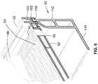
- FIG. 8is a partial perspective view of the display of FIG. 1 ;
- FIG. 9is a perspective view of an alternative embodiment of a divider associated with the tray of FIG. 1 ;
- FIG. 10is another perspective view of the divider of FIG. 9 .
- tray 22does not require any mounting hardware in its assembly.
- mounting hardwareit is meant screws, bolts, rivets, or any other component which a tool is typically required to install.
- tray 22employs resilient snap-fit connections to connect its various components.
- no hand toolsare required in the assembly and installation of tray 22 .
- retail merchandise display 20advantageously presents a 100% tool-free design.
- “snap-fit” connectionsmeans resilient connections in which male feature such as a tab, detent, projection, etc. is biased into a mating female feature such as a hole or slot requiring one or both of the male and female features to resiliently and elastically deform to accommodate such a connection.
- tray 22may be readily incorporated into an existing retail shelf 24 .
- tray 22does not require a custom made shelf or custom made vertical display to mount tray 22 to. Instead, a plurality of mounting plates are provided which mate with conventional features on shelf 22 and with tray 22 to hold the same in place on shelf 24 .
- display 20includes tray 22 mounted on a top surface 28 of shelf 24 .
- Tray 22defines a plurality of retail merchandise channels 26 which are arranged parallel to one another and extend from a back end 50 of tray 22 to a front end 54 of tray 22 .
- channels 26are arranged to carry items of retail merchandise 32 therein in a linear row.
- tray 22is in a gravity feed configuration in that its back 50 is elevated relative to its front end 54 . Due to the gravity feed configuration of tray 22 , as the lead item of merchandise 32 is vertically removed in direction 34 , the remaining items of merchandise 32 move forward along a feed direction 36 until the front-most item of retail merchandise 32 abuts a front stop 38 .
- tray 22need not employ the aforementioned gravity feed configuration to face retail merchandise. Instead, tray 22 may utilize a pusher system to bias merchandise toward front end 54 . In such a configuration, tray 22 will be generally parallel with shelf 24 such that back end 50 and front end 54 are at the same elevation relative to shelf 24 . As yet another alternative, tray 22 may be placed in its gravity feed configuration but nevertheless employ the pusher configuration described herein, depending on the size, weight, and other parameters of the merchandise to be faced.
- tray 22includes a first mounting rail 42 and a second mounting rail 44 . At least one tray section 46 is mounted between mounting rails 42 , 44 . In the illustrated embodiment, two tray sections 46 are utilized. However, a single tray section 46 may be employed, as well as more than two tray sections 46 . As will be understood from the following, each tray section 46 is configured to connect to adjacent tray sections as well as to mounting rails 42 , 44 .
- Tray 22also includes a support leg 52 mounted to first mounting rail 42 . Support leg 52 raises or elevates back end 50 of tray 22 relative to front end 54 to provide the aforementioned gravity feed functionality. Put differently, support leg 52 angles a retail merchandise support surface defined by tray 22 relative to top surface 28 of shelf 24 such that retail merchandise moves towards front stop 38 under the force of gravity. The height of front stop 38 may be varied to accommodate differing heights of retail merchandise.
- Display 20also includes a plurality of mounting plates 56 which are interposed between shelf 24 and tray 22 .
- Mounting plates 56include bent portions which are received in apertures 106 formed in shelf 24 .
- mounting plates 56also include projection 108 which are received in slots 70 of tray 22 (See FIG. 7 ). Such a configuration advantageously anchors front end 54 of tray 22 on shelf 24 .
- shelf 24may take on any conventional retail shelf form which includes a plurality of apertures formed therein for receipt of bent portions of mounting plates 56 . Accordingly, tray 22 is not limited to any particular style of shelf 24 and may be readily retrofit into a variety of existing shelves. Although not shown in FIG. 3 , those of skill in the art will also recognize that shelf 24 is typically mounted to an upright structure. Tray 22 is designed so that it does not require any manipulation or modification of such an upright structure and can instead readily interact with shelf 24 .
- Each tray section 46includes cap members 58 , 60 which are mounted to either end of a base member 62 .
- cap members 58 , 60are identical to one another. As such, a description of one cap member applies equally well to the other.
- Base member 62is an extruded component which defines a top retail merchandise support surface which is continuous and extends between back end 50 and front end 54 of tray 20 .
- Base member 62may be any length given the use of the extrusion process in its manufacture.
- Base member 62also includes a plurality of channels formed therein as described below.
- base member 62is formed by two interlocking subsections 64 a , 64 b .
- a single base section 62may be used.
- base member 62may be extruded at a given width, and then subsequently rip cut to its desired width.
- Base member 62may be formed of high density polyethylene as one example.
- the width of cap members 58 , 60may also vary depending on the width of base member 62 .
- a plurality of dividers 66extend over the retail merchandise support surface defined by base member 62 and include downwardly extending projections 68 which are received in select ones of the aforementioned linear row of slots 70 .
- the close spacing of the slotsallows for a high degree of variability of the width of any given channel 26 by spacing dividers 66 closer or farther away from one another.
- These dividers 66may be embodied as shown as generally flat walls, or alternatively, my incorporate a pusher assembly as described below relative to FIGS. 9 and 10 . Further, the dividers 66 are easily removable such that tray 22 may be utilized with only a single divider, or no dividers at all. Still further, wire dividers may be utilized instead of the plate-like elements illustrated. Still further, dividers 66 may be any height to accommodate merchandise of differing heights.
- slots 70are formed in each cap member 58 , 60 and extend entirely through the same. Slots 70 are arranged in a linear row which is perpendicular to feed direction 36 (See FIG. 2 ) of tray 22 and are formed in a body portion 40 of each cap member 58 , 60 .
- Each cap member 58 , 60also includes a plurality of projections 72 extending away from body portion 40 which are received in corresponding channels 74 of base member 62 as illustrated.
- a plurality of wire supports 76are received in channels 78 of base member 62 . Wire supports 76 provide additional rigidity and structural support to base member 62 .
- wire support 76may be omitted entirely in the event that generally light merchandise will be carried by tray 22 . Conversely, wire support 76 may be tailored using different materials and dimensions to vary the structural support provided thereby.
- FIG. 5the same illustrates a cross-section taken through tray section 46 .
- the projection 72 of cap member 58are shown installed within channel 74 .
- wire supports 76are shown installed within channel 78 .
- FIG. 5is the interlocking capabilities of base member 62 .
- subsection 64 aincludes an upwardly facing channel 82 on the right-most side thereof in FIG. 5 .
- Subsection 64 bis identical to subsection 64 a and thus also includes an upwardly facing channel 82 on the right-most side thereof in FIG. 5 .
- Each subsection 64 a , 64 balso includes a downwardly depending rib 80 on the left-most side thereof shown in FIG. 5 .
- This rib 80is configured to be received within upwardly facing channel 82 to interlock subsection 64 a with subsection 64 b . Likewise, this channel 82 and rib 80 configuration is also utilized to interlock adjacent tray sections 46 to one another. FIG. 5 also illustrates ribs 84 that form the merchandise support surface of base member 82 .
- FIG. 6the resilient snap-fit connection between each tray section 46 and mounting rails 42 , 44 is shown. Also, the resilient snap-fit connection between each cap member 58 , 60 and base member 62 is shown. In particular, FIG. 6 illustrates the snap-fit connection between cap member 60 and second mounting rail 44 as well as cap member 60 between base member 62 . It will be recognized that the following description of the aforementioned snap-fit connection applies equally well to cap member 58 and first mounting rail 42 as well as cap member 58 and base member 62 . Further, the description of the structural attributes of second mounting rail 44 shown in FIG. 6 applies equally well to first mounting rail 42 as mounting rails 42 , 44 are identical.
- Second mounting rail 44includes a horizontally extending mounting channel 86 .
- Second mounting rail 44also includes an upper channel 100 and a lower channel 102 which extend generally perpendicular to mounting channel 86 .
- Mounting channel 86includes a plurality of apertures 88 formed therein.
- Apertures 88are arranged to receive tabs 90 formed in a projection portion 48 of cap member 60 .
- Tabs 90are received within apertures 88 via a resilient snap-fit connection in that one or both of tabs 90 or the wall defining channel 86 including apertures 88 elastically deforms as projection portion 48 is biased into mounting channel 88 . This continues until tabs 90 are fully seated within apertures 88 and cap member 60 is thus locked to mounting rail 44 .
- base member 62includes an aperture 96 into which a projection 94 formed on one of the projections 72 of cap member 60 seats into.
- tab 94 and base member 62 in the region of aperture 96elastically deforms until tab 94 is fully seated within aperture 96 .
- mounting plate 56includes bent portions 104 .
- Bent portions 104may be fed through apertures 106 formed in shelf 24 .
- bent portions 104extend away from a base portion 110 of mounting plate 56 .
- each mounting plate 56includes a pair of bent portions 104 which are coplanar with one another but are not coplanar with base portion 110 as shown.
- a projection 108extends upwardly from base portion 110 and is received within a select one of slot 70 .
- Each mounting plate 56may include a single projection 108 or multiple projections 108 .
- support leg 52includes a generally vertical leg portion 112 with a foot portion 114 extending perpendicularly to leg portion 112 .
- a projection 116is formed at a top end of leg portion 112 .
- This projection 116has a generally circular cross-sectional profile and is received via a snap-fit connection in lower channel 102 of first mounting rail 42 .
- Lower channel 102may include undercut or ribs for securing projection 116 once it is fully inserted within channel 102 .
- the round outer profile of projection 116allows support leg 52 to rotate about its longitudinal axis within channel 102 to achieve a desired angle of support leg 52 relative to the remainder of tray 22 .
- the length of vertical leg portion 112may be varied as well to obtain a desired angle of tray 22 relative to shelf 24 .
- divider 120includes an integrated pusher assembly.
- the integrated pusher assemblyincludes a divider wall 122 with a pusher paddle 124 slidably mounted thereto.
- Pusher paddle 124includes a projection 126 which is received in a channel 128 of divider wall 122 to effectuate the aforementioned slidable connection.
- the pusher assemblyalso includes a coil spring which is uncoiled through the front of pusher paddle 124 and connected to divider wall 122 at a slot 132 thereof (see FIG. 9 ). The remainder of coil spring 130 remains coiled and contained within pusher paddle 124 as shown.
- divider wall 122also includes downward projections 134 which are received in slots 70 in the same manner as described above.
Landscapes
- Display Racks (AREA)
- Freezers Or Refrigerated Showcases (AREA)
Abstract
Description
Claims (20)
Priority Applications (5)
| Application Number | Priority Date | Filing Date | Title |
|---|---|---|---|
| US17/084,398US11197562B2 (en) | 2017-01-05 | 2020-10-29 | Retail merchandise tray and display incorporating same |
| US17/525,253US11457748B2 (en) | 2017-01-05 | 2021-11-12 | Retail merchandise tray and display incorporating same |
| US17/900,991US11793328B2 (en) | 2017-01-05 | 2022-09-01 | Retail merchandise tray and display incorporating same |
| US18/480,245US12178334B2 (en) | 2017-01-05 | 2023-10-03 | Retail merchandise tray and display incorporating same |
| US18/953,706US20250072634A1 (en) | 2017-01-05 | 2024-11-20 | Retail merchandise tray and display incorporating same |
Applications Claiming Priority (5)
| Application Number | Priority Date | Filing Date | Title |
|---|---|---|---|
| US201762442741P | 2017-01-05 | 2017-01-05 | |
| US15/838,674US10638856B2 (en) | 2017-01-05 | 2017-12-12 | Retail merchandise tray and display incorporating same |
| US16/827,314US10709264B1 (en) | 2017-01-05 | 2020-03-23 | Retail merchandise tray and display incorporating same |
| US16/884,195US10856671B2 (en) | 2017-01-05 | 2020-05-27 | Retail merchandise tray and display incorporating same |
| US17/084,398US11197562B2 (en) | 2017-01-05 | 2020-10-29 | Retail merchandise tray and display incorporating same |
Related Parent Applications (1)
| Application Number | Title | Priority Date | Filing Date |
|---|---|---|---|
| US16/884,195ContinuationUS10856671B2 (en) | 2017-01-05 | 2020-05-27 | Retail merchandise tray and display incorporating same |
Related Child Applications (1)
| Application Number | Title | Priority Date | Filing Date |
|---|---|---|---|
| US17/525,253ContinuationUS11457748B2 (en) | 2017-01-05 | 2021-11-12 | Retail merchandise tray and display incorporating same |
Publications (2)
| Publication Number | Publication Date |
|---|---|
| US20210045546A1 US20210045546A1 (en) | 2021-02-18 |
| US11197562B2true US11197562B2 (en) | 2021-12-14 |
Family
ID=62709040
Family Applications (8)
| Application Number | Title | Priority Date | Filing Date |
|---|---|---|---|
| US15/838,674ActiveUS10638856B2 (en) | 2017-01-05 | 2017-12-12 | Retail merchandise tray and display incorporating same |
| US16/827,314ActiveUS10709264B1 (en) | 2017-01-05 | 2020-03-23 | Retail merchandise tray and display incorporating same |
| US16/884,195ActiveUS10856671B2 (en) | 2017-01-05 | 2020-05-27 | Retail merchandise tray and display incorporating same |
| US17/084,398ActiveUS11197562B2 (en) | 2017-01-05 | 2020-10-29 | Retail merchandise tray and display incorporating same |
| US17/525,253ActiveUS11457748B2 (en) | 2017-01-05 | 2021-11-12 | Retail merchandise tray and display incorporating same |
| US17/900,991ActiveUS11793328B2 (en) | 2017-01-05 | 2022-09-01 | Retail merchandise tray and display incorporating same |
| US18/480,245ActiveUS12178334B2 (en) | 2017-01-05 | 2023-10-03 | Retail merchandise tray and display incorporating same |
| US18/953,706PendingUS20250072634A1 (en) | 2017-01-05 | 2024-11-20 | Retail merchandise tray and display incorporating same |
Family Applications Before (3)
| Application Number | Title | Priority Date | Filing Date |
|---|---|---|---|
| US15/838,674ActiveUS10638856B2 (en) | 2017-01-05 | 2017-12-12 | Retail merchandise tray and display incorporating same |
| US16/827,314ActiveUS10709264B1 (en) | 2017-01-05 | 2020-03-23 | Retail merchandise tray and display incorporating same |
| US16/884,195ActiveUS10856671B2 (en) | 2017-01-05 | 2020-05-27 | Retail merchandise tray and display incorporating same |
Family Applications After (4)
| Application Number | Title | Priority Date | Filing Date |
|---|---|---|---|
| US17/525,253ActiveUS11457748B2 (en) | 2017-01-05 | 2021-11-12 | Retail merchandise tray and display incorporating same |
| US17/900,991ActiveUS11793328B2 (en) | 2017-01-05 | 2022-09-01 | Retail merchandise tray and display incorporating same |
| US18/480,245ActiveUS12178334B2 (en) | 2017-01-05 | 2023-10-03 | Retail merchandise tray and display incorporating same |
| US18/953,706PendingUS20250072634A1 (en) | 2017-01-05 | 2024-11-20 | Retail merchandise tray and display incorporating same |
Country Status (3)
| Country | Link |
|---|---|
| US (8) | US10638856B2 (en) |
| EP (2) | EP4445794A3 (en) |
| WO (1) | WO2018128759A1 (en) |
Cited By (1)
| Publication number | Priority date | Publication date | Assignee | Title |
|---|---|---|---|---|
| US12178334B2 (en) | 2017-01-05 | 2024-12-31 | Fasteners For Retail, Inc. | Retail merchandise tray and display incorporating same |
Families Citing this family (15)
| Publication number | Priority date | Publication date | Assignee | Title |
|---|---|---|---|---|
| DE102017110002A1 (en)* | 2017-05-09 | 2018-11-15 | Rickard Nilsson | Shelf unit for a shelving system and shelving system |
| GB2566517A (en)* | 2017-09-15 | 2019-03-20 | Supply Point Systems Ltd | Shelving System |
| EP3498128B1 (en)* | 2017-12-14 | 2020-01-08 | Bruegmann GmbH & Co. KG | System comprising goods support and dividers |
| US11369215B2 (en) | 2018-12-17 | 2022-06-28 | Fasteners For Retail, Inc. | Retail shelving system |
| AU2020254110A1 (en)* | 2019-04-04 | 2021-11-11 | Pan-Oston Sdn Bhd | Shelving system improvements |
| USD879751S1 (en)* | 2019-05-30 | 2020-03-31 | Stormshell, LLC | Display enclosure |
| US20210137265A1 (en)* | 2019-11-11 | 2021-05-13 | Fasteners For Retail, Inc. | Product Divider Assembly |
| TWI712381B (en)* | 2020-02-25 | 2020-12-11 | 川湖科技股份有限公司 | Mounting device and mounting method for furniture assembly |
| USD965355S1 (en)* | 2020-03-18 | 2022-10-04 | Walgreen Co. | Cover for cosmetic products |
| EP3922140A3 (en)* | 2020-04-23 | 2022-02-16 | Fasteners for Retail, Inc. | Retail merchandise shelving system |
| US11617454B2 (en)* | 2020-07-24 | 2023-04-04 | Shopco U.S.A., Inc. | Fixture for storage and presentation of goods |
| US11147397B1 (en)* | 2021-02-11 | 2021-10-19 | Google Llc | Wedge apparatus for retail device display |
| US11744387B1 (en)* | 2021-06-10 | 2023-09-05 | Diam Uk Ltd | Customizable product storage and display system |
| HUE067401T2 (en)* | 2021-11-25 | 2024-10-28 | Jofemar Sa | Adaptable product storage and extraction tray |
| US12434919B2 (en)* | 2023-07-12 | 2025-10-07 | Maclean Mallard, L.L.C. | Adjustable divider assembly and conveyor incorporating same |
Citations (101)
| Publication number | Priority date | Publication date | Assignee | Title |
|---|---|---|---|---|
| US3229334A (en)* | 1961-12-30 | 1966-01-18 | Thome Kommanditgesellschaft Ge | Corner or butt joint |
| US3872802A (en) | 1973-01-08 | 1975-03-25 | Steelcase Inc | Filing cabinet |
| US3986616A (en) | 1975-06-24 | 1976-10-19 | Robert Gray | Shelf |
| US4205763A (en) | 1978-12-26 | 1980-06-03 | Marlboro Marketing, Inc. | Container dispensing device |
| US4454948A (en) | 1981-11-23 | 1984-06-19 | The Mead Corporation | Gravity feed display unit |
| US4461388A (en) | 1980-03-11 | 1984-07-24 | Leggett & Platt, Incorporated | Slip surface shelf merchandiser |
| US4696406A (en) | 1984-10-15 | 1987-09-29 | Masashi Karashima | Rack board |
| US4706824A (en)* | 1986-03-25 | 1987-11-17 | Marlboro Marketing, Inc. | Variable sized free standing promotional display |
| US4736997A (en) | 1987-06-05 | 1988-04-12 | General Electric Company | Household refrigerator shelf assembly |
| US4830201A (en) | 1988-04-11 | 1989-05-16 | Rtc Industries, Inc. | Spring-urged shelf divider system |
| US4960210A (en) | 1989-06-29 | 1990-10-02 | The Mead Corporation | Gravity feed gondola base |
| US5160051A (en) | 1989-02-07 | 1992-11-03 | Leggett & Platt, Incorporated | Storage rack shelving system |
| US5390802A (en)* | 1993-02-12 | 1995-02-21 | Hmg Worldwide In-Store Marketing, Inc. | Shelf assembly for gondola display structure |
| US5673801A (en) | 1996-03-25 | 1997-10-07 | Markson Rosenthal & Company | Shelf organizer display |
| US5813738A (en)* | 1997-06-20 | 1998-09-29 | Cheng; Wen Sen | Furniture combination |
| US5862923A (en) | 1992-12-18 | 1999-01-26 | Cannon Equipment Company | Self-facing shelf slide |
| US6082557A (en) | 1995-10-17 | 2000-07-04 | Checkmate International Pty. Ltd. | Shelving system |
| US6098821A (en) | 1998-09-23 | 2000-08-08 | Rousseau Metal Inc. | Removable bottom standing divider unit |
| US6129218A (en) | 1998-05-11 | 2000-10-10 | Target Brands, Inc. | Merchandise display system |
| US6132158A (en) | 1998-01-14 | 2000-10-17 | Unex Manufacturing Inc. | Universal flow track system |
| US6234328B1 (en) | 1999-09-24 | 2001-05-22 | Ndr Corporation | Adjustable shelf system |
| US20020088762A1 (en) | 1999-08-24 | 2002-07-11 | Burke Robert P. | Snap-fit adjustable display system |
| US6431808B1 (en) | 2000-11-30 | 2002-08-13 | Unarco Material Handling, Inc. | Storage rack having roller track |
| US6497326B1 (en) | 1997-11-28 | 2002-12-24 | Kawajun Co., Ltd. | Goods display unit |
| US6523703B1 (en) | 2001-09-26 | 2003-02-25 | Display Industries, Llc. | Pusher mechanism for a merchandising display shelf |
| US20030066811A1 (en) | 2001-10-05 | 2003-04-10 | Dimattio Thelma M. | Display apparatus with integrated dividers |
| US20030132182A1 (en)* | 2002-01-14 | 2003-07-17 | Richard Jay | Depth-extendable display track unit |
| US20040000528A1 (en) | 2001-12-17 | 2004-01-01 | Nagel Thomas O. | Product pusher for merchandise displays |
| US20040050811A1 (en) | 2000-11-15 | 2004-03-18 | Leahy John Clifton | Shelving system |
| US20040065631A1 (en) | 2002-08-16 | 2004-04-08 | Nagel Thomas O. | Product display rack |
| US20040118795A1 (en) | 2002-12-23 | 2004-06-24 | Burke Robert P. | Modular display rack having horizontally separable front barrier |
| US20040159622A1 (en) | 2003-02-14 | 2004-08-19 | Craft Charles W. | Modular multi-piece shelf and shelving unit |
| US20040178156A1 (en) | 2003-02-12 | 2004-09-16 | Knorring Edward I. | Method and apparatus for converting gondola shelf to gravity feed shelf |
| US20040245197A1 (en) | 2001-07-09 | 2004-12-09 | Mcelvaney Oliver | Shelf management systems |
| US20050077260A1 (en) | 2003-10-14 | 2005-04-14 | Fasteners For Retail, Inc. | Adjustable shelving system |
| US20050189310A1 (en) | 2001-04-26 | 2005-09-01 | Dci Marketing, Inc. | Merchandising system |
| US20050236351A1 (en)* | 2004-04-22 | 2005-10-27 | Royal Group Technologies And Outback Essentials Div. Of 876864 Ontario Inc. | Board mounting to support system |
| US20060037832A1 (en) | 2004-08-19 | 2006-02-23 | Lawless Robert J | Adaptable freewheel flow track systems, methods, and apparatus |
| US20060169659A1 (en)* | 2005-02-02 | 2006-08-03 | Larry Robinson | Modular shelving system |
| US20060186064A1 (en) | 2005-02-18 | 2006-08-24 | William Merit & Associates, Inc. | Method and apparatus for selective engagement of shelf divider structures within a shelf management system |
| US20060186065A1 (en) | 2005-02-19 | 2006-08-24 | Ciesick James M | Telescoping display rack |
| US7140499B2 (en) | 2002-12-23 | 2006-11-28 | Burke Display Systems, Inc. | Forward feeding modular display rack for rounded articles |
| US20070029270A1 (en) | 2005-08-04 | 2007-02-08 | Terry Hawkinson | Apparatus for holding and feeding product |
| US20070045209A1 (en) | 2005-08-31 | 2007-03-01 | Richardson Jed C | Stacking shelving system for utility shed |
| US20070080126A1 (en) | 2005-10-11 | 2007-04-12 | James Music | Slidable coupling components for shelf management systems |
| US20070090068A1 (en) | 2005-10-25 | 2007-04-26 | Rtc Industries, Inc. | Product management display system |
| US20070158281A1 (en) | 2001-05-17 | 2007-07-12 | Rtc Industries, Inc. | Multi-Component Display and Merchandise Systems |
| US20090242582A1 (en) | 2003-10-17 | 2009-10-01 | Rock-Tenn Shared Services, Llc | Theft deterrent system |
| US20090294392A1 (en) | 2008-05-27 | 2009-12-03 | Target Brands, Inc. | Quick secure shelving |
| US20100072152A1 (en) | 2007-12-12 | 2010-03-25 | Seidae Industrial Co., Ltd. | Shelf for showcase |
| KR100949574B1 (en) | 2009-04-28 | 2010-03-25 | 세대산전 주식회사 | A slant structure of shelf for showcase |
| US20100078402A1 (en) | 2008-10-01 | 2010-04-01 | Adco Industries - Technologies, L.P. | Shelving glide |
| US20100116760A1 (en)* | 2008-06-18 | 2010-05-13 | Huilin Min Fazzone | Modular shelving and methods for displaying retail products |
| US20100133214A1 (en)* | 2008-02-08 | 2010-06-03 | Hamlon Pty Ltd | Display unit with roller assembly shelving |
| US20100133219A1 (en) | 2008-11-26 | 2010-06-03 | Yeyang Sun | Modular gravity actuated rolling shelving assembly |
| US20100206829A1 (en) | 2009-02-13 | 2010-08-19 | L&P Property Management Company | Product display |
| US20100258513A1 (en) | 2009-04-08 | 2010-10-14 | Target Brands, Inc. | Product display system |
| US20110055103A1 (en) | 2004-02-03 | 2011-03-03 | Rtc Industries, Inc. | System for Inventory Management |
| US20110100941A1 (en) | 2009-11-05 | 2011-05-05 | Henschel-Steinau, Inc. | Modular Display and Dispensing Apparatus with Plural Dispensing Tiers |
| US20110100942A1 (en) | 2009-10-30 | 2011-05-05 | Robert Spizman | Gondola gravity feed retrofit shelving |
| US20110174750A1 (en) | 2008-03-21 | 2011-07-21 | Dimitris Poulokefalos | Merchandise display and pusher device |
| US20110186401A1 (en)* | 2010-02-02 | 2011-08-04 | Dirk A. Brugmann Kunststoff-Verarbeitung GmbH &. Co. KG | Article feed insert for an article feed system |
| US20110204012A1 (en)* | 2009-12-07 | 2011-08-25 | Sekisui Plastics Co., Ltd. | Commodity display take-out unit and commodity display shelf using the unit |
| US8042700B1 (en)* | 2008-12-29 | 2011-10-25 | Smalley Daniel J | End cap shelf system |
| US20110278246A1 (en) | 2010-05-14 | 2011-11-17 | Blake Daily | Display having variable incline shelves |
| US20110291540A1 (en)* | 2010-06-01 | 2011-12-01 | Richard Dean Davidson | Cabinet with a shelf that has a removable shelf liner and end cap |
| US20120000872A1 (en) | 2010-07-02 | 2012-01-05 | Edsal Manufacturing Co., Inc. | Convertible multifunctional shelving |
| US20120091162A1 (en) | 2010-10-18 | 2012-04-19 | Goliath Solutions, Llc | Computer-Implemented Systems and Methods for Providing an Out of Stock/Low Stock Alert |
| US20120118840A1 (en) | 2010-11-12 | 2012-05-17 | Frito-Lay North America, Inc. | Dual plane self-adjusting shelf |
| US20120217212A1 (en) | 2011-02-24 | 2012-08-30 | E-B Display Company, Inc. | Display assembly with integral roller base |
| US20130015155A1 (en)* | 2011-07-15 | 2013-01-17 | Dirk A. Brugmann Kunststoff-Verarbeitung Gmbh & Co. Kg | Merchandise feed insert for a merchandise feed system |
| US20130112640A1 (en) | 2008-12-24 | 2013-05-09 | Brett John Desmond | Shelving system |
| US8490800B2 (en) | 2010-05-14 | 2013-07-23 | Sabritas, S. De R.L. De C.V. | Gravity feed display rack |
| US20130213916A1 (en) | 2010-10-26 | 2013-08-22 | Checkmate International Pty Ltd. | Shelf divider system |
| US20140299560A1 (en) | 2013-04-09 | 2014-10-09 | Seidae Industrial Co., Ltd. | Shelf for display of goods |
| US20140319087A1 (en) | 2013-04-30 | 2014-10-30 | The Marco Company | Freezer Pusher |
| US8915381B2 (en) | 2011-06-01 | 2014-12-23 | American Greetings Corporation | Vertical roll wrap product tray kit |
| US20150041418A1 (en) | 2013-08-12 | 2015-02-12 | Fasteners For Retail, Inc. | Trackless pusher for large items |
| US20150053633A1 (en) | 2012-02-29 | 2015-02-26 | Roloro Limited | Roller assembly for gravity feed shelving and method of assembly |
| US20150114918A1 (en) | 2012-12-07 | 2015-04-30 | The Marco Company | Roller shelf |
| US9038804B1 (en)* | 2012-12-07 | 2015-05-26 | The Marco Company | Roller shelf |
| US20150238026A1 (en)* | 2014-02-26 | 2015-08-27 | Southern Imperial, Inc. | Snap-In Pusher |
| US20150289683A1 (en) | 2014-04-14 | 2015-10-15 | Fasteners For Retail, Inc. | Rail position lock |
| US20150359358A1 (en) | 2014-06-16 | 2015-12-17 | Presence From Innovation, Llc | Product merchandising system |
| US20160029794A1 (en) | 2013-04-08 | 2016-02-04 | Fasteners For Retail, Inc. | Latch assembly for securing tracks and dividers to a front rail |
| US20160066688A1 (en)* | 2014-09-10 | 2016-03-10 | Chih Hsiung Yu | Connector and side board for combination cabinet |
| US9370242B2 (en)* | 2014-01-14 | 2016-06-21 | Terry Store-Age S.P.A. | Kit for assembling a shelf unit |
| US20160296039A1 (en) | 2015-04-08 | 2016-10-13 | Fasteners For Retail, Inc. | Divider with selectively securable track assembly |
| US20170164762A1 (en) | 2015-10-22 | 2017-06-15 | Process Retail Group, Inc. | Stacked Can Merchandiser |
| US20170280894A1 (en) | 2014-12-23 | 2017-10-05 | Seidae Industrial Co., Ltd. | End cap for showcase roller shelf |
| US20170295958A1 (en) | 2014-09-30 | 2017-10-19 | Rehrig Pacific Company | Multi-position tray support |
| US9986854B2 (en) | 2015-08-06 | 2018-06-05 | Display Technologies, Llc | Product display assembly |
| US20180153313A1 (en) | 2016-12-05 | 2018-06-07 | Retail Space Solutions Llc | Shelf management system, components thereof, and related methods |
| US20180184814A1 (en) | 2017-01-05 | 2018-07-05 | Southern Imperial Llc | Retail merchandise tray and display incorporating same |
| US10034557B1 (en) | 2017-12-01 | 2018-07-31 | Southern Imperial Llc | Retail merchandise tray |
| US20180310707A1 (en)* | 2015-10-29 | 2018-11-01 | Ibk Project Srl | Kit for assembling furniture |
| US10154739B2 (en) | 2013-12-02 | 2018-12-18 | Retail Space Solutions Llc | Universal merchandiser and methods relating to same |
| US10178909B2 (en) | 2016-01-13 | 2019-01-15 | Rtc Industries, Inc. | Anti-splay device for merchandise display system |
| US10206520B2 (en) | 2005-09-12 | 2019-02-19 | Rtc Industries, Inc. | Product management display system |
| US20190387733A1 (en)* | 2018-04-12 | 2019-12-26 | Kim LYKKEN | Bait station system |
| US20200100588A1 (en)* | 2018-09-28 | 2020-04-02 | Creative Plastic Concepts, Llc | Shelf assembly |
- 2017
- 2017-12-12USUS15/838,674patent/US10638856B2/enactiveActive
- 2017-12-13WOPCT/US2017/065998patent/WO2018128759A1/ennot_activeCeased
- 2017-12-13EPEP24195983.2Apatent/EP4445794A3/enactivePending
- 2017-12-13EPEP17889705.4Apatent/EP3565440B1/enactiveActive
- 2020
- 2020-03-23USUS16/827,314patent/US10709264B1/enactiveActive
- 2020-05-27USUS16/884,195patent/US10856671B2/enactiveActive
- 2020-10-29USUS17/084,398patent/US11197562B2/enactiveActive
- 2021
- 2021-11-12USUS17/525,253patent/US11457748B2/enactiveActive
- 2022
- 2022-09-01USUS17/900,991patent/US11793328B2/enactiveActive
- 2023
- 2023-10-03USUS18/480,245patent/US12178334B2/enactiveActive
- 2024
- 2024-11-20USUS18/953,706patent/US20250072634A1/enactivePending
Patent Citations (107)
| Publication number | Priority date | Publication date | Assignee | Title |
|---|---|---|---|---|
| US3229334A (en)* | 1961-12-30 | 1966-01-18 | Thome Kommanditgesellschaft Ge | Corner or butt joint |
| US3872802A (en) | 1973-01-08 | 1975-03-25 | Steelcase Inc | Filing cabinet |
| US3986616A (en) | 1975-06-24 | 1976-10-19 | Robert Gray | Shelf |
| US4205763A (en) | 1978-12-26 | 1980-06-03 | Marlboro Marketing, Inc. | Container dispensing device |
| US4461388A (en) | 1980-03-11 | 1984-07-24 | Leggett & Platt, Incorporated | Slip surface shelf merchandiser |
| US4454948A (en) | 1981-11-23 | 1984-06-19 | The Mead Corporation | Gravity feed display unit |
| US4696406A (en) | 1984-10-15 | 1987-09-29 | Masashi Karashima | Rack board |
| US4706824A (en)* | 1986-03-25 | 1987-11-17 | Marlboro Marketing, Inc. | Variable sized free standing promotional display |
| US4736997A (en) | 1987-06-05 | 1988-04-12 | General Electric Company | Household refrigerator shelf assembly |
| US4830201A (en) | 1988-04-11 | 1989-05-16 | Rtc Industries, Inc. | Spring-urged shelf divider system |
| US5160051A (en) | 1989-02-07 | 1992-11-03 | Leggett & Platt, Incorporated | Storage rack shelving system |
| US4960210A (en) | 1989-06-29 | 1990-10-02 | The Mead Corporation | Gravity feed gondola base |
| US5862923A (en) | 1992-12-18 | 1999-01-26 | Cannon Equipment Company | Self-facing shelf slide |
| US5390802A (en)* | 1993-02-12 | 1995-02-21 | Hmg Worldwide In-Store Marketing, Inc. | Shelf assembly for gondola display structure |
| US6082557A (en) | 1995-10-17 | 2000-07-04 | Checkmate International Pty. Ltd. | Shelving system |
| US5673801A (en) | 1996-03-25 | 1997-10-07 | Markson Rosenthal & Company | Shelf organizer display |
| US5813738A (en)* | 1997-06-20 | 1998-09-29 | Cheng; Wen Sen | Furniture combination |
| US6497326B1 (en) | 1997-11-28 | 2002-12-24 | Kawajun Co., Ltd. | Goods display unit |
| US6132158A (en) | 1998-01-14 | 2000-10-17 | Unex Manufacturing Inc. | Universal flow track system |
| US6129218A (en) | 1998-05-11 | 2000-10-10 | Target Brands, Inc. | Merchandise display system |
| US6098821A (en) | 1998-09-23 | 2000-08-08 | Rousseau Metal Inc. | Removable bottom standing divider unit |
| US20020088762A1 (en) | 1999-08-24 | 2002-07-11 | Burke Robert P. | Snap-fit adjustable display system |
| US6234328B1 (en) | 1999-09-24 | 2001-05-22 | Ndr Corporation | Adjustable shelf system |
| US20040050811A1 (en) | 2000-11-15 | 2004-03-18 | Leahy John Clifton | Shelving system |
| US6431808B1 (en) | 2000-11-30 | 2002-08-13 | Unarco Material Handling, Inc. | Storage rack having roller track |
| US20050189310A1 (en) | 2001-04-26 | 2005-09-01 | Dci Marketing, Inc. | Merchandising system |
| US20070158281A1 (en) | 2001-05-17 | 2007-07-12 | Rtc Industries, Inc. | Multi-Component Display and Merchandise Systems |
| US20040245197A1 (en) | 2001-07-09 | 2004-12-09 | Mcelvaney Oliver | Shelf management systems |
| US6523703B1 (en) | 2001-09-26 | 2003-02-25 | Display Industries, Llc. | Pusher mechanism for a merchandising display shelf |
| US20030066811A1 (en) | 2001-10-05 | 2003-04-10 | Dimattio Thelma M. | Display apparatus with integrated dividers |
| US20040000528A1 (en) | 2001-12-17 | 2004-01-01 | Nagel Thomas O. | Product pusher for merchandise displays |
| US20030132182A1 (en)* | 2002-01-14 | 2003-07-17 | Richard Jay | Depth-extendable display track unit |
| US20040065631A1 (en) | 2002-08-16 | 2004-04-08 | Nagel Thomas O. | Product display rack |
| US7140499B2 (en) | 2002-12-23 | 2006-11-28 | Burke Display Systems, Inc. | Forward feeding modular display rack for rounded articles |
| US20040118795A1 (en) | 2002-12-23 | 2004-06-24 | Burke Robert P. | Modular display rack having horizontally separable front barrier |
| US20040178156A1 (en) | 2003-02-12 | 2004-09-16 | Knorring Edward I. | Method and apparatus for converting gondola shelf to gravity feed shelf |
| US20040159622A1 (en) | 2003-02-14 | 2004-08-19 | Craft Charles W. | Modular multi-piece shelf and shelving unit |
| US20050077260A1 (en) | 2003-10-14 | 2005-04-14 | Fasteners For Retail, Inc. | Adjustable shelving system |
| US20090242582A1 (en) | 2003-10-17 | 2009-10-01 | Rock-Tenn Shared Services, Llc | Theft deterrent system |
| US20110055103A1 (en) | 2004-02-03 | 2011-03-03 | Rtc Industries, Inc. | System for Inventory Management |
| US20050236351A1 (en)* | 2004-04-22 | 2005-10-27 | Royal Group Technologies And Outback Essentials Div. Of 876864 Ontario Inc. | Board mounting to support system |
| US20060037832A1 (en) | 2004-08-19 | 2006-02-23 | Lawless Robert J | Adaptable freewheel flow track systems, methods, and apparatus |
| US20060169659A1 (en)* | 2005-02-02 | 2006-08-03 | Larry Robinson | Modular shelving system |
| US20060186064A1 (en) | 2005-02-18 | 2006-08-24 | William Merit & Associates, Inc. | Method and apparatus for selective engagement of shelf divider structures within a shelf management system |
| US20060186065A1 (en) | 2005-02-19 | 2006-08-24 | Ciesick James M | Telescoping display rack |
| US20070029270A1 (en) | 2005-08-04 | 2007-02-08 | Terry Hawkinson | Apparatus for holding and feeding product |
| US20070045209A1 (en) | 2005-08-31 | 2007-03-01 | Richardson Jed C | Stacking shelving system for utility shed |
| US10206520B2 (en) | 2005-09-12 | 2019-02-19 | Rtc Industries, Inc. | Product management display system |
| US20070080126A1 (en) | 2005-10-11 | 2007-04-12 | James Music | Slidable coupling components for shelf management systems |
| US20070090068A1 (en) | 2005-10-25 | 2007-04-26 | Rtc Industries, Inc. | Product management display system |
| US20100072152A1 (en) | 2007-12-12 | 2010-03-25 | Seidae Industrial Co., Ltd. | Shelf for showcase |
| US20100133214A1 (en)* | 2008-02-08 | 2010-06-03 | Hamlon Pty Ltd | Display unit with roller assembly shelving |
| US20110174750A1 (en) | 2008-03-21 | 2011-07-21 | Dimitris Poulokefalos | Merchandise display and pusher device |
| US20090294392A1 (en) | 2008-05-27 | 2009-12-03 | Target Brands, Inc. | Quick secure shelving |
| US20100116760A1 (en)* | 2008-06-18 | 2010-05-13 | Huilin Min Fazzone | Modular shelving and methods for displaying retail products |
| US20100078402A1 (en) | 2008-10-01 | 2010-04-01 | Adco Industries - Technologies, L.P. | Shelving glide |
| US20100133219A1 (en) | 2008-11-26 | 2010-06-03 | Yeyang Sun | Modular gravity actuated rolling shelving assembly |
| US20130112640A1 (en) | 2008-12-24 | 2013-05-09 | Brett John Desmond | Shelving system |
| US8042700B1 (en)* | 2008-12-29 | 2011-10-25 | Smalley Daniel J | End cap shelf system |
| US20100206829A1 (en) | 2009-02-13 | 2010-08-19 | L&P Property Management Company | Product display |
| US20100258513A1 (en) | 2009-04-08 | 2010-10-14 | Target Brands, Inc. | Product display system |
| KR100949574B1 (en) | 2009-04-28 | 2010-03-25 | 세대산전 주식회사 | A slant structure of shelf for showcase |
| US20110100942A1 (en) | 2009-10-30 | 2011-05-05 | Robert Spizman | Gondola gravity feed retrofit shelving |
| US20110100941A1 (en) | 2009-11-05 | 2011-05-05 | Henschel-Steinau, Inc. | Modular Display and Dispensing Apparatus with Plural Dispensing Tiers |
| US20110204012A1 (en)* | 2009-12-07 | 2011-08-25 | Sekisui Plastics Co., Ltd. | Commodity display take-out unit and commodity display shelf using the unit |
| US20110186401A1 (en)* | 2010-02-02 | 2011-08-04 | Dirk A. Brugmann Kunststoff-Verarbeitung GmbH &. Co. KG | Article feed insert for an article feed system |
| US8573379B2 (en) | 2010-02-02 | 2013-11-05 | Dirk A. Brugmann Kunststoff-Verarbeitung Gmbh & Co. Kg | Article feed insert for an article feed system |
| US20110278246A1 (en) | 2010-05-14 | 2011-11-17 | Blake Daily | Display having variable incline shelves |
| US8490800B2 (en) | 2010-05-14 | 2013-07-23 | Sabritas, S. De R.L. De C.V. | Gravity feed display rack |
| US20110291540A1 (en)* | 2010-06-01 | 2011-12-01 | Richard Dean Davidson | Cabinet with a shelf that has a removable shelf liner and end cap |
| US20120000872A1 (en) | 2010-07-02 | 2012-01-05 | Edsal Manufacturing Co., Inc. | Convertible multifunctional shelving |
| US20120091162A1 (en) | 2010-10-18 | 2012-04-19 | Goliath Solutions, Llc | Computer-Implemented Systems and Methods for Providing an Out of Stock/Low Stock Alert |
| US20130213916A1 (en) | 2010-10-26 | 2013-08-22 | Checkmate International Pty Ltd. | Shelf divider system |
| US20120118840A1 (en) | 2010-11-12 | 2012-05-17 | Frito-Lay North America, Inc. | Dual plane self-adjusting shelf |
| US20120217212A1 (en) | 2011-02-24 | 2012-08-30 | E-B Display Company, Inc. | Display assembly with integral roller base |
| US8915381B2 (en) | 2011-06-01 | 2014-12-23 | American Greetings Corporation | Vertical roll wrap product tray kit |
| US20130015155A1 (en)* | 2011-07-15 | 2013-01-17 | Dirk A. Brugmann Kunststoff-Verarbeitung Gmbh & Co. Kg | Merchandise feed insert for a merchandise feed system |
| US20150053633A1 (en) | 2012-02-29 | 2015-02-26 | Roloro Limited | Roller assembly for gravity feed shelving and method of assembly |
| US9038804B1 (en)* | 2012-12-07 | 2015-05-26 | The Marco Company | Roller shelf |
| US20150114918A1 (en) | 2012-12-07 | 2015-04-30 | The Marco Company | Roller shelf |
| US20160029794A1 (en) | 2013-04-08 | 2016-02-04 | Fasteners For Retail, Inc. | Latch assembly for securing tracks and dividers to a front rail |
| US20140299560A1 (en) | 2013-04-09 | 2014-10-09 | Seidae Industrial Co., Ltd. | Shelf for display of goods |
| US9016482B2 (en) | 2013-04-09 | 2015-04-28 | Seidae Industrial Co., Ltd. | Shelf for display of goods |
| US20140319087A1 (en) | 2013-04-30 | 2014-10-30 | The Marco Company | Freezer Pusher |
| US20150041418A1 (en) | 2013-08-12 | 2015-02-12 | Fasteners For Retail, Inc. | Trackless pusher for large items |
| US10154739B2 (en) | 2013-12-02 | 2018-12-18 | Retail Space Solutions Llc | Universal merchandiser and methods relating to same |
| US9370242B2 (en)* | 2014-01-14 | 2016-06-21 | Terry Store-Age S.P.A. | Kit for assembling a shelf unit |
| US20150238026A1 (en)* | 2014-02-26 | 2015-08-27 | Southern Imperial, Inc. | Snap-In Pusher |
| US20150289683A1 (en) | 2014-04-14 | 2015-10-15 | Fasteners For Retail, Inc. | Rail position lock |
| US20150359358A1 (en) | 2014-06-16 | 2015-12-17 | Presence From Innovation, Llc | Product merchandising system |
| US20160066688A1 (en)* | 2014-09-10 | 2016-03-10 | Chih Hsiung Yu | Connector and side board for combination cabinet |
| US20170295958A1 (en) | 2014-09-30 | 2017-10-19 | Rehrig Pacific Company | Multi-position tray support |
| US20170280894A1 (en) | 2014-12-23 | 2017-10-05 | Seidae Industrial Co., Ltd. | End cap for showcase roller shelf |
| US10251493B2 (en)* | 2014-12-23 | 2019-04-09 | Seidae Industrial Co., Ltd. | End cap for showcase roller shelf |
| US20160296039A1 (en) | 2015-04-08 | 2016-10-13 | Fasteners For Retail, Inc. | Divider with selectively securable track assembly |
| US9986854B2 (en) | 2015-08-06 | 2018-06-05 | Display Technologies, Llc | Product display assembly |
| US20170164762A1 (en) | 2015-10-22 | 2017-06-15 | Process Retail Group, Inc. | Stacked Can Merchandiser |
| US20180310707A1 (en)* | 2015-10-29 | 2018-11-01 | Ibk Project Srl | Kit for assembling furniture |
| US10178909B2 (en) | 2016-01-13 | 2019-01-15 | Rtc Industries, Inc. | Anti-splay device for merchandise display system |
| US20180153313A1 (en) | 2016-12-05 | 2018-06-07 | Retail Space Solutions Llc | Shelf management system, components thereof, and related methods |
| US20180184814A1 (en) | 2017-01-05 | 2018-07-05 | Southern Imperial Llc | Retail merchandise tray and display incorporating same |
| US10638856B2 (en) | 2017-01-05 | 2020-05-05 | Fasteners For Retail, Inc. | Retail merchandise tray and display incorporating same |
| US20200214472A1 (en) | 2017-01-05 | 2020-07-09 | Fasteners For Retail, Inc. | Retail Merchandise Tray and Display Incorporating Same |
| US10856671B2 (en) | 2017-01-05 | 2020-12-08 | Fasteners For Retail, Inc. | Retail merchandise tray and display incorporating same |
| US10034557B1 (en) | 2017-12-01 | 2018-07-31 | Southern Imperial Llc | Retail merchandise tray |
| US20190387733A1 (en)* | 2018-04-12 | 2019-12-26 | Kim LYKKEN | Bait station system |
| US20200100588A1 (en)* | 2018-09-28 | 2020-04-02 | Creative Plastic Concepts, Llc | Shelf assembly |
Non-Patent Citations (3)
| Title |
|---|
| U.S. Appl. No. 15/838,674, filed Dec. 12, 2017. |
| U.S. Appl. No. 16/827,314, filed Mar. 23, 2020. |
| U.S. Appl. No. 16/884,195, filed May 27, 2020. |
Cited By (1)
| Publication number | Priority date | Publication date | Assignee | Title |
|---|---|---|---|---|
| US12178334B2 (en) | 2017-01-05 | 2024-12-31 | Fasteners For Retail, Inc. | Retail merchandise tray and display incorporating same |
Also Published As
| Publication number | Publication date |
|---|---|
| US10709264B1 (en) | 2020-07-14 |
| US20220408940A1 (en) | 2022-12-29 |
| EP4445794A2 (en) | 2024-10-16 |
| US20180184814A1 (en) | 2018-07-05 |
| EP3565440A4 (en) | 2020-06-03 |
| US11457748B2 (en) | 2022-10-04 |
| US10856671B2 (en) | 2020-12-08 |
| US11793328B2 (en) | 2023-10-24 |
| US20200281370A1 (en) | 2020-09-10 |
| US12178334B2 (en) | 2024-12-31 |
| EP3565440B1 (en) | 2024-09-18 |
| WO2018128759A1 (en) | 2018-07-12 |
| EP4445794A3 (en) | 2025-02-19 |
| EP3565440A1 (en) | 2019-11-13 |
| US10638856B2 (en) | 2020-05-05 |
| US20200214472A1 (en) | 2020-07-09 |
| US20240023727A1 (en) | 2024-01-25 |
| US20220071410A1 (en) | 2022-03-10 |
| US20250072634A1 (en) | 2025-03-06 |
| US20210045546A1 (en) | 2021-02-18 |
Similar Documents
| Publication | Publication Date | Title |
|---|---|---|
| US11197562B2 (en) | Retail merchandise tray and display incorporating same | |
| US11864649B2 (en) | Method of installing mounting system with insertable brackets and support brackets | |
| US10178909B2 (en) | Anti-splay device for merchandise display system | |
| US7775379B2 (en) | Retail display for greeting cards | |
| EP3096655B1 (en) | Product management display system | |
| US6302036B1 (en) | Shelving system, shelf support, and shelf | |
| US8162158B2 (en) | Slide through shelf | |
| EP0759719B1 (en) | Cooler display rack with adjustable gravity feed shelves | |
| US20050189310A1 (en) | Merchandising system | |
| US20050127014A1 (en) | Merchandising system | |
| US11737585B2 (en) | Shelving system and methods | |
| US20150164241A1 (en) | Pusher Assembly and Pusher Assembly Rack System | |
| US9351590B1 (en) | Adjustable depth wire divider for gondola shelving | |
| US11691815B2 (en) | Roller tracks with removable roller support bars, cable dividers and living hinges |
Legal Events
| Date | Code | Title | Description |
|---|---|---|---|
| FEPP | Fee payment procedure | Free format text:ENTITY STATUS SET TO UNDISCOUNTED (ORIGINAL EVENT CODE: BIG.); ENTITY STATUS OF PATENT OWNER: LARGE ENTITY | |
| AS | Assignment | Owner name:FASTENERS FOR RETAIL, INC., OHIO Free format text:MERGER;ASSIGNOR:SOUTHERN IMPERIAL LLC;REEL/FRAME:054226/0164 Effective date:20181206 Owner name:SOUTHERN IMPERIAL LLC, ILLINOIS Free format text:ASSIGNMENT OF ASSIGNORS INTEREST;ASSIGNORS:NAGEL, THOMAS O.;EWING, BRENT;REEL/FRAME:054226/0370 Effective date:20170111 Owner name:SOUTHERN IMPERIAL LLC, ILLINOIS Free format text:ASSIGNMENT OF ASSIGNORS INTEREST;ASSIGNOR:SOUTHERN IMPERIAL, INC.;REEL/FRAME:054226/0513 Effective date:20170802 | |
| STPP | Information on status: patent application and granting procedure in general | Free format text:APPLICATION DISPATCHED FROM PREEXAM, NOT YET DOCKETED | |
| STPP | Information on status: patent application and granting procedure in general | Free format text:DOCKETED NEW CASE - READY FOR EXAMINATION | |
| STPP | Information on status: patent application and granting procedure in general | Free format text:NON FINAL ACTION MAILED | |
| STPP | Information on status: patent application and granting procedure in general | Free format text:RESPONSE TO NON-FINAL OFFICE ACTION ENTERED AND FORWARDED TO EXAMINER | |
| STPP | Information on status: patent application and granting procedure in general | Free format text:NOTICE OF ALLOWANCE MAILED -- APPLICATION RECEIVED IN OFFICE OF PUBLICATIONS | |
| STPP | Information on status: patent application and granting procedure in general | Free format text:PUBLICATIONS -- ISSUE FEE PAYMENT RECEIVED | |
| STPP | Information on status: patent application and granting procedure in general | Free format text:PUBLICATIONS -- ISSUE FEE PAYMENT VERIFIED | |
| STCF | Information on status: patent grant | Free format text:PATENTED CASE | |
| AS | Assignment | Owner name:CERBERUS BUSINESS FINANCE AGENCY, LLC, NEW YORK Free format text:SECURITY INTEREST;ASSIGNOR:FASTENERS FOR RETAIL, INC.;REEL/FRAME:061365/0643 Effective date:20220901 | |
| MAFP | Maintenance fee payment | Free format text:PAYMENT OF MAINTENANCE FEE, 4TH YEAR, LARGE ENTITY (ORIGINAL EVENT CODE: M1551); ENTITY STATUS OF PATENT OWNER: LARGE ENTITY Year of fee payment:4 |