US11194108B2 - Slot-type optical cable - Google Patents
Slot-type optical cableDownload PDFInfo
- Publication number
- US11194108B2 US11194108B2US16/622,536US201816622536AUS11194108B2US 11194108 B2US11194108 B2US 11194108B2US 201816622536 AUS201816622536 AUS 201816622536AUS 11194108 B2US11194108 B2US 11194108B2
- Authority
- US
- United States
- Prior art keywords
- slot
- cable
- ribs
- ribbon
- type optical
- Prior art date
- Legal status (The legal status is an assumption and is not a legal conclusion. Google has not performed a legal analysis and makes no representation as to the accuracy of the status listed.)
- Active
Links
- 230000003287optical effectEffects0.000titleclaimsabstractdescription23
- 239000013307optical fiberSubstances0.000claimsabstractdescription24
- 230000002093peripheral effectEffects0.000claimsabstractdescription16
- 239000000463materialSubstances0.000claimsdescription10
- 239000000835fiberSubstances0.000description9
- 238000005452bendingMethods0.000description7
- 238000000576coating methodMethods0.000description6
- 238000010586diagramMethods0.000description6
- 238000004806packaging method and processMethods0.000description5
- 238000009434installationMethods0.000description4
- 239000011248coating agentSubstances0.000description3
- 239000011347resinSubstances0.000description3
- 229920005989resinPolymers0.000description3
- 229920002430Fibre-reinforced plasticPolymers0.000description2
- 239000004698PolyethyleneSubstances0.000description2
- 239000011151fibre-reinforced plasticSubstances0.000description2
- 238000000034methodMethods0.000description2
- 239000004745nonwoven fabricSubstances0.000description2
- -1polyethylene terephthalatePolymers0.000description2
- 239000005020polyethylene terephthalateSubstances0.000description2
- 229920000139polyethylene terephthalatePolymers0.000description2
- 229920000915polyvinyl chloridePolymers0.000description2
- 239000004800polyvinyl chlorideSubstances0.000description2
- 229910000831SteelInorganic materials0.000description1
- 239000006096absorbing agentSubstances0.000description1
- 238000009500colour coatingMethods0.000description1
- 230000006835compressionEffects0.000description1
- 238000007906compressionMethods0.000description1
- 230000000694effectsEffects0.000description1
- 238000001125extrusionMethods0.000description1
- 239000003365glass fiberSubstances0.000description1
- 229920001903high density polyethylenePolymers0.000description1
- 239000004700high-density polyethyleneSubstances0.000description1
- 229920001684low density polyethylenePolymers0.000description1
- 239000004702low-density polyethyleneSubstances0.000description1
- 238000005192partitionMethods0.000description1
- 229920000573polyethylenePolymers0.000description1
- 239000000843powderSubstances0.000description1
- 239000000700radioactive tracerSubstances0.000description1
- 239000010959steelSubstances0.000description1
Images


Classifications
- G—PHYSICS
- G02—OPTICS
- G02B—OPTICAL ELEMENTS, SYSTEMS OR APPARATUS
- G02B6/00—Light guides; Structural details of arrangements comprising light guides and other optical elements, e.g. couplings
- G02B6/44—Mechanical structures for providing tensile strength and external protection for fibres, e.g. optical transmission cables
- G02B6/4401—Optical cables
- G02B6/4407—Optical cables with internal fluted support member
- G02B6/4408—Groove structures in support members to decrease or harmonise transmission losses in ribbon cables
- G—PHYSICS
- G02—OPTICS
- G02B—OPTICAL ELEMENTS, SYSTEMS OR APPARATUS
- G02B6/00—Light guides; Structural details of arrangements comprising light guides and other optical elements, e.g. couplings
- G02B6/44—Mechanical structures for providing tensile strength and external protection for fibres, e.g. optical transmission cables
- G02B6/4401—Optical cables
- G02B6/4403—Optical cables with ribbon structure
- G02B6/4404—Multi-podded
Definitions
- the present inventionrelates to a slot type optical cable.
- Patent Literature 1discloses a structure in which a projecting shape is provided on a surface of a cable jacket (also referred to as “sheath”).
- Patent Literature 1JP-U-H2-71808
- a slot type optical cableincluding: an optical fiber; a slot rod that includes a plurality of ribs forming a groove in which the optical fiber is accommodatable; and a cable jacket that is provided around the slot rod, in which the cable jacket includes a sheath portion that is formed around the slot rod at substantially the same thickness by linearly connecting outermost peripheral edges of adjacent ribs.
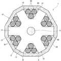
- FIG. 1is a diagram illustrating an example of a slot type optical cable according to a first embodiment of the present invention.
- FIG. 2Ais a diagram illustrating an example of a structure of an intermittent ribbon in a state where the intermittent ribbon is opened in an arrangement direction.
- FIG. 2Bis a cross-sectional view taken along line B-B of FIG. 2A .
- FIG. 3is a diagram illustrating an example of a slot type optical cable according to a second embodiment of the present invention.
- Patent Literature 1there is a problem in that the cable diameter increases by the amount of a projecting shape. Therefore, for a slot type optical cable, a structure capable of reducing friction during installation while avoiding an increase in the diameter of a cable is desired.
- an objectis to provide a slot type optical cable in which high-density packaging can be realized and the amount of friction during installation in a duct is small.
- an increase in the diameter of a cablecan be avoided, high-density packaging of optical fibers can be realized, and the amount of friction during installation in a duct can be reduced.
- a slot type optical cableincluding:
- a slot rodthat includes a plurality of ribs forming a groove in which the optical fiber is accommodatable
- the cable jacketincludes a sheath portion that is formed around the slot rod at substantially the same thickness by linearly connecting outermost peripheral edges of adjacent ribs.
- the periphery of the slot rodis covered with the sheath portion having a polygonal outer peripheral shape, and the contact range with a duct inner wall can be reduced compared to a case where a circular cable is routed in a duct. Therefore, it is easy to perform routing in the duct.
- the number of the ribsis 6 to 8.
- the number of the ribsis less than 6, bending directivity appears, and thus it is difficult to perform bending.
- the number of groovesis an odd number, for example, 5, it is difficult to perform bending.
- the number of ribsis more than 8, the shape of a cable is substantially circular such that the contact range with a duct inner wall increases. Therefore, the amount of friction increases, and it is difficult to perform routing in the duct.
- a grooveis formed using 6 to 8 ribs, a cable having no bending directivity that can be easily installed in a duct can be provided.
- a density of a material used for the sheath portionis lower than 0.942 g/cm 3 .
- the sheath portionis formed of a material having a relatively low density, the sheath portion is likely to be extruded to the periphery of the slot rod. Therefore, the productivity of the cable is improved.
- the ribbonis an intermittent ribbon in which a connection portion and a non-connection portion are intermittently formed in a longitudinal direction between some or all of adjacent optical fibers.
- the intermittent ribbonhas flexibility. Therefore, when the intermittent ribbon is used, the occupancy can be increased compared to a general ribbon.
- FIG. 1is a diagram illustrating an example of a slot type optical cable according to a first embodiment of the present invention.
- FIGS. 2A and 2Bare diagrams illustrating an example of a structure of the intermittent ribbon.
- the slot type optical cable 1 illustrated in FIG. 1includes: a slot rod 10 ; an optical unit 30 ; a wrapping tape 40 that is vertically attached to or horizontally wound around the periphery of the slot rod 10 ; and a cable jacket 41 that is provided around the wrapping tape 40 .
- a tension member 11is buried in a center portion of the slot rod 10 .
- a wire rod having a proof stress against tension and compressionfor example, steel wire or FRP (Fiber Reinforced Plastics) can be used.
- a plurality of (for example, six) slot grooves 12 having a spiral shape or a S-Z configurationare formed on an outer peripheral surface of the slot rod 10 along the cable longitudinal direction.
- the slot groove 12corresponds to the groove according to the present invention.
- the slot rod 10includes, for example, six slot ribs 13 that radially extend from the periphery of the tension member 11 , and the slot rib 13 forms the slot groove 12 and partitions the slop groove 12 from the other slope grooves 12 .
- the slot rib 13corresponds to the rib according to the present invention.
- a tracer mark that identifies the position of the slot groove 12can also be provided on an outer peripheral surface of the slot rib 13 .
- a plurality of 12-fiber intermittent ribbons 20are accommodated in the slot groove 12 .
- FIG. 2Aillustrates a state where the intermittent ribbon is opened in an arrangement direction
- FIG. 2Billustrates a cross-sectional view taken along line B-B of FIG. 2A
- the intermittent ribbon 20 illustrated in the drawinghas a configuration in which the 12-fiber ribbon is intermittently connected on a two-fiber basis.
- a ribbon coating 24 formed of an UV curable resinis provided around each of the optical fibers 21 .
- combinations of two fibers integrated with each otherare connected intermittently through a connection portion 22 and a non-connection portion 23 .
- Ribbon coatings 24are connected in the connection portion 22 , and adjacent ribbon coatings 24 are separated without being connected in the non-connection portion 23 .
- the connection portion and the non-connection portionare not necessarily on a two-fiber basis.
- adjacent ribbon coatings 24may be connected intermittently through the connection portion and the non-connection portion on an one-fiber basis.
- the optical fiber 21 accommodated in the intermittent ribbonrefers to, for example, an optical fiber in which a glass fiber having a standard outer diameter of 125 ⁇ m is covered with a coating having an outer diameter of about 250 ⁇ m and the outside thereof is further covered with a color coating.
- the optical fiber 21is not limited to this configuration and may be a thin fiber having an outer diameter in a range of 135 ⁇ m to 220 ⁇ m, for example, about 165 ⁇ m or 200 ⁇ m. When the thin fiber is used, it is easier to perform high-density packaging.
- the optical unit 30 illustrated in FIG. 1is formed, for example, by gathering a plurality of 12-fiber intermittent ribbons 20 and spirally twisting the gathered intermittent ribbons 20 .
- the twisted ribbons 20may be bound using a bundle material 31 for identification.
- the intermittent ribbons 20may be twisted not only in a spiral shape in one direction but also in a S-Z configuration in which they are periodically inverted.
- the intermittent ribbon 20is more flexible than a general ribbon.
- the occupancy of the optical fibers 21can be increased.
- connection type ribbons or a bundle of optical fibersmay be used instead of using the intermittent ribbons.
- the slot rod 10is wound using the wrapping tape 40 such that the optical unit 30 does not protrude, and outer peripheral shapes thereof are aligned in a polygonal shape (for example, a dodecagonal shape).
- the wrapping tape 40is wrapped such that the outermost peripheral edges of adjacent slot ribs 13 (edges of the slot ribs 13 that are positioned on the outermost peripheral side in the radial direction) are linearly connected.
- non-woven fabricthat is formed in a tape shape or a combination of a base material such as polyethylene terephthalate (PET) and non-woven fabric can be used.
- a water-absorbing agentfor example, water-absorbing powder
- the intermittent ribbonscan be made to be waterproof.
- the cable jacket 41that is formed by extruding a resin such as PE (polyethylene) or PVC (polyvinyl chloride) is provided on the outside of the wrapping tape 40 .
- PEpolyethylene
- PVCpolyvinyl chloride
- the cable jacket 41includes the sheath portion 42 in which an outer peripheral shape is formed in a polygonal shape (for example, a dodecagonal shape).
- the cable jacket 41may be provided by vertically attaching tear strings (not illustrated). In this case, the cable jacket 41 includes not only the sheath portion 42 but also the tear strings.
- the sheath portion 42covers the outermost peripheral edges of adjacent slot ribs 13 (edges of the slot ribs 13 that are positioned on the outermost peripheral side in the radial direction) in a state where they are linearly connected.
- the outermost peripheral edges of the slot ribs 13are indicated by, for example, A, B, and C in FIG. 1 .
- a and Bare linearly connected, and B and C are linearly connected.
- the sheath portion 42is formed such that the periphery of the slot rod 10 , specifically, the outside of the slot groove 12 or the outside of the slot rib 13 has substantially the same thickness.
- the periphery of the slot rod 10is covered with the sheath portion 42 having a polygonal outer peripheral shape, and the contact range with a duct inner wall can be reduced compared to a case where a circular cable is routed in a duct. Therefore, it is easy to perform routing in the duct. Unlike the technique in the related art, it is not necessary to provide a projection in a cable jacket, and even when the cable diameter is maintained to be the same as that of the related art, the diameter of the slot rod 10 can be increased. Therefore, high-density packaging of optical fibers can be realized.
- the density of a material used for the sheath portion 42is preferably lower than 0.942 g/cm 3 (for example, 0.93 g/cm 3 ).
- a material having a density of 0.942 g/cm 3 or higheris also referred to as “high-density polyethylene”, and a material having a density of less than 0.942 g/cm 3 is referred to as “intermediate-density or low-density polyethylene”.
- FIG. 3is a diagram illustrating an example of a slot type optical cable according to a second embodiment of the present invention.
- the slot rod according to the first embodimentis formed using six slot ribs 13 .
- the slot rodmay be formed using eight slot ribs 13 .
- the number of slot ribs 13is preferably 6 to 8.
- the reason for thisis that, when the number of slot ribs is less than 6, bending directivity appears, and it is difficult to perform bending. In particular, when the number of slot grooves is an odd number, for example, 5, it is difficult to perform bending.
- the number of slot ribsis more than 8, the shape of a cable is substantially circular such that the contact range with a duct inner wall increases. Therefore, the amount of friction during installation increases, and it is difficult to perform routing in the duct.
Landscapes
- Physics & Mathematics (AREA)
- General Physics & Mathematics (AREA)
- Optics & Photonics (AREA)
- Light Guides In General And Applications Therefor (AREA)
- Insulated Conductors (AREA)
Abstract
Description
- 1: slot type optical cable
- 10: slot rod
- 11: tension member
- 12: slot groove
- 13: slot rib
- 20: intermittent ribbon
- 21: optical fiber
- 22: connection portion
- 23: non-connection portion
- 24: ribbon coating
- 30: optical unit
- 31: bundle material
- 40: wrapping tape
- 41: cable jacket
- 42: sheath portion
Claims (3)
Applications Claiming Priority (4)
| Application Number | Priority Date | Filing Date | Title |
|---|---|---|---|
| JP2017-116639 | 2017-06-14 | ||
| JP2017116639 | 2017-06-14 | ||
| JPJP2017-116639 | 2017-06-14 | ||
| PCT/JP2018/022638WO2018230618A1 (en) | 2017-06-14 | 2018-06-13 | Slot-type optical cable |
Publications (2)
| Publication Number | Publication Date |
|---|---|
| US20200218021A1 US20200218021A1 (en) | 2020-07-09 |
| US11194108B2true US11194108B2 (en) | 2021-12-07 |
Family
ID=64660197
Family Applications (1)
| Application Number | Title | Priority Date | Filing Date |
|---|---|---|---|
| US16/622,536ActiveUS11194108B2 (en) | 2017-06-14 | 2018-06-13 | Slot-type optical cable |
Country Status (5)
| Country | Link |
|---|---|
| US (1) | US11194108B2 (en) |
| EP (1) | EP3640694A4 (en) |
| JP (1) | JPWO2018230618A1 (en) |
| CN (1) | CN110770621A (en) |
| WO (1) | WO2018230618A1 (en) |
Cited By (1)
| Publication number | Priority date | Publication date | Assignee | Title |
|---|---|---|---|---|
| US20230418013A1 (en)* | 2019-12-11 | 2023-12-28 | Fujikura Ltd. | Optical fiber cable |
Families Citing this family (3)
| Publication number | Priority date | Publication date | Assignee | Title |
|---|---|---|---|---|
| JPWO2018230618A1 (en)* | 2017-06-14 | 2020-04-16 | 住友電気工業株式会社 | Slotted optical cable |
| US20220326463A1 (en)* | 2019-06-07 | 2022-10-13 | Sumitomo Electric Industries, Ltd. | Optical fiber cable and manufacturing method for optical fiber cable |
| CN114675386B (en)* | 2022-04-01 | 2023-09-12 | 杭州富通通信技术股份有限公司 | an optical cable |
Citations (55)
| Publication number | Priority date | Publication date | Assignee | Title |
|---|---|---|---|---|
| GB1409303A (en) | 1972-09-20 | 1975-10-08 | Post Office | Optical strands |
| DE2511019A1 (en) | 1975-03-11 | 1976-09-23 | Siemens Ag | Core member for fibre optic cables - is fitted with reinforced centre and lubricated fibre strands to resist tension and bending |
| US4820014A (en)* | 1987-02-25 | 1989-04-11 | Sumitomo Electric Industries, Ltd. | Optical cable |
| JPH0271808U (en) | 1988-11-19 | 1990-05-31 | ||
| US4983013A (en)* | 1988-08-30 | 1991-01-08 | Siemens Aktiengesellschaft | Optical cable comprising a carrier member |
| US4997257A (en)* | 1989-04-14 | 1991-03-05 | Spedding Stephen T | Optical cable |
| US5166998A (en)* | 1992-02-21 | 1992-11-24 | Siecor Corporation | Optical ribbon cable component |
| US5222177A (en) | 1992-03-31 | 1993-06-22 | At&T Bell Laboratories | Underwater optical fiber cable having optical fiber coupled to grooved core member |
| US5561730A (en)* | 1995-02-23 | 1996-10-01 | Siecor Corporation | Cable containing fiber ribbons with optimized frictional properties |
| US5630002A (en)* | 1995-02-27 | 1997-05-13 | Sumitomo Electric Industries, Ltd. | Optical fiber cable |
| US5638478A (en)* | 1994-07-06 | 1997-06-10 | The Furukawa Electric Co., Ltd. | Optical fiber cable having a grooved spacer formed with one or more SZ-spiral grooves on its outer circumference along the longitudinal direction of the spacer the inverting angle of each groove being at least 180° |
| US5661836A (en)* | 1995-02-20 | 1997-08-26 | Sumitomo Electric Industries, Ltd. | Optical cable and manufacturing method thereof |
| US5668912A (en)* | 1996-02-07 | 1997-09-16 | Alcatel Na Cable Systems, Inc. | Rectangular optical fiber cable |
| US5715344A (en)* | 1995-10-31 | 1998-02-03 | Daewoo Telecom, Ltd. | Core for use in a slot type optical cable |
| US5751881A (en)* | 1995-06-08 | 1998-05-12 | Furukawa Electric Co., Ltd. | Optical fiber cable |
| US5848212A (en)* | 1996-09-10 | 1998-12-08 | Siecor Corporation | High density optical cable |
| US6052502A (en)* | 1997-09-22 | 2000-04-18 | Siecor Corporation | Ribbon optical cable having improved strength |
| US6122426A (en)* | 1997-07-15 | 2000-09-19 | Sumitomo Electric Industries, Ltd. | Optical cable and optical cable chamber element |
| US6160940A (en)* | 1997-06-05 | 2000-12-12 | Corning Cable Systems Llc | Fiber optic cable for installation in a cable passageway and methods and an apparatus for producing the same |
| US6259843B1 (en)* | 1998-09-22 | 2001-07-10 | Sumitomo Wiring Systems, Ltd. | Optical cable, a method of laying an optical cable, and a data transfer system using the optical cable |
| US20010028773A1 (en)* | 2000-01-26 | 2001-10-11 | Sumitomo Electric Industries, Ltd. | Fiber optic cable and optical transmission system |
| US6424772B1 (en)* | 1999-11-30 | 2002-07-23 | Corning Cable Systems, Llc | Fiber optic cable product and associated fabrication method and apparatus |
| US6711328B2 (en)* | 2001-07-12 | 2004-03-23 | Nkf Kabel B.V. | Installation bundle with spacer |
| US6768845B1 (en)* | 1999-02-19 | 2004-07-27 | Sumitomo Electric Industries, Ltd. | Optical cable for holding optical fiber ribbons having a plurality of one groove spacers |
| US20050244117A1 (en)* | 2002-09-11 | 2005-11-03 | The Furukawa Electric Co., Ltd. | Optical fiber tape of low polarization mode dispersion characteristic and method for measuring dynamic viscoelasticity of the optical fiber tape |
| JP2006018000A (en) | 2004-07-01 | 2006-01-19 | Fujikura Ltd | SZ slot type cable and SZ slot used for the SZ slot type cable |
| US20060120676A1 (en)* | 2004-12-08 | 2006-06-08 | Samsung Electronics Co.; Ltd | Slotted-core ribbon optical cable |
| US7155097B2 (en)* | 2001-03-09 | 2006-12-26 | Crystal Fibre A/S | Fabrication of microstructured fibres |
| JP2008286940A (en) | 2007-05-16 | 2008-11-27 | Furukawa Electric Co Ltd:The | Flame retardant optical cable |
| JP2010091842A (en) | 2008-10-09 | 2010-04-22 | Sumitomo Electric Ind Ltd | Optical cable |
| WO2011043324A1 (en) | 2009-10-06 | 2011-04-14 | 株式会社フジクラ | Optical fiber cable |
| US20110110635A1 (en)* | 2008-06-30 | 2011-05-12 | Kunihiro Toge | Optical fiber cable and optical fiber ribbon |
| US20120063732A1 (en)* | 2009-07-03 | 2012-03-15 | Huawei Technologies Co., Ltd. | Optical cable and optical cable system |
| US20120189257A1 (en)* | 2010-07-22 | 2012-07-26 | Furukawa Electric Co., Ltd. | Optical fiber, optical fiber ribbon and optical fiber cable |
| JP2013142764A (en) | 2012-01-11 | 2013-07-22 | Sumitomo Electric Ind Ltd | Optical fiber cable |
| US20150192748A1 (en) | 2014-01-08 | 2015-07-09 | Sumitomo Electric Industries, Ltd. | Optical fiber cable for air blow installation |
| CN105229510A (en) | 2013-05-07 | 2016-01-06 | 株式会社藤仓 | Optical fiber core and optical cable |
| JP2016018088A (en) | 2014-07-09 | 2016-02-01 | 住友電気工業株式会社 | Manufacturing method for optical cable |
| US20160291278A1 (en)* | 2015-04-01 | 2016-10-06 | Sumitomo Electric Industries, Ltd. | Optical fiber cable |
| US20170023754A1 (en)* | 2015-07-22 | 2017-01-26 | Ofs Fitel, Llc | Optical fiber cables |
| US9557231B2 (en)* | 2010-10-01 | 2017-01-31 | Afl Telecommunications Llc | Sensing cable |
| US20170031122A1 (en)* | 2015-04-01 | 2017-02-02 | Sumitomo Electric Industries, Ltd. | Optical fiber cable |
| US20170031088A1 (en)* | 2015-04-01 | 2017-02-02 | Sumitomo Electric Industries, Ltd. | Optical fiber cable |
| US20170115451A1 (en)* | 2014-05-09 | 2017-04-27 | Fujikura, Ltd. | Optical fiber cable |
| US20180314020A1 (en)* | 2016-01-13 | 2018-11-01 | Sumitomo Electric Industries, Ltd. | Intermittent-connection-type optical fiber ribbon and optical cable |
| US20180321453A1 (en)* | 2016-01-28 | 2018-11-08 | Sumitomo Electric Industries, Ltd. | Optical fiber cable |
| US20190011656A1 (en)* | 2015-07-31 | 2019-01-10 | Sumitomo Electric Industries, Ltd. | Optical fiber cable |
| US20190064462A1 (en)* | 2016-02-08 | 2019-02-28 | Sumitomo Electric Industries, Ltd. | Optical fiber cable |
| US20190265425A1 (en)* | 2018-02-27 | 2019-08-29 | Optical Cable Corporation | Deployable Fiber Optic Cable with Partially Bonded Ribbon Fibers |
| US20200064550A1 (en)* | 2016-12-06 | 2020-02-27 | Sumitomo Electric Industries, Ltd. | Intermittently-coupled type optical fiber ribbon, manufacturing method thereof, optical fiber cable, and optical fiber cord |
| US20200150368A1 (en)* | 2017-07-24 | 2020-05-14 | Sumitomo Electric Industries, Ltd. | Optical fiber ribbon and optical fiber cable |
| US20200183111A1 (en)* | 2016-06-13 | 2020-06-11 | Sumitomo Electric Industries, Ltd. | Optical fiber cable |
| US20200218021A1 (en)* | 2017-06-14 | 2020-07-09 | Sumitomo Electric Industries, Ltd. | Slot-type optical cable |
| US20200225432A1 (en)* | 2017-09-21 | 2020-07-16 | Sumitomo Electric Industries, Ltd. | Optical fiber cable |
| US20200371306A1 (en)* | 2017-03-07 | 2020-11-26 | Commscope Technologies Llc | System for locking optical fibers within a fiber optic cable |
Family Cites Families (4)
| Publication number | Priority date | Publication date | Assignee | Title |
|---|---|---|---|---|
| CN106959496A (en)* | 2015-03-10 | 2017-07-18 | 周惠 | A kind of optical cable and preparation method |
| JP6679875B2 (en)* | 2015-10-14 | 2020-04-15 | 住友電気工業株式会社 | Slot rods for fiber optic cables and fiber optic cables |
| CN205941998U (en)* | 2016-07-13 | 2017-02-08 | 深圳市九洲蓉胜科技有限公司 | Resistant type staying cable configuration that draws |
| CN206021977U (en)* | 2016-07-13 | 2017-03-15 | 深圳市九洲蓉胜科技有限公司 | A kind of multifunctional integrated miniature tether cable |
- 2018
- 2018-06-13JPJP2019525495Apatent/JPWO2018230618A1/enactivePending
- 2018-06-13USUS16/622,536patent/US11194108B2/enactiveActive
- 2018-06-13CNCN201880039545.XApatent/CN110770621A/enactivePending
- 2018-06-13WOPCT/JP2018/022638patent/WO2018230618A1/ennot_activeCeased
- 2018-06-13EPEP18817845.3Apatent/EP3640694A4/ennot_activeWithdrawn
Patent Citations (70)
| Publication number | Priority date | Publication date | Assignee | Title |
|---|---|---|---|---|
| GB1409303A (en) | 1972-09-20 | 1975-10-08 | Post Office | Optical strands |
| DE2511019A1 (en) | 1975-03-11 | 1976-09-23 | Siemens Ag | Core member for fibre optic cables - is fitted with reinforced centre and lubricated fibre strands to resist tension and bending |
| US4820014A (en)* | 1987-02-25 | 1989-04-11 | Sumitomo Electric Industries, Ltd. | Optical cable |
| US4983013A (en)* | 1988-08-30 | 1991-01-08 | Siemens Aktiengesellschaft | Optical cable comprising a carrier member |
| JPH0271808U (en) | 1988-11-19 | 1990-05-31 | ||
| US4997257A (en)* | 1989-04-14 | 1991-03-05 | Spedding Stephen T | Optical cable |
| US5166998A (en)* | 1992-02-21 | 1992-11-24 | Siecor Corporation | Optical ribbon cable component |
| US5222177A (en) | 1992-03-31 | 1993-06-22 | At&T Bell Laboratories | Underwater optical fiber cable having optical fiber coupled to grooved core member |
| JPH06102443A (en) | 1992-03-31 | 1994-04-15 | American Teleph & Telegr Co <Att> | Fiber optic cable and fiber optic cable core |
| US5638478A (en)* | 1994-07-06 | 1997-06-10 | The Furukawa Electric Co., Ltd. | Optical fiber cable having a grooved spacer formed with one or more SZ-spiral grooves on its outer circumference along the longitudinal direction of the spacer the inverting angle of each groove being at least 180° |
| US5661836A (en)* | 1995-02-20 | 1997-08-26 | Sumitomo Electric Industries, Ltd. | Optical cable and manufacturing method thereof |
| US5561730A (en)* | 1995-02-23 | 1996-10-01 | Siecor Corporation | Cable containing fiber ribbons with optimized frictional properties |
| US5630002A (en)* | 1995-02-27 | 1997-05-13 | Sumitomo Electric Industries, Ltd. | Optical fiber cable |
| US5751881A (en)* | 1995-06-08 | 1998-05-12 | Furukawa Electric Co., Ltd. | Optical fiber cable |
| US5845032A (en)* | 1995-06-08 | 1998-12-01 | The Furukawa Electric Co., Ltd. | Optical fiber cable |
| US5715344A (en)* | 1995-10-31 | 1998-02-03 | Daewoo Telecom, Ltd. | Core for use in a slot type optical cable |
| US5668912A (en)* | 1996-02-07 | 1997-09-16 | Alcatel Na Cable Systems, Inc. | Rectangular optical fiber cable |
| US5848212A (en)* | 1996-09-10 | 1998-12-08 | Siecor Corporation | High density optical cable |
| US6160940A (en)* | 1997-06-05 | 2000-12-12 | Corning Cable Systems Llc | Fiber optic cable for installation in a cable passageway and methods and an apparatus for producing the same |
| US6122426A (en)* | 1997-07-15 | 2000-09-19 | Sumitomo Electric Industries, Ltd. | Optical cable and optical cable chamber element |
| US6052502A (en)* | 1997-09-22 | 2000-04-18 | Siecor Corporation | Ribbon optical cable having improved strength |
| US6259843B1 (en)* | 1998-09-22 | 2001-07-10 | Sumitomo Wiring Systems, Ltd. | Optical cable, a method of laying an optical cable, and a data transfer system using the optical cable |
| US6768845B1 (en)* | 1999-02-19 | 2004-07-27 | Sumitomo Electric Industries, Ltd. | Optical cable for holding optical fiber ribbons having a plurality of one groove spacers |
| US6424772B1 (en)* | 1999-11-30 | 2002-07-23 | Corning Cable Systems, Llc | Fiber optic cable product and associated fabrication method and apparatus |
| US20010028773A1 (en)* | 2000-01-26 | 2001-10-11 | Sumitomo Electric Industries, Ltd. | Fiber optic cable and optical transmission system |
| US7155097B2 (en)* | 2001-03-09 | 2006-12-26 | Crystal Fibre A/S | Fabrication of microstructured fibres |
| US6711328B2 (en)* | 2001-07-12 | 2004-03-23 | Nkf Kabel B.V. | Installation bundle with spacer |
| US20050244117A1 (en)* | 2002-09-11 | 2005-11-03 | The Furukawa Electric Co., Ltd. | Optical fiber tape of low polarization mode dispersion characteristic and method for measuring dynamic viscoelasticity of the optical fiber tape |
| JP2006018000A (en) | 2004-07-01 | 2006-01-19 | Fujikura Ltd | SZ slot type cable and SZ slot used for the SZ slot type cable |
| US20060120676A1 (en)* | 2004-12-08 | 2006-06-08 | Samsung Electronics Co.; Ltd | Slotted-core ribbon optical cable |
| JP2008286940A (en) | 2007-05-16 | 2008-11-27 | Furukawa Electric Co Ltd:The | Flame retardant optical cable |
| US8548294B2 (en)* | 2008-06-30 | 2013-10-01 | Nippon Telegraph And Telephone Corporation | Optical fiber cable and optical fiber ribbon |
| US20110110635A1 (en)* | 2008-06-30 | 2011-05-12 | Kunihiro Toge | Optical fiber cable and optical fiber ribbon |
| JP2010091842A (en) | 2008-10-09 | 2010-04-22 | Sumitomo Electric Ind Ltd | Optical cable |
| US20120063732A1 (en)* | 2009-07-03 | 2012-03-15 | Huawei Technologies Co., Ltd. | Optical cable and optical cable system |
| US8660392B2 (en)* | 2009-07-03 | 2014-02-25 | Huawei Technologies Co., Ltd. | Optical cable and optical cable system |
| WO2011043324A1 (en) | 2009-10-06 | 2011-04-14 | 株式会社フジクラ | Optical fiber cable |
| US20120189257A1 (en)* | 2010-07-22 | 2012-07-26 | Furukawa Electric Co., Ltd. | Optical fiber, optical fiber ribbon and optical fiber cable |
| US9557231B2 (en)* | 2010-10-01 | 2017-01-31 | Afl Telecommunications Llc | Sensing cable |
| JP2013142764A (en) | 2012-01-11 | 2013-07-22 | Sumitomo Electric Ind Ltd | Optical fiber cable |
| CN105229510A (en) | 2013-05-07 | 2016-01-06 | 株式会社藤仓 | Optical fiber core and optical cable |
| US20160070079A1 (en) | 2013-05-07 | 2016-03-10 | Nippon Telegraph And Telephone Corporation | Optical fiber ribbon and optical fiber cable |
| US9541722B2 (en)* | 2013-05-07 | 2017-01-10 | Fujikura Ltd. | Optical fiber ribbon and optical fiber cable |
| US20150192748A1 (en) | 2014-01-08 | 2015-07-09 | Sumitomo Electric Industries, Ltd. | Optical fiber cable for air blow installation |
| JP2015129887A (en) | 2014-01-08 | 2015-07-16 | 住友電気工業株式会社 | Pneumatic fiber optic cable |
| US20170115451A1 (en)* | 2014-05-09 | 2017-04-27 | Fujikura, Ltd. | Optical fiber cable |
| JP2016018088A (en) | 2014-07-09 | 2016-02-01 | 住友電気工業株式会社 | Manufacturing method for optical cable |
| US9645340B2 (en)* | 2015-04-01 | 2017-05-09 | Sumitomo Electric Industries, Ltd. | Optical fiber cable |
| US20170031122A1 (en)* | 2015-04-01 | 2017-02-02 | Sumitomo Electric Industries, Ltd. | Optical fiber cable |
| US20170031088A1 (en)* | 2015-04-01 | 2017-02-02 | Sumitomo Electric Industries, Ltd. | Optical fiber cable |
| US20160291278A1 (en)* | 2015-04-01 | 2016-10-06 | Sumitomo Electric Industries, Ltd. | Optical fiber cable |
| US9696508B2 (en)* | 2015-04-01 | 2017-07-04 | Sumitomo Electric Industries, Ltd. | Optical fiber cable |
| US20170023754A1 (en)* | 2015-07-22 | 2017-01-26 | Ofs Fitel, Llc | Optical fiber cables |
| US10036863B2 (en)* | 2015-07-22 | 2018-07-31 | Ofs Fitel, Llc | Optical fiber cables with flat ribbon fibers |
| US10514517B2 (en)* | 2015-07-31 | 2019-12-24 | Sumitomo Electric Industries, Ltd. | Optical fiber cable |
| US20190011656A1 (en)* | 2015-07-31 | 2019-01-10 | Sumitomo Electric Industries, Ltd. | Optical fiber cable |
| US20180314020A1 (en)* | 2016-01-13 | 2018-11-01 | Sumitomo Electric Industries, Ltd. | Intermittent-connection-type optical fiber ribbon and optical cable |
| US10488609B2 (en)* | 2016-01-13 | 2019-11-26 | Sumitomo Electric Industries, Ltd. | Intermittent-connection-type optical fiber ribbon and optical cable |
| US10268009B2 (en)* | 2016-01-28 | 2019-04-23 | Sumitomo Electric Industries, Ltd. | Optical fiber cable |
| US20180321453A1 (en)* | 2016-01-28 | 2018-11-08 | Sumitomo Electric Industries, Ltd. | Optical fiber cable |
| US10416403B2 (en)* | 2016-02-08 | 2019-09-17 | Sumitomo Electric Industries, Ltd. | Optical fiber cable |
| US20190064462A1 (en)* | 2016-02-08 | 2019-02-28 | Sumitomo Electric Industries, Ltd. | Optical fiber cable |
| US20200183111A1 (en)* | 2016-06-13 | 2020-06-11 | Sumitomo Electric Industries, Ltd. | Optical fiber cable |
| US10845556B2 (en)* | 2016-06-13 | 2020-11-24 | Sumitomo Electric Industries, Ltd. | Optical fiber cable |
| US20200064550A1 (en)* | 2016-12-06 | 2020-02-27 | Sumitomo Electric Industries, Ltd. | Intermittently-coupled type optical fiber ribbon, manufacturing method thereof, optical fiber cable, and optical fiber cord |
| US20200371306A1 (en)* | 2017-03-07 | 2020-11-26 | Commscope Technologies Llc | System for locking optical fibers within a fiber optic cable |
| US20200218021A1 (en)* | 2017-06-14 | 2020-07-09 | Sumitomo Electric Industries, Ltd. | Slot-type optical cable |
| US20200150368A1 (en)* | 2017-07-24 | 2020-05-14 | Sumitomo Electric Industries, Ltd. | Optical fiber ribbon and optical fiber cable |
| US20200225432A1 (en)* | 2017-09-21 | 2020-07-16 | Sumitomo Electric Industries, Ltd. | Optical fiber cable |
| US20190265425A1 (en)* | 2018-02-27 | 2019-08-29 | Optical Cable Corporation | Deployable Fiber Optic Cable with Partially Bonded Ribbon Fibers |
Cited By (2)
| Publication number | Priority date | Publication date | Assignee | Title |
|---|---|---|---|---|
| US20230418013A1 (en)* | 2019-12-11 | 2023-12-28 | Fujikura Ltd. | Optical fiber cable |
| US12353036B2 (en)* | 2019-12-11 | 2025-07-08 | Fujikura Ltd. | Optical fiber cable |
Also Published As
| Publication number | Publication date |
|---|---|
| WO2018230618A1 (en) | 2018-12-20 |
| EP3640694A1 (en) | 2020-04-22 |
| US20200218021A1 (en) | 2020-07-09 |
| JPWO2018230618A1 (en) | 2020-04-16 |
| EP3640694A4 (en) | 2021-03-03 |
| CN110770621A (en) | 2020-02-07 |
Similar Documents
| Publication | Publication Date | Title |
|---|---|---|
| US11194108B2 (en) | Slot-type optical cable | |
| US9869838B2 (en) | Optical fiber cable and method of manufacturing same | |
| US10914906B2 (en) | Optical fiber cable | |
| WO2017131117A1 (en) | Optical fiber cable | |
| US11520114B2 (en) | Optical fiber cable having rollable ribbons and central strength member | |
| KR100526506B1 (en) | Optical cable for air blow installation | |
| JPWO2019088255A1 (en) | Fiber optic unit and fiber optic cable | |
| JP6459833B2 (en) | Fiber optic cable | |
| US20210072477A1 (en) | Optical fiber unit and optical fiber cable | |
| JP6679875B2 (en) | Slot rods for fiber optic cables and fiber optic cables | |
| US11125959B2 (en) | Flat drop optical fiber cable | |
| WO2019004147A1 (en) | Optical fiber cable | |
| JP2020079876A (en) | Slot rods for fiber optic cables and fiber optic cables | |
| JP7024719B2 (en) | Slot rod and fiber optic cable | |
| JP2018031887A (en) | Optical fiber cable | |
| JP6323411B2 (en) | Optical fiber ribbon and optical fiber cable | |
| CN104749725A (en) | Novel layer-stranded optical cable | |
| JP2004212960A (en) | Fiber optic cable | |
| KR20200097067A (en) | Complex wire cable | |
| WO2025135055A1 (en) | Optical fiber cable | |
| JP4234670B2 (en) | Fiber optic cable | |
| JP2014153521A (en) | Optical cable | |
| HK40019866A (en) | Slot-type optical cable | |
| JPH11311729A (en) | Fiber optic cable | |
| WO2023120483A1 (en) | Optical fiber cable |
Legal Events
| Date | Code | Title | Description |
|---|---|---|---|
| AS | Assignment | Owner name:SUMITOMO ELECTRIC INDUSTRIES, LTD., JAPAN Free format text:ASSIGNMENT OF ASSIGNORS INTEREST;ASSIGNORS:OKADA, KEISUKE;SATO, FUMIAKI;NAGAO, YOSHIAKI;SIGNING DATES FROM 20191209 TO 20191210;REEL/FRAME:051278/0877 | |
| FEPP | Fee payment procedure | Free format text:ENTITY STATUS SET TO UNDISCOUNTED (ORIGINAL EVENT CODE: BIG.); ENTITY STATUS OF PATENT OWNER: LARGE ENTITY | |
| STPP | Information on status: patent application and granting procedure in general | Free format text:RESPONSE TO NON-FINAL OFFICE ACTION ENTERED AND FORWARDED TO EXAMINER | |
| STPP | Information on status: patent application and granting procedure in general | Free format text:FINAL REJECTION MAILED | |
| STPP | Information on status: patent application and granting procedure in general | Free format text:RESPONSE AFTER FINAL ACTION FORWARDED TO EXAMINER | |
| STPP | Information on status: patent application and granting procedure in general | Free format text:ADVISORY ACTION MAILED | |
| STPP | Information on status: patent application and granting procedure in general | Free format text:NOTICE OF ALLOWANCE MAILED -- APPLICATION RECEIVED IN OFFICE OF PUBLICATIONS | |
| STPP | Information on status: patent application and granting procedure in general | Free format text:PUBLICATIONS -- ISSUE FEE PAYMENT RECEIVED | |
| STPP | Information on status: patent application and granting procedure in general | Free format text:PUBLICATIONS -- ISSUE FEE PAYMENT VERIFIED | |
| STCF | Information on status: patent grant | Free format text:PATENTED CASE | |
| MAFP | Maintenance fee payment | Free format text:PAYMENT OF MAINTENANCE FEE, 4TH YEAR, LARGE ENTITY (ORIGINAL EVENT CODE: M1551); ENTITY STATUS OF PATENT OWNER: LARGE ENTITY Year of fee payment:4 |