US11193609B2 - Pipe coupling - Google Patents
Pipe couplingDownload PDFInfo
- Publication number
- US11193609B2 US11193609B2US15/908,096US201815908096AUS11193609B2US 11193609 B2US11193609 B2US 11193609B2US 201815908096 AUS201815908096 AUS 201815908096AUS 11193609 B2US11193609 B2US 11193609B2
- Authority
- US
- United States
- Prior art keywords
- gasket
- sealing ring
- element assembly
- interior cavity
- annular sealing
- Prior art date
- Legal status (The legal status is an assumption and is not a legal conclusion. Google has not performed a legal analysis and makes no representation as to the accuracy of the status listed.)
- Active, expires
Links
Images


Classifications
- F—MECHANICAL ENGINEERING; LIGHTING; HEATING; WEAPONS; BLASTING
- F16—ENGINEERING ELEMENTS AND UNITS; GENERAL MEASURES FOR PRODUCING AND MAINTAINING EFFECTIVE FUNCTIONING OF MACHINES OR INSTALLATIONS; THERMAL INSULATION IN GENERAL
- F16L—PIPES; JOINTS OR FITTINGS FOR PIPES; SUPPORTS FOR PIPES, CABLES OR PROTECTIVE TUBING; MEANS FOR THERMAL INSULATION IN GENERAL
- F16L17/00—Joints with packing adapted to sealing by fluid pressure
- F16L17/02—Joints with packing adapted to sealing by fluid pressure with sealing rings arranged between outer surface of pipe and inner surface of sleeve or socket
- F16L17/03—Joints with packing adapted to sealing by fluid pressure with sealing rings arranged between outer surface of pipe and inner surface of sleeve or socket having annular axial lips
- F16L17/032—Joints with packing adapted to sealing by fluid pressure with sealing rings arranged between outer surface of pipe and inner surface of sleeve or socket having annular axial lips the sealing rings having only one lip
- F—MECHANICAL ENGINEERING; LIGHTING; HEATING; WEAPONS; BLASTING
- F16—ENGINEERING ELEMENTS AND UNITS; GENERAL MEASURES FOR PRODUCING AND MAINTAINING EFFECTIVE FUNCTIONING OF MACHINES OR INSTALLATIONS; THERMAL INSULATION IN GENERAL
- F16L—PIPES; JOINTS OR FITTINGS FOR PIPES; SUPPORTS FOR PIPES, CABLES OR PROTECTIVE TUBING; MEANS FOR THERMAL INSULATION IN GENERAL
- F16L21/00—Joints with sleeve or socket
- F16L21/02—Joints with sleeve or socket with elastic sealing rings between pipe and sleeve or between pipe and socket, e.g. with rolling or other prefabricated profiled rings
- F16L21/022—Joints with sleeve or socket with elastic sealing rings between pipe and sleeve or between pipe and socket, e.g. with rolling or other prefabricated profiled rings used with sleeves or nipples for pipes of the same diameter, or with reduction pieces
- F—MECHANICAL ENGINEERING; LIGHTING; HEATING; WEAPONS; BLASTING
- F16—ENGINEERING ELEMENTS AND UNITS; GENERAL MEASURES FOR PRODUCING AND MAINTAINING EFFECTIVE FUNCTIONING OF MACHINES OR INSTALLATIONS; THERMAL INSULATION IN GENERAL
- F16L—PIPES; JOINTS OR FITTINGS FOR PIPES; SUPPORTS FOR PIPES, CABLES OR PROTECTIVE TUBING; MEANS FOR THERMAL INSULATION IN GENERAL
- F16L21/00—Joints with sleeve or socket
- F16L21/02—Joints with sleeve or socket with elastic sealing rings between pipe and sleeve or between pipe and socket, e.g. with rolling or other prefabricated profiled rings
- F16L21/03—Joints with sleeve or socket with elastic sealing rings between pipe and sleeve or between pipe and socket, e.g. with rolling or other prefabricated profiled rings placed in the socket before connection
- F—MECHANICAL ENGINEERING; LIGHTING; HEATING; WEAPONS; BLASTING
- F16—ENGINEERING ELEMENTS AND UNITS; GENERAL MEASURES FOR PRODUCING AND MAINTAINING EFFECTIVE FUNCTIONING OF MACHINES OR INSTALLATIONS; THERMAL INSULATION IN GENERAL
- F16L—PIPES; JOINTS OR FITTINGS FOR PIPES; SUPPORTS FOR PIPES, CABLES OR PROTECTIVE TUBING; MEANS FOR THERMAL INSULATION IN GENERAL
- F16L25/00—Construction or details of pipe joints not provided for in, or of interest apart from, groups F16L13/00 - F16L23/00
- F16L25/12—Joints for pipes being spaced apart axially
- F—MECHANICAL ENGINEERING; LIGHTING; HEATING; WEAPONS; BLASTING
- F16—ENGINEERING ELEMENTS AND UNITS; GENERAL MEASURES FOR PRODUCING AND MAINTAINING EFFECTIVE FUNCTIONING OF MACHINES OR INSTALLATIONS; THERMAL INSULATION IN GENERAL
- F16L—PIPES; JOINTS OR FITTINGS FOR PIPES; SUPPORTS FOR PIPES, CABLES OR PROTECTIVE TUBING; MEANS FOR THERMAL INSULATION IN GENERAL
- F16L27/00—Adjustable joints; Joints allowing movement
- F16L27/02—Universal joints, i.e. with mechanical connection allowing angular movement or adjustment of the axes of the parts in any direction
Definitions
- This disclosurerelates to piping. More specifically, this disclosure relates to joining piping elements.
- Municipal piping systemsoften can include piping lines of various sizes. Even with respect to a measurement—for example, diameter of piping—industry standards can vary depending on the material used. For example, ductile iron piping can be measured to have a different diameter from steel piping, and steel piping can be measured to have a different diameter from polyvinyl chloride (PVC) piping, even if all the different piping materials are within the same piping diameter class. As such, piping elements can often be directed only toward one piping material. Additionally, different piping materials can have different manufacturing tolerances, further complicating the design of attachments for said municipal piping supplies.
- PVCpolyvinyl chloride
- a slip-on piping element assembly for coupling two pipe lengthsincludes a coupling body, the coupling body comprising an outer shell extending between a first end and a second end of the coupling body, the outer shell defining an axial direction extending from the first end to the second end and a radial direction extending orthogonally from the axial direction, an inner shell defining an interior cavity, a first bore defined in the first end and communicating with the interior cavity, and a second bore defined in the second end and communicating with the interior cavity; at least one gasket disposed within the interior cavity, each gasket comprising a gasket shoulder contacting the inner shell of the coupling body, an annular sealing ring including a sealing surface disposed radially inward on the annular sealing ring and adapted to seal against an outer surface of one pipe length, and a connecting portion connecting the gasket shoulder to the annular ring, wherein the annular sealing ring, the connecting portion, and the gasket shoulder define a channel, the channel in fluid communication with the interior cavity.
- a gasketincludes a gasket shoulder, the gasket shoulder defining a radial gasket end; an annular sealing ring defining a sealing surface disposed radially inward on the annular sealing ring, and; a connecting portion connecting the gasket shoulder to the annular ring, wherein the annular sealing ring, the connecting portion, and the gasket shoulder define a channel, the channel in fluid communication with the interior cavity.
- a method of joining two pipe lengthsincludes obtaining a piping element assembly, the piping element assembly comprising a coupling body, the coupling body comprising an outer shell extending between a first end and a second end of the coupling body, the outer shell defining an axial direction extending from the first end to the second end and a radial direction extending orthogonally from the axial direction, an inner shell defining an interior cavity, a first bore defined in the first end and communicating with the interior cavity, and a second bore defined in the second end and communicating with the interior cavity; at least one gasket disposed within the interior cavity, each gasket comprising a gasket shoulder contacting the inner shell of the coupling body, an annular sealing ring including a sealing surface disposed radially inward on the annular sealing ring and adapted to seal against an outer surface of one pipe length, and a connecting portion connecting the gasket shoulder to the annular ring, wherein the annular sealing ring, the connecting portion, and the gasket shoulder define a channel, the channel in fluid communication
- FIG. 1is a perspective view of a piping element assembly in connection with two pipe lengths in accord with one aspect of the current disclosure.
- FIG. 2is a perspective view of a coupling body of the piping element assembly of FIG. 1 .
- FIG. 3is a cutaway perspective view of the coupling body of FIG. 2 taken along an x-axis or an axial direction.
- FIG. 4is a cutaway side view of the coupling body of FIG. 2 taken along an x-axis or an axial direction.
- FIG. 5Ais a perspective view of a gasket of the piping element assembly of FIG. 1 .
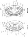
- FIG. 5Bis a second perspective view of a gasket of the piping element assembly of FIG. 1 .
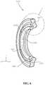
- FIG. 6is a cutaway perspective view of the gasket of FIG. 5B .
- FIG. 7is a detail view of the Detail 7 as annotated in FIG. 6 .
- FIG. 8is a cutaway side view of the piping element assembly in connection with two pipe lengths as indicated with reference to FIG. 1 .
- FIG. 9is a detail view of a gasket in accord with another aspect of the current disclosure.
- FIG. 10is a cutaway side view of a piping element assembly including the gasket of FIG. 9 arranged on pipe lengths having an angle of deflection in accord with one aspect of the current disclosure.
- Rangescan be expressed herein as from “about” one particular value, and/or to “about” another particular value. When such a range is expressed, another aspect includes from the one particular value and/or to the other particular value. Similarly, when values are expressed as approximations, by use of the antecedent “about,” it will be understood that the particular value forms another aspect. It will be further understood that the endpoints of each of the ranges are significant both in relation to the other endpoint, and independently of the other endpoint.
- a material property or dimension measuring about X or substantially X on a particular measurement scalemeasures within a range between X plus an industry-standard upper tolerance for the specified measurement and X minus an industry-standard lower tolerance for the specified measurement. Because tolerances can vary between different materials, processes and between different models, the tolerance for a particular measurement of a particular component can fall within a range of tolerances.
- the terms “optional” or “optionally”mean that the subsequently described event or circumstance can or cannot occur, and that the description includes instances where said event or circumstance occurs and instances where it does not.
- the piping element assemblycan comprise at least one gasket. It would be understood by one of skill in the art that the disclosed piping element assembly is described in but a few exemplary aspects among many. No particular terminology or description should be considered limiting on the disclosure or the scope of any claims issuing therefrom.
- a piping element assembly 1000is disclosed and described in FIG. 1 .
- the piping element assembly 1000can comprise a wide-range coupling capable of joining pipe lengths of various sizes with various manufacturing tolerances and/or with various materials.
- Pipe lengths as referred to in this disclosurewould be understood by one of skill in the art and can include round piping, tubing, or various connecting elements used in various fluid products applications.
- One of skill in the artwould understand that the term “pipe lengths” is not intended to limit the scope of the disclosure and could include any and all types of fluid containment or transportation implements.
- the piping element assembly 1000can effectively seal two pipe lengths with minimal manufacturing effort.
- the piping element assembly 1000can comprise a coupling body 1100 , a first gasket 1500 a , and a second gasket 1500 b (shown in FIG. 8 ).
- the piping element assembly 1000can be coupled to a first pipe length 102 a and a second pipe length 102 b .
- a cardinal orientation axis 10is shown in FIG. 1 and can comprise an x-axis 12 , a y-axis 14 , and a z-axis 16 .
- the x-axis 12can be co-linear with various aspects of the various piping features and can be aligned with axes of couplings, gaskets, and pipe lengths as described within this disclosure. As can be seen with reference to FIG.
- the x-axis 12is generally aligned in a horizontal arrangement and intended to be parallel to a ground plane along which the piping element assembly 1000 might be aligned.
- the y-axis 14is orthogonal to the x-axis 12 and also generally aligned in horizontal arrangement and intended to be parallel to a ground plane along which the piping element assembly 1000 might be aligned.
- the z-axis 16is arranged orthogonally to the x-axis 12 and the y-axis 14 and generally aligned in vertical arrangement and intended to be orthogonal to a ground plane along which the piping element assembly 1000 might be aligned.
- ground planesare referenced in this definition of the cardinal orientation axis 10 , the reference is by intention only, and reference to the x-axis 12 , y-axis 14 , and z-axis 16 within the disclosure will define the arrangement of features, parts, and apparatus of the piping element assembly 1000 in relation to each other.
- the ground planeshould be considered incidental to the arrangement of the other parts of the piping element assembly 1000 .
- a coupling body 1100can comprise an annular outer shell 1110 .
- the outer shell 1110can define an outer surface 1111 of the coupling body 1100 .
- the coupling body 1100can comprise a first end 1102 and a second end 1104 .
- the first end 1102can comprise a facing wall 1112 and the second end 1104 can comprise a facing wall 1114 (shown in FIG. 3 ).
- the facing walls 1112 , 1114 in the current aspectcan each be an annular disc.
- Each facing wall 1112 , 1114can comprise an outer surface 1116 , 1118 (shown in FIG. 3 ).
- Each facing wall 1112 , 1114can define a bore 1122 , 1124 (shown in FIG. 3 ).
- Each bore 1122 , 1124can be of about the same diameter.
- the piping element assembly 1000can be utilized on piping systems having 4-inch diameter piping.
- each bore 1122 , 1124can be slightly larger than four inches.
- the diameter of each bore 1122 , 1124can be about 5.5 inches.
- the diametercan be greater than 6 inches.
- the diametercan be smaller than 5 inches.
- each facing wall 1112 , 1114can be of a thickness, a shear facing 1126 , 1128 (shown in FIG. 3 ) can be seen.
- the shear facings 1126 , 1128can comprise shear surfaces 1127 , 1129 (shown in FIG. 3 ).
- the handle 1130can comprise a length 1132 as measured parallel to the x-axis 12 of about 3.7 inches, for example and without limitation.
- the handle 1130can be elevated from the surface 1111 by a stanchion 1133 .
- the stanchion 1133connects the handle 1130 to the coupling body 1100 .
- the stanchion 1133 in the current aspectcan be, for example and without limitation, about one to two inches in length and can comprise various fillets and radiuses to avoid sharp edges.
- the handle 1130can be of a thickness of about 1 ⁇ 2 inch to about 1 inch, for example and without limitation. In various aspects, these features can be of various shapes and sizes, and the measurements listed herein should not be considered limiting on the scope of the disclosure.
- the coupling body 1100can comprise a length 1134 that can be about 8 inches and an outer diameter 1136 that can be about 8.3 inches in the current aspect, although various aspects may comprise various lengths, diameters, and other measurements.
- a coupling body axis 1140can be seen as an axis of rotation of the coupling body 1100 .
- the coupling body axis 1140can be aligned with and/or parallel to the x-axis 12 .
- the coupling body 1100can be coaxial with bores 1122 , 1124 such that the coupling body axis 1140 can be an axis of the radial elements of the coupling body 1100 .
- the coupling body axis 1140can also define a general flow direction of water through the coupling body 1100 , although such arrangements will be discussed in greater detail in other places within this disclosure.
- the coupling body 1100can comprise an inner shell 1212 that can be annular and generally follow the outer shell 1110 in shape.
- the inner shell 1212can define an inner surface 1213 .
- Each facing wall 1112 , 1114can comprise an inner surface 1216 , 1218 .
- the coupling body 1100can define an interior cavity 1210 that can be the area within the enclosure of the coupling body 1100 .
- the interior cavity 1210can be defined generally by the inner shell 1212 and in the current aspect can comprise various portions as defined by features of the inner shell 1212 .
- a first gasket engagement portion 1222 and a second gasket engagement portion 1224 of the interior cavity 1210can be seen.
- the interior cavity 1210can also comprise a central portion 1225 , a first shoulder portion 1226 and a second shoulder portion 1228 .
- a first shoulder 1232 and a second shoulder 1252can be features of the inner shell 1212 .
- An upper portion of the first shoulder 1232can be denoted as 1232 a and a lower portion of the first shoulder 1232 can be denoted as 1232 b in the current aspect.
- An upper portion of the second shoulder 1252can be denoted as 1252 a and a lower portion of the second shoulder 1252 can be denoted as 1252 b in the current aspect.
- features of each upper portion 1232 a , 1252 acan be substantially similar to features of each lower portion 1232 b , 1252 b , respectively, such that discussion of various features can be coordinating between the various elements.
- Both the first shoulder 1232 and the second shoulder 1252 in the current aspectcan be substantially annular with profiles gradually modifying along the circumference of the coupling body 1100 .
- each shoulder 1232 , 1252can be thickest at opposing points and thinnest at coordinating points. The gradual thickening and thinning of the profiles of the shoulders 1232 , 1252 can assist with assembly of the piping element assembly 1000 by allowing a pathway for the gasket 1500 to be assembled into the coupling body 1100 .
- Each shoulder 1232 a,b , 1252 a,bcan comprise a radial wall 1234 a,b and 1254 a,b .
- each radial wall 1234 a,b , 1254 a,bcan comprise a radial surface 1236 a,b , 1256 a,b , respectively.
- Each shoulder 1232 a,b , 1252 a,bcan comprise an axial wall 1233 a,b , 1253 a,b which can comprise an axial surface 1237 a,b , 1257 a,b .
- Each shoulder 1232 a,b , 1252 a,bcan comprise a slope wall 1235 a,b , 1255 a,b which can comprise a slope surface 1238 a,b , 1258 a,b .
- Other parts of the inner shell 1212can comprise a first gasket region 1242 , a second gasket region 1246 , and a central region 1248 .
- the first gasket region 1242can comprise a first gasket region surface 1243
- the second gasket region 1246can comprise a second gasket region surface 1247
- the central region 1248can comprise a central region surface 1249 .
- Each shear facing 1126 , 1128can comprise an axial region 1261 , 1263 , respectively.
- Each shear facing 1126 , 1128can comprise a chamfer 1262 , 1264 , respectively
- the first gasket region 1242 and the second gasket region 1246each define a sloping surface such that a thickness of the coupling body 1100 as measured from the outer shell 1110 to the inner shell 1210 is variable along the coupling body axis 1140 .
- the thicknesscan be greater proximate each facing wall 1112 , 1114 , and the thickness can reduce along the coupling body axis 1140 until the beginning of each shoulder 1232 , 1252 .
- the gasket 1500can be seen from each side.
- the views of FIGS. 5A-5Bprovide views of the features.
- the view of FIG. 5Adisplays an outer facing portion of the gasket 1500 and the view of FIG. 5B displays an inner facing portion of the gasket 1500 .
- the gasket 1500can comprise an inner end 1502 and an outer end 1504 as measured along an axis 1505 of the gasket 1500 .
- the gasket 1500can comprise an outer end 1506 that can define an engagement surface 1507 .
- the engagement surface 1507 in the current aspectcan be angled substantially to match a profile of the coupling body 1100 when assembled, as will be discussed in further detail elsewhere in this disclosure.
- the gasket 1500can comprise an outer axial face 1510 that can be substantially planar.
- the outer axial face 1510can define an axial surface 1512 .
- the gasket 1500can comprise an extrusion prevention feature, and, in the current aspect, the extrusion prevention feature can be an annular protrusion 1515 .
- the annular protrusion 1515can be defined by a slope 1517 along a radially outward portion of the annular protrusion 1515 and a radius portion 1516 along a radially inward portion of the annular protrusion 1515 .
- the slope 1517can define a slope surface 1518 and the radius portion 1516 can define a radius surface 1519 .
- the gasket 1500can comprise an interior axial face 1520 that can itself define an axial surface 1522 .
- the gasket 1500can comprise a second interior axial face 1530 with an axial surface 1532 radially inward from the interior axial face 1520 .
- a groove 1535can be defined between a radially inward end of the interior axial face 1520 and a radially outward end of the second interior axial face 1530 .
- the groove 1535can be defined be a first slope 1536 and a second slope 1538 that can be substantially conical and arranged to define the groove 1535 .
- the first slope 1536can comprise a surface 1537 and the second slope 1538 can comprise a surface 1539 .
- the first slope 1536 and the second slope 1538can define generally frustoconical shapes arranged in opposing directions. As such, the groove 1535 can be annular in the region defined by the frustoconical shapes.
- the gasket 1500can comprise an annular sealing ring 1550 .
- the annular sealing ring 1550 of the current aspectcan be substantially circular in cross-section.
- the annular sealing ring 1550can comprise an engagement surface 1555 along a radially inward end of the annular sealing ring 1550 .
- a connecting region 1559can connect the sealing ring 1550 to the annular protrusion 1515 . Together, the connecting region 1559 , the sealing ring 1550 , and the annular protrusion 1515 can define a radially inner surface 1561 of the gasket 1500 .
- a channel 1570can be defined between the second interior axial face 1530 and the annular sealing ring 1550 .
- the channel 1570will be discussed in greater detail with reference to additional figures.
- the gasket 1500 of the current aspectcan define a plurality of leak pathways 1575 (seen in the view of FIG. 5B are 1575 a,b,c,d ). In the current aspect, six leak pathways 1575 can be defined.
- the channel 1570can be disposed between the second interior axial face 1530 and the annular sealing ring 1550 and can provide a pathway for water to travel axially behind the annular sealing ring 1550 .
- a connecting region 1559can be disposed between and connecting the annular sealing ring 1550 and the annular protrusion 1515 .
- the channel 1570can be defined partially by the annular sealing ring 1550 , partially by the connecting region 1559 , partially by the annular protrusion 1515 , and partially by portions of the gasket 1500 defining the second interior axial face 1530 .
- the groove 1535can be defined by the first slope 1536 and the second slope 1538 as previously mentioned.
- a radius 1581can connect the first slope 1536 to the second slope 1538
- a radius surface 1582can further define the groove 1535 .
- the gasket 1500can define a radius corner 1585 connecting the outer axial face 1510 to the outer end 1506 .
- the gasket 1500can define a radial-most end point 1586 which can be a point in cross-section and rotated about the axis 1505 .
- the channel 1570can comprise a channel surface 1591 .
- the channel surface 1591can comprise multiple surface portions.
- a connection membrane portion 1592can be defined along the channel 1570 at an area proximate the connecting region 1559 and generally opposite the radially inner surface 1561 . Adjacent the connection membrane portion 1592 can be a rear face portion 1593 .
- a radially outward portion 1594can define the channel 1570 from the rear face portion 1593 to the axial end of the channel 1570 proximate the second interior axial face 1530 .
- Each leak pathway 1575 in the current aspectcan be defined within the radially outward portion 1594 .
- a sealing ring portion 1596can define the remaining portion of the channel surface 1591 opposite the radially outward portion 1594 .
- the interior axial face 1520can be defined by a gasket shoulder 1521 .
- the leak pathway 1575defines a groove or channel that extends into the channel 1570 by a distance 1597 .
- a diameter 1598 of the annular sealing ring 1550can be seen and can be a diametral measurement of the annular sealing ring 1550 if the annular sealing ring 1550 were not attached to the connecting region 1559 .
- the distance 1597can be selected such that the leak pathway 1575 extends beyond the annular sealing ring 1550 and connects to the channel 1570 even if the sealing ring portion 1596 of the channel surface 1591 annular sealing ring 1550 were to become in contact with or engaged with the radially outward portion 1594 of the channel surface 1591 .
- the leak pathway 1575can provide a fluid path to ensure pressure consistency within the channel 1570 even when the gasket 1500 extrudes or changes shape.
- the annular sealing ring 1550 in the current aspectcan extend axially beyond the second interior axial face 1530 by a distance 1599 .
- the distance 1599can be less than a radius of the annular sealing ring 1550 , which would be half of the diameter 1598 .
- the gasket 1500can be made of various materials including but not limited to various rubbers, sealants, glues, membranes, and resins.
- materials for the gasket 1500can comprise durability, malleability, and sealing characteristics, among others.
- An appropriate materialcan be selected that is capable of withstanding pressures of municipal water systems without extruding but with appropriate sealing against leakage.
- the piping element assembly 1000can be assembled by arranging two gaskets 1500 a,b within the coupling body 1100 as seen with reference to FIG. 8 .
- Each gasket 1500 a,bcan be inserted within the coupling body 1100 and arranged so that each inner end 1502 a,b can face toward the interior cavity 1210 .
- An outer end 1504 a,b of each gasket 1500 a,bcan be arranged within the bores 1122 , 1124 .
- Each slope surface 1518 a,bcan be arranged in contact with the chamfer 1262 , 1264 .
- Each engagement surface 1507 a,bcan be arranged in contact with a gasket region surface 1243 , 1247 .
- Each gasket 1500 a,bcan be arranged to receive pipe length 102 a,b .
- the engagement surface 1555 a,b of each gasket 1500 a,bcan contact and engage an outer surface 112 a,b of the pipe length 102 a,b in sealing arrangement.
- the channel 1570 a,bcan be arranged to fill with water. Pressure applied to the channel surface 1591 a,b can cause force to be applied that can aide the annular sealing ring 1550 a,b in sealing against the pipe length 102 a,b.
- Pressure applied within the interior cavity 1210can also force the gasket 1500 a,b axially outward.
- the sloping alignment of the gasket regions 1242 , 1246 of the coupling body 1100can force the engagement surface 1507 a,b into tighter engagement with the gasket region surface 1243 , 1247 .
- the annular protrusion 1515 a,bcan be forced further into the bore 1122 , 1124 and cause additional sealing of the connecting region 1559 a,b along radially inner surface 1561 a,b against outer surface 112 a,b , and if forced further, the radius surface 1519 of the radius portion 1516 can seal against outer surface 112 a,b .
- the annular protrusion 1515 a,bcan also help prevent extrusion of the gasket 1500 through the space between the pipe length 102 a,b and the bore 1122 , 1124 , which can cause failure of the gasket 1500 and leaking of the piping element assembly 1000 in application.
- pressure within the interior cavity 1210can have the effect of forcing all portions of the gasket 1500 a,b axially outward, including the annular sealing ring 1550 .
- the channel 1570can be of particular importance in preventing the annular sealing ring 1550 from extruding out between the pipe length 102 and the coupling body 1100 .
- water pressure applied to connection membrane portion 1592 and sealing ring portion 1596 of the channel surface 1591can provide back pressure, effectively equalizing the axial pressure on the annular sealing ring 1550 .
- the channel 1570can be of particular importance in certain aspects to hold the gasket 1500 in place and keep effective sealing of the pipe element assembly 1000 .
- the leak pathways 1575can be of particular importance to reduce the chance of a pressure differential occurring within the channel 1570 as compared to the interior cavity 1210 .
- the gasket 2500can comprise features similar to gasket 1500 .
- An annular protrusion 2515can comprise a slope portion 2517 and a radius portion 2516 .
- the gasket 2500can comprise an axial face 2520 as can be defined by a gasket shoulder 2521 .
- the gasket 2500does not define a groove or channel defined in the gasket shoulder 2521 , although various aspects can define various grooves or channels.
- the gasket 2500can comprise an inner end 2502 and an outer end 2504 .
- the gasket 2500can define a channel 2570 arranged between the axial face 2520 and an annular sealing ring 2550 .
- the annual sealing ring 2550can define a diameter 1598 .
- the gasket 2500can comprise a connecting region 2559 that can define a radially inward surface 2561 .
- the channel 2570can define a channel surface 2591 that can comprise various portions.
- a connection membrane portion 2592can be defined along the channel 2570 at an area proximate the connecting region 2559 and generally opposite the radially inner surface 2561 . Adjacent the connection membrane portion 2592 can be a rear face portion 2593 .
- a radially outward portion 2594can define the channel 2570 from the rear face portion 2593 to the axial end of the channel 2570 proximate the interior axial face 2520 .
- a sealing ring back surface 2596can define the remaining portion of the channel surface 2591 along a mouth of the channel 2570 .
- the sealing ring back surface 2596can comprise portions outside the channel 2570 and thus not included within the definition of the channel surface 2591 in the current aspect.
- Various aspectscan comprise various arrangements.
- back pressurecan be an important element in preventing gasket pull-out when in-field.
- the arrangement of the annular sealing ring 2550can help prevent failure of the gasket 2500 .
- sealing ring back surface 2596can provide a surface for water pressure to be applied that can create back pressure on the annular sealing ring 2550 .
- the back pressurecan help equalize axial forces on the annular sealing ring 2550 to help prevent axial motion of portions of the gasket 2500 .
- a pipe element assembly 3000can comprise gasket 2500 a,b along with coupling body 1100 in arrangement as similarly described with reference to pipe element assembly 1000 .
- pipe lengths 102 a,bdefine axes 104 a,b .
- One advantage that can be included in the various aspects of the current disclosureis the ability to arrange pipe lengths 102 a,b such that the various axes 104 a,b can be arranged at an angle of deflection 3001 .
- one of the axes 104 a,bcan be arranged collinearly with the coupling body axis 1140 , although the axes 102 a,b need not be collinear with the coupling body axis 1140 .
- pipe lengths 102 a,bcan be arranged at angles of deflection 3001 of up to 4°. In various aspects of the pipe element assembly 1000 , 3000 , pipe lengths 102 a,b can be arranged at angles of deflection 3001 of up to 5°. In various aspects of the pipe element assembly 1000 , 3000 , pipe lengths 102 a,b can be arranged at angles of deflection 3001 of up 10°. In the various arrangements and aspects, pipe element assemblies 1000 , 3000 of the current disclosure can maintain sealed engagement of the pipe lengths 102 a,b even under high municipal water pressure ratings and even when arranged at angles of deflection 3001 cited above.
- the annular sealing ring 2550 in the current aspectcan extend axially beyond the interior axial face 2520 by a distance 2599 (shown in FIG. 9 ).
- the distance 2599can be greater than the diameter 1598 of the annular sealing ring 2550 .
- an entirety of the annular sealing ring 2550can extend beyond the reach of the channel 2570 .
- back pressurecan help equalize forces on the annular sealing ring 2550 to prevent axial motion of the annular sealing ring 2550 and to maintain suitable sealing against the pipe length 102 .
- the annular sealing ring 2550extends beyond the channel 2570 , there can be little risk of the annular sealing ring 2550 becoming sealably affixed to the channel 2570 and isolating the channel 2570 from communication with the interior cavity 1210 . As a result, back pressure on the annular sealing ring 2550 can be maintained even if the gasket 2500 is deformed or extruded in various positions. As such, in the current aspect, the gasket 2500 can omit leak pathways from the channel 2570 , although various aspects can reintroduce leak pathways if needed.
- a pipe element assembly 1000 , 3000can be assembled into a municipal piping system according to the following procedure, although various method steps can be implemented or omitted as would by understood by one of skill in the art.
- the piping element assembly 1000 , 3000can be used to join pipe lengths 102 for various reasons.
- the piping element assembly 1000 , 3000can be utilized to create an angle of deflection allowing two pipe lengths 102 a,b to be arranged at an angle.
- the piping element assembly 1000 , 3000can be utilized to repair pipe that has become broken or otherwise needs a joint to repair.
- the piping element assembly 1000 , 3000can be utilized to extend piping lengths across long spans where single piping units would not be long enough to cover the span and, as such, multiple pipe lengths 102 can be joined to cover the span.
- the piping element assembly 1000 , 3000can be buried as part of an underground municipal piping system, although the piping element assembly 1000 , 3000 need not be included in that type of system.
- two pipe lengths 102 a,bcan be selected to be joined.
- itcan be of benefit to arrange the first pipe length 102 a in the desired arrangement with respect to the second pipe length 102 b , although this step can be omitted.
- the first pipe length 102 acan be arranged adjacent to end 1102 or end 1104 of the coupling body 1100 .
- An end 106 a of the pipe length 102 acan be inserted into the bore 1122 or bore 1124 of the coupling body 1100 .
- the end 106 acan travel through the first gasket 1500 a or the first gasket 2500 a such that at least the engagement surface 1555 a contacts the pipe length 102 a along the outer surface 112 a .
- the piping element assembly 1000 , 3000can then be slid over the end of the first pipe length 102 a for a selected length so that the other end 1104 or end 1102 of the coupling body passes the end 106 b of the second pipe length 102 b .
- Thiscan provide clearance to allow the first pipe length 102 a with the piping element assembly 1000 , 3000 to be arranged in the desired position with respect to the second pipe length 102 b for coupling with the piping element assembly 1000 , 3000 .
- the end 106 bcan contact or, in some aspects, pass through the second gasket 1500 b or second gasket 2500 b .
- the second pipe length 102 bcan then be arranged proximate the other bore 1124 or bore 1122 (if not already arranged as such), and the coupling body 1100 can be slid back over such that the second gasket 1500 b or the second gasket 2500 b can contact an outer surface 112 b of the second pipe length 102 b .
- one gasket 1500 a or gasket 2500 acan contact one pipe length 102 a and one gasket 1500 b or gasket 2500 b can contact another pipe length 102 b with the ends 106 a,b disposed within the interior cavity 1210 .
- the piping element assembly 1000 , 3000can effectively couple piping of various materials even though measured outer diameters of those piping lengths may vary.
- steel pipecan have an outer diameter of about 4.5 inches while ductile iron pipe can have an outer diameter of about 4.8-4.9 inches.
- the piping element assembly 1000 , 3000can effectively join pipe lengths within a piping classification regardless of material.
- conditional languagesuch as, among others, “can,” “could,” “might,” or “may,” unless specifically stated otherwise, or otherwise understood within the context as used, is generally intended to convey that certain embodiments include, while other embodiments do not include, certain features, elements and/or steps. Thus, such conditional language is not generally intended to imply that features, elements and/or steps are in any way required for one or more particular embodiments or that one or more particular embodiments necessarily include logic for deciding, with or without user input or prompting, whether these features, elements and/or steps are included or are to be performed in any particular embodiment.
Landscapes
- Engineering & Computer Science (AREA)
- General Engineering & Computer Science (AREA)
- Mechanical Engineering (AREA)
- Physics & Mathematics (AREA)
- Fluid Mechanics (AREA)
- Gasket Seals (AREA)
Abstract
Description
Claims (17)
Priority Applications (1)
| Application Number | Priority Date | Filing Date | Title |
|---|---|---|---|
| US15/908,096US11193609B2 (en) | 2018-02-28 | 2018-02-28 | Pipe coupling |
Applications Claiming Priority (1)
| Application Number | Priority Date | Filing Date | Title |
|---|---|---|---|
| US15/908,096US11193609B2 (en) | 2018-02-28 | 2018-02-28 | Pipe coupling |
Publications (2)
| Publication Number | Publication Date |
|---|---|
| US20190264843A1 US20190264843A1 (en) | 2019-08-29 |
| US11193609B2true US11193609B2 (en) | 2021-12-07 |
Family
ID=67685675
Family Applications (1)
| Application Number | Title | Priority Date | Filing Date |
|---|---|---|---|
| US15/908,096Active2039-10-27US11193609B2 (en) | 2018-02-28 | 2018-02-28 | Pipe coupling |
Country Status (1)
| Country | Link |
|---|---|
| US (1) | US11193609B2 (en) |
Cited By (8)
| Publication number | Priority date | Publication date | Assignee | Title |
|---|---|---|---|---|
| US11306463B2 (en) | 2018-09-04 | 2022-04-19 | Mueller International, Llc | Hydrant shoe assembly |
| US11313504B2 (en) | 2017-04-19 | 2022-04-26 | Mueller International, Llc | Joint restraint device |
| US11396964B2 (en) | 2017-04-19 | 2022-07-26 | Mueller International, Llc | Joint restraint device |
| US11396965B2 (en) | 2019-07-19 | 2022-07-26 | Mueller International, Llc | Restraint gripper cover with lockout breakaway |
| US11473705B2 (en) | 2018-08-22 | 2022-10-18 | Mueller International, Llc | Joint restraint device |
| US11668416B2 (en) | 2019-02-04 | 2023-06-06 | Mueller International, Llc | Gland assembly |
| US11906082B2 (en) | 2017-04-19 | 2024-02-20 | Mueller International, Llc | Joint restraint device |
| US12031647B2 (en) | 2017-07-13 | 2024-07-09 | Mueller International, Llc | Wide range coupling |
Families Citing this family (5)
| Publication number | Priority date | Publication date | Assignee | Title |
|---|---|---|---|---|
| US11215306B2 (en) | 2017-04-19 | 2022-01-04 | Mueller International, Llc | Joint restraint device |
| US20210186089A1 (en)* | 2019-12-20 | 2021-06-24 | Kristian R. Merwin | Collar |
| US11413686B2 (en)* | 2020-03-06 | 2022-08-16 | Divergent Technologies, Inc. | Methods and apparatuses for sealing mechanisms for realizing adhesive connections with additively manufactured components |
| WO2024156003A1 (en)* | 2023-01-20 | 2024-07-25 | Fourth Power, Inc. | Brittle material joints with dynamic sealing |
| CN117267494A (en)* | 2023-11-07 | 2023-12-22 | 中国航发湖南动力机械研究所 | Flexible connection structure, engine and mounting method of flexible connection structure |
Citations (160)
| Publication number | Priority date | Publication date | Assignee | Title |
|---|---|---|---|---|
| US1945293A (en)* | 1931-10-13 | 1934-01-30 | Ralph H Pierce | Pipe joint |
| US1964044A (en) | 1931-10-22 | 1934-06-26 | Inner Tite Clamp Corp | Pipe joint packing device |
| US2355407A (en)* | 1943-04-28 | 1944-08-08 | Wyss Chris | Lock for pipe joints |
| US2394351A (en) | 1942-11-10 | 1946-02-05 | Paul D Wurzburger | Vibrationproof coupling |
| US2693374A (en) | 1950-05-05 | 1954-11-02 | Paul D Wurzburger | Pipe coupling with deformable ring for flareless pipe |
| US2887328A (en)* | 1955-04-21 | 1959-05-19 | Dresser Ind | Pressure-sealing coupling for plain end pipe |
| US3081102A (en)* | 1960-10-03 | 1963-03-12 | Murray Rubber Company Inc | Gasket for telescoping joint |
| US3150876A (en)* | 1961-11-14 | 1964-09-29 | Wylie M Lafferty | Sealing structure for pipe joints |
| US3162469A (en)* | 1961-02-14 | 1964-12-22 | Shohan Elliot | Pipe coupler |
| US3163432A (en)* | 1958-09-11 | 1964-12-29 | Eternit Sa | Couplings for pipes |
| US3179446A (en)* | 1963-11-04 | 1965-04-20 | Dresser Ind | Extension fitting having initial flexible lip seal gasket |
| US3186741A (en)* | 1963-04-01 | 1965-06-01 | Clow James B & Sons | Cushioned pipe joint |
| US3211472A (en) | 1963-08-30 | 1965-10-12 | Mcdowell Mfg Co | Coupling seal |
| US3249371A (en) | 1963-10-14 | 1966-05-03 | Imp Eastman Corp | Full grip clamp |
| US3252192A (en) | 1964-04-01 | 1966-05-24 | Joseph B Smith | Clamp ring for pipe and the like |
| US3315970A (en)* | 1965-02-08 | 1967-04-25 | John W Holoway | Flexible gasket for high and low pressure pipe joints |
| US3315971A (en)* | 1966-05-02 | 1967-04-25 | Amsted Ind Inc | Bell and spigot joint |
| US3414273A (en)* | 1966-06-16 | 1968-12-03 | Joe D. Sumner | Seal forming means for pipe joints of the bell and spigot type |
| US3432190A (en) | 1966-11-30 | 1969-03-11 | Aeroquip Corp | Clamp-type hose fitting |
| US3485515A (en)* | 1968-01-30 | 1969-12-23 | Mcdowell Mfg Co | Dragline coupling |
| US3573871A (en)* | 1968-11-12 | 1971-04-06 | Tyler Pipe Ind Inc | Gasket for bell-type pipe joint |
| US3642306A (en)* | 1970-05-04 | 1972-02-15 | Pierce Mfg | Canted seal irrigation coupling |
| US3653695A (en) | 1970-08-19 | 1972-04-04 | Dresser Ind | High temperature pipe coupling |
| US3680874A (en)* | 1970-08-24 | 1972-08-01 | Federal Mogul Corp | Flexible pneumatic duct connectors assembled with internal seals |
| US3684317A (en)* | 1970-04-20 | 1972-08-15 | Johns Manville | Pipe joint |
| US3698744A (en)* | 1971-01-06 | 1972-10-17 | Clow Corp | Axially locked pipe joint |
| GB1311434A (en) | 1971-02-15 | 1973-03-28 | Klipper Ind Inc | Protective cover for a pipe flange |
| US3877733A (en)* | 1973-06-14 | 1975-04-15 | Immanuel Straub | Pipe coupling |
| US3980097A (en) | 1975-07-29 | 1976-09-14 | Mueller Co. | Fire hydrant with drain valve and backflow preventer mechanism |
| US4092036A (en) | 1975-12-15 | 1978-05-30 | Kabushiki Kaisha Suiken | Pipe junction holder |
| US4380348A (en) | 1981-02-18 | 1983-04-19 | Clamp-All Corp. | Pipe clamping assembly |
| US4397485A (en)* | 1979-08-08 | 1983-08-09 | Aeroquip Corporation | Threadless pipe fitting |
| US4410479A (en)* | 1978-10-18 | 1983-10-18 | Battenfeld Maschinenfabriken Gmbh | Method of making a molded-joint assembly |
| US4522434A (en) | 1982-04-23 | 1985-06-11 | Victaulic Company Of America | Multiple key segmented pipe coupling |
| US4538841A (en) | 1983-09-12 | 1985-09-03 | Coupling Systems, Inc. | Insulated pipe couplings |
| US4544188A (en) | 1983-04-06 | 1985-10-01 | Columbus Foundries, Inc. | Pipe joint glands |
| US4568112A (en) | 1982-12-01 | 1986-02-04 | Ebba Iron Inc. | Pipe joint restrainer glands |
| US4569542A (en) | 1983-09-26 | 1986-02-11 | Dresser Industries, Inc. | Pipe coupling |
| US4609210A (en) | 1985-06-20 | 1986-09-02 | Scepter Manufacturing Company Limited | Restrainer device for couplings in pipelines |
| US4629176A (en) | 1984-12-07 | 1986-12-16 | Xerox Corporation | Paper gripper bar |
| US4664426A (en) | 1984-09-06 | 1987-05-12 | Kanto Chuutetsu Kabushiki Kaisha | Retainer ring for coupling together water supply pipes or the like |
| US4741356A (en) | 1986-08-08 | 1988-05-03 | Assured Flow Sales, Inc. | Hydrant variable riser and restraint |
| EP0273999A2 (en) | 1987-01-05 | 1988-07-13 | The Whitaker Corporation | Connector arrangement with toothed rack lever |
| US4768813A (en) | 1985-05-29 | 1988-09-06 | Timmons Fred A | Repair coupler |
| US4779900A (en) | 1987-02-11 | 1988-10-25 | Ebaa Iron Inc. | Segmented pipe joint retainer glands |
| US4791952A (en) | 1988-01-22 | 1988-12-20 | Halliburton Company | Hydrant and components thereof |
| US4848808A (en) | 1988-09-23 | 1989-07-18 | Tyler Pipe Industries, Inc. | Mechanical pipe joint |
| US4858968A (en) | 1988-03-17 | 1989-08-22 | Peter Moebius | Lockring tube joint |
| US4890967A (en) | 1987-10-06 | 1990-01-02 | Spectre Industries, Inc. | Bolt cap device |
| US5069490A (en) | 1989-10-06 | 1991-12-03 | Coupling Systems, Incorporated | Pipe coupling with spring off-set |
| US5071175A (en) | 1990-06-14 | 1991-12-10 | Kennedy Jr Harold | Pipe restrainer |
| US5121946A (en) | 1990-02-02 | 1992-06-16 | E. Peart & Company Limited | Pipe repair or joining collar |
| US5205568A (en) | 1991-03-14 | 1993-04-27 | Festo Kg | Sealing ring |
| US5232252A (en)* | 1989-09-11 | 1993-08-03 | Proprietary Technology, Inc. | Adaptive connector assembly |
| US5297826A (en) | 1991-11-07 | 1994-03-29 | Pont-A-Mousson S.A. | Locking joint for pipe systems |
| US5324083A (en)* | 1990-11-17 | 1994-06-28 | Dipl.-Ing. Dr. Ernst Vogelsang Gmbh & Co. Kg | Pipe connection with sleeve, insert part and retaining ring |
| US5335946A (en) | 1992-07-28 | 1994-08-09 | Romac Industries Inc. | Cooperating combination of a gland and a grip ring installed in restrained sealed bolted joints of fluid piping systems including both plastic pipe and metallic pipe |
| US5398980A (en) | 1993-11-16 | 1995-03-21 | Tyler Pipe Industries, Inc. | Mechanical pipe joint |
| US5437481A (en) | 1993-10-13 | 1995-08-01 | Spears Manufacturing Company | Durable plastic/metal transition fitting |
| US5468025A (en) | 1993-06-25 | 1995-11-21 | Adinolfe; Nicholas | Sewer line vent clamp assembly |
| US5476292A (en) | 1994-11-07 | 1995-12-19 | Victaulic Plc | Pipe couplings |
| US5498042A (en) | 1994-06-20 | 1996-03-12 | Victauli Company Of America | Quick connect connector for grooved pipe |
| US5505499A (en) | 1992-01-17 | 1996-04-09 | Wallbank; Graham T. | Pipe coupling |
| US5544922A (en) | 1995-04-21 | 1996-08-13 | Ebaa Iron, Inc. | Wedge assembly restraint |
| US5803110A (en) | 1997-11-24 | 1998-09-08 | Segal; Milton | Fire hydrant assembly |
| US5851037A (en) | 1997-04-17 | 1998-12-22 | Bridges; Donald Y. | Pipe coupling with gasket positioner |
| GR3030125T3 (en) | 1992-08-26 | 1999-07-30 | Krausz Eliezer Ind Dev Ltd | Method of preparing a radioactive rhenium complex solution. |
| US5941576A (en)* | 1995-06-09 | 1999-08-24 | Krausz; Eliezer | Connector and coupling means |
| DE19837803A1 (en) | 1998-08-20 | 2000-03-02 | Wolfgang Vahlbrauk | Pipe connector for connecting pipes in inaccessible or difficult conditions, has foxing flange for stepless adjustment of end axial bearing |
| US6106029A (en) | 1998-07-09 | 2000-08-22 | Dresser Industries, Inc. | Pipe coupling with improved pull-out restraint |
| US6173993B1 (en) | 1997-09-05 | 2001-01-16 | Ebaa Iron, Inc. | Joint restraint |
| US6273469B1 (en) | 1999-09-01 | 2001-08-14 | Trw Vehicle Safety Systems Inc. | Insert for protecting a vehicle occupant's head from an impact |
| US20020017789A1 (en) | 1999-06-16 | 2002-02-14 | Holmes William W. | Gland pipe fitting |
| US20020037194A1 (en) | 1999-10-08 | 2002-03-28 | The Ford Meter Box Company, Inc., A Corporation Of Indiana | Joint restraint assembly |
| US6364372B1 (en) | 1999-11-19 | 2002-04-02 | Ali Marandi | Fitting with integral half clamp |
| US6457718B1 (en) | 2000-08-25 | 2002-10-01 | S & B Technical Products, Inc. | Method of forming a pipe joint between metal pipes using an extensible gasket |
| US6481762B1 (en)* | 1999-02-02 | 2002-11-19 | Glynwed Pipe Systems Limited | Pipe coupling |
| US20030085566A1 (en) | 2000-06-13 | 2003-05-08 | Glynwed Pipe Systems Ltd. | Pipe coupling device |
| WO2004048835A1 (en) | 2002-11-27 | 2004-06-10 | Asco Controls B.V. | Pipe coupling |
| US20040108713A1 (en) | 2002-12-04 | 2004-06-10 | Eliezer Krausz | Clamp to anode connection |
| US20040232698A1 (en) | 2003-05-19 | 2004-11-25 | Jim Jones | Self restraining gasket and pipe joint |
| US6830268B2 (en) | 2002-11-27 | 2004-12-14 | Krausz Metal Industries Ltd. | Pipe repair clamp |
| CA2458710A1 (en) | 2004-02-25 | 2005-08-25 | Krausz Metal Industries Ltd. | Improved pipe clamp inner seal |
| CA2458788A1 (en) | 2004-02-25 | 2005-08-25 | Krausz Metal Industries Ltd. | Improved pipe repair clamp |
| US20050194784A1 (en) | 2004-03-04 | 2005-09-08 | Jim Jones | Restraining mechanical joint gasket for ductile iron pipe |
| US20050253380A1 (en) | 2004-05-14 | 2005-11-17 | Victaulic Company Of America | Deformable mechanical pipe coupling |
| US20060012172A1 (en) | 2004-07-13 | 2006-01-19 | Kennedy Harold Jr | Pipe joint restraint |
| US20060087121A1 (en) | 2004-10-22 | 2006-04-27 | Ebaa Iron, Inc. | Pipe ring apparatus and method |
| CN1894531A (en) | 2003-12-17 | 2007-01-10 | 东京都 | Pipe connection structure |
| US20070108766A1 (en) | 2005-11-14 | 2007-05-17 | Riordan John E Iii | Joint restraint for pipe fittings |
| US7232160B2 (en) | 2002-12-02 | 2007-06-19 | Krausz Metal Industries Ltd. | Pipe clamp inner seal |
| US7243955B2 (en)* | 1998-04-30 | 2007-07-17 | Krausz Metal Industries Ltd. | Universal pipe connectors and sealing element therefor |
| US20070295406A1 (en) | 2006-06-21 | 2007-12-27 | Mueller International, Inc. | Hydrant shoe with backflow prevention assembly |
| US7469939B2 (en) | 2003-05-26 | 2008-12-30 | Dellner Couplers Ab | Muff coupling for vehicle couplers |
| US7571940B2 (en) | 2007-12-04 | 2009-08-11 | Krausz Metal Industries Ltd. | Pipe coupling with built-in grip |
| US20090243289A1 (en) | 2008-02-12 | 2009-10-01 | Victaulic Company | Couplings Having Stiffening Ribs and Keys with Oppositely Disposed Camming Surfaces |
| USD602127S1 (en) | 2009-01-27 | 2009-10-13 | Victaulic Company | Flexible ribbed pipe coupling |
| US7625018B2 (en) | 2006-05-28 | 2009-12-01 | Krausz Metal Industries Ltd. | Cast flange for pipe couplings |
| US7654586B2 (en) | 2004-09-21 | 2010-02-02 | Krausz Industries Development Ltd. | Pipe seal element |
| US7748753B2 (en) | 2006-03-05 | 2010-07-06 | Krausz Industries Development Ltd. | Pipes coupling with integrated grip |
| US20100289256A1 (en) | 2009-05-18 | 2010-11-18 | Dennis Shumard | Pipe insertion indicator and method of use |
| US7837238B2 (en) | 2009-01-12 | 2010-11-23 | Krausz Industries Development Ltd | Pipe grip ring |
| US7883126B2 (en) | 2005-07-29 | 2011-02-08 | Terahop Networks, Inc. | Bolt-type seal lock having locking body pivotably connected to mounting component for attachment to shipping container door |
| US20110084484A1 (en) | 2009-10-12 | 2011-04-14 | Mikhail German | Self-restrained pipe joint system and method of assembly |
| US20110095519A1 (en) | 2008-05-14 | 2011-04-28 | Eliezer Krausz | Pipe clamp with self-aligning mechanism while closiing of same |
| US7997626B2 (en) | 2009-08-06 | 2011-08-16 | Krausz Industries Development Ltd | Pipe coupling with auxiliary clamp |
| US7997628B1 (en) | 2008-03-07 | 2011-08-16 | Smith Jr Fred R | Mechanically restrained push-on pipe connection |
| WO2011123865A1 (en) | 2010-04-02 | 2011-10-06 | Sta-Rite Industries, Llc | Air aspiration device |
| US8042816B2 (en) | 2006-04-23 | 2011-10-25 | Eliezer Krausz Industrial Development Ltd. | Seal profile |
| US20110291409A1 (en) | 2010-06-01 | 2011-12-01 | Kennedy Jr Harold | Pipe Gripping Elements with Buttress Pockets and Pipe Joint Restraints Incorporating Same |
| US20120025524A1 (en) | 2010-07-30 | 2012-02-02 | Eliezer Krausz | Grip ring assembly |
| CN202168185U (en) | 2011-06-29 | 2012-03-14 | 深圳市克劳兹电子有限公司 | Microphone and timing device thereof |
| US20120119485A1 (en) | 2009-07-14 | 2012-05-17 | Volkswagen Ag | Plug-in connector |
| EP2463567A1 (en) | 2010-12-12 | 2012-06-13 | Eliezer Krausz Industrial Development Ltd. | Pipe clamp assembly with tightening element bushing |
| EP2494249A1 (en) | 2009-10-28 | 2012-09-05 | Krausz Industries Development Ltd. | Pipe coupling with seal pressing device |
| US8313124B2 (en) | 2009-11-18 | 2012-11-20 | Eliezer Krausz Industrial Development Ltd | Pipe junction with seal pressing device |
| US20120299294A1 (en) | 2011-05-26 | 2012-11-29 | Avi Chiproot | Multilayer annular clamp |
| US20120299295A1 (en) | 2011-05-26 | 2012-11-29 | Avi Chiproot | Clamp assembly with resilient band having notches |
| US20130056980A1 (en) | 2011-09-05 | 2013-03-07 | Avi Chiproot | Mechanical joint restraint with pipe grip ring assembly |
| US8408606B2 (en) | 2010-12-12 | 2013-04-02 | Eliezer Krausz Industrial Development Ltd. | Pipe clamp assembly with tightening element keeper |
| IL196511A (en) | 2009-01-14 | 2013-08-29 | Eliezer Krausz | Pipe-coupling elastomer counter-balanced seal profile particularly useful for bell joint couplings |
| US20130328305A1 (en) | 2012-06-12 | 2013-12-12 | Avi Chiproot | Seal holding device for pipe clamp |
| IL196817A (en) | 2009-02-01 | 2013-12-31 | Eliezer Krausz | Two layer pipe junction seal |
| US20140001709A1 (en) | 2012-06-27 | 2014-01-02 | Avi Chiproot | Multilayer hydraulic seal assembly for clamp |
| US8651530B2 (en) | 2009-11-18 | 2014-02-18 | Eliezer Krausz Industrial Development Ltd. | Mechanical fastener for clamp |
| KR101418783B1 (en) | 2013-11-20 | 2014-07-16 | 주식회사 정원주철 | The pressing wheel for cast-iron pipe with horizontally pushing spike that is separation prevention |
| US8870189B2 (en) | 2006-03-29 | 2014-10-28 | Eliezer Krausz Industrial Development Ltd. | Adjustable seal |
| US20140319826A1 (en) | 2013-04-25 | 2014-10-30 | Avi Chiproot | Coupling for range of pipe diameters |
| US20140319781A1 (en) | 2013-04-25 | 2014-10-30 | Avi Chiproot | Hydraulic gasket for coupling |
| IL209936A (en) | 2010-12-12 | 2014-11-30 | Eliezer Krausz | Pipe clamp assembly with handle |
| US8960729B2 (en) | 2011-12-15 | 2015-02-24 | Eliezer Krausz Industrial Development Ltd. | Clamp assembly with annular clamps and bridge |
| US8960683B2 (en)* | 2009-01-07 | 2015-02-24 | Eliezer Krausz Industrial Development Ltd. | Pipe coupling seal |
| USD724185S1 (en) | 2012-12-19 | 2015-03-10 | Eliezer Krausz Industrial Development Ltd. | Pipe coupling with handle |
| US20150176728A1 (en) | 2013-12-23 | 2015-06-25 | Victaulic Company | Split Ring Coupling |
| US9086177B2 (en) | 2012-12-17 | 2015-07-21 | Eliezer Krausz Industrial Development Ltd. | Jointed bridge for clamp assembly |
| US20150204468A1 (en)* | 2012-09-26 | 2015-07-23 | Revelation Connection Technologies, Llc | Seismic conduit joint connector |
| US9109701B1 (en)* | 2013-10-17 | 2015-08-18 | Mcwane Inc. | Pipe joint gasket and method of making same |
| US9163760B2 (en) | 2011-06-09 | 2015-10-20 | Ebaa Iron, Inc. | Pipe joint restraint apparatus |
| CA2944828A1 (en) | 2014-05-22 | 2015-11-26 | Georg Fischer Waga N.V. | Fitting for coupling to a pipe |
| DE202016100359U1 (en) | 2016-01-27 | 2016-02-03 | Franz Baumgartner | Seal arrangement |
| WO2016108517A1 (en) | 2015-01-01 | 2016-07-07 | 김석윤 | Pipe connecting device using rotary wedge |
| KR20160082923A (en) | 2015-01-01 | 2016-07-11 | (주)웨지엔 | A pipe connecting system using rotatable wedges |
| US9441771B2 (en)* | 2010-02-26 | 2016-09-13 | Mueller International, Llc | Pipe coupling device |
| US20170030489A1 (en) | 2013-10-31 | 2017-02-02 | Bridgeport Fittings, Inc. | Co-molded sealing ring for use in an electrical fitting, and a raintight compression connector and raintight compression coupler incorporating a co-molded sealing ring |
| US20170114933A1 (en)* | 2013-05-17 | 2017-04-27 | Daniel A. Copeland | Pipe joint gasket and method of making same |
| US20170130431A1 (en) | 2015-11-09 | 2017-05-11 | Sensus Spectrum Llc | Fire hydrant monitoring system |
| US9890883B2 (en)* | 2010-06-08 | 2018-02-13 | Waterworks Technology Development Organization Co., Ltd. | Pipe joint, packing ring, and method for mounting pipe joint |
| US10107428B2 (en) | 2012-11-26 | 2018-10-23 | Hi-Sten. Co., Ltd. | Clamp for connecting pipe and device for connecting pipe including the same |
| US20180306354A1 (en) | 2017-04-19 | 2018-10-25 | Mueller International, Llc | Joint restraint device |
| WO2018194787A1 (en) | 2017-04-19 | 2018-10-25 | Mueller International, Llc | Joint restraint device |
| US20180306362A1 (en) | 2017-04-19 | 2018-10-25 | Mueller International, Llc | Joint restraint device |
| US20190017636A1 (en) | 2017-07-13 | 2019-01-17 | Mueller International, Llc | Wide range coupling |
| US20190145565A1 (en) | 2017-04-19 | 2019-05-16 | Mueller International, Llc | Joint restraint device |
| US20190331265A1 (en) | 2013-12-23 | 2019-10-31 | Victaulic Company | Split Ring Coupling and Fitting |
| WO2019212771A1 (en) | 2018-04-30 | 2019-11-07 | Mueller International, Llc | Joint restraint device |
| US20200063900A1 (en) | 2018-08-22 | 2020-02-27 | Mueller International, Llc | Joint restraint device |
| US20200071915A1 (en) | 2018-09-04 | 2020-03-05 | Mueller International, Llc | Hydrant shoe assembly |
| WO2020146073A1 (en) | 2019-01-08 | 2020-07-16 | Mueller International, Llc | Joint restraint device |
| US10851920B2 (en)* | 2013-07-09 | 2020-12-01 | Crane Limited | Pipe connection |
| US20210018125A1 (en) | 2019-07-19 | 2021-01-21 | Mueller International, Llc | Restraint gripper cover with lockout breakaway |
- 2018
- 2018-02-28USUS15/908,096patent/US11193609B2/enactiveActive
Patent Citations (175)
| Publication number | Priority date | Publication date | Assignee | Title |
|---|---|---|---|---|
| US1945293A (en)* | 1931-10-13 | 1934-01-30 | Ralph H Pierce | Pipe joint |
| US1964044A (en) | 1931-10-22 | 1934-06-26 | Inner Tite Clamp Corp | Pipe joint packing device |
| US2394351A (en) | 1942-11-10 | 1946-02-05 | Paul D Wurzburger | Vibrationproof coupling |
| US2355407A (en)* | 1943-04-28 | 1944-08-08 | Wyss Chris | Lock for pipe joints |
| US2693374A (en) | 1950-05-05 | 1954-11-02 | Paul D Wurzburger | Pipe coupling with deformable ring for flareless pipe |
| US2887328A (en)* | 1955-04-21 | 1959-05-19 | Dresser Ind | Pressure-sealing coupling for plain end pipe |
| US3163432A (en)* | 1958-09-11 | 1964-12-29 | Eternit Sa | Couplings for pipes |
| US3081102A (en)* | 1960-10-03 | 1963-03-12 | Murray Rubber Company Inc | Gasket for telescoping joint |
| US3162469A (en)* | 1961-02-14 | 1964-12-22 | Shohan Elliot | Pipe coupler |
| US3150876A (en)* | 1961-11-14 | 1964-09-29 | Wylie M Lafferty | Sealing structure for pipe joints |
| US3186741A (en)* | 1963-04-01 | 1965-06-01 | Clow James B & Sons | Cushioned pipe joint |
| US3211472A (en) | 1963-08-30 | 1965-10-12 | Mcdowell Mfg Co | Coupling seal |
| US3249371A (en) | 1963-10-14 | 1966-05-03 | Imp Eastman Corp | Full grip clamp |
| US3179446A (en)* | 1963-11-04 | 1965-04-20 | Dresser Ind | Extension fitting having initial flexible lip seal gasket |
| US3252192A (en) | 1964-04-01 | 1966-05-24 | Joseph B Smith | Clamp ring for pipe and the like |
| US3315970A (en)* | 1965-02-08 | 1967-04-25 | John W Holoway | Flexible gasket for high and low pressure pipe joints |
| US3315971A (en)* | 1966-05-02 | 1967-04-25 | Amsted Ind Inc | Bell and spigot joint |
| US3414273A (en)* | 1966-06-16 | 1968-12-03 | Joe D. Sumner | Seal forming means for pipe joints of the bell and spigot type |
| US3432190A (en) | 1966-11-30 | 1969-03-11 | Aeroquip Corp | Clamp-type hose fitting |
| US3485515A (en)* | 1968-01-30 | 1969-12-23 | Mcdowell Mfg Co | Dragline coupling |
| US3573871A (en)* | 1968-11-12 | 1971-04-06 | Tyler Pipe Ind Inc | Gasket for bell-type pipe joint |
| US3684317A (en)* | 1970-04-20 | 1972-08-15 | Johns Manville | Pipe joint |
| US3642306A (en)* | 1970-05-04 | 1972-02-15 | Pierce Mfg | Canted seal irrigation coupling |
| US3653695A (en) | 1970-08-19 | 1972-04-04 | Dresser Ind | High temperature pipe coupling |
| US3680874A (en)* | 1970-08-24 | 1972-08-01 | Federal Mogul Corp | Flexible pneumatic duct connectors assembled with internal seals |
| US3698744A (en)* | 1971-01-06 | 1972-10-17 | Clow Corp | Axially locked pipe joint |
| GB1311434A (en) | 1971-02-15 | 1973-03-28 | Klipper Ind Inc | Protective cover for a pipe flange |
| US3877733A (en)* | 1973-06-14 | 1975-04-15 | Immanuel Straub | Pipe coupling |
| US3980097A (en) | 1975-07-29 | 1976-09-14 | Mueller Co. | Fire hydrant with drain valve and backflow preventer mechanism |
| US4092036A (en) | 1975-12-15 | 1978-05-30 | Kabushiki Kaisha Suiken | Pipe junction holder |
| US4410479A (en)* | 1978-10-18 | 1983-10-18 | Battenfeld Maschinenfabriken Gmbh | Method of making a molded-joint assembly |
| US4397485A (en)* | 1979-08-08 | 1983-08-09 | Aeroquip Corporation | Threadless pipe fitting |
| US4380348A (en) | 1981-02-18 | 1983-04-19 | Clamp-All Corp. | Pipe clamping assembly |
| US4522434A (en) | 1982-04-23 | 1985-06-11 | Victaulic Company Of America | Multiple key segmented pipe coupling |
| US4568112A (en) | 1982-12-01 | 1986-02-04 | Ebba Iron Inc. | Pipe joint restrainer glands |
| US4544188A (en) | 1983-04-06 | 1985-10-01 | Columbus Foundries, Inc. | Pipe joint glands |
| US4538841A (en) | 1983-09-12 | 1985-09-03 | Coupling Systems, Inc. | Insulated pipe couplings |
| US4569542A (en) | 1983-09-26 | 1986-02-11 | Dresser Industries, Inc. | Pipe coupling |
| US4664426A (en) | 1984-09-06 | 1987-05-12 | Kanto Chuutetsu Kabushiki Kaisha | Retainer ring for coupling together water supply pipes or the like |
| US4629176A (en) | 1984-12-07 | 1986-12-16 | Xerox Corporation | Paper gripper bar |
| US4768813A (en) | 1985-05-29 | 1988-09-06 | Timmons Fred A | Repair coupler |
| US4609210A (en) | 1985-06-20 | 1986-09-02 | Scepter Manufacturing Company Limited | Restrainer device for couplings in pipelines |
| US4741356A (en) | 1986-08-08 | 1988-05-03 | Assured Flow Sales, Inc. | Hydrant variable riser and restraint |
| EP0273999A2 (en) | 1987-01-05 | 1988-07-13 | The Whitaker Corporation | Connector arrangement with toothed rack lever |
| US4779900A (en) | 1987-02-11 | 1988-10-25 | Ebaa Iron Inc. | Segmented pipe joint retainer glands |
| US4890967A (en) | 1987-10-06 | 1990-01-02 | Spectre Industries, Inc. | Bolt cap device |
| US4791952A (en) | 1988-01-22 | 1988-12-20 | Halliburton Company | Hydrant and components thereof |
| US4858968A (en) | 1988-03-17 | 1989-08-22 | Peter Moebius | Lockring tube joint |
| US4848808A (en) | 1988-09-23 | 1989-07-18 | Tyler Pipe Industries, Inc. | Mechanical pipe joint |
| US5232252A (en)* | 1989-09-11 | 1993-08-03 | Proprietary Technology, Inc. | Adaptive connector assembly |
| US5069490A (en) | 1989-10-06 | 1991-12-03 | Coupling Systems, Incorporated | Pipe coupling with spring off-set |
| US5121946A (en) | 1990-02-02 | 1992-06-16 | E. Peart & Company Limited | Pipe repair or joining collar |
| US5071175A (en) | 1990-06-14 | 1991-12-10 | Kennedy Jr Harold | Pipe restrainer |
| US5324083A (en)* | 1990-11-17 | 1994-06-28 | Dipl.-Ing. Dr. Ernst Vogelsang Gmbh & Co. Kg | Pipe connection with sleeve, insert part and retaining ring |
| US5205568A (en) | 1991-03-14 | 1993-04-27 | Festo Kg | Sealing ring |
| US5297826A (en) | 1991-11-07 | 1994-03-29 | Pont-A-Mousson S.A. | Locking joint for pipe systems |
| US5505499A (en) | 1992-01-17 | 1996-04-09 | Wallbank; Graham T. | Pipe coupling |
| US5335946A (en) | 1992-07-28 | 1994-08-09 | Romac Industries Inc. | Cooperating combination of a gland and a grip ring installed in restrained sealed bolted joints of fluid piping systems including both plastic pipe and metallic pipe |
| GR3030125T3 (en) | 1992-08-26 | 1999-07-30 | Krausz Eliezer Ind Dev Ltd | Method of preparing a radioactive rhenium complex solution. |
| US5468025A (en) | 1993-06-25 | 1995-11-21 | Adinolfe; Nicholas | Sewer line vent clamp assembly |
| US5437481A (en) | 1993-10-13 | 1995-08-01 | Spears Manufacturing Company | Durable plastic/metal transition fitting |
| US5398980A (en) | 1993-11-16 | 1995-03-21 | Tyler Pipe Industries, Inc. | Mechanical pipe joint |
| US5498042A (en) | 1994-06-20 | 1996-03-12 | Victauli Company Of America | Quick connect connector for grooved pipe |
| US5476292A (en) | 1994-11-07 | 1995-12-19 | Victaulic Plc | Pipe couplings |
| US5544922A (en) | 1995-04-21 | 1996-08-13 | Ebaa Iron, Inc. | Wedge assembly restraint |
| US5941576A (en)* | 1995-06-09 | 1999-08-24 | Krausz; Eliezer | Connector and coupling means |
| US5851037A (en) | 1997-04-17 | 1998-12-22 | Bridges; Donald Y. | Pipe coupling with gasket positioner |
| US6173993B1 (en) | 1997-09-05 | 2001-01-16 | Ebaa Iron, Inc. | Joint restraint |
| US5803110A (en) | 1997-11-24 | 1998-09-08 | Segal; Milton | Fire hydrant assembly |
| US7243955B2 (en)* | 1998-04-30 | 2007-07-17 | Krausz Metal Industries Ltd. | Universal pipe connectors and sealing element therefor |
| US6106029A (en) | 1998-07-09 | 2000-08-22 | Dresser Industries, Inc. | Pipe coupling with improved pull-out restraint |
| DE19837803A1 (en) | 1998-08-20 | 2000-03-02 | Wolfgang Vahlbrauk | Pipe connector for connecting pipes in inaccessible or difficult conditions, has foxing flange for stepless adjustment of end axial bearing |
| US6481762B1 (en)* | 1999-02-02 | 2002-11-19 | Glynwed Pipe Systems Limited | Pipe coupling |
| US20020017789A1 (en) | 1999-06-16 | 2002-02-14 | Holmes William W. | Gland pipe fitting |
| US6273469B1 (en) | 1999-09-01 | 2001-08-14 | Trw Vehicle Safety Systems Inc. | Insert for protecting a vehicle occupant's head from an impact |
| US20020037194A1 (en) | 1999-10-08 | 2002-03-28 | The Ford Meter Box Company, Inc., A Corporation Of Indiana | Joint restraint assembly |
| US6364372B1 (en) | 1999-11-19 | 2002-04-02 | Ali Marandi | Fitting with integral half clamp |
| US20030085566A1 (en) | 2000-06-13 | 2003-05-08 | Glynwed Pipe Systems Ltd. | Pipe coupling device |
| US6457718B1 (en) | 2000-08-25 | 2002-10-01 | S & B Technical Products, Inc. | Method of forming a pipe joint between metal pipes using an extensible gasket |
| WO2004048835A1 (en) | 2002-11-27 | 2004-06-10 | Asco Controls B.V. | Pipe coupling |
| US6830268B2 (en) | 2002-11-27 | 2004-12-14 | Krausz Metal Industries Ltd. | Pipe repair clamp |
| US7232160B2 (en) | 2002-12-02 | 2007-06-19 | Krausz Metal Industries Ltd. | Pipe clamp inner seal |
| US20040108713A1 (en) | 2002-12-04 | 2004-06-10 | Eliezer Krausz | Clamp to anode connection |
| US20040232698A1 (en) | 2003-05-19 | 2004-11-25 | Jim Jones | Self restraining gasket and pipe joint |
| US7469939B2 (en) | 2003-05-26 | 2008-12-30 | Dellner Couplers Ab | Muff coupling for vehicle couplers |
| CN1894531A (en) | 2003-12-17 | 2007-01-10 | 东京都 | Pipe connection structure |
| CA2458710A1 (en) | 2004-02-25 | 2005-08-25 | Krausz Metal Industries Ltd. | Improved pipe clamp inner seal |
| CA2458788A1 (en) | 2004-02-25 | 2005-08-25 | Krausz Metal Industries Ltd. | Improved pipe repair clamp |
| US20050194784A1 (en) | 2004-03-04 | 2005-09-08 | Jim Jones | Restraining mechanical joint gasket for ductile iron pipe |
| US20050253380A1 (en) | 2004-05-14 | 2005-11-17 | Victaulic Company Of America | Deformable mechanical pipe coupling |
| US20060012172A1 (en) | 2004-07-13 | 2006-01-19 | Kennedy Harold Jr | Pipe joint restraint |
| US7654586B2 (en) | 2004-09-21 | 2010-02-02 | Krausz Industries Development Ltd. | Pipe seal element |
| US20060087121A1 (en) | 2004-10-22 | 2006-04-27 | Ebaa Iron, Inc. | Pipe ring apparatus and method |
| US7883126B2 (en) | 2005-07-29 | 2011-02-08 | Terahop Networks, Inc. | Bolt-type seal lock having locking body pivotably connected to mounting component for attachment to shipping container door |
| US20070108766A1 (en) | 2005-11-14 | 2007-05-17 | Riordan John E Iii | Joint restraint for pipe fittings |
| US7748753B2 (en) | 2006-03-05 | 2010-07-06 | Krausz Industries Development Ltd. | Pipes coupling with integrated grip |
| US8870189B2 (en) | 2006-03-29 | 2014-10-28 | Eliezer Krausz Industrial Development Ltd. | Adjustable seal |
| US8042816B2 (en) | 2006-04-23 | 2011-10-25 | Eliezer Krausz Industrial Development Ltd. | Seal profile |
| US7625018B2 (en) | 2006-05-28 | 2009-12-01 | Krausz Metal Industries Ltd. | Cast flange for pipe couplings |
| US20070295406A1 (en) | 2006-06-21 | 2007-12-27 | Mueller International, Inc. | Hydrant shoe with backflow prevention assembly |
| US7571940B2 (en) | 2007-12-04 | 2009-08-11 | Krausz Metal Industries Ltd. | Pipe coupling with built-in grip |
| US20090243289A1 (en) | 2008-02-12 | 2009-10-01 | Victaulic Company | Couplings Having Stiffening Ribs and Keys with Oppositely Disposed Camming Surfaces |
| US7997628B1 (en) | 2008-03-07 | 2011-08-16 | Smith Jr Fred R | Mechanically restrained push-on pipe connection |
| US20110095519A1 (en) | 2008-05-14 | 2011-04-28 | Eliezer Krausz | Pipe clamp with self-aligning mechanism while closiing of same |
| US8960683B2 (en)* | 2009-01-07 | 2015-02-24 | Eliezer Krausz Industrial Development Ltd. | Pipe coupling seal |
| US7837238B2 (en) | 2009-01-12 | 2010-11-23 | Krausz Industries Development Ltd | Pipe grip ring |
| IL196511A (en) | 2009-01-14 | 2013-08-29 | Eliezer Krausz | Pipe-coupling elastomer counter-balanced seal profile particularly useful for bell joint couplings |
| USD602127S1 (en) | 2009-01-27 | 2009-10-13 | Victaulic Company | Flexible ribbed pipe coupling |
| IL196817A (en) | 2009-02-01 | 2013-12-31 | Eliezer Krausz | Two layer pipe junction seal |
| US20100289256A1 (en) | 2009-05-18 | 2010-11-18 | Dennis Shumard | Pipe insertion indicator and method of use |
| US20120119485A1 (en) | 2009-07-14 | 2012-05-17 | Volkswagen Ag | Plug-in connector |
| US7997626B2 (en) | 2009-08-06 | 2011-08-16 | Krausz Industries Development Ltd | Pipe coupling with auxiliary clamp |
| US20110084484A1 (en) | 2009-10-12 | 2011-04-14 | Mikhail German | Self-restrained pipe joint system and method of assembly |
| US8857861B2 (en) | 2009-10-12 | 2014-10-14 | Mueller International, Llc | Self-restrained pipe joint system |
| EP2494249A1 (en) | 2009-10-28 | 2012-09-05 | Krausz Industries Development Ltd. | Pipe coupling with seal pressing device |
| US8651530B2 (en) | 2009-11-18 | 2014-02-18 | Eliezer Krausz Industrial Development Ltd. | Mechanical fastener for clamp |
| US8313124B2 (en) | 2009-11-18 | 2012-11-20 | Eliezer Krausz Industrial Development Ltd | Pipe junction with seal pressing device |
| US9441771B2 (en)* | 2010-02-26 | 2016-09-13 | Mueller International, Llc | Pipe coupling device |
| WO2011123865A1 (en) | 2010-04-02 | 2011-10-06 | Sta-Rite Industries, Llc | Air aspiration device |
| US20110291409A1 (en) | 2010-06-01 | 2011-12-01 | Kennedy Jr Harold | Pipe Gripping Elements with Buttress Pockets and Pipe Joint Restraints Incorporating Same |
| US9890883B2 (en)* | 2010-06-08 | 2018-02-13 | Waterworks Technology Development Organization Co., Ltd. | Pipe joint, packing ring, and method for mounting pipe joint |
| US20120025524A1 (en) | 2010-07-30 | 2012-02-02 | Eliezer Krausz | Grip ring assembly |
| EP2463567A1 (en) | 2010-12-12 | 2012-06-13 | Eliezer Krausz Industrial Development Ltd. | Pipe clamp assembly with tightening element bushing |
| IL209936A (en) | 2010-12-12 | 2014-11-30 | Eliezer Krausz | Pipe clamp assembly with handle |
| US8408606B2 (en) | 2010-12-12 | 2013-04-02 | Eliezer Krausz Industrial Development Ltd. | Pipe clamp assembly with tightening element keeper |
| US20120299294A1 (en) | 2011-05-26 | 2012-11-29 | Avi Chiproot | Multilayer annular clamp |
| US20120299295A1 (en) | 2011-05-26 | 2012-11-29 | Avi Chiproot | Clamp assembly with resilient band having notches |
| US9163760B2 (en) | 2011-06-09 | 2015-10-20 | Ebaa Iron, Inc. | Pipe joint restraint apparatus |
| CN202168185U (en) | 2011-06-29 | 2012-03-14 | 深圳市克劳兹电子有限公司 | Microphone and timing device thereof |
| US20130056980A1 (en) | 2011-09-05 | 2013-03-07 | Avi Chiproot | Mechanical joint restraint with pipe grip ring assembly |
| US8960729B2 (en) | 2011-12-15 | 2015-02-24 | Eliezer Krausz Industrial Development Ltd. | Clamp assembly with annular clamps and bridge |
| US20130328305A1 (en) | 2012-06-12 | 2013-12-12 | Avi Chiproot | Seal holding device for pipe clamp |
| US20140001709A1 (en) | 2012-06-27 | 2014-01-02 | Avi Chiproot | Multilayer hydraulic seal assembly for clamp |
| US20150204468A1 (en)* | 2012-09-26 | 2015-07-23 | Revelation Connection Technologies, Llc | Seismic conduit joint connector |
| US10107428B2 (en) | 2012-11-26 | 2018-10-23 | Hi-Sten. Co., Ltd. | Clamp for connecting pipe and device for connecting pipe including the same |
| US9086177B2 (en) | 2012-12-17 | 2015-07-21 | Eliezer Krausz Industrial Development Ltd. | Jointed bridge for clamp assembly |
| USD724185S1 (en) | 2012-12-19 | 2015-03-10 | Eliezer Krausz Industrial Development Ltd. | Pipe coupling with handle |
| US20140319781A1 (en) | 2013-04-25 | 2014-10-30 | Avi Chiproot | Hydraulic gasket for coupling |
| US20140319826A1 (en) | 2013-04-25 | 2014-10-30 | Avi Chiproot | Coupling for range of pipe diameters |
| US20170114933A1 (en)* | 2013-05-17 | 2017-04-27 | Daniel A. Copeland | Pipe joint gasket and method of making same |
| US10851920B2 (en)* | 2013-07-09 | 2020-12-01 | Crane Limited | Pipe connection |
| US9109701B1 (en)* | 2013-10-17 | 2015-08-18 | Mcwane Inc. | Pipe joint gasket and method of making same |
| US20170030489A1 (en) | 2013-10-31 | 2017-02-02 | Bridgeport Fittings, Inc. | Co-molded sealing ring for use in an electrical fitting, and a raintight compression connector and raintight compression coupler incorporating a co-molded sealing ring |
| KR101418783B1 (en) | 2013-11-20 | 2014-07-16 | 주식회사 정원주철 | The pressing wheel for cast-iron pipe with horizontally pushing spike that is separation prevention |
| US20190331265A1 (en) | 2013-12-23 | 2019-10-31 | Victaulic Company | Split Ring Coupling and Fitting |
| US20150176728A1 (en) | 2013-12-23 | 2015-06-25 | Victaulic Company | Split Ring Coupling |
| CA2944828A1 (en) | 2014-05-22 | 2015-11-26 | Georg Fischer Waga N.V. | Fitting for coupling to a pipe |
| WO2016108517A1 (en) | 2015-01-01 | 2016-07-07 | 김석윤 | Pipe connecting device using rotary wedge |
| KR20160082923A (en) | 2015-01-01 | 2016-07-11 | (주)웨지엔 | A pipe connecting system using rotatable wedges |
| US20170130431A1 (en) | 2015-11-09 | 2017-05-11 | Sensus Spectrum Llc | Fire hydrant monitoring system |
| DE202016100359U1 (en) | 2016-01-27 | 2016-02-03 | Franz Baumgartner | Seal arrangement |
| US10677381B2 (en) | 2017-04-19 | 2020-06-09 | Mueller International, Llc | Joint restraint device |
| US20200025321A1 (en) | 2017-04-19 | 2020-01-23 | Mueller International, Llc | Joint restraint device |
| US20210324980A1 (en) | 2017-04-19 | 2021-10-21 | Mueller International, Llc | Joint restraint device |
| US20190145565A1 (en) | 2017-04-19 | 2019-05-16 | Mueller International, Llc | Joint restraint device |
| US20180306354A1 (en) | 2017-04-19 | 2018-10-25 | Mueller International, Llc | Joint restraint device |
| US11131412B2 (en) | 2017-04-19 | 2021-09-28 | Mueller International, Llc | Joint restraint device |
| WO2018194787A1 (en) | 2017-04-19 | 2018-10-25 | Mueller International, Llc | Joint restraint device |
| US20180306361A1 (en) | 2017-04-19 | 2018-10-25 | Mueller International, Llc | Joint restraint device |
| US20200263814A1 (en) | 2017-04-19 | 2020-08-20 | Mueller International, Llc | Joint restraint device |
| US20200248847A1 (en) | 2017-04-19 | 2020-08-06 | Mueller International, Llc | Joint restraint device |
| US20180306362A1 (en) | 2017-04-19 | 2018-10-25 | Mueller International, Llc | Joint restraint device |
| US10941887B2 (en) | 2017-07-13 | 2021-03-09 | Mueller International Llc | Wide range coupling |
| US20190017636A1 (en) | 2017-07-13 | 2019-01-17 | Mueller International, Llc | Wide range coupling |
| US20210102647A1 (en) | 2017-07-13 | 2021-04-08 | Mueller International, Llc | Wide range coupling |
| WO2019212771A1 (en) | 2018-04-30 | 2019-11-07 | Mueller International, Llc | Joint restraint device |
| WO2020040995A1 (en) | 2018-08-22 | 2020-02-27 | Mueller International, Llc | Joint restraint device |
| US20200063900A1 (en) | 2018-08-22 | 2020-02-27 | Mueller International, Llc | Joint restraint device |
| US10774508B2 (en) | 2018-09-04 | 2020-09-15 | Mueller International, Llc | Hydrant shoe assembly |
| WO2020050954A1 (en) | 2018-09-04 | 2020-03-12 | Mueller International, Llc | Hydrant shoe assembly |
| US20200071915A1 (en) | 2018-09-04 | 2020-03-05 | Mueller International, Llc | Hydrant shoe assembly |
| US20200354930A1 (en) | 2018-09-04 | 2020-11-12 | Mueller International, Llc | Hydrant shoe assembly |
| WO2020146073A1 (en) | 2019-01-08 | 2020-07-16 | Mueller International, Llc | Joint restraint device |
| US20210018125A1 (en) | 2019-07-19 | 2021-01-21 | Mueller International, Llc | Restraint gripper cover with lockout breakaway |
| WO2021015809A1 (en) | 2019-07-19 | 2021-01-28 | Mueller International, Llc | Restraint gripper cover with lockout breakaway |
Non-Patent Citations (64)
| Title |
|---|
| Furcoiu, Aurelian Ioan; Advisory Action for U.S. Appl. No. 16/109,204, filed Aug. 22, 2018, dated Mar. 19, 2021, 10 pgs. |
| Furcoiu, Aurelian Ioan; Corrected Notice of Allowance for U.S. Appl. No. 15/649,022, filed Jul. 13, 2017, dated Feb. 3, 2021, 7 pgs. |
| Furcoiu, Aurelian Ioan; Corrected Notice of Allowance for U.S. Appl. No. 15/649,022, filed Jul. 13, 2017, dated Jan. 1, 2021, 8 pgs. |
| Furcoiu, Aurelian Ioan; Corrected Notice of Allowance for U.S. Appl. No. 15/649,022, filed Jul. 13, 2017, dated Nov. 12, 2020, 7 pgs. |
| Furcoiu, Aurelian Ioan; Corrected Notice of Allowance for U.S. Appl. No. 15/649,022, filed Jul. 13, 2017, dated Nov. 16, 2020, 9 pgs. |
| Furcoiu, Aurelian Ioan; Corrected Notice of Allowance for U.S. Appl. No. 16/121,132, filed Sep. 4, 2018, dated Aug. 12, 2020, 8 pgs. |
| Furcoiu, Aurelian Ioan; Extended European Search Report for patent application No. 18787054.8, filed Mar. 21, 2018, dated Mar. 17, 2021 (received by European counsel for Applicant on Aug. 20, 2021), 9 pgs. |
| Furcoiu, Aurelian Ioan; Final Office Action for U.S. Appl. No. 15/882,512, filed Jan. 29, 2018, dated Jan. 28, 2021, 20 pgs. |
| Furcoiu, Aurelian Ioan; Final Office Action for U.S. Appl. No. 16/109,204, filed Aug. 22, 2018, dated Jun. 14, 2021, 22 pgs. |
| Furcoiu, Aurelian Ioan; Final Office Action for U.S. Appl. No. 16/121,132, filed Sep. 4, 2018, dated Jan. 20, 2020, 17 pgs. |
| Furcoiu, Aurelian Ioan; Final Office Action for U.S. Appl. No. 16/242,059, filed Jan. 8, 2019, dated Jun. 11, 2021, 24 pgs. |
| Furcoiu, Aurelian Ioan; Final Office Action for U.S. Appl. No. 16/575,013, filed Sep. 18, 2019, dated Jun. 17, 2021, 15 pgs. |
| Furcoiu, Aurelian Ioan; International Preliminary Report on Patentability for PCT Application No. PCT/US18/23554, filed Mar. 21, 2018, dated Oct. 31, 2019, 8 pgs. |
| Furcoiu, Aurelian Ioan; International Preliminary Report on Patentability for PCT Application No. PCT/US19/28339, filed Apr. 19, 2019, dated Nov. 12, 2020, 7 pgs. |
| Furcoiu, Aurelian Ioan; International Preliminary Report on Patentability for PCT Application No. PCT/US19/45453, filed Aug. 7, 2019, dated Mar. 4, 2021, 8 pgs. |
| Furcoiu, Aurelian Ioan; International Preliminary Report on Patentability for PCT Application No. PCT/US19/46085, filed Aug. 12, 2019, dated Mar. 18, 2021, 10 pgs. |
| Furcoiu, Aurelian Ioan; International Preliminary Report on Patentability for PCT Application No. PCT/US19/65201, filed Dec. 9, 2019, dated Jul. 22, 2021, 9 pgs. |
| Furcoiu, Aurelian Ioan; International Search Report and Written Opinion for PCT Application No. PCT/US19/28339, filed Apr. 19, 2019, dated Jun. 26, 2019, 8 pgs. |
| Furcoiu, Aurelian Ioan; International Search Report and Written Opinion for PCT Application No. PCT/US19/45453, filed Aug. 7, 2019, dated Oct. 28, 2019, 9 pgs. |
| Furcoiu, Aurelian Ioan; International Search Report and Written Opinion for PCT Application No. PCT/US19/46085, filed Aug. 12, 2019, dated Dec. 11, 2019, 13 pgs. |
| Furcoiu, Aurelian Ioan; International Search Report and Written Opinion for PCT Application No. PCT/US19/65201, filed Dec. 9, 2019, dated Feb. 24, 2020, 10 pgs. |
| Furcoiu, Aurelian Ioan; International Search Report for PCT Application No. PCT/US18/23554, filed Mar. 21, 2018, dated Jun. 6, 2018, 10 pgs. |
| Furcoiu, Aurelian Ioan; Invitation to Pay Additional Fees for PCT/US19/46085, filed Aug. 12, 2019, dated Oct. 9, 2019, 2 pgs. |
| Furcoiu, Aurelian Ioan; Non-Final Office Action for U.S. Appl. No. 15/490,926, filed Apr. 19, 2017, dated Mar. 14, 2019, 30 pgs. |
| Furcoiu, Aurelian Ioan; Non-Final Office Action for U.S. Appl. No. 15/649,022, filed Jul. 13, 2017, dated Jun. 25, 2020, 55 pgs. |
| Furcoiu, Aurelian Ioan; Non-Final Office Action for U.S. Appl. No. 15/882,512, filed Jan. 29, 2018, dated Dec. 12, 2019, 42 pgs. |
| Furcoiu, Aurelian Ioan; Non-Final Office Action for U.S. Appl. No. 15/882,512, filed Jan. 29, 2018, dated Jun. 26, 2020, 20 pgs. |
| Furcoiu, Aurelian Ioan; Non-Final Office Action for U.S. Appl. No. 15/966,796, filed Apr. 20, 2018, dated Feb. 24, 2020, 40 pgs. |
| Furcoiu, Aurelian Ioan; Non-Final Office Action for U.S. Appl. No. 15/966,796, filed Apr. 30, 2018, dated Sep. 3, 2020, 19 pgs. |
| Furcoiu, Aurelian Ioan; Non-Final Office Action for U.S. Appl. No. 16/109,204, filed Aug. 22, 2018, dated Dec. 22, 2020, 65 pgs. |
| Furcoiu, Aurelian Ioan; Non-Final Office Action for U.S. Appl. No. 16/109,204, filed Aug. 22, 2018, dated Sep. 23, 2021, 19 pgs. |
| Furcoiu, Aurelian Ioan; Non-Final Office Action for U.S. Appl. No. 16/121,132, filed Sep. 4, 2018, dated Nov. 12, 2019, 31 pgs. |
| Furcoiu, Aurelian Ioan; Non-Final Office Action for U.S. Appl. No. 16/242,059, filed Jan. 8, 2019, dated Nov. 20, 2020, 52 pgs. |
| Furcoiu, Aurelian Ioan; Non-Final Office Action for U.S. Appl. No. 16/266,835, filed Feb. 4, 2019, dated Mar. 24, 2021, 62 pgs. |
| Furcoiu, Aurelian Ioan; Non-Final Office Action for U.S. Appl. No. 16/575,013, filed Sep. 18, 2019, dated Mar. 10, 2021, 55 pgs. |
| Furcoiu, Aurelian Ioan; Non-Final Office Action for U.S. Appl. No. 16/854,369, filed Apr. 21, 2020, dated Sep. 22, 2021, 51 pgs. |
| Furcoiu, Aurelian Ioan; Non-Final Office Action for U.S. Appl. No. 16/942,996, filed Jul. 30, 2020, dated Sep. 29, 2021, 44 pgs. |
| Furcoiu, Aurelian Ioan; Notice of Allowance for U.S. Appl. No. 15/490,926, filed Apr. 19, 2017, dated Feb. 12, 2020, 15 pgs. |
| Furcoiu, Aurelian Ioan; Notice of Allowance for U.S. Appl. No. 15/649,022, filed Jul. 13, 2017, dated Dec. 9, 2020, 9 pgs. |
| Furcoiu, Aurelian Ioan; Notice of Allowance for U.S. Appl. No. 15/649,022, filed Jul. 13, 2017, dated Oct. 1, 2020, 16 pgs. |
| Furcoiu, Aurelian Ioan; Notice of Allowance for U.S. Appl. No. 15/882,512, filed Jan. 29, 2018, dated May 24, 2021, 23 pgs. |
| Furcoiu, Aurelian Ioan; Notice of Allowance for U.S. Appl. No. 15/966,796, filed Apr. 30, 2018, dated Mar. 26, 2021, 26 pgs. |
| Furcoiu, Aurelian Ioan; Notice of Allowance for U.S. Appl. No. 16/121,132, filed Sep. 4, 2018, dated Jun. 12, 2020, 9 pgs. |
| Furcoiu, Aurelian Ioan; Notice of Allowance for U.S. Appl. No. 16/242,059, filed Jan. 8, 2019, dated Mar. 13, 2021, 18 pgs. |
| Furcoiu, Aurelian Ioan; Notice of Allowance for U.S. Appl. No. 16/266,835, filed Feb. 4, 2019, dated Jul. 2, 2021, 11 pgs. |
| Furcoiu, Aurelian Ioan; Office Action for Chinese patent application No. 201880026432.6, file Mar. 21, 2018, dated May 28, 2021, 18 pgs. |
| Furcoiu, Aurelian Ioan; Office Action for Chinese patent application No. 201880026432.6, file Mar. 21, 2018, dated Nov. 4, 2020, 13 pgs. |
| Furcoiu, Aurelian Ioan; Office Action for European patent application No. 18787054.8, filed Mar. 21, 2018, dated Dec. 22, 2020, 3 pgs. |
| Furcoiu, Aurelian Ioan; Requirement for Restriction/Election for U.S. Appl. No. 15/490,926, filed Jan. 19, 2017, dated Jul. 1, 2019, 9 pgs. |
| Furcoiu, Aurelian Ioan; Requirement for Restriction/Election for U.S. Appl. No. 15/649,022, filed Jul. 13, 2017, dated May 19, 2020, 6 pgs. |
| Furcoiu, Aurelian Ioan; Requirement for Restriction/Election for U.S. Appl. No. 15/882,512, filed Jan. 29, 2018, dated Jul. 25, 2019, 8 pgs. |
| Furcoiu, Aurelian Ioan; Requirement for Restriction/Election for U.S. Appl. No. 15/966,796, filed Jan. 30, 2018, dated Sep. 27, 2019, 8 pgs. |
| Furcoiu, Aurelian Ioan; Requirement for Restriction/Election for U.S. Appl. No. 16/109,204, filed Mar. 22, 2018, dated Oct. 27, 2020, 6 pgs. |
| Furcoiu, Aurelian Ioan; Requirement for Restriction/Election for U.S. Appl. No. 16/266,835, filed Feb. 4, 2019, dated Feb. 22, 2021, 6 pgs. |
| Furcoiu, Aurelian Ioan; Supplemental Notice of Allowance for U.S. Appl. No. 15/490,926, filed Apr. 19, 2017, dated May 14, 2020, 7 pgs. |
| Furcoiu, Aurelian Ioan; Supplemental Notice of Allowance for U.S. Appl. No. 15/490,926, filed Jan. 19, 2017, dated Mar. 12, 2020, 9 pgs. |
| Furcoiu, Aurelian Ioan; Supplemental Notice of Allowance for U.S. Appl. No. 15/882,512, filed Jan. 29, 2018, dated Sep. 1, 2021, 11 pgs. |
| Furcoiu, Aurelian Ioan; Supplemental Notice of Allowance for U.S. Appl. No. 15/966,796, filed Apr. 30, 2018, dated Aug. 3, 2021, 7 pgs. |
| Furcoiu, Aurelian Ioan; Supplemental Notice of Allowance for U.S. Appl. No. 15/966,796, filed Apr. 30, 2018, dated May 19, 2021, 6 pgs. |
| Furcoiu, Aurelian Ioan; Supplemental Notice of Allowance for U.S. Appl. No. 16/242/059, filed Jan. 8, 2019, dated Sep. 1, 2021, 7 pgs. |
| Furcoiu, Aurelian Ioan; Supplemental Notice of Allowance for U.S. Appl. No. 16/266,835, filed Feb. 4, 2019, dated Aug. 17, 2021, 7 pgs. |
| Furcoiu, Aurelian Ioan; Supplemental Notice of Allowance for U.S. Appl. No. 16/266,835, filed Feb. 4, 2019, dated Oct. 6, 2021, 7 pgs. |
| Mitchell, Timothy J.; International Search Report and Written Opinion for PCT Application No. PCT/US19/65337, filed Dec. 10, 2019, dated Feb. 5, 2020, 9 pgs. |
| Mueller International, LLC; Presentation which includes descriptions and images of known restraint devices. The restraint devices were publicly available prior to Apr. 19, 2017, 39 pgs. |
Cited By (10)
| Publication number | Priority date | Publication date | Assignee | Title |
|---|---|---|---|---|
| US11313504B2 (en) | 2017-04-19 | 2022-04-26 | Mueller International, Llc | Joint restraint device |
| US11396964B2 (en) | 2017-04-19 | 2022-07-26 | Mueller International, Llc | Joint restraint device |
| US11435015B2 (en) | 2017-04-19 | 2022-09-06 | Mueller International, Llc | Joint restraint device |
| US11796103B2 (en) | 2017-04-19 | 2023-10-24 | Mueller International, Llc | Joint restraint device |
| US11906082B2 (en) | 2017-04-19 | 2024-02-20 | Mueller International, Llc | Joint restraint device |
| US12031647B2 (en) | 2017-07-13 | 2024-07-09 | Mueller International, Llc | Wide range coupling |
| US11473705B2 (en) | 2018-08-22 | 2022-10-18 | Mueller International, Llc | Joint restraint device |
| US11306463B2 (en) | 2018-09-04 | 2022-04-19 | Mueller International, Llc | Hydrant shoe assembly |
| US11668416B2 (en) | 2019-02-04 | 2023-06-06 | Mueller International, Llc | Gland assembly |
| US11396965B2 (en) | 2019-07-19 | 2022-07-26 | Mueller International, Llc | Restraint gripper cover with lockout breakaway |
Also Published As
| Publication number | Publication date |
|---|---|
| US20190264843A1 (en) | 2019-08-29 |
Similar Documents
| Publication | Publication Date | Title |
|---|---|---|
| US11193609B2 (en) | Pipe coupling | |
| US8096591B2 (en) | Split joint restraint device with dual pipe size capability | |
| US9500307B2 (en) | Slip-on coupling gasket | |
| US10697569B2 (en) | Fluid connector assembly and method of establishing a fluid connection | |
| CN108843867B (en) | Quick connector assembly for vehicle pipeline system | |
| US20160312935A1 (en) | Pipe coupling structure | |
| US20210172551A1 (en) | Pipe connector with annular communication | |
| US20150276099A1 (en) | Pipe connector apparatus | |
| TW201727121A (en) | Sprinkler adapter and pipe plug | |
| US20240392901A1 (en) | Tight-seal piping component | |
| KR101523176B1 (en) | Apparatus for Connecting Pipe | |
| CN105518358A (en) | Bead seal and connection device comprising such a seal | |
| KR20160119246A (en) | Pipe coupling | |
| US20170009923A1 (en) | Pipe Coupling | |
| US10655762B2 (en) | Threaded retainer | |
| US11320074B2 (en) | No contact connectors | |
| US20110254266A1 (en) | Self-restraining system for belled pipe | |
| GB2553966A (en) | Sealing system having interlocking inner diameter seal element to resist pressure changes | |
| US10323777B2 (en) | Pipe coupling fitting with internal spacer sleeve | |
| CN201539655U (en) | High leakage-resistant flange joint | |
| CN112524356A (en) | Double-end socket sealing structure and sealing test method for hollow structure wall winding pipe | |
| US20120001425A1 (en) | Fluid Line Connecting Fitting | |
| CA2732048C (en) | Split joint restraint device with dual pipe size capability | |
| CN201539656U (en) | High-leakage-resistance flange group | |
| CN104870880B (en) | Sealing elements and devices |
Legal Events
| Date | Code | Title | Description |
|---|---|---|---|
| FEPP | Fee payment procedure | Free format text:ENTITY STATUS SET TO UNDISCOUNTED (ORIGINAL EVENT CODE: BIG.); ENTITY STATUS OF PATENT OWNER: LARGE ENTITY | |
| AS | Assignment | Owner name:MUELLER INTERNATIONAL, LLC, GEORGIA Free format text:ASSIGNMENT OF ASSIGNORS INTEREST;ASSIGNOR:FURCOIU, AURELIAN IOAN;REEL/FRAME:045090/0149 Effective date:20180228 | |
| STPP | Information on status: patent application and granting procedure in general | Free format text:NON FINAL ACTION MAILED | |
| STPP | Information on status: patent application and granting procedure in general | Free format text:NON FINAL ACTION MAILED | |
| STPP | Information on status: patent application and granting procedure in general | Free format text:RESPONSE TO NON-FINAL OFFICE ACTION ENTERED AND FORWARDED TO EXAMINER | |
| STPP | Information on status: patent application and granting procedure in general | Free format text:FINAL REJECTION MAILED | |
| STPP | Information on status: patent application and granting procedure in general | Free format text:RESPONSE AFTER FINAL ACTION FORWARDED TO EXAMINER | |
| STPP | Information on status: patent application and granting procedure in general | Free format text:NOTICE OF ALLOWANCE MAILED -- APPLICATION RECEIVED IN OFFICE OF PUBLICATIONS | |
| STPP | Information on status: patent application and granting procedure in general | Free format text:AWAITING TC RESP., ISSUE FEE NOT PAID | |
| STPP | Information on status: patent application and granting procedure in general | Free format text:AWAITING TC RESP, ISSUE FEE PAYMENT VERIFIED | |
| STPP | Information on status: patent application and granting procedure in general | Free format text:PUBLICATIONS -- ISSUE FEE PAYMENT VERIFIED | |
| STCF | Information on status: patent grant | Free format text:PATENTED CASE | |
| MAFP | Maintenance fee payment | Free format text:PAYMENT OF MAINTENANCE FEE, 4TH YEAR, LARGE ENTITY (ORIGINAL EVENT CODE: M1551); ENTITY STATUS OF PATENT OWNER: LARGE ENTITY Year of fee payment:4 |