US11192469B2 - Vehicle seat with morphing bolsters - Google Patents
Vehicle seat with morphing bolstersDownload PDFInfo
- Publication number
- US11192469B2 US11192469B2US16/262,113US201916262113AUS11192469B2US 11192469 B2US11192469 B2US 11192469B2US 201916262113 AUS201916262113 AUS 201916262113AUS 11192469 B2US11192469 B2US 11192469B2
- Authority
- US
- United States
- Prior art keywords
- seat
- actuators
- vehicle seat
- conductor
- vehicle
- Prior art date
- Legal status (The legal status is an assumption and is not a legal conclusion. Google has not performed a legal analysis and makes no representation as to the accuracy of the status listed.)
- Active, expires
Links
Images


Classifications
- B—PERFORMING OPERATIONS; TRANSPORTING
- B60—VEHICLES IN GENERAL
- B60N—SEATS SPECIALLY ADAPTED FOR VEHICLES; VEHICLE PASSENGER ACCOMMODATION NOT OTHERWISE PROVIDED FOR
- B60N2/00—Seats specially adapted for vehicles; Arrangement or mounting of seats in vehicles
- B60N2/02—Seats specially adapted for vehicles; Arrangement or mounting of seats in vehicles the seat or part thereof being movable, e.g. adjustable
- B60N2/0224—Non-manual adjustments, e.g. with electrical operation
- B60N2/0244—Non-manual adjustments, e.g. with electrical operation with logic circuits
- B60N2/026—Non-manual adjustments, e.g. with electrical operation with logic circuits varying hardness or support of upholstery, e.g. for tuning seat comfort when driving curved roads
- B—PERFORMING OPERATIONS; TRANSPORTING
- B60—VEHICLES IN GENERAL
- B60N—SEATS SPECIALLY ADAPTED FOR VEHICLES; VEHICLE PASSENGER ACCOMMODATION NOT OTHERWISE PROVIDED FOR
- B60N2/00—Seats specially adapted for vehicles; Arrangement or mounting of seats in vehicles
- B60N2/90—Details or parts not otherwise provided for
- B60N2/914—Hydro-pneumatic adjustments of the shape
- B—PERFORMING OPERATIONS; TRANSPORTING
- B60—VEHICLES IN GENERAL
- B60N—SEATS SPECIALLY ADAPTED FOR VEHICLES; VEHICLE PASSENGER ACCOMMODATION NOT OTHERWISE PROVIDED FOR
- B60N2/00—Seats specially adapted for vehicles; Arrangement or mounting of seats in vehicles
- B60N2/90—Details or parts not otherwise provided for
- B60N2/986—Side-rests
- B60N2/99—Side-rests adjustable
- B60N2002/026—
- B—PERFORMING OPERATIONS; TRANSPORTING
- B60—VEHICLES IN GENERAL
- B60N—SEATS SPECIALLY ADAPTED FOR VEHICLES; VEHICLE PASSENGER ACCOMMODATION NOT OTHERWISE PROVIDED FOR
- B60N2210/00—Sensor types, e.g. for passenger detection systems or for controlling seats
- B60N2210/40—Force or pressure sensors
- B60N2210/44—Force or pressure sensors using fluids
- B—PERFORMING OPERATIONS; TRANSPORTING
- B60—VEHICLES IN GENERAL
- B60N—SEATS SPECIALLY ADAPTED FOR VEHICLES; VEHICLE PASSENGER ACCOMMODATION NOT OTHERWISE PROVIDED FOR
- B60N2220/00—Computerised treatment of data for controlling of seats
- B60N2220/20—Computerised treatment of data for controlling of seats using a deterministic algorithm
- B—PERFORMING OPERATIONS; TRANSPORTING
- B60—VEHICLES IN GENERAL
- B60N—SEATS SPECIALLY ADAPTED FOR VEHICLES; VEHICLE PASSENGER ACCOMMODATION NOT OTHERWISE PROVIDED FOR
- B60N2230/00—Communication or electronic aspects
- B60N2230/30—Signal processing of sensor data
Definitions
- the subject matter hereinrelates in general to vehicles and, more particularly, to vehicle seats.
- the subject matter described hereinis directed to a vehicle seat system.
- the systemcan include a vehicle seat.
- the systemcan include one or more actuators located within the vehicle seat.
- the one or more actuatorscan be operatively positioned such that, when activated, the one or more actuators cause a portion of the seat to morph into an activated configuration.
- the one or more actuatorscan include a bladder.
- the bladdercan include a flexible casing.
- the bladdercan define a fluid chamber.
- the fluid chambercan include a dielectric fluid.
- the one or more actuatorscan include a first conductor and a second conductor operatively positioned on opposite portions of the bladder.
- the one or more actuatorscan be configured such that, when electrical energy is supplied to the first conductor and the second conductor, the first conductor and the second conductor have opposite charges. As a result, the first conductor and the second conductor can be electrostatically attracted toward each other to cause at least a portion of the dielectric fluid to be displaced to an outer peripheral region of the fluid chamber. The outer peripheral region can bulge, which can result in an increase in the overall height of the one or more actuators.
- the subject matter described hereinis directed to a method of morphing a portion of a vehicle seat.
- One or more actuatorscan be located within the vehicle seat.
- the one or more actuatorscan be operatively positioned such that, when activated, the one or more actuators cause a portion of the seat to morph into an activated configuration.
- the one or more actuatorscan include a bladder.
- the bladdercan include a flexible casing.
- the bladdercan define a fluid chamber.
- the fluid chambercan include a dielectric fluid.
- the one or more actuatorscan include a first conductor and a second conductor operatively positioned on opposite portions of the bladder.
- the one or more actuatorscan be configured such that, when electrical energy is supplied to the first conductor and the second conductor, the first conductor and the second conductor have opposite charges. As a result, the first conductor and the second conductor can be electrostatically attracted toward each other to cause at least a portion of the dielectric fluid to be displaced to an outer peripheral region of the fluid chamber. The outer peripheral region can bulge, which can result in an increase in the overall height of the one or more actuators.
- the methodcan include determining, based on the sensor data acquired by one or more sensors, whether a seat actuator activation condition is met. The method can include, responsive to determining that the seat actuator activation condition is met, causing one or more actuators to be activated to cause a portion of the vehicle seat to morph into an activated configuration.
- FIG. 1is an example of a vehicle.
- FIG. 2Ais an example of a portion of a vehicle seat, showing a bolster in a non-activated configuration.
- FIG. 2Bis an example of the portion of the vehicle seat, showing the bolster in an activated configuration.
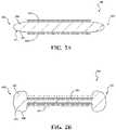
- FIG. 3Adepicts an example of a seat actuator, showing a non-activated condition.
- FIG. 3Bdepicts an example of the seat actuator, showing an activated condition.
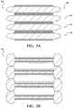
- FIG. 4Adepicts an example of a plurality of seat actuators arranged in a stack, showing a non-activated condition.
- FIG. 4Bdepicts an example of the plurality of seat actuators arranged in a stack, showing an activated condition.
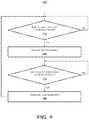
- FIG. 5is an example of a method of selectively morphing a portion of a vehicle seat.
- FIG. 6Ashows an example of an occupant in a vehicle seat when the seat actuators are in a non-activated configuration.
- FIG. 6Bshows an example of the occupant in the vehicle seat when the seat actuators are in the activated configuration.
- the one or more actuatorscan be any suitable type of actuator.
- the one or more actuatorscan include a bladder containing a dielectric fluid.
- a first conductor and a second conductorcan be operatively positioned on opposite portions of the bladder.
- the one or more actuatorscan be configured such that, when electrical energy is supplied to the first conductor and the second conductor, the first conductor and the second conductor have opposite charges.
- the first conductor and the second conductorcan be electrostatically attracted toward each other to cause at least a portion of the dielectric fluid to be displaced to an outer peripheral region of the fluid chamber, which can result in an increase in the overall height of the one or more actuators.
- vehiclemeans any form of motorized transport.
- vehicle 100can be an automobile. While arrangements will be described herein with respect to automobiles, it will be understood that embodiments are not limited to automobiles. In some implementations, the vehicle may be a watercraft, an aircraft or any other form of motorized transport.
- the vehicle 100can have an autonomous operational mode and/or a semi-autonomous operational mode.
- the vehicle 100can have an autonomous operational mode in which or more computing systems are used to navigate and/or maneuver the vehicle along a travel route with no input or supervision required from a human driver.
- the vehicle 100can have one or more semi-autonomous operational modes in which a portion of the navigation and/or maneuvering of the vehicle along a travel route is performed by one or more computing systems, and a portion of the navigation and/or maneuvering of the vehicle along a travel route is performed by a human driver.
- the vehicle 100can have a manual operational mode in which all of or a majority of the navigation and/or maneuvering of the vehicle is performed by a human driver.
- the vehicle 100can be a conventional vehicle that is configured to operate in only a manual mode.
- the vehicle 100can include various elements. Some of the possible elements of the vehicle 100 are shown in FIG. 1 and will now be described. It will be understood that it is not necessary for the vehicle 100 to have all of the elements shown in FIG. 1 or described herein.
- the vehicle 100can have any combination of the various elements shown in FIG. 1 . Further, the vehicle 100 can have additional elements to those shown in FIG. 1 . In some arrangements, the vehicle 100 may not include one or more of the elements shown in FIG. 1 .
- the various elementsmay be shown as being located on or within the vehicle 100 in FIG. 1 , it will be understood that one or more of these elements can be located external to the vehicle 100 . Thus, such elements are not located on, within, or otherwise carried by the vehicle 100 . Further, the elements shown may be physically separated by large distances. Indeed, one or more of the elements can be located remote from the vehicle 100 .
- the vehicle 100can include one or more processors 110 , one or more data stores 120 , one or more sensors 130 , one or more power sources 140 , one or more input interfaces 150 , one or more output interfaces 160 , one or more seats 170 , one or more seat actuators 180 , and one or more seat actuator control modules 190 . Each of these elements will be described in turn below.
- the vehicle 100can include one or more processors 110 .
- processors 110means any component or group of components that are configured to execute any of the processes described herein or any form of instructions to carry out such processes or cause such processes to be performed.
- the processor(s) 110may be implemented with one or more general-purpose and/or one or more special-purpose processors. Examples of suitable processors include microprocessors, microcontrollers, DSP processors, and other circuitry that can execute software.
- processorsinclude, but are not limited to, a central processing unit (CPU), an array processor, a vector processor, a digital signal processor (DSP), a field-programmable gate array (FPGA), a programmable logic array (PLA), an application specific integrated circuit (ASIC), programmable logic circuitry, and a controller.
- the processor(s) 110can include at least one hardware circuit (e.g., an integrated circuit) configured to carry out instructions contained in program code. In arrangements in which there is a plurality of processors 110 , such processors can work independently from each other or one or more processors can work in combination with each other. In one or more arrangements, one or more processors 110 can be a main processor(s) of the vehicle 100 . For instance, one or more processors 110 can be electronic control unit(s) (ECU).
- ECUelectronice control unit
- the vehicle 100can include one or more data stores 120 for storing one or more types of data.
- the data store(s) 120can include volatile and/or non-volatile memory. Examples of suitable data stores 120 include RAM (Random Access Memory), flash memory, ROM (Read Only Memory), PROM (Programmable Read-Only Memory), EPROM (Erasable Programmable Read-Only Memory), EEPROM (Electrically Erasable Programmable Read-Only Memory), registers, magnetic disks, optical disks, hard drives, or any other suitable storage medium, or any combination thereof.
- the data store(s) 120can be a component of the processor(s) 110 , or the data store(s) 120 can be operatively connected to the processor(s) 110 for use thereby.
- the term “operatively connected,” as used throughout this description,can include direct or indirect connections, including connections without direct physical contact.
- the vehicle 100can include one or more sensors 130 .
- Sensormeans any device, component and/or system that can detect, determine, assess, monitor, measure, quantify, acquire, and/or sense something.
- the one or more sensorscan detect, determine, assess, monitor, measure, quantify, acquire, and/or sense in real-time.
- real-timemeans a level of processing responsiveness that a user or system senses as sufficiently immediate for a particular process or determination to be made, or that enables the processor to keep up with some external process.
- the sensorscan work independently from each other.
- two or more of the sensorscan work in combination with each other.
- the two or more sensorscan form a sensor network.
- the sensor(s) 130can be operatively connected to the processor(s) 110 , the data store(s) 120 , and/or other elements of the vehicle 100 (including any of the elements shown in FIG. 1 ).
- the sensor(s) 130can include any suitable type of sensor. Various examples of different types of sensors will be described herein. However, it will be understood that the embodiments are not limited to the particular sensors described.
- the sensor(s) 130can include one or more vehicle sensors 131 .
- the vehicle sensor(s) 131can detect, determine, assess, monitor, measure, quantify and/or sense information about the vehicle 100 itself (e.g., position, orientation, speed, etc.).
- the vehicle sensors 131can include one or more vehicle speed sensors 132 , one or more steering angle sensors 133 , and/or one or more accelerometers 134 .
- the vehicle speed sensors 132can be any sensor configured to detect, determine, assess, monitor, measure, quantify and/or sense the speed of a vehicle, now known or later developed.
- the steering angle sensors 133can be any sensor configured to detect, determine, assess, monitor, measure, quantify and/or sense the steering wheel position angle and/or rate of turn, now known or later developed.
- the accelerometers 134can include any sensor, now know or later developed, configured to detect, determine, assess, monitor, measure, quantify and/or sense any information or data about acceleration forces experience by a vehicle or occupants of the vehicle.
- the accelerometers 124can be configured to detect, determine, assess, monitor, measure, quantify and/or sense any information or data about lateral acceleration forces.
- the sensor(s) 130can include one or more environment sensors configured to detect, determine, assess, monitor, measure, quantify, acquire, and/or sense driving environment data.
- Driving environment dataincludes and data or information about the external environment in which a vehicle is located or one or more portions thereof.
- the environment sensorscan include one or more cameras, one or more radar sensors, one or more lidar sensors, one or more sonar sensors, and/or one or more ranging sensors.
- the vehicle 100can include one or more power sources 140 .
- the power source(s) 140can be any power source capable of and/or configured to energize the seat actuator(s) 180 .
- the power source(s) 140can include one or more batteries, one or more fuel cells, one or more generators, one or more alternators, one or more solar cells, and combinations thereof.
- the power source(s) 140can be configured to supply positively charged electrical energy and/or negatively charged electrical energy.
- the vehicle 100can include one or more input interfaces 150 .
- An “input interface”includes any device, component, system, element or arrangement or groups thereof that enable information/data to be entered into a machine.
- the input interface(s) 150can receive an input from a vehicle occupant (e.g. a driver or a passenger). Any suitable input interface 150 can be used, including, for example, a keypad, display, touch screen, multi-touch screen, button, joystick, mouse, trackball, microphone and/or combinations thereof.
- the vehicle 100can include one or more output interfaces 160 .
- An “output interface”includes any device, component, system, element or arrangement or groups thereof that enable information/data to be presented to a vehicle occupant (e.g. a person, a vehicle occupant, etc.).
- the output interface(s) 160can present information/data to a vehicle occupant.
- the output interface(s) 160can include a display. Alternatively or in addition, the output interface(s) 160 may include an earphone and/or speaker.
- Some components of the vehicle 100may serve as both a component of the input interface(s) 150 and a component of the output interface(s) 160 .
- the vehicle 100can include one or more seats 170 .
- the seat(s) 170can be for any vehicle occupants, such for a driver or for a passenger.
- the seat(s) 170can be any type of vehicle seat, now known or later developed.
- the one or more seats 170can have any suitable configuration.
- the one or more seats 170can include a back portion 172 and a cushion portion 174 .
- the back portion 172 and/or the cushion portion 174can include bolsters 173 , 175 , respectively.
- one or more portions of the seat(s) 170can be configured to counteract lateral acceleration forces experienced by a vehicle occupant.
- the vehicle 100can include one or more seat actuators 180 .
- the seat actuator(s) 180can be operatively connected to one or more of the seats 170 .
- the seat actuator(s) 180can be located within a portion of the seat 170 .
- the seat actuators(s) 180can be located within the back portion 172 of the seat(s) 170 and/or within the cushion portion 174 of the seat(s) 170 . More particularly, the seat actuator(s) 180 can be located within a bolster of the back portion 172 and/or a bolster of the cushion portion 174 .
- the seat actuator(s) 180can be operatively positioned relative to one or more surfaces or portions of the seat(s) 170 .
- the surfacescan be a surface of the back portion 172 , the cushion portion 174 , a bolster of the back portion 172 , and/or a bolster of the cushion portion 174 .
- the seat actuator(s) 180can cause the surfaces or portions of the seat 170 to morph into a different configuration.
- the seat actuators 180can be any element or combination of elements operable to modify, adjust and/or alter one or more surfaces or portions of the vehicle seat(s) 170 .
- the seat actuators 180may activate responsive to receiving signals or other inputs from the processor(s) 110 and/or the seat actuator control module(s) 190 .
- the processor(s) 110 and/or the seat actuator control module(s) 190can be operatively connected to the seat actuators 180 .
- the seat actuator(s) 180are generally represented by a rectangular feature. It will be understood that any suitable actuator can be used.
- the seat actuator(s) 180will be described in greater detail below in connection with FIGS. 2-3 .
- the seat actuator(s) 180can be operatively positioned so that portions of the vehicle seat 170 can be morphed in a plurality of directions.
- one or more seat actuators 180can be configured to morph a first portion of the seat in a first direction
- one or more actuators 180can be configured to morph a second portion of the seat 170 in a second direction.
- the first portion and the second portioncan be the same. In other instances, the first portion and the second portion can be different.
- the vehicle 100can include one or more modules, at least some of which will be described herein.
- the modulescan be implemented as computer readable program code that, when executed by a processor, implement one or more of the various processes described herein.
- One or more of the modulescan be a component of the processor(s) 110 , or one or more of the modules can be executed on and/or distributed among other processing systems to which the processor(s) 110 is operatively connected.
- the modulescan include instructions (e.g., program logic) executable by one or more processor(s) 110 .
- one or more data stores 120may contain such instructions.
- the vehicle 100can include one or more modules.
- the modules described hereincan include artificial or computational intelligence elements, e.g., neural network, fuzzy logic or other machine learning algorithms. Further, in one or more arrangements, the modules can be distributed among a plurality of modules. In one or more arrangements, two or more of the modules described herein can be combined into a single module.
- the vehicle 100can include one or more seat actuator control modules 190 .
- the seat actuator control module(s) 190can include profiles and logic for actively controlling the seat actuator(s) 180 according to arrangements herein.
- the seat actuator control module(s) 190can be configured to determine when the seat actuator(s) 180 should be activated or deactivated.
- the seat actuator control module(s) 190can be configured to do so in any suitable manner.
- the seat actuator control module(s) 190can be configured to analyze data or information acquired by the sensor(s) 130 (e.g., the vehicle speed sensor(s) 132 , the steering angle sensor(s) 133 , and/or the accelerometers 134 ).
- the seat actuator control module(s) 190can be configured to detect user inputs (e.g., commands) provided on the input interface(s) 150 .
- the seat actuator control module(s) 190can retrieve raw data from the sensor(s) 130 and/or from the data store(s) 120 .
- the seat actuator control module(s) 190can use profiles, parameters, or setting loaded into the seat actuator control module(s) 190 and/or stored in the data store(s) 120 .
- the seat actuator control module(s) 190can analyze the sensor data to determine an appropriate action for the seat(s) 170 .
- the seat actuator control module(s) 190can be configured to cause one or more actuators 180 to be activated or deactivated.
- “cause” or “causing”means to make, force, compel, direct, command, instruct, and/or enable an event or action to occur or at least be in a state where such event or action may occur, either in a direct or indirect manner.
- the seat actuator control module(s) 190can selectively permit or prevent the flow of electrical energy from the power source(s) 140 to the seat actuator(s) 180 .
- the seat actuator control module(s) 190can be configured send control signals or commands over a communication network 195 to the seat actuator(s) 180 .
- the seat actuator control module(s) 190can be configured to cause the seat actuator(s) 180 to be selectively activated or deactivated based on one or more activation parameters. For instance, the seat actuator control module(s) 190 can be configured to compare one or more detected activation characteristics to one or more activation thresholds. If the threshold is met, then the seat actuator control module(s) 190 can cause the seat actuator(s) 180 to be activated or maintained in an activated condition. If the threshold is not met, then the seat actuator control module(s) 190 can cause the seat actuator(s) 180 to be deactivated or maintained in a deactivated or non-activated state.
- the vehicle speed thresholdcan be about 30 miles per hour (mph), 35 mph, 40 mph, 45 mph, 50 mph, 55 mph, 60 mph, 65 mph, 70 mph, or even greater, just to name a few possibilities. If a detected vehicle speed is above the vehicle speed threshold, the seat actuator control module(s) 190 can be configured to cause the seat actuator(s) 180 to be activated or maintained in an activated state. If a detected vehicle speed is below the vehicle speed threshold, the seat actuator control module(s) 190 can be configured to cause the seat actuator(s) 180 to be deactivated or maintained in a deactivated state.
- the steering angle thresholdcan be about 20 degrees, about 25 degrees, about 30 degrees, about 35 degrees, about 40 degrees, about 45 degrees, about 50 degrees, about 55 degrees, about 60 degrees, about 65 degrees, about 70 degrees, about 75 degrees, about 80 degrees, about 85 degrees, or about 90 degrees, just to name a few possibilities. If a detected steering angle is above the steering angle threshold, the seat actuator control module(s) 190 can be configured to cause the seat actuator(s) 180 to be activated or maintained in an activated state. If a detected steering angle is below the vehicle speed threshold, the seat actuator control module(s) 190 can be configured to cause the seat actuator(s) 180 to be deactivated or maintained in a deactivated state.
- the seat actuator control module(s) 190can be configured to cause the seat actuator(s) 180 to be selectively activated or deactivated based on both a vehicle sped threshold and a steering angle threshold. Thus, if a detected vehicle speed is above the vehicle speed threshold and if a detected steering angle is above the steering angle threshold, the seat actuator control module(s) 190 can be configured to cause the seat actuator(s) 180 to be activated or maintained in an activated state. If a detected vehicle speed is below the vehicle speed threshold and/or if a detected steering angle is below the steering angle threshold, the seat actuator control module(s) 190 can be configured to cause the seat actuator(s) 180 to be deactivated or maintained in a deactivated state.
- an acceleration thresholdsuch as a lateral acceleration threshold.
- the seat actuator control module(s) 190can be configured to cause the seat actuator(s) 180 to be activated or maintained in an activated state. If a detected steering angle is below the lateral acceleration threshold, the seat actuator control module(s) 190 can be configured to cause the seat actuator(s) 180 to be deactivated or maintained in a deactivated state.
- the seat actuator control module(s) 190can be configured to cause the seat actuator(s) 180 to be selectively activated or deactivated based on user inputs (e.g., commands). For instance, a user can provide an input on the input interface(s) 150 . The input can be to activate or deactivate the seat actuator(s) 180 . The seat actuator control module(s) 190 can be configured to cause the seat actuator(s) 180 to be deactivated or activated in accordance with the user input.
- user inputse.g., commands
- a usercan provide an input on the input interface(s) 150 .
- the inputcan be to activate or deactivate the seat actuator(s) 180 .
- the seat actuator control module(s) 190can be configured to cause the seat actuator(s) 180 to be deactivated or activated in accordance with the user input.
- the seat actuator control module(s) 190can be configured to control a plurality of seats 170 .
- the seat actuator control module(s) 190can be configured to control each seat 170 individually. Thus the control of one seat 170 is independent of the control of the other seats 170 .
- the seat actuator control module(s) 190can be configured to control the plurality of seat(s) 170 collectively. Thus, each seat 170 can be activated or deactivated at substantially the same time, to the same degree of actuations, and/or in substantially the same manner.
- the seat actuator control module(s) 190can be configured to determine the direction is which lateral acceleration will occur. Thus, if the seat actuator control module(s) 190 determines that the direction of lateral acceleration will be to the right, the seat actuator control module(s) 190 can activate the seat actuator(s) 180 on the opposite side (i.e., left side) of the seat 170 . Similarly, if the seat actuator control module(s) 190 determines that the direction of lateral acceleration will be to the left, the seat actuator control module(s) 190 can activate the seat actuator(s) 180 on the opposite (i.e., right) side of the seat 170 .
- the various elements of the vehicle 100can be communicatively linked to one another or one or more other elements through one or more communication networks 195 .
- the term “communicatively linked”can include direct or indirect connections through a communication channel, bus, pathway or another component or system.
- a “communication network”means one or more components designed to transmit and/or receive information from one source to another.
- the data store(s) 120 and/or one or more other elements of the vehicle 100can include and/or execute suitable communication software, which enables the various elements to communicate with each other through the communication network and perform the functions disclosed herein.
- the one or more communication networks 195can be implemented as, or include, without limitation, a wide area network (WAN), a local area network (LAN), the Public Switched Telephone Network (PSTN), a wireless network, a mobile network, a Virtual Private Network (VPN), the Internet, a hardwired communication bus, and/or one or more intranets.
- WANwide area network
- LANlocal area network
- PSTNPublic Switched Telephone Network
- VPNVirtual Private Network
- the Interneta hardwired communication bus, and/or one or more intranets.
- the communication networkfurther can be implemented as or include one or more wireless networks, whether short range (e.g., a local wireless network built using a Bluetooth or one of the IEEE 802 wireless communication protocols, e.g., 802.11a/b/g/i, 802.15, 802.16, 802.20, Wi-Fi Protected Access (WPA), or WPA2) or long range (e.g., a mobile, cellular, and/or satellite-based wireless network; GSM, TDMA, CDMA, WCDMA networks or the like).
- the communication networkcan include wired communication links and/or wireless communication links.
- the communication networkcan include any combination of the above networks and/or other types of networks.
- the seat actuator 180can have a body that is, at least in large part, made of a soft, flexible material.
- the seat actuator 180can include a bladder 181 containing a dielectric fluid 184 .
- the bladder 181can include a casing 330 .
- the casing 186can be made of a single piece of material, or a plurality of separate pieces of material that are joined together.
- An inner surface of the casing 186can define a fluid chamber.
- the bladder 181 and/or fluid chambercan be fluid impermeable.
- the bladder 181can be made of any suitable material.
- the bladder 181can be made of an insulating material.
- the insulating materialcan be flexible.
- the insulating materialcan be a polymer and/or an elastomeric polymer (elastomer).
- the polymers or elastomerscan be natural or synthetic in nature.
- the insulating materialcan be silicone rubber.
- insulating materialexamples include nitrile, ethylene propylene diene monomer (EPDM), fluorosilicone (FVMQ), vinylidene fluoride (VDF), hexafluoropropylene (HFP), tetrafluoroethylene (TFE), perfluoromethylvinylether (PMVE), polydimethylsiloxane (PDMS), natural rubber, neoprene, polyurethane, silicone, or combinations thereof.
- EPDMethylene propylene diene monomer
- FVMQfluorosilicone
- VDFvinylidene fluoride
- HFPhexafluoropropylene
- TFEtetrafluoroethylene
- PMVEperfluoromethylvinylether
- PDMSpolydimethylsiloxane
- natural rubberneoprene, polyurethane, silicone, or combinations thereof.
- a dielectric fluid 184can be any suitable material.
- the dielectric fluid 184can be ethylene glycol.
- the dielectric fluid 184can include transformer oil or mineral oil.
- the dielectric fluid 184can be a lipid based fluid, such as a vegetable oil-based dielectric fluid.
- the dielectric fluid 184can have various associated properties.
- the dielectric fluid 184can have an associated dielectric constant.
- the dielectric fluid 184can have a dielectric constant of 1 or greater, 2 or greater, 3 or greater, 4 or greater, 5 or greater, 6 or greater, 7 or greater, 8 or greater, 9 or greater, 10 or greater, 20 or greater, 30 or greater, 40 or greater, 50 or greater, or higher.
- the dielectric fluid 184can be a fluid that is resistant to electrical breakdown. In one or more arrangements, the dielectric fluid 184 , can provide electrical insulating properties. In one or more arrangements, the dielectric fluid 184 can provide electrical insulating properties. In one or more arrangements, the dielectric fluid 184 can prevent arcing between surrounding conductors.
- the seat actuator 180can include a plurality of conductors.
- the seat actuator 180can include a first conductor 188 and a second conductor 189 .
- the conductors 188 , 189can conduct electrical energy.
- the conductors 188 , 189can be made of any suitable material, such as a conductive elastomer. In one or more arrangements, the conductors 188 , 189 can be made of natural rubber with carbon or other conductive particles distributed throughout the material.
- the conductors 188 , 189can be made of the same material as each other, or the conductors 188 , 189 can be made of different materials.
- One or more of the conductors 188 , 189can be formed by a single, continuous structure, or one or more of the conductors 188 , 189 can be formed by a plurality of separate structures.
- the first conductor 188 and the second conductor 189can be located on opposite sides or portions of the bladder 181 . Thus, the first conductor 188 and the second conductor 189 can be separated by the bladder 181 .
- the first conductor 188 and/or the second conductor 189can be operatively connected to the bladder 181 in any suitable manner. In some instances, the first conductor 188 and/or the second conductor 189 can be embedded within a wall of the bladder 181 .
- the first conductor 188can be operatively positioned between the bladder 181 and an insulating material. In such case, the first conductor 188 can be substantially encapsulated by the bladder 181 and the insulating material.
- the second conductor 189can be operatively positioned between the bladder 181 and an insulating material.
- the second conductor 189can be substantially encapsulated by the bladder 181 and the insulating material.
- the insulating materialcan be made of an insulating elastomer.
- the insulating materialcan define exterior surfaces of the seat actuator 180 .
- Each of the conductors 188 , 189can be operatively connected to receive electrical energy from a power source (e.g., the power source(s) 140 ). As a result, electrical energy can be selectively supplied to each individual conductors 188 , 189 .
- a power sourcee.g., the power source(s) 140
- the seat actuator 180can have a non-activated mode and an activated mode. Each of these modes will be described in turn.
- FIG. 2Ashows an example of a non-activated mode of the seat actuator 180 .
- electrical energyis not supplied to the first conductor 188 and the second conductor 189 .
- the first conductor 188 and the second conductor 189can be spaced apart from each other.
- the bladder 181can be in a neutral state. In some instances, a portion of the bladder 181 can extend beyond the outer edges of the first conductor 188 and the second conductor 189 .
- FIG. 2Bshows an example of an activated mode of the seat actuator 180 .
- powercan be supplied to the first conductor 188 and the second conductor 189 .
- the first conductor 188can become positively charged and the second conductor 189 can become negatively charged.
- the first conductor 188 and the second conductor 189can be oppositely charged.
- the first conductor 188 and the second conductor 189can be attracted toward each other.
- the attraction between the first conductor 188 and the second conductor 189can cause them and the respective portions of the bladder 181 to move toward each other.
- the dielectric fluid 184 within the fluid chambercan be squeezed toward the outer peripheral region(s) 182 of the bladder 181 .
- the outer peripheral region(s) 182 of the bladder 181can bulge, as is shown in FIG. 3B .
- the outer peripheral region(s) 182 of the bladder 181may increase the overall height of the seat actuator 180 (in the top to bottom direction on the page).
- FIGS. 3A-3Ban example of a plurality of seat actuators 180 arranged in an actuator stack 300 is shown.
- FIG. 3Ashows the actuator stack 300 in a non-actuated mode.
- FIG. 4Bshows the actuator stack 400 in an actuated mode.
- the above-description of the seat actuator 180 in connection with FIGS. 2A-2Bapplies equally to the individual actuators 180 in the actuator stack 300 .
- the overall height (the top to bottom direction on the page) of the actuator stack 300can increase.
- the seat actuators 180 in the actuator stack 300can be actuated individually or two or more of the seat actuators 180 can be actuated at the same time.
- Neighboring actuators 180 in the actuator stack 300can be separated from each other by an insulating layer. In some instances, such an insulating layer can operatively connect the neighboring actuators 180 together.
- an individual actuator 180 or an actuator stack 300can be enclosed within a casing.
- the casingcan provide protection to the actuators(s) 180 and to the seat 170 .
- the casingcan be made of a flexible material that can accommodate the seat actuator(s) 180 when activated and deactivated.
- FIGS. 4A-4Ban example of a portion of a vehicle seat is shown.
- the seat actuator(s) 180will be described in connection with the cushion portion 174 of the vehicle seat 170 , but it will be understood that this description applies equally to the seat actuator(s) 180 in connection with the back portion 172 of the vehicle seat 170 .
- the seat actuator(s) 180are represented generally in FIGS. 4A and 4B for purposes of clarity.
- the seat actuator(s) 180can be operatively positioned within the vehicle seat 170 relative to one or more surfaces or portions of the seat(s) 170 .
- the surfacescan be a surface of the back portion 172 , the cushion portion 174 , the bolster 173 of the back portion 172 , the bolster 175 of the cushion portion 174 , and/or a headrest.
- the seat actuator(s) 180can cause the surfaces or portions of the seat to morph into a different configuration.
- the seat actuator 180can be a single actuator, a single stack of a plurality of actuators, a plurality of actuators, a plurality of stacks of actuators, and/or combinations thereof.
- FIG. 4Ashows an example of the seat actuator(s) 180 in a non-activated condition or a deactivated condition.
- the bolster 175 on the first side 177can have a non-activated configuration 205
- the bolster 175 on the second side 179can have a non-activated configuration 210 .
- the non-activated configurations 205 , 210can be substantially mirror images of each other.
- FIG. 4Bshows an example of the seat actuators 180 on the first side 177 remaining in the non-activated condition or a deactivated condition; however, the seat actuators 180 on the second side 179 are in an activated condition.
- the bolster 175 on the second side 179can have an activated configuration 220 .
- the overall size of the bolster 175 on the second side 179has become enlarged overall. It will be appreciated that the bolster 175 in the activated configuration 220 can provide additional resistance to lateral acceleration of a vehicle occupant in that direction, such as when a vehicle is turning.
- the method 500can begin with the seat actuator(s) 180 in a non-activated mode, such as is shown in FIG. 4A .
- the non-activated modeelectrical energy from the power source(s) 140 is not supplied to the seat actuator(s) 180 .
- the seat activation conditionmay be detected by the seat actuator control module(s) 190 , the processor(s) 110 , and/or one or more sensor(s) 130 .
- the seat actuator control module(s) 190 , the processor(s) 110 , and/or one or more sensor(s) 130can determine that data acquired by the vehicle sensor(s) 131 meets a seat activation condition. For instance, the seat actuator control module(s) 190 , the processor(s) 110 , and/or one or more sensor(s) 130 can determine whether the current vehicle speed and/or the current steering angle meet respective seat activation threshold. Alternatively or additionally, the seat actuator control module(s) 190 , the processor(s) 110 , and/or one or more sensor(s) 130 can determine whether the current lateral acceleration meets respective seat activation threshold.
- the seat actuator control module(s) 190 , the processor(s) 110 , and/or one or more sensor(s) 130can detect a user input indicating that the interface should be activated.
- the user inputcan be provided via the input interface(s) 150 .
- the method 500can end, return to block 510 , or proceed to some other block. However, if a seat activation condition is detected, then the method can proceed to block 520 .
- the seat actuator(s) 180can be activated.
- the seat actuator control module(s) 190 and/or the processor(s) 110may only actuate certain individual seat actuator(s) 180 while leaving others in a non-activated state.
- the seat actuator control module(s) 190 and/or the processor(s) 110can cause or allow the flow of electrical energy from the power sources(s) 140 to the seat actuator(s) 180 .
- the seat actuator(s) 180can morph to an activated shape, such as is shown in FIG. 2B or 3B .
- the seat actuator(s) 180can interact with portions of the vehicle seat 170 to cause a portion of the vehicle seat 170 to morph into an activated configuration, such as is shown in FIG. 4B .
- the methodcan continue to block 530 .
- the seat deactivation conditionmay be detected by the seat actuator control module(s) 190 , such as based on data acquired by the sensor(s) 130 and/or by detecting a user input or the cessation of a user input. If a seat deactivation condition is not detected, the method 500 can return to block 530 , or proceed to some other block. However, if a deactivation condition is detected, then the method can proceed to block 540 .
- the seat actuator(s) 180can be deactivated.
- the seat actuator control module(s) 190 and/or the processor(s) 110can cause the flow of electrical energy from the power sources(s) 140 to the seat actuator(s) 180 to be discontinued.
- the method 500can end. Alternatively, the method 500 can return to block 510 or some other block.
- FIGS. 6A-6Bshow an occupant 600 in the vehicle seat 170 .
- the vehicle seat 170can include the seat actuators 180 , though the seat actuators 180 are not shown in FIGS. 6A-6B .
- FIG. 6Ashows an example of an occupant in a vehicle seat when the seat actuators are in a non-activated configuration.
- lateral acceleration forces 650can act upon the vehicle and/or occupant 600 .
- the occupant 600may actually be or may feel like he or she is being pushed, moved, and/or forced at least to the left due to such forces.
- FIG. 6Bshows an example of the occupant in the vehicle seat when the seat actuators are in the activated configuration.
- the bolster 175 of the cushion portion 174can become enlarged as a result of the actuation of the seat actuators 180 in such location.
- the bolster 173 of the back portion 172can become enlarged as a result of the actuation of the seat actuators 180 .
- the activated configuration for the bolsters 173 , 175can provide lateral support 680 to the occupant 600 , which can help to reduce the effects experienced by the occupant 600 due to the lateral acceleration forces 650 .
- arrangements described hereincan provide numerous benefits, including one or more of the benefits mentioned herein.
- arrangements described hereincan provide lateral support for a vehicle occupant in conditions in which high lateral acceleration forces are experienced by the occupant.
- Arrangements described hereincan also allow a vehicle seat to be selectively morphed.
- the vehicle seatcan be in a normal configuration in most driving conditions and morphed when needed, thereby increasing occupant comfort.
- Arrangements described hereincan avoid the use of large and complicated gears and actuators, thereby enabling more compact designs and packaging.
- Arrangements described herecan provide for more efficient use of power.
- each block in the flowcharts or block diagramsmay represent a module, segment, or portion of code, which comprises one or more executable instructions for implementing the specified logical function(s).
- the functions noted in the blockmay occur out of the order noted in the figures. For example, two blocks shown in succession may, in fact, be executed substantially concurrently, or the blocks may sometimes be executed in the reverse order, depending upon the functionality involved.
- the systems, components and/or processes described abovecan be realized in hardware or a combination of hardware and software and can be realized in a centralized fashion in one processing system or in a distributed fashion where different elements are spread across several interconnected processing systems. Any kind of processing system or other apparatus adapted for carrying out the methods described herein is suited.
- a typical combination of hardware and softwarecan be a processing system with computer-usable program code that, when being loaded and executed, controls the processing system such that it carries out the methods described herein.
- the systems, components and/or processesalso can be embedded in a computer-readable storage, such as a computer program product or other data programs storage device, readable by a machine, tangibly embodying a program of instructions executable by the machine to perform methods and processes described herein. These elements also can be embedded in an application product which comprises all the features enabling the implementation of the methods described herein and, which when loaded in a processing system, is able to carry out these methods.
- arrangements described hereinmay take the form of a computer program product embodied in one or more computer-readable media having computer-readable program code embodied or embedded, e.g., stored, thereon. Any combination of one or more computer-readable media may be utilized.
- the computer-readable mediummay be a computer-readable signal medium or a computer-readable storage medium.
- the phrase “computer-readable storage medium”means a non-transitory storage medium.
- a computer-readable storage mediummay be, for example, but not limited to, an electronic, magnetic, optical, electromagnetic, infrared, or semiconductor system, apparatus, or device, or any suitable combination of the foregoing.
- a computer-readable storage mediummay be any tangible medium that can contain, or store a program for use by or in connection with an instruction execution system, apparatus, or device.
- Program code embodied on a computer-readable mediummay be transmitted using any appropriate medium, including but not limited to wireless, wireline, optical fiber, cable, RF, etc., or any suitable combination of the foregoing.
- Computer program code for carrying out operations for aspects of the present arrangementsmay be written in any combination of one or more programming languages, including an object oriented programming language such as JavaTM, Smalltalk, C++ or the like and conventional procedural programming languages, such as the “C” programming language or similar programming languages.
- the program codemay execute entirely on the user's computer, partly on the user's computer, as a stand-alone software package, partly on the user's computer and partly on a remote computer, or entirely on the remote computer or server.
- the remote computermay be connected to the user's computer through any type of network, including a local area network (LAN) or a wide area network (WAN), or the connection may be made to an external computer (for example, through the Internet using an Internet Service Provider).
- LANlocal area network
- WANwide area network
- Internet Service Provideran Internet Service Provider
- the terms “a” and “an,” as used herein,are defined as one or more than one.
- the term “plurality,” as used herein,is defined as two or more than two.
- the term “another,” as used herein,is defined as at least a second or more.
- the terms “including” and/or “having,” as used herein,are defined as comprising (i.e. open language).
- the phrase “at least one of . . . and . . . .” as used hereinrefers to and encompasses any and all possible combinations of one or more of the associated listed items.
- the phrase “at least one of A, B and C”includes A only, B only, C only, or any combination thereof (e.g., AB, AC, BC or ABC).
- the term “substantially” or “about”includes exactly the term it modifies and slight variations therefrom.
- the term “substantially parallel”means exactly parallel and slight variations therefrom.
- “Slight variations therefrom”can include within 15 degrees/percent/units or less, within 14 degrees/percent/units or less, within 13 degrees/percent/units or less, within 12 degrees/percent/units or less, within 11 degrees/percent/units or less, within 10 degrees/percent/units or less, within 9 degrees/percent/units or less, within 8 degrees/percent/units or less, within 7 degrees/percent/units or less, within 6 degrees/percent/units or less, within 5 degrees/percent/units or less, within 4 degrees/percent/units or less, within 3 degrees/percent/units or less, within 2 degrees/percent/units or less, or within 1 degree/percent/unit or less. In some instances, “substantially” can include being within normal manufacturing tolerances.
Landscapes
- Engineering & Computer Science (AREA)
- Aviation & Aerospace Engineering (AREA)
- Transportation (AREA)
- Mechanical Engineering (AREA)
- Seats For Vehicles (AREA)
Abstract
Description
Claims (20)
Priority Applications (1)
| Application Number | Priority Date | Filing Date | Title |
|---|---|---|---|
| US16/262,113US11192469B2 (en) | 2019-01-30 | 2019-01-30 | Vehicle seat with morphing bolsters |
Applications Claiming Priority (1)
| Application Number | Priority Date | Filing Date | Title |
|---|---|---|---|
| US16/262,113US11192469B2 (en) | 2019-01-30 | 2019-01-30 | Vehicle seat with morphing bolsters |
Publications (2)
| Publication Number | Publication Date |
|---|---|
| US20200238854A1 US20200238854A1 (en) | 2020-07-30 |
| US11192469B2true US11192469B2 (en) | 2021-12-07 |
Family
ID=71732202
Family Applications (1)
| Application Number | Title | Priority Date | Filing Date |
|---|---|---|---|
| US16/262,113Active2040-05-29US11192469B2 (en) | 2019-01-30 | 2019-01-30 | Vehicle seat with morphing bolsters |
Country Status (1)
| Country | Link |
|---|---|
| US (1) | US11192469B2 (en) |
Families Citing this family (30)
| Publication number | Priority date | Publication date | Assignee | Title |
|---|---|---|---|---|
| US11548261B2 (en) | 2018-10-24 | 2023-01-10 | Toyota Motor Engineering & Manufacturing North America, Inc. | Structure with selectively variable stiffness |
| US11067200B2 (en) | 2018-10-24 | 2021-07-20 | Toyota Motor Engineering & Manufacturing North America, Inc. | Self-healing microvalve |
| US11088635B2 (en) | 2018-10-25 | 2021-08-10 | Toyota Motor Engineering & Manufacturing North America, Inc. | Actuator with sealable edge region |
| US10946535B2 (en) | 2018-10-25 | 2021-03-16 | Toyota Motor Engineering & Manufacturing North America, Inc. | Earthworm-like motion of soft bodied structure |
| US11041576B2 (en) | 2018-10-25 | 2021-06-22 | Toyota Motor Engineering & Manufacturing North America, Inc. | Actuator with static activated position |
| US11081975B2 (en) | 2018-10-25 | 2021-08-03 | Toyota Motor Engineering & Manufacturing North America, Inc. | Somersaulting motion of soft bodied structure |
| US11498270B2 (en) | 2018-11-21 | 2022-11-15 | Toyota Motor Engineering & Manufacturing North America, Inc. | Programmable matter |
| US11195506B2 (en) | 2018-12-03 | 2021-12-07 | Toyota Motor Engineering & Manufacturing North America, Inc. | Sound-modulating windows |
| US11066016B2 (en) | 2018-12-18 | 2021-07-20 | Toyota Motor Engineering & Manufacturing North America, Inc. | Adjusting vehicle mirrors |
| US11479308B2 (en) | 2019-01-09 | 2022-10-25 | Toyota Motor Engineering & Manufacturing North America, Inc. | Active vehicle interface for crosswind management |
| US11285844B2 (en) | 2019-01-31 | 2022-03-29 | Toyota Motor Engineering & Manufacturing North America, Inc. | Vehicle seat with morphing portions |
| US11473567B2 (en) | 2019-02-07 | 2022-10-18 | Toyota Motor Engineering & Manufacturing North America, Inc. | Programmable surface |
| US10960793B2 (en) | 2019-03-06 | 2021-03-30 | Toyota Motor Engineering & Manufacturing North America, Inc. | Active vehicle seat with morphing portions |
| US11370330B2 (en) | 2019-03-22 | 2022-06-28 | Toyota Motor Engineering & Manufacturing North America, Inc. | Vehicle seat with morphing portions |
| US11752901B2 (en) | 2019-03-28 | 2023-09-12 | Toyota Motor Engineering & Manufacturing North America, Inc. | Vehicle seat with tilting seat portion |
| WO2021021609A1 (en)* | 2019-07-26 | 2021-02-04 | The Regents Of The University Of Michigan | Contactless patient motion monitoring |
| WO2021153262A1 (en)* | 2020-01-30 | 2021-08-05 | ソニーグループ株式会社 | Seat for mobile device, seat control device, and seat control method |
| US11370340B2 (en)* | 2020-07-17 | 2022-06-28 | Toyota Motor Engineering & Manufacturing North America, Inc. | Systems and methods for actuating pillows including actuating muscles |
| CN112009314B (en)* | 2020-08-10 | 2022-02-22 | 广州汽车集团股份有限公司 | Vehicle seat side wing adjusting method, device and system |
| EP4231877B1 (en)* | 2020-10-23 | 2025-09-17 | Prohibition X PTE. Ltd. | Smart mattress with adaptive actuation system |
| US11840161B2 (en)* | 2021-03-12 | 2023-12-12 | Toyota Motor Engineering & Manufacturing North America, Inc. | Seat blocking system and method |
| US11649004B2 (en)* | 2021-03-30 | 2023-05-16 | Toyota Motor Engineering & Manufacturing North America, Inc. | Seat devices comprising artificial muscles |
| US11897379B2 (en) | 2021-10-20 | 2024-02-13 | Toyota Motor Engineering & Manufacturing North America, Inc. | Seat with shape memory material member actuation |
| US12012025B2 (en) | 2022-04-12 | 2024-06-18 | Faurecia Automotive Seating, Llc | Occupant support and vehicle with occupant support |
| US12383066B2 (en) | 2022-04-26 | 2025-08-12 | Toyota Motor Engineering & Manufacturing North America, Inc. | Chair with shape memory material-based movement synchronized with visual content |
| US12241458B2 (en) | 2023-02-16 | 2025-03-04 | Toyota Motor Engineering & Manufacturing North America, Inc. | Actuator with contracting member |
| US12270386B2 (en) | 2023-02-16 | 2025-04-08 | Toyota Motor Engineering & Manufacturing North America, Inc. | Shape memory material member-based actuator |
| US12163507B2 (en) | 2023-02-22 | 2024-12-10 | Toyota Motor Engineering & Manufacturing North America, Inc. | Contracting member-based actuator with clutch |
| US12152570B2 (en) | 2023-02-22 | 2024-11-26 | Toyota Motor Engineering & Manufacturing North America, Inc. | Shape memory material member-based actuator with electrostatic clutch preliminary class |
| US12234811B1 (en) | 2023-08-21 | 2025-02-25 | Toyota Motor Engineering & Manufacturing North America, Inc. | Monitoring a state of a shape memory material member |
Citations (116)
| Publication number | Priority date | Publication date | Assignee | Title |
|---|---|---|---|---|
| US4286910A (en) | 1980-02-28 | 1981-09-01 | R. J. Reynolds Tobacco Company | Peristaltic valve for transferring material between zones |
| US4319427A (en) | 1981-04-20 | 1982-03-16 | Way Jr Lee V | Magnet effected advancing toy |
| US4726656A (en) | 1984-12-13 | 1988-02-23 | Donnelly Mirrors Limited | Vehicle rearview mirror assembly containing a fluid light controlling medium |
| US4848179A (en) | 1988-02-16 | 1989-07-18 | Trw Inc. | Flexidigit robotic manipulator |
| US4958100A (en) | 1989-02-22 | 1990-09-18 | Massachusetts Institute Of Technology | Actuated truss system |
| US4964062A (en) | 1988-02-16 | 1990-10-16 | Ubhayakar Shivadev K | Robotic arm systems |
| US5021798A (en) | 1988-02-16 | 1991-06-04 | Trw Inc. | Antenna with positionable reflector |
| US5065978A (en) | 1988-04-27 | 1991-11-19 | Dragerwerk Aktiengesellschaft | Valve arrangement of microstructured components |
| US5222668A (en) | 1991-04-03 | 1993-06-29 | International Business Machines Corporation | Fluid actuated connector |
| JPH07303381A (en) | 1994-05-02 | 1995-11-14 | Toshiba Corp | Electrostatic actuator |
| US5502345A (en) | 1994-08-29 | 1996-03-26 | The United States Of America As Represented By The Secretary Of The Navy | Unitary transducer with variable resistivity |
| US5536062A (en) | 1994-12-08 | 1996-07-16 | Spears; Dan E. | Cross wind conditioning for a tractor trailer combination |
| US5668432A (en) | 1995-03-24 | 1997-09-16 | Nippondenso Co., Ltd. | Articulation device |
| US6120002A (en) | 1998-01-08 | 2000-09-19 | Xerox Corporation | Fluid valves having cantilevered blocking films |
| US6215221B1 (en) | 1998-12-29 | 2001-04-10 | Honeywell International Inc. | Electrostatic/pneumatic actuators for active surfaces |
| US20020100888A1 (en) | 2000-12-12 | 2002-08-01 | Eastman Kodak Company | Electrostrictive valve for modulating a fluid flow |
| US6490960B1 (en) | 2001-07-11 | 2002-12-10 | Xerox Corporation | Muscle-emulating PC board actuator |
| US6702301B1 (en) | 1999-09-23 | 2004-03-09 | Meritor Light Vehicle Systems, Inc. | Active window seal |
| US20040107829A1 (en) | 2002-08-13 | 2004-06-10 | Davis Donald L. | Fluidic actuator |
| US6830071B2 (en) | 2001-02-06 | 2004-12-14 | Institute Of High Performance Computing | Microvalve devices |
| US20040261411A1 (en) | 1999-08-12 | 2004-12-30 | Macgregor Roderick | Shape-memory alloy actuators and control methods |
| US20050045480A1 (en) | 2003-08-29 | 2005-03-03 | John Krumme | Valve for controlling flow of a fluid |
| KR20050056526A (en) | 2003-12-10 | 2005-06-16 | 현대자동차주식회사 | Spring with variable elastic coefficient |
| US6939291B2 (en) | 2001-02-28 | 2005-09-06 | Korea Institute Of Science And Technology | Endoscopic device for locomotion through the gastro-intestinal tract |
| US20050198904A1 (en) | 2004-03-12 | 2005-09-15 | Browne Alan L. | Active seal assemblies for movable windows |
| US20060032715A1 (en)* | 2004-08-13 | 2006-02-16 | William Barvosa-Carter | Reversibly expandable energy absorbing assembly utilizing actively controlled and engineered materials for impact management and methods for operating the same |
| US20060038745A1 (en) | 2004-08-19 | 2006-02-23 | Alex Naksen | Variable stiffness screen |
| US7125077B2 (en) | 2002-10-25 | 2006-10-24 | L&P Property Management Company | Seat bolster adjustment apparatus and method |
| US20070046074A1 (en) | 2005-08-30 | 2007-03-01 | Aisin Seiki Kabushiki Kaisha | Seat apparatus |
| JP2007097292A (en) | 2005-09-28 | 2007-04-12 | Sony Computer Entertainment Inc | Electrostatic actuator |
| US20070120438A1 (en) | 2003-12-26 | 2007-05-31 | Commissariat A L'energie Atomique | Electrostatic control device |
| US7353747B2 (en) | 2005-07-28 | 2008-04-08 | Ethicon Endo-Surgery, Inc. | Electroactive polymer-based pump |
| US7484735B2 (en) | 2004-12-09 | 2009-02-03 | General Motors Corporation | Reversible thermally expandable and/or contractible seal assemblies |
| US20090086331A1 (en) | 2004-04-30 | 2009-04-02 | Gunasekaran R A | Wide-Angle Variable Focal Length Lens System |
| US7521840B2 (en) | 2005-03-21 | 2009-04-21 | Artificial Muscle, Inc. | High-performance electroactive polymer transducers |
| US20090115285A1 (en) | 2007-10-08 | 2009-05-07 | Khalil Najafi | Liquid-gap electrostatic hydraulic micro actuators |
| US7575807B1 (en) | 2004-05-28 | 2009-08-18 | Hrl Laboratories, Llc | Hybrid active deformable material structure |
| US7594697B2 (en)* | 2006-04-17 | 2009-09-29 | Gm Global Technology Operations, Inc. | Active material actuated headrest assemblies |
| US20090255187A1 (en) | 2008-04-10 | 2009-10-15 | Gm Global Technology Operations, Inc. | Active seal architectures |
| US20100090497A1 (en) | 2008-10-14 | 2010-04-15 | William Nelson Beckon | Vehicle airfoils for safety, efficiency, and performance |
| JP2010142275A (en) | 2008-12-16 | 2010-07-01 | Nhk Spring Co Ltd | Vehicle seat device |
| US7755840B2 (en) | 2005-05-14 | 2010-07-13 | Batchko Robert G | Fluidic optical devices |
| EP1904337B1 (en) | 2005-07-20 | 2010-10-13 | Prospective Concepts AG | Pneumatically adjustable side edges for vehicle seats |
| US20100258362A1 (en) | 2007-12-14 | 2010-10-14 | Barry Trimmer | Actuator powered deformable soft-bodied autonomous platforms |
| US7892630B1 (en) | 2004-08-13 | 2011-02-22 | Hrl Laboratories, Llc | Variable stiffness structure |
| US7901524B1 (en) | 2005-02-04 | 2011-03-08 | Hrl Laboratories, Llc | Actuation concepts for variable stiffness materials |
| US7905538B2 (en) | 2007-08-31 | 2011-03-15 | Gm Global Technology Operations, Inc. | Active material based concealment devices for seams |
| US7909403B2 (en)* | 2008-03-03 | 2011-03-22 | GM Global Technology Operations LLC | Manipulable seat bolster utilizing active material actuation |
| US20110188258A1 (en) | 2010-02-02 | 2011-08-04 | Koito Manufacturing Co., Ltd. | Actuator |
| US8136875B2 (en)* | 2009-07-15 | 2012-03-20 | Honda Motor Co., Ltd. | Cup holder and pivoting armrest |
| US8231563B2 (en) | 2009-12-30 | 2012-07-31 | Codman Neuro Sciences Sarl | Electrokinetic actuator to titrate fluid flow |
| US20120287493A1 (en) | 2011-05-12 | 2012-11-15 | Delphi Technologies, Inc. | Light distribution pattern control using object detection and electrowetting lenses |
| US8430810B2 (en) | 2007-02-12 | 2013-04-30 | Technion Research And Development Foundation, Ltd. | Inflatable balloon device and applications |
| US20130255815A1 (en) | 2012-03-30 | 2013-10-03 | Ford Global Technologies, Llc | Fluid conduit with variable flow resistance |
| US20130304049A1 (en) | 2012-05-11 | 2013-11-14 | Tyco Healthcare Group Lp | System and Method for Directing Energy to Tissue |
| US20140109560A1 (en) | 2010-11-19 | 2014-04-24 | President And Fellows Of Harvard College | Soft robotic actuators |
| KR101395364B1 (en) | 2012-11-20 | 2014-05-14 | 현대다이모스(주) | Control device for the bolster of car seat and the controlling method thereof |
| US8863608B2 (en) | 2009-12-15 | 2014-10-21 | Festo Ag & Co. Kg | Fluid-operated manipulator |
| US9061118B2 (en) | 2005-08-11 | 2015-06-23 | Technion Research & Development Foundation Ltd. | Tip propelled device for motion through a passage |
| US20150197173A1 (en)* | 2014-01-10 | 2015-07-16 | Ford Global Technologies, Llc | Electro-active polymer actuators for vehicle seating applications |
| US20150331156A1 (en) | 2011-07-26 | 2015-11-19 | Rensselaer Polytechnic Institute | Liquid lens with magnification control |
| US9308949B1 (en) | 2013-05-08 | 2016-04-12 | Paccar Inc | Systems and methods for reducing drag on a vehicle or vehicle combination |
| US20160106620A1 (en) | 2014-10-17 | 2016-04-21 | Toyota Boshoku Kabushiki Kaisha | Massage apparatus |
| US20170036709A1 (en) | 2015-08-07 | 2017-02-09 | Honda Motor Co., Ltd. | Vehicle aerodynamics control system and methods of use and manufacture thereof |
| US9580115B2 (en)* | 2013-10-01 | 2017-02-28 | Grammer Ag | Vehicle seat or vehicle cab with a suspension system, and utility vehicle |
| US20170080987A1 (en) | 2015-09-17 | 2017-03-23 | GM Global Technology Operations LLC | Determination of aerodynamic actuation commands |
| WO2017077541A1 (en) | 2015-11-04 | 2017-05-11 | Philip Bogrash | Springs with dynamically variable stiffness and actuation capability |
| US20170150252A1 (en) | 2014-12-08 | 2017-05-25 | Harman International Industries, Inc. | Adjusting speakers using facial recognition |
| US20170240224A1 (en) | 2014-08-05 | 2017-08-24 | Jaguar Land Rover Limited | Vehicle aerodynamic apparatus |
| US20170252260A1 (en) | 2015-03-23 | 2017-09-07 | Miga Motor Company | Body massager using shape memory alloy components |
| US9764113B2 (en) | 2013-12-11 | 2017-09-19 | Magenta Medical Ltd | Curved catheter |
| US9790968B2 (en) | 2014-07-17 | 2017-10-17 | President And Fellows Of Harvard College | Soft actuators and soft actuating devices |
| US20180036198A1 (en) | 2015-03-12 | 2018-02-08 | Brose Fahrzeugteile Gmbh & Co. Kommanditgesellschaft, Coburg | Massage device for a vehicle seat |
| US9919418B2 (en) | 2014-08-13 | 2018-03-20 | Seiko Epson Corporation | Piezoelectric driving device, robot, and driving method of the same |
| US9937966B1 (en) | 2016-10-11 | 2018-04-10 | Hyundai Motor Company | Apparatus for improving aerodynamic performance of vehicle |
| US9970564B2 (en)* | 2014-06-04 | 2018-05-15 | Kongsberg Automotive Ab | SMA valve for controlling pressurized air supply to an air cell in a vehicle seat |
| US20180172172A1 (en) | 2016-12-15 | 2018-06-21 | The Boeing Company | Fluid flow control device |
| US10058647B2 (en) | 2013-10-04 | 2018-08-28 | President And Fellows Of Harvard College | Biomimetic actuation device and system, and methods for controlling a biomimetic actuation device and system |
| WO2018175741A1 (en) | 2017-03-22 | 2018-09-27 | The Regents Of The University Of Colorado, A Body Corporate | Hydraulically amplified self-healing electrostatic transducers |
| CN108819806A (en) | 2018-06-19 | 2018-11-16 | 高顺 | Seat assembly with adjustable side bolster actuator |
| US20180339624A1 (en) | 2017-05-24 | 2018-11-29 | Ford Global Technologies, Llc | Deployable headrest |
| US20190023161A1 (en) | 2017-07-21 | 2019-01-24 | Toyota Motor Engineering & Manufacturing North America, Inc. | Seating arrangements in a vehicle |
| US20190032684A1 (en) | 2015-04-27 | 2019-01-31 | Regents Of The University Of Minnesota | Soft robots, soft actuators, and methods for making the same |
| US20190059608A1 (en) | 2017-08-22 | 2019-02-28 | Boe Technology Group Co., Ltd. | Chair and smart lumbar pillow system for chair |
| US10293718B1 (en) | 2016-06-22 | 2019-05-21 | Apple Inc. | Motion control seating system |
| US10302586B2 (en) | 2013-04-10 | 2019-05-28 | President And Fellows Of Harvard College | Stretchable ionics for transparent sensors and actuators |
| US20190232822A1 (en) | 2016-10-25 | 2019-08-01 | Bayerische Motoren Werke Aktiengesellschaft | Method and Device for Controlling a Vehicle Seat |
| US20190296217A1 (en) | 2018-03-21 | 2019-09-26 | Samsung Electronics Co., Ltd. | Actuator and soft robot |
| US20190312193A1 (en) | 2016-07-05 | 2019-10-10 | Koninklijke Philips N.V. | Shape change device |
| US20190322324A1 (en) | 2018-04-20 | 2019-10-24 | Autaero LLC | Enhanced vehicle efficiency using airfoil to raise rear wheels above road surface |
| US20190326505A1 (en) | 2016-12-09 | 2019-10-24 | Koninklijke Philips N.V. | Actuator device and method |
| US10532672B1 (en) | 2018-07-03 | 2020-01-14 | Toyota Motor Engineering & Manufacturing North America, Inc. | Adjustable firmness seat suspension and seat incorporating the same |
| US20200066963A1 (en) | 2016-12-09 | 2020-02-27 | Koninklijke Philips N.V. | Actuator device and method |
| US10631083B1 (en) | 2018-12-18 | 2020-04-21 | Toyota Motor Engineering & Manufacturing North America, Inc. | Adjusting vehicle speakers |
| US20200130202A1 (en) | 2018-10-25 | 2020-04-30 | Toyota Motor Engineering & Manufacturing North America, Inc. | Earthworm-like motion of soft bodied structure |
| US20200130321A1 (en) | 2018-10-24 | 2020-04-30 | Toyota Motor Engineering & Manufacturing North America, Inc. | Structure with selectively variable stiffness |
| US20200132223A1 (en) | 2018-10-24 | 2020-04-30 | Toyota Motor Engineering & Manufacturing North America, Inc. | Self-healing microvalve |
| US20200136526A1 (en) | 2018-10-25 | 2020-04-30 | Toyota Motor Engineering & Manufacturing North America, Inc. | Somersaulting motion of soft bodied structure |
| US20200136525A1 (en) | 2018-10-25 | 2020-04-30 | Toyota Motor Engineering & Manufacturing North America, Inc. | Actuator with sealable edge region |
| US20200132213A1 (en) | 2018-10-25 | 2020-04-30 | Toyota Motor Engineering & Manufacturing North America, Inc. | Actuator with static activated position |
| US10640033B1 (en) | 2018-12-18 | 2020-05-05 | Toyota Motor Engineering & Manufacturing North America, Inc. | Adjusting vehicle headlights |
| US20200156237A1 (en) | 2017-06-16 | 2020-05-21 | Temple Universtiy-Of The Commonwealth Sytem of Higher Education | Climbing soft robotics |
| US20200156314A1 (en) | 2018-11-21 | 2020-05-21 | Toyota Motor Engineering & Manufacturing North America, Inc. | Programmable matter |
| US20200182269A1 (en) | 2018-12-10 | 2020-06-11 | Toyota Motor Engineering & Manufacturing North America, Inc. | Soft-bodied actuator with pinched configuration |
| US10682903B1 (en) | 2018-12-18 | 2020-06-16 | Toyota Motor Engineering & Manufacturing North America, Inc. | Active seals for vehicles |
| US10682931B2 (en) | 2018-09-07 | 2020-06-16 | Toyota Motor Engineering & Manufactuing North America, Inc. | On-demand furniture |
| US20200189469A1 (en) | 2018-12-18 | 2020-06-18 | Toyota Motor Engineering & Manufacturing North America, Inc. | Adjusting vehicle mirrors |
| US20200216121A1 (en) | 2019-01-09 | 2020-07-09 | Toyota Motor Engineering & Manufacturing North America, Inc. | Active vehicle interface for crosswind management |
| US20200223325A1 (en) | 2019-01-10 | 2020-07-16 | Toyota Motor Engineering & Manufacturing North America, Inc. | Components with sma-controlled hinge |
| US20200247274A1 (en) | 2019-01-31 | 2020-08-06 | Toyota Motor Engineering & Manufacturing North America, Inc. | Vehicle seat with morphing portions |
| US20200259426A1 (en) | 2019-02-07 | 2020-08-13 | Toyota Motor Engineering & Manufacturing North America, Inc. | Programmable surface |
| US10746206B1 (en) | 2019-02-07 | 2020-08-18 | Toyota Motor Engineering & Manufacturing North America, Inc. | Soft-bodied fluidic actuator |
| US10749448B2 (en) | 2018-11-30 | 2020-08-18 | Facebook Technologies, Llc | Engineered loading response in electroactive polymer devices having structured nanovoids |
| US20200282878A1 (en) | 2019-03-06 | 2020-09-10 | Toyota Motor Engineering & Manufacturing North America, Inc. | Active vehicle seat with morphing portions |
| US20200298732A1 (en) | 2019-03-22 | 2020-09-24 | Toyota Motor Engineering & Manufacturing North America, Inc. | Vehicle seat with morphing portions |
| US10797217B2 (en) | 2015-03-31 | 2020-10-06 | Koninklijke Philips N.V. | Actuator or sensor device based on an electroactive polymer |
- 2019
- 2019-01-30USUS16/262,113patent/US11192469B2/enactiveActive
Patent Citations (122)
| Publication number | Priority date | Publication date | Assignee | Title |
|---|---|---|---|---|
| US4286910A (en) | 1980-02-28 | 1981-09-01 | R. J. Reynolds Tobacco Company | Peristaltic valve for transferring material between zones |
| US4319427A (en) | 1981-04-20 | 1982-03-16 | Way Jr Lee V | Magnet effected advancing toy |
| US4726656A (en) | 1984-12-13 | 1988-02-23 | Donnelly Mirrors Limited | Vehicle rearview mirror assembly containing a fluid light controlling medium |
| US4848179A (en) | 1988-02-16 | 1989-07-18 | Trw Inc. | Flexidigit robotic manipulator |
| US4964062A (en) | 1988-02-16 | 1990-10-16 | Ubhayakar Shivadev K | Robotic arm systems |
| US5021798A (en) | 1988-02-16 | 1991-06-04 | Trw Inc. | Antenna with positionable reflector |
| US5065978A (en) | 1988-04-27 | 1991-11-19 | Dragerwerk Aktiengesellschaft | Valve arrangement of microstructured components |
| US4958100A (en) | 1989-02-22 | 1990-09-18 | Massachusetts Institute Of Technology | Actuated truss system |
| US5222668A (en) | 1991-04-03 | 1993-06-29 | International Business Machines Corporation | Fluid actuated connector |
| JPH07303381A (en) | 1994-05-02 | 1995-11-14 | Toshiba Corp | Electrostatic actuator |
| US5502345A (en) | 1994-08-29 | 1996-03-26 | The United States Of America As Represented By The Secretary Of The Navy | Unitary transducer with variable resistivity |
| US5536062A (en) | 1994-12-08 | 1996-07-16 | Spears; Dan E. | Cross wind conditioning for a tractor trailer combination |
| US5668432A (en) | 1995-03-24 | 1997-09-16 | Nippondenso Co., Ltd. | Articulation device |
| US6120002A (en) | 1998-01-08 | 2000-09-19 | Xerox Corporation | Fluid valves having cantilevered blocking films |
| US6215221B1 (en) | 1998-12-29 | 2001-04-10 | Honeywell International Inc. | Electrostatic/pneumatic actuators for active surfaces |
| US20040261411A1 (en) | 1999-08-12 | 2004-12-30 | Macgregor Roderick | Shape-memory alloy actuators and control methods |
| US6702301B1 (en) | 1999-09-23 | 2004-03-09 | Meritor Light Vehicle Systems, Inc. | Active window seal |
| US20020100888A1 (en) | 2000-12-12 | 2002-08-01 | Eastman Kodak Company | Electrostrictive valve for modulating a fluid flow |
| US6830071B2 (en) | 2001-02-06 | 2004-12-14 | Institute Of High Performance Computing | Microvalve devices |
| US6939291B2 (en) | 2001-02-28 | 2005-09-06 | Korea Institute Of Science And Technology | Endoscopic device for locomotion through the gastro-intestinal tract |
| US6490960B1 (en) | 2001-07-11 | 2002-12-10 | Xerox Corporation | Muscle-emulating PC board actuator |
| US20040107829A1 (en) | 2002-08-13 | 2004-06-10 | Davis Donald L. | Fluidic actuator |
| US7125077B2 (en) | 2002-10-25 | 2006-10-24 | L&P Property Management Company | Seat bolster adjustment apparatus and method |
| US20050045480A1 (en) | 2003-08-29 | 2005-03-03 | John Krumme | Valve for controlling flow of a fluid |
| KR20050056526A (en) | 2003-12-10 | 2005-06-16 | 현대자동차주식회사 | Spring with variable elastic coefficient |
| US20070120438A1 (en) | 2003-12-26 | 2007-05-31 | Commissariat A L'energie Atomique | Electrostatic control device |
| US20050198904A1 (en) | 2004-03-12 | 2005-09-15 | Browne Alan L. | Active seal assemblies for movable windows |
| US8240677B2 (en) | 2004-03-12 | 2012-08-14 | GM Global Technology Operations LLC | Active material based seal assemblies |
| US20050206096A1 (en) | 2004-03-12 | 2005-09-22 | Browne Alan L | Active material based seal assemblies |
| US20070246898A1 (en) | 2004-03-12 | 2007-10-25 | Gm Global Technology Operations, Inc. | Discrete active seal assemblies |
| US20090086331A1 (en) | 2004-04-30 | 2009-04-02 | Gunasekaran R A | Wide-Angle Variable Focal Length Lens System |
| US7575807B1 (en) | 2004-05-28 | 2009-08-18 | Hrl Laboratories, Llc | Hybrid active deformable material structure |
| US20060032715A1 (en)* | 2004-08-13 | 2006-02-16 | William Barvosa-Carter | Reversibly expandable energy absorbing assembly utilizing actively controlled and engineered materials for impact management and methods for operating the same |
| US7892630B1 (en) | 2004-08-13 | 2011-02-22 | Hrl Laboratories, Llc | Variable stiffness structure |
| US20060038745A1 (en) | 2004-08-19 | 2006-02-23 | Alex Naksen | Variable stiffness screen |
| US7484735B2 (en) | 2004-12-09 | 2009-02-03 | General Motors Corporation | Reversible thermally expandable and/or contractible seal assemblies |
| US7901524B1 (en) | 2005-02-04 | 2011-03-08 | Hrl Laboratories, Llc | Actuation concepts for variable stiffness materials |
| US7521840B2 (en) | 2005-03-21 | 2009-04-21 | Artificial Muscle, Inc. | High-performance electroactive polymer transducers |
| US7755840B2 (en) | 2005-05-14 | 2010-07-13 | Batchko Robert G | Fluidic optical devices |
| EP1904337B1 (en) | 2005-07-20 | 2010-10-13 | Prospective Concepts AG | Pneumatically adjustable side edges for vehicle seats |
| US7353747B2 (en) | 2005-07-28 | 2008-04-08 | Ethicon Endo-Surgery, Inc. | Electroactive polymer-based pump |
| US9061118B2 (en) | 2005-08-11 | 2015-06-23 | Technion Research & Development Foundation Ltd. | Tip propelled device for motion through a passage |
| US20070046074A1 (en) | 2005-08-30 | 2007-03-01 | Aisin Seiki Kabushiki Kaisha | Seat apparatus |
| JP2007097292A (en) | 2005-09-28 | 2007-04-12 | Sony Computer Entertainment Inc | Electrostatic actuator |
| US7594697B2 (en)* | 2006-04-17 | 2009-09-29 | Gm Global Technology Operations, Inc. | Active material actuated headrest assemblies |
| US8430810B2 (en) | 2007-02-12 | 2013-04-30 | Technion Research And Development Foundation, Ltd. | Inflatable balloon device and applications |
| US7905538B2 (en) | 2007-08-31 | 2011-03-15 | Gm Global Technology Operations, Inc. | Active material based concealment devices for seams |
| US20090115285A1 (en) | 2007-10-08 | 2009-05-07 | Khalil Najafi | Liquid-gap electrostatic hydraulic micro actuators |
| US20100258362A1 (en) | 2007-12-14 | 2010-10-14 | Barry Trimmer | Actuator powered deformable soft-bodied autonomous platforms |
| US7909403B2 (en)* | 2008-03-03 | 2011-03-22 | GM Global Technology Operations LLC | Manipulable seat bolster utilizing active material actuation |
| US20090255187A1 (en) | 2008-04-10 | 2009-10-15 | Gm Global Technology Operations, Inc. | Active seal architectures |
| US20100090497A1 (en) | 2008-10-14 | 2010-04-15 | William Nelson Beckon | Vehicle airfoils for safety, efficiency, and performance |
| JP2010142275A (en) | 2008-12-16 | 2010-07-01 | Nhk Spring Co Ltd | Vehicle seat device |
| US8136875B2 (en)* | 2009-07-15 | 2012-03-20 | Honda Motor Co., Ltd. | Cup holder and pivoting armrest |
| US8863608B2 (en) | 2009-12-15 | 2014-10-21 | Festo Ag & Co. Kg | Fluid-operated manipulator |
| US8231563B2 (en) | 2009-12-30 | 2012-07-31 | Codman Neuro Sciences Sarl | Electrokinetic actuator to titrate fluid flow |
| US20110188258A1 (en) | 2010-02-02 | 2011-08-04 | Koito Manufacturing Co., Ltd. | Actuator |
| US20140109560A1 (en) | 2010-11-19 | 2014-04-24 | President And Fellows Of Harvard College | Soft robotic actuators |
| US10465723B2 (en) | 2010-11-19 | 2019-11-05 | President And Fellows Of Harvard College | Soft robotic actuators |
| US20120287493A1 (en) | 2011-05-12 | 2012-11-15 | Delphi Technologies, Inc. | Light distribution pattern control using object detection and electrowetting lenses |
| US20150331156A1 (en) | 2011-07-26 | 2015-11-19 | Rensselaer Polytechnic Institute | Liquid lens with magnification control |
| US20130255815A1 (en) | 2012-03-30 | 2013-10-03 | Ford Global Technologies, Llc | Fluid conduit with variable flow resistance |
| US20130304049A1 (en) | 2012-05-11 | 2013-11-14 | Tyco Healthcare Group Lp | System and Method for Directing Energy to Tissue |
| KR101395364B1 (en) | 2012-11-20 | 2014-05-14 | 현대다이모스(주) | Control device for the bolster of car seat and the controlling method thereof |
| US10302586B2 (en) | 2013-04-10 | 2019-05-28 | President And Fellows Of Harvard College | Stretchable ionics for transparent sensors and actuators |
| US9308949B1 (en) | 2013-05-08 | 2016-04-12 | Paccar Inc | Systems and methods for reducing drag on a vehicle or vehicle combination |
| US9580115B2 (en)* | 2013-10-01 | 2017-02-28 | Grammer Ag | Vehicle seat or vehicle cab with a suspension system, and utility vehicle |
| US10058647B2 (en) | 2013-10-04 | 2018-08-28 | President And Fellows Of Harvard College | Biomimetic actuation device and system, and methods for controlling a biomimetic actuation device and system |
| US9764113B2 (en) | 2013-12-11 | 2017-09-19 | Magenta Medical Ltd | Curved catheter |
| US20150197173A1 (en)* | 2014-01-10 | 2015-07-16 | Ford Global Technologies, Llc | Electro-active polymer actuators for vehicle seating applications |
| US9970564B2 (en)* | 2014-06-04 | 2018-05-15 | Kongsberg Automotive Ab | SMA valve for controlling pressurized air supply to an air cell in a vehicle seat |
| US9790968B2 (en) | 2014-07-17 | 2017-10-17 | President And Fellows Of Harvard College | Soft actuators and soft actuating devices |
| US20170240224A1 (en) | 2014-08-05 | 2017-08-24 | Jaguar Land Rover Limited | Vehicle aerodynamic apparatus |
| US9919418B2 (en) | 2014-08-13 | 2018-03-20 | Seiko Epson Corporation | Piezoelectric driving device, robot, and driving method of the same |
| US20160106620A1 (en) | 2014-10-17 | 2016-04-21 | Toyota Boshoku Kabushiki Kaisha | Massage apparatus |
| US20170150252A1 (en) | 2014-12-08 | 2017-05-25 | Harman International Industries, Inc. | Adjusting speakers using facial recognition |
| US20180036198A1 (en) | 2015-03-12 | 2018-02-08 | Brose Fahrzeugteile Gmbh & Co. Kommanditgesellschaft, Coburg | Massage device for a vehicle seat |
| US20170252260A1 (en) | 2015-03-23 | 2017-09-07 | Miga Motor Company | Body massager using shape memory alloy components |
| US10797217B2 (en) | 2015-03-31 | 2020-10-06 | Koninklijke Philips N.V. | Actuator or sensor device based on an electroactive polymer |
| US20190032684A1 (en) | 2015-04-27 | 2019-01-31 | Regents Of The University Of Minnesota | Soft robots, soft actuators, and methods for making the same |
| US20170036709A1 (en) | 2015-08-07 | 2017-02-09 | Honda Motor Co., Ltd. | Vehicle aerodynamics control system and methods of use and manufacture thereof |
| US20170080987A1 (en) | 2015-09-17 | 2017-03-23 | GM Global Technology Operations LLC | Determination of aerodynamic actuation commands |
| WO2017077541A1 (en) | 2015-11-04 | 2017-05-11 | Philip Bogrash | Springs with dynamically variable stiffness and actuation capability |
| US10293718B1 (en) | 2016-06-22 | 2019-05-21 | Apple Inc. | Motion control seating system |
| US20190312193A1 (en) | 2016-07-05 | 2019-10-10 | Koninklijke Philips N.V. | Shape change device |
| US9937966B1 (en) | 2016-10-11 | 2018-04-10 | Hyundai Motor Company | Apparatus for improving aerodynamic performance of vehicle |
| US20190232822A1 (en) | 2016-10-25 | 2019-08-01 | Bayerische Motoren Werke Aktiengesellschaft | Method and Device for Controlling a Vehicle Seat |
| US20200066963A1 (en) | 2016-12-09 | 2020-02-27 | Koninklijke Philips N.V. | Actuator device and method |
| US20190326505A1 (en) | 2016-12-09 | 2019-10-24 | Koninklijke Philips N.V. | Actuator device and method |
| US20180172172A1 (en) | 2016-12-15 | 2018-06-21 | The Boeing Company | Fluid flow control device |
| US20200032822A1 (en) | 2017-03-22 | 2020-01-30 | The Regents Of The University Of Colorado, A Body Corporate | Hydraulically Amplified Self-healing Electrostatic Actuators |
| WO2018175741A1 (en) | 2017-03-22 | 2018-09-27 | The Regents Of The University Of Colorado, A Body Corporate | Hydraulically amplified self-healing electrostatic transducers |
| US20180339624A1 (en) | 2017-05-24 | 2018-11-29 | Ford Global Technologies, Llc | Deployable headrest |
| US20200156237A1 (en) | 2017-06-16 | 2020-05-21 | Temple Universtiy-Of The Commonwealth Sytem of Higher Education | Climbing soft robotics |
| US20190023161A1 (en) | 2017-07-21 | 2019-01-24 | Toyota Motor Engineering & Manufacturing North America, Inc. | Seating arrangements in a vehicle |
| US20190059608A1 (en) | 2017-08-22 | 2019-02-28 | Boe Technology Group Co., Ltd. | Chair and smart lumbar pillow system for chair |
| US20190296217A1 (en) | 2018-03-21 | 2019-09-26 | Samsung Electronics Co., Ltd. | Actuator and soft robot |
| US20190322324A1 (en) | 2018-04-20 | 2019-10-24 | Autaero LLC | Enhanced vehicle efficiency using airfoil to raise rear wheels above road surface |
| CN108819806A (en) | 2018-06-19 | 2018-11-16 | 高顺 | Seat assembly with adjustable side bolster actuator |
| US10532672B1 (en) | 2018-07-03 | 2020-01-14 | Toyota Motor Engineering & Manufacturing North America, Inc. | Adjustable firmness seat suspension and seat incorporating the same |
| US10682931B2 (en) | 2018-09-07 | 2020-06-16 | Toyota Motor Engineering & Manufactuing North America, Inc. | On-demand furniture |
| US20200130321A1 (en) | 2018-10-24 | 2020-04-30 | Toyota Motor Engineering & Manufacturing North America, Inc. | Structure with selectively variable stiffness |
| US20200132223A1 (en) | 2018-10-24 | 2020-04-30 | Toyota Motor Engineering & Manufacturing North America, Inc. | Self-healing microvalve |
| US20200136526A1 (en) | 2018-10-25 | 2020-04-30 | Toyota Motor Engineering & Manufacturing North America, Inc. | Somersaulting motion of soft bodied structure |
| US20200136525A1 (en) | 2018-10-25 | 2020-04-30 | Toyota Motor Engineering & Manufacturing North America, Inc. | Actuator with sealable edge region |
| US20200130202A1 (en) | 2018-10-25 | 2020-04-30 | Toyota Motor Engineering & Manufacturing North America, Inc. | Earthworm-like motion of soft bodied structure |
| US20200132213A1 (en) | 2018-10-25 | 2020-04-30 | Toyota Motor Engineering & Manufacturing North America, Inc. | Actuator with static activated position |
| US10946535B2 (en) | 2018-10-25 | 2021-03-16 | Toyota Motor Engineering & Manufacturing North America, Inc. | Earthworm-like motion of soft bodied structure |
| US20200156314A1 (en) | 2018-11-21 | 2020-05-21 | Toyota Motor Engineering & Manufacturing North America, Inc. | Programmable matter |
| US10749448B2 (en) | 2018-11-30 | 2020-08-18 | Facebook Technologies, Llc | Engineered loading response in electroactive polymer devices having structured nanovoids |
| US20200182269A1 (en) | 2018-12-10 | 2020-06-11 | Toyota Motor Engineering & Manufacturing North America, Inc. | Soft-bodied actuator with pinched configuration |
| US10640033B1 (en) | 2018-12-18 | 2020-05-05 | Toyota Motor Engineering & Manufacturing North America, Inc. | Adjusting vehicle headlights |
| US10682903B1 (en) | 2018-12-18 | 2020-06-16 | Toyota Motor Engineering & Manufacturing North America, Inc. | Active seals for vehicles |
| US20200189469A1 (en) | 2018-12-18 | 2020-06-18 | Toyota Motor Engineering & Manufacturing North America, Inc. | Adjusting vehicle mirrors |
| US10631083B1 (en) | 2018-12-18 | 2020-04-21 | Toyota Motor Engineering & Manufacturing North America, Inc. | Adjusting vehicle speakers |
| US20200216121A1 (en) | 2019-01-09 | 2020-07-09 | Toyota Motor Engineering & Manufacturing North America, Inc. | Active vehicle interface for crosswind management |
| US20200223325A1 (en) | 2019-01-10 | 2020-07-16 | Toyota Motor Engineering & Manufacturing North America, Inc. | Components with sma-controlled hinge |
| US20200247274A1 (en) | 2019-01-31 | 2020-08-06 | Toyota Motor Engineering & Manufacturing North America, Inc. | Vehicle seat with morphing portions |
| US10746206B1 (en) | 2019-02-07 | 2020-08-18 | Toyota Motor Engineering & Manufacturing North America, Inc. | Soft-bodied fluidic actuator |
| US20200259426A1 (en) | 2019-02-07 | 2020-08-13 | Toyota Motor Engineering & Manufacturing North America, Inc. | Programmable surface |
| US20200282878A1 (en) | 2019-03-06 | 2020-09-10 | Toyota Motor Engineering & Manufacturing North America, Inc. | Active vehicle seat with morphing portions |
| US20200298732A1 (en) | 2019-03-22 | 2020-09-24 | Toyota Motor Engineering & Manufacturing North America, Inc. | Vehicle seat with morphing portions |
Non-Patent Citations (5)
| Title |
|---|
| Acome et al., "Hydraulically Amplified Self-Healing Electrostatic Actuators with Muscle-Like Performance," Science, vol. 359, Issue 6371, pp. 61-65 (Jan. 5, 2018) (6 pages). |
| Knoss, "Next-gen flexible robots move and heal like us," CU Boulder Today, Jan. 4, 2018, retrieved from the Internet: <https://www.colorado.edu/today/2018/01/04/next-gen-flexible-robots-move-and-heal-us>, [retrieved Mar. 30, 2018] (6 pages). |
| SMC Tech, "Precision Regulator: Series IR1000/2000/3000", SMC Tech, pp. 713-725 and 1-19, 2015 (53 pages). |
| U.S. Appl. No. 16/367,457, filed Mar. 28, 2019. |
| Yang et al., "Novel Design and Three-Dimensional Printing of Variable Stiffness Robotic Grippers," Dec. 2016, ASME Journal of Mechanisms and Robotics, vol. 8, p. 061010-1 to 061010-15 (15 pages). |
Also Published As
| Publication number | Publication date |
|---|---|
| US20200238854A1 (en) | 2020-07-30 |
Similar Documents
| Publication | Publication Date | Title |
|---|---|---|
| US11192469B2 (en) | Vehicle seat with morphing bolsters | |
| US11479308B2 (en) | Active vehicle interface for crosswind management | |
| US11370330B2 (en) | Vehicle seat with morphing portions | |
| US10682903B1 (en) | Active seals for vehicles | |
| US11285844B2 (en) | Vehicle seat with morphing portions | |
| US11752901B2 (en) | Vehicle seat with tilting seat portion | |
| US11279270B2 (en) | Occupant protection system and method including seatback | |
| CN111293922A (en) | Soft actuator with clamping structure | |
| US9283869B2 (en) | Power seat device | |
| CN112739581B (en) | Vehicle side airbag | |
| KR101878053B1 (en) | Electronic seat switch for power seat of autonomous driving vehicle and driving method of power seat using electronic seat switch | |
| US11897379B2 (en) | Seat with shape memory material member actuation | |
| US11840161B2 (en) | Seat blocking system and method | |
| US20150145659A1 (en) | Information presentation device, and method for controlling information presentation device | |
| US11603828B2 (en) | Overstress protection for shape memory alloy seat actuator | |
| US11305747B1 (en) | Control for brake system of vehicle | |
| US8380379B2 (en) | Walking assistive system | |
| US11195506B2 (en) | Sound-modulating windows | |
| US20250269779A1 (en) | Morphing origami structures | |
| KR20200006249A (en) | Vehicle and method for selecting driving mode | |
| JP6878127B2 (en) | vehicle | |
| JP6519508B2 (en) | Potential adjustment device | |
| EP4470863A1 (en) | Vehicle integration control device and vehicle integration control method | |
| JP2020018052A (en) | Moving object acceleration / deceleration control device, moving object acceleration / deceleration control method, and computer program |
Legal Events
| Date | Code | Title | Description |
|---|---|---|---|
| FEPP | Fee payment procedure | Free format text:ENTITY STATUS SET TO UNDISCOUNTED (ORIGINAL EVENT CODE: BIG.); ENTITY STATUS OF PATENT OWNER: LARGE ENTITY | |
| AS | Assignment | Owner name:TOYOTA MOTOR ENGINEERING & MANUFACTURING NORTH AMERICA, INC., TEXAS Free format text:ASSIGNMENT OF ASSIGNORS INTEREST;ASSIGNORS:GANDHI, UMESH N.;PINKELMAN, BRIAN J.;TSURUTA, RYOHEI;REEL/FRAME:048268/0117 Effective date:20190128 | |
| STPP | Information on status: patent application and granting procedure in general | Free format text:NOTICE OF ALLOWANCE MAILED -- APPLICATION RECEIVED IN OFFICE OF PUBLICATIONS | |
| STPP | Information on status: patent application and granting procedure in general | Free format text:PUBLICATIONS -- ISSUE FEE PAYMENT VERIFIED | |
| STPP | Information on status: patent application and granting procedure in general | Free format text:AWAITING TC RESP, ISSUE FEE PAYMENT VERIFIED | |
| STPP | Information on status: patent application and granting procedure in general | Free format text:PUBLICATIONS -- ISSUE FEE PAYMENT VERIFIED | |
| STCF | Information on status: patent grant | Free format text:PATENTED CASE | |
| AS | Assignment | Owner name:TOYOTA JIDOSHA KABUSHIKI KAISHA, JAPAN Free format text:ASSIGNMENT OF ASSIGNORS INTEREST;ASSIGNOR:TOYOTA MOTOR ENGINEERING & MANUFACTURING NORTH AMERICA, INC.;REEL/FRAME:058548/0071 Effective date:20211207 | |
| FEPP | Fee payment procedure | Free format text:MAINTENANCE FEE REMINDER MAILED (ORIGINAL EVENT CODE: REM.); ENTITY STATUS OF PATENT OWNER: LARGE ENTITY |