US11192451B2 - Methods and systems for energy management of a transport climate control system - Google Patents
Methods and systems for energy management of a transport climate control systemDownload PDFInfo
- Publication number
- US11192451B2 US11192451B2US16/574,754US201916574754AUS11192451B2US 11192451 B2US11192451 B2US 11192451B2US 201916574754 AUS201916574754 AUS 201916574754AUS 11192451 B2US11192451 B2US 11192451B2
- Authority
- US
- United States
- Prior art keywords
- vehicle
- power
- network
- power network
- climate control
- Prior art date
- Legal status (The legal status is an assumption and is not a legal conclusion. Google has not performed a legal analysis and makes no representation as to the accuracy of the status listed.)
- Active, expires
Links
Images


Classifications
- B—PERFORMING OPERATIONS; TRANSPORTING
- B60—VEHICLES IN GENERAL
- B60H—ARRANGEMENTS OF HEATING, COOLING, VENTILATING OR OTHER AIR-TREATING DEVICES SPECIALLY ADAPTED FOR PASSENGER OR GOODS SPACES OF VEHICLES
- B60H1/00—Heating, cooling or ventilating [HVAC] devices
- B60H1/00421—Driving arrangements for parts of a vehicle air-conditioning
- B60H1/00428—Driving arrangements for parts of a vehicle air-conditioning electric
- B—PERFORMING OPERATIONS; TRANSPORTING
- B60—VEHICLES IN GENERAL
- B60H—ARRANGEMENTS OF HEATING, COOLING, VENTILATING OR OTHER AIR-TREATING DEVICES SPECIALLY ADAPTED FOR PASSENGER OR GOODS SPACES OF VEHICLES
- B60H1/00—Heating, cooling or ventilating [HVAC] devices
- B60H1/00007—Combined heating, ventilating, or cooling devices
- B60H1/00014—Combined heating, ventilating, or cooling devices for load cargos on load transporting vehicles
- B—PERFORMING OPERATIONS; TRANSPORTING
- B60—VEHICLES IN GENERAL
- B60L—PROPULSION OF ELECTRICALLY-PROPELLED VEHICLES; SUPPLYING ELECTRIC POWER FOR AUXILIARY EQUIPMENT OF ELECTRICALLY-PROPELLED VEHICLES; ELECTRODYNAMIC BRAKE SYSTEMS FOR VEHICLES IN GENERAL; MAGNETIC SUSPENSION OR LEVITATION FOR VEHICLES; MONITORING OPERATING VARIABLES OF ELECTRICALLY-PROPELLED VEHICLES; ELECTRIC SAFETY DEVICES FOR ELECTRICALLY-PROPELLED VEHICLES
- B60L1/00—Supplying electric power to auxiliary equipment of vehicles
- B60L1/02—Supplying electric power to auxiliary equipment of vehicles to electric heating circuits
- B60L1/04—Supplying electric power to auxiliary equipment of vehicles to electric heating circuits fed by the power supply line
- B—PERFORMING OPERATIONS; TRANSPORTING
- B60—VEHICLES IN GENERAL
- B60H—ARRANGEMENTS OF HEATING, COOLING, VENTILATING OR OTHER AIR-TREATING DEVICES SPECIALLY ADAPTED FOR PASSENGER OR GOODS SPACES OF VEHICLES
- B60H1/00—Heating, cooling or ventilating [HVAC] devices
- B60H1/32—Cooling devices
- B60H1/3204—Cooling devices using compression
- B60H1/3232—Cooling devices using compression particularly adapted for load transporting vehicles
- B—PERFORMING OPERATIONS; TRANSPORTING
- B60—VEHICLES IN GENERAL
- B60L—PROPULSION OF ELECTRICALLY-PROPELLED VEHICLES; SUPPLYING ELECTRIC POWER FOR AUXILIARY EQUIPMENT OF ELECTRICALLY-PROPELLED VEHICLES; ELECTRODYNAMIC BRAKE SYSTEMS FOR VEHICLES IN GENERAL; MAGNETIC SUSPENSION OR LEVITATION FOR VEHICLES; MONITORING OPERATING VARIABLES OF ELECTRICALLY-PROPELLED VEHICLES; ELECTRIC SAFETY DEVICES FOR ELECTRICALLY-PROPELLED VEHICLES
- B60L58/00—Methods or circuit arrangements for monitoring or controlling batteries or fuel cells, specially adapted for electric vehicles
- B60L58/10—Methods or circuit arrangements for monitoring or controlling batteries or fuel cells, specially adapted for electric vehicles for monitoring or controlling batteries
- B60L58/18—Methods or circuit arrangements for monitoring or controlling batteries or fuel cells, specially adapted for electric vehicles for monitoring or controlling batteries of two or more battery modules
- B60L58/22—Balancing the charge of battery modules
- B—PERFORMING OPERATIONS; TRANSPORTING
- B60—VEHICLES IN GENERAL
- B60R—VEHICLES, VEHICLE FITTINGS, OR VEHICLE PARTS, NOT OTHERWISE PROVIDED FOR
- B60R16/00—Electric or fluid circuits specially adapted for vehicles and not otherwise provided for; Arrangement of elements of electric or fluid circuits specially adapted for vehicles and not otherwise provided for
- B60R16/02—Electric or fluid circuits specially adapted for vehicles and not otherwise provided for; Arrangement of elements of electric or fluid circuits specially adapted for vehicles and not otherwise provided for electric constitutive elements
- B60R16/03—Electric or fluid circuits specially adapted for vehicles and not otherwise provided for; Arrangement of elements of electric or fluid circuits specially adapted for vehicles and not otherwise provided for electric constitutive elements for supply of electrical power to vehicle subsystems or for
- H—ELECTRICITY
- H01—ELECTRIC ELEMENTS
- H01M—PROCESSES OR MEANS, e.g. BATTERIES, FOR THE DIRECT CONVERSION OF CHEMICAL ENERGY INTO ELECTRICAL ENERGY
- H01M10/00—Secondary cells; Manufacture thereof
- H01M10/42—Methods or arrangements for servicing or maintenance of secondary cells or secondary half-cells
- H01M10/425—Structural combination with electronic components, e.g. electronic circuits integrated to the outside of the casing
- H01M10/4257—Smart batteries, e.g. electronic circuits inside the housing of the cells or batteries
- H—ELECTRICITY
- H02—GENERATION; CONVERSION OR DISTRIBUTION OF ELECTRIC POWER
- H02J—CIRCUIT ARRANGEMENTS OR SYSTEMS FOR SUPPLYING OR DISTRIBUTING ELECTRIC POWER; SYSTEMS FOR STORING ELECTRIC ENERGY
- H02J7/00—Circuit arrangements for charging or depolarising batteries or for supplying loads from batteries
- H02J7/14—Circuit arrangements for charging or depolarising batteries or for supplying loads from batteries for charging batteries from dynamo-electric generators driven at varying speed, e.g. on vehicle
- H02J7/1423—Circuit arrangements for charging or depolarising batteries or for supplying loads from batteries for charging batteries from dynamo-electric generators driven at varying speed, e.g. on vehicle with multiple batteries
- H—ELECTRICITY
- H02—GENERATION; CONVERSION OR DISTRIBUTION OF ELECTRIC POWER
- H02J—CIRCUIT ARRANGEMENTS OR SYSTEMS FOR SUPPLYING OR DISTRIBUTING ELECTRIC POWER; SYSTEMS FOR STORING ELECTRIC ENERGY
- H02J7/00—Circuit arrangements for charging or depolarising batteries or for supplying loads from batteries
- H02J7/14—Circuit arrangements for charging or depolarising batteries or for supplying loads from batteries for charging batteries from dynamo-electric generators driven at varying speed, e.g. on vehicle
- H02J7/1438—Circuit arrangements for charging or depolarising batteries or for supplying loads from batteries for charging batteries from dynamo-electric generators driven at varying speed, e.g. on vehicle in combination with power supplies for loads other than batteries
- B—PERFORMING OPERATIONS; TRANSPORTING
- B60—VEHICLES IN GENERAL
- B60L—PROPULSION OF ELECTRICALLY-PROPELLED VEHICLES; SUPPLYING ELECTRIC POWER FOR AUXILIARY EQUIPMENT OF ELECTRICALLY-PROPELLED VEHICLES; ELECTRODYNAMIC BRAKE SYSTEMS FOR VEHICLES IN GENERAL; MAGNETIC SUSPENSION OR LEVITATION FOR VEHICLES; MONITORING OPERATING VARIABLES OF ELECTRICALLY-PROPELLED VEHICLES; ELECTRIC SAFETY DEVICES FOR ELECTRICALLY-PROPELLED VEHICLES
- B60L2210/00—Converter types
- B60L2210/30—AC to DC converters
- H—ELECTRICITY
- H01—ELECTRIC ELEMENTS
- H01M—PROCESSES OR MEANS, e.g. BATTERIES, FOR THE DIRECT CONVERSION OF CHEMICAL ENERGY INTO ELECTRICAL ENERGY
- H01M10/00—Secondary cells; Manufacture thereof
- H01M10/42—Methods or arrangements for servicing or maintenance of secondary cells or secondary half-cells
- H01M10/425—Structural combination with electronic components, e.g. electronic circuits integrated to the outside of the casing
- H01M2010/4271—Battery management systems including electronic circuits, e.g. control of current or voltage to keep battery in healthy state, cell balancing
- H—ELECTRICITY
- H02—GENERATION; CONVERSION OR DISTRIBUTION OF ELECTRIC POWER
- H02J—CIRCUIT ARRANGEMENTS OR SYSTEMS FOR SUPPLYING OR DISTRIBUTING ELECTRIC POWER; SYSTEMS FOR STORING ELECTRIC ENERGY
- H02J1/00—Circuit arrangements for DC mains or DC distribution networks
- H02J1/14—Balancing the load in a network
- Y—GENERAL TAGGING OF NEW TECHNOLOGICAL DEVELOPMENTS; GENERAL TAGGING OF CROSS-SECTIONAL TECHNOLOGIES SPANNING OVER SEVERAL SECTIONS OF THE IPC; TECHNICAL SUBJECTS COVERED BY FORMER USPC CROSS-REFERENCE ART COLLECTIONS [XRACs] AND DIGESTS
- Y02—TECHNOLOGIES OR APPLICATIONS FOR MITIGATION OR ADAPTATION AGAINST CLIMATE CHANGE
- Y02E—REDUCTION OF GREENHOUSE GAS [GHG] EMISSIONS, RELATED TO ENERGY GENERATION, TRANSMISSION OR DISTRIBUTION
- Y02E60/00—Enabling technologies; Technologies with a potential or indirect contribution to GHG emissions mitigation
- Y02E60/10—Energy storage using batteries
- Y—GENERAL TAGGING OF NEW TECHNOLOGICAL DEVELOPMENTS; GENERAL TAGGING OF CROSS-SECTIONAL TECHNOLOGIES SPANNING OVER SEVERAL SECTIONS OF THE IPC; TECHNICAL SUBJECTS COVERED BY FORMER USPC CROSS-REFERENCE ART COLLECTIONS [XRACs] AND DIGESTS
- Y02—TECHNOLOGIES OR APPLICATIONS FOR MITIGATION OR ADAPTATION AGAINST CLIMATE CHANGE
- Y02T—CLIMATE CHANGE MITIGATION TECHNOLOGIES RELATED TO TRANSPORTATION
- Y02T10/00—Road transport of goods or passengers
- Y02T10/60—Other road transportation technologies with climate change mitigation effect
- Y02T10/70—Energy storage systems for electromobility, e.g. batteries
- Y—GENERAL TAGGING OF NEW TECHNOLOGICAL DEVELOPMENTS; GENERAL TAGGING OF CROSS-SECTIONAL TECHNOLOGIES SPANNING OVER SEVERAL SECTIONS OF THE IPC; TECHNICAL SUBJECTS COVERED BY FORMER USPC CROSS-REFERENCE ART COLLECTIONS [XRACs] AND DIGESTS
- Y02—TECHNOLOGIES OR APPLICATIONS FOR MITIGATION OR ADAPTATION AGAINST CLIMATE CHANGE
- Y02T—CLIMATE CHANGE MITIGATION TECHNOLOGIES RELATED TO TRANSPORTATION
- Y02T10/00—Road transport of goods or passengers
- Y02T10/80—Technologies aiming to reduce greenhouse gasses emissions common to all road transportation technologies
- Y02T10/88—Optimized components or subsystems, e.g. lighting, actively controlled glasses
Definitions
- This disclosurerelates generally to energy management of a transport climate control system. More specifically, the disclosure relates to methods and systems for managing multiple energy sources for a transport climate control system.
- a transport climate control systemcan include, for example, a transport refrigeration system (TRS) and/or a heating, ventilation and air conditioning (HVAC) system.
- TRSis generally used to control an environmental condition (e.g., temperature, humidity, air quality, and the like) within a cargo space of a transport unit (e.g., a truck, a container (such as a container on a flat car, an intermodal container, etc.), a box car, a semi-tractor, a bus, or other similar transport unit).
- the TRScan maintain environmental condition(s) of the cargo space to maintain cargo (e.g., produce, frozen foods, pharmaceuticals, etc.)
- the transport unitcan include a HVAC system to control a climate within a passenger space of the vehicle.
- This disclosurerelates generally to energy management of a transport climate control system. More specifically, the disclosure relates to methods and systems for managing multiple energy sources for a transport climate control system.
- the embodiments described hereincan maintain climate control of an internal space of a transport unit (e.g., cargo space, passenger space, etc.) when available energy capacity from one or more energy sources is inconsistent.
- a transport unite.g., cargo space, passenger space, etc.
- This disclosurediscloses a vehicle electrical system for managing loads and multiple energy sources to allow for management of electrical energy to provide power to a transport climate control system (also referred to as a HVAC-R system) even if the vehicle power source (for example, the prime mover) is off or unable to fully power the climate control system (“holdover”).
- the vehicle electrical systemcan provide a boost to the vehicle power using an auxiliary energy source (e.g., auxiliary battery) when the vehicle power (for example, from the prime mover) is insufficient.
- auxiliary energy sourcee.g., auxiliary battery
- the vehicle alternatormight not be rated for the capacity needed for the loads.
- the vehicleis slowing down (i.e., the vehicle is not running a full speed), and thus the vehicle alternator is not provided by the vehicle a full capacity (for example, the vehicle alternator is provided with 70% or 65% of the rated capacity).
- the vehicle alternator at 100 Acan only provide 70 A or 65 A as the vehicle is slowing down.
- the vehicle equipped with auto start-stop systemfor example, to comply with the EU emission standard
- the vehiclecan shut down completely when the vehicle comes to a standstill stop (i.e., the vehicle alternator provides no current).
- emissionse.g., particulate matter emissions, nitrogen oxide emissions, noise emissions, etc.
- a vehicle prime movere.g., a combustion engine such as a diesel engine, etc.
- emission reducing componentse.g., emission control devices, an auto start-stop system, etc.
- the auto start-stop systemcan shut the prime mover off (i.e., the prime mover is not running) when, for example, the vehicle stops at a traffic light, stops at a store, etc.
- the amount of space between the vehicle alternator and the prime mover in the vehicle power bay that is available for other componentsis shrinking.
- this reduced spacecan make it difficult to provide a separate compressor coupled to (or tied to, mounted to) the prime mover in the vehicle power bay to provide for high cooling power load and supplement a transport climate control system.
- the embodiments described hereincan provide a transport climate control system that can be electrically driven by the power (for example, a 12V DC power) from the vehicle alternator. Also, the embodiments described herein can help to ensure that power for supply loads (e.g., the transport climate control system) is available as required. In particular, the embodiments described herein can ensure that the transport climate control system always has required power, by means of controlled hardware and power management algorithms to optimize vehicle power input, and by utilizing an attached auxiliary energy storage when necessary. The embodiments described herein can effectively manage multiple power sources and manage and optimize different input and output of the power.
- the powerfor example, a 12V DC power
- the embodiments described hereincan provide climate control within an internal space using a compressor that is disposed outside of the vehicle power bay and is driven by an electric drive. This can prevent the need for a compressor in the vehicle power bay and thereby increase the amount of space available in the vehicle power bay and can allow the separate compressor to operate even when the vehicle prime mover off.
- a method for managing energy to a transport climate control system from a vehicle electrical systemincludes a vehicle power network and an auxiliary power network connected to a transport climate control load network via a DC regulated bus.
- the methodincludes monitoring a vehicle voltage of the vehicle power network.
- the methodalso includes a controller determining whether the vehicle power network has sufficient power capacity available and whether the vehicle power network requires holdover assistance based on the vehicle voltage.
- the methodincludes the DC regulated bus sending vehicle power energy generated by the vehicle power network to the transport climate control load network without assistance of the auxiliary power network when the controller determines that the vehicle power network has sufficient power capacity available.
- the methodincludes the DC regulated bus sending the vehicle power energy generated by the vehicle power network and auxiliary power energy stored by the auxiliary power network to the transport climate control load network when the controller determines that the vehicle power network requires holdover assistance.
- a vehicle electrical systemfor managing energy to a transport climate control system.
- the vehicle electrical systemincludes a direct current (DC) regulated bus, a vehicle power network, an auxiliary power network, a transport climate control load network, and a controller.
- the vehicle power networkis configured to generate power from a vehicle and provide the generated power to the DC regulated bus.
- the auxiliary power networkincludes an auxiliary battery system connected to the DC regulated bus.
- the auxiliary battery systemis configured to store power and supply the stored power to the DC regulated bus.
- the transport climate control load networkreceives power from the DC regulated bus.
- the controlleris configured to monitor a vehicle voltage of the vehicle power network, and determine whether the vehicle power network has sufficient power capacity available and whether the vehicle power network requires holdover assistance based on the vehicle voltage.
- the DC regulated busis configured to send vehicle power energy generated by the vehicle power network to the transport climate control load network without assistance of the auxiliary power network when the controller determines that the vehicle power network has sufficient power capacity available.
- the DC regulated busis configured to send vehicle power energy generated by the vehicle power network and auxiliary power energy stored by the auxiliary power network to the transport climate control load network when the controller determines that the vehicle power network requires holdover assistance
- FIG. 1Aillustrates a side view of a truck with a front wall mounted vehicle powered transport refrigeration unit, according to one embodiment.
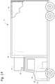
- FIG. 1Billustrates a schematic cross sectional side view of a refrigerated transport unit with a multi-temp transport refrigeration system, according to one embodiment.
- FIG. 1Cillustrates a perspective view of a vehicle with an APU, according to one embodiment.
- FIG. 1Dillustrates a front perspective view of an APU, according to one embodiment.
- FIG. 1Eillustrates a side view of a van with a roof mounted vehicle powered transport refrigeration unit, according to one embodiment.
- FIG. 2illustrates a block diagram schematic of one embodiment of a vehicle electrical system of a climate control system, according to one embodiment.
- FIG. 3illustrates a block diagram schematic of one embodiment of an Energy Management Module, according to one embodiment.
- FIG. 4illustrates a flowchart of one embodiment of a method for managing energy to a transport climate control load network from a vehicle electrical system.
- This disclosurerelates generally to energy sources and loads management. More specifically, the disclosure relates to methods and systems for managing and controlling auxiliary electrical storage and loads for multiple energy sources for a climate control system.
- a transport climate control systemsuch as a TRS or MTRS for a transport unit (TU), an HVAC system for a vehicle, etc.
- low voltagerefers Class A of the ISO 6469-3 in the automotive environment. In particular, a maximum working voltage of between 0V and 60V DC or between 0V and 30V AC.
- high voltagerefers Class B of the ISO 6469-3 in the automotive environment. In particular, a maximum working voltage of between 60V and 1500V DC or between 30V and 1000V AC.
- FIG. 1Adepicts a temperature-controlled straight truck 11 that includes a conditioned load space 12 for carrying cargo.
- a transport refrigeration unit (TRU) 14is mounted to a front wall 16 of the load space 12 .
- the TRU 14is controlled via a controller 15 to provide temperature control within the load space 12 .
- the truck 11further includes a vehicle power bay 18 , which houses a prime mover 21 , such as a combustion engine (e.g., diesel engine, etc.), that provides power to move the truck 11 and to operate the TRU 14 .
- the prime mover 21can work in combination with an optional machine 22 (e.g., an alternator) to operate the TRU 14 .
- the TRU 14includes a vehicle electrical system (see FIG. 2 ).
- the truck 11can be a hybrid vehicle that is powered by the prime mover 21 in combination with a battery power source or can be an electrically driven truck in which the prime mover 21 is replaced with an electric power source (e.g., a battery power source).
- a battery power sourcee.g., a battery power source
- FIG. 1Aillustrates a temperature-controlled straight truck 11
- a containersuch as a container on a flat car, an intermodal container, etc.
- box caror other similar transport unit.
- FIG. 1Billustrates one embodiment of a MTRS 100 for a TU 125 that can be towed, for example, by a tractor (not shown).
- the MTRS 100includes a TRU 110 that provides environmental control (e.g. temperature, humidity, air quality, etc.) within an internal space 150 of the TU 125 .
- the MTRS 100also includes a MTRS controller 170 and one or more sensors (e.g., Hall effect sensors, current transducers, etc.) (see FIG. 2 ) that are configured to measure one or more parameters (e.g., ambient temperature, compressor suction pressure, compressor discharge pressure, supply air temperature, return air temperature, humidity, etc.) of the MTRS 100 and communicate parameter data to the MTRS controller 170 .
- sensorse.g., Hall effect sensors, current transducers, etc.
- the MTRS 100is powered by a power module 112 .
- the TRU 110is disposed on a front wall 130 of the TU 125 . In other embodiments, it will be appreciated that the TRU 110 can be disposed, for example, on a rooftop 126 or another wall of the TU 125 .
- the MTRS 100can include an undermount unit 113 .
- the undermount unit 113can be a TRU that can also provide environmental control (e.g. temperature, humidity, air quality, etc.) within the internal space 150 of the TU 125 .
- the undermount unit 113can work in combination with the TRU 110 to provide redundancy or can replace the TRU 110 .
- the undermount unit 113can be a power module that includes, for example, a generator that can help power the TRU 110 .
- the programmable MTRS Controller 170may comprise a single integrated control unit or may comprise a distributed network of TRS control elements. The number of distributed control elements in a given network can depend upon the particular application of the principles described herein.
- the MTRS controller 170is configured to control operation of the MTRS 100 .
- the power module 112is disposed in the TRU 110 .
- the power module 112can be separate from the TRU 110 .
- the power module 112can include two or more different power sources disposed within or outside of the TRU 110 .
- the power module 112can include one or more of a prime mover, a battery, an alternator, a generator, a solar panel, a fuel cell, etc.
- the prime movercan be a combustion engine or a microturbine engine and can operate as a two speed prime mover, a variable speed prime mover, etc.
- the power module 112can provide power to, for example, the MTRS Controller 170 , a compressor (not shown), a plurality of DC (Direct Current) components (not shown), a power management unit (see FIG. 2 ), etc.
- the DC componentscan be accessories or components of the MTRS 100 that require DC power to operate. Examples of the DC components can include, for example, DC fan motor(s) for a condenser fan or an evaporator blower (e.g., an Electrically Commutated Motor (ECM), a Brushless DC Motor (BLDC), etc.), a fuel pump, a drain tube heater, solenoid valves (e.g., controller pulsed control valves), etc.
- ECMElectrically Commutated Motor
- BLDCBrushless DC Motor
- the power module 112can include a DC power source (not shown) for providing DC electrical power to the plurality of DC components (not shown), the power management unit (see FIG. 2 ), etc.
- the DC power sourcecan receive mechanical and/or electrical power from, for example, a utility power source (e.g., Utility power, etc.), a prime mover (e.g., a combustion engine such as a diesel engine, etc.) coupled with a generator machine (e.g., a belt-driven alternator, a direct drive generator, etc.), etc.
- a utility power sourcee.g., Utility power, etc.
- a prime movere.g., a combustion engine such as a diesel engine, etc.
- a generator machinee.g., a belt-driven alternator, a direct drive generator, etc.
- the bi-directional voltage convertercan be a bi-directional multi-battery voltage converter.
- the internal space 150can be divided into a plurality of zones 152 .
- the term “zone”means a part of an area of the internal space 150 separated by walls 175 . It will be appreciated that the invention disclosed herein can also be used in a single zone TRS.
- the MTRS 100 for the TU 125includes the TRU 110 and a plurality of remote evaporator units 180 .
- an HVAC systemcan be powered by an Auxiliary Power Unit (APU, see FIGS. 1C and 1D ).
- the APUcan be operated when a main prime mover of the TU 125 is turned off such as, for example, when a driver parks the TU 125 for an extended period of time to rest.
- the APUcan provide, for example, power to operate a secondary HVAC system to provide conditioned air to a cabin of the TU 125 .
- the APUcan also provide power to operate cabin accessories within the cabin such as a television, a microwave, a coffee maker, a refrigerator, etc.
- the APUcan be a mechanically driven APU (e.g., prime mover driven) or an electrically driven APU (e.g., battery driven).
- the tractorincludes a vehicle electrical system (see FIG. 2 ) for supplying electrical power to the electrical loads of the tractor, the MTRS 100 , and/or the TU 125 .
- FIG. 1Cillustrates a vehicle 10 according to one embodiment.
- the vehicle 10is a semi-tractor that is used to transport cargo stored in a cargo compartment (e.g., a container, a trailer, etc.) to one or more destinations.
- a cargo compartmente.g., a container, a trailer, etc.
- vehicleshall be used to represent all such tractors and trucks, and shall not be construed to limit the invention's application solely to a tractor in a tractor-trailer combination.
- the vehicle 10can be, for example, a straight truck, van, etc.
- the vehicle 10includes a primary power source 20 , a cabin 25 defining a sleeping portion 30 and a driving portion 35 , an APU 40 , and a plurality of vehicle accessory components 45 (e.g., electronic communication devices, cabin lights, a primary and/or secondary HVAC system, primary and/or secondary HVAC fan(s), sunshade(s) for a window/windshield of the vehicle 10 , cabin accessories, etc.).
- vehicle accessory components 45e.g., electronic communication devices, cabin lights, a primary and/or secondary HVAC system, primary and/or secondary HVAC fan(s), sunshade(s) for a window/windshield of the vehicle 10 , cabin accessories, etc.
- the cabin 25can be accessible via a driver side door (not shown) and a passenger side door 32 .
- the cabin 25can include a primary HVAC system (not shown) that can be configured to provide conditioned air within driving portion 35 and potentially the entire cabin 25 , and a secondary HVAC system (not shown) for providing conditioned air within the sleeping portion 30 of the cabin 25 .
- the cabin 25can also include a plurality of cabin accessories (not shown). Examples of cabin accessories can include, for example, a refrigerator, a television, a video game console, a microwave, device charging station(s), a continuous positive airway pressure (CPAP) machine, a coffee maker, a secondary HVAC system for providing conditioned air to the sleeping portion 30 .
- CPAPcontinuous positive airway pressure
- the primary power source 20can provide sufficient power to operate (e.g., drive) the vehicle 10 and any of the plurality of vehicle accessory components 45 and cabin accessory components 47 .
- the primary power source 20can also provide power to the primary HVAC system and the secondary HVAC system.
- the primary power sourcecan be a prime mover such as, for example, a combustion engine (e.g., a diesel engine, etc.).
- the APU 40is a secondary power unit for the vehicle 10 when the primary power source 20 is unavailable.
- the APU 40can be configured to provide power to one or more of the vehicle accessory components, the cabin accessories, the primary HVAC system and the secondary HVAC system.
- the APU 40can be an electric powered APU.
- the APU 40can be a prime mover powered APU.
- the APU 40can be attached to the vehicle 10 using any attachment method.
- the APU 40can be turned on (i.e., activated) or off (i.e., deactivated) by an occupant (e.g., driver or passenger) of the vehicle 10 .
- the APU 40generally does not provide sufficient power for operating (e.g., driving) the vehicle 10 .
- the APU 40can be controlled by an APU controller 41 .
- FIG. 1Dillustrates an electric APU 140 that can be used with a vehicle (e.g., the vehicle 10 shown in FIG. 1C ), according to one embodiment.
- the APU 140includes a plurality of energy storage elements 60 each of which is coupled to one of a plurality of converters 70 .
- the converters 70can provide electric power (e.g., AC or DC power) generated by the APU 140 to one or more vehicle accessory components, cabin accessory components, a primary HVAC system, and a secondary HVAC system.
- a secondary HVAC systemcan provide conditioned air to a sleeping portion of a vehicle cabin (e.g., the sleeping portion 30 of the cabin 25 shown in FIG. 1C ).
- the energy storage elements 60can be, for example, battery packs, fuel cells, etc.
- the APU 140can be turned on or off by an occupant (e.g., driver or passenger) of the vehicle.
- the occupantcan turn on the APU 140 to provide power stored in the energy storage elements 60 when a primary power source of the vehicle is turned off.
- the embodiments described hereincan also be used with a prime mover powered APU.
- the APU(e.g., the APU 40 as shown in FIG. 1C and/or the APU 140 as shown in FIG. 1D ) includes a vehicle electrical system (see FIG. 2 ).
- FIG. 1Edepicts a temperature-controlled van 80 that includes a conditioned load space 82 (or internal space) for carrying cargo.
- a transport refrigeration unit (TRU) 85is mounted to a rooftop 84 of the load space 82 .
- the TRU 85is controlled via a controller 83 to provide temperature control within the load space 82 .
- the van 80further includes a vehicle power bay 86 , which houses a prime mover 87 , such as a combustion engine (e.g., diesel engine, etc.), that provides power to move the van 80 and to operate the TRU 85 .
- the prime mover 87can work in combination with an optional machine 88 (e.g., an alternator) to operate the TRU 85 .
- an optional machine 88e.g., an alternator
- the TRU 85includes a vehicle electrical system (see FIG. 2 ).
- the van 80can be a hybrid vehicle that is powered by the prime mover 87 in combination with a battery power source or can be an electrically driven truck in which the prime mover 87 is replaced with an electric power source (e.g., a battery power source).
- FIG. 2illustrates a block diagram schematic of one embodiment of a vehicle electrical system 200 .
- the vehicle electrical system 200can be provided, for example, in the TRU 14 shown in FIG. 1A to supply electrical power to the TRU 14 .
- the vehicle electrical system 200can be provided to supply electrical power to the electrical loads of the tractor, the MTRS 100 , and/or the TU 125 shown in FIG. 1B .
- the vehicle electrical system 200can also be provided as part of an APU (e.g., the APU 40 shown in FIG. 1C and/or the APU 140 shown in FIG. 1D ) to supply electrical power to one or more loads connected to the APU.
- the vehicle electrical system 200 shown in FIG. 2is configured to operate with a prime mover powered vehicle. However, it will be appreciated that the vehicle electrical system 200 can also be configured to operate with an electric vehicle powered by an energy storage device (e.g., one or more batteries) and/or a hybrid vehicle powered by a combination of a prime mover and an energy storage device.
- the vehicle electrical system 200includes a DC regulated bus 202 electrically connecting a vehicle power network 204 , an auxiliary power network 206 , a utility power network 208 , a bi-directional voltage converter 240 and a transport climate control load network 212 .
- the DC regulated bus 202can be a 12 volts DC regulated bus.
- regulatedis a term of art.
- a regulated power supplycan convert unregulated AC (Alternating Current) supply into a constant DC, with the help of a rectifier (or an AC-DC converter, or the like), and can supply a stable voltage (or current in some situations), to a circuit or device that need to be operated within certain power supply limits.
- the voltage provided to the buscan vary, for example, between about 11 volts to about 15 volts.
- the DC regulated bus 202can travel from a vehicle power bay to a cab of the vehicle, to a TRU, and/or to a APU.
- the vehicle electrical system 200can manage and regulate energy from one or more energy sources from the vehicle power network 204 , the auxiliary power network 206 and/or the utility power network 208 to the transport climate control load network 212 via the bi-directional voltage converter 240 .
- the one or more energy sourcescan include a vehicle battery 210 and an vehicle alternator 205 via the vehicle power network 204 , a utility power 220 (also referred to as a shore power source) via the utility power network 208 , and/or one or more auxiliary batteries 230 via the auxiliary power network 206 .
- the vehicle electrical system 200is configured to supply energy to one or more loads from the transport climate control load network 212 .
- the loadscan be, for example, a compressor 255 , one or more evaporator blowers 265 , one or more condenser fans 270 , a heater 275 , and a controller 260 of an transport climate control system.
- the vehicle power network 204includes the vehicle battery 210 , the vehicle alternator 205 and a vehicle isolator 215 disposed between the vehicle alternator 205 and the vehicle battery 210 at one end and the DC regulated bus 202 at a second end.
- the vehicle battery 210can be used, for example, for starting a vehicle prime mover, running lights, powering vehicle accessory components, etc. In some embodiments, the vehicle battery 210 can also be used to power components of the transport climate control load network 208 .
- the vehicle battery 210 and the vehicle alternator 205are connected to the DC regulated bus 202 via a vehicle isolator 215 .
- the vehicle isolator 215can be a switch controlled by the controller 260 that isolates the bi-directional voltage converter 240 from receiving energy from the vehicle power network 204 .
- the vehicle alternator 205can be an electrical alternator that can provide AC power to the vehicle.
- the vehicle alternator 205can include a rectifier or an AC-DC converter (not shown) that rectifies or converts the AC power to a DC power.
- the vehicle alternator 205is connected to the DC regulated bus 202 via the vehicle isolator 215 .
- the vehicle alternator 205can provide the rectified or converted DC power (for example, 12V) to the DC regulated bus 202 .
- Electric vehiclescan include a motor generator and a high voltage (e.g., in a range between 60V and 1500V; for example 400V, 800V, etc.) DC battery to run the vehicle. Electric vehicles can also provide a relatively high voltage (e.g., 400V, 800V, etc.) DC power source (e.g., a battery pack, a rechargeable energy storage system (RESS), etc.). Electric vehicles can include one or more DC-DC converters (e.g., two DC-DC convertors) to convert the relatively high voltage (e.g., 400V, 800V, etc.) to a low voltage (e.g., in a range between 0V and 60V; for example 12V).
- a relatively high voltagee.g., 400V, 800V, etc.
- a low voltagee.g., in a range between 0V and 60V; for example 12V.
- the vehicle alternator 205can be replaced with a DC-DC converter having similar parameters as the vehicle alternator 205 in order to be able to provide a low voltage to the DC regulated bus 202 and power one or more loads of the transport climate control load network 212 .
- the converted low voltagee.g. 12V
- vehicle accessory componentse.g., electronic communication devices, cabin lights, a primary and/or secondary HVAC system, primary and/or secondary HVAC fan(s), sunshade(s) for a window/windshield of the vehicle 10 , cabin accessories, etc.
- the converted low voltage (e.g. 12V)can be provided to the DC regulated bus 202 for powering the transport climate control load network 212 .
- an electric vehiclecan provide for example, 7 kW-Hour energy from a 45 kW-Hour storage of the vehicle power network 204 to run the transport climate control load network 212 .
- a low voltagee.g., 12V
- Embodiments disclosed hereincan use take off power (e.g., electric power take off or ePTO) from the low voltage (for example, 12V) system for loads such as vehicle accessory components and/or the transport climate control load network 212 .
- the high voltage powercan provide power for driving the vehicle (e.g., transmission power take off) and the embodiments disclosed herein may not take electric power from the high voltage system.
- an alternatorsuch as the vehicle alternator 205
- a low voltage DC power sourcethat can provide a low voltage (e.g., 12V) to the DC regulated bus 202 .
- any type of power source from the vehicle that can provide power to the vehicle electrical system 200can be part of the vehicle power network 204 .
- Thiscan include, for example, the vehicle alternator 205 , the vehicle battery 210 , a RESS, a generator, an axle-mounted generator, a power take off (PTO) device or ePTO device with an auxiliary converter, etc.
- PTOpower take off
- a voltage sensor(not shown) can be provided in the vehicle power network 204 to monitor a vehicle voltage provided to the DC regulated bus 202 .
- a current sensor(not shown) can be provided in series with the vehicle isolator 215 to monitor the current to and from the auxiliary power network 206 .
- the utility power network 208includes the AC-DC converter 225 .
- a utility power (e.g., Utility power, etc.) 220can be connected to the AC-DC converter 225 to provide AC power input to the AC-DC converter 225 .
- the AC-DC converter 225converts the AC power from the utility power 220 and provides converted DC power to the DC regulated bus 202 .
- the converted DC power from the AC-DC converter 225 to the DC regulated bus 202can be, for example, 12 volts and 84 amps. While FIG. 2 shows a single AC-DC converter 225 , it is appreciated that in other embodiments the vehicle electrical system 200 can includes two or more AC-DC converters.
- each of the AC-DC converterscan be connected to the utility power 220 to provide additional power capacity to the vehicle electrical system 200 .
- each of the AC-DC converterscan provide different amounts of power.
- each of the AC-DC converterscan provide the same amount of power.
- the auxiliary power network 206includes an optional auxiliary battery system 230 and two auxiliary power on/off switches 235 disposed between the auxiliary battery system 230 and the DC regulated bus 202 .
- the auxiliary power network 206can be part of the transport climate control system and potentially housed within a transport refrigeration unit.
- the auxiliary power network 206can be external to the transport climate control system and part of the vehicle power network 204 .
- the auxiliary power network 206can be external to the transport climate control system and external to the vehicle power network 204 .
- the auxiliary battery system 230can include a one or more auxiliary batteries (also referred to as hold-over batteries).
- the auxiliary battery system 230can include two auxiliary batteries (not shown).
- Each of the auxiliary batteriescan also be connected to the DC regulated bus 202 via the bi-directional voltage converter 240 .
- each of the auxiliary batteriescan bypass the bi-directional voltage converter 240 and connect to the DC regulated bus 202 via one of the auxiliary power on/off switches 235 .
- the auxiliary battery system 230can provide sufficient energy to power the transport climate control load network 212 by itself.
- Each of the auxiliary power on/off switches 235can be controlled by the controller 260 .
- the bi-directional voltage converter 240is configured to transfer power from one of the vehicle power network 204 , the utility power network 208 and/or the auxiliary power network 206 to the transport climate control load network 212 .
- the bi-directional voltage converter 240can be part of an energy management module (e.g., a smart charge module (SCM), etc.).
- the bi-directional voltage converter 240can transfer power from the vehicle power network 204 and/or the utility power network 208 to charge one or more auxiliary batteries of the auxiliary battery system 230 .
- the bi-directional voltage converter 240can control current flow along the DC regulated bus 202 .
- the vehicle electrical system 200can include two or more bi-directional voltage converters 240 each of which is part of a separate SMC.
- the energy management modulecan be a DC-DC charger.
- the bi-directional voltage converter 240can step-down (buck) and step-up (boost) voltage for power being sent from the vehicle power network 204 and/or the utility power network 208 to the bi-directional voltage converter 240 , and from the bi-directional voltage converter 240 to the vehicle power network 204 and/or the utility power network 208 . Accordingly, the bi-directional voltage converter 240 can control current direction and current amount along the DC regulated bus 202 .
- the vehicle electrical system 200is controlled by the controller 260 .
- the controller 260can be, for example, the TRS controller 15 shown in FIG. 1A , the MTRS controller 170 of FIG. 1B , or the APU controller 41 .
- a remote controller 280can be connected to the controller 260 wirelessly (e.g., Bluetooth, ZigBee, etc.) or via wire (e.g., a communication link such as a RS485 communication link).
- the remote controller 280can be located in a cab of the vehicle and can be controlled by a user, for example, a driver.
- the remote controller 280can be used by a user to communicate the user's settings for components of the transport climate control load network 212 to the controller 260 .
- Components of the transport climate control load network 212can be, for example, part of a TRU that is mounted to the body of the vehicle (for example, truck). In some embodiments, the TRU can be above the cab of the truck. In another embodiment, the TRU can be on the top of the TU (for example, a top of a box where the external condensers are located).
- the transport climate control load network 212includes a Compressor Drive Module (CDM) 250 that drives the compressor 255 , one or more evaporator blowers 265 , one or more condenser fans 270 , the heater 275 , and the controller 260 .
- CDMCompressor Drive Module
- the DC regulated bus 202is connected to and powers each of the CDM 250 , the one or more evaporator blowers 265 , the one or more condenser fans 270 , the heater 275 , and the controller 260 . It will be appreciated that the CDM 250 and the compressor 255 can require the most power of the various loads of the transport climate control load network 212 .
- the CDM 250is configured to boost power from the DC regulated bus 202 and converts the power to AC power to drive the compressor 255 .
- the CDM 250can convert the low voltage DC power (for example, 12V) from the DC regulated bus 202 and provide, for example, 240V AC power to drive the compressor 255 .
- the CDM 250drives the compressor 255 to meet demand of the transport climate control system.
- the CDM 250can cause the vehicle voltage to droop.
- the CDM 250includes a DC-DC-AC converter in which the CDM 250 boosts the voltage from the DC regulated bus to a higher DC voltage and then converts the higher DC voltage to an AC voltage.
- the utility power 220can be connected directly to the compressor 255 and provide power to drive the compressor 255 thereby bypassing the CDM 250 .
- the CDM 250can be used as an AC-DC converter and convert power received from the utility power 220 into DC power that can be provided by the CDM 250 to the DC regulated bus 202 .
- the compressor 255can be a variable speed compressor. In some embodiments, the compressor 255 can require, for example, 1 KW of power to operate. In some embodiments, the one or more evaporator blowers 265 can require, for example, 100 W of power to operate. In some embodiments, the one or more condenser fans 270 can require, for example, 130 W of power to operate. In some embodiments, the heater 275 can require, for example, 1200 W of power to operate. Also, in some embodiments, the heater 275 can be configured to receive power from the CDM 250 .
- the compressor 255 and/or the heater 275When the compressor 255 and/or the heater 275 are powered directly by the utility power 220 , the compressor 255 and/or the heater 275 can be turned on and off (e.g., operate in a cycle sentry mode) in order to control the amount of cooling provided by the compressor 255 and/or the amount of heating provided by the heater 275 .
- FIG. 3illustrates a block diagram schematic of one embodiment of an energy management module 300 .
- a vehicle power network 304is electrically connected to the energy management module 300 .
- the vehicle power network 304can include one or more vehicle power sources such as, for example, a vehicle alternator (e.g., the vehicle alternator 205 ), a vehicle battery (e.g., the vehicle battery 210 ), etc.
- the energy management module 300includes a bi-directional voltage converter 330 .
- the bi-directional voltage converter 330can be, for example, the bi-directional voltage converter 240 shown in FIG. 2 .
- the bi-directional voltage converter 330can step-down (buck) and step-up (boost) voltage for power being sent from the vehicle power network 304 to the energy management module 300 and from the energy management module 300 to the vehicle power network 304 . Accordingly, the bi-directional voltage converter 240 can control current direction and current amount along a DC regulated bus of a vehicle electrical system. Detailed descriptions on some embodiments of the bi-directional voltage converters can be found in, for example, U.S. Pat. Nos. 8,441,228; 8,541,905; 9,199,543; and 9,102,241.
- the energy management module 300includes a plurality of electric switches 310 , 311 , and 312 .
- Each of the electric switches 310 , 311 , and 312connects to (or disconnects from) a corresponding battery module 340 , 341 , and 342 , respectively.
- the battery modules 340 , 341 , and 342can be, for example, the auxiliary battery system 230 shown in FIG. 2 .
- the plurality of electric switches 310 , 311 , and 312can be battery relays, electronic switches, etc.
- the electronic switches 310 , 311 , and 312can be, for example, semiconductor (solid-state) switches such as SmartFET type switches.
- SmartFET type switchescan be field-effect transistor (FET) switches that have smart built-in features such as diagnosis and protection capabilities.
- one or more of the battery modules 340 , 341 , and 342can be an auxiliary battery used to power components of the transport climate control load network 212 .
- the plurality of electric switches 310 , 311 , and 312is configured to selectively connect one or more of the battery modules 340 , 341 , and 342 to the bi-directional voltage converter 330 so that at any given time, a subset of the battery modules 340 , 341 , and 342 connects to the bi-directional voltage converter 330 .
- a controller(such as, for example, the controller 260 shown in FIG. 2 ) can be configured to control the plurality of electric switches 310 , 311 , 312 to selectively connect one or more of the battery modules 340 , 341 , and 342 to the bi-directional voltage converter 330 .
- the plurality of electric switches 310 , 311 , and 312can be configured to selectively connect more than one of the battery modules 340 , 341 , and 342 to the bi-directional voltage converter 330 . It will also be appreciated that the plurality of electric switches 310 , 311 , and 312 can be a single battery relay or a single electronic switch that can be configured to selectively connect one or more of the plurality of battery modules 340 , 341 , and 342 to the bi-directional voltage converter 330 .
- the bi-directional voltage converter 330can connect to a system bus of a vehicle electrical system (such as, for example, the DC regulated bus 202 shown in FIG. 2 ) so that the selected battery module(s) 340 , 341 , and 342 can deliver power to electrical loads (such as, for example, components of the transport climate control load network 212 shown in FIG. 2 ) of the vehicle electrical system or can be charged by other power sources.
- a controllerfor example, the controller 260 shown in FIG.
- the bi-directional voltage converter 330can control/switch a plurality of switches (not shown) of the bi-directional voltage converter 330 to control when and where the bi-directional voltage converter 330 directs current (for example, from the selected battery module 340 , 341 , 342 to the electrical loads in a discharging mode, or from other power source to the selected battery module 340 , 341 , 342 in a charging mode).
- the plurality of battery modules 340 , 341 , 342 of the energy management module 300can charge (i.e., deliver power to) battery module(s) of another energy management module, or vice versa, to balance the power/energy stored in the battery module(s) of each energy management module.
- battery module(s) of different energy management modulescan be combined/selected until the total power-delivery capacity (e.g. measured in peak amperes at a given voltage, such as 12 volts) is sufficient for supplying the power needs of the vehicle electrical system.
- the selected battery module(s) of different energy management modulescan provide adequate power to the electrical loads of the vehicle electrical system based on the load draw.
- the selected battery module(s) of different energy management modulesreceive power from one or more power sources during a charge phase, and discharges power to the electrical loads of the vehicle electrical system during a discharge phase.
- a charge phasemay occur when for example, a power source (such as, for example, the utility power network 208 shown in FIG. 2 ) provides power to the vehicle electrical system of the vehicle, and a discharge phase may occur when for example, the power source is not providing power to the vehicle electrical system of the vehicle (for example, when the prime mover (e.g., combustion engine) is stopped and utility power is unavailable).
- a power sourcesuch as, for example, the utility power network 208 shown in FIG. 2
- a discharge phasemay occur when for example, the power source is not providing power to the vehicle electrical system of the vehicle (for example, when the prime mover (e.g., combustion engine) is stopped and utility power is unavailable).
- utility power 208can be used to fill an energy shortfall when the vehicle cannot be run and a temperature control gap between the monitored temperature and a desired setpoint temperature of the internal space conditioned by the transport climate control system is large.
- a controllere.g., the controller 260 shown in FIG. 2
- the alertcan instruct the driver to start the vehicle and run at a fast idle (e.g., raise an idle speed of a prime mover of the vehicle without raising a speed at which the vehicle is moving) or downshift a vehicle prime mover to operate at a higher prime mover RPM so as to prevent a failure of the transport climate control system and to prevent shedding or derating of loads of the transport climate control load network 212 .
- the controller 260can instruct the vehicle to start an automatic restart module to start the vehicle and run at a fast idle to prevent failure of the transport climate control system and to prevent shedding or derating of loads of the transport climate control load network 212 .
- the controller 260can instruct the vehicle to disable an auto start/stop system of the vehicle prime mover.
- the alertcan be sent a time period (e.g., 1 to 5 minutes) before any action is taken or required.
- the bi-directional voltage converter 330 of the energy management module 300can transfer power/energy between a power source and the selected battery module(s) 340 , 341 , and 342 .
- the bi-directional voltage converter 330is also referred to as a bi-directional multi-battery voltage converter.
- the bi-directional voltage converter 330can include a control circuit (not shown). The control circuit can selectively energize one or more of the plurality of electric switches 310 , 311 , and 312 to connect the selected battery module(s) 340 , 341 , and 342 with the bi-directional voltage converter 330 .
- the energy management module 300can operate in one of three modes: a charge mode, a discharge mode, and a null mode.
- a charge modethe energy management module 300 can charge one or more of the battery modules 340 , 341 , and 342 using a power source (for example, the utility power 220 or the vehicle alternator 205 shown in FIG. 2 ).
- a discharge modethe energy management module 300 can deliver power from one or more of the battery modules 340 , 341 , and 342 to the electrical loads (for example, components of the transport climate control load network 212 shown in FIG. 2 ).
- the energy management module 300is configured to prevent current from flowing between any of the battery module 340 , 341 , and 342 and the rest of the vehicle electrical system.
- the control circuitis controlled such that none of the battery modules 340 , 341 , and 342 are energized.
- the energy management module 300 operational modescan be determined by the controller (for example, the controller 260 shown in FIG. 2 ).
- the controller(for example, the controller 260 shown in FIG. 2 ) can switch the bi-directional voltage converter 330 ON (enabled) to draw current from a system bus of a vehicle electrical system or OFF (disabled) to prevent the bi-directional voltage converter 330 from drawing current.
- the bi-directional voltage converter 330can direct current from one or more power sources to a selected battery module of the plurality of battery modules 340 , 341 , 342 .
- the bi-directional voltage converter 330When the bi-directional voltage converter 330 is switched ON in the discharging mode, the bi-directional voltage converter 330 can direct current from a selected battery module of the plurality of battery modules 340 , 341 , 342 to one or more electrical loads (e.g., components of the transport climate control load network 212 shown in FIG. 2 ). When the bi-directional voltage converter 330 is switched OFF, current can be prevented from flowing between the battery modules and the system bus via the bi-directional voltage converter 330 .
- one or more electrical loadse.g., components of the transport climate control load network 212 shown in FIG. 2 .
- FIG. 4illustrates a flowchart of one embodiment of a method 400 for managing energy to the transport climate control load network 212 from the vehicle electrical system 200 .
- the method 400begins at 405 whereby the controller 260 determines whether the utility power network 208 is connected to the utility power 220 and the utility power network 208 is permitted to receive power from the utility power 220 .
- the utility power network 208may be connected to the utility power 220 but not permitted to receive power from the utility power 220 when, for example, cost of power from the utility power 220 is too expensive, the use of utility power 220 by the vehicle electrical system 200 is being restricted, etc.
- the controller 260can be configured to monitor an ignition of the vehicle, determine that the utility power network 208 is permitted to receive power from the utility power 220 when the utility power 220 is connected to the utility power network 208 and the ignition of the vehicle is on, and determine that the utility power network 208 is not permitted to receive power from the utility power 220 when the utility power 220 is not connected to the utility power network 208 or the ignition of the vehicle is off.
- the method 400proceeds to 410 . If the utility power network 208 is not connected to the utility power 220 or the utility power network 208 is not permitted to receive power from the utility power 220 , the method 400 proceeds to 415 .
- the vehicle electrical system 200is operated with utility power.
- the AC-DC converter 225converts the utility power 220 into DC power that is provided to the DC regulated bus 202 .
- the controller 260is configured to control the vehicle isolator 215 so as to prevent power from the vehicle power network 204 to be supplied to DC regulated bus 202 .
- the controller 260is also configured to control the auxiliary power on/off switches 235 so as to prevent the auxiliary battery system 230 from supplying power to the DC regulated bus 202 .
- the vehicle electrical system 200can provide power to the transport climate control load network 212 .
- the controller 260can also determine whether one or more of the auxiliary batteries of the auxiliary battery system 230 require charging.
- the controller 260can be configured to operate the bi-directional voltage converter 240 in the charge mode so as to charge the one or more auxiliary batteries of the auxiliary battery system 230 . If charging is not required, the controller 260 can be configured to operate the bi-directional voltage converter 240 in the null mode. A method for charging the auxiliary battery system 230 is discussed below with respect to FIG. 5 . The method 400 then proceeds back to 405 .
- the controller 260monitors a vehicle voltage or current provided by the vehicle power network 204 to the DC regulated bus 202 .
- a voltage sensor(not shown) is disposed in the vehicle power network 204 to measure the vehicle voltage. The voltage sensor then sends the vehicle voltage measurement to the controller 260 .
- a current sensor(not shown) can be disposed in the vehicle power network 204 to measure current coming into and out of the vehicle battery 210 . In these embodiments, the current measurements can be sent to the controller 260 in lieu of the vehicle voltage measurement.
- the method 400then proceeds to 420 .
- the controller 260determines whether the vehicle power network 204 has excess power capacity available based on the vehicle voltage (or optionally the vehicle current) provided by the vehicle power network 204 to the DC regulated bus 202 .
- the vehicle electrical system 200can have excess power capacity available when, for example, the vehicle is highway cruising with limited stops or idling. Accordingly, the vehicle alternator 205 is supplying sufficient power to power the transport climate control network 212 by itself and can also supply power to the bi-directional voltage converter 240 to charge one or more auxiliary batteries of the auxiliary battery system 230 . In some embodiments, when the vehicle power network 204 has excess power capacity available, the vehicle alternator 205 can supply power to the DC regulated bus 202 without assistance of the vehicle battery 210 .
- the controller 260can determine that the vehicle power network 204 has excess power capacity available when the vehicle voltage is greater than an excess power capacity threshold. For example, when the DC regulated bus 202 is a 12 volt regulated bus, the controller 260 can determine that the vehicle power network 204 has excess power capacity available when the vehicle voltage provided by the vehicle power network 204 is greater than the excess power capacity threshold that is, for example, about 13.5 volts.
- the method 400proceeds to 425 . If the controller 260 determines that the vehicle power network 204 does not have excess power capacity available, the method 400 proceeds to 430 .
- the vehicle electrical system 200operates with excess power capacity.
- the controller 260is configured to control the vehicle isolator 215 so as to allow power from the vehicle power network 204 to be supplied to DC regulated bus 202 .
- the power from the vehicle power network 204is from the vehicle alternator 205 without depleting charge of the vehicle battery 210 .
- the controller 260is also configured to control the auxiliary power on/off switches 235 so as to prevent the auxiliary battery system 230 from supplying power to the DC regulated bus 202 .
- the vehicle electrical system 200can provide power to the transport climate control load network 212 to operate the transport climate control system as desired.
- the controller 260can also determine whether one or more of the auxiliary batteries of the auxiliary battery system 230 require charging. If charging is required, the controller 260 can be configured to operate the bi-directional voltage converter 240 in the charge mode so as to charge the one or more auxiliary batteries of the auxiliary battery system 230 . If charging is not required, the controller 260 can be configured to operate the bi-voltage directional converter 240 in the null mode.
- the DC regulated bus 202supplies required power to the transport climate control network 212 to operate the transport climate control system as desired and can supply any excess power available to the bi-directional voltage converter 240 to charge the auxiliary battery system 206 . The method 400 then proceeds back to 405 .
- the controller 260determines whether the vehicle power network 204 has sufficient power capacity available based on the vehicle voltage provided by the vehicle power network 204 to the DC regulated bus 202 .
- the vehicle electrical system 200can have sufficient power capacity available when, for example, the vehicle is city driving with stops and idling that can reduce the amount of power available by the vehicle alternator 205 . Accordingly, the vehicle alternator 205 , with potentially the assistance of the vehicle battery 210 , can supply sufficient power to power the transport climate control network 212 but potentially not enough to also supply power to the bi-directional voltage converter 240 to charge one or more auxiliary batteries of the auxiliary battery system 230 .
- the vehicle alternator 205supplies power to the DC regulated bus 202 with potentially the assistance of the vehicle battery 210 , thereby depleting charge of the vehicle battery 210 .
- the controller 260can determine that the vehicle power network 204 has sufficient power capacity available when the vehicle voltage is within a sufficient power capacity threshold range. For example, when the DC regulated bus 202 is a 12 volt regulated bus, the controller 260 can determine that the vehicle power network 204 has sufficient power capacity available when the vehicle voltage provided by the vehicle power network 204 is within the sufficient power capacity threshold range that is, for example, between about 13 volts and 13.5 volts.
- the method 400proceeds to 435 . If the controller 260 determines that the vehicle power network 204 does not have sufficient power capacity available, the method 400 proceeds to 480 .
- the vehicle electrical system 200operates with sufficient power capacity.
- the controller 260is configured to control the vehicle isolator 215 so as to allow power from the vehicle power network 204 to be supplied to the DC regulated bus 202 .
- the power from the vehicle power network 204is from the vehicle alternator 205 and the vehicle battery 210 , thereby depleting charge of the vehicle battery 210 .
- the controller 260is also configured to control the auxiliary power on/off switches 235 so as to prevent the auxiliary battery system 230 from supplying power to the DC regulated bus 202 .
- the vehicle electrical system 200can provide power to the transport climate control load network 212 as desired by the transport climate control system.
- the controller 260can be configured to operate the bi-directional voltage converter 240 in the null mode and prevent charging of the auxiliary battery system 230 .
- the method 400then proceeds to 440 .
- the controller 260monitors the power available capacity from the vehicle power network 204 . This can occur when, for example, the vehicle is stopped or idling for a period of time and the load on the vehicle power network 204 is greater than can be provided by the vehicle power network 204 .
- the controller 260can monitor the power available capacity from the vehicle power network 204 by monitoring the vehicle voltage provided by the vehicle power network 204 to the DC regulated bus 202 and/or by monitoring the vehicle current passing from the vehicle power network 204 to the DC regulated bus 202 .
- the controller 260can monitor the power available capacity from the vehicle power network 204 by starting a timer.
- the timercan be set to a predetermined time period based on, for example, testing data of the vehicle electrical system 200 .
- the controller 260can monitor the power available capacity from the vehicle power network 204 by both monitoring the vehicle voltage (and/or vehicle current) and by starting the timer.
- the timercan be set based on user requirements and in order to provide hysteresis and prevent mode cycling to the method 400 .
- the timercan be set to a number of minutes (e.g., a number between 1 to 5 minutes).
- Significant discharge of the vehicle battery 210can be a predetermined charge value of the vehicle battery 210 that is based on, for example, cargo customer requirements, vehicle requirements, and/or governmental regulations.
- significant discharge of the vehicle battery 210may be a charge value set to ensure that the vehicle battery can start a prime mover of the vehicle when the vehicle is not running.
- the method 400then proceeds to 445 .
- the controller 260determines whether the power available capacity has exceeded a capacity threshold.
- the capacity thresholdcan be a value that correlates with the battery power available capacity of the vehicle power network 204 and can be used to prevent, for example, significant discharge of the vehicle battery 210 .
- the capacity thresholdcan be a vehicle voltage value and/or a vehicle current value.
- the capacity thresholdcan be a timer value.
- the controller 260can use two capacity thresholds with the first capacity threshold being a vehicle voltage or current value and the second capacity threshold being a timer value.
- the controller 260determines that the power available capacity monitored at 440 exceeds the capacity threshold, the method 400 proceeds back to 435 .
- the controller 260can determine that the power available capacity monitored at 440 exceeds the capacity threshold, when both the first capacity threshold and the second capacity threshold are exceeded. That is, the vehicle voltage value is greater than a vehicle voltage value threshold and the timer value has not been reached.
- the controller 260determines that the power available capacity monitored at 440 does not exceed the capacity threshold, the method 400 proceeds to 455 .
- the controller 260can determine that the power available capacity monitored at 440 does not exceed the capacity threshold, when either the first capacity threshold or the second capacity threshold is exceeded. That is, the vehicle voltage value is less than or equal to a vehicle voltage threshold value or the timer value has been reached.
- the controller 260determines whether the auxiliary battery system 230 is sufficiently charged. In some embodiments, the controller 260 can determine the charge state of the auxiliary battery system 230 from the bi-directional voltage converter 240 . In some embodiments, the auxiliary battery system 230 can be sufficiently charged if the charge state is above a charge state threshold (e.g., 20%). If the charge state of the auxiliary battery system 230 is above the charge state threshold (i.e., the auxiliary battery system 230 is sufficiently charged), the method 400 proceeds to 450 . If the charge state of the auxiliary battery system 230 is below the charge state threshold (i.e., the auxiliary battery system 230 is not sufficiently charged), the method 400 proceeds to 470 .
- a charge state thresholde.g. 20%
- the controller 260can also send an alert, for example, to the user (e.g., vehicle driver), the cargo customer, etc. that there may be an energy scarcity of the vehicle electrical system 200 .
- the alertcan be sent via a SMS message, an email, can be displayed to the vehicle driver via the remote controller 280 , etc.
- the alertcan instruct the driver to start the vehicle and run at a fast idle (e.g., raise an idle speed of a prime mover of the vehicle without raising a speed at which the vehicle is moving) or downshift a vehicle prime mover to operate at a higher prime mover RPM so as to prevent a failure of the transport climate control system and to prevent shedding or derating of loads of the transport climate control load network 212 .
- the controller 260can instruct the vehicle to start an automatic restart module to start the vehicle and run at a fast idle to prevent failure of the transport climate control system and to prevent shedding or derating of loads of the transport climate control load network 212 .
- the controller 260can instruct the vehicle to disable an auto start/stop system of the vehicle prime mover.
- the alertcan be sent a time period (e.g., 1 to 5 minutes) before any action is taken or required.
- the controller 260determines whether the vehicle power network 204 requires holdover assistance based on the vehicle voltage provided by the vehicle power network 204 to the DC regulated bus 202 .
- the vehicle power network 204can require holdover assistance when, for example, the vehicle alternator 205 , with potentially the assistance of the vehicle battery 210 , is not supplying sufficient power to power the transport climate control network 212 .
- the vehicle alternator 205supplies power to the DC regulated bus 202 with potentially the assistance of the vehicle battery 210 , thereby depleting charge of the vehicle battery 210 .
- the controller 260can determine whether the vehicle power network requires holdover assistance when the vehicle voltage is within a holdover assistance threshold range.
- the controller 260can determine that the vehicle power network 204 requires holdover assistance when the vehicle voltage provided by the vehicle power network 204 is within the holdover assistance threshold range that is, for example, between about 12 volts and 13 volts.
- the method 400proceeds to 455 . If the controller 260 determines that the vehicle power network 204 does not require holdover assistance, the method 400 proceeds to 460 .
- the vehicle electrical system 200operates with holdover assistance.
- the controller 260is configured to control the vehicle isolator 215 so as to allow power from the vehicle power network 204 to be supplied to the DC regulated bus 202 .
- the controller 260is configured to control the auxiliary power on/off switches 235 so as to allow power from the auxiliary battery system 230 to be supplied to the to the DC regulated bus 202 .
- the auxiliary battery system 230can supplement the power provided by the vehicle power network 204 to ensure that the vehicle electrical system 200 can provide power to the transport climate control load network 212 as desired by the transport climate control system.
- the bi-directional voltage converter 240can be set to a predetermined discharge voltage, for example, about 15V (or 14.2V that is closer to the nominal voltage the vehicle alternator 205 can provide).
- the bi-directional voltage converter 240can run at a discharge mode, with a current limit of, for example, 40 A or 20 A or any suitable current required by the controller 260 to supplement the power from the vehicle power network 204 .
- the method 400then proceeds back to 405 .
- the controller 260determines whether the vehicle electrical system 200 should be exclusively powered by the auxiliary battery system 230 based on the vehicle electrical system power capacity available from the vehicle power network 204 to the DC regulated bus 202 .
- the vehicle power network 204can exclusively use power from the auxiliary battery system 230 to power the DC regulated bus 202 when, for example, use of the vehicle power network 204 would significantly discharge the vehicle battery 210 (such as when the vehicle is not running).
- one or more of the auxiliary batteries of the auxiliary battery system 230supplies power to the DC regulated bus 202 and the vehicle power network 204 is prevented from supplying power to the DC regulated bus 202 .
- the controller 260can determine that the vehicle electrical system 200 should be exclusively powered by the auxiliary battery system 230 when the vehicle voltage is within an exclusive power threshold range. For example, when the DC regulated bus 202 is a 12 volt regulated bus, the controller 260 can determine that the vehicle electrical system 200 should be exclusively powered by the auxiliary battery system 230 when the vehicle voltage provided by the vehicle power network 204 is within the exclusive power threshold range that is, for example, between about 11.5 volts and 12 volts.
- the method 400proceeds to 465 . If the controller 260 determines that the vehicle electrical system 200 should not be exclusively powered by the auxiliary battery system 230 , the method 400 proceeds to 470 .
- the vehicle electrical system 200is powered exclusively by the auxiliary battery system 230 .
- the controller 260is configured to control a range of operation of the vehicle isolator 215 so as to prevent power from the vehicle power network 204 to be supplied to the DC regulated bus 202 .
- the controller 260is configured to control the auxiliary power on/off switches 235 so as to allow power from the auxiliary battery system 230 to be supplied to the to the DC regulated bus 202 .
- the auxiliary battery system 230can provide sufficient power to ensure that the vehicle electrical system 200 can provide power to the transport climate control load network 212 as desired by the transport climate control system.
- the auxiliary battery system 230can bypass the bi-directional voltage converter 240 to supply the necessary current so the CDM 250 can operate to meet the transport climate control network demand.
- the controller 260can perform a load shedding process of the transport climate control load network 212 to reduce the amount of energy required by the DC regulated bus 202 and thereby the auxiliary power network 206 based on the amount of energy stored in the auxiliary battery system 230 .
- the controller 260can also send an alert, for example, to the user (e.g., vehicle driver), the cargo customer, etc. that there may be an energy scarcity of the vehicle electrical system 200 .
- the alertcan be sent via a SMS message, an email, can be displayed to the vehicle driver via the remote controller 280 , etc.
- the alertcan instruct the driver to start the vehicle and run at a fast idle (e.g., raise an idle speed of a prime mover of the vehicle without raising a speed at which the vehicle is moving) or downshift a vehicle prime mover to operate at a higher prime mover RPM so as to prevent a failure of the transport climate control system and to prevent shedding or derating of loads of the transport climate control load network 212 .
- the controller 260can instruct the vehicle to start an automatic restart module to start the vehicle and run at a fast idle to prevent failure of the transport climate control system and to prevent shedding or derating of loads of the transport climate control load network 212 .
- the controller 260can instruct the vehicle to disable an auto start/stop system of the vehicle prime mover.
- the alertcan be sent a time period (e.g., 1 to 5 minutes) before any action is taken or required.
- the controller 260determines whether the vehicle electrical system 200 should shut off power to the transport climate control load network 212 based on the vehicle voltage provided by vehicle power network 204 . That is, the controller 260 determines whether the DC regulated bus 202 should be prevented from receiving energy from the vehicle power network 204 , the auxiliary power network 206 and, when applicable, the utility power network 208 and sending said energy to the components of the transport climate control load network 212 .
- the vehicle electrical system 200should shut off power to the transport climate control load network 212 when, for example, there is insufficient power available to power the transport climate control network 212 or could harm operation of the vehicle.
- the controller 260can determine that the vehicle electrical system 200 should shut off power to the transport climate control load network 212 when the vehicle voltage is less than a shut off threshold. For example, when the DC regulated bus 202 is a 12 volt regulated bus, the controller 260 can determine that the vehicle electrical system 200 should shut off power to the transport climate control load network 212 when the vehicle voltage provided by the vehicle power network 204 is less than the shut off threshold that is, for example, about 11.5 volts. If the controller 260 determines that the vehicle electrical system 200 should shut off power to the transport climate control load network 212 , the method 400 proceeds to 475 . If the controller 260 determines that the vehicle electrical system 200 does not have to shut off power to the transport climate control load network 212 , the method 400 proceeds back to 405 .
- a shut off thresholdFor example, when the DC regulated bus 202 is a 12 volt regulated bus, the controller 260 can determine that the vehicle electrical system 200 should shut off power to the transport climate control load network 212 when the vehicle voltage provided by the
- the controller 260shuts off power from the vehicle electrical system 200 to the transport climate control load network 212 .
- the controller 260can be configured to control the vehicle isolator 215 so as to prevent power from the vehicle power network 204 to be supplied to the DC regulated bus 202 .
- the controller 260can be configured to control the auxiliary power on/off switches 235 so as to prevent power from the auxiliary battery system 230 to be supplied to the to the DC regulated bus 202 .
- the controller 260can also be configured to control the AC-DC converter 225 so as to prevent power from the utility power 220 .
- the controller 260can also send an alert, for example, to the user (e.g., vehicle driver), the cargo customer, etc.
- the alertcan be sent via a SMS message, an email, can be displayed to the vehicle driver via the remote controller 280 , etc.
- the alertcan instruct the driver to start the vehicle and run at a fast idle (e.g., raise an idle speed of a prime mover of the vehicle without raising a speed at which the vehicle is moving) or downshift a vehicle prime mover to operate at a higher prime mover RPM so as to prevent a failure of the transport climate control system and to prevent shedding or derating of loads of the transport climate control load network 212 .
- the controller 260can instruct the vehicle to start an automatic restart module to start the vehicle and run at a fast idle to prevent failure of the transport climate control system and to prevent shedding or derating of loads of the transport climate control load network 212 .
- the controller 260can instruct the vehicle to disable an auto start/stop system of the vehicle prime mover.
- the alertcan be sent a time period (e.g., 1 to 5 minutes) before any action is taken or required.
- the method 400allows for energy management of the vehicle electrical system 200 as power from the vehicle power network 204 is decreasing. It will be appreciated that a similar methodology can be applied for energy management of the vehicle electrical system 200 as power from the vehicle power network 204 is increasing.
- the thresholds used for switching between power from the vehicle power network 204 and the auxiliary power network 206can be the same or different as the thresholds provided in the method 400 .
- the embodiments described hereincan address two different but related issues.
- the first issueis related to variable loads.
- the vehicle alternator 205has nominal power capacity.
- the electrical system of the vehiclehas other loads such as the lights of the vehicle, etc.
- the power capacity of the vehicle alternator 205is constant, as all the other loads (such as lights, fan, CD player, etc.) are switching on or off, the available power capacity for the transport climate control system is therefore not constant but variable.
- the second issueis related to the speed of the prime mover of the vehicle. Assuming the vehicle has a prime mover (e.g., a combustion engine such as a diesel engine, etc.), and the power capacity of the vehicle alternator 205 is driven or determined by the speed of the prime mover.
- a prime movere.g., a combustion engine such as a diesel engine, etc.
- the power capacity that the vehicle(for example from the vehicle alternator 205 ) can provide drops. If the vehicle is running at a cruising speed, then the vehicle alternator 205 can generate required current for powering the transport climate control system). Part of the current provided by the vehicle (for example, the vehicle alternator 205 ) can be used to power the vehicle's other loads (such as lights, fan, CD player, etc.). The rest of the current can be drawn to the transport climate control system.
- a method for managing energy to a transport climate control system from a vehicle electrical system that includes a vehicle power network and an auxiliary power network connected to a transport climate control load network via a direct current (DC) regulated buscomprising:
- a controllerdetermining whether the vehicle power network has sufficient power capacity available and whether the vehicle power network requires holdover assistance based on the vehicle voltage
- the DC regulated bussending vehicle power energy generated by the vehicle power network to the transport climate control load network without assistance of the auxiliary power network when the controller determines that the vehicle power network has sufficient power capacity available;
- the DC regulated bussending the vehicle power energy generated by the vehicle power network and auxiliary power energy stored by the auxiliary power network to the transport climate control load network when the controller determines that the vehicle power network requires holdover assistance.
- Aspect 2The method of aspect 1, further comprising:
- the controllerdetermining whether the vehicle power network has excess power capacity available based on the vehicle voltage
- the DC regulated bussending vehicle power energy generated by the vehicle power network to the transport climate control load network and sending excess vehicle power energy generated by the vehicle power network not required by the transport climate control load network to a bi-directional voltage converter of the vehicle electrical system;
- the bi-directional voltage convertercharging an auxiliary battery system of the auxiliary power network with the excess vehicle power energy generated by the vehicle power network not required by the transport climate control load network.
- Aspect 3The method of aspect 2, wherein the controller determining that the vehicle power network has excess power capacity available when the vehicle voltage is greater than an excess power capacity threshold.
- Aspect 4The method of any of aspects 1-3, further comprising:
- the controllerdetermining whether utility power energy provided by a utility power network is available to the vehicle electrical system
- the DC regulated bussending utility power energy provided by the utility power network to the transport climate control load network.
- Aspect 5The method of aspect 4, wherein the controller determining whether the utility power energy is available includes:
- Aspect 6The method of any of aspects 1-5, further comprising:
- the controllerdetermining whether the vehicle electrical system should be exclusively powered by the auxiliary battery system based on the vehicle voltage
- the DC regulated bussending the auxiliary power energy stored by the auxiliary power network to the transport climate control network and preventing vehicle power energy generated by the vehicle power network to the transport climate control load network.
- Aspect 7The method of aspect 6, wherein the controller determining that the vehicle electrical system should be exclusively powered by the auxiliary battery system when the vehicle voltage is within an exclusive power threshold range.
- Aspect 8The method of any of aspects 1-7, further comprising:
- the controllerUpon the controller determining that the vehicle power network has sufficient power capacity available, the controller:
- Aspect 9The method of any of aspects 1-8, further comprising:
- the controllerdetermining whether the vehicle electrical system should shut off power to the transport climate control load network based on the vehicle voltage
- the controllerpreventing the DC regulated bus from receiving power from the vehicle power network and the auxiliary power network and sending power to the transport climate control load network when the controller determines that the vehicle electrical system should be shut off.
- Aspect 10The method of aspect 9, wherein the controller determining that the vehicle electrical system should shut off power to the transport climate control load network when the vehicle voltage is less than a shut off threshold.
- a vehicle electrical system for managing energy to a transport climate control systemcomprising:
- DCdirect current
- a vehicle power networkconfigured to generate power from a vehicle and provide the generated power to the DC regulated bus
- an auxiliary power networkthat includes an auxiliary battery system connected to the DC regulated bus, wherein the auxiliary battery system is configured to store power and supply the stored power to the DC regulated bus;
- a transport climate control load networkreceiving power from the DC regulated bus
- a controllerconfigured to monitor a vehicle voltage of the vehicle power network, and determine whether the vehicle power network has sufficient power capacity available and whether the vehicle power network requires holdover assistance based on the vehicle voltage
- the DC regulated busis configured to send vehicle power energy generated by the vehicle power network to the transport climate control load network without assistance of the auxiliary power network when the controller determines that the vehicle power network has sufficient power capacity available
- the DC regulated busis configured to send vehicle power energy generated by the vehicle power network and auxiliary power energy stored by the auxiliary power network to the transport climate control load network when the controller determines that the vehicle power network requires holdover assistance.
- Aspect 12The vehicle electrical system of aspect 11, wherein the vehicle power network includes a vehicle alternator and a vehicle battery connected to the DC regulated bus.
- Aspect 13The vehicle electrical system of aspect 12, wherein the vehicle power network includes a vehicle isolator disposed between the vehicle alternator and the vehicle battery at first end and the DC regulated bus at a second end, and
- controlleris configured to control the vehicle isolator to prevent the vehicle power network from supplying power generated by the vehicle power network to the transport climate control network when the controller determines that the vehicle electrical system should be exclusively powered by the auxiliary battery system.
- Aspect 14The vehicle electrical system of any of aspects 12 and 13, further comprising a utility power network connected to the DC regulated bus and configured to supply utility power to the vehicle electrical system, wherein the utility power network includes an alternating current (AC)-DC converter that can be coupled to a utility power source,
- ACalternating current
- the vehicle power networkincludes a vehicle isolator disposed between the vehicle alternator and the vehicle battery at first end and the DC regulated bus at a second end, and
- controlleris configured to control the vehicle isolator to prevent the vehicle power network from supplying power generated by the vehicle power network to the transport climate control network when the controller determines that utility power from a utility power network is available.
- Aspect 15The vehicle electrical system of any of aspects 11-14, further comprising a utility power network connected to the DC regulated bus and configured to supply utility power to the vehicle electrical system, wherein the utility power network includes an alternating current (AC)-DC converter that can be coupled to a utility power source.
- ACalternating current
- Aspect 16The vehicle electrical system of aspect 15, further comprising a bi-directional voltage converter that is part of a smart charge module, wherein the smart charge module is configured to charge the auxiliary battery system with power supplied by the utility power network when the controller determines that the AC-DC converter is coupled to the utility power source.
- Aspect 17The vehicle electrical system of any of aspects 11-16, further comprising a bi-directional voltage converter connected to the auxiliary battery system and the DC regulated bus, wherein the bi-directional voltage converter is configured to transfer power from one of the vehicle power network and the auxiliary power network to the transport climate control load network.
- Aspect 18The vehicle electrical system of aspect 17, wherein the bi-directional voltage converter is part of a smart charge module that is configured to charge the auxiliary battery system with power generated by the vehicle power network when the controller determines that the vehicle power network has excess power capacity available.
- Aspect 19The vehicle electrical system of any of aspects 11-18, wherein the transport climate control load network includes a compressor drive module that drives a compressor of the transport climate control system.
- Aspect 20The vehicle electrical system of any of aspects 11-19, wherein the auxiliary power network includes a plurality of auxiliary power on/off switches disposed between the auxiliary battery system and the DC regulated bus,
- controlleris configured to control the auxiliary power on/off switches to prevent the auxiliary power network from supplying power stored in the auxiliary battery system to the transport climate control network when the controller determines that the vehicle power network has sufficient power capacity available and is configured to control the auxiliary power on/off switches to allow the auxiliary power network to supply power stored in the auxiliary battery system to the transport climate control network when the controller determines that the vehicle power network requires holdover assistance.
Landscapes
- Engineering & Computer Science (AREA)
- Mechanical Engineering (AREA)
- Power Engineering (AREA)
- Thermal Sciences (AREA)
- Physics & Mathematics (AREA)
- Transportation (AREA)
- Chemical Kinetics & Catalysis (AREA)
- Life Sciences & Earth Sciences (AREA)
- Sustainable Development (AREA)
- Sustainable Energy (AREA)
- General Chemical & Material Sciences (AREA)
- Electrochemistry (AREA)
- Chemical & Material Sciences (AREA)
- Manufacturing & Machinery (AREA)
- Microelectronics & Electronic Packaging (AREA)
- Charge And Discharge Circuits For Batteries Or The Like (AREA)
- Electric Propulsion And Braking For Vehicles (AREA)
Abstract
Description
- determining whether utility power is connected to a utility power network of the vehicle electrical system, and
- monitoring an ignition of the vehicle;
- wherein the controller determines that the utility power energy is available when the controller determines that the utility power is connected to the utility power network and the ignition of the vehicle is on.
- starting a timer,
- monitoring a power available capacity of the vehicle power network,
- the controller determining that the vehicle power network requires holdover assistance when at least one of the timer ending and the power available capacity of the vehicle power network exceeding a capacity threshold, and
- the DC regulated bus sending vehicle power energy generated by the vehicle power network and auxiliary power energy stored by the auxiliary power network to the transport climate control load network when the controller determines that the vehicle power network requires holdover assistance.
Claims (19)
Applications Claiming Priority (3)
| Application Number | Priority Date | Filing Date | Title |
|---|---|---|---|
| EP18382672 | 2018-09-19 | ||
| EP18382672.6AEP3626489A1 (en) | 2018-09-19 | 2018-09-19 | Methods and systems for energy management of a transport climate control system |
| EP18382672.6 | 2018-09-19 |
Publications (2)
| Publication Number | Publication Date |
|---|---|
| US20200086744A1 US20200086744A1 (en) | 2020-03-19 |
| US11192451B2true US11192451B2 (en) | 2021-12-07 |
Family
ID=63722317
Family Applications (1)
| Application Number | Title | Priority Date | Filing Date |
|---|---|---|---|
| US16/574,754Active2040-01-21US11192451B2 (en) | 2018-09-19 | 2019-09-18 | Methods and systems for energy management of a transport climate control system |
Country Status (3)
| Country | Link |
|---|---|
| US (1) | US11192451B2 (en) |
| EP (1) | EP3626489A1 (en) |
| CN (1) | CN110920339B (en) |
Cited By (1)
| Publication number | Priority date | Publication date | Assignee | Title |
|---|---|---|---|---|
| US12420664B2 (en) | 2022-09-01 | 2025-09-23 | Carrier Corporation | Method and system for managing mileage capacity of a battery electric vehicle (BEV) |
Families Citing this family (44)
| Publication number | Priority date | Publication date | Assignee | Title |
|---|---|---|---|---|
| EP3626490A1 (en) | 2018-09-19 | 2020-03-25 | Thermo King Corporation | Methods and systems for power and load management of a transport climate control system |
| EP3626489A1 (en) | 2018-09-19 | 2020-03-25 | Thermo King Corporation | Methods and systems for energy management of a transport climate control system |
| US11273684B2 (en) | 2018-09-29 | 2022-03-15 | Thermo King Corporation | Methods and systems for autonomous climate control optimization of a transport vehicle |
| US11034213B2 (en) | 2018-09-29 | 2021-06-15 | Thermo King Corporation | Methods and systems for monitoring and displaying energy use and energy cost of a transport vehicle climate control system or a fleet of transport vehicle climate control systems |
| US11059352B2 (en) | 2018-10-31 | 2021-07-13 | Thermo King Corporation | Methods and systems for augmenting a vehicle powered transport climate control system |
| US10875497B2 (en) | 2018-10-31 | 2020-12-29 | Thermo King Corporation | Drive off protection system and method for preventing drive off |
| US10870333B2 (en) | 2018-10-31 | 2020-12-22 | Thermo King Corporation | Reconfigurable utility power input with passive voltage booster |
| US10926610B2 (en) | 2018-10-31 | 2021-02-23 | Thermo King Corporation | Methods and systems for controlling a mild hybrid system that powers a transport climate control system |
| US11022451B2 (en) | 2018-11-01 | 2021-06-01 | Thermo King Corporation | Methods and systems for generation and utilization of supplemental stored energy for use in transport climate control |
| US11554638B2 (en) | 2018-12-28 | 2023-01-17 | Thermo King Llc | Methods and systems for preserving autonomous operation of a transport climate control system |
| WO2020142066A1 (en) | 2018-12-31 | 2020-07-09 | Thermo King Corporation | Methods and systems for providing predictive energy consumption feedback for powering a transport climate control system using external data |
| WO2020142061A1 (en) | 2018-12-31 | 2020-07-09 | Thermo King Corporation | Methods and systems for notifying and mitigating a suboptimal event occurring in a transport climate control system |
| US11993131B2 (en) | 2018-12-31 | 2024-05-28 | Thermo King Llc | Methods and systems for providing feedback for a transport climate control system |
| US11072321B2 (en) | 2018-12-31 | 2021-07-27 | Thermo King Corporation | Systems and methods for smart load shedding of a transport vehicle while in transit |
| US12097751B2 (en) | 2018-12-31 | 2024-09-24 | Thermo King Llc | Methods and systems for providing predictive energy consumption feedback for powering a transport climate control system |
| FR3093492B1 (en)* | 2019-03-06 | 2025-03-07 | Speedinnov | Railway vehicle equipped with an electrical storage unit |
| US11376922B2 (en) | 2019-09-09 | 2022-07-05 | Thermo King Corporation | Transport climate control system with a self-configuring matrix power converter |
| US11794551B2 (en) | 2019-09-09 | 2023-10-24 | Thermo King Llc | Optimized power distribution to transport climate control systems amongst one or more electric supply equipment stations |
| US11420495B2 (en) | 2019-09-09 | 2022-08-23 | Thermo King Corporation | Interface system for connecting a vehicle and a transport climate control system |
| US10985511B2 (en) | 2019-09-09 | 2021-04-20 | Thermo King Corporation | Optimized power cord for transferring power to a transport climate control system |
| US11203262B2 (en) | 2019-09-09 | 2021-12-21 | Thermo King Corporation | Transport climate control system with an accessory power distribution unit for managing transport climate control loads |
| EP3789221B1 (en)* | 2019-09-09 | 2024-06-26 | Thermo King LLC | Prioritized power delivery for facilitating transport climate control |
| US11458802B2 (en) | 2019-09-09 | 2022-10-04 | Thermo King Corporation | Optimized power management for a transport climate control energy source |
| US11135894B2 (en) | 2019-09-09 | 2021-10-05 | Thermo King Corporation | System and method for managing power and efficiently sourcing a variable voltage for a transport climate control system |
| US11214118B2 (en) | 2019-09-09 | 2022-01-04 | Thermo King Corporation | Demand-side power distribution management for a plurality of transport climate control systems |
| WO2021087435A1 (en)* | 2019-10-31 | 2021-05-06 | Commercial Energy Solutions, LLC | Computer-controlled power takeoff driven motorized pump system |
| US11772508B2 (en)* | 2019-11-05 | 2023-10-03 | Carrier Corporation | Intelligent charging connector for transport refrigeration system |
| US11685225B2 (en)* | 2019-12-20 | 2023-06-27 | Lovis, Llc | Power takeoff-driven refrigeration |
| US12431764B2 (en)* | 2019-12-20 | 2025-09-30 | Lovis, Llc | Power takeoff-driven refrigeration |
| RU2750614C2 (en)* | 2019-12-27 | 2021-06-30 | Олег Адгамович НИГМАТУЛЛИН | Method of series connection of additional direct current sources for voltage leveling in network with load increase |
| US11489431B2 (en) | 2019-12-30 | 2022-11-01 | Thermo King Corporation | Transport climate control system power architecture |
| WO2021184015A1 (en)* | 2020-03-13 | 2021-09-16 | Rustee Stubbs | Electrically driven dump system |
| EP3902081A1 (en)* | 2020-04-21 | 2021-10-27 | Thermo King Corporation | System and method for managing electrical power drawn from a vehicle alternator |
| US11654740B2 (en) | 2020-04-30 | 2023-05-23 | Thermo King Llc | Data integrity of verification data for a transport climate control system |
| US11613159B2 (en)* | 2020-04-30 | 2023-03-28 | Thermo King Llc | Power protection system for a power module of a transport climate control system |
| US11584257B2 (en)* | 2020-10-05 | 2023-02-21 | Volvo Truck Corporation | Method for reducing the overall power consumption of a parked vehicle |
| US11673449B2 (en)* | 2020-12-30 | 2023-06-13 | Thermo King Llc | Method and system for control of a hybrid power system for powering a transport climate control system |
| EP4206007A1 (en)* | 2022-01-04 | 2023-07-05 | Carrier Corporation | Low voltage power system for a transport refrigeration unit |
| US12409709B2 (en) | 2022-01-04 | 2025-09-09 | Carrier Corporation | Medium-to-high voltage power system for a transport refrigeration unit |
| EP4273005A1 (en)* | 2022-05-05 | 2023-11-08 | Schmitz Cargobull AG | Utility vehicle trailer with a vehicle electrical system |
| US12355339B2 (en)* | 2022-07-18 | 2025-07-08 | Carrier Corporation | Hybrid power system for transport refrigeration systems |
| DE102023202400A1 (en) | 2023-03-16 | 2024-02-29 | Zf Friedrichshafen Ag | Control system for an electrically powered transport vehicle |
| EP4474181B1 (en)* | 2023-06-08 | 2025-07-30 | Thermo King LLC | An electrical apparatus for a transport refrigeration system |
| US12240337B1 (en) | 2024-02-13 | 2025-03-04 | Lovis, Llc | Vehicle auxiliary power system |
Citations (304)
| Publication number | Priority date | Publication date | Assignee | Title |
|---|---|---|---|---|
| US3875483A (en) | 1972-01-03 | 1975-04-01 | Tecumseh Products Co | Power supply for refrigeration units |
| EP0282051A2 (en) | 1987-03-12 | 1988-09-14 | Alex Müller | Tractor or trailer for transporting loads with an installation for cooling the load compartment by air circulation |
| DE3817365A1 (en) | 1988-05-20 | 1989-11-30 | Mueller Alex | Lorry or trailer with a loading area or refrigeration chamber cooled by a refrigeration unit at the front end by means of air circulation |
| US5104037A (en) | 1990-10-26 | 1992-04-14 | Aeg Westinghouse Transportation Systems, Inc. | Microprocessor controlled climate control device for a plurality of mass transit vehicles |
| EP0536552A1 (en) | 1991-09-12 | 1993-04-14 | Jacobs Japan, Inc. | A non-handle type tool chuck |
| US5231849A (en) | 1992-09-15 | 1993-08-03 | Rosenblatt Joel H | Dual-temperature vehicular absorption refrigeration system |
| DE29715576U1 (en) | 1997-09-01 | 1997-12-04 | Zeeuw, Hans de, 47228 Duisburg | Air distributor for cold rooms |
| US6034445A (en) | 1998-08-14 | 2000-03-07 | White Consolidated Industries, Inc. | Power source transfer lockout circuit |
| JP2000158930A (en) | 1998-11-28 | 2000-06-13 | Hino Auto Body Ltd | Method and device for supplying air conditioning air for vehicle |
| US6280320B1 (en) | 1999-07-13 | 2001-08-28 | Rite-Hite Holding Corporation | Frame to support a deflated fabric air duct |
| US20010025349A1 (en) | 2000-01-07 | 2001-09-27 | Sharood John N. | Retrofit monitoring device |
| CN2456117Y (en) | 2000-12-28 | 2001-10-24 | 上海纽福克斯汽车配件有限公司 | Universal electric refrigerator |
| US20020113576A1 (en) | 2001-02-21 | 2002-08-22 | Mitsuyo Oomura | Charging control system for air conditioner and battery |
| US6487869B1 (en) | 2001-11-06 | 2002-12-03 | Themo King Corporation | Compressor capacity control system |
| DE10138750A1 (en) | 2001-07-30 | 2003-02-27 | Caa Ag | Vehicle computer system for determining and displaying load power consumption has energy detection device that provides consumption data to evaluation device driving display |
| US20030043607A1 (en) | 2001-08-31 | 2003-03-06 | Patrizio Vinciarelli | Passive control of harmonic current drawn from an AC input by rectification circuitry |
| WO2003038988A1 (en) | 2001-10-02 | 2003-05-08 | Arthur Naiman | Speed and direction control for capacitor motors |
| US6560980B2 (en) | 2000-04-10 | 2003-05-13 | Thermo King Corporation | Method and apparatus for controlling evaporator and condenser fans in a refrigeration system |
| US20030106332A1 (en) | 2000-06-28 | 2003-06-12 | Hiroshi Okamoto | Refrigerating apparatus for use in vehicles, using an engine as power source |
| US6600237B1 (en) | 1999-11-18 | 2003-07-29 | Vb Autobatterie Gmbh | Method for controlling a plurality of electrical loads operated at the same time by a current source |
| US6631080B2 (en) | 2001-06-06 | 2003-10-07 | Hybrid Power Generation Systems Llc | Systems and methods for boosting DC link voltage in turbine generators |
| US20030200017A1 (en) | 2002-04-23 | 2003-10-23 | Capps Rick W. | Method and handling apparatus for a vehicular electrical system |
| US20030201097A1 (en) | 2002-04-29 | 2003-10-30 | Bergstrom, Inc. | Vehicle air conditioning and heating system providing engine on and engine off operation |
| DE10200637C1 (en) | 2002-01-10 | 2003-10-30 | Guenter Grams | Control method for automobile climate-control device, provides stepped switching in of individual climate-control elements for limiting switching in current |
| US6652330B1 (en) | 2002-08-06 | 2003-11-25 | Brunswick Corporation | Storage battery monitoring system with automatic electrical load shedding |
| US6700214B2 (en) | 2000-02-14 | 2004-03-02 | Aura Systems, Inc. | Mobile power generation system |
| US6753692B2 (en) | 2000-03-29 | 2004-06-22 | Canon Kabushiki Kaisha | Method and apparatus for testing solar panel, manufacturing method for manufacturing the solar panel, method and apparatus for inspecting solar panel generating system, insulation resistance measuring apparatus, and withstand voltage tester |
| US20040168455A1 (en) | 2002-11-05 | 2004-09-02 | Hiroki Nakamura | Vehicle air conditioner with regenerative electric power |
| US20050057210A1 (en) | 2003-09-09 | 2005-03-17 | Mitsuo Ueda | Converter circuit and motor driving apparatus |
| US20050065684A1 (en) | 2003-09-10 | 2005-03-24 | Larson Gerald L. | Modularized power take-off systems for vehicles |
| US6925826B2 (en) | 2003-05-05 | 2005-08-09 | Carrier Corporation | Modular bus air conditioning system |
| US20050285445A1 (en) | 2003-01-06 | 2005-12-29 | Johnson Controls Technology Company | Battery management system |
| US7011902B2 (en) | 2003-03-12 | 2006-03-14 | Ballard Power Systems Inc. | Black start method and apparatus for a fuel cell power plant, and fuel cell power plant with black start capability |
| US7120539B2 (en) | 2001-12-21 | 2006-10-10 | Garmin Ltd. | Navigation system, method and device with detour algorithm |
| US7122923B2 (en) | 2003-07-10 | 2006-10-17 | Magnetic Applications Inc. | Compact high power alternator |
| US7151326B2 (en) | 2003-09-23 | 2006-12-19 | Idle Free Systems, L.L.C. | System and method for safely and efficiently capturing power currently produced by already available power supplies to power electrical devices in a truck while its engine is turned off |
| US20060284601A1 (en) | 2004-07-02 | 2006-12-21 | Lembit Salasoo | High temperature battery system for hybrid locomotive and offhighway vehicles |
| CN1885660A (en) | 2006-06-16 | 2006-12-27 | 太原钢铁(集团)有限公司 | High power motor over-voltage protection device |
| US7176658B2 (en) | 2003-06-02 | 2007-02-13 | Magnetic Applications Inc. | Controller for permanent magnet alternator |
| US20070052241A1 (en) | 2005-08-31 | 2007-03-08 | Pacy David H | Auxiliary power device for refrigerated trucks |
| US7206692B2 (en) | 2001-12-11 | 2007-04-17 | Garmin Ltd. | System and method for estimating impedance time through a road network |
| CN2912069Y (en) | 2006-06-16 | 2007-06-13 | 太原钢铁(集团)有限公司 | Over-voltage protector of large power dynamo |
| US20070192116A1 (en) | 2006-02-10 | 2007-08-16 | Garmin Ltd., A Cayman Islands Corporation | Position-sensitive events |
| JP2007320352A (en) | 2006-05-30 | 2007-12-13 | Toyota Motor Corp | In-vehicle device control system |
| US7327123B2 (en) | 2005-02-02 | 2008-02-05 | Magnetic Applications, Inc. | Controller for AC generator |
| US20080147270A1 (en) | 2006-12-15 | 2008-06-19 | Denso Corporation | Vehicle interior environment control system |
| EP1935712A1 (en) | 2006-12-22 | 2008-06-25 | Nederlandse Organisatie voor Toegepast-Natuuurwetenschappelijk Onderzoek TNO | Vehicle system and method |
| US20080177678A1 (en) | 2007-01-24 | 2008-07-24 | Paul Di Martini | Method of communicating between a utility and its customer locations |
| US7424343B2 (en) | 2004-08-11 | 2008-09-09 | Lawrence Kates | Method and apparatus for load reduction in an electric power system |
| US7449798B2 (en) | 2002-08-01 | 2008-11-11 | I-Hits Laboratory | Co-generated power supply system |
| US20080281473A1 (en) | 2007-05-08 | 2008-11-13 | Pitt Ronald L | Electric energy bill reduction in dynamic pricing environments |
| WO2008153518A1 (en) | 2007-06-07 | 2008-12-18 | Carrier Corporation | Transport refrigeration unit auxiliary power |
| US7532960B2 (en) | 2001-03-27 | 2009-05-12 | General Electric Company | Hybrid energy off highway vehicle electric power management system and method |
| US20090122901A1 (en) | 2007-11-09 | 2009-05-14 | Lg Electronics Inc. | Method for configurating basic signal allocation unit and method for transmitting signals using the same |
| US20090121798A1 (en) | 2007-08-10 | 2009-05-14 | Melvin Leroy Levinson | High power microwave waste management |
| US20090126901A1 (en) | 2007-11-20 | 2009-05-21 | Thermo King Corporation | External noise reduction of hvac system for a vehicle |
| US20090178424A1 (en) | 2007-12-21 | 2009-07-16 | Lg Electronics Inc. | Air conditioner |
| US20090195349A1 (en) | 2008-02-01 | 2009-08-06 | Energyhub | System and method for home energy monitor and control |
| US20090228155A1 (en) | 2007-11-23 | 2009-09-10 | Slifkin Timothy P | Display and management of events in transport refrigeration units |
| US20090229288A1 (en) | 2006-11-15 | 2009-09-17 | Glacier Bay, Inc. | Hvac system |
| JP2009243780A (en) | 2008-03-31 | 2009-10-22 | Panasonic Corp | Air duct for painting work and air supply device for painting work |
| US20090314019A1 (en) | 2007-01-26 | 2009-12-24 | Yuji Fujimoto | Refrigeration unit for refrigerated vehicle |
| WO2009155941A1 (en) | 2008-06-24 | 2009-12-30 | Carrier Corporation | Method of controlling an air cooled heat exchanger |
| US20090320515A1 (en) | 2006-08-29 | 2009-12-31 | BSH Bosch und Siemens Hausgeräte GmbH | Refrigerating device comprising a pressure compensation opening |
| US20100045105A1 (en) | 2007-01-31 | 2010-02-25 | Carrier Corporation | Integrated multiple power conversion system for transport refrigeration units |
| US20100089669A1 (en) | 2006-10-03 | 2010-04-15 | Tomonari Taguchi | Electric vehicle and vehicle charging system |
| CN101713577A (en) | 2009-09-21 | 2010-05-26 | 浙江大学 | Wind-driven thermoacoustic vehicle air conditioning |
| US7728546B2 (en) | 2006-03-20 | 2010-06-01 | Denso Corporation | Multiple power supply apparatus with improved installability |
| US7730981B2 (en) | 2005-10-19 | 2010-06-08 | The Raymond Corporation | Lift truck with hybrid power source |
| WO2010065476A2 (en) | 2008-12-01 | 2010-06-10 | Odyne Systems, Llc | Hybrid drive for medium and heavy duty trucks |
| US7745953B2 (en) | 2005-05-02 | 2010-06-29 | Magneti Marelli Powertrain S.P.A. | Energy storage system for powering vehicle electric user devices |
| US20100230224A1 (en) | 2009-03-13 | 2010-09-16 | Donald Hindman | Cargo carrying vehicle with safety system for shore power connection |
| US7806796B2 (en) | 2006-03-14 | 2010-10-05 | Raphael Zhu | Power set for vehicles |
| US7830117B2 (en) | 2005-01-10 | 2010-11-09 | Odyne Systems, Llc | Vehicle charging, monitoring and control systems for electric and hybrid electric vehicles |
| US20100312425A1 (en) | 2009-06-05 | 2010-12-09 | Denso Corporation | Apparatus for managing energy supplied to functional device units realizing a specific function |
| US20100320018A1 (en) | 2009-06-18 | 2010-12-23 | Ford Global Technologies, Llc | Method And System To Prevent Vehicle Driveaway During Battery Charging |
| US20110000244A1 (en) | 2007-07-06 | 2011-01-06 | Carrier Corporation | Transport Refrigeration Series Hybrid Power Supply |
| US7898111B1 (en) | 2008-06-10 | 2011-03-01 | Network Engines, Inc. | Power supply methods and systems |
| US20110114398A1 (en) | 2009-11-17 | 2011-05-19 | Bianco James S | Battery Power System for Plug In Hybrid Tractor Trailers |
| US20110118916A1 (en) | 2009-11-17 | 2011-05-19 | Eric Gullichsen | Discrete Voltage Level Controller |
| WO2011066468A1 (en) | 2009-11-24 | 2011-06-03 | Telogis, Inc. | Vehicle route selection based on energy usage |
| US20110162395A1 (en) | 2008-09-17 | 2011-07-07 | Bruno Chakiachvili | Electrically powered transport refrigeration units |
| WO2011094099A1 (en) | 2010-01-29 | 2011-08-04 | Carrier Corporation | Solar power assisted transport refrigeration systems, transport refigeration units and methods for same |
| US20110208378A1 (en) | 2010-02-24 | 2011-08-25 | Gm Global Technology Operations, Inc. | Method for operating a hybrid vehicle |
| US20110224841A1 (en) | 2011-01-06 | 2011-09-15 | Ford Global Technologies, Llc | Methods and systems for monitoring a vehicle's energy source |
| US8020651B2 (en) | 2004-11-16 | 2011-09-20 | Volkswagen Aktiengesellschaft | Hybrid motor vehicle and method for controlling operation of a hybrid motor vehicle |
| US8030880B2 (en) | 2006-11-15 | 2011-10-04 | Glacier Bay, Inc. | Power generation and battery management systems |
| US20110241420A1 (en) | 2010-03-31 | 2011-10-06 | Zf Friedrichshafen Ag | Power supply device and unit |
| US20110265506A1 (en) | 2010-05-01 | 2011-11-03 | Gerald Allen Alston | High Ratio Mobile Electric HVAC System |
| CN202038315U (en) | 2011-03-31 | 2011-11-16 | 青岛理工大学 | An externally connected variable cross-section uniform air supply system for high-speed trains |
| US20110290893A1 (en) | 2010-05-26 | 2011-12-01 | John Douglas Steinberg | System and method for using a mobile electronic device to optimize an energy management system |
| US20120000212A1 (en) | 2010-06-30 | 2012-01-05 | Thermo King Corporation | Transport refrigeration system with predictive refrigeration |
| US8134339B2 (en) | 2007-02-28 | 2012-03-13 | Stmicroelectronics, Inc. | Integrated circuit and method for preserving vehicle's battery charge and protecting trailer load |
| US8170886B2 (en) | 2008-03-28 | 2012-05-01 | The Nielsen Company (U.S.), Llc | Systems, methods, and apparatus to generate an energy consumption index |
| US20120116931A1 (en) | 2010-11-08 | 2012-05-10 | System Planning Corporation | Method for establishing an impromtu geofenced area to organize and analyze shipments |
| US20120153722A1 (en) | 2010-12-16 | 2012-06-21 | Ashot Nazarian | Method and apparatus for integrated electric power generation, storage and supply distributed and networked at the same time |
| US8214141B2 (en) | 2005-08-10 | 2012-07-03 | Rm Acquisition, Llc | Route evaluation system |
| US20120198866A1 (en) | 2009-10-23 | 2012-08-09 | Carrier Corporation | Spatial control of conditioned gas delivery for transport refrigeration system to include cargo spatial temperature distribution, and methods for same |
| KR20120092834A (en) | 2011-02-14 | 2012-08-22 | (주)정은테크 | Device for increasing ride comfort of train |
| US20120245772A1 (en) | 2011-03-23 | 2012-09-27 | Robert Dean King | System for supplying propulsion energy from an auxiliary drive and method of making same |
| WO2012138497A1 (en) | 2011-04-04 | 2012-10-11 | Carrier Corporation | Semi-electric mobile refrigerated system |
| WO2012138500A1 (en) | 2011-04-04 | 2012-10-11 | Carrier Corporation | Transport refrigeration system and method for operating |
| US8295950B1 (en) | 2008-07-02 | 2012-10-23 | Jerry Lee Wordsworth | Intelligent power management system |
| US20120310416A1 (en) | 2011-06-03 | 2012-12-06 | Energyhub | Realization of energy savings potential through feedback |
| DE102011050719A1 (en) | 2011-05-30 | 2012-12-06 | Lti Drives Gmbh | Emergency operative driving circuit for three-phase motor in pitch drives for e.g. wind power plant, has inverter unit supplied by intermediate circuit and another inverter unit supplied by storage device, so that motor is energized |
| US20120310376A1 (en) | 2011-06-02 | 2012-12-06 | Microsoft Corporation | Occupancy prediction using historical occupancy patterns |
| US8381540B2 (en) | 2006-11-15 | 2013-02-26 | Crosspoint Solutions, Llc | Installable HVAC systems for vehicles |
| US20130073094A1 (en) | 2010-03-30 | 2013-03-21 | Telepure Limited | Building occupancy dependent control system |
| US20130088900A1 (en) | 2011-10-10 | 2013-04-11 | Jong-Ho Park | Energy storage system and controlling method of the same |
| US8441228B2 (en) | 2009-07-31 | 2013-05-14 | Thermo King Corporation | Bi-directional battery voltage converter |
| WO2013075623A1 (en) | 2011-11-25 | 2013-05-30 | Shenzhen Byd Auto R&D Company Limited | Dc/dc bidirectional converter |
| US20130158828A1 (en) | 2011-08-12 | 2013-06-20 | Mcalister Technologies, Llc | Reducing and/or harvesting drag energy from transport vehicles, including for chemical reactors, and associated systems and methods |
| WO2013096084A1 (en) | 2011-12-19 | 2013-06-27 | Carrier Corporation | Transport refrigeration system with regenerative elements |
| US8476872B2 (en) | 2009-08-12 | 2013-07-02 | Thermo King Corporation | Systems and methods of reducing a load on an engine |
| US20130175975A1 (en) | 2010-07-29 | 2013-07-11 | Mitsubishi Heavy Industries, Ltd. | Battery system for movable object and controlling method for the same |
| US8487458B2 (en) | 2008-01-17 | 2013-07-16 | Carrier Corporation | Two speed control for mobile refrigeration generators |
| US20130197748A1 (en) | 2013-02-11 | 2013-08-01 | Connecticut Electric, Inc. | Recreational Vehicle User Interface System and Method |
| US20130197730A1 (en) | 2012-01-26 | 2013-08-01 | GM Global Technology Operations LLC | Electric vehicle charge reduction apparatus and method |
| US20130231808A1 (en) | 2012-01-30 | 2013-09-05 | Jeffrey C. Flath | Method and apparatus for vehicular energy management |
| US8602141B2 (en) | 2010-04-05 | 2013-12-10 | Daimler Trucks North America Llc | Vehicle power system with fuel cell auxiliary power unit (APU) |
| WO2014002244A1 (en) | 2012-06-29 | 2014-01-03 | 本田技研工業株式会社 | Vehicle equipped with electrical storage device and air conditioner |
| US8626419B2 (en) | 2012-04-27 | 2014-01-07 | Fleetmatics Irl Limited | System and method for automated identification of frequent stop locations for vehicle fleets |
| US20140018969A1 (en) | 2012-07-14 | 2014-01-16 | Joseph W. Forbes, Jr. | Method and Apparatus for Actively Managing Electric Power Supply for an Electric Power Grid |
| EP2689944A2 (en) | 2012-07-24 | 2014-01-29 | Mitsubishi Heavy Industries, Ltd. | Refrigeration system for transportation |
| US8643217B2 (en) | 2007-12-26 | 2014-02-04 | Carrier Corporation | Apparatus and method for boosting output of a generator set |
| US8643216B2 (en) | 2009-07-31 | 2014-02-04 | Thermo King Corporation | Electrical storage element control system for a vehicle |
| US20140060097A1 (en) | 2012-08-31 | 2014-03-06 | Philip PERREAULT | Refrigerated truck battery back-up system and related methods |
| US8670225B2 (en) | 2008-09-22 | 2014-03-11 | Carrier Corporation | Data logging device for supply chain management |
| EP2717016A1 (en) | 2012-10-05 | 2014-04-09 | Hitachi, Ltd. | Method and system for providing route assistance for electric vehicles |
| WO2014058610A1 (en) | 2012-10-08 | 2014-04-17 | Thermo King Corporation | Systems and methods for powering a transport refrigeration system |
| US8723344B1 (en) | 2010-06-24 | 2014-05-13 | James Dierickx | Energy harvesting system |
| US20140137590A1 (en) | 2011-07-07 | 2014-05-22 | Carrier Corporation | Integrated Transport Refrigeration Unit |
| US8742620B1 (en) | 2012-07-10 | 2014-06-03 | Geneva Holdings, LLC | Electrical cogeneration system and method |
| WO2014085672A1 (en) | 2012-11-28 | 2014-06-05 | Thermo King Corporation | Methods and systems to control an engine of a transport refrigeration unit |
| US8760115B2 (en) | 2009-08-20 | 2014-06-24 | GM Global Technology Operations LLC | Method for charging a plug-in electric vehicle |
| US8764469B2 (en) | 2012-09-28 | 2014-07-01 | Atlantic Great Dane, Inc. | Power supply system including panel with safety release |
| WO2014106068A1 (en) | 2012-12-27 | 2014-07-03 | Thermo King Corporation | Systems and methods for engine power control for transport refrigeration system |
| WO2014106060A1 (en) | 2012-12-27 | 2014-07-03 | Thermo King Corporation | Geographic specific controlling of a transport refrigeration system |
| US20140203760A1 (en) | 2013-01-18 | 2014-07-24 | Caterpillar Inc. | Turbine engine hybrid power supply |
| US20140230470A1 (en) | 2013-02-15 | 2014-08-21 | City of Tallahassee | Vehicle Idle Time Reduction System and Method |
| US8818588B2 (en) | 2007-07-12 | 2014-08-26 | Odyne Systems, Llc | Parallel hybrid drive system utilizing power take off connection as transfer for a secondary energy source |
| EP2768693A2 (en) | 2011-10-19 | 2014-08-27 | NEC Europe Ltd. | Method, system and charging station for charging electric vehicles |
| US20140265560A1 (en) | 2013-03-15 | 2014-09-18 | Levant Power Corporation | System and method for using voltage bus levels to signal system conditions |
| US20140283533A1 (en) | 2013-03-22 | 2014-09-25 | Aura Systems, Inc. | Apparatus and Method for Electrical Transport Refrigeration in a Tractor-Trailer System |
| US8862356B2 (en) | 2010-03-02 | 2014-10-14 | International Truck Intellectual Property Company, Llc | Regenerative brake system reset feature and adaptive calibration for hybrid and electric vehicles |
| US20140335711A1 (en) | 2012-09-28 | 2014-11-13 | Atlantic Great Dane, Inc. | Power supply system including panel with safety release |
| US20140343741A1 (en) | 2011-08-17 | 2014-11-20 | Apm Terminals Management B.V. | Management system for refrigerated containers |
| US8912683B2 (en) | 2008-09-22 | 2014-12-16 | Open Energi Limited | Smart responsive electrical load |
| US8924057B2 (en) | 2010-03-19 | 2014-12-30 | GM Global Technology Operations LLC | Method for starting a hybrid vehicle |
| US20150019132A1 (en) | 2013-07-10 | 2015-01-15 | Ford Global Technologies, Llc | System and method for vehicle routing using stochastic optimization |
| US8978798B2 (en) | 2007-10-12 | 2015-03-17 | Odyne Systems, Llc | Hybrid vehicle drive system and method and idle reduction system and method |
| US20150081212A1 (en) | 2013-09-16 | 2015-03-19 | Fleetmatics Irl Limited | System and method for automated correction of geofences |
| CN104539184A (en) | 2014-12-12 | 2015-04-22 | 贵州永红航空机械有限责任公司 | Efficient transport refrigeration machine |
| US20150121923A1 (en) | 2012-05-01 | 2015-05-07 | Carrier Corporation | Transport refrigeration system having electric fans |
| US9030336B2 (en) | 2006-08-02 | 2015-05-12 | Omnitracs, Llc | Method and apparatus for obtaining weather information from road-going vehicles |
| US20150168032A1 (en) | 2011-12-19 | 2015-06-18 | Carrier Corporation | Power Supply System For Transport Refrigeration System |
| US9061680B2 (en) | 2007-07-12 | 2015-06-23 | Odyne Systems, Llc | Hybrid vehicle drive system and method for fuel reduction during idle |
| CN104734178A (en) | 2013-12-24 | 2015-06-24 | 珠海格力电器股份有限公司 | Solar air conditioning system and control method thereof |
| US20150188360A1 (en) | 2014-01-02 | 2015-07-02 | Robert W. Doane | Solar charging of multiple battery banks |
| JP5772439B2 (en) | 2011-09-21 | 2015-09-02 | 株式会社日本自動車部品総合研究所 | Vehicle charging device |
| US20150246593A1 (en) | 2014-02-28 | 2015-09-03 | Enow | Tractor trailer refrigeration unit |
| US9147335B2 (en) | 2011-12-22 | 2015-09-29 | Omnitracs, Llc | System and method for generating real-time alert notifications in an asset tracking system |
| DE102014208015A1 (en) | 2014-04-29 | 2015-10-29 | Bayerische Motoren Werke Aktiengesellschaft | AC / DC fast charger |
| US20150306937A1 (en) | 2013-01-17 | 2015-10-29 | Mitsubishi Electric Corporation | Vehicle air conditioning control device |
| US20150316301A1 (en) | 2014-05-02 | 2015-11-05 | Thermo King Corporation | Method and system for charging a transport refrigeration system |
| EP2942216A1 (en) | 2014-05-07 | 2015-11-11 | MAN Truck & Bus AG | Operating method for at least one air conditioning system of a vehicle |
| US20150344044A1 (en) | 2012-06-27 | 2015-12-03 | Mitsubishi Electric Corporation | Railway-car total heat exchange ventilation system |
| US20150345958A1 (en) | 2014-05-27 | 2015-12-03 | Atieva, Inc. | Method of Controlling an Auxiliary Vehicle System |
| US20150355288A1 (en) | 2013-02-19 | 2015-12-10 | Furukawa Electric Co., Ltd. | Secondary battery degradation determination method and secondary battery degradation determination device |
| US20150360568A1 (en) | 2014-06-12 | 2015-12-17 | Hollywood Trucks, LLC | Solar-thermal powered recreational vehicle |
| US20160011001A1 (en) | 2014-07-08 | 2016-01-14 | Omnitracs, Llc | Integration of hours of service and navigation |
| US20160035152A1 (en) | 2013-12-31 | 2016-02-04 | Agnik, Llc | Vehicle data mining based on vehicle onboard analysis and cloud-based distributed data stream mining algorithm |
| WO2016038838A1 (en) | 2014-09-09 | 2016-03-17 | 株式会社デンソー | Refrigerating device and container refrigerating system |
| US20160089994A1 (en) | 2014-09-29 | 2016-03-31 | Daimler Ag | Battery management system for a motor vehicle |
| US9313616B2 (en) | 2013-09-16 | 2016-04-12 | Fleetmatics Development Limited | System and method for automated identification of location types for geofences |
| US20160144764A1 (en) | 2013-06-18 | 2016-05-26 | Thermo King Corporation | Control method for a hybrid refrigeration system |
| US20160156258A1 (en)* | 2013-07-19 | 2016-06-02 | Calsonic Kansei Corporation | Power source control device and method for detecting relay abnormality |
| CN105711376A (en) | 2008-09-17 | 2016-06-29 | 开利公司 | Electric transport refrigeration unit |
| US20160252289A1 (en) | 2013-10-17 | 2016-09-01 | Carrier Corporation | Motor and drive arrangement for refrigeration system |
| US9436853B1 (en) | 2011-03-01 | 2016-09-06 | Globaltrak, Llc | Methods and apparatus for combining temperature data from separate segments of handling |
| US9440507B2 (en) | 2013-03-15 | 2016-09-13 | Levant Power Corporation | Context aware active suspension control system |
| WO2016145107A2 (en) | 2015-03-09 | 2016-09-15 | Bergstrom, Inc. | System and method for remotely managing climate control systems of a fleet of vehicles |
| US20160285416A1 (en) | 2015-03-24 | 2016-09-29 | Carrier Corporation | System and method for energy harvesting system planning and performance |
| US20160291622A1 (en) | 2015-03-31 | 2016-10-06 | Enernoc, Inc. | System for weather induced facility energy consumption characterization |
| US9463681B2 (en) | 2012-04-30 | 2016-10-11 | Thermo King Corporation | Real-time engine load control for electronically controlled engines |
| US20160327921A1 (en) | 2015-05-04 | 2016-11-10 | Johnson Controls Technology Company | Multi-function home control system with control system hub and remote sensors |
| CN106184252A (en) | 2016-07-28 | 2016-12-07 | 中车建设工程有限公司 | Train air-conditioning duty control method based on passenger's weighing system and confirmation method |
| US20160377309A1 (en) | 2015-06-24 | 2016-12-29 | Emerson Electric Co. | HVAC Performance And Energy Usage Monitoring And Reporting System |
| US9557100B2 (en) | 2009-10-27 | 2017-01-31 | Carrier Corporation | Hybrid refrigeration system for a mobile unit and method of operation |
| US20170030728A1 (en) | 2014-04-04 | 2017-02-02 | Tesla Motors, Inc. | Trip planning with energy constraint |
| US9562715B2 (en) | 2012-03-21 | 2017-02-07 | Thermo King Corporation | Power regulation system for a mobile environment-controlled unit and method of controlling the same |
| US20170063248A1 (en) | 2015-08-27 | 2017-03-02 | Lg Electronics Inc. | Power conversion apparatus and air conditioner including the same |
| US20170057323A1 (en) | 2015-08-31 | 2017-03-02 | Thermo King Corporation | Methods and systems to control engine loading on a transport refrigeration system |
| US20170098954A1 (en) | 2015-10-02 | 2017-04-06 | Carrier Corporation | Inductive charging for a vehicle |
| WO2017058660A1 (en) | 2015-09-28 | 2017-04-06 | Carrier Corporation | A vehicle comprising a wheel driven generator for charging a battery |
| US20170107910A1 (en)* | 2015-10-15 | 2017-04-20 | Ge Aviation Systems Llc | Method and apparatus for starting an aircraft engine and operating a power architecture for an aircraft |
| WO2017083333A1 (en) | 2015-11-09 | 2017-05-18 | Carrier Corporation | Parallel loop intermodal container |
| WO2017083336A1 (en) | 2015-11-09 | 2017-05-18 | Carrier Corporation | Refrigerated transport system with refrigerant dilution |
| CN106766419A (en) | 2016-11-11 | 2017-05-31 | 江苏大学 | The refrigerator car mixed refrigeration systems and its changing method under different operating modes of a kind of utilization photovoltaic energy storage |
| CN106774131A (en) | 2017-01-05 | 2017-05-31 | 河南机电职业学院 | A kind of urban track traffic energy consumption measurement control system and evaluation method |
| US20170190263A1 (en) | 2014-05-21 | 2017-07-06 | Audi Ag | Energy store, energy store arrangement for a motor vehicle and motor vehicle |
| US20170210194A1 (en) | 2014-01-29 | 2017-07-27 | Perpetual V2G Systems Limited | Improvements in and relating to a vehicular refrigerator system |
| US20170219374A1 (en) | 2016-01-28 | 2017-08-03 | Toyota Motor Engineering & Manufacturing North America, Inc. | Navigation system and method for determining a vehicle route optimized for maximum solar energy reception |
| US20170237355A1 (en) | 2014-07-24 | 2017-08-17 | Rheinisch-Westfalische Technische Hochschule Aachen | Dc-to-dc converter comprising a transformer |
| US9738160B2 (en) | 2012-12-31 | 2017-08-22 | Hyundai Motor Company | Fail-safe method and apparatus for high voltage parts in a hybrid vehicle |
| WO2017151698A1 (en) | 2016-03-01 | 2017-09-08 | Carrier Corporation | Cargo transport system for perishable products |
| US9758013B2 (en) | 2011-12-20 | 2017-09-12 | Carrier Corporation | Transport refrigeration system with engine shaft horsepower augmentation |
| US20170259764A1 (en) | 2014-11-25 | 2017-09-14 | Universidade Do Porto | Energy harvesting device for a transport vehicle |
| WO2017172484A1 (en) | 2016-03-28 | 2017-10-05 | Carrier Corporation | Cold chain overall cost and quality software as a service module |
| WO2017172855A1 (en) | 2016-03-30 | 2017-10-05 | Carrier Corporation | Transport refrigeration unit |
| US9784780B2 (en) | 2014-03-24 | 2017-10-10 | Ford Global Technologies, Llc | Battery simulator with variable current capacity |
| WO2017176725A1 (en) | 2016-04-05 | 2017-10-12 | Carrier Corporation | Engineless transport refrigeration unit |
| WO2017176729A1 (en) | 2016-04-05 | 2017-10-12 | Carrier Corporation | Transport refrigeration unit with battery boost |
| WO2017176682A1 (en) | 2016-04-04 | 2017-10-12 | Carrier Corporation | Power management system for a transport refrigeration unit |
| US20170302200A1 (en) | 2016-04-15 | 2017-10-19 | Emerson Climate Technologies, Inc. | Buck-converter-based drive circuits for driving motors of compressors and condenser fans |
| US9802482B2 (en)* | 2016-03-31 | 2017-10-31 | Thermo King Corporation | Method and system for detecting and managing an electrical phase loss condition in a climate controlled transport system |
| WO2017189485A1 (en) | 2016-04-27 | 2017-11-02 | Carrier Corporation | A perishable product condition system including an ad-hoc wireless mesh network of detectors |
| US9825549B2 (en) | 2015-04-09 | 2017-11-21 | Lsis Co., Ltd. | Multi-level inverter |
| US20170349078A1 (en) | 2016-06-01 | 2017-12-07 | Cummins Inc. | Hybrid reefer systems |
| US9846086B1 (en) | 2012-11-09 | 2017-12-19 | Startrak Systems Llc | System and method for time-temperature monitoring of transportable goods |
| WO2017218912A1 (en) | 2016-06-17 | 2017-12-21 | Carrier Corporation | Battery for temporary cooling of a transport refrigeration system |
| WO2017218910A2 (en) | 2016-06-17 | 2017-12-21 | Carrier Corporation | Battery system for refrigerated transport container |
| WO2017218909A1 (en) | 2016-06-17 | 2017-12-21 | Carrier Corporation | Mechanical subcooler with battery supplement |
| WO2018005957A1 (en) | 2016-06-30 | 2018-01-04 | Emerson Climate Technologies, Inc. | System and method of controlling compressor, evaporator fan, and condenser fan speeds during a battery mode of a refrigeration system for a container of a vehicle |
| GB2551999A (en) | 2016-07-06 | 2018-01-10 | Ford Global Tech Llc | Climate control method and system |
| WO2018009646A1 (en) | 2016-07-07 | 2018-01-11 | Carrier Corporation | Perishable product information coordination system for a cargo transport system |
| WO2018009798A1 (en) | 2016-07-08 | 2018-01-11 | Carrier Corporation | High voltage system for a transport refrigeration unit |
| WO2018017450A1 (en) | 2016-07-18 | 2018-01-25 | Carrier Corporation | Cold chain in-transit exchange of perishable goods |
| WO2018017818A1 (en) | 2016-07-22 | 2018-01-25 | Carrier Corporation | Cold chain transportation route modeling system |
| US20180029436A1 (en) | 2016-07-28 | 2018-02-01 | Volta Air Technology Inc. | Mobile Hybrid Electric Refrigeration System |
| US20180029488A1 (en) | 2015-02-18 | 2018-02-01 | Scania Cv Ab | Method and control system for charging a vehicle |
| US9893545B2 (en) | 2015-08-26 | 2018-02-13 | Phillips Connect Technologies Llc | Vehicle charging system for charging an auxiliary battery from a plurality of power sources |
| WO2018029502A1 (en) | 2016-08-11 | 2018-02-15 | Carrier Corporation | Energy harvesting system |
| US20180087813A1 (en) | 2015-03-20 | 2018-03-29 | Carrier Corporation | Transportation refrigeration unit with multiple compressors |
| US9931960B2 (en) | 2015-09-11 | 2018-04-03 | Ford Global Technologies, Llc | Electric or hybrid vehicle battery pack voltage measurement functional assessment and redundancy |
| US20180111441A1 (en) | 2015-03-19 | 2018-04-26 | Carrier Corporation | All electric architecture truck unit |
| US9975446B2 (en) | 2016-02-25 | 2018-05-22 | Ford Global Technologies, Llc | Vehicle charge system |
| CN108074466A (en) | 2018-01-12 | 2018-05-25 | 北京车和家信息技术有限公司 | The emulation mode of new energy vehicle heat management system |
| US20180154723A1 (en) | 2013-03-15 | 2018-06-07 | ClearMotion, Inc. | Self-driving vehicle with integrated active suspension |
| US10000122B2 (en) | 2014-03-31 | 2018-06-19 | Siemens Aktiengesellschaft | Method for operating parallel auxiliary converters in a rail vehicle |
| US20180170349A1 (en) | 2015-06-15 | 2018-06-21 | Volvo Bus Corporation | Adapting a vehicle control strategy based on historical data related to a geographical zone |
| EP3343728A1 (en) | 2016-12-30 | 2018-07-04 | Thermo King Corporation | Load management in a transport unit of a self-contained climate controlled storage unit |
| US20180201092A1 (en) | 2017-01-17 | 2018-07-19 | International Business Machines Corporation | Pre-Cooling and Pre-Heating Transportation Vehicles Using Predictive Crowd Estimation Techniques |
| US20180203443A1 (en) | 2017-01-16 | 2018-07-19 | Nio Usa, Inc. | Method and system for using weather information in operation of autonomous vehicles |
| US20180238698A1 (en) | 2017-02-22 | 2018-08-23 | Robert D. Pedersen | Systems And Methods Using Artificial Intelligence For Routing Electric Vehicles |
| JP2018136090A (en) | 2017-02-22 | 2018-08-30 | パナソニックIpマネジメント株式会社 | Cold storage and power supply allocation method |
| US20180306533A1 (en) | 2015-10-23 | 2018-10-25 | Carrier Corporation | Hydrophobic heat exchangers |
| WO2018204591A1 (en) | 2017-05-05 | 2018-11-08 | Carrier Corporation | Hybrid-power transport refrigeration systems |
| US20180326813A1 (en) | 2014-07-23 | 2018-11-15 | Jeffrey R. Ganiere | Vehicle refrigeration system and related methods |
| US20180334012A1 (en) | 2017-05-16 | 2018-11-22 | Toyota Motor Engineering & Manufacturing North America, Inc. | Efficient hvac operation by predictive control |
| US20180342877A1 (en) | 2017-05-24 | 2018-11-29 | Lg Fuel Cell Systems, Inc. | Ac coupled power electronics system for a fuel cell power system |
| US20180342876A1 (en) | 2017-05-24 | 2018-11-29 | Lg Fuel Cell Systems, Inc. | Dc coupled power electronics system for a fuel cell power system |
| CN108931006A (en) | 2018-07-01 | 2018-12-04 | 王子韩 | One kind being based on the auxiliary hot direct current air register of composite graphite alkene film and manufacturing method |
| US10148212B2 (en) | 2017-01-06 | 2018-12-04 | Thermo King Corporation | DC to DC converter sourcing variable DC link voltage |
| WO2018226389A1 (en) | 2017-06-07 | 2018-12-13 | Carrier Corporation | Hybrid power conversion system for a refrigerated transport vehicle and method |
| WO2018226649A1 (en) | 2017-06-06 | 2018-12-13 | Carrier Corporation | Transport refrigeration system |
| WO2018226906A1 (en) | 2017-06-07 | 2018-12-13 | Carrier Corporation | Transport refrigeration unit |
| US20180356870A1 (en) | 2015-12-18 | 2018-12-13 | Carrier Corporation | Methods and systems for monitoring power supply for a container |
| WO2018226848A1 (en) | 2017-06-07 | 2018-12-13 | Carrier Corporation | Transport refrigeration unit architecture and controls for smart grid optimization and integration |
| WO2018226862A1 (en) | 2017-06-07 | 2018-12-13 | Carrier Corporation | Transport refrigeration unit with an energy storage device |
| WO2018226986A1 (en) | 2017-06-08 | 2018-12-13 | Carrier Corporation | Method of control for economizer of transport refrigeration units |
| WO2018226857A1 (en) | 2017-06-07 | 2018-12-13 | Carrier Corporation | Transport refrigeration unit control with an energy storage device |
| WO2018226981A1 (en) | 2017-06-07 | 2018-12-13 | Carrier Corporation | Energy control for a transport refrigeration unit with an energy storage device |
| CN208306320U (en) | 2018-05-21 | 2019-01-01 | 安徽华菱汽车有限公司 | A kind of air-conditioner control system |
| US20190047496A1 (en) | 2016-09-30 | 2019-02-14 | Faraday&Future Inc. | External power supply for an electric vehicle |
| US10230236B2 (en)* | 2017-05-04 | 2019-03-12 | Thermo King Corporation | Method and system for feedback-based load control of a climate control system in transport |
| WO2019051086A1 (en) | 2017-09-06 | 2019-03-14 | Carrier Corporation | Transport refrigeration unit with a renewable wind-energy source |
| US20190081489A1 (en) | 2017-09-08 | 2019-03-14 | Proterra Inc. | Limiting voltage spikes during electric vehicle charging |
| US10240847B1 (en) | 2018-01-03 | 2019-03-26 | Robert P Thomas, Jr. | Efficient electric trailer refrigeration system |
| CN208650989U (en) | 2018-06-05 | 2019-03-26 | 重庆天人自控设备有限公司 | A kind of fixed device of microcomputer governor |
| US20190092122A1 (en) | 2017-09-22 | 2019-03-28 | Thermo King Corporation | Methods and systems for determining unit shutdown based on system operational parameters |
| US20190123544A1 (en) | 2017-10-20 | 2019-04-25 | Illinois Tool Works Inc. | Method and apparatus for adaptive ac/dc surge protection |
| US20190184838A1 (en) | 2017-12-20 | 2019-06-20 | Hyundai Motor Company | Method and system for controlling vehicle during charging |
| WO2019151947A1 (en) | 2018-02-05 | 2019-08-08 | H3 Dynamics Holdings Pte. Ltd. | Landing platform with improved charging for unmanned vehicles |
| US20190255914A1 (en) | 2018-02-19 | 2019-08-22 | Toyota Jidosha Kabushiki Kaisha | Cooling device for vehicle |
| JP2019145521A (en) | 2019-04-29 | 2019-08-29 | 株式会社半導体エネルギー研究所 | Electronic apparatus |
| EP3536552A1 (en) | 2018-03-06 | 2019-09-11 | Carrier Corporation | Interactive trip-planning application for transportation refrigeration unit with an energy storage device |
| US20190277561A1 (en) | 2018-03-07 | 2019-09-12 | Carrier Corporation | Method and system for controlling use of a portable cooling container |
| EP3540340A1 (en) | 2018-03-14 | 2019-09-18 | Carrier Corporation | Load management for refrigerated truck unit |
| US20190283541A1 (en) | 2018-03-19 | 2019-09-19 | Carrier Corporation | Load management for refrigerated truck unit |
| US20190283536A1 (en) | 2018-03-16 | 2019-09-19 | Honda Motor Co., Ltd. | Vehicle control device and delivery system |
| US10427537B2 (en)* | 2016-10-14 | 2019-10-01 | Ford Global Technologies, Llc | Vehicle power supply control |
| US20190308487A1 (en) | 2018-04-05 | 2019-10-10 | Ford Global Technologies, Llc | Auto-isolate vehicular climate system |
| US20200050753A1 (en) | 2016-10-12 | 2020-02-13 | Kortek Industries Pty Ltd | Configurable Wireless Power Control and Management |
| US20200076029A1 (en) | 2018-08-30 | 2020-03-05 | Ford Global Technologies, Llc | Method for the climate control of a battery electric vehicle |
| US20200086744A1 (en) | 2018-09-19 | 2020-03-19 | Thermo King Corporation | Methods and systems for energy management of a transport climate control system |
| WO2020069107A1 (en) | 2018-09-28 | 2020-04-02 | Carrier Corporation | Integrated charging port for refrigerated electrical or hybrid electrical truck |
| WO2020068475A1 (en) | 2018-09-28 | 2020-04-02 | Carrier Corporation | Transportation refrigeration unit with energy storage system and external dc power source |
| WO2020068556A1 (en) | 2018-09-28 | 2020-04-02 | Carrier Corporation | Electrical architecture for powering transportation refrigeration unit |
| WO2020068446A1 (en) | 2018-09-28 | 2020-04-02 | Carrier Corporation | Transportation refrigeration unit with cold climate battery heating |
| US20200101820A1 (en) | 2018-09-29 | 2020-04-02 | Thermo King Corporation | Methods and systems for monitoring and displaying energy use and energy cost of a transport vehicle climate control system or a fleet of transport vehicle climate control systems |
| WO2020068502A1 (en) | 2018-09-28 | 2020-04-02 | Carrier Corporation | Transportation refrigeration unit with external dc generator power source |
| WO2020068450A1 (en) | 2018-09-28 | 2020-04-02 | Carrier Corporation | Transportation refrigeration unit with dc generator charging of prime mover energy storage device |
| WO2020068469A1 (en) | 2018-09-28 | 2020-04-02 | Carrier Corporation | Transportation refrigeration unit with ac generator charging of prime mover energy storage device |
| WO2020068641A1 (en) | 2018-09-28 | 2020-04-02 | Carrier Corporation | Simultaneous charge/discharge of battery for transportation refrigeration usage |
| WO2020068646A1 (en) | 2018-09-28 | 2020-04-02 | Carrier Corporation | Transportation refrigeration unit with external ac generator power source |
| US20200136504A1 (en) | 2018-10-31 | 2020-04-30 | Thermo King Corporation | Reconfigurable utility power input with passive voltage booster |
| US20200130473A1 (en) | 2018-10-31 | 2020-04-30 | Thermo King Corporation | Methods and systems for controlling a mild hybrid system that powers a transport climate control system |
| US20200130645A1 (en) | 2018-10-31 | 2020-04-30 | Thermo King Corporation | Drive off protection system and method for preventing drive off |
| US20200130471A1 (en) | 2018-10-31 | 2020-04-30 | Thermo King Corporation | Methods and systems for augmenting a vehicle powered transport climate control system |
| US20200207184A1 (en) | 2018-12-28 | 2020-07-02 | Thermo King Corporation | Methods and systems for preserving autonomous operation of a transport climate control system |
| US20200231041A1 (en) | 2019-01-18 | 2020-07-23 | Thermo King Corporation | Multi-source power management for a transport refrigeration system |
| US20210061156A1 (en) | 2017-09-11 | 2021-03-04 | Carrier Corporation | A trailer transport refrigeration unit assisted by a tractor auxiliary power unit |
| US10995760B1 (en) | 2019-10-31 | 2021-05-04 | Commercial Energy Solutions, LLC | Computer-controlled power takeoff driven motorized pump system |
- 2018
- 2018-09-19EPEP18382672.6Apatent/EP3626489A1/enactivePending
- 2019
- 2019-09-18USUS16/574,754patent/US11192451B2/enactiveActive
- 2019-09-19CNCN201910890711.3Apatent/CN110920339B/enactiveActive
Patent Citations (332)
| Publication number | Priority date | Publication date | Assignee | Title |
|---|---|---|---|---|
| US3875483A (en) | 1972-01-03 | 1975-04-01 | Tecumseh Products Co | Power supply for refrigeration units |
| EP0282051A2 (en) | 1987-03-12 | 1988-09-14 | Alex Müller | Tractor or trailer for transporting loads with an installation for cooling the load compartment by air circulation |
| DE3817365A1 (en) | 1988-05-20 | 1989-11-30 | Mueller Alex | Lorry or trailer with a loading area or refrigeration chamber cooled by a refrigeration unit at the front end by means of air circulation |
| US5104037A (en) | 1990-10-26 | 1992-04-14 | Aeg Westinghouse Transportation Systems, Inc. | Microprocessor controlled climate control device for a plurality of mass transit vehicles |
| EP0536552A1 (en) | 1991-09-12 | 1993-04-14 | Jacobs Japan, Inc. | A non-handle type tool chuck |
| US5231849A (en) | 1992-09-15 | 1993-08-03 | Rosenblatt Joel H | Dual-temperature vehicular absorption refrigeration system |
| DE29715576U1 (en) | 1997-09-01 | 1997-12-04 | Zeeuw, Hans de, 47228 Duisburg | Air distributor for cold rooms |
| US6034445A (en) | 1998-08-14 | 2000-03-07 | White Consolidated Industries, Inc. | Power source transfer lockout circuit |
| JP2000158930A (en) | 1998-11-28 | 2000-06-13 | Hino Auto Body Ltd | Method and device for supplying air conditioning air for vehicle |
| US6280320B1 (en) | 1999-07-13 | 2001-08-28 | Rite-Hite Holding Corporation | Frame to support a deflated fabric air duct |
| US6600237B1 (en) | 1999-11-18 | 2003-07-29 | Vb Autobatterie Gmbh | Method for controlling a plurality of electrical loads operated at the same time by a current source |
| US20010025349A1 (en) | 2000-01-07 | 2001-09-27 | Sharood John N. | Retrofit monitoring device |
| US6700214B2 (en) | 2000-02-14 | 2004-03-02 | Aura Systems, Inc. | Mobile power generation system |
| US6753692B2 (en) | 2000-03-29 | 2004-06-22 | Canon Kabushiki Kaisha | Method and apparatus for testing solar panel, manufacturing method for manufacturing the solar panel, method and apparatus for inspecting solar panel generating system, insulation resistance measuring apparatus, and withstand voltage tester |
| US6560980B2 (en) | 2000-04-10 | 2003-05-13 | Thermo King Corporation | Method and apparatus for controlling evaporator and condenser fans in a refrigeration system |
| US6688125B2 (en) | 2000-06-28 | 2004-02-10 | Toshiba Carrier Corporation | Refrigerating apparatus for use in vehicles, using an engine as power source |
| US20030106332A1 (en) | 2000-06-28 | 2003-06-12 | Hiroshi Okamoto | Refrigerating apparatus for use in vehicles, using an engine as power source |
| CN2456117Y (en) | 2000-12-28 | 2001-10-24 | 上海纽福克斯汽车配件有限公司 | Universal electric refrigerator |
| US6518727B2 (en) | 2001-02-21 | 2003-02-11 | Denso Corporation | Charging control system for air conditioner and battery |
| US20020113576A1 (en) | 2001-02-21 | 2002-08-22 | Mitsuyo Oomura | Charging control system for air conditioner and battery |
| US7532960B2 (en) | 2001-03-27 | 2009-05-12 | General Electric Company | Hybrid energy off highway vehicle electric power management system and method |
| US6631080B2 (en) | 2001-06-06 | 2003-10-07 | Hybrid Power Generation Systems Llc | Systems and methods for boosting DC link voltage in turbine generators |
| DE10138750A1 (en) | 2001-07-30 | 2003-02-27 | Caa Ag | Vehicle computer system for determining and displaying load power consumption has energy detection device that provides consumption data to evaluation device driving display |
| US20030043607A1 (en) | 2001-08-31 | 2003-03-06 | Patrizio Vinciarelli | Passive control of harmonic current drawn from an AC input by rectification circuitry |
| WO2003038988A1 (en) | 2001-10-02 | 2003-05-08 | Arthur Naiman | Speed and direction control for capacitor motors |
| US6487869B1 (en) | 2001-11-06 | 2002-12-03 | Themo King Corporation | Compressor capacity control system |
| US7206692B2 (en) | 2001-12-11 | 2007-04-17 | Garmin Ltd. | System and method for estimating impedance time through a road network |
| US7120539B2 (en) | 2001-12-21 | 2006-10-10 | Garmin Ltd. | Navigation system, method and device with detour algorithm |
| DE10200637C1 (en) | 2002-01-10 | 2003-10-30 | Guenter Grams | Control method for automobile climate-control device, provides stepped switching in of individual climate-control elements for limiting switching in current |
| US20030200017A1 (en) | 2002-04-23 | 2003-10-23 | Capps Rick W. | Method and handling apparatus for a vehicular electrical system |
| US20030201097A1 (en) | 2002-04-29 | 2003-10-30 | Bergstrom, Inc. | Vehicle air conditioning and heating system providing engine on and engine off operation |
| US7449798B2 (en) | 2002-08-01 | 2008-11-11 | I-Hits Laboratory | Co-generated power supply system |
| US6652330B1 (en) | 2002-08-06 | 2003-11-25 | Brunswick Corporation | Storage battery monitoring system with automatic electrical load shedding |
| US20040168455A1 (en) | 2002-11-05 | 2004-09-02 | Hiroki Nakamura | Vehicle air conditioner with regenerative electric power |
| US20050285445A1 (en) | 2003-01-06 | 2005-12-29 | Johnson Controls Technology Company | Battery management system |
| US7011902B2 (en) | 2003-03-12 | 2006-03-14 | Ballard Power Systems Inc. | Black start method and apparatus for a fuel cell power plant, and fuel cell power plant with black start capability |
| US6925826B2 (en) | 2003-05-05 | 2005-08-09 | Carrier Corporation | Modular bus air conditioning system |
| US7176658B2 (en) | 2003-06-02 | 2007-02-13 | Magnetic Applications Inc. | Controller for permanent magnet alternator |
| US7122923B2 (en) | 2003-07-10 | 2006-10-17 | Magnetic Applications Inc. | Compact high power alternator |
| US20050057210A1 (en) | 2003-09-09 | 2005-03-17 | Mitsuo Ueda | Converter circuit and motor driving apparatus |
| US20050065684A1 (en) | 2003-09-10 | 2005-03-24 | Larson Gerald L. | Modularized power take-off systems for vehicles |
| US7151326B2 (en) | 2003-09-23 | 2006-12-19 | Idle Free Systems, L.L.C. | System and method for safely and efficiently capturing power currently produced by already available power supplies to power electrical devices in a truck while its engine is turned off |
| US20060284601A1 (en) | 2004-07-02 | 2006-12-21 | Lembit Salasoo | High temperature battery system for hybrid locomotive and offhighway vehicles |
| US7424343B2 (en) | 2004-08-11 | 2008-09-09 | Lawrence Kates | Method and apparatus for load reduction in an electric power system |
| US8020651B2 (en) | 2004-11-16 | 2011-09-20 | Volkswagen Aktiengesellschaft | Hybrid motor vehicle and method for controlling operation of a hybrid motor vehicle |
| US7830117B2 (en) | 2005-01-10 | 2010-11-09 | Odyne Systems, Llc | Vehicle charging, monitoring and control systems for electric and hybrid electric vehicles |
| US7327123B2 (en) | 2005-02-02 | 2008-02-05 | Magnetic Applications, Inc. | Controller for AC generator |
| US7745953B2 (en) | 2005-05-02 | 2010-06-29 | Magneti Marelli Powertrain S.P.A. | Energy storage system for powering vehicle electric user devices |
| US8214141B2 (en) | 2005-08-10 | 2012-07-03 | Rm Acquisition, Llc | Route evaluation system |
| US20070052241A1 (en) | 2005-08-31 | 2007-03-08 | Pacy David H | Auxiliary power device for refrigerated trucks |
| US7730981B2 (en) | 2005-10-19 | 2010-06-08 | The Raymond Corporation | Lift truck with hybrid power source |
| US20070192116A1 (en) | 2006-02-10 | 2007-08-16 | Garmin Ltd., A Cayman Islands Corporation | Position-sensitive events |
| US7806796B2 (en) | 2006-03-14 | 2010-10-05 | Raphael Zhu | Power set for vehicles |
| US7728546B2 (en) | 2006-03-20 | 2010-06-01 | Denso Corporation | Multiple power supply apparatus with improved installability |
| JP2007320352A (en) | 2006-05-30 | 2007-12-13 | Toyota Motor Corp | In-vehicle device control system |
| CN2912069Y (en) | 2006-06-16 | 2007-06-13 | 太原钢铁(集团)有限公司 | Over-voltage protector of large power dynamo |
| CN1885660A (en) | 2006-06-16 | 2006-12-27 | 太原钢铁(集团)有限公司 | High power motor over-voltage protection device |
| US9030336B2 (en) | 2006-08-02 | 2015-05-12 | Omnitracs, Llc | Method and apparatus for obtaining weather information from road-going vehicles |
| US20090320515A1 (en) | 2006-08-29 | 2009-12-31 | BSH Bosch und Siemens Hausgeräte GmbH | Refrigerating device comprising a pressure compensation opening |
| US20100089669A1 (en) | 2006-10-03 | 2010-04-15 | Tomonari Taguchi | Electric vehicle and vehicle charging system |
| US8030880B2 (en) | 2006-11-15 | 2011-10-04 | Glacier Bay, Inc. | Power generation and battery management systems |
| US20090229288A1 (en) | 2006-11-15 | 2009-09-17 | Glacier Bay, Inc. | Hvac system |
| US8381540B2 (en) | 2006-11-15 | 2013-02-26 | Crosspoint Solutions, Llc | Installable HVAC systems for vehicles |
| US20080147270A1 (en) | 2006-12-15 | 2008-06-19 | Denso Corporation | Vehicle interior environment control system |
| EP1935712A1 (en) | 2006-12-22 | 2008-06-25 | Nederlandse Organisatie voor Toegepast-Natuuurwetenschappelijk Onderzoek TNO | Vehicle system and method |
| US20080177678A1 (en) | 2007-01-24 | 2008-07-24 | Paul Di Martini | Method of communicating between a utility and its customer locations |
| US20090314019A1 (en) | 2007-01-26 | 2009-12-24 | Yuji Fujimoto | Refrigeration unit for refrigerated vehicle |
| US20100045105A1 (en) | 2007-01-31 | 2010-02-25 | Carrier Corporation | Integrated multiple power conversion system for transport refrigeration units |
| US8134339B2 (en) | 2007-02-28 | 2012-03-13 | Stmicroelectronics, Inc. | Integrated circuit and method for preserving vehicle's battery charge and protecting trailer load |
| US20080281473A1 (en) | 2007-05-08 | 2008-11-13 | Pitt Ronald L | Electric energy bill reduction in dynamic pricing environments |
| WO2008153518A1 (en) | 2007-06-07 | 2008-12-18 | Carrier Corporation | Transport refrigeration unit auxiliary power |
| US20110000244A1 (en) | 2007-07-06 | 2011-01-06 | Carrier Corporation | Transport Refrigeration Series Hybrid Power Supply |
| US9061680B2 (en) | 2007-07-12 | 2015-06-23 | Odyne Systems, Llc | Hybrid vehicle drive system and method for fuel reduction during idle |
| US8818588B2 (en) | 2007-07-12 | 2014-08-26 | Odyne Systems, Llc | Parallel hybrid drive system utilizing power take off connection as transfer for a secondary energy source |
| US20090121798A1 (en) | 2007-08-10 | 2009-05-14 | Melvin Leroy Levinson | High power microwave waste management |
| US8978798B2 (en) | 2007-10-12 | 2015-03-17 | Odyne Systems, Llc | Hybrid vehicle drive system and method and idle reduction system and method |
| US20090122901A1 (en) | 2007-11-09 | 2009-05-14 | Lg Electronics Inc. | Method for configurating basic signal allocation unit and method for transmitting signals using the same |
| US7900462B2 (en) | 2007-11-20 | 2011-03-08 | Thermo King Corporation | External noise reduction of HVAC system for a vehicle |
| US20090126901A1 (en) | 2007-11-20 | 2009-05-21 | Thermo King Corporation | External noise reduction of hvac system for a vehicle |
| US20090228155A1 (en) | 2007-11-23 | 2009-09-10 | Slifkin Timothy P | Display and management of events in transport refrigeration units |
| US20090178424A1 (en) | 2007-12-21 | 2009-07-16 | Lg Electronics Inc. | Air conditioner |
| US8643217B2 (en) | 2007-12-26 | 2014-02-04 | Carrier Corporation | Apparatus and method for boosting output of a generator set |
| US8487458B2 (en) | 2008-01-17 | 2013-07-16 | Carrier Corporation | Two speed control for mobile refrigeration generators |
| US20090195349A1 (en) | 2008-02-01 | 2009-08-06 | Energyhub | System and method for home energy monitor and control |
| US8170886B2 (en) | 2008-03-28 | 2012-05-01 | The Nielsen Company (U.S.), Llc | Systems, methods, and apparatus to generate an energy consumption index |
| JP2009243780A (en) | 2008-03-31 | 2009-10-22 | Panasonic Corp | Air duct for painting work and air supply device for painting work |
| US7898111B1 (en) | 2008-06-10 | 2011-03-01 | Network Engines, Inc. | Power supply methods and systems |
| WO2009155941A1 (en) | 2008-06-24 | 2009-12-30 | Carrier Corporation | Method of controlling an air cooled heat exchanger |
| US8295950B1 (en) | 2008-07-02 | 2012-10-23 | Jerry Lee Wordsworth | Intelligent power management system |
| CN105711376A (en) | 2008-09-17 | 2016-06-29 | 开利公司 | Electric transport refrigeration unit |
| US20110162395A1 (en) | 2008-09-17 | 2011-07-07 | Bruno Chakiachvili | Electrically powered transport refrigeration units |
| US8670225B2 (en) | 2008-09-22 | 2014-03-11 | Carrier Corporation | Data logging device for supply chain management |
| US8912683B2 (en) | 2008-09-22 | 2014-12-16 | Open Energi Limited | Smart responsive electrical load |
| WO2010065476A2 (en) | 2008-12-01 | 2010-06-10 | Odyne Systems, Llc | Hybrid drive for medium and heavy duty trucks |
| EP2365915A2 (en) | 2008-12-01 | 2011-09-21 | Odyne Systems, LLC | Hybrid drive for medium and heavy duty trucks |
| US20100230224A1 (en) | 2009-03-13 | 2010-09-16 | Donald Hindman | Cargo carrying vehicle with safety system for shore power connection |
| US20100312425A1 (en) | 2009-06-05 | 2010-12-09 | Denso Corporation | Apparatus for managing energy supplied to functional device units realizing a specific function |
| US20100320018A1 (en) | 2009-06-18 | 2010-12-23 | Ford Global Technologies, Llc | Method And System To Prevent Vehicle Driveaway During Battery Charging |
| US9102241B2 (en) | 2009-07-31 | 2015-08-11 | Thermo King Corporation | Bi-directional battery voltage converter |
| US8541905B2 (en) | 2009-07-31 | 2013-09-24 | Thermo King Corporation | Bi-directional battery voltage converter |
| US9199543B2 (en) | 2009-07-31 | 2015-12-01 | Thermo King Corporation | Bi-directional battery voltage converter |
| US8643216B2 (en) | 2009-07-31 | 2014-02-04 | Thermo King Corporation | Electrical storage element control system for a vehicle |
| US9694697B2 (en) | 2009-07-31 | 2017-07-04 | Thermo King Corporation | Bi-directional battery voltage converter |
| US8441228B2 (en) | 2009-07-31 | 2013-05-14 | Thermo King Corporation | Bi-directional battery voltage converter |
| US8476872B2 (en) | 2009-08-12 | 2013-07-02 | Thermo King Corporation | Systems and methods of reducing a load on an engine |
| US8760115B2 (en) | 2009-08-20 | 2014-06-24 | GM Global Technology Operations LLC | Method for charging a plug-in electric vehicle |
| CN101713577A (en) | 2009-09-21 | 2010-05-26 | 浙江大学 | Wind-driven thermoacoustic vehicle air conditioning |
| US20120198866A1 (en) | 2009-10-23 | 2012-08-09 | Carrier Corporation | Spatial control of conditioned gas delivery for transport refrigeration system to include cargo spatial temperature distribution, and methods for same |
| US9557100B2 (en) | 2009-10-27 | 2017-01-31 | Carrier Corporation | Hybrid refrigeration system for a mobile unit and method of operation |
| US20110114398A1 (en) | 2009-11-17 | 2011-05-19 | Bianco James S | Battery Power System for Plug In Hybrid Tractor Trailers |
| US20110118916A1 (en) | 2009-11-17 | 2011-05-19 | Eric Gullichsen | Discrete Voltage Level Controller |
| WO2011066468A1 (en) | 2009-11-24 | 2011-06-03 | Telogis, Inc. | Vehicle route selection based on energy usage |
| US20130000342A1 (en) | 2010-01-29 | 2013-01-03 | Carrier Corporation | Solar power assisted transport refrigeration systems, transport refrigeration units and methods for same |
| WO2011094099A1 (en) | 2010-01-29 | 2011-08-04 | Carrier Corporation | Solar power assisted transport refrigeration systems, transport refigeration units and methods for same |
| US20110208378A1 (en) | 2010-02-24 | 2011-08-25 | Gm Global Technology Operations, Inc. | Method for operating a hybrid vehicle |
| US8626367B2 (en) | 2010-02-24 | 2014-01-07 | GM Global Technology Operations LLC | Method for operating a hybrid vehicle |
| US8862356B2 (en) | 2010-03-02 | 2014-10-14 | International Truck Intellectual Property Company, Llc | Regenerative brake system reset feature and adaptive calibration for hybrid and electric vehicles |
| US8924057B2 (en) | 2010-03-19 | 2014-12-30 | GM Global Technology Operations LLC | Method for starting a hybrid vehicle |
| US20130073094A1 (en) | 2010-03-30 | 2013-03-21 | Telepure Limited | Building occupancy dependent control system |
| US20110241420A1 (en) | 2010-03-31 | 2011-10-06 | Zf Friedrichshafen Ag | Power supply device and unit |
| US8602141B2 (en) | 2010-04-05 | 2013-12-10 | Daimler Trucks North America Llc | Vehicle power system with fuel cell auxiliary power unit (APU) |
| US20110265506A1 (en) | 2010-05-01 | 2011-11-03 | Gerald Allen Alston | High Ratio Mobile Electric HVAC System |
| US20110290893A1 (en) | 2010-05-26 | 2011-12-01 | John Douglas Steinberg | System and method for using a mobile electronic device to optimize an energy management system |
| US8723344B1 (en) | 2010-06-24 | 2014-05-13 | James Dierickx | Energy harvesting system |
| US20120000212A1 (en) | 2010-06-30 | 2012-01-05 | Thermo King Corporation | Transport refrigeration system with predictive refrigeration |
| US20130175975A1 (en) | 2010-07-29 | 2013-07-11 | Mitsubishi Heavy Industries, Ltd. | Battery system for movable object and controlling method for the same |
| US20120116931A1 (en) | 2010-11-08 | 2012-05-10 | System Planning Corporation | Method for establishing an impromtu geofenced area to organize and analyze shipments |
| US20120153722A1 (en) | 2010-12-16 | 2012-06-21 | Ashot Nazarian | Method and apparatus for integrated electric power generation, storage and supply distributed and networked at the same time |
| US20110224841A1 (en) | 2011-01-06 | 2011-09-15 | Ford Global Technologies, Llc | Methods and systems for monitoring a vehicle's energy source |
| KR20120092834A (en) | 2011-02-14 | 2012-08-22 | (주)정은테크 | Device for increasing ride comfort of train |
| US9436853B1 (en) | 2011-03-01 | 2016-09-06 | Globaltrak, Llc | Methods and apparatus for combining temperature data from separate segments of handling |
| US20120245772A1 (en) | 2011-03-23 | 2012-09-27 | Robert Dean King | System for supplying propulsion energy from an auxiliary drive and method of making same |
| CN202038315U (en) | 2011-03-31 | 2011-11-16 | 青岛理工大学 | An externally connected variable cross-section uniform air supply system for high-speed trains |
| US9464839B2 (en) | 2011-04-04 | 2016-10-11 | Carrier Corporation | Semi-electric mobile refrigerated system |
| WO2012138497A1 (en) | 2011-04-04 | 2012-10-11 | Carrier Corporation | Semi-electric mobile refrigerated system |
| US20140020414A1 (en) | 2011-04-04 | 2014-01-23 | Carrier Corporation | Semi-Electric Mobile Refrigerated System |
| US9975403B2 (en) | 2011-04-04 | 2018-05-22 | Carrier Corporation | Transport refrigeration system and method for operating |
| WO2012138500A1 (en) | 2011-04-04 | 2012-10-11 | Carrier Corporation | Transport refrigeration system and method for operating |
| US20140026599A1 (en) | 2011-04-04 | 2014-01-30 | Carrier Corporation | Transport Refrigeration System And Method For Operating |
| DE102011050719A1 (en) | 2011-05-30 | 2012-12-06 | Lti Drives Gmbh | Emergency operative driving circuit for three-phase motor in pitch drives for e.g. wind power plant, has inverter unit supplied by intermediate circuit and another inverter unit supplied by storage device, so that motor is energized |
| US20120310376A1 (en) | 2011-06-02 | 2012-12-06 | Microsoft Corporation | Occupancy prediction using historical occupancy patterns |
| US20120310416A1 (en) | 2011-06-03 | 2012-12-06 | Energyhub | Realization of energy savings potential through feedback |
| US20140137590A1 (en) | 2011-07-07 | 2014-05-22 | Carrier Corporation | Integrated Transport Refrigeration Unit |
| US20130158828A1 (en) | 2011-08-12 | 2013-06-20 | Mcalister Technologies, Llc | Reducing and/or harvesting drag energy from transport vehicles, including for chemical reactors, and associated systems and methods |
| US20140343741A1 (en) | 2011-08-17 | 2014-11-20 | Apm Terminals Management B.V. | Management system for refrigerated containers |
| JP5772439B2 (en) | 2011-09-21 | 2015-09-02 | 株式会社日本自動車部品総合研究所 | Vehicle charging device |
| US20130088900A1 (en) | 2011-10-10 | 2013-04-11 | Jong-Ho Park | Energy storage system and controlling method of the same |
| EP2768693A2 (en) | 2011-10-19 | 2014-08-27 | NEC Europe Ltd. | Method, system and charging station for charging electric vehicles |
| WO2013075623A1 (en) | 2011-11-25 | 2013-05-30 | Shenzhen Byd Auto R&D Company Limited | Dc/dc bidirectional converter |
| US20150168032A1 (en) | 2011-12-19 | 2015-06-18 | Carrier Corporation | Power Supply System For Transport Refrigeration System |
| WO2013096084A1 (en) | 2011-12-19 | 2013-06-27 | Carrier Corporation | Transport refrigeration system with regenerative elements |
| US9758013B2 (en) | 2011-12-20 | 2017-09-12 | Carrier Corporation | Transport refrigeration system with engine shaft horsepower augmentation |
| US9147335B2 (en) | 2011-12-22 | 2015-09-29 | Omnitracs, Llc | System and method for generating real-time alert notifications in an asset tracking system |
| US20130197730A1 (en) | 2012-01-26 | 2013-08-01 | GM Global Technology Operations LLC | Electric vehicle charge reduction apparatus and method |
| US20130231808A1 (en) | 2012-01-30 | 2013-09-05 | Jeffrey C. Flath | Method and apparatus for vehicular energy management |
| US9562715B2 (en) | 2012-03-21 | 2017-02-07 | Thermo King Corporation | Power regulation system for a mobile environment-controlled unit and method of controlling the same |
| US8626419B2 (en) | 2012-04-27 | 2014-01-07 | Fleetmatics Irl Limited | System and method for automated identification of frequent stop locations for vehicle fleets |
| US9463681B2 (en) | 2012-04-30 | 2016-10-11 | Thermo King Corporation | Real-time engine load control for electronically controlled engines |
| US20150121923A1 (en) | 2012-05-01 | 2015-05-07 | Carrier Corporation | Transport refrigeration system having electric fans |
| US20150344044A1 (en) | 2012-06-27 | 2015-12-03 | Mitsubishi Electric Corporation | Railway-car total heat exchange ventilation system |
| WO2014002244A1 (en) | 2012-06-29 | 2014-01-03 | 本田技研工業株式会社 | Vehicle equipped with electrical storage device and air conditioner |
| US8742620B1 (en) | 2012-07-10 | 2014-06-03 | Geneva Holdings, LLC | Electrical cogeneration system and method |
| US20140018969A1 (en) | 2012-07-14 | 2014-01-16 | Joseph W. Forbes, Jr. | Method and Apparatus for Actively Managing Electric Power Supply for an Electric Power Grid |
| EP2689944A2 (en) | 2012-07-24 | 2014-01-29 | Mitsubishi Heavy Industries, Ltd. | Refrigeration system for transportation |
| US20140060097A1 (en) | 2012-08-31 | 2014-03-06 | Philip PERREAULT | Refrigerated truck battery back-up system and related methods |
| US20140335711A1 (en) | 2012-09-28 | 2014-11-13 | Atlantic Great Dane, Inc. | Power supply system including panel with safety release |
| US8764469B2 (en) | 2012-09-28 | 2014-07-01 | Atlantic Great Dane, Inc. | Power supply system including panel with safety release |
| US9093788B2 (en) | 2012-09-28 | 2015-07-28 | Atlantic Great Dane, Inc. | Power supply system including panel with safety release |
| EP2717016A1 (en) | 2012-10-05 | 2014-04-09 | Hitachi, Ltd. | Method and system for providing route assistance for electric vehicles |
| US9987906B2 (en) | 2012-10-08 | 2018-06-05 | Thermo King Corporation | Systems and methods for powering a transport refrigeration system |
| WO2014058610A1 (en) | 2012-10-08 | 2014-04-17 | Thermo King Corporation | Systems and methods for powering a transport refrigeration system |
| US9846086B1 (en) | 2012-11-09 | 2017-12-19 | Startrak Systems Llc | System and method for time-temperature monitoring of transportable goods |
| WO2014085672A1 (en) | 2012-11-28 | 2014-06-05 | Thermo King Corporation | Methods and systems to control an engine of a transport refrigeration unit |
| WO2014106060A1 (en) | 2012-12-27 | 2014-07-03 | Thermo King Corporation | Geographic specific controlling of a transport refrigeration system |
| WO2014106068A1 (en) | 2012-12-27 | 2014-07-03 | Thermo King Corporation | Systems and methods for engine power control for transport refrigeration system |
| US9738160B2 (en) | 2012-12-31 | 2017-08-22 | Hyundai Motor Company | Fail-safe method and apparatus for high voltage parts in a hybrid vehicle |
| US20150306937A1 (en) | 2013-01-17 | 2015-10-29 | Mitsubishi Electric Corporation | Vehicle air conditioning control device |
| US20140203760A1 (en) | 2013-01-18 | 2014-07-24 | Caterpillar Inc. | Turbine engine hybrid power supply |
| US20130197748A1 (en) | 2013-02-11 | 2013-08-01 | Connecticut Electric, Inc. | Recreational Vehicle User Interface System and Method |
| US8767379B2 (en) | 2013-02-11 | 2014-07-01 | Connecticut Electric, Inc. | Recreational vehicle user interface system and method |
| US20140230470A1 (en) | 2013-02-15 | 2014-08-21 | City of Tallahassee | Vehicle Idle Time Reduction System and Method |
| US20150355288A1 (en) | 2013-02-19 | 2015-12-10 | Furukawa Electric Co., Ltd. | Secondary battery degradation determination method and secondary battery degradation determination device |
| US20140265560A1 (en) | 2013-03-15 | 2014-09-18 | Levant Power Corporation | System and method for using voltage bus levels to signal system conditions |
| US9440507B2 (en) | 2013-03-15 | 2016-09-13 | Levant Power Corporation | Context aware active suspension control system |
| US20180154723A1 (en) | 2013-03-15 | 2018-06-07 | ClearMotion, Inc. | Self-driving vehicle with integrated active suspension |
| US20140283533A1 (en) | 2013-03-22 | 2014-09-25 | Aura Systems, Inc. | Apparatus and Method for Electrical Transport Refrigeration in a Tractor-Trailer System |
| US20160144764A1 (en) | 2013-06-18 | 2016-05-26 | Thermo King Corporation | Control method for a hybrid refrigeration system |
| US20150019132A1 (en) | 2013-07-10 | 2015-01-15 | Ford Global Technologies, Llc | System and method for vehicle routing using stochastic optimization |
| US20160156258A1 (en)* | 2013-07-19 | 2016-06-02 | Calsonic Kansei Corporation | Power source control device and method for detecting relay abnormality |
| US20150081212A1 (en) | 2013-09-16 | 2015-03-19 | Fleetmatics Irl Limited | System and method for automated correction of geofences |
| US9313616B2 (en) | 2013-09-16 | 2016-04-12 | Fleetmatics Development Limited | System and method for automated identification of location types for geofences |
| US20160252289A1 (en) | 2013-10-17 | 2016-09-01 | Carrier Corporation | Motor and drive arrangement for refrigeration system |
| CN104734178A (en) | 2013-12-24 | 2015-06-24 | 珠海格力电器股份有限公司 | Solar air conditioning system and control method thereof |
| US20160035152A1 (en) | 2013-12-31 | 2016-02-04 | Agnik, Llc | Vehicle data mining based on vehicle onboard analysis and cloud-based distributed data stream mining algorithm |
| US20150188360A1 (en) | 2014-01-02 | 2015-07-02 | Robert W. Doane | Solar charging of multiple battery banks |
| US20170210194A1 (en) | 2014-01-29 | 2017-07-27 | Perpetual V2G Systems Limited | Improvements in and relating to a vehicular refrigerator system |
| US20170217280A1 (en) | 2014-02-28 | 2017-08-03 | Enow, Inc. | Tractor trailer refrigeration unit |
| US20150246593A1 (en) | 2014-02-28 | 2015-09-03 | Enow | Tractor trailer refrigeration unit |
| US9784780B2 (en) | 2014-03-24 | 2017-10-10 | Ford Global Technologies, Llc | Battery simulator with variable current capacity |
| US10000122B2 (en) | 2014-03-31 | 2018-06-19 | Siemens Aktiengesellschaft | Method for operating parallel auxiliary converters in a rail vehicle |
| US20170030728A1 (en) | 2014-04-04 | 2017-02-02 | Tesla Motors, Inc. | Trip planning with energy constraint |
| DE102014208015A1 (en) | 2014-04-29 | 2015-10-29 | Bayerische Motoren Werke Aktiengesellschaft | AC / DC fast charger |
| US20150316301A1 (en) | 2014-05-02 | 2015-11-05 | Thermo King Corporation | Method and system for charging a transport refrigeration system |
| EP2942216A1 (en) | 2014-05-07 | 2015-11-11 | MAN Truck & Bus AG | Operating method for at least one air conditioning system of a vehicle |
| US20170190263A1 (en) | 2014-05-21 | 2017-07-06 | Audi Ag | Energy store, energy store arrangement for a motor vehicle and motor vehicle |
| US20150345958A1 (en) | 2014-05-27 | 2015-12-03 | Atieva, Inc. | Method of Controlling an Auxiliary Vehicle System |
| US20150360568A1 (en) | 2014-06-12 | 2015-12-17 | Hollywood Trucks, LLC | Solar-thermal powered recreational vehicle |
| US20160011001A1 (en) | 2014-07-08 | 2016-01-14 | Omnitracs, Llc | Integration of hours of service and navigation |
| US20180326813A1 (en) | 2014-07-23 | 2018-11-15 | Jeffrey R. Ganiere | Vehicle refrigeration system and related methods |
| US20170237355A1 (en) | 2014-07-24 | 2017-08-17 | Rheinisch-Westfalische Technische Hochschule Aachen | Dc-to-dc converter comprising a transformer |
| WO2016038838A1 (en) | 2014-09-09 | 2016-03-17 | 株式会社デンソー | Refrigerating device and container refrigerating system |
| US20180222278A1 (en) | 2014-09-09 | 2018-08-09 | Denso Corporation | Refrigeration device and container refrigeration system |
| US20160089994A1 (en) | 2014-09-29 | 2016-03-31 | Daimler Ag | Battery management system for a motor vehicle |
| US20170259764A1 (en) | 2014-11-25 | 2017-09-14 | Universidade Do Porto | Energy harvesting device for a transport vehicle |
| CN104539184A (en) | 2014-12-12 | 2015-04-22 | 贵州永红航空机械有限责任公司 | Efficient transport refrigeration machine |
| US20180029488A1 (en) | 2015-02-18 | 2018-02-01 | Scania Cv Ab | Method and control system for charging a vehicle |
| US9783024B2 (en) | 2015-03-09 | 2017-10-10 | Bergstrom Inc. | System and method for remotely managing climate control systems of a fleet of vehicles |
| US20180022187A1 (en) | 2015-03-09 | 2018-01-25 | Bergstrom, Inc. | System and Method for Remotely Managing Climate Control Systems of a Fleet of Vehicles |
| US20160280040A1 (en) | 2015-03-09 | 2016-09-29 | Bergstrom, Inc. | System and Method for Remotely Managing Climate Control Systems of a Fleet of Vehicles |
| WO2016145107A2 (en) | 2015-03-09 | 2016-09-15 | Bergstrom, Inc. | System and method for remotely managing climate control systems of a fleet of vehicles |
| US20180111441A1 (en) | 2015-03-19 | 2018-04-26 | Carrier Corporation | All electric architecture truck unit |
| US20180087813A1 (en) | 2015-03-20 | 2018-03-29 | Carrier Corporation | Transportation refrigeration unit with multiple compressors |
| US20160285416A1 (en) | 2015-03-24 | 2016-09-29 | Carrier Corporation | System and method for energy harvesting system planning and performance |
| US20160291622A1 (en) | 2015-03-31 | 2016-10-06 | Enernoc, Inc. | System for weather induced facility energy consumption characterization |
| US9825549B2 (en) | 2015-04-09 | 2017-11-21 | Lsis Co., Ltd. | Multi-level inverter |
| US20160327921A1 (en) | 2015-05-04 | 2016-11-10 | Johnson Controls Technology Company | Multi-function home control system with control system hub and remote sensors |
| US20180170349A1 (en) | 2015-06-15 | 2018-06-21 | Volvo Bus Corporation | Adapting a vehicle control strategy based on historical data related to a geographical zone |
| US20160377309A1 (en) | 2015-06-24 | 2016-12-29 | Emerson Electric Co. | HVAC Performance And Energy Usage Monitoring And Reporting System |
| US9893545B2 (en) | 2015-08-26 | 2018-02-13 | Phillips Connect Technologies Llc | Vehicle charging system for charging an auxiliary battery from a plurality of power sources |
| US20170063248A1 (en) | 2015-08-27 | 2017-03-02 | Lg Electronics Inc. | Power conversion apparatus and air conditioner including the same |
| US20170057323A1 (en) | 2015-08-31 | 2017-03-02 | Thermo King Corporation | Methods and systems to control engine loading on a transport refrigeration system |
| US9931960B2 (en) | 2015-09-11 | 2018-04-03 | Ford Global Technologies, Llc | Electric or hybrid vehicle battery pack voltage measurement functional assessment and redundancy |
| WO2017058660A1 (en) | 2015-09-28 | 2017-04-06 | Carrier Corporation | A vehicle comprising a wheel driven generator for charging a battery |
| US20170098954A1 (en) | 2015-10-02 | 2017-04-06 | Carrier Corporation | Inductive charging for a vehicle |
| US20170107910A1 (en)* | 2015-10-15 | 2017-04-20 | Ge Aviation Systems Llc | Method and apparatus for starting an aircraft engine and operating a power architecture for an aircraft |
| US20180306533A1 (en) | 2015-10-23 | 2018-10-25 | Carrier Corporation | Hydrophobic heat exchangers |
| WO2017083336A1 (en) | 2015-11-09 | 2017-05-18 | Carrier Corporation | Refrigerated transport system with refrigerant dilution |
| WO2017083333A1 (en) | 2015-11-09 | 2017-05-18 | Carrier Corporation | Parallel loop intermodal container |
| US20180356870A1 (en) | 2015-12-18 | 2018-12-13 | Carrier Corporation | Methods and systems for monitoring power supply for a container |
| US20170219374A1 (en) | 2016-01-28 | 2017-08-03 | Toyota Motor Engineering & Manufacturing North America, Inc. | Navigation system and method for determining a vehicle route optimized for maximum solar energy reception |
| US9975446B2 (en) | 2016-02-25 | 2018-05-22 | Ford Global Technologies, Llc | Vehicle charge system |
| WO2017151698A1 (en) | 2016-03-01 | 2017-09-08 | Carrier Corporation | Cargo transport system for perishable products |
| WO2017172484A1 (en) | 2016-03-28 | 2017-10-05 | Carrier Corporation | Cold chain overall cost and quality software as a service module |
| WO2017172855A1 (en) | 2016-03-30 | 2017-10-05 | Carrier Corporation | Transport refrigeration unit |
| US9802482B2 (en)* | 2016-03-31 | 2017-10-31 | Thermo King Corporation | Method and system for detecting and managing an electrical phase loss condition in a climate controlled transport system |
| WO2017176682A1 (en) | 2016-04-04 | 2017-10-12 | Carrier Corporation | Power management system for a transport refrigeration unit |
| WO2017176725A1 (en) | 2016-04-05 | 2017-10-12 | Carrier Corporation | Engineless transport refrigeration unit |
| WO2017176729A1 (en) | 2016-04-05 | 2017-10-12 | Carrier Corporation | Transport refrigeration unit with battery boost |
| US20190086138A1 (en) | 2016-04-05 | 2019-03-21 | Carrier Corporation | Engineless transport refrigeration unit |
| US20170302200A1 (en) | 2016-04-15 | 2017-10-19 | Emerson Climate Technologies, Inc. | Buck-converter-based drive circuits for driving motors of compressors and condenser fans |
| WO2017189485A1 (en) | 2016-04-27 | 2017-11-02 | Carrier Corporation | A perishable product condition system including an ad-hoc wireless mesh network of detectors |
| US20170349078A1 (en) | 2016-06-01 | 2017-12-07 | Cummins Inc. | Hybrid reefer systems |
| WO2017218909A1 (en) | 2016-06-17 | 2017-12-21 | Carrier Corporation | Mechanical subcooler with battery supplement |
| WO2017218912A1 (en) | 2016-06-17 | 2017-12-21 | Carrier Corporation | Battery for temporary cooling of a transport refrigeration system |
| WO2017218910A2 (en) | 2016-06-17 | 2017-12-21 | Carrier Corporation | Battery system for refrigerated transport container |
| WO2018005957A1 (en) | 2016-06-30 | 2018-01-04 | Emerson Climate Technologies, Inc. | System and method of controlling compressor, evaporator fan, and condenser fan speeds during a battery mode of a refrigeration system for a container of a vehicle |
| GB2551999A (en) | 2016-07-06 | 2018-01-10 | Ford Global Tech Llc | Climate control method and system |
| WO2018009646A1 (en) | 2016-07-07 | 2018-01-11 | Carrier Corporation | Perishable product information coordination system for a cargo transport system |
| WO2018009798A1 (en) | 2016-07-08 | 2018-01-11 | Carrier Corporation | High voltage system for a transport refrigeration unit |
| WO2018017450A1 (en) | 2016-07-18 | 2018-01-25 | Carrier Corporation | Cold chain in-transit exchange of perishable goods |
| WO2018017818A1 (en) | 2016-07-22 | 2018-01-25 | Carrier Corporation | Cold chain transportation route modeling system |
| US20180029436A1 (en) | 2016-07-28 | 2018-02-01 | Volta Air Technology Inc. | Mobile Hybrid Electric Refrigeration System |
| CN106184252A (en) | 2016-07-28 | 2016-12-07 | 中车建设工程有限公司 | Train air-conditioning duty control method based on passenger's weighing system and confirmation method |
| WO2018029502A1 (en) | 2016-08-11 | 2018-02-15 | Carrier Corporation | Energy harvesting system |
| US20190047496A1 (en) | 2016-09-30 | 2019-02-14 | Faraday&Future Inc. | External power supply for an electric vehicle |
| US20200050753A1 (en) | 2016-10-12 | 2020-02-13 | Kortek Industries Pty Ltd | Configurable Wireless Power Control and Management |
| US10427537B2 (en)* | 2016-10-14 | 2019-10-01 | Ford Global Technologies, Llc | Vehicle power supply control |
| CN106766419A (en) | 2016-11-11 | 2017-05-31 | 江苏大学 | The refrigerator car mixed refrigeration systems and its changing method under different operating modes of a kind of utilization photovoltaic energy storage |
| EP3343728A1 (en) | 2016-12-30 | 2018-07-04 | Thermo King Corporation | Load management in a transport unit of a self-contained climate controlled storage unit |
| CN106774131A (en) | 2017-01-05 | 2017-05-31 | 河南机电职业学院 | A kind of urban track traffic energy consumption measurement control system and evaluation method |
| US10148212B2 (en) | 2017-01-06 | 2018-12-04 | Thermo King Corporation | DC to DC converter sourcing variable DC link voltage |
| US20180203443A1 (en) | 2017-01-16 | 2018-07-19 | Nio Usa, Inc. | Method and system for using weather information in operation of autonomous vehicles |
| US20180201092A1 (en) | 2017-01-17 | 2018-07-19 | International Business Machines Corporation | Pre-Cooling and Pre-Heating Transportation Vehicles Using Predictive Crowd Estimation Techniques |
| JP2018136090A (en) | 2017-02-22 | 2018-08-30 | パナソニックIpマネジメント株式会社 | Cold storage and power supply allocation method |
| US20180238698A1 (en) | 2017-02-22 | 2018-08-23 | Robert D. Pedersen | Systems And Methods Using Artificial Intelligence For Routing Electric Vehicles |
| US10230236B2 (en)* | 2017-05-04 | 2019-03-12 | Thermo King Corporation | Method and system for feedback-based load control of a climate control system in transport |
| WO2018204591A1 (en) | 2017-05-05 | 2018-11-08 | Carrier Corporation | Hybrid-power transport refrigeration systems |
| US20200189361A1 (en) | 2017-05-05 | 2020-06-18 | Carrier Corporation | Hybrid-power transport refrigeration systems |
| US20180334012A1 (en) | 2017-05-16 | 2018-11-22 | Toyota Motor Engineering & Manufacturing North America, Inc. | Efficient hvac operation by predictive control |
| US20180342876A1 (en) | 2017-05-24 | 2018-11-29 | Lg Fuel Cell Systems, Inc. | Dc coupled power electronics system for a fuel cell power system |
| US20180342877A1 (en) | 2017-05-24 | 2018-11-29 | Lg Fuel Cell Systems, Inc. | Ac coupled power electronics system for a fuel cell power system |
| WO2018226649A1 (en) | 2017-06-06 | 2018-12-13 | Carrier Corporation | Transport refrigeration system |
| WO2018226389A1 (en) | 2017-06-07 | 2018-12-13 | Carrier Corporation | Hybrid power conversion system for a refrigerated transport vehicle and method |
| WO2018226862A1 (en) | 2017-06-07 | 2018-12-13 | Carrier Corporation | Transport refrigeration unit with an energy storage device |
| WO2018226857A1 (en) | 2017-06-07 | 2018-12-13 | Carrier Corporation | Transport refrigeration unit control with an energy storage device |
| WO2018226981A1 (en) | 2017-06-07 | 2018-12-13 | Carrier Corporation | Energy control for a transport refrigeration unit with an energy storage device |
| US20200106271A1 (en) | 2017-06-07 | 2020-04-02 | Carrier Corporation | Transport refrigeration unit architecture and controls for smart grid optimization and integration |
| WO2018226906A1 (en) | 2017-06-07 | 2018-12-13 | Carrier Corporation | Transport refrigeration unit |
| WO2018226848A1 (en) | 2017-06-07 | 2018-12-13 | Carrier Corporation | Transport refrigeration unit architecture and controls for smart grid optimization and integration |
| WO2018226986A1 (en) | 2017-06-08 | 2018-12-13 | Carrier Corporation | Method of control for economizer of transport refrigeration units |
| WO2019051086A1 (en) | 2017-09-06 | 2019-03-14 | Carrier Corporation | Transport refrigeration unit with a renewable wind-energy source |
| US20190081489A1 (en) | 2017-09-08 | 2019-03-14 | Proterra Inc. | Limiting voltage spikes during electric vehicle charging |
| US20210061156A1 (en) | 2017-09-11 | 2021-03-04 | Carrier Corporation | A trailer transport refrigeration unit assisted by a tractor auxiliary power unit |
| US20190092122A1 (en) | 2017-09-22 | 2019-03-28 | Thermo King Corporation | Methods and systems for determining unit shutdown based on system operational parameters |
| US20190123544A1 (en) | 2017-10-20 | 2019-04-25 | Illinois Tool Works Inc. | Method and apparatus for adaptive ac/dc surge protection |
| US20190184838A1 (en) | 2017-12-20 | 2019-06-20 | Hyundai Motor Company | Method and system for controlling vehicle during charging |
| US10240847B1 (en) | 2018-01-03 | 2019-03-26 | Robert P Thomas, Jr. | Efficient electric trailer refrigeration system |
| CN108074466A (en) | 2018-01-12 | 2018-05-25 | 北京车和家信息技术有限公司 | The emulation mode of new energy vehicle heat management system |
| WO2019151947A1 (en) | 2018-02-05 | 2019-08-08 | H3 Dynamics Holdings Pte. Ltd. | Landing platform with improved charging for unmanned vehicles |
| US20190255914A1 (en) | 2018-02-19 | 2019-08-22 | Toyota Jidosha Kabushiki Kaisha | Cooling device for vehicle |
| EP3536552A1 (en) | 2018-03-06 | 2019-09-11 | Carrier Corporation | Interactive trip-planning application for transportation refrigeration unit with an energy storage device |
| US20190277647A1 (en) | 2018-03-06 | 2019-09-12 | Carrier Corporation | Interactive trip-planning application for transportation refrigeration unit with an energy storage device |
| US20190277561A1 (en) | 2018-03-07 | 2019-09-12 | Carrier Corporation | Method and system for controlling use of a portable cooling container |
| EP3540340A1 (en) | 2018-03-14 | 2019-09-18 | Carrier Corporation | Load management for refrigerated truck unit |
| US20190283536A1 (en) | 2018-03-16 | 2019-09-19 | Honda Motor Co., Ltd. | Vehicle control device and delivery system |
| US20190283541A1 (en) | 2018-03-19 | 2019-09-19 | Carrier Corporation | Load management for refrigerated truck unit |
| US20190308487A1 (en) | 2018-04-05 | 2019-10-10 | Ford Global Technologies, Llc | Auto-isolate vehicular climate system |
| CN208306320U (en) | 2018-05-21 | 2019-01-01 | 安徽华菱汽车有限公司 | A kind of air-conditioner control system |
| CN208650989U (en) | 2018-06-05 | 2019-03-26 | 重庆天人自控设备有限公司 | A kind of fixed device of microcomputer governor |
| CN108931006A (en) | 2018-07-01 | 2018-12-04 | 王子韩 | One kind being based on the auxiliary hot direct current air register of composite graphite alkene film and manufacturing method |
| US20200076029A1 (en) | 2018-08-30 | 2020-03-05 | Ford Global Technologies, Llc | Method for the climate control of a battery electric vehicle |
| US20200086744A1 (en) | 2018-09-19 | 2020-03-19 | Thermo King Corporation | Methods and systems for energy management of a transport climate control system |
| WO2020068556A1 (en) | 2018-09-28 | 2020-04-02 | Carrier Corporation | Electrical architecture for powering transportation refrigeration unit |
| WO2020069107A1 (en) | 2018-09-28 | 2020-04-02 | Carrier Corporation | Integrated charging port for refrigerated electrical or hybrid electrical truck |
| WO2020068446A1 (en) | 2018-09-28 | 2020-04-02 | Carrier Corporation | Transportation refrigeration unit with cold climate battery heating |
| WO2020068475A1 (en) | 2018-09-28 | 2020-04-02 | Carrier Corporation | Transportation refrigeration unit with energy storage system and external dc power source |
| WO2020068502A1 (en) | 2018-09-28 | 2020-04-02 | Carrier Corporation | Transportation refrigeration unit with external dc generator power source |
| WO2020068450A1 (en) | 2018-09-28 | 2020-04-02 | Carrier Corporation | Transportation refrigeration unit with dc generator charging of prime mover energy storage device |
| WO2020068469A1 (en) | 2018-09-28 | 2020-04-02 | Carrier Corporation | Transportation refrigeration unit with ac generator charging of prime mover energy storage device |
| WO2020068641A1 (en) | 2018-09-28 | 2020-04-02 | Carrier Corporation | Simultaneous charge/discharge of battery for transportation refrigeration usage |
| WO2020068646A1 (en) | 2018-09-28 | 2020-04-02 | Carrier Corporation | Transportation refrigeration unit with external ac generator power source |
| US20200101820A1 (en) | 2018-09-29 | 2020-04-02 | Thermo King Corporation | Methods and systems for monitoring and displaying energy use and energy cost of a transport vehicle climate control system or a fleet of transport vehicle climate control systems |
| US11034213B2 (en) | 2018-09-29 | 2021-06-15 | Thermo King Corporation | Methods and systems for monitoring and displaying energy use and energy cost of a transport vehicle climate control system or a fleet of transport vehicle climate control systems |
| US20200136504A1 (en) | 2018-10-31 | 2020-04-30 | Thermo King Corporation | Reconfigurable utility power input with passive voltage booster |
| US20200130473A1 (en) | 2018-10-31 | 2020-04-30 | Thermo King Corporation | Methods and systems for controlling a mild hybrid system that powers a transport climate control system |
| US20200130645A1 (en) | 2018-10-31 | 2020-04-30 | Thermo King Corporation | Drive off protection system and method for preventing drive off |
| US20200130471A1 (en) | 2018-10-31 | 2020-04-30 | Thermo King Corporation | Methods and systems for augmenting a vehicle powered transport climate control system |
| US10875497B2 (en) | 2018-10-31 | 2020-12-29 | Thermo King Corporation | Drive off protection system and method for preventing drive off |
| US20200207184A1 (en) | 2018-12-28 | 2020-07-02 | Thermo King Corporation | Methods and systems for preserving autonomous operation of a transport climate control system |
| US20200231041A1 (en) | 2019-01-18 | 2020-07-23 | Thermo King Corporation | Multi-source power management for a transport refrigeration system |
| JP2019145521A (en) | 2019-04-29 | 2019-08-29 | 株式会社半導体エネルギー研究所 | Electronic apparatus |
| US10995760B1 (en) | 2019-10-31 | 2021-05-04 | Commercial Energy Solutions, LLC | Computer-controlled power takeoff driven motorized pump system |
Non-Patent Citations (32)
Cited By (1)
| Publication number | Priority date | Publication date | Assignee | Title |
|---|---|---|---|---|
| US12420664B2 (en) | 2022-09-01 | 2025-09-23 | Carrier Corporation | Method and system for managing mileage capacity of a battery electric vehicle (BEV) |
Also Published As
| Publication number | Publication date |
|---|---|
| CN110920339B (en) | 2025-02-28 |
| CN110920339A (en) | 2020-03-27 |
| EP3626489A1 (en) | 2020-03-25 |
| US20200086744A1 (en) | 2020-03-19 |
Similar Documents
| Publication | Publication Date | Title |
|---|---|---|
| US11192451B2 (en) | Methods and systems for energy management of a transport climate control system | |
| US11260723B2 (en) | Methods and systems for power and load management of a transport climate control system | |
| US11059352B2 (en) | Methods and systems for augmenting a vehicle powered transport climate control system | |
| EP3647089B1 (en) | Method and system for controlling a mild hybrid system that powers a transport climate system | |
| US10870333B2 (en) | Reconfigurable utility power input with passive voltage booster | |
| CN111376680B (en) | Method and system for maintaining autonomous operation of a transportation climate control system | |
| US8441228B2 (en) | Bi-directional battery voltage converter | |
| EP3756914B1 (en) | Climate controlled vehicle, transport climate control equipment, method of retrofitting a vehicle and method of operation | |
| US20130220588A1 (en) | Power Supply System For a Vehicle Climate Control Unit | |
| US12083865B2 (en) | Methods and systems of minimizing C-Rate fluctuation by adjusting operation of a transport climate control system | |
| US9211881B2 (en) | Control system for auxiliary power unit of a vehicle |
Legal Events
| Date | Code | Title | Description |
|---|---|---|---|
| FEPP | Fee payment procedure | Free format text:ENTITY STATUS SET TO UNDISCOUNTED (ORIGINAL EVENT CODE: BIG.); ENTITY STATUS OF PATENT OWNER: LARGE ENTITY | |
| AS | Assignment | Owner name:THERMO KING CORPORATION, MINNESOTA Free format text:ASSIGNMENT OF ASSIGNORS INTEREST;ASSIGNORS:SCHUMACHER, RYAN WAYNE;GARCIA FARRAN, JORDI;VILA, JOAN;AND OTHERS;SIGNING DATES FROM 20190902 TO 20200117;REEL/FRAME:051668/0611 | |
| STPP | Information on status: patent application and granting procedure in general | Free format text:DOCKETED NEW CASE - READY FOR EXAMINATION | |
| STPP | Information on status: patent application and granting procedure in general | Free format text:NON FINAL ACTION MAILED | |
| STPP | Information on status: patent application and granting procedure in general | Free format text:RESPONSE TO NON-FINAL OFFICE ACTION ENTERED AND FORWARDED TO EXAMINER | |
| STPP | Information on status: patent application and granting procedure in general | Free format text:NON FINAL ACTION MAILED | |
| STPP | Information on status: patent application and granting procedure in general | Free format text:NOTICE OF ALLOWANCE MAILED -- APPLICATION RECEIVED IN OFFICE OF PUBLICATIONS | |
| STPP | Information on status: patent application and granting procedure in general | Free format text:PUBLICATIONS -- ISSUE FEE PAYMENT VERIFIED | |
| STCF | Information on status: patent grant | Free format text:PATENTED CASE | |
| AS | Assignment | Owner name:THERMO KING LLC, MINNESOTA Free format text:CHANGE OF NAME;ASSIGNOR:THERMO KING CORPORATION;REEL/FRAME:062038/0947 Effective date:20221001 | |
| MAFP | Maintenance fee payment | Free format text:PAYMENT OF MAINTENANCE FEE, 4TH YEAR, LARGE ENTITY (ORIGINAL EVENT CODE: M1551); ENTITY STATUS OF PATENT OWNER: LARGE ENTITY Year of fee payment:4 |