US11192195B2 - Miter saw - Google Patents
Miter sawDownload PDFInfo
- Publication number
- US11192195B2 US11192195B2US16/159,217US201816159217AUS11192195B2US 11192195 B2US11192195 B2US 11192195B2US 201816159217 AUS201816159217 AUS 201816159217AUS 11192195 B2US11192195 B2US 11192195B2
- Authority
- US
- United States
- Prior art keywords
- saw
- blade guard
- lower blade
- protrusion
- miter
- Prior art date
- Legal status (The legal status is an assumption and is not a legal conclusion. Google has not performed a legal analysis and makes no representation as to the accuracy of the status listed.)
- Active
Links
Images


Classifications
- B—PERFORMING OPERATIONS; TRANSPORTING
- B23—MACHINE TOOLS; METAL-WORKING NOT OTHERWISE PROVIDED FOR
- B23D—PLANING; SLOTTING; SHEARING; BROACHING; SAWING; FILING; SCRAPING; LIKE OPERATIONS FOR WORKING METAL BY REMOVING MATERIAL, NOT OTHERWISE PROVIDED FOR
- B23D59/00—Accessories specially designed for sawing machines or sawing devices
- B23D59/001—Measuring or control devices, e.g. for automatic control of work feed pressure on band saw blade
- B23D59/002—Measuring or control devices, e.g. for automatic control of work feed pressure on band saw blade for the position of the saw blade
- B23D59/003—Indicating the cutting plane on the workpiece, e.g. by projecting a laser beam
- B—PERFORMING OPERATIONS; TRANSPORTING
- B23—MACHINE TOOLS; METAL-WORKING NOT OTHERWISE PROVIDED FOR
- B23D—PLANING; SLOTTING; SHEARING; BROACHING; SAWING; FILING; SCRAPING; LIKE OPERATIONS FOR WORKING METAL BY REMOVING MATERIAL, NOT OTHERWISE PROVIDED FOR
- B23D45/00—Sawing machines or sawing devices with circular saw blades or with friction saw discs
- B23D45/04—Sawing machines or sawing devices with circular saw blades or with friction saw discs with a circular saw blade or the stock carried by a pivoted lever
- B23D45/042—Sawing machines or sawing devices with circular saw blades or with friction saw discs with a circular saw blade or the stock carried by a pivoted lever with the saw blade carried by a pivoted lever
- B23D45/046—Sawing machines or sawing devices with circular saw blades or with friction saw discs with a circular saw blade or the stock carried by a pivoted lever with the saw blade carried by a pivoted lever the pivoted lever being mounted on a carriage
- B23D45/048—Sawing machines or sawing devices with circular saw blades or with friction saw discs with a circular saw blade or the stock carried by a pivoted lever with the saw blade carried by a pivoted lever the pivoted lever being mounted on a carriage the saw blade being adjustable according to angle of cut
- B—PERFORMING OPERATIONS; TRANSPORTING
- B23—MACHINE TOOLS; METAL-WORKING NOT OTHERWISE PROVIDED FOR
- B23D—PLANING; SLOTTING; SHEARING; BROACHING; SAWING; FILING; SCRAPING; LIKE OPERATIONS FOR WORKING METAL BY REMOVING MATERIAL, NOT OTHERWISE PROVIDED FOR
- B23D47/00—Sawing machines or sawing devices working with circular saw blades, characterised only by constructional features of particular parts
- B23D47/02—Sawing machines or sawing devices working with circular saw blades, characterised only by constructional features of particular parts of frames; of guiding arrangements for work-table or saw-carrier
- B23D47/025—Sawing machines or sawing devices working with circular saw blades, characterised only by constructional features of particular parts of frames; of guiding arrangements for work-table or saw-carrier of tables
- B—PERFORMING OPERATIONS; TRANSPORTING
- B27—WORKING OR PRESERVING WOOD OR SIMILAR MATERIAL; NAILING OR STAPLING MACHINES IN GENERAL
- B27B—SAWS FOR WOOD OR SIMILAR MATERIAL; COMPONENTS OR ACCESSORIES THEREFOR
- B27B5/00—Sawing machines working with circular or cylindrical saw blades; Components or equipment therefor
- B27B5/29—Details; Component parts; Accessories
- B—PERFORMING OPERATIONS; TRANSPORTING
- B27—WORKING OR PRESERVING WOOD OR SIMILAR MATERIAL; NAILING OR STAPLING MACHINES IN GENERAL
- B27G—ACCESSORY MACHINES OR APPARATUS FOR WORKING WOOD OR SIMILAR MATERIALS; TOOLS FOR WORKING WOOD OR SIMILAR MATERIALS; SAFETY DEVICES FOR WOOD WORKING MACHINES OR TOOLS
- B27G19/00—Safety guards or devices specially adapted for wood saws; Auxiliary devices facilitating proper operation of wood saws
- B27G19/02—Safety guards or devices specially adapted for wood saws; Auxiliary devices facilitating proper operation of wood saws for circular saws
- Y—GENERAL TAGGING OF NEW TECHNOLOGICAL DEVELOPMENTS; GENERAL TAGGING OF CROSS-SECTIONAL TECHNOLOGIES SPANNING OVER SEVERAL SECTIONS OF THE IPC; TECHNICAL SUBJECTS COVERED BY FORMER USPC CROSS-REFERENCE ART COLLECTIONS [XRACs] AND DIGESTS
- Y10—TECHNICAL SUBJECTS COVERED BY FORMER USPC
- Y10T—TECHNICAL SUBJECTS COVERED BY FORMER US CLASSIFICATION
- Y10T83/00—Cutting
- Y10T83/768—Rotatable disc tool pair or tool and carrier
- Y10T83/7684—With means to support work relative to tool[s]
- Y10T83/7693—Tool moved relative to work-support during cutting
- Y10T83/7697—Tool angularly adjustable relative to work-support
- Y—GENERAL TAGGING OF NEW TECHNOLOGICAL DEVELOPMENTS; GENERAL TAGGING OF CROSS-SECTIONAL TECHNOLOGIES SPANNING OVER SEVERAL SECTIONS OF THE IPC; TECHNICAL SUBJECTS COVERED BY FORMER USPC CROSS-REFERENCE ART COLLECTIONS [XRACs] AND DIGESTS
- Y10—TECHNICAL SUBJECTS COVERED BY FORMER USPC
- Y10T—TECHNICAL SUBJECTS COVERED BY FORMER US CLASSIFICATION
- Y10T83/00—Cutting
- Y10T83/768—Rotatable disc tool pair or tool and carrier
- Y10T83/7734—With guard for tool
- Y—GENERAL TAGGING OF NEW TECHNOLOGICAL DEVELOPMENTS; GENERAL TAGGING OF CROSS-SECTIONAL TECHNOLOGIES SPANNING OVER SEVERAL SECTIONS OF THE IPC; TECHNICAL SUBJECTS COVERED BY FORMER USPC CROSS-REFERENCE ART COLLECTIONS [XRACs] AND DIGESTS
- Y10—TECHNICAL SUBJECTS COVERED BY FORMER USPC
- Y10T—TECHNICAL SUBJECTS COVERED BY FORMER US CLASSIFICATION
- Y10T83/00—Cutting
- Y10T83/828—With illuminating or viewing means for work
- Y—GENERAL TAGGING OF NEW TECHNOLOGICAL DEVELOPMENTS; GENERAL TAGGING OF CROSS-SECTIONAL TECHNOLOGIES SPANNING OVER SEVERAL SECTIONS OF THE IPC; TECHNICAL SUBJECTS COVERED BY FORMER USPC CROSS-REFERENCE ART COLLECTIONS [XRACs] AND DIGESTS
- Y10—TECHNICAL SUBJECTS COVERED BY FORMER USPC
- Y10T—TECHNICAL SUBJECTS COVERED BY FORMER US CLASSIFICATION
- Y10T83/00—Cutting
- Y10T83/849—With signal, scale, or indicator
- Y10T83/853—Indicates tool position
- Y—GENERAL TAGGING OF NEW TECHNOLOGICAL DEVELOPMENTS; GENERAL TAGGING OF CROSS-SECTIONAL TECHNOLOGIES SPANNING OVER SEVERAL SECTIONS OF THE IPC; TECHNICAL SUBJECTS COVERED BY FORMER USPC CROSS-REFERENCE ART COLLECTIONS [XRACs] AND DIGESTS
- Y10—TECHNICAL SUBJECTS COVERED BY FORMER USPC
- Y10T—TECHNICAL SUBJECTS COVERED BY FORMER US CLASSIFICATION
- Y10T83/00—Cutting
- Y10T83/869—Means to drive or to guide tool
- Y10T83/8773—Bevel or miter cut
Definitions
- the present inventionrelates to power tools, and more particularly to miter saws.
- the present inventionprovides, in another aspect, a miter saw including a base assembly and a saw unit pivotably coupled to the base assembly.
- the saw unitincludes a saw blade and a lower blade guard covering a lower portion of the saw blade.
- the miter sawalso includes a linkage for raising the lower blade guard to expose the lower portion of the saw blade as the saw unit is lowered toward the base assembly.
- the linkageis operable to apply a force to the lower blade guard for holding the lower blade guard in a raised position, without any input from the operator of the miter saw and without changing the length of the linkage, to facilitate changing the saw blade.
- the present inventionprovides, in another aspect, a miter saw including a base assembly and a saw unit pivotably coupled to the base assembly.
- the saw unitincludes a saw blade and a lower blade guard covering a lower portion of the saw blade.
- the miter sawalso includes a linkage having a rear end pivotably coupled to the base assembly about a first pivot axis and an opposite front end. The length of the linkage between the front and rear ends is fixed.
- the linkageincludes a slot, having a front end and a rear end, proximate the front end of the linkage in which a protrusion of the lower blade guard is received.
- the linkageis operable to raise the lower blade guard to expose the lower portion of the saw blade as the saw unit is lowered toward the base assembly.
- the rear end of the slotis engageable with the protrusion of the lower blade guard for holding the lower blade guard in a raised position to facilitate changing the saw blade.
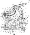
- FIG. 1is a front perspective view of a miter saw according to an embodiment of the invention.
- FIG. 2is a rear perspective view of the miter saw of FIG. 1 .
- FIG. 3is an enlarged view of a handle assembly of the miter saw of FIG. 1 including an adjustable work stop.
- FIG. 4is an enlarged view of the handle assembly of FIG. 3 with the adjustable work stopremoved.
- FIG. 5is a front perspective view of the miter saw of FIG. 1 , illustrating a work piece positioned between the work stop and a fence assembly of the miter saw.
- FIG. 6is a side view of a portion of the miter saw of FIG. 1 , illustrating a lower blade guard in a first position relative to a saw blade of the miter saw.
- FIG. 7is a side view of a portion of the miter saw of FIG. 1 , illustrating the lower blade guard in a second position relative to the saw blade of the miter saw.
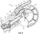
- FIG. 8is a side view of a portion of the miter saw of FIG. 1 , illustrating the lower blade guard in a third position relative to the saw blade of the miter saw.
- FIG. 9is a bottom perspective view of a portion of the miter saw of FIG. 1 , illustrating a guide rail lock subassembly in a locked position.
- FIG. 10is a bottom perspective view of the portion of the miter saw of FIG. 9 , illustrating the guide rail lock subassembly in an unlocked position.
- FIG. 11is an enlarged view of the miter saw of FIG. 1 , with portions removed, illustrating a brushless motor and associated power electronics.
- FIG. 12is a perspective view of a cut line indicator of the miter saw of FIG. 1 coupled to an upper blade guard.
- FIG. 13illustrates a portion of the cut line indicator of FIG. 12 .
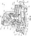
- FIG. 14is a rear perspective view of a bevel angle lock and detent override system of a miter saw according to another embodiment of the invention.
- FIG. 15is a rear cutaway view of the miter saw of FIG. 14 , illustrating a bevel angle detent system and portions of a bevel angle detent override system.
- FIG. 16is a perspective view of the bevel angle detent system and bevel angle detent override system of FIG. 15 .
- FIG. 17is a perspective view of a portion of a bevel arm of the miter saw of FIG. 14 , with portions of the bevel angle detent system and bevel angle detent override system attached.
- FIG. 18is a cross-sectional view of the bevel arm and a bevel arm mount of the miter saw of FIG. 14 taken along section 18 - 18 in FIG. 14 , illustrating the bevel angle detent system in an engaged configuration.
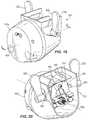
- FIG. 19is a front perspective view of a bevel angle lock and detent override system of a miter saw according to yet another embodiment of the invention.
- FIG. 20is a rear perspective view of the bevel angle lock and detent override system of FIG. 19 .
- FIG. 21is a perspective view of internal components of the bevel angle lock and detent override system of FIG. 19 .
- FIG. 22is a cross-sectional view of the bevel angle lock and detent override system, taken along section 22 - 22 in FIG. 19 , in a locked position associated with a predefined bevel angle.
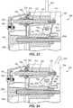
- FIG. 23is a cross-sectional view of the bevel angle lock and detent override system, taken along section 22 - 22 in FIG. 19 , in an unlocked or detent override position.
- FIG. 24is a cross-sectional view of the bevel angle lock and detent override system, taken along section 22 - 22 in FIG. 19 , in a locked position associated with a non-predefined bevel angle.
- a power tooli.e., miter saw 100
- the illustrated base assembly 105includes a turntable 120 , a base 125 , and a bevel arm 130 , with the turntable 120 pivotably coupled to the base 125 about a second or miter axis 135 for performing a first angled cut (e.g., a miter cut) on a work piece.
- the turntable 120defines a first work piece support surface 140 and the base 125 defines second work piece support surfaces 145 that are coplanar with the first work piece support surface 140 .
- the base assembly 105also includes spaced fence assemblies 150 , 155 positioned on opposite sides of the miter axis 135 that extend perpendicular to the work piece support surfaces 140 , 145 .
- the saw unit 110 and the bevel arm 130are configured to pivot with the turntable 120 about the miter axis 135 .
- the saw unit 110 and bevel arm 130are also pivotably coupled to the base 125 about a third or “bevel” axis 160 for performing a second angled cut (e.g., a bevel cut) on the work piece.
- the saw unit 110 and the bevel arm 130pivot relative to a bevel arm mount 165 about the bevel axis 160 with the bevel arm mount 165 being affixed to guide rails 170 which, in turn, are slidably coupled to the turntable 120 in a direction parallel with the bevel axis 160 (i.e., in a fore-aft direction).
- the illustrated saw unit 110includes a saw blade 175 , an upper blade guard 180 that covers an upper portion of the saw blade 175 , and a lower blade guard 185 that selectively covers a lower portion of the saw blade 175 .
- the lower blade guard 185pivots relative to the upper blade guard 180 about a fourth axis 190 , which is parallel with and spaced from a rotational axis 195 of the saw blade 175 ( FIG. 2 ).
- the saw unit 110also includes a motor 200 ( FIG. 11 ), a battery 205 for powering the motor 200 ( FIGS. 1 and 2 ), and an actuator (e.g., a trigger 210 ; FIG. 2 ) for selectively activating the motor 200 .
- the battery 205is configured as an 18 volt lithium-ion power tool battery pack 205 that is also operable to power other power tools (e.g., drills, circular saws, and the like).
- the battery pack 205may include a different nominal voltage (e.g., 12 volts, 28 volts, etc.).
- the miter saw 100may include a power cord for connection to an external power source (e.g., AC power through a wall outlet).
- the illustrated motor 200is a brushless direct current (i.e., DC) motor; but, in other embodiments of the miter saw 100 , the motor 200 may be a brushed DC motor or an alternating current (i.e., AC) motor.
- the illustrated saw unit 110includes a saw unit handle 215 that is graspable to facilitate transport and movement of the miter saw 100 .
- the miter saw 100further includes handle assemblies 220 positioned on each side of the base 125 ( FIG. 3 ).
- Each of the handle assemblies 220includes a handle 225 which, in combination with the saw unit handle 215 , facilitates transport and movement of the miter saw 100 .
- the handles 225are attached, respectively, to opposite side walls 230 of the base 125 by threaded fasteners (e.g., screws, not shown). Alternatively, quick-release fasteners may be used to attach the handles 225 to the base 125 , thereby permitting rapid installation and removal of the handle assemblies 220 from the base assembly 105 .
- the handles 225are “U” shaped to define (in conjunction with the side walls 230 of the base 125 ) a cavity 235 through which individuals may place their fingers to grasp each of the handles 225 .
- Each of the handles 225includes a third work piece support surface 240 that is coplanar with the first and second work piece support surfaces 140 , 145 of the turntable 120 and the base 125 , respectively. Accordingly, the handles 225 may also function as extensions to the primary work piece support surface of the miter saw 100 , which is collectively defined by the first and second work piece support surfaces 140 , 145 .
- each of the handle assemblies 220also includes a work stop 245 that is adjustable relative to the base 125 and the first and second fence assemblies 150 , 155 for securing a work piece 250 (e.g., crown molding) to the base 125 and/or the first and second fence assemblies 150 , 155 during a cutting operation.
- the work stop 245includes a rail 255 slidably received within a guide track 260 ( FIG. 4 ) defined by aligned slots 265 positioned between the first and second work piece support surfaces 140 , 145 of the base 125 and the handle 225 , respectively.
- the guide track 260extends in the fore-aft direction of the miter saw 100 ; therefore, movement of the rail 255 within the guide track 260 is limited to the fore-aft direction relative to the base 125 and the first and second fence assemblies 150 , 155 .
- the slots 265are defined by a combination of the handle 225 and the side wall 230 of the base 125 .
- the slots 265may be defined in the middle of the third work piece support surface 240 of each of the handles 225 .
- the depth of the slot 330is approximately equal to the height of the rail 255 .
- a top surface or a fourth work piece support surface 270 of the rail 255( FIG. 3 ) is coplanar with the first, second, and third work piece support surfaces 140 , 145 , 240 , effectively permitting the top surface 270 of the rail 255 to function as a work piece support surface above the cavity 235 .
- the work stop 245also includes a face 275 , oriented perpendicular to the first, second, and third work piece support surfaces 140 , 145 , 240 and parallel to the first and second fence assemblies 150 , 155 , against which the work piece 250 is abutted.
- Each of the handle assemblies 220also includes a lock 280 for securing the work stop 245 in a desired position in the guide track 260 for positioning the work piece 250 against the first and second fence assemblies 150 , 155 .
- the lock 280is configured as a threaded fastener (e.g., a wing screw) received within a threaded bore 290 ( FIG. 4 ) in the handle 225 .
- the wing screw 280protrudes through a longitudinal slot 295 in the rail 255 ( FIG. 3 ), thereby permitting sliding movement of the rail 255 within the guide track 260 while the wing screw 280 remains stationary in the handle 225 .
- a head of the wing screw 280is engageable with the top surface 270 of the rail 255 for securing the rail 255 (and therefore the remainder of the work stop 245 ) in a fixed fore-aft position relative to the base 125 and the first and second fence assemblies 150 , 155 .
- the handle assemblies 220are usable to extend the effective working surface of the turntable 120 and the base 125 .
- a work piece 250( FIG. 5 ) may be supported upon the first and second work piece support surfaces 140 , 145 of the turntable 120 and the base 125 , respectively, and the third and fourth work piece support surfaces 240 , 270 of at least one of the handle assemblies 220 attached to the base 125 .
- the usermay adjust the position of the rail 255 within the guide track 260 to a location that coincides with abutment of the face 275 against the work piece 250 .
- the wing screw 280is tightened in a locking (e.g., clockwise) direction for securing the rail 255 (and therefore the remainder of the work stop 245 ) to the handle 225 .
- a head of the wing screw 280clamps the rail 255 against the handle 225 , thereby affixing the work stop 245 to the handle 225 .
- the work piece 250is secured from movement in the fore-aft direction relative to the turntable 120 and base 125 in preparation for a cutting operation on the work piece 250 .
- the work piece 250may be simply removed from the miter saw 100 .
- another work piecemay be positioned to abut the face 275 , the fence assemblies 150 , 155 , and at least one of the work piece support surfaces 140 , 145 , 240 , 270 to provide a consistent repetition of the desired cutting operation.
- the saw unit 110includes a first torsion spring 300 ( FIG. 2 ) concentric with the first axis 115 and a second torsion spring 305 ( FIG. 6 ) concentric with the fourth axis 190 .
- the first torsion spring 300provides a first biasing rotational force, or a first moment M 1 , acting on the saw unit 110 in a counter-clockwise direction from the frame of reference of FIG. 6 to bias the saw unit 110 away from the turntable 120 toward a fully raised position, shown in FIG. 6 .
- the second torsion spring 305provides a second biasing rotational force, or a second moment M 2 , acting on the lower blade guard 185 in a clockwise direction from the frame of reference of FIG. 6 to bias the lower blade guard 185 toward a lowered position to cover a lower portion of the saw blade 175 .
- the miter saw 100also includes a rigid linkage 310 having a rear end 315 pivotably coupled to the bevel arm 130 about a horizontal pivot axis 320 that is parallel with the chopping axis 115 .
- the linkage 310also includes a front end 325 having a slot 330 in which a protrusion 335 extending from the lower blade guard 185 extends.
- the protrusion 335is a fastener (e.g., a screw, bolt, rivet, etc.) anchored to the lower blade guard 185 .
- the protrusion 335may be integrally formed with the lower blade guard 185 as a single piece.
- the slot 330includes a rear end 340 and an opposite front end 345 ( FIG. 7 ) between which the protrusion 335 may slide.
- a neutral line 350intersects and defines a distance between the horizontal pivot axis 320 and the fourth axis 190 .
- the linkage 310may function as a temporary restraining mechanism for holding the lower blade guard 185 in a raised position ( FIG. 8 ), without any input from the operator of the miter saw 100 , to facilitate easy removal and replacement of the saw blade 175 by providing unimpeded access to an arbor 360 ( FIG. 8 ) of the saw unit 110 .
- the lower blade guard 185can be rotated about the fourth axis 190 in response to application of a first force F 1 by the operator against the second moment M 2 imparted by the second torsion spring 305 , causing the protrusion 335 to slide within the slot 330 in the linkage 310 , until the protrusion 335 abuts the rear end 340 of the slot 330 ( FIG. 7 ).
- the protrusion 335is located above the neutral line 350 , and cannot move below the neutral line 350 due to the engagement between the protrusion 335 and the rear end 340 of the slot 330 .
- the saw unit 110is lowered by the operator to a second angle ⁇ 2 ( FIG. 8 ), which is less than the first angle ⁇ 1 , to create a gap between the protrusion 335 and the rear end 340 of the slot 330 . Thereafter, the operator continues to raise the lower blade guard 185 until the protrusion 335 crosses the neutral line 350 and contacts the rear end 340 of the slot 330 , at which time the operator may release the saw unit 110 and the lower blade guard 185 . Upon releasing the saw unit 110 , the first moment M 1 biases the saw unit 110 towards the fully raised position shown in FIG.
- the saw unit 110cannot physically move to the fully raised position because the protrusion 335 is abutted with the rear end 340 of the slot 330 .
- the protrusion 335applies a second force F 2 to the linkage 310 through a line of action 365 intersecting the horizontal pivot axis 320 of the linkage 310 .
- the linkage 310is rigid, it applies a reaction force F 3 to the protrusion 335 along the same line of action 365 in the opposite direction.
- the reaction force F 3is located below the neutral line 350 and spaced from the horizontal pivot axis 320 of the lower blade guard 185 , a third moment M 3 is created in a counter-clockwise direction from the reference frame of FIG. 8 that is equal and opposite to the second moment M 2 .
- the lower blade guard 185is maintained in the raised position shown in FIG. 8 for unimpeded access to the arbor 360 of the saw unit 110 to remove and replace the saw blade 175 .
- the operator of the miter saw 100needs only to further lower the saw unit 110 a slight amount from its orientation in FIG. 8 towards the turntable 120 , thus creating a gap between the rear end 340 of the slot 330 and the protrusion 335 .
- the reaction force F 3is removed from the protrusion 335 , creating an imbalance of forces on the lower blade guard 185 that rotates the lower blade guard 185 to the lowered position of FIG. 6 under the influence of the second moment M 2 , which is created by the second torsion spring 305 acting on the lower blade guard 185 .
- the protrusion 335is again positioned above the neutral line 350 .
- the miter saw 100includes a guide rail lock mechanism 370 for selectively maintaining the saw unit 110 in an optimal location relative to the turntable 120 for making repetitive chop cuts on one or more work pieces.
- the guide rail lock mechanism 370includes an actuator arm 375 and a latch 380 for locking the guide rails 170 in a particular location along the bevel axis 160 relative to the turntable 120 .
- the ends of the respective guide rails 170 opposite the bevel arm mount 165are connected by a guide bracket or stop 385 that functions as a stop to limit the extent to which the guide rails 170 may be extended from the turntable 120 .
- the actuator arm 375is slidable relative to the turntable 120 in a direction parallel with the bevel axis 160 , and includes a user-actuated tab 390 that extends laterally from the underside of the turntable 120 .
- the actuator arm 375also includes a finger 395 opposite the user actuated tab 390 .
- the latch 380is pivotably coupled to the turntable 120 about a fifth axis 400 that is parallel with the bevel axis 160 , and includes a cam surface 405 that is selectively engageable by the finger 395 .
- the fifth axis 400may be perpendicular to the bevel axis 160 .
- the latch 380also includes a locking groove 410 in which a portion of the guide bracket 385 is receivable.
- the latch 380is biased towards the guide bracket 385 by a spring 415 ( FIG. 9 ) located beneath the cam surface 405 .
- the latch 380may be biased away from the guide bracket 385 by the spring 415 .
- the latch 380also includes an angled surface 420 that is configured to initially engage with the guide bracket 385 as the guide bracket 385 slides into engagement with the latch 380 .
- the guide rail lock mechanism 370is positionable in either a locked position ( FIG. 9 ) or an unlocked position ( FIG. 10 ).
- a locked positiona portion of the guide bracket 385 is received within the locking groove 410 to inhibit the guide rails 170 , and ultimately the saw unit 110 , from translating relative to the turntable 120 along the bevel axis 160 .
- the saw unit 110is optimally positioned relative to the turntable 120 for making chop cuts.
- the saw blade 175is positioned relative to the turntable 120 in such a manner to optimize the cutting height of the saw blade 175 when the saw unit 110 is pivoted about the chopping axis 115 toward the turntable 120 .
- the user actuated tab 390is pushed towards the latch 380 , thereby causing the finger 395 on the actuator arm 375 to engage and slide along the cam surface 405 to pivot the latch 380 away from the guide bracket 385 .
- the user actuated tab 390is utilized to pivot the latch 380 towards the guide bracket 385 .
- friction between the cam surface 405 and finger 395maintains the latch 380 in the unlocked position until the user-actuated tab 390 is pulled away from the latch 380 , thereby disengaging the finger 395 from the cam surface 405 , and allowing the latch 380 to pivot back into the biased, locked position.
- the illustrated saw unit 110includes a saw arm 440 that is substantially hollow and supports power electronics (e.g., field-effect transistors or FETs 445 ) that are electrically connected to a first circuit board (e.g., a power printed circuit board or power PCB 450 ) via electrical leads 455 for powering the brushless motor 200 .
- the FETs 445are directly attached to a bracket 460 , which in turn is directly attached to a portion of the saw arm 440 . Accordingly, the FETs 445 are positioned remotely from the motor 200 .
- the bracket 460is made from aluminum, but in other embodiments, the bracket 460 may be made from other materials having a like thermal conductivity.
- the power PCB 450is supported within a plate 465 , which is attached to the saw arm 440 and in which electrical potting material (not shown) is contained for encapsulating and electrically isolating the power PCB 450 from the saw arm 440 .
- the brushless motor 200includes a second circuit board upon which one or more sensors (e.g., Hall-effect sensors) are incorporated for detecting a rotational speed of the motor 200 .
- sensorse.g., Hall-effect sensors
- the FETs 445During operation of the miter saw 100 , a substantial amount of heat is generated by the FETs 445 which, if not regulated, can lead to premature shutoff of the motor 200 . Because the FETs 445 are in direct contact with the saw arm 440 via the bracket 460 , the saw arm 440 functions as a heat sink for the FETs 445 . In particular, heat generated by the FETs 445 conducts through the bracket 460 to reach the saw arm 440 , where it is dissipated through the entire mass of the saw arm 440 , effectively using the saw arm 440 as a heat sink.
- the bevel arm 130may also function as a heat sink for the FETs 445 .
- heat from the FETs 445is more effectively and efficiently dissipated, permitting continued operation of the miter saw 100 without concern of premature shutoff of the motor 200 .
- the miter saw 100includes a cut line indicator 470 coupled to the upper blade guard 180 and positioned adjacent the saw blade 175 .
- the cut line indicator 470includes a housing 475 fixed to the upper blade guard 180 and a light source positioned within the housing 475 .
- the light sourcefor example, is a light emitting diode (e.g., LED 478 ) that is electrically activated in response to a user depressing the trigger 210 .
- the LED 478is oriented within the housing 475 to direct light towards portions of the saw blade 175 and the first work piece support surface 140 either when the saw unit 110 is in the fully raised position ( FIG. 7 ) or when the saw unit 110 is performing a cut on a work piece. Stated another way, a portion of the saw blade 175 is positioned between the first work piece support surface 140 and the LED 478 .
- the cut line indicator 470also includes a cover 480 ( FIGS. 12 and 13 ) positioned within an aperture 485 in the housing 475 to encapsulate the LED 478 ( FIG. 8 ) within the housing 475 .
- the cover 480is configured as an opaque cylindrical disk including a slot 490 and an alignment rib 495 .
- the rib 495is received within a corresponding slot contiguous with the aperture 485 to secure the cover 480 to the housing 475 (using, for example, a snap fit or an interference fit).
- the rib 495also angularly aligns or positions the slot 490 relative to the saw blade 175 so that the cover 480 may only be assembled to the housing 475 in a single orientation to ensure that the slot is aligned with the saw blade 175 .
- the slot 490is rectangular and defines a central axis 500 that is aligned with the saw blade 175 . Likewise, the central axis 500 of the slot 490 is substantially perpendicular to the rotational axis 195 of the saw blade 175 . In the illustrated embodiment, the slot 490 is positioned about 10 mm from the saw blade 175 . Alternatively, the slot 490 may be positioned between about 5 millimeters and about 15 millimeters from the saw blade 175 . In some embodiments, the slot 490 includes a width 505 between about 2 millimeters and about 10 millimeters. In other embodiments, the width 505 may be between about 3 millimeters and about 7 millimeters.
- the width 505may be between about 4 millimeters and about 6 millimeters. In yet other embodiments, the width 505 may be between the maximum width of the saw blade 175 plus one millimeter and the maximum width of the saw blade 175 plus three millimeters.
- the illustrated saw blade 175includes a maximum width of about 3 millimeters; however, in other embodiments, the maximum width of the saw blade 175 may between about 2 millimeters and about 4 millimeters.
- the slot 490also includes a length 510 between about 25 millimeters and about 35 millimeters.
- the LED 478 of the cut line indicator 470is illuminated in response to actuation of the trigger 210 .
- the LED 478may be manually turned on or off.
- the LED 478When the LED 478 is illuminated, light passes through the slot 490 to illuminate opposite sides of the saw blade 175 and the first work piece support surface 140 , yet is blocked from passing through the remainder of the cover 480 because the cover 480 is opaque. Because the saw blade 175 is positioned between the LED 478 and the first work piece support surface 140 , the saw blade 175 casts a shadow onto a work piece supported on the first work piece support surface 140 .
- the boundary of the shadow cast onto the work pieceis indicative of where on the work piece the saw blade 175 will cut.
- the crispness and accuracy of the shadow cut lineis increased compared to a conventional design having a transparent or translucent cover without any such slot like that in the present invention.
- the miter saw 100also includes a bevel angle lock and detent override system 425 that is similar to the bevel adjustment assembly disclosed in U.S. Pat. No. 7,574,950, the entire contents of which are incorporated herein by reference.
- the bevel angle lock and detent override system 425is adjustable between three positions consisting of a first locked position associated with a predefined bevel angle, an unlocked or detent override position, and a second locked position associated with a non-predefined bevel angle.
- an actuatore.g., a lever 430 pivotable about a sixth axis 435 is positioned in a first orientation (e.g., as illustrated in FIGS. 1 and 2 ) to lock or fix the saw unit 110 at a predefined bevel angle (e.g., 22.5, 30, 45, 60 degrees) relative to the base assembly 105 .
- the actuator 430is rotated from the first orientation into a second orientation to enable movement of the saw unit 110 relative to the base assembly 105 about the bevel axis 160 .
- the lever 430is further rotated from the second orientation to a third orientation to lock the saw unit 110 relative to the base assembly 105 at a bevel angle that is not one of the predefined bevel angles available when the lever 430 is in the first locked position.
- FIGS. 14-18illustrate a bevel angle lock and detent override system 625 for a miter saw in accordance with another embodiment of the invention.
- the bevel angle lock and detent override system 625may be substituted for the system 425 used in the miter saw 100 of FIG. 1 . Therefore, like components have been given like reference numbers plus the letter “a” and only the differences between the bevel angle lock and detent override systems 425 , 625 will be discussed in detail.
- the bevel angle lock and detent override system 625is configured to hold the bevel arm 130 in one of a plurality of predefined bevel angles relative to the turntable 120 .
- the bevel angle lock and detent override system 625includes a pair of actuators 630 , a shaft 635 interconnecting the actuators 630 , and a finger 640 coupled to the shaft 635 for co-rotation therewith.
- the system 625also includes a detent plate 645 affixed to the bevel arm mount 165 having a plurality of recesses 650 that correspond with predetermined bevel angles commonly used for cutting work pieces.
- Torsion springs 655are located within the respective actuators 630 for biasing the finger 640 into engagement with one of the recesses 650 in the detent plate 645 , thereby placing the system 625 into first locked position associated with a predefined bevel angle.
- the bevel angle lock and detent override system 625also includes a detent override system 660 to maintain the system 625 in the unlocked or detent override position—that is, maintaining the finger 640 disengaged from the detent plate 645 .
- the detent override system 660includes a cam member 665 coupled for co-rotation with the shaft 635 and a flat 670 defined on an interior surface of the bevel arm 130 .
- the cam member 665includes a lobe 675 with an increasing radius measured from a rotational axis of the shaft 635 (in a counter-clockwise direction from the frame of reference of FIG. 18 ) and an adjacent flat 680 .
- the finger 640By pivoting either of the actuators 630 against the bias of the torsion spring 655 in a clockwise direction from the frame of reference of FIG. 18 , the finger 640 is disengaged from the detent plate 645 and the lobe 675 frictionally engages the flat 670 on the bevel arm 130 in a progressive manner.
- the actuators 630may be pivoted until the flat 680 on the cam member 665 comes into contact with the flat 670 , after which further pivoting of the actuators 630 is prevented. Friction between the lobe 675 and/or flat 680 of the cam member 665 , and the flat 670 on the bevel arm 130 , temporarily holds the system 625 in the unlocked or detent override position.
- the bevel arm 130can be pivoted relative to the bevel arm mount 165 and turntable 120 to adjust the saw unit 110 for performing any of a number of different bevel angle cuts, either coinciding with any of the predetermined bevel angles defined by the recesses in the detent plate 645 , or uncommon bevel angles between any two adjacent recesses in the detent plate 645 .
- an over-center locking lever 685is utilized to clamp the bevel arm 130 against the bevel arm mount 165 to lock the saw unit 110 relative to the base assembly 105 at any non-predefined bevel angle.
- the userneeds only to pivot either of the actuators 630 in a reverse (i.e., counter-clockwise) direction to disengage the lobe 675 and/or flat 680 of the cam member 665 from the flat 670 on the bevel arm 130 .
- FIGS. 19-24illustrate a bevel angle lock and detent override system 825 for a miter saw in accordance with yet another embodiment of the invention.
- the bevel angle lock and detent override system 825is similar to the bevel angle lock and detent override system 425 ; therefore, like components have been given like reference numbers plus the letter “b” and only the differences between the bevel angle lock and detent override systems will be discussed in detail.
- the system 825includes a pair of actuators 830 , a shaft 885 interconnecting the actuators 830 , first cam members 890 , and second cam members 895 that co-rotate with the shaft 885 .
- the illustrated second cam members 895are located between the first cam members 890 , and the second cam members 895 include cam surfaces 900 a , 900 b , 900 c that define discrete portions of a periphery of the second cam members 895 .
- the second cam members 895are two separate components, but in other embodiments, the second cam members 895 may be integrally formed as a single component.
- the system 825also includes a pin 905 extending between the bevel arm 130 and the bevel arm mount 165 that is axially biased toward the bevel arm mount 165 by a coil spring 910 and a leaf spring 915 .
- a distal end of the leaf spring 915is attached to a rear end of the pin 905 , whereas the other end of the leaf spring 915 is affixed to the bevel arm 130 (e.g., via fasteners).
- the leaf spring 915also includes two arms in alignment with the respective first cam members 890 .
- the system 825also includes a stop 920 threaded to a front portion of the pin 905 , a brake member 925 concentric with the pin 905 , and a spring 930 biasing the brake member 925 toward the stop 920 .
- the bevel arm 130includes a flat 935 that extends parallel to the pin 905 and provides a surface for the second cam members 895 to engage.
- a detent plate 940 and a pressure plate 945are both coupled to the bevel arm mount 165 .
- the detent plate 940includes a plurality of apertures 950 that correspond with predetermined bevel angles commonly used for cutting work pieces (e.g., 38 degrees, 45 degrees, 52 degrees, 90 degrees, etc.).
- the pressure plate 945includes a radial slot 955 through which the pin 905 extends.
- the pressure plate 945is located between the stop 920 and the brake member 925
- the stop 920is located between the detent plate 940 and the pressure plate 945 .
- the brake member 925is biased towards the pressure plate 945 by the spring 930 .
- the system 825is adjustable between three positions consisting of a locked position associated with a predefined bevel angle ( FIG. 22 ), an unlocked or detent override position ( FIG. 23 ), and a locked position associated with a non-predefined bevel angle ( FIG. 24 ).
- the actuators 830are pivoted (from a vertical orientation) towards the bevel arm mount 165 , causing the cam surfaces 900 a to abut the flat 935 .
- the compression spring 910 and leaf spring 915bias the pin 905 into engagement with one of the apertures 950 in the detent plate 940 to lock the bevel arm 130 in a commonly used bevel angle relative to the turntable 120 .
- the actuators 830are pivoted toward a vertical orientation, causing the cam surfaces 900 b to frictionally engage the flat 935 and causing the first cam members 890 to deflect the leaf spring 915 away from the bevel arm mount 165 . Because the rear end of the pin 905 is affixed to the distal end of the leaf spring 915 , the pin 905 is also displaced rearward, disengaging the pin 905 from an aperture 950 in the detent plate 940 .
- the second cam members 895become interlocked with the flat 935 in an over-center manner, thereby maintaining the pin 905 in a detent override position.
- the bevel arm 130is free to pivot relative to the turntable 120 .
- the actuators 830are further pivoted away from the bevel arm mount 165 , causing the cam surfaces 900 c to frictionally engage the flat 935 and causing the first cam members 890 to further deflect the leaf spring 915 away from the bevel arm mount 165 .
- the pin 905is displaced further rearward, causing the stop 920 to frictionally engage the pressure plate 945 , which becomes clamped between the brake member 925 and stop 920 . Accordingly, the bevel arm 130 is effectively clamped against the bevel arm mount 165 .
- the system 825may be adjusted to the locked position shown in FIG. 24 when the desired bevel angle is not one of the predefined bevel angles available in the detent plate 940 .
Landscapes
- Engineering & Computer Science (AREA)
- Mechanical Engineering (AREA)
- Life Sciences & Earth Sciences (AREA)
- Wood Science & Technology (AREA)
- Forests & Forestry (AREA)
- Physics & Mathematics (AREA)
- Optics & Photonics (AREA)
- Sawing (AREA)
Abstract
Description
Claims (8)
Priority Applications (3)
| Application Number | Priority Date | Filing Date | Title |
|---|---|---|---|
| US16/159,217US11192195B2 (en) | 2015-02-25 | 2018-10-12 | Miter saw |
| US17/512,895US12257639B2 (en) | 2015-02-25 | 2021-10-28 | Miter saw |
| US19/029,013US20250162049A1 (en) | 2015-02-25 | 2025-01-17 | Miter saw |
Applications Claiming Priority (7)
| Application Number | Priority Date | Filing Date | Title |
|---|---|---|---|
| US201562120521P | 2015-02-25 | 2015-02-25 | |
| US201562181049P | 2015-06-17 | 2015-06-17 | |
| US201562238851P | 2015-10-08 | 2015-10-08 | |
| US201562247981P | 2015-10-29 | 2015-10-29 | |
| US201562265916P | 2015-12-10 | 2015-12-10 | |
| US15/053,733US10882123B2 (en) | 2015-02-25 | 2016-02-25 | Miter saw |
| US16/159,217US11192195B2 (en) | 2015-02-25 | 2018-10-12 | Miter saw |
Related Parent Applications (1)
| Application Number | Title | Priority Date | Filing Date |
|---|---|---|---|
| US15/053,733DivisionUS10882123B2 (en) | 2015-02-25 | 2016-02-25 | Miter saw |
Related Child Applications (1)
| Application Number | Title | Priority Date | Filing Date |
|---|---|---|---|
| US17/512,895ContinuationUS12257639B2 (en) | 2015-02-25 | 2021-10-28 | Miter saw |
Publications (2)
| Publication Number | Publication Date |
|---|---|
| US20190091779A1 US20190091779A1 (en) | 2019-03-28 |
| US11192195B2true US11192195B2 (en) | 2021-12-07 |
Family
ID=56689735
Family Applications (5)
| Application Number | Title | Priority Date | Filing Date |
|---|---|---|---|
| US15/053,733Active2037-01-11US10882123B2 (en) | 2015-02-25 | 2016-02-25 | Miter saw |
| US16/159,217ActiveUS11192195B2 (en) | 2015-02-25 | 2018-10-12 | Miter saw |
| US16/159,230ActiveUS11298763B2 (en) | 2015-02-25 | 2018-10-12 | Miter saw |
| US17/512,895ActiveUS12257639B2 (en) | 2015-02-25 | 2021-10-28 | Miter saw |
| US19/029,013PendingUS20250162049A1 (en) | 2015-02-25 | 2025-01-17 | Miter saw |
Family Applications Before (1)
| Application Number | Title | Priority Date | Filing Date |
|---|---|---|---|
| US15/053,733Active2037-01-11US10882123B2 (en) | 2015-02-25 | 2016-02-25 | Miter saw |
Family Applications After (3)
| Application Number | Title | Priority Date | Filing Date |
|---|---|---|---|
| US16/159,230ActiveUS11298763B2 (en) | 2015-02-25 | 2018-10-12 | Miter saw |
| US17/512,895ActiveUS12257639B2 (en) | 2015-02-25 | 2021-10-28 | Miter saw |
| US19/029,013PendingUS20250162049A1 (en) | 2015-02-25 | 2025-01-17 | Miter saw |
Country Status (4)
| Country | Link |
|---|---|
| US (5) | US10882123B2 (en) |
| EP (2) | EP3261794B1 (en) |
| CN (1) | CN208195813U (en) |
| WO (1) | WO2016138281A1 (en) |
Families Citing this family (24)
| Publication number | Priority date | Publication date | Assignee | Title |
|---|---|---|---|---|
| US9962852B2 (en)* | 2014-08-29 | 2018-05-08 | Black & Decker Inc. | Miter saw with improved carrying mode |
| GB201520416D0 (en)* | 2015-11-19 | 2016-01-06 | Black & Decker Inc | Sliding compound mitre saw |
| US10543542B2 (en)* | 2016-07-27 | 2020-01-28 | Tti (Macao Commercial Offshore) Limited | Miter saw |
| JP6847648B2 (en)* | 2016-12-05 | 2021-03-24 | 株式会社マキタ | Cutting machine |
| JP2021028090A (en)* | 2017-12-06 | 2021-02-25 | 株式会社マキタ | Stationary cutting machine for metalwork |
| DE102017130042A1 (en)* | 2017-12-14 | 2019-06-19 | Festool Gmbh | Supplementary support device for a workpiece support device |
| DE102018222159A1 (en)* | 2018-12-18 | 2020-06-18 | Robert Bosch Gmbh | Machine tool |
| US11072031B1 (en)* | 2019-01-21 | 2021-07-27 | Tony J. Ballew | Variable angle cutting deck for metal cutting chop saws |
| CN113661023A (en)* | 2019-04-12 | 2021-11-16 | 费斯托工具有限责任公司 | Machine tool with side contact body and support body |
| US12296397B2 (en)* | 2019-06-21 | 2025-05-13 | Milwaukee Electric Tool Corporation | Miter saw |
| JP1659989S (en)* | 2019-07-09 | 2020-05-25 | ||
| DE102019210187A1 (en)* | 2019-07-10 | 2021-01-14 | Festool Gmbh | Tool device |
| WO2021107827A1 (en)* | 2019-11-25 | 2021-06-03 | Husqvarna Ab | A hand-held electrically powered work tool |
| US11213903B2 (en)* | 2020-01-03 | 2022-01-04 | Dmt Holdings, Inc. | Sawing machine |
| US11642809B2 (en)* | 2020-03-24 | 2023-05-09 | Woodpeckers, Llc | Track square with adjustable mechanism |
| EP4175802A1 (en)* | 2020-07-01 | 2023-05-10 | Festool GmbH | Safety brakes for circular saw blades, circular saws that include the safety brakes, and methods of operating circular saws |
| US12263615B2 (en) | 2020-11-23 | 2025-04-01 | Milwaukee Electric Tool Corporation | Circular saw |
| JP7568545B2 (en) | 2021-03-02 | 2024-10-16 | 株式会社マキタ | Cutting machine |
| USD1039573S1 (en)* | 2021-04-06 | 2024-08-20 | Evolution Power Tools Limited | Mitering chop saw |
| CN113183244A (en)* | 2021-04-07 | 2021-07-30 | 浙江精深实业有限公司 | Foldable miter saw |
| USD1048123S1 (en)* | 2021-10-11 | 2024-10-22 | Evolution Power Tools Limited | Mitre saw |
| USD1061642S1 (en)* | 2022-01-18 | 2025-02-11 | Evolution Power Tools Limited | Mitre saw |
| US12083613B2 (en) | 2022-10-18 | 2024-09-10 | Techtronic Cordless Gp | Track saw including plunge lockout mechanism |
| DE102023113260A1 (en)* | 2023-05-22 | 2024-11-28 | Festool Gmbh | circular saw |
Citations (378)
| Publication number | Priority date | Publication date | Assignee | Title |
|---|---|---|---|---|
| US1480263A (en) | 1922-01-16 | 1924-01-08 | Hoffman Willie | Portable buffing tool |
| US3483901A (en) | 1967-12-12 | 1969-12-16 | Kyle Ray | Electric power saw miter machine |
| US3546502A (en) | 1969-02-19 | 1970-12-08 | Murphy Ind Inc G W | Electric hand tool with heat conductive thrust bearing means |
| US3821918A (en) | 1972-09-01 | 1974-07-02 | Rockwell International Corp | Motorized miter box |
| US3931751A (en) | 1974-11-13 | 1976-01-13 | Simonson Paul A | Collapsible mounting for power saw units |
| US3977278A (en) | 1975-06-18 | 1976-08-31 | Lawrence Peska Associates, Inc. | Automotive electric impact wrench |
| US3998121A (en) | 1976-02-03 | 1976-12-21 | B & E Products, Inc. | Miter cutting saw |
| US4051759A (en) | 1977-01-21 | 1977-10-04 | Gerald Oliff | Miter box for a portable electric saw |
| US4075916A (en) | 1976-05-21 | 1978-02-28 | Nipak, Inc. | Pipe cut off saw |
| US4109901A (en) | 1976-05-13 | 1978-08-29 | Akin Paul A | Miter table for portable circular saw |
| US4184395A (en) | 1978-04-10 | 1980-01-22 | Emerson Electric Co. | Radial arm saw |
| US4226152A (en) | 1979-05-29 | 1980-10-07 | The Stanley Works | Saw guide subassembly for mitre box |
| US4241634A (en) | 1979-05-29 | 1980-12-30 | The Stanley Works | Mitre box |
| US4245533A (en) | 1979-07-26 | 1981-01-20 | The Singer Company | Motorized circular miter chop saw |
| US4265154A (en) | 1979-10-15 | 1981-05-05 | The Singer Company | Motorized miter saw fence mounting |
| US4270427A (en) | 1980-02-04 | 1981-06-02 | Black & Decker Inc. | Bevel angle setting means for a power tool apparatus |
| US4299152A (en) | 1979-05-29 | 1981-11-10 | The Stanley Works | Mitre box |
| US4300426A (en) | 1979-04-16 | 1981-11-17 | Weaver Paul L | Power miter saw |
| US4315494A (en) | 1980-03-10 | 1982-02-16 | Diplacido Michele | Masonary saw jig |
| US4341247A (en) | 1980-06-06 | 1982-07-27 | Price T David | Extension table assembly for power tools |
| US4365531A (en) | 1980-11-05 | 1982-12-28 | Mita Wood Products Inc. | Miter box construction |
| US4428266A (en) | 1982-01-18 | 1984-01-31 | Hempe Manufacturing Co. | Miter saw having a swivel handle |
| US4448102A (en) | 1982-11-19 | 1984-05-15 | Thornton Jack L | Compound miter saw stand |
| US4465114A (en) | 1982-08-27 | 1984-08-14 | Schumacher Robert C | Woodworking bench |
| US4479555A (en) | 1981-11-13 | 1984-10-30 | Black & Decker Inc. | Power tool having a plastics material housing |
| US4519280A (en) | 1983-07-29 | 1985-05-28 | Cook Carl E | Miter board and saw guide |
| US4531441A (en) | 1981-02-19 | 1985-07-30 | Eugen Lutz Gmbh & Co. Maschinenfabrik | Combination table and miter saw |
| US4537105A (en) | 1983-08-16 | 1985-08-27 | Black & Decker Overseas Ag | Circular cross-cut and miter saw box |
| US4561336A (en) | 1984-02-23 | 1985-12-31 | Davis Harold E | Portable universal power miter saw workbench |
| US4581966A (en) | 1983-06-11 | 1986-04-15 | Black & Decker, Inc. | Chop saw linkage system for moving saw guard |
| US4589208A (en) | 1983-08-13 | 1986-05-20 | Matsushita Electric Works, Ltd. | Portable electric circular saw |
| US4638700A (en) | 1985-06-12 | 1987-01-27 | Makita Electric Works, Ltd. | Portable miter saws |
| US4646801A (en) | 1985-12-30 | 1987-03-03 | Hines Thomas E | Picture frame molding holding and cutting apparatus and method of using |
| US4658686A (en) | 1985-07-31 | 1987-04-21 | Shopsmith, Inc. | Miter gage |
| US4707204A (en) | 1980-11-25 | 1987-11-17 | Portas Deutschland Gmbh | Method of making a furniture front element |
| US4741387A (en) | 1987-08-03 | 1988-05-03 | Donald Strong | Locking means for miter gauge attachment |
| US4766963A (en) | 1982-09-22 | 1988-08-30 | Institut Cerac S.A. | Hand-held hammer tool |
| US4774866A (en) | 1987-01-12 | 1988-10-04 | Ryobi Ltd. | Blade guard arrangement in motor-driven chop saw |
| US4798113A (en) | 1986-04-14 | 1989-01-17 | Viazanko John P | Extension table apparatus for power saw |
| US4805504A (en) | 1986-12-29 | 1989-02-21 | Makita Electric Works, Ltd. | Safety cover for miter saw |
| US4833782A (en) | 1987-06-01 | 1989-05-30 | Robert E. Strauss | Saber saw tracing light |
| US4869142A (en) | 1987-02-20 | 1989-09-26 | Hitachi Koki Haramachi Co., Ltd. | Desk-top circular saw |
| US4874025A (en) | 1988-05-16 | 1989-10-17 | Cleveland Gary D | Miter saw utility stand |
| US4875399A (en) | 1988-06-23 | 1989-10-24 | Scott William D | Miter box attachment for cutting crown mouldings and the like |
| US4882962A (en) | 1988-08-19 | 1989-11-28 | Emerson Electric Co. | Angularly adjustable band saw |
| US4934233A (en)* | 1988-06-29 | 1990-06-19 | Emerson Electric Co. | Compound miter saw |
| US4937705A (en) | 1989-05-08 | 1990-06-26 | Eaton Corporation | Variable power control apparatus having external heat sink mounting battery clips |
| US4974651A (en) | 1989-02-27 | 1990-12-04 | Carmon Jimmy W | Portable workbench |
| US5004029A (en) | 1990-04-16 | 1991-04-02 | Garner William C | Saw table apparatus |
| US5020406A (en) | 1989-07-07 | 1991-06-04 | Makita Electric Works, Ltd. | Miter saw |
| US5038650A (en) | 1990-02-22 | 1991-08-13 | Hodge Larry E | Miter saw support and extension |
| US5054352A (en) | 1989-01-17 | 1991-10-08 | Makita Electric Wroks, Ltd. | Miter saw |
| US5063805A (en) | 1989-11-08 | 1991-11-12 | Emerson Electric Co. | Compound miter saw |
| US5105862A (en) | 1991-06-18 | 1992-04-21 | Skinner Kevin R | Extensions for a material support platform of a tool |
| US5117560A (en) | 1990-06-06 | 1992-06-02 | Mary Nevins | Full circle protractor with detachable adjustable leg assembly for measuring angles |
| US5121554A (en) | 1991-04-04 | 1992-06-16 | Havins Billy M | Apparatus and method for cutting precision angles |
| US5146826A (en) | 1990-01-13 | 1992-09-15 | Ryobi Ltd. | Circular saw device having variable cut-off angle |
| US5146825A (en) | 1990-07-31 | 1992-09-15 | Ryobi Ltd. | Motor-driven chop saw having improved lower blade guard arrangement |
| USD331416S (en) | 1989-08-10 | 1992-12-01 | Makita Electric Works, Ltd. | Miter saw |
| US5181448A (en) | 1991-12-20 | 1993-01-26 | Emerson Electric Co. | Miter saw apparatus with adjustable workpiece supporting fence |
| USD333824S (en) | 1990-08-03 | 1993-03-09 | Makita Electric Works, Ltd. | Miter saw |
| US5193598A (en) | 1992-06-23 | 1993-03-16 | Estrem Jim J | Portable support stand attachable to a sawhorse |
| US5199343A (en) | 1991-10-09 | 1993-04-06 | Black & Decker Inc. | Power saw with louvered blade guard |
| US5207007A (en) | 1991-11-25 | 1993-05-04 | Cucinotta Anthony J | Set-up tool |
| US5216964A (en) | 1991-02-05 | 1993-06-08 | Ryobi Limited | Angle adjusting device for circular saw with table |
| US5220857A (en) | 1991-11-21 | 1993-06-22 | Freeburger Barron D | Miter saw apparatus |
| US5235889A (en) | 1992-03-25 | 1993-08-17 | Delta International Machinery Corp. | Compound miter saw |
| US5239905A (en) | 1992-10-19 | 1993-08-31 | Dunn Gail E | Miter table molding positioning apparatus |
| US5241888A (en) | 1992-07-31 | 1993-09-07 | Rexon Industrial Corporation, Ltd. | Slidable compound miter saw |
| US5249496A (en) | 1992-08-13 | 1993-10-05 | Milwaukee Electric Tool Corporation | Indexing detent override mechanism |
| US5269356A (en) | 1992-03-17 | 1993-12-14 | Bartz William R | Device for cutting mating surfaces for mitered joints |
| US5279198A (en) | 1992-12-03 | 1994-01-18 | Cross Raymond E | Adjustable miter box with offset cutting location |
| US5285708A (en) | 1992-05-18 | 1994-02-15 | Porter-Cable Corporation | Miter saw alignment system |
| US5289047A (en) | 1991-05-07 | 1994-02-22 | Marquart Gmbh | Switch. especially battery switch for hand-operated electric tools |
| US5297463A (en) | 1991-10-09 | 1994-03-29 | Black & Decker Inc. | Adjustable fence for compound miter saw |
| US5320150A (en) | 1992-12-22 | 1994-06-14 | Ryobi America Corp. | Collapsible stand |
| US5320016A (en) | 1990-02-17 | 1994-06-14 | Keuro Besitz Gmbh & Co. Edv-Dienstleistungs Kg. | Vertical band saw |
| US5327653A (en) | 1992-08-19 | 1994-07-12 | Pistorius Robert T | Miter linear measurement gage |
| US5347902A (en) | 1992-03-25 | 1994-09-20 | Delta International Machinery Corp. | Motorized miter box |
| USD351393S (en) | 1992-12-28 | 1994-10-11 | Makita Corporation | Miter saw |
| US5357834A (en) | 1992-05-22 | 1994-10-25 | Makita Corporation | Miter saw |
| US5361853A (en) | 1991-11-29 | 1994-11-08 | Ryobi Limited | Power tool |
| US5370025A (en) | 1992-08-13 | 1994-12-06 | Milwaukee Electric Tool Corporation | Motorized saw with movable blade guard actuating linkage |
| US5392678A (en) | 1992-08-27 | 1995-02-28 | Makita Corporation | Miter saw |
| US5402701A (en) | 1993-12-16 | 1995-04-04 | Ingram; Stanley J. | Dual angle miter and gauge apparatus |
| USD357140S (en) | 1992-12-15 | 1995-04-11 | Delta International Machinery Corp. | Auxiliary/accessory support stand for work materials and miter saw |
| US5421231A (en) | 1992-02-24 | 1995-06-06 | Tapco Products Company, Inc. | Portable saw table |
| US5421228A (en) | 1990-06-29 | 1995-06-06 | Ryobi Limited | Desk-top slide type circular power saw |
| US5425294A (en) | 1993-06-03 | 1995-06-20 | Hitachi Koki Haramachi Co., Ltd. | Desk-top cutting machine with tiltable saw |
| US5437214A (en) | 1992-05-22 | 1995-08-01 | Makita Corporation | Miter saw |
| US5452515A (en) | 1993-01-02 | 1995-09-26 | Robert Bosch Gmbh | Hand circular saw with mitre adjusting device |
| US5462102A (en) | 1994-08-03 | 1995-10-31 | Searfoss; William A. | Adjustable rolling saw stand |
| US5483727A (en) | 1995-03-02 | 1996-01-16 | P&F Brother Industrial Corporation | Operating handle for a cutting device |
| US5493789A (en) | 1995-02-17 | 1996-02-27 | Duginske; Mark A. | Miter gauge calibrator |
| US5497816A (en) | 1994-09-09 | 1996-03-12 | Darland; Richard E. | Power miter table saw |
| US5513548A (en) | 1993-07-08 | 1996-05-07 | Black & Decker Inc. | Chop/table saw with parallelogram arrangement |
| US5524516A (en) | 1993-02-19 | 1996-06-11 | Makita Corporation | Miter saw |
| US5526856A (en) | 1995-06-27 | 1996-06-18 | Pedri; Attilio | Device for supporting workpiece for a portable power tool |
| US5542639A (en) | 1994-06-08 | 1996-08-06 | Delta International Machinery Corp. | Flat folding support |
| USD373129S (en) | 1994-06-08 | 1996-08-27 | Delta International Machinery Corp. | Sliding compound miter saw and stand |
| US5560273A (en) | 1994-06-09 | 1996-10-01 | Hempe Manufacturing Co., Inc. | Miter box with vertical and horizontal angular positioning devices |
| US5566603A (en) | 1993-05-04 | 1996-10-22 | Moeres; Reiner | Double-sided miter box for machine tools in particular panel saws |
| US5592981A (en) | 1995-11-03 | 1997-01-14 | Tracrac, Inc. | Portable work bench having sliding connections for releasably and adjustably attaching accessories thereto |
| US5623860A (en) | 1994-12-15 | 1997-04-29 | Emerson Electric Co. | Adjustable/bypassable bevel stop for compound miter saw |
| USD383472S (en) | 1996-06-27 | 1997-09-09 | Makita Corporation | Miter saw |
| USD383765S (en) | 1996-07-03 | 1997-09-16 | Makita Corporation | Miter saw |
| USD388442S (en) | 1996-06-17 | 1997-12-30 | Makita Corporation | Miter saw |
| USD388443S (en) | 1996-06-18 | 1997-12-30 | Makita Corporation | Miter saw |
| US5713258A (en) | 1995-10-31 | 1998-02-03 | Hempe Manufacturing Co., Inc. | Compound miter box |
| US5720096A (en) | 1993-04-26 | 1998-02-24 | Black & Decker Inc. | Power tool with locking fence |
| US5724875A (en) | 1995-10-10 | 1998-03-10 | Black & Decker Inc. | Guard and control apparatuses for sliding compound miter saw |
| US5730434A (en) | 1996-01-26 | 1998-03-24 | Emerson Electric Co. | Clamping devices for compound miter saws |
| US5735324A (en) | 1996-03-01 | 1998-04-07 | Ponce; Felix C. | Miter box with electronic measuring of lumber |
| US5735054A (en) | 1995-06-02 | 1998-04-07 | Cole; Jerry W. | Fixture for a table saw |
| US5737986A (en) | 1993-08-12 | 1998-04-14 | Black & Decker Inc. | Power saw fence guide |
| US5737990A (en) | 1991-10-11 | 1998-04-14 | Freeland; Brian Ellison | Apparatus for making miter joints |
| US5752422A (en) | 1995-10-04 | 1998-05-19 | Makita Corporation | Desk-top circular saw with an auxilliary guide fence |
| US5755148A (en) | 1995-07-07 | 1998-05-26 | Black & Decker Inc. | Adjustable fence for a compound miter saw |
| US5768967A (en) | 1995-06-15 | 1998-06-23 | Makita Corporation | Slide bar mounting mechanism in slide-type circular saw and method of mounting slide bars |
| US5771767A (en) | 1996-09-23 | 1998-06-30 | Itami; Steven D. | Angle attachment for woodworking tools |
| US5775192A (en) | 1996-03-20 | 1998-07-07 | Willard N. Fuecker | Sliding miter cutter |
| US5778747A (en) | 1996-11-21 | 1998-07-14 | Rexon Industrial Corp., Ltd. | Power saw having an ergonomically-designed handle and safety switch |
| US5782153A (en) | 1995-06-08 | 1998-07-21 | Makita Corporation | Desk-top circular saw including chip discharging means |
| US5787779A (en) | 1993-07-08 | 1998-08-04 | Black & Decker Inc. | Chop/table saw arrangement |
| US5791224A (en) | 1994-03-24 | 1998-08-11 | Ryobi Limited | Circular sawing machine |
| US5802943A (en) | 1996-12-05 | 1998-09-08 | Black & Decker Inc. | Bevel locking system for a sliding compound miter saw |
| US5816129A (en) | 1995-12-19 | 1998-10-06 | Singer; David K. | Miter fence for radial arm saw |
| US5819624A (en) | 1996-07-30 | 1998-10-13 | Milwaukee Electric Tool Corporation | Indexing override mechanism for a slide compound miter saw |
| US5819619A (en) | 1991-10-09 | 1998-10-13 | Black & Decker Inc. | Dust collection system for compound miter saw |
| US5823085A (en) | 1995-10-05 | 1998-10-20 | Makita Corporation | Miter saw |
| US5845410A (en) | 1996-08-08 | 1998-12-08 | Boker; Donald W. | Miter device and method |
| US5850698A (en) | 1997-05-30 | 1998-12-22 | Black & Decker Inc. | Portable circular saw |
| US5856715A (en) | 1996-12-13 | 1999-01-05 | Ryobi North America, Inc. | Portable electrical power tool having a rare earth permanent magnet motor |
| USD404043S (en) | 1997-06-19 | 1999-01-12 | Black & Decker Inc. | Stabilizer for a sliding compound miter saw |
| US5862732A (en) | 1996-07-30 | 1999-01-26 | Milwaukee Electric Tool Corporation | Support assembly for a slide compound miter saw |
| US5862734A (en) | 1995-12-12 | 1999-01-26 | Black & Decker Inc. | Bevel locking system for a sliding compound miter saw |
| US5865079A (en) | 1994-07-08 | 1999-02-02 | Milwaukee Electric Tool Corporation | Adjustable workpiece support apparatus for a compound miter saw |
| US5870939A (en) | 1996-02-05 | 1999-02-16 | Makita Corporation | Circular saw |
| US5875828A (en) | 1997-07-24 | 1999-03-02 | Black & Decker, Inc. | Portable work bench |
| US5893311A (en) | 1997-04-28 | 1999-04-13 | Huang; Peter | Protective covers of power saw |
| US5894776A (en) | 1996-01-17 | 1999-04-20 | Bartz; William R. | Table saw top and mitre bar |
| US5907987A (en) | 1996-12-05 | 1999-06-01 | Stumpf; William R. | Bevel locking system for a sliding compound miter saw |
| USD412333S (en) | 1998-05-11 | 1999-07-27 | Black & Decker Inc. | Support arm for a sliding compound miter saw |
| US5931072A (en) | 1996-07-23 | 1999-08-03 | Makita Corporation | Circular saw with an improved dust collector |
| US5931073A (en) | 1995-08-28 | 1999-08-03 | Hoyer-Ellefsen; Sigurd | Bevel angle control on translatory saw apparatus |
| US5937720A (en) | 1995-08-10 | 1999-08-17 | Milwaukee Electric Tool Corporation | Lower blade guard actuating mechanism for a slide compound miter saw |
| US5950514A (en) | 1997-02-28 | 1999-09-14 | Benedict Engineering Company | Miter saw blade guards |
| US5957021A (en) | 1995-10-10 | 1999-09-28 | Black & Decker, Inc. | Guard and control apparatuses for sliding compound miter saw |
| US5969312A (en) | 1998-06-24 | 1999-10-19 | S-B Power Tool Company | Ambidextrous powers-switch lock-out mechanism |
| USD415942S (en) | 1998-07-31 | 1999-11-02 | Makita Corporation | Miter saw |
| US5979283A (en) | 1996-12-11 | 1999-11-09 | Osborne; David H. | Miter guide |
| US5988031A (en) | 1994-06-08 | 1999-11-23 | Delta International Machinery Corp. | Adjustable tool station with rotatable table and wear components therefor |
| US5988243A (en) | 1997-07-24 | 1999-11-23 | Black & Decker Inc. | Portable work bench |
| US5996460A (en) | 1992-03-13 | 1999-12-07 | Waite; Lance H. | Cut line indicator for power cutting material |
| US6000140A (en) | 1997-12-01 | 1999-12-14 | Black & Decker Inc. | Power tool with lubricating system |
| USD418149S (en) | 1998-05-11 | 1999-12-28 | Black & Decker Inc. | Base assembly for a sliding compound miter saw |
| US6016732A (en) | 1995-08-10 | 2000-01-25 | Milwaukee Electric Tool Corporation | Indexing override mechanism for a slide compound miter saw |
| USD420369S (en) | 1998-07-15 | 2000-02-08 | Makita Corporation | Miter saw |
| USD420370S (en) | 1998-10-21 | 2000-02-08 | Makita Corporation | Miter saw |
| USD421267S (en) | 1998-10-06 | 2000-02-29 | Black & Decker Inc. | Sliding compound miter saw |
| US6029721A (en) | 1998-05-27 | 2000-02-29 | Black & Decker Inc. | Portable work bench |
| US6032562A (en) | 1995-12-12 | 2000-03-07 | Black & Decker Inc. | Bevel locking system for a sliding compound miter saw |
| USD423020S (en) | 1998-10-01 | 2000-04-18 | Black & Decker Inc. | Stabilizer for a sliding compound miter saw |
| USD423526S (en) | 1999-04-13 | 2000-04-25 | Ryobi North America, Inc. | Miter saw |
| USD424072S (en) | 1999-03-03 | 2000-05-02 | Makita Corporation | Miter saw |
| USD425083S (en) | 1999-07-26 | 2000-05-16 | Delta International Machinery Corp. | Miter saw |
| USD425917S (en) | 1998-10-01 | 2000-05-30 | Black & Decker Inc. | Stabilizer for a sliding compound miter saw |
| US6073529A (en) | 1998-02-06 | 2000-06-13 | Makita Corporation | Miter circular saw with an improved workpiece support fence |
| USD428426S (en) | 1999-04-13 | 2000-07-18 | Ryobi North America, Inc. | Miter saw |
| US6155318A (en) | 1997-03-04 | 2000-12-05 | Underwood; William D. | Adjustable portable saw support |
| US6170373B1 (en) | 1998-01-12 | 2001-01-09 | Makita Corporation | Circular saw having movement prevention means |
| US6182548B1 (en) | 1995-10-10 | 2001-02-06 | Black & Decker Inc. | Guard and control apparatuses for sliding compound miter saw |
| US20010000856A1 (en) | 1998-11-12 | 2001-05-10 | O'banion Michael L. | Miter saw workstation |
| US20010008098A1 (en) | 1998-07-13 | 2001-07-19 | Black & Decker Inc. | Chop saw |
| US6272961B1 (en) | 2000-02-07 | 2001-08-14 | Wy Peron Lee | Cutting machine with built-in miter cutting feature |
| US6279442B1 (en) | 1998-09-11 | 2001-08-28 | Chin-Chin Chang | Blade guard device for a sawing machine |
| US6289779B1 (en) | 1999-08-04 | 2001-09-18 | Tian Shoei Wang | Carpenter's sawing machine |
| US6320286B1 (en) | 1999-09-01 | 2001-11-20 | Ramachandran Ramarathnam | Portable electric tool |
| US20010047706A1 (en) | 1998-02-13 | 2001-12-06 | James Parks | Table saw |
| US20020001703A1 (en) | 2000-06-28 | 2002-01-03 | Sumitomo Chemical Company, Limited | Lightweight fiber-reinforced thermoplastic resin molding |
| US20020011702A1 (en) | 2000-05-31 | 2002-01-31 | Seiko Epson Corporation | Paper feeder |
| USD453569S1 (en) | 2001-01-08 | 2002-02-12 | Pharmacia Ab | Injection device |
| US20020017179A1 (en) | 2000-08-14 | 2002-02-14 | Gass Stephen F. | Miter saw with improved safety system |
| US20020029678A1 (en) | 2000-03-29 | 2002-03-14 | Erisoty James S. | Multi-angle miter box with clamping feature |
| US20020050201A1 (en) | 1997-05-09 | 2002-05-02 | William Lane | Table saw |
| US20020056348A1 (en) | 2000-09-29 | 2002-05-16 | Gass Stephen F. | Miter saw with improved safety system |
| US20020056349A1 (en) | 2000-09-29 | 2002-05-16 | Gass Stephen F. | Miter saw with improved safety system |
| US20020059854A1 (en) | 2000-09-29 | 2002-05-23 | Gass Stephen F. | Miter saw with improved safety system |
| US20020059853A1 (en) | 2000-09-29 | 2002-05-23 | Gass Stephen F. | Power saw with improved safety system |
| US20020066346A1 (en) | 2000-09-29 | 2002-06-06 | Gass Stephen F. | Miter saw with improved safety system |
| US6401584B1 (en) | 2000-07-19 | 2002-06-11 | James T. Rowe | Miter cutting guide apparatus |
| USD459373S1 (en) | 2001-03-13 | 2002-06-25 | Porter Cable Corp. | Miter saw |
| US20020100350A1 (en) | 2001-01-16 | 2002-08-01 | Brazell Kenneth M. | Sliding fence for a compound miter saw |
| US20020100352A1 (en) | 2001-01-29 | 2002-08-01 | Dils Jeffrey M. | Ergonomic miter saw handle |
| US6427570B1 (en) | 1991-10-09 | 2002-08-06 | Black & Decker Inc. | Dust collection system for compound miter saw |
| US20020104417A1 (en) | 2001-02-06 | 2002-08-08 | Ruey-Zon Chen | Quick press device for a table saw |
| US6431042B1 (en) | 1994-05-13 | 2002-08-13 | Milwaukee Electric Tool Corporation | Turntable mechanism for a cutting tool |
| US20020129688A1 (en) | 2001-03-15 | 2002-09-19 | Watson James G. | Precision electric miter box |
| US20020144582A1 (en) | 2001-04-10 | 2002-10-10 | He Cai Bai | Extendible compound miter saw |
| US6470778B1 (en) | 1998-05-20 | 2002-10-29 | Black & Decker Inc. | Dust collector for a power tool |
| US20020157731A1 (en) | 2001-04-30 | 2002-10-31 | Harper Donald A. | Portable mitre saw extension table |
| US6474207B1 (en) | 1994-07-08 | 2002-11-05 | Milwaukee Electric Tool Corporation | Bevel angle adjustment mechanism for a compound miter saw |
| US6474206B1 (en) | 1995-12-12 | 2002-11-05 | Black & Decker Inc. | Miter saw with wear plates and orientation system therefor |
| US6477929B1 (en) | 2000-04-01 | 2002-11-12 | Donald L. Gibbs, Sr. | Picture frame making accessory and method |
| US20020178884A1 (en) | 2001-05-30 | 2002-12-05 | Hsirong Chuang | Dual-end blinds trimming machine |
| USD467256S1 (en) | 2001-12-05 | 2002-12-17 | One World Technologies Limited | Cordless miter saw |
| US20030002008A1 (en) | 1998-12-18 | 2003-01-02 | Takashi Inoue | Image display device and its repairing method and apparatus |
| US20030007326A1 (en) | 2001-07-09 | 2003-01-09 | Intel Corporation | Clamshell heatsink |
| US20030005801A1 (en) | 2000-12-15 | 2003-01-09 | Hal Calcote | Power tool stand accessory top with vertical adjustment and frictional engagement lock |
| US20030015078A1 (en) | 2000-05-03 | 2003-01-23 | Taylor Christopher L. | Precision miter gauge |
| US6510722B1 (en) | 2000-05-10 | 2003-01-28 | Advanced Cardiovascular Systems, Inc. | Stent crimping tool for producing a grooved crimp |
| US6510772B2 (en) | 1999-07-26 | 2003-01-28 | Delta International Machinery Corp. | Dust collection system |
| US6513412B2 (en) | 2001-01-09 | 2003-02-04 | Porter Cable Corp. | Adjustment mechanism |
| US6523447B2 (en) | 1997-09-26 | 2003-02-25 | Black & Decker Inc. | Cordless chop saw |
| WO2003017742A1 (en) | 2001-08-10 | 2003-02-27 | Black & Decker Inc. | Electrically isolated module |
| US20030041715A1 (en) | 2001-09-04 | 2003-03-06 | One World Technologies, Inc. | Stock stop miter gauge |
| US6530303B1 (en) | 1999-06-10 | 2003-03-11 | Black & Decker Inc. | Table saw |
| US20030047050A1 (en) | 2001-09-07 | 2003-03-13 | Hitachi Koki Co., Ltd. | Portable circular power saw with optical alignment |
| US6532853B1 (en) | 1997-08-01 | 2003-03-18 | One World Technologies, Inc. | Table-top cutting machine |
| CN1404952A (en)* | 2002-09-28 | 2003-03-26 | 陈剑伦 | Sawing-piece mounting-dismounting device of cutting machine |
| US20030056631A1 (en) | 2001-09-07 | 2003-03-27 | Duginske Mark A. | Woodworking machinery jig and fixture system |
| US20030056630A1 (en) | 2001-09-21 | 2003-03-27 | Euther Phillips | Miter guide |
| US20030056632A1 (en) | 2000-10-24 | 2003-03-27 | Alison Ng | Adjustable tool station |
| US6543323B2 (en) | 2000-06-29 | 2003-04-08 | Hitachi Koki Co., Ltd. | Vice device in compound miter saw |
| US6561068B2 (en) | 1998-03-11 | 2003-05-13 | Black & Decker Inc. | Sliding saw |
| US20030094082A1 (en) | 2000-12-20 | 2003-05-22 | Ofer Meged | Device for providing miter saw settings |
| US20030110914A1 (en) | 2001-08-10 | 2003-06-19 | One World Technologies, Inc. | Bevel adjustment mechanism for a compound miter saw |
| US6581502B1 (en) | 2001-12-14 | 2003-06-24 | Richard P. Ryan | Miter box |
| US20030117028A1 (en) | 2001-12-11 | 2003-06-26 | Agnes Michael Jeffrey | Brushless motor having capacitors mounted on sidewall of motor housing |
| US6595095B2 (en) | 2001-04-12 | 2003-07-22 | Rexon Industrial Corp., Ltd. | Pivotable handle and angle adjustable device for miter saw |
| US20030140758A1 (en) | 2002-01-25 | 2003-07-31 | One World Technologies Limited | Light beam alignment system |
| USD478103S1 (en) | 2002-03-22 | 2003-08-05 | Makita Corporation | Miter saw |
| US20030145705A1 (en) | 2002-02-04 | 2003-08-07 | Blaine Miller | Fence |
| US20030150309A1 (en) | 2002-02-12 | 2003-08-14 | Goodwin Roger D. | Rip guide setting tool |
| US6615701B2 (en) | 2001-08-01 | 2003-09-09 | Delta International Machinery Corp. | Bevel stop for cutting device |
| US6616295B2 (en) | 2000-11-16 | 2003-09-09 | Makita Corporation | Lighting devices for power tools |
| US20030172789A1 (en) | 2002-03-18 | 2003-09-18 | Chen Ruey Zon | Circular sawing machine having a hidden-type infrared guide device |
| US6631661B2 (en) | 1995-12-12 | 2003-10-14 | Black & Decker Inc. | Bevel locking system for a sliding compound miter saw |
| US20030200852A1 (en) | 2002-04-30 | 2003-10-30 | Ezequiel Romo | Miter cut fine adjustment mechanism |
| US6658977B2 (en) | 2001-08-02 | 2003-12-09 | Lee-Cheng Chang | Locking mechanism for inclination adjustment of a blade of a cutting device |
| US6662697B1 (en) | 2002-05-24 | 2003-12-16 | Rexon Co., Ltd. | Circular saw having a saw arm angle adjusting device |
| US20040000163A1 (en) | 2002-05-31 | 2004-01-01 | North European Patents | Apparatus for collecting and purifying refrigerant in air conditioning systems |
| US20040003696A1 (en) | 2002-06-13 | 2004-01-08 | Radda Richard Ray | Sliding miter fence |
| US20040020342A1 (en) | 2002-08-02 | 2004-02-05 | Wattenbach Brian P. | Fence protection arrangement for a slide miter saw |
| US6692864B1 (en) | 1999-07-05 | 2004-02-17 | Matsushita Electric Industrial Co., Ltd. | Battery pack and power tool using the same |
| US20040049927A1 (en) | 2002-05-14 | 2004-03-18 | Chervon International Trading Co., Ltd. | Circular saw with laser alignment |
| US20040079214A1 (en) | 2001-02-08 | 2004-04-29 | Meredith Daryl S. | Miter saw |
| US6731503B2 (en) | 2001-08-10 | 2004-05-04 | Black & Decker Inc. | Electrically isolated module |
| US6732627B2 (en) | 2002-08-22 | 2004-05-11 | Black & Decker Inc. | Carrying mechanism for power tools |
| US20040089125A1 (en) | 2002-11-08 | 2004-05-13 | Emerson Electric Co. | Compound miter saw |
| US6742425B2 (en) | 2001-06-14 | 2004-06-01 | Black & Decker Inc. | Dust collector |
| US6745804B2 (en) | 2001-07-11 | 2004-06-08 | Black & Decker Inc. | Portable work bench |
| US20040112190A1 (en) | 2002-11-26 | 2004-06-17 | Hollis Michael Chad | Bevel angle locking actuator and bevel angle locking system for a saw |
| US6755107B2 (en) | 2001-05-18 | 2004-06-29 | One World Technologies Lmt. | Miter saw having a light beam alignment system |
| US6758123B2 (en) | 2002-10-16 | 2004-07-06 | S-B Power Tool Corporation | Bevel angle detent system for a compound miter saw |
| US6758122B2 (en) | 2002-09-26 | 2004-07-06 | P&F Brother Industrial Corporation | Guard and control assembly for a compound miter saw |
| US6779428B2 (en) | 2002-09-26 | 2004-08-24 | P & F Brother Industrial Corporation | Adjustment device for a compound miter saw |
| US6810780B2 (en) | 2001-05-10 | 2004-11-02 | Black & Decker Inc. | Miter detent override for a sliding compound miter saw |
| US6854372B2 (en) | 2002-06-04 | 2005-02-15 | William Jefferson Anthony | Enhanced miter saw |
| US6865976B2 (en) | 2002-09-11 | 2005-03-15 | Black & Decker Inc. | Bevel stop mechanism for a miter saw |
| US6886440B2 (en) | 2002-09-19 | 2005-05-03 | Black & Decker Inc. | Slide miter saw |
| US6892619B1 (en) | 2003-12-04 | 2005-05-17 | Chin-Chin Chang | Circular saw |
| US6899005B1 (en) | 1991-10-09 | 2005-05-31 | Black & Decker Inc. | Adjustable fence for compound miter saw |
| US20050217448A1 (en) | 2003-11-14 | 2005-10-06 | Walker Thomas E | Laser illuminator for indicating a saw kerf and kerf location on a power saw |
| US20050247178A1 (en) | 2004-04-15 | 2005-11-10 | Hetcher Jason D | Power tool having an elastomeric material |
| US6971297B1 (en) | 1995-10-10 | 2005-12-06 | Black & Decker Inc. | Guard and control apparatuses for sliding compound miter saw |
| US6971298B2 (en) | 2001-11-14 | 2005-12-06 | Hitachi Koki Co., Ltd. | Miter saw with laterally tiltable circular saw blade |
| US20050286261A1 (en) | 2004-06-23 | 2005-12-29 | Yung Li Hsing Electric Works Co., Ltd. | Laser guider for use in a machine tool |
| US20050284276A1 (en) | 2004-06-23 | 2005-12-29 | Credo Technology Corporation | Angular adjustment apparatus for a miter saw |
| US20060001103A1 (en) | 2004-06-30 | 2006-01-05 | Ghoneima Maged M | Interconnect structure in integrated circuits |
| US20060005681A1 (en) | 2004-07-07 | 2006-01-12 | Lambert Torrey R | Blade guard assembly for saws |
| US6988435B2 (en) | 2002-09-26 | 2006-01-24 | P & F Brother Industrial Corporation | Sawdust collection assembly for a compound miter saw |
| US6994007B2 (en) | 2002-07-09 | 2006-02-07 | Black & Decker Inc. | Chop saw |
| US6997091B1 (en) | 1997-07-22 | 2006-02-14 | Makita Corporation | Circular saw |
| US20060042444A1 (en) | 2004-08-31 | 2006-03-02 | Shigeharu Ushiwata | Miter saw having two laser oscillators |
| US7039548B2 (en) | 2003-10-08 | 2006-05-02 | Hitachi Koki Co., Ltd. | Miter saw for displaying angle of cutter blade cutting workpiece |
| US20060101967A1 (en) | 2002-11-19 | 2006-05-18 | Garcia Jaime E | Greater capacity cutting saw |
| JP2006142436A (en) | 2004-11-19 | 2006-06-08 | Matsushita Electric Works Ltd | Power tool |
| US7069831B2 (en) | 2004-08-18 | 2006-07-04 | Chin-Chin Chang | Sawdust collection system for a circular saw |
| US7109613B2 (en) | 2004-04-21 | 2006-09-19 | Choon Nang Electrical Appliance Mfy., Ltd. | Power hand tool |
| US7114425B2 (en) | 2002-04-30 | 2006-10-03 | Credo Technology Corporation | Fine-adjustment mechanism to preset a miter saw for precision miter cuts |
| US20060230894A1 (en) | 2005-04-13 | 2006-10-19 | Meredith Daryl S | Chop saw |
| US7127977B2 (en) | 2002-02-11 | 2006-10-31 | Porter-Cable/Delta | Remotely actuated beveling systems for a miter saw |
| US20060243113A1 (en) | 2005-04-29 | 2006-11-02 | Kaye Thomas R Jr | Bevel lock assembly for miter saws |
| US7131206B2 (en) | 2002-04-23 | 2006-11-07 | Chervon International Trading Co., Ltd. | Jig saw with laser alignment system |
| US20060249000A1 (en) | 2005-05-03 | 2006-11-09 | Meredith Daryl S | Miter assembly for miter saws |
| US7178438B2 (en) | 2003-06-30 | 2007-02-20 | Positec Power Tools (Suzhou) Co., Ltd. | Power miter saw |
| US7185998B2 (en) | 2002-01-21 | 2007-03-06 | Hitachi Koki Co., Ltd. | Power tool |
| JP2007075981A (en)* | 2005-09-16 | 2007-03-29 | Makita Corp | Cutting machine |
| US7201090B2 (en) | 2002-10-16 | 2007-04-10 | Robert Bosch Gmbh | Front-accessible bevel locking system |
| US7204178B2 (en) | 2004-01-22 | 2007-04-17 | Metabowerke Gmbh | Power cutting saw with dust catching device |
| US7222560B2 (en) | 2002-09-17 | 2007-05-29 | Black & Decker Inc. | Dust collection arrangement for a miter saw |
| US7226179B2 (en) | 2004-06-02 | 2007-06-05 | Black & Decker Inc. | Optical alignment system for power tools |
| US7243587B2 (en) | 2002-12-16 | 2007-07-17 | Black & Decker Inc. | Pivoting rear blade guard |
| US7267039B2 (en) | 2004-03-08 | 2007-09-11 | P & F Brother Industrial Corporation | Circular sawing machine with a multi-directional adjustable laser indication device |
| US20070234865A1 (en) | 2006-04-11 | 2007-10-11 | Pierluigi Spinelli | Table Fence For A Miter Saw With Top Table |
| US7287453B2 (en) | 2005-03-10 | 2007-10-30 | Sheng-Hsien Kuo | Woodworking table with an auxiliary device |
| US7311028B2 (en) | 2002-06-25 | 2007-12-25 | Black & Decker Inc. | Front bevel indicator/front bevel lock |
| US20080053805A1 (en) | 2006-08-30 | 2008-03-06 | Helmut Wanek | Power tool |
| US7346992B2 (en) | 2005-09-05 | 2008-03-25 | Hilti Aktiengesellschaft | Hand-held power tool with angle drive |
| US7387056B2 (en) | 2002-06-07 | 2008-06-17 | Makita Corporation | Slide compound saws |
| US20080150375A1 (en) | 2005-07-26 | 2008-06-26 | Jefcom Co., Ltd. | Electric power tool |
| US20080179078A1 (en) | 2006-11-22 | 2008-07-31 | Opsitos Robert J | Remote diodes in a cordless tool |
| US7406902B2 (en) | 1998-07-09 | 2008-08-05 | Makita Corporation | Battery powered table saws |
| US20080210073A1 (en) | 2007-02-16 | 2008-09-04 | Chervon Limited | Miter saw |
| US20090077817A1 (en) | 2007-09-21 | 2009-03-26 | Black & Decker Inc. | Dash-dot laser cutting guide tiltable from a housing for battery replacement |
| US20090151529A1 (en) | 2007-12-12 | 2009-06-18 | Makita Corporation | Cutting devices |
| US7559268B2 (en) | 2004-07-16 | 2009-07-14 | Makita Corporation | Dust-collecting devices and cutting devices with the dust-collecting devices |
| US20090229957A1 (en) | 2008-03-12 | 2009-09-17 | Makita Corporation | Electrical power tools |
| US7617755B2 (en) | 2001-02-01 | 2009-11-17 | Black & Decker Inc. | Miter saw |
| US20090301277A1 (en) | 2008-06-09 | 2009-12-10 | Aleksander Ipatenco | Saw With Moveable Material Support Surface |
| US20100083513A1 (en) | 2007-02-26 | 2010-04-08 | Roger Pellenc | Static cooling electric chain saw and method used to achieve said cooling |
| US20100091470A1 (en) | 2006-12-01 | 2010-04-15 | Oestling Carl Gunnar | Power tool with electronic control unit |
| US7726225B2 (en) | 2004-03-26 | 2010-06-01 | Hitachi Koki Co., Ltd. | Miter saw having holder fixing mechanism |
| US7789003B2 (en) | 2006-08-29 | 2010-09-07 | Rexon Industrial Corp., Ltd. | Miter saw |
| US20100224667A1 (en) | 2009-03-06 | 2010-09-09 | Hilti Aktiengesellschaft | Hand-operated drive-in power tool |
| US7797844B2 (en) | 2005-11-15 | 2010-09-21 | Black & Decker | Light line generating assembly |
| US20100242699A1 (en) | 2009-03-26 | 2010-09-30 | Makita Corporation | Slide type circular saw |
| US20100253162A1 (en) | 2007-01-18 | 2010-10-07 | Max Co., Ltd. | Power tool with brushless motor |
| US20100263511A1 (en) | 2007-12-04 | 2010-10-21 | Power Box Ag | Power tool cutting apparatus |
| US7819044B2 (en) | 2002-10-01 | 2010-10-26 | Black & Decker Inc. | Fence arrangement for a slide miter saw |
| US20100275755A1 (en)* | 2009-04-29 | 2010-11-04 | Credo Technology Corporation | Power miter saw having removable lower guard operating mechanism |
| US7946906B2 (en) | 2007-06-04 | 2011-05-24 | Black & Decker Inc. | Tile saw with laser guide |
| US20110174129A1 (en) | 2008-09-12 | 2011-07-21 | Gerhard Weusthf | Miter saw having an insert which preferably borders a sawing slot |
| US7990005B2 (en) | 2008-02-07 | 2011-08-02 | Atlas Dynamic Devices, Llc | Power transmission tool and system |
| US20110185581A1 (en) | 2010-01-29 | 2011-08-04 | Chervon Limited | Compact circular saw |
| US7997177B2 (en) | 2004-09-02 | 2011-08-16 | Hitachi Koki Co., Ltd. | Miter saw |
| US8025001B2 (en) | 2007-01-09 | 2011-09-27 | Rexon Industrial Corp., Ltd. | Miter saw with support devices |
| US20110265625A1 (en) | 2010-04-28 | 2011-11-03 | Robert Bosch Gmbh | Laser alignment system for saw |
| US8061251B2 (en) | 2004-04-15 | 2011-11-22 | Milwaukee Electric Tool Corporation | Miter adjustment assembly for a saw |
| US8069761B2 (en) | 2005-04-18 | 2011-12-06 | Black & Decker Inc. | Dust collector |
| US20110308368A1 (en) | 2008-12-18 | 2011-12-22 | Positec Power Tools (Suzhou) Co., Ltd. | Miter saw |
| US8104388B2 (en) | 2008-03-07 | 2012-01-31 | Oav Equipment And Tools, Inc. | Workpiece feeding device with angle detection means for saw machine |
| US20120031248A1 (en) | 2010-08-03 | 2012-02-09 | Chervon (Hk) Limited | Pull-rod locking device for a miter saw |
| US8161858B2 (en) | 2008-03-21 | 2012-04-24 | Makita Corporation | Table cutting machine |
| US8176823B2 (en) | 2009-04-28 | 2012-05-15 | Robert Bosch Gmbh | Miter saw with bevel lock arrangement |
| US8176824B2 (en) | 2009-04-28 | 2012-05-15 | Robert Bosch Gmbh | Miter saw with bevel stop toggle |
| US20120198708A1 (en) | 2011-02-09 | 2012-08-09 | Makita Corporation | Cutting tools |
| US8254125B2 (en) | 2010-09-27 | 2012-08-28 | X'pole Precision Tools Inc. | Machine tool with a heat conduction structure |
| US8272304B2 (en) | 2009-04-28 | 2012-09-25 | Robert Bosch Gmbh | Miter saw with improved dust collection system |
| US8272454B2 (en) | 2008-11-20 | 2012-09-25 | Makita Corporation | Cutting units and drive systems used for cutting devices |
| US8291804B2 (en) | 2006-04-28 | 2012-10-23 | Schmid & Wezel Gmbh & Co. | Drive unit with rotating saw blade for connection to a robot |
| US8307562B2 (en) | 2010-04-29 | 2012-11-13 | Black & Decker Inc. | Laser line generator having three intersecting light planes |
| US8375836B2 (en) | 2008-07-14 | 2013-02-19 | Makita Corporation | Cutting devices |
| US20130048329A1 (en) | 2010-11-30 | 2013-02-28 | Zhongguang Qian | Twin saw blade cutter |
| US8410645B2 (en) | 2009-07-08 | 2013-04-02 | Johnson Electric S.A. | Power tool |
| US8418590B2 (en) | 2008-06-04 | 2013-04-16 | Black & Decker Inc. | Miter saws having locking assemblies for optimal positioning of cutting blades |
| US8418560B2 (en) | 2011-07-28 | 2013-04-16 | General Electric Company | Composite fiber wave inspection system and method |
| US8424213B2 (en) | 2009-06-01 | 2013-04-23 | Chervon Limited | Circular saw having a direct current power supply |
| US20130142634A1 (en) | 2010-08-26 | 2013-06-06 | Turbomeca | Method for mountng shielding on a turbine casing, and mounting assembly for implementing same |
| US8511211B2 (en) | 2009-03-30 | 2013-08-20 | Robert Bosch Gmbh | Power miter saw having adjustable lower guard operating mechanism |
| US20130247737A1 (en) | 2012-03-26 | 2013-09-26 | Rexon Industrial Corp., Ltd. | Cutting indicator for circular saw |
| US8573104B2 (en) | 2010-01-07 | 2013-11-05 | Robert Bosch Gmbh | Miter detent override mechanism |
| US8578621B2 (en) | 2010-06-24 | 2013-11-12 | Chang Type Industrial Company, Ltd. | Drill presses having laser alignment systems and methods therefor |
| US20130313925A1 (en) | 2012-05-24 | 2013-11-28 | Milwaukee Electric Tool Corporation | Brushless dc motor power tool with combined pcb design |
| US8607680B1 (en) | 2012-03-20 | 2013-12-17 | Steven Carr | Combined dual bevel miter and radial arm saw device |
| US20140013912A1 (en) | 2012-07-11 | 2014-01-16 | Ningbo Defeng Power Technology Co., Ltd. | Cutter |
| US8631733B2 (en) | 2009-11-06 | 2014-01-21 | Hitachi Koki Co., Ltd. | Miter saw |
| US8657031B2 (en) | 2005-10-12 | 2014-02-25 | Black & Decker Inc. | Universal control module |
| US8661956B2 (en) | 2009-08-13 | 2014-03-04 | Robert Bosch Gmbh | Rear mounted miter saw fence |
| US8695468B2 (en) | 2007-10-30 | 2014-04-15 | Robert Bosch Gmbh | Locking assembly for a power miter saw |
| US8695224B2 (en) | 2007-09-13 | 2014-04-15 | Black & Decker Inc. | Saw with increased depth of cut |
| US8733220B2 (en) | 2010-06-28 | 2014-05-27 | Chervon (Hk) Limited | Miter saw |
| US8776656B2 (en) | 2008-07-22 | 2014-07-15 | Gerhard Weusthof | Circular and miter box saw |
| US8810085B2 (en) | 2008-09-26 | 2014-08-19 | Makita Corporation | Electric power tool including a plurality of circuit boards |
| US20140242517A1 (en) | 2013-02-28 | 2014-08-28 | Akira Igarashi | Lithographic printing plate precursors and use |
| US20140250704A1 (en) | 2013-03-07 | 2014-09-11 | Rexon Industrial Corp., Ltd. | Laser alignment device for circular saw |
| US20140272517A1 (en) | 2013-03-12 | 2014-09-18 | Milwaukee Electric Tool Corporation | Battery pack with heat sink |
| WO2014150859A1 (en) | 2013-03-15 | 2014-09-25 | Robert Bosch Gmbh | Power tool with brushless drive motor |
| US8858301B2 (en) | 2008-01-07 | 2014-10-14 | Lachlan George Reid | Attachment mechanism for a cutting disc |
| US20140361645A1 (en) | 2013-06-06 | 2014-12-11 | Milwaukee Electric Tool Corporation | Brushless dc motor configuration for a power tool |
| US20140366697A1 (en) | 2012-07-04 | 2014-12-18 | Sumec Hardware & Tools Co., Ltd. | Electric Mitre Saw |
| US8919235B2 (en) | 2009-03-17 | 2014-12-30 | Hitachi Koki Co., Ltd. | Cutting apparatus |
| US20150000203A1 (en) | 2013-06-28 | 2015-01-01 | Saint-Gobain Abrasives, Inc. | Multifunction Abrasive Article with Hybrid Bond |
| JP2015116650A (en) | 2013-12-20 | 2015-06-25 | 日立工機株式会社 | Electric tool |
| WO2015093057A1 (en) | 2013-12-20 | 2015-06-25 | Hitachi Koki Co., Ltd. | Power-actuated tool |
| US9393659B2 (en)* | 2011-12-19 | 2016-07-19 | Ken Holding Co., Ltd. | Cutting-off saw with safety protection device |
| US20180311861A1 (en) | 2017-04-27 | 2018-11-01 | Yongkang Congzhen Tools Co., Ltd. | Dust-free multifunctional cutting machine and electric cutter |
Family Cites Families (16)
| Publication number | Priority date | Publication date | Assignee | Title |
|---|---|---|---|---|
| US1476238A (en)* | 1922-02-20 | 1923-12-04 | Sumner M Bump | Indicator for edging saws |
| US2307820A (en)* | 1940-02-20 | 1943-01-12 | Charles M Butters | Shadow-line indicator for trimming saws |
| US4257297A (en)* | 1979-01-31 | 1981-03-24 | Peter Nidbella | Circular saw with visual cut line indicator |
| JPS63251117A (en)* | 1987-04-03 | 1988-10-18 | Hitachi Koki Co Ltd | Moving guard rotation device for cutting machine |
| US5446635A (en)* | 1993-06-24 | 1995-08-29 | Quarton, Inc. | Laser assembly for marking a line on a workpiece for guiding a cutting tool |
| US9724840B2 (en) | 1999-10-01 | 2017-08-08 | Sd3, Llc | Safety systems for power equipment |
| US20030233921A1 (en)* | 2002-06-19 | 2003-12-25 | Garcia Jaime E. | Cutter with optical alignment system |
| US6782783B2 (en) | 2002-07-26 | 2004-08-31 | Black & Decker Inc. | Slide miter saw |
| AU2005202908B2 (en) | 2004-07-13 | 2010-11-11 | Black & Decker, Inc. | Miter lock assembly for miter saws |
| US8763258B2 (en)* | 2008-01-31 | 2014-07-01 | Black & Decker Inc. | Portable band saw |
| US20110259167A1 (en)* | 2009-11-17 | 2011-10-27 | Lecc Technology Co., Ltd. | Laser assisted positioning mechanism |
| EP2681013B1 (en)* | 2011-03-04 | 2015-10-21 | Blount, INC. | Battery operated tool |
| GB2507943A (en)* | 2012-07-23 | 2014-05-21 | Black & Decker Inc | Dust removal for Saw |
| GB2504275A (en)* | 2012-07-23 | 2014-01-29 | Black & Decker Inc | Compact Drive Mechanism for Sliding Compound Mitre Saw |
| US10821591B2 (en)* | 2012-11-13 | 2020-11-03 | Milwaukee Electric Tool Corporation | High-power cordless, hand-held power tool including a brushless direct current motor |
| JP2015020257A (en) | 2013-07-22 | 2015-02-02 | 株式会社マキタ | Electric power tool |
- 2016
- 2016-02-25CNCN201690000703.7Upatent/CN208195813U/ennot_activeExpired - Fee Related
- 2016-02-25WOPCT/US2016/019592patent/WO2016138281A1/ennot_activeCeased
- 2016-02-25USUS15/053,733patent/US10882123B2/enactiveActive
- 2016-02-25EPEP16756372.5Apatent/EP3261794B1/enactiveActive
- 2016-02-25EPEP23154326.5Apatent/EP4201565A3/enactivePending
- 2018
- 2018-10-12USUS16/159,217patent/US11192195B2/enactiveActive
- 2018-10-12USUS16/159,230patent/US11298763B2/enactiveActive
- 2021
- 2021-10-28USUS17/512,895patent/US12257639B2/enactiveActive
- 2025
- 2025-01-17USUS19/029,013patent/US20250162049A1/enactivePending
Patent Citations (464)
| Publication number | Priority date | Publication date | Assignee | Title |
|---|---|---|---|---|
| US1480263A (en) | 1922-01-16 | 1924-01-08 | Hoffman Willie | Portable buffing tool |
| US3483901A (en) | 1967-12-12 | 1969-12-16 | Kyle Ray | Electric power saw miter machine |
| US3546502A (en) | 1969-02-19 | 1970-12-08 | Murphy Ind Inc G W | Electric hand tool with heat conductive thrust bearing means |
| US3821918A (en) | 1972-09-01 | 1974-07-02 | Rockwell International Corp | Motorized miter box |
| US3931751A (en) | 1974-11-13 | 1976-01-13 | Simonson Paul A | Collapsible mounting for power saw units |
| US3977278A (en) | 1975-06-18 | 1976-08-31 | Lawrence Peska Associates, Inc. | Automotive electric impact wrench |
| US3998121A (en) | 1976-02-03 | 1976-12-21 | B & E Products, Inc. | Miter cutting saw |
| US4109901A (en) | 1976-05-13 | 1978-08-29 | Akin Paul A | Miter table for portable circular saw |
| US4075916A (en) | 1976-05-21 | 1978-02-28 | Nipak, Inc. | Pipe cut off saw |
| US4051759A (en) | 1977-01-21 | 1977-10-04 | Gerald Oliff | Miter box for a portable electric saw |
| US4184395A (en) | 1978-04-10 | 1980-01-22 | Emerson Electric Co. | Radial arm saw |
| US4300426A (en) | 1979-04-16 | 1981-11-17 | Weaver Paul L | Power miter saw |
| US4226152A (en) | 1979-05-29 | 1980-10-07 | The Stanley Works | Saw guide subassembly for mitre box |
| US4241634A (en) | 1979-05-29 | 1980-12-30 | The Stanley Works | Mitre box |
| US4299152A (en) | 1979-05-29 | 1981-11-10 | The Stanley Works | Mitre box |
| US4245533A (en) | 1979-07-26 | 1981-01-20 | The Singer Company | Motorized circular miter chop saw |
| US4265154A (en) | 1979-10-15 | 1981-05-05 | The Singer Company | Motorized miter saw fence mounting |
| US4270427A (en) | 1980-02-04 | 1981-06-02 | Black & Decker Inc. | Bevel angle setting means for a power tool apparatus |
| US4315494A (en) | 1980-03-10 | 1982-02-16 | Diplacido Michele | Masonary saw jig |
| US4341247A (en) | 1980-06-06 | 1982-07-27 | Price T David | Extension table assembly for power tools |
| US4365531A (en) | 1980-11-05 | 1982-12-28 | Mita Wood Products Inc. | Miter box construction |
| US4707204A (en) | 1980-11-25 | 1987-11-17 | Portas Deutschland Gmbh | Method of making a furniture front element |
| US4783945A (en) | 1980-11-25 | 1988-11-15 | Portas Deutschland Gmbh | Furniture front element |
| US4531441A (en) | 1981-02-19 | 1985-07-30 | Eugen Lutz Gmbh & Co. Maschinenfabrik | Combination table and miter saw |
| US4479555A (en) | 1981-11-13 | 1984-10-30 | Black & Decker Inc. | Power tool having a plastics material housing |
| US4428266A (en) | 1982-01-18 | 1984-01-31 | Hempe Manufacturing Co. | Miter saw having a swivel handle |
| US4465114A (en) | 1982-08-27 | 1984-08-14 | Schumacher Robert C | Woodworking bench |
| US4766963A (en) | 1982-09-22 | 1988-08-30 | Institut Cerac S.A. | Hand-held hammer tool |
| US4448102A (en) | 1982-11-19 | 1984-05-15 | Thornton Jack L | Compound miter saw stand |
| US4581966A (en) | 1983-06-11 | 1986-04-15 | Black & Decker, Inc. | Chop saw linkage system for moving saw guard |
| US4519280A (en) | 1983-07-29 | 1985-05-28 | Cook Carl E | Miter board and saw guide |
| US4589208A (en) | 1983-08-13 | 1986-05-20 | Matsushita Electric Works, Ltd. | Portable electric circular saw |
| US4537105A (en) | 1983-08-16 | 1985-08-27 | Black & Decker Overseas Ag | Circular cross-cut and miter saw box |
| US4561336A (en) | 1984-02-23 | 1985-12-31 | Davis Harold E | Portable universal power miter saw workbench |
| US4638700A (en) | 1985-06-12 | 1987-01-27 | Makita Electric Works, Ltd. | Portable miter saws |
| US4658686A (en) | 1985-07-31 | 1987-04-21 | Shopsmith, Inc. | Miter gage |
| US4646801A (en) | 1985-12-30 | 1987-03-03 | Hines Thomas E | Picture frame molding holding and cutting apparatus and method of using |
| US4798113A (en) | 1986-04-14 | 1989-01-17 | Viazanko John P | Extension table apparatus for power saw |
| US4805504A (en) | 1986-12-29 | 1989-02-21 | Makita Electric Works, Ltd. | Safety cover for miter saw |
| US4774866A (en) | 1987-01-12 | 1988-10-04 | Ryobi Ltd. | Blade guard arrangement in motor-driven chop saw |
| US4869142A (en) | 1987-02-20 | 1989-09-26 | Hitachi Koki Haramachi Co., Ltd. | Desk-top circular saw |
| US5060548A (en) | 1987-02-20 | 1991-10-29 | Hitachi Koki Haramachi Co., Ltd. | Desk-top circular saw |
| US4833782A (en) | 1987-06-01 | 1989-05-30 | Robert E. Strauss | Saber saw tracing light |
| US4741387A (en) | 1987-08-03 | 1988-05-03 | Donald Strong | Locking means for miter gauge attachment |
| US4874025A (en) | 1988-05-16 | 1989-10-17 | Cleveland Gary D | Miter saw utility stand |
| US4875399A (en) | 1988-06-23 | 1989-10-24 | Scott William D | Miter box attachment for cutting crown mouldings and the like |
| US5042348A (en) | 1988-06-29 | 1991-08-27 | Emerson Electric Co. | Compound miter saw |
| US4934233A (en)* | 1988-06-29 | 1990-06-19 | Emerson Electric Co. | Compound miter saw |
| US5042348B1 (en) | 1988-06-29 | 1994-08-23 | Richard B Brundage | Compound miter saw |
| US4934233B1 (en)* | 1988-06-29 | 1994-08-23 | Emerson Electric Co | Compound miter saw |
| US4882962A (en) | 1988-08-19 | 1989-11-28 | Emerson Electric Co. | Angularly adjustable band saw |
| US5054352A (en) | 1989-01-17 | 1991-10-08 | Makita Electric Wroks, Ltd. | Miter saw |
| US4974651A (en) | 1989-02-27 | 1990-12-04 | Carmon Jimmy W | Portable workbench |
| US4937705A (en) | 1989-05-08 | 1990-06-26 | Eaton Corporation | Variable power control apparatus having external heat sink mounting battery clips |
| US5020406A (en) | 1989-07-07 | 1991-06-04 | Makita Electric Works, Ltd. | Miter saw |
| US5046390A (en) | 1989-07-07 | 1991-09-10 | Makita Electric Works, Ltd. | Miter saw |
| USD331416S (en) | 1989-08-10 | 1992-12-01 | Makita Electric Works, Ltd. | Miter saw |
| US5063805A (en) | 1989-11-08 | 1991-11-12 | Emerson Electric Co. | Compound miter saw |
| US5146826A (en) | 1990-01-13 | 1992-09-15 | Ryobi Ltd. | Circular saw device having variable cut-off angle |
| US5320016A (en) | 1990-02-17 | 1994-06-14 | Keuro Besitz Gmbh & Co. Edv-Dienstleistungs Kg. | Vertical band saw |
| US5038650A (en) | 1990-02-22 | 1991-08-13 | Hodge Larry E | Miter saw support and extension |
| US5004029A (en) | 1990-04-16 | 1991-04-02 | Garner William C | Saw table apparatus |
| US5117560A (en) | 1990-06-06 | 1992-06-02 | Mary Nevins | Full circle protractor with detachable adjustable leg assembly for measuring angles |
| US5421228A (en) | 1990-06-29 | 1995-06-06 | Ryobi Limited | Desk-top slide type circular power saw |
| US5146825A (en) | 1990-07-31 | 1992-09-15 | Ryobi Ltd. | Motor-driven chop saw having improved lower blade guard arrangement |
| USD333824S (en) | 1990-08-03 | 1993-03-09 | Makita Electric Works, Ltd. | Miter saw |
| US5216964A (en) | 1991-02-05 | 1993-06-08 | Ryobi Limited | Angle adjusting device for circular saw with table |
| US5121554A (en) | 1991-04-04 | 1992-06-16 | Havins Billy M | Apparatus and method for cutting precision angles |
| US5289047A (en) | 1991-05-07 | 1994-02-22 | Marquart Gmbh | Switch. especially battery switch for hand-operated electric tools |
| US5105862A (en) | 1991-06-18 | 1992-04-21 | Skinner Kevin R | Extensions for a material support platform of a tool |
| US6431040B1 (en) | 1991-10-09 | 2002-08-13 | Black & Decker Inc. | Dust collection system for compound miter saw |
| US6427570B1 (en) | 1991-10-09 | 2002-08-06 | Black & Decker Inc. | Dust collection system for compound miter saw |
| US6899005B1 (en) | 1991-10-09 | 2005-05-31 | Black & Decker Inc. | Adjustable fence for compound miter saw |
| US5819619A (en) | 1991-10-09 | 1998-10-13 | Black & Decker Inc. | Dust collection system for compound miter saw |
| US5199343A (en) | 1991-10-09 | 1993-04-06 | Black & Decker Inc. | Power saw with louvered blade guard |
| US5297463A (en) | 1991-10-09 | 1994-03-29 | Black & Decker Inc. | Adjustable fence for compound miter saw |
| US5737990A (en) | 1991-10-11 | 1998-04-14 | Freeland; Brian Ellison | Apparatus for making miter joints |
| US5220857A (en) | 1991-11-21 | 1993-06-22 | Freeburger Barron D | Miter saw apparatus |
| US5207007A (en) | 1991-11-25 | 1993-05-04 | Cucinotta Anthony J | Set-up tool |
| US5361853A (en) | 1991-11-29 | 1994-11-08 | Ryobi Limited | Power tool |
| US5181448A (en) | 1991-12-20 | 1993-01-26 | Emerson Electric Co. | Miter saw apparatus with adjustable workpiece supporting fence |
| US5203245A (en) | 1991-12-20 | 1993-04-20 | Emerson Electric Co. | Swinging blade guard assembly |
| US5421231A (en) | 1992-02-24 | 1995-06-06 | Tapco Products Company, Inc. | Portable saw table |
| US20020152862A1 (en) | 1992-03-13 | 2002-10-24 | Lance Waite | Method for power saw having cut line indicator |
| US6397717B1 (en) | 1992-03-13 | 2002-06-04 | Lance H. Waite | Cut line indicator for power cutting material |
| US5996460A (en) | 1992-03-13 | 1999-12-07 | Waite; Lance H. | Cut line indicator for power cutting material |
| US5269356A (en) | 1992-03-17 | 1993-12-14 | Bartz William R | Device for cutting mating surfaces for mitered joints |
| US5235889A (en) | 1992-03-25 | 1993-08-17 | Delta International Machinery Corp. | Compound miter saw |
| US5347902A (en) | 1992-03-25 | 1994-09-20 | Delta International Machinery Corp. | Motorized miter box |
| US5285708A (en) | 1992-05-18 | 1994-02-15 | Porter-Cable Corporation | Miter saw alignment system |
| US5660094A (en) | 1992-05-22 | 1997-08-26 | Makita Corporation | Miter saw |
| US5357834A (en) | 1992-05-22 | 1994-10-25 | Makita Corporation | Miter saw |
| US5839339A (en) | 1992-05-22 | 1998-11-24 | Makita Corporation | Miter saw |
| US5437214A (en) | 1992-05-22 | 1995-08-01 | Makita Corporation | Miter saw |
| US5582089A (en) | 1992-05-22 | 1996-12-10 | Makita Corporation | Miter saw |
| USRE35627E (en) | 1992-06-23 | 1997-10-14 | G. S., Inc. | Portable support stand |
| US5193598A (en) | 1992-06-23 | 1993-03-16 | Estrem Jim J | Portable support stand attachable to a sawhorse |
| US5241888A (en) | 1992-07-31 | 1993-09-07 | Rexon Industrial Corporation, Ltd. | Slidable compound miter saw |
| US5249496A (en) | 1992-08-13 | 1993-10-05 | Milwaukee Electric Tool Corporation | Indexing detent override mechanism |
| US5370025A (en) | 1992-08-13 | 1994-12-06 | Milwaukee Electric Tool Corporation | Motorized saw with movable blade guard actuating linkage |
| US5327653A (en) | 1992-08-19 | 1994-07-12 | Pistorius Robert T | Miter linear measurement gage |
| US5392678A (en) | 1992-08-27 | 1995-02-28 | Makita Corporation | Miter saw |
| US5239905A (en) | 1992-10-19 | 1993-08-31 | Dunn Gail E | Miter table molding positioning apparatus |
| US5279198A (en) | 1992-12-03 | 1994-01-18 | Cross Raymond E | Adjustable miter box with offset cutting location |
| USD357140S (en) | 1992-12-15 | 1995-04-11 | Delta International Machinery Corp. | Auxiliary/accessory support stand for work materials and miter saw |
| US5320150A (en) | 1992-12-22 | 1994-06-14 | Ryobi America Corp. | Collapsible stand |
| USD351393S (en) | 1992-12-28 | 1994-10-11 | Makita Corporation | Miter saw |
| US5452515A (en) | 1993-01-02 | 1995-09-26 | Robert Bosch Gmbh | Hand circular saw with mitre adjusting device |
| US5524516A (en) | 1993-02-19 | 1996-06-11 | Makita Corporation | Miter saw |
| US5720096A (en) | 1993-04-26 | 1998-02-24 | Black & Decker Inc. | Power tool with locking fence |
| US5566603A (en) | 1993-05-04 | 1996-10-22 | Moeres; Reiner | Double-sided miter box for machine tools in particular panel saws |
| US5425294A (en) | 1993-06-03 | 1995-06-20 | Hitachi Koki Haramachi Co., Ltd. | Desk-top cutting machine with tiltable saw |
| US5960691A (en) | 1993-07-08 | 1999-10-05 | Black & Decker Inc. | Chop/table saw arrangement |
| US5513548A (en) | 1993-07-08 | 1996-05-07 | Black & Decker Inc. | Chop/table saw with parallelogram arrangement |
| US5787779A (en) | 1993-07-08 | 1998-08-04 | Black & Decker Inc. | Chop/table saw arrangement |
| US5737986A (en) | 1993-08-12 | 1998-04-14 | Black & Decker Inc. | Power saw fence guide |
| US5402701A (en) | 1993-12-16 | 1995-04-04 | Ingram; Stanley J. | Dual angle miter and gauge apparatus |
| US5791224A (en) | 1994-03-24 | 1998-08-11 | Ryobi Limited | Circular sawing machine |
| US6431042B1 (en) | 1994-05-13 | 2002-08-13 | Milwaukee Electric Tool Corporation | Turntable mechanism for a cutting tool |
| US5542639A (en) | 1994-06-08 | 1996-08-06 | Delta International Machinery Corp. | Flat folding support |
| US5988031A (en) | 1994-06-08 | 1999-11-23 | Delta International Machinery Corp. | Adjustable tool station with rotatable table and wear components therefor |
| USD373129S (en) | 1994-06-08 | 1996-08-27 | Delta International Machinery Corp. | Sliding compound miter saw and stand |
| US6289778B1 (en) | 1994-06-08 | 2001-09-18 | Delta International Machinery Corp. | Adjustable tool station |
| US5560273A (en) | 1994-06-09 | 1996-10-01 | Hempe Manufacturing Co., Inc. | Miter box with vertical and horizontal angular positioning devices |
| US5865079A (en) | 1994-07-08 | 1999-02-02 | Milwaukee Electric Tool Corporation | Adjustable workpiece support apparatus for a compound miter saw |
| US6474207B1 (en) | 1994-07-08 | 2002-11-05 | Milwaukee Electric Tool Corporation | Bevel angle adjustment mechanism for a compound miter saw |
| US5462102A (en) | 1994-08-03 | 1995-10-31 | Searfoss; William A. | Adjustable rolling saw stand |
| US5497816A (en) | 1994-09-09 | 1996-03-12 | Darland; Richard E. | Power miter table saw |
| US5623860A (en) | 1994-12-15 | 1997-04-29 | Emerson Electric Co. | Adjustable/bypassable bevel stop for compound miter saw |
| US5493789A (en) | 1995-02-17 | 1996-02-27 | Duginske; Mark A. | Miter gauge calibrator |
| US5483727A (en) | 1995-03-02 | 1996-01-16 | P&F Brother Industrial Corporation | Operating handle for a cutting device |
| US6195905B1 (en) | 1995-06-02 | 2001-03-06 | Jerry W. Cole | Method of verifying the straightness of the arbor of the table saw |
| US6532679B2 (en) | 1995-06-02 | 2003-03-18 | Jerry W. Cole | Fixture for a table saw |
| US5735054A (en) | 1995-06-02 | 1998-04-07 | Cole; Jerry W. | Fixture for a table saw |
| US5782153A (en) | 1995-06-08 | 1998-07-21 | Makita Corporation | Desk-top circular saw including chip discharging means |
| US5768967A (en) | 1995-06-15 | 1998-06-23 | Makita Corporation | Slide bar mounting mechanism in slide-type circular saw and method of mounting slide bars |
| US5526856A (en) | 1995-06-27 | 1996-06-18 | Pedri; Attilio | Device for supporting workpiece for a portable power tool |
| US5957022A (en) | 1995-07-07 | 1999-09-28 | Black & Decker Inc. | Adjustable fence for a compound miter saw |
| US5943931A (en) | 1995-07-07 | 1999-08-31 | Black & Decker Inc. | Adjustable fence for a compound miter saw |
| US6425309B1 (en) | 1995-07-07 | 2002-07-30 | Black & Decker Inc. | Adjustable fence for a compound miter saw |
| US6418830B1 (en) | 1995-07-07 | 2002-07-16 | Black & Decker Inc. | Adjustable fence for a compound miter saw |
| US5755148A (en) | 1995-07-07 | 1998-05-26 | Black & Decker Inc. | Adjustable fence for a compound miter saw |
| US5937720A (en) | 1995-08-10 | 1999-08-17 | Milwaukee Electric Tool Corporation | Lower blade guard actuating mechanism for a slide compound miter saw |
| US6016732A (en) | 1995-08-10 | 2000-01-25 | Milwaukee Electric Tool Corporation | Indexing override mechanism for a slide compound miter saw |
| US5931073A (en) | 1995-08-28 | 1999-08-03 | Hoyer-Ellefsen; Sigurd | Bevel angle control on translatory saw apparatus |
| US5752422A (en) | 1995-10-04 | 1998-05-19 | Makita Corporation | Desk-top circular saw with an auxilliary guide fence |
| USRE38122E1 (en) | 1995-10-05 | 2003-05-27 | Makita Corporation | Miter saw |
| US5823085A (en) | 1995-10-05 | 1998-10-20 | Makita Corporation | Miter saw |
| US5724875A (en) | 1995-10-10 | 1998-03-10 | Black & Decker Inc. | Guard and control apparatuses for sliding compound miter saw |
| US5957021A (en) | 1995-10-10 | 1999-09-28 | Black & Decker, Inc. | Guard and control apparatuses for sliding compound miter saw |
| US6971297B1 (en) | 1995-10-10 | 2005-12-06 | Black & Decker Inc. | Guard and control apparatuses for sliding compound miter saw |
| US6182548B1 (en) | 1995-10-10 | 2001-02-06 | Black & Decker Inc. | Guard and control apparatuses for sliding compound miter saw |
| US5713258A (en) | 1995-10-31 | 1998-02-03 | Hempe Manufacturing Co., Inc. | Compound miter box |
| US5592981A (en) | 1995-11-03 | 1997-01-14 | Tracrac, Inc. | Portable work bench having sliding connections for releasably and adjustably attaching accessories thereto |
| US6606931B1 (en) | 1995-12-12 | 2003-08-19 | Black & Decker Inc. | Bevel locking system for a sliding compound miter saw |
| US6035754A (en) | 1995-12-12 | 2000-03-14 | Black & Decker Inc. | Bevel locking system for a sliding compound miter saw |
| US6032562A (en) | 1995-12-12 | 2000-03-07 | Black & Decker Inc. | Bevel locking system for a sliding compound miter saw |
| US7013780B2 (en) | 1995-12-12 | 2006-03-21 | Black & Decker Inc. | Miter saw with wear plates and orientation system therefor |
| US6474206B1 (en) | 1995-12-12 | 2002-11-05 | Black & Decker Inc. | Miter saw with wear plates and orientation system therefor |
| US7210415B2 (en) | 1995-12-12 | 2007-05-01 | Black & Decker Inc. | Miter saw with wear plates and orientation system therefor |
| US6067885A (en) | 1995-12-12 | 2000-05-30 | Black & Decker Inc. | Bevel locking system for a sliding compound miter saw |
| US5870938A (en) | 1995-12-12 | 1999-02-16 | Black & Decker Inc. | Bevel locking system for a sliding compound miter saw |
| US6101914A (en) | 1995-12-12 | 2000-08-15 | Black & Decker Inc. | Bevel locking system for a sliding compound miter saw |
| US6631661B2 (en) | 1995-12-12 | 2003-10-14 | Black & Decker Inc. | Bevel locking system for a sliding compound miter saw |
| US5862734A (en) | 1995-12-12 | 1999-01-26 | Black & Decker Inc. | Bevel locking system for a sliding compound miter saw |
| US5816129A (en) | 1995-12-19 | 1998-10-06 | Singer; David K. | Miter fence for radial arm saw |
| US5894776A (en) | 1996-01-17 | 1999-04-20 | Bartz; William R. | Table saw top and mitre bar |
| US5730434A (en) | 1996-01-26 | 1998-03-24 | Emerson Electric Co. | Clamping devices for compound miter saws |
| US5870939A (en) | 1996-02-05 | 1999-02-16 | Makita Corporation | Circular saw |
| US5735324A (en) | 1996-03-01 | 1998-04-07 | Ponce; Felix C. | Miter box with electronic measuring of lumber |
| US5775192A (en) | 1996-03-20 | 1998-07-07 | Willard N. Fuecker | Sliding miter cutter |
| USD388442S (en) | 1996-06-17 | 1997-12-30 | Makita Corporation | Miter saw |
| USD388443S (en) | 1996-06-18 | 1997-12-30 | Makita Corporation | Miter saw |
| USD383472S (en) | 1996-06-27 | 1997-09-09 | Makita Corporation | Miter saw |
| USD383765S (en) | 1996-07-03 | 1997-09-16 | Makita Corporation | Miter saw |
| US5931072A (en) | 1996-07-23 | 1999-08-03 | Makita Corporation | Circular saw with an improved dust collector |
| US5862732A (en) | 1996-07-30 | 1999-01-26 | Milwaukee Electric Tool Corporation | Support assembly for a slide compound miter saw |
| US5819624A (en) | 1996-07-30 | 1998-10-13 | Milwaukee Electric Tool Corporation | Indexing override mechanism for a slide compound miter saw |
| US5845410A (en) | 1996-08-08 | 1998-12-08 | Boker; Donald W. | Miter device and method |
| US5771767A (en) | 1996-09-23 | 1998-06-30 | Itami; Steven D. | Angle attachment for woodworking tools |
| US5778747A (en) | 1996-11-21 | 1998-07-14 | Rexon Industrial Corp., Ltd. | Power saw having an ergonomically-designed handle and safety switch |
| US5907987A (en) | 1996-12-05 | 1999-06-01 | Stumpf; William R. | Bevel locking system for a sliding compound miter saw |
| US6032563A (en) | 1996-12-05 | 2000-03-07 | Black & Decker Inc. | Bevel locking system for a sliding compound miter saw |
| US5802943A (en) | 1996-12-05 | 1998-09-08 | Black & Decker Inc. | Bevel locking system for a sliding compound miter saw |
| US6990883B2 (en) | 1996-12-05 | 2006-01-31 | Black & Decker Inc. | Bevel locking system for a sliding compound miter saw |
| US6520059B1 (en) | 1996-12-05 | 2003-02-18 | Black & Decker Inc. | Bevel locking system for a sliding compound miter saw |
| US7210385B2 (en) | 1996-12-05 | 2007-05-01 | Black & Decker Inc. | Bevel locking system for a sliding compound miter saw |
| US6823765B2 (en) | 1996-12-05 | 2004-11-30 | Black & Decker Inc. | Bevel locking system for a sliding compound miter saw |
| US20070163410A1 (en) | 1996-12-05 | 2007-07-19 | Stumpf William R | Bevel Locking System for a Sliding Compound Miter Saw |
| US5979283A (en) | 1996-12-11 | 1999-11-09 | Osborne; David H. | Miter guide |
| US5856715A (en) | 1996-12-13 | 1999-01-05 | Ryobi North America, Inc. | Portable electrical power tool having a rare earth permanent magnet motor |
| US5950514A (en) | 1997-02-28 | 1999-09-14 | Benedict Engineering Company | Miter saw blade guards |
| US6155318A (en) | 1997-03-04 | 2000-12-05 | Underwood; William D. | Adjustable portable saw support |
| US5893311A (en) | 1997-04-28 | 1999-04-13 | Huang; Peter | Protective covers of power saw |
| US20020050201A1 (en) | 1997-05-09 | 2002-05-02 | William Lane | Table saw |
| US5930903A (en) | 1997-05-30 | 1999-08-03 | Black & Decker, Inc. | Portable circular saw |
| US5850698A (en) | 1997-05-30 | 1998-12-22 | Black & Decker Inc. | Portable circular saw |
| US6026576A (en) | 1997-05-30 | 2000-02-22 | Black & Decker Inc. | Portable circular saw |
| USD404043S (en) | 1997-06-19 | 1999-01-12 | Black & Decker Inc. | Stabilizer for a sliding compound miter saw |
| US6997091B1 (en) | 1997-07-22 | 2006-02-14 | Makita Corporation | Circular saw |
| US7814947B2 (en) | 1997-07-24 | 2010-10-19 | Black & Decker Inc. | Portable work bench |
| US7530377B2 (en) | 1997-07-24 | 2009-05-12 | Black & Decker Inc. | Portable work bench |
| US6595251B2 (en) | 1997-07-24 | 2003-07-22 | Black & Decker Inc. | Portable work bench |
| US5875828A (en) | 1997-07-24 | 1999-03-02 | Black & Decker, Inc. | Portable work bench |
| US5921301A (en) | 1997-07-24 | 1999-07-13 | Black & Decker Inc. | Portable work bench |
| US6415831B2 (en) | 1997-07-24 | 2002-07-09 | Black & Decker Inc. | Portable work bench |
| US5988243A (en) | 1997-07-24 | 1999-11-23 | Black & Decker Inc. | Portable work bench |
| US7048021B2 (en) | 1997-07-24 | 2006-05-23 | Black & Decker Inc. | Portable work bench |
| US6199608B1 (en) | 1997-07-24 | 2001-03-13 | Black & Decker Inc. | Portable work bench |
| US6532853B1 (en) | 1997-08-01 | 2003-03-18 | One World Technologies, Inc. | Table-top cutting machine |
| US6523447B2 (en) | 1997-09-26 | 2003-02-25 | Black & Decker Inc. | Cordless chop saw |
| US6763751B2 (en) | 1997-09-26 | 2004-07-20 | Black & Decker Inc. | Cordless chop saw |
| US6145205A (en) | 1997-12-01 | 2000-11-14 | Black & Decker Inc. | Power tool with lubricating system |
| US6000140A (en) | 1997-12-01 | 1999-12-14 | Black & Decker Inc. | Power tool with lubricating system |
| US6170373B1 (en) | 1998-01-12 | 2001-01-09 | Makita Corporation | Circular saw having movement prevention means |
| US6073529A (en) | 1998-02-06 | 2000-06-13 | Makita Corporation | Miter circular saw with an improved workpiece support fence |
| US20030033920A1 (en) | 1998-02-13 | 2003-02-20 | James Parks | Table saw |
| US20010047706A1 (en) | 1998-02-13 | 2001-12-06 | James Parks | Table saw |
| US6575067B2 (en) | 1998-02-13 | 2003-06-10 | Black & Decker Inc. | Table saw |
| US20030140759A1 (en) | 1998-03-11 | 2003-07-31 | Daryl Meredith | Sliding saw |
| US6561068B2 (en) | 1998-03-11 | 2003-05-13 | Black & Decker Inc. | Sliding saw |
| USD412333S (en) | 1998-05-11 | 1999-07-27 | Black & Decker Inc. | Support arm for a sliding compound miter saw |
| USD418149S (en) | 1998-05-11 | 1999-12-28 | Black & Decker Inc. | Base assembly for a sliding compound miter saw |
| US6470778B1 (en) | 1998-05-20 | 2002-10-29 | Black & Decker Inc. | Dust collector for a power tool |
| US6029721A (en) | 1998-05-27 | 2000-02-29 | Black & Decker Inc. | Portable work bench |
| US5969312A (en) | 1998-06-24 | 1999-10-19 | S-B Power Tool Company | Ambidextrous powers-switch lock-out mechanism |
| US7406902B2 (en) | 1998-07-09 | 2008-08-05 | Makita Corporation | Battery powered table saws |
| US20010008098A1 (en) | 1998-07-13 | 2001-07-19 | Black & Decker Inc. | Chop saw |
| US20030209107A1 (en) | 1998-07-13 | 2003-11-13 | Dibbern John E. | Chop saw |
| USD420369S (en) | 1998-07-15 | 2000-02-08 | Makita Corporation | Miter saw |
| USD415942S (en) | 1998-07-31 | 1999-11-02 | Makita Corporation | Miter saw |
| US6279442B1 (en) | 1998-09-11 | 2001-08-28 | Chin-Chin Chang | Blade guard device for a sawing machine |
| USD425917S (en) | 1998-10-01 | 2000-05-30 | Black & Decker Inc. | Stabilizer for a sliding compound miter saw |
| USD423020S (en) | 1998-10-01 | 2000-04-18 | Black & Decker Inc. | Stabilizer for a sliding compound miter saw |
| USD421267S (en) | 1998-10-06 | 2000-02-29 | Black & Decker Inc. | Sliding compound miter saw |
| USD420370S (en) | 1998-10-21 | 2000-02-08 | Makita Corporation | Miter saw |
| US20010000856A1 (en) | 1998-11-12 | 2001-05-10 | O'banion Michael L. | Miter saw workstation |
| US20030002008A1 (en) | 1998-12-18 | 2003-01-02 | Takashi Inoue | Image display device and its repairing method and apparatus |
| USD424072S (en) | 1999-03-03 | 2000-05-02 | Makita Corporation | Miter saw |
| USD428426S (en) | 1999-04-13 | 2000-07-18 | Ryobi North America, Inc. | Miter saw |
| USD423526S (en) | 1999-04-13 | 2000-04-25 | Ryobi North America, Inc. | Miter saw |
| US20030089212A1 (en) | 1999-06-10 | 2003-05-15 | Parks James R. | Table saw |
| US6530303B1 (en) | 1999-06-10 | 2003-03-11 | Black & Decker Inc. | Table saw |
| US6692864B1 (en) | 1999-07-05 | 2004-02-17 | Matsushita Electric Industrial Co., Ltd. | Battery pack and power tool using the same |
| US6510772B2 (en) | 1999-07-26 | 2003-01-28 | Delta International Machinery Corp. | Dust collection system |
| USD425083S (en) | 1999-07-26 | 2000-05-16 | Delta International Machinery Corp. | Miter saw |
| US6289779B1 (en) | 1999-08-04 | 2001-09-18 | Tian Shoei Wang | Carpenter's sawing machine |
| US6320286B1 (en) | 1999-09-01 | 2001-11-20 | Ramachandran Ramarathnam | Portable electric tool |
| US6272961B1 (en) | 2000-02-07 | 2001-08-14 | Wy Peron Lee | Cutting machine with built-in miter cutting feature |
| US20020029678A1 (en) | 2000-03-29 | 2002-03-14 | Erisoty James S. | Multi-angle miter box with clamping feature |
| US6477929B1 (en) | 2000-04-01 | 2002-11-12 | Donald L. Gibbs, Sr. | Picture frame making accessory and method |
| US20030015078A1 (en) | 2000-05-03 | 2003-01-23 | Taylor Christopher L. | Precision miter gauge |
| US6510722B1 (en) | 2000-05-10 | 2003-01-28 | Advanced Cardiovascular Systems, Inc. | Stent crimping tool for producing a grooved crimp |
| US20020011702A1 (en) | 2000-05-31 | 2002-01-31 | Seiko Epson Corporation | Paper feeder |
| US20020001703A1 (en) | 2000-06-28 | 2002-01-03 | Sumitomo Chemical Company, Limited | Lightweight fiber-reinforced thermoplastic resin molding |
| US6543323B2 (en) | 2000-06-29 | 2003-04-08 | Hitachi Koki Co., Ltd. | Vice device in compound miter saw |
| US6401584B1 (en) | 2000-07-19 | 2002-06-11 | James T. Rowe | Miter cutting guide apparatus |
| US20020017179A1 (en) | 2000-08-14 | 2002-02-14 | Gass Stephen F. | Miter saw with improved safety system |
| US20020056348A1 (en) | 2000-09-29 | 2002-05-16 | Gass Stephen F. | Miter saw with improved safety system |
| US20020056349A1 (en) | 2000-09-29 | 2002-05-16 | Gass Stephen F. | Miter saw with improved safety system |
| US20020059854A1 (en) | 2000-09-29 | 2002-05-23 | Gass Stephen F. | Miter saw with improved safety system |
| US20020059853A1 (en) | 2000-09-29 | 2002-05-23 | Gass Stephen F. | Power saw with improved safety system |
| US20020066346A1 (en) | 2000-09-29 | 2002-06-06 | Gass Stephen F. | Miter saw with improved safety system |
| US20030056632A1 (en) | 2000-10-24 | 2003-03-27 | Alison Ng | Adjustable tool station |
| US6616295B2 (en) | 2000-11-16 | 2003-09-09 | Makita Corporation | Lighting devices for power tools |
| US20030005801A1 (en) | 2000-12-15 | 2003-01-09 | Hal Calcote | Power tool stand accessory top with vertical adjustment and frictional engagement lock |
| US20030094082A1 (en) | 2000-12-20 | 2003-05-22 | Ofer Meged | Device for providing miter saw settings |
| USD453569S1 (en) | 2001-01-08 | 2002-02-12 | Pharmacia Ab | Injection device |
| US6513412B2 (en) | 2001-01-09 | 2003-02-04 | Porter Cable Corp. | Adjustment mechanism |
| US20020100350A1 (en) | 2001-01-16 | 2002-08-01 | Brazell Kenneth M. | Sliding fence for a compound miter saw |
| US20020100352A1 (en) | 2001-01-29 | 2002-08-01 | Dils Jeffrey M. | Ergonomic miter saw handle |
| US7617755B2 (en) | 2001-02-01 | 2009-11-17 | Black & Decker Inc. | Miter saw |
| US20020104417A1 (en) | 2001-02-06 | 2002-08-08 | Ruey-Zon Chen | Quick press device for a table saw |
| US20080028908A1 (en) | 2001-02-08 | 2008-02-07 | Meredith Daryl S | Miter Saw |
| US20090120258A1 (en) | 2001-02-08 | 2009-05-14 | Meredith Daryl S | Miter saw |
| US20040079214A1 (en) | 2001-02-08 | 2004-04-29 | Meredith Daryl S. | Miter saw |
| US7252027B2 (en) | 2001-02-08 | 2007-08-07 | Black & Decker Inc. | Miter saw |
| USD459373S1 (en) | 2001-03-13 | 2002-06-25 | Porter Cable Corp. | Miter saw |
| US20020129688A1 (en) | 2001-03-15 | 2002-09-19 | Watson James G. | Precision electric miter box |
| US20020144582A1 (en) | 2001-04-10 | 2002-10-10 | He Cai Bai | Extendible compound miter saw |
| US6595095B2 (en) | 2001-04-12 | 2003-07-22 | Rexon Industrial Corp., Ltd. | Pivotable handle and angle adjustable device for miter saw |
| US20020157731A1 (en) | 2001-04-30 | 2002-10-31 | Harper Donald A. | Portable mitre saw extension table |
| US6810780B2 (en) | 2001-05-10 | 2004-11-02 | Black & Decker Inc. | Miter detent override for a sliding compound miter saw |
| US6755107B2 (en) | 2001-05-18 | 2004-06-29 | One World Technologies Lmt. | Miter saw having a light beam alignment system |
| US20020178884A1 (en) | 2001-05-30 | 2002-12-05 | Hsirong Chuang | Dual-end blinds trimming machine |
| US6742425B2 (en) | 2001-06-14 | 2004-06-01 | Black & Decker Inc. | Dust collector |
| US20030007326A1 (en) | 2001-07-09 | 2003-01-09 | Intel Corporation | Clamshell heatsink |
| US6745804B2 (en) | 2001-07-11 | 2004-06-08 | Black & Decker Inc. | Portable work bench |
| US6615701B2 (en) | 2001-08-01 | 2003-09-09 | Delta International Machinery Corp. | Bevel stop for cutting device |
| US6658977B2 (en) | 2001-08-02 | 2003-12-09 | Lee-Cheng Chang | Locking mechanism for inclination adjustment of a blade of a cutting device |
| USRE41857E1 (en) | 2001-08-02 | 2010-10-26 | Black & Decker Inc. | Locking mechanism for inclination adjustment of a blade of a cutting device |
| US6920047B2 (en) | 2001-08-10 | 2005-07-19 | Black & Decker Inc. | Electrically isolated module |
| US6731503B2 (en) | 2001-08-10 | 2004-05-04 | Black & Decker Inc. | Electrically isolated module |
| US20030110914A1 (en) | 2001-08-10 | 2003-06-19 | One World Technologies, Inc. | Bevel adjustment mechanism for a compound miter saw |
| WO2003017742A1 (en) | 2001-08-10 | 2003-02-27 | Black & Decker Inc. | Electrically isolated module |
| US20030041715A1 (en) | 2001-09-04 | 2003-03-06 | One World Technologies, Inc. | Stock stop miter gauge |
| US20030047050A1 (en) | 2001-09-07 | 2003-03-13 | Hitachi Koki Co., Ltd. | Portable circular power saw with optical alignment |
| US7096587B2 (en) | 2001-09-07 | 2006-08-29 | Hitachi Koki Co., Ltd. | Portable circular power saw with optical alignment |
| US20030056631A1 (en) | 2001-09-07 | 2003-03-27 | Duginske Mark A. | Woodworking machinery jig and fixture system |
| US20030056630A1 (en) | 2001-09-21 | 2003-03-27 | Euther Phillips | Miter guide |
| US6971298B2 (en) | 2001-11-14 | 2005-12-06 | Hitachi Koki Co., Ltd. | Miter saw with laterally tiltable circular saw blade |
| USD467256S1 (en) | 2001-12-05 | 2002-12-17 | One World Technologies Limited | Cordless miter saw |
| US20030117028A1 (en) | 2001-12-11 | 2003-06-26 | Agnes Michael Jeffrey | Brushless motor having capacitors mounted on sidewall of motor housing |
| US6581502B1 (en) | 2001-12-14 | 2003-06-24 | Richard P. Ryan | Miter box |
| US7934847B2 (en) | 2002-01-21 | 2011-05-03 | Hitachi Koki Co., Ltd. | Power tool with light unit |
| US7185998B2 (en) | 2002-01-21 | 2007-03-06 | Hitachi Koki Co., Ltd. | Power tool |
| US8517558B2 (en) | 2002-01-21 | 2013-08-27 | Hitachi Koki Co., Ltd. | Power tool |
| US20030140758A1 (en) | 2002-01-25 | 2003-07-31 | One World Technologies Limited | Light beam alignment system |
| US20030145705A1 (en) | 2002-02-04 | 2003-08-07 | Blaine Miller | Fence |
| US7127977B2 (en) | 2002-02-11 | 2006-10-31 | Porter-Cable/Delta | Remotely actuated beveling systems for a miter saw |
| US7530297B2 (en) | 2002-02-11 | 2009-05-12 | Black & Decker Inc. | Remotely actuated beveling systems for a miter saw |
| US20030150309A1 (en) | 2002-02-12 | 2003-08-14 | Goodwin Roger D. | Rip guide setting tool |
| US20030172789A1 (en) | 2002-03-18 | 2003-09-18 | Chen Ruey Zon | Circular sawing machine having a hidden-type infrared guide device |
| US6742430B2 (en) | 2002-03-18 | 2004-06-01 | Rexon Co., Ltd. | Circular sawing machine having a hidden-type infrared guide device |
| USD478103S1 (en) | 2002-03-22 | 2003-08-05 | Makita Corporation | Miter saw |
| US7131206B2 (en) | 2002-04-23 | 2006-11-07 | Chervon International Trading Co., Ltd. | Jig saw with laser alignment system |
| US7367253B2 (en) | 2002-04-30 | 2008-05-06 | Credo Technology Corporation | Cutting assembly having multiple turntable locking mechanisms |
| US20030200852A1 (en) | 2002-04-30 | 2003-10-30 | Ezequiel Romo | Miter cut fine adjustment mechanism |
| US7114425B2 (en) | 2002-04-30 | 2006-10-03 | Credo Technology Corporation | Fine-adjustment mechanism to preset a miter saw for precision miter cuts |
| US20040049927A1 (en) | 2002-05-14 | 2004-03-18 | Chervon International Trading Co., Ltd. | Circular saw with laser alignment |
| US6662697B1 (en) | 2002-05-24 | 2003-12-16 | Rexon Co., Ltd. | Circular saw having a saw arm angle adjusting device |
| US20040000163A1 (en) | 2002-05-31 | 2004-01-01 | North European Patents | Apparatus for collecting and purifying refrigerant in air conditioning systems |
| US6854372B2 (en) | 2002-06-04 | 2005-02-15 | William Jefferson Anthony | Enhanced miter saw |
| US7387056B2 (en) | 2002-06-07 | 2008-06-17 | Makita Corporation | Slide compound saws |
| US20040003696A1 (en) | 2002-06-13 | 2004-01-08 | Radda Richard Ray | Sliding miter fence |
| US7311028B2 (en) | 2002-06-25 | 2007-12-25 | Black & Decker Inc. | Front bevel indicator/front bevel lock |
| US7703366B2 (en) | 2002-06-25 | 2010-04-27 | Black & Decker Inc. | Front bevel indicator/front bevel lock |
| US20060156883A1 (en) | 2002-07-09 | 2006-07-20 | Kenyon Maria I | Chop saw |
| US6994007B2 (en) | 2002-07-09 | 2006-02-07 | Black & Decker Inc. | Chop saw |
| US20040020342A1 (en) | 2002-08-02 | 2004-02-05 | Wattenbach Brian P. | Fence protection arrangement for a slide miter saw |
| US6732627B2 (en) | 2002-08-22 | 2004-05-11 | Black & Decker Inc. | Carrying mechanism for power tools |
| US6865976B2 (en) | 2002-09-11 | 2005-03-15 | Black & Decker Inc. | Bevel stop mechanism for a miter saw |
| US7337702B2 (en) | 2002-09-11 | 2008-03-04 | Black & Decker Inc. | Bevel stop mechanism for a miter saw |
| US7222560B2 (en) | 2002-09-17 | 2007-05-29 | Black & Decker Inc. | Dust collection arrangement for a miter saw |
| US6886440B2 (en) | 2002-09-19 | 2005-05-03 | Black & Decker Inc. | Slide miter saw |
| US6758122B2 (en) | 2002-09-26 | 2004-07-06 | P&F Brother Industrial Corporation | Guard and control assembly for a compound miter saw |
| US6779428B2 (en) | 2002-09-26 | 2004-08-24 | P & F Brother Industrial Corporation | Adjustment device for a compound miter saw |
| US6988435B2 (en) | 2002-09-26 | 2006-01-24 | P & F Brother Industrial Corporation | Sawdust collection assembly for a compound miter saw |
| CN1404952A (en)* | 2002-09-28 | 2003-03-26 | 陈剑伦 | Sawing-piece mounting-dismounting device of cutting machine |
| US7819044B2 (en) | 2002-10-01 | 2010-10-26 | Black & Decker Inc. | Fence arrangement for a slide miter saw |
| US7201090B2 (en) | 2002-10-16 | 2007-04-10 | Robert Bosch Gmbh | Front-accessible bevel locking system |
| US6758123B2 (en) | 2002-10-16 | 2004-07-06 | S-B Power Tool Corporation | Bevel angle detent system for a compound miter saw |
| US20040089125A1 (en) | 2002-11-08 | 2004-05-13 | Emerson Electric Co. | Compound miter saw |
| US20060101967A1 (en) | 2002-11-19 | 2006-05-18 | Garcia Jaime E | Greater capacity cutting saw |
| US20080047406A1 (en) | 2002-11-26 | 2008-02-28 | Hollis Michael C | Bevel Angle Locking Actuator and Bevel Angle Locking System for a Saw |
| US20040112190A1 (en) | 2002-11-26 | 2004-06-17 | Hollis Michael Chad | Bevel angle locking actuator and bevel angle locking system for a saw |
| US7243587B2 (en) | 2002-12-16 | 2007-07-17 | Black & Decker Inc. | Pivoting rear blade guard |
| US7178438B2 (en) | 2003-06-30 | 2007-02-20 | Positec Power Tools (Suzhou) Co., Ltd. | Power miter saw |
| US7039548B2 (en) | 2003-10-08 | 2006-05-02 | Hitachi Koki Co., Ltd. | Miter saw for displaying angle of cutter blade cutting workpiece |
| US20050217448A1 (en) | 2003-11-14 | 2005-10-06 | Walker Thomas E | Laser illuminator for indicating a saw kerf and kerf location on a power saw |
| US6892619B1 (en) | 2003-12-04 | 2005-05-17 | Chin-Chin Chang | Circular saw |
| US7204178B2 (en) | 2004-01-22 | 2007-04-17 | Metabowerke Gmbh | Power cutting saw with dust catching device |
| US7267039B2 (en) | 2004-03-08 | 2007-09-11 | P & F Brother Industrial Corporation | Circular sawing machine with a multi-directional adjustable laser indication device |
| US7726225B2 (en) | 2004-03-26 | 2010-06-01 | Hitachi Koki Co., Ltd. | Miter saw having holder fixing mechanism |
| US7798041B2 (en) | 2004-04-15 | 2010-09-21 | Milwaukee Electric Tool Corporation | Miter adjustment assembly for a saw |
| US7574950B2 (en) | 2004-04-15 | 2009-08-18 | Milwaukee Electric Tool Corporation | Bevel adjustment assembly for a saw |
| US20060162523A1 (en) | 2004-04-15 | 2006-07-27 | Milwaukee Electric Tool Corporation | Miter adjustment assembly for a saw |
| US20050247178A1 (en) | 2004-04-15 | 2005-11-10 | Hetcher Jason D | Power tool having an elastomeric material |
| US20050247177A1 (en) | 2004-04-15 | 2005-11-10 | Hetcher Jason D | Table and base assembly for a power tool |
| US8061251B2 (en) | 2004-04-15 | 2011-11-22 | Milwaukee Electric Tool Corporation | Miter adjustment assembly for a saw |
| US7802505B2 (en) | 2004-04-15 | 2010-09-28 | Milwaukee Electric Tool Corporation | Dust collection assembly for a power tool |
| US20060266184A1 (en) | 2004-04-15 | 2006-11-30 | Hetcher Jason D | Power tool having an elastomeric material |
| US7109613B2 (en) | 2004-04-21 | 2006-09-19 | Choon Nang Electrical Appliance Mfy., Ltd. | Power hand tool |
| US7226179B2 (en) | 2004-06-02 | 2007-06-05 | Black & Decker Inc. | Optical alignment system for power tools |
| US20050286261A1 (en) | 2004-06-23 | 2005-12-29 | Yung Li Hsing Electric Works Co., Ltd. | Laser guider for use in a machine tool |
| US20050284276A1 (en) | 2004-06-23 | 2005-12-29 | Credo Technology Corporation | Angular adjustment apparatus for a miter saw |
| US20060001103A1 (en) | 2004-06-30 | 2006-01-05 | Ghoneima Maged M | Interconnect structure in integrated circuits |
| US20060005681A1 (en) | 2004-07-07 | 2006-01-12 | Lambert Torrey R | Blade guard assembly for saws |
| US7882771B2 (en) | 2004-07-16 | 2011-02-08 | Makita Corporation | Dust-collecting devices and cutting devices with the dust-collecting devices |
| US7559268B2 (en) | 2004-07-16 | 2009-07-14 | Makita Corporation | Dust-collecting devices and cutting devices with the dust-collecting devices |
| US7069831B2 (en) | 2004-08-18 | 2006-07-04 | Chin-Chin Chang | Sawdust collection system for a circular saw |
| US20060042444A1 (en) | 2004-08-31 | 2006-03-02 | Shigeharu Ushiwata | Miter saw having two laser oscillators |
| US7997177B2 (en) | 2004-09-02 | 2011-08-16 | Hitachi Koki Co., Ltd. | Miter saw |
| JP2006142436A (en) | 2004-11-19 | 2006-06-08 | Matsushita Electric Works Ltd | Power tool |
| US7287453B2 (en) | 2005-03-10 | 2007-10-30 | Sheng-Hsien Kuo | Woodworking table with an auxiliary device |
| US20060230894A1 (en) | 2005-04-13 | 2006-10-19 | Meredith Daryl S | Chop saw |
| US8069761B2 (en) | 2005-04-18 | 2011-12-06 | Black & Decker Inc. | Dust collector |
| US20060243113A1 (en) | 2005-04-29 | 2006-11-02 | Kaye Thomas R Jr | Bevel lock assembly for miter saws |
| US8960063B2 (en) | 2005-04-29 | 2015-02-24 | Black & Decker Inc. | Bevel lock assembly for miter saws |
| US7992478B2 (en) | 2005-05-03 | 2011-08-09 | Black & Decker Inc. | Miter assembly for miter saws |
| US20100018373A1 (en) | 2005-05-03 | 2010-01-28 | Meredith Daryl S | Miter Assembly for Miter Saws |
| US20060249000A1 (en) | 2005-05-03 | 2006-11-09 | Meredith Daryl S | Miter assembly for miter saws |
| US20080150375A1 (en) | 2005-07-26 | 2008-06-26 | Jefcom Co., Ltd. | Electric power tool |
| US7346992B2 (en) | 2005-09-05 | 2008-03-25 | Hilti Aktiengesellschaft | Hand-held power tool with angle drive |
| JP2007075981A (en)* | 2005-09-16 | 2007-03-29 | Makita Corp | Cutting machine |
| US8657031B2 (en) | 2005-10-12 | 2014-02-25 | Black & Decker Inc. | Universal control module |
| US7797844B2 (en) | 2005-11-15 | 2010-09-21 | Black & Decker | Light line generating assembly |
| US20070234865A1 (en) | 2006-04-11 | 2007-10-11 | Pierluigi Spinelli | Table Fence For A Miter Saw With Top Table |
| US8291804B2 (en) | 2006-04-28 | 2012-10-23 | Schmid & Wezel Gmbh & Co. | Drive unit with rotating saw blade for connection to a robot |
| US7789003B2 (en) | 2006-08-29 | 2010-09-07 | Rexon Industrial Corp., Ltd. | Miter saw |
| US20080053805A1 (en) | 2006-08-30 | 2008-03-06 | Helmut Wanek | Power tool |
| US20080179078A1 (en) | 2006-11-22 | 2008-07-31 | Opsitos Robert J | Remote diodes in a cordless tool |
| US20100091470A1 (en) | 2006-12-01 | 2010-04-15 | Oestling Carl Gunnar | Power tool with electronic control unit |
| US8025001B2 (en) | 2007-01-09 | 2011-09-27 | Rexon Industrial Corp., Ltd. | Miter saw with support devices |
| US20100253162A1 (en) | 2007-01-18 | 2010-10-07 | Max Co., Ltd. | Power tool with brushless motor |
| US20080210073A1 (en) | 2007-02-16 | 2008-09-04 | Chervon Limited | Miter saw |
| US20100083513A1 (en) | 2007-02-26 | 2010-04-08 | Roger Pellenc | Static cooling electric chain saw and method used to achieve said cooling |
| US7946906B2 (en) | 2007-06-04 | 2011-05-24 | Black & Decker Inc. | Tile saw with laser guide |
| US20140245622A1 (en) | 2007-09-13 | 2014-09-04 | Black & Decker Inc. | Saw with Increased Depth of Cut |
| US20140245621A1 (en) | 2007-09-13 | 2014-09-04 | Black & Decker Inc. | Saw with Increased Depth of Cut |
| US8695224B2 (en) | 2007-09-13 | 2014-04-15 | Black & Decker Inc. | Saw with increased depth of cut |
| US20090077817A1 (en) | 2007-09-21 | 2009-03-26 | Black & Decker Inc. | Dash-dot laser cutting guide tiltable from a housing for battery replacement |
| US20140224089A1 (en) | 2007-10-30 | 2014-08-14 | Robert Bosch Tool Corporation | Locking Assembly for a Power Miter Saw |
| US8695468B2 (en) | 2007-10-30 | 2014-04-15 | Robert Bosch Gmbh | Locking assembly for a power miter saw |
| US20100263511A1 (en) | 2007-12-04 | 2010-10-21 | Power Box Ag | Power tool cutting apparatus |
| US20090151529A1 (en) | 2007-12-12 | 2009-06-18 | Makita Corporation | Cutting devices |
| US8858301B2 (en) | 2008-01-07 | 2014-10-14 | Lachlan George Reid | Attachment mechanism for a cutting disc |
| US7990005B2 (en) | 2008-02-07 | 2011-08-02 | Atlas Dynamic Devices, Llc | Power transmission tool and system |
| US8104388B2 (en) | 2008-03-07 | 2012-01-31 | Oav Equipment And Tools, Inc. | Workpiece feeding device with angle detection means for saw machine |
| US20090229957A1 (en) | 2008-03-12 | 2009-09-17 | Makita Corporation | Electrical power tools |
| US20130119792A1 (en) | 2008-03-12 | 2013-05-16 | Makita Corporation | Electrical power tools |
| US8161858B2 (en) | 2008-03-21 | 2012-04-24 | Makita Corporation | Table cutting machine |
| US20130239767A1 (en) | 2008-06-04 | 2013-09-19 | Black & Decker Inc. | Miter saws having locking assemblies for optimal positioning of cutting blades |
| US8418590B2 (en) | 2008-06-04 | 2013-04-16 | Black & Decker Inc. | Miter saws having locking assemblies for optimal positioning of cutting blades |
| US20090301277A1 (en) | 2008-06-09 | 2009-12-10 | Aleksander Ipatenco | Saw With Moveable Material Support Surface |
| US8375836B2 (en) | 2008-07-14 | 2013-02-19 | Makita Corporation | Cutting devices |
| US8776656B2 (en) | 2008-07-22 | 2014-07-15 | Gerhard Weusthof | Circular and miter box saw |
| US20110174129A1 (en) | 2008-09-12 | 2011-07-21 | Gerhard Weusthf | Miter saw having an insert which preferably borders a sawing slot |
| US8810085B2 (en) | 2008-09-26 | 2014-08-19 | Makita Corporation | Electric power tool including a plurality of circuit boards |
| US8272454B2 (en) | 2008-11-20 | 2012-09-25 | Makita Corporation | Cutting units and drive systems used for cutting devices |
| US20110308368A1 (en) | 2008-12-18 | 2011-12-22 | Positec Power Tools (Suzhou) Co., Ltd. | Miter saw |
| US20100224667A1 (en) | 2009-03-06 | 2010-09-09 | Hilti Aktiengesellschaft | Hand-operated drive-in power tool |
| US8919235B2 (en) | 2009-03-17 | 2014-12-30 | Hitachi Koki Co., Ltd. | Cutting apparatus |
| US20100242699A1 (en) | 2009-03-26 | 2010-09-30 | Makita Corporation | Slide type circular saw |
| US8511211B2 (en) | 2009-03-30 | 2013-08-20 | Robert Bosch Gmbh | Power miter saw having adjustable lower guard operating mechanism |
| US8176823B2 (en) | 2009-04-28 | 2012-05-15 | Robert Bosch Gmbh | Miter saw with bevel lock arrangement |
| US8272304B2 (en) | 2009-04-28 | 2012-09-25 | Robert Bosch Gmbh | Miter saw with improved dust collection system |
| US8176824B2 (en) | 2009-04-28 | 2012-05-15 | Robert Bosch Gmbh | Miter saw with bevel stop toggle |
| US8266994B2 (en) | 2009-04-29 | 2012-09-18 | Robert Bosch Gmbh | Power miter saw having removable lower guard operating mechanism |
| US20100275755A1 (en)* | 2009-04-29 | 2010-11-04 | Credo Technology Corporation | Power miter saw having removable lower guard operating mechanism |
| US8424213B2 (en) | 2009-06-01 | 2013-04-23 | Chervon Limited | Circular saw having a direct current power supply |
| US8410645B2 (en) | 2009-07-08 | 2013-04-02 | Johnson Electric S.A. | Power tool |
| US8661956B2 (en) | 2009-08-13 | 2014-03-04 | Robert Bosch Gmbh | Rear mounted miter saw fence |
| US8631733B2 (en) | 2009-11-06 | 2014-01-21 | Hitachi Koki Co., Ltd. | Miter saw |
| US8573104B2 (en) | 2010-01-07 | 2013-11-05 | Robert Bosch Gmbh | Miter detent override mechanism |
| US20110185581A1 (en) | 2010-01-29 | 2011-08-04 | Chervon Limited | Compact circular saw |
| US10265787B2 (en) | 2010-04-28 | 2019-04-23 | Robert Bosch Tool Corporation | Laser alignment system for saw |
| US20110265625A1 (en) | 2010-04-28 | 2011-11-03 | Robert Bosch Gmbh | Laser alignment system for saw |
| US8307562B2 (en) | 2010-04-29 | 2012-11-13 | Black & Decker Inc. | Laser line generator having three intersecting light planes |
| US8578621B2 (en) | 2010-06-24 | 2013-11-12 | Chang Type Industrial Company, Ltd. | Drill presses having laser alignment systems and methods therefor |
| US8733220B2 (en) | 2010-06-28 | 2014-05-27 | Chervon (Hk) Limited | Miter saw |
| US20120031248A1 (en) | 2010-08-03 | 2012-02-09 | Chervon (Hk) Limited | Pull-rod locking device for a miter saw |
| US20130142634A1 (en) | 2010-08-26 | 2013-06-06 | Turbomeca | Method for mountng shielding on a turbine casing, and mounting assembly for implementing same |
| US8254125B2 (en) | 2010-09-27 | 2012-08-28 | X'pole Precision Tools Inc. | Machine tool with a heat conduction structure |
| US20130048329A1 (en) | 2010-11-30 | 2013-02-28 | Zhongguang Qian | Twin saw blade cutter |
| US20120198708A1 (en) | 2011-02-09 | 2012-08-09 | Makita Corporation | Cutting tools |
| US8418560B2 (en) | 2011-07-28 | 2013-04-16 | General Electric Company | Composite fiber wave inspection system and method |
| US9393659B2 (en)* | 2011-12-19 | 2016-07-19 | Ken Holding Co., Ltd. | Cutting-off saw with safety protection device |
| US8607680B1 (en) | 2012-03-20 | 2013-12-17 | Steven Carr | Combined dual bevel miter and radial arm saw device |
| US20130247737A1 (en) | 2012-03-26 | 2013-09-26 | Rexon Industrial Corp., Ltd. | Cutting indicator for circular saw |
| US20130313925A1 (en) | 2012-05-24 | 2013-11-28 | Milwaukee Electric Tool Corporation | Brushless dc motor power tool with combined pcb design |
| US20140366697A1 (en) | 2012-07-04 | 2014-12-18 | Sumec Hardware & Tools Co., Ltd. | Electric Mitre Saw |
| US20140013912A1 (en) | 2012-07-11 | 2014-01-16 | Ningbo Defeng Power Technology Co., Ltd. | Cutter |
| US20140242517A1 (en) | 2013-02-28 | 2014-08-28 | Akira Igarashi | Lithographic printing plate precursors and use |
| US9162298B2 (en) | 2013-03-07 | 2015-10-20 | Rexon Industrial Corp., Ltd. | Laser alignment device for circular saw |
| US20140250704A1 (en) | 2013-03-07 | 2014-09-11 | Rexon Industrial Corp., Ltd. | Laser alignment device for circular saw |
| US20140272517A1 (en) | 2013-03-12 | 2014-09-18 | Milwaukee Electric Tool Corporation | Battery pack with heat sink |
| WO2014150859A1 (en) | 2013-03-15 | 2014-09-25 | Robert Bosch Gmbh | Power tool with brushless drive motor |
| US20140361645A1 (en) | 2013-06-06 | 2014-12-11 | Milwaukee Electric Tool Corporation | Brushless dc motor configuration for a power tool |
| US20150000203A1 (en) | 2013-06-28 | 2015-01-01 | Saint-Gobain Abrasives, Inc. | Multifunction Abrasive Article with Hybrid Bond |
| WO2015093057A1 (en) | 2013-12-20 | 2015-06-25 | Hitachi Koki Co., Ltd. | Power-actuated tool |
| JP2015116650A (en) | 2013-12-20 | 2015-06-25 | 日立工機株式会社 | Electric tool |
| US20160229045A1 (en) | 2013-12-20 | 2016-08-11 | Hitachi Koki Co., Ltd. | Power-actuated tool |
| US20180311861A1 (en) | 2017-04-27 | 2018-11-01 | Yongkang Congzhen Tools Co., Ltd. | Dust-free multifunctional cutting machine and electric cutter |
Non-Patent Citations (10)
| Title |
|---|
| Bosch "3924 Cordless Miter Saw Operator's Manual" downloaded from the web site <https://www.boschtools.com/US/en/ocsmedia/r00155v1.pdf> on May 4, 2015. |
| CN-1404952-A English Translation; Xie Heping Mar. 2003.* |
| European Patent Office Search Report for Application No. 16756372.5 dated Oct. 16, 2018, 13 pages. |
| International Search Report and Written Opinion for Application No. PCT/US2016/019592 dated Jun. 24, 2016, 19 pages. |
| JP-2007075981-A English Translation; Numata, Fumitoshi; Mar. 2007.* |
| Makita "18V LXT Lithium-Ion Cordless 7-½ Dual Slide Compound Miter Saw Instruction Manual" downloaded from the web site <http://www.makitatools.com/enus/Modules/Tools/ToolDetails.aspx?Name=LXSL01Z> on Mar. 24, 2015. |
| Ryobi "MS180 Cordless Miter Saw Operator's Manual" downloaded from the web site <https://manuals.ttigroupna.com/system/files/5885/original/ms180_059_eng.pdf?2011> on May 4, 2015. |
| Ryobi "MS181 Cordless Miter Saw Operator's Manual" downloaded from the web site <https://manuals.ttigroupna.com/system/files/5888/original/MS181_075_eng.pdf?2011> on May 4, 2015. |
| Ryobi "P550 Cordless Miter Saw Operator's Manual" downloaded from the web site <https://www.ryobitools.com/support/manuals/details/P550> on May 4, 2015. |
| Ryobi "P551 Cordless Miter Saw Operator's Manual" downloaded from the web site <https://manuals.ttigroupna.com/system/files/5896/original/P551_224_eng_04.pdf?2013> on Dec. 11, 2015. |
Also Published As
| Publication number | Publication date |
|---|---|
| US20250162049A1 (en) | 2025-05-22 |
| EP4201565A3 (en) | 2023-09-20 |
| US20160243631A1 (en) | 2016-08-25 |
| US20220048123A1 (en) | 2022-02-17 |
| EP3261794A4 (en) | 2019-02-20 |
| US10882123B2 (en) | 2021-01-05 |
| EP3261794A1 (en) | 2018-01-03 |
| US20190091779A1 (en) | 2019-03-28 |
| EP4201565A2 (en) | 2023-06-28 |
| US11298763B2 (en) | 2022-04-12 |
| WO2016138281A1 (en) | 2016-09-01 |
| EP3261794B1 (en) | 2023-02-15 |
| CN208195813U (en) | 2018-12-07 |
| US12257639B2 (en) | 2025-03-25 |
| US20190076940A1 (en) | 2019-03-14 |
Similar Documents
| Publication | Publication Date | Title |
|---|---|---|
| US12257639B2 (en) | Miter saw | |
| US7814818B2 (en) | Modular table saw guarding system riving knife release mechanisms | |
| US6758123B2 (en) | Bevel angle detent system for a compound miter saw | |
| US7543522B2 (en) | Adjustable fence assembly for chop saw | |
| EP2246137B1 (en) | Miter saw with work surface extensions | |
| US7556401B2 (en) | Adjustable laser module | |
| US12263615B2 (en) | Circular saw | |
| CA2974671C (en) | Miter saw | |
| US20100050842A1 (en) | Miter Saw | |
| EP1671731B8 (en) | Clamping arrangement for receiving a saw blade in multiple orientations | |
| US20070095186A1 (en) | Guide and portable cutting tool provided therewith | |
| US20050060896A1 (en) | Clamping apparatus for a tool component and an improved scrolling mechanism | |
| TWM446669U (en) | Power saw | |
| US8266996B2 (en) | Adjustable fence assembly for a miter saw | |
| GB2320910A (en) | Saw blade adjusting mechanism | |
| EP1765546A2 (en) | Optical alignment system for power tools | |
| JP3676928B2 (en) | Vice equipment fence | |
| GB2497347A (en) | Chop Saw with top Table Saw | |
| US20100206153A1 (en) | Spreader mounting structure for saw machine | |
| US20100147127A1 (en) | Combination table-miter saw with adjustable light | |
| JP2005066730A (en) | Cutter |
Legal Events
| Date | Code | Title | Description |
|---|---|---|---|
| FEPP | Fee payment procedure | Free format text:ENTITY STATUS SET TO UNDISCOUNTED (ORIGINAL EVENT CODE: BIG.); ENTITY STATUS OF PATENT OWNER: LARGE ENTITY | |
| STPP | Information on status: patent application and granting procedure in general | Free format text:DOCKETED NEW CASE - READY FOR EXAMINATION | |
| STPP | Information on status: patent application and granting procedure in general | Free format text:NON FINAL ACTION MAILED | |
| STPP | Information on status: patent application and granting procedure in general | Free format text:RESPONSE TO NON-FINAL OFFICE ACTION ENTERED AND FORWARDED TO EXAMINER | |
| AS | Assignment | Owner name:MILWAUKEE ELECTRIC TOOL CORPORATION, WISCONSIN Free format text:ASSIGNMENT OF ASSIGNORS INTEREST;ASSIGNORS:CRABB, TAYLOR;ADAMS, JOSH;WATTENBACH, BRIAN;AND OTHERS;SIGNING DATES FROM 20160329 TO 20160421;REEL/FRAME:051859/0462 | |
| STPP | Information on status: patent application and granting procedure in general | Free format text:FINAL REJECTION MAILED | |
| STPP | Information on status: patent application and granting procedure in general | Free format text:RESPONSE TO NON-FINAL OFFICE ACTION ENTERED AND FORWARDED TO EXAMINER | |
| STPP | Information on status: patent application and granting procedure in general | Free format text:FINAL REJECTION MAILED | |
| STPP | Information on status: patent application and granting procedure in general | Free format text:RESPONSE AFTER FINAL ACTION FORWARDED TO EXAMINER | |
| STPP | Information on status: patent application and granting procedure in general | Free format text:NOTICE OF ALLOWANCE MAILED -- APPLICATION RECEIVED IN OFFICE OF PUBLICATIONS | |
| STPP | Information on status: patent application and granting procedure in general | Free format text:AWAITING TC RESP, ISSUE FEE PAYMENT VERIFIED | |
| STPP | Information on status: patent application and granting procedure in general | Free format text:PUBLICATIONS -- ISSUE FEE PAYMENT VERIFIED | |
| STCF | Information on status: patent grant | Free format text:PATENTED CASE | |
| AS | Assignment | Owner name:MILWAUKEE ELECTRIC TOOL CORPORATION, WISCONSIN Free format text:CORRECTIVE ASSIGNMENT TO CORRECT THE THE 4TH ASSIGNOR'S NAME PREVIOUSLY RECORDED AT REEL: 051859 FRAME: 0462. ASSIGNOR(S) HEREBY CONFIRMS THE ASSIGNMENT;ASSIGNORS:CRABB, TAYLOR;ADAMS, JOSH;WATTENBACH, BRIAN;AND OTHERS;SIGNING DATES FROM 20160329 TO 20160421;REEL/FRAME:063113/0788 | |
| MAFP | Maintenance fee payment | Free format text:PAYMENT OF MAINTENANCE FEE, 4TH YEAR, LARGE ENTITY (ORIGINAL EVENT CODE: M1551); ENTITY STATUS OF PATENT OWNER: LARGE ENTITY Year of fee payment:4 |