US11191938B2 - Introducer sheath and methods - Google Patents
Introducer sheath and methodsDownload PDFInfo
- Publication number
- US11191938B2 US11191938B2US14/600,660US201514600660AUS11191938B2US 11191938 B2US11191938 B2US 11191938B2US 201514600660 AUS201514600660 AUS 201514600660AUS 11191938 B2US11191938 B2US 11191938B2
- Authority
- US
- United States
- Prior art keywords
- introducer sheath
- elongate member
- hub
- lumen
- valve
- Prior art date
- Legal status (The legal status is an assumption and is not a legal conclusion. Google has not performed a legal analysis and makes no representation as to the accuracy of the status listed.)
- Active, expires
Links
Images


Classifications
- A—HUMAN NECESSITIES
- A61—MEDICAL OR VETERINARY SCIENCE; HYGIENE
- A61M—DEVICES FOR INTRODUCING MEDIA INTO, OR ONTO, THE BODY; DEVICES FOR TRANSDUCING BODY MEDIA OR FOR TAKING MEDIA FROM THE BODY; DEVICES FOR PRODUCING OR ENDING SLEEP OR STUPOR
- A61M39/00—Tubes, tube connectors, tube couplings, valves, access sites or the like, specially adapted for medical use
- A61M39/02—Access sites
- A—HUMAN NECESSITIES
- A61—MEDICAL OR VETERINARY SCIENCE; HYGIENE
- A61B—DIAGNOSIS; SURGERY; IDENTIFICATION
- A61B17/00—Surgical instruments, devices or methods
- A61B17/34—Trocars; Puncturing needles
- A61B17/3417—Details of tips or shafts, e.g. grooves, expandable, bendable; Multiple coaxial sliding cannulas, e.g. for dilating
- A61B17/3421—Cannulas
- A—HUMAN NECESSITIES
- A61—MEDICAL OR VETERINARY SCIENCE; HYGIENE
- A61B—DIAGNOSIS; SURGERY; IDENTIFICATION
- A61B10/00—Instruments for taking body samples for diagnostic purposes; Other methods or instruments for diagnosis, e.g. for vaccination diagnosis, sex determination or ovulation-period determination; Throat striking implements
- A61B10/02—Instruments for taking cell samples or for biopsy
- A61B10/0233—Pointed or sharp biopsy instruments
- A—HUMAN NECESSITIES
- A61—MEDICAL OR VETERINARY SCIENCE; HYGIENE
- A61M—DEVICES FOR INTRODUCING MEDIA INTO, OR ONTO, THE BODY; DEVICES FOR TRANSDUCING BODY MEDIA OR FOR TAKING MEDIA FROM THE BODY; DEVICES FOR PRODUCING OR ENDING SLEEP OR STUPOR
- A61M39/00—Tubes, tube connectors, tube couplings, valves, access sites or the like, specially adapted for medical use
- A61M39/02—Access sites
- A61M39/06—Haemostasis valves, i.e. gaskets sealing around a needle, catheter or the like, closing on removal thereof
- A—HUMAN NECESSITIES
- A61—MEDICAL OR VETERINARY SCIENCE; HYGIENE
- A61B—DIAGNOSIS; SURGERY; IDENTIFICATION
- A61B17/00—Surgical instruments, devices or methods
- A61B17/34—Trocars; Puncturing needles
- A61B17/3462—Trocars; Puncturing needles with means for changing the diameter or the orientation of the entrance port of the cannula, e.g. for use with different-sized instruments, reduction ports, adapter seals
- A—HUMAN NECESSITIES
- A61—MEDICAL OR VETERINARY SCIENCE; HYGIENE
- A61B—DIAGNOSIS; SURGERY; IDENTIFICATION
- A61B17/00—Surgical instruments, devices or methods
- A61B17/34—Trocars; Puncturing needles
- A61B17/3498—Valves therefor, e.g. flapper valves, slide valves
- A—HUMAN NECESSITIES
- A61—MEDICAL OR VETERINARY SCIENCE; HYGIENE
- A61B—DIAGNOSIS; SURGERY; IDENTIFICATION
- A61B17/00—Surgical instruments, devices or methods
- A61B2017/00477—Coupling
- A—HUMAN NECESSITIES
- A61—MEDICAL OR VETERINARY SCIENCE; HYGIENE
- A61M—DEVICES FOR INTRODUCING MEDIA INTO, OR ONTO, THE BODY; DEVICES FOR TRANSDUCING BODY MEDIA OR FOR TAKING MEDIA FROM THE BODY; DEVICES FOR PRODUCING OR ENDING SLEEP OR STUPOR
- A61M39/00—Tubes, tube connectors, tube couplings, valves, access sites or the like, specially adapted for medical use
- A61M39/02—Access sites
- A61M2039/0202—Access sites for taking samples
- A—HUMAN NECESSITIES
- A61—MEDICAL OR VETERINARY SCIENCE; HYGIENE
- A61M—DEVICES FOR INTRODUCING MEDIA INTO, OR ONTO, THE BODY; DEVICES FOR TRANSDUCING BODY MEDIA OR FOR TAKING MEDIA FROM THE BODY; DEVICES FOR PRODUCING OR ENDING SLEEP OR STUPOR
- A61M39/00—Tubes, tube connectors, tube couplings, valves, access sites or the like, specially adapted for medical use
- A61M39/02—Access sites
- A61M39/06—Haemostasis valves, i.e. gaskets sealing around a needle, catheter or the like, closing on removal thereof
- A61M2039/062—Haemostasis valves, i.e. gaskets sealing around a needle, catheter or the like, closing on removal thereof used with a catheter
- A—HUMAN NECESSITIES
- A61—MEDICAL OR VETERINARY SCIENCE; HYGIENE
- A61M—DEVICES FOR INTRODUCING MEDIA INTO, OR ONTO, THE BODY; DEVICES FOR TRANSDUCING BODY MEDIA OR FOR TAKING MEDIA FROM THE BODY; DEVICES FOR PRODUCING OR ENDING SLEEP OR STUPOR
- A61M39/00—Tubes, tube connectors, tube couplings, valves, access sites or the like, specially adapted for medical use
- A61M39/02—Access sites
- A61M39/06—Haemostasis valves, i.e. gaskets sealing around a needle, catheter or the like, closing on removal thereof
- A61M2039/0633—Haemostasis valves, i.e. gaskets sealing around a needle, catheter or the like, closing on removal thereof the seal being a passive seal made of a resilient material with or without an opening
- A—HUMAN NECESSITIES
- A61—MEDICAL OR VETERINARY SCIENCE; HYGIENE
- A61M—DEVICES FOR INTRODUCING MEDIA INTO, OR ONTO, THE BODY; DEVICES FOR TRANSDUCING BODY MEDIA OR FOR TAKING MEDIA FROM THE BODY; DEVICES FOR PRODUCING OR ENDING SLEEP OR STUPOR
- A61M39/00—Tubes, tube connectors, tube couplings, valves, access sites or the like, specially adapted for medical use
- A61M39/10—Tube connectors; Tube couplings
- A61M2039/1027—Quick-acting type connectors
- A—HUMAN NECESSITIES
- A61—MEDICAL OR VETERINARY SCIENCE; HYGIENE
- A61M—DEVICES FOR INTRODUCING MEDIA INTO, OR ONTO, THE BODY; DEVICES FOR TRANSDUCING BODY MEDIA OR FOR TAKING MEDIA FROM THE BODY; DEVICES FOR PRODUCING OR ENDING SLEEP OR STUPOR
- A61M39/00—Tubes, tube connectors, tube couplings, valves, access sites or the like, specially adapted for medical use
- A61M39/10—Tube connectors; Tube couplings
Definitions
- the present disclosurerelates generally to medical devices. More specifically, the present disclosure relates to devices that facilitate access to body tissue and/or fluid.
- a sheathmay be configured to introduce an elongate member into a patient.
- the access deviceis configured to prevent fluid from passing through the access device during operation.
- Certain embodimentsmay also be configured to facilitate the disengagement of an introducer sheath from an elongate member, such as a trocar or needle, that is configured to be inserted into the introducer sheath.
- FIG. 1is a perspective view of an access device that has been inserted into a patient.
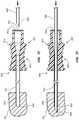
- FIG. 2Ais a perspective view of an introducer sheath and an elongate member in a first configuration.
- FIG. 2Bis an end view of the introducer sheath and elongate member of FIG. 2A with the proximal end of the introducer sheath and the distal end of the elongate member facing out of the page.
- FIG. 3is a perspective view of the elongate member and introducer sheath of FIG. 2A in a second configuration.
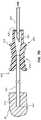
- FIG. 4is a cross-sectional side view of the introducer sheath and elongate member of FIG. 2A in a third configuration.
- FIG. 5is a cross-sectional side view of an introducer sheath, body tissue, and a needle in a first configuration.
- FIG. 6is a cross-sectional side view of the introducer sheath, body tissue, and needle of FIG. 5 in a second configuration.
- FIG. 7Ais a cross-sectional side view of a portion of an introducer sheath assembly in a first configuration.
- FIG. 7Bis a cross-sectional side view of a portion of the introducer sheath assembly of FIG. 7A in a second configuration.
- FIG. 7Cis a cross-sectional side view of a portion of the introducer sheath assembly of FIG. 7A in a third configuration.
- FIG. 7Dis a cross-sectional side view of a portion of the introducer sheath assembly of FIG. 7A in a fourth configuration.
- FIG. 7Eis a cross-sectional side view of a portion of the introducer sheath assembly of FIG. 7A in a fifth configuration.
- FIG. 7Fis a cross-sectional side view of a portion of the introducer sheath assembly of FIG. 7A in a sixth configuration.
- FIG. 7Gis a cross-sectional side view of a portion of the introducer sheath assembly of FIG. 7A , in a seventh configuration.
- Access devicesmay be configured to facilitate access to tissues and/or fluids during such procedures.
- an access devicemay comprise a lumen, at least a portion of which may be disposed within a patient.
- the lumenmay be used as a conduit for delivering medicaments and/or as a sheath that facilitates the insertion of needles or other elongate members.
- the access deviceis configured to protect tissue situated adjacent to the access device from contamination.
- the lumen of the access deviceprevents material that is carried by the needle or other elongate member from contacting at least a portion of the tissue situated adjacent the device.
- access devicessuch as an introducer sheath, may be used during a biopsy procedure.
- Biopsy samplesmay be obtained from various locations within a patient's body. For example, among other locations, medical practitioners may obtain biopsy samples from the liver, the bladder, the gastrointestinal tract, the prostate, breasts, lymph nodes, muscle, skin, or lungs.
- a practitionermay insert an introducer sheath into a patient.
- the introducer sheathmay comprise an elongate member, such as a cylindrical tube, with a lumen that extends through the elongate member. Insertion of the introducer sheath into the patient may be facilitated by first inserting a second elongate member, such as a trocar, into the introducer sheath such that a pointed end of the trocar protrudes from the distal end of the introducer sheath. With the pointed end protruding from the introducer sheath, the trocar and the introducer sheath may together be inserted into the patient.
- a second elongate membersuch as a trocar
- the trocarmay be withdrawn from the introducer sheath.
- the introducer sheathprovides a conduit that allows access to a patient's internal body tissue and/or fluid.
- This conduitmay be used to obtain tissue or fluid samples in the case of a biopsy, or the conduit may be used for other purposes (e.g., drug delivery).
- a cutting devicee.g., a needle or some other device configured to obtain body fluid and/or tissue samples
- the practitionermay then obtain a sample from the body and withdraw both the device and the sample from the introducer sheath.
- Biopsiesmay be obtained for numerous reasons. Exemplary reasons for seeking a biopsy sample include testing for cancer or other diseases, monitoring response to therapy, or determining the stage of a disease or condition. Lung biopsies, in particular, may facilitate the diagnosis of cancer, sarcoidosis, pulmonary fibrosis, and severe pneumonia. Tests on biopsied samples may also reveal the presence of bacteria, viruses, or fungi.
- the patientmay face a risk of infection from the biopsy procedure. Infection may arise from the patient's exposure to a non-sterile environment.
- One possible avenue of exposureis through an introducer sheath lumen, where the lumen places the patient's internal tissue in fluid communication with the external environment.
- a biopsy patientalso faces the risk that biopsy sample material will, to the patient's detriment, spread elsewhere in his or her body as a result of the procedure.
- a needlemay be inserted into a patient and manipulated to obtain a sample of diseased and/or cancerous material.
- such materialmay contact and/or deposit onto tissue situated adjacent to the path followed by the needle as it is withdrawn. In this manner, diseased and/or cancerous tissue may be inadvertently transported within the patient's body.
- the risks associated with the inadvertent spread of body tissue and/or fluid from the biopsy sitemay be mitigated as the introducer sheath may surround a portion of the biopsy needle and prevent contamination as it is withdrawn.
- Procedures involving access to the chest cavitypose another risk—a collapsed lung (pneumothorax).
- a lungmay collapse when air collects in the pleural cavity that surrounds a lung. Air may enter into the pleural cavity by escaping from the patient's own lung or by entering through a conduit that places the pleural cavity and the external environment in fluid communication with each other.
- factors that may increase the risk of pneumothoraxinclude the dwell time of the introducer sheath, puncture angles that are not perpendicular to the punctured surface, the diameter of the introducer sheath, and the depth and breadth of the inserted trocar and/or introducer sheath.
- the collapse of a lung via entry of air into the pleural cavitymay prevent the lung from filling properly and lead to oxygen deprivation, low blood pressure, and/or death.
- a chest tube or chest drainmay be inserted to remove air from the pleural cavity.
- the following exemplary procedureillustrates a possible scenario in which air may enter into a pleural cavity during a biopsy procedure.
- An introducer sheath with a trocar disposed within itis inserted into a patient.
- the trocarpierces a pleural membrane during insertion.
- the trocaris then withdrawn from the introducer sheath, leaving the distal end of the introducer sheath positioned adjacent to the pierced pleural membrane.
- a lumen that extends through the introducer sheathplaces the pleural cavity in fluid communication with the external environment. Air from the external environment may thus enter into the pleural cavity through the introducer sheath.
- the practitionermay then insert a biopsy needle through the introducer sheath to obtain a sample of pleural tissue.
- the deviceis then withdrawn from the introducer sheath, which again allows air to pass through the introducer sheath into the pleural cavity.
- Air from the external environmentmay enter into the pleural cavity during other procedures as well.
- the trocardoes not pierce the pleural membrane as the introducer sheath is inserted into the patient's chest. Rather, the pleural membrane is pierced after the trocar has been removed, when an inserted biopsy needle pierces the membrane to obtain a tissue sample. Withdrawal of the biopsy needle places the pleural cavity in fluid communication with the external environment via the introducer sheath, allowing air to fill the pleural cavity.
- a valvedisposed adjacent to a lumen that extends through an introducer sheath.
- a valveis disposed “adjacent to” a lumen if (1) the valve is disposed entirely within the lumen, (2) the valve is partially, but not wholly, disposed within the lumen, or (3) the valve is adjacent to, but does not lie within, the lumen.
- the valvemay be configured to allow a portion of a second elongate member (e.g., a trocar, a needle, cutting device) to pass through the valve.
- the valvemay be configured to prevent or reduce fluid flow across the introducer sheath (i.e., from the external environment to the patient and vice versa).
- the valvemay also prevent body tissue and fluid from being exposed to the nonsterile external environment.
- phrases “connected to” and “coupled to”refer to any form of interaction between two or more entities, including mechanical, electrical, magnetic, electromagnetic, fluid and thermal interaction.
- fluid communicationis used in its ordinary sense, and is broad enough to refer to arrangements in which a fluid (e.g., a gas or a liquid) can flow from one element to another element when the elements are in fluid communication with each other.
- proximal and distalare used herein to refer to opposite locations on a component or device.
- the proximal end of a component or deviceis defined as the end of the device closest to the practitioner when the device is in normal use by the practitioner.
- the distal endis the end opposite the proximal end, along the longitudinal direction of the device, or the end furthest from the practitioner during normal use.
- needleor “biopsy needle” refers to any device configured to withdraw a tissue or fluid sample from a patient (e.g., a hollow needle or an otherwise solid needle with a cutting or sectioning portion such as a trough).
- substantially perpendicularrefers to angles that are perpendicular to the reference surface or angles that deviate from being perpendicular to the reference surface by 5° or less.
- detentrefers to a multicomponent connection that restricts the relative movement of separable components via frictional engagement. Such multicomponent connections may comprise ridges, catches, protrusions, depressions, etc.
- vascular proceduresare procedures in which an introducer sheath is longitudinally inserted into a patient's vasculature (e.g., intravenous applications). All other procedures are “non-vascular.”
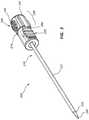
- FIG. 1is a perspective view of a medical device 100 , the distal end of which has been inserted into patient tissue and/or fluid 20 .
- the medical device 100may comprise an introducer sheath 110 and a needle 160 configured to be disposed within the introducer sheath 110 .
- the introducer sheath 110may be configured to facilitate access to body tissue and/or fluid, for example percutaneous access to body tissue.
- the introducer sheathis configured for use in non-vascular procedures (e.g., a lung biopsy).
- the introducer sheathmay comprise a rigid (e.g., steel or other metal) hypotube that is configured to facilitate percutaneous access to lung tissue.
- Such a devicemay not be configured for vascular access as a rigid sheath may tend to damage the vasculature if it were inserted longitudinally into a vein or artery due to its hardness and rigidity.
- the needle 160may be configured to obtain samples of body tissue or fluid 20 from within a patient.
- the introducer sheath 110is initially inserted and/or otherwise positioned in a patient's tissue and/or fluid 20 . Subsequently, the needle 160 is inserted into a lumen of the introducer sheath 110 . The needle 160 may emerge from the introducer sheath 110 to obtain a sample of tissue, for example, from a position adjacent the distal tip of the introducer sheath 110 . As shown in FIG. 1 , the introducer sheath 110 may comprise an introducer sheath hub 120 , a ridge 124 , and/or threads 122 , which may be configured to couple the introducer sheath 110 to an elongate member. Analogous components, as well as methods for using these components to couple an introducer sheath to an elongate member, will be further discussed in connection with other figures.
- the medical device 100is inserted into patient tissue and/or fluid 20 at an angle that is not perpendicular to the surface of the patient's skin.
- the medical device and/or components of the medical devicee.g., an introducer sheath, needle, or trocar
- the medical device and/or components of the medical deviceare inserted at an angle that is perpendicular or substantially perpendicular to the surface of the patient's skin or to the surface of the tissue within the patient that is to be sampled.
- FIGS. 2A-4depict another embodiment of a medical device 200 that resembles the medical device 100 described above in certain respects. Accordingly, like features are designated with like reference numerals, with the leading digits incremented to “2.”
- the embodiment depicted in FIGS. 2-4includes an introducer sheath 210 that may, in some respects, resemble the introducer sheath 110 of FIG. 1 .
- Relevant disclosure set forth above regarding similarly identified featuresthus may not be repeated hereafter.
- specific features of medical devices and related components shown in FIGS. 2A-4may not be shown or identified by a reference numeral in the drawings or specifically discussed in the written description that follows.
- FIGS. 2A-4provide various views of the medical device 200 .
- FIGS. 2A and 3provide perspective views of the medical device 200 in a first and second configuration, respectively.
- FIG. 2Bprovides end views of two components of the medical device 200
- FIG. 4provides a cross-sectional view of the medical device 200 .
- the medical device 200may comprise an introducer sheath 210 , a second elongate member 230 , and a lumen 214 .
- the second elongate member 230may comprise a trocar 232 that is configured to be at least partially disposed within a lumen 214 of the introducer sheath 210 .
- the second elongate member 230may alternatively or additionally comprise other elongate instruments, such as biopsy needles, injection needles, cutting devices and so forth.
- the distal tip 234 of the trocar 232may emerge from the distal end 219 of the introducer sheath 210 .
- the trocar 232 and introducer sheath 210may be inserted as a single unit into a patient.
- the pointed distal tip 234 of the trocar 232may be configured to pierce the patient's skin and tissue as the trocar 232 and introducer sheath 210 are inserted into the patient. In this manner, the placement of the introducer sheath 210 within the patient may be facilitated.
- the introducer sheath 210may comprise an introducer sheath hub 220 and a first elongate member 212 .
- a lumen 214may extend through the first elongate member 212 , along the longitudinal length of the elongate member 212 .
- the lumen 214may also extend through the introducer sheath hub 220 .
- the lumen 214may be configured to have a size and shape that accommodates at least a portion of a trocar, needle or other elongate instrument.
- the introducer sheath hub 220may be disposed adjacent a proximal end of the first elongate member 212 and may be configured to selectively couple to the second elongate member 230 .
- a trocar 232 and introducer sheath 210may be coupled to each other and together inserted into a patient.
- the introducer sheath hub 220comprises a ridge 224 and threads 222 .
- both the ridge 224 and threads 222are configured to releasably couple the introducer sheath 210 to a second elongate member 230 .
- the introducer sheath hubmay comprise only a ridge (and no threads) or threads (and no ridge), or some other coupling feature. While ridge 224 of the illustrated embodiment comprises an annular protrusion from the introducer sheath hub 220 , in other embodiments, a ridge or ridges may extend around only a portion of an introducer sheath hub's circumference. Further, in certain embodiments, recesses, protrusions, edges, or other features of the introducer sheath hub 220 may be configured to interact with components of the second elongate member 230 when coupling the introducer sheath hub 220 to the second elongate member 230 .
- the second elongate member 230may comprise a trocar 232 and a second elongate member hub 240 .
- the trocar 232may be configured to be disposed within the lumen 214 of introducer sheath 210 .
- the trocar 232may comprise a distal tip 234 that extends from the distal end 219 of the introducer sheath 210 when the second elongate member 230 is fully inserted into the introducer sheath 210 .
- Features or components of the second elongate member hub 240may be configured to interact with another component, such as the introducer sheath hub 220 , to facilitate coupling of the second elongate member hub 240 to the additional component.
- the second elongate member hub 240may comprise catches 244 , depressible members 246 , and a distal region 248 configured to frictionally engage the proximal end 218 of the introducer sheath hub 220 (e.g., by engaging one or more mating detent features on the proximal end 218 ).
- the second elongate member hub 240may approach the introducer sheath hub 220 .
- These hubsmay be configured to engage with and/or couple to each other via multiple mechanisms or connections.
- the introducer sheath hub 220 and the second elongate member hub 240may be configured to engage with each other via a snap fit-type mechanism.
- full insertion of the second elongate member 230 into the introducer sheath 210causes the catches 244 of the tabs 245 to be advanced over the ridge 224 of the introducer sheath hub 220 .
- the catches 244may “snap” over the ridge 224 to create a snap fit-type connection.
- the catches 244 and ridge 224may impede withdrawal of the second elongate member 230 from the introducer sheath 210 .
- the catches 244 and the ridge 224together form a detent 224 , 244 .
- the detent 224 , 244 shown in FIG. 3releasably couples the introducer sheath 210 to the second elongate member 230 .
- a ridge and catchmay be disengaged via actuation of a release mechanism (e.g., depression of a depressible member or members).
- depression of depressible members 246 that are disposed on opposite sides of the second elongate member hub 240causes the catches 244 to disengage from the ridge 224 of the introducer sheath 210 .
- depression of the depressible members 246causes the distal end of tabs 245 to be displaced radially from the longitudinal axis of the second elongate member 230 such that catches 244 may be freely inserted over or freely withdrawn from ridge 224 of the introducer sheath 210 .
- the introducer sheath hub 220 and second elongate member hub 240are exemplary.
- the introducer sheath hub and the second elongate member hubmay comprise components that differ from those disclosed in FIGS. 2A-4 .
- the second elongate member hubmay comprise a ridge while the introducer sheath hub comprises a catch configured to frictionally engage with the ridge.
- numerous other mechanisms for creating a snap fit-type connection between the introducer sheath hub and the second elongate member hubare within the scope of this disclosure.
- Such mechanismsinclude components such as portions of detents, bumps, protrusions, catches, dogs, pivoting members, holes, and recesses that are configured to interact with one another to restrict the relative movement of multiple components.
- one or more of these featureswill extend around the entire circumference of the introducer sheath hub or the second elongate member hub. In other embodiments, one or more of these features will extend around only a portion of the circumference of the hubs.
- sets of hubsthat are configured to selectively engage with one another by at least a snap-fit type connection, yet differ from those shown in FIGS. 2A-4 , are within the scope of this disclosure.
- the introducer sheath hub 220 and the second elongate member hub 240may also be configured to engage with each other via frictional engagement of a protrusion 247 of the second elongate member 230 with at least a portion of the lumen 214 .
- the protrusion 247may be inserted into and frictionally engage the lumen 214 .
- the protrusion 247 and the lumen 214may be tapered such that the protrusion 247 and the lumen 214 engage with one another along a mating taper.
- the frictional engagement of protrusion 247 with the lumen 214may be overcome by exerting opposing forces on the introducer sheath hub 220 and the second elongate member hub 240 .
- the introducer sheath hub 220 and the second elongate member hub 240may additionally or alternatively be configured to engage with each other via threads.
- the proximal end 218 of the introducer sheath 210comprises threads 222
- the second elongate member hub 240comprises threads 242 .
- An alternative view of the threads 222 , 242may be found in FIG. 2B , which provides an end view of the introducer sheath 210 and the second elongate member 230 of FIG. 2A with the proximal end of the introducer sheath 210 and distal end of the second elongate member 230 facing out of the page.
- introducer sheath hub threads 222comprise noncontiguous thread portions 222 a and 222 b , which are oppositely positioned around the proximal end 218 of the introducer sheath 210 .
- noncontiguous thread portions 242 a and 242 bmay be oppositely positioned around the second elongate member hub 240 .
- the second elongate member hub threads 242 and the introducer sheath hub threads 222may be configured such that the introducer sheath hub 220 and second elongate member hub 240 may more fully engage by rotating the threads 242 , 222 relative to each other.
- the introducer sheath hub threads 222 and the second elongate member hub threads 242are circumferentially aligned as they approach one another (e.g., the orientation shown in FIG. 2A where both threads 222 and 242 are vertically aligned with the ground)
- the introducer sheath hub threads 222will contact second elongate member hub threads 242 , preventing further insertion of the second elongate member 230 .
- the second elongate member hub 240may more fully engage with the introducer sheath hub 220 .
- the second elongate member hub 240may be rotated relative to the introducer sheath hub 220 such that the introducer sheath hub threads 222 and second elongate member hub threads 242 engage with each other.
- this rotation of the second elongate member hub 240 relative to the introducer sheath hub 220may also advance the second elongate member 230 with respect to the introducer sheath 210 .
- the componentsmay be configured such that when the threads are fully engaged, the second elongate member 230 is fully extended into the introducer sheath 210 and/or the components are disposed such that the catches 244 and ridge 224 are also engaged. The reverse of this process may be used to disengage the threads 222 , 242 from one another.
- FIGS. 2A-4is configured to facilitate the engagement of the introducer sheath hub 220 with the second elongate member hub 240 via at least three mechanisms: (1) a snap fit-type mechanism (e.g., the engagement of catches 244 with a ridge 224 ), (2) a frictional engagement mechanism (e.g., the engagement of the protrusion 247 with the lumen 214 ) and (3) a thread engagement mechanism (e.g., the engagement of introducer sheath hub threads 222 with second elongate member hub threads 242 ).
- a snap fit-type mechanisme.g., the engagement of catches 244 with a ridge 224
- a frictional engagement mechanisme.g., the engagement of the protrusion 247 with the lumen 214
- a thread engagement mechanisme.g., the engagement of introducer sheath hub threads 222 with second elongate member hub threads 242 .
- any sub combination of any of these three engagement mechanismsare present are also within
- a medical devicemay comprise only a snap fit-type mechanism, a thread engagement mechanism, or a friction-fit mechanism for engaging the hubs.
- a medical devicemay comprise any two of these engagement mechanisms.
- hubsmay be uncoupled from each other by any combination of depressing a depressible button, exerting opposing forces on the hubs, and/or rotating one hub relative to the other hub. Additionally, in some embodiments the hubs may disengage from each other via a process that does not include rotation of one hub relative to the other hub.
- an introducer sheathmay be disengaged from the second elongate member hub without rotating the second elongate member hub relative to the introducer sheath.
- the second elongate member hubmay be disengaged and withdrawn from the introducer sheath hub using a single hand.
- the practitionermay, with one hand, actuate a release mechanism (e.g., depress a depressible button) that causes the catches of the second elongate member hub to be radially displaced relative to the longitudinal axis of the second elongate member. With the catches displaced in this manner, the practitioner may exert a proximal force on the second elongate member hub with the same hand.
- a release mechanisme.g., depress a depressible button
- this proximal forcemay overcome such frictional forces and allow the second elongate member to be withdrawn from the introducer sheath without immobilizing the introducer sheath with a second hand.
- Embodiments without threadsmay facilitate such one-handed uncoupling of the second elongate member from the introducer sheath.
- one-handed uncouplingmay also comprise rotating the second elongate member relative to the introducer sheath.
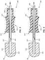
- FIG. 4is a cross-sectional side view of the medical device 200 of FIGS. 2A, 2B, and 3 , with the distal tip 219 of the introducer sheath 210 disposed within patient tissue and/or fluid 30 .
- a lumen 214extends through both the first elongate member 212 and the introducer sheath hub 220 .
- the lumen 214may have a larger circumference (or otherwise extend further from the longitudinal axis of the introducer sheath 210 ) at the proximal end 218 of the introducer sheath 210 than at the distal end 219 of the introducer sheath 210 .
- the larger circumference of the lumen 214 at its proximal endmay allow it to frictionally engage a protrusion 247 of the second elongate member hub 240 when the second elongate member 230 is fully inserted into the introducer sheath 210 .
- FIG. 4also discloses a valve 250 disposed adjacent to the lumen 214 .
- the valve 250is directly coupled to the introducer sheath hub 220 .
- the valve 250may comprise a slit 252 or other opening configured to allow traversal of the valve 250 by at least a portion of the second elongate member.
- the second elongate membermay traverse a valve without a slit (e.g., an elastomeric septum).
- the valve 250may comprise material (e.g., an elastomer) that conforms to the contours of the second elongate member to form a seal around the second elongate member.
- the distal end of a needle or trocarmay pass through the valve.
- the valve 250may impede the flow of fluid across the valve both (1) when an elongate member is disposed across the valve (e.g., the valve forms a seal around the elongate member that prevents fluid flow around the elongate member) and (2) when no elongate member traverses that valve.
- air or other fluidmay be unable to pass through the lumen 214 of the introducer sheath 210 and interact with the patient's body tissue or fluid 30 .
- fluid flow from the patient to the external environmentmay be impeded as well.
- the valveis disposed at the most proximal end of the introducer sheath 210 .
- the valvemay be disposed at other locations adjacent to or within the lumen.
- multiple serially disposed valvesmay be disposed within and/or adjacent to the lumen.
- the trocar 232may be withdrawn from the introducer sheath 210 , allowing for subsequent insertion of a biopsy needle or other medical device.
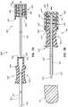
- FIGS. 5 and 6depict another embodiment of a medical device 300 .
- FIG. 5discloses a needle 360 , an introducer sheath 310 , and body tissue or fluid 40 in a first configuration
- FIG. 6discloses the same elements in a second configuration.
- FIG. 5discloses a needle 360 that is being inserted through an introducer sheath 310 into a patient to retrieve body tissue and/or body fluid 40 from the patient.
- the depicted needle 360is a cylindrical needle comprising a hollow tube. However, other needles may be used.
- a biopsy devicecomprising a partial core needle (e.g., a solid core needle that comprises troughs or recesses in an outside diameter of the needle), a full core needle (e.g., a needle assembly comprising two or more coaxial tubular needles configured to cut full core tissue from the patient), or any other elongate instrument, including those configured to cut or displace a tissue sample, may also be employed.
- a partial core needlee.g., a solid core needle that comprises troughs or recesses in an outside diameter of the needle
- a full core needlee.g., a needle assembly comprising two or more coaxial tubular needles configured to cut full core tissue from the patient
- any other elongate instrumentincluding those configured to cut or displace a tissue sample
- the distal tip 334 of the needle 360passes through the valve 350 and enters into the introducer sheath 320 .
- the valve 350may conform to the contours of the needle 360 , preventing fluid from passing through the valve.
- the practitionermay then use the needle 360 to obtain a tissue sample.
- at least the distal end 334 of the needle 360emerges from the distal end 319 of the introducer sheath 310 to obtain the tissue or fluid sample 40 .
- the needle 360may be withdrawn from the introducer sheath 310 .
- the desired tissue samplepasses through both (1) the introducer sheath lumen 314 and (2) the valve 350 .
- the elongate member 312 and other components of the introducer sheath 310may prevent tissue or fluid 40 that is being withdrawn from the patient from contacting tissue or fluid disposed adjacent the elongate member 312 as the sample is being withdrawn.
- the valve 350may be configured to seal around the needle 360 as the needle 360 is withdrawn from the introducer sheath 310 .
- the valvemay prevent the flow of fluid across the valve.
- FIGS. 7A-7Gare cross-sectional side views of an introducer sheath assembly in seven configurations, with each configuration corresponding to a position of the assembly during an exemplary procedure. Analogous procedures may or may not proceed through each configuration depicted. Additionally, analogous procedures may include configurations or steps not shown in FIGS. 7A-7G . Procedures with any sub-combination of the steps below are within the scope of this disclosure.
- FIG. 7Ashows an introducer sheath 410 and a second elongate instrument 430 with the second elongate instrument 430 disposed outside the introducer sheath 410 .
- the second elongate instrument 430comprises a trocar 432 and a second elongate member hub 440 .
- the trocar 432may be configured to be inserted into the introducer sheath 410 .
- the tip of the trocar 434may pass through the valve 450 .
- the valve 450With the trocar 432 disposed across the valve 450 , the valve 450 may seal around the trocar 432 , preventing the passage of air or other fluid across the valve 450 .
- the trocar 432may then be coupled to a second elongate member hub 440 that is configured to releasably engage with an introducer sheath hub 420 .
- the practitionermay first rotate the second elongate member 430 approximately 90 degrees about the longitudinal axis of the second elongate member 430 .
- the second elongate member hub 440may subsequently be inserted or nearly fully inserted into the introducer sheath hub 420 .
- the second elongate member hub 440may then be rotated approximately 90 degrees such that threads 442 engage with threads (not shown in this view) on the introducer sheath hub 420 .
- FIG. 7Bshows the trocar 432 fully disposed within the introducer sheath 410 and the second elongate member hub 440 coupled to the introducer sheath hub 420 .
- the trocar 432traverses the valve 450 , the catches 424 engage with the ridge 444 , the protrusion 447 frictionally engages with the lumen 414 , and the threads 442 of the second elongate member hub 440 engage with threads (not shown in this view) of the introducer sheath hub 420 .
- the second elongate member 430 and the introducer sheath 410may together be percutaneously inserted into a patient's tissue or fluid 50 such that the distal ends 434 , 419 of the second elongate member 430 and the introducer sheath 410 are disposed within body tissue and/or fluid 50 .
- the introducer sheathis inserted such that it does not extend within and along a longitudinal length of a vascular lumen.
- the pointed distal end 434 of trocar 432due to its ability to penetrate body tissue, may facilitate insertion of the first elongate member 412 of the introducer sheath 410 .
- FIG. 7Cshows the trocar 432 and the introducer sheath 410 in a fully engaged configuration with the distal tips 434 , 419 of the trocar 432 and introducer sheath 410 disposed within body tissue or fluid 50 .
- the second elongate member 430may be withdrawn by, for example, (1) depressing the depressible members 446 such that catches 424 disengage from ridge 444 , (2) rotating the second elongate member hub 440 relative to the introducer sheath hub 420 such that threads 442 disengage from threads on the introducer sheath hub 420 , and (3) exerting a proximal force on the second elongate member hub 440 such that the frictional forces between protrusions 447 and the lumen 414 are overcome.
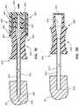
- FIG. 7Ddepicts an introducer sheath 410 disposed within a patient's fluid or tissue 50 .
- valve 450lies adjacent to the lumen 414 .
- Valve 450may prevent the flow of fluid from the external environment into the patient and from the patient into the external environment. In the absence of such a valve, air may enter into a region of the patient and cause damage (e.g., infection, pneumothorax).
- FIGS. 7E and 7Fshow a needle 460 , the introducer sheath 410 , and body tissue or fluid 50 , with the needle 460 disposed either outside of the introducer sheath ( FIG. 7E ) or disposed across the introducer sheath 410 with a distal tip 464 disposed within the patient's tissue or fluid 50 ( FIG. 7F ).
- a practitionermay insert the needle 460 across the valve 450 and into the patient's tissue or fluid 50 to obtain a biopsy sample.
- a practitionermay insert the needle across the valve 450 until the needle is disposed adjacent the distal end 419 of the introducer sheath 410 .
- the practitionermay then manipulate the needle 460 to obtain a biopsy sample.
- a practitionermay cause the tip 434 of the needle 460 to emerge from the distal tip 419 of the introducer sheath 410 such that fluid or tissue is disposed within the needle.
- FIG. 7Gdepicts a needle 460 , an introducer sheath 410 , and a biopsy sample with the biopsy sample disposed within the needle 460 and the distal tip 464 of the needle 460 disposed within the introducer sheath 410 .
- a biopsy sample disposed within the needle 460may be withdrawn from the introducer sheath 410 .
- elongate member 412may prevent the biopsy sample from contacting tissue disposed along the longitudinal axis of the first elongate member 412 .
- the valve 450prevents air and other fluids from crossing the valve 450 both while the needle 460 is being withdrawn and after the needle 460 has been withdrawn.
- Any methods disclosed hereininclude one or more steps or actions for performing the described method.
- the method steps and/or actionsmay be interchanged with one another.
- the order and/or use of specific steps and/or actionsmay be modified with respect to the exemplary procedure outlined above.
- sub routines or only a portion of a method described hereinmay be a separate method within the scope of this disclosure. Stated otherwise, some methods may include only a portion of the steps described in a more detailed method.
Landscapes
- Health & Medical Sciences (AREA)
- Life Sciences & Earth Sciences (AREA)
- Heart & Thoracic Surgery (AREA)
- Public Health (AREA)
- Veterinary Medicine (AREA)
- Engineering & Computer Science (AREA)
- Biomedical Technology (AREA)
- General Health & Medical Sciences (AREA)
- Animal Behavior & Ethology (AREA)
- Surgery (AREA)
- Molecular Biology (AREA)
- Medical Informatics (AREA)
- Pathology (AREA)
- Pulmonology (AREA)
- Anesthesiology (AREA)
- Hematology (AREA)
- Nuclear Medicine, Radiotherapy & Molecular Imaging (AREA)
- Surgical Instruments (AREA)
- Gastroenterology & Hepatology (AREA)
Abstract
Description
Claims (22)
Priority Applications (2)
| Application Number | Priority Date | Filing Date | Title |
|---|---|---|---|
| US14/600,660US11191938B2 (en) | 2014-01-21 | 2015-01-20 | Introducer sheath and methods |
| US17/457,859US20220088360A1 (en) | 2014-01-21 | 2021-12-06 | Introducer sheath and methods |
Applications Claiming Priority (2)
| Application Number | Priority Date | Filing Date | Title |
|---|---|---|---|
| US201461929614P | 2014-01-21 | 2014-01-21 | |
| US14/600,660US11191938B2 (en) | 2014-01-21 | 2015-01-20 | Introducer sheath and methods |
Related Child Applications (1)
| Application Number | Title | Priority Date | Filing Date |
|---|---|---|---|
| US17/457,859ContinuationUS20220088360A1 (en) | 2014-01-21 | 2021-12-06 | Introducer sheath and methods |
Publications (2)
| Publication Number | Publication Date |
|---|---|
| US20150201963A1 US20150201963A1 (en) | 2015-07-23 |
| US11191938B2true US11191938B2 (en) | 2021-12-07 |
Family
ID=53543788
Family Applications (2)
| Application Number | Title | Priority Date | Filing Date |
|---|---|---|---|
| US14/600,660Active2035-12-21US11191938B2 (en) | 2014-01-21 | 2015-01-20 | Introducer sheath and methods |
| US17/457,859PendingUS20220088360A1 (en) | 2014-01-21 | 2021-12-06 | Introducer sheath and methods |
Family Applications After (1)
| Application Number | Title | Priority Date | Filing Date |
|---|---|---|---|
| US17/457,859PendingUS20220088360A1 (en) | 2014-01-21 | 2021-12-06 | Introducer sheath and methods |
Country Status (3)
| Country | Link |
|---|---|
| US (2) | US11191938B2 (en) |
| EP (2) | EP3096831B1 (en) |
| WO (1) | WO2015112484A1 (en) |
Cited By (1)
| Publication number | Priority date | Publication date | Assignee | Title |
|---|---|---|---|---|
| US12415055B2 (en) | 2017-09-29 | 2025-09-16 | Terumo Kabushiki Kaisha | Catheter assembly and medical valve |
Families Citing this family (21)
| Publication number | Priority date | Publication date | Assignee | Title |
|---|---|---|---|---|
| RU2581871C2 (en) | 2011-01-28 | 2016-04-20 | Мерит Медикал Системз, Инк. | Electrospun ptfe coated stent and method of use |
| WO2014100349A1 (en) | 2012-12-19 | 2014-06-26 | Merit Medical Systems, Inc. | Biopsy device and method of use |
| US20240226430A1 (en)* | 2012-12-31 | 2024-07-11 | Medtg, Llc | Simultaneous infusion and blood collection devices |
| EP3868304A1 (en) | 2013-01-18 | 2021-08-25 | Merit Medical Systems, Inc. | Biopsy device with transfer of kinetic energy to the needle assembly |
| WO2015175537A1 (en)* | 2014-05-16 | 2015-11-19 | Silk Road Medical, Inc. | Vessel access and closure assist system and method |
| US9545264B2 (en)* | 2014-06-06 | 2017-01-17 | Surgiquest, Inc. | Trocars and obturators |
| ES2989899T3 (en) | 2015-02-26 | 2024-11-28 | Merit Medical Systems Inc | Medical devices in layers |
| CN107405139A (en) | 2015-03-04 | 2017-11-28 | 美国医疗设备有限公司 | Attenuation type biopsy device and its application method |
| US10806537B2 (en)* | 2015-11-11 | 2020-10-20 | Nico Corporation | Illumination sleeve |
| AU2017373953B2 (en) | 2016-12-08 | 2023-05-11 | Abiomed, Inc. | Overmold technique for peel-away introducer design |
| CN117898800A (en) | 2017-10-12 | 2024-04-19 | 波士顿科学医疗设备有限公司 | Medical device assembly |
| KR102452113B1 (en) | 2017-11-06 | 2022-10-07 | 아비오메드, 인크. | Separable hemostatic valve |
| US10702673B2 (en)* | 2018-01-19 | 2020-07-07 | Medtronic Vascular, Inc. | Expandable balloon sheaths |
| WO2019203820A1 (en)* | 2018-04-18 | 2019-10-24 | C.R. Bard, Inc. | Dual lumen coaxial introducer having integrated tissue marker delivery |
| ES2991910T3 (en) | 2018-05-16 | 2024-12-05 | Abiomed Inc | Removable cover set |
| US10820933B1 (en) | 2019-07-15 | 2020-11-03 | Osteon Medical LLC | Kyphoplasty system and method |
| EP4064989A4 (en)* | 2019-11-26 | 2023-12-06 | Medtg LLC | Infusion and blood collection devices and methods |
| CN113116502A (en)* | 2019-12-30 | 2021-07-16 | 杭州诺诚医疗器械有限公司 | Puncture needle assembly and ablation needle assembly |
| NL2026624B1 (en)* | 2020-10-05 | 2022-06-03 | D O R C Dutch Ophthalmic Res Center International B V | A trocar module, a fluid connector and methods |
| CN117597095A (en)* | 2021-07-20 | 2024-02-23 | 爱尔康公司 | Trocar cannula assembly cap |
| US11903628B1 (en) | 2023-04-20 | 2024-02-20 | Osteon Medical LLC | Kyphoplasty system and method |
Citations (76)
| Publication number | Priority date | Publication date | Assignee | Title |
|---|---|---|---|---|
| AT366546B (en) | 1975-07-01 | 1982-04-26 | Impulsa Veb K | METHOD AND DEVICE FOR PRODUCING BUTTER-LIKE PRODUCTS WITH LOW FAT CONTENT |
| US4785826A (en) | 1987-03-02 | 1988-11-22 | Ward John L | Biopsy instrument |
| US4922602A (en)* | 1981-03-16 | 1990-05-08 | Creative Research And Manufacturing, Inc. | Method of manufacturing a biopsy needle |
| US5172702A (en) | 1989-11-24 | 1992-12-22 | Medical Device Technologies, Inc. | Disposable spring-loaded soft tissue biopsy apparatus |
| US5176648A (en)* | 1991-12-13 | 1993-01-05 | Unisurge, Inc. | Introducer assembly and instrument for use therewith |
| EP0583144A1 (en) | 1992-08-13 | 1994-02-16 | Medtronic, Inc. | Surgical needle assembly |
| US5368574A (en)* | 1992-10-01 | 1994-11-29 | Ethicon, Inc. | Percutaneous catheter introducer |
| WO1996022733A1 (en) | 1995-01-26 | 1996-08-01 | Ascendia Ab | Instrument and apparatus for biopsy and a method thereof |
| US5800389A (en) | 1996-02-09 | 1998-09-01 | Emx, Inc. | Biopsy device |
| US5842999A (en) | 1996-07-31 | 1998-12-01 | C.R. Bard, Inc. | Automated tissue sampling device |
| WO1999044505A1 (en) | 1998-03-06 | 1999-09-10 | Ascendia Ab | Impact-damped biopsy instrument |
| USD418223S (en) | 1998-06-05 | 1999-12-28 | Eclipse Surgical Technologies, Inc. | Hand piece for surgical and biopsy procedures |
| EP0966920A2 (en) | 1998-06-24 | 1999-12-29 | Rubicor Medical, Inc. | Fine needle and core biopsy devices |
| USD428150S (en) | 1999-02-23 | 2000-07-11 | Lifescan, Inc. | Lancing device |
| US6126617A (en) | 1995-01-26 | 2000-10-03 | Ascendia Ab | Impact-damped biopsy instrument |
| USD457955S1 (en) | 2001-03-29 | 2002-05-28 | Annex Medical, Inc. | Handle |
| USD463555S1 (en) | 2000-10-26 | 2002-09-24 | Grieshaber & Co. Ag Schaffhausen | Ophthalmologic surgical instrument |
| US6488662B2 (en) | 2000-12-19 | 2002-12-03 | Laksen Sirimanne | Percutaneous catheter assembly |
| US6497687B1 (en) | 1999-06-22 | 2002-12-24 | Erblan Surgical Inc. | Safety trocar with progressive cutting tip guards and gas jet tissue deflector |
| US20030153842A1 (en) | 2000-07-29 | 2003-08-14 | Lamoureux Gary A. | Bone marrow extraction tool |
| US6656195B2 (en) | 2000-09-22 | 2003-12-02 | Medtronic Xomed, Inc. | Flexible inner tubular members and rotary tissue cutting instruments having flexible inner tubular members |
| US20040054377A1 (en) | 2002-07-12 | 2004-03-18 | Foster Thomas L. | Flexible cannula |
| USD490152S1 (en) | 2003-02-28 | 2004-05-18 | Glaukos Corporation | Surgical handpiece |
| US20040215103A1 (en) | 2003-04-24 | 2004-10-28 | Mueller Richard L. | Biopsy device |
| US20050054947A1 (en) | 2003-08-28 | 2005-03-10 | Goldenberg Alec S. | Rotating soft tissue biopsy needle |
| US20050125017A1 (en) | 2003-12-05 | 2005-06-09 | Paul Kudrna | Lancet device and method |
| WO2006013389A1 (en) | 2004-08-05 | 2006-02-09 | The University Court Of The University Of Dundee | Biopsy apparatus and method |
| US20060085019A1 (en) | 2004-10-20 | 2006-04-20 | Becton, Dickinson And Company | Surgical knife safety handle having user operable lock |
| US7041065B2 (en) | 2000-06-16 | 2006-05-09 | Anders Weilandt | Multiple-use biopsy apparatus and corresponding single-use biopsy instrument |
| EP1661521A1 (en) | 2004-11-25 | 2006-05-31 | Luigi Carro | Gripping member for biomedical needle |
| US20060211992A1 (en)* | 2004-11-18 | 2006-09-21 | Laparoscopic Partners Llc | Surgical instrument seal assembly and triple lead thread |
| US20060224082A1 (en) | 2005-04-05 | 2006-10-05 | Vetter James W | Methods and devices for removing tissue from a patient and placing a marker in the patient |
| US20070027407A1 (en) | 2000-11-06 | 2007-02-01 | Suros Surgical Systems, Inc. | Biopsy apparatus with vacuum relief |
| US20070078472A1 (en) | 2005-10-04 | 2007-04-05 | Gajendra Singh | Gajendra Safe Surgical Knife - AKA- GSS knife |
| US20070078442A1 (en)* | 2005-08-24 | 2007-04-05 | Mayse Martin L | Tapered attachment for pleural catheter |
| US20070093778A1 (en)* | 2005-10-25 | 2007-04-26 | Chris Cindrich | One piece low drag septum |
| US20070142744A1 (en) | 2005-12-16 | 2007-06-21 | Provencher Kevin M | Tissue sample needle and method of using same |
| US7247160B2 (en) | 2002-12-30 | 2007-07-24 | Calypso Medical Technologies, Inc. | Apparatuses and methods for percutaneously implanting objects in patients |
| US20070179403A1 (en) | 2003-03-29 | 2007-08-02 | C.R. Bard, Inc. | Coaxial cannula provided with a sealing element |
| US20070191775A1 (en)* | 2006-02-16 | 2007-08-16 | Medex, Inc. | Sealing Catheter Hub Attachment |
| US20070250037A1 (en) | 2002-10-10 | 2007-10-25 | Becton, Dickinson And Company | System and method of delivering local anesthesia |
| USD571009S1 (en) | 2006-08-31 | 2008-06-10 | Ventrassist Pty Ltd. | Trocar |
| US20080161720A1 (en) | 2002-10-07 | 2008-07-03 | Nicoson Zachary R | Registration system |
| US20080200833A1 (en) | 2003-10-14 | 2008-08-21 | Hardin Terry D | Vacuum assisted biopsy device |
| US20080228104A1 (en) | 2004-03-11 | 2008-09-18 | Uber Arthur E | Energy Assisted Medical Devices, Systems and Methods |
| US20080281223A1 (en) | 2007-05-11 | 2008-11-13 | Goldenberg Alec S | Biopsy needles |
| US20080294145A1 (en)* | 2007-05-25 | 2008-11-27 | Galt Medical Corporation | Catheter hub with flushable lumen and guidewire |
| US20080300507A1 (en) | 2005-01-28 | 2008-12-04 | The General Hospital Corporation | Biopsy Needle |
| US7470237B2 (en) | 2005-01-10 | 2008-12-30 | Ethicon Endo-Surgery, Inc. | Biopsy instrument with improved needle penetration |
| USD586916S1 (en) | 2008-05-09 | 2009-02-17 | Lifescan Scotland, Ltd. | Handheld lancing device |
| US20090143698A1 (en) | 2005-11-07 | 2009-06-04 | Janssens Jaak Ph | Biopsy Needle Assembly and a Device for Taking a Tissue Sample |
| USD598543S1 (en) | 2006-06-13 | 2009-08-18 | Angiomed Gmbh & Co. Medizintechnik Kg | Handle for a medical delivery device |
| US20090259200A1 (en) | 2008-04-14 | 2009-10-15 | Merit Medical Systems, Inc. | Quick release hemostasis valve |
| US20090275966A1 (en) | 2008-05-05 | 2009-11-05 | Miroslav Mitusina | Flexible inner members having flexible regions comprising a plurality of intertwined helical cuts |
| US20090299220A1 (en) | 2008-05-30 | 2009-12-03 | Inrad, Inc. | Biopsy Device Having Specimen Length Adjustment |
| US20100010526A1 (en) | 2008-07-10 | 2010-01-14 | B&M Precislon, Inc. | Flexible Inner Member Having a Flexible Region Comprising a Labyrinthine Cut |
| USD612051S1 (en) | 2008-12-18 | 2010-03-16 | Facet Technologies, Llc | Lancing device |
| USD612044S1 (en) | 2009-01-07 | 2010-03-16 | Greatbatch Ltd | Catheter handle |
| US20100130887A1 (en) | 2002-08-01 | 2010-05-27 | Selis James E | Biopsy devices and methods |
| US20100168773A1 (en) | 2007-03-05 | 2010-07-01 | Funderburk Robert V | Guarded surgical scalpel with means for mounting a blade thereon (and subsequently removing a used blade) and with further means for cleaning and sterilizing the scalpel following a surgical procedure |
| USD619251S1 (en) | 2008-03-21 | 2010-07-06 | Hilda Justiniano-Garcia | Adjustable multi-use punch |
| US20100179484A1 (en)* | 2007-07-02 | 2010-07-15 | Vygon | Device For Introducing A Catheter Guide Wire Into A Vessel |
| US20110251631A1 (en) | 2010-04-09 | 2011-10-13 | Oasis Medical, Inc. | Micro surgical knife with safety feature |
| US8137317B2 (en) | 2002-03-15 | 2012-03-20 | Oscor Inc. | Locking vascular introducer assembly with adjustable hemostatic seal |
| US20120220894A1 (en) | 2009-11-17 | 2012-08-30 | Melsheimer Jeffry S | Deflectable biopsy device |
| US20130131548A1 (en) | 2010-07-30 | 2013-05-23 | Cook Medical Technologies Llc | Coaxial incisional full-core biopsy needle |
| US20130150795A1 (en) | 2009-02-07 | 2013-06-13 | Merit Medical Systems, Inc | Valved connector |
| US20140100479A1 (en) | 2011-06-03 | 2014-04-10 | Theragenics Corporation | Methods and apparatus for tissue removal |
| US20140171826A1 (en) | 2012-12-19 | 2014-06-19 | Merit Medical Systems, Inc. | Biopsy device and method of use |
| US20140207021A1 (en) | 2013-01-18 | 2014-07-24 | Merit Medical Systems, Inc. | Impact biopsy device and method of use |
| US20140207069A1 (en)* | 2011-08-17 | 2014-07-24 | Access Scientific, Llc | Access device with valve |
| US20140276453A1 (en)* | 2013-03-15 | 2014-09-18 | B. Braun Melsungen Ag | Catheter assemblies with wipeable bloodstop and related methods |
| US20150045828A1 (en) | 2013-08-09 | 2015-02-12 | Merit Medical Systems, Inc. | Vascular filter delivery systems and methods |
| US20150094751A1 (en) | 2013-10-02 | 2015-04-02 | Medical Instrument Development Laboratories, Inc. | Cannula insertion tool |
| US20150201917A1 (en) | 2014-01-17 | 2015-07-23 | Merit Medical Systems, Inc. | Flush cut biopsy needle assembly and method of use |
| US20160089208A1 (en) | 2014-09-29 | 2016-03-31 | Transmed7, Llc | Excisional device distal working end actuation mechanism and method |
Family Cites Families (6)
| Publication number | Priority date | Publication date | Assignee | Title |
|---|---|---|---|---|
| FR2845607B1 (en)* | 2002-10-10 | 2005-06-24 | Vygon | MEDICAL USE FLUID CONNECTOR AND APPLICATIONS THEREOF |
| US7387624B2 (en)* | 2005-05-20 | 2008-06-17 | Medtronic, Inc. | Squeeze-actuated catheter connecter and method |
| US7922696B2 (en)* | 2007-01-24 | 2011-04-12 | Access Scientific, Inc. | Access device |
| US8235426B2 (en)* | 2008-07-03 | 2012-08-07 | Nordson Corporation | Latch assembly for joining two conduits |
| US8366635B2 (en)* | 2008-12-18 | 2013-02-05 | Devicor Medical Products, Inc. | Biopsy probe and targeting set interface |
| AU2011213558A1 (en)* | 2010-02-08 | 2012-09-27 | Access Scientific, Inc. | Access device |
- 2015
- 2015-01-20WOPCT/US2015/012002patent/WO2015112484A1/enactiveApplication Filing
- 2015-01-20EPEP15740963.2Apatent/EP3096831B1/enactiveActive
- 2015-01-20EPEP22163278.9Apatent/EP4035720A1/enactivePending
- 2015-01-20USUS14/600,660patent/US11191938B2/enactiveActive
- 2021
- 2021-12-06USUS17/457,859patent/US20220088360A1/enactivePending
Patent Citations (84)
| Publication number | Priority date | Publication date | Assignee | Title |
|---|---|---|---|---|
| AT366546B (en) | 1975-07-01 | 1982-04-26 | Impulsa Veb K | METHOD AND DEVICE FOR PRODUCING BUTTER-LIKE PRODUCTS WITH LOW FAT CONTENT |
| US4922602A (en)* | 1981-03-16 | 1990-05-08 | Creative Research And Manufacturing, Inc. | Method of manufacturing a biopsy needle |
| US4785826A (en) | 1987-03-02 | 1988-11-22 | Ward John L | Biopsy instrument |
| US5172702A (en) | 1989-11-24 | 1992-12-22 | Medical Device Technologies, Inc. | Disposable spring-loaded soft tissue biopsy apparatus |
| US5176648A (en)* | 1991-12-13 | 1993-01-05 | Unisurge, Inc. | Introducer assembly and instrument for use therewith |
| EP0583144A1 (en) | 1992-08-13 | 1994-02-16 | Medtronic, Inc. | Surgical needle assembly |
| US5368574A (en)* | 1992-10-01 | 1994-11-29 | Ethicon, Inc. | Percutaneous catheter introducer |
| US6126617A (en) | 1995-01-26 | 2000-10-03 | Ascendia Ab | Impact-damped biopsy instrument |
| US6196978B1 (en) | 1995-01-26 | 2001-03-06 | Ascendia Ab | Impact-damped biopsy instrument |
| US5788651A (en) | 1995-01-26 | 1998-08-04 | Weilandt; Anders | Instrument and apparatus for biopsy |
| WO1996022733A1 (en) | 1995-01-26 | 1996-08-01 | Ascendia Ab | Instrument and apparatus for biopsy and a method thereof |
| US5655542A (en) | 1995-01-26 | 1997-08-12 | Weilandt; Anders | Instrument and apparatus for biopsy and a method thereof |
| US6322523B2 (en) | 1995-01-26 | 2001-11-27 | Ascendia Ab | Impact-damped biopsy instrument |
| US20010009979A1 (en) | 1995-01-26 | 2001-07-26 | Ascendia Ab | Impact-damped biopsy instrument |
| US5800389A (en) | 1996-02-09 | 1998-09-01 | Emx, Inc. | Biopsy device |
| US5842999A (en) | 1996-07-31 | 1998-12-01 | C.R. Bard, Inc. | Automated tissue sampling device |
| WO1999044505A1 (en) | 1998-03-06 | 1999-09-10 | Ascendia Ab | Impact-damped biopsy instrument |
| USD418223S (en) | 1998-06-05 | 1999-12-28 | Eclipse Surgical Technologies, Inc. | Hand piece for surgical and biopsy procedures |
| EP0966920A2 (en) | 1998-06-24 | 1999-12-29 | Rubicor Medical, Inc. | Fine needle and core biopsy devices |
| USD428150S (en) | 1999-02-23 | 2000-07-11 | Lifescan, Inc. | Lancing device |
| US6497687B1 (en) | 1999-06-22 | 2002-12-24 | Erblan Surgical Inc. | Safety trocar with progressive cutting tip guards and gas jet tissue deflector |
| US7041065B2 (en) | 2000-06-16 | 2006-05-09 | Anders Weilandt | Multiple-use biopsy apparatus and corresponding single-use biopsy instrument |
| US20030153842A1 (en) | 2000-07-29 | 2003-08-14 | Lamoureux Gary A. | Bone marrow extraction tool |
| US6656195B2 (en) | 2000-09-22 | 2003-12-02 | Medtronic Xomed, Inc. | Flexible inner tubular members and rotary tissue cutting instruments having flexible inner tubular members |
| USD463555S1 (en) | 2000-10-26 | 2002-09-24 | Grieshaber & Co. Ag Schaffhausen | Ophthalmologic surgical instrument |
| US20070027407A1 (en) | 2000-11-06 | 2007-02-01 | Suros Surgical Systems, Inc. | Biopsy apparatus with vacuum relief |
| US6488662B2 (en) | 2000-12-19 | 2002-12-03 | Laksen Sirimanne | Percutaneous catheter assembly |
| USD457955S1 (en) | 2001-03-29 | 2002-05-28 | Annex Medical, Inc. | Handle |
| US8137317B2 (en) | 2002-03-15 | 2012-03-20 | Oscor Inc. | Locking vascular introducer assembly with adjustable hemostatic seal |
| US20040054377A1 (en) | 2002-07-12 | 2004-03-18 | Foster Thomas L. | Flexible cannula |
| US20100130887A1 (en) | 2002-08-01 | 2010-05-27 | Selis James E | Biopsy devices and methods |
| US20080161720A1 (en) | 2002-10-07 | 2008-07-03 | Nicoson Zachary R | Registration system |
| US20070250037A1 (en) | 2002-10-10 | 2007-10-25 | Becton, Dickinson And Company | System and method of delivering local anesthesia |
| US7247160B2 (en) | 2002-12-30 | 2007-07-24 | Calypso Medical Technologies, Inc. | Apparatuses and methods for percutaneously implanting objects in patients |
| USD490152S1 (en) | 2003-02-28 | 2004-05-18 | Glaukos Corporation | Surgical handpiece |
| US20070179403A1 (en) | 2003-03-29 | 2007-08-02 | C.R. Bard, Inc. | Coaxial cannula provided with a sealing element |
| US20040215103A1 (en) | 2003-04-24 | 2004-10-28 | Mueller Richard L. | Biopsy device |
| US20050054947A1 (en) | 2003-08-28 | 2005-03-10 | Goldenberg Alec S. | Rotating soft tissue biopsy needle |
| US7608048B2 (en) | 2003-08-28 | 2009-10-27 | Goldenberg Alec S | Rotating soft tissue biopsy needle |
| US20080200833A1 (en) | 2003-10-14 | 2008-08-21 | Hardin Terry D | Vacuum assisted biopsy device |
| US20050125017A1 (en) | 2003-12-05 | 2005-06-09 | Paul Kudrna | Lancet device and method |
| US20080228104A1 (en) | 2004-03-11 | 2008-09-18 | Uber Arthur E | Energy Assisted Medical Devices, Systems and Methods |
| WO2006013389A1 (en) | 2004-08-05 | 2006-02-09 | The University Court Of The University Of Dundee | Biopsy apparatus and method |
| US20060085019A1 (en) | 2004-10-20 | 2006-04-20 | Becton, Dickinson And Company | Surgical knife safety handle having user operable lock |
| US20060211992A1 (en)* | 2004-11-18 | 2006-09-21 | Laparoscopic Partners Llc | Surgical instrument seal assembly and triple lead thread |
| EP1661521A1 (en) | 2004-11-25 | 2006-05-31 | Luigi Carro | Gripping member for biomedical needle |
| US7470237B2 (en) | 2005-01-10 | 2008-12-30 | Ethicon Endo-Surgery, Inc. | Biopsy instrument with improved needle penetration |
| US20080300507A1 (en) | 2005-01-28 | 2008-12-04 | The General Hospital Corporation | Biopsy Needle |
| US20060224082A1 (en) | 2005-04-05 | 2006-10-05 | Vetter James W | Methods and devices for removing tissue from a patient and placing a marker in the patient |
| US20070078442A1 (en)* | 2005-08-24 | 2007-04-05 | Mayse Martin L | Tapered attachment for pleural catheter |
| US20070078472A1 (en) | 2005-10-04 | 2007-04-05 | Gajendra Singh | Gajendra Safe Surgical Knife - AKA- GSS knife |
| US20070093778A1 (en)* | 2005-10-25 | 2007-04-26 | Chris Cindrich | One piece low drag septum |
| US20090143698A1 (en) | 2005-11-07 | 2009-06-04 | Janssens Jaak Ph | Biopsy Needle Assembly and a Device for Taking a Tissue Sample |
| US20070142744A1 (en) | 2005-12-16 | 2007-06-21 | Provencher Kevin M | Tissue sample needle and method of using same |
| US20070191775A1 (en)* | 2006-02-16 | 2007-08-16 | Medex, Inc. | Sealing Catheter Hub Attachment |
| USD598543S1 (en) | 2006-06-13 | 2009-08-18 | Angiomed Gmbh & Co. Medizintechnik Kg | Handle for a medical delivery device |
| USD571009S1 (en) | 2006-08-31 | 2008-06-10 | Ventrassist Pty Ltd. | Trocar |
| US20100168773A1 (en) | 2007-03-05 | 2010-07-01 | Funderburk Robert V | Guarded surgical scalpel with means for mounting a blade thereon (and subsequently removing a used blade) and with further means for cleaning and sterilizing the scalpel following a surgical procedure |
| US20080281223A1 (en) | 2007-05-11 | 2008-11-13 | Goldenberg Alec S | Biopsy needles |
| US20080294145A1 (en)* | 2007-05-25 | 2008-11-27 | Galt Medical Corporation | Catheter hub with flushable lumen and guidewire |
| US20100179484A1 (en)* | 2007-07-02 | 2010-07-15 | Vygon | Device For Introducing A Catheter Guide Wire Into A Vessel |
| USD619251S1 (en) | 2008-03-21 | 2010-07-06 | Hilda Justiniano-Garcia | Adjustable multi-use punch |
| US20090259200A1 (en) | 2008-04-14 | 2009-10-15 | Merit Medical Systems, Inc. | Quick release hemostasis valve |
| US20090275966A1 (en) | 2008-05-05 | 2009-11-05 | Miroslav Mitusina | Flexible inner members having flexible regions comprising a plurality of intertwined helical cuts |
| USD586916S1 (en) | 2008-05-09 | 2009-02-17 | Lifescan Scotland, Ltd. | Handheld lancing device |
| US20090299220A1 (en) | 2008-05-30 | 2009-12-03 | Inrad, Inc. | Biopsy Device Having Specimen Length Adjustment |
| US20100010526A1 (en) | 2008-07-10 | 2010-01-14 | B&M Precislon, Inc. | Flexible Inner Member Having a Flexible Region Comprising a Labyrinthine Cut |
| USD612051S1 (en) | 2008-12-18 | 2010-03-16 | Facet Technologies, Llc | Lancing device |
| USD628293S1 (en) | 2008-12-18 | 2010-11-30 | Facet Technologies, Llc | Lancing device |
| USD612044S1 (en) | 2009-01-07 | 2010-03-16 | Greatbatch Ltd | Catheter handle |
| US20130150795A1 (en) | 2009-02-07 | 2013-06-13 | Merit Medical Systems, Inc | Valved connector |
| US20120220894A1 (en) | 2009-11-17 | 2012-08-30 | Melsheimer Jeffry S | Deflectable biopsy device |
| US20110251631A1 (en) | 2010-04-09 | 2011-10-13 | Oasis Medical, Inc. | Micro surgical knife with safety feature |
| US20130131548A1 (en) | 2010-07-30 | 2013-05-23 | Cook Medical Technologies Llc | Coaxial incisional full-core biopsy needle |
| US20140100479A1 (en) | 2011-06-03 | 2014-04-10 | Theragenics Corporation | Methods and apparatus for tissue removal |
| US20140207069A1 (en)* | 2011-08-17 | 2014-07-24 | Access Scientific, Llc | Access device with valve |
| US20140171826A1 (en) | 2012-12-19 | 2014-06-19 | Merit Medical Systems, Inc. | Biopsy device and method of use |
| US20140207021A1 (en) | 2013-01-18 | 2014-07-24 | Merit Medical Systems, Inc. | Impact biopsy device and method of use |
| US9392998B2 (en) | 2013-01-18 | 2016-07-19 | Merit Medical Systems, Inc. | Impact biopsy device and method of use |
| US20140276453A1 (en)* | 2013-03-15 | 2014-09-18 | B. Braun Melsungen Ag | Catheter assemblies with wipeable bloodstop and related methods |
| US20150045828A1 (en) | 2013-08-09 | 2015-02-12 | Merit Medical Systems, Inc. | Vascular filter delivery systems and methods |
| US20150094751A1 (en) | 2013-10-02 | 2015-04-02 | Medical Instrument Development Laboratories, Inc. | Cannula insertion tool |
| US20150201917A1 (en) | 2014-01-17 | 2015-07-23 | Merit Medical Systems, Inc. | Flush cut biopsy needle assembly and method of use |
| US20160089208A1 (en) | 2014-09-29 | 2016-03-31 | Transmed7, Llc | Excisional device distal working end actuation mechanism and method |
Non-Patent Citations (22)
| Title |
|---|
| European Search Report dated Aug. 17, 2017 for EP15737182.4. |
| European Search Report dated Nov. 13, 2017 for EP15740963.2. |
| International Preliminary Report dated Jul. 19, 2016 for PCT/US2015/011746. |
| International Search Report and Written Opinion dated Apr. 3, 2014 for PCT/US2013/076418. |
| International Search Report and Written Opinion dated Apr. 30, 2015 for PCT/US2015/012002. |
| International Search Report and Written Opinion dated Jan. 16, 2015 for PCT/US2015/011746. |
| International Search Report and Written Opinion dated Jun. 23, 2015 for PCT/US2013/076418. |
| International Search Report and Written Opinion dated May 1, 2014 for PCT/US2014/012043. |
| Notice of Allowance dated Nov. 27, 2019 for U.S. Appl. No. 14/598,457. |
| Notice of Allowance dated Oct. 23, 2019 for U.S. Appl. No. 15/184,551. |
| Office Action dated Aug. 28, 2017 for U.S. Appl. No. 14/598,457. |
| Office Action dated Aug. 9, 2019 for U.S. Appl. No. 14/598,457. |
| Office Action dated Feb. 26, 2019 for U.S. Appl. No. 15/184,551. |
| Office Action dated Jan. 25, 2018 for U.S. Appl. No. 14/598,457. |
| Office Action dated Mar. 1, 2019 for U.S. Appl. No. 14/598,457. |
| Office Action dated Mar. 20, 2017 for U.S. Appl. No. 14/598,457. |
| Office Action dated Mar. 26, 2018 for U.S. Appl. No. 15/184,551. |
| Office Action dated Oct. 9, 2018 for U.S. Appl. No. 15/184,551. |
| Office Action dated Sep. 4, 2018 for U.S. Appl. No. 14/598,457. |
| Shuttle® and CT-Core® Semi-Automatic devices; Updated to the website between No. 8, 2012-Jan. 24, 2013. Accessed website on Jun. 27, 2014 at http://www.vigeohealthcare.com/gb/int_radiplogy.html. |
| U.S. Appl. No. 14/598,457, filed Jun. 16, 2015, Snow. |
| U.S. Appl. No. 29/495,581, filed Jul. 2, 2014, Snow. |
Cited By (1)
| Publication number | Priority date | Publication date | Assignee | Title |
|---|---|---|---|---|
| US12415055B2 (en) | 2017-09-29 | 2025-09-16 | Terumo Kabushiki Kaisha | Catheter assembly and medical valve |
Also Published As
| Publication number | Publication date |
|---|---|
| EP3096831A4 (en) | 2017-12-13 |
| EP3096831A1 (en) | 2016-11-30 |
| US20220088360A1 (en) | 2022-03-24 |
| US20150201963A1 (en) | 2015-07-23 |
| EP4035720A1 (en) | 2022-08-03 |
| EP3096831B1 (en) | 2022-04-06 |
| WO2015112484A1 (en) | 2015-07-30 |
Similar Documents
| Publication | Publication Date | Title |
|---|---|---|
| US20220088360A1 (en) | Introducer sheath and methods | |
| JP7383102B2 (en) | Safety shields and related systems and methods for elongated instruments | |
| JP7586900B2 (en) | CATHETER ASSEMBLY FOR ACCESSING THE VASCULAR SYSTEM OF A PATIENT - Patent application | |
| US11896786B2 (en) | Catheter system and method of introducing an intravenous catheter into a patient | |
| JP7450551B2 (en) | Catheter system with remote instrument delivery | |
| US11969247B2 (en) | Extension housing a probe or intravenous catheter | |
| US10265507B2 (en) | Systems and methods for venipuncture and catheter placement | |
| US20200261007A1 (en) | Biopsy devices, rotary indexers, and methods of use | |
| EP3773856B1 (en) | Iv catheter with a tip protector | |
| US10548522B2 (en) | Releaseable catheter hub retainer | |
| US8690833B2 (en) | Intravenous catheter and insertion device with reduced blood spatter | |
| US11793498B2 (en) | Biopsy needle devices and methods of use | |
| BR112020021386A2 (en) | multiple-diameter catheter and related devices and methods | |
| US20110152836A1 (en) | Method and Apparatus for Arterial and Venous Cannulation | |
| EP2662108B1 (en) | Transseptal needle apparatus | |
| JP2023129552A (en) | needle and catheter assembly | |
| EP3697489A1 (en) | Catheter with threading flash confirmation | |
| JP7603611B2 (en) | Introducer needle and related catheter insertion device | |
| US20140221909A1 (en) | Surgical Aspiration and Irrigation | |
| CN118845007A (en) | Blood extraction device for paired blood extraction at multiple sites and method of use thereof | |
| WO2016160348A1 (en) | Catheter access device | |
| CN119894565A (en) | Puncture instrument, guide wire assembly for puncture instrument, medical complete equipment consisting of puncture instrument and guide wire assembly, and drainage unit |
Legal Events
| Date | Code | Title | Description |
|---|---|---|---|
| AS | Assignment | Owner name:MERIT MEDICAL SYSTEMS, INC., UTAH Free format text:ASSIGNMENT OF ASSIGNORS INTEREST;ASSIGNOR:SNOW, JEREMY W.;REEL/FRAME:034823/0646 Effective date:20140128 | |
| AS | Assignment | Owner name:WELLS FARGO BANK, NATIONAL ASSOCIATION, AS ADMINISTRATIVE AGENT, NORTH CAROLINA Free format text:SECURITY INTEREST;ASSIGNOR:MERIT MEDICAL SYSTEMS, INC.;REEL/FRAME:039609/0918 Effective date:20160706 Owner name:WELLS FARGO BANK, NATIONAL ASSOCIATION, AS ADMINIS Free format text:SECURITY INTEREST;ASSIGNOR:MERIT MEDICAL SYSTEMS, INC.;REEL/FRAME:039609/0918 Effective date:20160706 | |
| STPP | Information on status: patent application and granting procedure in general | Free format text:FINAL REJECTION MAILED | |
| STPP | Information on status: patent application and granting procedure in general | Free format text:DOCKETED NEW CASE - READY FOR EXAMINATION | |
| STPP | Information on status: patent application and granting procedure in general | Free format text:NON FINAL ACTION MAILED | |
| STPP | Information on status: patent application and granting procedure in general | Free format text:RESPONSE TO NON-FINAL OFFICE ACTION ENTERED AND FORWARDED TO EXAMINER | |
| STPP | Information on status: patent application and granting procedure in general | Free format text:FINAL REJECTION MAILED | |
| STPP | Information on status: patent application and granting procedure in general | Free format text:RESPONSE AFTER FINAL ACTION FORWARDED TO EXAMINER | |
| STCV | Information on status: appeal procedure | Free format text:NOTICE OF APPEAL FILED | |
| STCV | Information on status: appeal procedure | Free format text:APPEAL BRIEF (OR SUPPLEMENTAL BRIEF) ENTERED AND FORWARDED TO EXAMINER | |
| STPP | Information on status: patent application and granting procedure in general | Free format text:NOTICE OF ALLOWANCE MAILED -- APPLICATION RECEIVED IN OFFICE OF PUBLICATIONS | |
| STPP | Information on status: patent application and granting procedure in general | Free format text:PUBLICATIONS -- ISSUE FEE PAYMENT VERIFIED | |
| STCF | Information on status: patent grant | Free format text:PATENTED CASE | |
| MAFP | Maintenance fee payment | Free format text:PAYMENT OF MAINTENANCE FEE, 4TH YEAR, LARGE ENTITY (ORIGINAL EVENT CODE: M1551); ENTITY STATUS OF PATENT OWNER: LARGE ENTITY Year of fee payment:4 |