US11191647B2 - Adjustable distraction cage with linked locking mechanisms - Google Patents
Adjustable distraction cage with linked locking mechanismsDownload PDFInfo
- Publication number
- US11191647B2 US11191647B2US16/504,495US201916504495AUS11191647B2US 11191647 B2US11191647 B2US 11191647B2US 201916504495 AUS201916504495 AUS 201916504495AUS 11191647 B2US11191647 B2US 11191647B2
- Authority
- US
- United States
- Prior art keywords
- implant
- support
- locking
- lock
- vertebral
- Prior art date
- Legal status (The legal status is an assumption and is not a legal conclusion. Google has not performed a legal analysis and makes no representation as to the accuracy of the status listed.)
- Active, expires
Links
Images


Classifications
- A—HUMAN NECESSITIES
- A61—MEDICAL OR VETERINARY SCIENCE; HYGIENE
- A61F—FILTERS IMPLANTABLE INTO BLOOD VESSELS; PROSTHESES; DEVICES PROVIDING PATENCY TO, OR PREVENTING COLLAPSING OF, TUBULAR STRUCTURES OF THE BODY, e.g. STENTS; ORTHOPAEDIC, NURSING OR CONTRACEPTIVE DEVICES; FOMENTATION; TREATMENT OR PROTECTION OF EYES OR EARS; BANDAGES, DRESSINGS OR ABSORBENT PADS; FIRST-AID KITS
- A61F2/00—Filters implantable into blood vessels; Prostheses, i.e. artificial substitutes or replacements for parts of the body; Appliances for connecting them with the body; Devices providing patency to, or preventing collapsing of, tubular structures of the body, e.g. stents
- A61F2/02—Prostheses implantable into the body
- A61F2/30—Joints
- A61F2/44—Joints for the spine, e.g. vertebrae, spinal discs
- A61F2/4455—Joints for the spine, e.g. vertebrae, spinal discs for the fusion of spinal bodies, e.g. intervertebral fusion of adjacent spinal bodies, e.g. fusion cages
- A61F2/4465—Joints for the spine, e.g. vertebrae, spinal discs for the fusion of spinal bodies, e.g. intervertebral fusion of adjacent spinal bodies, e.g. fusion cages having a circular or kidney shaped cross-section substantially perpendicular to the axis of the spine
- A—HUMAN NECESSITIES
- A61—MEDICAL OR VETERINARY SCIENCE; HYGIENE
- A61F—FILTERS IMPLANTABLE INTO BLOOD VESSELS; PROSTHESES; DEVICES PROVIDING PATENCY TO, OR PREVENTING COLLAPSING OF, TUBULAR STRUCTURES OF THE BODY, e.g. STENTS; ORTHOPAEDIC, NURSING OR CONTRACEPTIVE DEVICES; FOMENTATION; TREATMENT OR PROTECTION OF EYES OR EARS; BANDAGES, DRESSINGS OR ABSORBENT PADS; FIRST-AID KITS
- A61F2/00—Filters implantable into blood vessels; Prostheses, i.e. artificial substitutes or replacements for parts of the body; Appliances for connecting them with the body; Devices providing patency to, or preventing collapsing of, tubular structures of the body, e.g. stents
- A61F2/02—Prostheses implantable into the body
- A61F2/30—Joints
- A61F2/44—Joints for the spine, e.g. vertebrae, spinal discs
- A61F2/4455—Joints for the spine, e.g. vertebrae, spinal discs for the fusion of spinal bodies, e.g. intervertebral fusion of adjacent spinal bodies, e.g. fusion cages
- A—HUMAN NECESSITIES
- A61—MEDICAL OR VETERINARY SCIENCE; HYGIENE
- A61F—FILTERS IMPLANTABLE INTO BLOOD VESSELS; PROSTHESES; DEVICES PROVIDING PATENCY TO, OR PREVENTING COLLAPSING OF, TUBULAR STRUCTURES OF THE BODY, e.g. STENTS; ORTHOPAEDIC, NURSING OR CONTRACEPTIVE DEVICES; FOMENTATION; TREATMENT OR PROTECTION OF EYES OR EARS; BANDAGES, DRESSINGS OR ABSORBENT PADS; FIRST-AID KITS
- A61F2/00—Filters implantable into blood vessels; Prostheses, i.e. artificial substitutes or replacements for parts of the body; Appliances for connecting them with the body; Devices providing patency to, or preventing collapsing of, tubular structures of the body, e.g. stents
- A61F2/02—Prostheses implantable into the body
- A61F2/30—Joints
- A61F2/44—Joints for the spine, e.g. vertebrae, spinal discs
- A61F2/441—Joints for the spine, e.g. vertebrae, spinal discs made of inflatable pockets or chambers filled with fluid, e.g. with hydrogel
- A—HUMAN NECESSITIES
- A61—MEDICAL OR VETERINARY SCIENCE; HYGIENE
- A61F—FILTERS IMPLANTABLE INTO BLOOD VESSELS; PROSTHESES; DEVICES PROVIDING PATENCY TO, OR PREVENTING COLLAPSING OF, TUBULAR STRUCTURES OF THE BODY, e.g. STENTS; ORTHOPAEDIC, NURSING OR CONTRACEPTIVE DEVICES; FOMENTATION; TREATMENT OR PROTECTION OF EYES OR EARS; BANDAGES, DRESSINGS OR ABSORBENT PADS; FIRST-AID KITS
- A61F2/00—Filters implantable into blood vessels; Prostheses, i.e. artificial substitutes or replacements for parts of the body; Appliances for connecting them with the body; Devices providing patency to, or preventing collapsing of, tubular structures of the body, e.g. stents
- A61F2/02—Prostheses implantable into the body
- A61F2/30—Joints
- A61F2/44—Joints for the spine, e.g. vertebrae, spinal discs
- A61F2/442—Intervertebral or spinal discs, e.g. resilient
- A—HUMAN NECESSITIES
- A61—MEDICAL OR VETERINARY SCIENCE; HYGIENE
- A61F—FILTERS IMPLANTABLE INTO BLOOD VESSELS; PROSTHESES; DEVICES PROVIDING PATENCY TO, OR PREVENTING COLLAPSING OF, TUBULAR STRUCTURES OF THE BODY, e.g. STENTS; ORTHOPAEDIC, NURSING OR CONTRACEPTIVE DEVICES; FOMENTATION; TREATMENT OR PROTECTION OF EYES OR EARS; BANDAGES, DRESSINGS OR ABSORBENT PADS; FIRST-AID KITS
- A61F2/00—Filters implantable into blood vessels; Prostheses, i.e. artificial substitutes or replacements for parts of the body; Appliances for connecting them with the body; Devices providing patency to, or preventing collapsing of, tubular structures of the body, e.g. stents
- A61F2/02—Prostheses implantable into the body
- A61F2/30—Joints
- A61F2/30721—Accessories
- A61F2/30742—Bellows or hose-like seals; Sealing membranes
- A—HUMAN NECESSITIES
- A61—MEDICAL OR VETERINARY SCIENCE; HYGIENE
- A61F—FILTERS IMPLANTABLE INTO BLOOD VESSELS; PROSTHESES; DEVICES PROVIDING PATENCY TO, OR PREVENTING COLLAPSING OF, TUBULAR STRUCTURES OF THE BODY, e.g. STENTS; ORTHOPAEDIC, NURSING OR CONTRACEPTIVE DEVICES; FOMENTATION; TREATMENT OR PROTECTION OF EYES OR EARS; BANDAGES, DRESSINGS OR ABSORBENT PADS; FIRST-AID KITS
- A61F2/00—Filters implantable into blood vessels; Prostheses, i.e. artificial substitutes or replacements for parts of the body; Appliances for connecting them with the body; Devices providing patency to, or preventing collapsing of, tubular structures of the body, e.g. stents
- A61F2/02—Prostheses implantable into the body
- A61F2/30—Joints
- A61F2/46—Special tools for implanting artificial joints
- A61F2/4603—Special tools for implanting artificial joints for insertion or extraction of endoprosthetic joints or of accessories thereof
- A61F2/4611—Special tools for implanting artificial joints for insertion or extraction of endoprosthetic joints or of accessories thereof of spinal prostheses
- A—HUMAN NECESSITIES
- A61—MEDICAL OR VETERINARY SCIENCE; HYGIENE
- A61F—FILTERS IMPLANTABLE INTO BLOOD VESSELS; PROSTHESES; DEVICES PROVIDING PATENCY TO, OR PREVENTING COLLAPSING OF, TUBULAR STRUCTURES OF THE BODY, e.g. STENTS; ORTHOPAEDIC, NURSING OR CONTRACEPTIVE DEVICES; FOMENTATION; TREATMENT OR PROTECTION OF EYES OR EARS; BANDAGES, DRESSINGS OR ABSORBENT PADS; FIRST-AID KITS
- A61F2/00—Filters implantable into blood vessels; Prostheses, i.e. artificial substitutes or replacements for parts of the body; Appliances for connecting them with the body; Devices providing patency to, or preventing collapsing of, tubular structures of the body, e.g. stents
- A61F2/02—Prostheses implantable into the body
- A61F2/48—Operating or control means, e.g. from outside the body, control of sphincters
- A61F2/482—Electrical means
- A—HUMAN NECESSITIES
- A61—MEDICAL OR VETERINARY SCIENCE; HYGIENE
- A61F—FILTERS IMPLANTABLE INTO BLOOD VESSELS; PROSTHESES; DEVICES PROVIDING PATENCY TO, OR PREVENTING COLLAPSING OF, TUBULAR STRUCTURES OF THE BODY, e.g. STENTS; ORTHOPAEDIC, NURSING OR CONTRACEPTIVE DEVICES; FOMENTATION; TREATMENT OR PROTECTION OF EYES OR EARS; BANDAGES, DRESSINGS OR ABSORBENT PADS; FIRST-AID KITS
- A61F2/00—Filters implantable into blood vessels; Prostheses, i.e. artificial substitutes or replacements for parts of the body; Appliances for connecting them with the body; Devices providing patency to, or preventing collapsing of, tubular structures of the body, e.g. stents
- A61F2/02—Prostheses implantable into the body
- A61F2/48—Operating or control means, e.g. from outside the body, control of sphincters
- A61F2/484—Fluid means, i.e. hydraulic or pneumatic
- A—HUMAN NECESSITIES
- A61—MEDICAL OR VETERINARY SCIENCE; HYGIENE
- A61F—FILTERS IMPLANTABLE INTO BLOOD VESSELS; PROSTHESES; DEVICES PROVIDING PATENCY TO, OR PREVENTING COLLAPSING OF, TUBULAR STRUCTURES OF THE BODY, e.g. STENTS; ORTHOPAEDIC, NURSING OR CONTRACEPTIVE DEVICES; FOMENTATION; TREATMENT OR PROTECTION OF EYES OR EARS; BANDAGES, DRESSINGS OR ABSORBENT PADS; FIRST-AID KITS
- A61F2/00—Filters implantable into blood vessels; Prostheses, i.e. artificial substitutes or replacements for parts of the body; Appliances for connecting them with the body; Devices providing patency to, or preventing collapsing of, tubular structures of the body, e.g. stents
- A61F2/02—Prostheses implantable into the body
- A61F2/30—Joints
- A61F2002/30001—Additional features of subject-matter classified in A61F2/28, A61F2/30 and subgroups thereof
- A61F2002/30003—Material related properties of the prosthesis or of a coating on the prosthesis
- A61F2002/3006—Properties of materials and coating materials
- A61F2002/30079—Properties of materials and coating materials magnetic
- A—HUMAN NECESSITIES
- A61—MEDICAL OR VETERINARY SCIENCE; HYGIENE
- A61F—FILTERS IMPLANTABLE INTO BLOOD VESSELS; PROSTHESES; DEVICES PROVIDING PATENCY TO, OR PREVENTING COLLAPSING OF, TUBULAR STRUCTURES OF THE BODY, e.g. STENTS; ORTHOPAEDIC, NURSING OR CONTRACEPTIVE DEVICES; FOMENTATION; TREATMENT OR PROTECTION OF EYES OR EARS; BANDAGES, DRESSINGS OR ABSORBENT PADS; FIRST-AID KITS
- A61F2/00—Filters implantable into blood vessels; Prostheses, i.e. artificial substitutes or replacements for parts of the body; Appliances for connecting them with the body; Devices providing patency to, or preventing collapsing of, tubular structures of the body, e.g. stents
- A61F2/02—Prostheses implantable into the body
- A61F2/30—Joints
- A61F2002/30001—Additional features of subject-matter classified in A61F2/28, A61F2/30 and subgroups thereof
- A61F2002/30003—Material related properties of the prosthesis or of a coating on the prosthesis
- A61F2002/3006—Properties of materials and coating materials
- A61F2002/3008—Properties of materials and coating materials radio-opaque, e.g. radio-opaque markers
- A—HUMAN NECESSITIES
- A61—MEDICAL OR VETERINARY SCIENCE; HYGIENE
- A61F—FILTERS IMPLANTABLE INTO BLOOD VESSELS; PROSTHESES; DEVICES PROVIDING PATENCY TO, OR PREVENTING COLLAPSING OF, TUBULAR STRUCTURES OF THE BODY, e.g. STENTS; ORTHOPAEDIC, NURSING OR CONTRACEPTIVE DEVICES; FOMENTATION; TREATMENT OR PROTECTION OF EYES OR EARS; BANDAGES, DRESSINGS OR ABSORBENT PADS; FIRST-AID KITS
- A61F2/00—Filters implantable into blood vessels; Prostheses, i.e. artificial substitutes or replacements for parts of the body; Appliances for connecting them with the body; Devices providing patency to, or preventing collapsing of, tubular structures of the body, e.g. stents
- A61F2/02—Prostheses implantable into the body
- A61F2/30—Joints
- A61F2002/30001—Additional features of subject-matter classified in A61F2/28, A61F2/30 and subgroups thereof
- A61F2002/30108—Shapes
- A61F2002/3011—Cross-sections or two-dimensional shapes
- A61F2002/30112—Rounded shapes, e.g. with rounded corners
- A61F2002/30133—Rounded shapes, e.g. with rounded corners kidney-shaped or bean-shaped
- A—HUMAN NECESSITIES
- A61—MEDICAL OR VETERINARY SCIENCE; HYGIENE
- A61F—FILTERS IMPLANTABLE INTO BLOOD VESSELS; PROSTHESES; DEVICES PROVIDING PATENCY TO, OR PREVENTING COLLAPSING OF, TUBULAR STRUCTURES OF THE BODY, e.g. STENTS; ORTHOPAEDIC, NURSING OR CONTRACEPTIVE DEVICES; FOMENTATION; TREATMENT OR PROTECTION OF EYES OR EARS; BANDAGES, DRESSINGS OR ABSORBENT PADS; FIRST-AID KITS
- A61F2/00—Filters implantable into blood vessels; Prostheses, i.e. artificial substitutes or replacements for parts of the body; Appliances for connecting them with the body; Devices providing patency to, or preventing collapsing of, tubular structures of the body, e.g. stents
- A61F2/02—Prostheses implantable into the body
- A61F2/30—Joints
- A61F2002/30001—Additional features of subject-matter classified in A61F2/28, A61F2/30 and subgroups thereof
- A61F2002/30316—The prosthesis having different structural features at different locations within the same prosthesis; Connections between prosthetic parts; Special structural features of bone or joint prostheses not otherwise provided for
- A61F2002/30329—Connections or couplings between prosthetic parts, e.g. between modular parts; Connecting elements
- A61F2002/30331—Connections or couplings between prosthetic parts, e.g. between modular parts; Connecting elements made by longitudinally pushing a protrusion into a complementarily-shaped recess, e.g. held by friction fit
- A61F2002/30362—Connections or couplings between prosthetic parts, e.g. between modular parts; Connecting elements made by longitudinally pushing a protrusion into a complementarily-shaped recess, e.g. held by friction fit with possibility of relative movement between the protrusion and the recess
- A61F2002/30364—Rotation about the common longitudinal axis
- A61F2002/30365—Rotation about the common longitudinal axis with additional means for limiting said rotation
- A—HUMAN NECESSITIES
- A61—MEDICAL OR VETERINARY SCIENCE; HYGIENE
- A61F—FILTERS IMPLANTABLE INTO BLOOD VESSELS; PROSTHESES; DEVICES PROVIDING PATENCY TO, OR PREVENTING COLLAPSING OF, TUBULAR STRUCTURES OF THE BODY, e.g. STENTS; ORTHOPAEDIC, NURSING OR CONTRACEPTIVE DEVICES; FOMENTATION; TREATMENT OR PROTECTION OF EYES OR EARS; BANDAGES, DRESSINGS OR ABSORBENT PADS; FIRST-AID KITS
- A61F2/00—Filters implantable into blood vessels; Prostheses, i.e. artificial substitutes or replacements for parts of the body; Appliances for connecting them with the body; Devices providing patency to, or preventing collapsing of, tubular structures of the body, e.g. stents
- A61F2/02—Prostheses implantable into the body
- A61F2/30—Joints
- A61F2002/30001—Additional features of subject-matter classified in A61F2/28, A61F2/30 and subgroups thereof
- A61F2002/30316—The prosthesis having different structural features at different locations within the same prosthesis; Connections between prosthetic parts; Special structural features of bone or joint prostheses not otherwise provided for
- A61F2002/30329—Connections or couplings between prosthetic parts, e.g. between modular parts; Connecting elements
- A61F2002/30405—Connections or couplings between prosthetic parts, e.g. between modular parts; Connecting elements made by screwing complementary threads machined on the parts themselves
- A—HUMAN NECESSITIES
- A61—MEDICAL OR VETERINARY SCIENCE; HYGIENE
- A61F—FILTERS IMPLANTABLE INTO BLOOD VESSELS; PROSTHESES; DEVICES PROVIDING PATENCY TO, OR PREVENTING COLLAPSING OF, TUBULAR STRUCTURES OF THE BODY, e.g. STENTS; ORTHOPAEDIC, NURSING OR CONTRACEPTIVE DEVICES; FOMENTATION; TREATMENT OR PROTECTION OF EYES OR EARS; BANDAGES, DRESSINGS OR ABSORBENT PADS; FIRST-AID KITS
- A61F2/00—Filters implantable into blood vessels; Prostheses, i.e. artificial substitutes or replacements for parts of the body; Appliances for connecting them with the body; Devices providing patency to, or preventing collapsing of, tubular structures of the body, e.g. stents
- A61F2/02—Prostheses implantable into the body
- A61F2/30—Joints
- A61F2002/30001—Additional features of subject-matter classified in A61F2/28, A61F2/30 and subgroups thereof
- A61F2002/30316—The prosthesis having different structural features at different locations within the same prosthesis; Connections between prosthetic parts; Special structural features of bone or joint prostheses not otherwise provided for
- A61F2002/30329—Connections or couplings between prosthetic parts, e.g. between modular parts; Connecting elements
- A61F2002/30476—Connections or couplings between prosthetic parts, e.g. between modular parts; Connecting elements locked by an additional locking mechanism
- A61F2002/30484—Mechanically expandable devices located on the first prosthetic part for locking into or onto the second prosthetic part
- A—HUMAN NECESSITIES
- A61—MEDICAL OR VETERINARY SCIENCE; HYGIENE
- A61F—FILTERS IMPLANTABLE INTO BLOOD VESSELS; PROSTHESES; DEVICES PROVIDING PATENCY TO, OR PREVENTING COLLAPSING OF, TUBULAR STRUCTURES OF THE BODY, e.g. STENTS; ORTHOPAEDIC, NURSING OR CONTRACEPTIVE DEVICES; FOMENTATION; TREATMENT OR PROTECTION OF EYES OR EARS; BANDAGES, DRESSINGS OR ABSORBENT PADS; FIRST-AID KITS
- A61F2/00—Filters implantable into blood vessels; Prostheses, i.e. artificial substitutes or replacements for parts of the body; Appliances for connecting them with the body; Devices providing patency to, or preventing collapsing of, tubular structures of the body, e.g. stents
- A61F2/02—Prostheses implantable into the body
- A61F2/30—Joints
- A61F2002/30001—Additional features of subject-matter classified in A61F2/28, A61F2/30 and subgroups thereof
- A61F2002/30316—The prosthesis having different structural features at different locations within the same prosthesis; Connections between prosthetic parts; Special structural features of bone or joint prostheses not otherwise provided for
- A61F2002/30329—Connections or couplings between prosthetic parts, e.g. between modular parts; Connecting elements
- A61F2002/30476—Connections or couplings between prosthetic parts, e.g. between modular parts; Connecting elements locked by an additional locking mechanism
- A61F2002/30495—Connections or couplings between prosthetic parts, e.g. between modular parts; Connecting elements locked by an additional locking mechanism using a locking ring
- A—HUMAN NECESSITIES
- A61—MEDICAL OR VETERINARY SCIENCE; HYGIENE
- A61F—FILTERS IMPLANTABLE INTO BLOOD VESSELS; PROSTHESES; DEVICES PROVIDING PATENCY TO, OR PREVENTING COLLAPSING OF, TUBULAR STRUCTURES OF THE BODY, e.g. STENTS; ORTHOPAEDIC, NURSING OR CONTRACEPTIVE DEVICES; FOMENTATION; TREATMENT OR PROTECTION OF EYES OR EARS; BANDAGES, DRESSINGS OR ABSORBENT PADS; FIRST-AID KITS
- A61F2/00—Filters implantable into blood vessels; Prostheses, i.e. artificial substitutes or replacements for parts of the body; Appliances for connecting them with the body; Devices providing patency to, or preventing collapsing of, tubular structures of the body, e.g. stents
- A61F2/02—Prostheses implantable into the body
- A61F2/30—Joints
- A61F2002/30001—Additional features of subject-matter classified in A61F2/28, A61F2/30 and subgroups thereof
- A61F2002/30316—The prosthesis having different structural features at different locations within the same prosthesis; Connections between prosthetic parts; Special structural features of bone or joint prostheses not otherwise provided for
- A61F2002/30329—Connections or couplings between prosthetic parts, e.g. between modular parts; Connecting elements
- A61F2002/30476—Connections or couplings between prosthetic parts, e.g. between modular parts; Connecting elements locked by an additional locking mechanism
- A61F2002/30505—Connections or couplings between prosthetic parts, e.g. between modular parts; Connecting elements locked by an additional locking mechanism spring biased
- A—HUMAN NECESSITIES
- A61—MEDICAL OR VETERINARY SCIENCE; HYGIENE
- A61F—FILTERS IMPLANTABLE INTO BLOOD VESSELS; PROSTHESES; DEVICES PROVIDING PATENCY TO, OR PREVENTING COLLAPSING OF, TUBULAR STRUCTURES OF THE BODY, e.g. STENTS; ORTHOPAEDIC, NURSING OR CONTRACEPTIVE DEVICES; FOMENTATION; TREATMENT OR PROTECTION OF EYES OR EARS; BANDAGES, DRESSINGS OR ABSORBENT PADS; FIRST-AID KITS
- A61F2/00—Filters implantable into blood vessels; Prostheses, i.e. artificial substitutes or replacements for parts of the body; Appliances for connecting them with the body; Devices providing patency to, or preventing collapsing of, tubular structures of the body, e.g. stents
- A61F2/02—Prostheses implantable into the body
- A61F2/30—Joints
- A61F2002/30001—Additional features of subject-matter classified in A61F2/28, A61F2/30 and subgroups thereof
- A61F2002/30316—The prosthesis having different structural features at different locations within the same prosthesis; Connections between prosthetic parts; Special structural features of bone or joint prostheses not otherwise provided for
- A61F2002/30329—Connections or couplings between prosthetic parts, e.g. between modular parts; Connecting elements
- A61F2002/30476—Connections or couplings between prosthetic parts, e.g. between modular parts; Connecting elements locked by an additional locking mechanism
- A61F2002/30514—Connections or couplings between prosthetic parts, e.g. between modular parts; Connecting elements locked by an additional locking mechanism using a locking washer
- A—HUMAN NECESSITIES
- A61—MEDICAL OR VETERINARY SCIENCE; HYGIENE
- A61F—FILTERS IMPLANTABLE INTO BLOOD VESSELS; PROSTHESES; DEVICES PROVIDING PATENCY TO, OR PREVENTING COLLAPSING OF, TUBULAR STRUCTURES OF THE BODY, e.g. STENTS; ORTHOPAEDIC, NURSING OR CONTRACEPTIVE DEVICES; FOMENTATION; TREATMENT OR PROTECTION OF EYES OR EARS; BANDAGES, DRESSINGS OR ABSORBENT PADS; FIRST-AID KITS
- A61F2/00—Filters implantable into blood vessels; Prostheses, i.e. artificial substitutes or replacements for parts of the body; Appliances for connecting them with the body; Devices providing patency to, or preventing collapsing of, tubular structures of the body, e.g. stents
- A61F2/02—Prostheses implantable into the body
- A61F2/30—Joints
- A61F2002/30001—Additional features of subject-matter classified in A61F2/28, A61F2/30 and subgroups thereof
- A61F2002/30316—The prosthesis having different structural features at different locations within the same prosthesis; Connections between prosthetic parts; Special structural features of bone or joint prostheses not otherwise provided for
- A61F2002/30329—Connections or couplings between prosthetic parts, e.g. between modular parts; Connecting elements
- A61F2002/30518—Connections or couplings between prosthetic parts, e.g. between modular parts; Connecting elements with possibility of relative movement between the prosthetic parts
- A61F2002/3052—Connections or couplings between prosthetic parts, e.g. between modular parts; Connecting elements with possibility of relative movement between the prosthetic parts unrestrained in only one direction, e.g. moving unidirectionally
- A61F2002/30522—Connections or couplings between prosthetic parts, e.g. between modular parts; Connecting elements with possibility of relative movement between the prosthetic parts unrestrained in only one direction, e.g. moving unidirectionally releasable, e.g. using a releasable ratchet
- A—HUMAN NECESSITIES
- A61—MEDICAL OR VETERINARY SCIENCE; HYGIENE
- A61F—FILTERS IMPLANTABLE INTO BLOOD VESSELS; PROSTHESES; DEVICES PROVIDING PATENCY TO, OR PREVENTING COLLAPSING OF, TUBULAR STRUCTURES OF THE BODY, e.g. STENTS; ORTHOPAEDIC, NURSING OR CONTRACEPTIVE DEVICES; FOMENTATION; TREATMENT OR PROTECTION OF EYES OR EARS; BANDAGES, DRESSINGS OR ABSORBENT PADS; FIRST-AID KITS
- A61F2/00—Filters implantable into blood vessels; Prostheses, i.e. artificial substitutes or replacements for parts of the body; Appliances for connecting them with the body; Devices providing patency to, or preventing collapsing of, tubular structures of the body, e.g. stents
- A61F2/02—Prostheses implantable into the body
- A61F2/30—Joints
- A61F2002/30001—Additional features of subject-matter classified in A61F2/28, A61F2/30 and subgroups thereof
- A61F2002/30316—The prosthesis having different structural features at different locations within the same prosthesis; Connections between prosthetic parts; Special structural features of bone or joint prostheses not otherwise provided for
- A61F2002/30329—Connections or couplings between prosthetic parts, e.g. between modular parts; Connecting elements
- A61F2002/30518—Connections or couplings between prosthetic parts, e.g. between modular parts; Connecting elements with possibility of relative movement between the prosthetic parts
- A61F2002/30523—Connections or couplings between prosthetic parts, e.g. between modular parts; Connecting elements with possibility of relative movement between the prosthetic parts by means of meshing gear teeth
- A61F2002/30525—Worm gears
- A—HUMAN NECESSITIES
- A61—MEDICAL OR VETERINARY SCIENCE; HYGIENE
- A61F—FILTERS IMPLANTABLE INTO BLOOD VESSELS; PROSTHESES; DEVICES PROVIDING PATENCY TO, OR PREVENTING COLLAPSING OF, TUBULAR STRUCTURES OF THE BODY, e.g. STENTS; ORTHOPAEDIC, NURSING OR CONTRACEPTIVE DEVICES; FOMENTATION; TREATMENT OR PROTECTION OF EYES OR EARS; BANDAGES, DRESSINGS OR ABSORBENT PADS; FIRST-AID KITS
- A61F2/00—Filters implantable into blood vessels; Prostheses, i.e. artificial substitutes or replacements for parts of the body; Appliances for connecting them with the body; Devices providing patency to, or preventing collapsing of, tubular structures of the body, e.g. stents
- A61F2/02—Prostheses implantable into the body
- A61F2/30—Joints
- A61F2002/30001—Additional features of subject-matter classified in A61F2/28, A61F2/30 and subgroups thereof
- A61F2002/30316—The prosthesis having different structural features at different locations within the same prosthesis; Connections between prosthetic parts; Special structural features of bone or joint prostheses not otherwise provided for
- A61F2002/30535—Special structural features of bone or joint prostheses not otherwise provided for
- A61F2002/30537—Special structural features of bone or joint prostheses not otherwise provided for adjustable
- A61F2002/3055—Special structural features of bone or joint prostheses not otherwise provided for adjustable for adjusting length
- A—HUMAN NECESSITIES
- A61—MEDICAL OR VETERINARY SCIENCE; HYGIENE
- A61F—FILTERS IMPLANTABLE INTO BLOOD VESSELS; PROSTHESES; DEVICES PROVIDING PATENCY TO, OR PREVENTING COLLAPSING OF, TUBULAR STRUCTURES OF THE BODY, e.g. STENTS; ORTHOPAEDIC, NURSING OR CONTRACEPTIVE DEVICES; FOMENTATION; TREATMENT OR PROTECTION OF EYES OR EARS; BANDAGES, DRESSINGS OR ABSORBENT PADS; FIRST-AID KITS
- A61F2/00—Filters implantable into blood vessels; Prostheses, i.e. artificial substitutes or replacements for parts of the body; Appliances for connecting them with the body; Devices providing patency to, or preventing collapsing of, tubular structures of the body, e.g. stents
- A61F2/02—Prostheses implantable into the body
- A61F2/30—Joints
- A61F2002/30001—Additional features of subject-matter classified in A61F2/28, A61F2/30 and subgroups thereof
- A61F2002/30316—The prosthesis having different structural features at different locations within the same prosthesis; Connections between prosthetic parts; Special structural features of bone or joint prostheses not otherwise provided for
- A61F2002/30535—Special structural features of bone or joint prostheses not otherwise provided for
- A61F2002/30537—Special structural features of bone or joint prostheses not otherwise provided for adjustable
- A61F2002/30556—Special structural features of bone or joint prostheses not otherwise provided for adjustable for adjusting thickness
- A—HUMAN NECESSITIES
- A61—MEDICAL OR VETERINARY SCIENCE; HYGIENE
- A61F—FILTERS IMPLANTABLE INTO BLOOD VESSELS; PROSTHESES; DEVICES PROVIDING PATENCY TO, OR PREVENTING COLLAPSING OF, TUBULAR STRUCTURES OF THE BODY, e.g. STENTS; ORTHOPAEDIC, NURSING OR CONTRACEPTIVE DEVICES; FOMENTATION; TREATMENT OR PROTECTION OF EYES OR EARS; BANDAGES, DRESSINGS OR ABSORBENT PADS; FIRST-AID KITS
- A61F2/00—Filters implantable into blood vessels; Prostheses, i.e. artificial substitutes or replacements for parts of the body; Appliances for connecting them with the body; Devices providing patency to, or preventing collapsing of, tubular structures of the body, e.g. stents
- A61F2/02—Prostheses implantable into the body
- A61F2/30—Joints
- A61F2002/30001—Additional features of subject-matter classified in A61F2/28, A61F2/30 and subgroups thereof
- A61F2002/30316—The prosthesis having different structural features at different locations within the same prosthesis; Connections between prosthetic parts; Special structural features of bone or joint prostheses not otherwise provided for
- A61F2002/30535—Special structural features of bone or joint prostheses not otherwise provided for
- A61F2002/30565—Special structural features of bone or joint prostheses not otherwise provided for having spring elements
- A—HUMAN NECESSITIES
- A61—MEDICAL OR VETERINARY SCIENCE; HYGIENE
- A61F—FILTERS IMPLANTABLE INTO BLOOD VESSELS; PROSTHESES; DEVICES PROVIDING PATENCY TO, OR PREVENTING COLLAPSING OF, TUBULAR STRUCTURES OF THE BODY, e.g. STENTS; ORTHOPAEDIC, NURSING OR CONTRACEPTIVE DEVICES; FOMENTATION; TREATMENT OR PROTECTION OF EYES OR EARS; BANDAGES, DRESSINGS OR ABSORBENT PADS; FIRST-AID KITS
- A61F2/00—Filters implantable into blood vessels; Prostheses, i.e. artificial substitutes or replacements for parts of the body; Appliances for connecting them with the body; Devices providing patency to, or preventing collapsing of, tubular structures of the body, e.g. stents
- A61F2/02—Prostheses implantable into the body
- A61F2/30—Joints
- A61F2002/30001—Additional features of subject-matter classified in A61F2/28, A61F2/30 and subgroups thereof
- A61F2002/30316—The prosthesis having different structural features at different locations within the same prosthesis; Connections between prosthetic parts; Special structural features of bone or joint prostheses not otherwise provided for
- A61F2002/30535—Special structural features of bone or joint prostheses not otherwise provided for
- A61F2002/30579—Special structural features of bone or joint prostheses not otherwise provided for with mechanically expandable devices, e.g. fixation devices
- A—HUMAN NECESSITIES
- A61—MEDICAL OR VETERINARY SCIENCE; HYGIENE
- A61F—FILTERS IMPLANTABLE INTO BLOOD VESSELS; PROSTHESES; DEVICES PROVIDING PATENCY TO, OR PREVENTING COLLAPSING OF, TUBULAR STRUCTURES OF THE BODY, e.g. STENTS; ORTHOPAEDIC, NURSING OR CONTRACEPTIVE DEVICES; FOMENTATION; TREATMENT OR PROTECTION OF EYES OR EARS; BANDAGES, DRESSINGS OR ABSORBENT PADS; FIRST-AID KITS
- A61F2/00—Filters implantable into blood vessels; Prostheses, i.e. artificial substitutes or replacements for parts of the body; Appliances for connecting them with the body; Devices providing patency to, or preventing collapsing of, tubular structures of the body, e.g. stents
- A61F2/02—Prostheses implantable into the body
- A61F2/30—Joints
- A61F2002/30001—Additional features of subject-matter classified in A61F2/28, A61F2/30 and subgroups thereof
- A61F2002/30316—The prosthesis having different structural features at different locations within the same prosthesis; Connections between prosthetic parts; Special structural features of bone or joint prostheses not otherwise provided for
- A61F2002/30535—Special structural features of bone or joint prostheses not otherwise provided for
- A61F2002/30581—Special structural features of bone or joint prostheses not otherwise provided for having a pocket filled with fluid, e.g. liquid
- A—HUMAN NECESSITIES
- A61—MEDICAL OR VETERINARY SCIENCE; HYGIENE
- A61F—FILTERS IMPLANTABLE INTO BLOOD VESSELS; PROSTHESES; DEVICES PROVIDING PATENCY TO, OR PREVENTING COLLAPSING OF, TUBULAR STRUCTURES OF THE BODY, e.g. STENTS; ORTHOPAEDIC, NURSING OR CONTRACEPTIVE DEVICES; FOMENTATION; TREATMENT OR PROTECTION OF EYES OR EARS; BANDAGES, DRESSINGS OR ABSORBENT PADS; FIRST-AID KITS
- A61F2/00—Filters implantable into blood vessels; Prostheses, i.e. artificial substitutes or replacements for parts of the body; Appliances for connecting them with the body; Devices providing patency to, or preventing collapsing of, tubular structures of the body, e.g. stents
- A61F2/02—Prostheses implantable into the body
- A61F2/30—Joints
- A61F2002/30001—Additional features of subject-matter classified in A61F2/28, A61F2/30 and subgroups thereof
- A61F2002/30316—The prosthesis having different structural features at different locations within the same prosthesis; Connections between prosthetic parts; Special structural features of bone or joint prostheses not otherwise provided for
- A61F2002/30535—Special structural features of bone or joint prostheses not otherwise provided for
- A61F2002/30589—Sealing means
- A—HUMAN NECESSITIES
- A61—MEDICAL OR VETERINARY SCIENCE; HYGIENE
- A61F—FILTERS IMPLANTABLE INTO BLOOD VESSELS; PROSTHESES; DEVICES PROVIDING PATENCY TO, OR PREVENTING COLLAPSING OF, TUBULAR STRUCTURES OF THE BODY, e.g. STENTS; ORTHOPAEDIC, NURSING OR CONTRACEPTIVE DEVICES; FOMENTATION; TREATMENT OR PROTECTION OF EYES OR EARS; BANDAGES, DRESSINGS OR ABSORBENT PADS; FIRST-AID KITS
- A61F2/00—Filters implantable into blood vessels; Prostheses, i.e. artificial substitutes or replacements for parts of the body; Appliances for connecting them with the body; Devices providing patency to, or preventing collapsing of, tubular structures of the body, e.g. stents
- A61F2/02—Prostheses implantable into the body
- A61F2/30—Joints
- A61F2002/30001—Additional features of subject-matter classified in A61F2/28, A61F2/30 and subgroups thereof
- A61F2002/30316—The prosthesis having different structural features at different locations within the same prosthesis; Connections between prosthetic parts; Special structural features of bone or joint prostheses not otherwise provided for
- A61F2002/30535—Special structural features of bone or joint prostheses not otherwise provided for
- A61F2002/30601—Special structural features of bone or joint prostheses not otherwise provided for telescopic
- A—HUMAN NECESSITIES
- A61—MEDICAL OR VETERINARY SCIENCE; HYGIENE
- A61F—FILTERS IMPLANTABLE INTO BLOOD VESSELS; PROSTHESES; DEVICES PROVIDING PATENCY TO, OR PREVENTING COLLAPSING OF, TUBULAR STRUCTURES OF THE BODY, e.g. STENTS; ORTHOPAEDIC, NURSING OR CONTRACEPTIVE DEVICES; FOMENTATION; TREATMENT OR PROTECTION OF EYES OR EARS; BANDAGES, DRESSINGS OR ABSORBENT PADS; FIRST-AID KITS
- A61F2/00—Filters implantable into blood vessels; Prostheses, i.e. artificial substitutes or replacements for parts of the body; Appliances for connecting them with the body; Devices providing patency to, or preventing collapsing of, tubular structures of the body, e.g. stents
- A61F2/02—Prostheses implantable into the body
- A61F2/30—Joints
- A61F2/30767—Special external or bone-contacting surface, e.g. coating for improving bone ingrowth
- A61F2/30771—Special external or bone-contacting surface, e.g. coating for improving bone ingrowth applied in original prostheses, e.g. holes or grooves
- A61F2002/30841—Sharp anchoring protrusions for impaction into the bone, e.g. sharp pins, spikes
- A—HUMAN NECESSITIES
- A61—MEDICAL OR VETERINARY SCIENCE; HYGIENE
- A61F—FILTERS IMPLANTABLE INTO BLOOD VESSELS; PROSTHESES; DEVICES PROVIDING PATENCY TO, OR PREVENTING COLLAPSING OF, TUBULAR STRUCTURES OF THE BODY, e.g. STENTS; ORTHOPAEDIC, NURSING OR CONTRACEPTIVE DEVICES; FOMENTATION; TREATMENT OR PROTECTION OF EYES OR EARS; BANDAGES, DRESSINGS OR ABSORBENT PADS; FIRST-AID KITS
- A61F2310/00—Prostheses classified in A61F2/28 or A61F2/30 - A61F2/44 being constructed from or coated with a particular material
- A61F2310/00005—The prosthesis being constructed from a particular material
- A61F2310/00011—Metals or alloys
- A61F2310/00017—Iron- or Fe-based alloys, e.g. stainless steel
- A—HUMAN NECESSITIES
- A61—MEDICAL OR VETERINARY SCIENCE; HYGIENE
- A61F—FILTERS IMPLANTABLE INTO BLOOD VESSELS; PROSTHESES; DEVICES PROVIDING PATENCY TO, OR PREVENTING COLLAPSING OF, TUBULAR STRUCTURES OF THE BODY, e.g. STENTS; ORTHOPAEDIC, NURSING OR CONTRACEPTIVE DEVICES; FOMENTATION; TREATMENT OR PROTECTION OF EYES OR EARS; BANDAGES, DRESSINGS OR ABSORBENT PADS; FIRST-AID KITS
- A61F2310/00—Prostheses classified in A61F2/28 or A61F2/30 - A61F2/44 being constructed from or coated with a particular material
- A61F2310/00005—The prosthesis being constructed from a particular material
- A61F2310/00011—Metals or alloys
- A61F2310/00023—Titanium or titanium-based alloys, e.g. Ti-Ni alloys
Definitions
- 12/548,260is a continuation-in-part of U.S. patent application Ser. No. 12/072,044, filed on Feb. 22, 2008, and is a continuation-in-part of U.S. patent application Ser. No. 12/380,840, filed on Mar. 4, 2009, which claims the benefit of the filing date of U.S. Provisional Patent Application No. 61/201,518, filed on Dec. 10, 2008, the disclosures of which are hereby incorporated herein by reference.
- the inventionrelates to devices and methods for stabilizing the vertebral motion segment. More specifically, the field of the invention relates to an expandable spinal implant with locking elements configured to lock the implant in an expanded configuration within an intervertebral space to provide controlled spinal correction in three dimensions for improved spinal intervertebral body distraction and fusion.
- a conventional spine cage or implantis characterized by a kidney bean shaped body which is typically inserted posteriorly through the neuroforamen of the distracted spine after a trial implant creates a pathway.
- Existing devices for interbody stabilizationhave important and significant limitations, including inability to expand and distract the end plates or to fix the device in place to prevent relative movement between the device and an adjacent vertebral body.
- Current devices for interbody stabilizationinclude static spacers composed of titanium, PEEK, and high performance thermoplastic polymer produced by VICTREX, (Victrex USA Inc, 3A Caledon Court; Greenville, S.C. 29615), carbon fiber, or resorbable polymers.
- interbody spacersdo not maintain interbody lordosis and can contribute to the formation of a straight or even kyphotic segment and the clinical problem of “flatback syndrome.”
- Separation of vertebral end platesincreases space available for the neural elements, specifically the neural foramen.
- Existing static cagesdo not reliably improve space for the neural elements. Therefore, what is needed is a spinal implant that will provide space for the neural elements posteriorly between the vertebral bodies, or at least maintain the natural bone contours to avoid neuropraxia (nerve stretch) or encroachment.
- Conventional devices for intervertebral body stabilizationinclude poor interface between bone and the biomaterial of the device.
- Conventional static interbody spacersform a weak interface between bone and biomaterial.
- the surface of such implantsis typically provided with a series of ridges or coated with hydroxyapetite, the ridges may be in parallel with applied horizontal vectors or side-to-side motion. That is, the ridges or coatings on the implant offer little resistance to movement applied to either side of the end plates.
- nonunionis common in allograft, titanium and polymer spacers, due to motion between the implant and host bone.
- This inventionis generally directed to a spinal implant for insertion between superior and second vertebral end plates after partial or total removal of a spinal disc.
- the spinal implant embodying features of the inventionhas a contracted configuration for easy installation between adjacent vertebral bodies and an expanded configuration to support the vertebrae in a desirable position. More specifically, the implant has a plurality of inter-engagable elements which locks the implant in an expanded configuration to hold the vertebral or joint sections in the desired positions.
- the inventionis particularly directed to a spinal implant suitable for placement between superior and interior vertebral bodies.
- the spinal implanthas a first member or top plate for engaging an end of the superior vertebral body and a second member or base for engaging an end of the inferior vertebral body and has one or more extendable support elements preferably with one or more top end plates that engage vertebral bodies in the expanded configuration.
- the one or more extendable support elementshave a first contracted configuration to facilitate deployment of the implant between the superior and inferior vertebral bodies and safely past sensitive neural elements and a second or an extended configuration to engage the end plates of the vertebral bodies.
- the implanthas a locking system with linked locking elements that mechanically engage or interlock with the extendable support element or the first member to lock the implant between the superior and inferior vertebral bodies in an expanded configuration.
- the extendable support element(s)may be extended in a variety of ways such as with fluid pressure, e.g. hydraulic fluid or gas, by mechanical force, such as a threaded connection with a rotating driving member or other suitable means. Fluidic displacement is preferred.
- the extendable support element(s)are disposed in cylinders which support and guide the extendable support elements when they are extended.
- the locking systemis separate from the extendable support member and cylinder receiving the supporter member, although the extending support member may initiate the locking system and the support member and cylinder may have lock support members attached thereto.
- the spinal implant having features of the inventioncomprises an inferior pressure applying member or base with a first bone engaging surface, one or more extendable support members cooperating with the base and a superior pressure applying member such as a top end plate with a second bone engaging surface that is coupled to the at least one extendable member.
- the spinal implantpreferably has a plurality of engaging locking elements that are configured to independently lock one or more of the extendable support members or pressure applying members in an extended configuration to thereby provide desired disc height between adjacent vertebrae.
- the spinal implant or selectively expanding spine cage (SEC) embodying features of the inventionis particularly suitable for posterior or transforaminal insertion between superior and inferior vertebral end plates as described in copending application Ser. No. 11/535,432, filed Sep. 26, 2006, and Ser. No. 11/692,800, filed Mar. 28, 2007.
- the implanthas a contracted or unexpanded configuration which allows easy deployment and is typically about 0.5 to about 1 cm in maximum short transverse dimension so as to enable minimally invasive insertion posteriorly between vertebral pedicles through a working space of approximately 1 cm in diameter.
- the spinal implant for placement between adjacent vertebral bodies as described abovehas an upper locking member with stepped supporting surfaces on the underside thereof and a lower locking member with stepped supporting surfaces on the top side thereof which are configured to engage the stepped supporting surface of the upper locking member to lock the implant in an extended configuration.
- Extension of the expandable members, such as bellows or pistons; or other appropriately sized mechanisms, such as cams or screws, to raise the superior pressure applying memberincreases longitudinal spacing between the upper and lower locking members.
- Relative motion, rotational or linear, between the upper and lower locking memberscauses the stepped supporting surfaces of the lower locking members and the stepped supporting surfaces of the upper locking members to re-engage to fix the locking members in an increased spaced apart relationship and thereby lock the implant in the extended configuration.
- the amount of vertical expansioncan be adjusted to create the desired anterior/posterior correction angle.
- the implantDue to the mechanical advantage provided by a hydraulic system or a proximally operated mechanical system, the implant has minimized size and diameter in its unexpanded state that is smaller than the diameter of a prepared neuroforamen.
- the implantthus can be inserted transforaminally and engaged between the end plates of the adjacent vertebra to effectively distract the intervertebral area, restore space for neural elements, stabilize the motion segment and eliminate pathologic segmental motion.
- the implantenhances spine arthrodesis by creating a rigid spine segment.
- the implantis preferably provided with a hollow interior to enable a comparatively large quantity of bone growth conductive or inductive agents to be contained therein that through openings communicate directly to adjacent bone. Importantly, this results in fixation forces greater than adjacent bone and soft tissue failure forces.
- the implantcan be used to promote fusion, and/or to correct deformities such as scoliosis, kyphosis, and spondylolisthesis.
- the clinical goals of the implant and the method for its insertionprovide a minimally invasive risk of trauma to nerve roots, reduce pain, improve function, and permit early mobilization of the patient after fusion surgery.
- the fixation elementsmaintain the implant in a desired position until healing (fusion or arthrodesis) occurs. At this point, the implant is incorporated inside bone and its role becomes quiescent.
- a feature of the inventionis that an implant can be inserted posteriorly between vertebral pedicles in only a working space of about 1 ⁇ 2 cm and then be expanded from about 100% to about 200%, typically about 160%, of its original insertion size and locked in that position to provide a closely controlled full range of permanent spinal correction in three dimensions.
- extendable, locking, bone engaging anchorsare provided to ensure that the implant is positively engaged with the bone after insertion.
- the present disclosureis directed to a lockable, extendable spinal implant for placement between first and second vertebral bodies.
- the implantincludes: first and second bone engaging members each having a surface configured to respectively engage opposed first and second vertebral bodies; extension means acting between the first and second bone engaging members to control extension of the bone engaging members between contracted and extended configurations; first and second fixed lock members fixed to one of the first and second bone engaging members and extending towards the opposite bone engaging member, the fixed lock members being spaced apart and each having a fixed locking surface; first and second moveable lock members captured between the first and second bone engaging members for cooperation with the fixed lock members, each moveable lock member having a moveable locking surface configured to engage an opposed fixed locking surface on one the fixed lock member to prevent contraction of the extension means; a locking actuator configured to engage the moveable locking surfaces with the fixed locking surfaces; and a link member operatively connected between the first and second moveable lock members to coordinate movement therebetween.
- the present disclosureis directed to a lockable, extendable spinal implant for placement between first and second vertebral bodies.
- the implantincludes: first and second bone engaging members each having a surface configured to respectively engage opposed first and second vertebral bodies; first and second pistons disposed on one the bone engaging member and cooperating with mating cylinders disposed on the opposite bone engaging member, the pistons moveable between a contracted configuration within the cylinders and an extended configuration extending from the cylinders; first and second arcuate, fixed lock members, each having a fixed locking surface, mounted to one of the bone engaging members, each disposed around one the piston, the fixed lock members extending towards the opposite bone engaging member; first and second moveable lock members, each formed around one the cylinder for cooperation with the fixed lock members, each moveable lock member having a moveable locking surface configured to engage an opposed fixed locking surface on one the fixed lock member to prevent contraction of the extension means; at least one biasing element acting on at least one the moveable lock member to bias the member into engagement with its associated fixed lock member; and a link
- the present disclosureis directed to a lockable, extendable spinal implant for placement between first and second vertebral bodies.
- the implantincludes: first and second bone engaging members each having a surface configured to respectively engage opposed first and second vertebral bodies; first and second pistons disposed on one the bone engaging member and cooperating with mating cylinders disposed on the opposite bone engaging member, the pistons moveable between a contracted configuration within the cylinders and an extended configuration extending from the cylinders; first and second arcuate, fixed lock members, each having a fixed locking surface, mounted to one of the bone engaging members, each disposed inside one the piston, the fixed lock members extending towards the opposite bone engaging member; first and second moveable lock members, each formed inside one the cylinder for cooperation with the fixed lock members, each moveable lock member having a moveable locking surface configured to engage an opposed fixed locking surface on one the fixed lock member to prevent contraction of the extension means; at least one biasing element acting on at least one the moveable lock member to bias the member into engagement with its associated fixed lock member; and a
- FIG. 1is a perspective view of an intervertebral implant in a contracted configuration embodying features of the invention.
- FIG. 2is a perspective view of the implant shown in FIG. 1 in an expanded configuration.
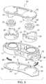
- FIG. 3is an exploded perspective view of the implant shown in FIG. 1 .
- FIG. 4Ais a top view of the implant shown in FIG. 1 .
- FIG. 4Bis a side cross-sectional view through line 4 B- 4 B of the implant shown in FIG. 4A .
- FIG. 5Ais a perspective view of a lower part of the implant shown in FIG. 1 with upper portions and bottom face removed.
- FIG. 5Bis a bottom view of the lower portion shown in FIG. 5A .
- FIG. 6Ais a perspective view of the upper portion of the implant shown in FIG. 1 with the lower portion removed.
- FIG. 6Bis an enlarged perspective view of the staircase-like lower lock support shown in FIG. 3 .
- FIG. 7is a partial side view of one of the locking mechanisms of the implant shown in FIG. 2 .
- FIGS. 8A-9Bare partial side views of the locking mechanism in FIG. 7 shown in different expanded and locked configurations.
- FIGS. 10A and 10B of the locking mechanismillustrate the expanded but unlocked configuration in FIG. 10A and the expanded and locked configuration in FIG. 10B .
- FIGS. 11A and 11Bare perspective views of the lower lock support and spring locking actuator illustrating the operation thereof.
- FIG. 11Cis a perspective view of an alternative locking mechanism and locking actuator embodying features of the invention.
- FIGS. 12A-12Care perspective views of alternative lower lock support designs embodying features of the invention.
- FIGS. 13A-13Bare perspective and side views respectively of an alternative implant embodying features of the invention which has an articulating top end plate.
- FIG. 14Ais an exploded perspective view of yet another alternative implant embodying features of the invention which has the lower lock supports within the extendable pistons.
- FIG. 14Bis a top view of the implant shown in FIG. 14A .
- FIG. 14Cis a side cross-sectional view through line 14 C- 14 C of the implant shown in FIG. 14B .
- FIG. 15is a perspective view of an alternative implant design having features of the invention wherein the locking mechanism surrounds a central opening in the top end plate.
- FIG. 16is a perspective view of an alternative implant design having features of the invention wherein the expanding piston is centrally located and locking mechanisms are provided on both sides of the expanding piston.
- FIG. 17is a simplified schematic illustration of an alternative implant design having ratchet and pawl locking members between the top and bottom plates of the implant.
- FIG. 18is a perspective view of an alternative implant design with ratchet and pawl locking members between the top and bottom plates of the implant.
- FIG. 19is a cross-sectional perspective view of an implant design with ratchet and cantilevered spring members between the top and bottom plates of the implant.
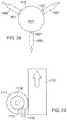
- FIGS. 20A-20B, 21A-21B, 22-26, 27A-27B, and 28-29schematically illustrate various means for locking an expanding member of implants in extended configurations embodying features of the invention.
- FIG. 30is a perspective view of yet another alternative implant design having features of the invention wherein the locking mechanism has straight upper and lower interfitting lock supports.
- FIG. 31A-31Gillustrate an alternative implant locking mechanism in which a wire-form surrounds a pair of upper support members with grooves configured to receive the wire-form.
- FIGS. 32A and 32Bare perspective views of a further alternative embodiment of the present invention including locking, conical bone engaging anchors.
- FIGS. 33A-Care perspective views showing alternative bone engaging anchors.
- FIGS. 34A and 34Bare perspective cross-sectional views of another alternative embodiment of the present invention including locking, screw-threaded bone engaging anchors.
- FIGS. 35A and 35Bare perspective views of yet another embodiment of the present invention including locking, telescoping bone engaging surfaces.
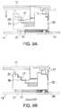
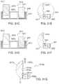
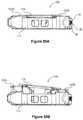
- FIGS. 36A and 36Bare cross-sectional views of another exemplary embodiment of the present invention shown in a collapsed and an expanded configuration respectively.
- FIG. 36Cis a posterior perspective view of the embodiment in FIG. 36B , shown in an expanded state.
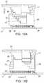
- FIGS. 37A and 37Bare end views of a lift mechanism according to a further exemplary embodiment of the present invention, shown in a collapsed and an expanded configuration respectively.
- FIGS. 38A and 38Bare end views of a cross section of another embodiment of the present invention utilizing the lift mechanism shown in FIGS. 37A and 37B , shown in a collapsed and an expanded configuration, respectively.
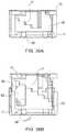
- FIGS. 39A and 39Bare top views of the respective embodiments shown in FIGS. 38A and 38B with the top plate removed.
- FIG. 40is an anterior perspective view of the embodiment shown in FIG. 38B .
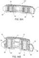
- FIG. 41is a posterior perspective view of still another exemplary embodiment of the present invention, shown in an expanded configuration.
- FIG. 42is a perspective view of a lift mechanism of the embodiment of FIG. 41 .
- FIGS. 43A and 43Bare cross-sectional views of the embodiment of FIG. 41 shown in a collapsed and an expanded configuration, respectively.
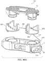
- FIG. 44is an exploded perspective view of another embodiment of the current invention.
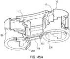
- FIG. 45Ais a partial inferior perspective of another embodiment of the present invention.
- FIG. 45Bis a partial top view of the embodiment shown in FIG. 45A .
- FIG. 46Ais an exploded perspective view of another embodiment of the current invention.
- FIGS. 46B and 46Care superior perspective views of the embodiment shown in FIG. 46A in the collapsed and expanded configurations respectively.
- FIG. 47is an exploded perspective view of another embodiment of the current invention.
- FIG. 48is an exploded perspective view of another embodiment of the current invention.
- FIG. 49is an exploded perspective view of another embodiment of the current invention.
- FIG. 50Ais a side view of an alternative implant design in a collapsed configuration having an articulating top plate.
- FIG. 50Bis a side view of the implant shown in FIG. 50A in an expanded configuration.
- FIG. 50Cis a top view of the implant shown in FIG. 50B .
- FIG. 50Dis a side cross-sectional through line 50 D of the implant shown in FIG. 50C .
- FIG. 51Ais a side view of an alternative implant in a collapsed configuration having an articulating top plate.
- FIG. 51Bis a side view of the implant shown in FIG. 51A in an expanded configuration.
- FIG. 52Ais a side view of an alternative implant in a collapsed configuration embodying features of the invention which has two separated top plates.
- FIG. 52Bis a side view of the implant shown in FIG. 52A in a slightly expanded configuration.
- FIG. 52Cis a side view of the implant shown in FIG. 52B in a more expanded configuration.
- FIG. 52Dis a side view of the implant shown in FIG. 52C in a fully expanded configuration.
- FIG. 52Eis a top view of the implant shown in FIG. 52D .
- FIG. 52Fis a side cross-sectional through line 52 F of the housing 111 of the implant shown in FIG. 52E .
- FIG. 53is a side view of an alternative implant design in a fully expanded configuration having two separated top plates.
- FIGS. 1-10Billustrate an example of an intervertebral implant 10 , a Selectively Expandable Cage (SEC), having features of the invention.
- the implant 10generally includes a housing 11 , a housing base 12 , an interlocking top end plate 13 , a bottom end plate 14 , an interior cavity 15 within the housing 11 and a pair of cylinders 16 .
- the top and bottom end platesare the bone engaging members of the implant, providing surfaces for engaging vertebrae above and below the implant when placed in the patient.
- Upper lock supports 17are attached to the underside of the top end plate 13 thus forming fixed lock members and have multi-stepped lower support surfaces 18 much like an inverted staircase.
- Lower lock supports 20having multi-stepped upper support surfaces 21 surround cylinders 16 much like an upright staircase.
- the multi-stepped support surfacesform the locking surfaces of the lock supports.
- Pistons 22are secured to the under surface of top end plate 13 .
- Seal members 23are slidably disposed within the cylinders 16 and are mounted on pistons 22 .
- the upper surface 24 of bottom end plate 14is provided with locking actuator channels 25 which partially receive spring locking actuators 26 .
- the base 12 of the housing 11has arcuate slots 27 which are configured to slidably receive the depending elements 28 or locking actuator transfer element of the lower lock supports 20 and partially receive the spring locking actuators 26 .
- Depending elements 28engage the forward end 30 of spring locking actuators 26 .
- the spring locking actuators 26are initially in a compressed configuration so that upon the extension of the top end plate 13 and the attached upper lock supports 17 , the lower lock supports 20 rotate about the cylinders 16 due to the force applied by the biased spring locking actuator 26 thus forming moveable lock members. This causes the lock support surfaces 21 of the lower lock supports 20 to engage support surfaces 18 of the upper lock supports so as to lock the top end plate 13 in an extended configuration.
- the support surfaces 18 of the upper lock supports 17 and the support surfaces 21 of the lower lock supports 20are tiered with multiple steps so that the implant 10 can be locked at several different expanded heights.
- the underside stepped support surfaces 18 of the upper lock support 17may be provided with increasing riser height (alignment faces 46 ) in the upward direction to provide smaller incremental expansion near the end of the piston expansion.
- the stepped support surfaces 21 of the lower lock support 20may be provided with decreasing riser height in the upward direction for the same reason.
- a variety of riser heights of the upper lock support 17 or lower lock support 20can be provided.
- the lowermost stepped support surface 18 of the upper lock support 17 and the uppermost stepped support surface 21 of the lower lock support 20may be provided with various lengths and widths to ensure better support.
- FIG. 2there are two sets of upper lock supports 17 attached to the top end plate 13 and there are two sets of lower lock supports 20 in this embodiment, but a single set or more than two sets of upper and lower lock supports can also be used to lock the implant 10 in the expanded state. Also shown, for example, in FIG. 2 are cylinders 16 and pistons 22 , which provide one example of extension means in embodiments of the present invention. Other examples of extension means are described herein below in connection with alternative embodiments of the invention.
- the implant 10is configured to be implanted between opposing vertebral bodies in the spine to facilitate bony fusion between those vertebral bodies.
- the implant 10is shown in its collapsed or contracted configuration in FIG. 1 and in one example of its expanded configuration in FIG. 2 .
- the implant 10can be inserted easily into the intervertebral body space through a minimal incision and with minimal tissue removal. Once in that space, the implant 10 can be expanded against the two opposing vertebral bodies to distract them and thereby restore height to the intervertebral space. This provides stable opposition of the implant 10 to both vertebral bodies and optimizes the bony fusion process.
- the fusion processcan also be enhanced by filling the interior cavity 15 with autologous bone graft, a bone growth enabling matrix, and/or bone growth stimulating substances prior to and/or after insertion into the body.
- FIGS. 3, 4A and 4BFurther details of individual parts of the implant 10 are depicted in FIGS. 3, 4A and 4B .
- Pistons 22are attached to the underside of the top end plate 13 which are configured to support seal members 23 which run inside of cylinders 16 located in the housing 11 .
- the seals 23 running inside the cylinders 16 and pistons 22 slidably disposed within the sealsare vertically displaced, translating the top end plate 13 vertically above the housing 11 .
- Lower lock supports 20are located around the outer wall of the cylinders 16 .
- the top end plate 13is vertically displaced, which in turn displaces the attached upper lock supports 17 , the lower lock supports are rotated by the biased locking actuators 26 to a locking position.
- Arcuate locking actuator channels 25 in the top surface of bottom plate 14 and the arcuate slots 27 in the housing base 12confines the locking actuators 26 to the housing 11 .
- the housing 11comprises an outer wall 31 and cylinders 16 which are secured to housing base 12 .
- the outer wall 31supports a leading nose 32 on the distal end and a delivery boss 33 on the proximal end.
- the leading nose 32has inwardly directed side tapered faces 34 and top tapered face 35 and bottom tapered face 36 . These tapered faces 34 , 35 and 36 enable non-traumatic insertion of the implant 10 past neural elements and between the vertebral bodies.
- the delivery boss 33contains a delivery tool anchor 37 which allows secure attachment of the implant 10 to a delivery tool (not shown), which is illustrated in co-pending application Ser. No. 11/535,432, filed Sep. 26, 2006, and Ser. No.
- the delivery boss 33also contains pressure input ports 38 which are used to deliver a pressurized fluid to the interiors of cylinders 16 .
- the outer wall 31 of the housing 11also provides side openings 40 which provide space for bony in-growth into central cavity 15 in the housing 11 and provide radiolucent openings for the radiographic imaging of the process of bony in-growth.
- the housing base 12also contains pressure channels 41 which deliver pressurized fluid from the pressure input ports 38 to the interior of cylinders 16 .
- the housing base 12 of implant 10is depicted with independent pressure channel 41 for each cylinder 16 , other embodiments can contain one or more branching pressure channels for delivering pressurized fluid to two or more cylinders 16 .
- the housing base 12also has locking actuator slots 27 which hold and guide the locking actuators 26 .
- the locking actuator slots 27contain a wider portion, locking actuator opening 42 , to enable insertion of the locking actuator 26 into the channels defined by the locking actuator slots 27 in housing base 12 and the locking actuator channels 25 in the bottom end plate 14 .
- the housing base 12also has optional alignment bosses 19 which align the bottom end plate 14 to the housing 11 via optional alignment holes 9 .
- FIGS. 6A and 6Billustrate further details of the top end plate 13 and the lower lock support 20 .
- the two sets of pistons 22 and upper lock supports 17are joined by connecting members or struts 44 .
- the pistons 22have seal bosses 45 on which the seals 23 are mounted.
- the upper lock supports 17have tiered lower support surfaces 18 and risers or alignment faces 46 .
- the tiered or stepped support surfaces 18 of the upper lock supports 17engage the stepped or tiered support surfaces 21 of the lower lock supports 20 .
- the alignment faces 46 of the upper lock supportare configured to engage the alignment faces 47 of the lower lock supports 20 .
- the uppermost support surface of the lower lock support 20has a lock support stop 50 which engages with the lower most alignment faces 46 of the upper lock support to prevent the lower lock support 20 from over rotating as it engages the upper lock support 17 .
- the bottom of the lower lock support 20also has the locking actuator transfer element 28 which engages the forward end 30 of the spring locking actuator 26 to transfer the actuation force from the locking actuator 26 to the lower lock support 20 .
- FIGS. 7 through 10Bshow details of the selectively expanding locking sequence of implant 10 with the housing 11 removed.
- the collapsed configurationis shown in FIG. 7 with the support surfaces 18 of the upper lock support 17 resting on the support surfaces 21 of the lower lock support 20 .
- the locking actuator 26is a biasing element, such as a spring, that engages the depending element or locking actuator transfer element 28 to urge the alignment faces of the lock supports in a direction where they contact.
- the alignment faces 47 of the lower lock supports 20are forced against the alignment faces 46 of the upper lock support 17 .
- the lock support stops 50fit within the lower lock stop relief 52 (shown best in FIG. 6A ) on the top end plate 13 .
- the pistons 22raise the top end plate 13 and attached upper lock supports 17 (straight arrow) moving the support surfaces 18 of the upper lock support 17 off of the support surfaces 21 and moving the lower alignment faces 46 past the upper alignment faces 47 .
- the locking actuators 26in this embodiment a compressed coiled spring engaging the locking actuator transfer element 28 force the lower lock supports 20 to rotate (curved arrow in FIGS. 8B and 9B ).
- the support surfaces 21 of the rotating lower lock supports 20move to the next lower level of the support surfaces 18 of the raised upper lock supports 17 until the alignment faces 47 of the lower lock supports 20 engage the next level of the alignment faces 46 of the upper lock supports 17 .
- the lower lock support 20 and upper lock support 17then lock the top end plate 13 at this expanded level. This process repeats itself at each locking level ( FIGS. 8A, 8B, 9A, 9B and 10A ) until the top level (or somewhere between) is reached as shown in FIG. 10B .
- the locking actuators 26engage the locking actuator transfer elements 28 and the lower lock supports 20 are rotated so the lowermost alignment surface 46 of the upper lock support 17 engages lock support stop 50 of the uppermost support surface 21 of the lower lock support 20 .
- the lowest support surfaces 18 of the upper lock supports 17 and the highest support surfaces 21are engaged providing all of the locking support.
- the lowest support surfaces 18 of the upper lock supports 17 and the highest support surfaces 21 of the lower lock supports 20can be wider than the other support faces to provide sufficient support material when only these two faces are engaged.
- FIGS. 11A and 11Billustrate the operation of locking actuator 26 .
- the spring locking actuator 26is compressed into an arc beneath the lower lock support 20 .
- One end of the spring locking actuator 26is constrained by the housing 11 (not shown) and the other is engaged with the locking actuator transfer element 28 .
- the locking actuator 26pushes against the locking actuator transfer element 28 and rotates the lower lock support 20 in a clockwise direction (arrow) as viewed from above.
- the angular orientation of the tiered upper and lower support surfaces 18 and 21can vary when there is more than one set of supports. As shown in FIG. 3 the proximal lower support surfaces 21 are oriented clockwise as viewed from above and the distal lower support surfaces 21 are oriented counter-clockwise. This opposite orientation provides enhanced locking support for rotational forces applied to the implant.
- FIG. 11CAn alternative locking actuator 26 a is shown in FIG. 11C as a torsion spring.
- This locking actuator 26 ahas constraining tab 53 secured to the lower lock support 20 and constraining tab 54 secured to the housing 11 .
- the torsion spring in FIG. 11Cdoes the same.
- An extension springwould work equally as well as a locking actuator 26 a .
- Spring actuatorscan be made of an appropriate biocompatible material such as stainless steel, NITINOL, titanium or a suitable polymer. Locking actuators are not limited to springs.
- a wide variety of mechanismscan be used to actuate the lower lock supports 20 , including but not limited to, a linear drive, an externally actuated tensile member, a worm gear, an inflated member such as a balloon or bellows, a magnet, a rotational drive such as a micro motor, a super elastic shape memory element, and the like.
- FIGS. 12A through 12Cshow variations of the lower lock support 20 described above.
- a tri-set lock support 20 ais shown whereby there are three sets of upper support surfaces 21 a , upper alignment surfaces 47 a and lock support stops 50 a rather than the two sets described above.
- This tri-set lower lock support 20 ahas two advantages over the two sets design, 1) there are three support columns rather than two locking the implant 10 in an expanded state thereby creating a more stable lock and 2) the tri-set lower lock support 20 a has to move or rotate much less for each locking level.
- This last advantageis significant when the locking actuator is a spring such as spring locking actuator 26 as this places less strain on the spring to achieve the required locking force at each step.
- Each lower lock support columnwill have a corresponding upper lock support column (not shown).
- the upper support surfaces 21 and lower support surfaces 18are not limited to two or three sets of surfaces. Any number of sets of support surfaces including a single set may be employed.
- FIG. 12Bshows an inter-digitating lower lock support 20 b .
- Each of the inter-digitating upper support surfaces 21 b on the inter-digitating lock support 20 bis paired with an inter-digitating stop 50 b which when paired with matching inter-digitating support surfaces and stops of an upper lock support (not shown) prevents the inter-digitating support surfaces 21 b from moving relative to the inter-digitating support surfaces of an upper lock support to unlock the implant without the inter-digitating lower support faces first lifting above the inter-digitating stop 50 b .
- This designprovides an enhanced locking feature.
- Upper alignment surfaces 47 bare again provided.
- the locking support 20 c shown in FIG. 12Cprovides an enhanced locking feature by providing inclined support surfaces 21 c which have a slope relative to the horizontal which requires matching inclined lower support surfaces on the upper lock supports (not shown) to be lifted above the inclined upper support surfaces 21 c before the upper lock support can be rotated to unlock the implant.
- FIGS. 12A and 12Cshow various lengths of locking actuator transfer elements or depending elements 28 .
- the locking actuator transfer element 28can vary in length depending on how much engagement is desired between the locking actuator transfer element 28 and the locking actuator slots 27 .
- the locking actuator transfer element 28includes one or more transfer element tabs 29 a and 29 c which vertically constrain the lower lock support 20 to the locking actuator slots 27 in the housing 11 .
- the wider locking actuator opening 42 described above(see FIG. 5B ) enables insertion of the locking actuator transfer element 28 with transfer element tabs 29 a and 29 c into the locking actuator slots 27 in housing base 12 at the rotational position where the locking actuator transfer element 28 is aligned with the locking actuator opening 42 .
- the transfer element tabsare constrained by lateral extensions on the sides of the narrower locking actuator slots 27 .
- the locking actuator transfer element 28provides both the function of transferring force from the locking actuator 26 to the lower lock support 20 as well as constraining the lower lock support 20 to the housing 11 .
- This later functionprevents the frictional forces between the lower alignment faces 46 and the upper alignment faces 47 created by the biased spring locking actuator 26 from lifting the lower lock support 20 along with the upper lock support 17 when the upper lock support 17 is lifted by the piston 22 .
- FIG. 12Bdepicts a locking actuator guide channel 80 .
- This locking actuator guide channel 80engages a tensile member (not shown) which transfers actuation force from the locking actuator 26 to the lower lock support 20 .
- Tensile memberscan be any of a number of known elements such as sutures made of polymers or natural materials, metal cable, plastic or metal rod and the like.
- FIGS. 13A and 13Billustrate an alternative design of an implant 110 embodying features of the invention.
- the implant 110has independent actuation of the distal piston 122 a and proximal piston 122 b .
- the two pistons 122 a and 122 bare interconnected by an articulating top end plate 113 which allows independent lift and locking of each side of the implant 110 .
- This independent lift and locking of both ends of the implant 110enables the implant to conform to intervertebralend plates that have uneven lateral heights between them. Further, this independent lift and locking allows the implant 110 to be used to create varying lateral heights between vertebralend plates which can be useful to compensate for a scoliosis in the spine.
- Implant 110has a housing 111 which has an alternative delivery tool anchor 160 located in it as well as alternative pressure input ports 137 .
- a variety of anchor designs or pressure portscan be used with any of the embodiments of the current device without departing from the scope of this invention.
- Lock and unlock access ports 138are also located on this housing 111 . These ports are used to guide lock and unlock mechanisms (not shown) which can be manipulated externally to the implant 110 to actuate the lower lock support 120 to not only move it under the upper lock support 117 to hold the piston 122 b and articulating end plate 113 in an expanded position, but also to move the lower lock support 120 away from the upper lock support 117 to allow the piston 122 b and articulating end plate 113 to collapse back into the housing 111 .
- lock/unlock mechanismscan be used with the current invention such as but not limited by, a tensile member including suture thread and metallic cable, a compressive member such as a metallic or polymer rod, pressurized fluid, a rotating drive, a super elastic shape memory element, and the like.
- FIGS. 14A-14Cdepict yet another alternative implant 210 that embodies features of the invention.
- Implant 210has an interfacing top plate 213 which connects to separate and freely rotating pistons 222 via the piston capture plate 270 on the interfacing top plate 213 and the piston heads 271 on the rotating pistons 222 ab .
- the rotating pistons 222 abalso interiorly contain upper lock supports 217 with support faces 218 and alignment faces 246 .
- Seals 223are mounted on the rotating pistons 222 ab and the seals 223 and rotating pistons 222 ab fit into internal cylinders 216 that are located on the housing 211 .
- the internal cylinders 216have lower lock supports 220 with support surfaces 221 and alignment faces 247 as well as lower retaining features 273 .
- the housing 211also contains one or more pressure input ports 238 .
- the implant 210is inserted into the intervertebral body space in a collapsed state and fluid pressure is delivered through the pressure input port(s) 238 to the internal cylinder(s) 216 to raise the seal(s) 223 and rotating piston(s) 222 ab out of the internal cylinder(s) thereby raising the interfacing top plate 213 and expanding the implant 210 .
- an actuatorrotates the rotating pistons 222 ab such that the lower support surfaces 218 of the upper lock supports 217 are moved above the upper support surfaces 221 of the lower lock supports 220 , to thereby lock the implant 210 in the expanded configuration.
- the actuatorcan be one or more tensile members such as suture threads or cables that extend from the user into the implant 210 through the lock and unlock access ports 238 on the interfacing top plate 213 to the piston head 271 .
- Applying tension to one or more tensile members when the piston is in an extended configurationwill rotate the piston heads 271 such that the support surfaces 218 of upper lock supports 217 are moved above the support surfaces 221 of the lower lock supports 220 thereby locking the implant 210 .
- applying tension to one or more tensile memberswill rotate the piston heads 271 such that the lower support surfaces 218 are moved away from the upper support surfaces 221 thereby unlocking the implant 210 and allowing the rotating pistons 222 ab to seat back into the internal cylinders 216 such that the implant 210 is once again in a collapsed configuration.
- FIG. 15illustrates an alternative implant design 310 embodying features of the invention which has a housing 311 , top end plate 313 and pistons 322 similar to the prior embodiments.
- This implant 310has upper lock supports 317 and lower lock supports 320 within a central portion of the implant.
- the upper lock supports 317are secured to the top end plate 313 and the lower lock supports 320 are secured to the base 314 with depending elements (not shown) as was described above and are moved as in the prior embodiments.
- FIG. 16illustrates an alternative implant design 410 embodying features of the invention which has a housing 411 , top end plate 413 and a centrally located piston 422 similar to the prior embodiments.
- This implant 410has upper lock supports 417 and lower lock supports 420 distal and proximal to the centrally located cylinder 416 and piston 422 .
- the upper lock supports 417are secured to the top end plate 413 and the lower lock supports 420 are secured to the base 412 and are moved as in the prior embodiments via depending elements (not shown) as was described above.
- FIG. 17shows another alternative implant 510 which has a pair of pistons 522 and which has a locking support system which includes ratchets 521 on the base 512 and pawls 517 pivotally mounted to and depending from the top end plate 513 . Expansion of the pistons 522 causes the free ends 518 of pawls 517 to engage recesses 520 in the ratchets 521 so as to lock the top end plate 513 in an extended configuration.
- FIG. 18illustrates another alternative implant design 610 which is similar to that shown in FIG. 17 .
- the free end of the pawl 617has a plurality of teeth 618 to provide greater effective contact between the pawl 617 and the ratchet 621 for locking of the implant 610 .
- FIG. 19is a cross section embodiment, showing implant 710 embodying features of the invention.
- the pistons 722are surrounded by upper lock support 717 which has at least one cantilever extension ending at the support surface 718 .
- the support surfaces 718are captured by the recessed support surfaces 721 which are located on the inner wall of the housing 711 .
- the support surfaces 718 of the upper lock support 717engages the recessed support surfaces 721 locking the implant 710 in place.
- the upper lock support 717can be rotated relative to the piston 722 and housing 711 to disengage the support surfaces 718 from the support surfaces 721 to unlock the implant 710 and lower the pistons 722 as needed.
- the implant 710can be unlocked by rotating the upper lock support constraints 775 relative to the upper lock support 717 to press on the cantilever extensions and disengage the support surfaces 718 from the support surfaces 721 .
- FIGS. 20A-31illustrate a variety of suitable means for locking extendable members such as pistons in extended configurations.
- FIGS. 20A, 20B, 21A, 21B, and 22-31show variations of lower lock supports and upper lock supports. In each of these variations there are support surfaces on the lower lock supports which engage support surfaces on the upper lock supports.
- support surfaces 818comprise grooves set into the upper lock support 817 .
- the lower lock support 820is a U-shaped tong which is configured to advance (as indicated by the arrow in FIG. 20A ) towards the upper lock support 817 and to engage one of the grooves with its upper support surface 821 for locking an implant not shown in these drawings.
- Lower lock support 820is withdrawn (as indicated by the arrow in FIG. 20B ) from the groove to disengage the lower lock support and unlock the implant.
- the lower lock support 920is a plate with an upper lock clearance opening 970 that is shaped to allow passage of the cylindrical flat-sided upper lock support 917 through the lower lock support 920 (arrow).
- FIG. 21Bonce the lower lock support 920 is positioned at the desired location it can be rotated approximately 90° (arrow) to engage the support surfaces of the lower lock support 920 with the support surfaces 918 of the upper lock support 917 .
- the shape of the upper lock support 917 and mating upper lock clearance opening 970 on the lower lock support 920are not restricted to the profile shown in FIGS. 21A and 21B nor is the locking actuation restricted to 90° rotation of one of the elements but can vary to any number of shapes that allow passage in one configuration but constraint when one of the elements is moved to another configuration.
- the upper lock support 1017is a cylinder with notches cut to create support surfaces 1018 .
- the lower lock support 1020is a pivoting pin 1070 with a pawl 1071 for the lower support surface 1021 .
- the support surfaceis biased as indicated by the arrow 1072 to allow the upper lock support 1017 to rise with an expandable member of an implant and to prevent the upper lock support from dropping. This allows the device to lock at each level when the subsequent support surface 1018 of the upper lock support 1017 engages the support surface 1021 of the lower lock support 1020 .
- the upper lock support 1017can also be lowered by moving the pivoting pin 1070 of the lower lock support 1020 away from the upper lock support 1017 to disengage the support surface 1021 from the support surface 1018 .
- FIG. 23shows yet another embodiment having features of the invention where the lower lock support 1120 is a pin configured to engage (arrow) support surfaces 1118 located in the upper lock support 1117 .
- the lower lock support 1120does not have to engage the full thickness of the upper lock support 1117 as shown in this figure, nor does the support surface 1118 have to extend through the entire thickness of the upper lock support 1117 but rather can engage any portion of the upper lock support 1117 that is sufficient to lock an implant in position.
- This embodimentalso allows a variety of shapes of pins 1120 and matching support surfaces 1118 .
- the lower lock support 1220is a grip with two pivoting jaws 1270 , the ends of which have support surfaces 1221 .
- the upper lock support 1217has a series of notches which have the support surfaces 1218 .
- a lock actuatorsuch as a compressive spring (not shown) can apply force (as shown by the arrows 1272 ) to the grip base extensions 1273 to lock the device.
- This variationhaving features of the invention allows the upper lock support 1217 to move upwards but prevents downward motion thereof. Downward motion of the upper lock support 1217 can be allowed by reversing the force on grip base extensions 1273 .
- the upper lock support 1317has one or more flat surfaces as the support surfaces 1318 .
- the lower lock support 1320has one or more pivoting pawls that have a support surface 1321 that engage the support surface 1318 and supports a load (arrow).
- the upper lock support 1417has an exterior support face 1418 which is gripped by the support face 1421 on the inner diameter of the wrapped lower lock support 1420 .
- This lower lock support 1420can be a torsion spring that in its free state grips the upper lock support 1417 and releases the upper lock support when a force (arrows) is applied to one or more of its ends 1470 as shown to increase the spring's inner diameter. The reverse is possible where in its free state the lower lock support 1420 allows movement of the upper lock support 1417 inside the inner diameter. When a tensile force is applied to the ends 1470 to reduce the inner diameter, the lower lock support grips the support surface 1418 of the upper lock support 1417 to lock the implant.
- FIGS. 27A and 27Bshow another variation which can be described as a canted washer type device.
- the lower lock support 1520is a plate with an upper lock clearance opening 1570 which allows relative movement of the upper lock support 1517 as shown in FIG. 27A .
- the edge of the upper lock clearance opening 1570comprises a lower support surface 1521 which engages the upper support surface 1518 which is the outer surface of the upper lock support 1517 locking it relative to the lower lock support 1520 .
- FIG. 28Yet another variation of the gripping lock of the current invention is shown in FIG. 28 .
- the lower lock support 1620comprises one or more jaws which have support surfaces 1621 that are configured to be forced against the support surface 1618 of the upper lock support 1617 to produce friction to lock the device in place.
- FIG. 29illustrates a lower lock support 1720 which comprises a pivot and pawl as has been detailed above.
- the end of the pawlcomprises a lower support surface 1721 which engages an upper support surface 1718 on the upper lock support 1717 .
- the upper lock support 1717is rotated counter clockwise by an expanding element (not shown). This rotation in turn raises the piston 1722 which expands the implant. In this manner the upper lock support 1717 is integrated into the lifting mechanism to engage the lower lock support 1720 and lock the implant as it expands.
- FIG. 30illustrates yet another alternative implant 1810 , similar to that shown in FIG. 1 except that the upper locking member 1817 and lower locking member 1818 have a linear shape rather than the arcuate shape of the prior embodiments.
- the implant 1810generally has a housing 1811 , a top plate 1813 , a bottom plate 1814 , pistons 1822 and cylinders 1816 .
- the upper locking member 1817has support surfaces 1818 and the lower locking member 1820 has support surfaces 1821 .
- the implant 1810has a locking actuator (not shown).
- FIGS. 31A-31Gillustrate another implant 1910 embodying features of the invention which have upper locking members 1917 with grooves 1970 having support surfaces 1918 and lower locking member 1920 with locking surfaces 1921 .
- the lower locking member 1920is a wire-form which encircles the exterior of both upper locking members 1917 and is configured to seat within the grooves 1970 . Expansion of the lower locking member 1920 (arrows in FIG. 31B ) by the locking actuator (not shown) causes the lower locking member 1920 to be pulled out of the groove 1970 and allows the upper locking member 1917 to rise with the expansion of the implant. Release of this expansion of the lower locking member 1920 (arrows in FIG. 31A ) allows the lower locking member 1920 to seat back into the groove 1970 locking the implant 1910 .
- FIG. 31Gillustrates a detail of an alternative implant 1910 a embodying features of the invention which have upper locking members 1917 a with grooves 1970 a having support surfaces 1918 a and lower locking member 1920 a with locking surfaces 1921 a .
- the lower locking member 1920 ais a wire-form which encircles the exterior of both upper locking members 1917 a and is configured to seat within the grooves 1970 a .
- the support surface 1918 alocks on the support surface 1921 a when there is a compressive or downward force (hollow arrow) on the upper locking member 1917 a locking the implant 1910 a .
- Upward force or extension (solid arrow) of the upper locking member 1917 acauses the lower locking member 1920 a to ride on the disengaging surface 1919 a and out of the groove 1970 a allowing the upper locking member 1917 a to rise with the expansion of the implant 1910 a.
- a piston/cylinder and locking arrangement as described abovemay be used to deploy extendable bone anchors.
- implant 10 A with conical bone engaging anchors 60 as shown in FIGS. 32A and 32Bmay be constructed with pistons 22 and cylinders 16 as described above in connection with implant 10 and shown, for example, in FIGS. 2, 3 and 4B .
- Implant 10 Ahas a housing 11 as previously described and may include other previously described features such as interior cavity 15 for bone growth stimulating substances.
- the two pistons 22instead of upper interlocking end plate 13 , individually terminate with conical bone engaging anchors 60 .
- the bone engaging anchors, including sharp leading tip 62form surface for engaging the vertebral body.
- bone engaging anchors 60are in a contracted configuration, within housing 11 , to facilitate insertion of implant 10 A.
- bone engaging anchors 60are moved to an extended configuration as shown in FIG. 32B , wherein at least leading tip 62 extends beyond housing 11 to engage and anchor in the bone.
- locking mechanismsincluding multi-stepped upper and lower lock supports 17 , 20 as previously described in connection with implant 10 and shown, e.g. in FIGS. 6A-12C , are provided to support each anchor 60 in the extended configuration. With this arrangement, the extended and locked anchor 60 helps to retain the implant in place.
- implant 10 B in FIG. 33Aincludes bone engaging anchors formed as spike 60 A and blade 60 B.
- Blade 60 Bcan be particularly effective in preventing motion along the insertion path after deployment.
- the length of the blade 60 Bis aligned in the direction shown by arrow A. This is substantially orthogonal to the direction of implantation (arrow B) and would resist movement in that direction.
- Implant 10 F, shown in FIG. 33Bincludes further possible variations.
- the bone engaging anchorsare formed as barbed spikes 60 C.
- lateral anchor 63for anchoring in laterally oriented tissue.
- lateral anchor 63includes a plain spike 60 A.
- Lateral anchor 63is formed in the same manner and with the same components, i.e. piston, cylinder, locking mechanism, etc. as elsewhere described in this application, except that the components are oriented laterally as shown.
- housing 11includes a central member 11 A that divides interior cavity 15 into two portions.
- FIG. 33Cshows a further alternative implant 10 G, including anchors 65 extending obliquely from housing 11 , rather than orthogonally. This oblique arrangement is helpful in resisting side to side rotational forces (for example when the patient/spine bends towards the side) and expansion forces.
- obliquely extending anchors 65are essentially identical to other bone engaging anchors described herein except for the oblique orientation.
- holes 68are provided in top end plate 66 for the spikes to pass through.
- bone engaging anchors according to embodiments of the inventionshould have a relatively small termination (e.g.
- implant 10 Cincludes screw-threaded members 64 as bone engaging anchors.
- Implant 10 Calso illustrates a further alternative wherein the bone engaging surfaces, such as the anchors, extend from opposite sides of the implant.
- interlocking end plate 13is replaced with an integrated top end plate 66 .
- Holes 68are provided for threaded member 64 to pass through. Persons of ordinary skill in the art will appreciate that holes 68 will be located as needed; in the illustrated embodiment one is in top end plate 66 and the other in bottom end plate 14 .
- Threaded members 64as bone engaging anchors extend outwardly from pistons 22 .
- the inner wall of housing 11is provided with a screw-threaded surface 70 that mates with corresponding threads 71 cooperating with pistons 22 .
- seals 23act between the pistons 22 and cylinders 16 to prevent leakage of hydraulic fluid.
- locking mechanismsas previously described and shown, for example, in FIGS. 6A-12C , may be employed to prevent the bone engaging anchors from becoming unengaged from the bone.
- upper and lower lock supports 17 , 20are visible around the outside of the piston and cylinders.
- use of a separate locking mechanismmay not be required.
- the configuration of the threads alonemay be sufficient to prevent the anchors from backing out.
- FIGS. 35A and 35Billustrate a further aspect of the present invention wherein locking mechanisms as described are utilized to secure telescoping bone engaging surfaces in place.
- telescopingrefers to nested, extendable members including at least one intermediate member between a base and bone engaging member.
- implant 10 Dhas substantially planar bone engaging members 72 .
- Bone engaging members 72are thus similar to the bone engaging members of implant 10 , but instead individually actuated without interlocking end plate 13 .
- the piston/cylinder arrangementis also similar to that previously described except that here upper piston 74 is received in intermediate piston 80 .
- Intermediate pistonis in turn received in cylinder 16 as was previously described for piston 22 .
- Upper piston 74is sealed against intermediate cylinder 78 of intermediate piston by upper piston seals 76 (see FIG. 35B ).
- the telescoping bone engaging members 72are secured by locking mechanisms in a similar manner to the earlier described embodiments, with the addition of an upper lock support 82 for the upper piston.
- Intermediate piston 80is supported by upper lock support 17 and lower lock support 20 as previously described.
- Upper lock support 82includes upper and lower lock supports 84 , 86 .
- upper piston 74is secured to upper lock support 84 of the upper lock set.
- Lower lock support 86 of the upper lock setis mounted on top of upper lock support 20 of the lower lock set.
- One difference from the earlier described embodimentsis that separate spring actuators 26 are not required for the upper lock set as they may be rotated along with the lower lock set by actuators 26 .
- Implant 10 Eas shown in FIG. 35B includes a further variation in which the planar portion of upper bone engaging surface 88 is effectively annular with a conical anchor 90 at the center.
- Advantages of embodiments of the present invention including bone engaging anchorsinclude the ability of the anchors to be extended lateral from the long axis of the implant (i.e., the insertion axis) with a relatively high force using the relatively small connection to the implant of the hydraulic line. This is an advantage over other methods that require larger access or larger connections to the implant for lager tools or non-hydraulic extension forces to extend the anchors into the hard, bony tissue.
- FIGS. 36A-Can alternative embodiment of the present invention comprising implant 10 F is shown wherein a pair of bellows 92 replaces the piston and cylinder pairs previously described. One end of bellows 92 is attached to housing 11 and the other end to top end plate 13 . A pressurized fluid added via pressure input ports 38 is directed through bellows orifice 94 into the inside of bellows 92 causing the bellows to expand.
- Bellows 92can be made of any biocompatible material such as the 316 series of stainless steels, titanium or a titanium alloy, a cobalt chromium alloy, or an implantable polymeric material.
- the bellowscan be of an accordion-like folding configuration as shown in FIGS. 36A-C or any other regular or irregular configuration which can fit inside of the housing and lock supports in the collapsed configuration and expand sufficiently when pressurized to lift top end plate 13 the desired amount away from housing 11 .
- Lower lock supports 20 and upper lock supports 17provide a confining geometry for bellows 92 , which allows use of an irregular bellows configuration. With a bellows arrangement as shown in FIGS. 36A and 36B , the amount of lift is not limited as is the case in a cylinder and piston to the amount that the collapsed cylinder and piston overlap.
- FIGS. 37A and 37Bshow an alternative rotating cam lift mechanism 93 .
- Cam lift mechanism 93includes cam 96 with a substantially curved cam surface 95 and a substantially flat top surface 97 , rotating shaft 98 , and shaft supports 99 .
- Cam 96is attached to rotating shaft 98 , and shaft 98 is supported by and rotates within shaft supports 99 .
- the shaft supports 99are anchored to the inside of housing 11 and rotation of shaft 98 (depicted by curved arrows) rotates the curved cam surface 95 against the bottom of top end plate 13 and moves top end plate 13 away from housing 11 as shown in FIGS.
- cam 96determines both the amount of lift that is possible and the relative amount of lift to the amount of rotation of the cam.
- the camis not limited by 90 degrees of rotation depicted in the figures. Any shape of a cam that is rotated by any amount from as little as 10 degrees to as much as 355 degrees is possible without departing from the scope of the present invention. Shaft rotation can be accomplished by several means as will be discussed in more detail below.
- Use of cam lift mechanism 93 as the lifting mechanism along with lower and upper locking supports 20 and 17 for implant 10 Gallows the lift mechanism to support only the initial lifting loads and not have to support the repetitive long-term supporting loads on implant 10 G which are borne by the locking supports.
- Cam 96does not require a substantially flat top surface 97 as shown in the exemplary embodiment to support top end plate 13 , but such a surface provides a rotational endpoint for the surgeon rotating shaft 98 .
- Implant 10 Huses a rotating screw lift mechanism 193 as shown in FIG. 42 .
- This mechanismincludes shaft 98 , shaft supports 99 , worm gears 170 attached to shaft 98 and a shaft input end 178 at one end of shaft 98 .
- the mechanismalso includes lift screws 172 , which have lower lift threads 174 and transfer gear 176 and supporting boss 186 . Applying a torque via shaft input end 178 turns shaft 98 , which turns the attached worm gears 170 . Worm gears 170 turn transfer gear 176 on lift screw 172 .
- Lift screw 172is contained within housing 11 by way of its supporting boss 186 , which is seated in housing bearing 188 .
- Rotation of lift screw 172transfers force from lower lift threads 174 to upper lift threads 182 on upper lift nut 180 .
- Upper lift nut 180is attached to top end plate 13 so that rotation of shaft input end 178 lifts upper end plate 13 away from housing 11 .
- the relative pitch of worm gears 170 and matching transfer gears 176 and the lower lift threads 174 and matching upper lift threads 182can be varied to achieve the desired amount of lift relative to the amount of rotation and torque.
- the torquecan be applied by any means well known by those skilled in the art including but not limited to electric motor, pneumatic or hydraulic turbine, or manual rotation of an actuator.
- Shaft input end 178is shown as a hexagonal post, but any alternative input end can be used without departing from the scope of the present invention, such as, but not limited to, a square or star-shaped post, a square, star or hexagonal-shaped socket, or a keyed shaft.
- an alternative embodiment of the implant 10 Iincludes a linking element 202 that connects the lower lock supports 20 A and 20 B.
- the linking element 202coordinates the action of the lower lock supports 20 A and 20 B.
- the locking actuator 26actuates the leading lower lock support 20 A
- the linking element 202in turn actuates the following lower lock support 20 B.
- the implant 10 Imay require only a single locking actuator 26 , however plural locking actuators as described above (see, for example, FIG. 3 ) may be employed for greater actuation force as needed.
- the linking element 202prevents the leading lower lock support 20 A from actuating until the alignment faces 46 of both the leading upper lock supports 17 A and the following upper lock supports 17 B each clear the alignment faces 47 of both the leading lower lock support 20 A and the following lock support 20 B. In this manner the linking element 202 ensures the coordinated actuation of the lower lock supports 20 A and 20 B to ensure that the implant 10 I will always lock at the same height on both sides. This can be advantageous for certain implants placed in the spine where an even expansion of the implant is desired.
- Linking plural lower lock supports, such as supports 20 A and 20 B, with a linking element 202 for even expansion in the manner describedmay be advantageous over an implant with a similarly sized single lock support 20 , and single cylinder 16 and piston 22 due to the increase in the number of support elements, the broader support base, and the increase in expansion force due to the increased number of cylinder and piston pairs.
- Increasing the size of a single lock supportwould still have disadvantages of a larger width that would limit the ability for implantation in minimally invasive surgery.
- Embodiments of the inventionare not limited to just the pair of lower locking supports 20 A and 20 B as shown in, for example, FIG. 33 . Rather, any number of sets of cylinders 16 , pistons 22 , upper lock supports 17 , and lower lock supports 20 , with a locking actuator 26 and the appropriate number of linking elements 202 are possible.
- linking element 202is configured to fit inside attachment grooves 204 on the lower lock support 20 A, B.
- linking element 202may be configured to rest on the outside diameter of the lower lock support 20 A, B.
- the linking element 202can also be configured to run underneath the lower lock supports 20 A, B as shown in FIGS. 45A-D .
- both of the lower lock supports 20 A and 20 Brotate in the same direction when actuated.
- Elements of an alternative implant shown in FIGS. 45A-Binclude lower lock supports 20 that actuate with rotation in opposite directions.
- the linking element 202is guided between the lower lock supports 20 through a link channel 210 in housing 11 ( FIG. 45B ).
- the linking element 202is constrained in the link channel 210 by a channel cover 208 .
- the linking element 202is connected to the lower lock supports 20 by means of link pins 206 .
- the linking elementcan be made from any of a variety of implantable materials including: a titanium wire, a titanium cable, a stainless steel wire or cable, a nitinol wire, a braided or mono-filament suture from any manner of suture material such as silk, polyester, polypropolyene, ePTFE, or UHWPE.
- An implantable materialthat has a tensile strength sufficient to transfer the actuation force from the leading lower lock support 20 A to the following lower lock support 20 B as well as flexibility sufficient to follow the link channel 210 and/or rotate around the lock supports 20 may be used.
- Linking element 202can be attached to the lower lock supports 20 in a number of ways known to those practiced in the art, the selection of which depends on factors such as the linking element material and the lower lock support material. Suitable techniques include laser welding, resistance welding, adhesive bonding, crimping, attaching with clamps, pins, or screws, or being threaded through an opening and securing with a knot.
- Unlocking tether 212is attached to the following lower lock support 20 B in attachment groove 204 .
- Unlocking tether 212is attached in the opposite direction as the linking element 202 and can be attached in any of the ways described above for attaching the link element 202 .
- the proximal end 214 of the unlocking tether 212exits the housing 11 of the implant 10 J through the unlock port 216 .
- the proximal end 214can be actuated by an external force or mechanism (not shown).
- Actuation of the proximal end 214 of the unlocking tether 212 to translate it away from the implant 10 Jcauses rotation of the following lower lock support 20 B, which will tension and translate the linking element 202 which will rotate the leading lower lock support 20 A.
- the unlocking tether 212can be used to unlock the implant 10 J so that it can collapse to a lower or to its original height.
- FIG. 46Bthe implant 10 J is collapsed and the unlocking tether 212 is extended a maximum distance out of the unlock port 216 .
- FIG. 46Cshows the same implant 10 J with the top plate 13 fully expanded above the housing 11 and locked.
- the unlocking tether 212has shortened as it was drawn into the implant 10 J as the lower lock supports 20 rotated into locking position.
- Tensioning or pulling on the unlocking tether 212will unlock the lower lock supports 20 and allow the top plate 13 to collapse back into the housing 11 .
- the ability to unlock and collapse the implant 10 Jcan be highly advantageous to a physician placing the device if there is a need to reposition or replace the device after it has been expanded in-vivo.
- FIG. 47another embodiment of an implant 10 K is shown with lower lock supports 20 that are located inside the cylinders 16 of the housing 11 .
- the linking element 202is a solid bar that can transfer compressive as well as tensile loads.
- the locking actuator 26rotates the leading lower lock support 20 A, which pushes on the linking element 202 .
- the linking element 202in turn pushes and rotates the following lower lock support 20 B.
- the lower lock supports 20 A and 20 Bengage the upper lock supports 17 that are located inside the pistons 22 (shown in FIG. 14C ).
- the rotation of the following lower lock support 20 Bpulls the unlocking tether 212 into the housing 11 through the unlocking port 38 .
- the unlocking tether 212can be tensioned away from the housing 11 to reverse the process and unlock the implant 10 K.
- FIG. 48an alternative embodiment of the implant 10 L is shown wherein thread gears 226 A and 226 B are used to both lock and unlock the lower lock supports 20 thus forming a combined linking and unlocking element.
- Threaded gears 226 A and 226 Bare mounted on a shaft 224 that is contained in the base of the housing.
- the proximal end of shaft 224has a keyed head 228 that can protrude from or rest in the locking port 222 .
- An external tool(not shown) can interface with the keyed head 228 to rotate it in either direction.
- Rotating the keyed head 228will in turn rotate the shaft 224 and the threaded gears 226 A and 226 B.
- the threaded gears 226 A and 226 Btransfer the force to the lower lock supports 20 through the geared bottom face 220 .
- the threaded gear 226 Ais oriented opposite of the threaded gear 226 B. This allows rotation of the shaft 224 to rotate the lower lock supports 20 in opposite directions relative to each other.
- the threaded gears 226 A and 226 Bcan be oriented in the same direction if it is desired to rotate the lower lock supports 20 in the same direction. In either case the shaft 224 can be rotated in one direction to rotate the lower lock supports 20 in the locking direction, and the shaft 224 can be rotated in the opposite direction to rotate the lower lock supports 20 in the unlocking direction.
- An unlocking tether as described hereincan be engaged and tensioned by any number of means including but not limited to gripping the unlocking tether between articulating grips, a collet or split ring clamp, crimping the unlocking tether to a tensioning wire or rod and cutting the unlocking tether to disengage after use, mounting a magnet on the proximal end 214 ( FIG.
- unlocking tether 46Aof the unlocking tether and engaging the magnet with a mating magnet attached to a tensioning wire of rod, adding a female or male thread to the proximal end 214 or the unlocking tether and engaging it with a mating thread on the end of a tensioning rod or wire, or providing a continuous unlocking tether all the way to the point external to the body for tensioning and then cutting the unlocking tether near the implant after use to disengage.
- the unlocking tethercan alternatively be pushed or compressed rather than tensioned as long as it is configured to rotate the lower lock supports 20 A and B in the unlock direction and deliver sufficient load without buckling when pushed.
- FIG. 49illustrates an alternative embodiment of an implant 10 M with a pushable unlocking tether 212 a .
- unlocking tether 212 aengages the proximal lower lock support 20 B to rotate it in the unlock direction when the unlocking tether 212 a is advanced towards the proximal lower lock support 20 B.
- the link 202transfers that rotation from the following lower lock support 20 B to the leading lower lock support 20 A.
- the link 202contains engagement pins 230 , which extend into receiving slots 232 on the lower lock supports 20 A and 20 B in order to transfer the lateral movement of the link 202 into rotation of the lower lock supports 20 A and 20 B.
- the unlocking tether 212can contain an engaging pin (not shown) to extend into a receiving slot (not shown) on the following lower lock support 20 B to transfer the lateral compressive force applied to the unlocking tether 212 a into rotation of the lower lock supports 20 B.
- This is just one method for attaching or engaging the unlocking tether 212 to the lower lock support 20the numerous methods previously described herein for attaching or engaging the link 202 to the lower lock supports 20 can be used for attaching or engaging the tether 212 as well.
- Unlocking tether 212 awhich is pushed to unlock the implant 10 M can be contained within the implant 10 M and a push rod (not shown) can be easily directed into the implant 10 M through the unlock port 216 to actuate the unlocking tether 212 a and unlock the implant 10 M such that it can collapse. This eliminates the need to attach to the unlocking tether 212 a which is required when the unlocking tether 212 a is tensioned to unlock the implant 10 M.
- FIGS. 50A-Dillustrate an alternate embodiment of the implant 10 N embodying features of the invention. Similar to the implant 110 as shown in FIGS. 13A and 13B , the top end plate 113 of the implant 10 N articulates relative to the distal piston 122 A and proximal piston 122 B. The ends of the articulating top plate 113 have spherical projections 2001 A and 20001 B which are contained within mating pockets 2002 A and 2002 B in the two pistons 122 A and 122 b . Split rings 2006 A and 2006 B are placed over the spherical projections 2001 A and 20001 B and into the pistons 122 A and 122 B to vertically constrain the articulating top plate 113 to the pistons.
- This geometryprovides articulation of the top plate 113 along not only the long axis (the axis extending along the line 50 C in FIG. 50C ), as with the implant 110 shown in FIGS. 13A-B , but also provides articulation in a side-to-side direction, which is an advantage for providing congruence of the implant to the intervertebral space.
- the articulating top plate 113is polyaxially movably coupled to the pistons 122 A and 122 B, allowing the plate 113 to articulate about at least two axes.
- FIG. 50DAlso shown in FIG. 50D are vertical constraints 2003 A and 2003 B which are attached to the distal piston 122 A and proximal piston 122 B. These two constraints 2003 A and 2003 B fit inside channels 2004 A and 2004 B in the housing 111 . The top portion of the channels 2004 A and 2004 B have a narrowed portion 2005 A and 2005 B that prevent the vertical constraints 2003 A and 2003 B from advancing out of the housing 111 . In this manner these vertical constraints 2003 A and 2003 B limit the maximum vertical movement of the pistons 122 A and 122 B relative to the housing 111 .
- FIGS. 51A-Billustrate another alternative embodiment.
- FIGS. 51A-Billustrate an implant 10 P that can have features similar to features in the embodiments illustrated in FIGS. 13A, 14A -C, and 49 .
- the implant 10 Phas the articulating top plate 113 similar to that shown in FIG. 13A which pivots relative to the distal piston 122 A and proximal piston 122 B about a distal pivot pin 2101 A and a proximal pivot pin 2101 B.
- the implant 10 Phas a distal piston 122 A and a proximal piston 122 B.
- the pistons 122 A and 122 Bcan have internal upper lock supports 217 .
- the pistons 122 A and 122 Bdo not rotate relative to the housing 111 as is the case in the implant 210 . Instead, lower lock supports 20 A and 20 B similar to those shown in FIG. 49 rotate relative to the housing 111 and the two pistons 122 A and 122 B to lock the height of the expanded implant. In this manner, benefits of several of the previously described embodiments are combined to provide and implant 10 P that can lock at different distal and proximal heights.
- FIGS. 52A-Fillustrate an alternative embodiment of the present invention, exemplified by implant 10 R.
- implant 10 Rcan include a distal piston top plate 2222 that can be completely separate from a proximal piston top plate 2223 .
- the two piston top plates 2222 and 2223can each expand to different heights relative to the housing 111 .
- the independently adjustable top plates and their respective pistonsprovide a simple construct that can achieve variable expansion similar to the articulating top plate 113 in implants 10 N and 10 P.
- the extendable memberssuch as pistons 122 A and 122 B, may be actuated by a common actuator such as a single syringe or other pressurized fluid source but constrained as described herein to rise to independent/different heights.
- a common actuatorsuch as a single syringe or other pressurized fluid source but constrained as described herein to rise to independent/different heights.
- constraintmay be provided by specific constraint means as described, by a common top plate such as shown in FIG. 50D or a combination thereof.
- the implant 10 Rcan include a proximal lower lock support 20 B that can have stepped support surfaces that have shorter increments than the stepped support surfaces on a distal lower lock support 20 A.
- the mating stepped support surfaces on the proximal upper lock support (not shown) in the proximal piston 122 Bcan also have shorter increments than the stepped support surfaces on the upper lock support in the distal piston 122 A.
- This variation in stepped support surfacecan be designed to produce a specifically desired expanded height difference between the expanded distal piston top plate 2222 and the expanded proximal piston top plate 2223 .
- the expanded height differencecan vary with the amount of expansion.
- This variationcan be valuable, for example, for creating lordotic congruence between the implant 10 R and the vertebral bodies as the amount of lordosis required for proper congruence and spinal foraminal opening can increase along with the increase in distance between the vertebral bodies.
- the implant 10 Rcan also have vertical constraints 2005 A and 2005 B which can be attached to the housing 111 .
- the vertical constraints 2005 A and 2005 Bcan prevent wide portions 2003 A and 2003 B of the distal piston 122 A and proximal piston 122 B from advancing out of the housing 111 . In this manner, these vertical constraints 2005 A and 2005 B can limit the maximum vertical movement of the pistons 2222 and 2223 relative to the housing 111 .
- FIG. 53illustrates yet another alternative embodiment.
- an implant 10 Scan have a distal piston 122 A that can have both a horizontal vertebral engagement surface 2240 and an angled vertebral engagement surface 2242 , such that the distal piston 122 A can have a variation in vertebral engagement surface angles.
- These variations in vertebral engagement surface anglescan be beneficial for providing even better congruence between the implant 10 S and the vertebral bodies when a lordotic or variable height expansion is desired.
- the implant 10 Scan also have a proximal piston 122 B with a higher horizontal vertebral engagement surface 2244 and a lower horizontal vertebral engagement surface 2246 , which can also improve congruence between the implant 10 S and the vertebral bodies when a lordotic or variable height expansion is desired.
- a proximal piston 122 Bwith a higher horizontal vertebral engagement surface 2244 and a lower horizontal vertebral engagement surface 2246 , which can also improve congruence between the implant 10 S and the vertebral bodies when a lordotic or variable height expansion is desired.
- any combination of these varied vertebral engagement surfacescan be employed on either the distal piston 122 A, the proximal piston 122 B, the articulating top plate 113 or the posterior surface of the housing 111 to provide optimal vertebral body congruency.
- a lateral cage implantas illustrated for exemplary embodiments of the present invention herein, is particularly advantaged by the use of anchors as described herein because the lateral approach to the spine is a long and narrow approach, which limits the ability of the surgeon to use other instrumentation to extend anchors from the cage (as can be done more readily, for example, with an anterior approach where the access is not as narrow).
- anchors according to embodiments of the present inventionare advantageous for any approach as they can produce the required extension forces regardless of patient anatomy or other restrictions on the use of alternative extension means by the surgeon.
- a partial or complete discectomyis usually performed prior to the insertion of the spinal implant having features of the invention between vertebral bodies.
- the implantis introduced in its unexpanded state to enable it to be inserted posteriorly with minimal trauma to the patient and risk of injury to nerve roots. Once in place the implant can be expanded to provide both medial and lateral spinal correction.
- the implanthas an unexpanded height of about 5 to about 15 mm, typically about 7 mm and is expandable to at least 130% to about 180% of the unexpanded height.
- the implantis about 9 to about 15 mm wide, typically about 12 mm wide and about 25 to about 55 mm long, typically about 35 mm long to facilitate minimally invasive insertion and thereby minimize trauma to the patient and risk of injury to nerve roots.
- the implantincluding its various components should be formed of biocompatible, substantially incompressible material such as PEEK or titanium, and preferably type 6-4 titanium alloy or other suitable materials which will allow for long-term deployment within a patient.
- implants described hereinare expanded by hydraulic fluid, other expansion means may be employed.
- the screw mechanism described hereinmay be employed to expand scissor jacks within the implant to engagement adjacent vertebral surfaces.
- the implantcan be provided with load or pressure sensors that register differential pressure and pressure intensity exerted on the engaging surfaces of the SEC by the patient's vertebrae end plates to generate corrective signals, for example by computer control, that are used, e.g. by the surgeon or by a computer-controlled mechanism to realign the patient's spine.
- the inventionmay further include a system that makes these adjustments, responsive to sensor signals, in real time and on a continual basis, such that the shapes of the implant changes to realign the patient's spine or mechanism.
- such systemis contemplated for use in setting the positions of the pistons during installation of the implant.
Landscapes
- Health & Medical Sciences (AREA)
- Engineering & Computer Science (AREA)
- Biomedical Technology (AREA)
- Orthopedic Medicine & Surgery (AREA)
- Neurology (AREA)
- Oral & Maxillofacial Surgery (AREA)
- Cardiology (AREA)
- Transplantation (AREA)
- Heart & Thoracic Surgery (AREA)
- Vascular Medicine (AREA)
- Life Sciences & Earth Sciences (AREA)
- Animal Behavior & Ethology (AREA)
- General Health & Medical Sciences (AREA)
- Public Health (AREA)
- Veterinary Medicine (AREA)
- Dispersion Chemistry (AREA)
- Chemical & Material Sciences (AREA)
- Prostheses (AREA)
Abstract
Description
Claims (20)
Priority Applications (2)
| Application Number | Priority Date | Filing Date | Title |
|---|---|---|---|
| US16/504,495US11191647B2 (en) | 2008-02-22 | 2019-07-08 | Adjustable distraction cage with linked locking mechanisms |
| US17/535,148US12232975B2 (en) | 2008-02-22 | 2021-11-24 | Lockable spinal implant |
Applications Claiming Priority (10)
| Application Number | Priority Date | Filing Date | Title |
|---|---|---|---|
| US12/072,044US8932355B2 (en) | 2008-02-22 | 2008-02-22 | Spinal implant with expandable fixation |
| US20151808P | 2008-12-10 | 2008-12-10 | |
| US12/380,840US20100145455A1 (en) | 2008-12-10 | 2009-03-04 | Lockable spinal implant |
| US12/548,260US8435296B2 (en) | 2008-02-22 | 2009-08-26 | Hydraulically actuated expanding spine cage with extendable locking anchor |
| PCT/US2009/067446WO2010068725A2 (en) | 2008-12-10 | 2009-12-10 | Lockable expanding spine cage |
| US12/787,281US8696751B2 (en) | 2008-12-10 | 2010-05-25 | Adjustable distraction cage with linked locking mechanisms |
| US13/843,390US8992620B2 (en) | 2008-12-10 | 2013-03-15 | Adjustable distraction cage with linked locking mechanisms |
| US14/644,969US9545316B2 (en) | 2008-02-22 | 2015-03-11 | Adjustable distraction cage with linked locking mechanisms |
| US15/377,377US10342673B2 (en) | 2008-02-22 | 2016-12-13 | Adjustable distraction cage with linked locking mechanisms |
| US16/504,495US11191647B2 (en) | 2008-02-22 | 2019-07-08 | Adjustable distraction cage with linked locking mechanisms |
Related Parent Applications (1)
| Application Number | Title | Priority Date | Filing Date |
|---|---|---|---|
| US15/377,377ContinuationUS10342673B2 (en) | 2008-02-22 | 2016-12-13 | Adjustable distraction cage with linked locking mechanisms |
Related Child Applications (1)
| Application Number | Title | Priority Date | Filing Date |
|---|---|---|---|
| US17/535,148ContinuationUS12232975B2 (en) | 2008-02-22 | 2021-11-24 | Lockable spinal implant |
Publications (2)
| Publication Number | Publication Date |
|---|---|
| US20190328544A1 US20190328544A1 (en) | 2019-10-31 |
| US11191647B2true US11191647B2 (en) | 2021-12-07 |
Family
ID=49212532
Family Applications (4)
| Application Number | Title | Priority Date | Filing Date |
|---|---|---|---|
| US13/843,390ActiveUS8992620B2 (en) | 2008-02-22 | 2013-03-15 | Adjustable distraction cage with linked locking mechanisms |
| US14/644,969ActiveUS9545316B2 (en) | 2008-02-22 | 2015-03-11 | Adjustable distraction cage with linked locking mechanisms |
| US15/377,377ActiveUS10342673B2 (en) | 2008-02-22 | 2016-12-13 | Adjustable distraction cage with linked locking mechanisms |
| US16/504,495Active2028-09-04US11191647B2 (en) | 2008-02-22 | 2019-07-08 | Adjustable distraction cage with linked locking mechanisms |
Family Applications Before (3)
| Application Number | Title | Priority Date | Filing Date |
|---|---|---|---|
| US13/843,390ActiveUS8992620B2 (en) | 2008-02-22 | 2013-03-15 | Adjustable distraction cage with linked locking mechanisms |
| US14/644,969ActiveUS9545316B2 (en) | 2008-02-22 | 2015-03-11 | Adjustable distraction cage with linked locking mechanisms |
| US15/377,377ActiveUS10342673B2 (en) | 2008-02-22 | 2016-12-13 | Adjustable distraction cage with linked locking mechanisms |
Country Status (1)
| Country | Link |
|---|---|
| US (4) | US8992620B2 (en) |
Families Citing this family (155)
| Publication number | Priority date | Publication date | Assignee | Title |
|---|---|---|---|---|
| US7041309B2 (en) | 2002-06-13 | 2006-05-09 | Neuropro Technologies, Inc. | Spinal fusion using an HMG-CoA reductase inhibitor |
| US8114158B2 (en)* | 2004-08-03 | 2012-02-14 | Kspine, Inc. | Facet device and method |
| US8597360B2 (en) | 2004-11-03 | 2013-12-03 | Neuropro Technologies, Inc. | Bone fusion device |
| US9526525B2 (en) | 2006-08-22 | 2016-12-27 | Neuropro Technologies, Inc. | Percutaneous system for dynamic spinal stabilization |
| PL2124831T3 (en) | 2007-03-15 | 2017-03-31 | Ortho-Space Ltd. | Prosthetic devices |
| US12232975B2 (en) | 2008-02-22 | 2025-02-25 | Howmedica Osteonics Corp. | Lockable spinal implant |
| US8992620B2 (en) | 2008-12-10 | 2015-03-31 | Coalign Innovations, Inc. | Adjustable distraction cage with linked locking mechanisms |
| US20100145455A1 (en) | 2008-12-10 | 2010-06-10 | Innvotec Surgical, Inc. | Lockable spinal implant |
| US8932355B2 (en) | 2008-02-22 | 2015-01-13 | Coalign Innovations, Inc. | Spinal implant with expandable fixation |
| EP2249747B1 (en) | 2008-03-07 | 2013-12-25 | Synthes GmbH | Expandable interbody spacer device |
| US8216317B2 (en) | 2008-03-31 | 2012-07-10 | Stryker Spine | Spinal implant apparatus and methods |
| US8998924B2 (en) | 2009-04-16 | 2015-04-07 | Coalign Innovations, Inc. | Insertion handle for surgical implants |
| WO2010135440A1 (en)* | 2009-05-22 | 2010-11-25 | Medtronic, Inc. | A cover having self-anchoring protrusions for use with an implantable medical device |
| US9642722B2 (en) | 2009-07-02 | 2017-05-09 | Atlas Spine, Inc. | Intervertebral expandable spacer |
| WO2011011626A2 (en)* | 2009-07-22 | 2011-01-27 | Spinex Tec, Llc | Coaxial screw gear sleeve mechanism |
| US9078766B2 (en) | 2012-07-06 | 2015-07-14 | Intel Corporation | Device and method with power efficient location notification function by periodically deactivating signal-based location service during travel until a wake trigger condition is met |
| US8685098B2 (en) | 2010-06-25 | 2014-04-01 | Globus Medical, Inc. | Expandable fusion device and method of installation thereof |
| US11344430B2 (en) | 2009-10-15 | 2022-05-31 | Globus Medical, Inc. | Expandable fusion device and method of installation thereof |
| US10098758B2 (en) | 2009-10-15 | 2018-10-16 | Globus Medical, Inc. | Expandable fusion device and method of installation thereof |
| US11103366B2 (en) | 2009-10-15 | 2021-08-31 | Globus Medical, Inc. | Expandable fusion device and method of installation thereof |
| US8353963B2 (en)* | 2010-01-12 | 2013-01-15 | Globus Medical | Expandable spacer and method for use thereof |
| US9421109B2 (en) | 2010-01-13 | 2016-08-23 | Jcbd, Llc | Systems and methods of fusing a sacroiliac joint |
| US9333090B2 (en)* | 2010-01-13 | 2016-05-10 | Jcbd, Llc | Systems for and methods of fusing a sacroiliac joint |
| US9381045B2 (en) | 2010-01-13 | 2016-07-05 | Jcbd, Llc | Sacroiliac joint implant and sacroiliac joint instrument for fusing a sacroiliac joint |
| WO2014015309A1 (en) | 2012-07-20 | 2014-01-23 | Jcbd, Llc | Orthopedic anchoring system and methods |
| CA3002234C (en) | 2010-01-13 | 2020-07-28 | Jcbd, Llc | Sacroiliac joint fixation fusion system |
| US9913726B2 (en) | 2010-02-24 | 2018-03-13 | Globus Medical, Inc. | Expandable intervertebral spacer and method of posterior insertion thereof |
| EP2547292B1 (en) | 2010-03-16 | 2019-04-24 | Pinnacle Spine Group, LLC | Ntervertebral implants and graft delivery systems |
| US8870880B2 (en) | 2010-04-12 | 2014-10-28 | Globus Medical, Inc. | Angling inserter tool for expandable vertebral implant |
| US9597200B2 (en) | 2010-06-25 | 2017-03-21 | Globus Medical, Inc | Expandable fusion device and method of installation thereof |
| US8632595B2 (en) | 2010-09-03 | 2014-01-21 | Globus Medical, Inc. | Expandable fusion device and method of installation thereof |
| US12059358B2 (en) | 2010-09-03 | 2024-08-13 | Globus Medical Inc. | Expandable fusion device and method of installation thereof |
| US10835387B2 (en) | 2010-09-03 | 2020-11-17 | Globus Medical Inc. | Expandable fusion device and method of installation thereof |
| US12370057B2 (en) | 2010-09-03 | 2025-07-29 | Globus Medical, Inc. | Expandable fusion device and method of installation thereof |
| US9351848B2 (en) | 2010-09-03 | 2016-05-31 | Globus Medical, Inc. | Expandable fusion device and method of installation thereof |
| US9566168B2 (en) | 2010-09-03 | 2017-02-14 | Globus Medical, Inc. | Expandable fusion device and method of installation thereof |
| US10945858B2 (en) | 2010-09-03 | 2021-03-16 | Globus Medical, Inc. | Expandable interspinous process fixation device |
| US10842644B2 (en) | 2010-09-03 | 2020-11-24 | Globus Medical, Inc. | Expandable fusion device and method of installation thereof |
| US8858637B2 (en) | 2010-09-30 | 2014-10-14 | Stryker Spine | Surgical implant with guiding rail |
| US9265620B2 (en) | 2011-03-18 | 2016-02-23 | Raed M. Ali, M.D., Inc. | Devices and methods for transpedicular stabilization of the spine |
| EP2720628B1 (en) | 2011-06-17 | 2021-08-11 | Jcbd, Llc | Sacroiliac joint implant system |
| US10420654B2 (en) | 2011-08-09 | 2019-09-24 | Neuropro Technologies, Inc. | Bone fusion device, system and method |
| US9358123B2 (en) | 2011-08-09 | 2016-06-07 | Neuropro Spinal Jaxx, Inc. | Bone fusion device, apparatus and method |
| WO2013023096A1 (en) | 2011-08-09 | 2013-02-14 | Neuropro Technologies, Inc. | Bone fusion device, system and method |
| US8864833B2 (en) | 2011-09-30 | 2014-10-21 | Globus Medical, Inc. | Expandable fusion device and method of installation thereof |
| US9289307B2 (en) | 2011-10-18 | 2016-03-22 | Ortho-Space Ltd. | Prosthetic devices and methods for using same |
| US9380932B1 (en) | 2011-11-02 | 2016-07-05 | Pinnacle Spine Group, Llc | Retractor devices for minimally invasive access to the spine |
| US20130116791A1 (en)* | 2011-11-04 | 2013-05-09 | Boo Holdings, Llc | Expandable intervertebral spacer implant |
| US9271777B2 (en) | 2011-12-14 | 2016-03-01 | Biomet Spine, Llc | Unilateral moveable interbody fusion device and method of use |
| WO2013149134A2 (en)* | 2012-03-30 | 2013-10-03 | Olympus Biotech Corporation | Alif spinal implant |
| US10159583B2 (en)* | 2012-04-13 | 2018-12-25 | Neuropro Technologies, Inc. | Bone fusion device |
| US9532883B2 (en) | 2012-04-13 | 2017-01-03 | Neuropro Technologies, Inc. | Bone fusion device |
| US9044342B2 (en) | 2012-05-30 | 2015-06-02 | Globus Medical, Inc. | Expandable interbody spacer |
| US10350081B2 (en) | 2012-12-11 | 2019-07-16 | Globus Medical, Inc. | Expandable vertebral implant |
| US8663332B1 (en) | 2012-12-13 | 2014-03-04 | Ouroboros Medical, Inc. | Bone graft distribution system |
| US9011493B2 (en) | 2012-12-31 | 2015-04-21 | Globus Medical, Inc. | Spinous process fixation system and methods thereof |
| US9782265B2 (en) | 2013-02-15 | 2017-10-10 | Globus Medical, Inc | Articulating and expandable vertebral implant |
| US10117754B2 (en) | 2013-02-25 | 2018-11-06 | Globus Medical, Inc. | Expandable intervertebral implant |
| US10004607B2 (en) | 2013-03-01 | 2018-06-26 | Globus Medical, Inc. | Articulating expandable intervertebral implant |
| US9204972B2 (en) | 2013-03-01 | 2015-12-08 | Globus Medical, Inc. | Articulating expandable intervertebral implant |
| WO2014165025A1 (en)* | 2013-03-13 | 2014-10-09 | Moximed, Inc. | Extra-articular implantable mechanical energy absorbing assemblies and methods |
| US10687962B2 (en) | 2013-03-14 | 2020-06-23 | Raed M. Ali, M.D., Inc. | Interbody fusion devices, systems and methods |
| US9861495B2 (en) | 2013-03-14 | 2018-01-09 | Raed M. Ali, M.D., Inc. | Lateral interbody fusion devices, systems and methods |
| WO2014159739A1 (en) | 2013-03-14 | 2014-10-02 | Pinnacle Spine Group, Llc | Interbody implants and graft delivery systems |
| US9233009B2 (en) | 2013-03-15 | 2016-01-12 | Globus Medical, Inc. | Expandable intervertebral implant |
| US9826986B2 (en) | 2013-07-30 | 2017-11-28 | Jcbd, Llc | Systems for and methods of preparing a sacroiliac joint for fusion |
| US9717539B2 (en) | 2013-07-30 | 2017-08-01 | Jcbd, Llc | Implants, systems, and methods for fusing a sacroiliac joint |
| EP2777632B1 (en)* | 2013-03-15 | 2020-04-22 | Howmedica Osteonics Corp. | Adjustable distraction cage with linked locking mechanisms. |
| WO2014146018A1 (en) | 2013-03-15 | 2014-09-18 | Jcbd, Llc | Systems and methods for fusing a sacroiliac joint and anchoring an orthopedic appliance |
| US9149367B2 (en) | 2013-03-15 | 2015-10-06 | Globus Medical Inc | Expandable intervertebral implant |
| CA2906531C (en) | 2013-03-15 | 2020-10-06 | Neuropro Technologies, Inc. | Bodiless bone fusion device, apparatus and method |
| US9700356B2 (en) | 2013-07-30 | 2017-07-11 | Jcbd, Llc | Systems for and methods of fusing a sacroiliac joint |
| US9186258B2 (en) | 2013-03-15 | 2015-11-17 | Globus Medical, Inc. | Expandable intervertebral implant |
| US10245087B2 (en) | 2013-03-15 | 2019-04-02 | Jcbd, Llc | Systems and methods for fusing a sacroiliac joint and anchoring an orthopedic appliance |
| US9572677B2 (en) | 2013-03-15 | 2017-02-21 | Globus Medical, Inc. | Expandable intervertebral implant |
| US9980825B2 (en)* | 2013-05-13 | 2018-05-29 | Biospine, Llc | Adjustable interbody fusion devices |
| US9186259B2 (en) | 2013-09-09 | 2015-11-17 | Ouroboros Medical, Inc. | Expandable trials |
| US9839528B2 (en) | 2014-02-07 | 2017-12-12 | Globus Medical, Inc. | Variable lordosis spacer and related methods of use |
| US9662224B2 (en) | 2014-02-07 | 2017-05-30 | Globus Medical, Inc. | Variable lordosis spacer and related methods of use |
| US9801546B2 (en) | 2014-05-27 | 2017-10-31 | Jcbd, Llc | Systems for and methods of diagnosing and treating a sacroiliac joint disorder |
| US10363142B2 (en) | 2014-12-11 | 2019-07-30 | K2M, Inc. | Expandable spinal implants |
| US9901459B2 (en) | 2014-12-16 | 2018-02-27 | Globus Medical, Inc. | Expandable fusion devices and methods of installation thereof |
| US9561113B2 (en) | 2014-12-23 | 2017-02-07 | Globus Medical, Inc. | Vertebral implants and methods for installation thereof |
| US9060876B1 (en) | 2015-01-20 | 2015-06-23 | Ouroboros Medical, Inc. | Stabilized intervertebral scaffolding systems |
| US11207191B2 (en) | 2015-03-10 | 2021-12-28 | Simplify Medical Pty Ltd | Intervertebral spacer that dynamically promotes bone growth |
| US9943416B2 (en)* | 2015-03-10 | 2018-04-17 | Simplify Medical Pty Limited | Intervertebral spacer that dynamically promotes bone growth |
| US9814602B2 (en) | 2015-05-14 | 2017-11-14 | Globus Medical, Inc. | Expandable intervertebral implants and methods of installation thereof |
| US10433975B2 (en) | 2015-05-21 | 2019-10-08 | Globus Medical, Inc. | Device and method for deployment of an anchoring device for intervertebral spinal fusion |
| US10765532B2 (en) | 2015-05-21 | 2020-09-08 | Globus Medical, Inc. | Device and method for deployment of an anchoring device for intervertebral spinal fusion |
| US10631997B2 (en) | 2015-05-21 | 2020-04-28 | Globus Medical, Inc. | Device and method for deployment of an anchoring device for intervertebral spinal fusion |
| JP6643364B2 (en) | 2015-06-25 | 2020-02-12 | インスティテュート フォー マスキュロスケレタル サイエンス アンド エジュケイション,リミテッド | Interbody fusion device and system for implantation |
| US10016282B2 (en) | 2015-07-17 | 2018-07-10 | Globus Medical, Inc. | Intervertebral spacer and plate |
| US11045326B2 (en) | 2015-07-17 | 2021-06-29 | Global Medical Inc | Intervertebral spacer and plate |
| US10034768B2 (en) | 2015-09-02 | 2018-07-31 | Globus Medical, Inc. | Implantable systems, devices and related methods |
| US10137009B2 (en) | 2015-09-02 | 2018-11-27 | Globus Medical, Inc. | Expandable intervertebral fusion devices and methods of installation thereof |
| WO2017046647A1 (en) | 2015-09-18 | 2017-03-23 | Ortho-Space Ltd. | Intramedullary fixated subacromial spacers |
| US10219914B2 (en) | 2015-11-10 | 2019-03-05 | Globus Medical, Inc. | Stabilized expandable intervertebral spacer |
| US10524928B2 (en) | 2015-12-15 | 2020-01-07 | Globus Medical, Inc | Stabilized intervertebral spacer |
| US10369004B2 (en) | 2015-12-16 | 2019-08-06 | Globus Medical, Inc. | Expandable intervertebralspacer |
| US9974575B2 (en) | 2016-02-02 | 2018-05-22 | Globus Medical, Inc. | Expandable spinal fixation system |
| US10548738B2 (en) | 2016-04-07 | 2020-02-04 | Howmedica Osteonics Corp. | Expandable interbody implant |
| US10285825B2 (en) | 2016-04-07 | 2019-05-14 | Howmedica Osteonics Corp. | Surgical insertion instruments |
| AU2017203369B2 (en)* | 2016-05-20 | 2022-04-28 | Vb Spine Us Opco Llc | Expandable interbody implant with lordosis correction |
| US9974662B2 (en) | 2016-06-29 | 2018-05-22 | Globus Medical, Inc. | Expandable fusion device and method of installation thereof |
| US10052215B2 (en) | 2016-06-29 | 2018-08-21 | Globus Medical, Inc. | Expandable fusion device and method of installation thereof |
| AU2017228529B2 (en) | 2016-09-12 | 2022-03-10 | Vb Spine Us Opco Llc | Interbody implant with independent control of expansion at multiple locations |
| US11596526B2 (en) | 2016-09-14 | 2023-03-07 | Globus Medical Inc. | Systems and methods for expandable corpectomy spacer implantation |
| US12161563B2 (en) | 2016-09-14 | 2024-12-10 | Globus Medical, Inc. | Systems and methods for expandable corpectomy spacer implantation |
| US9883953B1 (en) | 2016-09-21 | 2018-02-06 | Integrity Implants Inc. | Stabilized laterovertically-expanding fusion cage systems with tensioner |
| US10314718B2 (en)* | 2016-09-22 | 2019-06-11 | Loubert S. Suddaby | Expandable intervertebral fusion implant |
| US10307265B2 (en) | 2016-10-18 | 2019-06-04 | Institute for Musculoskeletal Science and Education, Ltd. | Implant with deployable blades |
| US10405992B2 (en) | 2016-10-25 | 2019-09-10 | Institute for Musculoskeletal Science and Education, Ltd. | Spinal fusion implant |
| AU2017251734B2 (en)* | 2016-10-26 | 2022-10-20 | Vb Spine Us Opco Llc | Expandable interbody implant with lateral articulation |
| JP7085554B2 (en) | 2017-01-10 | 2022-06-16 | インテグリティ インプランツ インコーポレイテッド | Deployable intervertebral fusion device |
| US10213321B2 (en) | 2017-01-18 | 2019-02-26 | Neuropro Technologies, Inc. | Bone fusion system, device and method including delivery apparatus |
| US10729560B2 (en) | 2017-01-18 | 2020-08-04 | Neuropro Technologies, Inc. | Bone fusion system, device and method including an insertion instrument |
| US10973657B2 (en) | 2017-01-18 | 2021-04-13 | Neuropro Technologies, Inc. | Bone fusion surgical system and method |
| US10111760B2 (en) | 2017-01-18 | 2018-10-30 | Neuropro Technologies, Inc. | Bone fusion system, device and method including a measuring mechanism |
| US11701239B2 (en) | 2017-01-26 | 2023-07-18 | Loubert S. Suddaby | Stand-alone expandable interbody spinal fusion device with integrated fixation mechanism |
| US11207192B2 (en) | 2017-01-26 | 2021-12-28 | Loubert S. Suddaby | Stand-alone expandable interbody spinal fusion device with integrated fixation mechanism |
| EP3573806A4 (en) | 2017-01-30 | 2019-12-11 | Ortho-Space Ltd. | Processing machine and methods for processing dip-molded articles |
| US10441430B2 (en) | 2017-07-24 | 2019-10-15 | K2M, Inc. | Expandable spinal implants |
| CN111031969A (en) | 2017-07-24 | 2020-04-17 | 整体植入有限公司 | Surgical implants and related methods |
| US10709578B2 (en) | 2017-08-25 | 2020-07-14 | Integrity Implants Inc. | Surgical biologics delivery system and related methods |
| US10603055B2 (en) | 2017-09-15 | 2020-03-31 | Jcbd, Llc | Systems for and methods of preparing and fusing a sacroiliac joint |
| EP3456297B1 (en) | 2017-09-15 | 2023-10-04 | Howmedica Osteonics Corp. | Instruments for expandable interbody implants |
| US11219532B2 (en) | 2017-09-18 | 2022-01-11 | Loubert S. Suddaby | Stand-alone expandable interbody spinal fusion device with locking mechanism |
| US10596010B2 (en) | 2017-09-18 | 2020-03-24 | Loubert S. Suddaby | Stand-alone expandable interbody spinal fusion device with locking mechanism |
| US10709569B2 (en) | 2017-11-09 | 2020-07-14 | Globus Medical, Inc. | Expandable intervertebral implant |
| JP7572857B2 (en) | 2018-03-01 | 2024-10-24 | インテグリティ インプランツ インコーポレイテッド | Expandable Fusion Device with Independent Deployment System |
| US11583413B2 (en) | 2018-03-08 | 2023-02-21 | Nexus Spine, L.L.C. | Expanding interbody spacers |
| US11173047B2 (en) | 2018-06-07 | 2021-11-16 | Stryker European Operations Holdings Llc | Surgical instrument with angled drive shaft |
| US11179242B2 (en) | 2019-07-18 | 2021-11-23 | Globus Medical, Inc. | Expanding intervertebral implants |
| WO2021030644A1 (en)* | 2019-08-15 | 2021-02-18 | Spineex, Inc. | Translating dual axis adjustable interbody fusion spinal system |
| US11259933B2 (en) | 2019-09-06 | 2022-03-01 | Globus Medical Inc. | Expandable motion preservation spacer |
| US11337824B2 (en) | 2019-12-20 | 2022-05-24 | Globus Medical, Inc. | Stabilizing vertebrae with articulating implants |
| US11154405B2 (en) | 2020-01-23 | 2021-10-26 | Globus Medical, Inc. | Articulating expandable interbody fusions devices |
| US11191650B2 (en) | 2020-02-03 | 2021-12-07 | Globus Medical Inc. | Expandable fusions devices, instruments, and methods thereof |
| US11707361B2 (en) | 2020-02-05 | 2023-07-25 | K2M, Inc. | Flexible interbody implant |
| WO2021207364A1 (en) | 2020-04-07 | 2021-10-14 | K2M, Inc. | Expandable implant with worm gear |
| US11298240B2 (en) | 2020-06-16 | 2022-04-12 | Globus Medical, Inc. | Expanding intervertebral implants |
| US11357640B2 (en) | 2020-07-08 | 2022-06-14 | Globus Medical Inc. | Expandable interbody fusions devices |
| US11491020B2 (en) | 2020-07-09 | 2022-11-08 | Globus Medical, Inc. | Articulating and expandable interbody fusions devices |
| US20220117749A1 (en) | 2020-07-09 | 2022-04-21 | Globus Medical, Inc. | Intradiscal fixation systems |
| EP4171448A4 (en) | 2020-07-20 | 2025-02-12 | Integrity Implants Inc. | EXPANDABLE FUSION DEVICE WITH INDEPENDENT EXPANSION SYSTEMS |
| WO2023285675A1 (en) | 2021-07-16 | 2023-01-19 | Blue Ocean Spine Gmbh | Adjustable intervertebral cage, associated instrument and manufacturing process therefor |
| US20240382319A1 (en)* | 2021-08-25 | 2024-11-21 | 25Segments Ag | Expandable intervertebral cage |
| US11944544B2 (en)* | 2021-11-19 | 2024-04-02 | Arthrology Consulting, Llc | Expandable augment system for acetabular cup |
| US11712346B2 (en)* | 2021-12-02 | 2023-08-01 | Globus Medical, Inc. | Expandable fusion device with integrated deployable retention spikes |
| US12324748B2 (en) | 2021-12-02 | 2025-06-10 | Globus Medical, Inc. | Expandable fusion device with integrated deployable retention spikes |
| US12011364B2 (en) | 2022-06-15 | 2024-06-18 | Globus Medical, Inc | Expandable footprint implant |
| US11883080B1 (en) | 2022-07-13 | 2024-01-30 | Globus Medical, Inc | Reverse dynamization implants |
| US12396867B2 (en) | 2023-03-21 | 2025-08-26 | Globus Medical, Inc. | Expandable footprint implant |
| US12427038B2 (en) | 2023-06-27 | 2025-09-30 | Globus Medical Inc. | Expandable intervertebral interbody implants |
| US12396866B2 (en) | 2023-09-27 | 2025-08-26 | Globus Medical, Inc. | Expandable anterior lumbar implants |
Citations (185)
| Publication number | Priority date | Publication date | Assignee | Title |
|---|---|---|---|---|
| US3875595A (en) | 1974-04-15 | 1975-04-08 | Edward C Froning | Intervertebral disc prosthesis and instruments for locating same |
| US4772287A (en) | 1987-08-20 | 1988-09-20 | Cedar Surgical, Inc. | Prosthetic disc and method of implanting |
| DE3729600A1 (en) | 1987-09-04 | 1989-03-16 | Aesculap Werke Ag | Implant for insertion between the vertebral bodies of the spine |
| US4932975A (en) | 1989-10-16 | 1990-06-12 | Vanderbilt University | Vertebral prosthesis |
| US4969888A (en) | 1989-02-09 | 1990-11-13 | Arie Scholten | Surgical protocol for fixation of osteoporotic bone using inflatable device |
| US5236460A (en) | 1990-02-12 | 1993-08-17 | Midas Rex Pneumatic Tools, Inc. | Vertebral body prosthesis |
| US5549679A (en) | 1994-05-20 | 1996-08-27 | Kuslich; Stephen D. | Expandable fabric implant for stabilizing the spinal motion segment |
| US5653763A (en) | 1996-03-29 | 1997-08-05 | Fastenetix, L.L.C. | Intervertebral space shape conforming cage device |
| US5665122A (en) | 1995-01-31 | 1997-09-09 | Kambin; Parviz | Expandable intervertebral cage and surgical method |
| US5674295A (en) | 1994-10-17 | 1997-10-07 | Raymedica, Inc. | Prosthetic spinal disc nucleus |
| US5723013A (en) | 1995-02-06 | 1998-03-03 | Jbs S.A. | Spacer implant for substituting missing vertebrae |
| US5827328A (en) | 1996-11-22 | 1998-10-27 | Buttermann; Glenn R. | Intervertebral prosthetic device |
| US5865848A (en) | 1997-09-12 | 1999-02-02 | Artifex, Ltd. | Dynamic intervertebral spacer and method of use |
| US5916267A (en) | 1997-04-07 | 1999-06-29 | Arthit Sitiso | Anterior spinal implant system for vertebral body prosthesis |
| US5980522A (en) | 1994-07-22 | 1999-11-09 | Koros; Tibor | Expandable spinal implants |
| US5989290A (en) | 1995-05-24 | 1999-11-23 | Biedermann; Lutz | Height-adjustable artificial vertebral body |
| US6022376A (en) | 1997-06-06 | 2000-02-08 | Raymedica, Inc. | Percutaneous prosthetic spinal disc nucleus and method of manufacture |
| US6039761A (en) | 1997-02-12 | 2000-03-21 | Li Medical Technologies, Inc. | Intervertebral spacer and tool and method for emplacement thereof |
| US6102950A (en) | 1999-01-19 | 2000-08-15 | Vaccaro; Alex | Intervertebral body fusion device |
| US6127597A (en) | 1997-03-07 | 2000-10-03 | Discotech N.V. | Systems for percutaneous bone and spinal stabilization, fixation and repair |
| US6176881B1 (en) | 1997-04-15 | 2001-01-23 | Synthes | Telescopic vertebral prosthesis |
| US6193756B1 (en) | 1997-09-30 | 2001-02-27 | Sulzer Orthopaedie Ag | Tubular support body for bridging two vertebrae |
| US6214012B1 (en) | 1998-11-13 | 2001-04-10 | Harrington Arthritis Research Center | Method and apparatus for delivering material to a desired location |
| US6296665B1 (en) | 2000-03-20 | 2001-10-02 | Electro-Biology, Inc. | Method and apparatus for spinal fixation |
| US20010056302A1 (en) | 2000-03-22 | 2001-12-27 | Boyer Michael L. | Skeletal reconstruction cages |
| US6371989B1 (en) | 1996-09-13 | 2002-04-16 | Jean-Luc Chauvin | Method of providing proper vertebral spacing |
| US6375683B1 (en) | 1997-05-02 | 2002-04-23 | Stryker France S.A. | Implant in particular for replacing a vertebral body in surgery of the spine |
| US6375682B1 (en) | 2001-08-06 | 2002-04-23 | Lewis W. Fleischmann | Collapsible, rotatable and expandable spinal hydraulic prosthetic device |
| US6395032B1 (en) | 1998-12-11 | 2002-05-28 | Dimso (Distribution Medicale Du Sud-Ouest) | Intervertebral disc prosthesis with liquid chamber |
| US20020128716A1 (en) | 1999-07-26 | 2002-09-12 | Howard Cohen | Spinal surgical prosthesis |
| US6454806B1 (en) | 1999-07-26 | 2002-09-24 | Advanced Prosthetic Technologies, Inc. | Spinal surgical prosthesis |
| US20020138146A1 (en) | 2000-04-18 | 2002-09-26 | Jackson Roger P. | Anterior expandable spinal fusion cage system |
| US20020151976A1 (en) | 1998-10-29 | 2002-10-17 | Kevin Foley | Expandable intervertebral spacers |
| WO2003003951A1 (en) | 2001-07-02 | 2003-01-16 | Surgicraft Limited | Collapsible and expandable instrument for insertion in a dorsal vertebra |
| US6527803B1 (en) | 1998-06-23 | 2003-03-04 | Dimso (Distribution Medicale Du Sud-Ouest) | Intersomatic spine implant having anchoring elements |
| US6562074B2 (en) | 2001-10-17 | 2003-05-13 | Medicinelodge, Inc. | Adjustable bone fusion implant and method |
| US20030114899A1 (en) | 1999-07-27 | 2003-06-19 | Woods Carla Mann | Patient programmer for implantable devices |
| US6582467B1 (en) | 2000-10-31 | 2003-06-24 | Vertelink Corporation | Expandable fusion cage |
| US6585699B2 (en) | 2000-04-13 | 2003-07-01 | Nna/S | Drug delivery device provided with a one-way mechanism |
| US20040030346A1 (en) | 1999-10-21 | 2004-02-12 | George Frey | Devices and techniques for a posterior lateral disc space approach |
| US6692495B1 (en) | 1999-10-14 | 2004-02-17 | Fred Zacouto | Vertebral fixator and articulation |
| WO2004016250A1 (en) | 2002-08-19 | 2004-02-26 | Orchid Health Care | Sustained release pharmaceutical composition of a cephalosporin antibiotic |
| WO2004016205A2 (en) | 2002-08-15 | 2004-02-26 | Coppes Justin K | Intervertebral disc implant |
| US6723126B1 (en) | 2002-11-01 | 2004-04-20 | Sdgi Holdings, Inc. | Laterally expandable cage |
| US6730088B2 (en) | 2001-08-29 | 2004-05-04 | Chung-Chun Yeh | Device for fixing spinal column under treatment |
| US20040097928A1 (en) | 1995-03-27 | 2004-05-20 | Thomas Zdeblick | Interbody fusion device and method for restoration of normal spinal anatomy |
| US20040133273A1 (en) | 2002-11-15 | 2004-07-08 | Cox Daniel L. | Apparatuses and methods for heart valve repair |
| US6764491B2 (en) | 1999-10-21 | 2004-07-20 | Sdgi Holdings, Inc. | Devices and techniques for a posterior lateral disc space approach |
| EP1442715A2 (en) | 2003-01-30 | 2004-08-04 | Surgical Navigation Technologies, Inc. | Tunable spinal implant and apparatus for its post-operative tuning |
| US20040153065A1 (en) | 2003-02-03 | 2004-08-05 | Lim Roy K. | Expanding interbody implant and articulating inserter and method |
| US20040186576A1 (en) | 2003-03-20 | 2004-09-23 | Spineco, Inc., An Ohio Corporation | Expandable spherical spinal implant |
| US6835207B2 (en) | 1996-07-22 | 2004-12-28 | Fred Zacouto | Skeletal implant |
| US20050033437A1 (en) | 2002-05-23 | 2005-02-10 | Pioneer Laboratories, Inc. | Artificial disc device |
| US20050043800A1 (en) | 2003-07-31 | 2005-02-24 | Paul David C. | Prosthetic spinal disc replacement |
| US20050049590A1 (en) | 2003-03-07 | 2005-03-03 | Neville Alleyne | Spinal implant with securement spikes |
| US6866682B1 (en) | 1999-09-02 | 2005-03-15 | Stryker Spine | Distractable corpectomy device |
| US6875235B2 (en) | 1999-10-08 | 2005-04-05 | Bret A. Ferree | Prosthetic joints with contained compressible resilient members |
| US20050085910A1 (en) | 2003-10-16 | 2005-04-21 | Sweeney Patrick J. | Vertebral prosthesis |
| US20050107881A1 (en) | 2003-05-02 | 2005-05-19 | Neville Alleyne | Artificial spinal disk |
| US20050113842A1 (en) | 2002-05-06 | 2005-05-26 | Rudolf Bertagnoli | Instrumentation and methods for preparation of an intervertebral space |
| US20050216084A1 (en) | 2003-04-22 | 2005-09-29 | Fleischmann Lewis W | Collapsible, rotatable, and tiltable hydraulic spinal disc prosthesis system with selectable modular components |
| US20050229433A1 (en) | 2004-03-03 | 2005-10-20 | Cachia Victor V | Catheter deliverable foot implant and method of delivering the same |
| US6960232B2 (en) | 2002-04-25 | 2005-11-01 | Blackstone Medical, Inc. | Artificial intervertebral disc |
| US20050251260A1 (en) | 2002-08-15 | 2005-11-10 | David Gerber | Controlled artificial intervertebral disc implant |
| US20050256576A1 (en) | 2004-05-13 | 2005-11-17 | Moskowitz Nathan C | Artificial expansile total lumbar and thoracic discs for posterior placement without supplemental instrumentation and its adaptation for anterior placement of artificial cervical, thoracic and lumbar discs |
| US20050273171A1 (en) | 2003-08-05 | 2005-12-08 | Gordon Charles R | Method of inserting an expandable intervertebral implant without overdistraction |
| US20050273170A1 (en) | 2004-06-08 | 2005-12-08 | Navarro Richard R | Prosthetic intervertebral spinal disc with integral microprocessor |
| US20050273169A1 (en) | 2004-02-23 | 2005-12-08 | Thomas Purcell | Artificial intervertebral disc assembly |
| US6981989B1 (en) | 2003-04-22 | 2006-01-03 | X-Pantu-Flex Drd Limited Liability Company | Rotatable and reversibly expandable spinal hydraulic prosthetic device |
| US20060036259A1 (en) | 2004-08-03 | 2006-02-16 | Carl Allen L | Spine treatment devices and methods |
| US7001431B2 (en) | 1994-05-06 | 2006-02-21 | Disc Dynamics, Inc. | Intervertebral disc prosthesis |
| US7018416B2 (en) | 2000-07-06 | 2006-03-28 | Zimmer Spine, Inc. | Bone implants and methods |
| US7018415B1 (en) | 2002-09-23 | 2006-03-28 | Sdgi Holdings, Inc. | Expandable spinal fusion device and methods of promoting spinal fusion |
| US20060085073A1 (en) | 2004-10-18 | 2006-04-20 | Kamshad Raiszadeh | Medical device systems for the spine |
| US20060089719A1 (en) | 2004-10-21 | 2006-04-27 | Trieu Hai H | In situ formation of intervertebral disc implants |
| EP1415624B1 (en) | 2002-10-30 | 2006-05-17 | Mauricio Rodolfo Carrasco | Implant for vertebral replacement and restoration of the normal spinal curvature |
| US20060106416A1 (en) | 2004-10-29 | 2006-05-18 | Douglas Raymond | Expandable ports and methods for minimally invasive surgery |
| US20060116767A1 (en) | 2002-11-14 | 2006-06-01 | Sepitec Foundation | Implant Used in Procedures for Stiffening the Vertebral Column |
| US7060073B2 (en) | 1999-10-21 | 2006-06-13 | Sdgi Holdings, Inc. | Devices and techniques for a posterior lateral disc space approach |
| US7060037B2 (en) | 2002-05-08 | 2006-06-13 | Medport, Llc | Digital thermometer for measuring body temperature |
| US7066958B2 (en) | 2002-05-10 | 2006-06-27 | Ferree Bret A | Prosthetic components with partially contained compressible resilient members |
| US20060142860A1 (en) | 2003-04-04 | 2006-06-29 | Theken Disc, Llc | Artificial disc prosthesis |
| US20060142861A1 (en) | 2004-12-29 | 2006-06-29 | Murray Ian P | Spinal disc replacement |
| US20060167547A1 (en) | 2005-01-21 | 2006-07-27 | Loubert Suddaby | Expandable intervertebral fusion implants having hinged sidewalls |
| US7094257B2 (en) | 2003-02-14 | 2006-08-22 | Zimmer Spine, Inc. | Expandable intervertebral implant cage |
| US20060200244A1 (en) | 2003-02-05 | 2006-09-07 | Richard Assaker | Vertebral replacement and distraction device for placing said implant |
| US20060235535A1 (en) | 1999-10-08 | 2006-10-19 | Ferree Bret A | Artificial disc and joint replacements with modular cushioning components |
| US20060235426A1 (en) | 2005-04-15 | 2006-10-19 | Sdgi Holdings, Inc. | Instruments, implants and methods for positioning implants into a spinal disc space |
| US7166110B2 (en) | 2004-01-09 | 2007-01-23 | Yundt Kent D | Method, system and apparatus for interbody fusion |
| US20070050033A1 (en) | 2005-09-01 | 2007-03-01 | Reo Michael L | Prosthetic intervertebral discs |
| US20070050030A1 (en) | 2005-08-23 | 2007-03-01 | Kim Richard C | Expandable implant device with interchangeable spacer |
| US20070073395A1 (en) | 2003-04-11 | 2007-03-29 | Daniel Baumgartner | Anchoring means for intervertebral implants |
| US7204853B2 (en) | 2003-08-05 | 2007-04-17 | Flexuspine, Inc. | Artificial functional spinal unit assemblies |
| US20070093901A1 (en) | 2005-09-26 | 2007-04-26 | Thomas Grotz | Selectively Expanding Spine Cage, Hydraulically Controllable in Three Dimensions for Enhanced Spinal Fusion |
| US20070093903A1 (en) | 2003-10-08 | 2007-04-26 | Cheng David M | Spine replacement system for the treatment of spine instability and degenerative disc disease |
| US7214243B2 (en) | 2002-10-21 | 2007-05-08 | 3Hbfm, Llc | Intervertebral disk prosthesis |
| US7217293B2 (en) | 2003-11-21 | 2007-05-15 | Warsaw Orthopedic, Inc. | Expandable spinal implant |
| US20070123987A1 (en) | 2005-11-02 | 2007-05-31 | Bernstein Avi J | Curvilinear cervical interbody device |
| US20070179611A1 (en) | 2005-12-22 | 2007-08-02 | Dipoto Gene P | Methods and devices for replacement of intervertebral discs |
| US20070233254A1 (en) | 2005-09-26 | 2007-10-04 | Thomas Grotz | Selectively expanding spine cage, hydraulically controllable in three dimensions for vertebral body replacement |
| WO2007124078A2 (en) | 2006-04-19 | 2007-11-01 | Spinal Kinetics, Inc. | Prosthetic intervertebral discs implantable by minimally invasive surgical techniques |
| US20070255415A1 (en) | 2006-05-01 | 2007-11-01 | Sdgi Holdings, Inc. | Expandable intervertebral spacers and methods of use |
| US20070255413A1 (en) | 2006-04-27 | 2007-11-01 | Sdgi Holdings, Inc. | Expandable intervertebral spacers and methods of use |
| US20070255409A1 (en) | 2006-04-27 | 2007-11-01 | Sdgi Holdings, Inc. | Expandable implant, instrument, and method |
| US7291158B2 (en) | 2004-11-12 | 2007-11-06 | Boston Scientific Scimed, Inc. | Cutting balloon catheter having a segmented blade |
| US7291150B2 (en) | 1999-12-01 | 2007-11-06 | Sdgi Holdings, Inc. | Intervertebral stabilising device |
| US20070270961A1 (en) | 2006-04-25 | 2007-11-22 | Sdgi Holdings, Inc. | Spinal implant with deployable and retractable barbs |
| US20070270964A1 (en) | 2006-04-27 | 2007-11-22 | Sdgi Holdings, Inc. | Expandable vertebral implant and methods of use |
| US20070288092A1 (en) | 2006-06-01 | 2007-12-13 | Bambakidis Nicholas | Expandable intervertebral implant and method |
| US7316714B2 (en) | 2003-08-05 | 2008-01-08 | Flexuspine, Inc. | Artificial functional spinal unit assemblies |
| US7316686B2 (en) | 1999-08-26 | 2008-01-08 | Warsaw Orthopedic, Inc. | Devices and methods for implanting fusion cages |
| US20080021556A1 (en) | 2006-07-21 | 2008-01-24 | Edie Jason A | Expandable vertebral implant and methods of use |
| WO2008011371A2 (en) | 2006-07-21 | 2008-01-24 | Warsaw Orthopedic, Inc. | Implant with nested members and methods of use |
| US20080021555A1 (en) | 2006-07-19 | 2008-01-24 | John White | Expandable vertebral body implants and methods of use |
| US20080058931A1 (en) | 2006-07-21 | 2008-03-06 | John White | Expandable vertebral implant and methods of use |
| US20080065082A1 (en) | 2006-09-08 | 2008-03-13 | Narissa Chang | Steerable rasp/trial inserter |
| US20080077150A1 (en) | 2006-09-22 | 2008-03-27 | Linh Nguyen | Steerable rasp/trial member inserter and method of use |
| US7351261B2 (en) | 2004-06-30 | 2008-04-01 | Depuy Spine, Inc. | Multi-joint implant |
| US20080086276A1 (en) | 2006-10-10 | 2008-04-10 | Nobuyuki Naka | Stress component measurement method |
| US20080097441A1 (en) | 2004-10-20 | 2008-04-24 | Stanley Kyle Hayes | Systems and methods for posterior dynamic stabilization of the spine |
| US20080103601A1 (en) | 1999-07-26 | 2008-05-01 | Ladislau Biro | Corpectomy vertebral body replacement implant system |
| US20080114467A1 (en) | 2006-11-09 | 2008-05-15 | Warsaw Orthopedic, Inc. | Expanding Vertebral Body Implant |
| US20080140207A1 (en) | 2006-12-07 | 2008-06-12 | Interventional Spine, Inc. | Intervertebral implant |
| US20080147193A1 (en) | 2006-11-23 | 2008-06-19 | Wilfried Matthis | Expandable intervertebral implant |
| WO2008086276A2 (en) | 2007-01-05 | 2008-07-17 | Universtiy Of Virginia Patent Foundation | Expandable intervertebral prosthesis device for posterior implantation and related method thereof |
| US20080177387A1 (en) | 2006-11-01 | 2008-07-24 | Warsaw Orthopedic, Inc. | Implants and Related Devices for Monitoring Bony Fusion |
| US20080183204A1 (en) | 2005-07-14 | 2008-07-31 | Stout Medical Group, L.P. | Expandable support device and method of use |
| US20080215153A1 (en) | 2003-08-07 | 2008-09-04 | Buttermann Glenn Robin | Apparatus and method for performing spinal surgery |
| WO2008112607A2 (en) | 2007-03-09 | 2008-09-18 | Blue Fury Consulting, Llc | Spinal implant |
| US20080243251A1 (en) | 2007-03-30 | 2008-10-02 | Shawn Stad | Intervertebral Device Having Expandable Endplates |
| US20080281424A1 (en) | 2006-11-29 | 2008-11-13 | John Parry | Orthopaedic Implants and Prostheses |
| US7452359B1 (en) | 1988-06-13 | 2008-11-18 | Warsaw Orthopedic, Inc. | Apparatus for inserting spinal implants |
| US20080288073A1 (en) | 2007-05-17 | 2008-11-20 | Depuy Spine, Inc. | Self-Distracting Cage |
| US20080300598A1 (en) | 2007-05-31 | 2008-12-04 | Spine Wave, Inc. | Expandable Interbody Fusion Device |
| WO2008148210A1 (en) | 2007-06-06 | 2008-12-11 | The Royal Institution For The Advancement Of Learning/Mcgill University | Prostethic vertebral body |
| US7470273B2 (en) | 2004-06-25 | 2008-12-30 | Ebi, Llc | Tool for intervertebral implant manipulation |
| US20090005874A1 (en) | 2003-04-22 | 2009-01-01 | Fleischmann Lewis W | Compressible, rotatable, and tiltable hydraulic spinal disc prosthesis system with selectable modular components |
| US20090005819A1 (en) | 2007-05-22 | 2009-01-01 | Eden Spine, Llc | Interspinous vertebral implant |
| US20090018661A1 (en) | 2003-08-01 | 2009-01-15 | Spinal Kinetics, Inc. | Prosthetic Intervertebral Discs |
| US20090043312A1 (en) | 2007-08-06 | 2009-02-12 | Koulisis Christo | Articulating Transforaminal Lumbar Interbody Fusion Inserter Device and Associated Method of Use |
| US20090048676A1 (en) | 2005-09-27 | 2009-02-19 | Fabian Jr Henry F | Spine surgery method and motion preserving implant |
| WO2009033100A1 (en) | 2007-09-07 | 2009-03-12 | Intrinsic Therapeutics, Inc. | Bone anchoring systems |
| US7507241B2 (en) | 2004-04-05 | 2009-03-24 | Expanding Orthopedics Inc. | Expandable bone device |
| US7520900B2 (en) | 2000-08-30 | 2009-04-21 | Warsaw Orthopedic, Inc. | Intervertebral disc nucleus implants and methods |
| WO2009064787A2 (en) | 2007-11-12 | 2009-05-22 | Synthes (U.S.A.) | Adjustable height intervertebral implant |
| US20090171389A1 (en) | 2007-12-31 | 2009-07-02 | Meera Sankaran | Bone fusion device and methods |
| US20090204215A1 (en) | 2008-02-07 | 2009-08-13 | K2M, Inc. | Expandable vertebral device with cam lock |
| US20090216331A1 (en) | 2008-02-22 | 2009-08-27 | Innvotec Surgicals, Inc. | Spinal Implant with expandable fixation |
| US20090222100A1 (en) | 2008-02-28 | 2009-09-03 | Stryker Spine | Tool for implanting expandable intervertebral implant |
| WO2009114381A1 (en) | 2008-03-07 | 2009-09-17 | Synthes Usa, Llc | Expandable interbody spacer device |
| US20090270987A1 (en) | 2008-04-24 | 2009-10-29 | Warsaw Orthopedic, Inc. | Expandable vertebral implants and methods of use |
| CN101610741A (en) | 2006-11-29 | 2009-12-23 | 外科技术有限公司 | Orthopaedic implants and prosthese |
| CN101631516A (en) | 2007-03-13 | 2010-01-20 | 新特斯有限责任公司 | Adjustable intervertebral implant |
| US20100016970A1 (en) | 2008-07-17 | 2010-01-21 | John Kapitan | Spinal interbody spacers |
| US20100057204A1 (en) | 2008-02-22 | 2010-03-04 | Murali Kadaba | Hydraulically Actuated Expanding Spine Cage With Extendable Locking Anchor |
| US7722674B1 (en) | 2005-08-12 | 2010-05-25 | Innvotec Surgical Inc. | Linearly expanding spine cage for enhanced spinal fusion |
| US7731751B2 (en) | 2005-03-31 | 2010-06-08 | Life Spine, Inc. | Expandable spinal devices and method of insertion |
| US20100249930A1 (en) | 2009-03-31 | 2010-09-30 | Medicinelodge, Inc. Dba Imds Co-Innovation | Double bundle acl repair |
| US20100286783A1 (en) | 2008-01-17 | 2010-11-11 | Synthes Usa, Llc | Expandable intervertebral implant and associated method of manufacturing the same |
| US7854766B2 (en) | 2004-05-13 | 2010-12-21 | Moskowitz Nathan C | Artificial total lumbar disc for unilateral safe and simple posterior placement in the lumbar spine, and removable bifunctional screw which drives vertical sliding expansile plate expansion, and interplate widening, and angled traction spikes |
| WO2011011609A2 (en) | 2009-07-22 | 2011-01-27 | Spinex Tec, Llc. | Methods and apparatuses for vertebral body distraction and fusion employing a coaxial screw gear sleeve mechanism |
| US7883543B2 (en) | 2004-10-01 | 2011-02-08 | Spinal Generations, Llc | Vertebral prosthesis and spinal fixation system |
| US20110130835A1 (en) | 2008-12-10 | 2011-06-02 | Innvotec Surgical, Inc. | Adjustable Distraction Cage With Linked Locking Mechanisms |
| US20120059469A1 (en) | 2009-03-31 | 2012-03-08 | Medicinelodge, Inc. Dba Imds Co-Innovation | Double bundle acl repair system |
| US8153785B2 (en) | 2009-04-06 | 2012-04-10 | Cheminpharma LLC | Stabilizing ligands for regulation of protein function |
| US20120130387A1 (en) | 2009-04-16 | 2012-05-24 | Coalign Innovations, Inc. | Insertion Handle For Surgical Implants |
| US20130096677A1 (en) | 2011-10-18 | 2013-04-18 | Dr. Thomas H. Myers | Acl implants, instruments, and methods |
| US20130158669A1 (en) | 2012-02-13 | 2013-06-20 | Arno Sungarian | Expandable Self-Anchoring Interbody Cage for Orthopedic Applications |
| US20130197647A1 (en) | 2005-03-31 | 2013-08-01 | Life Spine, Inc. | Expandable spinal interbody and intravertebral body devices |
| US20130197648A1 (en) | 2010-10-11 | 2013-08-01 | Heinrich Boehm | Implant for the spinal column and actuating instrument |
| US20130197642A1 (en) | 2012-01-28 | 2013-08-01 | Mark J. Ernst | Expandable implant for mammalian bony segment stabilization |
| US20130204374A1 (en) | 2012-02-05 | 2013-08-08 | Michael J. Milella, Jr. | In-situ formed spinal implant |
| US20130204368A1 (en) | 2012-02-06 | 2013-08-08 | Warsaw Orthopedic, Inc | Pultrusion Process for Preparing Composites Having Low Percentage of Fibers and Articles Made from Same |
| US20130253650A1 (en) | 2008-12-10 | 2013-09-26 | Coalign Innovations, Inc. | Adjustable Distraction Cage With Linked Locking Mechanisms |
| US20140018922A1 (en) | 2011-03-30 | 2014-01-16 | Trinity Orthopedics, Llc | Articulating Interbody Cage and Methods Thereof |
| US20140031938A1 (en) | 2012-07-26 | 2014-01-30 | Beat Lechmann | Expandable Implant |
| US20140107787A1 (en) | 2012-10-12 | 2014-04-17 | Warsaw Orthopedic, Inc. | Expandable spinal implant system and method |
| US20140243983A1 (en) | 2013-02-27 | 2014-08-28 | Vivonics, Inc. | Insertion tools and methods for minimally invasive spinal fusion cage |
| US9028550B2 (en) | 2005-09-26 | 2015-05-12 | Coalign Innovations, Inc. | Selectively expanding spine cage with enhanced bone graft infusion |
| US20150148908A1 (en) | 2012-05-18 | 2015-05-28 | Trinity Orthopedics,. LLC | Articulating Interbody Cage and Methods Thereof |
| US20180098860A1 (en) | 2016-09-21 | 2018-04-12 | Integrity Implants Inc. | Laterovertically-expanding fusion cage systems |
| US20180116811A1 (en) | 2016-10-27 | 2018-05-03 | Ldr Medical | Expansible Intersomatic Cage |
| US20180125671A1 (en) | 2016-10-27 | 2018-05-10 | Ldr Medical | Expansible Intervertebral Implant |
| US20190000644A1 (en)* | 2015-08-13 | 2019-01-03 | K2M, Inc. | Adjustable spinal implant |
| US20190231556A1 (en)* | 2007-03-29 | 2019-08-01 | Life Spine, Inc. | Radially expandable spinal interbody device and implantation tool |
- 2013
- 2013-03-15USUS13/843,390patent/US8992620B2/enactiveActive
- 2015
- 2015-03-11USUS14/644,969patent/US9545316B2/enactiveActive
- 2016
- 2016-12-13USUS15/377,377patent/US10342673B2/enactiveActive
- 2019
- 2019-07-08USUS16/504,495patent/US11191647B2/enactiveActive
Patent Citations (287)
| Publication number | Priority date | Publication date | Assignee | Title |
|---|---|---|---|---|
| US3875595A (en) | 1974-04-15 | 1975-04-08 | Edward C Froning | Intervertebral disc prosthesis and instruments for locating same |
| US4772287A (en) | 1987-08-20 | 1988-09-20 | Cedar Surgical, Inc. | Prosthetic disc and method of implanting |
| DE3729600A1 (en) | 1987-09-04 | 1989-03-16 | Aesculap Werke Ag | Implant for insertion between the vertebral bodies of the spine |
| US7452359B1 (en) | 1988-06-13 | 2008-11-18 | Warsaw Orthopedic, Inc. | Apparatus for inserting spinal implants |
| US4969888A (en) | 1989-02-09 | 1990-11-13 | Arie Scholten | Surgical protocol for fixation of osteoporotic bone using inflatable device |
| US4932975A (en) | 1989-10-16 | 1990-06-12 | Vanderbilt University | Vertebral prosthesis |
| US5236460A (en) | 1990-02-12 | 1993-08-17 | Midas Rex Pneumatic Tools, Inc. | Vertebral body prosthesis |
| US7001431B2 (en) | 1994-05-06 | 2006-02-21 | Disc Dynamics, Inc. | Intervertebral disc prosthesis |
| US5549679A (en) | 1994-05-20 | 1996-08-27 | Kuslich; Stephen D. | Expandable fabric implant for stabilizing the spinal motion segment |
| US5980522A (en) | 1994-07-22 | 1999-11-09 | Koros; Tibor | Expandable spinal implants |
| US5674295A (en) | 1994-10-17 | 1997-10-07 | Raymedica, Inc. | Prosthetic spinal disc nucleus |
| US5665122A (en) | 1995-01-31 | 1997-09-09 | Kambin; Parviz | Expandable intervertebral cage and surgical method |
| US5723013A (en) | 1995-02-06 | 1998-03-03 | Jbs S.A. | Spacer implant for substituting missing vertebrae |
| US20040097928A1 (en) | 1995-03-27 | 2004-05-20 | Thomas Zdeblick | Interbody fusion device and method for restoration of normal spinal anatomy |
| US5989290A (en) | 1995-05-24 | 1999-11-23 | Biedermann; Lutz | Height-adjustable artificial vertebral body |
| US5653763A (en) | 1996-03-29 | 1997-08-05 | Fastenetix, L.L.C. | Intervertebral space shape conforming cage device |
| US6835207B2 (en) | 1996-07-22 | 2004-12-28 | Fred Zacouto | Skeletal implant |
| US6371989B1 (en) | 1996-09-13 | 2002-04-16 | Jean-Luc Chauvin | Method of providing proper vertebral spacing |
| US5827328A (en) | 1996-11-22 | 1998-10-27 | Buttermann; Glenn R. | Intervertebral prosthetic device |
| US6039761A (en) | 1997-02-12 | 2000-03-21 | Li Medical Technologies, Inc. | Intervertebral spacer and tool and method for emplacement thereof |
| US6127597A (en) | 1997-03-07 | 2000-10-03 | Discotech N.V. | Systems for percutaneous bone and spinal stabilization, fixation and repair |
| US5916267A (en) | 1997-04-07 | 1999-06-29 | Arthit Sitiso | Anterior spinal implant system for vertebral body prosthesis |
| JP2001518824A (en) | 1997-04-15 | 2001-10-16 | ジンテーズ アクチエンゲゼルシャフト クール | Telescopic vertebral body prosthesis |
| US6176881B1 (en) | 1997-04-15 | 2001-01-23 | Synthes | Telescopic vertebral prosthesis |
| US6375683B1 (en) | 1997-05-02 | 2002-04-23 | Stryker France S.A. | Implant in particular for replacing a vertebral body in surgery of the spine |
| US6022376A (en) | 1997-06-06 | 2000-02-08 | Raymedica, Inc. | Percutaneous prosthetic spinal disc nucleus and method of manufacture |
| US5865848A (en) | 1997-09-12 | 1999-02-02 | Artifex, Ltd. | Dynamic intervertebral spacer and method of use |
| US6193756B1 (en) | 1997-09-30 | 2001-02-27 | Sulzer Orthopaedie Ag | Tubular support body for bridging two vertebrae |
| US6527803B1 (en) | 1998-06-23 | 2003-03-04 | Dimso (Distribution Medicale Du Sud-Ouest) | Intersomatic spine implant having anchoring elements |
| US20020151976A1 (en) | 1998-10-29 | 2002-10-17 | Kevin Foley | Expandable intervertebral spacers |
| US6214012B1 (en) | 1998-11-13 | 2001-04-10 | Harrington Arthritis Research Center | Method and apparatus for delivering material to a desired location |
| US6395032B1 (en) | 1998-12-11 | 2002-05-28 | Dimso (Distribution Medicale Du Sud-Ouest) | Intervertebral disc prosthesis with liquid chamber |
| US6102950A (en) | 1999-01-19 | 2000-08-15 | Vaccaro; Alex | Intervertebral body fusion device |
| US20040153156A1 (en) | 1999-07-26 | 2004-08-05 | Howard Cohen | Artificial disc spinal surgical prosthesis |
| US6719796B2 (en) | 1999-07-26 | 2004-04-13 | Advanced Prosthetic Technologies, Inc. | Spinal surgical prosthesis |
| US20020128716A1 (en) | 1999-07-26 | 2002-09-12 | Howard Cohen | Spinal surgical prosthesis |
| US7282063B2 (en) | 1999-07-26 | 2007-10-16 | Advanced Prosthetic Technologies, Inc. | Artificial disc spinal surgical prosthesis |
| US6454806B1 (en) | 1999-07-26 | 2002-09-24 | Advanced Prosthetic Technologies, Inc. | Spinal surgical prosthesis |
| US7824445B2 (en) | 1999-07-26 | 2010-11-02 | Ladislau Biro | Corpectomy vertebral body replacement implant system |
| US20080103601A1 (en) | 1999-07-26 | 2008-05-01 | Ladislau Biro | Corpectomy vertebral body replacement implant system |
| US20030114899A1 (en) | 1999-07-27 | 2003-06-19 | Woods Carla Mann | Patient programmer for implantable devices |
| US7316686B2 (en) | 1999-08-26 | 2008-01-08 | Warsaw Orthopedic, Inc. | Devices and methods for implanting fusion cages |
| US6866682B1 (en) | 1999-09-02 | 2005-03-15 | Stryker Spine | Distractable corpectomy device |
| US6875235B2 (en) | 1999-10-08 | 2005-04-05 | Bret A. Ferree | Prosthetic joints with contained compressible resilient members |
| US20060235535A1 (en) | 1999-10-08 | 2006-10-19 | Ferree Bret A | Artificial disc and joint replacements with modular cushioning components |
| US6692495B1 (en) | 1999-10-14 | 2004-02-17 | Fred Zacouto | Vertebral fixator and articulation |
| US7935124B2 (en) | 1999-10-21 | 2011-05-03 | Warsaw Orthopedic, Inc. | Devices and techniques for a posterior lateral disc space approach |
| US7967863B2 (en) | 1999-10-21 | 2011-06-28 | Warsaw Orthopedic, Inc. | Devices and techniques for a posterior lateral disc space approach |
| US20040030346A1 (en) | 1999-10-21 | 2004-02-12 | George Frey | Devices and techniques for a posterior lateral disc space approach |
| US20060264968A1 (en) | 1999-10-21 | 2006-11-23 | George Frey | Devices and techniques for a posterior lateral disc space approach |
| US7481812B2 (en) | 1999-10-21 | 2009-01-27 | Warsaw Orthopedic, Inc. | Devices and techniques for a posterior lateral disc space approach |
| US6764491B2 (en) | 1999-10-21 | 2004-07-20 | Sdgi Holdings, Inc. | Devices and techniques for a posterior lateral disc space approach |
| US6830570B1 (en) | 1999-10-21 | 2004-12-14 | Sdgi Holdings, Inc. | Devices and techniques for a posterior lateral disc space approach |
| US20090105836A1 (en) | 1999-10-21 | 2009-04-23 | George Frey | Devices and techniques for a posterior lateral disc space approach |
| US7060073B2 (en) | 1999-10-21 | 2006-06-13 | Sdgi Holdings, Inc. | Devices and techniques for a posterior lateral disc space approach |
| US7291150B2 (en) | 1999-12-01 | 2007-11-06 | Sdgi Holdings, Inc. | Intervertebral stabilising device |
| US6296665B1 (en) | 2000-03-20 | 2001-10-02 | Electro-Biology, Inc. | Method and apparatus for spinal fixation |
| US20010056302A1 (en) | 2000-03-22 | 2001-12-27 | Boyer Michael L. | Skeletal reconstruction cages |
| US6585699B2 (en) | 2000-04-13 | 2003-07-01 | Nna/S | Drug delivery device provided with a one-way mechanism |
| US20020138146A1 (en) | 2000-04-18 | 2002-09-26 | Jackson Roger P. | Anterior expandable spinal fusion cage system |
| US7018416B2 (en) | 2000-07-06 | 2006-03-28 | Zimmer Spine, Inc. | Bone implants and methods |
| US7520900B2 (en) | 2000-08-30 | 2009-04-21 | Warsaw Orthopedic, Inc. | Intervertebral disc nucleus implants and methods |
| US6582467B1 (en) | 2000-10-31 | 2003-06-24 | Vertelink Corporation | Expandable fusion cage |
| WO2003003951A1 (en) | 2001-07-02 | 2003-01-16 | Surgicraft Limited | Collapsible and expandable instrument for insertion in a dorsal vertebra |
| US6375682B1 (en) | 2001-08-06 | 2002-04-23 | Lewis W. Fleischmann | Collapsible, rotatable and expandable spinal hydraulic prosthetic device |
| US6730088B2 (en) | 2001-08-29 | 2004-05-04 | Chung-Chun Yeh | Device for fixing spinal column under treatment |
| US6562074B2 (en) | 2001-10-17 | 2003-05-13 | Medicinelodge, Inc. | Adjustable bone fusion implant and method |
| US6960232B2 (en) | 2002-04-25 | 2005-11-01 | Blackstone Medical, Inc. | Artificial intervertebral disc |
| US20050113842A1 (en) | 2002-05-06 | 2005-05-26 | Rudolf Bertagnoli | Instrumentation and methods for preparation of an intervertebral space |
| US7060037B2 (en) | 2002-05-08 | 2006-06-13 | Medport, Llc | Digital thermometer for measuring body temperature |
| US7066958B2 (en) | 2002-05-10 | 2006-06-27 | Ferree Bret A | Prosthetic components with partially contained compressible resilient members |
| US20050033437A1 (en) | 2002-05-23 | 2005-02-10 | Pioneer Laboratories, Inc. | Artificial disc device |
| US7563286B2 (en) | 2002-08-15 | 2009-07-21 | Synthes Usa, Llc | Controlled artificial intervertebral disc implant |
| WO2004016205A3 (en) | 2002-08-15 | 2004-05-27 | Justin K Coppes | Intervertebral disc implant |
| US7563284B2 (en) | 2002-08-15 | 2009-07-21 | Synthes Usa, Llc | Intervertebral disc implant |
| US20050197702A1 (en) | 2002-08-15 | 2005-09-08 | Coppes Justin K. | Intervertebral disc implant |
| WO2004016205A2 (en) | 2002-08-15 | 2004-02-26 | Coppes Justin K | Intervertebral disc implant |
| US20050251260A1 (en) | 2002-08-15 | 2005-11-10 | David Gerber | Controlled artificial intervertebral disc implant |
| WO2004016250A1 (en) | 2002-08-19 | 2004-02-26 | Orchid Health Care | Sustained release pharmaceutical composition of a cephalosporin antibiotic |
| US7018415B1 (en) | 2002-09-23 | 2006-03-28 | Sdgi Holdings, Inc. | Expandable spinal fusion device and methods of promoting spinal fusion |
| US7214243B2 (en) | 2002-10-21 | 2007-05-08 | 3Hbfm, Llc | Intervertebral disk prosthesis |
| EP1415624B1 (en) | 2002-10-30 | 2006-05-17 | Mauricio Rodolfo Carrasco | Implant for vertebral replacement and restoration of the normal spinal curvature |
| US6723126B1 (en) | 2002-11-01 | 2004-04-20 | Sdgi Holdings, Inc. | Laterally expandable cage |
| US6953477B2 (en) | 2002-11-01 | 2005-10-11 | Sdgi Holdings, Inc. | Laterally expandable cage |
| US20040088054A1 (en) | 2002-11-01 | 2004-05-06 | Bret Berry | Laterally expandable cage |
| US20060116767A1 (en) | 2002-11-14 | 2006-06-01 | Sepitec Foundation | Implant Used in Procedures for Stiffening the Vertebral Column |
| US20040133273A1 (en) | 2002-11-15 | 2004-07-08 | Cox Daniel L. | Apparatuses and methods for heart valve repair |
| EP1442715A2 (en) | 2003-01-30 | 2004-08-04 | Surgical Navigation Technologies, Inc. | Tunable spinal implant and apparatus for its post-operative tuning |
| EP1442715A3 (en) | 2003-01-30 | 2004-11-03 | Surgical Navigation Technologies, Inc. | Tunable spinal implant and apparatus for its post-operative tuning |
| CN1756516A (en) | 2003-02-03 | 2006-04-05 | Sdgi控股股份有限公司 | Expanding interbody implant and articulating inserter and method |
| US20040153065A1 (en) | 2003-02-03 | 2004-08-05 | Lim Roy K. | Expanding interbody implant and articulating inserter and method |
| US20060200244A1 (en) | 2003-02-05 | 2006-09-07 | Richard Assaker | Vertebral replacement and distraction device for placing said implant |
| US7094257B2 (en) | 2003-02-14 | 2006-08-22 | Zimmer Spine, Inc. | Expandable intervertebral implant cage |
| US20050049590A1 (en) | 2003-03-07 | 2005-03-03 | Neville Alleyne | Spinal implant with securement spikes |
| US7824444B2 (en) | 2003-03-20 | 2010-11-02 | Spineco, Inc. | Expandable spherical spinal implant |
| US20040186576A1 (en) | 2003-03-20 | 2004-09-23 | Spineco, Inc., An Ohio Corporation | Expandable spherical spinal implant |
| US7806935B2 (en) | 2003-04-04 | 2010-10-05 | Theken Spine, Llc | Artificial disc prosthesis |
| US20060149377A1 (en) | 2003-04-04 | 2006-07-06 | Theken Disc, Llc | Artificial disc prosthesis |
| US20060142860A1 (en) | 2003-04-04 | 2006-06-29 | Theken Disc, Llc | Artificial disc prosthesis |
| US7771480B2 (en) | 2003-04-04 | 2010-08-10 | Theken Spine, Llc | Artificial disc prosthesis |
| US7628815B2 (en) | 2003-04-11 | 2009-12-08 | Synthes Usa, Llc | Intervertebral implant with moveable endcaps |
| US20070073395A1 (en) | 2003-04-11 | 2007-03-29 | Daniel Baumgartner | Anchoring means for intervertebral implants |
| US7419505B2 (en) | 2003-04-22 | 2008-09-02 | Fleischmann Lewis W | Collapsible, rotatable, and tiltable hydraulic spinal disc prosthesis system with selectable modular components |
| US20050216084A1 (en) | 2003-04-22 | 2005-09-29 | Fleischmann Lewis W | Collapsible, rotatable, and tiltable hydraulic spinal disc prosthesis system with selectable modular components |
| US6981989B1 (en) | 2003-04-22 | 2006-01-03 | X-Pantu-Flex Drd Limited Liability Company | Rotatable and reversibly expandable spinal hydraulic prosthetic device |
| US20090005874A1 (en) | 2003-04-22 | 2009-01-01 | Fleischmann Lewis W | Compressible, rotatable, and tiltable hydraulic spinal disc prosthesis system with selectable modular components |
| US20080065220A1 (en) | 2003-05-02 | 2008-03-13 | Neville Alleyne | Artificial spinal disk |
| US7407513B2 (en) | 2003-05-02 | 2008-08-05 | Smart Disc, Inc. | Artificial spinal disk |
| US20080065221A1 (en) | 2003-05-02 | 2008-03-13 | Neville Alleyne | Artificial spinal disk |
| US20050107881A1 (en) | 2003-05-02 | 2005-05-19 | Neville Alleyne | Artificial spinal disk |
| US7621956B2 (en) | 2003-07-31 | 2009-11-24 | Globus Medical, Inc. | Prosthetic spinal disc replacement |
| US20050043800A1 (en) | 2003-07-31 | 2005-02-24 | Paul David C. | Prosthetic spinal disc replacement |
| US20090018661A1 (en) | 2003-08-01 | 2009-01-15 | Spinal Kinetics, Inc. | Prosthetic Intervertebral Discs |
| US7204853B2 (en) | 2003-08-05 | 2007-04-17 | Flexuspine, Inc. | Artificial functional spinal unit assemblies |
| US20050273171A1 (en) | 2003-08-05 | 2005-12-08 | Gordon Charles R | Method of inserting an expandable intervertebral implant without overdistraction |
| US7316714B2 (en) | 2003-08-05 | 2008-01-08 | Flexuspine, Inc. | Artificial functional spinal unit assemblies |
| US20080215153A1 (en) | 2003-08-07 | 2008-09-04 | Buttermann Glenn Robin | Apparatus and method for performing spinal surgery |
| US8057549B2 (en) | 2003-08-07 | 2011-11-15 | Dynamic Spine, Inc. | Apparatus and method for performing spinal surgery |
| US20070093903A1 (en) | 2003-10-08 | 2007-04-26 | Cheng David M | Spine replacement system for the treatment of spine instability and degenerative disc disease |
| US20050085910A1 (en) | 2003-10-16 | 2005-04-21 | Sweeney Patrick J. | Vertebral prosthesis |
| JP2008502372A (en) | 2003-10-22 | 2008-01-31 | パイオニア ラボラトリーズ インコーポレイテッド | Artificial intervertebral disc device |
| US7217293B2 (en) | 2003-11-21 | 2007-05-15 | Warsaw Orthopedic, Inc. | Expandable spinal implant |
| US7166110B2 (en) | 2004-01-09 | 2007-01-23 | Yundt Kent D | Method, system and apparatus for interbody fusion |
| US7670359B2 (en) | 2004-01-09 | 2010-03-02 | Yundt Kent D | Method, system and apparatus for interbody fusion |
| US7485145B2 (en) | 2004-02-23 | 2009-02-03 | Alphatec Spine, Incorporated | Artificial intervertebral disc assembly |
| US20050273169A1 (en) | 2004-02-23 | 2005-12-08 | Thomas Purcell | Artificial intervertebral disc assembly |
| US20050229433A1 (en) | 2004-03-03 | 2005-10-20 | Cachia Victor V | Catheter deliverable foot implant and method of delivering the same |
| US7507241B2 (en) | 2004-04-05 | 2009-03-24 | Expanding Orthopedics Inc. | Expandable bone device |
| WO2005112834A2 (en) | 2004-05-12 | 2005-12-01 | Moskowitz Nathan C | 3-d expansile intervertebral disc implant |
| US20050256576A1 (en) | 2004-05-13 | 2005-11-17 | Moskowitz Nathan C | Artificial expansile total lumbar and thoracic discs for posterior placement without supplemental instrumentation and its adaptation for anterior placement of artificial cervical, thoracic and lumbar discs |
| US7854766B2 (en) | 2004-05-13 | 2010-12-21 | Moskowitz Nathan C | Artificial total lumbar disc for unilateral safe and simple posterior placement in the lumbar spine, and removable bifunctional screw which drives vertical sliding expansile plate expansion, and interplate widening, and angled traction spikes |
| US20050273170A1 (en) | 2004-06-08 | 2005-12-08 | Navarro Richard R | Prosthetic intervertebral spinal disc with integral microprocessor |
| US7470273B2 (en) | 2004-06-25 | 2008-12-30 | Ebi, Llc | Tool for intervertebral implant manipulation |
| US7351261B2 (en) | 2004-06-30 | 2008-04-01 | Depuy Spine, Inc. | Multi-joint implant |
| US20060036259A1 (en) | 2004-08-03 | 2006-02-16 | Carl Allen L | Spine treatment devices and methods |
| US7883543B2 (en) | 2004-10-01 | 2011-02-08 | Spinal Generations, Llc | Vertebral prosthesis and spinal fixation system |
| US20060085073A1 (en) | 2004-10-18 | 2006-04-20 | Kamshad Raiszadeh | Medical device systems for the spine |
| WO2006044786A2 (en) | 2004-10-18 | 2006-04-27 | Kamshad Raiszadeh | Medical device systems for the spine |
| WO2006044786A3 (en) | 2004-10-18 | 2007-01-11 | Kamshad Raiszadeh | Medical device systems for the spine |
| US8025680B2 (en) | 2004-10-20 | 2011-09-27 | Exactech, Inc. | Systems and methods for posterior dynamic stabilization of the spine |
| US20080097441A1 (en) | 2004-10-20 | 2008-04-24 | Stanley Kyle Hayes | Systems and methods for posterior dynamic stabilization of the spine |
| US20060089719A1 (en) | 2004-10-21 | 2006-04-27 | Trieu Hai H | In situ formation of intervertebral disc implants |
| US20060106416A1 (en) | 2004-10-29 | 2006-05-18 | Douglas Raymond | Expandable ports and methods for minimally invasive surgery |
| US7291158B2 (en) | 2004-11-12 | 2007-11-06 | Boston Scientific Scimed, Inc. | Cutting balloon catheter having a segmented blade |
| US20060142861A1 (en) | 2004-12-29 | 2006-06-29 | Murray Ian P | Spinal disc replacement |
| US20060167547A1 (en) | 2005-01-21 | 2006-07-27 | Loubert Suddaby | Expandable intervertebral fusion implants having hinged sidewalls |
| US7731751B2 (en) | 2005-03-31 | 2010-06-08 | Life Spine, Inc. | Expandable spinal devices and method of insertion |
| US20130197647A1 (en) | 2005-03-31 | 2013-08-01 | Life Spine, Inc. | Expandable spinal interbody and intravertebral body devices |
| US20060235426A1 (en) | 2005-04-15 | 2006-10-19 | Sdgi Holdings, Inc. | Instruments, implants and methods for positioning implants into a spinal disc space |
| US20080183204A1 (en) | 2005-07-14 | 2008-07-31 | Stout Medical Group, L.P. | Expandable support device and method of use |
| US7819921B2 (en) | 2005-08-12 | 2010-10-26 | Coalign Innovations, Inc. | Linearly expanding spine cage for enhanced spinal fusion |
| US7722674B1 (en) | 2005-08-12 | 2010-05-25 | Innvotec Surgical Inc. | Linearly expanding spine cage for enhanced spinal fusion |
| US20070050030A1 (en) | 2005-08-23 | 2007-03-01 | Kim Richard C | Expandable implant device with interchangeable spacer |
| US20070050033A1 (en) | 2005-09-01 | 2007-03-01 | Reo Michael L | Prosthetic intervertebral discs |
| US7731753B2 (en) | 2005-09-01 | 2010-06-08 | Spinal Kinetics, Inc. | Prosthetic intervertebral discs |
| US7985256B2 (en) | 2005-09-26 | 2011-07-26 | Coalign Innovations, Inc. | Selectively expanding spine cage, hydraulically controllable in three dimensions for enhanced spinal fusion |
| US20180064557A1 (en) | 2005-09-26 | 2018-03-08 | Howmedica Osteonics Corp. | Selectively expanding spine cage with enhanced bone graft infusion |
| US20070233254A1 (en) | 2005-09-26 | 2007-10-04 | Thomas Grotz | Selectively expanding spine cage, hydraulically controllable in three dimensions for vertebral body replacement |
| US8480741B2 (en) | 2005-09-26 | 2013-07-09 | Coalign Innovations, Inc. | Selectively expanding spine cage, hydraulically controllable in three dimensions for vertebral body replacement |
| US8454695B2 (en) | 2005-09-26 | 2013-06-04 | Coalign Innovations, Inc. | Selectively expanding spine cage, hydraulically controllable in three dimensions for enhanced spinal fusion |
| US9814600B2 (en) | 2005-09-26 | 2017-11-14 | Howmedica Osteonics Corp. | Selectively expanding spine cage with enhanced bone graft infusion |
| US8394143B2 (en) | 2005-09-26 | 2013-03-12 | Coalign Innovations, Inc. | Selectively expanding spine cage, hydraulically controllable in three dimensions for enhanced spinal fusion |
| US20080161933A1 (en) | 2005-09-26 | 2008-07-03 | Innvotec Surgical, Inc. | Selectively expanding spine cage, hydraulically controllable in three dimensions for vertebral body replacement |
| US20110270398A1 (en) | 2005-09-26 | 2011-11-03 | Coalign Innovations, Inc. | Selectively Expanding Spine Cage, Hydraulically Controllable In Three Dimensions For Enhanced Spinal Fusion |
| US20120116518A1 (en) | 2005-09-26 | 2012-05-10 | Coalign Innovations, Inc. | Selectively Expanding Spine Cage, Hydraulically Controllable In Three Dimensions for Vertebral Body Replacement |
| US20080147194A1 (en) | 2005-09-26 | 2008-06-19 | Innvotec Srgical, Inc. | Selectively expanding spine cage, hydraulically controllable in three dimensions for enhanced spinal fusion |
| US9028550B2 (en) | 2005-09-26 | 2015-05-12 | Coalign Innovations, Inc. | Selectively expanding spine cage with enhanced bone graft infusion |
| US8070813B2 (en) | 2005-09-26 | 2011-12-06 | Coalign Innovations, Inc. | Selectively expanding spine cage, hydraulically controllable in three dimensions for vertebral body replacement |
| US20070093901A1 (en) | 2005-09-26 | 2007-04-26 | Thomas Grotz | Selectively Expanding Spine Cage, Hydraulically Controllable in Three Dimensions for Enhanced Spinal Fusion |
| US20090048676A1 (en) | 2005-09-27 | 2009-02-19 | Fabian Jr Henry F | Spine surgery method and motion preserving implant |
| US8062373B2 (en) | 2005-09-27 | 2011-11-22 | Fabian Jr Henry F | Spine surgery method and motion preserving implant |
| US20070123987A1 (en) | 2005-11-02 | 2007-05-31 | Bernstein Avi J | Curvilinear cervical interbody device |
| US20070179611A1 (en) | 2005-12-22 | 2007-08-02 | Dipoto Gene P | Methods and devices for replacement of intervertebral discs |
| US20110288646A1 (en) | 2006-04-04 | 2011-11-24 | Nathan Moskowitz | Artificial total lumbar disc for unilateral safe and simple posterior placement in the lumbar spine, and removeable bifunctional screw which drives vertical sliding expansile plate expansion, and interplate widening, and angled traction spikes |
| WO2007124078A3 (en) | 2006-04-19 | 2008-07-24 | Spinal Kinetics Inc | Prosthetic intervertebral discs implantable by minimally invasive surgical techniques |
| WO2007124078A2 (en) | 2006-04-19 | 2007-11-01 | Spinal Kinetics, Inc. | Prosthetic intervertebral discs implantable by minimally invasive surgical techniques |
| CN101686860A (en) | 2006-04-19 | 2010-03-31 | 脊椎动力学公司 | Artificial discs that can be implanted by minimally invasive surgical techniques |
| US20070270961A1 (en) | 2006-04-25 | 2007-11-22 | Sdgi Holdings, Inc. | Spinal implant with deployable and retractable barbs |
| US8187331B2 (en) | 2006-04-27 | 2012-05-29 | Warsaw Orthopedic, Inc. | Expandable vertebral implant and methods of use |
| US20070255413A1 (en) | 2006-04-27 | 2007-11-01 | Sdgi Holdings, Inc. | Expandable intervertebral spacers and methods of use |
| US20070255409A1 (en) | 2006-04-27 | 2007-11-01 | Sdgi Holdings, Inc. | Expandable implant, instrument, and method |
| US20070270964A1 (en) | 2006-04-27 | 2007-11-22 | Sdgi Holdings, Inc. | Expandable vertebral implant and methods of use |
| US7794501B2 (en) | 2006-04-27 | 2010-09-14 | Wasaw Orthopedic, Inc. | Expandable intervertebral spacers and methods of use |
| US20070255415A1 (en) | 2006-05-01 | 2007-11-01 | Sdgi Holdings, Inc. | Expandable intervertebral spacers and methods of use |
| US7708779B2 (en) | 2006-05-01 | 2010-05-04 | Warsaw Orthopedic, Inc. | Expandable intervertebral spacers and methods of use |
| US20070288092A1 (en) | 2006-06-01 | 2007-12-13 | Bambakidis Nicholas | Expandable intervertebral implant and method |
| US7862618B2 (en) | 2006-07-19 | 2011-01-04 | Warsaw Orthopedic, Inc. | Expandable vertebral body implants and methods of use |
| US20080021555A1 (en) | 2006-07-19 | 2008-01-24 | John White | Expandable vertebral body implants and methods of use |
| US20080058931A1 (en) | 2006-07-21 | 2008-03-06 | John White | Expandable vertebral implant and methods of use |
| US7731752B2 (en) | 2006-07-21 | 2010-06-08 | Warsaw Orthopedic, Inc. | Implant with nested members and methods of use |
| WO2008011371A3 (en) | 2006-07-21 | 2008-03-13 | Warsaw Orthopedic Inc | Implant with nested members and methods of use |
| US20080058930A1 (en) | 2006-07-21 | 2008-03-06 | Edie Jason A | Implant with nested members and methods of use |
| WO2008011371A2 (en) | 2006-07-21 | 2008-01-24 | Warsaw Orthopedic, Inc. | Implant with nested members and methods of use |
| US20080021556A1 (en) | 2006-07-21 | 2008-01-24 | Edie Jason A | Expandable vertebral implant and methods of use |
| US20080065082A1 (en) | 2006-09-08 | 2008-03-13 | Narissa Chang | Steerable rasp/trial inserter |
| US20080077150A1 (en) | 2006-09-22 | 2008-03-27 | Linh Nguyen | Steerable rasp/trial member inserter and method of use |
| WO2008039811A2 (en) | 2006-09-26 | 2008-04-03 | Innvotec Surgical, Inc. | Selectively expanding spine cage, hydraulically controllable in three dimensions for enhanced spinal fusion |
| WO2008039811A3 (en) | 2006-09-26 | 2008-07-03 | Innvotec Surgical Inc | Selectively expanding spine cage, hydraulically controllable in three dimensions for enhanced spinal fusion |
| US20080086276A1 (en) | 2006-10-10 | 2008-04-10 | Nobuyuki Naka | Stress component measurement method |
| US20080177387A1 (en) | 2006-11-01 | 2008-07-24 | Warsaw Orthopedic, Inc. | Implants and Related Devices for Monitoring Bony Fusion |
| US20080114467A1 (en) | 2006-11-09 | 2008-05-15 | Warsaw Orthopedic, Inc. | Expanding Vertebral Body Implant |
| US20080147193A1 (en) | 2006-11-23 | 2008-06-19 | Wilfried Matthis | Expandable intervertebral implant |
| US8366777B2 (en) | 2006-11-23 | 2013-02-05 | Biedermann Technologies Gmbh & Co. Kg | Expandable intervertebral implant |
| CN101610741A (en) | 2006-11-29 | 2009-12-23 | 外科技术有限公司 | Orthopaedic implants and prosthese |
| US20080281424A1 (en) | 2006-11-29 | 2008-11-13 | John Parry | Orthopaedic Implants and Prostheses |
| US20080140207A1 (en) | 2006-12-07 | 2008-06-12 | Interventional Spine, Inc. | Intervertebral implant |
| US8105382B2 (en) | 2006-12-07 | 2012-01-31 | Interventional Spine, Inc. | Intervertebral implant |
| WO2008086276A3 (en) | 2007-01-05 | 2009-12-30 | Universtiy Of Virginia Patent Foundation | Expandable intervertebral prosthesis device for posterior implantation and related method thereof |
| WO2008086276A2 (en) | 2007-01-05 | 2008-07-17 | Universtiy Of Virginia Patent Foundation | Expandable intervertebral prosthesis device for posterior implantation and related method thereof |
| WO2008112607A2 (en) | 2007-03-09 | 2008-09-18 | Blue Fury Consulting, Llc | Spinal implant |
| WO2008112607A3 (en) | 2007-03-09 | 2008-12-04 | Blue Fury Consulting Llc | Spinal implant |
| CN101631516A (en) | 2007-03-13 | 2010-01-20 | 新特斯有限责任公司 | Adjustable intervertebral implant |
| CN101686865A (en) | 2007-03-28 | 2010-03-31 | 英沃特克外科器械公司 | Selectively expanding spine cage, hydraulically controllable in three dimensions for vertebral body replacement |
| WO2008121251A3 (en) | 2007-03-28 | 2009-08-13 | Innvotec Surgical Inc | Selectively expanding spine cage, hydraulically controllable in three dimensions for vertebral body replacement |
| WO2008121251A2 (en) | 2007-03-28 | 2008-10-09 | Innvotec Surgical, Inc. | Selectively expanding spine cage, hydraulically controllable in three dimensions for vertebral body replacement |
| CN101686865B (en) | 2007-03-28 | 2013-05-22 | 联合创新公司 | Selectively expanding spine cage, hydraulically controllable in three dimensions for vertebral body replacement |
| US20190231556A1 (en)* | 2007-03-29 | 2019-08-01 | Life Spine, Inc. | Radially expandable spinal interbody device and implantation tool |
| US20080243251A1 (en) | 2007-03-30 | 2008-10-02 | Shawn Stad | Intervertebral Device Having Expandable Endplates |
| US8900305B2 (en) | 2007-03-30 | 2014-12-02 | DePuy Synthes Products, LLC | Intervertebral device having expandable endplates |
| US8574297B2 (en) | 2007-03-30 | 2013-11-05 | DePuy Synthes Products, LLC | Intervertebral device having expandable endplates |
| US8137401B2 (en) | 2007-03-30 | 2012-03-20 | Depuy Spine, Inc. | Intervertebral device having expandable endplates |
| US8273124B2 (en) | 2007-05-17 | 2012-09-25 | Depuy Spine, Inc. | Self-distracting cage |
| US20080288073A1 (en) | 2007-05-17 | 2008-11-20 | Depuy Spine, Inc. | Self-Distracting Cage |
| US20090005819A1 (en) | 2007-05-22 | 2009-01-01 | Eden Spine, Llc | Interspinous vertebral implant |
| US8021395B2 (en) | 2007-05-22 | 2011-09-20 | Eden Spine, Llc | Interspinous vertebral implant |
| US20080300598A1 (en) | 2007-05-31 | 2008-12-04 | Spine Wave, Inc. | Expandable Interbody Fusion Device |
| US7967867B2 (en) | 2007-05-31 | 2011-06-28 | Spine Wave, Inc. | Expandable interbody fusion device |
| WO2008148210A1 (en) | 2007-06-06 | 2008-12-11 | The Royal Institution For The Advancement Of Learning/Mcgill University | Prostethic vertebral body |
| US20090043312A1 (en) | 2007-08-06 | 2009-02-12 | Koulisis Christo | Articulating Transforaminal Lumbar Interbody Fusion Inserter Device and Associated Method of Use |
| WO2009033100A1 (en) | 2007-09-07 | 2009-03-12 | Intrinsic Therapeutics, Inc. | Bone anchoring systems |
| WO2009064787A2 (en) | 2007-11-12 | 2009-05-22 | Synthes (U.S.A.) | Adjustable height intervertebral implant |
| WO2009064787A3 (en) | 2007-11-12 | 2009-08-27 | Synthes (U.S.A.) | Adjustable height intervertebral implant |
| US20090171389A1 (en) | 2007-12-31 | 2009-07-02 | Meera Sankaran | Bone fusion device and methods |
| US7985231B2 (en) | 2007-12-31 | 2011-07-26 | Kyphon Sarl | Bone fusion device and methods |
| US20100286783A1 (en) | 2008-01-17 | 2010-11-11 | Synthes Usa, Llc | Expandable intervertebral implant and associated method of manufacturing the same |
| US20090204215A1 (en) | 2008-02-07 | 2009-08-13 | K2M, Inc. | Expandable vertebral device with cam lock |
| US8353961B2 (en) | 2008-02-07 | 2013-01-15 | K2M, Inc. | Expandable vertebral device with cam lock |
| US8956413B2 (en)* | 2008-02-22 | 2015-02-17 | Coalign Innovations, Inc. | Hydraulically actuated expanding spine cage with extendable locking anchor |
| US8435296B2 (en) | 2008-02-22 | 2013-05-07 | Coalign Innovations, Inc. | Hydraulically actuated expanding spine cage with extendable locking anchor |
| WO2009105182A1 (en) | 2008-02-22 | 2009-08-27 | Innvotec Surgical, Inc. | Spinal implant with expandable fixation |
| US9545316B2 (en)* | 2008-02-22 | 2017-01-17 | Howmedica Osteonics Corp. | Adjustable distraction cage with linked locking mechanisms |
| US20170224506A1 (en) | 2008-02-22 | 2017-08-10 | Howmedica Osteonics Corp. | Adjustable distraction cage with linked locking mechanisms |
| US20100057204A1 (en) | 2008-02-22 | 2010-03-04 | Murali Kadaba | Hydraulically Actuated Expanding Spine Cage With Extendable Locking Anchor |
| US10342673B2 (en)* | 2008-02-22 | 2019-07-09 | Howmedica Osteonics Corp. | Adjustable distraction cage with linked locking mechanisms |
| US20090216331A1 (en) | 2008-02-22 | 2009-08-27 | Innvotec Surgicals, Inc. | Spinal Implant with expandable fixation |
| US8267939B2 (en) | 2008-02-28 | 2012-09-18 | Stryker Spine | Tool for implanting expandable intervertebral implant |
| US20090222100A1 (en) | 2008-02-28 | 2009-09-03 | Stryker Spine | Tool for implanting expandable intervertebral implant |
| WO2009114381A1 (en) | 2008-03-07 | 2009-09-17 | Synthes Usa, Llc | Expandable interbody spacer device |
| US20090270987A1 (en) | 2008-04-24 | 2009-10-29 | Warsaw Orthopedic, Inc. | Expandable vertebral implants and methods of use |
| US8062368B2 (en) | 2008-04-24 | 2011-11-22 | Warsaw Orthopedic, Inc. | Expandable vertebral implants and methods of use |
| US20100016970A1 (en) | 2008-07-17 | 2010-01-21 | John Kapitan | Spinal interbody spacers |
| US8992620B2 (en) | 2008-12-10 | 2015-03-31 | Coalign Innovations, Inc. | Adjustable distraction cage with linked locking mechanisms |
| US8696751B2 (en) | 2008-12-10 | 2014-04-15 | Coalign Innovations, Inc. | Adjustable distraction cage with linked locking mechanisms |
| US20100145455A1 (en) | 2008-12-10 | 2010-06-10 | Innvotec Surgical, Inc. | Lockable spinal implant |
| US20110130835A1 (en) | 2008-12-10 | 2011-06-02 | Innvotec Surgical, Inc. | Adjustable Distraction Cage With Linked Locking Mechanisms |
| US8192495B2 (en) | 2008-12-10 | 2012-06-05 | Coalign Innovations, Inc. | Lockable spinal implant |
| US20130253650A1 (en) | 2008-12-10 | 2013-09-26 | Coalign Innovations, Inc. | Adjustable Distraction Cage With Linked Locking Mechanisms |
| WO2010068725A2 (en) | 2008-12-10 | 2010-06-17 | Innvotec Surgical, Inc. | Lockable expanding spine cage |
| US20100145456A1 (en) | 2008-12-10 | 2010-06-10 | Simpson Philip J | Lockable spinal implant |
| WO2010068725A3 (en) | 2008-12-10 | 2010-10-14 | Coalign Innovations, Inc. | Lockable expanding spine cage |
| US8894710B2 (en) | 2008-12-10 | 2014-11-25 | Coalign Innovations, Inc. | Lockable spinal implant |
| US20120245695A1 (en) | 2008-12-10 | 2012-09-27 | Coalign Innovations, Inc. | Lockable Spinal Implant |
| US20100249930A1 (en) | 2009-03-31 | 2010-09-30 | Medicinelodge, Inc. Dba Imds Co-Innovation | Double bundle acl repair |
| US20110137416A1 (en) | 2009-03-31 | 2011-06-09 | Thomas H. Myers | Double bundle acl repair |
| US20120283830A1 (en) | 2009-03-31 | 2012-11-08 | Imds Corporation | Double bundle acl repair |
| US20120059469A1 (en) | 2009-03-31 | 2012-03-08 | Medicinelodge, Inc. Dba Imds Co-Innovation | Double bundle acl repair system |
| US8153785B2 (en) | 2009-04-06 | 2012-04-10 | Cheminpharma LLC | Stabilizing ligands for regulation of protein function |
| US20120130387A1 (en) | 2009-04-16 | 2012-05-24 | Coalign Innovations, Inc. | Insertion Handle For Surgical Implants |
| WO2011011609A3 (en) | 2009-07-22 | 2011-06-09 | Spinex Tec, Llc. | Methods and apparatuses for vertebral body distraction and fusion employing a coaxial screw gear sleeve mechanism |
| US8303663B2 (en) | 2009-07-22 | 2012-11-06 | Spinex Tec, Llc | Methods and apparatuses for vertebral body distraction and fusion employing a coaxial screw gear sleeve mechanism |
| WO2011011609A2 (en) | 2009-07-22 | 2011-01-27 | Spinex Tec, Llc. | Methods and apparatuses for vertebral body distraction and fusion employing a coaxial screw gear sleeve mechanism |
| WO2011150077A1 (en) | 2010-05-25 | 2011-12-01 | Coalign Innovations, Inc. | Adjustable distraction cage with linked locking mechanisms |
| US20130197648A1 (en) | 2010-10-11 | 2013-08-01 | Heinrich Boehm | Implant for the spinal column and actuating instrument |
| US20140018922A1 (en) | 2011-03-30 | 2014-01-16 | Trinity Orthopedics, Llc | Articulating Interbody Cage and Methods Thereof |
| US20130096677A1 (en) | 2011-10-18 | 2013-04-18 | Dr. Thomas H. Myers | Acl implants, instruments, and methods |
| US20130197642A1 (en) | 2012-01-28 | 2013-08-01 | Mark J. Ernst | Expandable implant for mammalian bony segment stabilization |
| US20130204374A1 (en) | 2012-02-05 | 2013-08-08 | Michael J. Milella, Jr. | In-situ formed spinal implant |
| US20130204368A1 (en) | 2012-02-06 | 2013-08-08 | Warsaw Orthopedic, Inc | Pultrusion Process for Preparing Composites Having Low Percentage of Fibers and Articles Made from Same |
| US20130158669A1 (en) | 2012-02-13 | 2013-06-20 | Arno Sungarian | Expandable Self-Anchoring Interbody Cage for Orthopedic Applications |
| US20150148908A1 (en) | 2012-05-18 | 2015-05-28 | Trinity Orthopedics,. LLC | Articulating Interbody Cage and Methods Thereof |
| US20140031938A1 (en) | 2012-07-26 | 2014-01-30 | Beat Lechmann | Expandable Implant |
| US20140107787A1 (en) | 2012-10-12 | 2014-04-17 | Warsaw Orthopedic, Inc. | Expandable spinal implant system and method |
| US20140243983A1 (en) | 2013-02-27 | 2014-08-28 | Vivonics, Inc. | Insertion tools and methods for minimally invasive spinal fusion cage |
| US20190000644A1 (en)* | 2015-08-13 | 2019-01-03 | K2M, Inc. | Adjustable spinal implant |
| US20180098860A1 (en) | 2016-09-21 | 2018-04-12 | Integrity Implants Inc. | Laterovertically-expanding fusion cage systems |
| US20180116811A1 (en) | 2016-10-27 | 2018-05-03 | Ldr Medical | Expansible Intersomatic Cage |
| US20180125671A1 (en) | 2016-10-27 | 2018-05-10 | Ldr Medical | Expansible Intervertebral Implant |
Non-Patent Citations (10)
| Title |
|---|
| Extended European Search Report for Application No. 11787340.6 dated Jun. 25, 2014. |
| Extended European Search Report for Application No. EP14159619 dated Jun. 12, 2014. |
| International Search Report and Written Opinion dated Apr. 10, 2008 in related International Application No. PCT/US2007/079474. |
| International Search Report and Written Opinion dated Aug. 13, 2010, in related International Application No. PCT/US2009/067446 filed Dec. 10, 2009. |
| International Search Report and Written Opinion dated Jun. 30, 2009, in related International Application No. PCT/US2008/003776 filed Mar. 21, 2008. |
| International Search Report and Written Opinion dated Jun. 5, 2009 for related PCT/US2009/000974. |
| International Search Report and Written Opinion dated May 6, 2009, in related International Application No. PCT/US2009/000974 filed Feb. 17, 2009. |
| International Search Report and Written Opinion dated Nov. 11, 2010, in International Application No. PCT/US2010/031247 entitled "Insertion Handle for Implant." |
| International Search Report and Written Opinion dated Sep. 22, 2011 in related International Application No. PCT/US2011/037929. |
| Japanese Office Action for Application No. 2013-512209 dated Jan. 27, 2015. |
Also Published As
| Publication number | Publication date |
|---|---|
| US20130253650A1 (en) | 2013-09-26 |
| US8992620B2 (en) | 2015-03-31 |
| US20150289988A1 (en) | 2015-10-15 |
| US10342673B2 (en) | 2019-07-09 |
| US9545316B2 (en) | 2017-01-17 |
| US20190328544A1 (en) | 2019-10-31 |
| US20170224506A1 (en) | 2017-08-10 |
Similar Documents
| Publication | Publication Date | Title |
|---|---|---|
| US11191647B2 (en) | Adjustable distraction cage with linked locking mechanisms | |
| US8696751B2 (en) | Adjustable distraction cage with linked locking mechanisms | |
| AU2009324608B2 (en) | Lockable expanding spine cage | |
| AU2020200014B2 (en) | Adjustable distraction cage with linked locking mechanisms | |
| JP6833800B2 (en) | Expandable interbody device | |
| US20220226127A1 (en) | Lockable Spinal Implant |
Legal Events
| Date | Code | Title | Description |
|---|---|---|---|
| FEPP | Fee payment procedure | Free format text:ENTITY STATUS SET TO UNDISCOUNTED (ORIGINAL EVENT CODE: BIG.); ENTITY STATUS OF PATENT OWNER: LARGE ENTITY | |
| STPP | Information on status: patent application and granting procedure in general | Free format text:APPLICATION DISPATCHED FROM PREEXAM, NOT YET DOCKETED | |
| STPP | Information on status: patent application and granting procedure in general | Free format text:DOCKETED NEW CASE - READY FOR EXAMINATION | |
| AS | Assignment | Owner name:COALIGN INNOVATIONS, INC., CALIFORNIA Free format text:ASSIGNMENT OF ASSIGNORS INTEREST;ASSIGNORS:ASHLEY, JOHN E.;SIMPSON, PHILIP J.;KADABA, MURALI;AND OTHERS;SIGNING DATES FROM 20130318 TO 20130424;REEL/FRAME:051651/0266 Owner name:HOWMEDICA OSTEONICS CORP., NEW JERSEY Free format text:MERGER;ASSIGNOR:COALIGN INNOVATIONS, INC.;REEL/FRAME:051651/0863 Effective date:20141216 | |
| STPP | Information on status: patent application and granting procedure in general | Free format text:NON FINAL ACTION MAILED | |
| STPP | Information on status: patent application and granting procedure in general | Free format text:RESPONSE TO NON-FINAL OFFICE ACTION ENTERED AND FORWARDED TO EXAMINER | |
| STPP | Information on status: patent application and granting procedure in general | Free format text:AWAITING TC RESP., ISSUE FEE NOT PAID | |
| STPP | Information on status: patent application and granting procedure in general | Free format text:NOTICE OF ALLOWANCE MAILED -- APPLICATION RECEIVED IN OFFICE OF PUBLICATIONS | |
| AS | Assignment | Owner name:INNVOTEC SURGICAL, INC., CALIFORNIA Free format text:ASSIGNMENT OF ASSIGNORS INTEREST;ASSIGNOR:GILLESPIE, WALTER DEAN;REEL/FRAME:057950/0503 Effective date:20100527 | |
| AS | Assignment | Owner name:COALIGN INNOVATIONS, INC., CALIFORNIA Free format text:CHANGE OF NAME;ASSIGNOR:INNVOTEC SURGICAL, INC.;REEL/FRAME:057975/0467 Effective date:20100517 | |
| STPP | Information on status: patent application and granting procedure in general | Free format text:PUBLICATIONS -- ISSUE FEE PAYMENT VERIFIED | |
| STCF | Information on status: patent grant | Free format text:PATENTED CASE | |
| AS | Assignment | Owner name:VB SPINE US OPCO LLC, DELAWARE Free format text:ASSIGNMENT OF ASSIGNORS INTEREST;ASSIGNOR:HOWMEDICA OSTEONICS CORP.;REEL/FRAME:071224/0768 Effective date:20250328 | |
| MAFP | Maintenance fee payment | Free format text:PAYMENT OF MAINTENANCE FEE, 4TH YEAR, LARGE ENTITY (ORIGINAL EVENT CODE: M1551); ENTITY STATUS OF PATENT OWNER: LARGE ENTITY Year of fee payment:4 | |
| AS | Assignment | Owner name:ANKURA TRUST COMPANY, LLC, AS COLLATERAL AGENT, CONNECTICUT Free format text:PATENT SECURITY AGREEMENT;ASSIGNORS:K2M, INC.;VB SPINE US OPCO LLC;VB SPINE LLC;REEL/FRAME:071682/0116 Effective date:20250616 | |
| AS | Assignment | Owner name:TEXAS CAPITAL BANK, AS COLLATERAL AGENT, TEXAS Free format text:SECURITY INTEREST;ASSIGNORS:K2M, INC.;VB SPINE US OPCO LLC;REEL/FRAME:072340/0397 Effective date:20250401 |