US11191532B2 - Lateral access retractor and core insertion - Google Patents
Lateral access retractor and core insertionDownload PDFInfo
- Publication number
- US11191532B2 US11191532B2US16/369,139US201916369139AUS11191532B2US 11191532 B2US11191532 B2US 11191532B2US 201916369139 AUS201916369139 AUS 201916369139AUS 11191532 B2US11191532 B2US 11191532B2
- Authority
- US
- United States
- Prior art keywords
- rods
- retractor
- arm
- rod
- frame
- Prior art date
- Legal status (The legal status is an assumption and is not a legal conclusion. Google has not performed a legal analysis and makes no representation as to the accuracy of the status listed.)
- Active, expires
Links
Images


Classifications
- A—HUMAN NECESSITIES
- A61—MEDICAL OR VETERINARY SCIENCE; HYGIENE
- A61B—DIAGNOSIS; SURGERY; IDENTIFICATION
- A61B17/00—Surgical instruments, devices or methods
- A61B17/02—Surgical instruments, devices or methods for holding wounds open, e.g. retractors; Tractors
- A61B17/0206—Surgical instruments, devices or methods for holding wounds open, e.g. retractors; Tractors with antagonistic arms as supports for retractor elements
- A—HUMAN NECESSITIES
- A61—MEDICAL OR VETERINARY SCIENCE; HYGIENE
- A61B—DIAGNOSIS; SURGERY; IDENTIFICATION
- A61B1/00—Instruments for performing medical examinations of the interior of cavities or tubes of the body by visual or photographical inspection, e.g. endoscopes; Illuminating arrangements therefor
- A61B1/32—Devices for opening or enlarging the visual field, e.g. of a tube of the body
- A—HUMAN NECESSITIES
- A61—MEDICAL OR VETERINARY SCIENCE; HYGIENE
- A61B—DIAGNOSIS; SURGERY; IDENTIFICATION
- A61B17/00—Surgical instruments, devices or methods
- A61B17/02—Surgical instruments, devices or methods for holding wounds open, e.g. retractors; Tractors
- A61B17/0293—Surgical instruments, devices or methods for holding wounds open, e.g. retractors; Tractors with ring member to support retractor elements
- A—HUMAN NECESSITIES
- A61—MEDICAL OR VETERINARY SCIENCE; HYGIENE
- A61B—DIAGNOSIS; SURGERY; IDENTIFICATION
- A61B17/00—Surgical instruments, devices or methods
- A61B2017/0046—Surgical instruments, devices or methods with a releasable handle; with handle and operating part separable
- A—HUMAN NECESSITIES
- A61—MEDICAL OR VETERINARY SCIENCE; HYGIENE
- A61B—DIAGNOSIS; SURGERY; IDENTIFICATION
- A61B17/00—Surgical instruments, devices or methods
- A61B2017/00477—Coupling
Definitions
- Retractor devicesare used in many surgical contexts to create a corridor for accessing a target site, such as an intervertebral disc in a spine or locations accessible through the thoracic cavity. The performance of these devices becomes particularly important in minimally invasive surgical procedures.
- retractorsinclude three or four blades where each blade only moves along a single axis.
- a surgical portalcan only be created in one shape that is based on the shape of each blade.
- an implantwould otherwise only require an amount of clearance on each side of its surface for insertion based on the size of the implant, such existing retractors necessarily require the creation of a portal significantly larger than would otherwise be required in order to capture a space needed on all sides of the implant.
- the various aspects of the present disclosureprovide improvements including improvements to address the above deficiencies related to minimally invasive surgery. These improvements include, but are not limited to, provision of a retractor with rods that are retractable individually or simultaneously, where any number of the rods of a retractor can be moved in multiple degrees of freedom.
- the retractormay include a slide tool attached to the frame translatable through a sliding motion to cause the retractor rods to open rapidly.
- Other components designed to work with the retractormay also be used to position the rods at a predetermined spacing upon insertion, to hold the rods together, or to create the initial working portal prior to inserting the retractor.
- the present disclosurerelates to a retractor with five rods each having cylindrically shaped interior portions and an arm attachment on an exterior portion.
- the rodsare attached to a retractor frame via arms.
- the armsinclude a sliding connection at the frame to translate the arms radially to and from a center of the retractor, a pivoting connection adjacent to the rods so that the rods may be toed inward or outward, and a ratcheting mechanism adjacent to the rods and parallel to their length to adjust the rods toward and away from a plane through the arms and the frame in predetermined increments, as well as hold them in these positions.
- the retractoralso includes a U-shaped slide tool.
- the slide toolis engageable with the retractor frame and is dimensioned to slide under or through a channel(s) of the frame with its edges including ramps. These ramps are shaped to cause pins extending from the retractor arms to move a predetermined amount when the slide tool is pulled from the frame, thereby producing a predetermined rapid opening amount based on the dimensions of the slide tool.
- the retractormay be accompanied by a squid cap with a cavity therein so that it is engageable to a series of rods in contact with one another.
- the squid capincludes a hollow, generally cylindrical lower body with extensions separated by slots dimensioned to hold the rods in place with respect to one another.
- a central core elementwith a cylindrical shape, tapered tip, and grooves punctuating the cylindrical surface. The grooves are sized so that rods of the retractor may be disposed therein.
- the central core elementmay also include a handle.
- the retractormay be accompanied by a squid core combination structure for a surgical procedure.
- the squid core combination structureincludes a squid enclosure and a central core, the squid enclosure encapsulating the central core.
- the central coreis similar to that described above with a generally cylindrical shape having grooves therein extending along a length of the core.
- the squid enclosureincludes a unifying cap with squid rods extending therefrom, the rods sized and positioned relative to one another so that when cap is engaged to central core, the squid rods nest in the grooves of the central core.
- the squid rodsinclude an outer surface with a larger radius of curvature than an inside surface so that the combined squid rods and central core have a circular cross section.
- the retractormay be accompanied by a handle to control expansion of the working portal in either or both of the anterior-posterior direction or the cranial-caudal direction, assuming that the surgical approach is lateral.
- the handle mechanismsare mechanically connected to the arms of the retractor so that actuation of the handle is linked to a movement of an arm or arms.
- a retractor apparatusin one embodiment, includes a retractor frame, five arms attached to the retractor frame and five rods each attached to one of the five arms. Each rod includes a convex surface facing a center of the retractor frame. At least two of the five rods are movable independently from one another.
- a first rod of the five rodsincludes a longitudinal axis and is translatable along the longitudinal axis. Further, the first rod is attached to a first arm of the five arms and is pivotable relative to the first arm. The axis of pivot is offset from the longitudinal axis through which the first rod translates.
- the present disclosurerelates to a method of creating a working portal in a patient using a retractor.
- the retractorincludes five arms each having a rod engaged thereon and a rapid opening pin at an opposite end of the rod.
- a guidewireis aligned at a desired location entering the body and docked at a target site.
- the retractoris then prepared with a squid cap disposed thereon to keep the rods in contact with one another. Once the retractor is slid over guidewire via a central opening in the squid cap, the closed rods are advanced into the patient. The squid cap is then removed during or following insertion of the rods.
- a slide tool engaged below the retractor frameis translated, through a pulling motion for example, causing rapid opening pins to be caught by ramps on sides of slide tool.
- arms connected to the pinsare pulled in an external direction away from a center of the retractor frame between the rods. Each arm is pulled simultaneously in this rapid opening step, creating an initial working portal to view a maximum depth of the opening. Additional adjustment of one or more rods may be performed independently at this juncture to customize the size and shape of the working portal.
- the present disclosurerelates to a retractor apparatus with a retractor frame, five arms attached to the retractor frame and five rods, each rod including a convex surface facing a center of the retractor frame and attached to one of the five arms.
- Two of the five rodsare movable independently from one another in the structure and a first rod of the five rods includes a longitudinal axis and is translatable along the longitudinal axis. Additionally, wherein the first rod is pivotable relative to a first arm of the five arms it is attached to, and the axis of pivot is offset from the longitudinal axis through which the first rod translates.
- the retractorincludes a rotating support attached to the retractor frame such that the first arm is disposed therein, the rotating support rotatable about an axis perpendicular to a plane through the retractor frame so that the first rod is swingable in the plane.
- the retractoralso includes a fixed support immediately adjacent to the rotating support, the fixed support engaged with the fixed support through interlocking surface features so that rotating support is rotatable in predetermined increments.
- the first armincludes a first engagement feature thereon and the rotating support includes an opening therethrough with a second engagement feature thereon, the first arm linearly translatable along its longitudinal axis in predetermined increments through engagement between the first and second engagement features.
- the first armhas a length extending from a first end to a second end, a pivoting component attached to the first arm at the second end, the pivoting component attached to the arm through a pin coincident with the pivot axis and including the first rod movably attached thereon such that the pivoting component separates the first arm and the first rod.
- the first rodis pivotable up to twenty degrees outward and up to two degrees inward from a first rod orientation perpendicular to the first arm.
- the pivoting componentincludes a first engagement feature extending parallel to the longitudinal axis of the first rod and the rod includes an arm engagement portion with a second engagement feature extending parallel to the longitudinal axis so that rod is linearly translatable along the longitudinal axis in predetermined increments.
- the five rodsare cylindrical in shape. In yet another embodiment, wherein at least one rod of the five rods is cannulated through its length, the cannulation having a size sufficient for placement of a guidewire therethrough.
- the retractoris part of a system that also includes a squid cap.
- the squid capincludes extension portions extending from a perimeter of a central portion such that an open volume exists between the extension portions. Additionally, the squid cap is adapted to enclose and engage an outer envelope of the five rods.
- the five rodsare cylindrical in shape.
- the extension portionsare separated by slots on an end of the squid cap facing an end of the rods opposed the enclosed end, the slots sized to accommodate a rod therein.
- the systemalso includes a probe disposed through a hole in the squid cap so that the probe is positioned in between the five rods.
- the probeincludes two separate cannulations extending parallel to its longitudinal axis.
- the central portionhas a cylindrical shape and an entirety of the extension portions have a truncated conical shape.
- the open volumehas a diameter sufficient to hold the five rods therein when the rods abut one another.
- the retractoris part of a system that also includes a core structure.
- the core structureincludes longitudinally disposed grooves thereon, each groove shaped so that a rod of the five rods is removably fixed in the groove when disposed therein.
- the retractoris part of a system that also includes a slide tool.
- the slide toolis attached to the retractor frame and having a U-shape, the slide tool including an outer edge with plurality of ramps shaped to engage with at least one of the five arms when the slide tool is translated relative to the retractor frame thereby causing the at least one arm to translate away from the center of the retractor frame.
- Another aspect of the present disclosureis a system that includes a retractor frame, a plurality of rods, and a slide tool.
- Each rod of the plurality of rodsis attached to the retractor frame while the slide tool is slidably attached to the retractor frame.
- the slide toolis shaped so that two rods of the plurality of rods simultaneously move apart from one another when the slide tool is moved from a first position to a second position.
- the systemalso includes a plurality of arms attached to the retractor frame and one of the plurality of rods.
- the slide toolis substantially covered by the retractor frame when the slide tool is in the first position.
- the slide toolis U-shaped with an end component and first and second lateral components each extending from the end component.
- each of the lateral componentsincludes a lateral edge, the lateral edge having a flat portion and a ramp portion, the flat portion parallel to a direction of translation between the first and second positions and the ramp portion angled relative to the first portion.
- the ramp portions of the lateral componentsare angled and positioned to cause the two rods to move apart when the ramp portions engage and move respective pins extending transverse from the arm holding each of the respective rods.
- the lateral edgeseach extend from the end component to a free end, the ramp portion closer to the end component and the flat portion closer to the free end.
- the free ends of the lateral componentsdefine end ramps transverse to the flat portion of the lateral edge, the end ramps positioned to cause third and fourth rods to move apart from one another when pins extending transverse from arms connected to the third and fourth rods are engaged and moved by the end ramps.
- the end ramp of each lateral componentis movably attached to a remainder of the lateral component such that an angle of the end ramp relative to the flat portion of the lateral edge is adjustable.
- each lateral componentis movably attached to a remainder of the lateral component such that an angle of the ramp portion relative to the flat portion is adjustable.
- the lateral componentseach include a sliding engagement mechanism adapted for slidable engagement with the retractor frame.
- the present disclosurerelates to a squid core system with a squid enclosure and a central core.
- the squid enclosureincludes a unifying cap and a plurality of squid rods each extending from the unifying cap.
- the central coreengaged with the squid enclosure, an outer surface of the central core having a plurality grooves extending longitudinally thereon.
- the plurality of squid rodsare sized and positioned relative to one another to nest within respective grooves on the central core such that a maximum outer diameter of the central core is the same for the central core in isolation or with the plurality of squid rods nested therein.
- the squid rodsinclude outward facing surfaces opposite inward facing surfaces nesting in the central core, the outward facing surfaces having a radius of curvature consistent with that of the central core so that a perimeter of the central core is circular when the squid rods are nested in the grooves of the central core.
- the central coreis engaged to the squid enclosure in a manner so that removal or attachment of the squid enclosure involves translating the squid enclosure in a direction of a longitudinal axis of the central core.
- the grooves of the central coreare concave and form a partial circular shape.
- the central coreincludes a tapered tip at an end distal to the unifying cap.
- the present disclosurerelates to a kit with a retractor frame, a plurality of rotating supports, a plurality of arms, a plurality of rods and a slide tool.
- the plurality of rotating supportsare each adapted for securement to the retractor frame.
- Each arm of the plurality of armsis adapted for engagement to one of the plurality of rotating supports.
- Each rod of the plurality of rodsis adapted for engagement to one of the plurality of arms while the slide tool is adapted to slidably engage with the retractor frame.
- the plurality of rodsare cylindrical in shape.
- the kitalso includes a squid cap or central core element configured to engage and hold each of the plurality of rods simultaneously.
- Another aspect of the present disclosurerelates to a method of creating a surgical portal with steps including: advancing a plurality of retractor rods attached to a retractor frame into tissue of a patient when the plurality of retractor rods are in a first position; and translating a slide tool slidably attached to the retractor frame so that ramps on edges of the slide tool engage arms holding respective rods of the plurality of retractor rods, thereby causing at least two rods of the plurality of retractor rods to retract from one another and move into a second position.
- the edges of the slide tool used for this methodinclude ramps at an angle relative to a direction of translation of the slide tool and the at least two rods retract while engaged with the slide tool ramps.
- the present disclosurerelates to a retractor apparatus including a retractor frame, a plurality of arms, a plurality of rods, and a handle.
- the retractor frameincludes a central frame, a first frame extension and a second frame extension. Each of the frame extensions is separately attached to the central frame.
- the plurality of armsincludes a first arm and a second arm attached to the first frame extension.
- the plurality of armsalso includes a third arm and a fourth arm attached to the second frame extension.
- Each rod of the plurality of rodsis attached to a respective one of the plurality of arms.
- the handleextends from the central frame and includes a first actuation mechanism and a second actuation mechanism.
- the first actuation mechanismis adjustable to control a distance between the second arm and fourth arm moving in unison relative to the first arm and the third arm.
- the second actuation mechanismis adjustable to control a distance between the first frame extension and the second frame extension.
- the retractor apparatusmay include a first toeing cam on the retractor frame.
- the first toeing cammay be adapted to control toeing of a pair rods of the plurality of rods that are attached to the first arm and the second arm, respectively.
- the retractor apparatusmay also include a second toeing cam on the retractor frame. The second toeing cam may be adapted to control toeing of a pair of rods of the plurality of rods that are attached to the third arm and the fourth arm, respectively.
- the retractor apparatusmay include a fifth arm having a longitudinal axis.
- the fifth armmay be attached to the central frame and may be translatable along the longitudinal axis.
- the first frame extension and the second frame extensionmay include a free end remote from the central frame.
- the first frame extension and the second frame extensionmay be symmetrical about a central axis extending through the handle and the central frame.
- at least one of the first actuation mechanism and the second actuation mechanismmay be accessible from a side of the frame parallel to a plane through the central frame, first frame extension and second frame extension.
- FIG. 1is a perspective view of a retractor according to one embodiment of the disclosure.
- FIG. 2is an exploded view of the retractor of FIG. 1 .
- FIG. 3is a side view of an arm and attached rod of the retractor of FIG. 1 .
- FIG. 4is a close up perspective view of the rod and attached arm of FIG. 3 .
- FIG. 5is a side view of retractor rods with a squid cap according to one embodiment of the disclosure.
- FIG. 6is a bottom view of the system of FIG. 5 .
- FIG. 7is a close up cross sectional view of the system of FIG. 5 taken along line A-A of FIG. 6 .
- FIG. 8is a perspective view of the squid cap of the system shown in FIG. 5 .
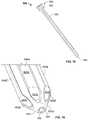
- FIG. 9is a perspective view of a central core element according to one embodiment of the disclosure with rods disposed thereon.
- FIG. 10is a side view of the central core element of FIG. 9 .
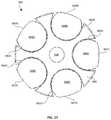
- FIG. 11is a bottom view of the central core element of FIG. 9 .
- FIG. 12is a perspective view of a squid cap and rod system according to one embodiment of the disclosure.
- FIG. 13is an exploded view of the system of FIG. 12 .
- FIG. 14is an angled sectional view of the system of FIG. 12 .
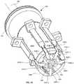
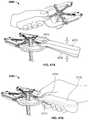
- FIG. 15is a perspective view of a squid core combination system according to one embodiment of the disclosure.
- FIG. 16is a close up view of an insertion end tip of the system of FIG. 15 .
- FIG. 17is a sectional view of a central core and squid rods of the system of FIG. 15 .
- FIGS. 18A-Bare sectional views of two variants of the central core of the system of FIG. 15 with retractor rods disposed therein.
- FIG. 19Ais a top view of the slide tool included with the retractor of FIG. 1 .
- FIG. 19Bis a perspective view of a retractor frame and slide element according to one embodiment of the disclosure.
- FIGS. 20-22are top views illustrating various positions of the rods of the retractor shown in FIG. 1 .
- FIG. 23is a perspective view of the arm and attached rod shown in FIG. 3 where the rod is toed out.
- FIG. 24is a perspective view of the arm and attached rod shown in FIG. 3 where the rod is advanced on its axis relative to the arm.
- FIGS. 25-26are perspective views of a retractor with handle in closed and open positions, respectively, according to one embodiment of the disclosure.
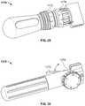
- FIGS. 27-30are perspective views of retractor handles according to unique embodiments of the disclosure.
- FIGS. 31-32are top views of a retractor according to one embodiment of the invention in closed and open positions, respectively.
- FIGS. 33-34are top views of a retractor according to one embodiment of the invention in closed and open positions, respectively.
- FIG. 35is an angled view of the retractor of FIG. 33 .
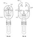
- FIGS. 36A-36Bare different views of a retractor in a closed position according to one embodiment of the disclosure.
- FIGS. 37A-37Bare different views of the retractor of FIGS. 36A-36B in an open position.
- FIGS. 38-39are top views of a retractor according to one embodiment of the disclosure in closed and open positions, respectively.
- FIG. 40is a perspective view of a retractor according to one embodiment of the disclosure.
- FIG. 41is a top view of retractor frame and handle combinations according to several embodiments of the disclosure.
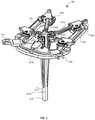
- FIG. 42is a perspective view of a retractor according to one embodiment of the disclosure.
- FIG. 43is a top view of a retractor according to one embodiment of the disclosure.
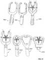
- FIG. 44includes several views of a retractor according to one embodiment of the disclosure.
- FIG. 45is a perspective view of a retractor according to one embodiment of the disclosure.
- FIG. 46is a top view of a retractor according to one embodiment of the disclosure.
- FIG. 47Aincludes two views of a retractor according to one embodiment of the disclosure.
- FIG. 47Bis a perspective view of a variant of the retractor depicted in FIG. 47A .
- FIG. 48is a side view of a combined central core and probe structure according to one embodiment of the disclosure.
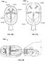
- FIGS. 49A-49Care views of a neuromonitoring patch according to one embodiment of the disclosure.
- FIG. 50is a side view of a quick connector according to one embodiment of the disclosure.
- FIG. 51is a top view of mechanical components within a retractor and handle combination according to one embodiment of the disclosure.
- FIGS. 52A and 52Bare perspective views of implants according to one embodiment of the disclosure.
- FIG. 53is a perspective view of implants according to one embodiment of the disclosure.
- the present disclosuredescribes various apparatuses, devices, systems, kits and methods to simplify and improve the effectiveness of tissue retraction to create a minimally invasive pathway to access a location to be operated upon, also referred to herein as a target site.
- the minimally invasive pathwayis also referred to as a surgical portal, which is a working volume within a patient undergoing surgery.
- the surgical portalrepresents a working volume generally interior to and between the retracted rods.
- surgical portalsmay be created beginning with a very small diameter to minimize risk to the patient upon entry into tissue, a size of a portal can be controlled, particularly in the early steps of a procedure using a squid cap or a central core element, and the expansion of the portal can be customized through opening with all rods or any combination of individual rods of the retractor.
- a slide tool as described hereinmay be used to quickly open a surgical portal, a technique known as rapid opening.
- target anatomyinclude the cervix, the thoracic cavity, the abdomen for anterior laparoscopy, minimally invasive surgery (MIS) laparotomy or anatomy within the retroperitoneal space, among other procedures, anatomy targeted in cardiac procedures and elements of the nervous system including the brain, cerebrovascular system and the spine.
- MISminimally invasive surgery
- the spineis referenced throughout the application, although it should be appreciated that the concepts described herein are in no way limited to the spine. Approaches to the spine may be lateral, anterior, anterior-lateral, posterior, posterior-lateral or posterior midline.
- the spinemay be accessed for any number of reasons, including treatment of spinal conditions such as disc herniation, implantation of motion preservation devices, total replacement of a disc and implantation of interbody devices, along with many other procedures.
- interbody device implantation proceduresinclude lateral lumbar interbody fusion (LLIF), oblique lumbar interbody fusion (OLIF), posterior lumbar interbody fusion (PLIF), anterior lumbar interbody fusion (ALIF), transforaminal lumbar interbody fusion (TLIF), and posterolateral lumbar fusion (PF).
- approaches to the spineare not limited, although the technology described herein is particularly advantageous when employed in a lateral trans-psoas or anterior to psoas approach.
- Retractor 100includes a frame 110 , connectors 102 , 103 attached to frame 110 , arms 121 A-E attached to frame 110 , and five rods 151 A-E attached to respective arms 121 A-E. Inclusion of five retractor rods makes the retractor quite versatile as the shape of a portal may be customized based on a unique position of each rod to more closely match dimensions of an implant to be placed in a patient. Details of the function of the retractor are described in greater detail below.
- Retractor 100also includes a slide tool 170 secured under frame 110 (see FIG. 19A ). Each of these components and their relationship with one another will now be described in detail.
- Frame 110is generally U-shaped, as best shown in FIG. 2 , and includes two lateral extensions 111 A, 111 B and an end portion 112 . These segments of the frame are arranged so that each lateral extension mirrors the other and extends from an opposite end of end portion 112 .
- the U-shape of the frameis advantageous in that it provides space on the open side of the frame for visualization, instrument use, and access to patient anatomy.
- Frame 110includes apertures, protrusions, and other structural features so that slide tool 170 , arms 121 A-E and connectors 102 , 103 may be secured thereto.
- the U-shapeis but one configuration that may be employed in accordance with the present invention.
- the framemeasures 166 mm in length and 112 mm in width.
- the framemay have other dimensions as a matter of design choice.
- the framemay have a length less than 166 mm, greater than 200 mm, or any length in between, and a width less than 112 mm, greater than 150 mm, or any width in between.
- various combinations of these dimensions and larger sizesare also contemplated.
- arms 121 A-Eseveral accessory components are included so that arms 121 A-E are securable to frame 110 .
- arms 121 A-Dthese components are generally the same, and like reference numerals refer to like elements.
- Arm 121 E and its accessoriesare also generally similar, although some features vary slightly. To the extent any particular arm includes distinguishable structure, such structure is outlined in the description below. Arm 121 A is now described in detail as representative of each of the five retractor arms shown in FIGS. 1 and 2 .
- Arm 121 Ais positioned within rotating support 131 A, and in turn, rotating support 131 A is secured to frame via post 133 A. Adjacent to rotating support 131 A and also attached to frame 110 is fixed support 141 A, as shown in FIGS. 1 and 2 .
- Arm 121 Aincludes teeth 122 A oriented in a direction perpendicular to a length of the arm, and extending over a majority of the arm length, as best shown in FIGS. 2 and 3 . These teeth 122 A complement corresponding teeth (not shown) on an interior surface of rotating support 131 A and thereby allow arm 121 A to be moved forward and backward along its length in predetermined increments based on the tooth spacing.
- a toeing cam 127 AToward a free end of the arm remote from frame 110 is a toeing cam 127 A, as shown in FIG. 4 , which is positioned under pivoting component 124 A. Toeing cam is rotatable to adjust its elevation relative to the arm, such adjustment causing a corresponding rotation in pivoting component 124 A, as described in greater detail in the method below. While one end of arm 121 A is held in place via rotating support 131 A, toward an opposite end are fork shaped extensions that include lateral openings. Pivoting component 124 A is disposed in between these forks and a pin 123 A is positioned through the openings in both the arm and the pivoting component to secure pivoting component 124 A to the main body of arm 121 A, as shown in FIG. 4 . This form of connection provides a pivoting connection between pivoting component 124 A and arm 121 A, where the axis of rotation is through an axis of pin 123 A.
- Pivoting component 124 Ais U-shaped with arms extending in a manner similar to the forks of arm 121 A. Disposed within the arms of pivoting component 124 A is a threaded insert 126 A, shown in place in FIG. 4 and as a separate element in FIG. 2 . At an end of pivoting component 124 A facing away from arm 121 A are two parallel grooves 125 A. These grooves are sized and dimensioned to complement corresponding grooves 155 A on rod 151 A, described in greater detail below, so that rod 151 A remains aligned with arm 121 A.
- rotating support 131 Ain addition to having an opening therethrough so that arm 121 A is positionable therein, rotating support 131 A also includes teeth 132 A on a lateral side surface, as shown in FIGS. 1 and 2 . In position secured to frame 110 , teeth 132 A face complementary teeth 142 A on a side surface of fixed support 141 A.
- rotating support 131 Ais rotatable in predetermined increments relative to fixed support 141 A, the increments based on a spacing of the teeth on the rotating support. Accordingly, with arm 121 A disposed in rotating support 131 A, arm 121 A is adjustable both longitudinally along its length and rotationally about an axis of rotation of rotating support 131 A, both in predetermined increments.
- Rotating support 131 A and fixed support 141 Aare also structured so that rotating support 131 A may be disengaged from fixed support 141 A.
- fixed support 141 Amay be actuated to disengage rotating support 131 A.
- rod 151 Ais secured to arm 121 A
- rod 151 Amoves in conjunction with arm 121 A.
- thisis advantageous as a position of a rod of the retractor may be tailored to create a desired size and shape of surgical portal. Customization of an opening size is further promoted due to each arm being independently adjustable relative to the others. It is important to note as well, however, that the retractor is also adjustable through simultaneous adjustment of two or more arms up to and including each and every arm.
- Rod 151 Asecured to arm 121 A, a connection therebetween is shown in FIG. 4 .
- Rod 151 Aincludes a portal defining portion 152 A and an arm engagement portion 153 A shaped similarity to a keel type structure, as shown in FIG. 3 .
- Portal defining portion 152 Aincludes a cylindrical surface 156 A extending from a first end 157 A near arm 121 A to a second end 158 A remote from the arm.
- portal defining portion 152 Aincludes a constant cross section over its length with dome shaped tips at both ends ( FIG. 3 ).
- the end tip shapes of portal defining portionmay be varied or the cross-section over its length may also be varied.
- Portal defining portion 152 A of rod 151 Amay be 4 mm in diameter, however other dimensions are also contemplated. Although not shown in FIGS. 1-4 , rods 151 A-E may be cannulated along their central longitudinal axis with an opening of sufficient size to pass a guidewire therethrough.
- Arm engagement portion 153 Aextends outward on one side of portal defining portion 152 A and has a constant width (measured as a distance between the arm and the rod) over a top segment of rod 151 A near arm 121 A. Moving away from arm 121 A, arm engagement portion 153 A tapers and terminates on cylindrical surface 156 A. In this manner, a length of arm engagement portion 153 A is less than that of portal defining portion 152 A. Over the constant depth segment of arm engagement portion 153 A are grooves 155 A shaped and sized to engage with grooves 125 A of arm 121 A, as noted above (see FIG. 4 ).
- Grooves 155 Aare positioned away from portal defining portion 152 A so that no structure obstructs engagement between rod 151 A and arm 121 A. Also positioned away from portal defining portion 152 A are teeth 154 A, oriented perpendicular to a length of rod 151 A and facing pivoting component 124 A. Teeth 154 A extend over a segment of arm engagement portion 153 A closest to arm 121 A and are sized and spaced to engage with threads on threaded insert 126 A. Thus, engagement between rod 151 A and arm 121 A is achieved through interaction between grooves 155 A and 125 A, and between teeth 154 A and threads on threaded insert 126 A.
- grooves 155 A in conjunction with teeth 154 Aare designed so that rod 151 A is adjustable relative to arm 121 A in a direction corresponding to the rod length in predetermined increments. For example, a position of rod 151 A may be adjusted into and out of the body. It should be noted that slot 155 A extends over a greater length than teeth 154 A as shown in FIG. 4 . This arrangement is advantageous in that it eases engagement between the rod and arm. In particular, upon first aligning rod with the forks in arm, slots 155 A rod may be slid into slots 125 A prior to engagement between respective teeth.
- each of an arm component (threaded insert and/or pivoting component) and rodinclude complementary mechanical stops. Such mechanical stops provide an added level of safety to prevent rod from translating beyond a predetermined amount from the arm and into the portal. Mechanical stops may be in the form of complementary protruding surfaces or other interconnecting structures as a matter of design choice.
- Rod 151 Amay swing in a plane through frame 110 via actuation of rotating support 131 A to adjust its connection location with fixed support 141 A.
- Rod 151 Ais translatable in a direction of the length of arm 121 A through adjustment of arm 121 A relative to rotating support 131 A.
- Rod 151 Ais also pivotable relative to arm 121 A about the axis through pin 123 A.
- rod 151 Ais translatable along its longitudinal axis via interaction of teeth 154 A and threads of insert 126 A, i.e., rotation of insert 126 A causing the rod to translate.
- retractor rods 121 B-D shown in FIGS. 1 and 2are also applicable to rods 121 B-D shown in FIGS. 1 and 2 .
- certain arms, such as arms 121 B, 121 Cmay be longer or shorter than the others depending on their relative position on retractor frame 110 .
- arm 121 Eis disposed in support 131 E, similarly to arms 121 A-D, which are respectively disposed in supports 131 A-D. However, unlike supports 131 A-D, support 131 E does not have a fixed support adjacent thereto (see FIGS. 1, 2 and 20 ). In the embodiment as depicted, employed in a lateral trans-psoas procedure, arm 121 E is left fixed in place so that rod 151 E remains fixed. Fixation of arm 121 E relative to frame 110 may be through fixation mechanisms as known to those of skill in the art. In some variants, and as described below, arm 121 E is movable relative to the retractor frame.
- the posterior rodmay include a pointed tip on an insertion end remote from the arm so that the rod may be secured and otherwise anchored to a bone for additional stability.
- This principlemay apply to any rod as deemed desirable for a given procedure.
- rod 151 E secured to arm 121 Eis electrically insulated and includes an electrode for neuromonitoring.
- one reason for the distinctive structure of arm 121 E and its associated componentsis that it is well suited for a lateral trans-psoas approach. This is because rod 151 E is positionable on a posterior side of the patient. In such approaches, rod 151 E functions to protect against impingement of nerves located posterior to rod 151 E since rod is held in place while rods 151 A-D are retracted. Similar principles may be applied in other approaches, although rod 151 E may be located elsewhere relative to a body of a patient.
- arm 121 E and its associated supporting structuresare translatable within support 131 E, without allowing support 131 E to rotate about an axis through its body.
- Arm 121 Eotherwise may be modified to include features so that rod 151 E is pivotable about arm 121 E for toeing in and out and so that it is translatable along its axis.
- modified arm 121 Emay be adjustable in three degrees of freedom.
- framemay include a fixed support near arm 121 E and arm 121 E may adjust in four degrees of freedom similar to the other rods.
- a retractormay include five rods that are all movable in multiple degrees of freedom.
- rod 151 Emay be constructed without structure for neuromonitoring.
- connectors 102 , 103are secured on end portion 112 thereof. Securement between connectors 102 , 103 and frame 110 may be through screws, as shown in FIG. 2 , or other means known to those of skill in the art.
- Each connector 102 , 103includes a fork shaped end for engagement to a rigid arm such as those described in U.S. Prov. Pat. App. No. 62/546,780, the disclosure of which is hereby incorporated by reference herein in its entirety, or another support structure. Engagement to the support structure holds the retractor in place relative to the body of the patient.
- Slide tool 170shown in FIG. 19A , in part in FIG. 1 and separated into its various subcomponents in FIG. 2 .
- Slide tool 170in its assembled state, is generally U-shaped with a similar outline to that of frame 110 . In this manner, when slide tool 170 is positioned directly underneath frame 110 , its outer perimeter is substantially covered by frame 110 , as shown in FIG. 1 .
- Slide tool 170includes two lateral components 171 A-B, and an end component 172 . Each component includes apertures so that screws may be used to connect the respective components.
- apertures 178 A, 178 B in lateral components 171 A-Bare aligned with respective apertures 179 A, 179 B in end component 172 and screws are placed therethrough to secure all three components.
- other meansmay also be used to hold each component together.
- slide tool 170may simply be a monolithic structure.
- Each lateral component 171 A-Bincludes a pair of rails, 174 A- 1 , 174 A- 2 and 174 B- 1 , 174 B- 2 , respectively.
- Such railsserve a dual function.
- the railsinclude a recess under their top surface to form a hook to engage with a corresponding feature (not shown) on a bottom surface of frame 110 .
- the rail structureallows slide tool 170 to translate relative to frame 110 .
- Each lateral component 171 A-Balso includes ramp surfaces located to pass over arms 121 A-E when slide tool 170 is translated with respect to frame 110 .
- Rampsinclude end ramps 175 A-B located closest to arms 121 B-C, and lateral ramps 176 A-B, located closest to arms 121 A, 121 D.
- Ramps 176 A-Bare located on an outside edge of each lateral component and are sloped at about thirty degrees relative to a longitudinal axis of each lateral component, with the ramp angle becoming shallower further away from end ramps.
- a lateral edge of lateral componentincludes a flat portion extending from end ramp 175 A or 175 B to a lateral ramp 176 A or 176 B, or ramp portion, which continues toward apertures 178 A-B, respectively.
- End ramps 175 A-Bare edges generally perpendicular to the longitudinal axis of the lateral components, although include rounded out corners, as shown in FIG. 20 , for example.
- the angle and other contours of the edge surfaces for the rampsmay be varied in any number of ways as a matter of design choice.
- central extension 173On end component 172 is central extension 173 , as shown in FIG. 2 .
- Central extension 173is sized to allow slide tool 170 to translate away from end portion 112 of frame 110 a certain amount.
- translation of the central extensionmay be interrupted by rod 151 E after a predetermined amount of translation.
- central extensionmay be smaller or larger with respect to the slide tool or may be absent altogether. The exact operation of these features is described in greater detail below, although it should be understood that the slide tool 170 operates to provide a rapid opening, i.e., retraction, of rods 151 A-E of the retractor, upon translation from a first position shown in FIG. 1 or 20 to a second position shown in FIG.
- the slide tool(not shown) may be modified to include slots through each lateral component.
- rapid opening pins extending from respective arms on the retractore.g., rapid opening pins 128 A-D shown in FIGS. 20-21
- slide tool 170includes the same capability as slide tool 170 for rapid retraction of the retractor rods, but, through the opposite surface within slots of the slide tool, allows for a reverse translation to bring the rods back into a closed position.
- the retractor of FIG. 1may be modified to appear as shown in FIGS. 33-35 .
- Retractor 1400may perform at least all of the rod movements possible with retractor 100 and provides for similar posterior rod adjustment and maximum surgical portal opening size.
- a retractor 1300 with frame 1310is more compact than retractor 100 and appears as shown in FIGS. 31-32 .
- the framemeasures 139 mm by 94 mm. In other examples, such dimensions may be larger or smaller.
- retractor 1300does not include external rotating supports to hold the arms of the retractor. The features of this retractor make possible its smaller size.
- Retractor 1300includes a slide tool 1370 for rapid opening, includes arms adapted for toeing of the rods, and also provides for individual rod retraction via arm translation relative to the frame. Arm 1321 E may be translated up to 10 mm.
- retractor 1300is compact, rods may still be retracted sufficiently to create a surgical portal measuring 20 mm by 30 mm.
- a retractormay be even smaller than retractor 1300 .
- such a retractormay have a frame measuring 132 mm by 88 mm in dimensions and include arms so that a surgical portal up to 14 mm by 24 mm in dimensions may be created through retraction.
- Such a retractorincludes a slide tool adapted for rapid opening of the rods, arms adapted for toeing of the rods, and translation of a posterior arm/rod by an amount up to 10 mm.
- the framemay also have dimensions in between the above examples or even smaller than the lower end of the range.
- a retractormay have a frame and arms as shown for retractors 2800 , 2900 depicted in FIGS. 45 and 46 .
- a retractor systemin another embodiment, includes a retractor and a squid cap 280 .
- the rods of the retractor with squid cap 280 disposed thereonare shown in FIGS. 5-7 while squid cap 280 is illustrated individually in FIG. 8 .
- Squid cap 280includes a handle 281 , a central body 285 , and extensions 286 A-E extending from the central body and defining a cavity therebetween.
- Handle 281 of squid cap 280is mushroom shaped to aid in gripping by a user, though other shapes and surface features are also contemplated as known to those of skill in the art. Extending from handle is a threaded handle extension 283 engageable with corresponding internal threads 287 inside central body 285 , as shown in FIG. 7 . As depicted in FIG. 7 , handle 281 is a separate element from central body 285 , however, it is contemplated that squid cap 280 may be a monolithic structure. Handle 281 also includes a central cannulation sized for placement of a probe 290 therein, as shown in FIGS. 7 and 8 .
- Probe 290serves to keep retractor in line with guidewire during advancement and withdrawal from a target site in a patient and also serves to keep the rods from floating into a center void in between the rods.
- the squid capmay exclude probe 290 .
- extensions 286 A-Ea combined cross section of extensions 286 A-E defines an opening therebetween as shown in FIGS. 6 and 8 that is large enough for enclosure of each rod 251 A-E.
- rods 251 A-Einclude side grooves 261 A-J sized and positioned for nesting of extensions 286 A-E therein.
- extension 286 Bis advanced in between grooves 261 D of rod 251 B and groove 261 E of rod 251 C, as shown in FIGS. 6 and 7 .
- Squid cap 280is secured over rods so that each rod 251 A-E abuts one another and probe 290 is disposed in between the rods, as shown in FIG. 6 .
- squid cap 280is positioned to surround the rods, a portion of each arm engagement portion 253 A-F passes through respective slots 289 A-E and out of an envelope of squid cap 280 , as shown in FIGS.
- squid cap 280to hold rods 251 A-E in position with respect to one another while the retractor arms remain engaged to the rods.
- the squid capmay be modified and otherwise adapted for engagement with rods 151 A-E or other rods having a keel type arm engagement structure.
- the squid capis made of a flexible material such as a polymer.
- a polymer squid capis advantageous in that it is radiolucent and has a flexible material property. This leaves room for rods to adjust within the squid cap.
- the squid capmay be expanded to bring it over the combined rods and once over, close against the rods providing an additional means of holding the rods together.
- the squid capmay also be customized for an angulation of the rods within the squid cap.
- the combined rodsmay form a shape coning inward from a tail end, defining a larger envelope at the tail end that is held by the squid cap.
- a retractor systemin another embodiment, includes a retractor and a central core element as shown in FIGS. 9-11 .
- central core 380is shown with retractor rods thereon, the remainder of the retractor not shown to provide improved visualization of the interaction between central core 380 and rods 351 A-E.
- Central core 380is an advantageous complement to the retractor in that it provides an initial predetermined spacing between rods 351 A-E prior to insertion of the rods into the patient, while the spacing is small enough so that the rods are still considered to be in the closed position. In this manner, a surgical portal is defined upon initial insertion of the rods, thereby reducing the effort necessary to increase the portal to a desired size when compared to insertion without a central core.
- central core 380includes a handle 381 with grips 385 at a first end corresponding to the trailing end of the retractor insertion.
- Handle 381is made of a material to reduce interference that may otherwise occur when x-rays are taken.
- the body of central core 380extends from handle 381 and includes a cylindrical surface 386 with equally spaced longitudinal recesses 382 A-E carved from the cylindrical surface and having a concave cross-section, best shown in FIG. 11 . These recesses have a radius of curvature matching that of the retractor rods so that when rods are nested therein, as shown in FIG. 9 , minimal space remains between the rods and the recesses.
- a length of central core 380is longer than rods 351 A-E of the retractor, as shown in FIG. 9 .
- This ensures tissue penetrationis through a tapered tip 383 located toward a leading end of central core 380 .
- the tapered tipis shaped so that resistance due to tissue is reduced when central core 380 is inserted into the patient.
- central core 380is cannulated 388 through its length on its central longitudinal axis.
- tapered tip 383terminates at insertion end face 384 , distal to handle 381 .
- Cannulation 388is of a sufficient diameter so that a guidewire is disposable therein.
- grooves 382 A-Eare shown with a dimension creating a loose fit with rods 351 A-E nested therein, it is contemplated as an alternative that such grooves can be defined by a surface curving inward at an outer circumference of the core, thereby creating a tight fit between the central core element 380 and rods secured therein, similar to that shown in the core of the squid core combination structure shown in FIG. 18B .
- a retractor systemin yet another embodiment, includes a retractor, a squid cap 480 and a probe 490 , as shown in FIGS. 12-14 .
- Probe 490is positioned in between the five rods of the retractor while squid cap 480 surrounds each of the portal defining, i.e., cylindrical portions of the rods to hold them in position with respect to each other.
- the arms of the retractorare secured to each rod at interfaces 454 A-E, partially shown in FIG. 12 .
- like reference numeralsrefer to like elements for features of rods 451 A-E.
- probe 490is cylindrical in shape and includes a trailing end 491 and a leading end in the form of a pointed tip 492 .
- probe 490is cannulated 498 with a size of the cannulation sufficient for placement of a guidewire therethrough.
- probemay include a second cannulation 499 , such as is shown in FIG. 14 , so that the guidewire may be repositioned at a predetermined offset from central cannula 498 .
- the retractor systemmay include a k-wire in place of a probe.
- Squid cap 480includes a handle in the form of a knob 481 , a neck 482 , a main body 485 with a cylindrical shape, and slightly tapered extensions 486 A-E extending from main body 485 .
- Knob 481is shaped to render advancement of squid cap 480 over rods 451 A-E easier when handled by a user.
- extensionsare separated by longitudinal slots extending from main body 485 to an open end 487 of squid cap 480 . As seen in FIG.
- each extensionhas a thickness so that a cavity within a combined inner surface of the extensions is sufficiently large for portal defining portions of rods 451 A-E to fit therein, along with lateral extensions 455 A- 1 , 455 A- 2 , 455 B- 1 , 455 B- 2 , 455 C- 1 , 455 C- 2 , 455 D- 1 , 455 D- 2 , 455 E- 1 , 455 E- 2 which are sized to abut inner surfaces of extensions 486 A-E and are best shown in FIG. 14 .
- Thiskeeps rods 451 A-E from retreating from their closed position or otherwise from sliding out from within squid cap 480 . Also shown in FIG.
- rods 451 A-Efit within squid cap 480 even when probe 490 is disposed in between the rods.
- squid cap 480retains rods 451 A-E in place in a closed position while squid cap 480 is held over the rods.
- Squid capalso includes an opening 489 in knob 481 sized for disposal of probe 490 therein, as shown in FIGS. 12 and 13 .
- a size of opening 489may be customized as needed to suit the size of the k-wire.
- a retractor systemin yet another embodiment, includes a retractor (not shown) and a squid core combination structure 500 as shown in FIGS. 15-16 .
- the combination structureincludes a squid enclosure 590 with squid rods 598 A-E extending therefrom, and a central core 580 .
- Central core 580includes a generally cylindrical surface with longitudinal grooves 582 A-E located at intervals around its circumference. Grooves 582 A-E have a concave outer surface and are sized for disposal of squid rods 598 A-E or rods 551 A-E therein. (See FIGS. 17 and 18A , respectively). Passing through a central longitudinal axis of central core 580 is a cannulation 588 sized so that central core 580 may be placed over a guidewire. Toward a leading end of central core 580 is a conical tip 583 , best shown in FIG. 16 , which is partially truncated at an insertion end surface 584 surrounding cannulation 588 .
- the tapering tip of central core 580reduces tissue resistance when squid core combination structure 500 is inserted into a patient.
- an engagement mechanism(not shown) for engagement between central core 580 and squid enclosure 590 .
- central core 580may be structured without a trailing engagement element and squid enclosure 590 and central core 580 may be held together by hand or with an external device.
- grooves 582 A-Eare “loose fitting” and thus open toward an outer surface of central core 580 , leaving a gap between the groove and a nested squid rod or retractor rod near the intersection of the groove and the central core outer surface.
- This groove shapeis described as loose fit because the rods are guided by the grooves but not held in place with a snap in connection, as shown in FIG. 17 , for example.
- central core 680includes grooves 682 A-E which fit tightly around a squid rod or a rod disposed therein, such as retractor rods 651 A-E shown in FIG. 18B .
- the rodsare shaped with a smooth, circular surface (convex) that interfaces with a complementary smooth circular surface (concave) on central core 580 , 680 .
- squid enclosure 590shown in its entirety in FIG. 15 , includes a unifying cap 595 and squid rods 598 A-E extending therefrom.
- Squid rods 598 A-Eare attached to unifying cap 595 through slots in the unifying cap.
- positioning of squid rods 598 A-E in respective slots of the caprenders each squid rod radially adjustable to move away or toward a surface of central core 580 , if desired.
- each squid rod 598 A-Emay be fixed in position relative to unifying cap 595 .
- each squid rod 598 A-Eis shaped to nest within recesses 582 A-E of central core 580 , and includes a partially circular cross-section to ensure an inner surface of such squid rods 598 A-E are flush with respective grooves 582 A-E when nested therein, as shown in FIG. 17 .
- surfaces 597 A-Eare surfaces 597 A-E, one for each squid rod, having a radius of curvature corresponding to that of central core 580 , shown in FIGS. 16 and 17 .
- squid rods 598 A-Eensures not only that squid rods nest in central core 580 , but that they do not protrude outside of an envelope of central core, minimizing a size of penetration when squid core combination structure 500 is inserted into a patient body.
- a taper 593 A-E at insertion ends of squid rods 598 A-Eincludes an outward facing surface having a curved surface matching that of conical tip 583 , as shown in FIG. 16 .
- a diameter of the combined structuremay be minimized.
- the diameter of the combined central core and squid rodsis 11 mm.
- a diameter of an outer envelope of the core with retractor rods nested thereinis 12 mm.
- a diameter of the squid core combination structure with squid rods disposed thereinmay be anywhere from 11 mm to 13 mm, with a corresponding increase in footprint with rods nested in the central core.
- squid core combination structure 500may be configured, depending on a stage in a surgical procedure, as squid enclosure 590 and central core 580 together or just central core 580 , with central core 580 designed to function with retractor rods.
- the retractor apparatus and its subcomponents and accessoriesmay be varied in many ways.
- the systemmay include a retractor with a total of two or more rods and/or arms attached thereto. Additionally, any portion of the total number of retractor arms may be configured to include some or all with two or more degrees of freedom of movement.
- any two rodsmay include different features for independent movement. For example, where a retractor includes five rods attached thereto, only two or three of the five rods may be configured to toe in and out, while another rod may swing, toe in or out, and telescope toward and away from the arm. In another example where a retractor includes seven rods, one rod, six rods, or any number in between may be configured to have four degrees of freedom.
- a diameter of the envelope of the rods when closedmay vary from 11.1 mm to 13 mm.
- a specific structure of the rodsmay also be varied.
- a portal defining portion of the rod defining a portal size and shape when such rod is retracted with other rods of a retractore.g., having a cylindrical shape in rods 151 A-E
- Other possibilitiesinclude a cross-sectional shape having some curved faces and some cornered edges.
- a size or shape of the cross-section of the portal defining portionmay vary over the length of the rod.
- the portal defining portionmay have a tapering characteristic, becoming smaller in cross-sectional size moving away from an end connected to the retractor.
- the portal defining portion of the rodmay also vary in any manner contemplated in WO2018/039228, the disclosure of which is hereby incorporated by reference herein in its entirety. Consistent with these examples, an end surface of the portal defining portion may be any shape and is not limited to the dome shaped structures depicted. In one example, an insertion end tip of the rod is pointed and may function as an anchor.
- the rodmay have a width and/or diameter, or a length, to suit a particular application.
- a diameter of portal defining portions 152 A-E of rods 151 A-Emay be 4 mm. Similar principles apply to a length of the rods, and rods may have a length ranging from 80 mm to 200 mm. This applies to any portal defining portion of a rod as described above or otherwise contemplated in this disclosure.
- Rodsmay also be as described in U.S. Provisional Patent Application No. 62/546,841 or WO2018/039228, the disclosures of which are hereby incorporated by reference herein in its entirety.
- any rods used as part of a retractor or larger systemmay be cannulated on a central axis of the portal defining portion or through any internal segment of the rod.
- the cannulationmay be sized for placement of guidewire, elements for the transmission of light, such as fiber optic cables, or an electrode for neuromonitoring, among other purposes.
- a surface of the rodmay also include recesses or other structural modifications to support the placement of LEDs on the rod.
- the rodsmay include a hinge mechanism along their length so that toeing of an end portion of the rod is possible.
- FIGS. 1-4illustrate rods with an arm engagement portion designed for securement of the rod to the retractor of FIG. 1
- such structuremay vary in any number of ways to accommodate a particular retractor structure used with the rod.
- the arm engagement portion of the rodis sized and shaped so that the rod in which it forms a part is compatible with the retractors described in WO2018/039228.
- the arm engagement portionmay have a width wider or narrower than a corresponding portal defining portion of rod, it may extend a distance greater or lesser from portal defining portion than the arm attachment portions of FIGS.
- an outside edge and/or taper of the arm engagement portionmay vary from the taper shown in the rod of FIG. 3 and may be customized as a matter of design choice. For example, instead of a gradual taper over a length of arm engagement portion 153 A as shown in FIG.
- an edge of the arm engagement portion remote from the cylindrical portion of the rodmay be parallel to the cylindrical portion over most of its length and then taper sharply adjacent to its end remote from the arm toward an insertion end of the rod, i.e., have a trapezoidal geometry. Accordingly, such trapezoidal geometry includes a much steeper taper than that of rod 151 A.
- the rodis subject to lower insertion forces when advanced into tissue than with the above described trapezoidal geometry while the rod of FIG. 3 , when used as a set of rods, creates a smaller sectional area for a viewing portal than a retractor with the rods having trapezoidal geometry.
- the geometry of the arm engagement portionmay be customized to achieve a desired compromise between structure to reduce insertion forces versus rod geometry to maximize a viewing portal into the patient.
- slide toolmay be modified.
- slide toolmay be as shown in FIG. 19B .
- Slide tool 770is movably attached to frame 710 and includes adjustable end ramps 775 A-B and lateral ramps 776 A-B.
- each rampincludes an adjustment mechanism (e.g., 775 A- 2 ) and pivot point (e.g., 775 A- 1 ) about which a respective ramp rotates.
- each rampis rotatable to change an angle of the ramp relative to an adjacent slide tool edge.
- the rampsmay also be slid longitudinally along the frame of the slide tool.
- the specific mechanism connecting the ramps to the slide tool and the manner of movement of the ramps relative to the toolmay be modified as a matter of design choice.
- ramp ratesmay be non-linear or even irregular to promote changing directions of the rods during opening and/or changing speeds of opening.
- Squid caps used with the retractors described in various embodiments of the disclosuremay be varied in many ways.
- the extensions of the squid capinclude particular dimensions to suit the rods they are intended to contain. Thus, if the rods are of a larger cross section, then the slot between extensions on the squid cap will be wider to accommodate the rods.
- Any squid capmay be modified to include a built in central probe, with or without a cannulation, or otherwise include a central cannulation for a guidewire.
- the squid capmay also include extensions that are slightly biased in an inward direction, so that when squid cap is inserted over retractor rods, such as is shown in FIG. 7 , the resistance from the extensions being forced outward assists in holding the rods in place relative to the squid cap.
- the handle for the squid capmay be modified in any manner desired as a matter of design choice.
- the central coremay or may not include a central cannulation or a handle, and where a handle is included, the type used may be a matter of design choice.
- the central core element, or shaftmay include grooves or other surface features promoting the engagement between the core and rods of a retractor. Where rods of a retractor intended to be used are non-circular in shape, the recesses in a central core element may be shaped so that such rods may still nest therein.
- the grooves or recesses in the central core elementmay open up towards an outer surface, i.e., loose fit, or arc inward, such as is shown in FIG. 18B , to create a snap in fit for the rods.
- the outer shape of the central coremay be tapered, non-circular or another shape to suit a desired retraction procedure and ultimately a desired working portal shape.
- the tip of the central core elementmay also be varied to have no taper, a steeper taper, or one having a shape other than those illustrated herein.
- the probeis cannulated with a 6 mm diameter.
- the probemay have a smaller diameter and perform the function of a guidewire, thus removing the need for a separate guidewire.
- the probemay have a 6 mm diameter, but may include a wire at an insertion end fixed to the probe and extending to a tip. In this instance, the wire tip may engage with a patient's anatomy, such as an intervertebral disc, and thereby perform the function of a guidewire anchoring to the target site.
- one or more rods of a retractormay include neuromonitoring technology.
- neuromonitoringas applied to a single rod, e.g., posterior rod 151 E in a lateral trans-psoas procedure
- a rodis cannulated through its length and includes an electrode disposed therein. The electrode extends to an end of the rod distal to an attached retractor arm and exits from a surface of rod offset from its center. Alternatively, it may exit on a centerline of rod.
- the majority of the rod lengthis insulated with a polymer material, for example, while the tip includes an exposed metallic surface.
- the roddoes not include a separate cannulation for an electrode and instead the electrode is attached to a surface of the rod and independently insulated. Because the electrode is designed to transmit an electric charge to stimulate areas proximal to it in a surgical portal, other envisioned configurations include an electrode over the length of the rod that is exposed at various points along the length of the rod, providing stimulation at locations in addition to the distal tip of the rod.
- a separate electrode or electrodes proximal to the nerve or muscle of concernto function as a sensor and a computer system for sending stimulation signals to the rod and to receive data from the nerve response to the stimulation.
- Incorporation of neuromonitoring into a probe or central core elementmay be achieved with similar structure as that described for the rod above.
- a wandmay also be included which may be used in the same manner to stimulate nearby tissue including nerves. It should be noted that in alternative arrangements, a retractor and its accessories may include no neuromonitoring.
- the retractormay be supplemented with a navigation system. Incorporation of a navigation system may be used to improve accuracy of placement for the probe and guidewire and during surgical procedures may reduce the number of fluoroscopy readings necessary. In some situations, use of navigation may allow viewing of the surgical procedure without the use of k-wire.
- the navigation systemincludes a power source, a controller with a user interface to monitor advancement of the retractor rods, a connective element to connect the controller with a sensor, and a sensor adapted to monitor the location of a central core, probe or rod it is connected to.
- the connective elementis wireless but can also include a physical wire attached to the sensor.
- the controller and accompanying monitoring equipmentare positioned outside of the body throughout the procedure.
- the interface included with the monitoring equipmentis a trackable device on the surface of the body of the patient and includes LEDs attached thereon for monitoring the position of the central core, probe and/or rods.
- the interfaceis configured so that the target anatomical location, e.g., intervertebral disc, is identifiable throughout the procedure, including its position relative to the elements with a sensor thereon.
- An exemplary navigation system of the variety described above that can be employed in conjunction with the methods described hereinis the SpineMask® Non-Invasive Tracker by Stryker® described in U.S. Pat. App. Pub. No. 2015/0327948, the disclosure of which is hereby incorporated by reference herein in its entirety.
- the navigation systemis configured so that when the retractor rods are inserted into the patient, the location and trajectory of the rods can be monitored during advancement and adjusted prior to reaching a final position adjacent to the anatomical location that is the subject of the surgery.
- two or more sensorscan be placed on one or more of the central core, probe and rods.
- traditional surgical instrumentsmay be used with navigation by providing a spine lock clamp attachable to the instrument.
- a retractor 800is as shown in FIGS. 25-26 .
- Retractor 800includes a handle 870 .
- Handle 870includes two dials 872 , 874 , which are interconnected with frame 810 .
- Frame 810includes four segments, 815 A-D, as shown in FIG. 26 .
- the framemeasures 134 mm in a long dimension and 87 mm in a short dimension when it is closed.
- a retractor having a size noted in the aforementioned examplemay be used to create an opening, i.e., surgical portal, up to 20 mm ⁇ 30 mm in dimensions.
- the exact dimensions of the retractormay vary and may be larger or smaller than the aforementioned example.
- Separation (retraction) between segments 815 A, 815 B and 815 C, 815 D, in the anterior-posterior direction when performing lateral surgeryis controlled through actuation of dial 874 .
- a series of mechanical parts or componentsprovides a link between the respective elements and is used to effectuate such separation, or in reverse, closure.
- the mechanism included for retraction or closure in the anterior-posterior directionis a worm drive or alternatively a rack and pinion mechanism.
- Separation between segments 815 A, 815 C and 815 B 815 D, in the cranial-caudal direction when performing lateral surgeryis controlled through actuation of dial 872 .
- gear, rack, pin and other componentsmay vary according to the particular handle-frame configuration.
- mechanical componentsmay be employed in the various retractor-handle combination structures of the present disclosure, including those with actuating mechanisms in the form of swinging handles, trigger handles, and buttons, among others.
- other mechanical components serving the same function as a rack and pinion and worm gearmay also be used if suitable based on a particular frame shape and handle.
- Color coding on frame 810may be used to identify which dial controls cranial-caudal retraction and which dial controls anterior-posterior retraction.
- Retractor 800allows for rapid opening via handle 870 , toeing of rods via toeing cams, e.g., toeing cam 827 A, individual rod retraction, and individual rod lengthening, i.e., extending depth of rod relative to the frame via threaded inserts, e.g., threaded insert 826 A.
- the rod attached to arm 821 E in FIGS. 25-26e.g., the posterior rod in a lateral trans-psoas procedure, may be adjusted in the axis of the arm up to 20 mm.
- retractor 1600includes a rapid opening feature and its frame 1610 measures 106 mm in a long dimension and 69 mm in a short dimension when closed.
- a retractor having a size noted in the aforementioned examplemay be used to create an opening, i.e., surgical portal, up to 20 mm ⁇ 30 mm in dimensions.
- retractor 1600allows for rod toeing and individual rod retraction.
- the rod attached to arm 1621 E in FIG. 38e.g., the posterior rod in a lateral trans-psoas procedure, may be adjusted in the axis of the arm up to 10 mm.
- a frame for retractor 1600may vary in size as a matter of design choice, and may be larger or smaller than the above referenced example. For instance, the frame may be less than 106 mm long, 130 mm long, or any length in between. It may have a width less than 69 mm, 85 mm, or any width in between. The frame may also be larger than the upper end of these examples. A combination of length and width for the frame is a matter of design choice.
- a retractor with attached handleis as shown in FIGS. 36A-36B and 37A-37B .
- Elements of retractor 1500are similar to those of retractor 800 shown in FIGS. 25-26 and like reference numerals refer to like elements.
- Yet another embodiment of a retractor with handleis shown in FIG. 40 .
- Elements of retractor 1700are similar to those of retractor 800 shown in FIGS. 25-26 and like reference numerals refer to like elements.
- FIG. 41including retractors 1800 , 1900 , 2000 , 2100 , 2200 , 2300 and 2400 .
- a retractor 2500may be as shown in FIG. 42 with a handle 2570 adapted so that rotation of the handle produces toeing in one or more rods through a mechanical connection.
- like reference numeralsrefer to like elements as shown in FIGS. 1, 2 and 20 , but in the 2500 series of numbers.
- Retractor 2500includes a central frame 2510 with a first frame extension 2515 A and a second frame extension 2515 B, each extending approximately in parallel and on opposite sides of the retractor structure.
- Each of the first and second frame extensionsincludes a pair of arms extending inwardly therefrom, 2521 A-B and 2521 C-D, respectively.
- Rods 2551 A-Dare attached at the end of each arm, as shown in FIG. 42 .
- From a central portion of central frame 2510extends a posterior arm 2521 E with a rod 2551 E attached to its free end. The rods are shown in the closed position in FIG. 42 .
- Retractoralso includes toeing cam 2527 A on first frame extension 2515 A and toeing cam 2527 B on second frame extension 2515 B.
- Each toeing camis actuatable to control rotation of the respective frame extension about its axis, which in turn toes the rods attached to the frame extension.
- Rotation of frame extensions 2515 A-Bis relative to a stationary position of central frame 2510 .
- actuation of toeing cam 2527 Acauses toeing of rods 2551 A, B attached to arms 2521 A, B relative to central frame 2510 and the rest of the retractor structure.
- Toeing cam 2527 Bfunctions in the same manner
- Posterior rod 2551 E attached to arm 2521 Eis linearly translatable either manually or through a mechanical element such as a rack and pinion or another mechanisms described elsewhere in the disclosure.
- each of the arms other than the posterior armmay be translated along its longitudinal axis through central frame 2510 .
- the arms attached to the first and second frame extensionsmay be fixed.
- the actuation mechanism on handle 2570shown as dial 2572 , controls rapid opening of the plurality of rods on the retractor through mechanical elements internal to the frame.
- a retractorin one variation of the retractor shown in FIG. 42 , includes a central frame with a first frame extension and a second frame extension, each frame extension having two arms with rods attached thereto, a posterior arm with rod attached extending from the central frame, and a handle on an end of the central frame including actuation mechanisms to control the position of the rods.
- the retractorincludes respective toeing cams to control toeing of the pair of arms extending from the applicable frame extension.
- the toeing camsare positioned on the respective frame extensions.
- the toeing camsare positioned adjacent to the frame extensions on the central frame.
- each of the first frame extension and the second frame extensionincludes two segments that are separable from one another to control a length of the frame extension.
- This featureis shown separately in other embodiments of the disclosure such as with segments 815 A, B extendable relative to segments 815 C, D, respectively, in retractor 800 shown in FIGS. 25-26 and also in retractor 1600 shown in FIGS. 38-39 .
- the segments of each frame extensionmove relative to each other so that the two arms attached to the applicable frame extension move closer or further apart when the frame extension shortens or lengthens. For example, an arm attached at an anterior end of a frame extension becomes closer to or further from an arm attached at a proximal end of the frame extension when a control is actuated.
- the handle of the retractorincludes a first actuation mechanism such as a dial to control the shortening or lengthening of the first frame extension and the second frame extension.
- a first actuation mechanismsuch as a dial to control the shortening or lengthening of the first frame extension and the second frame extension.
- the dialcontrols both frame extensions simultaneously so that each shortens or lengthens in unison.
- two dialsmay be included on the handle, one to control each frame extension.
- the shortening or lengthening of each frame extensionis in the anterior-posterior direction.
- the central frame attached to the posterior arm and abutting each of the first and second frame extensionsis further divided into three parts: A central region and two side regions that each become separate from the central region upon actuation of a second actuation mechanism on the handle.
- each side region of the frameWhen each side region of the frame separates from the central region, it moves orthogonally relative to a length of each frame extension and translates with a respective frame extension as it separates. With this control, first frame extension and second frame extension become closer or further apart in a cephalad caudal direction.
- the frameoptionally includes a third actuation element to control translation of the posterior arm along its longitudinal axis.
- FIG. 44A variant of the retractor shown in FIG. 42 is retractor 2700 depicted in FIG. 44 .
- a retractor 2600includes a handle 2670 attached to a pivot point 2690 on frame 2610 .
- the handlemay also be left-handed on an opposite side of the frame.
- the handleis connected to the arms of the retractor so that actuation of the handle causes on or more rods to retract.
- actuation of the handlecauses a rack and pinion and or worm gear mechanism to operate causing the arms of the retractor to retract.
- connection between the handle and the armsmay simply allow the handle to be rotated to make room for the user of the retractor. It is contemplated that handle 2670 may be rotated all the way to the frame edge. In other embodiments that are not shown, other actuation elements can be incorporated into the handle such as a squeeze trigger and or a release button. Each of these may be interconnected with mechanical components such as those already described.
- a retractor with handleis as shown in FIG. 47A .
- Retractor 3000includes handle 3070 having a trigger ratchet mechanism 3072 and a release button 3074 .
- Ratchet mechanism 3072is adjustable in increments and incorporates audible feedback such as clicking so a user recognizes when and how much the ratchet mechanism is adjusted. Actuation of ratchet mechanism 3072 controls rapid opening of retractor arms.
- Release button 3074is actuatable to undo the incremental closure of ratchet mechanism 3074 upon holding or otherwise pressing button 3074 . Alternatively, release button 3074 may merely cause force pulling on respective arms to be relaxed or may function as a reverse switch.
- a retractor 3100is as shown in FIG. 47B , and trigger ratchet mechanism 3172 is more compact, although performs the same function.
- the retractors of the various embodiments of the disclosuremay further include any one of the handles shown in FIGS. 27-30 .
- Each handle shown in FIGS. 27-30includes an engagement feature for attachment or detachment to a retractor so that the handle is removable.
- color coding on each handle 970 , 1070 , 1170 , 1270may be used to identify which dial or trigger controls cranial-caudal retraction and which dial or trigger controls anterior-posterior retraction.
- the handlesmay be configured to retract rods of a retractor with rotation in the opposite direction of that noted.
- Handle 970is shown in FIG. 27 and includes an upper dial 974 and a rotary dial 972 .
- Upper dial 974controls anterior-posterior movement of the retractor arms, and, as depicted, controls such movement in 6 mm predetermined increments, with indicators provided on the dial.
- Rotary dial 972controls the cranial-caudal movement of the retractor arms, and, as depicted, controls such movement in 4 mm predetermined increments.
- Counterclockwise movement of either dial 972 , 974expands the rods, while clockwise movement closes the rods.
- the number of settings or the increments for adjustment on either dialmay be varied as a matter of design choice.
- Handle 1070is shown in FIG. 28 and includes side dials 1072 A-B and an upper dial 1074 .
- Side dials 1072 A-Bcontrol anterior-posterior movement of the retractor arms, and, as depicted, control such movement in 6 mm predetermined increments, with indicators provided on the dial. Actuation of a side dial 1072 A, 1072 B causes the other side dial to actuate in unison. Clockwise movement of the dial expands the rods, while counterclockwise movement closes the rods.
- Upper dial 1074controls the cranial-caudal movement of the retractor arms, and, as depicted, controls such movement in 4 mm predetermined increments. Clockwise movement of the upper dial expands the rods, while counterclockwise movement closes the rods.
- the number of settings or the increments for adjustment on either dialmay be varied as a matter of design choice.
- Handle 1170is shown in FIG. 29 and includes an upper dial 1174 and a lower dial 1172 .
- Upper dial 1174controls anterior-posterior movement of the retractor arms, and, as depicted, controls such movement in 6 mm predetermined increments, with indicators provided on the dial. Clockwise movement of the dial expands the rods, while counterclockwise movement closes the rods.
- Lower dial 1172controls the cranial-caudal movement of the retractor arms, and, as depicted, controls such movement in 4 mm predetermined increments. Clockwise movement of the lower dial retracts the rods, while counterclockwise movement closes the rods.
- the number of settings or the increments for adjustment on either dialmay be varied as a matter of design choice.
- Handle 1270is shown in FIG. 30 and includes an upper dial 1274 and a trigger 1272 .
- Upper dial 1274controls cranial-caudal movement of the retractor arms, and, as depicted, controls such movement in 6 mm predetermined increments, with indicators provided on the dial. Counterclockwise movement of the dial retracts the rods, while clockwise movement closes the rods.
- Trigger 1272controls the anterior-posterior movement of the retractor arms, and, as depicted, controls such movement in 4 mm predetermined increments via a clicking mechanism.
- the number of settings or the increments for adjustment of the dial or triggermay be varied as a matter of design choice.
- a retractor systemmay be complemented by a combined, all-in-one central core and probe structure 3200 , as shown in FIG. 48 .
- Employment of combined structure 3200may eliminate the necessity of using a probe separately from initial retraction steps when creating a surgical portal.
- Structure 3200includes a core section 3280 , a tapering section 3283 , a probe section 3290 and a tip section 3292 .
- Core section 3280includes grooves 3282 for the rods similarly to the core element shown in FIGS. 9 and 10 , for example and may have a similar sectional dimension.
- the probe sectionincludes a lighting element 3298 which may be an LED, on its side as shown. In one example, the probe has a diameter of 7.5 mm.
- Lightingmay be powered by a wire running out of the portal or a wireless transmission coil may be incorporated into structure 3200 for use of a remote power source.
- the tipincludes exposure of an electrode 3293 for neuromonitoring.
- the structuremay be made of carbon fiber and, with lighting and neuromonitoring considered, may incorporate composite materials.
- the structuremay include none or only one of the lighting and neuromonitoring features.
- additional neuromonitoring patchesmay be included on other parts of the structure or on squid rods of an attached squid cap.
- extending from tipmay be a 2 mm stiff guide wire which can also function to anchor the structure.
- a retractor systemmay incorporate a neuromonitoring patch 3300 , as shown in FIGS. 49A-49C .
- Patch 3300is advantageous as it provides a way to conduct neuromonitoring without having specially insulated coatings on the retractor rods. This is in addition to its core function of providing for electrical conductivity while also having an insulation layer contacting skin of the patient.
- Neuromonitoring matchingincludes a strong woven cloth layer 3302 , conductive pro-stimulation layer 3304 , and a conductive carbon film 3306 .
- neuromonitoring match 3300is wrapped around a retractor rod 3310 as shown in FIG.
- the patchforms a sleeve type structure.
- a wire connection 3308 to facilitate the neuromonitoringis included.
- Another advantage of the neuromonitoring patchis that it may be replaced while keeping the same rod for additional use.
- a retractor systemmay be complemented by a quick connector 3400 for provisional engagement to a rigid arm as shown in FIG. 50 .
- Quick connectorincludes a knob 3402 , ball plunger release 3403 , and a stem with a threaded portion 3404 and a provisional lock section 3406 .
- a connection 3420 to a rigid arm or tableextends from the stem as shown.
- Quick connector 3400is advantageous in that it provides a simpler means of attaching the retractor to a rigid arm while also being adapted so that while engaged, the retractor may be aligned.
- kitsincluding one or more items, such as a set of retractor rods and a squid cap.
- a kitincludes five retractor rods and a squid cap.
- the kitmay include five rods and a squid core combination structure, a central core element, or a squid cap with probe.
- a kitmay include ten rods, fifteen rods, or any other number of rods along with one or more of a squid cap, squid core combination structure, central core element or squid cap with probe.
- any combination of retractor rods and the above described elementsmay be further complemented by a retractor handle.
- such combinationsmay further include a retractor frame or both a retractor handle and a retractor frame.
- the kit or individual items and combinations thereofmay be disposed within a packaging or a plurality of packages.
- all of the items of the kitmay be disposed within a single packaging.
- all of the rodsmay be in one packaging while all of the squid caps, central core elements and/or probes in another.
- the elements of a given kitmay be sorted into any subgroups desired, where each subgroup may be packaged separately.
- each item of a kitmay also be individually packaged.
- each rod and squid cap in a kitmay be packaged separately. Through packaging each item in the kit separately or in separate combinations, sterility may be controlled for each item within the kit.
- the present disclosurerelates to a method of creating a surgical portal for accessing a surgical site in a patient.
- a method of creating a surgical portal for accessing a surgical site in a patientis described with reference to a lateral trans-psoas approach to the spine, it is contemplated that such methods can be modified for other approaches to the spine or indeed surgery directed to other areas of the human anatomy, such as those described above.
- a retractor 100is used to open up a surgical portal through a sequence as shown in FIGS. 20-22 .
- rods 151 A-E of retractor 100are in a closed position in contact with one another, and squid cap 280 (shown in phantom) is slid onto a top side of rods adjacent to the arms of the retractor as shown in FIG. 20 .
- Engagementoccurs between arm engagement portions 153 A-E of the rods and slots 289 A-E of the squid cap, respectively.
- This form of engagementis also contemplated as being compatible with other types of rods and may involve modification of the slots 289 A-E on squid cap 280 for engagement with a surface on the rods.
- squid cap 280While squid cap 280 is positioned over rods 151 A-E, the rods are held in position with respect to each other and in contact with each other so that the rods as a group are centered on a central cannulation or squid central core 290 , as shown in FIG. 6 , for example.
- a circle around an outer envelope of the five closed rods in contact with one anotherhas a diameter of 10.9 mm when the rods are 4 mm in diameter.
- squid cap 280includes squid central core 290
- retractor 100is centered on a cannulation in squid central core 290 to place the core over the guidewire, thereby centering the retractor over the guidewire.
- the cannulation in the central coreis sufficient to fit over the guidewire, which in some examples varies from 1 mm to 4 mm in diameter. Maintaining a position of squid cap 280 over and around rods 151 A-E as shown in FIG. 20 , the rods are advanced into the patient. During insertion, squid cap 280 holds the rods in place to control a size of the initial tissue expansion.
- a rigid arm supportmay be as disclosed in U.S. Prov. Pat. App. No. 62/546,780.
- slide tool 170 secured directly beneath frame 110is used.
- the surgical portalis formed through a rapid actuation action by pulling slide tool 170 from the frame 110 , as shown in FIG. 21 .
- a toolsuch as a torx tool, may be used to pull the slide tool from the frame.
- Each arm 151 A-Eincludes an opening at an end remote from the rod with a rapid opening pin 128 A-E disposed therein, the pin oriented perpendicular to a length of the arm.
- the slide tool 170As the slide tool 170 is pulled, it catches pins in the arms that are in the path of the slide tool, and causes the arms to be retracted as the pins move with the moving edge of slide tool 170 .
- FIG. 21This is illustrated in FIG. 21 , where pins 128 B and 128 C catch onto end ramps 175 A and 175 B, respectively, and pins 128 A and 128 D catch onto lateral ramps 176 A and 176 B, respectively.
- arms 121 B, 121 Cmove in the same direction, causing rods 151 B, 151 C to move away from posterior rod 151 E.
- arms 121 A and 121 Dare pulled away from posterior rod 151 E.
- rod 151 Eis located on a posterior side of the patient and operates as a fixed rod.
- four of the five rodsactuate while one remains fixed as rapid opening is performed using slide tool 170 .
- the retraction procedureis arranged so that expansion occurs in an anterior direction to prevent any impingement of nerves located posterior to posterior rod 151 E. This is particularly critical in a lateral trans-psoas procedure since the area in the spinal region posterior to the posterior rod location has a significant presence of nerves.
- a shape of a surgical portal created through rapid opening using slide toolis controlled by the orientation of the retractor arms, the ramp slope (rate) on the slide tool and the geometry of the slide tool generally, and the spacing of predetermined increments for adjustment of the arms relative to the frame. Adjustment of the ramps, using mechanisms such as those shown in FIG. 19B , provides a means to change the geometry of the opening created through rapid opening. Further, a length of central extension 173 on slide tool 170 may be modified in size to dictate a maximum translation of slide tool as a longer central extension 173 will contact a keel of rod 151 E upon translation of the overall slide tool 170 .
- a size of a surgical portal opening created through the rapid opening using slide toolmay be user specified. For example, if an implant intended to be implanted into the patient is 12 mm ⁇ 22 mm in dimensions, a surgical portal 14 mm ⁇ 24 mm may be created through rapid opening. Similarly, ramp angles of the slide tool may be customized to create a desired opening shape so that clearance around the implant in the surgical portal after rapid opening is limited to 1 mm (e.g., an opening 10 mm ⁇ 20 mm for an implant of 8 mm ⁇ 18 mm). In an example where the retractor frame measures 166 mm ⁇ 112 mm, the rods can be retracted to create an opening measuring 20 mm ⁇ 30 mm in dimensions. In examples where the posterior rod, i.e., rod at the base of the U-shaped frame, is adjustable, such rod may be adjusted up to 20 mm to increase or decrease the surgical portal size.
- the portal shape and/or sizemay be tailored through individual adjustment of one or more rods. This may be advantageous, for example, to create a larger surgical portal than that possible with rapid opening, or to tailor the shape of the surgical portal, among many other purposes.
- rod 151 Bvia arm 121 B, is swung toward frame 110 and pulled away from posterior rod 151 E through rotating support 131 B to create a larger, irregular opening. Swinging occurs in predetermined increments, as teeth 132 B on rotating support 131 B are moved relative to teeth 142 B on fixed support 141 B.
- Arm 121 Bswings about an axis of rotation fixed on rotating support 131 B, as is apparent in FIG. 22 . Arms may swing up to thirty degrees to customize the working portal and move tissue out of the surgical portal.
- rod 151 Bmay be toed out or in by pivoting the rod relative to arm 121 B about pin 123 B, as shown in FIG. 23 , causing the surgical portal to flare outward toward the surgical site.
- toeingis accomplished through rotation of toeing cam 127 B.
- pivoting component 124 Bis caused to rotate upward or rotate downward depending on the direction of rotation of the cam.
- rotation of toeing cam 127 Bcauses pivoting component 124 B to rotate upward on its arm facing side so that rod toes outward.
- a 180 degree rotation of toeing cam 127 Bcauses rod to toe 10 degrees about pin 123 B.
- a jack-screwmay be used in place of a toeing cam to achieve the same function, where a jack-screw provides for toeing out of the rod up to 20 degrees relative to a rod orientation perpendicular to the arm.
- the rodmay be toed up to twenty degrees outward, i.e., in an external direction, or up to two degrees inward, i.e., in an internal direction. Nonetheless, it is contemplated that other structures capable of similar function may also be used as an input to cause toeing in the rod.
- Certain locations in the bodymay require a larger surface at the target site, for example, accessing the L4-L5 disc space, and toeing out may be a technique for providing the requisite surface area.
- Internal toeingis advantageous for, among other reasons, its structure to reduce tissue resistance when the rods are inserted.
- a rod position relative to a bottom end of the surgical portalmay be adjusted by sliding rod 151 B relative to groove 129 B on pivoting component 124 B of arm 121 B, as shown in FIG. 24 .
- Rod 151 Bmay be adjusted in predetermined increments based on a spacing of teeth 154 B as they engage with threads of threaded insert 126 B.
- threaded insert 126 Bis rotatable about its axis to cause rod 151 B to translate relative to the arm via incremental engagement with consecutive teeth 154 A on the rod.
- rodsmay be adjusted at least up to 5 mm either into or out of the surgical portal and relative to a connected arm, providing an overall range of movement up to 10 mm. Adjustment of a rod position along a direction of its length is advantageous in that it may be used to restrict tissue creep if the rod is lowered further into the surgical portal, addressing a particular concern during lateral trans-psoas procedures. Such telescoping adjustments may also be used to avoid sensitive anatomy otherwise encountered by the rod during advancement or to provide an additional way to improve docking to an intervertebral disc.
- retractor arms through actuation of slide toolis one way the arms may be linearly adjusted within the retractor frame, such movement may also be achieved with movement of individual rods.
- arm 121 Bcan be retracted or advanced along its longitudinal axis by ratcheting the arm within rotating support 131 B. Teeth (not shown) inside rotating support 131 B engage with teeth 122 B on arm to move it in predetermined increments.
- Such arm adjustmentmay be at 1.4 mm increments between the teeth, for example.
- rods 151 A and 151 B-Emay also be performed with rods 151 A and 151 B-E.
- individual rod adjustmentis not limited to a single rod overall or to any given step in the surgical portal creation procedure.
- Any number of rodsmay be manipulated to reach a customized rod position relative to the retractor frame.
- rods 151 A and 151 Cmay both be toed out.
- rod 151 Bis shifted downward on its longitudinal axis, while 151 C is toed out and 151 A is toed out and swung laterally. Any desired combination of adjustments may be employed among the rods of the retractor.
- the above descriptionillustrates that five rods on the retractor provides great versatility with respect to surgical portal shapes particularly when compared to three or four blade retractors.
- the retractor rodsmay be positioned to occupy a smaller footprint at the leading end of the surgical portal, thereby minimizing unnecessary intrusion into additional space within the body of the patient.
- Another advantage of creating a surgical portal using retractor 100is that the operation of the arms may be customized to move in two-dimensional space to achieve what is known as coning correction, correct cylinder, cylindrical portal or auto-toeing, allowing for the correction of detrimental toeing-in.
- Thisis an advantageous approach as the retractor rods holding tissue will have a tendency to toe-in at their insertion or distal ends due to tissue pressure, causing the surgical portal to decrease in size.
- Another reason for the application of this approachis to compensate for tolerance in the respective parts of the retractor, for example, natural movement of the arm relative to the frame within a 1 mm range in its at rest position. Two-dimensional movement of the arms is used to optimize rod positioning so that tissue loading on the rods is minimized.
- Examples of structural adjustments to compensate for toe-in tendency and/or tolerancesinclude inclusion of arms having a length with a 500 to 1000 mm radius to compensate for a one to two degree angulation in the rod. With an arm having such a shape, movement of the arm may be in two dimensions.
- rodsmay be outwardly biased in an initial closed position, and may be secured in grooves of a central core where the grooves are deep enough to wrap around the rods (tight fit grooves). This allows the biased rods to be inserted into a patient in a parallel fashion surrounding and secured to the central core so that when the core is removed, the rod bias causes the rods to toe out automatically, offsetting at least some of the natural toeing in of the rods due to load from adjacent tissue.
- a method of using a retractor to create a surgical portalincludes use of squid cap 480 and probe 490 , as shown in FIGS. 12-14 .
- the method of useis the same as that described above with squid cap 280 .
- probe 490is inserted into the patient and directed to the target site.
- a guidewireis inserted through cannulation 498 in probe 490 .
- squid cap 480is inserted over rods 451 A-E so as to engage and hold the rods in position within the squid cap.
- Squid cap 480is then centered over probe and advanced over the probe through central opening 489 , as shown in FIGS.
- squid cap 480combined with rods 451 A-E to be advanced to a target site for surgery within the patient while remaining centered on the guide wire.
- probe 490may be removed, leaving only the guidewire (not shown) in place docked at the target site.
- squid cap 480may be withdrawn from the rods. From this point, further steps may be performed to increase the size or otherwise change the shape of the portal using the slide tool or through individual actuation of one or more of the retractor arms, as described above.
- rods 351 A-Eare initially in position surrounding central core element 380 prior to advancement into the patient, as shown in FIG. 9 .
- handle 381is held and core 380 is pushed through a space between the initially closed rods of the retractor.
- An envelope including central core element 380 and rods 351 A-Eis compact as the rods slide into grooves 382 A-E on central core, as shown in FIG. 9 , for example.
- each rod 351 A-Enests into a respective groove 382 A-E so that a space in between the rods is approximately equal to a footprint of the central core.
- the retractoris then positioned over a previously docked guidewire and, centered on cannula 388 of central core element 380 , retractor is advanced into the patient over the guidewire. Put another way, cannula 388 of central core 380 is placed and advanced over the guidewire. As the retractor rods are advanced, central core element 380 holds the rods in place. Once the retractor and rods are in a desired position in the body of the patient, the retractor is locked with a rigid arm or other stabilization device and handle 381 is pulled from between the rods to remove central core element 380 from the patient. This leaves a small surgical portal in the space previously occupied by the central core. From this point, further steps may be performed to increase the size or otherwise change the shape of the portal using the slide tool or through individual actuation of one or more of the retractor arms, as described above.
- central core 380may also be left in place when rods are retracted. However, if central core 380 includes tight grooves that wrap around a majority of each rod circumference while central core is disposed between the rods (similar to what is shown for squid central core in FIG. 18B ), rods are in a “snap fit” type of connection, and may be more difficult to laterally retract from the central core without first removing the central core from the surgical portal.
- the retractormay be rotated when handle is in place between the rods. Because the rods are nested in the central core, turning of the handle causes the core to rotate, which in turn rotates the rods as they are held by the core. This allows the retractor to rotate based on rotation of the handle.
- squid core combination structure 500is used in a method of creating a surgical portal.
- a guidewireis docked at the target site of the surgery using a technique as preferred by the user. For example, employing techniques as described elsewhere in the disclosure.
- squid core combination structure 500is advanced over the guidewire via opening 588 (structure shown in FIG. 16 ).
- the combined structurehas an 11 mm outer diameter, even with squid rods 598 A-E nested in central core 580 grooves 582 A-E.
- squid enclosure 590is removed from central core 580 by pulling on unifying cap 595 , leaving only central core 580 in place within the patient, as squid rods 598 A-E are connected to unifying cap 595 and thus are removed with unifying cap 595 .
- initial steps in the methodmay be performed by first inserting central core 580 , then inserting squid rods 598 A-E over the core prior to once again removing squid rods.
- a retractor with rods attachedis then introduced to the surgical site by advancing the rods over central core 580 so that the rods (e.g., 551 A-E) nest within respective grooves 582 A-E of central core 580 .
- the retractor frameis locked or otherwise docked using a rigid arm or other supporting structure.
- Central core 580is then removed revealing an initial surgical portal with a view to the target site at an end remote from the retractor frame.
- the target siteis the spine
- vertebrae and/or an intervertebral discare visible at this juncture.
- This visualizationis advantageous in that it provides additional information to the user regarding actual conditions at the site which, in turn, may provide guidance on specific approaches to use for further retraction. From this point, further steps may be performed to increase the size or otherwise change the shape of the portal using the slide tool or through individual actuation of one or more of the retractor arms, as described above.
- the central coremay be left in place in the portal during initial retraction of the rods, if desired.
- a handlemay be secured to the retractor and used to control opening of the rods.
- rodsmay be opened in an anterior-posterior direction first, a cranial-caudal direction first, or both simultaneously, using dials, triggers, and other controlling mechanisms as described for the various handles contemplated herein, such as those shown in FIGS. 25-35, 36A, 36B, 37A, 37B, 38-44, and 47A -B.
- Handleis secured to the retractor frame in a manner so as to achieve a mechanical connection between the actuating mechanisms, e.g., dial, trigger, etc., and the frame or arms holding the rods. In some of these embodiments, such as those shown in FIGS.
- the handle of the retractor(e.g., handle 1480 ) is interconnected with a slide tool 1370 or 1470 so that rotation of the handle causes slide tool to translate relative to the frame of the retractor to provide rapid opening of the retractor rods.
- a closed position of retractorsis shown in FIGS. 31 and 33 , respectively, while an open position after rapid opening is shown in FIGS. 32 and 34 , respectively.
- FIG. 35depicts another view of the open retractor shown in FIG. 34 .
- FIGS. 36A-37Banother retractor 1500 is shown in closed and open positions.
- a connection between handle 1570 and arms 1521 A-Eis built into the retractor through mechanisms such as rack and pinion for cephalad-caudal movement and a worm drive gear for anterior-posterior movement. This allows rotation of each handle component 1572 , 1574 to convert into an output in the form of rod retraction as shown in FIGS. 37A-37B . Similar elements and functionality are present in the retractors shown in FIGS. 38-40 .
- frame extension arms 1612 A, 1612 Binclude markers denoting distance so that an amount of retraction may be monitored during use.
- the retractorwhen in position in the tissue of the patient and centered over the central core, probe or other space between the rods through which the guidewire runs, may be removed and then reinserted again over the guidewire, but centered on one of the rods of the retractor having a cannulation sized to accommodate the guidewire.
- a center of the retractorWhen reinserted, a center of the retractor is offset from the guidewire by a distance between the rod now inserted over the guidewire and the center of the retractor.
- a combination central core and probe structure 3200 as shown in FIG. 48may be used as part of a surgical procedure involving retraction of tissue using a retractor as contemplated in this disclosure.
- structure 3200may be inserted to create an initial opening.
- Added safetyis provided through the neuromonitoring electrode 3293 provided on the tip and the gradual taper reduces the potential for damaging tissue upon insertion.
- an opening the size of central core 3280is formed over most of the surgical depth, advancing the surgical procedure over what would otherwise be multiple steps with a single step.
- a surgical portalcan be created without the use of a central core, probe or squid cap and may rely solely on the retractor rods being inserted in a closed position and then being retracted as desired once the retractor is locked in place.
- a surgical portalcan be created solely through manual actuation of retractor arms, without the use of the slide tool.
- the methodmay also further include the insertion of bridges or shims to retain tissue and to provide lighting into the surgical portal once it has been opened.
- Bridges or shimsmay include built in lighting, such as an LED(s).
- Bridges and shimsmay include at least one groove so that they are slidable over the rod to be advanced into and held within the surgical portal.
- Power for the lightingmay be built into the shim or bridge or may be wired in from an external source.
- Bridges and shimsmay be as disclosed in U.S. Prov. Pat. App. No. 62/546,796, the disclosure of which is hereby incorporated by reference herein in its entirety.
- Ringsmay also be advanced between the rods to provide tissue retention and lighting and may be structured as described in WO2018/039228.
- the methods of retraction described aboveare generally made with reference to a lateral trans-psoas approach.
- the retractors contemplated hereinmay be used in many surgical contexts.
- certain features of the retractor or other associated componentsmay be altered or vary to suit other surgical procedures either in the spine or elsewhere in the body.
- rod lengthmay be different in such an approach.
- rod lengthmay be different in such an approach.
- less spacemay be available. In such instances, shorter rods or perhaps even smaller diameter rods may be used.
- alterations to a procedureinclude varying a rod tip location when fully advanced to a surgical target site, swapping one or more rods on a retractor to suit an intended approach, using particular rods, probes, central cores, bridges, rings or shims to optimize with a working area at a maximum depth of the surgical portal near a target site, and using a variable slide tool to alter the ramps to change the type and size of surgical portal opening created through the rapid opening feature.
- all rodsmay retract rather than keeping a single rod fixed.
- two or more rodsmay remain fixed during retraction.
- rods on a retractormay be substituted with rods having different features. Substitution may be performed simply by sliding out a rod from an attached arm through withdrawal of the rod along its longitudinal axis. Examples highlighting when such substitution may be desirable include replacing a solid rod with one having a cannulation sized for guidewire placement or replacing a rod with one adapted for lighting the surgical portal. Rods adapted for lighting may be rods with an internal bore for running fiber optic cables therethrough or may be rods with an LED attached, among others. Other substitutions may involve replacing a dome-tipped rod such as that shown in FIG. 2 with a pointed tip rod to function as an anchor rod. This type of rod may be particularly advantageous where the opening benefits from having a fixed rod among a plurality of rods.
- the method of retractionmay incorporate neuromonitoring, as previously described.
- the probewhen an electrode is affixed to a probe, the probe may be inserted and rotated during insertion to evaluate the presence of nerves in the path to be expanded into a surgical portal in multiple directions.
- the probemay also include multiple probes, if desired.
- the methodmay be performed using electrodes on one or more rods of the retractor or both the probe and the rods.
- neuromonitoring technologymay be included in any element inserted into the portal, such as bridges or shims.
- neuromonitoring patch 3300FIGS. 49A-49C ) may be used to conduct neuromonitoring. Patch 3300 may be attached to a retractor rod prior to insertion of the retractor or after insertion. Any number of rods may be complemented by a patch during the procedure.
- navigation technologyas previously described may be incorporated into the procedure to improve directional control of the retractor rods and associated elements when advancing toward a target site and during retraction.
- a retractormay be provisionally engaged with a rigid arm or table using quick connector 3400 as shown in FIG. 50 .
- quick connector ball plunger 3403is held down and placed over a threaded mount 3405 on a retractor frame 3410 .
- provisional lock section 3406is placed through the threaded mount on the frame. This provides provisional locking of the retractor.
- knob 3402is rotated so that threads 3404 engage with corresponding threads in mount 3405 .
- FIGS. 52A, 52B and 53depict further implants suitable for implantation in accordance with the present invention.
- FIGS. 52A-Bdepict an expandable implant
- FIG. 53depicts a static implant.
Landscapes
- Health & Medical Sciences (AREA)
- Life Sciences & Earth Sciences (AREA)
- Surgery (AREA)
- Molecular Biology (AREA)
- General Health & Medical Sciences (AREA)
- Biomedical Technology (AREA)
- Heart & Thoracic Surgery (AREA)
- Medical Informatics (AREA)
- Nuclear Medicine, Radiotherapy & Molecular Imaging (AREA)
- Animal Behavior & Ethology (AREA)
- Engineering & Computer Science (AREA)
- Public Health (AREA)
- Veterinary Medicine (AREA)
- Physics & Mathematics (AREA)
- Biophysics (AREA)
- Optics & Photonics (AREA)
- Pathology (AREA)
- Radiology & Medical Imaging (AREA)
- Surgical Instruments (AREA)
Abstract
Description
Claims (19)
Priority Applications (2)
| Application Number | Priority Date | Filing Date | Title |
|---|---|---|---|
| US16/369,139US11191532B2 (en) | 2018-03-30 | 2019-03-29 | Lateral access retractor and core insertion |
| US17/512,930US11911016B2 (en) | 2018-03-30 | 2021-10-28 | Lateral access retractor and core insertion |
Applications Claiming Priority (2)
| Application Number | Priority Date | Filing Date | Title |
|---|---|---|---|
| US201862650671P | 2018-03-30 | 2018-03-30 | |
| US16/369,139US11191532B2 (en) | 2018-03-30 | 2019-03-29 | Lateral access retractor and core insertion |
Related Child Applications (1)
| Application Number | Title | Priority Date | Filing Date |
|---|---|---|---|
| US17/512,930ContinuationUS11911016B2 (en) | 2018-03-30 | 2021-10-28 | Lateral access retractor and core insertion |
Publications (2)
| Publication Number | Publication Date |
|---|---|
| US20190298328A1 US20190298328A1 (en) | 2019-10-03 |
| US11191532B2true US11191532B2 (en) | 2021-12-07 |
Family
ID=66001125
Family Applications (2)
| Application Number | Title | Priority Date | Filing Date |
|---|---|---|---|
| US16/369,139Active2039-08-06US11191532B2 (en) | 2018-03-30 | 2019-03-29 | Lateral access retractor and core insertion |
| US17/512,930Active2039-09-25US11911016B2 (en) | 2018-03-30 | 2021-10-28 | Lateral access retractor and core insertion |
Family Applications After (1)
| Application Number | Title | Priority Date | Filing Date |
|---|---|---|---|
| US17/512,930Active2039-09-25US11911016B2 (en) | 2018-03-30 | 2021-10-28 | Lateral access retractor and core insertion |
Country Status (2)
| Country | Link |
|---|---|
| US (2) | US11191532B2 (en) |
| EP (1) | EP3545857B1 (en) |
Families Citing this family (14)
| Publication number | Priority date | Publication date | Assignee | Title |
|---|---|---|---|---|
| US11413029B2 (en) | 2018-10-24 | 2022-08-16 | Stryker European Operations Holdings Llc | Anterior to psoas instrumentation |
| US11771464B2 (en) | 2018-11-13 | 2023-10-03 | Stryker European Operations Limited | Probes for surgical access system |
| US11547395B2 (en)* | 2019-06-18 | 2023-01-10 | Nuvasive, Inc. | Tissue retraction system |
| CN112220511B (en)* | 2020-10-28 | 2021-09-21 | 陈浩 | Brain pressing plate for neurosurgery operation |
| CN112716541B (en)* | 2021-01-12 | 2022-02-18 | 山东大学齐鲁医院 | Cervical vertebra anterior surgery gap retractor |
| CN112890891B (en)* | 2021-01-28 | 2022-07-12 | 浙江大学 | Non-pneumatic axillary approach thyroid surgery inner support |
| CN112957085A (en)* | 2021-03-22 | 2021-06-15 | 山西白求恩医院(山西医学科学院) | Multifunctional drag hook for thyroid surgery and method thereof |
| US12369897B2 (en)* | 2021-05-07 | 2025-07-29 | Alphatec Spine, Inc. | Surgical retractors and methods of using the same |
| USD1002842S1 (en)* | 2021-06-29 | 2023-10-24 | Edward Rustamzadeh | Combination surgical spinal dilator and retractor system |
| US20240350130A1 (en)* | 2023-04-19 | 2024-10-24 | Life Spine, Inc. | Micro Retractor |
| US12310583B2 (en) | 2023-10-13 | 2025-05-27 | Cilag Gmbh International | Staple cartridges comprising trace retention features |
| US12349904B2 (en) | 2023-10-13 | 2025-07-08 | Cilag Gmbh International | Staple cartridges comprising staple retention features |
| US12295578B2 (en) | 2023-10-13 | 2025-05-13 | Cilag Gmbh International | Adjuncts for use with surgical stapling instruments |
| US12295576B2 (en) | 2023-10-13 | 2025-05-13 | Cilag Gmbh International | Zoned algorithm adaptive changes based on correlation of cooperative compression contributions of tissue |
Citations (395)
| Publication number | Priority date | Publication date | Assignee | Title |
|---|---|---|---|---|
| US380745A (en) | 1888-04-10 | Speculum | ||
| US447761A (en) | 1891-03-10 | Speculum | ||
| US832201A (en) | 1904-12-12 | 1906-10-02 | Samuel L Kistler | Dilator. |
| US1157202A (en) | 1913-10-14 | 1915-10-19 | Uri C Bates | Surgical apparatus. |
| US1428653A (en) | 1920-06-10 | 1922-09-12 | Nick Peter | Dilator combination |
| US1618261A (en) | 1927-02-22 | Viscera retainer for use in abdominal operations | ||
| US1827497A (en) | 1929-05-22 | 1931-10-13 | Varney William Thomas | Speculum |
| US1839726A (en) | 1930-08-01 | 1932-01-05 | Hubert R Arnold | Circular retractor |
| US1863057A (en) | 1930-03-03 | 1932-06-14 | George A Innes | Surgical drain |
| US1944009A (en) | 1932-06-14 | 1934-01-16 | Ralph W Homer | Intra-abdominal retractor |
| US2313164A (en) | 1939-11-13 | 1943-03-09 | Walfred A Nelson | Self-retaining surgical retractor |
| US2586488A (en) | 1949-05-11 | 1952-02-19 | David P Smith | Table supported surgical retractor |
| US2812758A (en) | 1955-07-26 | 1957-11-12 | John C Blumenschein | Surgical retractor |
| US2854983A (en) | 1957-10-31 | 1958-10-07 | Arnold M Baskin | Inflatable catheter |
| US3070088A (en) | 1961-02-02 | 1962-12-25 | Brahos Nicholas George | Surgical retractor device |
| US3087486A (en) | 1959-03-05 | 1963-04-30 | Cenco Instr Corp | Cardiac electrode means |
| US3221743A (en) | 1962-08-13 | 1965-12-07 | Pa Co Inc Du | System and apparatus for positioning and securing surgical implements |
| US3394700A (en) | 1965-12-24 | 1968-07-30 | Yamamoto Hideo | Circular surgical retractor apparatus |
| US3397699A (en) | 1966-05-05 | 1968-08-20 | Gerald C. Kohl | Retaining catheter having resiliently biased wing flanges |
| US3417746A (en) | 1968-02-27 | 1968-12-24 | Welch Allyn Inc | Illuminating endoscope with disposable elements |
| US3509883A (en) | 1967-11-29 | 1970-05-05 | Gen Electric | Expanding cannula |
| US3522799A (en) | 1967-06-21 | 1970-08-04 | William K Gauthier | Surgical retractor device |
| US3731673A (en) | 1971-03-29 | 1973-05-08 | W Halloran | Self-retaining muscle retractor |
| US3749088A (en) | 1971-06-23 | 1973-07-31 | W Kohlmann | Surgical retractor device |
| US3770342A (en) | 1971-05-07 | 1973-11-06 | R Dudragne | Device for lighting and examining a cavity |
| US3782370A (en) | 1972-07-12 | 1974-01-01 | B Mcdonald | Surgical retractor |
| US3788318A (en) | 1972-06-12 | 1974-01-29 | S Kim | Expandable cannular, especially for medical purposes |
| US3789852A (en) | 1972-06-12 | 1974-02-05 | S Kim | Expandable trochar, especially for medical purposes |
| US3796214A (en) | 1972-12-04 | 1974-03-12 | R Davis | Perineal retractor |
| US3807393A (en) | 1972-03-01 | 1974-04-30 | Donald B Mc | Surgical retractor |
| US3944341A (en) | 1972-09-25 | 1976-03-16 | Retina Foundation | Wide-angle ophthalmoscope and fundus camera |
| US3965890A (en) | 1974-10-18 | 1976-06-29 | William Kohlmann Gauthier | Surgical retractor |
| US3998217A (en) | 1975-01-13 | 1976-12-21 | William E. Trumbull | Surgical retractor device |
| US4010741A (en) | 1976-01-22 | 1977-03-08 | William Kohlmann Gauthier | Surgical retractor |
| US4130113A (en) | 1976-12-15 | 1978-12-19 | Richards Manufacturing Co., Inc. | Retractor |
| US4141364A (en) | 1977-03-18 | 1979-02-27 | Jorge Schultze | Expandable endotracheal or urethral tube |
| US4226228A (en) | 1978-11-02 | 1980-10-07 | Shin Hee J | Multiple joint retractor with light |
| US4254763A (en) | 1979-06-07 | 1981-03-10 | Codman & Shurtleff, Inc. | Surgical retractor assembly |
| US4312353A (en) | 1980-05-09 | 1982-01-26 | Mayfield Education And Research Fund | Method of creating and enlarging an opening in the brain |
| US4337763A (en) | 1980-04-21 | 1982-07-06 | The United States Of America As Represented By The Department Of Health, Education And Welfare | Illuminated surgical instrument |
| US4545374A (en) | 1982-09-03 | 1985-10-08 | Jacobson Robert E | Method and instruments for performing a percutaneous lumbar diskectomy |
| US4589868A (en) | 1984-03-12 | 1986-05-20 | Dretler Stephen P | Expandable dilator-catheter |
| US4616635A (en) | 1984-04-04 | 1986-10-14 | Aesculap-Werke Aktiengesellschaft | Surgical instrument for the splaying of wound edges |
| US4617916A (en) | 1984-11-08 | 1986-10-21 | Minnesota Scientific, Inc. | Retractor apparatus |
| US4716901A (en) | 1984-09-27 | 1988-01-05 | Pratt Burnerd International Limited | Surgical appliance for forming an opening through the skin |
| US4718151A (en) | 1984-11-08 | 1988-01-12 | Minnesota Scientific, Inc. | Retractor apparatus |
| US4739762A (en) | 1985-11-07 | 1988-04-26 | Expandable Grafts Partnership | Expandable intraluminal graft, and method and apparatus for implanting an expandable intraluminal graft |
| US4779611A (en) | 1987-02-24 | 1988-10-25 | Grooters Ronald K | Disposable surgical scope guide |
| US4813401A (en) | 1986-11-26 | 1989-03-21 | Grieshaber Manufacturing Company | Retractor |
| US4817587A (en) | 1987-08-31 | 1989-04-04 | Janese Woodrow W | Ring para-spinal retractor |
| US4896669A (en) | 1988-08-31 | 1990-01-30 | Meadox Medicals, Inc. | Dilatation catheter |
| US4949707A (en) | 1984-11-08 | 1990-08-21 | Minnesota Scientific, Inc. | Retractor apparatus |
| US4971037A (en) | 1988-09-19 | 1990-11-20 | Pilling Co. | Surgical retractor support |
| US4971038A (en) | 1989-04-26 | 1990-11-20 | Farley Daniel K | Table mounted surgical retractor |
| US5032113A (en) | 1989-04-13 | 1991-07-16 | Scimed Life Systems, Inc. | Innerless catheter |
| US5052373A (en) | 1988-07-29 | 1991-10-01 | Michelson Gary K | Spinal retractor |
| US5092314A (en) | 1990-05-08 | 1992-03-03 | Zeitels Steven M | Adjustable supraglottiscope and methods therefor |
| US5116318A (en) | 1989-06-06 | 1992-05-26 | Cordis Corporation | Dilatation balloon within an elastic sleeve |
| US5139511A (en) | 1990-02-14 | 1992-08-18 | Gill Steven S | Expansible cannula |
| US5183464A (en) | 1991-05-17 | 1993-02-02 | Interventional Thermodynamics, Inc. | Radially expandable dilator |
| US5312417A (en) | 1992-07-29 | 1994-05-17 | Wilk Peter J | Laparoscopic cannula assembly and associated method |
| US5320611A (en) | 1993-02-04 | 1994-06-14 | Peter M. Bonutti | Expandable cannula having longitudinal wire and method of use |
| US5351679A (en) | 1992-08-17 | 1994-10-04 | Ilya Mayzels | Surgical endoscopic retractor instrument |
| US5377667A (en) | 1992-12-03 | 1995-01-03 | Michael T. Patton | Speculum for dilating a body cavity |
| US5383889A (en) | 1991-05-29 | 1995-01-24 | Origin Medsystems, Inc. | Tethered everting balloon retractor for hollow bodies and method of using |
| US5391178A (en) | 1994-02-14 | 1995-02-21 | Yapor; Wesley | Cerebral dilator |
| US5391156A (en) | 1992-06-30 | 1995-02-21 | Ethicon, Inc. | Flexible encoscopic surgical port |
| US5425730A (en) | 1994-02-16 | 1995-06-20 | Luloh; K. P. | Illumination cannula system for vitreous surgery |
| US5431676A (en) | 1993-03-05 | 1995-07-11 | Innerdyne Medical, Inc. | Trocar system having expandable port |
| US5452732A (en) | 1994-04-26 | 1995-09-26 | Bircoll; Mel | Method of dissecting along connective tissue lines |
| US5460170A (en) | 1994-08-23 | 1995-10-24 | Hammerslag; Julius G. | Adjustable surgical retractor |
| US5474057A (en) | 1993-02-22 | 1995-12-12 | Valleylab Inc. | Laparoscopic dissection tension retractor device and method |
| US5496345A (en) | 1992-06-02 | 1996-03-05 | General Surgical Innovations, Inc. | Expansible tunneling apparatus for creating an anatomic working space |
| WO1996009013A1 (en) | 1994-09-21 | 1996-03-28 | Wake Forest University | Expandable, intraluminal stents |
| US5512038A (en) | 1993-11-15 | 1996-04-30 | O'neal; Darrell D. | Spinal retractor apparatus having a curved blade |
| US5514153A (en) | 1990-03-02 | 1996-05-07 | General Surgical Innovations, Inc. | Method of dissecting tissue layers |
| US5520611A (en) | 1993-12-16 | 1996-05-28 | Rao; Shekar | Illuminated retractor |
| US5522790A (en) | 1991-05-29 | 1996-06-04 | Origin Medsystems, Inc. | Retraction apparatus and methods for endoscopic surgery |
| US5580344A (en) | 1992-10-22 | 1996-12-03 | Hasson; Harrith M. | Incision converter & method of using the same |
| US5607441A (en) | 1995-03-24 | 1997-03-04 | Ethicon Endo-Surgery, Inc. | Surgical dissector |
| US5653726A (en) | 1994-11-03 | 1997-08-05 | Archimedes Surgical, Inc. | Retrograde dissector and method for facilitating a TRAM flap |
| US5678572A (en) | 1995-01-12 | 1997-10-21 | Shaw; Dein | Cavity expanding device for laparoscopic surgery |
| US5685826A (en) | 1990-11-05 | 1997-11-11 | General Surgical Innovations, Inc. | Mechanically expandable arthroscopic retractors and method of using the same |
| US5688223A (en) | 1995-11-08 | 1997-11-18 | Minnesota Scientific, Inc. | Retractor support with adjustable retractor blades |
| US5702417A (en) | 1995-05-22 | 1997-12-30 | General Surgical Innovations, Inc. | Balloon loaded dissecting instruments |
| US5707362A (en) | 1992-04-15 | 1998-01-13 | Yoon; Inbae | Penetrating instrument having an expandable anchoring portion for triggering protrusion of a safety member and/or retraction of a penetrating member |
| US5728046A (en) | 1995-06-23 | 1998-03-17 | Aesculap Ag | Surgical retractor |
| US5755661A (en) | 1993-06-17 | 1998-05-26 | Schwartzman; Alexander | Planar abdominal wall retractor for laparoscopic surgery |
| US5772681A (en) | 1993-03-02 | 1998-06-30 | Metra Aps | Dilation catheter |
| US5772661A (en) | 1988-06-13 | 1998-06-30 | Michelson; Gary Karlin | Methods and instrumentation for the surgical correction of human thoracic and lumbar spinal disease from the antero-lateral aspect of the spine |
| US5827318A (en) | 1990-03-02 | 1998-10-27 | General Surgical Innovations, Inc. | Method of dissecting tissue layers |
| US5827319A (en) | 1996-05-20 | 1998-10-27 | Innerdyne, Inc. | Radially expandable access system having disposable and reusable components |
| US5860997A (en) | 1990-03-02 | 1999-01-19 | General Surgical Innovations, Inc. | Method of dissecting tissue layers |
| US5865802A (en) | 1988-07-22 | 1999-02-02 | Yoon; Inbae | Expandable multifunctional instruments for creating spaces at obstructed sites endoscopically |
| US5888197A (en) | 1997-07-01 | 1999-03-30 | Thompson Surgical Instruments, Inc. | Cam-operated universal latch joint apparatus |
| WO1999016499A1 (en) | 1997-10-01 | 1999-04-08 | Boston Scientific Corporation | Dilation systems and related methods |
| US5893866A (en) | 1995-05-22 | 1999-04-13 | General Surgical Innovations, Inc. | Balloon dissecting instruments |
| US5897087A (en) | 1994-03-15 | 1999-04-27 | Thompson Surgical Instruments, Inc. | CAM tightened universal joint clamp |
| US5916151A (en) | 1995-03-07 | 1999-06-29 | Charters; John Dumergue | Apparatus for dilating a body cavity |
| US5919128A (en) | 1997-06-18 | 1999-07-06 | The Regents Of The University Of California | Sparse aperture endoscope |
| US5928139A (en) | 1998-04-24 | 1999-07-27 | Koros; Tibor B. | Retractor with adjustable length blades and light pipe guides |
| US5941777A (en) | 1994-11-29 | 1999-08-24 | Soriani & Moser Manufacturers Of Amusement Rides S.R.L. | Perfected amusement ride |
| US5944734A (en) | 1995-05-22 | 1999-08-31 | General Surgical Innovations, Inc. | Balloon dissecting instruments |
| US5944658A (en) | 1997-09-23 | 1999-08-31 | Koros; Tibor B. | Lumbar spinal fusion retractor and distractor system |
| US5954739A (en) | 1990-03-02 | 1999-09-21 | General Surgical Innovations, Inc. | Method of dissecting tissue layers |
| US5957832A (en) | 1993-10-08 | 1999-09-28 | Heartport, Inc. | Stereoscopic percutaneous visualization system |
| US5961499A (en) | 1993-02-04 | 1999-10-05 | Peter M. Bonutti | Expandable cannula |
| US5967970A (en) | 1997-09-26 | 1999-10-19 | Cowan; Michael A. | System and method for balloon-assisted retraction tube |
| US5993472A (en) | 1995-05-22 | 1999-11-30 | General Surgical Innovations, Inc. | Balloon dissecting instruments |
| US6004340A (en) | 1995-05-22 | 1999-12-21 | General Surgical Innovations, Inc. | Balloon dissecting instruments |
| US6004337A (en) | 1992-06-02 | 1999-12-21 | General Surgical Innovations, Inc. | Apparatus for developing an anatomic space for laparoscopic procedures with laparoscopic visualization |
| US6022340A (en) | 1995-12-04 | 2000-02-08 | Target Therapeutics Inc. | Ballon/delivery catheter assembly with adjustable balloOn positioning |
| US6027518A (en) | 1995-05-30 | 2000-02-22 | Gaber; Benny | Seizing instrument |
| US6032671A (en) | 1996-03-20 | 2000-03-07 | General Surgical Innovations, Inc. | Method and apparatus for combined dissection and retraction |
| US6036689A (en) | 1998-09-24 | 2000-03-14 | Tu; Lily Chen | Ablation device for treating atherosclerotic tissues |
| US6074343A (en) | 1999-04-16 | 2000-06-13 | Nathanson; Michael | Surgical tissue retractor |
| US6079761A (en) | 1998-08-10 | 2000-06-27 | The United States Of America As Represented By The Secretary Of The Army | Retractable grappling hook |
| US6083154A (en) | 1997-10-23 | 2000-07-04 | Sofamor S.N.C. | Surgical instrumentation and method for retracting and shifting tissues |
| US6093173A (en) | 1998-09-09 | 2000-07-25 | Embol-X, Inc. | Introducer/dilator with balloon protection and methods of use |
| US6139493A (en) | 1998-07-08 | 2000-10-31 | Koros; Tibor B. | Retractor with adjustable length blades and light pipe guides |
| US6206886B1 (en) | 1996-05-03 | 2001-03-27 | William F. Bennett | Arthroscopic rotator cuff repair apparatus and method |
| US6206826B1 (en) | 1997-12-18 | 2001-03-27 | Sdgi Holdings, Inc. | Devices and methods for percutaneous surgery |
| US6235043B1 (en) | 1994-01-26 | 2001-05-22 | Kyphon, Inc. | Inflatable device for use in surgical protocol relating to fixation of bone |
| US6234961B1 (en) | 1998-04-15 | 2001-05-22 | Pineridge Holding Pty. Ltd. | Ball and socket interconnection and retractor assembly employing the same |
| US6258089B1 (en) | 1998-05-19 | 2001-07-10 | Alphatec Manufacturing, Inc. | Anterior cervical plate and fixation system |
| US6267424B1 (en) | 1998-08-04 | 2001-07-31 | William A. Gillette | Compact grappling hook particularly adapted for military/tactical entry/exit operations in urban terrain |
| US6277136B1 (en) | 1990-03-02 | 2001-08-21 | General Surgical Innovations, Inc. | Method for developing an anatomic space |
| FR2807313A1 (en) | 2000-04-07 | 2001-10-12 | Materiel Orthopedique En Abreg | Device for maintaining the soft tissues during surgery of the vertebral column comprises valves acting on the incision edges mounted on a ring made of two half-rings connected by pins |
| US6312443B1 (en) | 1998-12-23 | 2001-11-06 | Nuvasive, Inc. | Expandable cannula |
| US6322500B1 (en) | 1996-12-23 | 2001-11-27 | University Of Massachusetts | Minimally invasive surgical apparatus |
| US6338730B1 (en) | 1993-02-04 | 2002-01-15 | Peter M. Bonutti | Method of using expandable cannula |
| US6354995B1 (en) | 1998-04-24 | 2002-03-12 | Moshe Hoftman | Rotational lateral expander device |
| US6387095B1 (en) | 1998-02-09 | 2002-05-14 | Loren R. Kennett | Surgical device comprising a radially expandable non-conductive sheath |
| US6431025B1 (en) | 1996-08-30 | 2002-08-13 | Tibor Koros | Ratchet mechanism for a surgical retractor assembly |
| US6436119B1 (en) | 1999-09-30 | 2002-08-20 | Raymedica, Inc. | Adjustable surgical dilator |
| US6464697B1 (en) | 1998-02-19 | 2002-10-15 | Curon Medical, Inc. | Stomach and adjoining tissue regions in the esophagus |
| US6466817B1 (en) | 1999-11-24 | 2002-10-15 | Nuvasive, Inc. | Nerve proximity and status detection system and method |
| US6464634B1 (en) | 2000-09-27 | 2002-10-15 | Depuy Acromed, Inc. | Surgical retractor system |
| US20020193822A1 (en) | 2001-04-16 | 2002-12-19 | Pro Duct Health, Inc. | Externally positioned medical dilator |
| US6511423B2 (en) | 2001-01-17 | 2003-01-28 | Thompson Surgical Instruments, Inc. | Cross bar for a surgical retractor system |
| US6564078B1 (en) | 1998-12-23 | 2003-05-13 | Nuvasive, Inc. | Nerve surveillance cannula systems |
| US6592602B1 (en) | 1999-10-08 | 2003-07-15 | General Surgical Innovations, Inc. | Balloon dissection apparatus |
| US6602190B2 (en) | 2001-05-25 | 2003-08-05 | Minnesota Scientific, Inc. | Multi-position spherical retractor holder |
| US6616605B2 (en) | 2001-02-15 | 2003-09-09 | Genesee Biomedical, Inc. | Quadretractor and method of use |
| US20030191371A1 (en) | 2002-04-05 | 2003-10-09 | Smith Maurice M. | Devices and methods for percutaneous tissue retraction and surgery |
| US6632235B2 (en) | 2001-04-19 | 2003-10-14 | Synthes (U.S.A.) | Inflatable device and method for reducing fractures in bone and in treating the spine |
| US20030195405A1 (en) | 1998-12-23 | 2003-10-16 | Nuvasive, Inc. | Nerve surveillance cannulae systems |
| US20030225433A1 (en) | 2001-10-16 | 2003-12-04 | Granit Medical Innovation, Inc. | Endoscopic retractor instrument and associated method |
| US20030225432A1 (en) | 2002-05-31 | 2003-12-04 | Baptiste Reginald C. | Soft tissue retraction device for an endoscopic instrument |
| US20030229273A1 (en) | 2002-06-06 | 2003-12-11 | Mulac Anthony J. | Universal scissors joint apparatus |
| US20030233115A1 (en) | 2002-04-25 | 2003-12-18 | Eversull Christian Scott | Expandable guide sheath and apparatus and methods using such sheaths |
| US6692462B2 (en) | 1999-05-19 | 2004-02-17 | Mackenzie Andrew J. | System and method for establishing vascular access |
| US20040087833A1 (en) | 2002-10-30 | 2004-05-06 | Thomas Bauer | Retractor |
| US6760616B2 (en) | 2000-05-18 | 2004-07-06 | Nu Vasive, Inc. | Tissue discrimination and applications in medical procedures |
| US20040236186A1 (en) | 2003-01-06 | 2004-11-25 | Chu David Z.J. | Expandable surgical retractor for internal body spaces approached with minimally invasive incisions or through existing orifices |
| US20040243167A1 (en) | 1999-05-28 | 2004-12-02 | Shigeru Tanaka | Specially shaped balloon device for use in surgery and mehtod of use |
| US20040243158A1 (en) | 2003-01-21 | 2004-12-02 | Angioscore, Inc., A Delaware Corporation | Apparatus and methods for treating hardened vascular lesions |
| US6846287B2 (en) | 1998-12-01 | 2005-01-25 | Atropos Limited | Surgical device for retracting and/or sealing an incision |
| US6849064B2 (en) | 2002-10-25 | 2005-02-01 | James S. Hamada | Minimal access lumbar diskectomy instrumentation and method |
| US6866676B2 (en) | 1992-06-02 | 2005-03-15 | General Surgical Innovations, Inc. | Apparatus and method for dissecting tissue layers |
| US6869398B2 (en) | 2003-01-06 | 2005-03-22 | Theodore G. Obenchain | Four-blade surgical speculum |
| US20050119531A1 (en) | 2000-09-01 | 2005-06-02 | Minnesota Scientific, Inc. | Method of performing shoulder surgery |
| US20050124937A1 (en) | 2003-12-05 | 2005-06-09 | Kick George F. | Expandable percutaneous sheath |
| US20050182436A1 (en) | 2004-02-18 | 2005-08-18 | Scimed Life Systems, Inc. | Apparatus and method for creating working channel through tissue |
| US6945933B2 (en) | 2002-06-26 | 2005-09-20 | Sdgi Holdings, Inc. | Instruments and methods for minimally invasive tissue retraction and surgery |
| US6948751B2 (en) | 2000-11-14 | 2005-09-27 | Tactical & Rescue Equipment, Llc | Collapsible grappling hook |
| US20050234493A1 (en) | 2004-03-31 | 2005-10-20 | Carr John P | Methods and devices for cavity creation in mammalian bone tissue |
| US20050234304A1 (en) | 2002-06-26 | 2005-10-20 | Sdgi Holdings, Inc. | Instruments and methods for minimally invasive tissue retraction and surgery |
| US20060004398A1 (en) | 2004-07-02 | 2006-01-05 | Binder Lawrence J Jr | Sequential dilator system |
| US20060052750A1 (en) | 2004-09-09 | 2006-03-09 | Jay Lenker | Expandable transluminal sheath |
| US7056321B2 (en) | 2000-08-01 | 2006-06-06 | Endius, Incorporated | Method of securing vertebrae |
| US20060135987A1 (en) | 2001-11-15 | 2006-06-22 | Jones Donald K | Embolic coil retrieval system |
| US20060135852A1 (en) | 2004-12-20 | 2006-06-22 | Tibor Koros | Rotatable holder assembly for a surgical retractor blade |
| US20060135981A1 (en) | 2004-09-09 | 2006-06-22 | Jay Lenker | Expandable transluminal sheath |
| US20060206009A1 (en) | 2005-02-10 | 2006-09-14 | The LeVahn Intellectual Property Holding Company, LLC | Movable table mounted split access port with removable handle for minimally invasive surgical procedures |
| US20060206008A1 (en) | 2005-03-09 | 2006-09-14 | Dalton Brian E | Retractor and method for percutaneous tissue retraction and surgery |
| WO2006102085A2 (en) | 2005-03-18 | 2006-09-28 | Alphaspine, Inc. | Less invasive access port system and method for using the same |
| US20060224044A1 (en) | 2005-03-31 | 2006-10-05 | Depuy Spine, Inc. | Surgical retractors and methods of use |
| US20060224045A1 (en) | 2005-03-31 | 2006-10-05 | Depuy Spine, Inc. | Integrated access device and light source for surgical procedures |
| US20060258951A1 (en) | 2005-05-16 | 2006-11-16 | Baxano, Inc. | Spinal Access and Neural Localization |
| US7144368B2 (en) | 2003-11-26 | 2006-12-05 | Synthes Spine Company, Lp | Guided retractor and methods of use |
| US7150714B2 (en) | 2004-06-14 | 2006-12-19 | Ebi, L.P. | Minimally invasive surgical spinal exposure system |
| US20060287574A1 (en) | 1999-08-25 | 2006-12-21 | Chin Albert K | Longitudinal dilator |
| US20070010716A1 (en) | 2005-07-11 | 2007-01-11 | Malandain Hugues F | Surgical access device, system, and methods of use |
| US20070032703A1 (en) | 2005-07-11 | 2007-02-08 | Sankaran Meera L | Radially expansive surgical instruments for tissue retraction and methods for using the same |
| US20070060939A1 (en) | 2005-09-02 | 2007-03-15 | Zimmer Spine, Inc. | Expandable and retractable cannula |
| US7195592B2 (en) | 2004-01-27 | 2007-03-27 | Sundaram Ravikumar | Surgical retractor apparatus for use with a surgical port |
| US7207949B2 (en) | 2003-09-25 | 2007-04-24 | Nuvasive, Inc. | Surgical access system and related methods |
| US7211098B2 (en) | 2004-03-23 | 2007-05-01 | Linvatec Corporation | Dilator for bone tunnels |
| US7223233B2 (en) | 2002-08-02 | 2007-05-29 | Warsaw Orthopedic, Inc. | Systems and techniques for illuminating a surgical space |
| US7235064B2 (en) | 1994-10-07 | 2007-06-26 | Sherwood Services Ag | Method and apparatus for anchoring laparoscopic instruments |
| US20070168043A1 (en) | 2006-01-13 | 2007-07-19 | Anova Corporation | Percutaneous cervical disc reconstruction |
| US20070208366A1 (en) | 2006-03-03 | 2007-09-06 | Richard Pellegrino | Minimally invasive tissue expander systems and methods |
| US20070213591A1 (en) | 2005-09-06 | 2007-09-13 | Stryker Gi Ltd. | Disposable Cap for Endoscope |
| US20070219416A1 (en) | 2006-03-16 | 2007-09-20 | Perez-Cruet Mick J | Minimally invasive surgical access device |
| US20070239159A1 (en) | 2005-07-22 | 2007-10-11 | Vertiflex, Inc. | Systems and methods for stabilization of bone structures |
| US20070270623A1 (en) | 2006-04-28 | 2007-11-22 | Fina Technology, Inc. | Alkylation reaction vessel |
| US20070270653A1 (en) | 2005-04-04 | 2007-11-22 | Spotlight Surgical, Inc. | Illuminated cannula |
| US7326226B2 (en) | 1999-08-04 | 2008-02-05 | Boston Scientific Scimed, Inc. | Percutaneous catheter and guidewire for filtering during ablation of myocardial or vascular tissue |
| US7329268B2 (en) | 2002-07-02 | 2008-02-12 | Warsaw Orthopedic, Inc. | Expandable percutaneous sheath |
| US20080058606A1 (en) | 2002-10-08 | 2008-03-06 | Nuvasive, Inc. | Surgical access system and related methods |
| US20080065178A1 (en) | 1999-11-24 | 2008-03-13 | Nuvasive, Inc. | Electromyography system |
| US7344495B2 (en) | 2004-01-27 | 2008-03-18 | Arvik Enterprises, Llc | Surgical retractor apparatus for use with a surgical port |
| WO2008039427A2 (en) | 2006-09-22 | 2008-04-03 | Alphatec Spine, Inc. | Retractor |
| US20080109026A1 (en) | 2004-10-28 | 2008-05-08 | Strategic Technology Assessment Group | Apparatus and Methods for Performing Brain Surgery |
| US20080147109A1 (en) | 2006-12-15 | 2008-06-19 | Parviz Kambin | Endoscopic balloon tissue dissector and retractor |
| US20080183204A1 (en) | 2005-07-14 | 2008-07-31 | Stout Medical Group, L.P. | Expandable support device and method of use |
| US20080215081A1 (en) | 2007-03-02 | 2008-09-04 | United Orthopedic Corporation & Shao-Kang Hsueh | Expansion mechanism for minimally invasive lumbar operation |
| US20080221586A1 (en) | 2007-02-09 | 2008-09-11 | Alphatec Spine, Inc. | Curviliner spinal access method and device |
| US7435219B2 (en) | 2004-03-25 | 2008-10-14 | Depuy Spine, Inc. | Surgical retractor positioning device |
| US20080255563A1 (en) | 2006-11-03 | 2008-10-16 | Innovative Spine | Instrumentation and method for providing surgical access to a spine |
| US7455639B2 (en) | 2004-09-20 | 2008-11-25 | Stephen Ritland | Opposing parallel bladed retractor and method of use |
| US7458933B2 (en) | 2001-11-21 | 2008-12-02 | Minnesota Scientific, Inc. | Method for knee-joint surgery |
| US20080319432A1 (en) | 2007-06-20 | 2008-12-25 | Scott Ely | Surgical illumination system and method |
| US20080319268A1 (en) | 2005-12-15 | 2008-12-25 | David Michaeli | Radial Expansible Retractor For Minimally Invasive Surgery |
| US7476232B2 (en) | 2005-03-04 | 2009-01-13 | Boston Scientific Scimed, Inc. | Access catheter having dilation capability and related methods |
| US20090024158A1 (en) | 2007-07-16 | 2009-01-22 | Zimmer Spine, Inc. | Access Port Expander And Method |
| US20090036746A1 (en) | 2007-08-01 | 2009-02-05 | Jonathan Blackwell | Instrumentation for tissue retraction |
| US20090036744A1 (en) | 2005-04-04 | 2009-02-05 | Invuity, Inc. | Illuminated Telescoping Cannula |
| US7488337B2 (en) | 2002-09-30 | 2009-02-10 | Saab Mark A | Apparatus and methods for bone, tissue and duct dilatation |
| US7491168B2 (en) | 2003-12-18 | 2009-02-17 | Depuy Spine, Inc. | Surgical retractor systems and illuminated cannulae |
| US20090062871A1 (en) | 2007-08-27 | 2009-03-05 | Singfatt Chin | Balloon cannula system for accessing and visualizing spine and related methods |
| US7522953B2 (en) | 2001-09-25 | 2009-04-21 | Nuvasive, Inc. | System and methods for performing surgical procedures and assessments |
| US20090149716A1 (en) | 2007-12-07 | 2009-06-11 | Socorro Medical, Inc. | Endoscopic system for accessing constrained surgical spaces |
| US20090171284A1 (en) | 2007-12-27 | 2009-07-02 | Cook Incorporated | Dilation system |
| US7556600B2 (en) | 2004-09-09 | 2009-07-07 | Zimmer Spine, Inc. | Surgical retraction apparatus and associated methods |
| US7582058B1 (en) | 2002-06-26 | 2009-09-01 | Nuvasive, Inc. | Surgical access system and related methods |
| US7594888B2 (en) | 2004-10-29 | 2009-09-29 | Depuy Spine, Inc. | Expandable ports and methods for minimally invasive surgery |
| WO2009137700A1 (en) | 2008-05-07 | 2009-11-12 | Synthes Usa, Llc | Method and apparatus for laterally accessing an intervertebral disc space |
| US7641664B2 (en) | 2004-02-12 | 2010-01-05 | Warsaw Orthopedic, Inc. | Surgical instrumentation and method for treatment of a spinal structure |
| US7645232B2 (en) | 2003-05-16 | 2010-01-12 | Zimmer Spine, Inc. | Access device for minimally invasive surgery |
| US20100041955A1 (en) | 2008-08-13 | 2010-02-18 | Invuity, Inc. | Cyclo Olefin Polymer and Copolymer Medical Devices |
| US7682378B2 (en) | 2004-11-10 | 2010-03-23 | Dfine, Inc. | Bone treatment systems and methods for introducing an abrading structure to abrade bone |
| US7683565B2 (en) | 2006-05-19 | 2010-03-23 | Mako Surgical Corp. | Method and apparatus for controlling a haptic device |
| US7686492B2 (en) | 2006-06-13 | 2010-03-30 | Invuity, Inc. | Film illumination system |
| US7691657B2 (en) | 2003-06-25 | 2010-04-06 | Lg Innotek Co., Ltd. | Light emitting device using nitride semiconductor and fabrication method of the same |
| US7691057B2 (en) | 2003-01-16 | 2010-04-06 | Nuvasive, Inc. | Surgical access system and related methods |
| US7704267B2 (en) | 2004-08-04 | 2010-04-27 | C. R. Bard, Inc. | Non-entangling vena cava filter |
| US20100160947A1 (en) | 2008-12-18 | 2010-06-24 | IMDS, Inc. | Systems and methods for dilation and dissection of tissues |
| US7744612B2 (en) | 2004-02-10 | 2010-06-29 | Spinal Elements, Inc. | System and method for protecting neurovascular structures |
| US7747311B2 (en) | 2002-03-06 | 2010-06-29 | Mako Surgical Corp. | System and method for interactive haptic positioning of a medical device |
| US20100178100A1 (en) | 2006-10-06 | 2010-07-15 | Helmut Fricke | Lockable joint |
| US7758501B2 (en) | 2006-01-04 | 2010-07-20 | Depuy Spine, Inc. | Surgical reactors and methods of minimally invasive surgery |
| US20100180906A1 (en) | 2009-01-22 | 2010-07-22 | Martha Marozsan | Hat Hair Comb Pin |
| US7780594B2 (en) | 2005-10-07 | 2010-08-24 | Alphatec Spine, Inc. | Retractor and methods of use |
| US7785253B1 (en)* | 2005-01-31 | 2010-08-31 | Nuvasive, Inc. | Surgical access system and related methods |
| US20100241129A1 (en) | 2009-03-18 | 2010-09-23 | Integrated Spinal Concepts, Inc. | Image-Guided Minimal-Step Placement Of Screw Into Bone |
| US7819801B2 (en) | 2003-02-27 | 2010-10-26 | Nuvasive, Inc. | Surgical access system and related methods |
| US7850608B2 (en) | 2002-10-25 | 2010-12-14 | K2M, Inc. | Minimal incision maximal access MIS spine instrumentation and method |
| US7874982B2 (en) | 2005-11-02 | 2011-01-25 | Depuy Spine, Inc. | Illuminated surgical access system including a surgical access device and coupled light emitter |
| US7887482B2 (en) | 2002-10-25 | 2011-02-15 | K2M, Inc. | Minimal access lumbar diskectomy instrumentation and method |
| US7891801B2 (en) | 2005-05-30 | 2011-02-22 | Konica Minolta Medical & Graphic, Inc. | Ultraviolet ray curable ink-jet ink, ink-jet recording method and ink-jet recording apparatus |
| US7905840B2 (en) | 2003-10-17 | 2011-03-15 | Nuvasive, Inc. | Surgical access system and related methods |
| US7909832B2 (en) | 2001-03-01 | 2011-03-22 | Warsaw Orthopedic, Inc. | Retractor for percutaneous surgery in a patient and method for use thereof |
| US7909761B2 (en) | 2006-10-26 | 2011-03-22 | Endoscopic Technologies, Inc. | Atraumatic tissue retraction device |
| US7918891B1 (en) | 2004-03-29 | 2011-04-05 | Nuvasive Inc. | Systems and methods for spinal fusion |
| US7920922B2 (en) | 2001-07-11 | 2011-04-05 | Nuvasive, Inc. | System and methods for determining nerve proximity, direction, and pathology during surgery |
| US7931589B2 (en) | 2006-11-09 | 2011-04-26 | Ebi, Llc | Surgical retractor device and related methods |
| US7935053B2 (en) | 2006-06-06 | 2011-05-03 | Globus Medical, Inc | Surgical Retractor System |
| US7946982B2 (en) | 2002-10-25 | 2011-05-24 | K2M, Inc. | Minimal incision maximal access MIS spine instrumentation and method |
| US7985179B2 (en) | 2006-01-23 | 2011-07-26 | Pioneer Surgical Technology | Retraction apparatus and method of use |
| US7988623B2 (en) | 2002-10-25 | 2011-08-02 | Zimmer Spine, Inc. | Apparatus and methods for shielding body structures during surgery |
| US8010180B2 (en) | 2002-03-06 | 2011-08-30 | Mako Surgical Corp. | Haptic guidance system and method |
| US20110237898A1 (en)* | 2008-12-18 | 2011-09-29 | Medicinelodge, Inc. Dba Imds Co-Innovation | Lateral access system for the lumbar spine |
| US8062303B2 (en) | 2006-08-16 | 2011-11-22 | K2M, Inc. | Apparatus and methods for inserting an implant |
| US8062217B2 (en) | 2007-01-26 | 2011-11-22 | Theken Spine, Llc | Surgical retractor with removable blades and method of use |
| US20120010472A1 (en) | 2008-12-26 | 2012-01-12 | Scott Spann | Retractor for use during retroperitoneal lateral insertion of spinal implants |
| US20120022575A1 (en) | 2010-07-26 | 2012-01-26 | Warsaw Orthopedic, Inc. An Indiana Corporation | Laterally expanding surgical dilator |
| US8114689B2 (en) | 2006-10-31 | 2012-02-14 | Samsung Electronics Co., Ltd. | Method for manufacturing light emitting diode chip and light emitting diode light source module |
| US8114161B2 (en) | 2005-05-06 | 2012-02-14 | Kensey Nash Corporation | System and devices for the repair of a vertebral disc defect |
| US20120041272A1 (en) | 2010-08-16 | 2012-02-16 | Dietze Jr Donald David | Surgical instrument system and method for providing retraction and vertebral distraction |
| US20120046526A1 (en) | 2010-08-21 | 2012-02-23 | New York Society For The Ruptured And Crippled Maintaining The Hospital For Special Surgery | Instruments for use in femoroacetabular impingement procedures |
| US8157728B2 (en) | 2005-04-01 | 2012-04-17 | Welch Allyn, Inc. | Vaginal speculum |
| US8206293B2 (en) | 2007-03-30 | 2012-06-26 | Exactech, Inc. | Retractor |
| US20120232349A1 (en) | 2011-03-08 | 2012-09-13 | Pioneer Surgical Technology, Inc. | Apparatus And Method For Enlarging An Incision |
| US8287522B2 (en) | 2006-05-19 | 2012-10-16 | Mako Surgical Corp. | Method and apparatus for controlling a haptic device |
| US8343065B2 (en) | 2007-10-18 | 2013-01-01 | Innovative Surgical Solutions, Llc | Neural event detection |
| US8343079B2 (en) | 2007-10-18 | 2013-01-01 | Innovative Surgical Solutions, Llc | Neural monitoring sensor |
| US8348837B2 (en) | 2008-12-09 | 2013-01-08 | Covidien Lp | Anoscope |
| US8353826B2 (en) | 2010-03-11 | 2013-01-15 | Globus Medical, Inc. | Tissue retractor and method of use |
| US8376937B2 (en) | 2010-01-28 | 2013-02-19 | Warsaw Orhtopedic, Inc. | Tissue monitoring surgical retractor system |
| US8409089B2 (en) | 2010-02-24 | 2013-04-02 | Meni-Med Ltd. | Surgical retractor |
| US20130103103A1 (en) | 2011-10-24 | 2013-04-25 | Warsaw Orthopedic, Inc | Surgical system methods for spinal access |
| US8430813B2 (en) | 2006-05-26 | 2013-04-30 | Depuy Spine, Inc. | Illuminated surgical access system including a surgical access device and integrated light emitter |
| US8449463B2 (en) | 2010-10-08 | 2013-05-28 | K2M, Inc. | Lateral access system and method of use |
| US8454504B2 (en) | 2010-02-24 | 2013-06-04 | Meni-Med Ltd | Surgical retractor |
| US8480704B2 (en) | 2009-02-26 | 2013-07-09 | Bhdl Holdings, Llc | Surgical dilator, retractor and mounting pad |
| US8491471B2 (en) | 2006-08-31 | 2013-07-23 | Dignity Health | Inflatable surgical retractor |
| US20130190575A1 (en) | 2011-08-31 | 2013-07-25 | Lanx, Inc. | Lateral Retractor System and Methods of Use |
| US8523767B2 (en) | 2011-06-16 | 2013-09-03 | Warsaw Orthopedic, Inc. | Add-on retractor element for retractor system |
| US8545531B2 (en) | 2009-06-26 | 2013-10-01 | Safe Wire Holding, Llc | Guidewire and method for surgical procedures |
| US8568317B1 (en) | 2005-09-27 | 2013-10-29 | Nuvasive, Inc. | System and methods for nerve monitoring |
| US8585762B2 (en) | 2008-03-14 | 2013-11-19 | DePuy Synthes Products, LLC | Nested expandable sleeve implant |
| US8591567B2 (en) | 2008-11-25 | 2013-11-26 | Edwards Lifesciences Corporation | Apparatus and method for in situ expansion of prosthetic device |
| US20130317303A1 (en) | 2006-08-31 | 2013-11-28 | Dignity Health | Inflatable Surgical Retractor |
| US8608652B2 (en) | 2009-11-05 | 2013-12-17 | Ethicon Endo-Surgery, Inc. | Vaginal entry surgical devices, kit, system, and method |
| US8635725B2 (en) | 2008-10-28 | 2014-01-28 | Tony Y. Tannoury | Prone and laterally angled surgical device and method |
| US8636656B2 (en) | 2011-08-16 | 2014-01-28 | Warsaw Orthopedic, Inc. | Retractor assemblies with blade drive mechanisms |
| US20140039264A1 (en) | 2011-11-01 | 2014-02-06 | DePuy Synthes Products, LLC | Dilation system |
| US8663102B2 (en) | 2010-02-24 | 2014-03-04 | Meni-Med Ltd. | Surgical retractor |
| US20140114135A1 (en) | 2012-10-22 | 2014-04-24 | Alan G Ellman | Tissue Retractor |
| US20140114139A1 (en) | 2012-10-24 | 2014-04-24 | Blackstone Medical, Inc. | Retractor device and method |
| US20140114138A1 (en) | 2012-10-24 | 2014-04-24 | Blackstone Medical, Inc. | Retractor device and method |
| US20140128979A1 (en) | 2011-11-15 | 2014-05-08 | Baxano Surgical, Inc. | Implants for Spinal Therapy |
| US20140142420A1 (en) | 2012-05-16 | 2014-05-22 | Avery M. Jackson, III | Illuminated Endoscopic Pedicle Probe With Replaceable Tip |
| US20140172002A1 (en) | 2012-12-19 | 2014-06-19 | Daniel Predick | Directional Sequential Dilation System With Neuro Monitoring |
| US8758236B2 (en) | 2011-05-10 | 2014-06-24 | Applied Medical Resources Corporation | Wound retractor |
| US8801608B2 (en) | 2009-04-03 | 2014-08-12 | Mitchell A. Hardenbrook | Two-stage spinal access channel with psoas docking |
| US8821394B2 (en) | 2012-03-30 | 2014-09-02 | DePuy Synthes Products, LLC | Methods and devices for tissue retraction |
| US20140257044A1 (en) | 2006-09-25 | 2014-09-11 | Spinal Elements, Inc. | Retractor |
| US20140257035A1 (en) | 2013-03-11 | 2014-09-11 | Spinal Elements, Inc. | Method of using a surgical tissue retractor |
| US20140275801A1 (en) | 2013-03-15 | 2014-09-18 | Regents Of University Of Minnesota | Micro-orifice surgical access system |
| US20140276869A1 (en) | 2013-03-15 | 2014-09-18 | Novitas Surgical, Llc | Surgical probe incorporating a dilator |
| US8855822B2 (en) | 2012-03-23 | 2014-10-07 | Innovative Surgical Solutions, Llc | Robotic surgical system with mechanomyography feedback |
| US20140316212A1 (en) | 2013-04-17 | 2014-10-23 | Alphatec Spine, Inc. | Systems and methods for tissue retraction |
| US8876687B2 (en) | 2006-03-08 | 2014-11-04 | Zimmer Spine, Inc. | Surgical retractor and retractor assembly |
| US8892259B2 (en) | 2012-09-26 | 2014-11-18 | Innovative Surgical Solutions, LLC. | Robotic surgical system with mechanomyography feedback |
| US8900137B1 (en) | 2011-04-26 | 2014-12-02 | Nuvasive, Inc. | Cervical retractor |
| US20140357946A1 (en) | 2013-06-04 | 2014-12-04 | Boston Scientific Scimed, Inc. | Tissue spreader for accessing papilla, and related methods of use |
| US8911364B2 (en) | 2005-09-08 | 2014-12-16 | DePuy Synthes Products, LLC | Spine retractor and distractor device |
| US20150018623A1 (en) | 2013-07-09 | 2015-01-15 | Adam Friedrich | Surgical Access Systems and Methods |
| US20150018625A1 (en) | 2013-07-09 | 2015-01-15 | Edwards Lifesciences Corporation | Tissue retractor |
| US8942797B2 (en) | 2007-10-18 | 2015-01-27 | Innovative Surgical Solutions, Llc | Neural monitoring system |
| US20150045626A1 (en) | 2013-08-12 | 2015-02-12 | Alphatec Spine, Inc. | Blade Attachment and Adjustment Mechanism for Tissue Retraction |
| US20150051506A1 (en) | 2013-08-13 | 2015-02-19 | Innovative Surgical Solutions, Llc | Neural event detection |
| US20150051448A1 (en) | 2011-08-19 | 2015-02-19 | Leonel A. Hunt | Surgical retractor system and methods of use |
| US20150051507A1 (en) | 2013-08-13 | 2015-02-19 | Innovative Surgical Solutions, Llc | Neural event detection |
| US8968363B2 (en) | 2010-03-11 | 2015-03-03 | Globus Medical, Inc. | Tissue retractor and methods of use |
| US8983593B2 (en) | 2011-11-10 | 2015-03-17 | Innovative Surgical Solutions, Llc | Method of assessing neural function |
| US20150080717A1 (en) | 2013-09-18 | 2015-03-19 | Stryker Corporation | Patient specific bone preparation for consistent effective fixation feature engagement |
| US8986344B2 (en) | 2005-12-07 | 2015-03-24 | Spinal Usa, Inc. | Stand-alone access system for minimally invasive spinal surgery |
| US20150088029A1 (en) | 2013-09-20 | 2015-03-26 | Innovative Surgical Solutions, Llc | Neural locating system |
| US20150088030A1 (en) | 2012-11-06 | 2015-03-26 | Nuvasive, Inc. | Systems and Methods for Performing Neurophysiologic Monitoring During Spine Surgery |
| US8992425B2 (en) | 2006-06-06 | 2015-03-31 | Globus Medical, Inc. | Surgical retractor system |
| US20150105624A1 (en) | 2005-09-27 | 2015-04-16 | Nuvasive, Inc. | Surgical access system and related methods |
| US20150112148A1 (en) | 2011-09-02 | 2015-04-23 | Jean Bouquet | Vaginal Speculum |
| US20150119987A1 (en) | 2013-10-28 | 2015-04-30 | Stryker Corporation | Implant design using heterogeneous bone properties and probabilistic tools to determine optimal geometries for fixation features |
| US9039630B2 (en) | 2012-08-22 | 2015-05-26 | Innovative Surgical Solutions, Llc | Method of detecting a sacral nerve |
| US9044280B1 (en) | 2008-10-13 | 2015-06-02 | Nuvasive, Inc. | Surgical access system and related methods |
| US9050146B2 (en) | 2009-11-10 | 2015-06-09 | Nuvasive, Inc. | Method and apparatus for performing spinal surgery |
| US20150164569A1 (en) | 2013-12-13 | 2015-06-18 | Stryker European Holdings I, Llc | Tissue retraction and vertebral displacement devices, systems, and methods for posterior spinal fusion |
| US9060757B2 (en) | 2008-05-05 | 2015-06-23 | Ranier Limited | Distractor |
| US9066701B1 (en) | 2012-02-06 | 2015-06-30 | Nuvasive, Inc. | Systems and methods for performing neurophysiologic monitoring during spine surgery |
| US9084550B1 (en) | 2007-10-18 | 2015-07-21 | Innovative Surgical Solutions, Llc | Minimally invasive nerve monitoring device and method |
| US20150230749A1 (en) | 2012-11-06 | 2015-08-20 | Nuvasive, Inc. | Systems and methods for performing neurophysiologic monitoring during spine surgery |
| US20150230787A1 (en) | 2014-02-18 | 2015-08-20 | Globus Medical., Inc. | Retracting Tissue |
| US9125587B2 (en) | 2013-03-15 | 2015-09-08 | DePuy Synthes Products, Inc. | Surgical retractors |
| US20150257784A1 (en) | 2014-03-11 | 2015-09-17 | Stryker European Holdings I, Llc | Endoscopic surgical systems and methods |
| US9138217B2 (en) | 2009-11-11 | 2015-09-22 | Nu Vasive, Inc. | Surgical access system and related methods |
| US20150327948A1 (en) | 2014-05-14 | 2015-11-19 | Stryker European Holdings I, Llc | Navigation System for and Method of Tracking the Position of a Work Target |
| US20150342589A1 (en) | 2014-05-29 | 2015-12-03 | DePuy Synthes Products, Inc. | Dilation system |
| US9206947B2 (en) | 2007-09-12 | 2015-12-08 | Lumitech Produktion Und Entwicklung Gmbh | LED module, LED illumination means, and LED lamp for the energy-efficient reproduction of white light |
| US20150366548A1 (en) | 2014-06-19 | 2015-12-24 | Warsaw Orohtopedic, Inc. | Cannula with flexible holder and methods of use |
| US9259144B2 (en) | 2002-07-11 | 2016-02-16 | Nuvasive, Inc. | Surgical access system and related methods |
| US20160051242A1 (en) | 2011-12-20 | 2016-02-25 | Life Spine, Inc. | Retractor |
| US9271711B2 (en) | 2012-03-30 | 2016-03-01 | DePuy Synthes Products, Inc. | Methods and devices for tissue retraction |
| US9271709B2 (en) | 2006-01-18 | 2016-03-01 | Invuity, Inc. | Retractor illumination system |
| US20160081681A1 (en) | 2013-10-07 | 2016-03-24 | Warsaw Orthopedic, Inc. | Spinal implant system and method for lumbar and lumbosacral fusion |
| US9301711B2 (en) | 2011-11-10 | 2016-04-05 | Innovative Surgical Solutions, Llc | System and method for assessing neural health |
| US9320506B2 (en) | 2009-10-21 | 2016-04-26 | Thompson Surgical Instruments, Inc. | Retractor system for anterior cervical spine surgery |
| US20160120532A1 (en) | 2014-11-03 | 2016-05-05 | Archer Medical, Inc. | Surgical retractor system and method |
| US9339263B2 (en) | 2014-01-03 | 2016-05-17 | DePuy Synthes Products, Inc. | Dilation system and method |
| US20160183913A1 (en) | 2013-07-17 | 2016-06-30 | Avaz Surgical, Llc | Identifying Anatomical Structures |
| US9380932B1 (en) | 2011-11-02 | 2016-07-05 | Pinnacle Spine Group, Llc | Retractor devices for minimally invasive access to the spine |
| US20160192922A1 (en) | 2014-02-18 | 2016-07-07 | Globus Medical, Inc | Retracting tissue |
| US9387009B2 (en) | 2007-10-05 | 2016-07-12 | DePuy Synthes Products, Inc. | Dilation system and method of using the same |
| US9386916B2 (en) | 2011-12-20 | 2016-07-12 | Life Spine, Inc. | Three-blade spinal retractor |
| US20160199193A1 (en) | 2015-01-14 | 2016-07-14 | Stryker European Holdings I, Llc | Spinal implant with porous and solid surfaces |
| US9408598B1 (en) | 2015-05-18 | 2016-08-09 | Altus Partners, Llc | Systems and methods for accessing an intervertebral disc space in a body of a patient |
| US20160242736A1 (en) | 2015-02-25 | 2016-08-25 | Decision Sciences Medical Company, LLC | Acoustic signal transmission couplants and coupling mediums |
| US9429746B2 (en) | 2006-04-27 | 2016-08-30 | Invuity, Inc. | Micro-optic adapters and tips for surgical illumination fibers |
| US9458935B2 (en) | 2006-10-06 | 2016-10-04 | Helmut Fricke | Lockable joint |
| US9480855B2 (en) | 2012-09-26 | 2016-11-01 | DePuy Synthes Products, Inc. | NIR/red light for lateral neuroprotection |
| US9486133B2 (en) | 2010-08-23 | 2016-11-08 | Nuvasive, Inc. | Surgical access system and related methods |
| US9498200B2 (en) | 2013-05-10 | 2016-11-22 | Spine Wave, Inc. | Method of retracting body tissue during surgery |
| US20160338795A1 (en) | 2015-05-19 | 2016-11-24 | Invuity, Inc. | Multispectral light source |
| US20160345949A1 (en) | 2015-05-28 | 2016-12-01 | William Harvey | Retractor system having an articulated frame |
| US20160361052A1 (en) | 2014-03-03 | 2016-12-15 | Alphatec Spine, Inc. | Soft tissue retractor |
| US20170000562A1 (en) | 2015-07-01 | 2017-01-05 | Mako Surgical Corp. | Implant placement planning |
| US20170007228A1 (en) | 2015-07-07 | 2017-01-12 | Alphatec Spine, Inc. | Retractor and retractor blade |
| US20170014119A1 (en) | 2015-07-15 | 2017-01-19 | Warsaw Orthopedic, Inc. | Surgical adaptor and method |
| US20170014118A1 (en) | 2015-07-15 | 2017-01-19 | Warsaw Orthopedic, Inc. | Surgical instrument and method of use |
| US9554789B2 (en) | 2013-04-17 | 2017-01-31 | DePuy Synthes Products, Inc. | Expandable dilator |
| US20170027555A1 (en) | 2014-04-16 | 2017-02-02 | Ebi, Llc | Surgical retractor |
| US20170065268A1 (en) | 2015-09-04 | 2017-03-09 | Thompson Surgical Instruments, Inc. | Surgical retractor with asymmetric blade |
| US20170071589A1 (en) | 2001-10-30 | 2017-03-16 | DePuy Synthes Products, Inc. | Configured and sized cannula |
| US9610130B2 (en) | 2011-09-23 | 2017-04-04 | Invuite, Inc. | Illuminated and modular soft tissue retractor |
| US9615818B2 (en) | 2010-09-20 | 2017-04-11 | DePuy Synthes Products, Inc. | Spinal access retractor |
| US9636097B2 (en) | 2014-07-31 | 2017-05-02 | Tedan Surgical Innovations, LLC. | Surgical retractor with a locking retractor blade |
| US9655505B1 (en) | 2012-02-06 | 2017-05-23 | Nuvasive, Inc. | Systems and methods for performing neurophysiologic monitoring during spine surgery |
| US20170215856A1 (en) | 2004-10-08 | 2017-08-03 | Nuvasive, Inc. | Surgical Access System and Related Methods |
| US20170231614A1 (en) | 2014-09-10 | 2017-08-17 | Spinal Elements, Inc. | Retractor |
| US9795370B2 (en) | 2014-08-13 | 2017-10-24 | Nuvasive, Inc. | Minimally disruptive retractor and associated methods for spinal surgery |
| US9848863B2 (en) | 2015-02-25 | 2017-12-26 | Globus Medical, Inc | Surgical retractor systems and methods |
| WO2018039228A1 (en) | 2016-08-23 | 2018-03-01 | Stryker European Holdings I, Llc | Instrumentation for the implantation of spinal implants |
Family Cites Families (1)
| Publication number | Priority date | Publication date | Assignee | Title |
|---|---|---|---|---|
| US10548738B2 (en) | 2016-04-07 | 2020-02-04 | Howmedica Osteonics Corp. | Expandable interbody implant |
- 2019
- 2019-03-29EPEP19166059.6Apatent/EP3545857B1/enactiveActive
- 2019-03-29USUS16/369,139patent/US11191532B2/enactiveActive
- 2021
- 2021-10-28USUS17/512,930patent/US11911016B2/enactiveActive
Patent Citations (599)
| Publication number | Priority date | Publication date | Assignee | Title |
|---|---|---|---|---|
| US380745A (en) | 1888-04-10 | Speculum | ||
| US447761A (en) | 1891-03-10 | Speculum | ||
| US1618261A (en) | 1927-02-22 | Viscera retainer for use in abdominal operations | ||
| US832201A (en) | 1904-12-12 | 1906-10-02 | Samuel L Kistler | Dilator. |
| US1157202A (en) | 1913-10-14 | 1915-10-19 | Uri C Bates | Surgical apparatus. |
| US1428653A (en) | 1920-06-10 | 1922-09-12 | Nick Peter | Dilator combination |
| US1827497A (en) | 1929-05-22 | 1931-10-13 | Varney William Thomas | Speculum |
| US1863057A (en) | 1930-03-03 | 1932-06-14 | George A Innes | Surgical drain |
| US1839726A (en) | 1930-08-01 | 1932-01-05 | Hubert R Arnold | Circular retractor |
| US1944009A (en) | 1932-06-14 | 1934-01-16 | Ralph W Homer | Intra-abdominal retractor |
| US2313164A (en) | 1939-11-13 | 1943-03-09 | Walfred A Nelson | Self-retaining surgical retractor |
| US2586488A (en) | 1949-05-11 | 1952-02-19 | David P Smith | Table supported surgical retractor |
| US2812758A (en) | 1955-07-26 | 1957-11-12 | John C Blumenschein | Surgical retractor |
| US2854983A (en) | 1957-10-31 | 1958-10-07 | Arnold M Baskin | Inflatable catheter |
| US3087486A (en) | 1959-03-05 | 1963-04-30 | Cenco Instr Corp | Cardiac electrode means |
| US3070088A (en) | 1961-02-02 | 1962-12-25 | Brahos Nicholas George | Surgical retractor device |
| US3221743A (en) | 1962-08-13 | 1965-12-07 | Pa Co Inc Du | System and apparatus for positioning and securing surgical implements |
| US3394700A (en) | 1965-12-24 | 1968-07-30 | Yamamoto Hideo | Circular surgical retractor apparatus |
| US3397699A (en) | 1966-05-05 | 1968-08-20 | Gerald C. Kohl | Retaining catheter having resiliently biased wing flanges |
| US3522799A (en) | 1967-06-21 | 1970-08-04 | William K Gauthier | Surgical retractor device |
| US3509883A (en) | 1967-11-29 | 1970-05-05 | Gen Electric | Expanding cannula |
| US3417746A (en) | 1968-02-27 | 1968-12-24 | Welch Allyn Inc | Illuminating endoscope with disposable elements |
| US3731673A (en) | 1971-03-29 | 1973-05-08 | W Halloran | Self-retaining muscle retractor |
| US3770342A (en) | 1971-05-07 | 1973-11-06 | R Dudragne | Device for lighting and examining a cavity |
| US3749088A (en) | 1971-06-23 | 1973-07-31 | W Kohlmann | Surgical retractor device |
| US3807393A (en) | 1972-03-01 | 1974-04-30 | Donald B Mc | Surgical retractor |
| US3789852A (en) | 1972-06-12 | 1974-02-05 | S Kim | Expandable trochar, especially for medical purposes |
| US3788318A (en) | 1972-06-12 | 1974-01-29 | S Kim | Expandable cannular, especially for medical purposes |
| US3782370A (en) | 1972-07-12 | 1974-01-01 | B Mcdonald | Surgical retractor |
| US3944341A (en) | 1972-09-25 | 1976-03-16 | Retina Foundation | Wide-angle ophthalmoscope and fundus camera |
| US3796214A (en) | 1972-12-04 | 1974-03-12 | R Davis | Perineal retractor |
| US3965890A (en) | 1974-10-18 | 1976-06-29 | William Kohlmann Gauthier | Surgical retractor |
| US3998217A (en) | 1975-01-13 | 1976-12-21 | William E. Trumbull | Surgical retractor device |
| US4010741A (en) | 1976-01-22 | 1977-03-08 | William Kohlmann Gauthier | Surgical retractor |
| US4130113A (en) | 1976-12-15 | 1978-12-19 | Richards Manufacturing Co., Inc. | Retractor |
| US4141364A (en) | 1977-03-18 | 1979-02-27 | Jorge Schultze | Expandable endotracheal or urethral tube |
| US4226228A (en) | 1978-11-02 | 1980-10-07 | Shin Hee J | Multiple joint retractor with light |
| US4254763A (en) | 1979-06-07 | 1981-03-10 | Codman & Shurtleff, Inc. | Surgical retractor assembly |
| US4337763A (en) | 1980-04-21 | 1982-07-06 | The United States Of America As Represented By The Department Of Health, Education And Welfare | Illuminated surgical instrument |
| US4312353A (en) | 1980-05-09 | 1982-01-26 | Mayfield Education And Research Fund | Method of creating and enlarging an opening in the brain |
| US4545374A (en) | 1982-09-03 | 1985-10-08 | Jacobson Robert E | Method and instruments for performing a percutaneous lumbar diskectomy |
| US4589868A (en) | 1984-03-12 | 1986-05-20 | Dretler Stephen P | Expandable dilator-catheter |
| US4616635A (en) | 1984-04-04 | 1986-10-14 | Aesculap-Werke Aktiengesellschaft | Surgical instrument for the splaying of wound edges |
| US4716901A (en) | 1984-09-27 | 1988-01-05 | Pratt Burnerd International Limited | Surgical appliance for forming an opening through the skin |
| US4617916A (en) | 1984-11-08 | 1986-10-21 | Minnesota Scientific, Inc. | Retractor apparatus |
| US4949707A (en) | 1984-11-08 | 1990-08-21 | Minnesota Scientific, Inc. | Retractor apparatus |
| US4718151A (en) | 1984-11-08 | 1988-01-12 | Minnesota Scientific, Inc. | Retractor apparatus |
| US4739762A (en) | 1985-11-07 | 1988-04-26 | Expandable Grafts Partnership | Expandable intraluminal graft, and method and apparatus for implanting an expandable intraluminal graft |
| US4739762B1 (en) | 1985-11-07 | 1998-10-27 | Expandable Grafts Partnership | Expandable intraluminal graft and method and apparatus for implanting an expandable intraluminal graft |
| US4813401A (en) | 1986-11-26 | 1989-03-21 | Grieshaber Manufacturing Company | Retractor |
| US4779611A (en) | 1987-02-24 | 1988-10-25 | Grooters Ronald K | Disposable surgical scope guide |
| US4817587A (en) | 1987-08-31 | 1989-04-04 | Janese Woodrow W | Ring para-spinal retractor |
| US5772661A (en) | 1988-06-13 | 1998-06-30 | Michelson; Gary Karlin | Methods and instrumentation for the surgical correction of human thoracic and lumbar spinal disease from the antero-lateral aspect of the spine |
| US5865802A (en) | 1988-07-22 | 1999-02-02 | Yoon; Inbae | Expandable multifunctional instruments for creating spaces at obstructed sites endoscopically |
| US5052373A (en) | 1988-07-29 | 1991-10-01 | Michelson Gary K | Spinal retractor |
| US4896669A (en) | 1988-08-31 | 1990-01-30 | Meadox Medicals, Inc. | Dilatation catheter |
| US4971037A (en) | 1988-09-19 | 1990-11-20 | Pilling Co. | Surgical retractor support |
| US5032113A (en) | 1989-04-13 | 1991-07-16 | Scimed Life Systems, Inc. | Innerless catheter |
| US4971038A (en) | 1989-04-26 | 1990-11-20 | Farley Daniel K | Table mounted surgical retractor |
| US5116318A (en) | 1989-06-06 | 1992-05-26 | Cordis Corporation | Dilatation balloon within an elastic sleeve |
| US5139511A (en) | 1990-02-14 | 1992-08-18 | Gill Steven S | Expansible cannula |
| US6187023B1 (en) | 1990-03-02 | 2001-02-13 | General Surgical Innovations, Inc. | Method of dissecting tissue layers |
| US6102928A (en) | 1990-03-02 | 2000-08-15 | General Surgical Innovations, Inc. | Method of dissecting tissue layers |
| US6171299B1 (en) | 1990-03-02 | 2001-01-09 | General Surgical Innovations, Inc. | Method of providing surgical access through an incision |
| US7311719B2 (en) | 1990-03-02 | 2007-12-25 | General Surgical Innovations, Inc. | Active cannulas |
| US7217273B2 (en) | 1990-03-02 | 2007-05-15 | General Surgical Innovations, Inc. | Fluid operated retractors |
| US6277136B1 (en) | 1990-03-02 | 2001-08-21 | General Surgical Innovations, Inc. | Method for developing an anatomic space |
| US5888196A (en) | 1990-03-02 | 1999-03-30 | General Surgical Innovations, Inc. | Mechanically expandable arthroscopic retractors |
| US5514153A (en) | 1990-03-02 | 1996-05-07 | General Surgical Innovations, Inc. | Method of dissecting tissue layers |
| US20080103519A1 (en) | 1990-03-02 | 2008-05-01 | Bonutti Peter M | Active cannulas |
| US5954739A (en) | 1990-03-02 | 1999-09-21 | General Surgical Innovations, Inc. | Method of dissecting tissue layers |
| US20080065140A1 (en) | 1990-03-02 | 2008-03-13 | Bonutti Peter M | Active cannulas |
| US5827318A (en) | 1990-03-02 | 1998-10-27 | General Surgical Innovations, Inc. | Method of dissecting tissue layers |
| US5860997A (en) | 1990-03-02 | 1999-01-19 | General Surgical Innovations, Inc. | Method of dissecting tissue layers |
| US20030181939A1 (en) | 1990-03-02 | 2003-09-25 | Bonutti Peter M. | Active cannulas |
| US5092314A (en) | 1990-05-08 | 1992-03-03 | Zeitels Steven M | Adjustable supraglottiscope and methods therefor |
| US5685826A (en) | 1990-11-05 | 1997-11-11 | General Surgical Innovations, Inc. | Mechanically expandable arthroscopic retractors and method of using the same |
| US5183464A (en) | 1991-05-17 | 1993-02-02 | Interventional Thermodynamics, Inc. | Radially expandable dilator |
| US5522790A (en) | 1991-05-29 | 1996-06-04 | Origin Medsystems, Inc. | Retraction apparatus and methods for endoscopic surgery |
| US5383889A (en) | 1991-05-29 | 1995-01-24 | Origin Medsystems, Inc. | Tethered everting balloon retractor for hollow bodies and method of using |
| US5707362A (en) | 1992-04-15 | 1998-01-13 | Yoon; Inbae | Penetrating instrument having an expandable anchoring portion for triggering protrusion of a safety member and/or retraction of a penetrating member |
| US6632234B2 (en) | 1992-06-02 | 2003-10-14 | General Surgical Innovations, Inc. | Apparatus and method for developing an anatomic space for laparoscopic procedures with laparoscopic visualization |
| US5496345A (en) | 1992-06-02 | 1996-03-05 | General Surgical Innovations, Inc. | Expansible tunneling apparatus for creating an anatomic working space |
| US6866676B2 (en) | 1992-06-02 | 2005-03-15 | General Surgical Innovations, Inc. | Apparatus and method for dissecting tissue layers |
| US6004337A (en) | 1992-06-02 | 1999-12-21 | General Surgical Innovations, Inc. | Apparatus for developing an anatomic space for laparoscopic procedures with laparoscopic visualization |
| US5830191A (en) | 1992-06-30 | 1998-11-03 | Ethicon, Inc. | Flexible endoscopic surgical port |
| US5391156A (en) | 1992-06-30 | 1995-02-21 | Ethicon, Inc. | Flexible encoscopic surgical port |
| US5312417A (en) | 1992-07-29 | 1994-05-17 | Wilk Peter J | Laparoscopic cannula assembly and associated method |
| US5351679A (en) | 1992-08-17 | 1994-10-04 | Ilya Mayzels | Surgical endoscopic retractor instrument |
| US5580344A (en) | 1992-10-22 | 1996-12-03 | Hasson; Harrith M. | Incision converter & method of using the same |
| US5377667A (en) | 1992-12-03 | 1995-01-03 | Michael T. Patton | Speculum for dilating a body cavity |
| US5505690A (en) | 1992-12-03 | 1996-04-09 | Michael T. Patton | Speculum for dilating a body cavity |
| US6814715B2 (en) | 1993-02-04 | 2004-11-09 | Bonutti 2003 Trust A | Expandable cannula |
| US5320611A (en) | 1993-02-04 | 1994-06-14 | Peter M. Bonutti | Expandable cannula having longitudinal wire and method of use |
| US5961499A (en) | 1993-02-04 | 1999-10-05 | Peter M. Bonutti | Expandable cannula |
| US6338730B1 (en) | 1993-02-04 | 2002-01-15 | Peter M. Bonutti | Method of using expandable cannula |
| US5474057A (en) | 1993-02-22 | 1995-12-12 | Valleylab Inc. | Laparoscopic dissection tension retractor device and method |
| US5772681A (en) | 1993-03-02 | 1998-06-30 | Metra Aps | Dilation catheter |
| US20030023259A1 (en) | 1993-03-05 | 2003-01-30 | Dubrul William R. | Trocar system having expandable port |
| US5431676A (en) | 1993-03-05 | 1995-07-11 | Innerdyne Medical, Inc. | Trocar system having expandable port |
| US6325812B1 (en) | 1993-03-05 | 2001-12-04 | Innerdyne, Inc. | Trocar system having expandable port |
| US6080174A (en) | 1993-03-05 | 2000-06-27 | Innerdyne, Inc. | Trocar system having expandable port |
| US20010039430A1 (en) | 1993-03-05 | 2001-11-08 | Dubrul William R. | Trocar system having expandable port |
| US7294136B2 (en) | 1993-03-05 | 2007-11-13 | Innerdyne, Inc. | Trocar system having expandable port |
| US6494893B2 (en) | 1993-03-05 | 2002-12-17 | Innderdyne, Inc. | Trocar system having expandable port |
| US5755661A (en) | 1993-06-17 | 1998-05-26 | Schwartzman; Alexander | Planar abdominal wall retractor for laparoscopic surgery |
| US5957832A (en) | 1993-10-08 | 1999-09-28 | Heartport, Inc. | Stereoscopic percutaneous visualization system |
| US5512038A (en) | 1993-11-15 | 1996-04-30 | O'neal; Darrell D. | Spinal retractor apparatus having a curved blade |
| US5520611A (en) | 1993-12-16 | 1996-05-28 | Rao; Shekar | Illuminated retractor |
| US6235043B1 (en) | 1994-01-26 | 2001-05-22 | Kyphon, Inc. | Inflatable device for use in surgical protocol relating to fixation of bone |
| US5391178A (en) | 1994-02-14 | 1995-02-21 | Yapor; Wesley | Cerebral dilator |
| US5425730A (en) | 1994-02-16 | 1995-06-20 | Luloh; K. P. | Illumination cannula system for vitreous surgery |
| US5897087A (en) | 1994-03-15 | 1999-04-27 | Thompson Surgical Instruments, Inc. | CAM tightened universal joint clamp |
| US5452732A (en) | 1994-04-26 | 1995-09-26 | Bircoll; Mel | Method of dissecting along connective tissue lines |
| US5460170A (en) | 1994-08-23 | 1995-10-24 | Hammerslag; Julius G. | Adjustable surgical retractor |
| WO1996009013A1 (en) | 1994-09-21 | 1996-03-28 | Wake Forest University | Expandable, intraluminal stents |
| US7235064B2 (en) | 1994-10-07 | 2007-06-26 | Sherwood Services Ag | Method and apparatus for anchoring laparoscopic instruments |
| US5653726A (en) | 1994-11-03 | 1997-08-05 | Archimedes Surgical, Inc. | Retrograde dissector and method for facilitating a TRAM flap |
| US5941777A (en) | 1994-11-29 | 1999-08-24 | Soriani & Moser Manufacturers Of Amusement Rides S.R.L. | Perfected amusement ride |
| US5678572A (en) | 1995-01-12 | 1997-10-21 | Shaw; Dein | Cavity expanding device for laparoscopic surgery |
| US5916151A (en) | 1995-03-07 | 1999-06-29 | Charters; John Dumergue | Apparatus for dilating a body cavity |
| US5607441A (en) | 1995-03-24 | 1997-03-04 | Ethicon Endo-Surgery, Inc. | Surgical dissector |
| US5944734A (en) | 1995-05-22 | 1999-08-31 | General Surgical Innovations, Inc. | Balloon dissecting instruments |
| US5782854A (en) | 1995-05-22 | 1998-07-21 | General Surgical Innovations, Inc. | Balloon loaded dissecting instruments |
| US6004340A (en) | 1995-05-22 | 1999-12-21 | General Surgical Innovations, Inc. | Balloon dissecting instruments |
| US5893866A (en) | 1995-05-22 | 1999-04-13 | General Surgical Innovations, Inc. | Balloon dissecting instruments |
| US5702417A (en) | 1995-05-22 | 1997-12-30 | General Surgical Innovations, Inc. | Balloon loaded dissecting instruments |
| US5993472A (en) | 1995-05-22 | 1999-11-30 | General Surgical Innovations, Inc. | Balloon dissecting instruments |
| US6027518A (en) | 1995-05-30 | 2000-02-22 | Gaber; Benny | Seizing instrument |
| US5728046A (en) | 1995-06-23 | 1998-03-17 | Aesculap Ag | Surgical retractor |
| US5688223A (en) | 1995-11-08 | 1997-11-18 | Minnesota Scientific, Inc. | Retractor support with adjustable retractor blades |
| US6022340A (en) | 1995-12-04 | 2000-02-08 | Target Therapeutics Inc. | Ballon/delivery catheter assembly with adjustable balloOn positioning |
| US6032671A (en) | 1996-03-20 | 2000-03-07 | General Surgical Innovations, Inc. | Method and apparatus for combined dissection and retraction |
| US20030018352A1 (en) | 1996-03-20 | 2003-01-23 | Mollenauer Kenneth H. | Method and apparatus for combined dissection and retraction |
| US6468205B1 (en) | 1996-03-20 | 2002-10-22 | General Surgical Innovations, Inc. | Method and apparatus for combined dissection and retraction |
| US6921364B2 (en) | 1996-03-20 | 2005-07-26 | General Surgical Innovations, Inc. | Method and apparatus for combined dissection and retraction |
| US6206886B1 (en) | 1996-05-03 | 2001-03-27 | William F. Bennett | Arthroscopic rotator cuff repair apparatus and method |
| US5827319A (en) | 1996-05-20 | 1998-10-27 | Innerdyne, Inc. | Radially expandable access system having disposable and reusable components |
| US6431025B1 (en) | 1996-08-30 | 2002-08-13 | Tibor Koros | Ratchet mechanism for a surgical retractor assembly |
| US6322500B1 (en) | 1996-12-23 | 2001-11-27 | University Of Massachusetts | Minimally invasive surgical apparatus |
| US5919128A (en) | 1997-06-18 | 1999-07-06 | The Regents Of The University Of California | Sparse aperture endoscope |
| US5888197A (en) | 1997-07-01 | 1999-03-30 | Thompson Surgical Instruments, Inc. | Cam-operated universal latch joint apparatus |
| US5944658A (en) | 1997-09-23 | 1999-08-31 | Koros; Tibor B. | Lumbar spinal fusion retractor and distractor system |
| US5967970A (en) | 1997-09-26 | 1999-10-19 | Cowan; Michael A. | System and method for balloon-assisted retraction tube |
| WO1999016499A1 (en) | 1997-10-01 | 1999-04-08 | Boston Scientific Corporation | Dilation systems and related methods |
| US6083154A (en) | 1997-10-23 | 2000-07-04 | Sofamor S.N.C. | Surgical instrumentation and method for retracting and shifting tissues |
| US6206826B1 (en) | 1997-12-18 | 2001-03-27 | Sdgi Holdings, Inc. | Devices and methods for percutaneous surgery |
| US6387095B1 (en) | 1998-02-09 | 2002-05-14 | Loren R. Kennett | Surgical device comprising a radially expandable non-conductive sheath |
| US6464697B1 (en) | 1998-02-19 | 2002-10-15 | Curon Medical, Inc. | Stomach and adjoining tissue regions in the esophagus |
| US6234961B1 (en) | 1998-04-15 | 2001-05-22 | Pineridge Holding Pty. Ltd. | Ball and socket interconnection and retractor assembly employing the same |
| US5928139A (en) | 1998-04-24 | 1999-07-27 | Koros; Tibor B. | Retractor with adjustable length blades and light pipe guides |
| US6354995B1 (en) | 1998-04-24 | 2002-03-12 | Moshe Hoftman | Rotational lateral expander device |
| US6258089B1 (en) | 1998-05-19 | 2001-07-10 | Alphatec Manufacturing, Inc. | Anterior cervical plate and fixation system |
| US6139493A (en) | 1998-07-08 | 2000-10-31 | Koros; Tibor B. | Retractor with adjustable length blades and light pipe guides |
| US6267424B1 (en) | 1998-08-04 | 2001-07-31 | William A. Gillette | Compact grappling hook particularly adapted for military/tactical entry/exit operations in urban terrain |
| US6079761A (en) | 1998-08-10 | 2000-06-27 | The United States Of America As Represented By The Secretary Of The Army | Retractable grappling hook |
| US6689152B2 (en) | 1998-09-09 | 2004-02-10 | Edwards Lifesciences Corp. | Introducer/dilator with balloon protection and methods of use |
| US6569182B1 (en) | 1998-09-09 | 2003-05-27 | Embol-X, Inc. | Introducer/dilator with balloon protection and methods of use |
| US6093173A (en) | 1998-09-09 | 2000-07-25 | Embol-X, Inc. | Introducer/dilator with balloon protection and methods of use |
| US6036689A (en) | 1998-09-24 | 2000-03-14 | Tu; Lily Chen | Ablation device for treating atherosclerotic tissues |
| US6846287B2 (en) | 1998-12-01 | 2005-01-25 | Atropos Limited | Surgical device for retracting and/or sealing an incision |
| US6564078B1 (en) | 1998-12-23 | 2003-05-13 | Nuvasive, Inc. | Nerve surveillance cannula systems |
| US8165653B2 (en) | 1998-12-23 | 2012-04-24 | Nuvasive, Inc. | Surgical access and nerve surveillance |
| US8489170B2 (en) | 1998-12-23 | 2013-07-16 | Nuvasive, Inc. | Surgical access and nerve surveillance |
| US20030195405A1 (en) | 1998-12-23 | 2003-10-16 | Nuvasive, Inc. | Nerve surveillance cannulae systems |
| US9014776B2 (en) | 1998-12-23 | 2015-04-21 | Nuvasive, Inc. | Surgical access and nerve surveillance |
| US20080065144A1 (en) | 1998-12-23 | 2008-03-13 | Marino James F | Nerve surveillance cannulae systems |
| US7962191B2 (en) | 1998-12-23 | 2011-06-14 | Nuvasive, Inc. | Nerve surveillance cannulae systems |
| US20080065135A1 (en) | 1998-12-23 | 2008-03-13 | Nuvasive, Inc. | Nerve surveillance cannulae systems |
| US7079883B2 (en) | 1998-12-23 | 2006-07-18 | Nuvaslve, Inc. | Nerve surveillance cannulae systems |
| US7693562B2 (en) | 1998-12-23 | 2010-04-06 | Nuvasive, Inc. | Nerve surveillance cannulae systems |
| US20150157228A1 (en) | 1998-12-23 | 2015-06-11 | Nuvasive, Inc. | Surgical Access |
| US20070049962A1 (en) | 1998-12-23 | 2007-03-01 | Nuvasive, Inc. | Nerve surveillance cannulae systems |
| US20080064945A1 (en) | 1998-12-23 | 2008-03-13 | Nuvasive, Inc. | Nerve surveillance cannulae systems |
| US6312443B1 (en) | 1998-12-23 | 2001-11-06 | Nuvasive, Inc. | Expandable cannula |
| US6074343A (en) | 1999-04-16 | 2000-06-13 | Nathanson; Michael | Surgical tissue retractor |
| US6692462B2 (en) | 1999-05-19 | 2004-02-17 | Mackenzie Andrew J. | System and method for establishing vascular access |
| US20040243167A1 (en) | 1999-05-28 | 2004-12-02 | Shigeru Tanaka | Specially shaped balloon device for use in surgery and mehtod of use |
| US7326226B2 (en) | 1999-08-04 | 2008-02-05 | Boston Scientific Scimed, Inc. | Percutaneous catheter and guidewire for filtering during ablation of myocardial or vascular tissue |
| US20060287574A1 (en) | 1999-08-25 | 2006-12-21 | Chin Albert K | Longitudinal dilator |
| US6436119B1 (en) | 1999-09-30 | 2002-08-20 | Raymedica, Inc. | Adjustable surgical dilator |
| US6592602B1 (en) | 1999-10-08 | 2003-07-15 | General Surgical Innovations, Inc. | Balloon dissection apparatus |
| US7470236B1 (en) | 1999-11-24 | 2008-12-30 | Nuvasive, Inc. | Electromyography system |
| US20150157227A1 (en) | 1999-11-24 | 2015-06-11 | Nuvasive, Inc. | Electromyography System |
| US8562539B2 (en) | 1999-11-24 | 2013-10-22 | Nuvasive, Inc. | Electromyography system |
| US6466817B1 (en) | 1999-11-24 | 2002-10-15 | Nuvasive, Inc. | Nerve proximity and status detection system and method |
| US8337410B2 (en) | 1999-11-24 | 2012-12-25 | Nu Vasive, Inc. | Electromyography system |
| US7991463B2 (en) | 1999-11-24 | 2011-08-02 | Nuvasive, Inc. | Electromyography system |
| US20120029382A1 (en) | 1999-11-24 | 2012-02-02 | Kelleher Brian S | Electromyography System |
| US7177677B2 (en) | 1999-11-24 | 2007-02-13 | Nuvasive, Inc. | Nerve proximity and status detection system and method |
| US7963927B2 (en) | 1999-11-24 | 2011-06-21 | Nuvasive, Inc. | Electromyography system |
| US8958869B2 (en) | 1999-11-24 | 2015-02-17 | Nuvasive, Inc. | Electromyography system |
| US20080071191A1 (en) | 1999-11-24 | 2008-03-20 | Nuvasive, Inc. | Electromyography system |
| US8641638B2 (en) | 1999-11-24 | 2014-02-04 | Nuvasive, Inc. | Electromyography system |
| US20080065178A1 (en) | 1999-11-24 | 2008-03-13 | Nuvasive, Inc. | Electromyography system |
| FR2807313A1 (en) | 2000-04-07 | 2001-10-12 | Materiel Orthopedique En Abreg | Device for maintaining the soft tissues during surgery of the vertebral column comprises valves acting on the incision edges mounted on a ring made of two half-rings connected by pins |
| US7050848B2 (en) | 2000-05-18 | 2006-05-23 | Nuvasive, Inc. | Tissue discrimination and applications in medical procedures |
| US6760616B2 (en) | 2000-05-18 | 2004-07-06 | Nu Vasive, Inc. | Tissue discrimination and applications in medical procedures |
| US20060224078A1 (en) | 2000-05-18 | 2006-10-05 | Nuvasive, Inc. | Tissue discrimination and applications in medical procedures |
| US8090436B2 (en) | 2000-05-18 | 2012-01-03 | Nuvasive, Inc. | Tissue discrimination and applications in medical procedures |
| US20110313312A1 (en) | 2000-05-18 | 2011-12-22 | Nuvasive, Inc. | Tissue Discrimination and Applications in Medical Procedures |
| US7056321B2 (en) | 2000-08-01 | 2006-06-06 | Endius, Incorporated | Method of securing vertebrae |
| US20050119531A1 (en) | 2000-09-01 | 2005-06-02 | Minnesota Scientific, Inc. | Method of performing shoulder surgery |
| US6464634B1 (en) | 2000-09-27 | 2002-10-15 | Depuy Acromed, Inc. | Surgical retractor system |
| US6948751B2 (en) | 2000-11-14 | 2005-09-27 | Tactical & Rescue Equipment, Llc | Collapsible grappling hook |
| US6511423B2 (en) | 2001-01-17 | 2003-01-28 | Thompson Surgical Instruments, Inc. | Cross bar for a surgical retractor system |
| US6616605B2 (en) | 2001-02-15 | 2003-09-09 | Genesee Biomedical, Inc. | Quadretractor and method of use |
| US7909832B2 (en) | 2001-03-01 | 2011-03-22 | Warsaw Orthopedic, Inc. | Retractor for percutaneous surgery in a patient and method for use thereof |
| US20020193822A1 (en) | 2001-04-16 | 2002-12-19 | Pro Duct Health, Inc. | Externally positioned medical dilator |
| US6632235B2 (en) | 2001-04-19 | 2003-10-14 | Synthes (U.S.A.) | Inflatable device and method for reducing fractures in bone and in treating the spine |
| US6602190B2 (en) | 2001-05-25 | 2003-08-05 | Minnesota Scientific, Inc. | Multi-position spherical retractor holder |
| US8055349B2 (en) | 2001-07-11 | 2011-11-08 | Nuvasive, Inc. | System and methods for determining nerve proximity, direction, and pathology during surgery |
| US8050769B2 (en) | 2001-07-11 | 2011-11-01 | Nuvasive, Inc. | System and methods for determining nerve proximity, direction, and pathology during surgery |
| US8068912B2 (en) | 2001-07-11 | 2011-11-29 | Nuvasive, Inc. | System and methods for determining nerve proximity, direction, and pathology during surgery |
| US7920922B2 (en) | 2001-07-11 | 2011-04-05 | Nuvasive, Inc. | System and methods for determining nerve proximity, direction, and pathology during surgery |
| US9037250B2 (en) | 2001-07-11 | 2015-05-19 | Nuvasive, Inc. | System and methods for determining nerve proximity, direction and pathology during surgery |
| US8812116B2 (en) | 2001-07-11 | 2014-08-19 | Nuvasive, Inc. | System and methods for determining nerve proximity, direction, and pathology during surgery |
| US20150216478A1 (en) | 2001-07-11 | 2015-08-06 | Nuvasive, Inc. | System and methods for determining nerve proximity, direction and pathology during surgery |
| US8634904B2 (en) | 2001-07-11 | 2014-01-21 | Nuvasive, Inc. | System and methods for determining nerve proximity, direction, and pathology during surgery |
| US8977352B2 (en) | 2001-09-25 | 2015-03-10 | Nuvasive, Inc. | Systems and methods for performing surgical procedures and assessments |
| US8265744B2 (en) | 2001-09-25 | 2012-09-11 | Nuvasive, Inc. | Systems and methods for performing surgical procedures and assessments |
| US8244343B2 (en) | 2001-09-25 | 2012-08-14 | Nuvasive, Inc. | System and methods for performing surgical procedures and assessments |
| US8027716B2 (en) | 2001-09-25 | 2011-09-27 | Nuvasive, Inc. | System and methods for performing surgical procedures and assessments |
| US8548579B2 (en) | 2001-09-25 | 2013-10-01 | Nuvasive, Inc. | System and methods for performing surgical procedures and assessments |
| US20150150693A1 (en) | 2001-09-25 | 2015-06-04 | Nuvasive, Inc. | Systems and methods for performing surgical procedures and assessments |
| US7522953B2 (en) | 2001-09-25 | 2009-04-21 | Nuvasive, Inc. | System and methods for performing surgical procedures and assessments |
| US8005535B2 (en) | 2001-09-25 | 2011-08-23 | Nuvasive, Inc. | System and methods for performing surgical procedures and assessments |
| US8000782B2 (en) | 2001-09-25 | 2011-08-16 | Nuvasive, Inc. | System and methods for performing surgical procedures and assessments |
| US8768450B2 (en) | 2001-09-25 | 2014-07-01 | Nuvasive, Inc. | System and methods for performing surgical procedures and assessments |
| US8738123B2 (en) | 2001-09-25 | 2014-05-27 | Nuvasive, Inc. | System and methods for performing surgical procedures and assessments |
| US20030225433A1 (en) | 2001-10-16 | 2003-12-04 | Granit Medical Innovation, Inc. | Endoscopic retractor instrument and associated method |
| US7396329B2 (en) | 2001-10-16 | 2008-07-08 | Granit Medical Innovations, Llc | Endoscopic retractor instrument and associated method |
| US10004488B2 (en) | 2001-10-30 | 2018-06-26 | DePuy Synthes Products, Inc. | Configured and sized cannula |
| US20170071589A1 (en) | 2001-10-30 | 2017-03-16 | DePuy Synthes Products, Inc. | Configured and sized cannula |
| US20060135987A1 (en) | 2001-11-15 | 2006-06-22 | Jones Donald K | Embolic coil retrieval system |
| US7458933B2 (en) | 2001-11-21 | 2008-12-02 | Minnesota Scientific, Inc. | Method for knee-joint surgery |
| US8095200B2 (en) | 2002-03-06 | 2012-01-10 | Mako Surgical Corp. | System and method for using a haptic device as an input device |
| US8010180B2 (en) | 2002-03-06 | 2011-08-30 | Mako Surgical Corp. | Haptic guidance system and method |
| US7747311B2 (en) | 2002-03-06 | 2010-06-29 | Mako Surgical Corp. | System and method for interactive haptic positioning of a medical device |
| US8571628B2 (en) | 2002-03-06 | 2013-10-29 | Mako Surgical Corp. | Apparatus and method for haptic rendering |
| US7261688B2 (en) | 2002-04-05 | 2007-08-28 | Warsaw Orthopedic, Inc. | Devices and methods for percutaneous tissue retraction and surgery |
| US20030191371A1 (en) | 2002-04-05 | 2003-10-09 | Smith Maurice M. | Devices and methods for percutaneous tissue retraction and surgery |
| US7988624B2 (en) | 2002-04-05 | 2011-08-02 | Warsaw Orthopedic, Inc. | Devices and methods for percutaneous tissue retraction and surgery |
| US20030233115A1 (en) | 2002-04-25 | 2003-12-18 | Eversull Christian Scott | Expandable guide sheath and apparatus and methods using such sheaths |
| US20030225432A1 (en) | 2002-05-31 | 2003-12-04 | Baptiste Reginald C. | Soft tissue retraction device for an endoscopic instrument |
| US20030229273A1 (en) | 2002-06-06 | 2003-12-11 | Mulac Anthony J. | Universal scissors joint apparatus |
| US20140288375A1 (en) | 2002-06-26 | 2014-09-25 | Nuvasive, Inc. | Surgical access system and related methods |
| USD666292S1 (en) | 2002-06-26 | 2012-08-28 | Nuvasive, Inc. | Dilator |
| US8182423B2 (en) | 2002-06-26 | 2012-05-22 | Nuvasive, Inc. | Surgical access system and related methods |
| US8672840B2 (en) | 2002-06-26 | 2014-03-18 | Nuvasive, Inc. | Surgical access system and related methods |
| US7935051B2 (en) | 2002-06-26 | 2011-05-03 | Nuvasive, Inc. | Surgical access system and related methods |
| US20050234304A1 (en) | 2002-06-26 | 2005-10-20 | Sdgi Holdings, Inc. | Instruments and methods for minimally invasive tissue retraction and surgery |
| USD652922S1 (en) | 2002-06-26 | 2012-01-24 | Nuvasive, Inc. | Dilator |
| US8192356B2 (en) | 2002-06-26 | 2012-06-05 | Nuvasive, Inc. | Surgical access system and related methods |
| USD652921S1 (en) | 2002-06-26 | 2012-01-24 | Nuvasive, Inc. | Dilator |
| USD652519S1 (en) | 2002-06-26 | 2012-01-17 | Nuvasive, Inc. | Dilator |
| US6945933B2 (en) | 2002-06-26 | 2005-09-20 | Sdgi Holdings, Inc. | Instruments and methods for minimally invasive tissue retraction and surgery |
| US7473222B2 (en) | 2002-06-26 | 2009-01-06 | Warsaw Orthopedic, Inc. | Instruments and methods for minimally invasive tissue retraction and surgery |
| USD666294S1 (en) | 2002-06-26 | 2012-08-28 | Nuvasive, Inc. | Dilator |
| US8708899B2 (en) | 2002-06-26 | 2014-04-29 | Nuvasive, Inc. | Surgical access system and related methods |
| US7976463B2 (en) | 2002-06-26 | 2011-07-12 | Warsaw Orthopedic, Inc. | Instruments and methods for minimally invasive tissue retraction and surgery |
| US7981029B2 (en) | 2002-06-26 | 2011-07-19 | Warsaw Orthopedic, Inc. | Instruments and methods for minimally invasive tissue retraction and surgery |
| US7582058B1 (en) | 2002-06-26 | 2009-09-01 | Nuvasive, Inc. | Surgical access system and related methods |
| US20140235950A1 (en) | 2002-06-26 | 2014-08-21 | Nuvasive, Inc. | Surgical access system and related methods |
| USD666293S1 (en) | 2002-06-26 | 2012-08-28 | Nuvasive, Inc. | Dilator |
| US8187179B2 (en) | 2002-06-26 | 2012-05-29 | Nuvasive, Inc. | Surgical access system and related methods |
| US7513869B2 (en) | 2002-06-26 | 2009-04-07 | Warsaw Orthopedic, Inc. | Instruments and methods for minimally invasive tissue retraction and surgery |
| US20140288374A1 (en) | 2002-06-26 | 2014-09-25 | Nuvasive, Inc. | Surgical access system and related methods |
| US8915846B2 (en) | 2002-06-26 | 2014-12-23 | Nuvasive, Inc. | Surgical access system and related methods |
| US7329268B2 (en) | 2002-07-02 | 2008-02-12 | Warsaw Orthopedic, Inc. | Expandable percutaneous sheath |
| US9259144B2 (en) | 2002-07-11 | 2016-02-16 | Nuvasive, Inc. | Surgical access system and related methods |
| US7223233B2 (en) | 2002-08-02 | 2007-05-29 | Warsaw Orthopedic, Inc. | Systems and techniques for illuminating a surgical space |
| US7488337B2 (en) | 2002-09-30 | 2009-02-10 | Saab Mark A | Apparatus and methods for bone, tissue and duct dilatation |
| US20080058606A1 (en) | 2002-10-08 | 2008-03-06 | Nuvasive, Inc. | Surgical access system and related methods |
| US20160081682A1 (en) | 2002-10-08 | 2016-03-24 | Nuvasive, Inc. | Surgical access system and related methods |
| US8956283B2 (en) | 2002-10-08 | 2015-02-17 | Nuvasive, Inc. | Surgical access system and related methods |
| US9204871B2 (en) | 2002-10-08 | 2015-12-08 | Nuvasive, Inc. | Surgical access system and related methods |
| US8679006B2 (en) | 2002-10-08 | 2014-03-25 | Nuvasive, Inc. | Surgical access system and related methods |
| US8137284B2 (en) | 2002-10-08 | 2012-03-20 | Nuvasive, Inc. | Surgical access system and related methods |
| US8192357B2 (en) | 2002-10-08 | 2012-06-05 | Nuvasive, Inc. | Surgical access system and related methods |
| US8512235B2 (en) | 2002-10-08 | 2013-08-20 | Nuvasive, Inc. | Surgical access system and related methods |
| US8663100B2 (en) | 2002-10-08 | 2014-03-04 | Nuvasive, Inc. | Surgical access system and related methods |
| US20160174959A1 (en) | 2002-10-08 | 2016-06-23 | Nuvasive, Inc. | Surgical access system and related methods |
| US7887482B2 (en) | 2002-10-25 | 2011-02-15 | K2M, Inc. | Minimal access lumbar diskectomy instrumentation and method |
| US6849064B2 (en) | 2002-10-25 | 2005-02-01 | James S. Hamada | Minimal access lumbar diskectomy instrumentation and method |
| US9095301B2 (en) | 2002-10-25 | 2015-08-04 | K2M, Inc. | Minimal incision maximal access MIS spine instrumentation and method |
| US7988623B2 (en) | 2002-10-25 | 2011-08-02 | Zimmer Spine, Inc. | Apparatus and methods for shielding body structures during surgery |
| US8303499B2 (en) | 2002-10-25 | 2012-11-06 | K2M, Inc. | Minimal incision maximal access MIS spine instrumentation and method |
| US8636657B2 (en) | 2002-10-25 | 2014-01-28 | K2M, Inc. | Minimal incision maximal access MIS spine instrumentation and method |
| US7883522B2 (en) | 2002-10-25 | 2011-02-08 | K2M, Inc. | Minimal access lumbar diskectomy instrumentation and method |
| US8298139B2 (en) | 2002-10-25 | 2012-10-30 | K2M, Inc. | Minimal incision maximal access MIS spine instrumentation and method |
| US7946982B2 (en) | 2002-10-25 | 2011-05-24 | K2M, Inc. | Minimal incision maximal access MIS spine instrumentation and method |
| US7850608B2 (en) | 2002-10-25 | 2010-12-14 | K2M, Inc. | Minimal incision maximal access MIS spine instrumentation and method |
| US20080132764A1 (en) | 2002-10-25 | 2008-06-05 | Hamada James S | Minimal access lumbar diskectomy instrumentation and method |
| US20040087833A1 (en) | 2002-10-30 | 2004-05-06 | Thomas Bauer | Retractor |
| US6869398B2 (en) | 2003-01-06 | 2005-03-22 | Theodore G. Obenchain | Four-blade surgical speculum |
| US7390298B2 (en) | 2003-01-06 | 2008-06-24 | City Of Hope | Expandable surgical retractor for internal body spaces approached with minimally invasive incisions or through existing orifices |
| US20040236186A1 (en) | 2003-01-06 | 2004-11-25 | Chu David Z.J. | Expandable surgical retractor for internal body spaces approached with minimally invasive incisions or through existing orifices |
| US8172750B2 (en) | 2003-01-16 | 2012-05-08 | Nuvasive, Inc. | Surgical access system and related methods |
| US8133173B2 (en) | 2003-01-16 | 2012-03-13 | Nuvasive, Inc. | Surgical access system and related methods |
| US8747307B2 (en) | 2003-01-16 | 2014-06-10 | Nuvasive, Inc. | Surgical access system and related methods |
| US8403841B2 (en) | 2003-01-16 | 2013-03-26 | Nuvasive, Inc. | Surgical access system and related methods |
| US8439832B2 (en) | 2003-01-16 | 2013-05-14 | Nuvasive, Inc. | Surgical access system and related methods |
| US9301743B2 (en) | 2003-01-16 | 2016-04-05 | Nuvasive, Inc. | Surgical access system and related methods |
| US8562521B2 (en) | 2003-01-16 | 2013-10-22 | Nuvasive, Inc. | Surgical access system and related methods |
| US8114019B2 (en) | 2003-01-16 | 2012-02-14 | Nuvasive, Inc. | Surgical access system and related methods |
| US20160174958A1 (en) | 2003-01-16 | 2016-06-23 | Nuvasive, Inc. | Surgical access system and related methods |
| US7691057B2 (en) | 2003-01-16 | 2010-04-06 | Nuvasive, Inc. | Surgical access system and related methods |
| US8602982B2 (en) | 2003-01-16 | 2013-12-10 | Nuvasive, Inc. | Surgical access system and related methods |
| US8343046B2 (en) | 2003-01-16 | 2013-01-01 | Nuvasive, Inc. | Surgical access system and related methods |
| US8523768B2 (en) | 2003-01-16 | 2013-09-03 | Nuvasive, Inc. | Surgical access system and related methods |
| US8753270B2 (en) | 2003-01-16 | 2014-06-17 | Nuvasive, Inc. | Surgical access system and related methods |
| US20040243158A1 (en) | 2003-01-21 | 2004-12-02 | Angioscore, Inc., A Delaware Corporation | Apparatus and methods for treating hardened vascular lesions |
| US8550994B2 (en) | 2003-02-27 | 2013-10-08 | Nuvasive, Inc. | Surgical access system and related methods |
| US8696559B2 (en) | 2003-02-27 | 2014-04-15 | Nuvasive, Inc. | Surgical access system and related methods |
| US7819801B2 (en) | 2003-02-27 | 2010-10-26 | Nuvasive, Inc. | Surgical access system and related methods |
| US20140148650A1 (en) | 2003-02-27 | 2014-05-29 | Nuvasive, Inc. | Surgical access system and related methods |
| US8303498B2 (en) | 2003-02-27 | 2012-11-06 | Nuvasive, Inc. | Surgical access system and related methods |
| US7892173B2 (en) | 2003-02-27 | 2011-02-22 | Nuvasive, Inc. | Surgical access system and related methods |
| US7645232B2 (en) | 2003-05-16 | 2010-01-12 | Zimmer Spine, Inc. | Access device for minimally invasive surgery |
| US7691657B2 (en) | 2003-06-25 | 2010-04-06 | Lg Innotek Co., Ltd. | Light emitting device using nitride semiconductor and fabrication method of the same |
| US8942801B2 (en) | 2003-09-25 | 2015-01-27 | Nuvasive, Inc. | Surgical access system and related methods |
| US8303515B2 (en) | 2003-09-25 | 2012-11-06 | Nuvasive, Inc. | Surgical access system and related methods |
| US8388527B2 (en) | 2003-09-25 | 2013-03-05 | Nuvasive, Inc. | Surgical access system and related method |
| US8355780B2 (en) | 2003-09-25 | 2013-01-15 | Nuvasive, Inc. | Surgical access system and related methods |
| US8628469B2 (en) | 2003-09-25 | 2014-01-14 | Nuvasive, Inc. | Surgical access system and related methods |
| US20150133734A1 (en) | 2003-09-25 | 2015-05-14 | Nuvasive, Inc. | Surgical access system and related methods |
| US7207949B2 (en) | 2003-09-25 | 2007-04-24 | Nuvasive, Inc. | Surgical access system and related methods |
| US8500634B2 (en) | 2003-09-25 | 2013-08-06 | Nuvasive, Inc. | Surgical access system and related methods |
| US8945004B2 (en) | 2003-09-25 | 2015-02-03 | Nuvasive, Inc. | Surgical access system and related methods |
| US9265493B2 (en) | 2003-09-25 | 2016-02-23 | Nuvasive, Inc. | Surgical access system and related methods |
| US8591432B2 (en) | 2003-09-25 | 2013-11-26 | Nuvasive, Inc. | Surgical access system and related methods |
| US8821396B1 (en) | 2003-09-25 | 2014-09-02 | Nuvasive, Inc. | Surgical access system and related methods |
| US20160120530A1 (en) | 2003-09-25 | 2016-05-05 | Nuvasive, Inc. | Surgical access system and related methods |
| US8556808B2 (en) | 2003-09-25 | 2013-10-15 | Nuvasive, Inc. | Surgical access system and related methods |
| US9314152B2 (en) | 2003-09-25 | 2016-04-19 | Nuvasive, Inc. | Surgical access system and related methods |
| US8753271B1 (en) | 2003-09-25 | 2014-06-17 | Nuvasive, Inc. | Surgical access system and related methods |
| US8764649B2 (en) | 2003-09-25 | 2014-07-01 | Nuvasive, Inc. | Surgical access system and related methods |
| US8016767B2 (en) | 2003-09-25 | 2011-09-13 | Nuvasive, Inc. | Surgical access system and related methods |
| US7905840B2 (en) | 2003-10-17 | 2011-03-15 | Nuvasive, Inc. | Surgical access system and related methods |
| US20160192921A1 (en) | 2003-10-17 | 2016-07-07 | Nuvasive, Inc. | Surgical Access System and Related Methods |
| US7144368B2 (en) | 2003-11-26 | 2006-12-05 | Synthes Spine Company, Lp | Guided retractor and methods of use |
| US20050124937A1 (en) | 2003-12-05 | 2005-06-09 | Kick George F. | Expandable percutaneous sheath |
| US8602984B2 (en) | 2003-12-18 | 2013-12-10 | DePuy Synthes Products, LLC | Surgical retractor systems and illuminated cannulae |
| US8622897B2 (en) | 2003-12-18 | 2014-01-07 | DePuy Synthes Products, LLC | Surgical methods and surgical kits |
| US7491168B2 (en) | 2003-12-18 | 2009-02-17 | Depuy Spine, Inc. | Surgical retractor systems and illuminated cannulae |
| US7344495B2 (en) | 2004-01-27 | 2008-03-18 | Arvik Enterprises, Llc | Surgical retractor apparatus for use with a surgical port |
| US7195592B2 (en) | 2004-01-27 | 2007-03-27 | Sundaram Ravikumar | Surgical retractor apparatus for use with a surgical port |
| US7744612B2 (en) | 2004-02-10 | 2010-06-29 | Spinal Elements, Inc. | System and method for protecting neurovascular structures |
| US7641664B2 (en) | 2004-02-12 | 2010-01-05 | Warsaw Orthopedic, Inc. | Surgical instrumentation and method for treatment of a spinal structure |
| US20050182436A1 (en) | 2004-02-18 | 2005-08-18 | Scimed Life Systems, Inc. | Apparatus and method for creating working channel through tissue |
| US7211098B2 (en) | 2004-03-23 | 2007-05-01 | Linvatec Corporation | Dilator for bone tunnels |
| US7435219B2 (en) | 2004-03-25 | 2008-10-14 | Depuy Spine, Inc. | Surgical retractor positioning device |
| US8574301B2 (en) | 2004-03-29 | 2013-11-05 | Nuvasive, Inc. | Systems and methods for spinal fusion |
| US8361156B2 (en) | 2004-03-29 | 2013-01-29 | Nuvasive, Inc. | Systems and methods for spinal fusion |
| US8608804B2 (en) | 2004-03-29 | 2013-12-17 | Nuvasive, Inc. | Systems and methods for spinal fusion |
| US8187334B2 (en) | 2004-03-29 | 2012-05-29 | Nuvasive, Inc. | System and methods for spinal fusion |
| US20160038302A1 (en) | 2004-03-29 | 2016-02-11 | Nuvasive, Inc. | Systems and methods for spinal fusion |
| US9180021B2 (en) | 2004-03-29 | 2015-11-10 | Nuvasive, Inc. | Systems and methods for spinal fusion |
| US8246686B1 (en) | 2004-03-29 | 2012-08-21 | Nuvasive, Inc. | Systems and methods for spinal fusion |
| US8685105B2 (en) | 2004-03-29 | 2014-04-01 | Nuvasive, Inc. | Systems and methods for spinal fusion |
| US8814940B2 (en) | 2004-03-29 | 2014-08-26 | Nuvasive, Inc. | Systems and methods for spinal fusion |
| US7918891B1 (en) | 2004-03-29 | 2011-04-05 | Nuvasive Inc. | Systems and methods for spinal fusion |
| US20050234493A1 (en) | 2004-03-31 | 2005-10-20 | Carr John P | Methods and devices for cavity creation in mammalian bone tissue |
| US7150714B2 (en) | 2004-06-14 | 2006-12-19 | Ebi, L.P. | Minimally invasive surgical spinal exposure system |
| US20060004398A1 (en) | 2004-07-02 | 2006-01-05 | Binder Lawrence J Jr | Sequential dilator system |
| US7704267B2 (en) | 2004-08-04 | 2010-04-27 | C. R. Bard, Inc. | Non-entangling vena cava filter |
| US7556600B2 (en) | 2004-09-09 | 2009-07-07 | Zimmer Spine, Inc. | Surgical retraction apparatus and associated methods |
| US20060135981A1 (en) | 2004-09-09 | 2006-06-22 | Jay Lenker | Expandable transluminal sheath |
| US20060052750A1 (en) | 2004-09-09 | 2006-03-09 | Jay Lenker | Expandable transluminal sheath |
| US7455639B2 (en) | 2004-09-20 | 2008-11-25 | Stephen Ritland | Opposing parallel bladed retractor and method of use |
| US20170215856A1 (en) | 2004-10-08 | 2017-08-03 | Nuvasive, Inc. | Surgical Access System and Related Methods |
| US20080109026A1 (en) | 2004-10-28 | 2008-05-08 | Strategic Technology Assessment Group | Apparatus and Methods for Performing Brain Surgery |
| US7594888B2 (en) | 2004-10-29 | 2009-09-29 | Depuy Spine, Inc. | Expandable ports and methods for minimally invasive surgery |
| US7682378B2 (en) | 2004-11-10 | 2010-03-23 | Dfine, Inc. | Bone treatment systems and methods for introducing an abrading structure to abrade bone |
| US20060135852A1 (en) | 2004-12-20 | 2006-06-22 | Tibor Koros | Rotatable holder assembly for a surgical retractor blade |
| US7785253B1 (en)* | 2005-01-31 | 2010-08-31 | Nuvasive, Inc. | Surgical access system and related methods |
| US20060206009A1 (en) | 2005-02-10 | 2006-09-14 | The LeVahn Intellectual Property Holding Company, LLC | Movable table mounted split access port with removable handle for minimally invasive surgical procedures |
| US7476232B2 (en) | 2005-03-04 | 2009-01-13 | Boston Scientific Scimed, Inc. | Access catheter having dilation capability and related methods |
| US7374534B2 (en) | 2005-03-09 | 2008-05-20 | Dalton Brian E | Retractor and method for percutaneous tissue retraction and surgery |
| US20060206008A1 (en) | 2005-03-09 | 2006-09-14 | Dalton Brian E | Retractor and method for percutaneous tissue retraction and surgery |
| WO2006102085A2 (en) | 2005-03-18 | 2006-09-28 | Alphaspine, Inc. | Less invasive access port system and method for using the same |
| US20060224045A1 (en) | 2005-03-31 | 2006-10-05 | Depuy Spine, Inc. | Integrated access device and light source for surgical procedures |
| US20060224044A1 (en) | 2005-03-31 | 2006-10-05 | Depuy Spine, Inc. | Surgical retractors and methods of use |
| US8157728B2 (en) | 2005-04-01 | 2012-04-17 | Welch Allyn, Inc. | Vaginal speculum |
| US7510524B2 (en) | 2005-04-04 | 2009-03-31 | Invuity, Inc. | Optical waveguide sheath |
| US20070270653A1 (en) | 2005-04-04 | 2007-11-22 | Spotlight Surgical, Inc. | Illuminated cannula |
| US20090036744A1 (en) | 2005-04-04 | 2009-02-05 | Invuity, Inc. | Illuminated Telescoping Cannula |
| US8114161B2 (en) | 2005-05-06 | 2012-02-14 | Kensey Nash Corporation | System and devices for the repair of a vertebral disc defect |
| US20060258951A1 (en) | 2005-05-16 | 2006-11-16 | Baxano, Inc. | Spinal Access and Neural Localization |
| US7891801B2 (en) | 2005-05-30 | 2011-02-22 | Konica Minolta Medical & Graphic, Inc. | Ultraviolet ray curable ink-jet ink, ink-jet recording method and ink-jet recording apparatus |
| US20070010716A1 (en) | 2005-07-11 | 2007-01-11 | Malandain Hugues F | Surgical access device, system, and methods of use |
| US20070032703A1 (en) | 2005-07-11 | 2007-02-08 | Sankaran Meera L | Radially expansive surgical instruments for tissue retraction and methods for using the same |
| US20120101341A1 (en) | 2005-07-11 | 2012-04-26 | Warsaw Orthopedic, Inc | Surgical access device system and methods of use |
| US8105236B2 (en) | 2005-07-11 | 2012-01-31 | Kyphon Sarl | Surgical access device, system, and methods of use |
| US20080183204A1 (en) | 2005-07-14 | 2008-07-31 | Stout Medical Group, L.P. | Expandable support device and method of use |
| US20070239159A1 (en) | 2005-07-22 | 2007-10-11 | Vertiflex, Inc. | Systems and methods for stabilization of bone structures |
| US20070060939A1 (en) | 2005-09-02 | 2007-03-15 | Zimmer Spine, Inc. | Expandable and retractable cannula |
| US20070213591A1 (en) | 2005-09-06 | 2007-09-13 | Stryker Gi Ltd. | Disposable Cap for Endoscope |
| US8911364B2 (en) | 2005-09-08 | 2014-12-16 | DePuy Synthes Products, LLC | Spine retractor and distractor device |
| US8568317B1 (en) | 2005-09-27 | 2013-10-29 | Nuvasive, Inc. | System and methods for nerve monitoring |
| US20150105624A1 (en) | 2005-09-27 | 2015-04-16 | Nuvasive, Inc. | Surgical access system and related methods |
| US7780594B2 (en) | 2005-10-07 | 2010-08-24 | Alphatec Spine, Inc. | Retractor and methods of use |
| US7874982B2 (en) | 2005-11-02 | 2011-01-25 | Depuy Spine, Inc. | Illuminated surgical access system including a surgical access device and coupled light emitter |
| US8986344B2 (en) | 2005-12-07 | 2015-03-24 | Spinal Usa, Inc. | Stand-alone access system for minimally invasive spinal surgery |
| US8152721B2 (en) | 2005-12-15 | 2012-04-10 | Microdel Idea Center Ltd. | Radial expansible retractor for minimally invasive surgery |
| US20080319268A1 (en) | 2005-12-15 | 2008-12-25 | David Michaeli | Radial Expansible Retractor For Minimally Invasive Surgery |
| US7758501B2 (en) | 2006-01-04 | 2010-07-20 | Depuy Spine, Inc. | Surgical reactors and methods of minimally invasive surgery |
| US20070168043A1 (en) | 2006-01-13 | 2007-07-19 | Anova Corporation | Percutaneous cervical disc reconstruction |
| US9271709B2 (en) | 2006-01-18 | 2016-03-01 | Invuity, Inc. | Retractor illumination system |
| US7985179B2 (en) | 2006-01-23 | 2011-07-26 | Pioneer Surgical Technology | Retraction apparatus and method of use |
| US20070208366A1 (en) | 2006-03-03 | 2007-09-06 | Richard Pellegrino | Minimally invasive tissue expander systems and methods |
| US8876687B2 (en) | 2006-03-08 | 2014-11-04 | Zimmer Spine, Inc. | Surgical retractor and retractor assembly |
| US20070219416A1 (en) | 2006-03-16 | 2007-09-20 | Perez-Cruet Mick J | Minimally invasive surgical access device |
| US7407483B2 (en) | 2006-03-16 | 2008-08-05 | Perez-Cruet Mick J | Minimally invasive surgical access device |
| US8323185B2 (en) | 2006-03-16 | 2012-12-04 | Thompson Mis, Llc | Surgical access device assembly |
| US20130211202A1 (en) | 2006-03-16 | 2013-08-15 | Thompson Mis | Minimally invasive surgical acess device |
| US9429746B2 (en) | 2006-04-27 | 2016-08-30 | Invuity, Inc. | Micro-optic adapters and tips for surgical illumination fibers |
| US20070270623A1 (en) | 2006-04-28 | 2007-11-22 | Fina Technology, Inc. | Alkylation reaction vessel |
| US7683565B2 (en) | 2006-05-19 | 2010-03-23 | Mako Surgical Corp. | Method and apparatus for controlling a haptic device |
| US8287522B2 (en) | 2006-05-19 | 2012-10-16 | Mako Surgical Corp. | Method and apparatus for controlling a haptic device |
| US8430813B2 (en) | 2006-05-26 | 2013-04-30 | Depuy Spine, Inc. | Illuminated surgical access system including a surgical access device and integrated light emitter |
| US7935053B2 (en) | 2006-06-06 | 2011-05-03 | Globus Medical, Inc | Surgical Retractor System |
| US9649101B2 (en) | 2006-06-06 | 2017-05-16 | Globus Medical, Inc. | Surgical retractor system |
| US20150164496A1 (en) | 2006-06-06 | 2015-06-18 | Globus Medical, Inc. | Surgical retractor system |
| US8992425B2 (en) | 2006-06-06 | 2015-03-31 | Globus Medical, Inc. | Surgical retractor system |
| US7686492B2 (en) | 2006-06-13 | 2010-03-30 | Invuity, Inc. | Film illumination system |
| US8062303B2 (en) | 2006-08-16 | 2011-11-22 | K2M, Inc. | Apparatus and methods for inserting an implant |
| US20130317303A1 (en) | 2006-08-31 | 2013-11-28 | Dignity Health | Inflatable Surgical Retractor |
| US9138137B2 (en) | 2006-08-31 | 2015-09-22 | Dignity Health | Inflatable surgical retractor |
| US8491471B2 (en) | 2006-08-31 | 2013-07-23 | Dignity Health | Inflatable surgical retractor |
| US9968347B2 (en) | 2006-09-22 | 2018-05-15 | Alphatec Spine, Inc. | Retractor |
| WO2008039427A2 (en) | 2006-09-22 | 2008-04-03 | Alphatec Spine, Inc. | Retractor |
| US8882661B2 (en) | 2006-09-22 | 2014-11-11 | Alphatec Spine, Inc. | Retractor |
| US20140257044A1 (en) | 2006-09-25 | 2014-09-11 | Spinal Elements, Inc. | Retractor |
| US9458935B2 (en) | 2006-10-06 | 2016-10-04 | Helmut Fricke | Lockable joint |
| US20100178100A1 (en) | 2006-10-06 | 2010-07-15 | Helmut Fricke | Lockable joint |
| US7909761B2 (en) | 2006-10-26 | 2011-03-22 | Endoscopic Technologies, Inc. | Atraumatic tissue retraction device |
| US8114689B2 (en) | 2006-10-31 | 2012-02-14 | Samsung Electronics Co., Ltd. | Method for manufacturing light emitting diode chip and light emitting diode light source module |
| US20080255563A1 (en) | 2006-11-03 | 2008-10-16 | Innovative Spine | Instrumentation and method for providing surgical access to a spine |
| US7931589B2 (en) | 2006-11-09 | 2011-04-26 | Ebi, Llc | Surgical retractor device and related methods |
| US20080147109A1 (en) | 2006-12-15 | 2008-06-19 | Parviz Kambin | Endoscopic balloon tissue dissector and retractor |
| US8062217B2 (en) | 2007-01-26 | 2011-11-22 | Theken Spine, Llc | Surgical retractor with removable blades and method of use |
| US20080221586A1 (en) | 2007-02-09 | 2008-09-11 | Alphatec Spine, Inc. | Curviliner spinal access method and device |
| US20080215081A1 (en) | 2007-03-02 | 2008-09-04 | United Orthopedic Corporation & Shao-Kang Hsueh | Expansion mechanism for minimally invasive lumbar operation |
| US7811230B2 (en) | 2007-03-02 | 2010-10-12 | United Orthopedic Corporation | Expansion mechanism for minimally invasive lumbar operation |
| US8206293B2 (en) | 2007-03-30 | 2012-06-26 | Exactech, Inc. | Retractor |
| US20080319432A1 (en) | 2007-06-20 | 2008-12-25 | Scott Ely | Surgical illumination system and method |
| US20090024158A1 (en) | 2007-07-16 | 2009-01-22 | Zimmer Spine, Inc. | Access Port Expander And Method |
| US8852089B2 (en) | 2007-08-01 | 2014-10-07 | Warsaw Orthopedic, Inc. | Instrumentation for tissue retraction |
| US20090036746A1 (en) | 2007-08-01 | 2009-02-05 | Jonathan Blackwell | Instrumentation for tissue retraction |
| US20090062871A1 (en) | 2007-08-27 | 2009-03-05 | Singfatt Chin | Balloon cannula system for accessing and visualizing spine and related methods |
| US9206947B2 (en) | 2007-09-12 | 2015-12-08 | Lumitech Produktion Und Entwicklung Gmbh | LED module, LED illumination means, and LED lamp for the energy-efficient reproduction of white light |
| US9387009B2 (en) | 2007-10-05 | 2016-07-12 | DePuy Synthes Products, Inc. | Dilation system and method of using the same |
| US20170340317A1 (en) | 2007-10-05 | 2017-11-30 | DePuy Synthes Products, Inc. | Dilation system and method of using the same |
| US8882679B2 (en) | 2007-10-18 | 2014-11-11 | Innovative Surgical Solutions, Llc | Neural monitoring system |
| US8979767B2 (en) | 2007-10-18 | 2015-03-17 | Innovative Surgical Solutions, Llc | Neural monitoring system |
| US8517954B2 (en) | 2007-10-18 | 2013-08-27 | Innovative Surgical Solutions, Llc | Neural monitoring system |
| US9084550B1 (en) | 2007-10-18 | 2015-07-21 | Innovative Surgical Solutions, Llc | Minimally invasive nerve monitoring device and method |
| US8343079B2 (en) | 2007-10-18 | 2013-01-01 | Innovative Surgical Solutions, Llc | Neural monitoring sensor |
| US8942797B2 (en) | 2007-10-18 | 2015-01-27 | Innovative Surgical Solutions, Llc | Neural monitoring system |
| US8343065B2 (en) | 2007-10-18 | 2013-01-01 | Innovative Surgical Solutions, Llc | Neural event detection |
| US20090149716A1 (en) | 2007-12-07 | 2009-06-11 | Socorro Medical, Inc. | Endoscopic system for accessing constrained surgical spaces |
| US20090171284A1 (en) | 2007-12-27 | 2009-07-02 | Cook Incorporated | Dilation system |
| US8585762B2 (en) | 2008-03-14 | 2013-11-19 | DePuy Synthes Products, LLC | Nested expandable sleeve implant |
| US9060757B2 (en) | 2008-05-05 | 2015-06-23 | Ranier Limited | Distractor |
| WO2009137700A1 (en) | 2008-05-07 | 2009-11-12 | Synthes Usa, Llc | Method and apparatus for laterally accessing an intervertebral disc space |
| US8808172B2 (en) | 2008-05-07 | 2014-08-19 | DePuy Synthes Products, LLC | Method and apparatus for laterally accessing an intervertebral disc space |
| US8317693B2 (en) | 2008-08-13 | 2012-11-27 | Invuity, Inc. | Cyclo olefin polymer and copolymer medical devices |
| US20100041955A1 (en) | 2008-08-13 | 2010-02-18 | Invuity, Inc. | Cyclo Olefin Polymer and Copolymer Medical Devices |
| US9351718B1 (en) | 2008-10-13 | 2016-05-31 | Nuvasive, Inc. | Surgical access system and related methods |
| US9044280B1 (en) | 2008-10-13 | 2015-06-02 | Nuvasive, Inc. | Surgical access system and related methods |
| US8635725B2 (en) | 2008-10-28 | 2014-01-28 | Tony Y. Tannoury | Prone and laterally angled surgical device and method |
| US8591567B2 (en) | 2008-11-25 | 2013-11-26 | Edwards Lifesciences Corporation | Apparatus and method for in situ expansion of prosthetic device |
| US8348837B2 (en) | 2008-12-09 | 2013-01-08 | Covidien Lp | Anoscope |
| US20130090680A1 (en) | 2008-12-18 | 2013-04-11 | Osteomed Llc | Systems and methods for dilation and dissection of tissues |
| US20110237898A1 (en)* | 2008-12-18 | 2011-09-29 | Medicinelodge, Inc. Dba Imds Co-Innovation | Lateral access system for the lumbar spine |
| US20160278755A1 (en) | 2008-12-18 | 2016-09-29 | Imds | Lateral access system for the lumbar spine |
| US20100160947A1 (en) | 2008-12-18 | 2010-06-24 | IMDS, Inc. | Systems and methods for dilation and dissection of tissues |
| US8992558B2 (en) | 2008-12-18 | 2015-03-31 | Osteomed, Llc | Lateral access system for the lumbar spine |
| US20120035730A1 (en) | 2008-12-26 | 2012-02-09 | Scott Spann | Minimally-invasive retroperitoneal lateral approach for spinal surgery |
| US20120010472A1 (en) | 2008-12-26 | 2012-01-12 | Scott Spann | Retractor for use during retroperitoneal lateral insertion of spinal implants |
| US20100180906A1 (en) | 2009-01-22 | 2010-07-22 | Martha Marozsan | Hat Hair Comb Pin |
| US8480704B2 (en) | 2009-02-26 | 2013-07-09 | Bhdl Holdings, Llc | Surgical dilator, retractor and mounting pad |
| US8870760B2 (en) | 2009-02-26 | 2014-10-28 | Bhdl Holdings, Llc | Surgical dilator, retractor and mounting pad |
| US20100241129A1 (en) | 2009-03-18 | 2010-09-23 | Integrated Spinal Concepts, Inc. | Image-Guided Minimal-Step Placement Of Screw Into Bone |
| US8801608B2 (en) | 2009-04-03 | 2014-08-12 | Mitchell A. Hardenbrook | Two-stage spinal access channel with psoas docking |
| US8545531B2 (en) | 2009-06-26 | 2013-10-01 | Safe Wire Holding, Llc | Guidewire and method for surgical procedures |
| US9320506B2 (en) | 2009-10-21 | 2016-04-26 | Thompson Surgical Instruments, Inc. | Retractor system for anterior cervical spine surgery |
| US8608652B2 (en) | 2009-11-05 | 2013-12-17 | Ethicon Endo-Surgery, Inc. | Vaginal entry surgical devices, kit, system, and method |
| US9050146B2 (en) | 2009-11-10 | 2015-06-09 | Nuvasive, Inc. | Method and apparatus for performing spinal surgery |
| US9138217B2 (en) | 2009-11-11 | 2015-09-22 | Nu Vasive, Inc. | Surgical access system and related methods |
| US8376937B2 (en) | 2010-01-28 | 2013-02-19 | Warsaw Orhtopedic, Inc. | Tissue monitoring surgical retractor system |
| US20130123582A1 (en) | 2010-01-28 | 2013-05-16 | Warsaw Orthopedic, Inc. | Tissue monitoring surgical retractor system |
| US8409089B2 (en) | 2010-02-24 | 2013-04-02 | Meni-Med Ltd. | Surgical retractor |
| US8663102B2 (en) | 2010-02-24 | 2014-03-04 | Meni-Med Ltd. | Surgical retractor |
| US8454504B2 (en) | 2010-02-24 | 2013-06-04 | Meni-Med Ltd | Surgical retractor |
| US8353826B2 (en) | 2010-03-11 | 2013-01-15 | Globus Medical, Inc. | Tissue retractor and method of use |
| US8968363B2 (en) | 2010-03-11 | 2015-03-03 | Globus Medical, Inc. | Tissue retractor and methods of use |
| US20120022575A1 (en) | 2010-07-26 | 2012-01-26 | Warsaw Orthopedic, Inc. An Indiana Corporation | Laterally expanding surgical dilator |
| US20120041272A1 (en) | 2010-08-16 | 2012-02-16 | Dietze Jr Donald David | Surgical instrument system and method for providing retraction and vertebral distraction |
| US20120046526A1 (en) | 2010-08-21 | 2012-02-23 | New York Society For The Ruptured And Crippled Maintaining The Hospital For Special Surgery | Instruments for use in femoroacetabular impingement procedures |
| US9486133B2 (en) | 2010-08-23 | 2016-11-08 | Nuvasive, Inc. | Surgical access system and related methods |
| US10172515B2 (en) | 2010-08-23 | 2019-01-08 | Nuvasive, Inc. | Surgical access system and related methods |
| US9615818B2 (en) | 2010-09-20 | 2017-04-11 | DePuy Synthes Products, Inc. | Spinal access retractor |
| US20170150956A1 (en) | 2010-09-20 | 2017-06-01 | DePuy Synthes Products, Inc. | Spinal Access Retractor |
| US9782158B2 (en) | 2010-10-08 | 2017-10-10 | K2M, Inc. | Lateral access system and method of use |
| US8449463B2 (en) | 2010-10-08 | 2013-05-28 | K2M, Inc. | Lateral access system and method of use |
| US9220491B2 (en) | 2010-10-08 | 2015-12-29 | K2M, Inc. | Lateral access system and method of use |
| US8702600B2 (en) | 2011-03-08 | 2014-04-22 | Pioneer Surgical Technology, Inc. | Apparatus and method for enlarging an incision |
| US20120232349A1 (en) | 2011-03-08 | 2012-09-13 | Pioneer Surgical Technology, Inc. | Apparatus And Method For Enlarging An Incision |
| US8900137B1 (en) | 2011-04-26 | 2014-12-02 | Nuvasive, Inc. | Cervical retractor |
| US8758236B2 (en) | 2011-05-10 | 2014-06-24 | Applied Medical Resources Corporation | Wound retractor |
| US8523767B2 (en) | 2011-06-16 | 2013-09-03 | Warsaw Orthopedic, Inc. | Add-on retractor element for retractor system |
| US8636656B2 (en) | 2011-08-16 | 2014-01-28 | Warsaw Orthopedic, Inc. | Retractor assemblies with blade drive mechanisms |
| US20150051448A1 (en) | 2011-08-19 | 2015-02-19 | Leonel A. Hunt | Surgical retractor system and methods of use |
| US20130190575A1 (en) | 2011-08-31 | 2013-07-25 | Lanx, Inc. | Lateral Retractor System and Methods of Use |
| US9572560B2 (en) | 2011-08-31 | 2017-02-21 | Zimmer Biomet Spine, Inc. | Lateral retractor system and methods of use |
| US20150112148A1 (en) | 2011-09-02 | 2015-04-23 | Jean Bouquet | Vaginal Speculum |
| US9610130B2 (en) | 2011-09-23 | 2017-04-04 | Invuite, Inc. | Illuminated and modular soft tissue retractor |
| US20130103103A1 (en) | 2011-10-24 | 2013-04-25 | Warsaw Orthopedic, Inc | Surgical system methods for spinal access |
| US20180333152A1 (en) | 2011-11-01 | 2018-11-22 | DePuy Synthes Products, Inc. | Dilation System |
| US20140039264A1 (en) | 2011-11-01 | 2014-02-06 | DePuy Synthes Products, LLC | Dilation system |
| US9808232B2 (en) | 2011-11-01 | 2017-11-07 | DePuy Synthes Products, Inc. | Dilation system |
| US9380932B1 (en) | 2011-11-02 | 2016-07-05 | Pinnacle Spine Group, Llc | Retractor devices for minimally invasive access to the spine |
| US8983593B2 (en) | 2011-11-10 | 2015-03-17 | Innovative Surgical Solutions, Llc | Method of assessing neural function |
| US9301711B2 (en) | 2011-11-10 | 2016-04-05 | Innovative Surgical Solutions, Llc | System and method for assessing neural health |
| US8795167B2 (en) | 2011-11-15 | 2014-08-05 | Baxano Surgical, Inc. | Spinal therapy lateral approach access instruments |
| US8932360B2 (en) | 2011-11-15 | 2015-01-13 | Baxano Surgical, Inc. | Implants for spinal therapy |
| US20140128979A1 (en) | 2011-11-15 | 2014-05-08 | Baxano Surgical, Inc. | Implants for Spinal Therapy |
| US9386916B2 (en) | 2011-12-20 | 2016-07-12 | Life Spine, Inc. | Three-blade spinal retractor |
| US20160051242A1 (en) | 2011-12-20 | 2016-02-25 | Life Spine, Inc. | Retractor |
| US9655505B1 (en) | 2012-02-06 | 2017-05-23 | Nuvasive, Inc. | Systems and methods for performing neurophysiologic monitoring during spine surgery |
| US9066701B1 (en) | 2012-02-06 | 2015-06-30 | Nuvasive, Inc. | Systems and methods for performing neurophysiologic monitoring during spine surgery |
| US8855822B2 (en) | 2012-03-23 | 2014-10-07 | Innovative Surgical Solutions, Llc | Robotic surgical system with mechanomyography feedback |
| US8821394B2 (en) | 2012-03-30 | 2014-09-02 | DePuy Synthes Products, LLC | Methods and devices for tissue retraction |
| US9271711B2 (en) | 2012-03-30 | 2016-03-01 | DePuy Synthes Products, Inc. | Methods and devices for tissue retraction |
| US20140142420A1 (en) | 2012-05-16 | 2014-05-22 | Avery M. Jackson, III | Illuminated Endoscopic Pedicle Probe With Replaceable Tip |
| US20180064450A1 (en) | 2012-05-16 | 2018-03-08 | Optical Spine, Llc | Illuminated probe with replaceable tip |
| US9039630B2 (en) | 2012-08-22 | 2015-05-26 | Innovative Surgical Solutions, Llc | Method of detecting a sacral nerve |
| US8892259B2 (en) | 2012-09-26 | 2014-11-18 | Innovative Surgical Solutions, LLC. | Robotic surgical system with mechanomyography feedback |
| US9480855B2 (en) | 2012-09-26 | 2016-11-01 | DePuy Synthes Products, Inc. | NIR/red light for lateral neuroprotection |
| US20140114135A1 (en) | 2012-10-22 | 2014-04-24 | Alan G Ellman | Tissue Retractor |
| US8894574B2 (en) | 2012-10-22 | 2014-11-25 | Alan G Ellman | Tissue retractor |
| US9113854B2 (en) | 2012-10-22 | 2015-08-25 | Alan G Ellman | Tissue retractor |
| US9693761B2 (en) | 2012-10-24 | 2017-07-04 | Blackstone Medical, Inc. | Retractor device and method |
| US20140114138A1 (en) | 2012-10-24 | 2014-04-24 | Blackstone Medical, Inc. | Retractor device and method |
| US20140114139A1 (en) | 2012-10-24 | 2014-04-24 | Blackstone Medical, Inc. | Retractor device and method |
| US20150230749A1 (en) | 2012-11-06 | 2015-08-20 | Nuvasive, Inc. | Systems and methods for performing neurophysiologic monitoring during spine surgery |
| US20150088030A1 (en) | 2012-11-06 | 2015-03-26 | Nuvasive, Inc. | Systems and Methods for Performing Neurophysiologic Monitoring During Spine Surgery |
| US20140172002A1 (en) | 2012-12-19 | 2014-06-19 | Daniel Predick | Directional Sequential Dilation System With Neuro Monitoring |
| US20140257035A1 (en) | 2013-03-11 | 2014-09-11 | Spinal Elements, Inc. | Method of using a surgical tissue retractor |
| US9125587B2 (en) | 2013-03-15 | 2015-09-08 | DePuy Synthes Products, Inc. | Surgical retractors |
| US20140275801A1 (en) | 2013-03-15 | 2014-09-18 | Regents Of University Of Minnesota | Micro-orifice surgical access system |
| US20140276869A1 (en) | 2013-03-15 | 2014-09-18 | Novitas Surgical, Llc | Surgical probe incorporating a dilator |
| US20140316212A1 (en) | 2013-04-17 | 2014-10-23 | Alphatec Spine, Inc. | Systems and methods for tissue retraction |
| US9554789B2 (en) | 2013-04-17 | 2017-01-31 | DePuy Synthes Products, Inc. | Expandable dilator |
| US9498200B2 (en) | 2013-05-10 | 2016-11-22 | Spine Wave, Inc. | Method of retracting body tissue during surgery |
| US20140357946A1 (en) | 2013-06-04 | 2014-12-04 | Boston Scientific Scimed, Inc. | Tissue spreader for accessing papilla, and related methods of use |
| US9808231B2 (en) | 2013-07-09 | 2017-11-07 | Edwards Lifesciences Corporation | Tissue retractor |
| US20150018625A1 (en) | 2013-07-09 | 2015-01-15 | Edwards Lifesciences Corporation | Tissue retractor |
| US10188376B2 (en) | 2013-07-09 | 2019-01-29 | Edwards Lifesciences Corporation | Tissue retractor |
| US20150018623A1 (en) | 2013-07-09 | 2015-01-15 | Adam Friedrich | Surgical Access Systems and Methods |
| US20160183913A1 (en) | 2013-07-17 | 2016-06-30 | Avaz Surgical, Llc | Identifying Anatomical Structures |
| US20150045626A1 (en) | 2013-08-12 | 2015-02-12 | Alphatec Spine, Inc. | Blade Attachment and Adjustment Mechanism for Tissue Retraction |
| US20150051506A1 (en) | 2013-08-13 | 2015-02-19 | Innovative Surgical Solutions, Llc | Neural event detection |
| US20150051507A1 (en) | 2013-08-13 | 2015-02-19 | Innovative Surgical Solutions, Llc | Neural event detection |
| US20150080717A1 (en) | 2013-09-18 | 2015-03-19 | Stryker Corporation | Patient specific bone preparation for consistent effective fixation feature engagement |
| US20150088029A1 (en) | 2013-09-20 | 2015-03-26 | Innovative Surgical Solutions, Llc | Neural locating system |
| US20160081681A1 (en) | 2013-10-07 | 2016-03-24 | Warsaw Orthopedic, Inc. | Spinal implant system and method for lumbar and lumbosacral fusion |
| US20150119987A1 (en) | 2013-10-28 | 2015-04-30 | Stryker Corporation | Implant design using heterogeneous bone properties and probabilistic tools to determine optimal geometries for fixation features |
| US20150164569A1 (en) | 2013-12-13 | 2015-06-18 | Stryker European Holdings I, Llc | Tissue retraction and vertebral displacement devices, systems, and methods for posterior spinal fusion |
| US9339263B2 (en) | 2014-01-03 | 2016-05-17 | DePuy Synthes Products, Inc. | Dilation system and method |
| US20150230787A1 (en) | 2014-02-18 | 2015-08-20 | Globus Medical., Inc. | Retracting Tissue |
| US20160192922A1 (en) | 2014-02-18 | 2016-07-07 | Globus Medical, Inc | Retracting tissue |
| US20160361052A1 (en) | 2014-03-03 | 2016-12-15 | Alphatec Spine, Inc. | Soft tissue retractor |
| US20150257784A1 (en) | 2014-03-11 | 2015-09-17 | Stryker European Holdings I, Llc | Endoscopic surgical systems and methods |
| US20170027555A1 (en) | 2014-04-16 | 2017-02-02 | Ebi, Llc | Surgical retractor |
| US20150327948A1 (en) | 2014-05-14 | 2015-11-19 | Stryker European Holdings I, Llc | Navigation System for and Method of Tracking the Position of a Work Target |
| US20150342589A1 (en) | 2014-05-29 | 2015-12-03 | DePuy Synthes Products, Inc. | Dilation system |
| US9642607B2 (en) | 2014-05-29 | 2017-05-09 | DePuy Synthes Products, Inc. | Dilation system and method |
| US10046149B2 (en) | 2014-05-29 | 2018-08-14 | DePuy Synthes Products, Inc. | Dilation system and method |
| US20150366548A1 (en) | 2014-06-19 | 2015-12-24 | Warsaw Orohtopedic, Inc. | Cannula with flexible holder and methods of use |
| US9636097B2 (en) | 2014-07-31 | 2017-05-02 | Tedan Surgical Innovations, LLC. | Surgical retractor with a locking retractor blade |
| US9795370B2 (en) | 2014-08-13 | 2017-10-24 | Nuvasive, Inc. | Minimally disruptive retractor and associated methods for spinal surgery |
| US20170231614A1 (en) | 2014-09-10 | 2017-08-17 | Spinal Elements, Inc. | Retractor |
| US20160120532A1 (en) | 2014-11-03 | 2016-05-05 | Archer Medical, Inc. | Surgical retractor system and method |
| US20160199193A1 (en) | 2015-01-14 | 2016-07-14 | Stryker European Holdings I, Llc | Spinal implant with porous and solid surfaces |
| US20160242736A1 (en) | 2015-02-25 | 2016-08-25 | Decision Sciences Medical Company, LLC | Acoustic signal transmission couplants and coupling mediums |
| US9848863B2 (en) | 2015-02-25 | 2017-12-26 | Globus Medical, Inc | Surgical retractor systems and methods |
| US9408598B1 (en) | 2015-05-18 | 2016-08-09 | Altus Partners, Llc | Systems and methods for accessing an intervertebral disc space in a body of a patient |
| US20160338795A1 (en) | 2015-05-19 | 2016-11-24 | Invuity, Inc. | Multispectral light source |
| US20160345949A1 (en) | 2015-05-28 | 2016-12-01 | William Harvey | Retractor system having an articulated frame |
| US20170000562A1 (en) | 2015-07-01 | 2017-01-05 | Mako Surgical Corp. | Implant placement planning |
| US20170007228A1 (en) | 2015-07-07 | 2017-01-12 | Alphatec Spine, Inc. | Retractor and retractor blade |
| US20170014119A1 (en) | 2015-07-15 | 2017-01-19 | Warsaw Orthopedic, Inc. | Surgical adaptor and method |
| US20170014118A1 (en) | 2015-07-15 | 2017-01-19 | Warsaw Orthopedic, Inc. | Surgical instrument and method of use |
| US20170065268A1 (en) | 2015-09-04 | 2017-03-09 | Thompson Surgical Instruments, Inc. | Surgical retractor with asymmetric blade |
| WO2018039228A1 (en) | 2016-08-23 | 2018-03-01 | Stryker European Holdings I, Llc | Instrumentation for the implantation of spinal implants |
Non-Patent Citations (25)
| Title |
|---|
| Aesculap Spine; Caspar Cervical Retractor System, Product Brochure Apr. 2009 Doc# 510, 16 pages. |
| Biomet Spine, "Timberline Lateral Fusion System, Surgical Technique Guide", Copyright 2014, 52 pages. |
| Biomet Spine; AccuVision Minimally Invasive Spinal Exposure System, Surgical Technique Dec. 2009, 28 pages. |
| Biomet Spine; VuePASS, Surgical Technique Jun. 2007 P/N 216001L. 36 pages. |
| Bush et al., U.S. Appl. No. 62/546,841, filed Aug. 17, 2017, titled "Independent Rod Suspension". |
| Bush et al., U.S. Appl. No. 62/546,841, titled "Independent Rod Suspension". |
| Depuy; Pipeline Concorde, Surgical Technique Jul. 2007 M102-20-001, 24 pages. |
| Extended European Search Report for Application No. 09837915.9 dated Mar. 28, 2014. |
| Extended European Search Report including Written Opinion for Application No. EP19166059.6, dated Nov. 29, 2019, pp. 1-11. |
| International Search Report for Application No. PCT/US2009/068474 dated Aug. 9, 2010. |
| International Search Report for Application No. PCT/US2011/032525 dated Dec. 15, 2011. |
| International Search Report for Application No. PCT/US2017/048009 dated Dec. 11, 2017, 7 pages. |
| K2M; Tera Nova, Product Brochure 2012 K2-15-7002-01 Rev.3, 2 pages. |
| Krause et al., U.S. Appl. No. 62/546,780, filed Aug. 17, 2017, titled "Lateral Access Alignment Guide and Rigid Arm". |
| LANX; Timberline Lateral Fusion System, Surgical Technique LIT8710-0111.03, 42 pages. |
| Medtronic; Mast Quadrant, Product Brochure 2005 MLITQUDST5, 40 pages. |
| Milz et al., U.S. Appl. No. 62/319,513, filed Apr. 7, 2016, titled "Expandable Interbody Implant.". |
| Milz et al., U.S. Appl. No. 62/560,910, filed Sep. 20, 2017, titled "Spinal Implants". |
| NuVasive; Maxcess—XLIF, Surgical Technique 2007 9500138 A.0, 32 pages. |
| Partial European Search Report including Provisional Opinion for EP19166059.6 dated Aug. 26, 2019. |
| Popejoy et al., U.S. Appl. No. 62/546,796, filed Aug. 17, 2017, titled "Bridges and Lighting for Lateral Access". |
| Synthes; Oracle Spacer, Technique Guide Dec. 2010 J8158-C, 40 pages. |
| Wills et al., U.S. Appl. No. 62/103,276, filed Jan. 14, 2015, titled "Spinal Implant With Porous and Solid Surfaces". |
| Zimmer Spine; Harmony Retractor System, Surgical Technique L1477 Rev. A Aug. 2009, 20 pages. |
| Zimmer; ARAS Retractor, Surgical Technique L1377 Rev. A 2007, 20 pages. |
Also Published As
| Publication number | Publication date |
|---|---|
| EP3545857B1 (en) | 2024-01-03 |
| US20220047256A1 (en) | 2022-02-17 |
| EP3545857A3 (en) | 2020-01-01 |
| EP3545857A2 (en) | 2019-10-02 |
| US20190298328A1 (en) | 2019-10-03 |
| US11911016B2 (en) | 2024-02-27 |
Similar Documents
| Publication | Publication Date | Title |
|---|---|---|
| US20220047256A1 (en) | Lateral Access Retractor and Core Insertion | |
| US10905408B2 (en) | Lateral retractor system and methods of use | |
| US10806595B2 (en) | Vertebral body replacement device and method for use to maintain a space between two vertebral bodies within a spine | |
| US9498200B2 (en) | Method of retracting body tissue during surgery | |
| AU2013262606B2 (en) | Vertebral body replacement device and method for use of the device with the inserting tool | |
| ES2375126T3 (en) | MINIMALLY INVASIVE VERTEBRAL STABILIZATION SYSTEM. |
Legal Events
| Date | Code | Title | Description |
|---|---|---|---|
| FEPP | Fee payment procedure | Free format text:ENTITY STATUS SET TO UNDISCOUNTED (ORIGINAL EVENT CODE: BIG.); ENTITY STATUS OF PATENT OWNER: LARGE ENTITY | |
| AS | Assignment | Owner name:STRYKER EUROPEAN HOLDINGS I, LLC, MICHIGAN Free format text:ASSIGNMENT OF ASSIGNORS INTEREST;ASSIGNORS:POPEJOY, SPENCER, POPE;BUSH, CHARLES L., JR;KRAUSE, STEVEN F.;SIGNING DATES FROM 20190327 TO 20190328;REEL/FRAME:048826/0662 | |
| AS | Assignment | Owner name:STRYKER EUROPEAN HOLDINGS I, LLC, MICHIGAN Free format text:CORRECTIVE ASSIGNMENT TO CORRECT THE INVENTOR NAME SPENCER POPE POPEJOY SHOULD READ SPENCER POPEJOY PREVIOUSLY RECORDED ON REEL 048826 FRAME 0662. ASSIGNOR(S) HEREBY CONFIRMS THE ASSIGNMENT;ASSIGNORS:POPEJOY, SPENCER;BUSH, CHARLES L., JR;KRAUSE, STEVEN F.;SIGNING DATES FROM 20190327 TO 20190328;REEL/FRAME:051312/0546 | |
| AS | Assignment | Owner name:STRYKER EUROPEAN OPERATIONS HOLDINGS, LLC, DELAWARE Free format text:ASSIGNMENT OF ASSIGNORS INTEREST;ASSIGNORS:BUSH, CHARLES L.;POPEJOY, SPENCER;KRAUSE, STEVEN F.;SIGNING DATES FROM 20190730 TO 20191101;REEL/FRAME:051544/0189 | |
| STPP | Information on status: patent application and granting procedure in general | Free format text:NON FINAL ACTION MAILED | |
| AS | Assignment | Owner name:STRYKER EUROPEAN OPERATIONS HOLDINGS LLC, MICHIGAN Free format text:CORRECTIVE ASSIGNMENT TO CORRECT THE ASSIGNEE TO STRYKER EUROPEAN OPERATIONS HOLDINGS LLC, THE EXECUTION DATE AND REPLACE ASSIGNMENT DOCUMENTS PREVIOUSLY RECORDED AT REEL: 048826 FRAME: 0662. ASSIGNOR(S) HEREBY CONFIRMS THE ASSIGNMENT;ASSIGNORS:BUSH, CHARLES L.;POPEJOY, SPENCER;KRAUSE, STEVEN F.;SIGNING DATES FROM 20190730 TO 20191101;REEL/FRAME:053629/0475 | |
| STPP | Information on status: patent application and granting procedure in general | Free format text:RESPONSE TO NON-FINAL OFFICE ACTION ENTERED AND FORWARDED TO EXAMINER | |
| STPP | Information on status: patent application and granting procedure in general | Free format text:NON FINAL ACTION MAILED | |
| STPP | Information on status: patent application and granting procedure in general | Free format text:NOTICE OF ALLOWANCE MAILED -- APPLICATION RECEIVED IN OFFICE OF PUBLICATIONS | |
| STPP | Information on status: patent application and granting procedure in general | Free format text:PUBLICATIONS -- ISSUE FEE PAYMENT VERIFIED | |
| STCF | Information on status: patent grant | Free format text:PATENTED CASE | |
| AS | Assignment | Owner name:STRYKER EUROPEAN OPERATIONS HOLDINGS LLC, MICHIGAN Free format text:ASSIGNMENT OF ASSIGNORS INTEREST;ASSIGNOR:STRYKER EUROPEAN HOLDINGS I, LLC;REEL/FRAME:064415/0620 Effective date:20230725 | |
| AS | Assignment | Owner name:STRYKER EUROPEAN OPERATIONS HOLDINGS LLC, MICHIGAN Free format text:CHANGE OF ADDRESS;ASSIGNOR:STRYKER EUROPEAN OPERATIONS HOLDINGS LLC;REEL/FRAME:069730/0754 Effective date:20241217 | |
| FEPP | Fee payment procedure | Free format text:SURCHARGE FOR LATE PAYMENT, LARGE ENTITY (ORIGINAL EVENT CODE: M1554); ENTITY STATUS OF PATENT OWNER: LARGE ENTITY | |
| MAFP | Maintenance fee payment | Free format text:PAYMENT OF MAINTENANCE FEE, 4TH YEAR, LARGE ENTITY (ORIGINAL EVENT CODE: M1551); ENTITY STATUS OF PATENT OWNER: LARGE ENTITY Year of fee payment:4 |