US11187285B2 - Systems and methods for selectively rotationally fixing a pedaled drivetrain - Google Patents
Systems and methods for selectively rotationally fixing a pedaled drivetrainDownload PDFInfo
- Publication number
- US11187285B2 US11187285B2US16/210,963US201816210963AUS11187285B2US 11187285 B2US11187285 B2US 11187285B2US 201816210963 AUS201816210963 AUS 201816210963AUS 11187285 B2US11187285 B2US 11187285B2
- Authority
- US
- United States
- Prior art keywords
- wheel
- drivetrain
- locking mechanism
- locked state
- flywheel
- Prior art date
- Legal status (The legal status is an assumption and is not a legal conclusion. Google has not performed a legal analysis and makes no representation as to the accuracy of the status listed.)
- Active, expires
Links
Images


Classifications
- A—HUMAN NECESSITIES
- A63—SPORTS; GAMES; AMUSEMENTS
- A63B—APPARATUS FOR PHYSICAL TRAINING, GYMNASTICS, SWIMMING, CLIMBING, OR FENCING; BALL GAMES; TRAINING EQUIPMENT
- A63B69/00—Training appliances or apparatus for special sports
- A63B69/16—Training appliances or apparatus for special sports for cycling, i.e. arrangements on or for real bicycles
- A—HUMAN NECESSITIES
- A63—SPORTS; GAMES; AMUSEMENTS
- A63B—APPARATUS FOR PHYSICAL TRAINING, GYMNASTICS, SWIMMING, CLIMBING, OR FENCING; BALL GAMES; TRAINING EQUIPMENT
- A63B22/00—Exercising apparatus specially adapted for conditioning the cardio-vascular system, for training agility or co-ordination of movements
- A63B22/04—Exercising apparatus specially adapted for conditioning the cardio-vascular system, for training agility or co-ordination of movements with movable multiple steps, i.e. more than one step per limb, e.g. steps mounted on endless loops, endless ladders
- A—HUMAN NECESSITIES
- A63—SPORTS; GAMES; AMUSEMENTS
- A63B—APPARATUS FOR PHYSICAL TRAINING, GYMNASTICS, SWIMMING, CLIMBING, OR FENCING; BALL GAMES; TRAINING EQUIPMENT
- A63B22/00—Exercising apparatus specially adapted for conditioning the cardio-vascular system, for training agility or co-ordination of movements
- A63B22/06—Exercising apparatus specially adapted for conditioning the cardio-vascular system, for training agility or co-ordination of movements with support elements performing a rotating cycling movement, i.e. a closed path movement
- A63B22/0605—Exercising apparatus specially adapted for conditioning the cardio-vascular system, for training agility or co-ordination of movements with support elements performing a rotating cycling movement, i.e. a closed path movement performing a circular movement, e.g. ergometers
- A—HUMAN NECESSITIES
- A63—SPORTS; GAMES; AMUSEMENTS
- A63B—APPARATUS FOR PHYSICAL TRAINING, GYMNASTICS, SWIMMING, CLIMBING, OR FENCING; BALL GAMES; TRAINING EQUIPMENT
- A63B22/00—Exercising apparatus specially adapted for conditioning the cardio-vascular system, for training agility or co-ordination of movements
- A63B22/06—Exercising apparatus specially adapted for conditioning the cardio-vascular system, for training agility or co-ordination of movements with support elements performing a rotating cycling movement, i.e. a closed path movement
- A63B22/0664—Exercising apparatus specially adapted for conditioning the cardio-vascular system, for training agility or co-ordination of movements with support elements performing a rotating cycling movement, i.e. a closed path movement performing an elliptic movement
- F—MECHANICAL ENGINEERING; LIGHTING; HEATING; WEAPONS; BLASTING
- F16—ENGINEERING ELEMENTS AND UNITS; GENERAL MEASURES FOR PRODUCING AND MAINTAINING EFFECTIVE FUNCTIONING OF MACHINES OR INSTALLATIONS; THERMAL INSULATION IN GENERAL
- F16D—COUPLINGS FOR TRANSMITTING ROTATION; CLUTCHES; BRAKES
- F16D11/00—Clutches in which the members have interengaging parts
- F16D11/14—Clutches in which the members have interengaging parts with clutching members movable only axially
- F—MECHANICAL ENGINEERING; LIGHTING; HEATING; WEAPONS; BLASTING
- F16—ENGINEERING ELEMENTS AND UNITS; GENERAL MEASURES FOR PRODUCING AND MAINTAINING EFFECTIVE FUNCTIONING OF MACHINES OR INSTALLATIONS; THERMAL INSULATION IN GENERAL
- F16D—COUPLINGS FOR TRANSMITTING ROTATION; CLUTCHES; BRAKES
- F16D41/00—Freewheels or freewheel clutches
- F16D41/04—Freewheels or freewheel clutches combined with a clutch for locking the driving and driven members
- F—MECHANICAL ENGINEERING; LIGHTING; HEATING; WEAPONS; BLASTING
- F16—ENGINEERING ELEMENTS AND UNITS; GENERAL MEASURES FOR PRODUCING AND MAINTAINING EFFECTIVE FUNCTIONING OF MACHINES OR INSTALLATIONS; THERMAL INSULATION IN GENERAL
- F16D—COUPLINGS FOR TRANSMITTING ROTATION; CLUTCHES; BRAKES
- F16D41/00—Freewheels or freewheel clutches
- F16D41/24—Freewheels or freewheel clutches specially adapted for cycles
- F16D41/26—Freewheels or freewheel clutches specially adapted for cycles with provision for altering the action
- F—MECHANICAL ENGINEERING; LIGHTING; HEATING; WEAPONS; BLASTING
- F16—ENGINEERING ELEMENTS AND UNITS; GENERAL MEASURES FOR PRODUCING AND MAINTAINING EFFECTIVE FUNCTIONING OF MACHINES OR INSTALLATIONS; THERMAL INSULATION IN GENERAL
- F16D—COUPLINGS FOR TRANSMITTING ROTATION; CLUTCHES; BRAKES
- F16D41/00—Freewheels or freewheel clutches
- F16D41/24—Freewheels or freewheel clutches specially adapted for cycles
- F16D41/30—Freewheels or freewheel clutches specially adapted for cycles with hinged pawl co-operating with teeth, cogs, or the like
- F—MECHANICAL ENGINEERING; LIGHTING; HEATING; WEAPONS; BLASTING
- F16—ENGINEERING ELEMENTS AND UNITS; GENERAL MEASURES FOR PRODUCING AND MAINTAINING EFFECTIVE FUNCTIONING OF MACHINES OR INSTALLATIONS; THERMAL INSULATION IN GENERAL
- F16D—COUPLINGS FOR TRANSMITTING ROTATION; CLUTCHES; BRAKES
- F16D48/00—External control of clutches
- F16D48/06—Control by electric or electronic means, e.g. of fluid pressure
- B—PERFORMING OPERATIONS; TRANSPORTING
- B60—VEHICLES IN GENERAL
- B60B—VEHICLE WHEELS; CASTORS; AXLES FOR WHEELS OR CASTORS; INCREASING WHEEL ADHESION
- B60B27/00—Hubs
- B60B27/02—Hubs adapted to be rotatably arranged on axle
- B60B27/04—Hubs adapted to be rotatably arranged on axle housing driving means, e.g. sprockets
- B60B27/047—Hubs adapted to be rotatably arranged on axle housing driving means, e.g. sprockets comprising a freewheel mechanisms
- F—MECHANICAL ENGINEERING; LIGHTING; HEATING; WEAPONS; BLASTING
- F16—ENGINEERING ELEMENTS AND UNITS; GENERAL MEASURES FOR PRODUCING AND MAINTAINING EFFECTIVE FUNCTIONING OF MACHINES OR INSTALLATIONS; THERMAL INSULATION IN GENERAL
- F16D—COUPLINGS FOR TRANSMITTING ROTATION; CLUTCHES; BRAKES
- F16D2300/00—Special features for couplings or clutches
- F16D2300/24—Concentric actuation rods, e.g. actuation rods extending concentrically through a shaft
- F—MECHANICAL ENGINEERING; LIGHTING; HEATING; WEAPONS; BLASTING
- F16—ENGINEERING ELEMENTS AND UNITS; GENERAL MEASURES FOR PRODUCING AND MAINTAINING EFFECTIVE FUNCTIONING OF MACHINES OR INSTALLATIONS; THERMAL INSULATION IN GENERAL
- F16D—COUPLINGS FOR TRANSMITTING ROTATION; CLUTCHES; BRAKES
- F16D2500/00—External control of clutches by electric or electronic means
- F16D2500/10—System to be controlled
- F16D2500/104—Clutch
- F16D2500/10406—Clutch position
Definitions
- This disclosuregenerally relates to pedaled drivetrains. More particularly, this disclosure generally relates to selectively changing a pedaled drivetrain from transmission of torque in a first direction only to transmission of torque in both rotational directions.
- Cyclic motioncan be very efficient power output for transportation and/or movement and is used in bicycles, tricycles, and other land-based vehicles; pedal boats and other water vehicles; and ultralight aircraft, microlight aircraft, and other aerial vehicles.
- the biomechanics of the cyclic motionmay produce lower impact on a user, reducing the risk of joint injury, skeletal injury, muscle injury, or combinations thereof.
- cyclic motionmay avoid repeated impacts on the body. Therefore, cyclic motion is a common exercise technique for fitness and/or rehabilitation.
- elliptical running machines, stationary bicycles, handcycles, and other cyclic and/or rotary motion machinesmay provide resistance training or endurance training with little or no impacts upon the user's body.
- a human-powered cycling systemmay have a drivetrain to direct energy from a user to a wheel, flywheel, or other rotating component of the cycling system.
- the drivetrainmay transmit energy from the user to a rotational axis in only one direction about the rotational axis, or the drivetrain may transmit energy from the user to the rotational axis in both directions about the rotational axis.
- many conventional bicyclesinclude a freewheel hub in the rear of the bicycle that may receive energy from a drive mechanism, such as a chain, to rotate the rear wheel in a forward direction and propel the bicycle. Rearward rotation of the drive mechanism relative to the wheel may be not transferred.
- “backpedaling” on a bicycle with a freewheel hubmay result in little or no energy transmitted to the rear wheel.
- the freewheel hubmay freely rotate in the forward direction relative to the drive mechanism (i.e., rotate in the forward direction faster than the drive mechanism), allowing the bicycle to roll forward faster than a user pedals the drive mechanism.
- Some bicyclesmay have a direct drive or “fixed gear” drivetrain that allows a user to slow a forward motion and/or propel the bicycle in a rearward direction by backpedaling.
- the direct drivemay couple the drive mechanism to the wheel, such that rotational movement of the drive mechanism in either direction is transmitted to the wheel and rotational movement of the wheel in either direction is similarly transmitted to the drive mechanism.
- Conventional exercise devicesutilize either a freewheel hub to simulate a conventional bicycle experience for exercise and/or training purposes or a direct drive to increase the energy requirements from the user and provide a more intense training experience.
- a pedaled drivetrainincludes a drive mechanism, a wheel, a freewheel hub, and a locking mechanism.
- the wheelhas a rotational axis.
- the freewheel hubconnects the drive mechanism to the wheel, and the freewheel hub transmits torque from the drive mechanism to the wheel in a first rotational direction around the rotational axis.
- the locking mechanismhas a locked state and an unlocked state. The locked state rotationally fixes a component of the drive mechanism to the wheel relative to the rotational axis.
- a cycling systemincludes a frame, handlebars supported by the frame, and a drivetrain supported by the frame.
- the drivetrainincludes a drive mechanism configured to receive an input torque from a user, a wheel, and a freewheel hub connecting the drive mechanism to the wheel and configured to transmit the input torque from the drive mechanism to the wheel in a first rotational direction of the wheel only.
- the drivetrainfurther includes a locking mechanism connected to the drive mechanism and the wheel.
- the locking mechanismhas a locked state and an unlocked state.
- the locked stateis configured to transmit at least 95% of the input torque to the wheel in the first rotational direction and in a second rotational direction of the wheel.
- the second rotational directionis opposite the first rotational direction.
- a method of transmitting torque in a pedaled drivetrainincludes receiving a first input force with at least one pedal, converting the first input force to a first input torque in a drivetrain in a first rotational direction of the drivetrain, and transmitting the first input torque through a freewheel hub to a wheel in a first rotational direction of the wheel.
- a locking mechanismis then moved from an unlocked state to a locked state to rotationally fix a component of the drivetrain to the wheel.
- the methodfurther includes receiving a second input force at the at least one pedal, converting the second input force to a second input torque in a drivetrain in a second rotational direction of the drivetrain opposite the first rotational direction of the drivetrain; and transmitting the second input torque through the locking mechanism to the wheel in the second rotational direction of the wheel.
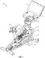
- FIG. 1is a perspective view of an exercise bicycle, according to at least one embodiment of the present disclosure
- FIG. 2is a side view of an elliptical trainer, according to at least one embodiment of the present disclosure
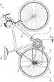
- FIG. 3is a side view of a bicycle, according to at least one embodiment of the present disclosure.
- FIG. 4-1is a side schematic representation of a drivetrain and wheel in an unlocked state, according to at least one embodiment of the present disclosure
- FIG. 4-2is a side schematic representation of the embodiment of a drivetrain and wheel of FIG. 4-1 in an unlocked state with the wheel rotating without an input force from the drivetrain;
- FIG. 5is a side schematic representation of the embodiment of a drivetrain and wheel of FIGS. 4-1 and 4-2 in a locked state;
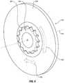
- FIG. 6-1is a right perspective view of an embodiment of a locking mechanism in an unlocked state, according to at least one embodiment of the present disclosure
- FIG. 6-2is a right perspective view of the embodiment of a locking mechanism of FIG. 6-1 in a locked state
- FIG. 7is an axial cross-sectional view of the embodiment of a locking mechanism of FIG. 6-1 ;
- FIG. 8is a left perspective view of the embodiment of a locking mechanism of FIG. 6-1 ;
- FIG. 9is an inside view of a rotatable handle of a locking mechanism, according to at least one embodiment of the present disclosure.
- FIG. 10is a side cross-sectional view of a locking mechanism with a friction clutch, according to at least one embodiment of the present disclosure.
- FIG. 11is a side cross-sectional view of an electrically actuated locking mechanism, according to at least one embodiment of the present disclosure.
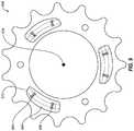
- FIG. 12is a perspective view of a wheel member of a locking mechanism with axially oriented interlocking features, according to at least one embodiment of the present disclosure
- FIG. 13is a side cross-section schematic representation of a locking mechanism including a fluid positioned therein, according to at least one embodiment of the present disclosure
- FIG. 14is a perspective view of a locking mechanism with radially movable components, according to at least one embodiment of the present disclosure.
- FIG. 15is a flowchart illustrating a method of selectively rotationally fixing a pedaled drivetrain and a wheel, according to at least one embodiment of the present disclosure.
- a drivetrainmay include a freewheel hub with a selectively actuatable locking mechanism to bypass the freewheel hub and create a direct drive linkage.
- a lockable hubmay provide additional training and/or propulsion options while increasing efficiency, safety, and enjoyment for a user.
- FIG. 1 through FIG. 3are examples of human-powered cycling systems. Each receives a circular or elliptical input from a user, and may transmit that input to a wheel or flywheel in one or two rotational directions.
- FIG. 1is a perspective view of an embodiment of an exercise bicycle 100 , according to the present disclosure.
- the exercise bicycle 100may include a frame 102 that supports a drivetrain 104 and at least one wheel 106 .
- the frame 102may further support a seat 108 for a user to sit upon, handlebars 110 for a user to grip, one or more displays 112 , or combinations thereof.
- an exercise bicycle 100may include a seat 108 but lack handlebars 110 , as a user may recline in the seat 108 without a need to stabilize herself during riding.
- Such embodimentsmay include a display 112 despite lacking handlebars 110 .
- an exercise bicycle 100may use one or more displays 112 to display feedback or other data regarding the operation of the exercise bicycle 100 .
- the drivetrain 104may be in data communication with the display 112 such that the display 112 presents real-time information collected from one or more sensors on the drivetrain 104 .
- the display 112may present information to the user regarding cadence, wattage, simulated distance, duration, simulated speed, resistance, incline, heart rate, respiratory rate, other measured or calculated data, or combinations thereof.
- the display 112may present use instructions to a user, such as workout instructions for predetermined workout regimens (stored locally or accessed via a network); live workout regimens, such as live workouts broadcast via a network connection; or simulated bicycle rides, such as replicated stages of real-world bicycle races.
- the display 112may present one or more entertainment options to a user during usage of the exercise bicycle 100 .
- the display 112may display broadcast or cable television, locally stored videos and/or audio, video and/or streamed via a network connection, video and/or audio displayed from a connected device (such as a smartphone, laptop, or other computing device connected to the display 112 ) or other entertainment sources.
- an exercise bicycle 100may lack a display 112 and provide information regarding the drivetrain 104 or other exercise session data to an external or peripheral device.
- the exercise bicycle 100may communicate with a smartphone, wearable device, tablet computer, laptop, or other electronic device to allow a user to log their exercise information.
- the exercise bicycle 100may have a computing device 114 in data communication with one or more components of the exercise bicycle 100 .
- the computing device 114may allow the exercise bicycle 100 to collect information from the drivetrain 104 and display such information in real-time.
- the computing device 114may send a command to activate one or more components of the frame 102 and/or drivetrain 104 to alter the behavior of the exercise bicycle 100 .
- the frame 102may move to simulate an incline or decline displayed on the display 112 during a training session.
- the drivetrain 104may change to alter resistance, gear, or other characteristics to simulate different experiences for a user.
- the drivetrain 104may increase resistance to simulate climbing a hill or other experience that requires greater energy input from the user, or the drivetrain 104 may change gear (e.g., physically or “virtually”) and the distance calculated by the computing device 114 may reflect the selected gear.
- geare.g., physically or “virtually”
- the drivetrain 104may be in data communication with the display 112 such that the drivetrain 104 may change in response to simulate one or more portions of an exercise experience.
- the display 112may present an incline to a user and the drivetrain 104 may increase in resistance to reflect the simulated incline.
- the display 112may present an incline to the user and the frame 102 may incline and the drivetrain 104 may increase resistance simultaneously to create an immersive experience for a user.
- the computing device 114may allow tracking of exercise information, logging of exercise information, communication of exercise information to an external electronic device, or combinations thereof with or without a display 112 .
- the computing device 114may include a communications device that allows the computing device 114 to communicate data to a third-party storage device (e.g., internet and/or cloud storage) that may be subsequently accessed by a user.
- a third-party storage devicee.g., internet and/or cloud storage
- the drivetrain 104may include an input component that receives an input force from the user and a drive mechanism that transmits the force through the drivetrain 104 to a hub that moves a wheel 106 .
- the input componentis a set of pedals 116 that allow the user to apply a force to a belt 118 .
- the belt 118may rotate an axle 120 .
- the rotation of the axle 120may be transmitted to a wheel 106 by a hub 122 .
- the belt 118may rotate a portion of the hub 122 , and the wheel 106 and hub 122 may be supported by the axle 120 while remaining rotationally uncoupled from the axle 120 .
- the present disclosurecontemplates a drive mechanism engaging with either the axle 120 and/or a portion of the hub 122 .
- the wheel 106may be a flywheel.
- the hub 122may be a freewheel hub 122 that allows the wheel 106 to continue rotating if the rotational velocity of the wheel 106 exceeds that of the axle 120 .
- the hub 122may be a direct drive or “fixed gear” hub 122 that communicates torque between the axle 120 and the wheel 106 in both directions about the rotational axis 124 of the wheel 106 , axle 120 , and hub 122 .
- the hub 122may be selectively movable from a freewheel behavior in an unlocked state to a direct drive behavior in a locked state to further enhance a user's experience and/or provide additional exercise options to a user.
- the unlocked statemay transmit an input torque from the drivetrain to a wheel in a first rotational direction and may transmit little or no torque in a second rotational direction.
- the unlocked statemay transmit substantially all of an input torque (less drivetrain losses and up to a tensile or other yield strength of the components) in the first rotational direction and less than 5% of an input torque in the second rotational direction.
- the unlocked statemay transmit substantially all of an input torque in the first rotational direction and less than 3% of an input torque in the second rotational direction.
- the unlocked statemay transmit substantially all of an input torque in the first rotational direction and less than 1% of an input torque in the second rotational direction. In at least some examples, the unlocked state may transmit less than 0.1% of an input torque in the second rotational direction.
- the locked statemay transmit substantially all of an input torque (less drivetrain losses and up to a tensile or other yield strength of the components) in the first rotational direction and in the second rotational direction. In some embodiments, the locked state may transmit greater than 95% of an input torque in the first rotational direction and in the second rotational direction. In other embodiments, the locked state may transmit greater than 97% of an input torque in the first rotational direction and in the second rotational direction. In yet other embodiments, the locked state may transmit greater than 99% of an input torque in the first rotational direction and in the second rotational direction.
- the locked statemay transmit greater than 300 Newton-meters (N-m) of torque from the drivetrain to the wheel in the first rotational direction and second rotational direction without slipping of the drivetrain and wheel relative to one another. In other embodiments, the locked state may transmit greater than 400 N-m of torque from the drivetrain to the wheel in the first rotational direction and second rotational direction without slipping of the drivetrain and wheel relative to one another. In some embodiments, the locked state may transmit greater than 500 N-m of torque from the drivetrain to the wheel in the first rotational direction and second rotational direction without slipping of the drivetrain and wheel relative to one another.
- N-mNewton-meters
- a brake 123may be positioned on or supported by the frame 102 and configured to stop or slow the wheel 106 or other part of the drivetrain 104 .
- the brake 123may be a friction brake, such as a drag brake, a drum brake, caliper brake, a cantilever brake, or a disc brake, that may be actuated mechanically, hydraulically, pneumatically, electronically, by other means, or combinations thereof.
- the brake 123may be a magnetic brake that slows and/or stops the movement of the wheel 106 and/or drivetrain 104 through the application of magnetic fields.
- the brakemay be manually forced in contact with the wheel 106 by a user rotating a knob to move the brake 123 .
- the brake 123may be a disc brake with a caliper hydraulically actuated with a lever on the handlebars 110 .
- the brakemay be actuated by the computing device 114 in response to one or more sensors.
- the changing of the drivetrain 104 from a freewheel (unidirectional) drivetrain to a direct-drive (bi-directional) drivetrainmay be limited by a lockout device.
- the drivetrain 104may be movable between the locked state and the unlocked state below a defined rotational velocity of the wheel 106 .
- the lockout devicemay prevent the movement between the locked state and the unlocked state when the wheel 106 has a rotational velocity greater than 60 revolutions per minute (RPM). In other embodiments, the lockout device may prevent the movement between the locked state and the unlocked state when the wheel 106 has a rotational velocity greater than 30 RPM.
- RPMrevolutions per minute
- the lockout devicemay prevent the movement between the locked state and the unlocked state when the wheel 106 has a rotational velocity greater than 10 RPM. In further embodiments, the lockout device may prevent the movement between the locked state and the unlocked state when the wheel 106 has a rotational velocity greater than 0 RPM. In at least one embodiment, the lockout device may prevent the movement between the locked state and the unlocked state unless the brake 123 is engaged with the wheel 106 and/or drivetrain 104 to prevent movement of the wheel 106 and/or drivetrain.
- the lockout device and/or the safety brakemay be in data communication with one or more sensors, such as a speed sensor, a torque sensor, a wattmeter, or other sensor to measure and monitor the user's inputs and movement of the drivetrain 104 and/or wheel 106 .
- sensorssuch as a speed sensor, a torque sensor, a wattmeter, or other sensor to measure and monitor the user's inputs and movement of the drivetrain 104 and/or wheel 106 .
- FIG. 2is another embodiment of a cycling system that may be used for exercise.
- An elliptical trainer 200may include a frame 202 that supports a drivetrain 204 connected to a wheel 206 with a safety brake 223 .
- the frame 202may support a display 212 and/or computing device 214 to present, track, log, store, or communicate information for a user.
- the drivetrain 204may have inputs from the user including both handlebars 210 and pedals 216 .
- the drive mechanismsuch as the linkage 218 of the illustrated embodiment, may receive force from the user through movement of the handlebars 210 and/or the pedals 216 .
- the pedals 216may cycle through an elliptical path, while the handlebars 210 may oscillate in an arcuate path (arrows A and B), to drive the linkage 218 .
- the drivetrain 204may have stationary handlebars 210 and the pedals 216 may drive the linkage 218 independently of the handlebars 210 .
- the linkage 218may rotate an axle 220 , and the rotation of the axle 220 may be transmitted to the wheel 206 by a hub 222 .
- the hub 222may be a freewheel hub 222 that allows the wheel 206 to continue rotating if the rotational velocity of the wheel 206 exceeds that of the axle 220 .
- the hub 222may be a direct drive hub 222 that communicates torque between the axle 220 and the wheel 206 in both directions about the rotational axis 224 of the wheel 206 , axle 220 , and hub 222 .
- the hub 222may be selectively movable from a freewheel behavior to a direct drive behavior to further enhance a user's experience and/or provide additional exercise options to a user.
- FIG. 3is a side view of an embodiment of another cycling system, according to the present disclosure.
- a bicycle 300may have a frame 302 that supports a drivetrain 304 configured to rotate a wheel 306 and seat 308 and/or handlebars 310 to support a user.
- the drivetrain 304may include pedals 316 to receive input force from a user and drive mechanism, such as a chain 318 or belt, to transmit the force to an axle 320 .
- a hub 322may transmit torque from the axle 320 to the wheel 306 to rotate the wheel 306 about a rotational axis 324 .
- the hub 322may be a freewheel hub 322 that allows the wheel 306 to continue rotating if the rotational velocity of the wheel 306 exceeds that of the axle 320 .
- the hub 322may be a direct drive hub 322 that communicates torque between the axle 320 and the wheel 306 in both directions about the rotational axis 324 of the wheel 306 , axle 320 , and hub 322 .
- the hub 322may be selectively movable from a freewheel behavior to a direct drive behavior to further enhance a user's experience and/or provide additional exercise options to a user.
- the hub 322may be movable between a locked position and an unlocked position by a controller 326 positioned on the handlebars 310 or other location accessible by the user during use of the bicycle 300 .
- FIG. 4-1 through FIG. 5are schematic representations of an embodiment of a drivetrain and wheel that may be used in the cycling systems described herein (e.g., the exercise bicycle 100 described in relation to FIG. 1 , elliptical trainer 200 described in relation to FIG. 2 , and bicycle 300 described in relation to FIG. 3 ).
- a pedaled drivetrain 404may be configured to rotate a wheel 406 .
- a “pedaled drivetrain”, as used herein,may include any linkage, mechanism, or system that receives an input force from a human in a cyclic pattern and transmits that force to rotate a wheel.
- a pedaled drivetrainmay include platform pedals, as are common on exercise bicycles and conventional bicycles for transportation.
- a pedaled drivetrainmay include “clipless pedals” that engage with a cleat on a user's shoe to allow more efficient power transfer to the drivetrain throughout the pedal stroke.
- a pedaled drivetrainmay include hand pedals or grips that allow a user to cycle the pedals of the drivetrain with their hands, for example, to strengthen or rehabilitate the user's upper body.
- a drivetrain having hand pedalsmay allow a user with limited or no lower body control to operate a cycling system for exercise and/or transportation.
- FIG. 4-1is a side view of a drivetrain 404 in an unlocked state transmitting a forward torque 428 from pedals 416 to a wheel 406 about a rotational axis 424 of the wheel 406 in a first rotational direction 430 .
- the drivetrain 404may include a drive mechanism that transmits the force from the pedals 416 to the wheel 406 .
- the chain 418may engage with a first gear 432 rotatable by the pedals 416 .
- the chain 418may also engage with a second gear 434 on the axle 420 to apply a torque to the axle 420 around the rotational axis 424 and rotate the axle 420 .
- the axle 420transmits torque to the wheel through a hub 422 .
- the hub 422is a freewheel hub that transmits torque in the first rotational direction 430 .
- FIG. 4-2illustrates the drivetrain 404 of FIG. 4-1 with the pedals 416 moving at a slower rotational rate than the wheel 406 in the first rotational direction 430 .
- the pedals 416may be stationary as the wheel 406 rotates due to rotational inertia or due to contact with the ground while a bicycle is moving.
- the pedals 416may be rotating in a second rotational direction, opposite the first rotational direction.
- the pedals 416may move the chain 418 and axle 420 in the second rotational direction, and the freewheel hub 422 may transmit little or no torque to the wheel 406 to disrupt the rotation of the wheel 406 in the first rotational direction 430 .
- FIG. 5is a side view of the drivetrain 404 of FIG. 4-1 in a second, locked state.
- the drivetrain 404may transmit torque to the wheel 406 in both the first rotational direction 430 and in an opposing second rotational direction 436 about the rotational axis 424 .
- the torque from rotation of the axle 420is directly transmitted to the wheel 406 in either rotational direction.
- a usermay apply a forward torque 428 to the pedals 416 , which is transmitted through the chain 418 to the axle 420 .
- the drivetrain 404rotationally locks the axle 420 and wheel 406 in the locked state. Movement of the wheel 406 , conversely, may apply a torque to the axle 420 through the hub 422 , moving the pedals 416 .
- the pedals 416when the wheel is moving in the first rotational direction 430 , the pedals 416 also move.
- the usermay apply a rearward torque 438 through the pedals 416 to decelerate the wheel 406 (i.e., accelerate the wheel 406 in the second rotational direction 436 ) without the need for other brakes on the wheel 406 itself.
- the drivetrainmay transition between the unlocked state and the locked state during movement of the drivetrain, and in other embodiments, the drivetrain may transition from the unlocked state to the locked state when the drivetrain is stationary. In yet other embodiments, a drivetrain may be configured to transition from the unlocked state to the locked state both during movement and while stationary. In at least one example, a drivetrain may transition between the unlocked state and the locked state while the axle of the drivetrain and the wheel are moving at an equivalent rotational velocity.
- FIG. 6-1is a perspective view illustrating a drivetrain 504 in an unlocked state.
- a drivetrain 504may have a drive mechanism such as the belt 518 depicted in the embodiment of FIG. 6-1 .
- the drive mechanismmay rotate an axle 520 and/or hub 522 about a rotational axis 524 of the axle 520 , hub 522 , and wheel 506 .
- the hub 522may transmit forward torque 528 to the wheel 506 and accelerate the wheel 506 in a forward first rotational direction 530 .
- the hub 522may behave similarly to a conventional freewheel hub, allowing input of rearward torque 538 from the drive mechanism to be not transmitted to the wheel 506 , thereby allowing the wheel 506 to rotate freely in the first rotational direction 530 .
- the drivetrain 504may include a locking mechanism 540 .
- the locking mechanism 540may be movable between an unlocked state (illustrated in FIG. 6-1 ) and a locked state (illustrated in FIG. 6-2 ), as described herein.
- the locking mechanism 540may have at least one wheel member 542 that is movable to engage with a drive member 544 .
- the wheel member 542may be movable in an axial direction 546 along the rotational axis 524 of the axle 520 , hub 522 , and wheel 506 .
- the wheel member 542may be movable in a radial direction or other direction perpendicular to the rotational axis 524 .
- the locking mechanism 540may be movable only when the safety brake 523 is engaged.
- the drive member 544may be rotationally fixed relative to the drive mechanism (e.g., the belt 518 ) and/or the axle 520 , such that the drive member 544 rotates at the same rotational velocity as the axle 520 .
- the wheel member 542may be rotationally fixed relative to the wheel 506 , such that the wheel member 542 rotates at the same rotational velocity as the wheel 506 . While in the illustrated embodiment of FIGS. 6-1 and 6-2 the wheel member 542 is movable relative to the wheel 506 and to the drive member 544 , in other embodiments, the drive member 544 may be movable relative to the wheel 506 and/or wheel member 542 instead of or in addition to the wheel member 542 .
- the wheel member 542 and/or drive member 544may include a unidirectional bearing.
- the freewheel hub 522may transmit torque in a first rotational direction 530 .
- the unidirectional bearingmay transmit torque through the locking mechanism 540 in a second rotational direction. In the locked state, therefore, the freewheel hub 522 and unidirectional bearing of the locking mechanism 540 may work in concert to rotationally fix the wheel 506 to the drivetrain 504 .
- the drive member 544may be selectively coupled to the wheel member 542 to transfer torque from the drive member 544 to the wheel member 542 , and for the wheel member 542 to transfer torque to the drive member 544 .
- Engaging the wheel member 542 and drive member 544may allow a user greater control over the movement of the wheel 506 and/or may enhance a user's exercise experience.
- the wheel member 542 and the drive member 544may engage by one or more interlocking mechanical features.
- the embodiment illustrated in FIG. 6-1 and FIG. 6-2depicts the engagement of a drive member 544 having a plurality of radially oriented (relative to the rotational axis 524 ) interlocking features 548 with a wheel member 542 having a plurality of complementary interlocking features 550 .
- the wheel member 542 and drive member 544may have axially oriented interlocking features.
- the wheel member 542 and drive member 544may engage through other non-mechanical engagement mechanisms, such as a friction clutch plate that uses contact friction between the wheel member 542 and drive member 544 , magnetic engagement between the wheel member 542 and drive member 544 , viscous drag engagement between the wheel member 542 and drive member 544 (e.g., surface engagement with a layer of fluid therebetween), or combinations thereof.
- a friction clutch platethat uses contact friction between the wheel member 542 and drive member 544
- magnetic engagement between the wheel member 542 and drive member 544e.g., magnetic engagement between the wheel member 542 and drive member 544
- viscous drag engagement between the wheel member 542 and drive member 544e.g., surface engagement with a layer of fluid therebetween
- FIG. 6-2is a perspective view of the drivetrain 504 and wheel 506 of FIG. 6-1 in a locked state.
- the wheel member 542may move in the axial direction toward the drive member 544 , engaging the wheel member 542 and the drive member 544 .
- the wheel member 542 and drive member 544may be rotationally fixed relative to one another such that the hub 522 is bypassed and torque is transmitted from the drive mechanism (i.e., the belt 518 ) and/or axle 520 directly to the wheel 506 .
- the locking mechanism 540may transmit forward torque 528 from the belt 518 and/or axle 520 to the wheel 506 to accelerate the wheel 506 in the first rotational direction 530 , and the locking mechanism 540 may transmit rearward torque 538 from the belt 518 and/or axle 520 to the wheel 506 to accelerate the wheel 506 in the second rotational direction 536 .
- the wheel member 542 of the locking mechanism 540may be rotationally fixed to the wheel 506 and axially movable relative to the wheel 506 one or more posts 552 .
- the wheel member 542may be movable relative to the wheel 506 in the axial direction 546 along another mechanism and may transfer torque to the wheel 506 through one or more splines, frictional engagement, magnetic engagement, viscous engagement, or combinations thereof.
- FIG. 7is an axial cross-sectional view of an embodiment of a locking mechanism 640 , according to the present disclosure.
- the locking mechanism 640may selectively engage in a locked state to bypass a hub 622 and transmit torque directly from a drive mechanism 618 to a wheel 606 .
- the locking mechanism 640is moved between the unlocked state (depicted in FIG. 7 ) and a locked state by mechanically moving a portion of the locking mechanism 640 in an axial direction 646 (i.e., in the direction of the axle 620 ).
- the movable portion of the locking mechanism 640may be movable along a post 652 or other support member.
- the wheel member 642 of the locking mechanism 640may be supported by a plurality of posts 652 rotationally fixing the wheel member 642 to the wheel 606 .
- the wheel member 642may be movable by a pushrod 654 that may apply an axial force to move the wheel member 642 in the axial direction 646 .
- the axial position of the pushrod 654may be selected by the user.
- the axial position of the pushrod 654may be selected by an electric motor in data communication with a computing device, such as a computing device described in relation to FIG. 1 through FIG. 3 .
- a computing devicemay selectively move the locking mechanism between the locked state and the unlocked state based upon a predetermined exercise plan or based upon information from one or more sensors in communication with the computing device.
- the axial position of the pushrod 654may be at least partially controlled by a handle 656 .
- the handle 656may allow the user to manually adjust the position of the pushrod 654 relative to the wheel 606 and/or drive member 644 .
- the handle 656may be movable in the axial direction 646 to urge the pushrod 654 in the axial direction 646 .
- the handle 656may be rotatable with a sloped surface to urge the pushrod 654 in the axial direction 646 .
- the handle 656may urge the pushrod 654 axially relative to the wheel member 642 .
- the wheel member 642 and drive member 644may engage via interlocking features 648 on the drive member 644 and complementary interlocking features 650 on the wheel member 642 .
- the interlocking features 648 and complementary interlocking features 650may be misaligned. In such instances, urging the wheel member 642 toward the drive member 644 may grind or damage the interlocking features 648 and complementary interlocking features 650 .
- the locking mechanism 640may include a motor 672 that urges the pushrod 654 and/or wheel member 642 in the axial direction 646 .
- the locking mechanism 640may include an electric motor, a pneumatic piston-and-cylinder, a hydraulic piston-and-cylinder, a linear magnet, or other actuator to urge the wheel member 642 and drive member 644 toward one another.
- the motor 672may apply a torque to the handle 656 to rotate the handle 656 and urge the pushrod 654 and/or wheel member 642 in the axial direction 646 .
- a biasing element 658may be positioned between the pushrod 654 and the wheel member 642 .
- the biasing element 658may apply a force to the wheel member 642 based upon the axial position of the pushrod 654 (e.g., based upon Hooke's Law).
- the biasing element 658may be a coil spring, such as illustrated in FIG. 7 .
- the biasing element 658may be a wave spring, a leaf spring, a compressible bushing, a compressible fluid, one or more magnets, or combinations thereof.
- the biasing element 658may urge the wheel member 642 and drive member 644 toward one another until the interlocking features 648 on the drive member 644 and complementary interlocking features 650 of the wheel member 642 align, at which point, the wheel member 642 and drive member 644 may move toward one another and the interlocking features 648 and complementary interlocking features 650 may engage such that the locking mechanism 640 is in the locked state.
- FIG. 8is a perspective view of the embodiment of a wheel 606 and handle 656 of FIG. 7 .
- the handle 656may be rotatable about the rotational axis 624 .
- rotating the handle 656 in a locking direction 660 about the rotational axis 624may move at least a portion of the locking mechanism in the axial direction 646 , moving the locking mechanism 640 to the locked state.
- the handle 656may have one or more surface features 662 to increase or improve a user's grip or tactile feedback with the handle 656 .
- the surface featuresmay include a textured surface, a rubberized surface, protrusions, recesses, or other features that may allow a user to identify and operate the handle more easily without visual confirmation.
- FIG. 9is a side view of the handle 656 of FIG. 8 illustrating the side facing the wheel and locking mechanism.
- a handle 656may have one or more sloped surfaces 664 at least partially recessed therein.
- the sloped surface 664may have a deep end 666 and a shallow end 668 .
- the rotating the handle 656 about the rotational axis 624may cause the sloped surface 664 to move relative to an end of a pushrod (such as pushrod 654 described in relation to FIG. 7 ) and urge the pushrod axially (i.e., perpendicularly to the rotation of the handle 656 ) as the sloped surface 664 moves past the pushrod.
- a pushrodsuch as pushrod 654 described in relation to FIG. 7
- the handle 656may be bistable.
- a bistable handle 656may have two positions in which the handle 656 is stable.
- the embodiment of a handle 656 illustrated in FIG. 7 through 9is stable at either end of the sloped surface 664 .
- a biasing element in a locking mechanismmay bias a pushrod toward the handle 656 and/or toward the sloped surface 664 .
- the pushrodmay press against the sloped surface 664 under force from the biasing element.
- the contact of the pushrod against the sloped surface 664may rotate the handle 656 about the rotational axis 624 until the pushrod is resting in the deep end 666 of the sloped surface 664 .
- the deep end 666may, therefore, be a first stable position of the handle 656 .
- the shallow end 668 of the sloped surface 664may have a recess or depression 670 therein, such that the pushrod may rest in the recess or depression 670 , creating a second stable position of the handle 656 .
- the contact from the pushrodmay bias the handle 656 toward the first stable position.
- the first stable positionmay be an unlocked state of the locking mechanism and the second stable position may be a locked state of the locking mechanism.
- the locking mechanismmay, therefore, be biased toward the unlocked state of the locking mechanism when between positions.
- the locking mechanismmay be biased toward a locked state of the locking mechanism when between positions.
- the sloped surfacemay be continuous and undulating about the rotational axis 624 of the handle 656 .
- the handle 656may rotate through indexed stable positions that alternate between a locked state and an unlocked state. For example, continuous rotation of the handle 656 in a first direction may cycle the locking mechanism between a locked state and an unlocked state.
- FIG. 6-1 through 9illustrate an embodiment of a locking mechanism with radial interlocking mechanical features to move the locking mechanism between a locked state and an unlocked state through axial movement
- other locking mechanismsmay use other engagement methods.
- embodiments of locking mechanismsmay transmit torque in a locked state using interlocking mechanical features oriented in the axial direction, friction forces oriented in the axial direction, friction forces oriented in the radial direction, magnetic forces, viscous drag forces, other engagement forces, or combinations thereof.
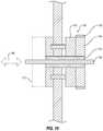
- FIG. 10illustrates another embodiment of a locking mechanism 740 for use in pedaled cycling systems.
- the locking mechanism 740may have a wheel member 742 and a drive member 744 .
- the drive member 744may be driven by a drive mechanism 718 directly.
- the drive mechanism 718may drive at least part of an axle 720 and/or hub 722 to which the drive member 744 is rotationally fixed.
- the wheel member 742may be movable in an axial direction 746 toward or away from the drive member 744 .
- the wheel member 742 and drive member 744may be movable relative to one another by manual manipulation by a user (such as the handle 656 described in relation to FIG. 7 through FIG. 9 ) or by a motor 772 .
- a surface of the wheel member 742may contact a surface of the drive member 744 .
- the friction between the wheel member 742 and drive member 744may be sufficient such that torque applied to the drive member 744 by the drive mechanism 718 may be transferred fully to the wheel member 742 (e.g., without slippage between the wheel member 742 and drive member 744 ) during usage.
- the surfaces of the wheel member 742 and drive member 744 in contact with one anothermay be substantially flat, with little or no surface relief or other interlocking features.
- the wheel member 742 and drive member 744may transmit torque therebetween similar to a friction clutch plate system.
- the wheel member 742 and drive member 744may have one or more surface features having a height in the axial direction 746 to increase friction and/or improve torque transmission between the wheel member 742 and drive member 744 .
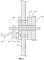
- FIG. 11is a side cross-sectional view of an embodiment of a locking mechanism 840 with an electric motor 872 that moves the locking mechanism between the locked state and the unlocked state.
- the electric motor 872may move one or more extensions 874 in the axial direction 846 .
- the electric motor 872may be in communication with one or more controllers (such as controller 326 described in relation to FIG.
- the electric motor 872may be in data communication via a wireless communication with one or more controllers and/or computing devices. In some embodiments, the electric motor 872 may be in data communication with one or more sensors that allow for feedback to the user and/or a computing device. The electric motor 872 may, therefore, operate as a lockout device of the locking mechanism 840 . The electric motor 872 may be controlled by a computing device that is also in communication with one or more sensors.
- the state of the locking mechanism 840may, therefore, be only changeable when the computing device receives information from the sensors that confirm the wheel 806 is stationary or below a threshold rotational velocity, or when the sensors confirm the user is not applying a torque to the drive member 844 .
- the computing devicemay send a command to the electric motor 872 to actuate the locking mechanism 840 when both the drive member 844 and the wheel member 842 are stationary.
- the computing devicemay send a command to the electric motor 872 to actuate the locking mechanism 840 when both the drive member 844 and the wheel member 842 have equal rotational velocities.
- the extensions 874may contact or be connected to the wheel member 842 .
- the extensions 874may be uncoupled from the wheel member 842 , allowing the wheel member 842 to rotate with the wheel 806 during use.
- the extensions 874may apply a force in the axial direction 846 while sliding on an outer surface 878 of the wheel member 842 as the wheel 806 and wheel member 842 continue to rotate.
- the electric motor 872 and extensions 874may apply an axial force to the wheel member 842 without impairing the rotation of the wheel 806 or otherwise interrupting the use of the wheel 806 .
- the extensions 874may slide along the outer surface 878 of the wheel member 842 .
- the extension 874may include one or more bearings that contact outer surface 878 of the wheel member 842 .
- the outer surface 878 of the wheel member 842may include one or more movable rings that may receive an axial force from the extensions 874 and transmit little or no torque from the contact with the extensions 874 to the remainder of the wheel member 842 and/or wheel 806 .
- a wheel member and/or drive membermay have one or more surface features that reduce the axial force necessary to transmit torque between the wheel member and drive member in the locked state.
- FIG. 12is a perspective view of an embodiment of a wheel member 942 that includes an interlocking mechanical feature 948 oriented in the axial direction 946 .
- the interlocking mechanical featuresmay be symmetrical about a rotational axis 924 (e.g., have the same profile in a first rotational direction and in a second rotational direction).
- a conventional gearmay have a plurality of teeth with a symmetrical profile in either rotational direction.
- the embodiment of a face gear illustrated in FIG. 12has a plurality of surface features with an asymmetric profile.
- the interlocking mechanical features 948may engage more aggressively in a second rotational direction 936 than a first rotational direction 930 .
- a rearward face 978 of the interlocking mechanical feature 948may have a steeper angle relative to the second rotational direction 936 than a forward face 980 relative to the first rotational direction 930 .
- An asymmetric profile of the interlocking mechanical features 948may allow the locking mechanism to “slip” in the first rotational direction 930 while engaging more aggressively in the second rotational direction as the rearward faces 978 compressively engage in a locked state in the second rotational direction 936 .
- a drivetrain according to the present disclosuremay rely upon a freewheel hub to transmit an input torque, therefore, a less aggressive profile in the first rotational direction may reduce the risk of damage to the locking mechanism without impairing the transmission of torque to the wheel in the first rotational direction.
- a locking mechanismmay have a locked state and an unlocked state.
- a locking mechanismmay further have an intermediate state.
- An intermediate statemay transmit some torque between a wheel member and a drive member without rotationally fixing the drive member and the wheel member.
- FIG. 13illustrates an embodiment of a locking mechanism 1040 including a wheel member 1042 and a drive member 1044 with a fluid 1082 positioned therebetween.
- the fluid 1082may be positioned in a housing 1084 .
- the fluid 1082may be a compressible fluid.
- the fluid 1084may be an incompressible fluid.
- the fluid 1082may have a viscosity that produced a drag force 1086 between the wheel member 1042 and the drive member 1044 .
- the drag force 1086may increase with a greater rotational velocity differential between the wheel member 1042 and the drive member 1044 .
- the drag force 1086may increase as a spacing 1088 between the wheel member 1042 and the drive member 1044 decreases.
- the spacing 1088 of the wheel member 1042 and drive member 1044may be changeable by manual manipulation by a user (such as the handle 656 described in relation to FIG. 7 through FIG. 9 ) or by a motor 1072 .
- the locking mechanism 1040may have an unlocked state with the wheel member 1042 and the drive member 1044 at a spacing sufficient to transmit less than 5% of the torque therebetween, a locked state in which the wheel member 1042 and the drive member 1044 contact one another and are rotationally fixed to one another by friction forces and/or a mechanical interlock, and an intermediate state in which the fluid drag forces 1086 transmit greater than 5% of a torque between the wheel member 1042 and the drive member 1044 and the wheel member 1042 and the drive member 1044 are not rotationally fixed relative to one another.
- An intermediate statemay be beneficial to allow the wheel member 1042 and the drive member 1044 to approach or match rotational velocities when transitioning between a locked state and an unlocked state during usage.
- the fluid 1082may have a variable viscosity.
- the fluid 1082may be a magnetorheological fluid that changes effective viscosity with the application of a magnetic field to the fluid.
- the fluid 1082may have a variable viscosity with a range sufficient such that a low end of the viscosity range (i.e., a low viscosity regime with no magnetic field applied) transmits less than 5% of the torque between the drivetrain and the wheel and a high end of the viscosity range (i.e., high viscosity regime with a magnetic field applied) rotationally fixes the drivetrain and wheel in a locked state.
- a variable viscosity fluidmay allow for a locking mechanism with a fixed spacing 1088 between the wheel member 1042 and the drive member 1044 .
- a locking mechanismmay include a wheel member and/or a drive member that is movable in a radial direction relative to a rotational axis of the wheel.
- a pedaled drivetrainmay have spatial limitations in the axial direction, and axial movement of a portion of the locking mechanism may be undesirable.
- increasing a width of a wheel, a hub, a cassette, or other portion of the drivetrain in an axial directionmay require altering a frame of an existing bicycle or other device. It may be beneficial, therefore to move one or more components in a radial direction to accommodate different form factors and/or housing dimensions.
- FIG. 14is a perspective view of another embodiment of a locking mechanism 1140 configured to selectively rotationally fix a drive mechanism 1118 and a wheel 1106 .
- a locking mechanism 1140may have a wheel member 1142 and a drive member 1144 that are positioned with at least part of one of the wheel member 1142 and drive member 1144 radially outside the other.
- at least a portion of a wheel member 1142may be positioned axially overlapping a portion of the drive member 1144 with respect to the rotational axis 1124 and further from the rotational axis 1124 in a radial direction 1190 perpendicular to the rotational axis 1124 .
- at least a portion of the wheel member 1142may operate similarly to a drum brake (for example, when actuated by a motor 1172 ) to compress the drive member 1144 and transmit torque therebetween in both a first rotational direction 1130 and a second rotational direction 1136 .
- FIG. 15is a flowchart illustrating an embodiment of a method 1291 of selectively rotationally fixing a pedaled drivetrain.
- the method 1291may include receiving a first input force from a user at 1292 .
- the first input forcemay be received by foot pedals, such as platform pedals, clip pedals, clipless pedals, or other pedals configured to receive force applied by a user's foot in a cyclic motion.
- the first input forcemay be received by hand pedals, such as rotatable grips, platforms, reciprocating handles, or other hand grips configured to receive force applied by a user's hand in a cyclic motion.
- the method 1291may further include converting the first input force to a first input torque in a first rotational direction at 1293 and transmitting the first input torque through a freewheel hub to a wheel in a first rotational direction of the wheel at 1294 .
- the method 1291includes moving a locking mechanism from an unlocked state to a locked state to rotationally fix at least a portion of the drivetrain to the wheel at 1295 .
- the locking mechanismis in the locked state, the method 1291 includes receiving a second input force from a user at 1296 and converting the second input force to a second input torque in a second rotational direction opposite the first rotational direction at 1297 .
- the method 1291then includes transmitting the second input torque through the locking mechanism in the locked state to the wheel in a second rotational direction of the wheel at 1298 .
- the methodmay include moving the locking mechanism to an intermediate state.
- the intermediate state of the locking mechanismmay transmit between 5% and 95% of a third input torque between the drivetrain and the wheel.
- the intermediate statemay transmit torque while allowing the drivetrain and the wheel to rotate at different rotational velocities.
- the locking mechanismmay remain in the intermediate state until the drivetrain and the wheel have rotational velocities within 5% of one another.
- the locking mechanismmay move the locked state to rotationally fix the drivetrain and the wheel relative to one another.
- the present inventionrelates to selectively moving a hub in a pedaled drivetrain from an unlocked state to a locked state.
- the unlocked statemay transmit an input torque from the drivetrain to a wheel in a first rotational direction and may transmit little or no torque in a second rotational direction.
- the unlocked statemay transmit substantially all of an input torque (less drivetrain losses and up to a tensile or other yield strength of the components) in the first rotational direction and less than 5% of an input torque in the second rotational direction.
- the unlocked statemay transmit substantially all of an input torque in the first rotational direction and less than 3% of an input torque in the second rotational direction.
- the unlocked statemay transmit substantially all of an input torque in the first rotational direction and less than 1% of an input torque in the second rotational direction.
- the locked statemay transmit substantially all of an input torque (less drivetrain losses and up to a tensile or other yield strength of the components) in the first rotational direction and in the second rotational direction. In some embodiments, the locked state may transmit greater than 95% of an input torque in the first rotational direction and in the second rotational direction. In other embodiments, the locked state may transmit greater than 97% of an input torque in the first rotational direction and in the second rotational direction. In yet other embodiments, the locked state may transmit greater than 99% of an input torque in the first rotational direction and in the second rotational direction.
- the locked statemay transmit greater than 300 Newton-meters (N-m) of torque from the drivetrain to the wheel in the first rotational direction and second rotational direction without slipping of the drivetrain and wheel relative to one another. In other embodiments, the locked state may transmit greater than 400 N-m of torque from the drivetrain to the wheel in the first rotational direction and second rotational direction without slipping of the drivetrain and wheel relative to one another. In some embodiments, the locked state may transmit greater than 500 N-m of torque from the drivetrain to the wheel in the first rotational direction and second rotational direction without slipping of the drivetrain and wheel relative to one another.
- N-mNewton-meters
- a pedaled drivetrain with a locked state and an unlocked statemay according to the present disclosure may be used in exercise systems or devices, such as stationary bicycles, elliptical trainers, treadmills, cross-country skiing trainers, stationary handcycles, rowing machines, or other exercises systems or devices that include rotational movement of components.
- a pedaled drivetrain with a locked state and an unlocked statemay according to the present disclosure may be used in transportation and/or recreational devices and systems, such as bicycles (road bicycles, mountain bicycles, recumbent bicycles, handcycles, etc.), pedalboats, microlight aircraft, pedal cars, or other pedal-powered vehicles.
- the pedaled drivetrainmay be selectively moved between the locked state and unlocked state by actuating a locking mechanism to engage a wheel member and a drive member.
- the wheel membermay be rotationally fixed to the wheel and the drive member may be rotationally fixed to a component of the drivetrain.
- the wheel member and drive membertransmit less than 5% of an input torque therebetween in the second rotational direction.
- the wheel member and drive membermay transmit greater than 95% of an input torque in the second rotational direction.
- the wheel member and drive membermay selectively engage through the movement of the wheel member and drive member towards one another, and the wheel member and drive member may selectively disengage through the movement of the wheel member and drive member away from one another.
- moving the locking mechanism between the locked state and the unlocked statemay include moving the wheel member relative to the wheel and drivetrain.
- moving the locking mechanism between the locked state and the unlocked statemay include moving the drive member relative to the wheel and drivetrain.
- moving the locking mechanism between the locked state and the unlocked statemay include moving the both the wheel member and drive member relative to the wheel and drivetrain.
- moving the locking mechanism between the locked state and the unlocked statemay include moving the wheel member relative to the wheel and drivetrain in an axial direction of the rotational axis of the wheel.
- moving the locking mechanism between the locked state and the unlocked statemay include moving the drive member relative to the wheel and drivetrain in an axial direction of the rotational axis of the wheel.
- moving the locking mechanism between the locked state and the unlocked statemay include moving the both the wheel member and drive member relative to the wheel and drivetrain in an axial direction of the rotational axis of the wheel.
- the engagement of the wheel member and drive member in the axial directionmay function similarly to a disc brake.
- moving the locking mechanism between the locked state and the unlocked statemay include moving the wheel member relative to the wheel and drivetrain in a radial direction of the rotational axis of the wheel.
- moving the locking mechanism between the locked state and the unlocked statemay include moving the drive member relative to the wheel and drivetrain in a radial direction of the rotational axis of the wheel.
- moving the locking mechanism between the locked state and the unlocked statemay include moving the both the wheel member and drive member relative to the wheel and drivetrain in a radial direction of the rotational axis of the wheel.
- the radial movement of the wheel member and the drive membermay function similarly to a drum brake.
- the wheel member and drive membermay directly contact one another.
- the wheel member and drive membermay engage one another and transmit torque therebetween through frictional engagement, mechanical interlocking features (such as radially and/or axially oriented gear teeth), or other surface features such as splines or uneven surfaces.
- the wheel member and drive membermay engage through frictional engagement of the wheel member and drive being compressed against one another.
- the wheel member and drive membermay have axially oriented interlocking features and the wheel member and drive member may engage through movement relative to one another in the axial direction (such as face gears).
- the wheel member and drive membermay have radially oriented interlocking features and the wheel member and drive member may engage through movement relative to one another in the axial direction (such as splines that rotationally interlock and allow axial translation).
- the wheel member and drive membermay have radially oriented interlocking features and the wheel member and drive member may engage through movement relative to one another in the radial direction (such as interlocking radial teeth).
- the wheel member and drive membermay indirectly engage one another with or without direct contact.
- the wheel member and drive membermay engage one another and transmit torque therebetween through magnetic engagement (permanent magnets and/or electromagnets), fluid drag engagement, or through other forces that do not require contact between the wheel member and drive member.
- a fluidmay be positioned between the wheel member and drive member.
- the drag of the fluidmay transmit at least a portion of the torque between the wheel member and drive member when the wheel member and drive member move relative to one another and induce movement of the fluid therebetween.
- the transmission of torque through the fluid dragmay change with a spacing between the wheel member and drive member. For example, more torque may be transmitted through the fluid drag as a spacing between the wheel member and drive member decreases. In other examples, more torque may be transmitted through the fluid drag in a higher viscosity fluid than in a lower viscosity fluid.
- the fluidmay have a variable viscosity, such as a magnetorheological fluid that changes effective viscosity through the application of a magnetic field.
- the wheel member and/or drive membermay include one or more magnets.
- the magnets of the wheel member and/or drive membermay produce a magnetic field that may interact with and apply a force between the wheel member and the drive member.
- the wheel membermay include a first magnet and the drive member may include a second magnet.
- a magnetic force between the first magnet and second magnetmay increase, enabling the transmission of a greater amount of torque between the wheel member and drive member.
- the first magnet and/or second magnetmay be an electromagnetic that may be selectively magnetized.
- a spacing between the wheel member and drive membermay be constant and the magnetic force therebetween may be increased or decreased by increasing or decreasing the magnetic field of the electromagnet(s).
- moving the locking mechanism between the locked state and the unlocked state (particularly moving into the locked state) while the wheel member and drive member are rotating with different rotational velocitiesmay break, bent, erode, wear, or otherwise damage the wheel member and/or drive member.
- the mechanical interlocking featuresmay grind or bend, inhibiting engagement of the wheel and drive members.
- “slipping” of frictional engagement surfacesmay prematurely wear the frictional engagement surfaces of the wheel member and/or drive member.
- a lockout devicemay prevent the engagement or movement of the wheel member and/or drive member toward one another when a wheel rotational velocity of the wheel member and a drive rotational velocity of the drive member are different.
- the lockout devicemay prevent movement engagement or movement of the wheel member and/or drive member toward one another when a wheel rotational velocity of the wheel member and a drive rotational velocity of the drive member are different by more than 0.1 RPM, 1.0 RPM, 6.0 RPM, 10.0 RPM, 30.0 RPM, 60.0 RPM, or more.
- the lockout devicemay prevent movement engagement or movement of the wheel member and/or drive member toward one another unless the wheel rotational velocity and the drive rotational velocity are the same.
- the lockout devicemay prevent movement engagement or movement of the wheel member and/or drive member toward one another unless the wheel rotational velocity and the drive rotational velocity are both 0 RPM (i.e., both are stationary).
- the lockout devicemay prevent engagement or movement of the wheel member and/or drive member toward one another unless a safety brake is engaged.
- the safety brakemay limit and/or prevent the rotation of the wheel and/or the drivetrain.
- the locking mechanismmay only be movable between the locked state and the unlocked state while the safety brake is engaged.
- the locking mechanismmay have an intermediate state in which more than 5% and less than 95% of torque is transmitted between the wheel member and the drive member.
- the intermediate statemay allow the wheel member and drive member to “slip” relative to one another to allow the wheel rotational velocity and drive rotational velocity to approach one another.
- a drive rotational speedmay be 0 RPM and the wheel rotational velocity may have a speed of 100 RPM.
- the locking mechanismmay move to the intermediate state to transmit a portion of the torque therebetween, and the drive rotational velocity may increase while the wheel rotational velocity may decrease. When the drive rotational velocity and wheel rotational velocity are within a predetermined range, the locking mechanism may move to the locked state.
- a usermay apply a transition input force into the drivetrain and the locking mechanism may transmit a portion of the transition input force through the locking mechanism in an intermediate state so the drive rotational velocity may approach the wheel rotational velocity.
- the locking mechanismmay move to the locked state.
- a lockout devicemay prevent movement from the intermediate state to the locked state with the transition input force is greater than 1 pound (4.45 Newtons).
- the locking mechanism, lockout device, safety brake, or combinations thereofmay be manually controlled by a user.
- a locking mechanismmay be actuated by a handle.
- a handlemay include a sloped surface that, upon rotation of the handle relative to the locking mechanism may urge the wheel member and the drive member to move relative to one another.
- the handlemay have a cam lobe that urges the wheel member and the drive member to move relative to one another.
- the locking mechanismmay be actuated through automated or powered means other than a manual lever moved by a user.
- the handlemay be rotated by a motor.
- the position of the wheel member and the drive member relative to one anothermay be controlled by an electric motor, such as a stepper motor or worm gear.
- the position of the wheel member and the drive member relative to one anotherby a pneumatic piston-and-cylinder.
- the position of the wheel member and the drive member relative to one anotherby a hydraulic piston-and-cylinder.
- the position of the wheel member and the drive member relative to one anotherby a linear magnetic actuator.
- a controllermay allow the user to selectively actuate the locking mechanism.
- a controllermay be provided on the handlebars and/or frame of a bicycle, a stationary bicycle, elliptical machine, or other pedaled device.
- the locking mechanism, lockout device, safety brake, or combinations thereofmay be controlled by a computing device.
- the computing devicemay coordinate the actuation of one or more of the locking mechanism, lockout device, and safety brake. For example, upon a user requesting the locking mechanism to move from an unlocked state to a locked state, the computing device may activate the safety brake to stop the wheel rotational velocity and/or drive rotational velocity, deactivate the lockout device, and actuate the locking mechanism to move to the locked state.
- the computing devicemay measure the wheel rotational velocity and/or the drive rotational velocity using one or more sensors (speed sensors, torque sensors, power meters, etc.), and the computing device may actuate the locking mechanism only when the wheel rotational velocity and drive rotational velocity are within a predetermined range.
- the computing devicemay present to a user a predetermined exercise routine.
- the predetermined exercise routinemay include a portion of the routine pedaling the pedaled drivetrain in an unlocked state and portion of the routine pedaling the pedaled drivetrain in the locked state.
- the computing devicemay activate the safety brake to slow and/or stop the wheel rotational velocity and/or drive rotational velocity, deactivate the lockout device, and actuate the locking mechanism to move to the locked state, and disengage the safety brake.
- the computing devicemay move the locking mechanism to an intermediate state to transfer a portion of the torque between the wheel member and drive member. The partial transfer of torque may cause the wheel rotational velocity and drive rotational velocity to approach one another.
- the computing devicemay measure the wheel rotational velocity and/or the drive rotational velocity using one or more sensors, and the computing device may actuate the locking mechanism when the wheel rotational velocity and drive rotational velocity are within a predetermined range.
- Numbers, percentages, ratios, or other values stated hereinare intended to include that value, and also other values that are “about” or “approximately” the stated value, as would be appreciated by one of ordinary skill in the art encompassed by embodiments of the present disclosure.
- a stated valueshould therefore be interpreted broadly enough to encompass values that are at least close enough to the stated value to perform a desired function or achieve a desired result.
- the stated valuesinclude at least the variation to be expected in a suitable manufacturing or production process, and may include values that are within 5%, within 1%, within 0.1%, or within 0.01% of a stated value.
- any directions or reference frames in the preceding descriptionare merely relative directions or movements.
- any references to “front” and “back” or “top” and “bottom” or “left” and “right”are merely descriptive of the relative position or movement of the related elements.
- pedaled drivetrainsaccording to the present disclosure may be described according to any of the following sections:
Landscapes
- Engineering & Computer Science (AREA)
- General Engineering & Computer Science (AREA)
- Mechanical Engineering (AREA)
- Health & Medical Sciences (AREA)
- General Health & Medical Sciences (AREA)
- Physical Education & Sports Medicine (AREA)
- Cardiology (AREA)
- Vascular Medicine (AREA)
- Physics & Mathematics (AREA)
- Fluid Mechanics (AREA)
- Retarders (AREA)
- Handcart (AREA)
- One-Way And Automatic Clutches, And Combinations Of Different Clutches (AREA)
- Motorcycle And Bicycle Frame (AREA)
- Automatic Cycles, And Cycles In General (AREA)
- Transmission Devices (AREA)
- Mechanical Control Devices (AREA)
- Electric Propulsion And Braking For Vehicles (AREA)
Abstract
Description
- 1. A pedaled drivetrain, the drivetrain comprising:
- a drive mechanism;
- a wheel having a rotational axis;
- a freewheel hub connecting the drive mechanism to the wheel and configured to transmit torque from the drive mechanism to the wheel in a first rotational direction around the rotational axis; and
- a locking mechanism having a locked state and an unlocked state, the locked state configured to transmit torque from the drive mechanism to the wheel in at least a second rotational direction around the rotational axis.
- 2. The drivetrain of section 1, the locking mechanism including a friction clutch.
- 3. The drivetrain of section 1, the locking mechanism including one or more interlocking mechanical features oriented in an axial direction of the rotational axis.
- 4. The drivetrain of any of sections 1-3, the locking mechanism including one or more interlocking mechanical features oriented in a radial direction of the rotational axis.
- 5. The drivetrain of any of sections 1-4, the locking mechanism being stable only in the locked state and the unlocked state.
- 6. The drivetrain of any of sections 1-5, the locking mechanism including an electric motor to actuate the locking mechanism between the locked state and the unlocked state.
- 7. The drivetrain of any of sections 1-6, the drive mechanism including a chain.
- 8. The drivetrain of any of sections 1-7, the wheel being a flywheel.
- 9. The drivetrain of any of sections 1-8, the locking mechanism having a sloped surface and a pushrod positioned adjacent the sloped surface, the pushrod being stable at a first end of the sloped surface and at a second end of the sloped surface, wherein the pushrod located at the first end is associated with the unlocked state and the pushrod located at the second end is associated with the locked state.
- 10. The drivetrain of section 9, the pushrod being biased toward the first end.
- 11. The drivetrain of any of sections 1-10, the locking mechanism having a first portion and a second portion, the locking mechanism being movable between the locked state and the unlocked state by rotating the first portion relative to the second portion.
- 12. The drivetrain of any of sections 1-11, the locking mechanism having an intermediate state, the intermediate state being configured to transmit between 5% and 95% of a torque between the drive mechanism and the wheel.
- 13. A cycling system, the system comprising:
- a frame;
- handlebars supported by the frame;
- a drivetrain supported by the frame, the drivetrain including:
- a drive mechanism configured to receive an input torque from a user; and
- the drivetrain of claim1, wherein the locked state is configured to transmit at least 95% of the input torque to the wheel in the first rotational direction and a second rotational direction of the wheel, the second rotational direction being opposite the first rotational direction.
- 14. The system of section 13, the locking mechanism actuatable from a controller on the handlebars.
- 15. The drivetrain of any of sections 1-12 or system of sections 13 or 14, further comprising:
- a computing device in data communication with the locking mechanism, the computing device configured to send a command to an electric motor to move the locking mechanism between the locked state and the unlocked state.
- 16. The system of section 15, the computing device in data communication with at least one sensor configured to measure rotation of the wheel.
- 17. The system of sections 15 or 16, the computing device in data communication with a safety brake configured to brake the wheel or drivetrain.
- 18. The drivetrain of any of sections 1-12 or system of sections 13-17, the locked state being configured to transmit at least 300 Newton-meters of torque.
- 19. The drivetrain of drivetrain of any of sections 1-12 or system of sections 13-18, further comprising a lockout device configured to prevent movement of the locking mechanism between the locked state and in unlocked state when a wheel member and drive member of the locking mechanism are moving relative to one another.
- 20. The drivetrain of drivetrain of any of sections 1-12 or system of sections 13-18, further comprising a lockout device configured to prevent movement of the locking mechanism between the locked state and in unlocked state unless a safety brake is engage with the wheel or drivetrain.
- 21. A method of transmitting torque in a pedaled drivetrain, the method comprising:
- receiving a first input force with at least one pedal;
- converting the first input force to a first input torque in a drivetrain in a first rotational direction of the drivetrain;
- transmitting the first input torque through a freewheel hub to a wheel in a first rotational direction of the wheel;
- moving a locking mechanism from an unlocked state to a locked state to rotationally fix a component of the drivetrain to the wheel;
- receiving a second input force at the at least one pedal;
- converting the second input force to a second input torque in a drivetrain in a second rotational direction of the drivetrain opposite the first rotational direction of the drivetrain; and
- transmitting the second input torque through the locking mechanism to the wheel in the second rotational direction of the wheel.
- 22. The method of section 21, further comprising:
- moving the locking mechanism to an intermediate state;
- transmitting between 5% and 95% of a third input torque from the drivetrain to the wheel in the intermediate state; and
- after a drivetrain rotational velocity is within 5% of a wheel rotational velocity, moving the locking mechanism to the locked state.
- 23. The method of section 21 or 22, moving a locking mechanism from an unlocked state to a locked state including actuating an electric motor.
- 24. The method of any of sections 21-23, moving a locking mechanism from an unlocked state to a locked state including moving at least one component of the locking mechanism in an axial direction of the rotational axis of the wheel.
- 25. The method of any of sections 21-24, moving a locking mechanism from an unlocked state to a locked state including moving at least one component of the locking mechanism in an axial direction of the rotational axis of the wheel.
- 26. The method of any of sections 21-25, further comprising moving a wheel member of the locking mechanism relative to the wheel, the wheel member rotationally fixed relative to the wheel.
- 27. The method of any of sections 21-26, further comprising moving a drive member of the locking mechanism in an axial direction relative to the rotational axis of the wheel, the drive member rotationally fixed relative to a component of the drivetrain.
- 28. The method of any of sections 21-27, further comprising moving a drive member of the locking mechanism in a radial direction relative to the rotational axis of the wheel, the drive member rotationally fixed relative to a component of the drivetrain.
- 29. The method of any of sections 21-28, moving a locking mechanism from an unlocked state to a locked state including frictionally engaging a wheel member and a drive member of the locking mechanism, the wheel member being rotationally fixed relative to the wheel and the drive member being rotationally fixed relative to a component of the drivetrain.
- 30. The method of any of sections 21-29, moving a locking mechanism from an unlocked state to a locked state including fluidly engaging a wheel member and a drive member of the locking mechanism, the wheel member being rotationally fixed relative to the wheel and the drive member being rotationally fixed relative to a component of the drivetrain.
- 31. The method of any of sections 21-30, further comprising sending a command from a computing device to the locking mechanism to move the locking mechanism from the unlocked state to a locked state.
- 32. The method of any of sections 21-31, sending a command from a computing device including coordinating moving the locking mechanism with an exercise routine presented to a user.
- 33. The method of any of sections 21-32, further comprising displaying an exercise routine to a user on a display.
- 34. The method of any of sections 21-33, further comprising engaging a lockout device that prevents moving the locking mechanism from the unlocked state to the locked state when the wheel is rotating.
- 35. The method of any of sections 21-34, further comprising engaging a lockout device that prevents moving the locking mechanism from the unlocked state to the locked state when a wheel member of the locking mechanism is rotating relative to a drive member of the locking mechanism at a rate greater than a predetermined threshold value, the wheel member being rotationally fixed relative to the wheel and the drive member being rotationally fixed relative to a component of the drivetrain.
- 36. The method of any of sections 21-35, further comprising engaging a brake to stop rotation of the wheel before moving the locking mechanism from the unlocked state to the locked state.
- 37. The method of any of sections 21-36, further comprising engaging a lockout device that only allows moving the locking mechanism from the unlocked state to the locked state when the brake is engaged.
- 38. The method of any of sections 21-37, further comprising:
- measuring a wheel rotational velocity of the wheel around the rotational axis and a drive rotational velocity of the drivetrain around the rotational axis; and
- engaging a lockout device that prevents moving the locking mechanism from the unlocked state to the locked state when the wheel rotational velocity is more than 10% different from the drive rotational velocity.
- 39. The method of section 38, further comprising:
- measuring a transition input force from a user at a pedal of the drivetrain; and
- engaging a lockout device that prevents moving the locking mechanism from the unlocked state to the locked state when the transition input force is greater than 1 pound (4.45 Newtons).
- 40. The method of section 39, further comprising:
- after transmitting the second input torque through the locking mechanism in the second rotational direction, moving a locking mechanism from the locked state to unlocked locked state to rotationally decouple the component of the drivetrain from the wheel.
- 1. A pedaled drivetrain, the drivetrain comprising:
Claims (19)
Priority Applications (4)
| Application Number | Priority Date | Filing Date | Title |
|---|---|---|---|
| US16/210,963US11187285B2 (en) | 2017-12-09 | 2018-12-05 | Systems and methods for selectively rotationally fixing a pedaled drivetrain |
| US17/525,255US11680611B2 (en) | 2017-12-09 | 2021-11-12 | Systems and methods for selectively rotationally fixing a pedaled drivetrain |
| US17/525,265US11708874B2 (en) | 2017-12-09 | 2021-11-12 | Systems and methods for selectively rotationally fixing a pedaled drivetrain |
| US18/205,299US12270441B2 (en) | 2017-12-09 | 2023-06-02 | Systems and methods for selectively rotationally fixing a pedaled drivetrain |
Applications Claiming Priority (3)
| Application Number | Priority Date | Filing Date | Title |
|---|---|---|---|
| US201762596815P | 2017-12-09 | 2017-12-09 | |
| US201762609718P | 2017-12-22 | 2017-12-22 | |
| US16/210,963US11187285B2 (en) | 2017-12-09 | 2018-12-05 | Systems and methods for selectively rotationally fixing a pedaled drivetrain |
Related Child Applications (2)
| Application Number | Title | Priority Date | Filing Date |
|---|---|---|---|
| US17/525,265ContinuationUS11708874B2 (en) | 2017-12-09 | 2021-11-12 | Systems and methods for selectively rotationally fixing a pedaled drivetrain |
| US17/525,255ContinuationUS11680611B2 (en) | 2017-12-09 | 2021-11-12 | Systems and methods for selectively rotationally fixing a pedaled drivetrain |
Publications (2)
| Publication Number | Publication Date |
|---|---|
| US20190178313A1 US20190178313A1 (en) | 2019-06-13 |
| US11187285B2true US11187285B2 (en) | 2021-11-30 |
Family
ID=66734641
Family Applications (4)
| Application Number | Title | Priority Date | Filing Date |
|---|---|---|---|
| US16/210,963Active2038-12-07US11187285B2 (en) | 2017-12-09 | 2018-12-05 | Systems and methods for selectively rotationally fixing a pedaled drivetrain |
| US17/525,255ActiveUS11680611B2 (en) | 2017-12-09 | 2021-11-12 | Systems and methods for selectively rotationally fixing a pedaled drivetrain |
| US17/525,265ActiveUS11708874B2 (en) | 2017-12-09 | 2021-11-12 | Systems and methods for selectively rotationally fixing a pedaled drivetrain |
| US18/205,299ActiveUS12270441B2 (en) | 2017-12-09 | 2023-06-02 | Systems and methods for selectively rotationally fixing a pedaled drivetrain |
Family Applications After (3)
| Application Number | Title | Priority Date | Filing Date |
|---|---|---|---|
| US17/525,255ActiveUS11680611B2 (en) | 2017-12-09 | 2021-11-12 | Systems and methods for selectively rotationally fixing a pedaled drivetrain |
| US17/525,265ActiveUS11708874B2 (en) | 2017-12-09 | 2021-11-12 | Systems and methods for selectively rotationally fixing a pedaled drivetrain |
| US18/205,299ActiveUS12270441B2 (en) | 2017-12-09 | 2023-06-02 | Systems and methods for selectively rotationally fixing a pedaled drivetrain |
Country Status (7)
| Country | Link |
|---|---|
| US (4) | US11187285B2 (en) |
| EP (1) | EP3720575A4 (en) |
| CN (2) | CN114681883B (en) |
| AU (2) | AU2018378967B2 (en) |
| CA (1) | CA3085313C (en) |
| TW (3) | TWI761089B (en) |
| WO (1) | WO2019113521A1 (en) |
Cited By (24)
| Publication number | Priority date | Publication date | Assignee | Title |
|---|---|---|---|---|
| USD982680S1 (en)* | 2021-02-08 | 2023-04-04 | Ningbo Bestgym Fitness Equipment Co., Ltd. | Exercise bike |
| US11642564B2 (en) | 2019-02-11 | 2023-05-09 | Ifit Inc. | Exercise machine |
| US11680611B2 (en) | 2017-12-09 | 2023-06-20 | Ifit Inc. | Systems and methods for selectively rotationally fixing a pedaled drivetrain |
| US20230201649A1 (en)* | 2021-12-29 | 2023-06-29 | Hydrow, Inc. | Exercise machine brake system |
| US11700905B2 (en) | 2014-03-10 | 2023-07-18 | Ifit Inc. | Pressure sensor to quantify work |
| US11779812B2 (en) | 2016-05-13 | 2023-10-10 | Ifit Inc. | Treadmill configured to automatically determine user exercise movement |
| US11794075B2 (en) | 2016-03-18 | 2023-10-24 | Ifit Inc. | Stationary exercise machine configured to execute a programmed workout with aerobic portions and lifting portions |
| US20230398402A1 (en)* | 2022-06-08 | 2023-12-14 | Ifit Inc. | Vibration isolation exercise machine |
| US11850497B2 (en) | 2019-10-11 | 2023-12-26 | Ifit Inc. | Modular exercise device |
| US11878206B2 (en) | 2013-03-14 | 2024-01-23 | Ifit Inc. | Strength training apparatus |
| US11878199B2 (en) | 2021-02-16 | 2024-01-23 | Ifit Inc. | Safety mechanism for an adjustable dumbbell |
| US11951358B2 (en) | 2019-02-12 | 2024-04-09 | Ifit Inc. | Encoding exercise machine control commands in subtitle streams |
| US11951377B2 (en) | 2020-03-24 | 2024-04-09 | Ifit Inc. | Leaderboard with irregularity flags in an exercise machine system |
| US12005315B2 (en) | 2018-07-13 | 2024-06-11 | Ifit Inc. | Cycling shoe power sensors |
| US12029935B2 (en) | 2021-08-19 | 2024-07-09 | Ifit Inc. | Adjustment mechanism for an adjustable kettlebell |
| US12029961B2 (en) | 2020-03-24 | 2024-07-09 | Ifit Inc. | Flagging irregularities in user performance in an exercise machine system |
| US12176009B2 (en) | 2021-12-30 | 2024-12-24 | Ifit Inc. | Systems and methods for synchronizing workout equipment with video files |
| US12219201B2 (en) | 2021-08-05 | 2025-02-04 | Ifit Inc. | Synchronizing video workout programs across multiple devices |
| US12263371B2 (en) | 2021-04-27 | 2025-04-01 | Ifit Inc. | Devices, systems, and methods for rotating a tread belt in two directions |
| US12280294B2 (en) | 2021-10-15 | 2025-04-22 | Ifit Inc. | Magnetic clutch for a pedaled drivetrain |
| US12350547B2 (en) | 2022-02-28 | 2025-07-08 | Ifit Inc. | Devices, systems, and methods for moving a movable step through a transition zone |
| US12350573B2 (en) | 2021-04-27 | 2025-07-08 | Ifit Inc. | Systems and methods for cross-training on exercise devices |
| US12409375B2 (en) | 2022-03-18 | 2025-09-09 | Ifit Inc. | Systems and methods for haptic simulation in incline exercise devices |
| US12433815B2 (en) | 2020-10-02 | 2025-10-07 | Ifit Inc. | Massage roller with pressure sensors |
Families Citing this family (31)
| Publication number | Priority date | Publication date | Assignee | Title |
|---|---|---|---|---|
| CN105848733B (en) | 2013-12-26 | 2018-02-13 | 爱康保健健身有限公司 | Magnetic resistance mechanism in hawser apparatus |
| US10940360B2 (en) | 2015-08-26 | 2021-03-09 | Icon Health & Fitness, Inc. | Strength exercise mechanisms |
| US10561894B2 (en) | 2016-03-18 | 2020-02-18 | Icon Health & Fitness, Inc. | Treadmill with removable supports |
| US11058914B2 (en) | 2016-07-01 | 2021-07-13 | Icon Health & Fitness, Inc. | Cooling methods for exercise equipment |
| US10918905B2 (en) | 2016-10-12 | 2021-02-16 | Icon Health & Fitness, Inc. | Systems and methods for reducing runaway resistance on an exercise device |
| TWI637770B (en) | 2016-11-01 | 2018-10-11 | 美商愛康運動與健康公司 | Drop-in pivot configuration for stationary bikes |
| US10702736B2 (en) | 2017-01-14 | 2020-07-07 | Icon Health & Fitness, Inc. | Exercise cycle |
| US11451108B2 (en) | 2017-08-16 | 2022-09-20 | Ifit Inc. | Systems and methods for axial impact resistance in electric motors |
| CN111491700B (en) | 2017-12-22 | 2022-03-04 | 艾肯运动与健康公司 | tiltable exercise machine |
| US11000730B2 (en) | 2018-03-16 | 2021-05-11 | Icon Health & Fitness, Inc. | Elliptical exercise machine |
| EP3815226B1 (en) | 2018-06-11 | 2023-05-31 | iFIT Inc. | Increased durability linear actuator |
| TWI761125B (en) | 2019-01-25 | 2022-04-11 | 美商愛康有限公司 | Interactive pedaled exercise device |
| WO2020236963A1 (en) | 2019-05-23 | 2020-11-26 | Icon Health & Fitness, Inc. | Systems and methods for cooling an exercise device |
| TWI839545B (en)* | 2019-07-30 | 2024-04-21 | 義大利商坎帕克諾羅公司 | Cogset and sub-assembly for bicycle rear wheel |
| IT201900013287A1 (en)* | 2019-07-30 | 2021-01-30 | Campagnolo Srl | Adapter for a sprocket body for a bicycle rear wheel |
| US11534651B2 (en) | 2019-08-15 | 2022-12-27 | Ifit Inc. | Adjustable dumbbell system |
| US11931622B2 (en)* | 2019-08-29 | 2024-03-19 | Wahoo Fitness Llc | Indoor training bicycle device |
| TWI750890B (en) | 2019-11-12 | 2021-12-21 | 美商愛康運動與健康公司 | Exercise storage system |
| US11931621B2 (en) | 2020-03-18 | 2024-03-19 | Ifit Inc. | Systems and methods for treadmill drift avoidance |
| US11660496B2 (en) | 2020-10-31 | 2023-05-30 | Blue Goji Llc | Exercise bike |
| US11226016B1 (en)* | 2020-11-11 | 2022-01-18 | Driven Innovations Ltd. | Automatic free-coasting freewheel apparatus |
| CN112402894B (en)* | 2020-11-20 | 2021-10-26 | 上海润米科技有限公司 | Unidirectional and bidirectional flywheel and adjusting system thereof |
| WO2022165331A1 (en)* | 2021-02-01 | 2022-08-04 | Ifit Inc. | Devices, systems, and methods for an exercise device automatic shut-off |
| US11865400B2 (en) | 2021-04-28 | 2024-01-09 | Life Fitness, Llc | Exercise machines having synchronizing clutch mechanism |
| US20230048348A1 (en)* | 2021-08-12 | 2023-02-16 | Anita Wu | Push scooter |
| KR20230135254A (en)* | 2022-03-16 | 2023-09-25 | 엘지전자 주식회사 | Fitness bike and controlling method thereof |
| KR102756696B1 (en)* | 2022-03-22 | 2025-01-16 | 엘지전자 주식회사 | Freewheel adjustable wheels and fitness bike therewith |
| CN116920330A (en)* | 2022-04-08 | 2023-10-24 | 特通科技有限公司 | Electric bicycle with built-in training function |
| KR20240008087A (en)* | 2022-07-11 | 2024-01-18 | 엘지전자 주식회사 | Mode switching system and exercise bicycle including the same |
| TWI844164B (en)* | 2022-11-15 | 2024-06-01 | 王國樑 | Fitness and entertainment device using the precession effect of a flywheel gyro to generate autonomous deflection |
| IT202300001227A1 (en)* | 2023-01-27 | 2024-07-27 | Lite Sport Srl | “TRAINING EQUIPMENT” |
Citations (515)
| Publication number | Priority date | Publication date | Assignee | Title |
|---|---|---|---|---|
| US3123646A (en) | 1964-03-03 | Primary acyclic amines | ||
| US3579339A (en) | 1967-05-23 | 1971-05-18 | Du Pont | Photopolymerizable dispersions and elements containing nonmigratory photoreducible dyes |
| US4023795A (en) | 1975-12-15 | 1977-05-17 | Pauls Edward A | Cross-country ski exerciser |
| US4300760A (en) | 1977-01-12 | 1981-11-17 | Harry Bobroff | Exercise device |
| GB2169363A (en)* | 1984-12-21 | 1986-07-09 | Paul Antony Fletcher | Alternative bicycle etc. wheel drive mechanisms |
| USD286311S (en) | 1984-05-25 | 1986-10-21 | Pro Form, Inc. | Rowing machine |
| US4630839A (en) | 1985-07-29 | 1986-12-23 | Alenax Corp. | Propulsion mechanism for lever propelled bicycles |
| US4681318A (en) | 1986-06-17 | 1987-07-21 | Grand Slam, Inc. | Ball hitting practice device |
| US4684126A (en) | 1984-08-29 | 1987-08-04 | Pro Form, Inc. | General purpose exercise machine |
| US4728102A (en) | 1986-04-28 | 1988-03-01 | P.S.I. Nordic Track, Inc. | Resistance indicator for frictionally resistant exercise device |
| US4750736A (en) | 1986-05-05 | 1988-06-14 | Weslo, Inc. | Multipurpose exercise machine |
| US4796881A (en) | 1986-05-08 | 1989-01-10 | Weslo, Inc. | Multipurpose exercising apparatus |
| US4813667A (en) | 1986-05-08 | 1989-03-21 | Weslo, Inc. | Multipurpose exerciser |
| US4830371A (en) | 1986-06-17 | 1989-05-16 | Grand Slam, Inc. | Ball hitting practice device |
| US4844451A (en) | 1988-07-29 | 1989-07-04 | Weslo, Inc. | Exercise cycle with locking mechanism |
| US4850585A (en) | 1987-09-08 | 1989-07-25 | Weslo, Inc. | Striding exerciser |
| US4880225A (en) | 1988-07-28 | 1989-11-14 | Diversified Products Corporation | Dual action cycle exerciser |
| USD304849S (en) | 1986-12-29 | 1989-11-28 | Weslo, Inc. | Treadmill exerciser |
| US4883272A (en) | 1988-05-02 | 1989-11-28 | Lay William C | Ball catching frame with ball expelling machine connected thereto |
| USD306468S (en) | 1986-12-22 | 1990-03-06 | Weslo, Inc. | Treadmill exerciser |
| USD306891S (en) | 1986-12-29 | 1990-03-27 | Weslo, Inc. | Treadmill exerciser |
| US4913396A (en) | 1988-10-12 | 1990-04-03 | Weslo, Inc. | Adjustable incline system for exercise equipment |
| USD307614S (en) | 1988-06-02 | 1990-05-01 | Proform Fitness Products, Inc. | Exercise cycle |
| US4921242A (en) | 1988-07-20 | 1990-05-01 | Weslo, Inc. | Exercise apparatus resistance system |
| USD307615S (en) | 1988-06-02 | 1990-05-01 | Proform Fitness Products, Inc. | Exercise cycle |
| US4932650A (en) | 1989-01-13 | 1990-06-12 | Proform Fitness Products, Inc. | Semi-recumbent exercise cycle |
| US4938478A (en) | 1988-02-29 | 1990-07-03 | Lay William C | Ball hitting practice device |
| USD309167S (en) | 1988-04-18 | 1990-07-10 | Weslo, Inc. | Exercise cycle |
| USD309485S (en) | 1988-12-21 | 1990-07-24 | Weslo, Inc. | Exercise cycle |
| USD310253S (en) | 1989-01-12 | 1990-08-28 | Proform Fitness Products, Inc. | Exercise cycle |
| US4955599A (en) | 1989-01-19 | 1990-09-11 | Proform Fitness Products, Inc. | Exercise cycle with gear drive |
| US4971316A (en) | 1988-06-02 | 1990-11-20 | Proform Fitness Products, Inc. | Dual action exercise cycle |
| US4974832A (en) | 1990-02-16 | 1990-12-04 | Proform Fitness Products, Inc. | Rower slant board |
| USD313055S (en) | 1989-03-21 | 1990-12-18 | Proform Fitness Products, Inc. | Exercise cycle console |
| US4979737A (en) | 1989-07-06 | 1990-12-25 | Kock Ronald W | Apparatus for exercising lower leg muscles |
| US4981294A (en) | 1990-02-16 | 1991-01-01 | Proform Fitness Products, Inc. | Exercise machines with dual resistance means |
| US4998725A (en) | 1989-02-03 | 1991-03-12 | Proform Fitness Products, Inc. | Exercise machine controller |
| US5000444A (en) | 1988-06-02 | 1991-03-19 | Proform Fitness Products, Inc. | Dual action exercise cycle |
| US5000442A (en) | 1990-02-20 | 1991-03-19 | Proform Fitness Products, Inc. | Cross country ski exerciser |
| US5000443A (en) | 1987-09-08 | 1991-03-19 | Weslo, Inc. | Striding exerciser |
| USD315765S (en) | 1989-02-03 | 1991-03-26 | Proform Fitness Products, Inc. | Treadmill |
| USD316124S (en) | 1989-01-19 | 1991-04-09 | Weslo, Inc. | Treadmill with siderail |
| US5013033A (en) | 1989-02-01 | 1991-05-07 | Proform Fitness Products, Inc. | Rowing apparatus |
| US5014980A (en) | 1988-07-29 | 1991-05-14 | Proform Fitness Products, Inc. | Exercise cycle with locking mechanism |
| US5016871A (en) | 1989-11-01 | 1991-05-21 | Proform Fitness Products, Inc. | Exercise machine resistance controller |
| US5029801A (en) | 1988-10-12 | 1991-07-09 | Proform Fitness Products, Inc. | Adjustable incline system for exercise equipment |
| USD318085S (en) | 1989-05-12 | 1991-07-09 | Proform Fitness Products, Inc. | Treadmill housing |
| USD318086S (en) | 1988-12-27 | 1991-07-09 | Proform Fitness Products, Inc. | Exercise cycle |
| US5034576A (en) | 1990-02-20 | 1991-07-23 | Proform Fitness Products, Inc. | Console switch |
| US5033736A (en) | 1989-12-01 | 1991-07-23 | Hirschfeld Scott M | Passive exercise bicycle |
| USD318699S (en) | 1989-02-01 | 1991-07-30 | Jacobson David L | Treadmill |
| US5058881A (en) | 1990-02-20 | 1991-10-22 | Proform Fitness Products, Inc. | Exercise machine height adjustment foot |
| US5058882A (en) | 1990-02-20 | 1991-10-22 | Proform Fitness Products, Inc. | Stepper exerciser |
| US5062633A (en) | 1990-08-31 | 1991-11-05 | Nordictrack, Inc. | Body-building exercise apparatus |
| USD321388S (en) | 1989-11-06 | 1991-11-05 | Proform Fitness Products, Inc. | Stepping exercise machine |
| US5062632A (en) | 1989-12-22 | 1991-11-05 | Proform Fitness Products, Inc. | User programmable exercise machine |
| US5062627A (en) | 1991-01-23 | 1991-11-05 | Proform Fitness Products, Inc. | Reciprocator for a stepper exercise machine |
| US5062626A (en) | 1990-02-20 | 1991-11-05 | Proform Fitness Products, Inc. | Treadmill speed adjustment |
| US5067710A (en) | 1989-02-03 | 1991-11-26 | Proform Fitness Products, Inc. | Computerized exercise machine |
| US5072929A (en) | 1990-06-13 | 1991-12-17 | Nordictrack, Inc. | Dual resistance exercise rowing machine |
| USD323009S (en) | 1990-01-31 | 1992-01-07 | Proform Fitness Products, Inc. | Treadmill exerciser |
| USD323199S (en) | 1990-01-31 | 1992-01-14 | Proform Fitness Products, Inc. | Treadmill exerciser |
| USD323198S (en) | 1990-01-31 | 1992-01-14 | Proform Fitness Products, Inc. | Treadmill exerciser |
| US5085305A (en)* | 1990-12-10 | 1992-02-04 | Cheng Yen Feng | Cam-operated, positive clutch with electromagnetic actuator |
| USD323863S (en) | 1989-09-07 | 1992-02-11 | Proform Fitness Products, Inc. | Stationary exercise cycle |
| US5088729A (en) | 1990-02-14 | 1992-02-18 | Weslo, Inc. | Treadmill frame and roller bracket assembly |
| US5090694A (en) | 1990-03-28 | 1992-02-25 | Nordictrack, Inc. | Combination chair and exercise unit |
| US5102380A (en) | 1989-02-01 | 1992-04-07 | Proform Fitness Products, Inc. | Cooling exercise treadmill |
| US5104120A (en) | 1989-02-03 | 1992-04-14 | Proform Fitness Products, Inc. | Exercise machine control system |
| US5108093A (en) | 1986-05-08 | 1992-04-28 | Weslo, Inc. | Multipurpose exerciser |
| USD326491S (en) | 1990-01-31 | 1992-05-26 | Dalebout William T | Stepping exercise machine |
| US5122105A (en) | 1990-08-31 | 1992-06-16 | Nordictrack, Inc. | Seat for an exercise apparatus |
| US5135216A (en) | 1991-01-29 | 1992-08-04 | Proform Fitness Products, Inc. | Modular resistance assembly for exercise machines |
| US5147265A (en) | 1990-03-28 | 1992-09-15 | Nordictrack, Inc. | Rotation-activated resistance device |
| US5149312A (en) | 1991-02-20 | 1992-09-22 | Proform Fitness Products, Inc. | Quick disconnect linkage for exercise apparatus |
| US5149084A (en) | 1990-02-20 | 1992-09-22 | Proform Fitness Products, Inc. | Exercise machine with motivational display |
| US5171196A (en) | 1989-01-03 | 1992-12-15 | Lynch Robert P | Treadmill with variable upper body resistance loading |
| USD332347S (en) | 1988-03-29 | 1993-01-12 | Raadt Rita V | Needle container |
| US5190505A (en) | 1989-11-06 | 1993-03-02 | Proform Fitness Products, Inc. | Stepper exerciser |
| US5192255A (en) | 1988-10-12 | 1993-03-09 | Weslo, Inc. | Adjustable incline system for exercise equipment |
| US5195937A (en) | 1990-03-28 | 1993-03-23 | Nordictrack, Inc. | Multi-exercise apparatus |
| US5203826A (en) | 1990-02-16 | 1993-04-20 | Proform Fitness Products, Inc. | Enclosed flywheel |
| USD335511S (en) | 1990-08-31 | 1993-05-11 | NordiTrack, Inc. | Housing for a resistance unit on an exercise machine |
| USD335905S (en) | 1991-05-06 | 1993-05-25 | Nordictrack, Inc. | Cross-country ski simulator exerciser |
| US5217487A (en) | 1991-07-25 | 1993-06-08 | Nordictrack, Inc. | Back therapy system |
| USD336498S (en) | 1991-07-25 | 1993-06-15 | Nordictrack, Inc. | Back therapy apparatus |
| USD337361S (en) | 1991-08-29 | 1993-07-13 | Nordictrack, Inc. | Multi-purpose torso exercise apparatus |
| US5226866A (en) | 1992-05-01 | 1993-07-13 | Nordictrack, Inc. | Trimodal exercise apparatus |
| USD337799S (en) | 1991-07-25 | 1993-07-27 | Nordictrack, Inc. | Exercise rowing machine |
| US5244446A (en) | 1991-08-29 | 1993-09-14 | Nordictrack, Inc. | Multi-purpose torso exercise apparatus |
| US5247853A (en) | 1990-02-16 | 1993-09-28 | Proform Fitness Products, Inc. | Flywheel |
| US5259611A (en) | 1989-11-01 | 1993-11-09 | Proform Fitness Products, Inc. | Direct drive controlled program system |
| USD342106S (en) | 1992-12-29 | 1993-12-07 | Nordictrack, Inc. | Exercise chair |
| US5279528A (en) | 1990-02-14 | 1994-01-18 | Proform Fitness Products, Inc. | Cushioned deck for treadmill |
| US5282776A (en) | 1992-09-30 | 1994-02-01 | Proform Fitness Products, Inc. | Upper body exerciser |
| USD344112S (en) | 1992-06-08 | 1994-02-08 | Smith Gary H | Physical exerciser |
| USD344557S (en) | 1993-05-25 | 1994-02-22 | Proform Fitness Products, Inc. | Treadmill |
| US5295931A (en) | 1992-09-04 | 1994-03-22 | Nordictrack, Inc. | Rowing machine exercise apparatus |
| US5302161A (en) | 1990-03-28 | 1994-04-12 | Noordictrack, Inc. | Flexible line guidance and tension measuring device |
| USD347251S (en) | 1992-03-06 | 1994-05-24 | Nordictrack, Inc. | Strength training bench |
| US5316534A (en) | 1992-02-14 | 1994-05-31 | Proform Fitness Products, Inc. | Multipurpose exercise machine |
| USD348493S (en) | 1993-04-08 | 1994-07-05 | Proform Fitness Products, Inc. | Combined handle and console unit for an exercise machine |
| USD348494S (en) | 1993-04-08 | 1994-07-05 | Proform Fitness Products, Inc. | Treadmill base |
| US5328164A (en) | 1990-12-14 | 1994-07-12 | Fuji Photo Film Co., Ltd. | Sheet feeding device |
| US5336142A (en) | 1993-02-04 | 1994-08-09 | Proform Fitness Products, Inc. | Stepper with adjustable resistance mechanism |
| USD349931S (en) | 1992-08-26 | 1994-08-23 | Nordictrack, Inc. | Physical exerciser |
| US5344376A (en) | 1992-08-26 | 1994-09-06 | Nordictrack, Inc. | Exercise apparatus with turntable and pivoting poles |
| USD351202S (en) | 1993-04-08 | 1994-10-04 | Proform Fitness Products, Inc. | Treadmill base |
| USD351435S (en) | 1991-05-06 | 1994-10-11 | Nordictrack, Inc. | Cross-country ski simulaor exerciser |
| USD351633S (en) | 1993-04-08 | 1994-10-18 | Proform Fitness Products, Inc. | Combined handle and console unit for an exerciser |
| USD352534S (en) | 1992-08-26 | 1994-11-15 | Nordictrack, Inc. | Rowing machine exerciser |
| USD353422S (en) | 1993-05-21 | 1994-12-13 | Nordictrack, Inc. | Recumbent exercise bicycle |
| US5374228A (en) | 1992-06-02 | 1994-12-20 | Nordictrack, Inc. | Downhill skiing exercise machine |
| US5382221A (en) | 1993-05-18 | 1995-01-17 | Hsu; Chi-Hsueh | Automatic massager |
| US5387168A (en) | 1992-12-16 | 1995-02-07 | Nordictrack, Inc. | Stabilizing belt for cross-country skiing exercise apparatus |
| US5393690A (en) | 1980-05-02 | 1995-02-28 | Texas Instruments Incorporated | Method of making semiconductor having improved interlevel conductor insulation |
| USD356128S (en) | 1993-04-20 | 1995-03-07 | Exerhealth, Inc. | Physical exerciser |
| US5409435A (en) | 1993-11-03 | 1995-04-25 | Daniels; John J. | Variable resistance exercise device |
| US5429563A (en) | 1992-05-01 | 1995-07-04 | Nordictrack, Inc. | Combination exercise apparatus |
| US5431612A (en) | 1994-06-24 | 1995-07-11 | Nordictrack, Inc. | Treadmill exercise apparatus with one-way clutch |
| USD360915S (en) | 1994-05-27 | 1995-08-01 | Nordictrack, Inc. | Exercise treadmill |
| US5468205A (en) | 1994-11-02 | 1995-11-21 | Mcfall; Michael | Portable door mounted exercise apparatus |
| US5489249A (en) | 1991-07-02 | 1996-02-06 | Proform Fitness Products, Inc. | Video exercise control system |
| US5492517A (en) | 1992-05-01 | 1996-02-20 | Nordictrack, Inc. | Exercise device |
| USD367689S (en) | 1995-04-11 | 1996-03-05 | Exerhealth, Inc. | Exercise machine |
| US5512025A (en) | 1989-02-03 | 1996-04-30 | Icon Health & Fitness, Inc. | User-programmable computerized console for exercise machines |
| US5511740A (en) | 1994-03-31 | 1996-04-30 | Nordictrack, Inc. | Resistance mechanism for exercise equipment |
| USD370949S (en) | 1994-10-31 | 1996-06-18 | Icon Health & Fitness, Inc. | Combined step bench and slide exerciser |
| US5527245A (en) | 1994-02-03 | 1996-06-18 | Icon Health & Fitness, Inc. | Aerobic and anaerobic exercise machine |
| USD371176S (en) | 1994-10-07 | 1996-06-25 | Icon Health & Fitness, Inc. | Step exercise bench |
| US5529553A (en) | 1995-02-01 | 1996-06-25 | Icon Health & Fitness, Inc. | Treadmill with belt tensioning adjustment |
| US5540429A (en) | 1993-12-30 | 1996-07-30 | Icon Health & Fitness, Inc. | Adjustable height basketball standard with telescoping tubes |
| US5549533A (en) | 1993-10-21 | 1996-08-27 | Icon Health & Fitness, Inc. | Combined leg press/leg extension machine |
| US5554085A (en) | 1994-02-03 | 1996-09-10 | Icon Health & Fitness, Inc. | Weight-training machine |
| US5569128A (en) | 1994-02-03 | 1996-10-29 | Icon Health & Fitness, Inc. | Leg and upper body exerciser |
| US5591105A (en) | 1994-12-21 | 1997-01-07 | Icon Health & Fitness, Inc. | Exercise step bench with adjustable legs |
| US5595556A (en) | 1992-09-30 | 1997-01-21 | Icon Health & Fitness, Inc. | Treadmill with upper body system |
| US5607375A (en) | 1994-12-24 | 1997-03-04 | Dalebout; William T. | Inclination mechanism for a treadmill |
| US5611539A (en) | 1995-02-01 | 1997-03-18 | Icon Health & Fitness, Inc. | Pole sport court |
| US5622527A (en) | 1986-05-08 | 1997-04-22 | Proform Fitness Products, Inc. | Independent action stepper |
| US5626542A (en) | 1996-01-31 | 1997-05-06 | Icon Health & Fitness, Inc. | Folding rider exerciser |
| US5637059A (en) | 1995-01-27 | 1997-06-10 | Icon Health & Fitness, Inc. | Adjustable multipurpose bench |
| USD380024S (en) | 1995-06-30 | 1997-06-17 | Nordictrack, Inc. | Back exercise apparatus |
| US5643153A (en) | 1993-01-27 | 1997-07-01 | Nordic Track, Inc. | Flywheel resistance mechanism for exercise equipment |
| USD380509S (en) | 1995-09-15 | 1997-07-01 | Healthrider, Inc. | Exercise machine |
| US5645509A (en) | 1991-07-02 | 1997-07-08 | Icon Health & Fitness, Inc. | Remote exercise control system |
| US5662557A (en) | 1996-01-30 | 1997-09-02 | Icon Health & Fitness, Inc. | Reorienting treadmill with latch |
| USD384118S (en) | 1996-03-05 | 1997-09-23 | Healthrider Corp. | Exercise machine |
| US5669857A (en) | 1994-12-24 | 1997-09-23 | Icon Health & Fitness, Inc. | Treadmill with elevation |
| US5672140A (en) | 1996-01-30 | 1997-09-30 | Icon Health & Fitness, Inc. | Reorienting treadmill with inclination mechanism |
| US5674453A (en) | 1996-01-30 | 1997-10-07 | Icon Health & Fitness, Inc. | Reorienting treadmill |
| US5674156A (en) | 1996-01-30 | 1997-10-07 | Icon Health & Fitness, Inc. | Reorienting treadmill with covered base |
| US5676624A (en) | 1996-01-30 | 1997-10-14 | Icon Health & Fitness, Inc. | Portable reorienting treadmill |
| US5683332A (en) | 1996-01-30 | 1997-11-04 | Icon Health & Fitness, Inc. | Cabinet treadmill |
| US5683331A (en) | 1994-10-07 | 1997-11-04 | Icon Health & Fitness, Inc. | Step exercise bench with ratcheting height adjustment |
| US5695433A (en) | 1992-11-19 | 1997-12-09 | Nordictrack, Inc. | Variable height body support for exercise apparatus |
| US5695435A (en) | 1995-02-01 | 1997-12-09 | Icon Health & Fitness, Inc. | Collapsible rider exerciser |
| USD387825S (en) | 1996-09-03 | 1997-12-16 | Nordictrack, Inc. | Exercise device |
| US5702325A (en) | 1996-01-30 | 1997-12-30 | Icon Health & Fitness, Inc. | Cabinet treadmill with handle |
| US5704879A (en) | 1996-01-30 | 1998-01-06 | Icon Health & Fitness, Inc. | Cabinet treadmill with latch |
| US5718657A (en) | 1996-01-30 | 1998-02-17 | Icon Health & Fitness, Inc. | Cabinet treadmill with repositioning assist |
| US5720200A (en) | 1995-01-06 | 1998-02-24 | Anderson; Kenneth J. | Performance measuring footwear |
| US5720698A (en) | 1996-05-06 | 1998-02-24 | Icon Health & Fitness, Inc. | Striding exerciser |
| US5722922A (en) | 1991-01-23 | 1998-03-03 | Icon Health & Fitness, Inc. | Aerobic and anaerobic exercise machine |
| USD392006S (en) | 1996-05-06 | 1998-03-10 | Icon Health & Fitness, Inc. | Striding exerciser |
| US5733229A (en) | 1995-02-01 | 1998-03-31 | Icon Health & Fitness, Inc. | Exercise apparatus using body weight resistance |
| US5743833A (en) | 1996-01-30 | 1998-04-28 | Icon Health & Fitness, Inc. | Cabinet treadmill with door |
| US5762587A (en) | 1995-02-01 | 1998-06-09 | Icon Health & Fitness, Inc. | Exercise machine with adjustable-resistance, hydraulic cylinder |
| JPH10167158A (en) | 1996-12-13 | 1998-06-23 | Matsuo Denshi Kk | bicycle |
| US5772560A (en) | 1996-01-30 | 1998-06-30 | Icon Health & Fitness, Inc. | Reorienting treadmill with lift assistance |
| US5810698A (en) | 1996-04-19 | 1998-09-22 | Nordic Track Inc | Exercise method and apparatus |
| US5827155A (en) | 1991-02-21 | 1998-10-27 | Icon Health & Fitness, Inc. | Resiliently mounted treadmill |
| US5830114A (en) | 1996-11-05 | 1998-11-03 | Nordictrack, Inc. | Variable incline folding exerciser |
| US5899834A (en) | 1997-10-28 | 1999-05-04 | Icon Health & Fitness, Inc. | Fold-out treadmill |
| USD412953S (en) | 1998-10-19 | 1999-08-17 | Icon Health & Fitness | Pair of arcuate console support arms for an exercise apparatus |
| US5951441A (en) | 1997-12-19 | 1999-09-14 | Icon Health & Fitness, Inc. | Cushioned treadmill belts and methods of manufacture |
| US5951448A (en) | 1997-03-21 | 1999-09-14 | Bolland; Kevin O. | Exercise machine for lower and upper body |
| USD413948S (en) | 1998-06-19 | 1999-09-14 | Icon Health & Fitness, Inc. | Abdominal exerciser |
| US5961424A (en) | 1997-02-18 | 1999-10-05 | Schwinn Cycling & Fitness Inc. | Free wheel clutch mechanism for bicycle drive train |
| USD416596S (en) | 1998-10-19 | 1999-11-16 | Icon Health & Fitness, Inc. | Arcuate console support arm assembly with triangular handrails |
| US6003166A (en) | 1997-12-23 | 1999-12-21 | Icon Health And Fitness, Inc. | Portable spa |
| US6019710A (en) | 1998-01-06 | 2000-02-01 | Icon Health & Fitness, Inc. | Exercising device with elliptical movement |
| US6059692A (en) | 1996-12-13 | 2000-05-09 | Hickman; Paul L. | Apparatus for remote interactive exercise and health equipment |
| USD425940S (en) | 1996-11-26 | 2000-05-30 | Halfen Joseph A | Aerobic ski exerciser |
| USD428949S (en) | 1999-09-21 | 2000-08-01 | The Simonson Family Partnership Rlllp | Exercise apparatus having single tower and support |
| US6123646A (en) | 1996-01-16 | 2000-09-26 | Colassi; Gary J. | Treadmill belt support deck |
| US6171217B1 (en) | 1999-02-09 | 2001-01-09 | Gordon L. Cutler | Convertible elliptical and recumbent cycle |
| US6171219B1 (en) | 1999-08-23 | 2001-01-09 | The Simonson Family Limited Partnership, Rlllp | Calf exercise apparatus |
| US6174267B1 (en) | 1998-09-25 | 2001-01-16 | William T. Dalebout | Treadmill with adjustable cushioning members |
| US6228003B1 (en) | 1998-03-17 | 2001-05-08 | Icon Health And Fitness, Inc. | Adjustable dumbbell and system |
| US6238323B1 (en) | 1999-09-14 | 2001-05-29 | The Simonson Family Limited Partnership Rlllp | Cable crossover exercise apparatus |
| US6251052B1 (en) | 1999-09-14 | 2001-06-26 | The Simonson Family Limited Partnership | Squat exercise apparatus |
| US6261022B1 (en) | 1998-03-17 | 2001-07-17 | Icon Health & Fitness, Inc. | Adjustable dumbbell and system |
| US6296594B1 (en) | 1999-11-10 | 2001-10-02 | The Simonson Family Limited Partnership Rlllp | Quad/hamstring exercise apparatus |
| US6312363B1 (en) | 1999-07-08 | 2001-11-06 | Icon Health & Fitness, Inc. | Systems and methods for providing an improved exercise device with motivational programming |
| USD450872S1 (en) | 2001-04-13 | 2001-11-20 | Icon Health & Fitness, Inc. | Knurled flashlight grip |
| USD452338S1 (en) | 2001-04-13 | 2001-12-18 | Icon Health & Fitness, Inc. | Flashlight |
| US20020016235A1 (en) | 2000-02-02 | 2002-02-07 | Icon Health & Fitness, Inc. | System and method for selective adjustment of exercise apparatus |
| USD453543S1 (en) | 2001-04-13 | 2002-02-12 | Icon Ip, Inc. | Treadmill deck |
| USD453948S1 (en) | 2001-04-13 | 2002-02-26 | Icon Ip, Inc. | Treadmill deck |
| US6350218B1 (en) | 1997-10-28 | 2002-02-26 | Icon Health & Fitness, Inc. | Fold-out treadmill |
| US6387020B1 (en) | 1999-08-23 | 2002-05-14 | Roy Simonson | Exercise apparatus |
| US20020077221A1 (en) | 2000-12-15 | 2002-06-20 | Dalebout William T. | Spinning exercise cycle with lateral movement |
| US6413191B1 (en) | 1998-01-20 | 2002-07-02 | Fitness Gaming Corporation | Exercise equipment connected to an electronic game of chance |
| US6422980B1 (en) | 1999-08-23 | 2002-07-23 | Roy Simonson | Standing abdominal exercise apparatus |
| US6458060B1 (en) | 1999-07-08 | 2002-10-01 | Icon Ip, Inc. | Systems and methods for interaction with exercise device |
| US6471622B1 (en) | 2000-03-16 | 2002-10-29 | Icon Ip, Inc. | Low-profile folding, motorized treadmill |
| US20020159253A1 (en) | 2001-04-26 | 2002-10-31 | Dalebout William T. | Attachable illumination device |
| US20030045406A1 (en) | 2001-08-28 | 2003-03-06 | Icon Ip,Inc. | Reorientable pulley system |
| US6563225B2 (en) | 2001-04-11 | 2003-05-13 | Hitachi, Ltd. | Product using Zn-Al alloy solder |
| US6601016B1 (en) | 2000-04-28 | 2003-07-29 | International Business Machines Corporation | Monitoring fitness activity across diverse exercise machines utilizing a universally accessible server system |
| US6623140B2 (en) | 2001-04-13 | 2003-09-23 | Scott R. Watterson | Illumination device having multiple light sources |
| US6648802B2 (en) | 2000-01-04 | 2003-11-18 | John Scott Ware | Variable pitch stationary exercise bicycle |
| US6685607B1 (en) | 2003-01-10 | 2004-02-03 | Icon Ip, Inc. | Exercise device with resistance mechanism having a pivoting arm and a resistance member |
| US6695581B2 (en) | 2001-12-19 | 2004-02-24 | Mcmillan Electric Company | Combination fan-flywheel-pulley assembly and method of forming |
| US6701271B2 (en) | 2001-05-17 | 2004-03-02 | International Business Machines Corporation | Method and apparatus for using physical characteristic data collected from two or more subjects |
| US6702719B1 (en) | 2000-04-28 | 2004-03-09 | International Business Machines Corporation | Exercise machine |
| US6730002B2 (en) | 2001-09-28 | 2004-05-04 | Icon Ip, Inc. | Inclining tread apparatus |
| US20040091307A1 (en) | 2002-11-13 | 2004-05-13 | James Thomas A. | Structural coupler |
| US6743153B2 (en) | 2001-09-06 | 2004-06-01 | Icon Ip, Inc. | Method and apparatus for treadmill with frameless treadbase |
| US6746371B1 (en) | 2000-04-28 | 2004-06-08 | International Business Machines Corporation | Managing fitness activity across diverse exercise machines utilizing a portable computer system |
| US6749537B1 (en) | 1995-12-14 | 2004-06-15 | Hickman Paul L | Method and apparatus for remote interactive exercise and health equipment |
| US6752453B1 (en) | 2003-03-29 | 2004-06-22 | Charles Yapp | Seat adjusting device of an exercising cycle |
| US6761667B1 (en) | 2000-02-02 | 2004-07-13 | Icon Ip, Inc. | Hiking exercise apparatus |
| US6770015B2 (en) | 2002-07-26 | 2004-08-03 | Free Motion Fitness, Inc. | Exercise apparatus with sliding pulley |
| US20040171464A1 (en) | 2003-02-28 | 2004-09-02 | Darren Ashby | Exercise device with body fat monitor |
| US6786852B2 (en) | 2001-08-27 | 2004-09-07 | Icon Ip, Inc. | Treadmill deck with cushioned sides |
| TWM245969U (en) | 2003-10-30 | 2004-10-11 | Eezcare Medical Corp | Fastening device for protective cover of air transport tube |
| US6821230B2 (en) | 1998-09-25 | 2004-11-23 | Icon Ip, Inc. | Treadmill with adjustable cushioning members |
| US6830540B2 (en) | 2001-02-01 | 2004-12-14 | Icon Ip, Inc. | Folding treadmill |
| US20050049123A1 (en) | 2003-08-27 | 2005-03-03 | Dalebout William T. | Exercise device with elongate flexible member |
| US6875160B2 (en) | 2001-08-30 | 2005-04-05 | Icon Ip, Inc. | Elliptical exercise device with leaf spring supports |
| US20050077805A1 (en) | 2003-10-10 | 2005-04-14 | Dalebout William T. | Modular storage cabinet |
| US20050107229A1 (en) | 2003-11-19 | 2005-05-19 | Wickens Krista M. | Partially stabilized exercise device |
| USD507311S1 (en) | 2003-08-27 | 2005-07-12 | Icon Ip, Inc. | Exercise device with elongated flexible member |
| US6918858B2 (en) | 1999-07-08 | 2005-07-19 | Icon Ip, Inc. | Systems and methods for providing an improved exercise device with access to motivational programming over telephone communication connection lines |
| US6921351B1 (en) | 2001-10-19 | 2005-07-26 | Cybergym, Inc. | Method and apparatus for remote interactive exercise and health equipment |
| US20050164839A1 (en) | 2004-01-09 | 2005-07-28 | Watterson Scott R. | Cushioning treadmill |
| US20050272577A1 (en) | 2003-01-10 | 2005-12-08 | Olson Michael L | Exercise apparatus with differential arm resistance assembly |
| US6974404B1 (en) | 1996-01-30 | 2005-12-13 | Icon Ip, Inc. | Reorienting treadmill |
| US6997852B2 (en) | 1999-07-08 | 2006-02-14 | Icon Ip, Inc. | Methods and systems for controlling an exercise apparatus using a portable remote device |
| US7025713B2 (en) | 2003-10-13 | 2006-04-11 | Icon Ip, Inc. | Weight lifting system with internal cam mechanism |
| USD520085S1 (en) | 2004-08-20 | 2006-05-02 | Icon Ip, Inc. | Exercise system shield |
| US7044897B2 (en) | 2001-11-21 | 2006-05-16 | Icon Ip, Inc. | Exercise machine with dual, cooperating weight stacks |
| US7060006B1 (en) | 1999-07-08 | 2006-06-13 | Icon Ip, Inc. | Computer systems and methods for interaction with exercise device |
| US7097588B2 (en) | 2003-02-14 | 2006-08-29 | Icon Ip, Inc. | Progresive heart rate monitor display |
| USD527776S1 (en) | 2004-08-20 | 2006-09-05 | Icon Ip, Inc. | Exercise system handle |
| US7112168B2 (en) | 2000-12-15 | 2006-09-26 | Icon Ip, Inc. | Selectively dynamic exercise platform |
| TWI264321B (en) | 2002-03-06 | 2006-10-21 | Nautilus Inc | Free wheel clutch mechanism for bicycle drive train |
| US7166064B2 (en) | 1999-07-08 | 2007-01-23 | Icon Ip, Inc. | Systems and methods for enabling two-way communication between one or more exercise devices and computer devices and for enabling users of the one or more exercise devices to competitively exercise |
| US7166062B1 (en) | 1999-07-08 | 2007-01-23 | Icon Ip, Inc. | System for interaction with exercise device |
| US7169093B2 (en) | 1999-09-14 | 2007-01-30 | Free Motion Fitness, Inc. | Cable crossover exercise apparatus |
| US7169087B2 (en) | 2003-02-19 | 2007-01-30 | Icon Health & Fitness, Inc. | Cushioned elliptical exerciser |
| US7192388B2 (en) | 1997-10-28 | 2007-03-20 | Icon Health & Fitness, Inc. | Fold-out treadmill |
| US20070117683A1 (en) | 2005-11-22 | 2007-05-24 | Icon Health & Fitness, Inc. | Exercising apparatus with varying length arms |
| US7250022B2 (en) | 2002-06-14 | 2007-07-31 | Dalebout William T | Exercise device with centrally mounted resistance rod |
| US7285075B2 (en) | 2003-12-11 | 2007-10-23 | Icon Ip, Inc. | Incline trainer |
| US20070254778A1 (en) | 2006-04-14 | 2007-11-01 | Ashby Darren C | Exercise apparatuses, components for exercise apparatuses and related methods |
| US20080051256A1 (en) | 1999-07-08 | 2008-02-28 | Icon Ip, Inc. | Exercise device with on board personal trainer |
| US7344481B2 (en) | 2004-01-09 | 2008-03-18 | Icon Ip, Inc. | Treadmill with moveable console |
| US7429236B2 (en) | 2003-08-25 | 2008-09-30 | Icon Ip, Inc. | Exercise device with single resilient elongate rod and weight selector controller |
| US20080242520A1 (en) | 2007-03-28 | 2008-10-02 | Hubbard Adam P | Exercise apparatus, resistance selector for exercise apparatus and related methods |
| US20080300110A1 (en) | 2007-05-29 | 2008-12-04 | Icon, Ip | Exercise device with exercise log and journal |
| USD588655S1 (en) | 2007-05-14 | 2009-03-17 | Icon Ip, Inc. | Rider-type exercise seat assembly |
| US20090105052A1 (en) | 2007-10-18 | 2009-04-23 | Icon Health And Fitness Inc. | Strength training system with folding frame |
| US7537549B2 (en) | 2000-02-02 | 2009-05-26 | Icon Ip, Inc. | Incline assembly with cam |
| US7537546B2 (en) | 1999-07-08 | 2009-05-26 | Icon Ip, Inc. | Systems and methods for controlling the operation of one or more exercise devices and providing motivational programming |
| US7537552B2 (en) | 2003-08-25 | 2009-05-26 | Icon Ip, Inc. (State Of Delaware) | Exercise device with centrally mounted resistance rod and automatic weight selector apparatus |
| US7563203B2 (en) | 1998-09-25 | 2009-07-21 | Icon Ip, Inc. | Treadmill with adjustable cushioning members |
| US7601105B1 (en) | 2005-07-11 | 2009-10-13 | Icon Ip, Inc. | Cable crossover exercise apparatus with lateral arm movement |
| US7604573B2 (en) | 2005-04-14 | 2009-10-20 | Icon Ip, Inc. | Method and system for varying stride in an elliptical exercise machine |
| US7618357B2 (en) | 2005-11-16 | 2009-11-17 | Icon Ip, Inc. | Foldable low-profile abdominal exercise machine |
| US7618350B2 (en) | 2007-06-04 | 2009-11-17 | Icon Ip, Inc. | Elliptical exercise machine with adjustable ramp |
| USD604373S1 (en) | 2008-05-15 | 2009-11-17 | Icon Ip, Inc. | Foldable low-profile abdominal exercise machine |
| US7628737B2 (en) | 2004-08-11 | 2009-12-08 | Icon Ip, Inc. | Repetition sensor in exercise equipment |
| US7628730B1 (en) | 1999-07-08 | 2009-12-08 | Icon Ip, Inc. | Methods and systems for controlling an exercise apparatus using a USB compatible portable remote device |
| US7658698B2 (en) | 2006-08-02 | 2010-02-09 | Icon Ip, Inc. | Variable stride exercise device with ramp |
| US7674205B2 (en) | 2007-05-08 | 2010-03-09 | Icon Ip, Inc. | Elliptical exercise machine with adjustable foot motion |
| US7713180B2 (en) | 2003-11-19 | 2010-05-11 | Icon Ip, Inc. | Partially stabilized exercise device with valve mechanism |
| US7713172B2 (en) | 2008-10-14 | 2010-05-11 | Icon Ip, Inc. | Exercise device with proximity sensor |
| US7717828B2 (en) | 2006-08-02 | 2010-05-18 | Icon Ip, Inc. | Exercise device with pivoting assembly |
| US7736279B2 (en) | 2007-02-20 | 2010-06-15 | Icon Ip, Inc. | One-step foldable elliptical exercise machine |
| US7740563B2 (en) | 2004-08-11 | 2010-06-22 | Icon Ip, Inc. | Elliptical exercise machine with integrated anaerobic exercise system |
| US7749144B2 (en) | 2005-11-16 | 2010-07-06 | Icon Ip, Inc. | Adjustable abdominal exercise machine |
| US7766797B2 (en) | 2004-08-11 | 2010-08-03 | Icon Ip, Inc. | Breakaway or folding elliptical exercise machine |
| US7771329B2 (en) | 2007-08-31 | 2010-08-10 | Icon Ip, Inc. | Strength system with pivoting components |
| US7815550B2 (en) | 2007-09-26 | 2010-10-19 | Icon Health & Fitness, Inc. | Exercise devices, components for exercise devices and related methods |
| US7862483B2 (en) | 2000-02-02 | 2011-01-04 | Icon Ip, Inc. | Inclining treadmill with magnetic braking system |
| KR20110001324A (en) | 2009-06-30 | 2011-01-06 | 한국과학기술원 | Method for Improving Video Transmission Quality over Heterogeneous Networks by Cross-Layer Technique |
| US7874615B2 (en) | 2007-03-29 | 2011-01-25 | Brunswick Corporation | Recumbent seat mechanism |
| USD635207S1 (en) | 2010-01-19 | 2011-03-29 | Icon Ip, Inc. | Resilient elongated body exercise device |
| US7963889B2 (en) | 2005-11-08 | 2011-06-21 | Ziad Badarneh | Indoor exercise cycle with tilt function |
| US7985164B2 (en) | 1999-07-08 | 2011-07-26 | Icon Ip, Inc. | Methods and systems for controlling an exercise apparatus using a portable data storage device |
| US8029415B2 (en) | 1999-07-08 | 2011-10-04 | Icon Ip, Inc. | Systems, methods, and devices for simulating real world terrain on an exercise device |
| US8033960B1 (en) | 2010-09-10 | 2011-10-11 | Icon Ip, Inc. | Non-linear resistance based exercise apparatus |
| USD650451S1 (en) | 2010-01-19 | 2011-12-13 | Icon Ip, Inc. | Cable and pulley device for exercise |
| USD652877S1 (en) | 2011-07-15 | 2012-01-24 | Icon Ip, Inc. | Kettle bell |
| US20120071301A1 (en) | 2010-09-22 | 2012-03-22 | Jemian Fitness Llc | Adjustable inclining and declining exercise bicycle |
| US8152702B2 (en) | 2008-03-05 | 2012-04-10 | Icon Health & Fitness, Inc. | Exercise apparatus, resistance selector for exercise apparatus and related methods |
| USD659777S1 (en) | 2010-12-03 | 2012-05-15 | Icon Ip, Inc. | Exercise device |
| USD660383S1 (en) | 2010-12-03 | 2012-05-22 | Icon Ip, Inc. | Dual curved support for an exercise device |
| US20120178592A1 (en) | 2011-01-11 | 2012-07-12 | Edison(s) Pte. Ltd. | Mobile gym and exercise bike |
| USD664613S1 (en) | 2011-07-15 | 2012-07-31 | Icon Ip, Inc. | Kettle bell |
| US8251874B2 (en) | 2009-03-27 | 2012-08-28 | Icon Health & Fitness, Inc. | Exercise systems for simulating real world terrain |
| US20120237911A1 (en) | 2011-03-16 | 2012-09-20 | Mark Watterson | Systems, Methods, and Devices for Interactive Exercise |
| US8298125B2 (en) | 2009-07-31 | 2012-10-30 | Icon Health & Fitness, Inc. | Weightlifting device with mechanism for disengaging weight plates |
| USD671177S1 (en) | 2011-11-11 | 2012-11-20 | Icon Ip, Inc. | Adjustable abdominal exercise apparatus |
| USD671178S1 (en) | 2011-11-11 | 2012-11-20 | Icon Ip, Inc. | Static frame abdominal exercise apparatus |
| US20120295774A1 (en) | 2011-05-19 | 2012-11-22 | Icon Ip, Inc. | Vibrating weight bar |
| TWM442167U (en) | 2012-05-22 | 2012-12-01 | King I Tech Corp | Electronic control type multidirectional tilt exercise bike |
| USD673626S1 (en) | 2011-07-19 | 2013-01-01 | Icon Health & Fitness, Inc. | Exercise device |
| US20130123083A1 (en) | 2011-11-11 | 2013-05-16 | Icon Ip, Inc. | Adjustable abdominal exercise apparatus |
| US20130165195A1 (en) | 2011-12-23 | 2013-06-27 | Icon Health & Fitness, Inc. | Competitive Race System |
| US20130172153A1 (en) | 2012-01-04 | 2013-07-04 | Icon Health & Fitness, Inc. | Exercise Device With Wireless Controll |
| US20130172152A1 (en) | 2012-01-04 | 2013-07-04 | Scott R. Watterson | Exercise Device Control Ring |
| US20130178334A1 (en) | 2012-01-06 | 2013-07-11 | Icon Health & Fitness, Inc. | Exercise Device Having Communication Linkage For Connection With External Computing Device |
| US20130178768A1 (en) | 2011-07-12 | 2013-07-11 | Icon Health & Fitness, Inc. | Massage tools |
| US20130190136A1 (en) | 2012-01-09 | 2013-07-25 | Icon Health & Fitness, Inc. | Exercise Device With Adjustable Console |
| US20130196822A1 (en) | 2012-01-31 | 2013-08-01 | Icon Health & Fitness, Inc. | Systems and Methods to Monitor an Exercise Routine |
| US20130196298A1 (en) | 2012-01-31 | 2013-08-01 | Icon Health & Fitness, Inc. | System and method to promote physical exercise |
| US20130196821A1 (en) | 2012-01-31 | 2013-08-01 | Icon Health & Fitness, Inc. | Systems and Methods to Generate a Customized Workout Routine |
| US20130218585A1 (en) | 2012-02-17 | 2013-08-22 | Icon Health & Fitness, Inc. | Health and Fitness Portal |
| WO2013138303A1 (en) | 2012-03-14 | 2013-09-19 | Keiser Dennis L | Eccentric idler |
| US20130244836A1 (en) | 2012-03-14 | 2013-09-19 | Icon Health & Fitness, Inc. | Door Frame Mounted Exercise Device And System |
| US20130267383A1 (en) | 2012-04-06 | 2013-10-10 | Icon Health & Fitness, Inc. | Integrated Exercise Device Environment Controller |
| US20130268101A1 (en) | 2012-04-09 | 2013-10-10 | Icon Health & Fitness, Inc. | Exercise Device Audio Cue System |
| US20130274067A1 (en) | 2011-09-01 | 2013-10-17 | Icon Health & Fitness, Inc. | System and method for simulating environmental conditions on an exercise device |
| CN103363001A (en) | 2013-07-31 | 2013-10-23 | 沈锡鹤 | Magneto-rheological power drive device and control method thereof |
| US20130281241A1 (en) | 2012-04-18 | 2013-10-24 | Icon Health & Fitness, Inc. | Treadbelts Comprising a Specialized Surface, Treadmills Including Such Treadbelts, and Related Methods |
| US20130334001A1 (en)* | 2012-06-19 | 2013-12-19 | Zf Friedrichshafen Ag | Connecting device for two shafts having a rebound cushion |
| US20140024499A1 (en) | 2012-07-23 | 2014-01-23 | Icon Health & Fitness, Inc. | Elliptical Exercise Device with Vibration Capabilities |
| US20140073970A1 (en) | 2012-09-13 | 2014-03-13 | Icon Health & Fitness, Inc. | Physiological Condition Monitor |
| US20140121071A1 (en) | 2012-10-31 | 2014-05-01 | Icon Health & Fitness, Inc. | Movable Pulley Systems, Methods and Devices for Exercise Machines |
| US20140135173A1 (en) | 2012-10-31 | 2014-05-15 | Icon Health & Fitness, Inc. | System and method for an interactive exercise routine |
| CN203609796U (en) | 2013-12-11 | 2014-05-28 | 高嵩 | Fitness equipment capable of generating electricity |
| US8740753B2 (en) | 2011-07-19 | 2014-06-03 | Icon Ip, Inc. | Adjustable resistance based exercise apparatus |
| USD707763S1 (en) | 2012-04-11 | 2014-06-24 | Icon Ip, Inc. | Treadmill |
| US8771153B2 (en) | 2010-11-08 | 2014-07-08 | Icon Ip, Inc. | Exercise weight bar with rotating handle and cam selection device |
| US8808148B2 (en) | 2011-01-21 | 2014-08-19 | Icon Ip, Inc. | Elliptical exercise machine with declining adjustable ramp |
| US8814762B2 (en) | 2010-11-08 | 2014-08-26 | Icon Ip, Inc. | Inelastic strap based exercise apparatus |
| USD712493S1 (en) | 2012-06-07 | 2014-09-02 | Icon Health & Fitness, Inc. | Paddling machine |
| US8827871B2 (en) | 2010-10-06 | 2014-09-09 | Foundation Fitness, LLC | Exercise bicycle frame with bicycle seat and handlebar adjustment assemblies |
| US20140274579A1 (en) | 2013-03-14 | 2014-09-18 | Icon Health & Fitness, Inc. | Treadmills with adjustable decks and related methods |
| US20140274574A1 (en) | 2013-03-14 | 2014-09-18 | Icon Health & Fitness, Inc. | Exercise apparatus comprising adjustable foot pads and related methods |
| US8840075B2 (en) | 2010-01-19 | 2014-09-23 | Icon Ip, Inc. | Door mounted exercise devices and systems |
| US20140287884A1 (en) | 2013-03-20 | 2014-09-25 | Icon Health & Fitness, Inc. | Paddle Exercise Apparatus |
| US20140309085A1 (en) | 2012-02-11 | 2014-10-16 | Icon Health & Fitness, Inc. | Indoor-Outdoor Exercise System |
| US8870726B2 (en) | 2010-11-10 | 2014-10-28 | Icon Ip, Inc. | System and method for exercising |
| US8876669B2 (en) | 2010-05-13 | 2014-11-04 | Shinn Fu Corporation | Exercise cycle with planetary gear system and rolling recoiled lateral motion system |
| US8894555B2 (en) | 2011-07-15 | 2014-11-25 | Icon Health & Fitness, Inc. | Hand-held combination exercise device |
| US8894549B2 (en) | 2011-08-03 | 2014-11-25 | Icon Health & Fitness, Inc. | Exercise device with adjustable foot pad |
| US8920288B2 (en) | 2011-08-03 | 2014-12-30 | Icon Health & Fitness, Inc. | Exercise device with fan controllable by a physiological condition of a user |
| KR101499823B1 (en) | 2014-07-31 | 2015-03-10 | 김재범 | Chamber pot of bicycle for health and standingtype |
| US8986165B2 (en) | 2012-03-07 | 2015-03-24 | Icon Health & Fitness, Inc. | User identification and safety key for exercise device |
| US8992364B2 (en) | 2012-02-04 | 2015-03-31 | Icon Health & Fitness, Inc. | Direct drive for exercise machines |
| USD726476S1 (en) | 2013-09-25 | 2015-04-14 | Icon Health & Fitness, Inc. | Bottle |
| US9039578B2 (en) | 2011-12-06 | 2015-05-26 | Icon Health & Fitness, Inc. | Exercise device with latching mechanism |
| USD731011S1 (en) | 2013-04-12 | 2015-06-02 | Icon Health & Fitness, Inc. | Exercise weight |
| US20150182779A1 (en) | 2013-12-31 | 2015-07-02 | Icon Health & Fitness, Inc. | Cable Attachment Release Mechanism |
| US20150182781A1 (en) | 2013-12-31 | 2015-07-02 | Icon Health & Fitness, Inc. | Selective Angular Positioning of the Crank of an Elliptical |
| US9072930B2 (en) | 2012-04-11 | 2015-07-07 | Icon Health & Fitness, Inc. | System and method for measuring running efficiencies on a treadmill |
| US9123317B2 (en) | 2012-04-06 | 2015-09-01 | Icon Health & Fitness, Inc. | Using music to motivate a user during exercise |
| US9119983B2 (en) | 2011-11-15 | 2015-09-01 | Icon Health & Fitness, Inc. | Heart rate based training system |
| US9126071B2 (en) | 2012-10-05 | 2015-09-08 | Icon Health & Fitness, Inc. | Cable end assemblies for exercise machines, exercise machines including such cable end assemblies, and related methods |
| US9126072B2 (en) | 2012-04-30 | 2015-09-08 | Icon Health & Fitness, Inc. | Free weight monitoring system |
| US20150253735A1 (en) | 2014-03-10 | 2015-09-10 | Icon Health & Fitness, Inc. | Watch with Multiple Sections for Tracking Multiple Parameters |
| US20150251055A1 (en) | 2014-03-10 | 2015-09-10 | Icon Health & Fitness, Inc. | Wireless Sensor to Provide Parameters to a Fitness Tracking Device |
| US20150253736A1 (en) | 2014-03-10 | 2015-09-10 | Icon Health & Fitness, Inc. | Watch with Multiple Sections for Tracking Multiple Parameters |
| US20150250418A1 (en) | 2014-03-10 | 2015-09-10 | Icon Health & Fitness, Inc. | Optical Pulse Rate Monitor |
| US20150258560A1 (en) | 2014-03-12 | 2015-09-17 | Icon Health & Fitness, Inc. | Scent Based Workout Mechanism |
| US9142139B2 (en) | 2012-04-30 | 2015-09-22 | ICON Health& Fitness, Inc. | Stimulating learning through exercise |
| US9138615B2 (en) | 2011-11-15 | 2015-09-22 | Icon Health & Fitness, Inc. | Exercise device with rack and pinion incline adjusting mechanism |
| US9144703B2 (en) | 2012-10-05 | 2015-09-29 | Icon Health & Fitness, Inc. | Weight selector assemblies, exercise machines including such weight selector assemblies, and related methods |
| US9186549B2 (en) | 2012-04-04 | 2015-11-17 | Icon Health & Fitness, Inc. | Systems, methods, and devices for gathering and transmitting exercise related data |
| US9186535B2 (en) | 2013-03-15 | 2015-11-17 | Icon Health & Fitness, Inc. | System and method for adjusting length of a cord |
| US9254416B2 (en) | 2012-04-11 | 2016-02-09 | Icon Health & Fitness, Inc. | Touchscreen exercise device controller |
| US9254409B2 (en) | 2013-03-14 | 2016-02-09 | Icon Health & Fitness, Inc. | Strength training apparatus with flywheel and related methods |
| US20160058335A1 (en) | 2014-08-29 | 2016-03-03 | Icon Health & Fitness, Inc. | Sensor Incorporated into an Exercise Garment |
| US20160063615A1 (en) | 2014-08-27 | 2016-03-03 | Icon Health & Fitness, Inc. | Marketing Products in Dynamic Content |
| US9278248B2 (en) | 2012-04-12 | 2016-03-08 | Icon Health & Fitness, Inc. | High efficiency treadmill motor control |
| US9278249B2 (en) | 2012-07-23 | 2016-03-08 | Icon Health & Fitness, Inc. | Exercise cycle with vibration capabilities |
| US9278250B2 (en) | 2013-12-27 | 2016-03-08 | Icon Health & Fitness, Inc. | Clamp assembly for an elliptical exercise machine |
| US9289648B2 (en) | 2012-07-23 | 2016-03-22 | Icon Health & Fitness, Inc. | Treadmill with deck vibration |
| US20160092909A1 (en) | 2014-09-30 | 2016-03-31 | Icon Health & Fitness, Inc. | Advertising Module |
| US20160101311A1 (en) | 2014-10-13 | 2016-04-14 | Icon Health & Fitness, Inc. | Resistance Selector for Exercise Apparatus |
| US20160107065A1 (en) | 2011-05-20 | 2016-04-21 | Icon Health & Fitness | Exercise system with display programming |
| US20160121074A1 (en) | 2014-11-05 | 2016-05-05 | Icon Health & Fitness, Inc. | System with a Heart Rate Adjusting Mechanism |
| US9339691B2 (en) | 2012-01-05 | 2016-05-17 | Icon Health & Fitness, Inc. | System and method for controlling an exercise device |
| US20160148536A1 (en) | 2014-11-26 | 2016-05-26 | Icon Health & Fitness, Inc. | Tracking Nutritional Information about Consumed Food with a Wearable Device |
| US9352186B2 (en) | 2012-04-05 | 2016-05-31 | Icon Health & Fitness, Inc. | Treadmill with selectively engageable deck stiffening mechanism |
| US9352185B2 (en) | 2011-07-12 | 2016-05-31 | Icon Health & Fitness, Inc. | Exercise device with inclination adjusting mechanism |
| US20160158595A1 (en) | 2014-12-05 | 2016-06-09 | Icon Health & Fitness, Inc. | Adjustable Stride Length in an Exercise Machine |
| US9381394B2 (en) | 2013-06-13 | 2016-07-05 | Icon Health & Fitness, Inc. | Folding elliptical lift assist system |
| US9387387B2 (en) | 2012-10-31 | 2016-07-12 | Icon Health & Fitness, Inc. | Exercise devices having damped joints and related methods |
| US9393453B2 (en) | 2012-11-27 | 2016-07-19 | Icon Health & Fitness, Inc. | Exercise device with vibration capabilities |
| US9403051B2 (en) | 2013-12-31 | 2016-08-02 | Icon Health & Fitness, Inc. | Exercise machine |
| US9403047B2 (en) | 2013-12-26 | 2016-08-02 | Icon Health & Fitness, Inc. | Magnetic resistance mechanism in a cable machine |
| US9421416B2 (en) | 2013-06-13 | 2016-08-23 | Icon Health & Fitness, Inc. | Folding elliptical stabilization system |
| US9460632B2 (en) | 2012-06-07 | 2016-10-04 | Icon Health & Fitness, Inc. | System and method for rewarding physical activity |
| US9457219B2 (en) | 2013-10-18 | 2016-10-04 | Icon Health & Fitness, Inc. | Squat exercise apparatus |
| US9457220B2 (en) | 2013-12-31 | 2016-10-04 | Icon Health & Fitness, Inc. | Push actuated positional adjustment of strength machines |
| US9457222B2 (en) | 2012-10-31 | 2016-10-04 | Icon Health & Fitness, Inc. | Arch track for elliptical exercise machine |
| US9468794B2 (en) | 2011-09-01 | 2016-10-18 | Icon Health & Fitness, Inc. | System and method for simulating environmental conditions on an exercise bicycle |
| US9468798B2 (en) | 2013-12-26 | 2016-10-18 | Icon Health & Fitness, Inc. | Decoupled arm supports in an elliptical machine |
| US9480874B2 (en) | 2013-12-31 | 2016-11-01 | Icon Health & Fitness, Inc. | Locking mechanism for a vertically storable exercise machine |
| US9492704B2 (en) | 2013-06-13 | 2016-11-15 | Icon Health & Fitness, Inc. | Folding rear drive elliptical |
| US9498668B2 (en) | 2014-03-10 | 2016-11-22 | Icon Health & Fitness, Inc. | Automated weight selector |
| US20160346595A1 (en) | 2015-05-26 | 2016-12-01 | Icon Health & Fitness, Inc. | Exercise Machine with Upright and Recumbent Cycling Modes |
| US9517378B2 (en) | 2011-08-03 | 2016-12-13 | Icon Health & Fitness, Inc. | Treadmill with foot fall monitor and cadence display |
| US9521901B2 (en) | 2014-03-10 | 2016-12-20 | Icon Health & Fitness, Inc. | Exercise equipment with integrated desk |
| US9533187B2 (en) | 2012-07-25 | 2017-01-03 | Icon Health & Fitness, Inc. | Core strengthening device |
| US9539461B2 (en) | 2012-10-31 | 2017-01-10 | Icon Health & Fitness, Inc. | Hook assemblies for exercise machines, exercise machines including such hook assemblies, and related methods |
| US20170036053A1 (en) | 2015-08-07 | 2017-02-09 | Icon Health & Fitness, Inc. | Emergency Stop with Magnetic Brake for an Exercise Device |
| JP2017036009A (en) | 2015-08-12 | 2017-02-16 | 日本電産コパル株式会社 | Bicycle speed control device and bicycle |
| US9579544B2 (en) | 2013-12-31 | 2017-02-28 | Icon Health & Fitness, Inc. | Exercise machine with multiple control modules |
| US20170056711A1 (en) | 2015-08-26 | 2017-03-02 | Icon Health & Fitness, Inc. | Strength Exercise Mechanisms |
| US20170056715A1 (en) | 2015-08-26 | 2017-03-02 | Icon Health & Fitness, Inc. | Strength Exercise Mechanisms |
| US9586086B2 (en) | 2014-07-02 | 2017-03-07 | Icon Health & Fitness, Inc. | Elliptical exercise machine with an adjustable connection |
| US9586090B2 (en) | 2012-04-12 | 2017-03-07 | Icon Health & Fitness, Inc. | System and method for simulating real world exercise sessions |
| US9604099B2 (en) | 2013-12-31 | 2017-03-28 | Icon Health & Fitness, Inc. | Positional lock for foot pedals of an elliptical exercise machine |
| US9616278B2 (en) | 2014-08-29 | 2017-04-11 | Icon Health & Fitness, Inc. | Laterally tilting treadmill deck |
| WO2017060895A1 (en) | 2015-10-08 | 2017-04-13 | Alon Cohen | Bicycle drive mechanism to enable coasting |
| TWI579197B (en) | 2014-09-15 | 2017-04-21 | 國立虎尾科技大學 | Can be stepped on the control of electric lift the big fly wheel reversing the device |
| US20170124912A1 (en) | 2015-11-04 | 2017-05-04 | Icon Health & Fitness, Inc. | Mobile device case with scale |
| US9675839B2 (en) | 2014-11-26 | 2017-06-13 | Icon Health & Fitness, Inc. | Treadmill with a tensioning mechanism for a slatted tread belt |
| US9682307B2 (en) | 2014-03-10 | 2017-06-20 | Icon Health & Fitness, Inc. | Exercise equipment with integrated desk |
| US9694234B2 (en) | 2014-11-26 | 2017-07-04 | Icon Health & Fitness, Inc. | Treadmill with slatted tread belt |
| US20170193578A1 (en) | 2015-12-31 | 2017-07-06 | Icon Health & Fitness, Inc. | System and Distribution of Nutritional Supplements |
| US9707443B2 (en) | 2011-05-30 | 2017-07-18 | The Spoke House Limited | Exercise device |
| US9767785B2 (en) | 2014-06-20 | 2017-09-19 | Icon Health & Fitness, Inc. | Noise cancelling mechanism in a treadmill |
| US9764186B2 (en) | 2014-11-26 | 2017-09-19 | Icon Health & Fitness, Inc. | Rowing machine having a beam with a hinge joint |
| US20170266533A1 (en) | 2016-03-18 | 2017-09-21 | Icon Health & Fitness, Inc. | Coordinated Displays in an Exercise Device |
| US20170266489A1 (en) | 2016-03-18 | 2017-09-21 | Icon Health & Fitness, Inc. | Exercise Device with a Gliding Element |
| US20170270820A1 (en) | 2016-03-18 | 2017-09-21 | Icon Health & Fitness, Inc. | Eating Feedback System |
| US9795822B2 (en) | 2014-09-30 | 2017-10-24 | Icon Health & Fitness, Inc. | Weight selector for multiple dumbbells |
| US9808672B2 (en) | 2014-07-25 | 2017-11-07 | Icon Health & Fitness, Inc. | Position sensor on a treadmill |
| US20180001135A1 (en) | 2016-07-01 | 2018-01-04 | Icon Health & Fitness, Inc. | Systems and methods for cooling internal exercise equipment components |
| US9878210B2 (en) | 2014-11-26 | 2018-01-30 | Icon Health & Fitness, Inc. | Human powered vehicle with an adjustment assembly |
| US20180036585A1 (en) | 2016-07-01 | 2018-02-08 | Icon Health & Fitness, Inc. | Cooling systems and methods for exercise equipment |
| US9889339B2 (en) | 2015-04-17 | 2018-02-13 | Icon Health & Fitness, Inc. | Exercise device with first and second trampoline mats at different heights |
| US9889334B2 (en) | 2013-03-15 | 2018-02-13 | Icon Health & Fitness, Inc. | Devices and methods for determining the weight of a treadmill user |
| US20180089396A1 (en) | 2016-09-28 | 2018-03-29 | Icon Health & Fitness, Inc. | Customizing Recipe Recommendations |
| US20180085630A1 (en) | 2016-09-28 | 2018-03-29 | Icon Health & Fitness, Inc. | Customizing Workout Recommendations |
| US9937378B2 (en) | 2015-02-24 | 2018-04-10 | Icon Health & Fitness, Inc. | Lateral roller support in an elliptical |
| US9937376B2 (en) | 2015-02-24 | 2018-04-10 | Icon Health & Fitness, Inc. | Entrapped roller of an elliptical |
| US9937377B2 (en) | 2015-02-24 | 2018-04-10 | Icon Health & Fitness, Inc. | Central resistance mechanism in an elliptical |
| US20180099180A1 (en) | 2016-10-12 | 2018-04-12 | Icon Health & Fitness, Inc. | Retractable Caster in an Exercise Machine |
| US20180099116A1 (en) | 2014-11-05 | 2018-04-12 | Icon Health & Fitness, Inc. | System for monitoring and controlling sleep |
| US9948037B2 (en) | 2014-06-20 | 2018-04-17 | Icon Health & Fitness, Inc. | Adapter with an electronic filtering system |
| US9943722B2 (en) | 2014-07-25 | 2018-04-17 | Icon Health & Fitness, Inc. | Determining work performed on a treadmill |
| US9943719B2 (en) | 2014-08-28 | 2018-04-17 | Icon Health & Fitness, Inc. | Weight selector release mechanism |
| US20180111034A1 (en) | 2016-10-26 | 2018-04-26 | Icon Health & Fitness, Inc. | Overlaying Exercise Information on a Remote Display |
| US20180117385A1 (en) | 2016-11-01 | 2018-05-03 | Icon Health & Fitness, Inc. | Body Weight Lift Mechanism on Treadmill |
| US20180117393A1 (en) | 2016-11-01 | 2018-05-03 | Icon Health & Fitness, Inc. | Elliptical and Stationary Bicycle Apparatus Including Row Functionality |
| US20180117383A1 (en) | 2016-11-01 | 2018-05-03 | Icon Health & Fitness, Inc. | Drop-in Pivot Configuration for Stationary Bike |
| US9968823B2 (en) | 2015-08-28 | 2018-05-15 | Icon Health & Fitness, Inc. | Treadmill with suspended tread belt |
| US9968821B2 (en) | 2015-08-28 | 2018-05-15 | Icon Health & Fitness, Inc. | Bushing in an exercise machine |
| US20180154209A1 (en) | 2016-12-05 | 2018-06-07 | Icon Health & Fitness, Inc. | Tread Belt Locking Mechanism |
| US10004940B2 (en) | 2012-11-30 | 2018-06-26 | Activetainment AS | Exercising bicycle |
| US10010756B2 (en) | 2015-01-16 | 2018-07-03 | Icon Health & Fitness, Inc. | Friction reducing assembly in an exercise machine |
| US10010755B2 (en) | 2015-01-16 | 2018-07-03 | Icon Health & Fitness, Inc. | Cushioning mechanism in an exercise machine |
| US20180200566A1 (en) | 2017-01-14 | 2018-07-19 | Icon Health & Fitness, Inc. | Exercise Cycle |
| US10029145B2 (en) | 2015-04-17 | 2018-07-24 | Icon Health & Fitness, Inc. | Exercise device with a trampoline surface and a rigid surface |
| US10046196B2 (en) | 2015-08-28 | 2018-08-14 | Icon Health & Fitness, Inc. | Pedal path of a stepping machine |
| USD826350S1 (en) | 2016-05-13 | 2018-08-21 | Icon Health & Fitness, Inc. | Exercise console |
| US10065064B2 (en) | 2014-09-30 | 2018-09-04 | Icon Health & Fitness, Inc. | Exercise machine with an adjustable weight mechanism |
| USD827733S1 (en) | 2016-05-13 | 2018-09-04 | Icon Health & Fitness, Inc. | Treadmill |
| US10071285B2 (en) | 2014-09-30 | 2018-09-11 | Icon Health & Fitness, Inc. | Adjustable dumbbell assembly capable of receiving remote instructions |
| US10086254B2 (en) | 2016-03-18 | 2018-10-02 | Icon Health & Fitness, Inc. | Energy efficiency indicator in a treadmill |
| US10085586B2 (en) | 2014-09-02 | 2018-10-02 | Icon Health & Fitness, Inc. | Dispensing nutrients |
| US10136842B2 (en) | 2014-11-26 | 2018-11-27 | Icon Health & Fitness, Inc. | Footwear apparatus with technique feedback |
| US10186161B2 (en) | 2014-08-27 | 2019-01-22 | Icon Health & Fitness, Inc. | Providing interaction with broadcasted media content |
| US10207143B2 (en) | 2014-01-30 | 2019-02-19 | Icon Health & Fitness, Inc. | Low profile collapsible treadmill |
| US10207147B2 (en) | 2015-08-28 | 2019-02-19 | Icon Health & Fitness, Inc. | Pedal path of a stepping machine |
| US10207148B2 (en) | 2016-10-12 | 2019-02-19 | Icon Health & Fitness, Inc. | Systems and methods for reducing runaway resistance on an exercise device |
| US20190058370A1 (en) | 2017-08-16 | 2019-02-21 | Icon Health & Fitness, Inc. | Systems and methods for axial impact resistance in electric motors |
| US10212994B2 (en) | 2015-11-02 | 2019-02-26 | Icon Health & Fitness, Inc. | Smart watch band |
| US10226664B2 (en) | 2015-05-26 | 2019-03-12 | Icon Health & Fitness, Inc. | Exercise machine with multiple exercising modes |
| US10226396B2 (en) | 2014-06-20 | 2019-03-12 | Icon Health & Fitness, Inc. | Post workout massage device |
| US10252109B2 (en) | 2016-05-13 | 2019-04-09 | Icon Health & Fitness, Inc. | Weight platform treadmill |
| US10258828B2 (en) | 2015-01-16 | 2019-04-16 | Icon Health & Fitness, Inc. | Controls for an exercise device |
| US10272317B2 (en) | 2016-03-18 | 2019-04-30 | Icon Health & Fitness, Inc. | Lighted pace feature in a treadmill |
| US10293211B2 (en) | 2016-03-18 | 2019-05-21 | Icon Health & Fitness, Inc. | Coordinated weight selection |
| USD852292S1 (en) | 2016-06-20 | 2019-06-25 | Icon Health & Fitness, Inc. | Console |
| US20190192898A1 (en) | 2017-12-22 | 2019-06-27 | Icon Health & Fitness, Inc. | Inclinable Exercise Machine |
| US20190192952A1 (en) | 2017-12-22 | 2019-06-27 | Icon Health & Fitness, Inc. | Audible belt guide in a treadmill |
| US10343017B2 (en) | 2016-11-01 | 2019-07-09 | Icon Health & Fitness, Inc. | Distance sensor for console positioning |
| US20190223612A1 (en) | 2018-01-22 | 2019-07-25 | Icon Health And Fitness, Inc. | Rockable Bed Frame |
| US10376736B2 (en) | 2016-10-12 | 2019-08-13 | Icon Health & Fitness, Inc. | Cooling an exercise device during a dive motor runway condition |
| US10388183B2 (en) | 2015-02-27 | 2019-08-20 | Icon Health & Fitness, Inc. | Encouraging achievement of health goals |
| US10391361B2 (en) | 2015-02-27 | 2019-08-27 | Icon Health & Fitness, Inc. | Simulating real-world terrain on an exercise device |
| US20190275366A1 (en) | 2016-07-01 | 2019-09-12 | Icon Health & Fitness, Inc. | Cooling methods for exercise equipment |
| US20190282852A1 (en) | 2018-03-16 | 2019-09-19 | Icon Health & Fitness, Inc. | Elliptical Exercise Machine |
| US10426989B2 (en) | 2014-06-09 | 2019-10-01 | Icon Health & Fitness, Inc. | Cable system incorporated into a treadmill |
| US10433612B2 (en) | 2014-03-10 | 2019-10-08 | Icon Health & Fitness, Inc. | Pressure sensor to quantify work |
| US10441840B2 (en) | 2016-03-18 | 2019-10-15 | Icon Health & Fitness, Inc. | Collapsible strength exercise machine |
| US10449416B2 (en) | 2015-08-26 | 2019-10-22 | Icon Health & Fitness, Inc. | Strength exercise mechanisms |
| USD864321S1 (en) | 2016-05-10 | 2019-10-22 | Icon Health & Fitness, Inc. | Console |
| USD864320S1 (en) | 2016-05-10 | 2019-10-22 | Icon Health & Fitness, Inc. | Console for exercise equipment |
| US20190329091A1 (en) | 2016-10-12 | 2019-10-31 | Icon Health & Fitness, Inc. | Systems and methods for reducing runaway resistance on an exercise device |
| US10493349B2 (en) | 2016-03-18 | 2019-12-03 | Icon Health & Fitness, Inc. | Display on exercise device |
| US10492519B2 (en) | 2016-09-28 | 2019-12-03 | Icon Health & Fitness, Inc. | Customizing nutritional supplement shake recommendations |
| US10500473B2 (en) | 2016-10-10 | 2019-12-10 | Icon Health & Fitness, Inc. | Console positioning |
| US20190376585A1 (en) | 2018-06-11 | 2019-12-12 | Icon Health & Fitness, Inc. | Increased durability linear actuator |
| US20200016459A1 (en) | 2018-07-13 | 2020-01-16 | Icon Health & Fitness, Inc. | Cycling Shoe Power Sensors |
| US10543395B2 (en) | 2016-12-05 | 2020-01-28 | Icon Health & Fitness, Inc. | Offsetting treadmill deck weight during operation |
| US10561893B2 (en) | 2016-10-12 | 2020-02-18 | Icon Health & Fitness, Inc. | Linear bearing for console positioning |
| US10561894B2 (en) | 2016-03-18 | 2020-02-18 | Icon Health & Fitness, Inc. | Treadmill with removable supports |
| US10569121B2 (en) | 2016-12-05 | 2020-02-25 | Icon Health & Fitness, Inc. | Pull cable resistance mechanism in a treadmill |
| US10569123B2 (en) | 2016-12-05 | 2020-02-25 | Icon Health & Fitness, Inc. | Deck adjustment interface |
| US10617913B2 (en)* | 2016-12-14 | 2020-04-14 | Falco Emotors Inc | Training system for an e-bike |
| US10670086B2 (en)* | 2017-08-24 | 2020-06-02 | Illinois Tool Works Inc. | Continuous torque appliance transmission shifter |
| US20200238130A1 (en) | 2019-01-25 | 2020-07-30 | Icon Health & Fitness, Inc. | Systems and methods for an interactive pedaled exercise device |
| US20200254295A1 (en) | 2019-02-11 | 2020-08-13 | Icon Health & Fitness, Inc. | Cable and power rack exercise machine |
| US20200254311A1 (en) | 2019-02-12 | 2020-08-13 | Icon Health & Fitness, Inc. | Controlling an exercise machine using a video workout program |
Family Cites Families (53)
| Publication number | Priority date | Publication date | Assignee | Title |
|---|---|---|---|---|
| US1278648A (en)* | 1917-11-28 | 1918-09-10 | Gaston Henry | Free-wheel drive for cycles. |
| US7569001B2 (en)* | 1997-02-18 | 2009-08-04 | Nautilus, Inc. | Free wheel clutch mechanism for bicycle drive train |
| US5944638A (en)* | 1997-04-26 | 1999-08-31 | Maresh; Joseph D. | Exercise apparatus and methods involving a flywheel |
| US20070281828A1 (en)* | 2000-03-21 | 2007-12-06 | Rice Michael J P | Games controllers |
| EP1642820B1 (en)* | 2004-09-29 | 2007-08-15 | Nexxtdrive Limited | Hub incorporating a variable ratio transmission system |
| JP4413165B2 (en)* | 2005-05-30 | 2010-02-10 | 本田技研工業株式会社 | Bicycle simulation equipment |
| EP2450589B1 (en)* | 2009-06-29 | 2022-03-23 | Tao Hong | Spatial wedgeing friction overrunning clutch |
| US20140251709A1 (en)* | 2011-08-17 | 2014-09-11 | Synergy Biosurgical Ag | Vehicle having a pedal drive and a reverse gear mechanism |
| US9109634B2 (en)* | 2013-10-22 | 2015-08-18 | E-Aam Driveline Systems Ab | Actuator with face dog clutch |
| DE102014224366B4 (en)* | 2014-11-28 | 2024-11-21 | Schaeffler Technologies AG & Co. KG | Actuating arrangement and method for actuating an actuating device |
| US9873287B2 (en)* | 2016-02-29 | 2018-01-23 | Shimano Inc. | Bicycle hub assembly and bicycle transmission system |
| US10300986B2 (en)* | 2016-04-27 | 2019-05-28 | Shimano Inc. | Bicycle transmission apparatus and bicycle drive unit |
| US10479441B2 (en)* | 2016-08-23 | 2019-11-19 | Shimano Inc. | Bicycle hub assembly and bicycle control system |
| CN206604073U (en)* | 2016-11-01 | 2017-11-03 | 万虎健身有限责任公司 | Bicycle training airplane |
| DK3450200T3 (en)* | 2017-08-29 | 2022-08-29 | Fazua Gmbh | WHEEL HUB TRANSMISSION FOR A WHEEL HUB OF A VEHICLE, WHEEL HUB AND AUXILIARY DRIVE VEHICLE |
| US11187285B2 (en) | 2017-12-09 | 2021-11-30 | Icon Health & Fitness, Inc. | Systems and methods for selectively rotationally fixing a pedaled drivetrain |
| WO2020236963A1 (en) | 2019-05-23 | 2020-11-26 | Icon Health & Fitness, Inc. | Systems and methods for cooling an exercise device |
| US11534651B2 (en) | 2019-08-15 | 2022-12-27 | Ifit Inc. | Adjustable dumbbell system |
| US20210046353A1 (en) | 2019-08-15 | 2021-02-18 | Icon Health & Fitness, Inc. | Treadmill with front and rear incline mechanisms |
| US20210110910A1 (en) | 2019-09-06 | 2021-04-15 | Icon Health & Fitness, Inc. | Nutrition methods |
| TWI776250B (en) | 2019-10-11 | 2022-09-01 | 美商愛康有限公司 | Modular exercise device |
| TWI750890B (en) | 2019-11-12 | 2021-12-21 | 美商愛康運動與健康公司 | Exercise storage system |
| US11931621B2 (en) | 2020-03-18 | 2024-03-19 | Ifit Inc. | Systems and methods for treadmill drift avoidance |
| WO2021195148A1 (en) | 2020-03-24 | 2021-09-30 | Icon Health & Fitness, Inc. | Leaderboard with irregularity flags in an exercise machine system |
| US12029961B2 (en) | 2020-03-24 | 2024-07-09 | Ifit Inc. | Flagging irregularities in user performance in an exercise machine system |
| WO2022051272A1 (en) | 2020-09-01 | 2022-03-10 | Icon Health & Fitness, Inc. | Detachable exercise tracking accessory |
| US20220241668A1 (en) | 2020-09-17 | 2022-08-04 | Icon Health & Fitness, Inc. | Exercise system display device support |
| US12433815B2 (en) | 2020-10-02 | 2025-10-07 | Ifit Inc. | Massage roller with pressure sensors |
| CN114712776B (en) | 2021-01-05 | 2024-03-19 | 爱康有限公司 | Adjustable dumbbell system |
| US20230158358A1 (en) | 2021-01-05 | 2023-05-25 | Ifit Inc. | Adjustable dumbbell system |
| WO2022165323A1 (en) | 2021-02-01 | 2022-08-04 | Ifit Inc. | Exercise storage system |
| WO2022165331A1 (en) | 2021-02-01 | 2022-08-04 | Ifit Inc. | Devices, systems, and methods for an exercise device automatic shut-off |
| US11878199B2 (en) | 2021-02-16 | 2024-01-23 | Ifit Inc. | Safety mechanism for an adjustable dumbbell |
| US20220280857A1 (en) | 2021-03-04 | 2022-09-08 | ICON Health & Fitness, Inc. n/k/a iFIT, Inc. | Video workout programs |
| TWI866346B (en) | 2021-03-24 | 2024-12-11 | 美商愛康有限公司 | Local exercise device network |
| US20220314078A1 (en) | 2021-04-02 | 2022-10-06 | ICON Health & Fitness, Inc. n/k/a iFIT, Inc. | Virtual environment workout controls |
| US20220362613A1 (en) | 2021-04-23 | 2022-11-17 | Ifit Inc. | Motorized pilates reformer system |
| US12350573B2 (en) | 2021-04-27 | 2025-07-08 | Ifit Inc. | Systems and methods for cross-training on exercise devices |
| US12263371B2 (en) | 2021-04-27 | 2025-04-01 | Ifit Inc. | Devices, systems, and methods for rotating a tread belt in two directions |
| WO2022232187A1 (en) | 2021-04-27 | 2022-11-03 | Ifit Inc. | Controlling access to a stationary exercise machine |
| US20220347516A1 (en) | 2021-04-30 | 2022-11-03 | Ifit Inc. | Systems and methods for magnetic user contact points in exercise devices |
| US20220347548A1 (en) | 2021-04-30 | 2022-11-03 | Ifit Inc. | Systems and methods for haptic simulation in exercise devices |
| US20230128721A1 (en) | 2021-05-13 | 2023-04-27 | Ifit Inc. | Custom video workout programs for execution on an exercise machine |
| TWI812208B (en) | 2021-05-14 | 2023-08-11 | 美商愛康有限公司 | Convertible rowing machine |
| US20220395729A1 (en) | 2021-06-15 | 2022-12-15 | Ifit Inc. | Systems and methods for gym connectivity |
| US12219201B2 (en) | 2021-08-05 | 2025-02-04 | Ifit Inc. | Synchronizing video workout programs across multiple devices |
| US12029935B2 (en) | 2021-08-19 | 2024-07-09 | Ifit Inc. | Adjustment mechanism for an adjustable kettlebell |
| US12280294B2 (en) | 2021-10-15 | 2025-04-22 | Ifit Inc. | Magnetic clutch for a pedaled drivetrain |
| US12364916B2 (en) | 2021-12-15 | 2025-07-22 | Ifit Inc. | Movable console |
| US20230191189A1 (en) | 2021-12-16 | 2023-06-22 | Ifit Inc. | Lift mechanism for an exercise device |
| US20230191197A1 (en) | 2021-12-16 | 2023-06-22 | Ifit Inc. | Smart glove |
| US20230218975A1 (en) | 2022-01-13 | 2023-07-13 | Ifit Inc. | Treadmill karaoke |
| US12350547B2 (en) | 2022-02-28 | 2025-07-08 | Ifit Inc. | Devices, systems, and methods for moving a movable step through a transition zone |
- 2018
- 2018-12-05USUS16/210,963patent/US11187285B2/enactiveActive
- 2018-12-06TWTW110106594Apatent/TWI761089B/enactive
- 2018-12-06TWTW107143798Apatent/TWI723305B/enactive
- 2018-12-06TWTW111108906Apatent/TWI795230B/enactive
- 2018-12-07WOPCT/US2018/064582patent/WO2019113521A1/ennot_activeCeased
- 2018-12-07AUAU2018378967Apatent/AU2018378967B2/enactiveActive
- 2018-12-07CNCN202210373539.6Apatent/CN114681883B/enactiveActive
- 2018-12-07CNCN201880079356.5Apatent/CN111432898B/enactiveActive
- 2018-12-07CACA3085313Apatent/CA3085313C/enactiveActive
- 2018-12-07EPEP18885683.5Apatent/EP3720575A4/enactivePending
- 2021
- 2021-06-17AUAU2021204037Apatent/AU2021204037B2/enactiveActive
- 2021-11-12USUS17/525,255patent/US11680611B2/enactiveActive
- 2021-11-12USUS17/525,265patent/US11708874B2/enactiveActive
- 2023
- 2023-06-02USUS18/205,299patent/US12270441B2/enactiveActive
Patent Citations (613)
| Publication number | Priority date | Publication date | Assignee | Title |
|---|---|---|---|---|
| US3123646A (en) | 1964-03-03 | Primary acyclic amines | ||
| US3579339A (en) | 1967-05-23 | 1971-05-18 | Du Pont | Photopolymerizable dispersions and elements containing nonmigratory photoreducible dyes |
| US4023795A (en) | 1975-12-15 | 1977-05-17 | Pauls Edward A | Cross-country ski exerciser |
| US4300760A (en) | 1977-01-12 | 1981-11-17 | Harry Bobroff | Exercise device |
| US5393690A (en) | 1980-05-02 | 1995-02-28 | Texas Instruments Incorporated | Method of making semiconductor having improved interlevel conductor insulation |
| USD286311S (en) | 1984-05-25 | 1986-10-21 | Pro Form, Inc. | Rowing machine |
| US4684126A (en) | 1984-08-29 | 1987-08-04 | Pro Form, Inc. | General purpose exercise machine |
| GB2169363A (en)* | 1984-12-21 | 1986-07-09 | Paul Antony Fletcher | Alternative bicycle etc. wheel drive mechanisms |
| US4630839A (en) | 1985-07-29 | 1986-12-23 | Alenax Corp. | Propulsion mechanism for lever propelled bicycles |
| US4728102A (en) | 1986-04-28 | 1988-03-01 | P.S.I. Nordic Track, Inc. | Resistance indicator for frictionally resistant exercise device |
| US4750736A (en) | 1986-05-05 | 1988-06-14 | Weslo, Inc. | Multipurpose exercise machine |
| US4813667A (en) | 1986-05-08 | 1989-03-21 | Weslo, Inc. | Multipurpose exerciser |
| US5622527A (en) | 1986-05-08 | 1997-04-22 | Proform Fitness Products, Inc. | Independent action stepper |
| US5108093A (en) | 1986-05-08 | 1992-04-28 | Weslo, Inc. | Multipurpose exerciser |
| US4796881A (en) | 1986-05-08 | 1989-01-10 | Weslo, Inc. | Multipurpose exercising apparatus |
| US4830371A (en) | 1986-06-17 | 1989-05-16 | Grand Slam, Inc. | Ball hitting practice device |
| US4681318A (en) | 1986-06-17 | 1987-07-21 | Grand Slam, Inc. | Ball hitting practice device |
| USD306468S (en) | 1986-12-22 | 1990-03-06 | Weslo, Inc. | Treadmill exerciser |
| USD306891S (en) | 1986-12-29 | 1990-03-27 | Weslo, Inc. | Treadmill exerciser |
| USD304849S (en) | 1986-12-29 | 1989-11-28 | Weslo, Inc. | Treadmill exerciser |
| US4850585A (en) | 1987-09-08 | 1989-07-25 | Weslo, Inc. | Striding exerciser |
| US5000443A (en) | 1987-09-08 | 1991-03-19 | Weslo, Inc. | Striding exerciser |
| US4938478A (en) | 1988-02-29 | 1990-07-03 | Lay William C | Ball hitting practice device |
| USD332347S (en) | 1988-03-29 | 1993-01-12 | Raadt Rita V | Needle container |
| USD309167S (en) | 1988-04-18 | 1990-07-10 | Weslo, Inc. | Exercise cycle |
| US4883272A (en) | 1988-05-02 | 1989-11-28 | Lay William C | Ball catching frame with ball expelling machine connected thereto |
| US5000444A (en) | 1988-06-02 | 1991-03-19 | Proform Fitness Products, Inc. | Dual action exercise cycle |
| USD307614S (en) | 1988-06-02 | 1990-05-01 | Proform Fitness Products, Inc. | Exercise cycle |
| US4971316A (en) | 1988-06-02 | 1990-11-20 | Proform Fitness Products, Inc. | Dual action exercise cycle |
| USD307615S (en) | 1988-06-02 | 1990-05-01 | Proform Fitness Products, Inc. | Exercise cycle |
| US4921242A (en) | 1988-07-20 | 1990-05-01 | Weslo, Inc. | Exercise apparatus resistance system |
| US4880225A (en) | 1988-07-28 | 1989-11-14 | Diversified Products Corporation | Dual action cycle exerciser |
| US5014980A (en) | 1988-07-29 | 1991-05-14 | Proform Fitness Products, Inc. | Exercise cycle with locking mechanism |
| US4844451A (en) | 1988-07-29 | 1989-07-04 | Weslo, Inc. | Exercise cycle with locking mechanism |
| US4913396A (en) | 1988-10-12 | 1990-04-03 | Weslo, Inc. | Adjustable incline system for exercise equipment |
| US5591106A (en) | 1988-10-12 | 1997-01-07 | Icon Health & Fitness, Inc. | Adjustable incline system for exercise equipment |
| US5192255A (en) | 1988-10-12 | 1993-03-09 | Weslo, Inc. | Adjustable incline system for exercise equipment |
| US4913396B2 (en) | 1988-10-12 | 1995-06-20 | Weslo Inc | Adjustable incline system for exercise equipment |
| US5372559A (en) | 1988-10-12 | 1994-12-13 | Weslo, Inc. | Adjustable incline system for exercise equipment |
| US5626538A (en) | 1988-10-12 | 1997-05-06 | Icon Health & Fitness, Inc. | Adjustable incline system for exercise equipment |
| US5192255B1 (en) | 1988-10-12 | 1995-01-31 | Citicorp North America Inc | Adjustable incline system for exercise equipment |
| US4913396B1 (en) | 1988-10-12 | 1993-05-18 | Weslo Inc | Adjustable incline system for exercise equipment |
| US5029801A (en) | 1988-10-12 | 1991-07-09 | Proform Fitness Products, Inc. | Adjustable incline system for exercise equipment |
| USD309485S (en) | 1988-12-21 | 1990-07-24 | Weslo, Inc. | Exercise cycle |
| USD318086S (en) | 1988-12-27 | 1991-07-09 | Proform Fitness Products, Inc. | Exercise cycle |
| US5171196A (en) | 1989-01-03 | 1992-12-15 | Lynch Robert P | Treadmill with variable upper body resistance loading |
| USD310253S (en) | 1989-01-12 | 1990-08-28 | Proform Fitness Products, Inc. | Exercise cycle |
| US4932650A (en) | 1989-01-13 | 1990-06-12 | Proform Fitness Products, Inc. | Semi-recumbent exercise cycle |
| US4955599A (en) | 1989-01-19 | 1990-09-11 | Proform Fitness Products, Inc. | Exercise cycle with gear drive |
| USD316124S (en) | 1989-01-19 | 1991-04-09 | Weslo, Inc. | Treadmill with siderail |
| USD318699S (en) | 1989-02-01 | 1991-07-30 | Jacobson David L | Treadmill |
| US5013033A (en) | 1989-02-01 | 1991-05-07 | Proform Fitness Products, Inc. | Rowing apparatus |
| US5102380A (en) | 1989-02-01 | 1992-04-07 | Proform Fitness Products, Inc. | Cooling exercise treadmill |
| US4998725A (en) | 1989-02-03 | 1991-03-12 | Proform Fitness Products, Inc. | Exercise machine controller |
| US5512025A (en) | 1989-02-03 | 1996-04-30 | Icon Health & Fitness, Inc. | User-programmable computerized console for exercise machines |
| US5067710A (en) | 1989-02-03 | 1991-11-26 | Proform Fitness Products, Inc. | Computerized exercise machine |
| USD315765S (en) | 1989-02-03 | 1991-03-26 | Proform Fitness Products, Inc. | Treadmill |
| US5104120A (en) | 1989-02-03 | 1992-04-14 | Proform Fitness Products, Inc. | Exercise machine control system |
| USD313055S (en) | 1989-03-21 | 1990-12-18 | Proform Fitness Products, Inc. | Exercise cycle console |
| USD318085S (en) | 1989-05-12 | 1991-07-09 | Proform Fitness Products, Inc. | Treadmill housing |
| US4979737A (en) | 1989-07-06 | 1990-12-25 | Kock Ronald W | Apparatus for exercising lower leg muscles |
| USD323863S (en) | 1989-09-07 | 1992-02-11 | Proform Fitness Products, Inc. | Stationary exercise cycle |
| US5259611A (en) | 1989-11-01 | 1993-11-09 | Proform Fitness Products, Inc. | Direct drive controlled program system |
| US5016871A (en) | 1989-11-01 | 1991-05-21 | Proform Fitness Products, Inc. | Exercise machine resistance controller |
| US5190505A (en) | 1989-11-06 | 1993-03-02 | Proform Fitness Products, Inc. | Stepper exerciser |
| USD321388S (en) | 1989-11-06 | 1991-11-05 | Proform Fitness Products, Inc. | Stepping exercise machine |
| US5033736A (en) | 1989-12-01 | 1991-07-23 | Hirschfeld Scott M | Passive exercise bicycle |
| US5062632A (en) | 1989-12-22 | 1991-11-05 | Proform Fitness Products, Inc. | User programmable exercise machine |
| USD323198S (en) | 1990-01-31 | 1992-01-14 | Proform Fitness Products, Inc. | Treadmill exerciser |
| USD323199S (en) | 1990-01-31 | 1992-01-14 | Proform Fitness Products, Inc. | Treadmill exerciser |
| USD323009S (en) | 1990-01-31 | 1992-01-07 | Proform Fitness Products, Inc. | Treadmill exerciser |
| USD326491S (en) | 1990-01-31 | 1992-05-26 | Dalebout William T | Stepping exercise machine |
| US5279528A (en) | 1990-02-14 | 1994-01-18 | Proform Fitness Products, Inc. | Cushioned deck for treadmill |
| US5088729A (en) | 1990-02-14 | 1992-02-18 | Weslo, Inc. | Treadmill frame and roller bracket assembly |
| US5203826A (en) | 1990-02-16 | 1993-04-20 | Proform Fitness Products, Inc. | Enclosed flywheel |
| US4981294A (en) | 1990-02-16 | 1991-01-01 | Proform Fitness Products, Inc. | Exercise machines with dual resistance means |
| US5247853A (en) | 1990-02-16 | 1993-09-28 | Proform Fitness Products, Inc. | Flywheel |
| US4974832A (en) | 1990-02-16 | 1990-12-04 | Proform Fitness Products, Inc. | Rower slant board |
| US5062626A (en) | 1990-02-20 | 1991-11-05 | Proform Fitness Products, Inc. | Treadmill speed adjustment |
| US5000442A (en) | 1990-02-20 | 1991-03-19 | Proform Fitness Products, Inc. | Cross country ski exerciser |
| US5034576A (en) | 1990-02-20 | 1991-07-23 | Proform Fitness Products, Inc. | Console switch |
| US5058882A (en) | 1990-02-20 | 1991-10-22 | Proform Fitness Products, Inc. | Stepper exerciser |
| US5058881A (en) | 1990-02-20 | 1991-10-22 | Proform Fitness Products, Inc. | Exercise machine height adjustment foot |
| US5149084A (en) | 1990-02-20 | 1992-09-22 | Proform Fitness Products, Inc. | Exercise machine with motivational display |
| US5195937A (en) | 1990-03-28 | 1993-03-23 | Nordictrack, Inc. | Multi-exercise apparatus |
| US5090694A (en) | 1990-03-28 | 1992-02-25 | Nordictrack, Inc. | Combination chair and exercise unit |
| US5147265A (en) | 1990-03-28 | 1992-09-15 | Nordictrack, Inc. | Rotation-activated resistance device |
| US5302161A (en) | 1990-03-28 | 1994-04-12 | Noordictrack, Inc. | Flexible line guidance and tension measuring device |
| US5072929A (en) | 1990-06-13 | 1991-12-17 | Nordictrack, Inc. | Dual resistance exercise rowing machine |
| USD335511S (en) | 1990-08-31 | 1993-05-11 | NordiTrack, Inc. | Housing for a resistance unit on an exercise machine |
| US5062633A (en) | 1990-08-31 | 1991-11-05 | Nordictrack, Inc. | Body-building exercise apparatus |
| US5122105A (en) | 1990-08-31 | 1992-06-16 | Nordictrack, Inc. | Seat for an exercise apparatus |
| US5085305A (en)* | 1990-12-10 | 1992-02-04 | Cheng Yen Feng | Cam-operated, positive clutch with electromagnetic actuator |
| US5328164A (en) | 1990-12-14 | 1994-07-12 | Fuji Photo Film Co., Ltd. | Sheet feeding device |
| US5062627A (en) | 1991-01-23 | 1991-11-05 | Proform Fitness Products, Inc. | Reciprocator for a stepper exercise machine |
| US5722922A (en) | 1991-01-23 | 1998-03-03 | Icon Health & Fitness, Inc. | Aerobic and anaerobic exercise machine |
| US5135216A (en) | 1991-01-29 | 1992-08-04 | Proform Fitness Products, Inc. | Modular resistance assembly for exercise machines |
| US5149312A (en) | 1991-02-20 | 1992-09-22 | Proform Fitness Products, Inc. | Quick disconnect linkage for exercise apparatus |
| US5827155A (en) | 1991-02-21 | 1998-10-27 | Icon Health & Fitness, Inc. | Resiliently mounted treadmill |
| USD351435S (en) | 1991-05-06 | 1994-10-11 | Nordictrack, Inc. | Cross-country ski simulaor exerciser |
| USD337666S (en) | 1991-05-06 | 1993-07-27 | Nordictrack, Inc. | Executive-style desk chair for strength training |
| USD335905S (en) | 1991-05-06 | 1993-05-25 | Nordictrack, Inc. | Cross-country ski simulator exerciser |
| US5645509A (en) | 1991-07-02 | 1997-07-08 | Icon Health & Fitness, Inc. | Remote exercise control system |
| US5489249A (en) | 1991-07-02 | 1996-02-06 | Proform Fitness Products, Inc. | Video exercise control system |
| USD337799S (en) | 1991-07-25 | 1993-07-27 | Nordictrack, Inc. | Exercise rowing machine |
| USD336498S (en) | 1991-07-25 | 1993-06-15 | Nordictrack, Inc. | Back therapy apparatus |
| US5217487A (en) | 1991-07-25 | 1993-06-08 | Nordictrack, Inc. | Back therapy system |
| USD337361S (en) | 1991-08-29 | 1993-07-13 | Nordictrack, Inc. | Multi-purpose torso exercise apparatus |
| US5244446A (en) | 1991-08-29 | 1993-09-14 | Nordictrack, Inc. | Multi-purpose torso exercise apparatus |
| US5316534A (en) | 1992-02-14 | 1994-05-31 | Proform Fitness Products, Inc. | Multipurpose exercise machine |
| USD347251S (en) | 1992-03-06 | 1994-05-24 | Nordictrack, Inc. | Strength training bench |
| US5226866A (en) | 1992-05-01 | 1993-07-13 | Nordictrack, Inc. | Trimodal exercise apparatus |
| US5429563A (en) | 1992-05-01 | 1995-07-04 | Nordictrack, Inc. | Combination exercise apparatus |
| US5492517A (en) | 1992-05-01 | 1996-02-20 | Nordictrack, Inc. | Exercise device |
| US5374228A (en) | 1992-06-02 | 1994-12-20 | Nordictrack, Inc. | Downhill skiing exercise machine |
| USD344112S (en) | 1992-06-08 | 1994-02-08 | Smith Gary H | Physical exerciser |
| USD349931S (en) | 1992-08-26 | 1994-08-23 | Nordictrack, Inc. | Physical exerciser |
| US5344376A (en) | 1992-08-26 | 1994-09-06 | Nordictrack, Inc. | Exercise apparatus with turntable and pivoting poles |
| USD352534S (en) | 1992-08-26 | 1994-11-15 | Nordictrack, Inc. | Rowing machine exerciser |
| US5295931A (en) | 1992-09-04 | 1994-03-22 | Nordictrack, Inc. | Rowing machine exercise apparatus |
| US5595556A (en) | 1992-09-30 | 1997-01-21 | Icon Health & Fitness, Inc. | Treadmill with upper body system |
| US5282776A (en) | 1992-09-30 | 1994-02-01 | Proform Fitness Products, Inc. | Upper body exerciser |
| US5695433A (en) | 1992-11-19 | 1997-12-09 | Nordictrack, Inc. | Variable height body support for exercise apparatus |
| US5387168A (en) | 1992-12-16 | 1995-02-07 | Nordictrack, Inc. | Stabilizing belt for cross-country skiing exercise apparatus |
| USD342106S (en) | 1992-12-29 | 1993-12-07 | Nordictrack, Inc. | Exercise chair |
| US5643153A (en) | 1993-01-27 | 1997-07-01 | Nordic Track, Inc. | Flywheel resistance mechanism for exercise equipment |
| US5336142A (en) | 1993-02-04 | 1994-08-09 | Proform Fitness Products, Inc. | Stepper with adjustable resistance mechanism |
| USD351202S (en) | 1993-04-08 | 1994-10-04 | Proform Fitness Products, Inc. | Treadmill base |
| USD348493S (en) | 1993-04-08 | 1994-07-05 | Proform Fitness Products, Inc. | Combined handle and console unit for an exercise machine |
| USD348494S (en) | 1993-04-08 | 1994-07-05 | Proform Fitness Products, Inc. | Treadmill base |
| USD351633S (en) | 1993-04-08 | 1994-10-18 | Proform Fitness Products, Inc. | Combined handle and console unit for an exerciser |
| USD356128S (en) | 1993-04-20 | 1995-03-07 | Exerhealth, Inc. | Physical exerciser |
| US5382221A (en) | 1993-05-18 | 1995-01-17 | Hsu; Chi-Hsueh | Automatic massager |
| USD353422S (en) | 1993-05-21 | 1994-12-13 | Nordictrack, Inc. | Recumbent exercise bicycle |
| USD344557S (en) | 1993-05-25 | 1994-02-22 | Proform Fitness Products, Inc. | Treadmill |
| US5549533A (en) | 1993-10-21 | 1996-08-27 | Icon Health & Fitness, Inc. | Combined leg press/leg extension machine |
| US5762584A (en) | 1993-11-03 | 1998-06-09 | Nordictrack, Inc. | Variable resistance exercise device |
| US5409435A (en) | 1993-11-03 | 1995-04-25 | Daniels; John J. | Variable resistance exercise device |
| US6027429A (en) | 1993-11-03 | 2000-02-22 | Nordictrack, Inc. | Variable resistance exercise device |
| US5540429A (en) | 1993-12-30 | 1996-07-30 | Icon Health & Fitness, Inc. | Adjustable height basketball standard with telescoping tubes |
| US5527245A (en) | 1994-02-03 | 1996-06-18 | Icon Health & Fitness, Inc. | Aerobic and anaerobic exercise machine |
| US5569128A (en) | 1994-02-03 | 1996-10-29 | Icon Health & Fitness, Inc. | Leg and upper body exerciser |
| US5554085A (en) | 1994-02-03 | 1996-09-10 | Icon Health & Fitness, Inc. | Weight-training machine |
| US5860894A (en) | 1994-02-03 | 1999-01-19 | Icon Health & Fitness, Inc. | Aerobic and anaerobic exercise machine |
| US5511740A (en) | 1994-03-31 | 1996-04-30 | Nordictrack, Inc. | Resistance mechanism for exercise equipment |
| USD360915S (en) | 1994-05-27 | 1995-08-01 | Nordictrack, Inc. | Exercise treadmill |
| US5431612A (en) | 1994-06-24 | 1995-07-11 | Nordictrack, Inc. | Treadmill exercise apparatus with one-way clutch |
| USD371176S (en) | 1994-10-07 | 1996-06-25 | Icon Health & Fitness, Inc. | Step exercise bench |
| US5683331A (en) | 1994-10-07 | 1997-11-04 | Icon Health & Fitness, Inc. | Step exercise bench with ratcheting height adjustment |
| USD370949S (en) | 1994-10-31 | 1996-06-18 | Icon Health & Fitness, Inc. | Combined step bench and slide exerciser |
| US5468205A (en) | 1994-11-02 | 1995-11-21 | Mcfall; Michael | Portable door mounted exercise apparatus |
| US5591105A (en) | 1994-12-21 | 1997-01-07 | Icon Health & Fitness, Inc. | Exercise step bench with adjustable legs |
| US5669857A (en) | 1994-12-24 | 1997-09-23 | Icon Health & Fitness, Inc. | Treadmill with elevation |
| US5607375A (en) | 1994-12-24 | 1997-03-04 | Dalebout; William T. | Inclination mechanism for a treadmill |
| US5720200A (en) | 1995-01-06 | 1998-02-24 | Anderson; Kenneth J. | Performance measuring footwear |
| US5637059A (en) | 1995-01-27 | 1997-06-10 | Icon Health & Fitness, Inc. | Adjustable multipurpose bench |
| US5733229A (en) | 1995-02-01 | 1998-03-31 | Icon Health & Fitness, Inc. | Exercise apparatus using body weight resistance |
| US5762587A (en) | 1995-02-01 | 1998-06-09 | Icon Health & Fitness, Inc. | Exercise machine with adjustable-resistance, hydraulic cylinder |
| US5529553A (en) | 1995-02-01 | 1996-06-25 | Icon Health & Fitness, Inc. | Treadmill with belt tensioning adjustment |
| US5611539A (en) | 1995-02-01 | 1997-03-18 | Icon Health & Fitness, Inc. | Pole sport court |
| US5695435A (en) | 1995-02-01 | 1997-12-09 | Icon Health & Fitness, Inc. | Collapsible rider exerciser |
| US5695434A (en) | 1995-02-01 | 1997-12-09 | Icon Health & Fitness, Inc. | Riding-type exercise machine |
| USD367689S (en) | 1995-04-11 | 1996-03-05 | Exerhealth, Inc. | Exercise machine |
| USD380024S (en) | 1995-06-30 | 1997-06-17 | Nordictrack, Inc. | Back exercise apparatus |
| USD380509S (en) | 1995-09-15 | 1997-07-01 | Healthrider, Inc. | Exercise machine |
| US6193631B1 (en) | 1995-12-14 | 2001-02-27 | Paul L. Hickman | Force script implementation over a wide area network |
| US7713171B1 (en) | 1995-12-14 | 2010-05-11 | Icon Ip, Inc. | Exercise equipment with removable digital script memory |
| US7980996B2 (en) | 1995-12-14 | 2011-07-19 | Icon Ip, Inc. | Method and apparatus for remote interactive exercise and health equipment |
| US7637847B1 (en) | 1995-12-14 | 2009-12-29 | Icon Ip, Inc. | Exercise system and method with virtual personal trainer forewarning |
| US8298123B2 (en) | 1995-12-14 | 2012-10-30 | Icon Health & Fitness, Inc. | Method and apparatus for remote interactive exercise and health equipment |
| US7625315B2 (en) | 1995-12-14 | 2009-12-01 | Icon Ip, Inc. | Exercise and health equipment |
| US6749537B1 (en) | 1995-12-14 | 2004-06-15 | Hickman Paul L | Method and apparatus for remote interactive exercise and health equipment |
| US7575536B1 (en) | 1995-12-14 | 2009-08-18 | Icon Ip, Inc. | Method and apparatus for remote interactive exercise and health equipment |
| US6808472B1 (en) | 1995-12-14 | 2004-10-26 | Paul L. Hickman | Method and apparatus for remote interactive exercise and health equipment |
| US7510509B2 (en) | 1995-12-14 | 2009-03-31 | Icon Ip, Inc. | Method and apparatus for remote interactive exercise and health equipment |
| US6123646A (en) | 1996-01-16 | 2000-09-26 | Colassi; Gary J. | Treadmill belt support deck |
| US5702325A (en) | 1996-01-30 | 1997-12-30 | Icon Health & Fitness, Inc. | Cabinet treadmill with handle |
| US5718657A (en) | 1996-01-30 | 1998-02-17 | Icon Health & Fitness, Inc. | Cabinet treadmill with repositioning assist |
| US5772560A (en) | 1996-01-30 | 1998-06-30 | Icon Health & Fitness, Inc. | Reorienting treadmill with lift assistance |
| US7540828B2 (en) | 1996-01-30 | 2009-06-02 | Icon Ip, Inc. | Reorienting treadmill |
| US5743833A (en) | 1996-01-30 | 1998-04-28 | Icon Health & Fitness, Inc. | Cabinet treadmill with door |
| US5672140A (en) | 1996-01-30 | 1997-09-30 | Icon Health & Fitness, Inc. | Reorienting treadmill with inclination mechanism |
| US5860893A (en) | 1996-01-30 | 1999-01-19 | Icon Health & Fitness | Treadmill with folding handrails |
| US5674453A (en) | 1996-01-30 | 1997-10-07 | Icon Health & Fitness, Inc. | Reorienting treadmill |
| US5674156A (en) | 1996-01-30 | 1997-10-07 | Icon Health & Fitness, Inc. | Reorienting treadmill with covered base |
| US5676624A (en) | 1996-01-30 | 1997-10-14 | Icon Health & Fitness, Inc. | Portable reorienting treadmill |
| US5683332A (en) | 1996-01-30 | 1997-11-04 | Icon Health & Fitness, Inc. | Cabinet treadmill |
| US5704879A (en) | 1996-01-30 | 1998-01-06 | Icon Health & Fitness, Inc. | Cabinet treadmill with latch |
| US6974404B1 (en) | 1996-01-30 | 2005-12-13 | Icon Ip, Inc. | Reorienting treadmill |
| US5662557A (en) | 1996-01-30 | 1997-09-02 | Icon Health & Fitness, Inc. | Reorienting treadmill with latch |
| US5626542A (en) | 1996-01-31 | 1997-05-06 | Icon Health & Fitness, Inc. | Folding rider exerciser |
| USD384118S (en) | 1996-03-05 | 1997-09-23 | Healthrider Corp. | Exercise machine |
| US5810698A (en) | 1996-04-19 | 1998-09-22 | Nordic Track Inc | Exercise method and apparatus |
| US5720698A (en) | 1996-05-06 | 1998-02-24 | Icon Health & Fitness, Inc. | Striding exerciser |
| USD392006S (en) | 1996-05-06 | 1998-03-10 | Icon Health & Fitness, Inc. | Striding exerciser |
| USD387825S (en) | 1996-09-03 | 1997-12-16 | Nordictrack, Inc. | Exercise device |
| US5830114A (en) | 1996-11-05 | 1998-11-03 | Nordictrack, Inc. | Variable incline folding exerciser |
| USD425940S (en) | 1996-11-26 | 2000-05-30 | Halfen Joseph A | Aerobic ski exerciser |
| US6059692A (en) | 1996-12-13 | 2000-05-09 | Hickman; Paul L. | Apparatus for remote interactive exercise and health equipment |
| JPH10167158A (en) | 1996-12-13 | 1998-06-23 | Matsuo Denshi Kk | bicycle |
| TW407113B (en) | 1997-02-18 | 2000-10-01 | Schwinn Cycling & Fitness Inc | Free wheel clutch mechanism for bicycle drive train |
| US5961424A (en) | 1997-02-18 | 1999-10-05 | Schwinn Cycling & Fitness Inc. | Free wheel clutch mechanism for bicycle drive train |
| US5951448A (en) | 1997-03-21 | 1999-09-14 | Bolland; Kevin O. | Exercise machine for lower and upper body |
| US5899834A (en) | 1997-10-28 | 1999-05-04 | Icon Health & Fitness, Inc. | Fold-out treadmill |
| US6033347A (en) | 1997-10-28 | 2000-03-07 | Icon Health & Fitness, Inc. | Fold-out treadmill |
| US7192388B2 (en) | 1997-10-28 | 2007-03-20 | Icon Health & Fitness, Inc. | Fold-out treadmill |
| US6350218B1 (en) | 1997-10-28 | 2002-02-26 | Icon Health & Fitness, Inc. | Fold-out treadmill |
| US5951441A (en) | 1997-12-19 | 1999-09-14 | Icon Health & Fitness, Inc. | Cushioned treadmill belts and methods of manufacture |
| US6003166A (en) | 1997-12-23 | 1999-12-21 | Icon Health And Fitness, Inc. | Portable spa |
| US6019710A (en) | 1998-01-06 | 2000-02-01 | Icon Health & Fitness, Inc. | Exercising device with elliptical movement |
| US6413191B1 (en) | 1998-01-20 | 2002-07-02 | Fitness Gaming Corporation | Exercise equipment connected to an electronic game of chance |
| US6261022B1 (en) | 1998-03-17 | 2001-07-17 | Icon Health & Fitness, Inc. | Adjustable dumbbell and system |
| US6228003B1 (en) | 1998-03-17 | 2001-05-08 | Icon Health And Fitness, Inc. | Adjustable dumbbell and system |
| USD413948S (en) | 1998-06-19 | 1999-09-14 | Icon Health & Fitness, Inc. | Abdominal exerciser |
| US7563203B2 (en) | 1998-09-25 | 2009-07-21 | Icon Ip, Inc. | Treadmill with adjustable cushioning members |
| US6174267B1 (en) | 1998-09-25 | 2001-01-16 | William T. Dalebout | Treadmill with adjustable cushioning members |
| US6280362B1 (en) | 1998-09-25 | 2001-08-28 | Icon Health & Fitness, Inc. | Treadmill with adjustable cushioning members |
| US6652424B2 (en) | 1998-09-25 | 2003-11-25 | William T. Dalebout | Treadmill with adjustable cushioning members |
| US6821230B2 (en) | 1998-09-25 | 2004-11-23 | Icon Ip, Inc. | Treadmill with adjustable cushioning members |
| USD416596S (en) | 1998-10-19 | 1999-11-16 | Icon Health & Fitness, Inc. | Arcuate console support arm assembly with triangular handrails |
| USD412953S (en) | 1998-10-19 | 1999-08-17 | Icon Health & Fitness | Pair of arcuate console support arms for an exercise apparatus |
| US6171217B1 (en) | 1999-02-09 | 2001-01-09 | Gordon L. Cutler | Convertible elliptical and recumbent cycle |
| US6458060B1 (en) | 1999-07-08 | 2002-10-01 | Icon Ip, Inc. | Systems and methods for interaction with exercise device |
| US7166064B2 (en) | 1999-07-08 | 2007-01-23 | Icon Ip, Inc. | Systems and methods for enabling two-way communication between one or more exercise devices and computer devices and for enabling users of the one or more exercise devices to competitively exercise |
| US7537546B2 (en) | 1999-07-08 | 2009-05-26 | Icon Ip, Inc. | Systems and methods for controlling the operation of one or more exercise devices and providing motivational programming |
| US7455622B2 (en) | 1999-07-08 | 2008-11-25 | Icon Ip, Inc. | Systems for interaction with exercise device |
| US6312363B1 (en) | 1999-07-08 | 2001-11-06 | Icon Health & Fitness, Inc. | Systems and methods for providing an improved exercise device with motivational programming |
| US8784270B2 (en) | 1999-07-08 | 2014-07-22 | Icon Ip, Inc. | Portable physical activity sensing system |
| US6997852B2 (en) | 1999-07-08 | 2006-02-14 | Icon Ip, Inc. | Methods and systems for controlling an exercise apparatus using a portable remote device |
| US7166062B1 (en) | 1999-07-08 | 2007-01-23 | Icon Ip, Inc. | System for interaction with exercise device |
| US6626799B2 (en) | 1999-07-08 | 2003-09-30 | Icon Ip, Inc. | System and methods for providing an improved exercise device with motivational programming |
| US8029415B2 (en) | 1999-07-08 | 2011-10-04 | Icon Ip, Inc. | Systems, methods, and devices for simulating real world terrain on an exercise device |
| US20080051256A1 (en) | 1999-07-08 | 2008-02-28 | Icon Ip, Inc. | Exercise device with on board personal trainer |
| US7628730B1 (en) | 1999-07-08 | 2009-12-08 | Icon Ip, Inc. | Methods and systems for controlling an exercise apparatus using a USB compatible portable remote device |
| US7645213B2 (en) | 1999-07-08 | 2010-01-12 | Watterson Scott R | Systems for interaction with exercise device |
| US8690735B2 (en) | 1999-07-08 | 2014-04-08 | Icon Health & Fitness, Inc. | Systems for interaction with exercise device |
| US7862478B2 (en) | 1999-07-08 | 2011-01-04 | Icon Ip, Inc. | System and methods for controlling the operation of one or more exercise devices and providing motivational programming |
| US6918858B2 (en) | 1999-07-08 | 2005-07-19 | Icon Ip, Inc. | Systems and methods for providing an improved exercise device with access to motivational programming over telephone communication connection lines |
| US9028368B2 (en) | 1999-07-08 | 2015-05-12 | Icon Health & Fitness, Inc. | Systems, methods, and devices for simulating real world terrain on an exercise device |
| US8758201B2 (en) | 1999-07-08 | 2014-06-24 | Icon Health & Fitness, Inc. | Portable physical activity sensing system |
| US7556590B2 (en) | 1999-07-08 | 2009-07-07 | Icon Ip, Inc. | Systems and methods for enabling two-way communication between one or more exercise devices and computer devices and for enabling users of the one or more exercise devices to competitively exercise |
| US20150238817A1 (en) | 1999-07-08 | 2015-08-27 | Icon Health & Fitness, Inc. | Exercise system |
| US7985164B2 (en) | 1999-07-08 | 2011-07-26 | Icon Ip, Inc. | Methods and systems for controlling an exercise apparatus using a portable data storage device |
| US7060008B2 (en) | 1999-07-08 | 2006-06-13 | Icon Ip, Inc. | Methods for providing an improved exercise device with access to motivational programming over telephone communication connection lines |
| US7060006B1 (en) | 1999-07-08 | 2006-06-13 | Icon Ip, Inc. | Computer systems and methods for interaction with exercise device |
| US7981000B2 (en) | 1999-07-08 | 2011-07-19 | Icon Ip, Inc. | Systems for interaction with exercise device |
| US7789800B1 (en) | 1999-07-08 | 2010-09-07 | Icon Ip, Inc. | Methods and systems for controlling an exercise apparatus using a USB compatible portable remote device |
| US6712740B2 (en) | 1999-08-23 | 2004-03-30 | Free Motion Fitness, Inc. | Exercise apparatus |
| US6171219B1 (en) | 1999-08-23 | 2001-01-09 | The Simonson Family Limited Partnership, Rlllp | Calf exercise apparatus |
| US6422980B1 (en) | 1999-08-23 | 2002-07-23 | Roy Simonson | Standing abdominal exercise apparatus |
| US6387020B1 (en) | 1999-08-23 | 2002-05-14 | Roy Simonson | Exercise apparatus |
| US7625321B2 (en) | 1999-09-14 | 2009-12-01 | Icon Ip, Inc | Cable crossover exercise apparatus |
| US7169093B2 (en) | 1999-09-14 | 2007-01-30 | Free Motion Fitness, Inc. | Cable crossover exercise apparatus |
| US6238323B1 (en) | 1999-09-14 | 2001-05-29 | The Simonson Family Limited Partnership Rlllp | Cable crossover exercise apparatus |
| US7282016B2 (en) | 1999-09-14 | 2007-10-16 | Icon Ip, Inc. | Cable crossover exercise apparatus |
| US6251052B1 (en) | 1999-09-14 | 2001-06-26 | The Simonson Family Limited Partnership | Squat exercise apparatus |
| US6458061B2 (en) | 1999-09-14 | 2002-10-01 | Roy Simonson | Cable crossover exercise apparatus |
| USD428949S (en) | 1999-09-21 | 2000-08-01 | The Simonson Family Partnership Rlllp | Exercise apparatus having single tower and support |
| US6296594B1 (en) | 1999-11-10 | 2001-10-02 | The Simonson Family Limited Partnership Rlllp | Quad/hamstring exercise apparatus |
| US6648802B2 (en) | 2000-01-04 | 2003-11-18 | John Scott Ware | Variable pitch stationary exercise bicycle |
| US7537549B2 (en) | 2000-02-02 | 2009-05-26 | Icon Ip, Inc. | Incline assembly with cam |
| US20020016235A1 (en) | 2000-02-02 | 2002-02-07 | Icon Health & Fitness, Inc. | System and method for selective adjustment of exercise apparatus |
| US8876668B2 (en) | 2000-02-02 | 2014-11-04 | Icon Ip, Inc. | Exercise device with magnetic braking system |
| US7645212B2 (en) | 2000-02-02 | 2010-01-12 | Icon Ip, Inc. | System and method for selective adjustment of exercise apparatus |
| US6761667B1 (en) | 2000-02-02 | 2004-07-13 | Icon Ip, Inc. | Hiking exercise apparatus |
| US7862483B2 (en) | 2000-02-02 | 2011-01-04 | Icon Ip, Inc. | Inclining treadmill with magnetic braking system |
| US6447424B1 (en) | 2000-02-02 | 2002-09-10 | Icon Health & Fitness Inc | System and method for selective adjustment of exercise apparatus |
| US9623281B2 (en) | 2000-02-02 | 2017-04-18 | Icon Health & Fitness, Inc. | Exercise device with braking system |
| US6471622B1 (en) | 2000-03-16 | 2002-10-29 | Icon Ip, Inc. | Low-profile folding, motorized treadmill |
| US6863641B1 (en) | 2000-04-28 | 2005-03-08 | International Business Machines Corporation | System for monitoring cumulative fitness activity |
| US6866613B1 (en) | 2000-04-28 | 2005-03-15 | International Business Machines Corporation | Program for monitoring cumulative fitness activity |
| US7070539B2 (en) | 2000-04-28 | 2006-07-04 | International Business Machines Corporation | Method for monitoring cumulative fitness activity |
| US6601016B1 (en) | 2000-04-28 | 2003-07-29 | International Business Machines Corporation | Monitoring fitness activity across diverse exercise machines utilizing a universally accessible server system |
| US6746371B1 (en) | 2000-04-28 | 2004-06-08 | International Business Machines Corporation | Managing fitness activity across diverse exercise machines utilizing a portable computer system |
| US6702719B1 (en) | 2000-04-28 | 2004-03-09 | International Business Machines Corporation | Exercise machine |
| US7128693B2 (en) | 2000-04-28 | 2006-10-31 | International Business Machines Corporation | Program and system for managing fitness activity across diverse exercise machines utilizing a portable computer system |
| US7112168B2 (en) | 2000-12-15 | 2006-09-26 | Icon Ip, Inc. | Selectively dynamic exercise platform |
| US20020077221A1 (en) | 2000-12-15 | 2002-06-20 | Dalebout William T. | Spinning exercise cycle with lateral movement |
| US6830540B2 (en) | 2001-02-01 | 2004-12-14 | Icon Ip, Inc. | Folding treadmill |
| US6563225B2 (en) | 2001-04-11 | 2003-05-13 | Hitachi, Ltd. | Product using Zn-Al alloy solder |
| USD452338S1 (en) | 2001-04-13 | 2001-12-18 | Icon Health & Fitness, Inc. | Flashlight |
| US6623140B2 (en) | 2001-04-13 | 2003-09-23 | Scott R. Watterson | Illumination device having multiple light sources |
| USD453543S1 (en) | 2001-04-13 | 2002-02-12 | Icon Ip, Inc. | Treadmill deck |
| USD450872S1 (en) | 2001-04-13 | 2001-11-20 | Icon Health & Fitness, Inc. | Knurled flashlight grip |
| USD453948S1 (en) | 2001-04-13 | 2002-02-26 | Icon Ip, Inc. | Treadmill deck |
| US20020159253A1 (en) | 2001-04-26 | 2002-10-31 | Dalebout William T. | Attachable illumination device |
| US6701271B2 (en) | 2001-05-17 | 2004-03-02 | International Business Machines Corporation | Method and apparatus for using physical characteristic data collected from two or more subjects |
| US6786852B2 (en) | 2001-08-27 | 2004-09-07 | Icon Ip, Inc. | Treadmill deck with cushioned sides |
| US20030045406A1 (en) | 2001-08-28 | 2003-03-06 | Icon Ip,Inc. | Reorientable pulley system |
| US6875160B2 (en) | 2001-08-30 | 2005-04-05 | Icon Ip, Inc. | Elliptical exercise device with leaf spring supports |
| US6743153B2 (en) | 2001-09-06 | 2004-06-01 | Icon Ip, Inc. | Method and apparatus for treadmill with frameless treadbase |
| US7377882B2 (en) | 2001-09-06 | 2008-05-27 | Icon Ip, Inc. | Method and apparatus for treadmill with frameless treadbase |
| US7052442B2 (en) | 2001-09-06 | 2006-05-30 | Icon Ip, Inc. | Method and apparatus for treadmill with frameless treadbase |
| US6730002B2 (en) | 2001-09-28 | 2004-05-04 | Icon Ip, Inc. | Inclining tread apparatus |
| US20040171465A1 (en) | 2001-09-28 | 2004-09-02 | Patrick Hald | Treadmill belt safety mechanism |
| US7857731B2 (en) | 2001-10-19 | 2010-12-28 | Icon Ip, Inc. | Mobile systems and methods for health, exercise and competition |
| US7549947B2 (en) | 2001-10-19 | 2009-06-23 | Icon Ip, Inc. | Mobile systems and methods for health, exercise and competition |
| US6921351B1 (en) | 2001-10-19 | 2005-07-26 | Cybergym, Inc. | Method and apparatus for remote interactive exercise and health equipment |
| US7044897B2 (en) | 2001-11-21 | 2006-05-16 | Icon Ip, Inc. | Exercise machine with dual, cooperating weight stacks |
| US6695581B2 (en) | 2001-12-19 | 2004-02-24 | Mcmillan Electric Company | Combination fan-flywheel-pulley assembly and method of forming |
| TWI264321B (en) | 2002-03-06 | 2006-10-21 | Nautilus Inc | Free wheel clutch mechanism for bicycle drive train |
| US7798946B2 (en) | 2002-06-14 | 2010-09-21 | Icon Ip, Inc. | Exercise device with centrally mounted resistance rod |
| US7250022B2 (en) | 2002-06-14 | 2007-07-31 | Dalebout William T | Exercise device with centrally mounted resistance rod |
| US6770015B2 (en) | 2002-07-26 | 2004-08-03 | Free Motion Fitness, Inc. | Exercise apparatus with sliding pulley |
| US20040091307A1 (en) | 2002-11-13 | 2004-05-13 | James Thomas A. | Structural coupler |
| US7482050B2 (en) | 2003-01-10 | 2009-01-27 | Icon Ip, Inc. | Exercise device with resistance mechanism having a pivoting arm and a resistance member |
| US20050272577A1 (en) | 2003-01-10 | 2005-12-08 | Olson Michael L | Exercise apparatus with differential arm resistance assembly |
| US6685607B1 (en) | 2003-01-10 | 2004-02-03 | Icon Ip, Inc. | Exercise device with resistance mechanism having a pivoting arm and a resistance member |
| US7097588B2 (en) | 2003-02-14 | 2006-08-29 | Icon Ip, Inc. | Progresive heart rate monitor display |
| US7169087B2 (en) | 2003-02-19 | 2007-01-30 | Icon Health & Fitness, Inc. | Cushioned elliptical exerciser |
| US7425188B2 (en) | 2003-02-19 | 2008-09-16 | Gaylen Ercanbrack | Cushioned elliptical exerciser |
| US20040171464A1 (en) | 2003-02-28 | 2004-09-02 | Darren Ashby | Exercise device with body fat monitor |
| US6752453B1 (en) | 2003-03-29 | 2004-06-22 | Charles Yapp | Seat adjusting device of an exercising cycle |
| US7537552B2 (en) | 2003-08-25 | 2009-05-26 | Icon Ip, Inc. (State Of Delaware) | Exercise device with centrally mounted resistance rod and automatic weight selector apparatus |
| US7429236B2 (en) | 2003-08-25 | 2008-09-30 | Icon Ip, Inc. | Exercise device with single resilient elongate rod and weight selector controller |
| USD507311S1 (en) | 2003-08-27 | 2005-07-12 | Icon Ip, Inc. | Exercise device with elongated flexible member |
| US20050049123A1 (en) | 2003-08-27 | 2005-03-03 | Dalebout William T. | Exercise device with elongate flexible member |
| US20050077805A1 (en) | 2003-10-10 | 2005-04-14 | Dalebout William T. | Modular storage cabinet |
| US7025713B2 (en) | 2003-10-13 | 2006-04-11 | Icon Ip, Inc. | Weight lifting system with internal cam mechanism |
| TWM245969U (en) | 2003-10-30 | 2004-10-11 | Eezcare Medical Corp | Fastening device for protective cover of air transport tube |
| US7713180B2 (en) | 2003-11-19 | 2010-05-11 | Icon Ip, Inc. | Partially stabilized exercise device with valve mechanism |
| US20050107229A1 (en) | 2003-11-19 | 2005-05-19 | Wickens Krista M. | Partially stabilized exercise device |
| US7285075B2 (en) | 2003-12-11 | 2007-10-23 | Icon Ip, Inc. | Incline trainer |
| US7344481B2 (en) | 2004-01-09 | 2008-03-18 | Icon Ip, Inc. | Treadmill with moveable console |
| US20050164839A1 (en) | 2004-01-09 | 2005-07-28 | Watterson Scott R. | Cushioning treadmill |
| US7740563B2 (en) | 2004-08-11 | 2010-06-22 | Icon Ip, Inc. | Elliptical exercise machine with integrated anaerobic exercise system |
| US7628737B2 (en) | 2004-08-11 | 2009-12-08 | Icon Ip, Inc. | Repetition sensor in exercise equipment |
| US7766797B2 (en) | 2004-08-11 | 2010-08-03 | Icon Ip, Inc. | Breakaway or folding elliptical exercise machine |
| US7909740B2 (en) | 2004-08-11 | 2011-03-22 | Icon Ip, Inc. | Elliptical exercise machine with integrated aerobic exercise system |
| US7775940B2 (en) | 2004-08-11 | 2010-08-17 | Icon Ip, Inc. | Folding elliptical exercise machine |
| USD527776S1 (en) | 2004-08-20 | 2006-09-05 | Icon Ip, Inc. | Exercise system handle |
| USD520085S1 (en) | 2004-08-20 | 2006-05-02 | Icon Ip, Inc. | Exercise system shield |
| US7901330B2 (en) | 2005-04-14 | 2011-03-08 | Icon Ip, Inc. | Method and system for varying stride in an elliptical exercise machine |
| US7604573B2 (en) | 2005-04-14 | 2009-10-20 | Icon Ip, Inc. | Method and system for varying stride in an elliptical exercise machine |
| US7601105B1 (en) | 2005-07-11 | 2009-10-13 | Icon Ip, Inc. | Cable crossover exercise apparatus with lateral arm movement |
| US7963889B2 (en) | 2005-11-08 | 2011-06-21 | Ziad Badarneh | Indoor exercise cycle with tilt function |
| US7618357B2 (en) | 2005-11-16 | 2009-11-17 | Icon Ip, Inc. | Foldable low-profile abdominal exercise machine |
| US7749144B2 (en) | 2005-11-16 | 2010-07-06 | Icon Ip, Inc. | Adjustable abdominal exercise machine |
| US20070117683A1 (en) | 2005-11-22 | 2007-05-24 | Icon Health & Fitness, Inc. | Exercising apparatus with varying length arms |
| US20070254778A1 (en) | 2006-04-14 | 2007-11-01 | Ashby Darren C | Exercise apparatuses, components for exercise apparatuses and related methods |
| US7717828B2 (en) | 2006-08-02 | 2010-05-18 | Icon Ip, Inc. | Exercise device with pivoting assembly |
| US7658698B2 (en) | 2006-08-02 | 2010-02-09 | Icon Ip, Inc. | Variable stride exercise device with ramp |
| US7736279B2 (en) | 2007-02-20 | 2010-06-15 | Icon Ip, Inc. | One-step foldable elliptical exercise machine |
| US20100242246A1 (en) | 2007-02-20 | 2010-09-30 | Icon Ip, Inc. | One-step foldable elliptical exercise machine |
| US20080242520A1 (en) | 2007-03-28 | 2008-10-02 | Hubbard Adam P | Exercise apparatus, resistance selector for exercise apparatus and related methods |
| US7874615B2 (en) | 2007-03-29 | 2011-01-25 | Brunswick Corporation | Recumbent seat mechanism |
| US7674205B2 (en) | 2007-05-08 | 2010-03-09 | Icon Ip, Inc. | Elliptical exercise machine with adjustable foot motion |
| USD588655S1 (en) | 2007-05-14 | 2009-03-17 | Icon Ip, Inc. | Rider-type exercise seat assembly |
| US20080300110A1 (en) | 2007-05-29 | 2008-12-04 | Icon, Ip | Exercise device with exercise log and journal |
| US7618350B2 (en) | 2007-06-04 | 2009-11-17 | Icon Ip, Inc. | Elliptical exercise machine with adjustable ramp |
| US7771329B2 (en) | 2007-08-31 | 2010-08-10 | Icon Ip, Inc. | Strength system with pivoting components |
| US7815550B2 (en) | 2007-09-26 | 2010-10-19 | Icon Health & Fitness, Inc. | Exercise devices, components for exercise devices and related methods |
| US20090105052A1 (en) | 2007-10-18 | 2009-04-23 | Icon Health And Fitness Inc. | Strength training system with folding frame |
| US8152702B2 (en) | 2008-03-05 | 2012-04-10 | Icon Health & Fitness, Inc. | Exercise apparatus, resistance selector for exercise apparatus and related methods |
| USD604373S1 (en) | 2008-05-15 | 2009-11-17 | Icon Ip, Inc. | Foldable low-profile abdominal exercise machine |
| US7713172B2 (en) | 2008-10-14 | 2010-05-11 | Icon Ip, Inc. | Exercise device with proximity sensor |
| US7862475B2 (en) | 2008-10-14 | 2011-01-04 | Scott Watterson | Exercise device with proximity sensor |
| US8251874B2 (en) | 2009-03-27 | 2012-08-28 | Icon Health & Fitness, Inc. | Exercise systems for simulating real world terrain |
| US8845493B2 (en) | 2009-03-27 | 2014-09-30 | Icon Ip, Inc. | System and method for exercising |
| KR20110001324A (en) | 2009-06-30 | 2011-01-06 | 한국과학기술원 | Method for Improving Video Transmission Quality over Heterogeneous Networks by Cross-Layer Technique |
| US8298125B2 (en) | 2009-07-31 | 2012-10-30 | Icon Health & Fitness, Inc. | Weightlifting device with mechanism for disengaging weight plates |
| US8840075B2 (en) | 2010-01-19 | 2014-09-23 | Icon Ip, Inc. | Door mounted exercise devices and systems |
| USD659775S1 (en) | 2010-01-19 | 2012-05-15 | Icon Ip, Inc. | Pulley device for exercise |
| USD650451S1 (en) | 2010-01-19 | 2011-12-13 | Icon Ip, Inc. | Cable and pulley device for exercise |
| USD635207S1 (en) | 2010-01-19 | 2011-03-29 | Icon Ip, Inc. | Resilient elongated body exercise device |
| US8876669B2 (en) | 2010-05-13 | 2014-11-04 | Shinn Fu Corporation | Exercise cycle with planetary gear system and rolling recoiled lateral motion system |
| US8033960B1 (en) | 2010-09-10 | 2011-10-11 | Icon Ip, Inc. | Non-linear resistance based exercise apparatus |
| US20120071301A1 (en) | 2010-09-22 | 2012-03-22 | Jemian Fitness Llc | Adjustable inclining and declining exercise bicycle |
| US8827871B2 (en) | 2010-10-06 | 2014-09-09 | Foundation Fitness, LLC | Exercise bicycle frame with bicycle seat and handlebar adjustment assemblies |
| US8771153B2 (en) | 2010-11-08 | 2014-07-08 | Icon Ip, Inc. | Exercise weight bar with rotating handle and cam selection device |
| US8814762B2 (en) | 2010-11-08 | 2014-08-26 | Icon Ip, Inc. | Inelastic strap based exercise apparatus |
| US8870726B2 (en) | 2010-11-10 | 2014-10-28 | Icon Ip, Inc. | System and method for exercising |
| USD659777S1 (en) | 2010-12-03 | 2012-05-15 | Icon Ip, Inc. | Exercise device |
| USD660383S1 (en) | 2010-12-03 | 2012-05-22 | Icon Ip, Inc. | Dual curved support for an exercise device |
| US20120178592A1 (en) | 2011-01-11 | 2012-07-12 | Edison(s) Pte. Ltd. | Mobile gym and exercise bike |
| US8808148B2 (en) | 2011-01-21 | 2014-08-19 | Icon Ip, Inc. | Elliptical exercise machine with declining adjustable ramp |
| US20120237911A1 (en) | 2011-03-16 | 2012-09-20 | Mark Watterson | Systems, Methods, and Devices for Interactive Exercise |
| US20120295774A1 (en) | 2011-05-19 | 2012-11-22 | Icon Ip, Inc. | Vibrating weight bar |
| US9636567B2 (en) | 2011-05-20 | 2017-05-02 | Icon Health & Fitness, Inc. | Exercise system with display programming |
| US20160107065A1 (en) | 2011-05-20 | 2016-04-21 | Icon Health & Fitness | Exercise system with display programming |
| US9707443B2 (en) | 2011-05-30 | 2017-07-18 | The Spoke House Limited | Exercise device |
| US20130178768A1 (en) | 2011-07-12 | 2013-07-11 | Icon Health & Fitness, Inc. | Massage tools |
| US9352185B2 (en) | 2011-07-12 | 2016-05-31 | Icon Health & Fitness, Inc. | Exercise device with inclination adjusting mechanism |
| USD664613S1 (en) | 2011-07-15 | 2012-07-31 | Icon Ip, Inc. | Kettle bell |
| US8894555B2 (en) | 2011-07-15 | 2014-11-25 | Icon Health & Fitness, Inc. | Hand-held combination exercise device |
| USD652877S1 (en) | 2011-07-15 | 2012-01-24 | Icon Ip, Inc. | Kettle bell |
| USD673626S1 (en) | 2011-07-19 | 2013-01-01 | Icon Health & Fitness, Inc. | Exercise device |
| US8740753B2 (en) | 2011-07-19 | 2014-06-03 | Icon Ip, Inc. | Adjustable resistance based exercise apparatus |
| US8894549B2 (en) | 2011-08-03 | 2014-11-25 | Icon Health & Fitness, Inc. | Exercise device with adjustable foot pad |
| US9517378B2 (en) | 2011-08-03 | 2016-12-13 | Icon Health & Fitness, Inc. | Treadmill with foot fall monitor and cadence display |
| US8920288B2 (en) | 2011-08-03 | 2014-12-30 | Icon Health & Fitness, Inc. | Exercise device with fan controllable by a physiological condition of a user |
| US9468794B2 (en) | 2011-09-01 | 2016-10-18 | Icon Health & Fitness, Inc. | System and method for simulating environmental conditions on an exercise bicycle |
| US20130274067A1 (en) | 2011-09-01 | 2013-10-17 | Icon Health & Fitness, Inc. | System and method for simulating environmental conditions on an exercise device |
| USD671178S1 (en) | 2011-11-11 | 2012-11-20 | Icon Ip, Inc. | Static frame abdominal exercise apparatus |
| USD671177S1 (en) | 2011-11-11 | 2012-11-20 | Icon Ip, Inc. | Adjustable abdominal exercise apparatus |
| US20130123083A1 (en) | 2011-11-11 | 2013-05-16 | Icon Ip, Inc. | Adjustable abdominal exercise apparatus |
| US9138615B2 (en) | 2011-11-15 | 2015-09-22 | Icon Health & Fitness, Inc. | Exercise device with rack and pinion incline adjusting mechanism |
| US9463356B2 (en) | 2011-11-15 | 2016-10-11 | Icon Health & Fitness, Inc. | Heart rate based training system |
| US9119983B2 (en) | 2011-11-15 | 2015-09-01 | Icon Health & Fitness, Inc. | Heart rate based training system |
| US9039578B2 (en) | 2011-12-06 | 2015-05-26 | Icon Health & Fitness, Inc. | Exercise device with latching mechanism |
| US20130165195A1 (en) | 2011-12-23 | 2013-06-27 | Icon Health & Fitness, Inc. | Competitive Race System |
| US9149683B2 (en) | 2012-01-04 | 2015-10-06 | Icon Health & Fitness, Inc. | Exercise device control ring |
| US20130172153A1 (en) | 2012-01-04 | 2013-07-04 | Icon Health & Fitness, Inc. | Exercise Device With Wireless Controll |
| US20130172152A1 (en) | 2012-01-04 | 2013-07-04 | Scott R. Watterson | Exercise Device Control Ring |
| US10220259B2 (en) | 2012-01-05 | 2019-03-05 | Icon Health & Fitness, Inc. | System and method for controlling an exercise device |
| US20190168072A1 (en) | 2012-01-05 | 2019-06-06 | Icon Health & Fitness, Inc. | System and Method For Controlling an Exercise Device |
| US9339691B2 (en) | 2012-01-05 | 2016-05-17 | Icon Health & Fitness, Inc. | System and method for controlling an exercise device |
| US20130178334A1 (en) | 2012-01-06 | 2013-07-11 | Icon Health & Fitness, Inc. | Exercise Device Having Communication Linkage For Connection With External Computing Device |
| US20130190136A1 (en) | 2012-01-09 | 2013-07-25 | Icon Health & Fitness, Inc. | Exercise Device With Adjustable Console |
| US20130196821A1 (en) | 2012-01-31 | 2013-08-01 | Icon Health & Fitness, Inc. | Systems and Methods to Generate a Customized Workout Routine |
| US20130196298A1 (en) | 2012-01-31 | 2013-08-01 | Icon Health & Fitness, Inc. | System and method to promote physical exercise |
| US20130196822A1 (en) | 2012-01-31 | 2013-08-01 | Icon Health & Fitness, Inc. | Systems and Methods to Monitor an Exercise Routine |
| US8992364B2 (en) | 2012-02-04 | 2015-03-31 | Icon Health & Fitness, Inc. | Direct drive for exercise machines |
| US20140309085A1 (en) | 2012-02-11 | 2014-10-16 | Icon Health & Fitness, Inc. | Indoor-Outdoor Exercise System |
| US8911330B2 (en) | 2012-02-11 | 2014-12-16 | Icon Health & Fitness, Inc. | Indoor-outdoor exercise system |
| US9028370B2 (en) | 2012-02-11 | 2015-05-12 | Icon Health & Fitness, Inc. | Indoor-outdoor exercise system |
| US8992387B2 (en) | 2012-02-11 | 2015-03-31 | Icon Health & Fitness, Inc. | Indoor-outdoor exercise system |
| US20130218585A1 (en) | 2012-02-17 | 2013-08-22 | Icon Health & Fitness, Inc. | Health and Fitness Portal |
| US8986165B2 (en) | 2012-03-07 | 2015-03-24 | Icon Health & Fitness, Inc. | User identification and safety key for exercise device |
| WO2013138303A1 (en) | 2012-03-14 | 2013-09-19 | Keiser Dennis L | Eccentric idler |
| US20130244836A1 (en) | 2012-03-14 | 2013-09-19 | Icon Health & Fitness, Inc. | Door Frame Mounted Exercise Device And System |
| US20150045190A1 (en) | 2012-03-14 | 2015-02-12 | Keiser Corporation | Eccentric idler |
| US9186549B2 (en) | 2012-04-04 | 2015-11-17 | Icon Health & Fitness, Inc. | Systems, methods, and devices for gathering and transmitting exercise related data |
| US9352186B2 (en) | 2012-04-05 | 2016-05-31 | Icon Health & Fitness, Inc. | Treadmill with selectively engageable deck stiffening mechanism |
| US9123317B2 (en) | 2012-04-06 | 2015-09-01 | Icon Health & Fitness, Inc. | Using music to motivate a user during exercise |
| US20130267383A1 (en) | 2012-04-06 | 2013-10-10 | Icon Health & Fitness, Inc. | Integrated Exercise Device Environment Controller |
| US20130268101A1 (en) | 2012-04-09 | 2013-10-10 | Icon Health & Fitness, Inc. | Exercise Device Audio Cue System |
| US9254416B2 (en) | 2012-04-11 | 2016-02-09 | Icon Health & Fitness, Inc. | Touchscreen exercise device controller |
| US9694242B2 (en) | 2012-04-11 | 2017-07-04 | Icon Health & Fitness, Inc. | System and method for measuring running efficiencies on a treadmill |
| US9072930B2 (en) | 2012-04-11 | 2015-07-07 | Icon Health & Fitness, Inc. | System and method for measuring running efficiencies on a treadmill |
| USD707763S1 (en) | 2012-04-11 | 2014-06-24 | Icon Ip, Inc. | Treadmill |
| US9278248B2 (en) | 2012-04-12 | 2016-03-08 | Icon Health & Fitness, Inc. | High efficiency treadmill motor control |
| US9586090B2 (en) | 2012-04-12 | 2017-03-07 | Icon Health & Fitness, Inc. | System and method for simulating real world exercise sessions |
| US9375605B2 (en) | 2012-04-12 | 2016-06-28 | Icon Health & Fitness, Inc. | High efficiency treadmill motor control |
| US10207145B2 (en) | 2012-04-12 | 2019-02-19 | Icon Health & Fitness, Inc. | High efficiency treadmill motor control |
| US20130281241A1 (en) | 2012-04-18 | 2013-10-24 | Icon Health & Fitness, Inc. | Treadbelts Comprising a Specialized Surface, Treadmills Including Such Treadbelts, and Related Methods |
| US9142139B2 (en) | 2012-04-30 | 2015-09-22 | ICON Health& Fitness, Inc. | Stimulating learning through exercise |
| US9126072B2 (en) | 2012-04-30 | 2015-09-08 | Icon Health & Fitness, Inc. | Free weight monitoring system |
| TWM442167U (en) | 2012-05-22 | 2012-12-01 | King I Tech Corp | Electronic control type multidirectional tilt exercise bike |
| USD712493S1 (en) | 2012-06-07 | 2014-09-02 | Icon Health & Fitness, Inc. | Paddling machine |
| US9460632B2 (en) | 2012-06-07 | 2016-10-04 | Icon Health & Fitness, Inc. | System and method for rewarding physical activity |
| US20130334001A1 (en)* | 2012-06-19 | 2013-12-19 | Zf Friedrichshafen Ag | Connecting device for two shafts having a rebound cushion |
| US9278249B2 (en) | 2012-07-23 | 2016-03-08 | Icon Health & Fitness, Inc. | Exercise cycle with vibration capabilities |
| US9289648B2 (en) | 2012-07-23 | 2016-03-22 | Icon Health & Fitness, Inc. | Treadmill with deck vibration |
| US20140024499A1 (en) | 2012-07-23 | 2014-01-23 | Icon Health & Fitness, Inc. | Elliptical Exercise Device with Vibration Capabilities |
| US9533187B2 (en) | 2012-07-25 | 2017-01-03 | Icon Health & Fitness, Inc. | Core strengthening device |
| US20140073970A1 (en) | 2012-09-13 | 2014-03-13 | Icon Health & Fitness, Inc. | Physiological Condition Monitor |
| US9126071B2 (en) | 2012-10-05 | 2015-09-08 | Icon Health & Fitness, Inc. | Cable end assemblies for exercise machines, exercise machines including such cable end assemblies, and related methods |
| US9144703B2 (en) | 2012-10-05 | 2015-09-29 | Icon Health & Fitness, Inc. | Weight selector assemblies, exercise machines including such weight selector assemblies, and related methods |
| US9457222B2 (en) | 2012-10-31 | 2016-10-04 | Icon Health & Fitness, Inc. | Arch track for elliptical exercise machine |
| US9387387B2 (en) | 2012-10-31 | 2016-07-12 | Icon Health & Fitness, Inc. | Exercise devices having damped joints and related methods |
| US9737755B2 (en) | 2012-10-31 | 2017-08-22 | Icon Health & Fitness, Inc. | Exercise devices having damped joints and related methods |
| US20140135173A1 (en) | 2012-10-31 | 2014-05-15 | Icon Health & Fitness, Inc. | System and method for an interactive exercise routine |
| US20140121071A1 (en) | 2012-10-31 | 2014-05-01 | Icon Health & Fitness, Inc. | Movable Pulley Systems, Methods and Devices for Exercise Machines |
| US9539461B2 (en) | 2012-10-31 | 2017-01-10 | Icon Health & Fitness, Inc. | Hook assemblies for exercise machines, exercise machines including such hook assemblies, and related methods |
| US9393453B2 (en) | 2012-11-27 | 2016-07-19 | Icon Health & Fitness, Inc. | Exercise device with vibration capabilities |
| US10004940B2 (en) | 2012-11-30 | 2018-06-26 | Activetainment AS | Exercising bicycle |
| US20140274574A1 (en) | 2013-03-14 | 2014-09-18 | Icon Health & Fitness, Inc. | Exercise apparatus comprising adjustable foot pads and related methods |
| US9254409B2 (en) | 2013-03-14 | 2016-02-09 | Icon Health & Fitness, Inc. | Strength training apparatus with flywheel and related methods |
| US20140274579A1 (en) | 2013-03-14 | 2014-09-18 | Icon Health & Fitness, Inc. | Treadmills with adjustable decks and related methods |
| US20190269958A1 (en) | 2013-03-14 | 2019-09-05 | Icon Health & Fitness, Inc. | Strength Training Apparatus |
| US10279212B2 (en) | 2013-03-14 | 2019-05-07 | Icon Health & Fitness, Inc. | Strength training apparatus with flywheel and related methods |
| US9616276B2 (en) | 2013-03-14 | 2017-04-11 | Icon Health & Fitness, Inc. | Strength training apparatus with flywheel and related methods |
| US9889334B2 (en) | 2013-03-15 | 2018-02-13 | Icon Health & Fitness, Inc. | Devices and methods for determining the weight of a treadmill user |
| US9186535B2 (en) | 2013-03-15 | 2015-11-17 | Icon Health & Fitness, Inc. | System and method for adjusting length of a cord |
| US20140287884A1 (en) | 2013-03-20 | 2014-09-25 | Icon Health & Fitness, Inc. | Paddle Exercise Apparatus |
| USD731011S1 (en) | 2013-04-12 | 2015-06-02 | Icon Health & Fitness, Inc. | Exercise weight |
| US9381394B2 (en) | 2013-06-13 | 2016-07-05 | Icon Health & Fitness, Inc. | Folding elliptical lift assist system |
| US9421416B2 (en) | 2013-06-13 | 2016-08-23 | Icon Health & Fitness, Inc. | Folding elliptical stabilization system |
| US9937379B2 (en) | 2013-06-13 | 2018-04-10 | Icon Health & Fitness, Inc. | Folding elliptical lift assist system |
| US9492704B2 (en) | 2013-06-13 | 2016-11-15 | Icon Health & Fitness, Inc. | Folding rear drive elliptical |
| CN103363001A (en) | 2013-07-31 | 2013-10-23 | 沈锡鹤 | Magneto-rheological power drive device and control method thereof |
| USD726476S1 (en) | 2013-09-25 | 2015-04-14 | Icon Health & Fitness, Inc. | Bottle |
| US9457219B2 (en) | 2013-10-18 | 2016-10-04 | Icon Health & Fitness, Inc. | Squat exercise apparatus |
| CN203609796U (en) | 2013-12-11 | 2014-05-28 | 高嵩 | Fitness equipment capable of generating electricity |
| US10188890B2 (en) | 2013-12-26 | 2019-01-29 | Icon Health & Fitness, Inc. | Magnetic resistance mechanism in a cable machine |
| US9468798B2 (en) | 2013-12-26 | 2016-10-18 | Icon Health & Fitness, Inc. | Decoupled arm supports in an elliptical machine |
| US9757605B2 (en) | 2013-12-26 | 2017-09-12 | Icon Health & Fitness, Inc. | Magnetic resistance mechanism in a cable machine |
| US9403047B2 (en) | 2013-12-26 | 2016-08-02 | Icon Health & Fitness, Inc. | Magnetic resistance mechanism in a cable machine |
| US20190151698A1 (en) | 2013-12-26 | 2019-05-23 | Icon Health & Fitness, Inc. | Magnetic Resistance Mechanism in a Cable Machine |
| US9968816B2 (en) | 2013-12-26 | 2018-05-15 | Icon Health & Fitness, Inc. | Magnetic resistance mechanism in a cable machine |
| USD868909S1 (en) | 2013-12-26 | 2019-12-03 | Icon Health & Fitness, Inc. | Exercise device |
| US9278250B2 (en) | 2013-12-27 | 2016-03-08 | Icon Health & Fitness, Inc. | Clamp assembly for an elliptical exercise machine |
| US20150182781A1 (en) | 2013-12-31 | 2015-07-02 | Icon Health & Fitness, Inc. | Selective Angular Positioning of the Crank of an Elliptical |
| US20150182779A1 (en) | 2013-12-31 | 2015-07-02 | Icon Health & Fitness, Inc. | Cable Attachment Release Mechanism |
| US9480874B2 (en) | 2013-12-31 | 2016-11-01 | Icon Health & Fitness, Inc. | Locking mechanism for a vertically storable exercise machine |
| US9457220B2 (en) | 2013-12-31 | 2016-10-04 | Icon Health & Fitness, Inc. | Push actuated positional adjustment of strength machines |
| US9579544B2 (en) | 2013-12-31 | 2017-02-28 | Icon Health & Fitness, Inc. | Exercise machine with multiple control modules |
| US9403051B2 (en) | 2013-12-31 | 2016-08-02 | Icon Health & Fitness, Inc. | Exercise machine |
| US9604099B2 (en) | 2013-12-31 | 2017-03-28 | Icon Health & Fitness, Inc. | Positional lock for foot pedals of an elliptical exercise machine |
| US10207143B2 (en) | 2014-01-30 | 2019-02-19 | Icon Health & Fitness, Inc. | Low profile collapsible treadmill |
| US9682307B2 (en) | 2014-03-10 | 2017-06-20 | Icon Health & Fitness, Inc. | Exercise equipment with integrated desk |
| US20150251055A1 (en) | 2014-03-10 | 2015-09-10 | Icon Health & Fitness, Inc. | Wireless Sensor to Provide Parameters to a Fitness Tracking Device |
| US9849326B2 (en) | 2014-03-10 | 2017-12-26 | Icon Health & Fitness, Inc. | Magnetic weight selector |
| US20190328079A1 (en) | 2014-03-10 | 2019-10-31 | Icon Health & Fitness, Inc. | Pressure Sensor to Quantify Work |
| US10433612B2 (en) | 2014-03-10 | 2019-10-08 | Icon Health & Fitness, Inc. | Pressure sensor to quantify work |
| US20150250418A1 (en) | 2014-03-10 | 2015-09-10 | Icon Health & Fitness, Inc. | Optical Pulse Rate Monitor |
| US20150253735A1 (en) | 2014-03-10 | 2015-09-10 | Icon Health & Fitness, Inc. | Watch with Multiple Sections for Tracking Multiple Parameters |
| US9498668B2 (en) | 2014-03-10 | 2016-11-22 | Icon Health & Fitness, Inc. | Automated weight selector |
| US20150253736A1 (en) | 2014-03-10 | 2015-09-10 | Icon Health & Fitness, Inc. | Watch with Multiple Sections for Tracking Multiple Parameters |
| US9521901B2 (en) | 2014-03-10 | 2016-12-20 | Icon Health & Fitness, Inc. | Exercise equipment with integrated desk |
| US20150258560A1 (en) | 2014-03-12 | 2015-09-17 | Icon Health & Fitness, Inc. | Scent Based Workout Mechanism |
| US10426989B2 (en) | 2014-06-09 | 2019-10-01 | Icon Health & Fitness, Inc. | Cable system incorporated into a treadmill |
| US10226396B2 (en) | 2014-06-20 | 2019-03-12 | Icon Health & Fitness, Inc. | Post workout massage device |
| US9948037B2 (en) | 2014-06-20 | 2018-04-17 | Icon Health & Fitness, Inc. | Adapter with an electronic filtering system |
| US9767785B2 (en) | 2014-06-20 | 2017-09-19 | Icon Health & Fitness, Inc. | Noise cancelling mechanism in a treadmill |
| US9586086B2 (en) | 2014-07-02 | 2017-03-07 | Icon Health & Fitness, Inc. | Elliptical exercise machine with an adjustable connection |
| US9808672B2 (en) | 2014-07-25 | 2017-11-07 | Icon Health & Fitness, Inc. | Position sensor on a treadmill |
| US9943722B2 (en) | 2014-07-25 | 2018-04-17 | Icon Health & Fitness, Inc. | Determining work performed on a treadmill |
| KR101499823B1 (en) | 2014-07-31 | 2015-03-10 | 김재범 | Chamber pot of bicycle for health and standingtype |
| US20160063615A1 (en) | 2014-08-27 | 2016-03-03 | Icon Health & Fitness, Inc. | Marketing Products in Dynamic Content |
| US20190080624A1 (en) | 2014-08-27 | 2019-03-14 | Icon Health & Fitness, Inc. | Providing Interaction with Broadcasted Media Content |
| US10186161B2 (en) | 2014-08-27 | 2019-01-22 | Icon Health & Fitness, Inc. | Providing interaction with broadcasted media content |
| US9943719B2 (en) | 2014-08-28 | 2018-04-17 | Icon Health & Fitness, Inc. | Weight selector release mechanism |
| US20160058335A1 (en) | 2014-08-29 | 2016-03-03 | Icon Health & Fitness, Inc. | Sensor Incorporated into an Exercise Garment |
| US9616278B2 (en) | 2014-08-29 | 2017-04-11 | Icon Health & Fitness, Inc. | Laterally tilting treadmill deck |
| US10085586B2 (en) | 2014-09-02 | 2018-10-02 | Icon Health & Fitness, Inc. | Dispensing nutrients |
| TWI579197B (en) | 2014-09-15 | 2017-04-21 | 國立虎尾科技大學 | Can be stepped on the control of electric lift the big fly wheel reversing the device |
| US9795822B2 (en) | 2014-09-30 | 2017-10-24 | Icon Health & Fitness, Inc. | Weight selector for multiple dumbbells |
| US10071285B2 (en) | 2014-09-30 | 2018-09-11 | Icon Health & Fitness, Inc. | Adjustable dumbbell assembly capable of receiving remote instructions |
| US10065064B2 (en) | 2014-09-30 | 2018-09-04 | Icon Health & Fitness, Inc. | Exercise machine with an adjustable weight mechanism |
| US20160092909A1 (en) | 2014-09-30 | 2016-03-31 | Icon Health & Fitness, Inc. | Advertising Module |
| US20160101311A1 (en) | 2014-10-13 | 2016-04-14 | Icon Health & Fitness, Inc. | Resistance Selector for Exercise Apparatus |
| US20160121074A1 (en) | 2014-11-05 | 2016-05-05 | Icon Health & Fitness, Inc. | System with a Heart Rate Adjusting Mechanism |
| US20180099116A1 (en) | 2014-11-05 | 2018-04-12 | Icon Health & Fitness, Inc. | System for monitoring and controlling sleep |
| US9694234B2 (en) | 2014-11-26 | 2017-07-04 | Icon Health & Fitness, Inc. | Treadmill with slatted tread belt |
| US10136842B2 (en) | 2014-11-26 | 2018-11-27 | Icon Health & Fitness, Inc. | Footwear apparatus with technique feedback |
| US20160148536A1 (en) | 2014-11-26 | 2016-05-26 | Icon Health & Fitness, Inc. | Tracking Nutritional Information about Consumed Food with a Wearable Device |
| US9675839B2 (en) | 2014-11-26 | 2017-06-13 | Icon Health & Fitness, Inc. | Treadmill with a tensioning mechanism for a slatted tread belt |
| US9764186B2 (en) | 2014-11-26 | 2017-09-19 | Icon Health & Fitness, Inc. | Rowing machine having a beam with a hinge joint |
| US20160148535A1 (en) | 2014-11-26 | 2016-05-26 | Icon Health & Fitness, Inc. | Tracking Nutritional Information about Consumed Food |
| US9878210B2 (en) | 2014-11-26 | 2018-01-30 | Icon Health & Fitness, Inc. | Human powered vehicle with an adjustment assembly |
| US20160158595A1 (en) | 2014-12-05 | 2016-06-09 | Icon Health & Fitness, Inc. | Adjustable Stride Length in an Exercise Machine |
| US10258828B2 (en) | 2015-01-16 | 2019-04-16 | Icon Health & Fitness, Inc. | Controls for an exercise device |
| US10010755B2 (en) | 2015-01-16 | 2018-07-03 | Icon Health & Fitness, Inc. | Cushioning mechanism in an exercise machine |
| US10010756B2 (en) | 2015-01-16 | 2018-07-03 | Icon Health & Fitness, Inc. | Friction reducing assembly in an exercise machine |
| US9937378B2 (en) | 2015-02-24 | 2018-04-10 | Icon Health & Fitness, Inc. | Lateral roller support in an elliptical |
| US9937377B2 (en) | 2015-02-24 | 2018-04-10 | Icon Health & Fitness, Inc. | Central resistance mechanism in an elliptical |
| US9937376B2 (en) | 2015-02-24 | 2018-04-10 | Icon Health & Fitness, Inc. | Entrapped roller of an elliptical |
| US10391361B2 (en) | 2015-02-27 | 2019-08-27 | Icon Health & Fitness, Inc. | Simulating real-world terrain on an exercise device |
| US10388183B2 (en) | 2015-02-27 | 2019-08-20 | Icon Health & Fitness, Inc. | Encouraging achievement of health goals |
| US9889339B2 (en) | 2015-04-17 | 2018-02-13 | Icon Health & Fitness, Inc. | Exercise device with first and second trampoline mats at different heights |
| US10029145B2 (en) | 2015-04-17 | 2018-07-24 | Icon Health & Fitness, Inc. | Exercise device with a trampoline surface and a rigid surface |
| US20160346595A1 (en) | 2015-05-26 | 2016-12-01 | Icon Health & Fitness, Inc. | Exercise Machine with Upright and Recumbent Cycling Modes |
| US10226664B2 (en) | 2015-05-26 | 2019-03-12 | Icon Health & Fitness, Inc. | Exercise machine with multiple exercising modes |
| US20170036053A1 (en) | 2015-08-07 | 2017-02-09 | Icon Health & Fitness, Inc. | Emergency Stop with Magnetic Brake for an Exercise Device |
| JP2017036009A (en) | 2015-08-12 | 2017-02-16 | 日本電産コパル株式会社 | Bicycle speed control device and bicycle |
| US10449416B2 (en) | 2015-08-26 | 2019-10-22 | Icon Health & Fitness, Inc. | Strength exercise mechanisms |
| US20170056711A1 (en) | 2015-08-26 | 2017-03-02 | Icon Health & Fitness, Inc. | Strength Exercise Mechanisms |
| US20170056715A1 (en) | 2015-08-26 | 2017-03-02 | Icon Health & Fitness, Inc. | Strength Exercise Mechanisms |
| US9968821B2 (en) | 2015-08-28 | 2018-05-15 | Icon Health & Fitness, Inc. | Bushing in an exercise machine |
| US9968823B2 (en) | 2015-08-28 | 2018-05-15 | Icon Health & Fitness, Inc. | Treadmill with suspended tread belt |
| US10046196B2 (en) | 2015-08-28 | 2018-08-14 | Icon Health & Fitness, Inc. | Pedal path of a stepping machine |
| US10207147B2 (en) | 2015-08-28 | 2019-02-19 | Icon Health & Fitness, Inc. | Pedal path of a stepping machine |
| WO2017060895A1 (en) | 2015-10-08 | 2017-04-13 | Alon Cohen | Bicycle drive mechanism to enable coasting |
| US10212994B2 (en) | 2015-11-02 | 2019-02-26 | Icon Health & Fitness, Inc. | Smart watch band |
| US20170124912A1 (en) | 2015-11-04 | 2017-05-04 | Icon Health & Fitness, Inc. | Mobile device case with scale |
| US20170193578A1 (en) | 2015-12-31 | 2017-07-06 | Icon Health & Fitness, Inc. | System and Distribution of Nutritional Supplements |
| US10293211B2 (en) | 2016-03-18 | 2019-05-21 | Icon Health & Fitness, Inc. | Coordinated weight selection |
| US10441840B2 (en) | 2016-03-18 | 2019-10-15 | Icon Health & Fitness, Inc. | Collapsible strength exercise machine |
| US20200009417A1 (en) | 2016-03-18 | 2020-01-09 | Icon Health & Fitness, Inc. | Cable Exercise Machine |
| US20190209893A1 (en) | 2016-03-18 | 2019-07-11 | Icon Health & Fitness, Inc. | Coordinated Weight Selection |
| US10086254B2 (en) | 2016-03-18 | 2018-10-02 | Icon Health & Fitness, Inc. | Energy efficiency indicator in a treadmill |
| US10561894B2 (en) | 2016-03-18 | 2020-02-18 | Icon Health & Fitness, Inc. | Treadmill with removable supports |
| US20170270820A1 (en) | 2016-03-18 | 2017-09-21 | Icon Health & Fitness, Inc. | Eating Feedback System |
| US10493349B2 (en) | 2016-03-18 | 2019-12-03 | Icon Health & Fitness, Inc. | Display on exercise device |
| US20170266489A1 (en) | 2016-03-18 | 2017-09-21 | Icon Health & Fitness, Inc. | Exercise Device with a Gliding Element |
| US10272317B2 (en) | 2016-03-18 | 2019-04-30 | Icon Health & Fitness, Inc. | Lighted pace feature in a treadmill |
| US20170266533A1 (en) | 2016-03-18 | 2017-09-21 | Icon Health & Fitness, Inc. | Coordinated Displays in an Exercise Device |
| USD864321S1 (en) | 2016-05-10 | 2019-10-22 | Icon Health & Fitness, Inc. | Console |
| USD864320S1 (en) | 2016-05-10 | 2019-10-22 | Icon Health & Fitness, Inc. | Console for exercise equipment |
| USD827733S1 (en) | 2016-05-13 | 2018-09-04 | Icon Health & Fitness, Inc. | Treadmill |
| US10252109B2 (en) | 2016-05-13 | 2019-04-09 | Icon Health & Fitness, Inc. | Weight platform treadmill |
| USD826350S1 (en) | 2016-05-13 | 2018-08-21 | Icon Health & Fitness, Inc. | Exercise console |
| US20190232112A1 (en) | 2016-05-13 | 2019-08-01 | Icon Health & Fitness, Inc. | Weight platform treadmill |
| USD852292S1 (en) | 2016-06-20 | 2019-06-25 | Icon Health & Fitness, Inc. | Console |
| US20180001135A1 (en) | 2016-07-01 | 2018-01-04 | Icon Health & Fitness, Inc. | Systems and methods for cooling internal exercise equipment components |
| US20190275366A1 (en) | 2016-07-01 | 2019-09-12 | Icon Health & Fitness, Inc. | Cooling methods for exercise equipment |
| US20180036585A1 (en) | 2016-07-01 | 2018-02-08 | Icon Health & Fitness, Inc. | Cooling systems and methods for exercise equipment |
| US20180089396A1 (en) | 2016-09-28 | 2018-03-29 | Icon Health & Fitness, Inc. | Customizing Recipe Recommendations |
| US10492519B2 (en) | 2016-09-28 | 2019-12-03 | Icon Health & Fitness, Inc. | Customizing nutritional supplement shake recommendations |
| US20190269971A1 (en) | 2016-09-28 | 2019-09-05 | Icon Health & Fitness, Inc. | Custom workout system |
| US20180085630A1 (en) | 2016-09-28 | 2018-03-29 | Icon Health & Fitness, Inc. | Customizing Workout Recommendations |
| US10500473B2 (en) | 2016-10-10 | 2019-12-10 | Icon Health & Fitness, Inc. | Console positioning |
| US10207148B2 (en) | 2016-10-12 | 2019-02-19 | Icon Health & Fitness, Inc. | Systems and methods for reducing runaway resistance on an exercise device |
| US20190329091A1 (en) | 2016-10-12 | 2019-10-31 | Icon Health & Fitness, Inc. | Systems and methods for reducing runaway resistance on an exercise device |
| US10376736B2 (en) | 2016-10-12 | 2019-08-13 | Icon Health & Fitness, Inc. | Cooling an exercise device during a dive motor runway condition |
| US10561893B2 (en) | 2016-10-12 | 2020-02-18 | Icon Health & Fitness, Inc. | Linear bearing for console positioning |
| US20180099180A1 (en) | 2016-10-12 | 2018-04-12 | Icon Health & Fitness, Inc. | Retractable Caster in an Exercise Machine |
| US20180111034A1 (en) | 2016-10-26 | 2018-04-26 | Icon Health & Fitness, Inc. | Overlaying Exercise Information on a Remote Display |
| US20180117383A1 (en) | 2016-11-01 | 2018-05-03 | Icon Health & Fitness, Inc. | Drop-in Pivot Configuration for Stationary Bike |
| US10343017B2 (en) | 2016-11-01 | 2019-07-09 | Icon Health & Fitness, Inc. | Distance sensor for console positioning |
| US10561877B2 (en) | 2016-11-01 | 2020-02-18 | Icon Health & Fitness, Inc. | Drop-in pivot configuration for stationary bike |
| US20180117393A1 (en) | 2016-11-01 | 2018-05-03 | Icon Health & Fitness, Inc. | Elliptical and Stationary Bicycle Apparatus Including Row Functionality |
| US20180117385A1 (en) | 2016-11-01 | 2018-05-03 | Icon Health & Fitness, Inc. | Body Weight Lift Mechanism on Treadmill |
| US10543395B2 (en) | 2016-12-05 | 2020-01-28 | Icon Health & Fitness, Inc. | Offsetting treadmill deck weight during operation |
| US20180154209A1 (en) | 2016-12-05 | 2018-06-07 | Icon Health & Fitness, Inc. | Tread Belt Locking Mechanism |
| US10569123B2 (en) | 2016-12-05 | 2020-02-25 | Icon Health & Fitness, Inc. | Deck adjustment interface |
| US10569121B2 (en) | 2016-12-05 | 2020-02-25 | Icon Health & Fitness, Inc. | Pull cable resistance mechanism in a treadmill |
| US10617913B2 (en)* | 2016-12-14 | 2020-04-14 | Falco Emotors Inc | Training system for an e-bike |
| US20180200566A1 (en) | 2017-01-14 | 2018-07-19 | Icon Health & Fitness, Inc. | Exercise Cycle |
| US20190058370A1 (en) | 2017-08-16 | 2019-02-21 | Icon Health & Fitness, Inc. | Systems and methods for axial impact resistance in electric motors |
| US10670086B2 (en)* | 2017-08-24 | 2020-06-02 | Illinois Tool Works Inc. | Continuous torque appliance transmission shifter |
| US20190192898A1 (en) | 2017-12-22 | 2019-06-27 | Icon Health & Fitness, Inc. | Inclinable Exercise Machine |
| US20190192952A1 (en) | 2017-12-22 | 2019-06-27 | Icon Health & Fitness, Inc. | Audible belt guide in a treadmill |
| US20190223612A1 (en) | 2018-01-22 | 2019-07-25 | Icon Health And Fitness, Inc. | Rockable Bed Frame |
| US20190282852A1 (en) | 2018-03-16 | 2019-09-19 | Icon Health & Fitness, Inc. | Elliptical Exercise Machine |
| US20190376585A1 (en) | 2018-06-11 | 2019-12-12 | Icon Health & Fitness, Inc. | Increased durability linear actuator |
| US20200016459A1 (en) | 2018-07-13 | 2020-01-16 | Icon Health & Fitness, Inc. | Cycling Shoe Power Sensors |
| US20200238130A1 (en) | 2019-01-25 | 2020-07-30 | Icon Health & Fitness, Inc. | Systems and methods for an interactive pedaled exercise device |
| US20200254295A1 (en) | 2019-02-11 | 2020-08-13 | Icon Health & Fitness, Inc. | Cable and power rack exercise machine |
| US20200254309A1 (en) | 2019-02-11 | 2020-08-13 | Icon Health & Fitness, Inc. | Exercise machine |
| US20200254311A1 (en) | 2019-02-12 | 2020-08-13 | Icon Health & Fitness, Inc. | Controlling an exercise machine using a video workout program |
Non-Patent Citations (21)
| Title |
|---|
| English Translation of Office Action and Search Report issued in Taiwan Patent Application No. 106133333 dated Apr. 19, 2018. |
| English Translation of Office Action and Search Report issued in Taiwan Patent Application No. 107143798 dated Aug. 22, 2019. |
| Extended European Search Report for EP Application No. 18885683.5, dated Jul. 27, 2021, 9 pages. |
| International Search Report and Written Opinion issued in PCT/US2018/013626 dated May 10, 2018. |
| International Search Report and Written Opinion issued in PCT/US2018/064582 dated Mar. 27, 2019. |
| Office Action in Chinese Application No. 201880079356.5, dated Dec. 31, 2020, 13 pages. |
| U.S. Appl. No. 13/088,007, filed Apr. 15, 2011, Scott R. Watterson. |
| U.S. Appl. No. 15/973,176, filed May 7, 2018, Melanie Douglass. |
| U.S. Appl. No. 16/879,376, filed May 20, 2020, David Hays. |
| U.S. Appl. No. 16/992,870, filed Aug. 13, 2020, Gaylen Ercanbrack. |
| U.S. Appl. No. 16/992,886, filed Aug. 13, 2020, William T. Dalebout. |
| U.S. Appl. No. 17/067,310, filed Oct. 9, 2020, Jared Willardson. |
| U.S. Appl. No. 17/096,350, filed Nov. 12, 2020, William T. Dalebout. |
| U.S. Appl. No. 29,021,127, filed Sep. 16, 2019, Gordon Cutler. |
| U.S. Appl. No. 62/897,113, filed Sep. 9, 2019, Megan Jane Ostler. |
| U.S. Appl. No. 62/991,378, filed Mar. 18, 2020, Chris Nascimento. |
| U.S. Appl. No. 62/994,204, filed Mar. 24, 2020, Chase Brammer. |
| U.S. Appl. No. 63/073,081, filed Sep. 1, 2020, Darren C. Ashby. |
| U.S. Appl. No. 63/079,697, filed Sep. 17, 2020, Jared Willardson. |
| U.S. Appl. No. 63/086,793, filed Oct. 2, 2020, Darren C. Ashby. |
| WEBPAGE: https://www.proform.com/exercise-bikes/tour-de-france-pro-5-bike updated Aug. 22, 2016. |
Cited By (32)
| Publication number | Priority date | Publication date | Assignee | Title |
|---|---|---|---|---|
| US11878206B2 (en) | 2013-03-14 | 2024-01-23 | Ifit Inc. | Strength training apparatus |
| US11700905B2 (en) | 2014-03-10 | 2023-07-18 | Ifit Inc. | Pressure sensor to quantify work |
| US11794075B2 (en) | 2016-03-18 | 2023-10-24 | Ifit Inc. | Stationary exercise machine configured to execute a programmed workout with aerobic portions and lifting portions |
| US12029943B2 (en) | 2016-03-18 | 2024-07-09 | Ifit Inc. | Stationary exercise machine configured to execute a programmed workout with aerobic portions and lifting portions |
| US12029944B2 (en) | 2016-03-18 | 2024-07-09 | Ifit Inc. | Stationary exercise machine configured to execute a programmed workout with aerobic portions and lifting portions |
| US12023549B2 (en) | 2016-03-18 | 2024-07-02 | Ifit Inc. | Stationary exercise machine configured to execute a programmed workout with aerobic portions and lifting portions |
| US11779812B2 (en) | 2016-05-13 | 2023-10-10 | Ifit Inc. | Treadmill configured to automatically determine user exercise movement |
| US11708874B2 (en) | 2017-12-09 | 2023-07-25 | Ifit Inc. | Systems and methods for selectively rotationally fixing a pedaled drivetrain |
| US11680611B2 (en) | 2017-12-09 | 2023-06-20 | Ifit Inc. | Systems and methods for selectively rotationally fixing a pedaled drivetrain |
| US12270441B2 (en) | 2017-12-09 | 2025-04-08 | Ifit Inc. | Systems and methods for selectively rotationally fixing a pedaled drivetrain |
| US12005315B2 (en) | 2018-07-13 | 2024-06-11 | Ifit Inc. | Cycling shoe power sensors |
| US11642564B2 (en) | 2019-02-11 | 2023-05-09 | Ifit Inc. | Exercise machine |
| US11951358B2 (en) | 2019-02-12 | 2024-04-09 | Ifit Inc. | Encoding exercise machine control commands in subtitle streams |
| US11850497B2 (en) | 2019-10-11 | 2023-12-26 | Ifit Inc. | Modular exercise device |
| US12296247B2 (en) | 2019-10-11 | 2025-05-13 | Ifit Inc. | Modular exercise device |
| US12029961B2 (en) | 2020-03-24 | 2024-07-09 | Ifit Inc. | Flagging irregularities in user performance in an exercise machine system |
| US11951377B2 (en) | 2020-03-24 | 2024-04-09 | Ifit Inc. | Leaderboard with irregularity flags in an exercise machine system |
| US12433815B2 (en) | 2020-10-02 | 2025-10-07 | Ifit Inc. | Massage roller with pressure sensors |
| USD982680S1 (en)* | 2021-02-08 | 2023-04-04 | Ningbo Bestgym Fitness Equipment Co., Ltd. | Exercise bike |
| US11878199B2 (en) | 2021-02-16 | 2024-01-23 | Ifit Inc. | Safety mechanism for an adjustable dumbbell |
| US12239872B2 (en) | 2021-02-16 | 2025-03-04 | Ifit Inc. | Safety mechanism for an adjustable dumbbell |
| US12263371B2 (en) | 2021-04-27 | 2025-04-01 | Ifit Inc. | Devices, systems, and methods for rotating a tread belt in two directions |
| US12350573B2 (en) | 2021-04-27 | 2025-07-08 | Ifit Inc. | Systems and methods for cross-training on exercise devices |
| US12219201B2 (en) | 2021-08-05 | 2025-02-04 | Ifit Inc. | Synchronizing video workout programs across multiple devices |
| US12029935B2 (en) | 2021-08-19 | 2024-07-09 | Ifit Inc. | Adjustment mechanism for an adjustable kettlebell |
| US12280294B2 (en) | 2021-10-15 | 2025-04-22 | Ifit Inc. | Magnetic clutch for a pedaled drivetrain |
| US12017107B2 (en)* | 2021-12-29 | 2024-06-25 | Hydrow, Inc. | Exercise machine brake system |
| US20230201649A1 (en)* | 2021-12-29 | 2023-06-29 | Hydrow, Inc. | Exercise machine brake system |
| US12176009B2 (en) | 2021-12-30 | 2024-12-24 | Ifit Inc. | Systems and methods for synchronizing workout equipment with video files |
| US12350547B2 (en) | 2022-02-28 | 2025-07-08 | Ifit Inc. | Devices, systems, and methods for moving a movable step through a transition zone |
| US12409375B2 (en) | 2022-03-18 | 2025-09-09 | Ifit Inc. | Systems and methods for haptic simulation in incline exercise devices |
| US20230398402A1 (en)* | 2022-06-08 | 2023-12-14 | Ifit Inc. | Vibration isolation exercise machine |
Also Published As
| Publication number | Publication date |
|---|---|
| CA3085313A1 (en) | 2019-06-13 |
| US20230304548A1 (en) | 2023-09-28 |
| WO2019113521A1 (en) | 2019-06-13 |
| AU2021204037A1 (en) | 2021-07-08 |
| TW202229026A (en) | 2022-08-01 |
| US11708874B2 (en) | 2023-07-25 |
| EP3720575A4 (en) | 2021-08-25 |
| US20190178313A1 (en) | 2019-06-13 |
| US12270441B2 (en) | 2025-04-08 |
| TW201927590A (en) | 2019-07-16 |
| TW202136076A (en) | 2021-10-01 |
| TWI723305B (en) | 2021-04-01 |
| TWI761089B (en) | 2022-04-11 |
| CN114681883B (en) | 2023-10-20 |
| CN111432898B (en) | 2022-04-29 |
| CN111432898A (en) | 2020-07-17 |
| CN114681883A (en) | 2022-07-01 |
| AU2018378967B2 (en) | 2021-08-19 |
| CA3085313C (en) | 2023-01-24 |
| AU2021204037B2 (en) | 2022-08-25 |
| AU2018378967A1 (en) | 2020-07-09 |
| US11680611B2 (en) | 2023-06-20 |
| US20220074454A1 (en) | 2022-03-10 |
| US20220074455A1 (en) | 2022-03-10 |
| TWI795230B (en) | 2023-03-01 |
| EP3720575A1 (en) | 2020-10-14 |
Similar Documents
| Publication | Publication Date | Title |
|---|---|---|
| US12270441B2 (en) | Systems and methods for selectively rotationally fixing a pedaled drivetrain | |
| US12280294B2 (en) | Magnetic clutch for a pedaled drivetrain | |
| EP3341089B1 (en) | Strength training device using magnetorheological fluid clutch apparatus | |
| CN113348022B (en) | System and method for interactive step-on exercise device | |
| JP4857344B2 (en) | Pedaling method and apparatus | |
| EP3254733A1 (en) | Multipurpose bicycle exercise machine | |
| US5662347A (en) | Pedal mechanism for cycle and exercise equipment | |
| US20100011891A1 (en) | Manpower-driven device with bi-directional input and constant directionalrotation output | |
| CA2394249A1 (en) | Mechanism for synchronizing the movement of the handlebars of an exercise apparatus | |
| CN101936272B (en) | Human drive device with bidirectional input and constant steering output | |
| CN109464773B (en) | Sports equipment and resistance system applied to same | |
| US20110232417A1 (en) | Drive device with human power bidirectional input in constant rotary direction and same speed ratio | |
| EP2275336A1 (en) | Manpower-driven device with bi-directional input and constant directional rotation output |
Legal Events
| Date | Code | Title | Description |
|---|---|---|---|
| FEPP | Fee payment procedure | Free format text:ENTITY STATUS SET TO UNDISCOUNTED (ORIGINAL EVENT CODE: BIG.); ENTITY STATUS OF PATENT OWNER: LARGE ENTITY | |
| STPP | Information on status: patent application and granting procedure in general | Free format text:DOCKETED NEW CASE - READY FOR EXAMINATION | |
| STPP | Information on status: patent application and granting procedure in general | Free format text:NON FINAL ACTION MAILED | |
| AS | Assignment | Owner name:JPMORGAN CHASE BANK, N.A., AS ADMINISTRATIVE AGENT, ILLINOIS Free format text:PATENT SECURITY AGREEMENT;ASSIGNOR:ICON HEALTH & FITNESS, INC.;REEL/FRAME:053548/0453 Effective date:20200427 | |
| STPP | Information on status: patent application and granting procedure in general | Free format text:RESPONSE TO NON-FINAL OFFICE ACTION ENTERED AND FORWARDED TO EXAMINER | |
| STPP | Information on status: patent application and granting procedure in general | Free format text:ADVISORY ACTION MAILED | |
| STPP | Information on status: patent application and granting procedure in general | Free format text:DOCKETED NEW CASE - READY FOR EXAMINATION | |
| STPP | Information on status: patent application and granting procedure in general | Free format text:NON FINAL ACTION MAILED | |
| AS | Assignment | Owner name:BANK OF AMERICA, N.A., AS ADMINISTRATIVE AGENT, CALIFORNIA Free format text:SECURITY INTEREST;ASSIGNOR:ICON HEALTH & FITNESS, INC.;REEL/FRAME:056238/0818 Effective date:20210512 | |
| AS | Assignment | Owner name:ICON HEALTH & FITNESS, INC., UTAH Free format text:TERMINATION AND RELEASE OF SECURITY INTEREST IN PATENTS;ASSIGNOR:JPMORGAN CHASE BANK, N.A., AS ADMINISTRATIVE AGENT;REEL/FRAME:056654/0951 Effective date:20210512 | |
| STPP | Information on status: patent application and granting procedure in general | Free format text:RESPONSE TO NON-FINAL OFFICE ACTION ENTERED AND FORWARDED TO EXAMINER | |
| STPP | Information on status: patent application and granting procedure in general | Free format text:NOTICE OF ALLOWANCE MAILED -- APPLICATION RECEIVED IN OFFICE OF PUBLICATIONS | |
| STPP | Information on status: patent application and granting procedure in general | Free format text:PUBLICATIONS -- ISSUE FEE PAYMENT VERIFIED | |
| STCF | Information on status: patent grant | Free format text:PATENTED CASE | |
| AS | Assignment | Owner name:IFIT INC, UTAH Free format text:CHANGE OF NAME;ASSIGNOR:ICON HEALTH & FITNESS, INC.;REEL/FRAME:058742/0476 Effective date:20210809 | |
| AS | Assignment | Owner name:IFIT INC., UTAH Free format text:TO CORRECT AN ERROR IN A COVER SHEET PREVIOUSLY RECORDED AT REEL/FRAME 058742/0476 - CORRECT ASSIGNEE NAME IFIT INC TO IFIT INC;ASSIGNOR:ICON HEALTH & FITNESS, INC.;REEL/FRAME:058957/0531 Effective date:20210809 | |
| AS | Assignment | Owner name:BANK OF AMERICA, N.A., AS AGENT, CALIFORNIA Free format text:SECURITY INTEREST;ASSIGNOR:IFIT INC.;REEL/FRAME:059086/0284 Effective date:20220224 | |
| AS | Assignment | Owner name:PLC AGENT LLC, MASSACHUSETTS Free format text:SECURITY INTEREST;ASSIGNOR:IFIT INC.;REEL/FRAME:059249/0466 Effective date:20220224 | |
| AS | Assignment | Owner name:IFIT INC., UTAH Free format text:ASSIGNMENT OF ASSIGNORS INTEREST;ASSIGNOR:WROBEL, DAVID E.;REEL/FRAME:059122/0851 Effective date:20180524 | |
| AS | Assignment | Owner name:ICON PREFERRED HOLDINGS, L.P., UTAH Free format text:INTELLECTUAL PROPERTY SECURITY AGREEMENT;ASSIGNOR:IFIT INC.;REEL/FRAME:059633/0313 Effective date:20220224 | |
| AS | Assignment | Owner name:ICON PREFERRED HOLDINGS, L.P., NEW YORK Free format text:CORRECTIVE ASSIGNMENT TO CORRECT THE THE ASSIGNEE'S ADDRESS PREVIOUSLY RECORDED AT REEL: 059633 FRAME: 0313. ASSIGNOR(S) HEREBY CONFIRMS THE ASSIGNMENT;ASSIGNOR:IFIT INC.;REEL/FRAME:060512/0315 Effective date:20220224 | |
| AS | Assignment | Owner name:LC9 CONNECTED HOLDINGS, LP, CONNECTICUT Free format text:SECURITY INTEREST;ASSIGNORS:IFIT INC.;ICON IP, INC.;REEL/FRAME:059857/0830 Effective date:20220224 | |
| AS | Assignment | Owner name:LC9 CONNECTED HOLDINGS, LP, CONNECTICUT Free format text:SECURITY INTEREST;ASSIGNORS:IFIT INC.;ICON IP, INC.;REEL/FRAME:066094/0529 Effective date:20231214 | |
| AS | Assignment | Owner name:ICON HEALTH & FITNESS, INC., UTAH Free format text:ASSIGNMENT OF ASSIGNORS INTEREST;ASSIGNOR:WROBEL, DAVID E.;REEL/FRAME:068931/0708 Effective date:20180524 | |
| MAFP | Maintenance fee payment | Free format text:PAYMENT OF MAINTENANCE FEE, 4TH YEAR, LARGE ENTITY (ORIGINAL EVENT CODE: M1551); ENTITY STATUS OF PATENT OWNER: LARGE ENTITY Year of fee payment:4 | |
| AS | Assignment | Owner name:CERBERUS BUSINESS FINANCE AGENCY, LLC, NEW YORK Free format text:SECURITY INTEREST;ASSIGNOR:IFIT, INC.;REEL/FRAME:071278/0707 Effective date:20250512 | |
| AS | Assignment | Owner name:ICON IP INC., UTAH Free format text:RELEASE BY SECURED PARTY;ASSIGNOR:ICON PREFERRED HOLDINGS, L.P.;REEL/FRAME:071336/0725 Effective date:20250512 Owner name:IFIT INC., UTAH Free format text:RELEASE BY SECURED PARTY;ASSIGNOR:ICON PREFERRED HOLDINGS, L.P.;REEL/FRAME:071336/0725 Effective date:20250512 | |
| AS | Assignment | Owner name:ICON IP, INC., UTAH Free format text:RELEASE BY SECURED PARTY;ASSIGNOR:BANK OF AMERICA, N.A.;REEL/FRAME:071351/0624 Effective date:20250512 Owner name:IFIT, INC. (F/K/A ICON HEALTH & FITNESS, INC.), UTAH Free format text:RELEASE BY SECURED PARTY;ASSIGNOR:BANK OF AMERICA, N.A.;REEL/FRAME:071351/0624 Effective date:20250512 Owner name:ICON IP, INC., UTAH Free format text:RELEASE BY SECURED PARTY;ASSIGNOR:PLC AGENT LLC;REEL/FRAME:071358/0584 Effective date:20250512 Owner name:IFIT INC., UTAH Free format text:RELEASE BY SECURED PARTY;ASSIGNOR:PLC AGENT LLC;REEL/FRAME:071358/0584 Effective date:20250512 | |
| AS | Assignment | Owner name:ICON IP INC., UTAH Free format text:RELEASE BY SECURED PARTY;ASSIGNOR:LC9 CONNECTED HOLDINGS, LP;REEL/FRAME:071407/0001 Effective date:20250512 Owner name:IFIT INC., UTAH Free format text:RELEASE BY SECURED PARTY;ASSIGNOR:LC9 CONNECTED HOLDINGS, LP;REEL/FRAME:071407/0001 Effective date:20250512 | |
| AS | Assignment | Owner name:ICON IP INC., UTAH Free format text:RELEASE OF INTELLECTUAL PROPERTY SECURITY INTEREST (4TH LIEN);ASSIGNOR:LC9 CONNECTED HOLDINGS, LP;REEL/FRAME:071429/0479 Effective date:20250512 Owner name:IFIT INC., UTAH Free format text:RELEASE OF INTELLECTUAL PROPERTY SECURITY INTEREST (4TH LIEN);ASSIGNOR:LC9 CONNECTED HOLDINGS, LP;REEL/FRAME:071429/0479 Effective date:20250512 |