US11187080B2 - Conical bit with diamond insert - Google Patents
Conical bit with diamond insertDownload PDFInfo
- Publication number
- US11187080B2 US11187080B2US15/960,749US201815960749AUS11187080B2US 11187080 B2US11187080 B2US 11187080B2US 201815960749 AUS201815960749 AUS 201815960749AUS 11187080 B2US11187080 B2US 11187080B2
- Authority
- US
- United States
- Prior art keywords
- bore
- tool
- body portion
- base
- bit
- Prior art date
- Legal status (The legal status is an assumption and is not a legal conclusion. Google has not performed a legal analysis and makes no representation as to the accuracy of the status listed.)
- Active
Links
Images


Classifications
- E—FIXED CONSTRUCTIONS
- E21—EARTH OR ROCK DRILLING; MINING
- E21C—MINING OR QUARRYING
- E21C35/00—Details of, or accessories for, machines for slitting or completely freeing the mineral from the seam, not provided for in groups E21C25/00 - E21C33/00, E21C37/00 or E21C39/00
- E21C35/18—Mining picks; Holders therefor
- E21C35/19—Means for fixing picks or holders
- E—FIXED CONSTRUCTIONS
- E21—EARTH OR ROCK DRILLING; MINING
- E21C—MINING OR QUARRYING
- E21C35/00—Details of, or accessories for, machines for slitting or completely freeing the mineral from the seam, not provided for in groups E21C25/00 - E21C33/00, E21C37/00 or E21C39/00
- E21C35/18—Mining picks; Holders therefor
- E21C35/183—Mining picks; Holders therefor with inserts or layers of wear-resisting material
- E21C35/1831—Fixing methods or devices
- E—FIXED CONSTRUCTIONS
- E21—EARTH OR ROCK DRILLING; MINING
- E21C—MINING OR QUARRYING
- E21C35/00—Details of, or accessories for, machines for slitting or completely freeing the mineral from the seam, not provided for in groups E21C25/00 - E21C33/00, E21C37/00 or E21C39/00
- E21C35/18—Mining picks; Holders therefor
- E21C35/183—Mining picks; Holders therefor with inserts or layers of wear-resisting material
- E21C35/1833—Multiple inserts
- E—FIXED CONSTRUCTIONS
- E21—EARTH OR ROCK DRILLING; MINING
- E21C—MINING OR QUARRYING
- E21C35/00—Details of, or accessories for, machines for slitting or completely freeing the mineral from the seam, not provided for in groups E21C25/00 - E21C33/00, E21C37/00 or E21C39/00
- E21C35/18—Mining picks; Holders therefor
- E21C35/183—Mining picks; Holders therefor with inserts or layers of wear-resisting material
- E21C35/1835—Chemical composition or specific material
- E—FIXED CONSTRUCTIONS
- E21—EARTH OR ROCK DRILLING; MINING
- E21C—MINING OR QUARRYING
- E21C35/00—Details of, or accessories for, machines for slitting or completely freeing the mineral from the seam, not provided for in groups E21C25/00 - E21C33/00, E21C37/00 or E21C39/00
- E21C35/18—Mining picks; Holders therefor
- E21C35/183—Mining picks; Holders therefor with inserts or layers of wear-resisting material
- E21C35/1837—Mining picks; Holders therefor with inserts or layers of wear-resisting material characterised by the shape
- B—PERFORMING OPERATIONS; TRANSPORTING
- B28—WORKING CEMENT, CLAY, OR STONE
- B28D—WORKING STONE OR STONE-LIKE MATERIALS
- B28D1/00—Working stone or stone-like materials, e.g. brick, concrete or glass, not provided for elsewhere; Machines, devices, tools therefor
- B28D1/18—Working stone or stone-like materials, e.g. brick, concrete or glass, not provided for elsewhere; Machines, devices, tools therefor by milling, e.g. channelling by means of milling tools
- B28D1/186—Tools therefor, e.g. having exchangeable cutter bits
Definitions
- This disclosurerelates to a point attack bit with a diamond bit tip insert used in mining, trenching, and milling equipment.
- Bit assembliescan include a bit and/or pick retained within a bore in a base bock. Bit assemblies can also include a bit and/or pick retained by a bit holder and the bit holder retained within a bore in a bit holder block, hereinafter referred to as a base block.
- a plurality of the bit assembliesare mounted on an outside surface of a rotatable, cylindrical drum, typically in a herringbone, V-shape, or spiral configuration.
- a plurality of the bit assembliescan also be mounted on an endless chain and plate configuration or on an outer surface of a continuous chain.
- Bit bodiescan include a generally conical, parabolic, and/or angular cutting tip that is mounted in a recess in a forward body portion of the bit body.
- the combinations of bit assemblieshave been utilized to remove material from the terra firma, such as degrading the surface of the earth, minerals, cement, concrete, macadam or asphalt pavement. Individual bits and/or picks, bit holders, and base blocks may wear down or break over time due to the harsh road and trenching degrading environment.
- the use of diamond coated and/or layered bit tips and bit tips including an overlay of a polycrystalline diamond structurehas been shown to increase the in-service life of those bit and/or picks.
- a polycrystalline diamond structuresuch as an industrial diamond material, natural diamond, polycrystalline diamond (PCD) material, and polycrystalline diamond composite or compact (PDC) material
- PCDpolycrystalline diamond
- PDCpolycrystalline diamond composite or compact
- This disclosurerelates generally to a point attack bit for mining, trenching, and/or milling equipment.
- a toolthat includes a body portion and a generally cylindrical shank depending axially from the body portion; and a forward portion integrally attached to the body portion.
- FIG. 1is an exploded side elevation view of a first embodiment of a bit, showing a bit tip insert and a transition member, in accordance with implementations of this disclosure;
- FIG. 2is a side elevation view of the first embodiment of the bit, shown assembled with the bit tip insert and the transition member, in accordance with implementations of this disclosure;
- FIG. 3is an exploded side elevation view of a second embodiment of a bit, showing a bit tip insert and a transition member, in accordance with implementations of this disclosure;
- FIG. 4is a side elevation view of the second embodiment of the bit, shown assembled with the bit tip insert and the transition member, in accordance with implementations of this disclosure;
- FIG. 5is an exploded side elevation view of a third embodiment of a bit, showing a bit tip insert and a transition member, in accordance with implementations of this disclosure
- FIG. 6is a side elevation view of the third embodiment of the bit, shown assembled with the bit tip insert and the transition member, in accordance with implementations of this disclosure;
- FIG. 7is an exploded side elevation view of a fourth embodiment of a bit, showing a bit tip insert and a transition member, in accordance with implementations of this disclosure
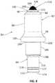
- FIG. 8is a side elevation view of the fourth embodiment of the bit, shown assembled with the bit tip insert and the transition member, in accordance with implementations of this disclosure
- FIG. 9is an exploded side elevation view of a fifth embodiment of a bit, showing a forward portion of the bit prior to welding, a bit tip insert, and a transition member, in accordance with implementations of this disclosure;
- FIG. 10is a side elevation view of the fifth embodiment of the bit, shown after welding the forward portion to the bit and assembled with the bit tip insert and the transition member, in accordance with implementations of this disclosure;
- FIG. 11is an exploded side elevation view of a sixth embodiment of a bit, showing a bit tip insert and a transition member, in accordance with implementations of this disclosure
- FIG. 12is a side elevation view of the sixth embodiment of the bit, shown assembled with the bit tip insert and the transition member, in accordance with implementations of this disclosure;
- FIG. 13is an exploded side elevation view of a seventh embodiment of a bit, showing a bit tip insert and a transition member, in accordance with implementations of this disclosure;
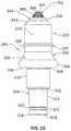
- FIG. 14is a side elevation view of the seventh embodiment of the bit, shown assembled with the bit tip insert and the transition member, in accordance with implementations of this disclosure;
- FIG. 15is an exploded side elevation view of an eighth embodiment of a bit, showing a forward portion of the bit prior to welding, a bit tip insert, and a transition member, in accordance with implementations of this disclosure;
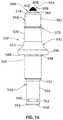
- FIG. 16is a side elevation view of the eighth embodiment of the bit, shown after welding the forward portion to the bit and assembled with the bit tip insert and the transition member, in accordance with implementations of this disclosure;
- FIG. 17is an exploded side elevation view of a ninth embodiment of a bit, showing a forward portion of the bit prior to welding, a bit tip insert, and a transition member, in accordance with implementations of this disclosure;
- FIG. 18is a side elevation view of the ninth embodiment of the bit, shown after welding the forward portion to the bit and assembled with the bit tip insert and the transition member, in accordance with implementations of this disclosure;
- FIG. 19is an exploded side elevation view of a tenth embodiment of a bit, showing a forward portion of the bit prior to welding and a bit tip insert, in accordance with implementations of this disclosure;
- FIG. 20is a side elevation view of the tenth embodiment of the bit, shown after welding the forward portion to the bit and assembled with the bit tip insert, in accordance with implementations of this disclosure;
- FIG. 21is an exploded side elevation view of an eleventh embodiment of a bit, showing a forward portion of the bit prior to welding and a bit tip insert, in accordance with implementations of this disclosure.
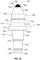
- FIG. 22is a side elevation view of the eleventh embodiment of the bit, shown after welding the forward portion to the bit and assembled with the bit tip insert, in accordance with implementations of this disclosure.
- Bit assembliescan include a bit and/or pick retained within a bore in a base bock. Bit assemblies can also include a bit and/or pick retained by a bit holder and the bit holder retained within a bore in a bit holder block, hereinafter referred to as a base block.
- a plurality of the bit assembliesare mounted on an outside surface of a rotatable, cylindrical drum, typically in a herringbone, V-shape, or spiral configuration.
- a plurality of the bit assembliescan also be mounted on an endless chain and plate configuration or on an outer surface of a continuous chain.
- Bit bodiescan include a generally conical, parabolic, and/or angular cutting tip that is mounted in a recess in a forward body portion of the bit body.
- the combinations of bit assemblieshave been utilized to remove material from the terra firma, such as degrading the surface of the earth, minerals, cement, concrete, macadam or asphalt pavement. Individual bits and/or picks, bit holders, and base blocks may wear down or break over time due to the harsh road degrading environment.
- the use of diamond coated and/or layered bit tips and bit tips including an overlay of a polycrystalline diamond structurehas been shown to increase the in-service life of those bit and/or picks.
- a polycrystalline diamond structuresuch as an industrial diamond material, natural diamond, polycrystalline diamond (PCD) material, and polycrystalline diamond composite or compact (PDC) material
- PCDpolycrystalline diamond
- PDCpolycrystalline diamond composite or compact
- a first embodiment of a rotatable or non-rotatable substantially solid bit or tool 10comprises a body portion 12 , which can be made of steel 15B37, 4140, 4340, or other similar suitable materials, and a shank 14 axially extending from a bottom of the body portion 12 .
- the body portion 12comprises a generally cylindrical or outwardly tapered upper body portion 16 axially depending from a frustoconical portion 18 adjacent a forward end 20 of the body portion 12 .
- a bore 22extends axially inwardly from the forward end 20 to a bore termination 24 disposed within the upper body portion 16 .
- the bore 22includes a generally cylindrical sidewall 58 and the bore termination 24 is generally flat.
- Subjacent the upper body portion 16is a mediate body portion 26 that generally slopes axially and radially outwardly to a radially extending generally arcuate tire portion 28 that terminates at a generally annular back flange 30 that denotes the bottom of the body portion 12 .
- the shank 14comprises a first segment 32 that slopes axially and radially inwardly from the back flange 30 to a generally cylindrical second segment 34 .
- the second segment 34axially extends from the first segment 32 to a shoulder 36 that slopes axially and radially inwardly from the second segment 34 to a generally cylindrical third segment 38 .
- the third segment 38axially extends from the shoulder 36 to a tapered distal portion 40 adjacent a distal end 42 of the shank 14 .
- the third segment 38comprises an annular groove 44 , which in this illustrated embodiment has an flat inner surface 45 but can also have an arcuate surface in other embodiments, adjacent the tapered distal portion 40 of the shank 14 where it can be engaged by a bit retainer or the like.
- the generally cylindrical bore 22provides a space for receiving a complementary shaped generally cylindrical outer surface or body 46 of an insert or transition member 48 , which in this embodiment is made of tungsten carbide.
- the transition member 48comprises a frustoconical portion 50 subjacent a forward end 52 of the transition member 48 that axially extends to the body 46 .
- the transition member 48further comprises a bore 54 , which is generally cylindrical in this embodiment, that extends axially inwardly from the forward end 52 of the transition member 48 to a bore termination 56 disposed within the body 46 of the transition member 48 .
- the bore termination 56has a frustoconical shape.
- the transition member 48 for the bit 10extends axially upwardly longitudinally from the forward end 20 of the body portion 12 when the body 46 is placed in the complementary shaped bore 22 of the body portion 12 .
- a bit tip insert 60comprises a generally conical tip 62 at a forward end 64 of a base 66 that includes a parabolic curved section below an apex of the tip insert 60 .
- the tip 62can also have a frustoconical shape, a flat generally cylindrical puck shape, a parabolic ballistic shape, an angular shape, and/or an arcuate shape.
- the tip insert 60can have a diameter in the range of 5 ⁇ 8 inch to 1.250 inch.
- the base 66comprises a complementary shaped generally cylindrical outer surface or sidewall 68 that is adapted to be mounted in the complementary shaped bore 54 that provides a space for receiving the bit tip insert 60 .
- the base 66includes a frustoconical portion 70 , adjacent a distal end 72 of the base 66 , which is complementary shaped to the bore termination 56 of the transition member 48 .
- the sidewall 68 of the base 66may require grinding.
- the frustoconical portion 70 and the distal end 72do not require additional finishing processes, such as grinding.
- the base 66may be made of steel or tungsten carbide and includes the tip 62 at the outer or forward end 64 of the base 66 .
- the tip 62comprises a substrate (not shown) that is primarily made of tungsten carbide and comprises an outer surface or forward end 74 that includes an overlay 76 of a polycrystalline diamond structure.
- the outer surface 74 of the tip 62may also have an overlay 76 of an industrial diamond material and may include a single coating or outer layer or multiple coating or outer layers of such industrial diamond material, natural diamond, polycrystalline diamond (PCD) material, and polycrystalline diamond composite or compact (PDC) material.
- the single or multiple coatings or layersmay be formed by a high pressure, high temperature (HPHT) process. During the HPHT process, excess PCD material may form a bulge or small flash between the tip 62 and the forward end 64 of the base 66 .
- HPHThigh pressure, high temperature
- the excess PCD materialcan be used as formed on tools that are used in milling, trenching, mining, and similar applications.
- the overlay 76occupies a large radial and axial profile of the tip 62 which allows faster heat transfer into a region subjacent to the overlay 76 PCD layer. Excessively high heat, such as temperatures above 1300 degrees F., is the greatest cause of PCD failure due to diamond connective failure, the quick heat transfer from the tip 62 of the PCD cutting zone to the subjacent region below the PCD drastically reduces the possibility of a temperature of the tip 62 of the PCD reaching temperatures at or above 1300 degrees F. for any extended period of time thereby avoiding failure of the PCD layer.
- the transition member 48is brazed in bore 22 of the body portion 12 and the bit tip insert 60 is brazed in the bore 54 of the transition member 48 , as shown in FIG. 2 .
- a second embodiment of a rotatable or non-rotatable substantially solid bit or tool 80comprises a body portion 82 , which can be made of steel 15B37, 4140, 4340, or other similar suitable materials, and a shank 84 axially extending from a bottom of the body portion 82 .
- the body portion 82comprises a generally cylindrical or outwardly tapered upper body portion 86 axially depending from a frustoconical portion 88 adjacent a forward end 90 of the body portion 82 .
- a bore 92extends axially inwardly from the forward end 90 to a bore termination 94 disposed within the upper body portion 86 .
- the bore 92includes a tapered sidewall 96 and the bore termination 24 is generally flat. Subjacent the upper body portion 86 is a mediate body portion 98 that generally slopes axially and radially outwardly to a radially extending generally arcuate tire portion 100 that terminates at a generally annular back flange 102 that denotes the bottom of the body portion 82 .
- the shank 84comprises a first segment 104 that slopes axially and radially inwardly from the back flange 102 to a generally cylindrical second segment 106 .
- the second segment 106axially extends from the first segment 104 to a shoulder 108 that slopes axially and radially inwardly from the second segment 106 to a generally cylindrical third segment 110 .
- the third segment 110axially extends from the shoulder 108 to a tapered distal portion 112 adjacent a distal end 114 of the shank 84 .
- the third segment 110comprises an annular groove 116 , which in this illustrated embodiment has an flat inner surface 117 but can also have an arcuate surface in other embodiments, adjacent the tapered distal portion 112 of the shank 84 where it can be engaged by a bit retainer or the like.
- the tapered bore 92provides a space for receiving a complementary shaped tapered outer surface or body 118 of an insert or transition member 120 , which in this embodiment is made of tungsten carbide.
- the transition member 120comprises a frustoconical portion 122 subjacent a forward end 124 of the transition member 120 that axially extends to the body 118 .
- the transition member 120further comprises a bore 126 , which includes a tapered sidewall 128 in this embodiment, that extends axially inwardly from the forward end 124 of the transition member 120 to a bore termination 130 disposed within the body 118 of the transition member 120 .
- the bore termination 130has a frustoconical shape.
- the transition member 120 for the bit 80extends axially upwardly longitudinally from the forward end 90 of the body portion 82 when the body 118 is placed in the complementary shaped bore 92 of the body portion 82 .
- a bit tip insert 132comprises a generally conical tip 134 at a forward end 136 of a base 138 that includes a parabolic curved section below an apex of the tip insert 132 .
- the tip 134can also have a frustoconical shape, a flat generally cylindrical puck shape, a parabolic ballistic shape, an angular shape, and/or an arcuate shape.
- the tip insert 132can have a diameter in the range of 5 ⁇ 8 inch to 1.250 inch.
- the base 138comprises a complementary shaped tapered outer surface or sidewall 140 that is adapted to be mounted in the complementary shaped bore 126 that provides a space for receiving the bit tip insert 132 .
- the base 138includes a frustoconical portion 142 , adjacent a distal end 144 of the base 138 , which is complementary shaped to the bore termination 130 of the transition member 120 .
- the sidewall 140 of the base 138may require grinding.
- the frustoconical portion 142 and the distal end 144do not require additional finishing processes, such as grinding.
- the base 138may be made of steel or tungsten carbide and includes the tip 134 at the outer or forward end 136 of the base 138 .
- the tip 134comprises a substrate (not shown) that is primarily made of tungsten carbide and comprises an outer surface or forward end 146 that includes an overlay 148 of a polycrystalline diamond structure.
- the outer surface 146 of the tip 134may also have an overlay 148 of an industrial diamond material and may include a single coating or outer layer or multiple coating or outer layers of such industrial diamond material, natural diamond, polycrystalline diamond (PCD) material, and polycrystalline diamond composite or compact (PDC) material.
- the single or multiple coatings or layersmay be formed by a high pressure, high temperature (HPHT) process. During the HPHT process, excess PCD material may form a bulge or small flash between the tip 134 and the forward end 136 of the base 138 .
- HPHThigh pressure, high temperature
- the excess PCD materialcan be used as formed on tools that are used in milling, trenching, mining, and similar applications.
- the overlay 148occupies a large radial and axial profile of the tip 134 which allows faster heat transfer into a region subjacent to the overlay 148 PCD layer. Excessively high heat, such as temperatures above 1300 degrees F., is the greatest cause of PCD failure due to diamond connective failure, the quick heat transfer from the tip 134 of the PCD cutting zone to the subjacent region below the PCD drastically reduces the possibility of a temperature of the tip 134 of the PCD reaching temperatures at or above 1300 degrees F. for any extended period of time thereby avoiding failure of the PCD layer.
- the transition member 120is brazed in bore 92 of the body portion 82 and the bit tip insert 132 is brazed in the bore 126 of the transition member 120 , as shown in FIG. 4 .
- a third embodiment of a rotatable or non-rotatable substantially solid bit or tool 150comprises a body portion 152 , which can be made of steel 15B37, 4140, 4340, or other similar suitable materials, and a shank 154 axially extending from a bottom of the body portion 152 .
- the body portion 152comprises a generally cylindrical or outwardly tapered upper body portion 156 axially depending from a frustoconical portion 158 adjacent a forward end 160 of the body portion 152 .
- a bore 162extends axially inwardly from the forward end 160 to a bore termination 164 disposed within the upper body portion 156 .
- the bore 162includes a generally cylindrical sidewall 166 and the bore termination 164 is generally flat. Subjacent the upper body portion 156 is a mediate body portion 168 that generally slopes axially and radially outwardly to a radially extending generally arcuate tire portion 170 that terminates at a generally annular back flange 172 that denotes the bottom of the body portion 152 .
- the shank 154comprises a first segment 174 that slopes axially and radially inwardly from the back flange 172 to a generally cylindrical second segment 176 .
- the second segment 176axially extends from the first segment 174 to a shoulder 178 that slopes axially and radially inwardly from the second segment 176 to a generally cylindrical third segment 180 .
- the third segment 180axially extends from the shoulder 178 to a tapered distal portion 182 adjacent a distal end 184 of the shank 154 .
- the third segment 180comprises an annular groove 186 , which in this illustrated embodiment has an flat inner surface 187 but can also have an arcuate surface in other embodiments, adjacent the tapered distal portion 182 of the shank 154 where it can be engaged by a bit retainer or the like.
- the generally cylindrical bore 162provides a space for receiving a complementary shaped generally cylindrical outer surface or body 188 of an insert or transition member 190 , which in this embodiment is made of tungsten carbide.
- the body 188 of the transition member 190axially extends from an interface 192 , such as a flat annular or generally cylindrical surface in this exemplary embodiment, that defines a forward end 194 of the transition member 190 .
- the transition member 190further comprises a bore 196 , which includes a generally cylindrical sidewall 198 in this embodiment, that extends axially inwardly from the forward end 194 of the transition member 190 to a bore termination 200 disposed within the body 188 of the transition member 190 .
- the bore termination 200has a frustoconical shape.
- the transition member 190 for the bit 150extends axially upwardly longitudinally from the forward end 160 of the body portion 152 when the body 188 is placed in the complementary shaped bore 162 of the body portion 152 .
- a bit tip insert 202comprises a generally conical tip 204 at a forward end 206 of a base 208 that includes a parabolic curved section below an apex of the tip insert 202 .
- the tip 204can also have a frustoconical shape, a flat generally cylindrical puck shape, a parabolic ballistic shape, an angular shape, and/or an arcuate shape.
- the tip insert 202can have a diameter in the range of 5 ⁇ 8 inch to 1.250 inch.
- the base 208comprises a complementary shaped generally cylindrical outer surface or sidewall 210 that is adapted to be mounted in the complementary shaped bore 196 that provides a space for receiving the bit tip insert 202 .
- the base 208includes a frustoconical portion 212 , adjacent a distal end 214 of the base 208 , which is complementary shaped to the bore termination 200 of the transition member 190 .
- the sidewall 210 of the base 208may require grinding.
- the frustoconical portion 212 and the distal end 214do not require additional finishing processes, such as grinding.
- the base 208may be made of steel or tungsten carbide and includes the tip 204 at the outer or forward end 206 of the base 208 .
- the tip 204comprises a substrate (not shown) that is primarily made of tungsten carbide and comprises an outer surface or forward end 216 that includes an overlay 218 of a polycrystalline diamond structure.
- the outer surface 216 of the tip 204may also have an overlay 218 of an industrial diamond material and may include a single coating or outer layer or multiple coating or outer layers of such industrial diamond material, natural diamond, polycrystalline diamond (PCD) material, and polycrystalline diamond composite or compact (PDC) material.
- the single or multiple coatings or layersmay be formed by a high pressure, high temperature (HPHT) process. During the HPHT process, excess PCD material may form a bulge or small flash between the tip 204 and the forward end 206 of the base 208 .
- HPHThigh pressure, high temperature
- the excess PCD materialcan be used as formed on tools that are used in milling, trenching, mining, and similar applications.
- the overlay 218occupies a large radial and axial profile of the tip 204 which allows faster heat transfer into a region subjacent to the overlay 218 PCD layer. Excessively high heat, such as temperatures above 1300 degrees F., is the greatest cause of PCD failure due to diamond connective failure, the quick heat transfer from the tip 204 of the PCD cutting zone to the subjacent region below the PCD drastically reduces the possibility of a temperature of the tip 204 of the PCD reaching temperatures at or above 1300 degrees F. for any extended period of time thereby avoiding failure of the PCD layer.
- the transition member 190is brazed in bore 162 of the body portion 152 and the bit tip insert 202 is brazed in the bore 196 of the transition member 190 , as shown in FIG. 6 .
- a fourth embodiment of a rotatable or non-rotatable substantially solid bit or tool 220comprises a body portion 222 , which can be made of steel 15B37, 4140, 4340, or other similar suitable materials, and a shank 224 axially extending from a bottom of the body portion 222 .
- the body portion 222comprises a generally cylindrical or outwardly tapered upper body portion 226 axially depending from a frustoconical portion 228 adjacent a forward end 230 of the body portion 222 .
- a bore 232extends axially inwardly from the forward end 230 to a bore termination 234 disposed within the upper body portion 226 .
- the bore 232includes a tapered sidewall 236 and the bore termination 234 is generally flat. Subjacent the upper body portion 226 is a mediate body portion 238 that generally slopes axially and radially outwardly to a radially extending generally arcuate tire portion 240 that terminates at a generally annular back flange 242 that denotes the bottom of the body portion 222 .
- the shank 224comprises a first segment 244 that slopes axially and radially inwardly from the back flange 242 to a generally cylindrical second segment 246 .
- the second segment 246axially extends from the first segment 244 to a shoulder 248 that slopes axially and radially inwardly from the second segment 246 to a generally cylindrical third segment 250 .
- the third segment 250axially extends from the shoulder 248 to a tapered distal portion 252 adjacent a distal end 254 of the shank 224 .
- the third segment 250comprises an annular groove 256 , which in this illustrated embodiment has an flat inner surface 257 but can also have an arcuate surface in other embodiments, adjacent the tapered distal portion 252 of the shank 224 where it can be engaged by a bit retainer or the like.
- the tapered bore 232provides a space for receiving a complementary shaped tapered outer surface or body 258 of an insert or transition member 260 , which in this embodiment is made of tungsten carbide.
- the body 258 of the transition member 260axially extends from an interface 262 , such as a flat annular or generally cylindrical surface in this exemplary embodiment, that defines a forward end 264 of the transition member 260 .
- the transition member 260further comprises a bore 266 , which includes a tapered sidewall 268 in this embodiment, that extends axially inwardly from the forward end 264 of the transition member 260 to a bore termination 270 disposed within the body 258 of the transition member 260 .
- the bore termination 270has a frustoconical shape.
- the transition member 260 for the bit 220extends axially upwardly longitudinally from the forward end 230 of the body portion 222 when the body 258 is placed in the complementary shaped bore 232 of the body portion 222 .
- a bit tip insert 272comprises a generally conical tip 274 at a forward end 276 of a base 278 that includes a parabolic curved section below an apex of the tip insert 272 .
- the tip 274can also have a frustoconical shape, a flat generally cylindrical puck shape, a parabolic ballistic shape, an angular shape, and/or an arcuate shape.
- the tip insert 272can have a diameter in the range of 5 ⁇ 8 inch to 1.250 inch.
- the base 278comprises a complementary shaped tapered outer surface or sidewall 280 that is adapted to be mounted in the complementary shaped bore 266 that provides a space for receiving the bit tip insert 272 .
- the base 278includes a frustoconical portion 282 , adjacent a distal end 284 of the base 278 , which is complementary shaped to the bore termination 270 of the transition member 260 .
- the sidewall 280 of the base 278may require grinding.
- the frustoconical portion 282 and the distal end 284do not require additional finishing processes, such as grinding.
- the base 278may be made of steel or tungsten carbide and includes the tip 274 at the outer or forward end 276 of the base 278 .
- the tip 274comprises a substrate (not shown) that is primarily made of tungsten carbide and comprises an outer surface or forward end 286 that includes an overlay 288 of a polycrystalline diamond structure.
- the outer surface 286 of the tip 274may also have an overlay 288 of an industrial diamond material and may include a single coating or outer layer or multiple coating or outer layers of such industrial diamond material, natural diamond, polycrystalline diamond (PCD) material, and polycrystalline diamond composite or compact (PDC) material.
- the single or multiple coatings or layersmay be formed by a high pressure, high temperature (HPHT) process. During the HPHT process, excess PCD material may form a bulge or small flash between the tip 274 and the forward end 276 of the base 278 .
- HPHThigh pressure, high temperature
- the excess PCD materialcan be used as formed on tools that are used in milling, trenching, mining, and similar applications.
- the overlay 288occupies a large radial and axial profile of the tip 274 which allows faster heat transfer into a region subjacent to the overlay 288 PCD layer. Excessively high heat, such as temperatures above 1300 degrees F., is the greatest cause of PCD failure due to diamond connective failure, the quick heat transfer from the tip 274 of the PCD cutting zone to the subjacent region below the PCD drastically reduces the possibility of a temperature of the tip 274 of the PCD reaching temperatures at or above 1300 degrees F. for any extended period of time thereby avoiding failure of the PCD layer.
- the transition member 260is brazed in bore 232 of the body portion 222 and the bit tip insert 272 is brazed in the bore 266 of the transition member 260 , as shown in FIG. 8 .
- a fifth embodiment of a rotatable or non-rotatable substantially solid bit or tool 290comprises a body portion 292 , which can be made of steel 15B37, 4140, 4340, or other similar suitable materials, and a shank 294 axially extending from a bottom of the body portion 292 .
- the body portion 292comprises a generally cylindrical or outwardly tapered upper body portion 296 axially depending from an interface 298 , such as a flat annular or generally cylindrical surface in this exemplary embodiment, that defines a forward end 300 of the body portion 292 .
- Subjacent the upper body portion 296is a mediate body portion 302 that generally slopes axially and radially outwardly to a radially extending generally arcuate tire portion 304 that terminates at a generally annular back flange 306 that denotes the bottom of the body portion 292 .
- the shank 294comprises a first segment 308 that slopes axially and radially inwardly from the back flange 306 to a generally cylindrical second segment 310 .
- the second segment 310axially extends from the first segment 308 to a shoulder 312 that slopes axially and radially inwardly from the second segment 310 to a generally cylindrical third segment 314 .
- the third segment 314axially extends from the shoulder 312 to a tapered distal portion 316 adjacent a distal end 318 of the shank 294 .
- the third segment 314comprises an annular groove 320 , which in this illustrated embodiment has an flat inner surface 321 but can also have an arcuate surface in other embodiments, adjacent the tapered distal portion 316 of the shank 294 where it can be engaged by a bit retainer or the like.
- a forward body or nose portion 322which can be made of steel 15B47, 4140, 4340, or other similar suitable materials and/or high wear, abrasive resistant, high strength alloy steel with a KSI strength in excess of 200 KSI, comprises a body 324 that axially extends from a forward end 326 to an interface 328 , such as a flat annular or generally cylindrical surface in this exemplary embodiment, defining a distal end 330 of the forward body portion 322 .
- the interface 328 of the forward body portion 322is friction welded to the interface 298 of the body portion 292 of the bit 290 , which forms a friction welded joint 331 ( FIG. 10 ) between the forward body portion 322 and the body portion 292 .
- the forward body portion 322further includes a frustoconical portion 332 adjacent the forward end 326 and a bore 334 that extends axially inwardly from the forward end 322 to a bore termination 336 disposed within the forward body portion 332 .
- the bore 334includes a generally cylindrical sidewall 338 and the bore termination 336 is generally flat.
- the generally cylindrical bore 334provides a space for receiving a complementary shaped generally cylindrical outer surface or body 340 of an insert or transition member 342 , which in this embodiment is made of tungsten carbide.
- the transition member 342comprises a frustoconical portion 344 subjacent a forward end 346 of the transition member 342 that axially extends to the body 340 .
- the transition member 342further comprises a bore 348 , which is generally cylindrical in this embodiment, that extends axially inwardly from the forward end 346 of the transition member 342 to a bore termination 350 disposed within the body 340 of the transition member 342 .
- the bore termination 350has a frustoconical shape.
- the transition member 342 for the bit 290extends axially upwardly longitudinally from the forward end 326 of the forward body portion 322 when the body 340 is placed in the complementary shaped bore 334 of the forward body portion 322 .
- a bit tip insert 352comprises a generally conical tip 354 at a forward end 356 of a base 358 that includes a parabolic curved section below an apex of the tip insert 352 .
- the tip 354can also have a frustoconical shape, a flat generally cylindrical puck shape, a parabolic ballistic shape, an angular shape, and/or an arcuate shape.
- the tip insert 352can have a diameter in the range of 5 ⁇ 8 inch to 1.250 inch.
- the base 358comprises a complementary shaped generally cylindrical outer surface or sidewall 360 that is adapted to be mounted in the complementary shaped bore 348 that provides a space for receiving the bit tip insert 352 .
- the base 358includes a frustoconical portion 362 , adjacent a distal end 364 of the base 358 , which is complementary shaped to the bore termination 350 of the transition member 342 .
- the sidewall 360 of the base 358may require grinding.
- the frustoconical portion 362 and the distal end 364do not require additional finishing processes, such as grinding.
- the base 358may be made of steel or tungsten carbide and includes the tip 354 at the outer or forward end 356 of the base 358 .
- the tip 354comprises a substrate (not shown) that is primarily made of tungsten carbide and comprises an outer surface or forward end 366 that includes an overlay 368 of a polycrystalline diamond structure.
- the outer surface 366 of the tip 354may also have an overlay 368 of an industrial diamond material and may include a single coating or outer layer or multiple coating or outer layers of such industrial diamond material, natural diamond, polycrystalline diamond (PCD) material, and polycrystalline diamond composite or compact (PDC) material.
- the single or multiple coatings or layersmay be formed by a high pressure, high temperature (HPHT) process. During the HPHT process, excess PCD material may form a bulge or small flash between the tip 354 and the forward end 356 of the base 358 .
- HPHThigh pressure, high temperature
- the excess PCD materialcan be used as formed on tools that are used in milling, trenching, mining, and similar applications.
- the overlay 368occupies a large radial and axial profile of the tip 354 which allows faster heat transfer into a region subjacent to the overlay 368 PCD layer. Excessively high heat, such as temperatures above 1300 degrees F., is the greatest cause of PCD failure due to diamond connective failure, the quick heat transfer from the tip 354 of the PCD cutting zone to the subjacent region below the PCD drastically reduces the possibility of a temperature of the tip 354 of the PCD reaching temperatures at or above 1300 degrees F. for any extended period of time thereby avoiding failure of the PCD layer.
- the interface 328 of the forward body portion 322is friction welded to the interface 298 of the body portion 292 of the bit 290 .
- the transition member 342is brazed in bore 334 of the forward body portion 322 and the bit tip insert 352 is brazed in the bore 348 of the transition member 342 , as shown in FIG. 10 .
- the bit tip insert 832may also be brazed to the transition member 342 and the transition member 342 may also be brazed to the forward body portion 322 and then hardened prior friction welding.
- a sixth embodiment of a rotatable or non-rotatable substantially solid bit or tool 370comprises a body portion 372 , which can be made of steel 15B37, 4140, 4340, or other similar suitable materials, and a shank 374 axially extending from a bottom of the body portion 372 .
- the body portion 372comprises a generally cylindrical first portion 376 axially depending from a frustoconical portion 378 adjacent a forward end 380 of the body portion 372 .
- a bore 382extends axially inwardly from the forward end 380 to a bore termination 384 disposed within a generally cylindrical or outwardly tapered second portion 386 subjacent the first portion 376 .
- the bore 382includes a generally cylindrical sidewall 388 and the bore termination 384 is generally flat. Subjacent the second portion 386 is a third portion 390 that generally slopes axially and radially outwardly to a radially extending generally arcuate fourth portion or tire portion 392 that terminates at a generally annular back flange 394 that denotes the bottom of the body portion 372 .
- the shank 374comprises a first segment 396 that slopes axially and radially inwardly from the back flange 394 to a generally cylindrical second segment 398 .
- the second segment 398axially extends from the first segment 396 to a shoulder 400 that slopes axially and radially inwardly from the second segment 398 to a generally cylindrical third segment 402 .
- the third segment 402axially extends from the shoulder 400 to a distal portion 404 adjacent a distal end 406 of the shank 374 .
- the third segment 402comprises an annular groove 408 , which in this illustrated embodiment has an arcuate inner surface 410 but can also have a flat surface in other embodiments, adjacent the distal portion 404 of the shank 374 where it can be engaged by a bit retainer or the like.
- the generally cylindrical bore 382provides a space for receiving a complementary shaped generally cylindrical outer surface or body 412 of an insert or transition member 414 , which in this embodiment is made of tungsten carbide.
- the transition member 414comprises a frustoconical portion 416 subjacent a forward end 418 of the transition member 414 that axially extends to the body 412 .
- the transition member 414further comprises a bore 420 , which includes a generally cylindrical sidewall 421 in this embodiment, that extends axially inwardly from the forward end 418 of the transition member 414 to a bore termination 422 disposed within the body 412 of the transition member 414 .
- the bore termination 422has a frustoconical shape.
- the transition member 414 for the bit 370extends axially upwardly longitudinally from the forward end 380 of the body portion 372 when the body 412 is placed in the complementary shaped bore 382 of the body portion 372 .
- a bit tip insert 424comprises a generally conical tip 426 at a forward end 428 of a base 430 that includes a parabolic curved section below an apex of the tip insert 424 .
- the tip 426can also have a frustoconical shape, a flat generally cylindrical puck shape, a parabolic ballistic shape, an angular shape, and/or an arcuate shape.
- the tip insert 424can have a diameter in the range of 5 ⁇ 8 inch to 1.250 inch.
- the base 430comprises a complementary shaped generally cylindrical outer surface or sidewall 432 that is adapted to be mounted in the complementary shaped bore 420 that provides a space for receiving the bit tip insert 424 .
- the base 430includes a frustoconical portion 434 , adjacent a distal end 436 of the base 430 , which is complementary shaped to the bore termination 422 of the transition member 414 .
- the sidewall 432 of the base 430may require grinding.
- the frustoconical portion 434 and the distal end 436do not require additional finishing processes, such as grinding.
- the base 430may be made of steel or tungsten carbide and includes the tip 426 at the outer or forward end 428 of the base 430 .
- the tip 426comprises a substrate (not shown) that is primarily made of tungsten carbide and comprises an outer surface or forward end 438 that includes an overlay 440 of a polycrystalline diamond structure.
- the outer surface 438 of the tip 426may also have an overlay 440 of an industrial diamond material and may include a single coating or outer layer or multiple coating or outer layers of such industrial diamond material, natural diamond, polycrystalline diamond (PCD) material, and polycrystalline diamond composite or compact (PDC) material.
- the single or multiple coatings or layersmay be formed by a high pressure, high temperature (HPHT) process. During the HPHT process, excess PCD material may form a bulge or small flash between the tip 426 and the forward end 428 of the base 430 .
- HPHThigh pressure, high temperature
- the excess PCD materialcan be used as formed on tools that are used in milling, trenching, mining, and similar applications.
- the overlay 440occupies a large radial and axial profile of the tip 426 which allows faster heat transfer into a region subjacent to the overlay 440 PCD layer. Excessively high heat, such as temperatures above 1300 degrees F., is the greatest cause of PCD failure due to diamond connective failure, the quick heat transfer from the tip 426 of the PCD cutting zone to the subjacent region below the PCD drastically reduces the possibility of a temperature of the tip 426 of the PCD reaching temperatures at or above 1300 degrees F. for any extended period of time thereby avoiding failure of the PCD layer.
- the transition member 414is brazed in bore 382 of the body portion 372 and the bit tip insert 424 is brazed in the bore 420 of the transition member 414 , as shown in FIG. 12 .
- a seventh embodiment of a rotatable or non-rotatable substantially solid bit or tool 450comprises a body portion 452 , which can be made of steel 15B37, 4140, 4340, or other similar suitable materials, and a shank 454 axially extending from a bottom of the body portion 452 .
- the body portion 452comprises a generally cylindrical first portion 456 axially depending from a frustoconical portion 458 adjacent a forward end 460 of the body portion 452 .
- a bore 462extends axially inwardly from the forward end 460 to a bore termination 464 disposed within a generally cylindrical or outwardly tapered second portion 466 subjacent the first portion 456 .
- the bore 462includes a tapered sidewall 468 and the bore termination 464 is generally flat. Subjacent the second portion 466 is a third portion 470 that generally slopes axially and radially outwardly to a radially extending generally arcuate fourth portion or tire portion 472 that terminates at a generally annular back flange 474 that denotes the bottom of the body portion 452 .
- the shank 454comprises a first segment 476 that slopes axially and radially inwardly from the back flange 474 to a generally cylindrical second segment 478 .
- the second segment 478axially extends from the first segment 476 to a shoulder 480 that slopes axially and radially inwardly from the second segment 478 to a generally cylindrical third segment 482 .
- the third segment 482axially extends from the shoulder 480 to a distal portion 484 adjacent a distal end 486 of the shank 454 .
- the third segment 482comprises an annular groove 488 , which in this illustrated embodiment has an arcuate inner surface 490 but can also have a flat surface in other embodiments, adjacent the distal portion 484 of the shank 454 where it can be engaged by a bit retainer or the like.
- the tapered bore 462provides a space for receiving a complementary shaped tapered outer surface or body 492 of an insert or transition member 494 , which in this embodiment is made of tungsten carbide.
- the transition member 494comprises a frustoconical portion 496 subjacent a forward end 498 of the transition member 494 that axially extends to the body 492 .
- the transition member 494further comprises a bore 500 , which includes a tapered sidewall 501 in this embodiment, that extends axially inwardly from the forward end 498 of the transition member 494 to a bore termination 502 disposed within the body 492 of the transition member 494 .
- the bore termination 502has a frustoconical shape.
- the transition member 494 for the bit 450extends axially upwardly longitudinally from the forward end 460 of the body portion 452 when the body 492 is placed in the complementary shaped bore 462 of the body portion 452 .
- a bit tip insert 504comprises a generally conical tip 506 at a forward end 508 of a base 510 that includes a parabolic curved section below an apex of the tip insert 504 .
- the tip 506can also have a frustoconical shape, a flat generally cylindrical puck shape, a parabolic ballistic shape, an angular shape, and/or an arcuate shape.
- the tip insert 504can have a diameter in the range of 5 ⁇ 8 inch to 1.250 inch.
- the base 510comprises a complementary shaped tapered outer surface or sidewall 512 that is adapted to be mounted in the complementary shaped bore 500 that provides a space for receiving the bit tip insert 504 .
- the base 510includes a frustoconical portion 514 , adjacent a distal end 516 of the base 510 , which is complementary shaped to the bore termination 502 of the transition member 494 .
- the sidewall 512 of the base 510may require grinding.
- the frustoconical portion 514 and the distal end 516do not require additional finishing processes, such as grinding.
- the base 510may be made of steel or tungsten carbide and includes the tip 506 at the outer or forward end 508 of the base 510 .
- the tip 506comprises a substrate (not shown) that is primarily made of tungsten carbide and comprises an outer surface or forward end 518 that includes an overlay 520 of a polycrystalline diamond structure.
- the outer surface 518 of the tip 506may also have an overlay 520 of an industrial diamond material and may include a single coating or outer layer or multiple coating or outer layers of such industrial diamond material, natural diamond, polycrystalline diamond (PCD) material, and polycrystalline diamond composite or compact (PDC) material.
- the single or multiple coatings or layersmay be formed by a high pressure, high temperature (HPHT) process. During the HPHT process, excess PCD material may form a bulge or small flash between the tip 506 and the forward end 508 of the base 510 .
- HPHThigh pressure, high temperature
- the excess PCD materialcan be used as formed on tools that are used in milling, trenching, mining, and similar applications.
- the overlay 520occupies a large radial and axial profile of the tip 506 which allows faster heat transfer into a region subjacent to the overlay 520 PCD layer. Excessively high heat, such as temperatures above 1300 degrees F., is the greatest cause of PCD failure due to diamond connective failure, the quick heat transfer from the tip 506 of the PCD cutting zone to the subjacent region below the PCD drastically reduces the possibility of a temperature of the tip 506 of the PCD reaching temperatures at or above 1300 degrees F. for any extended period of time thereby avoiding failure of the PCD layer.
- the transition member 494is brazed in bore 462 of the body portion 452 and the bit tip insert 504 is brazed in the bore 500 of the transition member 494 , as shown in FIG. 14 .
- an eighth embodiment of a rotatable or non-rotatable substantially solid bit or tool 530comprises a body portion 532 , which can be made of steel 15B37, 4140, 4340, or other similar suitable materials, and a shank 534 axially extending from a bottom of the body portion 532 .
- the body portion 532comprises a generally cylindrical or outwardly tapered upper body portion 536 axially depending from an interface 538 , such as a flat annular or generally cylindrical surface in this exemplary embodiment, that defines a forward end 540 of the body portion 532 .
- Subjacent the upper body portion 536is a mediate body portion 542 that generally slopes axially and radially outwardly to a radially extending generally arcuate tire portion 544 that terminates at a generally annular back flange 546 that denotes the bottom of the body portion 532 .
- the shank 534comprises a first segment 548 that slopes axially and radially inwardly from the back flange 546 to a generally cylindrical second segment 550 .
- the second segment 550axially extends from the first segment 548 to a shoulder 552 that slopes axially and radially inwardly from the second segment 550 to a generally cylindrical third segment 554 .
- the third segment 554axially extends from the shoulder 552 to a distal portion 556 adjacent a distal end 558 of the shank 534 .
- the third segment 554comprises an annular groove 560 , which in this illustrated embodiment has an arcuate inner surface 562 but can also have a flat surface in other embodiments, adjacent the distal portion 556 of the shank 534 where it can be engaged by a bit retainer or the like.
- a forward body or nose portion 564which can be made of steel 15B47, 4140, 4340, or other similar suitable materials and/or high wear, abrasive resistant, high strength alloy steel with a KSI strength in excess of 200 KSI, comprises a body 566 that axially extends from a forward end 568 to an interface 570 , such as a flat annular or generally cylindrical surface in this exemplary embodiment, defining a distal end 572 of the forward body portion 564 .
- the interface 570 of the forward body portion 564is friction welded to the interface 538 of the body portion 532 of the bit 530 , which forms a friction welded joint 573 ( FIG. 16 ) between the forward body portion 564 and the body portion 532 .
- the forward body portion 564further includes a frustoconical portion 574 adjacent the forward end 568 and a bore 576 that extends axially inwardly from the forward end 568 to a bore termination 578 disposed within the forward body portion 564 .
- the bore 576includes a generally cylindrical sidewall 580 and the bore termination 578 is generally flat.
- the generally cylindrical bore 576provides a space for receiving a complementary shaped generally cylindrical outer surface or body 582 of an insert or transition member 584 , which in this embodiment is made of tungsten carbide.
- the transition member 584comprises a frustoconical portion 586 subjacent a forward end 588 of the transition member 584 that axially extends to the body 582 .
- the transition member 584further comprises a bore 590 , which includes a generally cylindrical sidewall 591 in this embodiment, that extends axially inwardly from the forward end 588 of the transition member 584 to a bore termination 592 disposed within the body 582 of the transition member 584 .
- the bore termination 592has a frustoconical shape.
- the transition member 584 for the bit 530extends axially upwardly longitudinally from the forward end 568 of the forward body portion 564 when the body 582 is placed in the complementary shaped bore 576 of the forward body portion 564 .
- a bit tip insert 594comprises a generally conical tip 596 at a forward end 598 of a base 600 that includes a parabolic curved section below an apex of the tip insert 594 .
- the tip 596can also have a frustoconical shape, a flat generally cylindrical puck shape, a parabolic ballistic shape, an angular shape, and/or an arcuate shape.
- the tip insert 594can have a diameter in the range of 5 ⁇ 8 inch to 1.250 inch.
- the base 600comprises a complementary shaped generally cylindrical outer surface or sidewall 602 that is adapted to be mounted in the complementary shaped bore 590 that provides a space for receiving the bit tip insert 594 .
- the base 600includes a frustoconical portion 604 , adjacent a distal end 606 of the base 600 , which is complementary shaped to the bore termination 592 of the transition member 584 .
- the sidewall 602 of the base 600may require grinding.
- the frustoconical portion 604 and the distal end 606do not require additional finishing processes, such as grinding.
- the base 600may be made of steel or tungsten carbide and includes the tip 596 at the outer or forward end 598 of the base 600 .
- the tip 596comprises a substrate (not shown) that is primarily made of tungsten carbide and comprises an outer surface or forward end 608 that includes an overlay 610 of a polycrystalline diamond structure.
- the outer surface 608 of the tip 596may also have an overlay 610 of an industrial diamond material and may include a single coating or outer layer or multiple coating or outer layers of such industrial diamond material, natural diamond, polycrystalline diamond (PCD) material, and polycrystalline diamond composite or compact (PDC) material.
- the single or multiple coatings or layersmay be formed by a high pressure, high temperature (HPHT) process. During the HPHT process, excess PCD material may form a bulge or small flash between the tip 596 and the forward end 598 of the base 600 .
- HPHThigh pressure, high temperature
- the excess PCD materialcan be used as formed on tools that are used in milling, trenching, mining, and similar applications.
- the overlay 610occupies a large radial and axial profile of the tip 596 which allows faster heat transfer into a region subjacent to the overlay 610 PCD layer. Excessively high heat, such as temperatures above 1300 degrees F., is the greatest cause of PCD failure due to diamond connective failure, the quick heat transfer from the tip 596 of the PCD cutting zone to the subjacent region below the PCD drastically reduces the possibility of a temperature of the tip 596 of the PCD reaching temperatures at or above 1300 degrees F. for any extended period of time thereby avoiding failure of the PCD layer.
- the interface 570 of the forward body portion 564is friction welded to the interface 538 of the body portion 532 of the bit 530 .
- the transition member 584is brazed in bore 576 of the forward body portion 564 and the bit tip insert 594 is brazed in the bore 590 of the transition member 584 , as shown in FIG. 16 .
- the bit tip insert 832may also be brazed to transition member 584 and the transition member 584 may also be brazed to the forward body portion 564 and then hardened prior friction welding.
- a ninth embodiment of a rotatable or non-rotatable substantially solid bit or tool 620comprises a body portion 622 , which can be made of steel 15B37, 4140, 4340, or other similar suitable materials, and a shank 624 axially extending from a bottom of the body portion 622 .
- the body portion 622comprises a generally cylindrical or outwardly tapered upper body portion 626 axially depending from an interface 628 , such as a flat annular or generally cylindrical surface in this exemplary embodiment, that defines a forward end 630 of the body portion 622 .
- Subjacent the upper body portion 626is a mediate body portion 632 that generally slopes axially and radially outwardly to a radially extending generally arcuate tire portion 634 that terminates at a generally annular back flange 636 that denotes the bottom of the body portion 622 .
- the shank 624comprises a first segment 638 that slopes axially and radially inwardly from the back flange 636 to a generally cylindrical second segment 640 .
- the second segment 640axially extends from the first segment 638 to a shoulder 642 that slopes axially and radially inwardly from the second segment 640 to a generally cylindrical third segment 644 .
- the third segment 644axially extends from the shoulder 642 to a distal portion 646 adjacent a distal end 648 of the shank 624 .
- the third segment 644comprises an annular groove 650 , which in this illustrated embodiment has an arcuate inner surface 652 but can also have a flat surface in other embodiments, adjacent the distal portion 646 of the shank 624 where it can be engaged by a bit retainer or the like.
- a forward body or nose portion 654which can be made of steel 15B47, 4140, 4340, or other similar suitable materials and/or high wear, abrasive resistant, high strength alloy steel with a KSI strength in excess of 200 KSI, comprises a body 656 that axially extends from a forward end 658 to an interface 660 , such as a flat annular or generally cylindrical surface in this exemplary embodiment, defining a distal end 662 of the forward body portion 654 .
- the interface 660 of the forward body portion 654is friction welded to the interface 628 of the body portion 622 of the bit 620 , which forms a friction welded joint 663 ( FIG. 18 ) between the forward body portion 654 and the body portion 622 .
- the forward body portion 654further includes a frustoconical portion 664 adjacent the forward end 658 and a bore 666 that extends axially inwardly from the forward end 658 to a bore termination 668 disposed within the forward body portion 654 .
- the bore 666includes a tapered sidewall 670 and the bore termination 668 is generally flat.
- the generally cylindrical bore 666provides a space for receiving a complementary shaped generally cylindrical outer surface or body 672 of an insert or transition member 674 , which in this embodiment is made of tungsten carbide.
- the transition member 674comprises a frustoconical portion 676 subjacent a forward end 678 of the transition member 674 that axially extends to the body 672 .
- the transition member 674further comprises a bore 680 , which includes a tapered sidewall 681 in this embodiment, that extends axially inwardly from the forward end 678 of the transition member 674 to a bore termination 682 disposed within the body 672 of the transition member 674 .
- the bore termination 682has a frustoconical shape.
- the transition member 674 for the bit 620extends axially upwardly longitudinally from the forward end 658 of the forward body portion 654 when the body 672 is placed in the complementary shaped bore 666 of the forward body portion 654 .
- a bit tip insert 684comprises a generally conical tip 686 at a forward end 688 of a base 690 that includes a parabolic curved section below an apex of the tip insert 684 .
- the tip 686can also have a frustoconical shape, a flat generally cylindrical puck shape, a parabolic ballistic shape, an angular shape, and/or an arcuate shape.
- the tip insert 684can have a diameter in the range of 5 ⁇ 8 inch to 1.250 inch.
- the base 690comprises a complementary shaped tapered outer surface or sidewall 692 that is adapted to be mounted in the complementary shaped bore 680 that provides a space for receiving the bit tip insert 684 .
- the base 690includes a frustoconical portion 694 , adjacent a distal end 696 of the base 690 , which is complementary shaped to the bore termination 682 of the transition member 674 .
- the sidewall 692 of the base 690may require grinding.
- the frustoconical portion 694 and the distal end 696do not require additional finishing processes, such as grinding.
- the base 690may be made of steel or tungsten carbide and includes the tip 686 at the outer or forward end 688 of the base 690 .
- the tip 686comprises a substrate (not shown) that is primarily made of tungsten carbide and comprises an outer surface or forward end 698 that includes an overlay 700 of a polycrystalline diamond structure.
- the outer surface 698 of the tip 686may also have an overlay 700 of an industrial diamond material and may include a single coating or outer layer or multiple coating or outer layers of such industrial diamond material, natural diamond, polycrystalline diamond (PCD) material, and polycrystalline diamond composite or compact (PDC) material.
- the single or multiple coatings or layersmay be formed by a high pressure, high temperature (HPHT) process. During the HPHT process, excess PCD material may form a bulge or small flash between the tip 686 and the forward end 688 of the base 690 .
- HPHThigh pressure, high temperature
- the excess PCD materialcan be used as formed on tools that are used in milling, trenching, mining, and similar applications.
- the overlay 700occupies a large radial and axial profile of the tip 686 which allows faster heat transfer into a region subjacent to the overlay 700 PCD layer. Excessively high heat, such as temperatures above 1300 degrees F., is the greatest cause of PCD failure due to diamond connective failure, the quick heat transfer from the tip 686 of the PCD cutting zone to the subjacent region below the PCD drastically reduces the possibility of a temperature of the tip 686 of the PCD reaching temperatures at or above 1300 degrees F. for any extended period of time thereby avoiding failure of the PCD layer.
- the interface 660 of the forward body portion 654is friction welded to the interface 628 of the body portion 622 of the bit 620 .
- the transition member 674is brazed in bore 666 of the forward body portion 654 and the bit tip insert 684 is brazed in the bore 680 of the transition member 674 , as shown in FIG. 18 .
- the bit tip insert 684may also be brazed to the transition member 674 and the transition member 674 may also be brazed to the forward body portion 654 and then hardened prior friction welding.
- a tenth embodiment of a rotatable or non-rotatable substantially solid bit or tool 710comprises a body portion 712 , which can be made of steel 15B37, 4140, 4340, or other similar suitable materials, and a shank 714 axially extending from a bottom of the body portion 712 .
- the body portion 712comprises a generally cylindrical upper body portion 716 axially depending from an interface 718 , such as a flat annular or generally cylindrical surface in this exemplary embodiment, that defines a forward end 720 of the body portion 712 .
- Subjacent the upper body portion 716is a mediate body portion 722 that generally slopes axially and radially outwardly to a radially extending generally arcuate tire portion 724 that terminates at a generally annular back flange 726 that denotes the bottom of the body portion 712 .
- the shank 714comprises a first segment 728 that slopes axially and radially inwardly from the back flange 726 to a generally cylindrical second segment 730 .
- the second segment 730axially extends from the first segment 728 to a shoulder 732 that slopes axially and radially inwardly from the second segment 730 to a generally cylindrical third segment 734 .
- the third segment 734axially extends from the shoulder 732 to a tapered distal portion 736 adjacent a distal end 738 of the shank 714 .
- the third segment 734comprises an annular groove 740 , which in this illustrated embodiment has an flat inner surface 742 but can also have an arcuate surface in other embodiments, adjacent the tapered distal portion 736 of the shank 714 where it can be engaged by a bit retainer or the like.
- a forward body or nose portion 744which can be made of steel 15B47, 4140, 4340, or other similar suitable materials and/or high wear, abrasive resistant, high strength alloy steel with a KSI strength in excess of 200 KSI, comprises a frustoconical portion 746 adjacent a generally cylindrical base 748 that axially extends from the frustoconical portion 746 to an interface 750 , such as a flat annular or generally cylindrical surface in this exemplary embodiment, defining a distal end 752 of the forward body portion 744 .
- the interface 750 of the forward body portion 744is friction welded to the interface 718 of the body portion 712 of the bit 710 , which forms a friction welded joint 753 ( FIG.
- the frustoconical portion 746includes a bore 754 that extends axially inwardly from a forward end 756 of the forward body portion 744 to a bore termination 758 disposed within the frustoconical portion 746 .
- the bore 754includes a generally cylindrical sidewall 760 and the bore termination 758 has a frustoconical shape.
- a bit tip insert 762comprises a generally conical tip 764 at a forward end 766 of a base 768 that includes a parabolic curved section below an apex of the tip insert 762 .
- the tip 764can also have a frustoconical shape, a flat generally cylindrical puck shape, a parabolic ballistic shape, an angular shape, and/or an arcuate shape.
- the tip insert 762can have a diameter in the range of 5 ⁇ 8 inch to 1.250 inch.
- the base 768comprises a complementary shaped generally cylindrical outer surface or sidewall 770 that is adapted to be mounted in the complementary shaped bore 754 that provides a space for receiving the bit tip insert 762 .
- the base 768includes a frustoconical portion 772 , adjacent a distal end 774 of the base 768 , which is complementary shaped to the bore termination 758 of the forward body portion 744 .
- the sidewall 770 of the base 768may require grinding.
- the frustoconical portion 772 and the distal end 774do not require additional finishing processes, such as grinding.
- the base 768may be made of steel or tungsten carbide and includes the tip 764 at the outer or forward end 766 of the base 768 .
- the tip 764comprises a substrate (not shown) that is primarily made of tungsten carbide and comprises an outer surface or forward end 776 that includes an overlay 778 of a polycrystalline diamond structure.
- the outer surface 776 of the tip 764may also have an overlay 778 of an industrial diamond material and may include a single coating or outer layer or multiple coating or outer layers of such industrial diamond material, natural diamond, polycrystalline diamond (PCD) material, and polycrystalline diamond composite or compact (PDC) material.
- the single or multiple coatings or layersmay be formed by a high pressure, high temperature (HPHT) process. During the HPHT process, excess PCD material may form a bulge or small flash between the tip 764 and the forward end 766 of the base 768 .
- HPHThigh pressure, high temperature
- the excess PCD materialcan be used as formed on tools that are used in milling, trenching, mining, and similar applications.
- the overlay 778occupies a large radial and axial profile of the tip 764 which allows faster heat transfer into a region subjacent to the overlay 778 PCD layer. Excessively high heat, such as temperatures above 1300 degrees F., is the greatest cause of PCD failure due to diamond connective failure, the quick heat transfer from the tip 764 of the PCD cutting zone to the subjacent region below the PCD drastically reduces the possibility of a temperature of the tip 764 of the PCD reaching temperatures at or above 1300 degrees F. for any extended period of time thereby avoiding failure of the PCD layer.
- the interface 750 of the forward body portion 744is friction welded to the interface 718 of the body portion 712 of the bit 710 .
- the bit tip insert 762is brazed in the bore 754 of the forward body portion 744 , as shown in FIG. 20 .
- the bit tip insert 762may also be brazed to the forward body portion 744 and then hardened prior friction welding.
- an eleventh embodiment of a rotatable or non-rotatable substantially solid bit or tool 780comprises a body portion 782 , which can be made of steel 15B37, 4140, 4340, or other similar suitable materials, and a shank 784 axially extending from a bottom of the body portion 782 .
- the body portion 782comprises a generally cylindrical upper body portion 786 axially depending from an interface 788 , such as a flat annular or generally cylindrical surface in this exemplary embodiment, that defines a forward end 790 of the body portion 782 .
- Subjacent the upper body portion 786is a mediate body portion 792 that generally slopes axially and radially outwardly to a radially extending generally arcuate tire portion 794 that terminates at a generally annular back flange 796 that denotes the bottom of the body portion 782 .
- the shank 784comprises a first segment 798 that slopes axially and radially inwardly from the back flange 796 to a generally cylindrical second segment 800 .
- the second segment 800axially extends from the first segment 798 to a shoulder 802 that slopes axially and radially inwardly from the second segment 800 to a generally cylindrical third segment 804 .
- the third segment 804axially extends from the shoulder 802 to a tapered distal portion 806 adjacent a distal end 808 of the shank 784 .
- the third segment 804comprises an annular groove 810 , which in this illustrated embodiment has an flat inner surface 812 but can also have an arcuate surface in other embodiments, adjacent the tapered distal portion 806 of the shank 744 where it can be engaged by a bit retainer or the like.
- a forward body or nose portion 814which can be made of steel 15B47, 4140, 4340, or other similar suitable materials and/or high wear, abrasive resistant, high strength alloy steel with a KSI strength in excess of 200 KSI, comprises a frustoconical portion 816 adjacent a generally cylindrical base 818 that axially extends from the frustoconical portion 816 to an interface 820 , such as a flat annular or generally cylindrical surface in this exemplary embodiment, defining a distal end 822 of the forward body portion 814 .
- the interface 820 of the forward body portion 814is friction welded to the interface 788 of the body portion 782 of the bit 780 , which forms a friction welded joint 823 ( FIG.
- the frustoconical portion 816includes a bore 824 that extends axially inwardly from a forward end 826 of the forward body portion 814 to a bore termination 828 disposed within the frustoconical portion 816 .
- the bore 824includes a tapered sidewall 830 and the bore termination 828 has a frustoconical shape.
- a bit tip insert 832comprises a generally conical tip 834 at a forward end 836 of a base 838 that includes an angular section below an apex of the tip insert 832 .
- the tip 834can also have a frustoconical shape, a flat generally cylindrical puck shape, a parabolic ballistic shape, an angular shape, and/or an arcuate shape.
- the tip insert 832can have a diameter in the range of 5 ⁇ 8 inch to 1.250 inch.
- the base 838comprises a complementary shaped tapered outer surface or sidewall 840 that is adapted to be mounted in the complementary shaped bore 824 that provides a space for receiving the bit tip insert 832 .
- the base 838includes a frustoconical portion 848 , adjacent a distal end 850 of the bit tip insert 832 , which is complementary shaped to the bore termination 828 of the forward body portion 814 .
- the sidewall 840 of the base 838comprises a first plurality of circumferentially spaced protrusions 842 adjacent the forward end 836 of the base 838 and a second plurality of circumferentially spaced protrusions 844 adjacent the frustoconical portion 848 of the base 838 , the first plurality of circumferentially spaced protrusions 842 and the second plurality of circumferentially spaced protrusions 844 adapted to provide for precision spacing between the parts, and both self-centering and self-aligning of the tip insert 832 in the bore 824 of the forward body portion 814 .
- the sidewall 840 of the base 838is sufficiently spaced from the sidewall 830 of the bore 824 of the forward body portion 814 and the frustoconical portion 848 adjacent the distal end 850 of the bit tip insert 832 is sufficiently spaced from the bore termination 828 of the bore 824 of the forward body portion 814 to allow braze material to flow between the parts.
- the sidewall 840 of the base 838may require grinding.
- the frustoconical portion 848 and the distal end 850do not require additional finishing processes, such as grinding.
- the base 838may be made of steel or tungsten carbide and includes the tip 834 at the outer or forward end 836 of the base 838 . In this embodiment, both the base 838 and the tip 834 are made of tungsten carbide.
- the term “or”is intended to mean an inclusive “or” rather than an exclusive “or”. That is, unless specified otherwise, or clear from context, “X includes A or B” is intended to mean any of the natural inclusive permutations. That is, if X includes A; X includes B; or X includes both A and B, then “X includes A or B” is satisfied under any of the foregoing instances. In addition, “X includes at least one of A and B” is intended to mean any of the natural inclusive permutations. That is, if X includes A; X includes B; or X includes both A and B, then “X includes at least one of A and B” is satisfied under any of the foregoing instances.
Landscapes
- Engineering & Computer Science (AREA)
- Mining & Mineral Resources (AREA)
- Geology (AREA)
- Life Sciences & Earth Sciences (AREA)
- General Life Sciences & Earth Sciences (AREA)
- Geochemistry & Mineralogy (AREA)
- Mechanical Engineering (AREA)
- Chemical & Material Sciences (AREA)
- Chemical Kinetics & Catalysis (AREA)
- General Chemical & Material Sciences (AREA)
- Earth Drilling (AREA)
- Polishing Bodies And Polishing Tools (AREA)
- Drilling And Exploitation, And Mining Machines And Methods (AREA)
Abstract
Description
Claims (38)
Priority Applications (4)
| Application Number | Priority Date | Filing Date | Title |
|---|---|---|---|
| US15/960,749US11187080B2 (en) | 2018-04-24 | 2018-04-24 | Conical bit with diamond insert |
| CA3040953ACA3040953A1 (en) | 2018-04-24 | 2019-04-23 | Conical bit with diamond insert |
| EP19170810.6AEP3561224A1 (en) | 2018-04-24 | 2019-04-24 | Conical bit with diamond insert |
| US16/887,466US20200300086A1 (en) | 2017-03-24 | 2020-05-29 | Bit |
Applications Claiming Priority (1)
| Application Number | Priority Date | Filing Date | Title |
|---|---|---|---|
| US15/960,749US11187080B2 (en) | 2018-04-24 | 2018-04-24 | Conical bit with diamond insert |
Related Child Applications (1)
| Application Number | Title | Priority Date | Filing Date |
|---|---|---|---|
| US15/927,795Continuation-In-PartUS10968738B1 (en) | 2017-03-24 | 2018-03-21 | Remanufactured conical bit |
Publications (2)
| Publication Number | Publication Date |
|---|---|
| US20190323346A1 US20190323346A1 (en) | 2019-10-24 |
| US11187080B2true US11187080B2 (en) | 2021-11-30 |
Family
ID=66251662
Family Applications (1)
| Application Number | Title | Priority Date | Filing Date |
|---|---|---|---|
| US15/960,749ActiveUS11187080B2 (en) | 2017-03-24 | 2018-04-24 | Conical bit with diamond insert |
Country Status (3)
| Country | Link |
|---|---|
| US (1) | US11187080B2 (en) |
| EP (1) | EP3561224A1 (en) |
| CA (1) | CA3040953A1 (en) |
Families Citing this family (1)
| Publication number | Priority date | Publication date | Assignee | Title |
|---|---|---|---|---|
| CN115898395B (en)* | 2022-12-20 | 2024-03-26 | 郑州机械研究所有限公司 | A pick-type polycrystalline diamond composite sheet and its preparation method and device |
Citations (222)
| Publication number | Priority date | Publication date | Assignee | Title |
|---|---|---|---|---|
| US2382947A (en) | 1944-07-27 | 1945-08-14 | Waldes Kohinoor Inc | Securing means |
| US3342532A (en)* | 1965-03-15 | 1967-09-19 | Cincinnati Mine Machinery Co | Cutting tool comprising holder freely rotatable in socket with bit frictionally attached |
| GB1114156A (en) | 1964-09-01 | 1968-05-15 | Coal Industry Patents Ltd | Improvements in or relating to cutter picks |
| US3397012A (en) | 1966-12-19 | 1968-08-13 | Cincinnati Mine Machinery Co | Cutter bits and means for mounting them |
| US3476438A (en) | 1967-12-18 | 1969-11-04 | Gen Electric | Cutter bit |
| US3519309A (en) | 1965-08-12 | 1970-07-07 | Kennametal Inc | Rotary cone bit retained by captive keeper ring |
| GB1239142A (en)* | 1969-03-17 | 1971-07-14 | ||
| US3833264A (en) | 1970-09-02 | 1974-09-03 | G Elders | Self-sharpening bit and mounting therefor |
| US3833265A (en) | 1965-10-20 | 1974-09-03 | G Elders | Rotatable sleeve for self-sharpening bit |
| US3865437A (en) | 1973-08-16 | 1975-02-11 | Kennametal Inc | Rotary mining tool retaining structure |
| US4084856A (en) | 1976-02-09 | 1978-04-18 | Fansteel Inc. | Self-retaining sleeve and bit |
| DE2849711A1 (en)* | 1977-12-14 | 1979-06-21 | Ostravsko Karvinske Doly Oboro | CHISELS FOR MINING MACHINERY |
| US4247150A (en) | 1978-06-15 | 1981-01-27 | Voest-Alpine Aktiengesellschaft | Bit arrangement for a cutting tool |
| USRE30807E (en) | 1979-12-17 | 1981-12-01 | Point-attack bit | |
| US4310939A (en) | 1978-10-06 | 1982-01-19 | Daido Metal Company Ltd. | Method of producing semicircular washers having a projection to prevent rotation |
| US4453775A (en) | 1980-11-24 | 1984-06-12 | Padley & Venables Limited | Cutting tool and method of manufacturing such a tool |
| US4478298A (en) | 1982-12-13 | 1984-10-23 | Petroleum Concepts, Inc. | Drill bit stud and method of manufacture |
| US4489986A (en) | 1982-11-01 | 1984-12-25 | Dziak William A | Wear collar device for rotatable cutter bit |
| US4525178A (en) | 1984-04-16 | 1985-06-25 | Megadiamond Industries, Inc. | Composite polycrystalline diamond |
| US4561698A (en) | 1984-06-21 | 1985-12-31 | Beebe Donald E | Wear protector for tooth brackets on roadway surface cutting machines |
| US4570726A (en) | 1982-10-06 | 1986-02-18 | Megadiamond Industries, Inc. | Curved contact portion on engaging elements for rotary type drag bits |
| US4632463A (en) | 1984-08-03 | 1986-12-30 | The Cincinnati Mine Machinery Company | Combined base member and bit holder with protected retainer |
| US4694918A (en) | 1985-04-29 | 1987-09-22 | Smith International, Inc. | Rock bit with diamond tip inserts |
| US4702525A (en)* | 1985-04-08 | 1987-10-27 | Sollami Phillip A | Conical bit |
| US4763956A (en) | 1987-01-16 | 1988-08-16 | Fansteel Inc. | Mining tool retainer |
| US4811801A (en) | 1988-03-16 | 1989-03-14 | Smith International, Inc. | Rock bits and inserts therefor |
| US4818027A (en) | 1987-01-23 | 1989-04-04 | Betek Bergbau-Und Hartmetalltechnik Karl-Heinz Simon Gmbh & Co. Kg | Round shaft bit |
| US4821819A (en) | 1987-08-11 | 1989-04-18 | Kennametal Inc. | Annular shim for construction bit having multiple perforations for stress relief |
| US4844550A (en) | 1987-07-21 | 1989-07-04 | Beebe Donald E | Wear protector for tooth brackets on roadway surface cutting machines |
| US4915455A (en) | 1988-11-09 | 1990-04-10 | Joy Technologies Inc. | Miner cutting bit holding apparatus |
| US4944559A (en) | 1988-06-02 | 1990-07-31 | Societe Industrielle De Combustible Nucleaire | Tool for a mine working machine comprising a diamond-charged abrasive component |
| US4981328A (en) | 1989-08-22 | 1991-01-01 | Kennametal Inc. | Rotatable tool having a carbide insert with bumps |
| US5067775A (en) | 1988-04-21 | 1991-11-26 | Kennametal Inc. | Retainer for rotatable bits |
| US5088797A (en) | 1990-09-07 | 1992-02-18 | Joy Technologies Inc. | Method and apparatus for holding a cutting bit |
| US5098167A (en) | 1990-10-01 | 1992-03-24 | Latham Winchester E | Tool block with non-rotating, replaceable wear insert/block |
| US5159233A (en) | 1990-10-29 | 1992-10-27 | Sponseller Harold P | Spark plug and method for assembling a spark plug |
| US5161627A (en) | 1990-01-11 | 1992-11-10 | Burkett Kenneth H | Attack tool insert with polycrystalline diamond layer |
| US5273343A (en) | 1992-11-16 | 1993-12-28 | Valenite Inc. | Non-rotatable sleeve for a cutting tool bit holder and method of making the same |
| US5287937A (en) | 1992-06-30 | 1994-02-22 | The Sollami Company | Drill bits and the blades therefor |
| US5303984A (en) | 1992-11-16 | 1994-04-19 | Valenite Inc. | Cutting bit holder sleeve with retaining flange |
| US5352079A (en) | 1993-03-19 | 1994-10-04 | Eaton Corporation | Retaining ring and cutter therefor |
| US5370448A (en) | 1993-05-17 | 1994-12-06 | Cincinnati Mine Machinery Company | Wedging arrangement for attaching a bit holder to the base member of a mining road working, or earth moving machine |
| US5374111A (en) | 1993-04-26 | 1994-12-20 | Kennametal Inc. | Extraction undercut for flanged bits |
| US5415462A (en) | 1994-04-14 | 1995-05-16 | Kennametal Inc. | Rotatable cutting bit and bit holder |
| US5417475A (en) | 1992-08-19 | 1995-05-23 | Sandvik Ab | Tool comprised of a holder body and a hard insert and method of using same |
| US5458210A (en) | 1993-10-15 | 1995-10-17 | The Sollami Company | Drill bits and blades therefor |
| US5484191A (en) | 1993-09-02 | 1996-01-16 | The Sollami Company | Insert for tungsten carbide tool |
| US5492188A (en) | 1994-06-17 | 1996-02-20 | Baker Hughes Incorporated | Stress-reduced superhard cutting element |
| US5551760A (en) | 1993-09-02 | 1996-09-03 | The Sollami Company | Tungsten carbide insert for a cutting tool |
| US5607206A (en) | 1995-08-02 | 1997-03-04 | Kennametal Inc. | Cutting tool holder retention system |
| US5628549A (en) | 1995-12-13 | 1997-05-13 | Kennametal Inc. | Cutting tool sleeve rotation limitation system |
| US5720528A (en) | 1996-12-17 | 1998-02-24 | Kennametal Inc. | Rotatable cutting tool-holder assembly |
| US5725283A (en) | 1996-04-16 | 1998-03-10 | Joy Mm Delaware, Inc. | Apparatus for holding a cutting bit |
| US5823632A (en) | 1996-06-13 | 1998-10-20 | Burkett; Kenneth H. | Self-sharpening nosepiece with skirt for attack tools |
| US5924501A (en) | 1996-02-15 | 1999-07-20 | Baker Hughes Incorporated | Predominantly diamond cutting structures for earth boring |
| US5931542A (en) | 1997-03-18 | 1999-08-03 | Rogers Tool Works, Inc. | Device and method for preventing wear on road milling and trenching equipment |
| US5934854A (en) | 1994-10-24 | 1999-08-10 | Lucas Industries Public Limited Company | Ring fastener, apparatus for installing same, and installation method for the ring fastener |
| US5992405A (en) | 1998-01-02 | 1999-11-30 | The Sollami Company | Tool mounting for a cutting tool |
| US6019434A (en) | 1997-10-07 | 2000-02-01 | Fansteel Inc. | Point attack bit |
| USD420013S (en) | 1998-09-04 | 2000-02-01 | Hydra Tools International Limited | Sleeve for tooling system for mineral winning |
| US6102486A (en)* | 1997-07-31 | 2000-08-15 | Briese Industrial Technologies, Inc. | Frustum cutting bit arrangement |
| US6176552B1 (en) | 1998-10-05 | 2001-01-23 | Kennametal Inc. | Cutting bit support member with undercut flange for removal |
| US6196340B1 (en) | 1997-11-28 | 2001-03-06 | U.S. Synthetic Corporation | Surface geometry for non-planar drill inserts |
| US6199451B1 (en) | 1996-09-09 | 2001-03-13 | The Sollami Company | Tool having a tungsten carbide insert |
| US6250535B1 (en) | 2000-01-24 | 2001-06-26 | The Sollami Company | Method for bonding a tubular part in coaxial relationship with a part having a bore therein |
| US6331035B1 (en) | 1999-03-19 | 2001-12-18 | Kennametal Pc Inc. | Cutting tool holder assembly with press fit |
| US6341823B1 (en) | 2000-05-22 | 2002-01-29 | The Sollami Company | Rotatable cutting tool with notched radial fins |
| US6357832B1 (en) | 1998-07-24 | 2002-03-19 | The Sollami Company | Tool mounting assembly with tungsten carbide insert |
| US6371567B1 (en) | 1999-03-22 | 2002-04-16 | The Sollami Company | Bit holders and bit blocks for road milling, mining and trenching equipment |
| US6382733B1 (en) | 1998-03-03 | 2002-05-07 | Minnovation Limited | Hydraulically ejectable mineral cutting apparatus |
| US20020074850A1 (en) | 2000-12-20 | 2002-06-20 | Montgomery Robert H. | Manually replaceable protective wear sleeve |
| US20020074851A1 (en) | 2000-12-20 | 2002-06-20 | Montgomery Robert H. | Protective wear sleeve having tapered lock and retainer |
| US6428110B1 (en) | 2000-08-16 | 2002-08-06 | Kennametal Inc. | Cutting tool retainer |
| US20020167216A1 (en) | 1999-03-22 | 2002-11-14 | Sollami Phillip A. | Bit holders and bit blocks for road milling, mining and trenching equipment |
| US20020192025A1 (en) | 2001-05-25 | 2002-12-19 | Johnson H. Matthew | Cutting machine with flywheel gearbox design and method for use |
| US6508516B1 (en) | 1999-05-14 | 2003-01-21 | Betek Bergbau-Und Hartmetalltechnik Karl-Heinz Simon Gmbh & Co. Kg | Tool for a coal cutting, mining or road cutting machine |
| USD471211S1 (en) | 2000-10-23 | 2003-03-04 | The Sollami Company | Quick change bit holder with hardened insert |
| US20030047985A1 (en) | 2001-09-10 | 2003-03-13 | Stiffler Stephen P. | Embossed washer |
| US20030052530A1 (en) | 2001-09-18 | 2003-03-20 | Sollami Phillip A. | Hardened tip for cutting tools |
| US20030122414A1 (en)* | 2001-12-31 | 2003-07-03 | Sollami Phillip A. | Cutting tool with hardened tip having a tapered base |
| US20030209366A1 (en)* | 2002-05-07 | 2003-11-13 | Mcalvain Bruce William | Rotatable point-attack bit with protective body |
| US20040004389A1 (en) | 2002-06-14 | 2004-01-08 | Latham Winchester E. | Replacable wear surface for bit support |
| US6685273B1 (en) | 2000-02-15 | 2004-02-03 | The Sollami Company | Streamlining bit assemblies for road milling, mining and trenching equipment |
| US20040026132A1 (en)* | 2002-08-10 | 2004-02-12 | Hall David R. | Pick for disintegrating natural and man-made materials |
| US6692083B2 (en) | 2002-06-14 | 2004-02-17 | Keystone Engineering & Manufacturing Corporation | Replaceable wear surface for bit support |
| US6846045B2 (en) | 2002-04-12 | 2005-01-25 | The Sollami Company | Reverse taper cutting tip with a collar |
| US6866343B2 (en) | 2001-12-15 | 2005-03-15 | Wirtgen Gmbh | Chisel holder changing system with chisel holder receivers |
| US20050212345A1 (en) | 2004-03-26 | 2005-09-29 | Sandvik Ab | Rotary cutting bit having spark suppression sleeve |
| US6968912B2 (en) | 2002-12-12 | 2005-11-29 | The Sollami Company | Drill blades for drill bit |
| US6994404B1 (en) | 2002-01-24 | 2006-02-07 | The Sollami Company | Rotatable tool assembly |
| US20060071538A1 (en) | 2004-09-28 | 2006-04-06 | Sollami Phillip A | Non-rotatable wear ring and retainer sleeve for a rotatable tool |
| DE102004049710A1 (en) | 2004-10-11 | 2006-04-13 | Springfix-Befestigungstechnik Gmbh | Connection between shaft and functional component comprises washer which fits into a peripheral groove in the shaft to hold component in place, washer having central aperture surrounded by two arms, forming horseshoe shape |
| US20060186724A1 (en) | 2005-02-18 | 2006-08-24 | Sandvik Ab | Tool holder block and sleeve retained therein by interference fit |
| US7118181B2 (en) | 2004-08-12 | 2006-10-10 | Frear Joseph K | Cutting tool wear sleeves and retention apparatuses |
| US20060261663A1 (en) | 2005-05-19 | 2006-11-23 | Sollami Jimmie L | Spring lock mechanism for a ground-engaging |
| US7150505B2 (en) | 2004-12-14 | 2006-12-19 | The Sollami Company | Retainer sleeve and wear ring for a rotatable tool |
| US20070040442A1 (en) | 2005-08-22 | 2007-02-22 | Sandvik Intellectual Property Ab | Rotary cutting pick |
| US7195321B1 (en) | 2004-12-15 | 2007-03-27 | The Sollami Company | Wear ring for a rotatable tool |
| USD554162S1 (en) | 2007-03-27 | 2007-10-30 | Hall David R | Diamond enhanced cutting element |
| US7320505B1 (en) | 2006-08-11 | 2008-01-22 | Hall David R | Attack tool |
| US20080036283A1 (en) | 2006-08-11 | 2008-02-14 | Hall David R | Attack Tool |
| US20080036276A1 (en) | 2006-08-11 | 2008-02-14 | Hall David R | Lubricated Pick |
| US20080035386A1 (en) | 2006-08-11 | 2008-02-14 | Hall David R | Pick Assembly |
| US20080042484A1 (en)* | 2006-08-21 | 2008-02-21 | Majagi Shivanand I | Cutting bit body and method for making the same |
| US7338135B1 (en) | 2006-08-11 | 2008-03-04 | Hall David R | Holder for a degradation assembly |
| US7347292B1 (en) | 2006-10-26 | 2008-03-25 | Hall David R | Braze material for an attack tool |
| USD566137S1 (en) | 2006-08-11 | 2008-04-08 | Hall David R | Pick bolster |
| US7384105B2 (en) | 2006-08-11 | 2008-06-10 | Hall David R | Attack tool |
| US20080145686A1 (en) | 2006-10-25 | 2008-06-19 | Mirchandani Prakash K | Articles Having Improved Resistance to Thermal Cracking |
| US7396086B1 (en) | 2007-03-15 | 2008-07-08 | Hall David R | Press-fit pick |
| US20080164747A1 (en) | 2006-12-20 | 2008-07-10 | Sandvik Intellectual Property Ab | Rotary cutting pick |
| US7401862B2 (en) | 2003-07-14 | 2008-07-22 | Wirtgen Gmbh | Construction machine |
| US7410221B2 (en) | 2006-08-11 | 2008-08-12 | Hall David R | Retainer sleeve in a degradation assembly |
| US7413258B2 (en) | 2006-08-11 | 2008-08-19 | Hall David R | Hollow pick shank |
| US7413256B2 (en) | 2006-08-11 | 2008-08-19 | Hall David R | Washer for a degradation assembly |
| US7419224B2 (en) | 2006-08-11 | 2008-09-02 | Hall David R | Sleeve in a degradation assembly |
| WO2008105915A2 (en) | 2006-08-11 | 2008-09-04 | Hall David R | Thick pointed superhard material |
| US7445294B2 (en) | 2006-08-11 | 2008-11-04 | Hall David R | Attack tool |
| US20080284234A1 (en) | 2007-05-14 | 2008-11-20 | Hall David R | Pick with a Reentrant |
| USD581952S1 (en) | 2006-08-11 | 2008-12-02 | Hall David R | Pick |
| US7469972B2 (en) | 2006-06-16 | 2008-12-30 | Hall David R | Wear resistant tool |
| WO2009006612A1 (en) | 2007-07-03 | 2009-01-08 | Hall David R | Wear resistant tool |
| US7523794B2 (en) | 2006-12-18 | 2009-04-28 | Hall David R | Wear resistant assembly |
| US20090146491A1 (en) | 2007-12-05 | 2009-06-11 | Sandvik Intellectual Property Ab | Breaking or excavating tool with cemented tungsten carbide insert and ring |
| US20090160238A1 (en) | 2007-12-21 | 2009-06-25 | Hall David R | Retention for Holder Shank |
| US7568770B2 (en) | 2006-06-16 | 2009-08-04 | Hall David R | Superhard composite material bonded to a steel body |
| US7569249B2 (en) | 2007-02-12 | 2009-08-04 | Hall David R | Anvil for a HPHT apparatus |
| US7571782B2 (en) | 2007-06-22 | 2009-08-11 | Hall David R | Stiffened blade for shear-type drill bit |
| US7575425B2 (en) | 2006-08-31 | 2009-08-18 | Hall David R | Assembly for HPHT processing |
| US7588102B2 (en) | 2006-10-26 | 2009-09-15 | Hall David R | High impact resistant tool |
| US7600544B1 (en) | 2004-11-15 | 2009-10-13 | The Sollami Company | Retainer for a rotatable tool |
| US20090256413A1 (en)* | 2008-04-11 | 2009-10-15 | Majagi Shivanand I | Cutting bit useful for impingement of earth strata |
| US20090261646A1 (en) | 2008-04-22 | 2009-10-22 | Kennametal Inc. | Indexable Cutting Tool System |
| US7628233B1 (en) | 2008-07-23 | 2009-12-08 | Hall David R | Carbide bolster |
| US7635168B2 (en) | 2006-08-11 | 2009-12-22 | Hall David R | Degradation assembly shield |
| US7637574B2 (en) | 2006-08-11 | 2009-12-29 | Hall David R | Pick assembly |
| US7648210B2 (en) | 2006-08-11 | 2010-01-19 | Hall David R | Pick with an interlocked bolster |
| US7665552B2 (en) | 2006-10-26 | 2010-02-23 | Hall David R | Superhard insert with an interface |
| US20100045094A1 (en) | 2008-08-19 | 2010-02-25 | The Sollami Company | Bit Holder Usable in Bit Blocks Having Either of a Cylindrical or Non-Locking Taper Bore |
| US7669938B2 (en) | 2006-08-11 | 2010-03-02 | Hall David R | Carbide stem press fit into a steel body of a pick |
| US7681338B2 (en) | 2007-02-12 | 2010-03-23 | Hall David R | Rolling assembly and pick assembly mounted on a trencher |
| US7712693B2 (en) | 2006-08-11 | 2010-05-11 | Hall David R | Degradation insert with overhang |
| US7717365B2 (en) | 2006-08-11 | 2010-05-18 | Hall David R | Degradation insert with overhang |
| US7722127B2 (en) | 2006-08-11 | 2010-05-25 | Schlumberger Technology Corporation | Pick shank in axial tension |
| US20100244545A1 (en) | 2006-06-16 | 2010-09-30 | Hall David R | Shearing Cutter on a Degradation Drum |
| US20100253130A1 (en) | 2009-04-02 | 2010-10-07 | The Sollami Company | Slotted Shank Bit Holder |
| US7832808B2 (en) | 2007-10-30 | 2010-11-16 | Hall David R | Tool holder sleeve |
| US20100320829A1 (en) | 2008-08-19 | 2010-12-23 | The Sollami Company | Bit Holder Usable in Bit Blocks Having Either of a Cylindrical or Non-Locking Taper Bore |
| US20100320003A1 (en) | 2009-06-17 | 2010-12-23 | The Sollami Co. | Bit for use in at least one of mining, trenching and milling applications |
| US20110006588A1 (en) | 2009-07-13 | 2011-01-13 | Sandvik Intellectual Property Ab | Adaptive sleeve retainer for tool pick |
| US20110089747A1 (en) | 2009-04-10 | 2011-04-21 | Kennametal Inc. | Retention assembly for cutting bit |
| US20110175430A1 (en) | 2010-01-20 | 2011-07-21 | Ernst Heiderich | Pick tool and method for making same |
| US7992944B2 (en) | 2006-08-11 | 2011-08-09 | Schlumberger Technology Corporation | Manually rotatable tool |
| US7997660B2 (en) | 2007-09-04 | 2011-08-16 | Sandvik Intellectual Property Ab | Hybrid retainer sleeve for tool inserted into block |
| US7997661B2 (en) | 2006-08-11 | 2011-08-16 | Schlumberger Technology Corporation | Tapered bore in a pick |
| US8007051B2 (en) | 2006-08-11 | 2011-08-30 | Schlumberger Technology Corporation | Shank assembly |
| US8033615B2 (en) | 2006-08-11 | 2011-10-11 | Schlumberger Technology Corporation | Retention system |
| US8033616B2 (en) | 2006-08-11 | 2011-10-11 | Schlumberger Technology Corporation | Braze thickness control |
| US8038223B2 (en) | 2007-09-07 | 2011-10-18 | Schlumberger Technology Corporation | Pick with carbide cap |
| US20110254350A1 (en) | 2007-12-21 | 2011-10-20 | Hall David R | Resilent Connection between a Pick Shank and Block |
| US20120001475A1 (en) | 2010-06-30 | 2012-01-05 | Gregory Henry Dubay | Cutter assembly configured to allow tool rotation |
| US20120027514A1 (en) | 2010-07-28 | 2012-02-02 | Hall David R | Pavement Degradation System with a Diesel Electric Drum |
| US8118371B2 (en) | 2006-08-11 | 2012-02-21 | Schlumberger Technology Corporation | Resilient pick shank |
| GB2483157A (en) | 2010-08-24 | 2012-02-29 | Element Six Abrasives Sa | Wear Part |
| US20120056465A1 (en) | 2009-05-14 | 2012-03-08 | Sandvik Mining And Construction G.M.B.H. | Cutting tool for a mining machine |
| US8136887B2 (en) | 2006-08-11 | 2012-03-20 | Schlumberger Technology Corporation | Non-rotating pick with a pressed in carbide segment |
| US20120068527A1 (en) | 2010-09-07 | 2012-03-22 | Bomag Gmbh | Quick-change tool holder system for a cutting tool |
| US20120104830A1 (en) | 2010-10-27 | 2012-05-03 | Sandvik Intellectual Property Ab | Grading Pick With Extended Fins |
| US8201892B2 (en) | 2006-08-11 | 2012-06-19 | Hall David R | Holder assembly |
| US8215420B2 (en) | 2006-08-11 | 2012-07-10 | Schlumberger Technology Corporation | Thermally stable pointed diamond with increased impact resistance |
| US20120181845A1 (en) | 2010-07-28 | 2012-07-19 | The Sollami Company | Dual Slotted Holder Body for Removal Tool Access |
| US20120242136A1 (en)* | 2011-03-21 | 2012-09-27 | Kennametal Inc. | Cutting Tool |
| US20120248663A1 (en) | 2011-03-29 | 2012-10-04 | Hall David R | Forming a Polycrystalline Cermanic in Multiple Sintering Phases |
| US20120280559A1 (en) | 2011-05-07 | 2012-11-08 | Richard Wayne Watson | Casing Block |
| US20120319454A1 (en) | 2011-06-20 | 2012-12-20 | Kennametal Inc. | Retainer Sleeve and Washer for Cutting Tool |
| DE102011079115A1 (en) | 2011-07-14 | 2013-01-17 | The Sollami Company | Rotatable tool for use in e.g. cutting machine utilized for removing hard concrete surface for road construction in e.g. civil engineering, has spring washer provided at cylindrical shaft behind annular flange |
| US8414085B2 (en) | 2006-08-11 | 2013-04-09 | Schlumberger Technology Corporation | Shank assembly with a tensioned element |
| DE202012100353U1 (en) | 2012-02-02 | 2013-05-03 | Caterpillar Global Mining Europe Gmbh | Tool holder for mounting a chisel tool |
| US8449039B2 (en) | 2010-08-16 | 2013-05-28 | David R. Hall | Pick assembly with integrated piston |
| US20130169023A1 (en) | 2011-12-28 | 2013-07-04 | Sandvik Intellectual Property Ab | Bit Sleeve with Compression Band Retainers |
| US8485609B2 (en) | 2006-08-11 | 2013-07-16 | Schlumberger Technology Corporation | Impact tool |
| US20130181501A1 (en) | 2012-01-17 | 2013-07-18 | David R. Hall | Pick with Threaded Shank |
| US8500209B2 (en) | 2006-08-11 | 2013-08-06 | Schlumberger Technology Corporation | Manually rotatable tool |
| US20130307316A1 (en) | 2010-11-11 | 2013-11-21 | Bomag Gmbh | Interchangeable Holder System For A Chisel |
| US20140035346A1 (en) | 2012-07-31 | 2014-02-06 | Anne K. Fundakowski | Milling drum having integral tool mounting blocks |
| US20140110991A1 (en)* | 2012-10-19 | 2014-04-24 | Phillip Sollami | Combination Polycrystalline Diamond Bit and Bit Holder |
| US8740314B2 (en) | 2011-01-11 | 2014-06-03 | Joy Mm Delaware, Inc. | Bit holding system with an opening for removal of broken bits |
| US20140232172A1 (en) | 2011-10-11 | 2014-08-21 | Wirtgen Gmbh | Shank-Type Pick |
| US20140262541A1 (en) | 2013-03-12 | 2014-09-18 | Guilin Color Engineered Diamond Technology (EDT) Co., LTD | Ballistic polycrystalline mining tool and method for making the same |
| US20140326516A1 (en) | 2011-11-17 | 2014-11-06 | Smith International, Inc. | Rolling cutter with side retention |
| US20150028656A1 (en) | 2010-08-27 | 2015-01-29 | Phillip Sollami | Bit Holder |
| US20150035343A1 (en)* | 2013-08-05 | 2015-02-05 | Kennametal Inc. | Insert with offset apex for a cutter bit and a cutter bit having the same |
| US9028008B1 (en) | 2014-01-16 | 2015-05-12 | Kennametal Inc. | Cutting tool assembly including retainer sleeve with compression band |
| US20150137579A1 (en) | 2012-02-14 | 2015-05-21 | Element Six Gmbh | Pick tool and method of using same |
| US20150198040A1 (en)* | 2014-01-13 | 2015-07-16 | Sandvik Intellectual Property Ab | Cutting pick tool |
| US20150240634A1 (en)* | 2014-02-26 | 2015-08-27 | Phillip Sollami | Bit Holder Shank and Differential Interference Between the Shank Distal Portion and the Bit Holder Block Bore |
| US20150285074A1 (en) | 2014-04-02 | 2015-10-08 | Phillip Sollami | Bit/Holder with Enlarged Ballistic Tip Insert |
| US20150300166A1 (en) | 2012-08-31 | 2015-10-22 | Element Six Gmbh | Pick assembly, bit assembly and degradation tool |
| US20150308488A1 (en) | 2012-12-13 | 2015-10-29 | Mack Trucks, Inc. | Retaining ring retention system and method |
| US20150315910A1 (en) | 2012-10-19 | 2015-11-05 | Phillip Sollami | Combination Polycrystalline Diamond Bit and Bit Holder |
| US20150354285A1 (en) | 2006-08-11 | 2015-12-10 | Schlumberger Technology Corporation | Pointed working ends on a bit |
| US20160102550A1 (en) | 2014-10-14 | 2016-04-14 | Kennametal Inc. | Cutting tool mounting assembly with elastomeric coated bushing |
| US9316061B2 (en) | 2006-08-11 | 2016-04-19 | David R. Hall | High impact resistant degradation element |
| US20160194956A1 (en) | 2015-01-07 | 2016-07-07 | Phillip Sollami | Various Bit Holders and Unitary Bit/Holders for Use with Shortened Depth Bit Holder Blocks |
| GB2534370A (en) | 2015-01-20 | 2016-07-27 | Halco Rock Tools Ltd | A cutting element for a drill bit |
| US20160229084A1 (en) | 2013-09-26 | 2016-08-11 | Wirtgen Gmbh | Tool Holder And Combination Of A Tool Holder And Tool |
| US20160237818A1 (en) | 2015-02-12 | 2016-08-18 | Kennametal Inc. | Tool holder and base mounting assembly |
| US20170089198A1 (en) | 2015-09-30 | 2017-03-30 | Phillip Sollami | Reverse Taper Shanks and Complementary Base Block Bores for Bit Assemblies |
| US20170101867A1 (en) | 2015-10-13 | 2017-04-13 | Smith International, Inc. | Axially compressive degradation picks and holders |
| EP3214261A1 (en) | 2016-03-05 | 2017-09-06 | The Sollami Company | Bit holder (pick) with shortened shank and angular differential between the shank and base block bore |
| US20170342831A1 (en)* | 2016-05-24 | 2017-11-30 | Kennametal Inc. | Rotatable cutting tool with cutting insert and bolster |
| US9909416B1 (en) | 2013-09-18 | 2018-03-06 | The Sollami Company | Diamond tipped unitary holder/bit |
| US20180245467A1 (en)* | 2017-02-28 | 2018-08-30 | Kennametal Inc. | Rotatable cutting tool |
| US10107098B2 (en) | 2016-03-15 | 2018-10-23 | The Sollami Company | Bore wear compensating bit holder and bit holder block |
| US10107097B1 (en) | 2012-10-19 | 2018-10-23 | The Sollami Company | Combination polycrystalline diamond bit and bit holder |
| US10105870B1 (en) | 2012-10-19 | 2018-10-23 | The Sollami Company | Combination polycrystalline diamond bit and bit holder |
| US10180065B1 (en) | 2015-10-05 | 2019-01-15 | The Sollami Company | Material removing tool for road milling mining and trenching operations |
| US10260342B1 (en) | 2012-10-19 | 2019-04-16 | The Sollami Company | Combination polycrystalline diamond bit and bit holder |
| US10323515B1 (en) | 2012-10-19 | 2019-06-18 | The Sollami Company | Tool with steel sleeve member |
| US10370966B1 (en) | 2014-04-23 | 2019-08-06 | The Sollami Company | Rear of base block |
| US10385689B1 (en) | 2010-08-27 | 2019-08-20 | The Sollami Company | Bit holder |
| US10415386B1 (en) | 2013-09-18 | 2019-09-17 | The Sollami Company | Insertion-removal tool for holder/bit |
- 2018
- 2018-04-24USUS15/960,749patent/US11187080B2/enactiveActive
- 2019
- 2019-04-23CACA3040953Apatent/CA3040953A1/enactivePending
- 2019-04-24EPEP19170810.6Apatent/EP3561224A1/ennot_activeWithdrawn
Patent Citations (285)
| Publication number | Priority date | Publication date | Assignee | Title |
|---|---|---|---|---|
| US2382947A (en) | 1944-07-27 | 1945-08-14 | Waldes Kohinoor Inc | Securing means |
| GB1114156A (en) | 1964-09-01 | 1968-05-15 | Coal Industry Patents Ltd | Improvements in or relating to cutter picks |
| US3342532A (en)* | 1965-03-15 | 1967-09-19 | Cincinnati Mine Machinery Co | Cutting tool comprising holder freely rotatable in socket with bit frictionally attached |
| US3519309A (en) | 1965-08-12 | 1970-07-07 | Kennametal Inc | Rotary cone bit retained by captive keeper ring |
| US3833265A (en) | 1965-10-20 | 1974-09-03 | G Elders | Rotatable sleeve for self-sharpening bit |
| US3397012A (en) | 1966-12-19 | 1968-08-13 | Cincinnati Mine Machinery Co | Cutter bits and means for mounting them |
| US3476438A (en) | 1967-12-18 | 1969-11-04 | Gen Electric | Cutter bit |
| US3476438B1 (en) | 1967-12-18 | 1983-08-16 | ||
| GB1239142A (en)* | 1969-03-17 | 1971-07-14 | ||
| US3833264A (en) | 1970-09-02 | 1974-09-03 | G Elders | Self-sharpening bit and mounting therefor |
| US3865437A (en) | 1973-08-16 | 1975-02-11 | Kennametal Inc | Rotary mining tool retaining structure |
| US4084856A (en) | 1976-02-09 | 1978-04-18 | Fansteel Inc. | Self-retaining sleeve and bit |
| DE2849711A1 (en)* | 1977-12-14 | 1979-06-21 | Ostravsko Karvinske Doly Oboro | CHISELS FOR MINING MACHINERY |
| GB2010356A (en)* | 1977-12-14 | 1979-06-27 | Ostravsko Karvinske Doly | Mineral-Mining Cutter Pick |
| US4247150A (en) | 1978-06-15 | 1981-01-27 | Voest-Alpine Aktiengesellschaft | Bit arrangement for a cutting tool |
| US4310939A (en) | 1978-10-06 | 1982-01-19 | Daido Metal Company Ltd. | Method of producing semicircular washers having a projection to prevent rotation |
| USRE30807E (en) | 1979-12-17 | 1981-12-01 | Point-attack bit | |
| US4453775A (en) | 1980-11-24 | 1984-06-12 | Padley & Venables Limited | Cutting tool and method of manufacturing such a tool |
| US4570726A (en) | 1982-10-06 | 1986-02-18 | Megadiamond Industries, Inc. | Curved contact portion on engaging elements for rotary type drag bits |
| US4489986A (en) | 1982-11-01 | 1984-12-25 | Dziak William A | Wear collar device for rotatable cutter bit |
| US4478298A (en) | 1982-12-13 | 1984-10-23 | Petroleum Concepts, Inc. | Drill bit stud and method of manufacture |
| US4604106A (en) | 1984-04-16 | 1986-08-05 | Smith International Inc. | Composite polycrystalline diamond compact |
| US4525178A (en) | 1984-04-16 | 1985-06-25 | Megadiamond Industries, Inc. | Composite polycrystalline diamond |
| US4525178B1 (en) | 1984-04-16 | 1990-03-27 | Megadiamond Ind Inc | |
| US4561698A (en) | 1984-06-21 | 1985-12-31 | Beebe Donald E | Wear protector for tooth brackets on roadway surface cutting machines |
| US4632463A (en) | 1984-08-03 | 1986-12-30 | The Cincinnati Mine Machinery Company | Combined base member and bit holder with protected retainer |
| US4702525A (en)* | 1985-04-08 | 1987-10-27 | Sollami Phillip A | Conical bit |
| US4694918A (en) | 1985-04-29 | 1987-09-22 | Smith International, Inc. | Rock bit with diamond tip inserts |
| US4763956A (en) | 1987-01-16 | 1988-08-16 | Fansteel Inc. | Mining tool retainer |
| US4818027A (en) | 1987-01-23 | 1989-04-04 | Betek Bergbau-Und Hartmetalltechnik Karl-Heinz Simon Gmbh & Co. Kg | Round shaft bit |
| US4844550A (en) | 1987-07-21 | 1989-07-04 | Beebe Donald E | Wear protector for tooth brackets on roadway surface cutting machines |
| US4821819A (en) | 1987-08-11 | 1989-04-18 | Kennametal Inc. | Annular shim for construction bit having multiple perforations for stress relief |
| US4811801A (en) | 1988-03-16 | 1989-03-14 | Smith International, Inc. | Rock bits and inserts therefor |
| US5067775A (en) | 1988-04-21 | 1991-11-26 | Kennametal Inc. | Retainer for rotatable bits |
| US4944559A (en) | 1988-06-02 | 1990-07-31 | Societe Industrielle De Combustible Nucleaire | Tool for a mine working machine comprising a diamond-charged abrasive component |
| US4915455A (en) | 1988-11-09 | 1990-04-10 | Joy Technologies Inc. | Miner cutting bit holding apparatus |
| US4981328A (en) | 1989-08-22 | 1991-01-01 | Kennametal Inc. | Rotatable tool having a carbide insert with bumps |
| US5161627A (en) | 1990-01-11 | 1992-11-10 | Burkett Kenneth H | Attack tool insert with polycrystalline diamond layer |
| US5302005A (en) | 1990-09-07 | 1994-04-12 | Joy Technologies Inc. | Apparatus for holding a cutting bit |
| US5088797A (en) | 1990-09-07 | 1992-02-18 | Joy Technologies Inc. | Method and apparatus for holding a cutting bit |
| US5098167A (en) | 1990-10-01 | 1992-03-24 | Latham Winchester E | Tool block with non-rotating, replaceable wear insert/block |
| US5159233A (en) | 1990-10-29 | 1992-10-27 | Sponseller Harold P | Spark plug and method for assembling a spark plug |
| US5287937A (en) | 1992-06-30 | 1994-02-22 | The Sollami Company | Drill bits and the blades therefor |
| US5417475A (en) | 1992-08-19 | 1995-05-23 | Sandvik Ab | Tool comprised of a holder body and a hard insert and method of using same |
| US5273343A (en) | 1992-11-16 | 1993-12-28 | Valenite Inc. | Non-rotatable sleeve for a cutting tool bit holder and method of making the same |
| US5303984A (en) | 1992-11-16 | 1994-04-19 | Valenite Inc. | Cutting bit holder sleeve with retaining flange |
| US5352079A (en) | 1993-03-19 | 1994-10-04 | Eaton Corporation | Retaining ring and cutter therefor |
| US5374111A (en) | 1993-04-26 | 1994-12-20 | Kennametal Inc. | Extraction undercut for flanged bits |
| US5370448A (en) | 1993-05-17 | 1994-12-06 | Cincinnati Mine Machinery Company | Wedging arrangement for attaching a bit holder to the base member of a mining road working, or earth moving machine |
| US5484191A (en) | 1993-09-02 | 1996-01-16 | The Sollami Company | Insert for tungsten carbide tool |
| US5551760A (en) | 1993-09-02 | 1996-09-03 | The Sollami Company | Tungsten carbide insert for a cutting tool |
| US5458210A (en) | 1993-10-15 | 1995-10-17 | The Sollami Company | Drill bits and blades therefor |
| US5415462A (en) | 1994-04-14 | 1995-05-16 | Kennametal Inc. | Rotatable cutting bit and bit holder |
| US5492188A (en) | 1994-06-17 | 1996-02-20 | Baker Hughes Incorporated | Stress-reduced superhard cutting element |
| US5934854A (en) | 1994-10-24 | 1999-08-10 | Lucas Industries Public Limited Company | Ring fastener, apparatus for installing same, and installation method for the ring fastener |
| US5607206A (en) | 1995-08-02 | 1997-03-04 | Kennametal Inc. | Cutting tool holder retention system |
| US5628549A (en) | 1995-12-13 | 1997-05-13 | Kennametal Inc. | Cutting tool sleeve rotation limitation system |
| US5924501A (en) | 1996-02-15 | 1999-07-20 | Baker Hughes Incorporated | Predominantly diamond cutting structures for earth boring |
| US5725283A (en) | 1996-04-16 | 1998-03-10 | Joy Mm Delaware, Inc. | Apparatus for holding a cutting bit |
| US5823632A (en) | 1996-06-13 | 1998-10-20 | Burkett; Kenneth H. | Self-sharpening nosepiece with skirt for attack tools |
| US6199451B1 (en) | 1996-09-09 | 2001-03-13 | The Sollami Company | Tool having a tungsten carbide insert |
| US5720528A (en) | 1996-12-17 | 1998-02-24 | Kennametal Inc. | Rotatable cutting tool-holder assembly |
| US5931542A (en) | 1997-03-18 | 1999-08-03 | Rogers Tool Works, Inc. | Device and method for preventing wear on road milling and trenching equipment |
| US6102486A (en)* | 1997-07-31 | 2000-08-15 | Briese Industrial Technologies, Inc. | Frustum cutting bit arrangement |
| US6019434A (en) | 1997-10-07 | 2000-02-01 | Fansteel Inc. | Point attack bit |
| US6196340B1 (en) | 1997-11-28 | 2001-03-06 | U.S. Synthetic Corporation | Surface geometry for non-planar drill inserts |
| US5992405A (en) | 1998-01-02 | 1999-11-30 | The Sollami Company | Tool mounting for a cutting tool |
| US6382733B1 (en) | 1998-03-03 | 2002-05-07 | Minnovation Limited | Hydraulically ejectable mineral cutting apparatus |
| US6357832B1 (en) | 1998-07-24 | 2002-03-19 | The Sollami Company | Tool mounting assembly with tungsten carbide insert |
| USD420013S (en) | 1998-09-04 | 2000-02-01 | Hydra Tools International Limited | Sleeve for tooling system for mineral winning |
| US6176552B1 (en) | 1998-10-05 | 2001-01-23 | Kennametal Inc. | Cutting bit support member with undercut flange for removal |
| US6331035B1 (en) | 1999-03-19 | 2001-12-18 | Kennametal Pc Inc. | Cutting tool holder assembly with press fit |
| US6585326B2 (en) | 1999-03-22 | 2003-07-01 | The Sollami Company | Bit holders and bit blocks for road milling, mining and trenching equipment |
| US6371567B1 (en) | 1999-03-22 | 2002-04-16 | The Sollami Company | Bit holders and bit blocks for road milling, mining and trenching equipment |
| USRE44690E1 (en) | 1999-03-22 | 2014-01-07 | Phillip A. Sollami | Bit holders and bit blocks for road milling, mining and trenching equipment |
| US20030015907A1 (en) | 1999-03-22 | 2003-01-23 | Sollami Phillip A. | Bit holders and bit blocks for road milling, mining and trenching equipment |
| US20020109395A1 (en) | 1999-03-22 | 2002-08-15 | Sollami Phillip A. | Bit holders and bit blocks for road milling, mining and trenching equipment |
| US20020167216A1 (en) | 1999-03-22 | 2002-11-14 | Sollami Phillip A. | Bit holders and bit blocks for road milling, mining and trenching equipment |
| US6508516B1 (en) | 1999-05-14 | 2003-01-21 | Betek Bergbau-Und Hartmetalltechnik Karl-Heinz Simon Gmbh & Co. Kg | Tool for a coal cutting, mining or road cutting machine |
| US6250535B1 (en) | 2000-01-24 | 2001-06-26 | The Sollami Company | Method for bonding a tubular part in coaxial relationship with a part having a bore therein |
| US6685273B1 (en) | 2000-02-15 | 2004-02-03 | The Sollami Company | Streamlining bit assemblies for road milling, mining and trenching equipment |
| US20110204703A1 (en) | 2000-02-15 | 2011-08-25 | Phillip Sollami | Bit Assemblies for Road Milling Mining and Trenching Equipment |
| US7950745B2 (en) | 2000-02-15 | 2011-05-31 | The Sollami Company | Streamlining bit assemblies for road milling, mining and trenching equipment |
| US20040174065A1 (en) | 2000-02-15 | 2004-09-09 | Phillip Sollami | Streamlining bit assemblies for road milling, mining and trenching equipment |
| US20120286559A1 (en) | 2000-02-15 | 2012-11-15 | Pillip Sollami | Streamlining bit assemblies for road milling mining and treching equipment |
| US7883155B2 (en) | 2000-02-15 | 2011-02-08 | The Sollami Company | Bit assemblies for road milling, mining and trenching equipment |
| US20070052279A1 (en) | 2000-02-15 | 2007-03-08 | Phillip Sollami | Bit assemblies for road milling, mining and trenching equipment |
| US7097258B2 (en) | 2000-02-15 | 2006-08-29 | The Sollami Company | Streamlining bit assemblies for road milling, mining and trenching equipment |
| US6341823B1 (en) | 2000-05-22 | 2002-01-29 | The Sollami Company | Rotatable cutting tool with notched radial fins |
| US6428110B1 (en) | 2000-08-16 | 2002-08-06 | Kennametal Inc. | Cutting tool retainer |
| USD471211S1 (en) | 2000-10-23 | 2003-03-04 | The Sollami Company | Quick change bit holder with hardened insert |
| USD488170S1 (en) | 2000-10-23 | 2004-04-06 | The Sollami Company | Quick change bit holder with hardened insert |
| US6786557B2 (en) | 2000-12-20 | 2004-09-07 | Kennametal Inc. | Protective wear sleeve having tapered lock and retainer |
| US6854810B2 (en) | 2000-12-20 | 2005-02-15 | Kennametal Inc. | T-shaped cutter tool assembly with wear sleeve |
| US7210744B2 (en) | 2000-12-20 | 2007-05-01 | Kennametal Inc. | Manually replaceable protective wear sleeve |
| US20020074851A1 (en) | 2000-12-20 | 2002-06-20 | Montgomery Robert H. | Protective wear sleeve having tapered lock and retainer |
| US20020074850A1 (en) | 2000-12-20 | 2002-06-20 | Montgomery Robert H. | Manually replaceable protective wear sleeve |
| US20020192025A1 (en) | 2001-05-25 | 2002-12-19 | Johnson H. Matthew | Cutting machine with flywheel gearbox design and method for use |
| US20030047985A1 (en) | 2001-09-10 | 2003-03-13 | Stiffler Stephen P. | Embossed washer |
| US6824225B2 (en) | 2001-09-10 | 2004-11-30 | Kennametal Inc. | Embossed washer |
| US20030052530A1 (en) | 2001-09-18 | 2003-03-20 | Sollami Phillip A. | Hardened tip for cutting tools |
| US6866343B2 (en) | 2001-12-15 | 2005-03-15 | Wirtgen Gmbh | Chisel holder changing system with chisel holder receivers |
| US20030122414A1 (en)* | 2001-12-31 | 2003-07-03 | Sollami Phillip A. | Cutting tool with hardened tip having a tapered base |
| US6739327B2 (en) | 2001-12-31 | 2004-05-25 | The Sollami Company | Cutting tool with hardened tip having a tapered base |
| US6994404B1 (en) | 2002-01-24 | 2006-02-07 | The Sollami Company | Rotatable tool assembly |
| US6846045B2 (en) | 2002-04-12 | 2005-01-25 | The Sollami Company | Reverse taper cutting tip with a collar |
| US20030209366A1 (en)* | 2002-05-07 | 2003-11-13 | Mcalvain Bruce William | Rotatable point-attack bit with protective body |
| US6692083B2 (en) | 2002-06-14 | 2004-02-17 | Keystone Engineering & Manufacturing Corporation | Replaceable wear surface for bit support |
| US20040004389A1 (en) | 2002-06-14 | 2004-01-08 | Latham Winchester E. | Replacable wear surface for bit support |
| US20040026132A1 (en)* | 2002-08-10 | 2004-02-12 | Hall David R. | Pick for disintegrating natural and man-made materials |
| US6733087B2 (en) | 2002-08-10 | 2004-05-11 | David R. Hall | Pick for disintegrating natural and man-made materials |
| US6968912B2 (en) | 2002-12-12 | 2005-11-29 | The Sollami Company | Drill blades for drill bit |
| US7401862B2 (en) | 2003-07-14 | 2008-07-22 | Wirtgen Gmbh | Construction machine |
| US20050212345A1 (en) | 2004-03-26 | 2005-09-29 | Sandvik Ab | Rotary cutting bit having spark suppression sleeve |
| US7118181B2 (en) | 2004-08-12 | 2006-10-10 | Frear Joseph K | Cutting tool wear sleeves and retention apparatuses |
| US7229136B2 (en) | 2004-09-28 | 2007-06-12 | The Sollami Company | Non-rotatable wear ring and retainer sleeve for a rotatable tool |
| US20060071538A1 (en) | 2004-09-28 | 2006-04-06 | Sollami Phillip A | Non-rotatable wear ring and retainer sleeve for a rotatable tool |
| DE102004049710A1 (en) | 2004-10-11 | 2006-04-13 | Springfix-Befestigungstechnik Gmbh | Connection between shaft and functional component comprises washer which fits into a peripheral groove in the shaft to hold component in place, washer having central aperture surrounded by two arms, forming horseshoe shape |
| US7600544B1 (en) | 2004-11-15 | 2009-10-13 | The Sollami Company | Retainer for a rotatable tool |
| US7150505B2 (en) | 2004-12-14 | 2006-12-19 | The Sollami Company | Retainer sleeve and wear ring for a rotatable tool |
| US7195321B1 (en) | 2004-12-15 | 2007-03-27 | The Sollami Company | Wear ring for a rotatable tool |
| US7234782B2 (en) | 2005-02-18 | 2007-06-26 | Sandvik Intellectual Property Ab | Tool holder block and sleeve retained therein by interference fit |
| US20070013224A1 (en) | 2005-02-18 | 2007-01-18 | Sandvik Intellectual Property Ab. | Tool holder block and sleeve retained therein by interference fit |
| US20060186724A1 (en) | 2005-02-18 | 2006-08-24 | Sandvik Ab | Tool holder block and sleeve retained therein by interference fit |
| US20060261663A1 (en) | 2005-05-19 | 2006-11-23 | Sollami Jimmie L | Spring lock mechanism for a ground-engaging |
| US20070040442A1 (en) | 2005-08-22 | 2007-02-22 | Sandvik Intellectual Property Ab | Rotary cutting pick |
| US20100244545A1 (en) | 2006-06-16 | 2010-09-30 | Hall David R | Shearing Cutter on a Degradation Drum |
| US7568770B2 (en) | 2006-06-16 | 2009-08-04 | Hall David R | Superhard composite material bonded to a steel body |
| US7469972B2 (en) | 2006-06-16 | 2008-12-30 | Hall David R | Wear resistant tool |
| USD581952S1 (en) | 2006-08-11 | 2008-12-02 | Hall David R | Pick |
| US8029068B2 (en) | 2006-08-11 | 2011-10-04 | Schlumberger Technology Corporation | Locking fixture for a degradation assembly |
| US7320505B1 (en) | 2006-08-11 | 2008-01-22 | Hall David R | Attack tool |
| US8414085B2 (en) | 2006-08-11 | 2013-04-09 | Schlumberger Technology Corporation | Shank assembly with a tensioned element |
| US8215420B2 (en) | 2006-08-11 | 2012-07-10 | Schlumberger Technology Corporation | Thermally stable pointed diamond with increased impact resistance |
| US8201892B2 (en) | 2006-08-11 | 2012-06-19 | Hall David R | Holder assembly |
| US8485609B2 (en) | 2006-08-11 | 2013-07-16 | Schlumberger Technology Corporation | Impact tool |
| US7410221B2 (en) | 2006-08-11 | 2008-08-12 | Hall David R | Retainer sleeve in a degradation assembly |
| US7413258B2 (en) | 2006-08-11 | 2008-08-19 | Hall David R | Hollow pick shank |
| US7413256B2 (en) | 2006-08-11 | 2008-08-19 | Hall David R | Washer for a degradation assembly |
| US7419224B2 (en) | 2006-08-11 | 2008-09-02 | Hall David R | Sleeve in a degradation assembly |
| WO2008105915A2 (en) | 2006-08-11 | 2008-09-04 | Hall David R | Thick pointed superhard material |
| US7445294B2 (en) | 2006-08-11 | 2008-11-04 | Hall David R | Attack tool |
| US8500209B2 (en) | 2006-08-11 | 2013-08-06 | Schlumberger Technology Corporation | Manually rotatable tool |
| USD566137S1 (en) | 2006-08-11 | 2008-04-08 | Hall David R | Pick bolster |
| US7464993B2 (en) | 2006-08-11 | 2008-12-16 | Hall David R | Attack tool |
| US8136887B2 (en) | 2006-08-11 | 2012-03-20 | Schlumberger Technology Corporation | Non-rotating pick with a pressed in carbide segment |
| US7384105B2 (en) | 2006-08-11 | 2008-06-10 | Hall David R | Attack tool |
| US7469971B2 (en) | 2006-08-11 | 2008-12-30 | Hall David R | Lubricated pick |
| US8118371B2 (en) | 2006-08-11 | 2012-02-21 | Schlumberger Technology Corporation | Resilient pick shank |
| US7475948B2 (en) | 2006-08-11 | 2009-01-13 | Hall David R | Pick with a bearing |
| WO2008105915A3 (en) | 2006-08-11 | 2009-02-05 | David R Hall | Thick pointed superhard material |
| US8061784B2 (en) | 2006-08-11 | 2011-11-22 | Schlumberger Technology Corporation | Retention system |
| US8033616B2 (en) | 2006-08-11 | 2011-10-11 | Schlumberger Technology Corporation | Braze thickness control |
| US8033615B2 (en) | 2006-08-11 | 2011-10-11 | Schlumberger Technology Corporation | Retention system |
| US8007051B2 (en) | 2006-08-11 | 2011-08-30 | Schlumberger Technology Corporation | Shank assembly |
| US20080036283A1 (en) | 2006-08-11 | 2008-02-14 | Hall David R | Attack Tool |
| US7997661B2 (en) | 2006-08-11 | 2011-08-16 | Schlumberger Technology Corporation | Tapered bore in a pick |
| US7992944B2 (en) | 2006-08-11 | 2011-08-09 | Schlumberger Technology Corporation | Manually rotatable tool |
| US7992945B2 (en) | 2006-08-11 | 2011-08-09 | Schlumberger Technology Corporation | Hollow pick shank |
| US7963617B2 (en) | 2006-08-11 | 2011-06-21 | Schlumberger Technology Corporation | Degradation assembly |
| US7338135B1 (en) | 2006-08-11 | 2008-03-04 | Hall David R | Holder for a degradation assembly |
| US7600823B2 (en) | 2006-08-11 | 2009-10-13 | Hall David R | Pick assembly |
| US20080036276A1 (en) | 2006-08-11 | 2008-02-14 | Hall David R | Lubricated Pick |
| US20080035386A1 (en) | 2006-08-11 | 2008-02-14 | Hall David R | Pick Assembly |
| US20150354285A1 (en) | 2006-08-11 | 2015-12-10 | Schlumberger Technology Corporation | Pointed working ends on a bit |
| US7635168B2 (en) | 2006-08-11 | 2009-12-22 | Hall David R | Degradation assembly shield |
| US7637574B2 (en) | 2006-08-11 | 2009-12-29 | Hall David R | Pick assembly |
| US7648210B2 (en) | 2006-08-11 | 2010-01-19 | Hall David R | Pick with an interlocked bolster |
| US9316061B2 (en) | 2006-08-11 | 2016-04-19 | David R. Hall | High impact resistant degradation element |
| US7722127B2 (en) | 2006-08-11 | 2010-05-25 | Schlumberger Technology Corporation | Pick shank in axial tension |
| US7669938B2 (en) | 2006-08-11 | 2010-03-02 | Hall David R | Carbide stem press fit into a steel body of a pick |
| US7717365B2 (en) | 2006-08-11 | 2010-05-18 | Hall David R | Degradation insert with overhang |
| US7712693B2 (en) | 2006-08-11 | 2010-05-11 | Hall David R | Degradation insert with overhang |
| US20080042484A1 (en)* | 2006-08-21 | 2008-02-21 | Majagi Shivanand I | Cutting bit body and method for making the same |
| US7575425B2 (en) | 2006-08-31 | 2009-08-18 | Hall David R | Assembly for HPHT processing |
| US20080145686A1 (en) | 2006-10-25 | 2008-06-19 | Mirchandani Prakash K | Articles Having Improved Resistance to Thermal Cracking |
| US7469756B2 (en) | 2006-10-26 | 2008-12-30 | Hall David R | Tool with a large volume of a superhard material |
| US20120261977A1 (en) | 2006-10-26 | 2012-10-18 | Schlumberger Technology Corporation | Thick Pointed Superhard Material |
| US7588102B2 (en) | 2006-10-26 | 2009-09-15 | Hall David R | High impact resistant tool |
| US20080100124A1 (en) | 2006-10-26 | 2008-05-01 | Hall David R | Tool with a Large Volume of a Superhard Material |
| US7665552B2 (en) | 2006-10-26 | 2010-02-23 | Hall David R | Superhard insert with an interface |
| US8109349B2 (en) | 2006-10-26 | 2012-02-07 | Schlumberger Technology Corporation | Thick pointed superhard material |
| US7353893B1 (en) | 2006-10-26 | 2008-04-08 | Hall David R | Tool with a large volume of a superhard material |
| US7347292B1 (en) | 2006-10-26 | 2008-03-25 | Hall David R | Braze material for an attack tool |
| US7523794B2 (en) | 2006-12-18 | 2009-04-28 | Hall David R | Wear resistant assembly |
| US20080164747A1 (en) | 2006-12-20 | 2008-07-10 | Sandvik Intellectual Property Ab | Rotary cutting pick |
| US7681338B2 (en) | 2007-02-12 | 2010-03-23 | Hall David R | Rolling assembly and pick assembly mounted on a trencher |
| US7569249B2 (en) | 2007-02-12 | 2009-08-04 | Hall David R | Anvil for a HPHT apparatus |
| US7401863B1 (en) | 2007-03-15 | 2008-07-22 | Hall David R | Press-fit pick |
| US7396086B1 (en) | 2007-03-15 | 2008-07-08 | Hall David R | Press-fit pick |
| USD554162S1 (en) | 2007-03-27 | 2007-10-30 | Hall David R | Diamond enhanced cutting element |
| US20080284234A1 (en) | 2007-05-14 | 2008-11-20 | Hall David R | Pick with a Reentrant |
| US7594703B2 (en) | 2007-05-14 | 2009-09-29 | Hall David R | Pick with a reentrant |
| US7571782B2 (en) | 2007-06-22 | 2009-08-11 | Hall David R | Stiffened blade for shear-type drill bit |
| WO2009006612A1 (en) | 2007-07-03 | 2009-01-08 | Hall David R | Wear resistant tool |
| US7997660B2 (en) | 2007-09-04 | 2011-08-16 | Sandvik Intellectual Property Ab | Hybrid retainer sleeve for tool inserted into block |
| US8038223B2 (en) | 2007-09-07 | 2011-10-18 | Schlumberger Technology Corporation | Pick with carbide cap |
| US7832808B2 (en) | 2007-10-30 | 2010-11-16 | Hall David R | Tool holder sleeve |
| US20090146491A1 (en) | 2007-12-05 | 2009-06-11 | Sandvik Intellectual Property Ab | Breaking or excavating tool with cemented tungsten carbide insert and ring |
| US8007049B2 (en) | 2007-12-05 | 2011-08-30 | Sandvik Intellectual Property Ab | Breaking or excavating tool with cemented tungsten carbide insert and ring |
| US20110254350A1 (en) | 2007-12-21 | 2011-10-20 | Hall David R | Resilent Connection between a Pick Shank and Block |
| US8292372B2 (en) | 2007-12-21 | 2012-10-23 | Hall David R | Retention for holder shank |
| US8646848B2 (en) | 2007-12-21 | 2014-02-11 | David R. Hall | Resilient connection between a pick shank and block |
| US20090160238A1 (en) | 2007-12-21 | 2009-06-25 | Hall David R | Retention for Holder Shank |
| US20090256413A1 (en)* | 2008-04-11 | 2009-10-15 | Majagi Shivanand I | Cutting bit useful for impingement of earth strata |
| US20090261646A1 (en) | 2008-04-22 | 2009-10-22 | Kennametal Inc. | Indexable Cutting Tool System |
| US7628233B1 (en) | 2008-07-23 | 2009-12-08 | Hall David R | Carbide bolster |
| US20100320829A1 (en) | 2008-08-19 | 2010-12-23 | The Sollami Company | Bit Holder Usable in Bit Blocks Having Either of a Cylindrical or Non-Locking Taper Bore |
| US7789468B2 (en) | 2008-08-19 | 2010-09-07 | The Sollami Company | Bit holder usable in bit blocks having either of a cylindrical or non-locking taper bore |
| US20100045094A1 (en) | 2008-08-19 | 2010-02-25 | The Sollami Company | Bit Holder Usable in Bit Blocks Having Either of a Cylindrical or Non-Locking Taper Bore |
| US8622482B2 (en) | 2008-08-19 | 2014-01-07 | Phillip Sollami | Bit holder usable in bit blocks having either of a cylindrical or non-locking taper bore |
| US8540320B2 (en) | 2009-04-02 | 2013-09-24 | The Sollami Company | Slotted shank bit holder |
| US20100253130A1 (en) | 2009-04-02 | 2010-10-07 | The Sollami Company | Slotted Shank Bit Holder |
| US20110089747A1 (en) | 2009-04-10 | 2011-04-21 | Kennametal Inc. | Retention assembly for cutting bit |
| US20120056465A1 (en) | 2009-05-14 | 2012-03-08 | Sandvik Mining And Construction G.M.B.H. | Cutting tool for a mining machine |
| US20100320003A1 (en) | 2009-06-17 | 2010-12-23 | The Sollami Co. | Bit for use in at least one of mining, trenching and milling applications |
| US20110006588A1 (en) | 2009-07-13 | 2011-01-13 | Sandvik Intellectual Property Ab | Adaptive sleeve retainer for tool pick |
| US20110175430A1 (en) | 2010-01-20 | 2011-07-21 | Ernst Heiderich | Pick tool and method for making same |
| US20120001475A1 (en) | 2010-06-30 | 2012-01-05 | Gregory Henry Dubay | Cutter assembly configured to allow tool rotation |
| US20120027514A1 (en) | 2010-07-28 | 2012-02-02 | Hall David R | Pavement Degradation System with a Diesel Electric Drum |
| US20120181845A1 (en) | 2010-07-28 | 2012-07-19 | The Sollami Company | Dual Slotted Holder Body for Removal Tool Access |
| US8622483B2 (en) | 2010-07-28 | 2014-01-07 | Phillip Sollami | Dual slotted holder body for removal tool access |
| US8449039B2 (en) | 2010-08-16 | 2013-05-28 | David R. Hall | Pick assembly with integrated piston |
| US20130199693A1 (en) | 2010-08-24 | 2013-08-08 | Klaus Tank | Wear part |
| GB2483157A (en) | 2010-08-24 | 2012-02-29 | Element Six Abrasives Sa | Wear Part |
| US10385689B1 (en) | 2010-08-27 | 2019-08-20 | The Sollami Company | Bit holder |
| US20150028656A1 (en) | 2010-08-27 | 2015-01-29 | Phillip Sollami | Bit Holder |
| US10072501B2 (en) | 2010-08-27 | 2018-09-11 | The Sollami Company | Bit holder |
| US20120068527A1 (en) | 2010-09-07 | 2012-03-22 | Bomag Gmbh | Quick-change tool holder system for a cutting tool |
| US9004610B2 (en) | 2010-09-07 | 2015-04-14 | Bomag Gmbh | Quick-change tool holder system for a cutting tool |
| US20120104830A1 (en) | 2010-10-27 | 2012-05-03 | Sandvik Intellectual Property Ab | Grading Pick With Extended Fins |
| US20130307316A1 (en) | 2010-11-11 | 2013-11-21 | Bomag Gmbh | Interchangeable Holder System For A Chisel |
| US8740314B2 (en) | 2011-01-11 | 2014-06-03 | Joy Mm Delaware, Inc. | Bit holding system with an opening for removal of broken bits |
| US20120242136A1 (en)* | 2011-03-21 | 2012-09-27 | Kennametal Inc. | Cutting Tool |
| US8728382B2 (en) | 2011-03-29 | 2014-05-20 | David R. Hall | Forming a polycrystalline ceramic in multiple sintering phases |
| US20120248663A1 (en) | 2011-03-29 | 2012-10-04 | Hall David R | Forming a Polycrystalline Cermanic in Multiple Sintering Phases |
| US20120280559A1 (en) | 2011-05-07 | 2012-11-08 | Richard Wayne Watson | Casing Block |
| US20120319454A1 (en) | 2011-06-20 | 2012-12-20 | Kennametal Inc. | Retainer Sleeve and Washer for Cutting Tool |
| DE102011079115A1 (en) | 2011-07-14 | 2013-01-17 | The Sollami Company | Rotatable tool for use in e.g. cutting machine utilized for removing hard concrete surface for road construction in e.g. civil engineering, has spring washer provided at cylindrical shaft behind annular flange |
| US20140232172A1 (en) | 2011-10-11 | 2014-08-21 | Wirtgen Gmbh | Shank-Type Pick |
| US20140326516A1 (en) | 2011-11-17 | 2014-11-06 | Smith International, Inc. | Rolling cutter with side retention |
| US20130169023A1 (en) | 2011-12-28 | 2013-07-04 | Sandvik Intellectual Property Ab | Bit Sleeve with Compression Band Retainers |
| US20130181501A1 (en) | 2012-01-17 | 2013-07-18 | David R. Hall | Pick with Threaded Shank |
| DE202012100353U1 (en) | 2012-02-02 | 2013-05-03 | Caterpillar Global Mining Europe Gmbh | Tool holder for mounting a chisel tool |
| US20150137579A1 (en) | 2012-02-14 | 2015-05-21 | Element Six Gmbh | Pick tool and method of using same |
| US20140035346A1 (en) | 2012-07-31 | 2014-02-06 | Anne K. Fundakowski | Milling drum having integral tool mounting blocks |
| US20150300166A1 (en) | 2012-08-31 | 2015-10-22 | Element Six Gmbh | Pick assembly, bit assembly and degradation tool |
| US10105870B1 (en) | 2012-10-19 | 2018-10-23 | The Sollami Company | Combination polycrystalline diamond bit and bit holder |
| US10260342B1 (en) | 2012-10-19 | 2019-04-16 | The Sollami Company | Combination polycrystalline diamond bit and bit holder |
| US9988903B2 (en) | 2012-10-19 | 2018-06-05 | The Sollami Company | Combination polycrystalline diamond bit and bit holder |
| US20150292325A1 (en) | 2012-10-19 | 2015-10-15 | Phillip Sollami | Combination Polycrystalline Diamond Bit and Bit Holder |
| US9518464B2 (en) | 2012-10-19 | 2016-12-13 | The Sollami Company | Combination polycrystalline diamond bit and bit holder |
| US20150315910A1 (en) | 2012-10-19 | 2015-11-05 | Phillip Sollami | Combination Polycrystalline Diamond Bit and Bit Holder |
| US9039099B2 (en) | 2012-10-19 | 2015-05-26 | Phillip Sollami | Combination polycrystalline diamond bit and bit holder |
| US10107097B1 (en) | 2012-10-19 | 2018-10-23 | The Sollami Company | Combination polycrystalline diamond bit and bit holder |
| US20140110991A1 (en)* | 2012-10-19 | 2014-04-24 | Phillip Sollami | Combination Polycrystalline Diamond Bit and Bit Holder |
| US10323515B1 (en) | 2012-10-19 | 2019-06-18 | The Sollami Company | Tool with steel sleeve member |
| US20150308488A1 (en) | 2012-12-13 | 2015-10-29 | Mack Trucks, Inc. | Retaining ring retention system and method |
| US20140262541A1 (en) | 2013-03-12 | 2014-09-18 | Guilin Color Engineered Diamond Technology (EDT) Co., LTD | Ballistic polycrystalline mining tool and method for making the same |
| US20150035343A1 (en)* | 2013-08-05 | 2015-02-05 | Kennametal Inc. | Insert with offset apex for a cutter bit and a cutter bit having the same |
| US9909416B1 (en) | 2013-09-18 | 2018-03-06 | The Sollami Company | Diamond tipped unitary holder/bit |
| US10415386B1 (en) | 2013-09-18 | 2019-09-17 | The Sollami Company | Insertion-removal tool for holder/bit |
| US20160229084A1 (en) | 2013-09-26 | 2016-08-11 | Wirtgen Gmbh | Tool Holder And Combination Of A Tool Holder And Tool |
| US20150198040A1 (en)* | 2014-01-13 | 2015-07-16 | Sandvik Intellectual Property Ab | Cutting pick tool |
| US9028008B1 (en) | 2014-01-16 | 2015-05-12 | Kennametal Inc. | Cutting tool assembly including retainer sleeve with compression band |
| US20150240634A1 (en)* | 2014-02-26 | 2015-08-27 | Phillip Sollami | Bit Holder Shank and Differential Interference Between the Shank Distal Portion and the Bit Holder Block Bore |
| US9879531B2 (en) | 2014-02-26 | 2018-01-30 | The Sollami Company | Bit holder shank and differential interference between the shank distal portion and the bit holder block bore |
| US20150285074A1 (en) | 2014-04-02 | 2015-10-08 | Phillip Sollami | Bit/Holder with Enlarged Ballistic Tip Insert |
| US9976418B2 (en) | 2014-04-02 | 2018-05-22 | The Sollami Company | Bit/holder with enlarged ballistic tip insert |
| US10370966B1 (en) | 2014-04-23 | 2019-08-06 | The Sollami Company | Rear of base block |
| US20160102550A1 (en) | 2014-10-14 | 2016-04-14 | Kennametal Inc. | Cutting tool mounting assembly with elastomeric coated bushing |
| DE102015121953A1 (en) | 2015-01-07 | 2016-07-07 | THE SOLLAMI COMPANY, a Corporation of the State of Illinois | Chisel holder and chisel / chisel holder units for use with shortened chisel holder blocks |
| US10337324B2 (en) | 2015-01-07 | 2019-07-02 | The Sollami Company | Various bit holders and unitary bit/holders for use with shortened depth bit holder blocks |
| US20160194956A1 (en) | 2015-01-07 | 2016-07-07 | Phillip Sollami | Various Bit Holders and Unitary Bit/Holders for Use with Shortened Depth Bit Holder Blocks |
| GB2534370A (en) | 2015-01-20 | 2016-07-27 | Halco Rock Tools Ltd | A cutting element for a drill bit |
| US20160237818A1 (en) | 2015-02-12 | 2016-08-18 | Kennametal Inc. | Tool holder and base mounting assembly |
| DE102016118658A1 (en) | 2015-09-30 | 2017-03-30 | Phillip Sollami | INVERSE REINFORCED SHAFTS AND COMPLEMENTARY FOOT BLOCK DRILLING FOR CHISEL ASSEMBLIES |
| US20170089198A1 (en) | 2015-09-30 | 2017-03-30 | Phillip Sollami | Reverse Taper Shanks and Complementary Base Block Bores for Bit Assemblies |
| US10502056B2 (en) | 2015-09-30 | 2019-12-10 | The Sollami Company | Reverse taper shanks and complementary base block bores for bit assemblies |
| US10180065B1 (en) | 2015-10-05 | 2019-01-15 | The Sollami Company | Material removing tool for road milling mining and trenching operations |
| US20170101867A1 (en) | 2015-10-13 | 2017-04-13 | Smith International, Inc. | Axially compressive degradation picks and holders |
| EP3214261A1 (en) | 2016-03-05 | 2017-09-06 | The Sollami Company | Bit holder (pick) with shortened shank and angular differential between the shank and base block bore |
| US10107098B2 (en) | 2016-03-15 | 2018-10-23 | The Sollami Company | Bore wear compensating bit holder and bit holder block |
| US20170342831A1 (en)* | 2016-05-24 | 2017-11-30 | Kennametal Inc. | Rotatable cutting tool with cutting insert and bolster |
| US20180245467A1 (en)* | 2017-02-28 | 2018-08-30 | Kennametal Inc. | Rotatable cutting tool |
Also Published As
| Publication number | Publication date |
|---|---|
| EP3561224A1 (en) | 2019-10-30 |
| US20190323346A1 (en) | 2019-10-24 |
| CA3040953A1 (en) | 2019-10-24 |
Similar Documents
| Publication | Publication Date | Title |
|---|---|---|
| US10577931B2 (en) | Bit holder (pick) with shortened shank and angular differential between the shank and base block bore | |
| US7635168B2 (en) | Degradation assembly shield | |
| US9458607B2 (en) | Rotatable cutting tool with head portion having elongated projections | |
| US9074471B2 (en) | Insert with offset apex for a cutter bit and a cutter bit having the same | |
| US20170268334A1 (en) | Bore wear compensating bit holder and bit holder block | |
| US7641004B2 (en) | Drill bit | |
| AU651095B2 (en) | Rotatable cutting tool | |
| US10294786B2 (en) | Rotatable cutting tool with cutting insert and bolster | |
| GB2531125A (en) | Pick assembly, processing assembly comprising it, method of making it and method of using it | |
| US11187080B2 (en) | Conical bit with diamond insert | |
| US10612375B2 (en) | Bit retainer | |
| US20180258618A1 (en) | Tool having a hard material | |
| US11103939B2 (en) | Rotatable bit cartridge | |
| US20170198577A1 (en) | Rotatable Cutting Tool | |
| US8079648B2 (en) | Cold-formed cutting tool | |
| US10876402B2 (en) | Bit tip insert | |
| WO2019010527A1 (en) | Mining pick | |
| US20250052154A1 (en) | Rotatable cutting tool with cutting insert and bolster | |
| US20100259092A1 (en) | Rotatable Cutting Tool With Continuous Arcuate Head Portion | |
| US20200300086A1 (en) | Bit |
Legal Events
| Date | Code | Title | Description |
|---|---|---|---|
| AS | Assignment | Owner name:THE SOLLAMI COMPANY, ILLINOIS Free format text:ASSIGNMENT OF ASSIGNORS INTEREST;ASSIGNOR:SOLLAMI, PHILLIP;REEL/FRAME:046008/0523 Effective date:20180424 | |
| FEPP | Fee payment procedure | Free format text:ENTITY STATUS SET TO UNDISCOUNTED (ORIGINAL EVENT CODE: BIG.); ENTITY STATUS OF PATENT OWNER: SMALL ENTITY | |
| FEPP | Fee payment procedure | Free format text:ENTITY STATUS SET TO SMALL (ORIGINAL EVENT CODE: SMAL); ENTITY STATUS OF PATENT OWNER: SMALL ENTITY | |
| STPP | Information on status: patent application and granting procedure in general | Free format text:RESPONSE TO NON-FINAL OFFICE ACTION ENTERED AND FORWARDED TO EXAMINER | |
| STPP | Information on status: patent application and granting procedure in general | Free format text:FINAL REJECTION MAILED | |
| STPP | Information on status: patent application and granting procedure in general | Free format text:ADVISORY ACTION MAILED | |
| STPP | Information on status: patent application and granting procedure in general | Free format text:NON FINAL ACTION MAILED | |
| STPP | Information on status: patent application and granting procedure in general | Free format text:RESPONSE TO NON-FINAL OFFICE ACTION ENTERED AND FORWARDED TO EXAMINER | |
| STPP | Information on status: patent application and granting procedure in general | Free format text:DOCKETED NEW CASE - READY FOR EXAMINATION | |
| STPP | Information on status: patent application and granting procedure in general | Free format text:NON FINAL ACTION MAILED | |
| STPP | Information on status: patent application and granting procedure in general | Free format text:RESPONSE TO NON-FINAL OFFICE ACTION ENTERED AND FORWARDED TO EXAMINER | |
| STPP | Information on status: patent application and granting procedure in general | Free format text:NOTICE OF ALLOWANCE MAILED -- APPLICATION RECEIVED IN OFFICE OF PUBLICATIONS | |
| STPP | Information on status: patent application and granting procedure in general | Free format text:PUBLICATIONS -- ISSUE FEE PAYMENT VERIFIED | |
| STCF | Information on status: patent grant | Free format text:PATENTED CASE | |
| MAFP | Maintenance fee payment | Free format text:PAYMENT OF MAINTENANCE FEE, 4TH YR, SMALL ENTITY (ORIGINAL EVENT CODE: M2551); ENTITY STATUS OF PATENT OWNER: SMALL ENTITY Year of fee payment:4 |