US11185830B2 - Fluid mixer - Google Patents
Fluid mixerDownload PDFInfo
- Publication number
- US11185830B2 US11185830B2US16/111,733US201816111733AUS11185830B2US 11185830 B2US11185830 B2US 11185830B2US 201816111733 AUS201816111733 AUS 201816111733AUS 11185830 B2US11185830 B2US 11185830B2
- Authority
- US
- United States
- Prior art keywords
- fluid
- inlet
- channel
- flow
- mixing chamber
- Prior art date
- Legal status (The legal status is an assumption and is not a legal conclusion. Google has not performed a legal analysis and makes no representation as to the accuracy of the status listed.)
- Active, expires
Links
- QLYALZVIIJBFNA-UHFFFAOYSA-N[O-][N+](CCC1CC1)=OChemical compound[O-][N+](CCC1CC1)=OQLYALZVIIJBFNA-UHFFFAOYSA-N0.000description1
Images


Classifications
- B01F5/0645—
- B—PERFORMING OPERATIONS; TRANSPORTING
- B01—PHYSICAL OR CHEMICAL PROCESSES OR APPARATUS IN GENERAL
- B01D—SEPARATION
- B01D15/00—Separating processes involving the treatment of liquids with solid sorbents; Apparatus therefor
- B01D15/08—Selective adsorption, e.g. chromatography
- B01D15/10—Selective adsorption, e.g. chromatography characterised by constructional or operational features
- B01D15/16—Selective adsorption, e.g. chromatography characterised by constructional or operational features relating to the conditioning of the fluid carrier
- B01D15/166—Fluid composition conditioning, e.g. gradient
- B01F13/0061—
- B—PERFORMING OPERATIONS; TRANSPORTING
- B01—PHYSICAL OR CHEMICAL PROCESSES OR APPARATUS IN GENERAL
- B01F—MIXING, e.g. DISSOLVING, EMULSIFYING OR DISPERSING
- B01F25/00—Flow mixers; Mixers for falling materials, e.g. solid particles
- B01F25/40—Static mixers
- B01F25/42—Static mixers in which the mixing is affected by moving the components jointly in changing directions, e.g. in tubes provided with baffles or obstructions
- B01F25/43—Mixing tubes, e.g. wherein the material is moved in a radial or partly reversed direction
- B01F25/432—Mixing tubes, e.g. wherein the material is moved in a radial or partly reversed direction with means for dividing the material flow into separate sub-flows and for repositioning and recombining these sub-flows; Cross-mixing, e.g. conducting the outer layer of the material nearer to the axis of the tube or vice-versa
- B01F25/4321—Mixing tubes, e.g. wherein the material is moved in a radial or partly reversed direction with means for dividing the material flow into separate sub-flows and for repositioning and recombining these sub-flows; Cross-mixing, e.g. conducting the outer layer of the material nearer to the axis of the tube or vice-versa the subflows consisting of at least two flat layers which are recombined, e.g. using means having restriction or expansion zones
- B—PERFORMING OPERATIONS; TRANSPORTING
- B01—PHYSICAL OR CHEMICAL PROCESSES OR APPARATUS IN GENERAL
- B01F—MIXING, e.g. DISSOLVING, EMULSIFYING OR DISPERSING
- B01F25/00—Flow mixers; Mixers for falling materials, e.g. solid particles
- B01F25/40—Static mixers
- B01F25/42—Static mixers in which the mixing is affected by moving the components jointly in changing directions, e.g. in tubes provided with baffles or obstructions
- B01F25/43—Mixing tubes, e.g. wherein the material is moved in a radial or partly reversed direction
- B01F25/432—Mixing tubes, e.g. wherein the material is moved in a radial or partly reversed direction with means for dividing the material flow into separate sub-flows and for repositioning and recombining these sub-flows; Cross-mixing, e.g. conducting the outer layer of the material nearer to the axis of the tube or vice-versa
- B01F25/4323—Mixing tubes, e.g. wherein the material is moved in a radial or partly reversed direction with means for dividing the material flow into separate sub-flows and for repositioning and recombining these sub-flows; Cross-mixing, e.g. conducting the outer layer of the material nearer to the axis of the tube or vice-versa using elements provided with a plurality of channels or using a plurality of tubes which can either be placed between common spaces or collectors
- B01F25/43231—Mixing tubes, e.g. wherein the material is moved in a radial or partly reversed direction with means for dividing the material flow into separate sub-flows and for repositioning and recombining these sub-flows; Cross-mixing, e.g. conducting the outer layer of the material nearer to the axis of the tube or vice-versa using elements provided with a plurality of channels or using a plurality of tubes which can either be placed between common spaces or collectors the channels or tubes crossing each other several times
- B—PERFORMING OPERATIONS; TRANSPORTING
- B01—PHYSICAL OR CHEMICAL PROCESSES OR APPARATUS IN GENERAL
- B01F—MIXING, e.g. DISSOLVING, EMULSIFYING OR DISPERSING
- B01F33/00—Other mixers; Mixing plants; Combinations of mixers
- B01F33/30—Micromixers
- B01F33/301—Micromixers using specific means for arranging the streams to be mixed, e.g. channel geometries or dispositions
- B01F5/0641—
- B01F5/0644—
- G—PHYSICS
- G01—MEASURING; TESTING
- G01N—INVESTIGATING OR ANALYSING MATERIALS BY DETERMINING THEIR CHEMICAL OR PHYSICAL PROPERTIES
- G01N30/00—Investigating or analysing materials by separation into components using adsorption, absorption or similar phenomena or using ion-exchange, e.g. chromatography or field flow fractionation
- G01N30/02—Column chromatography
- G01N30/26—Conditioning of the fluid carrier; Flow patterns
- G01N30/28—Control of physical parameters of the fluid carrier
- G01N30/34—Control of physical parameters of the fluid carrier of fluid composition, e.g. gradient
- B—PERFORMING OPERATIONS; TRANSPORTING
- B01—PHYSICAL OR CHEMICAL PROCESSES OR APPARATUS IN GENERAL
- B01F—MIXING, e.g. DISSOLVING, EMULSIFYING OR DISPERSING
- B01F2101/00—Mixing characterised by the nature of the mixed materials or by the application field
- B01F2101/23—Mixing of laboratory samples e.g. in preparation of analysing or testing properties of materials
- B01F2215/0037—
- G—PHYSICS
- G01—MEASURING; TESTING
- G01N—INVESTIGATING OR ANALYSING MATERIALS BY DETERMINING THEIR CHEMICAL OR PHYSICAL PROPERTIES
- G01N30/00—Investigating or analysing materials by separation into components using adsorption, absorption or similar phenomena or using ion-exchange, e.g. chromatography or field flow fractionation
- G01N30/02—Column chromatography
- G01N30/26—Conditioning of the fluid carrier; Flow patterns
- G01N30/28—Control of physical parameters of the fluid carrier
- G01N30/34—Control of physical parameters of the fluid carrier of fluid composition, e.g. gradient
- G01N2030/347—Control of physical parameters of the fluid carrier of fluid composition, e.g. gradient mixers
Definitions
- the inventionrelates generally to fluid mixers. More specifically, the invention relates to multi-path fluid mixers for use in microfluidic separation systems to mix solvent compositions.
- Chromatographyis a set of techniques for separating a mixture into its constituents.
- a pumptakes in and delivers a composition of liquid solvents at high pressure to a sample manager, where a sample (i.e., material under analysis) awaits injection into the mixture.
- a mixerblends the liquid solvents into a substantially homogenous composition.
- the resulting compositioncomprised of the mixture of liquid solvents and injected sample moves to a point of use, such as a column of particulate matter.
- a detectorreceives the elution from the column and produces an output from which the identity and quantity of the analytes may be determined.
- High-performance liquid chromatographyuses two basic elution modes: isocratic elution and gradient elution.
- isocratic elution modethe mobile phase, comprised of either a pure solvent or a mixture of solvents, remains the same throughout the chromatography run.
- gradient elution modethe composition of the mobile phase changes during the separation. Creation of the gradient involves the mixing of multiple solvents, the proportions of which change over time in accordance with a predetermined timetable.
- Some HPLC systemscreate the gradient under high pressure, by mixing the solvents downstream, on the outlet side of the pumps. Such HPLC systems are referred to herein as high-pressure gradient systems.
- HPLC systemscreate the gradient under low pressure, using a gradient proportioning valve to select from up to four solvents, combining the multiple solvents on the intake side of a single aspirating pump, and changing the proportions of the solvents over time.
- Such HPLC systemsare referred to herein as low-pressure gradient systems.
- high-pressure gradient systemshave lesser dwell volumes than low-pressure gradient systems because the solvent mixing occurs after the pumps instead of before the intake side of the pump.
- low-pressure gradient systemscan produce a gradient with just one pump, whereas high-pressure gradient systems generally require one pump for each solvent.
- low-pressure-gradient systemsare more amenable than high-pressure gradient systems to tertiary and quaternary gradients, and, thus, find use predominantly in such chromatography applications, whereas high-pressure gradient systems generally involve binary gradients.
- the output stream of solvent composition produced by low-pressure and high-pressure gradient systemstypically has detectable perturbations in a chromatographic baseline, referred to as compositional noise.
- compositional noiseWhen a gradient pump outputs a mixture of two fluids—either isocratic or gradient elution—frequencies of operation manifest as oscillations in the compositional output.
- a conventional approach for reducing compositional noiseis to couple a large-volume mixer to the output of the pump system.
- This mixermay add an undesirable amount of delay volume to the chromatography system, which can affect the delivery of accurate and reproducible gradients and negatively affect cycle time for a liquid chromatography system.
- the mixermay actually be ineffective in adequately reducing the compositional noise.
- a fluid mixercomprising a mixing well, a distribution well, and a plurality of fluidic paths extending from the distribution well to the mixing well.
- the flow of solvent compositionsplits at the distribution well into as many streams as fluidic paths.
- the fluidic pathshave different dwell volumes that determine a percentage of the flow of solvent composition carried by each of the fluidic paths.
- the dwell volumes of the fluidic pathsare specifically configured to target the known noise characteristic in the flow of solvent composition.
- the streamsrecombine at the mixing well in accordance with the percentages determined by the dwell volumes of the fluidic paths to produce an output compositional stream having the noise characteristic attenuated.
- Such known fluid mixerswherein each path has a different dwell volume, may serve to reduce or substantially eliminate compositional noise.
- the different dwell volumescause differing volumetric flow rates in each fluidic path. Accordingly, the time taken for a fluid to pass through a fluidic path will be different for each fluidic path. This leads to inconsistent channel clearance, which can require additional down time when the solvents are changed.
- fluidse.g. solvents
- the density of at least some of the constituent fluidsmay differ.
- the fluidsmay be substantially immiscible.
- the present inventionprovides a fluid mixer comprising:
- a flow splittercomprising an inlet for receiving a flow of fluid, the flow splitter configured to split the flow of fluid into first and second fluid streams, the second fluid stream having a higher density than the first fluid stream;
- a mixing chambercomprising a first inlet and a second inlet, the second inlet positioned below the first inlet; and a mixing well, wherein the second inlet of the mixing chamber is configured to receive the first fluid stream and the first inlet of the mixing chamber is configured to receive the second fluid stream, to promote mixing of the first and second streams in the mixing well.
- the flow splittercomprises:
- a second outletin fluid communication with the splitter well, for conveying the second stream.
- the second outletis positioned below the first outlet.
- the first outlet and the second outletare on opposing sides of the splitter well.
- the flow splittercomprises a splitter plate which presents a leading edge to the flow of fluid in use, to create said first stream above the splitter plate and said second stream below the splitter plate.
- the vertical position of the splitter plateis adjustable.
- At least a part of the splitter plateis generally co-planar with the direction of the flow of fluid in use.
- the fluid mixerfurther comprises:
- a first channelhaving an inlet to receive and convey the first fluid stream towards an outlet of the first channel, the outlet of the first channel in fluid communication with the second inlet of the mixing chamber;
- a second channelhaving an inlet to receive and convey the second fluid stream towards an outlet of the second channel, the outlet of the second channel in fluid communication with the first inlet of the mixing chamber.
- the length of the first channelis substantially the same as the length of the second channel.
- the volume of the first channelis substantially the same as the volume of the second channel.
- the cross-sectional area of the first channelis substantially the same as the cross-sectional area of the second channel.
- the first and second inlets of the mixing chamberare on opposing sides of the mixing well.
- the axis of the first inlet of the mixing chamberis substantially co-axial with the axis of the second inlet of the mixing chamber, such that the first and second fluid streams are directed substantially towards one another in the mixing well.
- the volume of the first channelis dissimilar to the volume of the second channel.
- each channelcomprises a flow restrictor fluidly connected to a conduit, the conduit being downstream of the flow restrictor.
- the length of the conduit of the first channelis substantially equal to the length of the conduit of the second channel.
- the length of the conduit of the first channelis different to the length of the conduit of the second channel.
- the cross-section area of the conduit of the first channelis different to the cross-section area of the conduit of the second channel.
- the flow restrictorsare substantially identical.
- the pressure drop across each of the flow restrictorsis substantially identical.
- the pressure drop across the flow restrictor of at least one channelis greater than the pressure drop across the conduit of the channel.
- the pressure drop across the flow restrictor of a channelis at least 10 times greater than the pressure drop across the conduit of that channel.
- the channelsare configured to have substantially identical volumetric flow rates.
- a fluid mixer arrangementcomprising a plurality of fluid mixers according to the claims.
- the mixing chamber of each fluid mixercomprises an outlet and the plurality of fluid mixers are arranged in series, such that the outlet of the mixing chamber of a first mixer is fluidly connected to the inlet of the flow splitter of a subsequent fluid mixer.
- At least a second fluid mixeris provided in at least one of the fluid streams of a first fluid mixer.
- the present inventionprovides a fluid mixer comprising:
- a flow splittercomprising an inlet for receiving a flow of fluid, the flow splitter configured to split the flow of fluid into a plurality of fluid streams;
- the plurality of channelshave dissimilar volumes and a substantially identical pressure drop across the length of each channel
- a mixing chambercomprising a plurality of inlets, each fluidly connected to a corresponding one of said plurality of channels.
- each channelcomprises a flow restrictor fluidly connected to a conduit, the conduit being downstream of the flow restrictor.
- each of the plurality of conduitsare of substantially equal length.
- At least some of the plurality of conduitsare of different lengths.
- At least some of the plurality of conduitshave different cross-sectional areas.
- the plurality of flow restrictorsare substantially identical.
- the pressure drop across each of the plurality of flow restrictorsis substantially identical.
- the pressure drop across the flow restrictor of a channelis greater than the pressure drop across the conduit of that channel.
- the pressure drop across the flow restrictor of a channelis at least 10 times greater than the pressure drop across the conduit of that channel.
- the plurality of channelsare configured to have substantially identical volumetric flow rates.
- the flow splitteris configured to split the flow of fluid into first and second fluid streams, the second fluid stream having a higher density than the first fluid stream; and the mixing chamber comprises a first inlet and a second inlet, the second inlet positioned below the first inlet; and a mixing well, wherein the second inlet of the mixing chamber is configured to receive the first fluid stream and the first inlet of the mixing chamber is configured to receive the second fluid stream, to promote mixing of the first and second streams in the mixing well.
- the flow splittercomprises:
- the second outletis positioned below the first outlet.
- the first outlet and the second outletare on opposing sides of the splitter well.
- the flow splittercomprises a splitter plate which presents a leading edge to the flow of fluid in use, to create said first stream above the splitter plate and said second stream below the splitter plate.
- the vertical position of the splitter plateis adjustable.
- At least a part of the splitter plateis generally co-planar with the direction of the flow of fluid in use.
- the fluid mixerfurther comprises:
- a first channelhaving an inlet to receive and convey a first fluid stream towards an outlet of the first channel, the outlet of the first channel in fluid communication with a second inlet of the mixing chamber;
- a second channelhaving an inlet to receive and convey a second fluid stream towards an outlet of the second channel, the outlet of the second channel in fluid communication with a first inlet of the mixing chamber.
- the length of the first channelis substantially the same as the length of the second channel.
- the volume of the first channelis substantially the same as the volume of the second channel.
- the cross-sectional area of the first channelis substantially the same as the cross-sectional area of the second channel.
- the first and second inlets of the mixing chamberare on opposing sides of the mixing well.
- the axis of the first inlet of the mixing chamberis substantially co-axial with the axis of the second inlet of the mixing chamber, such that the first and second fluid streams are directed substantially towards one another in the mixing well.
- the present inventionprovides a fluid mixer arrangement, comprising a plurality of fluid mixers according to the claims.
- the mixing chamber of each fluid mixercomprises an outlet and the plurality of fluid mixers are arranged in series, such that the outlet of the mixing chamber of a first mixer is fluidly connected to the inlet of the flow splitter of a subsequent fluid mixer.
- At least a second fluid mixeris provided in at least one of the fluid streams of a first fluid mixer.
- FIG. 1schematically illustrates a fluid mixer according to one embodiment described herein;
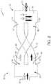
- FIG. 2schematically illustrates a vertical cross section of the fluid mixer shown in FIG. 1 ;
- FIG. 3schematically illustrates a flow splitter of a fluid mixer of an embodiment described herein;
- FIG. 4schematically illustrates a mixing chamber of a fluid of an embodiment described herein
- FIG. 5schematically illustrates another flow splitter of a fluid mixer of an embodiment described herein;
- FIG. 6illustrates a fluid mixer according to another embodiment described herein
- FIG. 7schematically illustrates a fluid mixer according to another embodiment described herein.
- FIG. 8schematically illustrates a fluid mixer according to another embodiment described herein.
- FIG. 9illustrates a fluid mixer arrangement according to another embodiment described herein.
- FIG. 10illustrates a fluid mixer arrangement according to another embodiment described herein.
- FIG. 11illustrates a fluid mixer arrangement according to another embodiment described herein.
- FIG. 12illustrates a fluid mixer arrangement according to another embodiment described herein.
- a fluid mixerwhich is able to split a flow of fluid into first and second fluid streams of different density and promote their mixing
- a fluid mixercomprising a plurality of channels, each of dissimilar volume but having a substantially identical pressure drop across each channel, which preferably ensures a substantially identical volumetric flow rate through each of the channels of the mixer.
- FIGS. 1 and 2illustrate a fluid mixer ( 1 ) comprising a flow splitter ( 20 ) and a mixing chamber ( 30 ).
- the flow splitter ( 20 )comprises an inlet ( 21 ) for receiving a flow of fluid to be mixed.
- the flow splitter ( 20 )is configured to split the flow of fluid received at the inlet ( 21 ) into a first fluid stream ( 22 ) and a second fluid stream ( 23 ).
- the second fluid stream ( 23 )has a higher density than the first fluid stream ( 22 ).
- the flow of fluid received at the inlet ( 21 ) of the flow splitter ( 20 )is split, by density, into the first ( 22 ) and second ( 23 ) fluid streams by virtue of gravity.
- the first fluid stream ( 22 )is vertically above the second fluid stream ( 23 ) at the point of leaving the flow splitter.
- the composition of the fluid flowis schematically illustrated in FIG. 2 using ‘black’ and ‘white’ arrows.
- a white arrow, or the white element of an arrowis used to signify the relatively less dense part of the fluid stream.
- a black arrowor the black element of an arrow, is used to signify the relatively more dense part of the fluid stream.
- the arrow used to denote the first fluid stream ( 22 )is white; and the arrow used to denote the second fluid stream ( 23 ) is black.
- the arrow used to denote the inlet flow of fluidis both black and white, signifying that it comprises both the first and second fluid streams, albeit not homogeneously mixed.
- the black and white arrows in the mixing chamber ( 36 )signify the mixing of the first ( 22 ) and second ( 23 ) streams.
- the dotted arrow used to signify the outlet stream 37schematically illustrates its substantially homogeneous nature.
- the flow splitter ( 20 )comprises a splitter well ( 26 ) in fluid communication with the fluid inlet ( 21 ).
- the flow splitter ( 20 )preferably further comprises a first outlet ( 24 ) in fluid communication with the splitter well ( 26 ), for conveying the first fluid stream ( 22 ) away from the splitter well ( 26 ).
- the flow splitter ( 20 )preferably further comprises a second outlet ( 25 ) in fluid communication with the splitter well ( 26 ), for conveying the second fluid stream ( 23 ).
- the first outlet ( 24 )is vertically above the second outlet ( 25 ).
- FIG. 2is a cross-sectional side view of the arrangement shown in FIG. 1 .
- first outlet ( 24 )is exactly vertically above the second outlet ( 25 ).
- first outlet ( 24 )is at least higher than the second outlet ( 25 ), such that, due to gravity, the second fluid stream ( 23 ) passing into the second outlet ( 25 ) will likely be more dense than the first fluid stream ( 22 ) passing into the first outlet ( 24 ).
- FIG. 3An alternative flow splitter ( 120 ) is schematically illustrated in FIG. 3 .
- the flow splitter ( 120 ) of FIG. 3comprises an inlet ( 21 ).
- the flow splitter ( 120 )further comprises a first outlet ( 124 ) and a second outlet ( 125 ).
- the first outlet ( 124 ) and second outlet ( 125 ) of the flow splitter ( 120 ) shown in FIG. 3are arranged on opposing sides of the splitter well ( 126 ).
- the first outlet ( 124 ) and the second outlet ( 125 )are directed away from one another.
- the arrangement shown in FIG. 3may provide for more effective splitting of the fluid flow in the fluid inlet ( 21 ).
- FIG. 5schematically illustrates another flow splitter ( 20 ) of a mixer.
- the flow splitter ( 20 ) illustrated in FIG. 5generally corresponds to the flow splitter ( 20 ) shown in FIG. 2 .
- the flow splitter ( 20 ) in FIG. 5additionally comprises a splitter plate ( 27 ) which presents a leading edge ( 28 ) to the flow of fluid in use, to create a second fluid stream ( 23 ) having a lower density than a first fluid stream ( 22 ).
- the distance between the inlet ( 21 ) and the first ( 24 ) and second ( 25 ) outletsis configured such that the incoming fluid is able to be sufficiently passively separated, due to gravity, into a lower, dense, part and an upper, less dense, part.
- the vertical position of the splitter plate ( 27 ) and/or the vertical position of the leading edge ( 28 ) of the splitter plate ( 27 )is adjustable.
- the position of the leading edge ( 28 ) and/or the splitter plate ( 27 )may be configured so as to substantially align with the fluid boundary (meniscus) between the two immiscible fluids.
- At least a part of the splitter plate ( 27 ), preferably the part of the splitter plate ( 27 ) adjacent the leading edge ( 28 ),is generally coplanar with the direction of flow of the inlet fluid in use.
- the mixing chamber ( 30 )comprises a first fluid inlet ( 31 ) and a second fluid inlet ( 32 ).
- the second fluid inlet ( 32 )is positioned vertically below the first inlet ( 31 ).
- the second fluid inlet ( 32 )is at least lower than the first inlet ( 31 ).
- the mixing chamber ( 30 )further comprises a mixing well ( 36 ).
- the second inlet ( 32 ) of the mixing chamber ( 30 )is configured to receive the first fluid stream ( 22 ).
- the first inlet ( 31 ) of the mixing chamber ( 30 )is configured to receive the second fluid stream ( 23 ).
- the first ( 22 ) and second ( 23 ) fluid streamsarrive at the mixing chamber ( 30 ) in an orientation which is inverted from the orientation in which they left the flow splitter ( 20 ). In other words, the first ( 22 ) and second ( 23 ) fluid streams are “flipped”.
- the benefit of this arrangementis that it promotes more effective mixing of the first ( 22 ) and second ( 23 ) fluid streams in the mixing well ( 36 ) of the mixing chamber ( 30 ).
- the fluid output ( 37 ) of the fluid mixer ( 1 )is preferably more homogenous than that received at the inlet ( 21 ) of the flow splitter ( 20 ) of the fluid mixer ( 1 ).
- the fluid mixer ( 1 )preferably further comprises a first channel ( 40 ) and a second channel ( 45 ).
- the first channel ( 40 )has an inlet ( 41 ) configured to receive and convey the first fluid stream ( 22 ) towards an outlet ( 42 ) of the first channel ( 40 ).
- the inlet ( 41 ) of the first channel ( 40 )is fluidly connected to the first outlet ( 24 ) of the flow splitter ( 20 ).
- the outlet ( 42 ) of the first channel ( 40 )is in fluid communication with the second inlet ( 32 ) of the mixing chamber ( 30 ).
- the fluid mixer ( 1 )further comprises a second channel ( 45 ) having an inlet ( 46 ) which is configured to receive and convey the second fluid stream ( 23 ) towards an outlet ( 47 ) of the second channel ( 45 ).
- the inlet ( 46 ) of the second channel ( 45 )is in fluid communication with the second outlet ( 25 ) of the flow splitter ( 20 ).
- the outlet ( 47 ) of the second channel ( 45 )is in fluid communication with the first inlet ( 31 ) of the mixing chamber ( 30 ).
- the flow stream received at the inlet ( 21 )is split vertically and then later rejoined in a reversed orientation. As a result, a less dense fluid stream is introduced into a more dense fluid stream from below and gravity causes the two fluid streams to mix—i.e. the more dense fluid stream flows ‘through’ the less dense fluid stream, causing mixing.
- the length of the first channel ( 40 )is substantially the same as the length of the second channel ( 45 ).
- the volume of the first channel ( 40 )is substantially the same as the volume of the second channel ( 45 ).
- the cross sectional area of the first channel ( 40 )is substantially the same as the cross sectional area of the second channel ( 45 ).
- first ( 40 ) and second ( 45 ) channelsappear to be of the same length, cross-section and volume, this is not essential.
- the volume of the first channel ( 40 )may be dissimilar to the volume of the second channel ( 45 ).
- the mixing chamber ( 30 )is similar in form to the flow splitter ( 20 ). That is to say that the first ( 31 ) and second ( 32 ) inlets of the mixing chamber ( 30 ) are on the same side face of the mixing well ( 36 ), such that the respective axes of the first ( 31 ) and second ( 32 ) inlets are parallel to one another.
- the first inlet ( 131 ) and the second inlet ( 132 ) of the mixing chamber ( 130 )are provided on opposing sides of the mixing well ( 136 ). Consequently, the axis of the first inlet ( 131 ) of the mixing chamber ( 130 ) is substantially co-axial with the axis of the second inlet ( 132 ) of the mixing chamber ( 130 ), such that the first ( 22 ) and second ( 23 ) fluid streams are directed substantially towards one another in the mixing well ( 136 ), thereby aiding mixing.
- the relative velocity of the colliding first ( 22 ) and second ( 23 ) fluid streamswill be the sum of the velocity of each stream ( 22 , 23 ).
- the mixing well ( 36 , 136 ) of the mixing chamber ( 30 , 130 )may comprise other features which aid the mixing of the first ( 22 ) and second ( 23 ) fluid streams. Such features may comprise components (not shown) to increase the turbulence of the fluid in the mixing well ( 36 , 136 ). In some embodiments there may be a mechanical agitator (not shown) in the mixing well ( 36 , 136 ).
- FIG. 6illustrates a fluid mixer arrangement ( 200 ).
- the fluid mixer arrangement ( 200 )comprises a plurality of fluid mixers ( 1 ) according to an embodiment described herein.
- the mixing, and thus homogenisation, of the fluidis preferably further improved.
- a fluid mixeris provided by forming cavities within a block of material, to define the flow splitter, mixing chamber and channels etc. Consequently, the figures illustrate a ‘negative’ of those cavities. This is why the inlet 21 illustrated in FIG. 6 apparently comprises a solid article—it is the ‘negative’ of the inlet 21 . Given the complex nature of the components of the invention, it will be appreciated that this method of illustrating the invention is clearer than providing multiple cross-sectional views and cut-through views of a block containing cavities which form the various features.
- the first fluid mixer ( 1 ) in the series of the fluid mixer arrangement ( 200 ) shown in FIG. 6comprises a fluid inlet ( 21 ) which is in fluid communication with a flow splitter ( 20 ).
- the flow splitter ( 20 )splits the flow of fluid into first ( 22 ) and second ( 23 ) fluid streams, which are conveyed by first ( 40 ) and second ( 45 ) channels.
- the first ( 40 ) and second ( 45 ) channels illustrated in FIG. 6are of different physical form to those illustrated schematically in FIGS. 1 and 2 . This is because the arrangement ( 200 ) shown in FIG. 6 is the negative of the channels which are formed in a microfluidic device. Preferably, the microfluidic device is formed by bonding multiple layers of material to one another, each layer comprising groove/indentations which are aligned together to form channels therein. The exact physical form of the first ( 40 ) and second ( 45 ) channels is not of significance. It is to be noted from FIG. 6 that the outlet ( 42 ) of the first channel ( 40 ) is positioned vertically below the outlet ( 47 ) of the second channel ( 45 ).
- the use of a fluid mixer arrangement ( 200 ) incorporating multiple stages of fluid mixerspreferably increases turbulence and increases the homogenisation of the mixed fluid.
- a secondary fluid mixermay be provided within one of the fluid streams of a first fluid mixer. That is to say, between passing from the flow splitter ( 20 ) to the mixing chamber ( 30 ), one of the first ( 22 ) and second ( 23 ) fluid streams may be passed through a secondary fluid mixer which further splits that stream into two sub-streams and promotes mixing of the fluid in that stream. Multiple fluid mixers may be consecutively “nested” within a larger fluid mixer arrangement.
- FIG. 7schematically illustrates a fluid mixer ( 300 ) embodying a second aspect.
- the fluid mixer ( 300 )comprises a flow splitter ( 320 ) comprising an inlet ( 321 ) for receiving a flow of fluid.
- the flow splitter ( 320 )is configured to split the flow of fluid into a plurality of fluid streams ( 322 a , 322 b , 322 c , 322 d ).
- the flow splitter ( 320 )comprises a plurality of outlets ( 324 a , 324 b , 324 c , 324 d ).
- FIG. 7schematically illustrates the fluid mixer ( 300 ) in plan view (as compared to a side view). Therefore, the outlets ( 324 a - d ) are in the same horizontal plane. However, this is not essential.
- the fluid mixer ( 300 )further comprises a plurality of channels ( 340 a , 340 b , 340 c , 340 d ), each for conveying a corresponding one of the plurality of streams ( 322 a - d ).
- Each of the plurality of channels ( 340 a - d )have dissimilar internal volumes but a substantially identical pressure drop across the length of each channel ( 340 a - d ).
- the fluid mixer ( 300 )further comprises a mixing chamber ( 330 ) comprising a plurality of inlets ( 331 a , 331 b , 331 c , 331 d ), each fluidly connected to a corresponding one of the plurality of channels ( 340 a - d ).
- a mixing chamber ( 330 )comprising a plurality of inlets ( 331 a , 331 b , 331 c , 331 d ), each fluidly connected to a corresponding one of the plurality of channels ( 340 a - d ).
- channel ( 340 a )is connected to inlet ( 331 a )
- channel ( 340 b )is connected to inlet ( 331 b ) etc.
- Each channel ( 340 a - d )preferably comprises a flow restrictor ( 370 a - 370 d ) connected to a conduit ( 360 a - 360 d ), the conduit ( 360 ) being downstream of the flow restrictor ( 370 a - 370 d ).
- each of the plurality of conduits ( 360 a - d )are of substantially equal length.
- conduitsare of different lengths. In another embodiment, shown in FIG. 8 , the conduits ( 460 a - d ) are all of different lengths.
- At least some of the plurality of conduits ( 360 a - d )have different cross-sectional areas.
- Both the length and cross-sectional area of a channelmay be different to both the length and cross-sectional area of another channel.
- the cross-sectional area of a channelmay be uniform or non-uniform along its length.
- the plurality of flow restrictors ( 370 a - d )are substantially identical such that the pressure drop across each of the plurality of flow restrictors ( 370 a - d ) is substantially identical.
- the pressure drop across a flow restrictor ( 370 )is greater than the pressure drop across the conduit ( 360 ) of that channel ( 340 ).
- the pressure drop across the flow restrictor ( 370 )is at least 10 times greater than the pressure drop across the conduit ( 360 ) of that channel ( 340 ).
- the plurality of channels ( 340 a - d )are configured to have substantially identical volumetric flow rates therethrough.
- a benefit of such an arrangementis that it suppresses, or substantially cancels, volumetric noise frequencies in the fluid stream without having differential volumetric flow rates through each of the channels which would otherwise create inconsistent channel clearance upon changing a solvent.
- those component parts of the inlet fluid streamwill recombine at the mixing chamber ( 330 ) at substantially the same time.
- the pressure drop across each of the conduits ( 360 a - d )may differ.
- the pressure drop across a fluid restrictor ( 370 a - d )is preferably substantially higher than the pressure drop across a corresponding conduit ( 360 a - d ). Consequently, the pressure drop across the channels ( 340 a - d ) as a whole will be substantially the same.
- FIGS. 7 and 8there are four channels ( 340 a - d ), but this is not essential. There may be more or fewer than four channels. There may be two channels.
- a plurality of fluid mixers ( 300 , 400 )may be provided in a fluid mixer arrangement.
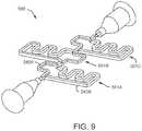
- FIG. 9illustrates a fluid mixer arrangement ( 500 ) comprising three fluid mixers ( 501 a ), ( 501 b ), ( 501 c ), connected in series. Accordingly, the arrangement ( 500 ) shown in FIG. 9 generally corresponds to the arrangement ( 200 ) illustrated in FIG. 6 , by providing a series of interconnected fluid mixers.
- each of the fluid mixers ( 501 a - c )comprises two channels ( 540 a - b ).
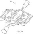
- FIG. 10illustrates another fluid mixer arrangement ( 600 ), which comprises 8 channels ( 640 ).
- the mixer arrangement ( 600 ) illustrated in FIG. 10comprises a series of flow splitters ( 620 a - c ), which each split the incoming fluid flow into two fluid streams. Each of those fluid streams is then further split by a second stage splitter into two sub-streams, which are then split by a third stage of flow splitter. With reference to FIG. 10 , each of the two fluid streams exiting the first stage flow splitter ( 620 a ) communicate with a respective second stage flow splitter ( 620 b ).
- Each of the fluid streams from each of those second stage flow splitters ( 620 b )are then fed to a third stage flow splitter ( 620 c ).
- FIG. 6illustrates a mixer arrangement comprising a plurality of the same type of fluid mixer (embodying the first aspect).
- FIG. 9illustrates a mixer arrangement comprising a plurality of mixers embodying the second aspect of the invention. It is, of course, possible to provide a mixer arrangement comprising different fluid mixers connected in series. For example, a fluid mixer as illustrated in FIGS. 1 and 2 may be provided upstream of the fluid mixer illustrated in FIG. 7 . Any combination of any of the mixers illustrated, described and/or envisaged herein may be connected together to form a mixer arrangement.
- both the primary and second aspectscan be combined in a single mixer embodiment.
- FIG. 11illustrates a fluid mixer ( 700 ) comprising a flow splitter ( 720 ) comprising an inlet ( 721 ) for receiving a flow of fluid.
- the flow splitter ( 720 )is configured to split the flow of fluid into first and second fluid streams.
- the second fluid streamhas a higher density than the first fluid stream.
- the flow splitter ( 720 )has an arrangement corresponding to that of the flow splitter ( 120 ) illustrated in FIG. 3 —i.e. outlets on opposing sides of the chamber.
- the fluid mixer ( 700 ) of FIG. 11further comprises a mixing chamber ( 730 ) comprising a first inlet and a second inlet (partially obscured in FIG. 11 ).
- the fluid mixer ( 700 )further comprises a first channel ( 740 ) which conveys the first fluid stream from the flow splitter ( 720 ) to the second inlet of the mixing chamber ( 730 ).
- the fluid mixer ( 700 )further comprises a second channel ( 745 ) configured to receive and convey the second fluid stream towards the first inlet of the mixing chamber ( 730 ).
- the first inlet of the mixing chamber ( 730 )is arranged vertically above the second inlet of the mixing chamber ( 730 ). Accordingly, as with the embodiments illustrated and described with reference to FIGS. 1 to 6 , the first and second fluid streams are inverted, promoting mixing as they recombine in the mixing chamber ( 730 ).
- the first channel ( 740 )has a different length and cross section to the second channel ( 745 ). Accordingly, the channels ( 740 , 745 ) have dissimilar volumes. Preferably, they have substantially identical pressure drops across the length of each of the first ( 740 ) and second ( 745 ) channels.
- a benefit of an embodiment, such as the fluid mixer ( 700 ) illustrated in FIG. 11combining both the primary and secondary aspects is that it provides a fluid mixer which has advantages of each aspect of the invention. Specifically, the inversion of the split fluid stream promotes homogenisation of the fluid, whereas the use of channels with dissimilar volumes but equal pressure drops serves to reduce, or substantially cancel, volumetric noise frequencies.
- FIG. 12shows another fluid mixer ( 800 ) incorporating both the primary and secondary aspects.
- the fluid mixer ( 800 ) shown in FIG. 12comprises four parallel channels which are all of dissimilar volumes but substantially identical pressure drops thereacross.
- each parallel channel ( 840 )comprises a conduit ( 860 ) and a fluid restrictor (not labelled).
- the fluid mixer ( 800 ) shown in FIG. 12comprises two stages of flow splitter ( 820 ).
- the initial fluid stream from the fluid inlet ( 821 )is split into two fluid streams (of different densities) and conveyed via a first channel ( 840 a ) and a second channel ( 845 a ).
- Each of those channels ( 840 a ), ( 845 b )then communicates with a second stage flow splitter ( 820 b ) which further splits the fluid flow into two further channels ( 840 b ), ( 845 b ).
- the second stage flow splitters ( 820 b )also split the fluid into first and second fluid streams of different densities.
- the fluidthen passes through the four conduits ( 860 a - d ).
- the network of channels between the fluid inlet ( 821 ) and the fluid conduit ( 860 a )-( 860 d )create four pathways which are substantially of the same length.
- the pathwayscreate a fluid restrictor, each having a substantially identical pressure drop thereacross. Downstream of the fluid conduits ( 860 a )-( 860 d ), the fluid streams recombine in a two stage mixing chamber ( 830 ) arrangement.
- the fluid mixers of FIGS. 11 and 12conveniently incorporate, harmoniously and synergistically, each of the primary and secondary aspects.
Landscapes
- Chemical & Material Sciences (AREA)
- Chemical Kinetics & Catalysis (AREA)
- Dispersion Chemistry (AREA)
- Analytical Chemistry (AREA)
- Physics & Mathematics (AREA)
- Health & Medical Sciences (AREA)
- Life Sciences & Earth Sciences (AREA)
- Biochemistry (AREA)
- General Health & Medical Sciences (AREA)
- General Physics & Mathematics (AREA)
- Immunology (AREA)
- Pathology (AREA)
Abstract
Description
Claims (10)
Priority Applications (1)
| Application Number | Priority Date | Filing Date | Title |
|---|---|---|---|
| US16/111,733US11185830B2 (en) | 2017-09-06 | 2018-08-24 | Fluid mixer |
Applications Claiming Priority (2)
| Application Number | Priority Date | Filing Date | Title |
|---|---|---|---|
| US201762554835P | 2017-09-06 | 2017-09-06 | |
| US16/111,733US11185830B2 (en) | 2017-09-06 | 2018-08-24 | Fluid mixer |
Publications (2)
| Publication Number | Publication Date |
|---|---|
| US20190070572A1 US20190070572A1 (en) | 2019-03-07 |
| US11185830B2true US11185830B2 (en) | 2021-11-30 |
Family
ID=64500429
Family Applications (1)
| Application Number | Title | Priority Date | Filing Date |
|---|---|---|---|
| US16/111,733Active2039-06-15US11185830B2 (en) | 2017-09-06 | 2018-08-24 | Fluid mixer |
Country Status (4)
| Country | Link |
|---|---|
| US (1) | US11185830B2 (en) |
| EP (1) | EP3678764B1 (en) |
| CN (1) | CN111050895B (en) |
| WO (1) | WO2019050699A2 (en) |
Families Citing this family (9)
| Publication number | Priority date | Publication date | Assignee | Title |
|---|---|---|---|---|
| US11065549B2 (en)* | 2019-03-15 | 2021-07-20 | Sony Interactive Entertainment Inc. | AI modeling for video game coaching and matchmaking |
| JP7448540B2 (en)* | 2019-07-19 | 2024-03-12 | アルプスアルパイン株式会社 | fluid stirring device |
| US11555805B2 (en) | 2019-08-12 | 2023-01-17 | Waters Technologies Corporation | Mixer for chromatography system |
| CN111534412B (en)* | 2020-05-26 | 2024-02-20 | 南京智能高端装备产业研究院有限公司 | Device for labeling cell magnetic beads |
| CN116134312A (en)* | 2020-07-07 | 2023-05-16 | 沃特世科技公司 | Mixer for liquid chromatography |
| EP4179311B1 (en)* | 2020-07-07 | 2025-07-30 | Waters Technologies Corporation | Combination mixer arrangement for noise reduction in fluid chromatography |
| EP4217729B1 (en) | 2020-09-22 | 2025-08-13 | Waters Technologies Corporation | Continuous flow mixer |
| EP4341681A1 (en) | 2021-05-20 | 2024-03-27 | Waters Technologies Corporation | Equal dispersion split-flow mixer |
| JP2025112820A (en)* | 2024-01-22 | 2025-08-01 | 株式会社東芝 | Flow channel structure, flow channel structure unit, and method for producing lipid particles |
Citations (222)
| Publication number | Priority date | Publication date | Assignee | Title |
|---|---|---|---|---|
| US3404869A (en) | 1966-07-18 | 1968-10-08 | Dow Chemical Co | Interfacial surface generator |
| US3583678A (en) | 1969-09-15 | 1971-06-08 | Dow Badische Co | Interfacial surface generators |
| US3595531A (en) | 1969-11-04 | 1971-07-27 | Dow Chemical Co | Mixer apparatus |
| US3830369A (en) | 1973-12-11 | 1974-08-20 | E Pfadenhauer | High pressure gradient chamber for liquid chromatography |
| US3857551A (en) | 1973-06-21 | 1974-12-31 | Nus Corp | Device to dampen fluctuations in the concentration of a substance in a flowing stream of fluid |
| US3860217A (en) | 1973-04-26 | 1975-01-14 | Kenics Corp | Shear mixer |
| JPS5191175A (en) | 1975-02-06 | 1976-08-10 | Yakuzaino kinitsukongohoho | |
| JPS51102252A (en) | 1975-03-05 | 1976-09-09 | Masao Moryama | Kongosochi |
| US3985019A (en) | 1975-11-10 | 1976-10-12 | Boehme Detlef R | Liquid chromatography system with solvent proportioning |
| US4198168A (en) | 1978-04-12 | 1980-04-15 | Liquid Control Incorporated | Phase blending static mixing process and apparatus |
| JPS5592130A (en) | 1980-01-14 | 1980-07-12 | Masao Moriyama | Mixer |
| JPS55159831A (en) | 1979-05-30 | 1980-12-12 | Toray Ind Inc | Converting element of position of fluid |
| US4311586A (en) | 1980-04-22 | 1982-01-19 | Tracor, Inc. | Solvent mixing in HPLC using low pressure solvent metering pumps |
| US4437812A (en) | 1977-05-13 | 1984-03-20 | Varian Associates, Inc. | Single-pump multiple stroke proportioning for gradient elution liquid chromatography |
| US4496245A (en) | 1983-03-07 | 1985-01-29 | International Business Machines Corporation | Liquid chromatography proportioning valve and mixer |
| US4506987A (en) | 1982-09-08 | 1985-03-26 | The United States Of America As Represented By The United States Department Of Energy | High pressure liquid chromatographic gradient mixer |
| US4534659A (en) | 1984-01-27 | 1985-08-13 | Millipore Corporation | Passive fluid mixing system |
| JPS6248428U (en) | 1985-09-09 | 1987-03-25 | ||
| JPS6295727U (en) | 1985-12-09 | 1987-06-18 | ||
| JPS62210042A (en) | 1986-03-07 | 1987-09-16 | Hitachi Ltd | Device for mixing liquid |
| US4767279A (en) | 1987-06-02 | 1988-08-30 | Millipore Corporation | Fluid composition and volumetric delivery control |
| US4842730A (en) | 1986-09-17 | 1989-06-27 | U.S. Philips Corporation | Liquid chomatograph apparatus |
| US4882062A (en) | 1986-08-29 | 1989-11-21 | Rainin Instrument Co., Inc. | Solvent mixing chamber for a liquid chromatography system |
| US4882063A (en) | 1987-07-13 | 1989-11-21 | Isco, Inc. | Chromatographic system |
| JPH02167469A (en) | 1988-12-21 | 1990-06-27 | Yokogawa Electric Corp | Solvent mixer for liquid chromatography |
| JPH02170047A (en) | 1988-12-23 | 1990-06-29 | Yokogawa Electric Corp | Solvent mixer for liquid chromatography |
| US4954253A (en) | 1987-05-14 | 1990-09-04 | Nauchno-Tekhnicheskoe Objedinenie Akademii Nauk Sssr | Device for preparing a gradient solution for a high-pressure liquid chromatograph |
| US4971450A (en)* | 1986-01-13 | 1990-11-20 | Horst Gerich | Interfacial surface generator |
| US5275723A (en) | 1992-07-06 | 1994-01-04 | Sp Industries Ltd. Partnership | Mobile phase reservoir |
| US5304487A (en) | 1992-05-01 | 1994-04-19 | Trustees Of The University Of Pennsylvania | Fluid handling in mesoscale analytical devices |
| JPH06324026A (en) | 1993-05-11 | 1994-11-25 | Irika Kiki Kk | Liquid chromatrography device |
| US5423661A (en) | 1992-08-13 | 1995-06-13 | Millipore Corporation | Fluid metering, mixing and composition control system |
| JPH07159388A (en) | 1993-12-02 | 1995-06-23 | Jeol Ltd | Mixer for supercritical fluid chromatography |
| US5486335A (en) | 1992-05-01 | 1996-01-23 | Trustees Of The University Of Pennsylvania | Analysis based on flow restriction |
| DE19511603A1 (en) | 1995-03-30 | 1996-10-02 | Norbert Dr Ing Schwesinger | Device for mixing small amounts of liquid |
| WO1997000125A1 (en) | 1995-06-16 | 1997-01-03 | Novartis Ag | Flow cell for the passive mixing of flowable substances |
| US5637469A (en) | 1992-05-01 | 1997-06-10 | Trustees Of The University Of Pennsylvania | Methods and apparatus for the detection of an analyte utilizing mesoscale flow systems |
| US5656034A (en) | 1995-03-31 | 1997-08-12 | Perkin Elmer Corp | High-pressure micro-volume syringe pump |
| US5664938A (en) | 1992-03-05 | 1997-09-09 | Yang; Frank Jiann-Fu | Mixing apparatus for microflow gradient pumping |
| US5738783A (en) | 1994-05-09 | 1998-04-14 | Shiseido Company, Ltd. | Liquid chromatograph having a micro- and semi-micro column |
| US5846411A (en) | 1993-08-02 | 1998-12-08 | Institute Francais Du Petrole | Single-phase fluid distributor-mixer-extractor for beds of granular solids |
| JP2587162Y2 (en) | 1991-11-15 | 1998-12-14 | ジーエルサイエンス株式会社 | Liquid chromatograph mixer |
| US5887977A (en) | 1997-09-30 | 1999-03-30 | Uniflows Co., Ltd. | Stationary in-line mixer |
| US5918976A (en) | 1994-09-06 | 1999-07-06 | Konica Corporation | Mixing method |
| JP2603770Y2 (en) | 1993-06-30 | 2000-03-21 | ジーエルサイエンス株式会社 | Gradient mixer for liquid chromatography |
| US6048496A (en) | 1996-06-05 | 2000-04-11 | Gi Sciences Incorporated | Mixer for liquid chromatograph |
| WO2000022436A1 (en) | 1998-10-13 | 2000-04-20 | Biomicro Systems, Inc. | Fluid circuit components based upon passive fluid dynamics |
| DE19902697A1 (en) | 1999-01-14 | 2000-07-20 | Guenter J Eppert | Dynamic mixing chamber for high pressure liquid chromatography process has minimum dwell volume and exactly reproduces liquid gradients |
| US6170981B1 (en) | 1998-05-07 | 2001-01-09 | Purdue Research Foundation | In situ micromachined mixer for microfluidic analytical systems |
| US6190034B1 (en) | 1995-10-03 | 2001-02-20 | Danfoss A/S | Micro-mixer and mixing method |
| US6319469B1 (en) | 1995-12-18 | 2001-11-20 | Silicon Valley Bank | Devices and methods for using centripetal acceleration to drive fluid movement in a microfluidics system |
| EP1174179A1 (en) | 2000-07-20 | 2002-01-23 | Agilent Technologies, Inc. (a Delaware corporation) | Method and apparatus for mixing fluids |
| EP1193496A1 (en) | 1999-05-19 | 2002-04-03 | Eisai Co., Ltd. | Branch pipe device for gradient high performance liquid chromatography |
| US20020113095A1 (en) | 2000-09-18 | 2002-08-22 | Jeon Noo Li | Method and apparatus for gradient generation |
| US20020134143A1 (en) | 2001-02-27 | 2002-09-26 | Isco, Inc. | Liquid chromatographic method and system |
| KR20020085903A (en) | 2001-05-10 | 2002-11-18 | 대한민국(관리부서 서울대학교(정밀기계설계공동연구소)) | Apparatus for mixing fluids by micro channel |
| WO2003015890A1 (en) | 2001-08-20 | 2003-02-27 | President And Fellows Of Harvard College | Fluidic arrays and method of using |
| WO2003024598A1 (en) | 2001-09-17 | 2003-03-27 | Gyros Ab | Functional unit enabling controlled flow in a microfluidic device |
| US20030077204A1 (en) | 2001-10-18 | 2003-04-24 | Minoru Seki | Micro-globule metering and sampling structure and microchips having the structure |
| WO2003047736A1 (en) | 2001-12-06 | 2003-06-12 | Accoris Gmbh | Microemulsifier |
| US20030123322A1 (en) | 2001-12-31 | 2003-07-03 | Industrial Technology Research Institute | Microfluidic mixer apparatus and microfluidic reactor apparatus for microfluidic processing |
| US6637463B1 (en) | 1998-10-13 | 2003-10-28 | Biomicro Systems, Inc. | Multi-channel microfluidic system design with balanced fluid flow distribution |
| US20040011413A1 (en) | 2001-06-15 | 2004-01-22 | Yasuhisa Fujii | Mixing method, mixing structure, micromixer and microchip having the mixing structure |
| US20040092033A1 (en) | 2002-10-18 | 2004-05-13 | Nanostream, Inc. | Systems and methods for preparing microfluidic devices for operation |
| US20040096867A1 (en) | 2001-03-19 | 2004-05-20 | Per Andersson | Characterization of reaction variables |
| US20040109793A1 (en) | 2002-02-07 | 2004-06-10 | Mcneely Michael R | Three-dimensional microfluidics incorporating passive fluid control structures |
| KR20040069496A (en) | 2003-01-29 | 2004-08-06 | 코스모지놈 주식회사 | Microfluidic mixer and manufacturing method thereof |
| US6843262B2 (en) | 2001-04-25 | 2005-01-18 | President And Fellows Of Harvard College | Fluidic switches and methods for controlling flow in fluidic systems |
| US6845787B2 (en) | 2002-02-23 | 2005-01-25 | Nanostream, Inc. | Microfluidic multi-splitter |
| US6887384B1 (en) | 2001-09-21 | 2005-05-03 | The Regents Of The University Of California | Monolithic microfluidic concentrators and mixers |
| US6890093B2 (en) | 2000-08-07 | 2005-05-10 | Nanostream, Inc. | Multi-stream microfludic mixers |
| US6893547B2 (en) | 2000-06-14 | 2005-05-17 | Board Of Regents, The University Of Texas System | Apparatus and method for fluid injection |
| US20050118070A1 (en) | 2003-10-23 | 2005-06-02 | Patrick Griss | Flow triggering device |
| JP3665680B2 (en) | 1996-06-05 | 2005-06-29 | ジーエルサイエンス株式会社 | Trace analysis method and liquid chromatograph |
| US6916113B2 (en) | 2003-05-16 | 2005-07-12 | Agilent Technologies, Inc. | Devices and methods for fluid mixing |
| WO2005063368A2 (en) | 2003-12-23 | 2005-07-14 | The Regents Of The University Of Michigan | Method for mixing fluid streams, microfluidic mixer and microfluidic chip utilizing same |
| US6919046B2 (en) | 2001-06-07 | 2005-07-19 | Nanostream, Inc. | Microfluidic analytical devices and methods |
| JP2005211857A (en) | 2004-02-02 | 2005-08-11 | National Food Research Institute | Resin microchannel substrate and manufacturing method thereof |
| EP1566215A2 (en) | 2004-02-17 | 2005-08-24 | Boehringer Ingelheim microParts GmbH | Microstructured platform and method of handling a liquid |
| US6942792B2 (en) | 2002-08-28 | 2005-09-13 | Shimadzu Corporation | Mixer for liquid chromatograph |
| US6958119B2 (en) | 2002-02-26 | 2005-10-25 | Agilent Technologies, Inc. | Mobile phase gradient generation microfluidic device |
| US20050252840A1 (en) | 2004-05-13 | 2005-11-17 | Eksigent Technologies, Llc | Micromixer |
| US6981522B2 (en) | 2001-06-07 | 2006-01-03 | Nanostream, Inc. | Microfluidic devices with distributing inputs |
| JP2006003203A (en) | 2004-06-17 | 2006-01-05 | Shiseido Co Ltd | Gradient mixer for liquid chromatography |
| US6987263B2 (en) | 2002-12-13 | 2006-01-17 | Nanostream, Inc. | High throughput systems and methods for parallel sample analysis |
| US6991729B2 (en) | 2001-04-12 | 2006-01-31 | Daicel Chemical Industries, Ltd. | Optical isomer separating filler, production method therefor and application method therefor |
| WO2006017039A1 (en) | 2004-07-13 | 2006-02-16 | Waters Investments Limited | Fluid mixer assembly |
| US20060039829A1 (en) | 2004-08-21 | 2006-02-23 | Ji Won Suk | Microfluidic device, and diagnostic and analytical apparatus using the same |
| JP2006122735A (en) | 2004-10-26 | 2006-05-18 | Dainippon Screen Mfg Co Ltd | Channel structure and fluid mixing apparatus |
| JP3780917B2 (en) | 2001-11-22 | 2006-05-31 | 株式会社島津製作所 | Liquid chromatograph and its eluent mixing device |
| US20060171864A1 (en) | 2005-01-07 | 2006-08-03 | Philippe Caze | High performance microreaction device |
| US7105304B1 (en) | 2000-11-07 | 2006-09-12 | Caliper Life Sciences, Inc. | Pressure-based mobility shift assays |
| US7111501B2 (en) | 2003-10-03 | 2006-09-26 | Agilent Technologies, Inc. | Devices and methods for separating constituents |
| US7112277B2 (en) | 2003-06-30 | 2006-09-26 | Agilent Technologis, Inc. | Methods and systems for separating constituents of a highly aqueous fluid |
| JP2006281008A (en) | 2005-03-31 | 2006-10-19 | Dainippon Ink & Chem Inc | Micro mixer |
| US7134453B2 (en) | 2003-01-23 | 2006-11-14 | Boehringer Ingelheim Microparts Gmbh | Microfluidic switch for stopping a liquid flow during a time interval |
| US7143785B2 (en) | 2002-09-25 | 2006-12-05 | California Institute Of Technology | Microfluidic large scale integration |
| US20060273012A1 (en) | 2005-03-02 | 2006-12-07 | Agilent Technologies, Inc. | Column with additional fluid introduction |
| US7147364B2 (en) | 2003-09-29 | 2006-12-12 | Hitachi High-Technologies Corporation | Mixer and liquid analyzer provided with same |
| US20060280029A1 (en) | 2005-06-13 | 2006-12-14 | President And Fellows Of Harvard College | Microfluidic mixer |
| US20060285433A1 (en) | 2005-06-20 | 2006-12-21 | Jing-Tang Yang | Fluidic mixer of serpentine channel incorporated with staggered sudden-expansion and convergent cross sections |
| KR100666500B1 (en) | 2005-02-25 | 2007-01-09 | 학교법인 포항공과대학교 | Spiral Lamination Chaos Micro Mixer |
| JP3865119B2 (en) | 2001-06-29 | 2007-01-10 | 株式会社島津製作所 | Mobile phase gradient apparatus and high-performance liquid chromatograph using the same |
| US7178386B1 (en) | 2003-04-10 | 2007-02-20 | Nanostream, Inc. | Parallel fluid processing systems and methods |
| WO2007021755A2 (en) | 2005-08-11 | 2007-02-22 | Eksigent Technologies, Llc | Microfluidic systems, devices and methods for reducing noise generated by mechanical instabilities |
| JP2007090262A (en) | 2005-09-29 | 2007-04-12 | Mitsubishi Heavy Ind Ltd | Fluid mixing apparatus |
| US7204139B2 (en) | 2002-07-12 | 2007-04-17 | Mitsubishi Chemical Corporation | Analytical chip, analytical-chip unit, and analysis apparatus |
| US7207345B2 (en) | 2002-09-24 | 2007-04-24 | The Technology Partnership Plc | Fluid routing device |
| CN1964777A (en) | 2004-06-11 | 2007-05-16 | 康宁股份有限公司 | Microstructure configuration for mixing and pressure drop optimization |
| EP1788388A1 (en) | 2005-11-18 | 2007-05-23 | Agilent Technologies, Inc. | Devices and methods using fluid-transporting features with differing residence times |
| US20070148048A1 (en) | 2003-12-16 | 2007-06-28 | Jousse Fabien Frederic R M | Microfluidic device |
| US7241423B2 (en) | 2000-02-03 | 2007-07-10 | Cellular Process Chemistry, Inc. | Enhancing fluid flow in a stacked plate microreactor |
| JP3959436B2 (en) | 2003-08-29 | 2007-08-15 | 独立行政法人物質・材料研究機構 | Flow fluctuation structure and micromixer |
| US7261812B1 (en) | 2002-02-13 | 2007-08-28 | Nanostream, Inc. | Multi-column separation devices and methods |
| US7278329B2 (en) | 2003-11-05 | 2007-10-09 | Agilent Technologies, Inc. | Chromatography system with blockage determination |
| US20070240989A1 (en) | 2001-12-18 | 2007-10-18 | Jeremy Levitan | Microfluidic pumps and mixers driven by induced-charge electro-osmosis |
| US20070263477A1 (en) | 2006-05-11 | 2007-11-15 | The Texas A&M University System | Method for mixing fluids in microfluidic channels |
| US20070269894A1 (en) | 2006-05-18 | 2007-11-22 | Howland David R | Solution dispensing system |
| US20070297285A1 (en) | 2006-06-23 | 2007-12-27 | Cross William M | Fractal distributor for two phase mixing |
| JP4082309B2 (en) | 2003-08-22 | 2008-04-30 | 株式会社島津製作所 | Solution mixer for liquid chromatography |
| US7390121B2 (en) | 1998-03-27 | 2008-06-24 | Bayer Aktiengesellschaft | Static mixer module |
| JP2009018311A (en) | 2008-10-30 | 2009-01-29 | Hitachi Plant Technologies Ltd | Microfluidic chip |
| US20090044619A1 (en) | 2007-08-13 | 2009-02-19 | Fiering Jason O | Devices and methods for producing a continuously flowing concentration gradient in laminar flow |
| US20090142846A1 (en) | 2005-08-11 | 2009-06-04 | Eksigent Technologies, Llc | Methods for measuring biochemical reactions |
| US20090148858A1 (en) | 2005-08-11 | 2009-06-11 | Eksigent Technologies, Llc | Methods for characterizing biological molecule modulators |
| US20090207687A1 (en) | 2005-10-03 | 2009-08-20 | Honeywell International Inc. | Apparatus and method for preparing ultrapure solvent blends |
| JP2009208052A (en) | 2008-03-06 | 2009-09-17 | National Institute Of Advanced Industrial & Technology | Micro mixer |
| EP2106846A1 (en) | 2008-04-04 | 2009-10-07 | Nederlandse Organisatie voor toegepast- natuurwetenschappelijk onderzoek TNO | Mixing junction |
| US20090255601A1 (en) | 2008-04-14 | 2009-10-15 | Agilent Technologies, Inc. | Fluidic conduit with repeated disturbance of laminar flow |
| JP4348820B2 (en) | 2000-03-24 | 2009-10-21 | 株式会社島津製作所 | Liquid mixer |
| US20090268548A1 (en) | 2005-08-11 | 2009-10-29 | Eksigent Technologies, Llc | Microfluidic systems, devices and methods for reducing diffusion and compliance effects at a fluid mixing region |
| JP4360206B2 (en) | 2004-01-08 | 2009-11-11 | 東ソー株式会社 | Liquid chromatograph mixer |
| WO2010015238A1 (en) | 2008-08-08 | 2010-02-11 | Dionex Softron Gmbh | Mixing device for liquid chromatography |
| US20100040483A1 (en) | 2008-06-24 | 2010-02-18 | Berger Terry A | Compressible fluid pumping system |
| WO2010022428A1 (en) | 2008-08-28 | 2010-03-04 | Technische Universität Wien | Microfluid device |
| WO2010030720A1 (en) | 2008-09-12 | 2010-03-18 | Water Technologies Corporation | Valve switch modulation for reducing errors due oscillations of the inlet fluid of a pump system |
| US20100078086A1 (en) | 2008-09-29 | 2010-04-01 | Roland Guidat | Multiple flow path microreactor design |
| JP2010082533A (en) | 2008-09-30 | 2010-04-15 | Asahi Organic Chem Ind Co Ltd | Mixer |
| US20100159573A1 (en) | 2008-12-22 | 2010-06-24 | Electronics And Telecommunications Research Institute | Microfluidic dilution device |
| US7744762B2 (en) | 2006-08-24 | 2010-06-29 | Virginia Tech Intellectual Properties, Inc. | Microfluidic devices and methods facilitating high-throughput, on-chip detection and separation techniques |
| US20100189602A1 (en) | 2009-01-26 | 2010-07-29 | Agilent Technologies, Inc. | Separation device with moveable filling channel |
| WO2010083884A1 (en) | 2009-01-22 | 2010-07-29 | Agilent Technologies, Inc. | Apparatus for generating small flow rates in a channel |
| WO2010107677A1 (en) | 2009-03-14 | 2010-09-23 | Oleg Shinkazh | Countercurrent tangential chromatography methods, and apparatus |
| WO2011003412A2 (en) | 2009-07-08 | 2011-01-13 | Dionex Softron Gmbh | Longitudinal mixing device, in particular for high performance liquid chromatography |
| US7887753B2 (en) | 2000-11-16 | 2011-02-15 | California Institute Of Technology | Apparatus and methods for conducting assays and high throughput screening |
| JP4683066B2 (en) | 2008-04-14 | 2011-05-11 | コニカミノルタホールディングス株式会社 | Liquid mixing mechanism |
| US20110113866A1 (en) | 2009-11-13 | 2011-05-19 | Alan Finlay | Microengineered Supercritical Fluid Chromatography System |
| US7976779B2 (en) | 2002-06-26 | 2011-07-12 | California Institute Of Technology | Integrated LC-ESI on a chip |
| US20110192217A1 (en) | 2010-02-08 | 2011-08-11 | Agilent Technologies, Inc. | Flow Distribution Mixer |
| WO2011158430A1 (en) | 2010-06-16 | 2011-12-22 | 株式会社 日立ハイテクノロジーズ | Liquid mixing device and liquid chromatograph |
| CN102686321A (en) | 2009-10-05 | 2012-09-19 | 诺信公司 | Two-component liquid dispenser gun and system |
| US20120269027A1 (en) | 2009-12-23 | 2012-10-25 | Huanming Xia | Microfluidic mixing apparatus and method |
| NL2006787C2 (en) | 2011-05-16 | 2012-11-19 | Avantium Holding B V | COMPOUNDER AND METHOD FOR MIXING ONE OR MORE VISCOUS FLUIDS. |
| US20120309648A1 (en) | 2007-07-06 | 2012-12-06 | The Regents Of The University Of Calfornia | Integrated microfluidics for highly parallel screening of chemical reactions |
| WO2012166756A1 (en) | 2011-05-31 | 2012-12-06 | Corning Incorporated | Twist flow microfluidic mixer and module |
| US8329407B2 (en) | 2002-05-09 | 2012-12-11 | The University Of Chicago | Method for conducting reactions involving biological molecules in plugs in a microfluidic system |
| WO2013090141A1 (en) | 2011-12-14 | 2013-06-20 | Waters Technologies Corporation | Targeted frequency multiple path length mixers |
| CN203061073U (en) | 2012-12-19 | 2013-07-17 | 大连依利特分析仪器有限公司 | High Pressure Static Mixer for Chromatography |
| WO2013187916A1 (en) | 2012-06-15 | 2013-12-19 | Agilent Technologies, Inc. | Static mixer for high pressure or supercritical fluid chromatography systems |
| CN203385703U (en) | 2013-07-19 | 2014-01-08 | 安徽皖仪科技股份有限公司 | Ion chromatography gradient static mixer |
| JP5427603B2 (en) | 2006-04-25 | 2014-02-26 | ヴェロシス インコーポレイテッド | A flow delivery channel that controls the flow in the process channel |
| US20140061133A1 (en) | 2012-08-31 | 2014-03-06 | Joseph Lewis HERMAN | Method and Apparatus for Split-Flow-Mixing Liquid Chromatography |
| WO2014034259A1 (en) | 2012-08-29 | 2014-03-06 | 株式会社 日立ハイテクノロジーズ | Liquid mixers and liquid chromatographs |
| US8696193B2 (en) | 2009-03-06 | 2014-04-15 | Ehrfeld Mikrotechnik Bts Gmbh | Coaxial compact static mixer and use thereof |
| US8764279B2 (en) | 2008-07-18 | 2014-07-01 | 3M Innovation Properties Company | Y-cross mixers and fluid systems including the same |
| US20140230528A1 (en) | 2011-06-17 | 2014-08-21 | Waters Technologies Corporation | Turbulent flow mixing device for use in a chromatography system |
| US20140241110A1 (en) | 2011-08-11 | 2014-08-28 | Canon Kabushiki Kaisha | Fluidic channel device, method for mixing fluids, fluid control device, and liquid control system |
| CN104076112A (en) | 2013-03-27 | 2014-10-01 | 北京普源精电科技有限公司 | Mixer and high performance liquid chromatograph |
| US20140345372A1 (en) | 2012-02-01 | 2014-11-27 | Waters Technologies Corporation | Managing fluidic connections to microfluidic devices |
| CN204116295U (en) | 2014-10-24 | 2015-01-21 | 王峰 | A kind of chromatographic analyzer of liquid phase static mixer |
| US20150265978A1 (en) | 2014-03-24 | 2015-09-24 | Man Truck & Bus Ag | Homogenization apparatus for at least two fluid flows, in particular for homogeneous gas/air mixing in a gas engine |
| WO2016082520A1 (en) | 2014-11-26 | 2016-06-02 | 源创精科生物科技(长沙)有限公司 | Pressure coupling type chromatographic column fluid distributor |
| US20160161454A1 (en) | 2014-12-08 | 2016-06-09 | Clemson University | High resolution analyte recovery system and method |
| DE102015100693A1 (en) | 2015-01-19 | 2016-07-21 | Agilent Technologies, Inc. - A Delaware Corporation - | Adjusting a fluid composition taking into account a mixing phenomenon |
| US20160250606A1 (en) | 2015-02-26 | 2016-09-01 | Tokyo Electron Limited | Method and system for a spiral mixer |
| US20160266078A1 (en) | 2014-01-09 | 2016-09-15 | Hitachi High-Technologies Corporation | Liquid Mixing Device, and Liquid Chromatography Apparatus |
| CN106166453A (en) | 2016-07-06 | 2016-11-30 | 安徽皖仪科技股份有限公司 | A kind of passive mixing device for high performance liquid chromatography |
| US9527010B2 (en) | 2009-09-25 | 2016-12-27 | Ge Healthcare Bio-Sciences Corp. | Separation system and method |
| US9528968B2 (en) | 2014-10-14 | 2016-12-27 | Waters Technologies Corporation | Enhanced sensitivity of detection in electrospray ionization mass spectrometry using a post-column modifier and a microfluidic device |
| US9557317B2 (en) | 2014-06-25 | 2017-01-31 | PureHoney Technologies, Inc. | Automated sample fractionation prior to mass spectrometric analysis |
| US9566537B2 (en) | 2012-08-31 | 2017-02-14 | Xi'an Aolan Science And Technology Co., Ltd. | Multidimensional liquid chromatography separation system and separation method for protein separation |
| CN106422832A (en) | 2016-11-21 | 2017-02-22 | 浙江福立分析仪器股份有限公司 | High-voltage static mixer for liquid chromatography system and liquid mixing method |
| US9636646B2 (en) | 2011-01-12 | 2017-05-02 | Tetra Laval Holdings & Finance S.A. | Layer multiplier for fluids with high viscosity |
| KR101736797B1 (en) | 2016-01-29 | 2017-05-17 | 인하대학교 산학협력단 | Micromixer for mixing fluids |
| US9679757B2 (en) | 2013-04-12 | 2017-06-13 | Waters Technologies Corporation | Liquid chromatography systems and methods |
| US20170173496A1 (en) | 2015-08-27 | 2017-06-22 | Mark A. Stone | Low-retention pre-columns: a straightforward approach to enable larger injection volumes and reduce extra-column effects in hplc |
| CN106902662A (en) | 2017-03-09 | 2017-06-30 | 安徽皖仪科技股份有限公司 | A kind of fluid path or gas circuit blender |
| US9766217B2 (en) | 2006-09-08 | 2017-09-19 | Novo Nordisk A/S | Methods of optimizing chromatographic separation of polypeptides |
| US9791107B2 (en) | 2011-07-27 | 2017-10-17 | Agilent Technologies, Inc. | Packet-wise proportioning followed by immediate longitudinal mixing |
| US20170333898A1 (en) | 2016-05-19 | 2017-11-23 | Plasmotica, LLC | Self-flowing microfluidic analytical chip |
| US9884266B2 (en) | 2013-07-08 | 2018-02-06 | Orlab Chromatography, Llc | Fluoropolymer pneumatically/hydraulically actuated liquid chromatographic system for use with harsh reagents |
| US20180056252A1 (en) | 2016-08-29 | 2018-03-01 | Mott Corporation | High performance static mixer |
| US20180088091A1 (en) | 2015-03-31 | 2018-03-29 | Waters Technologies Corporation | Multi-injection mode valve module |
| US9945820B2 (en) | 2012-11-30 | 2018-04-17 | Agilent Technologies, Inc. | Mixer bypass sample injection for liquid chromatography |
| DE102018104840A1 (en) | 2018-03-02 | 2018-04-19 | Agilent Technologies Inc. | Fluid mixer with non-circular cable cross-section |
| US9970908B2 (en) | 2013-07-17 | 2018-05-15 | Sekisui Medical Co., Ltd. | Gradient liquid feed device for sample analyzer |
| US9987604B2 (en) | 2013-03-27 | 2018-06-05 | Nanotemper Technologies Gmbh | Method and apparatus for contactless mixing of liquids |
| US10052628B2 (en) | 2007-09-18 | 2018-08-21 | Indiana University Research And Technology Corporation | Compact microfluidic structures for manipulating fluids |
| WO2018226907A2 (en) | 2017-06-07 | 2018-12-13 | University Of Maryland, Baltimore Country | Factory-on-a-chip for production of biologically derived medicines/biopharmaceuticals/biologics/ biotherapeutics |
| CN109173766A (en) | 2018-09-25 | 2019-01-11 | 北京工业大学 | A kind of high-performance micro-mixer in ultra performance liquid chromatography analyzer |
| US20190070571A1 (en) | 2017-09-06 | 2019-03-07 | Waters Technologies Corporation | Fluid mixer |
| US10238989B2 (en) | 2011-12-14 | 2019-03-26 | Waters Technologies Corporation | Hybrid gradient delivery system and operation |
| US10247673B2 (en) | 2007-04-18 | 2019-04-02 | Ondavia, Inc. | Portable water quality instrument |
| WO2019086671A1 (en) | 2017-11-06 | 2019-05-09 | Bozic Alexander | System for pumping a compressible liquid |
| US10295512B2 (en) | 2015-12-08 | 2019-05-21 | Dionex Corporation | Multi-lumen mixing device for chromatography |
| WO2019097490A1 (en) | 2017-11-20 | 2019-05-23 | Agilent Technologies, Inc. | Manufacture of a microfluidic component by additive manufacturing |
| US20190170706A1 (en) | 2016-05-05 | 2019-06-06 | Waters Technologies Corporation | Method and apparatus for injecting a chromatographic sample |
| FR3075068A1 (en) | 2017-12-18 | 2019-06-21 | IFP Energies Nouvelles | MICROFLUIDIC CHIP FOR MIXING AT LEAST TWO FLUIDS AND FOR ANALYZING THE COMPOSITION OF FLUIDS |
| KR102014601B1 (en) | 2017-10-19 | 2019-08-26 | 인하대학교 산학협력단 | Three-dimensional flow structure microfluidic mixer |
| US20190265206A1 (en) | 2015-10-20 | 2019-08-29 | Waters Technologies Corporation | Systems, methods and devices for cross-stream injection chromatography |
| CN209333548U (en) | 2018-12-10 | 2019-09-03 | 杭州旭昱科技有限公司 | A kind of liquid chromatogram geopressure gradient static mixer |
| WO2019168970A1 (en) | 2018-02-28 | 2019-09-06 | Reolab | Modular microchannel systems |
| WO2019167011A1 (en) | 2018-03-02 | 2019-09-06 | Agilent Technologies, Inc. | Fluid mixing by means of fluid supply lines with line-specifically associated fluid pumps for liquid chromatography |
| WO2019186223A1 (en) | 2018-03-28 | 2019-10-03 | Bio-Rad Laboratories, Inc. | Fluid mixer, pressure sensor |
| WO2019204508A1 (en) | 2018-04-18 | 2019-10-24 | University Of Houston System | Systems and method for detection of analytes in high volumetric flow applications |
| CN110394105A (en) | 2019-07-09 | 2019-11-01 | 上海伍丰科学仪器有限公司 | Micro-volume dynamic mixing device for liquid chromatograph mobile phase on-line mixing |
| WO2019229819A1 (en) | 2018-05-28 | 2019-12-05 | 株式会社島津製作所 | Automatic sample introduction device, chromatograph, automatic sample introduction method, and analysis method |
| WO2019240653A1 (en) | 2018-06-12 | 2019-12-19 | Martin Andersson | Microfluidic mixing system and method |
| US20190383777A1 (en) | 2018-06-18 | 2019-12-19 | Shimadzu Corporation | Flow channel mechanism and liquid chromatograph including the same |
| US20200025723A1 (en) | 2018-07-23 | 2020-01-23 | Waters Technologies Corporation | Dispersive element in liquid chromatography systems |
| US20200023295A1 (en) | 2018-07-19 | 2020-01-23 | Waters Technologies Corporation | Solvent reservoir filters, systems and methods |
| WO2020099865A1 (en) | 2018-11-16 | 2020-05-22 | Fujifilm Diosynth Biotechnologies Uk Limited | Static mixer |
- 2018
- 2018-08-24USUS16/111,733patent/US11185830B2/enactiveActive
- 2018-09-05EPEP18811085.2Apatent/EP3678764B1/enactiveActive
- 2018-09-05CNCN201880058118.6Apatent/CN111050895B/enactiveActive
- 2018-09-05WOPCT/US2018/047904patent/WO2019050699A2/ennot_activeCeased
Patent Citations (244)
| Publication number | Priority date | Publication date | Assignee | Title |
|---|---|---|---|---|
| US3404869A (en) | 1966-07-18 | 1968-10-08 | Dow Chemical Co | Interfacial surface generator |
| US3583678A (en) | 1969-09-15 | 1971-06-08 | Dow Badische Co | Interfacial surface generators |
| US3595531A (en) | 1969-11-04 | 1971-07-27 | Dow Chemical Co | Mixer apparatus |
| US3860217A (en) | 1973-04-26 | 1975-01-14 | Kenics Corp | Shear mixer |
| US3857551A (en) | 1973-06-21 | 1974-12-31 | Nus Corp | Device to dampen fluctuations in the concentration of a substance in a flowing stream of fluid |
| US3830369A (en) | 1973-12-11 | 1974-08-20 | E Pfadenhauer | High pressure gradient chamber for liquid chromatography |
| JPS5191175A (en) | 1975-02-06 | 1976-08-10 | Yakuzaino kinitsukongohoho | |
| JPS51102252A (en) | 1975-03-05 | 1976-09-09 | Masao Moryama | Kongosochi |
| US3985019A (en) | 1975-11-10 | 1976-10-12 | Boehme Detlef R | Liquid chromatography system with solvent proportioning |
| US4437812A (en) | 1977-05-13 | 1984-03-20 | Varian Associates, Inc. | Single-pump multiple stroke proportioning for gradient elution liquid chromatography |
| US4198168A (en) | 1978-04-12 | 1980-04-15 | Liquid Control Incorporated | Phase blending static mixing process and apparatus |
| JPS55159831A (en) | 1979-05-30 | 1980-12-12 | Toray Ind Inc | Converting element of position of fluid |
| JPS5592130A (en) | 1980-01-14 | 1980-07-12 | Masao Moriyama | Mixer |
| US4311586A (en) | 1980-04-22 | 1982-01-19 | Tracor, Inc. | Solvent mixing in HPLC using low pressure solvent metering pumps |
| US4506987A (en) | 1982-09-08 | 1985-03-26 | The United States Of America As Represented By The United States Department Of Energy | High pressure liquid chromatographic gradient mixer |
| US4496245A (en) | 1983-03-07 | 1985-01-29 | International Business Machines Corporation | Liquid chromatography proportioning valve and mixer |
| US4534659A (en) | 1984-01-27 | 1985-08-13 | Millipore Corporation | Passive fluid mixing system |
| JPS6248428U (en) | 1985-09-09 | 1987-03-25 | ||
| JPS6295727U (en) | 1985-12-09 | 1987-06-18 | ||
| US4971450A (en)* | 1986-01-13 | 1990-11-20 | Horst Gerich | Interfacial surface generator |
| JPS62210042A (en) | 1986-03-07 | 1987-09-16 | Hitachi Ltd | Device for mixing liquid |
| US4882062A (en) | 1986-08-29 | 1989-11-21 | Rainin Instrument Co., Inc. | Solvent mixing chamber for a liquid chromatography system |
| US4842730A (en) | 1986-09-17 | 1989-06-27 | U.S. Philips Corporation | Liquid chomatograph apparatus |
| US4954253A (en) | 1987-05-14 | 1990-09-04 | Nauchno-Tekhnicheskoe Objedinenie Akademii Nauk Sssr | Device for preparing a gradient solution for a high-pressure liquid chromatograph |
| US4767279A (en) | 1987-06-02 | 1988-08-30 | Millipore Corporation | Fluid composition and volumetric delivery control |
| US4882063A (en) | 1987-07-13 | 1989-11-21 | Isco, Inc. | Chromatographic system |
| JPH02167469A (en) | 1988-12-21 | 1990-06-27 | Yokogawa Electric Corp | Solvent mixer for liquid chromatography |
| JPH02170047A (en) | 1988-12-23 | 1990-06-29 | Yokogawa Electric Corp | Solvent mixer for liquid chromatography |
| JP2587162Y2 (en) | 1991-11-15 | 1998-12-14 | ジーエルサイエンス株式会社 | Liquid chromatograph mixer |
| US5664938A (en) | 1992-03-05 | 1997-09-09 | Yang; Frank Jiann-Fu | Mixing apparatus for microflow gradient pumping |
| US5304487A (en) | 1992-05-01 | 1994-04-19 | Trustees Of The University Of Pennsylvania | Fluid handling in mesoscale analytical devices |
| US5486335A (en) | 1992-05-01 | 1996-01-23 | Trustees Of The University Of Pennsylvania | Analysis based on flow restriction |
| US5637469A (en) | 1992-05-01 | 1997-06-10 | Trustees Of The University Of Pennsylvania | Methods and apparatus for the detection of an analyte utilizing mesoscale flow systems |
| US5275723A (en) | 1992-07-06 | 1994-01-04 | Sp Industries Ltd. Partnership | Mobile phase reservoir |
| US5423661A (en) | 1992-08-13 | 1995-06-13 | Millipore Corporation | Fluid metering, mixing and composition control system |
| JPH06324026A (en) | 1993-05-11 | 1994-11-25 | Irika Kiki Kk | Liquid chromatrography device |
| JP2603770Y2 (en) | 1993-06-30 | 2000-03-21 | ジーエルサイエンス株式会社 | Gradient mixer for liquid chromatography |
| US5846411A (en) | 1993-08-02 | 1998-12-08 | Institute Francais Du Petrole | Single-phase fluid distributor-mixer-extractor for beds of granular solids |
| JPH07159388A (en) | 1993-12-02 | 1995-06-23 | Jeol Ltd | Mixer for supercritical fluid chromatography |
| US5738783A (en) | 1994-05-09 | 1998-04-14 | Shiseido Company, Ltd. | Liquid chromatograph having a micro- and semi-micro column |
| US5918976A (en) | 1994-09-06 | 1999-07-06 | Konica Corporation | Mixing method |
| EP1243314A2 (en) | 1995-03-30 | 2002-09-25 | MERCK PATENT GmbH | Method and apparatus for mixing minute amounts of liquid |
| DE19511603A1 (en) | 1995-03-30 | 1996-10-02 | Norbert Dr Ing Schwesinger | Device for mixing small amounts of liquid |
| US5904424A (en)* | 1995-03-30 | 1999-05-18 | Merck Patent Gesellschaft Mit Beschrankter Haftung | Device for mixing small quantities of liquids |
| US5656034A (en) | 1995-03-31 | 1997-08-12 | Perkin Elmer Corp | High-pressure micro-volume syringe pump |
| WO1997000125A1 (en) | 1995-06-16 | 1997-01-03 | Novartis Ag | Flow cell for the passive mixing of flowable substances |
| US6190034B1 (en) | 1995-10-03 | 2001-02-20 | Danfoss A/S | Micro-mixer and mixing method |
| US6319469B1 (en) | 1995-12-18 | 2001-11-20 | Silicon Valley Bank | Devices and methods for using centripetal acceleration to drive fluid movement in a microfluidics system |
| US6048496A (en) | 1996-06-05 | 2000-04-11 | Gi Sciences Incorporated | Mixer for liquid chromatograph |
| JP3665680B2 (en) | 1996-06-05 | 2005-06-29 | ジーエルサイエンス株式会社 | Trace analysis method and liquid chromatograph |
| US5887977A (en) | 1997-09-30 | 1999-03-30 | Uniflows Co., Ltd. | Stationary in-line mixer |
| US7390121B2 (en) | 1998-03-27 | 2008-06-24 | Bayer Aktiengesellschaft | Static mixer module |
| US6170981B1 (en) | 1998-05-07 | 2001-01-09 | Purdue Research Foundation | In situ micromachined mixer for microfluidic analytical systems |
| WO2000022436A1 (en) | 1998-10-13 | 2000-04-20 | Biomicro Systems, Inc. | Fluid circuit components based upon passive fluid dynamics |
| US6637463B1 (en) | 1998-10-13 | 2003-10-28 | Biomicro Systems, Inc. | Multi-channel microfluidic system design with balanced fluid flow distribution |
| DE19902697A1 (en) | 1999-01-14 | 2000-07-20 | Guenter J Eppert | Dynamic mixing chamber for high pressure liquid chromatography process has minimum dwell volume and exactly reproduces liquid gradients |
| EP1193496A1 (en) | 1999-05-19 | 2002-04-03 | Eisai Co., Ltd. | Branch pipe device for gradient high performance liquid chromatography |
| JP4043718B2 (en) | 1999-05-19 | 2008-02-06 | エーザイ・アール・アンド・ディー・マネジメント株式会社 | Branch piping system for gradient high performance liquid chromatography |
| US7241423B2 (en) | 2000-02-03 | 2007-07-10 | Cellular Process Chemistry, Inc. | Enhancing fluid flow in a stacked plate microreactor |
| JP4348820B2 (en) | 2000-03-24 | 2009-10-21 | 株式会社島津製作所 | Liquid mixer |
| US6893547B2 (en) | 2000-06-14 | 2005-05-17 | Board Of Regents, The University Of Texas System | Apparatus and method for fluid injection |
| EP1174179A1 (en) | 2000-07-20 | 2002-01-23 | Agilent Technologies, Inc. (a Delaware corporation) | Method and apparatus for mixing fluids |
| US6629775B2 (en) | 2000-07-20 | 2003-10-07 | Agilent Technologies, Inc. | Method and apparatus for mixing fluids |
| US6890093B2 (en) | 2000-08-07 | 2005-05-10 | Nanostream, Inc. | Multi-stream microfludic mixers |
| US6883559B2 (en) | 2000-09-18 | 2005-04-26 | President And Fellows Of Harvard College | Method and apparatus for gradient generation |
| US7314070B2 (en) | 2000-09-18 | 2008-01-01 | President And Fellows Of Harvard College | Method and apparatus for gradient generation |
| US20020113095A1 (en) | 2000-09-18 | 2002-08-22 | Jeon Noo Li | Method and apparatus for gradient generation |
| US6705357B2 (en) | 2000-09-18 | 2004-03-16 | President And Fellows Of Harvard College | Method and apparatus for gradient generation |
| US7105304B1 (en) | 2000-11-07 | 2006-09-12 | Caliper Life Sciences, Inc. | Pressure-based mobility shift assays |
| US7887753B2 (en) | 2000-11-16 | 2011-02-15 | California Institute Of Technology | Apparatus and methods for conducting assays and high throughput screening |
| US20020134143A1 (en) | 2001-02-27 | 2002-09-26 | Isco, Inc. | Liquid chromatographic method and system |
| US20040096867A1 (en) | 2001-03-19 | 2004-05-20 | Per Andersson | Characterization of reaction variables |
| US6991729B2 (en) | 2001-04-12 | 2006-01-31 | Daicel Chemical Industries, Ltd. | Optical isomer separating filler, production method therefor and application method therefor |
| US6843262B2 (en) | 2001-04-25 | 2005-01-18 | President And Fellows Of Harvard College | Fluidic switches and methods for controlling flow in fluidic systems |
| KR20020085903A (en) | 2001-05-10 | 2002-11-18 | 대한민국(관리부서 서울대학교(정밀기계설계공동연구소)) | Apparatus for mixing fluids by micro channel |
| US6981522B2 (en) | 2001-06-07 | 2006-01-03 | Nanostream, Inc. | Microfluidic devices with distributing inputs |
| US6919046B2 (en) | 2001-06-07 | 2005-07-19 | Nanostream, Inc. | Microfluidic analytical devices and methods |
| US20040011413A1 (en) | 2001-06-15 | 2004-01-22 | Yasuhisa Fujii | Mixing method, mixing structure, micromixer and microchip having the mixing structure |
| US6851846B2 (en) | 2001-06-15 | 2005-02-08 | Minolta Co., Ltd. | Mixing method, mixing structure, micromixer and microchip having the mixing structure |
| JP3865119B2 (en) | 2001-06-29 | 2007-01-10 | 株式会社島津製作所 | Mobile phase gradient apparatus and high-performance liquid chromatograph using the same |
| WO2003015890A1 (en) | 2001-08-20 | 2003-02-27 | President And Fellows Of Harvard College | Fluidic arrays and method of using |
| WO2003024598A1 (en) | 2001-09-17 | 2003-03-27 | Gyros Ab | Functional unit enabling controlled flow in a microfluidic device |
| US6887384B1 (en) | 2001-09-21 | 2005-05-03 | The Regents Of The University Of California | Monolithic microfluidic concentrators and mixers |
| US20030077204A1 (en) | 2001-10-18 | 2003-04-24 | Minoru Seki | Micro-globule metering and sampling structure and microchips having the structure |
| JP3780917B2 (en) | 2001-11-22 | 2006-05-31 | 株式会社島津製作所 | Liquid chromatograph and its eluent mixing device |
| WO2003047736A1 (en) | 2001-12-06 | 2003-06-12 | Accoris Gmbh | Microemulsifier |
| US20070240989A1 (en) | 2001-12-18 | 2007-10-18 | Jeremy Levitan | Microfluidic pumps and mixers driven by induced-charge electro-osmosis |
| US20030123322A1 (en) | 2001-12-31 | 2003-07-03 | Industrial Technology Research Institute | Microfluidic mixer apparatus and microfluidic reactor apparatus for microfluidic processing |
| US20040109793A1 (en) | 2002-02-07 | 2004-06-10 | Mcneely Michael R | Three-dimensional microfluidics incorporating passive fluid control structures |
| US7261812B1 (en) | 2002-02-13 | 2007-08-28 | Nanostream, Inc. | Multi-column separation devices and methods |
| US6845787B2 (en) | 2002-02-23 | 2005-01-25 | Nanostream, Inc. | Microfluidic multi-splitter |
| US6958119B2 (en) | 2002-02-26 | 2005-10-25 | Agilent Technologies, Inc. | Mobile phase gradient generation microfluidic device |
| US8329407B2 (en) | 2002-05-09 | 2012-12-11 | The University Of Chicago | Method for conducting reactions involving biological molecules in plugs in a microfluidic system |
| WO2003098218A1 (en) | 2002-05-10 | 2003-11-27 | Biomicro Systems, Inc. | Multi-channel microfluidic system design with balanced fluid flow distribution |
| US7976779B2 (en) | 2002-06-26 | 2011-07-12 | California Institute Of Technology | Integrated LC-ESI on a chip |
| US7204139B2 (en) | 2002-07-12 | 2007-04-17 | Mitsubishi Chemical Corporation | Analytical chip, analytical-chip unit, and analysis apparatus |
| US6942792B2 (en) | 2002-08-28 | 2005-09-13 | Shimadzu Corporation | Mixer for liquid chromatograph |
| US7207345B2 (en) | 2002-09-24 | 2007-04-24 | The Technology Partnership Plc | Fluid routing device |
| US7143785B2 (en) | 2002-09-25 | 2006-12-05 | California Institute Of Technology | Microfluidic large scale integration |
| US20040092033A1 (en) | 2002-10-18 | 2004-05-13 | Nanostream, Inc. | Systems and methods for preparing microfluidic devices for operation |
| US6987263B2 (en) | 2002-12-13 | 2006-01-17 | Nanostream, Inc. | High throughput systems and methods for parallel sample analysis |
| US7134453B2 (en) | 2003-01-23 | 2006-11-14 | Boehringer Ingelheim Microparts Gmbh | Microfluidic switch for stopping a liquid flow during a time interval |
| KR20040069496A (en) | 2003-01-29 | 2004-08-06 | 코스모지놈 주식회사 | Microfluidic mixer and manufacturing method thereof |
| US7178386B1 (en) | 2003-04-10 | 2007-02-20 | Nanostream, Inc. | Parallel fluid processing systems and methods |
| US6916113B2 (en) | 2003-05-16 | 2005-07-12 | Agilent Technologies, Inc. | Devices and methods for fluid mixing |
| US7112277B2 (en) | 2003-06-30 | 2006-09-26 | Agilent Technologis, Inc. | Methods and systems for separating constituents of a highly aqueous fluid |
| JP4082309B2 (en) | 2003-08-22 | 2008-04-30 | 株式会社島津製作所 | Solution mixer for liquid chromatography |
| JP3959436B2 (en) | 2003-08-29 | 2007-08-15 | 独立行政法人物質・材料研究機構 | Flow fluctuation structure and micromixer |
| US7147364B2 (en) | 2003-09-29 | 2006-12-12 | Hitachi High-Technologies Corporation | Mixer and liquid analyzer provided with same |
| US7111501B2 (en) | 2003-10-03 | 2006-09-26 | Agilent Technologies, Inc. | Devices and methods for separating constituents |
| US20050118070A1 (en) | 2003-10-23 | 2005-06-02 | Patrick Griss | Flow triggering device |
| US7278329B2 (en) | 2003-11-05 | 2007-10-09 | Agilent Technologies, Inc. | Chromatography system with blockage determination |
| US20070148048A1 (en) | 2003-12-16 | 2007-06-28 | Jousse Fabien Frederic R M | Microfluidic device |
| WO2005063368A3 (en) | 2003-12-23 | 2005-08-25 | Univ Michigan | Method for mixing fluid streams, microfluidic mixer and microfluidic chip utilizing same |
| US20070177458A1 (en) | 2003-12-23 | 2007-08-02 | The Regents Of The University Of Michigan | Method for mixing fluid streams, microfluidic mixer and microfluidic chip utilizing same |
| WO2005063368A2 (en) | 2003-12-23 | 2005-07-14 | The Regents Of The University Of Michigan | Method for mixing fluid streams, microfluidic mixer and microfluidic chip utilizing same |
| JP4360206B2 (en) | 2004-01-08 | 2009-11-11 | 東ソー株式会社 | Liquid chromatograph mixer |
| JP2005211857A (en) | 2004-02-02 | 2005-08-11 | National Food Research Institute | Resin microchannel substrate and manufacturing method thereof |
| EP1566215A2 (en) | 2004-02-17 | 2005-08-24 | Boehringer Ingelheim microParts GmbH | Microstructured platform and method of handling a liquid |
| US20080043570A1 (en) | 2004-05-13 | 2008-02-21 | Eksigent Technologies, Inc. | Micromixer |
| US20050252840A1 (en) | 2004-05-13 | 2005-11-17 | Eksigent Technologies, Llc | Micromixer |
| CN1964777A (en) | 2004-06-11 | 2007-05-16 | 康宁股份有限公司 | Microstructure configuration for mixing and pressure drop optimization |
| JP2006003203A (en) | 2004-06-17 | 2006-01-05 | Shiseido Co Ltd | Gradient mixer for liquid chromatography |
| WO2006017039A1 (en) | 2004-07-13 | 2006-02-16 | Waters Investments Limited | Fluid mixer assembly |
| US10335753B2 (en) | 2004-07-13 | 2019-07-02 | Waters Technologies Corporation | Fluid mixer assembly |
| US20060039829A1 (en) | 2004-08-21 | 2006-02-23 | Ji Won Suk | Microfluidic device, and diagnostic and analytical apparatus using the same |
| JP2006122735A (en) | 2004-10-26 | 2006-05-18 | Dainippon Screen Mfg Co Ltd | Channel structure and fluid mixing apparatus |
| US20060171864A1 (en) | 2005-01-07 | 2006-08-03 | Philippe Caze | High performance microreaction device |
| KR100666500B1 (en) | 2005-02-25 | 2007-01-09 | 학교법인 포항공과대학교 | Spiral Lamination Chaos Micro Mixer |
| US20060273012A1 (en) | 2005-03-02 | 2006-12-07 | Agilent Technologies, Inc. | Column with additional fluid introduction |
| JP2006281008A (en) | 2005-03-31 | 2006-10-19 | Dainippon Ink & Chem Inc | Micro mixer |
| US20060280029A1 (en) | 2005-06-13 | 2006-12-14 | President And Fellows Of Harvard College | Microfluidic mixer |
| US20060285433A1 (en) | 2005-06-20 | 2006-12-21 | Jing-Tang Yang | Fluidic mixer of serpentine channel incorporated with staggered sudden-expansion and convergent cross sections |
| US20090268548A1 (en) | 2005-08-11 | 2009-10-29 | Eksigent Technologies, Llc | Microfluidic systems, devices and methods for reducing diffusion and compliance effects at a fluid mixing region |
| WO2007021755A2 (en) | 2005-08-11 | 2007-02-22 | Eksigent Technologies, Llc | Microfluidic systems, devices and methods for reducing noise generated by mechanical instabilities |
| US20090142846A1 (en) | 2005-08-11 | 2009-06-04 | Eksigent Technologies, Llc | Methods for measuring biochemical reactions |
| US20090148858A1 (en) | 2005-08-11 | 2009-06-11 | Eksigent Technologies, Llc | Methods for characterizing biological molecule modulators |
| JP2007090262A (en) | 2005-09-29 | 2007-04-12 | Mitsubishi Heavy Ind Ltd | Fluid mixing apparatus |
| US20090207687A1 (en) | 2005-10-03 | 2009-08-20 | Honeywell International Inc. | Apparatus and method for preparing ultrapure solvent blends |
| EP1788388A1 (en) | 2005-11-18 | 2007-05-23 | Agilent Technologies, Inc. | Devices and methods using fluid-transporting features with differing residence times |
| US20070113907A1 (en) | 2005-11-18 | 2007-05-24 | Reid Brennen | Devices and methods using fluid-transporting features of differing dwell times |
| JP5427603B2 (en) | 2006-04-25 | 2014-02-26 | ヴェロシス インコーポレイテッド | A flow delivery channel that controls the flow in the process channel |
| US20070263477A1 (en) | 2006-05-11 | 2007-11-15 | The Texas A&M University System | Method for mixing fluids in microfluidic channels |
| US20070269894A1 (en) | 2006-05-18 | 2007-11-22 | Howland David R | Solution dispensing system |
| US20070297285A1 (en) | 2006-06-23 | 2007-12-27 | Cross William M | Fractal distributor for two phase mixing |
| US7744762B2 (en) | 2006-08-24 | 2010-06-29 | Virginia Tech Intellectual Properties, Inc. | Microfluidic devices and methods facilitating high-throughput, on-chip detection and separation techniques |
| US9766217B2 (en) | 2006-09-08 | 2017-09-19 | Novo Nordisk A/S | Methods of optimizing chromatographic separation of polypeptides |
| US10247673B2 (en) | 2007-04-18 | 2019-04-02 | Ondavia, Inc. | Portable water quality instrument |
| US20120309648A1 (en) | 2007-07-06 | 2012-12-06 | The Regents Of The University Of Calfornia | Integrated microfluidics for highly parallel screening of chemical reactions |
| US20090044619A1 (en) | 2007-08-13 | 2009-02-19 | Fiering Jason O | Devices and methods for producing a continuously flowing concentration gradient in laminar flow |
| US10052628B2 (en) | 2007-09-18 | 2018-08-21 | Indiana University Research And Technology Corporation | Compact microfluidic structures for manipulating fluids |
| JP2009208052A (en) | 2008-03-06 | 2009-09-17 | National Institute Of Advanced Industrial & Technology | Micro mixer |
| EP2106846A1 (en) | 2008-04-04 | 2009-10-07 | Nederlandse Organisatie voor toegepast- natuurwetenschappelijk onderzoek TNO | Mixing junction |
| US20090255601A1 (en) | 2008-04-14 | 2009-10-15 | Agilent Technologies, Inc. | Fluidic conduit with repeated disturbance of laminar flow |
| JP4683066B2 (en) | 2008-04-14 | 2011-05-11 | コニカミノルタホールディングス株式会社 | Liquid mixing mechanism |
| US20100040483A1 (en) | 2008-06-24 | 2010-02-18 | Berger Terry A | Compressible fluid pumping system |
| US8764279B2 (en) | 2008-07-18 | 2014-07-01 | 3M Innovation Properties Company | Y-cross mixers and fluid systems including the same |
| WO2010015238A1 (en) | 2008-08-08 | 2010-02-11 | Dionex Softron Gmbh | Mixing device for liquid chromatography |
| US8979358B2 (en) | 2008-08-08 | 2015-03-17 | Dionex Softron Gmbh | Mixing device for liquid chromatography |
| WO2010022428A1 (en) | 2008-08-28 | 2010-03-04 | Technische Universität Wien | Microfluid device |
| WO2010030720A1 (en) | 2008-09-12 | 2010-03-18 | Water Technologies Corporation | Valve switch modulation for reducing errors due oscillations of the inlet fluid of a pump system |
| US20100078086A1 (en) | 2008-09-29 | 2010-04-01 | Roland Guidat | Multiple flow path microreactor design |
| JP2010082533A (en) | 2008-09-30 | 2010-04-15 | Asahi Organic Chem Ind Co Ltd | Mixer |
| JP2009018311A (en) | 2008-10-30 | 2009-01-29 | Hitachi Plant Technologies Ltd | Microfluidic chip |
| US20100159573A1 (en) | 2008-12-22 | 2010-06-24 | Electronics And Telecommunications Research Institute | Microfluidic dilution device |
| WO2010083884A1 (en) | 2009-01-22 | 2010-07-29 | Agilent Technologies, Inc. | Apparatus for generating small flow rates in a channel |
| US20100189602A1 (en) | 2009-01-26 | 2010-07-29 | Agilent Technologies, Inc. | Separation device with moveable filling channel |
| US8696193B2 (en) | 2009-03-06 | 2014-04-15 | Ehrfeld Mikrotechnik Bts Gmbh | Coaxial compact static mixer and use thereof |
| WO2010107677A1 (en) | 2009-03-14 | 2010-09-23 | Oleg Shinkazh | Countercurrent tangential chromatography methods, and apparatus |
| WO2011003412A2 (en) | 2009-07-08 | 2011-01-13 | Dionex Softron Gmbh | Longitudinal mixing device, in particular for high performance liquid chromatography |
| US9527010B2 (en) | 2009-09-25 | 2016-12-27 | Ge Healthcare Bio-Sciences Corp. | Separation system and method |
| CN102686321A (en) | 2009-10-05 | 2012-09-19 | 诺信公司 | Two-component liquid dispenser gun and system |
| US20110113866A1 (en) | 2009-11-13 | 2011-05-19 | Alan Finlay | Microengineered Supercritical Fluid Chromatography System |
| US20120269027A1 (en) | 2009-12-23 | 2012-10-25 | Huanming Xia | Microfluidic mixing apparatus and method |
| US8511889B2 (en)* | 2010-02-08 | 2013-08-20 | Agilent Technologies, Inc. | Flow distribution mixer |
| US20110192217A1 (en) | 2010-02-08 | 2011-08-11 | Agilent Technologies, Inc. | Flow Distribution Mixer |
| WO2011158430A1 (en) | 2010-06-16 | 2011-12-22 | 株式会社 日立ハイテクノロジーズ | Liquid mixing device and liquid chromatograph |
| US9128071B2 (en) | 2010-06-16 | 2015-09-08 | Hitachi High-Technologies Corporation | Liquid mixing device and liquid chromatograph |
| US9636646B2 (en) | 2011-01-12 | 2017-05-02 | Tetra Laval Holdings & Finance S.A. | Layer multiplier for fluids with high viscosity |
| NL2006787C2 (en) | 2011-05-16 | 2012-11-19 | Avantium Holding B V | COMPOUNDER AND METHOD FOR MIXING ONE OR MORE VISCOUS FLUIDS. |
| WO2012166756A1 (en) | 2011-05-31 | 2012-12-06 | Corning Incorporated | Twist flow microfluidic mixer and module |
| US20140230528A1 (en) | 2011-06-17 | 2014-08-21 | Waters Technologies Corporation | Turbulent flow mixing device for use in a chromatography system |
| US9791107B2 (en) | 2011-07-27 | 2017-10-17 | Agilent Technologies, Inc. | Packet-wise proportioning followed by immediate longitudinal mixing |
| US20140241110A1 (en) | 2011-08-11 | 2014-08-28 | Canon Kabushiki Kaisha | Fluidic channel device, method for mixing fluids, fluid control device, and liquid control system |
| US10238989B2 (en) | 2011-12-14 | 2019-03-26 | Waters Technologies Corporation | Hybrid gradient delivery system and operation |
| US9968894B2 (en) | 2011-12-14 | 2018-05-15 | Waters Technologies Corporation | Targeted frequency multiple path length mixers |
| WO2013090141A1 (en) | 2011-12-14 | 2013-06-20 | Waters Technologies Corporation | Targeted frequency multiple path length mixers |
| US20140345372A1 (en) | 2012-02-01 | 2014-11-27 | Waters Technologies Corporation | Managing fluidic connections to microfluidic devices |
| WO2013187916A1 (en) | 2012-06-15 | 2013-12-19 | Agilent Technologies, Inc. | Static mixer for high pressure or supercritical fluid chromatography systems |
| WO2014034259A1 (en) | 2012-08-29 | 2014-03-06 | 株式会社 日立ハイテクノロジーズ | Liquid mixers and liquid chromatographs |
| US20140061133A1 (en) | 2012-08-31 | 2014-03-06 | Joseph Lewis HERMAN | Method and Apparatus for Split-Flow-Mixing Liquid Chromatography |
| US9566537B2 (en) | 2012-08-31 | 2017-02-14 | Xi'an Aolan Science And Technology Co., Ltd. | Multidimensional liquid chromatography separation system and separation method for protein separation |
| US9945820B2 (en) | 2012-11-30 | 2018-04-17 | Agilent Technologies, Inc. | Mixer bypass sample injection for liquid chromatography |
| CN203061073U (en) | 2012-12-19 | 2013-07-17 | 大连依利特分析仪器有限公司 | High Pressure Static Mixer for Chromatography |
| CN104076112B (en) | 2013-03-27 | 2018-09-25 | 苏州普源精电科技有限公司 | A kind of mixer and high performance liquid chromatograph |
| CN104076112A (en) | 2013-03-27 | 2014-10-01 | 北京普源精电科技有限公司 | Mixer and high performance liquid chromatograph |
| US9987604B2 (en) | 2013-03-27 | 2018-06-05 | Nanotemper Technologies Gmbh | Method and apparatus for contactless mixing of liquids |
| US9679757B2 (en) | 2013-04-12 | 2017-06-13 | Waters Technologies Corporation | Liquid chromatography systems and methods |
| US9884266B2 (en) | 2013-07-08 | 2018-02-06 | Orlab Chromatography, Llc | Fluoropolymer pneumatically/hydraulically actuated liquid chromatographic system for use with harsh reagents |
| US9970908B2 (en) | 2013-07-17 | 2018-05-15 | Sekisui Medical Co., Ltd. | Gradient liquid feed device for sample analyzer |
| CN203385703U (en) | 2013-07-19 | 2014-01-08 | 安徽皖仪科技股份有限公司 | Ion chromatography gradient static mixer |
| US20160266078A1 (en) | 2014-01-09 | 2016-09-15 | Hitachi High-Technologies Corporation | Liquid Mixing Device, and Liquid Chromatography Apparatus |
| US10088459B2 (en) | 2014-01-09 | 2018-10-02 | Hitachi High-Technologies Corporation | Liquid mixing device, and liquid chromatography apparatus |
| US20150265978A1 (en) | 2014-03-24 | 2015-09-24 | Man Truck & Bus Ag | Homogenization apparatus for at least two fluid flows, in particular for homogeneous gas/air mixing in a gas engine |
| CN104948351A (en) | 2014-03-24 | 2015-09-30 | 曼卡车和巴士股份公司 | Homogenization apparatus for at least two fluid flows |
| US9557317B2 (en) | 2014-06-25 | 2017-01-31 | PureHoney Technologies, Inc. | Automated sample fractionation prior to mass spectrometric analysis |
| US9528968B2 (en) | 2014-10-14 | 2016-12-27 | Waters Technologies Corporation | Enhanced sensitivity of detection in electrospray ionization mass spectrometry using a post-column modifier and a microfluidic device |
| CN204116295U (en) | 2014-10-24 | 2015-01-21 | 王峰 | A kind of chromatographic analyzer of liquid phase static mixer |
| WO2016082520A1 (en) | 2014-11-26 | 2016-06-02 | 源创精科生物科技(长沙)有限公司 | Pressure coupling type chromatographic column fluid distributor |
| US20160161454A1 (en) | 2014-12-08 | 2016-06-09 | Clemson University | High resolution analyte recovery system and method |
| DE102015100693A1 (en) | 2015-01-19 | 2016-07-21 | Agilent Technologies, Inc. - A Delaware Corporation - | Adjusting a fluid composition taking into account a mixing phenomenon |
| US20160250606A1 (en) | 2015-02-26 | 2016-09-01 | Tokyo Electron Limited | Method and system for a spiral mixer |
| US20180088091A1 (en) | 2015-03-31 | 2018-03-29 | Waters Technologies Corporation | Multi-injection mode valve module |
| US20170173496A1 (en) | 2015-08-27 | 2017-06-22 | Mark A. Stone | Low-retention pre-columns: a straightforward approach to enable larger injection volumes and reduce extra-column effects in hplc |
| US20190265206A1 (en) | 2015-10-20 | 2019-08-29 | Waters Technologies Corporation | Systems, methods and devices for cross-stream injection chromatography |
| US10295512B2 (en) | 2015-12-08 | 2019-05-21 | Dionex Corporation | Multi-lumen mixing device for chromatography |
| KR101736797B1 (en) | 2016-01-29 | 2017-05-17 | 인하대학교 산학협력단 | Micromixer for mixing fluids |
| US20190170706A1 (en) | 2016-05-05 | 2019-06-06 | Waters Technologies Corporation | Method and apparatus for injecting a chromatographic sample |
| US20170333898A1 (en) | 2016-05-19 | 2017-11-23 | Plasmotica, LLC | Self-flowing microfluidic analytical chip |
| CN106166453A (en) | 2016-07-06 | 2016-11-30 | 安徽皖仪科技股份有限公司 | A kind of passive mixing device for high performance liquid chromatography |
| US20180056252A1 (en) | 2016-08-29 | 2018-03-01 | Mott Corporation | High performance static mixer |
| CN106422832A (en) | 2016-11-21 | 2017-02-22 | 浙江福立分析仪器股份有限公司 | High-voltage static mixer for liquid chromatography system and liquid mixing method |
| CN106902662A (en) | 2017-03-09 | 2017-06-30 | 安徽皖仪科技股份有限公司 | A kind of fluid path or gas circuit blender |
| WO2018226907A2 (en) | 2017-06-07 | 2018-12-13 | University Of Maryland, Baltimore Country | Factory-on-a-chip for production of biologically derived medicines/biopharmaceuticals/biologics/ biotherapeutics |
| US20190070571A1 (en) | 2017-09-06 | 2019-03-07 | Waters Technologies Corporation | Fluid mixer |
| KR102014601B1 (en) | 2017-10-19 | 2019-08-26 | 인하대학교 산학협력단 | Three-dimensional flow structure microfluidic mixer |
| WO2019086671A1 (en) | 2017-11-06 | 2019-05-09 | Bozic Alexander | System for pumping a compressible liquid |
| US20200276728A1 (en) | 2017-11-20 | 2020-09-03 | Agilent Technologies, Inc. | Manufacture of a microfluidic component by additive manufacturing |
| WO2019097490A1 (en) | 2017-11-20 | 2019-05-23 | Agilent Technologies, Inc. | Manufacture of a microfluidic component by additive manufacturing |
| FR3075068A1 (en) | 2017-12-18 | 2019-06-21 | IFP Energies Nouvelles | MICROFLUIDIC CHIP FOR MIXING AT LEAST TWO FLUIDS AND FOR ANALYZING THE COMPOSITION OF FLUIDS |
| WO2019168970A1 (en) | 2018-02-28 | 2019-09-06 | Reolab | Modular microchannel systems |
| DE102018104840A1 (en) | 2018-03-02 | 2018-04-19 | Agilent Technologies Inc. | Fluid mixer with non-circular cable cross-section |
| WO2019167011A1 (en) | 2018-03-02 | 2019-09-06 | Agilent Technologies, Inc. | Fluid mixing by means of fluid supply lines with line-specifically associated fluid pumps for liquid chromatography |
| WO2019186223A1 (en) | 2018-03-28 | 2019-10-03 | Bio-Rad Laboratories, Inc. | Fluid mixer, pressure sensor |
| WO2019204508A1 (en) | 2018-04-18 | 2019-10-24 | University Of Houston System | Systems and method for detection of analytes in high volumetric flow applications |
| WO2019229819A1 (en) | 2018-05-28 | 2019-12-05 | 株式会社島津製作所 | Automatic sample introduction device, chromatograph, automatic sample introduction method, and analysis method |
| WO2019240653A1 (en) | 2018-06-12 | 2019-12-19 | Martin Andersson | Microfluidic mixing system and method |
| US20190383777A1 (en) | 2018-06-18 | 2019-12-19 | Shimadzu Corporation | Flow channel mechanism and liquid chromatograph including the same |
| US20200023295A1 (en) | 2018-07-19 | 2020-01-23 | Waters Technologies Corporation | Solvent reservoir filters, systems and methods |
| US20200025723A1 (en) | 2018-07-23 | 2020-01-23 | Waters Technologies Corporation | Dispersive element in liquid chromatography systems |
| CN109173766A (en) | 2018-09-25 | 2019-01-11 | 北京工业大学 | A kind of high-performance micro-mixer in ultra performance liquid chromatography analyzer |
| WO2020099865A1 (en) | 2018-11-16 | 2020-05-22 | Fujifilm Diosynth Biotechnologies Uk Limited | Static mixer |
| CN209333548U (en) | 2018-12-10 | 2019-09-03 | 杭州旭昱科技有限公司 | A kind of liquid chromatogram geopressure gradient static mixer |
| CN110394105A (en) | 2019-07-09 | 2019-11-01 | 上海伍丰科学仪器有限公司 | Micro-volume dynamic mixing device for liquid chromatograph mobile phase on-line mixing |
Non-Patent Citations (34)
| Title |
|---|
| "Appropriate Mixer Volume for HPLC and UHPLC Applications," Oct. 11, 2014. https://hplctips.blogspot.com/2014/10/appropriate-mixer-volume-for-hplc-and.html. |
| "Dynamic Mixing Chamber Manual V.7119-1," Knauer, Berlin, Germany, Aug. 2016. |
| "HPLC Gradient Mixers," Mott, 2020. https://mottcorp.com/product/mixers/hplc-gradient-static-mixers/. |
| "HyperShear(TM) HPLC and UHPLC Mixers" 2014, Analytical Scientific Instruments US, Inc. |
| "Reliable Solvent Mixing in UHPLC," Thermo Fisher Scientific, Inc., 2016. |
| "Varian Dual Chamber Dynamic Mixer Instruction Manual," Varian, Publication No. 0391467400, Issue 5, Feb. 2009. |
| Anovska, et al. "Development of small-volume, microfluidic chaotic mixers for future application in two-dimensional liquid chromatography," RSC Adv., 2017, 7, pp. 9090-9099. |
| Chen, et al. "Combining selection valve and mixing chamber for nanoflow gradient generation: Toward developing a iquid chromatography cartridge coupled with mass spectrometer for protein and peptide analysis." Analytica Chimica Acta 887 (2015) pp. 230-236. |
| Chisolm, et al. "Development and characterization of ‘push-pull’ sampling device with fast reaction quenching coupled to high-performance liquid chromatography for pharmaceutical process analytical technologies," Journal of Chromatography A 1217 (2010) 7471-7477. |
| Davis, et al. "A Sample, Reliable Rapid-Mixing Apparatus for Continuous-Flow Studies," Analytical Biochemistry 97 (1979) pp. 428-437. |
| Engelhardt, Heinz and Helmut Elgass, "Problems in the application of gradient elution to high-pressure iquid chromatography," Journal of Chromatography 112 (1975) pp. 415-423. |
| Examination Report in European Patent Application No. 18765324.1 dated May 11, 2021. |
| Examination Report in European Patent Application No. 18811085.2 dated May 11, 2021. |
| Gilbert, Scott "Lab-on-a-chip miniaturized on-line liquid chromatography," Crystal Vision Microsystems, CPAC Satellite Workshop, Rome, Italy, Mar. 20-22, 2006. |
| Huft, et al. "Microfluidic Integration of Paralell Solid-Phase Liquid Chromatography," Analytical Chemistry 85 (2013) 2999-3005. |
| International Preliminary Report on Patentability in PCT/US2018/047899 dated Mar. 19, 2020. |
| International Preliminary Report on Patentability in PCT/US2018/047904 dated Mar. 19, 2020. |
| International Search Report & Written Opinion in PCT/US2018/047899 dated Jan. 10, 2019; 22 pages. |
| International Search Report and Written Opinion in PCT/US2018/047904 dated Apr. 5, 2019; 21 pages. |
| International Search Report and Written Opinion in PCT/US2020/045581 dated Nov. 11, 2020. |
| Invitation to Pay Additional Fees and Partial International Search in PCT/US2018/047899 dated Nov. 13, 2018; 16 pages. |
| Invitation to Pay Additional Fees and Partial Search Report in PCT/US2018/047904 dated Feb. 15, 2019; 15 pages. |
| Jeon, et al., "Generation of Solution and Surface Gradients Using Microfluidic Systems," Langmuir 2000,vol. 16, No. 22, pp. 8311-8316. |
| Kaminski, et al. "Programming the Elution Gradient in High-Performance Chromatography by Varying the Volume of the Mixing Chambers," Journal of Chromatography 176 (1979) pp. 171-180. |
| Kostanyan, Artak E. and Andrei A. Voshkin, "Support-free pulsedliquid-liquid chromatogrpahy," Journal of Chromatography A 1216 (2009) p. 7761-7766. |
| Lawati, et al. "Combination of capillary micellar liquid chromatography with on-chip microfluidic chemiluminescence detection for direct analysis of buspirone in human plasma," Taianta 127 (2014) pp. 230-238. |
| Nguyen, Nam-Trung and Steven T. Wereley, "Fundamentals and Applications of Microfluidics, Second Edition," 2006, Artech House, Inc., p. 380. |
| Non-Final Office Action in U.S. Appl. No. 16/111,699 dated Jun. 1, 2021. |
| Qian, Shizhi and Haim H. Bau, "Magneto-hydrodynamics based microfluidics," Mechanics Research Communications 36 (2009) 10-21. |
| Restriction/Election Requirement in U.S. Appl. No. 16/111,699, dated Jan. 21, 2021; 8 pages. |
| Shi, et al., "Mixing enhancement via a serpentine micromixer for real-time activation of carboxyl," Chemical Engineering Journal, 2019. https://doi.org/10.1016/j.cej.2019.123642. |
| Steele, et al. "Reducing HPLC/UHPLC System Noise and Volume with High Performance Static Mixers," Feb. 26, 2017, Mott Corporation. |
| Takeuchi, Toyohide and Daido Ishii, "Continuous Gradient Elution in Micro High-Performance Liquid Chromatography," Journal of Chromatography 253 (1982) pp. 41-47. |
| Wang, et al. "On-line two-dimensional countercurrent chromatography × high performance liquid chromatography system with a novel fragmentarydilution and turbulent mixing interface for preparation of coumarinsfrom Cnidium monnieri" Journal of Chromatography A, 1406 (2015) pp. 215-223. |
Also Published As
| Publication number | Publication date |
|---|---|
| US20190070572A1 (en) | 2019-03-07 |
| EP3678764A2 (en) | 2020-07-15 |
| CN111050895A (en) | 2020-04-21 |
| EP3678764B1 (en) | 2022-07-27 |
| WO2019050699A3 (en) | 2019-05-02 |
| CN111050895B (en) | 2022-06-03 |
| WO2019050699A2 (en) | 2019-03-14 |
Similar Documents
| Publication | Publication Date | Title |
|---|---|---|
| US11185830B2 (en) | Fluid mixer | |
| US20190070571A1 (en) | Fluid mixer | |
| EP2790821B1 (en) | Targeted frequency multiple path length mixers | |
| US11130074B2 (en) | Hybrid gradient delivery system and operation | |
| US8511889B2 (en) | Flow distribution mixer | |
| CN103703426B (en) | Fluid feed system, configuration device and the method for operating fluid feed system | |
| JP5012148B2 (en) | Liquid chromatograph | |
| US20110141844A1 (en) | Static mixer | |
| US12352733B2 (en) | Mixer for chromatography system | |
| JP7136276B2 (en) | supercritical fluid chromatograph | |
| US11821882B2 (en) | Continuous flow mixer | |
| US20220410093A1 (en) | Passive solvent mixer for liquid chromatography | |
| US12399158B2 (en) | Equal dispersion split-flow mixer | |
| CN112740029A (en) | Low pressure gradient liquid delivery system and liquid chromatograph |
Legal Events
| Date | Code | Title | Description |
|---|---|---|---|
| FEPP | Fee payment procedure | Free format text:ENTITY STATUS SET TO UNDISCOUNTED (ORIGINAL EVENT CODE: BIG.); ENTITY STATUS OF PATENT OWNER: LARGE ENTITY | |
| AS | Assignment | Owner name:WATERS TECHNOLOGIES CORPORATION, MASSACHUSETTS Free format text:ASSIGNMENT OF ASSIGNORS INTEREST;ASSIGNORS:MACKINNON, PETER;JACKSON, MICHAEL R.;REEL/FRAME:047071/0951 Effective date:20181004 | |
| STPP | Information on status: patent application and granting procedure in general | Free format text:DOCKETED NEW CASE - READY FOR EXAMINATION | |
| STPP | Information on status: patent application and granting procedure in general | Free format text:RESPONSE AFTER FINAL ACTION FORWARDED TO EXAMINER | |
| STPP | Information on status: patent application and granting procedure in general | Free format text:ADVISORY ACTION MAILED | |
| STPP | Information on status: patent application and granting procedure in general | Free format text:DOCKETED NEW CASE - READY FOR EXAMINATION | |
| STPP | Information on status: patent application and granting procedure in general | Free format text:NON FINAL ACTION MAILED | |
| STPP | Information on status: patent application and granting procedure in general | Free format text:RESPONSE TO NON-FINAL OFFICE ACTION ENTERED AND FORWARDED TO EXAMINER | |
| STPP | Information on status: patent application and granting procedure in general | Free format text:NOTICE OF ALLOWANCE MAILED -- APPLICATION RECEIVED IN OFFICE OF PUBLICATIONS | |
| STPP | Information on status: patent application and granting procedure in general | Free format text:PUBLICATIONS -- ISSUE FEE PAYMENT RECEIVED | |
| STPP | Information on status: patent application and granting procedure in general | Free format text:AWAITING TC RESP, ISSUE FEE PAYMENT VERIFIED | |
| STPP | Information on status: patent application and granting procedure in general | Free format text:PUBLICATIONS -- ISSUE FEE PAYMENT VERIFIED | |
| STCF | Information on status: patent grant | Free format text:PATENTED CASE | |
| MAFP | Maintenance fee payment | Free format text:PAYMENT OF MAINTENANCE FEE, 4TH YEAR, LARGE ENTITY (ORIGINAL EVENT CODE: M1551); ENTITY STATUS OF PATENT OWNER: LARGE ENTITY Year of fee payment:4 |