US11185668B2 - Catheter insertion device with tip protector housing - Google Patents
Catheter insertion device with tip protector housingDownload PDFInfo
- Publication number
- US11185668B2 US11185668B2US16/486,108US201816486108AUS11185668B2US 11185668 B2US11185668 B2US 11185668B2US 201816486108 AUS201816486108 AUS 201816486108AUS 11185668 B2US11185668 B2US 11185668B2
- Authority
- US
- United States
- Prior art keywords
- catheter
- tip protector
- hub
- protector housing
- needle
- Prior art date
- Legal status (The legal status is an assumption and is not a legal conclusion. Google has not performed a legal analysis and makes no representation as to the accuracy of the status listed.)
- Active, expires
Links
Images


Classifications
- A—HUMAN NECESSITIES
- A61—MEDICAL OR VETERINARY SCIENCE; HYGIENE
- A61M—DEVICES FOR INTRODUCING MEDIA INTO, OR ONTO, THE BODY; DEVICES FOR TRANSDUCING BODY MEDIA OR FOR TAKING MEDIA FROM THE BODY; DEVICES FOR PRODUCING OR ENDING SLEEP OR STUPOR
- A61M25/00—Catheters; Hollow probes
- A61M25/01—Introducing, guiding, advancing, emplacing or holding catheters
- A61M25/06—Body-piercing guide needles or the like
- A61M25/0612—Devices for protecting the needle; Devices to help insertion of the needle, e.g. wings or holders
- A61M25/0618—Devices for protecting the needle; Devices to help insertion of the needle, e.g. wings or holders having means for protecting only the distal tip of the needle, e.g. a needle guard
- A—HUMAN NECESSITIES
- A61—MEDICAL OR VETERINARY SCIENCE; HYGIENE
- A61M—DEVICES FOR INTRODUCING MEDIA INTO, OR ONTO, THE BODY; DEVICES FOR TRANSDUCING BODY MEDIA OR FOR TAKING MEDIA FROM THE BODY; DEVICES FOR PRODUCING OR ENDING SLEEP OR STUPOR
- A61M25/00—Catheters; Hollow probes
- A61M25/0097—Catheters; Hollow probes characterised by the hub
- A—HUMAN NECESSITIES
- A61—MEDICAL OR VETERINARY SCIENCE; HYGIENE
- A61M—DEVICES FOR INTRODUCING MEDIA INTO, OR ONTO, THE BODY; DEVICES FOR TRANSDUCING BODY MEDIA OR FOR TAKING MEDIA FROM THE BODY; DEVICES FOR PRODUCING OR ENDING SLEEP OR STUPOR
- A61M25/00—Catheters; Hollow probes
- A61M25/01—Introducing, guiding, advancing, emplacing or holding catheters
- A61M25/06—Body-piercing guide needles or the like
- A61M25/0612—Devices for protecting the needle; Devices to help insertion of the needle, e.g. wings or holders
- A61M25/0631—Devices for protecting the needle; Devices to help insertion of the needle, e.g. wings or holders having means for fully covering the needle after its withdrawal, e.g. needle being withdrawn inside the handle or a cover being advanced over the needle
Definitions
- a push-off tab located on the catheter hubfacilitates deployment, but becomes an obstruction post-deployment, when the catheter is in use. Making the push-off tab smaller in such implementations, so as to be less of an obstruction, makes it difficult for an operator to grip or otherwise actuate.
- there is a risk of premature separation of the needle tip protector from the catheter hubparticularly when a bending moment is introduced at or near their coupling and/or the needle is being withdrawn, thus undermining the desired protection against needle sticks.
- Premature separation of the needle tip protector from the catheter hubmay occur when excessive pressure is applied when gripping the needle hub with the needle tip protector positioned inside of the needle hub. Further, premature separation may occur in the event of excessive upward pull against the needle hub with the needle tip protector positioned inside of the needle hub. Still further, premature separation may occur in the event of excessive needle bend after the needle hub is pulled proximally of the needle tip protector.
- FIG. 1illustrates an example embodiment of a safety catheter assembly
- FIGS. 2A and 2Billustrate side views of an example embodiment of a safety catheter assembly, in ready and released positions, respectively;
- FIGS. 3A and 3Billustrate top and side views, respectively, of another example embodiment of a safety catheter assembly in a ready position
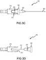
- FIGS. 3C and 3Dillustrate top views of yet another example embodiment of a safety catheter assembly, in ready and released positions, respectively;
- FIG. 4illustrates a safety catheter assembly comprising a pivoting joint in accordance with an embodiment of the present disclosure
- FIG. 5illustrates a safety catheter assembly comprising a ball joint in accordance with an embodiment of the present disclosure
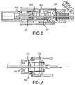
- FIG. 6illustrates a cross-sectional view of a safety catheter assembly in accordance with an embodiment of the present disclosure
- FIG. 7illustrates yet another cross-sectional view of a safety catheter assembly in accordance with an embodiment of the present disclosure
- FIG. 8illustrates contact points at a coupling of a safety catheter assembly in accordance with an embodiment of the present disclosure
- FIGS. 9A and 9Billustrate cross-sectional and perspective views, respectively, of a tip protector housing comprising an extension in accordance with an embodiment of the present disclosure
- FIG. 9Cillustrates a cross-sectional view of a tip protector housing comprising an extension in accordance with an embodiment of the present disclosure
- FIGS. 9D and 9Eillustrate cross-sectional and perspective views, respectively, of a tip protector housing comprising a plurality of extensions in accordance with an embodiment of the present disclosure.
- FIGS. 10A and 10Billustrate locked and unlocked positions, respectively, of a safety catheter assembly comprising an lock sleeve in accordance with an embodiment of the present disclosure.
- any of the method or process descriptionsmay be executed in any order and are not necessarily limited to the order presented.
- any reference to singularincludes plural embodiments, and any reference to more than one component or step may include a singular embodiment or step.
- any reference to attached, fixed, connected, coupled or the likemay include permanent (e.g., integral), removable, temporary, partial, full, and/or any other possible attachment option. Any of the components may be coupled to each other via friction, snap, sleeves, brackets, clips or other means now known in the art or hereinafter developed. Additionally, any reference to without contact (or similar phrases) may also include reduced contact or minimal contact.
- proximal(ly)refers to closer to the operator and further from the subject, while “distal(ly)” refers to further from the operator and closer to the subject.
- a safety catheter assembly 100is disclosed herein.
- Example embodiments of safety catheter assembly 100comprise a needle hub 110 , a catheter hub 120 , a tip protector housing 130 , and a push-off tab 132 extending radially from tip protector housing 130 or a portion thereof.
- Needle hub 110 , catheter hub 120 , catheter 122 , and tip protector housing 130can each be comprised of materials now known in the art or hereinafter developed.
- a catheter hub and a cathetermay be referred to together herein as a catheter assembly.
- a needle hub, a needle and a tip protector housingmay be referred to together herein as a catheter insertion device.
- needle hub 110is a structure to which a needle 112 is connected or which otherwise secures needle 112 .
- Needle 112can extend distally from a distal end of needle hub 110 .
- Needle 112can be a conventional intravenous needle, a trocar or the like.
- catheter hub 120is a structure to which a catheter 122 is connected or which otherwise secures catheter 122 .
- Catheter 122can extend distally from a distal end of catheter hub 120 .
- Catheter hub 120 and catheter 122can each have a lumen extending there through, the lumen of catheter hub 120 being in communication with the lumen of catheter 122 .
- tip protector housing 130is positioned between needle hub 110 and catheter hub 120 , and is configured to protect an operator from accidental needle sticks.
- push-off tab 132extends radially from tip protector housing 130 , being either coupled to or integral with tip protector housing 130 .
- push-off tab 132extends radially in a direction away from a skin surface, for example, on the side interfaced with by an operator.
- Push-off tab 132can have a height, as measured from its base at tip protector housing 130 , of more than about 2 mm, or more than about 4 mm, or more than about 6 mm.
- Push-off tab 132 not located on catheter hub 120can facilitate deployment while not being an obstruction post-deployment.
- push-off tab 132can be located proximal to, coincident with, or distal to, a proximal end of catheter hub 120 .
- Push-off tab 132can be configured to be comfortable for an operator when used correctly, and/or uncomfortable for an operator when used incorrectly.
- a proximal side of push-off tab 132can be smooth and ergonomically suited for being pressed by an operator's finger, while a distal side of push-off tab 132 can be rough or angled to discourage contact by an operator.
- needle hub 110is adjacent, but not coupled, to tip protector housing 130 . In such embodiment, there may be no overlap between a distal end of needle hub 110 and a proximal end of tip protector housing 130 . In other example embodiments, a distal end of needle hub 110 is passively coupled to a proximal end of tip protector housing 130 .
- the couplingcan include sliding contact with a key and keyway or the like, for example, to prevent rotational relative movement, but not axial relative movement.
- tip protector housing 130is removably coupled to catheter hub 120 by a coupling that separates when a threshold force is exceeded.
- threshold force couplingscan include friction fit joints, a snap fit joints, or the like.
- a proximal end of catheter hub 120may comprise a snap groove that removably interfaces with a snap ring on a distal end of tip protector housing.
- Safety catheter assembly 100 as described hereinhas at least three positions. In a ready position, at least a portion of needle 112 extends through catheter 122 , and a distal tip of needle 112 extends beyond a tip of catheter 122 . In the ready position, a distal end of tip protector housing 130 is temporarily coupled to a proximal end of catheter hub 120 .
- catheter 122 and needle 112(and catheter hub 120 and needle hub 110 ) have been moved relative to each other such that no portion of needle 112 extends through catheter 122 , and the distal tip of needle 112 is securely housed within tip protector housing 130 (e.g., with or without structure being displaced in front of the distal tip of needle 112 ), so as to provide protection against accidental needle sticks.
- tip protector housing 130In the safe position, distal end of tip protector housing 130 is still temporarily coupled to proximal end of catheter hub 120 .
- tip protector housing 130the distal tip of needle 112 is housed within tip protector housing 130 , and distal end of tip protector housing 130 is released from proximal end of catheter hub 120 .
- Safety catheter assembly 200in accordance with another embodiment of the present disclosure will now be described with reference to FIGS. 2A and 2B .
- Safety catheter assembly 200is shown in a ready position in FIG. 2A , and a portion of safety catheter assembly 200 is shown in a released position in FIG. 2B .
- a needle hub 210has a needle 212 extending from a distal end of needle hub 210 .
- a catheter hub 220has a catheter 222 extending from a distal end of catheter hub 220 .
- a tip protector housing 230is located between needle hub 210 and catheter hub 220 .
- a push-off tab 232extends radially from tip protector housing 230 .
- tip protector housing 230comprises a tab extension 234 extending distally over at least a portion of catheter hub 220 , for example, over more than about 20 percent, or about 30 percent, or about 50 percent, of the overall length of catheter hub 220 .
- the overlap of tip protector housing 230does not diminish any contact between catheter hub 220 and a skin surface.
- tab extension 234can be located exclusively on the side of safety catheter assembly 200 interfaced with by an operator.
- the overlap of tip protector housing 230may absorb all or a portion of a bending moment at the coupling between catheter hub 220 and tip protector housing 230 . In this regard, the overlap of tip protector housing 230 may prevent premature separation of tip protector housing 230 from the catheter hub 220 .
- Tab extension 234can comprise a substantially flat profile or a curved profile (e.g., concave toward catheter hub 220 ) that substantially wraps over or otherwise follows the curvature of the overlapped portion of catheter hub 220 .
- Tab extension 234 having a flat profilein example embodiments can have a width smaller than, about equal to, or greater than the diameter of catheter hub 220 .
- Example embodiments of tab extension 234 having a curved profilecan wrap about the catheter hub 220 by differing amounts, such 60 degrees or greater, 120 degrees or greater, 180 degrees or greater, or even up to 270 degrees or greater.
- push off-tab 232extends radially from tab extension 234 of tip protector housing 230 , push off-tab 232 being either coupled to or integral with tab extension 234 .
- push-off tab 232is located over a portion of catheter hub 220 (i.e., push-off tab 232 is located distal to a proximal end of catheter hub 220 ). Positioning push-off tab 232 above catheter hub 220 may also direct forces along the axis of needle 212 , which can prevent side loading and bending moments at the coupling between catheter hub 220 and tip protector housing 230 .
- Safety catheter assembly 300in accordance with the present disclosure will now be described with reference to FIGS. 3A-3D .
- Safety catheter assembly 300is shown in a ready position in FIGS. 3A-3C , and a portion of safety catheter assembly 300 is shown in a released position in FIG. 3D .
- a needle hub 310has a needle 312 extending from a distal end of needle hub 310 .
- a catheter hub 320has a catheter 322 extending from a distal end of catheter hub 320 .
- a tip protector housing 330is located between needle hub 310 and catheter hub 320 .
- a push-off tab 332extends radially from tip protector housing 330 .
- tip protector housing 330is at least partially housed within or enclosed by needle hub 310 when in the ready position. In this regard, at least a portion of tip protector housing 330 has a diameter (or other cross section) smaller than at least a portion of needle hub 310 .
- needle hub 310comprises a window 314 through which push-off tab 332 radially extends from tip protector housing 330 . Stated another way, tip protector housing 330 can be substantially housed within or enclosed by needle hub 310 , except for window 314 in needle hub 310 through which push-off tab 332 extends and is accessible.
- needle hub 310comprises a plurality of windows 314 , for example on opposing sides of needle hub 310 . Window 314 generally extends from, and is open to, a distal end of needle hub 310 .
- a distal end of tip protector housing 330substantially coincides with a distal end of needle hub 310 (e.g., with reference to FIGS. 3A and 3B ). Stated differently, tip protector housing 330 is completely circumferentially enclosed within needle hub 310 (except for push-off tab 332 ) in example embodiments, such that a distal end of needle hub 310 is adjacent to a proximal end of catheter hub 320 . In such embodiments, the distal end of needle hub 310 and a proximal end of catheter hub 320 may not overlap.
- a distal end of tip protector housing 330extends distal to a distal end of needle hub 310 (e.g., with reference to FIGS. 3C and 3D ).
- push-off tab 332is not located over any portion of catheter hub 320 (i.e., push-off tab 332 is located coincident with or proximal to a proximal end of catheter hub 320 ).
- a tip protector housingcan be completely circumferentially housed within a needle hub, except for a tab extension as described with reference to FIGS. 2A and 2B , from which a push-off tab extends radially for an operator to grip or otherwise actuate.
- Such embodimentmay be particularly beneficial in terms of shortening the overall length of the safety catheter assembly.
- the present disclosurecontemplates additional embodiments configured to lessen the risk of premature separation between the catheter assembly and the catheter insertion device.
- a safety catheter assemblycan comprise a catheter assembly and a catheter insertion device.
- the catheter assemblycan comprise a catheter hub and a catheter extending distally from the catheter hub.
- the catheter insertion devicecan comprise a needle hub, a needle extending distally from the needle hub along a longitudinal axis and having a sharp distal tip, and a tip protector housing.
- each of the catheter hub and the tip protector housingcan define a coupling.
- the couplingcan be constructed and/or arranged to couple the catheter insertion device to the catheter.
- the couplingcan be configured to selectively release the catheter insertion device from the catheter when a threshold release force applied proximally along the longitudinal axis is exceeded.
- a threshold release forcein accordance with the present disclosure, can be below about 0.75 pounds force, or between about 0.75 and 0.25 pounds force, for example, about 0.7, 0.6, 0.5, 0.4 or 0.3 pounds force.
- the couplingcan be configured to prevent release of the catheter insertion device from the catheter responsive to forces applied laterally to the longitudinal axis.
- the needlein a ready position, extends through the catheter of the catheter assembly and the tip protector housing is coupled to the catheter hub through the coupling.
- retraction of the needle relative to the catheter along the longitudinal axismoves the catheter insertion device to a safe position with the sharp distal tip of the needle housed within the tip protector housing and the tip protector housing coupled to the catheter hub through the coupling.
- further retraction of the needle along the longitudinal axis with a force in excess of a release forcemoves the catheter insertion device to a released position with the needle separated from the catheter, the distal tip of the needle housed within the tip protector housing and the tip protector housing released from the catheter hub.
- the risk of premature separationcan be lessened by incorporating structure to increase compliance between a catheter assembly as described herein (or a portion thereof, e.g., a catheter hub) and a catheter insertion device as described herein (or a portion thereof, e.g., a tip protector housing).
- a safety catheter assembly 400can comprise a coupling defined by at least a portion of each of a catheter hub 420 and a tip protector housing 430 .
- the couplingcan comprise a pivoting joint 440 that allows tip protector housing 430 to pivot or rotate relative to catheter hub 420 and away from the longitudinal axis of safety catheter assembly 400 , and do so in the direction shown by the arrows.
- Pivoting joint 440can comprise protrusions on the inside of tip protector housing 430 that are received in dimples on the outside of catheter hub 420 , or vice versa.
- a safety catheter assembly 500can comprise a coupling defined by at least a portion of each of a catheter hub 520 and a tip protector housing 530 .
- the couplingcan comprise a ball joint 550 that allows tip protector housing 530 to pivot or rotate relative to catheter hub 520 and away from the longitudinal axis of safety catheter assembly 500 , and do so in a plurality of directions.
- an amount of clearance 661 between an interior surface of a needle hub 610 and an exterior surface of a tip protector housing 630can provide space for movement of needle hub 610 relative to tip protector housing 630 to thereby permit a needle 612 to bend with a decreased risk of premature separation between a catheter hub 620 and tip protector housing 630 .
- an amount of clearance 762 between an interior surface of a tip protector housing 730 and a needle 712can provide space for needle 712 to bend with a decreased risk of premature separation between a catheter hub and tip protector housing 730 .
- needle 712may be allowed to bend without initially contacting the tip protector housing, either directed or through the tip protector.
- the risk of premature separationcan be lessened by incorporating structure to decrease compliance between a catheter assembly as described herein (or a portion thereof, e.g., a catheter hub) and a catheter insertion device as described herein (or a portion thereof, e.g., a tip protector housing).
- a needle hubcan comprises a stiffness sufficient to resist temporary deformation by a user during use, such as when gripped with excessive forces by a user. This may be accomplished by molding the needle hub from a stiffer material. Additionally or alternatively, the needle hub design may be altered to create a stiffer structure, such as with the addition of ribs, thicker walls and the like.
- an amount of clearance between an interior surface of a needle hub and an exterior surface of a catheter hubcan be lessened.
- an interior surface of a needle hub and an exterior surface of a catheter hubcan be in close contact or proximity to one another.
- the risk of premature separation between the catheter hub and a tip protector housingcan be lessened.
- one or more contact points between the catheter hub and the tip protector housingcan counter forces that may cause unintended separation at a coupling defined by at least a portion of each of a catheter hub and a tip protector housing.
- the orientation of the contact point(s) relative to the anticipated bending moment(s)can further counter forces that may cause unintended separation.
- a couplingcan comprise a first contact point 871 between a catheter hub 820 and a tip protector housing oriented at 0 degrees and a second contact point 872 between catheter hub 820 and the tip protector housing oriented at 180 degrees.
- the location of one or more contact pointscan be selected such that moments about a vertical plane 873 are resisted more than moments about a horizontal plane 874 .
- forces that may cause unintended separationmay be countered, while not necessarily increasing the force required to intentionally separate catheter hub 820 from the tip protector housing.
- a tip protector housing 930can comprise an extension 931 coupled to a distal portion of tip protector housing 930 and received within a groove or recess of a proximal portion 921 of a catheter hub 920 when the safety catheter assembly is in both a ready position and a safe position.
- Extension 931can be constructed as a solid, cylindrical structure (as best illustrated in FIG. 9E ), or comprise a plurality of tabs arranged in a circular orientation (as best illustrated in FIG. 9B ).
- Extension 931may have a shape other than circular.
- Groove or recess of proximal portion 921can generally correspond to extension 931 , for example, to permit coupling of catheter hub 920 with tip protector housing 930 only when rotated relative to each other in a desired orientation.
- a tip protector housing 930can comprise a dome extension 933 coupled to a distal portion of tip protector housing 930 and received within a recess of a proximal portion 923 of a catheter hub 920 .
- Recess of proximal portion 923can generally correspond to dome extension 933 .
- a tip protector housing 930can comprise extensions 931 , 933 coupled to distal portions of tip protector housing 930 and received within grooves or recesses of proximal portions 921 , 923 of a catheter hub 920 .
- a catheter insertion devicecan comprise a lock sleeve 1035 .
- Lock sleeve 1035can be moveable within a tip protector housing 1030 from a locked position ( FIG. 10A ) in which lock sleeve 1035 is positioned at least partially within a proximal portion of a catheter hub 1020 in the direction shown by the arrows to an unlocked position ( FIG. 10B ) in which lock sleeve 1035 is not positioned within a proximal portion of catheter hub 1020 .
- lock sleeve 1035may prevent inward movement of a tab 1025 on catheter hub 1020 from a gap 1037 .
- Gap 1037 and tab 1025can each be circumferential or at discrete positions around the circumference of tip protector housing 1030 and catheter hub 1020 , respectively.
- Gap 1037 and tab 1025can combine to form a snap fit joint.
- lock sleeve 1035may no longer prevent inward movement of tab 1025 from a gap 1037 such that tab 1025 no longer prevents separation of a coupling defined by at least a portion of each of catheter hub 1020 and tip protector housing 1030 .
- Lock sleeve 1025may be formed as an integral part of the tip protector or may be a separate component that is connected to or acted on by the tip protector to move lock sleeve 1025 proximally.
- the lock sleevemay include features that are positioned proximally of the proximal end of the tip protector. In this respect, lock sleeve 1025 will be pulled proximally to the unlocked position by the tip protector, when the tip protector is acted on by a bump on a needle.
- a lock sleeve(or similar type mechanisms) is rotatable relative to a tip protector housing and/or catheter hub to move between a locked and an unlocked position.
- Helical or ramped featuresmay be formed directly in the needle shaft. During needle withdrawal as the needle is pulled proximally, these helical features or ramps can act to rotate a lock sleeve to cause disengagement of the tip protector housing and the catheter hub.
- the ramp featuresmay be formed directly on the metal material of the needle shaft.
- a separate component that includes the helical or ramp featuresmay be secured to the needle shaft, such as with an adhesive.
- Including the helical or ramp features in a separate componentmay allow the helical/ramp features to be positioned in greater radial distance from the central needle axis, thus providing for greater mechanical advantage in moving the lock sleeve from the locked position to the unlocked position.
- a coupling defined by at least a portion of each of catheter hub 1020 and tip protector housing 1030provides an overlap between tip protector housing 1030 and catheter hub 1020 .
- the distance of overlap, taken in a direction that extends distally to proximally,can be increased to provide greater resistance to bending moments or side loads that may cause premature separation.
Landscapes
- Health & Medical Sciences (AREA)
- Life Sciences & Earth Sciences (AREA)
- Biophysics (AREA)
- Pulmonology (AREA)
- Engineering & Computer Science (AREA)
- Anesthesiology (AREA)
- Biomedical Technology (AREA)
- Heart & Thoracic Surgery (AREA)
- Hematology (AREA)
- Animal Behavior & Ethology (AREA)
- General Health & Medical Sciences (AREA)
- Public Health (AREA)
- Veterinary Medicine (AREA)
- Infusion, Injection, And Reservoir Apparatuses (AREA)
- Media Introduction/Drainage Providing Device (AREA)
Abstract
Description
Claims (22)
Priority Applications (1)
| Application Number | Priority Date | Filing Date | Title |
|---|---|---|---|
| US16/486,108US11185668B2 (en) | 2017-03-06 | 2018-03-06 | Catheter insertion device with tip protector housing |
Applications Claiming Priority (4)
| Application Number | Priority Date | Filing Date | Title |
|---|---|---|---|
| US201762467397P | 2017-03-06 | 2017-03-06 | |
| US201762576836P | 2017-10-25 | 2017-10-25 | |
| PCT/US2018/021135WO2018165151A1 (en) | 2017-03-06 | 2018-03-06 | Catheter insertion device with tip protector housing |
| US16/486,108US11185668B2 (en) | 2017-03-06 | 2018-03-06 | Catheter insertion device with tip protector housing |
Related Parent Applications (1)
| Application Number | Title | Priority Date | Filing Date |
|---|---|---|---|
| PCT/US2018/021135A-371-Of-InternationalWO2018165151A1 (en) | 2017-03-06 | 2018-03-06 | Catheter insertion device with tip protector housing |
Related Child Applications (1)
| Application Number | Title | Priority Date | Filing Date |
|---|---|---|---|
| US17/514,438ContinuationUS12318558B2 (en) | 2017-03-06 | 2021-10-29 | Catheter insertion device with tip protector housing |
Publications (2)
| Publication Number | Publication Date |
|---|---|
| US20200230367A1 US20200230367A1 (en) | 2020-07-23 |
| US11185668B2true US11185668B2 (en) | 2021-11-30 |
Family
ID=63448303
Family Applications (2)
| Application Number | Title | Priority Date | Filing Date |
|---|---|---|---|
| US16/486,108Active2038-08-11US11185668B2 (en) | 2017-03-06 | 2018-03-06 | Catheter insertion device with tip protector housing |
| US17/514,438Active2038-12-02US12318558B2 (en) | 2017-03-06 | 2021-10-29 | Catheter insertion device with tip protector housing |
Family Applications After (1)
| Application Number | Title | Priority Date | Filing Date |
|---|---|---|---|
| US17/514,438Active2038-12-02US12318558B2 (en) | 2017-03-06 | 2021-10-29 | Catheter insertion device with tip protector housing |
Country Status (3)
| Country | Link |
|---|---|
| US (2) | US11185668B2 (en) |
| EP (1) | EP3568185A4 (en) |
| WO (1) | WO2018165151A1 (en) |
Families Citing this family (2)
| Publication number | Priority date | Publication date | Assignee | Title |
|---|---|---|---|---|
| US20210187250A1 (en)* | 2019-12-18 | 2021-06-24 | Becton, Dickinson And Company | Inhibiting fluid leakage and splatter in catheter devices and systems |
| JP2024527091A (en)* | 2021-07-30 | 2024-07-19 | スミス メディカル エーエスディー インコーポレーテッド | Safe Catheter Assembly with Passive Blood Control |
Citations (37)
| Publication number | Priority date | Publication date | Assignee | Title |
|---|---|---|---|---|
| US3335723A (en) | 1964-12-02 | 1967-08-15 | Baxter Laboratories Inc | Indwelling catheter unit |
| US3352306A (en) | 1963-12-23 | 1967-11-14 | Hrisch Sidney | Intravenous catheter assembly |
| US4755356A (en) | 1986-01-23 | 1988-07-05 | Robbins Scientific Corporation | Locking microcentrifuge tube |
| WO1996014894A1 (en)* | 1994-11-14 | 1996-05-23 | Innocare One, Ltd. | Elongated medical channel assembly and method of preventing dislodgement |
| US5697014A (en) | 1995-12-28 | 1997-12-09 | Brother Kogyo Kabushiki Kaisha | Toner level detecting device having a substantially non-uniform width and toner storage box having same |
| WO1999052584A1 (en) | 1998-04-09 | 1999-10-21 | Becton, Dickinson And Company | Catheter and introducer needle assembly with needle shield |
| EP0993839A1 (en) | 1998-10-13 | 2000-04-19 | Terumo Kabushiki Kaisha | Self-retaining needle assembly and valve element for use therein |
| WO2001056642A1 (en) | 2000-02-04 | 2001-08-09 | Becton, Dickinson And Company | Catheter and introducer needle assembly with compact needle shield |
| US20020107483A1 (en)* | 2001-02-06 | 2002-08-08 | Cook Daniel J. | Needle enclosing safety catheter |
| WO2002096494A1 (en) | 2001-05-25 | 2002-12-05 | Becton, Dickinson And Company | Cantilever push tab for an intravenous medical device |
| US6497994B1 (en) | 2000-06-29 | 2002-12-24 | Ethicon, Inc. | Photolithographic process for the formation of a one-piece needle |
| US6527747B2 (en)* | 2001-05-25 | 2003-03-04 | Becton Dickinson And Company | Introducer needle assembly having a tethered needle shield |
| US20030105431A1 (en)* | 1998-04-09 | 2003-06-05 | Howell Glade H. | Catheter and introducer needle assembly with compact needle shield |
| US20040215146A1 (en) | 2003-04-28 | 2004-10-28 | Merit Medical Systems, Inc. | Vascular blood containment device |
| US20040267200A1 (en) | 2003-06-27 | 2004-12-30 | Carlyon James L. | Safety needle shield apparatus |
| US20050015071A1 (en) | 2002-06-21 | 2005-01-20 | Brimhall Greg L | Method of and apparatus for controlling flashback in an introducer needle and catheter assembly |
| US20050075606A1 (en)* | 1998-07-31 | 2005-04-07 | Michael Botich | Retractable needle medical device |
| JP2006055674A (en) | 1996-10-25 | 2006-03-02 | Terumo Corp | Intravenous cannula assembly |
| US20080300543A1 (en)* | 2007-05-30 | 2008-12-04 | Smiths Medical Asd, Inc. | Enclosed needle cannula device with proximal end cap |
| US7597681B2 (en)* | 2005-08-08 | 2009-10-06 | Smiths Medical Asd, Inc. | Needle guard mechanism with shroud |
| US7736337B2 (en)* | 2006-02-16 | 2010-06-15 | Smiths Medical, Asd, Inc. | Sealing catheter hub attachment |
| US20100305519A1 (en) | 2009-06-02 | 2010-12-02 | Becton, Dickinson And Company | Cannula having an overlapping cannula feature and notch feature |
| US20110054403A1 (en) | 2009-08-27 | 2011-03-03 | Terumo Kabushiki Kaisha | Indwelling needle assembly and method of using the same |
| US20110054402A1 (en) | 2009-08-27 | 2011-03-03 | Terumo Kabushiki Kaisha | Indwelling needle assembly and method of using the same |
| US20120136311A1 (en) | 2009-08-13 | 2012-05-31 | Vigmed Ab | Catheter needle tip shielding device |
| US20120323181A1 (en) | 2011-06-17 | 2012-12-20 | Shaw Thomas J | Intravenous Catheter Introducer with Needle Retraction Controlled by Catheter Hub Seal |
| US8979803B2 (en) | 2007-04-05 | 2015-03-17 | Allan J. Darr | Stylet for bilumenal flexible medical device |
| US20150151084A1 (en) | 2013-12-04 | 2015-06-04 | B. Braun Melsungen Ag | Catheter assembly blood control device and related methods |
| US20160106959A1 (en)* | 2013-08-21 | 2016-04-21 | B. Braun Melsungen Ag | Catheter assembly |
| US20160220791A1 (en)* | 2015-01-30 | 2016-08-04 | Smiths Medical Asd, Inc. | Releaseable catheter hub retainer |
| US20160220161A1 (en)* | 2015-01-30 | 2016-08-04 | Smiths Medical Asd, Inc. | Needle assembly with diagnostic analysis provisions |
| US20160228683A1 (en) | 2013-10-22 | 2016-08-11 | Bernd Tietze | Catheter puncture device |
| US20160310704A1 (en) | 2013-12-04 | 2016-10-27 | B. Braun Melsungen Ag | Needle assembly with sealed notch and related methods |
| US20160354539A1 (en) | 2015-06-08 | 2016-12-08 | B. Braun Melsungen Ag | Catheter devices with needle guards and related methods |
| US20170120010A1 (en) | 2015-10-28 | 2017-05-04 | Becton, Dickinson And Company | Integrated catheter with independent fluid paths |
| US20180028788A1 (en) | 2013-02-05 | 2018-02-01 | Vascular Pathways, Inc. | Systems And Methods For Needle And Catheter Advancement |
| US20180339131A1 (en) | 2017-05-26 | 2018-11-29 | Piper Access, Llc | Catheter delivery devices, systems, and methods |
Family Cites Families (5)
| Publication number | Priority date | Publication date | Assignee | Title |
|---|---|---|---|---|
| US5558651A (en) | 1990-04-20 | 1996-09-24 | Becton Dickinson And Company | Apparatus and method for a needle tip cover |
| US5810780A (en) | 1996-05-10 | 1998-09-22 | Becton Dickinson And Company | Multiple cross section needle and elastic plug assembly for a medical device |
| US6322537B1 (en)* | 1999-12-30 | 2001-11-27 | Ethicon, Inc. | Safety intravenous catheter |
| CN203196075U (en)* | 2013-04-03 | 2013-09-18 | 英属维尔京群岛圣采科技投资有限公司 | Structure for anti-pricking indwelling needle |
| US20170354799A1 (en) | 2016-06-10 | 2017-12-14 | Deepak Gupta | Cannula needle |
- 2018
- 2018-03-06EPEP18763871.3Apatent/EP3568185A4/enactivePending
- 2018-03-06USUS16/486,108patent/US11185668B2/enactiveActive
- 2018-03-06WOPCT/US2018/021135patent/WO2018165151A1/ennot_activeCeased
- 2021
- 2021-10-29USUS17/514,438patent/US12318558B2/enactiveActive
Patent Citations (38)
| Publication number | Priority date | Publication date | Assignee | Title |
|---|---|---|---|---|
| US3352306A (en) | 1963-12-23 | 1967-11-14 | Hrisch Sidney | Intravenous catheter assembly |
| US3335723A (en) | 1964-12-02 | 1967-08-15 | Baxter Laboratories Inc | Indwelling catheter unit |
| US4755356A (en) | 1986-01-23 | 1988-07-05 | Robbins Scientific Corporation | Locking microcentrifuge tube |
| WO1996014894A1 (en)* | 1994-11-14 | 1996-05-23 | Innocare One, Ltd. | Elongated medical channel assembly and method of preventing dislodgement |
| US5697014A (en) | 1995-12-28 | 1997-12-09 | Brother Kogyo Kabushiki Kaisha | Toner level detecting device having a substantially non-uniform width and toner storage box having same |
| JP2006055674A (en) | 1996-10-25 | 2006-03-02 | Terumo Corp | Intravenous cannula assembly |
| US20030105431A1 (en)* | 1998-04-09 | 2003-06-05 | Howell Glade H. | Catheter and introducer needle assembly with compact needle shield |
| WO1999052584A1 (en) | 1998-04-09 | 1999-10-21 | Becton, Dickinson And Company | Catheter and introducer needle assembly with needle shield |
| US20050075606A1 (en)* | 1998-07-31 | 2005-04-07 | Michael Botich | Retractable needle medical device |
| EP0993839A1 (en) | 1998-10-13 | 2000-04-19 | Terumo Kabushiki Kaisha | Self-retaining needle assembly and valve element for use therein |
| WO2001056642A1 (en) | 2000-02-04 | 2001-08-09 | Becton, Dickinson And Company | Catheter and introducer needle assembly with compact needle shield |
| US6497994B1 (en) | 2000-06-29 | 2002-12-24 | Ethicon, Inc. | Photolithographic process for the formation of a one-piece needle |
| US20020107483A1 (en)* | 2001-02-06 | 2002-08-08 | Cook Daniel J. | Needle enclosing safety catheter |
| US6527747B2 (en)* | 2001-05-25 | 2003-03-04 | Becton Dickinson And Company | Introducer needle assembly having a tethered needle shield |
| WO2002096494A1 (en) | 2001-05-25 | 2002-12-05 | Becton, Dickinson And Company | Cantilever push tab for an intravenous medical device |
| US20050015071A1 (en) | 2002-06-21 | 2005-01-20 | Brimhall Greg L | Method of and apparatus for controlling flashback in an introducer needle and catheter assembly |
| US20040215146A1 (en) | 2003-04-28 | 2004-10-28 | Merit Medical Systems, Inc. | Vascular blood containment device |
| US20040267200A1 (en) | 2003-06-27 | 2004-12-30 | Carlyon James L. | Safety needle shield apparatus |
| US7597681B2 (en)* | 2005-08-08 | 2009-10-06 | Smiths Medical Asd, Inc. | Needle guard mechanism with shroud |
| US7736337B2 (en)* | 2006-02-16 | 2010-06-15 | Smiths Medical, Asd, Inc. | Sealing catheter hub attachment |
| US8979803B2 (en) | 2007-04-05 | 2015-03-17 | Allan J. Darr | Stylet for bilumenal flexible medical device |
| US20080300543A1 (en)* | 2007-05-30 | 2008-12-04 | Smiths Medical Asd, Inc. | Enclosed needle cannula device with proximal end cap |
| US20100305519A1 (en) | 2009-06-02 | 2010-12-02 | Becton, Dickinson And Company | Cannula having an overlapping cannula feature and notch feature |
| US20120136311A1 (en) | 2009-08-13 | 2012-05-31 | Vigmed Ab | Catheter needle tip shielding device |
| US20110054402A1 (en) | 2009-08-27 | 2011-03-03 | Terumo Kabushiki Kaisha | Indwelling needle assembly and method of using the same |
| US20110054403A1 (en) | 2009-08-27 | 2011-03-03 | Terumo Kabushiki Kaisha | Indwelling needle assembly and method of using the same |
| US20120323181A1 (en) | 2011-06-17 | 2012-12-20 | Shaw Thomas J | Intravenous Catheter Introducer with Needle Retraction Controlled by Catheter Hub Seal |
| US20180028788A1 (en) | 2013-02-05 | 2018-02-01 | Vascular Pathways, Inc. | Systems And Methods For Needle And Catheter Advancement |
| US20160106959A1 (en)* | 2013-08-21 | 2016-04-21 | B. Braun Melsungen Ag | Catheter assembly |
| US20160228683A1 (en) | 2013-10-22 | 2016-08-11 | Bernd Tietze | Catheter puncture device |
| US20160310704A1 (en) | 2013-12-04 | 2016-10-27 | B. Braun Melsungen Ag | Needle assembly with sealed notch and related methods |
| US20150151084A1 (en) | 2013-12-04 | 2015-06-04 | B. Braun Melsungen Ag | Catheter assembly blood control device and related methods |
| US20160220161A1 (en)* | 2015-01-30 | 2016-08-04 | Smiths Medical Asd, Inc. | Needle assembly with diagnostic analysis provisions |
| US20160220791A1 (en)* | 2015-01-30 | 2016-08-04 | Smiths Medical Asd, Inc. | Releaseable catheter hub retainer |
| US20160354539A1 (en) | 2015-06-08 | 2016-12-08 | B. Braun Melsungen Ag | Catheter devices with needle guards and related methods |
| US20170120010A1 (en) | 2015-10-28 | 2017-05-04 | Becton, Dickinson And Company | Integrated catheter with independent fluid paths |
| WO2017074684A1 (en) | 2015-10-28 | 2017-05-04 | Becton, Dickinson And Company | Integrated catheter with independent fluid paths |
| US20180339131A1 (en) | 2017-05-26 | 2018-11-29 | Piper Access, Llc | Catheter delivery devices, systems, and methods |
Non-Patent Citations (7)
| Title |
|---|
| EUIPO; Search Report dated Sep. 24, 2020 in EP Application No. 18763871.3. |
| EUIPO; Search Report dated Sep. 27, 2020 in EP Application No. 18764834.0. |
| International Search Report and Written Opinion PCT Application No. PCT/US18/021135 dated May 16, 2018. |
| International Search Report and Written Opinion PCT Application No. PCT/US18/021143 dated May 11, 2018. |
| International Search Report and Written Opinion PCT Application No. PCT/US18/021155 dated Apr. 27, 2018. |
| ISA; International Search Report and Written Opinion PCT Application No. PCT/US2020/021485 dated May 5, 2020. |
| USPTO; Non-Final Office Action dated Mar. 24, 2021 in U.S. Appl. No. 16/486,126. |
Also Published As
| Publication number | Publication date |
|---|---|
| EP3568185A4 (en) | 2020-10-28 |
| WO2018165151A1 (en) | 2018-09-13 |
| EP3568185A1 (en) | 2019-11-20 |
| US12318558B2 (en) | 2025-06-03 |
| WO2018165151A8 (en) | 2020-04-02 |
| US20200230367A1 (en) | 2020-07-23 |
| US20220047852A1 (en) | 2022-02-17 |
Similar Documents
| Publication | Publication Date | Title |
|---|---|---|
| US12318558B2 (en) | Catheter insertion device with tip protector housing | |
| ES2909485T3 (en) | Double Bore Cannula Needle Devices and Related Methods | |
| EP1752183B1 (en) | Needle guard mechanism with angled strut wall | |
| EP3900769B1 (en) | Safety needle assemblies | |
| EP1764127B2 (en) | Needle guard clip with heel | |
| CA2818687C (en) | Stent delivery systems and methods | |
| MX2010012271A (en) | Needle tip spring protector. | |
| JP5813500B2 (en) | Needle protection assembly with radially movable locking element | |
| EP3238770B1 (en) | Indwelling needle assembly | |
| EP2852427B1 (en) | Coupling arrangement for a telescopic device | |
| WO2008138352A1 (en) | Coupling arrangement for a telescopic device | |
| JP2003510137A (en) | Compact needle point shield | |
| JP2011045739A (en) | Needle shielding device | |
| MX2013003128A (en) | Catheter assembly with improved safety means. | |
| EP4051347B1 (en) | Needle protection device comprising syringe centring features and disassembly lock | |
| JP2022084759A (en) | Intravenous catheter assembly with cannula safety mechanism | |
| CN109475700B (en) | Cap assembly for a medicament delivery device | |
| US20110071469A1 (en) | Single Use Retractable Infusion or Transfusion Needle | |
| CN115768510B (en) | Intravenous catheter device with sliding safety mechanism | |
| EP3908355B1 (en) | Telescoping needle shield with blood exposure prevention | |
| JP7609986B2 (en) | Assembly for drug delivery device | |
| RU2773205C9 (en) | Safe needle device and node | |
| ES2395331T3 (en) | Resettable safety sleeve for medical needles | |
| HK1106455B (en) | Needle guard clip with heel | |
| HK1184087A (en) | Needle safety device and assembly |
Legal Events
| Date | Code | Title | Description |
|---|---|---|---|
| AS | Assignment | Owner name:SMITHS MEDICAL ASD, INC, MINNESOTA Free format text:ASSIGNMENT OF ASSIGNORS INTEREST;ASSIGNORS:DALENA, MICHELE E;FELICITO, KATHRYN;GORAL, DAVID J;AND OTHERS;SIGNING DATES FROM 20180420 TO 20180504;REEL/FRAME:050055/0950 | |
| FEPP | Fee payment procedure | Free format text:ENTITY STATUS SET TO UNDISCOUNTED (ORIGINAL EVENT CODE: BIG.); ENTITY STATUS OF PATENT OWNER: LARGE ENTITY | |
| STPP | Information on status: patent application and granting procedure in general | Free format text:APPLICATION DISPATCHED FROM PREEXAM, NOT YET DOCKETED | |
| STPP | Information on status: patent application and granting procedure in general | Free format text:DOCKETED NEW CASE - READY FOR EXAMINATION | |
| STPP | Information on status: patent application and granting procedure in general | Free format text:NON FINAL ACTION MAILED | |
| STPP | Information on status: patent application and granting procedure in general | Free format text:RESPONSE TO NON-FINAL OFFICE ACTION ENTERED AND FORWARDED TO EXAMINER | |
| STPP | Information on status: patent application and granting procedure in general | Free format text:NOTICE OF ALLOWANCE MAILED -- APPLICATION RECEIVED IN OFFICE OF PUBLICATIONS | |
| STPP | Information on status: patent application and granting procedure in general | Free format text:PUBLICATIONS -- ISSUE FEE PAYMENT VERIFIED | |
| STCF | Information on status: patent grant | Free format text:PATENTED CASE | |
| AS | Assignment | Owner name:WELLS FARGO BANK, NATIONAL ASSOCIATION, AS COLLATERAL AGENT, TEXAS Free format text:SECURITY AGREEMENT;ASSIGNOR:SMITHS MEDICAL ASD, INC.;REEL/FRAME:061179/0320 Effective date:20220815 | |
| AS | Assignment | Owner name:ICU MEDICAL, INC., CALIFORNIA Free format text:MERGER;ASSIGNOR:SMITHS MEDICAL ASD, INC.;REEL/FRAME:069101/0767 Effective date:20240801 | |
| MAFP | Maintenance fee payment | Free format text:PAYMENT OF MAINTENANCE FEE, 4TH YEAR, LARGE ENTITY (ORIGINAL EVENT CODE: M1551); ENTITY STATUS OF PATENT OWNER: LARGE ENTITY Year of fee payment:4 |