US11185653B2 - Pressurizing masks, systems and methods - Google Patents
Pressurizing masks, systems and methodsDownload PDFInfo
- Publication number
- US11185653B2 US11185653B2US15/128,906US201515128906AUS11185653B2US 11185653 B2US11185653 B2US 11185653B2US 201515128906 AUS201515128906 AUS 201515128906AUS 11185653 B2US11185653 B2US 11185653B2
- Authority
- US
- United States
- Prior art keywords
- mask
- user
- cannula
- interface system
- recess
- Prior art date
- Legal status (The legal status is an assumption and is not a legal conclusion. Google has not performed a legal analysis and makes no representation as to the accuracy of the status listed.)
- Active, expires
Links
Images


Classifications
- A—HUMAN NECESSITIES
- A61—MEDICAL OR VETERINARY SCIENCE; HYGIENE
- A61M—DEVICES FOR INTRODUCING MEDIA INTO, OR ONTO, THE BODY; DEVICES FOR TRANSDUCING BODY MEDIA OR FOR TAKING MEDIA FROM THE BODY; DEVICES FOR PRODUCING OR ENDING SLEEP OR STUPOR
- A61M16/00—Devices for influencing the respiratory system of patients by gas treatment, e.g. ventilators; Tracheal tubes
- A61M16/20—Valves specially adapted to medical respiratory devices
- A61M16/201—Controlled valves
- A61M16/202—Controlled valves electrically actuated
- A—HUMAN NECESSITIES
- A61—MEDICAL OR VETERINARY SCIENCE; HYGIENE
- A61M—DEVICES FOR INTRODUCING MEDIA INTO, OR ONTO, THE BODY; DEVICES FOR TRANSDUCING BODY MEDIA OR FOR TAKING MEDIA FROM THE BODY; DEVICES FOR PRODUCING OR ENDING SLEEP OR STUPOR
- A61M16/00—Devices for influencing the respiratory system of patients by gas treatment, e.g. ventilators; Tracheal tubes
- A61M16/06—Respiratory or anaesthetic masks
- A61M16/0666—Nasal cannulas or tubing
- A61M16/0672—Nasal cannula assemblies for oxygen therapy
- A—HUMAN NECESSITIES
- A61—MEDICAL OR VETERINARY SCIENCE; HYGIENE
- A61M—DEVICES FOR INTRODUCING MEDIA INTO, OR ONTO, THE BODY; DEVICES FOR TRANSDUCING BODY MEDIA OR FOR TAKING MEDIA FROM THE BODY; DEVICES FOR PRODUCING OR ENDING SLEEP OR STUPOR
- A61M16/00—Devices for influencing the respiratory system of patients by gas treatment, e.g. ventilators; Tracheal tubes
- A61M16/06—Respiratory or anaesthetic masks
- A61M16/0605—Means for improving the adaptation of the mask to the patient
- A—HUMAN NECESSITIES
- A61—MEDICAL OR VETERINARY SCIENCE; HYGIENE
- A61M—DEVICES FOR INTRODUCING MEDIA INTO, OR ONTO, THE BODY; DEVICES FOR TRANSDUCING BODY MEDIA OR FOR TAKING MEDIA FROM THE BODY; DEVICES FOR PRODUCING OR ENDING SLEEP OR STUPOR
- A61M16/00—Devices for influencing the respiratory system of patients by gas treatment, e.g. ventilators; Tracheal tubes
- A61M16/06—Respiratory or anaesthetic masks
- A61M16/0666—Nasal cannulas or tubing
- A—HUMAN NECESSITIES
- A61—MEDICAL OR VETERINARY SCIENCE; HYGIENE
- A61M—DEVICES FOR INTRODUCING MEDIA INTO, OR ONTO, THE BODY; DEVICES FOR TRANSDUCING BODY MEDIA OR FOR TAKING MEDIA FROM THE BODY; DEVICES FOR PRODUCING OR ENDING SLEEP OR STUPOR
- A61M16/00—Devices for influencing the respiratory system of patients by gas treatment, e.g. ventilators; Tracheal tubes
- A61M16/06—Respiratory or anaesthetic masks
- A61M16/0683—Holding devices therefor
- A—HUMAN NECESSITIES
- A61—MEDICAL OR VETERINARY SCIENCE; HYGIENE
- A61M—DEVICES FOR INTRODUCING MEDIA INTO, OR ONTO, THE BODY; DEVICES FOR TRANSDUCING BODY MEDIA OR FOR TAKING MEDIA FROM THE BODY; DEVICES FOR PRODUCING OR ENDING SLEEP OR STUPOR
- A61M16/00—Devices for influencing the respiratory system of patients by gas treatment, e.g. ventilators; Tracheal tubes
- A61M16/0057—Pumps therefor
- A61M16/0066—Blowers or centrifugal pumps
- A61M16/0069—Blowers or centrifugal pumps the speed thereof being controlled by respiratory parameters, e.g. by inhalation
- A—HUMAN NECESSITIES
- A61—MEDICAL OR VETERINARY SCIENCE; HYGIENE
- A61M—DEVICES FOR INTRODUCING MEDIA INTO, OR ONTO, THE BODY; DEVICES FOR TRANSDUCING BODY MEDIA OR FOR TAKING MEDIA FROM THE BODY; DEVICES FOR PRODUCING OR ENDING SLEEP OR STUPOR
- A61M16/00—Devices for influencing the respiratory system of patients by gas treatment, e.g. ventilators; Tracheal tubes
- A61M16/20—Valves specially adapted to medical respiratory devices
- A61M16/208—Non-controlled one-way valves, e.g. exhalation, check, pop-off non-rebreathing valves
- A—HUMAN NECESSITIES
- A61—MEDICAL OR VETERINARY SCIENCE; HYGIENE
- A61M—DEVICES FOR INTRODUCING MEDIA INTO, OR ONTO, THE BODY; DEVICES FOR TRANSDUCING BODY MEDIA OR FOR TAKING MEDIA FROM THE BODY; DEVICES FOR PRODUCING OR ENDING SLEEP OR STUPOR
- A61M16/00—Devices for influencing the respiratory system of patients by gas treatment, e.g. ventilators; Tracheal tubes
- A61M16/0003—Accessories therefor, e.g. sensors, vibrators, negative pressure
- A61M2016/0027—Accessories therefor, e.g. sensors, vibrators, negative pressure pressure meter
Definitions
- the present disclosuregenerally relates to a respiratory mask for use in combination with a nasal high flow cannula. More particularly, the present disclosure relates to a mask that covers nasal high flow cannula to provide an increased or controlled expiratory pressure.
- COPDChronic Obstructive Pulmonary Disease
- OSAObstructive Sleep Apnea
- CPAPContinuous Positive Airway Pressure
- Non-invasive respiratory pressurizationis commonly administered by delivering pressurized breathing gases to a user's mouth and/or nose.
- CPAP treatmentis usually provided by a breathing assistance system.
- Breathing assistance systemsgenerally incorporate a source of pressurized gases (potentially a compressor, pressurized gas canister or hospital compressed air supply) and an interface configured to deliver the pressurized gases to a user. Additionally, breathing assistance systems may incorporate a humidifier for heating and humidifying the breathing gases prior to delivery to the user.
- Other supported breathing systemsinclude ventilators and respirators. These may adjust pressure between inspiratory and expiratory phases of the breathing cycle, and typically include a return line for the interface.
- Conventional interfacesare configured to form a seal with the user's face or upper airway to facilitate adequate pressurization of the user's respiratory system.
- FormaTM, SimplusTM, OracleTM, ZestTM, EsonTM OpusTM, and PilairoTMare examples of sealing respiratory user interfaces produced by Fisher & Paykel Healthcare. These interfaces are configured to seal with one or more of a user's face, mouth, nose and nares.
- the seal formed between the interface and user's respiratory systemallows the mask pressure to be regulated by reducing gas leaks and providing a controlled breathing gases exhaust. Gases may be exhausted from the user interface directly to the surrounding atmosphere (through outlet vents) or to another component in the breathing assistance system responsible for controlling the exhaust of breathing gas.
- Non-sealing interfacesare often employed for supplemental oxygen therapy.
- Typical supplemental oxygen therapy interfacesdeliver flow rates up to 5 l/min directly to the user's nares. Air from the user's surroundings is entrained with the oxygen during normal inhalation, resulting in an increased oxygen concentrations being received by the user's lungs.
- Common supplemental oxygen therapy interfacesare supported by a pair of delivery lumen that loop over the users ears.
- the lumenhave small diameters (typically, but not limited to, a range of 0.5-7 mm) and supply oxygen to both sides of the nasal cannula, providing even flow to each nasal prong.
- Facial masksare traditionally used for high flow (HF) oxygen therapy.
- HF oxygen therapyinvolves providing a flow of oxygen to the nares of a user at flow rates greater than traditional supplemental oxygen therapy.
- flow rates of HF oxygen therapycan be within a range of 6-60 L/min.
- Non-sealing HF nasal cannulasuch as Fisher & Paykel Healthcare's OptiflowTM Nasal Cannula, are also being promoted for flow rate based treatments (including HF oxygen therapy) where respiratory system pressure regulation can only be imprecisely controlled because the cannula is non sealed.
- Direct delivery of breathing gases to a user's narescan be advantageous as the gases can be administered at a greater temperature and humidity than viable with facial masks. Additionally, direct delivery of the breathing gases allows exhaled gasses to be cleared at the end of expiration, thereby lowering anatomical dead-space.
- Other advantages of nasal HF therapyare that users can eat and drink whilst wearing a cannula and cannulas are much smaller and lower profile than typical positive pressure interfaces, thus making them less invasive.
- nasal cannulasare not always suitable for users that experience respiratory distress, including hyperventilation, as they do not provide pressure support.
- An object of at least one embodimentis to provide a respiratory mask capable of being applied to a patient's face in combination with a nasal cannula, to deliver high flow therapy with increased or controlled expiratory pressure or to provide the industry or public with a useful choice.
- a respiratory maskis configured to overlay a nasal cannula fitted to a user's face.
- the maskincludes a cushion configured to seal with a user's face, allowing a breathing cavity or interior space of the mask to be pressurized. Pressurization of the mask allows for expiratory pressure to be increased or controlled, which may help to treat respiratory distress in COPD patients receiving HF therapy via nasal cannula.
- the maskis configured to be secured to the user independently of the nasal cannula, thus allowing increased expiratory pressure to be selectively applied.
- the sealing cushion of the maskcan include recesses or cut-outs that substantially fit the geometry of a nasal cannula.
- the maskcan include one or more one-way valves that allow entrainment of ambient air during inhalation.
- an interface systemcomprises a nasal cannula having a cannula body. At least one nasal prong extends from the cannula body. A gases tube communicates with the at least one nasal prong. A cannula retention arrangement is coupled to the cannula body and retains the nasal cannula on the head of a user.
- a maskhas a mask body, which defines a user-contacting surface and an interior space when the user-contacting surface is in contact with a face of the user.
- the maskfurther comprises a mask retention arrangement that is coupled to the mask body and retains the mask on the head of the user. The interior space of the mask accommodates at least a portion of the cannula body including the at least one nasal prong when the mask is positioned on the head of the user with the user-contacting surface in contact with the face of the user.
- the maskis adapted to create a seal around the nose and/or mouth of the user when the mask is used in combination with the nasal cannula and when the user-contacting surface is in contact with the face of the user, the seal being sufficient to provide increased expiratory pressure relative to use of the nasal cannula without the mask.
- the maskis also adapted to create a seal around the nasal cannula when the mask is used in combination with the nasal cannula and when the user-contacting surface is in contact with the face of the user, the seal around the nose and/or mouth and the seal on the nasal cannula being sufficient to provide increased expiratory pressure relative to use of the nasal cannula without the mask.
- the mask bodycomprises a frame, wherein the mask retention arrangement is coupled to the frame.
- the mask retention arrangementcomprises a mask headgear.
- the cannula retention arrangementcomprises a cannula headgear.
- the cannula headgearcomprises a strap that, in use, extends around the head of the user.
- the cannula bodycomprises a pair of side arms on opposing sides of the cannula body, wherein the cannula headgear is coupled to each of the pair of side arms.
- the mask bodycomprises at least one recess adapted to allow the nasal cannula to extend from within the interior space to outside of the interior space.
- the at least one recessis adapted to accommodate the gases tube.
- the at least one recesscomprises a semi-circular profile.
- the at least one recesscomprises a portion shaped to correspond to a shape of the gases tube.
- the at least one recessis located in a lateral portion of the mask body.
- the mask bodycomprises a cushion that defines the user-contacting surface, wherein the at least one recess is at least partially defined by the cushion.
- the at least one recessinterrupts the user-contacting surface.
- the at least one recesscomprises a first recess on a first side of the mask and a second recess on a second side of the mask. In some configurations, a shape and/or size of the first and second recesses are different from one another.
- the maskcomprises a one-way valve that opens to allow air to enter the interior space of the mask and closes to inhibit air from exiting the interior space of the mask.
- the valvecan be biased or pre-loaded to a slightly open position. In some such configurations, the valve can move from the biased, pre-loaded or normal position to the closed position in response to expiration by the user.
- the maskcomprises a vent that allows pressure within the interior space of the mask to be released.
- the ventis manually operable.
- an effective size of the ventis variable.
- the maskfurther comprises a bias flow vent.
- the maskfurther comprises a condensation vent that permits water to be evacuated from the interior space of the mask.
- the maskfurther comprises a pressure port that communicates with the interior space and allows measurement of a pressure within the interior space.
- the maskfurther comprises a positive end expiratory pressure valve that opens at or above a threshold pressure within the interior space of the mask.
- a maskis configured for use in combination with a nasal cannula or other unsealing or high flow interface.
- the maskcan be applied and removed from a user separately from the nasal cannula.
- the nasal cannulahas a cannula body, at least one nasal prong that extends from the cannula body, a gases tube that communicates with the at least one nasal prong and a cannula headgear that is coupled to the cannula body and retains the nasal cannula on the head of a user.
- the maskcomprises a mask body.
- the mask bodydefines a user-contacting surface and an interior space when the user-contacting surface is in contact with a face of the user.
- the maskfurther comprises a mask retention arrangement that is coupled to the mask body and retains the mask on the head of the user.
- the interior space of the maskaccommodates at least a portion of the cannula body including the at least one nasal prong when the mask is positioned on the head of the user with the user-contacting surface in contact with the face of the user.
- the mask bodycomprises at least one recess adapted to allow the nasal cannula to extend from within the interior space to outside of the interior space, wherein the at least one recess interrupts the user-contacting surface.
- the maskis adapted to create a seal around the nose and/or mouth of the user when the mask is used in combination with the nasal cannula and when the user-contacting surface is in contact with the face of the user, the seal being sufficient to provide increased expiratory pressure relative to use of the nasal cannula without the mask.
- the maskis also adapted to create a seal around the nasal cannula when the mask is used in combination with the nasal cannula and when the user-contacting surface is in contact with the face of the user, the seal around the nose and/or mouth and the seal on the nasal cannula being sufficient to provide increased expiratory pressure relative to use of the nasal cannula without the mask.
- the mask bodycomprises a frame, wherein the mask retention arrangement is coupled to the frame.
- the mask retention arrangementcomprises a mask headgear.
- the at least one recessis adapted to accommodate the gases tube.
- the at least one recesscomprises a semi-circular profile.
- the at least one recesscomprises a portion shaped to correspond to a shape of the gases tube.
- the at least one recessis located in a lateral portion of the mask body.
- the mask bodycomprises a cushion that defines the user-contacting surface, wherein the at least one recess is at least partially defined by the cushion.
- the at least one recesscomprises a first recess on a first side of the mask and a second recess on a second side of the mask. In some configurations, a size and/or shape of the first and second recesses are different from one another.
- the maskcomprises a one-way valve that opens to allow air to enter the interior space of the mask and closes to inhibit air from exiting the interior space of the mask.
- the valvecan be biased or pre-loaded to a slightly open position. In some such configurations, the valve can move from the biased, pre-loaded or normal position to the closed position in response to expiration by the user.
- the maskcomprises a vent that allows pressure within the interior space of the mask to be released.
- the ventis manually operable.
- an effective size of the ventis variable.
- the maskfurther comprises a bias flow vent.
- the maskfurther comprises a condensation vent that permits water to be evacuated from the interior space of the mask.
- the maskfurther comprises a pressure port that communicates with the interior space and allows measurement of a pressure within the interior space.
- the maskfurther comprises a positive end expiratory pressure valve that opens at or above a threshold pressure within the interior space of the mask.
- a method of providing respiratory support to a patientincludes applying a nasal cannula to the patient, providing a flow of gas to the nares of the patient through the nasal cannula, and selectively applying a mask to the patient over the nasal cannula, wherein the mask comprises an interior space that accommodates the nasal cannula and wherein the mask creates a seal on the face of the patient, to increase an expiratory pressure relative to use of the nasal cannula without the mask.
- the methodfurther comprises allowing air to enter the interior space of the mask through a one-way valve.
- the methodfurther comprises relieving the pressure within the interior space by opening a vent.
- the methodfurther comprises allowing air to exit the interior space of the mask through a one-way valve when the pressure within the interior space is at or above a threshold value.
- the methodfurther comprises selectively removing the mask from the patient without removing the nasal cannula.
- any of the above-described systems or methodscan replace the nasal cannula with another unsealing or high flow interface.
- any of the above-described systems, masks or methodscan replace the mask with another suitable sealing interface capable of accommodating the unsealing or high flow interface.
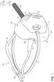
- FIG. 1is a perspective view of a mask having certain features, aspects or advantages of a preferred embodiment overlaying a nasal cannula.
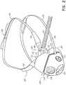
- FIG. 2is an exploded view of the mask and a nasal cannula of FIG. 1 .
- FIG. 3is a front view of the mask and cannula of FIG. 1 .
- FIG. 4is a perspective view of the underside of the mask of FIG. 1 .
- FIG. 5is a perspective view of the underside of an alternative embodiment of a mask having certain features, aspects or advantages of a preferred embodiment.
- FIG. 6 ais a graph of respiratory pressure with only a nasal cannula and without a mask.
- FIG. 6 bis a graph of respiratory pressure with the combination of a nasal cannula and a mask.
- CPAPsupplemental oxygen therapy
- HF therapiesinclude, but are not limited to, CPAP, supplemental oxygen therapy and HF therapies. These therapies all have advantages and disadvantages.
- the masks disclosed herein, when used in combination with a nasal cannula,may be able to provide users or patients with the benefits of combined therapies. More specifically, the disclosed masks or systems may allow the provision of gases at higher temperatures and/or humidity levels, such as a nasal cannula can supply, and the increased respiratory pressures required or desirable for the treatment of respiratory distress.
- FIG. 1is a perspective view of an embodiment of a mask 100 overlaying a nasal cannula 102 .
- FIG. 2shows an exploded view of the same mask 100 and nasal cannula 102 set-up.
- the nasal cannula 102can provide the flow of breathing gas to the user.
- the nasal cannula 102can be applied to the user separately from the mask 100 .
- the mask 100can be selectively applied to the user without removal of the nasal cannula 102 and, preferably, without significant movement or other manipulation of the nasal cannula 102 .
- the mask 100preferably can be removed from the user without removal of the nasal cannula 102 and, preferably, without significant movement or other manipulation of the nasal cannula 102 .
- a nasal cannula 102is illustrated herein, other suitable interfaces can be used to deliver the flow of breathing gas to the user, including, for example but without limitation, other suitable high flow therapy interfaces.
- Such interfacespreferably are unsealing interfaces that do not create an airtight seal or a substantially airtight seal with the user.
- a high flow therapycan be delivered via an oral interface or a tracheal interface instead of the nasal cannula 102 , and pressure support can be augmented by placing a mask 100 or other interface over that oral or tracheal interface. Therefore, references to nasal cannula 102 herein can also refer more generally to other suitable unsealing or high flow interfaces, unless otherwise indicated explicitly or by the context of the disclosure.
- the mask 100is specially shaped or configured to accommodate the nasal cannula 102 and allow the nasal cannula 102 to extend from within the mask 100 to outside of the mask 100 while being capable of creating a sufficient seal with the user's face to provide increased pressure within the mask 100 .
- use of the mask 100 in combination with the nasal cannula 102allows the respiratory pressure within the user's airways to be elevated relative to the pressure when using the nasal cannula 102 without the mask 100 .
- such an arrangementcan help to treat respiratory distress in, for example, COPD patients receiving HF therapy via the nasal cannula 102 .
- the mask 100 and nasal cannula 102can be sold as a system or kit, in which the mask 100 and nasal cannula 102 are sold together or in a single package.
- the mask 100can be configured for use in combination with one or more particular models of nasal cannula, but can be sold separately from such nasal cannula.
- the mask 100can be configured for use in combination with a broad spectrum of nasal cannula; however, in order to accommodate many different nasal cannula shapes and designs, the ability of the mask 100 to create an optimal seal with at least a portion of the nasal cannula may be compromised. Nonetheless, such a general purpose mask can create a seal that is sufficient to provide pressure support to the user.
- the mask 100 and nasal cannula 102are at least designed, if not sold, as a system.
- the nasal cannula 102can be of any suitable configuration for the intended use, such as HF nasal therapy.
- the nasal cannula 102can have a body 150 from which at least one nasal prong 152 extends. In the illustrated arrangement, a pair of nasal prongs 152 is provided. Preferably, when the nasal cannula 102 is properly positioned on the user's head, the nasal prongs 152 extend toward or into, but do not fully seal with, the user's nares.
- the nasal cannula 102includes a gases or breathing circuit that communicates with the nasal prongs 152 .
- the gases circuitcomprises at least one gases tube 154 that supplies a flow of breathing gas to the nasal prongs 152 and, thus, can be referred to as a supply tube.
- a single supply tube 154is provided and extends to one side of the nasal cannula 102 .
- the supply tube 154can extend in other directions and/or multiple supply tubes 154 can be provided.
- a supply tube 154can be provided on and extend to each side of the nasal cannula 102 .
- the supply tube 154can be connected to a source of pressurized gases 300 and, optionally, a humidifier 302 .
- the source of pressurized gases 300can be configured to supply supplemental oxygen to the user. Any suitable source of pressurized gases 300 can be used.
- the nasal cannula 102preferably also includes a retention or headgear arrangement that secures or retains the nasal cannula 102 onto the user's head.
- the headgear arrangementis in the form of a single strap 156 that extends around the user's head from one side of the cannula body 150 to the other side of the cannula body 150 .
- the headgear arrangementcan more complex, such as including multiple straps or multiple strap portions.
- the headgear arrangementcan include a rear portion that extends around the back of the user's head and/or an upper portion that extends over the top of the user's head.
- the headgear arrangementcan include flexible or relatively rigid portions, elastic or relatively inelastic portions or any combination thereof.
- the headgear arrangementincludes one or more adjustment portions or adjustment mechanisms 158 that permit adjustment of a length or size of the headgear arrangement.
- the adjustment mechanism 158can be of any suitable arrangement, such as any multi-position connector, and can have discrete adjustment positions or can be infinitely adjustable.
- the adjustment mechanism 158can include a strap or strap portion forming or having one or more adjustment loops or overlapping portions that can be adjusted in size via a sliding buckle or hook-and-loop fastener, for example.
- Other suitable arrangements, such as multi-position snap closures, for example,can also be used.
- the nasal cannula 102can include other arrangements for securing or retaining the nasal cannula 102 on the user's head.
- the nasal cannula 102can comprise ‘loop’ pads on patient-facing surfaces of the cannula body 150 that can interface with complementary ‘hook’ pads adhered to the face of the user (e.g., for a ‘hook-and-loop’ style connection), or vice-versa.
- the nasal cannula 102could be connected to a helmet, bonnet or coif-style headwear adapted to secure or retain the nasal cannula 102 on the head.
- a portion of the nasal cannula 102(including but not limited to the cannula body 150 ) could be adhered directly to the face (using, for example, a resealable adhesive structure).
- the headgear or other retention arrangement of the nasal cannula 102is separate from the headgear or other retention arrangement of the mask 100 , or at least is capable of retaining the nasal cannula 102 on the user's head without assistance or reliance on the headgear or other retention arrangement of the mask 100 .
- the nasal cannula 102can be of any suitable arrangement for the desired use.
- the cannula body 150can comprise a frame 160 that supports the nasal prong(s) 152 .
- the nasal prong(s) 152can be unitarily formed with the frame 160 or can be a separate component(s) that is permanently or removably secured to the frame 160 .
- the nasal prongs 152 and frame 160are a unitary structure that is formed by, for example, injection molding.
- the illustrated frame 160is a generally elongate structure that extends in a lateral direction across the upper lip and toward or onto the cheeks of the user.
- the nasal prong 152extends upwardly from a central portion of the frame 160 .
- the frame 160can be made from a relatively soft, resilient material such that the frame 160 can generally hold its shape in the absence of external forces applied to the frame 160 , but can also generally conform to the face of the particular user.
- a soft, flexible materialsuch as silicone, other cannula material known in the art or other suitable materials can be used.
- the head strap 156can be coupled to lateral end portions of the frame 160 by any suitable connector, such as a clip 162 having a locking tab or other locking member that engages a slot or other locking surface of the frame 160 .
- the clips 162can be formed at least in part from or can include a covering sleeve made from a soft material (e.g., silicone) to provide comfort to the user and/or enhance the grip of the clips 162 on the user's face.
- the frame 160can be configured to receive a manifold 164 that is connected to the supply tube 154 and delivers a flow of gas from the supply tube 154 to the nasal prong(s) 152 .
- the manifold 164can be constructed of a material that is relatively rigid or more rigid than the material of the frame 160 and/or nasal prong(s) 152 .
- the manifold 164is constructed in whole or in part from polycarbonate, high-density polyethylene (HDPE) or another suitable material.
- the manifold 164can include one or more openings or ports that allow communication of a flow of breathing gases from the supply tube 154 to the nasal prong(s) 152 via the manifold 164 .
- a suitable nasal cannula 102is disclosed in Applicant's Publication No. WO2014/182179, entitled PATIENT INTERFACE AND HEADGEAR FOR A RESPIRATORY APPARATUS, the entirety of which is hereby incorporated by reference herein and made a part of the present disclosure.
- the illustrated mask 100includes a sealing cushion 104 , one or more cannula cut-outs 106 , a mask frame 108 , a headgear arrangement or head strap 110 , a one-way valve 112 , a variable vent 114 and a fixed bias flow vent 116 .
- the illustrated mask 100may not include an air supply conduit or connection port. Instead, a portion or most of the air flow to the user is supplied by the nasal cannula system 102 with any deficit being supplied through the one-way valve(s) 112 . With such an arrangement, the mask 100 can act as a pressure vessel that can increase the expiratory pressure within the airways of the user.
- the mask 100can comprise a mask body 170 , which can be made up of, in whole or in part, the mask frame 108 and the sealing cushion 104 .
- the sealing cushion 104can be referred to herein as a “seal” or as a “cushion.”
- the mask frame 108can be unitary with or can support the cushion 104 . In the illustrated arrangement, the mask frame 108 and the cushion 104 are separate components or at least formed in separate steps.
- the mask frame 108can be constructed from a material that is capable of at least substantially maintaining its shape in the absence of external forces applied to the mask frame 108 . In some configurations, the mask frame 108 can be resilient. In other configurations, the mask frame 108 can be relatively rigid or more rigid than the cushion 104 .
- the mask frame 108can be constructed in whole or in part from polycarbonate, high-density polyethylene (HDPE) or another suitable material.
- the mask frame 108can be a one-piece structure or can be a multi-piece structure.
- a first mask frame portion or elementcan support the cushion 104 and a second mask frame portion or element can provide for connection of the headgear 110 .
- the first mask frame portion and the second mask frame portioncan be permanently or, preferably, removably connected to one another.
- the cushion 104can be configured to provide an interface between the user and the mask 100 and can be made from a flexible material, such as silicone rubber, a thermoplastic elastomer or any other suitable seal material.
- the cushion 104can be secured to the mask frame 108 by any suitable process or arrangement.
- the cushion 104can be removably coupled to the mask frame 108 , such as by a flange-and-groove arrangement.
- the cushion 104can be attached to the mask frame 108 by adhesives or during the forming process (e.g., overmolding or co-molding).
- the cushion 104preferably includes one or more features configured to accommodate the nasal cannula 102 when the mask 100 is applied to a user while the nasal cannula 102 is in use.
- the cushion 104can include at least one cannula recess or cut-out 106 .
- the cushion 104can include other configurations to accommodate the nasal cannula 102 , such as regions of increased compliance or thin-walled regions that allow the cushion 104 to stretch over the nasal cannula 102 .
- Such thin-walled regionsmay have a wall thickness that is significantly thinner than surrounding portions of the cushion 104 and may be sized and/or shaped to generally correspond to the size and/or shape of the portion of the nasal cannula 102 that passes underneath the cushion 104 .
- Examples of thin-walled regionsare described in Applicant's PCT Application No. PCT/NZ2015/050019, filed Feb. 26, 2015, entitled “RESPIRATORY MASK WITH NASOGASTRIC TUBE PATH,” the entirety of which is incorporated by reference herein and made a part of the present disclosure.
- the cushion 104includes a cannula cut-out 106 on each side of the mask 100 .
- the illustrated cushion 104includes a cut-out 106 on each lateral side of the mask 100 .
- the cut-outs 106can be configured to accommodate, complement or match the lateral geometry of a nasal cannula, in general, or a particular nasal cannula 102 . Such an arrangement enables a cannula to pass between the mask 100 and a user's face, preferably with minimal or acceptable gaps between the cannula and mask 100 .
- the mask 100when properly positioned on the user in combination with the nasal cannula 102 , can create a seal with the face of the user that is sufficient to allow for an increase in pressure within an interior space or breathing cavity of the mask 100 and/or an increased expiratory pressure within the user's airways relative to the use of the nasal cannula 102 without the mask 100 .
- the mask 100also creates at least a substantial seal with the nasal cannula 102 .
- the combination of the seal with the user's face and with the nasal cannula 102is sufficient to allow for an increase in pressure within an interior space or breathing cavity of the mask 100 and/or an increased expiratory pressure within the user's airways.
- descriptions of a seal between the mask 100 and the user's face hereincan include the seal between the mask 100 and the nasal cannula 102 unless otherwise indicated.
- the mask 100is capable of creating a seal with the user's face that is sufficient to allow for a therapeutically-significant increase in an increase in pressure within an interior space or breathing cavity of the mask 100 and/or an increased expiratory pressure within the user's airways relative to the use of the nasal cannula 102 without the mask 100 .
- mask 100can be configured for use with a particular nasal cannula or several particular nasal cannula.
- the mask 100can be configured for use with the nasal cannula 102 shown and described herein.
- the cut-outs 106can be configured to accommodate portions of the nasal cannula 102 that pass between the cushion 104 and the user's face when the mask 100 is used in combination with the nasal cannula 102 .
- the cut-outs 106can have a shape or profile that approximates, is complementary to or closely matches a shape of the portion of the nasal cannula 102 that passes through the cut-out 106 .
- the cut-outs 106can simply accommodate or approximate the shape of the nasal cannula 102 and the mask 100 can rely on the ability of the material of the cushion 104 to stretch or conform to the shape of the nasal cannula 102 .
- the cut-outs 106can closely follow or substantially match the shape of the nasal cannula 102 .
- the cushion 104can be shaped, sized or otherwise configured to encompass a user's nose and/or mouth.
- the cushion 104can have a side wall 118 , which can have a substantially triangular shape or profile.
- the side wall 118can have a first end that is proximal to the user's face and transitions into a sealing surface or a user-contacting surface 172 that contacts the user's face.
- the sealing surface 172extends, in a substantially perpendicular direction, from the side wall 118 towards the center of the mask 100 .
- the cannula cut-outs 106can take the form of stepped regions in the sealing surface 172 . In some configurations, the cut-outs 106 create a gap in a sealing surface 172 of the cushion 104 . That is, end portions of the cut-outs 106 can be spaced from one another in a direction that traces a perimeter of the sealing surface 172 .
- Nasal cannulastypically extend laterally from the underside of a user's nose, across the user's cheeks towards the user's ears.
- the geometry of the surface of the cushion 104 within the cut-outs 106can be configured to match the geometry of the nasal cannula that extends beneath the mask's sealing surface. Depending on the particular nasal cannula used in combination with the mask 100 , this may require or make it desirable that the shape or geometry of the cut-outs 106 is different on each side of the cushion 104 . For example, if the cannula has an asymmetric air supply as in the cannula 102 of FIGS. 1 to 4 , the shape or geometry of the cut-outs 106 may also be asymmetrical.
- a portion of the frame 160 of the nasal cannula 102passes between the cushion 104 and the user's face on one side of the mask 100 .
- the cut-out 106has a generally rectangular profile or shape that generally corresponds to the shape of the portion of the frame 160 that underlies the cushion 104 .
- a portion of the frame 160 and the supply tube 154passes between the cushion 104 and the user's face, as shown in FIG. 2 .
- the cut-out 106comprises a generally semi-circular profile or shape that generally corresponds to the shape of the supply tube 154 .
- the cut-out 106 on the tube 154 sidecan also include a generally rectangular portion such that the cut-out 106 overall generally corresponds to the shape of the combination of the frame 160 and supply tube 154 .
- one or more one-way valves 112are provided on the mask 100 , such as within the mask frame 108 .
- the one-way valve(s) 112can be configured to open on inhalation by the user, allowing for entrainment of ambient air along with the air supplied by the nasal cannula 102 , and at least partially close to restrict flow on exhalation by the user in order to maintain the increased pressure within the mask 100 .
- the entrainment of ambient airhelps to ensure that the user's inspiratory flow requirements are met, by reducing inspiratory resistance.
- the one-way valve(s) 112can remain closed on exhalation, thus restricting air flow between the inside of the mask 100 and the atmosphere, thus increasing the resistance to expiration and pressure within the user's airways. Increased respiratory pressure and expiratory resistance can help to reduce user's breathing rates.
- the valve(s) 112can remain somewhat open in the absence of inhalation by the user instead of being completely closed.
- the valve(s) 112can be pre-loaded or biased to a slightly open position, thus allowing ambient gases to pass through the valve(s) 112 and into the mask 100 .
- the one-way valve(s)can be configured to move to a closed position from a slightly-opened biased or normal position in response to an appropriate force (e.g., expiration by the user).
- the biascan be selected so that 1-5 cm of gas pressure moves the valve 112 toward or to the closed position, thereby increasing pressure in the mask.
- the one or more valves 112can be located on the lateral sides of the mask frame 108 ; however, in other embodiments, the valves 112 may be located in any other suitable location on the mask 100 .
- a variable vent 114is included in the mask 100 .
- the vent 114can comprise an opening or open region in the mask frame 108 that can be provided with, for example, a manual mechanism that allows a user to variably open and close the vent 114 by blocking a portion or an entirety of the opening.
- an effective size of the opening that permits communication with the atmosphere outside of the mask 100can be varied, thereby allowing an effective size of the vent 114 to be varied.
- the vent 114may be non-variable and/or may be automatically controlled.
- the variable vent 114can enable the application of expiratory pressure to be selectively applied without removal of the mask 100 .
- variable vent 114can allow users and/or medical practitioners to selectively apply and/or variably adjust the amount of pressure provided by the mask 100 .
- variable vent 114is substantially open, breathable gases can at least relatively freely flow in and out of the mask 100 and the pressure inside the mask 100 can be substantially the same as atmospheric pressure.
- variable vent 114can be opened to reduce the internal pressure within the mask 100 , and if the user's breathing rate remains stable then the mask can be removed. If, however the user's breathing rate increases then the variable vent 114 can be closed and the internal pressure restored, without the hassle of refitting the mask. Having a variable vent 114 may allow the user to be gradually weaned from the pressure support, by gradually opening the vent 114 to reduce the internal pressure within the mask 100 .
- variable vent 114can be centrally located on the front of the mask 100 . This location can be beneficial in allowing for easy access and manipulation of the vent 114 by the user or medical practitioner.
- the vent 114can comprise a semicircular outlet 202 that can be partially or completely concealed by a rotatable cover 204 .
- the vent covermay be configured to move in a variety of ways including, but not limited to, planar sliding, hinged motion or the removal of a completely separate cap.
- the mask 100includes one or more fixed bias flow vents 116 .
- the bias flow vent 116may take any suitable form that allows the flow of breathable gases from inside the mask 100 to the atmosphere. This may include, but is not limited to, one or more small holes, a region of porous material, or a gap between the cushion 104 and the cannula 102 or user's face.
- the bias flow vent 116provides an exhaust path to flush CO 2 from the mask 100 .
- the geometry of the bias flow vent 116can be selected or configured to allow for a certain flow rate of air to pass through the bias flow vent 116 , which can be determined at least in part on the dead space within the mask 100 .
- the bias flow vent 116comprises a series of small holes located in a central position on the mask frame 108 . However, in other arrangements, the bias flow vent(s) 116 can be located in any other suitable position on the mask 100 .
- the mask 100can be secured to the user independently of the nasal cannula 102 via a head strap 110 or any other appropriate securement arrangement. Being attached to the user independently of the nasal cannula 102 allows adjustments to the fit of the mask 100 with minimal interference to the fit of the nasal cannula 102 . Because the mask 100 is substantially larger than a nasal cannula, it may require higher headgear tensions or greater structural integrity in order to be secured effectively to a user's head and/or face. In the arrangement of FIGS. 1-4 , the head strap 110 may be configured to include a single or bifurcated strap, which can be made from an elastic material.
- the head strap 110can be made of a substantially inelastic material and can include an adjustment mechanism, such as a buckle or any other appropriate mechanism.
- the mask 100may be configured to include a headgear that includes multiple straps and adjustment mechanisms, such as but not limited to hook and loop tabs.
- both the mask 100 and cannula 102can be specifically designed for use as a system or can be provided as an integrated unit.
- FIG. 4illustrates the underside of the mask 100 .
- FIG. 4also shows an additional (optional) vent 400 that can be configured to allow condensation to be released from inside of the mask 100 .
- the gases applied to a patient during HF therapycan have a high temperature and humidity.
- the high temperature and humidity of the gaswill result in the formation of condensation within the mask 100 as a result of restricted airflow out of the mask and the cold surfaces of the mask frame 108 .
- a vent 400can be provided to the mask 100 to allow condensation to be removed from the mask 100 .
- the vent 400can be or comprise a one-way valve that opens on inhalation to allow water accumulated in the region of the valve to drain out during inhalation.
- the vent 400can be or comprise a one-way valve that opens on exhalation to allow water to be forced out of the mask 100 .
- the valvecan be configured so as not to substantially reduce the internal pressure within the mask 100 , when open on exhalation.
- the vent 400can be an opening that is sealed with a manually removable plug or cap. The user or a medical practitioner can open the vent 400 as necessary or desired to drain water from the mask 100 .
- the vent 400is located on a lower and/or downward facing surface of the mask frame 108 .
- vent 400to act as a water trap because gravity will encourage condensation to fall towards the bottom of the mask 100 and, thus, the vent 400 .
- By releasing the water from the bottom of the mask 100it may be possible to reduce the buildup of condensation without needing to remove the mask 100 .
- FIG. 5illustrates a view of the underside of an alternative embodiment of a mask 500 , which can be the same as or similar to the mask 100 with the exception of the features explicitly described herein.
- a pressure port 502can be provided on the mask 500 to allow the pressure inside the mask 500 to be measured.
- the pressure data from inside the mask 500can then be used by the flow controller for the cannula 102 to measure respiratory rate and the level of respiratory distress.
- This informationcould then be communicated to a display, such as the display on the flow controller, or via USB, Bluetooth or another suitable communication protocol to a computer or phone display to indicate a suitable opening position for the variable vent 114 .
- This positioncould be manually set by the medical practitioner or in a further embodiment could be automatically controlled by the flow controller to maintain expiratory pressure at a level to achieve a desired respiratory rate.
- This controlmay be through an electronic connection between the flow controller and the mask 500 that can enable the control of an automated valve that adjusts the pressure within the mask 500 via controlled venting.
- the displayed informationmay also indicate when the mask 500 can be removed, as the patient no longer requires pressure support, and the therapy can continue with the cannula 102 only.
- the motor speed of the flow controllercould be altered during inspiration and expiration, to control the pressure within the mask 500 and manage a user's respiratory rate. In this way the effect of opening a variable vent 114 can be automatically simulated by slowing the flow controller motor speed during expiration.
- the controllermay then use pressure measurements from within the mask 500 , provided via the pressure port 502 , to determine whether the patient respiratory rate is such that the mask 500 can be safely removed with the therapy continuing through the cannula 102 alone.
- Such an arrangementessentially provides a closed loop system, wherein the flow controller can measure, interpret and influence the breathing rates of a user by modifying flow induced pressure, without the need for interaction from a medical practitioner. In such an arrangement, preferably, the only interaction required by a medical practitioner will be the application and removal of the mask 500 .
- the mask 500can additionally or alternatively include a port 504 , as shown in FIG. 5 , which allows a Positive End Expiratory Pressure (PEEP) Valve 506 to be connected to the mask 500 .
- PEEPPositive End Expiratory Pressure
- Any suitable PEEP valve configurationsuch as those known in the art, may be used for this purpose.
- One example of a PEEP valve configurationis incorporated into a connector in Applicant's U.S. Pat. No. 7,341,059, entitled “BREATHING ASSISTANCE APPARATUS,” the entirety of which is incorporated by reference herein and made a part of the present disclosure.
- the mask 500acts as a pressure vessel causing the respiration pressure to increase.
- the PEEP valve 506will set a maximum pressure threshold, which when exceeded the PEEP valve 506 will open and vent the above-threshold pressure. When the pressure is at or below the PEEP valve pressure, the valve will close again. Therefore, the mask 500 will allow the generation of positive pressure in the mask 500 , airways and lungs while the PEEP valve 506 will limit the maximum expiration pressure developed.
- the PEEP valve 506can provide a maximum allowed positive pressure, which may be manually variable, or in some embodiments may be variably controlled by the feedback loop provided by the flow controller, pressure port 502 , and an electronic actuator. In a further variation of this arrangement, a PEEP valve 506 can be permanently connected to the mask 500 .
- FIGS. 6 a and 6 bdemonstrate the impact that the application of the mask 100 , 500 has when combined with a nasal cannula 102 .
- FIG. 6 ashows the pressure inside the nares of a patient when wearing a nasal cannula 102 supplying a flow rate of 30 L/min.
- FIG. 6 bshows the pressure inside the nares of a patient wearing the mask 100 , 500 in combination with a nasal cannula 102 supplying a flow rate of 30 L/min.
- the application of the mask 100 , 500 over the top of a cannula 102has the desired effects of increasing the respiration pressure, shown by the increased height of the wave form, and decreasing the respiration rate, as shown by the longer wavelength.
- respiratory pressureis increased in both the inspiratory and expiratory phases of the user's breathing cycle. It is beneficial for the expiratory pressure to be increased as it can reduce respiratory distress, as shown by the decreased respiration rate.
- any quantity, dimension, size, formulation, parameter, shape and other characteristic disclosed hereinneed not be exact, unless otherwise indicated, but can be interpreted as being preceded by the term “about” or “approximately.” Accordingly, such quantity, dimension, size, formulation, parameter, shape and other characteristic can be approximated and/or larger or smaller, as desired, reflecting acceptable tolerances, conversion factors, rounding off, measurement error and the like and other factors known to those of skill in the art.
- Numerical datamay be expressed or presented herein in a range format. It is to be understood that such a range format is used merely for convenience and brevity and thus should be interpreted flexibly to include not only the numerical values explicitly recited as the limits of the range, but also interpreted to include all of the individual numerical values or sub-ranges encompassed within that range as if each numerical value and sub-range is explicitly recited. As an illustration, a numerical range of “1 to 5” should be interpreted to include not only the explicitly recited values of about 1 to about 5, but should also be interpreted to also include individual values and sub-ranges within the indicated range.
- the inventionmay also be said broadly to consist in the parts, elements and features referred to or indicated in the specification of the application, individually or collectively, in any or all combinations of two or more of said parts, elements or features.
Landscapes
- Health & Medical Sciences (AREA)
- Pulmonology (AREA)
- Emergency Medicine (AREA)
- Hematology (AREA)
- Animal Behavior & Ethology (AREA)
- Anesthesiology (AREA)
- Biomedical Technology (AREA)
- Heart & Thoracic Surgery (AREA)
- Veterinary Medicine (AREA)
- Life Sciences & Earth Sciences (AREA)
- Engineering & Computer Science (AREA)
- General Health & Medical Sciences (AREA)
- Public Health (AREA)
- Otolaryngology (AREA)
- Respiratory Apparatuses And Protective Means (AREA)
- Accommodation For Nursing Or Treatment Tables (AREA)
- Infusion, Injection, And Reservoir Apparatuses (AREA)
- Measurement Of The Respiration, Hearing Ability, Form, And Blood Characteristics Of Living Organisms (AREA)
Abstract
Description
Claims (36)
Priority Applications (1)
| Application Number | Priority Date | Filing Date | Title |
|---|---|---|---|
| US15/128,906US11185653B2 (en) | 2014-03-27 | 2015-03-27 | Pressurizing masks, systems and methods |
Applications Claiming Priority (3)
| Application Number | Priority Date | Filing Date | Title |
|---|---|---|---|
| US201461971464P | 2014-03-27 | 2014-03-27 | |
| PCT/IB2015/052257WO2015145390A1 (en) | 2014-03-27 | 2015-03-27 | Pressurizing masks, systems and methods |
| US15/128,906US11185653B2 (en) | 2014-03-27 | 2015-03-27 | Pressurizing masks, systems and methods |
Related Parent Applications (1)
| Application Number | Title | Priority Date | Filing Date |
|---|---|---|---|
| PCT/IB2015/052257A-371-Of-InternationalWO2015145390A1 (en) | 2014-03-27 | 2015-03-27 | Pressurizing masks, systems and methods |
Related Child Applications (1)
| Application Number | Title | Priority Date | Filing Date |
|---|---|---|---|
| US17/451,239ContinuationUS12121661B2 (en) | 2014-03-27 | 2021-10-18 | Pressurizing masks, systems and methods |
Publications (2)
| Publication Number | Publication Date |
|---|---|
| US20170182275A1 US20170182275A1 (en) | 2017-06-29 |
| US11185653B2true US11185653B2 (en) | 2021-11-30 |
Family
ID=54194058
Family Applications (3)
| Application Number | Title | Priority Date | Filing Date |
|---|---|---|---|
| US15/128,906Active2037-07-29US11185653B2 (en) | 2014-03-27 | 2015-03-27 | Pressurizing masks, systems and methods |
| US17/451,239ActiveUS12121661B2 (en) | 2014-03-27 | 2021-10-18 | Pressurizing masks, systems and methods |
| US18/889,191PendingUS20250121150A1 (en) | 2014-03-27 | 2024-09-18 | Pressurizing masks, systems and methods |
Family Applications After (2)
| Application Number | Title | Priority Date | Filing Date |
|---|---|---|---|
| US17/451,239ActiveUS12121661B2 (en) | 2014-03-27 | 2021-10-18 | Pressurizing masks, systems and methods |
| US18/889,191PendingUS20250121150A1 (en) | 2014-03-27 | 2024-09-18 | Pressurizing masks, systems and methods |
Country Status (13)
| Country | Link |
|---|---|
| US (3) | US11185653B2 (en) |
| EP (4) | EP4272793A3 (en) |
| JP (4) | JP6681339B2 (en) |
| CN (4) | CN118001535A (en) |
| AU (5) | AU2015237807C1 (en) |
| CA (1) | CA2943925A1 (en) |
| DE (1) | DE112015001488T5 (en) |
| ES (1) | ES2966496T3 (en) |
| GB (2) | GB2541567B (en) |
| NZ (1) | NZ724272A (en) |
| PL (1) | PL3939645T3 (en) |
| SG (3) | SG11201607805SA (en) |
| WO (1) | WO2015145390A1 (en) |
Cited By (3)
| Publication number | Priority date | Publication date | Assignee | Title |
|---|---|---|---|---|
| US11826509B2 (en) | 2017-05-22 | 2023-11-28 | Fisher & Paykel Healthcare Limited | Respiratory user interface |
| US12023443B2 (en) | 2009-12-23 | 2024-07-02 | Fisher & Paykel Healthcare Limited | Breathing assistance system |
| US12121661B2 (en) | 2014-03-27 | 2024-10-22 | Fisher & Paykel Healthcare Limited | Pressurizing masks, systems and methods |
Families Citing this family (19)
| Publication number | Priority date | Publication date | Assignee | Title |
|---|---|---|---|---|
| CN116899065A (en) | 2013-03-15 | 2023-10-20 | 费雪派克医疗保健有限公司 | Nasal cannula assemblies and related components |
| ES2817076T3 (en) | 2013-08-09 | 2021-04-06 | Fisher & Paykel Healthcare Ltd | Asymmetric Nasal Delivery Elements and Accessories for Nasal Interfaces |
| NZ714595A (en) | 2014-06-19 | 2017-06-30 | Resmed Ltd | Patient interface for respiratory therapy |
| US20170028150A1 (en)* | 2015-07-31 | 2017-02-02 | Linda McNulty | Conversion mask |
| MX2018006874A (en) | 2015-12-10 | 2019-10-07 | ResMed Pty Ltd | Methods and apparatus for respiratory treatment. |
| IT201600089365A1 (en)* | 2016-09-02 | 2018-03-02 | Paola Papoff | METHOD AND SYSTEM FOR THE DETERMINATION OF THE RESPIRATORY PROFILE OF A PATIENT SUBJECT TO OXYGEN THERAPY AT HIGH FLOWS THROUGH NOSE-NANNULE |
| USD870269S1 (en) | 2016-09-14 | 2019-12-17 | Fisher & Paykel Healthcare Limited | Nasal cannula assembly |
| CN106943656A (en)* | 2017-03-31 | 2017-07-14 | 宁波圣宇瑞医疗器械有限公司 | Noninvasive breathing mask and its lung ventilator applied |
| WO2020056511A1 (en)* | 2018-09-19 | 2020-03-26 | St. Michael's Hospital | Systems, devices and methods for modulating a respiratory drive of a patient |
| USD941993S1 (en)* | 2019-08-23 | 2022-01-25 | ResMed Pty Ltd | Tube headgear for patient interface |
| US20220023512A1 (en)* | 2020-07-21 | 2022-01-27 | Carl Morgan | Exhalation Disposal System |
| JP7492734B2 (en)* | 2020-08-24 | 2024-05-30 | 学校法人東京医科大学 | Respiratory mask |
| CN116018170A (en)* | 2020-09-01 | 2023-04-25 | 斯坦福设备有限公司 | Aerosol High Flow Therapy Devices |
| WO2022069255A1 (en)* | 2020-09-30 | 2022-04-07 | Koninklijke Philips N.V. | Soft slide-through mechanism for cpap headgear |
| KR102545210B1 (en)* | 2020-12-10 | 2023-06-20 | 신진숙 | adhesion-type positive airway pressure mask |
| JP2024502288A (en) | 2020-12-23 | 2024-01-18 | フィッシャー アンド ペイケル ヘルスケア リミテッド | Integration and mode switching for breathing equipment |
| KR102497384B1 (en)* | 2021-01-18 | 2023-02-08 | 티엔에스에이아이 주식회사 | System for health examination using mask |
| DE102021102308A1 (en)* | 2021-02-02 | 2022-08-04 | Drägerwerk AG & Co. KGaA | Mask assembly, retention means, ventilator and method of adjusting a mask assembly |
| CN113134148B (en)* | 2021-04-27 | 2022-03-08 | 山东大学齐鲁医院(青岛) | Heart internal medicine first aid respirator |
Citations (73)
| Publication number | Priority date | Publication date | Assignee | Title |
|---|---|---|---|---|
| US1896716A (en) | 1926-12-21 | 1933-02-07 | Elmer I Mckesson | Gas handling apparatus |
| US2375803A (en) | 1944-04-18 | 1945-05-15 | United Shoe Machinery Corp | Trimming machine |
| US2663297A (en) | 1953-01-19 | 1953-12-22 | Harold G Belasco | Nasal adapter for oxygen inhalation |
| US2693800A (en) | 1951-04-27 | 1954-11-09 | Caldwell Lyle | Nasal cannula |
| US2868199A (en)* | 1955-05-20 | 1959-01-13 | Charles H Hudson | Cannula |
| US3330274A (en) | 1964-10-15 | 1967-07-11 | Puritan Compressed Gas Corp | Oro-nasal face mask with improved pneumatic sealing cuff |
| US3513844A (en) | 1968-04-30 | 1970-05-26 | Metro Hospital Supply Co Inc | Adjustable nonrestrictive nasal cannula |
| US4201205A (en) | 1978-01-20 | 1980-05-06 | Hudson Oxygen Therapy Sales Company | Oxygen mask |
| US4231363A (en) | 1979-01-08 | 1980-11-04 | Grimes Jerry L | Gas delivery face shield |
| US4248218A (en) | 1978-09-22 | 1981-02-03 | Fischer Charles M | Gas administration scavenging mask |
| US4328797A (en)* | 1980-07-23 | 1982-05-11 | Rollins Iii Offord L | Naso-gastric oxygen mask |
| US4354488A (en) | 1980-11-24 | 1982-10-19 | Dow Corning Corporation | Nose mask gas delivery device |
| WO1982003548A1 (en) | 1981-04-24 | 1982-10-28 | Sullivan Colin Edward | Device for treating snoring sickness |
| US5005571A (en)* | 1988-11-25 | 1991-04-09 | Dietz Henry G | Mouth nose mask for use with an inhalation therapy and/or breathing monitoring apparatus |
| US5400781A (en) | 1993-08-03 | 1995-03-28 | Davenport; Richard A. | CO2 gas sampling mask having a bevelled sampling tube extending into the mask |
| US5474060A (en) | 1993-08-23 | 1995-12-12 | Evans; David | Face mask with gas sampling port |
| EP0747078A2 (en) | 1995-06-06 | 1996-12-11 | RESPIRONICS Inc. | Nasal mask |
| US6357437B1 (en) | 1999-02-19 | 2002-03-19 | Vortex Recoveries Inc. | Waste gas recovery apparatus |
| US20020053347A1 (en) | 1999-06-18 | 2002-05-09 | Saeed Ziaee | Nasal Mask |
| US20020112730A1 (en) | 1998-12-01 | 2002-08-22 | Dutkiewicz Edward P. | Oxygen delivery and gas sensing nasal cannula system |
| US20020122746A1 (en) | 2001-03-08 | 2002-09-05 | Nihon Kohden Corporation | Sensor for measuring carbon dioxide in respiratory gas |
| US20030024533A1 (en)* | 2001-08-02 | 2003-02-06 | Sniadach Joseph A. | Multi-port mask |
| US6561190B1 (en) | 1997-02-10 | 2003-05-13 | Resmed Limited | Mask and a vent assembly therefor |
| EP1334742A2 (en) | 2001-09-07 | 2003-08-13 | Resmed Limited | Mask assembly |
| US20030168063A1 (en) | 2002-03-08 | 2003-09-11 | Gambone Anthony Joseph | Pressure face mask and nasal mask |
| US6679265B2 (en) | 2001-10-25 | 2004-01-20 | Worldwide Medical Technologies | Nasal cannula |
| EP1484075A1 (en) | 2003-06-03 | 2004-12-08 | Hans Rudolph, Inc. | Tube seal adaptor for respiratory masks |
| US20040261797A1 (en)* | 2003-05-30 | 2004-12-30 | White Craig Karl | Breathing assistance apparatus |
| US20050011523A1 (en) | 2003-07-18 | 2005-01-20 | Acoba, Llc | Method and system of Individually controlling airway pressure of a patient's nares |
| US20050028822A1 (en) | 2003-08-08 | 2005-02-10 | Tiara Medical Systems, Inc. | Sealing nasal cannula |
| WO2005018524A2 (en) | 2003-08-18 | 2005-03-03 | Wondka Anthony D | Method and device for non-invasive ventilation with nasal interface |
| US20050098183A1 (en)* | 2003-01-15 | 2005-05-12 | John Nash | Face masks |
| US20060169281A1 (en) | 2005-02-03 | 2006-08-03 | Aylsworth Alonzo C | Continuous flow selective delivery of therapeutic gas |
| US20060266361A1 (en) | 2005-05-31 | 2006-11-30 | Shara Hernandez | Ventilation interface |
| US20060278233A1 (en) | 2003-07-30 | 2006-12-14 | Mcauley Alastair E | Forehead rest for respiratory masks |
| US20070079982A1 (en) | 2003-09-19 | 2007-04-12 | Laurent Kristopher P M | Connector |
| US20070089749A1 (en) | 2005-10-24 | 2007-04-26 | Ric Investments, Llc. | Patient interface with an integral cushion and nasal pillows |
| US20070107737A1 (en) | 2005-09-12 | 2007-05-17 | Mergenet Medical, Inc. | Nasal cannula |
| US20070113856A1 (en) | 2005-11-22 | 2007-05-24 | General Electric Company | Respiratory monitoring with cannula receiving respiratory airflows |
| US20070113848A1 (en) | 2005-11-22 | 2007-05-24 | General Electric Company | Respiratory monitoring with cannula receiving respiratory airflows and exhaled gases |
| US20070125385A1 (en) | 2005-12-07 | 2007-06-07 | Ho Peter C F | Full face respiratory mask with integrated nasal interface |
| US20070125380A1 (en) | 2005-11-22 | 2007-06-07 | General Electric Company | Respiratory monitoring with differential pressure transducer |
| EP1800707A1 (en) | 2005-12-22 | 2007-06-27 | General Electric Company | Integrated ventilator nasal trigger and gas monitoring system |
| US7255107B1 (en) | 2003-10-14 | 2007-08-14 | Gomez Roy C | Nasal mask assembly for nasal delivery |
| US7341059B2 (en) | 2002-02-04 | 2008-03-11 | Fisher & Paykel Healthcare Limited | Breathing assistance apparatus |
| US20080060653A1 (en) | 2006-09-11 | 2008-03-13 | Michael David Hallett | Mask System with Improved Sealing Properties for Administering Nasal Positive Airway Pressure Therapy |
| WO2008031149A1 (en) | 2006-09-11 | 2008-03-20 | Diagnose It Pty Ltd | A system, method and apparatus for monitoring a medical condition |
| US20080078389A1 (en) | 2006-09-29 | 2008-04-03 | Yang Xiao | Heliox delivery system and method with positive pressure support |
| US20080295846A1 (en) | 2007-05-29 | 2008-12-04 | Steve Han | Integrated mask and prongs for nasal CPAP |
| US20080319334A1 (en) | 2007-02-16 | 2008-12-25 | Nihon Kohden Corporation | Nasal mask for carbon dioxide gas measurement |
| US20090000618A1 (en)* | 2004-09-20 | 2009-01-01 | Sydney Warren | Single sided housing for medical canula tubing combining wireless cellular phone and audio technology with oxygen delivery systems |
| JP2009512510A (en) | 2005-10-19 | 2009-03-26 | バイアシス・ヘルスケア・インコーポレイテッド | Particle-blocking oxygen supply mask |
| US20090101147A1 (en) | 2005-09-12 | 2009-04-23 | Mergenet Medical, Inc. | High Flow Therapy Artificial Airway Interfaces and Related Methods |
| US20090173349A1 (en) | 2008-01-07 | 2009-07-09 | Shara Hernandez | Nasal ventilation interface |
| CN101489617A (en) | 2006-07-14 | 2009-07-22 | 菲舍尔和佩克尔保健有限公司 | breathing assistance device |
| WO2009109005A1 (en) | 2008-03-04 | 2009-09-11 | Resmed Ltd | Unobtrusive interface systems |
| WO2010057166A1 (en) | 2008-11-17 | 2010-05-20 | The Metrohealth System | Combination lung ventilation and mucus clearance apparatus and method |
| US20110009763A1 (en) | 2009-01-05 | 2011-01-13 | Oridion Medical 1987 Ltd. | Exhaled breath sampling with delivery of gas |
| WO2011078702A1 (en) | 2009-12-24 | 2011-06-30 | Farm Improvements Limited | Fluid delivery device |
| WO2011078703A1 (en) | 2009-12-23 | 2011-06-30 | Fisher & Paykel Healthcare Limited | An interface |
| US20120055480A1 (en) | 2010-09-07 | 2012-03-08 | Wilkinson William R | Ventilator systems and methods |
| US20120125338A1 (en) | 2010-11-22 | 2012-05-24 | Alireza Yarahmadi | Dual tube mask with nasal cannula |
| US20120285448A1 (en) | 2011-05-11 | 2012-11-15 | Dugan Greg J | Tube placement in non-invasive ventilation |
| WO2012154883A2 (en) | 2011-05-11 | 2012-11-15 | Carefusion 207, Inc. | Ventilation devices and related parts and methods |
| US8342179B2 (en) | 2005-11-09 | 2013-01-01 | Respan Products, Inc. | Disposable mask assembly with exhaust filter and valve disc and method of assembling same |
| JP2013507205A (en) | 2009-10-14 | 2013-03-04 | バランサイアー エーペーエス | Medical breathing mask |
| US20140096773A1 (en) | 2010-02-19 | 2014-04-10 | Resmed Limited | Supplemental gas delivery device for mask assembly |
| US20140107517A1 (en)* | 2012-10-17 | 2014-04-17 | Shabina M Hussain | Oxygen face mask with capnometer and side port |
| US20140166015A1 (en) | 2012-12-18 | 2014-06-19 | Herbert Ross Waggoner | Dual mode medical oxygen delivery system |
| US20140246025A1 (en)* | 2012-04-13 | 2014-09-04 | Fresca Medical, Inc. | Auto-feedback valve for a sleep apnea device |
| US9032955B2 (en) | 2005-06-06 | 2015-05-19 | Resmed Limited | Mask system |
| US20150217074A1 (en)* | 2012-07-27 | 2015-08-06 | Resmed Limited | Patient interface and method for making same |
| WO2015145390A1 (en) | 2014-03-27 | 2015-10-01 | Fisher & Paykel Healthcare Limited | Pressurizing masks, systems and methods |
Family Cites Families (43)
| Publication number | Priority date | Publication date | Assignee | Title |
|---|---|---|---|---|
| US2675803A (en) | 1954-04-20 | Gas feeding mask | ||
| US2156852A (en)* | 1935-12-24 | 1939-05-02 | Horak Vaclav | Gas mask |
| US2313999A (en) | 1942-06-30 | 1943-03-16 | Air Reduction | Apparatus for administering oxygen |
| US2341566A (en)* | 1942-08-22 | 1944-02-15 | Monro Randolph | Noncombatant gas mask |
| US3968812A (en)* | 1971-10-12 | 1976-07-13 | Instrumentation Industries, Inc. | Apparatus for removal of condensed moisture from respiratory tubes |
| US4328767A (en) | 1981-04-13 | 1982-05-11 | Peterson Edwin R | Retractable leash collar |
| US6439234B1 (en)* | 1998-04-03 | 2002-08-27 | Salter Labs | Nasal cannula |
| US6418928B1 (en) | 2000-09-25 | 2002-07-16 | Mallinckrodt Inc. | Multi-seal respirator mask |
| EP2301616B8 (en)* | 2000-12-22 | 2019-07-24 | ResMed Pty Ltd | Flow regulation vent |
| AU2007202555B2 (en)* | 2001-12-04 | 2011-09-08 | ResMed Pty Ltd | Respiratory Mask Having Gas Washout Vent and Gas Washout Vent Assembly for a Respiratory Mask |
| CN1826151A (en)* | 2003-07-18 | 2006-08-30 | 阿科巴有限责任公司 | Method and system of individually controlling airway pressure of a patient's nares |
| EP2510968B1 (en) | 2003-12-31 | 2017-02-08 | ResMed Limited | Compact oronasal patient interface |
| US20060081243A1 (en) | 2004-10-15 | 2006-04-20 | Southmedic Incorporated | Patient oxygen delivery mask |
| CN2778307Y (en)* | 2005-01-14 | 2006-05-10 | 上海市第五人民医院 | Nasal intubation mask |
| US7866320B2 (en)* | 2005-06-08 | 2011-01-11 | Nichols Heath C | Nasal canula and mouthpiece assembly and method |
| NL1030026C1 (en)* | 2005-09-26 | 2007-03-27 | Think Global B V | Administering and evacuation system. |
| CN2915144Y (en)* | 2006-06-08 | 2007-06-27 | 袁科宇 | A vent adjustable oxygen mask |
| US8875709B2 (en) | 2007-05-10 | 2014-11-04 | Resmed Limited | Mask assembly |
| ES2580177T3 (en)* | 2008-05-13 | 2016-08-19 | Boston Scientific Scimed, Inc. | Steering system with locking mechanism |
| WO2010076704A1 (en) | 2008-12-30 | 2010-07-08 | Koninklijke Philips Electronics N.V. | System and respiration appliance for supporting the airway of a subject |
| EP2414018B1 (en)* | 2009-04-03 | 2019-02-20 | ResMed Ltd. | Mask system |
| US8365734B1 (en)* | 2009-04-29 | 2013-02-05 | Edward Lehman | Multi-port, intubation-permitting, oxygen mask |
| US20120167892A1 (en) | 2009-09-11 | 2012-07-05 | Koninklijke Philips Electronics N.V. | Patient interface device including a mechanism for manipulating the position of an internal component thereof |
| WO2011050059A1 (en)* | 2009-10-20 | 2011-04-28 | Michael Gerard Lalonde | Integrated positive airway pressure apparatus |
| US7958889B1 (en)* | 2010-01-15 | 2011-06-14 | Aurora L. Fernandez de Castro | Protective face cover and moldable attachment |
| CN102791334B (en)* | 2010-07-02 | 2015-07-08 | Msa技术有限公司 | Masks with open ports |
| WO2012040791A1 (en) | 2010-09-30 | 2012-04-05 | Resmed Limited | Patient interface systems |
| CN103974735A (en) | 2011-09-13 | 2014-08-06 | 雷斯梅德有限公司 | Vent arrangement for respiratory mask |
| CN202590116U (en)* | 2012-04-17 | 2012-12-12 | 宁波圣宇瑞医疗器械有限公司 | Adjustable oxygen concentration mask |
| US20140190479A1 (en)* | 2013-01-10 | 2014-07-10 | Nellcor Puritan Bennett Llc | Speaking valve with saturation indication |
| US10987477B2 (en) | 2013-02-04 | 2021-04-27 | ResMed Pty Ltd | Respiratory apparatus |
| NZ631169A (en) | 2013-03-15 | 2017-04-28 | Resmed Ltd | Method and apparatus for controlling pressurized gas delivered to a patient |
| CN114404763A (en) | 2013-05-07 | 2022-04-29 | 费雪派克医疗保健有限公司 | Patient interface and headgear for a respiratory device |
| WO2014181214A1 (en) | 2013-05-09 | 2014-11-13 | Koninklijke Philips N.V. | Stabilized mask |
| CN103405843B (en)* | 2013-08-02 | 2015-06-17 | 山东大学 | Ventilation hood with positive airway pressure adjustable with changes of postures |
| NZ720335A (en) | 2013-11-15 | 2021-07-30 | ResMed Pty Ltd | Patient interface and method for making same |
| US20170173291A1 (en) | 2014-08-20 | 2017-06-22 | Revolutionary Medical Devices ,Inc. | Ventilation mask |
| CN107073236B (en) | 2014-09-18 | 2020-05-05 | 瑞思迈私人有限公司 | Gas washout vent for patient interface |
| US10094731B2 (en) | 2015-03-24 | 2018-10-09 | Fuji Xerox Co., Ltd. | Standing position evaluation apparatus, standing position evaluation method, and non-transitory computer readable medium |
| CN107635614A (en) | 2015-06-11 | 2018-01-26 | 革新医疗器械有限公司 | ventilation mask |
| CN118987436A (en) | 2015-07-20 | 2024-11-22 | 瑞思迈私人有限公司 | Patient interface with volume reduction member |
| CN110944704B (en) | 2017-05-22 | 2022-12-23 | 菲舍尔和佩克尔保健有限公司 | Respiratory user interface |
| US10870520B2 (en) | 2018-07-03 | 2020-12-22 | Marc Heinke | Drinking container with pivoting closure |
- 2015
- 2015-03-27SGSG11201607805SApatent/SG11201607805SA/enunknown
- 2015-03-27WOPCT/IB2015/052257patent/WO2015145390A1/enactiveApplication Filing
- 2015-03-27EPEP23191796.4Apatent/EP4272793A3/enactivePending
- 2015-03-27EPEP21187243.7Apatent/EP3939645B1/enactiveActive
- 2015-03-27JPJP2016559289Apatent/JP6681339B2/enactiveActive
- 2015-03-27AUAU2015237807Apatent/AU2015237807C1/enactiveActive
- 2015-03-27CNCN202410175668.3Apatent/CN118001535A/enactivePending
- 2015-03-27ESES21187243Tpatent/ES2966496T3/enactiveActive
- 2015-03-27CNCN202010711924.8Apatent/CN111840738B/enactiveActive
- 2015-03-27CACA2943925Apatent/CA2943925A1/enactivePending
- 2015-03-27DEDE112015001488.8Tpatent/DE112015001488T5/enactivePending
- 2015-03-27EPEP19163360.1Apatent/EP3556418B1/enactiveActive
- 2015-03-27CNCN201580016543.5Apatent/CN106456920B/enactiveActive
- 2015-03-27CNCN202010710206.9Apatent/CN111840737B/enactiveActive
- 2015-03-27GBGB1618169.5Apatent/GB2541567B/enactiveActive
- 2015-03-27PLPL21187243.7Tpatent/PL3939645T3/enunknown
- 2015-03-27GBGB2014273.3Apatent/GB2584971B8/enactiveActive
- 2015-03-27EPEP15768567.8Apatent/EP3122408B1/enactiveActive
- 2015-03-27USUS15/128,906patent/US11185653B2/enactiveActive
- 2015-03-27NZNZ724272Apatent/NZ724272A/enunknown
- 2015-03-27SGSG10201913692WApatent/SG10201913692WA/enunknown
- 2015-03-27SGSG10201808472UApatent/SG10201808472UA/enunknown
- 2019
- 2019-11-22AUAU2019268202Apatent/AU2019268202B2/enactiveActive
- 2020
- 2020-03-23JPJP2020050550Apatent/JP7026156B2/enactiveActive
- 2021
- 2021-05-24AUAU2021203341Apatent/AU2021203341B2/enactiveActive
- 2021-10-18USUS17/451,239patent/US12121661B2/enactiveActive
- 2022
- 2022-02-14JPJP2022020188Apatent/JP7463417B2/enactiveActive
- 2023
- 2023-02-07AUAU2023200651Apatent/AU2023200651B2/enactiveActive
- 2023-12-01JPJP2023203820Apatent/JP7575562B2/enactiveActive
- 2024
- 2024-09-18USUS18/889,191patent/US20250121150A1/enactivePending
- 2025
- 2025-05-15AUAU2025203509Apatent/AU2025203509A1/enactivePending
Patent Citations (86)
| Publication number | Priority date | Publication date | Assignee | Title |
|---|---|---|---|---|
| US1896716A (en) | 1926-12-21 | 1933-02-07 | Elmer I Mckesson | Gas handling apparatus |
| US2375803A (en) | 1944-04-18 | 1945-05-15 | United Shoe Machinery Corp | Trimming machine |
| US2693800A (en) | 1951-04-27 | 1954-11-09 | Caldwell Lyle | Nasal cannula |
| US2663297A (en) | 1953-01-19 | 1953-12-22 | Harold G Belasco | Nasal adapter for oxygen inhalation |
| US2868199A (en)* | 1955-05-20 | 1959-01-13 | Charles H Hudson | Cannula |
| US3330274A (en) | 1964-10-15 | 1967-07-11 | Puritan Compressed Gas Corp | Oro-nasal face mask with improved pneumatic sealing cuff |
| US3513844A (en) | 1968-04-30 | 1970-05-26 | Metro Hospital Supply Co Inc | Adjustable nonrestrictive nasal cannula |
| US4201205A (en) | 1978-01-20 | 1980-05-06 | Hudson Oxygen Therapy Sales Company | Oxygen mask |
| US4248218A (en) | 1978-09-22 | 1981-02-03 | Fischer Charles M | Gas administration scavenging mask |
| US4231363A (en) | 1979-01-08 | 1980-11-04 | Grimes Jerry L | Gas delivery face shield |
| US4328797A (en)* | 1980-07-23 | 1982-05-11 | Rollins Iii Offord L | Naso-gastric oxygen mask |
| US4354488A (en) | 1980-11-24 | 1982-10-19 | Dow Corning Corporation | Nose mask gas delivery device |
| WO1982003548A1 (en) | 1981-04-24 | 1982-10-28 | Sullivan Colin Edward | Device for treating snoring sickness |
| US4944310A (en) | 1981-04-24 | 1990-07-31 | Somed Pty. Ltd. | Device for treating snoring sickness |
| US5005571A (en)* | 1988-11-25 | 1991-04-09 | Dietz Henry G | Mouth nose mask for use with an inhalation therapy and/or breathing monitoring apparatus |
| US5400781A (en) | 1993-08-03 | 1995-03-28 | Davenport; Richard A. | CO2 gas sampling mask having a bevelled sampling tube extending into the mask |
| US5474060A (en) | 1993-08-23 | 1995-12-12 | Evans; David | Face mask with gas sampling port |
| EP0747078A2 (en) | 1995-06-06 | 1996-12-11 | RESPIRONICS Inc. | Nasal mask |
| US6561190B1 (en) | 1997-02-10 | 2003-05-13 | Resmed Limited | Mask and a vent assembly therefor |
| US20020112730A1 (en) | 1998-12-01 | 2002-08-22 | Dutkiewicz Edward P. | Oxygen delivery and gas sensing nasal cannula system |
| US6357437B1 (en) | 1999-02-19 | 2002-03-19 | Vortex Recoveries Inc. | Waste gas recovery apparatus |
| US20020053347A1 (en) | 1999-06-18 | 2002-05-09 | Saeed Ziaee | Nasal Mask |
| US20020122746A1 (en) | 2001-03-08 | 2002-09-05 | Nihon Kohden Corporation | Sensor for measuring carbon dioxide in respiratory gas |
| US20030024533A1 (en)* | 2001-08-02 | 2003-02-06 | Sniadach Joseph A. | Multi-port mask |
| EP1334742A2 (en) | 2001-09-07 | 2003-08-13 | Resmed Limited | Mask assembly |
| US6679265B2 (en) | 2001-10-25 | 2004-01-20 | Worldwide Medical Technologies | Nasal cannula |
| US7341059B2 (en) | 2002-02-04 | 2008-03-11 | Fisher & Paykel Healthcare Limited | Breathing assistance apparatus |
| US20030168063A1 (en) | 2002-03-08 | 2003-09-11 | Gambone Anthony Joseph | Pressure face mask and nasal mask |
| US20050098183A1 (en)* | 2003-01-15 | 2005-05-12 | John Nash | Face masks |
| US20040261797A1 (en)* | 2003-05-30 | 2004-12-30 | White Craig Karl | Breathing assistance apparatus |
| US7493902B2 (en) | 2003-05-30 | 2009-02-24 | Fisher & Paykel Healthcare Limited | Breathing assistance apparatus |
| EP1484075A1 (en) | 2003-06-03 | 2004-12-08 | Hans Rudolph, Inc. | Tube seal adaptor for respiratory masks |
| US20040244799A1 (en) | 2003-06-03 | 2004-12-09 | Hans Rudolph, Inc. | Tube seal adaptor for face masks |
| US20050011523A1 (en) | 2003-07-18 | 2005-01-20 | Acoba, Llc | Method and system of Individually controlling airway pressure of a patient's nares |
| US20060278233A1 (en) | 2003-07-30 | 2006-12-14 | Mcauley Alastair E | Forehead rest for respiratory masks |
| US20050028822A1 (en) | 2003-08-08 | 2005-02-10 | Tiara Medical Systems, Inc. | Sealing nasal cannula |
| US7406966B2 (en) | 2003-08-18 | 2008-08-05 | Menlo Lifesciences, Llc | Method and device for non-invasive ventilation with nasal interface |
| WO2005018524A2 (en) | 2003-08-18 | 2005-03-03 | Wondka Anthony D | Method and device for non-invasive ventilation with nasal interface |
| US20050066976A1 (en) | 2003-08-18 | 2005-03-31 | Wondka Anthony D. | Method and device for non-invasive ventilation with nasal interface |
| US20070079982A1 (en) | 2003-09-19 | 2007-04-12 | Laurent Kristopher P M | Connector |
| US7255107B1 (en) | 2003-10-14 | 2007-08-14 | Gomez Roy C | Nasal mask assembly for nasal delivery |
| US20090000618A1 (en)* | 2004-09-20 | 2009-01-01 | Sydney Warren | Single sided housing for medical canula tubing combining wireless cellular phone and audio technology with oxygen delivery systems |
| US20060169281A1 (en) | 2005-02-03 | 2006-08-03 | Aylsworth Alonzo C | Continuous flow selective delivery of therapeutic gas |
| US20060266361A1 (en) | 2005-05-31 | 2006-11-30 | Shara Hernandez | Ventilation interface |
| US9032955B2 (en) | 2005-06-06 | 2015-05-19 | Resmed Limited | Mask system |
| US20070107737A1 (en) | 2005-09-12 | 2007-05-17 | Mergenet Medical, Inc. | Nasal cannula |
| US20090101147A1 (en) | 2005-09-12 | 2009-04-23 | Mergenet Medical, Inc. | High Flow Therapy Artificial Airway Interfaces and Related Methods |
| JP2009512510A (en) | 2005-10-19 | 2009-03-26 | バイアシス・ヘルスケア・インコーポレイテッド | Particle-blocking oxygen supply mask |
| US20070089749A1 (en) | 2005-10-24 | 2007-04-26 | Ric Investments, Llc. | Patient interface with an integral cushion and nasal pillows |
| US8342179B2 (en) | 2005-11-09 | 2013-01-01 | Respan Products, Inc. | Disposable mask assembly with exhaust filter and valve disc and method of assembling same |
| US20070113848A1 (en) | 2005-11-22 | 2007-05-24 | General Electric Company | Respiratory monitoring with cannula receiving respiratory airflows and exhaled gases |
| US20070125380A1 (en) | 2005-11-22 | 2007-06-07 | General Electric Company | Respiratory monitoring with differential pressure transducer |
| US20070113856A1 (en) | 2005-11-22 | 2007-05-24 | General Electric Company | Respiratory monitoring with cannula receiving respiratory airflows |
| US20070125385A1 (en) | 2005-12-07 | 2007-06-07 | Ho Peter C F | Full face respiratory mask with integrated nasal interface |
| US20070144518A1 (en) | 2005-12-22 | 2007-06-28 | Acker Jaron M | Integrated ventilator nasal trigger and gas monitoring system |
| EP1800707A1 (en) | 2005-12-22 | 2007-06-27 | General Electric Company | Integrated ventilator nasal trigger and gas monitoring system |
| CN101489617A (en) | 2006-07-14 | 2009-07-22 | 菲舍尔和佩克尔保健有限公司 | breathing assistance device |
| WO2008031149A1 (en) | 2006-09-11 | 2008-03-20 | Diagnose It Pty Ltd | A system, method and apparatus for monitoring a medical condition |
| US20080060653A1 (en) | 2006-09-11 | 2008-03-13 | Michael David Hallett | Mask System with Improved Sealing Properties for Administering Nasal Positive Airway Pressure Therapy |
| US20080078389A1 (en) | 2006-09-29 | 2008-04-03 | Yang Xiao | Heliox delivery system and method with positive pressure support |
| US20080319334A1 (en) | 2007-02-16 | 2008-12-25 | Nihon Kohden Corporation | Nasal mask for carbon dioxide gas measurement |
| US20080295846A1 (en) | 2007-05-29 | 2008-12-04 | Steve Han | Integrated mask and prongs for nasal CPAP |
| US20090173349A1 (en) | 2008-01-07 | 2009-07-09 | Shara Hernandez | Nasal ventilation interface |
| US20110067704A1 (en) | 2008-03-04 | 2011-03-24 | Resmed Limited | Unobtrusive interface systems |
| WO2009109005A1 (en) | 2008-03-04 | 2009-09-11 | Resmed Ltd | Unobtrusive interface systems |
| US8844530B2 (en) | 2008-11-17 | 2014-09-30 | Hill-Rom Services Pte. Ltd. | Combination lung ventilation and mucus clearance apparatus and method |
| WO2010057166A1 (en) | 2008-11-17 | 2010-05-20 | The Metrohealth System | Combination lung ventilation and mucus clearance apparatus and method |
| US20110009763A1 (en) | 2009-01-05 | 2011-01-13 | Oridion Medical 1987 Ltd. | Exhaled breath sampling with delivery of gas |
| JP2013507205A (en) | 2009-10-14 | 2013-03-04 | バランサイアー エーペーエス | Medical breathing mask |
| US10556079B2 (en) | 2009-12-23 | 2020-02-11 | Fisher & Paykel Healthcare Limited | Breathing assistance system |
| US20190351168A1 (en) | 2009-12-23 | 2019-11-21 | Fisher & Paykel Healthcare Limited | Breathing assistance system |
| WO2011078703A1 (en) | 2009-12-23 | 2011-06-30 | Fisher & Paykel Healthcare Limited | An interface |
| JP2013515560A (en) | 2009-12-23 | 2013-05-09 | フィッシャー アンド ペイケル ヘルスケア リミテッド | interface |
| WO2011078702A1 (en) | 2009-12-24 | 2011-06-30 | Farm Improvements Limited | Fluid delivery device |
| US20140096773A1 (en) | 2010-02-19 | 2014-04-10 | Resmed Limited | Supplemental gas delivery device for mask assembly |
| US20120055480A1 (en) | 2010-09-07 | 2012-03-08 | Wilkinson William R | Ventilator systems and methods |
| US20120125338A1 (en) | 2010-11-22 | 2012-05-24 | Alireza Yarahmadi | Dual tube mask with nasal cannula |
| WO2012154883A2 (en) | 2011-05-11 | 2012-11-15 | Carefusion 207, Inc. | Ventilation devices and related parts and methods |
| US20120285448A1 (en) | 2011-05-11 | 2012-11-15 | Dugan Greg J | Tube placement in non-invasive ventilation |
| US20140246025A1 (en)* | 2012-04-13 | 2014-09-04 | Fresca Medical, Inc. | Auto-feedback valve for a sleep apnea device |
| US20150217074A1 (en)* | 2012-07-27 | 2015-08-06 | Resmed Limited | Patient interface and method for making same |
| US20140107517A1 (en)* | 2012-10-17 | 2014-04-17 | Shabina M Hussain | Oxygen face mask with capnometer and side port |
| US20140166015A1 (en) | 2012-12-18 | 2014-06-19 | Herbert Ross Waggoner | Dual mode medical oxygen delivery system |
| WO2015145390A1 (en) | 2014-03-27 | 2015-10-01 | Fisher & Paykel Healthcare Limited | Pressurizing masks, systems and methods |
| EP3122408A1 (en) | 2014-03-27 | 2017-02-01 | Fisher & Paykel Healthcare Corporation Limited | Pressurizing masks, systems and methods |
| EP3556418A1 (en) | 2014-03-27 | 2019-10-23 | Fisher & Paykel Healthcare Limited | Pressurizing mask |
Non-Patent Citations (11)
| Title |
|---|
| AU Patent Examination Report 1 for Patent Application No. 2010/335069 dated Apr. 30, 2015. 6 pages. |
| Australian Government, Examination Report No. 1 for Standard Patent Application, Application No. 2015237807, dated Dec. 21, 2018, in 4 pages. |
| Chinese Patent Office, First Office Action, Chinese Application for Invention No. 201580016543.5, dated Jun. 25, 2018, in 15 pages. |
| EPO Supplementary Search Report for Application No. for PCT/NZ2010000260 dated Feb. 26, 2015, 5 pages. |
| European Search Report and Written Opinion, Application No. PCT/IB2015/052257, dated Oct. 18, 2017, in 8 pages. |
| http://en.wikipedia.org/wiki/Oxygen_therapy. Viewed on Jan. 29, 2021. |
| International Search Report, PCT/NZ2010/000260; dated Apr. 24, 2011; 6 pages. |
| Japanese Patent Office, Official Action, Application No. 2016-559289, dated Oct. 25, 2018, 6 pages. |
| Japanese Patent Office, Second Official Action, Application No. JP 2016-559289, dated Jun. 21, 2019, in 2 pages. |
| SIPO Notification of First Office Action (PCT in National Phase) for Application No. 201080063516.0 dated May 6, 2014, 7 pages. |
| SIPO Second Office Action for Application No. 201080063516.0 dated Feb. 17, 2015, 4 pages. |
Cited By (4)
| Publication number | Priority date | Publication date | Assignee | Title |
|---|---|---|---|---|
| US12023443B2 (en) | 2009-12-23 | 2024-07-02 | Fisher & Paykel Healthcare Limited | Breathing assistance system |
| US12364831B2 (en) | 2009-12-23 | 2025-07-22 | Fisher & Paykel Healthcare Limited | Interface |
| US12121661B2 (en) | 2014-03-27 | 2024-10-22 | Fisher & Paykel Healthcare Limited | Pressurizing masks, systems and methods |
| US11826509B2 (en) | 2017-05-22 | 2023-11-28 | Fisher & Paykel Healthcare Limited | Respiratory user interface |
Also Published As
Similar Documents
| Publication | Publication Date | Title |
|---|---|---|
| US12121661B2 (en) | Pressurizing masks, systems and methods | |
| US12161808B2 (en) | User interface for supplying gases to an airway | |
| US7559327B2 (en) | Ventilation interface | |
| CN114728145A (en) | Treatment system for respiratory related disorders and patient interface and headgear therefor | |
| US10682483B2 (en) | Apparatus and method for delivering a gas mixture to a child | |
| WO2023279161A1 (en) | A gas flow control structure for a respiratory therapy system |
Legal Events
| Date | Code | Title | Description |
|---|---|---|---|
| AS | Assignment | Owner name:FISHER & PAYKEL HEALTHCARE LIMITED, NEW ZEALAND Free format text:ASSIGNMENT OF ASSIGNORS INTEREST;ASSIGNORS:O'DONNELL, KEVIN PETER;KIRTON, ROBERT STUART;BABBAGE, SEAN JOEL;AND OTHERS;SIGNING DATES FROM 20161005 TO 20161111;REEL/FRAME:040434/0702 | |
| STPP | Information on status: patent application and granting procedure in general | Free format text:DOCKETED NEW CASE - READY FOR EXAMINATION | |
| STPP | Information on status: patent application and granting procedure in general | Free format text:NON FINAL ACTION MAILED | |
| STPP | Information on status: patent application and granting procedure in general | Free format text:RESPONSE TO NON-FINAL OFFICE ACTION ENTERED AND FORWARDED TO EXAMINER | |
| STPP | Information on status: patent application and granting procedure in general | Free format text:FINAL REJECTION MAILED | |
| STPP | Information on status: patent application and granting procedure in general | Free format text:DOCKETED NEW CASE - READY FOR EXAMINATION | |
| STPP | Information on status: patent application and granting procedure in general | Free format text:NON FINAL ACTION MAILED | |
| STPP | Information on status: patent application and granting procedure in general | Free format text:DOCKETED NEW CASE - READY FOR EXAMINATION | |
| STPP | Information on status: patent application and granting procedure in general | Free format text:NON FINAL ACTION MAILED | |
| STPP | Information on status: patent application and granting procedure in general | Free format text:RESPONSE TO NON-FINAL OFFICE ACTION ENTERED AND FORWARDED TO EXAMINER | |
| STPP | Information on status: patent application and granting procedure in general | Free format text:NOTICE OF ALLOWANCE MAILED -- APPLICATION RECEIVED IN OFFICE OF PUBLICATIONS | |
| STPP | Information on status: patent application and granting procedure in general | Free format text:AWAITING TC RESP, ISSUE FEE PAYMENT VERIFIED | |
| STPP | Information on status: patent application and granting procedure in general | Free format text:PUBLICATIONS -- ISSUE FEE PAYMENT VERIFIED | |
| STCF | Information on status: patent grant | Free format text:PATENTED CASE | |
| CC | Certificate of correction | ||
| MAFP | Maintenance fee payment | Free format text:PAYMENT OF MAINTENANCE FEE, 4TH YEAR, LARGE ENTITY (ORIGINAL EVENT CODE: M1551); ENTITY STATUS OF PATENT OWNER: LARGE ENTITY Year of fee payment:4 |