US11184745B2 - Actor system and method for transmitting a message from a first actor to a second actor - Google Patents
Actor system and method for transmitting a message from a first actor to a second actorDownload PDFInfo
- Publication number
- US11184745B2 US11184745B2US16/776,011US202016776011AUS11184745B2US 11184745 B2US11184745 B2US 11184745B2US 202016776011 AUS202016776011 AUS 202016776011AUS 11184745 B2US11184745 B2US 11184745B2
- Authority
- US
- United States
- Prior art keywords
- actor
- message
- gateway
- distributed computer
- sms
- Prior art date
- Legal status (The legal status is an assumption and is not a legal conclusion. Google has not performed a legal analysis and makes no representation as to the accuracy of the status listed.)
- Active
Links
Images


Classifications
- H—ELECTRICITY
- H04—ELECTRIC COMMUNICATION TECHNIQUE
- H04L—TRANSMISSION OF DIGITAL INFORMATION, e.g. TELEGRAPHIC COMMUNICATION
- H04L69/00—Network arrangements, protocols or services independent of the application payload and not provided for in the other groups of this subclass
- H04L69/40—Network arrangements, protocols or services independent of the application payload and not provided for in the other groups of this subclass for recovering from a failure of a protocol instance or entity, e.g. service redundancy protocols, protocol state redundancy or protocol service redirection
- G—PHYSICS
- G06—COMPUTING OR CALCULATING; COUNTING
- G06F—ELECTRIC DIGITAL DATA PROCESSING
- G06F9/00—Arrangements for program control, e.g. control units
- G06F9/06—Arrangements for program control, e.g. control units using stored programs, i.e. using an internal store of processing equipment to receive or retain programs
- G06F9/44—Arrangements for executing specific programs
- H—ELECTRICITY
- H04—ELECTRIC COMMUNICATION TECHNIQUE
- H04L—TRANSMISSION OF DIGITAL INFORMATION, e.g. TELEGRAPHIC COMMUNICATION
- H04L12/00—Data switching networks
- H—ELECTRICITY
- H04—ELECTRIC COMMUNICATION TECHNIQUE
- H04L—TRANSMISSION OF DIGITAL INFORMATION, e.g. TELEGRAPHIC COMMUNICATION
- H04L51/00—User-to-user messaging in packet-switching networks, transmitted according to store-and-forward or real-time protocols, e.g. e-mail
- H04L51/21—Monitoring or handling of messages
- H04L51/23—Reliability checks, e.g. acknowledgments or fault reporting
- H04L51/38—
- H—ELECTRICITY
- H04—ELECTRIC COMMUNICATION TECHNIQUE
- H04L—TRANSMISSION OF DIGITAL INFORMATION, e.g. TELEGRAPHIC COMMUNICATION
- H04L51/00—User-to-user messaging in packet-switching networks, transmitted according to store-and-forward or real-time protocols, e.g. e-mail
- H04L51/58—Message adaptation for wireless communication
- H—ELECTRICITY
- H04—ELECTRIC COMMUNICATION TECHNIQUE
- H04L—TRANSMISSION OF DIGITAL INFORMATION, e.g. TELEGRAPHIC COMMUNICATION
- H04L69/00—Network arrangements, protocols or services independent of the application payload and not provided for in the other groups of this subclass
- H04L69/08—Protocols for interworking; Protocol conversion
- H—ELECTRICITY
- H04—ELECTRIC COMMUNICATION TECHNIQUE
- H04W—WIRELESS COMMUNICATION NETWORKS
- H04W4/00—Services specially adapted for wireless communication networks; Facilities therefor
- H04W4/12—Messaging; Mailboxes; Announcements
- H04W4/14—Short messaging services, e.g. short message services [SMS] or unstructured supplementary service data [USSD]
- H—ELECTRICITY
- H04—ELECTRIC COMMUNICATION TECHNIQUE
- H04W—WIRELESS COMMUNICATION NETWORKS
- H04W4/00—Services specially adapted for wireless communication networks; Facilities therefor
- H04W4/18—Information format or content conversion, e.g. adaptation by the network of the transmitted or received information for the purpose of wireless delivery to users or terminals
- H—ELECTRICITY
- H04—ELECTRIC COMMUNICATION TECHNIQUE
- H04W—WIRELESS COMMUNICATION NETWORKS
- H04W4/00—Services specially adapted for wireless communication networks; Facilities therefor
- H04W4/70—Services for machine-to-machine communication [M2M] or machine type communication [MTC]
- H—ELECTRICITY
- H04—ELECTRIC COMMUNICATION TECHNIQUE
- H04W—WIRELESS COMMUNICATION NETWORKS
- H04W4/00—Services specially adapted for wireless communication networks; Facilities therefor
- H04W4/12—Messaging; Mailboxes; Announcements
Definitions
- the present technologyrelates to distributed data processing and, specifically, to a method and system for transmitting a message.
- cloud storageis a model of computer storage in which the digital data is stored in logical pools.
- the physical storagewhere the digital data is actually stored, spans multiple servers, possibly located in different locations (i.e. different data centers), and is typically managed by a company hosting cloud storage services. Users and/or organizations usually buy or lease storage capacity from cloud storage service providers in order to store their digital data. In return, cloud storage service providers are responsible for keeping the digital data available and accessible while ensuring that the physical storage is protected for avoiding data loss.
- a sending actor of a conventional actor systemsends a message to a receiving actor
- the sending actorwaits for notification of receipt from the receiving actor. If the actor does not receive this notification within a pre-determined timeout interval, the message may be deemed undelivered. A variety of reasons may cause a non receipt of the notification by the sending actor within the pre-determined timeout interval.
- the mailbox of the receiving actormay be full (or almost full) so that the pre-determined timeout interval expires before the receiving actor gets to the message in question.
- the receiving actormay be down (“dead”) or otherwise unresponsive. As such, the sending actor does not receive the notification since the message has not been successfully received by the receiving actor.
- the receiving actoris a remote/external actor (e.g., part of a different actor system than the sending actor)
- a communication link between the respective actor systems of the sending actor and of the receiving actormay not be functional. In this example, the message may not be successfully sent to the receiving actor, and therefore, the receiving actor does not issue the notification.
- the sending actor of a conventional actor systemis configured to wait until the pre-determined timeout interval expires before triggering a remedial action with regard to the message. This “waiting” performed by the sending actor is undesirable, since it introduces delays in the distributed processing of data by the conventional actor system.
- methods and systems of the present technologyenable determining that (i) a given message has not been successfully received by a destination/receiving actor (e.g., that the destination/receiving actor is “dead” or unresponsive), and/or (ii) a communication link between the departure/sending actor and the destination/receiving actor is not functional, and that, without waiting for a pre-determined timeout interval to expire.
- actorsmay generate messages in a particular manner that may allow actor systems, and/or actors within actor systems, to keep track of message deliveries and communication sessions established between actors.
- actor systems, and/or actors within actor systemsmay identify issues with message deliveries and communication sessions, without having the actor sending the message to wait for a pre-determined timeout interval to expire, in order to cause remedial actions to be performed.
- a method of transmitting a messagecomprising generating, by the first actor of the actor system, the message.
- the messageincluding payload data indicative of information to be provided by the first actor to the second actor, and a first trigger for triggering verification of whether the second actor has successfully received the message.
- the methodcomprises sending, by the first actor of the actor system, the message to the second actor.
- the methodcomprises in response to determining, by the actor system in response to the first trigger, that the second actor has not successfully received the message, instructing, by the actor system, the first actor that the message is not received by the second actor.
- the actor systemis a first actor system
- the distributed computer systemhas a second actor system
- the methodfurther comprises identifying by the actor system whether the message is a local message or an external message.
- a given local messageis to be transmitted between the first actor and the second actor and where the second actor is part of the first actor system.
- a given external messageis to be transmitted between the first actor and the second actor, and where the second actor is part of the second actor system.
- the respective first actor system and the second actor systemare executed on respective different computer devices of the distributed computer system.
- the first actor and the second actorare respective State Machines (SMs).
- SMsState Machines
- the messageis the external message.
- the messagefurther includes a second trigger for triggering verification of whether a communication link is maintained between the first actor and the second actor.
- the first actor systemcomprises a first gateway actor.
- the second actor systemcomprises a second gateway actor.
- the first gateway actor and the second gateway actorare configured to transmit messages between the first actor system and the second actor system.
- the instructing the first actor that the message is not received by the second actoris in response to at least one of: (i) determining, in response to the first trigger, that the second actor has not successfully received the message; and (ii) determining, in response to the second trigger, that the communication link is not functional.
- the first actor, the second actor, the first gateway actor, and the second gateway actorare all implemented as State Machines (SMs).
- SMsState Machines
- the first actor and the second actorare implemented as SMs of a first type and the first gateway actor and the second gateway actor are implemented as SMs of the second type.
- the SMs of the first typedo not have access to communication protocols executed between the first actor system and the second actor system.
- the SMs of the second typehave access to communication protocols executed between the first actor system and the second actor system.
- the sending the messagecomprises: sending the message from the first actor to the first gateway actor, sending the message by the first gateway actor to the second gateway actor, and sending the message by the second gateway actor to the second actor.
- the determining that the communication link is not functionalcomprises determining, by the first gateway actor, that a communication link between the first gateway actor and the second gateway actor is not functional.
- the determining that the communication link between the first gateway actor and the second gateway actor is not functionalis performed by at least one of a pinging-type mechanism, and a heartbeat-type mechanism.
- the determining that the second actor has not received the messagecomprises determining, by the second gateway actor, that the second actor has not received the message.
- the messageis the internal message
- the sending the messagecomprises directly sending the message from the first actor to the second actor.
- the instructingis executed in response to directly sending the message from the first actor to the second actor.
- the actor systemis implemented as a State Machine (SM).
- SMState Machine
- the instructing, by the actor system, the first actor that the message is not received by the second actorcauses the first actor to take a remedial action in regard to the message.
- the remedial actionis executed without waiting for a timeout period to expire.
- the remedial actionis executed without the first actor having to maintain a timeout period process.
- the instructing the first actor that the message is not received by the second actorcauses the first actor to take a remedial action in regard to the message.
- the remedial actionis executed without waiting for a timeout period to expire.
- the remedial actionis executed without the first actor having to maintain a timeout period process.
- a distributed computed systemimplementing an actor system.
- the actor systemhosts a first actor.
- a messageis to be transmitted from the first actor to a second actor.
- the first actoris configured to generate the message.
- the messageincludes payload data indicative of information to be provided by the first actor to the second actor, and a first trigger for triggering verification of whether the second actor has successfully received the message.
- the first actoris configured to send the message to the second actor.
- the actor systemIn response to determining, by the actor system in response to the first trigger, that the second actor has not successfully received the message, the actor system is configured to instruct the first actor that the message is not received by the second actor.
- the actor systemis a first actor system
- the distributed computer systemhosts a second actor system
- the first actor systemis further configured to identify whether the message is a local message or an external message.
- a given local messageis to be transmitted between the first actor and the second actor, and where the second actor is part of the first actor system.
- a given external messageis to be transmitted between the first actor and the second actor, and where the second actor is part of the second actor system.
- the respective first actor system and the second actor systemare executed on respective different computer devices of the distributed computer system.
- the first actor and the second actorare respective State Machines (SMs).
- SMsState Machines
- the messageis the external message.
- the messagefurther includes a second trigger for triggering verification of whether a communication link is maintained between the first actor and the second actor.
- the first actor systemcomprises a first gateway actor.
- the second actor systemcomprises a second gateway actor.
- the first gateway actor and the second gateway actorare configured to transmit messages between the first actor system and the second actor system.
- the actor systemis configured to instruct the first actor that the message is not received by the second actor is in response to at least one of: (i) determining, in response to the first trigger, that the second actor has not successfully received the message, and (ii) determining, in response to the second trigger, that the communication link is not functional.
- the first actor, the second actor, the first gateway actor, and the second gateway actorare all implemented as State Machines (SMs).
- SMsState Machines
- the first actor and the second actorare implemented as SMs of a first type and the first gateway actor and the second gateway actor are implemented as SMs of the second type.
- the SMs of the first typedo not have access to communication protocols executed between the first actor system and the second actor system.
- the SMs of the second typehave access to communication protocols executed between the first actor system and the second actor system.
- the first actor configured to send the messagecomprises the first actor being configured to send the message to the first gateway actor, the first gateway actor being configured to send the message to the second gateway actor, and the second gateway actor being configured to send the message to the second actor.
- the determining that the communication link is not functionalcomprises the first gateway actor configured to determine that a communication link between the first gateway actor and the second gateway actor is not functional.
- the determining that the communication link between the first gateway actor and the second gateway actor is not functionalis performed by at least one of a pinging-type mechanism, and a heartbeat-type mechanism.
- the determining that the second actor has not received the messagecomprises the second gateway actor configured to determine that the second actor has not received the message.
- the messageis the internal message.
- the sending the messagecomprises the first actor being configured to directly send the message to the second actor.
- the actor system configured to instructis executed in response to the first actor configured to directly send the message to the second actor.
- the actor systemis implemented as a State Machine (SM).
- SMState Machine
- the actor systemconfigured to instruct the first actor that the message is not received by the second actor causes the first actor to take a remedial action in regard to the message.
- the remedial actionis executed without waiting for a timeout period to expire.
- the remedial actionis executed without the first actor having to maintain a timeout period process.
- instructing the first actor that the message is not received by the second actorcauses the first actor to take a remedial action in regard to the message.
- the remedial actionis executed without waiting for a timeout period to expire.
- the remedial actionis executed without the first actor having to maintain a timeout period process.
- a “server”is a computer program that is running on appropriate hardware and is capable of receiving requests (e.g., from client devices) over a network, and carrying out those requests, or causing those requests to be carried out.
- the hardwaremay be one physical computer or one physical computer system, but neither is required to be the case with respect to the present technology.
- a “server”is not intended to mean that every task (e.g., received instructions or requests) or any particular task will have been received, carried out, or caused to be carried out, by the same server (i.e., the same software and/or hardware); it is intended to mean that any number of software elements or hardware devices may be involved in receiving/sending, carrying out or causing to be carried out any task or request, or the consequences of any task or request; and all of this software and hardware may be one server or multiple servers, both of which are included within the expression “at least one server”.
- client deviceis any computer hardware that is capable of running software appropriate to the relevant task at hand.
- client devicesinclude personal computers (desktops, laptops, netbooks, etc.), smartphones, and tablets, as well as network equipment such as routers, switches, and gateways.
- network equipmentsuch as routers, switches, and gateways.
- a device acting as a client device in the present contextis not precluded from acting as a server to other client devices.
- the use of the expression “a client device”does not preclude multiple client devices being used in receiving/sending, carrying out or causing to be carried out any task or request, or the consequences of any task or request, or steps of any method described herein.
- informationincludes information of any nature or kind whatsoever capable of being stored in a database.
- informationincludes, but is not limited to audiovisual works (images, movies, sound records, presentations etc.), data (location data, numerical data, etc.), text (opinions, comments, questions, messages, etc.), documents, spreadsheets, lists of words, etc.
- componentis meant to include software (appropriate to a particular hardware context) that is both necessary and sufficient to achieve the specific function(s) being referenced.
- computer usable information storage mediumis intended to include media of any nature and kind whatsoever, including RAM, ROM, disks (CD-ROMs, DVDs, floppy disks, hard drivers, etc.), USB keys, solid state-drives, tape drives, etc.
- first”, “second”, “third”, etc.have been used as adjectives only for the purpose of allowing for distinction between the nouns that they modify from one another, and not for the purpose of describing any particular relationship between those nouns.
- first serverand “third server” is not intended to imply any particular order, type, chronology, hierarchy or ranking (for example) of/between the server, nor is their use (by itself) intended imply that any “second server” must necessarily exist in any given situation.
- reference to a “first” element and a “second” elementdoes not preclude the two elements from being the same actual real-world element.
- a “first” server and a “second” servermay be the same software and/or hardware, in other cases they may be different software and/or hardware.
- Implementations of the present technologyeach have at least one of the above-mentioned object and/or aspects, but do not necessarily have all of them. It should be understood that some aspects of the present technology that have resulted from attempting to attain the above-mentioned object may not satisfy this object and/or may satisfy other objects not specifically recited herein.
- FIG. 1depicts a system suitable for implementing non-limiting embodiments of the present technology
- FIG. 2depicts a storage device of a distributed storage sub-system of FIG. 1 in accordance with some embodiments of the present technology
- FIG. 3depicts a conventional actor system implemented in some prior art technologies
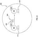
- FIG. 4depicts an embodiment of an actor system implemented in the system of FIG. 1 in accordance with some embodiments of the present technology
- FIG. 5depicts another embodiments of actor systems implemented in the system of FIG. 1 in accordance with some embodiments of the present technology.
- FIG. 6depicts a block diagram of a method for transmitting a message being implemented in accordance with non-limiting embodiments of the present technology.
- FIG. 1there is depicted a distributed computer-processing system 100 or a “distributed processing system” 100 , for short.
- the distributed processing system 100is configured for implementing non-limiting embodiments of the present technology. It is to be expressly understood that the distributed processing system 100 as depicted is merely an illustrative implementation of the present technology. Thus, the description thereof that follows is intended to be only a description of illustrative examples of the present technology. This description is not intended to define the scope or set forth the bounds of the present technology.
- the distributed processing system 100may provide in certain instances simple implementations of the present technology, and that where such is the case they have been presented in this manner as an aid to understanding. As persons skilled in the art would understand, various implementations of the present technology may be of a greater complexity.
- the distributed processing system 100comprises a request source 102 , a communication network 103 , a request pre-processing sub-system 104 , a transaction processing sub-system 105 , a transaction routing sub-system 106 , a distributed storage sub-system 108 , a database sub-system 110 , and an operational sub-system 111 .
- the request source 102may be an electronic device associated with an end user (e.g., a client device) or, alternatively, any other sub-system of the distributed processing system 100 that is configured to provide user requests for the distributed processing system 100 . It should be expressly understood that even though FIG. 1 depicts only a single instance of the request source 102 , the distributed processing system 100 may have multiple instances of the request source 102 . As illustrated herein, the request source 102 is part of the distributed processing system 100 ; however, in some embodiments of the present technology, the request source 102 may be external to the distributed processing system 100 , and connected via a communication link (not numbered).
- a typical implementation of the distributed processing system 100can include a large number of request sources 102 , such as hundred instances, thousand instances, million instances, and the like.
- the request source 102may be a given client device, such as a smartphone, for example, associated with a given user of the distributed processing system 100 .
- the distributed processing system 100may potentially provide cloud storage services for the given client device of the given user.
- the request source 102may be a given sub-system, such as a remote server, for example, providing user requests to the distributed processing system 100 .
- the distributed processing system 100may provide fault-tolerant data processing and/or storage services for an operator of the given sub-system.
- the request source 102may be a given client device or another sub-system which can be internal or external to the distributed processing system 100 .
- the request source 102is configured to issue a plurality of requests 180 , each of which will be referred herein below as the request 180 .
- the nature of the request 180will depend on a type of the request source 102 .
- one example of the request 180is a query expressed in Structured Query Language (SQL). Therefore, it is contemplated that in some embodiments of the present technology, the request 180 may be expressed in a declarative programming language, which means that the request 180 may be a declarative-type request.
- SQLStructured Query Language
- declarative programmingis a style of building a structure and elements of computer programs that expresses the logic of a computation without describing a control flow thereof.
- Common declarative programming languagesinclude, but are not limited to, SQL, XQuery and other database query languages.
- a declarative-type requestis one that specifies an action in terms of “what” needs to be executed, as opposed to how “how” it needs to be executed.
- a given declarative-type requestmay be associated with a given condition under which a given action should be executed.
- the given conditionmay be, for example, a condition on which entity the given action is to be executed or where to obtain values for the given action to be executed.
- the given declarative-type requestcan be formulated such as: “Upsert a value of 5 in a cell associated with a key that is equal to a value of a cell associated with a key A” and “For all keys associated with a cell having a value of 5, replace that value with a value 10”.
- examples of declarative languages and examples of declarative-type requestshave been provided above for ease of illustration only, and that other declarative languages and other declarative-type requests may be used by the request source 102 , without departing from the scope of the present technology.
- the request source 102is also configured to receive a plurality of responses 181 , each of which will be referred herein below as the response 181 .
- the distributed processing system 100may generate the response 181 destined to the request source 102 associated with the respective request 180 .
- the nature of the response 181will depend on inter alia a type of the request source 102 , the type of the respective request 180 and whether the distributed processing system 100 processed (or potentially not processed) the respective request 180 .
- the distributed processing system 100may generate the response 181 only in case of a failure to process the request, only in case of a successful processing of the request, or both.
- the distributed processing system 100may be configured to request additional data from the request source 102 for continuing or completing processing of the request 180 .
- the distributed processing system 100may be configured to generate the response 181 in a form of a data-request message being indicative of additional data requested by the distributed processing system 100 for continuing or completing the processing of the request 180 .
- the distributed processing system 100may be configured to generate the response 181 in a form of a success message being indicative of successful processing of the respective request 180 .
- the distributed processing system 100may be configured to generate the response 181 in a form of a failure message being indicative of failed processing of the respective request 180 .
- the request source 102may be configured to perform additional actions such as, but not limited to, re-issuing the request 180 , performing diagnostic analyzes for identifying the reason of failed processing of the request 180 by the distributed processing system 100 , issuing a new request destined to the distributed processing system 100 , and the like.
- the request source 102is communicatively coupled to the communication network 103 for providing the request 180 to the distributed processing system 100 and for receiving the response 181 from the distributed processing system 100 .
- the communication network 103can be implemented as the Internet.
- the communication network 103can be implemented differently, such as any wide-area communication network, local-area communication network, a private communication network and the like. How a communication link (not separately numbered) between the request source 102 and the communication network 103 is implemented will depend on inter alia how the request source 102 is implemented.
- the communication linkcan be implemented as a wireless communication link (such as but not limited to, a 3G communication network link, a 4G communication network link, Wireless Fidelity, or WiFi® for short, Bluetooth® and the like).
- the communication linkcan be either wireless (such as Wireless Fidelity, or WiFi® for short, Bluetooth® or the like) or wired (such as an Ethernet based connection).
- the communication network 103is configured to transmit inter alia a request data-packet comprising the request 180 from the request source 102 to the request pre-processing sub-system 104 of the distributed processing system 100 .
- this request data-packetmay comprise computer-executable instructions written in a given declarative-type programming language which represent the request 180 .
- the communication network 103is also configured to transmit inter alia a response data-packet comprising the response 181 from the distributed processing system 100 to the request source 102 .
- this response data-packetmay comprise computer-executable instructions representing the response 181 .
- the communication network 103may be implemented in a different manner from what is described above or, in some cases, may even be omitted, without departing from the scope of the present technology.
- the distributed processing system 100comprises the operational sub-system 111 , or simply “the hive”, for short.
- the hive 111is a given software-based application (for example, a state machine) that is configured to manage at least some sub-systems of the distributed processing system 100 , such as the request pre-processing sub-system 104 , and the transaction processing sub-system 105 , for example.
- the hive 111may be embodied as a given State Machine (SM) that is configured to generate, delete and/or balance load of other SMs forming the at least some sub-systems of the distributed processing system 100 .
- SMState Machine
- a given SMis a computational model employed by computer systems and which is defined by a list of “states”.
- the given SMmay change its current state in response to some external input and may be in exactly one state at any given moment in time.
- a change from a given state to another state of the given SMis called a “state transition”.
- the SMs forming the at least some sub-systems of the distributed processing system 100are deterministic in nature, that is, each state transition of each such SM is uniquely determined by (i) a current state of a respective SM and (ii) a given external input provided to the respective SM. In other words, for a given current state of the respective SM and for a given external input, there is a unique next state of the respective SM. This deterministic nature of the state transition is true irrespective of which SM of the distributed processing system 100 is undergoing the state transition.
- the distributed processing system 100may need to receive external inputs of a particular type that satisfy this deterministic property of the SMs of the at least some sub-systems of the distributed processing system 100 .
- the distributed processing system 100also comprises the distributed storage sub-system 108 .
- the distributed storage sub-system 108is configured to inter alia store “system data” indicative of states, state transitions, external inputs and/or outputs of at least some of the SMs of the distributed processing system 100 .
- system data associated with a given SM of the distributed processing system 100may be stored in a form of a log, and where the log is indicative of a historical listing of states, state transitions, external inputs and/or outputs of the given SM.
- the distributed storage sub-system 108is also configured to store “client data”—i.e. data associated with the processed external inputs by the distributed processing system 100 .
- client datamay be stored as part of the system data in the distributed storage sub-system 108 without departing from the scope of the present technology.
- the distributed storage sub-system 108comprises a plurality of storage devices 112 , each of which will be referred herein below as the storage device 112 .
- the plurality of storage devices 112can be located in a single location or distributed amongst different locations.
- some or all of the plurality of storage devices 112can be located in a single server rack and/or a single data center and/or distributed over a plurality of server racks in one or more data centers.
- the system data and/or the client data stored by a given storage device 112may be replicated and stored on more than one other storage devices 112 .
- replication and storing of the system data and/or the client datamay result in a fault-tolerant storage of the system data and/or the client data by the distributed processing system 100 .
- Fault-tolerant storage of the system data and/or the client datamay allow preventing data loss in cases where a given storage device 112 of the distributed storage sub-system 108 becomes, temporarily or permanently, unavailable for storage and data retrieval purposes.
- this fault-tolerant storage of the system data and/or the client datamay allow preventing data loss in cases where a given SM of the distributed processing system 100 becomes, temporarily or permanently, unavailable.
- the storage device 112may be implemented as a computer server.
- the computer servercomprises at least one physical memory device (i.e. a memory drive 126 ) and hosts one or more software applications configured to execute computer-readable instructions.
- the memory drive 126can be executed as solid state drive (SSD), hard disk drive (HDD), or the like. Therefore, it can be said that the at least one physical memory device can be implemented as either a movable disk type device or a immovable (static) disk type device.
- a given storage device 112may be configured to host software applications, such as, but not limited to: (i) a virtual-drive (Vdrive) application 114 , a physical-drive (Pdrive) application 115 , at least one drive model application 118 , at least one operation scheduling application 120 , a real-time operation enforcing application 122 , and at least one SM proxy 124 .
- Vdrivevirtual-drive
- Pdrivephysical-drive
- the transaction processing sub-system 105may be formed by a number of deterministic SMs that require receiving external inputs of a particular type and which satisfy the deterministic property of the deterministic SMs. It should also be recalled that the request source 102 issues the request 180 in a form of a declarative-type request.
- the request pre-processing sub-system 104is configured to receive the request 180 , which is the declarative-type request originated from the request source 102 , and to pre-process/translate the request 180 into a plurality of deterministic transactions 182 that satisfy the deterministic property of the number of deterministic SMs forming the transaction processing sub-system 105 .
- the purpose of the request pre-processing sub-system 104is to ensure that the transaction processing sub-system 105 is able to process the request 180 by pre-processing/translating the request 180 into a plurality of transactions that are processable by the deterministic SMs of the transaction processing sub-system 105 .
- the request pre-processing sub-system 104is also configured to generate the response 181 to be transmitted to the request source 102 .
- the request pre-processing sub-system 104is communicatively coupled to the transaction processing sub-system 105 , not only to transmit thereto the plurality of deterministic transactions 182 , but also to receive therefrom information regarding processing of the plurality of deterministic transaction 182 .
- the plurality of deterministic transactions 182can be of one or more of any of a “write” type and a “read” type.
- the request pre-processing sub-system 104is implemented as at least one SM, without departing from the scope of the present technology.
- the distributed computer-processing system 100 of FIG. 1may support ACID transactions.
- ACIDatomicity, consistency, isolation and durability
- transactions destined to the transaction processing sub-system 105may be atomical, consistent, isolated and durable, without departing from the scope of the present technology.
- the transaction processing sub-system 105is configured to receive and process the plurality of deterministic transactions 182 , thereby processing the request 180 of the request source 102 .
- the transaction processing sub-system 105includes (i) the transaction routing sub-system 106 and (ii) the database sub-system 110 , which will now be described in turn.
- the database sub-system 110includes a plurality of transaction destination locations (TDLs) and is partitioned into a plurality of shards 109 , each of which will be referred herein below as the shard 109 .
- the database sub-system 110may host a database having a given database table (or more than one).
- the given database tablemay be composed of at least two columns, such as a first column having keys and a second column having records that store data in association with the respective keys.
- a given TDLmay correspond to a given row of the given database table, that is, the given TDL may correspond to a given key and a respective record in the given database table.
- each shard 109 of the database sub-system 110hosts a portion of the given database table.
- the given plurality of TDLscorresponding to the respective rows of the given database table, is split between the plurality of shards 109 such that each shard 109 comprises a respective subset (e.g. range) of the given plurality of TDLs.
- each one of the plurality of shards 109may be implemented by a respective deterministic SM. This means that, upon receiving a given transaction destined to a TDL of a given shard 109 implemented by a given SM, the given SM may process the transaction and thereby transition to a new state thereof from a current state thereof based on the given transaction, as explained above.
- the transaction routing sub-system 106is configured to route transactions from the plurality of deterministic transaction 182 to respective transaction destination locations TDLs and, therefore, to the respective shards 109 of the database sub-system 110 .
- the transaction routing sub-system 106may be formed by a plurality of ports that are generally configured to (i) receive the plurality of deterministic transactions 182 from the request pre-processing sub-system 104 , (ii) order the plurality of deterministic transactions 182 into subsets of deterministic transactions destined to respective shards 109 , and (iii) generate centralized per-shard orders for execution by the respective shards 109 of the deterministic transactions in each one of the centralized per-shard orders of execution.
- each one of the plurality of ports forming the transaction routing sub-system 106may be implemented as a respective SM.
- the plurality of portsmay comprise two different types of ports for routing transactions from the plurality of deterministic transactions 182 to the respective shards 109 .
- at least some functionalities of the plurality of portsmay be executed by the SMs corresponding to the plurality of shards 109 .
- SMs of the transaction processing sub-system 105may be communicatively coupled to the distributed storage sub-system 108 by a respective communication link 160 .
- a given communication link 160is to convey system data indicative of inter alia states, state transitions, external inputs and/or outputs of respective SMs to the distributed storage sub-system 108 for storage thereof. How the communication links 160 are established and how the distributed storage sub-system 108 is configured to store the system data will now be described in greater detail with reference to FIG. 2 .
- the storage device 112which is part of the distributed storage sub-system 108 .
- the storage device 112comprises the at least one SM proxy 124 .
- the purpose of a given SM proxyis to manage communication between a given SM and the distributed storage sub-system 108 .
- the at least one SM proxy 124 of the storage device 112may be an Application Programing Interface (API) managing communication between a given SM and the storage device 112 .
- APIApplication Programing Interface
- the at least one SM proxy 124itself can be implemented as a SM.
- the at least one SM proxy 124can be implemented as a software module (not in itself a SM) for executing functions described immediately above.
- a given SM proxy 124may be configured to (i) receive system data indicative of a log update of a given SM via a respective communication link 160 , (ii) process the system data, and (iii) transmit the processed system data to a respective Vdrive application 114 for further processing.
- the at least one SM proxy 124may be configured to process the system data, for example, for ensuring consistency and fault-tolerance of the system data. It is contemplated that the at least one SM proxy 124 may be configured to perform erasure-coding of system data, in some embodiments of the present technology. Broadly speaking, erasure-coding is an encoding method in which data is provided with redundancy and is then split into several fragments. Such redundancy provision and fragmentation may facilitate restoration of data if one ore more fragments are lost due to faults in a given system.
- the so-processed system data by the at least one SM proxy 124is received by the at least one respective Vdrive application 114 of the storage device 112 .
- the purpose of a given Vdrive application 114is to process the system data received from the at least one SM proxy 124 and, in response, generate corresponding I/O operations that are to be executed by the memory drive 126 for storing the system data on the memory drive 126 of the storage device 112 .
- the at least one Vdrive application 114generates the I/O operations corresponding to the system data received thereby, the at least one Vdrive application 114 then transmits the I/O operations to the Pdrive application 116 .
- a given storage device 112may have more than one SM proxies 124 for processing and transmitting system data to more than one respective Vdrive application 114 , which in turn process the system data, generate respective I/O operations, and transmit the respective I/O operations to a single Pdrive application 116 of the storage device 112 .
- the purpose of the Pdrive application 116is to control operation of the memory drive 126 .
- the Pdrive application 116may be configured to perform encoding of I/O operations to be executed on the memory drive 126 and various other functionalities that facilitate reliable storage of data on the memory drive 126 .
- the Pdrive application 116is commutatively coupled to the operation scheduling application 120 to transmit thereto the I/O operations.
- the operation scheduling application 120is configured for scheduling the transmission of the I/O operations to the memory drive 126 . It is contemplated that the operation scheduling application 120 , or simply “scheduler” for short, may execute various scheduling schemes for determining an order in which the I/O operations are to be transmitted to the memory drive 126 for further execution.
- the operation scheduling application 120may be implemented as part of the Pdrive application 116 .
- execution of various scheduling schemesmay be performed by the Pdrive application 116 , without departing from the scope of the present technology.
- the operation scheduling application 120may provide a hybrid scheduling scheme.
- the operation scheduling application 120may provide a scheduling scheme that is of a “fair” type and, under certain conditions, is also of a “real-time” type.
- a given storage device 112may require to store I/O operations corresponding to system data associated with more than one SMs.
- each one of the more than one SMsis associated with a pre-determined proportion of drive bandwidth that the memory drive 126 may allocate for executing the I/O operations associated with that respective SM. Therefore, broadly speaking, fair-type scheduling schemes are configured to order the I/O operations to be transmitted to the memory drive 126 such that the drive bandwidth of the memory drive 126 for executing the ordered I/O operations is used in accordance with the pre-determined proportions associated with the more than one SMs.
- the distributed processing system 100may be employed for providing cloud storage services.
- the I/O operationsmay be associated with respective deadlines that are indicative of a moment in time after which the execution of the respective I/O operations is no longer performed within an acceptable amount of time for supporting real-time requirements of the distributed processing system 100 . Therefore, broadly speaking, real-time scheduling schemes are configured to order the I/O operations to be transmitted to the memory drive 126 such that the I/O operations are to be executed by the memory drive 126 within respectively associated deadlines.
- the operation scheduling application 120may provide a hybrid scheduling scheme that is able to order the I/O operations for transmission of the memory drive 126 for execution such that the pre-determined proportions of drive bandwidth for each respective SM is respected and that respective deadlines of the I/O operations are also respected.
- the memory drive 126is a storage medium for executing I/O operations and thereby storing system data transmitted to the storage device 112 .
- the memory drive 126may be implemented as an HDD or an SSD.
- the memory drive 126includes a drive-internal logic 250 for selecting a given I/O operation for current execution amongst all I/O operations transmitted thereto.
- I/O operationsmay potentially be sent one-by-one for execution to the memory drive 126 , but this would result in an increased latency between the memory drive 126 and other components of the storage device 112 . Therefore, the I/O operations may also be transmitted in batches or groups of I/O operations to the memory drive 126 . Once a batch or group of I/O operations is received by the memory drive 126 , the drive-internal logic 250 is configured to select amongst the I/O operations available thereto (from the batch) a most efficient I/O operation for execution.
- the most efficient I/O operationmay be selected based on a variety of criteria such as, for example, a location where a previous I/O operation has been executed on the memory drive 126 and locations of the I/O operations available to the memory drive 126 where they are ought to be executed on the memory drive 126 .
- the drive-internal logic 250is configured to select, for a current execution, a most efficient one (from the perspective of the memory drive 126 ) amongst all the I/O operations available to the memory drive 126 at a given moment in time.
- the operation scheduling application 120may have ordered I/O operations in a specific order of transmission for respecting the real-time requirements of the distributed processing system 100
- the drive-internal logic 250 of the memory drive 126may instruct the memory drive 126 to organize them in an execution order that is different from the transmission order selected by the operation scheduling application 120 .
- the execution ordermay no longer respect the real-time requirements of the distributed processing system 100 (especially as additional I/O operations are received from the operation scheduling application 120 , which additional I/O operations may be more “efficient” from the perspective of the memory drive 126 and that may be picked over non-yet-executed I/O operations).
- the storage device 112may include the real-time operation enforcing application 122 .
- the real-time operation enforcing application 122allows controlling which I/O operations amongst those that have been already ordered by the operation scheduling application 120 are transmitted at any given time to the memory drive 126 for execution.
- the real-time operation enforcing application 122may be implemented as part of the Pdrive application 116 .
- the above-mentioned functionalities of the real-time operation enforcing application 122may be performed by the Pdrive application 116 , without departing from the scope of the present technology.
- the storage device 112is also configured to host at least one respective drive model application 118 for each memory drive 126 of the storage device 112 .
- the drive model application 118is configured to emulate ideal operation of the memory drive 126 for diagnostic analyses of the memory drive 126 .
- the operation scheduling application 120may also be configured to employ the drive model application 118 for ordering the I/O operations for transmission to the memory drive 126 .
- the at least one respective drive model application 118may be implemented as part of the Pdrive application 116 .
- the above-mentioned functionalities of the at least one respective drive model application 118may be performed by the Pdrive application 116 , without departing from the scope of the present technology.
- a conventional actor system 300is depicted a conventional actor system 300 .
- Actor systemsare typically implemented for performing distributed processing of data.
- the conventional actor system 300comprises a first actor 302 and a second actor 304 .
- the first actor 302 and the second actor 304are sometime referred to as “processing units” of the conventional actor system 300 which are created/launched for processing data in a distributed manner.
- a given actor (such as one of the first actor 302 and the second actor 304 ) in the conventional actor system 300may be configured to inter alia send a message to other actors, and designate how messages received thereby are to be handled.
- the first actor 302may be configured to send a message 350 to the second actor 304
- the second actor 304may designate how the message 350 received thereby is to be handled.
- the first actor 302 and the second actor 304may have respective addresses for communication purposes.
- the first actor 302has a first address 312
- the second actor 304has a second address 314 .
- the first actor 302has knowledge of the second address 314 of the second actor 304 .
- a given address of a given actormay be indicative of whether the given actor is a local actor or otherwise a remote/external actor.
- the second address 314 of the second actor 304comprises information that is indicative of that the second actor 304 is a local actor—that is, that the second actor 304 is part of the same actor system (i.e., the conventional actor system 300 ) as the first actor 302 .
- the second address 314may comprise information indicative that the second actor 304 is a remote/external actor—that is, that the second actor 304 and the first actor 302 are part of different actor systems.
- the first actor 302 and the second actor 304also have respective mailboxes for communication purposes.
- the first actor 302has a first mailbox 322
- the second actor 304has a second mailbox 324 .
- the purpose of a given mailboxis to serve as a message processing queue for messages received by the respective actor.
- the first mailbox 322may be used as a message processing queue for messages received by the first actor 302
- the second mailbox 324may be used as a message processing queue for messages received by the second actor 304 .
- Messages in a given mailboxmay be processed by a respective actor in a First-In-First-Out (FIFO) order, for example.
- FIFOFirst-In-First-Out
- Each actor in the conventional actor system 300has a respective “state” that can be modified based on information received through a message from another actor.
- the second actor 304has a given current state.
- the message 350comprises payload data indicative of information to be provided from the first actor 302 to the second actor 304 .
- the second actor 304can process the message 350 and can transition into a new given state based on (i) the given current state thereof and (ii) the payload data of the message 350 .
- actorsare implemented with timeout mechanisms for ensuring that messages sent thereby are processed and, if not, to trigger remedial actions with regard to those messages. For example, when the first actor 302 sends the message 350 to the second actor 304 , the first actor 302 , in a sense, “expects” a notification from the second actor 304 , within a pre-determined timeout interval, indicative of that the message 350 has been processed by the second actor 304 .
- the message 350is considered as being successfully processed by the second actor 304 .
- a remedial actionmay include re-sending the message 350 to the second actor 304 , sending the message 350 to another actor, and the like.
- a variety of reasonsmay cause a non receipt of the notification by the first actor 302 within the pre-determined timeout interval.
- the second mailbox 324 of the second actor 304may be full (or almost full) so that the pre-determined timeout interval expires before the second actor 304 gets to the message 350 amongst all the messages in the second mailbox 324 .
- the second actor 304may be down (“dead”) or otherwise unresponsive. As such, the first actor 302 does not receive the notification since the message 350 has not been successfully received by the second actor 304 .
- a communication link between the respective actor systems of the first actor 302 and of the second actor 304may not be functional.
- the message 350may not be successfully sent to the second actor 304 , and therefore, the second actor 304 does not issue the notification.
- the first actor 302 of the conventional actor system 300is configured to wait until the pre-determined timeout interval expires before triggering a remedial action with regard to the message 350 .
- This “waiting” performed by the first actor 302is undesirable, since it introduces delays in the distributed processing of data by the conventional actor system 300 .
- methods and systems of the present technologyenable determining that (i) a given message has not been successfully received by a destination actor (e.g., that the destination actor is “dead” or unresponsive), and/or (ii) a communication link between the departure actor and the destination actor is not functional, and that, without waiting for a pre-determined timeout interval to expire.
- actorsmay generate messages in a particular manner that may allow actor systems, and/or actors within actor systems, to keep track of message deliveries and communication sessions established between actors.
- actor systems, and/or actors within actor systemsmay identify issues with message deliveries and communication sessions, without having the departure actor to wait for a pre-determined timeout interval to expire, in order to cause remedial actions to be performed.
- the actor system 400comprises a first actor 402 and a second actor 404 .
- the first actor 402has a first address 412 and a first mailbox 422
- the second actor 404has a second address 414 and a second mailbox 424 .
- the first actor 402may be implemented as a first given port of the transaction routing sub-system 106 (see FIG. 1 ), while the second actor 404 may be implemented as a second given port of the transaction routing sub-system 106 .
- the first actor 402 and the second actor 404may be implemented as respective SMs (or respective virtual machines).
- the actor system 400may comprise a supervisory actor (not depicted), in addition to the first actor 402 and the second actor 404 .
- the purpose of this supervisory actoris to boot or “launch” actors of the actor system 400 when needed. For example, if a given actor of the actor system 400 is down, the supervisory actor of the actor system 400 may be tasked with launching another actor for replacing the given actor that is down.
- the first actor 402is configured to send a message 450 to the second actor 404 for processing.
- the first actor 402is configured to generate the message 450 in a specific manner, which is implemented in accordance with the non-limiting embodiments of the present technology.
- the first actor 402 of the actor system 400is configured to generate the message 450 such that the message 450 includes a first trigger 460 , in addition to the payload data.
- the first trigger 460is instrumental in triggering verification of whether the second actor 404 has successfully received the message 450 .
- the first trigger 460may trigger the actor system 400 (actor system of the destination actor) to verify whether the second actor 404 has successfully received the message 450 .
- the message 450may be generated by the first actor 402 so as to include a first trigger field (not depicted) that includes the first trigger 460 in a form of information that is instrumental in triggering the verification of whether the second actor 404 has successfully received the message 450 .
- the first actor 402is configured to send the message 450 with the first trigger 460 to the second actor 404 .
- the first actor 402may have knowledge of the second address 414 of the second actor 404 .
- the second address 414may be indicative of that the second actor 404 is a local actor—that is, the second actor 404 is part of the same actor system as the first actor 402 (e.g., the actor system 400 ).
- the first actor 402is configured to send the message 450 to the second actor 404 based on the second address 414 .
- the message 450is a given local message. As such, the message 450 may be directly sent (without intermediary actors, for example) from the first actor 402 to the second actor 404 by the actor system 400 .
- the first trigger 460triggers the actor system 400 to verify whether the second actor 404 successfully receives the message 450 . It is contemplated that the actor system 400 may track delivery of the message 450 in response to first trigger 460 .
- the actor system 400may send a notification to first actor 402 indicative of that the message 450 is received by the second actor 404 .
- the message 450may be queued in the second mailbox 424 of the second actor 404 .
- the actor system 400may send a different notification to first actor 402 that instructs the first actor 402 that the message 450 is not received by the second actor 404 .
- the actor system 400may determine that the second actor 404 is “dead” or unresponsive.
- the actor system 400may have access to an actor table that lists all actors that are implemented by the actor system 400 .
- the actor system 400may be configured to “look up” the second actor 404 in that actor table and verify whether the second actor 404 is “dead” or unresponsive. As such, if the second actor 404 is determined to be responsive, the actor system 400 may determine that the second actor 404 successfully received the message 450 . However, if the second actor 404 is determined to be “dead” or unresponsive, the actor system 400 may determine that the second actor 404 has not successfully received the message 450 .
- the triggering of the verification of whether the second actor 404 has successfully received the message 450 by the first trigger 460is performed without waiting for a timeout period.
- the actor system 400is triggered by first trigger 460 of the message 450 to verify whether or not the second actor 404 is “dead” or unresponsive, and that, without waiting for a time period.
- generating messages in the specific manner described hereinmay be performed in combination with timeout period processes that may be performed by actors of a given actor system.
- actorsmay implement timeout period processes, while also generating messages with triggers as described herein.
- this instruction by the actor system 400may cause the first actor 402 to perform a remedial action with regard to the message 450 .
- remedial action performed by the first actor 402may be executed without waiting for a timeout period to expire. This also means that, in some embodiments of the present technology, the remedial action with regard to the message 450 may be triggered and/or performed by the first actor 402 without the first actor 402 having or needing to maintain a timeout period process.
- remedial actionsmay be performed by the first actor 402 with regard to the message 450 if the message 450 is not received by the second actor 404 . Which specific remedial action is performed by the first actor 402 depends on inter alia different implementations of the present technology.
- the first actor 402may implement or otherwise have access to a remedial action algorithm.
- the first actor 402may be configured to, in response to being instructed that the second actor 404 did not received the message 450 , employ the remedial action algorithm for determining which specific remedial action is to be performed.
- the selection of a specific remedial action by the remedial action algorithmmay depend on, but not limited to, the payload data of the message 450 .
- first actor system 500and a second actor system 580 as envisioned in some non-limiting embodiments of the present technology. Both the first actor system 500 and the second actor system 580 are part of a service provision system 501 . It is contemplated that, in some embodiments of the present technology, the service provision system 501 may require actors of the first actor system 500 to communicate (e.g., exchange remote/external messages) with actors from the second actor system 580 .
- the first actor system 500may be implemented as the transaction routing sub-system 106 (see FIG. 1 ), while the second actor system 580 may be implemented as the database sub-system 110 .
- the service provision system 501may be implemented as the transaction processing sub-system 105 , for example.
- the first actor system 500 and the second actor system 580may be communicatively coupled in accordance with a common addressing scheme (e.g., implemented in a common addressing space).
- a common addressing schemee.g., implemented in a common addressing space.
- the addressing schememay be implemented by the service provision system 501 for communication purposes between the first actor system 500 and the second actor system 580 .
- the first actor system 500comprises a first actor 502
- the second actor system 580comprises a second actor 504
- the first actor 502may be a given port of the transaction routing sub-system 106
- the second actor 504may be a given shard 109 of the database sub-system 110 .
- the first actor system 500also comprises a first gateway actor 530
- the second actor system 580also comprises a second gateway actor 540
- gateway actorsare implemented by respective actor systems and are used for communication purposes between actors systems of the service provision system 501 .
- the first actor 502may not send a message 550 directly to the second actor 504 , since the second actor 504 is a remote/external actor.
- the message 550may be routed from the first actor 502 to the second actor 504 via the first gateway actor 530 and the second gateway actor 540 . How the message 550 may be generated and routed from the first actor 502 to the second actor 504 will now be described.
- the first actor 502has a first address 512 and a first mailbox 522
- the second actor 504has a second address 514 and a second mailbox 524 .
- the first actor 502is configured to generate the message 550 that is to be sent to the second address 514 (associated with the second actor 504 ).
- the first actor system 500may determine that the second address 514 is a remote/external address to the first actor system 500 .
- the first actor system 500may determine that the second address 514 is not associated with any actor of its own, but rather that the second address 514 is a given address of within the second actor system 580 .
- the first actor system 500may be configured to send the message 550 from the first actor 502 to the first gateway actor 530 .
- the first gateway actor 530maintains a communication link 590 with the second gateway actor 540 .
- the communication link 590enables communication between actors of the first actor system 500 and actors of the second actor system 580 . In other words, messages between actors of the first actor system 500 and actors of the second actor system 580 are exchanged via the communication link 590 .
- the first gateway actor 530may send the message 550 via the communication link 590 to the second gateway actor 540 .
- the second gateway actor 540may be configured to determine that the message 550 is destined to the second address 514 . As such, the second actor system 580 may send the message 550 from the second gateway actor 540 to the second actor 504 based on the second address 514 .
- the message 550may include payload data to be provided by the first actor 502 to the second actor 504 , as well as a first trigger 560 and a second trigger 570 .
- the purpose and functionality of the first trigger 560 and of the second trigger 570will now be described in turn.
- the purpose of the first trigger 560is to trigger verification of whether the second actor 504 successfully receives the message 550 .
- the first trigger 560triggers the second actor system 580 (the actor system of the destination actor being the second actor 504 ) to verify whether the second actor 504 successfully receives the message 550 .
- the second actor system 580may instruct the first actor 502 that the message 550 is not received by the second actor 504 .
- the second actor system 580may instruct the second gateway actor 540 to generate a notification on behalf of the second actor 504 indicative of the message 550 not having been received by the second actor 504 , and send this notification back to the first gateway actor 530 via the communication link 590 , and from which this notification is sent by the first actor system 500 to the first actor 502 .
- a notification indicative of that the message 550 is received by the second actor 504may be sent from the second gateway actor 540 to the first gateway actor 530 and then to the first actor 502 .
- the purpose of the second trigger 570is to trigger verification of whether communication is established between the first actor 502 and the second actor 504 .
- the second trigger 570triggers the first gateway actor 530 to verify whether the communication link 590 is established and functional.
- the first gateway actor 530may be configured to employ a pining-type mechanism with the second gateway actor 540 in order to keep track of whether the communication link 590 is functional.
- the first gateway actor 530may be configured to employ a TCP/IP-type mechanism with the second gateway actor 540 in order to keep track of whether the communication link 590 is functional. Which specific mechanism the first gateway actor 530 may employ for verifying whether the communication link 590 is functional may depend on inter alia how lower layers of the service provision system 501 are implemented.
- the first gateway actor 530may store information regarding messages that have been received thereby for external transmission to external actor systems (such as the second actor system 580 ). For example, when the message 550 is received by the first gateway actor 530 , the first gateway actor 530 may store information regarding the first address 512 of the first actor 502 that generated the message 550 and the second address 514 of the second actor 504 that is to receive the message 550 .
- the first gateway actor 530may send the message 550 to the second gateway actor 540 .
- the first gateway actor 530may keep track of whether the communication link 590 is functional while and/or after sending the message 550 . If the first gateway actor 530 determines that communication link 590 is not functional, the first gateway actor 530 may send a notification to the first actor 502 (based on the information that has been stored when the message 550 was received by the first gateway actor 530 ) instructing the first actor 502 that the message 550 is not received by the second actor 504 .
- a method 600 depicted in FIG. 6may be performed by one or more actor systems. The method 600 will now be described in greater details.
- Step 602Generating, by the First Actor of the Actor System, the Message, the Message Including (i) Payload Data Indicative of Information to be Provided by the First Actor to the Second Actor, and (ii) a First Trigger for Triggering Verification of Whether the Second Actor has Successfully Received the Message
- the method 600begins at step 602 with a first actor of an actor system generating a message. Let's take the example of the first actor 402 of the actor system 400 depicted in FIG. 4 .
- the message 450is to be transmitted from the first actor 402 to the second actor 404 .
- the first actor 402 and the second actor 404may be implemented as respective SMs. Also, in other embodiments of the present technology, the actor system 400 may be implemented in the distributed computer system 100 (see FIG. 1 ).
- the message 450is generated by the first actor 402 such that the message 450 includes (i) payload data indicative of information to be provided by the first actor 402 to the second actor 404 , and (ii) a first trigger 460 for triggering verification of whether the second actor 404 has successfully received the message 450 .
- the actor system 400may be configured to identify whether the message 450 is a local message or a remote/external message.
- the actor system 400may identify the message 450 as being a local message because the message 450 is to be transmitted between the first actor 402 and the second actor 404 which are both part of the actor system 400 .
- a given message to be transmittedmay be generated such that it further includes a second trigger.
- the message 550includes the second trigger 570 for triggering verification of whether a communication link is maintained between the first actor 502 and the second actor 504 .
- the first actor system 500may identify the message 550 as being a remote/external message because the message 550 is to be transmitted between the first actor 502 and the second actor 504 which are not part of a same actor system—that is, the first actor 502 is part of the first actor system 500 , while the second actor 504 is part of the second actor system 580 .
- the first actor system 500 and the second actor system 580may be executed on respective different computer devices of the distributed computer system 100 (see FIG. 1 ).
- the first actor system 500 and the second actor system 580may be implemented on different storage devices 112 .
- Step 604Sending, by the First Actor, the Message to the Second Actor
- the method 600continues to step 604 with the first actor sending the message to the second actor.
- the first actor 402may send the message 450 to the second actor 404 .
- the message 450may be transmitted by the actor system 400 from the first actor 402 to the second actor 404 .
- the message 450may be directly sent from the first actor 402 to the second actor 404 .
- the message 450may be directly transmitted by actor system 400 from the first actor 402 to the second actor 404 without the message 450 being received by intermediary actors.
- the message 550is a remote/external message.
- the first actor system 500has the first gateway actor 530 and the second actor system 580 has the second gateway actor 540 .
- the first gateway actor 530 and the second gateway actor 540are configured to transmit messages between the first actor system 500 and the second actor system 580 .
- the first gateway actor 530 and the second gateway actor 540may be implemented as respective SMs.
- the first actor 502 and the second actor 504may be implemented as SMs of a first type, while the first gateway actor 530 and the second gateway actor 540 may be implemented as SMs of a second type.
- the SMs of the first typemay not have access to communication protocols executed between the first actor system 500 and the second actor system 580 .
- the SMs of the second typemay have access to communication protocols executed between the first actor system 500 and the second actor system 580 .
- sending the message 550may comprise (i) sending the message 550 from the first actor 502 to the first gateway actor 530 (for example, the first actor system 500 may transmit the message 550 from the first actor 502 to the first gateway actor 530 ), (ii) sending the message 550 by the first gateway actor 530 to the second gateway actor 540 (for example, via the communication link 590 ), and (iii) sending the message 550 by the second gateway actor 540 to the second actor 504 (for example, the second actor system 580 may transmit the message 550 from the second gateway actor 540 to the second actor 504 ).
- Step 606In Response to Determining, by the Actor System in Response to the First Trigger, that the Second Actor has not Successfully Received the Message, Instructing, by the Actor System, the First Actor that the Message is not Received by the Second Actor
- the method 600ends at step 606 with the actor system, in response to determining that the second actor has not successfully received the message, instructing the first actor that the message is not received by the second actor.
- the actor system 400In response to determining, by the actor system 400 in response to the first trigger 460 , that the second actor 404 has not successfully received the message 450 , the actor system 400 is configured to instruct the first actor 402 that the message 450 is not received by the second actor 404 .
- this instruction by the actor system 400may be executed further in response to directly sending the message 450 from the first actor 402 to the second actor 404 .
- actor system 400may determine in response to the first trigger 460 that the second actor 404 is dead or otherwise unresponsive and, as such, has not successfully received the message 450 sent thereto.
- this instruction by the actor system 400may cause the first actor 402 to take a remedial action in regard to the message 450 . It is contemplated that the remedial action may be executed (i) without waiting for a timeout period to expire and/or (ii) without the first actor 402 having to maintain a timeout period process.
- the first actor 502may be instructed that the message 550 is not received by the second actor 504 in response to at least one of (i) determining, in response to the first trigger 560 , that the second actor 504 has not successfully received the message 550 , and (ii) determining, in response to the second trigger 570 , that the communication link between the first actor 502 and the second actor 504 is not functional.
- the determination that the second actor 504 has not successfully received the message 550may comprise determining, by the second gateway actor 540 , that the second actor 504 has not received the message 550 . It is contemplated that the second actor system 580 may determine that the second actor is dead or otherwise unresponsive and, as such, may determine and notify the second gateway actor 540 that the second actor 504 has not successfully received the message 550 .
- the determination that the communication link between the first actor 502 and the second actor 504 is not functionalmay comprise determining by the first gateway actor 530 , that the communication link 590 between the first gateway actor 530 and the second gateway actor 540 is not functional.
- the first gateway actor 530may execute at least one of (i) a pinging-type mechanism, and (ii) a TCP/IP-type mechanism.
- triggers included in messagesmay be generated by departure/sending actors.
- a departure/sending actormay generate a given first trigger if the message is determined (e.g., by the respective actor system) to be a local message.
- the departure/sending actormay generate a given first trigger and a given second trigger if the message is determined (e.g., by the respective actor system) to be a remote/external message.
- triggersmay be generated by other entities than the departure/sending actor.
- at least one of a given first trigger and a given second triggermay be generated by the respective actor system of the departure/sending actor and then added to the message.
- a given second triggermay be generated by a given first gateway actor of a same actor system as the departure/sending actor and then added to the message.
Landscapes
- Engineering & Computer Science (AREA)
- Computer Networks & Wireless Communication (AREA)
- Signal Processing (AREA)
- Computer Security & Cryptography (AREA)
- Software Systems (AREA)
- Theoretical Computer Science (AREA)
- Physics & Mathematics (AREA)
- General Engineering & Computer Science (AREA)
- General Physics & Mathematics (AREA)
- Computer And Data Communications (AREA)
Abstract
Description
Claims (30)
Applications Claiming Priority (3)
| Application Number | Priority Date | Filing Date | Title |
|---|---|---|---|
| RURU2019103253 | 2019-02-06 | ||
| RU2019103253 | 2019-02-06 | ||
| RU2019103253ARU2746042C1 (en) | 2019-02-06 | 2019-02-06 | Method and the system for message transmission |
Publications (2)
| Publication Number | Publication Date |
|---|---|
| US20200252761A1 US20200252761A1 (en) | 2020-08-06 |
| US11184745B2true US11184745B2 (en) | 2021-11-23 |
Family
ID=71836873
Family Applications (1)
| Application Number | Title | Priority Date | Filing Date |
|---|---|---|---|
| US16/776,011ActiveUS11184745B2 (en) | 2019-02-06 | 2020-01-29 | Actor system and method for transmitting a message from a first actor to a second actor |
Country Status (2)
| Country | Link |
|---|---|
| US (1) | US11184745B2 (en) |
| RU (1) | RU2746042C1 (en) |
Families Citing this family (9)
| Publication number | Priority date | Publication date | Assignee | Title |
|---|---|---|---|---|
| RU2718215C2 (en) | 2018-09-14 | 2020-03-31 | Общество С Ограниченной Ответственностью "Яндекс" | Data processing system and method for detecting jam in data processing system |
| RU2731321C2 (en) | 2018-09-14 | 2020-09-01 | Общество С Ограниченной Ответственностью "Яндекс" | Method for determining a potential fault of a storage device |
| RU2721235C2 (en) | 2018-10-09 | 2020-05-18 | Общество С Ограниченной Ответственностью "Яндекс" | Method and system for routing and execution of transactions |
| RU2714602C1 (en) | 2018-10-09 | 2020-02-18 | Общество С Ограниченной Ответственностью "Яндекс" | Method and system for data processing |
| RU2711348C1 (en) | 2018-10-15 | 2020-01-16 | Общество С Ограниченной Ответственностью "Яндекс" | Method and system for processing requests in a distributed database |
| RU2714373C1 (en) | 2018-12-13 | 2020-02-14 | Общество С Ограниченной Ответственностью "Яндекс" | Method and system for scheduling execution of input/output operations |
| RU2749649C2 (en) | 2018-12-21 | 2021-06-16 | Общество С Ограниченной Ответственностью "Яндекс" | Method and system for scheduling processing of i/o operations |
| RU2720951C1 (en) | 2018-12-29 | 2020-05-15 | Общество С Ограниченной Ответственностью "Яндекс" | Method and distributed computer system for data processing |
| RU2746042C1 (en)* | 2019-02-06 | 2021-04-06 | Общество С Ограниченной Ответственностью "Яндекс" | Method and the system for message transmission |
Citations (138)
| Publication number | Priority date | Publication date | Assignee | Title |
|---|---|---|---|---|
| US5247677A (en) | 1992-05-22 | 1993-09-21 | Apple Computer, Inc. | Stochastic priority-based task scheduler |
| US5278984A (en) | 1990-12-19 | 1994-01-11 | Bull Hn Information Systems Inc. | Method for managing requests by specifying time intervals for transmitting a minimum number of messages for specific destinations and priority levels |
| US5577202A (en) | 1992-08-24 | 1996-11-19 | Trw Inc. | Message handling system for automated gateway between first and second handling systems wherein first envelope is added to a second envelope respectively without changing text |
| US5640563A (en) | 1992-01-31 | 1997-06-17 | International Business Machines Corporation | Multi-media computer operating system and method |
| US5845316A (en) | 1996-05-23 | 1998-12-01 | Lucent Technologies Inc. | Scheduling random I/O for data storage tape |
| US6023720A (en) | 1998-02-09 | 2000-02-08 | Matsushita Electric Industrial Co., Ltd. | Simultaneous processing of read and write requests using optimized storage partitions for read and write request deadlines |
| GB2351375A (en) | 1999-03-25 | 2000-12-27 | Dell Usa Lp | Storage Domain Management System |
| US6256755B1 (en) | 1998-10-19 | 2001-07-03 | International Business Machines Corporation | Apparatus and method for detecting defective NVRAM cells |
| US20020099756A1 (en) | 2000-08-23 | 2002-07-25 | Francky Catthoor | Task concurrency management design method |
| US6553472B2 (en) | 2001-01-12 | 2003-04-22 | Sun Microsystems, Inc. | Method for programming clock delays, command delays, read command parameter delays, and write command parameter delays of a memory controller in a high performance microprocessor |
| US20030115410A1 (en) | 1999-06-03 | 2003-06-19 | Lucent Technologies Inc. | Method and apparatus for improving file system response time |
| US6757897B1 (en) | 2000-02-29 | 2004-06-29 | Cisco Technology, Inc. | Apparatus and methods for scheduling and performing tasks |
| US6791992B1 (en) | 1999-10-07 | 2004-09-14 | The Regents Of The University Of California | Earliest-deadline-first queuing cell switching architecture and method |
| US20040213387A1 (en) | 2003-04-23 | 2004-10-28 | Sashikanth Chandrasekaran | Propagating commit times |
| US6851115B1 (en) | 1999-01-05 | 2005-02-01 | Sri International | Software-based architecture for communication and cooperation among distributed electronic agents |
| EP1508850A2 (en) | 2003-08-20 | 2005-02-23 | Microsoft Corporation | Continuous media priority aware storage scheduler |
| US20050047425A1 (en) | 2003-09-03 | 2005-03-03 | Yonghe Liu | Hierarchical scheduling for communications systems |
| RU2273105C2 (en) | 2001-04-30 | 2006-03-27 | Нокиа Корпорейшн | System for transmitting messages |
| US7073021B2 (en) | 2003-03-21 | 2006-07-04 | Seagate Technology Llc | Semantically-aware, dynamic, window-based disc scheduling method and apparatus for better fulfilling application requirements |
| US20070002750A1 (en) | 2005-07-01 | 2007-01-04 | Nec Laboratories America, Inc. | Generic Real Time Scheduler for Wireless Packet Data Systems |
| US7177866B2 (en) | 2001-03-16 | 2007-02-13 | Gravic, Inc. | Asynchronous coordinated commit replication and dual write with replication transmission and locking of target database on updates only |
| US20070226332A1 (en) | 2006-03-24 | 2007-09-27 | International Business Machines Corporation | System and method for managing storage system performance as a resource |
| US20070268516A1 (en) | 2006-05-19 | 2007-11-22 | Jamsheed Bugwadia | Automated policy-based network device configuration and network deployment |
| US20070282660A1 (en) | 2006-06-01 | 2007-12-06 | Peter Forth | Task management systems and methods |
| US20080049633A1 (en) | 2006-08-22 | 2008-02-28 | Reuters America Inc. | Time monitor |
| US20080168452A1 (en) | 2007-01-04 | 2008-07-10 | Hitachi Global Storage Technologies Netherlands, B.V. | Adaptive Command Scheduling |
| US20080320482A1 (en) | 2007-06-20 | 2008-12-25 | Dawson Christopher J | Management of grid computing resources based on service level requirements |
| US7474989B1 (en) | 2005-03-17 | 2009-01-06 | Rockwell Collins, Inc. | Method and apparatus for failure prediction of an electronic assembly using life consumption and environmental monitoring |
| US20090013154A1 (en) | 2006-01-31 | 2009-01-08 | Hewlett-Packard Developement Company, Lp | Multilayer distributed processing system |
| US7562362B1 (en) | 2003-06-18 | 2009-07-14 | Apple Inc. | User control of task priority |
| EP2110990A1 (en) | 2008-04-16 | 2009-10-21 | Nokia Siemens Networks Oy | Managing a network element |
| US20090292744A1 (en) | 2008-05-22 | 2009-11-26 | Fujitsu Limited | Solution method of in-doubt state in two-phase commit protocol of distributed transaction |
| US20090300449A1 (en) | 2006-03-30 | 2009-12-03 | Alibaba Group Holding Limited | Method and System for Message Retransmission and Intersystem Message Delivery |
| RU2376635C2 (en) | 2002-10-23 | 2009-12-20 | Закрытое акционерное общество "МедиаЛингва" | Method and system for carrying out transactions in network using network identifiers |
| US20100011182A1 (en) | 2008-07-08 | 2010-01-14 | Hitachi Global Storage Technologies Netherlands, B. V. | Techniques For Scheduling Requests For Accessing Storage Devices Using Sliding Windows |
| US20100035581A1 (en) | 2008-08-11 | 2010-02-11 | Sung Jun Park | Data transmission method and user equipment for the same |
| RU2388039C2 (en) | 2003-12-31 | 2010-04-27 | Майкрософт Корпорейшн | Simplified input/output protocol |
| US20100185847A1 (en) | 2009-01-20 | 2010-07-22 | New York University | Database outsourcing with access privacy |
| US20110145830A1 (en) | 2009-12-14 | 2011-06-16 | Fujitsu Limited | Job assignment apparatus, job assignment program, and job assignment method |
| US20110153566A1 (en) | 2009-12-18 | 2011-06-23 | Microsoft Corporation | Optimistic serializable snapshot isolation |
| US7971093B1 (en) | 2008-01-16 | 2011-06-28 | Network Appliance, Inc. | Apparatus and method to proactively address hard disk drive inefficiency and failure |
| US20110196834A1 (en) | 2010-02-09 | 2011-08-11 | Alexander Kesselman | Storing Replication Requests for Objects In A Distributed Storage System |
| US20110219100A1 (en) | 2005-09-30 | 2011-09-08 | Cleversafe, Inc. | Streaming media software interface to a dispersed data storage network |
| US8037024B1 (en) | 2008-06-04 | 2011-10-11 | Google Inc. | Data propagation in a multi-shard database system |
| US20110261698A1 (en) | 2010-04-23 | 2011-10-27 | Kamerkar Sushil S | Traffic Generator with Priority Flow Control |
| US20110314070A1 (en) | 2010-06-18 | 2011-12-22 | Microsoft Corporation | Optimization of storage and transmission of data |
| US8117621B2 (en) | 2007-10-24 | 2012-02-14 | International Business Machines Corporation | Simulating a multi-queue scheduler using a single queue on a processor |
| US20120046807A1 (en)* | 2010-08-18 | 2012-02-23 | Snap-On Incorporated | System and Method for Preventing Theft of Vehicle Diagnostic Equipment |
| US20120047317A1 (en) | 2010-08-20 | 2012-02-23 | Samsung Electronics Co., Ltd. | Semiconductor storage device and method of throttling performance of the same |
| US20120066449A1 (en) | 2010-09-15 | 2012-03-15 | John Colgrove | Scheduling of reconstructive i/o read operations in a storage environment |
| US8145838B1 (en) | 2009-03-10 | 2012-03-27 | Netapp, Inc. | Processing and distributing write logs of nodes of a cluster storage system |
| US20120124273A1 (en) | 2010-11-12 | 2012-05-17 | Seagate Technology Llc | Estimating Wear of Non-Volatile, Solid State Memory |
| US20120204265A1 (en) | 2002-03-08 | 2012-08-09 | Mcafee, Inc. | Systems and Methods For Message Threat Management |
| US8254172B1 (en) | 2009-09-30 | 2012-08-28 | Western Digital Technologies, Inc. | Wear leveling non-volatile semiconductor memory based on erase times and program times |
| US20120278801A1 (en) | 2011-04-28 | 2012-11-01 | Vmware, Inc. | Maintaining high availability of a group of virtual machines using heartbeat messages |
| US20130042156A1 (en) | 2011-08-12 | 2013-02-14 | Oracle International Corporation | Utilizing multiple storage devices to reduce write latency for database logging |
| US20130132057A1 (en) | 2011-11-17 | 2013-05-23 | Microsoft Corporation | Throttle disk i/o using disk drive simulation model |
| US20130191836A1 (en) | 2012-01-24 | 2013-07-25 | John J. Meyer | System and method for dynamically coordinating tasks, schedule planning, and workload management |
| US20130227186A1 (en) | 2012-02-27 | 2013-08-29 | Arm Limited | Transaction routing device and method for routing transactions in an integrated circuit |
| RU2494453C2 (en) | 2011-11-24 | 2013-09-27 | Закрытое акционерное общество "Лаборатория Касперского" | Method for distributed performance of computer security tasks |
| US8595302B2 (en) | 2008-02-22 | 2013-11-26 | Qualcomm Incorporated | Method and apparatus for monitoring message status in an asynchronous mediated communication system |
| US20130326161A1 (en) | 2012-05-31 | 2013-12-05 | Oren Cohen | Method and Host Device for Assessing Execution of Trim Commands |
| CN103514037A (en) | 2012-06-21 | 2014-01-15 | 中兴通讯股份有限公司 | Task scheduling processing method and device |
| US20140019987A1 (en) | 2011-04-19 | 2014-01-16 | Abhishek Verma | Scheduling map and reduce tasks for jobs execution according to performance goals |
| US20140074623A1 (en)* | 2012-09-10 | 2014-03-13 | Bce Inc. | Targeted messaging |
| US20140157276A1 (en) | 2012-12-05 | 2014-06-05 | International Business Machines Corporation | Distributed transaction routing |
| US20140208327A1 (en) | 2013-01-18 | 2014-07-24 | Nec Laboratories America, Inc. | Method for simultaneous scheduling of processes and offloading computation on many-core coprocessors |
| US8799913B2 (en) | 2010-01-07 | 2014-08-05 | Samsung Electronics Co., Ltd | Computing system, method and computer-readable medium for managing a processing of tasks |
| US20140226565A1 (en)* | 2008-03-03 | 2014-08-14 | Optis Wireless Technology, Llc | Information exchange between gateways for route optimization with network-based mobility management |
| US8826301B2 (en) | 2009-10-30 | 2014-09-02 | Ginno games Inc. | Method and system for processing data for preventing deadlock |
| US20140250438A1 (en) | 2013-03-04 | 2014-09-04 | Korea Advanced Institute Of Science And Technology | Scheduling method in multiprocessor apparatus and method of assigning priorities to tasks using pseudo-deadlines in multiprocessor apparatus |
| US8838539B1 (en) | 2011-10-05 | 2014-09-16 | Google Inc. | Database replication |
| US20140282572A1 (en) | 2013-03-14 | 2014-09-18 | Samsung Electronics Co., Ltd. | Task scheduling with precedence relationships in multicore systems |
| US8850446B2 (en) | 2008-06-19 | 2014-09-30 | Freescale Semiconductor, Inc. | System and method for using a task starvation indication to prevent starvations of tasks in a multiple processing entity system |
| US8850018B2 (en) | 1999-03-26 | 2014-09-30 | Microsoft Corporation | Consistent cluster operational data in a server cluster using a quorum of replicas |
| US20140304601A1 (en) | 2007-12-12 | 2014-10-09 | Mogreet, Inc. | Methods and systems for video messaging |
| RU2533638C2 (en) | 2010-01-08 | 2014-11-20 | Хуавей Текнолоджиз Ко., Лтд. | Data configuration method and device |
| US8930954B2 (en) | 2010-08-10 | 2015-01-06 | International Business Machines Corporation | Scheduling parallel data tasks |
| US8966490B2 (en) | 2008-06-19 | 2015-02-24 | Freescale Semiconductor, Inc. | System, method and computer program product for scheduling a processing entity task by a scheduler in response to a peripheral task completion indicator |
| RU2543558C2 (en) | 2009-03-18 | 2015-03-10 | РОКСТАР КОНСОРЦИУМ ЮЭс ЛП | Input/output routing method and device and card |
| RU2547705C2 (en) | 2010-06-23 | 2015-04-10 | Интернэшнл Бизнес Машинз Корпорейшн | Translation of input/output addresses to memory addresses |
| US20150127625A1 (en) | 2011-04-26 | 2015-05-07 | Brian J. Bulkowski | Cluster-node load balancing in a distributed database system |
| US20150128149A1 (en) | 2013-11-01 | 2015-05-07 | Theplatform, Llc | Managing Fairness In Task Bundling Of A Queue |
| US9037826B1 (en) | 2012-02-29 | 2015-05-19 | Amazon Technologies, Inc. | System for optimization of input/output from a storage array |
| US9047331B2 (en) | 2011-04-21 | 2015-06-02 | International Business Machines Corporation | Scalable row-store with consensus-based replication |
| US9093160B1 (en) | 2014-05-30 | 2015-07-28 | Sandisk Technologies Inc. | Methods and systems for staggered memory operations |
| US20150237157A1 (en) | 2014-02-18 | 2015-08-20 | Salesforce.Com, Inc. | Transparent sharding of traffic across messaging brokers |
| US9203900B2 (en) | 2011-09-23 | 2015-12-01 | Netapp, Inc. | Storage area network attached clustered storage system |
| US20150347185A1 (en) | 2014-05-28 | 2015-12-03 | Freescale Semiconductor, Inc. | Explicit barrier scheduling mechanism for pipelining of stream processing algorithms |
| US20150347554A1 (en) | 2014-05-30 | 2015-12-03 | Wal-Mart Stores, Inc. | Shard Determination Logic for Scalable Order and Inventory Management Architecture with a Sharded Transactional Database |
| US20150347211A1 (en) | 2010-10-26 | 2015-12-03 | International Business Machines Corporation | Scalable prediction failure analysis for memory used in modern computers |
| US9251195B2 (en) | 2011-07-05 | 2016-02-02 | Murakumo Corporation | Method of managing database |
| US9304694B2 (en) | 2010-09-15 | 2016-04-05 | Pure Storage, Inc. | Scheduling of reactive I/O operations in a storage environment |
| US9348592B2 (en) | 2011-12-22 | 2016-05-24 | Intel Corporation | Apparatus and method for sliding window data access |
| US20160149964A1 (en)* | 2013-07-30 | 2016-05-26 | Unify Gmbh & Co. Kg | Apparatus and method for communications involving a legacy device |
| US9354813B1 (en) | 2012-12-28 | 2016-05-31 | Emc Corporation | Data storage system modeling |
| CN105653365A (en) | 2016-02-22 | 2016-06-08 | 青岛海尔智能家电科技有限公司 | Task processing method and device |
| US20160188376A1 (en) | 2014-12-26 | 2016-06-30 | Universidad De Santiago De Chile | Push/Pull Parallelization for Elasticity and Load Balance in Distributed Stream Processing Engines |
| US9400682B2 (en) | 2012-12-06 | 2016-07-26 | Hewlett Packard Enterprise Development Lp | Ranking and scheduling of monitoring tasks |
| US20160266934A1 (en) | 2015-03-11 | 2016-09-15 | Sandisk Technologies Inc. | Task queues |
| US20160291885A1 (en) | 2015-03-31 | 2016-10-06 | Symantec Corporation | Two level qos scheduling for latency and queue depth control |
| US9477521B2 (en) | 2014-05-29 | 2016-10-25 | Netapp, Inc. | Method and system for scheduling repetitive tasks in O(1) |
| US9489443B1 (en) | 2013-05-24 | 2016-11-08 | Amazon Technologies, Inc. | Scheduling of splits and moves of database partitions |
| WO2016197716A1 (en) | 2016-01-18 | 2016-12-15 | 中兴通讯股份有限公司 | Task scheduling method and device |
| US9547528B1 (en) | 2010-03-29 | 2017-01-17 | EMC IP Holding Company LLC | Pizza scheduler |
| US20170017676A1 (en) | 2014-03-31 | 2017-01-19 | Huawei Technologies Co., Ltd. | Event Processing System |
| US20170031713A1 (en) | 2015-07-29 | 2017-02-02 | Arm Limited | Task scheduling |
| US9569339B1 (en) | 2015-07-23 | 2017-02-14 | Amazon Technologies, Inc. | Debugging in an actor-based system |
| US20170048021A1 (en) | 2014-05-13 | 2017-02-16 | Cloud Crowding Corp. | Distributed secure data storage and transmission of streaming media content |
| US20170109203A1 (en) | 2015-10-15 | 2017-04-20 | International Business Machines Corporation | Task scheduling |
| US9639396B2 (en) | 2014-09-16 | 2017-05-02 | Nxp Usa, Inc. | Starvation control in a data processing system |
| US20170147488A1 (en) | 2014-06-30 | 2017-05-25 | Hewlett-Packard Enterprise Development LP | Concurrent dead actor collection |
| US20170177697A1 (en) | 2015-12-21 | 2017-06-22 | Sap Se | Distributed database transaction protocol |
| US9699017B1 (en) | 2013-09-25 | 2017-07-04 | Amazon Technologies, Inc. | Dynamic utilization of bandwidth for a quorum-based distributed storage system |
| RU2628146C2 (en) | 2011-10-17 | 2017-08-15 | Альстом Текнолоджи Лтд | Method of warning detection of failure in the device, computer program, system and module for warning detection of failure in the device |
| US20170308403A1 (en) | 2014-10-22 | 2017-10-26 | Telefonaktiebolaget Lm Ericsson (Publ) | Coordinated Scheduling between Real-Time Processes |
| US9811391B1 (en) | 2016-03-04 | 2017-11-07 | Color Genomics, Inc. | Load balancing and conflict processing in workflow with task dependencies |
| US20170374516A1 (en) | 2014-12-14 | 2017-12-28 | Zte Corporation | Techniques for operating a distributed communication network |
| US20180006999A1 (en)* | 2015-06-30 | 2018-01-04 | AO Kaspersky Lab | Computer security architecture and related computing method |
| US20180041477A1 (en) | 2015-02-20 | 2018-02-08 | Pristine Machine, LLC | Method to split data operational function among system layers |
| US20180052710A1 (en) | 2016-08-19 | 2018-02-22 | SK Hynix Inc. | Data processing system and operating method thereof |
| US9921557B2 (en) | 2014-01-15 | 2018-03-20 | SILVAIR Sp. z o.o. | Automation system comprising a monitoring device and methods therefor |
| RU2649788C1 (en) | 2016-06-16 | 2018-04-04 | Общество С Ограниченной Ответственностью "Яндекс" | Method and system for transaction request processing in distributed data processing systems |
| US20180101448A1 (en) | 2016-10-10 | 2018-04-12 | AlphaPoint | Distributed ledger comprising snapshots |
| US20180114290A1 (en) | 2016-10-21 | 2018-04-26 | Advanced Micro Devices, Inc. | Reconfigurable virtual graphics and compute processor pipeline |
| US20180157543A1 (en) | 2016-12-06 | 2018-06-07 | Synchronoss Technologies, Inc. | System and method for a generic actor system container application |
| US20180260125A1 (en) | 2017-03-10 | 2018-09-13 | Pure Storage, Inc. | Synchronously replicating datasets and other managed objects to cloud-based storage systems |
| US20180293123A1 (en) | 2017-04-10 | 2018-10-11 | Western Digital Technologies, Inc. | Detecting Memory Failures in the Runtime Environment |
| US20180300385A1 (en) | 2010-12-23 | 2018-10-18 | Dwight Merriman | Systems and methods for database zone sharding and api integration |
| RU2670573C2 (en) | 2013-10-30 | 2018-10-23 | МАЙКРОСОФТ ТЕКНОЛОДЖИ ЛАЙСЕНСИНГ, ЭлЭлСи | Data management for connected devices |
| US20190163546A1 (en) | 2017-11-24 | 2019-05-30 | Microsoft Technology Licensing, Llc | Correlating failures with performance in application telemetry data |
| US20190171763A1 (en) | 2017-12-06 | 2019-06-06 | Futurewei Technologies, Inc. | High-throughput distributed transaction management for globally consistent sharded oltp system and method of implementing |
| US20190199515A1 (en) | 2017-12-26 | 2019-06-27 | Akamai Technologies, Inc. | Concurrent transaction processing in a high performance distributed system of record |
| US20190392061A1 (en) | 2018-06-21 | 2019-12-26 | Amazon Technologies, Inc. | Ordering transaction requests in a distributed database according to an independently assigned sequence |
| US10552215B1 (en) | 2017-08-05 | 2020-02-04 | Jia Xu | System and method of handling real-time process overruns on a multiprocessor |
| US10572323B1 (en) | 2017-10-24 | 2020-02-25 | EMC IP Holding Company LLC | Predicting physical storage unit health |
| US20200074416A1 (en) | 2018-08-30 | 2020-03-05 | Mastercard International Incorporated | Routing transactions to a priority processing network based on routing rules |
| US20200252761A1 (en)* | 2019-02-06 | 2020-08-06 | Yandex Europe Ag | Method and system for transmitting a message |
- 2019
- 2019-02-06RURU2019103253Apatent/RU2746042C1/enactive
- 2020
- 2020-01-29USUS16/776,011patent/US11184745B2/enactiveActive
Patent Citations (145)
| Publication number | Priority date | Publication date | Assignee | Title |
|---|---|---|---|---|
| US5278984A (en) | 1990-12-19 | 1994-01-11 | Bull Hn Information Systems Inc. | Method for managing requests by specifying time intervals for transmitting a minimum number of messages for specific destinations and priority levels |
| US5640563A (en) | 1992-01-31 | 1997-06-17 | International Business Machines Corporation | Multi-media computer operating system and method |
| US5247677A (en) | 1992-05-22 | 1993-09-21 | Apple Computer, Inc. | Stochastic priority-based task scheduler |
| US5577202A (en) | 1992-08-24 | 1996-11-19 | Trw Inc. | Message handling system for automated gateway between first and second handling systems wherein first envelope is added to a second envelope respectively without changing text |
| US5845316A (en) | 1996-05-23 | 1998-12-01 | Lucent Technologies Inc. | Scheduling random I/O for data storage tape |
| US6023720A (en) | 1998-02-09 | 2000-02-08 | Matsushita Electric Industrial Co., Ltd. | Simultaneous processing of read and write requests using optimized storage partitions for read and write request deadlines |
| US6256755B1 (en) | 1998-10-19 | 2001-07-03 | International Business Machines Corporation | Apparatus and method for detecting defective NVRAM cells |
| US6859931B1 (en) | 1999-01-05 | 2005-02-22 | Sri International | Extensible software-based architecture for communication and cooperation within and between communities of distributed agents and distributed objects |
| US6851115B1 (en) | 1999-01-05 | 2005-02-01 | Sri International | Software-based architecture for communication and cooperation among distributed electronic agents |
| GB2351375A (en) | 1999-03-25 | 2000-12-27 | Dell Usa Lp | Storage Domain Management System |
| US8850018B2 (en) | 1999-03-26 | 2014-09-30 | Microsoft Corporation | Consistent cluster operational data in a server cluster using a quorum of replicas |
| US20030115410A1 (en) | 1999-06-03 | 2003-06-19 | Lucent Technologies Inc. | Method and apparatus for improving file system response time |
| US6791992B1 (en) | 1999-10-07 | 2004-09-14 | The Regents Of The University Of California | Earliest-deadline-first queuing cell switching architecture and method |
| US6757897B1 (en) | 2000-02-29 | 2004-06-29 | Cisco Technology, Inc. | Apparatus and methods for scheduling and performing tasks |
| US20020099756A1 (en) | 2000-08-23 | 2002-07-25 | Francky Catthoor | Task concurrency management design method |
| US6553472B2 (en) | 2001-01-12 | 2003-04-22 | Sun Microsystems, Inc. | Method for programming clock delays, command delays, read command parameter delays, and write command parameter delays of a memory controller in a high performance microprocessor |
| US7177866B2 (en) | 2001-03-16 | 2007-02-13 | Gravic, Inc. | Asynchronous coordinated commit replication and dual write with replication transmission and locking of target database on updates only |
| RU2273105C2 (en) | 2001-04-30 | 2006-03-27 | Нокиа Корпорейшн | System for transmitting messages |
| US20120204265A1 (en) | 2002-03-08 | 2012-08-09 | Mcafee, Inc. | Systems and Methods For Message Threat Management |
| RU2376635C2 (en) | 2002-10-23 | 2009-12-20 | Закрытое акционерное общество "МедиаЛингва" | Method and system for carrying out transactions in network using network identifiers |
| US7073021B2 (en) | 2003-03-21 | 2006-07-04 | Seagate Technology Llc | Semantically-aware, dynamic, window-based disc scheduling method and apparatus for better fulfilling application requirements |
| US20040213387A1 (en) | 2003-04-23 | 2004-10-28 | Sashikanth Chandrasekaran | Propagating commit times |
| US7562362B1 (en) | 2003-06-18 | 2009-07-14 | Apple Inc. | User control of task priority |
| EP1508850A3 (en) | 2003-08-20 | 2015-03-18 | Microsoft Technology Licensing, LLC | Continuous media priority aware storage scheduler |
| EP1508850A2 (en) | 2003-08-20 | 2005-02-23 | Microsoft Corporation | Continuous media priority aware storage scheduler |
| US20050047425A1 (en) | 2003-09-03 | 2005-03-03 | Yonghe Liu | Hierarchical scheduling for communications systems |
| RU2388039C2 (en) | 2003-12-31 | 2010-04-27 | Майкрософт Корпорейшн | Simplified input/output protocol |
| US7474989B1 (en) | 2005-03-17 | 2009-01-06 | Rockwell Collins, Inc. | Method and apparatus for failure prediction of an electronic assembly using life consumption and environmental monitoring |
| US20070002750A1 (en) | 2005-07-01 | 2007-01-04 | Nec Laboratories America, Inc. | Generic Real Time Scheduler for Wireless Packet Data Systems |
| US20110219100A1 (en) | 2005-09-30 | 2011-09-08 | Cleversafe, Inc. | Streaming media software interface to a dispersed data storage network |
| US20090013154A1 (en) | 2006-01-31 | 2009-01-08 | Hewlett-Packard Developement Company, Lp | Multilayer distributed processing system |
| US20070226332A1 (en) | 2006-03-24 | 2007-09-27 | International Business Machines Corporation | System and method for managing storage system performance as a resource |
| US20090300449A1 (en) | 2006-03-30 | 2009-12-03 | Alibaba Group Holding Limited | Method and System for Message Retransmission and Intersystem Message Delivery |
| US20070268516A1 (en) | 2006-05-19 | 2007-11-22 | Jamsheed Bugwadia | Automated policy-based network device configuration and network deployment |
| US20070282660A1 (en) | 2006-06-01 | 2007-12-06 | Peter Forth | Task management systems and methods |
| US20080049633A1 (en) | 2006-08-22 | 2008-02-28 | Reuters America Inc. | Time monitor |
| US20080168452A1 (en) | 2007-01-04 | 2008-07-10 | Hitachi Global Storage Technologies Netherlands, B.V. | Adaptive Command Scheduling |
| US20080320482A1 (en) | 2007-06-20 | 2008-12-25 | Dawson Christopher J | Management of grid computing resources based on service level requirements |
| US8117621B2 (en) | 2007-10-24 | 2012-02-14 | International Business Machines Corporation | Simulating a multi-queue scheduler using a single queue on a processor |
| US20140304601A1 (en) | 2007-12-12 | 2014-10-09 | Mogreet, Inc. | Methods and systems for video messaging |
| US7971093B1 (en) | 2008-01-16 | 2011-06-28 | Network Appliance, Inc. | Apparatus and method to proactively address hard disk drive inefficiency and failure |
| US8595302B2 (en) | 2008-02-22 | 2013-11-26 | Qualcomm Incorporated | Method and apparatus for monitoring message status in an asynchronous mediated communication system |
| US20140226565A1 (en)* | 2008-03-03 | 2014-08-14 | Optis Wireless Technology, Llc | Information exchange between gateways for route optimization with network-based mobility management |
| EP2110990A1 (en) | 2008-04-16 | 2009-10-21 | Nokia Siemens Networks Oy | Managing a network element |
| US20090292744A1 (en) | 2008-05-22 | 2009-11-26 | Fujitsu Limited | Solution method of in-doubt state in two-phase commit protocol of distributed transaction |
| US8037024B1 (en) | 2008-06-04 | 2011-10-11 | Google Inc. | Data propagation in a multi-shard database system |
| US8966490B2 (en) | 2008-06-19 | 2015-02-24 | Freescale Semiconductor, Inc. | System, method and computer program product for scheduling a processing entity task by a scheduler in response to a peripheral task completion indicator |
| US8850446B2 (en) | 2008-06-19 | 2014-09-30 | Freescale Semiconductor, Inc. | System and method for using a task starvation indication to prevent starvations of tasks in a multiple processing entity system |
| US20100011182A1 (en) | 2008-07-08 | 2010-01-14 | Hitachi Global Storage Technologies Netherlands, B. V. | Techniques For Scheduling Requests For Accessing Storage Devices Using Sliding Windows |
| US20100035581A1 (en) | 2008-08-11 | 2010-02-11 | Sung Jun Park | Data transmission method and user equipment for the same |
| US20100185847A1 (en) | 2009-01-20 | 2010-07-22 | New York University | Database outsourcing with access privacy |
| US8145838B1 (en) | 2009-03-10 | 2012-03-27 | Netapp, Inc. | Processing and distributing write logs of nodes of a cluster storage system |
| RU2543558C2 (en) | 2009-03-18 | 2015-03-10 | РОКСТАР КОНСОРЦИУМ ЮЭс ЛП | Input/output routing method and device and card |
| US8254172B1 (en) | 2009-09-30 | 2012-08-28 | Western Digital Technologies, Inc. | Wear leveling non-volatile semiconductor memory based on erase times and program times |
| US8826301B2 (en) | 2009-10-30 | 2014-09-02 | Ginno games Inc. | Method and system for processing data for preventing deadlock |
| US20110145830A1 (en) | 2009-12-14 | 2011-06-16 | Fujitsu Limited | Job assignment apparatus, job assignment program, and job assignment method |
| US20110153566A1 (en) | 2009-12-18 | 2011-06-23 | Microsoft Corporation | Optimistic serializable snapshot isolation |
| US8799913B2 (en) | 2010-01-07 | 2014-08-05 | Samsung Electronics Co., Ltd | Computing system, method and computer-readable medium for managing a processing of tasks |
| RU2533638C2 (en) | 2010-01-08 | 2014-11-20 | Хуавей Текнолоджиз Ко., Лтд. | Data configuration method and device |
| US20110196834A1 (en) | 2010-02-09 | 2011-08-11 | Alexander Kesselman | Storing Replication Requests for Objects In A Distributed Storage System |
| US9547528B1 (en) | 2010-03-29 | 2017-01-17 | EMC IP Holding Company LLC | Pizza scheduler |
| US20110261698A1 (en) | 2010-04-23 | 2011-10-27 | Kamerkar Sushil S | Traffic Generator with Priority Flow Control |
| RU2581551C2 (en) | 2010-06-18 | 2016-04-20 | МАЙКРОСОФТ ТЕКНОЛОДЖИ ЛАЙСЕНСИНГ, ЭлЭлСи | Method for optimisation of data storage and transmission |
| US20110314070A1 (en) | 2010-06-18 | 2011-12-22 | Microsoft Corporation | Optimization of storage and transmission of data |
| RU2547705C2 (en) | 2010-06-23 | 2015-04-10 | Интернэшнл Бизнес Машинз Корпорейшн | Translation of input/output addresses to memory addresses |
| US8930954B2 (en) | 2010-08-10 | 2015-01-06 | International Business Machines Corporation | Scheduling parallel data tasks |
| US20120046807A1 (en)* | 2010-08-18 | 2012-02-23 | Snap-On Incorporated | System and Method for Preventing Theft of Vehicle Diagnostic Equipment |
| US20120047317A1 (en) | 2010-08-20 | 2012-02-23 | Samsung Electronics Co., Ltd. | Semiconductor storage device and method of throttling performance of the same |
| US9304694B2 (en) | 2010-09-15 | 2016-04-05 | Pure Storage, Inc. | Scheduling of reactive I/O operations in a storage environment |
| US20120066449A1 (en) | 2010-09-15 | 2012-03-15 | John Colgrove | Scheduling of reconstructive i/o read operations in a storage environment |
| US20150347211A1 (en) | 2010-10-26 | 2015-12-03 | International Business Machines Corporation | Scalable prediction failure analysis for memory used in modern computers |
| WO2012065018A2 (en) | 2010-11-12 | 2012-05-18 | Seagate Technology Llc | Estimating wear of non-volatile, solid state memory |
| US20120124273A1 (en) | 2010-11-12 | 2012-05-17 | Seagate Technology Llc | Estimating Wear of Non-Volatile, Solid State Memory |
| US20180300385A1 (en) | 2010-12-23 | 2018-10-18 | Dwight Merriman | Systems and methods for database zone sharding and api integration |
| US20140019987A1 (en) | 2011-04-19 | 2014-01-16 | Abhishek Verma | Scheduling map and reduce tasks for jobs execution according to performance goals |
| US9047331B2 (en) | 2011-04-21 | 2015-06-02 | International Business Machines Corporation | Scalable row-store with consensus-based replication |
| US20150127625A1 (en) | 2011-04-26 | 2015-05-07 | Brian J. Bulkowski | Cluster-node load balancing in a distributed database system |
| US20120278801A1 (en) | 2011-04-28 | 2012-11-01 | Vmware, Inc. | Maintaining high availability of a group of virtual machines using heartbeat messages |
| US9251195B2 (en) | 2011-07-05 | 2016-02-02 | Murakumo Corporation | Method of managing database |
| US20130042156A1 (en) | 2011-08-12 | 2013-02-14 | Oracle International Corporation | Utilizing multiple storage devices to reduce write latency for database logging |
| US9203900B2 (en) | 2011-09-23 | 2015-12-01 | Netapp, Inc. | Storage area network attached clustered storage system |
| US8838539B1 (en) | 2011-10-05 | 2014-09-16 | Google Inc. | Database replication |
| RU2628146C2 (en) | 2011-10-17 | 2017-08-15 | Альстом Текнолоджи Лтд | Method of warning detection of failure in the device, computer program, system and module for warning detection of failure in the device |
| US20130132057A1 (en) | 2011-11-17 | 2013-05-23 | Microsoft Corporation | Throttle disk i/o using disk drive simulation model |
| RU2494453C2 (en) | 2011-11-24 | 2013-09-27 | Закрытое акционерное общество "Лаборатория Касперского" | Method for distributed performance of computer security tasks |
| US9348592B2 (en) | 2011-12-22 | 2016-05-24 | Intel Corporation | Apparatus and method for sliding window data access |
| US20130191836A1 (en) | 2012-01-24 | 2013-07-25 | John J. Meyer | System and method for dynamically coordinating tasks, schedule planning, and workload management |
| US20130227186A1 (en) | 2012-02-27 | 2013-08-29 | Arm Limited | Transaction routing device and method for routing transactions in an integrated circuit |
| US9037826B1 (en) | 2012-02-29 | 2015-05-19 | Amazon Technologies, Inc. | System for optimization of input/output from a storage array |
| US20130326161A1 (en) | 2012-05-31 | 2013-12-05 | Oren Cohen | Method and Host Device for Assessing Execution of Trim Commands |
| CN103514037B (en) | 2012-06-21 | 2018-06-01 | 中兴通讯股份有限公司 | Task scheduling processing method and device |
| CN103514037A (en) | 2012-06-21 | 2014-01-15 | 中兴通讯股份有限公司 | Task scheduling processing method and device |
| US20140074623A1 (en)* | 2012-09-10 | 2014-03-13 | Bce Inc. | Targeted messaging |
| US20140157276A1 (en) | 2012-12-05 | 2014-06-05 | International Business Machines Corporation | Distributed transaction routing |
| US9400682B2 (en) | 2012-12-06 | 2016-07-26 | Hewlett Packard Enterprise Development Lp | Ranking and scheduling of monitoring tasks |
| US9354813B1 (en) | 2012-12-28 | 2016-05-31 | Emc Corporation | Data storage system modeling |
| US20140208327A1 (en) | 2013-01-18 | 2014-07-24 | Nec Laboratories America, Inc. | Method for simultaneous scheduling of processes and offloading computation on many-core coprocessors |
| US20140250438A1 (en) | 2013-03-04 | 2014-09-04 | Korea Advanced Institute Of Science And Technology | Scheduling method in multiprocessor apparatus and method of assigning priorities to tasks using pseudo-deadlines in multiprocessor apparatus |
| US20140282572A1 (en) | 2013-03-14 | 2014-09-18 | Samsung Electronics Co., Ltd. | Task scheduling with precedence relationships in multicore systems |
| US9489443B1 (en) | 2013-05-24 | 2016-11-08 | Amazon Technologies, Inc. | Scheduling of splits and moves of database partitions |
| US20160149964A1 (en)* | 2013-07-30 | 2016-05-26 | Unify Gmbh & Co. Kg | Apparatus and method for communications involving a legacy device |
| US9699017B1 (en) | 2013-09-25 | 2017-07-04 | Amazon Technologies, Inc. | Dynamic utilization of bandwidth for a quorum-based distributed storage system |
| RU2670573C2 (en) | 2013-10-30 | 2018-10-23 | МАЙКРОСОФТ ТЕКНОЛОДЖИ ЛАЙСЕНСИНГ, ЭлЭлСи | Data management for connected devices |
| US20150128149A1 (en) | 2013-11-01 | 2015-05-07 | Theplatform, Llc | Managing Fairness In Task Bundling Of A Queue |
| US9921557B2 (en) | 2014-01-15 | 2018-03-20 | SILVAIR Sp. z o.o. | Automation system comprising a monitoring device and methods therefor |
| US20150237157A1 (en) | 2014-02-18 | 2015-08-20 | Salesforce.Com, Inc. | Transparent sharding of traffic across messaging brokers |
| RU2665212C2 (en) | 2014-03-31 | 2018-08-28 | Хуавей Текнолоджиз Ко., Лтд. | Event processing system |
| US20170017676A1 (en) | 2014-03-31 | 2017-01-19 | Huawei Technologies Co., Ltd. | Event Processing System |
| US20170048021A1 (en) | 2014-05-13 | 2017-02-16 | Cloud Crowding Corp. | Distributed secure data storage and transmission of streaming media content |
| EA031078B1 (en) | 2014-05-13 | 2018-11-30 | Клауд Краудинг Корп. | Method and device for storing and processing data |
| US20150347185A1 (en) | 2014-05-28 | 2015-12-03 | Freescale Semiconductor, Inc. | Explicit barrier scheduling mechanism for pipelining of stream processing algorithms |
| US9477521B2 (en) | 2014-05-29 | 2016-10-25 | Netapp, Inc. | Method and system for scheduling repetitive tasks in O(1) |
| US9093160B1 (en) | 2014-05-30 | 2015-07-28 | Sandisk Technologies Inc. | Methods and systems for staggered memory operations |
| US20150347554A1 (en) | 2014-05-30 | 2015-12-03 | Wal-Mart Stores, Inc. | Shard Determination Logic for Scalable Order and Inventory Management Architecture with a Sharded Transactional Database |
| US20170147488A1 (en) | 2014-06-30 | 2017-05-25 | Hewlett-Packard Enterprise Development LP | Concurrent dead actor collection |
| US9639396B2 (en) | 2014-09-16 | 2017-05-02 | Nxp Usa, Inc. | Starvation control in a data processing system |
| US20170308403A1 (en) | 2014-10-22 | 2017-10-26 | Telefonaktiebolaget Lm Ericsson (Publ) | Coordinated Scheduling between Real-Time Processes |
| US20170374516A1 (en) | 2014-12-14 | 2017-12-28 | Zte Corporation | Techniques for operating a distributed communication network |
| US20160188376A1 (en) | 2014-12-26 | 2016-06-30 | Universidad De Santiago De Chile | Push/Pull Parallelization for Elasticity and Load Balance in Distributed Stream Processing Engines |
| US20180041477A1 (en) | 2015-02-20 | 2018-02-08 | Pristine Machine, LLC | Method to split data operational function among system layers |
| US20160266934A1 (en) | 2015-03-11 | 2016-09-15 | Sandisk Technologies Inc. | Task queues |
| US20160291885A1 (en) | 2015-03-31 | 2016-10-06 | Symantec Corporation | Two level qos scheduling for latency and queue depth control |
| US20180006999A1 (en)* | 2015-06-30 | 2018-01-04 | AO Kaspersky Lab | Computer security architecture and related computing method |
| US9569339B1 (en) | 2015-07-23 | 2017-02-14 | Amazon Technologies, Inc. | Debugging in an actor-based system |
| US20170031713A1 (en) | 2015-07-29 | 2017-02-02 | Arm Limited | Task scheduling |
| US20170109203A1 (en) | 2015-10-15 | 2017-04-20 | International Business Machines Corporation | Task scheduling |
| US20170177697A1 (en) | 2015-12-21 | 2017-06-22 | Sap Se | Distributed database transaction protocol |
| WO2016197716A1 (en) | 2016-01-18 | 2016-12-15 | 中兴通讯股份有限公司 | Task scheduling method and device |
| CN105653365A (en) | 2016-02-22 | 2016-06-08 | 青岛海尔智能家电科技有限公司 | Task processing method and device |
| US9811391B1 (en) | 2016-03-04 | 2017-11-07 | Color Genomics, Inc. | Load balancing and conflict processing in workflow with task dependencies |
| RU2649788C1 (en) | 2016-06-16 | 2018-04-04 | Общество С Ограниченной Ответственностью "Яндекс" | Method and system for transaction request processing in distributed data processing systems |
| US20180052710A1 (en) | 2016-08-19 | 2018-02-22 | SK Hynix Inc. | Data processing system and operating method thereof |
| US20180101448A1 (en) | 2016-10-10 | 2018-04-12 | AlphaPoint | Distributed ledger comprising snapshots |
| US20180114290A1 (en) | 2016-10-21 | 2018-04-26 | Advanced Micro Devices, Inc. | Reconfigurable virtual graphics and compute processor pipeline |
| US20180157543A1 (en) | 2016-12-06 | 2018-06-07 | Synchronoss Technologies, Inc. | System and method for a generic actor system container application |
| US20180260125A1 (en) | 2017-03-10 | 2018-09-13 | Pure Storage, Inc. | Synchronously replicating datasets and other managed objects to cloud-based storage systems |
| US20180293123A1 (en) | 2017-04-10 | 2018-10-11 | Western Digital Technologies, Inc. | Detecting Memory Failures in the Runtime Environment |
| US10552215B1 (en) | 2017-08-05 | 2020-02-04 | Jia Xu | System and method of handling real-time process overruns on a multiprocessor |
| US10572323B1 (en) | 2017-10-24 | 2020-02-25 | EMC IP Holding Company LLC | Predicting physical storage unit health |
| US20190163546A1 (en) | 2017-11-24 | 2019-05-30 | Microsoft Technology Licensing, Llc | Correlating failures with performance in application telemetry data |
| US20190171763A1 (en) | 2017-12-06 | 2019-06-06 | Futurewei Technologies, Inc. | High-throughput distributed transaction management for globally consistent sharded oltp system and method of implementing |
| US20190199515A1 (en) | 2017-12-26 | 2019-06-27 | Akamai Technologies, Inc. | Concurrent transaction processing in a high performance distributed system of record |
| US20190392061A1 (en) | 2018-06-21 | 2019-12-26 | Amazon Technologies, Inc. | Ordering transaction requests in a distributed database according to an independently assigned sequence |
| US20200074416A1 (en) | 2018-08-30 | 2020-03-05 | Mastercard International Incorporated | Routing transactions to a priority processing network based on routing rules |
| US20200252761A1 (en)* | 2019-02-06 | 2020-08-06 | Yandex Europe Ag | Method and system for transmitting a message |
Non-Patent Citations (30)
| Title |
|---|
| "Deadline scheduler", retrieved on Wikipedia on Jan. 21, 2019. |
| "Elevator algorithm", retrieved on Wikipedia on Jan. 21, 2019. |
| "Shortest seek first", retrieved on Wikipedia on Jan. 21, 2019. |
| Abeni et al, "Constant Bandwidth Server Revisited", EWiLi'14, Nov. 2014, Lisbon, Portugal. |
| Chopra et al, "Deadline and Cost based Workflow Scheduling in Hybrid Cloud", 2013, IEEE, pp. 840-846 (Oct. 21, 2013). |
| Ex Parte Quale Action dated Apr. 23, 2020 received in respect of a related U.S. Appl. No. 16/383,976. |
| Ex Parte Quale Action dated Oct. 22, 2020 received in respect of a related U.S. Appl. No. 16/560,409. |
| Grefen et al. "Two-Layer Transaction Management for Workflow Management Applications", Database and Expert Systems Applications, pp. 430-439, publication date: Sep. 1997430-439. |
| Kumar et al, "Optimized Particle Swarm Optimization Based Deadline Constrained Task Scheduling in Hybrid Cloud", ICTACT Journal of Soft Computing, Jan. 2016, vol. 06, Issue 02, pp. 1117-1122 (Year: 2016). |
| Notice of Allowance dated Mar. 23, 2021 received in respect of a related U.S. Appl. No. 16/574,277. |
| Notice of Allowance dated May 18, 2021 received in respect of a related U.S. Appl. No. 16/401,688. |
| Notice of Allowance dated Oct. 15, 2020 received in respect of a related U.S. Appl. No. 16/433,186. |
| Office Action dated Dec. 4, 2020 received in respect of a related U.S. Appl. No. 16/401,688. |
| Office Action dated Jan. 1, 2021 received in respect of a related U.S. Appl. No. 16/384,301. |
| Office Action dated Mar. 10, 2021 received in respect of a related U.S. Appl. No. 16/367,537. |
| Office Action dated Nov. 12, 2020 received in respect of a related U.S. Appl. No. 16/367,537. |
| Office Action dated Oct. 23, 2020 received in respect of a related U.S. Appl. No. 16/504,040. |
| Ruemmier "An Introduction to Disk Drive Modeling", Hewlett Packard Laboratories, IEEE, Mar. 1994, pp. 17-29 (Mar. 1994). |
| Russian Search Report dated Feb. 25, 2010 issued in respect of the Russian Patent Application No. RU2018135460. |
| Russian Search Report dated Feb. 25, 2020 issued in respect of the Russian Patent Application No. RU2018147497. |
| Russian Search Report dated Jan. 18, 2021 issued in respect of the Russian Patent Application No. RU2019103253. |
| Russian Search Report dated Nov. 25, 2019 issued in respect of the Russian Patent Application No. RU2018135452. |
| Russian Search Report dated Nov. 26, 2019 issued in respect of the Russian Patent Application No. RU2018132714. |
| Russian Search Report dated Nov. 26, 2019 issued in respect of the Russian Patent Application No. RU2018144176. |
| Russian Search Report dated Nov. 8, 2019 issued in respect of the Russian Patent Application No. RU2018132711. |
| Russian Search Report dated Oct. 30, 2019 issued in respect of the Russian Patent Application No. RU2018136221. |
| Shin et al, "Deadline-Guaranteed Scheduling Algorithm with Improved Resource Utilization for Cloud Computing", 12th Annual IEEE Consumer Communications and Networking Conference (CCNC), 2015, pp. 814-819 (Jul. 16, 2015). |
| Srinivasan et al, "Deadline-based scheduling of periodic task systems on multiprocessors", Information Processing Letters 84 (2002), 93-98, Elsevier, pp. 93-98 (Oct. 31, 2002). |
| Virtuozzo Storage 2.3, Installation Guide, Dec. 14, 2017, retrieved from https://docs.virtuozzo.com/virtuozzo_storage_2_installation_guide/planning-virtuozzo-storage-infrastructure/understanding-data-redundancy.html. |
| Yuan et al, "Deadline divison-based heuristic for cost optimization in workflow scheduling". Information Sciences 179 (2009) 2562-2575, Elsevier, pp. 2562-2575 (Feb. 10, 2009). |
Also Published As
| Publication number | Publication date |
|---|---|
| RU2746042C1 (en) | 2021-04-06 |
| US20200252761A1 (en) | 2020-08-06 |
Similar Documents
| Publication | Publication Date | Title |
|---|---|---|
| US11184745B2 (en) | Actor system and method for transmitting a message from a first actor to a second actor | |
| US10999157B1 (en) | Remote cloud-based monitoring of storage systems | |
| US9537710B2 (en) | Non-disruptive failover of RDMA connection | |
| US8151062B2 (en) | Consistency models in a distributed store | |
| US20210182246A1 (en) | Efficient transaction log and database processing | |
| US10455264B2 (en) | Bulk data extraction system | |
| US20190238605A1 (en) | Verification of streaming message sequence | |
| US20220321567A1 (en) | Context Tracking Across a Data Management Platform | |
| WO2009050187A1 (en) | Method and system for handling failover in a distributed environment that uses session affinity | |
| US20180324118A1 (en) | Messaging queue service api optimization system | |
| JP6279744B2 (en) | How to queue email web client notifications | |
| US11288254B2 (en) | Method of and system for processing request in distributed database | |
| US11048547B2 (en) | Method and system for routing and executing transactions | |
| US11729111B2 (en) | Pluggable data resource management controller | |
| US11010090B2 (en) | Method and distributed computer system for processing data | |
| US10996986B2 (en) | Method and system for scheduling i/o operations for execution | |
| US10908982B2 (en) | Method and system for processing data | |
| US11003600B2 (en) | Method and system for scheduling I/O operations for processing | |
| US9330709B2 (en) | Tape library string request management | |
| US20220286284A1 (en) | Performing key server redundancy verification to verify a key is obtained from redundant key servers | |
| US7783931B2 (en) | Alternate communication path between ESSNI server and CEC | |
| US11061720B2 (en) | Processing system and method of detecting congestion in processing system | |
| US10705761B2 (en) | Method of and system for scheduling transmission of I/O operations | |
| JP2018163572A (en) | Storage system and communication method |
Legal Events
| Date | Code | Title | Description |
|---|---|---|---|
| AS | Assignment | Owner name:YANDEX EUROPE AG, SWITZERLAND Free format text:ASSIGNMENT OF ASSIGNORS INTEREST;ASSIGNOR:YANDEX LLC;REEL/FRAME:051661/0587 Effective date:20190701 Owner name:YANDEX LLC, RUSSIAN FEDERATION Free format text:ASSIGNMENT OF ASSIGNORS INTEREST;ASSIGNOR:YANDEX.TECHNOLOGIES LLC;REEL/FRAME:051661/0549 Effective date:20190701 Owner name:YANDEX.TECHNOLOGIES LLC, RUSSIAN FEDERATION Free format text:ASSIGNMENT OF ASSIGNORS INTEREST;ASSIGNOR:PODLUZHNY, DENIS NIKOLAEVICH;REEL/FRAME:051661/0496 Effective date:20181008 | |
| FEPP | Fee payment procedure | Free format text:ENTITY STATUS SET TO UNDISCOUNTED (ORIGINAL EVENT CODE: BIG.); ENTITY STATUS OF PATENT OWNER: LARGE ENTITY | |
| STPP | Information on status: patent application and granting procedure in general | Free format text:NON FINAL ACTION MAILED | |
| STPP | Information on status: patent application and granting procedure in general | Free format text:RESPONSE TO NON-FINAL OFFICE ACTION ENTERED AND FORWARDED TO EXAMINER | |
| STPP | Information on status: patent application and granting procedure in general | Free format text:NOTICE OF ALLOWANCE MAILED -- APPLICATION RECEIVED IN OFFICE OF PUBLICATIONS | |
| STPP | Information on status: patent application and granting procedure in general | Free format text:AWAITING TC RESP, ISSUE FEE PAYMENT RECEIVED | |
| STPP | Information on status: patent application and granting procedure in general | Free format text:PUBLICATIONS -- ISSUE FEE PAYMENT VERIFIED | |
| STPP | Information on status: patent application and granting procedure in general | Free format text:AWAITING TC RESP, ISSUE FEE PAYMENT VERIFIED | |
| STPP | Information on status: patent application and granting procedure in general | Free format text:WITHDRAW FROM ISSUE AWAITING ACTION | |
| STPP | Information on status: patent application and granting procedure in general | Free format text:NOTICE OF ALLOWANCE MAILED -- APPLICATION RECEIVED IN OFFICE OF PUBLICATIONS Free format text:AWAITING TC RESP., ISSUE FEE NOT PAID | |
| STPP | Information on status: patent application and granting procedure in general | Free format text:AWAITING TC RESP., ISSUE FEE NOT PAID | |
| STPP | Information on status: patent application and granting procedure in general | Free format text:NOTICE OF ALLOWANCE MAILED -- APPLICATION RECEIVED IN OFFICE OF PUBLICATIONS | |
| STPP | Information on status: patent application and granting procedure in general | Free format text:PUBLICATIONS -- ISSUE FEE PAYMENT VERIFIED | |
| STCF | Information on status: patent grant | Free format text:PATENTED CASE | |
| AS | Assignment | Owner name:DIRECT CURSUS TECHNOLOGY L.L.C, UNITED ARAB EMIRATES Free format text:ASSIGNMENT OF ASSIGNORS INTEREST;ASSIGNOR:YANDEX EUROPE AG;REEL/FRAME:065418/0705 Effective date:20231016 | |
| AS | Assignment | Owner name:DIRECT CURSUS TECHNOLOGY L.L.C, UNITED ARAB EMIRATES Free format text:CORRECTIVE ASSIGNMENT TO CORRECT THE PROPERTY TYPE FROM APPLICATION 11061720 TO PATENT 11061720 AND APPLICATION 11449376 TO PATENT 11449376 PREVIOUSLY RECORDED ON REEL 065418 FRAME 0705. ASSIGNOR(S) HEREBY CONFIRMS THE ASSIGNMENT;ASSIGNOR:YANDEX EUROPE AG;REEL/FRAME:065531/0493 Effective date:20231016 | |
| AS | Assignment | Owner name:Y.E. HUB ARMENIA LLC, ARMENIA Free format text:ASSIGNMENT OF ASSIGNORS INTEREST;ASSIGNOR:DIRECT CURSUS TECHNOLOGY L.L.C;REEL/FRAME:068534/0537 Effective date:20240721 | |
| MAFP | Maintenance fee payment | Free format text:PAYMENT OF MAINTENANCE FEE, 4TH YEAR, LARGE ENTITY (ORIGINAL EVENT CODE: M1551); ENTITY STATUS OF PATENT OWNER: LARGE ENTITY Year of fee payment:4 |