US11184589B2 - Doorbell communication systems and methods - Google Patents
Doorbell communication systems and methodsDownload PDFInfo
- Publication number
- US11184589B2 US11184589B2US16/883,313US202016883313AUS11184589B2US 11184589 B2US11184589 B2US 11184589B2US 202016883313 AUS202016883313 AUS 202016883313AUS 11184589 B2US11184589 B2US 11184589B2
- Authority
- US
- United States
- Prior art keywords
- doorbell
- computing device
- visitor
- communication
- security system
- Prior art date
- Legal status (The legal status is an assumption and is not a legal conclusion. Google has not performed a legal analysis and makes no representation as to the accuracy of the status listed.)
- Active
Links
Images


Classifications
- H—ELECTRICITY
- H04—ELECTRIC COMMUNICATION TECHNIQUE
- H04B—TRANSMISSION
- H04B5/00—Near-field transmission systems, e.g. inductive or capacitive transmission systems
- H04B5/70—Near-field transmission systems, e.g. inductive or capacitive transmission systems specially adapted for specific purposes
- H04B5/77—Near-field transmission systems, e.g. inductive or capacitive transmission systems specially adapted for specific purposes for interrogation
- G—PHYSICS
- G08—SIGNALLING
- G08B—SIGNALLING OR CALLING SYSTEMS; ORDER TELEGRAPHS; ALARM SYSTEMS
- G08B13/00—Burglar, theft or intruder alarms
- G08B13/02—Mechanical actuation
- G08B13/14—Mechanical actuation by lifting or attempted removal of hand-portable articles
- G08B13/1472—Mechanical actuation by lifting or attempted removal of hand-portable articles with force or weight detection
- G—PHYSICS
- G08—SIGNALLING
- G08B—SIGNALLING OR CALLING SYSTEMS; ORDER TELEGRAPHS; ALARM SYSTEMS
- G08B13/00—Burglar, theft or intruder alarms
- G08B13/18—Actuation by interference with heat, light, or radiation of shorter wavelength; Actuation by intruding sources of heat, light, or radiation of shorter wavelength
- G08B13/189—Actuation by interference with heat, light, or radiation of shorter wavelength; Actuation by intruding sources of heat, light, or radiation of shorter wavelength using passive radiation detection systems
- G08B13/194—Actuation by interference with heat, light, or radiation of shorter wavelength; Actuation by intruding sources of heat, light, or radiation of shorter wavelength using passive radiation detection systems using image scanning and comparing systems
- G08B13/196—Actuation by interference with heat, light, or radiation of shorter wavelength; Actuation by intruding sources of heat, light, or radiation of shorter wavelength using passive radiation detection systems using image scanning and comparing systems using television cameras
- G08B13/19665—Details related to the storage of video surveillance data
- G08B13/19676—Temporary storage, e.g. cyclic memory, buffer storage on pre-alarm
- G—PHYSICS
- G08—SIGNALLING
- G08B—SIGNALLING OR CALLING SYSTEMS; ORDER TELEGRAPHS; ALARM SYSTEMS
- G08B13/00—Burglar, theft or intruder alarms
- G08B13/18—Actuation by interference with heat, light, or radiation of shorter wavelength; Actuation by intruding sources of heat, light, or radiation of shorter wavelength
- G08B13/189—Actuation by interference with heat, light, or radiation of shorter wavelength; Actuation by intruding sources of heat, light, or radiation of shorter wavelength using passive radiation detection systems
- G08B13/194—Actuation by interference with heat, light, or radiation of shorter wavelength; Actuation by intruding sources of heat, light, or radiation of shorter wavelength using passive radiation detection systems using image scanning and comparing systems
- G08B13/196—Actuation by interference with heat, light, or radiation of shorter wavelength; Actuation by intruding sources of heat, light, or radiation of shorter wavelength using passive radiation detection systems using image scanning and comparing systems using television cameras
- G08B13/19678—User interface
- G08B13/19684—Portable terminal, e.g. mobile phone, used for viewing video remotely
- G—PHYSICS
- G08—SIGNALLING
- G08B—SIGNALLING OR CALLING SYSTEMS; ORDER TELEGRAPHS; ALARM SYSTEMS
- G08B13/00—Burglar, theft or intruder alarms
- G08B13/18—Actuation by interference with heat, light, or radiation of shorter wavelength; Actuation by intruding sources of heat, light, or radiation of shorter wavelength
- G08B13/189—Actuation by interference with heat, light, or radiation of shorter wavelength; Actuation by intruding sources of heat, light, or radiation of shorter wavelength using passive radiation detection systems
- G08B13/194—Actuation by interference with heat, light, or radiation of shorter wavelength; Actuation by intruding sources of heat, light, or radiation of shorter wavelength using passive radiation detection systems using image scanning and comparing systems
- G08B13/196—Actuation by interference with heat, light, or radiation of shorter wavelength; Actuation by intruding sources of heat, light, or radiation of shorter wavelength using passive radiation detection systems using image scanning and comparing systems using television cameras
- G08B13/19695—Arrangements wherein non-video detectors start video recording or forwarding but do not generate an alarm themselves
- G—PHYSICS
- G08—SIGNALLING
- G08B—SIGNALLING OR CALLING SYSTEMS; ORDER TELEGRAPHS; ALARM SYSTEMS
- G08B13/00—Burglar, theft or intruder alarms
- G08B13/22—Electrical actuation
- G08B13/24—Electrical actuation by interference with electromagnetic field distribution
- G08B13/2402—Electronic Article Surveillance [EAS], i.e. systems using tags for detecting removal of a tagged item from a secure area, e.g. tags for detecting shoplifting
- G08B13/2451—Specific applications combined with EAS
- G08B13/2462—Asset location systems combined with EAS
- G—PHYSICS
- G08—SIGNALLING
- G08B—SIGNALLING OR CALLING SYSTEMS; ORDER TELEGRAPHS; ALARM SYSTEMS
- G08B13/00—Burglar, theft or intruder alarms
- G08B13/22—Electrical actuation
- G08B13/24—Electrical actuation by interference with electromagnetic field distribution
- G08B13/2402—Electronic Article Surveillance [EAS], i.e. systems using tags for detecting removal of a tagged item from a secure area, e.g. tags for detecting shoplifting
- G08B13/2465—Aspects related to the EAS system, e.g. system components other than tags
- G08B13/248—EAS system combined with another detection technology, e.g. dual EAS and video or other presence detection system
- G—PHYSICS
- G08—SIGNALLING
- G08B—SIGNALLING OR CALLING SYSTEMS; ORDER TELEGRAPHS; ALARM SYSTEMS
- G08B21/00—Alarms responsive to a single specified undesired or abnormal condition and not otherwise provided for
- G08B21/18—Status alarms
- G08B21/22—Status alarms responsive to presence or absence of persons
- G—PHYSICS
- G08—SIGNALLING
- G08B—SIGNALLING OR CALLING SYSTEMS; ORDER TELEGRAPHS; ALARM SYSTEMS
- G08B3/00—Audible signalling systems; Audible personal calling systems
- G08B3/10—Audible signalling systems; Audible personal calling systems using electric transmission; using electromagnetic transmission
- H04B5/0062—
- H04L61/6063—
- H—ELECTRICITY
- H04—ELECTRIC COMMUNICATION TECHNIQUE
- H04N—PICTORIAL COMMUNICATION, e.g. TELEVISION
- H04N7/00—Television systems
- H04N7/18—Closed-circuit television [CCTV] systems, i.e. systems in which the video signal is not broadcast
- H04N7/183—Closed-circuit television [CCTV] systems, i.e. systems in which the video signal is not broadcast for receiving images from a single remote source
- H04N7/186—Video door telephones
- G06K2209/21—
- G—PHYSICS
- G06—COMPUTING OR CALCULATING; COUNTING
- G06Q—INFORMATION AND COMMUNICATION TECHNOLOGY [ICT] SPECIALLY ADAPTED FOR ADMINISTRATIVE, COMMERCIAL, FINANCIAL, MANAGERIAL OR SUPERVISORY PURPOSES; SYSTEMS OR METHODS SPECIALLY ADAPTED FOR ADMINISTRATIVE, COMMERCIAL, FINANCIAL, MANAGERIAL OR SUPERVISORY PURPOSES, NOT OTHERWISE PROVIDED FOR
- G06Q10/00—Administration; Management
- G06Q10/08—Logistics, e.g. warehousing, loading or distribution; Inventory or stock management
- G06Q10/083—Shipping
- G06Q10/0833—Tracking
- G—PHYSICS
- G06—COMPUTING OR CALCULATING; COUNTING
- G06V—IMAGE OR VIDEO RECOGNITION OR UNDERSTANDING
- G06V2201/00—Indexing scheme relating to image or video recognition or understanding
- G06V2201/07—Target detection
- G—PHYSICS
- G08—SIGNALLING
- G08B—SIGNALLING OR CALLING SYSTEMS; ORDER TELEGRAPHS; ALARM SYSTEMS
- G08B13/00—Burglar, theft or intruder alarms
- G08B13/18—Actuation by interference with heat, light, or radiation of shorter wavelength; Actuation by intruding sources of heat, light, or radiation of shorter wavelength
- G08B13/189—Actuation by interference with heat, light, or radiation of shorter wavelength; Actuation by intruding sources of heat, light, or radiation of shorter wavelength using passive radiation detection systems
- G08B13/194—Actuation by interference with heat, light, or radiation of shorter wavelength; Actuation by intruding sources of heat, light, or radiation of shorter wavelength using passive radiation detection systems using image scanning and comparing systems
- G08B13/196—Actuation by interference with heat, light, or radiation of shorter wavelength; Actuation by intruding sources of heat, light, or radiation of shorter wavelength using passive radiation detection systems using image scanning and comparing systems using television cameras
- G08B13/19617—Surveillance camera constructional details
- G08B13/19619—Details of casing
- G—PHYSICS
- G08—SIGNALLING
- G08B—SIGNALLING OR CALLING SYSTEMS; ORDER TELEGRAPHS; ALARM SYSTEMS
- G08B13/00—Burglar, theft or intruder alarms
- G08B13/18—Actuation by interference with heat, light, or radiation of shorter wavelength; Actuation by intruding sources of heat, light, or radiation of shorter wavelength
- G08B13/189—Actuation by interference with heat, light, or radiation of shorter wavelength; Actuation by intruding sources of heat, light, or radiation of shorter wavelength using passive radiation detection systems
- G08B13/194—Actuation by interference with heat, light, or radiation of shorter wavelength; Actuation by intruding sources of heat, light, or radiation of shorter wavelength using passive radiation detection systems using image scanning and comparing systems
- G08B13/196—Actuation by interference with heat, light, or radiation of shorter wavelength; Actuation by intruding sources of heat, light, or radiation of shorter wavelength using passive radiation detection systems using image scanning and comparing systems using television cameras
- G08B13/19654—Details concerning communication with a camera
- G08B13/19656—Network used to communicate with a camera, e.g. WAN, LAN, Internet
- G—PHYSICS
- G08—SIGNALLING
- G08B—SIGNALLING OR CALLING SYSTEMS; ORDER TELEGRAPHS; ALARM SYSTEMS
- G08B15/00—Identifying, scaring or incapacitating burglars, thieves or intruders, e.g. by explosives
- G—PHYSICS
- G08—SIGNALLING
- G08B—SIGNALLING OR CALLING SYSTEMS; ORDER TELEGRAPHS; ALARM SYSTEMS
- G08B19/00—Alarms responsive to two or more different undesired or abnormal conditions, e.g. burglary and fire, abnormal temperature and abnormal rate of flow
- G08B19/005—Alarms responsive to two or more different undesired or abnormal conditions, e.g. burglary and fire, abnormal temperature and abnormal rate of flow combined burglary and fire alarm systems
- H—ELECTRICITY
- H04—ELECTRIC COMMUNICATION TECHNIQUE
- H04L—TRANSMISSION OF DIGITAL INFORMATION, e.g. TELEGRAPHIC COMMUNICATION
- H04L2101/00—Indexing scheme associated with group H04L61/00
- H04L2101/60—Types of network addresses
- H04L2101/618—Details of network addresses
- H04L2101/663—Transport layer addresses, e.g. aspects of transmission control protocol [TCP] or user datagram protocol [UDP] ports
- H—ELECTRICITY
- H04—ELECTRIC COMMUNICATION TECHNIQUE
- H04W—WIRELESS COMMUNICATION NETWORKS
- H04W88/00—Devices specially adapted for wireless communication networks, e.g. terminals, base stations or access point devices
- H04W88/02—Terminal devices
Definitions
- Various embodiments disclosed hereinrelate to doorbells. Certain embodiments relate to communication between a person near a doorbell and a person in another location.
- Homes, offices, and other buildingssometimes include communication and surveillance systems to enable friendly visitors to summon occupants of the buildings and to deter unwanted visitors.
- Communication and surveillance systemscan include video cameras and doorbells.
- Doorbellscan enable a person located outside of an entry point, such as a door, to alert a person inside of an entry point that someone outside would like to talk to someone inside.
- Doorbellssometimes include a button located near a door, such as a front door, side door, or back door of a home, office, dwelling, warehouse, building, or structure.
- Doorbellsare sometimes used near a gate or some other entrance to a partially enclosed area. Pushing the doorbell sometimes causes a chime or other alerting sound to be emitted. In some cases, this alerting sound can typically be heard within a short distance from the entry point or sound source.
- a doorbellcan have a visitor detection system.
- the visitor detection systemcan comprise at least one of a camera, a microphone, and a motion detector.
- the method for using the doorbellcan comprise recording, via the camera, video data that represents a video.
- the methodcan also comprise recording, via the microphone, audio data that represents audio.
- the method of using the doorbellcan comprise transmitting at least a portion of the video data and at least a portion of the audio data, to a remote computing device that is communicatively coupled to the doorbell.
- the methodcan comprise transmitting the video data and the audio data to a remote server that is communicatively coupled to the doorbell.
- the method of using the doorbellcan further comprise detecting, via the visitor detection system, a presence of a visitor.
- the method of using the doorbellcan further comprise transmitting, via UDP, at least the portion of the video data and at least a portion of the audio data to the remote computing device.
- the methodcan further comprise transmitting, via TCP, the video data and the audio data to the remote server.
- the steps of recording the video data, recording the audio data, transmitting at least the portion of the video data and at least the portion of the audio data to the remote computing device, and transmitting the video data and the audio data to the remote servercan be performed concurrently.
- the video datacan define a larger video file size than the portion of the video data
- the audio datacan define a larger audio file size than the portion of the audio data.
- the method of using the doorbellcan further comprise pausing the step of transmitting, via TCP, the video data and the audio data to the remote server. In several embodiments, pausing the step of transmitting, via TCP, the video data and the audio data to the remote server can be performed in response to exceeding a predetermined transmission capacity.
- the predetermined transmission capacitycan be between the doorbell and at least one of the remote computing device and the remote server.
- the predetermined transmission capacitycan be less than a predetermined threshold.
- pausing the step of transmitting, via TCP, the video data and the audio data to the remote servercan be performed in response to receiving a request from the remote computing device.
- the requestcan be generated by a user selecting an input on a display screen of the remote computing device.
- the method of using the doorbellcan further comprise transmitting, via TCP, the video data and the audio data from the remote server to the remote computing device.
- the video data and the audio datacan be transmitted, via TCP, from the remote server to the remote computing device. The video data and the audio data can be available for viewing and listening on the remote computing device at least 15 minutes after the recording began.
- the method of using the doorbellcan further comprise storing, via a ring buffer of the doorbell, up to 20 minutes of video and audio.
- the ring buffercan process a queue of the video data and audio data in a first in first out manner.
- transmitting the video data and audio data to the remote servercan occur at a rate that is faster than the camera records the video data and the microphone records the audio data.
- a doorbell systemcan comprise a doorbell.
- the doorbellcan comprise a doorbell housing and a camera that can be coupled to the doorbell housing.
- the cameracan be configured to record video data.
- the doorbellcan also comprise a microphone that can be coupled to the doorbell housing.
- the microphonecan be configured to record audio data.
- the doorbellcan also comprise a communication module that can be coupled to the doorbell housing.
- the communication modulecan be configured to transmit at least a portion of the video data and at least a portion of the audio data to a remote computing device that is communicatively coupled to the doorbell.
- the communication modulecan be configured to transmit the video data and the audio data to a remote server that can be communicatively coupled to the doorbell.
- the doorbell systemcan further comprise a motion detector that can be coupled to the doorbell housing.
- the motion detectorcan be configured to detect a presence of a visitor.
- the communication modulecan transmit, via UDP, at least the portion of the video data and at least a portion of the audio data to the remote computing device.
- the communication modulecan transmit, via TCP, the video data and the audio data to the remote server.
- the doorbell systemcan further comprise a ring buffer that can be communicatively coupled to the communication module.
- the ring buffercan store up to 20 minutes of video that represents the video data.
- the ring buffercan also store up to 20 minutes of audio that represents the audio data.
- the ring buffercan process a queue of the video data and audio data in a first in first out manner.
- the doorbell systemcan further comprise the remote computing device that can be communicatively coupled to the doorbell.
- the remote servercan be communicatively coupled to the doorbell.
- the doorbell systemcan further comprise TCP transmitted video and audio that can be stored on the remote server.
- the TCP transmitted video and audio filecan be replayed on the remote computing device at least 15 minutes after the recording began.
- the TCP transmitted video and audiocan represent a full version of the video data and the audio data.
- UDP transmitted video and audiocan be live-streamed on the remote computing device in near real-time to the video being recorded by the camera and the audio being recorded by the microphone.
- the UDP transmitted video and audiocan represent a partial version of the video data and the audio data.
- a doorbellcan have a visitor detection system that can comprise at least one of a camera, a microphone, and a motion detector.
- the method for using the doorbellcan comprise recording, via the camera, video data at a first point in time.
- the methodcan also comprise recording, via the microphone, audio data at the first point in time.
- the methodcan further comprise detecting, via the motion detector, a presence of a visitor at a second point in time.
- the methodcan further comprise transmitting the video data and the audio data to at least one of a remote server and a remote computing device.
- Each of the remote server and the remote computing devicecan be communicatively coupled to the doorbell.
- the video data and audio datacan comprise continuous video and audio, beginning at the first point in time until a second predetermined amount of time after the second point in time.
- the method of using the doorbellcan further comprise recording, via a ring buffer of the doorbell, the video data and audio data from the first point in time.
- the amount of time between the first point in time and the second point in timecan be about 8 seconds.
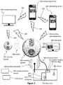
- FIG. 1illustrates a front view of a communication system, according to some embodiments.
- FIG. 2illustrates a computing device running software, according to some embodiments.
- FIG. 3illustrates an embodiment in which a security system is connected to a building, according to some embodiments.
- FIG. 4illustrates a communication system that includes a security system, a doorbell button, a wireless router, a server, and users, according to some embodiments.
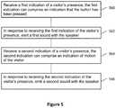
- FIG. 5illustrates a flow diagram showing a method of operating a security system, according to some embodiments.
- FIG. 6illustrates a flow diagram showing another method of operating a security system, according to some embodiments.
- FIGS. 7, 8, 9 and 10illustrate visitors being detected by security systems, according to various embodiments.
- FIG. 11illustrates a block diagram of a security system that is communicatively coupled to a communication system, according to some embodiments.
- FIG. 12illustrates a block diagram of various event detection devices that are communicatively coupled to a communication system, according to some embodiments.
- FIG. 13illustrates a flowchart of a method of monitoring for an event through a communication system, according to some embodiments.
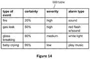
- FIG. 14illustrates an example of various alarm types that may be used based on the certainty and severity of the event, according to some embodiments.
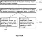
- FIGS. 15, 16, 17, 18, 19, 20, 21, 22, 23, 24, 25, 26, 27 and 28illustrate flow diagrams showing methods of operating a security system, according to various embodiments.
- FIG. 29illustrates a back view of the doorbell from FIG. 1 without a mounting bracket, according to some embodiments.
- FIG. 30illustrates a diagrammatic view of a doorbell and a doorbell control software application running on a computing device, according to some embodiments.
- FIG. 31illustrates a front view of a doorbell chime, according to some embodiments.
- FIG. 32illustrates a side perspective view of a doorbell chime, according to some embodiments.
- FIG. 33illustrates a front view of a doorbell chime coupled to a power outlet, according to some embodiments.
- FIGS. 34, 35, and 36illustrate diagrammatic views of doorbell systems, according to some embodiments.
- FIG. 37illustrates a back view of a chime without a back cover to show various components of the chime's electrical system, according to some embodiments.
- FIGS. 38, 39, 40, 41, 42, and 43illustrate method flowcharts, according to some embodiments.
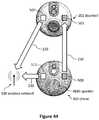
- FIGS. 44 and 45illustrate diagrammatic views of doorbell systems, according to some embodiments.
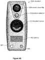
- FIG. 46illustrates a front view of a doorbell, according to some embodiments.
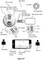
- FIG. 47illustrates data transmission between the doorbell system, a remote computing device, and a remote server according to some embodiments.
- FIG. 48illustrates time increments for recording video and audio data in a doorbell system, according to some embodiments.
- Communication systemscan provide a secure and convenient way for a remotely located individual to communicate with a person who is approaching a sensor, such as a proximity sensor or motion sensor, or with a person who rings a doorbell, which can be located in a doorway, near an entrance, or within 15 feet of a door.
- Some communication systemsallow an individual to hear, see, and talk with visitors who approach at least a portion of the communication system and/or press a button, such as a doorbell's button.
- communication systemscan use a computing device to enable a remotely located person to see, hear, and/or talk with visitors.
- Computing devicescan include computers, laptops, tablets, mobile devices, smartphones, cellular phones, and wireless devices (e.g., cars with wireless communication).
- Example computing devicesinclude the iPhone, iPad, iMac, MacBook Air, and MacBook Pro made by Apple Inc. Communication between a remotely located person and a visitor can occur via the Internet, cellular networks, telecommunication networks, and wireless networks.
- FIG. 1illustrates a front view of a communication system embodiment.
- the communication system 200can include a security system 202 (e.g., a doorbell) and a computing device 204 .
- a security system 202e.g., a doorbell
- the security system 202can include a camera assembly 208 and a doorbell button 212 .
- the camera assembly 208can be a video camera, which in some embodiments is a webcam.
- the security system 202can include a diagnostic light 216 and a power indicator light 220 .
- the diagnostic light 216is a first color (e.g., blue) if the security system 202 and/or the communication system 200 is connected to a wireless Internet network and is a second color (e.g., red) if the security system 202 and/or the communication system 200 is not connected to a wireless Internet network.
- the power indicator 220is a first color if the security system 202 is connected to a power source.
- the power sourcecan be power supplied by the building 300 to which the security system 202 is attached.
- the power indicator 220is a second color or does not emit light if the security system 202 is not connected to the power source.
- the security system 202(e.g., a doorbell) can receive power and/or information from an Ethernet cable 221 that can be electrically coupled to the doorbell.
- the Ethernet cable 221can exit a hole in an exterior of a building near an entryway to enable electrically coupling the doorbell to the Ethernet cable 221 .
- the security system 202can include at least one speaker 488 .
- the speaker 488can be located along any portion of the security system 202 .
- the speaker 488can be located within an inner portion of the security system 202 or along an outer portion of the security system 202 .
- the speaker 488can be any type of sound output device configured to emit sound, such as a digital speaker, an analog speaker, and the like.
- the security system 202e.g., a doorbell
- the security system 202can include an outer housing 224 , which can be water resistant and/or waterproof.
- the outer housingcan be made from metal or plastic, such as molded plastic with a hardness of 60 Shore D.
- the outer housing 224is made from brushed nickel or aluminum.
- the security system 202can be electrically coupled to a power source, such as wires electrically connected to a building's electrical power system.
- the security system 202includes a battery for backup and/or primary power.
- Wireless communication 230can enable the security system 202 (e.g., a doorbell) to communicate with the computing device 204 . Some embodiments enable communication via cellular and/or WiFi networks. Some embodiments enable communication via the Internet. Several embodiments enable wired communication between the security system 202 and the computing device 204 .
- the wireless communication 230can include the following communication means: radio, WiFi (e.g., wireless local area network), cellular, Internet, Bluetooth, telecommunication, electromagnetic, infrared, light, sonic, and microwave. Other communication means are used by some embodiments.
- the security system 202can initiate voice calls or send text messages to a computing device 204 (e.g., a smartphone, a desktop computer, a tablet computer, a laptop computer).
- a computing device 204e.g., a smartphone, a desktop computer, a tablet computer, a laptop computer.
- NFCnear field communication
- the doorbell 202 and/or the computing device 204can include a NFC tag.
- Some NFC technologiesinclude Bluetooth, radio-frequency identification, and QR codes.
- Some embodimentsinclude computer software (e.g., application software), which can be a mobile application designed to run on smartphones, tablet computers, and other mobile devices. Software of this nature is sometimes referred to as “app” software. Some embodiments include software designed to run on desktop computers and laptop computers.
- the computing device 204can run software with a graphical user interface.
- the user interfacecan include icons or buttons.
- the softwareis configured for use with a touch-screen computing device such as a smartphone or tablet.
- FIG. 2illustrates a computing device 204 running software.
- the softwareincludes a user interface 240 displayed on a display screen 242 .
- the user interface 240can include a security system indicator 244 , which can indicate the location of the security system that the user interface is displaying. For example, a person can use one computing device 204 to control and/or interact with multiple security systems, such as one security system located at a front door and another security system located at a back door. Selecting the security system indicator 244 can allow the user to choose another security system (e.g., the back door security system rather than the front door security system).
- another security systeme.g., the back door security system rather than the front door security system.
- the user interface 240can include a connectivity indicator 248 .
- the connectivity indicatorcan indicate whether the computing device is in communication with a security system, the Internet, and/or a cellular network.
- the connectivity indicator 248can alert the user if the computing device 204 has lost its connection with the security system 202 ; the security system 202 has been damaged; the security system 202 has been stolen; the security system 202 has been removed from its mounting location; the security system 202 lost electrical power; and/or if the computing device 204 cannot communicate with the security system 202 .
- the connectivity indicator 248alerts the user of the computing device 204 by flashing, emitting a sound, displaying a message, and/or displaying a symbol.
- a remote server 206sends an alert (e.g., phone call, text message, image on the user interface 240 ) regarding the power and/or connectivity issue.
- the remote server 206can manage communication between the security system 202 and the computing device.
- information from the security system 202is stored by the remote server 206 .
- information from the security system 202is stored by the remote server 206 until the information can be sent to the computing device 204 , uploaded to the computing device 204 , and/or displayed to the remotely located person via the computing device 204 .
- the remote server 206can be a computing device that stores information from the security system 202 and/or from the computing device 204 .
- the remote server 206is located in a data center.
- the computing device 204 and/or the remote server 206attempts to communicate with the security system 202 . If the computing device 204 and/or the remote server 206 is unable to communicate with the security system 202 , the computing device 204 and/or the remote server 206 alerts the remotely located person via the software, phone, text, a displayed message, and/or a website. In some embodiments, the computing device 204 and/or the remote server 206 attempts to communicate with the security system 202 periodically; at least every five hours and/or less than every 10 minutes; at least every 24 hours and/or less than every 60 minutes; or at least every hour and/or less than every second.
- the server 206can initiate communication to the computer device 204 and/or to the security system 202 . In several embodiments, the server 206 can initiate, control, and/or block communication between the computing device 204 and the security system 202 .
- a usercan log into an “app,” website, and/or software on a computing device (e.g., mobile computing device, smartphone, tablet, desktop computer) to adjust the security system settings discussed herein.
- a computing devicee.g., mobile computing device, smartphone, tablet, desktop computer
- a computing devicecan enable a user to watch live video and/or hear live audio from a security system due to the user's request rather than due to actions of a visitor.
- Some embodimentsinclude a computing device initiating a live video feed (or a video feed that is less than five minutes old).
- the user interface 240displays an image 252 such as a still image or a video of an area near and/or in front of the security system 202 .
- the image 252can be taken by the camera assembly 208 and stored by the security system 202 , server 206 , and/or computing device 204 .
- the user interface 240can include a recording button 256 to enable a user to record images, videos, and/or sound from the camera assembly 208 , microphone of the security system 202 , and/or microphone of the computing device 204 .
- the user interface 240includes a picture button 260 to allow the user to take still pictures and/or videos of the area near and/or in front of the security system 202 .
- the user interface 240can also include a sound adjustment button 264 and a mute button 268 .
- the user interface 240can include camera manipulation buttons such as zoom, pan, and light adjustment buttons.
- the camera assembly 208automatically adjusts between Day Mode and Night Mode.
- Some embodimentsinclude an infrared camera and/or infrared lights to illuminate an area near the security system 202 to enable the camera assembly 208 to provide sufficient visibility (even at night).
- buttonsinclude diverse means of selecting various options, features, and functions. Buttons can be selected by mouse clicks, keyboard commands, and touching a touch screen. Many embodiments include buttons that can be selected without touch screens.
- the user interface 240includes a quality selection button, which can allow a user to select the quality and/or amount of the data transmitted from the security system 202 to the computing device 204 and/or from the computing device 204 to the security system 202 .
- videocan be sent to and/or received from the computing device 204 using video chat protocols such as FaceTime (by Apple Inc.) or Skype (by Microsoft Corporation).
- videochat protocolssuch as FaceTime (by Apple Inc.) or Skype (by Microsoft Corporation).
- these videosare played by videoconferencing apps on the computing device 204 instead of being played by the user interface 240 .
- the user interface 240can include a termination button 276 to end communication between the security system 202 and the computing device 204 .
- the termination button 276ends the ability of the person located near the security system 202 (i.e., the visitor) to hear and/or see the user of the computing device 204 , but does not end the ability of the user of the computing device 204 to hear and/or see the person located near the security system 202 .
- a button 276is both an answer button (to accept a communication request from a visitor) and is a termination button (to end communication between the security system 202 and the computing device 204 ).
- the button 276can include the word “Answer” when the system is attempting to establish two-way communication between the visitor and the user. Selecting the button 276 when the system is attempting to establish two-way communication between the visitor and the user can start two-way communication.
- the button 276can include the words “End Call” during two-way communication between the visitor and the user. Selecting the button 276 during two-way communication between the visitor and the user can terminate two-way communication. In some embodiments, terminating two-way communication still enables the user to see and hear the visitor. In some embodiments, terminating two-way communication causes the computing device 204 to stop showing video from the security system and to stop emitting sounds recorded by the security system.
- the user interface 240opens as soon as the security system detects a visitor (e.g., senses indications of a visitor). Once the user interface 240 opens, the user can see and/or hear the visitor even before “answering” or otherwise accepting two-way communication, in several embodiments.
- Some method embodimentsinclude detecting a visitor with a security system.
- the methodscan include causing the user interface to display on a remote computing device 204 due to the detection of the visitor (e.g., with or without user interaction).
- the methodscan include displaying video from the security system and/or audio from the security system before the user accepts two-way communication with the visitor.
- the methodscan include displaying video from the security system and/or audio from the security system before the user accepts the visitor's communication request.
- the methodscan include the computing device simultaneously asking the user if the user wants to accept (e.g., answer) the communication request and displaying audio and/or video of the visitor. For example, in some embodiments, the user can see and hear the visitor via the security system before opening a means of two-way communication with the visitor.
- the softwareincludes means to start the video feed on demand.
- a user of the computing devicemight wonder what is happening near the security system 202 .
- the usercan open the software application on the computing device 204 and instruct the application to show live video and/or audio from the security device 202 even if no event near the security system 202 has triggered the communication.
- the security device 202can be configured to record when the security device 202 detects movement and/or the presence of a person.
- the user of the computing device 204can later review all video and/or audio records when the security device 202 detected movement and/or the presence of a person.
- the server 206controls communication between the computing device 204 and the security system 202 , which can be a doorbell with a camera, a microphone, and a speaker. In several embodiments, the server 206 does not control communication between the computing device 204 and the security system 202 .
- data captured by the security system and/or the computing device 204is stored by another remote device such as the server 206 .
- Cloud storage, enterprise storage, and/or networked enterprise storagecan be used to store video, pictures, and/or audio from the communication system 200 or from any part of the communication system 200 .
- the usercan download and/or stream stored data and/or storage video, pictures, and/or audio. For example, a user can record visitors for a year and then later can review conversations with visitors from the last year.
- remote storage, the server 206 , the computing device 204 , and/or the security system 202can store information and statistics regarding visitors and usage.
- FIG. 3illustrates an embodiment in which a doorbell 202 is connected to a building 300 , which can include an entryway 310 that has a door 254 .
- a visitor 388can approach the doorbell 202 and then can be detected by the doorbell 202 .
- the visitor 388can press the doorbell button 212 .
- the user of the doorbell 202can configure the doorbell 202 such that when the visitor 388 presses the doorbell button 212 , the user receives a notification regarding the visitor 388 .
- Electrical wires 304can electrically couple the doorbell 202 to the electrical system of the building 300 such that the doorbell 202 can receive electrical power from the building 300 .
- the buildingcan include a door lock 250 to lock the door 254 .
- a wireless network 308can allow devices to wirelessly access the Internet.
- the security system 202can access the Internet via the wireless network 308 .
- the wireless network 308can transmit data from the security system 202 to the Internet, which can transmit the data to remotely located computing devices 204 .
- the Internet and wireless networkscan transmit data from remotely located computing devices 204 to the security system 202 .
- a security system 202connects to a home's WiFi.
- one computing device 204can communicate with multiple security systems 202 .
- multiple computing devices 204can communicate with one security system 202 .
- the security system 202can communicate (e.g., wirelessly 230 ) with a television 306 , which can be a smart television. Users can view the television 306 to see a visitor and/or talk with the visitor.
- a television 306which can be a smart television. Users can view the television 306 to see a visitor and/or talk with the visitor.
- FIG. 4illustrates a communication system 310 that includes a security system 320 , a doorbell button 212 , a WiFi router 328 , a server 332 , and users 336 .
- a visitorinitiates a communication request by pressing the doorbell button 212 or triggering a motion or proximity sensor. The visitor can trigger the motion or proximity sensor by approaching the security system 320 .
- the security system 320connects or otherwise communicates with a home WiFi router 328 .
- the server 332receives a signal from the WiFi router 328 and sends video and/or audio to the users 336 via a wireless network 364 .
- the userssee the visitor, hear the visitor, and talk with the visitor.
- Step 370can include using a software application to see, hear, and/or talk with the visitor.
- the visitor and users 336can engage in two-way communication 374 via the internet or other wireless communication system even when the visitor and the users 336 are located far away from each other.
- Some embodimentsenable users to receive communication requests and communicate with visitors via diverse mobile communication standards including third generation (“3G”), fourth generation (“4G”), long term evolution (“LTE”), worldwide interoperability for microwave access (“WiMAX”), and WiFi.
- 3Gthird generation
- 4Gfourth generation
- LTElong term evolution
- WiMAXworldwide interoperability for microwave access
- WiFiWorldwide Interoperability for microwave access
- the users 336utilize the communication system 310 to communicate with visitors who are in close proximity to the users 336 .
- a user 336 located inside her homecan communicate with a visitor located just outside the home via the communication system 310 .
- FIG. 29illustrates an internal view of the doorbell 202 .
- Doorbells 202can include a chip 480 (e.g., integrated circuits, microprocessor, computer) and a memory 492 .
- Doorbells 202can also include a microphone 484 and a speaker 488 .
- the speaker 488can comprise a flat speaker and a sound chamber 460 configured to amplify an emitted sound.
- the flat speakercan be located in the sound chamber.
- Some doorbell embodimentsinclude a proximity sensor 500 .
- doorbells 202include a wireless communication module 504 , such as a WiFi module.
- the communication module 504can have an integrated antenna.
- an antennais contained within the outer housing 224 .
- the doorbell 202can include one or more heating elements 508 configured to regulate the temperature of the doorbell 202 .
- doorbells 202can be used in very cold environments, such as in Alaska.
- the heating element 508can be used in various methods to protect temperature sensitive portions of the doorbell 202 from cold weather.
- the doorbell 202can include a thermometer 512 to enable the system to determine the temperature inside a portion of the doorbell 202 and/or outside the doorbell 202 .
- Several embodimentscan be configured for 9 to 40 volts alternating current (“VAC”) and/or 9 to 40 volts direct current (“VDC”). Some embodiments convert input electricity into direct current (DC), such as 12 VDC.
- DCdirect current
- Several embodimentsinclude a converter 494 for power conversion (e.g., converting electrical energy from one form to another).
- the converter 494can convert input power (e.g., from wiring in a building) to a suitable power form for the doorbell 202 .
- the power conversioncan convert between AC and DC, change the voltage, and/or change the frequency.
- the converter 494can include a transformer and/or a voltage regulator.
- the converter 494can include a DC to DC converter, a voltage stabilizer, a linear regulator, a surge protector, a rectifier, a power supply unit, a switch, an inverter, and/or a voltage converter. In some embodiments, the converter 494 converts 50 Hertz (“Hz”) power into 60 Hz power.
- HzHertz
- the electrical components of the doorbell 202can be electrically coupled to a printed circuit board (“PCB”) 516 and can receive electrical power from the PCB 516 .
- PCBprinted circuit board
- the PCB 516 and the electrical components of the doorbell 202can be the electrical system 456 of the doorbell 202 . Additional details regarding the PCB 516 and the electrical components of the doorbell 202 are described in U.S. Nonprovisional patent application Ser. No. 14/612,376; filed Feb. 3, 2015; and entitled DOORBELL COMMUNICATION SYSTEMS AND METHODS. The entire contents of patent application Ser. No. 14/612,376 are incorporated by reference herein.
- softwarecan start the video feed on demand.
- a user of the computing devicemight wonder what is happening near the security system 202 .
- the usercan open the software application (e.g., an “app”) on the computing device 204 and instruct the application to show live video and/or audio from the security device 202 even if no event near the security system 202 has triggered the communication.
- the software applicatione.g., an “app”
- a usercan initiate communicate via a doorbell and/or can initiate live video from the doorbell by pressing a button 260 on a user interface (shown in FIG. 2 ). Pressing the on-demand button 260 again can terminate the communication and/or the live video.
- the security system 202may be configured to play unique sounds in response to detecting specific situations and/or during certain times of day.
- the soundsmay be preprogrammed sounds or completely customizable by a user of the security system 202 .
- the security system 202may be configured to play any of the sounds according to specific situations.
- the security system 202may be configured to play a specific message for a specific visiting individual, and/or may be configured to play a specific message when a potential visitor is identified as a specific person or is included in a list of specific people.
- the security system 202may include a speaker 488 configured to emit any type of sound.
- the security system 202may also include a visitor detection system that may include at least one of a button 212 , a camera 208 , and a motion detector 218 . Accordingly, the visitor detection system may be configurable to receive various indications of a visitor's presence.
- the speaker 488 and the visitor detection systemmay be directly or indirectly coupled to the security system 202 . Even still, the speaker 488 and the visitor detection system may be mechanically, electrically, and/or communicatively coupled to the security system 202 .
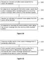
- the security system 202may detect different indications of a visitor's presence. As shown in FIG. 5 , the security system 202 can be configured to receive a first indication of a visitor's presence (at step 560 ). In response to receiving the first indication of the visitor's presence, the security system 202 can emit a first sound with the speaker 488 (at step 562 ). The security system 202 can be configured to receive a second indication of a visitor's presence (at step 564 ). In response to receiving the second indication of the visitor's presence, the security system 202 can emit a second sound with the speaker 488 (at step 566 ). The first sound can be audibly different than the second sound.
- the security system 202by the speaker 488 , can emit different sounds.
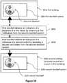
- the security system 202when the security system 202 receives an indication that a visitor 580 has pressed the button 212 (at step 582 ), this can be interpreted as an indication of a friendly, or welcome visitor.
- the speaker 488can emit a first sound (at step 584 ), such as a friendly sound (e.g. “Welcome to our very abode.”).
- the security system 202when the security system 202 receives an indication that a visitor 586 has been moving in front of the security system 202 for a prolonged or predetermined time (e.g. 15 seconds or any time that indicates that the visitor is loitering) without pressing the button 212 (at step 588 ), this can be interpreted as an unfriendly or unwelcome visitor.
- the speaker 488can emit a second sound (at step 590 ).
- the second soundcan be an alert sound (e.g. a warning to move away from the building 300 —“Step away from the house!”).
- the security system 202can be configured to emit any number of sounds, such as a third sound, a fourth sound, a fifth sound, and any number of additional sounds.
- the security system 202can be configured to receive any number of indications.
- the indicationscan include indications of a remote computing device 204 , a noise, a thermal signature (such as a thermal gradient indicating the presence of a person or animal), a retina scan, a fingerprint scan, a ground vibration, and the like. It should be appreciated that the indication can include any indication of a presence of any visitor, such as a person or animal.
- the security system 202can emit different sounds for a first visitor. For example, as the first visitor approaches the building 300 , the security system 202 can emit a first sound based upon the motion of the first visitor. As well, the security system 202 can emit a second sound once the first visitor pushes the button 212 of the security system 202 .
- the security system 202can be configured to any environment in which the building 300 is situated. For example, some buildings 300 can be located in high traffic areas where it is common for people to walk by the front of the security system 202 without pressing the button 212 . In this regard, the security system 202 can be configured to ignore indications of motion and only emit sounds in response to affirmative indications that the visitor is visiting the building 300 , such as an indication that the button 212 has been pressed. In some embodiments, the security system 202 can be configured to only respond to motion in certain zones.
- the security system 202can be configured to ignore all motion that occurs more than 15 feet from the security system 202 . In this manner, the security system 202 can only respond to movements occurring on the building property.
- combinations of indicationscan be interpreted in various manners. For example, a combination of an indication of motion (i.e. movement) of a visitor in front of the security system 202 and an indication that the visitor has pressed the button 212 can indicate that the visitor is welcome at the building 300 . As previously described, the speaker 488 of the security system 202 can emit a friendly message in response to the combination of indications.
- an indication of motioni.e. movement
- an indication that the visitor has pressed the button 212can indicate that the visitor is welcome at the building 300 .
- the speaker 488 of the security system 202can emit a friendly message in response to the combination of indications.
- the security system 202can be configured to emit different sounds in response to a positive detection of one indication and a negative detection of another indication. For example, if the security system 202 detects motion of a visitor but does not detect sound, this can be interpreted as an unwelcome visitor, such as a prowler sneaking around the outside of the building 300 . In response, the speaker 488 of the security system 202 can emit an alert sound (e.g. a warning to exit the premise before the authorities are notified).
- an alert sounde.g. a warning to exit the premise before the authorities are notified.
- the time of day and/or day when a visitor approaches the building 300can also indicate whether the visitor is welcome or not.
- the security system 202can be configured to receive an indication of a visitor's presence at a first time of day (at step 570 ).
- the first time of daycan occur between sunrise and sunset, or any other time of day.
- the security system 202can emit a first sound with the speaker 488 (at step 572 ).
- the first soundcomprises an audible message spoken by a female voice, while some embodiments may comprise an audible message spoken by a male voice.
- the security system 202can be configured to receive an indication of the visitor's presence at a second time of day (at step 574 ). It should be appreciated that the second time of day can occur between sunset and sunrise, or any other time of day. In response to receiving the indication of the visitor's presence at the second time of day, the security system 202 can emit a second sound with the speaker 488 (at step 576 ). In some embodiments, the second sound comprises an audible message spoken by a male voice, while some embodiments may comprise an audible message spoken by a female voice.
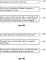
- the speaker 488can emit a welcome message (e.g. “Welcome. We'll be right there.) (at step 596 ).
- a welcome messagee.g. “Welcome. We'll be right there.
- the speaker 488can emit a do not disturb message or a message instructing the visitor to come back another time (e.g. “Please come back tomorrow!”).
- Combinations of indicationscan be interpreted differently depending on the time of day. For example, in response to an indication of a motion and a noise during the day, the speaker 488 of the security system 202 can emit a friendly message. However, in response to an indication of a motion and a noise during the night, the speaker 488 can emit a warning message.
- the security system 202can be configured to respond differently based on the unique circumstances of the indication. For example, if the motion detector 218 of the security system 202 detects a slow movement versus a faster movement, then the speaker 488 can emit different sounds based upon these various circumstances.
- a slow movementcan be interpreted as a prowler approaching the building, while a faster movement, such as a movement of a person walking at 3.5 miles per hour, can be interpreted as a friendly visitor approaching the building 300 .
- the time of daycan be any selected time of day and any number of time ranges can be used.
- the security system 202can emit a welcome message during sunrise to sunset and an alert or warning message during sunset to sunrise. Accordingly, because sunrise and sunset change on a daily basis, the security system 202 can be communicatively coupled to an outside database(s) to allow the security system 202 to thereby automatically respond to these ever-changing conditions.
- the security system 202can elect to emit a particular sound, such as a first sound or a second sound, based on a time at which the security system 202 detects an indication of a presence of a visitor.
- the security system 202is configured to detect an amount of light, which may indicate a time of day. In response to detecting the amount of light, the security system 202 can elect to emit the first sound or the second sound based on the amount of light.
- the security system 202can be configured to provide unique responses during different time ranges on specific days. For example, the user may have a bowling league every third Monday of the month. Accordingly, during that time, (e.g. from 6 pm-8:30 pm) on the third Monday of the month, in response to detecting an indication of a presence of a friendly visitor, the speaker 488 of the security system 202 can emit a friendly message telling the visitor that their presence is appreciated but the visitor should come back another time. In another example, the user may be on vacation from the 1st to the 10 th and the user may wish to emit more intimidating warnings to secure the building 300 . Generally speaking, the security system 202 can be configured to emit any type of sound in response to any time of day and/or day.
- the security system 202can be configured to detect specific visitors and emit certain sounds in response to detecting the specific visitors. For example, if the security system 202 detects a first visitor, such as a relative of the homeowner, the security system 202 can always emit a friendly sound, no matter how the first visitor approaches the home, or during what time of day. As well, if the security system 202 detects a second visitor, such as an unknown party (e.g. a solicitor), the security system 202 can emit an unfriendly sound, no matter how the second visitor approaches the home, or during what time of day.
- a first visitorsuch as a relative of the homeowner
- the security system 202can always emit a friendly sound, no matter how the first visitor approaches the home, or during what time of day.
- a second visitorsuch as an unknown party (e.g. a solicitor)
- the security system 202can emit an unfriendly sound, no matter how the second visitor approaches the home, or during what time of day.
- the security system 202can use any type of identity recognition technology, such as facial recognition, to determine an indication of an identity of a visitor.
- identity recognition technologysuch as facial recognition
- Some of these types of identity recognition technologiesare disclosed in U.S. Nonprovisional patent application Ser. No. 14/612,376; filed Feb. 3, 2015; and entitled DOORBELL COMMUNICATION SYSTEMS AND METHODS. The entire contents of patent application Ser. No. 14/612,376 are incorporated by reference herein.
- the different types of sounds emitted by the speaker 488can be configured to match the appropriate indication as detected by the security system 202 .
- the speaker 488can emit a message spoken by a male voice to thereby intimidate the unfriendly visitor.
- the security system 202detects a friendly visitor, the speaker 488 can emit a message spoken by a female voice to thereby welcome the visitor.
- the security system 202can be configured to emit any other type of sound. For example, a welcome visitor can be greeted by a pleasant melody or a ding-dong, while an unwelcome visitor can be greeted by an alarm sound or a warning message.
- messagescan be spoken in any language, volume, pitch, accent, and the like. Users may find that various combinations of vocal characteristics to be useful in different situations. For example, if a user is hosting a Mardi Jerusalem party, the user can configure the security system 202 to emit a message spoken by a person with a southern accent. Generally, it should be appreciated that the speaker 488 of the security system 202 can be configured to emit any type of sound for any type of specific situation.
- the security system 202can be configured to play a specific message if the potential visitor is not included in a list. For example, where a potential visitor is not included in a list of the resident's contacts, the security system 202 can be configured to indicate that the resident does not accept solicitors and/or request the visitor to provide identifying information or describe the purpose of the visit.
- the security system 202can be configured to play a specific message if the potential visitor has a criminal background. For example, a user can configure the security system 202 to play a specific message where a potential visitor is a registered sex offender.
- the sounds emitted by the security system 202can be recorded by the user him/herself.
- the soundscan be downloaded from another source, such as a remote computer (e.g. a remote server), a remote computing device (e.g. a smart phone), a website, a database (e.g. iTunes®), and the like.
- methodscan include selecting the first sound and the second sound with a remote computing device that is configured to receive alerts from the doorbell.
- the selected soundscan be wirelessly transmitted to the doorbell.
- the soundscan be recorded with a remote computing device 204 and the sounds can be set up for temporary use whereby the sounds can expire upon a predetermined time.
- a usercan enter an expiration date of the recorded sound with the remote computing device 204 .
- the usercan wirelessly send the first sound and the expiration date from the remote computing device to the doorbell. Once the expiration date passes, the security system 202 can then cease to emit the recorded sound from the security system 202 .
- the security system 202can be configured to receive sound emitting parameters from a remote computing device 204 .
- the security system 202can emit a predetermined sound based upon the sound emitting parameter.
- the sound emitting parameterincludes at least one of an identity of the first visitor, data associated with the first visitor, a time, a location of a user of the remote computing device.
- the security system 202can automatically download a third sound based on the sound emitting parameters. The security system 202 can emit the third sound from the speaker according to rules associated with the third sound.
- Embodiments of the security system 202can be configured to alert individuals located outside of a building (e.g. a home).
- the security system 202can be configured to flash a light, emit a sound (e.g. alternating high pitch and low pitch sounds), initiate a communication session with a remote computing device 204 , and the like.
- These various alertscan be useful to individuals, such as first responders, seeking to identify the location of an event, such as an emergency event(s) occurring within or outside the home.
- Homemay refer to a building whereby one or more occupants sleep in the building on a permanent basis. Home may distinguishable from an office building by the lack of permanent occupants that sleep in the office building. Home may refer to an apartment building due to the permanent nature of an occupant for the duration of a lease. Home may be distinguishable from a hotel due to the lack of permanent occupants.
- FIG. 11illustrates an embodiment in which a security system 202 is communicatively coupled to a communication device 416 .
- the security system 202may be part of a communication system 400 .
- the communication system 400can be similar to that of the communication system 200 except, the communication system 400 may also be configured to allow communication between the security system 202 and the communication device 416 .
- the security system 202can be communicatively coupled, directly and/or via the cloud, to a communication device 416 , such as a hub device, a communication system, and/or an event detection device 418 , such as a sensor, (e.g., a peripheral device, such as a Nest Protect® (registered by Google Inc.), Nest Learning Thermostat® (registered by Google Inc.), DropCam® (registered by Google Inc.), and the like.
- the communication device 416 , event detection device 418 and/or the security system 202can be used to monitor various events within the building 300 (e.g., home).
- the communication device 416 and/or event detection device 418can detect emergency events and then notify the security system 202 .
- the communication device 416is communicatively coupled to the event detection device 418 that detects the emergency event or adverse event (which is discussed further herein).
- the security system 202may directly or indirectly receive a notification of the emergency event from the event detection device 418 and/or the communication device 416 .
- the security system 202can communicate with the communication device 416 via a communication network 414 .
- the communication network 414can be similar to the wireless communication 230 , however, the communication network 414 can be wired or wireless.
- the communication network 414can utilize the existing electrical wires in the doorbell wires to communicate with the security system 202 (e.g., powerline networking).
- the communication network 414can also utilize a wired Local Area Network.
- the communication network 414can include a Wide Area Network (WAN) that connects the communication device 416 to the security system 202 over the Internet.
- WANWide Area Network
- the communication device 416is a type of device that is configured to connect multiple devices and facilitate communication between the multiple devices.
- the security system 202may be a device that also is communicatively coupled to the communication device 416 .
- the communication device 416may receive a transmission from one device (i.e., an event detection device 418 ), make a determination on what type of communication to perform (e.g., an alert), and transmit the communication to a second device (e.g., the security system 202 ) to take further action.
- the security system 202can be configured to communicate with remote computing devices (i.e., the computing device 204 ).
- the computing device 204may refer to a remote computing device in embodiments.
- the security system 202can initiate a communication session through the communication network 414 by sending a request to the computing device 204 to establish a secure connection (e.g., a virtual private network) to enhance security.
- the communication sessionmay also include an indication that an event (as discussed further herein) has been initiated.
- the security system 202can have an outer housing 224 .
- the outer housing 224may be configurable to attach to a building 300 .
- the outer housing 224 of the security system 202can attach to the building 300 using a variety of permanent or temporary mounting mechanisms.
- the permanent mounting mechanismmay prevent the removal of the security system 202 .
- the building 300may include a variety of structures.
- the building 300includes a home, which is a type of building 300 .
- the homecan include various types of structures in various square footages.
- a homecan be a wooden framed building with an exterior of stucco, brick, or siding.
- a homecan be distinguished from other types of buildings based on the livable area (e.g., 500 square feet to 5000 square feet).
- a homecan also be defined as being a freestanding structure without shared walls.
- a homemay also be defined by zoning constraints.
- the homemay be zoned residential instead of commercial or industrial.
- the outer housing 224can also include a visitor detection system 412 coupled to the outer housing 224 .
- the visitor detection system 412can be an assembly of components that are collectively configured to detect visitors in the immediate vicinity (e.g., within 0.5 to 50 feet) of the security system 202 .
- the visitor detection system 412can include the doorbell button 212 , the camera assembly 208 , and an audio input device 410 .
- the visitor detection system 412can also include the motion detector 218 and fingerprint sensor 210 .
- the audio input device 410can be a device that captures audio (e.g., a microphone).
- the audio input device 410can have various sensitivity ranges depending on the application.
- the audio input device 410can include multiple microphones to extend the coverage area of audio capture.
- the audio input devicecan have one microphone on board the outer housing 224 and receive input from another microphone located within the house (e.g., through the communication network 414 ).
- the outer housing 224may also include a deactivation unit 411 .
- the deactivation unit 411can be a component that is communicatively coupled to the security system 202 .
- the deactivation unit 411may be responsible for disabling the alert communication system 402 .
- the deactivation unit 411is part of the alert communication system 402 .
- the alert communication system 402may work passively or actively.
- the actively monitoring for the commandcan be advantageous where communication is lost with the deactivation unit 411 (i.e., the communication is modified or the deactivation is spoofed by an intruder).
- the deactivation unit 411may also passively monitor for the command. For example, an occupant may input a command through the deactivation unit 411 that is transmitted to the security system 202 . The security system 202 can receive the command passively. In embodiments, the deactivation unit 411 may also be communicatively coupled with a remote computing device 204 . The deactivation command may originate from the remote computing device 204 to deactivate the alert communication system 402 in either actively or passively.
- the outer housing 224can also include an alert communication system 402 coupled to the outer housing 224 .
- the alert communication system 402can be configurable to activate in response to an initiation of an event. For example, an alert from the communication device 416 that is transmitted to the security system 202 can activate various components on the security system 202 through the alert communication system 402 .
- the alert communication system 402can include components to communicate alerts to a user (e.g., an occupant of the home).
- the alert communication system 402is the security system 202 or part of the security system 202 .
- the alert communication system 402includes a light 406 and a speaker 404 .
- the light 406can comprise the diagnostic light 216 and/or the power indicator light 220 , as shown in FIG. 1 , and/or any other light coupled to the security system 202 .
- the speaker 404may comprise the speaker 488 , as illustrated in FIG. 1 , and/or any other speaker coupled to the security system 202 .
- the alert communication system 402refers to a collection of components for the purpose of alerting an occupant of the building 300 .
- the alert communication system 402can also refer to a control unit for the components that alert an occupant of the building 300 .
- the control of the alert communication system 402can be separate from the control for the security system 202 .
- the alert communication system 402is attached to an exterior surface of the home (i.e., a building 300 ).
- the outer housing 224may be attached to an interior surface of the home (i.e., a building 300 ).
- the remote computing device 204can be operated by the homeowner (i.e., a type of occupant).
- the speaker 404 of the alert communication system 404can be configured to emit a sound in response to the initiation of the event. For example, if the communication device 416 transmits an alert that indicates an emergency, then the security device 202 can emit a sound in the speaker 404 that indicates danger.
- the speaker 404can be configured to emit a wide-range of sounds and various decibel levels depending on the application. For example, a more severe alert can be louder than a less severe alert.
- the security system 202can alert an occupant of suspicious smoke by saying the location of the smoke and the time the smoke was detected.
- the speaker 404can simply emit a voice that says “Danger, Danger, Danger” to alert an occupant of the building 300 .
- the sound emitted by the security device 202can be unique to the type of alert. For example, if a fire alert is transmitted by the communication device 416 , then the security device 202 can emit a voice that says “Fire, Fire, Fire” and repeats at a set interval.
- Various soundscan also be used to selectively alert other occupants. For example, a high frequency sound of 24 kHz to 45 kHz can selectively alert canine occupants of the building 300 without alerting a human. In another example, a sound from 17 kHz to 23 kHz may selectively alert children but not adults.
- Various patterns of soundscan also be produced. For example, the “SOS” Morse code pattern may be used to indicate distress.
- the light 406 of the security system 202may be configurable to illuminate in response to the initiation of the event.
- the light 406can emit a variety of colors in a variety of patterns.
- the light 406can emit both a green light, a white light, and a red light.
- a green lightcan be lit during normal operation.
- a white light colorcan be used for ordinary alerts, such as a power outage.
- a red light colorcan be used to indicate an imminent emergency that alerts the occupant to leave the building 300 immediately.
- the red light colorcan be used to alert the occupant of a gas leakage or a fire or armed intruders.
- the light 406can flash at various frequencies to indicate a pattern. For example, three short flashes, followed by three long flashes, followed by three short flashes, can indicate distress. While rapid flashes can indicate a higher priority than slower flashes of light.
- the light 406can be coordinated with the speaker 404 . For example, the light 406 can flash at the same time that the speaker 404 makes a sound. The light 406 can also flash before or after the emission of sound from the speaker 404 .
- the alert communication system 402can also include emission of an odor.
- the odorcan be discernable by an occupant to know that something is wrong or can ward away an intruder. For example, if the communication device 416 alerts the security system 202 of an intruder, then a strong smell (such as that of a skunk) can trigger a silent alarm.
- a strong smellsuch as that of a skunk
- Various smellscan be used. For example, flowery odors can be used for non-urgent alerts (such as a water leak) while mercaptan-based odors can be used for urgent alerts.
- the alert communication system 402can include remote communication 407 .
- the remote communication 407can be responsible for communicating with a remote computing device 204 the status of the alarm.
- the remote communication 407can be a module that communicates with a security monitoring service, which can also have a dedicated communication channel that is different than the communication network 414 in order to alert authorities in the event of a power outage.
- the security system 202is powered by an electrical power input 408 .
- the electrical power input 408can be a battery.
- the electrical power input 408can also be from an electrical source such as from a household Alternating Current.
- the electrical power input 408can also be configured to receive a step-down voltage (e.g., around 8V to 24V) from doorbell wires 304 .
- the alert communication system 402may be electrically coupled to electrical wires 409 (through the electrical power input 408 ).
- the electrical wires 409can be configurable to be coupled to the doorbell wires 304 of a home (e.g., the building 300 ).
- the alert communication system 402can be configurable to activate in response to a determination that an event has been initiated through the electrical wires 409 .
- the communicationcan happen over powerline networking.
- Various spikes in electrical signals from the electrical wires 409can also signal the alert communication system 402 .
- a lack of electrical signal from the electrical wires 409can also activate the alert communication system 402 .
- the lack of electrical power input 408 from the electrical wires 409can activate the alert communication system 402 .
- the alert communication system 402can further utilize a backup battery system through the electrical power input 408 and cause the light 406 to emit white colored light so that an occupant can see.
- the security system 202may be configured as a passive or active device. As a passive device, the security system 202 may receive notifications of emergency events from the communication device and/or the event detection device 418 . For example, a smoke detector event detection device 418 can transmit a smoke event to the communication device, which may communicate to the security system 202 an indication that the smoke event is occurring. The security system 202 can be monitoring for notifications from the communication device whenever a communication channel is established.
- the security system 202may be configured to actively monitor whether the communication device and/or event detection device 418 has detected the occurrence or initiation of an emergency event (or adverse event). For example, the security system 202 can periodically request from the communication device a status of events. If there is no status, then the security system 202 can wait until another request is filled.
- FIG. 12illustrates a block diagram of an enhanced view of various event detection devices 418 , according to some embodiments.
- the event detection devices 418can be communicatively coupled to the communication device. Types of event detection device 418 can include a smoke alarm 420 or a burglar alarm 422 .
- the event detection device 418can be configured to communicate with a communication device or to the remote device 204 through the communication network 414 . In embodiments, the event detection device 418 can be “smart” and communicate with a variety of devices.
- the event detection device 418can connect via the Internet of Things (IoT) and may each have a unique network identifier. The IoT may encompass various standards.
- IoTInternet of Things
- standardsmay include ALLJOYN® (Registered by Qualcomm Innovation Center Inc.), Thread Group, IEEE® (Registered by the Institute of Electronic and Electrical Engineers, Inc.) P2413 working group, IoTivity® (Registered by Samsung Electronics Co., Ltd.), or Representational State Transfer.
- the security system 202may comprise an alert communication system 402 that may include a light 406 , a speaker 404 , and a wireless communication system 230 that may be configured to initiate a transmission with a remote computing device 204 .
- the communication devicemay comprise a smart smoke detector 420 (e.g. Nest Protect®, registered by Google Inc.), and in response to the smart smoke detector detecting elevated levels of smoke 434 , or elevated levels of other toxic gases, the security system 202 may activate its alert communication system 402 (e.g. flashing a light and/or emit a sound). This may thereby alert individuals outside the home as to the location of the home where the emergency event is occurring.
- the emergency eventcan comprise any type of event 424 that may require the attention of another party.
- eventcan refer to an emergency event or an adverse event, which indicates harm to an occupant or requires the attention of a party other than the occupant.
- the emergency eventmay comprise at least one of a fire 426 , a gas leak 428 , a break-in 436 , elevated levels of smoke 434 , elevated levels of radon 432 , elevated levels of carbon monoxide 430 , and the like.
- the alert communication system 402can be configured to alert individuals located outside the home in any variety of ways.
- the alert communication system 402can flash a bright light emitting diode and/or a light located behind the doorbell button 212 , such as the diagnostic light 216 , on the security system 202 .
- the alert communication system 402can emit a loud sound from the speaker 404 .
- the loud soundcan be alternating high and low pitch sounds that may be heard by individuals located within 300 feet of the home.
- the high and low pitch soundscan be of high and low frequencies that may be heard by individuals located within a neighboring home and/or a vehicle passing by.
- the loud soundcan be a unique sound easily detectable by individuals.
- the soundcan comprise a noise that indicates danger or help is required.
- the alert communication system 402can be configured to initiate a transmission to a remote computing device 204 .
- the security system 202may initiate a computing session and/or a notification with the remote computing device 204 to alert an individual that is operating the remote computing device 204 of the break-in 436 at the home.
- the security system 202can initiate a transmission to any other party, such as an emergency dispatcher (e.g. 911).
- the security system 202may be configured to activate its alert communication system 402 after a predetermined amount of time.
- the predetermined amount of timemay be 0 seconds, 10 seconds, 20 seconds, 1 minute, and the like.
- the alert communication system 402may activate nearly at the same time as the communication device 416 detecting the emergency event 424 or any time thereafter.
- FIG. 13illustrates a flowchart of a method 500 of monitoring for an event through a communication device 416 , according to some embodiments.
- the method 500can generally involve connecting to a communication device 416 and receiving a notification of an event from the communication device 416 .
- the security system 202can react based on the event from the communication system.
- the method 500begins at block 510 .
- the security system 202can establish a connection with the communication system.
- the communication device 416may utilize either a wired or wireless connection 230 to communicate with the security system 202 .
- a wireless home networkthat utilizes Wi-Fi may be used or local BluetoothTM pairing may be used.
- the communication device 416may be configured to only communicate with security system 202 at the ID provided by the security system 202 .
- the security system 202may have a unique IPv6 address that the communication device 416 transmits to.
- the communication device 416may also have a unique IPv6 address that the security system 202 transmits to.
- the security system 202may also be configured to receive alerts from only the IPv6 address that belongs to the communication device 416 , thus preventing spoofing type alarms.
- Various permissionsmay be set up using an Application Programming Interface (API) of the communication device 416 .
- APIApplication Programming Interface
- the security system 202can be set up as a client with read/write permissions which identifies the security system 202 that has permission to share data with the communication device 416 .
- the security system 202may monitor for an event.
- the security system 202monitors for an event from the communication device 416 .
- the communication device 416may receive a notification of an event from an event detection device 418 .
- the security system 202can monitor for an event using localized components.
- the security system 202may have a camera that is used to monitor for suspicious activity.
- the eventmay be communicated with the communication device 416 and the communication device 416 may take appropriate action (e.g., notify emergency services).
- the types of eventsmay be selected from at least one of a fire, a gas leak, a break-in, elevated levels of smoke, elevated levels of radon, elevated levels of carbon monoxide, and the like.
- the event detection device 418may detect an event using a variety of methods. For example, various thresholds may be employed to detect an event 424 .
- the elevated levels of smoke event 434can be based off of optical obscuration or electrostatic precipitation.
- the smokecan be based off of a threshold of parts per million or percentage of optical transmittance.
- the radon event 432can be based off of PicoCuries per Liter reading from a radon detection unit.
- the gas leak event 428can be based off of an 80% Lower Explosive Limit.
- Various gas detectorscan be used (e.g., electrochemical, infrared point, infrared imaging, semiconductor, ultrasonic, holographic, etc.).
- a fire event 426may be detected using temperature or a combination of readings from a smoke event 434 and a carbon monoxide event 430 .
- the break-in event 436may utilize various sensors present in the security system 202 or external sensors to the security system 202 (e.g., motion sensors).
- the event 424is associated with a home (i.e., building 300 ), and the doorbell (i.e., security system 202 ) is attached to the home of a homeowner.
- the security system 202can determine whether an event has been initiated.
- the eventmay be initiated whenever the security system 202 receives a transmission from a communication device 416 communicatively coupled to the security system.
- the transmissionmay be over various forms of communication and provide an indication that the event has been initiated.
- the security system 202may monitor the communication system to detect whether the event has been initiated.
- the security system 202e.g., the doorbell
- the security device 202can establish a communication session with a remote computing device 204 in a similar manner as to the communication device 416 .
- the communication sessionmay include an indication that the event that has been initiated. For example, an occupant can receive a communication of a fire alert on a local application on their remote computing device 204 from the security system 202 .
- the security system 202can determine the alarm type. In embodiments, block 516 may be optional. Despite a variety of devices available to the security system 202 , not all devices or tools may be appropriate in certain settings. For example, a non-urgent alert (such as elevated radon levels) may not warrant a high-pitched, high-volume noise in the middle of the night.
- the security system 202can balance the severity of the alert with the certainty for the alert. For example, significant amounts of dust can trigger a smoke detector but the certainty of a fire can be determined using a carbon monoxide detector in conjunction with the smoke detector. The severity of a fire may be high but if the certainty that a fire is occurring is low, then the security system 202 can determine that another alarm type is more appropriate. Examples of determining an alarm type are described further herein.
- the security system 202can activate the alert communication system 402 in response to determining that the event has been initiated in block 514 .
- activating the alert communication system 402can include activating selected components of the alert communication system 402 (e.g., the speaker 404 or the light 406 ).
- the alert communication system 402can include a light 406 which, when the alert communication system 402 is activated, can cause the light 406 to illuminate in a variety of patterns and colors.
- the alert communication system 402can also include a speaker 404 that emits a sound in a variety of intensities, frequencies, and patterns.
- the activatingcan also include activating a control element for the alert communication system 402 .
- the control element for the alert communication system 402can instigate a variety of patterns and alerts for multiple components (e.g., a flashing light followed by emission of selected sound frequencies).
- the security system 202can monitor for a command to deactivate the alert communication system 402 .
- block 520may be optional.
- a user of the security system 202may not desire the security system 202 to alert occupants (e.g., a false positive).
- the commandcan be a sequence of instructions that is understood by the security system 202 to deactivate the alert communication system 402 .
- the commandcan be a button press and an audible predetermined message.
- an occupantcan push a button (e.g., the door bell button 220 ) and speak an audible predetermined message such as “Alarm Deactivate” to deactivate the alert communication system 402 .
- the deactivation unit 411can be configured to perform vocal recognition in order to distinguish between the voice of the occupant with the voice of a non-occupant, such as a prowler. Once the command is received, then the method 500 can continue to operation 522 .
- the security system 202can deactivate the alert communication system 402 in response to receiving the command to deactivate the alert communication system.
- the alert communication system 402may be deactivated in a variety of ways.
- the alert communication system 402may deactivate (e.g. turn off the current alert) in response to the security system 202 receiving an indication that the doorbell button 212 has been pressed.
- the security system 202may be configured to turn off the alert communication system 402 in response to receiving an audible predetermined message, such as a spoken safety message or a spoken password that indicates that the event is being attended to or has ended.
- the security system 202can receive a deactivation command from the remote computing device 204 .
- the deactivation of the alert communication system 402can include selectively deactivating less than all of the components of the alert communication system 402 .
- the deactivating of the alert communication system 402can include deactivating only the localized communication (i.e., the speaker 404 and the light 406 ) but not the remote communication 407 with law enforcement (e.g., a silent alarm).
- FIG. 14illustrates an example table 600 of various alarm types that are used based on the certainty and severity of the event, according to some embodiments.
- the table 600can correspond to block 516 in FIG. 13 where a security system 202 can determine the alarm type.
- the alarm typemay be pre-assigned depending on the certainty and the severity of the event. For example, an occupant may desire that a gas leak is always associated with an audible alarm and a red light, despite a low certainty.
- the alarm typecan also be based on threshold values. For example, if the certainty of a fire is 20% but the severity is high, the security system 202 can create a score that is based on the severity and the certainty. The security system 202 , based on the score, can determine the type of alarm. For example, a high severity event with a low certainty may (such as the fire) may be associated with a sound to invite an occupant to investigate further. A high severity event such as a gas leak but with a higher certainty may trigger a red flash along with the sound. A low severity event such as a baby crying can trigger a different set of alarm types such as playing comforting music.
- a high severity event with a low certaintymay (such as the fire) may be associated with a sound to invite an occupant to investigate further.
- a high severity eventsuch as a gas leak but with a higher certainty may trigger a red flash along with the sound.
- a low severity eventsuch as a baby crying can trigger a different set of alarm types such as playing comforting music.
- the security system 202may be configured to receive a custom sound(s) from a user and thereby emit the custom sound in response to a particular situation(s).
- a doorbell system 200may receive a custom message (at step 1500 ).
- a user of the systemmay then optionally assign the custom message to a select visitor (at step 1502 ).
- the doorbell 202may then respond by emitting the custom message with a speaker 404 , 488 of the doorbell 202 (at step 1506 ).
- the term “detecting”may be defined as discovering or identifying the presence or existence of a visitor. As such, the term “detecting” may be used interchangeably with the term “determining.”
- the custom sound, or custom messagemay be received by the doorbell system 200 in a variety of ways.
- the doorbell system 200may download the custom message from a remote computer, such as a remote computing device (e.g. a smart phone) (at step 1600 ).
- the doorbell system 200may record the custom message (at step 1602 ).
- a user of the doorbell system 200may record the custom message on his or her remote computing device, such as a smart phone, (at step 1602 ) and then download the custom message from the smart phone onto the doorbell system 200 .
- the custom messagemay be directly recorded by the doorbell 202 (at step 1602 ), such as recorded by a microphone of the doorbell 202 .
- the custom messagemay be recorded by any type of recording device that is communicatively coupled to the doorbell system 200 (at step 1602 ). In this manner, the doorbell system 200 may download the custom message from the recording device.
- any number of custom messagesmay be recorded and/or downloaded by the doorbell system 200 .
- the doorbell systemmay record and/or download a second custom message (at step 1604 ), a third custom message, a fourth custom message, and any number of additional custom messages.
- the doorbell system 200may also be configured to interact with a visitor whereby the doorbell system 200 gives and receives audible information. In this manner, the doorbell system 200 may interpret information from the visitor.
- the doorbell system 200e.g. a speaker 404 , 488 of the doorbell 202
- the doorbell system 200may be configured to emit an audible question(s) (at step 1700 ).
- the doorbell system 200e.g. via a microphone of the doorbell 202
- the doorbell system 200may then receive an audible response from the visitor (at step 1702 ).
- the doorbell system 200may thereby determine the meaning of the audible response given by the visitor.
- the doorbell system 200may determine whether the audible response comprises a first meaning or a second meaning (at step 1704 ). For example, if the doorbell system 200 determines that the audible response comprises the first meaning, the doorbell 202 may then emit a first audible response, via the speaker 404 , 488 , (at step 1706 ). As well, if the doorbell system 200 determines that the audible response comprises the second meaning, the doorbell 202 may then emit a second audible response, via the speaker 404 , 488 , (at step 1708 ). In this manner, the doorbell system 200 may be a smart system that is able to interpret and respond to different responses given by the visitor.
- the doorbell system 200may also be configured to initiate a communication session with a remote computing device 204 , such as a remote computing device 204 associated with the visitor and/or a user of the doorbell system 200 (e.g. a resident of the building 300 ).
- a remote computing device 204such as a remote computing device 204 associated with the visitor and/or a user of the doorbell system 200 (e.g. a resident of the building 300 ).
- the doorbell system 200may detect an indication of a presence of a visitor (at step 1800 ).
- the doorbell system 200may then initiate a communication session with the remote computing device of the visitor and/or the resident (at step 1802 ).
- the communication sessionmay comprise any type of communication and/or transmission to the remote computing device, such as a text message, phone call, voicemail, email, and the like.
- the communication sessionmay comprise a written message that substantially matches a content of the custom message as emitted by the speaker 404 , 488 . In this manner, hearing impaired visitors
- the doorbell system 200may be configured to determine an identity of a first visitor and/or a second visitor. Accordingly, the doorbell system 200 may initiate a communication session, such as transmit a text message, to a remote computing device 204 that includes at least one of the identity of the first visitor and/or the identity of the second visitor. Generally, it should be appreciated that the communication session may include any type of information relating to the visitor and/or the visitor's presence at the doorbell 200 .
- the doorbell system 200may also be configured to detect various types of visitors.
- the doorbell system 200may be referred to as a first doorbell system 200 a , which may be configured to detect an indication of a presence of a criminal (at step 1900 ).
- the first doorbell system 200 amay detect the indication of the presence of a visitor, such as a criminal, by receiving a notification from a second doorbell system 200 b that is communicatively coupled to the first doorbell system 200 a and remotely located with respect to the first doorbell system 200 a .
- the second doorbell system 200 bmay determine that a criminal is in the area and then alert all other doorbell systems 200 located within the vicinity, including the first doorbell system 200 a.
- the doorbell 202may emit a warning message with a speaker 404 , 488 of the doorbell 202 (at step 1902 ).
- the doorbell system 200may then initiate a communication session with a law enforcement agency to notify the agency of the presence of the criminal (at step 1904 ).
- the warning messagemay include a message to scare away the criminal and/or inform the criminal that the law enforcement agency has been contacted.
- the doorbell system 200may also be configured to identify a visitor, such as a criminal or suspicious person, by taking a picture of the visitor (at step 2000 ). The doorbell system 200 may then determine, based on the picture, that the visitor is included in a database of suspicious visitors, such as a database of criminals, that previously visited other doorbells 202 (at step 2002 ). The doorbell system 200 , and/or a remote computer, may use facial recognition software to match the facial data of the criminal with facial data from a law enforcement database. As well, the doorbell system 200 may detect the indication of the presence of the criminal by detecting body language of the criminal, such as detecting evasive or suspicious moves, detecting a fingerprint of the criminal, detecting a retina of the criminal, and the like.
- a visitorsuch as a criminal or suspicious person
- the doorbell system 200may be configured to determine various types of visitors. As shown in FIG. 21 , for example, the doorbell system 200 may determine that a visitor is a predetermined visitor type (at step 2100 ).
- the predetermined visitor typemay comprise any type of visitor, such as a known visitor (e.g. a friend, a family member, and/or anyone included on a smart phone contact list of a user), a known visitor, a suspicious visitor, a criminal, and the like.
- the doorbell system 200via the doorbell 202 , can select a custom message from a first message and a second message (at step 2102 ).
- the doorbell system 200may emit the first message (at step 2104 ).
- the first messageoptionally includes a name of the known person.
- the doorbell system 200may determine that a known person named Tim, who is a friend of the resident, is present. Accordingly, the doorbell 202 may audibly announce, “Welcome, Tim.”
- the doorbell 202may emit the second message (at step 2106 ). For example, if the doorbell system 200 determines that the stranger is a solicitor, the doorbell 202 may emit an audible message informing the solicitor that the resident does not purchase items from solicitors, an apology, and an invitation to exit the premise. Generally, it should be appreciated that the doorbell system 200 may be configured to determine any type of visitor and emit any type of custom message in response to the type of visitor.
- the doorbell system 200may also be configured to emit custom messages in response to the occurrence of predetermined conditions. As illustrated in FIG. 22 , the doorbell system 200 may detect an indication of a presence of a visitor (at step 2200 ). The doorbell system 200 may thereby determine that a predetermined condition has occurred (at step 2202 ). For example, the predetermined condition may be a time of day, a period of days, such as a time when the resident(s) is on vacation, an event (e.g. a birthday party, during a football game, etc.), and the like. Accordingly, in response to the indication of the presence of the visitor and the occurrence of the predetermined condition, the doorbell 202 may thereby emit a custom message (at step 2204 ). It should be appreciated that the custom message may correspond with the occurrence of the predetermined condition. For example, if the predetermined condition is the occurrence of a game in which the resident's favorite football team is competing, then the custom message may be the fight song for the football team.
- the predetermined condition
- the predetermined conditionmay also be an occurrence when the resident(s) is away from the building 300 or when the resident(s) is located within the building 300 .
- the doorbell system 200may be configured to record and/or download more than one custom message, such as a first custom message and/or a second custom message, and then emit the respective custom message in particular situations (at step 2300 ). Accordingly, the method may thereby include determining whether a resident is located within the building 300 or whether the resident is not located within the building 300 (at step 2302 ). In response to determining that the resident is present within the building 300 , the doorbell 202 may thereby emit the first custom message (at step 2304 ).
- the first custom messagemay be a message informing the visitor that the resident will be right there, such as, “Please wait a moment. Mr. Banks will be right there” (whereby Mr. Banks is the resident).
- the doorbell 202may thereby emit the second custom message (at step 2306 ).
- the second custom messagemay include a message informing the visitor that the resident is busy (if the visitor is a suspicious person—to avoid a robbery) or away from the building 300 (if the visitor is a known person).
- the second custom messagemay state, “I'm sorry. Mr. Banks is currently occupied. Please come back another time.”
- the doorbell system 200via the doorbell 202 , may be configured to receive the custom message in response to a variety of inputs as received by the doorbell system 200 .
- the doorbell 202may receive an indication of a first button press from a button 212 of the doorbell 202 (at step 2400 ).
- the doorbell 202may thereby record the custom message and store the custom message within a memory of the doorbell system 200 (at step 2402 ).
- the doorbell system 200may be configured to receive an input, such as receive an indication of a second button press from the doorbell 202 (at step 2404 ).
- the doorbell system 200can thereby erase the custom message from the memory of the doorbell system 200 (at step 2406 ).
- first button presscan refer to any number of button presses or duration of respective button presses.
- the first button presscan comprise two button presses and the second button press can comprise one button press.
- the first button presscan comprise one button press and the second button press can comprise two button presses.
- the first button presscan comprise the button 212 being pressed for a first duration and the second button press can comprise the button 212 being pressed for a second duration.
- the first durationcan be greater than, equal to, or less than the second duration.
- the inputsmay be any type of inputs into the doorbell system 200 .
- the doorbell system 200may be configured to receive various motions from the user.
- the camera 208 of the doorbell 202may detect a first motion from the user, such as the user waving a hand once. In response to detecting the first motion, the doorbell 202 may thereby record the custom message and store the custom message within a memory of the doorbell system 200 .
- the camera 208may detect a second motion from the user, such as the user waving a hand twice. In response to detecting the second motion, the doorbell 202 may thereby erase the custom message from the memory of the doorbell system 200 .
- any type of inputsuch as a bodily motion, may be received by the doorbell system 200 .
- the doorbell system 200may also be configured to provide security and anonymity to a user of the doorbell system 200 .
- the doorbell system 200may record and/or download a first custom message (at step 2500 ).
- the first custom messagemay be spoken by a first voice.
- the doorbell system 200may be configured to effectively convert the first message into a second message, whereby the second message is spoken by a second voice that is different from the first voice.
- the content of the first custom messagecan substantially match the content of the second custom message.
- the doorbell system 200may emit the second custom message (at step 2502 ) that is spoken by the second voice. In this manner, the doorbell system 200 may effectively protect the identity of the user (e.g. resident) of the doorbell system 200 .
- the doorbell system 200may create a schedule of a first timeframe to emit a first sound, a second timeframe to emit a second sound, and a third timeframe to emit a third sound (at step 2600 ).
- the doorbell system 200may thereby determine that a visitation time of the visitor is within the first timeframe (at step 2602 ), and in response to determining that the visitation time of the visitor is within the first timeframe, the doorbell 202 may emit the first sound (at step 2604 ). Accordingly, if the doorbell system 200 determines that the visitation time of the visitor is within the second timeframe, the doorbell 202 may emit the second sound. Likewise, if the doorbell system 200 determines that the visitation time of the visitor is within the third timeframe, the doorbell 202 may emit the third sound.
- the first timeframemight include overnight and morning hours when the resident is either sleeping or getting ready for work. The first sound may thereby inform a visitor that the resident is busy and that the visitor should come back another time.
- the second timeframemight include daytime hours, when the resident is away at work. The second sound might include a message that the resident is not available and that the visitor can reach the resident at work or on the resident's smart phone, if the visitor is a known or trusted visitor.
- the third timeframemight include a time during evening hours when the resident is home from work. The third sound may thereby inform the visitor that the resident will answer the door shortly.
- the doorbell system 200may be configured to accommodate any timeframe or number of timeframes. As well, the doorbell system 200 may be configured to receive and thereby emit any sound in response to any of the respective timeframes.
- the doorbell system 200may be configured to receive any number of custom messages and then emit respective messages in response to the doorbell system 200 (e.g. the doorbell 202 ) detecting an indication of a presence of any number of respective visitors.
- the doorbell 202may emit a first custom audible message with a speaker 404 , 488 in response to the doorbell system 200 detecting an indication of a presence of a first visitor (at step 2700 ).
- the doorbell 202may emit a second custom audible message with the speaker 404 , 488 in response to the doorbell system 200 detecting an indication of a presence of a second visitor (at step 2702 ).
- the doorbell 202may emit a third custom audible message with the speaker 404 , 488 in response to the doorbell system 200 detecting an indication of a presence of a third visitor (at step 2704 ).
- the first, second and third custom audible messagescan be assigned to specific visitors or groups of visitors.
- the first custom audible messagemay be assigned to a specific first visitor.
- the first custom audible messagemay be assigned to a specific group or type of visitor, such as any known visitor.
- the doorbell system 200may be referred to as a first doorbell system 200 a that is attached to a first building 300 a .
- the first doorbell system 200 amay be communicatively coupled to a second doorbell system 200 b that is attached to an exterior of a second building 300 b that is remotely located with respect to the first building 300 a .
- the first doorbell 202 amay also be communicatively coupled to the second doorbell 202 b .
- the first doorbell system 202 amay detect an indication of a presence of a first visitor by receiving a first notification from the second doorbell system 202 b (at step 2800 ).
- the first doorbell system 202 amay detect an indication of a presence of a second visitor by receiving a second notification from the second doorbell system 202 b (at step 2802 ). In this manner, the first doorbell system 202 a and the second doorbell system 202 b may be networked. This may allow doorbell systems 200 that are located within a specific area, such as a neighborhood, to communicate and transmit data to each other. The network of doorbell systems may exchange information and/or data to thereby monitor the entire neighborhood.
- Chimes 302(shown in FIGS. 3 and 31-37 ) can include all of the features, assemblies, parts, systems, and components of any doorbell 202 described herein or incorporated by reference. Chimes 302 can include all the items shown in FIG. 12 .
- the chime 302is a remote communication device that can be configured to communicate with any doorbell 202 described herein or incorporated by reference.
- a usercan use the remote computing device 204 to select a sound emitted by the chime 302 (e.g., a remote communication device) located inside the building or silence the chime 302 located inside the building.
- the chime 302e.g., a remote communication device
- Several embodimentsinclude many different sounds that the chime 302 can emit when someone “rings” the doorbell 202 or is detected by the doorbell 202 .
- the chime 302may receive backup or primary power from a power source of a building 300 and/or a battery 462 b located within the chime.
- the chime 302may include various components to detect different events within the vicinity of the chime 302 .
- embodimentsmay include a motion detector 218 configurable to detect motion along an inside portion of the building 300 .
- the chime 302may also include a camera assembly 208 b configurable to capture an image along the inside portion of the building 300 .
- the chime 302may include a speaker 488 b configurable to emit sounds and a microphone 484 b configurable to receive an audible message spoken by a user.
- the chime 302may include additional components including, but not limited to, a thermometer 512 b configurable to determine temperature along the inside portion of the building 300 and a humidity sensor 305 configurable to determine humidity along the inside portion of the building 300 .
- the chime 302may include a detection system 528 b that may include miscellaneous detection components to monitor and detect various other events.
- the chime 302may include a communication system 504 b configurable to communicatively couple the chime to the doorbell 202 , the remote computing device 204 , and/or any other communication device.
- the communication system 504 bmay communicate via WiFi, Bluetooth, Bluetooth Low Energy, Thread, ZigBee, and the like. It should be appreciated that the chime 302 may utilize none, some, or all the same components as utilized by the doorbell 202 .
- a usercan select a sound to be emitted by the chime 302 on her remote computing device 204 by using a control application 600 .
- the remote computing device 204can then send the sound to the chime 302 via the doorbell 202 (and/or via a server 206 and a wireless network 308 ).
- the soundcan be a song, a greeting recorded by the user, or any other type of sound.
- Some embodimentsinclude using a remote computing device 204 to download a sound from the Internet, sending the sound (or data associated with the sound) to the doorbell 202 (e.g., in response to using the remote computing device 204 to select the sound), sending the sound (or data associated with the sound) from the doorbell 202 to the chime 302 , and/or emitting the sound from the chime 302 .
- the chime 302can include an electrical plug 307 .
- the plug 307can be mechanically and electrically coupled to a power outlet 309 (as shown in FIG. 33 ).
- the doorbell 202can serve as a communication bridge between the remote computing device 204 and the chime 302 .
- the doorbell 202can be used to enable the remote computing device 204 to control the chime 302 .
- a usercan select an option (e.g., a song or a chime setting) on the remote computing device 204 , then the system can send information regarding the option to and/or from the computing device 204 . Then, the system can send information regarding the option from the doorbell 202 to the chime 302 in response to the user selecting the option via the remote computing device 204 .
- the communication 230 between the computing device 204 and the doorbell 202can be wireless.
- the communication 230 between the doorbell 202 and the chime 302can be wireless.
- the chime 302(e.g., a remote communication device) can serve as a communication bridge between the remote computing device 204 and the doorbell 202 . This can be especially helpful when the doorbell 202 cannot access the wireless network 308 of the building 300 to which the doorbell is mechanically and/or electrically coupled.
- the chime 302can be located inside the building 300 , and thus, is more likely to access the wireless network 308 of the building 300 (due to a superior signal strength of the wireless network 308 at the chime 302 compared to the signal strength at the doorbell 202 , which can be located much farther from a router of the wireless network 308 ).
- Some embodimentsinclude configuring the chime 302 to serve as a communication bridge between the remote computing device 204 and the doorbell 202 in response to a first wireless signal strength of the wireless network 308 at a first location of the chime 302 being greater than a second wireless signal strength of the wireless network 308 at a second location of the doorbell 202 .
- the chime 302(e.g., a remote communication device) can serve as a communication bridge between the doorbell 202 and a wireless network 308 of a building 300 .
- FIG. 32illustrates embodiments of the chime 302 (e.g., a remote communication device) that include at least one plug 307 that may be electrically, mechanically and/or communicatively coupled to a power outlet 309 .
- the one plug 307can thereby electrically and/or communicatively couple the doorbell 202 to the wires of the power outlet 309 .
- the system 200can be configured to communicate in various manners.
- the remote computing device 204communicates directly with the doorbell 202 , while the doorbell 202 communicates directly with the chime 302 .
- the remote computing device 204communicates directly with the chime 302 , while the doorbell 202 communicates directly with the chime.
- the system 200can be configured in any manner by the user.
- the doorbell system 200can emit sounds from a chime 302 .
- the methodcan include selecting the sound by a remote computing device 204 (at step 1300 ).
- the remote computing device 204can allow a user to select the sound by toggling a radio button (not shown) as displayed on a screen of the remote computing device 204 .
- the usercan select the sound by selecting a song or any type of audio file from a database, such as a music database (e.g. iTunes®), that is accessible through the remote computing device 204 .
- the remote computing device 204can be a server 206 , a communication device with a user interface (e.g. smart phone, tablet, etc.), and the like.
- methodscan also include sending a data file, which can include a first data file 213 and/or a second data file 211 , to a doorbell 202 that is communicatively coupled to the remote computing device 204 (at step 1302 ).
- the data file 211 , 213can include information that can represent the sound.
- the data file 211 , 213can be sent by the remote computing device 204 to the server 206 to the doorbell 202 .
- the data file 211 , 213can be sent by the remote computing device 204 to the doorbell 202 .
- the remote computing device 204can instruct the server 206 , via a wireless communication 230 including a signal 604 , to send the data file 211 , 213 to the doorbell 202 .
- methodscan include the doorbell 202 sending the data file 211 , 213 to the chime 302 that is communicatively coupled to the doorbell 202 and remotely located with respect to the doorbell 202 (at step 1304 ).
- the data file 211 , 213is transmitted wirelessly to the chime 302 .
- the data file 211 , 213is transmitted via a wire, such as wire 304 b , as shown in FIG. 38 . In this manner, the data file 211 , 213 is transmitted via a sound file communication 209 .
- the chime 302can receive the data file 211 , 213 .
- the data filecan be downloaded from a web server, by at least one of the doorbell and the chime. Even still, in some embodiments, the remote computing device 204 can download the data file from the web server.
- Methodscan also include emitting the sound from a speaker 488 b of the chime 302 at least partially in response to the chime 302 receiving the data file 211 , 213 and at least partially in response to the doorbell 202 detecting an indication of a presence of a visitor.
- the doorbell system 200can alert the user by playing any type of customized or prerecorded sound through the speaker 488 b of the chime 302 .
- methods of the doorbell system 200may configure the system 200 to emit the sound in accordance with certain parameters, such as sound emission parameters. Accordingly, methods may include receiving, by the doorbell 202 , a sound emission parameter from the remote computing device 204 . Methods may also include emitting the sound from a speaker 488 b of the chime 302 in response to the doorbell system 202 determining that the sound emission parameter has been met.
- the sound emission parametersmay comprise predetermined timeframes. For example, the user may elect a sound emission parameter, such as a “do not disturb” parameter, so that the chime 302 does not emit the sound during predetermined hours of the day.
- the sound emission parameters 302may comprise specific visitors.
- the sound emission parameterscan instruct the chime 302 not to emit the sound when the doorbell system 200 detects the presence of the unknown or unwelcome visitor.
- the chime 302may also be configured to emit an audible message from a speaker 488 b of the chime 302 .
- the audible messagemay be a message that is spoken by a user and recorded by the doorbell 202 , the remote computing device 204 , and/or the chime 302 itself.
- a user of the system 200may wish to transmit an audible message through the chime 302 .
- a first residentmay speak an audible message such as, “Honey, I'll be home in 30 minutes,” into his/her remote computing device 204 .
- the system 200may emit the audible message from the chime 302 .
- the first residentmy type a message into his/her remote computing device 204 , and the system 200 may thereby announce an audible message that comprises the contents of the typed message.
- the chime 302may also be used to detect motion and capture audio and video recordings along an inside portion of a building 300 .
- the methodmay include the motion detector 218 b of the chime 302 detecting a first motion within the inside portion of the building 300 .
- Methodsmay also include initiating a first communication session with the remote computing device 204 in response to the motion detector 218 b of the chime 302 detecting the first motion.
- the first communication sessionmay include a first notification of the first motion detected by the motion detector of the chime.
- the chime 302may detect a prowler within the inside portion of the building 300 and the system 200 may thereby send an alert to the remote computing device 204 of the user.
- the methodmay also include the motion detector 218 b of the chime 302 detecting a second motion within an inside portion of the building 300 .
- the system 200may thereby initiate a second communication session with a second remote computing device 204 b in response to the motion detector 218 b of the chime 302 detecting the second motion.
- the second communication sessioncan comprise a second notification of the second motion detected by the chime 302 .
- the first remote computing device 204 amay not receive the second communication session.
- the system 200can be configured to alert different users based on different motions within the building 300 .
- the chime 302may detect suspicious motions and thereby alert the police.
- the chime 302may detect non-suspicious motions within the building 300 , such as the dog walking around, whereupon an alert is sent to the remote computing device 204 of the resident.
- methodsmay include selecting more than one sound and sending the more than one sound to the chime 302 .
- methodsmay include selecting a second sound by the remote computing device 204 and thereby sending a second data file comprising second information to the doorbell 202 .
- the second informationmay represent the second sound.
- methodsmay include sending the second data file to the chime 302 .
- the chime 302may be configured to emit different sounds in response to different motions detected by the motion detector 218 of the doorbell along an outside portion of the building 300 .
- methodsmay include detecting a first motion, by a motion detector 218 of the doorbell 202 , along the outside portion of the building 300 .
- the chimemay thereby emit the first sound from a speaker 488 b of the chime 302 .
- the motion detector 218 of the doorbell 202may detect a second motion along the outside portion of the building 300 . It should be appreciated that the second motion may be different from the first motion, or the same.
- methodsmay include emitting the second sound from the speaker 488 of the chime 302 in response to the doorbell 202 detecting the second motion.
- the chime 302may be configured to audibly alert people within the building 300 as to whether various motions have been detected by the doorbell 202 .
- the chime 302may emit an audible alarm if the doorbell 202 detects a suspicious motion.
- the chime 302may emit a more friendly sound (e.g. “ding-dong”) if the doorbell 202 detects a non-suspicious motion.
- this disclosurealso includes a method of using a doorbell system 200 to emit a sound from a chime 302 .
- the methodmay include selecting a sound by a remote computing device 204 (at step 1400 ) and sending a data file 211 , 213 comprising information to the chime 302 (at step 1402 ). It should be appreciated that the information may represent the sound.
- the data file 211 , 213may be sent to the chime 302 by the remote computing device 204 and/or the server 206 .
- methodsmay include detecting an indication of a presence of a visitor with a doorbell 202 (at step 1404 ) and emitting the sound from a speaker 488 b of the chime 302 in response to detecting the indication of the presence of the visitor (at step 1406 ).
- the chime 302 and/or the doorbell 202may also capture audio, images and/or video.
- methodsmay include using the camera 208 b of the chime 302 to capture an image and/or video within the inside portion of the building 300 .
- the image and/or videomay correspond to the motion detected by the chime 302 .
- the image and/or videomay thereby be sent to the doorbell 202 and/or the remote computing device 204 where the image and/or video can be viewed via a control application 600 viewed on a display 603 of the computing device 204 .
- the methodmay use a microphone 484 b of the chime to detect and record audio within the inside portion of the building 300 .
- the audio recordingmay thereby be transmitted to the doorbell 202 and/or the remote computing device 204 , where it can be played back.
- the system 200may be configured to respond in other various ways in response to detecting a motion. For instance, in embodiments, in response to detecting a motion with the motion detector 218 b of the chime 302 , the doorbell 202 may flash a light 216 , 220 to thereby indicate to people passing by the building 300 that there is an event underway at the building 300 . This may serve useful to personnel (e.g. law enforcement) to thereby determine the exact location of the building 300 .
- personnele.g. law enforcement
- the chime 302may be configured to emit any various type of sound in response to any of the previously mentioned components detecting various events.
- the chime 302may emit a first sound in response to the doorbell detecting an indication of a presence of a visitor.
- the chime 302may emit a second sound in response to the motion detector 218 b detecting motion along the inside portion of the building 300 .
- the chime 302may emit a third sound, such as an announcement of the temperature as detected by the thermometer 528 b .
- the chime 302may be configured to emit a fourth sound in response to the humidity sensor 305 detecting that a predetermined humidity has been met.
- the disclosurealso includes methods of identifying visitors and emitting different sounds according to the visitor detected.
- methodsmay include recognizing, by a doorbell 202 , a first visitor (at step 1500 ).
- the methodmay include emitting the first sound from the chime 302 in response to recognizing the first visitor (at step 1502 ).
- the methodmay include emitting a second sound from the chime in response to not recognizing, by the doorbell 202 , a second visitor (at step 1506 ). It should be appreciated that the first sound and the second sounds can be different, or the same.
- methodsmay include recognizing the first visitor and/or the second visitor by detecting various traits, such as a physical trait of the respective visitor.
- Physical traitscan include traits such as a fingerprint, gait, body type, height, silhouette traits, silhouette volume, silhouette dimensions, other physical characteristics, and the like.
- the system 200may be configured to recognize the first visitor and/or the second visitor by the doorbell 202 detecting a trait of an electronic device in the possession of the first visitor and/or the second visitor.
- the system 200may be configured to detect a first remote computing device 204 d associated with the first visitor and/or a second remote computing device 204 e associated with the second visitor.
- the chime 302may emit a sound associated with the particular visitor.
- the doorbell system 200may also be electrically and communicatively coupled via any type of wired communication standard (e.g. wires).
- the wiresmay be the copper wires of the building 300 .
- the doorbell system 200may be coupled to a doorbell power supply 312 of a building 300 .
- the doorbell system 200may include a first wire 304 c that may electrically couple the doorbell 202 to the power supply 312 of the building 300 .
- the doorbell system 200may include a second wire 304 b that may electrically and/or communicatively couple the chime 302 to the doorbell 202 .
- the doorbell system 200may include a third wire 304 a that may electrically couple the chime 302 to the power supply 312 to form a circuit comprising the first wire 304 c , the doorbell 202 , the second wire 304 b , the chime 302 , the third wire 304 a , and the power supply 312 .
- the chime 302may be configured to receive a first data file from the doorbell 202 via the second wire 304 b .
- the doorbell system 200may include a sound file communication 209 that may be sent from the doorbell 202 to the chime 302 via the second wire 304 b .
- the sound file communication 209may comprise at least one thousand bytes.
- the sound file communication 209may comprise less than one thousand bytes.
- the second wire 304 bmay enable two-way communication from the doorbell 202 to the chime 302 and/or from the chime 302 to the doorbell 202 .
- the first data filemay comprise commands to perform various operations or put the doorbell system 200 into various settings.
- the first data filemay comprise a command configured to place the chime 302 into silent mode, such that the chime 302 does not emit a sound.
- the first data filemay comprise a command configured to adjust a volume setting of the chime 302 .
- the first data filemay comprise a command configured to adjust a duration of a notification sound emitted by the chime 302 .
- the first data filemay command the chime 302 to perform any such operation.
- the data filemay comprise data gathered by the doorbell system 200 , such as a video recorded by the doorbell 202 .
- the data filemay include information regarding an event that occurred outside the chime 302 , such as the presence of a prowler or an image of an object associated with a motion detected by the system 200 .
- the data filemay comprise identifying information regarding the person and/or object detected by the chime 302 .
- the doorbell 202 and/or chime 302may detect a person located outside or inside the building 300 . The chime may then receive the data file that comprises the identity of the person as detected by the doorbell 202 and/or chime 302 .
- the doorbell 202may wirelessly receive the first data file from the remote computing device 204 . In this manner, the
- doorbell 202may receive various files, such as audio, and an image and/or video as recorded by the chime via the first wire. It should also be appreciated that the chime 302 may receive the various files from the doorbell 202 and/or the remote computing device 204 .
- the disclosurealso includes a method of electrically coupling a doorbell system 200 to a doorbell power supply 312 of a building 300 .
- the methodmay include coupling a doorbell 202 to a remote chime 302 via a first wire 304 c (at step 1600 ).
- the methodmay include receiving, by the doorbell 202 , a first data file comprising information (at step 1602 ).
- the methodmay include sending a second data file comprising the information from the doorbell to the remote chime via the first wire (at step 1604 ).
- the informationmay represent a sound that was unknown to the chime 302 prior to receiving the second data file.
- the methodmay include emitting the sound from the chime 302 at least partially in response to receiving the second data file.
- the methodmay include the chime using the second data file to emit a sound.
- the second data filemay comprise at least one thousand bytes.
- the second data filemay comprise less than one thousand bytes.
- the methodmay include emitting the sound from the chime 302 at least partially in response to the chime 302 receiving a sound emission parameter from the doorbell 202 and/or the remote computing device 204 .
- the chime 302may receive a sound emission parameter to only emit the sound between the hours of 9 am and 9 pm. Accordingly, if the system 200 detects a presence of a visitor between 9 am and 9 pm, and in response to the chime 302 having received the data file, the chime 302 may emit a sound in response to the doorbell system 200 having determined that the sound emission parameter has been met.
- the chime 302can serve as the communication hub that links the doorbell 202 to the remote computing device 204 , and vice versa.
- the chime 302can be configured as the communication hub for a variety of reasons.
- the doorbell systemcan be configured to detect whether the doorbell 202 comprises inadequate wireless performance to communicate with a remote computing device 204 via at least one of the wireless network and a cellular network. Accordingly, when the doorbell 202 receives inadequate wireless performance, the doorbell 202 can thereby communicate with the chime 302 , which in turn communicates with the remote computing device 204 to thereby communicatively couple the doorbell 202 to the remote computing device 204 .
- methods of using the doorbell systemcan include coupling communicatively the chime 302 to a wireless network of the building 300 (at step 1700 ).
- the chime 302can thereby be communicatively coupled to the doorbell 202 and to a remote computing device 204 (at step 1700 ).
- the doorbell systemcan be used to detect an indication of a presence of a visitor and thereby transmit the indication from the doorbell 202 to the remote computing device 204 via the chime 302 .
- the presence of the visitorcan be detected via a variety of indications.
- methodscan include detecting, by the doorbell 202 , a trigger of a button 212 of the doorbell 202 (at step 1702 ).
- methodscan also include sending an alert 232 a , such as a visitor alert 232 a , from the doorbell 202 to the chime 302 and thereby sending the visitor alert 232 a from the chime 302 to the remote computing device 204 (at step 1706 ).
- the chime 302can communicatively couple the doorbell 202 to the remote computing device 204 .
- the chime 302can serve as the hub that communicatively couples the doorbell 202 to the remote computing device 204 .
- the visitor alert 232 a , 232 bcan be transmitted via the data file 213 , first data file 213 b , second data file 213 a , and/or the data file 211 .
- the visitor alert 232 acan be sent from the doorbell 202 to the chime 302 and/or the remote computing device 204 by a variety of methods.
- the doorbell 202can be communicatively coupled to the chime 302 via a wire, a wireless network of the building 300 , and/or a cellular network.
- the chime 302can be communicatively coupled to the remote computing device 204 via the wireless network of the building 300 and/or a cellular network.
- Methodscan thereby include sending the visitor alert 232 a from the doorbell 202 to the chime 302 via any combination of transmission systems including the wire, wireless network of the building 300 , and/or cellular network (at step 1708 ).
- methodscan include sending the visitor alert 232 a from the chime 302 to the remote computing device 204 via any combination including the wireless network of the building 300 and/or cellular network (at step 1708 ).
- the doorbell 202may receive a wireless signal, but the wireless signal may be inadequate to transmit specific communications from the doorbell 202 to the remote computing device 204 .
- the chime 302may serve as the communication hub between the doorbell 202 and the remote computing device 204 .
- methodsmay include sending the visitor alert 232 a from the chime 302 to the remote computing device 204 in response to the doorbell system detecting that the doorbell 202 comprises inadequate wireless performance to send the visitor alert 232 a to the remote computing device 204 via at least one of the wireless network and a cellular network (at step 1710 ). Described differently, some methods can include sending the visitor alert 232 a from the chime 302 to the remote computing device 204 in response to the doorbell system detecting that a wireless signal of the doorbell 202 is below a threshold (at step 1712 ).
- the doorbell 202 , remote computing device 204 , and the chime 302may be located in different locations with respect to each other.
- the doorbell 202may be located outside of the building 300
- the chime 302may be located inside the building 300
- the remote computing device 204can be remotely located with respect to the building 300 .
- methodsmay include sending the visitor alert 232 a from the doorbell 202 to the chime 302 while the doorbell 202 is located outside the building 300 and while the chime 302 is located inside the building 300 (at step 1800 ).
- methodsmay include sending the visitor alert 232 a from the chime 302 to the remote computing device 204 that may be located inside or outside of the building 300 .
- the visitor alert 232 acan take various forms that alert a user that a visitor is present at the doorbell 202 or that a visitor has left a message for the user via the doorbell 202 .
- the visitor alert 232 acan comprise a video, an image, a sound, a text message, an email, a phone call, and the like.
- methodscan include capturing the video and/or image via a camera assembly 208 of the doorbell 202 (at step 1704 ).
- methodscan include recording the sound with a microphone 484 of the doorbell 202 .
- Methodscan even include the visitor making a phone call through the doorbell 202 to the remote computing device 204 , whereby the chime 302 communicatively couples the doorbell 202 to the remote computing device 204 to enable the phone call.
- the doorbell systemcan thereby include various communications between the doorbell 202 and the chime 302 , and between the chime 302 and the remote computing device 204 .
- the doorbell systemcan include a first communication from the doorbell 202 to the chime 302 .
- the first communicationcan include a video and/or image taken by a camera 208 of the doorbell 202 .
- the doorbell systemcan include a second communication from the chime 302 to the remote computing device 204 .
- the second communicationcan also comprise the video.
- the chime 302can be communicatively coupled via the wireless network and/or cellular network to other peripheral devices, such as a door lock (e.g. a smart door lock) (at step 1802 ), a remote sensor (e.g. a fire alarm, a smoke alarm, a carbon monoxide detector, and a burglar alarm) (at step 1804 ), and the like.
- the chime 302can serve as the communication hub, not only between the doorbell 202 and the remote computing device 204 , but also between the doorbell 202 , the remote computing device 204 , the door lock, the remote sensor, and any other peripheral device.
- the chime 302may be used to transmit and communicate messages and instructions between devices. For example, a user may enter an instruction on a remote computing device 204 to lock a front door lock. The instruction may then be sent from the remote computing device 204 to the chime 302 whereby the chime 302 sends the instruction to the front door lock to move to a locked position. In response, the front door lock may lock the front door.
- the chime 302may detect an indication of an adverse event and/or receive the indication of the adverse event from the remote sensor.
- the adverse eventcan comprise various events, such as a motion, breaking glass, fire, a fire alarm sound, smoke, and the like.
- methodscan include directly detecting an adverse event with the chime 302 (at step 1806 ), such as detecting the sound of glass breaking via a microphone of the chime 302 .
- methodscan include the chime 302 receiving an indication of the adverse event from the remote sensor that is communicatively coupled to the chime 302 , whereby the remote sensor is configured to detect adverse events.
- methodscan include sending an alert 232 b of the adverse event (e.g.
- the adverse event alert 232 bcan comprise a notification of the adverse event to thereby put the user on notice of the adverse event.
- the chime 302can be configured to communicate with other devices, such as the remote computing device 204 , remote sensors, and the like, via any wireless personal area network.
- the chime 302can be configured to communicate via Bluetooth, Bluetooth low energy, and the like. In this manner the chime 302 can communicate with Bluetooth low energy tags.
- the chime 302may include a light configurable to illuminate an area or provide ambient lighting for comfort, such as a nightlight.
- the lightmay comprise the diagnostic light 216 , the power indicator light 220 , and/or any other light electrically coupled to the chime 302 .
- the lightmay be activated by various means, such as in response to an audible message from a user (e.g. “Max, turn on the light”). Even still, the light may be configurable to activate in response to external conditions, such as darkness of an adjacent area, much like a nightlight.
- a systemcan include a remote sensor 418 that is located outside of the doorbell 202 , outside of the chime 302 , and outside of the remote computing device 204 .
- the remote sensor 418can be located inside or outside of the building 300 .
- the remote sensor 418can include a speaker 488 c that can emit sounds 236 (e.g., alarm sounds).
- a microphone 484 b (shown in FIG. 31 ) of the chime 302can detect (e.g., “hear”) the sounds 236 . Then, the chime 302 can send a notification to the remote computing device 204 in response to detecting the sounds 236 and/or in response to receiving a wireless communication 230 from the remote sensor 418 .
- Remote sensors 418can include a fire alarm, a smoke alarm, a carbon monoxide detector, a motion sensor, a glass-break sensor, and a burglar alarm.
- the chime 302can listen for a smoke alarm. Then, the chime 302 can send a notification to the remote computing device 204 in response to hearing the alarm sound of the smoke alarm.
- Some embodimentsinclude sending a second alert from the chime 302 to the remote computing device 204 in response to receiving, by the chime 302 , a communication from the remote sensor 418 .
- Some embodimentsinclude coupling communicatively the chime 302 to a remote sensor 418 .
- the remote sensor 418can comprise at least one of a fire detector, a smoke detector, and a carbon monoxide detector.
- Embodimentscan also include sending a second alert from the chime 302 to the remote computing device 204 in response to receiving, by the chime 302 , a communication from the remote sensor 418 .
- Several embodimentscomprise detecting, by a microphone 484 b (shown in FIG. 31 ) of the chime 302 , an alarm sound emitted by a remote sensor 418 , and then sending a second alert from the chime 302 to the remote computing device 204 in response to detecting the alarm sound.
- Some embodimentsinclude detecting, by a microphone 484 b of the chime 302 , an alarm sound emitted by a remote smoke detector (e.g., 418 ), and then sending a second alert from the chime 302 to the remote computing device 204 in response to detecting the alarm sound.
- Several embodimentsinclude detecting, by a microphone 484 b of the chime 302 , an alarm sound emitted by a remote motion sensor device (e.g., 418 ), and then sending a second alert from the chime 302 to the remote computing device 204 in response to detecting the alarm sound.
- a remote motion sensor devicee.g., 418
- Burglarsoften break glass windows and glass doors to enter homes and other buildings. Some embodiments include detecting, by a microphone 484 b of the chime 302 , glass breaking, and then sending a second alert from the chime 302 to the remote computing device 204 in response to detecting the glass breaking.
- Some systemsinclude a remote sensor 418 having at least one of a fire detector, a smoke detector, a carbon monoxide detector, a motion detector, and a glass-break detector.
- the remote sensor 418can be communicatively coupled to the chime 302 (e.g., via wireless communication 230 ).
- Systemscan include a third communication from the remote sensor 418 to the chime 302 .
- Systemsinclude a chime 302 that has a microphone 484 b (shown in FIG. 31 ).
- Systemscan also include a remote sensor 418 , an alarm sound 236 emitted by the remote sensor 418 , and a third communication sent from the chime 302 to the remote computing device 204 in response to the microphone 484 b of the chime 302 detecting the alarm sound 236 .
- FIG. 36illustrates a doorbell system configured to be coupled to a building 300 having a wireless network 308 .
- the doorbell systemcan include a doorbell 202 having a button 212 configured to be pressed by a visitor to notify occupants of the building 300 .
- the doorbell 202can comprises a first wireless communication system 503 and a second wireless communication system 507 (as shown in FIG. 44 ).
- the first wireless communication system 503can consume less energy per unit of operating time than the second wireless communication system 507 .
- the doorbell systemalso includes a remote communication device (e.g., the chime 302 ) coupled to a power outlet 309 (as shown in FIG. 33 ) of the building 300 and located remotely relative to the doorbell 202 .
- the remote communication device 302comprises a speaker 488 b configured to emit a sound in response to the visitor pressing the button 212 .
- the remote communication device 302comprises a third wireless communication system 509 and a fourth wireless communication system 511 (as shown in FIG. 44 ).
- the third wireless communication system 509can consume less energy per unit of operating time than the fourth wireless communication system 511 .
- the second 507 and fourth 511 wireless communication systemscan be Wi-Fi systems.
- the first 503 and third 509 wireless communication systemscan be Bluetooth, Bluetooth Low Energy, Thread, ZigBee, and or any other suitable system.
- An advantage of some embodimentsis that more power-hungry communication systems are used less often than more energy efficient systems. This can be especially helpful when the doorbell 202 runs on battery power.
- the remote communication system 302is communicatively coupled with the wireless network 308 via the fourth wireless communication system 511 , and is communicatively coupled with the first wireless communication system 503 of the doorbell 202 via the third wireless communication system 509 .
- the doorbell 202is communicatively coupled with the wireless network 308 via the second wireless communication system 507 in response to receiving a communication from the remote communication device 302 via the first wireless communication system 503 .
- FIG. 45illustrates how a remote computing device 204 can send a communication to a wireless network 308 of a building, which can then send a wireless communication to the fourth wireless communication system 511 .
- the remote communication device 302can then use its third wireless communication system 509 to send a communication to the first wireless communication system 503 of the doorbell.
- the doorbell 202can then use its second wireless communication system 507 to send a communication to the wireless network 308 and/or to the remote computing device 204 .
- the communicationcan be a doorbell setting parameter that a user “sets” by selecting an option on an “app” run by the remote computing device 204 .
- the doorbell 202can update a doorbell setting (e.g., power management settings, camera settings, notification preferences, doorbell light settings) in response to receiving the doorbell setting parameter.
- the doorbell 202“wakes up” in response to receiving a communication from the remote communication device 302 .
- the remote communication device 302can send the doorbell 202 a wake up command in response to receiving a wake up command from the remote computing device 204 .
- the doorbell 202can “wake up” by turning on the camera, starting to record a video, and/or beginning wireless communication with the wireless network 308 .
- FIG. 46illustrates a front view of another doorbell 202 m .
- This doorbell 202 mincludes a battery 462 .
- the battery 462can provide electrical power such that the doorbell 202 m does not need to be connected to a building's electrical system to receive electricity.
- This doorbell 202 mcan include any of the items described in the context of other doorbells 202 illustrated herein or incorporated by reference.
- Wireless communication systemscan offer a secure and convenient way for an individual to communicate with and see a remotely located person.
- a doorbell systemcan employ a wireless communication system that can allow a remotely located person to see, hear, and/or talk with visitors. This communication can occur through a computing device, while the person is at a different location than the visitor.
- Computing devicescan include computers, laptops, tablets, mobile devices, smartphones, cellular phones, and wireless devices (e.g., cars with wireless communication).
- Example computing devicesinclude the iPhone, iPad, iMac, MacBook Air, and MacBook Pro made by Apple Inc. Communication between a remotely located person and a visitor can occur via the Internet, cellular networks, telecommunication networks, and wireless networks.
- the doorbell system 200can have a visitor detection system 528 (shown in FIG. 29 ) that can comprise at least one of a camera 208 , a microphone 484 , and a motion detector 218 .
- the method of operating the doorbell 202can comprise recording video data 214 via the camera 208 , recording audio data 215 via the microphone 484 , transmitting at least a portion of the video data 214 and at least a portion of the audio data 215 to a remote computing device 204 , and transmitting the video data 214 and audio data 215 to a remote server 206 .
- the remote computing device 204 and the remote server 206can be communicatively coupled to the doorbell 202 .
- This methodcan allow the user 336 to view or hear the data 213 collected from the doorbell 202 from their computer or smartphone, as well as allow the user 336 to review the data 213 stored on the server 206 at a later time.
- this methodcan further comprise the detection of a visitor 338 via the doorbell detection system 528 , shown in FIG. 29 .
- IPInternet Protocol
- UDPUser Datagram Protocol
- TCPTransmission Control Protocol
- UDPis a fast method of sending data. However, it does not allow for error correction. Therefore, data sent via the internet can contain errors due to data collisions that are a result of the simultaneous data packet transmission being sent over the same wavelength by different devices. UDP is typically used to stream video and audio due to its speed.
- TCPoffers error correction by controlling the flow of data to prevent data collisions and ensure the delivered data matches the original data. This flow control can stop the flow of data until packets of data are accurately delivered. Because of this, TCP can be used to transmit important information such as database information, websites, or email.
- the method of operating the doorbell system 200can include transmitting at a portion of the video data 214 and at least a portion of the audio data 215 to the remote computing device 204 via UDP while transmitting the video data 214 and the audio data 215 to the remote server 206 via TCP.
- this method of doorbell operationcan comprise the transmission of data 213 , via UDP, to a remote computing device 204 .
- the transmission of data 213 , via TCP, to the remote server 206can be performed concurrently.
- At least a portion of the steps of recording video data 214 , recording audio data 215 , and transmitting all or some of the data 213 to the remote computing device 204 and the remote server 206can be done simultaneously.
- the video data 214can define a larger video file size than the portion of the video data 214 and the audio data 215 defines a larger audio file size than the portion of the audio data 215 .
- Thiscan be due to the type of internet protocol being used. TCP is a perfect copy, while UDP transmission is less accurate and may omit portions of the video and audio.
- Operating the doorbell system 200can include the ability to pause the transmission the video data 214 and the audio data 215 , via TCP, to the remote server 206 . It may be useful to pause TCP transmission to a remote server 206 , such as the Cloud, if the bandwidth is limited to prevent streaming quality via UDP to the user's 336 remote computing device 204 , such as a smartphone.
- the pausingcan be performed in response to exceeding a predetermined transmission capacity, or limited bandwidth, between the doorbell 202 and at least one of the remote computing device 204 and the remote server 206 being less than a predetermined threshold.
- pausing the step of transmitting, via TCP, the video data 214 and the audio data 215 to the remote server 206can be performed in response to receiving a request 211 from the remote computing device 204 .
- the request 211can be generated by a user 336 selecting an input 243 on a display screen 242 of the remote computing device 204 .
- the user 336may choose to pause the video 214 and audio data 215 being sent to a remote server 206 to improve data streaming. The user 336 may do this through a message on their smartphone that inquires whether the video or audio quality is poor.
- the doorbell method or operationcan further comprise transmitting, via TCP, the video data 214 and the audio data 215 from the remote server 206 to the remote computing device 204 .
- the usercan send a request 211 to view the previously recorded and more accurate TCP video 214 and audio 215 at a later time on their smartphone or another remote computing device 204 .
- the video data 214 and the audio data 215can be transmitted, via TCP, from the remote server 206 to the remote computing device 204 , the data 213 can be available for viewing and listening on the remote computing device 204 at least 15 minutes after the recording began.
- the methodcan further comprise storing, via a ring buffer 505 of the doorbell 202 , up to 20 minutes of video 214 and audio 215 data.
- the ring buffer 505can process a queue of the video data 214 and audio data 215 in a first in first out, or FIFO, manner.
- transmitting the video data 214 and audio data 215 to the remote server 206can occur at a rate that is faster than the camera 208 records the video data 214 and the microphone 484 records the audio data 215 . This means that since the upload speed can be faster than the camera recording rate, the system will not fail to record the video data 214 and audio data 215 .
- a doorbell system 200can comprise a communication module 504 coupled to the doorbell housing 560 .
- the camera 208can be configurable to record video data 214 .
- the microphone 484can be configurable to record audio data 215 .
- the communication module 504can be configurable to transmit at least a portion of the video data 214 and at least a portion of the audio data 215 to a remote computing device 204 that can be communicatively coupled to the doorbell 202 .
- the communication module 504can also be configurable to transmit the video data 214 and the audio data 215 to a remote server 206 that is communicatively coupled to the doorbell 202 .
- the communication module 504can transmit, via UDP, at least the portion of the video data 214 and at least a portion of the audio data 215 to the remote computing device 204 .
- the communication module 504can transmit, via TCP, the video data 214 and the audio data 215 to the remote server 206 .
- the doorbell system 200can further comprise a ring buffer 505 .
- a ring bufferis a fixed-sized data structure that acts as if it were connected end to end.
- datais allocated to memory in a First In First Out manner. This means that data structure is queued, where the first entry of data is at the head of the queue and processed first. As data is allocated to memory, it is entered into the queue structure in the order it was processed. Likewise, when data is taken out of memory, it is removed in the same order in which it arrived. As data is removed from the queue, all elements in memory are shifted to allow a new data to be stored at the end of the queue.
- the ring buffer 505can be communicatively coupled to the communication module 504 .
- the ring buffer 505can store, for example, up to 20 minutes of video, that can represents the video data 214 , and up to 20 minutes of audio, that can represent the audio data 215 .
- the ring buffer 505can processes a queue of the video data 214 and audio data 215 in a first in first out, or FIFO, manner.
- the doorbell system 200can further comprise a remote computing device 204 that can be communicatively coupled to the doorbell 202 .
- the doorbell system 200can further comprise TCP transmitted video and audio that can be stored on the remote server 206 .
- the TCP transmitted video and audio filemay be able to be replayed on the remote computing device 204 at least 15 minutes after the recording began.
- the TCP transmitted video and audiocan also represent a full version of the video data 214 and the audio data 215 .
- UDP transmitted video 214 and audio 215can be live-streamed on the remote computing device 204 in near real-time to the video 215 being recorded by the camera 208 and the audio 215 being recorded by the microphone 484 .
- the UDP transmitted video and audiocan represent a partial version of the video data 214 and the audio data 215 .
- a doorbell 202can have having a visitor detection system 528 (shown in FIG. 29 ) that can comprise at least one of a camera 208 , a microphone 484 , and a motion detector 218 .
- some methods of using this doorbell system 200can comprise recording, via the camera 208 , video data 214 at a first point in time 700 .
- Methodscan also include recording, via the microphone 484 , audio data 215 at the first point in time 700 .
- methodscan then detect, via the motion detector 218 , a presence of a visitor 580 at a second point in time 702 .
- the doorbell system 200can then transmit the video data 214 and the audio data 215 to at least one of a remote server 206 and a remote computing device 204 .
- Each of the remote server 206 and the remote computing device 204can be communicatively coupled to the doorbell 202 , so that the video data 215 and audio data 215 can comprise continuous video and audio beginning at the first point in time 700 until a second predetermined amount of time 706 after the second point in time 702 .
- the doorbell system 200can further comprise recording, via a ring buffer 505 of the doorbell 202 , the video data 214 and audio data 215 from the first point in time 700 .
- the amount of time between the first point in time 700 and the second point in time 702can be a predetermined amount of time 704 , such as five, eight, or ten seconds.
- the camera 208 and the microphone 484are always recording data 213 such that if the motion detector 218 detects motion, then the memory buffer will have video data 214 and audio data 215 already stored for a predetermined amount of time 704 before the motion was detected. This video data 214 and audio data 215 can then be viewed by the user 336 at a later time.
- section headings and subheadings provided hereinare nonlimiting.
- the section headings and subheadingsdo not represent or limit the full scope of the embodiments described in the sections to which the headings and subheadings pertain.
- a section titled “Topic 1”may include embodiments that do not pertain to Topic 1 and embodiments described in other sections may apply to and be combined with embodiments described within the “Topic 1” section.
- routines, processes, methods, and algorithms described in the preceding sectionsmay be embodied in, and fully or partially automated by, code modules executed by one or more computers, computer processors, or machines configured to execute computer instructions.
- the code modulesmay be stored on any type of non-transitory computer-readable storage medium or tangible computer storage device, such as hard drives, solid state memory, flash memory, optical disc, and/or the like.
- the processes and algorithmsmay be implemented partially or wholly in application-specific circuitry.
- the results of the disclosed processes and process stepsmay be stored, persistently or otherwise, in any type of non-transitory computer storage such as, e.g., volatile or non-volatile storage.
- A, B, and/or Ccan be replaced with A, B, and C written in one sentence and A, B, or C written in another sentence.
- A, B, and/or Cmeans that some embodiments can include A and B, some embodiments can include A and C, some embodiments can include B and C, some embodiments can only include A, some embodiments can include only B, some embodiments can include only C, and some embodiments include A, B, and C.
- the term “and/or”is used to avoid unnecessary redundancy.
Landscapes
- Physics & Mathematics (AREA)
- Engineering & Computer Science (AREA)
- General Physics & Mathematics (AREA)
- Multimedia (AREA)
- Electromagnetism (AREA)
- Automation & Control Theory (AREA)
- Signal Processing (AREA)
- Computer Security & Cryptography (AREA)
- Human Computer Interaction (AREA)
- Computer Networks & Wireless Communication (AREA)
- Emergency Management (AREA)
- Business, Economics & Management (AREA)
- Interconnected Communication Systems, Intercoms, And Interphones (AREA)
Abstract
Description
Claims (20)
Priority Applications (4)
| Application Number | Priority Date | Filing Date | Title |
|---|---|---|---|
| US16/883,313US11184589B2 (en) | 2014-06-23 | 2020-05-26 | Doorbell communication systems and methods |
| US17/531,505US11641452B2 (en) | 2015-05-08 | 2021-11-19 | Doorbell communication systems and methods |
| US18/134,442US12075196B2 (en) | 2015-05-08 | 2023-04-13 | Doorbell communication systems and methods |
| US18/791,114US20240397021A1 (en) | 2015-05-08 | 2024-07-31 | Doorbell communication systems and methods |
Applications Claiming Priority (20)
| Application Number | Priority Date | Filing Date | Title |
|---|---|---|---|
| US201462016057P | 2014-06-23 | 2014-06-23 | |
| US201462016050P | 2014-06-23 | 2014-06-23 | |
| US201462016053P | 2014-06-23 | 2014-06-23 | |
| US201462026639P | 2014-07-19 | 2014-07-19 | |
| US201562135133P | 2015-03-18 | 2015-03-18 | |
| US201562143032P | 2015-04-04 | 2015-04-04 | |
| US201562158750P | 2015-05-08 | 2015-05-08 | |
| US14/726,517US9179109B1 (en) | 2013-12-06 | 2015-05-30 | Doorbell communication systems and methods |
| US14/740,199US9197867B1 (en) | 2013-12-06 | 2015-06-15 | Identity verification using a social network |
| US14/748,054US9230424B1 (en) | 2013-12-06 | 2015-06-23 | Doorbell communities |
| US14/797,711US9237318B2 (en) | 2013-07-26 | 2015-07-13 | Doorbell communication systems and methods |
| US14/797,637US9247219B2 (en) | 2013-07-26 | 2015-07-13 | Doorbell communication systems and methods |
| US14/813,479US9253455B1 (en) | 2014-06-25 | 2015-07-30 | Doorbell communication systems and methods |
| US14/861,613US10044519B2 (en) | 2015-01-05 | 2015-09-22 | Doorbell communication systems and methods |
| US15/167,831US9508239B1 (en) | 2013-12-06 | 2016-05-27 | Doorbell package detection systems and methods |
| US201662400611P | 2016-09-27 | 2016-09-27 | |
| US15/341,140US10687029B2 (en) | 2015-09-22 | 2016-11-02 | Doorbell communication systems and methods |
| US15/455,360US9888216B2 (en) | 2015-09-22 | 2017-03-10 | Doorbell communication systems and methods |
| US15/811,829US10674119B2 (en) | 2015-09-22 | 2017-11-14 | Doorbell communication systems and methods |
| US16/883,313US11184589B2 (en) | 2014-06-23 | 2020-05-26 | Doorbell communication systems and methods |
Related Parent Applications (1)
| Application Number | Title | Priority Date | Filing Date |
|---|---|---|---|
| US15/811,829ContinuationUS10674119B2 (en) | 2014-06-23 | 2017-11-14 | Doorbell communication systems and methods |
Related Child Applications (1)
| Application Number | Title | Priority Date | Filing Date |
|---|---|---|---|
| US17/531,505ContinuationUS11641452B2 (en) | 2015-05-08 | 2021-11-19 | Doorbell communication systems and methods |
Publications (2)
| Publication Number | Publication Date |
|---|---|
| US20200322578A1 US20200322578A1 (en) | 2020-10-08 |
| US11184589B2true US11184589B2 (en) | 2021-11-23 |
Family
ID=78594962
Family Applications (1)
| Application Number | Title | Priority Date | Filing Date |
|---|---|---|---|
| US16/883,313ActiveUS11184589B2 (en) | 2014-06-23 | 2020-05-26 | Doorbell communication systems and methods |
Country Status (1)
| Country | Link |
|---|---|
| US (1) | US11184589B2 (en) |
Cited By (2)
| Publication number | Priority date | Publication date | Assignee | Title |
|---|---|---|---|---|
| US20220044509A1 (en)* | 2019-05-24 | 2022-02-10 | 1Valet Corp. | Method and system for access to a secured building |
| US20220076517A1 (en)* | 2019-05-24 | 2022-03-10 | 1Valet Corp. | Method and system for access to a secured building and a secured locker system |
Families Citing this family (2)
| Publication number | Priority date | Publication date | Assignee | Title |
|---|---|---|---|---|
| US20210297835A1 (en)* | 2020-03-23 | 2021-09-23 | Arris Enterprises Llc | Security device with alternate communication channel |
| EP4184829A4 (en)* | 2020-07-14 | 2023-08-02 | Huawei Technologies Co., Ltd. | DATA TRANSMISSION METHOD, TRANSMITTER AND RECEIVER |
Citations (392)
| Publication number | Priority date | Publication date | Assignee | Title |
|---|---|---|---|---|
| US1647708A (en) | 1925-02-04 | 1927-11-01 | Monica Pasquale Della | Doorbell and light-control switch |
| US1647558A (en) | 1927-11-01 | Doorbell structure | ||
| US3240113A (en) | 1961-08-29 | 1966-03-15 | Visophone Internat Establishme | Pickup and projection mirror system for panoramic photography and panoramic picture projection at horizontal plane angles |
| US3708742A (en) | 1971-06-30 | 1973-01-02 | Ibm | High dc to low dc voltage converter |
| US4523193A (en) | 1983-11-21 | 1985-06-11 | Levinson Samuel H | Remote-controlled doorbell signal receiver |
| USD283130S (en) | 1983-11-30 | 1986-03-25 | Claiborne Electronics, Inc. | Combined door viewer and two-way intercom unit |
| USD297222S (en) | 1985-12-20 | 1988-08-16 | Rauch Howard L | Smoke and fire alarm |
| US4843461A (en) | 1985-06-25 | 1989-06-27 | Matsushita Electric Works, Ltd. | Over-door interphone system provided with a night-vision monitoring device |
| US4982092A (en) | 1973-07-05 | 1991-01-01 | The United States Of America As Represented By The Secretary Of The Navy | 360 Degree optical surveillance system |
| US5210520A (en) | 1987-07-15 | 1993-05-11 | Housley Todd B | Programmable doorbell control |
| US5428388A (en) | 1992-06-15 | 1995-06-27 | Richard von Bauer | Video doorbell system |
| US5493618A (en) | 1993-05-07 | 1996-02-20 | Joseph Enterprises | Method and apparatus for activating switches in response to different acoustic signals |
| US5521578A (en) | 1991-01-31 | 1996-05-28 | Delvalle; Ivan | Display and control device for homes, apartments, and other buildings |
| USD371086S (en) | 1995-04-11 | 1996-06-25 | DAC Technolgies of America, Inc. | Window alarm |
| US5602580A (en) | 1993-09-17 | 1997-02-11 | Tseng; Ling-Yuan | Video communication controller using FM sideband transmission |
| USD381638S (en) | 1995-03-07 | 1997-07-29 | Siemens Nixdorf Informationssysteme Ag | Portable multimedia terminal housing |
| US5774569A (en) | 1994-07-25 | 1998-06-30 | Waldenmaier; H. Eugene W. | Surveillance system |
| US5781108A (en) | 1995-11-14 | 1998-07-14 | Future Tech Systems, Inc. | Automated detection and monitoring (ADAM) |
| US5784446A (en) | 1996-11-01 | 1998-07-21 | Cms Investors | Method and apparatus for installing telephone intercom-voice messaging apparatus at doorbell for dwelling |
| USD404673S (en) | 1998-04-30 | 1999-01-26 | Tom Gordon | Doorbell button |
| US5907352A (en) | 1997-02-20 | 1999-05-25 | Gilley; Terry W. | Door mountable security system |
| EP0684743B1 (en) | 1994-05-25 | 1999-07-28 | Siemens Aktiengesellschaft | Programmable radio transceiver |
| US5995139A (en) | 1995-09-25 | 1999-11-30 | Samsung Electronics., Ltd. | System for identifying visitors using CCTV camera and home computer |
| US6028626A (en) | 1995-01-03 | 2000-02-22 | Arc Incorporated | Abnormality detection and surveillance system |
| USD421727S (en) | 1999-05-11 | 2000-03-21 | Theodore Pierson | Doorbell button |
| USD422521S (en) | 1999-07-29 | 2000-04-11 | Universal Security Instruments, Inc. | Smoke detector |
| US6073192A (en) | 1994-09-07 | 2000-06-06 | Rsi Systems, Inc. | Peripheral video conferencing system with control unit that controls presentation of remote video signal through the output connector |
| US6094213A (en) | 1997-04-12 | 2000-07-25 | Samsung Electronics Co., Ltd. | Computer conference system with video phone connecting function |
| US6185294B1 (en) | 1996-11-01 | 2001-02-06 | O. Joseph Chornenky | Method and apparatus for installing telephone intercom-voice messaging apparatus at doorbell for dwelling |
| US6226031B1 (en) | 1992-02-19 | 2001-05-01 | Netergy Networks, Inc. | Video communication/monitoring apparatus and method therefor |
| US20010010555A1 (en) | 1996-06-24 | 2001-08-02 | Edward Driscoll Jr | Panoramic camera |
| US20010022627A1 (en) | 2000-03-20 | 2001-09-20 | Rainer Bernhardt | Video surveillance apparatus with a dome camera and a protective housing |
| US6313743B1 (en) | 1997-08-01 | 2001-11-06 | Siemens Aktiengellschaft | Home emergency warning system |
| WO2001093220A1 (en) | 2000-05-26 | 2001-12-06 | Royal Thoughts, L.L.C. | Modular communication and control system and method |
| US6375366B1 (en) | 1998-10-23 | 2002-04-23 | Sony Corporation | Omnidirectional camera device |
| US20020097161A1 (en) | 2001-01-25 | 2002-07-25 | Deeds Douglas Arthur | Alarm system with integrated weather alert function |
| US6429893B1 (en) | 1998-06-04 | 2002-08-06 | Alfred X. Xin | Security system |
| US20030009364A1 (en) | 2001-07-06 | 2003-01-09 | Masanori Miyoshi | Facility management system based on flow-line information |
| US20030025599A1 (en) | 2001-05-11 | 2003-02-06 | Monroe David A. | Method and apparatus for collecting, sending, archiving and retrieving motion video and still images and notification of detected events |
| US6535243B1 (en) | 1998-01-06 | 2003-03-18 | Hewlett- Packard Company | Wireless hand-held digital camera |
| US6542078B2 (en) | 1996-05-30 | 2003-04-01 | Henry J. Script | Portable motion detector and alarm system and method |
| US20030081952A1 (en) | 2001-06-19 | 2003-05-01 | Geng Z. Jason | Method and apparatus for omnidirectional three dimensional imaging |
| US6590604B1 (en) | 2000-04-07 | 2003-07-08 | Polycom, Inc. | Personal videoconferencing system having distributed processing architecture |
| US6661340B1 (en) | 2001-04-24 | 2003-12-09 | Microstrategy Incorporated | System and method for connecting security systems to a wireless device |
| US6727811B1 (en) | 1999-06-25 | 2004-04-27 | Gregory Fendis | Monitoring system |
| US20040085205A1 (en) | 2002-10-31 | 2004-05-06 | Jacob Yeh | Monitor system with video and audio transmission actuated by doorbell actuator |
| US20040086093A1 (en) | 2002-10-29 | 2004-05-06 | Schranz Paul Steven | VoIP security monitoring & alarm system |
| US20040085449A1 (en) | 1999-12-15 | 2004-05-06 | Advanced Technology Video, Inc. | Directional motion estimator |
| US20040095254A1 (en) | 2002-09-20 | 2004-05-20 | Maruszczak Douglas D. | Door bell answering system |
| US20040117039A1 (en) | 2002-12-05 | 2004-06-17 | Overhead Door Corporation | Door operator console with message center |
| US6753899B2 (en) | 2002-09-03 | 2004-06-22 | Audisoft | Method and apparatus for telepresence |
| US6778084B2 (en) | 2002-01-09 | 2004-08-17 | Chang Industry, Inc. | Interactive wireless surveillance and security system and associated method |
| US20040178889A1 (en) | 2000-12-20 | 2004-09-16 | Buckingham Duane W. | System and method for managing services and facilities in a multi-unit building |
| US6812970B1 (en) | 2000-05-15 | 2004-11-02 | Mcbride Richard L. | Video camera utilizing power line modulation |
| US20040229569A1 (en) | 2003-05-13 | 2004-11-18 | Hewlett-Packard Development Company, L.P. | Door answering systems and methods |
| US6828909B2 (en) | 1996-05-30 | 2004-12-07 | Guardit Technologies Llc | Portable motion detector and alarm system and method |
| US20040257336A1 (en) | 2003-03-05 | 2004-12-23 | Shmuel Hershkovitz | Security system user interface with video display |
| USD500751S1 (en) | 2003-12-25 | 2005-01-11 | Matsushita Electric Industrial Co., Ltd. | Outdoor intercom unit |
| US20050006528A1 (en) | 2002-09-26 | 2005-01-13 | Sami Movsesian | Integrated cockpit door lock and access system |
| US20050007451A1 (en) | 2003-07-11 | 2005-01-13 | Chiang Thomas Shiaw-Cherng | Premises entry security system |
| USD501652S1 (en) | 2003-05-15 | 2005-02-08 | Theodore Pierson | Doorbell push button |
| US20050040954A1 (en) | 2003-08-19 | 2005-02-24 | Mcnally Terry C. | Pressure sensitive doorbell mat |
| US20050046584A1 (en) | 1992-05-05 | 2005-03-03 | Breed David S. | Asset system control arrangement and method |
| US20050057361A1 (en) | 2003-07-10 | 2005-03-17 | University Of Florida Research Foundation, Inc. | Remote surveillance and assisted care using a mobile communication device |
| US6870488B1 (en) | 2002-08-07 | 2005-03-22 | John L. Compton | Driveway security sensor |
| US20050097248A1 (en) | 2003-10-29 | 2005-05-05 | Kelley Brian H. | System and method for establishing a communication between a peripheral device and a wireless device |
| US20050116480A1 (en) | 2003-03-21 | 2005-06-02 | Deng Sheng B. | Door lock and operation mechanism |
| US6928461B2 (en) | 2001-01-24 | 2005-08-09 | Raja Singh Tuli | Portable high speed internet access device with encryption |
| US6930599B2 (en) | 1999-07-20 | 2005-08-16 | @ Security Broadband Corp. | Security system |
| US20050237208A1 (en) | 2004-04-09 | 2005-10-27 | Jamie Wojcik | Motion detector and illumination apparatus and method |
| US20050259641A1 (en) | 2004-05-20 | 2005-11-24 | Sonata Systems Inc. | Systems and methods for communication platforms |
| US20050267605A1 (en) | 2004-01-07 | 2005-12-01 | Lee Paul K | Home entertainment, security, surveillance, and automation control system |
| GB2400958B (en) | 2003-04-23 | 2005-12-07 | Frank Cunningham | Security system |
| US20050285944A1 (en) | 2000-10-04 | 2005-12-29 | Mikio Watanabe | Recording apparatus, communications apparatus, recording system, communications system, and methods therefor |
| US20050285934A1 (en) | 2002-10-15 | 2005-12-29 | Ronald Carter | Automated audio video messaging and answering system |
| US20060010504A1 (en) | 2004-07-06 | 2006-01-12 | Via Telecom, Ltd. | Security apparatus using a telecommunication device |
| US6993123B1 (en) | 2000-03-10 | 2006-01-31 | Verizon Services Corp. | Intelligent access control system |
| US20060038663A1 (en) | 2004-05-08 | 2006-02-23 | Scott Steinetz | Sampling playback doorbell system |
| US20060063517A1 (en) | 2004-09-22 | 2006-03-23 | Yeonjoo Oh | Intelligent system for identifying visitor and providing communication service using mobile terminal and method thereof |
| USD519100S1 (en) | 2005-01-13 | 2006-04-18 | Matsushita Electric Industrial Co., Ltd. | Outdoor intercom unit |
| US20060093187A1 (en) | 2004-10-12 | 2006-05-04 | Anurag Mittal | Video-based encroachment detection |
| US20060100002A1 (en) | 2003-10-15 | 2006-05-11 | Eaton Corporation | Wireless node providing improved battery power consumption and system employing the same |
| USD522490S1 (en) | 2004-07-28 | 2006-06-06 | Matsushita Electric Industrial, Co., Ltd. | Outdoor intercom unit |
| US20060139449A1 (en) | 2004-12-23 | 2006-06-29 | Wen-Liang Cheng | Wireless audio-video doorbell monitoring system |
| US20060152365A1 (en) | 2003-10-15 | 2006-07-13 | Kim Walter T | Anti-theft and security system for computers |
| US20060156361A1 (en) | 2005-01-12 | 2006-07-13 | Wang Walter W | Remote viewing system |
| USD525963S1 (en) | 2004-07-28 | 2006-08-01 | Matsushita Electric Industrial Co., Ltd. | Outdoor intercom unit |
| US20060187034A1 (en) | 2005-02-04 | 2006-08-24 | Styers Justin R | Remote garage door monitoring system |
| US20060195872A1 (en)* | 2005-02-25 | 2006-08-31 | Samsung Electronics Co., Ltd. | System and method for providing a personal broadcasting service using a mobile communication terminal |
| US7113578B2 (en) | 2002-11-12 | 2006-09-26 | Electronic Locking Specialties, Inc. | Vandal proof intercom system for apartment buildings |
| USD531160S1 (en) | 2004-07-28 | 2006-10-31 | Matsushita Electric Industrial Co., Ltd. | Outdoor intercom unit |
| US20060271678A1 (en) | 2005-05-30 | 2006-11-30 | Rambus, Inc. | Self-powered devices and methods |
| US20060273895A1 (en) | 2005-06-07 | 2006-12-07 | Rhk Technology, Inc. | Portable communication device alerting apparatus |
| US7154531B2 (en) | 2001-10-26 | 2006-12-26 | The Chamberlain Group, Inc. | Detecting objects by digital imaging device |
| US20070008081A1 (en) | 2005-06-17 | 2007-01-11 | Tylicki Scott B | MP3 doorbell chime system |
| US20070012602A1 (en) | 2002-05-16 | 2007-01-18 | United Parcel Service Of America, Inc. | Systems and Methods for Package Sortation and Delivery Using Radio Frequency Identification Technology |
| US20070025712A1 (en) | 2005-08-01 | 2007-02-01 | Scott Jezierski | Apparatus and method for remote viewing system |
| US20070029486A1 (en) | 2005-03-21 | 2007-02-08 | Visonic Ltd. | Passive infra-red detectors |
| US20070046442A1 (en) | 2005-08-25 | 2007-03-01 | O-Zone Management Corporation | Wireless door chime having changeable high quality sounds and method therefor |
| US20070052531A1 (en) | 2005-09-02 | 2007-03-08 | Mathews David K | Apparatus and method for converting a low voltage AC wiring circuit to a high speed data communications link |
| US20070066316A1 (en) | 2005-09-20 | 2007-03-22 | Hoover Thomas R | Multi-channel Internet protocol smart devices |
| US20070103541A1 (en) | 2002-10-15 | 2007-05-10 | Revolutionary Concepts, Inc. | Two-way audio-video communication method for receiving person at entrance |
| US20070109441A1 (en) | 2005-11-15 | 2007-05-17 | Yi-Jen Cheng | Defogging device for a surveillance camera |
| US20070118831A1 (en) | 2003-09-08 | 2007-05-24 | Sony Corporation | Control device, control method, recording medium, program, and building |
| US20070126574A1 (en) | 2005-12-02 | 2007-06-07 | Peter Langer | Automatic Doorbell Driver |
| US20070132413A1 (en) | 2001-07-19 | 2007-06-14 | Overhead Door Corporation | Speech activated door operator system |
| US20070146122A1 (en) | 2005-12-22 | 2007-06-28 | Ratner David L | Window-attached alerting device |
| US20070146115A1 (en) | 2005-01-27 | 2007-06-28 | Roosli Philipp A | Power management lock system and method |
| US20070176778A1 (en) | 2004-03-31 | 2007-08-02 | Omron Corporation | Information processing apparatus, information processing control system, control method for information processing apparatus, control program for informaion processing apparaus recording meduim on which control program for information processing apparatus is recorded |
| US20070194945A1 (en) | 2004-12-07 | 2007-08-23 | Paul Atkinson | Mobile Device for Selectively Activating a Target and Method of Using Same |
| US20070206510A1 (en) | 2006-03-03 | 2007-09-06 | Garmin Ltd. | System and method for adaptive network technique using isochronous transmission |
| US20070216764A1 (en) | 2006-01-09 | 2007-09-20 | Samsung Electronics Co., Ltd. | Access authentication system and method using smart communicator |
| WO2007111802A2 (en) | 2006-03-24 | 2007-10-04 | Rsialarm, Inc. | Security monitoring with programmable mapping |
| US20070237358A1 (en) | 2006-04-11 | 2007-10-11 | Wei-Nan William Tseng | Surveillance system with dynamic recording resolution and object tracking |
| US20080004995A1 (en) | 2006-06-20 | 2008-01-03 | United Parcel Service Of America, Inc. | Systems and Methods for Providing Personalized Delivery Services |
| US20080028063A1 (en) | 2006-07-28 | 2008-01-31 | Microsoft Corporation | Presence-based Location and/or Proximity Awareness |
| US7330112B1 (en) | 2003-09-09 | 2008-02-12 | Emigh Aaron T | Location-aware services |
| US7330649B2 (en) | 2001-11-21 | 2008-02-12 | Thales Avionics, Inc. | Universal security camera |
| US20080036862A1 (en) | 2006-08-11 | 2008-02-14 | Steve Lang | Digital video surveillance system |
| USD562306S1 (en) | 2007-03-27 | 2008-02-19 | Samsung Electronics Co., Ltd. | Door-phone for home network |
| US20080047287A1 (en) | 2006-08-24 | 2008-02-28 | Jonathan Paul Ruppert | Refrigerator based audio-visual presentation and communication system |
| US7375492B2 (en) | 2003-12-12 | 2008-05-20 | Microsoft Corporation | Inductively charged battery pack |
| US20080129825A1 (en) | 2006-12-04 | 2008-06-05 | Lynx System Developers, Inc. | Autonomous Systems And Methods For Still And Moving Picture Production |
| US20080128586A1 (en) | 2006-10-13 | 2008-06-05 | Johnson Richard L | Sun sensor assembly and related method of using |
| US20080129498A1 (en) | 2006-12-01 | 2008-06-05 | Embarq Holdings Company, Llc | System and method for receiving security content from wireless cameras |
| US20080136915A1 (en) | 2006-12-06 | 2008-06-12 | Sony Corporation | Wall mount camera |
| US20080145050A1 (en)* | 2000-11-08 | 2008-06-19 | Yaron Mayer | System and method for improving the efficiency of routers on the Internet and/or cellular networks and/or other networks and alleviating bottlenecks and overloads on the network |
| US20080157956A1 (en) | 2006-12-29 | 2008-07-03 | Nokia Corporation | Method for the monitoring of sleep using an electronic device |
| US20080157936A1 (en) | 2005-06-09 | 2008-07-03 | Whirlpool Corporation | Appliance Network for a Networked Appliance and a Remote User Interface |
| US20080167072A1 (en) | 2007-01-04 | 2008-07-10 | Viktors Berstis | System and method for providing telephone service access via a gateway telephone |
| US20080198225A1 (en) | 2006-12-07 | 2008-08-21 | Ehud Gal | TVMS- a total view monitoring system |
| USD577301S1 (en) | 2007-06-18 | 2008-09-23 | Honeywell International, Inc. | Gas detector |
| US7460149B1 (en) | 2007-05-28 | 2008-12-02 | Kd Secure, Llc | Video data storage, search, and retrieval using meta-data and attribute data in a video surveillance system |
| US20080297339A1 (en) | 2008-07-18 | 2008-12-04 | Mathews David K | Apparatus and Method for Converting a Low Voltage AC Wiring Circuit to a High Speed Data Communications Link |
| US7477134B2 (en) | 2006-05-06 | 2009-01-13 | Peter Langer | Apparatuses and methods for driving a doorbell system peripheral load at a higher current |
| US7492303B1 (en) | 2006-05-09 | 2009-02-17 | Personnel Protection Technologies Llc | Methods and apparatus for detecting threats using radar |
| US20090059002A1 (en) | 2007-08-29 | 2009-03-05 | Kim Kwang Baek | Method and apparatus for processing video frame |
| USD588574S1 (en) | 2008-06-11 | 2009-03-17 | Aiphone Co., Ltd. | Interphone |
| US20090093235A1 (en) | 2007-10-05 | 2009-04-09 | Colin Grealish | System and method for protecting data in wireless devices |
| US7526102B2 (en) | 2005-09-13 | 2009-04-28 | Verificon Corporation | System and method for object tracking and activity analysis |
| US20090141939A1 (en) | 2007-11-29 | 2009-06-04 | Chambers Craig A | Systems and Methods for Analysis of Video Content, Event Notification, and Video Content Provision |
| USD595260S1 (en) | 2008-06-11 | 2009-06-30 | Aiphone Co., Ltd. | Interphone |
| US20090167862A1 (en) | 2005-09-22 | 2009-07-02 | Jentoft Keith A | Security monitoring with programmable mapping |
| US20090207249A1 (en) | 2008-02-14 | 2009-08-20 | Bulent Erel | Climate controlled surveillance system |
| US20090213208A1 (en) | 2008-02-21 | 2009-08-27 | Otto Glatt | Panoramic camera |
| US7583191B2 (en) | 2006-11-14 | 2009-09-01 | Zinser Duke W | Security system and method for use of same |
| US20090243852A1 (en) | 2007-10-23 | 2009-10-01 | La Crosse Technology, Ltd. | Remote Location Monitoring |
| US20090273670A1 (en) | 2008-04-16 | 2009-11-05 | Christina Tamayo | Door cam security |
| US20090284578A1 (en) | 2008-05-11 | 2009-11-19 | Revolutionary Concepts, Inc. | Real estate communications and monitoring systems and methods for use by real estate agents |
| US20090296641A1 (en) | 2008-05-28 | 2009-12-03 | Maik Bienas | Wireless femtocell setup methods and apparatus |
| US20090302995A1 (en) | 2006-05-02 | 2009-12-10 | Jang-Ho Park | Multi digital door |
| US20090308116A1 (en) | 2006-07-27 | 2009-12-17 | Harry Lambrou | Lock Arrangement and a Method of Providing Power to a Lock |
| US20100087161A1 (en) | 2008-10-08 | 2010-04-08 | Sony Ericsson Mobile Communications Ab | Personal security feature for a regular camera phone |
| US7701171B2 (en) | 2005-08-31 | 2010-04-20 | Pro Tech Monitoring, Inc. | System, method and apparatus for charging a worn device |
| US20100103300A1 (en) | 2008-10-24 | 2010-04-29 | Tenebraex Corporation | Systems and methods for high resolution imaging |
| US20100109903A1 (en) | 2008-11-03 | 2010-05-06 | Thingmagic, Inc. | Methods and Apparatuses For RFID Tag Range Determination |
| US20100134072A1 (en) | 2004-09-15 | 2010-06-03 | Belkin International, Inc. | Rechargeable Battery Packs And Related Methods |
| US20100141761A1 (en) | 2008-12-08 | 2010-06-10 | Mccormack Kenneth | Method and system for stabilizing video images |
| US7738917B2 (en) | 2003-03-31 | 2010-06-15 | Vtech Telecommunications Limited | Intercom/wireless door bell for multi-handset telephone system |
| US7752070B2 (en) | 2002-11-12 | 2010-07-06 | Sas Institute Inc. | Enterprise information evolution analysis system |
| US7751285B1 (en) | 2005-03-28 | 2010-07-06 | Nano Time, LLC | Customizable and wearable device with electronic images |
| US20100195810A1 (en) | 2009-02-02 | 2010-08-05 | Alarmforce Industries Inc. | Security system with two-way communication and video |
| US20100225455A1 (en) | 2007-10-24 | 2010-09-09 | Jimmy David Claiborne | Polyphonic Doorbell Chime System |
| US20100245060A1 (en) | 2009-03-31 | 2010-09-30 | Scott Blaise Tylicki | Method and Apparatus Pertaining to Doorbell Chimes |
| US7809966B2 (en) | 2006-01-06 | 2010-10-05 | Canon Kabushiki Kaisha | Information processing apparatus having a low power consumption state and releasing the low power consumption state to perform communication, and power control method therefor |
| US7826729B2 (en) | 2007-09-17 | 2010-11-02 | Airmar Technology Corporation | Underwater camera assembly |
| US20100276570A1 (en) | 2007-12-12 | 2010-11-04 | Mark Kevin Moser | Light source tracker |
| US20110028118A1 (en) | 2009-08-03 | 2011-02-03 | Palm, Inc. | Systems and methods for providing contacts in emergency situation |
| US20110025852A1 (en) | 2009-08-03 | 2011-02-03 | NL Giken Incorporated | Monitoring System |
| US20110074570A1 (en) | 2009-09-25 | 2011-03-31 | At&T Intellectual Property I, Lp | Systems and Methods for Remote Building Security and Automation |
| US20110090085A1 (en) | 2009-10-15 | 2011-04-21 | At & T Intellectual Property I, L.P. | System and Method to Monitor a Person in a Residence |
| US20110121940A1 (en) | 2009-11-24 | 2011-05-26 | Joseph Jones | Smart Door |
| US20110140845A1 (en) | 2008-07-18 | 2011-06-16 | Brent Sanders | Personal safety device |
| US20110156566A1 (en) | 2009-12-25 | 2011-06-30 | Fu Zhun Precision Industry (Shen Zhen) Co., Ltd. | Led lamp |
| US7991575B2 (en) | 2009-01-08 | 2011-08-02 | Trimble Navigation Limited | Method and system for measuring angles based on 360 degree images |
| US7991381B1 (en) | 2007-04-18 | 2011-08-02 | Cellco Partnership | Hierarchical telematics emergency call direction |
| US20110207509A1 (en) | 2010-02-24 | 2011-08-25 | Palm, Inc. | Apparatus and methods for providing intelligent battery management |
| US8016676B2 (en) | 2008-05-11 | 2011-09-13 | Revolutionary Concepts, Inc. | Child's car seat assembly enabling access to remote gaming applications and two-way person-to-person communications |
| US20110221582A1 (en) | 2003-07-30 | 2011-09-15 | Lear Corporation | User-Assisted Programmable Appliance Control |
| US20110260880A1 (en) | 2010-04-21 | 2011-10-27 | Lance Dean | Solar powered light and alarm system |
| US20110287718A1 (en) | 2005-06-23 | 2011-11-24 | Microsoft Corporation | Provisioning of wireless connectivity for devices using nfc |
| US20110313775A1 (en) | 2010-05-20 | 2011-12-22 | Google Inc. | Television Remote Control Data Transfer |
| US20120011559A1 (en) | 2010-07-06 | 2012-01-12 | Nokia Corporation | Method and apparatus for selecting a security policy |
| US20120027248A1 (en) | 2010-07-27 | 2012-02-02 | International Business Machines Corporation | Foreground Analysis Based on Tracking Information |
| US20120030133A1 (en) | 2010-02-26 | 2012-02-02 | Rademaker William B | Systems and methods for arranging delivery of a package |
| US20120044085A1 (en) | 2010-08-19 | 2012-02-23 | World Enterpise Sino Ltd | Multifunctional doorbell with controllable lighting |
| US20120044049A1 (en) | 2010-08-23 | 2012-02-23 | Samir Vig | Smart Doorbell Security System and Method to Identify Visitors |
| US20120044050A1 (en) | 2010-08-23 | 2012-02-23 | Samir Vig | Smart Doorbell Security System and Method to Identify Visitors |
| US8125329B1 (en) | 2005-10-12 | 2012-02-28 | Hirou Timothy L | Identification system |
| US8139098B2 (en) | 2002-10-15 | 2012-03-20 | Revolutionary Concepts, Inc. | Video communication method for receiving person at entrance |
| US8144184B2 (en) | 2002-10-15 | 2012-03-27 | Revolutionary Concepts, Inc. | Detection and viewing system |
| US20120085824A1 (en) | 2010-10-08 | 2012-04-12 | Symbol Technologies, Inc. | Object proximity sensor recessed into imaging reader |
| US20120098439A1 (en) | 2007-03-27 | 2012-04-26 | Wireless Environment, Llc | Coordinated System of Battery Powered Wireless Lights |
| US20120108215A1 (en) | 2010-10-29 | 2012-05-03 | Nader Kameli | Remote notification device |
| US20120105631A1 (en) | 2008-10-13 | 2012-05-03 | Withings | Method and Device for Tele-Viewing |
| US20120113253A1 (en) | 2010-11-08 | 2012-05-10 | Terry Slater | Residential Video Surveillance Device |
| US20120127308A1 (en) | 2010-10-14 | 2012-05-24 | Xerox Corporation | Computer-Implemented System And Method For Providing Gun Shot Detection Through A Centralized Parking Services Server |
| USD660819S1 (en) | 2012-01-04 | 2012-05-29 | Amroad Technology Inc. | Door intercom |
| US8193919B2 (en) | 2007-05-05 | 2012-06-05 | Peter Langer | Apparatuses and methods for driving a doorbell system peripheral load at a higher current |
| US20120162416A1 (en) | 2010-12-22 | 2012-06-28 | Pelco, Inc. | Stopped object detection |
| US8224311B2 (en) | 2002-07-23 | 2012-07-17 | At&T Intellectual Property I, L.P. | System and method for updating data in remote devices |
| US20120182427A1 (en) | 2011-06-06 | 2012-07-19 | Aaron Marshall | System and method for providing thermal gender recognition |
| US8237574B2 (en) | 2008-06-05 | 2012-08-07 | Hawkeye Systems, Inc. | Above-water monitoring of swimming pools |
| US20120200942A1 (en) | 2006-12-29 | 2012-08-09 | Schmidt William P | Geometrically Shaped Ellipsoid Vehicular Mirror |
| US20120229282A1 (en) | 2011-03-10 | 2012-09-13 | Security Identification Systems Corporation a Florida | Maritime Overboard Detection and Tracking System |
| US20120230203A1 (en) | 2008-12-23 | 2012-09-13 | Centurylink Intellectual Property Llc | Network User Usage Profiling |
| US20120230696A1 (en) | 2000-11-15 | 2012-09-13 | Federal Law Enforcement Development Services, Inc. | Led light communication system |
| US20120267962A1 (en) | 2009-05-15 | 2012-10-25 | Hanchett Jr Leland J | System for Providing Power and Data Transmission Between a Door and a Frame |
| US20120280789A1 (en) | 2011-05-02 | 2012-11-08 | Apigy Inc. | Systems and methods for controlling a locking mechanism using a portable electronic device |
| US20120287123A1 (en) | 2011-05-11 | 2012-11-15 | Google Inc. | Point-of-View Object Selection |
| US20120293310A1 (en) | 2011-05-17 | 2012-11-22 | Heathco, Llc | Method and Apparatus Pertaining to Using a Door Chime to Audibilize Non-Door-Chime Messages |
| US8334656B2 (en) | 2009-11-03 | 2012-12-18 | Msi, Llc | Replaceable lighting unit with adjustable output intensity and optional capability for reporting usage information, and method of operating same |
| US20120320150A1 (en) | 2011-06-15 | 2012-12-20 | Montgomery Myles | Multi-lens, 360-degree time lapse camera |
| US20120327246A1 (en) | 2005-03-07 | 2012-12-27 | International Business Machines Corporation | Automatic Multiscale Image Acquisition from a Steerable Camera |
| US20120327225A1 (en) | 2011-06-22 | 2012-12-27 | Barley Christopher B | Surveillance camera with wireless communication and control capability |
| US8354914B2 (en) | 2005-01-27 | 2013-01-15 | Inncom International, Inc. | Reduced power electronic lock system |
| US20130017812A1 (en) | 2011-07-14 | 2013-01-17 | Colin Foster | Remote access control to residential or office buildings |
| US20130020875A1 (en) | 2010-06-30 | 2013-01-24 | Wozniak John A | Battery pack for an electronic device |
| US20130039499A1 (en) | 2007-08-03 | 2013-02-14 | Jean-Marc G. Patenaude | Emergency notification device and system |
| US20130045763A1 (en) | 2011-04-28 | 2013-02-21 | Cellnock Corporation | System and method for providing notice of visitor |
| US20130057696A1 (en) | 2011-09-02 | 2013-03-07 | Verizon Patent And Licensing, Inc. | Personal mobile surveillance systems and methods |
| US20130057695A1 (en) | 2011-09-07 | 2013-03-07 | Timothy J. Huisking | Method and apparatus for unlocking/locking a door and enabling two-way communications with a door security system via a smart phone |
| CN202872976U (en) | 2012-09-21 | 2013-04-10 | 天津市滨海新区塘沽海天科贸有限公司 | Electronic doorbell based on GPRS network |
| US20130091213A1 (en) | 2011-10-08 | 2013-04-11 | Broadcom Corporation | Management of social device interaction with social network infrastructure |
| US20130094444A1 (en) | 2011-10-13 | 2013-04-18 | Applied Communications Sciences | Automatic provisioning of an m2m device having a wifi interface |
| CN202939738U (en) | 2012-09-26 | 2013-05-15 | 孙华 | Novel remote monitoring doorbell |
| US20130130749A1 (en) | 2011-09-02 | 2013-05-23 | Gn Netcom A/S | Battery Powered Electronic Device Comprising A Movable Part and Adapted to Be Set Into Shipping Mode |
| US20130128050A1 (en) | 2011-11-22 | 2013-05-23 | Farzin Aghdasi | Geographic map based control |
| US20130136033A1 (en) | 2011-11-28 | 2013-05-30 | Abhishek Patil | One-click connect/disconnect feature for wireless devices forming a mesh network |
| US20130147616A1 (en) | 2011-12-13 | 2013-06-13 | General Motors Llc | Entryway control and monitoring system |
| US20130147964A1 (en) | 2007-11-28 | 2013-06-13 | Flir Systems, Inc. | Infrared camera systems and methods for maritime applications |
| US20130173477A1 (en) | 2011-08-19 | 2013-07-04 | Geoffrey I. Cairns | Storing and forwarding credentials securely from one RFID device to another |
| US20130169814A1 (en) | 2011-12-28 | 2013-07-04 | Da-Ming Liu | Lamp socket type camera |
| US20130169809A1 (en) | 2011-08-05 | 2013-07-04 | Marine and Remote Sensing Solutions Ltd. | Monitoring system, monitoring module apparatus and method of monitoring a volume |
| US8504103B2 (en) | 2007-08-09 | 2013-08-06 | Dale Ficquette | Cellular home security system |
| US20130208123A1 (en) | 2012-02-13 | 2013-08-15 | Honeywell International Inc. | Method and System for Collecting Evidence in a Security System |
| US20130223833A1 (en) | 2012-02-28 | 2013-08-29 | David M. Tenenbaum | Camera pod |
| US20130223279A1 (en) | 2012-02-24 | 2013-08-29 | Peerapol Tinnakornsrisuphap | Sensor based configuration and control of network devices |
| USD689828S1 (en) | 2010-10-25 | 2013-09-17 | Theodore Pierson | Doorbell button |
| US8565399B2 (en) | 2005-10-20 | 2013-10-22 | NobelBiz, Inc. | System and method for modifying communication information (MCI) |
| US8562158B2 (en) | 2004-07-06 | 2013-10-22 | Tseng-Lu Chien | Device having built-in digital data device for LED bulb |
| US20130286211A1 (en) | 2012-04-26 | 2013-10-31 | Jianhua Cao | Method and apparatus for live capture image-live streaming camera utilizing personal portable device |
| USD692847S1 (en) | 2011-04-18 | 2013-11-05 | WGI Innovations Ltd. | Mobile wireless sound monitor base |
| US20130293722A1 (en) | 2012-05-07 | 2013-11-07 | Chia Ming Chen | Light control systems and methods |
| US20130328522A1 (en) | 2012-06-06 | 2013-12-12 | Johnson Controls Technology Company | Battery charging and maintaining with defective battery monitoring |
| US20130335219A1 (en) | 2012-05-07 | 2013-12-19 | Integrated Security Corporation | Intelligent sensor network |
| US20140009609A1 (en) | 2012-07-06 | 2014-01-09 | Conexant Systems, Inc. | Video door monitor using smarttv with voice wakeup |
| US8630452B2 (en) | 2011-08-02 | 2014-01-14 | Patents Innovations, Llc | Mailboxes and mailbox systems enabling enhanced security and logistics, and/or associated methods |
| US20140015967A1 (en) | 2012-07-16 | 2014-01-16 | Shaun Moore | Social intelligence, tracking and monitoring system and methods |
| US8665333B1 (en) | 2007-01-30 | 2014-03-04 | Videomining Corporation | Method and system for optimizing the observation and annotation of complex human behavior from video sources |
| US20140070922A1 (en) | 2012-09-10 | 2014-03-13 | Garry Davis | Doorbell system, apparatus, and method |
| US20140077929A1 (en) | 2012-03-08 | 2014-03-20 | Unikey Technologies, Inc. | Wireless access control system and related methods |
| US20140088761A1 (en) | 2012-09-21 | 2014-03-27 | Irobot Corporation | Proximity Sensing On Mobile Robots |
| US20140087780A1 (en) | 2006-03-17 | 2014-03-27 | Raj V. Abhyanker | Emergency including crime broadcast in a neighborhood social network |
| WO2014062321A1 (en) | 2012-10-17 | 2014-04-24 | Unikey Technologies, Inc. | Wireless access control system and related methods |
| US20140118600A1 (en) | 2012-10-30 | 2014-05-01 | Samsung Electronics Co., Ltd. | Method for controlling camera of device and device thereof |
| US20140125754A1 (en) | 2006-03-07 | 2014-05-08 | Helen Haywood | Web portal for managing premise security |
| US20140149706A1 (en) | 2012-11-26 | 2014-05-29 | Samsung Electronics Co., Ltd. | Storage device and data transfering method thereof |
| USD707147S1 (en) | 2012-07-30 | 2014-06-17 | Amroad Technology Inc. | Doorbell |
| US20140167676A1 (en) | 2011-06-06 | 2014-06-19 | Robert Bosch Gmbh | Battery pack having a separate power supply device for a wireless communication device of the battery pack |
| US20140188643A1 (en) | 2013-01-01 | 2014-07-03 | Bank Of America Corporation | Transaction cost recovery for funds transfer |
| WO2014107196A1 (en) | 2013-01-04 | 2014-07-10 | Unikey Technologies, Inc. | Wireless access control system and related methods |
| US8780201B1 (en) | 2013-07-26 | 2014-07-15 | SkyBell Technologies, Inc. | Doorbell communication systems and methods |
| US20140210590A1 (en) | 2013-01-30 | 2014-07-31 | International Business Machines Corporation | Entry technology for building automation |
| USD710728S1 (en) | 2013-06-27 | 2014-08-12 | BOT Home Automation, Inc. | Electronic device |
| USD710727S1 (en) | 2013-06-27 | 2014-08-12 | BOT Home Automation, Inc. | Electronic device |
| USD711275S1 (en) | 2013-07-26 | 2014-08-19 | SkyBell Technologies, Inc. | Doorbell |
| US20140253725A1 (en) | 2013-03-05 | 2014-09-11 | Lku Technology Ltd. | Enhanced Surveillance Camera |
| US20140266669A1 (en) | 2013-03-14 | 2014-09-18 | Nest Labs, Inc. | Devices, methods, and associated information processing for security in a smart-sensored home |
| US20140260449A1 (en) | 2013-03-15 | 2014-09-18 | Kwikset Corporation | Wireless lockset with integrated antenna, touch activation, and light communication method |
| US20140267740A1 (en) | 2013-03-13 | 2014-09-18 | Kwikset Corporation | Electronic lock with remote monitoring |
| WO2014144628A2 (en) | 2013-03-15 | 2014-09-18 | Master Lock Company | Cameras and networked security systems and methods |
| US20140267716A1 (en) | 2013-03-15 | 2014-09-18 | Vivint, Inc. | Methods for using an image capture device integrated at a building entry with an automation control panel, and systems and devices related thereto |
| US20140265359A1 (en) | 2013-03-15 | 2014-09-18 | August Home, Inc. | Intelligent Door Lock System |
| US20140266767A1 (en) | 2013-03-15 | 2014-09-18 | Oplink Communications, Inc. | Security system power management |
| US20140285672A1 (en) | 2009-06-03 | 2014-09-25 | Flir Systems, Inc. | Infrared camera systems and methods for dual sensor applications |
| US20140292194A1 (en) | 2012-01-06 | 2014-10-02 | Thermal Solution Resources, Llc | LED Lamps with Enhanced Wireless Communication |
| US20140292481A1 (en) | 2011-03-17 | 2014-10-02 | Unikey Technologies, Inc. | Wireless access control system and related methods |
| US8866598B2 (en) | 2004-08-02 | 2014-10-21 | Hill-Rom Services, Inc. | Healthcare communication system with whiteboard |
| US8872915B1 (en) | 2013-07-26 | 2014-10-28 | SkyBell Technologies, Inc. | Doorbell communication systems and methods |
| US8875208B1 (en)* | 2007-11-21 | 2014-10-28 | Skype | High quality multimedia transmission from a mobile device for live and on-demand viewing |
| US20140320663A1 (en) | 2004-07-06 | 2014-10-30 | Tseng-Lu Chien | Device Having Built-In Digital Data Device Powered by Unlimited Power Source for Light Device |
| US20140334684A1 (en) | 2012-08-20 | 2014-11-13 | Jonathan Strimling | System and method for neighborhood-scale vehicle monitoring |
| US20140340894A1 (en) | 2004-07-06 | 2014-11-20 | Tseng-Lu Chien | LED Bulb Has Multiple Features |
| US20140368643A1 (en) | 2013-06-12 | 2014-12-18 | Prevvio IP Holding LLC | Systems and methods for monitoring and tracking emergency events within a defined area |
| US8937659B1 (en) | 2013-07-26 | 2015-01-20 | SkyBell Technologies, Inc. | Doorbell communication and electrical methods |
| US20150022618A1 (en) | 2013-07-18 | 2015-01-22 | Bot Home Automation Inc. | Wireless Entrance Communication Device |
| US20150022319A1 (en) | 2008-10-13 | 2015-01-22 | Gentex Corporation | Communication system and method |
| US20150022620A1 (en) | 2013-07-18 | 2015-01-22 | Bot Home Automation Inc. | Wireless Entrance Communication Device |
| US8941736B1 (en) | 2013-07-26 | 2015-01-27 | SkyBell Technologies, Inc. | Doorbell communication systems and methods |
| US20150027178A1 (en) | 2013-07-26 | 2015-01-29 | Joseph Frank Scalisi | Smart lock systems and methods |
| US20150029335A1 (en) | 2013-07-26 | 2015-01-29 | SkyBell Technologies, Inc. | Doorbell communication systems and methods |
| US20150035987A1 (en)* | 2012-09-07 | 2015-02-05 | Jose Mario Fernandez | Method and apparatus for unlocking/locking a door and enabling two-way communications with a door security system via a smart phone |
| US8953040B1 (en) | 2013-07-26 | 2015-02-10 | SkyBell Technologies, Inc. | Doorbell communication and electrical systems |
| WO2015023737A1 (en) | 2013-08-15 | 2015-02-19 | Unikey Technologies, Inc. | Wireless access control system and related methods |
| US20150049191A1 (en) | 2013-07-26 | 2015-02-19 | SkyBell Technologies, Inc. | Doorbell communication systems and methods |
| US20150054949A1 (en) | 2013-07-26 | 2015-02-26 | SkyBell Technologies, Inc. | Doorbell communication systems and methods |
| US20150063559A1 (en) | 2013-08-27 | 2015-03-05 | James Siminoff | System and Method for Controlling Calls for Contact Centers |
| US20150061859A1 (en) | 2013-03-14 | 2015-03-05 | Google Inc. | Security scoring in a smart-sensored home |
| US20150070495A1 (en) | 2013-07-26 | 2015-03-12 | SkyBell Technologies, Inc. | Doorbell security and safety |
| US20150084779A1 (en) | 2012-10-30 | 2015-03-26 | Continental Automotive Systems, Inc. | Garage door open alert |
| US20150092055A1 (en) | 2013-07-26 | 2015-04-02 | SkyBell Technologies, Inc. | Pool monitor systems and methods |
| US20150109111A1 (en) | 2013-10-23 | 2015-04-23 | The Chamberlain Group, Inc. | Wireless Door Chime |
| US20150109104A1 (en) | 2012-09-21 | 2015-04-23 | Google Inc. | Smart invitation handling at a smart-home |
| US20150109112A1 (en) | 2012-09-21 | 2015-04-23 | Google Inc. | Occupant notification of visitor interaction with a doorbell at a smart-home |
| US9021134B1 (en)* | 2006-03-03 | 2015-04-28 | Juniper Networks, Inc. | Media stream transport conversion within an intermediate network device |
| US20150120598A1 (en) | 2012-09-21 | 2015-04-30 | Google Inc. | Tracking of a package delivery to a smart-home |
| US20150120015A1 (en) | 2012-09-21 | 2015-04-30 | Google Inc. | Automated handling of a package delivery at a smart-home |
| US20150127712A1 (en) | 2012-09-21 | 2015-05-07 | Google Inc. | Handling security services visitor at a smart-home |
| US20150145991A1 (en) | 2013-11-22 | 2015-05-28 | Vose Technical Systems, Inc. | System and method for shared surveillance |
| US20150156030A1 (en) | 2012-09-21 | 2015-06-04 | Google Inc. | Handling specific visitor behavior at an entryway to a smart-home |
| US20150156031A1 (en) | 2012-09-21 | 2015-06-04 | Google Inc. | Environmental sensing with a doorbell at a smart-home |
| US9053622B2 (en) | 2013-07-26 | 2015-06-09 | Joseph Frank Scalisi | Light socket cameras |
| US20150163463A1 (en) | 2013-12-06 | 2015-06-11 | Vivint, Inc. | Systems and methods for operating a doorbell camera |
| US20150161856A1 (en) | 2013-12-09 | 2015-06-11 | Echostar Technologies L.L.C. | Systems and methods for home automation integration with a doorbell |
| US9057210B2 (en) | 2011-03-17 | 2015-06-16 | Unikey Technologies, Inc. | Wireless access control system and related methods |
| US9060104B2 (en) | 2013-07-26 | 2015-06-16 | SkyBell Technologies, Inc. | Doorbell communication systems and methods |
| US9058738B1 (en) | 2013-07-26 | 2015-06-16 | SkyBell Technologies, Inc. | Doorbell communication systems and methods |
| US20150179031A1 (en) | 2013-12-19 | 2015-06-25 | Robert F. Wallace | Security device |
| US9071923B2 (en) | 2012-12-20 | 2015-06-30 | Cellco Partnership | Automatic archiving of an application on a mobile device |
| US20150185964A1 (en)* | 2013-12-31 | 2015-07-02 | Google Inc. | Methods, systems, and media for rewinding media content based on detected audio events |
| US20150194839A1 (en) | 2014-01-06 | 2015-07-09 | Otter Products, Llc | Rechargeable battery pack |
| US20150208032A1 (en)* | 2014-01-17 | 2015-07-23 | James Albert Gavney, Jr. | Content data capture, display and manipulation system |
| US20150228281A1 (en) | 2014-02-07 | 2015-08-13 | First Principles,Inc. | Device, system, and method for active listening |
| US9113051B1 (en) | 2013-07-26 | 2015-08-18 | SkyBell Technologies, Inc. | Power outlet cameras |
| US20150236966A1 (en)* | 2014-02-18 | 2015-08-20 | Alcatel-Lucent Usa Inc. | Control of congestion window size of an information transmission connection |
| US9142214B2 (en) | 2013-07-26 | 2015-09-22 | SkyBell Technologies, Inc. | Light socket cameras |
| US20150276266A1 (en) | 2014-03-28 | 2015-10-01 | Google Inc. | Facilitating radio frequency communications among environmental control system components |
| US20150275564A1 (en) | 2014-04-01 | 2015-10-01 | Avi Rosenthal | Garage door operator accessory |
| US9172922B1 (en) | 2013-12-06 | 2015-10-27 | SkyBell Technologies, Inc. | Doorbell communication systems and methods |
| US20150310381A1 (en) | 2014-04-29 | 2015-10-29 | Vivint, Inc. | Systems and methods for secure package delivery |
| US20150312531A1 (en) | 2014-04-25 | 2015-10-29 | The Chamberlain Group, Inc. | Wireless Camera Facilitated Building Security |
| US20150309487A1 (en) | 2014-04-25 | 2015-10-29 | Vivint, Inc. | Managing home automation system based on occupancy |
| US20150338812A1 (en) | 2014-05-23 | 2015-11-26 | Ricoh Company, Ltd. | End position detection device, image forming apparatus, end position detection method and storage medium |
| US20150339895A1 (en) | 2014-05-23 | 2015-11-26 | Sercomm Corporation | Doorbell device |
| US9230424B1 (en) | 2013-12-06 | 2016-01-05 | SkyBell Technologies, Inc. | Doorbell communities |
| US20160001719A1 (en) | 2013-02-13 | 2016-01-07 | Jaguar Land Rover Limited | Charging Method |
| US20160019495A1 (en) | 2014-07-18 | 2016-01-21 | Dmitriy Kolchin | System and method for context-sensitive delivery notification |
| US20160057199A1 (en)* | 2014-08-21 | 2016-02-25 | Facebook, Inc. | Systems and methods for transmitting a media file in multiple portions |
| WO2016032217A1 (en) | 2014-08-27 | 2016-03-03 | 주식회사 토브넷 | Surveillance system |
| US20160058181A1 (en) | 2014-09-03 | 2016-03-03 | Qing Han | Systems and Methods for Securing and Temperature Regulating a Delivery Container |
| US9282665B1 (en) | 2014-01-13 | 2016-03-08 | Litex Industries, Limited | Illuminated doorbell chime system |
| US20160073479A1 (en) | 2013-05-01 | 2016-03-10 | BeON HOME INC. | Modular illumination device and associated systems and methods |
| US20160078699A1 (en) | 2014-09-12 | 2016-03-17 | StoryCloud, Inc. | Method and apparatus for network controlled access to physical spaces |
| US20160104061A1 (en) | 2014-10-08 | 2016-04-14 | Randy McGill | Synthetic barcode payment system and method |
| US20160125357A1 (en) | 2014-11-04 | 2016-05-05 | Newvistas, Llc | System and method for linking an event to video documenting the event |
| US9338594B1 (en) | 2013-02-08 | 2016-05-10 | Urban Airship, Inc. | Processing location information |
| US9336637B2 (en) | 2011-03-17 | 2016-05-10 | Unikey Technologies Inc. | Wireless access control system and related methods |
| US20160171435A1 (en) | 2014-12-12 | 2016-06-16 | At&T Intellectual Property I, L.P. | Method and apparatus for providing secure delivery |
| US20160171439A1 (en) | 2014-11-21 | 2016-06-16 | Deliveright Logistics, Inc. | Delivery management systems and methods for zero-inventory distribution |
| US20160191864A1 (en) | 2013-07-18 | 2016-06-30 | BOT Home Automation, Inc. | Wireless entrance communication device |
| US20160219254A1 (en) | 2015-01-27 | 2016-07-28 | Sercomm Corporation | Doorbell device and method thereof |
| US20160235236A1 (en) | 2015-02-13 | 2016-08-18 | Cisco Technology, Inc. | Smart postal box in support of autonomous delivery nodes |
| US20160247344A1 (en) | 2015-02-13 | 2016-08-25 | David L. Eichenblatt | Systems and methods for facilitating package delivery or pickup |
| US20160261425A1 (en) | 2014-06-23 | 2016-09-08 | Google Inc. | Methods and apparatus for using smart environment devices via application program interfaces |
| US20160292936A1 (en) | 2015-04-01 | 2016-10-06 | Smartdrive Systems, Inc. | Vehicle event recording system and method |
| US20160300187A1 (en) | 2015-04-10 | 2016-10-13 | Smiotex, Inc. | Devices, systems, and methods for storing items |
| US20160307380A1 (en) | 2015-04-20 | 2016-10-20 | Gate Labs Inc. | Access management system |
| US20160330403A1 (en) | 2015-05-07 | 2016-11-10 | BOT Home Automation, Inc. | Wireless audio/video recording and communication doorbells with integrated image sensor/button |
| US20160366373A1 (en) | 2013-07-17 | 2016-12-15 | BOT Home Automation, Inc. | Wireless speaker devices for wireless audio/video recording and communication devices |
| US20170023780A1 (en) | 2015-05-09 | 2017-01-26 | Chiaro Technologies LLC | Catadioptric projector systems, devices, and methods |
| US20170064504A1 (en) | 2015-08-28 | 2017-03-02 | Boban Jose | System and method for detecting a loss of portable property |
| US9615199B1 (en) | 2005-04-04 | 2017-04-04 | X One, Inc. | Methods for identifying location of individuals who are in proximity to a user of a network tracking system |
| US20170109984A1 (en) | 2015-10-16 | 2017-04-20 | Vivint, Inc. | Adjustable movement detection doorbell |
| US20170124510A1 (en) | 2015-11-02 | 2017-05-04 | Sargent Manufacturing Company | Methods and systems for ensuring secure delivery of parcels using internet-enabled storage receptacle |
| US20170149855A1 (en)* | 2015-11-24 | 2017-05-25 | Comcast Cable Communications, Llc | Methods And Systems For Intelligent Utilization Of Off-Peak Network Bandwidth |
| USD788061S1 (en) | 2014-07-18 | 2017-05-30 | BOT Home Automation, Inc. | Wireless entrance communication device |
| US9674433B1 (en) | 2014-07-24 | 2017-06-06 | Hoyos Vsn Corp. | Image center calibration for a quadric panoramic optical device |
| US20170160144A1 (en) | 2015-12-04 | 2017-06-08 | BOT Home Automation, Inc. | Motion detection for a/v recording and communication devices |
| US20170163944A1 (en) | 2015-12-04 | 2017-06-08 | BOT Home Automation, Inc. | Motion detection for a/v recording and communication devices |
| USD789404S1 (en) | 2016-01-20 | 2017-06-13 | BOT Home Automation, Inc. | Display screen or portion thereof with animated graphical user interface |
| USD789820S1 (en) | 2016-03-15 | 2017-06-20 | BOT Home Automation, Inc. | Doorbell |
| USD791243S1 (en) | 2016-05-26 | 2017-07-04 | BOT Home Automation, Inc. | Illuminated sign |
| USD791241S1 (en) | 2016-05-05 | 2017-07-04 | BOT Home Automation, Inc. | Illuminated sign |
| USD791165S1 (en) | 2016-01-20 | 2017-07-04 | BOT Home Automation, Inc. | Display screen or portion thereof with animated graphical user interface |
| USD791240S1 (en) | 2016-05-05 | 2017-07-04 | BOT Home Automation, Inc. | Illuminated sign |
| USD791878S1 (en) | 2016-05-26 | 2017-07-11 | BOT Home Automation, Inc. | Illuminated sign |
| US20170220872A1 (en) | 2015-01-13 | 2017-08-03 | Vivint, Inc. | Enhanced doorbell camera interactions |
| US9734675B2 (en) | 2013-07-17 | 2017-08-15 | BOT Home Automation, Inc. | Wireless communication USB dongle |
| US20170251182A1 (en) | 2016-02-26 | 2017-08-31 | BOT Home Automation, Inc. | Triggering Actions Based on Shared Video Footage from Audio/Video Recording and Communication Devices |
| US9761092B2 (en) | 2016-02-01 | 2017-09-12 | Sercomm Corporation | Doorbell system and doorbell control device |
| US20170272706A1 (en) | 2016-03-15 | 2017-09-21 | BOT Home Automation, Inc. | Audio/Video Recording and Communication Devices |
| USD798177S1 (en) | 2016-09-14 | 2017-09-26 | Ring Inc. | Audio/Video doorbell |
| US20170280112A1 (en) | 2016-02-26 | 2017-09-28 | BOT Home Automation, Inc. | Providing Status Information for Secondary Devices with Video Footage from Audio/Video Recording and Communication Devices |
| US20170280565A1 (en) | 2016-03-24 | 2017-09-28 | BOT Home Automation, Inc. | Jumpers for pcb design and assembly |
| US20170293883A1 (en) | 2016-04-08 | 2017-10-12 | Jianhua Li | Package Security Device |
| US20170294694A1 (en) | 2016-04-07 | 2017-10-12 | BOT Home Automation, Inc. | Combination heatsink and battery heater for electronic devices |
| US9810887B1 (en) | 2014-09-05 | 2017-11-07 | Hoyos Integrity Corporation | Overhang enclosure of a panoramic optical device to eliminate double reflection |
| US20180019889A1 (en) | 2016-07-12 | 2018-01-18 | Google Inc. | Methods and Devices for Presenting Video Feeds in a User Interface |
| US9978260B2 (en) | 2012-12-18 | 2018-05-22 | Samsung Electronics Co., Ltd. | Method and apparatus for controlling a home device remotely in a home network system |
| US10289917B1 (en) | 2013-11-12 | 2019-05-14 | Kuna Systems Corporation | Sensor to characterize the behavior of a visitor or a notable event |
| US10367814B2 (en) | 2014-06-22 | 2019-07-30 | Citrix Systems, Inc. | Enabling user entropy encryption in non-compliant mobile applications |
- 2020
- 2020-05-26USUS16/883,313patent/US11184589B2/enactiveActive
Patent Citations (432)
| Publication number | Priority date | Publication date | Assignee | Title |
|---|---|---|---|---|
| US1647558A (en) | 1927-11-01 | Doorbell structure | ||
| US1647708A (en) | 1925-02-04 | 1927-11-01 | Monica Pasquale Della | Doorbell and light-control switch |
| US3240113A (en) | 1961-08-29 | 1966-03-15 | Visophone Internat Establishme | Pickup and projection mirror system for panoramic photography and panoramic picture projection at horizontal plane angles |
| US3708742A (en) | 1971-06-30 | 1973-01-02 | Ibm | High dc to low dc voltage converter |
| US4982092A (en) | 1973-07-05 | 1991-01-01 | The United States Of America As Represented By The Secretary Of The Navy | 360 Degree optical surveillance system |
| US4523193A (en) | 1983-11-21 | 1985-06-11 | Levinson Samuel H | Remote-controlled doorbell signal receiver |
| USD283130S (en) | 1983-11-30 | 1986-03-25 | Claiborne Electronics, Inc. | Combined door viewer and two-way intercom unit |
| US4843461A (en) | 1985-06-25 | 1989-06-27 | Matsushita Electric Works, Ltd. | Over-door interphone system provided with a night-vision monitoring device |
| USD297222S (en) | 1985-12-20 | 1988-08-16 | Rauch Howard L | Smoke and fire alarm |
| US5210520A (en) | 1987-07-15 | 1993-05-11 | Housley Todd B | Programmable doorbell control |
| US5521578A (en) | 1991-01-31 | 1996-05-28 | Delvalle; Ivan | Display and control device for homes, apartments, and other buildings |
| US6226031B1 (en) | 1992-02-19 | 2001-05-01 | Netergy Networks, Inc. | Video communication/monitoring apparatus and method therefor |
| US20050046584A1 (en) | 1992-05-05 | 2005-03-03 | Breed David S. | Asset system control arrangement and method |
| US5428388A (en) | 1992-06-15 | 1995-06-27 | Richard von Bauer | Video doorbell system |
| US5493618A (en) | 1993-05-07 | 1996-02-20 | Joseph Enterprises | Method and apparatus for activating switches in response to different acoustic signals |
| US5602580A (en) | 1993-09-17 | 1997-02-11 | Tseng; Ling-Yuan | Video communication controller using FM sideband transmission |
| EP0684743B1 (en) | 1994-05-25 | 1999-07-28 | Siemens Aktiengesellschaft | Programmable radio transceiver |
| US5774569A (en) | 1994-07-25 | 1998-06-30 | Waldenmaier; H. Eugene W. | Surveillance system |
| US6073192A (en) | 1994-09-07 | 2000-06-06 | Rsi Systems, Inc. | Peripheral video conferencing system with control unit that controls presentation of remote video signal through the output connector |
| US6028626A (en) | 1995-01-03 | 2000-02-22 | Arc Incorporated | Abnormality detection and surveillance system |
| USD381638S (en) | 1995-03-07 | 1997-07-29 | Siemens Nixdorf Informationssysteme Ag | Portable multimedia terminal housing |
| USD371086S (en) | 1995-04-11 | 1996-06-25 | DAC Technolgies of America, Inc. | Window alarm |
| US5995139A (en) | 1995-09-25 | 1999-11-30 | Samsung Electronics., Ltd. | System for identifying visitors using CCTV camera and home computer |
| US5781108A (en) | 1995-11-14 | 1998-07-14 | Future Tech Systems, Inc. | Automated detection and monitoring (ADAM) |
| US6828909B2 (en) | 1996-05-30 | 2004-12-07 | Guardit Technologies Llc | Portable motion detector and alarm system and method |
| US6542078B2 (en) | 1996-05-30 | 2003-04-01 | Henry J. Script | Portable motion detector and alarm system and method |
| US20010010555A1 (en) | 1996-06-24 | 2001-08-02 | Edward Driscoll Jr | Panoramic camera |
| US5784446A (en) | 1996-11-01 | 1998-07-21 | Cms Investors | Method and apparatus for installing telephone intercom-voice messaging apparatus at doorbell for dwelling |
| US6185294B1 (en) | 1996-11-01 | 2001-02-06 | O. Joseph Chornenky | Method and apparatus for installing telephone intercom-voice messaging apparatus at doorbell for dwelling |
| US5907352A (en) | 1997-02-20 | 1999-05-25 | Gilley; Terry W. | Door mountable security system |
| US6094213A (en) | 1997-04-12 | 2000-07-25 | Samsung Electronics Co., Ltd. | Computer conference system with video phone connecting function |
| US6313743B1 (en) | 1997-08-01 | 2001-11-06 | Siemens Aktiengellschaft | Home emergency warning system |
| US6535243B1 (en) | 1998-01-06 | 2003-03-18 | Hewlett- Packard Company | Wireless hand-held digital camera |
| USD404673S (en) | 1998-04-30 | 1999-01-26 | Tom Gordon | Doorbell button |
| US6429893B1 (en) | 1998-06-04 | 2002-08-06 | Alfred X. Xin | Security system |
| US6375366B1 (en) | 1998-10-23 | 2002-04-23 | Sony Corporation | Omnidirectional camera device |
| USD421727S (en) | 1999-05-11 | 2000-03-21 | Theodore Pierson | Doorbell button |
| US6727811B1 (en) | 1999-06-25 | 2004-04-27 | Gregory Fendis | Monitoring system |
| US6930599B2 (en) | 1999-07-20 | 2005-08-16 | @ Security Broadband Corp. | Security system |
| USD422521S (en) | 1999-07-29 | 2000-04-11 | Universal Security Instruments, Inc. | Smoke detector |
| US20040085449A1 (en) | 1999-12-15 | 2004-05-06 | Advanced Technology Video, Inc. | Directional motion estimator |
| US6993123B1 (en) | 2000-03-10 | 2006-01-31 | Verizon Services Corp. | Intelligent access control system |
| US20010022627A1 (en) | 2000-03-20 | 2001-09-20 | Rainer Bernhardt | Video surveillance apparatus with a dome camera and a protective housing |
| US6590604B1 (en) | 2000-04-07 | 2003-07-08 | Polycom, Inc. | Personal videoconferencing system having distributed processing architecture |
| US6812970B1 (en) | 2000-05-15 | 2004-11-02 | Mcbride Richard L. | Video camera utilizing power line modulation |
| WO2001093220A1 (en) | 2000-05-26 | 2001-12-06 | Royal Thoughts, L.L.C. | Modular communication and control system and method |
| US20050285944A1 (en) | 2000-10-04 | 2005-12-29 | Mikio Watanabe | Recording apparatus, communications apparatus, recording system, communications system, and methods therefor |
| US20080145050A1 (en)* | 2000-11-08 | 2008-06-19 | Yaron Mayer | System and method for improving the efficiency of routers on the Internet and/or cellular networks and/or other networks and alleviating bottlenecks and overloads on the network |
| US20120230696A1 (en) | 2000-11-15 | 2012-09-13 | Federal Law Enforcement Development Services, Inc. | Led light communication system |
| US20040178889A1 (en) | 2000-12-20 | 2004-09-16 | Buckingham Duane W. | System and method for managing services and facilities in a multi-unit building |
| US6928461B2 (en) | 2001-01-24 | 2005-08-09 | Raja Singh Tuli | Portable high speed internet access device with encryption |
| US20020097161A1 (en) | 2001-01-25 | 2002-07-25 | Deeds Douglas Arthur | Alarm system with integrated weather alert function |
| US6661340B1 (en) | 2001-04-24 | 2003-12-09 | Microstrategy Incorporated | System and method for connecting security systems to a wireless device |
| US20030025599A1 (en) | 2001-05-11 | 2003-02-06 | Monroe David A. | Method and apparatus for collecting, sending, archiving and retrieving motion video and still images and notification of detected events |
| US20030081952A1 (en) | 2001-06-19 | 2003-05-01 | Geng Z. Jason | Method and apparatus for omnidirectional three dimensional imaging |
| US20030009364A1 (en) | 2001-07-06 | 2003-01-09 | Masanori Miyoshi | Facility management system based on flow-line information |
| US20070132413A1 (en) | 2001-07-19 | 2007-06-14 | Overhead Door Corporation | Speech activated door operator system |
| US7154531B2 (en) | 2001-10-26 | 2006-12-26 | The Chamberlain Group, Inc. | Detecting objects by digital imaging device |
| US7330649B2 (en) | 2001-11-21 | 2008-02-12 | Thales Avionics, Inc. | Universal security camera |
| US6778084B2 (en) | 2002-01-09 | 2004-08-17 | Chang Industry, Inc. | Interactive wireless surveillance and security system and associated method |
| US20070012602A1 (en) | 2002-05-16 | 2007-01-18 | United Parcel Service Of America, Inc. | Systems and Methods for Package Sortation and Delivery Using Radio Frequency Identification Technology |
| US8224311B2 (en) | 2002-07-23 | 2012-07-17 | At&T Intellectual Property I, L.P. | System and method for updating data in remote devices |
| US6870488B1 (en) | 2002-08-07 | 2005-03-22 | John L. Compton | Driveway security sensor |
| US6753899B2 (en) | 2002-09-03 | 2004-06-22 | Audisoft | Method and apparatus for telepresence |
| US20040095254A1 (en) | 2002-09-20 | 2004-05-20 | Maruszczak Douglas D. | Door bell answering system |
| US20050006528A1 (en) | 2002-09-26 | 2005-01-13 | Sami Movsesian | Integrated cockpit door lock and access system |
| US8164614B2 (en) | 2002-10-15 | 2012-04-24 | Revolutionary Concepts, Inc. | Communication and monitoring system |
| US20050285934A1 (en) | 2002-10-15 | 2005-12-29 | Ronald Carter | Automated audio video messaging and answering system |
| US8144183B2 (en) | 2002-10-15 | 2012-03-27 | Revolutionary Concepts, Inc. | Two-way audio-video communication method for receiving person at entrance |
| US20120262581A1 (en) | 2002-10-15 | 2012-10-18 | Ronald Carter | Communication and monitoring system |
| US8154581B2 (en) | 2002-10-15 | 2012-04-10 | Revolutionary Concepts, Inc. | Audio-video communication system for receiving person at entrance |
| US20070103541A1 (en) | 2002-10-15 | 2007-05-10 | Revolutionary Concepts, Inc. | Two-way audio-video communication method for receiving person at entrance |
| US8144184B2 (en) | 2002-10-15 | 2012-03-27 | Revolutionary Concepts, Inc. | Detection and viewing system |
| US7193644B2 (en) | 2002-10-15 | 2007-03-20 | Revolutionary Concepts, Inc. | Automated audio video messaging and answering system |
| US8139098B2 (en) | 2002-10-15 | 2012-03-20 | Revolutionary Concepts, Inc. | Video communication method for receiving person at entrance |
| US20040086093A1 (en) | 2002-10-29 | 2004-05-06 | Schranz Paul Steven | VoIP security monitoring & alarm system |
| US20040085205A1 (en) | 2002-10-31 | 2004-05-06 | Jacob Yeh | Monitor system with video and audio transmission actuated by doorbell actuator |
| US7113578B2 (en) | 2002-11-12 | 2006-09-26 | Electronic Locking Specialties, Inc. | Vandal proof intercom system for apartment buildings |
| US7752070B2 (en) | 2002-11-12 | 2010-07-06 | Sas Institute Inc. | Enterprise information evolution analysis system |
| US20040117039A1 (en) | 2002-12-05 | 2004-06-17 | Overhead Door Corporation | Door operator console with message center |
| US20040257336A1 (en) | 2003-03-05 | 2004-12-23 | Shmuel Hershkovitz | Security system user interface with video display |
| US7486271B2 (en) | 2003-03-05 | 2009-02-03 | Shmuel Hershkovitz | Security system user interface with video display |
| US20050116480A1 (en) | 2003-03-21 | 2005-06-02 | Deng Sheng B. | Door lock and operation mechanism |
| US7738917B2 (en) | 2003-03-31 | 2010-06-15 | Vtech Telecommunications Limited | Intercom/wireless door bell for multi-handset telephone system |
| GB2400958B (en) | 2003-04-23 | 2005-12-07 | Frank Cunningham | Security system |
| US20040229569A1 (en) | 2003-05-13 | 2004-11-18 | Hewlett-Packard Development Company, L.P. | Door answering systems and methods |
| USD501652S1 (en) | 2003-05-15 | 2005-02-08 | Theodore Pierson | Doorbell push button |
| US20050057361A1 (en) | 2003-07-10 | 2005-03-17 | University Of Florida Research Foundation, Inc. | Remote surveillance and assisted care using a mobile communication device |
| US20050071879A1 (en) | 2003-07-10 | 2005-03-31 | University Of Florida Research Foundation, Inc. | Smart space appliance control using a mobile communications device |
| US20050007451A1 (en) | 2003-07-11 | 2005-01-13 | Chiang Thomas Shiaw-Cherng | Premises entry security system |
| US7015943B2 (en) | 2003-07-11 | 2006-03-21 | Chiang Thomas S C | Premises entry security system |
| US20110221582A1 (en) | 2003-07-30 | 2011-09-15 | Lear Corporation | User-Assisted Programmable Appliance Control |
| US20050040954A1 (en) | 2003-08-19 | 2005-02-24 | Mcnally Terry C. | Pressure sensitive doorbell mat |
| US20070118831A1 (en) | 2003-09-08 | 2007-05-24 | Sony Corporation | Control device, control method, recording medium, program, and building |
| US7330112B1 (en) | 2003-09-09 | 2008-02-12 | Emigh Aaron T | Location-aware services |
| US20060152365A1 (en) | 2003-10-15 | 2006-07-13 | Kim Walter T | Anti-theft and security system for computers |
| US20060100002A1 (en) | 2003-10-15 | 2006-05-11 | Eaton Corporation | Wireless node providing improved battery power consumption and system employing the same |
| US20050097248A1 (en) | 2003-10-29 | 2005-05-05 | Kelley Brian H. | System and method for establishing a communication between a peripheral device and a wireless device |
| CN1902609B (en) | 2003-10-29 | 2010-05-05 | 高通股份有限公司 | System and method for establishing a communication between a peripheral device and a wireless device |
| US7375492B2 (en) | 2003-12-12 | 2008-05-20 | Microsoft Corporation | Inductively charged battery pack |
| USD500751S1 (en) | 2003-12-25 | 2005-01-11 | Matsushita Electric Industrial Co., Ltd. | Outdoor intercom unit |
| US20050267605A1 (en) | 2004-01-07 | 2005-12-01 | Lee Paul K | Home entertainment, security, surveillance, and automation control system |
| US20070176778A1 (en) | 2004-03-31 | 2007-08-02 | Omron Corporation | Information processing apparatus, information processing control system, control method for information processing apparatus, control program for informaion processing apparaus recording meduim on which control program for information processing apparatus is recorded |
| US20050237208A1 (en) | 2004-04-09 | 2005-10-27 | Jamie Wojcik | Motion detector and illumination apparatus and method |
| US20060038663A1 (en) | 2004-05-08 | 2006-02-23 | Scott Steinetz | Sampling playback doorbell system |
| US20050259641A1 (en) | 2004-05-20 | 2005-11-24 | Sonata Systems Inc. | Systems and methods for communication platforms |
| US8562158B2 (en) | 2004-07-06 | 2013-10-22 | Tseng-Lu Chien | Device having built-in digital data device for LED bulb |
| US20140340894A1 (en) | 2004-07-06 | 2014-11-20 | Tseng-Lu Chien | LED Bulb Has Multiple Features |
| US20140320663A1 (en) | 2004-07-06 | 2014-10-30 | Tseng-Lu Chien | Device Having Built-In Digital Data Device Powered by Unlimited Power Source for Light Device |
| US20060010504A1 (en) | 2004-07-06 | 2006-01-12 | Via Telecom, Ltd. | Security apparatus using a telecommunication device |
| USD525963S1 (en) | 2004-07-28 | 2006-08-01 | Matsushita Electric Industrial Co., Ltd. | Outdoor intercom unit |
| USD522490S1 (en) | 2004-07-28 | 2006-06-06 | Matsushita Electric Industrial, Co., Ltd. | Outdoor intercom unit |
| USD531160S1 (en) | 2004-07-28 | 2006-10-31 | Matsushita Electric Industrial Co., Ltd. | Outdoor intercom unit |
| US8866598B2 (en) | 2004-08-02 | 2014-10-21 | Hill-Rom Services, Inc. | Healthcare communication system with whiteboard |
| US20100134072A1 (en) | 2004-09-15 | 2010-06-03 | Belkin International, Inc. | Rechargeable Battery Packs And Related Methods |
| US7956576B2 (en) | 2004-09-15 | 2011-06-07 | Belkin International, Inc. | Rechargeable battery packs and related methods |
| US20060063517A1 (en) | 2004-09-22 | 2006-03-23 | Yeonjoo Oh | Intelligent system for identifying visitor and providing communication service using mobile terminal and method thereof |
| US20060093187A1 (en) | 2004-10-12 | 2006-05-04 | Anurag Mittal | Video-based encroachment detection |
| US20070194945A1 (en) | 2004-12-07 | 2007-08-23 | Paul Atkinson | Mobile Device for Selectively Activating a Target and Method of Using Same |
| US20060139449A1 (en) | 2004-12-23 | 2006-06-29 | Wen-Liang Cheng | Wireless audio-video doorbell monitoring system |
| US20060156361A1 (en) | 2005-01-12 | 2006-07-13 | Wang Walter W | Remote viewing system |
| USD519100S1 (en) | 2005-01-13 | 2006-04-18 | Matsushita Electric Industrial Co., Ltd. | Outdoor intercom unit |
| US8354914B2 (en) | 2005-01-27 | 2013-01-15 | Inncom International, Inc. | Reduced power electronic lock system |
| US20070146115A1 (en) | 2005-01-27 | 2007-06-28 | Roosli Philipp A | Power management lock system and method |
| US20060187034A1 (en) | 2005-02-04 | 2006-08-24 | Styers Justin R | Remote garage door monitoring system |
| US20100289661A1 (en) | 2005-02-04 | 2010-11-18 | Styers Justin R | Remote garage door monitoring system |
| US20060195872A1 (en)* | 2005-02-25 | 2006-08-31 | Samsung Electronics Co., Ltd. | System and method for providing a personal broadcasting service using a mobile communication terminal |
| US20120327246A1 (en) | 2005-03-07 | 2012-12-27 | International Business Machines Corporation | Automatic Multiscale Image Acquisition from a Steerable Camera |
| US20070029486A1 (en) | 2005-03-21 | 2007-02-08 | Visonic Ltd. | Passive infra-red detectors |
| US7751285B1 (en) | 2005-03-28 | 2010-07-06 | Nano Time, LLC | Customizable and wearable device with electronic images |
| US9615199B1 (en) | 2005-04-04 | 2017-04-04 | X One, Inc. | Methods for identifying location of individuals who are in proximity to a user of a network tracking system |
| US20060271678A1 (en) | 2005-05-30 | 2006-11-30 | Rambus, Inc. | Self-powered devices and methods |
| US20060273895A1 (en) | 2005-06-07 | 2006-12-07 | Rhk Technology, Inc. | Portable communication device alerting apparatus |
| US20080157936A1 (en) | 2005-06-09 | 2008-07-03 | Whirlpool Corporation | Appliance Network for a Networked Appliance and a Remote User Interface |
| US20070008081A1 (en) | 2005-06-17 | 2007-01-11 | Tylicki Scott B | MP3 doorbell chime system |
| US20110287718A1 (en) | 2005-06-23 | 2011-11-24 | Microsoft Corporation | Provisioning of wireless connectivity for devices using nfc |
| US20070025712A1 (en) | 2005-08-01 | 2007-02-01 | Scott Jezierski | Apparatus and method for remote viewing system |
| US20070046442A1 (en) | 2005-08-25 | 2007-03-01 | O-Zone Management Corporation | Wireless door chime having changeable high quality sounds and method therefor |
| US7701171B2 (en) | 2005-08-31 | 2010-04-20 | Pro Tech Monitoring, Inc. | System, method and apparatus for charging a worn device |
| US20070052531A1 (en) | 2005-09-02 | 2007-03-08 | Mathews David K | Apparatus and method for converting a low voltage AC wiring circuit to a high speed data communications link |
| US7526102B2 (en) | 2005-09-13 | 2009-04-28 | Verificon Corporation | System and method for object tracking and activity analysis |
| US20070066316A1 (en) | 2005-09-20 | 2007-03-22 | Hoover Thomas R | Multi-channel Internet protocol smart devices |
| US20090167862A1 (en) | 2005-09-22 | 2009-07-02 | Jentoft Keith A | Security monitoring with programmable mapping |
| US8125329B1 (en) | 2005-10-12 | 2012-02-28 | Hirou Timothy L | Identification system |
| US8565399B2 (en) | 2005-10-20 | 2013-10-22 | NobelBiz, Inc. | System and method for modifying communication information (MCI) |
| US20070109441A1 (en) | 2005-11-15 | 2007-05-17 | Yi-Jen Cheng | Defogging device for a surveillance camera |
| US7440025B2 (en) | 2005-11-15 | 2008-10-21 | Yi-Jen Cheng | Defogging device for a surveillance camera |
| US7429924B2 (en) | 2005-12-02 | 2008-09-30 | Peter Langer | Automatic doorbell driver |
| US20070126574A1 (en) | 2005-12-02 | 2007-06-07 | Peter Langer | Automatic Doorbell Driver |
| US20070146122A1 (en) | 2005-12-22 | 2007-06-28 | Ratner David L | Window-attached alerting device |
| US7809966B2 (en) | 2006-01-06 | 2010-10-05 | Canon Kabushiki Kaisha | Information processing apparatus having a low power consumption state and releasing the low power consumption state to perform communication, and power control method therefor |
| US20070216764A1 (en) | 2006-01-09 | 2007-09-20 | Samsung Electronics Co., Ltd. | Access authentication system and method using smart communicator |
| US9021134B1 (en)* | 2006-03-03 | 2015-04-28 | Juniper Networks, Inc. | Media stream transport conversion within an intermediate network device |
| US20070206510A1 (en) | 2006-03-03 | 2007-09-06 | Garmin Ltd. | System and method for adaptive network technique using isochronous transmission |
| US20140125754A1 (en) | 2006-03-07 | 2014-05-08 | Helen Haywood | Web portal for managing premise security |
| US20140087780A1 (en) | 2006-03-17 | 2014-03-27 | Raj V. Abhyanker | Emergency including crime broadcast in a neighborhood social network |
| WO2007111802A2 (en) | 2006-03-24 | 2007-10-04 | Rsialarm, Inc. | Security monitoring with programmable mapping |
| US20070237358A1 (en) | 2006-04-11 | 2007-10-11 | Wei-Nan William Tseng | Surveillance system with dynamic recording resolution and object tracking |
| US20090302995A1 (en) | 2006-05-02 | 2009-12-10 | Jang-Ho Park | Multi digital door |
| US7477134B2 (en) | 2006-05-06 | 2009-01-13 | Peter Langer | Apparatuses and methods for driving a doorbell system peripheral load at a higher current |
| US7492303B1 (en) | 2006-05-09 | 2009-02-17 | Personnel Protection Technologies Llc | Methods and apparatus for detecting threats using radar |
| US20080004995A1 (en) | 2006-06-20 | 2008-01-03 | United Parcel Service Of America, Inc. | Systems and Methods for Providing Personalized Delivery Services |
| US20090308116A1 (en) | 2006-07-27 | 2009-12-17 | Harry Lambrou | Lock Arrangement and a Method of Providing Power to a Lock |
| US20080028063A1 (en) | 2006-07-28 | 2008-01-31 | Microsoft Corporation | Presence-based Location and/or Proximity Awareness |
| US20080036862A1 (en) | 2006-08-11 | 2008-02-14 | Steve Lang | Digital video surveillance system |
| US20080047287A1 (en) | 2006-08-24 | 2008-02-28 | Jonathan Paul Ruppert | Refrigerator based audio-visual presentation and communication system |
| US20080128586A1 (en) | 2006-10-13 | 2008-06-05 | Johnson Richard L | Sun sensor assembly and related method of using |
| US7583191B2 (en) | 2006-11-14 | 2009-09-01 | Zinser Duke W | Security system and method for use of same |
| US7746223B2 (en) | 2006-12-01 | 2010-06-29 | Embarq Holdings Company, Llc | System and method for receiving security content from wireless cameras |
| US20080129498A1 (en) | 2006-12-01 | 2008-06-05 | Embarq Holdings Company, Llc | System and method for receiving security content from wireless cameras |
| US20080129825A1 (en) | 2006-12-04 | 2008-06-05 | Lynx System Developers, Inc. | Autonomous Systems And Methods For Still And Moving Picture Production |
| US20080136915A1 (en) | 2006-12-06 | 2008-06-12 | Sony Corporation | Wall mount camera |
| US20080198225A1 (en) | 2006-12-07 | 2008-08-21 | Ehud Gal | TVMS- a total view monitoring system |
| US20120200942A1 (en) | 2006-12-29 | 2012-08-09 | Schmidt William P | Geometrically Shaped Ellipsoid Vehicular Mirror |
| US20080157956A1 (en) | 2006-12-29 | 2008-07-03 | Nokia Corporation | Method for the monitoring of sleep using an electronic device |
| US20080167072A1 (en) | 2007-01-04 | 2008-07-10 | Viktors Berstis | System and method for providing telephone service access via a gateway telephone |
| US8665333B1 (en) | 2007-01-30 | 2014-03-04 | Videomining Corporation | Method and system for optimizing the observation and annotation of complex human behavior from video sources |
| US20120098439A1 (en) | 2007-03-27 | 2012-04-26 | Wireless Environment, Llc | Coordinated System of Battery Powered Wireless Lights |
| USD562306S1 (en) | 2007-03-27 | 2008-02-19 | Samsung Electronics Co., Ltd. | Door-phone for home network |
| US7991381B1 (en) | 2007-04-18 | 2011-08-02 | Cellco Partnership | Hierarchical telematics emergency call direction |
| US8193919B2 (en) | 2007-05-05 | 2012-06-05 | Peter Langer | Apparatuses and methods for driving a doorbell system peripheral load at a higher current |
| US20090072963A1 (en) | 2007-05-05 | 2009-03-19 | Peter Langer | Apparatuses and Methods for Driving a Doorbell System Peripheral Load at a Higher Current |
| US7460149B1 (en) | 2007-05-28 | 2008-12-02 | Kd Secure, Llc | Video data storage, search, and retrieval using meta-data and attribute data in a video surveillance system |
| USD577301S1 (en) | 2007-06-18 | 2008-09-23 | Honeywell International, Inc. | Gas detector |
| US20130039499A1 (en) | 2007-08-03 | 2013-02-14 | Jean-Marc G. Patenaude | Emergency notification device and system |
| US8504103B2 (en) | 2007-08-09 | 2013-08-06 | Dale Ficquette | Cellular home security system |
| US20090059002A1 (en) | 2007-08-29 | 2009-03-05 | Kim Kwang Baek | Method and apparatus for processing video frame |
| US7826729B2 (en) | 2007-09-17 | 2010-11-02 | Airmar Technology Corporation | Underwater camera assembly |
| US20090093235A1 (en) | 2007-10-05 | 2009-04-09 | Colin Grealish | System and method for protecting data in wireless devices |
| US20090243852A1 (en) | 2007-10-23 | 2009-10-01 | La Crosse Technology, Ltd. | Remote Location Monitoring |
| US20100225455A1 (en) | 2007-10-24 | 2010-09-09 | Jimmy David Claiborne | Polyphonic Doorbell Chime System |
| US8875208B1 (en)* | 2007-11-21 | 2014-10-28 | Skype | High quality multimedia transmission from a mobile device for live and on-demand viewing |
| US20130147964A1 (en) | 2007-11-28 | 2013-06-13 | Flir Systems, Inc. | Infrared camera systems and methods for maritime applications |
| US20090141939A1 (en) | 2007-11-29 | 2009-06-04 | Chambers Craig A | Systems and Methods for Analysis of Video Content, Event Notification, and Video Content Provision |
| US20100276570A1 (en) | 2007-12-12 | 2010-11-04 | Mark Kevin Moser | Light source tracker |
| US20090207249A1 (en) | 2008-02-14 | 2009-08-20 | Bulent Erel | Climate controlled surveillance system |
| US20090213208A1 (en) | 2008-02-21 | 2009-08-27 | Otto Glatt | Panoramic camera |
| US20090273670A1 (en) | 2008-04-16 | 2009-11-05 | Christina Tamayo | Door cam security |
| US20090284578A1 (en) | 2008-05-11 | 2009-11-19 | Revolutionary Concepts, Inc. | Real estate communications and monitoring systems and methods for use by real estate agents |
| US8016676B2 (en) | 2008-05-11 | 2011-09-13 | Revolutionary Concepts, Inc. | Child's car seat assembly enabling access to remote gaming applications and two-way person-to-person communications |
| US20090296641A1 (en) | 2008-05-28 | 2009-12-03 | Maik Bienas | Wireless femtocell setup methods and apparatus |
| US8237574B2 (en) | 2008-06-05 | 2012-08-07 | Hawkeye Systems, Inc. | Above-water monitoring of swimming pools |
| US8669876B2 (en) | 2008-06-05 | 2014-03-11 | 1998 David B. and Ann E. Anderson Revocable Trust | Above-water monitoring of swimming pools |
| USD588574S1 (en) | 2008-06-11 | 2009-03-17 | Aiphone Co., Ltd. | Interphone |
| USD595260S1 (en) | 2008-06-11 | 2009-06-30 | Aiphone Co., Ltd. | Interphone |
| US20110140845A1 (en) | 2008-07-18 | 2011-06-16 | Brent Sanders | Personal safety device |
| US20080297339A1 (en) | 2008-07-18 | 2008-12-04 | Mathews David K | Apparatus and Method for Converting a Low Voltage AC Wiring Circuit to a High Speed Data Communications Link |
| US20100087161A1 (en) | 2008-10-08 | 2010-04-08 | Sony Ericsson Mobile Communications Ab | Personal security feature for a regular camera phone |
| US20150022319A1 (en) | 2008-10-13 | 2015-01-22 | Gentex Corporation | Communication system and method |
| US20120105631A1 (en) | 2008-10-13 | 2012-05-03 | Withings | Method and Device for Tele-Viewing |
| US20100103300A1 (en) | 2008-10-24 | 2010-04-29 | Tenebraex Corporation | Systems and methods for high resolution imaging |
| US20100109903A1 (en) | 2008-11-03 | 2010-05-06 | Thingmagic, Inc. | Methods and Apparatuses For RFID Tag Range Determination |
| US20100141761A1 (en) | 2008-12-08 | 2010-06-10 | Mccormack Kenneth | Method and system for stabilizing video images |
| US20120230203A1 (en) | 2008-12-23 | 2012-09-13 | Centurylink Intellectual Property Llc | Network User Usage Profiling |
| US20110264405A1 (en) | 2009-01-08 | 2011-10-27 | Trimble Navigation Limited | Method and system for measuring angles based on 360 degree images |
| US7991575B2 (en) | 2009-01-08 | 2011-08-02 | Trimble Navigation Limited | Method and system for measuring angles based on 360 degree images |
| US20100195810A1 (en) | 2009-02-02 | 2010-08-05 | Alarmforce Industries Inc. | Security system with two-way communication and video |
| US20100245060A1 (en) | 2009-03-31 | 2010-09-30 | Scott Blaise Tylicki | Method and Apparatus Pertaining to Doorbell Chimes |
| US20120267962A1 (en) | 2009-05-15 | 2012-10-25 | Hanchett Jr Leland J | System for Providing Power and Data Transmission Between a Door and a Frame |
| US20140285672A1 (en) | 2009-06-03 | 2014-09-25 | Flir Systems, Inc. | Infrared camera systems and methods for dual sensor applications |
| US20110025852A1 (en) | 2009-08-03 | 2011-02-03 | NL Giken Incorporated | Monitoring System |
| US20110028118A1 (en) | 2009-08-03 | 2011-02-03 | Palm, Inc. | Systems and methods for providing contacts in emergency situation |
| US20110074570A1 (en) | 2009-09-25 | 2011-03-31 | At&T Intellectual Property I, Lp | Systems and Methods for Remote Building Security and Automation |
| US20110090085A1 (en) | 2009-10-15 | 2011-04-21 | At & T Intellectual Property I, L.P. | System and Method to Monitor a Person in a Residence |
| US8334656B2 (en) | 2009-11-03 | 2012-12-18 | Msi, Llc | Replaceable lighting unit with adjustable output intensity and optional capability for reporting usage information, and method of operating same |
| US20110121940A1 (en) | 2009-11-24 | 2011-05-26 | Joseph Jones | Smart Door |
| US20110156566A1 (en) | 2009-12-25 | 2011-06-30 | Fu Zhun Precision Industry (Shen Zhen) Co., Ltd. | Led lamp |
| US20110207509A1 (en) | 2010-02-24 | 2011-08-25 | Palm, Inc. | Apparatus and methods for providing intelligent battery management |
| US20120030133A1 (en) | 2010-02-26 | 2012-02-02 | Rademaker William B | Systems and methods for arranging delivery of a package |
| US20110260880A1 (en) | 2010-04-21 | 2011-10-27 | Lance Dean | Solar powered light and alarm system |
| US20110313775A1 (en) | 2010-05-20 | 2011-12-22 | Google Inc. | Television Remote Control Data Transfer |
| US20130020875A1 (en) | 2010-06-30 | 2013-01-24 | Wozniak John A | Battery pack for an electronic device |
| US20120011559A1 (en) | 2010-07-06 | 2012-01-12 | Nokia Corporation | Method and apparatus for selecting a security policy |
| US20120027248A1 (en) | 2010-07-27 | 2012-02-02 | International Business Machines Corporation | Foreground Analysis Based on Tracking Information |
| US20120044085A1 (en) | 2010-08-19 | 2012-02-23 | World Enterpise Sino Ltd | Multifunctional doorbell with controllable lighting |
| US20120044049A1 (en) | 2010-08-23 | 2012-02-23 | Samir Vig | Smart Doorbell Security System and Method to Identify Visitors |
| US20120044050A1 (en) | 2010-08-23 | 2012-02-23 | Samir Vig | Smart Doorbell Security System and Method to Identify Visitors |
| US20120085824A1 (en) | 2010-10-08 | 2012-04-12 | Symbol Technologies, Inc. | Object proximity sensor recessed into imaging reader |
| US20120127308A1 (en) | 2010-10-14 | 2012-05-24 | Xerox Corporation | Computer-Implemented System And Method For Providing Gun Shot Detection Through A Centralized Parking Services Server |
| USD689828S1 (en) | 2010-10-25 | 2013-09-17 | Theodore Pierson | Doorbell button |
| US20120108215A1 (en) | 2010-10-29 | 2012-05-03 | Nader Kameli | Remote notification device |
| US20120113253A1 (en) | 2010-11-08 | 2012-05-10 | Terry Slater | Residential Video Surveillance Device |
| US20120162416A1 (en) | 2010-12-22 | 2012-06-28 | Pelco, Inc. | Stopped object detection |
| US20120229282A1 (en) | 2011-03-10 | 2012-09-13 | Security Identification Systems Corporation a Florida | Maritime Overboard Detection and Tracking System |
| US20150211259A1 (en) | 2011-03-17 | 2015-07-30 | Unikey Technologies, Inc. | Wireless access control system and related methods |
| US9057210B2 (en) | 2011-03-17 | 2015-06-16 | Unikey Technologies, Inc. | Wireless access control system and related methods |
| US20150213658A1 (en) | 2011-03-17 | 2015-07-30 | Unikey Technologies, Inc. | Wireless access control system and related methods |
| US9218696B2 (en) | 2011-03-17 | 2015-12-22 | Unikey Technologies Inc. | Wireless access control system and related methods |
| US9196104B2 (en) | 2011-03-17 | 2015-11-24 | Unikey Technologies Inc. | Wireless access control system and related methods |
| US20140292481A1 (en) | 2011-03-17 | 2014-10-02 | Unikey Technologies, Inc. | Wireless access control system and related methods |
| US9336637B2 (en) | 2011-03-17 | 2016-05-10 | Unikey Technologies Inc. | Wireless access control system and related methods |
| USD692847S1 (en) | 2011-04-18 | 2013-11-05 | WGI Innovations Ltd. | Mobile wireless sound monitor base |
| US20130045763A1 (en) | 2011-04-28 | 2013-02-21 | Cellnock Corporation | System and method for providing notice of visitor |
| US20120280789A1 (en) | 2011-05-02 | 2012-11-08 | Apigy Inc. | Systems and methods for controlling a locking mechanism using a portable electronic device |
| US20120280783A1 (en) | 2011-05-02 | 2012-11-08 | Apigy Inc. | Systems and methods for controlling a locking mechanism using a portable electronic device |
| US20120280790A1 (en) | 2011-05-02 | 2012-11-08 | Apigy Inc. | Systems and methods for controlling a locking mechanism using a portable electronic device |
| US20120287123A1 (en) | 2011-05-11 | 2012-11-15 | Google Inc. | Point-of-View Object Selection |
| US20120293310A1 (en) | 2011-05-17 | 2012-11-22 | Heathco, Llc | Method and Apparatus Pertaining to Using a Door Chime to Audibilize Non-Door-Chime Messages |
| US20140167676A1 (en) | 2011-06-06 | 2014-06-19 | Robert Bosch Gmbh | Battery pack having a separate power supply device for a wireless communication device of the battery pack |
| US20120182427A1 (en) | 2011-06-06 | 2012-07-19 | Aaron Marshall | System and method for providing thermal gender recognition |
| US20120320150A1 (en) | 2011-06-15 | 2012-12-20 | Montgomery Myles | Multi-lens, 360-degree time lapse camera |
| US20120327225A1 (en) | 2011-06-22 | 2012-12-27 | Barley Christopher B | Surveillance camera with wireless communication and control capability |
| US20130017812A1 (en) | 2011-07-14 | 2013-01-17 | Colin Foster | Remote access control to residential or office buildings |
| US8630452B2 (en) | 2011-08-02 | 2014-01-14 | Patents Innovations, Llc | Mailboxes and mailbox systems enabling enhanced security and logistics, and/or associated methods |
| US20130169809A1 (en) | 2011-08-05 | 2013-07-04 | Marine and Remote Sensing Solutions Ltd. | Monitoring system, monitoring module apparatus and method of monitoring a volume |
| US20130173477A1 (en) | 2011-08-19 | 2013-07-04 | Geoffrey I. Cairns | Storing and forwarding credentials securely from one RFID device to another |
| US8976244B2 (en) | 2011-09-02 | 2015-03-10 | Verizon Patent And Licensing Inc. | Personal mobile surveillance systems and methods |
| US20130130749A1 (en) | 2011-09-02 | 2013-05-23 | Gn Netcom A/S | Battery Powered Electronic Device Comprising A Movable Part and Adapted to Be Set Into Shipping Mode |
| US20130057696A1 (en) | 2011-09-02 | 2013-03-07 | Verizon Patent And Licensing, Inc. | Personal mobile surveillance systems and methods |
| US20130057695A1 (en) | 2011-09-07 | 2013-03-07 | Timothy J. Huisking | Method and apparatus for unlocking/locking a door and enabling two-way communications with a door security system via a smart phone |
| US20130091213A1 (en) | 2011-10-08 | 2013-04-11 | Broadcom Corporation | Management of social device interaction with social network infrastructure |
| US20130094444A1 (en) | 2011-10-13 | 2013-04-18 | Applied Communications Sciences | Automatic provisioning of an m2m device having a wifi interface |
| US20130128050A1 (en) | 2011-11-22 | 2013-05-23 | Farzin Aghdasi | Geographic map based control |
| US20130136033A1 (en) | 2011-11-28 | 2013-05-30 | Abhishek Patil | One-click connect/disconnect feature for wireless devices forming a mesh network |
| US20130147616A1 (en) | 2011-12-13 | 2013-06-13 | General Motors Llc | Entryway control and monitoring system |
| US20130169814A1 (en) | 2011-12-28 | 2013-07-04 | Da-Ming Liu | Lamp socket type camera |
| USD660819S1 (en) | 2012-01-04 | 2012-05-29 | Amroad Technology Inc. | Door intercom |
| US20140292194A1 (en) | 2012-01-06 | 2014-10-02 | Thermal Solution Resources, Llc | LED Lamps with Enhanced Wireless Communication |
| US20130208123A1 (en) | 2012-02-13 | 2013-08-15 | Honeywell International Inc. | Method and System for Collecting Evidence in a Security System |
| US20130223279A1 (en) | 2012-02-24 | 2013-08-29 | Peerapol Tinnakornsrisuphap | Sensor based configuration and control of network devices |
| US20130223833A1 (en) | 2012-02-28 | 2013-08-29 | David M. Tenenbaum | Camera pod |
| US20140077929A1 (en) | 2012-03-08 | 2014-03-20 | Unikey Technologies, Inc. | Wireless access control system and related methods |
| US20130286211A1 (en) | 2012-04-26 | 2013-10-31 | Jianhua Cao | Method and apparatus for live capture image-live streaming camera utilizing personal portable device |
| US20130293722A1 (en) | 2012-05-07 | 2013-11-07 | Chia Ming Chen | Light control systems and methods |
| US20130335219A1 (en) | 2012-05-07 | 2013-12-19 | Integrated Security Corporation | Intelligent sensor network |
| US20130328522A1 (en) | 2012-06-06 | 2013-12-12 | Johnson Controls Technology Company | Battery charging and maintaining with defective battery monitoring |
| US20140009609A1 (en) | 2012-07-06 | 2014-01-09 | Conexant Systems, Inc. | Video door monitor using smarttv with voice wakeup |
| US20140015967A1 (en) | 2012-07-16 | 2014-01-16 | Shaun Moore | Social intelligence, tracking and monitoring system and methods |
| USD707147S1 (en) | 2012-07-30 | 2014-06-17 | Amroad Technology Inc. | Doorbell |
| US20140334684A1 (en) | 2012-08-20 | 2014-11-13 | Jonathan Strimling | System and method for neighborhood-scale vehicle monitoring |
| US20150035987A1 (en)* | 2012-09-07 | 2015-02-05 | Jose Mario Fernandez | Method and apparatus for unlocking/locking a door and enabling two-way communications with a door security system via a smart phone |
| US20140070922A1 (en) | 2012-09-10 | 2014-03-13 | Garry Davis | Doorbell system, apparatus, and method |
| CN202872976U (en) | 2012-09-21 | 2013-04-10 | 天津市滨海新区塘沽海天科贸有限公司 | Electronic doorbell based on GPRS network |
| US20150109104A1 (en) | 2012-09-21 | 2015-04-23 | Google Inc. | Smart invitation handling at a smart-home |
| US20140088761A1 (en) | 2012-09-21 | 2014-03-27 | Irobot Corporation | Proximity Sensing On Mobile Robots |
| US20150112885A1 (en) | 2012-09-21 | 2015-04-23 | Google Inc. | Limited access invitation handling at a smart-home |
| US20150120015A1 (en) | 2012-09-21 | 2015-04-30 | Google Inc. | Automated handling of a package delivery at a smart-home |
| US20150109112A1 (en) | 2012-09-21 | 2015-04-23 | Google Inc. | Occupant notification of visitor interaction with a doorbell at a smart-home |
| US20150156030A1 (en) | 2012-09-21 | 2015-06-04 | Google Inc. | Handling specific visitor behavior at an entryway to a smart-home |
| US20150120598A1 (en) | 2012-09-21 | 2015-04-30 | Google Inc. | Tracking of a package delivery to a smart-home |
| US20150156031A1 (en) | 2012-09-21 | 2015-06-04 | Google Inc. | Environmental sensing with a doorbell at a smart-home |
| US20150127712A1 (en) | 2012-09-21 | 2015-05-07 | Google Inc. | Handling security services visitor at a smart-home |
| CN202939738U (en) | 2012-09-26 | 2013-05-15 | 孙华 | Novel remote monitoring doorbell |
| WO2014062321A1 (en) | 2012-10-17 | 2014-04-24 | Unikey Technologies, Inc. | Wireless access control system and related methods |
| US20140118600A1 (en) | 2012-10-30 | 2014-05-01 | Samsung Electronics Co., Ltd. | Method for controlling camera of device and device thereof |
| US20150084779A1 (en) | 2012-10-30 | 2015-03-26 | Continental Automotive Systems, Inc. | Garage door open alert |
| US20140149706A1 (en) | 2012-11-26 | 2014-05-29 | Samsung Electronics Co., Ltd. | Storage device and data transfering method thereof |
| US9978260B2 (en) | 2012-12-18 | 2018-05-22 | Samsung Electronics Co., Ltd. | Method and apparatus for controlling a home device remotely in a home network system |
| US9071923B2 (en) | 2012-12-20 | 2015-06-30 | Cellco Partnership | Automatic archiving of an application on a mobile device |
| US20140188643A1 (en) | 2013-01-01 | 2014-07-03 | Bank Of America Corporation | Transaction cost recovery for funds transfer |
| WO2014107196A1 (en) | 2013-01-04 | 2014-07-10 | Unikey Technologies, Inc. | Wireless access control system and related methods |
| US20140210590A1 (en) | 2013-01-30 | 2014-07-31 | International Business Machines Corporation | Entry technology for building automation |
| US9338594B1 (en) | 2013-02-08 | 2016-05-10 | Urban Airship, Inc. | Processing location information |
| US20160001719A1 (en) | 2013-02-13 | 2016-01-07 | Jaguar Land Rover Limited | Charging Method |
| US20140253725A1 (en) | 2013-03-05 | 2014-09-11 | Lku Technology Ltd. | Enhanced Surveillance Camera |
| US20140267740A1 (en) | 2013-03-13 | 2014-09-18 | Kwikset Corporation | Electronic lock with remote monitoring |
| US20150061859A1 (en) | 2013-03-14 | 2015-03-05 | Google Inc. | Security scoring in a smart-sensored home |
| US20140266669A1 (en) | 2013-03-14 | 2014-09-18 | Nest Labs, Inc. | Devices, methods, and associated information processing for security in a smart-sensored home |
| US20160105644A1 (en) | 2013-03-15 | 2016-04-14 | Vardr Pty. Ltd. | Cameras and networked security systems and methods |
| WO2014144628A2 (en) | 2013-03-15 | 2014-09-18 | Master Lock Company | Cameras and networked security systems and methods |
| US20140267716A1 (en) | 2013-03-15 | 2014-09-18 | Vivint, Inc. | Methods for using an image capture device integrated at a building entry with an automation control panel, and systems and devices related thereto |
| US20140265359A1 (en) | 2013-03-15 | 2014-09-18 | August Home, Inc. | Intelligent Door Lock System |
| US20140266767A1 (en) | 2013-03-15 | 2014-09-18 | Oplink Communications, Inc. | Security system power management |
| US20140260449A1 (en) | 2013-03-15 | 2014-09-18 | Kwikset Corporation | Wireless lockset with integrated antenna, touch activation, and light communication method |
| US20160073479A1 (en) | 2013-05-01 | 2016-03-10 | BeON HOME INC. | Modular illumination device and associated systems and methods |
| US20140368643A1 (en) | 2013-06-12 | 2014-12-18 | Prevvio IP Holding LLC | Systems and methods for monitoring and tracking emergency events within a defined area |
| USD710727S1 (en) | 2013-06-27 | 2014-08-12 | BOT Home Automation, Inc. | Electronic device |
| USD710728S1 (en) | 2013-06-27 | 2014-08-12 | BOT Home Automation, Inc. | Electronic device |
| US20160366373A1 (en) | 2013-07-17 | 2016-12-15 | BOT Home Automation, Inc. | Wireless speaker devices for wireless audio/video recording and communication devices |
| US9734675B2 (en) | 2013-07-17 | 2017-08-15 | BOT Home Automation, Inc. | Wireless communication USB dongle |
| US20160191864A1 (en) | 2013-07-18 | 2016-06-30 | BOT Home Automation, Inc. | Wireless entrance communication device |
| US9584775B2 (en) | 2013-07-18 | 2017-02-28 | BOT Home Automation, Inc. | Wireless entrance communication device |
| US20150022618A1 (en) | 2013-07-18 | 2015-01-22 | Bot Home Automation Inc. | Wireless Entrance Communication Device |
| US20150022620A1 (en) | 2013-07-18 | 2015-01-22 | Bot Home Automation Inc. | Wireless Entrance Communication Device |
| US20150049191A1 (en) | 2013-07-26 | 2015-02-19 | SkyBell Technologies, Inc. | Doorbell communication systems and methods |
| US9113051B1 (en) | 2013-07-26 | 2015-08-18 | SkyBell Technologies, Inc. | Power outlet cameras |
| US20150027178A1 (en) | 2013-07-26 | 2015-01-29 | Joseph Frank Scalisi | Smart lock systems and methods |
| US8947530B1 (en) | 2013-07-26 | 2015-02-03 | Joseph Frank Scalisi | Smart lock systems and methods |
| US9053622B2 (en) | 2013-07-26 | 2015-06-09 | Joseph Frank Scalisi | Light socket cameras |
| US9055202B1 (en) | 2013-07-26 | 2015-06-09 | SkyBell Technologies, Inc. | Doorbell communication systems and methods |
| US8941736B1 (en) | 2013-07-26 | 2015-01-27 | SkyBell Technologies, Inc. | Doorbell communication systems and methods |
| US9049352B2 (en) | 2013-07-26 | 2015-06-02 | SkyBell Technologies, Inc. | Pool monitor systems and methods |
| US9013575B2 (en) | 2013-07-26 | 2015-04-21 | SkyBell Technologies, Inc. | Doorbell communication systems and methods |
| US9060104B2 (en) | 2013-07-26 | 2015-06-16 | SkyBell Technologies, Inc. | Doorbell communication systems and methods |
| US9058738B1 (en) | 2013-07-26 | 2015-06-16 | SkyBell Technologies, Inc. | Doorbell communication systems and methods |
| US9060103B2 (en) | 2013-07-26 | 2015-06-16 | SkyBell Technologies, Inc. | Doorbell security and safety |
| US9065987B2 (en) | 2013-07-26 | 2015-06-23 | SkyBell Technologies, Inc. | Doorbell communication systems and methods |
| US8937659B1 (en) | 2013-07-26 | 2015-01-20 | SkyBell Technologies, Inc. | Doorbell communication and electrical methods |
| US20150092055A1 (en) | 2013-07-26 | 2015-04-02 | SkyBell Technologies, Inc. | Pool monitor systems and methods |
| US8953040B1 (en) | 2013-07-26 | 2015-02-10 | SkyBell Technologies, Inc. | Doorbell communication and electrical systems |
| US8780201B1 (en) | 2013-07-26 | 2014-07-15 | SkyBell Technologies, Inc. | Doorbell communication systems and methods |
| USD711275S1 (en) | 2013-07-26 | 2014-08-19 | SkyBell Technologies, Inc. | Doorbell |
| US20150070495A1 (en) | 2013-07-26 | 2015-03-12 | SkyBell Technologies, Inc. | Doorbell security and safety |
| US20150054949A1 (en) | 2013-07-26 | 2015-02-26 | SkyBell Technologies, Inc. | Doorbell communication systems and methods |
| US8823795B1 (en) | 2013-07-26 | 2014-09-02 | SkyBell Technologies, Inc. | Doorbell communication systems and methods |
| US20150029335A1 (en) | 2013-07-26 | 2015-01-29 | SkyBell Technologies, Inc. | Doorbell communication systems and methods |
| US8842180B1 (en) | 2013-07-26 | 2014-09-23 | SkyBell Technologies, Inc. | Doorbell communication systems and methods |
| US9142214B2 (en) | 2013-07-26 | 2015-09-22 | SkyBell Technologies, Inc. | Light socket cameras |
| US8872915B1 (en) | 2013-07-26 | 2014-10-28 | SkyBell Technologies, Inc. | Doorbell communication systems and methods |
| WO2015023737A1 (en) | 2013-08-15 | 2015-02-19 | Unikey Technologies, Inc. | Wireless access control system and related methods |
| US20150063559A1 (en) | 2013-08-27 | 2015-03-05 | James Siminoff | System and Method for Controlling Calls for Contact Centers |
| US20150109111A1 (en) | 2013-10-23 | 2015-04-23 | The Chamberlain Group, Inc. | Wireless Door Chime |
| US10289917B1 (en) | 2013-11-12 | 2019-05-14 | Kuna Systems Corporation | Sensor to characterize the behavior of a visitor or a notable event |
| US20150145991A1 (en) | 2013-11-22 | 2015-05-28 | Vose Technical Systems, Inc. | System and method for shared surveillance |
| US9230424B1 (en) | 2013-12-06 | 2016-01-05 | SkyBell Technologies, Inc. | Doorbell communities |
| US9172922B1 (en) | 2013-12-06 | 2015-10-27 | SkyBell Technologies, Inc. | Doorbell communication systems and methods |
| US20150163463A1 (en) | 2013-12-06 | 2015-06-11 | Vivint, Inc. | Systems and methods for operating a doorbell camera |
| US20150161856A1 (en) | 2013-12-09 | 2015-06-11 | Echostar Technologies L.L.C. | Systems and methods for home automation integration with a doorbell |
| US20150179031A1 (en) | 2013-12-19 | 2015-06-25 | Robert F. Wallace | Security device |
| US20150185964A1 (en)* | 2013-12-31 | 2015-07-02 | Google Inc. | Methods, systems, and media for rewinding media content based on detected audio events |
| US20150194839A1 (en) | 2014-01-06 | 2015-07-09 | Otter Products, Llc | Rechargeable battery pack |
| US9282665B1 (en) | 2014-01-13 | 2016-03-08 | Litex Industries, Limited | Illuminated doorbell chime system |
| US20150208032A1 (en)* | 2014-01-17 | 2015-07-23 | James Albert Gavney, Jr. | Content data capture, display and manipulation system |
| US20150228281A1 (en) | 2014-02-07 | 2015-08-13 | First Principles,Inc. | Device, system, and method for active listening |
| US20150236966A1 (en)* | 2014-02-18 | 2015-08-20 | Alcatel-Lucent Usa Inc. | Control of congestion window size of an information transmission connection |
| US20150276266A1 (en) | 2014-03-28 | 2015-10-01 | Google Inc. | Facilitating radio frequency communications among environmental control system components |
| US20150275564A1 (en) | 2014-04-01 | 2015-10-01 | Avi Rosenthal | Garage door operator accessory |
| US20150312531A1 (en) | 2014-04-25 | 2015-10-29 | The Chamberlain Group, Inc. | Wireless Camera Facilitated Building Security |
| US20150309487A1 (en) | 2014-04-25 | 2015-10-29 | Vivint, Inc. | Managing home automation system based on occupancy |
| US20150310381A1 (en) | 2014-04-29 | 2015-10-29 | Vivint, Inc. | Systems and methods for secure package delivery |
| US20150339895A1 (en) | 2014-05-23 | 2015-11-26 | Sercomm Corporation | Doorbell device |
| US20150338812A1 (en) | 2014-05-23 | 2015-11-26 | Ricoh Company, Ltd. | End position detection device, image forming apparatus, end position detection method and storage medium |
| US10367814B2 (en) | 2014-06-22 | 2019-07-30 | Citrix Systems, Inc. | Enabling user entropy encryption in non-compliant mobile applications |
| US20160261425A1 (en) | 2014-06-23 | 2016-09-08 | Google Inc. | Methods and apparatus for using smart environment devices via application program interfaces |
| US20160019495A1 (en) | 2014-07-18 | 2016-01-21 | Dmitriy Kolchin | System and method for context-sensitive delivery notification |
| USD788061S1 (en) | 2014-07-18 | 2017-05-30 | BOT Home Automation, Inc. | Wireless entrance communication device |
| US9674433B1 (en) | 2014-07-24 | 2017-06-06 | Hoyos Vsn Corp. | Image center calibration for a quadric panoramic optical device |
| US20160057199A1 (en)* | 2014-08-21 | 2016-02-25 | Facebook, Inc. | Systems and methods for transmitting a media file in multiple portions |
| WO2016032217A1 (en) | 2014-08-27 | 2016-03-03 | 주식회사 토브넷 | Surveillance system |
| US20160058181A1 (en) | 2014-09-03 | 2016-03-03 | Qing Han | Systems and Methods for Securing and Temperature Regulating a Delivery Container |
| US9810887B1 (en) | 2014-09-05 | 2017-11-07 | Hoyos Integrity Corporation | Overhang enclosure of a panoramic optical device to eliminate double reflection |
| US20160078699A1 (en) | 2014-09-12 | 2016-03-17 | StoryCloud, Inc. | Method and apparatus for network controlled access to physical spaces |
| US20160104061A1 (en) | 2014-10-08 | 2016-04-14 | Randy McGill | Synthetic barcode payment system and method |
| US20160125357A1 (en) | 2014-11-04 | 2016-05-05 | Newvistas, Llc | System and method for linking an event to video documenting the event |
| US20160171439A1 (en) | 2014-11-21 | 2016-06-16 | Deliveright Logistics, Inc. | Delivery management systems and methods for zero-inventory distribution |
| US20160171435A1 (en) | 2014-12-12 | 2016-06-16 | At&T Intellectual Property I, L.P. | Method and apparatus for providing secure delivery |
| US20170220872A1 (en) | 2015-01-13 | 2017-08-03 | Vivint, Inc. | Enhanced doorbell camera interactions |
| US20160219254A1 (en) | 2015-01-27 | 2016-07-28 | Sercomm Corporation | Doorbell device and method thereof |
| US20160247344A1 (en) | 2015-02-13 | 2016-08-25 | David L. Eichenblatt | Systems and methods for facilitating package delivery or pickup |
| US20160235236A1 (en) | 2015-02-13 | 2016-08-18 | Cisco Technology, Inc. | Smart postal box in support of autonomous delivery nodes |
| US20160292936A1 (en) | 2015-04-01 | 2016-10-06 | Smartdrive Systems, Inc. | Vehicle event recording system and method |
| US20160300187A1 (en) | 2015-04-10 | 2016-10-13 | Smiotex, Inc. | Devices, systems, and methods for storing items |
| US20160307380A1 (en) | 2015-04-20 | 2016-10-20 | Gate Labs Inc. | Access management system |
| US20160330403A1 (en) | 2015-05-07 | 2016-11-10 | BOT Home Automation, Inc. | Wireless audio/video recording and communication doorbells with integrated image sensor/button |
| US20170023780A1 (en) | 2015-05-09 | 2017-01-26 | Chiaro Technologies LLC | Catadioptric projector systems, devices, and methods |
| US20170064504A1 (en) | 2015-08-28 | 2017-03-02 | Boban Jose | System and method for detecting a loss of portable property |
| US20170109984A1 (en) | 2015-10-16 | 2017-04-20 | Vivint, Inc. | Adjustable movement detection doorbell |
| US20170124510A1 (en) | 2015-11-02 | 2017-05-04 | Sargent Manufacturing Company | Methods and systems for ensuring secure delivery of parcels using internet-enabled storage receptacle |
| US20170149855A1 (en)* | 2015-11-24 | 2017-05-25 | Comcast Cable Communications, Llc | Methods And Systems For Intelligent Utilization Of Off-Peak Network Bandwidth |
| US20170160144A1 (en) | 2015-12-04 | 2017-06-08 | BOT Home Automation, Inc. | Motion detection for a/v recording and communication devices |
| US20170160138A1 (en) | 2015-12-04 | 2017-06-08 | BOT Home Automation, Inc. | Motion detection for a/v recording and communication devices |
| US20170163944A1 (en) | 2015-12-04 | 2017-06-08 | BOT Home Automation, Inc. | Motion detection for a/v recording and communication devices |
| US20170162225A1 (en) | 2015-12-04 | 2017-06-08 | BOT Home Automation, Inc. | Motion detection for a/v recording and communication devices |
| US20170160137A1 (en) | 2015-12-04 | 2017-06-08 | BOT Home Automation, Inc. | Motion detection for a/v recording and communication devices |
| USD789404S1 (en) | 2016-01-20 | 2017-06-13 | BOT Home Automation, Inc. | Display screen or portion thereof with animated graphical user interface |
| USD791165S1 (en) | 2016-01-20 | 2017-07-04 | BOT Home Automation, Inc. | Display screen or portion thereof with animated graphical user interface |
| US9761092B2 (en) | 2016-02-01 | 2017-09-12 | Sercomm Corporation | Doorbell system and doorbell control device |
| US20170251182A1 (en) | 2016-02-26 | 2017-08-31 | BOT Home Automation, Inc. | Triggering Actions Based on Shared Video Footage from Audio/Video Recording and Communication Devices |
| US20170251035A1 (en) | 2016-02-26 | 2017-08-31 | BOT Home Automation, Inc. | Sharing Video Footage from Audio/Video Recording and Communication Devices |
| US20170251173A1 (en) | 2016-02-26 | 2017-08-31 | BOT Home Automation, Inc. | Sharing Video Footage from Audio/Video Recording and Communication Devices |
| US20170280112A1 (en) | 2016-02-26 | 2017-09-28 | BOT Home Automation, Inc. | Providing Status Information for Secondary Devices with Video Footage from Audio/Video Recording and Communication Devices |
| USD789820S1 (en) | 2016-03-15 | 2017-06-20 | BOT Home Automation, Inc. | Doorbell |
| US20170272706A1 (en) | 2016-03-15 | 2017-09-21 | BOT Home Automation, Inc. | Audio/Video Recording and Communication Devices |
| US20170280565A1 (en) | 2016-03-24 | 2017-09-28 | BOT Home Automation, Inc. | Jumpers for pcb design and assembly |
| US20170294694A1 (en) | 2016-04-07 | 2017-10-12 | BOT Home Automation, Inc. | Combination heatsink and battery heater for electronic devices |
| US20170293883A1 (en) | 2016-04-08 | 2017-10-12 | Jianhua Li | Package Security Device |
| USD791240S1 (en) | 2016-05-05 | 2017-07-04 | BOT Home Automation, Inc. | Illuminated sign |
| USD791241S1 (en) | 2016-05-05 | 2017-07-04 | BOT Home Automation, Inc. | Illuminated sign |
| USD791878S1 (en) | 2016-05-26 | 2017-07-11 | BOT Home Automation, Inc. | Illuminated sign |
| USD791243S1 (en) | 2016-05-26 | 2017-07-04 | BOT Home Automation, Inc. | Illuminated sign |
| US20180019889A1 (en) | 2016-07-12 | 2018-01-18 | Google Inc. | Methods and Devices for Presenting Video Feeds in a User Interface |
| USD798177S1 (en) | 2016-09-14 | 2017-09-26 | Ring Inc. | Audio/Video doorbell |
Non-Patent Citations (99)
| Title |
|---|
| A HD Cameras—AC Adapter Spy Camera—Downloaded on Jun. 24, 2014 from ahdcameras.com. |
| Adafruit—Lock-Style Solenoid—Downloaded on Aug. 22, 2014 from www.AdaFruit.com. |
| Adafruit—Push-Pull Solenoid—Technical Details—Downloaded on Aug. 22, 2014 from www.AdaFruit.com. |
| Amazon—Amazon Cloud Cam Indoor Security Camera, works with Alexa—Downloaded on Oct. 25, 2017 from https://www.amazon.com/Amazon-Cloud-Indoor-Security-Camera/dp/B01C4UY0JK/ref=sr_tr_1?s=amazon-devices&ie=UTF8&qid=1508945752&sr=1-1&keywords=amazon+cloud+cam. |
| Amazon—Amazon Key In-Home Kit includes: Amazon Cloud Cam (Key Edition) indoor security camera and compatible smart lock—Downloaded on Oct. 25, 2017 from https://www.amazon.com/dp/B00KCYQGXE?locationCheckInvoked=1. |
| Amazon—Amazon Key—Downloaded on Oct. 25, 2017 from https://www.amazon.com/b?ie=UTF8&node=17285120011. |
| ATT—August Wi-Fi Doorbell Cam—Downloaded on Oct. 25, 2017 from https://m.att.com/shopmobile/accessories/specialty-items/August_Wi-Fi_Doorbell_Cam/_jcr_content.html?referrer=https%253A%2F%2Fwww.google.com%2F; prior art publication at least as of Jun. 9, 2017. |
| August Doorbell Cam—Downloaded on Nov. 12, 2015 from http://august.com/products/august-doorbell/. |
| August Smart Lock—Downloaded on Jun. 10, 2014 from www.August.com. |
| August Smart Lock—Downloaded on Oct. 10, 2014 from www.August.com. |
| August—August Doorbell Cam Pro—Downloaded on Oct. 25, 2017 from http://august.com/products/doorbell-camera/?utm_source=Owners+from+Salesforce&utm_campaign=83b33655ed-EMAIL_CAMPAIGN_2017_06_06&utm_medium=email&utm_term=0_15a5cc0eb8-83b33655ed-247286221&mc_cid=83b33655ed&mc_eid=9d1996d140; prior art publication at least as of Jun. 11, 2017. |
| Best Buy—Vivint Smart Home—Downloaded on Oct. 25, 2017 from https://www.bestbuy.com/site/home-security-solutions/smart-home/pcmcat748302047019.c?id=pcmcat748302047019&ref=P30T29R169&loc=BODY&CampaignID=860152&eut=2387920889; prior art publication at least as of Aug. 25, 2017. |
| Bluetooth—Our History; Prior art least as of Oct. 17, 2013. |
| Business Insider—The best security cameras you can buy for your home—Downloaded on Oct. 25, 2017 from http://www.businessinsider.com/best-security-camera-home/#the-best-home-security-camera-for-outdoors-and-indoors-2; prior art publication at least as of May 27, 2017. |
| Cellnock website—downloaded on Nov. 18, 2013 from http://cellnock.com/; The website says CellNock is "patent pending". |
| Cellnock—Index page—Originally downloaded on Sep. 23, 2013 from http://cellnock.com/index.html; The website says CellNock is "patent pending". |
| Christie Street—Doorbot—Downloaded on Jun. 14, 2013 from https://christiestreet.com/products/doorbot. |
| Chui Doorbell—Downloaded on Jan. 23, 2015 from http://www.getchui.com/. |
| Clare Controls—The Clare Video Doorbell—Downloaded on Oct. 25, 2017 from https://www.clarecontrols.com/video-doorbell; prior art publication at least as of Jun. 1, 2017. |
| CNBC—This $200 ‘smart’ doorbell will show you who (or what) is in front of your house at all times—Downloaded on Oct. 25, 2017 from https://www.cnbc.com/2017/07/23/ring-doorbell-2-review.html; prior art publication at least as of Jul. 23, 2017. |
| CNET—Alarm.com Garage Door Camera—Downloaded on Mar. 9, 2015 from http://www.cnet.com/au/products/alarm-com-for-apple-watch/. |
| CNET—Notifi by Chamberlain—Downloaded on Jan. 9, 2015 from http://www.cnet.com/products/chamberlain-notifi-video-door-chime/. |
| Craig & Comapny—Home Tech: Doorbot—Downloaded on Nov. 18, 2013 from http://www.craigncompany.com/home-tech-doorbot/; prior art publication at least as of Jun. 10, 2013. |
| Dealerscope—Petra Named Exclusive Distributor for New Uniden U-Bell DB1 Wireless Video Doorbell—Downloaded on Oct. 25, 2017 from http://www.dealerscope.com/article/petra-named-exclusive-distributor-new-uniden-u-bell-db1-wireless-video-doorbell/; prior art publication at least as of Oct. 3, 2017. |
| DefenDoor—DefenDoor by Glate LLC—Downloaded on Dec. 11, 2014 from https://www.kickstarter.com/projects/85455040/defendoor-a-home-security-system-that-syncs-with-y. |
| Digital Trends—Doorbot wi-fi doorbell camera lets you see visitors on your smartphone—Downloaded on Nov. 18, 2013 from http://www.digitaltrends.com/lifestyle/doorbot-camera-see-visitors-smartphone/; prior art publication at least as of Dec. 9, 2012. |
| Ding, a beautifully simple smart doorbell—Downloaded on Oct. 25, 2017 from https://www.indiegogo.com/projects/ding-a-beautifully-simple-smart-doorbell-home-technology#/; prior art publication at least as of Jun. 5, 2017. |
| Doorbird—Downloaded on Jan. 23, 2015 from http://www.doorbird.com/. |
| Doorbot "fact sheet"—Downloaded on Nov. 18, 2013 from http://cdn.shopify.com/s/files/1/0247/6501/files/DoorBotMediaKit.pdf?17037. |
| Doorbot users manual—Downloaded on Nov. 18, 2013 from http://static.mydoorbot.com/DoorBot%20Users%20Manual%201.0.pdf. |
| Doorbot website—Downloaded on Jul. 26, 2013 from http://www.getdoorbot.com. |
| Dropcam—Downloaded on Jan. 19, 2015 from https://www.dropcam.com/dropcam-pro. |
| Engadget—Amazon partners are reportedly exploring in-home deliveries—Downloaded on Oct. 19, 2017 from https://www.engadget.com/2016/09/27/amazon-august-garageio-inhome/; prior art publication at least as of Sep. 27, 2016. |
| Eyetalk for Home—Downloaded May 24, 2013 from http://www.revolutionaryconceptsinc.com/forhome.html. |
| Fanfare Chime—Downloaded on Oct. 10, 2014 from https://www.kickstarter.com/projects/1040187373/1919517395?token=47099d90. |
| Gate: Your Personal Doorman—Downloaded on Oct. 25, 2017 from https://www.indiegogo.com/projects/gate-your-personal-doorman#/; prior art publication at least as of Sep. 25, 2017. |
| Giz Mag—Downloaded on Jan. 23, 2015 from http://www.gizmag.com/gopano-micro-captures-360-degree-video-on-iphone/18542/. |
| Honeywell RCWL105A1003/N Plug-in Wireless Doorbell / Door Chime and Push Button; Downloaded on Apr. 16, 2019 from https://www.amazon.com/Honeywell-RCWL105A1003-Plug-Wireless-Button/dp/B001G0MATM; Prior art at least as of Sep. 26, 2008. |
| HSN—Samsung SmartCam High-Definition Video Doorbell—Downloaded on Oct. 25, 2017 from https://www.hsn.com/products/samsung-smartcam-high-definition-video-doorbell/8534791; prior art publication at least as of Oct. 22, 2017. |
| I-Bell—Downloaded on Jan. 13, 2015 from https://www.kickstarter.com/projects/729057054/i-bell. |
| Ichime—iChime Customizable Digital Chime System—Downloaded on Nov. 7, 2014 from http://www.ichime.com/. |
| Idoorcam—A Wi-Fi Enabled, Webcam Doorbell—Downloaded on Sep. 3, 2013 from http://www.idoorcam.com/. |
| IEEE Standards Association; IEEE 802.15.1-2002—IEEE Standard for Telecommunications and Information Exchange Between Systems—LAN/MAN—Specific Requirements—Part 15: Wireless Medium Access Control (MAC) and Physical Layer (PHY) Specifications for Wireless Personal Area Networks (WPANs); Downloaded on Apr. 29, 2019 from https://standards.ieee.org/standard/802_15_1-2002.html; Prior art at least as of Jun. 14, 2002. |
| InTune; InTune MP3 Door Chime Manual; Downloaded on Apr. 29, 2019 from https://www.heath-zenith.com/system/spree/documents/attachments/000/000/839/original/205371-02A.pdf?1436551434 ; Prior art at least as of 2013. |
| Kevo Lock—Installation guide—Downloaded on Oct. 10, 2014 from http://s7d5.scene7.com/is/content/BDHHI/Kwikset/Website%20Content/Kevo/installation_guide.pdf. |
| Kevo Lock—User guide—Downloaded on Jun. 10, 2014 from http://s7d5.scene7.com/is/content/BDHHI/Kwikset/Website%20Content/Kevo/kevo-userguide-kwikset_eng.pdf. |
| Kocchi's Cobell Wi-Fi Doorbell—Downloaded on Sep. 14, 2015 from http://www.kocchis.com/Cobell_Manual.pdf. |
| Langer—Langer Doorbell Button Sized Light—Downloaded on Sep. 16, 2013 from http://www.youtube.com/watch?v=u9nNCm4tSYI. |
| Langer—Langer Doorbell Light—Downloaded on Sep. 16, 2013 from http://www.youtube.com/watch?v=6dbU-Gyigx8. |
| Lockitron—Downloaded on Jul. 24, 2013 from https://lockitron.com/preorder. |
| Logittech—Logitech Circle 2—Downloaded on Oct. 19, 2017 from from https://www.logitech.com/en-us/product/circle-2-home-security-camera; prior art publication at least as of Jul. 26, 2017. |
| Mashable—Walmart is teaming with a smart lock startup to deliver food sliaight to your fridge—Downloaded on Oct. 25, 2017 from http://mashable.com/2017/09/24/walmart-smart-lock-grocery-delivery/#7b0i0W4L_mqf; prior art publication at least as of Sep. 24, 2017. |
| Mybells—Downloaded on Nov. 18, 2013 from http://www.indiegogo.com/projects/mybells-the-smart-bells. |
| Myintercom Video System—Downloaded on Jun. 8, 2015 from http://myintercom.de/en/funktionsweise. |
| Nest Home Index—Downloaded on Nov. 12, 2015 from https://nest.com/blog/2015/11/09/the-first-nest-home-index/?utm_medium=paid%20social&utm_source=Facebook&utm_campaign-Nest%20Home%20Index&utm_content=Launch%20post. |
| Nest—Say hello to Nest Hello—Downloaded on Oct. 25, 2017 from https://nest.com/blog/2017/09/20/say-hello-to-nest-hello/?utm_campaign=nest%20hello%20preannounce&utm_source=nest%20customers&utm_medium=m-email&utm_content=learn%20more; prior art publication at least as of Sep. 27, 2017. |
| Newsday—Google's Nest launches video doorbell, new security system—Downloaded on Oct. 25, 2017 from https://www.newsday.com/lifestyle/google-s-nest-launches-video-doorbell-new-security-system-1.14498694; prior art publication at least as of Oct. 18, 2017. |
| Nortek Control—Go Control: Smart Doorbell Camera—Downloaded on Oct. 19, 2017 from https://www.nortekcontrol.com/pdf/literature/GC-DBC-1-GoControl-Smart-Doorbell-Camera-Spec-Sheet.pdf; prior art publication at least as of Dec. 18, 2016. |
| Nutone; College Pride Mechanism; Prior art at least as of Jun. 8, 2013. |
| Nutone; LA600WH Universal Wired/Wireless MP3 Doorbell Mechanism, 6″w x 9-½″h x 2-¼″d in White; Downloaded on Apr. 29, 2019 from http://www.nutone.com/products/product/e2562b0e-4fe5-432a-ac70-228953b19875; Prior art at least as of May 30, 2013. |
| Nutone—LA600WH Door Chime—Installation & Operating Instructions; Downloaded on Apr. 29, 2019 from http://www.nutone.com/common/productDigitalAssethandler.ashx?id=5b25a40a-c56f-44bf-99d1-5b0c17f266e9; Prior art at east as of Sep. 18, 2013. |
| NY Times—Was That an Intruder or a Pet? The Security Cams That Can Tell—Downloaded on Oct. 19, 2017 from https://www.nytimes.com/2017/08/09/technology/personaltech/internet-connected-security-cameras-wirecutter.html/?rref=collection%2Fsectioncollection%2Fpersonaltech; prior art publication at least as of Aug. 10, 2017. |
| Peeple—Peephole Camera—Downloaded on May 14, 2015 from https://www.kickstarter.com/projects/1544392549/peeple-caller-id-for-your-front-door/video_share. |
| Perkin Elmer; Dual Element Detector; Prior art at least as of Mar. 25, 2007. |
| Perkin Elmer; LHi968—LHi 968 Dual Element Detector, Top Line; Prior art at least as of Mar. 18, 2007. |
| Perkin Elmer; Pyroelectric Inftared Detectors; Prior art at least as of Apr. 16, 2009. |
| Philips InSight Baby Monitor—Originally downloaded on Jul. 24, 2013 from http://www.amazon.com/Philips-B120-37-InSight-Wireless/dp/B00AALO9Z6/ref=sr_1_3?ie-UTF8&qid=1384808431&sr=8-3&keywords=philips+insight. |
| Ring Video Doorbell—Downloaded on Oct. 10, 2014 from www.ring.com. |
| Ring—Chime Pro—Downloaded on Oct. 25, 2017 from https://ring.com/chime-pro; prior art publication at least as of Aug. 23, 2017. |
| Ring—Products—Downloaded on Oct. 30, 2017 from https://ring.com/. |
| Rollup iHome Peephole Doorbell—Downloaded on May 7, 2015 from http://www.rollupcn.com. |
| Sado Tech Model C Wireless Doorbell Operating at over 500-feet Range with Over 50 Chimes, No Batteries Required for Receiver; Downloaded on Apr. 16, 2019 from https://www.amazon.com/SadoTech-Wireless-Doorbell-Operating-Batteries/dp/B00FR4YQYK; Prior art at least as of Oct. 10, 2013. |
| Schlage Electronic Lock—User guide—Downloaded on Jun. 10, 2014 from www.schlage.com. |
| Seco-Larm; Enforcer DP-236Q Wireless Video Door Phone Manual; Downloaded on Apr. 29, 2019 from http://www.seco-larm.com/image/data/A_Documents/02_Manuals/MiDP-236Q_150528.pdf. |
| Sengled Snap Light Camera—Downloaded on Mar. 9, 2015 from http://www.sengled.com/product/snap. |
| Skybell—MySkyBell.com (previously iDoorCam.com)—Downloaded on Nov. 18, 2013 from http://www.myskybell.com/. |
| Smanos—Smart Video Doorbell—Downloaded on Oct. 25, 2017 from http://www.smanos.com/doorbell; prior art publication at least as of May 22, 2017. |
| Smartbell—A Doorbell for Smartphones, published by Scrambled Brains Tech, LLC., Oct. 1, 2013. |
| Smartbell—Downloaded on Dec. 5, 2013 from http://smartbell.co/. |
| Smartbell—SmartBell on Kickstarter—Downloaded on Feb. 28, 2014 from http://www.kickstarter.com/projects/1256599792/smartbell-wi-fi-doorbell-for-video-chats-to-ios-an. |
| Squaritz IDS Doorbell System—Downloaded on Aug. 15, 2013 from http://www.indiegogo.com/projects/squaritz-ids-intelligent-doorbell-system. |
| Tech Crunch—Chui Doorbell—Downloaded on Jan. 23, 2015 from http://techcrunch.com/2014/04/18/214-technologies-is-crowdfunding-a-smart-doorbell-called-chui/. |
| Tech Crunch—Doorboot becomes Ring—Downloaded on Oct. 10, 2014 from http://techcrunch.com/2014/09/29/doorbot-ring-home-security-doorbell/?ncid=rss&utm_source=feedburner&utm_medium=feed&utm_campaign=Feed. |
| Tech Crunch—Ring adds three connected Spotlight Cams to its Floodlight Cam lineup—Downloaded on Oct. 25, 2017 from https://techcrunch.com/2017/07/31/ring-adds-three-connected-spotlight-cams-to-its-floodlight-cam-lineup/; prior art publication at least as of Aug. 2, 2017. |
| Tech Crunch—Ring Chime—Smart Chime—Downloaded on May 13, 2015 from http://techcrunch.com/2015/05/13/rings-smart-doorbell-gets-a-smart-speaker/#.y0xlqx:SpqY. |
| The Next Web—Hardware renaissance: A look at the Christie Street platform and doorbot video stiearning doorbell—Downloaded on Nov. 18, 2013 from http://thenextweb.com/insider/2012/12/10/satisfaction-lies-in-hardware-for-siminoffs-christie-street-platform-and-doorbot-video-streaming-doorbell/; prior art publication at least as of Dec. 10, 2012. |
| TP-Link—Website—Downloaded on Jul. 15, 2014 from www.tp-link.us. |
| Twice—Samsung Wisenet SmartCam D1 Video Doorbell—Downloaded on Oct. 25, 2017 from http://www.twice.com/news/smart-home/samsung-wisenet-smartcam-d1-video-doorbell/65643; prior art publication at least as of Jul. 31, 2017. |
| Vivant Doorbell Camera—Downloaded on May 20, 2015 from http://www.vivint.com/company/newsroom/press/Vivint-Introduces-Wi-Fi-Enabled-Doorbell-Camera-into-Its-Smart-Home-Platform. |
| Wikipedia—Power Matters Alliance—Downloaded on Aug. 23, 2014 from www.wikipedia.com. |
| Wikipedia—Qi—Downloaded on Aug. 23, 2014 from www.wikipedia.com. |
| Wirecutter—The Best Smart Doorbell Camera—Downloaded on Oct. 25, 2017 from https://thewirecutter.com/reviews/best-smart-doorbell-camera/; prior art publication at least as of Oct. 19, 2017. |
| Wired—Review: August Smart Lock—Downloaded on Oct. 25, 2017 from https://www.wired.com/2017/09/review-august-smart-lock/; prior art publication at least as of Sep. 24, 2017. |
| Wireless Video Doorbell Pager—Downloaded on Aug. 9, 2013 from http://www.indiegogo.com/projects/wireless-video-doorbell-pager--4. |
| Wisenet—SmartCam D1—Downloaded on Oct. 19, 2017 from http://www.wisenetlife.com/en-us/product/SmartCam/SNH-V6435DN;jsessionid=023065D418C9E9CA7335F6D9B4E2C8DC/faq/?currtPg=4; prior art publication at least as of Sep. 23, 2017. |
| Yam; Innovative Advances in LED Technology; Microelectronics journal; Nov. 9, 2004; pp. 129-137; vol. 36; Retrieved Apr. 16, 2019. |
| Zd Net—Amazon to develop a smart doorbell to deliver packages inside your home—Downloaded on Oct. 25, 2017 from http://www.zdnet.com/article/amazon-plans-to-develop-smart-doorbell-to-deliver-packages-inside-your-home/; prior art publication at least as of Oct. 11, 2017. |
| Zheludev; The life and times of the LED—a 100-year history; Nature Photonics; Apr. 2007, pp. 189-192; vol. 1; Nature Publishing Group; Retrieved Apr. 16, 2019. |
| Zmodo—Greet Pro with Beam Alert—Downloaded on Oct. 25, 2017 from http://www.zmodo.com/greetpro-1080p-wifi-video-doorbell/. |
Cited By (5)
| Publication number | Priority date | Publication date | Assignee | Title |
|---|---|---|---|---|
| US20220044509A1 (en)* | 2019-05-24 | 2022-02-10 | 1Valet Corp. | Method and system for access to a secured building |
| US20220076517A1 (en)* | 2019-05-24 | 2022-03-10 | 1Valet Corp. | Method and system for access to a secured building and a secured locker system |
| US11443580B2 (en)* | 2019-05-24 | 2022-09-13 | 1Valet Corp. | Method and system for access to a secured building |
| US12056974B2 (en)* | 2019-05-24 | 2024-08-06 | 1Valet Corp. | Method and system for access to a secured building and a secured locker system |
| US12380755B2 (en)* | 2019-05-24 | 2025-08-05 | 1Valet Corp. | Method and system for access to a secured building |
Also Published As
| Publication number | Publication date |
|---|---|
| US20200322578A1 (en) | 2020-10-08 |
Similar Documents
| Publication | Publication Date | Title |
|---|---|---|
| US11343473B2 (en) | Doorbell communication systems and methods | |
| US10674119B2 (en) | Doorbell communication systems and methods | |
| US10687029B2 (en) | Doorbell communication systems and methods | |
| US10044519B2 (en) | Doorbell communication systems and methods | |
| US9160987B1 (en) | Doorbell chime systems and methods | |
| US9179108B1 (en) | Doorbell chime systems and methods | |
| US9179107B1 (en) | Doorbell chime systems and methods | |
| US9196133B2 (en) | Doorbell communication systems and methods | |
| US20170084132A1 (en) | Doorbell communication systems and methods | |
| US20210083896A1 (en) | Doorbell communication systems and methods | |
| US20200336329A1 (en) | Doorbell communications systems and methods | |
| US12347302B2 (en) | Doorbell communication systems and methods | |
| US20200364991A1 (en) | Doorbell communication systems and methods | |
| US11184589B2 (en) | Doorbell communication systems and methods | |
| EP3662652A1 (en) | Doorbell communication systems and methods | |
| US20240397021A1 (en) | Doorbell communication systems and methods | |
| US12095586B2 (en) | Doorbell communications systems and methods | |
| US20250039339A1 (en) | Doorbell communication systems and methods | |
| US12432084B2 (en) | Doorbell communication systems and methods | |
| US12236774B2 (en) | Doorbell communication systems and methods |
Legal Events
| Date | Code | Title | Description |
|---|---|---|---|
| FEPP | Fee payment procedure | Free format text:ENTITY STATUS SET TO UNDISCOUNTED (ORIGINAL EVENT CODE: BIG.); ENTITY STATUS OF PATENT OWNER: SMALL ENTITY | |
| FEPP | Fee payment procedure | Free format text:ENTITY STATUS SET TO SMALL (ORIGINAL EVENT CODE: SMAL); ENTITY STATUS OF PATENT OWNER: SMALL ENTITY | |
| STPP | Information on status: patent application and granting procedure in general | Free format text:APPLICATION DISPATCHED FROM PREEXAM, NOT YET DOCKETED | |
| STPP | Information on status: patent application and granting procedure in general | Free format text:DOCKETED NEW CASE - READY FOR EXAMINATION | |
| STPP | Information on status: patent application and granting procedure in general | Free format text:NON FINAL ACTION MAILED | |
| STPP | Information on status: patent application and granting procedure in general | Free format text:RESPONSE TO NON-FINAL OFFICE ACTION ENTERED AND FORWARDED TO EXAMINER | |
| STPP | Information on status: patent application and granting procedure in general | Free format text:NOTICE OF ALLOWANCE MAILED -- APPLICATION RECEIVED IN OFFICE OF PUBLICATIONS | |
| AS | Assignment | Owner name:SKYBELL TECHNOLOGIES IP, LLC, CALIFORNIA Free format text:ASSIGNMENT OF ASSIGNORS INTEREST;ASSIGNOR:SKYBELL TECHNOLOGIES, INC.;REEL/FRAME:057866/0562 Effective date:20211021 Owner name:SKYBELL TECHNOLOGIES, INC., CALIFORNIA Free format text:ASSIGNMENT OF ASSIGNORS INTEREST;ASSIGNORS:SCALISI, JOSEPH FRANK;KASMIR, SETON PAUL;NORBERG, JEREMY;REEL/FRAME:057862/0617 Effective date:20171129 | |
| STPP | Information on status: patent application and granting procedure in general | Free format text:PUBLICATIONS -- ISSUE FEE PAYMENT VERIFIED | |
| STCF | Information on status: patent grant | Free format text:PATENTED CASE | |
| AS | Assignment | Owner name:STAR MOUNTAIN DIVERSIFIED CREDIT INCOME FUND III, LP, NEW YORK Free format text:SECURITY INTEREST;ASSIGNORS:SKYBELL TECHNOLOGIES, INC.;SKYBELL TECHNOLOGIES IP, LLC;SB IP HOLDINGS LLC;REEL/FRAME:061100/0143 Effective date:20220805 | |
| FEPP | Fee payment procedure | Free format text:ENTITY STATUS SET TO UNDISCOUNTED (ORIGINAL EVENT CODE: BIG.); ENTITY STATUS OF PATENT OWNER: LARGE ENTITY | |
| MAFP | Maintenance fee payment | Free format text:PAYMENT OF MAINTENANCE FEE, 4TH YEAR, LARGE ENTITY (ORIGINAL EVENT CODE: M1551); ENTITY STATUS OF PATENT OWNER: LARGE ENTITY Year of fee payment:4 |