US11183335B2 - Power factor correction capacitors - Google Patents
Power factor correction capacitorsDownload PDFInfo
- Publication number
- US11183335B2 US11183335B2US15/276,129US201615276129AUS11183335B2US 11183335 B2US11183335 B2US 11183335B2US 201615276129 AUS201615276129 AUS 201615276129AUS 11183335 B2US11183335 B2US 11183335B2
- Authority
- US
- United States
- Prior art keywords
- cover
- capacitors
- capacitive elements
- terminal
- cover assembly
- Prior art date
- Legal status (The legal status is an assumption and is not a legal conclusion. Google has not performed a legal analysis and makes no representation as to the accuracy of the status listed.)
- Active
Links
Images


Classifications
- H—ELECTRICITY
- H01—ELECTRIC ELEMENTS
- H01G—CAPACITORS; CAPACITORS, RECTIFIERS, DETECTORS, SWITCHING DEVICES, LIGHT-SENSITIVE OR TEMPERATURE-SENSITIVE DEVICES OF THE ELECTROLYTIC TYPE
- H01G4/00—Fixed capacitors; Processes of their manufacture
- H01G4/38—Multiple capacitors, i.e. structural combinations of fixed capacitors
- H—ELECTRICITY
- H01—ELECTRIC ELEMENTS
- H01G—CAPACITORS; CAPACITORS, RECTIFIERS, DETECTORS, SWITCHING DEVICES, LIGHT-SENSITIVE OR TEMPERATURE-SENSITIVE DEVICES OF THE ELECTROLYTIC TYPE
- H01G2/00—Details of capacitors not covered by a single one of groups H01G4/00-H01G11/00
- H01G2/10—Housing; Encapsulation
- H01G2/106—Fixing the capacitor in a housing
- H—ELECTRICITY
- H01—ELECTRIC ELEMENTS
- H01G—CAPACITORS; CAPACITORS, RECTIFIERS, DETECTORS, SWITCHING DEVICES, LIGHT-SENSITIVE OR TEMPERATURE-SENSITIVE DEVICES OF THE ELECTROLYTIC TYPE
- H01G4/00—Fixed capacitors; Processes of their manufacture
- H01G4/002—Details
- H01G4/005—Electrodes
- H01G4/012—Form of non-self-supporting electrodes
- H—ELECTRICITY
- H01—ELECTRIC ELEMENTS
- H01G—CAPACITORS; CAPACITORS, RECTIFIERS, DETECTORS, SWITCHING DEVICES, LIGHT-SENSITIVE OR TEMPERATURE-SENSITIVE DEVICES OF THE ELECTROLYTIC TYPE
- H01G4/00—Fixed capacitors; Processes of their manufacture
- H01G4/002—Details
- H01G4/224—Housing; Encapsulation
- H—ELECTRICITY
- H01—ELECTRIC ELEMENTS
- H01G—CAPACITORS; CAPACITORS, RECTIFIERS, DETECTORS, SWITCHING DEVICES, LIGHT-SENSITIVE OR TEMPERATURE-SENSITIVE DEVICES OF THE ELECTROLYTIC TYPE
- H01G4/00—Fixed capacitors; Processes of their manufacture
- H01G4/002—Details
- H01G4/228—Terminals
- H—ELECTRICITY
- H01—ELECTRIC ELEMENTS
- H01G—CAPACITORS; CAPACITORS, RECTIFIERS, DETECTORS, SWITCHING DEVICES, LIGHT-SENSITIVE OR TEMPERATURE-SENSITIVE DEVICES OF THE ELECTROLYTIC TYPE
- H01G4/00—Fixed capacitors; Processes of their manufacture
- H01G4/002—Details
- H01G4/228—Terminals
- H01G4/232—Terminals electrically connecting two or more layers of a stacked or rolled capacitor
- H—ELECTRICITY
- H01—ELECTRIC ELEMENTS
- H01G—CAPACITORS; CAPACITORS, RECTIFIERS, DETECTORS, SWITCHING DEVICES, LIGHT-SENSITIVE OR TEMPERATURE-SENSITIVE DEVICES OF THE ELECTROLYTIC TYPE
- H01G4/00—Fixed capacitors; Processes of their manufacture
- H01G4/002—Details
- H01G4/228—Terminals
- H01G4/236—Terminals leading through the housing, i.e. lead-through
- H—ELECTRICITY
- H01—ELECTRIC ELEMENTS
- H01G—CAPACITORS; CAPACITORS, RECTIFIERS, DETECTORS, SWITCHING DEVICES, LIGHT-SENSITIVE OR TEMPERATURE-SENSITIVE DEVICES OF THE ELECTROLYTIC TYPE
- H01G4/00—Fixed capacitors; Processes of their manufacture
- H01G4/32—Wound capacitors
Definitions
- This descriptionrelates to a single device capable of providing selectively connectable capacitive elements for power factor correction.
- power factorcan be considered a measure of efficiency as represented by the ratio of the average power available and the actual amount of power being used.
- the power factorcan be defined as the ratio of the real power flowing to a load, to the apparent power in the load.
- Real poweris generally considered the capacity of the circuit for performing work in a particular time
- apparent poweris the product of the current and voltage of a circuit such as a load. This ratio is a dimensionless number and can be scaled over a particular numerical range (e.g., between ⁇ 1 and 1). Due to energy stored in the load and returned to the source, due to a non-linear load, etc., the apparent power is typically greater than the real power.
- a load with a low power factordraws more current than a load with a high power factor for the same amount of power being transferred.
- higher currents associated with lower power factorscan result in an increase is wasteful energy lost and a higher cost to industrial and commercial customers operating with low power factors.
- the apparatus and techniques described hererelate to providing selectable amounts of capacitance for providing different levels of reactive power from a single device to achieve more functionality and flexibility from the single device, reduce inventory and converse storage space.
- an apparatusin one aspect, includes a case capable of receiving a plurality of capacitive elements, each capacitor element having at least two capacitors, and each capacitor having a capacitive value.
- the apparatusalso includes a cover assembly with a peripheral edge secured to the case.
- the cover assemblyincludes, for each of the plurality of capacitive elements, a cover terminal that extends upwardly from the cover assembly generally at a central region of the cover assembly. Each cover terminal is connected to one of the at least two capacitors of the respective one of the plurality of capacitive elements.
- the cover assemblyalso includes, for each of the plurality of capacitive elements, a cover terminal that extends upwardly from the cover assembly at a position spaced apart from the cover terminal generally at the central region of the cover assembly.
- the cover assemblyalso includes a common insulation barrier mounted to the cover assembly. One cover terminal that extends upwardly from the cover assembly generally at the central region of the cover assembly extends through the common insulation barrier.
- the common insulation barrierincludes barrier fins extending radially outwards.
- the cover assemblyalso includes a separate insulation barrier mounted to the cover assembly. One cover terminal that extends upwardly from the cover assembly at the spaced apart position extends through the separate insulation barrier.
- Implementationsmay include any or all of the following features.
- Two or more of the at least two capacitorsmay have equivalent capacitance values.
- Two or more of the at least two capacitors for each of the plurality of capacitive elementsmay have equivalent capacitance values.
- the capacitive elementsmay include a cylindrically wound capacitive element.
- the apparatusmay further include an insulating fluid in the case at least partially surrounding the plurality of capacitive elements.
- the cover terminal that extends upwardly from the cover assembly generally at the central region of the cover assemblymay have a first size and the cover terminal that extends upwardly from the cover assembly at the spaced apart position may have a second size, different from the first size.
- the first sizemay be a first diameter and the second size is a second diameter.
- the plurality of capacitive elementsmay be connected in a delta configuration.
- the at least two capacitorsmay be connected in parallel by connecting the cover terminal that extends upwardly from the cover assembly generally at the central region of the cover assembly and the cover terminal that extends upwardly from the cover assembly at the spaced apart position.
- the apparatusmay have a first KVAR value for the cover terminal that extends upwardly from the cover assembly generally at the central region of the cover assembly being disconnected from the cover terminal that extends upwardly from the cover assembly at the spaced apart position.
- the apparatusmay have a first KVAR value for the cover terminal that extends upwardly from the cover assembly generally at the central region of the cover assembly being disconnected from the cover terminal that extends upwardly from the cover assembly at the spaced apart position, and, the apparatus may have a second KVAR value for the cover terminal that extends upwardly from the cover assembly generally at the central region of the cover assembly being connected to the cover terminal that extends upwardly from the cover assembly at the spaced apart position.
- an apparatusin another aspect, includes a case capable of receiving a plurality of capacitive elements, each capacitor element having at least two capacitors, and each capacitor having a capacitive value.
- the apparatusalso includes a cover assembly with a peripheral edge secured to the case.
- the cover assemblyincludes, for each of the plurality of capacitive elements, a cover terminal that extends upwardly from the cover assembly generally at a central region of the cover assembly. Each cover terminal is connected to one of the at least two capacitors of the respective one of the plurality of capacitive elements.
- the cover assemblyalso includes, for each of the plurality of capacitive elements, a cover terminal that extends upwardly from the cover assembly at a position spaced apart from the cover terminal generally at the central region of the cover assembly.
- the cover assemblyalso includes a common insulation barrier mounted to the cover assembly. One cover terminal that extends upwardly from the cover assembly generally at the central region of the cover assembly extends through the common insulation barrier.
- the common insulation barrierincludes barrier fins extending radially outwards.
- the cover assemblyalso includes a separate insulation barrier mounted to the cover assembly. One cover terminal that extends upwardly from the cover assembly at the spaced apart position extends through the separate insulation barrier.
- the apparatushas a first KVAR value for the cover terminal that extends upwardly from the cover assembly generally at the central region of the cover assembly being disconnected from the cover terminal that extends upwardly from the cover assembly at the spaced apart position, and, the apparatus has a second KVAR value for the cover terminal that extends upwardly from the cover assembly generally at the central region of the cover assembly being connected to the cover terminal that extends upwardly from the cover assembly at the spaced apart position.
- Implementationsmay include any or all of the following features.
- Two or more of the at least two capacitorsmay have equivalent capacitance values.
- Two or more of the at least two capacitors for each of the plurality of capacitive elementsmay have equivalent capacitance values.
- the capacitive elementsmay include a cylindrically wound capacitive element.
- the apparatusmay further include an insulating fluid in the case at least partially surrounding the plurality of capacitive elements.
- FIG. 1is a perspective view of an adjustable power factor correction capacitor capable of providing selectable reactive power.
- FIG. 2is an exploded view of the adjustable power factor correction capacitor of FIG. 1 .
- FIG. 3is a perspective view of one capacitive element included in the adjustable power factor correction capacitor of FIG. 1 .
- FIG. 4is an electrical schematic of one capacitive element included in the adjustable power factor correction capacitor of FIG. 1 .
- FIG. 5is a partial cross section of one capacitive element included in the adjustable power factor correction capacitor of FIG. 1 .
- FIG. 6is a cover assembly for the adjustable power factor correction capacitor of FIG. 1 .
- FIG. 7is a schematic diagram of the three capacitive elements included in the adjustable power factor correction capacitor of FIG. 1 .
- FIGS. 8 and 9are schematic diagrams illustrating selectable adjustments to the connections of the capacitive elements included in the adjustable power factor correction capacitor of FIG. 1 .
- FIG. 10is a top view of the cover assembly of FIG. 6 .
- FIG. 11is a top view of the cover assembly of FIG. 6 , including conductive connectors.
- a high power factoris generally desirable in electrical systems (e.g., an electric transmission system) to reduce transmission losses and improve voltage regulation at a load.
- electrical systemse.g., an electric transmission system
- reactive elementsmay be used to supply or absorb reactive power near the load, and thereby reduce the apparent power.
- a network of one or more capacitors, inductors, etc.may be used to correct low power factors of various types of loads.
- a linear loadgenerally presents a constant load to a supply.
- Power factor correction for such a linear loadcan be provided by presenting a reactive load of equal and opposite sign.
- linear load power factor correctioncan be applied by adding capacitors for an inductive load, and/or, adding inductors for a capacitive load.
- one or more motorsmay present an inductive load to a supply, and capacitors may be added to neutralize the effect of the load inductance and adjust the power factor to a value closer to a unity.
- devices used for correcting the power factorare deployed near the load (e.g., at a power panel, etc.), however in some arrangements the devices may be installed at a relatively remote location (e.g., at a central substation, etc.). Along with being installed at a single location, such devices may also be installed in a distributed manner over multiple locations. In some arrangements, such power factor correction devices may be able to compensate for sudden changes of power factor, for example, due to large fluctuating industrial loads.
- the reactive power provided by a capacitorcan be represented as a measure of volt-ampere reactive (VAR). In many instances this measure is scaled (e.g., by a factor of one thousand) to be represented as a kilovar (KVAR) of the reactive power supplied by the capacitor.
- VARvolt-ampere reactive
- KVARkilovar
- the KVAR of a capacitorcan be determined from its capacitive reactance, X c , which can be defined as:
- X c1 ( 2 ⁇ ⁇ ⁇ ⁇ fC ) ( 1 ) where f is frequency and C is the capacitance of the capacitor. From this quantity, the KVAR rating of the capacitor can be calculated from:
- KVAR( V n ) 2 ( 1000 ⁇ ⁇ X c ) ( 2 ) where V n is the voltage applied to the terminals of the capacitor.
- V nis the voltage applied to the terminals of the capacitor.
- an adjustable power factor correction capacitor 10is shown in FIGS. 1-2 .
- the adjustable power factor correction capacitor 10allows one of multiple (e.g., two) KVARs to be selected prior to installation. As such, a technician can easily carry a single device and be able to select a KVAR value for applying to a particular load. By incorporating the functionality of multiple devices into a single device, the total number of power factor correction capacitors needed in stock can be reduced along with the number of different variations of capacitors to install for different load conditions. Similarly, less power factor correction capacitors need to be carried to the site, e.g., for service calls.
- the adjustable power correction capacitor 10includes a number of capacitive elements (e.g., capacitive element 12 , 14 , 16 ), as presented in the exploded view in FIG. 2 .
- Each of the capacitive elements 12 , 14 , 16includes multiple capacitor sections and each individual section provides a capacitance value.
- each of the capacitive elements 12 , 14 , 16includes two separate capacitor sections with corresponding capacitance values that may or may not be equivalent (e.g., both may have equivalent or different capacitance values represented in micro-farads).
- one or more production techniquesmay be implemented, for example, each element may be produced as a wound cylindrical element.
- capacitor sections of the capacitive element 12can be wound on a winding machine onto a rotating spindle.
- one metalized dielectric filmcan fed from a first supply roll, and a second metalized dielectric film can fed from a second supply roll.
- both filmscarry near their respective surfaces a thin metallic layer that extends to one edge (e.g., the right or left edge) of the film but terminates short of the opposing edge (e.g., the left or right edge) leaving a non-metalized strip therealong.
- the capacitive element 30includes a pair of capacitors that share a common single plate 20 .
- the two filmscan be wound on the spindle of a winding machine for a preselected number of revolutions. The number of revolutions generally depends upon the capacitance value desired. If the capacitance values of the dual capacitors are to be equal, one-half of the total length of the film is first wound.
- the winding machineis stopped and voltage is applied to the metal layer of the film (e.g., by an electrode).
- the winding processis then continued, for example at a slower speed, and the metallic layer is vaporized, leaving a non-metalized intermediate region.
- the length of the non-metalized regionis generally sufficient to encircle the capacitive element 30 at least once.
- a non-conductive sheet 36 of a materialsuch as a plastic.
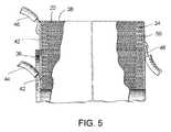
- the sheet 36is generally not centered along the length of the cylindrical section of the element. As illustrated in FIG.
- the sheet 36forms a circular barrier which extends outwardly from that end of the capacitive element 30 having the metalized edge of film. Winding is continued and terminated for the first and second films and the completed element may be wrapped, for example, by a suitable tape 38 .
- the capacitive element 30is metal plated in a manner employed for attaching leads, e.g. the ends are sprayed with molten copper to which a layer of solder is applied. Thereafter, the barrier formed by sheet 36 is trimmed as shown in FIG. 5 .
- the completed element, as shown in FIGS. 3 and 5includes on one end, for example, a copper-solder layer 50 which electrically engages the metalized layer 20 of the first film (for the common single plate).
- the opposite end of the capacitive element 30includes a similar layer 42 which, however, is interrupted by the barrier formed by sheet 36 so that the inner layer engages that portion of metalized layer 24 of the second film (for one capacitor plate) while the outer portion engages the metalized layer 24 which succeeded the formation of the non-metallic region (for another capacitor plate).
- conductors 44 , 46may be soldered to these regions as indicated.
- a conductor 48may be similarly soldered to the opposite end.
- the capacitive element 30 formed from metalized filmis generally compact in size and simultaneously provides for the attachment of leads and maintaining the separate electrical integrity of the multiple capacitors included in the element.
- One or more techniquesmay be employed for producing such capacitive elements, such as techniques described in U.S. Pat. No.
- each of the other capacitive elements 14 and 16can be produced in a similar manner.
- each elementis produced on a central spool or mandrel, which has a central opening.
- First and second dielectric films, each having a metalized layer on one side thereof,are wound in cylindrical form on the mandrel with the nonmetalized side of one film being in contact with the metalized side of the other. Selected portions of one or both of the metalized layers are removed in order to provide a capacitor.
- an element insulation barrieris inserted into the winding to separate the capacitors, the element insulation barrier also assuming a cylindrical configuration.
- the element insulation barriermay be a material such as an insulating polymer sheet material.
- a variety of thicknessesmay be used, for example the thickness may range from 0.0025 to 0.007 inch. Other materials may also be employed, and generally the material or materials employed for the barrier is substantially able to withstand heat from adjacent soldering without losing integrity of electrical insulation, such that adjacent sections can become bridged.
- conductors in the form of insulated wiresare used to electrically connect the capacitive elements 12 , 14 , 16 (as shown in FIG. 2 ).
- the insulation of the wiresmay be color-coded to facilitate identifying which wire is connected to which capacitive element.
- other types of conductorsmay be used in place of or in combination with insulated wires, for example, foil strip conductors may be implemented.
- Each of the capacitive elements 12 , 14 , 16may provide a variety of capacitance levels.
- the two capacitors of each capacitive elementmay provide equivalent capacitances.
- both capacitorsmay have a value of 38.0 microfarads, or, in another arrangement both of the capacitors may have a lesser values such as 19.0 microfarads or larger values such as 76.0 microfarads.
- Different ranges of capacitancemay also be produced for the capacitive elements (e.g., values larger than 76.0 microfarads, values less than 19.0 microfarads, values between 76.0 microfarads and 19.0 microfarads, etc.).
- the capacitive elements 12 , 14 and 16may be designed for larger or smaller KVAR ratings, voltage ratings, etc. as needed. While equivalent capacitance values may be provided by each of the capacitive elements, one or more of the elements may be produced to provide different capacitance values. Similarly, each of the elements may provide one or more capacitance values that are different from the capacitance values provided by other elements. Regarding the methodology described above for producing the capacitive elements, the capacitance value generally increases with the amount of metallic film included in each capacitor; however, one or more other techniques may be implemented for providing capacitors of the sections of the capacitive elements. Further, while each capacitive element may provide two capacitors, more or less capacitors may be provided by a capacitive element.
- the power correction capacitor 10includes a case 60 , having a generally cylindrical side wall and a bottom wall 62 (not visual in the figure).
- the case 60is formed of aluminum and the cylindrical side wall has an outside diameter of approximately 3.50 inches.
- Such a diameter for power correction capacitors of this typecan be considered as being readily receivable in a mounting space.
- Other diametersmay, however, be used, and the case may be produced from other suitable materials such as plastic or a combination of materials.
- one or more insulating fluids(not shown) is provided within the case 60 , at least partly and preferably substantially surrounding all or a portion of the capacitive elements 12 , 14 , 16 .
- a variety of fluidsmay be implemented such as a polyurethane oil.
- the insulating fluidmay have a viscosity in the range of about 500 to 3000 poise at 25° C., and preferably, a viscosity is in the range of about 1900 to 2500 poise at 25° C.
- the insulating fluidmay be produced by reacting a primary polyol, such as castor oil, a ricinoleic acid derivative thereof or a combination of both, with an organic polyisocyanate.
- the reactionmay be carried out in the presence of a secondary polyol which acts as a chain extender for the urethane polymerization.
- Organic polyisocyanates that can be utilized to produce the insulating fluidinclude: aliphatic polyisocyanates, cycloliphatic polyisocyanates, aromatic polyisocyanates, polymethyleneisocyanates, polyphenylisocyanates, methylenediisocyanates and any organic polyisocyanates that are prepolymers prepared by reacting a polyisocyanate with any polyol in quantities such that the NCO/OH ratio is greater than 1 to 1.
- a preferred secondary polyolis hydroxy-terminated polybutadiene diol because it demonstrates outstanding electrical and thermal expansion properties as well as provides structural support to the resulting polymeric matrix.
- the overall NCO/OH ratio (OH groups of both primary and secondary polyols if present) to produce the high viscosity polyurethane oilmay range from about 0.1 to 1 to about 0.6 to 1.
- the desired NCO/OH ratio and the particular polyisocyanate, primary and secondary polyol starting materials chosen for the reactioncan dictate the final viscosity of the resulting polyurethane oil insulating fluid.
- any reaction done with an NCO/OH ratio higher than about 0.6 to 1will generally produce a solid elastomeric material which is unsuitable for use as an insulating oil in metalized film capacitors.
- a polyurethane oil insulating fluid usedis not expected to provide any substantial dielectric properties to the power factor correction capacitor 10 as it is not intended to impregnate or otherwise penetrate into the capacitive elements 12 , 14 , 16 .
- the capacitive elementsare not a hermetically sealed unit, under certain conditions of time, temperature and production techniques, it is possible that some insulating fluid could migrate into the capacitive elements such that the insulating fluid contacts the marginal edges, and in some instances, the few outer layers of the tightly wound metalized polymer films.
- operation of the power factor correction capacitorshould be generally unaffected.
- the power factor correction capacitor 10also has a cover assembly 80 as illustrated in in FIG. 6 .
- the cover assembly 80may provide other functionality.
- the cover assembly 80may include a pressure interrupter.
- the cover assembly 80includes a circular cover 82 , which may be deformable, having an upstanding cylindrical skirt 84 and a peripheral rim.
- the skirt 84generally fits into the open top formed from by the cylindrical side wall of the case 60 , and the peripheral rim may be crimped into position to seal the interior of the capacitor 10 and any fluid contained therein.
- the cover assembly 80includes six cover terminals mounted on the circular cover 82 .
- each of the cover terminalstake the form of a treaded portion of a bolt, however, other types of electrically conductive connections and devices may be utilized.
- Three of the cover terminals 86 , 88 , 90are mounted generally centrally on the circular cover 82 .
- a corresponding cover terminale.g., cover terminals 92 , 94 and 96 ) is mounted at a spaced apart location.
- each of the cover terminals 86 , 88 and 90emerge from a common insulation barrier 98 while the cover terminals 92 , 94 , and 96 emerge from separate insulation barriers 100 , 102 and 104 . Due to their respective separations and insulation barriers, each of the cover terminals are substantially insulated from each another and the circular cover 82 .
- three barrier fins 106extend respectively radially outwardly from a central point of the common insulation barrier to corresponding edges such that they are deployed between adjacent pairs of the cover terminals 86 , 88 and 90 . This provides additional protection against any arcing or bridging contact between adjacent cover terminals 86 , 88 and 90 .
- the three finsmay further extend vertically for additional isolation of the cover terminals 86 , 88 and 90 .
- the cover assembly 80also includes a disconnect plate 108 , which may be constructed of one or more rigid insulating materials such as a phenolic.
- the disconnect plate 108is spaced below the circular cover 82 , e.g., by one or more spacers.
- the disconnect plate 108is provided with openings accommodating the distal ends of terminal posts (not shown) that are respectively connected to a corresponding one of the cover terminals 86 - 96 .
- the openingsallow for electrical connections to be established between the cover terminals 86 - 96 and the capacitors of the capacitive elements 12 , 14 , 16 included in the power factor correction capacitor 10 .
- the disconnect plate 108may be provided with mechanical guides (e.g., raised linear guides, dimple guides 142 , etc.) generally adjacent the openings to accommodate the distal ends of the terminal posts.
- wires, foil strips, etc.may be electrically connected to the distal ends of terminal posts as provided through openings in the disconnect plate 108 .
- wiresare desirable in place of foil strips because they are better accommodated in the case 60 and have good insulating properties, resist nicking and are readily available with colored insulations.
- foil tabsmay be welded to each of the distal ends of the terminal posts of the cover terminals 86 - 96 , and the guides may be helpful in positioning the foil tabs for the welding procedure.
- the attachmentmay be accomplished by welding the distal end of a foil strip to the terminal post, and then cutting the foil strip to leave a foil tab. Thereafter, a wire conductor may be soldered to the tab. Other wires may be similarly connected to their respective cover terminals using this technique or one or more other conductive attachment techniques may be employed.
- one of the two capacitors for each of the capacitive elements 12 , 14 , 16is connected to a corresponding cover terminal 86 , 88 , 90 that emerges from the common insulation barrier 98 and the companion capacitor for each of the capacitive elements 12 , 14 , 16 is connection to a corresponding cover terminal 92 , 94 , 96 that emerges from one of the separate insulation barriers 100 , 102 , 104 .
- the cover terminals and/or insulation barriersmay be color coded to assist a technician with identifying the capacitors (and corresponding capacitance values) of the capacitive elements included in the power factor correction capacitor 10 .
- wire conductors connecting the capacitors (of the capacitive elements) and terminal postsmay be color-coded to facilitate assembly, in that each capacitor and its wire conductor are readily associated with the correct corresponding section cover terminal, and that the correct capacitor and/or capacitive element can be identified on the cover of the cover assembly 80 to make the desired connections for establishing a selected capacitance value.
- each capacitive elementincludes two capacitors that share a common plate. As illustrated in the figure, each capacitor is represented with a capacitor symbol that shares a common electrode with a companion capacitor also formed in the corresponding capacitive element.
- capacitive element 12includes capacitors 110 and 112
- capacitive element 14includes capacitors 114 and 116
- capacitive element 16includes capacitors 118 and 120 . While this particular arrangement provides two capacitor sections in each capacitive element, as indicated with the two capacitor symbols overlaying each of the three capacitive elements, each of the capacitive elements may be produced with more or less capacitors.
- one capacitore.g., capacitors 110 , 114 , 118
- the corresponding companion capacitore.g., capacitors 112 , 116 , 120
- one or more parameterse.g., capacitance value, KVAR, etc.
- the power factor correction capacitor 10e.g., the KVAR provided by the single device can be changed.
- the figureprovides a correspondence between the connections between the capacitors (of the capacitive elements) and the cover terminals of the power factor correction capacitor 10 .
- the capacitors 110 and 112 of capacitive element 12are respectively connected to cover terminal 86 and cover terminal 94 .
- Capacitors 114 and 116are respectively connected to cover terminal 88 and 96
- capacitors 118 and 120are respectively connected to cover terminals 90 and 92 . Also with reference to FIG.
- each capacitor that is connected to one cover terminal that emerges from the common insulation barrier 98e.g., cover terminals 86 , 88 and 90
- one capacitor that is connected to a cover terminal that emerges from one of the separate insulation barrierse.g., cover terminal 94 emerges from insulation barrier 104 , cover terminal 96 emerges from insulation barrier 102 , and cover terminal 92 emerges from insulation barrier 100 ).
- an electrical connectionneeds to be established between one cover terminal that emerges from the common insulation barrier 98 (e.g., cover terminal 86 for capacitor 110 ) and the corresponding cover terminal that emerges from a separate insulation barrier (e.g., cover terminal 94 that emerges from insulation barrier 104 for capacitor 112 ).
- the common insulation barrier 98e.g., cover terminal 86 for capacitor 110
- a separate insulation barriere.g., cover terminal 94 that emerges from insulation barrier 104 for capacitor 112 .
- the power factor correction capacitor 10is able to provide reactive power to a three-phase electrical system such as a three-phase electrical power system.
- a three-phase electrical systemsuch as a three-phase electrical power system.
- three-phase power with a single voltage magnitudecan be delivered to a load.
- other configurationsmay be used for connecting the capacitive elements of the power factor correction capacitor 10 .
- the capacitive elementsmay be connected in a wye, star or other type of configuration that may allow the use of two voltages for the three phases.
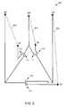
- a schematic diagram 300is presented that represents the capacitors of the three capacitive elements 12 , 14 , and 16 (shown in FIG. 7 ). Along with the individual capacitors 110 , 112 , 114 , 116 , 118 , 120 the diagram 300 also schematically represents the cover terminals 86 , 88 , 90 , 92 , 94 , 96 and the corresponding connections to the capacitors. With reference to FIG. 7 , capacitors 112 , 114 and 118 are connected in a delta configuration while one electrode of each of the companion capacitors 110 , 116 and 120 are simply connected to cover terminals and do not connect to the circuit.
- the delta configurationonly includes the capacitances of the connected capacitors 112 , 114 and 118 , which alone factor into defining the operating parameters of the power factor correction capacitor 10 (i.e., not connected into the delta configuration, the capacitances of capacitors 110 , 116 and 120 do not factor into defining the parameters of the power factor correction capacitor).
- each of the capacitors 112 , 114 and 118 connected into the delta configurationhave equivalent capacitance values.
- each capacitance valuemay be 38 microfarads for each of the capacitors 112 , 114 , 118 .
- a 10 KVAR reactive poweris provided by the power factor correction capacitor 10 .
- the reactive powerproportionally increases.
- the KVAR value provided by the power factor correction capacitor 10correspondingly increases.
- additional capacitancemay be connected in parallel with each capacitor that forms the delta configuration.
- the corresponding companion capacitormay be connected in parallel to the capacitor that is connected to form the delta configuration.
- a schematic diagram 400is presented that represents connecting the respective companion capacitors in parallel to increase the capacitance values included in the delta configuration and correspondingly increase the KVAR value provided by the power factor correction capacitor 10 .
- each of the capacitors 112 , 114 , 118are connected in parallel with their corresponding companion capacitor 110 , 116 or 118 of the respective capacitive elements 12 , 14 and 16 .
- dashed line 402represents capacitor 110 being connected in parallel with capacitor 112
- dashed line 404represents capacitor 114 being connected in parallel with capacitor 116
- dashed line 406represents capacitor 118 being connected in parallel with capacitor 120 .
- the companion capacitorsmay or may not have capacitance values that are equivalent to capacitors already connected into the delta configuration.
- each of the companion capacitor sections 110 , 116 and 120have equivalent capacitance values (e.g., 38 microfarads) that are also equivalent to the capacitance values (e.g., 38 microfarads) of the capacitors 112 , 114 , 118 connected in the delta configuration.
- each capacitive element 12 , 14 , 16now provides a capacitance value of 76 microfarads (i.e., 38 microfarads plus 38 microfarads in parallel) to the delta configuration.
- the reactive power rating of the power factor correction capacitor 10increases to 20 KVAR.
- the dashed lines 402 , 404 and 406represent the electrical connections needed to connect the respective capacitors in parallel.
- One or more techniquesmay be implemented for forming such connections.
- such connectionsmay be formed by using the cover terminals located on the assembly cover 80 of the power factor correction capacitor 10 .
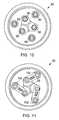
- FIGS. 10 and 11top views of the cover assembly 80 (shown in FIG. 6 ) and the cover terminals are presented.
- these two figuresdemonstrate how the cover terminals 86 , 88 , 90 , 92 , 94 and 96 can be used to form electrical connections to change capacitance values of three capacitive elements 12 , 14 and 16 included in the power factor correction capacitor 10 .
- the delta configuration(as shown in schematic diagram of 300 of FIG. 8 ) is formed by only one capacitor (e.g., capacitors 112 , 114 and 118 ) from each of the three capacitive elements 12 , 14 and 16 .
- terminal cover terminals 86 , 88 and 90are connected into the delta configuration and using the example provided, the power factor correction capacitor 10 provides 10 KVAR by using three capacitance values each of 38 microfarads with a voltage of 480 volts AC at an operating frequency of 60 Hz.
- electrical connectionsare formed between pairs of cover terminals to adjust the KVAR provided by the power factor correction capacitor 10 .
- corresponding pairs of capacitors(of the capacitive elements 12 , 14 and 16 ) are connected in parallel to increase the capacitance values and thereby increase the KVAR of the power factor correction capacitor 10 .
- one conductore.g., conductive plate 500 ) forms an electrical connection between cover terminal 86 and cover terminal 94 .
- each pair of capacitorse.g., capacitors 110 and 112 ; capacitors 114 and 116 ; capacitors 118 and 120
- each corresponding pair of capacitorsis connected in parallel to combine the individual capacitance values.
- the 38 microfarad capacitance of capacitor 110is connected in parallel with the 38 microfarad capacitance of capacitor 112 to form a capacitance value of 76 microfarads.
- the reactive power provided by the power factor correction capacitor 10increases from 10 KVAR to 20 KVAR for an applied voltage of 480 volts AC with an operating frequency of 60 Hz.
- other parameters associated with the power factor correction capacitor 10may be changed. For example, larger or smaller KVAR ratings may be provided by similar power factor correction capacitors that implement these techniques.
- Differentials between the KVAR ratings provided by the power factor correction capacitor 10may also vary. For example, rather than doubling the KVAR values (e.g., from 10 KVAR to 20 KVAR), larger or smaller differentials may be designed (e.g., a power factor correction capacitor provides 10 KVAR or 15 KVAR). Different voltages (e.g., 240 volts AC), voltage ranges (e.g., 240-525 volts AC), operating frequencies (e.g., 50 Hz, 120 Hz, etc.), frequency ranges, etc. may be used by similar power factor correction capacitors that are capable of adjusting their parameters such as KVAR values.
- Different voltagese.g., 240 volts AC
- voltage rangese.g., 240-525 volts AC
- operating frequenciese.g., 50 Hz, 120 Hz, etc.
- frequency ranges, etc.may be used by similar power factor correction capacitors that are capable of adjusting their parameters such as KVAR values.
- each capacitive element 12 , 14 and 16are included in the power factor correction capacitor 10 ; however in some arrangements more or less capacitive elements may be included.
- each capacitive elementincludes two capacitors in the demonstrated example. However, in some arrangements more or less capacitors may be included in each of the capacitive elements.
- different elementsmay be implemented. For example, some of the capacitive elements may include one number of capacitors (e.g., two capacitors) while other capacitive elements may include another number of capacitors (e.g., four, six, eight capacitors). Further the techniques implemented to produce the capacitive elements and components thereof may vary for different types of power factor correction capacitors. Such variations to the capacitive elements may correspondingly call for adjustments to the number of cover terminals present on the cover assembly of a power factor correction capacitor.
- one or more type of devices and construction techniquesmay be implemented connecting the cover terminals.
- the connectionsare provided by metallic plates that have through-holes located at their ends for being bolted onto the cover terminals (e.g., with one or nuts, washers, etc.).
- the cover terminalsmay be provided by threaded bolts, screws, etc. capable of being inserted through one of the holes of the metallic plates.
- different sized holes inmay be drilled into the end of the metallic plates.
- threaded bolts that emerge from the common isolation barrier 98may each have one diameter (e.g., 1 ⁇ 4 inch) while the threaded bolts that emerge from each of the separate isolation barriers 100 , 102 , 104 may have a second diameter (e.g., 5/16 inch).
- each metallic platemay have one hole size (e.g., 1 ⁇ 4 inch diameter) at one end of the plate and the other hole size (e.g., 5/16 inch) at the opposing end of the plate.
- other functionalitymay be incorporated into the power factor correction capacitor 10 .
- capacitive elementsmade of wound metalized polymer film. If the capacitive element fails, it may do so in a sudden and violent manner, producing heat and outgassing such that high internal pressures are developed within the housing.
- Pressure responsive interrupter systemsallow the connection between the capacitive element and the cover terminals to break in response to the high internal pressure, thereby removing the capacitive element from a circuit and stopping the high heat and overpressure condition within the housing before the housing ruptures.
- Such pressure interrupter systemsmay be incorporated in to the power factor correction capacitor 10 .
- a pressure interrupter cover assemblycan provide such protection for the capacitor 10 and its capacitive elements 12 , 14 , 16 .
- outgassingmay cause the circular cover to deform upwardly into a generally domed shape.
- the terminal postsare also displaced upwardly from the disconnect plate, and the electrical connection (e.g., formed by foil leads, foil tabs, etc.) with one of the capacitive elements can break.
- the structural aspects of connections to the cover terminals and terminal postscorresponding to the various capacitors may make a pressure interrupter cover assembly more responsive to failure of one or more of the capacitive elements.
- the solder and wiregreatly enhance the rigidity of foil tabs wherein upon deformation of the cover, the terminal posts may break cleanly from the foil tabs instead of pulling the foil tabs partially before breaking the connection.
- the power factor correction capacitor 10despite having cover terminals, is able to satisfy safety requirements for fluid-filled metalized film capacitors, which may be considered a substantial advance.
Landscapes
- Engineering & Computer Science (AREA)
- Power Engineering (AREA)
- Microelectronics & Electronic Packaging (AREA)
- Manufacturing & Machinery (AREA)
- Fixed Capacitors And Capacitor Manufacturing Machines (AREA)
Abstract
Description
where f is frequency and C is the capacitance of the capacitor. From this quantity, the KVAR rating of the capacitor can be calculated from:
where Vnis the voltage applied to the terminals of the capacitor. As provided by equations (1) and (2), the KVAR rating of a capacitor is directly proportional to the capacitance value of the capacitor and thereby the KVAR rating increases with capacitance. As such, to adjust the KVAR for appropriately supplying a load, different and selectable values of capacitances may need to be installed near the load.
Claims (17)
Priority Applications (5)
| Application Number | Priority Date | Filing Date | Title |
|---|---|---|---|
| US15/276,129US11183335B2 (en) | 2013-05-21 | 2016-09-26 | Power factor correction capacitors |
| US15/705,787US10147549B2 (en) | 2013-05-21 | 2017-09-15 | Power factor correction capacitors |
| US16/207,930US11189425B1 (en) | 2013-05-21 | 2018-12-03 | Power factor correction capacitors |
| US17/532,218US12230451B2 (en) | 2013-05-21 | 2021-11-22 | Power factor correction capacitors |
| US19/031,203US20250239412A1 (en) | 2013-05-21 | 2025-01-17 | Power Factor Correction Capacitors |
Applications Claiming Priority (4)
| Application Number | Priority Date | Filing Date | Title |
|---|---|---|---|
| US201361825850P | 2013-05-21 | 2013-05-21 | |
| US14/283,960US9318261B2 (en) | 2013-05-21 | 2014-05-21 | Power factor correction capacitors |
| US14/663,620US9496086B2 (en) | 2013-05-21 | 2015-03-20 | Power factor correction capacitors |
| US15/276,129US11183335B2 (en) | 2013-05-21 | 2016-09-26 | Power factor correction capacitors |
Related Parent Applications (1)
| Application Number | Title | Priority Date | Filing Date |
|---|---|---|---|
| US14/663,620ContinuationUS9496086B2 (en) | 2013-05-21 | 2015-03-20 | Power factor correction capacitors |
Related Child Applications (1)
| Application Number | Title | Priority Date | Filing Date |
|---|---|---|---|
| US15/705,787ContinuationUS10147549B2 (en) | 2013-05-21 | 2017-09-15 | Power factor correction capacitors |
Publications (2)
| Publication Number | Publication Date |
|---|---|
| US20170011855A1 US20170011855A1 (en) | 2017-01-12 |
| US11183335B2true US11183335B2 (en) | 2021-11-23 |
Family
ID=51934110
Family Applications (7)
| Application Number | Title | Priority Date | Filing Date |
|---|---|---|---|
| US14/283,960ActiveUS9318261B2 (en) | 2013-05-21 | 2014-05-21 | Power factor correction capacitors |
| US14/663,620ActiveUS9496086B2 (en) | 2013-05-21 | 2015-03-20 | Power factor correction capacitors |
| US15/276,129ActiveUS11183335B2 (en) | 2013-05-21 | 2016-09-26 | Power factor correction capacitors |
| US15/705,787ActiveUS10147549B2 (en) | 2013-05-21 | 2017-09-15 | Power factor correction capacitors |
| US16/207,930ActiveUS11189425B1 (en) | 2013-05-21 | 2018-12-03 | Power factor correction capacitors |
| US17/532,218ActiveUS12230451B2 (en) | 2013-05-21 | 2021-11-22 | Power factor correction capacitors |
| US19/031,203PendingUS20250239412A1 (en) | 2013-05-21 | 2025-01-17 | Power Factor Correction Capacitors |
Family Applications Before (2)
| Application Number | Title | Priority Date | Filing Date |
|---|---|---|---|
| US14/283,960ActiveUS9318261B2 (en) | 2013-05-21 | 2014-05-21 | Power factor correction capacitors |
| US14/663,620ActiveUS9496086B2 (en) | 2013-05-21 | 2015-03-20 | Power factor correction capacitors |
Family Applications After (4)
| Application Number | Title | Priority Date | Filing Date |
|---|---|---|---|
| US15/705,787ActiveUS10147549B2 (en) | 2013-05-21 | 2017-09-15 | Power factor correction capacitors |
| US16/207,930ActiveUS11189425B1 (en) | 2013-05-21 | 2018-12-03 | Power factor correction capacitors |
| US17/532,218ActiveUS12230451B2 (en) | 2013-05-21 | 2021-11-22 | Power factor correction capacitors |
| US19/031,203PendingUS20250239412A1 (en) | 2013-05-21 | 2025-01-17 | Power Factor Correction Capacitors |
Country Status (2)
| Country | Link |
|---|---|
| US (7) | US9318261B2 (en) |
| WO (1) | WO2014190072A1 (en) |
Cited By (18)
| Publication number | Priority date | Publication date | Assignee | Title |
|---|---|---|---|---|
| US20220336156A1 (en)* | 2013-05-21 | 2022-10-20 | Amrad Manufacturing, Llc | Power Factor Correction Capacitors |
| US11575298B2 (en) | 2021-04-30 | 2023-02-07 | Amrad Manufacturing, Llc | Hard start kit for multiple replacement applications |
| US11651903B1 (en) | 2005-04-07 | 2023-05-16 | Amrad Manufacturing, Llc | Capacitor for multiple replacement applications |
| USD1045798S1 (en) | 2005-12-23 | 2024-10-08 | Amrad Manufacturing, Llc | Capacitor |
| US12125645B1 (en) | 2019-06-07 | 2024-10-22 | Amrad Manufacturing, Llc | Capacitor with multiple elements for multiple replacement applications |
| USD1052528S1 (en) | 2019-06-25 | 2024-11-26 | Amrad Manufacturing, Llc | Capacitor |
| USD1054379S1 (en) | 2020-11-24 | 2024-12-17 | Amrad Manufacturing, Llc | Capacitor with relay |
| USD1055860S1 (en) | 2018-12-13 | 2024-12-31 | Amrad Manufacturing, Llc | Magnet for attachment to a capacitor |
| US12191087B2 (en) | 2017-05-12 | 2025-01-07 | Amrad Manufacturing, Llc | Capacitor with multiple elements for multiple replacement applications |
| USD1059290S1 (en) | 2019-07-11 | 2025-01-28 | Amrad Manufacturing, Llc | Capacitor |
| US12224131B1 (en) | 2009-11-13 | 2025-02-11 | Amrad Manufacturing, Llc | Hard start kit for multiple replacement applications |
| US12224132B1 (en) | 2005-04-07 | 2025-02-11 | Amrad Manufacturing, Llc | Capacitor with multiple elements for multiple replacement applications |
| US12230447B2 (en) | 2018-12-28 | 2025-02-18 | Amrad Manufacturing, Llc | Capacitor with multiple elements for multiple replacement applications |
| US12230452B1 (en) | 2005-04-07 | 2025-02-18 | Amrad Manufacturing, Llc | Capacitor with multiple elements for multiple replacement applications |
| US12260998B2 (en) | 2005-04-07 | 2025-03-25 | Amrad Manufacturing, Llc | Capacitor with multiple elements for multiple replacement applications |
| US12272503B2 (en) | 2017-05-12 | 2025-04-08 | Amrad Manufacturing, Llc | Capacitor with multiple elements for multiple replacement applications |
| US12293879B2 (en) | 2006-12-29 | 2025-05-06 | Amrad Manufacturing, Llc | Electrolytic capacitive device |
| US12437918B2 (en) | 2023-09-22 | 2025-10-07 | Amrad Manufacturing, Llc | Capacitor mount |
Families Citing this family (7)
| Publication number | Priority date | Publication date | Assignee | Title |
|---|---|---|---|---|
| US11183338B2 (en) | 2005-04-07 | 2021-11-23 | Amrad Manufacturing, Llc | Capacitor with multiple elements for multiple replacement applications |
| US9859060B1 (en) | 2017-02-07 | 2018-01-02 | American Radionic Company, Inc. | Capacitor with multiple elements for multiple replacement applications |
| US11195663B2 (en) | 2017-05-12 | 2021-12-07 | Amrad Manufacturing, Llc | Capacitor with multiple elements for multiple replacement applications |
| US10497518B1 (en) | 2017-12-13 | 2019-12-03 | American Radionic Company, Inc. | Hard start kit for multiple replacement applications |
| US11424077B1 (en) | 2017-12-13 | 2022-08-23 | Amrad Manufacturing, Llc | Hard start kit for multiple replacement applications |
| US10147550B1 (en) | 2018-04-27 | 2018-12-04 | American Radionic Company, Inc. | Capacitor with multiple elements for multiple replacement applications |
| US20230065268A1 (en)* | 2021-08-24 | 2023-03-02 | Eaton Intelligent Power Limited | Dielectric nanofluid for a capacitor system |
Citations (228)
| Publication number | Priority date | Publication date | Assignee | Title |
|---|---|---|---|---|
| US1665499A (en) | 1928-04-10 | System of grouping units | ||
| US1707959A (en) | 1923-10-12 | 1929-04-02 | Dubilier Condenser Corp | Condenser |
| US1789949A (en) | 1930-10-18 | 1931-01-20 | Aerovox Wireless Corp | Electrolytic cell |
| US1943714A (en) | 1930-05-21 | 1934-01-16 | Gen Electric | Combination high and low capacity condenser |
| US2050062A (en) | 1929-11-14 | 1936-08-04 | Ralph D Mershon | Electrolytic condenser |
| GB517718A (en) | 1939-06-21 | 1940-02-07 | Sidney George Brown | Improvements in or relating to electric condensers |
| US2202166A (en) | 1937-11-04 | 1940-05-28 | Mallory & Co Inc P R | Condenser mounting |
| US2296123A (en) | 1941-02-18 | 1942-09-15 | Gen Electric | Electroresponsive device |
| US2569925A (en) | 1948-12-30 | 1951-10-02 | Cornell Dubilier Electric | Terminal block for electrolytic capacitors |
| US2607833A (en) | 1947-12-18 | 1952-08-19 | Stromberg Carlson Co | Telephone ringer |
| US2779813A (en) | 1951-11-16 | 1957-01-29 | Aerovox Corp | Electrical capacitor |
| US2896008A (en) | 1953-12-29 | 1959-07-21 | Mc Graw Edison Co | Seal of bushing to casing of electrical apparatus |
| US2968752A (en) | 1957-01-24 | 1961-01-17 | Sprague Electric Co | Multiple capacitor |
| US3010056A (en) | 1958-12-05 | 1961-11-21 | Illinois Condenser Company | Multiple-terminal miniature capacitor and method of making same |
| US3015687A (en) | 1959-11-03 | 1962-01-02 | Sprague Electric Co | Electrical component terminal |
| US3041477A (en) | 1958-08-08 | 1962-06-26 | Budts Lucien | Multivibrator circuit arrangement |
| US3210457A (en) | 1962-07-23 | 1965-10-05 | Gen Motors Corp | Motor mountable safety capacitor package |
| US3246205A (en) | 1962-07-19 | 1966-04-12 | Imrich M Miller | Capacitor protective device |
| US3302081A (en) | 1965-09-30 | 1967-01-31 | Gen Electric | Capacitor assembly with high resistance shunt |
| US3304473A (en) | 1963-11-12 | 1967-02-14 | Sprague Electric Co | Nonbursting electrical capacitor |
| US3377510A (en) | 1967-11-09 | 1968-04-09 | Gen Electric | Electrical apparatus |
| US3454858A (en) | 1967-06-05 | 1969-07-08 | Cornell Dubilier Electric | High load motor starting arrangement |
| US3473088A (en) | 1965-10-19 | 1969-10-14 | Int Standard Electric Corp | Pressure-activated fuse for electrical components |
| US3524614A (en) | 1968-08-05 | 1970-08-18 | Billy S Sorth | Magnetic cup holder |
| US3553542A (en) | 1969-08-21 | 1971-01-05 | Sprague Electric Co | Capacitor disconnect device |
| US3555370A (en) | 1969-03-17 | 1971-01-12 | Cornell Dubilier Electric | Electrolytic capacitors having improved seal and vent |
| US3593066A (en) | 1969-09-11 | 1971-07-13 | Rayford M Norman | Assembly having a plurality of capacitors |
| US3771321A (en) | 1972-10-04 | 1973-11-13 | Climate Control Systems Inc | Modular air conditioning equipment |
| JPS498748A (en) | 1972-05-25 | 1974-01-25 | ||
| JPS498747A (en) | 1972-05-25 | 1974-01-25 | ||
| US3803457A (en) | 1972-05-09 | 1974-04-09 | Nichicon Capacitor Ltd | Block type electrolytic capacitor |
| US3921041A (en) | 1975-02-24 | 1975-11-18 | American Radionic | Dual capacitor |
| US3988650A (en) | 1974-02-08 | 1976-10-26 | Siemens Aktiengesellschaft | Aluminum-electrolytic capacitor having a low impedance and low inductance |
| US4009425A (en) | 1975-02-14 | 1977-02-22 | Matsushita Electric Industrial Co., Ltd. | Capacitor with intersecting lead plates |
| US4028595A (en) | 1975-12-02 | 1977-06-07 | American Radionic Co., Inc. | Multi-voltage capacitor section |
| FR2343221A1 (en) | 1976-03-01 | 1977-09-30 | Applied Power Inc | DEVICE FOR MEASURING ANGLE RELATIONSHIPS OF VEHICLE WHEELS |
| US4106068A (en) | 1977-01-27 | 1978-08-08 | General Electric Company | Pressure sensitive interrupter |
| US4107758A (en) | 1977-05-16 | 1978-08-15 | Sprague Electric Company | Fused oil filled capacitor |
| US4112424A (en) | 1976-03-12 | 1978-09-05 | Digicourse, Inc. | Alphanumeric display system |
| US4209815A (en) | 1978-04-17 | 1980-06-24 | Jard, Inc. | Capacitor protective circuit |
| US4240126A (en) | 1979-02-16 | 1980-12-16 | Icar Industria Condensatori Applicazioni Elettroelettroniche S.P.A. | Electric capacitor constructed to prevent explosion |
| US4263638A (en) | 1979-06-25 | 1981-04-21 | American Radionic Co., Inc. | Dial wound capacitor and method of making same |
| GB2070861A (en) | 1979-08-03 | 1981-09-09 | Bosch Gmbh Robert | An electrical capacitor |
| US4312027A (en) | 1980-07-21 | 1982-01-19 | American Radionic Co., Inc. | Multiple capacitor winding with electrostatic shielding |
| US4326237A (en) | 1981-01-02 | 1982-04-20 | Sprague Electric Company | Dual AC motor-run capacitors |
| US4352145A (en) | 1980-11-05 | 1982-09-28 | American Radionic Co., Inc. | Multiple element cylindrical metallized film capacitors and method of making the same |
| US4363078A (en) | 1980-04-17 | 1982-12-07 | Sprague Electric Company | Miniature electrolytic capacitor with anchoring terminal |
| US4398782A (en) | 1981-02-26 | 1983-08-16 | Sprague Electric Company | Interrupter for multisection AC capacitors |
| US4408818A (en) | 1981-02-26 | 1983-10-11 | Sprague Electric Company | Capacitor cover-terminal assembly |
| US4420791A (en) | 1981-12-28 | 1983-12-13 | Emhart Industries, Inc. | Dielectric fluid |
| US4447854A (en) | 1982-11-22 | 1984-05-08 | Sprague Electric Company | Oval dual-AC-capacitor package |
| US4459637A (en) | 1983-05-31 | 1984-07-10 | Emhart Industries, Inc. | Dielectric fluid for a capacitor |
| US4486809A (en) | 1981-02-23 | 1984-12-04 | Emhart Industries, Inc. | Anchoring means for a capacitor |
| US4546300A (en) | 1983-03-17 | 1985-10-08 | A. O. Smith Corporation | Electric power supply connection for submersible capacitor-start motor apparatus |
| US4558394A (en) | 1984-04-02 | 1985-12-10 | American Radionic Co., Inc. | Capacitor unit with multiple selectable capacitance values |
| US4586107A (en) | 1984-06-05 | 1986-04-29 | Gen Electric | Dry capacitor circuit interrupter |
| GB2169747A (en) | 1985-01-14 | 1986-07-16 | Ric Limited | Improvements in protective devices for electrical equipment and components, such as capacitors |
| US4609967A (en) | 1985-10-15 | 1986-09-02 | Emhart Industries, Inc. | Dielectric fluid for a capacitor |
| US4621301A (en) | 1985-10-31 | 1986-11-04 | Emhart Industries, Inc. | Dielectric fluid for a capacitor |
| US4631631A (en) | 1985-10-03 | 1986-12-23 | Emhart Industries, Inc. | Capacitor cover and terminal connection |
| US4633367A (en) | 1985-11-27 | 1986-12-30 | North American Philips Corporation | Pressure sensitive fault current interrupter for metallized film capacitors with oil impregnate |
| US4633369A (en) | 1985-02-12 | 1986-12-30 | Cooper Industries, Inc. | Power factor correction capacitor |
| US4633365A (en) | 1985-03-05 | 1986-12-30 | American Radionic Co., Inc. | Metallized capacitor with protective interrupter device and method of making the same |
| US4639828A (en) | 1985-11-27 | 1987-01-27 | North American Philips Corporation | Pressure sensitive fault current interrupter for multiple capacitor device |
| US4642731A (en) | 1986-06-16 | 1987-02-10 | Emhart Industries, Inc. | Dielectric fluid for a capacitor |
| US4698725A (en) | 1986-03-21 | 1987-10-06 | Aerovox Incorporated | Pressure sensitive interrupters for capacitors |
| US4737785A (en) | 1983-03-08 | 1988-04-12 | Hans J. Hertneck | Device for locks |
| US4754361A (en) | 1986-01-20 | 1988-06-28 | Ducati Energia, S.P.A. | Resinated capacitive-body capacitor with interspace and explosion-preventing device |
| US4768129A (en) | 1986-01-17 | 1988-08-30 | Tdk Corporation | Through type twin capacitor |
| US4811161A (en) | 1986-09-11 | 1989-03-07 | Tdk Corporation | Through-type capacitor and magnetron using same |
| US4812941A (en) | 1987-08-19 | 1989-03-14 | Magnetec Corporation | Capacitor and method of manufacture |
| US4897760A (en) | 1988-06-29 | 1990-01-30 | Aerovox, Inc. | Capacitor disconnection |
| USD307000S (en) | 1986-03-25 | 1990-04-03 | Tdk Corporation | Through-type capacitor |
| US5006726A (en) | 1987-03-23 | 1991-04-09 | Murata Manufacturing Co., Ltd. | Pulse generator including coaxial type capacitor |
| US5019934A (en) | 1986-06-04 | 1991-05-28 | Aerovox Incorporated | Capacitor circuit interruption |
| US5032948A (en) | 1989-10-06 | 1991-07-16 | Minnesota Mining And Manufacturing Company | Die cut disposable grounding wrist strap |
| US5138519A (en) | 1991-09-16 | 1992-08-11 | Stockman Robert M | Selectively variable capacitor |
| US5148347A (en) | 1990-05-09 | 1992-09-15 | Aerovox Incorporated | Polymer-encased electrical capacitor with pressure sensitive circuit interrupter |
| US5196818A (en) | 1992-03-30 | 1993-03-23 | Anderson Steven P | Wrist mounted magnetic holder |
| US5247236A (en) | 1989-08-31 | 1993-09-21 | Schroeder Fritz H | Starting device and circuit for starting single phase motors |
| US5280219A (en) | 1991-05-21 | 1994-01-18 | Materials Research Corporation | Cluster tool soft etch module and ECR plasma generator therefor |
| US5313360A (en) | 1993-06-28 | 1994-05-17 | American Radionic Co., Inc. | Dual Capacitor |
| US5381301A (en) | 1993-05-11 | 1995-01-10 | Aerovox Incorporated | Leak-tight and rupture proof, ultrasonically-welded, polymer-encased electrical capacitor with pressure sensitive circuit interrupter |
| US5412532A (en) | 1992-11-24 | 1995-05-02 | Matsushita Electric Industrial Co., Ltd. | Polygonal capacitor |
| JPH07211596A (en) | 1994-01-21 | 1995-08-11 | Sanyo Electric Co Ltd | Electronic component and its manufacture |
| US5528120A (en) | 1994-09-09 | 1996-06-18 | Sealed Unit Parts Co., Inc. | Adjustable electronic potential relay |
| US5561357A (en) | 1995-04-24 | 1996-10-01 | Schroeder; Fritz H. | Starting device and circuit for starting single phase motors |
| US5673168A (en) | 1995-12-19 | 1997-09-30 | United Chemi-Con Manufacturing | High ripple current capacitor |
| US5691845A (en) | 1994-08-12 | 1997-11-25 | Tdk Corporation | Optical isolator, optical isolator with fiber and method for making the same |
| US5817975A (en) | 1995-09-21 | 1998-10-06 | Magnetek, Inc. | Housing with integral mounting bracket |
| US5917975A (en) | 1996-12-10 | 1999-06-29 | Bloom; Cary | Apparatus for, and method of, forming a low stress tight fit of an optical fiber to an external element |
| US5921820A (en) | 1996-09-24 | 1999-07-13 | Bc Components Holdings B.V. | Passive component |
| US5940263A (en) | 1995-03-23 | 1999-08-17 | Jakoubovitch; Albert | Power capacitor bank switching devices |
| US6009348A (en) | 1998-04-03 | 1999-12-28 | Medtronic, Inc. | Implantable medical device having flat electrolytic capacitor with registered electrode layers |
| US6014308A (en) | 1998-10-28 | 2000-01-11 | American Radionic Co., Inc. | Metallized polymer film capacitor having a high viscosity polyurethane oil insulating fluid |
| US6031713A (en) | 1997-06-25 | 2000-02-29 | Matsushita Electric Industrial Co., Ltd. | Aluminum electrolytic capacitor |
| US6084764A (en) | 1998-12-21 | 2000-07-04 | Hamilton Sundstrand Corporation | Capacitor disconnecting assembly |
| US6141205A (en) | 1998-04-03 | 2000-10-31 | Medtronic, Inc. | Implantable medical device having flat electrolytic capacitor with consolidated electrode tabs and corresponding feedthroughs |
| US6147856A (en) | 1999-03-31 | 2000-11-14 | International Business Machine Corporation | Variable capacitor with wobble motor disc selector |
| US6157531A (en) | 1998-04-03 | 2000-12-05 | Medtronic, Inc. | Implantable medical device having flat electrolytic capacitor with liquid electrolyte fill tube |
| US6160465A (en) | 1997-11-07 | 2000-12-12 | Murata Manufacturing Co. Ltd. | High-frequency choke coil |
| US6212058B1 (en) | 1998-04-01 | 2001-04-03 | Vishay Electronic Gmbh | Power capacitor |
| US6222270B1 (en) | 1997-06-24 | 2001-04-24 | Samsung Electronics Co., Ltd. | Integrated circuit bonding pads including closed vias and closed conductive patterns |
| US6229236B1 (en) | 1999-06-30 | 2001-05-08 | Lynn Edwin Fisher | Mounting bracket for motor capacitor |
| US6233133B1 (en) | 1999-05-05 | 2001-05-15 | Shui-Te Weng | Capacitor |
| EP1115128A2 (en) | 2000-01-05 | 2001-07-11 | American Radionic Co., Inc. | Fluid-filled capacitor with pressure interrupter means and internal compressible air chamber |
| US6282081B1 (en) | 1999-02-17 | 2001-08-28 | Hitachi Maxell, Ltd. | Electrode for capacitor, method for producing the same and capacitor |
| US6282078B1 (en) | 2000-04-19 | 2001-08-28 | Real Power Cap Company | Capacitor for car stereo with current distributing capability |
| US20010025618A1 (en) | 2000-03-24 | 2001-10-04 | Kelling Gordon L. | Capacitive remote vehicle starter |
| US6310756B1 (en) | 1999-03-02 | 2001-10-30 | Matsushita Electric Industrial Co., Ltd. | Capacitor |
| US20020030548A1 (en) | 2000-05-17 | 2002-03-14 | Murata Manufacturing Co., Ltd. | Nonreciprocal circuit device and communication apparatus including the same |
| US6373720B1 (en) | 1998-04-22 | 2002-04-16 | Alcatel | Module with electronic components |
| US6385490B1 (en) | 1999-12-16 | 2002-05-07 | Cardiac Pacemakers, Inc. | Capacitors with recessed rivets allow smaller implantable defibrillators |
| US6404618B1 (en) | 2000-11-06 | 2002-06-11 | Yosemite Investment Co. Inc. | Electrolytic capacitor operable as an A/C capacitor |
| US6410184B1 (en) | 1999-01-28 | 2002-06-25 | Sanyo Electric Co., Ltd. | Power source containing rechargeable batteries |
| US6490158B1 (en) | 2001-10-04 | 2002-12-03 | Diversitech Corporation | Motor start capacitor assembly |
| US6538544B1 (en) | 2000-06-26 | 2003-03-25 | Industrial Magnetics, Inc. | Pneumatically actuated magnetic workpiece holder |
| US6552893B2 (en) | 2000-11-08 | 2003-04-22 | Matsushita Electric Industrial Co., Ltd. | Capacitor |
| US6697249B2 (en) | 2000-11-09 | 2004-02-24 | Foc Frankenburg Oil Company | Supercapacitor and a method of manufacturing such a supercapacitor |
| US6798677B2 (en) | 2000-08-01 | 2004-09-28 | Alstom | Modular power converter |
| US6807048B1 (en) | 2003-05-30 | 2004-10-19 | Medtronic, Inc. | Electrolytic capacitor for use in an implantable medical device |
| US6816541B1 (en) | 1999-05-24 | 2004-11-09 | Texas Instruments Incorporated | Spread spectrum interference cancellation |
| US6819545B1 (en) | 2003-03-21 | 2004-11-16 | Parallax Power Components, Llc | High current capacitors |
| US6842328B2 (en) | 2003-05-30 | 2005-01-11 | Joachim Hossick Schott | Capacitor and method for producing a capacitor |
| US6847517B2 (en) | 2002-11-29 | 2005-01-25 | Honda Motor Co., Ltd. | Polarizable electrode for electric double layer capacitor and methods for producing polarizable electrode and capacitor |
| US6888266B2 (en) | 2001-03-08 | 2005-05-03 | Kold Ban International, Ltd. | Vehicle with switched supplemental energy storage system for engine cranking |
| US6922330B2 (en) | 2002-04-18 | 2005-07-26 | Medtronic, Inc. | Implantable medical device having flat electrolytic capacitor fabricated with laser welded anode sheets |
| US20050272012A1 (en) | 2004-04-15 | 2005-12-08 | Sean Logan | Method and apparatus for thermal coding of colors |
| US6982539B1 (en) | 2004-03-11 | 2006-01-03 | Diversitech Corporation | Motor starting device |
| US20060007387A1 (en) | 2004-07-01 | 2006-01-12 | Xiao Tony X | Flip up clip on frame with stepless angle control hinge |
| US6995971B2 (en) | 2003-05-30 | 2006-02-07 | Medtronic, Inc. | Capacitors including interacting separators and surfactants |
| US20060067031A1 (en) | 2004-09-24 | 2006-03-30 | Silicon Bandwidth, Inc. | Decoupling capacitor for an integrated circuit and method of manufacturing thereof |
| US7031139B1 (en) | 2002-12-05 | 2006-04-18 | Pacesetter, Inc. | Stackable capacitor having opposed contacts for an implantable electronic medical device |
| US7046498B1 (en) | 2004-12-15 | 2006-05-16 | Shou-Hsiung Huang | C-shaped combination capacitor assembly |
| USD522456S1 (en) | 2002-11-29 | 2006-06-06 | Honda Giken Kogyo Kabushiki Kaisha | Capacitor cell |
| US20060201971A1 (en) | 2005-03-14 | 2006-09-14 | Xerox Corporation | Particle dispenser cartridge arranged with dispenser nozzle outer shutter rails |
| US7110240B2 (en) | 2000-03-20 | 2006-09-19 | Medtronic, Inc. | Implantable medical device having flat electrolytic capacitor with differing sized anode and cathode layers |
| US20060227495A1 (en)* | 2005-04-07 | 2006-10-12 | Stockman Robert M | Capacitor for multiple replacement applications |
| US20070025051A1 (en) | 2005-04-07 | 2007-02-01 | Stockman Robert M | Capacitor with multiple elements for multiple replacement applications |
| US7184256B1 (en) | 2005-08-29 | 2007-02-27 | Tdk Corporation | High-voltage feed-through capacitor and magnetron |
| JP2007059477A (en) | 2005-08-22 | 2007-03-08 | Nichicon Corp | Solid electrolytic capacitor |
| US7206186B1 (en) | 2006-05-31 | 2007-04-17 | Cornell Dubilier Marketing, Inc. | Hermetically sealed electrolytic capacitor |
| US7251123B2 (en) | 1998-10-02 | 2007-07-31 | Cardiac Pacemakers, Inc. | Smaller electrolytic capacitors for implantable defibrillators |
| US20070221278A1 (en) | 2004-05-14 | 2007-09-27 | Hydrelis | Flow Interrupter for a Liquid or Gaseous Fluid Flow Pipe |
| USD551943S1 (en) | 2006-02-28 | 2007-10-02 | The Gates Corporation | Dual-mass damper |
| US20070279015A1 (en) | 2006-06-05 | 2007-12-06 | Livingston Francis X | Integrated power factor correction capacitance unit |
| US20070283707A1 (en) | 2006-05-11 | 2007-12-13 | Matsushita Electric Industrial Co., Ltd. | Air conditioner |
| US20070295877A1 (en) | 2006-06-20 | 2007-12-27 | Gaydos Deanne | Magnetic Cup Holder |
| USD562237S1 (en) | 2007-05-14 | 2008-02-19 | Ta-Sen Tu | DC motor |
| US7365959B1 (en)* | 2004-08-12 | 2008-04-29 | Charles Barry Ward | Multi value capacitor |
| US20080158780A1 (en) | 2006-12-29 | 2008-07-03 | American Radionic Company, Inc. | Electrolytic Capacitor |
| US20080217053A1 (en) | 2007-03-05 | 2008-09-11 | Robert Vojtila | Insulation barrier for high voltage power lines and method of installation of same |
| US20090001921A1 (en) | 2006-01-20 | 2009-01-01 | Carrier Corporation | Electronic Method for Starting a Compressor |
| US7474520B2 (en) | 2005-05-06 | 2009-01-06 | Asahi Glass Company, Limited | Storage device |
| US7492574B2 (en) | 2005-03-14 | 2009-02-17 | Maxwell Technologies, Inc. | Coupling of cell to housing |
| US20090059463A1 (en)* | 2007-08-27 | 2009-03-05 | Charles Barry Ward | Multi-value capacitor with safety disconnect mechanism |
| US7511941B1 (en) | 2005-06-08 | 2009-03-31 | Maxwell Technologies, Inc. | Ultrasonic sealed fill hole |
| US20090115557A1 (en) | 2006-03-31 | 2009-05-07 | Omron Corporation | Electromagnetic relay |
| US7547233B2 (en) | 2003-09-18 | 2009-06-16 | Panasonic Corporation | Capacitor unit |
| US20090261762A1 (en) | 2008-04-16 | 2009-10-22 | Toyota Jidosha Kabushiki Kaisha | Drive device, hybrid vehicle equipped with the drive device, and control method for drive device |
| US7619420B2 (en) | 2006-08-21 | 2009-11-17 | American Radionic Company, Inc. | Capacitance measurement device |
| US7667954B2 (en) | 2003-05-30 | 2010-02-23 | Medtronic, Inc. | Capacitor |
| WO2010031594A1 (en) | 2008-09-19 | 2010-03-25 | Bombardier Transportation Gmbh | Arrangement and method for holding a plurality of electric capacitor assemblies |
| WO2010037186A1 (en) | 2008-09-30 | 2010-04-08 | Carrier Corporation | Cylindrical condenser |
| US7710713B2 (en) | 2006-09-20 | 2010-05-04 | Greatbatch Ltd. | Flat sealing of anode/separator assembly for use in capacitors |
| USD621789S1 (en) | 2009-10-27 | 2010-08-17 | Hon Hai Precision Ind. Co., Ltd. | Electrical connector |
| USD623500S1 (en) | 2009-04-20 | 2010-09-14 | Armorworks Enterprises, Llc | Tie-down base plate |
| US7848079B1 (en) | 2006-01-18 | 2010-12-07 | Musco Corporation | Multi-capacitor assembly |
| US20110003173A1 (en) | 2003-09-26 | 2011-01-06 | Furuya Metal Co., Ltd. | Silver alloy, sputtering target material thereof, and thin film thereof |
| US7867290B2 (en) | 2009-01-12 | 2011-01-11 | Medtronic, Inc. | Separator filled with electrolyte |
| US7881043B2 (en) | 2005-12-01 | 2011-02-01 | Panasonic Corporation | Wound electric double-layer capacitor |
| US7911766B2 (en) | 2004-06-11 | 2011-03-22 | Batscap | Supercapacitor cover with integrated center terminal |
| CN101991323A (en) | 2009-08-31 | 2011-03-30 | 南通芯迎设计服务有限公司 | Magnetic paper cup holder |
| US20110075342A1 (en) | 2009-09-30 | 2011-03-31 | Apple Inc. | Cover glass to housing interface system |
| US20110134584A1 (en) | 2009-11-13 | 2011-06-09 | Stockman Richard W | Hard start kit for multiple replacement applications |
| US7987593B1 (en)* | 2009-03-02 | 2011-08-02 | Direct Brand Ltd. | Method for generating selective capacitance values |
| US8029290B2 (en) | 2008-03-10 | 2011-10-04 | Regal Beloit Corporation | Methods and apparatus for coupling capacitors |
| US20120026046A1 (en) | 2010-07-30 | 2012-02-02 | Motorola, Inc. | Antenna integrated with a portable communication device |
| US8170662B2 (en) | 2006-08-03 | 2012-05-01 | Cardiac Pacemakers, Inc. | Method and apparatus for charging partitioned capacitors |
| US8174817B2 (en) | 2009-06-16 | 2012-05-08 | High Energy Corp. | Sealed and impregnated wound capacitor assemblies |
| US8274778B2 (en) | 2008-01-17 | 2012-09-25 | Toyota Jidosha Kabushiki Kaisha | Capacitor |
| US8310802B2 (en) | 2006-08-28 | 2012-11-13 | Panasonic Corporation | Metallization film capacitor having divided electrode with fuse |
| US8331076B2 (en) | 2010-07-16 | 2012-12-11 | Ut-Battelle, Llc | Clad fiber capacitor and method of making same |
| EP2587503A2 (en) | 2010-06-28 | 2013-05-01 | International Capacitors S. A. | Power capacitor for low voltage, provided with capacitor elements, a capacitor element and a method for producing said capacitor element |
| US8465555B2 (en) | 2004-07-16 | 2013-06-18 | Cardiac Pacemakers, Inc. | Method and apparatus for high voltage aluminum capacitor design |
| US8514547B2 (en) | 2010-11-01 | 2013-08-20 | Avx Corporation | Volumetrically efficient wet electrolytic capacitor |
| US8514548B2 (en) | 2009-07-27 | 2013-08-20 | The Paper Battery Co. | Compliant energy storing structural sheet |
| US8559161B2 (en) | 2009-11-04 | 2013-10-15 | Panasonic Corporation | Metallized film capacitor and case mold type capacitor including same |
| US20140049205A1 (en) | 2012-08-15 | 2014-02-20 | Rbc Manufacturing Corporation | Start capacitor assemblies and methods for operating electric motors |
| US20140126107A1 (en) | 2011-06-29 | 2014-05-08 | Soshin Electric Co., Ltd. | Capacitor |
| US20140138009A1 (en) | 2012-11-19 | 2014-05-22 | Samsung Display Co., Ltd. | Method and apparatus for manufacturing flexible display device |
| US8761875B2 (en) | 2006-08-03 | 2014-06-24 | Cardiac Pacemakers, Inc. | Method and apparatus for selectable energy storage partitioned capacitor |
| US20140201018A1 (en) | 2008-09-29 | 2014-07-17 | Battelle Memorial Institute | Electric power grid control using a market-based resource allocation system |
| US20140232485A1 (en) | 2011-07-08 | 2014-08-21 | Kemet Electronics Corporation | Discharge Capacitor |
| US8842411B2 (en) | 2011-02-23 | 2014-09-23 | Pacesetter, Inc. | RF trapezoidal capacitor based EMI feedthru filter assembly |
| US8853318B2 (en) | 2008-06-06 | 2014-10-07 | Allnex Belgium S.A. | Aqueous radiation curable polyurethane compositions |
| US8861178B2 (en) | 2012-05-25 | 2014-10-14 | Kojima Press Industry Co., Ltd. | Film capacitor element, film capacitor, and method of producing the film capacitor element |
| US8861184B2 (en) | 2007-08-07 | 2014-10-14 | MAX-PLANCK-Gesellschaft zur Förderung der Wissenschaften e.V. | Method for fabricating a multi-layer capacitor and a multi-layer capacitor |
| US8871850B2 (en) | 2006-02-01 | 2014-10-28 | Daikin Industries, Ltd. | Highly dielectric film |
| US20140347784A1 (en) | 2013-05-21 | 2014-11-27 | American Radionic Company, Inc. | Power Factor Correction Capacitors |
| US20150022991A1 (en) | 2005-04-07 | 2015-01-22 | American Radionic Company, Inc. | Capacitor with multiple elements for multiple replacement applications |
| USD729164S1 (en) | 2013-09-02 | 2015-05-12 | Foshan City Shunde District Lun Jiao Sheng Ye Electrical Co., Ltd | Capacitor |
| CN204351550U (en) | 2014-12-15 | 2015-05-27 | 尹德耀 | A kind of multipurpose magnetic force glass stand |
| JP2015130259A (en) | 2014-01-07 | 2015-07-16 | 日本特殊陶業株式会社 | Relay and junction block |
| US9105401B2 (en) | 2011-12-02 | 2015-08-11 | Avx Corporation | Wet electrolytic capacitor containing a gelled working electrolyte |
| US20150287308A1 (en) | 2014-04-04 | 2015-10-08 | Timothy G. Shuttleworth | Security systems for containers |
| US20160028230A1 (en) | 2014-07-22 | 2016-01-28 | Richard H. Sherratt and Susan B. Sherratt Trust Fund | DC Energy Transfer Apparatus, Applications, Components, and Methods |
| US9466429B1 (en) | 2014-02-07 | 2016-10-11 | Cornell Dubilier Marketing, Inc. | Configurable multi-capacitor assembly |
| USD771567S1 (en) | 2014-02-07 | 2016-11-15 | Siemens Aktiengesellschaft | Corona ring |
| US20170229242A1 (en) | 2012-04-25 | 2017-08-10 | Mjg Innovations, Llc | Protected capacitor system and method |
| US20170372838A1 (en) | 2016-06-28 | 2017-12-28 | Cornell Dubilier Electronics, Inc. | Capacitor with pressure interrupter |
| US9859060B1 (en) | 2017-02-07 | 2018-01-02 | American Radionic Company, Inc. | Capacitor with multiple elements for multiple replacement applications |
| US20180061600A1 (en) | 2016-08-31 | 2018-03-01 | Panasonic Intellectual Property Management Co., Ltd. | Electromagnetic relay |
| US9916934B1 (en) | 2016-04-11 | 2018-03-13 | Cornell Dubilier Electronics, Inc. | Multi-rated capacitor assembly |
| USD818437S1 (en) | 2005-12-23 | 2018-05-22 | American Radionic Company, Inc. | Capacitor |
| US20180254150A1 (en) | 2005-04-07 | 2018-09-06 | American Radionic Company, Inc. | Capacitor with multiple elements for multiple replacement applications |
| CN304806073S (en) | 2018-09-07 | |||
| US20180261391A1 (en) | 2005-04-07 | 2018-09-13 | American Radionic Company, Inc. | Capacitor with multiple elements for multiple replacement applications |
| US10147550B1 (en) | 2018-04-27 | 2018-12-04 | American Radionic Company, Inc. | Capacitor with multiple elements for multiple replacement applications |
| US10209751B2 (en) | 2012-02-14 | 2019-02-19 | Emerson Electric Co. | Relay switch control and related methods |
| US10256195B2 (en) | 2015-06-19 | 2019-04-09 | Murata Manufacturing Co., Ltd. | Module and method for manufacturing same |
| US10497518B1 (en) | 2017-12-13 | 2019-12-03 | American Radionic Company, Inc. | Hard start kit for multiple replacement applications |
| US20200066470A1 (en) | 2018-08-25 | 2020-02-27 | Soweto Abijah Mitchell | Multi-functional multi-purpose magnetically operated electric switch |
| US10586655B1 (en) | 2018-12-28 | 2020-03-10 | American Radionic Company, Inc. | Capacitor with multiple elements for multiple replacement applications |
| US20200161507A1 (en) | 2018-11-21 | 2020-05-21 | Osram Opto Semiconductors Gmbh | Barrier Layer Functioned Novel-Structure Ceramic Converter Materials and Light Emitting Devices |
| WO2020123834A1 (en) | 2018-12-12 | 2020-06-18 | Priefert Mfg. Co, Inc. | Heavy duty detachable beverage and phone holder and associated systems and methods |
| USD892741S1 (en) | 2018-08-02 | 2020-08-11 | Lester Electrical | Receptacle assembly |
| USD893441S1 (en) | 2019-06-28 | 2020-08-18 | Applied Materials, Inc. | Base plate for a processing chamber substrate support |
Family Cites Families (62)
| Publication number | Priority date | Publication date | Assignee | Title |
|---|---|---|---|---|
| CA204952A (en) | 1920-10-19 | A. Denmire Harold | Collapsible tire core | |
| CA204951A (en) | 1920-10-19 | T. Gasper Frank | Electro-magnetic device | |
| CA188725A (en) | 1918-03-25 | 1919-02-18 | George Petrie Sandie | Bed for invalids |
| US2974234A (en) | 1958-10-10 | 1961-03-07 | Raymond N Rowe | Dynamoelectric device |
| US3955170A (en) | 1974-11-29 | 1976-05-04 | Texas Instruments Incorporated | Solid state switch |
| US4112474A (en) | 1977-01-27 | 1978-09-05 | General Electric Company | Capacitor protective device |
| USD253887S (en) | 1977-06-28 | 1980-01-08 | Turner James F | Panel for an electronic module |
| GB1602610A (en) | 1977-08-11 | 1981-11-11 | Ching Wa Pun | Electric batteries |
| US4360848A (en) | 1980-06-18 | 1982-11-23 | Noutko Theodore E | Capacitor protective device |
| US4388669A (en) | 1981-02-19 | 1983-06-14 | General Electric Company | Polyglycol dielectric capacitor fluid |
| US4813116A (en) | 1981-08-18 | 1989-03-21 | Westinghouse Electric Corp. | Method of making a multi-section power capacitor with all-film dielectric |
| DE3319373A1 (en) | 1983-05-27 | 1984-11-29 | Siemens AG, 1000 Berlin und 8000 München | ELECTRIC CAPACITOR |
| GB2174544B (en) | 1985-05-01 | 1988-08-24 | Ric Limited | Improvements in capacitous employing protective devices |
| CN2033169U (en) | 1987-09-02 | 1989-02-22 | 王晓云 | Singal phase long life electricity-saving motor |
| US5162718A (en) | 1989-08-31 | 1992-11-10 | Schroeder Fritz H | Starting device and circuit for starting single phase motors |
| US4992910A (en) | 1989-11-06 | 1991-02-12 | The Evans Findings Company, Inc. | Electrical component package |
| JPH0758661B2 (en) | 1990-10-01 | 1995-06-21 | 松下電器産業株式会社 | Composite capacitor |
| KR100366551B1 (en) | 1994-09-29 | 2003-03-12 | 닛뽄 케미콘 가부시끼가이샤 | Electrolytic Capacitors |
| JP3524237B2 (en) | 1995-09-27 | 2004-05-10 | ソニー株式会社 | Electric vehicle battery structure |
| JPH09129519A (en) | 1995-10-30 | 1997-05-16 | Matsushita Electric Ind Co Ltd | Electrolytic capacitor with safety mechanism |
| USD408266S (en) | 1998-04-01 | 1999-04-20 | Santiago John V | Panel support |
| US6320348B1 (en) | 1999-06-14 | 2001-11-20 | Andrew S. Kadah | Time rate of change motor start circuit |
| JP2001177310A (en) | 1999-12-16 | 2001-06-29 | Murata Mfg Co Ltd | Irreversible circuit element and communication unit |
| USD464028S1 (en) | 2001-03-19 | 2002-10-08 | Amherst Holding Co. | Fiber holder adapter |
| US6466429B1 (en) | 2001-05-03 | 2002-10-15 | C And T Co., Inc. | Electric double layer capacitor |
| USD504181S1 (en) | 2001-11-08 | 2005-04-19 | Pergo (Europe) Ab | Laminate transition molding |
| US6720689B2 (en) | 2001-12-11 | 2004-04-13 | Black & Decker Inc. | Brushless motor having capacitors mounted on sidewall of motor housing |
| US6706079B1 (en) | 2002-05-03 | 2004-03-16 | C And T Company, Inc. | Method of formation and charge of the negative polarizable carbon electrode in an electric double layer capacitor |
| USD509801S1 (en) | 2002-11-12 | 2005-09-20 | Ilsco Corporation | Interconnect for electrically connecting plural electrically conductive neutral bars in fixed spaced-apart relationship |
| KR100560494B1 (en) | 2003-11-29 | 2006-03-13 | 삼성에스디아이 주식회사 | Cap Assembly and Secondary Battery Using the Same |
| USD541746S1 (en) | 2004-04-29 | 2007-05-01 | Durable Systems, Inc. | Thermal body |
| USD541218S1 (en) | 2004-05-26 | 2007-04-24 | Durable Systems, Inc. | Thermal material body |
| USD529202S1 (en) | 2005-01-28 | 2006-09-26 | Matsushita Electric Industrial Co., Ltd. | LED module |
| US11183337B1 (en) | 2005-04-07 | 2021-11-23 | Amrad Manufacturing, Llc | Capacitor with multiple elements for multiple replacement applications |
| JP2007006566A (en) | 2005-06-22 | 2007-01-11 | Hitachi Ltd | Motor control device |
| US8059856B2 (en) | 2006-07-31 | 2011-11-15 | Peavey Electronics Corporation | Methods and apparatus for providing a heat sink for a loudspeaker |
| USD573008S1 (en) | 2006-09-08 | 2008-07-15 | Mark Sipe | Heavyweight wire support |
| US7337945B1 (en) | 2007-05-01 | 2008-03-04 | Riggs Robert W | Mailbox delivery indicator apparatus |
| KR100922855B1 (en)* | 2007-10-25 | 2009-10-27 | 킴스테크날리지 주식회사 | Stacked electrochemical cell with quasi-bipolar structure |
| US8619409B2 (en)* | 2008-10-01 | 2013-12-31 | Taiyo Yuden Co., Ltd. | Electrochemical device |
| KR101049282B1 (en) | 2009-03-03 | 2011-07-13 | 주식회사 네스캡 | Electrical energy storage |
| US8149568B2 (en) | 2010-03-18 | 2012-04-03 | Northern Lights Semiconductor Corp. | Load system for an Mcap energy storage module |
| US9947467B2 (en) | 2012-04-25 | 2018-04-17 | Mjg Innovations, Llc | Protected capacitor system and method |
| USD681438S1 (en) | 2012-04-30 | 2013-05-07 | Clenergy (Xiamen) Technology Co., Ltd. | Pivotable rail clamp |
| USD707639S1 (en) | 2013-03-18 | 2014-06-24 | American Tack & Hardware Co., Inc. | Switch guard |
| TWD160510S (en) | 2013-08-30 | 2014-05-11 | 東貝光電科技股份有限公司 | LED bracket |
| CN104201077A (en) | 2014-09-18 | 2014-12-10 | 青岛易特优电子有限公司 | Built-in thermal fuse device |
| KR20160061825A (en) | 2014-11-24 | 2016-06-01 | 한국단자공업 주식회사 | Fuse/relay unit |
| USD747225S1 (en) | 2015-01-30 | 2016-01-12 | Itt Manufacturing Enterprises Llc. | Mounting bracket and a combination of a mounting bracket and a sensing module |
| CN204539389U (en) | 2015-04-09 | 2015-08-05 | 深圳市沃思行科技发展有限公司 | A kind of car-mounted device |
| JP1557475S (en) | 2015-11-17 | 2016-08-29 | ||
| USD816470S1 (en) | 2015-12-09 | 2018-05-01 | Andy Green | String groove masonry clamp |
| US11195663B2 (en) | 2017-05-12 | 2021-12-07 | Amrad Manufacturing, Llc | Capacitor with multiple elements for multiple replacement applications |
| CN208608067U (en) | 2017-05-12 | 2019-03-15 | 美国射电电子公司 | It is a kind of that the device of multiple optional capacitances is provided |
| JP1614953S (en) | 2017-11-28 | 2018-10-01 | ||
| US11424077B1 (en) | 2017-12-13 | 2022-08-23 | Amrad Manufacturing, Llc | Hard start kit for multiple replacement applications |
| WO2020044645A1 (en) | 2018-08-29 | 2020-03-05 | 株式会社前田シェルサービス | Magnetic filter device |
| USD906969S1 (en) | 2018-12-13 | 2021-01-05 | American Radionic Company, Inc. | Magnet for attachment to a capacitor |
| USD906247S1 (en) | 2019-07-11 | 2020-12-29 | American Radionic Company, Inc. | Capacitor |
| USD914605S1 (en) | 2019-09-09 | 2021-03-30 | Sunsun Electronic Technology Inc. | Electric fence element |
| USD943535S1 (en) | 2020-01-23 | 2022-02-15 | Harting Ag | Electrically insulating connector part to be mounted on a printed circuit board |
| CA3157689A1 (en) | 2021-04-30 | 2022-10-30 | Amrad Manufacturing, Llc | Hard start kit for multiple replacement applications |
- 2014
- 2014-05-21USUS14/283,960patent/US9318261B2/enactiveActive
- 2014-05-21WOPCT/US2014/039003patent/WO2014190072A1/enactiveApplication Filing
- 2015
- 2015-03-20USUS14/663,620patent/US9496086B2/enactiveActive
- 2016
- 2016-09-26USUS15/276,129patent/US11183335B2/enactiveActive
- 2017
- 2017-09-15USUS15/705,787patent/US10147549B2/enactiveActive
- 2018
- 2018-12-03USUS16/207,930patent/US11189425B1/enactiveActive
- 2021
- 2021-11-22USUS17/532,218patent/US12230451B2/enactiveActive
- 2025
- 2025-01-17USUS19/031,203patent/US20250239412A1/enactivePending
Patent Citations (288)
| Publication number | Priority date | Publication date | Assignee | Title |
|---|---|---|---|---|
| CN305625370S (en) | 2020-02-21 | |||
| CN304806073S (en) | 2018-09-07 | |||
| US1665499A (en) | 1928-04-10 | System of grouping units | ||
| US1707959A (en) | 1923-10-12 | 1929-04-02 | Dubilier Condenser Corp | Condenser |
| US2050062A (en) | 1929-11-14 | 1936-08-04 | Ralph D Mershon | Electrolytic condenser |
| US1943714A (en) | 1930-05-21 | 1934-01-16 | Gen Electric | Combination high and low capacity condenser |
| US1789949A (en) | 1930-10-18 | 1931-01-20 | Aerovox Wireless Corp | Electrolytic cell |
| US2202166A (en) | 1937-11-04 | 1940-05-28 | Mallory & Co Inc P R | Condenser mounting |
| GB517718A (en) | 1939-06-21 | 1940-02-07 | Sidney George Brown | Improvements in or relating to electric condensers |
| US2296123A (en) | 1941-02-18 | 1942-09-15 | Gen Electric | Electroresponsive device |
| US2607833A (en) | 1947-12-18 | 1952-08-19 | Stromberg Carlson Co | Telephone ringer |
| US2569925A (en) | 1948-12-30 | 1951-10-02 | Cornell Dubilier Electric | Terminal block for electrolytic capacitors |
| US2779813A (en) | 1951-11-16 | 1957-01-29 | Aerovox Corp | Electrical capacitor |
| US2896008A (en) | 1953-12-29 | 1959-07-21 | Mc Graw Edison Co | Seal of bushing to casing of electrical apparatus |
| US2968752A (en) | 1957-01-24 | 1961-01-17 | Sprague Electric Co | Multiple capacitor |
| US3041477A (en) | 1958-08-08 | 1962-06-26 | Budts Lucien | Multivibrator circuit arrangement |
| US3010056A (en) | 1958-12-05 | 1961-11-21 | Illinois Condenser Company | Multiple-terminal miniature capacitor and method of making same |
| US3015687A (en) | 1959-11-03 | 1962-01-02 | Sprague Electric Co | Electrical component terminal |
| US3246205A (en) | 1962-07-19 | 1966-04-12 | Imrich M Miller | Capacitor protective device |
| US3210457A (en) | 1962-07-23 | 1965-10-05 | Gen Motors Corp | Motor mountable safety capacitor package |
| US3304473A (en) | 1963-11-12 | 1967-02-14 | Sprague Electric Co | Nonbursting electrical capacitor |
| US3302081A (en) | 1965-09-30 | 1967-01-31 | Gen Electric | Capacitor assembly with high resistance shunt |
| US3473088A (en) | 1965-10-19 | 1969-10-14 | Int Standard Electric Corp | Pressure-activated fuse for electrical components |
| US3454858A (en) | 1967-06-05 | 1969-07-08 | Cornell Dubilier Electric | High load motor starting arrangement |
| US3377510A (en) | 1967-11-09 | 1968-04-09 | Gen Electric | Electrical apparatus |
| US3524614A (en) | 1968-08-05 | 1970-08-18 | Billy S Sorth | Magnetic cup holder |
| US3555370A (en) | 1969-03-17 | 1971-01-12 | Cornell Dubilier Electric | Electrolytic capacitors having improved seal and vent |
| US3553542A (en) | 1969-08-21 | 1971-01-05 | Sprague Electric Co | Capacitor disconnect device |
| US3593066A (en) | 1969-09-11 | 1971-07-13 | Rayford M Norman | Assembly having a plurality of capacitors |
| US3803457A (en) | 1972-05-09 | 1974-04-09 | Nichicon Capacitor Ltd | Block type electrolytic capacitor |
| JPS498747A (en) | 1972-05-25 | 1974-01-25 | ||
| JPS498748A (en) | 1972-05-25 | 1974-01-25 | ||
| US3771321A (en) | 1972-10-04 | 1973-11-13 | Climate Control Systems Inc | Modular air conditioning equipment |
| US3988650A (en) | 1974-02-08 | 1976-10-26 | Siemens Aktiengesellschaft | Aluminum-electrolytic capacitor having a low impedance and low inductance |
| US4009425A (en) | 1975-02-14 | 1977-02-22 | Matsushita Electric Industrial Co., Ltd. | Capacitor with intersecting lead plates |
| US3921041A (en) | 1975-02-24 | 1975-11-18 | American Radionic | Dual capacitor |
| US4028595A (en) | 1975-12-02 | 1977-06-07 | American Radionic Co., Inc. | Multi-voltage capacitor section |
| FR2343221A1 (en) | 1976-03-01 | 1977-09-30 | Applied Power Inc | DEVICE FOR MEASURING ANGLE RELATIONSHIPS OF VEHICLE WHEELS |
| US4095902A (en) | 1976-03-01 | 1978-06-20 | Applied Power Inc. | Automobile wheel alignment device and method |
| US4112424A (en) | 1976-03-12 | 1978-09-05 | Digicourse, Inc. | Alphanumeric display system |
| US4106068A (en) | 1977-01-27 | 1978-08-08 | General Electric Company | Pressure sensitive interrupter |
| US4107758A (en) | 1977-05-16 | 1978-08-15 | Sprague Electric Company | Fused oil filled capacitor |
| US4209815A (en) | 1978-04-17 | 1980-06-24 | Jard, Inc. | Capacitor protective circuit |
| US4240126A (en) | 1979-02-16 | 1980-12-16 | Icar Industria Condensatori Applicazioni Elettroelettroniche S.P.A. | Electric capacitor constructed to prevent explosion |
| US4263638A (en) | 1979-06-25 | 1981-04-21 | American Radionic Co., Inc. | Dial wound capacitor and method of making same |
| GB2070861A (en) | 1979-08-03 | 1981-09-09 | Bosch Gmbh Robert | An electrical capacitor |
| US4363078A (en) | 1980-04-17 | 1982-12-07 | Sprague Electric Company | Miniature electrolytic capacitor with anchoring terminal |
| US4312027A (en) | 1980-07-21 | 1982-01-19 | American Radionic Co., Inc. | Multiple capacitor winding with electrostatic shielding |
| US4352145A (en) | 1980-11-05 | 1982-09-28 | American Radionic Co., Inc. | Multiple element cylindrical metallized film capacitors and method of making the same |
| US4326237A (en) | 1981-01-02 | 1982-04-20 | Sprague Electric Company | Dual AC motor-run capacitors |
| US4486809A (en) | 1981-02-23 | 1984-12-04 | Emhart Industries, Inc. | Anchoring means for a capacitor |
| US4398782A (en) | 1981-02-26 | 1983-08-16 | Sprague Electric Company | Interrupter for multisection AC capacitors |
| US4408818A (en) | 1981-02-26 | 1983-10-11 | Sprague Electric Company | Capacitor cover-terminal assembly |
| US4420791A (en) | 1981-12-28 | 1983-12-13 | Emhart Industries, Inc. | Dielectric fluid |
| US4447854A (en) | 1982-11-22 | 1984-05-08 | Sprague Electric Company | Oval dual-AC-capacitor package |
| US4737785A (en) | 1983-03-08 | 1988-04-12 | Hans J. Hertneck | Device for locks |
| US4546300A (en) | 1983-03-17 | 1985-10-08 | A. O. Smith Corporation | Electric power supply connection for submersible capacitor-start motor apparatus |
| US4459637A (en) | 1983-05-31 | 1984-07-10 | Emhart Industries, Inc. | Dielectric fluid for a capacitor |
| US4558394A (en) | 1984-04-02 | 1985-12-10 | American Radionic Co., Inc. | Capacitor unit with multiple selectable capacitance values |
| US4586107A (en) | 1984-06-05 | 1986-04-29 | Gen Electric | Dry capacitor circuit interrupter |
| GB2169747A (en) | 1985-01-14 | 1986-07-16 | Ric Limited | Improvements in protective devices for electrical equipment and components, such as capacitors |
| US4633369A (en) | 1985-02-12 | 1986-12-30 | Cooper Industries, Inc. | Power factor correction capacitor |
| US4633365A (en) | 1985-03-05 | 1986-12-30 | American Radionic Co., Inc. | Metallized capacitor with protective interrupter device and method of making the same |
| US4631631A (en) | 1985-10-03 | 1986-12-23 | Emhart Industries, Inc. | Capacitor cover and terminal connection |
| US4609967A (en) | 1985-10-15 | 1986-09-02 | Emhart Industries, Inc. | Dielectric fluid for a capacitor |
| US4621301A (en) | 1985-10-31 | 1986-11-04 | Emhart Industries, Inc. | Dielectric fluid for a capacitor |
| US4633367A (en) | 1985-11-27 | 1986-12-30 | North American Philips Corporation | Pressure sensitive fault current interrupter for metallized film capacitors with oil impregnate |
| US4639828A (en) | 1985-11-27 | 1987-01-27 | North American Philips Corporation | Pressure sensitive fault current interrupter for multiple capacitor device |
| US4768129A (en) | 1986-01-17 | 1988-08-30 | Tdk Corporation | Through type twin capacitor |
| US4754361A (en) | 1986-01-20 | 1988-06-28 | Ducati Energia, S.P.A. | Resinated capacitive-body capacitor with interspace and explosion-preventing device |
| US4698725A (en) | 1986-03-21 | 1987-10-06 | Aerovox Incorporated | Pressure sensitive interrupters for capacitors |
| USD307000S (en) | 1986-03-25 | 1990-04-03 | Tdk Corporation | Through-type capacitor |
| US5019934A (en) | 1986-06-04 | 1991-05-28 | Aerovox Incorporated | Capacitor circuit interruption |
| US4642731A (en) | 1986-06-16 | 1987-02-10 | Emhart Industries, Inc. | Dielectric fluid for a capacitor |
| US4811161A (en) | 1986-09-11 | 1989-03-07 | Tdk Corporation | Through-type capacitor and magnetron using same |
| US5006726A (en) | 1987-03-23 | 1991-04-09 | Murata Manufacturing Co., Ltd. | Pulse generator including coaxial type capacitor |
| US4812941A (en) | 1987-08-19 | 1989-03-14 | Magnetec Corporation | Capacitor and method of manufacture |
| US4897760A (en) | 1988-06-29 | 1990-01-30 | Aerovox, Inc. | Capacitor disconnection |
| US5247236A (en) | 1989-08-31 | 1993-09-21 | Schroeder Fritz H | Starting device and circuit for starting single phase motors |
| US5032948A (en) | 1989-10-06 | 1991-07-16 | Minnesota Mining And Manufacturing Company | Die cut disposable grounding wrist strap |
| US5148347A (en) | 1990-05-09 | 1992-09-15 | Aerovox Incorporated | Polymer-encased electrical capacitor with pressure sensitive circuit interrupter |
| US5280219A (en) | 1991-05-21 | 1994-01-18 | Materials Research Corporation | Cluster tool soft etch module and ECR plasma generator therefor |
| US5138519A (en) | 1991-09-16 | 1992-08-11 | Stockman Robert M | Selectively variable capacitor |
| US5196818A (en) | 1992-03-30 | 1993-03-23 | Anderson Steven P | Wrist mounted magnetic holder |
| US5412532A (en) | 1992-11-24 | 1995-05-02 | Matsushita Electric Industrial Co., Ltd. | Polygonal capacitor |
| US5381301A (en) | 1993-05-11 | 1995-01-10 | Aerovox Incorporated | Leak-tight and rupture proof, ultrasonically-welded, polymer-encased electrical capacitor with pressure sensitive circuit interrupter |
| US5313360A (en) | 1993-06-28 | 1994-05-17 | American Radionic Co., Inc. | Dual Capacitor |
| JPH07211596A (en) | 1994-01-21 | 1995-08-11 | Sanyo Electric Co Ltd | Electronic component and its manufacture |
| US5691845A (en) | 1994-08-12 | 1997-11-25 | Tdk Corporation | Optical isolator, optical isolator with fiber and method for making the same |
| US5528120A (en) | 1994-09-09 | 1996-06-18 | Sealed Unit Parts Co., Inc. | Adjustable electronic potential relay |
| US5940263A (en) | 1995-03-23 | 1999-08-17 | Jakoubovitch; Albert | Power capacitor bank switching devices |
| US5561357A (en) | 1995-04-24 | 1996-10-01 | Schroeder; Fritz H. | Starting device and circuit for starting single phase motors |
| US5817975A (en) | 1995-09-21 | 1998-10-06 | Magnetek, Inc. | Housing with integral mounting bracket |
| US5673168A (en) | 1995-12-19 | 1997-09-30 | United Chemi-Con Manufacturing | High ripple current capacitor |
| US5921820A (en) | 1996-09-24 | 1999-07-13 | Bc Components Holdings B.V. | Passive component |
| US5917975A (en) | 1996-12-10 | 1999-06-29 | Bloom; Cary | Apparatus for, and method of, forming a low stress tight fit of an optical fiber to an external element |
| US6222270B1 (en) | 1997-06-24 | 2001-04-24 | Samsung Electronics Co., Ltd. | Integrated circuit bonding pads including closed vias and closed conductive patterns |
| US6031713A (en) | 1997-06-25 | 2000-02-29 | Matsushita Electric Industrial Co., Ltd. | Aluminum electrolytic capacitor |
| US6160465A (en) | 1997-11-07 | 2000-12-12 | Murata Manufacturing Co. Ltd. | High-frequency choke coil |
| US6212058B1 (en) | 1998-04-01 | 2001-04-03 | Vishay Electronic Gmbh | Power capacitor |
| US6009348A (en) | 1998-04-03 | 1999-12-28 | Medtronic, Inc. | Implantable medical device having flat electrolytic capacitor with registered electrode layers |
| US6157531A (en) | 1998-04-03 | 2000-12-05 | Medtronic, Inc. | Implantable medical device having flat electrolytic capacitor with liquid electrolyte fill tube |
| US6141205A (en) | 1998-04-03 | 2000-10-31 | Medtronic, Inc. | Implantable medical device having flat electrolytic capacitor with consolidated electrode tabs and corresponding feedthroughs |
| US6373720B1 (en) | 1998-04-22 | 2002-04-16 | Alcatel | Module with electronic components |
| US7251123B2 (en) | 1998-10-02 | 2007-07-31 | Cardiac Pacemakers, Inc. | Smaller electrolytic capacitors for implantable defibrillators |
| CA2285721A1 (en) | 1998-10-28 | 2000-04-28 | Robert M. Stockman | Metallized polymer film capacitor having a high viscosity polyurethane oil insulating fluid |
| US6014308A (en) | 1998-10-28 | 2000-01-11 | American Radionic Co., Inc. | Metallized polymer film capacitor having a high viscosity polyurethane oil insulating fluid |
| US6084764A (en) | 1998-12-21 | 2000-07-04 | Hamilton Sundstrand Corporation | Capacitor disconnecting assembly |
| US6410184B1 (en) | 1999-01-28 | 2002-06-25 | Sanyo Electric Co., Ltd. | Power source containing rechargeable batteries |
| US6282081B1 (en) | 1999-02-17 | 2001-08-28 | Hitachi Maxell, Ltd. | Electrode for capacitor, method for producing the same and capacitor |
| US6310756B1 (en) | 1999-03-02 | 2001-10-30 | Matsushita Electric Industrial Co., Ltd. | Capacitor |
| US6147856A (en) | 1999-03-31 | 2000-11-14 | International Business Machine Corporation | Variable capacitor with wobble motor disc selector |
| US6233133B1 (en) | 1999-05-05 | 2001-05-15 | Shui-Te Weng | Capacitor |
| US6816541B1 (en) | 1999-05-24 | 2004-11-09 | Texas Instruments Incorporated | Spread spectrum interference cancellation |
| US6229236B1 (en) | 1999-06-30 | 2001-05-08 | Lynn Edwin Fisher | Mounting bracket for motor capacitor |
| US6385490B1 (en) | 1999-12-16 | 2002-05-07 | Cardiac Pacemakers, Inc. | Capacitors with recessed rivets allow smaller implantable defibrillators |
| EP1115128A2 (en) | 2000-01-05 | 2001-07-11 | American Radionic Co., Inc. | Fluid-filled capacitor with pressure interrupter means and internal compressible air chamber |
| US6313978B1 (en) | 2000-01-05 | 2001-11-06 | American Radionic Co., Inc. | Fluid-filled capacitor with pressure interrupter means and internal compressible air chamber |
| US7110240B2 (en) | 2000-03-20 | 2006-09-19 | Medtronic, Inc. | Implantable medical device having flat electrolytic capacitor with differing sized anode and cathode layers |
| US20010025618A1 (en) | 2000-03-24 | 2001-10-04 | Kelling Gordon L. | Capacitive remote vehicle starter |
| US6282078B1 (en) | 2000-04-19 | 2001-08-28 | Real Power Cap Company | Capacitor for car stereo with current distributing capability |
| US20020030548A1 (en) | 2000-05-17 | 2002-03-14 | Murata Manufacturing Co., Ltd. | Nonreciprocal circuit device and communication apparatus including the same |
| US6538544B1 (en) | 2000-06-26 | 2003-03-25 | Industrial Magnetics, Inc. | Pneumatically actuated magnetic workpiece holder |
| US6798677B2 (en) | 2000-08-01 | 2004-09-28 | Alstom | Modular power converter |
| US6404618B1 (en) | 2000-11-06 | 2002-06-11 | Yosemite Investment Co. Inc. | Electrolytic capacitor operable as an A/C capacitor |
| US6552893B2 (en) | 2000-11-08 | 2003-04-22 | Matsushita Electric Industrial Co., Ltd. | Capacitor |
| US6697249B2 (en) | 2000-11-09 | 2004-02-24 | Foc Frankenburg Oil Company | Supercapacitor and a method of manufacturing such a supercapacitor |
| US6888266B2 (en) | 2001-03-08 | 2005-05-03 | Kold Ban International, Ltd. | Vehicle with switched supplemental energy storage system for engine cranking |
| US6490158B1 (en) | 2001-10-04 | 2002-12-03 | Diversitech Corporation | Motor start capacitor assembly |
| US6922330B2 (en) | 2002-04-18 | 2005-07-26 | Medtronic, Inc. | Implantable medical device having flat electrolytic capacitor fabricated with laser welded anode sheets |
| US6847517B2 (en) | 2002-11-29 | 2005-01-25 | Honda Motor Co., Ltd. | Polarizable electrode for electric double layer capacitor and methods for producing polarizable electrode and capacitor |
| USD522456S1 (en) | 2002-11-29 | 2006-06-06 | Honda Giken Kogyo Kabushiki Kaisha | Capacitor cell |
| US7031139B1 (en) | 2002-12-05 | 2006-04-18 | Pacesetter, Inc. | Stackable capacitor having opposed contacts for an implantable electronic medical device |
| US6930874B2 (en) | 2003-03-21 | 2005-08-16 | Parallax Power Components, Llc | High current capacitors |
| US6819545B1 (en) | 2003-03-21 | 2004-11-16 | Parallax Power Components, Llc | High current capacitors |
| US6807048B1 (en) | 2003-05-30 | 2004-10-19 | Medtronic, Inc. | Electrolytic capacitor for use in an implantable medical device |
| US7667954B2 (en) | 2003-05-30 | 2010-02-23 | Medtronic, Inc. | Capacitor |
| US6842328B2 (en) | 2003-05-30 | 2005-01-11 | Joachim Hossick Schott | Capacitor and method for producing a capacitor |
| US6995971B2 (en) | 2003-05-30 | 2006-02-07 | Medtronic, Inc. | Capacitors including interacting separators and surfactants |
| US7547233B2 (en) | 2003-09-18 | 2009-06-16 | Panasonic Corporation | Capacitor unit |
| US20110003173A1 (en) | 2003-09-26 | 2011-01-06 | Furuya Metal Co., Ltd. | Silver alloy, sputtering target material thereof, and thin film thereof |
| US6982539B1 (en) | 2004-03-11 | 2006-01-03 | Diversitech Corporation | Motor starting device |
| US20050272012A1 (en) | 2004-04-15 | 2005-12-08 | Sean Logan | Method and apparatus for thermal coding of colors |
| US20070221278A1 (en) | 2004-05-14 | 2007-09-27 | Hydrelis | Flow Interrupter for a Liquid or Gaseous Fluid Flow Pipe |
| US7911766B2 (en) | 2004-06-11 | 2011-03-22 | Batscap | Supercapacitor cover with integrated center terminal |
| US20060007387A1 (en) | 2004-07-01 | 2006-01-12 | Xiao Tony X | Flip up clip on frame with stepless angle control hinge |
| US8465555B2 (en) | 2004-07-16 | 2013-06-18 | Cardiac Pacemakers, Inc. | Method and apparatus for high voltage aluminum capacitor design |
| US7365959B1 (en)* | 2004-08-12 | 2008-04-29 | Charles Barry Ward | Multi value capacitor |
| US20060067031A1 (en) | 2004-09-24 | 2006-03-30 | Silicon Bandwidth, Inc. | Decoupling capacitor for an integrated circuit and method of manufacturing thereof |
| US7046498B1 (en) | 2004-12-15 | 2006-05-16 | Shou-Hsiung Huang | C-shaped combination capacitor assembly |
| US20060201971A1 (en) | 2005-03-14 | 2006-09-14 | Xerox Corporation | Particle dispenser cartridge arranged with dispenser nozzle outer shutter rails |
| US7492574B2 (en) | 2005-03-14 | 2009-02-17 | Maxwell Technologies, Inc. | Coupling of cell to housing |
| US7203053B2 (en) | 2005-04-07 | 2007-04-10 | American Radionic Company, Inc. | Capacitor for multiple replacement applications |
| US10249439B2 (en) | 2005-04-07 | 2019-04-02 | American Radionic Company, Inc. | Capacitor for multiple replacement applications |
| US20110157764A1 (en) | 2005-04-07 | 2011-06-30 | American Radionic Company, Inc. | Capacitor with multiple elements for multiple replacement applications |
| US10134528B2 (en)* | 2005-04-07 | 2018-11-20 | American Radionic Company, Inc. | Capacitor for multiple replacement applications |
| US20180254150A1 (en) | 2005-04-07 | 2018-09-06 | American Radionic Company, Inc. | Capacitor with multiple elements for multiple replacement applications |
| US7423861B2 (en) | 2005-04-07 | 2008-09-09 | American Radionic Company, Inc. | Capacitor with multiple elements for multiple replacement applications |
| US10056194B2 (en)* | 2005-04-07 | 2018-08-21 | American Radionic Company, Inc. | Capacitor with multiple elements for multiple replacement applications |
| US20170236646A1 (en) | 2005-04-07 | 2017-08-17 | American Radionic Company, Inc. | Capacitor for multiple replacement applications |
| US8270143B2 (en) | 2005-04-07 | 2012-09-18 | American Radionic Company, Inc. | Capacitor for multiple replacement applications |
| US7474519B2 (en) | 2005-04-07 | 2009-01-06 | American Radionic Company, Inc. | Capacitor for multiple replacement applications |
| US20190057815A1 (en) | 2005-04-07 | 2019-02-21 | American Radionic Company, Inc. | Capacitor with multiple elements for multiple replacement applications |
| US20090052109A1 (en) | 2005-04-07 | 2009-02-26 | American Radionic Company, Inc. | Capacitor for Multiple Replacement Applications |
| US20170110252A1 (en) | 2005-04-07 | 2017-04-20 | American Radionic Company, Inc. | Capacitor with multiple elements for multiple replacement applications |
| US20130003252A1 (en) | 2005-04-07 | 2013-01-03 | American Radionic Company, Inc. | Capacitor for multiple replacement applications |
| US20170032898A1 (en) | 2005-04-07 | 2017-02-02 | American Radionic Company, Inc. | Capacitor with multiple elements for multiple replacement applications |
| US20070236860A1 (en) | 2005-04-07 | 2007-10-11 | American Radionic Company, Inc. | Capacitor for multiple replacement applications |
| US20090219665A1 (en) | 2005-04-07 | 2009-09-03 | American Radionic Company, Inc. | Capacitor with multiple elements for multiple replacement applications |
| US9536670B2 (en) | 2005-04-07 | 2017-01-03 | American Radionic Company, Inc. | Capacitor with multiple elements for multiple replacement applications |
| US20160233030A1 (en) | 2005-04-07 | 2016-08-11 | American Radionic Company, Inc. | Capacitor for Multiple Replacement Applications |
| US20180261391A1 (en) | 2005-04-07 | 2018-09-13 | American Radionic Company, Inc. | Capacitor with multiple elements for multiple replacement applications |
| US9412521B2 (en) | 2005-04-07 | 2016-08-09 | American Radionic Company, Inc. | Capacitor with multiple elements for multiple replacement applications |
| US9378893B2 (en) | 2005-04-07 | 2016-06-28 | American Radionic Company, Inc. | Capacitor with multiple elements for multiple replacement applications |
| US9343238B2 (en) | 2005-04-07 | 2016-05-17 | American Radionic Company, Inc. | Capacitor for multiple replacement applications |
| US20150138690A1 (en) | 2005-04-07 | 2015-05-21 | American Radionic Company, Inc. | Capacitor with multiple elements for multiple replacement applications |
| US20150022991A1 (en) | 2005-04-07 | 2015-01-22 | American Radionic Company, Inc. | Capacitor with multiple elements for multiple replacement applications |
| US7835133B2 (en) | 2005-04-07 | 2010-11-16 | American Radionic Company, Inc. | Capacitor for multiple replacement applications |
| US20150016012A1 (en) | 2005-04-07 | 2015-01-15 | American Radionic Company, Inc. | Capacitor with multiple elements for multiple replacement applications |
| US10475588B2 (en) | 2005-04-07 | 2019-11-12 | American Radionic Company, Inc. | Capacitor with multiple elements for multiple replacement applications |
| US8891224B2 (en) | 2005-04-07 | 2014-11-18 | America Radionic Company, Inc. | Capacitor with multiple elements for multiple replacement applications |
| US20130343029A1 (en) | 2005-04-07 | 2013-12-26 | American Radionic Company, Inc. | Capacitor with multiple elements for multiple replacement applications |
| US20110063775A1 (en) | 2005-04-07 | 2011-03-17 | American Radionic Company, Inc. | Capacitor for multiple replacement applications |
| US7911762B2 (en) | 2005-04-07 | 2011-03-22 | American Radionic Company, Inc. | Capacitor with multiple elements for multiple replacement applications |
| US20070025051A1 (en) | 2005-04-07 | 2007-02-01 | Stockman Robert M | Capacitor with multiple elements for multiple replacement applications |
| US8531815B2 (en) | 2005-04-07 | 2013-09-10 | American Radionic Company, Inc. | Capacitor with multiple elements for multiple replacement applications |
| US20060227495A1 (en)* | 2005-04-07 | 2006-10-12 | Stockman Robert M | Capacitor for multiple replacement applications |
| US7474520B2 (en) | 2005-05-06 | 2009-01-06 | Asahi Glass Company, Limited | Storage device |
| US7511941B1 (en) | 2005-06-08 | 2009-03-31 | Maxwell Technologies, Inc. | Ultrasonic sealed fill hole |
| JP2007059477A (en) | 2005-08-22 | 2007-03-08 | Nichicon Corp | Solid electrolytic capacitor |
| US7184256B1 (en) | 2005-08-29 | 2007-02-27 | Tdk Corporation | High-voltage feed-through capacitor and magnetron |
| US7881043B2 (en) | 2005-12-01 | 2011-02-01 | Panasonic Corporation | Wound electric double-layer capacitor |
| USD829173S1 (en) | 2005-12-23 | 2018-09-25 | American Radionic Company, Inc. | Capacitor |
| USD818959S1 (en) | 2005-12-23 | 2018-05-29 | American Radionic Company, Inc. | Capacitor |
| USD818437S1 (en) | 2005-12-23 | 2018-05-22 | American Radionic Company, Inc. | Capacitor |
| US7848079B1 (en) | 2006-01-18 | 2010-12-07 | Musco Corporation | Multi-capacitor assembly |
| US20090001921A1 (en) | 2006-01-20 | 2009-01-01 | Carrier Corporation | Electronic Method for Starting a Compressor |
| US8871850B2 (en) | 2006-02-01 | 2014-10-28 | Daikin Industries, Ltd. | Highly dielectric film |
| USD551943S1 (en) | 2006-02-28 | 2007-10-02 | The Gates Corporation | Dual-mass damper |
| US20090115557A1 (en) | 2006-03-31 | 2009-05-07 | Omron Corporation | Electromagnetic relay |
| US20070283707A1 (en) | 2006-05-11 | 2007-12-13 | Matsushita Electric Industrial Co., Ltd. | Air conditioner |
| US7206186B1 (en) | 2006-05-31 | 2007-04-17 | Cornell Dubilier Marketing, Inc. | Hermetically sealed electrolytic capacitor |
| US20070279015A1 (en) | 2006-06-05 | 2007-12-06 | Livingston Francis X | Integrated power factor correction capacitance unit |
| US20070295877A1 (en) | 2006-06-20 | 2007-12-27 | Gaydos Deanne | Magnetic Cup Holder |
| US8170662B2 (en) | 2006-08-03 | 2012-05-01 | Cardiac Pacemakers, Inc. | Method and apparatus for charging partitioned capacitors |
| US8761875B2 (en) | 2006-08-03 | 2014-06-24 | Cardiac Pacemakers, Inc. | Method and apparatus for selectable energy storage partitioned capacitor |
| US7619420B2 (en) | 2006-08-21 | 2009-11-17 | American Radionic Company, Inc. | Capacitance measurement device |
| US8310802B2 (en) | 2006-08-28 | 2012-11-13 | Panasonic Corporation | Metallization film capacitor having divided electrode with fuse |
| US7710713B2 (en) | 2006-09-20 | 2010-05-04 | Greatbatch Ltd. | Flat sealing of anode/separator assembly for use in capacitors |
| US20170186554A1 (en) | 2006-12-29 | 2017-06-29 | American Radionic Company, Inc. | Electrolytic Capacitor |
| US20080158780A1 (en) | 2006-12-29 | 2008-07-03 | American Radionic Company, Inc. | Electrolytic Capacitor |
| US20130329342A1 (en) | 2006-12-29 | 2013-12-12 | American Radionic Company, Inc. | Electrolytic Capacitor |
| US10056195B2 (en) | 2006-12-29 | 2018-08-21 | American Radionic Company, Inc. | Electrolytic Capacitor |
| US8537522B2 (en) | 2006-12-29 | 2013-09-17 | American Radionic Company, Inc. | Electrolytic capacitor |
| US20110228446A1 (en) | 2006-12-29 | 2011-09-22 | American Radionic Company, Inc. | Electrolytic Capacitor |
| US9424995B2 (en) | 2006-12-29 | 2016-08-23 | American Radionic Company, Inc. | Electrolytic capacitor |
| US7952854B2 (en) | 2006-12-29 | 2011-05-31 | American Radionic Company, Inc. | Electrolytic capacitor |
| US20190057817A1 (en) | 2006-12-29 | 2019-02-21 | American Radionic Company, Inc. | Electrolytic Capacitor |
| US20080217053A1 (en) | 2007-03-05 | 2008-09-11 | Robert Vojtila | Insulation barrier for high voltage power lines and method of installation of same |
| USD562237S1 (en) | 2007-05-14 | 2008-02-19 | Ta-Sen Tu | DC motor |
| US8861184B2 (en) | 2007-08-07 | 2014-10-14 | MAX-PLANCK-Gesellschaft zur Förderung der Wissenschaften e.V. | Method for fabricating a multi-layer capacitor and a multi-layer capacitor |
| US20090059463A1 (en)* | 2007-08-27 | 2009-03-05 | Charles Barry Ward | Multi-value capacitor with safety disconnect mechanism |
| US8274778B2 (en) | 2008-01-17 | 2012-09-25 | Toyota Jidosha Kabushiki Kaisha | Capacitor |
| US8029290B2 (en) | 2008-03-10 | 2011-10-04 | Regal Beloit Corporation | Methods and apparatus for coupling capacitors |
| US20090261762A1 (en) | 2008-04-16 | 2009-10-22 | Toyota Jidosha Kabushiki Kaisha | Drive device, hybrid vehicle equipped with the drive device, and control method for drive device |
| US8853318B2 (en) | 2008-06-06 | 2014-10-07 | Allnex Belgium S.A. | Aqueous radiation curable polyurethane compositions |
| WO2010031594A1 (en) | 2008-09-19 | 2010-03-25 | Bombardier Transportation Gmbh | Arrangement and method for holding a plurality of electric capacitor assemblies |
| US20140201018A1 (en) | 2008-09-29 | 2014-07-17 | Battelle Memorial Institute | Electric power grid control using a market-based resource allocation system |
| WO2010037186A1 (en) | 2008-09-30 | 2010-04-08 | Carrier Corporation | Cylindrical condenser |
| US7867290B2 (en) | 2009-01-12 | 2011-01-11 | Medtronic, Inc. | Separator filled with electrolyte |
| US7987593B1 (en)* | 2009-03-02 | 2011-08-02 | Direct Brand Ltd. | Method for generating selective capacitance values |
| USD623500S1 (en) | 2009-04-20 | 2010-09-14 | Armorworks Enterprises, Llc | Tie-down base plate |
| US8174817B2 (en) | 2009-06-16 | 2012-05-08 | High Energy Corp. | Sealed and impregnated wound capacitor assemblies |
| US8514548B2 (en) | 2009-07-27 | 2013-08-20 | The Paper Battery Co. | Compliant energy storing structural sheet |
| CN101991323A (en) | 2009-08-31 | 2011-03-30 | 南通芯迎设计服务有限公司 | Magnetic paper cup holder |
| US20110075342A1 (en) | 2009-09-30 | 2011-03-31 | Apple Inc. | Cover glass to housing interface system |
| USD621789S1 (en) | 2009-10-27 | 2010-08-17 | Hon Hai Precision Ind. Co., Ltd. | Electrical connector |
| US8559161B2 (en) | 2009-11-04 | 2013-10-15 | Panasonic Corporation | Metallized film capacitor and case mold type capacitor including same |
| US20160203916A1 (en) | 2009-11-13 | 2016-07-14 | American Radionic Company, Inc. | Hard Start Kit for Multiple Replacement Applications |
| US9324501B2 (en) | 2009-11-13 | 2016-04-26 | American Radionic Company, Inc. | Hard start kit for multiple replacement applications |
| US20130214720A1 (en) | 2009-11-13 | 2013-08-22 | American Radionic Company, Inc. | Hard Start Kit for Multiple Replacement Applications |
| US20140285949A1 (en) | 2009-11-13 | 2014-09-25 | American Radionic Company, Inc. | Hard Start Kit for Multiple Replacement Applications |
| US8885318B2 (en) | 2009-11-13 | 2014-11-11 | American Radionic Company, Inc. | Hard start kit for multiple replacement applications |
| US8456795B2 (en) | 2009-11-13 | 2013-06-04 | American Radionic Company, Inc. | Hard start kit for multiple replacement applications |
| US20110134584A1 (en) | 2009-11-13 | 2011-06-09 | Stockman Richard W | Hard start kit for multiple replacement applications |
| US10163571B2 (en)* | 2009-11-13 | 2018-12-25 | American Radionic Co., Inc. | Hard start kit for multiple replacement applications |
| EP2587503A2 (en) | 2010-06-28 | 2013-05-01 | International Capacitors S. A. | Power capacitor for low voltage, provided with capacitor elements, a capacitor element and a method for producing said capacitor element |
| US8331076B2 (en) | 2010-07-16 | 2012-12-11 | Ut-Battelle, Llc | Clad fiber capacitor and method of making same |
| US20120026046A1 (en) | 2010-07-30 | 2012-02-02 | Motorola, Inc. | Antenna integrated with a portable communication device |
| US8514547B2 (en) | 2010-11-01 | 2013-08-20 | Avx Corporation | Volumetrically efficient wet electrolytic capacitor |
| US8842411B2 (en) | 2011-02-23 | 2014-09-23 | Pacesetter, Inc. | RF trapezoidal capacitor based EMI feedthru filter assembly |
| US20140126107A1 (en) | 2011-06-29 | 2014-05-08 | Soshin Electric Co., Ltd. | Capacitor |
| US20140232485A1 (en) | 2011-07-08 | 2014-08-21 | Kemet Electronics Corporation | Discharge Capacitor |
| US9105401B2 (en) | 2011-12-02 | 2015-08-11 | Avx Corporation | Wet electrolytic capacitor containing a gelled working electrolyte |
| US10209751B2 (en) | 2012-02-14 | 2019-02-19 | Emerson Electric Co. | Relay switch control and related methods |
| US20170229242A1 (en) | 2012-04-25 | 2017-08-10 | Mjg Innovations, Llc | Protected capacitor system and method |
| US8861178B2 (en) | 2012-05-25 | 2014-10-14 | Kojima Press Industry Co., Ltd. | Film capacitor element, film capacitor, and method of producing the film capacitor element |
| US20140049205A1 (en) | 2012-08-15 | 2014-02-20 | Rbc Manufacturing Corporation | Start capacitor assemblies and methods for operating electric motors |
| US20140138009A1 (en) | 2012-11-19 | 2014-05-22 | Samsung Display Co., Ltd. | Method and apparatus for manufacturing flexible display device |
| US10147549B2 (en) | 2013-05-21 | 2018-12-04 | American Radionic Company, Inc. | Power factor correction capacitors |
| US9496086B2 (en)* | 2013-05-21 | 2016-11-15 | American Radionic Company, Inc. | Power factor correction capacitors |
| US9318261B2 (en)* | 2013-05-21 | 2016-04-19 | American Radionic Company, Inc. | Power factor correction capacitors |
| US20140347784A1 (en) | 2013-05-21 | 2014-11-27 | American Radionic Company, Inc. | Power Factor Correction Capacitors |
| WO2014190072A1 (en) | 2013-05-21 | 2014-11-27 | American Radionic Company, Inc. | Power factor correction capacitors |
| US20150255218A1 (en) | 2013-05-21 | 2015-09-10 | American Radionic Company, Inc. | Power Factor Correction Capacitors |
| US20180090278A1 (en)* | 2013-05-21 | 2018-03-29 | American Radionic Company, Inc. | Power Factor Correction Capacitors |
| USD729164S1 (en) | 2013-09-02 | 2015-05-12 | Foshan City Shunde District Lun Jiao Sheng Ye Electrical Co., Ltd | Capacitor |
| JP2015130259A (en) | 2014-01-07 | 2015-07-16 | 日本特殊陶業株式会社 | Relay and junction block |
| USD771567S1 (en) | 2014-02-07 | 2016-11-15 | Siemens Aktiengesellschaft | Corona ring |
| US9466429B1 (en) | 2014-02-07 | 2016-10-11 | Cornell Dubilier Marketing, Inc. | Configurable multi-capacitor assembly |
| US20150287308A1 (en) | 2014-04-04 | 2015-10-08 | Timothy G. Shuttleworth | Security systems for containers |
| US20160028230A1 (en) | 2014-07-22 | 2016-01-28 | Richard H. Sherratt and Susan B. Sherratt Trust Fund | DC Energy Transfer Apparatus, Applications, Components, and Methods |
| CN204351550U (en) | 2014-12-15 | 2015-05-27 | 尹德耀 | A kind of multipurpose magnetic force glass stand |
| US10256195B2 (en) | 2015-06-19 | 2019-04-09 | Murata Manufacturing Co., Ltd. | Module and method for manufacturing same |
| US9916934B1 (en) | 2016-04-11 | 2018-03-13 | Cornell Dubilier Electronics, Inc. | Multi-rated capacitor assembly |
| US20170372838A1 (en) | 2016-06-28 | 2017-12-28 | Cornell Dubilier Electronics, Inc. | Capacitor with pressure interrupter |
| US20180061600A1 (en) | 2016-08-31 | 2018-03-01 | Panasonic Intellectual Property Management Co., Ltd. | Electromagnetic relay |
| US10366840B1 (en) | 2017-02-07 | 2019-07-30 | American Radionic Company, Inc. | Capacitor with multiple elements for multiple replacement applications |
| US9859060B1 (en) | 2017-02-07 | 2018-01-02 | American Radionic Company, Inc. | Capacitor with multiple elements for multiple replacement applications |
| US20200143994A1 (en) | 2017-05-12 | 2020-05-07 | American Radionic Company, Inc. | Capacitor with multiple elements for multiple replacement applications |
| US10497518B1 (en) | 2017-12-13 | 2019-12-03 | American Radionic Company, Inc. | Hard start kit for multiple replacement applications |
| US10147550B1 (en) | 2018-04-27 | 2018-12-04 | American Radionic Company, Inc. | Capacitor with multiple elements for multiple replacement applications |
| USD892741S1 (en) | 2018-08-02 | 2020-08-11 | Lester Electrical | Receptacle assembly |
| US20200066470A1 (en) | 2018-08-25 | 2020-02-27 | Soweto Abijah Mitchell | Multi-functional multi-purpose magnetically operated electric switch |
| US20200161507A1 (en) | 2018-11-21 | 2020-05-21 | Osram Opto Semiconductors Gmbh | Barrier Layer Functioned Novel-Structure Ceramic Converter Materials and Light Emitting Devices |
| WO2020123834A1 (en) | 2018-12-12 | 2020-06-18 | Priefert Mfg. Co, Inc. | Heavy duty detachable beverage and phone holder and associated systems and methods |
| US10586655B1 (en) | 2018-12-28 | 2020-03-10 | American Radionic Company, Inc. | Capacitor with multiple elements for multiple replacement applications |
| USD893441S1 (en) | 2019-06-28 | 2020-08-18 | Applied Materials, Inc. | Base plate for a processing chamber substrate support |
Non-Patent Citations (90)
| Title |
|---|
| "AC Capacitors," brochure by AmRad Engineering, Inc., undated (4 pages). |
| "American Radionic Co., Inc. Introduces . . . The World's First Multiple Metallized Film Dielectric Capacitor Produced from a Single Winding! The Patented Ultramet™ Capacitor," poster by American Radionic Co., Inc. (undated) (one page). |
| "American Radionic Co., Inc. Introduces a New Circuit Component the Patented Ultramet™ Capacitor," poster by American Radionic Co., Inc., (poster undated, 1980 year date appears below one image), (one page). |
| "American Radionic Co., Inc. Introduces a New Circuit Component, The Patented Ultramet™ Capacitor," poster by American Radionic Co., Inc., which is reprint from Electronic News dated Feb. 11, 1980, (one page). |
| "American Radionic Company's Chronology of Patents, New Products and Technology Transfer Programs —From the Present, to the Past, a Thirty-Five Year Review," online website having URL: http:/www.americanradionic.com/content/blogcategory/13/29/8/16 , accessed May 19, 2014 (undated) (3 pages). |
| "American Radionic Introduces Capacitors Without Compromise", color brochure, 1989, (1 page). |
| "American Radionics—Home of the Turbo200 MultiUse Capacitor," online archive of website captured at http://web.archive.org/web/20050309191805fw_/http://www.americanradionic.com/home , Mar. 9, 2005, (16 pages) (accessed May 29, 2014). |
| "AmRad Engineering: Universal Capacitor," The Air Conditioning|Heating|Refrigeration News, Jan. 29, 2005, Printout of website having URL: http://www.archrnews.com/articles/print/amrad-engineering-universal-capacitor (accessed Jun. 2, 2014) (1 page). |
| "Capacitors —Motor Run, Oil Filled Capacitors, AC Rated. AmRad." Online archive of website captured at http://webarchive.org/web/20041214091042/http://americanradionic.com, Dec. 14, 2004, (13 pages) (accessed May 29, 2014). |
| "Capacitors —Motor Run, Oil Filled Capacitors, AC Rated. AmRad." Online archive of website captured at http:/webarchive.org/web/20011126195819/http://www.americanradionic.com, Nov. 26, 2001, (13 pages) (accessed May 29, 2014). |
| "Capacitors —Motor Run, Oil Filled Capacitors, AC Rated. AmRad." Printout of website having URL: http://amradcapacitors.com/index.htm, Jan. 3, 2003(20 pages). |
| "Industrial Power Factor Correction Capacitors," Cornell Dubilier, Undated (1 page). |
| "Product of the Year Awards," Electronic Products Magazine, Jan. 1981, pp. 39-45. |
| "Super-Sized Show," ASHRae Journal Show Daily, 2005 International Air-Conditioning, Heating, Refrigerating Exposition, Tuesday, Feb. 8, 2005 (24 pages). |
| "The Patented Ultramet™ Capacitor," poster by American Radionic Co., Inc., (undated) (three pages). |
| "The Patented Ultramet™ Capacitor. A product of years of American Radionic research & development," poster by American Radionic Co., Inc. (undated) (one page). |
| Amazon. <URL :https ://www.amazon.com/dp/BO lF7P8GJO/ref=sspa_dk_detail_4?psc= 1 > Aug. 1, 2016, TradePro PowerWell Dual Run Round Capacitor, 6 pages. |
| Amazon. <URL: https ://www.amazon.com/gp/product/BO 1HPK5 ANO/ref=s9_dcacsd_dcoop_bw_c_x_6_w> Aug. 21, 2016, Titan TRCFD405 Dual Rated Motor Run Capacitor, 6 pages. |
| Amazon. <URL: https://www.amazon.com/AmRad-Turbo-200-Mini-Oval/dp/BOOKQSKDOY/ref=pd sbs 60 4? encoding=UTF8&pd rd i=BOOKQSKDOY&pd rd r=A6')/OE2')/080')/OA6.> May 5, 2015. AmRad Turbo 200 Mini Oval Capacitor with label and color trim, 5 pages. |
| Amazon. <URL: https://www.amazon.com/Amrad-Turbo-Universal-Motor-Capacitor/dp/BOOB6iOTOM/ref=pd rhf dp s cp 0 7? encoding=UTF8&pd rd i=BOOB6!OTO M&pd rd r=N5WYCAD5Y36C86DFWDEG&pd rd w=6tW71&pd rd wg=DWEJcApsc=l&refR ID=N5WYCAD5Y36C86DFWDEG> Jan. 27, 2013. Amrad Turbo 200X Universal Motor Run Capacitor. |
| Amazon. <URL: https://www.amazon.com/AmRad-U5A2227-MFD-370-Volt/dp/BOOGSU3YV8/ref=pd dayO 328 6? encoding=UTF8&pd rd i=BOOGSU3YV8&pd rd r%E2')/080')/QA6> Jun. 29, 2014, AmRad Dual Run Capacitor, 6 pages. |
| Amazon. <URL: https://www.amazon.com/Labels-Protective-Backed-Clean-Remove-Adhesive/dp/BOOVIDWlCl/ref=sr 1_18?ie=UTF8&clid=1522957818&sr=8-18&keycYOE2')/080')/QA6.> Apr. 1, 2015, Labels, 7 pages. |
| Amazon. <URL: https://www.amazon.com/MARS-Motors-Armatures-12788-Capacitor/dp/BOOCOYS2CM/ref=pd sim 328 6? encoding=UTF8&pd rd i=BOOCOYS2CM&p d rd r=KEFTlDXGOAWQlKCZDJFJ&pd rd w=LNF6S&pd rd wg=5eFTh&psc=l&refRID=K EFT1DXGOAWQ1KCZDJFJ> Jan. 25, 2012. MARS Dual Run Capacitor, 7 pages. |
| Amazon. <URL: https://www.amazon.com/Packard-TRCFD405-5MFD-370VACCapacitor/dp/B009558E9U/ref=pd sim 328 4? encoding=UTF8&pd rd i=B009558E9U &pd rd r=SXlDRWZQZ8SH12JWHYH2&pd rd w=yljQe&pd rd wg=mHOnl&psc=l&ref RID=SXlDRWZQZ8SH12JWHYH2&dplD=31IxzeyCr/0252B7L&preST= QL70 &dpSrc=detail. > May 1, 2015, Packard Capacitor, 5 pages. |
| Amazon. <URL: https://www.amazon.com/Universal-Capacitor-Trane-Replacement -USA2031/dp/BOOGSU40KW/ref=pd sim 328 3? encoding=UTF8&pd rd i=BOOGSU40KW& pd_rd_r=YX6P84XR7NY113X4DWJG&pd_rd_w=gejaD&pd_rd_wg=NLVIY&psc=l&refRID=Y X6P84XR7NY113X4DWJG> Nov. 26, 2014. Am Rad Oval Universal Capacitor with label and color trim, 6 pages. |
| Amazon. <URL: https://www.amazon.eom/CPT00656-Trane-Round-Capacitor-Upgrade/dp/BOOEVTIOMC/ref=cm_cr_arp_d_product_top?ie=UTF8.> May 11, 2016. Replacement Trane Round Dual Run Capacitor, 6 pages. |
| Amazon. Link: https://www.amazon.com/Round-Universal-Capacitor-Replacement-USA2235/dp/B00GSU4401/ref=cm_cr_arp_d_product_top?ie=UTF8. Jun. 20, 2014. Round Dual Universal Capacitor, (Year: 2014). |
| Answer and affirmative defenses to Complaint by Cornell-Dubliner Electronics, Inc (Allaman, Melissa) (Entered: Jan. 9, 2015). |
| Answer and affirmative defenses to Complaint by Packard Inc. (Allaman, Melissa) (Entered: Jan. 9, 2015). |
| Case Management and Scheduling Order: Amended Pleadings and Joinder of Parties due by Apr. 9, 2015. Discovery due by Feb. 16, 2016. Dispositive motions due by Apr. 7, 2016. Pretrial statement due by Aug. 11, 2016. All other motions due by Jul. 28, 2016. Plaintiff disclosure of expert report due by Dec. 10, 2015. Defendant disclosure of expert report due by Jan. 14, 2016. Final Pretrial Conference set for Aug. 18, 2016 at 01:15 PM in Orlando Courtroom 4 A before Judge Roy B. Dalton, Jr., Jury Trial Set for the trial team commencing Sep. 6, 2016 at 09:00 AM in Orlando Courtroom 4 A before Judge Roy B. Dalton Jr., Conduct mediation hearing by Mar. 29, 2016. Lead counsel to coordinate dates. Signed by Judge Roy B. Dalton, Jr. on Feb. 10, 2015. (VMF). (Entered: Feb. 10, 2015). |
| Complaint for Patent Infringement against Cornell-Dubliner Electronics, Inc., Packard Inc. with Jury Demand (Filing fee $400 receipt No. ORL-38930) filed by American Radionic Company, Inc. (Attachments: #1 Civil Cover sheet, #2 Exhibit A)(LMM) Modified on Nov. 19, 2014 (LMM). (Entered: Nov. 19, 2014). |
| Declaration of Noah C. Graubart in Support of Plaintiff's Claim Construction Brief by American Radionic Company, Inc. (Attachments: #1 Exhibit 1, #2 Exhibit 2, #3 Exhibit 3, #4 Exhibit 4, #5 Exhibit 5, #6 Exhibit 6) (Graubart, Noah) (Entered: Jun. 18, 2015). |
| Defendants' First Supplemental Disclosure of Non-Infringement and Invalidity Contentions American Radionic, Inc., v. Packard, Inc., and Cornell-Dubilier Electronics, Inc., No. 6:14-cv-01881-RBD-KRS. |
| Document from Defendants' First Supplemental Disclosure of Non-Infringement and Invalidity Contentions that purported to be Standard for Safety UL 810 Capacitors, Underwriters Laboratories Inc. having multiple dates ranging from 1976 to 1988 (22 pages). |
| Ebay, "25 + 3 nF MFD x 370 / 440 VAC Motor Run Capacitator AmRad USA2224BA—Made in USA," ebay.com, 2020 retrieved from URL: https://www.ebay.com/itm/25-3-uF-MFD-x-370-440-VAC-Motor-Run-Capacitor-AmRad-USA2224BA-Made-in-USA-/164162793031; retrieved on Oct. 28, 2020, 15 pages. |
| Edisontechcenter. Link: http://edisontechcenter.org/batteries.html#drycell. 2014. Bright Star 1.5 V Columbia dry cell. (Year: 2014), 10 pages. |
| Eveready. Link: http://www.eveready.conn/about-US/battery-history. Visited Nov. 30, 2018. 1950s Eveready Battery, (Year: 2018), 2 pages. |
| First Amended Answer and affirmative defenses to 1 Complaint by Cornell-Dubliner Electronics, Inc. (Allaman, Melissa) (Entered: Feb. 4, 2015). |
| First Amended Answer and affirmative defenses to 1 Complaint by Packard Inc (Allaman, Melissa) (Entered: Jan. 9, 2015). |
| Grainger, "Round Motor Dual Run Capacitor, 40/5 Microfarad Rating, 370VAC Voltage," Retrieved from the Internet: URL<https://www.grainger.com/product/5CMW3&ATJ2966!3!166587674359!!!g!82128730437!?c m mmc=PPC:+Google+PLA?campaignid=719691765&s kwcid=AT42966!3!166587674359!!!!8212 87304371&ef id-WRSnxQAAAILWhRlb:20170824174108:s>. Visited Aug. 24, 2017, Capacitor. |
| Hudis, Martin et al., "Motor-Run Capacitors," Motors & Motor Control, undated (reprinted from Appliance Manufacturer, Oct. 1994) (3 pages). |
| Hudis, Martin, "Plastic Case Self-Protected Liquid Filled AC Capacitors for 70° Applications," Presented at CAPTECH '97, Mar. 1997, 7 pages. |
| Hudis, Martin, "Technology Evolution in Metallized Polymeric Film Capacitors over the Past 10 Years," Presented at CARTS Symposium in Nice, France, Oct. 1996, 9 pages. |
| International Search Report and Written Opinion, PCT/US2014/39003, dated Oct. 2, 2014, 12 pages. |
| Joint Pre-Hearing Statement re: Claim Construction by American Radionic Company, Inc., Packard Inc., Cornell-Dubliner Electronics, Inc. (Attachments: #1 Exhibit 1, #2 Exhibit 2) (Graubart, Noah) Modified on Jul. 24, 2015. |
| Macomber, Laird L., et al., "New Solid Polymer Aluminum Capacitors Improve Reliability," Electro Power Electronics, Oct. 1, 2001, 5 pages. |
| Macomber, Laird L., et al., "Solid Polymer Aluminum Capacitor Chips in DC-DC Converter Modules Reduce Cost and Size and Improve High-Frequency Performance," PCIM Power Electronics 2001 Proceeding for the PowerSystems World Conference, Sep. 2001, 8 pages. |
| Mallory Distributor Products Co., 1967 Precision Electronic Components Catalog, 52 pages. |
| MGH NMR Center, "Strategies to Repair or Replace Old Electrolytic Capacitors," Retrieved from: Link: https://www.nmr.mgh.harvard.edu/-reese/electrolytics/, Nov. 30, 2001, visited on Aug. 26, 2020, 6 pages. |
| Minute Entry, Proceedings of Claim Construction Hearing held before Judge Roy B. Dalton, Jr. on Aug. 24, 2015. Court Report: Arnie First (VMF) (FMV). (Entered: Aug. 24, 2015). |
| Notice of Filing of Claim Construction Evidence by American Radionic Company, Inc. (Attachments: #1 Exhibit 1, #2 Exhibit 2, #3 Exhibit 3) (Graubart, Noah) Modified on Aug. 25, 2015 (EJS). (Entered: Aug. 25, 2015). |
| Order granting 69 Motion for Consent Judgment and Injunction, Signed by Judge Roy B. Dalton, Jr. on Nov. 5, 2015. (CAC) (Entered Nov. 5, 2015). |
| Parente, Audrey, "Can-sized device the right fit," The Daytona Beach News-Journal, Jan. 3, 2005 (2 pages). |
| PCT International Preliminary Report on Patentability in International Appln. No. PCT/US2007/89034, dated Jul. 9, 2009, 6 pages. |
| PCT International Preliminary Report on Patentability in International Appln. No. PCT/US2014/039003, dated Dec. 3, 2015, 7 pages. |
| PCT International Preliminary Report on Patentability in International Appln. No. PCT/US2019/068738, dated Jul. 8, 2021, 11 pages. |
| PCT International Search Report and Written Opinion in International Appln. No. PCT/US2007/89034, dated Apr. 18, 2008, 9 pages. |
| PCT International Search Report and Written Opinion in International Appln. No. PCT/US2019/068738, dated Mar. 10, 2020 13 pages. |
| Photograph 1 from Defendants' First Supplemental Disclosure of Non-Infringement and Invalidity Contentions, undated (1 page). |
| Photograph 10, undated (1 page). |
| Photograph 11, undated (1 page). |
| Photograph 12, undated (1 page). |
| Photograph 13, undated (1 page). |
| Photograph 14, undated (1 page). |
| Photograph 15, undated (1 page). |
| Photograph 16, undated (1 page). |
| Photograph 17, undated (1 page). |
| Photograph 18, undated (1 page). |
| Photograph 19, undated (1 page). |
| Photograph 2 from Defendants' First Supplemental Disclosure of Non-Infringement and Invalidity Contentions, undated (1 page). |
| Photograph 20, undated (1 page). |
| Photograph 3 from Defendants' First Supplemental Disclosure of Non-Infringement and Invalidity Contentions, undated (1 page). |
| Photograph 4 from Defendants' First Supplemental Disclosure of Non-Infringement and Invalidity Contentions, undated (1 page). |
| Photograph 5 from Defendants' First Supplemental Disclosure of Non-Infringement and Invalidity Contentions, undated (1 page). |
| Photograph 6 from Defendants' First Supplemental Disclosure of Non-Infringement and Invalidity Contentions, undated (1 page). |
| Photograph 7 from Defendants' First Supplemental Disclosure of Non-Infringement and Invalidity Contentions, undated (1 page). |
| Photograph 8, undated (1 page). |
| Photograph 9, undated (1 page). |
| Plaintiff's Brief re 59 Declaration Plaintiff's Claim Construction Brief filed by American Radionic Company, Inc. (Graubart, Noah) (Entered May 18, 2015). |
| Response to Plaintiff's Claim Construction Brief re 60 Brief—Plaintiff filed by Cornell-Dubliner Electronics, Inc., Packard Inc. (Killen, Craig) Modified on Jul. 17, 2015 (EJS). (Entered Jul. 16, 2015). |
| Ruby Lane, SuzansTreasures.shop, Link: https://www.rubylane.com/item/34499-CCKx20-x20205/Mazon-Cobalt-Glass-Jar-Medicine-Bottle. Visited Jul. 22, 2019. 1940s Mazon Cobalt Glass Jar Medicine Bottle. |
| Status report Joint Claim Construction Statement by American Radionic Company, Inc., Packard Inc., and Cornell-Dubliner Electronics, Inc. (Attachments: #1 Exhibit 1, #2 Exhibit 2) (Graubart, Noah) Modified on May 29, 2015 (SWT). (Entered: May 28, 2015). |
| Transcript of Markman Hearing held on Aug. 24, 2015 before Judge Roy B. Dalton, Jr., Court Reporter Arnie R. First, DRD, CRR< ArnieFirst.CourtReporter@gmail.com. Transcript may be viewed at the court public terminal or purchased through the Court Reporter before the deadline for Release of Transcript Restriction. After that date it may be obtained through PACER or purchased through the court Reporter, Redaction Request due Oct. 22, 2015. Redacted Transcript Deadline set for Nov. 2, 2015. Release of Transcript Restriction set for Dec. 30, 2015. (ARF) (Entered: Oct. 1, 2015). |
| Wikimedia Commons. Link: https://connnnons.wikimedia.Org/wiki/File:PP4-PP3-batteries.jpg. Oct. 22, 2016, Eveready PP4 battery, (Year: 2016), 17 pages. |
| YouTube video "AmRad's Turbo Installation" published on Apr. 22, 2012 by AmRad Engineering {link: https://www.youtube.com/watch?v=axo86NCbuNs&lc=UgguTwZgduBg5HgCoAEC. |
| YouTube video "HVAC 1 AC Repairs 1 Turbo 200 Capacitor Install 1 Crest Hill, IL 1 2" published on Jul. 15, 2011 by NLB Heating & Cooling hereafter referred to as NLB {link to video : https://www.youtube.com/watch?v=U7h7pgl2t6M}. |
| YouTube. <URL: https://www.youtube.com/watch?v=19A9IvQ611A&t=3s>Oct. 1, 2015. GE Dual Run Capacitor, 5 pages. |
| YouTube. <URL: https://www.youtube.com/watch?v=R5B189BWrzO> Jul. 29, 2011. HVAC Service : Install New Turbo 200 Capacitor,. |
| YouTube. <URL: https://www.youtube.com/watch?v=U7h7pgl2t6M> Jul. 15, 2011. How To Install The Turbo 200 Capacitor. |
| YouTube. <URL: https://www.youtube.com/watch?v=Xiw_xHXJHUg> September4, 2011. AmRad Dual Run Capacitor, 4 pages. |
Cited By (24)
| Publication number | Priority date | Publication date | Assignee | Title |
|---|---|---|---|---|
| US11651903B1 (en) | 2005-04-07 | 2023-05-16 | Amrad Manufacturing, Llc | Capacitor for multiple replacement applications |
| US12272501B2 (en) | 2005-04-07 | 2025-04-08 | Amrad Manufacturing, Llc | Capacitor for multiple replacement applications |
| US12260998B2 (en) | 2005-04-07 | 2025-03-25 | Amrad Manufacturing, Llc | Capacitor with multiple elements for multiple replacement applications |
| US12230452B1 (en) | 2005-04-07 | 2025-02-18 | Amrad Manufacturing, Llc | Capacitor with multiple elements for multiple replacement applications |
| US12224132B1 (en) | 2005-04-07 | 2025-02-11 | Amrad Manufacturing, Llc | Capacitor with multiple elements for multiple replacement applications |
| USD1045798S1 (en) | 2005-12-23 | 2024-10-08 | Amrad Manufacturing, Llc | Capacitor |
| US12293879B2 (en) | 2006-12-29 | 2025-05-06 | Amrad Manufacturing, Llc | Electrolytic capacitive device |
| US12224131B1 (en) | 2009-11-13 | 2025-02-11 | Amrad Manufacturing, Llc | Hard start kit for multiple replacement applications |
| US20220336156A1 (en)* | 2013-05-21 | 2022-10-20 | Amrad Manufacturing, Llc | Power Factor Correction Capacitors |
| US12230451B2 (en)* | 2013-05-21 | 2025-02-18 | Amrad Manufacturing, Llc | Power factor correction capacitors |
| US12272503B2 (en) | 2017-05-12 | 2025-04-08 | Amrad Manufacturing, Llc | Capacitor with multiple elements for multiple replacement applications |
| US12308179B2 (en) | 2017-05-12 | 2025-05-20 | Amrad Manufacturing, Llc | Capacitor with multiple elements for multiple replacement applications |
| US12191087B2 (en) | 2017-05-12 | 2025-01-07 | Amrad Manufacturing, Llc | Capacitor with multiple elements for multiple replacement applications |
| US12211655B2 (en) | 2017-05-12 | 2025-01-28 | Amrad Manufacturing, Llc | Capacitor with multiple elements for multiple replacement applications |
| USD1055860S1 (en) | 2018-12-13 | 2024-12-31 | Amrad Manufacturing, Llc | Magnet for attachment to a capacitor |
| US12230447B2 (en) | 2018-12-28 | 2025-02-18 | Amrad Manufacturing, Llc | Capacitor with multiple elements for multiple replacement applications |
| US12315679B2 (en) | 2018-12-28 | 2025-05-27 | Amrad Manufacturing, Llc | Capacitor with multiple elements for multiple replacement applications |
| US12125645B1 (en) | 2019-06-07 | 2024-10-22 | Amrad Manufacturing, Llc | Capacitor with multiple elements for multiple replacement applications |
| USD1052528S1 (en) | 2019-06-25 | 2024-11-26 | Amrad Manufacturing, Llc | Capacitor |
| USD1059290S1 (en) | 2019-07-11 | 2025-01-28 | Amrad Manufacturing, Llc | Capacitor |
| USD1054379S1 (en) | 2020-11-24 | 2024-12-17 | Amrad Manufacturing, Llc | Capacitor with relay |
| US11575298B2 (en) | 2021-04-30 | 2023-02-07 | Amrad Manufacturing, Llc | Hard start kit for multiple replacement applications |
| US12260991B2 (en) | 2021-04-30 | 2025-03-25 | Amrad Manufacturing, Llc | Hard start kit for multiple replacement applications |
| US12437918B2 (en) | 2023-09-22 | 2025-10-07 | Amrad Manufacturing, Llc | Capacitor mount |
Also Published As
| Publication number | Publication date |
|---|---|
| US20170011855A1 (en) | 2017-01-12 |
| US20150255218A1 (en) | 2015-09-10 |
| US12230451B2 (en) | 2025-02-18 |
| US20220336156A1 (en) | 2022-10-20 |
| WO2014190072A1 (en) | 2014-11-27 |
| US20250239412A1 (en) | 2025-07-24 |
| US20180090278A1 (en) | 2018-03-29 |
| US9496086B2 (en) | 2016-11-15 |
| US20140347784A1 (en) | 2014-11-27 |
| US9318261B2 (en) | 2016-04-19 |
| US10147549B2 (en) | 2018-12-04 |
| US11189425B1 (en) | 2021-11-30 |
Similar Documents
| Publication | Publication Date | Title |
|---|---|---|
| US12230451B2 (en) | Power factor correction capacitors | |
| US12293879B2 (en) | Electrolytic capacitive device | |
| US11177074B1 (en) | Capacitor for multiple replacement applications | |
| US12278059B2 (en) | Capacitor with multiple elements for multiple replacement applications |
Legal Events
| Date | Code | Title | Description |
|---|---|---|---|
| AS | Assignment | Owner name:AMERICAN RADIONIC COMPANY, INC., FLORIDA Free format text:ASSIGNMENT OF ASSIGNORS INTEREST;ASSIGNORS:STOCKMAN, ROBERT M.;STOCKMAN, RICHARD W.;TRICANO, MICHAEL B.;AND OTHERS;REEL/FRAME:040032/0801 Effective date:20150527 | |
| STPP | Information on status: patent application and granting procedure in general | Free format text:NON FINAL ACTION MAILED | |
| STPP | Information on status: patent application and granting procedure in general | Free format text:RESPONSE TO NON-FINAL OFFICE ACTION ENTERED AND FORWARDED TO EXAMINER | |
| STPP | Information on status: patent application and granting procedure in general | Free format text:NOTICE OF ALLOWANCE MAILED -- APPLICATION RECEIVED IN OFFICE OF PUBLICATIONS | |
| STPP | Information on status: patent application and granting procedure in general | Free format text:DOCKETED NEW CASE - READY FOR EXAMINATION | |
| AS | Assignment | Owner name:AMRAD MANUFACTURING, LLC, TEXAS Free format text:ASSIGNMENT OF ASSIGNORS INTEREST;ASSIGNOR:AMERICAN RADIONIC COMPANY, INC.;REEL/FRAME:053488/0675 Effective date:20200730 | |
| AS | Assignment | Owner name:FROST BANK, TEXAS Free format text:SECURITY INTEREST;ASSIGNOR:AMRAD MANUFACTURING, LLC;REEL/FRAME:053599/0324 Effective date:20200730 | |
| STPP | Information on status: patent application and granting procedure in general | Free format text:NOTICE OF ALLOWANCE MAILED -- APPLICATION RECEIVED IN OFFICE OF PUBLICATIONS | |
| STPP | Information on status: patent application and granting procedure in general | Free format text:DOCKETED NEW CASE - READY FOR EXAMINATION | |
| STPP | Information on status: patent application and granting procedure in general | Free format text:NOTICE OF ALLOWANCE MAILED -- APPLICATION RECEIVED IN OFFICE OF PUBLICATIONS | |
| STPP | Information on status: patent application and granting procedure in general | Free format text:NOTICE OF ALLOWANCE MAILED -- APPLICATION RECEIVED IN OFFICE OF PUBLICATIONS | |
| STPP | Information on status: patent application and granting procedure in general | Free format text:PUBLICATIONS -- ISSUE FEE PAYMENT VERIFIED | |
| STCF | Information on status: patent grant | Free format text:PATENTED CASE | |
| AS | Assignment | Owner name:AMRAD MANUFACTURING, LLC, TEXAS Free format text:RELEASE BY SECURED PARTY;ASSIGNOR:FROST BANK;REEL/FRAME:069475/0217 Effective date:20241129 Owner name:VLADMIR, LTD., TEXAS Free format text:RELEASE BY SECURED PARTY;ASSIGNOR:FROST BANK;REEL/FRAME:069475/0217 Effective date:20241129 | |
| MAFP | Maintenance fee payment | Free format text:PAYMENT OF MAINTENANCE FEE, 4TH YR, SMALL ENTITY (ORIGINAL EVENT CODE: M2551); ENTITY STATUS OF PATENT OWNER: SMALL ENTITY Year of fee payment:4 | |
| AS | Assignment | Owner name:HVAC SOUTH, LLC, CALIFORNIA Free format text:CONFIRMATORY ASSIGNMENT;ASSIGNOR:AMRAD MANUFACTURING, LLC;REEL/FRAME:071738/0759 Effective date:20250331 |