US11182339B2 - Data processing circuit, data storage device including the same, and operating method thereof - Google Patents
Data processing circuit, data storage device including the same, and operating method thereofDownload PDFInfo
- Publication number
- US11182339B2 US11182339B2US14/873,975US201514873975AUS11182339B2US 11182339 B2US11182339 B2US 11182339B2US 201514873975 AUS201514873975 AUS 201514873975AUS 11182339 B2US11182339 B2US 11182339B2
- Authority
- US
- United States
- Prior art keywords
- bits
- write
- bit group
- transformed
- processing circuit
- Prior art date
- Legal status (The legal status is an assumption and is not a legal conclusion. Google has not performed a legal analysis and makes no representation as to the accuracy of the status listed.)
- Active, expires
Links
Images


Classifications
- G—PHYSICS
- G11—INFORMATION STORAGE
- G11C—STATIC STORES
- G11C7/00—Arrangements for writing information into, or reading information out from, a digital store
- G11C7/10—Input/output [I/O] data interface arrangements, e.g. I/O data control circuits, I/O data buffers
- G11C7/1015—Read-write modes for single port memories, i.e. having either a random port or a serial port
- G11C7/1036—Read-write modes for single port memories, i.e. having either a random port or a serial port using data shift registers
- G—PHYSICS
- G06—COMPUTING OR CALCULATING; COUNTING
- G06F—ELECTRIC DIGITAL DATA PROCESSING
- G06F16/00—Information retrieval; Database structures therefor; File system structures therefor
- G06F16/10—File systems; File servers
- G06F16/11—File system administration, e.g. details of archiving or snapshots
- G06F16/116—Details of conversion of file system types or formats
- G—PHYSICS
- G06—COMPUTING OR CALCULATING; COUNTING
- G06F—ELECTRIC DIGITAL DATA PROCESSING
- G06F16/00—Information retrieval; Database structures therefor; File system structures therefor
- G06F16/20—Information retrieval; Database structures therefor; File system structures therefor of structured data, e.g. relational data
- G06F16/28—Databases characterised by their database models, e.g. relational or object models
- G06F16/284—Relational databases
- G06F16/285—Clustering or classification
- G—PHYSICS
- G06—COMPUTING OR CALCULATING; COUNTING
- G06F—ELECTRIC DIGITAL DATA PROCESSING
- G06F7/00—Methods or arrangements for processing data by operating upon the order or content of the data handled
- G06F7/58—Random or pseudo-random number generators
- G06F7/582—Pseudo-random number generators
- G06F7/584—Pseudo-random number generators using finite field arithmetic, e.g. using a linear feedback shift register
Definitions
- Various embodimentsgenerally relate to a data storage device and, more particularly, to a data storage device capable of randomizing and de-randomizing data.
- Data storage devicesstore data provided from an external device in response to a write request from the external device. Data storage devices also provide stored data to external devices in response to a read request from the external device.
- the external deviceis an electronic device capable of processing data, examples of which include computers, digital cameras and mobile phones. Data storage devices may be embedded in the external device, or may be physically separate but electrically coupled to the external device.
- the data storage devicemay be a personal computer memory card international association (PCMCIA) card, a compact flash (CF) card, a smart media card, a memory stick, a multimedia card in the form of an MMC, an eMMC, an RS-MMC and an MMC-micro, a secure digital card in the form of an SD, a mini-SD and a micro-SD, a universal flash storage (UFS), or a solid state drive (SSD).
- PCMCIApersonal computer memory card international association
- CFcompact flash
- smart media carda memory stick
- MMCmultimedia card in the form of an MMC
- eMMCeMMC
- RS-MMCRS-MMC
- MMC-micromultimedia card in the form of an SD
- SDSecure Digital
- mini-SDmini-SD
- micro-SDmicro-SD
- UFSuniversal flash storage
- SSDsolid state drive
- a data storage deviceincludes nonvolatile memory for data storage.
- a nonvolatile memory apparatuscan retain stored data even without a constant power source.
- Examples of nonvolatile memory apparatusesinclude flash memory, such as NAND flash or NOR flash, ferroelectric random access memory (FeRAM), phase change random access memory (PCRAM), magnetoresistive random access memory (MRAM) and resistive random access memory (RERAM).
- a data processing circuitmay include: a plurality of transformation blocks suitable for respectively transforming in parallel a plurality of input bit groups into a plurality of output bit groups, wherein each of the transformation blocks transforms a corresponding input bit group into a corresponding output bit group using a random pattern.
- a data storage devicemay include: a plurality of transformation blocks suitable for respectively transforming in parallel a plurality of write bit groups into a plurality of transformed write bit groups; and a nonvolatile memory apparatus suitable for storing the transformed write bit groups.
- a method for operating a data storage devicemay include: transforming respectively in parallel a plurality of write bit groups into a plurality of transformed write bit groups; and storing the transformed write bit groups.
- FIG. 1is a block diagram exemplarily illustrating a data processing circuit in accordance with an embodiment of the present invention.
- FIG. 2is a diagram illustrating an example of first and second LFSRs shown in FIG. 1 .
- FIG. 3is a block diagram exemplarily illustrating randomization and de-randomization of a data processing circuit of FIG. 1 in accordance with an embodiment of the present invention.
- FIG. 4is a block diagram exemplarily illustrating a data storage device in accordance with an embodiment of the present invention.
- FIG. 5is a flow chart exemplarily illustrating an operation of a data storage device of FIG. 4 in accordance with an embodiment of the present invention.
- FIG. 6is a flow chart exemplarily illustrating an operation of a data processing circuit of FIG. 4 in accordance with an embodiment of the present invention.
- FIG. 7is a flow chart exemplarily illustrating an operation of a data storage device of FIG. 4 in accordance with an embodiment of the present invention.
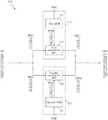
- FIG. 1is a block diagram exemplarily illustrating a data processing circuit 100 in accordance with an embodiment of the present invention.
- the data processing circuit 100may transform a plurality of input bits IBT into a plurality of output bits OBT, and output the output bits OBT.
- the data processing circuit 100may generate the output bits OBT by randomizing the input bits IBT.
- the data processing circuit 100may generate output data by randomizing a pattern of the input bits IBT in order to minimize data Interference and suppress data deformation.
- the plurality of input bits IBTmay be inputted in parallel to the data processing circuit 100 .
- the total number of the bits inputted in parallel to the data processing circuit 100may be 8, 16 or the like.
- the plurality of input bits IBTmay be grouped into a plurality of input bit groups. For example, upper half bits and lower half bits among the plurality of input bits IBT may be grouped into first and second input bit groups IBG 1 and IBG 2 , respectively.
- the number of input bit groupsare not intended to be a limiting feature.
- the data processing circuit 100may include a plurality of transformation blocks, for example, first and second transformation blocks 110 and 120 .
- the first and second input bit groups IBG 1 and IBG 2may be inputted in parallel to the first and second transformation blocks 110 and 120 .
- the first input bit group IBG 1may be inputted to the first transformation block 110
- the second input bit group IBG 2may be inputted to the second transformation block 120 .
- the plurality of input bits IBT comprising the first and second input bit groups IBG 1 and IBG 2may be inputted in parallel to the first and second transformation blocks 110 and 120 .
- the first and second transformation blocks 110 and 120may respectively transform the first and second input bit groups IBG 1 and IBG 2 in parallel into first and second output bit groups OBG 1 and OBG 2 .
- the first transformation block 110may transform the first input bit group IBG 1 into the first output bit group OBG 1
- the second transformation block 120may transform the second input bit group IBG 2 into the second output bit group OBG 2 .
- the first and second transformation blocks 110 and 120may respectively output in parallel the first and second output bit groups OBG 1 and OBG 2 .
- the first and second transformation blocks 110 and 120may output in parallel the output bits OBT comprising the first and second output bit groups OBG 1 and OBG 2 .
- the first transformation block 110may include a first random pattern generation unit 111 and a first calculation unit 113 .
- the first random pattern generation unit 111may generate a first random pattern RPT 1 based on a seed SEED.
- the first random pattern generation unit 111may include a first linear feedback shift register (hereinafter, referred to as a ‘first LFSR’) for generating the first random pattern RPT 1 based on the seed SEED.
- first LFSRfirst linear feedback shift register
- the first calculation unit 113may perform a logic operation on the first input bit group IBG 1 and the first random pattern RPT 1 , and generate the first output bit group OBG 1 .
- the logic operation of the first calculation unit 113may be an XOR operation.
- the second transformation block 120may include a second random pattern generation unit 121 and a second calculation unit 123 .
- the second random pattern generation unit 121may generate a second random pattern RPT 2 based on the seed SEED.
- the second random pattern generation unit 121may include a second linear feedback shift register (hereinafter, referred to as a ‘second LFSR’) for generating the second random pattern RPT 2 based on the seed SEED.
- second LFSRsecond linear feedback shift register
- the second calculation unit 123may perform a logic operation on the second input bit group IBG 2 and the second random pattern RPT 2 , and generate the second output bit group OBG 2 .
- the logic operation of the second calculation unit 123may be an XOR operation.
- the first and second LFSRs 111 and 121may correspond to different characteristic polynomials. Meanwhile, in accordance with the embodiment, when the data processing circuit 100 includes at least three LFSRs, the LFSRs may correspond to at least two characteristic polynomials.
- each of the first and second LFSRs 111 and 121may generate a maximum length sequence.
- the degrees of the characteristic polynomials of the first and second LFSRs 111 and 121may be a multiple number of the plurality of input bit groups IBG 1 and IBG 2 inputted to the first and second transformation blocks 110 and 120 , respectively.
- the degree of each of the characteristic polynomials of the first and second LFSRs 111 and 121may be a multiple number of the plurality of input bits IBT inputted to the data processing circuit 100 .
- the data processing circuit 100may inverse transform the transformed data by performing the above-described data transformation process.
- the first and second transformation blocks 110 and 120may respectively transform in parallel the first and second output bit groups OBG 1 and OBG 2 into the first and second input bit groups IBG 1 and IBG 2 .
- the first and second transformation blocks 110 and 120may output in parallel the first and second input bit groups IBG 1 and IBG 2 , that is, the input bits IBT.
- the number of transformation blocks included in the data processing circuit 100is not be specifically limited.
- the number of the transformation blocks included in the data processing circuit 100may determine the bit number of respective input bit groups. For example, when the number of transformation blocks included in the data processing circuit 100 is L, the bit number of respective input bit groups of the input bits IBT having J number of bits will be J/L.
- the number of bits of each output bit groupmay be set to be the same as the number of bits of each input bit group.
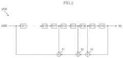
- FIG. 2is a diagram illustrating an example of the first and second LFSRs 111 and 123 shown in FIG. 1 .
- FIG. 2illustrates an LFSR of the Fibonacci implementation, another implementation, for example, an LFSR of the Galois implementation, may also be realized.
- the LFSRmay include 16 registers D 1 to D 16 which are electrically coupled in series.
- the seed SEEDmay be inputted to the first register D 1 , each of the registers D 1 to D 15 may shift a stored value to next register each time a clock signal is enabled (not shown), and the last register D 16 may output a sequence SQ.
- FIG. 2exemplarily shows the outputs of the registers D 16 , D 14 , D 13 and D 11 as the tabs.
- the tabsmay be fed back to the first register D 1 after XOR operations through XOR operation units T 1 to T 3 .
- the LFSRmay be used to generate a random pattern, for example, each of the first and second random patterns RPT 1 and RPT 2 of FIG. 1 .
- the LFSRmay generate a random pattern of K bits based on the values stored in K number of registers selected among N number of total registers in the LSFR each time the clock signal is enabled.
- the LFSR comprising N number of total registersmay correspond to the following characteristic polynomial.
- f ( x )x N +a (N-1) x (N-1) +a (N-2) x (N-2) + . . . +a 1 x+ 1
- the coefficient a imay be 0 or 1 according to the positions of the tabs.
- the LFSR shown in FIG. 2may correspond to a tab sequence [16, 14, 13, 11] representing the positions of the tabs.
- the sequence SQ outputted from the last register D 16 in response to the enablement of the clock signal, that is, the output of the LFSRmay be repeated with a predetermined cycle.
- the LFSRmay output the sequence SQ with a maximum length.
- the length of the sequence SQmay be 2 N ⁇ 1.
- the sequence SQmay be repeated with a cycle of 2 N ⁇ 1.
- the sequence SQmay be defined as a maximum length sequence or an M-sequence. The M-sequence may be outputted when the N registers have 2 N ⁇ 1 number of states except that all of the N registers have the state of 0.
- the tab progressions of the LFSR including 4 tabs and outputting the M-sequencemay be as follows:
- the M-sequencemay have the maximum cycle of 2 N ⁇ 1, and the M-sequence may include 2 (N-1) number of 1s and 2 (N-1) ⁇ 1 number of 0s. Therefore, the random pattern generated from the LFSR, which outputs the M-sequence, may improve randomness of data.
- the first and second random pattern generation units 111 and 121may be the same or different.
- the first and second LFSRs 111 and 121may correspond to different characteristic polynomials, in which case the first and second LFSRs 111 and 121 may output different sequences or different random patterns RPT 1 and RPT 2 based on the same seed SEED.
- the degree of the characteristic polynomials of the first and second LFSRs 111 and 121may be a multiple number of the plurality of input bit groups IBG 1 and IBG 2 inputted to the first and second transformation blocks 110 and 120 , respectively.
- Each of the first and second LFSRs 111 and 121may include N number of registers in total, and the N may be a multiple number of each of the plurality of input bit groups IBG 1 and IBG 2 .
- the degree of each of the characteristic polynomials of the first and second LFSRs 111 and 121may be a multiple number of the plurality of input bits IBT inputted to the data processing circuit 100 .
- each of the first and second LFSRs 111 and 121may include N number of registers in total, and the N may be a multiple number of the plurality of input bits IBT.
- each of the first and second LFSRs 111 and 121may output the M-sequence.
- the first and second LFSRs 111 and 121may output the sequences SQ or the first and second random patterns RPT 1 and RPT 2 with the cycle of 2 N ⁇ 1, respectively.
- FIG. 3is a block diagram exemplarily illustrating randomization and de-randomization of the data processing circuit 100 of FIG. 1 in accordance with an embodiment of the present invention.
- FIG. 3exemplarily shows upper 4 bits and lower 4 bits, among the input bits IBT of 8 bits, that are grouped into the first and second input bit groups IBG 1 and IBG 2 , respectively.
- the input bits IBTmay be inputted in parallel to the data processing circuit 100 .
- the first and second input bit groups IBG 1 and IBG 2may be respectively inputted in parallel to the first and second transformation blocks 110 and 120 .
- the first and second LFSRs 111 and 121may generate the different first and second random patterns RPT 1 and RPT 2 based on the seed SEED due to the different characteristic polynomials.
- the first calculation unit 113may generate the first output bit group OBG 1 by performing an XOR operation on corresponding bits of the first input bit group IBG 1 and the first random pattern RPT 1
- the second calculation unit 123may generate the second output bit group OBG 2 by performing an XOR operation on corresponding bits of the second input bit group IBG 2 and the second random pattern RPT 2 .
- the first and second output bit groups OBG 1 and OBG 2may be outputted in parallel from the first and second transformation blocks 110 and 120 .
- the output bits OBT comprising the first and second output bit groups OBG 1 and OBG 2may be outputted in parallel from the data processing circuit 100 .
- FIG. 4is a block diagram exemplarily illustrating the data storage device 100 in accordance with an embodiment of the present invention.
- the data storage device 10may include a controller 200 and a nonvolatile memory apparatus 300 .
- the controller 200may include a processor 210 , a data processing circuit 220 , and a memory 230 , which may be electrically coupled and communicate with one another through an internal bus 240 .
- the processor 210may control the general operations of the data storage device 10 .
- the processor 210may control the components of the controller 200 to perform predetermined functions.
- the processor 210may control the write operation or the read operation of the nonvolatile memory apparatus 300 in response to a write request or a read request from an external device.
- the data processing circuit 220may transform write bits WB to be stored in the nonvolatile memory apparatus 300 into transformed write bits RDWB, and may inverse transform the read bits RDRB, which are read from the nonvolatile memory apparatus 300 , into inverse-transformed read bits RB.
- the transformed write bits RDWBhave the same value as the read bits RDRB
- the inverse-transformed read bits RBmay have the same values as the write bits WB, which means that the write bits WB may be restored to have the original value through the transformation process as described above with reference to FIGS. 1 to 3 when the write bits WB are stored in and then read from the nonvolatile memory apparatus 300 .
- the data processing circuit 220may include a plurality of transformation blocks (not shown).
- the plurality of transformation blocksmay respectively transform in parallel a plurality of write bit groups included in the write bits WB into a plurality of transformed write bit groups, and may respectively output in parallel the plurality of transformed write bit groups.
- the transformed write bits RDWBmay comprise the plurality of transformed write bit groups.
- the data processing circuit 220may inverse transform in parallel a plurality of read bit groups included in the read bits RDRB into a plurality of inverse-transformed read bit groups.
- the inverse-transformed read bits RBmay comprise the plurality of inverse-transformed read bit groups.
- the data processing circuit 220may inverse transform the read bits RDRB into the plurality of inverse-transformed read bits RB by performing a transformation process to the plurality of read bits RDRB in substantially the same manner as the transformation process to the plurality of write bits WB.
- the data processing circuit 220may be the same as the data processing circuit 100 described with reference to FIGS. 1 to 3 .
- the write bits WB and the transformed write bits RDWBmay be the plurality of input bits IBT and the plurality of output bits OBT described with reference to FIGS. 1 to 3 , respectively.
- the seed inputted to the data processing circuit 220may correspond to a memory region of the nonvolatile memory apparatus 300 , in or from which data are to be stored or read.
- the seedmay be provided to the data processing circuit 220 according to the address offset of the corresponding memory region of the nonvolatile memory apparatus 300 . Accordingly, the seed corresponding to each memory region is fixed, and thus the data may be restored to have the original value through the same seed where the data is stored in and then read from the corresponding memory region of the nonvolatile memory apparatus 300 through the transformation process as described above with reference to FIGS. 1 to 3 .
- the memory 230may serve as a working memory, a buffer memory or a cache memory of the processor 210 .
- the memory 230 as a working memorymay store software programs and various program data for driving the processor 210 .
- the memory 230 as a buffer memorymay buffer the data transmitted between the external device and the nonvolatile memory apparatus 300 .
- the memory 230 as a cache memorymay temporarily store cache data.
- the nonvolatile memory apparatus 300may be provided in parallel with the plurality of transformed write bits RDWB, and store the plurality of transformed write bits RDWB through a write operation.
- the nonvolatile memory apparatus 300may read the plurality of transformed write bits RDWB stored therein, as the plurality of read bits RDRB, and output in parallel the plurality of read bits RDRB.
- the nonvolatile memory apparatus 300may transmit and receive data in parallel to and from the controller 200 through a plurality of data lines DL.
- FIG. 4shows an example in which the data storage device 10 includes one nonvolatile memory apparatus 300 , the embodiment is not limited to such an example, and it is to be noted that the data storage device 10 may include a plurality of nonvolatile memory apparatus 300 .
- the data processing circuit 220may be disposed in the nonvolatile memory apparatus 300 instead of the controller 200 .
- the data processing circuit 220may transform the plurality of write bits WB transmitted from the controller 200 , and may inverse transform the read bits RDRB into the inverse-transformed read bits RB and transmit the inverse-transformed read bits RB to the controller 200 .
- the data processing circuit 220may be integrated into a separate chip and be disposed between the controller 200 and the nonvolatile memory apparatus 300 , and may transmit transformed/inverse-transformed data between the controller 200 and the nonvolatile memory apparatus 300 .
- FIG. 5is a flow chart exemplarily illustrating an operation of the data storage device 10 of FIG. 4 in accordance with an embodiment of the present invention.
- FIG. 5shows a process of transforming data to be stored in the nonvolatile memory apparatus 300 .
- the data processing circuit 220may receive in parallel the plurality of write bit groups included in the plurality of write bits WB.
- the plurality of write bits WBmay be inputted in parallel to the data processing circuit 220 .
- the plurality of transformation blocks included in the data processing circuit 220may transform in parallel the plurality of write bit groups into the transformed write bit groups through different random patterns, respectively.
- the controller 200may transmit in parallel the plurality of transformed write bit groups to the nonvolatile memory apparatus 300 .
- the plurality of transformed write bits RDWBmay comprise the plurality of transformed write bit groups.
- the nonvolatile memory apparatus 300may store the transformed write bit groups through a write operation.
- FIG. 6is a flow chart exemplarily illustrating an operation of the data processing circuit 220 of FIG. 4 in accordance with an embodiment of the present invention.
- FIG. 6exemplarily shows step S 120 described with reference to FIG. 5 .
- the plurality of random pattern generation units included in the data processing circuit 220may generate a plurality of different random patterns based on a seed.
- the plurality of random pattern generation unitsmay be the random pattern generation units 111 and 121 described with reference to FIGS. 1 to 3 .
- the plurality of calculation units included in the data processing circuit 220may perform logic operations on the plurality of write bit groups and the plurality of random patterns, and generate the plurality of transformed write bit groups.
- the plurality of calculation unitsmay be the calculation units 113 and 123 described with reference to FIGS. 1 to 3 .
- FIG. 7is a flow chart exemplarily illustrating an operation of the data storage device 10 of FIG. 4 in accordance with an embodiment of the present invention.
- FIG. 7shows a process of inverse-transforming the data read from the nonvolatile memory apparatus 300 .
- the nonvolatile memory apparatus 300may read the plurality of transformed write bit groups stored therein, as the plurality of read bit groups.
- the plurality of read bits RDRBmay comprise the plurality of read bit groups.
- the nonvolatile memory apparatus 300may transmit in parallel the plurality of read bit groups to the controller 200 .
- the plurality of transformation blocks included in the data processing circuit 220may respectively inverse-transform in parallel the plurality of read bit groups to generate the plurality of inverse-transformed read bit groups.
- the plurality of inverse-transformed read bits RBmay comprise the plurality of inverse-transformed read bit groups.
- the embodimentsit is possible to effectively improve the randomness of data to be stored in the nonvolatile memory apparatus 300 through data processing by the plurality of transformation blocks disposed in parallel. Accordingly, it is possible to secure data reliability. Moreover, the rate of increase in the hardware size of the data processing circuit 220 for the parallel process of the plurality of transformation blocks is significantly smaller than the increase rate in hardware size for increasing the degree of the LFSR in order to lengthen the sequence. Therefore an advantage may be provided in retaining price competitiveness.
Landscapes
- Engineering & Computer Science (AREA)
- Theoretical Computer Science (AREA)
- Databases & Information Systems (AREA)
- Physics & Mathematics (AREA)
- General Physics & Mathematics (AREA)
- General Engineering & Computer Science (AREA)
- Data Mining & Analysis (AREA)
- Computational Mathematics (AREA)
- Mathematical Analysis (AREA)
- Mathematical Optimization (AREA)
- Pure & Applied Mathematics (AREA)
- Software Systems (AREA)
- Techniques For Improving Reliability Of Storages (AREA)
- Detection And Correction Of Errors (AREA)
Abstract
Description
f(x)=xN+a(N-1)x(N-1)+a(N-2)x(N-2)+ . . . +a1x+1
f(x)=x16+x14+x13+x11+1
Claims (16)
Priority Applications (5)
| Application Number | Priority Date | Filing Date | Title |
|---|---|---|---|
| US16/988,026US11515897B2 (en) | 2015-05-29 | 2020-08-07 | Data storage device |
| US16/987,977US11611359B2 (en) | 2015-05-29 | 2020-08-07 | Data storage device |
| US17/193,135US11928077B2 (en) | 2015-05-29 | 2021-03-05 | Data processing circuit, data storage device including the same, and operating method thereof |
| US18/185,163US11996865B2 (en) | 2015-05-29 | 2023-03-16 | Data storage device |
| US18/641,441US20240283467A1 (en) | 2015-05-29 | 2024-04-22 | Data storage device |
Applications Claiming Priority (2)
| Application Number | Priority Date | Filing Date | Title |
|---|---|---|---|
| KR10-2015-0076165 | 2015-05-29 | ||
| KR1020150076165AKR102285940B1 (en) | 2015-05-29 | 2015-05-29 | Data processing circuit, data storage device comprising data processing circuit and operating method thereof |
Related Parent Applications (1)
| Application Number | Title | Priority Date | Filing Date |
|---|---|---|---|
| US15/620,909Continuation-In-PartUS10741212B2 (en) | 2015-05-29 | 2017-06-13 | Error correction code (ECC) encoders, ECC encoding methods capable of encoding for one clock cycle, and memory controllers including the ECC encoders |
Related Child Applications (4)
| Application Number | Title | Priority Date | Filing Date |
|---|---|---|---|
| US15/016,443Continuation-In-PartUS10102066B2 (en) | 2015-05-29 | 2016-02-05 | Data processing device and operating method thereof |
| US16/988,026Continuation-In-PartUS11515897B2 (en) | 2015-05-29 | 2020-08-07 | Data storage device |
| US16/987,977Continuation-In-PartUS11611359B2 (en) | 2015-05-29 | 2020-08-07 | Data storage device |
| US17/193,135ContinuationUS11928077B2 (en) | 2015-05-29 | 2021-03-05 | Data processing circuit, data storage device including the same, and operating method thereof |
Publications (2)
| Publication Number | Publication Date |
|---|---|
| US20160350316A1 US20160350316A1 (en) | 2016-12-01 |
| US11182339B2true US11182339B2 (en) | 2021-11-23 |
Family
ID=57399810
Family Applications (2)
| Application Number | Title | Priority Date | Filing Date |
|---|---|---|---|
| US14/873,975Active2037-12-28US11182339B2 (en) | 2015-05-29 | 2015-10-02 | Data processing circuit, data storage device including the same, and operating method thereof |
| US17/193,135Active2035-10-20US11928077B2 (en) | 2015-05-29 | 2021-03-05 | Data processing circuit, data storage device including the same, and operating method thereof |
Family Applications After (1)
| Application Number | Title | Priority Date | Filing Date |
|---|---|---|---|
| US17/193,135Active2035-10-20US11928077B2 (en) | 2015-05-29 | 2021-03-05 | Data processing circuit, data storage device including the same, and operating method thereof |
Country Status (3)
| Country | Link |
|---|---|
| US (2) | US11182339B2 (en) |
| KR (1) | KR102285940B1 (en) |
| CN (1) | CN106205661A (en) |
Families Citing this family (1)
| Publication number | Priority date | Publication date | Assignee | Title |
|---|---|---|---|---|
| KR20210079556A (en)* | 2019-12-20 | 2021-06-30 | 에스케이하이닉스 주식회사 | Memory system, memory controller, and operating method of memory system |
Citations (66)
| Publication number | Priority date | Publication date | Assignee | Title |
|---|---|---|---|---|
| US4757478A (en) | 1985-12-17 | 1988-07-12 | U.S. Philips Corporation | Decoder circuit for a static random access memory |
| US4993029A (en)* | 1989-03-13 | 1991-02-12 | International Business Machines Corporation | Method and apparatus for randomizing data in a direct access storage device |
| US6543021B1 (en) | 1998-07-16 | 2003-04-01 | Canon Kabushiki Kaisha | Method and device for coding and transmission using a sub-code of a product code |
| US6711709B1 (en) | 1998-06-24 | 2004-03-23 | Unisys Corporation | Integrated block checking system for rapid file transfer of compressed data |
| CN1622137A (en) | 2005-01-07 | 2005-06-01 | 北京北大方正电子有限公司 | Method for rapidly compressing and decompressing image |
| US20060156189A1 (en) | 2004-12-21 | 2006-07-13 | Andrew Tomlin | Method for copying data in reprogrammable non-volatile memory |
| US20070033485A1 (en) | 2005-07-13 | 2007-02-08 | Leanics Corporation | Low-complexity hybrid LDPC code encoder |
| US20070043998A1 (en) | 2005-08-03 | 2007-02-22 | Novowave, Inc. | Systems and methods for a turbo low-density parity-check decoder |
| US20070047660A1 (en) | 2005-08-26 | 2007-03-01 | Koichi Mitani | Image processing apparatus, image processing method, recording medium, and program |
| US20070206675A1 (en) | 2004-08-04 | 2007-09-06 | Takeshi Tanaka | Image Decoding Device |
| US20070226593A1 (en) | 2006-03-07 | 2007-09-27 | Broadcom Corporation, A California Corporation | Performing multiple Reed-Solomon (RS) software error correction coding (ECC) Galois field computations simultaneously |
| US20080205145A1 (en)* | 2007-02-28 | 2008-08-28 | Kabushiki Kaisha Toshiba | Memory controller controlling semiconductor storage device and semiconductor device |
| CN101308706A (en) | 2007-05-18 | 2008-11-19 | 瑞昱半导体股份有限公司 | Data writing method and error correction coding and decoding method suitable for flash memory |
| US20090015291A1 (en) | 2007-07-10 | 2009-01-15 | Samsung Electronics Co., Ltd. | Semiconductor memory device and method of generating chip enable signal thereof |
| CN101465654A (en) | 2009-01-06 | 2009-06-24 | 中山大学 | Method for judging decode halt of LDPC code based on checksum error mode |
| US20090177931A1 (en) | 2008-01-03 | 2009-07-09 | Samsung Eletronics Co.,Ltd | Memory device and error control codes decoding method |
| US20090180533A1 (en) | 2008-01-11 | 2009-07-16 | Apple Inc. | control of video decoder for reverse playback operation |
| US20090193213A1 (en)* | 2007-02-12 | 2009-07-30 | Xyratex Technology Limited | Method and apparatus for data transform |
| CN101527844A (en) | 2008-03-04 | 2009-09-09 | 深圳市爱国者嵌入式系统科技有限公司 | Method for block execution of data to be decoded |
| US20090276609A1 (en) | 2008-04-30 | 2009-11-05 | Moyer William C | Configurable pipeline based on error detection mode in a data processing system |
| US20100088575A1 (en) | 2008-10-07 | 2010-04-08 | Eran Sharon | Low density parity code (ldpc) decoding for memory with multiple log likelihood ratio (llr) decoders |
| US7710758B2 (en) | 2004-10-29 | 2010-05-04 | Samsung Electronics Co., Ltd. | Multichip system and method of transferring data therein |
| KR20110067656A (en) | 2009-12-15 | 2011-06-22 | 한국전자통신연구원 | Efficient scrambling or descrambling method and system |
| US8095859B1 (en) | 2008-01-09 | 2012-01-10 | L-3 Communications, Corp. | Encoder for low-density parity check codes |
| US8195622B2 (en) | 2007-01-07 | 2012-06-05 | Apple Inc. | Method and apparatus for simplifying the decoding of data |
| KR20120095609A (en) | 2011-02-21 | 2012-08-29 | 삼성전자주식회사 | Semiconductor memory system and program method thereof |
| US8332723B2 (en) | 2008-08-19 | 2012-12-11 | Lg Electronics Inc. | Transmitting/receiving system and method of processing data in the transmitting/receiving system |
| US8443251B1 (en) | 2011-12-15 | 2013-05-14 | Lsi Corporation | Systems and methods for out of order processing in a data retry |
| US20130132792A1 (en) | 2011-11-21 | 2013-05-23 | Ryo Yamaki | Storage device including error correction function and error correction method |
| US8527720B2 (en) | 2008-12-03 | 2013-09-03 | Lsi Corporation | Methods of capturing and naming dynamic storage tiering configurations to support data pre-staging |
| US8527843B2 (en) | 2007-09-19 | 2013-09-03 | Telefonaktiebolaget L M Ericsson (Publ) | Iterative decoding of blocks with cyclic redundancy checks |
| US8527718B2 (en) | 2009-03-31 | 2013-09-03 | Lsi Corporation | Explicit data segment boundaries with SCSI I/O referrals |
| US20130254639A1 (en) | 2012-03-26 | 2013-09-26 | Xilinx, Inc. | Parallel encoding for non-binary linear block code |
| US20130254623A1 (en) | 2012-03-22 | 2013-09-26 | Lsi Corporation | Systems and Methods for Variable Redundancy Data Protection |
| US20130254616A1 (en) | 2012-03-22 | 2013-09-26 | Lsi Corporation | Systems and Methods for Variable Rate Coding in a Data Processing System |
| US20130265842A1 (en) | 2004-11-29 | 2013-10-10 | Rambus Inc. | Micro-Threaded Memory |
| US20130276038A1 (en) | 2012-04-12 | 2013-10-17 | Kabushiki Kaisha Toshiba | Video server for controlling video signal output and video signal output control method |
| US20140068320A1 (en) | 2012-08-31 | 2014-03-06 | Cleversafe, Inc. | Adjusting dispersed storage error encoding parameters |
| US20140122962A1 (en) | 2012-10-31 | 2014-05-01 | Wipro Limited | Methods and systems for minimizing decoding delay in distributed video coding |
| US20140168811A1 (en) | 2012-12-19 | 2014-06-19 | Lsi Corporation | Irregular Low Density Parity Check Decoder With Low Syndrome Error Handling |
| US8839077B2 (en) | 2009-12-31 | 2014-09-16 | National Tsing Hua University | Low density parity check codec |
| KR20150017948A (en) | 2013-08-08 | 2015-02-23 | 삼성전자주식회사 | the method of ECC decoder operation and the memory controller including it |
| US20150095274A1 (en)* | 2013-10-02 | 2015-04-02 | Qualcomm Incorporated | Method and apparatus for producing programmable probability distribution function of pseudo-random numbers |
| US9009567B2 (en) | 2011-12-12 | 2015-04-14 | Cleversafe, Inc. | Encrypting distributed computing data |
| US20150169406A1 (en) | 2013-12-16 | 2015-06-18 | Sandisk Technologies Inc. | Decoding techniques for a data storage device |
| CN104768061A (en) | 2014-01-03 | 2015-07-08 | 三星电子株式会社 | Display driver and method for operating image data processing device |
| US9081677B2 (en) | 2011-02-22 | 2015-07-14 | Mitsubishi Electric Corporation | Method and device for estimating input bit error ratio |
| US20150279421A1 (en) | 2014-03-28 | 2015-10-01 | Lsi Corporation | Adaptive calibration of noise predictive finite impulse response filter based on decoder convergence |
| US20150301985A1 (en)* | 2014-04-22 | 2015-10-22 | Sandisk Enterprise Ip Llc | Low complexity partial parallel architectures for fourier transform and inverse fourier transform over subfields of a finite field |
| US20150312027A1 (en)* | 2014-04-25 | 2015-10-29 | Electronics And Telecommunications Research Institute | Function masking apparatus in symmetric cryptographic algorithm for preventing side channel attacks and method thereof |
| US9214964B1 (en) | 2012-09-24 | 2015-12-15 | Marvell International Ltd. | Systems and methods for configuring product codes for error correction in a hard disk drive |
| US20150363263A1 (en) | 2014-06-12 | 2015-12-17 | HGST Netherlands B.V. | ECC Encoder Using Partial-Parity Feedback |
| US9231623B1 (en) | 2013-09-11 | 2016-01-05 | SK Hynix Inc. | Chase decoding for turbo-product codes (TPC) using error intersections |
| US20160006462A1 (en) | 2014-07-07 | 2016-01-07 | Ocz Storage Solutions, Inc. | Non-volatile memory controller with error correction (ecc) tuning via error statistics collection |
| US20160006459A1 (en) | 2014-07-07 | 2016-01-07 | Ocz Storage Solutions, Inc. | Low ber hard-decision ldpc decoder |
| US20160011939A1 (en) | 2014-07-09 | 2016-01-14 | Qualcomm Incorporated | Systems and methods for reliably storing data using liquid distributed storage |
| US20160154698A1 (en) | 2014-12-02 | 2016-06-02 | Cleversafe, Inc. | Coordinating storage of data in dispersed storage networks |
| US20160179608A1 (en) | 2014-12-22 | 2016-06-23 | Sandisk Technologies Inc. | Removing read disturb signatures for memory analytics |
| US20160249234A1 (en) | 2015-02-22 | 2016-08-25 | The Regents Of The University Of Michigan | Iterative detection-decoding system |
| US20160292426A1 (en)* | 2015-03-30 | 2016-10-06 | Rockwell Automation Technologies, Inc. | Method and Apparatus for Scrambling a High Speed Data Transmission |
| US9495243B2 (en) | 2012-12-18 | 2016-11-15 | Western Digital Technologies, Inc. | Error correcting code encoder supporting multiple code rates and throughput speeds for data storage systems |
| US20180032396A1 (en) | 2016-07-29 | 2018-02-01 | Sandisk Technologies Llc | Generalized syndrome weights |
| US20180034477A1 (en) | 2016-07-29 | 2018-02-01 | Sandisk Technologies Llc | Decoder with parallel decoding paths |
| US10102066B2 (en) | 2015-09-25 | 2018-10-16 | SK Hynix Inc. | Data processing device and operating method thereof |
| US10396827B2 (en) | 2015-09-25 | 2019-08-27 | SK Hynix Inc. | Data storage device |
| US20200004677A1 (en) | 2018-06-27 | 2020-01-02 | Intel Corporation | Hardware-assisted paging mechanisms |
Family Cites Families (10)
| Publication number | Priority date | Publication date | Assignee | Title |
|---|---|---|---|---|
| US20070083491A1 (en)* | 2004-05-27 | 2007-04-12 | Silverbrook Research Pty Ltd | Storage of key in non-volatile memory |
| US20080123979A1 (en)* | 2006-11-27 | 2008-05-29 | Brian Schoner | Method and system for digital image contour removal (dcr) |
| CN102099793B (en) | 2008-06-24 | 2013-10-16 | 桑迪士克以色列有限公司 | Method and device for error correction based on erasure count of solid-state memory |
| JP5506828B2 (en) | 2009-03-05 | 2014-05-28 | エルエスアイ コーポレーション | Improved turbo equalization method for iterative decoder |
| JP2011065599A (en) | 2009-09-18 | 2011-03-31 | Toshiba Corp | Memory system and method of controlling the same |
| JP5039160B2 (en) | 2010-03-02 | 2012-10-03 | 株式会社東芝 | Nonvolatile semiconductor memory system |
| KR101818671B1 (en)* | 2011-04-19 | 2018-02-28 | 삼성전자주식회사 | Nonvolatile memory device and nonvolatile memory system and random data read method thereof |
| KR101767649B1 (en)* | 2011-05-11 | 2017-08-14 | 삼성전자주식회사 | Seed generating method and flash memory device and memory system using the same |
| US8954816B2 (en) | 2011-11-28 | 2015-02-10 | Sandisk Technologies Inc. | Error correction coding (ECC) decode operation scheduling |
| US11611359B2 (en) | 2015-05-29 | 2023-03-21 | SK Hynix Inc. | Data storage device |
- 2015
- 2015-05-29KRKR1020150076165Apatent/KR102285940B1/enactiveActive
- 2015-10-02USUS14/873,975patent/US11182339B2/enactiveActive
- 2015-11-09CNCN201510760584.7Apatent/CN106205661A/enactivePending
- 2021
- 2021-03-05USUS17/193,135patent/US11928077B2/enactiveActive
Patent Citations (68)
| Publication number | Priority date | Publication date | Assignee | Title |
|---|---|---|---|---|
| US4757478A (en) | 1985-12-17 | 1988-07-12 | U.S. Philips Corporation | Decoder circuit for a static random access memory |
| US4993029A (en)* | 1989-03-13 | 1991-02-12 | International Business Machines Corporation | Method and apparatus for randomizing data in a direct access storage device |
| US6711709B1 (en) | 1998-06-24 | 2004-03-23 | Unisys Corporation | Integrated block checking system for rapid file transfer of compressed data |
| US6543021B1 (en) | 1998-07-16 | 2003-04-01 | Canon Kabushiki Kaisha | Method and device for coding and transmission using a sub-code of a product code |
| US20070206675A1 (en) | 2004-08-04 | 2007-09-06 | Takeshi Tanaka | Image Decoding Device |
| US7710758B2 (en) | 2004-10-29 | 2010-05-04 | Samsung Electronics Co., Ltd. | Multichip system and method of transferring data therein |
| US20130265842A1 (en) | 2004-11-29 | 2013-10-10 | Rambus Inc. | Micro-Threaded Memory |
| US20060156189A1 (en) | 2004-12-21 | 2006-07-13 | Andrew Tomlin | Method for copying data in reprogrammable non-volatile memory |
| CN1622137A (en) | 2005-01-07 | 2005-06-01 | 北京北大方正电子有限公司 | Method for rapidly compressing and decompressing image |
| US20070033485A1 (en) | 2005-07-13 | 2007-02-08 | Leanics Corporation | Low-complexity hybrid LDPC code encoder |
| US20070043998A1 (en) | 2005-08-03 | 2007-02-22 | Novowave, Inc. | Systems and methods for a turbo low-density parity-check decoder |
| US20070047660A1 (en) | 2005-08-26 | 2007-03-01 | Koichi Mitani | Image processing apparatus, image processing method, recording medium, and program |
| US20070226593A1 (en) | 2006-03-07 | 2007-09-27 | Broadcom Corporation, A California Corporation | Performing multiple Reed-Solomon (RS) software error correction coding (ECC) Galois field computations simultaneously |
| US8195622B2 (en) | 2007-01-07 | 2012-06-05 | Apple Inc. | Method and apparatus for simplifying the decoding of data |
| US20090193213A1 (en)* | 2007-02-12 | 2009-07-30 | Xyratex Technology Limited | Method and apparatus for data transform |
| US20080205145A1 (en)* | 2007-02-28 | 2008-08-28 | Kabushiki Kaisha Toshiba | Memory controller controlling semiconductor storage device and semiconductor device |
| CN101308706A (en) | 2007-05-18 | 2008-11-19 | 瑞昱半导体股份有限公司 | Data writing method and error correction coding and decoding method suitable for flash memory |
| US20090015291A1 (en) | 2007-07-10 | 2009-01-15 | Samsung Electronics Co., Ltd. | Semiconductor memory device and method of generating chip enable signal thereof |
| US8527843B2 (en) | 2007-09-19 | 2013-09-03 | Telefonaktiebolaget L M Ericsson (Publ) | Iterative decoding of blocks with cyclic redundancy checks |
| US20090177931A1 (en) | 2008-01-03 | 2009-07-09 | Samsung Eletronics Co.,Ltd | Memory device and error control codes decoding method |
| US8499217B2 (en) | 2008-01-03 | 2013-07-30 | Samsung Electronics Co., Ltd. | Memory device and error control codes decoding method |
| US8095859B1 (en) | 2008-01-09 | 2012-01-10 | L-3 Communications, Corp. | Encoder for low-density parity check codes |
| US20090180533A1 (en) | 2008-01-11 | 2009-07-16 | Apple Inc. | control of video decoder for reverse playback operation |
| CN101527844A (en) | 2008-03-04 | 2009-09-09 | 深圳市爱国者嵌入式系统科技有限公司 | Method for block execution of data to be decoded |
| US20090276609A1 (en) | 2008-04-30 | 2009-11-05 | Moyer William C | Configurable pipeline based on error detection mode in a data processing system |
| US8332723B2 (en) | 2008-08-19 | 2012-12-11 | Lg Electronics Inc. | Transmitting/receiving system and method of processing data in the transmitting/receiving system |
| US20100088575A1 (en) | 2008-10-07 | 2010-04-08 | Eran Sharon | Low density parity code (ldpc) decoding for memory with multiple log likelihood ratio (llr) decoders |
| US8527720B2 (en) | 2008-12-03 | 2013-09-03 | Lsi Corporation | Methods of capturing and naming dynamic storage tiering configurations to support data pre-staging |
| CN101465654A (en) | 2009-01-06 | 2009-06-24 | 中山大学 | Method for judging decode halt of LDPC code based on checksum error mode |
| US8527718B2 (en) | 2009-03-31 | 2013-09-03 | Lsi Corporation | Explicit data segment boundaries with SCSI I/O referrals |
| KR20110067656A (en) | 2009-12-15 | 2011-06-22 | 한국전자통신연구원 | Efficient scrambling or descrambling method and system |
| US8839077B2 (en) | 2009-12-31 | 2014-09-16 | National Tsing Hua University | Low density parity check codec |
| KR20120095609A (en) | 2011-02-21 | 2012-08-29 | 삼성전자주식회사 | Semiconductor memory system and program method thereof |
| US9081677B2 (en) | 2011-02-22 | 2015-07-14 | Mitsubishi Electric Corporation | Method and device for estimating input bit error ratio |
| US20130132792A1 (en) | 2011-11-21 | 2013-05-23 | Ryo Yamaki | Storage device including error correction function and error correction method |
| US9009567B2 (en) | 2011-12-12 | 2015-04-14 | Cleversafe, Inc. | Encrypting distributed computing data |
| US8443251B1 (en) | 2011-12-15 | 2013-05-14 | Lsi Corporation | Systems and methods for out of order processing in a data retry |
| US20130254616A1 (en) | 2012-03-22 | 2013-09-26 | Lsi Corporation | Systems and Methods for Variable Rate Coding in a Data Processing System |
| US20130254623A1 (en) | 2012-03-22 | 2013-09-26 | Lsi Corporation | Systems and Methods for Variable Redundancy Data Protection |
| US20130254639A1 (en) | 2012-03-26 | 2013-09-26 | Xilinx, Inc. | Parallel encoding for non-binary linear block code |
| US20130276038A1 (en) | 2012-04-12 | 2013-10-17 | Kabushiki Kaisha Toshiba | Video server for controlling video signal output and video signal output control method |
| US20140068320A1 (en) | 2012-08-31 | 2014-03-06 | Cleversafe, Inc. | Adjusting dispersed storage error encoding parameters |
| US9214964B1 (en) | 2012-09-24 | 2015-12-15 | Marvell International Ltd. | Systems and methods for configuring product codes for error correction in a hard disk drive |
| US20140122962A1 (en) | 2012-10-31 | 2014-05-01 | Wipro Limited | Methods and systems for minimizing decoding delay in distributed video coding |
| US9495243B2 (en) | 2012-12-18 | 2016-11-15 | Western Digital Technologies, Inc. | Error correcting code encoder supporting multiple code rates and throughput speeds for data storage systems |
| US20140168811A1 (en) | 2012-12-19 | 2014-06-19 | Lsi Corporation | Irregular Low Density Parity Check Decoder With Low Syndrome Error Handling |
| KR20150017948A (en) | 2013-08-08 | 2015-02-23 | 삼성전자주식회사 | the method of ECC decoder operation and the memory controller including it |
| US9231623B1 (en) | 2013-09-11 | 2016-01-05 | SK Hynix Inc. | Chase decoding for turbo-product codes (TPC) using error intersections |
| US20150095274A1 (en)* | 2013-10-02 | 2015-04-02 | Qualcomm Incorporated | Method and apparatus for producing programmable probability distribution function of pseudo-random numbers |
| US20150169406A1 (en) | 2013-12-16 | 2015-06-18 | Sandisk Technologies Inc. | Decoding techniques for a data storage device |
| CN104768061A (en) | 2014-01-03 | 2015-07-08 | 三星电子株式会社 | Display driver and method for operating image data processing device |
| US20150195581A1 (en) | 2014-01-03 | 2015-07-09 | Maeum LEE | Display driver and method of operating image data processing device |
| US20150279421A1 (en) | 2014-03-28 | 2015-10-01 | Lsi Corporation | Adaptive calibration of noise predictive finite impulse response filter based on decoder convergence |
| US20150301985A1 (en)* | 2014-04-22 | 2015-10-22 | Sandisk Enterprise Ip Llc | Low complexity partial parallel architectures for fourier transform and inverse fourier transform over subfields of a finite field |
| US20150312027A1 (en)* | 2014-04-25 | 2015-10-29 | Electronics And Telecommunications Research Institute | Function masking apparatus in symmetric cryptographic algorithm for preventing side channel attacks and method thereof |
| US20150363263A1 (en) | 2014-06-12 | 2015-12-17 | HGST Netherlands B.V. | ECC Encoder Using Partial-Parity Feedback |
| US20160006462A1 (en) | 2014-07-07 | 2016-01-07 | Ocz Storage Solutions, Inc. | Non-volatile memory controller with error correction (ecc) tuning via error statistics collection |
| US20160006459A1 (en) | 2014-07-07 | 2016-01-07 | Ocz Storage Solutions, Inc. | Low ber hard-decision ldpc decoder |
| US20160011939A1 (en) | 2014-07-09 | 2016-01-14 | Qualcomm Incorporated | Systems and methods for reliably storing data using liquid distributed storage |
| US20160154698A1 (en) | 2014-12-02 | 2016-06-02 | Cleversafe, Inc. | Coordinating storage of data in dispersed storage networks |
| US20160179608A1 (en) | 2014-12-22 | 2016-06-23 | Sandisk Technologies Inc. | Removing read disturb signatures for memory analytics |
| US20160249234A1 (en) | 2015-02-22 | 2016-08-25 | The Regents Of The University Of Michigan | Iterative detection-decoding system |
| US20160292426A1 (en)* | 2015-03-30 | 2016-10-06 | Rockwell Automation Technologies, Inc. | Method and Apparatus for Scrambling a High Speed Data Transmission |
| US10102066B2 (en) | 2015-09-25 | 2018-10-16 | SK Hynix Inc. | Data processing device and operating method thereof |
| US10396827B2 (en) | 2015-09-25 | 2019-08-27 | SK Hynix Inc. | Data storage device |
| US20180032396A1 (en) | 2016-07-29 | 2018-02-01 | Sandisk Technologies Llc | Generalized syndrome weights |
| US20180034477A1 (en) | 2016-07-29 | 2018-02-01 | Sandisk Technologies Llc | Decoder with parallel decoding paths |
| US20200004677A1 (en) | 2018-06-27 | 2020-01-02 | Intel Corporation | Hardware-assisted paging mechanisms |
Non-Patent Citations (8)
| Title |
|---|
| Author: Manohar Ayinala, Keshab K. Parhi; Title "Efficient Parallel VLSI Architecture for Linear Feedback Shift Registers"; Date: 2010; Publisher: IEEE; Pertinent Pages: whold document as attached (pp. 52-57) (Year: 2010).* |
| Certificate of Invention Patent issued by the CNIPA on Feb. 19, 2021. |
| Notice of Allowance issued by the USPTO for U.S. Appl. No. 16/517,144 dated Mar. 3, 2021. |
| Notice of Allowance issued by the USPTO for U.S. Appl. No. 16/549,930 dated Mar. 30, 2021. |
| Office Action issued by State Intellectual Property Office (SIPO) of China dated Apr. 13, 2020. |
| Office Action issued by the Chinese Patent Office dated Aug. 18, 2021. |
| Office Action issued by the Korea Intellectual Property Office dated Jan. 26, 2021. |
| Wu W.Q. et al., Design of parameterized LFSR modules based on VHDL, Journal of Naval University of Engineering, Jun 2009, pp. 90-94, vol. 21, No. 3, China Academic Journal Electronic Publishing House. |
Also Published As
| Publication number | Publication date |
|---|---|
| CN106205661A (en) | 2016-12-07 |
| KR102285940B1 (en) | 2021-08-05 |
| US20210191899A1 (en) | 2021-06-24 |
| US20160350316A1 (en) | 2016-12-01 |
| KR20160140061A (en) | 2016-12-07 |
| US11928077B2 (en) | 2024-03-12 |
Similar Documents
| Publication | Publication Date | Title |
|---|---|---|
| US9400750B2 (en) | Nonvolatile memory device and nonvolatile memory system and random data read method thereof | |
| CN101763895B (en) | Data storage device and data storage system having randomizer/de-randomizer | |
| US9158500B2 (en) | Device and method for processing data including generating a pseudo random number sequence | |
| US9268531B1 (en) | Nonvolatile memory system, storage device and method for operating nonvolatile memory device | |
| CN108351833B (en) | Techniques for compressing secret symbol data for memory encryption | |
| US9298613B2 (en) | Integrated circuit for computing target entry address of buffer descriptor based on data block offset, method of operating same, and system including same | |
| US9923578B2 (en) | Parity check circuit and memory device including the same | |
| US10162750B2 (en) | System address reconstruction | |
| US11656772B2 (en) | Memory controller and storage device including the same | |
| US11928077B2 (en) | Data processing circuit, data storage device including the same, and operating method thereof | |
| US20250112760A1 (en) | Memory device and method for data encryption/decryption of memory device | |
| KR20160104389A (en) | Data storage device and operating method thereof | |
| US9672105B2 (en) | Device and method for processing data using logical information and physical information | |
| US11740871B2 (en) | Binary parallel adder and multiplier | |
| JP4863279B2 (en) | Memory system and memory access method | |
| CN113468518B (en) | Method and apparatus for information protection for non-volatile memory | |
| CN119943111A (en) | A memory operation method, a memory and a memory system | |
| CN117891432A (en) | A random number generation method, device and electronic device |
Legal Events
| Date | Code | Title | Description |
|---|---|---|---|
| AS | Assignment | Owner name:SK HYNIX INC., KOREA, REPUBLIC OF Free format text:ASSIGNMENT OF ASSIGNORS INTEREST;ASSIGNOR:CHO, KYOUNG LAE;REEL/FRAME:036746/0228 Effective date:20150921 | |
| STPP | Information on status: patent application and granting procedure in general | Free format text:NON FINAL ACTION MAILED | |
| STPP | Information on status: patent application and granting procedure in general | Free format text:RESPONSE TO NON-FINAL OFFICE ACTION ENTERED AND FORWARDED TO EXAMINER | |
| STPP | Information on status: patent application and granting procedure in general | Free format text:FINAL REJECTION MAILED | |
| STPP | Information on status: patent application and granting procedure in general | Free format text:RESPONSE AFTER FINAL ACTION FORWARDED TO EXAMINER | |
| STPP | Information on status: patent application and granting procedure in general | Free format text:DOCKETED NEW CASE - READY FOR EXAMINATION | |
| STPP | Information on status: patent application and granting procedure in general | Free format text:NON FINAL ACTION MAILED | |
| STPP | Information on status: patent application and granting procedure in general | Free format text:RESPONSE TO NON-FINAL OFFICE ACTION ENTERED AND FORWARDED TO EXAMINER | |
| STPP | Information on status: patent application and granting procedure in general | Free format text:FINAL REJECTION MAILED | |
| STPP | Information on status: patent application and granting procedure in general | Free format text:DOCKETED NEW CASE - READY FOR EXAMINATION | |
| STPP | Information on status: patent application and granting procedure in general | Free format text:NOTICE OF ALLOWANCE MAILED -- APPLICATION RECEIVED IN OFFICE OF PUBLICATIONS | |
| STPP | Information on status: patent application and granting procedure in general | Free format text:NOTICE OF ALLOWANCE MAILED -- APPLICATION RECEIVED IN OFFICE OF PUBLICATIONS | |
| STPP | Information on status: patent application and granting procedure in general | Free format text:DOCKETED NEW CASE - READY FOR EXAMINATION | |
| STPP | Information on status: patent application and granting procedure in general | Free format text:NOTICE OF ALLOWANCE MAILED -- APPLICATION RECEIVED IN OFFICE OF PUBLICATIONS | |
| STPP | Information on status: patent application and granting procedure in general | Free format text:AWAITING TC RESP., ISSUE FEE NOT PAID | |
| STPP | Information on status: patent application and granting procedure in general | Free format text:NOTICE OF ALLOWANCE MAILED -- APPLICATION RECEIVED IN OFFICE OF PUBLICATIONS | |
| STPP | Information on status: patent application and granting procedure in general | Free format text:DOCKETED NEW CASE - READY FOR EXAMINATION | |
| STPP | Information on status: patent application and granting procedure in general | Free format text:NOTICE OF ALLOWANCE MAILED -- APPLICATION RECEIVED IN OFFICE OF PUBLICATIONS | |
| STPP | Information on status: patent application and granting procedure in general | Free format text:PUBLICATIONS -- ISSUE FEE PAYMENT VERIFIED | |
| STCF | Information on status: patent grant | Free format text:PATENTED CASE | |
| STPP | Information on status: patent application and granting procedure in general | Free format text:WITHDRAW FROM ISSUE AWAITING ACTION | |
| STPP | Information on status: patent application and granting procedure in general | Free format text:DOCKETED NEW CASE - READY FOR EXAMINATION | |
| STPP | Information on status: patent application and granting procedure in general | Free format text:NOTICE OF ALLOWANCE MAILED -- APPLICATION RECEIVED IN OFFICE OF PUBLICATIONS | |
| STPP | Information on status: patent application and granting procedure in general | Free format text:AWAITING TC RESP., ISSUE FEE NOT PAID | |
| STPP | Information on status: patent application and granting procedure in general | Free format text:NOTICE OF ALLOWANCE MAILED -- APPLICATION RECEIVED IN OFFICE OF PUBLICATIONS | |
| STPP | Information on status: patent application and granting procedure in general | Free format text:PUBLICATIONS -- ISSUE FEE PAYMENT VERIFIED | |
| STCF | Information on status: patent grant | Free format text:PATENTED CASE | |
| MAFP | Maintenance fee payment | Free format text:PAYMENT OF MAINTENANCE FEE, 4TH YEAR, LARGE ENTITY (ORIGINAL EVENT CODE: M1551); ENTITY STATUS OF PATENT OWNER: LARGE ENTITY Year of fee payment:4 |