US11180249B2 - Spooler for unmanned aerial vehicle system - Google Patents
Spooler for unmanned aerial vehicle systemDownload PDFInfo
- Publication number
- US11180249B2 US11180249B2US16/691,235US201916691235AUS11180249B2US 11180249 B2US11180249 B2US 11180249B2US 201916691235 AUS201916691235 AUS 201916691235AUS 11180249 B2US11180249 B2US 11180249B2
- Authority
- US
- United States
- Prior art keywords
- filament
- aerial vehicle
- spooling apparatus
- exit geometry
- exit
- Prior art date
- Legal status (The legal status is an assumption and is not a legal conclusion. Google has not performed a legal analysis and makes no representation as to the accuracy of the status listed.)
- Active
Links
Images


Classifications
- B—PERFORMING OPERATIONS; TRANSPORTING
- B64—AIRCRAFT; AVIATION; COSMONAUTICS
- B64C—AEROPLANES; HELICOPTERS
- B64C39/00—Aircraft not otherwise provided for
- B64C39/02—Aircraft not otherwise provided for characterised by special use
- B64C39/022—Tethered aircraft
- B—PERFORMING OPERATIONS; TRANSPORTING
- B64—AIRCRAFT; AVIATION; COSMONAUTICS
- B64C—AEROPLANES; HELICOPTERS
- B64C39/00—Aircraft not otherwise provided for
- B64C39/02—Aircraft not otherwise provided for characterised by special use
- B64C39/024—Aircraft not otherwise provided for characterised by special use of the remote controlled vehicle type, i.e. RPV
- B—PERFORMING OPERATIONS; TRANSPORTING
- B64—AIRCRAFT; AVIATION; COSMONAUTICS
- B64D—EQUIPMENT FOR FITTING IN OR TO AIRCRAFT; FLIGHT SUITS; PARACHUTES; ARRANGEMENT OR MOUNTING OF POWER PLANTS OR PROPULSION TRANSMISSIONS IN AIRCRAFT
- B64D47/00—Equipment not otherwise provided for
- B64D47/08—Arrangements of cameras
- B—PERFORMING OPERATIONS; TRANSPORTING
- B64—AIRCRAFT; AVIATION; COSMONAUTICS
- B64F—GROUND OR AIRCRAFT-CARRIER-DECK INSTALLATIONS SPECIALLY ADAPTED FOR USE IN CONNECTION WITH AIRCRAFT; DESIGNING, MANUFACTURING, ASSEMBLING, CLEANING, MAINTAINING OR REPAIRING AIRCRAFT, NOT OTHERWISE PROVIDED FOR; HANDLING, TRANSPORTING, TESTING OR INSPECTING AIRCRAFT COMPONENTS, NOT OTHERWISE PROVIDED FOR
- B64F3/00—Ground installations specially adapted for captive aircraft
- B—PERFORMING OPERATIONS; TRANSPORTING
- B64—AIRCRAFT; AVIATION; COSMONAUTICS
- B64U—UNMANNED AERIAL VEHICLES [UAV]; EQUIPMENT THEREFOR
- B64U10/00—Type of UAV
- B64U10/60—Tethered aircraft
- B—PERFORMING OPERATIONS; TRANSPORTING
- B64—AIRCRAFT; AVIATION; COSMONAUTICS
- B64U—UNMANNED AERIAL VEHICLES [UAV]; EQUIPMENT THEREFOR
- B64U80/00—Transport or storage specially adapted for UAVs
- B64U80/60—Transport or storage specially adapted for UAVs by wearable objects, e.g. garments or helmets
- H—ELECTRICITY
- H02—GENERATION; CONVERSION OR DISTRIBUTION OF ELECTRIC POWER
- H02G—INSTALLATION OF ELECTRIC CABLES OR LINES, OR OF COMBINED OPTICAL AND ELECTRIC CABLES OR LINES
- H02G11/00—Arrangements of electric cables or lines between relatively-movable parts
- H02G11/02—Arrangements of electric cables or lines between relatively-movable parts using take-up reel or drum
- B64C2201/027—
- B64C2201/127—
- B64C2201/148—
- B64C2201/201—
- B64C2201/203—
- B64C2201/208—
- B—PERFORMING OPERATIONS; TRANSPORTING
- B64—AIRCRAFT; AVIATION; COSMONAUTICS
- B64U—UNMANNED AERIAL VEHICLES [UAV]; EQUIPMENT THEREFOR
- B64U20/00—Constructional aspects of UAVs
- B64U20/50—Foldable or collapsible UAVs
- B—PERFORMING OPERATIONS; TRANSPORTING
- B64—AIRCRAFT; AVIATION; COSMONAUTICS
- B64U—UNMANNED AERIAL VEHICLES [UAV]; EQUIPMENT THEREFOR
- B64U2101/00—UAVs specially adapted for particular uses or applications
- B64U2101/30—UAVs specially adapted for particular uses or applications for imaging, photography or videography
- B—PERFORMING OPERATIONS; TRANSPORTING
- B64—AIRCRAFT; AVIATION; COSMONAUTICS
- B64U—UNMANNED AERIAL VEHICLES [UAV]; EQUIPMENT THEREFOR
- B64U2201/00—UAVs characterised by their flight controls
- B64U2201/20—Remote controls
- B64U2201/202—Remote controls using tethers for connecting to ground station
- B—PERFORMING OPERATIONS; TRANSPORTING
- B64—AIRCRAFT; AVIATION; COSMONAUTICS
- B64U—UNMANNED AERIAL VEHICLES [UAV]; EQUIPMENT THEREFOR
- B64U50/00—Propulsion; Power supply
- B64U50/30—Supply or distribution of electrical power
- B64U50/34—In-flight charging
- B—PERFORMING OPERATIONS; TRANSPORTING
- B64—AIRCRAFT; AVIATION; COSMONAUTICS
- B64U—UNMANNED AERIAL VEHICLES [UAV]; EQUIPMENT THEREFOR
- B64U80/00—Transport or storage specially adapted for UAVs
- B64U80/70—Transport or storage specially adapted for UAVs in containers
- B—PERFORMING OPERATIONS; TRANSPORTING
- B64—AIRCRAFT; AVIATION; COSMONAUTICS
- B64U—UNMANNED AERIAL VEHICLES [UAV]; EQUIPMENT THEREFOR
- B64U80/00—Transport or storage specially adapted for UAVs
- B64U80/80—Transport or storage specially adapted for UAVs by vehicles
- B64U80/86—Land vehicles
Definitions
- a spooling apparatusin general, includes a filament feeding mechanism for deploying and retracting filament from the spooling apparatus to an aerial vehicle, an exit geometry sensor for sensing an exit geometry of the filament from the spooling apparatus, and a controller for controlling the feeding mechanism to feed and retract the filament based on the exit geometry.
- aspectsmay include one or more of the following features.
- the spooling apparatusmay include a spool of filament.
- the spooling apparatusmy include a tension sensing and mitigation mechanism for sensing tension present on the filament and causing the controller to adjust an amount of deployed filament based on the sensed tension.
- the tension sensing and mitigation mechanismmay be further configured to mitigate an amount of slack in the filament within the spooling apparatus.
- the exit geometry sensormay be configured to sense an angle of departure of the filament from the spooling apparatus.
- the exit geometry sensormay be configured to sense a location of the filament at an exit of the spooling apparatus.
- a method for managing a filament coupling an aerial vehicle to a spooling apparatusincludes sensing an exit geometry of the filament from the spooling apparatus and feeding filament from the spooling apparatus according to the exit geometry including controlling a length of filament deployed from the spooling apparatus based on the exit geometry.
- aspectsmay include one or more of the following features.
- FIG. 2is a spooling apparatus.
- FIG. 3illustrates a number of operational scenarios of the ground powered or non-ground powered tethered unmanned aerial vehicle system.
- FIG. 8is a collapsible aerial vehicle.
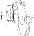
- FIG. 11is a vehicle mountable version of the ground powered or non-ground powered tethered unmanned aerial vehicle system.
- a ground powered unmanned aerial vehicle system 100includes an unmanned aerial vehicle 102 which is powered by and in communication with a base station 104 over an electrically conductive filament 106 .
- the base station 104includes a power source 108 (e.g., a generator, battery, or power grid), a control station 110 (e.g., a laptop computer), and a spooling apparatus 112 .
- the power source 108provides power to the aerial vehicle 102 over the filament 106 .
- the control station 110communicates with the aerial vehicle 102 by, for example, establishing a network connection (e.g., an Ethernet connection) between itself and the aerial vehicle 102 over the filament 106 . In various embodiments, different types of information can be communicated between the control station 110 and the aerial vehicle 102 .
- a network connectione.g., an Ethernet connection
- control station 110can send control information such as flight control information (e.g., GPS coordinates, flight speed, etc.), payload control information, and sensor (e.g., camera) control information to the aerial vehicle 102 .
- the aerial vehicle 102can send information such as vehicle status information (e.g., current GPS coordinates, current payload status, etc.) and sensor data (e.g., video streams acquired by on-vehicle cameras) back to the control station 110 .
- vehicle status informatione.g., current GPS coordinates, current payload status, etc.
- sensor datae.g., video streams acquired by on-vehicle cameras
- the filament 106is the same or similar to the filaments described in U.S. Pat. No. 7,510,142 titled “AERIAL ROBOT,” U.S. Pat. No.
- a user 114can interact with the control station 110 to view sensor data and flight status information from the aerial vehicle 102 and/or to specify commands for controlling the aerial vehicle 102 .
- ground powered unmanned aerial vehicle system 100One common application for the ground powered unmanned aerial vehicle system 100 is to survey (e.g., video monitoring) a geographical area.
- the user 114 of the system 100may use the control station 110 to issue a command to the aerial vehicle 102 , causing the aerial vehicle 102 to hover at a given GPS coordinate (i.e., a latitude, longitude, and altitude).
- the user 114may monitor sensor data (e.g., a 720p video stream) from the aerial vehicle 102 to, for example, ensure that no unauthorized parties are approaching the user's position.
- the aerial vehicle 102includes control systems that continuously attempt to maintain the vehicle 102 at the commanded GPS coordinate (note that in some embodiments, the control system may be located in the base station 104 .
- the control systemmay be located in the base station 104 .
- the aerial vehicle 102is rarely able to maintain its position exactly at the commanded GPS coordinate.
- windcan cause the aerial vehicle 102 to significantly deviate from the commanded GPS coordinate. Without mitigation, such a deviation can cause the amount of slack on the filament 106 to vary, possibly damaging the very thin, lightweight, and fragile filament 106 .
- windmay blow the vehicle 102 in a direction away from the base station 104 , causing the amount of slack on the filament 106 to decrease, potentially placing excess tension on the filament 106 or at the very least placing a lateral force on the aerial vehicle 102 which the aerial vehicle 102 must compensate for. Without mitigation, such excess tension may result in the filament 106 breaking. Conversely, wind may blow the vehicle 102 in a direction toward the base station 104 , causing the amount of slack on the filament 106 to increase. Without mitigation, the filament 106 with excess slack can potentially fall toward the ground and become tangled with ground based objects.
- slackrefers to a degree of tautness in the filament 106 .
- the amount of slack on the filament 106increases.
- the amount of slack on the filamentcan be characterized in a length of an excess of deployed filament 106 or a length of a shortage of deployed filament 106 .
- the spooling apparatus 112is configured to mitigate the risks described above by controlling the amount of filament 106 that is deployed such that the amount of slack on the filament 106 is optimized.
- the desired amount of slackminimizes (or generally reduces or limits) the amount of horizontal force between the base station 104 and the aerial vehicle 102 while maintaining a safe distance between the ground the filament 106 .
- Optimizing of the amount of slack on the filament 106reduces the risk of breaking the filament 106 due to excess tension on the filament 106 and reduces the risk of having the filament 106 become entangled with objects close to the ground due to excess slack on the paid out filament 106 .
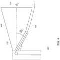
- the spooling apparatus 112utilizes a relationship that exists between the amount of slack on the filament 106 and an exit angle, ⁇ E 214 of the filament 106 from the spooling apparatus 112 .
- ⁇ E 214the exit angle
- the filament 106becomes less taut, causing the amount of slack on the filament 106 to increase.
- the exit angle, ⁇ E 214 of the filament 106 from the spooling apparatus 112decreases.
- the spooling apparatus 112is configured to control the amount of filament 106 that is deployed according to a desired exit angle or set-point, ⁇ O 220 of the filament 106 from the spooling apparatus 112 , for example to maintain the set-point, ⁇ O 220 . Furthermore, the spooling apparatus 112 also prevents tension in the filament 106 from exceeding a predefined maximum tension.
- the position sensor 227includes a straw-like tube 230 which coaxially surrounds a portion of the filament 106 at the point where the filament 106 exits the spooling apparatus 112 .
- the straw like tube 230is coupled to, for example, a high precision potentiometer, which outputs a signal indicative of the exit angle, ⁇ E 214 of the filament 106 .
- various types of position sensorssuch as optical, mechanical, or magnetic rotary encoders are used to sense ⁇ E 214 of the straw.
- different types of sensorssuch as inductive position sensors can be used to sense ⁇ E 214 .
- the filament feeding mechanismis described as being included in the feeder/tension sensor 226 (e.g., as pinch rollers). In other examples, the filament feeding mechanism is included at the exit of the spooling apparatus, for example, in the position sensor 227 .
- control systemis a cascaded control system with an inner loop which controls a torque output of the spool motor and one or more output loops that implement position, velocity, tension, and angle based control.
- the ground powered unmanned aerial vehicle system 100is shown with the filament 106 in three different scenarios.
- a sufficiently deployed filament 334has a sufficient amount of filament deployed, causing the actual exit angle, ⁇ E 214 measured by the position sensor 227 to be substantially the same as the desired exit angle, ⁇ O 220 (in this example, 0°).
- the spooling apparatus 112does not need to take any action to correct the exit angle, ⁇ E 214 of the filament.
- an overly taut filament 336has too little filament deployed, causing the actual exit angle, ⁇ E 214 measured by the position sensor 227 to be greater than the desired exit angle, ⁇ O 220 .
- the spooling apparatus 112acts to deploy additional filament in order to provide slack to the deployed filament.
- control system 228determines that the actual exit angle, ⁇ E 214 is greater than the desired exit angle, ⁇ O 220 and sends a control signal, Cmd 232 to the spool 224 , commanding the spool 224 to adjust the amount of deployed filament until the actual exit angle, ⁇ E 214 and the desired exit angle, ⁇ O 220 are substantially the same.
- an overly slack filament 338has too much filament deployed, causing the actual exit angle, ⁇ E 214 measured by the position sensor 227 to be less than the desired exit angle, ⁇ O 220 .
- the spooling apparatus 112acts to re-spool the deployed filament in order to reduce the amount of slack on the deployed filament.
- control system 228determines that the actual exit angle, ⁇ E 214 is less than the desired exit angle, ⁇ O 220 and sends a control signal, Cmd 232 to the spool 224 , commanding the spool 224 to adjust the amount of deployed filament until the actual exit angle, ⁇ E 214 and the desired exit angle, ⁇ O 220 are substantially the same.
- the filament 106is required to carry a substantial amount of power to the aerial vehicle 102 and resistive losses in the filament 106 cause heating of the filament 106 .
- the deployed filament 106is cooled as it drifts through the air.
- the spooled (i.e., un-deployed) filament 106can become overheated, possibly damaging the filament.
- the spool 224is hollow and includes a plurality of perforations 544 . Air is forced into the hollow spool 224 , creating a positive pressure within the spool 224 which causes the air to flow out of the spool 224 through the perforations 544 .
- deploying or re-spooling of filament 106 on the spool 224is at least in part accomplished by rotating the spool 224 while laterally moving a level winder (see the level winder of FIG. 6 ) back and forth from one end of the spool 224 to the other.
- a spooling patternis defined by an amount of lateral movement of the level winder relative to the number of rotations of the spool and is referred to as the “cross ratio.”
- Different cross ratiosmay be chosen for different applications. For example, certain cross ratios may be advantageous for applications where heating of the spooled microfilament is a problem. Such cross ratios may, for example, maximize airflow through the perforations 544 . Other cross ratios may be advantageous for applications where cross-talk between individual windings is a problem.
- the cross ratio for a given applicationmust be taken into account when winding new spools of microfilament.
- the firmware of the spooling apparatusmust also be configured to maintain the desired cross ratio as the microfilament is deployed and re-spooled from the spooling apparatus.
- the boundary 742is three dimensional.
- the boundary 742 shown in FIG. 7may have, for example, a three dimensional dome shape.
- the boundary 742can take on other shapes, including user-defined and possibly irregular shapes.
- the boundary 742may be maintained by providing the spooling apparatus 112 of the base station 104 with a limited amount of filament 106 such that, as the aerial vehicle 102 approaches the boundary 742 , the spooling apparatus 112 is unable to deploy any more filament 106 .
- the boundary 742may be maintained by providing the spooling apparatus 112 with a specification of the boundary 742 and configuring the spooling apparatus 112 to refuse to deploy additional filament 106 when the aerial vehicle 102 is at the edge of the boundary 742 .
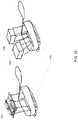
- the elements described abovecan be packaged into a human portable container such as a backpack 1094 that can easily be carried by a human.
- the back packcan be configured to facilitate safe and secure transportation of the collapsed aerial vehicle 1095 , the base station of the aerial vehicle system 1096 , and the spooling apparatus 1098 .
- the base station 1096 and the spooling apparatus 1098are packed first into the backpack 1094 and the collapsed aerial vehicle 1095 is packed on top of the base station 1096 and the spooling apparatus 1098 .
- the aerial vehicle 102includes payload that includes a high definition visible light video camera and the video stream is a high definition digital video stream such as a 720p, 1080i, or 1080p video stream.
- the aerial vehicleincludes a payload including multicore cameras, TOF laser depth cameras, hyperspectral cameras, or multi-sensor gigapixel camera arrays.
- the aerial vehicle 102includes a night vision camera such as an active illumination video camera or a thermal imaging camera.
- the aerial vehicle 102includes both a visible light video camera and a night vision camera.
- the aerial vehicle 102includes a high resolution still camera.
- other payloadscan include sensors, emitters (e.g., lasers), or weapons systems.
- the position sensor 227While the above description generally describes the position sensor 227 as being located within the spooling apparatus 112 , it is noted that the position sensor 227 does not need to be located within the spooling apparatus 112 . For example, the position sensor 227 could be located some distance from the spooling apparatus 112
- the spooling apparatus 112maintains a record of how much filament 106 is currently deployed and the control system 228 takes the record into account when controlling the speed and direction of rotation of the spool 224 .
- the aerial vehicle 102includes a configurable bay for accepting custom payloads.
Landscapes
- Engineering & Computer Science (AREA)
- Aviation & Aerospace Engineering (AREA)
- Remote Sensing (AREA)
- Mechanical Engineering (AREA)
- Transportation (AREA)
- Forklifts And Lifting Vehicles (AREA)
- Control Of Position, Course, Altitude, Or Attitude Of Moving Bodies (AREA)
Abstract
Description
- quickly feeding the
filament 106 from thespooler 224 through the spoolingapparatus 112, and - measuring the tension,
T 229 that is present on thefilament 106.
- quickly feeding the
Claims (20)
Priority Applications (2)
| Application Number | Priority Date | Filing Date | Title |
|---|---|---|---|
| US16/691,235US11180249B2 (en) | 2013-03-15 | 2019-11-21 | Spooler for unmanned aerial vehicle system |
| US17/520,459US11661187B2 (en) | 2013-03-15 | 2021-11-05 | Spooler for unmanned aerial vehicle system |
Applications Claiming Priority (3)
| Application Number | Priority Date | Filing Date | Title |
|---|---|---|---|
| US13/838,399US9290269B2 (en) | 2013-03-15 | 2013-03-15 | Spooler for unmanned aerial vehicle system |
| US15/041,211US10507914B2 (en) | 2013-03-15 | 2016-02-11 | Spooler for unmanned aerial vehicle system |
| US16/691,235US11180249B2 (en) | 2013-03-15 | 2019-11-21 | Spooler for unmanned aerial vehicle system |
Related Parent Applications (1)
| Application Number | Title | Priority Date | Filing Date |
|---|---|---|---|
| US15/041,211ContinuationUS10507914B2 (en) | 2013-03-15 | 2016-02-11 | Spooler for unmanned aerial vehicle system |
Related Child Applications (1)
| Application Number | Title | Priority Date | Filing Date |
|---|---|---|---|
| US17/520,459ContinuationUS11661187B2 (en) | 2013-03-15 | 2021-11-05 | Spooler for unmanned aerial vehicle system |
Publications (2)
| Publication Number | Publication Date |
|---|---|
| US20200189732A1 US20200189732A1 (en) | 2020-06-18 |
| US11180249B2true US11180249B2 (en) | 2021-11-23 |
Family
ID=50733318
Family Applications (4)
| Application Number | Title | Priority Date | Filing Date |
|---|---|---|---|
| US13/838,399Active2034-01-10US9290269B2 (en) | 2013-03-15 | 2013-03-15 | Spooler for unmanned aerial vehicle system |
| US15/041,211ActiveUS10507914B2 (en) | 2013-03-15 | 2016-02-11 | Spooler for unmanned aerial vehicle system |
| US16/691,235ActiveUS11180249B2 (en) | 2013-03-15 | 2019-11-21 | Spooler for unmanned aerial vehicle system |
| US17/520,459ActiveUS11661187B2 (en) | 2013-03-15 | 2021-11-05 | Spooler for unmanned aerial vehicle system |
Family Applications Before (2)
| Application Number | Title | Priority Date | Filing Date |
|---|---|---|---|
| US13/838,399Active2034-01-10US9290269B2 (en) | 2013-03-15 | 2013-03-15 | Spooler for unmanned aerial vehicle system |
| US15/041,211ActiveUS10507914B2 (en) | 2013-03-15 | 2016-02-11 | Spooler for unmanned aerial vehicle system |
Family Applications After (1)
| Application Number | Title | Priority Date | Filing Date |
|---|---|---|---|
| US17/520,459ActiveUS11661187B2 (en) | 2013-03-15 | 2021-11-05 | Spooler for unmanned aerial vehicle system |
Country Status (4)
| Country | Link |
|---|---|
| US (4) | US9290269B2 (en) |
| CA (1) | CA2906605C (en) |
| SG (2) | SG10201707574UA (en) |
| WO (1) | WO2014152159A1 (en) |
Cited By (1)
| Publication number | Priority date | Publication date | Assignee | Title |
|---|---|---|---|---|
| US20200406773A1 (en)* | 2019-06-26 | 2020-12-31 | Alberto Daniel Lacaze | Self-Powered Drone Tether |
Families Citing this family (100)
| Publication number | Priority date | Publication date | Assignee | Title |
|---|---|---|---|---|
| US9753355B2 (en) | 2012-08-17 | 2017-09-05 | Perspective Robotics Ag | Flying camera with string assembly for localization and interaction |
| US9290269B2 (en) | 2013-03-15 | 2016-03-22 | CyPhy Works, Inc. | Spooler for unmanned aerial vehicle system |
| US10144511B2 (en) | 2013-04-02 | 2018-12-04 | Hood Technology Corporation | Helicopter-mediated system and method for launching and retrieving an aircraft |
| US10569868B2 (en) | 2013-04-02 | 2020-02-25 | Hood Technology Corporation | Multicopter-assisted system and method for launching and retrieving a fixed-wing aircraft |
| US10583920B2 (en) | 2013-04-02 | 2020-03-10 | Hood Technology Corporation | Multicopter-assisted system and method for launching and retrieving a fixed-wing aircraft |
| US9359075B1 (en)* | 2013-04-02 | 2016-06-07 | Hood Technology Corporation | Helicopter-mediated system and method for launching and retrieving an aircraft |
| US9346547B2 (en) | 2013-08-26 | 2016-05-24 | Google Inc. | Mechanisms for lowering a payload to the ground from a UAV |
| US9434481B2 (en) | 2013-09-23 | 2016-09-06 | Aerovel Corporation | Apparatus and method for launch and retrieval of a hovering aircraft |
| US9321531B1 (en) | 2014-07-08 | 2016-04-26 | Google Inc. | Bystander interaction during delivery from aerial vehicle |
| US10414493B2 (en) | 2014-07-11 | 2019-09-17 | Aerovel Corporation | Apparatus and method for automated launch, retrieval, and servicing of a hovering aircraft |
| US9849981B1 (en) | 2014-08-28 | 2017-12-26 | X Development Llc | Payload-release device position tracking |
| WO2016065343A1 (en) | 2014-10-23 | 2016-04-28 | Dezso Molnar | Unmanned aerial vehicle with lighting and cooling therefor |
| CN104485606A (en)* | 2014-12-24 | 2015-04-01 | 国家电网公司 | A small multi-axis unmanned aerial vehicle traction rope deployment system |
| US20160200437A1 (en)* | 2015-01-12 | 2016-07-14 | Mark Andrew Ryan | Tethered Flight Control System for Small Unmanned Aircraft |
| WO2016167849A1 (en)* | 2015-01-15 | 2016-10-20 | Hood Technology Corporation | Helicopter-mediated system and method for launching and retrieving an aircraft |
| CN104538899A (en)* | 2015-01-19 | 2015-04-22 | 中兴长天信息技术(北京)有限公司 | Wireless-transmission-based unmanned aerial vehicle platform for power line inspection |
| FR3033256B1 (en)* | 2015-03-02 | 2018-06-01 | Elistair | SYSTEM FOR POWERING ELECTRIC POWER FROM A DRONE |
| KR20160112252A (en) | 2015-03-18 | 2016-09-28 | 엘지전자 주식회사 | Unmanned air device and method of controlling the same |
| US9894327B1 (en)* | 2015-06-22 | 2018-02-13 | State Farm Mutual Automobile Insurance Company | Systems and methods for remote data collection using unmanned vehicles |
| JP6908937B2 (en) | 2015-08-17 | 2021-07-28 | エイチ3 ダイナミックス ホールディングス プライベート リミテッド | Drone box |
| US10252800B1 (en)* | 2015-10-23 | 2019-04-09 | ScanTech Industries, Inc. | Aerial drone deployed non-destructive evaluation scanner |
| US10676331B1 (en)* | 2015-10-23 | 2020-06-09 | Scantech Instruments, Inc. | Winch for an aerial drone deployed non-destructive evaluation scanner |
| US11230391B2 (en)* | 2015-11-16 | 2022-01-25 | Altaeros Energies, Inc. | Systems and methods for attitude control of tethered aerostats |
| JP6734646B2 (en)* | 2015-12-22 | 2020-08-05 | 株式会社ミヤマエ | Flight aids for unmanned aerial vehicles |
| WO2017117291A1 (en) | 2015-12-28 | 2017-07-06 | Dezso Molnar | Tethered unmanned aerial system |
| WO2017117298A1 (en) | 2015-12-28 | 2017-07-06 | Dezso Molnar | Unmanned aerial system with transportable screen |
| WO2017117296A1 (en) | 2015-12-28 | 2017-07-06 | Dezso Molnar | Water and lighting displays including unmanned aerial system |
| CN105667819A (en)* | 2016-01-11 | 2016-06-15 | 四川海天仪表电器开发有限公司 | Wire suspension system and method for operating suspension flight vehicle |
| CN105752337B (en)* | 2016-02-26 | 2018-04-03 | 北京计算机技术及应用研究所 | One kind is tethered at unmanned plane automatic deploying and retracting line control system |
| US10399702B2 (en) | 2016-03-15 | 2019-09-03 | Aerovel Corporation | Capture and launch apparatus and method of using same for automated launch, retrieval, and servicing of a hovering aircraft |
| JP6667329B2 (en)* | 2016-03-18 | 2020-03-18 | 株式会社Ihiエアロスペース | Landing aids and methods |
| US10752357B2 (en) | 2016-03-22 | 2020-08-25 | Hood Technology Corporation | Rotorcraft-assisted system and method for launching and retrieving a fixed-wing aircraft into and from free flight |
| US11977395B2 (en)* | 2016-03-24 | 2024-05-07 | Teledyne Flir Defense, Inc. | Persistent aerial communication and control system |
| WO2018089859A1 (en) | 2016-11-10 | 2018-05-17 | CyPhy Works, Inc. | Cellular communication devices and methods |
| US11174021B2 (en)* | 2016-03-24 | 2021-11-16 | Flir Detection, Inc. | Persistent aerial reconnaissance and communication system |
| US12030629B2 (en) | 2016-03-24 | 2024-07-09 | Teledyne Flir Detection, Inc. | Cellular communication devices and methods |
| US9975632B2 (en) | 2016-04-08 | 2018-05-22 | Drona, LLC | Aerial vehicle system |
| JP2017217942A (en)* | 2016-06-03 | 2017-12-14 | 株式会社衛星ネットワーク | Unmanned aircraft system, unmanned aircraft, mooring device |
| US10460279B2 (en)* | 2016-06-28 | 2019-10-29 | Wing Aviation Llc | Interactive transport services provided by unmanned aerial vehicles |
| US10696420B2 (en) | 2016-08-17 | 2020-06-30 | Hood Technology Corporation | Rotorcraft-assisted system and method for launching and retrieving a fixed-wing aircraft into and from free flight |
| US10364030B2 (en) | 2016-09-09 | 2019-07-30 | Wing Aviation Llc | Methods and systems for user interaction and feedback via control of tether |
| US11104438B2 (en) | 2016-09-09 | 2021-08-31 | Wing Aviation Llc | Payload coupling apparatus for UAV and method of delivering a payload |
| US10793274B2 (en) | 2016-09-09 | 2020-10-06 | Wing Aviation Llc | Payload coupling apparatus for UAV and method of delivering a payload |
| US10000285B2 (en) | 2016-09-09 | 2018-06-19 | X Development Llc | Methods and systems for detecting and resolving failure events when raising and lowering a payload |
| US10793272B2 (en) | 2016-09-09 | 2020-10-06 | Wing Aviation Llc | Unmanned aerial vehicle and techniques for securing a payload to the UAV in a desired orientation |
| US10414488B2 (en) | 2016-09-09 | 2019-09-17 | Wing Aviation Llc | Methods and systems for damping oscillations of a payload |
| US10232940B2 (en) | 2016-09-09 | 2019-03-19 | Wing Aviation Llc | Methods and systems for raising and lowering a payload |
| EP3529144B1 (en) | 2016-10-18 | 2021-12-08 | Altaeros Energies, Inc. | Systems and methods for automated, lighter-than-air airborne platform |
| JP6555226B2 (en)* | 2016-10-31 | 2019-08-07 | キヤノンマーケティングジャパン株式会社 | Unmanned aircraft control system, control method thereof, and program |
| US11204612B2 (en) | 2017-01-23 | 2021-12-21 | Hood Technology Corporation | Rotorcraft-assisted system and method for launching and retrieving a fixed-wing aircraft |
| US10535986B2 (en)* | 2017-01-25 | 2020-01-14 | Tribune Broadcasting Company, Llc | Tethered unmanned aerial vehicle system |
| GB2559185A (en)* | 2017-01-31 | 2018-08-01 | Aquila Aerospace Ltd | Surveillance apparatus |
| FR3063070B1 (en)* | 2017-02-23 | 2021-11-05 | Centre Nat Etd Spatiales | DEPLOYMENT SYSTEM INCLUDING A MOBILE PLATFORM AND AN OBSERVATION KIT INCLUDING A WINCH |
| US20180251216A1 (en)* | 2017-03-06 | 2018-09-06 | Hoverfly Technologies, Inc. | Constant tension tether management system for atethered aircraft |
| US11713118B1 (en) | 2017-03-06 | 2023-08-01 | Hoverfly Technologies. Inc. | Constant tension tether management system for a tethered aircraft |
| CN106950995B (en)* | 2017-05-05 | 2020-12-25 | 成都通甲优博科技有限责任公司 | Unmanned aerial vehicle flight method and system |
| US20180319495A1 (en)* | 2017-05-05 | 2018-11-08 | Pinnacle Vista, LLC | Relay drone method |
| US10988257B2 (en)* | 2017-05-11 | 2021-04-27 | Hood Technology Corporation | Aircraft-retrieval system |
| US11524797B2 (en) | 2017-05-11 | 2022-12-13 | Hood Technology Corporation | Aircraft-retrieval system |
| US11148802B1 (en)* | 2017-06-22 | 2021-10-19 | Arrowhead Center, Inc. | Robust cooperative localization and navigation of tethered heterogeneous autonomous unmanned vehicles in resource-constrained environments |
| FR3069851B1 (en) | 2017-08-07 | 2021-08-06 | Univ Claude Bernard Lyon | SECURITY SYSTEM FOR FLYING OBJECTS |
| US11414187B2 (en) | 2017-09-06 | 2022-08-16 | Hood Technology Corporation | Parasail-assisted systems and methods for launching and retrieving a fixed-wing aircraft into and from free flight |
| US11667398B2 (en) | 2017-09-06 | 2023-06-06 | Hood Technology Corporation | Multicopter-assisted systems and methods for launching and retrieving a fixed-wing aircraft into and from free flight |
| US11027844B2 (en) | 2017-09-06 | 2021-06-08 | Hood Technology Corporation | Rotorcraft-assisted system for launching and retrieving a fixed-wing aircraft into and from free flight |
| US10890927B2 (en)* | 2017-09-21 | 2021-01-12 | The United States Of America, As Represented By The Secretary Of The Navy | Persistent surveillance unmanned aerial vehicle and launch/recovery platform system and method of using with secure communication, sensor systems, targeting systems, locating systems, and precision landing and stabilization systems |
| EP3688885B1 (en) | 2017-09-27 | 2022-07-27 | Teledyne FLIR Detection, Inc. | Persistent aerial communication and control system |
| JP6903540B2 (en)* | 2017-09-29 | 2021-07-14 | セコム株式会社 | Monitoring system |
| US11312492B1 (en) | 2017-11-09 | 2022-04-26 | Hood Technology Corporation | Rotorcraft-assisted systems and methods for launching and retrieving a fixed-wing aircraft into and from free flight |
| US10875644B2 (en)* | 2017-12-28 | 2020-12-29 | Aurora Flight Sciences Corporation | Ground manipulation system and method for fixing an aircraft |
| US10737783B2 (en) | 2018-01-16 | 2020-08-11 | RSQ-Systems SPRL | Control systems for unmanned aerial vehicles |
| US11401034B2 (en) | 2018-02-28 | 2022-08-02 | Walmart Apollo, Llc | Drone delivery system having a single use lowering line |
| US10696396B2 (en)* | 2018-03-05 | 2020-06-30 | Rsq-Systems Us Llc | Stability systems for tethered unmanned aerial vehicles |
| JP2019156241A (en)* | 2018-03-14 | 2019-09-19 | 株式会社フカデン | Reel device and flight body system |
| WO2019178388A1 (en)* | 2018-03-15 | 2019-09-19 | Unmanned Systems and Solutions, LLC | Unmanned aerial vehicle tether system |
| JP7106160B2 (en)* | 2018-03-27 | 2022-07-26 | 株式会社Acsl | unmanned aerial vehicle |
| US10435152B1 (en) | 2018-05-21 | 2019-10-08 | Superior Essex International LP | Airfoil cables for use with drones |
| JP6986686B2 (en)* | 2018-07-03 | 2021-12-22 | パナソニックIpマネジメント株式会社 | Information processing method, control device and mooring mobile |
| US10773800B2 (en) | 2018-07-26 | 2020-09-15 | RSQ-Systems SPRL | Vehicle-based deployment of a tethered surveillance drone |
| US11358718B2 (en)* | 2018-08-21 | 2022-06-14 | Seung Hee CHOI | Low-altitude unmanned aerial vehicle surveillance system |
| US10906173B2 (en)* | 2018-11-15 | 2021-02-02 | Zezhi Intellectual Property Service | Smart cabinet |
| CN109607331B (en)* | 2019-02-13 | 2024-02-27 | 深圳市赛为智能股份有限公司 | Tethered unmanned aerial vehicle coiling and uncoiling line buffer structure and working method thereof |
| US11513536B2 (en)* | 2019-03-29 | 2022-11-29 | T-Mobile Usa, Inc. | Operation of a tethered drone |
| US11691761B2 (en)* | 2019-05-17 | 2023-07-04 | FlyFocus Sp. z.o.o. | Detachable power cable for unmanned aerial vehicle |
| US11235892B2 (en)* | 2019-05-22 | 2022-02-01 | Hood Technology Corporation | Aircraft retrieval system and method |
| US20200377210A1 (en)* | 2019-05-30 | 2020-12-03 | Pegasus Aeronautics Corporation | High endurance mobile unmanned aerial vehicle system |
| JP6826294B2 (en)* | 2019-07-11 | 2021-02-03 | キヤノンマーケティングジャパン株式会社 | System, its control method, and program |
| US20210061487A1 (en)* | 2019-08-29 | 2021-03-04 | Blue Vigil, LLC | Unmanned Aerial Vehicle Tether Spool |
| GB2587325B (en)* | 2019-09-06 | 2022-06-08 | Tethered Drone Systems Ltd | Cooling Unmanned Aerial Vehicles (Drones) Using Fans or Redirecting Cool Air |
| US11414002B2 (en)* | 2019-09-25 | 2022-08-16 | The Boeing Company | Systems, methods, and apparatus for high-traffic density air transportation |
| US11989033B2 (en) | 2019-09-25 | 2024-05-21 | The Boeing Company | Systems, methods, and apparatus for high-traffic density personalized transportation |
| US11586222B2 (en) | 2019-09-25 | 2023-02-21 | The Boeing Company | Systems, methods, and apparatus for high-traffic density transportation pathways |
| JP7465581B2 (en) | 2019-12-18 | 2024-04-11 | アベティクス グローバル ピーティーイー.エルティーディー. | Tether management system and method |
| US11417223B2 (en) | 2020-01-19 | 2022-08-16 | Flir Unmanned Aerial Systems Ulc | Flight altitude estimation systems and methods |
| US11423790B2 (en) | 2020-01-19 | 2022-08-23 | Flir Unmanned Aerial Systems Ulc | Tether management systems and methods |
| WO2021155299A1 (en)* | 2020-01-31 | 2021-08-05 | Flir Detection, Inc. | Cable spooler for a mobile robot |
| US11667402B2 (en) | 2020-09-08 | 2023-06-06 | Wing Aviation Llc | Landing pad with charging and loading functionality for unmanned aerial vehicle |
| EP4414315A3 (en) | 2021-03-07 | 2024-11-20 | MetraLabs GmbH Neue Technologien und Systeme | Winch service robot |
| CN117897545A (en)* | 2022-03-09 | 2024-04-16 | 深圳市大疆创新科技有限公司 | UAV base station and UAV system |
| US20230348119A1 (en)* | 2022-04-27 | 2023-11-02 | Equinox Innovative Systems | Unmanned aerial vehicle tethered with optical fiber |
| US12145753B2 (en)* | 2022-08-09 | 2024-11-19 | Pete Bitar | Compact and lightweight drone delivery device called an ArcSpear electric jet drone system having an electric ducted air propulsion system and being relatively difficult to track in flight |
Citations (161)
| Publication number | Priority date | Publication date | Assignee | Title |
|---|---|---|---|---|
| US2995740A (en) | 1957-08-30 | 1961-08-08 | Raymond C Shreckengost | Radar system |
| US2996269A (en) | 1956-04-12 | 1961-08-15 | Charles B Bolton | Helicopter with counter-rotating propeller |
| US3053480A (en) | 1959-10-06 | 1962-09-11 | Piasecki Aircraft Corp | Omni-directional, vertical-lift, helicopter drone |
| US3053481A (en) | 1957-08-29 | 1962-09-11 | Wyatt Theodore | Tether station |
| US3149803A (en) | 1961-07-19 | 1964-09-22 | Us Industries Inc | Tethered hovering platform |
| US3176288A (en) | 1957-08-29 | 1965-03-30 | Wyatt Theodore | System for extending the range of a search radar |
| US3176413A (en) | 1963-03-20 | 1965-04-06 | Dornier Werke Gmbh | Flyable helicopter pilot training apparatus |
| US3181816A (en) | 1962-09-12 | 1965-05-04 | Bolkow Entwicklungen Kg | Fettered rotary wing aircraft |
| US3217097A (en) | 1961-08-09 | 1965-11-09 | Fritz K Pauli | Tethered hovering platform for aerial surveillance |
| US3223359A (en) | 1964-03-19 | 1965-12-14 | Fairchild Hiller Corp | Helicopter flight control system |
| US3223358A (en) | 1964-03-18 | 1965-12-14 | Fairchild Hiller Corp | Tethered helicopter |
| US3228629A (en) | 1964-01-22 | 1966-01-11 | Ripper Robots Ltd | Rotary wing aircraft having autopiloting means |
| US3241145A (en) | 1963-07-03 | 1966-03-15 | Us Industries Inc | Tethered hovering communication platform with composite tethering cable used for microwave and power trans-mission |
| US3381922A (en) | 1961-01-18 | 1968-05-07 | Laing Nikolaus | Captive helicopter |
| US3496469A (en) | 1966-09-28 | 1970-02-17 | Avco Corp | System and method for measurement of path losses in microwave relay surveying |
| US3611367A (en) | 1968-02-01 | 1971-10-05 | Houston Hotchkiss Brandt Comp | Airborne station for aerial observation system |
| US3618259A (en) | 1970-11-09 | 1971-11-09 | Voorhis F Wigal | Remotely powered flying device |
| US3710006A (en) | 1971-07-01 | 1973-01-09 | Schlumberger Technology Corp | Marine streamer cable |
| US3717719A (en) | 1971-11-17 | 1973-02-20 | Int Standard Electric Corp | Coaxial cable inner conductor |
| US3919805A (en) | 1973-11-16 | 1975-11-18 | Victor Stanzel | Model aircraft |
| US3943357A (en) | 1973-08-31 | 1976-03-09 | William Howard Culver | Remote controlled vehicle systems |
| US3991512A (en) | 1973-11-16 | 1976-11-16 | Victor Stanzel Company | Model aircraft |
| US4058277A (en) | 1974-09-19 | 1977-11-15 | Dornier Gmbh. | Captive remote-controlled helicopter |
| US4095759A (en) | 1974-03-14 | 1978-06-20 | Dornier Gmbh | Device for stabilization of captive aircraft |
| US4133139A (en) | 1977-05-13 | 1979-01-09 | Victor Stanzel | Jet-propelled model airplane |
| US4161843A (en) | 1978-09-01 | 1979-07-24 | Hui Danny C T | Electrically powered toy aircraft |
| US4233605A (en) | 1979-02-15 | 1980-11-11 | Northrop Corporation | Helicopter radar decoy |
| US4478379A (en) | 1981-05-28 | 1984-10-23 | Canadair Limited | Unmanned remotely piloted aircraft |
| US4508934A (en) | 1983-09-29 | 1985-04-02 | Gould Inc. | High-current sweep cable |
| US4573937A (en) | 1984-07-19 | 1986-03-04 | Victor Stanzel | Jet propelled model airplane |
| US4664340A (en) | 1984-02-23 | 1987-05-12 | Imperial Chemical Industries Plc | Vehicles |
| US4795111A (en) | 1987-02-17 | 1989-01-03 | Moller International, Inc. | Robotic or remotely controlled flying platform |
| US4799914A (en) | 1987-02-09 | 1989-01-24 | Hutchinson Jack M | Remote control lighter-than-air toy with tether |
| US4808999A (en) | 1988-02-18 | 1989-02-28 | Loral Corp. | Towed decoy with fiber optic link |
| US4842221A (en) | 1988-04-21 | 1989-06-27 | Westinghouse Electric Corp. | Lightning hardened tether cable and an aerostat tethered to a mooring system therewith |
| US4999640A (en) | 1989-09-05 | 1991-03-12 | Westinghouse Electric Corp. | Aerostat tether lighting apparatus |
| US5070955A (en) | 1990-05-04 | 1991-12-10 | Aerovironment, Inc. | Passively stable hovering system |
| US5072396A (en) | 1989-11-08 | 1991-12-10 | Smiths Industries Public Limited Company | Navigation systems |
| US5115997A (en) | 1990-01-12 | 1992-05-26 | Teledyne Industries, Inc. | Surveillance balloon |
| US5120905A (en) | 1988-07-18 | 1992-06-09 | Cousin Freres (S.A.) | Electrocarrier cable |
| US5136295A (en) | 1991-05-14 | 1992-08-04 | The Boeing Company | Airborne fiber optic decoy architecture |
| US5152478A (en) | 1990-05-18 | 1992-10-06 | United Technologies Corporation | Unmanned flight vehicle including counter rotating rotors positioned within a toroidal shroud and operable to provide all required vehicle flight controls |
| US5208757A (en) | 1990-01-12 | 1993-05-04 | Societe Anonyme Dite: Aerospatiale Societe Nationale Industrielle | Airborne system for determining the position of an aerial vehicle and its applications |
| US5260820A (en) | 1991-05-14 | 1993-11-09 | Bull James G | Airborne fiber optic decoy architecture |
| US5289994A (en) | 1989-10-10 | 1994-03-01 | Juan Del Campo Aguilera | Equipment carrying remote controlled aircraft |
| FR2712563A1 (en) | 1993-11-18 | 1995-05-24 | Cr2A | Bidirectional optical signal transmission device for optical cable guided missile |
| US5419513A (en) | 1993-05-11 | 1995-05-30 | United Technologies Corporation | Ancillary aerodynamic structures for an unmanned aerial vehicle having ducted, coaxial counter-rotating rotors |
| WO1995024004A1 (en) | 1994-03-02 | 1995-09-08 | United Technologies Corporation | Variable referenced control system for remotely operated vehicles |
| US5525883A (en) | 1994-07-08 | 1996-06-11 | Sara Avitzour | Mobile robot location determination employing error-correcting distributed landmarks |
| US5709580A (en) | 1996-05-28 | 1998-01-20 | Stanzel; Victor | Control and power mechanism for model aircraft |
| US5722618A (en) | 1994-08-16 | 1998-03-03 | Northrop Grumman Corporation | Airborne tethered sensor system |
| US5752088A (en) | 1997-02-03 | 1998-05-12 | Desselle; Alex S. | Aerial photography device |
| US5757157A (en) | 1995-11-16 | 1998-05-26 | Tcom, L.P. | Sensor mount apparatus |
| US5765783A (en) | 1994-03-04 | 1998-06-16 | The Boeing Company | Vertically launchable and recoverable winged aircraft |
| US5779190A (en) | 1995-11-22 | 1998-07-14 | Northrop Grumman Corporation | Portable unmanned aerial vehicle |
| US5904724A (en) | 1996-01-19 | 1999-05-18 | Margolin; Jed | Method and apparatus for remotely piloting an aircraft |
| DE19808777A1 (en) | 1998-03-03 | 1999-09-09 | Quaas | Annular free flight body used as carrier for observation and measurement systems |
| US6010093A (en) | 1999-04-28 | 2000-01-04 | Paulson; Allen E. | High altitude airship system |
| US6086014A (en) | 1998-08-12 | 2000-07-11 | Bragg, Jr.; Albert J. | Roadable aircraft |
| US6104970A (en) | 1998-02-17 | 2000-08-15 | Raytheon Company | Crawler inspection vehicle with precise mapping capability |
| US6270038B1 (en) | 1999-04-22 | 2001-08-07 | Sikorsky Aircraft Corporation | Unmanned aerial vehicle with counter-rotating ducted rotors and shrouded pusher-prop |
| US6325330B1 (en) | 1998-08-18 | 2001-12-04 | Lockheed Martin Corporation | Power generation, transmission, and distribution system for an aerostat using a lightweight tether |
| US6364253B1 (en) | 2000-04-25 | 2002-04-02 | The United States Of America As Represented By The Secretary Of The Navy | Remote piloted vehicle powered by beamed radiation |
| US6384765B1 (en) | 1998-11-18 | 2002-05-07 | Celsiustech Electronics Ab | Repeater jamming transmitter and casing for the same |
| US6389194B1 (en) | 2000-07-13 | 2002-05-14 | Bbnt Solutions Llc | Method and apparatus for coupling fiber optic cables |
| US6419190B1 (en) | 2000-10-10 | 2002-07-16 | Gino Francis Nguegang | Airborne cleaning and painting robot |
| US6422506B1 (en) | 2000-10-12 | 2002-07-23 | The United States Of America As Represented By The Secretary Of The Navy | Towed airborne array system |
| US6427944B1 (en) | 2000-07-13 | 2002-08-06 | Bbnt Solutions Llc | Systems and methods for using airborne communication nodes |
| WO2002061971A1 (en) | 2001-02-01 | 2002-08-08 | Skylinc Limited | Communication system using an aerostat tethered above the earth surface and linked to a base station by an optical fibre |
| US6450445B1 (en) | 1998-12-11 | 2002-09-17 | Moller International, Inc. | Stabilizing control apparatus for robtic or remotely controlled flying platform |
| US6450452B1 (en) | 1999-05-24 | 2002-09-17 | Lockheed Martin Corporation | Fly back booster |
| US6502787B1 (en) | 2002-02-22 | 2003-01-07 | Micro Autonomous Systems Llc | Convertible vertical take-off and landing miniature aerial vehicle |
| US6542109B2 (en) | 1999-11-30 | 2003-04-01 | Roke Manor Research Limited | Autonomous off-board defensive aids system |
| US6567044B2 (en) | 2001-09-20 | 2003-05-20 | Ernest A. Carroll | Miniature, unmanned remotely guided vehicles for locating an object with a beacon |
| US6620018B1 (en) | 2001-04-19 | 2003-09-16 | Justin Chao | Flying toy device including simulated fan jet propulsion system |
| US6672543B2 (en) | 2001-10-11 | 2004-01-06 | Bae Systems Information And Electronics Systems Integration Inc. | Compact mechanism for retrieval of a towed body from moving vehicles |
| US6705573B2 (en) | 1999-12-30 | 2004-03-16 | Advanced Aerospace Technologies, Inc. | Survivability and mission flexibility enhancements for reconnaissance aircraft |
| US20040167682A1 (en) | 2003-02-21 | 2004-08-26 | Lockheed Martin Corporation | Virtual sensor mast |
| US6804495B2 (en) | 2001-10-05 | 2004-10-12 | Northrop Grumman Corporation | Wireless communicator link from towed/surrogate decoy transmitter to the host aircraft |
| US6811113B1 (en) | 2000-03-10 | 2004-11-02 | Sky Calypso, Inc. | Internet linked environmental data collection system and method |
| US6845939B1 (en) | 2003-10-24 | 2005-01-25 | G. Douglas Baldwin | Tailboom-stabilized VTOL aircraft |
| US6857596B1 (en) | 2003-07-10 | 2005-02-22 | Ae Systems Information And Electronic Systems Integration Inc. | High speed electro-optic payout system incorporating a stationary optical terminus |
| US6868314B1 (en) | 2001-06-27 | 2005-03-15 | Bentley D. Frink | Unmanned aerial vehicle apparatus, system and method for retrieving data |
| US6874729B1 (en) | 1999-07-23 | 2005-04-05 | Advanced Aerospace Technologies, Inc. | Launch and recovery system for unmanned aerial vehicles |
| US6931247B2 (en) | 2000-02-14 | 2005-08-16 | Aerovironment, Inc. | Aircraft control method |
| US6933965B2 (en) | 2001-03-13 | 2005-08-23 | Tacshot, Inc. | Panoramic aerial imaging device |
| US7039367B1 (en) | 2003-01-31 | 2006-05-02 | The United States Of America As Represented By The Secretary Of The Navy | Communications using unmanned surface vehicles and unmanned micro-aerial vehicles |
| US7040247B2 (en) | 2004-01-28 | 2006-05-09 | Fac Systems Inc. | Stabilizing surface for flight deck or other uses |
| US7183663B2 (en)* | 2001-11-07 | 2007-02-27 | Bryan William Roberts | Precisely controlled flying electric generators |
| US7210654B1 (en) | 2003-07-23 | 2007-05-01 | Mission Technologies, Inc. | Unmanned airborne reconnaissance system |
| US7264204B1 (en) | 2005-12-12 | 2007-09-04 | The United States Of America As Represented By The Secretary Of The Navy | Unmanned aerial vehicle catcher |
| US20070244608A1 (en) | 2006-04-13 | 2007-10-18 | Honeywell International Inc. | Ground control station for UAV |
| US7287723B2 (en) | 2005-07-14 | 2007-10-30 | Barnes Tracy L | Tethered or free flight blimp with collapsible tail fins |
| US7296530B1 (en) | 2005-12-12 | 2007-11-20 | United States Of America As Represented By The Secretary Of The Navy | Unmanned system for underwater object inspection, identification and/or neutralization |
| WO2007141795A1 (en) | 2006-06-08 | 2007-12-13 | Israel Aerospace Industries Ltd. | Unmanned air vehicle system |
| EP1901153A1 (en) | 2006-09-12 | 2008-03-19 | OFFIS e.V. | Control system for unmanned 4-rotor-helicopter |
| US7364114B2 (en) | 2002-03-06 | 2008-04-29 | Aloys Wobben | Aircraft |
| FR2909972A1 (en) | 2006-12-18 | 2008-06-20 | Novadem Sarl | Vertical take-off and land aircraft for military application, has blocking unit selecting blocking configuration of arms in deployed position and releasing configuration of arms for authorizing arms to pass through folding position of arms |
| US7410125B2 (en) | 2005-05-05 | 2008-08-12 | Lockheed Martin Corporation | Robotically assisted launch/capture platform for an unmanned air vehicle |
| US7506837B2 (en) | 2004-09-17 | 2009-03-24 | Aurora Flight Sciences Corporation | Inbound transition control for a tail-sitting vertical take off and landing aircraft |
| US7510142B2 (en) | 2006-02-24 | 2009-03-31 | Stealth Robotics | Aerial robot |
| US7520466B2 (en) | 2005-03-17 | 2009-04-21 | Nicolae Bostan | Gyro-stabilized air vehicle |
| US7520463B2 (en) | 2002-10-15 | 2009-04-21 | Bae Systems Information And Electronic Systems Integration Inc. | Method and apparatus for fast deploying and retrieving of towed bodies |
| US7530787B2 (en) | 2005-05-31 | 2009-05-12 | Sikorsky Aircraft Corporation | Rotor hub fairing system for a counter-rotating, coaxial rotor system |
| US7530527B2 (en) | 2003-05-30 | 2009-05-12 | Qinetiq Limited | Method and device for launching aerial vehicles |
| US7556219B2 (en) | 2004-02-24 | 2009-07-07 | Swift Engineering, Inc. | Unmanned aerial vehicle and launch assembly |
| US7559191B2 (en) | 2004-09-17 | 2009-07-14 | Aurora Flight Sciences Corporation | Ducted spinner for engine cooling |
| US7631834B1 (en) | 2006-02-24 | 2009-12-15 | Stealth Robotics, Llc | Aerial robot with dispensable conductive filament |
| US20100013236A1 (en)* | 2008-07-18 | 2010-01-21 | Baseload Energy,Inc. | Tether handling for airborne electricity generators |
| US7665691B2 (en) | 2007-02-27 | 2010-02-23 | Raytheon Company | Aerial vehicle launching system and method |
| US7708222B2 (en) | 2007-04-27 | 2010-05-04 | Stratocomm Corporation | Long mission tethered aerostat and method of accomplishing |
| US7712701B1 (en) | 2006-02-10 | 2010-05-11 | Lockheed Martin Corporation | Unmanned aerial vehicle with electrically powered, counterrotating ducted rotors |
| FR2941921A1 (en) | 2009-02-12 | 2010-08-13 | Geocean | Captive maintained aerodyne i.e. unmanned aerodyne, recovering method, involves deploying parachute during detection of failure of unit, and connecting aerodyne to launching and receiving device by exerting traction on link or cable |
| US7775483B2 (en) | 2008-12-03 | 2010-08-17 | Gaylord G Olson | Launch and recovery system for tethered airborne elements |
| US7789341B2 (en) | 2004-04-14 | 2010-09-07 | Arlton Paul E | Rotary wing aircraft having a non-rotating structural backbone and a rotor blade pitch controller |
| EP2228301A2 (en) | 2009-03-10 | 2010-09-15 | Honeywell International Inc. | Tether energy supply system |
| US7900866B2 (en) | 2007-10-18 | 2011-03-08 | The Boeing Company | System and methods for airborne launch and recovery of aircraft |
| US20110139928A1 (en) | 2009-12-12 | 2011-06-16 | John William Morris | Autogyro air vehicle |
| US8001764B2 (en) | 2004-09-17 | 2011-08-23 | Aurora Flight Sciences Corporation | Vibration isolation engine mount system and method for ducted fans |
| US20110222047A1 (en)* | 2008-09-19 | 2011-09-15 | Avishay Guetta | Aerial observation system |
| US8028952B2 (en) | 2008-03-31 | 2011-10-04 | The Boeing Company | System for shipboard launch and recovery of unmanned aerial vehicle (UAV) aircraft and method therefor |
| WO2012007942A2 (en) | 2010-07-12 | 2012-01-19 | Powermat Ltd. | Power management system and method for an inductive power transfer system |
| US8109711B2 (en) | 2008-07-18 | 2012-02-07 | Honeywell International Inc. | Tethered autonomous air vehicle with wind turbines |
| US20120112008A1 (en) | 2010-08-16 | 2012-05-10 | Primal Innovation | System for high altitude tethered powered flight platform |
| WO2012094430A2 (en) | 2011-01-04 | 2012-07-12 | Reconrobotics, Inc. | Tethered airborne surveillance system |
| US8231083B2 (en) | 2007-10-18 | 2012-07-31 | The Boeing Company | System and methods for airborne launch and recovery of aircraft |
| US20120298793A1 (en) | 2011-05-23 | 2012-11-29 | Sky Windpower Corporation | Flying electric generators with clean air rotors |
| US8382029B2 (en) | 2006-07-31 | 2013-02-26 | University Of Florida Research Foundation, Inc. | Wingless hovering of micro air vehicle |
| CN202807086U (en) | 2012-09-19 | 2013-03-20 | 天津全华时代航天科技发展有限公司 | Electric power tethered observation platform |
| WO2013052178A2 (en) | 2011-06-09 | 2013-04-11 | Lasermotive, Inc. | An aerial platform system, and related methods |
| US8421257B2 (en) | 2009-03-11 | 2013-04-16 | Dimitri Chernyshov | Tethered glider system for power generation |
| CN202953185U (en) | 2012-11-07 | 2013-05-29 | 上海交通大学无锡研究院 | Dual-power-source mixed power distribution tethered flight platform |
| CN103144779A (en) | 2012-11-30 | 2013-06-12 | 中国电子科技集团公司第七研究所 | Multi-rotor-wing unmanned aerial vehicle mooring system |
| CN203047531U (en) | 2012-11-15 | 2013-07-10 | 深圳市大疆创新科技有限公司 | Multi-rotor unmanned aerial vehicle |
| CN203127141U (en) | 2012-12-13 | 2013-08-14 | 深圳市大疆创新科技有限公司 | Multi-rotor wing unmanned aerial vehicle |
| US20130233964A1 (en) | 2012-03-07 | 2013-09-12 | Aurora Flight Sciences Corporation | Tethered aerial system for data gathering |
| WO2013162128A1 (en) | 2012-04-24 | 2013-10-31 | 유콘시스템 주식회사 | Cable connection unmanned aerial vehicle system |
| US20130311009A1 (en) | 2009-07-06 | 2013-11-21 | Honeywell International Inc. | Flight technical control management for an unmanned aerial vehicle |
| US8602349B2 (en) | 2010-06-23 | 2013-12-10 | Dimitri Petrov | Airborne, tethered, remotely stabilized surveillance platform |
| US8646719B2 (en) | 2010-08-23 | 2014-02-11 | Heliplane, Llc | Marine vessel-towable aerovehicle system with automated tow line release |
| US8708285B1 (en) | 2011-01-11 | 2014-04-29 | The United States Of America As Represented By The Secretary Of The Navy | Micro-unmanned aerial vehicle deployment system |
| US8777157B2 (en) | 2008-10-31 | 2014-07-15 | University Of Kansas | Tethered hovering platform |
| US8825225B1 (en) | 2013-02-15 | 2014-09-02 | Disney Enterprises, Inc. | Aerial display system with floating projection screens |
| US20140284531A1 (en) | 2013-03-15 | 2014-09-25 | Robert Hoyt | Orbital Winch |
| US20140304107A1 (en) | 2012-12-03 | 2014-10-09 | CLARKE William McALLISTER | Webrooming with rfid-scanning robots |
| US8894001B2 (en) | 2009-06-03 | 2014-11-25 | Grant Calverley | Gyroglider power-generation, control apparatus and method |
| US8931727B2 (en) | 2011-03-07 | 2015-01-13 | William A. Engblom | Dual-aircraft atmospheric platform |
| US8948928B2 (en) | 2013-04-19 | 2015-02-03 | Sikorsky Aircraft Corporation | Sustained over-the-horizon vertical takeoff and landing sensing system |
| US8963362B2 (en) | 2012-04-26 | 2015-02-24 | Yik Hei Sia | Power generating windbags and waterbags |
| US8989922B2 (en) | 2013-03-15 | 2015-03-24 | Azure Sky Group, LLC. | Modular drone and methods for use |
| US8991793B1 (en) | 2012-05-29 | 2015-03-31 | The Boeing Company | UAV capture of micro cargo aloft |
| US9016617B2 (en) | 2012-11-15 | 2015-04-28 | SZ DJI Technology Co., Ltd | Unmanned aerial vehicle and operations thereof |
| US9022322B2 (en) | 2013-03-15 | 2015-05-05 | Curnell Melvin Westbrook, SR. | Remotely-controlled emergency aerial vehicle |
| US9045218B2 (en) | 2013-03-08 | 2015-06-02 | The Boeing Company | Autonomous aircraft with disconnectable tether |
| US20150184638A1 (en)* | 2013-12-30 | 2015-07-02 | Google Inc. | Extruded Drum Surface for Storage of Tether |
| US9156565B2 (en)* | 2013-12-30 | 2015-10-13 | Google Inc. | Methods for perching |
| US9290269B2 (en) | 2013-03-15 | 2016-03-22 | CyPhy Works, Inc. | Spooler for unmanned aerial vehicle system |
| US9302770B2 (en) | 2014-08-28 | 2016-04-05 | Google Inc. | Payload-release device and operation thereof |
| US20160137311A1 (en) | 2013-03-14 | 2016-05-19 | Aurora Flight Sciences Corporation | Aerial system and vehicle for continuous operation |
| US9373262B2 (en) | 2011-08-04 | 2016-06-21 | Silicis Technologies, Inc. | Autonomous intelligence surveillance reconnaissance and payload delivery system and method of using same |
| US9753355B2 (en) | 2012-08-17 | 2017-09-05 | Perspective Robotics Ag | Flying camera with string assembly for localization and interaction |
Family Cites Families (12)
| Publication number | Priority date | Publication date | Assignee | Title |
|---|---|---|---|---|
| US4065080A (en)* | 1976-11-26 | 1977-12-27 | Alison Dave R | Kite reel system |
| US5334070A (en) | 1993-04-20 | 1994-08-02 | Uni-King Toys Ltd. | Tethered controlled flying toy |
| US20070200032A1 (en)* | 2006-02-24 | 2007-08-30 | Eadie William J | Radio frequency emitting hook system for a rotary-wing aircraft external load handling |
| US7673831B2 (en)* | 2006-06-08 | 2010-03-09 | Lockheed Martin Corporation | Small unmanned air vehicle system for deploying and towing a sensor in a tow medium and methods related thereto |
| US7980202B2 (en)* | 2008-01-11 | 2011-07-19 | Christopher Kent Bentz | Apparatus for preventing entanglement of multiple lines fed from separate reels |
| US8151735B1 (en)* | 2010-02-10 | 2012-04-10 | Paws Aboard, LLC | Leash |
| US8888049B2 (en)* | 2011-12-18 | 2014-11-18 | Google Inc. | Kite ground station and system using same |
| ITTO20120299A1 (en)* | 2012-04-05 | 2013-10-06 | Oto Melara Spa | DEVICE AND METHOD FOR THE AUTOMATIC CONTROL OF A WINCH AND VEHICLE DEVICE TO WHICH THIS DEVICE IS APPLIED. |
| US8876571B2 (en) | 2013-02-15 | 2014-11-04 | Disney Enterprises, Inc. | Aerial display system with marionettes articulated and supported by airborne devices |
| US9422918B2 (en)* | 2013-12-27 | 2016-08-23 | Google Inc. | Methods and systems for managing power generation and temperature control of an aerial vehicle operating in crosswind-flight mode |
| US9884692B2 (en)* | 2014-06-30 | 2018-02-06 | X Development Llc | Systems and methods for controlling rotation and twist of a tether |
| US20160207626A1 (en)* | 2015-01-21 | 2016-07-21 | Glen R. Bailey | Airborne Surveillance Kite |
- 2013
- 2013-03-15USUS13/838,399patent/US9290269B2/enactiveActive
- 2014
- 2014-03-14SGSG10201707574UApatent/SG10201707574UA/enunknown
- 2014-03-14CACA2906605Apatent/CA2906605C/enactiveActive
- 2014-03-14WOPCT/US2014/027019patent/WO2014152159A1/enactiveApplication Filing
- 2014-03-14SGSG11201507589TApatent/SG11201507589TA/enunknown
- 2016
- 2016-02-11USUS15/041,211patent/US10507914B2/enactiveActive
- 2019
- 2019-11-21USUS16/691,235patent/US11180249B2/enactiveActive
- 2021
- 2021-11-05USUS17/520,459patent/US11661187B2/enactiveActive
Patent Citations (168)
| Publication number | Priority date | Publication date | Assignee | Title |
|---|---|---|---|---|
| US2996269A (en) | 1956-04-12 | 1961-08-15 | Charles B Bolton | Helicopter with counter-rotating propeller |
| US3053481A (en) | 1957-08-29 | 1962-09-11 | Wyatt Theodore | Tether station |
| US3176288A (en) | 1957-08-29 | 1965-03-30 | Wyatt Theodore | System for extending the range of a search radar |
| US2995740A (en) | 1957-08-30 | 1961-08-08 | Raymond C Shreckengost | Radar system |
| US3053480A (en) | 1959-10-06 | 1962-09-11 | Piasecki Aircraft Corp | Omni-directional, vertical-lift, helicopter drone |
| US3381922A (en) | 1961-01-18 | 1968-05-07 | Laing Nikolaus | Captive helicopter |
| US3149803A (en) | 1961-07-19 | 1964-09-22 | Us Industries Inc | Tethered hovering platform |
| US3217097A (en) | 1961-08-09 | 1965-11-09 | Fritz K Pauli | Tethered hovering platform for aerial surveillance |
| US3181816A (en) | 1962-09-12 | 1965-05-04 | Bolkow Entwicklungen Kg | Fettered rotary wing aircraft |
| US3176413A (en) | 1963-03-20 | 1965-04-06 | Dornier Werke Gmbh | Flyable helicopter pilot training apparatus |
| US3241145A (en) | 1963-07-03 | 1966-03-15 | Us Industries Inc | Tethered hovering communication platform with composite tethering cable used for microwave and power trans-mission |
| US3228629A (en) | 1964-01-22 | 1966-01-11 | Ripper Robots Ltd | Rotary wing aircraft having autopiloting means |
| US3223358A (en) | 1964-03-18 | 1965-12-14 | Fairchild Hiller Corp | Tethered helicopter |
| US3223359A (en) | 1964-03-19 | 1965-12-14 | Fairchild Hiller Corp | Helicopter flight control system |
| US3496469A (en) | 1966-09-28 | 1970-02-17 | Avco Corp | System and method for measurement of path losses in microwave relay surveying |
| US3611367A (en) | 1968-02-01 | 1971-10-05 | Houston Hotchkiss Brandt Comp | Airborne station for aerial observation system |
| US3618259A (en) | 1970-11-09 | 1971-11-09 | Voorhis F Wigal | Remotely powered flying device |
| US3710006A (en) | 1971-07-01 | 1973-01-09 | Schlumberger Technology Corp | Marine streamer cable |
| US3717719A (en) | 1971-11-17 | 1973-02-20 | Int Standard Electric Corp | Coaxial cable inner conductor |
| US3943357A (en) | 1973-08-31 | 1976-03-09 | William Howard Culver | Remote controlled vehicle systems |
| US3919805A (en) | 1973-11-16 | 1975-11-18 | Victor Stanzel | Model aircraft |
| US3991512A (en) | 1973-11-16 | 1976-11-16 | Victor Stanzel Company | Model aircraft |
| US4095759A (en) | 1974-03-14 | 1978-06-20 | Dornier Gmbh | Device for stabilization of captive aircraft |
| US4058277A (en) | 1974-09-19 | 1977-11-15 | Dornier Gmbh. | Captive remote-controlled helicopter |
| US4133139A (en) | 1977-05-13 | 1979-01-09 | Victor Stanzel | Jet-propelled model airplane |
| US4161843A (en) | 1978-09-01 | 1979-07-24 | Hui Danny C T | Electrically powered toy aircraft |
| US4233605A (en) | 1979-02-15 | 1980-11-11 | Northrop Corporation | Helicopter radar decoy |
| US4478379A (en) | 1981-05-28 | 1984-10-23 | Canadair Limited | Unmanned remotely piloted aircraft |
| US4508934A (en) | 1983-09-29 | 1985-04-02 | Gould Inc. | High-current sweep cable |
| US4664340A (en) | 1984-02-23 | 1987-05-12 | Imperial Chemical Industries Plc | Vehicles |
| US4573937A (en) | 1984-07-19 | 1986-03-04 | Victor Stanzel | Jet propelled model airplane |
| US4799914A (en) | 1987-02-09 | 1989-01-24 | Hutchinson Jack M | Remote control lighter-than-air toy with tether |
| US4795111A (en) | 1987-02-17 | 1989-01-03 | Moller International, Inc. | Robotic or remotely controlled flying platform |
| US4808999A (en) | 1988-02-18 | 1989-02-28 | Loral Corp. | Towed decoy with fiber optic link |
| US4842221A (en) | 1988-04-21 | 1989-06-27 | Westinghouse Electric Corp. | Lightning hardened tether cable and an aerostat tethered to a mooring system therewith |
| US5120905A (en) | 1988-07-18 | 1992-06-09 | Cousin Freres (S.A.) | Electrocarrier cable |
| US4999640A (en) | 1989-09-05 | 1991-03-12 | Westinghouse Electric Corp. | Aerostat tether lighting apparatus |
| US5289994A (en) | 1989-10-10 | 1994-03-01 | Juan Del Campo Aguilera | Equipment carrying remote controlled aircraft |
| US5072396A (en) | 1989-11-08 | 1991-12-10 | Smiths Industries Public Limited Company | Navigation systems |
| US5115997A (en) | 1990-01-12 | 1992-05-26 | Teledyne Industries, Inc. | Surveillance balloon |
| US5208757A (en) | 1990-01-12 | 1993-05-04 | Societe Anonyme Dite: Aerospatiale Societe Nationale Industrielle | Airborne system for determining the position of an aerial vehicle and its applications |
| US5070955A (en) | 1990-05-04 | 1991-12-10 | Aerovironment, Inc. | Passively stable hovering system |
| US5152478A (en) | 1990-05-18 | 1992-10-06 | United Technologies Corporation | Unmanned flight vehicle including counter rotating rotors positioned within a toroidal shroud and operable to provide all required vehicle flight controls |
| US5136295A (en) | 1991-05-14 | 1992-08-04 | The Boeing Company | Airborne fiber optic decoy architecture |
| US5260820A (en) | 1991-05-14 | 1993-11-09 | Bull James G | Airborne fiber optic decoy architecture |
| US5419513A (en) | 1993-05-11 | 1995-05-30 | United Technologies Corporation | Ancillary aerodynamic structures for an unmanned aerial vehicle having ducted, coaxial counter-rotating rotors |
| FR2712563A1 (en) | 1993-11-18 | 1995-05-24 | Cr2A | Bidirectional optical signal transmission device for optical cable guided missile |
| WO1995024004A1 (en) | 1994-03-02 | 1995-09-08 | United Technologies Corporation | Variable referenced control system for remotely operated vehicles |
| US5765783A (en) | 1994-03-04 | 1998-06-16 | The Boeing Company | Vertically launchable and recoverable winged aircraft |
| US5525883A (en) | 1994-07-08 | 1996-06-11 | Sara Avitzour | Mobile robot location determination employing error-correcting distributed landmarks |
| US5722618A (en) | 1994-08-16 | 1998-03-03 | Northrop Grumman Corporation | Airborne tethered sensor system |
| US5757157A (en) | 1995-11-16 | 1998-05-26 | Tcom, L.P. | Sensor mount apparatus |
| US5779190A (en) | 1995-11-22 | 1998-07-14 | Northrop Grumman Corporation | Portable unmanned aerial vehicle |
| US5904724A (en) | 1996-01-19 | 1999-05-18 | Margolin; Jed | Method and apparatus for remotely piloting an aircraft |
| US5709580A (en) | 1996-05-28 | 1998-01-20 | Stanzel; Victor | Control and power mechanism for model aircraft |
| US5752088A (en) | 1997-02-03 | 1998-05-12 | Desselle; Alex S. | Aerial photography device |
| US6104970A (en) | 1998-02-17 | 2000-08-15 | Raytheon Company | Crawler inspection vehicle with precise mapping capability |
| DE19808777A1 (en) | 1998-03-03 | 1999-09-09 | Quaas | Annular free flight body used as carrier for observation and measurement systems |
| US6086014A (en) | 1998-08-12 | 2000-07-11 | Bragg, Jr.; Albert J. | Roadable aircraft |
| US6325330B1 (en) | 1998-08-18 | 2001-12-04 | Lockheed Martin Corporation | Power generation, transmission, and distribution system for an aerostat using a lightweight tether |
| US6384765B1 (en) | 1998-11-18 | 2002-05-07 | Celsiustech Electronics Ab | Repeater jamming transmitter and casing for the same |
| US6450445B1 (en) | 1998-12-11 | 2002-09-17 | Moller International, Inc. | Stabilizing control apparatus for robtic or remotely controlled flying platform |
| US6270038B1 (en) | 1999-04-22 | 2001-08-07 | Sikorsky Aircraft Corporation | Unmanned aerial vehicle with counter-rotating ducted rotors and shrouded pusher-prop |
| US6010093A (en) | 1999-04-28 | 2000-01-04 | Paulson; Allen E. | High altitude airship system |
| US6450452B1 (en) | 1999-05-24 | 2002-09-17 | Lockheed Martin Corporation | Fly back booster |
| US7097137B2 (en) | 1999-07-23 | 2006-08-29 | Advanced Aerospace Technologies, Inc. | Launch and recovery system for unmanned aerial vehicles |
| US6874729B1 (en) | 1999-07-23 | 2005-04-05 | Advanced Aerospace Technologies, Inc. | Launch and recovery system for unmanned aerial vehicles |
| US6542109B2 (en) | 1999-11-30 | 2003-04-01 | Roke Manor Research Limited | Autonomous off-board defensive aids system |
| US6705573B2 (en) | 1999-12-30 | 2004-03-16 | Advanced Aerospace Technologies, Inc. | Survivability and mission flexibility enhancements for reconnaissance aircraft |
| US6931247B2 (en) | 2000-02-14 | 2005-08-16 | Aerovironment, Inc. | Aircraft control method |
| US6811113B1 (en) | 2000-03-10 | 2004-11-02 | Sky Calypso, Inc. | Internet linked environmental data collection system and method |
| US8011615B2 (en) | 2000-03-10 | 2011-09-06 | Sky Innovations, Inc. | Internet linked environmental data collection system and method |
| US6364253B1 (en) | 2000-04-25 | 2002-04-02 | The United States Of America As Represented By The Secretary Of The Navy | Remote piloted vehicle powered by beamed radiation |
| US6389194B1 (en) | 2000-07-13 | 2002-05-14 | Bbnt Solutions Llc | Method and apparatus for coupling fiber optic cables |
| US6427944B1 (en) | 2000-07-13 | 2002-08-06 | Bbnt Solutions Llc | Systems and methods for using airborne communication nodes |
| US6419190B1 (en) | 2000-10-10 | 2002-07-16 | Gino Francis Nguegang | Airborne cleaning and painting robot |
| US6422506B1 (en) | 2000-10-12 | 2002-07-23 | The United States Of America As Represented By The Secretary Of The Navy | Towed airborne array system |
| WO2002061971A1 (en) | 2001-02-01 | 2002-08-08 | Skylinc Limited | Communication system using an aerostat tethered above the earth surface and linked to a base station by an optical fibre |
| US6933965B2 (en) | 2001-03-13 | 2005-08-23 | Tacshot, Inc. | Panoramic aerial imaging device |
| US6620018B1 (en) | 2001-04-19 | 2003-09-16 | Justin Chao | Flying toy device including simulated fan jet propulsion system |
| US6868314B1 (en) | 2001-06-27 | 2005-03-15 | Bentley D. Frink | Unmanned aerial vehicle apparatus, system and method for retrieving data |
| US6567044B2 (en) | 2001-09-20 | 2003-05-20 | Ernest A. Carroll | Miniature, unmanned remotely guided vehicles for locating an object with a beacon |
| US6804495B2 (en) | 2001-10-05 | 2004-10-12 | Northrop Grumman Corporation | Wireless communicator link from towed/surrogate decoy transmitter to the host aircraft |
| US6683555B2 (en) | 2001-10-11 | 2004-01-27 | Bae Systems Information And Electronic Systems Integration, Inc. | Fast deploy, retrievable and reusable airborne counter-measure system |
| US6672543B2 (en) | 2001-10-11 | 2004-01-06 | Bae Systems Information And Electronics Systems Integration Inc. | Compact mechanism for retrieval of a towed body from moving vehicles |
| US7183663B2 (en)* | 2001-11-07 | 2007-02-27 | Bryan William Roberts | Precisely controlled flying electric generators |
| US6502787B1 (en) | 2002-02-22 | 2003-01-07 | Micro Autonomous Systems Llc | Convertible vertical take-off and landing miniature aerial vehicle |
| US7364114B2 (en) | 2002-03-06 | 2008-04-29 | Aloys Wobben | Aircraft |
| US7520463B2 (en) | 2002-10-15 | 2009-04-21 | Bae Systems Information And Electronic Systems Integration Inc. | Method and apparatus for fast deploying and retrieving of towed bodies |
| US7039367B1 (en) | 2003-01-31 | 2006-05-02 | The United States Of America As Represented By The Secretary Of The Navy | Communications using unmanned surface vehicles and unmanned micro-aerial vehicles |
| US20040167682A1 (en) | 2003-02-21 | 2004-08-26 | Lockheed Martin Corporation | Virtual sensor mast |
| US7530527B2 (en) | 2003-05-30 | 2009-05-12 | Qinetiq Limited | Method and device for launching aerial vehicles |
| US6857596B1 (en) | 2003-07-10 | 2005-02-22 | Ae Systems Information And Electronic Systems Integration Inc. | High speed electro-optic payout system incorporating a stationary optical terminus |
| US7210654B1 (en) | 2003-07-23 | 2007-05-01 | Mission Technologies, Inc. | Unmanned airborne reconnaissance system |
| US6845939B1 (en) | 2003-10-24 | 2005-01-25 | G. Douglas Baldwin | Tailboom-stabilized VTOL aircraft |
| US7040247B2 (en) | 2004-01-28 | 2006-05-09 | Fac Systems Inc. | Stabilizing surface for flight deck or other uses |
| US7556219B2 (en) | 2004-02-24 | 2009-07-07 | Swift Engineering, Inc. | Unmanned aerial vehicle and launch assembly |
| US7789341B2 (en) | 2004-04-14 | 2010-09-07 | Arlton Paul E | Rotary wing aircraft having a non-rotating structural backbone and a rotor blade pitch controller |
| US7506837B2 (en) | 2004-09-17 | 2009-03-24 | Aurora Flight Sciences Corporation | Inbound transition control for a tail-sitting vertical take off and landing aircraft |
| US7559191B2 (en) | 2004-09-17 | 2009-07-14 | Aurora Flight Sciences Corporation | Ducted spinner for engine cooling |
| US8001764B2 (en) | 2004-09-17 | 2011-08-23 | Aurora Flight Sciences Corporation | Vibration isolation engine mount system and method for ducted fans |
| US7520466B2 (en) | 2005-03-17 | 2009-04-21 | Nicolae Bostan | Gyro-stabilized air vehicle |
| US7410125B2 (en) | 2005-05-05 | 2008-08-12 | Lockheed Martin Corporation | Robotically assisted launch/capture platform for an unmanned air vehicle |
| US7530787B2 (en) | 2005-05-31 | 2009-05-12 | Sikorsky Aircraft Corporation | Rotor hub fairing system for a counter-rotating, coaxial rotor system |
| US7552894B2 (en) | 2005-07-14 | 2009-06-30 | Tracy L. Barnes | Assembly method for tethered or free flight blimp with collapsible tail fins |
| US7287723B2 (en) | 2005-07-14 | 2007-10-30 | Barnes Tracy L | Tethered or free flight blimp with collapsible tail fins |
| US7264204B1 (en) | 2005-12-12 | 2007-09-04 | The United States Of America As Represented By The Secretary Of The Navy | Unmanned aerial vehicle catcher |
| US7296530B1 (en) | 2005-12-12 | 2007-11-20 | United States Of America As Represented By The Secretary Of The Navy | Unmanned system for underwater object inspection, identification and/or neutralization |
| US7712701B1 (en) | 2006-02-10 | 2010-05-11 | Lockheed Martin Corporation | Unmanned aerial vehicle with electrically powered, counterrotating ducted rotors |
| US7510142B2 (en) | 2006-02-24 | 2009-03-31 | Stealth Robotics | Aerial robot |
| US7631834B1 (en) | 2006-02-24 | 2009-12-15 | Stealth Robotics, Llc | Aerial robot with dispensable conductive filament |
| US20070244608A1 (en) | 2006-04-13 | 2007-10-18 | Honeywell International Inc. | Ground control station for UAV |
| WO2007141795A1 (en) | 2006-06-08 | 2007-12-13 | Israel Aerospace Industries Ltd. | Unmanned air vehicle system |
| US8382029B2 (en) | 2006-07-31 | 2013-02-26 | University Of Florida Research Foundation, Inc. | Wingless hovering of micro air vehicle |
| EP1901153A1 (en) | 2006-09-12 | 2008-03-19 | OFFIS e.V. | Control system for unmanned 4-rotor-helicopter |
| FR2909972A1 (en) | 2006-12-18 | 2008-06-20 | Novadem Sarl | Vertical take-off and land aircraft for military application, has blocking unit selecting blocking configuration of arms in deployed position and releasing configuration of arms for authorizing arms to pass through folding position of arms |
| US7665691B2 (en) | 2007-02-27 | 2010-02-23 | Raytheon Company | Aerial vehicle launching system and method |
| US7708222B2 (en) | 2007-04-27 | 2010-05-04 | Stratocomm Corporation | Long mission tethered aerostat and method of accomplishing |
| US7900866B2 (en) | 2007-10-18 | 2011-03-08 | The Boeing Company | System and methods for airborne launch and recovery of aircraft |
| US8231083B2 (en) | 2007-10-18 | 2012-07-31 | The Boeing Company | System and methods for airborne launch and recovery of aircraft |
| US8028952B2 (en) | 2008-03-31 | 2011-10-04 | The Boeing Company | System for shipboard launch and recovery of unmanned aerial vehicle (UAV) aircraft and method therefor |
| US20100013236A1 (en)* | 2008-07-18 | 2010-01-21 | Baseload Energy,Inc. | Tether handling for airborne electricity generators |
| US8907516B2 (en) | 2008-07-18 | 2014-12-09 | Jst Llc | Tether handling for airborne electricity generators |
| US8109711B2 (en) | 2008-07-18 | 2012-02-07 | Honeywell International Inc. | Tethered autonomous air vehicle with wind turbines |
| US8982333B2 (en) | 2008-09-19 | 2015-03-17 | Shilat Optronics Ltd. | Aerial observation system |
| US20110222047A1 (en)* | 2008-09-19 | 2011-09-15 | Avishay Guetta | Aerial observation system |
| US8777157B2 (en) | 2008-10-31 | 2014-07-15 | University Of Kansas | Tethered hovering platform |
| US7775483B2 (en) | 2008-12-03 | 2010-08-17 | Gaylord G Olson | Launch and recovery system for tethered airborne elements |
| FR2941921A1 (en) | 2009-02-12 | 2010-08-13 | Geocean | Captive maintained aerodyne i.e. unmanned aerodyne, recovering method, involves deploying parachute during detection of failure of unit, and connecting aerodyne to launching and receiving device by exerting traction on link or cable |
| US20110180667A1 (en) | 2009-03-10 | 2011-07-28 | Honeywell International Inc. | Tether energy supply system |
| EP2228301A2 (en) | 2009-03-10 | 2010-09-15 | Honeywell International Inc. | Tether energy supply system |
| US8421257B2 (en) | 2009-03-11 | 2013-04-16 | Dimitri Chernyshov | Tethered glider system for power generation |
| US8894001B2 (en) | 2009-06-03 | 2014-11-25 | Grant Calverley | Gyroglider power-generation, control apparatus and method |
| US20130311009A1 (en) | 2009-07-06 | 2013-11-21 | Honeywell International Inc. | Flight technical control management for an unmanned aerial vehicle |
| US20110139928A1 (en) | 2009-12-12 | 2011-06-16 | John William Morris | Autogyro air vehicle |
| US8602349B2 (en) | 2010-06-23 | 2013-12-10 | Dimitri Petrov | Airborne, tethered, remotely stabilized surveillance platform |
| WO2012007942A2 (en) | 2010-07-12 | 2012-01-19 | Powermat Ltd. | Power management system and method for an inductive power transfer system |
| US20120112008A1 (en) | 2010-08-16 | 2012-05-10 | Primal Innovation | System for high altitude tethered powered flight platform |
| US8646719B2 (en) | 2010-08-23 | 2014-02-11 | Heliplane, Llc | Marine vessel-towable aerovehicle system with automated tow line release |
| WO2012094430A2 (en) | 2011-01-04 | 2012-07-12 | Reconrobotics, Inc. | Tethered airborne surveillance system |
| US8708285B1 (en) | 2011-01-11 | 2014-04-29 | The United States Of America As Represented By The Secretary Of The Navy | Micro-unmanned aerial vehicle deployment system |
| US8931727B2 (en) | 2011-03-07 | 2015-01-13 | William A. Engblom | Dual-aircraft atmospheric platform |
| US20120298793A1 (en) | 2011-05-23 | 2012-11-29 | Sky Windpower Corporation | Flying electric generators with clean air rotors |
| WO2013052178A2 (en) | 2011-06-09 | 2013-04-11 | Lasermotive, Inc. | An aerial platform system, and related methods |
| US9373262B2 (en) | 2011-08-04 | 2016-06-21 | Silicis Technologies, Inc. | Autonomous intelligence surveillance reconnaissance and payload delivery system and method of using same |
| US20130233964A1 (en) | 2012-03-07 | 2013-09-12 | Aurora Flight Sciences Corporation | Tethered aerial system for data gathering |
| WO2013162128A1 (en) | 2012-04-24 | 2013-10-31 | 유콘시스템 주식회사 | Cable connection unmanned aerial vehicle system |
| US8963362B2 (en) | 2012-04-26 | 2015-02-24 | Yik Hei Sia | Power generating windbags and waterbags |
| US8991793B1 (en) | 2012-05-29 | 2015-03-31 | The Boeing Company | UAV capture of micro cargo aloft |
| US9753355B2 (en) | 2012-08-17 | 2017-09-05 | Perspective Robotics Ag | Flying camera with string assembly for localization and interaction |
| CN202807086U (en) | 2012-09-19 | 2013-03-20 | 天津全华时代航天科技发展有限公司 | Electric power tethered observation platform |
| CN202953185U (en) | 2012-11-07 | 2013-05-29 | 上海交通大学无锡研究院 | Dual-power-source mixed power distribution tethered flight platform |
| CN203047531U (en) | 2012-11-15 | 2013-07-10 | 深圳市大疆创新科技有限公司 | Multi-rotor unmanned aerial vehicle |
| US9016617B2 (en) | 2012-11-15 | 2015-04-28 | SZ DJI Technology Co., Ltd | Unmanned aerial vehicle and operations thereof |
| CN103144779A (en) | 2012-11-30 | 2013-06-12 | 中国电子科技集团公司第七研究所 | Multi-rotor-wing unmanned aerial vehicle mooring system |
| US20140304107A1 (en) | 2012-12-03 | 2014-10-09 | CLARKE William McALLISTER | Webrooming with rfid-scanning robots |
| CN203127141U (en) | 2012-12-13 | 2013-08-14 | 深圳市大疆创新科技有限公司 | Multi-rotor wing unmanned aerial vehicle |
| US8825225B1 (en) | 2013-02-15 | 2014-09-02 | Disney Enterprises, Inc. | Aerial display system with floating projection screens |
| US9045218B2 (en) | 2013-03-08 | 2015-06-02 | The Boeing Company | Autonomous aircraft with disconnectable tether |
| US20160137311A1 (en) | 2013-03-14 | 2016-05-19 | Aurora Flight Sciences Corporation | Aerial system and vehicle for continuous operation |
| US9022322B2 (en) | 2013-03-15 | 2015-05-05 | Curnell Melvin Westbrook, SR. | Remotely-controlled emergency aerial vehicle |
| US8989922B2 (en) | 2013-03-15 | 2015-03-24 | Azure Sky Group, LLC. | Modular drone and methods for use |
| US9290269B2 (en) | 2013-03-15 | 2016-03-22 | CyPhy Works, Inc. | Spooler for unmanned aerial vehicle system |
| US20140284531A1 (en) | 2013-03-15 | 2014-09-25 | Robert Hoyt | Orbital Winch |
| US8948928B2 (en) | 2013-04-19 | 2015-02-03 | Sikorsky Aircraft Corporation | Sustained over-the-horizon vertical takeoff and landing sensing system |
| US20150184638A1 (en)* | 2013-12-30 | 2015-07-02 | Google Inc. | Extruded Drum Surface for Storage of Tether |
| US9156565B2 (en)* | 2013-12-30 | 2015-10-13 | Google Inc. | Methods for perching |
| US9302770B2 (en) | 2014-08-28 | 2016-04-05 | Google Inc. | Payload-release device and operation thereof |
Non-Patent Citations (53)
| Title |
|---|
| Borys, "Stable Eyes" Tethered Hovering Platform Development. Thesis, Submitted to the graduate degree program in Aerospace Engineering and the Faculty of the Graduate School of the University of Kansis in partial fulfillment of the requirements for the degree of Master's of Science. 150 pages, (2008). |
| Bouabdallah et al., Towards Intelligent Miniature Flying Robots. Advanced Robotics. 2006;25:429-440. |
| Brooke, High Altitude LTA Platforms: Capabilities and Possibilities. AIM 5th Aviation, Technology, Integration, and Operations Conference. pp. 1-7, Sep. 26-28, 2005. |
| Brynestad, Investigation of the flight control requirements of a half-scale ducted fan Unmanned Aerial Vehicle. Thesis, Calhoun: The NPS Institutional Archive Space Repository. 84 pages, Mar. 1992. |
| Byrne et al., Stereo Based Obstacle Detection for an Unmanned Air Vehicle. Proceedings of the 2006 IEEE International Conference on Robotics and Automation. pp. 2830-2835, May 2006. |
| Clark, Canadair CL-227 remotely piloted vehicle. Proceedings of SPIE, 26 Annual Technical Symposium. pp. 112-120, (1982). |
| Culver, Military Applications of Fiber Optic Tethered Vehicle Technology_ Proceedings of SPIE, O-E/Fiber Lase '88, Fiber Optic Systems for Mobile Platform II. 1988;989: 156-161. |
| Demars et al., C3ISR Digital Network Backbone Architecture. Proceedings of SPIE, AeroSense '99, pp. 99-115, (1999). |
| Dickard, Mini-RPV Recovery System Conceptual Study_ USMMRDL-TR-77-24, Teledyne Ryan Aeronautical. Eustis Directorate. 322 pages, Aug. 1977. |
| Epley, Stratospheric Aircraft, Blimps, Balloons, and Long Endurance Vehicles. AIM, American Institute of Aeronautics and Astronautics. Future Aeronautical and Space Systems, Progress in Astronautics and Aeronautics. Chapter 5, pp. 211-250, (1996). |
| Fletcher, Autonomous Vehicles and the Net-centric Battlespace. International Unmanned Vehicle Symposium. 6 pages, Apr. 24-28, 2000. |
| Fowers et al., Vision Aided Stabilization and the Development of a Quad-Rotor Micro UAV. Proceedings of the 2007, 12 EEE International Symposium on Computational Intelligence in Robotics and Automation. pp. 143-148, Jun. 20-23, 2007. |
| Goebel, Unmanned Aerial Vehicles. Retrieved online at: https://web.archive.org/web/20120111195444/http://www.vectorsite.neUtwuav/html. 3 pages. Mar. 1, 2010. |
| Goller, Tethered Rotorplatforms and Their Mission Potential. Seventh European Rotorcraft and Powered Lift Aircraft Forum. Sep. 8-11, 1981, 13 pages. |
| Han et al., Smart Deployment Movement of Unmanned Air Vehicle to Improve Connectivity in MANET. IEEE Communications Society, WCNC 2006 Proceedings. pp. 252-257, (2006). |
| Hanford et al., A Small-Semi-Autonomous Rotary-Wing Unmanned Air Vehicle (UAV). Infotech@Aerospace. pp. 1-10, Sep. 26-29, 2005. |
| Hoffmann et al., Quadrotor Helicopter Flight Dynamics and Control: Theory and Experiment. American Institute of Aeronautics and Astronautics. Retrieved online at: https://pdfs.semanticscholar.org/r6a9/522225a98956d390f3d342244868867 c4 72c.pdf. 20 pages, Aug. 23, 2007. |
| Howard et al., Survey of Unmanned Air Vehicles. Proceedings of the American Control Conference. pp. 2950-2953, Jun. 1995. |
| Johnson et al., Modeling, Control, and Flight Testing of a Small Ducted-Fan Aircraft. Journal of Guidance, Control, and Dynamics. Jul.-Aug. 2006;29(4):769-779. |
| Jourdan, Trajectory Design and Vehicle Guidance for a Mid-Air Rendezvous between Two Autonomous Aircraft. Submitted to the Department of Aeronautics and Astronautics in partil fulfillment of the requirements for the degree of Master of Science in Aeronautics and Astronautics at the Massachusetts Institute of Technology. 126 pages, Jun. 2003. |
| Kannamuller et al., Tethered RPV-Rotorcraft. Rotorcraft Design, 9 pages, Jan. 1978. |
| Kepler, Parent Child Unmanned Aerial Vehicles and the Structural Dynamics of an Outboard Horizontal Stabilizer Aircraft. Submitted to the Department of Aeronautics and Astronautics in partial fulfillment of the requirements for the Degree of Master of Science in Aeronautics and Astronautics at the Massachusetts Institute of Technology. 136 pages, Jun. 2002. |
| Kivrak, Design of Control Systems for a Quadrotor Flight Vehicle Equipped with Inertial Sensors. A Thesis Submitted to The Graduate School of Natural and Applied Sciences of Atilim University. In Partial Fulfillment of the Requirement or the Degree of Master of Science in The Department of Mechatronics Engineering. 104 pages, Dec. 2006. |
| Lupashin et al., Stabilization of a Flying Vehicle on a Taut Tether using Inertial Sensing. 2013 IEEE/RSJ International Conference on Intelligent Robots and Systems (IROS). pp. 2432-2438, Nov. 3-7, 2013. |
| Merz, Development and testing of the digital control system for the Archytas Unmanned Air Vehicle. Thesis. Naval Postgraduate School. 117 pages, Dec. 1992. |
| Meyer, et al., Comprehensive Simulation of Quadrotor UAVs Using ROS and Gazebo, Department of Mechanical Engineering, TU Darmstadt, Germany, 2012, LNAI 7628, pp. 400-411. |
| Monton, Hardware and Software Implementation of a Control Pod for Airborne Wind Energy. Thesis, Escola Technical Superior d'Enginyeria de Telecommunication de Barcelona. 117 pages. (2011-2012). |
| Muttin, Frederic, Modelling of A Captive Unmanned Aerial System Teledetecing Oil Pollution on Sea Surface, 2012, Trial—00788980. |
| Muttin, Umbilical deployment modeling for tethered UAV detecting oil pollution from ship. Applied Ocean Research. 2011 ;33:332-343. |
| Nagler, Design and Development of the One Man Coaxial Rotor Helicopter. Annals of the New York Academy of Sciences. Mar. 1963;107(1):19-24. |
| Noji et al., Multibeam Adaptive Array for RPV Antijam Communication. International Telemetering Conference Proceedings. Retrieved online at: http:/hdl.handle.net/10150/609360. 14 pages, (1975). |
| Oh et al., Approaches for a Tether-Guided Landing of an Autonomous Helicopter. IEEE Transactions on Robotics. Jun. 2006;22(3):536-544. |
| Oh et al., Autonomous Helicopter Landing on a Moving Platform Using a Tether. Proceedings of the 2005 IEEE International Conference on Robotics and Automation. pp. 3960-3965, Apr. 2005. |
| Omelchenko, Avionics Systems Design for Cooperative Unmanned Air and Ground Vehicles. Submitted to the Department of Aeronautics and Astronautics in partial fulfillment of the requirements for the degrees of Master of Science in Aeronautics and Astronautics and Engineer in Aeronautics and Astronautics at the Massachusetts Institute of Technology. 95 pages, Jun. 2004. |
| Park, Avionics and Control System Development for Mid-Air Rendezvous of Two Unmanned Aerial Vehicles. Submitted to the Department of Aeronautics and Astronautics in partial fulfillment of the requirements for the degree of Doctor of Philosophy in Aeronautics and Astronautics at the Massachusetts Institute of Technology. 181 pages, Feb. 2004. |
| Park, Integration of Parent-Child Unmanned Air Vehicle Focusing on Control System Development. Submitted to the Department of Aeronautics and Astronautics in partial fulfillment of the requirements for the degree of Master of Science in Aeronautics and Astronautics at the Massachusetts Institute of Technology. 115 pages, Feb. 2001. |
| Patel et al., A Testbed for Mini Quadrotor Unmanned Aerial Vehicle with Protective Shroud. 2nd Annual Symposium on Graduate Research and Scholarly Projects. pp. 26-27, (2006). |
| Pratt et al., Use of Tethered Small Unmanned Aerial System at Berkman Plaza II Collapse. Proceedings of the 2008 EEE International Workshop on Safety, Security and Rescue Robotics. pp. 134-139, Oct. 2008. |
| Ruffier et al., Aerial robot piloted in steep relief by optic flow sensors. 2008 IEEE/RSJ International Conference on Intelligent Robots and Systems. pp. 1266-1273, Sep. 22-26, 2008. |
| Salih et al., Modelling and PIO Controller Design for a Quadrotor Unmanned Air Vehicle. 2010 IEEE International Conference on Automation Quality and Testing Robotics (AQTR). 5 pages, May 28-30, 2010. |
| Schmidt et al., Automatic Hover Control of an Unmanned Tethered Rotorplatform. Automatica. 1974; 10:393-403. |
| Snyder, Counter Narcotics Missions for Unmanned Aerial Vehicles. A Research Report Submitted to the Facility in Partial Fulfillment of the Graduation Requirements. Maxwell Air Force Base, Alabama. 33 pages, Apr. 2000. |
| Sousa et al., Distributed sensor and vehicle networked systems for environmental applications. Biologi Italiani. Sep. 2003;33(8):57-60. |
| Stentz et al., Integrated Air/Ground Vehicle System for Semi-Autonomous Off-Road Navigation. AUVSI Symposium. 15 pages, Jul. 9-11, 2002. |
| Stone et al., Flight Testing of the T-Wing Tail-Sitter Unmanned Air Vehicle. Journal of Aircraft. Mar.-Apr. 2008;45 (2):673-685. |
| Stone et al., Optimization of Transition Manoeuvres for a Tail-Sitter Unmanned Air Vehicle (UAV). Australian Aerospace International Congress. Retrieved online at: http://www.aeromech.usyd. edu.au/uav/twing/pdfs/AIAC_paper_final.pdf. 14 pages, (2001). |
| Stone, Control Architecture for a Tail-Sitter Unmanned Air Vehicle. 5th Asian Control Conference. pp. 736-744, (2004). |
| Stone, The T-wing tail-sitter unmanned air vehicle: from design concept to research flight vehicle. Proclnstn Meeh Engrs. 2004; 218(PartG):417-433. |
| Totsuka et al., Quad-rotor Flying along the Pipe. Proceedings of tech 2012 JSME Conference on Robotics and Mechatronics. pp. 2A2-L09(1)-2A2-L09(4), May 27-29, 2012. |
| Walker et al., Effects of Tether on Rotor UAS Flight. Retrieved online at: www.araa.asn.au/fsr/fsr2013/papers/ap159s2.pdf. 13 pages, (2013). |
| Yamada et al., Research of flying robot of bridge inspection. Implementation of control to avoid contact with structure, Proceedings of the 2014 JSME Conference on Robotics and Mechatronics. pp. 2A1-B02(1)-2A1-B02(4), May 25-29, 2014. |
| Yokota et al., Children Watching System Using a Small UAV. Position Estimation and Following Control of a Target Person. Proceedings of the 2013 JSME Conference on Robotics and Mechatronics. pp. 1A1-F04(1)-1A1-F04(4), May 22-25, 2013. |
| Zheng et al., Real-time Route Planning for Unmanned Air Vehicle with an Evolutionary Algorithm. International Journal of Pattern Recognition and Artificial Intelligence. 2003;17(1):63-81. |
Cited By (3)
| Publication number | Priority date | Publication date | Assignee | Title |
|---|---|---|---|---|
| US20200406773A1 (en)* | 2019-06-26 | 2020-12-31 | Alberto Daniel Lacaze | Self-Powered Drone Tether |
| US11884175B2 (en)* | 2019-06-26 | 2024-01-30 | Robotic Research Opco, Llc | Self-powered drone tether |
| US20240190278A1 (en)* | 2019-06-26 | 2024-06-13 | Robotic Research Opco, Llc | Self-powered drone tether |
Also Published As
| Publication number | Publication date |
|---|---|
| US10507914B2 (en) | 2019-12-17 |
| CA2906605A1 (en) | 2014-09-25 |
| US20170008626A1 (en) | 2017-01-12 |
| SG10201707574UA (en) | 2017-11-29 |
| WO2014152159A1 (en) | 2014-09-25 |
| US20220055745A1 (en) | 2022-02-24 |
| US20140263852A1 (en) | 2014-09-18 |
| US9290269B2 (en) | 2016-03-22 |
| CA2906605C (en) | 2021-12-14 |
| SG11201507589TA (en) | 2015-10-29 |
| US20200189732A1 (en) | 2020-06-18 |
| US11661187B2 (en) | 2023-05-30 |
Similar Documents
| Publication | Publication Date | Title |
|---|---|---|
| US11661187B2 (en) | Spooler for unmanned aerial vehicle system | |
| US11977395B2 (en) | Persistent aerial communication and control system | |
| EP3688885B1 (en) | Persistent aerial communication and control system | |
| US10710746B2 (en) | Ground station and tether for unmanned aerial vehicles | |
| US12030629B2 (en) | Cellular communication devices and methods | |
| CA3018601C (en) | Persistent aerial reconnaissance and communication system | |
| JP7216845B2 (en) | Suspended aerial vehicle system with thruster stabilization | |
| JP6572020B2 (en) | Vehicle with vehicle | |
| KR101350291B1 (en) | Unmanned aerial vehicle system with cable connection equipment | |
| US9800091B2 (en) | Aerial platform powered via an optical transmission element | |
| US20160144958A1 (en) | Tethered aerial systems for data gathering | |
| JP2022504280A (en) | Fixed aerial countermeasures for rapid deployment and neutralization of target aircraft | |
| WO2018089859A1 (en) | Cellular communication devices and methods | |
| US20210241636A1 (en) | Tether management systems and methods | |
| CA3087379A1 (en) | Tethered unmanned aerial vehicle system | |
| KR20160081328A (en) | autonomous sail-type balloon | |
| CN114590408A (en) | load carrying components |
Legal Events
| Date | Code | Title | Description |
|---|---|---|---|
| FEPP | Fee payment procedure | Free format text:ENTITY STATUS SET TO UNDISCOUNTED (ORIGINAL EVENT CODE: BIG.); ENTITY STATUS OF PATENT OWNER: LARGE ENTITY | |
| AS | Assignment | Owner name:CYPHY WORKS, INC., MASSACHUSETTS Free format text:ASSIGNMENT OF ASSIGNORS INTEREST;ASSIGNORS:WALKER, JASON S.;WARE, JOHN W.;JOHNSON, SAMUEL A.;AND OTHERS;SIGNING DATES FROM 20130402 TO 20130507;REEL/FRAME:052151/0190 Owner name:FLIR DETECTION, INC., OKLAHOMA Free format text:ASSIGNMENT OF ASSIGNORS INTEREST;ASSIGNOR:CYPHY WORKS, INC.;REEL/FRAME:052089/0483 Effective date:20190912 | |
| STPP | Information on status: patent application and granting procedure in general | Free format text:DOCKETED NEW CASE - READY FOR EXAMINATION | |
| STPP | Information on status: patent application and granting procedure in general | Free format text:NON FINAL ACTION MAILED | |
| STPP | Information on status: patent application and granting procedure in general | Free format text:FINAL REJECTION MAILED | |
| STPP | Information on status: patent application and granting procedure in general | Free format text:NOTICE OF ALLOWANCE MAILED -- APPLICATION RECEIVED IN OFFICE OF PUBLICATIONS | |
| STPP | Information on status: patent application and granting procedure in general | Free format text:PUBLICATIONS -- ISSUE FEE PAYMENT VERIFIED | |
| STCF | Information on status: patent grant | Free format text:PATENTED CASE | |
| AS | Assignment | Owner name:TELEDYNE FLIR DETECTION, INC., OKLAHOMA Free format text:CHANGE OF NAME;ASSIGNOR:FLIR DETECTION, INC.;REEL/FRAME:058598/0873 Effective date:20210705 | |
| MAFP | Maintenance fee payment | Free format text:PAYMENT OF MAINTENANCE FEE, 4TH YEAR, LARGE ENTITY (ORIGINAL EVENT CODE: M1551); ENTITY STATUS OF PATENT OWNER: LARGE ENTITY Year of fee payment:4 |