US11179926B2 - Hybridized light sources - Google Patents
Hybridized light sourcesDownload PDFInfo
- Publication number
- US11179926B2 US11179926B2US15/380,525US201615380525AUS11179926B2US 11179926 B2US11179926 B2US 11179926B2US 201615380525 AUS201615380525 AUS 201615380525AUS 11179926 B2US11179926 B2US 11179926B2
- Authority
- US
- United States
- Prior art keywords
- photopolymerizable material
- transparent window
- cross
- section
- projector
- Prior art date
- Legal status (The legal status is an assumption and is not a legal conclusion. Google has not performed a legal analysis and makes no representation as to the accuracy of the status listed.)
- Active, expires
Links
- 239000000463materialSubstances0.000claimsabstractdescription58
- 238000000034methodMethods0.000claimsabstractdescription28
- 238000004519manufacturing processMethods0.000claimsabstractdescription22
- 239000000654additiveSubstances0.000claimsabstractdescription8
- 230000000996additive effectEffects0.000claimsabstractdescription8
- 230000005855radiationEffects0.000claimsdescription12
- 238000006116polymerization reactionMethods0.000claimsdescription10
- 230000001678irradiating effectEffects0.000claimsdescription9
- 239000000203mixtureSubstances0.000description5
- 238000010586diagramMethods0.000description2
- 230000005764inhibitory processEffects0.000description2
- 229920000642polymerPolymers0.000description2
- 2380000101463D printingMethods0.000description1
- 238000002835absorbanceMethods0.000description1
- 238000013459approachMethods0.000description1
- 230000006735deficitEffects0.000description1
- 230000000694effectsEffects0.000description1
- 238000007654immersionMethods0.000description1
- 239000003112inhibitorSubstances0.000description1
- 230000002452interceptive effectEffects0.000description1
- 238000001459lithographyMethods0.000description1
- 238000002844meltingMethods0.000description1
- 230000008018meltingEffects0.000description1
- 230000035515penetrationEffects0.000description1
- 239000000843powderSubstances0.000description1
- 239000011347resinSubstances0.000description1
- 229920005989resinPolymers0.000description1
Images


Classifications
- B—PERFORMING OPERATIONS; TRANSPORTING
- B29—WORKING OF PLASTICS; WORKING OF SUBSTANCES IN A PLASTIC STATE IN GENERAL
- B29C—SHAPING OR JOINING OF PLASTICS; SHAPING OF MATERIAL IN A PLASTIC STATE, NOT OTHERWISE PROVIDED FOR; AFTER-TREATMENT OF THE SHAPED PRODUCTS, e.g. REPAIRING
- B29C64/00—Additive manufacturing, i.e. manufacturing of three-dimensional [3D] objects by additive deposition, additive agglomeration or additive layering, e.g. by 3D printing, stereolithography or selective laser sintering
- B29C64/10—Processes of additive manufacturing
- B29C64/106—Processes of additive manufacturing using only liquids or viscous materials, e.g. depositing a continuous bead of viscous material
- B29C64/124—Processes of additive manufacturing using only liquids or viscous materials, e.g. depositing a continuous bead of viscous material using layers of liquid which are selectively solidified
- B29C64/129—Processes of additive manufacturing using only liquids or viscous materials, e.g. depositing a continuous bead of viscous material using layers of liquid which are selectively solidified characterised by the energy source therefor, e.g. by global irradiation combined with a mask
- B29C64/135—Processes of additive manufacturing using only liquids or viscous materials, e.g. depositing a continuous bead of viscous material using layers of liquid which are selectively solidified characterised by the energy source therefor, e.g. by global irradiation combined with a mask the energy source being concentrated, e.g. scanning lasers or focused light sources
- B—PERFORMING OPERATIONS; TRANSPORTING
- B29—WORKING OF PLASTICS; WORKING OF SUBSTANCES IN A PLASTIC STATE IN GENERAL
- B29C—SHAPING OR JOINING OF PLASTICS; SHAPING OF MATERIAL IN A PLASTIC STATE, NOT OTHERWISE PROVIDED FOR; AFTER-TREATMENT OF THE SHAPED PRODUCTS, e.g. REPAIRING
- B29C64/00—Additive manufacturing, i.e. manufacturing of three-dimensional [3D] objects by additive deposition, additive agglomeration or additive layering, e.g. by 3D printing, stereolithography or selective laser sintering
- B29C64/20—Apparatus for additive manufacturing; Details thereof or accessories therefor
- B29C64/264—Arrangements for irradiation
- B29C64/268—Arrangements for irradiation using laser beams; using electron beams [EB]
- B—PERFORMING OPERATIONS; TRANSPORTING
- B29—WORKING OF PLASTICS; WORKING OF SUBSTANCES IN A PLASTIC STATE IN GENERAL
- B29C—SHAPING OR JOINING OF PLASTICS; SHAPING OF MATERIAL IN A PLASTIC STATE, NOT OTHERWISE PROVIDED FOR; AFTER-TREATMENT OF THE SHAPED PRODUCTS, e.g. REPAIRING
- B29C64/00—Additive manufacturing, i.e. manufacturing of three-dimensional [3D] objects by additive deposition, additive agglomeration or additive layering, e.g. by 3D printing, stereolithography or selective laser sintering
- B29C64/20—Apparatus for additive manufacturing; Details thereof or accessories therefor
- B29C64/264—Arrangements for irradiation
- B29C64/277—Arrangements for irradiation using multiple radiation means, e.g. micromirrors or multiple light-emitting diodes [LED]
- B—PERFORMING OPERATIONS; TRANSPORTING
- B29—WORKING OF PLASTICS; WORKING OF SUBSTANCES IN A PLASTIC STATE IN GENERAL
- B29C—SHAPING OR JOINING OF PLASTICS; SHAPING OF MATERIAL IN A PLASTIC STATE, NOT OTHERWISE PROVIDED FOR; AFTER-TREATMENT OF THE SHAPED PRODUCTS, e.g. REPAIRING
- B29C64/00—Additive manufacturing, i.e. manufacturing of three-dimensional [3D] objects by additive deposition, additive agglomeration or additive layering, e.g. by 3D printing, stereolithography or selective laser sintering
- B29C64/40—Structures for supporting 3D objects during manufacture and intended to be sacrificed after completion thereof
- B—PERFORMING OPERATIONS; TRANSPORTING
- B33—ADDITIVE MANUFACTURING TECHNOLOGY
- B33Y—ADDITIVE MANUFACTURING, i.e. MANUFACTURING OF THREE-DIMENSIONAL [3-D] OBJECTS BY ADDITIVE DEPOSITION, ADDITIVE AGGLOMERATION OR ADDITIVE LAYERING, e.g. BY 3-D PRINTING, STEREOLITHOGRAPHY OR SELECTIVE LASER SINTERING
- B33Y10/00—Processes of additive manufacturing
- B—PERFORMING OPERATIONS; TRANSPORTING
- B33—ADDITIVE MANUFACTURING TECHNOLOGY
- B33Y—ADDITIVE MANUFACTURING, i.e. MANUFACTURING OF THREE-DIMENSIONAL [3-D] OBJECTS BY ADDITIVE DEPOSITION, ADDITIVE AGGLOMERATION OR ADDITIVE LAYERING, e.g. BY 3-D PRINTING, STEREOLITHOGRAPHY OR SELECTIVE LASER SINTERING
- B33Y30/00—Apparatus for additive manufacturing; Details thereof or accessories therefor
- B—PERFORMING OPERATIONS; TRANSPORTING
- B29—WORKING OF PLASTICS; WORKING OF SUBSTANCES IN A PLASTIC STATE IN GENERAL
- B29K—INDEXING SCHEME ASSOCIATED WITH SUBCLASSES B29B, B29C OR B29D, RELATING TO MOULDING MATERIALS OR TO MATERIALS FOR MOULDS, REINFORCEMENTS, FILLERS OR PREFORMED PARTS, e.g. INSERTS
- B29K2105/00—Condition, form or state of moulded material or of the material to be shaped
- B29K2105/0058—Liquid or visquous
Definitions
- the present disclosuregenerally relates to an apparatus and method for additive manufacturing using multiple light sources, including digital light processing (DLP) projectors in combination with focused energy sources, such as laser beams.
- DLPdigital light processing
- the apparatus and method according to the present disclosurecan be used to make various objects, including components having strong polymerized inner core portions and well defined outer surfaces, and processes utilizing these components.
- Additive manufacturing or three-dimensional printing processesare being increasingly used to manufacture structurally complex and intricate objects.
- Processessuch as selective laser melting (SLM), digital light processing (DLP), and stereo lithography (SLA) have been used to produce objects for a variety of industries.
- DLPuses a projector to project an image onto a photohardenable composition to solidify or cure it. Because DLP uses a projector, it often provides a broad, flood exposure at a range of wavelengths.
- U.S. Pat. No. 5,175,077 (“the '077 patent”) and U.S. Pat. No. 5,236,326 (“the '326 patent”) to DuPontuse two exposure elements which may be flood exposure or locally irradiating, on a tank of a photohardenable composition.
- the exposure elements of the '077 and '326 patentsare designed to provide actinic radiations of different wavelengths; the first wavelength is selected to harden the composition, while the second wavelength activates an inhibitor of photohardening. Irradiation at the inhibition wavelength creates an inhibition layer, which serves to un-adhere the photohardened composition.
- the present disclosurerelates to an apparatus for additive manufacturing of an object.
- the apparatuscomprises a tank for holding a photopolymerizable material, the tank comprising a lower surface with a window extending over at least a portion of the lower surface; a digital light processing (DLP) projector for projecting radiation through the transparent window; a focused energy source for irradiating the photopolymerizable material through the transparent window; and a production platform, the production platform adapted to descend to and ascend from the tank.
- the focused energy sourceemits radiation between 340 and 420 nm, and the window permits radiation emitted by the DLP projector and the focused energy source to enter the tank.
- the apparatusfurther comprises a galvanometer for moving the laser beam over the window in a controlled manner.
- the focused energy sourceemits a focused energy beam which follows a path from the focused energy source through the transparent window.
- the radiation projected by the DLP projectorfollows a path from the projector through the transparent window.
- the apparatusfurther comprises one or more mirrors placed along the path of the focused energy beam.
- the apparatusfurther comprises a digital micromirror device (DMD) placed along the path of the radiation projected by the DLP projector.
- the focused energy sourceemits radiation between 350 to 400 nm.
- the present disclosurerelates to a method for additive manufacturing of a desired object, the method including steps (a) to (d).
- Step (a)involves lowering a production platform into a tank for holding a photopolymerizable material.
- Step (b)involves projecting light in the shape of at least an outer perimeter of a cross section of the object.
- Step (c)involves irradiating at least a portion of a cross section of the object using a focused energy source at a wavelength between 340 and 420 nm.
- Step (d)involves raising the production platform and repeating steps (a) and (b) and/or (c) until the desired object is built.
- the objectis built on the build platform.
- projecting light and irradiatingcauses the photopolymerizable material to polymerize.
- the photopolymerizable materialpolymerizes onto the build platform.
- the tankcomprises a transparent window that is transparent to the projected light and the irradiation.
- step (b)comprises projecting light from a digital light processing (DLP) projector through the transparent window
- step (c)comprises irradiating through the transparent window.
- the transparent windowis located on the bottom of the tank.
- the outer perimeter of the objecthas a dimensional accuracy of about 0.0001 to about 0.001 inches.
- the step (c) irradiationis carried out in a hatch pattern that defines a hatch area of the cross section of the object.
- the step (b) projectingis carried out to define a projected area of light over the cross section of the object, and the hatch area is less than the projected area in each cross section of the object that is formed using steps (b) and (c).
- FIGS. 1-5are schematic diagrams showing an example of an apparatus according to the present disclosure.
- FIG. 6shows a schematic view of irradiation from underneath a tank in an example of an apparatus according to the present disclosure.
- FIG. 7shows a schematic view of irradiation from underneath a tank in an example of an apparatus according to the present disclosure.
- DLPdirect light processing
- SLMsingle laser laser
- the perimeteris defined by a mask or pattern defining points to be irradiated and cured by the DLP projector.
- the mask or patternmay be projected using a digital micromirror device (DMD), exposing a projected area to different energy intensities. Individual pixels of the projected image can be turned on or off at a high frequency. The net result of a pixel's on and off counts determines the irradiated exposure and therefore the amount of cure exhibited by the material.
- DMDdigital micromirror device
- the polymerizationoccurs between the underlying window and the last cured layer of the object being built.
- the underlying windowprovides support allowing thin filaments of material to be produced without the need for a separate support structure.
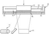
- FIGS. 1-3show schematic diagrams of an apparatus according to the present disclosure.
- a build platform 412is provided above the tank 404 ; it is supported by a lifting mechanism (not shown) so that it is held in a height-adjustable way over the tank bottom 406 in the region above the DLP projector or exposure unit 410 (see FIG. 1 ).
- the production platform 412may likewise be transparent or translucent in order that light can be shone in by a further exposure unit above the production platform in such a way that, at least when forming the first layer on the lower side of the production platform 412 , it can also be exposed from above so that the layer cured first on the build platform adheres thereto with even greater reliability.
- the tank 404contains a filling of photopolymerizable material 420 .
- the material level of the fillingis much higher than the thickness of the layers which are intended to be defined for position-selective exposure.
- the following procedureis adopted.
- the build platform 412is lowered by the lifting mechanism in a controlled way so that (before the first exposure step) its lower side is immersed in the filling of photopolymerizable material 420 and approaches the tank bottom 406 to such an extent that precisely the desired layer thickness ⁇ (see FIG. 2 ) remains between the lower side of the production platform 412 and the tank bottom 406 .
- the desired position-selective layer exposureis carried out for this layer, in order to cure it in the desired shape.
- exposure from abovemay also take place through the transparent or translucent build platform 412 , so that reliable and complete curing takes place particularly in the contact region between the lower side of the production platform 412 and the photopolymerizable material, and therefore good adhesion of the first layer to the build platform 412 is ensured.
- the build platformis raised again by means of the lifting mechanism (see FIG. 3 ).
- an elongate mixing element 432is moved through the filling of photopolymerizable material 420 in the tank.
- the mixing element 432comprises an elongate wire which is tensioned between two support arms 430 mounted movably on the side walls of the tank 4 .
- the support arms 430may be mounted movably in guide slots 434 in the side walls of the tank 404 , so that the wire 432 tensioned between the support arms 430 can be moved relative to the tank 404 , parallel to the tank bottom 406 , by moving the support arms 430 in the guide slots 434 .
- the elongate mixing element 432has dimensions, and its movement is guided relative to the tank bottom, such that the upper edge of the elongate mixing element 432 remains below the material level of the filling of photopolymerizable material 420 in the tank outside the exposed region. As can be seen in the sectional view of FIG. 5 , the mixing element 432 is below the material level in the tank over the entire length of the wire, and only the support arms 430 protrude beyond the material level in the tank.
- the effect of arranging the elongate mixing element below the material level in the tank 4is not that the elongate mixing element 432 substantially moves material in front of it during its movement relative to the tank through the exposed region, but rather this material flows over the mixing element 432 while executing a slight upward movement, as indicated by the arrow A in FIG. 4 . It has been found that by this type of action on the photopolymerizable material in the tank, it is effectively stimulated to flow back into the material-depleted exposed region between the production platform 412 and the DLP projector or exposure unit 410 and the focused energy source 411 .
- the movement of the elongate mixing element 432 relative to the tankmay firstly, with a stationary tank 404 , be carried out by a linear drive which moves the support arms 430 along the guide slots 434 in order to achieve the desired movement of the elongate mixing element 432 through the exposed region between the production platform 412 and the exposure unit 410 .
- the tank bottom 406has recesses 406 ′ on both sides.
- the support arms 430project with their lower ends into these recesses 406 ′. This makes it possible for the elongate mixing element 432 to be held at the height of the tank bottom 406 , without interfering with the movement of the lower ends of the support arms 430 through the tank bottom 406 .
- FIG. 6shows a schematic of a method of manufacturing an object according to the present disclosure.
- DLP projector 410 and focused energy source 411irradiate from underneath a tank holding a photopolymerizable material, through a transparent window.
- the DLPprojects an image defining an outer perimeter of the layer of the object to be built.
- Focused energy source 411which may be a laser, then irradiates an inner region of the layer of the object to be built.
- the focused energy beam emitted by the focused energy sourcemay optionally be reflected by one or more mirrors in the path of the focused energy beam from the source to and through the transparent window.
- the energy emitted by the DLP projectormay optionally be modulated by a DMD device in the path of the projected radiation from the DLP projector to and through the transparent window.
- the DLPprojects an image defining the entire area of the layer of the object to be built, as shown in FIG. 7 .
- Exposing cross sections using the DLP/laser hatch overlaphas the ability to optimize strength of the interior with dimensional accuracy at the surface of the object to be built, which may be a plastic article.
- the DLP projectionmay provide an initial polymerization of the photopolymerizable material, at both the outer perimeter of the layer of the object and the inner region of the layer of the object; and subsequent irradiation with focused energy source 411 may provide further polymerization of the photopolymerizable material of the inner region of the layer of the object.
- the tankmay be positioned on a rotatable platform.
- the tankmay be rotated relative to the platform and light source to provide a fresh layer of polymer in which to dip the build platform for building the successive layers.
- the photopolymerizable materialmay respond to more than one wavelength of energy.
- the photopolymerizable materialhas different response characteristics at different wavelengths, such as different depth of penetration or different cured or polymerized properties.
- the different wavelengthsmay have separate absorbance bands and may thusly elicit mutually exclusive responses from the photopolymerizable material.
- the apparatus according to the present disclosuremay comprise multiple projectors, such as multiple DLP projectors, instead of a DLP projector and a focused energy source.
- the multiple DLP projectorsmay have different energies.
- the multiple DLP projectorsmay have the same energy.
- the multiple DLP projectorsmay use different light intensities in a given build layer.
- the multiple projectorsmay be used with one or more mirrors in the path of the energy beam emitted.
- the energy emitted by the one or more projectorsmay be modulated using a pixel pattern that is turned on and off at high frequency.
- the net on/off countdetermines the duration and level of exposure of the photopolymerizable material to irradiation, as well as the degree of cure or polymerization of the photopolymerizable material.
Landscapes
- Engineering & Computer Science (AREA)
- Chemical & Material Sciences (AREA)
- Materials Engineering (AREA)
- Physics & Mathematics (AREA)
- Optics & Photonics (AREA)
- Manufacturing & Machinery (AREA)
- Mechanical Engineering (AREA)
- Health & Medical Sciences (AREA)
- Toxicology (AREA)
- Plasma & Fusion (AREA)
- Microelectronics & Electronic Packaging (AREA)
Abstract
Description
Claims (21)
Priority Applications (5)
| Application Number | Priority Date | Filing Date | Title |
|---|---|---|---|
| US15/380,525US11179926B2 (en) | 2016-12-15 | 2016-12-15 | Hybridized light sources |
| CN201780077860.7ACN110087863A (en) | 2016-12-15 | 2017-11-30 | mixed light source |
| EP17881329.1AEP3554792B1 (en) | 2016-12-15 | 2017-11-30 | Hybridized light sources |
| PCT/US2017/063881WO2018111565A1 (en) | 2016-12-15 | 2017-11-30 | Hybridized light sources |
| CN202411475614.5ACN119058086A (en) | 2016-12-15 | 2017-11-30 | Mixed light sources |
Applications Claiming Priority (1)
| Application Number | Priority Date | Filing Date | Title |
|---|---|---|---|
| US15/380,525US11179926B2 (en) | 2016-12-15 | 2016-12-15 | Hybridized light sources |
Publications (2)
| Publication Number | Publication Date |
|---|---|
| US20180169969A1 US20180169969A1 (en) | 2018-06-21 |
| US11179926B2true US11179926B2 (en) | 2021-11-23 |
Family
ID=62557234
Family Applications (1)
| Application Number | Title | Priority Date | Filing Date |
|---|---|---|---|
| US15/380,525Active2037-08-04US11179926B2 (en) | 2016-12-15 | 2016-12-15 | Hybridized light sources |
Country Status (4)
| Country | Link |
|---|---|
| US (1) | US11179926B2 (en) |
| EP (1) | EP3554792B1 (en) |
| CN (2) | CN119058086A (en) |
| WO (1) | WO2018111565A1 (en) |
Families Citing this family (15)
| Publication number | Priority date | Publication date | Assignee | Title |
|---|---|---|---|---|
| CN109866414A (en)* | 2017-12-04 | 2019-06-11 | 三纬国际立体列印科技股份有限公司 | Three-dimensional printing method |
| IT202000003653A1 (en)* | 2020-02-21 | 2021-08-21 | Axtra3D Inc | Predictive method and relative apparatus for isotropic stereolithographic 3D printing with hybrid light source at variable speed and power |
| US11155028B1 (en)* | 2020-04-24 | 2021-10-26 | Sprintray Inc. | Apparatus and method for three-dimensional printing |
| US11707883B2 (en) | 2020-11-20 | 2023-07-25 | General Electric Company | Foil interaction device for additive manufacturing |
| US11865780B2 (en) | 2021-02-26 | 2024-01-09 | General Electric Company | Accumalator assembly for additive manufacturing |
| US11951679B2 (en) | 2021-06-16 | 2024-04-09 | General Electric Company | Additive manufacturing system |
| US11731367B2 (en) | 2021-06-23 | 2023-08-22 | General Electric Company | Drive system for additive manufacturing |
| US11958249B2 (en) | 2021-06-24 | 2024-04-16 | General Electric Company | Reclamation system for additive manufacturing |
| US11958250B2 (en) | 2021-06-24 | 2024-04-16 | General Electric Company | Reclamation system for additive manufacturing |
| US11826950B2 (en) | 2021-07-09 | 2023-11-28 | General Electric Company | Resin management system for additive manufacturing |
| US12370741B2 (en) | 2021-08-13 | 2025-07-29 | General Electric Company | Material deposition assembly for additive manufacturing |
| US12296535B2 (en) | 2021-08-24 | 2025-05-13 | General Electric Company | Attachment structure for additive manufacturing |
| US11813799B2 (en) | 2021-09-01 | 2023-11-14 | General Electric Company | Control systems and methods for additive manufacturing |
| EP4249216A1 (en) | 2022-03-23 | 2023-09-27 | General Electric Company | Systems and methods for additive manufacturing |
| US12403654B2 (en) | 2022-09-30 | 2025-09-02 | General Electric Company | Systems and methods for additive manufacturing |
Citations (77)
| Publication number | Priority date | Publication date | Assignee | Title |
|---|---|---|---|---|
| US4041476A (en) | 1971-07-23 | 1977-08-09 | Wyn Kelly Swainson | Method, medium and apparatus for producing three-dimensional figure product |
| US5094935A (en)* | 1990-06-26 | 1992-03-10 | E. I. Dupont De Nemours And Company | Method and apparatus for fabricating three dimensional objects from photoformed precursor sheets |
| US5175077A (en) | 1990-07-05 | 1992-12-29 | E. I. Du Pont De Nemours And Company | Solid imaging system using photohardening inhibition |
| US5236812A (en) | 1989-12-29 | 1993-08-17 | E. I. Du Pont De Nemours And Company | Solid imaging method and apparatus |
| US5236326A (en) | 1990-07-05 | 1993-08-17 | E. I. Du Pont De Nemours And Company | Solid imaging system using photohardening inhibition |
| JPH06246839A (en) | 1993-02-26 | 1994-09-06 | Teijin Seiki Co Ltd | Optically shaping device |
| US5460758A (en)* | 1990-12-21 | 1995-10-24 | Eos Gmbh Electro Optical Systems | Method and apparatus for production of a three-dimensional object |
| WO1996000422A1 (en)* | 1994-06-27 | 1996-01-04 | Hercules Incorporated | Programmable mask for producing three-dimensional objects |
| US5610824A (en) | 1989-10-27 | 1997-03-11 | 3D Systems, Inc. | Rapid and accurate production of stereolithographic parts |
| US5764521A (en) | 1995-11-13 | 1998-06-09 | Stratasys Inc. | Method and apparatus for solid prototyping |
| US5866058A (en) | 1997-05-29 | 1999-02-02 | Stratasys Inc. | Method for rapid prototyping of solid models |
| US5900207A (en) | 1996-02-08 | 1999-05-04 | Rutgers, The State University Old Queens | Solid freeform fabrication methods |
| US5939008A (en) | 1998-01-26 | 1999-08-17 | Stratasys, Inc. | Rapid prototyping apparatus |
| US5968561A (en) | 1998-01-26 | 1999-10-19 | Stratasys, Inc. | High performance rapid prototyping system |
| US5980813A (en) | 1997-04-17 | 1999-11-09 | Sri International | Rapid prototyping using multiple materials |
| US6051179A (en) | 1997-03-19 | 2000-04-18 | Replicator Systems, Inc. | Apparatus and method for production of three-dimensional models by spatial light modulator |
| US6067480A (en) | 1997-04-02 | 2000-05-23 | Stratasys, Inc. | Method and apparatus for in-situ formation of three-dimensional solid objects by extrusion of polymeric materials |
| US6110411A (en) | 1997-03-18 | 2000-08-29 | Clausen; Christian Henning | Laser sinterable thermoplastic powder |
| WO2001000390A1 (en)* | 1999-06-25 | 2001-01-04 | HAP Handhabungs-, Automatisierungs- und Präzisionstechnik GmbH | Method and device for producing an object by means of stereolithography |
| US6200646B1 (en) | 1999-08-25 | 2001-03-13 | Spectra Group Limited, Inc. | Method for forming polymeric patterns, relief images and colored polymeric bodies using digital light processing technology |
| US6391245B1 (en) | 1999-04-13 | 2002-05-21 | Eom Technologies, L.L.C. | Method for creating three-dimensional objects by cross-sectional lithography |
| US6468891B2 (en)* | 2000-02-24 | 2002-10-22 | Micron Technology, Inc. | Stereolithographically fabricated conductive elements, semiconductor device components and assemblies including such conductive elements, and methods |
| US6500378B1 (en)* | 2000-07-13 | 2002-12-31 | Eom Technologies, L.L.C. | Method and apparatus for creating three-dimensional objects by cross-sectional lithography |
| US6641897B2 (en)* | 1998-02-13 | 2003-11-04 | The Milwaukee School Of Engineering | Three dimensional object |
| US20050191016A1 (en)* | 2002-04-10 | 2005-09-01 | Fuji Photo Film Co., Ltd. | Exposure head, exposure apparatus, and application thereof |
| US6947058B1 (en) | 2001-05-18 | 2005-09-20 | Autodesk, Inc. | Incremental update of graphical images when using anti-aliasing techniques |
| US7045738B1 (en) | 2002-10-01 | 2006-05-16 | Southern Methodist University | Powder delivery system and method |
| US7084875B2 (en) | 2002-07-19 | 2006-08-01 | Autodesk Canada Co. | Processing scene objects |
| WO2006109355A1 (en) | 2005-04-11 | 2006-10-19 | Japan Science And Technology Agency | Multiple-beam microstructure laser lithographic method and device employing laser beams of different wavelength |
| US20060230984A1 (en) | 2002-09-25 | 2006-10-19 | Z Corporation | Three dimensional printing material system and method |
| US7158849B2 (en) | 2004-10-28 | 2007-01-02 | National Cheng Kung University | Method for rapid prototyping by using linear light as sources |
| US7164420B2 (en) | 2003-07-24 | 2007-01-16 | Autodesk, Inc. | Ray tracing hierarchy |
| US7555726B2 (en) | 1998-07-21 | 2009-06-30 | Autodesk, Inc. | System for accessing a large number of menu items using a zoned menu bar |
| US7569174B2 (en) | 2004-12-07 | 2009-08-04 | 3D Systems, Inc. | Controlled densification of fusible powders in laser sintering |
| US7614866B2 (en) | 2007-01-17 | 2009-11-10 | 3D Systems, Inc. | Solid imaging apparatus and method |
| US7742060B2 (en) | 2006-09-22 | 2010-06-22 | Autodesk, Inc. | Sampling methods suited for graphics hardware acceleration |
| US20110089610A1 (en)* | 2009-10-19 | 2011-04-21 | Global Filtration Systems | Resin Solidification Substrate and Assembly |
| US20110101570A1 (en)* | 2006-04-28 | 2011-05-05 | Envisiontec Gmbh | Device and Method for Producing a Three-Dimensional Object by Means of Mask Exposure |
| US7995073B1 (en) | 2006-07-12 | 2011-08-09 | Autodesk, Inc. | System and method for anti-aliasing compound shape vector graphics |
| US8259103B2 (en) | 2009-02-03 | 2012-09-04 | Autodesk, Inc. | Position pegs for a three-dimensional reference grid |
| US8269767B2 (en) | 2009-02-03 | 2012-09-18 | Autodesk, Inc. | Multiscale three-dimensional reference grid |
| WO2012127456A1 (en) | 2011-03-24 | 2012-09-27 | Ramot At Tel-Aviv University Ltd. | Method and devices for solid structure formation by localized microwaves |
| US20130008879A1 (en) | 2011-07-07 | 2013-01-10 | Lockheed Martin Corporation | Method and system for hybrid direct manufacturing |
| CN103522546A (en) | 2013-09-26 | 2014-01-22 | 瑞安市麦田网络科技有限公司 | High-precision laser photocuring 3D (three dimensional) printer |
| US8666142B2 (en) | 2008-11-18 | 2014-03-04 | Global Filtration Systems | System and method for manufacturing |
| US20140099476A1 (en) | 2012-10-08 | 2014-04-10 | Ramesh Subramanian | Additive manufacture of turbine component with multiple materials |
| US8744184B2 (en) | 2004-10-22 | 2014-06-03 | Autodesk, Inc. | Graphics processing method and system |
| US20140200865A1 (en) | 2006-08-31 | 2014-07-17 | Ivoclar Vivadent Ag | Interactive dental restorative network |
| US8873024B2 (en) | 2009-03-06 | 2014-10-28 | Nederlandse Organisatie Voor Toegepast-Natuurwetenschappelijk Onderzoek Tno | Illumination system for use in a stereolithography apparatus |
| US20140348692A1 (en) | 2011-12-23 | 2014-11-27 | Compagnie Generale Des Establissements Michelin | Method and apparatus for producing three-dimensional objects |
| US20140348691A1 (en) | 2013-05-23 | 2014-11-27 | Arcam Ab | Method and apparatus for additive manufacturing |
| CN104175559A (en) | 2014-08-15 | 2014-12-03 | 中国科学院重庆绿色智能技术研究院 | Liquid phase laser three-dimensional printing system and method based on nanoparticles |
| US20150086409A1 (en) | 2013-09-20 | 2015-03-26 | Arcam Ab | Method for additive manufacturing |
| US8992816B2 (en) | 2008-01-03 | 2015-03-31 | Arcam Ab | Method and apparatus for producing three-dimensional objects |
| US20150102531A1 (en) | 2013-10-11 | 2015-04-16 | Global Filtration Systems, A Dba Of Gulf Filtration Systems Inc. | Apparatus and method for forming three-dimensional objects using a curved build platform |
| US20150140155A1 (en) | 2013-11-15 | 2015-05-21 | Kabushiki Kaisha Toshiba | Three-dimensional modeling head and three-dimensional modeling device |
| US20150158111A1 (en) | 2013-11-27 | 2015-06-11 | SLM Solutions Group AG | Method and device for controlling an irradiation system |
| US20150165695A1 (en) | 2013-12-13 | 2015-06-18 | Xyzprinting, Inc. | Three dimensional printing apparatus |
| WO2015153030A1 (en) | 2014-04-01 | 2015-10-08 | Stratasys, Inc. | Electrophotography-based additive manufacturing with overlay control |
| US9159155B2 (en) | 2008-12-01 | 2015-10-13 | Autodesk, Inc. | Image rendering |
| US20150306819A1 (en) | 2012-12-17 | 2015-10-29 | Arcam Ab | Method and apparatus for additive manufacturing |
| US9186847B2 (en) | 2009-08-18 | 2015-11-17 | Sintermask Gmbh | Method and device for producing a three-dimensional object |
| US9205601B2 (en)* | 2013-02-12 | 2015-12-08 | Carbon3D, Inc. | Continuous liquid interphase printing |
| US20150352668A1 (en) | 2008-09-05 | 2015-12-10 | Mtt Technologies Limited | Additive manufacturing apparatus with a chamber and a removably-mountable optical module; method of preparing a laser processing apparatus with such removably-mountable optical module |
| US9221100B2 (en) | 2009-12-04 | 2015-12-29 | Slm Solutions Gmbh | Optical irradiation unit for a plant for producing workpieces by irradiation of powder layers with laser radiation |
| WO2016009426A1 (en) | 2014-07-13 | 2016-01-21 | Stratasys Ltd. | Method and system for rotational 3d printing |
| US20160067921A1 (en) | 2014-09-08 | 2016-03-10 | Autodesk, Inc. | Three dimensional printing adhesion reduction using photoinhibition |
| US20160082662A1 (en) | 2014-09-18 | 2016-03-24 | Daniel Majer | Device and a method for 3d printing and manufacturing of materials using quantum cascade lasers |
| US20160107383A1 (en) | 2010-04-25 | 2016-04-21 | Stratasys Ltd. | Solid freeform fabrication of shelled objects |
| US20160137839A1 (en) | 2014-06-23 | 2016-05-19 | Carbon3D, Inc. | Polyurethane resins having multiple mechanisms of hardening for use in producing three-dimensional objects |
| CN105635705A (en) | 2015-12-30 | 2016-06-01 | 大族激光科技产业集团股份有限公司 | Enhanced digital-light-processing mask exposure rapid prototyping method and apparatus |
| US20160167160A1 (en) | 2014-12-15 | 2016-06-16 | Arcam Ab | Method for additive manufacturing |
| US20160176114A1 (en) | 2014-12-17 | 2016-06-23 | National Applied Research Laboratories | System for online monitoring powder-based 3d printing processes and method thereof |
| WO2016106136A2 (en) | 2014-12-23 | 2016-06-30 | Stratasys, Inc. | Resin slot extruder for additive manufacturing system |
| US20160184931A1 (en) | 2012-03-29 | 2016-06-30 | Materials Solutions | Apparatus and methods for additive-layer manufacturin of an article |
| US20160243649A1 (en) | 2014-07-10 | 2016-08-25 | Guangzhou Institute of Advanced Technology, Chinise Academy of Sciences | Optical system for 3d printing and control method thereof |
| JP2016196098A (en) | 2015-04-02 | 2016-11-24 | カンタツ株式会社 | Stereolithography equipment |
- 2016
- 2016-12-15USUS15/380,525patent/US11179926B2/enactiveActive
- 2017
- 2017-11-30CNCN202411475614.5Apatent/CN119058086A/enactivePending
- 2017-11-30CNCN201780077860.7Apatent/CN110087863A/enactivePending
- 2017-11-30WOPCT/US2017/063881patent/WO2018111565A1/ennot_activeCeased
- 2017-11-30EPEP17881329.1Apatent/EP3554792B1/enactiveActive
Patent Citations (84)
| Publication number | Priority date | Publication date | Assignee | Title |
|---|---|---|---|---|
| US4041476A (en) | 1971-07-23 | 1977-08-09 | Wyn Kelly Swainson | Method, medium and apparatus for producing three-dimensional figure product |
| US5610824A (en) | 1989-10-27 | 1997-03-11 | 3D Systems, Inc. | Rapid and accurate production of stereolithographic parts |
| US5236812A (en) | 1989-12-29 | 1993-08-17 | E. I. Du Pont De Nemours And Company | Solid imaging method and apparatus |
| US5094935A (en)* | 1990-06-26 | 1992-03-10 | E. I. Dupont De Nemours And Company | Method and apparatus for fabricating three dimensional objects from photoformed precursor sheets |
| US5175077A (en) | 1990-07-05 | 1992-12-29 | E. I. Du Pont De Nemours And Company | Solid imaging system using photohardening inhibition |
| US5236326A (en) | 1990-07-05 | 1993-08-17 | E. I. Du Pont De Nemours And Company | Solid imaging system using photohardening inhibition |
| US5460758A (en)* | 1990-12-21 | 1995-10-24 | Eos Gmbh Electro Optical Systems | Method and apparatus for production of a three-dimensional object |
| JPH06246839A (en) | 1993-02-26 | 1994-09-06 | Teijin Seiki Co Ltd | Optically shaping device |
| WO1996000422A1 (en)* | 1994-06-27 | 1996-01-04 | Hercules Incorporated | Programmable mask for producing three-dimensional objects |
| US5764521A (en) | 1995-11-13 | 1998-06-09 | Stratasys Inc. | Method and apparatus for solid prototyping |
| US5900207A (en) | 1996-02-08 | 1999-05-04 | Rutgers, The State University Old Queens | Solid freeform fabrication methods |
| US6110411A (en) | 1997-03-18 | 2000-08-29 | Clausen; Christian Henning | Laser sinterable thermoplastic powder |
| US6051179A (en) | 1997-03-19 | 2000-04-18 | Replicator Systems, Inc. | Apparatus and method for production of three-dimensional models by spatial light modulator |
| US6067480A (en) | 1997-04-02 | 2000-05-23 | Stratasys, Inc. | Method and apparatus for in-situ formation of three-dimensional solid objects by extrusion of polymeric materials |
| US5980813A (en) | 1997-04-17 | 1999-11-09 | Sri International | Rapid prototyping using multiple materials |
| US5866058A (en) | 1997-05-29 | 1999-02-02 | Stratasys Inc. | Method for rapid prototyping of solid models |
| US5968561A (en) | 1998-01-26 | 1999-10-19 | Stratasys, Inc. | High performance rapid prototyping system |
| US5939008A (en) | 1998-01-26 | 1999-08-17 | Stratasys, Inc. | Rapid prototyping apparatus |
| US6641897B2 (en)* | 1998-02-13 | 2003-11-04 | The Milwaukee School Of Engineering | Three dimensional object |
| US8522159B2 (en) | 1998-07-21 | 2013-08-27 | Autodesk, Inc. | System for accessing a large number of menu items using a zoned menu bar |
| US7555726B2 (en) | 1998-07-21 | 2009-06-30 | Autodesk, Inc. | System for accessing a large number of menu items using a zoned menu bar |
| US6391245B1 (en) | 1999-04-13 | 2002-05-21 | Eom Technologies, L.L.C. | Method for creating three-dimensional objects by cross-sectional lithography |
| WO2001000390A1 (en)* | 1999-06-25 | 2001-01-04 | HAP Handhabungs-, Automatisierungs- und Präzisionstechnik GmbH | Method and device for producing an object by means of stereolithography |
| US6200646B1 (en) | 1999-08-25 | 2001-03-13 | Spectra Group Limited, Inc. | Method for forming polymeric patterns, relief images and colored polymeric bodies using digital light processing technology |
| US6468891B2 (en)* | 2000-02-24 | 2002-10-22 | Micron Technology, Inc. | Stereolithographically fabricated conductive elements, semiconductor device components and assemblies including such conductive elements, and methods |
| US6500378B1 (en)* | 2000-07-13 | 2002-12-31 | Eom Technologies, L.L.C. | Method and apparatus for creating three-dimensional objects by cross-sectional lithography |
| US6947058B1 (en) | 2001-05-18 | 2005-09-20 | Autodesk, Inc. | Incremental update of graphical images when using anti-aliasing techniques |
| US20050191016A1 (en)* | 2002-04-10 | 2005-09-01 | Fuji Photo Film Co., Ltd. | Exposure head, exposure apparatus, and application thereof |
| US7084875B2 (en) | 2002-07-19 | 2006-08-01 | Autodesk Canada Co. | Processing scene objects |
| US20060230984A1 (en) | 2002-09-25 | 2006-10-19 | Z Corporation | Three dimensional printing material system and method |
| US7045738B1 (en) | 2002-10-01 | 2006-05-16 | Southern Methodist University | Powder delivery system and method |
| US7164420B2 (en) | 2003-07-24 | 2007-01-16 | Autodesk, Inc. | Ray tracing hierarchy |
| US8805064B2 (en) | 2004-10-22 | 2014-08-12 | Autodesk, Inc. | Graphics processing method and system |
| US8744184B2 (en) | 2004-10-22 | 2014-06-03 | Autodesk, Inc. | Graphics processing method and system |
| US9153052B2 (en) | 2004-10-22 | 2015-10-06 | Autodesk, Inc. | Graphics processing method and system |
| US7158849B2 (en) | 2004-10-28 | 2007-01-02 | National Cheng Kung University | Method for rapid prototyping by using linear light as sources |
| US7569174B2 (en) | 2004-12-07 | 2009-08-04 | 3D Systems, Inc. | Controlled densification of fusible powders in laser sintering |
| WO2006109355A1 (en) | 2005-04-11 | 2006-10-19 | Japan Science And Technology Agency | Multiple-beam microstructure laser lithographic method and device employing laser beams of different wavelength |
| US20110101570A1 (en)* | 2006-04-28 | 2011-05-05 | Envisiontec Gmbh | Device and Method for Producing a Three-Dimensional Object by Means of Mask Exposure |
| US7995073B1 (en) | 2006-07-12 | 2011-08-09 | Autodesk, Inc. | System and method for anti-aliasing compound shape vector graphics |
| US20140200865A1 (en) | 2006-08-31 | 2014-07-17 | Ivoclar Vivadent Ag | Interactive dental restorative network |
| US7742060B2 (en) | 2006-09-22 | 2010-06-22 | Autodesk, Inc. | Sampling methods suited for graphics hardware acceleration |
| US7614866B2 (en) | 2007-01-17 | 2009-11-10 | 3D Systems, Inc. | Solid imaging apparatus and method |
| US8992816B2 (en) | 2008-01-03 | 2015-03-31 | Arcam Ab | Method and apparatus for producing three-dimensional objects |
| US20150352668A1 (en) | 2008-09-05 | 2015-12-10 | Mtt Technologies Limited | Additive manufacturing apparatus with a chamber and a removably-mountable optical module; method of preparing a laser processing apparatus with such removably-mountable optical module |
| US8666142B2 (en) | 2008-11-18 | 2014-03-04 | Global Filtration Systems | System and method for manufacturing |
| US9159155B2 (en) | 2008-12-01 | 2015-10-13 | Autodesk, Inc. | Image rendering |
| US8269767B2 (en) | 2009-02-03 | 2012-09-18 | Autodesk, Inc. | Multiscale three-dimensional reference grid |
| US8259103B2 (en) | 2009-02-03 | 2012-09-04 | Autodesk, Inc. | Position pegs for a three-dimensional reference grid |
| US8873024B2 (en) | 2009-03-06 | 2014-10-28 | Nederlandse Organisatie Voor Toegepast-Natuurwetenschappelijk Onderzoek Tno | Illumination system for use in a stereolithography apparatus |
| US9186847B2 (en) | 2009-08-18 | 2015-11-17 | Sintermask Gmbh | Method and device for producing a three-dimensional object |
| US20110089610A1 (en)* | 2009-10-19 | 2011-04-21 | Global Filtration Systems | Resin Solidification Substrate and Assembly |
| US9221100B2 (en) | 2009-12-04 | 2015-12-29 | Slm Solutions Gmbh | Optical irradiation unit for a plant for producing workpieces by irradiation of powder layers with laser radiation |
| US20160107383A1 (en) | 2010-04-25 | 2016-04-21 | Stratasys Ltd. | Solid freeform fabrication of shelled objects |
| WO2012127456A1 (en) | 2011-03-24 | 2012-09-27 | Ramot At Tel-Aviv University Ltd. | Method and devices for solid structure formation by localized microwaves |
| US20130008879A1 (en) | 2011-07-07 | 2013-01-10 | Lockheed Martin Corporation | Method and system for hybrid direct manufacturing |
| US8513562B2 (en) | 2011-07-07 | 2013-08-20 | Lockheed Martin Corporation | Method and system for hybrid direct manufacturing |
| US20140348692A1 (en) | 2011-12-23 | 2014-11-27 | Compagnie Generale Des Establissements Michelin | Method and apparatus for producing three-dimensional objects |
| US20160184931A1 (en) | 2012-03-29 | 2016-06-30 | Materials Solutions | Apparatus and methods for additive-layer manufacturin of an article |
| US20140099476A1 (en) | 2012-10-08 | 2014-04-10 | Ramesh Subramanian | Additive manufacture of turbine component with multiple materials |
| US20150306819A1 (en) | 2012-12-17 | 2015-10-29 | Arcam Ab | Method and apparatus for additive manufacturing |
| US9205601B2 (en)* | 2013-02-12 | 2015-12-08 | Carbon3D, Inc. | Continuous liquid interphase printing |
| US9415443B2 (en) | 2013-05-23 | 2016-08-16 | Arcam Ab | Method and apparatus for additive manufacturing |
| US20140348691A1 (en) | 2013-05-23 | 2014-11-27 | Arcam Ab | Method and apparatus for additive manufacturing |
| US20150086409A1 (en) | 2013-09-20 | 2015-03-26 | Arcam Ab | Method for additive manufacturing |
| CN103522546A (en) | 2013-09-26 | 2014-01-22 | 瑞安市麦田网络科技有限公司 | High-precision laser photocuring 3D (three dimensional) printer |
| US20150102531A1 (en) | 2013-10-11 | 2015-04-16 | Global Filtration Systems, A Dba Of Gulf Filtration Systems Inc. | Apparatus and method for forming three-dimensional objects using a curved build platform |
| US20150140155A1 (en) | 2013-11-15 | 2015-05-21 | Kabushiki Kaisha Toshiba | Three-dimensional modeling head and three-dimensional modeling device |
| US20150158111A1 (en) | 2013-11-27 | 2015-06-11 | SLM Solutions Group AG | Method and device for controlling an irradiation system |
| US20150165695A1 (en) | 2013-12-13 | 2015-06-18 | Xyzprinting, Inc. | Three dimensional printing apparatus |
| WO2015153030A1 (en) | 2014-04-01 | 2015-10-08 | Stratasys, Inc. | Electrophotography-based additive manufacturing with overlay control |
| US20160137839A1 (en) | 2014-06-23 | 2016-05-19 | Carbon3D, Inc. | Polyurethane resins having multiple mechanisms of hardening for use in producing three-dimensional objects |
| US20160243649A1 (en) | 2014-07-10 | 2016-08-25 | Guangzhou Institute of Advanced Technology, Chinise Academy of Sciences | Optical system for 3d printing and control method thereof |
| WO2016009426A1 (en) | 2014-07-13 | 2016-01-21 | Stratasys Ltd. | Method and system for rotational 3d printing |
| CN104175559A (en) | 2014-08-15 | 2014-12-03 | 中国科学院重庆绿色智能技术研究院 | Liquid phase laser three-dimensional printing system and method based on nanoparticles |
| US20160067921A1 (en) | 2014-09-08 | 2016-03-10 | Autodesk, Inc. | Three dimensional printing adhesion reduction using photoinhibition |
| US20160082662A1 (en) | 2014-09-18 | 2016-03-24 | Daniel Majer | Device and a method for 3d printing and manufacturing of materials using quantum cascade lasers |
| US20160167160A1 (en) | 2014-12-15 | 2016-06-16 | Arcam Ab | Method for additive manufacturing |
| US20160176114A1 (en) | 2014-12-17 | 2016-06-23 | National Applied Research Laboratories | System for online monitoring powder-based 3d printing processes and method thereof |
| WO2016106136A2 (en) | 2014-12-23 | 2016-06-30 | Stratasys, Inc. | Resin slot extruder for additive manufacturing system |
| JP2016196098A (en) | 2015-04-02 | 2016-11-24 | カンタツ株式会社 | Stereolithography equipment |
| CN105635705A (en) | 2015-12-30 | 2016-06-01 | 大族激光科技产业集团股份有限公司 | Enhanced digital-light-processing mask exposure rapid prototyping method and apparatus |
| US20170326786A1 (en)* | 2015-12-30 | 2017-11-16 | Han's Laser Technology Industry Group Co., Ltd. | Enhanced digital light processing-based mask projection stereolithography method and apparatus |
| US10639843B2 (en) | 2015-12-30 | 2020-05-05 | Han's Laser Technology Industry Group Co., Ltd. | Enhanced digital light processing-based mask projection stereolithography method and apparatus |
Non-Patent Citations (2)
| Title |
|---|
| European Search Report Corresponding to Application No. 17881329 dated May 26, 2020. |
| International Search Report and Written Opinion issued in connection with corresponding PCT Application No. PCT/US2017/063881 dated Apr. 27, 2018. |
Also Published As
| Publication number | Publication date |
|---|---|
| EP3554792B1 (en) | 2022-04-06 |
| WO2018111565A1 (en) | 2018-06-21 |
| EP3554792A4 (en) | 2020-06-24 |
| CN119058086A (en) | 2024-12-03 |
| EP3554792A1 (en) | 2019-10-23 |
| US20180169969A1 (en) | 2018-06-21 |
| CN110087863A (en) | 2019-08-02 |
Similar Documents
| Publication | Publication Date | Title |
|---|---|---|
| US11179926B2 (en) | Hybridized light sources | |
| JP5024001B2 (en) | Stereolithography apparatus and stereolithography method | |
| CN105216319B (en) | 3D stereoprojection formula photocuring 3D printers | |
| RU2720796C2 (en) | Apparatus and method for increasing adhesion of component layer with bearing object | |
| JP2014511788A (en) | Stereolithography machine for producing a three-dimensional object and stereolithography method applicable to said machine | |
| JPH0757532B2 (en) | Three-dimensional shape forming method | |
| US11597140B2 (en) | Apparatus for photo-curing photo-sensitive materials for the formation of three-dimensional objects using extraction plate with continuous motion | |
| JP7012705B2 (en) | Methods for solidifying photopolymerizable diffuse reflective materials | |
| JP2015136857A (en) | Stereolithography apparatus and stereolithography method | |
| JP2016511713A (en) | 3D object production | |
| WO2017140546A1 (en) | Optical method and apparatus for fabricating a structured object | |
| JPH02502898A (en) | Method and apparatus for producing three-dimensional objects by photohardening | |
| WO2015152744A1 (en) | A method for additive manufacturing of a spatial 3d object and a device for additive manufacturing of a spatial 3d object | |
| CN108248020A (en) | A kind of horizontal DLP shadow casting techniques face exposure molding machine and method | |
| US20210260819A1 (en) | Systems, apparatuses, and methods for manufacturing three dimensional objects via continuously curing photopolymers, utilising a vessel containing an interface fluid | |
| KR101772996B1 (en) | Apparatus for stereolithography of layer form and method for operating the same | |
| EP3551435B1 (en) | Stereolithography machine with improved optical group | |
| JP2018043462A (en) | 3D modeling apparatus and manufacturing method of 3D model | |
| JPH0523588B2 (en) | ||
| JPH0834063A (en) | Stereolithography method, apparatus therefor, and resin molding | |
| JP3578590B2 (en) | Stereolithography equipment using lamps | |
| WO2018203867A1 (en) | Scanning vat-photopolymerization | |
| JP2861321B2 (en) | Method of forming three-dimensional object | |
| JP4578211B2 (en) | Stereolithography method and apparatus | |
| JPH0533899B2 (en) |
Legal Events
| Date | Code | Title | Description |
|---|---|---|---|
| AS | Assignment | Owner name:GENERAL ELECTRIC COMPANY, NEW YORK Free format text:ASSIGNMENT OF ASSIGNORS INTEREST;ASSIGNORS:MURPHY, WILLIAM;DEPALMA, STEPHANIE LYNN;SANDS, TRAVIS;AND OTHERS;SIGNING DATES FROM 20161128 TO 20161202;REEL/FRAME:041076/0753 | |
| STPP | Information on status: patent application and granting procedure in general | Free format text:RESPONSE TO NON-FINAL OFFICE ACTION ENTERED AND FORWARDED TO EXAMINER | |
| STPP | Information on status: patent application and granting procedure in general | Free format text:FINAL REJECTION MAILED | |
| STPP | Information on status: patent application and granting procedure in general | Free format text:RESPONSE AFTER FINAL ACTION FORWARDED TO EXAMINER | |
| STPP | Information on status: patent application and granting procedure in general | Free format text:ADVISORY ACTION MAILED | |
| STPP | Information on status: patent application and granting procedure in general | Free format text:DOCKETED NEW CASE - READY FOR EXAMINATION | |
| STPP | Information on status: patent application and granting procedure in general | Free format text:NON FINAL ACTION MAILED | |
| STPP | Information on status: patent application and granting procedure in general | Free format text:RESPONSE TO NON-FINAL OFFICE ACTION ENTERED AND FORWARDED TO EXAMINER | |
| STPP | Information on status: patent application and granting procedure in general | Free format text:FINAL REJECTION MAILED | |
| STPP | Information on status: patent application and granting procedure in general | Free format text:RESPONSE AFTER FINAL ACTION FORWARDED TO EXAMINER | |
| STPP | Information on status: patent application and granting procedure in general | Free format text:NOTICE OF ALLOWANCE MAILED -- APPLICATION RECEIVED IN OFFICE OF PUBLICATIONS | |
| STPP | Information on status: patent application and granting procedure in general | Free format text:AWAITING TC RESP, ISSUE FEE PAYMENT VERIFIED | |
| STPP | Information on status: patent application and granting procedure in general | Free format text:PUBLICATIONS -- ISSUE FEE PAYMENT VERIFIED | |
| STCF | Information on status: patent grant | Free format text:PATENTED CASE | |
| MAFP | Maintenance fee payment | Free format text:PAYMENT OF MAINTENANCE FEE, 4TH YEAR, LARGE ENTITY (ORIGINAL EVENT CODE: M1551); ENTITY STATUS OF PATENT OWNER: LARGE ENTITY Year of fee payment:4 |