US11179237B2 - Valvular sleeve for valvular prostheses and corresponding device - Google Patents
Valvular sleeve for valvular prostheses and corresponding deviceDownload PDFInfo
- Publication number
- US11179237B2 US11179237B2US15/746,747US201615746747AUS11179237B2US 11179237 B2US11179237 B2US 11179237B2US 201615746747 AUS201615746747 AUS 201615746747AUS 11179237 B2US11179237 B2US 11179237B2
- Authority
- US
- United States
- Prior art keywords
- valvular
- portions
- sleeve
- stent
- outflow end
- Prior art date
- Legal status (The legal status is an assumption and is not a legal conclusion. Google has not performed a legal analysis and makes no representation as to the accuracy of the status listed.)
- Active
Links
Images


Classifications
- A—HUMAN NECESSITIES
- A61—MEDICAL OR VETERINARY SCIENCE; HYGIENE
- A61F—FILTERS IMPLANTABLE INTO BLOOD VESSELS; PROSTHESES; DEVICES PROVIDING PATENCY TO, OR PREVENTING COLLAPSING OF, TUBULAR STRUCTURES OF THE BODY, e.g. STENTS; ORTHOPAEDIC, NURSING OR CONTRACEPTIVE DEVICES; FOMENTATION; TREATMENT OR PROTECTION OF EYES OR EARS; BANDAGES, DRESSINGS OR ABSORBENT PADS; FIRST-AID KITS
- A61F2/00—Filters implantable into blood vessels; Prostheses, i.e. artificial substitutes or replacements for parts of the body; Appliances for connecting them with the body; Devices providing patency to, or preventing collapsing of, tubular structures of the body, e.g. stents
- A61F2/02—Prostheses implantable into the body
- A61F2/24—Heart valves ; Vascular valves, e.g. venous valves; Heart implants, e.g. passive devices for improving the function of the native valve or the heart muscle; Transmyocardial revascularisation [TMR] devices; Valves implantable in the body
- A61F2/2412—Heart valves ; Vascular valves, e.g. venous valves; Heart implants, e.g. passive devices for improving the function of the native valve or the heart muscle; Transmyocardial revascularisation [TMR] devices; Valves implantable in the body with soft flexible valve members, e.g. tissue valves shaped like natural valves
- A61F2/2418—Scaffolds therefor, e.g. support stents
- A—HUMAN NECESSITIES
- A61—MEDICAL OR VETERINARY SCIENCE; HYGIENE
- A61F—FILTERS IMPLANTABLE INTO BLOOD VESSELS; PROSTHESES; DEVICES PROVIDING PATENCY TO, OR PREVENTING COLLAPSING OF, TUBULAR STRUCTURES OF THE BODY, e.g. STENTS; ORTHOPAEDIC, NURSING OR CONTRACEPTIVE DEVICES; FOMENTATION; TREATMENT OR PROTECTION OF EYES OR EARS; BANDAGES, DRESSINGS OR ABSORBENT PADS; FIRST-AID KITS
- A61F2/00—Filters implantable into blood vessels; Prostheses, i.e. artificial substitutes or replacements for parts of the body; Appliances for connecting them with the body; Devices providing patency to, or preventing collapsing of, tubular structures of the body, e.g. stents
- A61F2/02—Prostheses implantable into the body
- A61F2/24—Heart valves ; Vascular valves, e.g. venous valves; Heart implants, e.g. passive devices for improving the function of the native valve or the heart muscle; Transmyocardial revascularisation [TMR] devices; Valves implantable in the body
- A61F2/2412—Heart valves ; Vascular valves, e.g. venous valves; Heart implants, e.g. passive devices for improving the function of the native valve or the heart muscle; Transmyocardial revascularisation [TMR] devices; Valves implantable in the body with soft flexible valve members, e.g. tissue valves shaped like natural valves
- A61F2/2415—Manufacturing methods
- A—HUMAN NECESSITIES
- A61—MEDICAL OR VETERINARY SCIENCE; HYGIENE
- A61F—FILTERS IMPLANTABLE INTO BLOOD VESSELS; PROSTHESES; DEVICES PROVIDING PATENCY TO, OR PREVENTING COLLAPSING OF, TUBULAR STRUCTURES OF THE BODY, e.g. STENTS; ORTHOPAEDIC, NURSING OR CONTRACEPTIVE DEVICES; FOMENTATION; TREATMENT OR PROTECTION OF EYES OR EARS; BANDAGES, DRESSINGS OR ABSORBENT PADS; FIRST-AID KITS
- A61F2/00—Filters implantable into blood vessels; Prostheses, i.e. artificial substitutes or replacements for parts of the body; Appliances for connecting them with the body; Devices providing patency to, or preventing collapsing of, tubular structures of the body, e.g. stents
- A61F2/02—Prostheses implantable into the body
- A61F2/24—Heart valves ; Vascular valves, e.g. venous valves; Heart implants, e.g. passive devices for improving the function of the native valve or the heart muscle; Transmyocardial revascularisation [TMR] devices; Valves implantable in the body
- A61F2/2475—Venous valves
- A—HUMAN NECESSITIES
- A61—MEDICAL OR VETERINARY SCIENCE; HYGIENE
- A61F—FILTERS IMPLANTABLE INTO BLOOD VESSELS; PROSTHESES; DEVICES PROVIDING PATENCY TO, OR PREVENTING COLLAPSING OF, TUBULAR STRUCTURES OF THE BODY, e.g. STENTS; ORTHOPAEDIC, NURSING OR CONTRACEPTIVE DEVICES; FOMENTATION; TREATMENT OR PROTECTION OF EYES OR EARS; BANDAGES, DRESSINGS OR ABSORBENT PADS; FIRST-AID KITS
- A61F2210/00—Particular material properties of prostheses classified in groups A61F2/00 - A61F2/26 or A61F2/82 or A61F9/00 or A61F11/00 or subgroups thereof
- A61F2210/0014—Particular material properties of prostheses classified in groups A61F2/00 - A61F2/26 or A61F2/82 or A61F9/00 or A61F11/00 or subgroups thereof using shape memory or superelastic materials, e.g. nitinol
- A—HUMAN NECESSITIES
- A61—MEDICAL OR VETERINARY SCIENCE; HYGIENE
- A61F—FILTERS IMPLANTABLE INTO BLOOD VESSELS; PROSTHESES; DEVICES PROVIDING PATENCY TO, OR PREVENTING COLLAPSING OF, TUBULAR STRUCTURES OF THE BODY, e.g. STENTS; ORTHOPAEDIC, NURSING OR CONTRACEPTIVE DEVICES; FOMENTATION; TREATMENT OR PROTECTION OF EYES OR EARS; BANDAGES, DRESSINGS OR ABSORBENT PADS; FIRST-AID KITS
- A61F2210/00—Particular material properties of prostheses classified in groups A61F2/00 - A61F2/26 or A61F2/82 or A61F9/00 or A61F11/00 or subgroups thereof
- A61F2210/0076—Particular material properties of prostheses classified in groups A61F2/00 - A61F2/26 or A61F2/82 or A61F9/00 or A61F11/00 or subgroups thereof multilayered, e.g. laminated structures
- A—HUMAN NECESSITIES
- A61—MEDICAL OR VETERINARY SCIENCE; HYGIENE
- A61F—FILTERS IMPLANTABLE INTO BLOOD VESSELS; PROSTHESES; DEVICES PROVIDING PATENCY TO, OR PREVENTING COLLAPSING OF, TUBULAR STRUCTURES OF THE BODY, e.g. STENTS; ORTHOPAEDIC, NURSING OR CONTRACEPTIVE DEVICES; FOMENTATION; TREATMENT OR PROTECTION OF EYES OR EARS; BANDAGES, DRESSINGS OR ABSORBENT PADS; FIRST-AID KITS
- A61F2220/00—Fixations or connections for prostheses classified in groups A61F2/00 - A61F2/26 or A61F2/82 or A61F9/00 or A61F11/00 or subgroups thereof
- A61F2220/0025—Connections or couplings between prosthetic parts, e.g. between modular parts; Connecting elements
- A61F2220/0033—Connections or couplings between prosthetic parts, e.g. between modular parts; Connecting elements made by longitudinally pushing a protrusion into a complementary-shaped recess, e.g. held by friction fit
- A—HUMAN NECESSITIES
- A61—MEDICAL OR VETERINARY SCIENCE; HYGIENE
- A61F—FILTERS IMPLANTABLE INTO BLOOD VESSELS; PROSTHESES; DEVICES PROVIDING PATENCY TO, OR PREVENTING COLLAPSING OF, TUBULAR STRUCTURES OF THE BODY, e.g. STENTS; ORTHOPAEDIC, NURSING OR CONTRACEPTIVE DEVICES; FOMENTATION; TREATMENT OR PROTECTION OF EYES OR EARS; BANDAGES, DRESSINGS OR ABSORBENT PADS; FIRST-AID KITS
- A61F2220/00—Fixations or connections for prostheses classified in groups A61F2/00 - A61F2/26 or A61F2/82 or A61F9/00 or A61F11/00 or subgroups thereof
- A61F2220/0025—Connections or couplings between prosthetic parts, e.g. between modular parts; Connecting elements
- A61F2220/0041—Connections or couplings between prosthetic parts, e.g. between modular parts; Connecting elements using additional screws, bolts, dowels or rivets, e.g. connecting screws
- A—HUMAN NECESSITIES
- A61—MEDICAL OR VETERINARY SCIENCE; HYGIENE
- A61F—FILTERS IMPLANTABLE INTO BLOOD VESSELS; PROSTHESES; DEVICES PROVIDING PATENCY TO, OR PREVENTING COLLAPSING OF, TUBULAR STRUCTURES OF THE BODY, e.g. STENTS; ORTHOPAEDIC, NURSING OR CONTRACEPTIVE DEVICES; FOMENTATION; TREATMENT OR PROTECTION OF EYES OR EARS; BANDAGES, DRESSINGS OR ABSORBENT PADS; FIRST-AID KITS
- A61F2220/00—Fixations or connections for prostheses classified in groups A61F2/00 - A61F2/26 or A61F2/82 or A61F9/00 or A61F11/00 or subgroups thereof
- A61F2220/0025—Connections or couplings between prosthetic parts, e.g. between modular parts; Connecting elements
- A61F2220/005—Connections or couplings between prosthetic parts, e.g. between modular parts; Connecting elements using adhesives
- A—HUMAN NECESSITIES
- A61—MEDICAL OR VETERINARY SCIENCE; HYGIENE
- A61F—FILTERS IMPLANTABLE INTO BLOOD VESSELS; PROSTHESES; DEVICES PROVIDING PATENCY TO, OR PREVENTING COLLAPSING OF, TUBULAR STRUCTURES OF THE BODY, e.g. STENTS; ORTHOPAEDIC, NURSING OR CONTRACEPTIVE DEVICES; FOMENTATION; TREATMENT OR PROTECTION OF EYES OR EARS; BANDAGES, DRESSINGS OR ABSORBENT PADS; FIRST-AID KITS
- A61F2220/00—Fixations or connections for prostheses classified in groups A61F2/00 - A61F2/26 or A61F2/82 or A61F9/00 or A61F11/00 or subgroups thereof
- A61F2220/0025—Connections or couplings between prosthetic parts, e.g. between modular parts; Connecting elements
- A61F2220/0058—Connections or couplings between prosthetic parts, e.g. between modular parts; Connecting elements soldered or brazed or welded
- A—HUMAN NECESSITIES
- A61—MEDICAL OR VETERINARY SCIENCE; HYGIENE
- A61F—FILTERS IMPLANTABLE INTO BLOOD VESSELS; PROSTHESES; DEVICES PROVIDING PATENCY TO, OR PREVENTING COLLAPSING OF, TUBULAR STRUCTURES OF THE BODY, e.g. STENTS; ORTHOPAEDIC, NURSING OR CONTRACEPTIVE DEVICES; FOMENTATION; TREATMENT OR PROTECTION OF EYES OR EARS; BANDAGES, DRESSINGS OR ABSORBENT PADS; FIRST-AID KITS
- A61F2220/00—Fixations or connections for prostheses classified in groups A61F2/00 - A61F2/26 or A61F2/82 or A61F9/00 or A61F11/00 or subgroups thereof
- A61F2220/0025—Connections or couplings between prosthetic parts, e.g. between modular parts; Connecting elements
- A61F2220/0075—Connections or couplings between prosthetic parts, e.g. between modular parts; Connecting elements sutured, ligatured or stitched, retained or tied with a rope, string, thread, wire or cable
- A—HUMAN NECESSITIES
- A61—MEDICAL OR VETERINARY SCIENCE; HYGIENE
- A61F—FILTERS IMPLANTABLE INTO BLOOD VESSELS; PROSTHESES; DEVICES PROVIDING PATENCY TO, OR PREVENTING COLLAPSING OF, TUBULAR STRUCTURES OF THE BODY, e.g. STENTS; ORTHOPAEDIC, NURSING OR CONTRACEPTIVE DEVICES; FOMENTATION; TREATMENT OR PROTECTION OF EYES OR EARS; BANDAGES, DRESSINGS OR ABSORBENT PADS; FIRST-AID KITS
- A61F2230/00—Geometry of prostheses classified in groups A61F2/00 - A61F2/26 or A61F2/82 or A61F9/00 or A61F11/00 or subgroups thereof
- A61F2230/0002—Two-dimensional shapes, e.g. cross-sections
- A61F2230/0004—Rounded shapes, e.g. with rounded corners
- A61F2230/001—Figure-8-shaped, e.g. hourglass-shaped
- A—HUMAN NECESSITIES
- A61—MEDICAL OR VETERINARY SCIENCE; HYGIENE
- A61F—FILTERS IMPLANTABLE INTO BLOOD VESSELS; PROSTHESES; DEVICES PROVIDING PATENCY TO, OR PREVENTING COLLAPSING OF, TUBULAR STRUCTURES OF THE BODY, e.g. STENTS; ORTHOPAEDIC, NURSING OR CONTRACEPTIVE DEVICES; FOMENTATION; TREATMENT OR PROTECTION OF EYES OR EARS; BANDAGES, DRESSINGS OR ABSORBENT PADS; FIRST-AID KITS
- A61F2230/00—Geometry of prostheses classified in groups A61F2/00 - A61F2/26 or A61F2/82 or A61F9/00 or A61F11/00 or subgroups thereof
- A61F2230/0063—Three-dimensional shapes
- A61F2230/0067—Three-dimensional shapes conical
- A—HUMAN NECESSITIES
- A61—MEDICAL OR VETERINARY SCIENCE; HYGIENE
- A61F—FILTERS IMPLANTABLE INTO BLOOD VESSELS; PROSTHESES; DEVICES PROVIDING PATENCY TO, OR PREVENTING COLLAPSING OF, TUBULAR STRUCTURES OF THE BODY, e.g. STENTS; ORTHOPAEDIC, NURSING OR CONTRACEPTIVE DEVICES; FOMENTATION; TREATMENT OR PROTECTION OF EYES OR EARS; BANDAGES, DRESSINGS OR ABSORBENT PADS; FIRST-AID KITS
- A61F2230/00—Geometry of prostheses classified in groups A61F2/00 - A61F2/26 or A61F2/82 or A61F9/00 or A61F11/00 or subgroups thereof
- A61F2230/0063—Three-dimensional shapes
- A61F2230/0073—Quadric-shaped
- A61F2230/0078—Quadric-shaped hyperboloidal
- A—HUMAN NECESSITIES
- A61—MEDICAL OR VETERINARY SCIENCE; HYGIENE
- A61F—FILTERS IMPLANTABLE INTO BLOOD VESSELS; PROSTHESES; DEVICES PROVIDING PATENCY TO, OR PREVENTING COLLAPSING OF, TUBULAR STRUCTURES OF THE BODY, e.g. STENTS; ORTHOPAEDIC, NURSING OR CONTRACEPTIVE DEVICES; FOMENTATION; TREATMENT OR PROTECTION OF EYES OR EARS; BANDAGES, DRESSINGS OR ABSORBENT PADS; FIRST-AID KITS
- A61F2250/00—Special features of prostheses classified in groups A61F2/00 - A61F2/26 or A61F2/82 or A61F9/00 or A61F11/00 or subgroups thereof
- A61F2250/0014—Special features of prostheses classified in groups A61F2/00 - A61F2/26 or A61F2/82 or A61F9/00 or A61F11/00 or subgroups thereof having different values of a given property or geometrical feature, e.g. mechanical property or material property, at different locations within the same prosthesis
- A61F2250/0037—Special features of prostheses classified in groups A61F2/00 - A61F2/26 or A61F2/82 or A61F9/00 or A61F11/00 or subgroups thereof having different values of a given property or geometrical feature, e.g. mechanical property or material property, at different locations within the same prosthesis differing in height or in length
- A—HUMAN NECESSITIES
- A61—MEDICAL OR VETERINARY SCIENCE; HYGIENE
- A61F—FILTERS IMPLANTABLE INTO BLOOD VESSELS; PROSTHESES; DEVICES PROVIDING PATENCY TO, OR PREVENTING COLLAPSING OF, TUBULAR STRUCTURES OF THE BODY, e.g. STENTS; ORTHOPAEDIC, NURSING OR CONTRACEPTIVE DEVICES; FOMENTATION; TREATMENT OR PROTECTION OF EYES OR EARS; BANDAGES, DRESSINGS OR ABSORBENT PADS; FIRST-AID KITS
- A61F2250/00—Special features of prostheses classified in groups A61F2/00 - A61F2/26 or A61F2/82 or A61F9/00 or A61F11/00 or subgroups thereof
- A61F2250/0014—Special features of prostheses classified in groups A61F2/00 - A61F2/26 or A61F2/82 or A61F9/00 or A61F11/00 or subgroups thereof having different values of a given property or geometrical feature, e.g. mechanical property or material property, at different locations within the same prosthesis
- A61F2250/0039—Special features of prostheses classified in groups A61F2/00 - A61F2/26 or A61F2/82 or A61F9/00 or A61F11/00 or subgroups thereof having different values of a given property or geometrical feature, e.g. mechanical property or material property, at different locations within the same prosthesis differing in diameter
Definitions
- the descriptionrelates to valvular prostheses.
- One or more embodimentsmay apply to valvular prostheses, such as valvular heart prostheses.
- Valvular prosthesesare an effective means of treating various pathologies, such as e.g. cardiac valve pathologies, and providing a higher life expectancy and less morbidity in those patients receiving an implanted prosthesis.
- An object of one or more embodimentsis to meet such a demand.
- One or more embodimentsmay relate to a corresponding prosthetic valvular device, including e.g. a valvular sleeve coupled with a stent.
- FIGS. 1 and 2are exemplary representations of prosthetic valvular devices
- FIGS. 3 and 4are exemplary representations of stents for prosthetic valvular devices
- FIGS. 5A, 5B, 6 and 7are exemplary of the production of valvular sleeves for valvular prostheses according to one or more embodiments
- FIGS. 8 to 11are exemplary of the production of valvular sleeves for valvular prostheses according to one or more embodiments
- FIGS. 12 and 13are exemplary of coupling a valvular sleeve of one or more embodiments with a stent
- FIGS. 14 to 18are further exemplary of coupling a valvular sleeve of one or more embodiments with a stent
- FIGS. 19 and 20 a to 20 dare exemplary of the possible use of pad members in the leaflets of a valvular sleeve of one or more embodiments;
- FIGS. 21 to 24are exemplary of the production of tapered valvular sleeves
- FIGS. 25 to 28are exemplary of ways of mounting a valvular sleeve on a stent, with FIG. 26 an enlarged view of the portion of FIG. 25 indicated by the arrow XXVI and FIG. 28 a cross-sectional view along line XXVIII-XXVIII of FIG. 26 ; and
- FIGS. 29 and 30are exemplary of the production of valvular sleeves for valvular prostheses according to one or more embodiments.
- references to “an embodiment” or “one embodiment” in the framework of the present descriptionis intended to indicate that a particular configuration, structure, or characteristic described in relation to the embodiment is comprised in at least one embodiment.
- phrases such as “in an embodiment” or “in one embodiment” that may be present in one or more points of the present descriptiondo not necessarily refer to one and the same embodiment.
- particular conformations, structures, or characteristicsmay be combined in any adequate way in one or more embodiments.
- reference numeral 10indicates a valvular prosthesis.
- the prosthesismay be adapted for implantation at a valvular site of a patient.
- a heart annulussuch as e.g. an aortic annulus, may be exemplary of such an implantation site.
- a pulmonary valvular annulusmay be exemplary of another site for implantation of a valvular heart prosthesis.
- a mitral valvular annulusmay be exemplary of a further site for implantation of such an implantation site.
- exemplary implantation sitesmay include, e.g. various sites in the blood circulatory system, both arterial and venous.
- the prosthesis 10may include a valvular sleeve 14 .
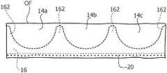
- the valvular sleeve 14may include a tubular body intended to define a flow conduit (e.g. a conduit for the flow of blood) between an inflow end IF and an outflow end OF.
- a flow conduite.g. a conduit for the flow of blood
- the valvular sleeve 14may include one or more (e.g., a plurality) a plurality of valve leaflets.
- a plurality of valve leafletsFor example, an embodiment having three leaflets, indicated as 14 a , 14 b and 14 c , are shown by way of example in the drawings.
- the one or more valve leaflets 14 a , 14 b , 14 cmay extend from the inflow end IF towards the outflow end OF (that is distally of the inflow end IF) and is displaceable under fluid pressure, e.g. blood pressure:
- inflow endand “outflow end” refer to the direction of unimpeded fluid flow through the valve prosthesis 10 .
- the valvular sleeve 14may be coupled with a supporting armature 16 , currently referred to as “stent”, which is intended to support the (generally flexible) valvular sleeve 14 .
- FIGS. 3 and 4are exemplary of stents 16 adapted for use with valvular sleeves 14 including three leaflets 14 a , 14 b , 14 c.
- Stents 16 as exemplified in FIGS. 3 and 4may be (substantially) rigid or flexible.
- Stent materialsmay include metals (e.g. titanium, cobalt-chrome alloys, Nitinol) or polymers (e.g. Polyoxymethylene (POM) such as Delrin® or polycarbonate).
- metalse.g. titanium, cobalt-chrome alloys, Nitinol
- polymerse.g. Polyoxymethylene (POM) such as Delrin® or polycarbonate.
- Stent configurationsmay vary depending on the material of the stent. It will be appreciated that a wide variety of biocompatible materials may be incorporated into stents 16 .
- FIG. 3is exemplary of a solid (e.g. non-apertured) structure which may be adapted for use for e.g. a polymer stent.
- the open (e.g. apertured) configuration of FIG. 4may be adapted for use e.g. for a metal stent 16 .
- One or more embodimentsmay include network-like stent structures, e.g. for valvular prostheses intended to be (e.g. radially) collapsed in view of implantation: EP-A-1 690 515 A1 is exemplary of a valvular prosthesis including such a collapsible stent.
- coupling a valvular sleeve 14 with a stent 16may be either with the stent 16 surrounding (e.g., radially outside of) the valvular sleeve 14 as schematically represented in FIG. 1 (and FIGS. 26 to 28 ) or with the valvular sleeve 14 surrounding the stent 16 as schematically represented in FIG. 2 .
- the stent 16may be at least partly “sandwiched” between two portions of the valvular sleeve 14 , e.g. as better detailed in the following.
- the valvular sleeve 14may be “sandwiched” between two portions of the stent 16 .
- the stent 16may include a ring-like body 160 intended to be located at the inflow end IF of the valvular sleeve 14 and a plurality of posts or prongs 162 extending from the base body 160 in a distal direction from the inflow end IF towards the outflow end OF of the valvular sleeve 14 .
- the stent 16may include three posts or prongs 162 equally spaced 120° around the circumferential extension of the base body 160 , that is equally angularly spaced around the main axis X 160 of the annular body 160 (and the stent 16 as a whole).
- FIGS. 3 and 4are exemplary of embodiments wherein the stent 16 includes a proximal (e.g. inflow) edge or rim extending along a circular line centered around a main axis X 160 and a distal (e.g. outflow) edge or rim extending along a scalloped line, that is an arched line connecting the distal ends of the prongs 162 .
- a proximal edge or rimextending along a circular line centered around a main axis X 160 and a distal (e.g. outflow) edge or rim extending along a scalloped line, that is an arched line connecting the distal ends of the prongs 162 .
- the leaflets 14 a , 14 b , 14 c of the valvular sleeve 14may have a semi-lunar (half-moon), scoop-like shape so that each leaflet 14 a , 14 b , 14 c in turn includes a proximal, crescent-shaped margin essentially co-extensive with one of the scallops of the stent 16 as well as a distal margin adapted to coapt with the distal margins of the other leaflets when the valvular sleeve is in the “closed” condition, which impedes fluid flow from the outflow end OF towards the inflow end IF.
- a stent 16may not be present, thus providing a valvular prosthesis of high flexibility.
- a valvular prosthesismay include various other elements in addition to the valvular sleeve 14 or the prosthetic valvular device (valvular sleeve 14 plus stent 16 ) as considered herein.
- These other elementsmay include e.g. a sewing ring R (as exemplified in phantom lines in FIGS. 1 and 2 ), one or more sealing skirts, and other structures intended to facilitate delivery and/or implantation of the prosthesis at the implantation site.
- a sewing ring Ras exemplified in phantom lines in FIGS. 1 and 2
- one or more sealing skirtsand other structures intended to facilitate delivery and/or implantation of the prosthesis at the implantation site.
- One or more embodimentsmay take advantage of the possibility of producing the valvular sleeve 14 of a flexible material which may be in the form of e.g. a planar sheet member or a tubular member as better detailed in the following.
- Materials adapted to provide a desired degree of flexibility of the valvular sleeve 14may include e.g.
- One or more embodimentsmay employ sheet or laminar material reinforced by fibers, such as e.g. carbon fibers or Kevlar® fibers.
- Materials adapted for use in one or more embodimentsmay include e.g.:
- tissue-engineeringMaterials produced by “tissue-engineering” technologies may represent an option for one or more embodiments.
- the valvular sleeve 14may be coated with a biocompatible coating e.g. a carbonaceous biocompatible coating. Such a coating may extend over the whole sleeve or only over part of it e.g. the part exposed to blood flow.
- a biocompatible coatinge.g. a carbonaceous biocompatible coating.
- Such a coatingmay extend over the whole sleeve or only over part of it e.g. the part exposed to blood flow.
- such flexible materiale.g. a fabric material
- tubular sheet member Tsuch flexible material may be formed to a tubular sheet member T.
- FIGS. 5A and 5Bare schematically representative of such a tubular sheet member T which may be either produced as such (e.g. as a knitted fabric) as schematically shown in FIG. 5A or produced by folding into a tube a sheet member which is then closed along a longitudinal joining line L 1 (e.g. by stitching or welding) as schematically shown in FIG. 5B
- a longitudinal joining line L 1e.g. by stitching or welding
- Tubular sheet members T as schematically represented in FIGS. 5A and 5Bmay be similar to vascular grafts as currently used e.g. in replacing portions of blood vessels or other types of body lumen.
- FIG. 6is schematically representative of the possibility of “overturning” or everting such a tubular sheet element to obtain a double-walled annular (tubular) member adapted to produce a valvular sleeve 14 .
- a tubular sheet member Tmay be regarded as including two longitudinally adjacent (subsequent) sections T 10 , T 20 with e.g. the second section T 20 adapted to be overturned outwardly with respect to the first section T 10 as schematically represented in FIG. 6 to produce the tubular body of FIG. 7 .
- the section T 20surrounds the section T 10 , so that the portions T 10 , T 20 form the inner portion and the outer portion, respectively, of a double-walled tubular body as shown in FIG. 7 .
- the overturning process of FIG. 6(however performed, inwardly or outwardly) may lead to the two sections T 10 , T 20 lying one inside the other with the line T 2 at which overturning has taken place located at one of the ends of the tubular body shown in FIG. 7 .
- the two sections T 10 , T 20i.e. the inner and outer portions of the tubular body of FIG. 7 , may be of a same length or different lengths. In one or more embodiments these inner and outer sheets may be trimmed to a same length (height) by cutting the portion of the longer sheet protruding with respect to the shorter sheet.
- FIGS. 8 to 11are exemplary of another approach for producing a tubular body essentially as depicted in FIG. 7 .
- such a tubular bodymay be produced by using (instead of a tubular sheet member T as shown in FIGS. 5A and 5B ) a planar sheet member S (e.g. of a rectangular or square shape) which may be U-folded at a folding line S 2 as schematically shown in FIG. 9 to produce a U-folded sheet member including two sections S 10 , S 20 facing each other in the U-shape.
- a planar sheet member Se.g. of a rectangular or square shape
- Such a U-shaped sheet member as shown in FIG. 9may then be handled as a sort of band or ribbon and brought to a ring or collar shape as schematically shown in FIG. 10 .
- This shaping into a ring or collarwill result in the opposed end edges L 10 , L 20 of the U-shaped sheet member of FIG. 9 being arranged facing each other.
- the end edges L 10 , L 20may then be joined to each other (e.g. via stitching, adhesive, welding, including ultrasound welding) along a joining line W to again produce a double-walled tubular body as shown in FIG. 11 including an outer portion and an inner portion corresponding to the portions S 10 , S 20 originally arranged side-to-side of the sheet member S of FIG. 8 .
- portion S 10 or the portion S 20will constitute the inner or the outer portion of the tubular body of FIG. 11 will depend, e.g. on the direction of shaping into a ring or collar the U-shaped sheet member of FIG. 9 as schematically shown in FIG. 10 .
- joining the opposed end edges L 10 , L 20 of the U-folded sheet member of FIG. 9 shaped into a ring or collar as shown in FIG. 10may involve both the inner and outer portions S 10 , S 20 . In one or more embodiments such joining may involve only one of these portions (e.g. S 10 or S 20 ).
- the process as describedmay lead to the two portions S 10 , S 20 lying one inside the other with the line S 2 at which the sheet member of FIG. 8 has been folded located at one of the ends of the tubular body shown in FIG. 11 .
- the two portions S 10 , S 20i.e. the inner and outer portions of the tubular body of FIG. 11 may be of equal or different widths (orthogonal to the folding line S 2 ). In one or more embodiments, these inner and outer portions may again be trimmed to a same length (height) by cutting the portion of the longer sheet protruding with respect to the shorter sheet.
- FIG. 12is schematically exemplary of fitting a tubular body as exemplified in FIG. 7 or FIG. 11 onto a stent 16 (e.g. a stent as exemplified in FIG. 3 ) so that the tubular body of FIG. 7 or FIG. 11 may be included as a valvular sleeve 14 in a prosthetic valvular device 10 .
- a stent 16e.g. a stent as exemplified in FIG. 3
- such a valvular sleeve 14 for valvular prosthesesmay include a tubular body (e.g. as shown in FIGS. 7 and 11 ) extending between an inflow end IF and an outflow end OF of the valvular sleeve 14 , with such a tubular body including an inner portion 141 and an outer portion 142 .
- inner and outerrefer to the radial direction of the sleeve 14 , e.g. with the outer portion 142 surrounding (e.g. radially outside of) the inner portion 141 .
- a tubular body as per FIG. 7 or FIG. 11may be fitted onto a stent 16 in such a way that the overturning line T 2 or the folding line S 2 may be located at the outflow end OF of the valvular sleeve 14 .
- the overturning line T 2 or the folding line S 2may be located at the distal margins of the leaflets 14 a , 14 b , 14 c , that is—as indicated previously—at the margins adapted to coapt when the valvular sleeve is in the closed position which impedes fluid flow from the outflow end OF towards the inflow end IF.
- the inner and outer portions 141 , 142being formed by overturning/folding a sheet-like member (possibly formed into a tube) the inner portion 141 and outer portion 142 will be formed out of a single sheet member having a loop or fold extending around the outflow end OF between the inner and outer portions 141 , 142 .
- the inner and outer portions 141 , 142are parts of a same laminar (sheet-like) body e.g. of a fabric material or the like, with a loop or fold at the overturning line T 2 /folding line S 2 located at (e.g. extending around) the outflow end OF of the sleeve 14 .
- the inner and outer portions 141 , 142will not require to be joined at the outflow end OF of the sleeve 14 by resorting to e.g. stitching, gluing, welding and so on, as required if two separate sheets were joined at the outflow end OF of the sleeve 14 .
- the two portions 141 , 142being already connected at the overturning line T 1 or the folding line S 2 “originally”, e.g. due to being formed as one piece of fabric or other laminar material, will avoid any sort of cutting (followed by stitching, gluing, welding and so on) as possibly needed to connect two separate portions 141 and 142 .
- the drawbackspossibly related e.g. to fibres of a fabric cut becoming loose, sharp edges or protrusions formed by cutting, stitching, gluing, welding may thus be avoided.
- FIG. 12is exemplary of a way of coupling the valvular sleeve 14 to a stent 16 by taking advantage of the valvular sleeve 14 being a double-walled structure including an inner portion 141 and an outer portion 142 with a loop or fold therebetween.
- the valvular sleeve 14may be vested onto the stent 16 as schematically shown in FIG. 13 , e.g. by simply letting the stent 16 extend in the (inverted) U-shape or channel shape of the structure of the valvular sleeve 14 .
- the valvular sleeve 14may be retained onto the stent 16 against any force urging the valvular sleeve 14 in the proximal direction (outflow to inflow, e.g. downward in FIG. 13 ) without any other form of coupling (e.g. stitching, and so on) being required for that purpose.
- Such a sort of a form couplingmay facilitate the action of the prosthetic valvular device 10 in impeding undesired proximal flow (e.g. of blood) from the outflow end OF towards the inflow end IF.
- the overturning line T 2 or the folding line S 2may be located at the distal margins of the (double-walled) leaflets 14 a , 14 b , 14 c.
- the valvular sleeve 14may be included in a “stentless” valvular prosthesis without being coupled to a stent.
- FIGS. 12 and 13coupling with a stent 16 has been exemplified in FIGS. 12 and 13 with the stent 16 extending between the inner sheet 141 and the outer sheet 142 of the valvular sleeve 14 .
- Other embodiments as exemplified in FIGS. 1 and 2may provide for a stent 16 being configured either for surrounding the valvular sleeve 14 (e.g. as better detailed in the following) or for being surrounded by the valvular sleeve 14 .
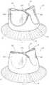
- the (double-walled) leaflet portions 14 a , 14 b , 14 cmay be shaped to a desired semi-lunar (e.g. eyelid-shaped) scoop-like form as exemplified e.g. in FIGS. 1 and 2 with such shape retained in the absence of any fluid force applied thereto.
- Thismay be the condition in which the valvular sleeve 14 may be stored e.g. mounted in a holder in a container or in an implantation kit to be made available at the implantation theatre.
- Such shaping of the leafletsmay be by known means including e.g. mechanical shaping, liquid pressure, application of heat or combinations of these.
- the nature of the sheet material (e.g. fabric or tissue) of the valvular sleeve 14may dictate or limit available options for the technique(s) adopted for shaping the leaflets.
- FIG. 14reproduces for the sake of simplicity the same situation as depicted in FIG. 12 (namely the possible coupling of the valvular sleeve 14 with a stent 16 ).
- the valvular sleeve 14 and the stent 16are shown in a notional expanded circumferential view, that is in a notional deployed plane view, as would result by cutting the substantially cylindrical shape of the prosthetic device 10 along one of its generating lines and letting the device 10 lie flat on a plane.
- FIGS. 15 to 18are exemplary of various embodiments where the inner and outer portions 141 , 142 of the valvular sleeve 10 may be joined at various points, e.g. via stitching, adhesive, welding, including ultrasound welding. While most of the examples illustrated in FIGS. 15 to 18 (and FIGS. 20 to 28 ) refer to a prosthetic valvular device including a valvular sleeve 14 coupled with a stent 16 , the relative disclosure will identically apply to a “stentless” valvular sleeve 14 , that is a valvular sleeve 14 intended to be used in a valvular prosthesis without coupling with a stent 16 .
- FIG. 15exemplifies the possibility of joining (e.g. by stitching, adhesive, welding including ultrasound welding: hereinafter all these exemplary possibilities will be referred simply as “joining”) the inner and outer portions 141 , 142 with a continuous or discontinuous, e.g. point-wise, joining line 20 extending along the inflow end IF of the valvular sleeve 14 .
- the inner and outer portions 141 , 142 formed of a single piece of sheet material with a loop therebetween at the outflow end OF(that is, at the distal margins of the leaflets 14 a , 14 b , 14 c ) will also be joined—by a positive seam as represented the joining line 20 —at the inflow end IF so that the double-walled structure of the valvular sleeve 14 may be closed (also) at the inflow end IF.
- a joining line 20 as exemplified in FIG. 15may join the inner portion 141 and the outer portion 142 by extending longitudinally or axially outwardly of the stent 16 (if present), such that the stent is not located between the inner portion 141 and outer portion 142 of the sleeve 14 .
- the joining line 20may extend to the stent 16 , e.g. in the form of stitches extending through apertures (e.g. holes) in the stent 16 .
- all or portions of the stentmay be located or “sandwiched” between the inner and outer portions 141 , 142 .
- FIG. 16is exemplary of the possibility of providing a joining line 22 (again adapted to be produced with any of the exemplary joining techniques considered in the foregoing) extending along a scalloped trajectory more or less closely following the crescent-shaped proximal margins of the leaflet portions of the inner and outer sheets 141 , 142 : these leaflet portions of the portions 141 and 142 of the tubular body of the sleeve are indicated with the same references 14 a , 14 b , 14 c used for the valve leaflets as shown e.g. in FIGS. 1 and 2 .
- FIG. 16shows that the joining line 22 may extend arcuately between the prongs 162 of the stent thus forming the so-called “commissures” of the valvular sleeve 14 .
- both joining line 20 ( FIG. 15 ) and joining line 22 ( FIG. 160 )are used to capture the stent 16 between a portion of the inner and outer portions 141 , 142 of valvular sleeve 14 .
- FIGS. 17 and 18are exemplary of the possibility of forming joining lines 24 and 26 to join the inner and outer portions 141 , 142 within their leaflet portions 14 a , 14 b , 14 c .
- a series of concentric arcuate joining linescomprising progressively smaller arcuate lengths, is provided from the proximal leaflet margins adjacent to the stent 16 to an outermost arcuate length near distal leaflet margins (i.e., the margins that coapt to impede fluid flow from the outflow end OF to the inflow end IF).
- other joining linese.g., parallel, perpendicular, or otherwise angled with respect to the axis X 160 of the valve, may be used in alternative embodiments.
- the leaflets(which are double-walled due to the presence of the inner portion 141 and the outer portion 142 ) will behave in fact as a single (layered) laminar body e.g. avoiding the formation of pockets between the inner and outer portions 141 , 142 .
- joining lines 24 , 26may be beneficial in facilitating bestowing onto the leaflet portions 14 a , 14 b , 14 c their concave scoop-like configuration as exemplified in FIGS. 1 and 2 and/or in facilitating retention of such a configuration as possibly imparted with other means as discussed previously.
- the pattern of the joining lines 24 , 26may facilitate achieving/retaining a certain shape and may include e.g. radial lines with respect to the half-moon shape of the leaflets 14 a , 14 b , 14 c as shown in FIG. 17 or extend along scalloped trajectories somewhat reproducing the scalloped trajectory of the joining line 22 at the proximal margins of the leaflets 14 a , 14 b , 14 c.
- FIG. 19is exemplary of the possibility of including pad members 28 in the space between the inner wall portion 141 and the outer wall portion 142 at the leaflet portions 14 a , 14 b , 14 c.
- such pad members 28may be generally crescent—shaped, semi-circular, semi-elliptical or eyelid-shaped (e.g. in the form of a shield), and may be scored or have notches cut in portions thereof, as schematically represented in parts a), b), c) and d) of FIG. 20 .
- the pad members 28may be planar or nearly planar, or may comprise a curved surface comprising a portion of a three-dimensional spherical body or a shape derived therefrom, as illustrated in parts b), c) and d) of FIG. 20 .
- the pad members 28may include a flexible material.
- the pad members 28may include a spongy material.
- the pad members 28may have a surface sculpturing as exemplified at 280 in part c) of FIG. 20 . This may facilitate following the rhythmic deformation that the leaflets 14 a , 14 b , 14 c undergo (e.g. under pulsating blood pressure) in operation.
- the pad members 28may include e.g. at their distal rim, at least one notch 282 which may bestow on the pad member an overall V or U shape.
- the notch or notches 282may facilitate the closing and opening movement of the corresponding leaflet, that is the movement of the leaflet portions under fluid pressure between an inward condition to impede fluid flow from the outflow end OF to the inflow end IF and an outward condition to permit fluid flow from the inflow end IF to the outflow end OF.
- the pad members 28may be retained at their location and prevented from being dislodged distally of the valvular sleeve 14 by the loop or fold between the inner portion 141 and the outer portion 142 at the outflow end OF of the valvular sleeve 14 .
- the joining lines 24 , 26 and/or the pad members 28may be functional in bestowing onto the leaflets 14 a , 14 b , 14 c a “bi-stable” behaviour thus making the leaflets 14 a , 14 b , 14 c capable of alternatively “snapping open” under inflow-to-outflow fluid (e.g. blood) pressure and “snapping closed” under reversed outflow-to-inflow fluid pressure.
- inflow-to-outflow fluide.g. blood
- the valvular sleeve 14 as exemplified hereinmay include a plurality of (e.g., three) double-walled valve leaflets 14 a , 14 b , 14 c (with the stent 16 , if present, including a matching plurality (e.g., three) prongs 162 ) equally extending angularly 120° around the main axis X 160 .
- a plurality of (e.g., three) double-walled valve leaflets 14 a , 14 b , 14 cwith the stent 16 , if present, including a matching plurality (e.g., three) prongs 162 ) equally extending angularly 120° around the main axis X 160 .
- One or more embodimentsmay include a different number of leaflets and/or leaflets of different sizes.
- embodiments for use e.g. in venous valvesmay include two leaflets or even just one leaflet.
- Valvular sleeves for implantation at, e.g., a mitral sitemay include a higher number of leaflets e.g. four leaflets, possibly of different sizes.
- One or more embodimentsare largely independent of the number and sizes of the leaflets in the valvular sleeve 14 .
- FIGS. 21 to 28are exemplary of possible embodiments wherein a valvular sleeve 14 may have a tapered shape from a (larger) inflow end IF towards a (narrower) outflow end OF.
- a tapered configurationmay be regarded as more closely reproducing the anatomy of certain natural valves intended to be replaced with a valve prosthesis.
- a stent (if contemplated) for such a valvular prosthesismay include prongs (posts) 162 which extend from a base body 160 in a distal direction from the inflow end IF to the outflow end OF with a general taper causing the distal ends of the prongs 162 to lie on an outflow circumference (as schematically indicated in chain line OF of FIG. 21 ) which has a smaller radius than the inflow end IF.
- FIGS. 22 to 24are exemplary of one or more embodiments which may permit to produce a double-walled tubular body essentially similar to the tubular body as shown in FIG. 7 . While still including sections T 10 , T 20 adapted to form the inner portion 141 and the outer portion 142 (or vice versa) of the valvular sleeve 14 as discussed in the foregoing, the tubular body of FIG. 24 will exhibit an overall tapered (e.g. frusto-conical) shape.
- an overall taperede.g. frusto-conical
- FIGS. 22 to 24is essentially similar (also as regards the possibility for the sections T 10 , T 20 to exchange their roles in forming the inner and the outer portions 141 , 142 ) to the embodiment of FIGS. 5A, 5B, 6 and 7 .
- the tubular sheet member Tmay be an hourglass-shaped tube with an overturning (folding) line T 2 arranged at the waist line of the hourglass shape.
- FIG. 23Such an hourglass-shaped tubular member T as shown in FIG. 23 may be produced e.g. by means of fabric knitting techniques adapted for use also for medical devices (e.g. vascular grafts).
- FIGS. 22 and 23refer to a (non-mandatory) embodiment where the hourglass-shaped tubular sheet member T is produced starting from a longer tubular sheet member T 1 (produced e.g. by a knitting process of a known type) including an intermediate hourglass-shaped portion which is isolated by cutting opposed cylindrical ends T 3 .
- the tapered tubular body of FIG. 24may then be used either in a tapered valvular prosthesis of the stentless type or in a tapered valvular prosthetic device 10 for a stented valvular prosthesis by being coupled with a stent 16 as exemplified in FIG. 21 .
- FIGS. 12 to 20The related disclosure provided in connection with FIGS. 12 to 20 will thus apply (also) to such a tapered valvular sleeve 14 /valvular prosthetic device 10 .
- FIGS. 25 to 28exemplify one embodiment of a way of coupling a valvular sleeve 14 with a stent 16 by arranging the stent 16 surrounding the valvular sleeve 14 as schematically represented in FIG. 1 .
- FIGS. 25 to 28exemplify such embodiments in connection with a tapered valvular sleeve 14 /stent 16 .
- the same conceptsmay apply also to a non-tapered valvular sleeve 14 /stent 16 as discussed previously in this description.
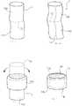
- the prongs 162 extending distally of the main body 162 from the inflow end IF to the outflow end OFmay include a longitudinal slit or aperture 180 into which a folded portion 140 , formed e.g. at one of the commissures of the valvular sleeve 14 , may be inserted as shown e.g. in FIGS. 26 to 28 .
- the valvular sleeve 14will essentially extend within a portion of the stent 16 , that is with the stent 16 largely surrounding the valvular sleeve 14 .
- the folded portions 140will at least marginally extend at the outer surface of the stent 16 so that a peg member 144 may be inserted into each folded portion 140 to provide anchoring of the commissures of valvular sleeve 14 to the prongs 162 .
- That mounting arrangementmay be applied also in the case on non-tapered (e.g. cylindrical) valvular sleeves 14 /stents 16 .
- the slits or apertures 180may be provided with an increasing width (e.g. with a sort of “raindrop” shape) in the distal direction of the stent 16 , namely with a width increasing away from the body portion 160 .
- the peg members 144may be inserted wedge-like into the folded portions 140 in such a way that the folded portions 140 will be widening towards the outflow end OF of the valvular sleeve.
- the circumferential extension, and thus the radial size of the valvular sleeve 14 within the stent 16will thus be smaller at the outflow end OF in comparison with the inflow end IF: this is because the folded portions 140 will “draw” more material of the valvular sleeve 14 out of the stent 16 at the outflow end OF than at the inflow end IF.
- the “effective” valvular sleeve 14 surrounded by the stent 16will then have a tapered shape as in the case of the tapered tubular body of FIG. 24 .
- FIGS. 29 and 30are exemplary of still another way of producing a tubular body as exemplified e.g. in FIG. 11 for use in any of the embodiments exemplified herein.
- a tubular sheet member T 4may again be used.
- the tubular member T 4may be formed into a ring or collar as schematically shown in FIG. 29 , thus undergoing the same type of shaping as discussed in connection with FIG. 10 .
- the tubular member T 4will have opposed ends, again designated L 10 , L 20 , which may be joined to each other at a joining line W to form a tubular body adapted for use as a valvular sleeve 14 as disclosed in the foregoing.
- the tubular member T 4will in fact have two opposed loop portions designated S 2 and S 1 in FIG. 29 .
- One of these loop portions at the sides of the flattened tubular member T 4 shaped into a ring or collarmay in fact correspond to a folding line S 2 forming a loop between the two wall portions of the ribbon-like tubular member.
- Such a folding line S 2may again be located at the outflow end OF of the tubular sleeve 14 as exemplified previously in connection with FIGS. 10 to 13 .
- the loop portion S 1may be cut in order to open the tubular body at the end opposed the folding line S 2 as in the case of the tubular body of FIG. 11 . This will permit insertion of a stent 16 into the valvular sleeve as schematically shown in FIGS. 12 and 14 .
- the opposed walls S 10 and S 20 of the tubular member T 4may be left connected at both lines S 2 and S 1 .
- Thismay apply e.g. to “stentless” valvular prostheses for which coupling to a support stent 16 may not be envisaged or to those embodiments were coupling with a stent 16 may occur either by causing the stent 16 to surround the valvular sleeve 14 (see e.g. FIG. 1 ) or by causing the valvular sleeve 14 to surround the stent 16 , so that the space between the inner portion 141 and the outer portion 142 may not need to be made open for permitting insertion of a stent 16 therein.
- an arrangement wherein the inner and outer portions 141 , 142 of the valvular sleeve 14 have a loop or fold therebetween at both the inflow end IF and the outflow end OF (that is at the distal margins of the leaflets 14 a , 14 b , 14 c )may be adapted for coupling to a stent using the slit/aperture and peg arrangement as exemplified in FIGS. 25 to 28 .
- a double-walled tubular body as exemplified in FIG. 30may be produced by knitting methods (e.g. by means of circular knitting machines) as a single body, thus dispensing with the need of providing a joining line W.
- One or more embodimentsmay thus include a plurality of (e.g. three) valve leaflet portions extending distally of said inflow end towards distal margins at said outflow end.
- valve leafletsmay be displaceable under fluid pressure to an inward, “closed” condition wherein the distal margins of the leaflets coapt to impede fluid flow from said outflow end to said inflow end.
- the inner and outer portions 141 , 142 of the (double-walled) leaflets 14 a , 14 b , 14 cmay be formed of a single piece of sheet material with a fold or loop (e.g. the folding line S 2 ) therebetween at the outflow end OF (that is, at the distal margins of the leaflets 14 a , 14 b , 14 c ).
- a valvular sleeve for valvular prosthesesincluding a tubular body extending between an inflow end and an outflow end, the tubular body including a sheet member folded at said outflow end, whereby the tubular body includes an inner tubular portion and an outer tubular portion surrounding the inner tubular portion.
- valvular sleeve of Embodiment 1wherein said inner and outer portions comprise either of:
- valvular sleeve of Embodiment 1 or Embodiment 2wherein said inner and outer portions are joined to each other, optionally by suture, at said inflow end.
- the valvular sleeve of Embodiment 1wherein said inner and outer portions comprise respective wall portions of a tubular ribbon-like member, optionally having opposed ends joined to each other to form said tubular body.
- valve leaflet portionsextending distally of said inflow end towards said outflow end, said valve leaflet portions displaceable under fluid pressure to an inward condition to impede fluid flow from said outflow end to said inflow end and an outward condition to permit fluid flow from said inflow end to said outflow end.
- valve leaflet portionsIn some embodiments: The valvular sleeve of Embodiment 5, wherein said inner and outer portions are joined to each other, preferably by suture, at said valve leaflet portions.
- valve leaflet portionsIn some embodiments: The valvular sleeve of Embodiment 6, wherein said inner and outer portions are joined to each other at said valve leaflet portions by at least one of:
- valvular sleeve of any of the previous Embodimentswherein said inner and outer portions comprise respective subsequent sections of an hourglass-shaped tubular sheet member overturned at an overturn line at the waistline of the hourglass shape, said overturn line being at said outflow end of the valvular sleeve, whereby said valvular sleeve has a tapered shape from said inflow end towards said outflow end.
- a prosthetic valvular deviceincluding:
- the prosthetic valvular device of Embodiment 10including anchoring formations, optionally suture formations, anchoring said valvular sleeve to said stent.
Landscapes
- Health & Medical Sciences (AREA)
- Engineering & Computer Science (AREA)
- Cardiology (AREA)
- Biomedical Technology (AREA)
- Transplantation (AREA)
- Oral & Maxillofacial Surgery (AREA)
- Heart & Thoracic Surgery (AREA)
- Vascular Medicine (AREA)
- Life Sciences & Earth Sciences (AREA)
- Animal Behavior & Ethology (AREA)
- General Health & Medical Sciences (AREA)
- Public Health (AREA)
- Veterinary Medicine (AREA)
- Manufacturing & Machinery (AREA)
- Prostheses (AREA)
Abstract
Description
- radially outwardly to permit fluid flow from the inflow end IF to the outflow end OF of the valvular sleeve14 (upward direction, in the figures), and
- radially inwardly to impede or obstruct fluid flow in the opposite direction, namely from the outflow end OF to the inflow end IF of the valvular sleeve14 (downward direction, in the figures).
- In one or more embodiments, the
valvular sleeve 14 may reproduce operation of a natural valve, e.g. with theleaflets - to an inward coapting condition to impede fluid (e.g. blood) flow from the outflow end OF to the inflow end IF, and
- to an outward expanded condition to permit fluid (e.g. blood) flow from the inflow end IF towards the outflow end OF.
- fabrics produced e.g. by knitting, weaving or felting fibers, including “non-woven” materials,
- sheet or laminar materials produced e.g. by lamination, molding or dipping.
- biocompatible polymers, such e.g. as silicone, polyethylene, polypropylene, polytetrafluoroethylene (PTFE), polyethylene terephthalate (PET) such as Dacron®;
- biological materials such as e.g. bovine, porcine or equine pericardium.
- the
inner portion 141 may include e.g. the first section T10 (resp. the second section T20) of the tubular sheet member T or the first portion S10 (resp. the second portion S20) of the sheet member S, - the
outer portion 142 may include e.g. the second section T20 (resp. the first section T10) of the tubular sheet member T or the second portion S20 (resp. the first portion S10) of the sheet member S.
- the
- respective subsequent sections of a tubular member overturned at an overturn line at said outflow end;
- respective portions of a sheet member U-folded at a folding line at said outflow end, said U-folded sheet member having opposed end edges joined to each other to form said tubular body.
- a scalloped joining line extending at a proximal edge of said leaflet portions,
- a pattern of joining lines extending distally of a proximal edge of said leaflet portions.
- a valvular sleeve according to any of
Embodiments 1 to 9, - a stent supporting said valvular sleeve.
- a valvular sleeve according to any of
- said stent is arranged surrounding said valvular sleeve and includes a ring-like body at said inflow end of the valvular sleeve with a plurality of prongs extending from said ring-like body in a distal direction from said inflow end towards said outflow end of the valvular sleeve,
- said prongs have a longitudinal slit,
- said valvular sleeve includes folded portions which extend through the longitudinal slits of said prongs externally of said stent, and
- peg members are inserted into said folded portions of the valvular sleeve externally of said stent to provide anchoring of said valvular sleeve to the stent.
- said prongs extend distally of said ring-like body from said inflow end towards said outflow end of the valvular sleeve with a tapered shape of said stent,
- said prongs have a longitudinal slit having an increasing width in said distal direction, and
- said peg members are inserted wedge-like into said folded portions of the valvular sleeve to provide anchoring of said valvular sleeve to the stent, wherein the valvular sleeve is radially larger at said inflow end than at said outflow end.
Claims (20)
Applications Claiming Priority (3)
| Application Number | Priority Date | Filing Date | Title |
|---|---|---|---|
| ITUB2015A002409AITUB20152409A1 (en) | 2015-07-22 | 2015-07-22 | VALVE SLEEVE FOR VALVULAR PROSTHESIS AND CORRESPONDING DEVICE |
| IT102015000037126 | 2015-07-22 | ||
| PCT/IB2016/054281WO2017013578A1 (en) | 2015-07-22 | 2016-07-19 | A valvular sleeve for valvular prostheses and corresponding device |
Publications (2)
| Publication Number | Publication Date |
|---|---|
| US20180214263A1 US20180214263A1 (en) | 2018-08-02 |
| US11179237B2true US11179237B2 (en) | 2021-11-23 |
Family
ID=54251681
Family Applications (1)
| Application Number | Title | Priority Date | Filing Date |
|---|---|---|---|
| US15/746,747ActiveUS11179237B2 (en) | 2015-07-22 | 2016-07-19 | Valvular sleeve for valvular prostheses and corresponding device |
Country Status (6)
| Country | Link |
|---|---|
| US (1) | US11179237B2 (en) |
| EP (1) | EP3324892B1 (en) |
| CN (1) | CN107847322A (en) |
| CA (1) | CA2991854A1 (en) |
| IT (1) | ITUB20152409A1 (en) |
| WO (1) | WO2017013578A1 (en) |
Cited By (1)
| Publication number | Priority date | Publication date | Assignee | Title |
|---|---|---|---|---|
| US20230363895A1 (en)* | 2014-10-13 | 2023-11-16 | Edwards Lifesciences Corporation | Prosthetic valved conduit |
Families Citing this family (51)
| Publication number | Priority date | Publication date | Assignee | Title |
|---|---|---|---|---|
| US8870950B2 (en) | 2009-12-08 | 2014-10-28 | Mitral Tech Ltd. | Rotation-based anchoring of an implant |
| US20110224785A1 (en) | 2010-03-10 | 2011-09-15 | Hacohen Gil | Prosthetic mitral valve with tissue anchors |
| US8579964B2 (en) | 2010-05-05 | 2013-11-12 | Neovasc Inc. | Transcatheter mitral valve prosthesis |
| US11653910B2 (en) | 2010-07-21 | 2023-05-23 | Cardiovalve Ltd. | Helical anchor implantation |
| US9763657B2 (en) | 2010-07-21 | 2017-09-19 | Mitraltech Ltd. | Techniques for percutaneous mitral valve replacement and sealing |
| US9554897B2 (en) | 2011-04-28 | 2017-01-31 | Neovasc Tiara Inc. | Methods and apparatus for engaging a valve prosthesis with tissue |
| US9308087B2 (en) | 2011-04-28 | 2016-04-12 | Neovasc Tiara Inc. | Sequentially deployed transcatheter mitral valve prosthesis |
| JP5872692B2 (en) | 2011-06-21 | 2016-03-01 | トゥエルヴ, インコーポレイテッド | Artificial therapy device |
| US8852272B2 (en) | 2011-08-05 | 2014-10-07 | Mitraltech Ltd. | Techniques for percutaneous mitral valve replacement and sealing |
| WO2013021374A2 (en) | 2011-08-05 | 2013-02-14 | Mitraltech Ltd. | Techniques for percutaneous mitral valve replacement and sealing |
| EP2739214B1 (en) | 2011-08-05 | 2018-10-10 | Cardiovalve Ltd | Percutaneous mitral valve replacement and sealing |
| US11202704B2 (en) | 2011-10-19 | 2021-12-21 | Twelve, Inc. | Prosthetic heart valve devices, prosthetic mitral valves and associated systems and methods |
| US9039757B2 (en) | 2011-10-19 | 2015-05-26 | Twelve, Inc. | Prosthetic heart valve devices, prosthetic mitral valves and associated systems and methods |
| JP6133309B2 (en) | 2011-10-19 | 2017-05-24 | トゥエルヴ, インコーポレイテッド | Prosthetic heart valve device |
| EA201400478A1 (en) | 2011-10-19 | 2014-10-30 | Твелв, Инк. | DEVICES, SYSTEMS AND METHODS OF PROTESIZING THE HEART VALVE |
| US9345573B2 (en) | 2012-05-30 | 2016-05-24 | Neovasc Tiara Inc. | Methods and apparatus for loading a prosthesis onto a delivery system |
| US20150351906A1 (en) | 2013-01-24 | 2015-12-10 | Mitraltech Ltd. | Ventricularly-anchored prosthetic valves |
| US9572665B2 (en) | 2013-04-04 | 2017-02-21 | Neovasc Tiara Inc. | Methods and apparatus for delivering a prosthetic valve to a beating heart |
| EP3174502B1 (en) | 2014-07-30 | 2022-04-06 | Cardiovalve Ltd | Apparatus for implantation of an articulatable prosthetic valve |
| US9974651B2 (en) | 2015-02-05 | 2018-05-22 | Mitral Tech Ltd. | Prosthetic valve with axially-sliding frames |
| CN110141399B (en) | 2015-02-05 | 2021-07-27 | 卡迪尔维尔福股份有限公司 | Prosthetic valve with axial sliding frame |
| CA3007660A1 (en) | 2015-12-15 | 2017-06-22 | Neovasc Tiara Inc. | Transseptal delivery system |
| US10433952B2 (en) | 2016-01-29 | 2019-10-08 | Neovasc Tiara Inc. | Prosthetic valve for avoiding obstruction of outflow |
| US10531866B2 (en) | 2016-02-16 | 2020-01-14 | Cardiovalve Ltd. | Techniques for providing a replacement valve and transseptal communication |
| US20190231525A1 (en) | 2016-08-01 | 2019-08-01 | Mitraltech Ltd. | Minimally-invasive delivery systems |
| CA3031187A1 (en) | 2016-08-10 | 2018-02-15 | Cardiovalve Ltd. | Prosthetic valve with concentric frames |
| CA3042588A1 (en) | 2016-11-21 | 2018-05-24 | Neovasc Tiara Inc. | Methods and systems for rapid retraction of a transcatheter heart valve delivery system |
| US10702378B2 (en) | 2017-04-18 | 2020-07-07 | Twelve, Inc. | Prosthetic heart valve device and associated systems and methods |
| US10709591B2 (en) | 2017-06-06 | 2020-07-14 | Twelve, Inc. | Crimping device and method for loading stents and prosthetic heart valves |
| CA3069991C (en)* | 2017-06-29 | 2022-05-31 | Open Stent Solution | Intraluminal support structure and prosthetic valve from the same |
| US10786352B2 (en) | 2017-07-06 | 2020-09-29 | Twelve, Inc. | Prosthetic heart valve devices and associated systems and methods |
| US10729541B2 (en) | 2017-07-06 | 2020-08-04 | Twelve, Inc. | Prosthetic heart valve devices and associated systems and methods |
| US11246704B2 (en)* | 2017-08-03 | 2022-02-15 | Cardiovalve Ltd. | Prosthetic heart valve |
| US10888421B2 (en) | 2017-09-19 | 2021-01-12 | Cardiovalve Ltd. | Prosthetic heart valve with pouch |
| US11793633B2 (en) | 2017-08-03 | 2023-10-24 | Cardiovalve Ltd. | Prosthetic heart valve |
| US12064347B2 (en) | 2017-08-03 | 2024-08-20 | Cardiovalve Ltd. | Prosthetic heart valve |
| CA3073834A1 (en) | 2017-08-25 | 2019-02-28 | Neovasc Tiara Inc. | Sequentially deployed transcatheter mitral valve prosthesis |
| US20190083242A1 (en)* | 2017-09-19 | 2019-03-21 | Cardiovalve Ltd. | Systems and methods for implanting a prosthetic valve within a native heart valve |
| WO2019081453A1 (en)* | 2017-10-23 | 2019-05-02 | Symetis Sa | Prosthetic valve leaflet |
| GB201720803D0 (en) | 2017-12-13 | 2018-01-24 | Mitraltech Ltd | Prosthetic Valve and delivery tool therefor |
| GB201800399D0 (en) | 2018-01-10 | 2018-02-21 | Mitraltech Ltd | Temperature-control during crimping of an implant |
| CN113271890B (en) | 2018-11-08 | 2024-08-30 | 内奥瓦斯克迪亚拉公司 | Ventricular deployment of transcatheter mitral valve prosthesis |
| CA3132873A1 (en) | 2019-03-08 | 2020-09-17 | Neovasc Tiara Inc. | Retrievable prosthesis delivery system |
| CA3135753C (en) | 2019-04-01 | 2023-10-24 | Neovasc Tiara Inc. | Controllably deployable prosthetic valve |
| US11491006B2 (en) | 2019-04-10 | 2022-11-08 | Neovasc Tiara Inc. | Prosthetic valve with natural blood flow |
| US12186188B2 (en) | 2019-05-01 | 2025-01-07 | Twelve, Inc. | Support devices for transcatheter delivery system handles |
| US11452599B2 (en) | 2019-05-02 | 2022-09-27 | Twelve, Inc. | Fluid diversion devices for hydraulic delivery systems and associated methods |
| US11779742B2 (en) | 2019-05-20 | 2023-10-10 | Neovasc Tiara Inc. | Introducer with hemostasis mechanism |
| JP7520897B2 (en) | 2019-06-20 | 2024-07-23 | ニオバスク ティアラ インコーポレイテッド | Thin prosthetic mitral valve |
| CN115209837A (en)* | 2020-03-02 | 2022-10-18 | 百多力股份公司 | Heart valve prosthesis |
| US12357459B2 (en) | 2020-12-03 | 2025-07-15 | Cardiovalve Ltd. | Transluminal delivery system |
Citations (68)
| Publication number | Priority date | Publication date | Assignee | Title |
|---|---|---|---|---|
| US3574865A (en) | 1968-08-08 | 1971-04-13 | Michigan Instr Inc | Prosthetic sutureless heart valve |
| US3655306A (en) | 1970-01-19 | 1972-04-11 | Donald Nixon Ross | Apparatus for molding heart valves |
| US3739402A (en) | 1970-10-15 | 1973-06-19 | Cutter Lab | Bicuspid fascia lata valve |
| US4084268A (en) | 1976-04-22 | 1978-04-18 | Shiley Laboratories, Incorporated | Prosthetic tissue heart valve |
| US4118806A (en) | 1976-02-04 | 1978-10-10 | Thermo Electron Corporation | Prosthetic blood vessel |
| US4265694A (en) | 1978-12-14 | 1981-05-05 | The United States Of America As Represented By The Department Of Health, Education And Welfare | Method of making unitized three leaflet heart valve |
| US4345340A (en) | 1981-05-07 | 1982-08-24 | Vascor, Inc. | Stent for mitral/tricuspid heart valve |
| US4364126A (en) | 1981-07-28 | 1982-12-21 | Vascor, Inc. | Heart valve with removable cusp protector band |
| US4364127A (en) | 1981-10-02 | 1982-12-21 | Research Corporation | Trileaflet type prosthetic heart valve |
| US4477930A (en) | 1982-09-28 | 1984-10-23 | Mitral Medical International, Inc. | Natural tissue heat valve and method of making same |
| US4501030A (en) | 1981-08-17 | 1985-02-26 | American Hospital Supply Corporation | Method of leaflet attachment for prosthetic heart valves |
| US4535483A (en) | 1983-01-17 | 1985-08-20 | Hemex, Inc. | Suture rings for heart valves |
| US4626255A (en) | 1983-09-23 | 1986-12-02 | Christian Weinhold | Heart valve bioprothesis |
| US4680031A (en) | 1982-11-29 | 1987-07-14 | Tascon Medical Technology Corporation | Heart valve prosthesis |
| US4778461A (en) | 1985-11-23 | 1988-10-18 | Beiersdorf Ag | Heart valve prosthesis and process for its production |
| US4786556A (en) | 1986-03-24 | 1988-11-22 | Becton, Dickinson And Company | Polymeric articles having enhanced antithrombogenic activity |
| US4816029A (en) | 1981-05-07 | 1989-03-28 | Medtronic, Inc. | Stent for aortic heart valve |
| US4888009A (en) | 1985-04-05 | 1989-12-19 | Abiomed, Inc. | Prosthetic heart valve |
| US4939007A (en) | 1988-03-07 | 1990-07-03 | Becton, Dickinson And Company | Article having a hemocompatible surface |
| US5032666A (en) | 1989-06-19 | 1991-07-16 | Becton, Dickinson And Company | Amine rich fluorinated polyurethaneureas and their use in a method to immobilize an antithrombogenic agent on a device surface |
| US5071431A (en) | 1990-11-07 | 1991-12-10 | Carbomedics, Inc. | Suture rings for heart valves and method of securing suture rings to heart valves |
| US5084315A (en) | 1990-02-01 | 1992-01-28 | Becton, Dickinson And Company | Lubricious coatings, medical articles containing same and method for their preparation |
| US5104406A (en) | 1990-02-21 | 1992-04-14 | Sorin Biomedica S.P.A. | Heart valve prosthesis |
| US5123919A (en) | 1991-11-21 | 1992-06-23 | Carbomedics, Inc. | Combined prosthetic aortic heart valve and vascular graft |
| US5139515A (en) | 1990-08-15 | 1992-08-18 | Francis Robicsek | Ascending aortic prosthesis |
| US5147391A (en) | 1990-04-11 | 1992-09-15 | Carbomedics, Inc. | Bioprosthetic heart valve with semi-permeable commissure posts and deformable leaflets |
| WO1992019185A1 (en) | 1991-05-08 | 1992-11-12 | Nika Health Products Limited | Process and apparatus for the production of a heart valve prosthesis |
| US5258023A (en) | 1992-02-12 | 1993-11-02 | Reger Medical Development, Inc. | Prosthetic heart valve |
| US5397346A (en) | 1992-04-28 | 1995-03-14 | Carbomedics, Inc. | Prosthetic heart valve with sewing ring |
| US5397348A (en) | 1993-12-13 | 1995-03-14 | Carbomedics, Inc. | Mechanical heart valve with compressible stiffening ring |
| US5411552A (en) | 1990-05-18 | 1995-05-02 | Andersen; Henning R. | Valve prothesis for implantation in the body and a catheter for implanting such valve prothesis |
| US5545215A (en) | 1994-09-14 | 1996-08-13 | Duran; Carlos G. | External sigmoid valve complex frame and valved conduit supported by the same |
| US5562729A (en) | 1994-11-01 | 1996-10-08 | Biocontrol Technology, Inc. | Heart valve |
| US5755782A (en) | 1991-01-24 | 1998-05-26 | Autogenics | Stents for autologous tissue heart valve |
| WO1998025549A1 (en) | 1996-12-10 | 1998-06-18 | Purdue Research Foundation | Artificial vascular valves |
| US5780807A (en) | 1994-11-28 | 1998-07-14 | Advanced Cardiovascular Systems, Inc. | Method and apparatus for direct laser cutting of metal stents |
| US5876436A (en) | 1994-10-21 | 1999-03-02 | St. Jude Medical, Inc. | Rotatable cuff assembly for a heart valve prosthesis |
| US5891195A (en) | 1996-05-24 | 1999-04-06 | Sulzer Carbomedics Inc. | Combined prosthetic aortic heart valve and vascular graft with sealed sewing ring |
| US6143025A (en) | 1996-07-29 | 2000-11-07 | Edwards Lifesciences Corporation | Suture rings for rotatable artificial heart valves |
| US6171335B1 (en) | 1997-01-24 | 2001-01-09 | Aortech Europe Limited | Heart valve prosthesis |
| US20010002445A1 (en) | 1997-12-29 | 2001-05-31 | The Cleveland Clinic Foundation | Bioprosthetic cardiovascular valve system |
| US6299638B1 (en) | 1999-06-10 | 2001-10-09 | Sulzer Carbomedics Inc. | Method of attachment of large-bore aortic graft to an aortic valve |
| US6352554B2 (en) | 1998-05-08 | 2002-03-05 | Sulzer Vascutek Limited | Prosthetic tubular aortic conduit and method for manufacturing the same |
| US6425916B1 (en) | 1999-02-10 | 2002-07-30 | Michi E. Garrison | Methods and devices for implanting cardiac valves |
| US20030023302A1 (en) | 2001-07-26 | 2003-01-30 | Riyad Moe | Sewing cuff assembly for heart valves |
| US20030055496A1 (en)* | 2001-09-19 | 2003-03-20 | Cai Chad Q. | Polymer leaflet designs for medical devices |
| US20030114913A1 (en)* | 2001-10-11 | 2003-06-19 | Benjamin Spenser | Implantable prosthetic valve |
| US20040030381A1 (en) | 2002-07-16 | 2004-02-12 | Shu Mark C.S. | Heart valve prosthesis |
| US6709457B1 (en) | 1999-11-24 | 2004-03-23 | St. Jude Medical, Inc. | Attachment of suture cuff to prosthetic heart valve |
| US6716244B2 (en) | 2000-12-20 | 2004-04-06 | Carbomedics, Inc. | Sewing cuff assembly for heart valves |
| US6790229B1 (en) | 1999-05-25 | 2004-09-14 | Eric Berreklouw | Fixing device, in particular for fixing to vascular wall tissue |
| US20040186565A1 (en) | 2000-04-06 | 2004-09-23 | Stefan Schreck | Minimally-invasive heart valves with wireforms |
| US20050043790A1 (en)* | 2001-07-04 | 2005-02-24 | Jacques Seguin | Kit enabling a prosthetic valve to be placed in a body enabling a prosthetic valve to be put into place in a duct in the body |
| US6893459B1 (en) | 2000-09-20 | 2005-05-17 | Ample Medical, Inc. | Heart valve annulus device and method of using same |
| US20050137682A1 (en) | 2003-12-22 | 2005-06-23 | Henri Justino | Stent mounted valve |
| US20050165479A1 (en) | 2004-01-26 | 2005-07-28 | Drews Michael J. | Heart valve assembly and methods for using them |
| US20050240263A1 (en) | 2002-12-20 | 2005-10-27 | Fogarty Thomas J | Biologically implantable prosthesis and methods of using the same |
| US20060271175A1 (en) | 2001-09-07 | 2006-11-30 | Woolfson Steven B | Fixation band for affixing a prosthetic heart valve to tissue |
| US7186265B2 (en) | 2003-12-10 | 2007-03-06 | Medtronic, Inc. | Prosthetic cardiac valves and systems and methods for implanting thereof |
| US20070255400A1 (en) | 2003-10-23 | 2007-11-01 | Parravicini Roberto E | Prosthetic Valve Apparatus, In Particular for Cardiac Applications |
| US20080091261A1 (en)* | 2006-10-13 | 2008-04-17 | Creighton University | Implantable valve prosthesis |
| EP1690515B1 (en) | 2005-02-10 | 2008-07-30 | Sorin Biomedica Cardio S.R.L. | Cardiac-valve prosthesis |
| WO2011109450A2 (en) | 2010-03-01 | 2011-09-09 | Colibri Heart Valve Llc | Percutaneously deliverable heart valve and methods associated therewith |
| EP2572676A2 (en) | 2007-09-26 | 2013-03-27 | St. Jude Medical, Inc. | Collapsible prosthetic heart valves |
| US20130197631A1 (en) | 2011-04-01 | 2013-08-01 | W. L. Gore & Associates, Inc. | Durable multi-layer high strength polymer composite suitable for implant and articles produced therefrom |
| US20140249623A1 (en)* | 2013-03-01 | 2014-09-04 | Cormatrix Cardiovascular, Inc. | Anchored Cardiovascular Valve |
| CA2664223C (en) | 2006-10-02 | 2014-11-18 | Edwards Lifesciences Corporation | Sutureless heart valve attachment |
| US20150032205A1 (en)* | 2013-03-14 | 2015-01-29 | Cormatrix Cardiovascular, Inc | Seamless Tubular Extracellular Matrix Prosthetic Valve and Method for Forming Same |
Family Cites Families (1)
| Publication number | Priority date | Publication date | Assignee | Title |
|---|---|---|---|---|
| US8945212B2 (en)* | 2011-04-01 | 2015-02-03 | W. L. Gore & Associates, Inc. | Durable multi-layer high strength polymer composite suitable for implant and articles produced therefrom |
- 2015
- 2015-07-22ITITUB2015A002409Apatent/ITUB20152409A1/enunknown
- 2016
- 2016-07-19CACA2991854Apatent/CA2991854A1/ennot_activeAbandoned
- 2016-07-19EPEP16745505.4Apatent/EP3324892B1/enactiveActive
- 2016-07-19USUS15/746,747patent/US11179237B2/enactiveActive
- 2016-07-19WOPCT/IB2016/054281patent/WO2017013578A1/ennot_activeCeased
- 2016-07-19CNCN201680041463.XApatent/CN107847322A/enactivePending
Patent Citations (69)
| Publication number | Priority date | Publication date | Assignee | Title |
|---|---|---|---|---|
| US3574865A (en) | 1968-08-08 | 1971-04-13 | Michigan Instr Inc | Prosthetic sutureless heart valve |
| US3655306A (en) | 1970-01-19 | 1972-04-11 | Donald Nixon Ross | Apparatus for molding heart valves |
| US3739402A (en) | 1970-10-15 | 1973-06-19 | Cutter Lab | Bicuspid fascia lata valve |
| US4118806A (en) | 1976-02-04 | 1978-10-10 | Thermo Electron Corporation | Prosthetic blood vessel |
| US4084268A (en) | 1976-04-22 | 1978-04-18 | Shiley Laboratories, Incorporated | Prosthetic tissue heart valve |
| US4265694A (en) | 1978-12-14 | 1981-05-05 | The United States Of America As Represented By The Department Of Health, Education And Welfare | Method of making unitized three leaflet heart valve |
| US4345340A (en) | 1981-05-07 | 1982-08-24 | Vascor, Inc. | Stent for mitral/tricuspid heart valve |
| US4816029A (en) | 1981-05-07 | 1989-03-28 | Medtronic, Inc. | Stent for aortic heart valve |
| US4364126A (en) | 1981-07-28 | 1982-12-21 | Vascor, Inc. | Heart valve with removable cusp protector band |
| US4501030A (en) | 1981-08-17 | 1985-02-26 | American Hospital Supply Corporation | Method of leaflet attachment for prosthetic heart valves |
| US4364127A (en) | 1981-10-02 | 1982-12-21 | Research Corporation | Trileaflet type prosthetic heart valve |
| US4477930A (en) | 1982-09-28 | 1984-10-23 | Mitral Medical International, Inc. | Natural tissue heat valve and method of making same |
| US4680031A (en) | 1982-11-29 | 1987-07-14 | Tascon Medical Technology Corporation | Heart valve prosthesis |
| US4535483A (en) | 1983-01-17 | 1985-08-20 | Hemex, Inc. | Suture rings for heart valves |
| US4626255A (en) | 1983-09-23 | 1986-12-02 | Christian Weinhold | Heart valve bioprothesis |
| US4888009A (en) | 1985-04-05 | 1989-12-19 | Abiomed, Inc. | Prosthetic heart valve |
| US4778461A (en) | 1985-11-23 | 1988-10-18 | Beiersdorf Ag | Heart valve prosthesis and process for its production |
| US4786556A (en) | 1986-03-24 | 1988-11-22 | Becton, Dickinson And Company | Polymeric articles having enhanced antithrombogenic activity |
| US4939007A (en) | 1988-03-07 | 1990-07-03 | Becton, Dickinson And Company | Article having a hemocompatible surface |
| US5032666A (en) | 1989-06-19 | 1991-07-16 | Becton, Dickinson And Company | Amine rich fluorinated polyurethaneureas and their use in a method to immobilize an antithrombogenic agent on a device surface |
| US5084315A (en) | 1990-02-01 | 1992-01-28 | Becton, Dickinson And Company | Lubricious coatings, medical articles containing same and method for their preparation |
| US5104406A (en) | 1990-02-21 | 1992-04-14 | Sorin Biomedica S.P.A. | Heart valve prosthesis |
| US5147391A (en) | 1990-04-11 | 1992-09-15 | Carbomedics, Inc. | Bioprosthetic heart valve with semi-permeable commissure posts and deformable leaflets |
| US5411552A (en) | 1990-05-18 | 1995-05-02 | Andersen; Henning R. | Valve prothesis for implantation in the body and a catheter for implanting such valve prothesis |
| US5139515A (en) | 1990-08-15 | 1992-08-18 | Francis Robicsek | Ascending aortic prosthesis |
| US5071431A (en) | 1990-11-07 | 1991-12-10 | Carbomedics, Inc. | Suture rings for heart valves and method of securing suture rings to heart valves |
| US5755782A (en) | 1991-01-24 | 1998-05-26 | Autogenics | Stents for autologous tissue heart valve |
| WO1992019185A1 (en) | 1991-05-08 | 1992-11-12 | Nika Health Products Limited | Process and apparatus for the production of a heart valve prosthesis |
| US5123919A (en) | 1991-11-21 | 1992-06-23 | Carbomedics, Inc. | Combined prosthetic aortic heart valve and vascular graft |
| US5258023A (en) | 1992-02-12 | 1993-11-02 | Reger Medical Development, Inc. | Prosthetic heart valve |
| US5397346A (en) | 1992-04-28 | 1995-03-14 | Carbomedics, Inc. | Prosthetic heart valve with sewing ring |
| US5397348A (en) | 1993-12-13 | 1995-03-14 | Carbomedics, Inc. | Mechanical heart valve with compressible stiffening ring |
| US5545215A (en) | 1994-09-14 | 1996-08-13 | Duran; Carlos G. | External sigmoid valve complex frame and valved conduit supported by the same |
| US5876436A (en) | 1994-10-21 | 1999-03-02 | St. Jude Medical, Inc. | Rotatable cuff assembly for a heart valve prosthesis |
| US5562729A (en) | 1994-11-01 | 1996-10-08 | Biocontrol Technology, Inc. | Heart valve |
| US5780807A (en) | 1994-11-28 | 1998-07-14 | Advanced Cardiovascular Systems, Inc. | Method and apparatus for direct laser cutting of metal stents |
| US5891195A (en) | 1996-05-24 | 1999-04-06 | Sulzer Carbomedics Inc. | Combined prosthetic aortic heart valve and vascular graft with sealed sewing ring |
| US6143025A (en) | 1996-07-29 | 2000-11-07 | Edwards Lifesciences Corporation | Suture rings for rotatable artificial heart valves |
| WO1998025549A1 (en) | 1996-12-10 | 1998-06-18 | Purdue Research Foundation | Artificial vascular valves |
| US6171335B1 (en) | 1997-01-24 | 2001-01-09 | Aortech Europe Limited | Heart valve prosthesis |
| US20010002445A1 (en) | 1997-12-29 | 2001-05-31 | The Cleveland Clinic Foundation | Bioprosthetic cardiovascular valve system |
| US6352554B2 (en) | 1998-05-08 | 2002-03-05 | Sulzer Vascutek Limited | Prosthetic tubular aortic conduit and method for manufacturing the same |
| US6425916B1 (en) | 1999-02-10 | 2002-07-30 | Michi E. Garrison | Methods and devices for implanting cardiac valves |
| US6790229B1 (en) | 1999-05-25 | 2004-09-14 | Eric Berreklouw | Fixing device, in particular for fixing to vascular wall tissue |
| US6299638B1 (en) | 1999-06-10 | 2001-10-09 | Sulzer Carbomedics Inc. | Method of attachment of large-bore aortic graft to an aortic valve |
| US6709457B1 (en) | 1999-11-24 | 2004-03-23 | St. Jude Medical, Inc. | Attachment of suture cuff to prosthetic heart valve |
| US20040186565A1 (en) | 2000-04-06 | 2004-09-23 | Stefan Schreck | Minimally-invasive heart valves with wireforms |
| US6893459B1 (en) | 2000-09-20 | 2005-05-17 | Ample Medical, Inc. | Heart valve annulus device and method of using same |
| US6716244B2 (en) | 2000-12-20 | 2004-04-06 | Carbomedics, Inc. | Sewing cuff assembly for heart valves |
| US20050043790A1 (en)* | 2001-07-04 | 2005-02-24 | Jacques Seguin | Kit enabling a prosthetic valve to be placed in a body enabling a prosthetic valve to be put into place in a duct in the body |
| US20030023302A1 (en) | 2001-07-26 | 2003-01-30 | Riyad Moe | Sewing cuff assembly for heart valves |
| US20060271175A1 (en) | 2001-09-07 | 2006-11-30 | Woolfson Steven B | Fixation band for affixing a prosthetic heart valve to tissue |
| US20030055496A1 (en)* | 2001-09-19 | 2003-03-20 | Cai Chad Q. | Polymer leaflet designs for medical devices |
| US20030114913A1 (en)* | 2001-10-11 | 2003-06-19 | Benjamin Spenser | Implantable prosthetic valve |
| EP2399549A1 (en) | 2001-10-11 | 2011-12-28 | Edwards Lifesciences PVT, Inc. | Implantable prosthetic device |
| US20040030381A1 (en) | 2002-07-16 | 2004-02-12 | Shu Mark C.S. | Heart valve prosthesis |
| US20050240263A1 (en) | 2002-12-20 | 2005-10-27 | Fogarty Thomas J | Biologically implantable prosthesis and methods of using the same |
| US20070255400A1 (en) | 2003-10-23 | 2007-11-01 | Parravicini Roberto E | Prosthetic Valve Apparatus, In Particular for Cardiac Applications |
| US7186265B2 (en) | 2003-12-10 | 2007-03-06 | Medtronic, Inc. | Prosthetic cardiac valves and systems and methods for implanting thereof |
| US20050137682A1 (en) | 2003-12-22 | 2005-06-23 | Henri Justino | Stent mounted valve |
| US20050165479A1 (en) | 2004-01-26 | 2005-07-28 | Drews Michael J. | Heart valve assembly and methods for using them |
| EP1690515B1 (en) | 2005-02-10 | 2008-07-30 | Sorin Biomedica Cardio S.R.L. | Cardiac-valve prosthesis |
| CA2664223C (en) | 2006-10-02 | 2014-11-18 | Edwards Lifesciences Corporation | Sutureless heart valve attachment |
| US20080091261A1 (en)* | 2006-10-13 | 2008-04-17 | Creighton University | Implantable valve prosthesis |
| EP2572676A2 (en) | 2007-09-26 | 2013-03-27 | St. Jude Medical, Inc. | Collapsible prosthetic heart valves |
| WO2011109450A2 (en) | 2010-03-01 | 2011-09-09 | Colibri Heart Valve Llc | Percutaneously deliverable heart valve and methods associated therewith |
| US20130197631A1 (en) | 2011-04-01 | 2013-08-01 | W. L. Gore & Associates, Inc. | Durable multi-layer high strength polymer composite suitable for implant and articles produced therefrom |
| US20140249623A1 (en)* | 2013-03-01 | 2014-09-04 | Cormatrix Cardiovascular, Inc. | Anchored Cardiovascular Valve |
| US20150032205A1 (en)* | 2013-03-14 | 2015-01-29 | Cormatrix Cardiovascular, Inc | Seamless Tubular Extracellular Matrix Prosthetic Valve and Method for Forming Same |
Non-Patent Citations (20)
| Title |
|---|
| Akutsu, et al., "Polyurethane Artificial Heart Valves in Animals," Journal of Applied Physiology, Apr. 1959, vol. 14, pp. 1045-1048. |
| Bernacca, et al., "Hydrodynamic Function of Polyurethane Prosthetic Heart Valves: Influences of Young's Modulus and Leaflet Thickness," Sixth World Biomaterials Congress Transactions, Society for Biomaterials, Minneapolis, Minnesota, 2000, p. 584. |
| Bernacca, et al., "Polyurethane Heart Valve Durability: Effects of Leaflet Thickness and Material," The International Journal of Artificial Organs, 1997, vol. 20(6), pp. 327-331. |
| Carbomedics Inc., "Optiform® Mitral Valve Information for Use," Copyright, CarboMedics Incorporated, 2003. |
| Carbomedics Inc., "Orbis™ Prosthetic Heart Valve Information for Use," Copyright, CarboMedics Incorporated, 2003. |
| Carbomedics Inc., "Prosthetic Heart Valve Instructions for Use," Copyright, CarboMedics Incorporated, 2003. |
| Coleman D.L., "Mineralization of Blood Pump Bladders," Transactions of the American Society for Artificial Internal Organs, 1981, vol. 27, pp. 708-713. |
| Definition of "coextensive" retrieved from https://www.lexico.com/en/definition/coextensive on Aug. 18, 2021 (Year: 2021).* |
| Fisher, et al., "A New Design of Polymer Synthetic Leaflet Heart Valve," Sixth World Biomaterials Congress Transactions, Society for Biomaterials, Minneapolis, Minnesota, 2000, 68 pages. |
| Hanson, et al., "In Vivo Evaluation of Artificial Surfaces with a Nonhuman Primate Model of Arterial Thrombosis," Journal of Laboratory and Clinical Medicine, 1980, vol. 95, pp. 289-304. |
| Hilbert, et al., "Evaluation of Explanted Polyurethane Trileaflet Cardiac Valve Prostheses," The Journal of Thoracic and Cardiovascular Surgery, Sep. 1987, vol. 94(3), pp. 419-429. |
| International Preliminary Report on Patentability issued in PCT/IB2016/054281, dated May 2, 2018, 6 pages. |
| International Search Report and Written Opinion issued in PCT/IB2016/054281, dated Oct. 14, 2016, 13 pages. |
| Italian Search Report and Written Opinion issued in IT application No. 102015000037126, completed Apr. 22, 2016, 10 pages, with Translation of Written Opinion. |
| Martin, et al., "Polydimethylsiloxane/Polyether-mixed macrodiol-Based Polyurethane Elastomers: Biostability," Biomaterials, May 2000, vol. 21(10),pp. 1021-1029. |
| Schoen, et al., "Biomaterial-Associated Calcification: Pathology, Mechanisms, and Strategies for Prevention," Journal of Biomedical Materials Research, Apr. 1988, vol. 22(A1), pp. 11-36. |
| Thoma, et al., "Ionic Interactions of Polyurethanes," Journal of Biomaterials Applications, Oct. 1988, vol. 3, pp. 180-206. |
| Ward R.S., "Surface Modification Prior to Surface Formulation: Control of Polymer Surface Properties via Bulk Composition," Medical Plastics and Biomaterials, 1995, vol. 2, pp. 34-41. |
| Ward R.S., "Thermoplastic Silicone-Urethane Copolymers: A New Class of Biomedical Elastomers," Medical Device & Diagnostic Industry, Apr. 2000. |
| Ward, et al., "High-Strength, Optically Clear, Silicone-Urethane Thermoplastics for Biomedical Use: Bulk Properties," Sixth World Biomaterials Congress Transactions, Society for Biomaterials, Minneapolis, Minnesota, 2000, p. 431. |
Cited By (2)
| Publication number | Priority date | Publication date | Assignee | Title |
|---|---|---|---|---|
| US20230363895A1 (en)* | 2014-10-13 | 2023-11-16 | Edwards Lifesciences Corporation | Prosthetic valved conduit |
| US11974913B2 (en)* | 2014-10-13 | 2024-05-07 | Edwards Lifesciences Corporation | Prosthetic valved conduit |
Also Published As
| Publication number | Publication date |
|---|---|
| CA2991854A1 (en) | 2017-01-26 |
| EP3324892B1 (en) | 2021-03-24 |
| EP3324892A1 (en) | 2018-05-30 |
| CN107847322A (en) | 2018-03-27 |
| WO2017013578A1 (en) | 2017-01-26 |
| US20180214263A1 (en) | 2018-08-02 |
| ITUB20152409A1 (en) | 2017-01-22 |
Similar Documents
| Publication | Publication Date | Title |
|---|---|---|
| US11179237B2 (en) | Valvular sleeve for valvular prostheses and corresponding device | |
| US20250312152A1 (en) | Hybrid heart valves | |
| JP6679558B2 (en) | Valve replacement device | |
| JP6795591B2 (en) | Atrial pocket closure for artificial heart valve | |
| JP7022678B2 (en) | Thrombus management and structural compliance features of the artificial heart valve | |
| CN106999279B (en) | Transcatheter valve prosthesis with outer skirt for sealing and preventing paravalvular leakage | |
| CN112336498B (en) | Mitral valve assembly | |
| EP2886083B2 (en) | A collapsible valve prosthesis | |
| EP2967869B1 (en) | Rapidly deployable surgical heart valves | |
| EP1883375B1 (en) | Rapid deployment prosthetic heart valve | |
| US9370418B2 (en) | Rapidly deployable surgical heart valves | |
| US8876897B2 (en) | Implantable prosthetic valves and methods relating to same | |
| US20140222140A1 (en) | Methods of implanting minimally-invasive prosthetic heart valves | |
| CN110167488A (en) | Prosthetic heart valve with leaflet inflow under frame | |
| CN108969150A (en) | Reversed leaflet prosthetic valves | |
| CN111148486A (en) | Heart valve frame design with non-uniform struts | |
| US20220409367A1 (en) | Suture with aperture for use in prosthetic devices | |
| CN218792635U (en) | Tectorial membrane mechanism for transcardial mitral valve replacement valve device | |
| HK1114762B (en) | Rapid deployment prosthetic heart valve | |
| HK1114762A (en) | Rapid deployment prosthetic heart valve |
Legal Events
| Date | Code | Title | Description |
|---|---|---|---|
| FEPP | Fee payment procedure | Free format text:ENTITY STATUS SET TO UNDISCOUNTED (ORIGINAL EVENT CODE: BIG.); ENTITY STATUS OF PATENT OWNER: LARGE ENTITY | |
| AS | Assignment | Owner name:SORIN GROUP ITALIA S.R.L., ITALY Free format text:ASSIGNMENT OF ASSIGNORS INTEREST;ASSIGNORS:ROLANDO, GIOVANNI;GASCHINO, PAOLO;SIGNING DATES FROM 20180125 TO 20180131;REEL/FRAME:044931/0369 | |
| STPP | Information on status: patent application and granting procedure in general | Free format text:DOCKETED NEW CASE - READY FOR EXAMINATION | |
| STPP | Information on status: patent application and granting procedure in general | Free format text:NON FINAL ACTION MAILED | |
| STPP | Information on status: patent application and granting procedure in general | Free format text:RESPONSE TO NON-FINAL OFFICE ACTION ENTERED AND FORWARDED TO EXAMINER | |
| STPP | Information on status: patent application and granting procedure in general | Free format text:FINAL REJECTION MAILED | |
| STPP | Information on status: patent application and granting procedure in general | Free format text:RESPONSE AFTER FINAL ACTION FORWARDED TO EXAMINER | |
| STPP | Information on status: patent application and granting procedure in general | Free format text:ADVISORY ACTION MAILED | |
| STPP | Information on status: patent application and granting procedure in general | Free format text:NON FINAL ACTION MAILED | |
| STPP | Information on status: patent application and granting procedure in general | Free format text:FINAL REJECTION MAILED | |
| STPP | Information on status: patent application and granting procedure in general | Free format text:DOCKETED NEW CASE - READY FOR EXAMINATION | |
| STPP | Information on status: patent application and granting procedure in general | Free format text:NON FINAL ACTION MAILED | |
| STPP | Information on status: patent application and granting procedure in general | Free format text:RESPONSE TO NON-FINAL OFFICE ACTION ENTERED AND FORWARDED TO EXAMINER | |
| AS | Assignment | Owner name:CORCYM S.R.L., ITALY Free format text:ASSIGNMENT OF ASSIGNORS INTEREST;ASSIGNOR:SORIN GROUP ITALIA S.R.L.;REEL/FRAME:056513/0715 Effective date:20210524 | |
| STPP | Information on status: patent application and granting procedure in general | Free format text:FINAL REJECTION MAILED | |
| STPP | Information on status: patent application and granting procedure in general | Free format text:RESPONSE AFTER FINAL ACTION FORWARDED TO EXAMINER | |
| STPP | Information on status: patent application and granting procedure in general | Free format text:NOTICE OF ALLOWANCE MAILED -- APPLICATION RECEIVED IN OFFICE OF PUBLICATIONS | |
| STPP | Information on status: patent application and granting procedure in general | Free format text:PUBLICATIONS -- ISSUE FEE PAYMENT VERIFIED | |
| STCF | Information on status: patent grant | Free format text:PATENTED CASE | |
| AS | Assignment | Owner name:HAYFIN SERVICES LLP, UNITED KINGDOM Free format text:SECURITY INTEREST;ASSIGNOR:CORCYM S.R.L.;REEL/FRAME:060451/0783 Effective date:20211217 | |
| MAFP | Maintenance fee payment | Free format text:PAYMENT OF MAINTENANCE FEE, 4TH YEAR, LARGE ENTITY (ORIGINAL EVENT CODE: M1551); ENTITY STATUS OF PATENT OWNER: LARGE ENTITY Year of fee payment:4 |