US11179234B2 - Ligament fixation system, implants, devices, and methods of use - Google Patents
Ligament fixation system, implants, devices, and methods of useDownload PDFInfo
- Publication number
- US11179234B2 US11179234B2US16/134,236US201816134236AUS11179234B2US 11179234 B2US11179234 B2US 11179234B2US 201816134236 AUS201816134236 AUS 201816134236AUS 11179234 B2US11179234 B2US 11179234B2
- Authority
- US
- United States
- Prior art keywords
- implant
- breakaway
- anchor member
- head
- head member
- Prior art date
- Legal status (The legal status is an assumption and is not a legal conclusion. Google has not performed a legal analysis and makes no representation as to the accuracy of the status listed.)
- Active, expires
Links
Images


Classifications
- A—HUMAN NECESSITIES
- A61—MEDICAL OR VETERINARY SCIENCE; HYGIENE
- A61B—DIAGNOSIS; SURGERY; IDENTIFICATION
- A61B17/00—Surgical instruments, devices or methods
- A61B17/56—Surgical instruments or methods for treatment of bones or joints; Devices specially adapted therefor
- A61B17/58—Surgical instruments or methods for treatment of bones or joints; Devices specially adapted therefor for osteosynthesis, e.g. bone plates, screws or setting implements
- A61B17/68—Internal fixation devices, including fasteners and spinal fixators, even if a part thereof projects from the skin
- A61B17/80—Cortical plates, i.e. bone plates; Instruments for holding or positioning cortical plates, or for compressing bones attached to cortical plates
- A61B17/8061—Cortical plates, i.e. bone plates; Instruments for holding or positioning cortical plates, or for compressing bones attached to cortical plates specially adapted for particular bones
- A—HUMAN NECESSITIES
- A61—MEDICAL OR VETERINARY SCIENCE; HYGIENE
- A61F—FILTERS IMPLANTABLE INTO BLOOD VESSELS; PROSTHESES; DEVICES PROVIDING PATENCY TO, OR PREVENTING COLLAPSING OF, TUBULAR STRUCTURES OF THE BODY, e.g. STENTS; ORTHOPAEDIC, NURSING OR CONTRACEPTIVE DEVICES; FOMENTATION; TREATMENT OR PROTECTION OF EYES OR EARS; BANDAGES, DRESSINGS OR ABSORBENT PADS; FIRST-AID KITS
- A61F2/00—Filters implantable into blood vessels; Prostheses, i.e. artificial substitutes or replacements for parts of the body; Appliances for connecting them with the body; Devices providing patency to, or preventing collapsing of, tubular structures of the body, e.g. stents
- A61F2/02—Prostheses implantable into the body
- A61F2/08—Muscles; Tendons; Ligaments
- A61F2/0811—Fixation devices for tendons or ligaments
- A—HUMAN NECESSITIES
- A61—MEDICAL OR VETERINARY SCIENCE; HYGIENE
- A61B—DIAGNOSIS; SURGERY; IDENTIFICATION
- A61B17/00—Surgical instruments, devices or methods
- A61B17/16—Instruments for performing osteoclasis; Drills or chisels for bones; Trepans
- A61B17/1662—Instruments for performing osteoclasis; Drills or chisels for bones; Trepans for particular parts of the body
- A61B17/1682—Instruments for performing osteoclasis; Drills or chisels for bones; Trepans for particular parts of the body for the foot or ankle
- A—HUMAN NECESSITIES
- A61—MEDICAL OR VETERINARY SCIENCE; HYGIENE
- A61B—DIAGNOSIS; SURGERY; IDENTIFICATION
- A61B17/00—Surgical instruments, devices or methods
- A61B17/56—Surgical instruments or methods for treatment of bones or joints; Devices specially adapted therefor
- A61B17/58—Surgical instruments or methods for treatment of bones or joints; Devices specially adapted therefor for osteosynthesis, e.g. bone plates, screws or setting implements
- A61B17/68—Internal fixation devices, including fasteners and spinal fixators, even if a part thereof projects from the skin
- A61B17/84—Fasteners therefor or fasteners being internal fixation devices
- A61B17/86—Pins or screws or threaded wires; nuts therefor
- A61B17/8625—Shanks, i.e. parts contacting bone tissue
- A—HUMAN NECESSITIES
- A61—MEDICAL OR VETERINARY SCIENCE; HYGIENE
- A61B—DIAGNOSIS; SURGERY; IDENTIFICATION
- A61B17/00—Surgical instruments, devices or methods
- A61B17/56—Surgical instruments or methods for treatment of bones or joints; Devices specially adapted therefor
- A61B17/58—Surgical instruments or methods for treatment of bones or joints; Devices specially adapted therefor for osteosynthesis, e.g. bone plates, screws or setting implements
- A61B17/88—Osteosynthesis instruments; Methods or means for implanting or extracting internal or external fixation devices
- A61B17/92—Impactors or extractors, e.g. for removing intramedullary devices
- A—HUMAN NECESSITIES
- A61—MEDICAL OR VETERINARY SCIENCE; HYGIENE
- A61B—DIAGNOSIS; SURGERY; IDENTIFICATION
- A61B17/00—Surgical instruments, devices or methods
- A61B17/56—Surgical instruments or methods for treatment of bones or joints; Devices specially adapted therefor
- A61B17/58—Surgical instruments or methods for treatment of bones or joints; Devices specially adapted therefor for osteosynthesis, e.g. bone plates, screws or setting implements
- A61B17/68—Internal fixation devices, including fasteners and spinal fixators, even if a part thereof projects from the skin
- A61B17/84—Fasteners therefor or fasteners being internal fixation devices
- A61B17/86—Pins or screws or threaded wires; nuts therefor
- A61B17/8625—Shanks, i.e. parts contacting bone tissue
- A61B17/8635—Tips of screws
- A—HUMAN NECESSITIES
- A61—MEDICAL OR VETERINARY SCIENCE; HYGIENE
- A61B—DIAGNOSIS; SURGERY; IDENTIFICATION
- A61B17/00—Surgical instruments, devices or methods
- A61B17/56—Surgical instruments or methods for treatment of bones or joints; Devices specially adapted therefor
- A61B17/58—Surgical instruments or methods for treatment of bones or joints; Devices specially adapted therefor for osteosynthesis, e.g. bone plates, screws or setting implements
- A61B17/68—Internal fixation devices, including fasteners and spinal fixators, even if a part thereof projects from the skin
- A61B17/84—Fasteners therefor or fasteners being internal fixation devices
- A61B17/86—Pins or screws or threaded wires; nuts therefor
- A61B17/864—Pins or screws or threaded wires; nuts therefor hollow, e.g. with socket or cannulated
- A—HUMAN NECESSITIES
- A61—MEDICAL OR VETERINARY SCIENCE; HYGIENE
- A61B—DIAGNOSIS; SURGERY; IDENTIFICATION
- A61B17/00—Surgical instruments, devices or methods
- A61B17/04—Surgical instruments, devices or methods for suturing wounds; Holders or packages for needles or suture materials
- A61B17/0401—Suture anchors, buttons or pledgets, i.e. means for attaching sutures to bone, cartilage or soft tissue; Instruments for applying or removing suture anchors
- A61B2017/0411—Instruments for removing suture anchors
- A—HUMAN NECESSITIES
- A61—MEDICAL OR VETERINARY SCIENCE; HYGIENE
- A61B—DIAGNOSIS; SURGERY; IDENTIFICATION
- A61B17/00—Surgical instruments, devices or methods
- A61B17/04—Surgical instruments, devices or methods for suturing wounds; Holders or packages for needles or suture materials
- A61B17/0401—Suture anchors, buttons or pledgets, i.e. means for attaching sutures to bone, cartilage or soft tissue; Instruments for applying or removing suture anchors
- A61B2017/044—Suture anchors, buttons or pledgets, i.e. means for attaching sutures to bone, cartilage or soft tissue; Instruments for applying or removing suture anchors with a threaded shaft, e.g. screws
- A—HUMAN NECESSITIES
- A61—MEDICAL OR VETERINARY SCIENCE; HYGIENE
- A61B—DIAGNOSIS; SURGERY; IDENTIFICATION
- A61B90/00—Instruments, implements or accessories specially adapted for surgery or diagnosis and not covered by any of the groups A61B1/00 - A61B50/00, e.g. for luxation treatment or for protecting wound edges
- A61B90/03—Automatic limiting or abutting means, e.g. for safety
- A61B2090/037—Automatic limiting or abutting means, e.g. for safety with a frangible part, e.g. by reduced diameter
- A—HUMAN NECESSITIES
- A61—MEDICAL OR VETERINARY SCIENCE; HYGIENE
- A61F—FILTERS IMPLANTABLE INTO BLOOD VESSELS; PROSTHESES; DEVICES PROVIDING PATENCY TO, OR PREVENTING COLLAPSING OF, TUBULAR STRUCTURES OF THE BODY, e.g. STENTS; ORTHOPAEDIC, NURSING OR CONTRACEPTIVE DEVICES; FOMENTATION; TREATMENT OR PROTECTION OF EYES OR EARS; BANDAGES, DRESSINGS OR ABSORBENT PADS; FIRST-AID KITS
- A61F2/00—Filters implantable into blood vessels; Prostheses, i.e. artificial substitutes or replacements for parts of the body; Appliances for connecting them with the body; Devices providing patency to, or preventing collapsing of, tubular structures of the body, e.g. stents
- A61F2/02—Prostheses implantable into the body
- A61F2/08—Muscles; Tendons; Ligaments
- A61F2/0811—Fixation devices for tendons or ligaments
- A61F2002/0817—Structure of the anchor
- A—HUMAN NECESSITIES
- A61—MEDICAL OR VETERINARY SCIENCE; HYGIENE
- A61F—FILTERS IMPLANTABLE INTO BLOOD VESSELS; PROSTHESES; DEVICES PROVIDING PATENCY TO, OR PREVENTING COLLAPSING OF, TUBULAR STRUCTURES OF THE BODY, e.g. STENTS; ORTHOPAEDIC, NURSING OR CONTRACEPTIVE DEVICES; FOMENTATION; TREATMENT OR PROTECTION OF EYES OR EARS; BANDAGES, DRESSINGS OR ABSORBENT PADS; FIRST-AID KITS
- A61F2/00—Filters implantable into blood vessels; Prostheses, i.e. artificial substitutes or replacements for parts of the body; Appliances for connecting them with the body; Devices providing patency to, or preventing collapsing of, tubular structures of the body, e.g. stents
- A61F2/02—Prostheses implantable into the body
- A61F2/08—Muscles; Tendons; Ligaments
- A61F2/0811—Fixation devices for tendons or ligaments
- A61F2002/0847—Mode of fixation of anchor to tendon or ligament
- A61F2002/0858—Fixation of tendon or ligament between anchor and bone, e.g. interference screws, wedges
- A—HUMAN NECESSITIES
- A61—MEDICAL OR VETERINARY SCIENCE; HYGIENE
- A61F—FILTERS IMPLANTABLE INTO BLOOD VESSELS; PROSTHESES; DEVICES PROVIDING PATENCY TO, OR PREVENTING COLLAPSING OF, TUBULAR STRUCTURES OF THE BODY, e.g. STENTS; ORTHOPAEDIC, NURSING OR CONTRACEPTIVE DEVICES; FOMENTATION; TREATMENT OR PROTECTION OF EYES OR EARS; BANDAGES, DRESSINGS OR ABSORBENT PADS; FIRST-AID KITS
- A61F2/00—Filters implantable into blood vessels; Prostheses, i.e. artificial substitutes or replacements for parts of the body; Appliances for connecting them with the body; Devices providing patency to, or preventing collapsing of, tubular structures of the body, e.g. stents
- A61F2/02—Prostheses implantable into the body
- A61F2/08—Muscles; Tendons; Ligaments
- A61F2/0811—Fixation devices for tendons or ligaments
- A61F2002/0876—Position of anchor in respect to the bone
- A61F2002/0882—Anchor in or on top of a bone tunnel, i.e. a hole running through the entire bone
- A—HUMAN NECESSITIES
- A61—MEDICAL OR VETERINARY SCIENCE; HYGIENE
- A61F—FILTERS IMPLANTABLE INTO BLOOD VESSELS; PROSTHESES; DEVICES PROVIDING PATENCY TO, OR PREVENTING COLLAPSING OF, TUBULAR STRUCTURES OF THE BODY, e.g. STENTS; ORTHOPAEDIC, NURSING OR CONTRACEPTIVE DEVICES; FOMENTATION; TREATMENT OR PROTECTION OF EYES OR EARS; BANDAGES, DRESSINGS OR ABSORBENT PADS; FIRST-AID KITS
- A61F2/00—Filters implantable into blood vessels; Prostheses, i.e. artificial substitutes or replacements for parts of the body; Appliances for connecting them with the body; Devices providing patency to, or preventing collapsing of, tubular structures of the body, e.g. stents
- A61F2/02—Prostheses implantable into the body
- A61F2/28—Bones
- A61F2002/2892—Tibia
- A—HUMAN NECESSITIES
- A61—MEDICAL OR VETERINARY SCIENCE; HYGIENE
- A61F—FILTERS IMPLANTABLE INTO BLOOD VESSELS; PROSTHESES; DEVICES PROVIDING PATENCY TO, OR PREVENTING COLLAPSING OF, TUBULAR STRUCTURES OF THE BODY, e.g. STENTS; ORTHOPAEDIC, NURSING OR CONTRACEPTIVE DEVICES; FOMENTATION; TREATMENT OR PROTECTION OF EYES OR EARS; BANDAGES, DRESSINGS OR ABSORBENT PADS; FIRST-AID KITS
- A61F2210/00—Particular material properties of prostheses classified in groups A61F2/00 - A61F2/26 or A61F2/82 or A61F9/00 or A61F11/00 or subgroups thereof
- A61F2210/0004—Particular material properties of prostheses classified in groups A61F2/00 - A61F2/26 or A61F2/82 or A61F9/00 or A61F11/00 or subgroups thereof bioabsorbable
- A—HUMAN NECESSITIES
- A61—MEDICAL OR VETERINARY SCIENCE; HYGIENE
- A61F—FILTERS IMPLANTABLE INTO BLOOD VESSELS; PROSTHESES; DEVICES PROVIDING PATENCY TO, OR PREVENTING COLLAPSING OF, TUBULAR STRUCTURES OF THE BODY, e.g. STENTS; ORTHOPAEDIC, NURSING OR CONTRACEPTIVE DEVICES; FOMENTATION; TREATMENT OR PROTECTION OF EYES OR EARS; BANDAGES, DRESSINGS OR ABSORBENT PADS; FIRST-AID KITS
- A61F2250/00—Special features of prostheses classified in groups A61F2/00 - A61F2/26 or A61F2/82 or A61F9/00 or A61F11/00 or subgroups thereof
- A61F2250/0014—Special features of prostheses classified in groups A61F2/00 - A61F2/26 or A61F2/82 or A61F9/00 or A61F11/00 or subgroups thereof having different values of a given property or geometrical feature, e.g. mechanical property or material property, at different locations within the same prosthesis
- A61F2250/003—Special features of prostheses classified in groups A61F2/00 - A61F2/26 or A61F2/82 or A61F9/00 or A61F11/00 or subgroups thereof having different values of a given property or geometrical feature, e.g. mechanical property or material property, at different locations within the same prosthesis differing in adsorbability or resorbability, i.e. in adsorption or resorption time
- A61F2250/0031—Special features of prostheses classified in groups A61F2/00 - A61F2/26 or A61F2/82 or A61F9/00 or A61F11/00 or subgroups thereof having different values of a given property or geometrical feature, e.g. mechanical property or material property, at different locations within the same prosthesis differing in adsorbability or resorbability, i.e. in adsorption or resorption time made from both resorbable and non-resorbable prosthetic parts, e.g. adjacent parts
- A—HUMAN NECESSITIES
- A61—MEDICAL OR VETERINARY SCIENCE; HYGIENE
- A61F—FILTERS IMPLANTABLE INTO BLOOD VESSELS; PROSTHESES; DEVICES PROVIDING PATENCY TO, OR PREVENTING COLLAPSING OF, TUBULAR STRUCTURES OF THE BODY, e.g. STENTS; ORTHOPAEDIC, NURSING OR CONTRACEPTIVE DEVICES; FOMENTATION; TREATMENT OR PROTECTION OF EYES OR EARS; BANDAGES, DRESSINGS OR ABSORBENT PADS; FIRST-AID KITS
- A61F2250/00—Special features of prostheses classified in groups A61F2/00 - A61F2/26 or A61F2/82 or A61F9/00 or A61F11/00 or subgroups thereof
- A61F2250/0058—Additional features; Implant or prostheses properties not otherwise provided for
- A61F2250/0071—Additional features; Implant or prostheses properties not otherwise provided for breakable or frangible
Definitions
- the present inventionrelates generally to general, podiatric, and orthopaedic surgery related to fixation of ligaments. More specifically, but not exclusively, the present invention relates to devices, systems, and methods for achieving ligament fixation.
- Syndesmotic injuriesare a result of trauma (not specific to sports injuries) and can occur as a purely ligamentous injury or in combination with an ankle fracture. These ligaments become disrupted, separated, or injured where semi-constrained approximation and fixation is needed to aide in healing without the need for a second surgery, such as removing a rigid fixation screw.
- the current standard of care for syndesmotic injuriesinvolves either rigid fixation with a screw, or a tether-based constraint across the entire width of the ankle (TightRope, etc.).
- the more rigid screw-based fixationis simple to implant and stabilizes the joint, but fails to allow any motion at all, as would normally exist physiologically. This limits the patient's range of motion, and unpredictable screw failure locations can result in damage to existing bone and patient pain.
- Tethered constraintssuch as the Arthrex Tightrope, do allow for motion of the joint, but by spanning the entire width of the ankle, fail to mimic the intact ligament structures of the syndesmosis in terms of attachment location and distance between the tibia and fibula.
- tethered constraintsresult in a necessary decrease in structural strength due to the surgical technique of the Tightrope and like devices involving drilling a hole through both the tibia and fibula which remains unfilled by structural material (e.g. a metal screw).
- the present disclosureis directed toward devices and methods for use in ligament fixation.
- the devices, systems, and methods for achieving ligament fixationare directed toward devices and methods for use in ligament fixation.
- an implantincluding a head member and an anchor member coupled to the head member.
- a method for inserting an implantincluding obtaining the implant.
- the implantincluding a head member and an anchor member coupled to the head member.
- the methodalso including engaging the implant with an insertion instrument and inserting the implant into a patient to position the head member in a first bone and the anchor member in a second bone.
- the present disclosureprovides an implant comprising a head member, a breakaway portion and an anchor member coupled to the head member.
- the head membercoupling to the anchor member by the breakaway portion.
- the breakaway portionextends between a first end of the anchor member and a second end of the head member.
- the breakaway portioncomprises a circumferential groove.
- the circumferential groovedefines a first diameter that is less than a second diameter defined by a portion of the head member positioned proximate to the breakaway portion and a third diameter defined by a portion of the anchor member positioned proximate to the breakaway portion.
- a ratio of the first diameter to the second and/or the first diameter to the third diameteris within the range of 64% to 89%.
- the breakaway portioncomprises at least one opening extending in a radial direction from a center axis of the breakaway portion. In some embodiments, the breakaway portion comprises openings positioned around a circumference of the breakaway portion. In some embodiments, the breakaway portion comprises at least one through hole extending through the diameter of the implant.
- the head membercomprises a shaft portion with a first end and a second end extending from the breakaway portion, a head portion extending from the first end of the shaft member, and a tool engagement opening extending into the head portion toward the second end of the shaft portion.
- a portion of the shaft portioncomprises external threads.
- a portion of the shaft portion at the second endis void of external threads.
- the anchor membercomprises a shaft portion with a first end and a second end, a proximal coupling portion extending from the first end of the shaft portion of the anchor member to the breakaway portion, and a distal portion extending from the second end of the shaft portion of the anchor member.
- a portion of the shaft portion of the anchor membercomprises external threads.
- the proximal coupling portionis void of external threads.
- the proximal coupling portioncomprises removal members positioned around the circumference of the anchor member.
- the removal memberscomprise outer planar surfaces circumferentially arranged about the proximal coupling portion.
- the outer planar surfacesform an external hexagonal drive feature.
- the proximal coupling portioncomprises an internal drive opening extending into the implant from an end of the distal portion of the anchor member.
- the distal portioncomprises a feature positioned around a circumference of the anchor member.
- the featurecomprises at least one cutting flute.
- the featurecomprises a plurality of circumferentially arranged longitudinally extending flutes.
- the featurecomprises outer planar surfaces circumferentially arranged about the anchor member.
- the head member, the breakaway portion and the anchor memberare integral.
- the implantis of one-piece construction.
- the implantcomprises a cannulated opening extending through the entire length of the implant from a proximal head portion of the head member defining a first end of the implant to a distal end of the anchor member defining a second end of the implant.
- the breakaway portionis formed from a bio-resorbable material.
- the present disclosureprovides a method for inserting an implant comprising obtaining an implant, the implant comprising a head member, a breakaway portion; and an anchor member coupled to the head member, wherein the head member is coupled to the anchor member by the breakaway portion.
- the methodfurther comprises engaging the head member of the implant with an insertion instrument.
- the methodfurther comprises inserting the implant into a patient such that the head member is positioned within a first bone, the anchor member is positioned within a second bone, and the breakaway portion is positioned at least partially within a gap extending between the first and second bones.
- the implantcomprises an implant described above.
- the first boneis a fibula
- the second boneis a tibia
- the gapis a tibiofibular space.
- the inserting the implantcomprises rotating the implant about an axis of rotation thereof while in contact with at least one of the first and second bones.
- the present disclosureprovides a system that comprises a plurality of implants, an insertion instrument for coupling to the head member of the implant, and a removal instrument for coupling to the anchor member of the implant.
- the implantmay comprise an implant described above.
- the insertion instrumentis configured to removable couple with the head member and rotate the implant about an axis of rotation thereof.
- the removal instrumentis configured to removable couple with the anchor member and rotate the implant about an axis of rotation thereof.
- the present disclosureprovides a system that comprises a plurality of implants, each implant comprising an implant described above, the lengths of at least one of the head members and the anchor members of the plurality of implants being different.
- systemfurther comprises an insertion instrument configured to removable couple with the head member and rotate the implant about an axis of rotation thereof. In some embodiments, the system further comprises a removal instrument configured to removable couple with the anchor member and rotate the implant about an axis of rotation thereof.
- the present disclosureprovides an implant comprising a head member, a breakaway portion and an anchor member coupled to the head member, the head member being coupled to the anchor member by the breakaway portion.
- the breakaway portionextends between a first end of the anchor member and a second end of the head member.
- the breakaway portioncomprises a circumferential groove that defines a first diameter that is less than a second diameter defined by a portion of the head member positioned proximate to the breakaway portion and a third diameter defined by a portion of the anchor member positioned proximate to the breakaway portion.
- a ratio of the first diameter to the second and/or the first diameter to the third diameteris within the range of 64% to 89%.
- the breakaway portioncomprises a plurality of openings positioned around a circumference of the breakaway portion that extend in a radial direction from a center axis of the breakaway portion. In some embodiments, the breakaway portion comprises at least one through hole extending through a diameter of the breakaway portion.
- the head membercomprises a shaft portion with a first end and a second end extending from the breakaway portion, a head portion extending from the first end of the shaft member, and a tool engagement opening extending into the head portion toward the second end of the shaft portion.
- the shaft portioncomprises external threads, and wherein a portion of the shaft portion at the second end is void of external threads.
- the anchor membercomprises a shaft portion with a first end and a second end, a proximal coupling portion extending from the first end of the shaft portion of the anchor member to the breakaway portion, and a distal portion extending from the second end of the shaft portion of the anchor member.
- at least a portion of the shaft portion of the anchor membercomprises external threads, and wherein the proximal coupling portion is void of external threads.
- the proximal coupling portioncomprises outer planar surfaces circumferentially arranged about the proximal coupling portion.
- the proximal coupling portioncomprises an internal drive opening extending into the implant from an end of the distal portion of the anchor member.
- the distal portioncomprises at least one cutting flute.
- the distal portioncomprises a plurality of circumferentially arranged longitudally extending flutes.
- the head member, the breakaway portion and the anchor memberare integral.
- the implantcomprises a cannulated opening extending through an entire length of the implant extending from a proximal head portion of the head member defining a first end of the implant to a distal end of the anchor member defining a second end of the implant.
- the breakaway portionis formed of a bio-resorbable material.
- the present disclosureprovides a method for inserting an implant comprising obtaining an implant.
- the implantcomprises a head member, a breakaway portion and an anchor member coupled to the head member, the head member being coupled to the anchor member by the breakaway portion.
- the methodfurther comprises engaging the head member of the implant with an insertion instrument, and inserting the implant into a patient such that the head member is positioned within a first bone, the anchor member is positioned within a second bone, and the breakaway portion is positioned at least partially within a gap extending between the first and second bones.
- the first boneis a fibula
- the second boneis a tibia
- the gapis a tibiofibular space.
- the breakaway portioncomprises a circumferential groove that defines a first diameter that is less than a second diameter defined by a portion of the head member positioned proximate to the breakaway portion and a third diameter defined by a portion of the anchor member positioned proximate to the breakaway portion, and a ratio of the first diameter to the second and/or the first diameter to the third diameter is within the range of 64% to 89%.
- the anchor membercomprises a distal end portion comprising a plurality of circumferentially arranged longitudally extending flutes.
- FIG. 1is a side perspective view of one embodiment of an implant, in accordance with an aspect of the present disclosure
- FIG. 2is a side view of the implant of FIG. 1 , in accordance with an aspect of the present disclosure
- FIG. 3is a first cross-sectional view of the implant of FIG. 1 taken along line 3 - 3 in FIG. 2 , in accordance with an aspect of the present disclosure
- FIG. 4is a side perspective view of the breakaway portion of the anchor member of the implant of FIG. 1 , in accordance with an aspect of the present disclosure
- FIG. 5is a side perspective view of a portion of another breakaway portion of the anchor member of the implant of FIG. 1 , in accordance with an aspect of the present disclosure
- FIG. 6is a side perspective view of a portion of the implant of FIG. 1 with another breakaway portion of the anchor member with an enlarged view of the end of the anchor member, in accordance with an aspect of the present disclosure
- FIG. 7is a side perspective view of a portion of another anchor member of the implant of FIG. 1 , in accordance with an aspect of the present disclosure
- FIG. 8is a distal, transverse planar view of a fibula and tibia with a k-wire inserted through a plate, the fibula and into the tibia, in accordance with an aspect of the present disclosure
- FIG. 9is a distal, transverse planar view of the bones of FIG. 8 with a cannulated drill inserted over the k-wire of FIG. 8 through the plate, fibula and into the tibia, in accordance with an aspect of the present disclosure
- FIG. 10is a distal, transverse planar view of the bones of FIG. 9 after the drill and k-wire are removed, in accordance with an aspect of the present disclosure
- FIG. 11is a distal, transverse planar view of the bones of FIG. 10 with the implant of FIG. 1 inserted into the drilled opening, in accordance with an aspect of the present disclosure
- FIG. 12is a distal, transverse planar view of the bones of FIG. 11 with the implant of FIG. 1 after the implant breaks and the head member is removed from the fibula, in accordance with an aspect of the present disclosure
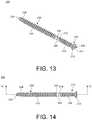
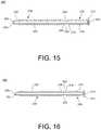
- FIG. 13is perspective side view of another implant, in accordance with an aspect of the present disclosure.
- FIG. 14is a side view of the implant of FIG. 13 , in accordance with an aspect of the present disclosure.
- FIG. 15is a first cross-sectional view of the implant of FIG. 13 taken along line 15 - 15 in FIG. 14 , in accordance with an aspect of the present disclosure
- FIG. 16is a second cross-sectional view of the implant of FIG. 13 taken along a longitudinal line perpendicular to line 15 - 15 in FIG. 14 , in accordance with an aspect of the present disclosure
- FIG. 17is a distal, transverse planar view of the bones of FIG. 8 with the implant of FIG. 13 inserted into the drilled opening with a driver instrument, in accordance with an aspect of the present disclosure
- FIG. 18is a distal, transverse planar view of the bones of FIG. 17 after removal of the driver instrument, in accordance with an aspect of the present disclosure
- FIG. 19is a posterior view of the tibia and fibula of FIG. 18 with the implant of FIG. 13 inserted through a plate, fibula, and into the tibia, in accordance with an aspect of the present disclosure
- FIG. 20is a side perspective view of one embodiment of an implant and removal instrument, in accordance with an aspect of the present disclosure.
- FIG. 21is a side perspective view of the implant and removal instrument of FIG. 20 in an engaged state, in accordance with an aspect of the present disclosure
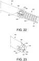
- FIG. 22is a side enlarged perspective view of a portion of the implant and removal instrument of FIG. 20 in an engaged state, in accordance with an aspect of the present disclosure.
- FIG. 23is a side enlarged perspective cross-sectional view of a portion of the implant and removal instrument of FIG. 20 in an engaged state, in accordance with an aspect of the present disclosure.
- proximal, distal, anterior or plantar, posterior or dorsal, medial, lateral, superior and inferiorare defined by their standard usage for indicating a particular part or portion of a bone or implant according to the relative disposition of the natural bone or directional terms of reference.
- proximalmeans the portion of a device or implant nearest the torso
- distalindicates the portion of the device or implant farthest from the torso.
- anterioris a direction towards the front side of the body
- posteriormeans a direction towards the back side of the body
- medialmeans towards the midline of the body
- lateralis a direction towards the sides or away from the midline of the body
- superiormeans a direction above and “inferior” means a direction below another object or structure.
- the term “dorsal”refers to the top of the foot and the term “plantar” refers the bottom of the foot.
- positions or directionsmay be used herein with reference to anatomical structures or surfaces.
- the bones of the foot, ankle and lower legmay be used to describe the surfaces, positions, directions or orientations of the implants, devices, instrumentation and methods.
- the implants, devices, instrumentation and methods, and the aspects, components, features and the like thereof, disclosed hereinare described with respect to one side of the body for brevity purposes.
- the implants, devices, instrumentation and methods, and the aspects, components, features and the like thereof, described and/or illustrated hereinmay be changed, varied, modified, reconfigured or otherwise altered for use or association with another side of the body for a same or similar purpose without departing from the spirit and scope of the invention.
- the implants, devices, instrumentation and methods, and the aspects, components, features and the like thereof, described herein with respect to the right legmay be mirrored so that they likewise function with the left leg.
- implants, devices, instrumentation and methods, and the aspects, components, features and the like thereof, disclosed hereinare described with respect to the leg for brevity purposes, but it should be understood that the implants, devices, instrumentation and methods may be used with other bones of the body having similar structures.
- implants 100 , 200 and 300there is illustrated implants 100 , 200 and 300 .
- the implants 100 , 200 and 300may be, for example, supportive enough to heal syndesmotic ligaments post-operatively.
- the implants 100 , 200 and 300may also, for example, selectively constrain motion in all directions to allow for the ligaments to heal. After the syndesmotic ligaments heal, the implants 100 , 200 and 300 allow for physiologic motion.
- the components of the implants 100 , 200 and 300may be made of, for example, titanium, stainless steel, polymers, and resorbable or time release materials.
- the implants 100 , 200 and 300also allow for screw-like implantation and temporary rigid fixation, then, after insertion, the implants 100 , 200 and 300 are designed to break away (e.g., fracture and/or dissolve) at a specific location after a plurality of loading cycles (e.g., a number of loading cycles that may differ according to load).
- the loading cyclesmay be a plurality of non-weight bearing and/or weight bearing loading cycles.
- the implants 100 , 200 and 300may be designed to fail (i.e., fracture or break) in fatigue at the breakaway portion.
- the implants 100 , 200 and 300may be designed to concentrate forces that are applied to the implants 100 , 200 and 300 (e.g., after implantation/in situ) at/to the breakaway portion such that failure (e.g., fatigue fracture) occurs at the at the breakaway portion.
- the breakaway portionmay comprise a circumferential groove. The temporary rigid fixation of the implants 100 , 200 and 300 gives the fixed joint time to stabilize through healing and then allows physiologic motion after breakaway (e.g., fracture and/or dissolve) of the breakaway portion.
- the breakaway locationis set in the space or gap between the fibula and tibia, where the subsequent risk of damage to native bone is lower.
- the surgical methodincludes drilling a hole through both the tibia and fibula and then inserting an implant 100 , 200 and 300 to fill the bone cavities to provide a stronger post-op construct.
- the implant 100includes a head member or fibula member 110 , an anchor member or tibia member 130 , and a breakaway portion or notch 102 positioned between the head member 110 and the anchor member 130 .
- the head member 110is coupled to the anchor member 130 by the breakaway portion 102 .
- the breakaway portion 102may be recessed into the exterior surface of the implant 100 to form a notch, groove, recess, necking or the like, as shown in FIGS. 1-3 .
- the implant 100may be, for example, a solid or one-piece construct, as shown in FIG. 3 .
- the implant 100may optionally include, for example, a cannulated opening or through hole (not shown) which extends the entire length of the implant 100 .
- the implant 100may have a length of, for example, approximately 40 mm to 70 mm.
- the length of the head member 110may remain constant and the length of the anchor member 130 may be variable to correspond to the varying size of a patient's bones 180 , 182 .
- the head member 110may, for example, be available in multiple lengths to correspond to the varying size of a patient's bones 180 , 182 and the length of the anchor member 130 may remain constant.
- both the head member 110 and the anchor member 130may be available in multiple lengths to allow for selection based on the size of the patient's bones 180 , 182 .
- the head member 110may have a length of, for example, between approximately 10 mm and 20 mm.
- the anchor member 130may have a length of, for example, between approximately 20 mm and 60 mm.
- the head member or fibula member 110may include a head or button portion 112 at a first end of the implant 100 and a shaft member or threaded portion 116 extending from the head 112 .
- the head 112may also include a tool engagement opening 114 positioned on a surface that is opposite the shaft member 116 , as shown in FIGS. 1 and 3 .
- the tool engagement opening 114may have a non-circular or multi-lobed shape, although other polygonal shapes are also contemplated, including a hexagonal shape or a hexalobular drive feature.
- the head member 110may also include a distal coupling portion 118 at a second end of the shaft member 116 opposite the head 112 .
- the distal coupling portion 118is connected to the breakaway notch 102 on a first side.
- the distal coupling portion 118may be, for example, a portion of the shaft member 116 which is smooth or lacks threads.
- the implant 100may be made of, for example, titanium, stainless steel, polymer, or another like material as known by one of ordinary skill in the art.
- the anchor member or tibia member 130may include a shaft portion or threaded portion 132 , as shown in FIGS. 1-4 .
- the shaft portion 132may include a distal end 134 at the second end of the implant 100 and the shaft portion 132 .
- the shaft portion 132may also include a proximal coupling portion 136 at a first end of the shaft portion 132 opposite the distal end 134 .
- the proximal coupling portion 136is connected to the breakaway portion 102 on a second side opposite the distal coupling portion 118 of the head member 110 .
- the proximal coupling portion 136may be, for example, a section of the shaft portion 132 which lacks threads and includes at least one lateral removal member 138 .
- the at least one lateral removal member 138may be, for example, an external hexagonal drive feature, as shown in FIGS. 1-7 .
- the anchor member 130may also include a distal feature or portion 152 positioned at the distal or second end 134 of the anchor member 130 adjacent to the distal end 134 .
- the distal portion 152may include surfaces for engaging an extraction instrument (not shown).
- the surfaces of the distal portion 152may form, for example, a hexagonal drive portion similar to the at least one lateral removal member 138 .
- the distal portion 152may further be, for example, a plurality of circumferentially spaced or arranged longitudinally extending flutes (e.g., cutting flutes) or teeth, as shown in FIGS. 1 and 2 .
- the distal feature or portion 152may comprise four (4) circumferentially spaced or arranged longitudinally extending flutes or indentations.
- the distal end 134 of the anchor member 130may also include, for example, an opening or recess 154 extending into the core of the anchor member 130 along the longitudinal axis of the implant 100 , as shown in FIG. 3 .
- the opening 154may be, for example, continuous or aligned with the cannulation.
- the breakaway portion 102may be, for example, a notch, groove, necking, or recess into the exterior surface of the implant 100 .
- the notch, groove, necking, or recessmay have, for example, a curved, rounded, or “V” shape.
- the breakaway portion 102may be, for example, a resorbable material or member positioned between and coupling the head member 110 to the anchor member 130 .
- the resorbable breakaway portion 102may include, for example, a notch, groove, necking, or recess with a curved, rounded or “V” shape or, alternatively, the resorbable breakaway portion 102 may be flush with the exterior surface of the distal coupling portion 118 and proximal coupling portion 136 .
- the resorbable breakaway portion 102may initially provide a connection between the head member 110 and anchor member 130 to constrain motion between the bones 180 , 182 . Then, once the resorbable breakaway portion 102 breaks down and resorbs into the patient, the head member 110 and anchor member 130 will be separated and motion between the bones 180 , 182 will no longer be constrained.
- the proximal end of the anchor member 130may be, for example, smooth or flat.
- the implant 100may have, for example, a breakaway feature ratio between the circumferential breakaway notch or groove of the breakaway portion 102 and the proximate portion of the distal coupling portion 118 and/or the proximal coupling portion 136 , such as a breakaway feature ratio within the range of 64% to 89%, and more preferably within the range of 75% to 82%. For example, as shown in FIG.
- the ratio of the (maximum) diameter D 1 of the circumferential breakaway notch or groove of the breakaway portion 102 to the (maximum) diameter D 2 of the proximate portion of the distal coupling portion 118 D 2 and/or the proximal coupling portion 136may be within the range of 64% to 89%, and more preferably within the range of 75% to 82%.
- the implant 100may be configured such that the stress applied to the implant 100 in situ is concentrated at/to the breakaway portion 102 (e.g., the circumferential groove thereof), and the breakaway portion 102 (e.g., the circumferential groove thereof) may be configured to fail (i.e., fracture) in fatigue due to such stresses.
- the circumferential groove of the breakaway portion 102may thereby define a (maximum) diameter D 1 that is less than a (maximum) diameter D 2 defined by a portion of the head member 130 positioned proximate to the breakaway portion 102 (e.g., the distal coupling portion 118 ) and/or a diameter defined by a portion of the anchor member 130 positioned proximate to the breakaway portion 102 (e.g., the proximal coupling portion 136 ), as shown in FIG. 3 .
- the breakaway portion 102may include, for example, an internal drive feature 140 for receiving an extraction instrument to remove the anchor member 130 .
- the internal drive feature 140may be, for example, a hexagonal or other multi-lobed drive opening 142 .
- the breakaway portion 102may also include, for example, at least one hole 144 .
- the at least one hole 144may be, for example, at least one through hole extending through the entire diameter of the implant 100 perpendicular to the longitudinal axis or alternatively, only through a portion of the implant 100 .
- the holes 144may be radially positioned, for example, between the distal coupling portion 118 of the head member 110 and the proximal coupling portion 136 of the anchor member 130 .
- the breakaway portion 102may include, for example, at least one channel 146 extending into the implant 100 from an exterior surface to form at least one blind hole, pocket or opening 148 .
- the breakaway portion 102 of FIG. 7may include an opening 150 positioned, for example, in the center of the anchor member 130 and extend into the anchor member 130 along the longitudinal axis of the implant 100 .
- the breakaway portion 102is designed or configured to fail at the precise location of the breakaway portion 102 .
- the materials and sizes of the implant 100are selected to withstand a desired torsional force, bending moment, etc. at the breakaway portion 102 .
- Alternative external and internal removal featuresthat allow for engagement of an extraction instrument to remove the anchor member 130 from a lateral side of the patient are also contemplated.
- the methodmay include positioning a plate 184 on a bone 182 , for example, a fibula, and driving a k-wire or guide wire 186 through two bones 180 , 182 , for example, a fibula 182 and tibia 180 , as shown in FIG. 8 .
- a drill 188may be inserted over the k-wire 186 by aligning a cannulated opening 190 in the drill 188 with the k-wire 186 .
- the drill 188may be used to drill an opening 192 through the bones 180 , 182 .
- the opening 192may have a diameter, for example, that corresponds to the minor diameter or shaft of the anchor member 130 .
- the drill 188 and k-wire 186may be removed from the bones 180 , 182 , as shown in FIG. 10 .
- measurements of the opening 192may be taken using a cannulated depth gauge (not shown) inserted over the k-wire 186 . Once the measurements are taken the k-wire 186 may then be removed.
- the k-wire 186may be removed from the bones 180 , 182 and a standard depth gauge (not shown) may be used to take the measurements.
- an overall or first measurement of the opening or drill hole 192may be taken using a cannulated depth gauge, standard depth gauge or other like instrument.
- the surgeonmay also take a second measurement of the portion of the opening 192 in the fibula using, for example, a standard depth gauge or like instrument, to determine the size of the head member 110 .
- a driver instrument(not shown) may be used to insert the implant 100 into the opening 192 in the bones 180 , 182 , as shown in FIG. 11 .
- the implant 100may be inserted to position the anchor member 130 in the tibia 180 , the head member 110 in the fibula 182 , and the breakaway notch 102 in a tibiofibular space or gap d, as shown in FIG. 11 .
- the space or gap dmay be, for example, approximately 3 mm.
- the torsional force applied to the head member 110 for inserting the implant 100may be transmitted to the anchor member 130 through the breakaway portion 102 .
- the driver instrument(not shown) may be removed from head member 110 of the implant 100 , as shown in FIG. 11 , and the surgical procedure may be completed.
- the breakaway portion 102will eventually fail or fracture leaving the head member 110 separated from the anchor member 130 and the motion between the tibia 180 and fibula 182 no longer constrained. Once the breakaway portion 102 fails the patient's physiologic motion is restored. Absent any further complications, the head member 110 and anchor member 130 may remain in the patient's fibula 182 and tibia 180 , respectively. However, if hardware removal is required, the head member 110 may be removed from the fibula 182 after the breakaway portion 102 fractures, as shown in FIG. 12 . In addition, if necessary, the anchor member 130 may be removed from the tibia 180 , as well. The anchor member 130 may be removed, for example, medially using the distal drive feature 152 or laterally using the lateral removal member 138 of the proximal coupling portion 136 .
- FIGS. 13-19illustrates another exemplary alternative implant 200 .
- the exemplary implant 200 of FIGS. 13-19is substantially similar to the exemplary implant 100 described above with respect to FIGS. 1-12 , and therefore like reference numerals preceded by the numeral “2,” as opposed to “1,” are used to indicate like elements, aspects, functions, actions, configurations and the like.
- the implant 200 of FIGS. 13-19may include any of the elements, aspects, functions, actions, configurations and the like of the implant 100 of FIGS. 1-12 .
- the description above directed thereto with respect to the implant 100 of FIGS. 1-12thereby equally applies to the exemplary implant 200 of FIGS. 13-19 , including description regarding alternative embodiments thereto (i.e., modifications, variations or the like).
- the implant 200includes a head member 210 , an anchor member 230 , and a breakaway portion or notch 204 positioned between the head member 210 and the anchor member 230 .
- the head member 210is coupled to the anchor member 230 by the intermediate breakaway portion 204 .
- the breakaway portion 204may include, for example, a notch, recess, necking, or groove with a curved, rounded or “V” shape, which may be recessed into the exterior surface of the implant 200 , as shown in FIGS. 13-16 .
- the breakaway portion 204may be, for example, a resorbable material or member positioned between and coupling the head member 210 to the anchor member 230 .
- the implant 200 with the resorbable material or membermay be, for example, integral with the head member 210 and anchor member 230 forming a one-piece construct or, alternatively, may be a three-piece construct coupled together to form the implant 200 .
- the resorbable breakaway portion 204may include, for example, a notch, groove, necking, or recess with a curved, rounded or “V” shape or, alternatively, the resorbable breakaway portion 204 may be flush with the exterior surface of the distal coupling portion 218 and proximal coupling portion 236 .
- the resorbable breakaway portion 204may initially provide a fixed connection between the head member 210 and anchor member 230 to constrain motion between the bones 180 , 182 . Once the resorbable breakaway portion 204 is resorbed into the patient, the head member 210 and anchor member 230 will be separated and motion between the bones 180 , 182 will no longer be constrained.
- the one piece implant 200may also include, for example, a cannulated opening or through hole 202 extending the entire length of the implant 200 , as shown in FIGS. 15 and 16 . It is also contemplated that the implant 200 may be, for example a solid implant without a central opening or an implant with a central opening that only extends along a portion of the length of the implant. The implant 200 may be, for example, approximately 40 mm to 70 mm long. In one embodiment, the length of the head member 210 may remain constant with the length of the anchor member 230 being available in multiple sizes to correspond to the varying sizes of a patient's bones 180 , 182 .
- the head member 210may, for example, be available in multiple lengths to correspond to the varying sizes of a patient's bones 180 , 182 with the corresponding length of the anchor member 230 remaining constant.
- both the head member 210 and the anchor member 230may be available in multiple lengths to allow for implant matching based on the size of the patient's bones 180 , 182 .
- the head member 210may have a length of, for example, between approximately 10 mm and 20 mm.
- the anchor member 230may have a length of, for example, between approximately 20 mm and 60 mm.
- the head member or fibula member 210may include a head or button portion 212 at a first end of the implant 200 and a shaft member or threaded portion 216 extending from the head 212 .
- the head 212may also include a tool engagement opening 214 positioned on a surface that is opposite the shaft member 216 , as shown in FIGS. 13, 15 and 16 .
- the tool engagement opening 214may have a multi-lobed shape, although other polygonal shapes are also contemplated, including a hexagonal shape or a hexalobular drive feature.
- the head member 210may also include a distal coupling portion 218 at a second end of the shaft member 216 opposite the head 212 .
- the distal coupling portion 218is connected to the breakaway portion 204 on a first side.
- the distal coupling portion 218may be, for example, a portion of the shaft member 216 which is smooth or lacks threads.
- the cannulated opening 202may extend through the head member 210 from the tool engagement opening 214 to the distal coupling portion 218 .
- the implant 200may be made of, for example, titanium, stainless steel, polymer, or another like material as known by one of ordinary skill in the art.
- the anchor member or tibia member 230may include a shaft portion or threaded portion 232 , as shown in FIGS. 12-15 .
- the shaft portion 232may include cutting end 234 at the second end of the implant 200 and the shaft portion 232 .
- the cutting end 234may include, for example, cutting flutes, teeth or the like.
- the shaft portion 232may also include a proximal coupling portion 236 at a first end of the shaft portion 232 opposite the cutting end 234 .
- the proximal coupling portion 236is connected to the breakaway portion 204 on a second side opposite the distal coupling portion 218 of the head member 210 .
- the proximal coupling portion 236may be, for example, a section of the shaft portion 232 which is smooth or lacks threads.
- the cannulated opening 202may extend through the anchor member 230 from the proximal coupling portion 236 to the cutting end 234 .
- the anchor member 230may also include a distal feature or portion 238 positioned at the second end of the anchor member 130 adjacent to the cutting end 234 .
- the distal feature 238may be, for example, a hexagonal drive feature.
- the methodmay include forming the opening 192 , as shown in FIGS. 8-10 and described in greater detail above with reference to implant 100 , which will not be described again here for brevity sake.
- the opening 192may be, for example, formed through an opening in a plate 184 positioned on the lateral aspect of the fibula 182 .
- the opening 192may be formed through the bones 180 , 182 without alignment with a plate 184 .
- the methodmay include inserting the implant 200 with a driver instrument 194 into the opening 192 in the bones 180 , 182 .
- the implant 200may be inserted to position the anchor member 230 in the tibia 180 , the head member 210 in the fibula 182 , and the breakaway portion 204 in a tibiofibular space or gap, as shown in FIG. 18 .
- the space or gap dmay be, for example, approximately 3 mm.
- the implant 200Immediately after surgery, the joint is supported by the rigid fixation of the implant 200 . Once sufficient healing has occurred to permit weight bearing on the limb of the patient, the implant 200 will break at the breakaway portion 204 . After the breakaway portion 204 fractures or breaks, physiologic motion between the tibia 180 and fibula 182 is restored and the implant 200 may remain in place. If the implant 200 does need to be removed, the drive feature 238 positioned on the second end of the anchor member 230 may be used to remove the anchor member 230 and the tool engagement opening 214 positioned on the first end of the head member 210 may be used to remove the head member 210 .
- FIGS. 20-23illustrates another exemplary alternative implant 300 .
- the exemplary implant 300 of FIGS. 20-23is substantially similar to the exemplary implant 100 of FIGS. 1-12 and/or the exemplary implant 200 of FIGS. 13-19 , and therefore like reference numerals preceded by the numeral “3,” as opposed to “1” or “2,” are used to indicate like elements, aspects, functions, actions, configurations and the like.
- the implant 300 of FIGS. 20-23may include any of the elements, aspects, functions, actions, configurations and the like of the implant 100 of FIGS. 1-12 and/or the implant 200 of FIGS. 13-19 .
- the description above directed thereto with respect to the implant 100 of FIGS. 1-12 and/or the implant 200 of FIGS. 13-19thereby equally applies to the exemplary implant 300 of FIGS. 20-23 , including description regarding alternative embodiments thereto (i.e., modifications, variations or the like).
- the shaft distal end 334 at the second end of the implant 300 and the shaft portion 332 of the anchor member 330may be relatively blunt or bullet-shaped.
- the shaft distal end 334may include a flat or planar distal surface oriented normal to the longitudinal axis and/or axis of rotation of the implant 300 .
- the anchor member 330 of the implant 300may also include a distal feature or portion 352 positioned at the distal or second end 334 of the anchor member 330 adjacent to, or extending from, the distal end 334 .
- the distal portion 352may comprise a plurality of circumferentially spaced or arranged longitudinally extending flutes, indentations or grooves.
- the distal feature or portion 352may comprise three (3) circumferentially spaced or arranged longitudinally extending flutes, indentations or grooves.
- the distal feature or portion 352may be configured to engage, mate or cooperate with an extraction instrument 395 , as shown in FIGS. 20-23 .
- the extraction instrument 395may be a medial extraction instrument.
- the extraction instrument 395may include an internal aperture or cavity 397 extending into a free end thereof.
- the end of the extraction instrument 395may also include a plurality of circumferentially spaced or arranged longitudinally extending projections, fingers or teeth 399 , as shown in FIGS. 20-23 . Gaps or spaces may circumferentially extend between adjacent projections 399 that are configured to accommodate the portions of the anchor member 330 that are void of the distal feature/grooves 352 .
- the number and configuration of the plurality of circumferentially arranged longitudinally extending projections 399may correspond to the circumferentially arranged longitudinally extending grooves of the distal feature or portion 352 .
- the plurality of circumferentially arranged longitudinally extending projections 399may be configured to engage (e.g., mate or otherwise extend within) the plurality of circumferentially spaced or arranged longitudinally extending grooves of the distal portion 352 .
- the end of the extraction instrument 395may engage over the distal end 334 and distal portion 352 of the implant 300 such that the distal end 334 (and potentially the distal portion 352 ) is positioned within the internal cavity 397 with the plurality of circumferentially arranged longitudinally extending projections 399 engaged or mated within the plurality of circumferentially arranged longitudinally extending grooves of the distal portion 352 , as shown in FIGS.
- the extraction instrument 395 and the implant 300may thereby be rotationally fixed or coupled together. In this way, the extraction instrument 395 may extend to the distal end 334 of the implant 300 and engage the distal portion 352 , and apply a torque thereto to axially or longitudally drive the implant, potentially after implantation. The extraction instrument 395 may thereby be utilized to remove the implant after implantation.
- the head member, anchor member, breakaway portion, and other components of the implant and/or system as disclosed in the specification, including the accompanying abstract and drawings,may be replaced by alternative component(s) or feature(s), such as those disclosed in another embodiment, which serve the same, equivalent or similar purpose as known by those skilled in the art to achieve the same, equivalent or similar results by such alternative component(s) or feature(s) to provide a similar function for the intended purpose.
- the implants and systemsmay include more or fewer components or features than the embodiments as described and illustrated herein.
- FIGS. 1-4, 11 and 12 , FIG. 5 , FIG. 6 , FIG. 7 , FIGS. 13-19 and FIGS. 20-23may all be used interchangeably and in alternative combinations as would be modified or altered by one of skill in the art. Accordingly, this detailed description of the currently-preferred embodiments is to be taken in an illustrative, as opposed to limiting of the invention.
- a method or device that “comprises,” “has,” “includes,” or “contains” one or more steps or elementspossesses those one or more steps or elements, but is not limited to possessing only those one or more steps or elements.
- a step of a method or an element of a device that “comprises,” “has,” “includes,” or “contains” one or more featurespossesses those one or more features, but is not limited to possessing only those one or more features.
- a device or structure that is configured in a certain wayis configured in at least that way, but may also be configured in ways that are not listed.
Landscapes
- Health & Medical Sciences (AREA)
- Orthopedic Medicine & Surgery (AREA)
- Life Sciences & Earth Sciences (AREA)
- Surgery (AREA)
- Veterinary Medicine (AREA)
- General Health & Medical Sciences (AREA)
- Public Health (AREA)
- Engineering & Computer Science (AREA)
- Biomedical Technology (AREA)
- Heart & Thoracic Surgery (AREA)
- Animal Behavior & Ethology (AREA)
- Molecular Biology (AREA)
- Medical Informatics (AREA)
- Nuclear Medicine, Radiotherapy & Molecular Imaging (AREA)
- Neurology (AREA)
- Oral & Maxillofacial Surgery (AREA)
- Dentistry (AREA)
- Rehabilitation Therapy (AREA)
- Rheumatology (AREA)
- Cardiology (AREA)
- Transplantation (AREA)
- Vascular Medicine (AREA)
- Prostheses (AREA)
Abstract
Description
Claims (20)
Priority Applications (1)
| Application Number | Priority Date | Filing Date | Title |
|---|---|---|---|
| US16/134,236US11179234B2 (en) | 2017-09-15 | 2018-09-18 | Ligament fixation system, implants, devices, and methods of use |
Applications Claiming Priority (3)
| Application Number | Priority Date | Filing Date | Title |
|---|---|---|---|
| US201762559047P | 2017-09-15 | 2017-09-15 | |
| PCT/US2018/051349WO2019055923A1 (en) | 2017-09-15 | 2018-09-17 | Ligament fixation system, implants, devices, and methods of use |
| US16/134,236US11179234B2 (en) | 2017-09-15 | 2018-09-18 | Ligament fixation system, implants, devices, and methods of use |
Related Parent Applications (1)
| Application Number | Title | Priority Date | Filing Date |
|---|---|---|---|
| PCT/US2018/051349ContinuationWO2019055923A1 (en) | 2017-09-15 | 2018-09-17 | Ligament fixation system, implants, devices, and methods of use |
Publications (2)
| Publication Number | Publication Date |
|---|---|
| US20190083232A1 US20190083232A1 (en) | 2019-03-21 |
| US11179234B2true US11179234B2 (en) | 2021-11-23 |
Family
ID=65719634
Family Applications (1)
| Application Number | Title | Priority Date | Filing Date |
|---|---|---|---|
| US16/134,236Active2039-02-23US11179234B2 (en) | 2017-09-15 | 2018-09-18 | Ligament fixation system, implants, devices, and methods of use |
Country Status (1)
| Country | Link |
|---|---|
| US (1) | US11179234B2 (en) |
Cited By (18)
| Publication number | Priority date | Publication date | Assignee | Title |
|---|---|---|---|---|
| US11376134B1 (en) | 2020-11-05 | 2022-07-05 | Warsaw Orthopedic, Inc. | Dual expanding spinal implant, system, and method of use |
| US11395743B1 (en) | 2021-05-04 | 2022-07-26 | Warsaw Orthopedic, Inc. | Externally driven expandable interbody and related methods |
| US11517363B2 (en) | 2020-11-05 | 2022-12-06 | Warsaw Orthopedic, Inc. | Screw driver and complimentary screws |
| US11517443B2 (en) | 2020-11-05 | 2022-12-06 | Warsaw Orthopedic, Inc. | Dual wedge expandable implant, system and method of use |
| US11612499B2 (en) | 2021-06-24 | 2023-03-28 | Warsaw Orthopedic, Inc. | Expandable interbody implant |
| US11638653B2 (en) | 2020-11-05 | 2023-05-02 | Warsaw Orthopedic, Inc. | Surgery instruments with a movable handle |
| US11806250B2 (en) | 2018-02-22 | 2023-11-07 | Warsaw Orthopedic, Inc. | Expandable spinal implant system and method of using same |
| US11833059B2 (en) | 2020-11-05 | 2023-12-05 | Warsaw Orthopedic, Inc. | Expandable inter-body device, expandable plate system, and associated methods |
| US11850163B2 (en) | 2022-02-01 | 2023-12-26 | Warsaw Orthopedic, Inc. | Interbody implant with adjusting shims |
| US11963881B2 (en) | 2020-11-05 | 2024-04-23 | Warsaw Orthopedic, Inc. | Expandable inter-body device, system, and method |
| US12121453B2 (en) | 2020-11-05 | 2024-10-22 | Warsaw Orthopedic, Inc. | Dual wedge expandable implant with eyelets, system, and method of use |
| US12171439B2 (en) | 2020-11-05 | 2024-12-24 | Warsaw Orthopedic, Inc. | Protected drill |
| US12239544B2 (en) | 2020-11-05 | 2025-03-04 | Warsaw Orthopedic, Inc. | Rhomboid shaped implants |
| US12268614B2 (en) | 2021-06-24 | 2025-04-08 | Warsaw Orthopedic, Inc. | Interbody implant with adjusting shims |
| US12295865B2 (en) | 2021-06-24 | 2025-05-13 | Warsaw Orthopedic, Inc. | Expandable interbody implant and corresponding inserter |
| US12318308B2 (en) | 2020-11-05 | 2025-06-03 | Warsaw Orthopedic, Inc. | Dual expandable inter-body device |
| US12414863B2 (en) | 2021-06-24 | 2025-09-16 | Warsaw Orthopedic, Inc. | Expandable interbody implant and corresponding surgical tool |
| US12440349B2 (en) | 2022-02-04 | 2025-10-14 | Warsaw Orthopedic, Inc. | Expandable interbody implant and breakoff screw |
Families Citing this family (9)
| Publication number | Priority date | Publication date | Assignee | Title |
|---|---|---|---|---|
| US11540866B2 (en) | 2017-03-29 | 2023-01-03 | Bone Solutions, Inc. | Implant of osteostimulative material |
| US11179234B2 (en) | 2017-09-15 | 2021-11-23 | Paragon 28, Inc. | Ligament fixation system, implants, devices, and methods of use |
| WO2019071273A1 (en) | 2017-10-06 | 2019-04-11 | Paragon 28, Inc. | Ligament fixation system, implants, devices, and methods of use |
| ES2955370T3 (en) | 2017-10-25 | 2023-11-30 | Paragon 28 Inc | Fixation system for ligaments, implants and devices with compression cap |
| US20190125420A1 (en)* | 2017-10-31 | 2019-05-02 | Bone Solutions, Inc. | Bioabsorbable Composite Screw |
| WO2019168663A1 (en)* | 2018-03-02 | 2019-09-06 | Scot Hodkiewicz | Pin fastener with removeable drill bit for bone fixator |
| CA3153728A1 (en)* | 2019-09-12 | 2021-03-18 | Paragon 28, Inc. | Dynamic fixation implant and method of use |
| US11660092B2 (en)* | 2020-09-29 | 2023-05-30 | Covidien Lp | Adapter for securing loading units to handle assemblies of surgical stapling instruments |
| US12076065B2 (en)* | 2021-02-05 | 2024-09-03 | Acumed Llc | Bone screw with reduced flank portion |
Citations (68)
| Publication number | Priority date | Publication date | Assignee | Title |
|---|---|---|---|---|
| US3953896A (en) | 1974-09-06 | 1976-05-04 | Richards Manufacturing Company, Inc. | Prosthetic ligament |
| US4463753A (en)* | 1980-01-04 | 1984-08-07 | Gustilo Ramon B | Compression bone screw |
| US4955910A (en) | 1989-07-17 | 1990-09-11 | Boehringer Mannheim Corporation | Fixation system for an elongated prosthesis |
| US5004474A (en) | 1989-11-28 | 1991-04-02 | Baxter International Inc. | Prosthetic anterior cruciate ligament design |
| US5061137A (en) | 1991-04-29 | 1991-10-29 | Ford Motor Company | Fastener with resilient linking means |
| US5152790A (en) | 1991-03-21 | 1992-10-06 | American Cyanamid Company | Ligament reconstruction graft anchor apparatus |
| US5507812A (en) | 1992-12-28 | 1996-04-16 | Moore; David E. | Modular prosthetic ligament |
| US5968045A (en) | 1997-10-14 | 1999-10-19 | Frazier; John K. | Intra-articular tendon sling fixation screw |
| US6187008B1 (en) | 1999-07-07 | 2001-02-13 | Bristol-Myers Squibb | Device for temporarily fixing bones |
| DE19943594A1 (en) | 1999-09-11 | 2001-04-12 | Merete Medical Gmbh | Bone screw, especially for comminuted fracture; has round countersunk head and partial thread segments spaced by shaft parts having breaking parts and has self-tapping grooves at shaft parts |
| DE10015734A1 (en) | 2000-03-02 | 2001-09-13 | Med Medical Engineering Dev Lt | Screw connection for osteosynthesis, e.g. to fix tibia head plate; has screw with conical head and ring, which can be moved in bearing ring, but is spread by screw head to fix angle of implant |
| US20020143333A1 (en) | 2001-03-30 | 2002-10-03 | Von Hoffmann Gerard | Method and apparatus for fixation of proximal femoral fractures |
| US6461373B2 (en) | 2000-05-26 | 2002-10-08 | Arthrex, Inc. | Biointerference screw fixation technique |
| US6652592B1 (en) | 1997-10-27 | 2003-11-25 | Regeneration Technologies, Inc. | Segmentally demineralized bone implant |
| US20040172032A1 (en) | 2002-09-06 | 2004-09-02 | Jackson Roger P. | Anti-splay medical implant closure with multi-surface removal aperture |
| US20050059972A1 (en) | 2003-09-16 | 2005-03-17 | Spineco, Inc., An Ohio Corporation | Bone anchor prosthesis and system |
| US6921402B2 (en) | 2001-12-27 | 2005-07-26 | Ethicon, Inc. | Polymer-based orthopedic screw and driver system with increased insertion torque tolerance and associated method for making and using same |
| WO2006124987A1 (en) | 2005-05-17 | 2006-11-23 | Smith & Nephew, Inc. | Axial compression fastener system |
| US7235091B2 (en) | 2002-06-20 | 2007-06-26 | Brian Thornes | Apparatus and method for fixation of ankle syndesmosis |
| US7235078B2 (en) | 2002-11-26 | 2007-06-26 | Hs West Investments Llc | Protective devices for use with angled interference screws |
| US20070162124A1 (en) | 2005-12-19 | 2007-07-12 | Whittaker Gregory R | Arthroscopic implants with integral fixation devices and method for use |
| US20070218750A1 (en) | 2006-03-17 | 2007-09-20 | Nexa Orthopedics, Inc. | Snap-off screw with recessed breakoff area |
| US20070282342A1 (en) | 2004-03-26 | 2007-12-06 | Alfred Niederberger | Articulated Bone Screw |
| US20090198287A1 (en) | 2008-02-04 | 2009-08-06 | Mark Hsien Nien Chiu | Bone fixation device and method of use thereof |
| US7608098B1 (en) | 2004-11-09 | 2009-10-27 | Biomet Sports Medicine, Llc | Bone fixation device |
| US7625395B2 (en) | 2001-06-21 | 2009-12-01 | Novoplant Gmbh | Implantable screw for stabilization of a joint or a bone fracture |
| US20090306777A1 (en) | 2005-03-31 | 2009-12-10 | Bachler Feintech Ag | Apparatus for fixing a ligament |
| US7727278B2 (en) | 2005-03-04 | 2010-06-01 | Rti Biologics, Inc. | Self fixing assembled bone-tendon-bone graft |
| WO2010121234A1 (en) | 2009-04-17 | 2010-10-21 | Hodge W Andrew | Internal joint bracing system and suture anchoring assembly therefore |
| GR20090100297A (en) | 2009-05-27 | 2010-12-21 | Ελευθεριος Σπυριδωνα Νικας | Screw or bolt for the syndesmosis between fibula and tibia |
| US20110040335A1 (en) | 2008-04-22 | 2011-02-17 | Synthes Usa, Llc | Bone fixation element with reduction tabs |
| US7955388B2 (en) | 2006-11-01 | 2011-06-07 | Acumed Llc | Orthopedic connector system |
| US20110184471A1 (en) | 2010-01-28 | 2011-07-28 | Warsaw Orthopedic, Inc. | Bone anchor with predetermined break point and removal features |
| US20120123474A1 (en) | 2010-11-17 | 2012-05-17 | Zajac Eric S | Adjustable suture-button construct for ankle syndesmosis repair |
| US20120150237A1 (en) | 2009-06-08 | 2012-06-14 | Z-Medical Gmbh & Co.Kg | Bone screw |
| US20120172936A1 (en)* | 2010-12-29 | 2012-07-05 | Tarsus Medical Inc. | Methods and devices for treating a syndesmosis injury |
| CN102670291A (en) | 2012-05-29 | 2012-09-19 | 开平市中心医院 | Inferior tibiofibular bolt elastic fixing device |
| US20120271416A1 (en) | 2011-04-25 | 2012-10-25 | Mackay Gordon M | Internal brace for tissue repairs and reinforcements |
| US20120303038A1 (en) | 2011-05-25 | 2012-11-29 | Oliviero Durante | Aiming device having radio-opaque markers |
| US20130030480A1 (en) | 2011-06-14 | 2013-01-31 | University Of South Florida | Systems and methods for ankle syndesmosis fixation |
| WO2013015754A1 (en) | 2011-05-11 | 2013-01-31 | Yilmaz Olday | Double compression screw |
| CN102920498A (en) | 2012-10-24 | 2013-02-13 | 高国栋 | Telescopic tibiofibular syndesmosis fastening screw |
| US8439976B2 (en) | 2009-03-31 | 2013-05-14 | Arthrex, Inc. | Integrated adjustable button-suture-graft construct with two fixation devices |
| US20130184708A1 (en) | 2010-08-29 | 2013-07-18 | Bonfix Ltd. | Orthopedic implant for treatment of bone deformities |
| US8597337B2 (en) | 2008-02-14 | 2013-12-03 | Lloyd P. Champagne | Joint fusion device |
| US20130338722A1 (en)* | 2010-07-07 | 2013-12-19 | Matthew Adam Yalizis | Compression bone screw |
| US20140025166A1 (en) | 2004-10-26 | 2014-01-23 | P Tech, Llc | Devices and methods for stabilizing tissue and implants |
| US8696719B2 (en) | 2010-06-03 | 2014-04-15 | Tarsus Medical Inc. | Methods and devices for treating hallux valgus |
| US8696716B2 (en) | 2007-08-02 | 2014-04-15 | Proactive Orthopedics, Llc | Fixation and alignment device and method used in orthopaedic surgery |
| US20140121711A1 (en) | 2011-06-06 | 2014-05-01 | Alexandre Worcel | Osteosynthesis device with plate and pins |
| US20140214095A1 (en) | 2011-09-30 | 2014-07-31 | The Trustees Of Columbia University In The City Of New York | Systems and devices for the reduction and association of bones |
| US20140228866A1 (en) | 2013-02-13 | 2014-08-14 | VentureMD Innovations, LLC | Method of Anchoring a Suture |
| US20140236237A1 (en)* | 2011-10-05 | 2014-08-21 | The University Of Akron | Reduced shock breakaway set screw for use with a surgical construct |
| US20140243977A1 (en) | 2011-04-16 | 2014-08-28 | Slobodan Tepic | Prosthetic System for Orthopedic Repair |
| US8864804B2 (en) | 2008-02-14 | 2014-10-21 | Lloyd P. Champagne | Bent dip fusion screw |
| US20150051601A1 (en) | 2013-08-15 | 2015-02-19 | DePuy Synthes Products, LLC | Apparatus and method for syndesmosis fixation |
| US20150073475A1 (en) | 2013-09-12 | 2015-03-12 | Michael Paul Schaller | Joint stability device and method |
| US9089371B1 (en) | 2014-09-19 | 2015-07-28 | Globus Medical Inc. | Orthopedic stabilization devices and methods for installation thereof |
| US20160045636A1 (en) | 2014-08-15 | 2016-02-18 | Tepha, Inc. | Self-retaining sutures of poly-4-hydroxybutyrate and copolymers thereof |
| WO2016133938A1 (en) | 2015-02-16 | 2016-08-25 | Akros Medical, Inc. | Devices, systems, and methods for semi-rigid bone fixation |
| US20160367303A1 (en) | 2013-12-13 | 2016-12-22 | The University Of Akron | Minimal shock set screw |
| US20170079698A1 (en) | 2015-07-13 | 2017-03-23 | IntraFuse, LLC | Flexible bone implant |
| US20170258572A1 (en) | 2016-03-13 | 2017-09-14 | Pontis Orthopaedics | Apparatus and method for repair of disruptions between bones |
| US20180092681A1 (en) | 2016-10-05 | 2018-04-05 | Bluewater Medical GmbH | Screw |
| US20180344374A1 (en) | 2017-06-05 | 2018-12-06 | Conmed Corporation | Flexible Screw |
| US20190083232A1 (en) | 2017-09-15 | 2019-03-21 | Paragon 28, Inc. | Ligament fixation system, implants, devices, and methods of use |
| US20190336270A1 (en) | 2017-10-06 | 2019-11-07 | Paragon 28, Inc. | Ligament fixation system, implants, devices, and methods of use |
| US20190336190A1 (en) | 2017-10-25 | 2019-11-07 | Paragon 28, Inc. | Ligament fixation system, implants, and devices with a compression cap, and methods of use |
- 2018
- 2018-09-18USUS16/134,236patent/US11179234B2/enactiveActive
Patent Citations (72)
| Publication number | Priority date | Publication date | Assignee | Title |
|---|---|---|---|---|
| US3953896A (en) | 1974-09-06 | 1976-05-04 | Richards Manufacturing Company, Inc. | Prosthetic ligament |
| US4463753A (en)* | 1980-01-04 | 1984-08-07 | Gustilo Ramon B | Compression bone screw |
| US4955910A (en) | 1989-07-17 | 1990-09-11 | Boehringer Mannheim Corporation | Fixation system for an elongated prosthesis |
| US5004474A (en) | 1989-11-28 | 1991-04-02 | Baxter International Inc. | Prosthetic anterior cruciate ligament design |
| US5152790A (en) | 1991-03-21 | 1992-10-06 | American Cyanamid Company | Ligament reconstruction graft anchor apparatus |
| US5061137A (en) | 1991-04-29 | 1991-10-29 | Ford Motor Company | Fastener with resilient linking means |
| US5507812A (en) | 1992-12-28 | 1996-04-16 | Moore; David E. | Modular prosthetic ligament |
| US5968045A (en) | 1997-10-14 | 1999-10-19 | Frazier; John K. | Intra-articular tendon sling fixation screw |
| US6652592B1 (en) | 1997-10-27 | 2003-11-25 | Regeneration Technologies, Inc. | Segmentally demineralized bone implant |
| US6187008B1 (en) | 1999-07-07 | 2001-02-13 | Bristol-Myers Squibb | Device for temporarily fixing bones |
| DE19943594A1 (en) | 1999-09-11 | 2001-04-12 | Merete Medical Gmbh | Bone screw, especially for comminuted fracture; has round countersunk head and partial thread segments spaced by shaft parts having breaking parts and has self-tapping grooves at shaft parts |
| DE10015734A1 (en) | 2000-03-02 | 2001-09-13 | Med Medical Engineering Dev Lt | Screw connection for osteosynthesis, e.g. to fix tibia head plate; has screw with conical head and ring, which can be moved in bearing ring, but is spread by screw head to fix angle of implant |
| US6461373B2 (en) | 2000-05-26 | 2002-10-08 | Arthrex, Inc. | Biointerference screw fixation technique |
| US20020143333A1 (en) | 2001-03-30 | 2002-10-03 | Von Hoffmann Gerard | Method and apparatus for fixation of proximal femoral fractures |
| US7625395B2 (en) | 2001-06-21 | 2009-12-01 | Novoplant Gmbh | Implantable screw for stabilization of a joint or a bone fracture |
| US6921402B2 (en) | 2001-12-27 | 2005-07-26 | Ethicon, Inc. | Polymer-based orthopedic screw and driver system with increased insertion torque tolerance and associated method for making and using same |
| US7235091B2 (en) | 2002-06-20 | 2007-06-26 | Brian Thornes | Apparatus and method for fixation of ankle syndesmosis |
| US20040172032A1 (en) | 2002-09-06 | 2004-09-02 | Jackson Roger P. | Anti-splay medical implant closure with multi-surface removal aperture |
| US7235078B2 (en) | 2002-11-26 | 2007-06-26 | Hs West Investments Llc | Protective devices for use with angled interference screws |
| US20050059972A1 (en) | 2003-09-16 | 2005-03-17 | Spineco, Inc., An Ohio Corporation | Bone anchor prosthesis and system |
| US20070282342A1 (en) | 2004-03-26 | 2007-12-06 | Alfred Niederberger | Articulated Bone Screw |
| US20140025166A1 (en) | 2004-10-26 | 2014-01-23 | P Tech, Llc | Devices and methods for stabilizing tissue and implants |
| US7608098B1 (en) | 2004-11-09 | 2009-10-27 | Biomet Sports Medicine, Llc | Bone fixation device |
| US7727278B2 (en) | 2005-03-04 | 2010-06-01 | Rti Biologics, Inc. | Self fixing assembled bone-tendon-bone graft |
| US20090306777A1 (en) | 2005-03-31 | 2009-12-10 | Bachler Feintech Ag | Apparatus for fixing a ligament |
| WO2006124987A1 (en) | 2005-05-17 | 2006-11-23 | Smith & Nephew, Inc. | Axial compression fastener system |
| US20150081019A1 (en) | 2005-12-19 | 2015-03-19 | Depuy Mitek, Llc | Arthroscopic implants with integral fixation devices and method for use |
| US20070162124A1 (en) | 2005-12-19 | 2007-07-12 | Whittaker Gregory R | Arthroscopic implants with integral fixation devices and method for use |
| US20070218750A1 (en) | 2006-03-17 | 2007-09-20 | Nexa Orthopedics, Inc. | Snap-off screw with recessed breakoff area |
| US7955388B2 (en) | 2006-11-01 | 2011-06-07 | Acumed Llc | Orthopedic connector system |
| US8696716B2 (en) | 2007-08-02 | 2014-04-15 | Proactive Orthopedics, Llc | Fixation and alignment device and method used in orthopaedic surgery |
| US20090198287A1 (en) | 2008-02-04 | 2009-08-06 | Mark Hsien Nien Chiu | Bone fixation device and method of use thereof |
| US8597337B2 (en) | 2008-02-14 | 2013-12-03 | Lloyd P. Champagne | Joint fusion device |
| US8864804B2 (en) | 2008-02-14 | 2014-10-21 | Lloyd P. Champagne | Bent dip fusion screw |
| US20110040335A1 (en) | 2008-04-22 | 2011-02-17 | Synthes Usa, Llc | Bone fixation element with reduction tabs |
| US8439976B2 (en) | 2009-03-31 | 2013-05-14 | Arthrex, Inc. | Integrated adjustable button-suture-graft construct with two fixation devices |
| WO2010121234A1 (en) | 2009-04-17 | 2010-10-21 | Hodge W Andrew | Internal joint bracing system and suture anchoring assembly therefore |
| GR20090100297A (en) | 2009-05-27 | 2010-12-21 | Ελευθεριος Σπυριδωνα Νικας | Screw or bolt for the syndesmosis between fibula and tibia |
| US20120150237A1 (en) | 2009-06-08 | 2012-06-14 | Z-Medical Gmbh & Co.Kg | Bone screw |
| US20110184471A1 (en) | 2010-01-28 | 2011-07-28 | Warsaw Orthopedic, Inc. | Bone anchor with predetermined break point and removal features |
| US8696719B2 (en) | 2010-06-03 | 2014-04-15 | Tarsus Medical Inc. | Methods and devices for treating hallux valgus |
| US20130338722A1 (en)* | 2010-07-07 | 2013-12-19 | Matthew Adam Yalizis | Compression bone screw |
| US20130184708A1 (en) | 2010-08-29 | 2013-07-18 | Bonfix Ltd. | Orthopedic implant for treatment of bone deformities |
| US20120123474A1 (en) | 2010-11-17 | 2012-05-17 | Zajac Eric S | Adjustable suture-button construct for ankle syndesmosis repair |
| US9138219B2 (en) | 2010-12-29 | 2015-09-22 | Tarsus Medical Inc. | Methods and devices for treating a syndesmosis injury |
| US20120172936A1 (en)* | 2010-12-29 | 2012-07-05 | Tarsus Medical Inc. | Methods and devices for treating a syndesmosis injury |
| US20140243977A1 (en) | 2011-04-16 | 2014-08-28 | Slobodan Tepic | Prosthetic System for Orthopedic Repair |
| US20120271416A1 (en) | 2011-04-25 | 2012-10-25 | Mackay Gordon M | Internal brace for tissue repairs and reinforcements |
| WO2013015754A1 (en) | 2011-05-11 | 2013-01-31 | Yilmaz Olday | Double compression screw |
| US20120303038A1 (en) | 2011-05-25 | 2012-11-29 | Oliviero Durante | Aiming device having radio-opaque markers |
| US20140121711A1 (en) | 2011-06-06 | 2014-05-01 | Alexandre Worcel | Osteosynthesis device with plate and pins |
| US20130030480A1 (en) | 2011-06-14 | 2013-01-31 | University Of South Florida | Systems and methods for ankle syndesmosis fixation |
| US20140214095A1 (en) | 2011-09-30 | 2014-07-31 | The Trustees Of Columbia University In The City Of New York | Systems and devices for the reduction and association of bones |
| US9907576B2 (en)* | 2011-10-05 | 2018-03-06 | The University Of Akron | Reduced shock breakaway set screw for use with a surgical construct |
| US20140236237A1 (en)* | 2011-10-05 | 2014-08-21 | The University Of Akron | Reduced shock breakaway set screw for use with a surgical construct |
| CN102670291A (en) | 2012-05-29 | 2012-09-19 | 开平市中心医院 | Inferior tibiofibular bolt elastic fixing device |
| CN102920498A (en) | 2012-10-24 | 2013-02-13 | 高国栋 | Telescopic tibiofibular syndesmosis fastening screw |
| US20140228866A1 (en) | 2013-02-13 | 2014-08-14 | VentureMD Innovations, LLC | Method of Anchoring a Suture |
| US20150051601A1 (en) | 2013-08-15 | 2015-02-19 | DePuy Synthes Products, LLC | Apparatus and method for syndesmosis fixation |
| US20150073475A1 (en) | 2013-09-12 | 2015-03-12 | Michael Paul Schaller | Joint stability device and method |
| US20160367303A1 (en) | 2013-12-13 | 2016-12-22 | The University Of Akron | Minimal shock set screw |
| US20160045636A1 (en) | 2014-08-15 | 2016-02-18 | Tepha, Inc. | Self-retaining sutures of poly-4-hydroxybutyrate and copolymers thereof |
| US9089371B1 (en) | 2014-09-19 | 2015-07-28 | Globus Medical Inc. | Orthopedic stabilization devices and methods for installation thereof |
| WO2016133938A1 (en) | 2015-02-16 | 2016-08-25 | Akros Medical, Inc. | Devices, systems, and methods for semi-rigid bone fixation |
| US20160287302A1 (en) | 2015-02-16 | 2016-10-06 | Akros Medical, Inc. | Devices, systems, and methods for semi-rigid bone fixation |
| US20170079698A1 (en) | 2015-07-13 | 2017-03-23 | IntraFuse, LLC | Flexible bone implant |
| US20170258572A1 (en) | 2016-03-13 | 2017-09-14 | Pontis Orthopaedics | Apparatus and method for repair of disruptions between bones |
| US20180092681A1 (en) | 2016-10-05 | 2018-04-05 | Bluewater Medical GmbH | Screw |
| US20180344374A1 (en) | 2017-06-05 | 2018-12-06 | Conmed Corporation | Flexible Screw |
| US20190083232A1 (en) | 2017-09-15 | 2019-03-21 | Paragon 28, Inc. | Ligament fixation system, implants, devices, and methods of use |
| US20190336270A1 (en) | 2017-10-06 | 2019-11-07 | Paragon 28, Inc. | Ligament fixation system, implants, devices, and methods of use |
| US20190336190A1 (en) | 2017-10-25 | 2019-11-07 | Paragon 28, Inc. | Ligament fixation system, implants, and devices with a compression cap, and methods of use |
Non-Patent Citations (8)
| Title |
|---|
| "Interventional procedure overview of suture fixation of acute disruption of the distal tibiofibular syndesmosis," National Institute for Health and Care Excellence, www.nice.org.uk, 43 pages, Jul. 2014. |
| Extended European Search Report issued in European Patent Application No. 18856721.8, dated May 4, 2021, 8 pages. |
| International Preliminary Report on Patentability for International Application No. PCT/US2018/051349, dated Mar. 17, 2020, 5 pages, International Bureau of WIPO. |
| International Search Report and Written Opinion of the International Searching Authority for PCT/US2018/051349, dated Dec. 3, 2018, 7 pages. |
| International Search Report and Written Opinion of the International Searching Authority for PCT/US2020/050438, dated Dec. 10, 2020, 8 pages. |
| Partial Supplementary European Search Report issued in European Patent Application No. 18870486.0 dated Jun. 23, 2021, 13 pages. |
| Porucznik, "Screw vs. tightrope fixation for syndesmotic fractures," AAOS NOW, http://www.aaos.org/news/aaosnow/may08/clinical4.asp, 3 pages, May 2008. |
| Xu et al., "Flexible fixation of syndesmotic diastasis using the assembled bolt-tightrope system," Scandinavian Journal of Trauma, Resuscitation and Emergency Medicine, vol. 21(71), 9 pages, 2013. |
Cited By (24)
| Publication number | Priority date | Publication date | Assignee | Title |
|---|---|---|---|---|
| US11806250B2 (en) | 2018-02-22 | 2023-11-07 | Warsaw Orthopedic, Inc. | Expandable spinal implant system and method of using same |
| US12036132B2 (en) | 2018-02-22 | 2024-07-16 | Warsaw Orthopedic, Inc. | Expandable spinal implant system and method of using same |
| US11969196B2 (en) | 2020-11-05 | 2024-04-30 | Warsaw Orthopedic, Inc. | Expandable inter-body device, system, and method |
| US11833059B2 (en) | 2020-11-05 | 2023-12-05 | Warsaw Orthopedic, Inc. | Expandable inter-body device, expandable plate system, and associated methods |
| US11564724B2 (en) | 2020-11-05 | 2023-01-31 | Warsaw Orthopedic, Inc. | Expandable inter-body device, system and method |
| US12364529B2 (en) | 2020-11-05 | 2025-07-22 | Warsaw Orthopedic, Inc. | Expandable inter-body device, system, and method |
| US11617658B2 (en) | 2020-11-05 | 2023-04-04 | Warsaw Orthopedic, Inc. | Expandable inter-body device, system and method |
| US11638653B2 (en) | 2020-11-05 | 2023-05-02 | Warsaw Orthopedic, Inc. | Surgery instruments with a movable handle |
| US11517363B2 (en) | 2020-11-05 | 2022-12-06 | Warsaw Orthopedic, Inc. | Screw driver and complimentary screws |
| US12239544B2 (en) | 2020-11-05 | 2025-03-04 | Warsaw Orthopedic, Inc. | Rhomboid shaped implants |
| US12318308B2 (en) | 2020-11-05 | 2025-06-03 | Warsaw Orthopedic, Inc. | Dual expandable inter-body device |
| US12053392B2 (en) | 2020-11-05 | 2024-08-06 | Warsaw Orthopedic, Inc. | Expandable inter-body device, expandable plate system, and associated methods |
| US11517443B2 (en) | 2020-11-05 | 2022-12-06 | Warsaw Orthopedic, Inc. | Dual wedge expandable implant, system and method of use |
| US11376134B1 (en) | 2020-11-05 | 2022-07-05 | Warsaw Orthopedic, Inc. | Dual expanding spinal implant, system, and method of use |
| US11963881B2 (en) | 2020-11-05 | 2024-04-23 | Warsaw Orthopedic, Inc. | Expandable inter-body device, system, and method |
| US12121453B2 (en) | 2020-11-05 | 2024-10-22 | Warsaw Orthopedic, Inc. | Dual wedge expandable implant with eyelets, system, and method of use |
| US12171439B2 (en) | 2020-11-05 | 2024-12-24 | Warsaw Orthopedic, Inc. | Protected drill |
| US11395743B1 (en) | 2021-05-04 | 2022-07-26 | Warsaw Orthopedic, Inc. | Externally driven expandable interbody and related methods |
| US12268614B2 (en) | 2021-06-24 | 2025-04-08 | Warsaw Orthopedic, Inc. | Interbody implant with adjusting shims |
| US12295865B2 (en) | 2021-06-24 | 2025-05-13 | Warsaw Orthopedic, Inc. | Expandable interbody implant and corresponding inserter |
| US11612499B2 (en) | 2021-06-24 | 2023-03-28 | Warsaw Orthopedic, Inc. | Expandable interbody implant |
| US12414863B2 (en) | 2021-06-24 | 2025-09-16 | Warsaw Orthopedic, Inc. | Expandable interbody implant and corresponding surgical tool |
| US11850163B2 (en) | 2022-02-01 | 2023-12-26 | Warsaw Orthopedic, Inc. | Interbody implant with adjusting shims |
| US12440349B2 (en) | 2022-02-04 | 2025-10-14 | Warsaw Orthopedic, Inc. | Expandable interbody implant and breakoff screw |
Also Published As
| Publication number | Publication date |
|---|---|
| US20190083232A1 (en) | 2019-03-21 |
Similar Documents
| Publication | Publication Date | Title |
|---|---|---|
| US11179234B2 (en) | Ligament fixation system, implants, devices, and methods of use | |
| US11786282B2 (en) | Ligament fixation system, implants, and devices with a compression cap, and methods of use | |
| US12290294B2 (en) | Bone fixation assembly, implants and methods of use | |
| US10492838B2 (en) | Flexible bone implant | |
| US20170189085A1 (en) | Flexible intramedullary nail | |
| US12161546B2 (en) | Ligament fixation system, implants, devices, and methods of use | |
| US20080208261A1 (en) | Method of using an intramedullary implant for fracture fixation | |
| CA2904487A1 (en) | Devices and methods for bone anchoring | |
| US10772733B2 (en) | Implants and methods of use and assembly | |
| AU2019301165B2 (en) | Implants, alignment guides, systems and methods of use | |
| US20250241742A1 (en) | Dynamic fixation implant and method of use | |
| US20170056077A1 (en) | Flexible bone screw | |
| JP2020523114A (en) | Adjustable orthopedic instrument | |
| WO2008039405A2 (en) | Interlocking nail geometry and method of use | |
| JP2023105819A (en) | Systems and methods for intramedullary nail implantation | |
| WO2019055923A1 (en) | Ligament fixation system, implants, devices, and methods of use | |
| AU2013248171A1 (en) | Modular lag screw |
Legal Events
| Date | Code | Title | Description |
|---|---|---|---|
| FEPP | Fee payment procedure | Free format text:ENTITY STATUS SET TO UNDISCOUNTED (ORIGINAL EVENT CODE: BIG.); ENTITY STATUS OF PATENT OWNER: SMALL ENTITY | |
| FEPP | Fee payment procedure | Free format text:ENTITY STATUS SET TO SMALL (ORIGINAL EVENT CODE: SMAL); ENTITY STATUS OF PATENT OWNER: SMALL ENTITY | |
| AS | Assignment | Owner name:PARAGON 28, INC., COLORADO Free format text:ASSIGNMENT OF ASSIGNORS INTEREST;ASSIGNORS:DACOSTA, ALBERT;GILL, SEAN;MLADINICH, PETER ANDREW;AND OTHERS;SIGNING DATES FROM 20180921 TO 20180925;REEL/FRAME:047125/0613 | |
| STPP | Information on status: patent application and granting procedure in general | Free format text:DOCKETED NEW CASE - READY FOR EXAMINATION | |
| STPP | Information on status: patent application and granting procedure in general | Free format text:NON FINAL ACTION MAILED | |
| STPP | Information on status: patent application and granting procedure in general | Free format text:RESPONSE TO NON-FINAL OFFICE ACTION ENTERED AND FORWARDED TO EXAMINER | |
| AS | Assignment | Owner name:ZIONS BANCORPORATION, N.A. DBA VECTRA BANK COLORADO, COLORADO Free format text:SECURITY INTEREST;ASSIGNOR:PARAGON 28, INC.;REEL/FRAME:054484/0600 Effective date:20201119 | |
| STPP | Information on status: patent application and granting procedure in general | Free format text:FINAL REJECTION MAILED | |
| STPP | Information on status: patent application and granting procedure in general | Free format text:RESPONSE AFTER FINAL ACTION FORWARDED TO EXAMINER | |
| STPP | Information on status: patent application and granting procedure in general | Free format text:NOTICE OF ALLOWANCE MAILED -- APPLICATION RECEIVED IN OFFICE OF PUBLICATIONS | |
| AS | Assignment | Owner name:PARAGON 28, INC., COLORADO Free format text:RELEASE BY SECURED PARTY;ASSIGNOR:ZIONS BANCORPORATION, N.A. DBA VECTRA BANK COLORADO, AS SUCCESSOR-BY-MERGER TO ZB, N.A. DBA VECTRA BANK COLORADO;REEL/FRAME:056320/0224 Effective date:20210506 Owner name:MIDCAP FINANCIAL TRUST, AS ADMINISTRATIVE AGENT, MARYLAND Free format text:SECURITY INTEREST (REVOLVING);ASSIGNOR:PARAGON 28, INC.;REEL/FRAME:056320/0316 Effective date:20210506 Owner name:MIDCAP FINANCIAL TRUST, AS ADMINISTRATIVE AGENT, MARYLAND Free format text:SECURITY INTEREST (TERM);ASSIGNOR:PARAGON 28, INC.;REEL/FRAME:056320/0335 Effective date:20210506 | |
| STPP | Information on status: patent application and granting procedure in general | Free format text:NOTICE OF ALLOWANCE MAILED -- APPLICATION RECEIVED IN OFFICE OF PUBLICATIONS | |
| STPP | Information on status: patent application and granting procedure in general | Free format text:DOCKETED NEW CASE - READY FOR EXAMINATION | |
| STPP | Information on status: patent application and granting procedure in general | Free format text:NOTICE OF ALLOWANCE MAILED -- APPLICATION RECEIVED IN OFFICE OF PUBLICATIONS | |
| STPP | Information on status: patent application and granting procedure in general | Free format text:PUBLICATIONS -- ISSUE FEE PAYMENT VERIFIED | |
| STCF | Information on status: patent grant | Free format text:PATENTED CASE | |
| AS | Assignment | Owner name:ARES CAPITAL CORPORATION, NEW YORK Free format text:SECURITY INTEREST;ASSIGNORS:PARAGON 28, INC.;PARAGON ADVANCED TECHNOLOGIES, INC.;REEL/FRAME:065448/0214 Effective date:20231102 | |
| AS | Assignment | Owner name:PARAGON 28, INC., COLORADO Free format text:RELEASE OF INTELLECTUAL PROPERTY SECURITY INTEREST AT REEL/FRAME NO. 56320/0316;ASSIGNOR:MIDCAP FINANCIAL TRUST, AS AGENT;REEL/FRAME:065548/0338 Effective date:20231102 Owner name:PARAGON 28, INC., COLORADO Free format text:RELEASE OF INTELLECTUAL PROPERTY SECURITY INTEREST AT REEL/FRAME NO. 56320/0335;ASSIGNOR:MIDCAP FINANCIAL TRUST, AS AGENT;REEL/FRAME:065548/0284 Effective date:20231102 | |
| AS | Assignment | Owner name:PARAGON ADVANCED TECHNOLOGIES, INC., COLORADO Free format text:RELEASE BY SECURED PARTY;ASSIGNOR:ARES CAPITAL CORPORATION;REEL/FRAME:070908/0038 Effective date:20250421 Owner name:PARAGON 28, INC., COLORADO Free format text:RELEASE BY SECURED PARTY;ASSIGNOR:ARES CAPITAL CORPORATION;REEL/FRAME:070908/0038 Effective date:20250421 | |
| MAFP | Maintenance fee payment | Free format text:PAYMENT OF MAINTENANCE FEE, 4TH YR, SMALL ENTITY (ORIGINAL EVENT CODE: M2551); ENTITY STATUS OF PATENT OWNER: SMALL ENTITY Year of fee payment:4 |