US11179203B2 - Position-tracking-enabling connector for an ear-nose-throat (ENT) tool - Google Patents
Position-tracking-enabling connector for an ear-nose-throat (ENT) toolDownload PDFInfo
- Publication number
- US11179203B2 US11179203B2US15/795,169US201715795169AUS11179203B2US 11179203 B2US11179203 B2US 11179203B2US 201715795169 AUS201715795169 AUS 201715795169AUS 11179203 B2US11179203 B2US 11179203B2
- Authority
- US
- United States
- Prior art keywords
- connector
- tracking
- medical instrument
- ent
- position sensor
- Prior art date
- Legal status (The legal status is an assumption and is not a legal conclusion. Google has not performed a legal analysis and makes no representation as to the accuracy of the status listed.)
- Active, expires
Links
Images


Classifications
- A—HUMAN NECESSITIES
- A61—MEDICAL OR VETERINARY SCIENCE; HYGIENE
- A61B—DIAGNOSIS; SURGERY; IDENTIFICATION
- A61B34/00—Computer-aided surgery; Manipulators or robots specially adapted for use in surgery
- A61B34/20—Surgical navigation systems; Devices for tracking or guiding surgical instruments, e.g. for frameless stereotaxis
- A—HUMAN NECESSITIES
- A61—MEDICAL OR VETERINARY SCIENCE; HYGIENE
- A61B—DIAGNOSIS; SURGERY; IDENTIFICATION
- A61B17/00—Surgical instruments, devices or methods
- A61B17/24—Surgical instruments, devices or methods for use in the oral cavity, larynx, bronchial passages or nose; Tongue scrapers
- A—HUMAN NECESSITIES
- A61—MEDICAL OR VETERINARY SCIENCE; HYGIENE
- A61B—DIAGNOSIS; SURGERY; IDENTIFICATION
- A61B5/00—Measuring for diagnostic purposes; Identification of persons
- A61B5/06—Devices, other than using radiation, for detecting or locating foreign bodies ; Determining position of diagnostic devices within or on the body of the patient
- A61B5/061—Determining position of a probe within the body employing means separate from the probe, e.g. sensing internal probe position employing impedance electrodes on the surface of the body
- A61B5/062—Determining position of a probe within the body employing means separate from the probe, e.g. sensing internal probe position employing impedance electrodes on the surface of the body using magnetic field
- A—HUMAN NECESSITIES
- A61—MEDICAL OR VETERINARY SCIENCE; HYGIENE
- A61B—DIAGNOSIS; SURGERY; IDENTIFICATION
- A61B90/00—Instruments, implements or accessories specially adapted for surgery or diagnosis and not covered by any of the groups A61B1/00 - A61B50/00, e.g. for luxation treatment or for protecting wound edges
- A61B90/90—Identification means for patients or instruments, e.g. tags
- A61B90/98—Identification means for patients or instruments, e.g. tags using electromagnetic means, e.g. transponders
- G—PHYSICS
- G06—COMPUTING OR CALCULATING; COUNTING
- G06F—ELECTRIC DIGITAL DATA PROCESSING
- G06F21/00—Security arrangements for protecting computers, components thereof, programs or data against unauthorised activity
- G06F21/10—Protecting distributed programs or content, e.g. vending or licensing of copyrighted material ; Digital rights management [DRM]
- A—HUMAN NECESSITIES
- A61—MEDICAL OR VETERINARY SCIENCE; HYGIENE
- A61B—DIAGNOSIS; SURGERY; IDENTIFICATION
- A61B17/00—Surgical instruments, devices or methods
- A61B2017/00017—Electrical control of surgical instruments
- A61B2017/00199—Electrical control of surgical instruments with a console, e.g. a control panel with a display
- A—HUMAN NECESSITIES
- A61—MEDICAL OR VETERINARY SCIENCE; HYGIENE
- A61B—DIAGNOSIS; SURGERY; IDENTIFICATION
- A61B17/00—Surgical instruments, devices or methods
- A61B2017/00477—Coupling
- A61B2017/00482—Coupling with a code
- A—HUMAN NECESSITIES
- A61—MEDICAL OR VETERINARY SCIENCE; HYGIENE
- A61B—DIAGNOSIS; SURGERY; IDENTIFICATION
- A61B34/00—Computer-aided surgery; Manipulators or robots specially adapted for use in surgery
- A61B34/20—Surgical navigation systems; Devices for tracking or guiding surgical instruments, e.g. for frameless stereotaxis
- A61B2034/2046—Tracking techniques
- A61B2034/2051—Electromagnetic tracking systems
- A—HUMAN NECESSITIES
- A61—MEDICAL OR VETERINARY SCIENCE; HYGIENE
- A61B—DIAGNOSIS; SURGERY; IDENTIFICATION
- A61B34/00—Computer-aided surgery; Manipulators or robots specially adapted for use in surgery
- A61B34/20—Surgical navigation systems; Devices for tracking or guiding surgical instruments, e.g. for frameless stereotaxis
- A61B2034/2046—Tracking techniques
- A61B2034/2059—Mechanical position encoders
- A—HUMAN NECESSITIES
- A61—MEDICAL OR VETERINARY SCIENCE; HYGIENE
- A61B—DIAGNOSIS; SURGERY; IDENTIFICATION
- A61B90/00—Instruments, implements or accessories specially adapted for surgery or diagnosis and not covered by any of the groups A61B1/00 - A61B50/00, e.g. for luxation treatment or for protecting wound edges
- A61B90/08—Accessories or related features not otherwise provided for
- A61B2090/0803—Counting the number of times an instrument is used
- A—HUMAN NECESSITIES
- A61—MEDICAL OR VETERINARY SCIENCE; HYGIENE
- A61B—DIAGNOSIS; SURGERY; IDENTIFICATION
- A61B90/00—Instruments, implements or accessories specially adapted for surgery or diagnosis and not covered by any of the groups A61B1/00 - A61B50/00, e.g. for luxation treatment or for protecting wound edges
- A61B90/08—Accessories or related features not otherwise provided for
- A61B2090/0814—Preventing re-use
- A—HUMAN NECESSITIES
- A61—MEDICAL OR VETERINARY SCIENCE; HYGIENE
- A61B—DIAGNOSIS; SURGERY; IDENTIFICATION
- A61B2560/00—Constructional details of operational features of apparatus; Accessories for medical measuring apparatus
- A61B2560/02—Operational features
- A61B2560/0266—Operational features for monitoring or limiting apparatus function
- A61B2560/028—Arrangements to prevent overuse, e.g. by counting the number of uses
- A—HUMAN NECESSITIES
- A61—MEDICAL OR VETERINARY SCIENCE; HYGIENE
- A61B—DIAGNOSIS; SURGERY; IDENTIFICATION
- A61B2562/00—Details of sensors; Constructional details of sensor housings or probes; Accessories for sensors
- A61B2562/08—Sensors provided with means for identification, e.g. barcodes or memory chips
- A—HUMAN NECESSITIES
- A61—MEDICAL OR VETERINARY SCIENCE; HYGIENE
- A61B—DIAGNOSIS; SURGERY; IDENTIFICATION
- A61B2562/00—Details of sensors; Constructional details of sensor housings or probes; Accessories for sensors
- A61B2562/22—Arrangements of medical sensors with cables or leads; Connectors or couplings specifically adapted for medical sensors
- A61B2562/225—Connectors or couplings
- A61B2562/227—Sensors with electrical connectors
- A—HUMAN NECESSITIES
- A61—MEDICAL OR VETERINARY SCIENCE; HYGIENE
- A61B—DIAGNOSIS; SURGERY; IDENTIFICATION
- A61B5/00—Measuring for diagnostic purposes; Identification of persons
- A61B5/06—Devices, other than using radiation, for detecting or locating foreign bodies ; Determining position of diagnostic devices within or on the body of the patient
- A61B5/065—Determining position of the probe employing exclusively positioning means located on or in the probe, e.g. using position sensors arranged on the probe
- H04B5/0062—
- H—ELECTRICITY
- H04—ELECTRIC COMMUNICATION TECHNIQUE
- H04B—TRANSMISSION
- H04B5/00—Near-field transmission systems, e.g. inductive or capacitive transmission systems
- H04B5/70—Near-field transmission systems, e.g. inductive or capacitive transmission systems specially adapted for specific purposes
- H04B5/77—Near-field transmission systems, e.g. inductive or capacitive transmission systems specially adapted for specific purposes for interrogation
Definitions
- the present inventionrelates generally to methods and devices related to invasive medical instruments, and particularly to methods and devices for enabling position tracking capabilities with invasive medical instruments.
- Embodimentsinclude navigation devices for use in conjunction with image guidance or navigation system and hand-held devices having an identification module.
- the identification moduleenables a navigational localizer to identify the type of a navigational adaptor that is being connected to navigational localizer. This enables the registration of the location and orientation of the distal tip of navigational adaptor.
- U.S. Patent Application Publication 2014/0066944issued as U.S. Pat. No. 9,554,864 on Jan. 31, 2007, describes a system and method for tool exchange during surgery for cooperatively controlled robots.
- the systemcomprises a tool-holder for receiving a surgical tool adapted to be held by a robot and a surgeon.
- the systemcomprises a sensor for detecting if the surgical tool is docked within the tool-holder, and a selector for automatically selecting different movements or actions of the tool-holder to be performed based upon information detected by the sensor.
- U.S. Pat. No. 7,796,040describes a smart connector system that includes a machine connector disposed on a face of a surgical machine, an RFID reader antenna located in close proximity to the machine connector and the face of the surgical machine, and an accessory connector adapted to couple with the machine connector.
- the accessory connectorhas an RFID tag antenna and is capable of attaching a tool to the surgical machine. When the accessory connector is brought within close proximity to the machine connector, a communications connection is established between the RFID tag antenna and the RFID reader antenna.
- U.S. Pat. No. 8,035,487describes a surgical tool system comprising a control console, a powered surgical device, an intermediate attachment removably connected to the surgical device and a cutting accessory removably connected to the intermediate attachment.
- an identification deviceInternal to the cutting accessory is an identification device that contains data specific to the operation of the accessory.
- the control consolethrough the transfer of signals through the powered surgical device and the intermediate attachment reads the data in the cutting accessory. Based on these data, the control console selectively actuates the powered surgical device.
- the identification devicemay be an RFID chip.
- the identification device internal to the intermediate attachmentprovides the control console with data describing the intermediate attachment.
- An embodiment of the present inventionprovides a medical instrument including a shaft, one or more position sensors, a connector and interrogation circuitry.
- the shaftis configured for insertion into a body of a patient.
- the one or more position sensorsare fitted at a distal end of the shaft.
- the connectoris configured to receive a mating connector.
- the interrogation circuitryis configured to detect whether the mating connector is connected to the connector, and, if not connected, to prevent tracking a position of the distal end in the body using the one or more position sensors.
- the medical instrumentfurther includes a tool that is coupled to the distal end of the shaft and is configured to perform an Ear-Nose-Throat (ENT) procedure.
- ENTEar-Nose-Throat
- the one or more position sensorsare configured to send position signals to a position tracking system.
- an ENT position-tracking-enabling connectorthat includes a case, a mating connector on the case and enablement circuitry.
- the mating connectoris configured to connect the ENT position-tracking-enabling connector to a medical instrument.
- the enablement circuitrywhich is contained in the case, is configured, when connected to the medical instrument, to enable tracking a position of a distal end of the medical instrument in a body of a patient.
- the enablement circuitryincludes a Radio-Frequency Identification (RFID) circuit that is configured to validate position-tracking terms-of-use, and to enable tracking the position of the distal end only when the terms-of-use are valid.
- RFIDRadio-Frequency Identification
- the ENT position-tracking-enabling connectorfurther includes a counter circuit, which is encoded with a preset maximal number of usage-sessions of the medical instrument and is configured to indicate to the enablement circuitry whether the preset maximal number of usage-sessions has been reached.
- the enablement circuitryis configured to prevent tracking the position of the distal end, upon receiving from the counter circuit an indication that a preset maximal number of usage-sessions value has been reached.
- the enablement circuitry and the counter circuitare both integrated on a single circuit board.
- a methodincluding, for a medical instrument that includes a shaft for insertion into a body of a patient, one or more position sensors fitted at a distal end of the shaft, and a connector, checking whether a mating connector is connected to the connector. If the mating connector is not connected, tracking a position of the distal end in the body using the one or more position sensors is prevented.
- a position tracking enablement methodincluding, in a position-tracking-enabling device that comprises a case and a connector on the case, checking whether the connector is connected to a mating connector in a medical instrument.
- a position-tracking-enabling devicethat comprises a case and a connector on the case
- the connectoris connected to the medical instrument
- tracking of a position of a distal end of the medical instrument in a body of a patientis enabled.
- FIG. 1is a schematic, pictorial illustration of an ENT treatment system comprising a position-tracking-enabling connector, in accordance with an embodiment of the present invention
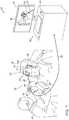
- FIG. 2is a sectional side view of an ear, and an ENT invasive instrument with a position-tracking-enabling connector plugged into a receptacle at its handle, in accordance with an embodiment of the present invention
- FIG. 3is a block diagram that schematically illustrates a position-tracking-enabling connector, in accordance with an embodiment of the present invention
- FIGS. 4A and 4Bare circuit diagrams showing principles of operation of counter circuits, in accordance with embodiments of the present invention.
- FIG. 5is a flow chart that schematically illustrates a method for enabling and controlling the operation of a position sensor using a position-tracking-enabling connector, in accordance with an embodiment of the present invention.
- ENT position tracking capabilitiesallow ENT physicians to successfully navigate flexible invasive medical instruments though complicated structures comprising multiple openings, and narrow and/or winding canals. Nevertheless, in many clinical cases these costly position tracking capabilities are not medically required. Unmanaged provisioning of costly position tracking capabilities may unnecessarily increase the cost of a medical procedure.
- Embodiments of the present inventionthat are described herein below provide a position-tracking-enabling connector that enables the physician to apply position tracking capabilities selectively, e.g., as required medically and/or approved financially.
- the ENT medical instrumentcan be operated with or without position tracking, in flexible modes of operation that allow the physician to manage the incurred costs of the medical procedure.
- an ENT invasive instrumentis fitted at its distal end with a position sensor, and is configured to accept an ENT position-tracking-enabling connector in a receptacle fitted at its proximal end.
- the position sensoris configured to produce position signals that are indicative of a position of the distal end of the ENT invasive instrument in the ENT system of a patient.
- the position-tracking-enabling connectoris configured to enable such capabilities only if terms of use (possibly encoded in the position-tracking-enabling connector) are valid, such as a valid expiration date and/or one or more usage-sessions are available.
- the position-tracking-enabling connectoralerts the physician when the preset maximal number of usage-sessions has been reached.
- the disclosed techniquesassist the physician and the healthcare system to control the cost of care, and implement pricy position tracking capabilities only when necessarily, and in a budget-minded manner. Moreover, the disclosed techniques enable the physician to selectively use expensive associated tooling, such as high-end, high-quality, multiple-use insertion tube tools equipped with position sensors, while being able to flexibly plan and manage the costs of equipment and operation.
- FIG. 1is a schematic, pictorial illustration of an ENT treatment system 20 comprising an ENT position-tracking-enabling connector 55 , in accordance with an embodiment of the present invention.
- ENT position tracking and treatment system 20comprises a medical instrument, such an ENT insertion tube 28 , which is configured to diagnose and/or treat an ENT medical condition, such as infection in an Eustachian tube 50 of a patient 22 .
- ENT insertion tube 28comprises a tool fitted at its distal end, such as an ENT tool 38 , which a physician 24 inserts into a nose 26 of patient 22 .
- ENT tool 38comprises a position sensor 60 .
- ENT insertion tube 28further comprises a handheld ENT apparatus 30 , coupled to a proximal end of ENT tool 38 and configured to assist physician 24 in manipulate tool 38 into Eustachian tube 50 through a nose 26 and in applying the treatment.
- ENT apparatus 30is configured with a receptacle, which may be located at a handle 53 . The receptacle is able to receive ENT position-tracking-enabling connector 55 .
- position sensor 60sends position signals to a position tracking system. Without an enablement from ENT position-tracking-enabling connector 55 position sensor 60 will not be functional.
- the position tracking systemcomprises a magnetic position tracking system, such as CARTOTM position tracking that is part of system 20 .
- the CARTOTM position tracking systemis configured to track the position of one or more position sensors in the head of patient 22 .
- System 20comprises a location pad 40 , which comprises field-generators 44 fixed on a frame 46 .
- Position sensor 60generate position signals in response to the sensed external magnetic fields from the field generators, thereby enabling a processor 34 to map the position of sensor 60 in a coordinate system of system 20 .
- Location pad 40that defines a fixed coordinate system to which the position of sensor 60 is mapped. In the exemplary configuration shown in FIG. 1 , pad 40 comprises five field-generators 44 but may comprise any other suitable number of generators 44 .
- Pad 40further comprises a pillow (not shown) placed under a head 41 of patient 22 , such that generators 44 are located at fixed, known positions external to patient 22 .
- system 20comprises console 33 , which comprises a processor 34 , typically a general-purpose computer, with suitable front end and interface circuits for receiving signals from tool 28 having a magnetic type of position sensor 60 attached thereon, via a cable 32 , and for controlling other components of system 20 described herein.
- processor 34typically a general-purpose computer, with suitable front end and interface circuits for receiving signals from tool 28 having a magnetic type of position sensor 60 attached thereon, via a cable 32 , and for controlling other components of system 20 described herein.
- Console 33further comprises input devices 39 and a user display 36 , which is configured to display relevant data (e.g., position coordinates) received from processor 34 or inputs inserted by physician 24 .
- Console 33comprises a driver circuit (not shown), which is configured to drive field-generators 44 with suitable signals so as to generate magnetic fields in a predefined working volume around head 41 .
- FIG. 1shows only elements related to the disclosed techniques, for the sake of simplicity and clarity.
- System 20typically comprises additional modules and elements that are not directly related to the disclosed techniques, and thus, intentionally omitted from FIG. 1 and from the corresponding description.
- Processor 34may be programmed in software to carry out the functions that are used by the system, and to store data in a memory (not shown) to be processed or otherwise used by the software.
- the softwaremay be downloaded to the processor in electronic form, over a network, for example, or it may be provided on non-transitory tangible media, such as optical, magnetic or electronic memory media.
- some or all of the functions of processor 34may be carried out by dedicated or programmable digital hardware components.
- FIG. 2is a sectional side view of an ear 48 and an ENT invasive instrument, such as insertion tube 28 , with ENT position-tracking-enabling connector 55 plugged into a receptacle 54 at its handle 53 , in accordance with an embodiment of the present invention.
- physician 24operates insertion tube 28 so as to insert ENT tool 38 into the patient's ENT system, in the present example into Eustachian tube 50 .
- ENT tool 38is coupled to ENT apparatus 30 , located externally to patient 22 and may be used by physician 24 for navigating ENT tool 38 from the nose to Eustachian tube 50 of ear 48 . Additionally or alternatively, any other suitable apparatus may be used by the physician for the navigation of ENT tool 38 .
- ENT tool 38further comprises a position sensor 60 connected to a position tracking system, as described in FIG. 1 above.
- ENT apparatus 30is equipped with receptacle 54 in its handle 53 .
- ENT position-tracking-enabling connector 55can plug into receptacle 54 , to enable position sensor 60 to track the position of ENT tool 38 in Eustachian tube 50 .
- sensor 60is electrically disconnected or disabled in a secured manner.
- interrogation circuitry 57 inside handle 53is wired to receptacle 54 , and comprises passive circuitry (e.g. soldered interconnects) that may or may not become connected by enablement circuitry located inside position-tracking-enabling connector 55 (Seen in FIG. 3 ). The decision is taken by the enablement circuitry, depending on terms of use encoded into position-tracking-enabling connector 55 .
- the enablement circuitry in connector 55closes a circuit in series with interrogation circuitry 57 , causing position sensor 60 to become available to a control console (such as one shown in FIG. 1 ), and by doing so enables position tracking.
- ENT position-tracking-enabling connector 55may comprise any suitable configuration, having any suitable size and shape and arranged so that, for example, it may enable positioning functionality for more than one ENT tool, for example, for an ablation catheter and for a suction tool.
- receptacle 54any type, shape and form of connecter may be used, for example a plug that fits a receptacle included in ENT position-tracking-enabling connector 55 .
- position sensor 60which in the embodiment described in FIGS. 1 and 2 is a magnetic sensor, may comprise a single coil or any other suitable number of coils configured to generate position signals.
- FIG. 3is a block diagram that schematically illustrates ENT position-tracking-enabling connector 55 , in accordance with an embodiment of the present invention.
- position-tracking-enabling connector 55comprises a case 62 and a plug 56 .
- position-tracking-enabling connector 55comprises enablement circuitry 64 and counter circuitry 66 .
- ENT position-tracking-enabling connector 55enables the operation of position sensor 60 only under terms of use encoded therein, e.g., given usage-sessions and/or an expiration date, as explained below.
- enablement circuitry 64 and/or counter circuitry 66are configured to hold encoded terms of use and correspondingly to selectively enable position sensor 60 to send position signals to console 33 .
- counter circuitry 66is configured to indicate to enablement circuitry 64 whether the preset maximal number of usage-sessions has been reached, and enablement circuitry 64 is configured to disable (i.e., deactivate) the position sensor communication when the usage-sessions reached a preset maximal number.
- position-tracking-enabling connector 55includes a Radio-Frequency Identification (RFID) circuit.
- RFIDRadio-Frequency Identification
- FIGS. 4A and 4Bare detailed circuit diagrams showing principles of operation of counter circuits 88 A and 88 B, respectively, in accordance with embodiments of the present invention.
- circuit 88 A shown in FIG. 4Awhich is included in counter circuitry 66 , comprises a usage-sessions counter 90 A, which is configured to count sessions of usage of the ENT medical instrument.
- An induction coil 91 Acharges a capacitor 92 A when ENT tool 38 (and thus sensor 60 ) is exposed to the magnetic field generated by field-generators 44 .
- a diode 93 Aensures the electrical current is direct current (DC).
- ENT position-tracking-enabling connector 55is plugged into connector 54
- connector 54shorts (closes) switch 94 A in circuit 88 A. Voltage supply is then provided to counter 90 A that includes a small nonvolatile memory.
- the counter 90 Areceives voltage supply and increments the count of usage sessions by one, from the last value stored at its memory. Counter 90 A then self-disconnects itself by switching a relay 96 as commanded by counter 90 A via line 101 . In an optional embodiment, the number of previously-held usage-sessions and/or of the remaining number of usage-sessions is read from pin 100 A of counter 90 A, for example to be displayed to the physician on an alphanumeric display.
- circuit 88 B shown in FIG. 4Bwhich is included in counter circuitry 66 , comprises a coil 91 B, a capacitor 92 B, a diode 93 B and a switch 94 B having similar functions to coil 91 A, capacitor 92 A, diode 93 A and switch 94 A of circuit 88 A.
- Counter 90 Bis configured to count instants of usage by dates (e.g., count individual usage days).
- circuity 88 Breceives a constant power supply so it is always on.
- Circuit 88 Blogs the date of plugging and/or unplugging ENT position-tracking-enabling connector 55 to/from connector 54 . Therefore, if, for example, the physician disconnects and connects ENT position-tracking-enabling connector 55 multiple times on the same day, these multiple sessions will not increase the number of usage sessions counted, for example the number of days already used.
- Counter 90 Blogs the plugging and/or unplugging of ENT position-tracking-enabling connector 55 by line 102 receiving voltage, or stopping to receive voltage, respectively, each time switch 94 B is closed or opened (i.e., by respectively plugging or unplugging ENT position-tracking-enabling connector 55 ).
- the count of past usage days and/or of remaining usage daysis read from a pin 100 B of counter 90 B, for example to be displayed to the physician on an alphanumeric display.
- identification circuitry 64 and counter circuitry 66are both integrated on a single printed circuit board.
- the various elements of position-tracking-enabling connector 55may be implemented in hardware, e.g., using one or more discrete components, Field-Programmable Gate Arrays (FPGAs) or Application-Specific Integrated Circuits (ASICs).
- FPGAsField-Programmable Gate Arrays
- ASICsApplication-Specific Integrated Circuits
- some elements of position-tracking-enabling connector 55e.g., counter circuitry 66 , may be implemented in software, or using a combination of software and hardware elements.
- the configuration of position-tracking-enabling connector 55 shown in FIG. 3is an example configuration, which is depicted purely for the sake of conceptual clarity. In alternative embodiments, position-tracking-enabling connector 55 may be implemented using any other suitable components or configuration.
- FIG. 5is a flow chart that schematically illustrates a method for enabling and controlling the operation of a position sensor using ENT position-tracking-enabling connector 55 , in accordance with an embodiment of the present invention.
- the position tracking functionalitye.g. given by position sensor 60
- the position tracking functionalityis initially disabled, at a disablement step 72 .
- interrogation-circuitry 57 in handle 53 of ENT invasive instrument 28did not yet become interconnected via enablement circuitry 64 in position-tracking-enabling connector 55 .
- physician 24plugs position-tracking-enabling connector 55 into receptacle 54 .
- Interrogation-circuitry 57then becomes interconnected via enablement circuitry 64 (i.e., the medical instrument ‘detects’ the presence of position-tracking-enabling connector 55 ).
- enablement circuitry 64checks whether the terms of use encoded into one of position-tracking-enabling connector 55 circuits (such as number of remaining usage-sessions (i.e., if a maximal number of usage-sessions value has been reached), as counted by counter circuitry 66 ) are valid. If so, enablement circuitry 64 enables position sensor 60 operation, at an enablement step 76 . Otherwise, i.e., if enablement circuitry 64 detects that terms of use encoded into position-tracking-enabling connector 55 are invalid, enablement circuitry 64 maintains position sensor 60 disabled, looping back to disablement step 72 .
- an alpha-numeric display contained in case 62 of position-tracking-enabling connector 55presents to physician 24 the remaining usage-sessions, for example by receiving the remaining usage-sessions from counter 90 A, at a notification step 78 .
- ENT invasive instrument 28 and position-tracking-enabling connector 55 shown in the figuresare chosen purely for the sake of conceptual clarity.
- the disclosed techniquesmay be implemented using other suitable configurations comprising, for example, other ENT tools and ENT systems, such as an ablation catheter connected to a position tracking and ablation system.
- the architecture and functionality of the position-tracking-enabling connectormay vary, such as for example its circuitry and the details of the encoded terms of use with the coupled medical instrument, and how these terms are encoded.
- invasive instrument 28may include both an active interrogation-circuitry, and active enablement circuitry.
- ENT position-tracking-enabling connector 55may comprise then passive encoded circuitry.
- an Electronically Erasable Programmable Read-Only Memory (EEPROM) and/or Flash memorymay be fitted into various circuits of ENT position-tracking-enabling connector 55 as to perform at least part of its functionalities, such as the interrogation and the enablement.
- EEPROMElectronically Erasable Programmable Read-Only Memory
- Flash memorymay be fitted into various circuits of ENT position-tracking-enabling connector 55 as to perform at least part of its functionalities, such as the interrogation and the enablement.
Landscapes
- Health & Medical Sciences (AREA)
- Engineering & Computer Science (AREA)
- Life Sciences & Earth Sciences (AREA)
- Surgery (AREA)
- Veterinary Medicine (AREA)
- Biomedical Technology (AREA)
- General Health & Medical Sciences (AREA)
- Animal Behavior & Ethology (AREA)
- Medical Informatics (AREA)
- Molecular Biology (AREA)
- Public Health (AREA)
- Heart & Thoracic Surgery (AREA)
- Physics & Mathematics (AREA)
- Nuclear Medicine, Radiotherapy & Molecular Imaging (AREA)
- Pathology (AREA)
- Oral & Maxillofacial Surgery (AREA)
- Software Systems (AREA)
- Theoretical Computer Science (AREA)
- Human Computer Interaction (AREA)
- Biophysics (AREA)
- Robotics (AREA)
- Pulmonology (AREA)
- General Physics & Mathematics (AREA)
- Computer Hardware Design (AREA)
- Electromagnetism (AREA)
- Technology Law (AREA)
- Multimedia (AREA)
- Dentistry (AREA)
- Otolaryngology (AREA)
- General Engineering & Computer Science (AREA)
- Computer Security & Cryptography (AREA)
- Computer Networks & Wireless Communication (AREA)
- Signal Processing (AREA)
- Media Introduction/Drainage Providing Device (AREA)
- Endoscopes (AREA)
- Surgical Instruments (AREA)
- Manufacturing Of Electrical Connectors (AREA)
- Coupling Device And Connection With Printed Circuit (AREA)
- Cable Accessories (AREA)
- Measuring And Recording Apparatus For Diagnosis (AREA)
Abstract
Description
Claims (10)
Priority Applications (7)
| Application Number | Priority Date | Filing Date | Title |
|---|---|---|---|
| US15/795,169US11179203B2 (en) | 2017-10-26 | 2017-10-26 | Position-tracking-enabling connector for an ear-nose-throat (ENT) tool |
| IL262142AIL262142B2 (en) | 2017-10-26 | 2018-10-04 | A position-tracking-enabling connector for an ear-nose-throat (ent) tool |
| AU2018241160AAU2018241160A1 (en) | 2017-10-26 | 2018-10-05 | A position-tracking-enabling connector for an ear-nose-throat (ent) tool |
| CA3021786ACA3021786A1 (en) | 2017-10-26 | 2018-10-23 | A position-tracking-enabling connector for an ear-nose-throat (ent) tool |
| EP18202555.1AEP3477514B1 (en) | 2017-10-26 | 2018-10-25 | A position-tracking-enabling connector for an ear-nose-throat(ent) tool |
| JP2018200644AJP7278742B2 (en) | 2017-10-26 | 2018-10-25 | Connector for ear, nose and throat (ENT) tools to enable position tracking |
| CN201811258207.3ACN109700530B (en) | 2017-10-26 | 2018-10-26 | Position tracking enabled connector for ear, nose and throat (ENT) tools |
Applications Claiming Priority (1)
| Application Number | Priority Date | Filing Date | Title |
|---|---|---|---|
| US15/795,169US11179203B2 (en) | 2017-10-26 | 2017-10-26 | Position-tracking-enabling connector for an ear-nose-throat (ENT) tool |
Publications (2)
| Publication Number | Publication Date |
|---|---|
| US20190125450A1 US20190125450A1 (en) | 2019-05-02 |
| US11179203B2true US11179203B2 (en) | 2021-11-23 |
Family
ID=64308465
Family Applications (1)
| Application Number | Title | Priority Date | Filing Date |
|---|---|---|---|
| US15/795,169Active2039-12-06US11179203B2 (en) | 2017-10-26 | 2017-10-26 | Position-tracking-enabling connector for an ear-nose-throat (ENT) tool |
Country Status (7)
| Country | Link |
|---|---|
| US (1) | US11179203B2 (en) |
| EP (1) | EP3477514B1 (en) |
| JP (1) | JP7278742B2 (en) |
| CN (1) | CN109700530B (en) |
| AU (1) | AU2018241160A1 (en) |
| CA (1) | CA3021786A1 (en) |
| IL (1) | IL262142B2 (en) |
Families Citing this family (2)
| Publication number | Priority date | Publication date | Assignee | Title |
|---|---|---|---|---|
| US11510692B2 (en)* | 2019-05-31 | 2022-11-29 | Biosense Webster (Israel) Ltd. | Ear-nose-throat (ENT) navigable shaver with ferromagnetic components |
| JP7198336B1 (en) | 2021-12-08 | 2022-12-28 | 功憲 末次 | Current position measurement system, current position measurement device, current position measurement program, magnetic field generator, and magnetic field generation program |
Citations (30)
| Publication number | Priority date | Publication date | Assignee | Title |
|---|---|---|---|---|
| US5391199A (en) | 1993-07-20 | 1995-02-21 | Biosense, Inc. | Apparatus and method for treating cardiac arrhythmias |
| WO1996005768A1 (en) | 1994-08-19 | 1996-02-29 | Biosense, Inc. | Medical diagnosis, treatment and imaging systems |
| US6239724B1 (en) | 1997-12-30 | 2001-05-29 | Remon Medical Technologies, Ltd. | System and method for telemetrically providing intrabody spatial position |
| US6332089B1 (en) | 1996-02-15 | 2001-12-18 | Biosense, Inc. | Medical procedures and apparatus using intrabody probes |
| US20020032380A1 (en)* | 1996-02-15 | 2002-03-14 | David E. Acker | Medical probes with field transducers |
| US20020065455A1 (en) | 1995-01-24 | 2002-05-30 | Shlomo Ben-Haim | Medical diagnosis, treatment and imaging systems |
| US20020161421A1 (en)* | 2000-11-20 | 2002-10-31 | Chris Lee | Connector and guidewire connectable thereto |
| US6484118B1 (en) | 2000-07-20 | 2002-11-19 | Biosense, Inc. | Electromagnetic position single axis system |
| US20030120150A1 (en) | 2001-12-21 | 2003-06-26 | Assaf Govari | Wireless position sensor |
| US6618612B1 (en) | 1996-02-15 | 2003-09-09 | Biosense, Inc. | Independently positionable transducers for location system |
| US20040068178A1 (en) | 2002-09-17 | 2004-04-08 | Assaf Govari | High-gradient recursive locating system |
| US20070225550A1 (en) | 2006-03-24 | 2007-09-27 | Abhishek Gattani | System and method for 3-D tracking of surgical instrument in relation to patient body |
| US7796040B2 (en) | 2006-07-21 | 2010-09-14 | Alcon, Inc. | Smart connector system for surgical machine |
| US20100261967A1 (en) | 2009-04-14 | 2010-10-14 | Verathon Inc. | Video laryngoscope system and devices |
| US7840254B2 (en) | 2005-01-18 | 2010-11-23 | Philips Electronics Ltd | Electromagnetically tracked K-wire device |
| US20110238063A1 (en)* | 2010-03-29 | 2011-09-29 | Tyco Healthcare Group Lp | Method of Tracking Reposable Instrument Usage |
| US8035487B2 (en) | 2001-08-08 | 2011-10-11 | Stryker Corporation | Method for assembling, identifying and controlling a powered surgical tool assembly assembled from multiple components |
| US8190389B2 (en) | 2006-05-17 | 2012-05-29 | Acclarent, Inc. | Adapter for attaching electromagnetic image guidance components to a medical device |
| US20140066944A1 (en) | 2010-08-02 | 2014-03-06 | The Johns Hopkins University | Tool exchange interface and control algorithm for cooperative surgical robots |
| US8821376B2 (en) | 2007-03-12 | 2014-09-02 | David Tolkowsky | Devices and methods for performing medical procedures in tree-like luminal structures |
| US20140275765A1 (en)* | 2013-03-15 | 2014-09-18 | Steven C. Gebhart | Probe assembly and disposable cover particularly for use in endoscope applications of low coherence interferometry |
| US20140275997A1 (en) | 2013-03-15 | 2014-09-18 | Intuitive Surgical Operations, Inc. | Shape sensor systems for tracking interventional instruments and mehods of use |
| US8942780B2 (en) | 2005-10-04 | 2015-01-27 | Ascension Technology Corporation | DC magnetic-based position and orientation monitoring system for tracking medical instruments |
| US8961398B2 (en) | 2004-04-21 | 2015-02-24 | Acclarent, Inc. | Methods and apparatus for treating disorders of the ear, nose and throat |
| US20150155912A1 (en)* | 2012-04-16 | 2015-06-04 | Icu Medical, Inc. | Medical cable including authentication circuit |
| US20160066770A1 (en) | 2014-04-02 | 2016-03-10 | Visionscope Technologies Llc | Devices and methods for minimally invasive arthroscopic surgery |
| US20170119473A1 (en)* | 2015-10-30 | 2017-05-04 | Acclarent, Inc. | System and method for navigation of surgical instruments |
| US20170143366A1 (en)* | 2015-11-25 | 2017-05-25 | Ethicon Endo-Surgery, Llc | Restricted usage features for surgical instrument |
| US20180085036A1 (en)* | 2014-11-25 | 2018-03-29 | Impeto Medical | Device for measuring electrophysiological data with improved reliability |
| EP3381384A1 (en) | 2017-03-28 | 2018-10-03 | Biosense Webster (Israel) Ltd. | A medical device having a reusable position sensor |
Family Cites Families (15)
| Publication number | Priority date | Publication date | Assignee | Title |
|---|---|---|---|---|
| US5304214A (en)* | 1992-01-21 | 1994-04-19 | Med Institute, Inc. | Transurethral ablation catheter |
| EP0980226B1 (en)* | 1998-02-05 | 2005-12-28 | Biosense Webster, Inc. | Apparatus for intracardiac drug delivery |
| CA2334495A1 (en)* | 2001-02-06 | 2002-08-06 | Surgical Navigation Specialists, Inc. | Computer-aided positioning method and system |
| US20040049121A1 (en)* | 2002-09-06 | 2004-03-11 | Uri Yaron | Positioning system for neurological procedures in the brain |
| US20090090763A1 (en)* | 2007-10-05 | 2009-04-09 | Tyco Healthcare Group Lp | Powered surgical stapling device |
| JP2008301968A (en)* | 2007-06-06 | 2008-12-18 | Olympus Medical Systems Corp | Endoscopic image processing device |
| CN101438955A (en)* | 2008-12-25 | 2009-05-27 | 哈尔滨工业大学 | Automatic guidance method of catheter |
| ES2900584T3 (en)* | 2010-12-23 | 2022-03-17 | Bard Access Systems Inc | System for guiding a rigid instrument |
| US8734500B2 (en)* | 2011-09-27 | 2014-05-27 | DePuy Synthes Products, LLC | Distal detachment mechanisms for vascular devices |
| US9498182B2 (en)* | 2012-05-22 | 2016-11-22 | Covidien Lp | Systems and methods for planning and navigation |
| US9463307B2 (en)* | 2012-12-21 | 2016-10-11 | Medtronic Xomed, Inc. | Sinus dilation system and method |
| AU2014200501B2 (en)* | 2013-03-07 | 2017-08-24 | Covidien Lp | Powered surgical stapling device |
| CN103750823B (en)* | 2014-01-13 | 2016-08-17 | 孙冰 | Pulse-taking instrument that a kind of intelligent terminal of utilization remotely feels the pulse and method thereof |
| US9480416B2 (en)* | 2014-01-17 | 2016-11-01 | Biosense Webster (Israel) Ltd. | Signal transmission using catheter braid wires |
| JP6629230B2 (en)* | 2014-04-02 | 2020-01-15 | インテュイティブ サージカル オペレーションズ, インコーポレイテッド | Minimal invasive system |
- 2017
- 2017-10-26USUS15/795,169patent/US11179203B2/enactiveActive
- 2018
- 2018-10-04ILIL262142Apatent/IL262142B2/enunknown
- 2018-10-05AUAU2018241160Apatent/AU2018241160A1/ennot_activeAbandoned
- 2018-10-23CACA3021786Apatent/CA3021786A1/ennot_activeAbandoned
- 2018-10-25EPEP18202555.1Apatent/EP3477514B1/enactiveActive
- 2018-10-25JPJP2018200644Apatent/JP7278742B2/enactiveActive
- 2018-10-26CNCN201811258207.3Apatent/CN109700530B/enactiveActive
Patent Citations (34)
| Publication number | Priority date | Publication date | Assignee | Title |
|---|---|---|---|---|
| US5391199A (en) | 1993-07-20 | 1995-02-21 | Biosense, Inc. | Apparatus and method for treating cardiac arrhythmias |
| WO1996005768A1 (en) | 1994-08-19 | 1996-02-29 | Biosense, Inc. | Medical diagnosis, treatment and imaging systems |
| US20020065455A1 (en) | 1995-01-24 | 2002-05-30 | Shlomo Ben-Haim | Medical diagnosis, treatment and imaging systems |
| US6690963B2 (en) | 1995-01-24 | 2004-02-10 | Biosense, Inc. | System for determining the location and orientation of an invasive medical instrument |
| US6332089B1 (en) | 1996-02-15 | 2001-12-18 | Biosense, Inc. | Medical procedures and apparatus using intrabody probes |
| US20020032380A1 (en)* | 1996-02-15 | 2002-03-14 | David E. Acker | Medical probes with field transducers |
| US6618612B1 (en) | 1996-02-15 | 2003-09-09 | Biosense, Inc. | Independently positionable transducers for location system |
| US6239724B1 (en) | 1997-12-30 | 2001-05-29 | Remon Medical Technologies, Ltd. | System and method for telemetrically providing intrabody spatial position |
| US6484118B1 (en) | 2000-07-20 | 2002-11-19 | Biosense, Inc. | Electromagnetic position single axis system |
| US20020161421A1 (en)* | 2000-11-20 | 2002-10-31 | Chris Lee | Connector and guidewire connectable thereto |
| US8035487B2 (en) | 2001-08-08 | 2011-10-11 | Stryker Corporation | Method for assembling, identifying and controlling a powered surgical tool assembly assembled from multiple components |
| US8535342B2 (en) | 2001-08-08 | 2013-09-17 | Stryker Corporation | Powered surgical handpiece with an antenna for reading data from a memory integral with a cutting accessory attached to the handpiece |
| US20030120150A1 (en) | 2001-12-21 | 2003-06-26 | Assaf Govari | Wireless position sensor |
| US20040068178A1 (en) | 2002-09-17 | 2004-04-08 | Assaf Govari | High-gradient recursive locating system |
| US8961398B2 (en) | 2004-04-21 | 2015-02-24 | Acclarent, Inc. | Methods and apparatus for treating disorders of the ear, nose and throat |
| US9167961B2 (en) | 2004-04-21 | 2015-10-27 | Acclarent, Inc. | Methods and apparatus for treating disorders of the ear nose and throat |
| US7840254B2 (en) | 2005-01-18 | 2010-11-23 | Philips Electronics Ltd | Electromagnetically tracked K-wire device |
| US8942780B2 (en) | 2005-10-04 | 2015-01-27 | Ascension Technology Corporation | DC magnetic-based position and orientation monitoring system for tracking medical instruments |
| US20070225550A1 (en) | 2006-03-24 | 2007-09-27 | Abhishek Gattani | System and method for 3-D tracking of surgical instrument in relation to patient body |
| US8190389B2 (en) | 2006-05-17 | 2012-05-29 | Acclarent, Inc. | Adapter for attaching electromagnetic image guidance components to a medical device |
| US7796040B2 (en) | 2006-07-21 | 2010-09-14 | Alcon, Inc. | Smart connector system for surgical machine |
| US8821376B2 (en) | 2007-03-12 | 2014-09-02 | David Tolkowsky | Devices and methods for performing medical procedures in tree-like luminal structures |
| US20100261967A1 (en) | 2009-04-14 | 2010-10-14 | Verathon Inc. | Video laryngoscope system and devices |
| US20110238063A1 (en)* | 2010-03-29 | 2011-09-29 | Tyco Healthcare Group Lp | Method of Tracking Reposable Instrument Usage |
| US20140066944A1 (en) | 2010-08-02 | 2014-03-06 | The Johns Hopkins University | Tool exchange interface and control algorithm for cooperative surgical robots |
| US20150155912A1 (en)* | 2012-04-16 | 2015-06-04 | Icu Medical, Inc. | Medical cable including authentication circuit |
| US20140275765A1 (en)* | 2013-03-15 | 2014-09-18 | Steven C. Gebhart | Probe assembly and disposable cover particularly for use in endoscope applications of low coherence interferometry |
| US20140275997A1 (en) | 2013-03-15 | 2014-09-18 | Intuitive Surgical Operations, Inc. | Shape sensor systems for tracking interventional instruments and mehods of use |
| US20160066770A1 (en) | 2014-04-02 | 2016-03-10 | Visionscope Technologies Llc | Devices and methods for minimally invasive arthroscopic surgery |
| US20180085036A1 (en)* | 2014-11-25 | 2018-03-29 | Impeto Medical | Device for measuring electrophysiological data with improved reliability |
| US20170119473A1 (en)* | 2015-10-30 | 2017-05-04 | Acclarent, Inc. | System and method for navigation of surgical instruments |
| WO2017074977A1 (en) | 2015-10-30 | 2017-05-04 | Acclarent, Inc. | System and method for navigation of surgical instruments |
| US20170143366A1 (en)* | 2015-11-25 | 2017-05-25 | Ethicon Endo-Surgery, Llc | Restricted usage features for surgical instrument |
| EP3381384A1 (en) | 2017-03-28 | 2018-10-03 | Biosense Webster (Israel) Ltd. | A medical device having a reusable position sensor |
Non-Patent Citations (1)
| Title |
|---|
| European Search Report dated Mar. 22, 2019 from corresponding European Patent Application No. 18202555.1. |
Also Published As
| Publication number | Publication date |
|---|---|
| IL262142B1 (en) | 2023-03-01 |
| CA3021786A1 (en) | 2019-04-26 |
| AU2018241160A1 (en) | 2019-05-16 |
| EP3477514B1 (en) | 2022-09-28 |
| CN109700530A (en) | 2019-05-03 |
| US20190125450A1 (en) | 2019-05-02 |
| JP7278742B2 (en) | 2023-05-22 |
| JP2019076730A (en) | 2019-05-23 |
| IL262142A (en) | 2019-02-28 |
| EP3477514A1 (en) | 2019-05-01 |
| IL262142B2 (en) | 2023-07-01 |
| CN109700530B (en) | 2024-10-11 |
Similar Documents
| Publication | Publication Date | Title |
|---|---|---|
| US9411995B2 (en) | Physiological sensor system with automatic authentication and validation by means of a radio frequency identification protocol with an integrated RFID interrogator system | |
| EP1581100A2 (en) | A method and apparatus for improved surgical navigation employing electronic identification with automatically actuated flexible medical devices | |
| US9622808B2 (en) | Device for contactless communication and use of a memory device | |
| AU2018260778A1 (en) | Automatic identification of instruments | |
| JP2011518602A (en) | Wirelessly powered medical devices and devices | |
| US10485405B2 (en) | Coupling device for releasable connection of a medical or dental handpiece to a drive unit or to a supply tubing | |
| KR20080045165A (en) | Method and system for configuring a surgical device and entering data | |
| EP3381384B1 (en) | A medical device having a reusable position sensor | |
| EP3477514B1 (en) | A position-tracking-enabling connector for an ear-nose-throat(ent) tool | |
| CN112543621B (en) | System and method for connecting instruments | |
| WO2021045995A1 (en) | Needle-guidance systems, devices, and method thereof including rfid technology | |
| AU2004203489A1 (en) | Calibration data compression | |
| EP1480153A2 (en) | Medical tool mangement and support system | |
| US9241656B2 (en) | Serially connected autonomous location pads | |
| JP4542292B2 (en) | Endoscope system | |
| KR102762346B1 (en) | A position tracking apparatus for head and neck igs using magnetic field | |
| US20220415494A1 (en) | Medical device having commmunication function and communication system | |
| US9625441B2 (en) | Biological sample measurement device |
Legal Events
| Date | Code | Title | Description |
|---|---|---|---|
| FEPP | Fee payment procedure | Free format text:ENTITY STATUS SET TO UNDISCOUNTED (ORIGINAL EVENT CODE: BIG.); ENTITY STATUS OF PATENT OWNER: LARGE ENTITY | |
| STPP | Information on status: patent application and granting procedure in general | Free format text:DOCKETED NEW CASE - READY FOR EXAMINATION | |
| AS | Assignment | Owner name:BIOSENSE WEBSTER (ISRAEL) LTD., ISRAEL Free format text:ASSIGNMENT OF ASSIGNORS INTEREST;ASSIGNORS:GOVARI, ASSAF;GLINER, VADIM;BOUMENDIL, ALON;SIGNING DATES FROM 20180925 TO 20181024;REEL/FRAME:047505/0617 | |
| STPP | Information on status: patent application and granting procedure in general | Free format text:NON FINAL ACTION MAILED | |
| STPP | Information on status: patent application and granting procedure in general | Free format text:NON FINAL ACTION MAILED | |
| STPP | Information on status: patent application and granting procedure in general | Free format text:FINAL REJECTION MAILED | |
| STPP | Information on status: patent application and granting procedure in general | Free format text:RESPONSE AFTER FINAL ACTION FORWARDED TO EXAMINER | |
| STPP | Information on status: patent application and granting procedure in general | Free format text:ADVISORY ACTION MAILED | |
| STPP | Information on status: patent application and granting procedure in general | Free format text:DOCKETED NEW CASE - READY FOR EXAMINATION | |
| STPP | Information on status: patent application and granting procedure in general | Free format text:NON FINAL ACTION MAILED | |
| STPP | Information on status: patent application and granting procedure in general | Free format text:RESPONSE TO NON-FINAL OFFICE ACTION ENTERED AND FORWARDED TO EXAMINER | |
| STPP | Information on status: patent application and granting procedure in general | Free format text:NOTICE OF ALLOWANCE MAILED -- APPLICATION RECEIVED IN OFFICE OF PUBLICATIONS | |
| STPP | Information on status: patent application and granting procedure in general | Free format text:AWAITING TC RESP., ISSUE FEE NOT PAID | |
| STPP | Information on status: patent application and granting procedure in general | Free format text:PUBLICATIONS -- ISSUE FEE PAYMENT RECEIVED | |
| STPP | Information on status: patent application and granting procedure in general | Free format text:PUBLICATIONS -- ISSUE FEE PAYMENT VERIFIED | |
| STCF | Information on status: patent grant | Free format text:PATENTED CASE | |
| MAFP | Maintenance fee payment | Free format text:PAYMENT OF MAINTENANCE FEE, 4TH YEAR, LARGE ENTITY (ORIGINAL EVENT CODE: M1551); ENTITY STATUS OF PATENT OWNER: LARGE ENTITY Year of fee payment:4 |