US11179149B2 - Counter-torque implant - Google Patents
Counter-torque implantDownload PDFInfo
- Publication number
- US11179149B2 US11179149B2US16/031,764US201816031764AUS11179149B2US 11179149 B2US11179149 B2US 11179149B2US 201816031764 AUS201816031764 AUS 201816031764AUS 11179149 B2US11179149 B2US 11179149B2
- Authority
- US
- United States
- Prior art keywords
- plug
- implant
- punch
- bone
- bridge
- Prior art date
- Legal status (The legal status is an assumption and is not a legal conclusion. Google has not performed a legal analysis and makes no representation as to the accuracy of the status listed.)
- Active, expires
Links
Images


Classifications
- A—HUMAN NECESSITIES
- A61—MEDICAL OR VETERINARY SCIENCE; HYGIENE
- A61B—DIAGNOSIS; SURGERY; IDENTIFICATION
- A61B17/00—Surgical instruments, devices or methods
- A61B17/064—Surgical staples, i.e. penetrating the tissue
- A61B17/0642—Surgical staples, i.e. penetrating the tissue for bones, e.g. for osteosynthesis or connecting tendon to bone
- A—HUMAN NECESSITIES
- A61—MEDICAL OR VETERINARY SCIENCE; HYGIENE
- A61B—DIAGNOSIS; SURGERY; IDENTIFICATION
- A61B17/00—Surgical instruments, devices or methods
- A61B17/068—Surgical staplers, e.g. containing multiple staples or clamps
- A61B17/0682—Surgical staplers, e.g. containing multiple staples or clamps for applying U-shaped staples or clamps, e.g. without a forming anvil
- A—HUMAN NECESSITIES
- A61—MEDICAL OR VETERINARY SCIENCE; HYGIENE
- A61B—DIAGNOSIS; SURGERY; IDENTIFICATION
- A61B17/00—Surgical instruments, devices or methods
- A61B17/10—Surgical instruments, devices or methods for applying or removing wound clamps, e.g. containing only one clamp or staple; Wound clamp magazines
- A—HUMAN NECESSITIES
- A61—MEDICAL OR VETERINARY SCIENCE; HYGIENE
- A61B—DIAGNOSIS; SURGERY; IDENTIFICATION
- A61B17/00—Surgical instruments, devices or methods
- A61B17/16—Instruments for performing osteoclasis; Drills or chisels for bones; Trepans
- A61B17/1604—Chisels; Rongeurs; Punches; Stamps
- A—HUMAN NECESSITIES
- A61—MEDICAL OR VETERINARY SCIENCE; HYGIENE
- A61B—DIAGNOSIS; SURGERY; IDENTIFICATION
- A61B17/00—Surgical instruments, devices or methods
- A61B17/16—Instruments for performing osteoclasis; Drills or chisels for bones; Trepans
- A61B17/1613—Component parts
- A61B17/1615—Drill bits, i.e. rotating tools extending from a handpiece to contact the worked material
- A—HUMAN NECESSITIES
- A61—MEDICAL OR VETERINARY SCIENCE; HYGIENE
- A61B—DIAGNOSIS; SURGERY; IDENTIFICATION
- A61B17/00—Surgical instruments, devices or methods
- A61B17/16—Instruments for performing osteoclasis; Drills or chisels for bones; Trepans
- A61B17/17—Guides or aligning means for drills, mills, pins or wires
- A—HUMAN NECESSITIES
- A61—MEDICAL OR VETERINARY SCIENCE; HYGIENE
- A61B—DIAGNOSIS; SURGERY; IDENTIFICATION
- A61B17/00—Surgical instruments, devices or methods
- A61B17/56—Surgical instruments or methods for treatment of bones or joints; Devices specially adapted therefor
- A61B17/58—Surgical instruments or methods for treatment of bones or joints; Devices specially adapted therefor for osteosynthesis, e.g. bone plates, screws or setting implements
- A61B17/68—Internal fixation devices, including fasteners and spinal fixators, even if a part thereof projects from the skin
- A61B17/80—Cortical plates, i.e. bone plates; Instruments for holding or positioning cortical plates, or for compressing bones attached to cortical plates
- A61B17/8061—Cortical plates, i.e. bone plates; Instruments for holding or positioning cortical plates, or for compressing bones attached to cortical plates specially adapted for particular bones
- A—HUMAN NECESSITIES
- A61—MEDICAL OR VETERINARY SCIENCE; HYGIENE
- A61B—DIAGNOSIS; SURGERY; IDENTIFICATION
- A61B17/00—Surgical instruments, devices or methods
- A61B17/56—Surgical instruments or methods for treatment of bones or joints; Devices specially adapted therefor
- A61B17/58—Surgical instruments or methods for treatment of bones or joints; Devices specially adapted therefor for osteosynthesis, e.g. bone plates, screws or setting implements
- A61B17/68—Internal fixation devices, including fasteners and spinal fixators, even if a part thereof projects from the skin
- A61B17/80—Cortical plates, i.e. bone plates; Instruments for holding or positioning cortical plates, or for compressing bones attached to cortical plates
- A61B17/809—Cortical plates, i.e. bone plates; Instruments for holding or positioning cortical plates, or for compressing bones attached to cortical plates with bone-penetrating elements, e.g. blades or prongs
- A—HUMAN NECESSITIES
- A61—MEDICAL OR VETERINARY SCIENCE; HYGIENE
- A61B—DIAGNOSIS; SURGERY; IDENTIFICATION
- A61B17/00—Surgical instruments, devices or methods
- A61B17/56—Surgical instruments or methods for treatment of bones or joints; Devices specially adapted therefor
- A61B17/58—Surgical instruments or methods for treatment of bones or joints; Devices specially adapted therefor for osteosynthesis, e.g. bone plates, screws or setting implements
- A61B17/88—Osteosynthesis instruments; Methods or means for implanting or extracting internal or external fixation devices
- A61B17/8872—Instruments for putting said fixation devices against or away from the bone
- A—HUMAN NECESSITIES
- A61—MEDICAL OR VETERINARY SCIENCE; HYGIENE
- A61F—FILTERS IMPLANTABLE INTO BLOOD VESSELS; PROSTHESES; DEVICES PROVIDING PATENCY TO, OR PREVENTING COLLAPSING OF, TUBULAR STRUCTURES OF THE BODY, e.g. STENTS; ORTHOPAEDIC, NURSING OR CONTRACEPTIVE DEVICES; FOMENTATION; TREATMENT OR PROTECTION OF EYES OR EARS; BANDAGES, DRESSINGS OR ABSORBENT PADS; FIRST-AID KITS
- A61F2/00—Filters implantable into blood vessels; Prostheses, i.e. artificial substitutes or replacements for parts of the body; Appliances for connecting them with the body; Devices providing patency to, or preventing collapsing of, tubular structures of the body, e.g. stents
- A61F2/02—Prostheses implantable into the body
- A61F2/30—Joints
- A61F2/30721—Accessories
- A61F2/30724—Spacers for centering an implant in a bone cavity, e.g. in a cement-receiving cavity
- A—HUMAN NECESSITIES
- A61—MEDICAL OR VETERINARY SCIENCE; HYGIENE
- A61F—FILTERS IMPLANTABLE INTO BLOOD VESSELS; PROSTHESES; DEVICES PROVIDING PATENCY TO, OR PREVENTING COLLAPSING OF, TUBULAR STRUCTURES OF THE BODY, e.g. STENTS; ORTHOPAEDIC, NURSING OR CONTRACEPTIVE DEVICES; FOMENTATION; TREATMENT OR PROTECTION OF EYES OR EARS; BANDAGES, DRESSINGS OR ABSORBENT PADS; FIRST-AID KITS
- A61F2/00—Filters implantable into blood vessels; Prostheses, i.e. artificial substitutes or replacements for parts of the body; Appliances for connecting them with the body; Devices providing patency to, or preventing collapsing of, tubular structures of the body, e.g. stents
- A61F2/02—Prostheses implantable into the body
- A61F2/30—Joints
- A61F2/42—Joints for wrists or ankles; for hands, e.g. fingers; for feet, e.g. toes
- A61F2/4202—Joints for wrists or ankles; for hands, e.g. fingers; for feet, e.g. toes for ankles
- A—HUMAN NECESSITIES
- A61—MEDICAL OR VETERINARY SCIENCE; HYGIENE
- A61F—FILTERS IMPLANTABLE INTO BLOOD VESSELS; PROSTHESES; DEVICES PROVIDING PATENCY TO, OR PREVENTING COLLAPSING OF, TUBULAR STRUCTURES OF THE BODY, e.g. STENTS; ORTHOPAEDIC, NURSING OR CONTRACEPTIVE DEVICES; FOMENTATION; TREATMENT OR PROTECTION OF EYES OR EARS; BANDAGES, DRESSINGS OR ABSORBENT PADS; FIRST-AID KITS
- A61F2/00—Filters implantable into blood vessels; Prostheses, i.e. artificial substitutes or replacements for parts of the body; Appliances for connecting them with the body; Devices providing patency to, or preventing collapsing of, tubular structures of the body, e.g. stents
- A61F2/02—Prostheses implantable into the body
- A61F2/30—Joints
- A61F2/44—Joints for the spine, e.g. vertebrae, spinal discs
- A61F2/4455—Joints for the spine, e.g. vertebrae, spinal discs for the fusion of spinal bodies, e.g. intervertebral fusion of adjacent spinal bodies, e.g. fusion cages
- A—HUMAN NECESSITIES
- A61—MEDICAL OR VETERINARY SCIENCE; HYGIENE
- A61B—DIAGNOSIS; SURGERY; IDENTIFICATION
- A61B17/00—Surgical instruments, devices or methods
- A61B17/56—Surgical instruments or methods for treatment of bones or joints; Devices specially adapted therefor
- A61B17/58—Surgical instruments or methods for treatment of bones or joints; Devices specially adapted therefor for osteosynthesis, e.g. bone plates, screws or setting implements
- A61B17/68—Internal fixation devices, including fasteners and spinal fixators, even if a part thereof projects from the skin
- A61B17/80—Cortical plates, i.e. bone plates; Instruments for holding or positioning cortical plates, or for compressing bones attached to cortical plates
- A61B17/8004—Cortical plates, i.e. bone plates; Instruments for holding or positioning cortical plates, or for compressing bones attached to cortical plates with means for distracting or compressing the bone or bones
- A—HUMAN NECESSITIES
- A61—MEDICAL OR VETERINARY SCIENCE; HYGIENE
- A61B—DIAGNOSIS; SURGERY; IDENTIFICATION
- A61B17/00—Surgical instruments, devices or methods
- A61B17/56—Surgical instruments or methods for treatment of bones or joints; Devices specially adapted therefor
- A61B17/58—Surgical instruments or methods for treatment of bones or joints; Devices specially adapted therefor for osteosynthesis, e.g. bone plates, screws or setting implements
- A61B17/68—Internal fixation devices, including fasteners and spinal fixators, even if a part thereof projects from the skin
- A61B17/80—Cortical plates, i.e. bone plates; Instruments for holding or positioning cortical plates, or for compressing bones attached to cortical plates
- A61B17/8052—Cortical plates, i.e. bone plates; Instruments for holding or positioning cortical plates, or for compressing bones attached to cortical plates immobilised relative to screws by interlocking form of the heads and plate holes, e.g. conical or threaded
- A—HUMAN NECESSITIES
- A61—MEDICAL OR VETERINARY SCIENCE; HYGIENE
- A61B—DIAGNOSIS; SURGERY; IDENTIFICATION
- A61B17/00—Surgical instruments, devices or methods
- A61B17/56—Surgical instruments or methods for treatment of bones or joints; Devices specially adapted therefor
- A61B17/58—Surgical instruments or methods for treatment of bones or joints; Devices specially adapted therefor for osteosynthesis, e.g. bone plates, screws or setting implements
- A61B17/68—Internal fixation devices, including fasteners and spinal fixators, even if a part thereof projects from the skin
- A61B17/84—Fasteners therefor or fasteners being internal fixation devices
- A61B17/86—Pins or screws or threaded wires; nuts therefor
- A61B17/8605—Heads, i.e. proximal ends projecting from bone
- A—HUMAN NECESSITIES
- A61—MEDICAL OR VETERINARY SCIENCE; HYGIENE
- A61B—DIAGNOSIS; SURGERY; IDENTIFICATION
- A61B17/00—Surgical instruments, devices or methods
- A61B17/064—Surgical staples, i.e. penetrating the tissue
- A61B2017/0641—Surgical staples, i.e. penetrating the tissue having at least three legs as part of one single body
- A—HUMAN NECESSITIES
- A61—MEDICAL OR VETERINARY SCIENCE; HYGIENE
- A61B—DIAGNOSIS; SURGERY; IDENTIFICATION
- A61B17/00—Surgical instruments, devices or methods
- A61B17/064—Surgical staples, i.e. penetrating the tissue
- A61B2017/0645—Surgical staples, i.e. penetrating the tissue being elastically deformed for insertion
- A—HUMAN NECESSITIES
- A61—MEDICAL OR VETERINARY SCIENCE; HYGIENE
- A61B—DIAGNOSIS; SURGERY; IDENTIFICATION
- A61B17/00—Surgical instruments, devices or methods
- A61B17/56—Surgical instruments or methods for treatment of bones or joints; Devices specially adapted therefor
- A61B17/58—Surgical instruments or methods for treatment of bones or joints; Devices specially adapted therefor for osteosynthesis, e.g. bone plates, screws or setting implements
- A61B17/68—Internal fixation devices, including fasteners and spinal fixators, even if a part thereof projects from the skin
- A61B2017/681—Alignment, compression, or distraction mechanisms
- A—HUMAN NECESSITIES
- A61—MEDICAL OR VETERINARY SCIENCE; HYGIENE
- A61B—DIAGNOSIS; SURGERY; IDENTIFICATION
- A61B90/00—Instruments, implements or accessories specially adapted for surgery or diagnosis and not covered by any of the groups A61B1/00 - A61B50/00, e.g. for luxation treatment or for protecting wound edges
- A61B90/03—Automatic limiting or abutting means, e.g. for safety
- A61B2090/031—Automatic limiting or abutting means, e.g. for safety torque limiting
- A—HUMAN NECESSITIES
- A61—MEDICAL OR VETERINARY SCIENCE; HYGIENE
- A61B—DIAGNOSIS; SURGERY; IDENTIFICATION
- A61B90/00—Instruments, implements or accessories specially adapted for surgery or diagnosis and not covered by any of the groups A61B1/00 - A61B50/00, e.g. for luxation treatment or for protecting wound edges
- A61B90/03—Automatic limiting or abutting means, e.g. for safety
- A61B2090/033—Abutting means, stops, e.g. abutting on tissue or skin
- A—HUMAN NECESSITIES
- A61—MEDICAL OR VETERINARY SCIENCE; HYGIENE
- A61B—DIAGNOSIS; SURGERY; IDENTIFICATION
- A61B90/00—Instruments, implements or accessories specially adapted for surgery or diagnosis and not covered by any of the groups A61B1/00 - A61B50/00, e.g. for luxation treatment or for protecting wound edges
- A61B90/06—Measuring instruments not otherwise provided for
- A61B2090/062—Measuring instruments not otherwise provided for penetration depth
- A—HUMAN NECESSITIES
- A61—MEDICAL OR VETERINARY SCIENCE; HYGIENE
- A61F—FILTERS IMPLANTABLE INTO BLOOD VESSELS; PROSTHESES; DEVICES PROVIDING PATENCY TO, OR PREVENTING COLLAPSING OF, TUBULAR STRUCTURES OF THE BODY, e.g. STENTS; ORTHOPAEDIC, NURSING OR CONTRACEPTIVE DEVICES; FOMENTATION; TREATMENT OR PROTECTION OF EYES OR EARS; BANDAGES, DRESSINGS OR ABSORBENT PADS; FIRST-AID KITS
- A61F2/00—Filters implantable into blood vessels; Prostheses, i.e. artificial substitutes or replacements for parts of the body; Appliances for connecting them with the body; Devices providing patency to, or preventing collapsing of, tubular structures of the body, e.g. stents
- A61F2/02—Prostheses implantable into the body
- A61F2/28—Bones
- A61F2002/2835—Bone graft implants for filling a bony defect or an endoprosthesis cavity, e.g. by synthetic material or biological material
- A—HUMAN NECESSITIES
- A61—MEDICAL OR VETERINARY SCIENCE; HYGIENE
- A61F—FILTERS IMPLANTABLE INTO BLOOD VESSELS; PROSTHESES; DEVICES PROVIDING PATENCY TO, OR PREVENTING COLLAPSING OF, TUBULAR STRUCTURES OF THE BODY, e.g. STENTS; ORTHOPAEDIC, NURSING OR CONTRACEPTIVE DEVICES; FOMENTATION; TREATMENT OR PROTECTION OF EYES OR EARS; BANDAGES, DRESSINGS OR ABSORBENT PADS; FIRST-AID KITS
- A61F2/00—Filters implantable into blood vessels; Prostheses, i.e. artificial substitutes or replacements for parts of the body; Appliances for connecting them with the body; Devices providing patency to, or preventing collapsing of, tubular structures of the body, e.g. stents
- A61F2/02—Prostheses implantable into the body
- A61F2/30—Joints
- A61F2002/30001—Additional features of subject-matter classified in A61F2/28, A61F2/30 and subgroups thereof
- A61F2002/30621—Features concerning the anatomical functioning or articulation of the prosthetic joint
- A61F2002/30622—Implant for fusing a joint or bone material
- A—HUMAN NECESSITIES
- A61—MEDICAL OR VETERINARY SCIENCE; HYGIENE
- A61F—FILTERS IMPLANTABLE INTO BLOOD VESSELS; PROSTHESES; DEVICES PROVIDING PATENCY TO, OR PREVENTING COLLAPSING OF, TUBULAR STRUCTURES OF THE BODY, e.g. STENTS; ORTHOPAEDIC, NURSING OR CONTRACEPTIVE DEVICES; FOMENTATION; TREATMENT OR PROTECTION OF EYES OR EARS; BANDAGES, DRESSINGS OR ABSORBENT PADS; FIRST-AID KITS
- A61F2/00—Filters implantable into blood vessels; Prostheses, i.e. artificial substitutes or replacements for parts of the body; Appliances for connecting them with the body; Devices providing patency to, or preventing collapsing of, tubular structures of the body, e.g. stents
- A61F2/02—Prostheses implantable into the body
- A61F2/30—Joints
- A61F2/30721—Accessories
- A61F2002/30754—Implants for interposition between two natural articular surfaces
- A—HUMAN NECESSITIES
- A61—MEDICAL OR VETERINARY SCIENCE; HYGIENE
- A61F—FILTERS IMPLANTABLE INTO BLOOD VESSELS; PROSTHESES; DEVICES PROVIDING PATENCY TO, OR PREVENTING COLLAPSING OF, TUBULAR STRUCTURES OF THE BODY, e.g. STENTS; ORTHOPAEDIC, NURSING OR CONTRACEPTIVE DEVICES; FOMENTATION; TREATMENT OR PROTECTION OF EYES OR EARS; BANDAGES, DRESSINGS OR ABSORBENT PADS; FIRST-AID KITS
- A61F2/00—Filters implantable into blood vessels; Prostheses, i.e. artificial substitutes or replacements for parts of the body; Appliances for connecting them with the body; Devices providing patency to, or preventing collapsing of, tubular structures of the body, e.g. stents
- A61F2/02—Prostheses implantable into the body
- A61F2/30—Joints
- A61F2/30767—Special external or bone-contacting surface, e.g. coating for improving bone ingrowth
- A61F2/30771—Special external or bone-contacting surface, e.g. coating for improving bone ingrowth applied in original prostheses, e.g. holes or grooves
- A61F2002/30795—Blind bores, e.g. of circular cross-section
- A61F2002/30807—Plurality of blind bores
- A61F2002/30808—Plurality of blind bores parallel
- A—HUMAN NECESSITIES
- A61—MEDICAL OR VETERINARY SCIENCE; HYGIENE
- A61F—FILTERS IMPLANTABLE INTO BLOOD VESSELS; PROSTHESES; DEVICES PROVIDING PATENCY TO, OR PREVENTING COLLAPSING OF, TUBULAR STRUCTURES OF THE BODY, e.g. STENTS; ORTHOPAEDIC, NURSING OR CONTRACEPTIVE DEVICES; FOMENTATION; TREATMENT OR PROTECTION OF EYES OR EARS; BANDAGES, DRESSINGS OR ABSORBENT PADS; FIRST-AID KITS
- A61F2/00—Filters implantable into blood vessels; Prostheses, i.e. artificial substitutes or replacements for parts of the body; Appliances for connecting them with the body; Devices providing patency to, or preventing collapsing of, tubular structures of the body, e.g. stents
- A61F2/02—Prostheses implantable into the body
- A61F2/30—Joints
- A61F2/30767—Special external or bone-contacting surface, e.g. coating for improving bone ingrowth
- A61F2/30771—Special external or bone-contacting surface, e.g. coating for improving bone ingrowth applied in original prostheses, e.g. holes or grooves
- A61F2002/3082—Grooves
- A61F2002/30827—Plurality of grooves
- A61F2002/30828—Plurality of grooves parallel
- A—HUMAN NECESSITIES
- A61—MEDICAL OR VETERINARY SCIENCE; HYGIENE
- A61F—FILTERS IMPLANTABLE INTO BLOOD VESSELS; PROSTHESES; DEVICES PROVIDING PATENCY TO, OR PREVENTING COLLAPSING OF, TUBULAR STRUCTURES OF THE BODY, e.g. STENTS; ORTHOPAEDIC, NURSING OR CONTRACEPTIVE DEVICES; FOMENTATION; TREATMENT OR PROTECTION OF EYES OR EARS; BANDAGES, DRESSINGS OR ABSORBENT PADS; FIRST-AID KITS
- A61F2/00—Filters implantable into blood vessels; Prostheses, i.e. artificial substitutes or replacements for parts of the body; Appliances for connecting them with the body; Devices providing patency to, or preventing collapsing of, tubular structures of the body, e.g. stents
- A61F2/02—Prostheses implantable into the body
- A61F2/30—Joints
- A61F2/30767—Special external or bone-contacting surface, e.g. coating for improving bone ingrowth
- A61F2002/3093—Special external or bone-contacting surface, e.g. coating for improving bone ingrowth for promoting ingrowth of bone tissue
Definitions
- Implants for joint or bone fusion, and instrumentation for preparing a joint or bones to receive an implantare disclosed.
- the implants disclosedmay be used to compress and/or provide torsional stability to a joint, osteotomy, fracture, or interface between two bodies, at least two bones, at least two bone portions, or at least two objects.
- the implants disclosedmay be used in joint fusion procedures, fracture repair, osteotomies, or other situations where is it desirable to compress and/or provide rotational stability to two tissue portions.
- Each implantmay also be referred to as a bone staple, clip, plate, fastener, and/or plug, and may include one or more integrated anti-torque features.
- the disclosed technologyincludes an implant element, a plug, that is implanted in the joint or interface so that a portion of the implant element protrudes into each bone fragment.
- the plugresists forces such as shear and rotation at the joint or interface.
- the plugmay be a stand alone implant or it may be combined with other implant elements, such as staples, plates, and the like. When combined, the plug may be a separate part or integrally formed with the other implant element(s). The plug does not interfere with dynamic compression provided by a staple because it is not restrained in the plane of compression, and in some examples, it may lie out of the plane of compression.
- Successful bone fusionrelies upon stable initial fixation of two or more bone fragments or pieces. Until fusion is achieved, one or more implants must stabilize the bone fragments against relative translation and/or rotation in response to forces acting across the joint or interface between the bone fragments.
- the various systems and methods of the present technologyhave been developed in response to the present state of the art, and in particular, in response to the problems and needs in the art that have not yet been fully solved by currently available implants or clips and corresponding instrument systems.
- the systems and methods of the present technologymay provide enhanced rotational stability across a joint, osteotomy, fracture, or other interface between two bone portions.
- a system for stabilizing a first bone relative to a second bone, wherein a joint separates the first and second bonesincludes: a dynamic implant having first and second legs connected by a bridge, and having a plug extending from a bone-facing side of the bridge, wherein the plug has a cross-section that is elongated along a direction parallel to a line extending between the first and second legs, wherein the implant has a free state in which the legs converge as they extend away from the bridge, and an elastically deformed state in which the legs are substantially parallel; and a drill guide having first and second lumens corresponding to the first and second legs of the implant, and having a slot corresponding to the center of the plug.
- Embodiments of this aspect of the technologymay further include a punch guide having first and second pegs corresponding to the first and second legs of the implant and the first and second lumens of the drill guide, and having a slot corresponding to the cross-section of the plug; and a punch having a cutting portion that has a cross-section that corresponds to the cross-section of the plug and the punch guide slot.
- Another aspect of the technologyis a method of stabilizing a first bone relative to a second bone, wherein a joint separates the first and second bones, the method having the steps of:
- a bone plate systemhaving: a bone plate having a bone-facing side, an opposite obverse side, first and second receiver holes each extending through the plate between the bone-facing and obverse sides, first and second fastener holes each extending through the plate between the bone-facing and obverse sides, and a plug extending outwardly from the bone-facing side and having a cross-section that is elongated along a direction parallel to a line extending between the first and second receiver hole centers or a line extending between the first and second fastener hole centers; and a compression bone staple having first and second legs connected by a bridge, wherein the staple has a free state in which the legs converge as they extend away from the bridge, and an elastically deformed state in which the legs are substantially parallel; wherein the staple is coupled to the plate so that the first and second legs extend through the first and second receiver holes and protrude beyond the bone-facing side.
- Yet another aspect of the technologyis a method of stabilizing a first bone relative to a second bone, wherein a joint separates the first and second bones, the method having the steps of: providing a bone plate having a bone-facing side, an opposite obverse side, first and second receiver holes each extending through the plate between the bone-facing and obverse sides, first and second fastener holes each extending through the plate between the bone-facing and obverse sides, and a plug extending outwardly from the bone-facing side and having a cross-section that is elongated along a direction parallel to a line extending between the first and second receiver hole centers or a line extending between the first and second fastener hole centers; providing a compression bone staple having first and second legs connected by a bridge, wherein the staple has a free state in which the legs converge as they extend away from the bridge, and an elastically deformed state in which the legs are substantially parallel; preparing a slot across the joint, wherein the slot has a cross-section that is
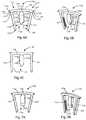
- FIG. 1Ais an isometric view of an implant comprising a compression bone staple and an independent plug with the staple in a relaxed state
- FIG. 1Bis a front view of the implant with the staple in an elastically deformed state
- FIG. 1Cis a front view of the implant with the staple in the relaxed state
- FIG. 2Ais a front view of the staple of FIG. 1A in the relaxed state
- FIG. 2Bis an isometric view of the staple of FIG. 1A in the relaxed state
- FIG. 3Ais an isometric view of the plug of FIG. 1A
- FIG. 3Bis a front view of the plug of FIG. 1A
- FIG. 3Cis a side view of the plug of FIG. 1A , the plug rotated 90° with respect to FIG. 3B
- FIG. 3Dis an isometric view of an alternative embodiment of a plug
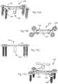
- FIG. 4Ais an isometric view of a drill guide for use with the implant of FIG. 1A ;
- FIG. 4Bis a front view of the drill guide of FIG. 4A ;
- FIG. 4Cis a top detail view of a guide portion of the drill guide of FIG. 4A ;
- FIG. 4Dis an isometric detail view of the guide portion of the drill guide of FIG. 4A ;
- FIG. 7Ais a front view of another embodiment of an implant comprising a compression bone staple and an integrated anti-torque plug with the staple in a relaxed state; and FIG. 7B is an isometric view of the staple of FIG. 7A ;
- FIG. 8Ais a top view of a joint between a first bone portion and a second bone portion, and pilot holes drilled into the joint and bone portions;
- FIG. 8Bis an isometric view of the joint of FIG. 8A , with the plug of FIG. 3D implanted in the joint;
- FIG. 8Cis an isometric view of the joint of FIG. 8A with the implant of FIG. 6A and the independent anti-torque plug of FIG. 3D inserted into the joint;
- FIG. 9Ais an isometric view of an implant including a clip and an interbody spacer
- FIG. 9Bis an isometric view of the implant of FIG. 9A with the clip joined to the spacer;
- FIG. 10Ais a side view of another embodiment of an implant comprising a compression bone staple and two integrated anti-torque plugs with the staple in an elastically deformed state;
- FIG. 10Bis an isometric view of the implant of FIG. 10A and another interbody spacer;
- FIG. 10Cis an isometric view of the interbody spacer of FIG. 10B joined to the implant of FIG. 10A ;
- FIG. 11Ais an anterior view of an implant including a spacer and two clips, implanted together in a tibiotalar joint
- FIG. 11Bis an oblique view of the implant and tibiotalar joint of FIG. 11B
- FIG. 11Cis an isometric view of the implant of FIG. 11A
- FIG. 11Dis an exploded isometric view of the implant of FIG. 11A ;
- FIG. 12Ais an isometric anterior view of an implant including a spacer and two clips, implanted together in an intervertebral joint;
- FIG. 12Bis an isometric view of the implant of FIG. 12A ;
- FIG. 12Cis an exploded isometric view of the implant of FIG. 12A ;
- FIG. 13is a top view of another embodiment of an implant including an anti-torque plug
- FIG. 14is a top view of another embodiment of an implant including an anti-torque plug
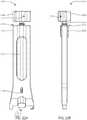
- FIG. 18Ais an isometric view of a drill guide for use with the implant of FIG. 17A ;
- FIG. 18Bis a front view of the drill guide of FIG. 18A ;
- FIG. 18Cis a top detail view of a guide portion of the drill guide of FIG. 18A ;
- FIG. 18Dis an isometric detail view of the guide portion of the drill guide of FIG. 18A ;
- FIG. 19Ais an isometric view of a drill for use with the drill guide of FIG. 18A ; and FIG. 19B is a bottom oblique view of the drill of FIG. 19A ;
- FIG. 20Ais an exploded isometric view of a handle and a punch guide body of a punch guide for use with the implant of FIG. 17A ; and FIG. 20B is another exploded isometric view of the handle and punch guide body of FIG. 20A from a different direction;
- FIG. 21Ais an isometric view of a punch for use with the punch guide of FIG. 20A ; and FIG. 21B is another isometric view of the punch of FIG. 21A from a different direction;
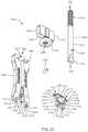
- FIG. 22Ais a front view of an implant inserter
- FIG. 22Bis a side view of the implant inserter of FIG. 22A
- FIG. 22Cis a front cross-sectional view of the implant inserter of FIG. 22A , taken along section line 22 C- 22 C of FIG. 22B
- FIG. 22Dis a side cross-sectional view of the implant inserter of FIG. 22A , taken along section line 22 D- 22 D of FIG. 22A
- FIG. 22Eis an exploded isometric view of the implant inserter of FIG. 22A
- FIG. 22Fis another exploded isometric view of the implant inserter of FIG. 22A from a different direction;
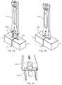
- FIG. 23is an isometric view of a joint between a first bone portion and a second bone portion
- FIG. 24is an isometric view of the joint of FIG. 23 with the drill guide of FIG. 18A positioned over the joint and the drill of FIG. 19A inserted through the drill guide;
- FIG. 25is an isometric view of the joint of FIG. 24 with holes drilled in the first and second bone portions;
- FIG. 26Ais an isometric view of the joint of FIG. 25 with the assembled punch guide of FIG. 20A engaged in the holes in the first and second bone portions; and FIG. 26B is a cross-sectional view through the punch guide and bone portions of FIG. 26A ;
- FIG. 27Ais an isometric view of the joint and punch guide of FIG. 26 with the punch of FIG. 21A inserted through the punch guide; and FIG. 27B is a cross-sectional view through the punch, punch guide, and bone portions of FIG. 27A ;
- FIG. 28is an isometric view of the joint of FIG. 27 with a slot punched into the first and second bone portions and extending across the joint;
- FIG. 29is an isometric view of the joint of FIG. 28 with the implant of FIG. 17A coupled to the implant inserter of FIG. 22A , the implant in an insertion state;
- FIG. 30is an isometric view of the joint, implant, and implant inserter of FIG. 29 with the implant inserted into the holes and slot in the first and second bone portions;
- FIG. 31is a bottom oblique view of the implant of FIG. 17A coupled to the implant inserter of FIG. 22A ;
- FIG. 32is an isometric view of the joint and implant of FIG. 30 after disconnecting the implant inserter from the implant;
- FIG. 33is a cross-sectional view of the joint and implant of FIG. 32 ;
- FIG. 34is a perspective view of a system including a clip, an inserter, a drill guide assembly, a broach guide, a punch, a broach removal knob, a tamp, a k-wire, a reamer, and a bone pin;
- FIG. 35is a perspective view of the compression bone staple and inserter of FIG. 34 ;
- FIG. 36is another perspective view of the compression bone staple and inserter of FIG. 35 from a different direction;
- FIG. 37is a perspective exploded view of the compression bone staple and inserter of FIG. 35 ;
- FIG. 38is another perspective exploded view of the compression bone staple and inserter of FIG. 35 from a different direction;
- FIG. 39is a front view of the compression bone staple and inserter of FIG. 35 ;
- FIG. 40is a right view of the compression bone staple and inserter of FIG. 35 ;
- FIG. 41is a cross-sectional view of the compression bone staple and inserter of FIG. 35 , taken along section line 41 - 41 of FIG. 40 ;
- FIG. 42is a cross-sectional view of the compression bone staple and inserter of FIG. 35 , taken along section line 42 - 42 of FIG. 39 ;
- FIG. 43is a perspective view of the drill guide assembly of FIG. 34 ;
- FIG. 44is another perspective view of the drill guide assembly of FIG. 43 from a different direction;
- FIG. 46is a perspective view of the punch and broach removal knob of FIG. 34 operatively assembled together;
- FIG. 47is another perspective view of the punch and broach removal knob of FIG. 46 from a different direction;
- FIG. 50is another perspective view of the broach guide of FIG. 34 from a different direction;
- FIG. 51is an isometric view of an implant assembly including a bone plate and a compression bone staple
- FIG. 52is an isometric view of the implant assembly of FIG. 51 from a different direction;
- FIG. 53is an isometric exploded view of the implant assembly of FIG. 51 ;
- FIG. 54is another isometric exploded view of the implant assembly of FIG. 51 from a different direction.
- FIG. 55is a cross-sectional view of the implant assembly of FIG. 51 taken along a mid-plane extending along the length of the plate.
- phrases “connected to,” “coupled to” and “in communication with”refer to any form of interaction between two or more entities, including mechanical, electrical, magnetic, electromagnetic, fluid, and thermal interaction. Two components may be functionally coupled to each other even though they are not in direct contact with each other.
- the term “abutting”refers to items that are in direct physical contact with each other, although the items may not necessarily be attached together.
- the phrase “fluid communication”refers to two features that are connected such that a fluid within one feature is able to pass into the other feature.
- a standard system of three mutually perpendicular reference planesis employed.
- a sagittal planedivides a body into right and left portions.
- a coronal planedivides a body into anterior and posterior portions.
- a transverse planedivides a body into superior and inferior portions.
- a mid-sagittal, mid-coronal, or mid-transverse planedivides a body into equal portions, which may be bilaterally symmetric.
- the intersection of the sagittal and coronal planesdefines a superior-inferior or cephalad-caudal axis.
- the intersection of the sagittal and transverse planesdefines an anterior-posterior axis.
- the intersection of the coronal and transverse planesdefines a medial-lateral axis.
- the superior-inferior or cephalad-caudal axis, the anterior-posterior axis, and the medial-lateral axisare mutually perpendicular.
- Anteriormeans toward the front of a body. Posterior means toward the back of a body. Superior or cephalad means toward the head. Inferior or caudal means toward the feet or tail. Medial means toward the midline of a body, particularly toward a plane of bilateral symmetry of the body. Lateral means away from the midline of a body or away from a plane of bilateral symmetry of the body. Axial means toward a central axis of a body. Abaxial means away from a central axis of a body. Ipsilateral means on the same side of the body. Contralateral means on the opposite side of the body. Proximal means toward the trunk of the body. Proximal may also mean toward a user or operator.
- Distalmeans away from the trunk. Distal may also mean away from a user or operator.
- Dorsalmeans toward the top of the foot. Plantar means toward the sole of the foot.
- Varusmeans deviation of the distal part of the leg below the knee inward, resulting in a bowlegged appearance.
- Valgusmeans deviation of the distal part of the leg below the knee outward, resulting in a knock-kneed appearance.
- substantiallymeans ⁇ 20% for linear dimensions and ⁇ 20° for angular dimensions.
- an implant 100includes a plug 150 and a clip 200 . It is appreciated that the plug 150 and clip 200 may be used together as implant 100 ; however, each may also be used independently. One or more implants 100 , clips 200 , and/or plugs 150 may be implanted in a single procedure, for example to join two bone portions together.
- the clip 200includes bone engaging members 202 and 204 which may be integral to a clip bridge 206 , also referred to as a clip body.
- the bone engaging members 202 and 204may be referred to as legs or fixation elements.
- a clipmay include more than two bone engaging members; or alternatively may include openings for one or more independent fasteners in lieu of integrated bone engaging members.
- the bone engaging member 202extends from a left end 230 of the clip bridge 206 and the bone engaging member 204 extends from an opposite right end 232 of the clip bridge 206 .
- Bone engaging member 202has a proximal end 234 attached to the left end 230 of the clip bridge 206 and an opposite distal end 236 which is a free end.
- Bone engaging member 204has a proximal end 238 attached to the right end 232 of the clip bridge 206 and an opposite distal end 240 which is a free end.
- Clip bridge 206has an upper or proximal surface 208 and a lower surface 210 .
- the lower surface 210may be referred to as a bone facing surface or distal surface.
- Bone engaging member 202extends from the lower surface 210 beside bone engaging member 204 .
- the bone engaging members 202 and 204may have features 212 that may improve bone purchase or improve pull out strength of the clip 200 from bone or soft tissue.
- the features 212may be referred to as teeth or serrations.
- the features 212are shown on facing sides of the bone engaging members 202 , 204 but may be on any or all sides of the bone engaging members.
- the clip 200may have projections or other connecting means 214 and 216 for connection with a means of insertion.
- the connecting means 214 , 216may be referred to as tabs, ears, protrusions, wings, retainers, connection features, or retaining members.
- the connecting means 214 and 216are shown extending sideways outwardly from the left and right ends 230 , 232 of the bridge 206 , respectively, along a longitudinal direction established by the bridge. In other embodiments, the connecting means may project perpendicularly with respect to the bridge.
- the connecting means 214 and 216may have lower surfaces 218 and 220 respectively that may releasably engage with a means of insertion that may allow an inserter or other means of insertion to be side loading, top loading or pivotably loaded.
- an inserter for clip 200may be side loading or pivotably loading.
- the lower surfaces 218 , 220may be referred to as bone facing surfaces or distal surfaces. Referring to FIG. 2A , the lower surfaces 218 , 220 are proximally spaced apart from, or proximally offset from, the lower surface 210 toward the upper surface 208 .
- the dashed extension lines 210 ′ and 210 ′′ in FIG. 2Ashow the level of the lower surface 210 versus the lower surfaces 218 , 220 .
- a means of insertionmay maintain the clip 200 in a first configuration thereby allowing a second configuration once an inserter is disassembled from the implant.
- the first configurationmay be an elastically deformed state, for example an insertion state, as seen in FIG. 1B .
- the second configurationmay be a free state or an implanted state, as seen in FIGS. 1A, 1C, and 2A .
- the means of insertionmay utilize features similar to connecting means 214 and 216 in combination with other surfaces such as top surface 208 . This combination of means of insertion may be used to maintain one or more features or arms or projections in a particular configuration.
- This combination of means of insertionmay create a bending modality, such as a three point or four point bend, to maintain a specific clip device configuration or combination of configurations.
- a combination of surfaces and means of insertion, such as connecting means 214may be used on the entire clip or portions of a clip to create or maintain a particular configuration of a clip.
- a tab such as 214 and top surface, such as 208may be used to maintain one side of a clip or one leg of a clip in a particular configuration. When disassembled, that leg may have a configuration that is different from or the same as the configuration of the rest of the clip.
- the clip 200is shown in the free state, or relaxed state, which is the shape of the clip 200 when no external forces are acting upon the clip 200 , other than gravity; the clip 200 experiences no elastic or plastic deflection or deformation.
- the bone engaging members 202 and 204converge as they extend away from the bridge 206 so that the distal ends 236 , 240 are closer together than are the proximal ends 234 , 238 .
- An angle 222is formed between the converging bone engaging members 202 and 204 in the free state. The angle 222 opens toward the bridge 206 .
- the angle 222may be referred to as a free state angle.
- plug 150extends between a proximal or first end 154 and a distal or second end 156 , along a longitudinal axis 158 .
- a plug head 160is at the first end 154 , separated from a plug tip 162 by a plug body 152 .
- the plug head 160may include a slot or channel 164 shaped to complementarily receive the clip bridge 206 , the channel flanked by opposing first and second rails 166 , 168 . From a superior or top down perspective, the plug head 160 may have a circular perimeter, whereas the body 152 is generally rectangular in cross-section, in order to prevent rotation of the plug 150 once inserted.
- the thickness of the body 152may be the same as or similar to the thickness of the bridge 206 and/or bone engaging members 202 , 204 of the clip 200 in the same direction (front-back), or the body 152 may be thicker or thinner than the clip 200 .
- the body 152is thinner than the bone engaging members 202 , 204 .
- the plug tip 162is tapered to facilitate insertion into bone.
- One or more sides of the plug body 152 and/or tip 162may include features 170 that may improve bone purchase.
- the features 170may be referred to as teeth or serrations.
- the features 170are shown on opposing sides of the plug body 152 and tip 162 , but may be on any or all sides. In an embodiment, features 170 may be absent.
- the cross-sectional shape of the bodymay be rectangular, triangular, round, double-barrel or another shape.
- a drill guide 300may be employed to prepare pilot holes for implant 200 in a joint 2 between a first bone 4 and a second bone 6 .
- the joint 2may be an actual anatomical joint, an osteotomy, a fracture, or an interface between the first and second bones 4 , 6 .
- Drill guide BOOmay include a handle portion 302 and a guide portion 304 ; some embodiments may exclude the handle portion 302 .
- the guide portion 304includes a guide bar 310 from which one or more guide elements may depend. In the embodiment depicted, guide portion 304 includes first and second single hole guide elements 312 , 314 which flank a multi-hole guide element 316 .
- guide element 312surrounds and supports a first lumen 322 ; guide element 314 surrounds and supports a second lumen 324 , and guide element 316 surrounds and supports a third lumen 326 . All the guide elements may include pointed or tapered tips to facilitate engagement with bone or tissues during the drilling procedure.
- Guide element 316includes a wedge 318 which may be aligned with a joint 2 to control placement of the pilot holes with respect to the joint 2 , during a drilling procedure.
- the first and second lumens 322 , 324are circular in a transverse cross section, and each are shaped to guide a drill for drilling a single bore.
- the third lumen 326includes three overlapping lumens 327 , 328 , 329 .
- the third lumen 326has the shape of three overlapping circles, which may be called a “snowman shape.”
- the elongated transverse shape of the third lumen 326allows a single drill to be used to create a pilot hole large enough to receive the plug 150 .
- the third lumenmay have an oval, circular, figure eight, rectangular, or other shape cross-sectional shape which provides a line to line or interference fit between the lumen and the plug upon insertion of the plug.
- the first, second and third lumens 322 , 324 , 326are co-planar. In other embodiments, one or more of the lumens may be out of the plane of the others.
- Drill guide 300is positioned adjacent the first and second bone portions 4 , 6 , with guide portion 304 spanning the joint 302 .
- the guide portion 304may be impacted, with wedge 318 positioned in joint 2 .
- Wedge 318may be pressed, impacted or otherwise aligned into the joint 2 , to ensure proper alignment of the drill guide with respect to the joint 2 , and may ensure that the pilot holes are centered with respect to the joint line.
- Pilot holes 352 , 354 , and 356are drilled into the bone portions 4 , 6 and joint 2 .
- Residual material 358which may be in the form of ridges, may be left in pilot hole 356 . This residual material may create interference for the plug 150 providing a tight fit of the plug in the pilot hole 356 .
- plug 150is inserted into the pilot hole 356 and in contact with bone portions 4 , 6 .
- the plugprovides stability to the joint, and provides resistance to forces acting on the joint, including shear and rotational forces.
- Head 160 of the plugis oriented so that channel 164 is approximately perpendicular to the joint 2 , and is aligned in the same plane with outboard pilot holes 352 , 354 .
- clip 200is inserted with bridge 206 approximately perpendicular to the joint 2 .
- a means of insertionsuch as an instrument may flex clip 200 toward the insertion state to urge leg distal ends 236 , 240 away from one another.
- Bone engaging member 202is inserted in pilot hole 352 , and bone engaging member 204 is inserted in pilot hole 354 .
- Clip bridge 206is received in channel 164 , preventing rotation of the clip 200 once inserted, and preventing rotation of the bone portions 4 , 6 relative to one another.
- a plug 180includes a head 190 which lacks a channel.
- plug 180may be offset from the plane of corresponding implant 200 , as shown in FIGS. 8B and 8C .
- Drill guide 300may be used to prepare an offset pilot hole 366 .
- Plug 180may be implanted independently as a stand-alone implant, or may be implanted with a staple such as clip 200 or others disclosed herein.
- plug 150may be implanted to be offset from the plane of clip 200 .
- the plug 180may provide torsional stability, preventing rotation of the bone portions 4 , 6 relative to one another, and/or preventing shear forces from acting upon the joint.
- plug 150may be implanted with another corresponding implant such as a bone plate.
- the plug and bone plate combinationmay be implanted across a joint between two bones, bodies or devices to resist rotation of the bodies about the joint.
- the bone platemay have two or more openings for fasteners, and a feature to cooperatively connect with plug 150 .
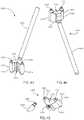
- a clip 1100includes an integrated anti-torque plug 1150 .
- Clip 1100 and other clips disclosed hereinmay also be referred to as a fastener, staple, or implant.
- Anti-torque plug 1150 and other anti-torque features disclosed hereinmay also be referred to as a tab, keel, post, or implant.
- FIGS. 7A-7Bshow an alternate embodiment of an implant; clip 1200 includes an integrated anti-torque plug 1250 which has a chisel-shaped tip.
- FIG. 3Dshows an independent anti-torque plug 180 .
- One or more clips 1100 , 1200 , plates and/or plugs 180 disclosed hereinmay be implanted in a single procedure, for example to join two bone portions together.
- the clip 1100includes bone engaging members 1102 and 1104 which may be integral to a clip bridge 1106 , also referred to as a clip body.
- the bone engaging members 1102 and 1104may be referred to as legs.
- a clipmay include more than two bone engaging members; or alternatively may include openings for one or more independent fasteners in lieu of the bone engaging members.
- the implant 1100may be more similar to a plate.
- the bone engaging member 1102extends from a left end 1130 of the clip bridge 1106 and the bone engaging member 1104 extends from an opposite right end 1132 of the clip bridge 1106 .
- Bone engaging member 1102has a proximal end 1134 attached to the left end 1130 of the clip bridge 1106 and an opposite distal end 1136 which is a free end.
- Bone engaging member 1104has a proximal end 1138 attached to the right end 1132 of the clip bridge 1106 and an opposite distal end 1140 which is a free end.
- Clip bridge 1106has at least one upper or proximal surface 1108 and at least one lower or distal surface 1110 .
- the lower surface 1110may be referred to as a bone facing surface.
- Bone engaging member 1102extends from the lower surface 1110 beside bone engaging member 1104 .
- the bone engaging members 1102 and 1104may have features 1112 that may improve bone purchase or improve pull out strength of the clip 1100 from bone or soft tissue.
- the features 1112may be referred to as teeth or serrations.
- the features 1112are shown on facing sides of the bone engaging members 1102 , 1104 but may be on any or all sides of the bone engaging members.
- the clip 1100may have projections or other connecting means 1114 and 1116 for connection with a means of insertion.
- the connecting means 1114 , 1116may be referred to as tabs, ears, protrusions, wings, retainers, or retaining members.
- the connecting means 1114 and 1116are shown extending sideways outwardly from the left and right ends 1130 , 1132 of the bridge 1106 , respectively, along a longitudinal direction established by the bridge. In other embodiments, the connecting means may project perpendicularly with respect to the bridge.
- the connecting means 1114 and 1116may have lower or distal surfaces 1118 and 1120 respectively that may releasably engage with a means of insertion that may allow an inserter or other means of insertion to be side loading, top loading or pivotably loaded.
- a means of insertionthat may allow an inserter or other means of insertion to be side loading, top loading or pivotably loaded.
- an inserter for clip 1100may be side loading or pivotably loading.
- the lower surfaces 1118 , 1120may be referred to as bone facing surfaces. Referring to FIG. 6A , the lower surfaces 1118 , 1120 are proximally spaced apart from, or proximally offset from, the lower surface 1110 .
- the dashed extension lines 1110 ′ and 1110 ′′ in FIG. 6Ashow the level of the lower surface 1110 versus the lower surfaces 1118 , 1120 .
- An integrated anti-torque plug 1150projects distally from the lower surface 1110 of bridge 1106 .
- a single plug 1150is centered between bone engaging members 1102 , 1104 ; in other embodiments the plug may be off-center relative to the members 1102 , 1104 , and/or a plurality of plugs may be included.
- the plugmay also be connected to the implant 1100 in more than one location along the lower surface 1110 of bridge 1106 .
- Plug 1150includes a neck portion 1152 where the plug is joined to bridge 1106 , a body 1154 , and a tip 1156 .
- Neck portion 1152may be formed as a waist having a reduced width with respect to the plug body 1154 as shown in FIGS.
- the plug thickness between sides 1160 and 1166is less than the thickness of the bone engaging members 1102 , 1104 in the same direction.
- the plug tip 1156may be tapered on at least two sides 1162 , 1164 with respect to the plug body to facilitate insertion into a joint.
- the plug sides 1160 , 1162 , 1164 , 1166may be smooth as seen in FIGS. 6A-6C ; in other embodiments one or more plug sides may include teeth, serrations, or other surface roughening. In other embodiments, the plug may have a differently shaped cross-section.
- the plugdoes not preclude compression of the bone segments by the bone engaging members 1102 , 1104 , at least because the plug is oriented in a plane coplanar with, or parallel to, the plane of the bridge 1106 and bone engaging members 1102 , 1104 of the clip 1100 .
- a combination of surfaces and means of insertion, such as connecting means 1114may be used on the entire clip or portions of a clip to create or maintain a particular configuration of a clip.
- a tabsuch as 1114 and top surface, such as 1108 may be used to maintain one side of a clip or one leg of a clip in a particular configuration. When disassembled, that leg may have a configuration that is different from or the same as the configuration of the rest of the clip.
- the clip 1100is shown in the free state, or relaxed state, which is the shape of the clip 1100 when no external forces are acting upon the clip 1100 , other than gravity; the clip 1100 experiences no elastic or plastic deflection or deformation.
- the bone engaging members 1102 and 1104converge as they extend away from the bridge 1106 so that the distal ends 1136 , 1140 are closer together than are the proximal ends 1134 , 1138 .
- An angle 1122is formed between the converging bone engaging members 1102 and 1104 in the free state. The angle 1122 opens toward the bridge 1106 .
- the angle 1122may be referred to as a free state angle.
- Clip 1200includes a first bone-engaging member 1202 , a second bone-engaging member 1204 , a bridge 1206 , and an integrated anti-torque plug 1250 .
- the descriptions of the bone engaging members, bridge and anti-torque plug of clip 1100are applicable to clip 1200 .
- the descriptions of the free state, the elastically deformed state, and means of insertion of clip 1100are also applicable to clip 1200 .
- the anti-torque plug 1250 of clip 1200includes neck 1252 and body 1254 portions, as described for clip 1100 .
- a tip portion 1256 of clip 1200is tapered on all four sides with respect to the body 1254 , to form a chisel or wedge shape.
- Other embodimentsmay include tip portions having other taper shapes in which one or more sides of the tip is tapered with respect to the body. In other embodiments, the taper may extend along one or more body portion sides.
- an independent anti-torque plug 180extends between a proximal or first end 182 and a distal or second end 184 , along a longitudinal axis 186 .
- a plug head 190is at the first end 182 , separated from a plug tip 188 by a plug body 192 .
- the plug head 190may have a circular perimeter, whereas the body 192 is generally rectangular in cross-section, in order to prevent rotation of the plug 180 once inserted.
- the plug tip 188is tapered to facilitate insertion into bone.
- One or more sides of the plug body 192 and/or tip 188may include features 194 that may improve bone purchase.
- the features 194may be referred to as teeth or serrations.
- the features 194are shown on opposing sides of the plug body 192 and tip 188 , but may be on any or all sides. In an embodiment, features 194 may be absent. In other embodiments, the cross-sectional shape of the body 192 may be rectangular, triangular, round, double-barrel or another shape.
- One or more plugs 180may be implanted independently in a joint to prevent rotation of the bones or bodies about the joint, and/or one or more plugs 180 may be implanted in conjunction with any of the clips disclosed herein, as in FIG. 8C , to provide additional joint stability.
- the drill guide BOOmay be employed to prepare pilot holes for implants 180 , 1100 , 1200 or any implant disclosed herein, in a joint 2 between a first bone 4 and a second bone 6 .
- the joint 2may be an actual anatomical joint, an osteotomy, a fracture, or an interface between the first and second bones 4 , 6 .
- Drill guide BOOmay be used to prepare a joint for implantation of any of the implants disclosed herein.
- Other instrumentationmay be used to prepare a site to receive one or more of the implants described herein, including punches, drills, saws, sawblades, or any other instrument capable of creating an opening through the tissue, bone or joint material.
- Drill guide 300is positioned adjacent the first and second bone portions 4 , 6 , with guide portion 304 spanning the joint 2 .
- the guide portion 304may be impacted, with wedge 318 positioned in joint 2 .
- Wedge 318may be pressed, impacted or otherwise aligned into the joint 2 , to ensure proper alignment of the drill guide with respect to the joint 2 , and may ensure that the pilot holes are centered with respect to the joint line. Pilot holes 352 , 354 , and 356 are drilled into the bone portions 4 , 6 and joint 2 .
- Residual material 358which may be in the form of ridges, may be left in pilot hole 356 . This residual material may create interference for the plug 1150 providing a tight fit of the plug in the pilot hole 356 .
- another pilot hole 366may be created for implantation of an independent anti-torque plug 180 . Pilot hole 366 may be drilled in joint 2 , and may be offset from pilot holes 352 , 354 , and 356 .
- clip 1100is inserted into the pilot holes 352 , 354 , 356 , with bridge 1106 approximately perpendicular to the joint 2 .
- a means of insertionsuch as an instrument may flex clip 1100 toward the insertion state to urge leg distal ends 1136 , 1140 away from one another.
- Bone engaging member 1102is inserted into pilot hole 352
- bone engaging member 1104is inserted into pilot hole 354
- plug 1150is inserted into the joint, in pilot hole 356 and in contact with bone portions 4 , 6 .
- the plug 1150provides stability to the joint, and provides resistance to forces acting on the joint, including shear and rotational forces.
- an auxiliary independent anti-torque plug 180may be implanted in optional pilot hole 366 .
- the plug 180may be oriented so that features 70 are approximately perpendicular to the joint 2 , in order to provide an interference fit with any residual material in pilot hole 366 .
- Plug 180may be offset from the plane of the bone engaging members 1102 , 1104 and plug 1150 of clip 1100 .
- implant 1400includes a clip 1500 and a spacer 1450 .
- the description of clip 1100may apply to clip 1500 , with the exception that clip 1500 includes a plug 1550 having neck portion 1552 which may be greater to or equal in width to the body of the plug.
- Spacer 1450includes a body 1452 , and may have one or more fenestrations 1454 for insertion of bone graft material and/or for bone in-growth.
- Spacer 1450also includes a slot 1456 shaped to receive a plug such as plug 1550 , and may form an interference fit with neck 1552 when joined with the plug as shown in FIG.
- spacer 1450may be joined to clip 1500 , and the resultant implant 1400 may be implanted as a unit. Alternately, spacer 1450 may be implanted into a prepared joint space first, and then clip 1500 may be implanted, with slot 1456 receiving plug 1550 .
- implant 1600includes a clip 1700 and a spacer 1650 .
- the description of clip 1100may apply to clip 1700 , with the exception that clip 1700 includes two anti-torque plugs 1750 , 1770 .
- Each anti-torque plug 1750 , 1770may include a neck portion 1752 , 1772 which may taper outward from the neck to the clip bridge 1706 .
- Spacer 1650includes a body 1652 , and may have one or more fenestrations 1654 for insertion of bone graft material and/or for bone in-growth.
- Spacer 1650also includes slots 1656 , 1658 shaped to receive plugs 1750 , 1770 , which may form an interference fit when the spacer 1650 joined with the plugs as shown in FIG. 10C .
- spacer 1650may be joined to clip 1700 , and the resultant implant 1600 may be implanted as a unit into a joint between two bodies, for example two bones.
- spacer 1650may be implanted into a prepared joint space first, and then clip 1700 may be implanted, with slots 1656 , 1658 receiving plugs 1750 , 1770 .
- FIGS. 11A-12Cadditional examples of implants comprising clips and spacers are shown.
- FIGS. 11A and 11Bdepict an implant 1800 implanted into a tibiotalar joint between a tibia 8 and a talus 10 .
- FIGS. 11C and 11Dillustrate that implant 1800 comprises two clips 1500 in combination with a spacer 1850 .
- FIG. 12Adepicts an implant 1900 implanted into an intervertebral joint between a first vertebra 12 and a second vertebra 14 .
- FIGS. 12B and 12Cillustrate that implant 1900 comprises two clips 1500 in combination with a spacer 1950 .
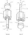
- Implant 2000includes implant body 2006 , and keel 2050 which projects away from implant body 2006 .
- Implant 2000may include one or more bone engagement features 2002 , 2004 to fasten the implant 2000 to bone, tissue, and/or another device.
- Bone engagement features 2002 , 2004may be integrated into implant body 2006 , for example as posts, legs, or pins; or may be separate fasteners such as screws.
- the implant 2000may include a first configuration which is an elastically deformed state for insertion, and a second configuration which is a relaxed or free state when implanted, as described above for implants 1100 , 1200 .
- the keel 2050has a star-shaped cross-sectional shape, with four flanges or lobes 2052 , 2054 , 2056 , 2058 protruding from a central keel body 2060 .
- a distal tip of the keelmay be tapered to facilitate introduction into a joint.
- the keel 2050may be integrally formed with the implant body 2006 as one piece, or may be a separate entity joined to the implant body before or during implantation.
- Implant 2000may be implanted according to the methods described above for implants 1100 , 1200 .
- the flanges 2052 , 2054 , 2056 , 2058can have an interference fit with the surrounding joint tissues, to resist rotation and shear forces around the joint.
- Implant 2100includes implant body 2106 , and keel 2150 which projects away from implant body 2106 .
- Implant 2100may include one or more bone engagement features 2102 , 2104 to fasten the implant 2100 to bone, tissue and/or another device.
- Bone engagement features 2102 , 2104may be integrated into implant body 2106 , for example as posts, legs, or pins; or may be separate fasteners such as screws.
- the implant 2100may include a first configuration which is an elastically deformed state for insertion, and a second configuration which is a relaxed or free state when implanted, as described above for implants 1100 , 1200 .
- the keel 2150includes four longitudinal edges 2152 , 2154 , 2156 , 2158 projecting from a central keel body 2160 .
- a distal tip of the keelmay be tapered to facilitate introduction into a joint.
- the keel 2150may be integrally formed with the implant body 2106 as one piece, or may be a separate entity joined to the implant body before or during implantation.
- Implant 2100may be implanted according to the methods described above for implants 1100 , 1200 .
- the edges 2152 , 2154 , 2156 , 2158can have an interference fit with the surrounding joint tissues, to resist rotation and shear forces acting on the joint.
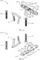
- Implant 2200includes a plate 2206 and a keel 2250 .
- the plate 2206 depictedincludes openings for a plurality of bone screws 2280 for fastening the plate 2206 across a joint between two bones or bodies.
- fastenersmay be formed integrally with the plate 2206 .
- the keel 2250is received in a slot 2202 in the plate and projects inferiorly below the plate.
- the keelmay be formed integrally with the plate, as shown for implants 1100 , 1200 .
- drill guide BOOmay be used to create a pilot hole for keel 2250 in a joint 2 between first second bodies 4 , 6 .
- Plate 2206may be oriented perpendicular to the joint and fastened to the bodies 4 , 6 with fasteners 2280 .
- Keel 2250may be inserted through slot 2202 and into the joint 2 .
- Keel 2250may be fastened to the plate 2206 .
- keel 2250may be joined to the plate 2206 before implantation.
- the keel 2250may be replaced by implant 1100 , 1200 , 1500 , 1700 , 2000 , or 2100 . It is appreciated that within the scope of the disclosure, other shapes or configurations of plates may include an integrated or associated keel.
- keels 1150 , 1250 , 2060 , 2160 , 2250 and other keels disclosed hereinmay have other shapes, including but not limited to square, rectangular, triangular, star, and/or irregular or asymmetric.
- the keels disclosed hereinmay also have rounded shapes, if they are sufficiently sized to provide an interference fit with the surrounding tissues or bodies in which they are implanted, in order to resist rotation and shear forces.
- Implant 2300includes first and second bone engagement members 2302 , 2304 and an implant body 2306 .
- the implant 2300may include a first configuration which is an elastically deformed state for insertion, and a second configuration which is a relaxed or free state when implanted, as described above for implants 1100 , 1200 .
- the implant 2300includes protrusion 2350 which projects inferiorly from the implant body 2306 .
- Implant 2300may be implanted into a joint, as described previously for implants 1100 , 1200 .
- Protrusion 2350is received in joint 2 and may form an interference fit in a prepared pilot hole, and the bone engagement members 2302 , 2304 may provide compression across the joint.
- the protrusion 2350may provide stability to the joint and resist rotation and shear forces acting on the joint.
- another implant or clip 2400includes an integrated anti-torque plug 2450 .
- Clip 2400 and other clips disclosed hereinmay also be referred to as a fastener, staple, or implant.
- Anti-torque plug 2450 and other anti-torque features disclosed hereinmay also be referred to as a tab, keel, post, or implant.
- One or more clips 2400may be implanted in a single procedure, for example to join two bone portions together.
- the clip 2400includes bone engaging members 2402 and 2404 which may be integral to a clip bridge 2406 , also referred to as a clip body.
- the bone engaging members 2402 and 2404may be referred to as legs.
- a clipmay include more than two bone engaging members; or alternatively may include openings for one or more independent fasteners in lieu of the bone engaging members.
- the implant 2400may be more similar to a plate.
- the bone engaging member 2402extends from a left end 2430 of the clip bridge 2406 and the bone engaging member 2404 extends from an opposite right end 2432 of the clip bridge 2406 .
- Bone engaging member 2402has a proximal end 2434 attached to the left end 2430 of the clip bridge 2406 and an opposite distal end 2436 which is a free end.
- Bone engaging member 2404has a proximal end 2438 attached to the right end 2432 of the clip bridge 2406 and an opposite distal end 2440 which is a free end.
- Clip bridge 2406has at least one upper or proximal surface 2408 and at least one lower or distal surface 2410 .
- the lower surface 2410may be referred to as a bone facing surface.
- Bone engaging member 2402extends from the lower surface 2410 beside bone engaging member 2404 .
- the bone engaging members 2402 and 2404may have features 2412 that may improve bone purchase or improve pull out strength of the clip 2400 from bone or soft tissue.
- the features 2412may be referred to as teeth or serrations.
- the features 2412are shown on facing sides of the bone engaging members 2402 , 2404 but may be on any or all sides of the bone engaging members.
- the clip 2400may have projections or other connecting means 2414 and 2416 for connection with a means of insertion.
- the connecting means 2414 , 2416may be referred to as tabs, ears, protrusions, wings, retainers, or retaining members.
- the connecting means 2414 and 2416are shown extending sideways outwardly from the left and right ends 2430 , 2432 of the bridge 2406 , respectively, along a longitudinal direction established by the bridge. In other embodiments, the connecting means may project perpendicularly with respect to the bridge.
- the connecting means 2414 and 2416may have lower or distal surfaces 2418 and 2420 respectively that may releasably engage with a means of insertion that may allow an inserter or other means of insertion to be side loading, top loading or pivotably loaded.
- a means of insertionthat may allow an inserter or other means of insertion to be side loading, top loading or pivotably loaded.
- an inserter for clip 2400may be side loading or pivotably loading.
- the lower surfaces 2418 , 2420may be referred to as bone facing surfaces. Referring to FIG. 17A , the lower surfaces 2418 , 2420 are proximally spaced apart from, or proximally offset from, the lower surface 2410 .
- the dashed extension lines 2410 ′ and 2410 ′′ in FIG. 17Ashow the level of the lower surface 2410 versus the lower surfaces 2418 , 2420 .
- An integrated anti-torque plug 2450projects distally from the lower surface 2410 of bridge 2406 .
- a single plug 2450is centered between bone engaging members 2402 , 2404 ; in other embodiments the plug may be off-center relative to the members 2402 , 2404 , and/or a plurality of plugs may be included.
- the plugmay also be connected to the implant 2400 in more than one location along the lower surface 2410 of bridge 2406 .
- Plug 2450includes a neck portion 2452 where the plug is joined to bridge 2406 , a body 2454 , and a tip 2456 .
- Neck portion 2452may be formed as a waist having a reduced width with respect to the plug body 2454 as shown in FIGS.
- plug 2450is connected to the clip 2400 only via the bridge 2406 , and not along the bone engaging members 2402 , 2404 .
- Plug 2450may be rectangular in cross-section and includes four sides 2460 , 2462 , 2464 , 2466 .
- the plug thickness between sides 2460 and 2466may be less than, the same as, similar to, or greater than the thickness of the bridge 2406 and/or bone engaging members 2402 , 2404 of the clip 2400 in the same direction (front-back).
- the plug thickness between sides 2460 and 2466is less than the thickness of the bridge and bone engaging members 2402 , 2404 in the same direction, as seen best in FIGS. 17C-17D .
- the plug tip 2456may be tapered on at least two sides 2462 , 2464 with respect to the plug body to facilitate insertion into a joint.
- the plug sides 2460 , 2462 , 2464 , 2466may be smooth as seen in FIGS. 17A-17D ; in other embodiments one or more plug sides may include teeth, serrations, or other surface roughening. In other embodiments, the plug may have a differently shaped cross-section.
- the plugdoes not preclude compression of the bone segments by the bone engaging members 2402 , 2404 , at least because the plug is oriented in a plane coplanar with, or parallel to, the plane of the bridge 2406 and bone engaging members 2402 , 2404 of the clip 2400 , as shown in FIG. 17C .
- a means of insertionmay maintain the clip 2400 in a first configuration thereby allowing a second configuration once an inserter is disassembled from the implant.
- the first configurationmay be an elastically deformed state, for example an insertion state.
- the second configurationmay be a free state or an implanted state, as seen in FIG. 17A .
- the means of insertionmay utilize features similar to connecting means 2414 and 2416 in combination with other surfaces such as top surface 2408 .
- This combination of means of insertionmay be used to maintain one or more features or arms or projections in a particular configuration.
- This combination of means of insertionmay create a bending modality, such as a three point or four point bend, to maintain a specific clip device configuration or combination of configurations.
- a combination of surfaces and means of insertion, such as connecting means 2414may be used on the entire clip or portions of a clip to create or maintain a particular configuration of a clip.
- a tab such as 2414 and top surface, such as 2408may be used to maintain one side of a clip or one leg of a clip in a particular configuration. When disassembled, that leg may have a configuration that is different from or the same as the configuration of the rest of the clip.
- the clip 2400is shown in the free state, or relaxed state, which is the shape of the clip 2400 when no external forces are acting upon the clip 2400 , other than gravity; the clip 2400 experiences no elastic or plastic deflection or deformation.
- the bone engaging members 2402 and 2404converge as they extend away from the bridge 2406 so that the distal ends 2436 , 2440 are closer together than are the proximal ends 2434 , 2438 .
- An angle 2422is formed between the converging bone engaging members 2402 and 2404 in the free state. The angle 2422 opens toward the bridge 2406 .
- the angle 2422may be referred to as a free state angle.
- a drill guide 2500may be employed to prepare pilot holes for implant 2400 in a joint 2 between a first bone 4 and a second bone 6 .
- the joint 2may be an actual anatomical joint, an osteotomy, a fracture, or an interface between the first and second bones 4 , 6 .
- Drill guide 2500may include a handle portion 2502 and a guide portion 2504 ; some embodiments may exclude the handle portion 2502 .
- the guide portion 2504includes a guide bar 2510 from which one or more guide elements may depend. In the embodiment depicted, guide portion 2504 includes first and second single hole guide elements 2512 , 2514 .
- first and second lumens 2522 , 2524are circular in a transverse cross section, and each is shaped to guide a drill for drilling a single bore.
- first and second lumens 2522 , 2524are co-planar. In other embodiments, one or more of the lumens may be out of the plane of the others.
- a drill bit 2550may be used with the drill guide 2500 to prepare pilot holes for implant 2400 .
- the drill bit 2550extends between a distal end 2552 and a proximal end 2554 .
- the distal end 2552includes a cutting portion 2556 with side and/or end cutting flutes.
- the proximal end 2554includes a torque coupling portion 2558 for connection to a powered or manual torque source, such as an electric drill or a T-handle.
- the drill bit 2550is shown with an optional intermediate portion 2560 with an outer diameter that is larger than the outer diameter of the cutting portion 2556 and smaller than the outer diameter of the torque coupling portion 2558 .
- the drill bit 2550may include one or more depth marks and/or depth stops and/or indicia.
- a shoulder 2562 between the cutting portion 2556 and the intermediate portion 2560may serve as a depth mark or depth stop.
- Another depth mark 2564is shown in the intermediate portion 2560 proximal to the shoulder 2562 .
- the shoulder 2562 and/or depth mark 2564may align with, or may make contact with, a corresponding feature of the drill guide 2500 .
- the depth mark 2564may align with the proximal side of the guide bar 2510 to indicate that the drill bit 2550 has been advanced to the proper depth.
- a punch guide 2600may include a punch guide body 2602 and a handle 2604 .
- the punch guide 2600is illustrated in exploded views in FIGS. 20A-20B and operatively assembled in FIGS. 26A-27B .
- Bilateral pegs 2618 , 2620extend distally from the distal side 2606 to the left and right of the lumen 2616 .
- the pegs 2618 , 2620may have distal tapered or pointed tips as shown in FIG. 20B .
- a boss 2622may extend obliquely outwardly and proximally from the handle-facing side 2610 .
- the boss 2622may be centered in the left-right width of the punch guide body 2602 .
- An internally threaded hole 2624may extend into the boss 2622 .
- the handle 2604may be a generally cylindrical shaft that extends between a distal end 2626 and a proximal end 2628 .
- the distal end 2626may include an externally threaded distal tip portion 2630 with threads that are complementary to the internal threads in the hole 2624 of the punch guide body 2602 .
- the proximal end 2628may function as a handle.
- the punch guide 2600may be assembled by threading the distal tip portion 2630 into the internally threaded hole 2624 . In use, the punch guide body 2602 and handle 2604 are fixed together.
- a punch 2650may be used with the punch guide 2600 to prepare a slot to receive the plug 2450 of the clip 2400 .
- the punch 2650extends between a distal end 2652 and a proximal end 2654 .
- the punch 2650may include four portions or segments along its distal-proximal length.
- a first portion 2656may extend proximally from the distal end 2652 .
- the first portion 2656may have an elongated cross-sectional shape that is complementary to the cross-sectional shape of the lumen 2616 of the punch guide 2600 .
- the distal-most aspect of the first portion 2656may be sharpened or pointed to penetrate bone.
- a second portion 2662may extend proximally from the first portion 2656 .
- the second portion 2662may have the same cross-sectional shape as the first portion, outwardly offset so that the second portion is wider and/or thicker than the first portion.
- a third portion 2664may extend proximally from the second portion 2662 .
- the third portion 2664may have a cross sectional shape that is similar to, or different from, the cross-sectional shapes of the first and second portions 2656 , 2662 , and which may be outwardly offset so that the third portion is wider and/or thicker than the second portion.
- the third portion 2664is shown with a rectangular cross-sectional shape.
- a transverse hole 2666may extend through the thickness of the punch 2650 in the third portion 2664 .
- a fourth portion 2668may extend proximally from the third portion 2664 .
- the fourth portion 2668may have a circular cross-sectional shape that is outwardly offset so that the fourth portion is wider and/or thicker than the third portion 2664 .
- the third and fourth portions 2664 , 2668together or separately, may function as a handle.
- the fourth portion 2668may function as a strike platform to impact the punch 2650 distally into bone or proximally out of bone.
- the punch guide 2600 and punch 2650may be combined together in a single instrument.
- the punch guide body 2602 , handle 2604 , and punch 2650may be formed together as a unitary part.
- the feature corresponding to the punch 2650may be equivalent to the first portion 2656 shown in FIGS. 21A, 21B, and 27B , which is the portion that protrudes distally from the punch guide body 2602 between the pegs 2618 , 2620 .
- an inserter 2700may be used with any of the implants or clips disclosed herein.
- the inserter 2700may include a body 2702 , a ram 2704 , a ram pin 2706 , a knob 2708 , a shaft 2710 , and a knob pin 2712 .
- the ram 2702 and the ram pin 2706may be coupled together as a ram sub-assembly 2714 .
- the knob 2708 , the shaft 2710 , and the knob pin 2712may be coupled together as a shaft sub-assembly 2716 .
- the body 2702extends between a distal end 2718 and a proximal end 2720 .
- the body 2702may be a generally plate-like part that is wider at the distal end 2718 and narrower at the proximal end 2720 .
- the distal-most aspect of the body 2702may include two jaws or hooks 2722 , 2724 that face each other across a shallow alcove 2726 .
- the hooks 2722 , 2724include proximal surfaces 2728 , 2730 , respectively.
- the hook 2722includes a front wall 2732 and the hook 2724 includes a back wall 2734 .
- a notch 2736extends proximally from a central portion of the alcove 2726 .
- a first slot 2738extends through the body 2702 proximal to the notch 2736 along a front-back direction.
- the slot 2738is elongated along a proximal-distal direction.
- a second slot 2740extends through the body 2702 proximal to the slot 2738 along the front-back direction.
- the slot 2740is elongated along the proximal-distal direction.
- the second slot 2740is longer than the first slot 2738 in the proximal-distal direction and is wider than the first slot 2738 in the left-right direction.
- a first central longitudinal hole 2742extends proximally into the body 2702 from the distal end 2718 to the slot 2740 .
- the slot 2738 and the hole 2742intersect at right angles.
- a second central longitudinal hole 2744extends distally into the body 2702 from the proximal end 2720 to the slot 2740 .
- the hole 2744may be internally threaded.
- the body 2702may be thickened in the vicinity of the hole 2744 so as to adequately support the hole 2744 under expected loads.
- the ram 2704extends between a distal end 2750 and a proximal end 2752 .
- the ram 2704includes a distal head 2754 , which may be generally rectangular as shown. As seen best in FIGS. 22A and 22C , the distal-most aspect of the head 2754 may be convex in a front or back view.
- a shaft 2756extends proximally from the head 2754 .
- the shaft 2756may have a circular cross section as shown.
- the outer diameter of the shaft 2756may be similar to the thickness of the head 2754 in a front-back direction, and may be less than the width of the head in a left-right direction.
- a transverse hole 2758extends through the shaft 2756 near the proximal end 2752 .
- the knob 2708may be a generally rectangular part which may be contoured to match the proximal end 2720 of the body 2702 .
- a central longitudinal hole 2760may extend through the knob in a proximal-distal direction.
- a transverse hole 2762may extend through the knob in a front-back direction.
- the shaft 2710extends between a distal end 2770 and a proximal end 2772 .
- the shaft 2710may include three portions or segments along its distal-proximal length.
- a first portion 2774extends proximally from the distal end 2770 , has a circular cross section, and a smooth outer surface.
- a second portion 2778extends proximally from the first portion 2774 and has external threads 2780 .
- the minor diameter of the external threadsmay be greater than the outer diameter of the first portion 2774 .
- a third portion 2782extends proximally from the second portion 2778 to the proximal end 2720 , has a circular cross section, and a smooth outer surface.
- the outer diameter of the third portion 2782may be similar to the minor diameter of the external threads 2780 .
- a transverse hole 2784extends through the third portion 2782 near the proximal end 2772 .
- the knob 2708 , the shaft 2710 , and the knob pin 2712may be coupled together to form the shaft sub-assembly 2716 by inserting the third portion 2782 of the shaft 2710 into the hole 2760 of the knob 2708 , aligning the transverse holes 2762 , 2784 , and inserting the knob pin 2712 through the holes 2762 , 2784 .
- the inserter 2700may be assembled by inserting the shaft 2756 of the ram 2704 into the hole 2742 of the body 2702 , aligning the transverse hole 2758 with the first slot 2738 , and inserting the ram pin 2706 through the slot 2738 and hole 2758 ; and by inserting the first portion 2774 of the shaft 2710 into the hole 2744 of the body 2702 and advancing the shaft distally relative to the body until the first portion enters the hole 2742 and the external threads 2780 engage the internal threads of the hole 2744 .
- the head 2754may be at least partially received in the notch 2736 . Referring to FIGS. 22C and 22D , the distal end 2770 of the shaft 2710 directly contacts the proximal end 2752 of the ram 2704 , but the two parts are not otherwise mechanically connected.
- the inserter 2700may be coupled to any implant or clip disclosed herein.
- Clip 2400will be used as an example.
- a method of coupling the inserter 2700 to the clip 2400may include any or all of the following steps in any order: rotating the knob 2708 counterclockwise; rotating the shaft 2710 counterclockwise; rotating the shaft sub-assembly 2714 clockwise; moving the ram 2704 proximally; moving the ram sub-assembly 2714 proximally; positioning the upper surface 2408 of the bridge 2406 of the clip 2400 against the distal-most aspect of the ram 2704 ; orienting the bridge 2406 relative to the body 2702 so that the front wall 2732 is in front of the connecting means 2414 and the back wall 2734 is in back of the connecting means 2416 ; orienting the bridge 2406 relative to the body 2702 so that the longitudinal direction established by the bridge is oblique to the left-right direction between the hooks 2722 , 2724 ; rotating the body 2702 clockwise; sliding the hook
- the inserter 2700may be disconnected from the implant 2400 at least by reversing the assembly steps.
- the inserter 2700may be actuated to move the implant 2400 between the free state and an elastically deformed state.
- clockwise rotation of the knob 2708 , the shaft 2710 , or the shaft sub-assembly 2716causes the ram 2704 or the ram sub-assembly 2714 to move distally relative to the body 2702 against the static resistance or support of the hooks 2722 , 2724 or other static support feature(s).
- Thiscauses the bridge 2406 to elastically deform in three or four point bending, which causes the bone engaging members 2402 , 2404 to spread apart.
- Creating the third hole in the first and second bone fragmentsmay include the steps of: inserting the peg 2618 of the punch guide 2600 in the first hole; inserting the peg 2620 in the second hole; inserting the first portion 2656 of the punch 2650 in the lumen 2616 of the punch guide 2600 ; advancing the punch 2650 in the lumen 2616 ; impacting the punch; and abutting the third portion 2664 of the punch 2650 against the proximal side 2608 of the punch guide body 2602 .
- FIG. 23shows a joint 2 between a first bone 4 and a second bone 6 .
- FIG. 24shows the steps of positioning the guide element 2512 of the drill guide 2500 against the first bone fragment 4 ; positioning the guide element 2514 against the second bone fragment 6 so that the guide elements 2512 , 2514 are on either side of an interface 2 between the first and second bone fragments 4 , 6 ; and inserting the drill bit 2550 through the first lumen 2522 of the drill guide 2500 ; rotating the drill bit 2550 to form the first hole in the first bone fragment 4 .
- FIG. 25shows the joint 2 after creating first and second holes 2492 , 2494 in the first and second bone fragments 4 , 6 .
- FIGS. 26A and 26Bshow the steps of inserting the peg 2618 of the punch guide 2600 in the first hole 2492 ; and inserting the peg 2620 in the second hole 2494 .
- FIGS. 27A and 27Bshow the steps of inserting the first portion 2656 of the punch 2650 in the lumen 2616 of the punch guide 2600 ; advancing the punch 2650 in the lumen 2616 ; impacting the punch; and abutting the third portion 2664 of the punch 2650 against the proximal side 2608 of the punch guide body 2602 .
- FIG. 28shows the joint 2 after creating the third hole 2496 in the first and second bone fragments 4 , 6 .
- FIG. 30shows the steps of inserting the plug 2450 in the third hole 2496 ; and seating the lower surface 2410 against a surface of the first or second bone fragment.
- FIG. 31is an oblique detail view of the distal end of the inserter 2700 coupled to the implant 2400 .
- FIGS. 32 and 33show the implant 2400 fully seated in the bone fragments 4 , 6 .
- an implant and instrument system 3000may include an implant 3100 and one or more instruments.
- the system 3000is shown with an implant or clip 3100 , an inserter 3200 , a drill guide assembly 3300 , a broach guide 3400 , a punch 3500 , a broach removal knob 3600 , a tamp 3700 , a k-wire 3750 , a reamer 3800 , and a bone pin 3850 .
- the clip 3100includes an integrated anti-torque plug 3150 .
- Clip 3100 and other clips disclosed hereinmay also be referred to as a fastener, staple, or implant.
- Anti-torque plug 3150 and other anti-torque features disclosed hereinmay also be referred to as a tab, keel, post, or implant.
- One or more clips 3100may be implanted in a single procedure, for example to join two bone portions together.
- the clip 3100may be similar to the implant or clip 2400 .
- the clip 3100includes bone engaging members 3102 and 3104 which may be integral to a clip bridge 3106 , also referred to as a clip body.
- the bone engaging members 3102 and 3104may be referred to as legs.
- a clipmay include more than two bone engaging members; or alternatively may include openings for one or more independent fasteners in lieu of the bone engaging members.
- the implant 3100may be more similar to a plate.
- the bone engaging member 3102extends from a left end 3130 of the clip bridge 3106 and the bone engaging member 3104 extends from an opposite right end 3132 of the clip bridge 3106 .
- Bone engaging member 3102has a proximal end 3134 attached to the left end 3130 of the clip bridge 3106 and an opposite distal end 3136 which is a free end.
- Bone engaging member 3104has a proximal end 3138 attached to the right end 3132 of the clip bridge 3106 and an opposite distal end 3140 which is a free end.
- Clip bridge 3106has at least one upper or proximal surface 3108 and at least one lower or distal surface 3110 .
- the lower surface 3110may be referred to as a bone facing surface.
- Bone engaging member 3102extends from the lower surface 3110 beside bone engaging member 3104 .
- the bone engaging members 3102 and 3104may have features 3112 that may improve bone purchase or improve pull out strength of the clip 3100 from bone or soft tissue.
- the features 3112may be referred to as teeth or serrations.
- the features 3112may be on facing sides of the bone engaging members 3102 , 3104 or on any or all sides of the bone engaging members.
- the clip 3100may have projections or other connecting means 3114 and 3116 for connection with a means of insertion.
- the connecting means 3114 , 3116may be referred to as tabs, ears, protrusions, wings, retainers, or retaining members.
- the connecting means 3114 and 3116are shown extending sideways outwardly from the left and right ends 3130 , 3132 of the bridge 3106 , respectively, along a longitudinal direction established by the bridge. In other embodiments, the connecting means may project perpendicularly with respect to the bridge.
- the connecting means 3114 and 3116may have lower or distal surfaces 3118 and 3120 respectively that may releasably engage with a means of insertion that may allow an inserter or other means of insertion to be side loading, top loading or pivotably loaded.
- a means of insertionthat may allow an inserter or other means of insertion to be side loading, top loading or pivotably loaded.
- an inserter for clip 3100may be side loading or pivotably loading.
- the lower surfaces 3118 , 3120may be referred to as bone facing surfaces. Referring to FIG. 41 , the lower surfaces 3118 , 3120 are proximally spaced apart from, or proximally offset from, the lower surface 3110 .
- the dashed extension lines 3110 ′ and 3110 ′′ in FIG. 41show the level of the lower surface 3110 versus the lower surfaces 3118 , 3120 .
- An integrated anti-torque plug 3150projects distally from the lower surface 3110 of bridge 3106 .
- a single plug 3150is centered between bone engaging members 3102 , 3104 ; in other embodiments the plug may be off-center relative to the members 3102 , 3104 , and/or a plurality of plugs may be included.
- the plugmay also be connected to the implant 3100 in more than one location along the lower surface 3110 of bridge 3106 .
- Plug 3150includes a neck portion 3152 where the plug is joined to bridge 3106 , a body 3154 , and a tip 3156 .
- Neck portion 3152may be formed as a waist having a reduced width with respect to the plug body 3154 as shown in FIG.
- plug 3150is connected to the clip 3100 only via the bridge 3106 , and not along the bone engaging members 3102 , 3104 .
- Plug 3150may be rectangular in cross-section and includes four sides 3160 , 3162 , 3164 , 3166 .
- Plug 3150may have another elongated cross-sectional shape, such as oval, polygonal, elliptical, etc., The plug thickness between sides 3160 and 3166 may be less than, the same as, similar to, or greater than the thickness of the bridge 3106 and/or bone engaging members 3102 , 3104 of the clip 3100 in the same direction (front-back).
- the plug thickness between sides 3160 and 3166is less than the thickness of the bridge and bone engaging members 3102 , 3104 in the same direction, as seen best in FIG. 42 .
- the thickness of the bridge 3106is greater than the thickness of the bone engaging members 3102 , 3104 , as seen best in FIG. 42 ; referring to FIG. 38 , the bridge 3106 may decrease in thickness toward the left and right ends 3130 , 3132 and connecting means 3114 , 3116 .
- the major front-back dimension of the bridge 3106may be 5 mm
- the front-back dimension of the connecting means 3114 , 3116may be 2.7 mm
- the front-back dimension of the plug 3150 between sides 3160 and 3166may be 1 mm.
- the plug tip 3156may be tapered on at least two sides 3162 , 3164 with respect to the plug body to facilitate insertion into a joint.
- the plug sides 3160 , 3162 , 3164 , 3166may be smooth as seen in FIGS. 37 and 38 ; in other embodiments one or more plug sides may include teeth, serrations, or other surface roughening. In other embodiments, the plug may have a differently shaped cross-section.
- the plugdoes not preclude compression of the bone segments by the bone engaging members 3102 , 3104 , at least because the elongated cross-section of the plug 3150 is oriented in a plane coplanar with, or parallel to, the plane of the bridge 3106 and bone engaging members 3102 , 3104 of the clip 3100 , as shown in FIGS. 41 and 42 .
- the cross-section of the plug 3150is elongated along a direction parallel to, or colinear with, a line extending between the bone engaging members 3102 , 3104 .
- a means of insertionmay maintain the clip 3100 in a first configuration thereby allowing a second configuration once an inserter is disassembled from the implant.
- the first configurationmay be an elastically deformed state, for example an insertion state.
- the second configurationmay be a free state or an implanted state, as seen in FIG. 39 .
- the means of insertionmay utilize features similar to connecting means 3114 and 3116 in combination with other surfaces such as top surface 3108 . This combination of means of insertion may be used to maintain one or more features or arms or projections in a particular configuration.
- This combination of means of insertionmay create a bending modality, such as a three point or four point bend, to maintain a specific clip device configuration or combination of configurations.
- the clip 3100is shown in the free state, or relaxed state, which is the shape of the clip 3100 when no external forces are acting upon the clip 3100 , other than gravity; the clip 3100 experiences no elastic or plastic deflection or deformation.
- the bone engaging members 3102 and 3104converge as they extend away from the bridge 3106 so that the distal ends 3136 , 3140 are closer together than are the proximal ends 3134 , 3138 .
- An angle 3122is formed between the converging bone engaging members 3102 and 3104 in the free state. The angle 3122 opens toward the bridge 3106 .
- the angle 3122may be referred to as a free state angle.
- the ram or shaft 3204extends between a distal end 3250 and a proximal end 3252 .
- the ram 3204includes a distal head 3254 , which may be generally rectangular as shown. As seen best in FIGS. 39 and 41 , the distal-most aspect of the head 3254 may be convex in a front or back view.
- a shaft 3256extends proximally from the head 3254 .
- the shaft 3256may have a circular cross section as shown.
- the outer diameter of the shaft 3256may be greater than the thickness of the head 3254 in a front-back direction, and may be less than the width of the head in a left-right direction, as seen best in FIGS. 41 and 42 .
- a transverse hole 3258extends through the shaft 3256 proximal to the head 3254 .
- the proximal end 3252 of the ram 3204may include external threads 3259 .
- the ram 3204 and the ram pin 3206may be coupled together to form the ram sub-assembly 3214 by inserting the ram pin through the hole 3258 .
- the ram pin 3206may be fixed within the hole 3258 by a press fit, swaging operation, welding or brazing operation, or the like.
- the knob 3208may include a generally rectangular body 3262 which may be contoured to match the proximal end 3220 of the body 3202 .
- a central longitudinal internally threaded hole 3260may extend through the knob 3208 along a proximal-distal direction.
- the knob 3208may include a first shaft portion 3264 extending distally from the body 3262 concentric with the hole 3260 .
- the outer diameter of the first shaft portion 3264may be less than the outer dimensions of the body 3262 in a front, back, left, or right view.
- a second shaft portion 3266may extend distally from the first shaft portion 3264 concentric with the hole 3260 .
- the outer diameter of the second shaft portion 3266may be greater than the outer diameter of the first shaft portion 3264 .
- the inserter 3200may be assembled by coupling the knob 3208 to the body 3202 so that the first shaft portion 3264 is in the third notch 3244 and the second shaft portion 3266 is in the transverse slot 3246 ; inserting the ram pin 3206 into the hole 3258 of the ram 3204 to form the ram sub-assembly 3214 ; inserting the proximal end 3252 of the ram into the distal end of the hole 3242 of the body 3202 ; advancing the ram proximally until the proximal end 3252 reaches the knob 3208 ; and engaging the external and internal threads 3259 , 3260 so that the head 3254 is received in the first notch 3236 and the pin 3206 is received in the second notch 3238 .
- the drill guide assembly 3300may include a handle 3302 and a guide 3304 .
- the drill guide assembly 3300may be similar to the drill guide 2500 .
- the drill guide assembly 3300may be used to prepare holes in a first bone 4 and a second bone 6 on either side of a joint 2 .
- the joint 2may be an anatomical joint, an osteotomy, a fracture, or an interface between the first and second bones 4 , 6 .
- FIGS. 46-48the punch 3500 and broach removal knob 3600 are shown operatively assembled in FIGS. 46 and 47 , and separated in FIG. 48 .
- the punch 3500 and broach removal knob 3600may be operatively assembled by threading the third portion 3514 of the punch 3500 into the hole 3602 of the broach removal knob 3600 .
- the broach guide 3400may be a generally rectangular shape with a distal side 3406 , a proximal side 3408 , a left side 3412 , and a right side 3414 .
- the broach guide 3400may be similar to the punch guide 2600 , and may be referred to as a punch guide itself.
- a lumen 3416extends through the broach guide 3400 between the distal and proximal sides 3406 , 3408 .
- the lumen 3416may have a transverse cross section that is elongated in a left-right direction as shown.
- the cross-sectional shapemay be rectangular, oval, snowman, or another shape. An oval shape is shown.
- the lumen 3416may be sized and shaped to receive the first and second portions 3506 , 3512 of the punch 3500 .
- the lumen 3416may be centered in the left-right width of the broach guide 3400 .
- Bilateral pegs 3418 , 3420extend distally from the distal side 3406 to the left and right of the lumen 3416 .
- the pegs 3418 , 3420may have distal tapered or pointed tips as shown in FIG. 49 .
- the pegsmay be separate parts or integrally formed with the broach guide 3400 .
- the pegs 3418 , 3420fit into the holes in the first and second bones 4 , 6 made using the drill guide assembly 3300 .
- the punch 3500When the punch 3500 , broach removal knob 3600 , and broach guide 3400 are operatively assembled, the punch 3500 may be advanced distally through the broach guide 3400 to prepare a slot across the joint 2 between the first and second bones 4 , 6 .
- the broach removal knob 3600may be rotated relative to the punch 3500 to move the broach removal knob distally to push against the broach guide 3400 to push the punch 3500 proximally out of the bones 4 , 6 and the broach guide.
- the tamp 3700may be an elongated generally rectangular solid part with a hole 3702 through each end.
- the tamp 3700may be employed to push the implant 3100 farther into the first and second bones 4 , 6 after the inserter 3200 has been disconnected from the implant 3100 .
- the drill guide assembly 3300When the part is received in a complementary slot 3316 , the drill guide assembly 3300 will be oriented more precisely perpendicular to the joint 2 , and subsequently the broach guide 3400 , punch 3500 , and implant 3100 will be oriented more precisely perpendicular to the joint 2 .
- the reamer 3800 and the bone pin 3850are sized to be received in either lumen 3322 , 3324 of the drill guide assembly 3300 .
- a surgical method for using the system 3000 to stabilize first and second bone fragmentsmay include any or all of the following steps in any order:
- the k-wire 3750indicates where the midpoint of the plug 3150 will be located when the implant 3100 is inserted.
- the k-wire 3750may be inserted in the joint 2 between first and second bones 4 , 6 so that the plug 3150 will be centered across the joint 2 .
- the punch 3500 , broach guide 3400 , and plug 3150may be dimensioned relative to each other so that when the distal end of the third portion 3514 contacts the proximal side 3408 , the first portion 3506 protrudes from the distal end of the lumen 3416 a distance that corresponds to the location of the tip 3156 of the plug 3150 when the implant 3100 is inserted.
- the punch 3500forms a slot in the first and second bones 4 , 6 across the joint 2 (or across the desired location as established by the k-wire 3750 ).
- the broach removal knob 3600may be rotated relative to the punch 3500 to move the broach removal knob distally to push against the broach guide 3400 to push the punch 3500 proximally out of the bones 4 , 6 and the broach guide, if needed.
- the bone pin 3850may be inserted into the hole 3516 of the punch 3500 or the hole 3422 of the broach guide 3400 to aid in removal, if needed.
- This stepmay include turning the knob 3208 to move the ram 3204 distally to press against the proximal surface 3108 of the bridge 3106 to flatten the bridge against the resistance of the connecting means 3114 , 3116 in the hooks 3222 , 3224 , thereby spreading apart the free ends 3136 , 3140 of the bone engaging members 3102 , 3104 .
- the bone engaging members 3102 , 3104are substantially parallel in the elastically deformed state, in other words parallel in the view of the user.
- This stepmay include placing one end of the tamp 3700 against the bridge 3106 and impacting the opposite end of the tamp with a mallet.
- Implant 4000includes a plate 4002 and the clip 200 ( FIGS. 2A and 2B ).
- the implant 4000may also include one or more fasteners, such as the two bone screws 2280 shown.
- the implant 4000may be similar to implant 2200 or assembly 100 disclosed in U.S. patent application Ser. No. 15/209,623, which is incorporated herein by reference in its entirety.
- the non-threaded portion 4020may be adjacent to the obverse side 4012 .
- the non-threaded portion 4020may be concave and/or elongated.
- One end of the plate 4002is shown with an optional hole 4021 with a concave elongated non-threaded portion 4020 and no internally threaded portion.
- An optional groove 4022 in the obverse side 4012extends between two of the holes 4016 , and slightly beyond each of the holes. Each of these two holes 4016 is also elongated toward the other hole 4016 , leaving a web 4024 extending between the two holes 4016 .
- the web 4024may be adjacent to the reverse side 4014 .
- the plate 4002may be much more stiff than the dynamic element, which in this example is the clip or staple 200 .
- the plate 4002may be rigid or static. Alternatively, the plate 4002 may be malleable or elastic.
- the plate 4002may include rigid and malleable regions.
- the plate 4002includes an integral anti-torque plug 4050 which extends from the reverse side 4014 of the web 4024 .
- the plug 4050may also be referred to as a tab, keel, post, or the like.
- the plug 4050is depicted as being centered on the web 4024 between the two receiver holes 4028 ; in other embodiments the plug may be off-center relative to the receiver holes 4028 and/or web 4024 and/or a plurality of plugs may be included.
- the plugmay also be connected to the plate 4002 in more than one location along the reverse side 4014 .
- Plug 4050includes a neck portion 4052 where the plug is joined to the web 4024 , a body 4054 , and a tip 4056 .
- Neck portion 4052may be formed as a waist having a reduced width with respect to the web 4024 or the plate 4002 , as shown in FIG. 54 ; in other embodiments the neck portion 4052 may be wider than or equal in width with respect to the web 4024 or the plate 4002 .
- plug 4050is connected to the plate 4002 only via the web 4024 , and not along the remainder of the reverse side 4014 .
- Plug 4050may be rectangular in cross-section and includes four sides 4060 , 4062 , 4064 , 4066 . The plug thickness between sides 4060 and 4066 may be less than, the same as, similar to, or greater than the thickness of the bridge 206 and/or bone engaging members 202 , 204 of the clip 200 in the same direction (front-back).
- the plug thickness between sides 4060 and 4066is less than the thickness of the bridge 206 and bone engaging members 202 , 204 of the clip 200 or the screws 2280 in the same direction, as seen best in FIGS. 51 and 52 .
- the plug tip 4056may be tapered on at least two sides 4062 , 4064 with respect to the plug body 4054 to facilitate insertion into a joint 2 .
- the plug sides 4060 , 4062 , 4064 , 4066may be smooth as seen in FIGS. 51 and 52 ; in other embodiments one or more plug sides may include teeth, serrations, or other surface roughening. In other embodiments, the plug may have a differently shaped cross-section.
- the plugdoes not preclude compression of the bone segments by the bone engaging members 202 , 204 of the clip 200 or the screws 2280 at least because the plug is oriented in a plane coplanar with, or parallel to, the plane of the bridge 206 and bone engaging members 202 , 204 of the clip 200 and the screws 2280 , as shown in FIGS. 51 and 52 .
- the plug 4050sustains most of the torsion across the joint 2 , which relieves stress from the extracortical main body of the plate 4002 . This means that the body of the plate 4002 may be made thinner than a plate lacking the plug 4050 .
- the implant 4000may be operatively assembled by inserting the distal ends 236 , 240 of the bone engaging members 202 , 204 of the clip 200 through the receiver holes 4028 of the plate 4002 .
- the clip 200may be advanced until the lower surface 210 of the bridge 206 contacts the upper surface of the web 4024 , so that the bridge 206 is at least partially within the groove 4022 , if present.
- the bone engaging members 202 , 204protrude through the reverse side 4014 of the plate 4002 .
- the clip 200may be in the free state or an elastically deformed state.
- the clip 200may be coupled to any of the inserters 2700 , 3200 disclosed herein, or in the documents incorporated by reference in this application.
- the bilateral extensions of groove 4022 beyond the receiver holes 4028may provide clearance for inserter jaws to engage and disengage the connecting means 214 , 216 of the clip 200 when the clip is fully advanced into the receiver 4026 .
- the illustrated groove extensionsmay be particularly useful for inserters with jaws that engage the connecting means 214 , 216 along the longitudinal direction of the bridge 206 .
- This stepmay involve inserting a k-wire in the joint 2 , as described above for k-wire 3750 , and referencing the k-wire with an instrument to center the bone slot over the joint 2 .
- Preparing holes for the screws 2280 in the first and second bones 4 , 6may involve engaging guide elements of a drill guide with the intended screw holes, for example the left-most hole 4016 and the hole 4021 , and actuating a drill through each guide element to create one hole in the first bone 4 and a second hole in the second bone 6 .
- This stepmay optionally involve compressing the first and second bones 4 , 6 together before drilling the holes.
- Preparing holes for the bone engaging members 202 , 204 of the clip 200 in the first and second bones 4 , 6may involve engaging guide elements of another drill guide with the receiver 4026 , for example the receiver holes 4028 , and actuating a drill through each guide element and the corresponding receiver hole 4028 to create one hole in the first bone 4 , and a second hole in the second bone 6 .
- This stepmay optionally involve compressing the first and second bones 4 , 6 together before drilling the holes.
- Inserting the bone engaging members 202 , 204 of the clip 200 through the receiver holes 4028 and into the bone holes for the bone engaging membersmay involve coupling the clip 200 to an inserter and/or moving the clip into an elastically deformed state before inserting the bone engaging members through the receiver holes and into the bone holes.
- This stepmay also involve allowing the clip 200 to move toward the relaxed or free state by actuating the inserter and/or disconnecting the inserter from the clip 200 .
- the implants or clips disclosed hereinmay be made from nitinol, titanium, stainless steel, polymers including PEEK, or any material providing the elastic properties to allow the clip to provide compression across the joint.
- the plugs disclosed hereinmay be made from PEEK, titanium, stainless steel, allograft, UHMWPE or any other biocompatible material suitable to resist joint forces for a time. Additionally, any of these materials could be coated with osteoconductive coatings/surface treatments such as hydroxyapatite, trabecular metal, porous beads, and/or nanotubes, among others. It is appreciated that the use of the implants disclosed herein is not limited to bone; any of the implants, clips, or plugs described herein may be implanted into other tissues or materials.
- upper and lowerand “top” and “bottom”, “front”, “side”, and “rear” are used as relative terms herein for ease of description and understanding. It is understood that in embodiments of the disclosure, upper and lower entities may be reversed, as may top and bottom, front and rear.
- Any methods disclosed hereinincludes one or more steps or actions for performing the described method.
- the method steps and/or actionsmay be interchanged with one another.
- the order and/or use of specific steps and/or actionsmay be modified.
Landscapes
- Health & Medical Sciences (AREA)
- Orthopedic Medicine & Surgery (AREA)
- Life Sciences & Earth Sciences (AREA)
- Surgery (AREA)
- Engineering & Computer Science (AREA)
- Biomedical Technology (AREA)
- General Health & Medical Sciences (AREA)
- Animal Behavior & Ethology (AREA)
- Heart & Thoracic Surgery (AREA)
- Public Health (AREA)
- Veterinary Medicine (AREA)
- Molecular Biology (AREA)
- Nuclear Medicine, Radiotherapy & Molecular Imaging (AREA)
- Medical Informatics (AREA)
- Neurology (AREA)
- Oral & Maxillofacial Surgery (AREA)
- Dentistry (AREA)
- Cardiology (AREA)
- Transplantation (AREA)
- Vascular Medicine (AREA)
- Rheumatology (AREA)
- Prostheses (AREA)
- Surgical Instruments (AREA)
Abstract
Description
Claims (32)
Priority Applications (2)
| Application Number | Priority Date | Filing Date | Title |
|---|---|---|---|
| US16/031,764US11179149B2 (en) | 2017-02-07 | 2018-07-10 | Counter-torque implant |
| US17/532,927US20220079578A1 (en) | 2017-02-07 | 2021-11-22 | Counter-torque implant |
Applications Claiming Priority (4)
| Application Number | Priority Date | Filing Date | Title |
|---|---|---|---|
| US201762456098P | 2017-02-07 | 2017-02-07 | |
| US201762455754P | 2017-02-07 | 2017-02-07 | |
| PCT/US2018/017229WO2018148284A1 (en) | 2017-02-07 | 2018-02-07 | Counter-torque implant |
| US16/031,764US11179149B2 (en) | 2017-02-07 | 2018-07-10 | Counter-torque implant |
Related Parent Applications (1)
| Application Number | Title | Priority Date | Filing Date |
|---|---|---|---|
| PCT/US2018/017229Continuation-In-PartWO2018148284A1 (en) | 2017-02-07 | 2018-02-07 | Counter-torque implant |
Related Child Applications (1)
| Application Number | Title | Priority Date | Filing Date |
|---|---|---|---|
| US17/532,927ContinuationUS20220079578A1 (en) | 2017-02-07 | 2021-11-22 | Counter-torque implant |
Publications (2)
| Publication Number | Publication Date |
|---|---|
| US20180353172A1 US20180353172A1 (en) | 2018-12-13 |
| US11179149B2true US11179149B2 (en) | 2021-11-23 |
Family
ID=63107047
Family Applications (2)
| Application Number | Title | Priority Date | Filing Date |
|---|---|---|---|
| US16/031,764Active2039-01-29US11179149B2 (en) | 2017-02-07 | 2018-07-10 | Counter-torque implant |
| US17/532,927PendingUS20220079578A1 (en) | 2017-02-07 | 2021-11-22 | Counter-torque implant |
Family Applications After (1)
| Application Number | Title | Priority Date | Filing Date |
|---|---|---|---|
| US17/532,927PendingUS20220079578A1 (en) | 2017-02-07 | 2021-11-22 | Counter-torque implant |
Country Status (3)
| Country | Link |
|---|---|
| US (2) | US11179149B2 (en) |
| EP (1) | EP3579762B1 (en) |
| WO (1) | WO2018148284A1 (en) |
Cited By (8)
| Publication number | Priority date | Publication date | Assignee | Title |
|---|---|---|---|---|
| WO2023047330A1 (en) | 2021-09-22 | 2023-03-30 | Crossroads Extremity Systems, Llc | Systems and methods for bone fixation |
| US20230404637A1 (en)* | 2022-06-15 | 2023-12-21 | DePuy Synthes Products, Inc. | Orthopedic fixation system and methods of use thereof |
| USD1009269S1 (en) | 2018-08-08 | 2023-12-26 | Medshape, Inc. | Low profile staple |
| US11911026B1 (en) | 2018-08-08 | 2024-02-27 | Medshape, Inc. | Low profile staple and methods for using the same |
| US11911025B1 (en) | 2018-08-08 | 2024-02-27 | Medshape, Inc. | Low profile staple and methods for using same |
| USD1024332S1 (en) | 2018-08-08 | 2024-04-23 | Medshape, Inc. | Low profile staple |
| US12059183B2 (en) | 2020-07-31 | 2024-08-13 | Crossroads Extremity Systems, Llc | Bone plates with dynamic elements and screws |
| USD1081989S1 (en) | 2018-08-08 | 2025-07-01 | Medshape, Inc. | Low profile staple |
Families Citing this family (27)
| Publication number | Priority date | Publication date | Assignee | Title |
|---|---|---|---|---|
| AU2014365821B2 (en) | 2013-12-20 | 2019-10-03 | Crossroads Extremity Systems, Llc | Polyaxial locking hole |
| US11202626B2 (en) | 2014-07-10 | 2021-12-21 | Crossroads Extremity Systems, Llc | Bone implant with means for multi directional force and means of insertion |
| JP2017529886A (en) | 2014-07-10 | 2017-10-12 | クロスローズ エクストリミティ システムズ リミテッド ライアビリティ カンパニー | Bone implant and means of insertion |
| WO2017011589A1 (en) | 2015-07-13 | 2017-01-19 | Crossroads Extremity Systems, Llc | Bone plates with dynamic elements |
| US11864753B2 (en) | 2017-02-06 | 2024-01-09 | Crossroads Extremity Systems, Llc | Implant inserter |
| EP3579762B1 (en) | 2017-02-07 | 2024-06-26 | Crossroads Extremity Systems, LLC | Counter-torque implant |
| US10987101B2 (en) | 2017-12-22 | 2021-04-27 | Ortho Solutions Holdings Limited | Superelastic bone compression staple |
| US11000281B2 (en) | 2017-12-22 | 2021-05-11 | Ortho Solutions Holdings Limited | Bone staple inserter |
| US10918484B2 (en)* | 2018-03-13 | 2021-02-16 | Pressio, Inc. | Continuous compression fixation device for the fusion of an intercalary structural augment |
| US11000323B2 (en) | 2018-06-01 | 2021-05-11 | Ortho Solutions Holdings Limited | Claw foot bone plate and plate inserter system with fixed and active compression, and method for its use |
| US20220008106A1 (en)* | 2018-12-27 | 2022-01-13 | Wright Medical Technology, Inc. | Bone fixation implants |
| US11278277B2 (en)* | 2019-01-17 | 2022-03-22 | Acumed Llc | Bone clip with resilient arm for proximal compression |
| WO2021016418A1 (en)* | 2019-07-23 | 2021-01-28 | Coleman Robert Glen | Tibial plateau leveling osteotomy systems and methods |
| JP7639014B2 (en) | 2020-02-19 | 2025-03-04 | クロスローズ エクストリミティ システムズ リミテッド ライアビリティ カンパニー | Systems and methods for lapidus bunion repair |
| US11642124B2 (en) | 2020-06-16 | 2023-05-09 | Ortho Solutions Holdings Limited | Reinforced bridge superelastic bone compression staple and inserter system |
| CN111904587B (en)* | 2020-09-18 | 2025-04-11 | 徐顺利 | A Kirschner wire guide based on patella thickness |
| USD961081S1 (en) | 2020-11-18 | 2022-08-16 | Crossroads Extremity Systems, Llc | Orthopedic implant |
| CA3222736A1 (en) | 2021-05-19 | 2022-11-24 | Crossroads Extremity Systems, Llc | Systems and methods for joint fusion |
| USD998147S1 (en) | 2021-06-21 | 2023-09-05 | Pressio, Inc. | Boring tool handle |
| USD977640S1 (en) | 2021-06-21 | 2023-02-07 | Pressio, Inc. | Staple instrument |
| USD996480S1 (en) | 2021-06-21 | 2023-08-22 | Pressio Inc. | Boring tool |
| US11311289B1 (en) | 2021-06-21 | 2022-04-26 | Pressio Inc. | Compression and fixation systems and processes for using the same |
| US20240315696A1 (en)* | 2021-07-01 | 2024-09-26 | Tyber Medical Llc | Compression Staple Insertion Kit |
| US20230092178A1 (en) | 2021-09-21 | 2023-03-23 | Crossroads Extremity Systems, Llc | Systems and methods for joint fusion |
| CN114504368B (en)* | 2022-02-14 | 2025-04-04 | 常州亨杰医疗器械有限公司 | Small joint elastic fixation system and assembly method thereof |
| US20240293118A1 (en)* | 2023-03-02 | 2024-09-05 | Medartis Ag | Compression fastener, instruments and methods |
| DE102023119921B4 (en)* | 2023-07-27 | 2025-02-13 | mechamed GmbH | fixation element for osteosynthesis |
Citations (394)
| Publication number | Priority date | Publication date | Assignee | Title |
|---|---|---|---|---|
| US2010913A (en) | 1934-04-12 | 1935-08-13 | Greenfield Tap & Die Corp | Double purpose threading die |
| US2133859A (en) | 1938-03-31 | 1938-10-18 | Louis J Padula | Bone setting |
| US2544492A (en) | 1947-03-20 | 1951-03-06 | Downing Francis Harold | Staple holder |
| US2811073A (en) | 1950-10-31 | 1957-10-29 | Lindsay Stevens Carstairs | Three legged staple |
| US3741205A (en) | 1971-06-14 | 1973-06-26 | K Markolf | Bone fixation plate |
| US4263903A (en) | 1979-01-08 | 1981-04-28 | Richards Manufacturing Co., Inc. | Medical staple means |
| US4278091A (en) | 1980-02-01 | 1981-07-14 | Howmedica, Inc. | Soft tissue retainer for use with bone implants, especially bone staples |
| DE3119550A1 (en) | 1981-05-16 | 1982-12-09 | Aesculap-Werke Ag Vormals Jetter & Scheerer, 7200 Tuttlingen | Surgical forceps |
| EP0092383A2 (en) | 1982-04-15 | 1983-10-26 | Ethicon, Inc. | Silicone coated surgical staple |
| GB2118474A (en) | 1982-04-15 | 1983-11-02 | Techmedica Inc | Medical staple device |
| US4415111A (en) | 1980-04-22 | 1983-11-15 | Mcharrie John C | Stapling devices |
| US4454875A (en) | 1982-04-15 | 1984-06-19 | Techmedica, Inc. | Osteal medical staple |
| US4484570A (en) | 1980-05-28 | 1984-11-27 | Synthes Ltd. | Device comprising an implant and screws for fastening said implant to a bone, and a device for connecting two separated pieces of bone |
| US4655222A (en) | 1984-07-30 | 1987-04-07 | Ethicon, Inc. | Coated surgical staple |
| EP0253629A1 (en) | 1986-07-14 | 1988-01-20 | Minnesota Mining And Manufacturing Company | Staple |
| US4723540A (en)* | 1986-07-15 | 1988-02-09 | Gilmer Jr Raymond E | Apparatus and method for exerting and maintaining a force between two bone members |
| US4805617A (en) | 1987-11-05 | 1989-02-21 | Ethicon, Inc. | Surgical fastening systems made from polymeric materials |
| US4848328A (en) | 1986-05-20 | 1989-07-18 | Laboureau Jacques P | Agraffe for osteosynthesis |
| US4852558A (en) | 1987-07-29 | 1989-08-01 | Outerbridge Howard K G | Compressible bone staple |
| US5013315A (en) | 1985-07-12 | 1991-05-07 | Minnesota Mining And Manufacturing Company | Semiabsorbable bone plate spacer |
| US5044540A (en) | 1990-03-05 | 1991-09-03 | Micro Precision, Inc. | Surgical stapling instrument |
| WO1992017122A2 (en) | 1991-03-27 | 1992-10-15 | Rainer Baumgart | Elastic clamp |
| US5209756A (en) | 1989-11-03 | 1993-05-11 | Bahaa Botros Seedhom | Ligament fixation staple |
| CA2063484A1 (en) | 1992-03-19 | 1993-09-20 | Christian Mai | Osteosynthesis plate and fastener with dynamic compressive restraint characteristics |
| US5246443A (en) | 1990-10-30 | 1993-09-21 | Christian Mai | Clip and osteosynthesis plate with dynamic compression and self-retention |
| US5258012A (en) | 1992-06-30 | 1993-11-02 | Ethicon, Inc. | Surgical fasteners |
| FR2628312B1 (en) | 1988-03-10 | 1994-01-28 | Lebeguec Pierre | SURGICAL STAPLE, AND IMPACTOR TOOL FOR ITS IMPLANTATION |
| FR2694696A1 (en) | 1992-08-14 | 1994-02-18 | Memometal Ind | Shape-memory alloy clip for bone fractures - is made from nickel@-titanium@ alloy, and is in form of staple with two branches having contact zones and connection piece |
| US5352229A (en)* | 1993-05-12 | 1994-10-04 | Marlowe Goble E | Arbor press staple and washer and method for its use |
| US5395372A (en) | 1993-09-07 | 1995-03-07 | Danek Medical, Inc. | Spinal strut graft holding staple |
| US5425489A (en) | 1990-12-20 | 1995-06-20 | United States Surgical Corporation | Fascia clip and instrument |
| US5449359A (en) | 1991-09-05 | 1995-09-12 | Groiso; Jorge A. | Elastic clip for osteosynthesis |
| US5454814A (en) | 1992-09-02 | 1995-10-03 | Orthomed Sarl | Surgical clamp and clamp driving device |
| US5456400A (en) | 1993-04-22 | 1995-10-10 | United States Surgical Corporation | Apparatus and clip for fastening body tissue |
| EP0682920A1 (en) | 1994-02-15 | 1995-11-22 | Amp Developpement | Packaging for object made of shape memory metal |
| US5490409A (en) | 1994-11-07 | 1996-02-13 | K-Medic, Inc. | Adjustable cam action rod bender for surgical rods |
| US5498749A (en) | 1993-10-22 | 1996-03-12 | Eastman Chemical Company | Process for separating cyclohexane dimethanol from dimethyl terephthalate |
| FR2725126A1 (en) | 1994-10-04 | 1996-04-05 | Mai Christian | LIGAMENT IMPLANT WITH SHAPE MEMORY |
| US5520700A (en) | 1992-11-13 | 1996-05-28 | Technion Research & Development Foundation, Ltd. | Stapler device particularly useful in medical suturing |
| US5578034A (en) | 1995-06-07 | 1996-11-26 | Danek Medical, Inc. | Apparatus for preventing screw backout in a bone plate fixation system |
| US5607425A (en) | 1993-10-08 | 1997-03-04 | Rogozinski; Chaim | Apparatus, method and system for the treatment of spinal conditions |
| EP0768062A1 (en) | 1995-10-11 | 1997-04-16 | Dae-Kyung Bae | A plate-staple for use in osteotomy on proximal portion of tibia |
| US5628740A (en) | 1993-12-23 | 1997-05-13 | Mullane; Thomas S. | Articulating toggle bolt bone screw |
| US5634926A (en) | 1995-04-25 | 1997-06-03 | Jobe; Richard P. | Surgical bone fixation apparatus |
| US5662655A (en)* | 1992-07-24 | 1997-09-02 | Laboureau; Jacques Philippe | Osteosynthesis plate-staple |
| DE29721858U1 (en) | 1997-12-10 | 1998-02-05 | Aesculap AG & Co. KG, 78532 Tuttlingen | Fastening element for bone plates with associated application tool |
| US5716357A (en) | 1993-10-08 | 1998-02-10 | Rogozinski; Chaim | Spinal treatment and long bone fixation apparatus and method |
| EP0826340A2 (en) | 1996-09-03 | 1998-03-04 | Medinov-Amp | Support for surgical staple of elastic, superelastic or shape memory type |
| US5749564A (en) | 1996-09-04 | 1998-05-12 | Malek; Shahin Shane | Staple removing device |
| US5779707A (en) | 1992-11-13 | 1998-07-14 | Bertholet; Maurice | Link piece for bony elements |
| FR2758252A1 (en) | 1997-01-16 | 1998-07-17 | Memometal Ind | SUPPORT FOR CONTAINMENT OR OSTEOSYNTHESIS STAPLE |
| US5788698A (en) | 1993-04-19 | 1998-08-04 | Savornin; Claude | Osteosynthesis clip and ancillary material for its emplacement |
| EP0867149A1 (en) | 1995-04-25 | 1998-09-30 | Richard P. Jobe | Surgical bone fixation apparatus |
| US5931839A (en) | 1995-01-27 | 1999-08-03 | Medoff; Robert J. | Pin plate for fixation of bone fractures |
| DE19821680C1 (en) | 1998-05-14 | 1999-08-19 | Aesculap Ag & Co Kg | Bone plate mounting to hold fractured bones together for healing |
| US5947999A (en) | 1996-12-03 | 1999-09-07 | Groiso; Jorge A. | Surgical clip and method |
| US5947968A (en) | 1997-11-03 | 1999-09-07 | Rogozinski; Chaim | Graft anchor and method |
| US5972000A (en) | 1992-11-13 | 1999-10-26 | Influence Medical Technologies, Ltd. | Non-linear anchor inserter device and bone anchors |
| US6019759A (en) | 1996-07-29 | 2000-02-01 | Rogozinski; Chaim | Multi-Directional fasteners or attachment devices for spinal implant elements |
| DE20001879U1 (en) | 2000-02-03 | 2000-03-30 | Aesculap AG & Co. KG, 78532 Tuttlingen | Bone plate |
| US6059787A (en) | 1999-04-26 | 2000-05-09 | Allen; Drew | Compression bone staple apparatus and method |
| US6089435A (en) | 1996-09-04 | 2000-07-18 | Malek; Shahin S. | Combination stapler and staple remover |
| US6105936A (en) | 1997-09-04 | 2000-08-22 | Malek; Shahin S. | Staple remover |
| US6120503A (en)* | 1994-03-28 | 2000-09-19 | Michelson; Gary Karlin | Apparatus instrumentation, and method for spinal fixation |
| CN2404495Y (en) | 1999-11-11 | 2000-11-08 | 顺德市乐从医院 | Shape memory teethed arm locking type composite and pressing steel bone plate |
| US6179840B1 (en) | 1999-07-23 | 2001-01-30 | Ethicon, Inc. | Graft fixation device and method |
| US6187009B1 (en) | 1997-02-28 | 2001-02-13 | Synthes (U.S.A.) | Osteosynthesis implant |
| WO2001056489A1 (en) | 2000-02-03 | 2001-08-09 | Aesculap Ag & Co. Kg | Bone plate |
| US6281262B1 (en) | 1998-11-12 | 2001-08-28 | Takiron Co., Ltd. | Shape-memory, biodegradable and absorbable material |
| US20010028148A1 (en) | 1999-05-14 | 2001-10-11 | White Patrick Michel | Stress induced connecting assembly |
| US6322562B1 (en) | 1998-12-19 | 2001-11-27 | Dietmar Wolter | Fixation system for bones |
| US6364884B1 (en) | 1999-07-23 | 2002-04-02 | Ethicon, Inc. | Method of securing a graft using a graft fixation device |
| US6387041B1 (en) | 1999-01-08 | 2002-05-14 | Boaz Harari | Tack device |
| US6402765B1 (en) | 2000-06-12 | 2002-06-11 | Niti Alloys Technologies Ltd. | Surgical clip |
| US6402766B2 (en) | 1999-07-23 | 2002-06-11 | Ethicon, Inc. | Graft fixation device combination |
| US6406480B1 (en) | 1992-11-13 | 2002-06-18 | American Med Syst | Bone anchor inserter with retractable shield |
| US6423073B2 (en) | 1999-07-23 | 2002-07-23 | Ethicon, Inc. | Instrument for inserting graft fixation device |
| US20020111641A1 (en) | 2001-01-08 | 2002-08-15 | Incisive Surgical, Inc. | Bioabsorbable surgical clip with engageable expansion structure |
| US6436110B2 (en) | 1999-07-23 | 2002-08-20 | Ethicon, Inc. | Method of securing a graft using a graft fixation device |
| US6447517B1 (en) | 1999-07-23 | 2002-09-10 | Ethicon, Inc. | Instrument for inserting graft fixation device |
| US6497707B1 (en) | 1999-07-23 | 2002-12-24 | Ethicon, Inc. | Graft fixation device combination |
| US6544273B1 (en) | 1999-01-08 | 2003-04-08 | Ams Research Corporation | Tack device with shield |
| US20030083663A1 (en) | 2000-04-20 | 2003-05-01 | Jorg Goldhahn | Device for fixing implants on or in a bone |
| US6582435B2 (en) | 2001-11-29 | 2003-06-24 | Bioplate, Inc. | Bone alignment and fixation device and installation method, using guide tab |
| WO2003068081A1 (en) | 2002-02-11 | 2003-08-21 | Tri-Med, Inc. | A fracture fixation device in which a fixation pin is axially restrained |
| US20030158553A1 (en) | 1988-06-13 | 2003-08-21 | Michelson Gary Karlin | Instrumentation for the surgical correction of spinal disease |
| WO2003071962A2 (en) | 2002-02-25 | 2003-09-04 | Yeung Jeffrey E | Expandable fastener with compressive grips |
| US6635058B2 (en) | 1992-11-13 | 2003-10-21 | Ams Research Corporation | Bone anchor |
| US6652531B2 (en) | 2001-11-29 | 2003-11-25 | Bioplate, Inc. | Bone alignment and fixation device and installation method, using attachment structure |
| US20030225409A1 (en) | 2002-02-01 | 2003-12-04 | Freid James M. | Spinal plate extender system and method |
| US6679885B2 (en) | 2001-11-29 | 2004-01-20 | Bioplate, Inc. | Bone alignment and fixation device and installation method, using multiple clip section attachment structure |
| US6709437B2 (en) | 2001-11-26 | 2004-03-23 | Bioplate, Inc. | Bone alignment and fixation device and installation method, using bowed strut attachment structure |
| US20040073222A1 (en) | 2000-11-28 | 2004-04-15 | Tomoaki Koseki | Ligament fixing system |
| US20040127896A1 (en) | 2002-10-28 | 2004-07-01 | Alan Lombardo | Bone plate assembly provided with screw locking mechanisms |
| US20040172040A1 (en) | 2001-10-19 | 2004-09-02 | Heggeness Michael H. | Bone compression devices and systems and methods of contouring and using same |
| US20040220570A1 (en) | 1998-05-19 | 2004-11-04 | Synthes (Usa) | Osteosynthetic implant with an embedded hinge joint |
| US20050021032A1 (en) | 2003-07-22 | 2005-01-27 | Ja-Kyo Koo | Cervical spine fixator and screwdriver used therefor |
| US20050021035A1 (en) | 2002-01-22 | 2005-01-27 | Groiso Jorge Abel | Bone staple and methods for correcting bone deficiencies by controllably suppressing and/or inducing the growth of the epiphyseal plate |
| US20050043757A1 (en) | 2000-06-12 | 2005-02-24 | Michael Arad | Medical devices formed from shape memory alloys displaying a stress-retained martensitic state and method for use thereof |
| US20050049600A1 (en) | 2003-08-05 | 2005-03-03 | Groiso Jorge A. | Osteosynthesis clip and insertion tool for inserting an osteosynthesis clip into bone tissue fragments |
| US20050085818A1 (en) | 2003-10-17 | 2005-04-21 | Huebner Randall J. | Systems for distal radius fixation |
| US20050101961A1 (en) | 2003-11-12 | 2005-05-12 | Huebner Randall J. | Bone screws |
| US20050107796A1 (en) | 2003-09-29 | 2005-05-19 | Darin Gerlach | Bone plates and methods for provisional fixation using same |
| US6896684B2 (en) | 2000-06-12 | 2005-05-24 | Niti Medical Technologies Ltd. | Surgical clip applicator device |
| US20050119667A1 (en) | 2003-12-02 | 2005-06-02 | Eurosurgical Sa | Clip-type surgical instrument for spinal implant |
| US20050165400A1 (en) | 2004-01-26 | 2005-07-28 | Fernandez Alberto A. | Variable angle locked bone fixation system |
| US20050171544A1 (en) | 2004-02-02 | 2005-08-04 | Acumed Llc | Bone plate with toothed aperture |
| DE102004015223A1 (en) | 2004-03-24 | 2005-10-06 | Otten, Gert, Prof. Dr.med. | Surgical staple assembled of two elements and appropriate stapler in particular for joining outer ends of intestine segments |
| US20050234458A1 (en) | 2004-04-19 | 2005-10-20 | Huebner Randall J | Expanded stabilization of bones |
| US20050240187A1 (en) | 2004-04-22 | 2005-10-27 | Huebner Randall J | Expanded fixation of bones |
| US6974461B1 (en) | 1999-09-14 | 2005-12-13 | Dietmar Wolter | Fixation system for bones |
| FR2874166A1 (en) | 2004-08-11 | 2006-02-17 | Surge Foot | SURGICAL CLIP |
| FR2874316A1 (en) | 2004-08-23 | 2006-02-24 | Medicrea Sa | Cervical vertebral column osteosynthesis or arthrodesis material, has plate fixing screw and intervertebral screw mounting screw that comprise of hexagonal portions with facets near band`s smooth surface in screws` angular positions |
| US20060058802A1 (en)* | 2004-09-06 | 2006-03-16 | Hakon Kofoed | Fixation implant for a bone graft within a joint for the purpose of ensuring arthrodesis of the joint |
| US20060058796A1 (en) | 2004-09-14 | 2006-03-16 | Hartdegen Vernon R | Compression brace |
| US20060106391A1 (en) | 2004-11-12 | 2006-05-18 | Huebner Randall J | Wire systems for fixing bones |
| US20060122604A1 (en) | 2004-12-08 | 2006-06-08 | Depuy Spine, Inc. | Locking bone screw and spinal plate system |
| US20060122605A1 (en) | 2004-12-06 | 2006-06-08 | Suh Sean S | Translational plate with cover blocking system |
| US20060129151A1 (en) | 2002-08-28 | 2006-06-15 | Allen C W | Systems and methods for securing fractures using plates and cable clamps |
| US7090676B2 (en) | 2002-11-19 | 2006-08-15 | Acumed Llc | Adjustable bone plates |
| US20060200147A1 (en) | 2005-02-18 | 2006-09-07 | Ensign Michael D | Orthopedic plate system and method for using the same |
| US20060241612A1 (en) | 2005-04-12 | 2006-10-26 | Robert J. Medoff | Bearing plate for use in fracture fixation having a spherical bearing hole with yielding expandability |
| US20060241618A1 (en) | 2003-02-03 | 2006-10-26 | Stryker Trauma S.A. | Implantable orthopaedic device |
| US20060264936A1 (en) | 2004-11-30 | 2006-11-23 | Partin Jason I | Systems and methods for bone fixation |
| US7147640B2 (en) | 2003-03-12 | 2006-12-12 | Acumed Llc | External fixator |
| US7153309B2 (en) | 2002-11-19 | 2006-12-26 | Acumed Llc | Guide system for bone-repair devices |
| US20070055249A1 (en) | 2003-06-20 | 2007-03-08 | Jensen David G | Bone plates with intraoperatively tapped apertures |
| US7189237B2 (en) | 2002-11-19 | 2007-03-13 | Acumed Llc | Deformable bone plates |
| US7214232B2 (en) | 1999-07-23 | 2007-05-08 | Ethicon, Inc. | Graft fixation device |
| US7229452B2 (en) | 2002-04-22 | 2007-06-12 | Tyco Healthcare Group Lp | Tack and tack applier |
| US7235079B2 (en) | 2004-11-18 | 2007-06-26 | Acumed Llc | Composite bone fasteners |
| US20070173840A1 (en) | 2006-01-11 | 2007-07-26 | Huebner Randall J | Bone plate with cover |
| US7250054B2 (en) | 2002-08-28 | 2007-07-31 | Smith & Nephew, Inc. | Systems, methods, and apparatuses for clamping and reclamping an orthopedic surgical cable |
| US20070191850A1 (en)* | 2004-08-27 | 2007-08-16 | Depuy Spine, Inc. | Vertebral staples and insertion tools |
| US20070233116A1 (en) | 2006-03-17 | 2007-10-04 | Sven Olerud | Bone fixation assembly |
| US7311712B2 (en) | 2004-02-26 | 2007-12-25 | Aesculap Implant Systems, Inc. | Polyaxial locking screw plate assembly |
| EP1870042A1 (en) | 2006-06-21 | 2007-12-26 | Textile Hi-Tec (T.H.T.) | Surgical assembly for applying a compression staple |
| WO2008007196A2 (en) | 2006-07-07 | 2008-01-17 | Precimed, S.A. | Bone plate with complex, adjacent holes joined by a relief-space |
| US20080147125A1 (en) | 2006-12-12 | 2008-06-19 | Dennis Colleran | Active Settling Plate and Method of Use |
| US20080195099A1 (en) | 2007-02-13 | 2008-08-14 | The Brigham And Women's Hospital, Inc. | Osteotomy system |
| US20080200955A1 (en) | 2005-02-22 | 2008-08-21 | Kyon | Plate and Screws for Treatment of Bone Fractures |
| US20080255620A1 (en) | 2007-03-30 | 2008-10-16 | Strauss Kevin R | Anterior Vertebral Plate With Spike Fixation |
| US7438209B1 (en) | 2007-03-15 | 2008-10-21 | Ethicon Endo-Surgery, Inc. | Surgical stapling instruments having a releasable staple-forming pocket |
| WO2008129061A1 (en) | 2007-04-24 | 2008-10-30 | Small Bone Innovations International | Instrument for manipulating a surgical staple and method for producing this instrument |
| US20080275510A1 (en) | 2007-05-03 | 2008-11-06 | Medartis Ag | Fixation Device, Combination of a Fixation Device with an Elongate Element, Arrangment with Such a Combination and Osteosynthesis Set |
| US20080288000A1 (en) | 2007-05-18 | 2008-11-20 | U.S. Spinal Technologies, L.L.C. | Cervical plate locking mechanism and associated surgical method |
| US20080319443A1 (en)* | 2007-06-19 | 2008-12-25 | Nexa Orthopedics, Inc. | Bone staple with compressible deformation region |
| US7473255B2 (en) | 2006-02-08 | 2009-01-06 | Synthes (U.S.A.) | Transbuccal plate holding cannula |
| US7473257B2 (en) | 2003-01-17 | 2009-01-06 | Stryker Leibinger Gmbh & Co. Kg | Bending pliers for perforated bone plates and bending-pliers system |
| US20090054930A1 (en) | 2007-08-20 | 2009-02-26 | Kamran Aflatoon | Anterior cervical staple |
| US7500979B2 (en) | 2005-08-31 | 2009-03-10 | Ethicon Endo-Surgery, Inc. | Surgical stapling device with multiple stacked actuator wedge cams for driving staple drivers |
| US7506791B2 (en) | 2006-09-29 | 2009-03-24 | Ethicon Endo-Surgery, Inc. | Surgical stapling instrument with mechanical mechanism for limiting maximum tissue compression |
| US7537596B2 (en) | 2003-06-20 | 2009-05-26 | Acumed Llc | Bone plates with intraoperatively tapped apertures |
| US7537604B2 (en) | 2002-11-19 | 2009-05-26 | Acumed Llc | Bone plates with slots |
| US7537603B2 (en) | 2002-07-22 | 2009-05-26 | Acumed Llc | Bone fusion system |
| US20090138082A1 (en) | 2007-11-19 | 2009-05-28 | Nuvasive, Inc. | Textile-Based Plate Implant and Related Methods |
| US7556647B2 (en) | 2003-10-08 | 2009-07-07 | Arbor Surgical Technologies, Inc. | Attachment device and methods of using the same |
| US20090177203A1 (en) | 2008-01-04 | 2009-07-09 | Inbone Technologies, Inc. | Devices, systems and methods for re-alignment of bone |
| US7562105B2 (en) | 2003-11-26 | 2009-07-14 | Intel Corporation | Methods and apparatus for generating a delay using a counter |
| US20090182383A1 (en) | 2008-01-14 | 2009-07-16 | Amedica Corporation | Bone fixation plate with anchor retaining member |
| US20090187247A1 (en) | 2008-01-23 | 2009-07-23 | Metcalf Jr Newton H | Spinal implant having a resorbable anchor device for temporarily securing an interbody device to adjacent upper and lower vertebrae |
| WO2009091770A1 (en) | 2008-01-17 | 2009-07-23 | Warsaw Orthopedic, Inc. | Spinal osteosynthesis device |
| FR2927527A1 (en) | 2008-02-14 | 2009-08-21 | Small Bone Innovations Interna | Handling instrument for surgical osteosynthesis agrafe, has middle stud projected perpendicular to plane in which slideway is extended, and displacement unit i.e. mounting pad, displacing agrafe in slideway |
| US7578825B2 (en) | 2004-04-19 | 2009-08-25 | Acumed Llc | Placement of fasteners into bone |
| US20090254126A1 (en) | 2008-04-04 | 2009-10-08 | Skeletal Dynamics Llc | Compression/distraction osteotomy system, plate, method, drill guide and saw guide |
| US20090254090A1 (en)* | 2008-04-02 | 2009-10-08 | Tornier Sas | Compression staple |
| US20090281543A1 (en) | 2008-05-09 | 2009-11-12 | Skeletal Dynamics Llc | Formable bone plate, clamping apparatus, osteotomy system and method for reconstructing a bone |
| US7618441B2 (en) | 2002-01-22 | 2009-11-17 | Jorge Abel Groiso | Bone staple and methods for correcting spine disorders |
| WO2010004602A1 (en) | 2008-06-16 | 2010-01-14 | Ntplast S.R.L. | Elastic fixing device for closing the sternum after a sternotomy, process and instruments for applying such device |
| US7651498B2 (en) | 2003-03-09 | 2010-01-26 | Edward G. Shifrin | Sternal closure system, method and apparatus therefor |
| US7669746B2 (en) | 2005-08-31 | 2010-03-02 | Ethicon Endo-Surgery, Inc. | Staple cartridges for forming staples having differing formed staple heights |
| FR2935256A1 (en) | 2008-09-04 | 2010-03-05 | Tornier Sa | Impactor for positioning surgical staplers to maintain bony parts in position, has immobilization unit i.e. end portion, immobilizing bridges of staplers relative to elastic strip when arms of staplers distally project with respect to strip |
| US7673781B2 (en) | 2005-08-31 | 2010-03-09 | Ethicon Endo-Surgery, Inc. | Surgical stapling device with staple driver that supports multiple wire diameter staples |
| US20100076448A1 (en) | 2003-12-29 | 2010-03-25 | Abdou M Samy | Plating system for bone fixation and method of implantation |
| US20100082065A1 (en) | 2008-10-01 | 2010-04-01 | Butler Michael S | Spinal Facet Fastener |
| US20100100138A1 (en) | 2005-09-21 | 2010-04-22 | Reynolds Joseph E | Endoscopic Insturments and Mehod for Delivery of Spinal Implant |
| US7704279B2 (en) | 2005-04-12 | 2010-04-27 | Moskowitz Mosheh T | Bi-directional fixating transvertebral body screws, zero-profile horizontal intervertebral miniplates, expansile intervertebral body fusion devices, and posterior motion-calibrating interarticulating joint stapling device for spinal fusion |
| US20100106196A1 (en) | 2008-10-24 | 2010-04-29 | Paul Lawrence Erickson | Method and system for attaching a plate to a bone |
| US7717945B2 (en) | 2002-07-22 | 2010-05-18 | Acumed Llc | Orthopedic systems |
| US20100125275A1 (en)* | 2008-11-20 | 2010-05-20 | Kyle Kinmon | Surgical device, system and method of use thereof |
| US20100133316A1 (en) | 2008-11-28 | 2010-06-03 | Emmanuel Lizee | Instrument and assembly for fitting a compression staple |
| US7740634B2 (en) | 2006-03-20 | 2010-06-22 | Depuy Products, Inc. | Method of bone plate shaping |
| US7766948B1 (en) | 2005-05-05 | 2010-08-03 | Ebi, Llc | Bone fixation assembly |
| US7766209B2 (en) | 2008-02-13 | 2010-08-03 | Ethicon Endo-Surgery, Inc. | Surgical stapling instrument with improved firing trigger arrangement |
| US7771433B2 (en) | 2004-12-14 | 2010-08-10 | Depuy Products, Inc. | Bone fracture fixation plate shaping system |
| US20100211116A1 (en) | 2009-02-13 | 2010-08-19 | Sean Suh | Orthopedic Anchor Assembly |
| US20100256765A1 (en) | 2009-04-01 | 2010-10-07 | Butler Michael S | Spinal Implants and Deployment Instruments For Covering Traumatized Spinal Disc Areas |
| US7832612B2 (en) | 2008-09-19 | 2010-11-16 | Ethicon Endo-Surgery, Inc. | Lockout arrangement for a surgical stapler |
| US20100292715A1 (en) | 2009-05-12 | 2010-11-18 | Ethicon, Inc. | Surgical fasteners, applicator instruments, and methods for deploying surgical fasteners |
| US7846188B2 (en) | 2005-04-12 | 2010-12-07 | Moskowitz Nathan C | Bi-directional fixating transvertebral body screws, zero-profile horizontal intervertebral miniplates, total intervertebral body fusion devices, and posterior motion-calibrating interarticulating joint stapling device for spinal fusion |
| US20100312280A1 (en) | 2008-12-05 | 2010-12-09 | Synthes Usa, Llc | Anchor-in-anchor system for use in bone fixation |
| US7857836B2 (en) | 2005-07-13 | 2010-12-28 | Acumed Llc | Bone plates with movable locking elements |
| US7867265B2 (en) | 2003-06-11 | 2011-01-11 | Synthes Usa, Llc | Bone clamp |
| GB2471648A (en) | 2009-06-18 | 2011-01-12 | Osteotec Ltd | Resiliently deformable bone staple for osteosynthesis |
| US20110022099A1 (en) | 2006-08-18 | 2011-01-27 | Ashman Richard B | Shape-Transforming Implant Device |
| WO2011014547A1 (en) | 2009-07-31 | 2011-02-03 | Medoff Robert J | Locking pin plate assembly adapted for fracture fixation |
| US20110029023A1 (en) | 2009-07-30 | 2011-02-03 | Clariance | Slide-type anti-backout device for prosthesis |
| US20110054542A1 (en) | 2009-08-31 | 2011-03-03 | Warsaw Orthopedic, Inc. | System with integral locking mechanism |
| US7914532B2 (en) | 2005-10-21 | 2011-03-29 | Acumed Llc | Orthopedic rod with locking aperture |
| US7927332B2 (en) | 2004-11-12 | 2011-04-19 | Acumed Llc | Bone reamer |
| US20110092981A1 (en) | 2009-10-15 | 2011-04-21 | Ho-Kin Ng | Bending tool and method for reshaping a bone plate |
| US20110098754A1 (en) | 2009-05-26 | 2011-04-28 | Urs Hulliger | Variable Angle Screw Plate Systems |
| US7934630B2 (en) | 2005-08-31 | 2011-05-03 | Ethicon Endo-Surgery, Inc. | Staple cartridges for forming staples having differing formed staple heights |
| US7935126B2 (en) | 2006-03-20 | 2011-05-03 | Depuy Products, Inc. | Bone plate shaping system |
| US7942903B2 (en) | 2005-04-12 | 2011-05-17 | Moskowitz Ahmnon D | Bi-directional fixating transvertebral body screws and posterior cervical and lumbar interarticulating joint calibrated stapling devices for spinal fusion |
| US20110118796A1 (en) | 2004-08-09 | 2011-05-19 | Reiley Mark A | Systems and methods for the fixation or fusion of bone |
| US20110118840A1 (en) | 2009-11-18 | 2011-05-19 | Innovasis, Inc. | Spinal implant with staples |
| US7955388B2 (en) | 2006-11-01 | 2011-06-07 | Acumed Llc | Orthopedic connector system |
| US7963982B2 (en) | 2007-07-16 | 2011-06-21 | X-Spine Systems, Inc. | Implant plate screw locking system and screw having a locking member |
| US7972363B2 (en) | 2005-04-12 | 2011-07-05 | Moskowitz Ahmnon D | Bi-directional fixating/locking transvertebral body screw/intervertebral cage stand-alone constructs and posterior cervical and lumbar interarticulating joint stapling guns and devices for spinal fusion |
| US20110202092A1 (en) | 2008-06-03 | 2011-08-18 | Synthes Usa, Llc | Variable Angle Fixation Element System |
| WO2011110916A1 (en) | 2010-03-08 | 2011-09-15 | Miami Device Solutions, Llc | Locking element for a polyaxial bone anchor, bone plate assembly and tool |
| US8043346B2 (en) | 2007-05-18 | 2011-10-25 | Custom Spine, Inc. | Anterior cervical plate with independent spring-loaded locking slides for each screw |
| US20110270326A1 (en) | 2010-04-30 | 2011-11-03 | Michael Black | Locking Bone Screws and Methods of Use Thereof |
| US20110295324A1 (en) | 2010-03-19 | 2011-12-01 | Brian Donley | Tabbed compression plate and method of use |
| US20110313421A1 (en) | 2010-06-17 | 2011-12-22 | Chris Sidebotham | Low profile medical locking plate and bone screw design for bone fractures |
| US20110319942A1 (en) | 2010-06-23 | 2011-12-29 | Apex Biomedical Company Llc | Flexible plate fixation of bone fractures |
| US20120022600A1 (en) | 2008-09-18 | 2012-01-26 | Synthes Usa, Llc | Anterior transpedicular screw-and-plate system |
| US8105367B2 (en) | 2003-09-29 | 2012-01-31 | Smith & Nephew, Inc. | Bone plate and bone plate assemblies including polyaxial fasteners |
| US8114139B2 (en) | 2006-04-27 | 2012-02-14 | Medicrea Technologies | Osteosynthesis plate |
| US20120053638A1 (en) | 2009-04-20 | 2012-03-01 | Creaholic S.A. | Fastening apparatus for surgical retaining systems |
| US20120065690A1 (en) | 2004-02-26 | 2012-03-15 | Scott Perrow | Bone Plate System |
| US8137351B2 (en) | 2004-04-16 | 2012-03-20 | Memometal Technologies | Clamp for positioning a superelastic osteosynthesis clip |
| US8141762B2 (en) | 2009-10-09 | 2012-03-27 | Ethicon Endo-Surgery, Inc. | Surgical stapler comprising a staple pocket |
| US20120078371A1 (en) | 2010-09-23 | 2012-03-29 | Thomas Gamache | Fusion cage with in-line single piece fixation |
| US20120095513A1 (en) | 2010-10-15 | 2012-04-19 | Wasaw Orthopedic, Inc. | Retaining mechanism |
| US8172886B2 (en) | 2004-12-14 | 2012-05-08 | Depuy Products, Inc. | Bone plate with pre-assembled drill guide tips |
| US8182518B2 (en) | 2003-12-22 | 2012-05-22 | Life Spine, Inc. | Static and dynamic cervical plates and cervical plate constructs |
| US20120130374A1 (en) | 2010-11-23 | 2012-05-24 | Nicolas Bouduban | Surgical implant |
| US20120136396A1 (en) | 2009-05-15 | 2012-05-31 | Smith & Nephew, Inc. | Polyaxial fastener systems and methods |
| US20120143193A1 (en) | 2010-07-21 | 2012-06-07 | Urs Hulliger | Device for Osteosynthesis |
| US20120179207A1 (en) | 2011-01-10 | 2012-07-12 | Anis Mekhail | Surgical plate system and method |
| US20120191141A1 (en) | 2011-01-20 | 2012-07-26 | Alphatec Spine, Inc. | Bone fixation systems and methods |
| US8231627B2 (en) | 2007-07-19 | 2012-07-31 | Acumed Llc | Insertion tool for bone plates |
| US8231662B2 (en) | 2006-10-17 | 2012-07-31 | Acumed Llc | Bone fixation with a strut-stabilized bone plate |
| US8257370B2 (en) | 2005-04-12 | 2012-09-04 | Moskowitz Ahmnon D | Posterior cervical and lumbar interarticulating joint staples, stapling guns, and devices for spinal fusion |
| US8262711B2 (en) | 2009-03-13 | 2012-09-11 | Spinal Simplicity Llc | Dynamic vertebral column plate system |
| US8287543B2 (en)* | 2003-04-10 | 2012-10-16 | Robert J. Medoff | Fracture fixation system including buttress pin and post washer |
| US20120323284A1 (en) | 2011-06-15 | 2012-12-20 | Smith & Nephew, Inc. | Variable angle locking implant |
| US8337537B2 (en) | 2001-07-16 | 2012-12-25 | Depuy Products, Inc. | Device from naturally occurring biologically derived materials |
| US20130006247A1 (en) | 2011-06-29 | 2013-01-03 | Nextremity Solutions, Llc | Bone plate hybrid device |
| US20130023938A1 (en) | 2011-07-20 | 2013-01-24 | Acumed Llc | Bone fixation with overlapping bone plates |
| WO2013010282A1 (en) | 2011-07-18 | 2013-01-24 | Woodwelding Ag | Method and implant for stabilizing separated bone portions relative to each other |
| US20130023940A1 (en) | 2011-07-19 | 2013-01-24 | Noah Hansell | Locking Confirmation Mechanism For a Bone Screw and Plate Assembly |
| US20130026206A1 (en) | 2011-07-27 | 2013-01-31 | William Casey Fox | Bone staple, instrument and method of use and manufacturing |
| US20130046346A1 (en) | 2011-08-16 | 2013-02-21 | Goetz Thorwarth | Thermoplastic Multilayer Article |
| US8382807B2 (en) | 2005-07-25 | 2013-02-26 | Smith & Nephew, Inc. | Systems and methods for using polyaxial plates |
| US8393517B2 (en) | 2009-06-26 | 2013-03-12 | QuickRing Medical Technologies, Ltd. | Surgical stapler and method of surgical stapling |
| US8398717B2 (en) | 2008-11-10 | 2013-03-19 | Acumed Llc | Partial or complete prosthetic replacement arthroplasty of the distal radioulnar joint |
| US8413872B2 (en) | 2009-10-28 | 2013-04-09 | Covidien Lp | Surgical fastening apparatus |
| FR2980966A1 (en) | 2011-10-10 | 2013-04-12 | S B M | Osteosynthesis staple for joining bones during orthopedic surgery, has hook elements joined to each other during impaction of anchoring tabs into bone bodies, where locking unit produces compression effect of bone bodies against each other |
| WO2013055824A1 (en) | 2011-10-10 | 2013-04-18 | William Casey Fox | Shape changing bone implant for enhanced healing |
| US8425575B2 (en) | 2010-09-27 | 2013-04-23 | Acumed Llc | Bone plate supported by a leg member and used as a lever |
| US8425576B2 (en) | 2010-01-26 | 2013-04-23 | Westmark Medical, Llc. | Bone screw retention mechanism |
| US8430292B2 (en) | 2009-10-28 | 2013-04-30 | Covidien Lp | Surgical fastening apparatus |
| US20130109910A1 (en) | 2009-12-30 | 2013-05-02 | James A. Alexander | Systems, implants, tools, and methods for treatments of pelvic conditions |
| US8449561B2 (en) | 1999-07-23 | 2013-05-28 | Depuy Mitek, Llc | Graft fixation device combination |
| US8453908B2 (en) | 2008-02-13 | 2013-06-04 | Ethicon Endo-Surgery, Inc. | Surgical stapling instrument with improved firing trigger arrangement |
| US20130150900A1 (en) | 2011-12-09 | 2013-06-13 | Dr. Steven L. Haddad | Orthopedic plate, orthopedic device, method of coupling bone segments, and method of assembling an orthopedic plate |
| US8486116B2 (en) | 2010-01-08 | 2013-07-16 | Biomet Manufacturing Ring Corporation | Variable angle locking screw |
| US8496693B2 (en) | 2007-10-16 | 2013-07-30 | Amendia Inc. | Bone screw retaining and removal system |
| US8518090B2 (en) | 2010-10-05 | 2013-08-27 | Acumed Llc | Fastener with serrated thread for attachment to a bone plate at a selectable angle |
| US20130226252A1 (en)* | 2010-09-30 | 2013-08-29 | Woodwelding Ag | Method and implant for stabilizing two bone portions separated by a cut or fracture |
| US8523919B2 (en) | 2010-09-27 | 2013-09-03 | Acumed Llc | Targeting guide with a radiopaque marker to facilitate positioning a bone plate on bone |
| US20130231667A1 (en)* | 2012-03-01 | 2013-09-05 | Solana Surgical, Llc | Surgical staple |
| US20130238035A1 (en) | 2009-07-31 | 2013-09-12 | Robert J. Medoff | Locking pin plate assembly adapted for fracture fixation |
| US8540133B2 (en) | 2008-09-19 | 2013-09-24 | Ethicon Endo-Surgery, Inc. | Staple cartridge |
| US20130267956A1 (en) | 2012-03-26 | 2013-10-10 | Imds Corporation | Blade anchor for foot and ankle |
| US8561870B2 (en) | 2008-02-13 | 2013-10-22 | Ethicon Endo-Surgery, Inc. | Surgical stapling instrument |
| US8574270B2 (en) | 2009-03-13 | 2013-11-05 | Spinal Simplicity Llc | Bone plate assembly with bone screw retention features |
| US20130303071A1 (en) | 2012-05-09 | 2013-11-14 | Suzuki Motor Corporation | Air feed structure for vehicle |
| US8585743B2 (en) | 2008-09-15 | 2013-11-19 | Biomet C.V. | Low profile screw and washer system for bone plating |
| US8584853B2 (en)* | 2012-02-16 | 2013-11-19 | Biomedical Enterprises, Inc. | Method and apparatus for an orthopedic fixation system |
| US8596514B2 (en) | 2009-03-19 | 2013-12-03 | Ot Medical, Llc | Method and apparatus for delivering a shape memory article to a surgical site |
| US20130325074A1 (en) | 2012-06-05 | 2013-12-05 | Blackstone Medical, Inc. | Orthopedic devices with a locking mechanism |
| WO2013186205A1 (en) | 2012-06-12 | 2013-12-19 | Spineart Sa | Fixing system for articular facets and applications thereof |
| US20130345752A1 (en) | 2005-11-02 | 2013-12-26 | Med-Innovation, LLC | Medical Affixation Device |
| US20140018862A1 (en) | 2012-06-27 | 2014-01-16 | DePuy Synthes Products, LLC | Variable angle bone fixation device |
| US20140018809A1 (en) | 2012-01-20 | 2014-01-16 | Dallen Medical, Inc. | Compression bone staple |
| US8652142B2 (en) | 2006-04-28 | 2014-02-18 | Acumed Llc | Osteotomy systems |
| US8657820B2 (en) | 2009-10-12 | 2014-02-25 | Tornier, Inc. | Bone plate and keel systems |
| US20140058461A1 (en) | 2012-08-27 | 2014-02-27 | Michael Black | Fenestrated Bone Screw |
| US8728129B2 (en) | 2011-01-07 | 2014-05-20 | Biomet Manufacturing, Llc | Variable angled locking screw |
| US8728128B2 (en) | 2006-03-21 | 2014-05-20 | Nexus Spine, L.L.C. | Cervical pop rivet locking mechanism |
| US20140142628A1 (en) | 2012-11-19 | 2014-05-22 | Warsaw Orthopedic, Inc. | Surgical implant system and method |
| US8740915B2 (en) | 2010-04-27 | 2014-06-03 | DePuy Synthes Products, LLC | Bone fixation systems and methods of use |
| US20140163682A1 (en) | 2012-12-11 | 2014-06-12 | Expandable Vertebral Implant | Expandable Vertebral Implant |
| US20140163683A1 (en) | 2012-12-11 | 2014-06-12 | Jody L. Seifert | Expandable Vertebral Implant |
| US20140172026A1 (en) | 2012-12-05 | 2014-06-19 | Lutz Biedermann | Dynamic bone anchor and method of manufacturing a dynamic bone anchor |
| US8777969B2 (en) | 2001-10-23 | 2014-07-15 | Covidien Lp | Surgical fasteners |
| US8779927B2 (en) | 2010-09-07 | 2014-07-15 | Grid Net, Inc. | Power outage notification |
| US20140200670A1 (en) | 2013-01-16 | 2014-07-17 | Spinefrontier Inc | System and method for a spinal stabilization implant assembly |
| US8784450B2 (en) | 2005-04-12 | 2014-07-22 | Mosheh T. MOSKOWITZ | Interarticulating spinous and transverse process staples for spinal fusion |
| US20140207195A1 (en) | 2007-12-17 | 2014-07-24 | DePuy Synthes Products, LLC | Dynamic bone fixation element and method of using the same |
| US20140222086A1 (en) | 2011-09-14 | 2014-08-07 | Markus Kuster | Implantable device |
| US8800838B2 (en) | 2005-08-31 | 2014-08-12 | Ethicon Endo-Surgery, Inc. | Robotically-controlled cable-based surgical end effectors |
| US20140276830A1 (en) | 2013-03-14 | 2014-09-18 | Daniel F. Cheney | Bone staples and methods of use therefor and manufacturing thereof |
| US20140296925A1 (en) | 2009-02-13 | 2014-10-02 | Globus Medical, Inc | Orthopedic Anchor Assembly |
| US20140309639A1 (en)* | 2011-11-07 | 2014-10-16 | Synchro Medical | Osteosynthesis Clip |
| US8870882B2 (en) | 2008-12-05 | 2014-10-28 | Jeffrey KLEINER | Apparatus and method of spinal implant and fusion |
| US8888826B2 (en) | 2008-11-20 | 2014-11-18 | Mbrace, Llc | Surgical device, system and method of use thereof |
| US8894651B2 (en) | 2007-09-11 | 2014-11-25 | Kamran Aflatoon | Method of lateral facet approach, decompression and fusion using screws and staples as well as arthroplasty |
| US20140358187A1 (en) | 2013-06-03 | 2014-12-04 | Biomedical Enterprises, Inc. | Method and apparatus for loading and implanting a shape memory implant |
| US8906046B2 (en) | 2008-09-20 | 2014-12-09 | Microkoll Inc. | Apparatus and method for tissue adhesion |
| US20150012003A1 (en) | 2013-07-03 | 2015-01-08 | Acumed Llc | Instrument for bending a bone fixation device |
| WO2015004391A1 (en) | 2013-07-12 | 2015-01-15 | Neosteo | Surgical staple placement assembly |
| US8940028B2 (en) | 2005-07-25 | 2015-01-27 | Smith & Nephew, Inc. | Systems and methods for using polyaxial plates |
| US8974504B2 (en) | 2012-05-10 | 2015-03-10 | Spinal Simplicity Llc | Dynamic bone fracture plates |
| US20150080914A1 (en) | 2013-09-16 | 2015-03-19 | Oregon Health & Science University | Bioabsorbable clips and applicator for tissue closure |
| US20150080969A1 (en) | 2013-09-19 | 2015-03-19 | Warsaw Orthopedic, Inc. | Surgical implant system and method |
| US8986305B2 (en) | 2007-09-11 | 2015-03-24 | Kamran Aflatoon | Method of lateral facet approach, decompression and fusion using screws and staples as well as arthroplasty |
| US9017380B2 (en) | 2006-04-03 | 2015-04-28 | Woodwelding Ag | Surgical method, kit of parts, and implant |
| US20150133940A1 (en) | 2013-11-13 | 2015-05-14 | Mx Orthopedics, Corp. | Staples for generating and applying compression within a body |
| US9034037B2 (en) | 2005-05-12 | 2015-05-19 | Medicrea International | Vertebral osteosynthesis equipment |
| US20150173751A1 (en) | 2013-12-23 | 2015-06-25 | Ethicon Endo-Surgery, Inc. | Surgical staples, staple cartridges and surgical end effectors |
| WO2015095126A1 (en) | 2013-12-20 | 2015-06-25 | Hartdegen Vernon | Polyaxial locking hole |
| US20150173756A1 (en) | 2013-12-23 | 2015-06-25 | Ethicon Endo-Surgery, Inc. | Surgical cutting and stapling methods |
| US9072554B2 (en) | 2005-09-21 | 2015-07-07 | Children's Hospital Medical Center | Orthopedic implant |
| WO2015107311A1 (en) | 2014-01-20 | 2015-07-23 | Arthroplastie Diffusion | Surgical instrument for fitting an osteosynthesis clip |
| US9095338B2 (en)* | 2012-10-09 | 2015-08-04 | Wright Medical Technology, Inc. | Surgical staple insertion device |
| US20150216573A1 (en) | 2013-01-16 | 2015-08-06 | Spinefrontier, Inc | Bone fastener for a spinal fixation assembly |
| US9107661B2 (en) | 2011-12-19 | 2015-08-18 | Rotation Medical, Inc. | Fasteners and fastener delivery devices for affixing sheet-like materials to bone or tissue |
| US20150238191A1 (en) | 2014-02-24 | 2015-08-27 | Ethicon Endo-Surgery, Inc. | Implantable layers comprising a pressed region |
| US20150238238A1 (en)* | 2014-02-27 | 2015-08-27 | Biomedical Enterprises, Inc. | Method and apparatus for use of a compressing plate |
| US9125650B2 (en) | 2011-12-19 | 2015-09-08 | Rotation Medical, Inc. | Apparatus and method for forming pilot holes in bone and delivering fasteners therein for retaining an implant |
| US9138233B2 (en) | 2011-03-17 | 2015-09-22 | Micokoll Inc. | Apparatus and method for tissue adhesion |
| US20150282819A1 (en)* | 2014-04-03 | 2015-10-08 | Neutin Orthopedics, LLC | One piece handheld staple holder and drill guide for application of a medical shape memory, elastic or superelastic nitinol memory bone staple |
| US20150313592A1 (en) | 2012-12-06 | 2015-11-05 | In2Bones | Compression Clip Having Convergent Legs |
| US9180022B2 (en) | 2013-06-28 | 2015-11-10 | DePuy Synthes Products, Inc. | Spinal alignment clip |
| US20150320462A1 (en) | 2014-04-17 | 2015-11-12 | Markku Biedermann | Bone plate with enlarged angle of inclination for a bone anchor to a favored side |
| US20150351764A1 (en) | 2014-06-10 | 2015-12-10 | Ethicon Endo-Surgery, Inc. | Devices and methods for sealing staples in tissue |
| WO2016007624A1 (en) | 2014-07-10 | 2016-01-14 | Orthodiscovery Group Llc | Bone implant and means of insertion |
| WO2016007626A1 (en) | 2014-07-10 | 2016-01-14 | Orthodiscovery Group Llc | Bone implant with anti-rotation |
| US9237891B2 (en) | 2005-08-31 | 2016-01-19 | Ethicon Endo-Surgery, Inc. | Robotically-controlled surgical stapling devices that produce formed staples having different lengths |
| US20160015384A1 (en) | 2013-04-04 | 2016-01-21 | Merete Medical Gmbh | Staple Implant for Influencing the Growth in Bone Regions Bordering an Epiphyseal Plate |
| WO2016025162A1 (en) | 2014-08-12 | 2016-02-18 | Orthodiscovery Group Llc | Bone implant with means for multi directional force |
| US9265649B2 (en) | 2010-12-13 | 2016-02-23 | Quiescence Medical, Inc. | Apparatus and methods for treating sleep apnea |
| US9271726B2 (en) | 2011-12-19 | 2016-03-01 | Rotation Medical, Inc. | Fasteners and fastener delivery devices for affixing sheet-like materials to bone or tissue |
| US20160066907A1 (en) | 2014-05-07 | 2016-03-10 | Biomedical Enterprises, Inc. | Method and apparatus for loading and implanting a shape memory implant |
| US9283006B2 (en) | 2011-09-22 | 2016-03-15 | Mx Orthopedics, Corp. | Osteosynthetic shape memory material intramedullary bone stent and method for treating a bone fracture using the same |
| US20160074037A1 (en) | 2014-05-07 | 2016-03-17 | Biomedical Enterprises, Inc. | Method and apparatus for loading and implanting a shape memory implant |
| USD752219S1 (en) | 2015-01-02 | 2016-03-22 | Incisive Surgical, Inc. | Tissue fastening instrument |
| US20160089191A1 (en) | 2014-09-25 | 2016-03-31 | Stryker European Holdings I, Llc | Bone plate locking mechanism |
| US20160100835A1 (en) | 2012-07-30 | 2016-04-14 | Conextions, Inc. | Devices, systems, and methods for repairing soft tissue and attaching soft tissue to bone |
| US20160157906A1 (en)* | 2011-11-01 | 2016-06-09 | Engage Medical Holdings, Llc | Blade anchor systems for bone fusion |
| US9370356B2 (en) | 2011-12-19 | 2016-06-21 | Rotation Medical, Inc. | Fasteners and fastener delivery devices for affixing sheet-like materials to bone or tissue |
| US20160192930A1 (en)* | 2015-01-07 | 2016-07-07 | Biomet C.V. | Orthopedic implant for bone fixation |
| US9387116B2 (en) | 2010-12-13 | 2016-07-12 | Quiescence Medical, Inc. | Apparatus and methods for treating sleep apnea |
| US20160199060A1 (en) | 2014-11-13 | 2016-07-14 | Mx Orthopedics, Corp. | Staples for generating and applying compression within a body |
| WO2016110760A1 (en) | 2015-01-05 | 2016-07-14 | Strait Access Technologies Holdings (Pty) Ltd | Heart valve leaflet capture device |
| US9402624B1 (en) | 2013-03-14 | 2016-08-02 | Ascension Orthopedics, Inc. | Bone fixation staple |
| US20160235460A1 (en) | 2015-02-14 | 2016-08-18 | ln2Bones USA, LLC | Surgical bending instrument |
| US20160242771A1 (en) | 2015-02-24 | 2016-08-25 | Orthovestments, Llc | Orthopedic bone staple with polyaxial compression capability |
| US20160242927A1 (en) | 2012-12-11 | 2016-08-25 | Globus Medical, Inc. | Expandable vertebral implant |
| US9445808B2 (en) | 2012-12-11 | 2016-09-20 | Ethicon Endo-Surgery, Llc | Electrosurgical end effector with tissue tacking features |
| US9451957B2 (en) | 2011-07-27 | 2016-09-27 | William Casey Fox | Bone staple extrusion instrument and method of use and manufacturing |
| US9463015B2 (en) | 2011-09-09 | 2016-10-11 | Cardica, Inc. | Surgical stapler for aortic anastomosis |
| US9486212B2 (en) | 2013-03-15 | 2016-11-08 | Orthohelix Surgical Designs, Inc. | Bone staple storage, inserter, and method for use therewith |
| US20160338697A1 (en)* | 2015-05-20 | 2016-11-24 | Lutz Biedermann | Surgical staple and instrument for holding and implanting the surgical staple |
| US20160354117A1 (en) | 2011-05-10 | 2016-12-08 | Peter Nakaji | Cranial plating and bur hole cover system and methods of use |
| US9532821B2 (en) | 2005-04-12 | 2017-01-03 | Nathan C. Moskowitz | Bi-directional fixating/locking transvertebral body screw/intervertebral cage stand-alone constructs with vertical hemi-bracket screw locking mechanism |
| US20170000533A1 (en)* | 2015-07-02 | 2017-01-05 | First Ray, LLC | Compression implants, instruments and methods |
| US9539023B2 (en) | 2012-05-17 | 2017-01-10 | Jeffrey Marotte | Circumcision tool |
| US20170007305A1 (en)* | 2013-12-20 | 2017-01-12 | Crossroads Extremity Systems, Llc | Bone plates with dynamic elements |
| US20170065312A1 (en) | 2015-09-05 | 2017-03-09 | Centric Medical, LLC | Orthopedic Implants With Variable Angle Bone Screw Locking |
| US20170065276A1 (en)* | 2014-05-21 | 2017-03-09 | Nextremity Solutions, Inc. | Staples and staple delivery and drill guides |
| US9615856B2 (en) | 2011-11-01 | 2017-04-11 | Imds Llc | Sacroiliac fusion cage |
| US20170119443A1 (en) | 2007-05-18 | 2017-05-04 | Us Spine, Inc. | Medical device locking mechanisms and related methods and systems |
| US20170156776A1 (en) | 2010-03-03 | 2017-06-08 | Globus Medical, Inc. | Low profile fastening assembly |
| US20170164990A1 (en) | 2014-08-28 | 2017-06-15 | Nextremity Solutions, Inc. | Bone fixation devices and methods |
| US20170181779A1 (en) | 2015-12-29 | 2017-06-29 | Orthohelix Surgical Designs, Inc. | Active compression plate and method for its use |
| US20170196606A1 (en) | 2016-01-12 | 2017-07-13 | Globus Medical, Inc. | Spinal plate assembly having locking mechanism |
| US20170202585A1 (en) | 2015-11-13 | 2017-07-20 | Leith Medical LLC | Bone Fixation Systems, Apparatuses, and Methods with Anti-Back-Out Feature |
| US20170209193A1 (en)* | 2014-07-10 | 2017-07-27 | Crossroads Extremity Systems, Llc | Bone implant with means for multi directional force and means of insertion |
| WO2017139315A1 (en) | 2016-02-08 | 2017-08-17 | Crossroads Extremity Systems, Llc | Fixation staples for use in surgical procedures |
| US20170231625A1 (en) | 2016-02-16 | 2017-08-17 | Andronica Shontay Mandell Handie | Surgical staple insertion device |
| WO2017139328A1 (en) | 2016-02-08 | 2017-08-17 | Crossroads Extremity Systems, Llc | Implant inserter |
| US20170238974A1 (en) | 2004-12-08 | 2017-08-24 | DePuy Synthes Products, Inc. | Hybrid spinal plates |
| US20170245901A1 (en) | 2014-10-06 | 2017-08-31 | Implantable Design, Llc | Distraction plate system |
| US20170281157A1 (en)* | 2014-07-10 | 2017-10-05 | Crossroads Extremity Systems, Llc | Bone implant with means for multi directional force and means of insertion |
| US20170354509A1 (en) | 2015-03-18 | 2017-12-14 | Biomet C.V. | Implant configured for hammertoe and small bone fixation |
| US20180000592A1 (en)* | 2008-10-21 | 2018-01-04 | Ww Technology Ag | Method for fusing a human or animal joint as well as fusion device and tool set for carrying out the method |
| US9918762B2 (en) | 2015-04-23 | 2018-03-20 | Acumed Llc | System for deforming plate members on bone |
| WO2018145064A1 (en) | 2017-02-06 | 2018-08-09 | Crossroads Extremity Systems, Llc | Implant inserter |
| WO2018148284A1 (en) | 2017-02-07 | 2018-08-16 | Crossroads Extremity Systems, Llc | Counter-torque implant |
| US20180296257A1 (en) | 2017-04-06 | 2018-10-18 | Raymond Penzimer | Orthopedic Plate with Modular Peg and Compression Screw |
| US10166022B2 (en)* | 2014-09-29 | 2019-01-01 | Biomet C.V. | Method and apparatus for bone fixation |
| US20190000451A1 (en)* | 2017-06-28 | 2019-01-03 | Biedermann Technologies Gmbh & Co. Kg | Surgical Staple and Instrument for Holding and Implanting the Surgical Staple |
| US10186402B2 (en) | 2014-11-19 | 2019-01-22 | Tokyo Electron Limited | Measurement system and measurement method |
| US20190150921A1 (en) | 2017-11-22 | 2019-05-23 | Arthrex, Inc. | Staple delivery device |
| US10357986B2 (en) | 2012-07-18 | 2019-07-23 | Hewlett-Packard Development Company, L.P. | Fabric print media |
| USD870284S1 (en)* | 2017-07-31 | 2019-12-17 | Crossroads Extremity Systems, Llc | Osteosynthesis clip |
| US20200000465A1 (en)* | 2018-06-28 | 2020-01-02 | Ortho Solutions Holdings Limited | Superelastic bone compression staple in staple system |
| US20200000464A1 (en)* | 2018-07-02 | 2020-01-02 | DePuy Synthes Products, Inc. | Orthopedic fixation system and method of use thereof |
Family Cites Families (17)
| Publication number | Priority date | Publication date | Assignee | Title |
|---|---|---|---|---|
| US6008433A (en)* | 1998-04-23 | 1999-12-28 | Stone; Kevin R. | Osteotomy wedge device, kit and methods for realignment of a varus angulated knee |
| US6086593A (en)* | 1998-06-30 | 2000-07-11 | Bonutti; Peter M. | Method and apparatus for use in operating on a bone |
| ITBO20020224A1 (en)* | 2002-04-23 | 2003-10-23 | Citieffe Srl | STABILIZER SUPPORT FOR ADDITION AND SUBTRACTION OSTEOTOMIES |
| US7914561B2 (en)* | 2002-12-31 | 2011-03-29 | Depuy Spine, Inc. | Resilient bone plate and screw system allowing bi-directional assembly |
| US7048739B2 (en)* | 2002-12-31 | 2006-05-23 | Depuy Spine, Inc. | Bone plate and resilient screw system allowing bi-directional assembly |
| JP2007521885A (en)* | 2004-02-05 | 2007-08-09 | オステオバイオロジックス, インコーポレイテッド | Absorbable orthopedic implant |
| US7931680B2 (en)* | 2005-03-31 | 2011-04-26 | Depuy Products, Inc. | Plate for lengthening the lateral column of the foot |
| US20070198016A1 (en)* | 2006-02-21 | 2007-08-23 | Osteomed, L.P. | Compression stabilizing spacers |
| US20080015590A1 (en)* | 2006-06-19 | 2008-01-17 | Depuy Products, Inc. | Implant device with placement indicia |
| DE102007045885B4 (en)* | 2007-09-25 | 2014-12-31 | Zimmer Gmbh | One-piece medical foot implant as well as system |
| US20110087295A1 (en)* | 2009-10-12 | 2011-04-14 | University Of Utah | Bone fixation systems |
| US8998903B2 (en)* | 2010-03-10 | 2015-04-07 | Orthohelix Surgical Designs, Inc. | Wedge opening osteotomy plate |
| US9005255B2 (en)* | 2011-02-15 | 2015-04-14 | Orthohelix Surgical Designs, Inc. | Orthopedic compression plate |
| US9949773B2 (en)* | 2012-12-28 | 2018-04-24 | Paragon 28, Inc. | Orthopedic bone plate and locking tab apparatus and method of use |
| US10779816B2 (en)* | 2016-07-07 | 2020-09-22 | Medline Industries, Inc. | Orthopedic implant, method, and kit |
| WO2018085365A2 (en)* | 2016-11-01 | 2018-05-11 | Kls-Martin, L.P. | Craniomaxillofacial bone plate sizers and templates |
| US12059183B2 (en)* | 2020-07-31 | 2024-08-13 | Crossroads Extremity Systems, Llc | Bone plates with dynamic elements and screws |
- 2018
- 2018-02-07EPEP18750828.8Apatent/EP3579762B1/enactiveActive
- 2018-02-07WOPCT/US2018/017229patent/WO2018148284A1/ennot_activeCeased
- 2018-07-10USUS16/031,764patent/US11179149B2/enactiveActive
- 2021
- 2021-11-22USUS17/532,927patent/US20220079578A1/enactivePending
Patent Citations (566)
| Publication number | Priority date | Publication date | Assignee | Title |
|---|---|---|---|---|
| US2010913A (en) | 1934-04-12 | 1935-08-13 | Greenfield Tap & Die Corp | Double purpose threading die |
| US2133859A (en) | 1938-03-31 | 1938-10-18 | Louis J Padula | Bone setting |
| US2544492A (en) | 1947-03-20 | 1951-03-06 | Downing Francis Harold | Staple holder |
| US2811073A (en) | 1950-10-31 | 1957-10-29 | Lindsay Stevens Carstairs | Three legged staple |
| US3741205A (en) | 1971-06-14 | 1973-06-26 | K Markolf | Bone fixation plate |
| US4263903A (en) | 1979-01-08 | 1981-04-28 | Richards Manufacturing Co., Inc. | Medical staple means |
| US4278091A (en) | 1980-02-01 | 1981-07-14 | Howmedica, Inc. | Soft tissue retainer for use with bone implants, especially bone staples |
| US4415111A (en) | 1980-04-22 | 1983-11-15 | Mcharrie John C | Stapling devices |
| US4484570A (en) | 1980-05-28 | 1984-11-27 | Synthes Ltd. | Device comprising an implant and screws for fastening said implant to a bone, and a device for connecting two separated pieces of bone |
| DE3119550A1 (en) | 1981-05-16 | 1982-12-09 | Aesculap-Werke Ag Vormals Jetter & Scheerer, 7200 Tuttlingen | Surgical forceps |
| EP0092383A2 (en) | 1982-04-15 | 1983-10-26 | Ethicon, Inc. | Silicone coated surgical staple |
| GB2118474A (en) | 1982-04-15 | 1983-11-02 | Techmedica Inc | Medical staple device |
| US4438769A (en) | 1982-04-15 | 1984-03-27 | Pratt Clyde R | Medical staple device |
| US4454875A (en) | 1982-04-15 | 1984-06-19 | Techmedica, Inc. | Osteal medical staple |
| US4655222A (en) | 1984-07-30 | 1987-04-07 | Ethicon, Inc. | Coated surgical staple |
| US5013315A (en) | 1985-07-12 | 1991-05-07 | Minnesota Mining And Manufacturing Company | Semiabsorbable bone plate spacer |
| US4848328A (en) | 1986-05-20 | 1989-07-18 | Laboureau Jacques P | Agraffe for osteosynthesis |
| EP0253629A1 (en) | 1986-07-14 | 1988-01-20 | Minnesota Mining And Manufacturing Company | Staple |
| US4723540A (en)* | 1986-07-15 | 1988-02-09 | Gilmer Jr Raymond E | Apparatus and method for exerting and maintaining a force between two bone members |
| US4852558A (en) | 1987-07-29 | 1989-08-01 | Outerbridge Howard K G | Compressible bone staple |
| US4805617A (en) | 1987-11-05 | 1989-02-21 | Ethicon, Inc. | Surgical fastening systems made from polymeric materials |
| FR2628312B1 (en) | 1988-03-10 | 1994-01-28 | Lebeguec Pierre | SURGICAL STAPLE, AND IMPACTOR TOOL FOR ITS IMPLANTATION |
| US20030158553A1 (en) | 1988-06-13 | 2003-08-21 | Michelson Gary Karlin | Instrumentation for the surgical correction of spinal disease |
| US5209756A (en) | 1989-11-03 | 1993-05-11 | Bahaa Botros Seedhom | Ligament fixation staple |
| US5044540A (en) | 1990-03-05 | 1991-09-03 | Micro Precision, Inc. | Surgical stapling instrument |
| US5246443A (en) | 1990-10-30 | 1993-09-21 | Christian Mai | Clip and osteosynthesis plate with dynamic compression and self-retention |
| US5425489A (en) | 1990-12-20 | 1995-06-20 | United States Surgical Corporation | Fascia clip and instrument |
| WO1992017122A2 (en) | 1991-03-27 | 1992-10-15 | Rainer Baumgart | Elastic clamp |
| US5660188A (en) | 1991-05-09 | 1997-08-26 | Groiso; Jorge A. | Procedure for applying an elastic clip |
| US5853414A (en) | 1991-05-09 | 1998-12-29 | Groiso; Jorge A. | Elastic clip for osteosynthesis |
| US5449359A (en) | 1991-09-05 | 1995-09-12 | Groiso; Jorge A. | Elastic clip for osteosynthesis |
| CA2063484A1 (en) | 1992-03-19 | 1993-09-20 | Christian Mai | Osteosynthesis plate and fastener with dynamic compressive restraint characteristics |
| US5258012A (en) | 1992-06-30 | 1993-11-02 | Ethicon, Inc. | Surgical fasteners |
| US5662655A (en)* | 1992-07-24 | 1997-09-02 | Laboureau; Jacques Philippe | Osteosynthesis plate-staple |
| FR2694696A1 (en) | 1992-08-14 | 1994-02-18 | Memometal Ind | Shape-memory alloy clip for bone fractures - is made from nickel@-titanium@ alloy, and is in form of staple with two branches having contact zones and connection piece |
| US5454814A (en) | 1992-09-02 | 1995-10-03 | Orthomed Sarl | Surgical clamp and clamp driving device |
| US5807403A (en) | 1992-11-13 | 1998-09-15 | Technion Research And Development Foundation, Ltd. | Medical anchor device with suture thread and method for implantation into bone |
| US6663642B2 (en) | 1992-11-13 | 2003-12-16 | Ams Research Corporation | System for bone screw insertion |
| US6334446B1 (en) | 1992-11-13 | 2002-01-01 | American Medical Systems, Inc. | Medical sling procedures and anchor insertion methods and devices |
| US5520700A (en) | 1992-11-13 | 1996-05-28 | Technion Research & Development Foundation, Ltd. | Stapler device particularly useful in medical suturing |
| US6406480B1 (en) | 1992-11-13 | 2002-06-18 | American Med Syst | Bone anchor inserter with retractable shield |
| US6635058B2 (en) | 1992-11-13 | 2003-10-21 | Ams Research Corporation | Bone anchor |
| US6746455B2 (en) | 1992-11-13 | 2004-06-08 | Ams Research Corporation | Bone anchor inserter with retractable shield |
| US20020095181A1 (en) | 1992-11-13 | 2002-07-18 | Mordechay Beyar | Medical sling procedures and anchor insertion methods and devices |
| US5779707A (en) | 1992-11-13 | 1998-07-14 | Bertholet; Maurice | Link piece for bony elements |
| US6592610B2 (en) | 1992-11-13 | 2003-07-15 | Ams Research Corporation | Medical sling procedures and anchor insertion methods and devices |
| US5972000A (en) | 1992-11-13 | 1999-10-26 | Influence Medical Technologies, Ltd. | Non-linear anchor inserter device and bone anchors |
| US6575998B2 (en) | 1992-11-13 | 2003-06-10 | Ams Research Corporation | Medical sling procedures and anchor insertion methods and devices |
| US6575984B2 (en) | 1992-11-13 | 2003-06-10 | Ams Research Corporation | Medical sling procedures and anchor insertion methods and devices |
| US5788698A (en) | 1993-04-19 | 1998-08-04 | Savornin; Claude | Osteosynthesis clip and ancillary material for its emplacement |
| US5456400A (en) | 1993-04-22 | 1995-10-10 | United States Surgical Corporation | Apparatus and clip for fastening body tissue |
| US5352229A (en)* | 1993-05-12 | 1994-10-04 | Marlowe Goble E | Arbor press staple and washer and method for its use |
| US5395372A (en) | 1993-09-07 | 1995-03-07 | Danek Medical, Inc. | Spinal strut graft holding staple |
| US5716357A (en) | 1993-10-08 | 1998-02-10 | Rogozinski; Chaim | Spinal treatment and long bone fixation apparatus and method |
| US5607425A (en) | 1993-10-08 | 1997-03-04 | Rogozinski; Chaim | Apparatus, method and system for the treatment of spinal conditions |
| US6017343A (en) | 1993-10-08 | 2000-01-25 | Rogozinski; Chaim | Apparatus, method and system for the treatment of spinal conditions and fixation of pelvis and long bones |
| US6010504A (en) | 1993-10-08 | 2000-01-04 | Rogozinski; Chaim | Apparatus, method and system for the treatment of spinal conditions and fixation of pelvis and long bones |
| US5904682A (en) | 1993-10-08 | 1999-05-18 | Rogozinski; Chaim | Apparatus, method and system for the treatment of spinal conditions and fixation of pelvis and long bones |
| US6336927B2 (en) | 1993-10-08 | 2002-01-08 | Chaim Rogozinski | Apparatus, method and system for the treatment of spinal conditions and fixation of pelvis and long bones |
| US6379354B1 (en) | 1993-10-08 | 2002-04-30 | Chaim Rogozinski | Spinal implant and method |
| US5498749A (en) | 1993-10-22 | 1996-03-12 | Eastman Chemical Company | Process for separating cyclohexane dimethanol from dimethyl terephthalate |
| US5628740A (en) | 1993-12-23 | 1997-05-13 | Mullane; Thomas S. | Articulating toggle bolt bone screw |
| EP0682920A1 (en) | 1994-02-15 | 1995-11-22 | Amp Developpement | Packaging for object made of shape memory metal |
| US20020095155A1 (en) | 1994-03-28 | 2002-07-18 | Michelson Gary Karlin | Spinal implant containing bone morphogenetic protein |
| US6120503A (en)* | 1994-03-28 | 2000-09-19 | Michelson; Gary Karlin | Apparatus instrumentation, and method for spinal fixation |
| FR2725126A1 (en) | 1994-10-04 | 1996-04-05 | Mai Christian | LIGAMENT IMPLANT WITH SHAPE MEMORY |
| US5490409A (en) | 1994-11-07 | 1996-02-13 | K-Medic, Inc. | Adjustable cam action rod bender for surgical rods |
| US5931839A (en) | 1995-01-27 | 1999-08-03 | Medoff; Robert J. | Pin plate for fixation of bone fractures |
| EP0867149A1 (en) | 1995-04-25 | 1998-09-30 | Richard P. Jobe | Surgical bone fixation apparatus |
| US5785713A (en) | 1995-04-25 | 1998-07-28 | Jobe; Richard P. | Surgical fixation apparatus |
| US5634926A (en) | 1995-04-25 | 1997-06-03 | Jobe; Richard P. | Surgical bone fixation apparatus |
| US5578034A (en) | 1995-06-07 | 1996-11-26 | Danek Medical, Inc. | Apparatus for preventing screw backout in a bone plate fixation system |
| EP0768062A1 (en) | 1995-10-11 | 1997-04-16 | Dae-Kyung Bae | A plate-staple for use in osteotomy on proximal portion of tibia |
| US6019759A (en) | 1996-07-29 | 2000-02-01 | Rogozinski; Chaim | Multi-Directional fasteners or attachment devices for spinal implant elements |
| EP0826340A2 (en) | 1996-09-03 | 1998-03-04 | Medinov-Amp | Support for surgical staple of elastic, superelastic or shape memory type |
| US6089435A (en) | 1996-09-04 | 2000-07-18 | Malek; Shahin S. | Combination stapler and staple remover |
| US5749564A (en) | 1996-09-04 | 1998-05-12 | Malek; Shahin Shane | Staple removing device |
| US5947999A (en) | 1996-12-03 | 1999-09-07 | Groiso; Jorge A. | Surgical clip and method |
| US5993476A (en) | 1996-12-03 | 1999-11-30 | Groiso; Jorge A. | Surgical clip and method |
| FR2758252A1 (en) | 1997-01-16 | 1998-07-17 | Memometal Ind | SUPPORT FOR CONTAINMENT OR OSTEOSYNTHESIS STAPLE |
| EP0857462A1 (en) | 1997-01-16 | 1998-08-12 | Memometal Industries | Support for compression or osteosynthesis staple |
| US6187009B1 (en) | 1997-02-28 | 2001-02-13 | Synthes (U.S.A.) | Osteosynthesis implant |
| US6105936A (en) | 1997-09-04 | 2000-08-22 | Malek; Shahin S. | Staple remover |
| US5947968A (en) | 1997-11-03 | 1999-09-07 | Rogozinski; Chaim | Graft anchor and method |
| DE29721858U1 (en) | 1997-12-10 | 1998-02-05 | Aesculap AG & Co. KG, 78532 Tuttlingen | Fastening element for bone plates with associated application tool |
| DE19821680C1 (en) | 1998-05-14 | 1999-08-19 | Aesculap Ag & Co Kg | Bone plate mounting to hold fractured bones together for healing |
| US20040220570A1 (en) | 1998-05-19 | 2004-11-04 | Synthes (Usa) | Osteosynthetic implant with an embedded hinge joint |
| US6281262B1 (en) | 1998-11-12 | 2001-08-28 | Takiron Co., Ltd. | Shape-memory, biodegradable and absorbable material |
| US6322562B1 (en) | 1998-12-19 | 2001-11-27 | Dietmar Wolter | Fixation system for bones |
| US6544273B1 (en) | 1999-01-08 | 2003-04-08 | Ams Research Corporation | Tack device with shield |
| US7226408B2 (en) | 1999-01-08 | 2007-06-05 | Ams Research Corporation | Tack device with shield |
| US8672828B2 (en) | 1999-01-08 | 2014-03-18 | Ams Research Corporation | Tack device with shield |
| US8241326B2 (en) | 1999-01-08 | 2012-08-14 | Ams Research Corporation | Tack device |
| US6387041B1 (en) | 1999-01-08 | 2002-05-14 | Boaz Harari | Tack device |
| US6730110B1 (en) | 1999-01-08 | 2004-05-04 | Ams Research Corporation | Tack device |
| US6783531B2 (en) | 1999-04-26 | 2004-08-31 | Drew Allen, DPM | Compression bone staple, apparatus and method |
| US6348054B1 (en) | 1999-04-26 | 2002-02-19 | Drew Allen | Stapling method for fastening a first bone segment to a second bone segment |
| US6059787A (en) | 1999-04-26 | 2000-05-09 | Allen; Drew | Compression bone staple apparatus and method |
| US20120024937A1 (en) | 1999-04-26 | 2012-02-02 | Dallen Medical, Inc. | Compression bone staple, apparatus and method of the invention |
| US20050096660A1 (en) | 1999-04-26 | 2005-05-05 | Drew Allen | Compression bone staple, apparatus and method |
| US20010028148A1 (en) | 1999-05-14 | 2001-10-11 | White Patrick Michel | Stress induced connecting assembly |
| US7214232B2 (en) | 1999-07-23 | 2007-05-08 | Ethicon, Inc. | Graft fixation device |
| US6364884B1 (en) | 1999-07-23 | 2002-04-02 | Ethicon, Inc. | Method of securing a graft using a graft fixation device |
| US8016867B2 (en) | 1999-07-23 | 2011-09-13 | Depuy Mitek, Inc. | Graft fixation device and method |
| US8449561B2 (en) | 1999-07-23 | 2013-05-28 | Depuy Mitek, Llc | Graft fixation device combination |
| US6179840B1 (en) | 1999-07-23 | 2001-01-30 | Ethicon, Inc. | Graft fixation device and method |
| US6497707B1 (en) | 1999-07-23 | 2002-12-24 | Ethicon, Inc. | Graft fixation device combination |
| US6402766B2 (en) | 1999-07-23 | 2002-06-11 | Ethicon, Inc. | Graft fixation device combination |
| US6423073B2 (en) | 1999-07-23 | 2002-07-23 | Ethicon, Inc. | Instrument for inserting graft fixation device |
| US6447517B1 (en) | 1999-07-23 | 2002-09-10 | Ethicon, Inc. | Instrument for inserting graft fixation device |
| US6436110B2 (en) | 1999-07-23 | 2002-08-20 | Ethicon, Inc. | Method of securing a graft using a graft fixation device |
| US6974461B1 (en) | 1999-09-14 | 2005-12-13 | Dietmar Wolter | Fixation system for bones |
| CN2404495Y (en) | 1999-11-11 | 2000-11-08 | 顺德市乐从医院 | Shape memory teethed arm locking type composite and pressing steel bone plate |
| DE20001879U1 (en) | 2000-02-03 | 2000-03-30 | Aesculap AG & Co. KG, 78532 Tuttlingen | Bone plate |
| WO2001056489A1 (en) | 2000-02-03 | 2001-08-09 | Aesculap Ag & Co. Kg | Bone plate |
| US20030083663A1 (en) | 2000-04-20 | 2003-05-01 | Jorg Goldhahn | Device for fixing implants on or in a bone |
| US6402765B1 (en) | 2000-06-12 | 2002-06-11 | Niti Alloys Technologies Ltd. | Surgical clip |
| US6896684B2 (en) | 2000-06-12 | 2005-05-24 | Niti Medical Technologies Ltd. | Surgical clip applicator device |
| US20050043757A1 (en) | 2000-06-12 | 2005-02-24 | Michael Arad | Medical devices formed from shape memory alloys displaying a stress-retained martensitic state and method for use thereof |
| US20040073222A1 (en) | 2000-11-28 | 2004-04-15 | Tomoaki Koseki | Ligament fixing system |
| US20020111641A1 (en) | 2001-01-08 | 2002-08-15 | Incisive Surgical, Inc. | Bioabsorbable surgical clip with engageable expansion structure |
| US7044951B2 (en) | 2001-02-12 | 2006-05-16 | Robert J. Medoff | Fracture fixation device in which a fixation pin is axially restrained |
| US8337537B2 (en) | 2001-07-16 | 2012-12-25 | Depuy Products, Inc. | Device from naturally occurring biologically derived materials |
| US20040172040A1 (en) | 2001-10-19 | 2004-09-02 | Heggeness Michael H. | Bone compression devices and systems and methods of contouring and using same |
| US8777969B2 (en) | 2001-10-23 | 2014-07-15 | Covidien Lp | Surgical fasteners |
| US9402623B2 (en) | 2001-10-23 | 2016-08-02 | Covidien Lp | Surgical fasteners |
| US6709437B2 (en) | 2001-11-26 | 2004-03-23 | Bioplate, Inc. | Bone alignment and fixation device and installation method, using bowed strut attachment structure |
| US6652531B2 (en) | 2001-11-29 | 2003-11-25 | Bioplate, Inc. | Bone alignment and fixation device and installation method, using attachment structure |
| US6582435B2 (en) | 2001-11-29 | 2003-06-24 | Bioplate, Inc. | Bone alignment and fixation device and installation method, using guide tab |
| US6679885B2 (en) | 2001-11-29 | 2004-01-20 | Bioplate, Inc. | Bone alignment and fixation device and installation method, using multiple clip section attachment structure |
| US20050021035A1 (en) | 2002-01-22 | 2005-01-27 | Groiso Jorge Abel | Bone staple and methods for correcting bone deficiencies by controllably suppressing and/or inducing the growth of the epiphyseal plate |
| US7618441B2 (en) | 2002-01-22 | 2009-11-17 | Jorge Abel Groiso | Bone staple and methods for correcting spine disorders |
| US6966911B2 (en) | 2002-01-22 | 2005-11-22 | Jorge Abel Groiso | Bone staple and methods for correcting bone deficiencies by controllably suppressing and/or inducing the growth of the epiphyseal plate |
| US20030225409A1 (en) | 2002-02-01 | 2003-12-04 | Freid James M. | Spinal plate extender system and method |
| WO2003068081A1 (en) | 2002-02-11 | 2003-08-21 | Tri-Med, Inc. | A fracture fixation device in which a fixation pin is axially restrained |
| US7918879B2 (en) | 2002-02-25 | 2011-04-05 | Jeffrey Eric Yeung | Expandable fastener with compressive grips |
| US20110029016A1 (en) | 2002-02-25 | 2011-02-03 | Yeung Jeffrey E | Elastic tissue closure with elastic staple |
| WO2003071962A2 (en) | 2002-02-25 | 2003-09-04 | Yeung Jeffrey E | Expandable fastener with compressive grips |
| US20070208358A1 (en) | 2002-04-22 | 2007-09-06 | Tyco Healthcare Group Lp | Tack and tack applier |
| US7229452B2 (en) | 2002-04-22 | 2007-06-12 | Tyco Healthcare Group Lp | Tack and tack applier |
| US7717945B2 (en) | 2002-07-22 | 2010-05-18 | Acumed Llc | Orthopedic systems |
| US8425574B2 (en) | 2002-07-22 | 2013-04-23 | Acumed, Llc | Bone fixation with a bone plate attached to a fastener assembly |
| US20110022049A1 (en) | 2002-07-22 | 2011-01-27 | Acumed Llc | Adjustable bone plates |
| US9308033B2 (en) | 2002-07-22 | 2016-04-12 | Acumed Llc | Adjustable bone plates |
| US9414871B2 (en) | 2002-07-22 | 2016-08-16 | Acumed Llc | Bone plates with movable locking elements |
| US7537603B2 (en) | 2002-07-22 | 2009-05-26 | Acumed Llc | Bone fusion system |
| US7250054B2 (en) | 2002-08-28 | 2007-07-31 | Smith & Nephew, Inc. | Systems, methods, and apparatuses for clamping and reclamping an orthopedic surgical cable |
| US20060129151A1 (en) | 2002-08-28 | 2006-06-15 | Allen C W | Systems and methods for securing fractures using plates and cable clamps |
| US7255701B2 (en) | 2002-08-28 | 2007-08-14 | Smith & Nephew, Inc. | System, methods, and apparatuses for clamping and reclamping an orthopedic surgical cable |
| US20040127896A1 (en) | 2002-10-28 | 2004-07-01 | Alan Lombardo | Bone plate assembly provided with screw locking mechanisms |
| US7189237B2 (en) | 2002-11-19 | 2007-03-13 | Acumed Llc | Deformable bone plates |
| US7153309B2 (en) | 2002-11-19 | 2006-12-26 | Acumed Llc | Guide system for bone-repair devices |
| US7704251B2 (en) | 2002-11-19 | 2010-04-27 | Acumed Llc | Adjustable bone plates |
| US7326212B2 (en) | 2002-11-19 | 2008-02-05 | Acumed Llc | Bone plates with reference marks |
| US7537604B2 (en) | 2002-11-19 | 2009-05-26 | Acumed Llc | Bone plates with slots |
| US7090676B2 (en) | 2002-11-19 | 2006-08-15 | Acumed Llc | Adjustable bone plates |
| US7473257B2 (en) | 2003-01-17 | 2009-01-06 | Stryker Leibinger Gmbh & Co. Kg | Bending pliers for perforated bone plates and bending-pliers system |
| US20060241618A1 (en) | 2003-02-03 | 2006-10-26 | Stryker Trauma S.A. | Implantable orthopaedic device |
| US7651498B2 (en) | 2003-03-09 | 2010-01-26 | Edward G. Shifrin | Sternal closure system, method and apparatus therefor |
| US7147640B2 (en) | 2003-03-12 | 2006-12-12 | Acumed Llc | External fixator |
| US8287543B2 (en)* | 2003-04-10 | 2012-10-16 | Robert J. Medoff | Fracture fixation system including buttress pin and post washer |
| US7867265B2 (en) | 2003-06-11 | 2011-01-11 | Synthes Usa, Llc | Bone clamp |
| US7537596B2 (en) | 2003-06-20 | 2009-05-26 | Acumed Llc | Bone plates with intraoperatively tapped apertures |
| US20070055249A1 (en) | 2003-06-20 | 2007-03-08 | Jensen David G | Bone plates with intraoperatively tapped apertures |
| US20050021032A1 (en) | 2003-07-22 | 2005-01-27 | Ja-Kyo Koo | Cervical spine fixator and screwdriver used therefor |
| US20050049600A1 (en) | 2003-08-05 | 2005-03-03 | Groiso Jorge A. | Osteosynthesis clip and insertion tool for inserting an osteosynthesis clip into bone tissue fragments |
| US7179260B2 (en) | 2003-09-29 | 2007-02-20 | Smith & Nephew, Inc. | Bone plates and bone plate assemblies |
| US8105367B2 (en) | 2003-09-29 | 2012-01-31 | Smith & Nephew, Inc. | Bone plate and bone plate assemblies including polyaxial fasteners |
| US7905910B2 (en) | 2003-09-29 | 2011-03-15 | Smith & Nephew, Inc. | Bone plates and bone plate assemblies |
| US20150196333A1 (en) | 2003-09-29 | 2015-07-16 | Smith & Nephew, Inc. | Bone plate and bone plate assemblies including polyaxial fasteners |
| US7909858B2 (en) | 2003-09-29 | 2011-03-22 | Smith & Nephew, Inc. | Bone plate systems using provisional fixation |
| US20110282393A1 (en) | 2003-09-29 | 2011-11-17 | Smith & Nephew, Inc. | Bone plate systems using provisional fixation |
| US20050107796A1 (en) | 2003-09-29 | 2005-05-19 | Darin Gerlach | Bone plates and methods for provisional fixation using same |
| US8992581B2 (en) | 2003-09-29 | 2015-03-31 | Smith & Nephew, Inc. | Bone plate and bone plate assemblies including polyaxial fasteners |
| US8603161B2 (en) | 2003-10-08 | 2013-12-10 | Medtronic, Inc. | Attachment device and methods of using the same |
| US7556647B2 (en) | 2003-10-08 | 2009-07-07 | Arbor Surgical Technologies, Inc. | Attachment device and methods of using the same |
| US20140100652A1 (en) | 2003-10-08 | 2014-04-10 | Medtronic, Inc. | Attachment device and methods of using the same |
| US20050085818A1 (en) | 2003-10-17 | 2005-04-21 | Huebner Randall J. | Systems for distal radius fixation |
| US20050101961A1 (en) | 2003-11-12 | 2005-05-12 | Huebner Randall J. | Bone screws |
| US7562105B2 (en) | 2003-11-26 | 2009-07-14 | Intel Corporation | Methods and apparatus for generating a delay using a counter |
| US20050119667A1 (en) | 2003-12-02 | 2005-06-02 | Eurosurgical Sa | Clip-type surgical instrument for spinal implant |
| US8182518B2 (en) | 2003-12-22 | 2012-05-22 | Life Spine, Inc. | Static and dynamic cervical plates and cervical plate constructs |
| US20100076448A1 (en) | 2003-12-29 | 2010-03-25 | Abdou M Samy | Plating system for bone fixation and method of implantation |
| US20050165400A1 (en) | 2004-01-26 | 2005-07-28 | Fernandez Alberto A. | Variable angle locked bone fixation system |
| US20050171544A1 (en) | 2004-02-02 | 2005-08-04 | Acumed Llc | Bone plate with toothed aperture |
| US20120065690A1 (en) | 2004-02-26 | 2012-03-15 | Scott Perrow | Bone Plate System |
| US7311712B2 (en) | 2004-02-26 | 2007-12-25 | Aesculap Implant Systems, Inc. | Polyaxial locking screw plate assembly |
| DE102004015223A1 (en) | 2004-03-24 | 2005-10-06 | Otten, Gert, Prof. Dr.med. | Surgical staple assembled of two elements and appropriate stapler in particular for joining outer ends of intestine segments |
| US8137351B2 (en) | 2004-04-16 | 2012-03-20 | Memometal Technologies | Clamp for positioning a superelastic osteosynthesis clip |
| US20050234458A1 (en) | 2004-04-19 | 2005-10-20 | Huebner Randall J | Expanded stabilization of bones |
| US7578825B2 (en) | 2004-04-19 | 2009-08-25 | Acumed Llc | Placement of fasteners into bone |
| US20050240187A1 (en) | 2004-04-22 | 2005-10-27 | Huebner Randall J | Expanded fixation of bones |
| US8177819B2 (en) | 2004-04-22 | 2012-05-15 | Acumed Llc | Expanded fixation of bones |
| US20110118796A1 (en) | 2004-08-09 | 2011-05-19 | Reiley Mark A | Systems and methods for the fixation or fusion of bone |
| FR2874166A1 (en) | 2004-08-11 | 2006-02-17 | Surge Foot | SURGICAL CLIP |
| FR2874316A1 (en) | 2004-08-23 | 2006-02-24 | Medicrea Sa | Cervical vertebral column osteosynthesis or arthrodesis material, has plate fixing screw and intervertebral screw mounting screw that comprise of hexagonal portions with facets near band`s smooth surface in screws` angular positions |
| US20070191850A1 (en)* | 2004-08-27 | 2007-08-16 | Depuy Spine, Inc. | Vertebral staples and insertion tools |
| US20060058802A1 (en)* | 2004-09-06 | 2006-03-16 | Hakon Kofoed | Fixation implant for a bone graft within a joint for the purpose of ensuring arthrodesis of the joint |
| US20140316470A1 (en) | 2004-09-14 | 2014-10-23 | Wright Medical Technology, Inc. | Compression brace |
| US20060058796A1 (en) | 2004-09-14 | 2006-03-16 | Hartdegen Vernon R | Compression brace |
| US20100036430A1 (en) | 2004-09-14 | 2010-02-11 | Wright Medical Technology, Inc. | Compression brace |
| US20060106391A1 (en) | 2004-11-12 | 2006-05-18 | Huebner Randall J | Wire systems for fixing bones |
| US7927332B2 (en) | 2004-11-12 | 2011-04-19 | Acumed Llc | Bone reamer |
| US7235079B2 (en) | 2004-11-18 | 2007-06-26 | Acumed Llc | Composite bone fasteners |
| US20060264936A1 (en) | 2004-11-30 | 2006-11-23 | Partin Jason I | Systems and methods for bone fixation |
| US20060122605A1 (en) | 2004-12-06 | 2006-06-08 | Suh Sean S | Translational plate with cover blocking system |
| US20060122604A1 (en) | 2004-12-08 | 2006-06-08 | Depuy Spine, Inc. | Locking bone screw and spinal plate system |
| US20170238974A1 (en) | 2004-12-08 | 2017-08-24 | DePuy Synthes Products, Inc. | Hybrid spinal plates |
| US8172886B2 (en) | 2004-12-14 | 2012-05-08 | Depuy Products, Inc. | Bone plate with pre-assembled drill guide tips |
| US8241338B2 (en) | 2004-12-14 | 2012-08-14 | Biomet C.V. | Bone plate with pre-assembled drill guide tips |
| US9220515B2 (en) | 2004-12-14 | 2015-12-29 | Biomet C.V. | Bone plate with pre-assembled drill guide tips |
| US8545540B2 (en) | 2004-12-14 | 2013-10-01 | Biomet C.V. | Bone plate with pre-assembled drill guide tips |
| US7771433B2 (en) | 2004-12-14 | 2010-08-10 | Depuy Products, Inc. | Bone fracture fixation plate shaping system |
| US9370376B2 (en) | 2004-12-14 | 2016-06-21 | Biomet C.V. | Drill guides and extension therefor for simultaneous use on a bone plate |
| US8834537B2 (en) | 2004-12-14 | 2014-09-16 | Biomet C.V. | Drill guides for bone plate |
| US20060200147A1 (en) | 2005-02-18 | 2006-09-07 | Ensign Michael D | Orthopedic plate system and method for using the same |
| US20080200955A1 (en) | 2005-02-22 | 2008-08-21 | Kyon | Plate and Screws for Treatment of Bone Fractures |
| US8734516B2 (en) | 2005-04-12 | 2014-05-27 | Ahmnon D. Moskowitz | Bi-directional fixating/locking transvertebral body screw/intervertebral cage stand-alone constructs having a central screw locking lever, and pliers and devices for spinal fusion |
| US7846188B2 (en) | 2005-04-12 | 2010-12-07 | Moskowitz Nathan C | Bi-directional fixating transvertebral body screws, zero-profile horizontal intervertebral miniplates, total intervertebral body fusion devices, and posterior motion-calibrating interarticulating joint stapling device for spinal fusion |
| US9005293B2 (en) | 2005-04-12 | 2015-04-14 | Ahmnon D. Moskowitz | Bi-directional fixating transvertebral body screws and posterior cervical and lumbar interarticulating joint calibrated stapling devices for spinal fusion |
| US20060241612A1 (en) | 2005-04-12 | 2006-10-26 | Robert J. Medoff | Bearing plate for use in fracture fixation having a spherical bearing hole with yielding expandability |
| US9301854B2 (en) | 2005-04-12 | 2016-04-05 | Ahmnon D. Moskowitz | Bi-directional fixating transvertebral body screws and posterior cervical and lumbar interarticulating joint calibrated stapling devices for spinal fusion |
| US7704279B2 (en) | 2005-04-12 | 2010-04-27 | Moskowitz Mosheh T | Bi-directional fixating transvertebral body screws, zero-profile horizontal intervertebral miniplates, expansile intervertebral body fusion devices, and posterior motion-calibrating interarticulating joint stapling device for spinal fusion |
| US7942903B2 (en) | 2005-04-12 | 2011-05-17 | Moskowitz Ahmnon D | Bi-directional fixating transvertebral body screws and posterior cervical and lumbar interarticulating joint calibrated stapling devices for spinal fusion |
| US7972363B2 (en) | 2005-04-12 | 2011-07-05 | Moskowitz Ahmnon D | Bi-directional fixating/locking transvertebral body screw/intervertebral cage stand-alone constructs and posterior cervical and lumbar interarticulating joint stapling guns and devices for spinal fusion |
| US9532821B2 (en) | 2005-04-12 | 2017-01-03 | Nathan C. Moskowitz | Bi-directional fixating/locking transvertebral body screw/intervertebral cage stand-alone constructs with vertical hemi-bracket screw locking mechanism |
| US8257370B2 (en) | 2005-04-12 | 2012-09-04 | Moskowitz Ahmnon D | Posterior cervical and lumbar interarticulating joint staples, stapling guns, and devices for spinal fusion |
| US8784450B2 (en) | 2005-04-12 | 2014-07-22 | Mosheh T. MOSKOWITZ | Interarticulating spinous and transverse process staples for spinal fusion |
| US8353913B2 (en) | 2005-04-12 | 2013-01-15 | Moskowitz Ahmnon D | Bi-directional fixating transvertebral body screws and posterior cervical and lumbar interarticulating joint calibrated stapling devices for spinal fusion |
| US7951180B2 (en) | 2005-04-12 | 2011-05-31 | Moskowitz Mosheh T | Bi-directional fixating transvertebral body screws, zero-profile horizontal intervertebral miniplates, expansile intervertebral body fusion devices, and posterior motion-calibrating interarticulating joint stapling device for spinal fusion |
| US7766948B1 (en) | 2005-05-05 | 2010-08-03 | Ebi, Llc | Bone fixation assembly |
| US9034037B2 (en) | 2005-05-12 | 2015-05-19 | Medicrea International | Vertebral osteosynthesis equipment |
| US7857836B2 (en) | 2005-07-13 | 2010-12-28 | Acumed Llc | Bone plates with movable locking elements |
| US20150142063A1 (en) | 2005-07-25 | 2015-05-21 | Smith & Nephew, Inc. | Systems and methods for using polyaxial plates |
| US8940028B2 (en) | 2005-07-25 | 2015-01-27 | Smith & Nephew, Inc. | Systems and methods for using polyaxial plates |
| US8382807B2 (en) | 2005-07-25 | 2013-02-26 | Smith & Nephew, Inc. | Systems and methods for using polyaxial plates |
| US8888824B2 (en) | 2005-07-25 | 2014-11-18 | Smith & Nephew, Inc. | Systems and methods for using polyaxial plates |
| US20150066095A1 (en) | 2005-07-25 | 2015-03-05 | Smith & Nephew, Inc. | Systems and methods for using polyaxial plates |
| US8747444B2 (en) | 2005-08-23 | 2014-06-10 | Nathan Moskowitz | Bi-directional fixating transvertebral body screws, zero-profile horizontal intervertebral miniplates, total intervertebral body fusion devices, and posterior motion-calibrating interarticulating joint stapling device for spinal fusion |
| US8800838B2 (en) | 2005-08-31 | 2014-08-12 | Ethicon Endo-Surgery, Inc. | Robotically-controlled cable-based surgical end effectors |
| US7673781B2 (en) | 2005-08-31 | 2010-03-09 | Ethicon Endo-Surgery, Inc. | Surgical stapling device with staple driver that supports multiple wire diameter staples |
| US8464923B2 (en) | 2005-08-31 | 2013-06-18 | Ethicon Endo-Surgery, Inc. | Surgical stapling devices for forming staples with different formed heights |
| US9237891B2 (en) | 2005-08-31 | 2016-01-19 | Ethicon Endo-Surgery, Inc. | Robotically-controlled surgical stapling devices that produce formed staples having different lengths |
| US9561032B2 (en) | 2005-08-31 | 2017-02-07 | Ethicon Endo-Surgery, Llc | Staple cartridge comprising a staple driver arrangement |
| US7669746B2 (en) | 2005-08-31 | 2010-03-02 | Ethicon Endo-Surgery, Inc. | Staple cartridges for forming staples having differing formed staple heights |
| US7500979B2 (en) | 2005-08-31 | 2009-03-10 | Ethicon Endo-Surgery, Inc. | Surgical stapling device with multiple stacked actuator wedge cams for driving staple drivers |
| US8567656B2 (en) | 2005-08-31 | 2013-10-29 | Ethicon Endo-Surgery, Inc. | Staple cartridges for forming staples having differing formed staple heights |
| US8317070B2 (en) | 2005-08-31 | 2012-11-27 | Ethicon Endo-Surgery, Inc. | Surgical stapling devices that produce formed staples having different lengths |
| US8636187B2 (en) | 2005-08-31 | 2014-01-28 | Ethicon Endo-Surgery, Inc. | Surgical stapling systems that produce formed staples having different lengths |
| US9307988B2 (en) | 2005-08-31 | 2016-04-12 | Ethicon Endo-Surgery, Llc | Staple cartridges for forming staples having differing formed staple heights |
| US7934630B2 (en) | 2005-08-31 | 2011-05-03 | Ethicon Endo-Surgery, Inc. | Staple cartridges for forming staples having differing formed staple heights |
| US9326768B2 (en) | 2005-08-31 | 2016-05-03 | Ethicon Endo-Surgery, Llc | Staple cartridges for forming staples having differing formed staple heights |
| US20100100138A1 (en) | 2005-09-21 | 2010-04-22 | Reynolds Joseph E | Endoscopic Insturments and Mehod for Delivery of Spinal Implant |
| US9072554B2 (en) | 2005-09-21 | 2015-07-07 | Children's Hospital Medical Center | Orthopedic implant |
| US7914532B2 (en) | 2005-10-21 | 2011-03-29 | Acumed Llc | Orthopedic rod with locking aperture |
| US20130345752A1 (en) | 2005-11-02 | 2013-12-26 | Med-Innovation, LLC | Medical Affixation Device |
| US20070173840A1 (en) | 2006-01-11 | 2007-07-26 | Huebner Randall J | Bone plate with cover |
| US7473255B2 (en) | 2006-02-08 | 2009-01-06 | Synthes (U.S.A.) | Transbuccal plate holding cannula |
| US20070233116A1 (en) | 2006-03-17 | 2007-10-04 | Sven Olerud | Bone fixation assembly |
| US7935126B2 (en) | 2006-03-20 | 2011-05-03 | Depuy Products, Inc. | Bone plate shaping system |
| US8858562B2 (en) | 2006-03-20 | 2014-10-14 | Biomet C.V. | Bone plate shaping system |
| US20150148850A1 (en) | 2006-03-20 | 2015-05-28 | Biomet C.V. | Method of Bone Plate Reshaping |
| US20150045804A1 (en) | 2006-03-20 | 2015-02-12 | Biomet C.V. | Bone Plate Shaping System |
| US7740634B2 (en) | 2006-03-20 | 2010-06-22 | Depuy Products, Inc. | Method of bone plate shaping |
| US8728128B2 (en) | 2006-03-21 | 2014-05-20 | Nexus Spine, L.L.C. | Cervical pop rivet locking mechanism |
| US9017380B2 (en) | 2006-04-03 | 2015-04-28 | Woodwelding Ag | Surgical method, kit of parts, and implant |
| US8114139B2 (en) | 2006-04-27 | 2012-02-14 | Medicrea Technologies | Osteosynthesis plate |
| US8652142B2 (en) | 2006-04-28 | 2014-02-18 | Acumed Llc | Osteotomy systems |
| EP1870042A1 (en) | 2006-06-21 | 2007-12-26 | Textile Hi-Tec (T.H.T.) | Surgical assembly for applying a compression staple |
| WO2008007196A2 (en) | 2006-07-07 | 2008-01-17 | Precimed, S.A. | Bone plate with complex, adjacent holes joined by a relief-space |
| US8252032B2 (en) | 2006-07-07 | 2012-08-28 | Swiss Pro Orthopedic Sa | Bone plate with complex, adjacent holes joined by a relief-space |
| US8100953B2 (en) | 2006-07-07 | 2012-01-24 | Swiss Pro Orthpedic SA | Bone plate with complex, adjacent holes joined by a relief-space |
| US20110022099A1 (en) | 2006-08-18 | 2011-01-27 | Ashman Richard B | Shape-Transforming Implant Device |
| US8720766B2 (en) | 2006-09-29 | 2014-05-13 | Ethicon Endo-Surgery, Inc. | Surgical stapling instruments and staples |
| US8499993B2 (en) | 2006-09-29 | 2013-08-06 | Ethicon Endo-Surgery, Inc. | Surgical staple cartridge |
| US8973804B2 (en) | 2006-09-29 | 2015-03-10 | Ethicon Endo-Surgery, Inc. | Cartridge assembly having a buttressing member |
| US8365976B2 (en) | 2006-09-29 | 2013-02-05 | Ethicon Endo-Surgery, Inc. | Surgical staples having dissolvable, bioabsorbable or biofragmentable portions and stapling instruments for deploying the same |
| US9179911B2 (en) | 2006-09-29 | 2015-11-10 | Ethicon Endo-Surgery, Inc. | End effector for use with a surgical fastening instrument |
| US8348131B2 (en) | 2006-09-29 | 2013-01-08 | Ethicon Endo-Surgery, Inc. | Surgical stapling instrument with mechanical indicator to show levels of tissue compression |
| US7966799B2 (en) | 2006-09-29 | 2011-06-28 | Ethicon Endo-Surgery, Inc. | Method of manufacturing staples |
| US8808325B2 (en) | 2006-09-29 | 2014-08-19 | Ethicon Endo-Surgery, Inc. | Surgical stapling instrument with staples having crown features for increasing formed staple footprint |
| US8220690B2 (en) | 2006-09-29 | 2012-07-17 | Ethicon Endo-Surgery, Inc. | Connected surgical staples and stapling instruments for deploying the same |
| US7506791B2 (en) | 2006-09-29 | 2009-03-24 | Ethicon Endo-Surgery, Inc. | Surgical stapling instrument with mechanical mechanism for limiting maximum tissue compression |
| US8485412B2 (en) | 2006-09-29 | 2013-07-16 | Ethicon Endo-Surgery, Inc. | Surgical staples having attached drivers and stapling instruments for deploying the same |
| US8360297B2 (en) | 2006-09-29 | 2013-01-29 | Ethicon Endo-Surgery, Inc. | Surgical cutting and stapling instrument with self adjusting anvil |
| US8899465B2 (en) | 2006-09-29 | 2014-12-02 | Ethicon Endo-Surgery, Inc. | Staple cartridge comprising drivers for deploying a plurality of staples |
| US7665647B2 (en) | 2006-09-29 | 2010-02-23 | Ethicon Endo-Surgery, Inc. | Surgical cutting and stapling device with closure apparatus for limiting maximum tissue compression force |
| US8763875B2 (en) | 2006-09-29 | 2014-07-01 | Ethicon Endo-Surgery, Inc. | End effector for use with a surgical fastening instrument |
| US9408604B2 (en) | 2006-09-29 | 2016-08-09 | Ethicon Endo-Surgery, Llc | Surgical instrument comprising a firing system including a compliant portion |
| US7794475B2 (en) | 2006-09-29 | 2010-09-14 | Ethicon Endo-Surgery, Inc. | Surgical staples having compressible or crushable members for securing tissue therein and stapling instruments for deploying the same |
| US8231662B2 (en) | 2006-10-17 | 2012-07-31 | Acumed Llc | Bone fixation with a strut-stabilized bone plate |
| US7955388B2 (en) | 2006-11-01 | 2011-06-07 | Acumed Llc | Orthopedic connector system |
| US20080147125A1 (en) | 2006-12-12 | 2008-06-19 | Dennis Colleran | Active Settling Plate and Method of Use |
| US20080195099A1 (en) | 2007-02-13 | 2008-08-14 | The Brigham And Women's Hospital, Inc. | Osteotomy system |
| US8991676B2 (en) | 2007-03-15 | 2015-03-31 | Ethicon Endo-Surgery, Inc. | Surgical staple having a slidable crown |
| US7735703B2 (en) | 2007-03-15 | 2010-06-15 | Ethicon Endo-Surgery, Inc. | Re-loadable surgical stapling instrument |
| US8925788B2 (en) | 2007-03-15 | 2015-01-06 | Ethicon Endo-Surgery, Inc. | End effectors for surgical stapling instruments |
| US7673782B2 (en) | 2007-03-15 | 2010-03-09 | Ethicon Endo-Surgery, Inc. | Surgical stapling instrument having a releasable buttress material |
| US8672208B2 (en) | 2007-03-15 | 2014-03-18 | Ethicon Endo-Surgery, Inc. | Surgical stapling instrument having a releasable buttress material |
| US8668130B2 (en) | 2007-03-15 | 2014-03-11 | Ethicon Endo-Surgery, Inc. | Surgical stapling systems and staple cartridges for deploying surgical staples with tissue compression features |
| US8186560B2 (en) | 2007-03-15 | 2012-05-29 | Ethicon Endo-Surgery, Inc. | Surgical stapling systems and staple cartridges for deploying surgical staples with tissue compression features |
| US7669747B2 (en) | 2007-03-15 | 2010-03-02 | Ethicon Endo-Surgery, Inc. | Washer for use with a surgical stapling instrument |
| US8727197B2 (en) | 2007-03-15 | 2014-05-20 | Ethicon Endo-Surgery, Inc. | Staple cartridge cavity configuration with cooperative surgical staple |
| US8590762B2 (en) | 2007-03-15 | 2013-11-26 | Ethicon Endo-Surgery, Inc. | Staple cartridge cavity configurations |
| US7438209B1 (en) | 2007-03-15 | 2008-10-21 | Ethicon Endo-Surgery, Inc. | Surgical stapling instruments having a releasable staple-forming pocket |
| US9289206B2 (en) | 2007-03-15 | 2016-03-22 | Ethicon Endo-Surgery, Llc | Lateral securement members for surgical staple cartridges |
| US7604151B2 (en) | 2007-03-15 | 2009-10-20 | Ethicon Endo-Surgery, Inc. | Surgical stapling systems and staple cartridges for deploying surgical staples with tissue compression features |
| US20080255620A1 (en) | 2007-03-30 | 2008-10-16 | Strauss Kevin R | Anterior Vertebral Plate With Spike Fixation |
| WO2008129061A1 (en) | 2007-04-24 | 2008-10-30 | Small Bone Innovations International | Instrument for manipulating a surgical staple and method for producing this instrument |
| US20080275510A1 (en) | 2007-05-03 | 2008-11-06 | Medartis Ag | Fixation Device, Combination of a Fixation Device with an Elongate Element, Arrangment with Such a Combination and Osteosynthesis Set |
| US8043346B2 (en) | 2007-05-18 | 2011-10-25 | Custom Spine, Inc. | Anterior cervical plate with independent spring-loaded locking slides for each screw |
| US20080288000A1 (en) | 2007-05-18 | 2008-11-20 | U.S. Spinal Technologies, L.L.C. | Cervical plate locking mechanism and associated surgical method |
| US20170119443A1 (en) | 2007-05-18 | 2017-05-04 | Us Spine, Inc. | Medical device locking mechanisms and related methods and systems |
| US20080319443A1 (en)* | 2007-06-19 | 2008-12-25 | Nexa Orthopedics, Inc. | Bone staple with compressible deformation region |
| US7963982B2 (en) | 2007-07-16 | 2011-06-21 | X-Spine Systems, Inc. | Implant plate screw locking system and screw having a locking member |
| US8475504B2 (en) | 2007-07-19 | 2013-07-02 | Acumed Llc | Method of bone fixation with slender spanning members disposed outside bone |
| US8231627B2 (en) | 2007-07-19 | 2012-07-31 | Acumed Llc | Insertion tool for bone plates |
| US20090054930A1 (en) | 2007-08-20 | 2009-02-26 | Kamran Aflatoon | Anterior cervical staple |
| US8986305B2 (en) | 2007-09-11 | 2015-03-24 | Kamran Aflatoon | Method of lateral facet approach, decompression and fusion using screws and staples as well as arthroplasty |
| US8894651B2 (en) | 2007-09-11 | 2014-11-25 | Kamran Aflatoon | Method of lateral facet approach, decompression and fusion using screws and staples as well as arthroplasty |
| US8496693B2 (en) | 2007-10-16 | 2013-07-30 | Amendia Inc. | Bone screw retaining and removal system |
| US20090138082A1 (en) | 2007-11-19 | 2009-05-28 | Nuvasive, Inc. | Textile-Based Plate Implant and Related Methods |
| US20140207195A1 (en) | 2007-12-17 | 2014-07-24 | DePuy Synthes Products, LLC | Dynamic bone fixation element and method of using the same |
| US20130138154A1 (en) | 2008-01-04 | 2013-05-30 | Inbone Medical Technologies, Inc. | Devices, systems and methods for re-alignment of bone |
| US20150164564A1 (en) | 2008-01-04 | 2015-06-18 | Inbone Medical Technologies, Inc. | Devices, systems and methods for re-alignment of bone |
| US20090177203A1 (en) | 2008-01-04 | 2009-07-09 | Inbone Technologies, Inc. | Devices, systems and methods for re-alignment of bone |
| US20090182383A1 (en) | 2008-01-14 | 2009-07-16 | Amedica Corporation | Bone fixation plate with anchor retaining member |
| WO2009091770A1 (en) | 2008-01-17 | 2009-07-23 | Warsaw Orthopedic, Inc. | Spinal osteosynthesis device |
| EP2231044A1 (en) | 2008-01-17 | 2010-09-29 | Warsaw Orthopedic, Inc. | Spinal osteosynthesis device |
| US20090187247A1 (en) | 2008-01-23 | 2009-07-23 | Metcalf Jr Newton H | Spinal implant having a resorbable anchor device for temporarily securing an interbody device to adjacent upper and lower vertebrae |
| US8561870B2 (en) | 2008-02-13 | 2013-10-22 | Ethicon Endo-Surgery, Inc. | Surgical stapling instrument |
| US7766209B2 (en) | 2008-02-13 | 2010-08-03 | Ethicon Endo-Surgery, Inc. | Surgical stapling instrument with improved firing trigger arrangement |
| US8540129B2 (en) | 2008-02-13 | 2013-09-24 | Ethicon Endo-Surgery, Inc. | Surgical stapling instrument with improved firing trigger arrangement |
| US8453908B2 (en) | 2008-02-13 | 2013-06-04 | Ethicon Endo-Surgery, Inc. | Surgical stapling instrument with improved firing trigger arrangement |
| FR2927527A1 (en) | 2008-02-14 | 2009-08-21 | Small Bone Innovations Interna | Handling instrument for surgical osteosynthesis agrafe, has middle stud projected perpendicular to plane in which slideway is extended, and displacement unit i.e. mounting pad, displacing agrafe in slideway |
| US20090254090A1 (en)* | 2008-04-02 | 2009-10-08 | Tornier Sas | Compression staple |
| US20090254126A1 (en) | 2008-04-04 | 2009-10-08 | Skeletal Dynamics Llc | Compression/distraction osteotomy system, plate, method, drill guide and saw guide |
| US20090281543A1 (en) | 2008-05-09 | 2009-11-12 | Skeletal Dynamics Llc | Formable bone plate, clamping apparatus, osteotomy system and method for reconstructing a bone |
| US20110202092A1 (en) | 2008-06-03 | 2011-08-18 | Synthes Usa, Llc | Variable Angle Fixation Element System |
| WO2010004602A1 (en) | 2008-06-16 | 2010-01-14 | Ntplast S.R.L. | Elastic fixing device for closing the sternum after a sternotomy, process and instruments for applying such device |
| FR2935256A1 (en) | 2008-09-04 | 2010-03-05 | Tornier Sa | Impactor for positioning surgical staplers to maintain bony parts in position, has immobilization unit i.e. end portion, immobilizing bridges of staplers relative to elastic strip when arms of staplers distally project with respect to strip |
| US8585743B2 (en) | 2008-09-15 | 2013-11-19 | Biomet C.V. | Low profile screw and washer system for bone plating |
| US9005206B2 (en) | 2008-09-15 | 2015-04-14 | Biomet C.V. | Screw and washer dispenser system |
| US20120022600A1 (en) | 2008-09-18 | 2012-01-26 | Synthes Usa, Llc | Anterior transpedicular screw-and-plate system |
| US7905381B2 (en) | 2008-09-19 | 2011-03-15 | Ethicon Endo-Surgery, Inc. | Surgical stapling instrument with cutting member arrangement |
| US8205781B2 (en) | 2008-09-19 | 2012-06-26 | Ethicon Endo-Surgery, Inc. | Surgical stapler with apparatus for adjusting staple height |
| US7857186B2 (en) | 2008-09-19 | 2010-12-28 | Ethicon Endo-Surgery, Inc. | Surgical stapler having an intermediate closing position |
| US8540133B2 (en) | 2008-09-19 | 2013-09-24 | Ethicon Endo-Surgery, Inc. | Staple cartridge |
| US7832612B2 (en) | 2008-09-19 | 2010-11-16 | Ethicon Endo-Surgery, Inc. | Lockout arrangement for a surgical stapler |
| US9289210B2 (en) | 2008-09-19 | 2016-03-22 | Ethicon Endo-Surgery, Llc | Surgical stapler with apparatus for adjusting staple height |
| US9326771B2 (en) | 2008-09-19 | 2016-05-03 | Ethicon Endo-Surgery, Llc | Staple cartridge |
| US7954686B2 (en) | 2008-09-19 | 2011-06-07 | Ethicon Endo-Surgery, Inc. | Surgical stapler with apparatus for adjusting staple height |
| US8906046B2 (en) | 2008-09-20 | 2014-12-09 | Microkoll Inc. | Apparatus and method for tissue adhesion |
| US20100082065A1 (en) | 2008-10-01 | 2010-04-01 | Butler Michael S | Spinal Facet Fastener |
| US20180000592A1 (en)* | 2008-10-21 | 2018-01-04 | Ww Technology Ag | Method for fusing a human or animal joint as well as fusion device and tool set for carrying out the method |
| US20100106196A1 (en) | 2008-10-24 | 2010-04-29 | Paul Lawrence Erickson | Method and system for attaching a plate to a bone |
| US9078757B2 (en) | 2008-11-10 | 2015-07-14 | Acumed Llc | Partial or complete prosthetic replacement arthroplasty of the distal radioulnar joint |
| US8398717B2 (en) | 2008-11-10 | 2013-03-19 | Acumed Llc | Partial or complete prosthetic replacement arthroplasty of the distal radioulnar joint |
| US20130218285A1 (en) | 2008-11-10 | 2013-08-22 | Acumed Llc | Partial or complete prosthetic replacement arthroplasty of the distal radiolulnar joint |
| US8679123B2 (en) | 2008-11-20 | 2014-03-25 | Mbrace, Llc | Surgical device, system and method of use thereof |
| US20100125275A1 (en)* | 2008-11-20 | 2010-05-20 | Kyle Kinmon | Surgical device, system and method of use thereof |
| US8888826B2 (en) | 2008-11-20 | 2014-11-18 | Mbrace, Llc | Surgical device, system and method of use thereof |
| US20100133316A1 (en) | 2008-11-28 | 2010-06-03 | Emmanuel Lizee | Instrument and assembly for fitting a compression staple |
| US8870882B2 (en) | 2008-12-05 | 2014-10-28 | Jeffrey KLEINER | Apparatus and method of spinal implant and fusion |
| US20100312280A1 (en) | 2008-12-05 | 2010-12-09 | Synthes Usa, Llc | Anchor-in-anchor system for use in bone fixation |
| US20100211116A1 (en) | 2009-02-13 | 2010-08-19 | Sean Suh | Orthopedic Anchor Assembly |
| US20140296925A1 (en) | 2009-02-13 | 2014-10-02 | Globus Medical, Inc | Orthopedic Anchor Assembly |
| US9095388B2 (en) | 2009-03-13 | 2015-08-04 | Spinal Simplicity Llc | Bone plate assembly with plates that ratchet together |
| US8814915B2 (en) | 2009-03-13 | 2014-08-26 | Spinal Simplicity Llc | Dynamic vertebral column plate system |
| US8882812B2 (en) | 2009-03-13 | 2014-11-11 | Spinal Simplicity Llc | Bone plate assembly with plates that ratchet together |
| US8262711B2 (en) | 2009-03-13 | 2012-09-11 | Spinal Simplicity Llc | Dynamic vertebral column plate system |
| US8574270B2 (en) | 2009-03-13 | 2013-11-05 | Spinal Simplicity Llc | Bone plate assembly with bone screw retention features |
| US20140034702A1 (en)* | 2009-03-19 | 2014-02-06 | Ot Medical, Llc | Method and apparatus for delivering a shape memory article to a surgical site |
| US8596514B2 (en) | 2009-03-19 | 2013-12-03 | Ot Medical, Llc | Method and apparatus for delivering a shape memory article to a surgical site |
| US20100256765A1 (en) | 2009-04-01 | 2010-10-07 | Butler Michael S | Spinal Implants and Deployment Instruments For Covering Traumatized Spinal Disc Areas |
| US20120053638A1 (en) | 2009-04-20 | 2012-03-01 | Creaholic S.A. | Fastening apparatus for surgical retaining systems |
| US20100292715A1 (en) | 2009-05-12 | 2010-11-18 | Ethicon, Inc. | Surgical fasteners, applicator instruments, and methods for deploying surgical fasteners |
| US20120136396A1 (en) | 2009-05-15 | 2012-05-31 | Smith & Nephew, Inc. | Polyaxial fastener systems and methods |
| US20110098754A1 (en) | 2009-05-26 | 2011-04-28 | Urs Hulliger | Variable Angle Screw Plate Systems |
| GB2471648A (en) | 2009-06-18 | 2011-01-12 | Osteotec Ltd | Resiliently deformable bone staple for osteosynthesis |
| US8393517B2 (en) | 2009-06-26 | 2013-03-12 | QuickRing Medical Technologies, Ltd. | Surgical stapler and method of surgical stapling |
| US20110029023A1 (en) | 2009-07-30 | 2011-02-03 | Clariance | Slide-type anti-backout device for prosthesis |
| WO2011014547A1 (en) | 2009-07-31 | 2011-02-03 | Medoff Robert J | Locking pin plate assembly adapted for fracture fixation |
| US20110029025A1 (en) | 2009-07-31 | 2011-02-03 | Medoff Robert J | Locking pin plate assembly adapted for fracture fixation |
| US20120150240A1 (en) | 2009-07-31 | 2012-06-14 | Medoff Robert J | Locking pin plate assembly adapted for fracture fixation |
| US20130238035A1 (en) | 2009-07-31 | 2013-09-12 | Robert J. Medoff | Locking pin plate assembly adapted for fracture fixation |
| US20110054542A1 (en) | 2009-08-31 | 2011-03-03 | Warsaw Orthopedic, Inc. | System with integral locking mechanism |
| US8348129B2 (en) | 2009-10-09 | 2013-01-08 | Ethicon Endo-Surgery, Inc. | Surgical stapler having a closure mechanism |
| US8141762B2 (en) | 2009-10-09 | 2012-03-27 | Ethicon Endo-Surgery, Inc. | Surgical stapler comprising a staple pocket |
| US8657820B2 (en) | 2009-10-12 | 2014-02-25 | Tornier, Inc. | Bone plate and keel systems |
| US20110092981A1 (en) | 2009-10-15 | 2011-04-21 | Ho-Kin Ng | Bending tool and method for reshaping a bone plate |
| US9421013B2 (en) | 2009-10-28 | 2016-08-23 | Covidien Lp | Surgical Fastening Apparatus |
| US8430292B2 (en) | 2009-10-28 | 2013-04-30 | Covidien Lp | Surgical fastening apparatus |
| US8413872B2 (en) | 2009-10-28 | 2013-04-09 | Covidien Lp | Surgical fastening apparatus |
| US9408603B2 (en) | 2009-10-28 | 2016-08-09 | Covidien Lp | Surgical fastening apparatus |
| US20110118840A1 (en) | 2009-11-18 | 2011-05-19 | Innovasis, Inc. | Spinal implant with staples |
| US20130109910A1 (en) | 2009-12-30 | 2013-05-02 | James A. Alexander | Systems, implants, tools, and methods for treatments of pelvic conditions |
| US8486116B2 (en) | 2010-01-08 | 2013-07-16 | Biomet Manufacturing Ring Corporation | Variable angle locking screw |
| US8425576B2 (en) | 2010-01-26 | 2013-04-23 | Westmark Medical, Llc. | Bone screw retention mechanism |
| US20170156776A1 (en) | 2010-03-03 | 2017-06-08 | Globus Medical, Inc. | Low profile fastening assembly |
| US20120059425A1 (en) | 2010-03-08 | 2012-03-08 | Markku Biedermann | Locking Element for a Polyaxial Bone Anchor, Bone Plate Assembly and Tool |
| WO2011110916A1 (en) | 2010-03-08 | 2011-09-15 | Miami Device Solutions, Llc | Locking element for a polyaxial bone anchor, bone plate assembly and tool |
| US20110295324A1 (en) | 2010-03-19 | 2011-12-01 | Brian Donley | Tabbed compression plate and method of use |
| US8740915B2 (en) | 2010-04-27 | 2014-06-03 | DePuy Synthes Products, LLC | Bone fixation systems and methods of use |
| US20110270326A1 (en) | 2010-04-30 | 2011-11-03 | Michael Black | Locking Bone Screws and Methods of Use Thereof |
| US20110313421A1 (en) | 2010-06-17 | 2011-12-22 | Chris Sidebotham | Low profile medical locking plate and bone screw design for bone fractures |
| US20110319942A1 (en) | 2010-06-23 | 2011-12-29 | Apex Biomedical Company Llc | Flexible plate fixation of bone fractures |
| US9603641B2 (en) | 2010-07-21 | 2017-03-28 | DePuy Synthes Products, Inc. | Device for osteosynthesis |
| US20120143193A1 (en) | 2010-07-21 | 2012-06-07 | Urs Hulliger | Device for Osteosynthesis |
| US8779927B2 (en) | 2010-09-07 | 2014-07-15 | Grid Net, Inc. | Power outage notification |
| US20120078371A1 (en) | 2010-09-23 | 2012-03-29 | Thomas Gamache | Fusion cage with in-line single piece fixation |
| US8652180B2 (en) | 2010-09-27 | 2014-02-18 | Acumed Llc | Handle assembly having a radiopaque region to facilitate positioning a bone plate on bone |
| US8425575B2 (en) | 2010-09-27 | 2013-04-23 | Acumed Llc | Bone plate supported by a leg member and used as a lever |
| US20140163621A1 (en) | 2010-09-27 | 2014-06-12 | Acumed Llc | Targeting guide with a radiopaque marker to facilitate positioning a bone plate on bone |
| US8523919B2 (en) | 2010-09-27 | 2013-09-03 | Acumed Llc | Targeting guide with a radiopaque marker to facilitate positioning a bone plate on bone |
| US20130226252A1 (en)* | 2010-09-30 | 2013-08-29 | Woodwelding Ag | Method and implant for stabilizing two bone portions separated by a cut or fracture |
| US8518090B2 (en) | 2010-10-05 | 2013-08-27 | Acumed Llc | Fastener with serrated thread for attachment to a bone plate at a selectable angle |
| US20120095513A1 (en) | 2010-10-15 | 2012-04-19 | Wasaw Orthopedic, Inc. | Retaining mechanism |
| WO2012071129A2 (en) | 2010-11-23 | 2012-05-31 | Synthes Gmbh | Surgical implant |
| US20120130374A1 (en) | 2010-11-23 | 2012-05-24 | Nicolas Bouduban | Surgical implant |
| US9387116B2 (en) | 2010-12-13 | 2016-07-12 | Quiescence Medical, Inc. | Apparatus and methods for treating sleep apnea |
| US9265649B2 (en) | 2010-12-13 | 2016-02-23 | Quiescence Medical, Inc. | Apparatus and methods for treating sleep apnea |
| US8728129B2 (en) | 2011-01-07 | 2014-05-20 | Biomet Manufacturing, Llc | Variable angled locking screw |
| US9763715B2 (en) | 2011-01-10 | 2017-09-19 | Spinecraft, LLC | Surgical plate system and method |
| US20120179207A1 (en) | 2011-01-10 | 2012-07-12 | Anis Mekhail | Surgical plate system and method |
| US20120191141A1 (en) | 2011-01-20 | 2012-07-26 | Alphatec Spine, Inc. | Bone fixation systems and methods |
| US9138233B2 (en) | 2011-03-17 | 2015-09-22 | Micokoll Inc. | Apparatus and method for tissue adhesion |
| US9370355B2 (en) | 2011-03-17 | 2016-06-21 | Micokoll Inc. | Apparatus and method for tissue adhesion |
| US20160354117A1 (en) | 2011-05-10 | 2016-12-08 | Peter Nakaji | Cranial plating and bur hole cover system and methods of use |
| US20120323284A1 (en) | 2011-06-15 | 2012-12-20 | Smith & Nephew, Inc. | Variable angle locking implant |
| US20130006247A1 (en) | 2011-06-29 | 2013-01-03 | Nextremity Solutions, Llc | Bone plate hybrid device |
| US9955964B2 (en)* | 2011-07-18 | 2018-05-01 | Woodwelding Ag | Method and implant for stabilizing separated bone portions relative to each other |
| WO2013010282A1 (en) | 2011-07-18 | 2013-01-24 | Woodwelding Ag | Method and implant for stabilizing separated bone portions relative to each other |
| US20170112553A1 (en) | 2011-07-19 | 2017-04-27 | Globus Medical, Inc. | Locking Confirmation Mechanism for a bone Screw and plate assembly |
| US20130023940A1 (en) | 2011-07-19 | 2013-01-24 | Noah Hansell | Locking Confirmation Mechanism For a Bone Screw and Plate Assembly |
| US20130023938A1 (en) | 2011-07-20 | 2013-01-24 | Acumed Llc | Bone fixation with overlapping bone plates |
| US20130030437A1 (en) | 2011-07-27 | 2013-01-31 | William Casey Fox | Bone staple, instrument and method of use and manufacturing |
| US20130026206A1 (en) | 2011-07-27 | 2013-01-31 | William Casey Fox | Bone staple, instrument and method of use and manufacturing |
| US9017331B2 (en) | 2011-07-27 | 2015-04-28 | William Casey Fox | Bone staple, instrument and method of use and manufacturing |
| US9451957B2 (en) | 2011-07-27 | 2016-09-27 | William Casey Fox | Bone staple extrusion instrument and method of use and manufacturing |
| US9339268B2 (en) | 2011-07-27 | 2016-05-17 | William Casey Fox | Bone staple, instrument and method of use and manufacturing |
| US20130046346A1 (en) | 2011-08-16 | 2013-02-21 | Goetz Thorwarth | Thermoplastic Multilayer Article |
| US9463015B2 (en) | 2011-09-09 | 2016-10-11 | Cardica, Inc. | Surgical stapler for aortic anastomosis |
| US20140222086A1 (en) | 2011-09-14 | 2014-08-07 | Markus Kuster | Implantable device |
| US9283006B2 (en) | 2011-09-22 | 2016-03-15 | Mx Orthopedics, Corp. | Osteosynthetic shape memory material intramedullary bone stent and method for treating a bone fracture using the same |
| WO2013055824A1 (en) | 2011-10-10 | 2013-04-18 | William Casey Fox | Shape changing bone implant for enhanced healing |
| FR2980966A1 (en) | 2011-10-10 | 2013-04-12 | S B M | Osteosynthesis staple for joining bones during orthopedic surgery, has hook elements joined to each other during impaction of anchoring tabs into bone bodies, where locking unit produces compression effect of bone bodies against each other |
| US20140257420A1 (en) | 2011-10-10 | 2014-09-11 | William Casey Fox | Shape changing bone implant and method of use for enhancing healing |
| US20160157906A1 (en)* | 2011-11-01 | 2016-06-09 | Engage Medical Holdings, Llc | Blade anchor systems for bone fusion |
| US9615856B2 (en) | 2011-11-01 | 2017-04-11 | Imds Llc | Sacroiliac fusion cage |
| US20140309639A1 (en)* | 2011-11-07 | 2014-10-16 | Synchro Medical | Osteosynthesis Clip |
| US20130150900A1 (en) | 2011-12-09 | 2013-06-13 | Dr. Steven L. Haddad | Orthopedic plate, orthopedic device, method of coupling bone segments, and method of assembling an orthopedic plate |
| US9107661B2 (en) | 2011-12-19 | 2015-08-18 | Rotation Medical, Inc. | Fasteners and fastener delivery devices for affixing sheet-like materials to bone or tissue |
| US9247978B2 (en) | 2011-12-19 | 2016-02-02 | Rotation Medical, Inc. | Apparatus and method for forming pilot holes in bone and delivering fasteners therein for retaining an implant |
| US9125650B2 (en) | 2011-12-19 | 2015-09-08 | Rotation Medical, Inc. | Apparatus and method for forming pilot holes in bone and delivering fasteners therein for retaining an implant |
| US9370356B2 (en) | 2011-12-19 | 2016-06-21 | Rotation Medical, Inc. | Fasteners and fastener delivery devices for affixing sheet-like materials to bone or tissue |
| US9566063B2 (en) | 2011-12-19 | 2017-02-14 | Rotation Medical, Inc. | Fasteners and fastener delivery devices for affixing sheet-like materials to bone or tissue |
| US9271726B2 (en) | 2011-12-19 | 2016-03-01 | Rotation Medical, Inc. | Fasteners and fastener delivery devices for affixing sheet-like materials to bone or tissue |
| US9414841B2 (en) | 2011-12-19 | 2016-08-16 | Rotation Medical, Inc. | Fasteners and fastener delivery devices for affixing sheet-like materials to bone or tissue |
| US20140018809A1 (en) | 2012-01-20 | 2014-01-16 | Dallen Medical, Inc. | Compression bone staple |
| US9101349B2 (en) | 2012-02-16 | 2015-08-11 | Biomedical Enterprises, Inc. | Apparatus for an orthopedic fixation system |
| US20140014553A1 (en) | 2012-02-16 | 2014-01-16 | Adam T. Knight | Method and apparatus for an orthopedic fixation system |
| US20140020333A1 (en) | 2012-02-16 | 2014-01-23 | Adam T. Knight | Method and apparatus for an orthopedic fixation system |
| US20140024002A1 (en) | 2012-02-16 | 2014-01-23 | Adam T. Knight | Method and apparatus for an orthopedic fixation system |
| US9204932B2 (en) | 2012-02-16 | 2015-12-08 | Biomedical Enterprises, Inc. | Apparatus for an orthopedic fixation system |
| US8584853B2 (en)* | 2012-02-16 | 2013-11-19 | Biomedical Enterprises, Inc. | Method and apparatus for an orthopedic fixation system |
| WO2013130978A2 (en) | 2012-03-01 | 2013-09-06 | Solana Surgical, Llc | Surgical staple |
| US20130231667A1 (en)* | 2012-03-01 | 2013-09-05 | Solana Surgical, Llc | Surgical staple |
| US20130267956A1 (en) | 2012-03-26 | 2013-10-10 | Imds Corporation | Blade anchor for foot and ankle |
| US20130303071A1 (en) | 2012-05-09 | 2013-11-14 | Suzuki Motor Corporation | Air feed structure for vehicle |
| US20150216570A1 (en) | 2012-05-10 | 2015-08-06 | Spinal Simplicity Llc | Dynamic bone fracture plates |
| US8974504B2 (en) | 2012-05-10 | 2015-03-10 | Spinal Simplicity Llc | Dynamic bone fracture plates |
| US9539023B2 (en) | 2012-05-17 | 2017-01-10 | Jeffrey Marotte | Circumcision tool |
| US20130325074A1 (en) | 2012-06-05 | 2013-12-05 | Blackstone Medical, Inc. | Orthopedic devices with a locking mechanism |
| WO2013186205A1 (en) | 2012-06-12 | 2013-12-19 | Spineart Sa | Fixing system for articular facets and applications thereof |
| US20140018862A1 (en) | 2012-06-27 | 2014-01-16 | DePuy Synthes Products, LLC | Variable angle bone fixation device |
| US10357986B2 (en) | 2012-07-18 | 2019-07-23 | Hewlett-Packard Development Company, L.P. | Fabric print media |
| US20160100835A1 (en) | 2012-07-30 | 2016-04-14 | Conextions, Inc. | Devices, systems, and methods for repairing soft tissue and attaching soft tissue to bone |
| US20140058461A1 (en) | 2012-08-27 | 2014-02-27 | Michael Black | Fenestrated Bone Screw |
| US9095338B2 (en)* | 2012-10-09 | 2015-08-04 | Wright Medical Technology, Inc. | Surgical staple insertion device |
| US20140142628A1 (en) | 2012-11-19 | 2014-05-22 | Warsaw Orthopedic, Inc. | Surgical implant system and method |
| US20140172026A1 (en) | 2012-12-05 | 2014-06-19 | Lutz Biedermann | Dynamic bone anchor and method of manufacturing a dynamic bone anchor |
| US20150313592A1 (en) | 2012-12-06 | 2015-11-05 | In2Bones | Compression Clip Having Convergent Legs |
| US20140163683A1 (en) | 2012-12-11 | 2014-06-12 | Jody L. Seifert | Expandable Vertebral Implant |
| US9445808B2 (en) | 2012-12-11 | 2016-09-20 | Ethicon Endo-Surgery, Llc | Electrosurgical end effector with tissue tacking features |
| US20160242927A1 (en) | 2012-12-11 | 2016-08-25 | Globus Medical, Inc. | Expandable vertebral implant |
| US20140163682A1 (en) | 2012-12-11 | 2014-06-12 | Expandable Vertebral Implant | Expandable Vertebral Implant |
| US20140200670A1 (en) | 2013-01-16 | 2014-07-17 | Spinefrontier Inc | System and method for a spinal stabilization implant assembly |
| US20150216573A1 (en) | 2013-01-16 | 2015-08-06 | Spinefrontier, Inc | Bone fastener for a spinal fixation assembly |
| US20140276830A1 (en) | 2013-03-14 | 2014-09-18 | Daniel F. Cheney | Bone staples and methods of use therefor and manufacturing thereof |
| US9402624B1 (en) | 2013-03-14 | 2016-08-02 | Ascension Orthopedics, Inc. | Bone fixation staple |
| US9486212B2 (en) | 2013-03-15 | 2016-11-08 | Orthohelix Surgical Designs, Inc. | Bone staple storage, inserter, and method for use therewith |
| US20160015384A1 (en) | 2013-04-04 | 2016-01-21 | Merete Medical Gmbh | Staple Implant for Influencing the Growth in Bone Regions Bordering an Epiphyseal Plate |
| US20140358187A1 (en) | 2013-06-03 | 2014-12-04 | Biomedical Enterprises, Inc. | Method and apparatus for loading and implanting a shape memory implant |
| US9180022B2 (en) | 2013-06-28 | 2015-11-10 | DePuy Synthes Products, Inc. | Spinal alignment clip |
| US20150012003A1 (en) | 2013-07-03 | 2015-01-08 | Acumed Llc | Instrument for bending a bone fixation device |
| WO2015004391A1 (en) | 2013-07-12 | 2015-01-15 | Neosteo | Surgical staple placement assembly |
| US20150080914A1 (en) | 2013-09-16 | 2015-03-19 | Oregon Health & Science University | Bioabsorbable clips and applicator for tissue closure |
| US20150080969A1 (en) | 2013-09-19 | 2015-03-19 | Warsaw Orthopedic, Inc. | Surgical implant system and method |
| US20150133940A1 (en) | 2013-11-13 | 2015-05-14 | Mx Orthopedics, Corp. | Staples for generating and applying compression within a body |
| US20170007305A1 (en)* | 2013-12-20 | 2017-01-12 | Crossroads Extremity Systems, Llc | Bone plates with dynamic elements |
| US20180206892A1 (en) | 2013-12-20 | 2018-07-26 | Crossroads Extremity Systems, Llc | Polyaxial locking hole |
| US9924984B2 (en) | 2013-12-20 | 2018-03-27 | Crossroads Extremity Systems, Llc | Polyaxial locking hole |
| EP3082632A1 (en) | 2013-12-20 | 2016-10-26 | Crossroads Extremity Systems, LLC | Polyaxial locking hole |
| WO2015095126A1 (en) | 2013-12-20 | 2015-06-25 | Hartdegen Vernon | Polyaxial locking hole |
| US20150173749A1 (en) | 2013-12-23 | 2015-06-25 | Ethicon Endo-Surgery, Inc. | Surgical staples and staple cartridges |
| US20150173751A1 (en) | 2013-12-23 | 2015-06-25 | Ethicon Endo-Surgery, Inc. | Surgical staples, staple cartridges and surgical end effectors |
| US9549735B2 (en) | 2013-12-23 | 2017-01-24 | Ethicon Endo-Surgery, Llc | Fastener cartridge comprising a firing member including fastener transfer surfaces |
| US20150173756A1 (en) | 2013-12-23 | 2015-06-25 | Ethicon Endo-Surgery, Inc. | Surgical cutting and stapling methods |
| US20150173750A1 (en) | 2013-12-23 | 2015-06-25 | Ethicon Endo-Surgery, Inc. | Surgical staples and methods for making the same |
| WO2015107311A1 (en) | 2014-01-20 | 2015-07-23 | Arthroplastie Diffusion | Surgical instrument for fitting an osteosynthesis clip |
| US20150238191A1 (en) | 2014-02-24 | 2015-08-27 | Ethicon Endo-Surgery, Inc. | Implantable layers comprising a pressed region |
| US20150238238A1 (en)* | 2014-02-27 | 2015-08-27 | Biomedical Enterprises, Inc. | Method and apparatus for use of a compressing plate |
| US20150282819A1 (en)* | 2014-04-03 | 2015-10-08 | Neutin Orthopedics, LLC | One piece handheld staple holder and drill guide for application of a medical shape memory, elastic or superelastic nitinol memory bone staple |
| US20150320462A1 (en) | 2014-04-17 | 2015-11-12 | Markku Biedermann | Bone plate with enlarged angle of inclination for a bone anchor to a favored side |
| US20160066907A1 (en) | 2014-05-07 | 2016-03-10 | Biomedical Enterprises, Inc. | Method and apparatus for loading and implanting a shape memory implant |
| US20160074037A1 (en) | 2014-05-07 | 2016-03-17 | Biomedical Enterprises, Inc. | Method and apparatus for loading and implanting a shape memory implant |
| US20170065276A1 (en)* | 2014-05-21 | 2017-03-09 | Nextremity Solutions, Inc. | Staples and staple delivery and drill guides |
| US20150351762A1 (en) | 2014-06-10 | 2015-12-10 | Ethicon Endo-Surgery, Inc. | Devices and methods for sealing staples in tissue |
| US20150351763A1 (en) | 2014-06-10 | 2015-12-10 | Ethicon Endo-Surgery, Inc. | Devices and Methods for Sealing Staples in Tisue |
| US20150351764A1 (en) | 2014-06-10 | 2015-12-10 | Ethicon Endo-Surgery, Inc. | Devices and methods for sealing staples in tissue |
| WO2016007624A1 (en) | 2014-07-10 | 2016-01-14 | Orthodiscovery Group Llc | Bone implant and means of insertion |
| US20170281157A1 (en)* | 2014-07-10 | 2017-10-05 | Crossroads Extremity Systems, Llc | Bone implant with means for multi directional force and means of insertion |
| WO2016007626A1 (en) | 2014-07-10 | 2016-01-14 | Orthodiscovery Group Llc | Bone implant with anti-rotation |
| US20170196604A1 (en) | 2014-07-10 | 2017-07-13 | Crossroads Extremity Systems, Llc | Bone implant and means of insertion |
| US10492841B2 (en)* | 2014-07-10 | 2019-12-03 | Crossroads Extremity Systems, Llc | Bone implant and means of insertion |
| US20170209193A1 (en)* | 2014-07-10 | 2017-07-27 | Crossroads Extremity Systems, Llc | Bone implant with means for multi directional force and means of insertion |
| EP3166522A1 (en) | 2014-07-10 | 2017-05-17 | Crossroads Extremity Systems, LLC | Bone implant and means of insertion |
| EP3166505A1 (en) | 2014-07-10 | 2017-05-17 | Crossroads Extremity Systems, LLC | Bone implant with anti-rotation |
| US20170202552A1 (en)* | 2014-07-10 | 2017-07-20 | Crossroads Extremity Systems, Llc | Bone implant with anti-rotation |
| WO2016025162A1 (en) | 2014-08-12 | 2016-02-18 | Orthodiscovery Group Llc | Bone implant with means for multi directional force |
| EP3179939A1 (en) | 2014-08-12 | 2017-06-21 | Crossroads Extremity Systems, LLC | Bone implant with means for multi directional force |
| US20170164990A1 (en) | 2014-08-28 | 2017-06-15 | Nextremity Solutions, Inc. | Bone fixation devices and methods |
| US20160089191A1 (en) | 2014-09-25 | 2016-03-31 | Stryker European Holdings I, Llc | Bone plate locking mechanism |
| US10166022B2 (en)* | 2014-09-29 | 2019-01-01 | Biomet C.V. | Method and apparatus for bone fixation |
| US20170245901A1 (en) | 2014-10-06 | 2017-08-31 | Implantable Design, Llc | Distraction plate system |
| US20160199060A1 (en) | 2014-11-13 | 2016-07-14 | Mx Orthopedics, Corp. | Staples for generating and applying compression within a body |
| US10186402B2 (en) | 2014-11-19 | 2019-01-22 | Tokyo Electron Limited | Measurement system and measurement method |
| USD752219S1 (en) | 2015-01-02 | 2016-03-22 | Incisive Surgical, Inc. | Tissue fastening instrument |
| WO2016110760A1 (en) | 2015-01-05 | 2016-07-14 | Strait Access Technologies Holdings (Pty) Ltd | Heart valve leaflet capture device |
| US20160192930A1 (en)* | 2015-01-07 | 2016-07-07 | Biomet C.V. | Orthopedic implant for bone fixation |
| US20160235460A1 (en) | 2015-02-14 | 2016-08-18 | ln2Bones USA, LLC | Surgical bending instrument |
| US20160242771A1 (en) | 2015-02-24 | 2016-08-25 | Orthovestments, Llc | Orthopedic bone staple with polyaxial compression capability |
| US20170354509A1 (en) | 2015-03-18 | 2017-12-14 | Biomet C.V. | Implant configured for hammertoe and small bone fixation |
| US9918762B2 (en) | 2015-04-23 | 2018-03-20 | Acumed Llc | System for deforming plate members on bone |
| US20160338697A1 (en)* | 2015-05-20 | 2016-11-24 | Lutz Biedermann | Surgical staple and instrument for holding and implanting the surgical staple |
| US20170000533A1 (en)* | 2015-07-02 | 2017-01-05 | First Ray, LLC | Compression implants, instruments and methods |
| WO2017011589A1 (en) | 2015-07-13 | 2017-01-19 | Crossroads Extremity Systems, Llc | Bone plates with dynamic elements |
| US20170065312A1 (en) | 2015-09-05 | 2017-03-09 | Centric Medical, LLC | Orthopedic Implants With Variable Angle Bone Screw Locking |
| US20170202585A1 (en) | 2015-11-13 | 2017-07-20 | Leith Medical LLC | Bone Fixation Systems, Apparatuses, and Methods with Anti-Back-Out Feature |
| US20170181779A1 (en) | 2015-12-29 | 2017-06-29 | Orthohelix Surgical Designs, Inc. | Active compression plate and method for its use |
| US20170196606A1 (en) | 2016-01-12 | 2017-07-13 | Globus Medical, Inc. | Spinal plate assembly having locking mechanism |
| WO2017139328A1 (en) | 2016-02-08 | 2017-08-17 | Crossroads Extremity Systems, Llc | Implant inserter |
| WO2017139315A1 (en) | 2016-02-08 | 2017-08-17 | Crossroads Extremity Systems, Llc | Fixation staples for use in surgical procedures |
| US20170231625A1 (en) | 2016-02-16 | 2017-08-17 | Andronica Shontay Mandell Handie | Surgical staple insertion device |
| US20180317906A1 (en) | 2017-02-06 | 2018-11-08 | Crossroads Extremity Systems, Llc | Implant inserter |
| WO2018145064A1 (en) | 2017-02-06 | 2018-08-09 | Crossroads Extremity Systems, Llc | Implant inserter |
| US20200008807A1 (en) | 2017-02-06 | 2020-01-09 | Crossroads Extremity Systems, Llc | Implant inserter |
| WO2018148284A1 (en) | 2017-02-07 | 2018-08-16 | Crossroads Extremity Systems, Llc | Counter-torque implant |
| US20180296257A1 (en) | 2017-04-06 | 2018-10-18 | Raymond Penzimer | Orthopedic Plate with Modular Peg and Compression Screw |
| US20190000451A1 (en)* | 2017-06-28 | 2019-01-03 | Biedermann Technologies Gmbh & Co. Kg | Surgical Staple and Instrument for Holding and Implanting the Surgical Staple |
| USD870284S1 (en)* | 2017-07-31 | 2019-12-17 | Crossroads Extremity Systems, Llc | Osteosynthesis clip |
| USD892331S1 (en)* | 2017-07-31 | 2020-08-04 | Crossroads Extremity Systems, Llc | Osteosynthesis clip features |
| US20190150921A1 (en) | 2017-11-22 | 2019-05-23 | Arthrex, Inc. | Staple delivery device |
| US20200000465A1 (en)* | 2018-06-28 | 2020-01-02 | Ortho Solutions Holdings Limited | Superelastic bone compression staple in staple system |
| US20200000464A1 (en)* | 2018-07-02 | 2020-01-02 | DePuy Synthes Products, Inc. | Orthopedic fixation system and method of use thereof |
Cited By (13)
| Publication number | Priority date | Publication date | Assignee | Title |
|---|---|---|---|---|
| USD1025358S1 (en) | 2018-08-08 | 2024-04-30 | Medshape, Inc. | Low profile staple |
| USD1009269S1 (en) | 2018-08-08 | 2023-12-26 | Medshape, Inc. | Low profile staple |
| US11911026B1 (en) | 2018-08-08 | 2024-02-27 | Medshape, Inc. | Low profile staple and methods for using the same |
| US11911025B1 (en) | 2018-08-08 | 2024-02-27 | Medshape, Inc. | Low profile staple and methods for using same |
| USD1024332S1 (en) | 2018-08-08 | 2024-04-23 | Medshape, Inc. | Low profile staple |
| US12207815B1 (en) | 2018-08-08 | 2025-01-28 | Medshape, Inc. | Low profile staple and methods for using the same |
| US12318086B1 (en) | 2018-08-08 | 2025-06-03 | Medshape, Inc. | Low profile staple and methods for using same |
| USD1081989S1 (en) | 2018-08-08 | 2025-07-01 | Medshape, Inc. | Low profile staple |
| USD1087407S1 (en) | 2018-08-08 | 2025-08-05 | Medshape, Inc. | Low profile staple |
| US12059183B2 (en) | 2020-07-31 | 2024-08-13 | Crossroads Extremity Systems, Llc | Bone plates with dynamic elements and screws |
| WO2023047330A1 (en) | 2021-09-22 | 2023-03-30 | Crossroads Extremity Systems, Llc | Systems and methods for bone fixation |
| US20230404637A1 (en)* | 2022-06-15 | 2023-12-21 | DePuy Synthes Products, Inc. | Orthopedic fixation system and methods of use thereof |
| US12127773B2 (en)* | 2022-06-15 | 2024-10-29 | DePuy Synthes Products, Inc. | Orthopedic fixation system and methods of use thereof |
Also Published As
| Publication number | Publication date |
|---|---|
| WO2018148284A1 (en) | 2018-08-16 |
| US20220079578A1 (en) | 2022-03-17 |
| EP3579762A4 (en) | 2021-04-07 |
| EP3579762A1 (en) | 2019-12-18 |
| EP3579762B1 (en) | 2024-06-26 |
| US20180353172A1 (en) | 2018-12-13 |
Similar Documents
| Publication | Publication Date | Title |
|---|---|---|
| US20220079578A1 (en) | Counter-torque implant | |
| US11951014B2 (en) | Upper extremity fusion devices and methods | |
| US12396768B2 (en) | Intramedullary nail alignment guides, fixation guides, devices, systems, and methods of use | |
| EP2702956B1 (en) | Holder/impactor for contoured bone plate for fracture fixation | |
| US9603640B2 (en) | Lower extremity fusion devices and methods | |
| AU2013216571B2 (en) | Contoured bone plate for fracture fixation having hook members and holder/impactor for same | |
| AU2007227246A1 (en) | Orthopaedic plate and screw assembly | |
| JP2024530511A (en) | Bone fixation devices, systems, methods, and instruments | |
| WO2019169319A1 (en) | Implants and methods of use and assembly | |
| JP2020062398A (en) | System and method for intramedullary nail implantation | |
| CA3217302A1 (en) | Bone fixation devices | |
| US12059183B2 (en) | Bone plates with dynamic elements and screws |
Legal Events
| Date | Code | Title | Description |
|---|---|---|---|
| FEPP | Fee payment procedure | Free format text:ENTITY STATUS SET TO UNDISCOUNTED (ORIGINAL EVENT CODE: BIG.); ENTITY STATUS OF PATENT OWNER: SMALL ENTITY | |
| FEPP | Fee payment procedure | Free format text:ENTITY STATUS SET TO SMALL (ORIGINAL EVENT CODE: SMAL); ENTITY STATUS OF PATENT OWNER: SMALL ENTITY | |
| AS | Assignment | Owner name:CROSSROADS EXTREMITY SYSTEMS, LLC, TENNESSEE Free format text:ASSIGNMENT OF ASSIGNORS INTEREST;ASSIGNORS:HARTDEGEN, VERNON R.;HOLLIS, MICHAEL CHAD;HILL, SCOTT;SIGNING DATES FROM 20180821 TO 20180824;REEL/FRAME:046774/0252 | |
| STPP | Information on status: patent application and granting procedure in general | Free format text:DOCKETED NEW CASE - READY FOR EXAMINATION | |
| STPP | Information on status: patent application and granting procedure in general | Free format text:NON FINAL ACTION MAILED | |
| STPP | Information on status: patent application and granting procedure in general | Free format text:RESPONSE TO NON-FINAL OFFICE ACTION ENTERED AND FORWARDED TO EXAMINER | |
| STPP | Information on status: patent application and granting procedure in general | Free format text:FINAL REJECTION MAILED | |
| STPP | Information on status: patent application and granting procedure in general | Free format text:RESPONSE AFTER FINAL ACTION FORWARDED TO EXAMINER | |
| STPP | Information on status: patent application and granting procedure in general | Free format text:NOTICE OF ALLOWANCE MAILED -- APPLICATION RECEIVED IN OFFICE OF PUBLICATIONS | |
| STPP | Information on status: patent application and granting procedure in general | Free format text:PUBLICATIONS -- ISSUE FEE PAYMENT VERIFIED | |
| STCF | Information on status: patent grant | Free format text:PATENTED CASE | |
| FEPP | Fee payment procedure | Free format text:ENTITY STATUS SET TO UNDISCOUNTED (ORIGINAL EVENT CODE: BIG.); ENTITY STATUS OF PATENT OWNER: LARGE ENTITY | |
| MAFP | Maintenance fee payment | Free format text:PAYMENT OF MAINTENANCE FEE, 4TH YEAR, LARGE ENTITY (ORIGINAL EVENT CODE: M1551); ENTITY STATUS OF PATENT OWNER: LARGE ENTITY Year of fee payment:4 |